JP2019518488A - Surgical instrument with improved stop / start control during firing motion - Google Patents
Surgical instrument with improved stop / start control during firing motionDownload PDFInfo
- Publication number
- JP2019518488A JP2019518488AJP2018554044AJP2018554044AJP2019518488AJP 2019518488 AJP2019518488 AJP 2019518488AJP 2018554044 AJP2018554044 AJP 2018554044AJP 2018554044 AJP2018554044 AJP 2018554044AJP 2019518488 AJP2019518488 AJP 2019518488A
- Authority
- JP
- Japan
- Prior art keywords
- sensor
- surgical instrument
- anvil
- tissue
- end effector
- Prior art date
- Legal status (The legal status is an assumption and is not a legal conclusion. Google has not performed a legal analysis and makes no representation as to the accuracy of the status listed.)
- Granted
Links
Images


Classifications
- A—HUMAN NECESSITIES
- A61—MEDICAL OR VETERINARY SCIENCE; HYGIENE
- A61B—DIAGNOSIS; SURGERY; IDENTIFICATION
- A61B17/00—Surgical instruments, devices or methods
- A61B17/068—Surgical staplers, e.g. containing multiple staples or clamps
- A61B17/0682—Surgical staplers, e.g. containing multiple staples or clamps for applying U-shaped staples or clamps, e.g. without a forming anvil
- A61B17/0686—Surgical staplers, e.g. containing multiple staples or clamps for applying U-shaped staples or clamps, e.g. without a forming anvil having a forming anvil staying below the tissue during stapling
- A—HUMAN NECESSITIES
- A61—MEDICAL OR VETERINARY SCIENCE; HYGIENE
- A61B—DIAGNOSIS; SURGERY; IDENTIFICATION
- A61B17/00—Surgical instruments, devices or methods
- A61B17/068—Surgical staplers, e.g. containing multiple staples or clamps
- A61B17/072—Surgical staplers, e.g. containing multiple staples or clamps for applying a row of staples in a single action, e.g. the staples being applied simultaneously
- A61B17/07207—Surgical staplers, e.g. containing multiple staples or clamps for applying a row of staples in a single action, e.g. the staples being applied simultaneously the staples being applied sequentially
- A—HUMAN NECESSITIES
- A61—MEDICAL OR VETERINARY SCIENCE; HYGIENE
- A61B—DIAGNOSIS; SURGERY; IDENTIFICATION
- A61B5/00—Measuring for diagnostic purposes; Identification of persons
- A61B5/05—Detecting, measuring or recording for diagnosis by means of electric currents or magnetic fields; Measuring using microwaves or radio waves
- A61B5/053—Measuring electrical impedance or conductance of a portion of the body
- G—PHYSICS
- G16—INFORMATION AND COMMUNICATION TECHNOLOGY [ICT] SPECIALLY ADAPTED FOR SPECIFIC APPLICATION FIELDS
- G16H—HEALTHCARE INFORMATICS, i.e. INFORMATION AND COMMUNICATION TECHNOLOGY [ICT] SPECIALLY ADAPTED FOR THE HANDLING OR PROCESSING OF MEDICAL OR HEALTHCARE DATA
- G16H20/00—ICT specially adapted for therapies or health-improving plans, e.g. for handling prescriptions, for steering therapy or for monitoring patient compliance
- G16H20/40—ICT specially adapted for therapies or health-improving plans, e.g. for handling prescriptions, for steering therapy or for monitoring patient compliance relating to mechanical, radiation or invasive therapies, e.g. surgery, laser therapy, dialysis or acupuncture
- G—PHYSICS
- G16—INFORMATION AND COMMUNICATION TECHNOLOGY [ICT] SPECIALLY ADAPTED FOR SPECIFIC APPLICATION FIELDS
- G16H—HEALTHCARE INFORMATICS, i.e. INFORMATION AND COMMUNICATION TECHNOLOGY [ICT] SPECIALLY ADAPTED FOR THE HANDLING OR PROCESSING OF MEDICAL OR HEALTHCARE DATA
- G16H40/00—ICT specially adapted for the management or administration of healthcare resources or facilities; ICT specially adapted for the management or operation of medical equipment or devices
- G16H40/60—ICT specially adapted for the management or administration of healthcare resources or facilities; ICT specially adapted for the management or operation of medical equipment or devices for the operation of medical equipment or devices
- G16H40/63—ICT specially adapted for the management or administration of healthcare resources or facilities; ICT specially adapted for the management or operation of medical equipment or devices for the operation of medical equipment or devices for local operation
- A—HUMAN NECESSITIES
- A61—MEDICAL OR VETERINARY SCIENCE; HYGIENE
- A61B—DIAGNOSIS; SURGERY; IDENTIFICATION
- A61B17/00—Surgical instruments, devices or methods
- A61B17/068—Surgical staplers, e.g. containing multiple staples or clamps
- A61B17/072—Surgical staplers, e.g. containing multiple staples or clamps for applying a row of staples in a single action, e.g. the staples being applied simultaneously
- A—HUMAN NECESSITIES
- A61—MEDICAL OR VETERINARY SCIENCE; HYGIENE
- A61B—DIAGNOSIS; SURGERY; IDENTIFICATION
- A61B17/00—Surgical instruments, devices or methods
- A61B2017/00004—(bio)absorbable, (bio)resorbable or resorptive
- A—HUMAN NECESSITIES
- A61—MEDICAL OR VETERINARY SCIENCE; HYGIENE
- A61B—DIAGNOSIS; SURGERY; IDENTIFICATION
- A61B17/00—Surgical instruments, devices or methods
- A61B2017/00017—Electrical control of surgical instruments
- A—HUMAN NECESSITIES
- A61—MEDICAL OR VETERINARY SCIENCE; HYGIENE
- A61B—DIAGNOSIS; SURGERY; IDENTIFICATION
- A61B17/00—Surgical instruments, devices or methods
- A61B2017/00017—Electrical control of surgical instruments
- A61B2017/00022—Sensing or detecting at the treatment site
- A61B2017/00026—Conductivity or impedance, e.g. of tissue
- A—HUMAN NECESSITIES
- A61—MEDICAL OR VETERINARY SCIENCE; HYGIENE
- A61B—DIAGNOSIS; SURGERY; IDENTIFICATION
- A61B17/00—Surgical instruments, devices or methods
- A61B2017/00017—Electrical control of surgical instruments
- A61B2017/00022—Sensing or detecting at the treatment site
- A61B2017/00039—Electric or electromagnetic phenomena other than conductivity, e.g. capacity, inductivity, Hall effect
- A—HUMAN NECESSITIES
- A61—MEDICAL OR VETERINARY SCIENCE; HYGIENE
- A61B—DIAGNOSIS; SURGERY; IDENTIFICATION
- A61B17/00—Surgical instruments, devices or methods
- A61B2017/00017—Electrical control of surgical instruments
- A61B2017/00022—Sensing or detecting at the treatment site
- A61B2017/00057—Light
- A61B2017/00066—Light intensity
- A—HUMAN NECESSITIES
- A61—MEDICAL OR VETERINARY SCIENCE; HYGIENE
- A61B—DIAGNOSIS; SURGERY; IDENTIFICATION
- A61B17/00—Surgical instruments, devices or methods
- A61B2017/00017—Electrical control of surgical instruments
- A61B2017/00115—Electrical control of surgical instruments with audible or visual output
- A61B2017/00119—Electrical control of surgical instruments with audible or visual output alarm; indicating an abnormal situation
- A61B2017/00123—Electrical control of surgical instruments with audible or visual output alarm; indicating an abnormal situation and automatic shutdown
- A—HUMAN NECESSITIES
- A61—MEDICAL OR VETERINARY SCIENCE; HYGIENE
- A61B—DIAGNOSIS; SURGERY; IDENTIFICATION
- A61B17/00—Surgical instruments, devices or methods
- A61B2017/00367—Details of actuation of instruments, e.g. relations between pushing buttons, or the like, and activation of the tool, working tip, or the like
- A61B2017/00398—Details of actuation of instruments, e.g. relations between pushing buttons, or the like, and activation of the tool, working tip, or the like using powered actuators, e.g. stepper motors, solenoids
- A—HUMAN NECESSITIES
- A61—MEDICAL OR VETERINARY SCIENCE; HYGIENE
- A61B—DIAGNOSIS; SURGERY; IDENTIFICATION
- A61B17/00—Surgical instruments, devices or methods
- A61B2017/0046—Surgical instruments, devices or methods with a releasable handle; with handle and operating part separable
- A—HUMAN NECESSITIES
- A61—MEDICAL OR VETERINARY SCIENCE; HYGIENE
- A61B—DIAGNOSIS; SURGERY; IDENTIFICATION
- A61B17/00—Surgical instruments, devices or methods
- A61B2017/00681—Aspects not otherwise provided for
- A61B2017/00725—Calibration or performance testing
- A—HUMAN NECESSITIES
- A61—MEDICAL OR VETERINARY SCIENCE; HYGIENE
- A61B—DIAGNOSIS; SURGERY; IDENTIFICATION
- A61B17/00—Surgical instruments, devices or methods
- A61B2017/00681—Aspects not otherwise provided for
- A61B2017/00734—Aspects not otherwise provided for battery operated
- A—HUMAN NECESSITIES
- A61—MEDICAL OR VETERINARY SCIENCE; HYGIENE
- A61B—DIAGNOSIS; SURGERY; IDENTIFICATION
- A61B17/00—Surgical instruments, devices or methods
- A61B17/068—Surgical staplers, e.g. containing multiple staples or clamps
- A61B17/072—Surgical staplers, e.g. containing multiple staples or clamps for applying a row of staples in a single action, e.g. the staples being applied simultaneously
- A61B2017/07214—Stapler heads
- A61B2017/07257—Stapler heads characterised by its anvil
- A—HUMAN NECESSITIES
- A61—MEDICAL OR VETERINARY SCIENCE; HYGIENE
- A61B—DIAGNOSIS; SURGERY; IDENTIFICATION
- A61B17/00—Surgical instruments, devices or methods
- A61B17/068—Surgical staplers, e.g. containing multiple staples or clamps
- A61B17/072—Surgical staplers, e.g. containing multiple staples or clamps for applying a row of staples in a single action, e.g. the staples being applied simultaneously
- A61B2017/07214—Stapler heads
- A61B2017/07271—Stapler heads characterised by its cartridge
- A—HUMAN NECESSITIES
- A61—MEDICAL OR VETERINARY SCIENCE; HYGIENE
- A61B—DIAGNOSIS; SURGERY; IDENTIFICATION
- A61B17/00—Surgical instruments, devices or methods
- A61B17/068—Surgical staplers, e.g. containing multiple staples or clamps
- A61B17/072—Surgical staplers, e.g. containing multiple staples or clamps for applying a row of staples in a single action, e.g. the staples being applied simultaneously
- A61B2017/07214—Stapler heads
- A61B2017/07285—Stapler heads characterised by its cutter
- A—HUMAN NECESSITIES
- A61—MEDICAL OR VETERINARY SCIENCE; HYGIENE
- A61B—DIAGNOSIS; SURGERY; IDENTIFICATION
- A61B17/00—Surgical instruments, devices or methods
- A61B17/28—Surgical forceps
- A61B17/29—Forceps for use in minimally invasive surgery
- A61B2017/2926—Details of heads or jaws
- A61B2017/2927—Details of heads or jaws the angular position of the head being adjustable with respect to the shaft
- A—HUMAN NECESSITIES
- A61—MEDICAL OR VETERINARY SCIENCE; HYGIENE
- A61B—DIAGNOSIS; SURGERY; IDENTIFICATION
- A61B90/00—Instruments, implements or accessories specially adapted for surgery or diagnosis and not covered by any of the groups A61B1/00 - A61B50/00, e.g. for luxation treatment or for protecting wound edges
- A61B90/06—Measuring instruments not otherwise provided for
- A61B2090/064—Measuring instruments not otherwise provided for for measuring force, pressure or mechanical tension
- A61B2090/065—Measuring instruments not otherwise provided for for measuring force, pressure or mechanical tension for measuring contact or contact pressure
- A—HUMAN NECESSITIES
- A61—MEDICAL OR VETERINARY SCIENCE; HYGIENE
- A61B—DIAGNOSIS; SURGERY; IDENTIFICATION
- A61B90/00—Instruments, implements or accessories specially adapted for surgery or diagnosis and not covered by any of the groups A61B1/00 - A61B50/00, e.g. for luxation treatment or for protecting wound edges
- A61B90/08—Accessories or related features not otherwise provided for
- A61B2090/0807—Indication means
- A—HUMAN NECESSITIES
- A61—MEDICAL OR VETERINARY SCIENCE; HYGIENE
- A61B—DIAGNOSIS; SURGERY; IDENTIFICATION
- A61B90/00—Instruments, implements or accessories specially adapted for surgery or diagnosis and not covered by any of the groups A61B1/00 - A61B50/00, e.g. for luxation treatment or for protecting wound edges
- A61B90/30—Devices for illuminating a surgical field, the devices having an interrelation with other surgical devices or with a surgical procedure
- A61B2090/309—Devices for illuminating a surgical field, the devices having an interrelation with other surgical devices or with a surgical procedure using white LEDs
Landscapes
- Health & Medical Sciences (AREA)
- Engineering & Computer Science (AREA)
- Life Sciences & Earth Sciences (AREA)
- Surgery (AREA)
- General Health & Medical Sciences (AREA)
- Medical Informatics (AREA)
- Public Health (AREA)
- Biomedical Technology (AREA)
- Nuclear Medicine, Radiotherapy & Molecular Imaging (AREA)
- Heart & Thoracic Surgery (AREA)
- Molecular Biology (AREA)
- Animal Behavior & Ethology (AREA)
- Veterinary Medicine (AREA)
- Primary Health Care (AREA)
- Epidemiology (AREA)
- Urology & Nephrology (AREA)
- Radiology & Medical Imaging (AREA)
- Physics & Mathematics (AREA)
- Biophysics (AREA)
- Pathology (AREA)
- Business, Economics & Management (AREA)
- General Business, Economics & Management (AREA)
- Surgical Instruments (AREA)
Abstract
Translated fromJapaneseDescription
Translated fromJapanese本開示は、外科用器具に関し、また様々な状況において、組織をステープル留め及び切断するために設計された、外科用ステープル留め及び切断器具並びにそれらのステープルカートリッジに関する。 The present disclosure relates to surgical instruments and, in various situations, to surgical stapling and severing instruments and their staple cartridges designed to staple and cut tissue.
電動式外科用ステープル留め及び切断器具では、現在の勾配、大きさ、位置と、安定化(クリープ)自動再開トリガとの組み合わせに基づいた、切断部材の前進サイクル内での動作トリガの感知、比較、及び提供を行うことが有用であり得る。これまでにいくつかの装置が製造及び使用されてきたが、本発明者らよりも以前に添付の特許請求の範囲に記載される装置を製造又は使用した者はないものと考えられる。 Motorized surgical stapling and severing instruments sense and compare motion triggers within the advancing cycle of the cutting member based on the combination of the current gradient, size, position, and stabilization (creep) auto-restart trigger And providing may be useful. While several devices have been manufactured and used to date, it is believed that no one has ever made or used the devices described in the appended claims prior to the inventors.
いくつかの態様では、外科用器具が提供される。外科用器具は、細長いチャネルと、細長いチャネルに枢動可能に接続されたアンビルと、アンビルに機械的に結合された閉鎖部材と、閉鎖部材に機械的に結合された電動モータと、電動モータに電気的に結合されたモータコントローラと、モータコントローラに電気的に接続された制御回路と、を備え、制御回路は、第1の事前定義されたイベントを監視し、第2の事前定義されたイベントを監視し、第1の事前定義されたイベントの発生後に、モータコントローラに停止信号を提供して、細長いチャネル及びアンビルのうちの少なくとも1つの閉鎖運動を停止し、かつ第2の事前定義されたイベントの発生後に、モータコントローラに開始信号を提供して、細長いチャネル及びアンビルのうちの少なくとも1つの閉鎖運動を開始するように構成されている。 In some aspects, a surgical instrument is provided. The surgical instrument comprises an elongated channel, an anvil pivotally connected to the elongated channel, a closure member mechanically coupled to the anvil, an electric motor mechanically coupled to the closure member, and an electric motor An electrically coupled motor controller and a control circuit electrically connected to the motor controller, the control circuit monitoring a first predefined event, and a second predefined event Monitoring and providing a stop signal to the motor controller after occurrence of the first predefined event to stop the closing motion of at least one of the elongated channel and the anvil, and the second predefined After the occurrence of the event, providing a start signal to the motor controller to initiate a closing movement of at least one of the elongated channel and the anvil It has been made.
上記の「発明の概要」はあくまで例示的なものに過ぎず、いかなる意味においても限定を目的としたものではない。上記に述べた例示的な態様及び特徴に加えて、更なる態様及び特徴が、図面及び以下の詳細な説明を参照することにより明らかになるであろう。 The above "Summary of the Invention" is merely illustrative and is not intended to be limiting in any way. In addition to the exemplary aspects and features described above, further aspects and features will become apparent by reference to the drawings and the following detailed description.
本明細書に記載される態様の新規特徴は、添付の「特許請求の範囲」に具体的に記載される。しかしながら、態様は、構成及び動作方法のいずれに関しても、以下の説明文を、以下のような添付の図面と併せて参照することによってより深い理解を得ることができる。
本願の出願人は、本願と同日に出願された以下の特許出願を所有しており、これらはそれぞれの全体内容が参照により本明細書に組み込まれる:
米国特許出願第____________号、発明の名称「STAPLE FORMATION DETECTION MECHANISMS」(END7774USNP/150513)、
米国特許出願第____________号、発明の名称「SURGICAL INSTRUMENT WITH DETECTION SENSORS」(END7775USNP/150514)、
米国特許出願第____________号、発明の名称「SURGICAL INSTRUMENT WITH ADJUSTABLE STOP/START CONTROL DURING A FIRING MOTION」(END7777USNP/150516)、
米国特許出願第____________号、発明の名称「SURGICAL INSTRUMENT WITH MULTIPLE PROGRAM RESPONSES DURING A FIRING MOTION」(END7782USNP/150517)、
米国特許出願第____________号、発明の名称「SURGICAL INSTRUMENT WITH MULTIPLE PROGRAM RESPONSES DURING A FIRING MOTION」(END7783USNP/150518)、
米国特許出願第____________号、発明の名称「MODULAR SURGICAL INSTRUMENT WITH CONFIGURABLE OPERATING MODE」(END7784USNP/150519)、
米国特許出願第____________号、発明の名称「SYSTEMS AND METHODS FOR CONTROLLING A SURGICAL STAPLING AND CUTTING INSTRUMENT」(END7785USNP/150520)、及び
米国特許出願第____________号、発明の名称「SYSTEMS AND METHODS FOR CONTROLLING A SURGICAL STAPLING AND CUTTING INSTRUMENT」(END7786USNP/150521)。The applicants of the present application own the following patent applications filed the same day as the present application, which are incorporated herein by reference in their entirety:
U.S. patent application _____________, title of the invention "STAPLE FORMATION DETECTION MECHANISMS" (END 777 4 USNP / 150 513),
U.S. Patent Application _____________, entitled "SURGICAL INSTRUMENT WITH DETECTION SENSORS" (END7775USNP / 150514),
U.S. Patent Application _____________, entitled "SURGICAL INSTRUMENT WITH ADJUSTABLE STOP / START CONTROL DURING A FIRING MOTION" (END 7777 USNP / 150516),
U.S. Patent Application _____________, entitled "SURGICAL INSTRUMENT WITH MULTIPLE PROGRAM RESPONSES DURING A FIRING MOTION" (END 7782 USNP / 150517),
U.S. Patent Application _____________, entitled "SURGICAL INSTRUMENT WITH MULTIPLE PROGRAM RESPONSES DURING A FIRING MOTION" (END 7783 USNP / 150518),
U.S. Patent Application _____________, entitled "MODULAR SURGICAL INSTRUMENT WITH CONFIGURABLE OPERATING MODE" (END 7784 USNP / 150519),
U.S. Patent Application _____________, "SYSTEMS AND METHODS FOR CONTROLLING A SURGICAL STAPLING AND CUTTING INSTRUMENT" (END 7785 USNP / 150520), and U.S. Patent Application ______________, "SYSTEMS AND METHODS FOR CONTROLLING A SURGICAL STAPLING AND "CUTTING INSTRUMENT" (END 7786 USNP / 150521).
本開示では、本明細書に開示される装置及び方法の、構造、機能、製造、並びに使用の原理について、総合的な理解を提供する。これらの態様の1つ又は2つ以上の例が、添付の図面に例示されている。当業者であれば、本明細書に具体的に記載され、添付の図面に示される装置及び方法は、非限定的な例であることが理解されるであろう。1つの例と関連して例示又は記載する特徴は、他の例の特徴と組み合わされてもよい。かかる修正及び変形は、本開示の範囲内に含まれることが意図される。 The present disclosure provides a comprehensive understanding of the principles of structure, function, manufacture, and use of the devices and methods disclosed herein. One or more examples of these aspects are illustrated in the accompanying drawings. Those skilled in the art will appreciate that the devices and methods specifically described herein and illustrated in the accompanying drawings are non-limiting examples. The features illustrated or described in connection with one example may be combined with the features of other examples. Such modifications and variations are intended to be included within the scope of the present disclosure.
腹腔鏡下及び低侵襲性の外科的処置を行うための、様々な例示的な装置及び方法が提供される。しかしながら、本明細書に開示する様々な方法及び装置は、例えば、開放的外科的処置と関連するものを含む多数の外科的処置及び用途で使用することができることが、当業者には容易に理解されるであろう。この「発明を実施するための形態」を読み進めると、本明細書で開示する様々な器具が、自然開口部を通って、組織内に形成された切込み又は穿刺孔を通ってなど、任意の方式で体の内部に挿入され得ることが、当業者には更に明らかとなろう。器具の作動部分又はエンドエフェクタ部分は、直接患者の体の内部に挿入されてもよく、あるいは、外科用器具のエンドエフェクタ及び細長シャフトを前進させ得る作動チャネルを有するアクセス装置を通って挿入されてもよい。 Various exemplary devices and methods are provided for performing laparoscopic and minimally invasive surgical procedures. However, one of ordinary skill in the art will readily appreciate that the various methods and devices disclosed herein can be used in a number of surgical procedures and applications, including, for example, those associated with open surgical procedures. Will be done. Proceeding with this “form to practice the invention”, the various instruments disclosed herein can be any of the various devices disclosed herein, such as through natural openings, through incisions or punctures formed in tissue, etc. It will be further apparent to one skilled in the art that it can be inserted into the body internally in a manner. The actuating portion or end effector portion of the instrument may be inserted directly into the patient's body or, alternatively, through an access device having an actuation channel through which the surgical instrument's end effector and elongated shaft can be advanced. It is also good.
ある態様では、本開示は、モータ制御動作を感知し、分析し、実施し、自動的に再開するように構成された、外科用ステープル留め及び切断器具を提供する。プログラムトリガは、特定の閾値又はイベントのために切断部材の前進を停止するためにコントローラに提供され、次いでコントローラは、別の特定のイベント時に切断部材の自動前進を再び有効にする。コントローラは、一時停止/待機及び負荷の安定化(組織クリープ)を生じさせて、一定時間/レートウィンドウ内で自動調節を自動的に再開する、経時的な力の変化率(力勾配)トリガを、一時停止/待機を生じさせる、外科医可変レート作動制御及び経時的な力のフィードバック変化率(力勾配)トリガと合わせて監視し、前進を再開する前に一時停止期間又は特定の負荷の低下のいずれかを必要とする。コントローラは、力勾配及び力の大きさトリガと、組織の安定化との組み合わせ、並びに第2のトリガを提供して切断動作を再開する。 In one aspect, the present disclosure provides a surgical stapling and severing instrument configured to sense, analyze, perform and automatically resume motor control operations. A program trigger is provided to the controller to stop the advancement of the cutting member for a particular threshold or event, and the controller then re-enables the automatic advancement of the cutting member upon another particular event. The controller generates pause / standby and load stabilization (tissue creep) to automatically resume automatic adjustment within a fixed time / rate window, force change rate (force gradient) trigger over time Monitor, in conjunction with the surgeon's variable rate actuation control and force feedback rate of change (force gradient) trigger over time, causing pause / wait, and pause or a specific load drop before resuming advancement. I need one. The controller provides a combination of force gradient and force magnitude triggers and tissue stabilization as well as a second trigger to resume the cutting operation.
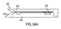
図106〜114に関連して記載されるように、電動式ステープル留め及び切断器具(外科用器具)の様々な態様を説明する前に、本開示はまず、本電動式外科用器具が実装され得、電動式外科用器具の基盤となる動作及び機能を十分に理解するために必要な背景を提供する、機械的及び電気的プラットフォームの概要を説明するために、図1〜105を参照する。したがって、図1〜14は、本電動式ステープル留め及び切断器具が実装され得る、基盤となる機械的プラットフォームの概要の例を提供する。図15〜21は、一般的な基盤となるマイクロコントローラ、モータドライブ、及び本電動式外科用器具が実装され得る電気相互接続プラットフォームの例を説明する。図22〜34は、例示的なエンドエフェクタチャネルフレーム、及びエンドエフェクタのアンビルとステープルカートリッジとの間に位置する組織に対して加えられる力の測定を説明する。図35〜37は、本電動式外科用器具の機能を制御するための例示的な回路を説明する。図38〜95は、例示的なセンサ、及びセンサ出力を用いて本電動式外科用器具を実装するフィードバックシステムを説明する。図97〜97は、本電動式外科用器具に給電するための例示的な電源組立体を説明する。図98〜105は、モータ速度及び本外科用器具の駆動可能部材を制御するための制御システムの例を説明し、このシステムは、センサと、そのためのフィードバック要素と、を含む。本電動式外科用器具が実装され得る、基盤となる機械的及び電気的プラットフォームの理解に基づいて、読者は、モータ制御動作を感知し、分析し、実施し、自動的に再開するように構成された、外科用ステープル留め及び切断器具を説明するための図106〜114に関連する説明を受ける。 Before describing the various aspects of the electrically powered stapling and severing instrument (surgical instrument) as described in connection with FIGS. 106-114, the present disclosure begins with the implementation of the electrically powered surgical instrument. Reference is made to FIGS. 1-105 to provide an overview of the mechanical and electrical platforms that provide the necessary background to obtain a full understanding of the underlying operation and function of the powered surgical instrument. Thus, Figures 1-14 provide an example of an overview of the underlying mechanical platform on which the present motorized stapling and severing instrument can be implemented. FIGS. 15-21 illustrate examples of common underlying microcontrollers, motor drives, and electrical interconnection platforms on which the powered surgical instrument may be implemented. 22-34 illustrate measurement of the force applied to an exemplary end effector channel frame and tissue located between the end effector's anvil and a staple cartridge. 35-37 describe an exemplary circuit for controlling the functionality of the present powered surgical instrument. 38-95 illustrate an exemplary sensor and feedback system implementing the powered surgical instrument with sensor output. 97-97 illustrate an exemplary power supply assembly for powering the powered surgical instrument. Figures 98-105 illustrate examples of motor speed and control systems for controlling the actuable members of the surgical instrument, the system including a sensor and a feedback element therefor. Based on an understanding of the underlying mechanical and electrical platforms on which the powered surgical instrument can be implemented, the reader is configured to sense, analyze, perform and automatically resume motor control operations. The description given in connection with FIGS. 106-114 is for explaining the surgical stapling and severing instrument.
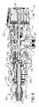
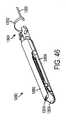
したがって、ここで図を参照すると、図1〜6は、再使用されてもされなくてもよい、切断及び締結用のモータ駆動の外科用器具10を示す。図示の例では、外科用器具10は、臨床医が把持し、操作し、作動させるように構成されているハンドル組立体14を備えるハウジング12を含む。ハウジング12は、1つ又は2つ以上の外科的タスク又は処置を行うように構成されているエンドエフェクタ300が動作可能に結合されている、交換式シャフト組立体200に動作可能に取り付けるように構成されている。本発明を実施するための形態を読み進めるに従って、本明細書で開示する様々な形態の交換式シャフト組立体の様々な独自で新規な構成が、ロボット制御式の外科用システムと関連させて効果的に用いられ得ることも理解されよう。したがって、「ハウジング」という用語はまた、本明細書に開示する交換式シャフト組立体及びそれらそれぞれの等価物を作動させるのに使用することができる、少なくとも1つの制御運動を生成し適用するように構成されている、少なくとも1つの駆動システムを収容するか又は別の方法で動作可能に支持する、ロボットシステムのハウジング又は類似の部分を包含してもよい。「フレーム」という用語は、手持ち式外科用器具の一部分を指してもよい。「フレーム」という用語はまた、ロボット制御式の外科用器具の一部分、及び/又は外科用器具を動作可能に制御するために使用され得るロボットシステムの一部分を表す場合もある。例えば、本明細書で開示する交換式シャフト組立体は、参照によって全ての内容が本明細書に組み込まれる、米国特許第9,072,535号、発明の名称「SURGICAL STAPLING INSTRUMENTS WITH ROTATABLE STAPLE DEPLOYMENT ARRANGEMENTS」で開示されている様々なロボットシステム、器具、構成要素及び方法と共に用いられ得る。 Thus, referring now to the figures, Figures 1-6 show a motorized
図1〜図2に示されるハウジング12は、外科用ステープルカートリッジ304を中で動作可能に支持するように構成されている、外科用切断及び締結デバイスを備えるエンドエフェクタ300を含む、交換式シャフト組立体200と接続されて示されている。ハウジング12は、種々のサイズ及びタイプのステープルカートリッジを支持するように適合されたエンドエフェクタを含み、種々のシャフトの長さ、サイズ、及びタイプなどを有する交換式シャフト組立体と接続されて使用するように構成されてもよい。加えて、ハウジング12はまた、例えば、運動、並びに高周波(RF)エネルギー、超音波エネルギー及び/又は運動などの他の形態のエネルギーを、様々な外科用途及び処置に関連して用いられるように適合されたエンドエフェクタ構成に印加するように構成された組立体を含んだ様々な他の交換式シャフト組立体と共に効果的に用いられてもよい。更に、エンドエフェクタ、シャフト組立体、ハンドル、外科用器具、及び/又は外科用器具システムは、任意の好適な締結具を利用して組織を締結することができる。例えば、中に着脱可能に格納された複数の締結具を備える締結具カートリッジが、シャフト組立体のエンドエフェクタに着脱可能に挿入及び/又は装着され得る。 The
図1は、交換式シャフト組立体200が動作可能に結合された外科用器具10を示している。図2は、ハウジング12又はハンドル組立体14への交換式シャフト組立体200の取り付けを示している。図4に示すように、ハンドル組立体14は、ねじ、スナップ機構、接着剤などで相互連結され得る一対の相互連結可能なハンドルハウジングセグメント16及び18を備え得る。図示の構成において、ハンドルハウジングセグメント16、18は、臨床医に握持及び操作され得るピストルグリップ部分19を形成するように協働する。以下で更に詳細に論じられるように、ハンドル組立体14は、その中に複数の駆動システムを動作可能に支持し、それら駆動システムは、ハンドル組立体に動作可能に装着された交換式シャフト組立体の対応部分に、様々な制御運動を生成して適用するように構成されている。 FIG. 1 shows a
ここで図4を参照すると、ハンドル組立体14は、複数の駆動システムを動作可能に支持するフレーム20を更に含んでもよい。例えば、フレーム20は、全体として30で示される「第1の」即ち閉鎖駆動システムを動作可能に支持することができ、この閉鎖駆動システムは、動作可能に取り付けられた又は結合された交換式シャフト組立体200に対して開閉運動を適用するために用いられてもよい。少なくとも1つの形態では、閉鎖駆動システム30は、フレーム20によって枢動可能に支持される閉鎖トリガ32の形態のアクチュエータを含んでもよい。より具体的には、図4に示されるように、閉鎖トリガ32は、枢動ピン33によってハンドル組立体14に枢動可能に結合されている。かかる構成により、臨床医が閉鎖トリガ32を操作することが可能になり、そのため、臨床医がハンドル組立体14のピストルグリップ部分19を把持するとき、閉鎖トリガ32は、開始位置又は「非作動」位置から「作動」位置へ、より具体的には完全圧縮位置又は完全作動位置へと容易に枢動できるようになっている。閉鎖トリガ32は、ばね又は他の付勢装置(図示せず)によって、非作動位置へと付勢されてもよい。様々な形態では、閉鎖駆動システム30は、閉鎖トリガ32に枢動可能に結合された閉鎖リンケージ組立体34を更に含む。図4に示されるように、閉鎖リンクケージ組立体34は、ピン35によって閉鎖トリガ32に枢動可能に結合された第1の閉鎖リンク36及び第2の閉鎖リンク38を含んでもよい。第2の閉鎖リンク38は、本明細書では「取り付け部材」と呼ばれることもあり、横断取り付けピン37を含み得る。 Referring now to FIG. 4, the
依然として図4を参照すると、第1の閉鎖リンク36は、フレーム20に枢動可能に結合された閉鎖解除組立体60と協働するように構成されている端部、つまりロック壁39を有してよいことが観察できる。少なくとも1つの形態では、閉鎖解除組立体60は、遠位側に突出するロック爪64がその上に形成された閉鎖解除ボタン組立体62を備えてもよい。閉鎖解除ボタン組立体62は、解除ばね(図示せず)によって反時計方向に枢動させられてもよい。臨床医が閉鎖トリガ32をその非作動位置からハンドル組立体14のピストルグリップ部分19に向かって押下すると、ロック爪64が第1の閉鎖リンク36上のロック壁39との保持係合に至る地点に向かって第1の閉鎖リンク36が上向きに枢動し、それによって閉鎖トリガ32が非作動位置に復帰することが防止される。したがって、閉鎖解除組立体60は、閉鎖トリガ32を完全作動位置でロックするように働く。臨床医が、閉鎖トリガ32をロック解除して、それを非作動位置へ付勢することができるようにしたい場合、臨床医は単純に、閉鎖解除ボタン組立体62を枢動させ、それによってロック爪64を移動させて、第1の閉鎖リンク36上のロック壁39との係合から外す。ロック爪64が移動させられて第1の閉鎖リンク36との係合から外れると、閉鎖トリガ32は枢動して非作動位置に戻ってもよい。他の閉鎖トリガロック及び解放構成もまた用いられてよい。 Still referring to FIG. 4, the first closure link 36 has an end or lock
上記に加えて更に、図10〜図11は、組織を交換式シャフト組立体200の顎部間に位置付けることができる、交換式シャフト組立体200の開放構成、即ち非クランプ構成と関連付けられる非作動位置にある、閉鎖トリガ32を示している。図12は、組織が交換式シャフト組立体200の顎部間でクランプされる、交換式シャフト組立体200の閉鎖構成、即ちクランプ構成と関連付けられる作動位置にある、閉鎖トリガ32を示している。図11及び図13を比較すると、閉鎖トリガ32をその非作動位置(図11)から作動位置(図13)へと移動させると、閉鎖解除ボタン組立体62が第1の位置(図11)と第2の位置(図13)との間で枢動することが、読者には理解されるであろう。閉鎖解除ボタン組立体62の回転は、上向きの回転であるとして言及され得るが、閉鎖解除ボタン組立体62の少なくとも一部分は、回路基板100に向かって回転させられている。図4を参照すると、閉鎖解除ボタン組立体62は、そこから延在するアーム61と、アーム61に装着される、例えば永久磁石などの磁気要素63と、を含むことができる。閉鎖解除ボタン組立体62をその第1の位置から第2の位置へと回転させると、磁気要素63は、回路基板100に向かって移動することができる。回路基板100は、磁気要素63の移動を検出するように構成された、少なくとも1つのセンサを含むことができる。少なくとも1つの態様では、例えば、磁場センサ65が回路基板100の底面に装着され得る。磁場センサ65は、磁気要素63の移動によって生じる磁場センサ65を取り巻く磁場の変化を検出するように構成され得る。磁場センサ65は、例えば、コントローラ1500と信号連通することができ、コントローラ1500は、閉鎖解除ボタン組立体62が、閉鎖トリガ32の非作動位置及びエンドエフェクタの開放構成と関連付けられるその第1の位置、閉鎖トリガ32の作動位置及びエンドエフェクタの閉鎖構成と関連付けられるその第2の位置、並びに/又は第1の位置と第2の位置との間の任意の位置にあるかを判定できる。 In addition to the above, FIGS. 10-11 can be positioned between the jaws of the
本開示の全体にわたって用いられているように、磁場センサは、とりわけ、ホール効果センサ、探りコイル、フラックスゲート、光ポンピング、核摂動、SQUID、ホール効果、異方性磁気抵抗、巨大磁気抵抗、磁気トンネル接合、巨大磁気インピーダンス、磁歪/圧電複合材、磁気ダイオード、磁気トランジスタ、光ファイバ、光磁気、及び微小電気機械システム系の磁気センサであってよい。 As used throughout the present disclosure, magnetic field sensors may be used, inter alia, Hall effect sensors, probe coils, flux gates, optical pumping, nuclear perturbations, SQUIDs, Hall effects, anisotropic magnetoresistance, giant magnetoresistance, magnetism, among others. The magnetic sensor may be a tunnel junction, giant magnetoimpedance, magnetostrictive / piezoelectric composite, magnetic diode, magnetic transistor, optical fiber, magneto-optical, and micro-electro-mechanical system system.
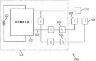
少なくとも1つの形態では、ハンドル組立体14及びフレーム20は、取り付けられた交換式シャフト組立体の対応部分に対して発射運動を適用するように構成されている、本明細書では発射駆動システム80と呼ばれる別の駆動システムを動作可能に支持してもよい。発射駆動システム80はまた、本明細書では「第2の駆動システム」と呼ばれることもある。発射駆動システム80は、ハンドル組立体14のピストルグリップ部分19に位置する電動モータ82を用いてもよい。様々な形態では、電動モータ82は、例えば、約25,000RPMの最大回転数を有するブラシ付きDC駆動モータであってよい。他の構成では、モータとしては、ブラシレスモータ、コードレスモータ、同期モータ、ステッパモータ、又は他の任意の好適な電動モータを挙げることができる。電動モータ82は、一形態では取り外し可能なパワーパック92を備えてよい、電源90によって給電されてよい。例えば、図4に示されるように、取り外し可能なパワーパック92は、遠位側ハウジング部分96に取り付けるために構成されている、近位側ハウジング部分94を備えてよい。近位側ハウジング部分94及び遠位側ハウジング部分96は、複数の電池98を中に動作可能に支持するように構成されている。電池98はそれぞれ、例えば、リチウムイオン(「LI」)又は他の好適な電池を含んでもよい。遠位側ハウジング部分96は、電動モータ82にやはり動作可能に結合されている、制御回路基板100に取り外し可能かつ動作可能に取り付けられるために構成されている。直列に接続されてもよい多数の電池98が、外科用器具10の電源として使用されてもよい。それに加えて、電源90は、交換可能及び/又は再充電可能であってもよい。 In at least one form, the
他の様々な形態に関連して上に概説したように、電動モータ82は、長手方向に移動可能な駆動部材120上にある駆動歯122の組又はラックと噛合係合して装着されるギヤ減速機組立体84と動作可能に連係する、回転式シャフト(図示せず)を含むことができる。使用の際、電源90によって提供される電圧極性によって電動モータ82を時計方向に動作させることができるが、電池によって電動モータに印加される電圧極性は、電動モータ82を反時計方向に動作させるために反転させることができる。電動モータ82がある方向に回転されると、長手方向に移動可能な駆動部材120は、遠位方向「DD」に軸方向に駆動されることになる。電動モータ82が反対の回転方向に駆動されると、長手方向に移動可能な駆動部材120は、近位方向「PD」に軸方向駆動されることになる。ハンドル組立体14は、電源90によって電動モータ82に付与される極性を反転させるように構成され得るスイッチを備えることができる。本明細書で説明する他の形態と同様に、ハンドル組立体14はまた、長手方向に移動可能な駆動部材120の位置、及び/又は長手方向に移動可能な駆動部材120が移動されている方向を検出するように構成されているセンサを含むこともできる。 As outlined above in connection with the various other aspects, the
電動モータ82の作動は、ハンドル組立体14上に枢動可能に支持される発射トリガ130によって制御され得る。発射トリガ130は、非作動位置と作動位置との間で枢動させられてもよい。発射トリガ130は、ばね132若しくは他の付勢装置によって非作動位置へと付勢されてもよく、それにより、臨床医が発射トリガ130を解放すると、それがばね132若しくは付勢装置によって非作動位置へと枢動されるか又は別の方法で復帰させられてもよい。少なくとも1つの形態では、発射トリガ130は、上述したように、閉鎖トリガ32の「外側」に位置付けることができる。少なくとも1つの形態では、発射トリガ安全ボタン134が、ピン35によって閉鎖トリガ32に枢動可能に装着されてもよい。発射トリガ安全ボタン134は、発射トリガ130と閉鎖トリガ32との間に位置付けられ、そこから突出する枢動アーム136を有してよい。図4を参照されたい。閉鎖トリガ32が非作動位置にあるとき、発射トリガ安全ボタン134は、ハンドル組立体14内に収容され、臨床医は容易には安全ボタン134にアクセスすることができず、発射トリガ130の作動を防止する安全位置と、発射トリガ130が発射され得る発射位置との間で移動することもできない。臨床医が閉鎖トリガ32を押下すると、発射トリガ安全ボタン134及び発射トリガ130が下に枢動して、次いで、臨床医がそれらを操作することが可能になる。 The operation of the
上述したように、ハンドル組立体14は、閉鎖トリガ32及び発射トリガ130を含むことができる。図11〜図13を参照すると、発射トリガ130を閉鎖トリガ32に枢動可能に装着することができる。閉鎖トリガ32は、そこから延在するアーム31を含むことができ、発射トリガ130は、枢動ピン33を中心にしてアーム31に枢動可能に装着することができる。閉鎖トリガ32をその非作動位置(図11)から作動位置(図13)へと移動させると、上に概説したように、発射トリガ130が下向きに下降することができる。発射トリガ安全ボタン134がその発射位置へと移動した後、主に図18Aを参照すると、発射トリガ130を押下して、外科用器具発射システムのモータを動作させることができる。様々な例では、ハンドル組立体14は、例えば、閉鎖トリガ32の位置及び/又は発射トリガ130の位置を判断するように構成された、システム800などの追跡システムを含むことができる。主に図11及び図13を参照すると、追跡システム800は、例えば、発射トリガ130から延在するアーム801に装着される、磁石802などの磁気要素を含むことができる。追跡システム800は、例えば、磁石802の位置を追跡するように構成され得る、第1の磁場センサ803及び第2の磁場センサ804など、1つ又は2つ以上のセンサを備えることができる。 As mentioned above, the
図11及び図13を比較すると、閉鎖トリガ32をその非作動位置から作動位置へと移動させると、磁石802が、第1の磁場センサ803に隣接した第1の位置と、第2の磁場センサ804に隣接した第2の位置との間で移動できることが、読者には理解されるであろう。 11 and 13, when the
図11及び図13を比較すると、発射トリガ130を未発射位置(図11)から発射後位置(図13)へと移動させると、磁石802が第2の磁場センサ804に対して移動できることが、読者には更に理解されるであろう。第1及び第2の磁場センサ803及び804は、磁石802の移動を追跡することができ、回路基板100のコントローラと信号連通することができる。第1の磁場センサ803及び/又は第2の磁場センサ804からのデータを用いて、コントローラは、事前定義された経路に沿って磁石802の位置を判定することができ、その位置に基づいて、コントローラは、閉鎖トリガ32がその非作動位置、その作動位置、又はこれらの間の位置にあるかを判定することができる。同様に、第1の磁場センサ803及び/又は第2の磁場センサ804からのデータを用いて、コントローラは、事前定義された経路に沿って磁石802の位置を判定することができ、その位置に基づいて、コントローラは、発射トリガ130がその未発射位置、その完全発射後位置、又はこれらの間の位置にあるかを判定することができる。 11 and 13, when moving the firing
上述したように、少なくとも1つの形態では、長手方向可動駆動部材120は、ギヤ減速機組立体84の対応する駆動ギヤ86と噛合係合するために、その上に形成された駆動歯122のラックを有する。少なくとも1つの形態はまた、電動モータ82が使用不能になった場合に、臨床医が長手方向に移動可能な駆動部材120を手動で後退させることができるように構成されている、手動作動式の緊急離脱組立体140を含む。緊急離脱組立体140は、手動で枢動させて、長手方向に移動可能な駆動部材120にやはり設けられた歯124とラチェット係合するように構成された、レバー又はハンドル組立体14を含んでもよい。したがって、臨床医は、ハンドル組立体14を使用して長手方向に移動可能な駆動部材120を近位方向「PD」にラチェットで駆動させることによって、長手方向に移動可能な駆動部材120を手動により後退させることができる。米国特許第8,608,045号、発明の名称「POWERED SURGICAL CUTTING AND STAPLING APPARATUS WITH MANUALLY RETRACTABLE FIRING SYSTEM」は、緊急離脱装置、並びにやはり本明細書に開示の様々な器具と共に用いられてもよい他の構成要素、装置、及びシステムを開示している。米国特許第8,608,045号は、その全体が参照により本明細書に組み込まれる。 As mentioned above, in at least one form, the longitudinally
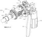
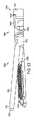
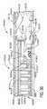
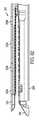
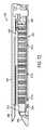
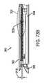
ここで図1を参照すると、交換式シャフト組立体200は、外科用ステープルカートリッジ304を中で動作可能に支持するように構成されている細長いチャネル302を備える、エンドエフェクタ300を含む。エンドエフェクタ300は、細長いチャネル302に対して枢動可能に支持されるアンビル306を更に含んでもよい。交換式シャフト組立体200は、シャフト軸線SA−SAに対して所望の位置でエンドエフェクタ300を解除可能に保持するように構成することができる、関節継手270及び関節ロック350(図7)を更に含んでもよい。エンドエフェクタ300、関節継手270、及び関節ロック350の構造と動作に関する詳細は、米国特許出願公開第2014/0263541号、発明の名称「ARTICULATABLE SURGICAL INSTRUMENT COMPRISING AN ARTICULATION LOCK」に説明されおり、その全体が参照により本明細書に組み込まれる。図7に示されるように、交換式シャフト組立体200は、ノズル部分202、203で構成される近位側ハウジング又はノズル201を更に含むことができる。交換式シャフト組立体200は、エンドエフェクタ300のアンビル306を開閉するために利用することができる、閉鎖管260を更に含むことができる。主としてここで図7を参照すると、交換式シャフト組立体200はスパイン210を含むことができ、スパイン210は、関節ロック350のシャフトフレーム212を固定可能に支持するように構成され得る。図7を参照されたい。スパイン210は、(1)発射部材220を中で摺動可能に支持するように、かつ(2)スパイン210の周りに延在する閉鎖管260を摺動可能に支持するように、構成することができる。スパイン210はまた、関節ドライバ230を摺動可能に支持するように構成することができる。関節ドライバ230は、関節ロック350を動作可能に係合するように構成された遠位端部231を有する。関節ロック350は、エンドエフェクタフレーム(図示せず)上の駆動ピン(図示せず)に動作可能に係合するように適合された、関節フレーム352と連係する。上述したように、関節ロック350及び関節フレームの動作に関する更なる詳細は、米国特許出願公開第2014/0263541号に見出すことができる。様々な状況において、スパイン210は、シャーシ240内で回転可能に支持される近位端部211を備えることができる。1つの構成では、例えば、スパイン210の近位端部211には、シャーシ240内で支持されるように構成されたスパイン軸受216にねじ込みによって取り付けられるように、ねじ山214が形成される。かかる構成により、シャーシ240に対するスパイン210の回転可能な取り付けが容易になって、スパイン210を、シャーシ240に対してシャフト軸線SA−SAを中心にして選択可能に回転させることができる。 Referring now to FIG. 1, the
交換式シャフト組立体200は、シャーシ240に対して軸方向に移動され得るようにその中で摺動可能に支持される、閉鎖シャトル250を含む。図3に示されるように、閉鎖シャトル250は、更に詳細に後述するように、第2の閉鎖リンク38に取り付けられる横断取り付けピン37に取り付けるために構成されている、一対の近位側に突出するフック252を含む。閉鎖管260の近位端部261は、相対回転するように閉鎖シャトル250に結合されている。例えば、U字コネクタ263は、閉鎖管260の近位端部261にある環状スロット262に挿入され、閉鎖シャトル250の垂直スロット253内で保定される。かかる構成は、閉鎖管260を閉鎖シャトル250と共に軸方向移動するようにそれに取り付ける役割を果たし、一方で閉鎖管260がシャフト軸線SA−SAを中心にして閉鎖シャトル250に対して回転することを可能にする。閉鎖ばね268は、閉鎖管260上で軸止され、閉鎖管260を近位方向「PD」に付勢する役割を果たし、それによって、シャフト組立体がハンドル組立体14に動作可能に結合されると、閉鎖トリガを非作動位置へと枢動する役割を果たすことができる。 The
少なくとも1つの形態では、交換式シャフト組立体200は、関節継手270を更に含んでもよい。しかしながら、他の交換式シャフト組立体は、関節運動可能でなくてもよい。様々な形態によれば、二重枢動閉鎖スリーブ組立体271は、上側及び下側の遠位側に突出するタング273、274を有する、エンドエフェクタ閉鎖スリーブ組立体272を含む。エンドエフェクタ閉鎖スリーブ組立体272は、馬蹄形アパーチャ275と、米国特許出願公開第2014/0263541号に記載される様々な方式でアンビル306上の開放タブと係合するためのタブ276と、を含む。本明細書で更に詳述するように、馬蹄形アパーチャ275及びタブ276は、アンビル306が開放されているときにアンビル上のタブに係合する。上側二重枢動リンク277は、閉鎖管260上にある上部近位突出タング273の上部遠位ピンホール、及び上部遠位突出タング264の上部近位ピンホールにそれぞれ係合する、上向きに突出する遠位及び近位枢動ピンを含む。下部二重枢動リンク278は、下部近位突出タング274の下部遠位ピンホール、及び下部遠位突出タング265の下部近位ピンホールにそれぞれ係合する、上向きに突出する遠位及び近位枢動ピンを含む。図7も参照されたい。 In at least one form,
使用の際、閉鎖管260は、例えば、閉鎖トリガ32の作動に応答して、アンビル306を閉鎖するように遠位側(方向「DD」)に並進される。アンビル306は、閉鎖管260を、したがってエンドエフェクタ閉鎖スリーブ組立体272を遠位側に並進させて、前述の参照の米国特許出願公開第2014/0263541号に記載されている方式でアンビル306の近位表面に衝突させることによって閉鎖される。同参照文献にやはり詳細に記載されているように、閉鎖管260及びエンドエフェクタ閉鎖スリーブ組立体272を近位側に並進させて、タブ276及び馬蹄形アパーチャ275をアンビルタブに接触させ、それを押してアンビル306を持ち上げることによって、アンビル306が開放される。アンビル開位置において、閉鎖管260は、その近位位置へと移動させられる。 In use, the
上述したように、外科用器具10は、エンドエフェクタ300を定位置で選択的にロックするように構成し動作させることができる、米国特許出願公開第2014/0263541号に更に詳細に記載されているタイプ及び構造の関節ロック350を更に含んでもよい。かかる構成によって、関節ロック350がそのロック解除状態にあるとき、エンドエフェクタ300を、閉鎖管260に対して回転させること、即ち関節運動させることが可能になる。かかるロック解除状態では、エンドエフェクタ300を閉鎖管260に対して関節運動させるために、エンドエフェクタ300を、例えば、患者の体内の手術部位を取り囲む軟組織及び/又は骨に対して位置付け、押すことができる。エンドエフェクタ300はまた、関節ドライバ230によって閉鎖管260に対して関節運動させてもよい。 As mentioned above,
やはり上述したように、交換式シャフト組立体200は、スパイン210内で軸方向移動するように支持される発射部材220を更に含む。発射部材220は、遠位側切断部分又はナイフバー280に取り付けるために構成されている中間発射シャフト222を含む。発射部材220はまた、本明細書において「第2のシャフト」及び/又は「第2のシャフト組立体」と呼ばれることもある。図7に示されるように、中間発射シャフト222は、その遠位端に、ナイフバー280の近位端282にあるタブ284を受け入れるように構成することができる、長手方向スロット223を含んでもよい。長手方向スロット223及び近位端部282は、それらの間の相対運動を可能にするようにサイズ決めして構成することができ、かつスリップ継手286を備えることができる。スリップ継手286は、ナイフバー280を移動させずに、又は少なくとも実質的に移動させずに、発射部材220の中間発射シャフト222を移動させて、エンドエフェクタ300を関節運動させることを可能にすることができる。エンドエフェクタ300が好適に配向された後は、ナイフバー280を進め、チャネル302内に位置するステープルカートリッジを発射するため、長手方向スロット223の近位側の側壁がタブ284に接触するまで、中間発射シャフト222を遠位側に進めることができる。図7で更に分かるように、スパイン210は細長い開口部又は窓213を有して、スパイン210への中間発射シャフト222の組み付け及び挿入を容易にしている。中間発射シャフト222が挿入されると、頂部フレームセグメント215がシャフトフレーム212と係合されて、中間発射シャフト222及びナイフバー280を中に封入してもよい。発射部材220の動作に関する更なる記載は、米国特許出願公開第2014/0263541号に見出すことができる。 Also as described above,
上記に加えて更に、交換式シャフト組立体200は、関節ドライバ230を発射部材220に選択的かつ解除可能に結合するように構成することができる、クラッチ組立体400を含むことができる。1つの形態では、クラッチ組立体400は、発射部材220の周りに位置付けられたロックカラー、即ちロックスリーブ402を含み、ロックスリーブ402は、ロックスリーブ402が関節ドライバ360を発射部材220に結合する係合位置と、関節ドライバ360が発射部材220に動作可能に結合されない係合解除位置との間で回転され得る。ロックスリーブ402がその係合位置にあるとき、発射部材220の遠位方向移動によって、関節ドライバ360を遠位側に移動させることができ、それに対応して、発射部材220の近位方向移動によって、関節ドライバ230を近位側に移動させることができる。ロックスリーブ402がその係合解除位置にあるとき、発射部材220の移動は、関節ドライバ230に伝達されず、その結果、発射部材220は、関節ドライバ230とは独立して移動することができる。様々な状況において、関節ドライバ230が発射部材220によって近位又は遠位方向で移動させられていないとき、関節ドライバ230を関節ロック350によって定位置で保持することができる。 In addition to the above, the
図7〜9に示されるように、交換式シャフト組立体200は、閉鎖管260上に回転可能に受け入れられるスイッチドラム500を更に含む。スイッチドラム500は、外向き突出作動ピン410を中に受容するためのシャフトボス504が形成された中空シャフトセグメント502を備える。様々な状況において、作動ピン410は、スロット267を通って、ロックスリーブ402に設けられた長手方向スロット408内へと延在して、ロックスリーブ402が関節ドライバ230と係合されたときにその軸方向運動を容易にする。回転ねじりばね420は、図8に示されるように、スイッチドラム500のシャフトボス504及びノズルハウジング203の一部分に係合して、付勢力をスイッチドラム500に加えるように構成されている。スイッチドラム500は、そこに画定された、少なくとも部分的に円周方向の開口部506を更に備えることができ、その開口部は、図5及び図6を参照すると、ノズル部分202、203から延在する円周方向マウント204、205を受け入れ、スイッチドラム500とノズル201との間の相対回転は許容するが並進は許容しないように構成することができる。これらの図に示されるように、円周方向マウント204及び205はまた、閉鎖管260の開口部266を通って延在して、スパイン210位置する陥凹部に収まる。しかしながら、円周方向マウント204、205がスイッチドラム500内のそれぞれの部分的に円周方向の開口部506の端部に達する点までノズル201が回転すると、スイッチドラム500がシャフト軸線SA−SAを中心にして回転する。スイッチドラム500が回転すると、最終的に、作動ピン410及びロックスリーブ402が、その係合位置と係合解除位置との間で回転することになる。したがって、本質的に、ノズル201は、米国特許出願公開第2014/0263541号に更に詳細に記載されている様々な方式で、関節駆動システムと発射駆動システムとを動作可能に係合及び係合解除するために用いることができる。 As shown in FIGS. 7-9, the
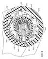
やはり図7〜9に示されるように、交換式シャフト組立体200は、例えば、エンドエフェクタ300との間で電力を伝導し、かつ/又はエンドエフェクタ300との間で信号を通信するように構成することができる、スリップリング組立体600を備えることができる。スリップリング組立体600は、シャーシ240から延在するシャーシ装着フランジ242に装着される近位コネクタフランジ604と、ノズル部分202、203に画定されたスロット内に位置付けられる遠位コネクタフランジ601とを備えることができる。近位コネクタフランジ604は第1の面を備えることができ、遠位コネクタフランジ601は、第1の面に隣接して位置付けられ、かつ第1の面に対して移動可能である第2の面を備えることができる。遠位コネクタフランジ601は、シャフト軸線SA−SAを中心にして、近位コネクタフランジ604に対して回転することができる。近位コネクタフランジ604は、その第1の面に画定される、複数の同心の、又は少なくとも実質的に同心の導体602を備えることができる。コネクタ607は、遠位コネクタフランジ601の近位側に装着することができ、複数の接点(図示せず)を有してもよく、各接点は、導体602のうち1つに対応してそれと電気的に接触する。かかる構成により、近位コネクタフランジ604と遠位コネクタフランジ601とが、それらの間の電気的接触を維持したまま相対回転することが可能になる。近位コネクタフランジ604は、例えば、シャーシ240に装着されたシャフト回路基板610と信号連通して導体602を配置することができる、電気コネクタ606を含むことができる。少なくとも1つの例では、複数の導体を備える配線ハーネスが、電気コネクタ606とシャフト回路基板610との間に延在することができる。電気コネクタ606は、シャーシ装着フランジ242に画定されたコネクタ開口部243を通って近位側に延在してもよい。米国特許出願公開第2014/0263551号、発明の名称「STAPLE CARTRIDGE TISSUE THICKNESS SENSOR SYSTEM」は、その全体を参照により本明細書に組み込む。米国特許出願公開第2014/0263552号、名称「STAPLE CARTRIDGE TISSUE THICKNESS SENSOR SYSTEM」は、その全体を参照により本明細書に組み込む。スリップリング組立体600に関する更なる詳細は、米国特許出願公開第2014/0263541号に見出すことができる。 As also shown in FIGS. 7-9, the
上述のように、交換式シャフト組立体200は、ハンドル組立体14に固定可能に取り付けられる近位部分と、長手方向軸線を中心に回転可能である遠位部分とを含み得る。回転可能な遠位シャフト部分は、上述したように、スリップリング組立体600を中心にして近位部分に対して回転させることができる。スリップリング組立体600の遠位コネクタフランジ601は、回転可能な遠位シャフト部分内に位置付けることができる。また、上記に加えて更に、スイッチドラム500も、回転可能な遠位シャフト部分内に位置付けることができる。回転可能な遠位シャフト部分を回転させると、遠位コネクタフランジ601及びスイッチドラム500を互いに同期して回転させることができる。それに加えて、スイッチドラム500を、遠位コネクタフランジ601に対して第1の位置と第2の位置との間で回転させることができる。スイッチドラム500がその第1の位置にあると、関節駆動システムが発射駆動システムから動作可能に係合解除されてもよく、したがって、発射駆動システムの動作によって、交換式シャフト組立体200のエンドエフェクタ300を関節運動させることができない。スイッチドラム500がその第2の位置にあると、関節駆動システムが発射駆動システムと動作可能に係合されてもよく、したがって、発射駆動システムの動作によって交換式シャフト組立体200のエンドエフェクタ300を関節運動させることができる。スイッチドラム500をその第1の位置と第2の位置との間で移動させると、スイッチドラム500は、遠位コネクタフランジ601に対して移動させられる。様々な例において、交換式シャフト組立体200は、スイッチドラム500の位置を検出するように構成された少なくとも1つのセンサを備えることができる。次に図9を参照すると、遠位コネクタフランジ601は、例えば磁場センサ605を備えることができ、スイッチドラム500は、例えば永久磁石505などの磁気要素を備えることができる。磁場センサ605は、永久磁石505の位置を検出するように構成され得る。スイッチドラム500がその第1の位置と第2の位置との間で回転されるとき、永久磁石505は磁場センサ605に対して移動し得る。様々な例において、磁場センサ605は、永久磁石505が移動されるときに生じる磁場の変化を検出し得る。磁場センサ605は、例えば、シャフト回路基板610及び/又はハンドル内に位置する回路基板100と信号連通し得る。磁場センサ605からの信号に基づき、シャフト回路基板610及び/又はハンドル内に位置するハンドル回路基板100上のコントローラは、関節駆動システムが発射駆動システムと係合されるか又はそこから係合解除されるかどうかを判定し得る。 As mentioned above,
再び図3を参照すると、シャーシ240は、フレーム20の遠位側取り付けフランジ700内に形成された、対応するダブテールスロット702内に受け入れられるように適合された、シャーシ上に形成された少なくとも1つの、好ましくは2つの先細取り付け部分244を含む。各ダブテールスロット702は、先細取り付け部分244を中に収めて受け入れるように、先細であってもよく、又は言い換えればある程度V字形であってもよい。図3から更に分かるように、シャフト取り付けラグ226が、中間発射シャフト222の近位端に形成される。更に詳細に後述するように、交換式シャフト組立体200がハンドル組立体14に結合されると、シャフト取り付けラグ226は、例えば、図3及び図6に示すように、長手方向に移動可能な駆動部材120の遠位端125に形成された発射シャフト取り付けクレードル126に受け入れられる。 Referring again to FIG. 3,
様々なシャフト組立体は、交換式シャフト組立体200をハウジング12に、より具体的にはフレーム20に取り外し可能に結合するためのラッチシステム710を用いる。近位側に突出するロックラグ714にはそれぞれ、シャーシ240に形成された対応する穴245に受け入れられるように適合された、枢動ロックラグ716が形成される。かかる構成により、ロックヨーク712をシャーシ240に枢動可能に取り付けやすくなる。ロックヨーク712は、フレーム20の遠位側取り付けフランジ700の対応するロック移動止め又は溝704と解除可能に係合するように構成された、2つの近位側に突出するロックラグ714を含んでもよい。図3を参照されたい。様々な形態では、ロックヨーク712は、ばね又は付勢部材(図示せず)によって近位方向に付勢される。ロックヨーク712の作動は、シャーシ240に装着されたラッチアクチュエータ組立体720上に摺動可能に装着される、ラッチボタン722によって遂行されてもよい。ラッチボタン722は、ロックヨーク712に対して近位方向に付勢されていてもよい。更に詳細に後述するように、ロックヨーク712は、ラッチボタンを遠位方向で付勢することによってロック解除位置へと移動させられてもよく、それによってまた、ロックヨーク712が枢動して、フレーム20の遠位側取り付けフランジ700との保定係合から外れる。ロックヨーク712がフレーム20の遠位側取り付けフランジ700と「保定係合」しているとき、枢動ロックラグ716は、遠位側取り付けフランジ700の対応するロック移動止め又は溝704内に保定されて収まっている。 Various shaft assemblies use a
組織を切断し締結するように適合された本明細書に記載されるタイプのエンドエフェクタ、並びに他のタイプのエンドエフェクタを含む、交換式シャフト組立体を用いる場合、エンドエフェクタの作動中に交換式シャフト組立体がハウジングから不用意に分離されることを防止することが望ましいことがある。例えば、使用の際、臨床医は、閉鎖トリガ32を作動させて標的組織を把持し、所望の位置へと操作することがある。標的組織がエンドエフェクタ300内に所望の配向で位置付けられると、臨床医は、次に、閉鎖トリガ32を完全に作動させてアンビル306を閉鎖し、標的組織を切断及びステープル留めの位置でクランプしてもよい。その場合、第1の駆動システム30は、完全に作動している。標的組織がエンドエフェクタ300にクランプされた後、交換式シャフト組立体200がハウジング12から不用意に分離されることを防止することが望ましいことがある。ラッチシステム710の1つの形態は、かかる不用意な分離を防止するように構成されている。 When using a replaceable shaft assembly that includes an end effector of the type described herein adapted to cut and fasten tissue, as well as other types of end effectors, the exchangeable type of end effector is interchangeable It may be desirable to prevent the shaft assembly from being inadvertently separated from the housing. For example, in use, the clinician may actuate the
ロックヨーク712は、閉鎖シャトル250上に形成されたロックラグ部分256に接触するように適合された、少なくとも1つの、好ましくは2つのロックフック718を含む。図10及び11を参照すると、閉鎖シャトル250が非作動位置にある(即ち、第1の閉鎖駆動システム30が非作動で、アンビル306が開放されている)とき、ロックヨーク712を遠位方向で枢動させて、交換式シャフト組立体200をハウジング12からロック解除してもよい。その位置では、ロックフック718は、閉鎖シャトル250上のロックラグ256に接触しない。しかしながら、閉鎖シャトル250を作動位置へと移動させる(即ち、第1の閉鎖駆動システム30を作動させ、アンビル306が閉位置にある)と、ロックヨーク712がロック解除位置へと枢動することが防止される。図12及び13を参照されたい。言い換えると、臨床医がロックヨーク712をロック解除位置へと枢動させようとした場合、又は例えば、ロックヨーク712が、別の場合では遠位側に枢動することがあるような形で不用意に突き当たるか又は接触した場合、ロックヨーク712上のロックフック718が閉鎖シャトル250上のロックラグ256に接触し、ロックヨーク712がロック解除位置へと移動することを防止する。 The locking
これから、ハンドル組立体14への交換式シャフト組立体200の取り付けについて、図3を参照して記載する。結合プロセスを開始するために、臨床医は、シャーシ240上に形成された先細取り付け部分244がフレーム20のダブテールスロット702と位置合わせされるようにして、交換式シャフト組立体200のシャーシ240をフレーム20の遠位側取り付けフランジ700の上方に、又はそれに隣接して位置付けてもよい。臨床医は、次に、交換式シャフト組立体200を、シャフト軸線SA−SAに垂直な設置軸線IAに沿って移動させて、先細取り付け部分244を対応するダブテール受け入れスロット702と「動作可能に係合」させて収めてもよい。その際、中間発射シャフト222上のシャフト取り付けラグ226もまた、長手方向に移動可能な駆動部材120の発射シャフト取り付けクレードル126に収められ、第2の閉鎖リンク38上にある横断取り付けピン37の部分が、閉鎖シャトル250の対応する近位側に突出するフック252に収められる。本明細書で使用するとき、2つの構成要素の文脈における「動作可能な係合」という用語は、それら2つの構成要素が互いに十分に係合され、それにより、作動運動をそれらに適用すると、構成要素が意図される行為、機能、及び/又は手順を実施し得ることを意味する。 The attachment of
上述したように、交換式シャフト組立体200の少なくとも5つのシステムが、ハンドル組立体14の少なくとも5つの対応するシステムと動作可能に結合され得る。第1のシステムは、交換式シャフト組立体200のフレーム又はスパインをハンドル組立体14のフレーム20と結合及び/又は位置合わせするフレームシステムを備えることができる。別のシステムは、ハンドル組立体14の閉鎖トリガ32と、閉鎖管260と、交換式シャフト組立体200のアンビル306とを動作可能に接続することができる閉鎖駆動システム30を備えることができる。上で概説したように、交換式シャフト組立体200の閉鎖シャトル250を、第2の閉鎖リンク38上にある横断取り付けピン37と係合させることができる。別のシステムは、ハンドル組立体14の発射トリガ130を交換式シャフト組立体200の中間発射シャフト222と動作可能に接続することができる発射駆動システム80を備えることができる。 As mentioned above, at least five systems of
上で概説したように、シャフト取り付けラグ226は、長手方向に移動可能な駆動部材120の発射シャフト取り付けクレードル126と動作可能に接続することができる。別のシステムは、例えば交換式シャフト組立体200などのシャフト組立体が、ハンドル組立体14と動作可能に係合されていることを、例えばコントローラなど、ハンドル組立体14内のコントローラに信号伝達することができ、並びに/又は(2)電力及び/若しくは通信信号を交換式シャフト組立体200とハンドル組立体14との間で伝導することができる電気システムを含むことができる。例えば、交換式シャフト組立体200は、シャフト回路基板610に動作可能に装着される電気コネクタ1410を含むことができる。シャフト上に位置する電気コネクタ1410は、ハンドル内に位置する回路基板100上で電気コネクタ1400と嵌合係合するように構成されている。回路及び制御システムに関する更なる詳細は、米国特許出願公開第2014/0263541号に見出すことができる。第5のシステムは、交換式シャフト組立体200をハンドル組立体14に解除可能にロックするラッチングシステムで構成されてもよい。 As outlined above, the
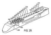
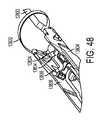
図14を参照すると、エンドエフェクタ300の非限定的な形態が示されている。上述したように、エンドエフェクタ300は、アンビル306及び外科用ステープルカートリッジ304を含んでもよい。この非限定的な例では、アンビル306は、細長いチャネル198に結合されている。例えば、アパーチャ199を、アンビル306から延在するピン152を受け入れることができる細長いチャネル198内に画定することができ、アパーチャ199によって、細長いチャネル198及び外科用ステープルカートリッジ304に対してアンビル306を開位置から閉位置まで枢動させることができる。それに加えて、図14は、エンドエフェクタ300内へと長手方向で並進するように構成された発射バー172を示している。発射バー172は、1つの中実部分から構築されてもよく、又は様々な例では、例えば鋼板のスタックを含む、積層材料を含んでもよい。発射バー172の遠位側に突出する端部は、E型梁178に取り付けることができ、E型梁178は、中でも特に、アンビル306が閉位置にあるとき、細長いチャネル198内に位置付けられた外科用ステープルカートリッジ304からアンビル306を離すことを支援することができる。E型梁178はまた、E型梁178を発射バー172によって遠位側に前進させながら組織を切るために使用することができる、鋭利な切刃182を含むことができる。動作の際、E型梁178はまた、外科用ステープルカートリッジ304を作動させること、即ち発射することができる。外科用ステープルカートリッジ304は、ステープルドライバ192上に載置された複数のステープル191を、それぞれの上向きに開いたステープルキャビティ195内で保持する、成型カートリッジ本体194を含むことができる。楔形スレッド190は、E型梁178によって遠位側に駆動されて、外科用ステープルカートリッジ304の様々な構成要素を共に保持するカートリッジトレイ196上を摺動する。楔形スレッド190は、E型梁178の切刃182がクランプされた組織を切る間、ステープルドライバ192を上向きにカム駆動して、ステープル191を追い出してアンビル306と変形接触させる。 Referring to FIG. 14, a non-limiting form of
上記に加えて更に、E型梁178は、発射の間、アンビル306に係合する上部ピン180を含むことができる。E型梁178は、カートリッジ本体194、カートリッジトレイ196、及び細長いチャネル198の様々な部分に係合することができる、中央ピン184と下部フット186とを更に含むことができる。外科用ステープルカートリッジ304が細長いチャネル198内に位置付けられると、カートリッジ本体194に画定されたスロット193を、カートリッジトレイ196に画定された長手方向スロット197及び細長いチャネル198に画定されたスロット189と位置合わせすることができる。使用の際、E型梁178は、位置合わせされた細長いスロット193、197、及び189を通って摺動することができ、図14に示されるように、E型梁178の下部フット186は、スロット189の長さに沿って細長いチャネル198の底面に沿って通っている溝に係合することができ、中央ピン184は、長手方向スロット197の長さに沿ってカートリッジトレイ196の上面に係合することができ、上部ピン180は、アンビル306に係合することができる。かかる状況では、発射バー172が遠位側へと移動させられて、ステープルを外科用ステープルカートリッジ304から発射し、かつ/又はアンビル306と外科用ステープルカートリッジ304との間に捕捉された組織を切開するにつれて、E型梁178は、アンビル306と外科用ステープルカートリッジ304とを離すか、又はこれらの相対移動を制限することができる。その後、発射バー172及びE型梁178を近位側へと後退させることができ、それによってアンビル306を開いて、ステープル留めされ切られた2つの組織部分を解放することができる(図示せず)。 In addition to the above, the
外科用器具10(図1〜14)について一般的用語で記載してきたが、ここで、外科用器具10の様々な電気/電子構成要素について詳細に記載する。図2及び図3を再び参照すると、ハンドル組立体14は、複数の電気接点を備える電気コネクタ1400を含むことができる。ここで図15を参照すると、電気コネクタ1400は、例えば、第1の電気接点1401aと、第2の電気接点1401bと、第3の電気接点1401cと、第4の電気接点1401dと、第5の電気接点1401eと、第6の電気接点1401fとを備えることができる。図示の例は6つの接点を利用しているが、6つより多い接点又は6つより少ない接点を利用し得る他の例も考えられる。 Having described in general terms the surgical instrument 10 (FIGS. 1-14), various electrical / electronic components of the
図15に示されるように、第1の電気接点1401aは、トランジスタ1408と電気通信することができ、電気接点1401b〜1401eは、コントローラ1500と電気通信することができ、第6の電気接点1401fは、アースと電気通信することができる。特定の状況では、ハンドル1042が給電状態にあるとき、電気接点1401b〜1401eのうちの1つ又は2つ以上が、コントローラ1500の1つ又は2つ以上の出力チャネルと電気通信していてもよく、通電することができ、又は電位を印加することができる。いくつかの状況では、電気接点1401b〜1401eのうちの1つ又は2つ以上が、コントローラ1500の1つ又は2つ以上の入力チャネルと電気通信していてもよく、ハンドル組立体14が給電状態にあるとき、コントローラ1500は、かかる電気接点に電位が印加されたときにそれを検出するように構成することができる。例えば、交換式シャフト組立体200などのシャフト組立体が、ハンドル組立体14に組み付けられたとき、電気接点1401a〜1401fは、互いに連通しなくてもよい。しかしながら、シャフト組立体がハンドル組立体14に組み付けられていないとき、電気コネクタ1400の電気接点1401a〜1401fは、露出していてもよく、またいくつかの状況では、電気接点1401a〜1401fのうちの1つ又は2つ以上が、互いに電気通信されて偶然に配置されてもよい。かかる状況は、例えば、電気接点1401a〜1401fのうちの1つ又は2つ以上が導電性材料と接触すると生じる可能性がある。これが生じると、例えば、コントローラ1500が、エラー入力を受信する場合があり、かつ/又は交換式シャフト組立体200が、エラー出力を受信する場合がある。この問題に対処するために、様々な状況では、例えば、交換式シャフト組立体200などのシャフト組立体がハンドル組立体14に取り付けられていないとき、ハンドル組立体14は、給電されなくてもよい。 As shown in FIG. 15, the first
他の状況では、例えば、交換式シャフト組立体200などのシャフト組立体が、ハンドル1042に取り付けられていないとき、ハンドル1042に給電することができる。かかる状況では、コントローラ1500は、シャフト組立体がハンドル組立体14に取り付けられるまで、コントローラ1500と電気通信している接点、即ち、例えば電気接点1401b〜1401eに印加される、入力又は電位を無視するように構成することができる。コントローラ1500は、そのような状況下でハンドル組立体14の他の機能を操作するために電力を供給されてもよいが、ハンドル組立体14は非給電状態にあってもよい。ある意味で、電気接点1401b〜1401eに加えられる電位がハンドル組立体14の動作に影響することがないので、電気コネクタ1400は非給電状態にあってもよい。電気接点1401b〜1401eが給電停止状態にあっても、コントローラ1500と電気通信していない電気接点1401a及び1401fは給電停止状態にあってもなくてもよいことが、読者には理解されるであろう。例えば、第6の電気接点1401fは、ハンドル組立体14が給電状態にあるか給電停止状態にあるかに関わらず、アースと電気通信したままであってもよい。 In other situations, the handle 1042 can be powered when a shaft assembly, such as, for example, a
更に、トランジスタ1408、及び/又は例えばトランジスタ1412などの任意の他の好適なトランジスタの配置、及び/又はスイッチは、ハンドル組立体14が給電状態にあるか給電停止状態にあるかに関わらず、例えばハンドル組立体14内の電池などの電源1404から第1の電気接点1401aへの電力の供給を制御するように構成されてもよい。様々な状況では、交換式シャフト組立体200は、例えば、交換式シャフト組立体200がハンドル組立体14と係合されたときにトランジスタ1408の状態を変化させるように構成することができる。特定の状況下では、以下に加えて更に、磁場センサ1402は、トランジスタ1412の状態を切り換えるように構成され得、トランジスタ1412は結果として、トランジスタ1408の状態を切り換えて、最終的に電源1404から第1の電気接点1401aに電力を供給することができる。このようにして、電気コネクタ1400までの電源回路と信号回路の両方に対して、シャフト組立体がハンドル組立体14に設置されていないときは給電停止し、シャフト組立体がハンドル組立体14に設置されているときは給電することができる。 Further,
様々な状況では、図15を再び参照すると、ハンドル組立体14は、例えば磁場センサ1402を含むことができ、磁場センサ1402は、シャフト組立体がハンドル組立体14に結合されると、例えば交換式シャフト組立体200などのシャフト組立体上の、例えば磁気要素1407(図3)などの検出可能な要素を検出するように構成することができる。磁場センサ1402は、例えば電池などの電源1406によって給電することができ、電源1406は実際に、磁場センサ1402の検出信号を増幅し、図15に示される回路を介してコントローラ1500の入力チャネルと通信することができる。コントローラ1500が、シャフト組立体がハンドル組立体14に少なくとも部分的に結合されていること、またその結果として、電気接点1401a〜1401fが露出しなくなっていることを示す入力を受信すると、コントローラ1500は、その通常の、つまり給電動作状態に入ることができる。かかる動作状態では、コントローラ1500は、その通常の使用時に、電気接点1401b〜1401eのうちの1つ又は2つ以上にシャフト組立体から伝達された信号を評価し、かつ/又は、電気接点1401b〜1401eのうちの1つ又は2つ以上を通してシャフト組立体に信号を伝達する。様々な状況において、磁場センサ1402が磁気要素1407を検出し得るにはその前に、交換式シャフト組立体200が完全に着座されなければならない場合がある。交換式シャフト組立体200の存在を検出するために磁場センサ1402を利用することができるが、例えば、シャフト組立体がハンドル組立体14に組み付けられているか否かを検出するために、センサ及び/又はスイッチの任意の好適なシステムを利用することができる。このようにして、上記に加えて更に、電気コネクタ1400までの電源回路と信号回路の両方に対して、シャフト組立体がハンドル組立体14に設置されていないときは給電停止し、シャフト組立体がハンドル組立体14に設置されているときは給電することができる。 In various situations, referring again to FIG. 15, the
様々な実施例において、本開示の全体にわたって用いられているように、例えば、シャフト組立体がハンドル組立体14に組み付けられているか否かを検出するために、任意の好適な磁場センサが用いられてもよい。例えば、磁場感知に使用される技術としては、とりわけ、ホール効果センサ、探りコイル、フラックスゲート、光ポンピング、核摂動、SQUID(超伝導量子干渉素子、ジョセフソン接合を含む超伝導ループに基づく、極めて弱い磁場の測定に用いられる非常に高感度の磁力計)、ホール効果、異方性磁気抵抗、巨大磁気抵抗、磁気トンネル接合、巨大磁気インピーダンス、磁歪/圧電複合材、磁気ダイオード、磁気トランジスタ、光ファイバ、光磁気、及び微小電気機械システム系の磁気センサが挙げられる。 In various embodiments, as used throughout the present disclosure, any suitable magnetic field sensor may be used, for example, to detect whether the shaft assembly is assembled to the
図15を参照すると、コントローラ1500は、一般に、プロセッサ(「マイクロプロセッサ」)と、プロセッサに動作可能に結合された1つ又は2つ以上のメモリユニットとを備えてよい。メモリに記憶された命令コードを実行することによって、プロセッサは、例えば、モータ、様々な駆動システム、及び/又はユーザディスプレイなど、外科用器具の様々な構成要素を制御してもよい。コントローラ1500は、集積型及び/若しくは個々のハードウェア要素、ソフトウェア要素、並びに/又はそれら両者の組み合わせを用いて実装され得る。集積型ハードウェア要素の例としては、プロセッサ、マイクロプロセッサ、コントローラ、コントローラ、集積回路、特定用途向け集積回路(ASIC)、プログラマブル論理デバイス(PLD)、デジタル信号プロセッサ(DSP)、フィールドプログラマブルゲートアレイ(FPGA)、論理ゲート、レジスタ、半導体素子、チップ、マイクロチップ、チップセット、コントローラ、システムオンチップ(SoC)、及び/又はシステムインパッケージ(SIP)が挙げられ得る。個々のハードウェア要素の例としては、論理ゲート、電界効果トランジスタ、バイポーラトランジスタ、抵抗、コンデンサ、インダクタ、及び/若しくはリレーなど、回路並びに/又は回路素子が挙げられ得る。特定の例では、コントローラ1500は、例えば、1つ又は2つ以上の基板上に離散的及び集積型の回路素子又は構成要素を含むハイブリッド回路を含んでもよい。 Referring to FIG. 15,
図15を参照すると、コントローラ1500は、例えば、Texas Instrumentsから入手可能なLM4F230H5QRであってもよい。特定の例では、Texas InstrumentsのLM4F230H5QRは、製品データシートから容易に入手可能な他の機構の中でも、最大40MHz、256KBの単一サイクルフラッシュメモリ若しくは他の不揮発性メモリのオンチップメモリと、40MHz超の性能を改善するためのプリフェッチバッファと、32KBの単一サイクルシリアルランダムアクセスメモリ(SRAM)と、StellarisWare(登録商標)ソフトウェアを搭載した内部読み取り専用メモリ(ROM)と、2KBの電気的消去可能なプログラマブル読み取り専用メモリ(EEPROM)と、1つ又は2つ以上のパルス幅変調(PWM)モジュールと、1つ又は2つ以上のアナログ直交エンコーダ入力部(QEI)と、12個のアナログ入力チャネルを備えた、1つ又は2つ以上の12ビットアナログデジタル変換器(ADC)と、を備えたARM Cortex−M4Fプロセッサコアである。他のコントローラが、本開示と共に使用するために容易に代用され得る。したがって、本開示は、この文脈に限定されるべきではない。 Referring to FIG. 15,
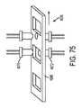
上述したように、ハンドル組立体14及び/又は交換式シャフト組立体200は、交換式シャフト組立体200がハンドル組立体14に組み付けられていないとき、又は完全に組み付けられていないときに、ハンドル上に位置する電気コネクタ1400の接点及び/又はシャフト上に位置する電気コネクタ1410の接点が短絡することを防止するか、又は少なくともその可能性を低減するように構成された、システム及び構成を含むことができる。図3を参照すると、ハンドル上に位置する電気コネクタ1400は、フレーム20に画定されたキャビティ1409内に少なくとも部分的に入り込ませることができる。電気コネクタ1400の6つの電気接点1401a〜1401fは、キャビティ1409内に完全に入り込ませることができる。かかる配置は、物体が電気接点1401a〜1401fの1つ又は2つ以上に偶発的に接触する可能性を低減することができる。同様に、シャフト上に位置する電気コネクタ1410を、シャーシ240に画定された陥凹部内に位置付けることができ、それによって、シャフト上に位置する電気コネクタ1410の電気接点1411a〜1411fのうちの1つ又は2つ以上に物体が偶発的に接触する可能性を低減することができる。図3に示される特定の例に関して、シャフト上に位置する電気接点1411a〜1411fは、雄接点を備えることができる。少なくとも1つの例では、シャフトに位置する電気接点1411a〜1411fのそれぞれは、例えば、ハンドル上に位置する電気接点1401a〜1401fを係合するように構成することができる、電気接点から延在する可撓性突出部を備えることができる。ハンドル上に位置する電気接点1401a〜1401fは、雌接点を備えることができる。少なくとも1つの例では、ハンドル上に位置する各電気接点1401a〜1401fは、例えば、平坦面を備えることができ、それに接してシャフト上に位置する雄電気接点1401a〜1401fがワイプし、即ち摺動し、接点間の導電性の連係を維持することができる。様々な例では、交換式シャフト組立体200がハンドル組立体14に組み付けられる方向は、ハンドル上に位置する電気接点1401a〜1401fに対して平行であるか、又は少なくとも実質的に平行であることができ、それにより、交換式シャフト組立体200がハンドル組立体14に組み付けられると、シャフト上に位置する電気接点1411a〜1411fは、ハンドル上に位置する電気接点1401a〜1401fに接して摺動する。様々な代替的な例では、ハンドルに位置する電気接点1401a〜1401fが雄接点を備えることができ、シャフト上に位置する電気接点1411a〜1411fが雌接点を備えることができる。特定の代替的な例では、ハンドル上に位置する電気接点1401a〜1401f及びシャフト上に位置する電気接点1411a〜1411fは、接点の任意の好適な配置を備えることができる。 As mentioned above, the
様々な例では、ハンドル組立体14は、ハンドル上に位置する電気コネクタ1400を少なくとも部分的に被覆するように構成されたコネクタガード、及び/又はシャフト上に位置する電気コネクタ1410を少なくとも部分的に被覆するように構成されたコネクタガードを備えることができる。コネクタガードは、シャフト組立体がハンドルに組み付けられていないとき、又は部分的にのみ組み付けられているとき、物体が電気コネクタの接点に偶発的に触れることを防止するか、又は少なくともその可能性を低減することができる。コネクタガードは、可動であることができる。例えば、コネクタガードは、コネクタを少なくとも部分的に防護する防護位置と、コネクタを防護しないか、又は少なくともわずかしか防護しない非防護位置との間で移動させることができる。少なくとも1つの例では、シャフト組立体がハンドルに組み付けられるにつれて、コネクタガードを変位させることができる。例えば、ハンドルがハンドルコネクタガードを備える場合、シャフト組立体がハンドルに組み付けられるにつれて、シャフト組立体がハンドルコネクタガードに接触し、それを変位させることができる。同様に、シャフト組立体がシャフトコネクタガードを備える場合、シャフト組立体がハンドルに組み付けられるにつれて、ハンドルがシャフトコネクタガードに接触し、それを変位させることができる。様々な例では、コネクタガードは、例えばドアを備えることができる。少なくとも1つの例では、ドアは、ハンドル又はシャフトが接触すると、ドアを特定の方向に変位させることを容易にすることができる、傾斜面を備えることができる。様々な例では、コネクタガードを、例えば、並進及び/又は回転させることができる。特定の例では、コネクタガードは、電気コネクタの接点を被覆する少なくとも1つのフィルムを備えることができる。シャフト組立体がハンドルに組み付けられると、フィルムは破断され得る。少なくとも1つの例では、コネクタの雄接点は、フィルムを貫通することができ、その後、フィルムの下に位置付けられた対応する接点に係合する。 In various examples, the
上述したように、外科用器具は、例えば、電気コネクタ1400などの電気コネクタの接点を、選択的に給電又は活性化することができるシステムを含むことができる。様々な例では、接点を不活性状態と活性化状態との間で遷移させることができる。特定の例では、接点を、監視状態、非活性化状態、及び活性化状態の間で遷移させることができる。例えば、コントローラ1500は例えば、シャフト組立体がハンドル組立体14に組み付けられていないときの電気接点1401a〜1401fを監視して、電気接点1401a〜1401fのうちの1つ又は2つ以上が短絡されている可能性があるか否かを判定することができる。コントローラ1500は、電気接点1401a〜1401fそれぞれに低電位を印加し、接点それぞれに最小限の抵抗のみが存在するか否かを見積もるように構成することができる。かかる動作状態は、監視状態を含むことができる。接点において検出された抵抗が高い場合、又は閾値抵抗を上回る場合、コントローラ1500は、その接点を、1つを超える接点を、あるいは全ての接点を非活性化することができる。かかる動作状態は、非活性化状態を含むことができる。シャフト組立体がハンドル組立体14に組み付けられ、上述したように、それがコントローラ1500によって検出された場合、コントローラ1500は、電気接点1401a〜1401fに対する電位を増加することができる。かかる動作状態は、活性化状態を含むことができる。 As mentioned above, the surgical instrument can include, for example, a system that can selectively power or activate contacts of an electrical connector, such as
本明細書に開示される様々なシャフト組立体は、センサ、及びハウジング内のコントローラとの電気的連通を要する他の様々な構成要素を用いてもよい。これらのシャフト組立体は、一般に、ハウジングに対して回転することができるように構成されており、互いに対して回転してもよい2つ又は3つ以上の構成要素間でのかかる電気的連通を容易にする接続を要する。本明細書に開示されるタイプのエンドエフェクタを用いると、コネクタ装置は、本質的に比較的堅牢でもある一方、シャフト組立体コネクタ部分に嵌合するように、ある程度コンパクトでなければならない。 The various shaft assemblies disclosed herein may use sensors and various other components that require electrical communication with the controller in the housing. These shaft assemblies are generally configured to be rotatable relative to the housing, and such electrical communication between two or more components that may rotate relative to one another Requires a connection to facilitate. With end effectors of the type disclosed herein, the connector device must be relatively compact to fit into the shaft assembly connector portion while being inherently inherently relatively rigid.
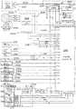
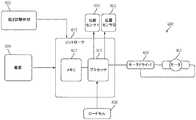
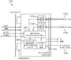
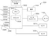
ここで、複数の回路セグメント2002a〜2002gを備えるセグメント化回路2000の一例が示されている、図16A及び16Bに移る。複数の回路セグメント2002a〜2002gを備えるセグメント化回路2000は、非限定的に、例えば図1〜図13に示される外科用器具10など、電動外科用器具を制御するように構成されている。複数の回路セグメント2002a〜2002gは、電動外科用器具10の1つ又は2つ以上の動作を制御するように構成されている。安全プロセッサセグメント2002a(セグメント1)は、安全プロセッサ2004を備える。一次プロセッサセグメント2002b(セグメント2)は、一次プロセッサ2006を備える。安全プロセッサ2004及び/又は一次プロセッサ2006は、1つ又は2つ以上の追加の回路セグメント2002c〜2002gと相互作用して、電動外科用器具10の動作を制御するように構成されている。一次プロセッサ2006は、例えば、1つ又は2つ以上の回路セグメント2002c〜2002g、電池2008、及び/又は複数のスイッチ2058a〜2070に結合された、複数の入力を備える。セグメント化回路2000は、例えば、電動外科用器具10内のプリント回路基板組立体(PCBA)など、任意の好適な回路によって実装されてもよい。プロセッサという用語は、本明細書で使用するとき、任意のマイクロプロセッサ、プロセッサ、コントローラ、又はコンピュータの中央処理装置(CPU)の機能を1つの集積回路又は最大で数個の集積回路上に組み込んだ、他の基本コンピューティングデバイスを含むことが理解されるべきである。プロセッサは、デジタルデータを入力として受理し、メモリに記憶された命令に従ってそのデータを処理し、結果を出力として提供する、多目的のプログラマブルデバイスである。これは、内部メモリを有するので、逐次的デジタル論理の一例である。プロセッサは、二進数法で表される数字及び記号で動作する。 Turning now to FIGS. 16A and 16B, an example of a
一態様では、一次プロセッサ2006は、Texas Instruments製のARM Cortexの商品名で知られているものなど、任意のシングルコア又はマルチコアプロセッサであってもよい。一実施例では、安全プロセッサ2004は、やはりTexas Instruments製の、Hercules ARM Cortex R4の商品名で知られている、TMS570及びRM4xなど、2つのコントローラベースファミリを備える安全コントローラプラットフォームであってもよい。それにもかかわらず、コントローラ及び安全プロセッサに好適な他の置換品も制限なく用いることができる。一実施例では、安全プロセッサ2004は、拡張性がある性能、接続性、及びメモリの選択肢を提供しながら、高度な集積化された安全特性を提供するため、中でも特に、IEC 61508及びISO 26262の安全限界用途向けに特定的に構成されてもよい。特定の例では、一次プロセッサ2006は、図14〜17Bに関連して記載されるように、シングルコア又はマルチコアコントローラのLM4F230H5QRであってよい。 In one aspect,
一例では、セグメント化回路2000は、加速度セグメント2002c(セグメント3)を備える。加速度セグメント2002cは、加速度計2022を備える。加速度計2022は、電動外科用器具10の移動又は加速度を検出するように構成されている。いくつかの実施例では、加速度計2022からの入力は、例えば、スリープモードとの間での遷移、電動外科用器具の配向の識別、及び/又は外科用器具が落下したときの識別に使用される。いくつかの実施例では、加速度セグメント2002cは、安全プロセッサ2004及び/又は一次プロセッサ2006に結合されている。 In one example, the
一態様では、セグメント化回路2000は、ディスプレイセグメント2002d(セグメント4)を備える。ディスプレイセグメント2002dは、一次プロセッサ2006に結合されたディスプレイコネクタ2024を備える。ディスプレイコネクタ2024は、1つ又は2つ以上のディスプレイの集積回路ドライバ2026を通して、一次プロセッサ2006をディスプレイ2028に結合する。ディスプレイの集積回路ドライバ2026は、ディスプレイ2028と一体化されてもよく、かつ/又はディスプレイ2028とは別個に配置されてもよい。ディスプレイ2028は、例えば、有機発光ダイオード(OLED)ディスプレイ、液晶ディスプレイ(LCD)、及び/又は任意の他の好適なディスプレイなど、任意の好適なディスプレイを含んでもよい。いくつかの実施例では、ディスプレイセグメント2002dは、安全プロセッサ2004に結合されている。 In one aspect, the
いくつかの態様では、セグメント化回路2000は、シャフトセグメント2002e(セグメント5)を備える。シャフトセグメント2002eは、外科用器具10に結合された交換式シャフト組立体200(図1)に対する1つ又は2つ以上の制御、及び/又は交換式シャフト組立体200(図1)に結合されたエンドエフェクタ300に対する1つ又は2つ以上の制御機器を備える。シャフトセグメント2002eは、一次プロセッサ2006をシャフトPCBA 2031に結合するように構成された、シャフトコネクタ2030を備える。シャフトPCBA 2031は、第1の関節スイッチ2036、第2の関節スイッチ2032、及びシャフトPCBA EEPROM 2034を備える。いくつかの実施例では、シャフトPCBA EEPROM 2034は、交換式シャフト組立体200及び/又はシャフトPCBA 2031固有の1つ又は2つ以上のパラメータ、ルーチン、及び/又はプログラムを含む。シャフトPCBA 2031は、交換式シャフト組立体200に結合され、及び/又は、外科用器具10と一体であってもよい。いくつかの実施例では、シャフトセグメント2002eは、第2のシャフトEEPROM 2038を備える。第2のシャフトEEPROM 2038は、電動外科用器具10と接続され得る1つ若しくは2つ以上のシャフト組立体200及び/又はエンドエフェクタ300に対応する複数のアルゴリズム、ルーチン、パラメータ、及び/又は他のデータを含む。 In some aspects, the
いくつかの態様では、セグメント化回路2000は、位置エンコーダセグメント2002f(セグメント6)を備える。位置エンコーダセグメント2002fは、1つ又は2つ以上の磁気角度回転位置エンコーダ2040a〜2040bを備える。1つ又は2つ以上の磁気角度回転位置エンコーダ2040a〜2040bは、外科用器具10のモータ2048、交換式シャフト組立体200(図1)、及び/又はエンドエフェクタ300の回転位置を識別するように構成されている。いくつかの実施例では、磁気角度回転位置エンコーダ2040a〜2040bは、安全プロセッサ2004及び/又は一次プロセッサ2006に結合されてもよい。 In some aspects, the
いくつかの態様では、セグメント化回路2000は、モータ回路セグメント2002g(セグメント7)を備える。モータ回路セグメント2002gは、電動外科用器具10の1つ又は2つ以上の移動を制御するように構成されたモータ2048を備える。モータ2048は、Hブリッジドライバ2042及び1つ又は2つ以上のHブリッジ電界効果トランジスタ2044(FET)によって、一次プロセッサ2006に結合されている。HブリッジFET 2044は、安全プロセッサ2004に結合されている。モータ電流センサ2046は、モータ2048の電流引き出しを測定するため、モータ2048と直列に結合されている。モータ電流センサ2046は、一次プロセッサ2006及び/又は安全プロセッサ2004と信号連通している。いくつかの実施例では、モータ2048は、モータ電磁干渉(EMI)フィルタ2050に結合されている。 In some aspects,
いくつかの態様では、セグメント化回路2000は、電源セグメント2002h(セグメント8)を備える。電池2008は、安全プロセッサ2004、一次プロセッサ2006、及び追加回路セグメント2002c〜2002gのうちの1つ又は2つ以上に結合されている。電池2008は、電池コネクタ2010及び電流センサ2012によってセグメント化回路2000に結合されている。電流センサ2012は、セグメント化回路2000の合計電流引き出しを測定するように構成されている。いくつかの実施例では、1つ又は2つ以上の電圧変換器2014a、2014b、2016が、既定の電圧値を1つ又は2つ以上の回路セグメント2002a〜2002gに提供するように構成されている。例えば、いくつかの実施例では、セグメント化回路2000は、3.3V電圧変換器2014a〜2014b及び/又は5V電圧変換器2016を備えてもよい。ブースト変換器2018は、例えば13V以下など、既定量以下のブースト電圧を提供するように構成されている。ブースト変換器2018は、電力集約的な動作の間、追加の電圧及び/又は電流を提供し、電圧低下又は低電力状態を防止するように構成されている。 In some aspects, the
いくつかの態様では、安全プロセッサセグメント2002aは、モータ電力スイッチ2020を備える。モータ電力スイッチ2020は、電源セグメント2002hとモータ回路セグメント2002gとの間に結合されている。安全プロセッサセグメント2002aは、本明細書で更に詳細に考察するように、安全プロセッサ2004及び/又は一次プロセッサ2006によってエラー若しくは障害状態が検出されると、モータ回路セグメント2002gに対する電力を遮断するように構成されている。回路セグメント2002a〜2002gは、回路セグメント2002a〜2002hの全ての構成要素が物理的に近接して配置されて示されているが、回路セグメント2002a〜2002hは、同じ回路セグメント2002a〜2002gの他の構成要素から物理的及び/又は電気的に分離している構成要素を備えてもよいことが、当業者には認識されるであろう。いくつかの実施例では、1つ又は2つ以上の構成要素が、2つ又は3つ以上の回路セグメント2002a〜2002gの間で共有されてもよい。 In some aspects, the
いくつかの態様では、複数のスイッチ2056〜2070が、安全プロセッサ2004及び/又は一次プロセッサ2006に結合されている。複数のスイッチ2056〜2070は、外科用器具10の1つ又は2つ以上の動作を制御し、セグメント化回路2000の1つ又は2つ以上の動作を制御し、かつ/又は外科用器具10の状態を示すように構成されてもよい。例えば、緊急離脱ドアスイッチ2056は、緊急離脱ドアの状態を示すように構成されている。例えば、左側関節左スイッチ2058a、左側関節右スイッチ2060a、左側関節中央スイッチ2062a、右側関節左スイッチ2058b、右側関節右スイッチ2060b、及び右側関節中央スイッチ2062bなど、複数の関節運動スイッチは、シャフト組立体200及び/又はエンドエフェクタ300の関節運動を制御するように構成されている。左側反転スイッチ2064a及び右側反転スイッチ2064bは、一次プロセッサ2006に結合されている。いくつかの実施例では、左側関節左スイッチ2058a、左側関節右スイッチ2060a、左側関節中央スイッチ2062a、及び左側反転スイッチ2064aを備える左側スイッチは、左側可撓コネクタ2072aによって一次プロセッサ2006に結合されている。右側関節左スイッチ2058b、右側関節右スイッチ2060b、右側関節中央スイッチ2062b、及び右側反転スイッチ2064bを備える右側スイッチは、右側可撓コネクタ2072bによって一次プロセッサ2006に結合されている。いくつかの実施例では、発射スイッチ2066、クランプ解除スイッチ2068、及びシャフト係合スイッチ2070は、一次プロセッサ2006に結合されている。 In some aspects, a plurality of switches 2056-2070 are coupled to
いくつかの態様では、複数のスイッチ2056〜2070は、例えば、外科用器具10のハンドル、複数のインジケータスイッチ、及び/又はそれらの任意の組み合わせに装着される、複数のハンドル制御を備えてもよい。様々な例では、複数のスイッチ2056〜2070により、外科医が外科用器具を操作し、セグメント化回路2000に対して外科用器具の位置及び/若しくは動作に関するフィードバックを提供し、かつ/又は外科用器具10の安全でない動作を示すことが可能になる。いくつかの実施例では、追加のスイッチ又はより少数のスイッチが、セグメント化回路2000に結合されてもよく、スイッチ2056〜2070のうちの1つ又は2つ以上を組み合わせて単一のスイッチとしてもよく、かつ/又は拡張して複数のスイッチとしてもよい。例えば、一実施例では、左側及び/又は右側関節運動スイッチ2058a〜2064bのうちの1つ又は2つ以上を組み合わせて、単一の多重位置スイッチとしてもよい。 In some aspects, the plurality of switches 2056-2070 may comprise a plurality of handle controls, for example, mounted on the handle of the
一態様では、安全プロセッサ2004は、他の安全動作の中でも特に、ウォッチドッグ機能を実現するように構成されている。セグメント化回路2000の安全プロセッサ2004及び一次プロセッサ2006は、信号連通している。プロセッサのアライブハートビート信号は、出力2097で提供される。加速度セグメント2002cは、外科用器具10の移動を監視するように構成された加速度計2022を備える。様々な例では、加速度計2022は、単軸、二軸、又は三軸加速度計であってもよい。加速度計2022は、必ずしも座標加速度(速度の変化率)ではない適正な加速度を測定するのに用いられてもよい。その代わりに、加速度計は、加速度計2022の基準フレーム内で静止している試験質量が経験する重量の現象と関連付けられる加速度を見る。例えば、地表面で静止している加速度計2022は、その重量により、g=9.8m/s2(重力)の真っ直ぐ上向きの加速度を測定する。加速度計2022が測定することができる別のタイプの加速度は、g力加速度である。他の様々な例では、加速度計2022は、単軸、二軸、又は三軸加速度計を備えてもよい。更に、加速度セグメント2002cは、加速度、傾き、衝撃、振動、回転、及び複数の自由度(DoF)を検出し測定する、1つ又は2つ以上の慣性センサを備えてもよい。好適な慣性センサは、加速度計(単軸、二軸、若しくは三軸)、地球の磁界などの空間中の磁界を測定する磁力計、及び/又は角速度を測定するジャイロスコープを備えてもよい。In one aspect,
一態様では、安全プロセッサ2004は、例えばモータ回路セグメント2002gなど、1つ又は2つ以上の回路セグメント2002c〜2002hに関して、ウォッチドッグ機能を実現するように構成されている。これに関して、安全プロセッサ2004は、ウォッチドッグ機能を用いて、一次プロセッサ2006の誤動作を検出しそこから復帰する。正常動作の間、安全プロセッサ2004は、一次プロセッサ2006のハードウェア障害又はプログラムエラーを監視し、修正動作(単数若しくは複数)を開始する。修正動作は、一次プロセッサ2006を安全状態に置くこと、及び正常なシステム動作を復元することを含んでもよい。一実施例では、安全プロセッサ2004は、少なくとも第1のセンサに結合されている。第1のセンサは、外科用器具10(図1〜図4)の第1の特性を測定する。いくつかの実施例では、安全プロセッサ2004は、外科用器具10の測定された特性を既定値と比較するように構成されている。例えば、一実施例において、磁気角度回転位置エンコーダ2040aは、安全プロセッサ2004に結合されている。磁気角度回転位置エンコーダ2040aは、モータの速度及び位置情報を安全プロセッサ2004に提供する。安全プロセッサ2004は、磁気角度回転位置エンコーダ2040aを監視し、その値を速度及び/又は位置の最大値と比較し、既定値を上回るモータ2048の動作を防止する。いくつかの実施例では、既定値は、一次プロセッサ2006と通信している第2の磁気角度回転位置エンコーダ2040bによって供給される値、及び/又は例えば安全プロセッサ2004に結合されたメモリモジュールから、安全プロセッサ2004に提供される値から計算される、モータ2048のリアルタイムの速度及び/又は位置に基づいて計算される。 In one aspect,
いくつかの態様では、第2のセンサが、一次プロセッサ2006に結合されている。第2のセンサは、第1の物理的特性を測定するように構成されている。安全プロセッサ2004及び一次プロセッサ2006は、第1のセンサ及び第2のセンサそれぞれの値を示す信号を提供するように構成されている。安全プロセッサ2004又は一次プロセッサ2006のどちらかが許容可能な範囲外の値を示しているとき、セグメント化回路2000は、例えばモータ回路セグメント2002gなど、回路セグメント2002c〜2002hのうちの少なくとも1つの動作を防止する。例えば、図16A及び16Bに示される例では、安全プロセッサ2004は、第1の磁気角度回転位置エンコーダ2040aに結合され、一次プロセッサ2006は、第2の磁気角度回転位置エンコーダ2040bに結合されている。磁気角度回転位置エンコーダ2040a、2040bは、例えば、サイン及びコサイン出力を含む磁気角度回転入力など、任意の好適なモータ位置センサを含んでもよい。磁気角度回転位置エンコーダ2040a、2040bは、モータ2048の位置を示すそれぞれの信号を、安全プロセッサ2004及び一次プロセッサ2006に提供する。 In some aspects, a second sensor is coupled to
安全プロセッサ2004及び一次プロセッサ2006は、第1の磁気角度回転位置エンコーダ2040a及び第2の磁気角度回転位置エンコーダ2040bの値が既定範囲内のとき、活性化信号を生成する。一次プロセッサ2006又は安全プロセッサ2004のどちらかが既定範囲外の値を検出すると、活性化信号は終了され、例えばモータ回路セグメント2002gなど、回路セグメント2002c〜2002hのうちの少なくとも1つの動作が遮断及び/又は防止される。例えば、いくつかの実施例では、一次プロセッサ2006からの活性化信号及び安全プロセッサ2004からの活性化信号は、ANDゲートに結合されている。ANDゲートは、モータ電源スイッチ2020に結合されている。ANDゲートは、安全プロセッサ2004及び一次プロセッサ2006の両方からの活性化信号が高であり、磁気角度回転位置エンコーダ2040a、2040bの値が既定範囲内にあることが示されたとき、モータ電源スイッチ2020を閉位置で、即ちオン位置で維持する。磁気角度回転位置エンコーダ2040a、2040bのどちらかが既定範囲外の値を検出すると、その磁気角度回転位置エンコーダ2040a、2040bからの活性化信号は低に設定され、ANDゲートの出力は低に設定されて、モータ電源スイッチ2020が開放される。いくつかの実施例では、第1の磁気角度回転位置エンコーダサ2040a及び第2の磁気角度回転位置エンコーダ2040bの値は、例えば、安全プロセッサ2004及び/又は一次プロセッサ2006によって比較される。第1のセンサと第2のセンサの値が異なる場合、安全プロセッサ2004及び/又は一次プロセッサ2006は、モータ回路セグメント2002gの動作を防止してもよい。 The
いくつかの態様では、安全プロセッサ2004は、第2の磁気角度回転位置エンコーダ2040bの値を示す信号を受信し、第2のセンサ値を第1のセンサ値と比較する。例えば、一態様では、安全プロセッサ2004は、第1の磁気角度回転位置エンコーダ2040aに直接結合されている。第2の磁気角度回転位置エンコーダ2040bは、一次プロセッサ2006に結合され、それによって第2の磁気角度回転位置エンコーダ2040bの値が安全プロセッサ2004に提供され、かつ/又は安全プロセッサ2004に直接結合されている。安全プロセッサ2004は、第1の磁気角度回転位置エンコーダ2040の値を第2の磁気角度回転位置エンコーダ2040bの値と比較する。安全プロセッサ2004が第1の磁気角度回転位置エンコーダ2040aと第2の磁気角度回転位置エンコーダ2040bとの間の不整合を検出すると、安全プロセッサ2004は、例えばモータ回路セグメント2002gへの電力を止めることによって、モータ回路セグメント2002gの動作を遮断してもよい。 In some aspects, the
いくつかの態様では、安全プロセッサ2004及び/又は一次プロセッサ2006は、外科用器具の第1の特性を測定するように構成された第1の磁気角度回転位置エンコーダ2040a、及び外科用器具の第2の特性を測定するように構成された第2の磁気角度回転位置エンコーダ2040bに結合されている。第1の特性及び第2の特性は、外科用器具が正常に動作しているときは既定の関係を含む。安全プロセッサ2004は、第1の特性及び第2の特性を監視する。既定の関係と矛盾する第1の特性及び/又は第2の特性の値が検出されると、障害が生じる。障害が生じると、安全プロセッサ2004は、例えば、回路セグメントのうち少なくとも1つの動作を防止する、既定の動作を実行する、かつ/又は一次プロセッサ2006をリセットするなど、少なくとも1つの動作を行う。例えば、障害が検出されると、安全プロセッサ2004は、モータ電源スイッチ2020を開いて、モータ回路セグメント2002gに対する電力を止めてもよい。 In some aspects, the
一態様では、安全プロセッサ2004は、独立制御アルゴリズムを実行するように構成されている。動作の際、安全プロセッサ2004は、セグメント化回路2000を監視し、例えば一次プロセッサ2006など、他の回路構成要素からの信号を独立して制御及び/又はオーバーライドするように構成されている。安全プロセッサ2004は、外科用器具10の1つ若しくは2つ以上の動作及び/又は位置に基づいて、プログラムされたアルゴリズムを実行してもよく、かつ/又は動作中にオンザフライで更新若しくはプログラムされてもよい。例えば、一実施例では、安全プロセッサ2004は、新しいシャフト及び/又はエンドエフェクタが外科用器具10に結合される毎に、新しいパラメータ及び/又は安全アルゴリズムを用いて再プログラムされる。いくつかの実施例では、安全プロセッサ2004によって記憶された1つ又は2つ以上の安全値が、一次プロセッサ2006によって複製される。安全プロセッサ2004又は一次プロセッサ2006のどちらかによって記憶された値及び/又はパラメータが適正であることを担保するため、双方向エラー検出が行われる。 In one aspect, the
いくつかの態様では、安全プロセッサ2004及び一次プロセッサ2006は、冗長安全チェックを実現する。安全プロセッサ2004及び一次プロセッサ2006は、正常動作を示す周期信号を提供する。例えば、動作の間、安全プロセッサ2004は、安全プロセッサ2004がコードを実行しており、正常に動作していることを、一次プロセッサ2006に対して示してもよい。一次プロセッサ2006は、同様に、一次プロセッサ2006がコードを実行しており、正常に動作していることを、安全プロセッサ2004に対して示してもよい。いくつかの実施例では、安全プロセッサ2004と一次プロセッサ2006との間の通信は、既定の間隔で起こる。既定の間隔は、一定であってもよく、又は外科用器具10の回路状態及び/若しくは動作に基づいて可変であってもよい。 In some aspects,
図17A及び17Bは、図1〜14に示す電動外科用器具10を制御するように構成されたセグメント化回路3000の別の態様を示す。図14A、17Bに示すように、ハンドル組立体14は電動モータ3014を含んでもよく、電動モータ3014は、モータドライバ3015によって制御され得るものであり、また外科用器具10の発射システムによって用いられ得るものである。様々な形態では、電動モータ3014は、例えば、約25,000RPMの最大回転数を有するブラシ付きDC駆動モータであってよい。別の構成において、電動モータ3014としては、ブラシレスモータ、コードレスモータ、同期モータ、ステッパモータ、又は任意の他の好適な電動モータが挙げられ得る。特定の状況下では、モータドライバ3015は、例えば図17A及び17Bに示されているように、HブリッジFET 3019を備えてよい。電動モータ3014は、ハンドル組立体14に解除可能に取り付けられ得る電源組立体3006によって給電することができる。電源組立体3006は、制御電力を外科用器具10に供給するように構成されている。電源組立体3006は、外科用器具10に給電するための電源として使用され得る、直列に接続された複数の電池セルを備えてもよい。かかる構成では、電源組立体3006は、電池パックと呼ばれ得る。特定の状況下では、電源組立体3006の電池セルは、交換可能及び/又は再充電可能であってよい。少なくとも1つの例では、電池セルは、電源組立体3006に別個に結合され得るリチウムイオン電池であってよい。 17A and 17B illustrate another aspect of a
外科用器具10での使用に適した駆動システム及び閉鎖システムの例は、米国特許出願公開第2014/0263539号、発明の名称「CONTROL SYSTEMS FOR SURGICAL INSTRUMENTS」に開示されており、その開示内容全体が本明細書に参照により組み込まれる。例えば、電動モータ3014は、回転式シャフト(図示せず)を含むことができ、その回転式シャフトは、長手方向に移動可能な駆動部材上の駆動歯の組又はラックとの噛合い係合をなして取り付けられ得るギヤ減速機組立体と動作可能に連係し得る。使用の際に、電池によって提供される電圧極性は、電動モータ3014を動作させて、エンドエフェクタ300を実行するように長手方向に移動可能な駆動部材を駆動し得る。例えば、電動モータ3014は、長手方向に移動可能な駆動部材を駆動して発射機構を前進させることで、例えば、エンドエフェクタ300と共に組み立てられたステープルカートリッジから、エンドエフェクタ300によって捕捉された組織へステープルを発射するように、かつ/又は切断部材を前進させることで、エンドエフェクタ300によって捕捉された組織を切断するように、構成され得る。 An example of a drive system and closure system suitable for use in the
図17A及び17Bに示すように、また以下で更に詳細に説明するように、電源組立体3006は、電源管理コントローラを含むことができ、電源管理コントローラは、例えば、交換式シャフト組立体200がハンドル組立体14(図1)に結合されている間に、電動モータ3014に給電するための第1の電源出力を送出して切断部材を前進させるために、また、交換式シャフト組立体200がハンドル組立体14に結合されている間に、電動モータ3014に給電するための第2の電源出力を送出して切断部材を前進させるために、電源組立体3006の電源出力を変調させるように構成され得る。そのような変調は、ハンドル組立体14に結合されている交換式シャフト組立体に必要以上の過剰な電力を電動モータ3014に伝達することを回避する上で有益となり得る。 As shown in FIGS. 17A and 17B, and as will be described in more detail below, the
特定の状況下では、インターフェース3024は、例えば、ハンドル組立体14(図1)に存在するメインコントローラ3017を介してかかる通信信号を経路指定することにより、電源管理コントローラ3016とシャフト組立体コントローラ3022との間の1つ又は2つ以上の通信信号の伝送を容易にし得る。他の状況下では、インターフェース3024は、交換式シャフト組立体200(図1)及び電源組立体3006がハンドル組立体14に結合されている間に、ハンドル組立体14を介して電源管理コントローラ3016とシャフト組立体コントローラ3022との間の直接線の通信を容易にし得る。 Under certain circumstances, interface 3024 may route
一例として、メインコントローラ3017は、Texas Instrumentsの商標名ARM Cortexとして知られるものなど、任意のシングルコア又はマルチコアプロセッサであってよい。一例として、外科用器具10(図1〜4)は、例えば、同じくTexas Instrumentsの商標名Hercules ARM Cortex R4として知られる、TMS570及びRM4xなどの2つのコントローラベースファミリを備える、安全コントローラプラットフォームなどの、電源管理コントローラ3016を備え得る。それにもかかわらず、コントローラ及び安全プロセッサに好適な他の置換品も制限なく用いることができる。一例では、安全プロセッサ2004(図16A)は、拡張性がある性能、接続性、及びメモリの選択肢を提供しながら、高度な集積化された安全特性を提供するため、中でも特に、IEC 61508及びISO 26262の安全限界用途向けに特定的に構成されてもよい。 As an example,
特定の例では、メインコントローラ3017は、図15〜17Bに関連して記載されるように、シングルコア又はマルチコアコントローラのLM4F230H5QRであってよい。 In particular examples,
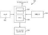
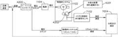
図18は、ハンドル組立体14(図1)と電源組立体との間及びハンドル組立体14と交換式シャフト組立体との間のインターフェースを示す、図1の外科用器具のブロック図である。図18に示すように、電源組立体3006は、電源管理回路3034を含んでよく、電源管理回路3034は、電源管理コントローラ3016、電力変調器3038、及び電流検出回路3036を含み得る。電源管理回路3034は、交換式シャフト組立体200(図1)及び電源組立体3006がハンドル組立体14に結合されている間に、交換式シャフト組立体200の電力要件に基づいて電池3007の電力出力を変調するように構成され得る。例えば、電源管理コントローラ3016は、電源組立体3006の電力出力の電力変調器3038を制御するようにプログラムされ得、電流検出回路3036は、電池3007の電力出力に関するフィードバックを電源管理コントローラ3016に提供するため、電源組立体3006の電力出力を監視するように用いられ得、そのため、電源管理コントローラ3016は、電源組立体3006の電力出力を調節して、所望の出力を維持することができる。 18 is a block diagram of the surgical instrument of FIG. 1 showing the interface between the handle assembly 14 (FIG. 1) and the power supply assembly and between the
電源管理コントローラ3016及び/又はシャフト組立体コントローラ3022はそれぞれ、多数のソフトウェアモジュールを記憶し得る1つ若しくは2つ以上のプロセッサ及び/又はメモリ装置を備え得る点に注目すべきである。外科用器具10(図1)の特定のモジュール及び/又はブロックが例として記載され得るが、より多くの若しくはより少ない数のモジュール及び/又はブロックが使用され得ることが明らかとなる。更に、様々な例が、説明を容易にするためにモジュール及び/又はブロックとして記載される場合があるが、そのようなモジュール及び/又はブロックは、1つ又は2つ以上の、例えばプロセッサ、デジタル信号プロセッサ(DSP)、プログラマブルロジックデバイス(PLD)、特定用途向け集積回路(ASIC)、回路、レジスタのような、ハードウェアコンポーネント、及び/若しくは、例えばプログラム、サブルーチン、ロジックのようなソフトウェアコンポーネント、並びに/又は、ハードウェアコンポーネントとソフトウェアコンポーネントとの組み合わせ、によって実施され得る。 It should be noted that
特定の例では、外科用器具10(図1〜4)は、ユーザに感覚フィードバックを提供するための1つ又は2つ以上の装置を含み得る、出力装置3042を備えてよい。このような装置は、例えば、視覚的フィードバック装置(例えば、LCDディスプレイスクリーン、LEDインジケータ)、可聴フィードバック装置(例えば、スピーカー、ブザー)又は触覚フィードバック装置(例えば、触覚作動装置)を含んでもよい。特定の状況下では、出力装置3042は、ハンドル組立体14(図1)に含まれ得るディスプレイ3043を備えてよい。シャフト組立体コントローラ3022及び/又は電源管理コントローラ3016は、出力装置3042を介して外科用器具10のユーザにフィードバックを提供し得る。インターフェース3024は、シャフト組立体コントローラ3022及び/又は電源管理コントローラ3016を出力装置3042に接続するように構成され得る。読者は、出力装置3042が代わりに電源組立体3006と統合され得ることを理解するであろう。このような状況下では、交換式シャフト組立体200がハンドル組立体14に結合されている一方で、出力装置3042とシャフト組立体コントローラ3022との間の通信はインターフェース3024を介して成し遂げられ得る。 In particular examples, surgical instrument 10 (FIGS. 1-4) may include an
外科用器具10(図1〜図4)及びその動作を制御するための1つ又は2つ以上のセグメント化回路2000、3000について記載したが、ここからは、本開示では、外科用器具10及びセグメント化回路2000(又は3000)の様々な特定の構成について説明する。 Although described with respect to the surgical instrument 10 (FIGS. 1-4) and one or
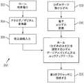
様々な態様において、本開示は、データの保存及び使用のための技術を提示する。一態様において、データの保存及び使用は、複数レベルの動作閾値に基づいている。このような閾値は、最終上限閾値限界及び最終下限閾値限界を含み、電流、電圧、発射負荷、トルクが最終閾値を超えると、モータが停止されるか、リターンが起動され、あるいは、閾値内で動作している間は、装置がモータの負荷を自動的に補う。 In various aspects, the present disclosure presents techniques for data storage and use. In one aspect, storage and use of data is based on multiple levels of operating thresholds. Such thresholds include the final upper threshold limit and the final lower threshold limit, and when the current, voltage, launch load, torque exceeds the final threshold, the motor is stopped, a return is triggered, or within the threshold. While operating, the device automatically compensates for the motor load.
一態様において、外科用器具10(図1〜18に関して記載される)は、最小及び最大閉鎖クランプ負荷を許容範囲内に維持するために、最終上限閾値及び最終下限閾値を監視するように構成され得る。最小値に達しない場合、外科用器具10は始動できず、又はそれが最小値を下回る場合、ユーザの動作が必要とされる。クランプ負荷が好適なレベルであるが、発射中に最小値を下回る場合、外科用器具10は、モータの速度を調節する、又はユーザに警告することができる。動作中に下限値を超えた場合、ユニットは発射が予定通りに完了しない可能性があるという警告を発することができる。外科用器具10はまた、電池電圧が最終下限値を下回るときを監視するように構成することができ、残りの電池電力は、装置をI型梁に静止した状態へと戻すためのみに使用される。エンドエフェクタ内の故障を感知するために、アンビルの開放力を使用することができる。あるいは、外科用器具10は、モータ電流が増加する、又は関連する速度が低下するときを監視するように構成することができ、よってモータ制御は、速度を一定に維持するために、パルス幅又は周波数変調を増加させる。 In one aspect, the surgical instrument 10 (described with respect to FIGS. 1-18) is configured to monitor the final upper threshold and the final lower threshold to maintain the minimum and maximum closing clamp loads within an acceptable range. obtain. If the minimum is not reached, the
別の態様において、外科用器具10(図1)は、電流引き込み、圧力、発射負荷、トルクの最終閾値を検出するように構成され得、これにより、これらの閾値のいずれかを超えると、外科用器具10はモータを停止するか、又はモータによってナイフを発射前位置に戻す。最終閾値よりも小さな二次閾値が、モータ制御パラメータを変更することによって、条件の変化に適合するために、モータ制御プログラムを変更するために使用されてもよい。限界閾値は、別のカウンタ又は入力への比例的な応答に基づくステップ関数又はランプ関数として構成することができる。例えば、滅菌する場合、0〜200滅菌サイクルにおいて変更せず、201〜400滅菌サイクルにおいて、使用毎にモータを1%減速し、400を超える滅菌サイクルでは使用が防止される。モータの速度もまた、組織用隙間及び電流引き込みに基づいて変化させることができる。 In another aspect, the surgical instrument 10 (FIG. 1) can be configured to detect the final thresholds of current draw, pressure, firing load, torque, thereby allowing surgery when any of these thresholds are exceeded. The
電動の再使用可能なステープラ装置の理想的な機能に影響し得る多くのパラメータが存在する。これらのパラメータのほとんどは、装置がこれらを超えて動作するべきではない、最終最大閾値及び/又は最終最小閾値を有する。それでも、装置の機能動作に影響し得る、限界値も存在する。これらの、複数のパラメータによるこれらの複数の限界は、装置の動作プログラムへの多重及び累積的効果をもたらし得る。 There are many parameters that can affect the ideal functionality of the motorized reusable stapler device. Most of these parameters have a final maximum threshold and / or a final minimum threshold that the device should not operate above. Nevertheless, there are also limit values that can affect the functional operation of the device. These multiple limitations with these multiple parameters can result in multiple and cumulative effects on the device's operating program.
したがって、本開示は、外科用器具に関し、様々な状況において、組織をステープリングし切断するように設計された、外科用ステープリング及び切断器具、並びにそのためのステープルカートリッジに関する。 Thus, the present disclosure relates to surgical instruments and, in various contexts, to surgical stapling and cutting instruments designed to staple and cut tissue, and staple cartridges therefor.
電気機械装置の効率的な性能は、様々な要因に依存する。その1つは機能エンベロープ(operational envelope)、即ち、装置がその意図される機能を実行する際のパラメータ、条件及びイベントの範囲である。例えば、電流により駆動されるモータにより動力を与えられる装置において、一定の電流閾値を超えたところに、装置が所望されるよりも非効率に動作する動作範囲が存在することがある。換言すると、上方「速度制限」が存在することがあり、これを超えると効率性が低下する。このような上限閾値は、実質的な非効率性、又は更には装置の劣化を防ぐ上で有意義であり得る。 The efficient performance of an electromechanical device depends on various factors. One is the functional envelope, ie the range of parameters, conditions and events as the device performs its intended function. For example, in a device powered by a current driven motor, an operating range may exist where the device operates less efficiently than desired above a certain current threshold. In other words, upper "speed limits" may be present, beyond which efficiency is reduced. Such upper threshold may be significant in preventing substantial inefficiencies or even degradation of the device.
しかしながら、機能エンベロープ内において、動作状態における効率性を高めるために利用可能な範囲を形成し得る、閾値が存在することがある。換言すると、規定された機能エンベロープ(又はサブエンベロープ)内に、装置がより良好に適応し、かつ機能することができる、領域が存在することがある。このような範囲は、限界閾値と、最終閾値との間にあり得る。加えて、これらの範囲は、「スイートスポット」、又は既定の任意の範囲若しくは点を含むことがある。これらの範囲はまた、性能が適切であると判定される、大きな範囲を含み得る。 However, within the functional envelope, there may be thresholds that may form an available range to increase efficiency in operating conditions. In other words, there may be areas within the defined functional envelope (or sub-envelope) where the device can better adapt and function. Such a range may be between the critical threshold and the final threshold. In addition, these ranges may include "sweet spots" or any predetermined range or point. These ranges may also include large ranges where performance is determined to be appropriate.
その上、又はその下で、装置の停止など、動作(1つ又は複数)がとられる(又は動作をとるのを控える)、最終閾値が規定されてもよい。その上、又はその下で、動作(1つ又は複数)がとられる(又は動作をとるのを控える)、限界閾値が規定されてもよい。非限定的な例により、モータの電流引き込みが最終閾値の75%を超える点を規定するように限界閾値が設定されてもよい。限界閾値を超えると、その結果装置は、例えば、モータ速度が最終閾値に向かって上昇し続けるのに伴い、モータ速度を、度合いを増しながら低減させ始めることがある。 Additionally, or below, a final threshold may be defined where the action or actions are taken (or refraining from taking action), such as stopping the device. Additionally, or under, action threshold (s) may be taken (or refraining from taking action), threshold thresholds may be defined. By way of non-limiting example, the threshold limit may be set to define a point at which the current draw of the motor exceeds 75% of the final threshold. When the threshold limit is exceeded, the result may be that the device starts to reduce the motor speed with increasing degree, for example, as the motor speed continues to rise towards the final threshold.
閾値を超えた結果として行われる調節を実行するために、様々なメカニズムが使用され得る。例えば、調節は、ステップ関数を反映してもよい。これはまた、ランプ関数を反映してもよい。他の関数が使用されてもよい。 Various mechanisms may be used to perform the adjustments made as a result of crossing the threshold. For example, the adjustment may reflect a step function. This may also reflect a ramp function. Other functions may be used.
様々な態様において、追加的なメカニズムにより性能を高めるために、多重閾値(overlaying threshold)が規定されてもよい。多重閾値は、複数のパラメータにより規定される、1つ又は2つ以上の閾値を含む場合がある。多重閾値は、別の閾値(1つ又は複数)を生成する入力として、1つ又は2つ以上の閾値を生じてもよい。多重閾値は、既定であるか、又は、例えば動作時に動的に生成されてもよい。多重閾値は、閾値が複数の入力により規定されるときに有効になってもよい。例えば、滅菌サイクル数が300(限界閾値)を超えるが、500(最終閾値)以下であるとき、装置はモータをより遅く動作させる。次に、電流引き込みが、75%の限界閾値を超えると、装置は度合いを増しながら速度を落とす。 In various aspects, overlaying thresholds may be defined to enhance performance by additional mechanisms. Multiple thresholds may include one or more thresholds defined by a plurality of parameters. Multiple thresholds may result in one or more thresholds as input to generate another threshold (s). Multiple thresholds may be predetermined or, for example, generated dynamically at the time of operation. Multiple thresholds may be enabled when the threshold is defined by multiple inputs. For example, when the number of sterilization cycles is above 300 (limit threshold) but below 500 (final threshold), the device operates the motor more slowly. Then, if the current draw exceeds the threshold threshold of 75%, the device slows down to a greater degree.
図19は、様々な実施例による外科用器具10(図1〜4)の切刃182(図14)の鋭さを評価するためのシステム4311の論理図を示す。いくつかの例において、システム4311は、鋭さ試験部材4302を通して切刃182を前進させる能力を試験することによって、切刃182の鋭さを評価することができる。例えば、システム4311は、切刃182が鋭さ試験部材4302の少なくとも既定の部分を完全に横切する、かつ/又は完全に通過するのにかかる期間を観察するように構成することができる。観察された期間が既定の閾値を超過する場合、回路4310は、例えば、切刃182の鋭さが許容可能なレベルを下回っていると結論付けてもよい。 FIG. 19 illustrates a logic diagram of a
一態様では、鋭さ試験部材4302を利用して、切刃182(図14)の鋭さを試験することができる。特定の例では、鋭さ試験部材4302は、例えば、外科用ステープルカートリッジ304(図1、2、及び15)のカートリッジ本体194(図14)に取り付ける、及び/又はそれと一体化させることができる。特定の例では、鋭さ試験部材4302は、例えば、外科用ステープルカートリッジ304の近位部分に配置することができる。特定の例では、鋭さ試験部材4302は、例えば、外科用ステープルカートリッジ304のカートリッジデッキ、又はカートリッジ本体194上に配置することができる。 In one aspect, the
特定の例では、ロードセル4335は、例えば、切刃182(図14)が鋭さ試験部材4302と係合し、かつ/又はそれに接触している状態で、切刃182に加えられる力(Fx)を監視するように構成することができる。切刃182が鋭さ試験部材4302と係合され、かつ/又はそれに接触している間、鋭さ試験部材4302によって切刃182に加えられる力(Fx)は、少なくとも部分的に、切刃182の鋭さに依存し得ることが、読者には理解されるであろう。特定の例において、切刃182の鋭さの減少は、切刃182が鋭さ試験部材4302を切断又は通過するのに要する力(Fx)の増加をもたらし得る。鋭さ試験部材4302のロードセル4335を利用して、切刃182が鋭さ試験部材4302を通じて事前定義された距離(D)だけ移動する間に、切刃182にかけられた力(Fx)を測定してもよく、これは、切刃182の鋭さを判定するために利用することができる。 In a particular example,
特定の例では、システム4311は、プロセッサ4315(「マイクロプロセッサ」)と、1つ又は2つ以上のコンピュータ可読媒体若しくはメモリユニット4317(「メモリ」)とを含んでもよい、コントローラ4313(「マイクロコントローラ」)を含んでもよい。特定の例では、メモリ4317は、様々なプログラム命令を記憶してもよく、それが実行されると、プロセッサ4315に、本明細書に記載される複数の機能及び/又は計算を実施させることができる。特定の例において、メモリ4317は、例えばプロセッサ4315に結合されてもよい。電源4319は、例えば、コントローラ4313に電力を供給するように構成することができる。特定の例において、電源4319は、例えばLiイオン電池などの電池(又は「電池パック」若しくは「パワーパック」)を含んでもよい。特定の例では、電池パックは、ハンドル組立体14に解除可能に装着されるように構成されてもよい。直列で接続された多数の電池セルが、電源4319として使用されてもよい。特定の例において、電源4319は、例えば、交換可能及び/又は充電式であってもよい。 In particular examples, the
特定の例では、コントローラ4313は、例えば、フィードバックシステム及び/又はロックアウトメカニズム4123に動作可能に結合することができる。 In particular examples,
システム4311は1つ又は2つ以上の位置センサを備えてもよい。本開示と共に使用するのに適した例示の位置センサ及び位置付けシステムが、米国特許出願公開第2014/0263538号、発明の名称「SENSOR ARRANGEMENTS FOR ABSOLUTE POSITIONING SYSTEM FOR SURGICAL INSTRUMENTS」に記載されており、その開示の全体を参照により本明細書に組み込む。特定の例において、システム4311は、第1の位置センサ4321及び第2の位置センサ4323を含んでもよい。特定の例では、第1の位置センサ4321は、例えば、鋭さ試験部材4302の近位端における切刃182(図14)の第1の位置を検出するのに利用することができ、第2の位置センサ4323は、例えば、鋭さ試験部材4302の遠位端における切刃182の第2の位置を検出するのに利用することができる。
特定の例では、第1及び第2の位置センサ4321及び4323はそれぞれ、コントローラ4313に対して第1及び第2の位置信号を提供するために利用することができる。位置信号は、コントローラ4313と第1及び第2の位置センサ4321及び4323との間のインターフェースに基づくアナログ信号又はデジタル値であってもよいことが理解されるであろう。一実施例において、コントローラ4313と第1及び第2の位置センサ4321及び4323との間のインターフェースは、標準的なシリアル周辺インターフェース(SPI)であることができ、位置信号は、上述したように、切刃182の第1の位置及び第2の位置を表すデジタル値であることができる。 In a particular example, first and
上記に加えて更に、プロセッサ4315は、第1の位置信号の受信と第2の位置信号の受信との間の期間を判定してもよい。判定された期間は、例えば鋭さ試験部材4302の近位端における第1の位置から、例えば鋭さ試験部材4302の遠位端における第2の位置まで、鋭さ試験部材4302を通して切刃182(図14)を前進させるのにかかる時間に相当し得る。少なくとも1つの例では、コントローラ4313は、第1の位置信号を受信するとプロセッサ4315によってアクティブ化し、第2の位置信号を受信すると非アクティブ化することができる、時間要素を含んでもよい。時間要素のアクティブ化と非アクティブ化との間の期間は、例えば、切刃182を第1の位置から第2の位置まで前進させるのにかかる時間に相当してもよい。時間要素は、リアルタイムクロック、時間関数を実現するように構成されたプロセッサ、又は他の任意の好適なタイミング回路を備えてもよい。 In addition to the above, the
様々な例では、コントローラ4313は、切刃182(図14)を第1の位置から第2の位置まで前進させるのにかかる期間を、事前定義された閾値と比較して、例えば、切刃182の鋭さが許容可能なレベルを下回っているか否かを評価することができる。特定の例では、コントローラ4313は、測定された期間が、例えば1%、5%、10%、25%、50%、100%、及び/又は100%超、事前定義された閾値を超過した場合に、切刃182の鋭さが許容可能なレベルを下回っていると結論付けてもよい。 In various examples,
図20は、様々な態様による、様々な鋭さレベルで鋭さ試験部材4302によって外科用器具10(図1〜4)の切刃に対して加えられる力を判定するためのシステム4340の論理図を示す。図20を参照すると、様々な例では、電動モータ4331は、発射バー172(図20)を駆動して、例えば、発射行程の間は切刃182(図14)を前進させ、かつ/又は復帰行程の間は切刃182を後退させることができる。モータドライバ4333は、電動モータ4331を制御することができ、例えばコントローラ4313などのコントローラは、モータドライバ4333と信号通信することができる。電動モータ4331が切刃182を前進させるにつれて、コントローラ4313は、例えば、電動モータ4331によって引き込まれる電流を判定することができる。かかる例では、切刃182を前進させるのに要する力は、例えば、電動モータ4331によって引き込まれる電流に対応することができる。やはり図20を参照すると、外科用器具10のコントローラ4313は、切刃182の前進の間に電動モータ4331によって引き込まれる電流が増加したかを判定することができ、増加した場合、電流の増加率を計算することができる。 FIG. 20 illustrates a logic diagram of a system 4340 for determining the force applied by the
特定の例では、電動モータ4331によって引き込まれる電流は、切刃182(図14)が鋭さ試験部材4302と接触している間、鋭さ試験部材4302の切刃182に対する抵抗により、大幅に増加し得る。例えば、電動モータ4331によって引き込まれる電流は、切刃182が鋭さ試験部材4302を係合し、通過し、及び/又はこれを切断するにつれて大幅に増加し得る。切刃182に対する鋭さ試験部材4302の抵抗は、切刃182の鋭さに部分的に依存し、繰り返し使用によって切刃182の鋭さが減少するにつれて、切刃182に対する鋭さ試験部材4302の抵抗が増加することが、読者には理解されるであろう。したがって、切刃が鋭さ試験部材4302と接触している間、電動モータ4331によって引き込まれる電流の増加率の値は、例えば、繰り返し使用によって切刃182の鋭さが減少するにつれて増加し得る。 In a particular example, the current drawn by the
特定の例では、電動モータ4331によって引き込まれる電流の増加率の判定された値は、電動モータ4331によって引き込まれる電流の最大検出増加率であることができる。様々な例において、コントローラ4313は、電動モータ4331によって引き込まれる電流の増加率の判定された値を、電動モータ4331によって引き込まれる電流の増加率の事前既定された閾値と比較することができる。判定された値が事前定義された閾値を超過した場合、コントローラ4313は、例えば、切刃182の鋭さが許容可能なレベルを下回っていると結論付けることができる。 In a particular example, the determined value of the rate of increase of the current drawn by the
特定の例では、図20に示されるように、プロセッサ4315は、例えば、フィードバックシステム及び/又はロックアウトメカニズムと通信することができる。特定の例では、例えば、電動モータ4331によって引き込まれる電流の増加率の判定された値が事前定義された閾値を超過した場合、プロセッサ4315は、フィードバックシステムを用いてユーザに注意することができる。特定の例では、例えば、電動モータ4331によって引き込まれる電流の増加率の判定された値が事前定義された閾値を超過した場合、プロセッサ4315は、ロックアウトメカニズムを用いて切刃182(図14)の前進を防止してもよい。特定の例では、システム4311は、第1及び第2の位置センサ4321、4323を含んでよい。外科用器具10(図1〜4)は、ロードセル4335を含んでもよい。 In particular examples, as shown in FIG. 20,
様々な例では、コントローラ4313は、アルゴリズムを利用して、電動モータ4331によって引き込まれる電流の変化を判定することができる。例えば、電流センサは、発射行程の間、電動モータ4331によって引き込まれる電流を検出することができる。電流センサは、電動モータによって引き込まれる電流を継続的に検出することができ、かつ/又は電動モータによる電流引き込みを間欠的に検出することができる。様々な例では、アルゴリズムは、例えば、最近の電流読み取り値を直前の電流読み取り値と比較することができる。それに加えて、又は代替的に、アルゴリズムは、期間X内のサンプル読み取り値を、以前の電流読み取り値と比較することができる。例えば、アルゴリズムは、サンプル読み取り値を、例えば、直前の期間Xなど、以前の期間X内の以前のサンプル読み取り値と比較することができる。他の例では、アルゴリズムは、モータによって引き込まれる電流の傾向的な平均を計算することができる。アルゴリズムは、例えば、最近の電流読み取り値を含む、期間Xの間の平均電流引き込みを計算することができ、また、平均電流引き込みを、例えば直前の期間Xの間の平均電流引き込みと比較することができる。 In various examples,
特定の例では、ロードセル4335(図19、20)は、例えば、切刃182(図14)が鋭さ試験部材4302(図19、20)と係合し、かつ/又はそれに接触している状態で、切刃182に加えられる力(Fx)を監視するように構成することができる。切刃182が鋭さ試験部材4302と係合され、かつ/又はそれに接触している間、鋭さ試験部材4302によって切刃182に加えられる力(Fx)は、少なくとも部分的に、切刃182の鋭さに依存し得ることが、読者には理解されるであろう。特定の例において、切刃182の鋭さの減少は、切刃182が鋭さ試験部材4302を切断又は通過するのに要する力(FX)の増加をもたらし得る。特定の例では、コントローラ4313(図19、20)は、切刃182(図14)に加えられる監視された力(Fx)の最大値を、1つ又は2つ以上の事前定義された閾値と比較してもよい。 In particular examples, load cell 4335 (FIGS. 19, 20) may, for example, have cutting edge 182 (FIG. 14) engage and / or contact sharpness test member 4302 (FIGS. 19, 20). , The force (Fx) applied to the
特定の例では、切刃182(図14)は、第1の厚さを含む捕捉された組織を横切するのには十分に鋭いことがあるが、例えば、第1の厚さよりも厚い第2の厚さを含む捕捉された組織を横切するには鋭さが十分でないことがある。特定の例において、切刃182が捕捉された組織を横切するのに要する力によって規定されるような、切刃182の鋭さレベルは、例えば、捕捉された組織が特定の組織厚さ範囲内にある組織厚さを含む場合に、捕捉された組織を横切するのに適正であり得る。特定の例では、メモリ4317(図19、20)は、エンドエフェクタ300によって捕捉された組織の1つ又は2つ以上の事前定義された組織厚さ範囲、及び事前定義された組織厚さ範囲と関連付けられた事前定義された閾値力を格納することができる。特定の例において、事前定義された閾値力はそれぞれ、事前定義された閾値力と関連付けられた組織厚さ範囲に包含される組織厚さ(Tx)を含む、捕捉された組織を横切するために好適である、切刃182の最小鋭さレベルを表してもよい。特定の例において、組織厚さ(Tx)を含む捕捉された組織を切刃182が横切するのに要する力(Fx)が、組織厚さ(Tx)を包含する事前定義された組織厚さ範囲と関連付けられた事前定義された閾値力を超過した場合、切刃182は、例えば、捕捉された組織を横切するには鋭さが十分でないことがある。 In certain instances, the cutting edge 182 (FIG. 14) may be sharp enough to cross captured tissue containing a first thickness, but may, for example, be thicker than the first thickness. The sharpness may not be sufficient to cross captured tissue containing a thickness of two. In certain instances, the level of sharpness of the
様々な態様では、本開示は、組織圧迫を判定するための技術、及び組織圧迫に応じて(図1〜18に関連して説明した)外科用器具10の動作を制御する追加の技術を提供する。一実施例では、カートリッジは、意図された組織のタイプ及び厚さに基づいて別様に閉鎖するように外科用器具10を駆動する可変圧迫アルゴリズムを定義するように構成され得る。別の実施例では、外科用器具10は、発射中に経験する負荷に基づいて閉鎖を適応させるように、外科医の使用及び元の組織圧迫プロファイルから学習する。外科用器具10が、このカートリッジタイプについて経験したものとは劇的に異なる組織圧迫の負荷を経験したときに、器具は、そのことをユーザに強調する。 In various aspects, the present disclosure provides techniques for determining tissue compression and additional techniques for controlling the operation of surgical instrument 10 (as described in connection with FIGS. 1-18) in response to tissue compression. Do. In one example, the cartridge may be configured to define a variable compression algorithm that drives the
器具が病院の使用に順応してくるにつれて経時的にモータ制御アルゴリズムをアクティブ調節すると、充電式電池の寿命を向上させること、並びに、組織流動を最小限に抑える組織/処置の要件に調節することができ、したがって、組織封着におけるステープル形成を向上させることができる。 Actively adjusting the motor control algorithm over time as the device adapts to hospital use to improve the life of the rechargeable battery, as well as adjusting to the tissue / treatment requirements that minimize tissue flow And, thus, can improve staple formation in tissue sealing.
したがって、本開示は、外科用器具に関し、様々な状況において、組織をステープリングし切断するように設計された、外科用ステープリング及び切断器具、並びにそのためのステープルカートリッジに関する。例えば、様々な態様では、本開示は、ハンドルが、意図された組織特性について調節するように閉鎖及び発射アルゴリズムを調節することを可能にするために、カートリッジのタイプ又は組織の間隙を感知するように構成された、内視鏡器具を提供する。この適応アルゴリズム調節は、装置が2つの異なるシステムに反応し、そこから恩恵を受けることを可能にするユーザの動作から「学習する」ことができる。開示する適応アルゴリズムによって提供される第1の恩恵は、組織流動及びステープル形成を含む。装置がユーザの基本傾向及びステップタイミングを学習するにつれて、装置は、より一貫して信頼性の高い出力を提供するように、閉鎖速度及び発射速度を調節することができる。開示する適応アルゴリズムによって提供される第2の恩恵は、電池パックに関係している。装置が器具の発射回数及び使用状態を学習するにつれて、装置は、電池寿命を長くするために事前定義された様式で、モータの電流ニーズ/速度を調節することができる。重度の肥満に対する処置を行う病院で使用される装置は、主に結腸直腸又は胸部の処置を行う病院で使用される装置と同様の様式で動作する可能性は実質的には小さい。したがって、装置が、経時的に、実質的に同様の処置を行うために使用されるときに、装置は、その動作アルゴリズムを学習し、「理想的な」排出及び組織流動の包絡線内で維持するように調節するように構成されている。 Thus, the present disclosure relates to surgical instruments and, in various contexts, to surgical stapling and cutting instruments designed to staple and cut tissue, and staple cartridges therefor. For example, in various aspects, the present disclosure may sense cartridge type or tissue clearance to allow the handle to adjust the closure and firing algorithm to adjust for the intended tissue characteristics. An endoscopic instrument is provided. This adaptive algorithm adjustment can "learn" from the user's actions that allow the device to react to and benefit from two different systems. The first benefits provided by the disclosed adaptation algorithm include tissue flow and staple formation. As the device learns the user's basic tendency and step timing, the device can adjust the closing speed and the firing rate to provide a more consistent and reliable output. A second benefit provided by the disclosed adaptation algorithm relates to the battery pack. As the device learns how many times the device has fired and used, the device can adjust the current needs / speed of the motor in a predefined manner to extend battery life. Devices used in hospitals treating severe obesity are substantially less likely to operate in a manner similar to devices used in hospitals treating mainly colorectal or breast. Thus, when the device is used to perform substantially the same procedure over time, the device learns its operational algorithm and maintains it within the "ideal" drainage and tissue flow envelope It is configured to make adjustments.
安全かつ効果的な外科手術には、関与する組織の十分な知識と、その組織への敬意が必要である。臨床医は、外科手術中に行われる調節が有益であり得ることに注意を払っている。これらの調節は、望ましいステープル形成を検出し、促進するメカニズムを含む。 Safe and effective surgery requires a good knowledge of the tissue involved and a respect for that tissue. Clinicians are careful that adjustments made during surgery may be beneficial. These adjustments include mechanisms that detect and promote desired staple formation.
内視鏡器具は、外科的処置に関してそれらを使用する間に、相当量のデータを生成し、監視し、処理することができる。電池の使用を含むかかるデータは、外科用器具自体から取得することができる。加えて、組織圧迫などの特性を含めて、外科用器具が相互作用する組織の特性からデータを取得することができる。更に、臨床医と外科用器具自体との相互作用から、データを取得することができる。そのように取得したデータのリポジトリを処理することができ、所望の場合には、現在の外科的処置に対する安全かつ効果的な結果を促進し、並びに、複数の臨床医によるより一般化された生産的な使用のための基礎を作るように、外科用器具を状況に適応するように設計することができる。かかる適応調節(外科的処置中と、器具が複数の外科的処置から引き出される使用パターンに基づいて「学習する」場合の双方)は、患者ケア環境全体を向上させる多数のメカニズムを提供することができる。 Endoscope instruments can generate, monitor, and process substantial amounts of data while using them for surgical procedures. Such data, including the use of batteries, can be obtained from the surgical instrument itself. In addition, data can be obtained from the properties of the tissue with which the surgical tool interacts, including properties such as tissue compression. Furthermore, data can be obtained from the interaction between the clinician and the surgical instrument itself. Repositories of such acquired data can be processed, and if desired, facilitate safe and effective results for current surgical procedures, as well as more generalized production by multiple clinicians Surgical instruments can be designed to adapt to the situation so as to provide a basis for practical use. Such adaptive adjustment (both during the surgical procedure and when the instrument “learns” based on usage patterns derived from multiple surgical procedures) provides a number of mechanisms to improve the overall patient care environment. it can.
図21は、外科用器具の動作を適応させるためのプロセスの一態様を示している。図21に示すように、モジュールを、外科用器具10(図1〜4)に取り付ける、又は他の場合には装填することができる(5160)。モジュールは、選択又はアップロードされたプログラムを含むことができる(5162)。外科用器具10を動作させる準備ができるように、制御機器をアクティブ化することができる(5164)。外科用器具10の使用中、又は使用後、制御手段を含めて、プログラムを適応させることができる(5166)。例えば、これは、外科用器具10内の、又は外科用器具10の遠隔操作に関して、データレートを調節することを含むことができる。これは、アンビル306(図1)及び外科用ステープルカートリッジ304(図1)が閉鎖運動に従事する速度などの速度を調節することを含むことができる。これは、エミッタ及びセンサからのパルス、又は、組織に電流のパルスを印加すること、並びにかかるパルスのタイミングを含むこともできる。これは、降下した場合の外科用器具10の加速など、加速、あるいはスリープモードからの遷移に適応するようにプログラムを調節することを含むことができる。プログラムは、クランプ力に基づいて実際の/又は予想される負荷を処理するように適応され得る。 FIG. 21 illustrates one aspect of a process for adapting the operation of the surgical instrument. As shown in FIG. 21, the module can be attached or otherwise loaded (5160) to the surgical instrument 10 (FIGS. 1-4). The module may include the selected or uploaded program (5162). The control device may be activated 5164 so that the
例えば、ステープル留め処置を実行するアクションを完了するために、外科用器具10(図1〜4)を用いることができる(5168)。外科用器具10の適切なメモリ位置に、データを記録することができる(5170)。センサがパラメータをどの程度正確に測定したか、及び/測定するかなど、センサ挙動を評価することができる(5172)。組織特性、待機期間及び発射速度を含むがこれらに限定されない予期データを評価することができる5174。本明細書に開示した上記のメカニズムは、更に、プログラムを適応させる入力を提供することができる(5166)。加えて、組織特性履歴、実際の組織特性、又は予想される組織特性に基づいて、組織同定を実行することができ(5178)、これは、更にプログラムを適応させる入力を提供することができる(5166)。加えて、組織同定(5178)の特性を更新することができる。更に、処置中に測定されたセンサ入力(5176)を、更にプログラムを適応させる追加の入力(5166)として使用することができ、かかるセンサ測定は、アンビル306と外科用ステープルカートリッジ304との間に間隙の測定を含むことができ、機能、電流、又はトルクの導関数を含む微分測定が取得される。 For example, surgical instrument 10 (FIGS. 1-4) can be used to complete an action to perform a stapling procedure (5168). Data may be recorded at an appropriate memory location of the surgical instrument 10 (5170). Sensor behavior may be evaluated, such as how accurately the sensor measured and / or measured parameters (5172). Expected data can be evaluated including, but not limited to, tissue characteristics, waiting periods and firing rates. The above disclosed mechanism disclosed herein can further provide an input to adapt the program (5166). In addition, tissue identification can be performed (5178) based on tissue characteristic history, actual tissue characteristics, or expected tissue characteristics, which can provide input to further adapt the program ( 5166). In addition, the properties of tissue identification (5178) can be updated. In addition, the sensor input (5176) measured during the procedure can be used as an additional input (5166) to further adapt the program, such sensor measurement being between the
エンドエフェクタ6006は、組織を圧縮、切断、又はステープル留めするために使用されてよい。次に、図23Aを参照すると、エンドエフェクタ6030は、圧縮、切断、又はステープル留めの前に、医師によって組織6032を取り巻くように位置付けられてよい。図23Aに示されるように、エンドエフェクタを使用する準備をしている間、組織に圧縮は適用されなくてよい。次に、図23Bを参照すると、エンドカッターのハンドル(例えば、ハンドル6002)を係合させることによって、医師は、エンドエフェクタ6030を使用して組織6032を圧縮してよい。一態様では、組織6032は、図23Bに示されるように、その最大閾値まで圧縮されてよい。 End effector 6006 may be used to compress, cut or staple tissue. Referring now to FIG. 23A,
図23Aを参照すると、様々な力が、エンドエフェクタ6030によって組織6032に適用されてよい。例えば、組織6032がエンドエフェクタ6030のアンビル6034とチャネルフレーム6036との間で圧縮されると、それによって垂直力F1及びF2が適用されてよい。次に、図23Bを参照すると、エンドエフェクタ6030によって圧縮されるとき、様々な斜め方向及び/又は横方向の力もまた、組織6032に適用されてよい。例えば、力F3が適用されてよい。エンドカッター6000などの医療デバイスを操作するために、エンドエフェクタによって組織に適用されている様々な形態の圧縮を検出又は計算することが望ましいことがある。例えば、垂直方向又は横方向の圧縮の理解は、エンドエフェクタがステープル動作をより精密又は正確に適用することを可能にし得、あるいはエンドカッターをより適切又は安全に使用することができるようなエンドカッターの情報を操作者に与え得る。 Referring to FIG. 23A, various forces may be applied to the
組織6032を貫通する方向の圧縮は、組織6032のインピーダンスから決定され得る。様々な圧縮水準において、組織6032のインピーダンスZは増加又は減少し得る。電圧V及び電流Iを組織6032に印加することによって、組織6032のインピーダンスZが様々な圧縮水準で決定され得る。例えば、インピーダンスZは、印加された電圧Vを電流Iで除することによって計算され得る。 Compression in the direction through
次に図24を参照すると、一態様では、RF電極6038は、エンドエフェクタ6030の上(例えば、エンドエフェクタ6030のステープルカートリッジ、ナイフ、又はチャネルフレームの上)に位置付けられ得る。更に、電気接点6040は、エンドエフェクタ6030のアンビル6034の上に位置付けられ得る。一態様では、電気接点は、エンドエフェクタのチャネルフレームの上に位置付けられ得る。組織6032がエンドエフェクタ6030のアンビル6034と、例えば、チャネルフレーム6036との間で圧縮されると、組織6032のインピーダンスZは変化する。エンドエフェクタ6030によって生じる垂直方向の組織圧縮6042は、組織6032のインピーダンスZの関数として測定され得る。 Referring now to FIG. 24, in one aspect, the
次に図25を参照すると、一態様では、RF電極6038が位置付けられると、電気接点6044は、エンドエフェクタ6030のアンビル6034の反対端の上に位置付けられ得る。組織6032がエンドエフェクタ6030のアンビル6034と、例えば、チャネルフレーム6036との間で圧縮されると、組織6032のインピーダンスZは変化する。エンドエフェクタ6030によって生じる横方向の組織圧縮6046は、組織6032のインピーダンスZの関数として測定され得る。 Referring now to FIG. 25, in one aspect, once the
次に図26を参照すると、一態様では、電気接点6050は、アンビル6034の上に位置付けられ得、電気接点6052は、チャネルフレーム6036においてエンドエフェクタ6030の反対端の上に位置付けられ得る。RF電極6048は、エンドエフェクタ6030の中央部に側方に位置付けられ得る。組織6032がエンドエフェクタ6030のアンビル6034と、例えば、チャネルフレーム6036との間で圧縮されると、組織6032のインピーダンスZは変化する。RF電極6048の左右における横方向の圧縮又は角度のある圧縮6054及び6056は、エンドエフェクタ6030によって発生し得、RF電極6048並びに電気接点6050及び6052の相対的な位置付けに基づいて、組織6032の様々なインピーダンスZの関数として測定され得る。 Referring now to FIG. 26, in one aspect,
本開示に記載の技術及び特徴のうちの1つ又は2つ以上によれば、上述したように、RF電極は、RFセンサとして使用され得る。次に図27を参照すると、一態様では、RFセンサ6062は、エンドエフェクタのチャネルフレーム6066に挿入されたステープルカートリッジ6060の上に位置付けられ得る。RF電極は、エンドカッターのハンドル(例えば、ハンドル6002)内の電源によって給電され得る電力線6064から続き得る。 According to one or more of the techniques and features described in the present disclosure, as described above, the RF electrode may be used as an RF sensor. Referring now to FIG. 27, in one aspect, the
次に図28を参照すると、一態様では、RF電極6074及び6076は、エンドエフェクタ6070のチャネルフレーム6078に挿入されたステープルカートリッジ6072の上に位置付けられ得る。図示されるように、RF電極6074は、エンドカッターハンドルに対するエンドエフェクタの近位位置に配置され得る。更に、RF電極6076は、エンドカッターハンドルに対するエンドエフェクタの遠位位置に配置され得る。RF電極6074及び6076は、エンドエフェクタ上の1つ又は2つ以上の電気接点の位置に基づいて組織内の様々な点において垂直方向、横方向、近位、又は遠位の圧縮を測定するために利用され得る。 Referring now to FIG. 28, in one aspect,
次に図29を参照すると、一態様では、RF電極6084〜6116は、圧縮情報を所望する様々な点に基づいて、チャネルフレーム6080(又はエンドエフェクタの他の構成要素)に挿入されたステープルカートリッジ6082の上に位置付けられ得る。次に図30を参照すると、一態様では、RF電極6122〜6140は、圧縮情報を所望する別個の点において、ステープルカートリッジ6120の上に位置付けられ得る。次に図31を参照すると、RF電極6152〜6172は、圧縮測定をどの程度正確又は精密にする必要があるかに基づいて、ステープルカートリッジの複数の区域内で様々な点に位置付けられ得る。例えば、RF電極6152〜6156は、区域6158内の圧縮測定をどの程度正確又は精密にする必要があるかに応じて、ステープルカートリッジ6150の区域6158内に位置付けられ得る。更に、RF電極6160〜6164は、区域6166内の圧縮測定をどの程度正確又は精密にする必要があるかに応じて、ステープルカートリッジ6150の区域6166内に位置付けられ得る。加えて、RF電極6168〜6172は、区域6174内の圧縮測定をどの程度正確又は精密にする必要があるかに応じて、ステープルカートリッジ6150の区域6174内に位置付けられ得る。 Referring now to FIG. 29, in one aspect, the RF electrodes 6084-6116 are staple cartridges inserted into the channel frame 6080 (or other components of the end effector) based on various points where compression information is desired. It can be positioned over 6082. Referring now to FIG. 30, in one aspect, the RF electrodes 6122-6140 can be positioned on the staple cartridge 6120 at discrete points where compression information is desired. Referring now to FIG. 31, RF electrodes 6152-6172 can be positioned at various points within the plurality of sections of the staple cartridge based on how accurate or precise the compression measurements need to be. For example, the RF electrodes 6152-6156 may be positioned within the
本明細書に記載するRF電極は、チャネルフレームに挿入されたステープルカートリッジを通って配線され得る。次に図32を参照すると、一態様では、RF電極は、プレス成形された直径約1.0mmの「マッシュルームヘッド」6180を有し得る。RF電極はプレス成形された直径約1.0mmの「マッシュルームヘッド」を有し得るが、これは、非限定的な例を意図するものであり、RF電極は、それぞれの特定の用途又は設計に応じて異なる形状及び大きさになってよい。RF電極は、導電線6182に接続されても、締結されてもよく、又はそれを形成してもよい。導電線6182は、直径約0.5mmであってもよく、あるいは特定の用途又は設計に基づいてより大きい又はより小さい直径を有してもよい。更に、導電線は、絶縁被覆6184を有してよい。一実施例では、RF電極は、ステープルカートリッジ、チャネルフレーム、ナイフ、又はエンドエフェクタの他の構成要素を通って突出してよい。 The RF electrodes described herein may be wired through the staple cartridge inserted into the channel frame. Referring now to FIG. 32, in one aspect, the RF electrode may have a press-formed "mushroom head" 6180 of about 1.0 mm diameter. The RF electrode may have a pressed "mashhead" about 1.0 mm in diameter, but this is intended as a non-limiting example, and the RF electrode may be used in each particular application or design. Depending, it may be of different shape and size. The RF electrode may be connected to, fastened to, or form
次に図33を参照すると、RF電極は、エンドエフェクタのステープルカートリッジ又はチャネルフレームの単一の壁を通って、又は複数の壁を通って配線され得る。例えば、RF電極6190〜6194は、エンドエフェクタのステープルカートリッジ又はチャネルフレームの壁6196を通って配線され得る。導線6198の1つ又は2つ以上は、RF電極6190〜6194に接続されても、締結されても、その一部になってもよく、例えば、エンドカッターのハンドル内の電源から壁6196を通り抜けてよい。 Referring now to FIG. 33, RF electrodes may be routed through a single wall or through multiple walls of the staple cartridge or channel frame of the end effector. For example, RF electrodes 6190-6194 may be wired through the staple cartridge or
次に図34を参照すると、電源は、RF電極と通信していてもよく、又は導線若しくはケーブルを通ってRF電極に電力を供給してもよい。導線又はケーブルは、個々の導線それぞれに合流し、電源に通じ得る。例えば、RF電極6204〜6212は、電源から導線又はケーブル6202を通って電力を受け取ってよく、この導線又はケーブルは、エンドエフェクタのステープルカートリッジ6200又はチャネルフレームを通り抜けてよい。一実施例では、RF電極6204〜6212のそれぞれは、導線若しくはケーブル6202にまで続く又はこれを通り抜ける、それ自身の導線を有してよい。ステープルカートリッジ6200又はチャネルフレームはまた、例えば、図16A、16Bに関連して示される一次プロセッサ2006、又は図17A、17B、及び18に関連して示されるメインコントローラ3017など、コントローラ6214を含んでもよい。コントローラ6214は、ステープルカートリッジ6200又はチャネルフレームフォームファクタに嵌合するように適切にサイズ決定される必要があることは理解されるであろう。また、コントローラ(Also, the controller) Referring now to FIG. 34, the power supply may be in communication with the RF electrode or may supply power to the RF electrode through a lead or cable. The conductors or cables may merge into each individual conductor and lead to a power source. For example, the RF electrodes 6204-6212 may receive power from a power source through leads or cable 6202, which may pass through the staple cartridge 6200 or channel frame of the end effector. In one embodiment, each of the RF electrodes 6204-6212 may have its own lead which continues or passes through the lead or cable 6202. The staple cartridge 6200 or channel frame may also include a
様々な態様では、医療デバイスと共に使用するための、本明細書に記載の組織圧縮センサシステムは、周波数発生器を含み得る。周波数発生器は、エンドカッターなど、医療デバイスの回路基板上に配置され得る。例えば、周波数発生器は、エンドカッターのシャフト又はハンドル内の回路基板上に配置され得る。次に図35を参照すると、本開示の一例による例示的な回路図6220が示されている。図示されるように、周波数発生器6222は、電源6221から電力又は電流を受け取り得、1つ又は2つ以上のRF信号を1つ又は2つ以上のRF電極6224に供給し得る。上述したように、1つ又は2つ以上のRF電極は、ステープルカートリッジ又はチャネルフレームなど、エンドエフェクタ又はエンドカッター上の様々な位置又は構成要素に位置付けられ得る。電気接点6226又は6228など、1つ又は2つ以上の電気接点は、エンドエフェクタのチャネルフレーム又はアンビルの上に位置付けられ得る。更に、フィルタ6230又は6232など、1つ又は2つ以上のフィルタは、図35に示されるように電気接点6226又は6228と通信可能に結合され得る。フィルタ6230及び6232は、周波数発生器6222によって供給される1つ又は2つ以上のRF信号を、単一のリターン経路6234に合流する前にフィルタ処理し得る。1つ又は2つ以上のRF信号に関連した電圧V及び電流Iは、1つ又は2つ以上のRF電極6224と電気接点6226又は6228との間で圧縮され及び/又は通信可能に結合され得る組織に関連したインピーダンスZを計算するために使用され得る。 In various aspects, the tissue compression sensor system described herein for use with a medical device may include a frequency generator. The frequency generator may be disposed on the circuit board of a medical device, such as an end cutter. For example, the frequency generator may be disposed on a circuit board in the shaft or handle of the end cutter. Referring now to FIG. 35, an exemplary circuit diagram 6220 according to an example of the present disclosure is shown. As shown,
次に図36を参照すると、本明細書に記載される組織圧縮センサシステムの様々な構成要素は、エンドカッターのハンドル6236内に配置され得る。例えば、回路図6220aに示されるように、周波数発生器6222は、ハンドル6236内に配置され得、電源6221から電力を受け取る。また、電流I1及び電流I2が、電気接点6228及び6226に対応するリターン経路上で測定され得る。供給経路とリターン経路との間で印加される電圧Vを使用して、インピーダンスZ1及びZ2が計算され得る。Z1は、RF電極6224の1つ又は2つ以上と電気接点6228との間で圧縮され及び/又は通信可能に結合される組織のインピーダンスに対応し得る。更に、Z2は、RF電極6224の1つ又は2つ以上と電気接点6226との間で圧縮され及び/又は通信可能に結合される組織のインピーダンスに対応し得る。式Z1=V/I1及びZ2=V/I2を適用すると、エンドエフェクタによって圧縮された組織の様々な圧縮水準に対応するインピーダンスZ1及びZ2が計算され得る。 Referring now to FIG. 36, various components of the tissue compression sensor system described herein may be disposed within the
次に図37を参照すると、本開示の1つ又は2つ以上の態様が、回路図6250に記載されている。ある実装では、エンドカッターのハンドル6252にある電源は、周波数発生器6254に電力を供給し得る。周波数発生器6254は、1つ又は2つ以上のRF信号を生成し得る。1つ又は2つ以上のRF信号は、エンドカッターのシャフト6258内にあり得る、マルチプレクサ6256において多重化又は重ね合わされ得る。このようにして、2つ又は3つ以上のRF信号は、重ね合わされ(又は、例えば、共にネスト又は変調され)、エンドエフェクタに伝達され得る。1つ又は2つ以上のRF信号は、エンドカッターのエンドエフェクタ6262にある(例えば、ステープルカートリッジ内に位置付けられる)1つ又は2つ以上のRF電極6260に通電し得る。組織(図示せず)は、1つ又は2つ以上のRF電極6260と1つ又は2つ以上の電気接点との間で圧縮され及び/又は通信可能に結合され得る。例えば、組織は、1つ又は2つ以上のRF電極6260と、エンドエフェクタ6262のチャネルフレーム内に位置付けられた電気接点6264又はエンドエフェクタ6262のアンビル内に位置付けられた電気接点6266と、の間で圧縮され及び/又は通信可能に結合され得る。フィルタ6268は、電気接点6264に通信可能に結合され得、フィルタ6270は、電気接点6266に通信可能に結合され得る。 Referring now to FIG. 37, one or more aspects of the present disclosure are described in circuit diagram 6250. In one implementation, the power supply at the
1つ又は2つ以上のRF信号に関連した電圧V及び電流Iは、ステープルカートリッジ(1つ又は2つ以上のRF電極6260に通信可能に結合される)と、チャネルフレーム又はアンビル(電気接点6264又は6266の1つ又は2つ以上に通信可能に結合される)と、の間で圧縮され得る組織に関連したインピーダンスZを計算するために使用され得る。 Voltage V and current I associated with one or more RF signals are coupled to a staple cartridge (communicatively coupled to one or more RF electrodes 6260) and a channel frame or anvil (electrical contacts 6264). Or communicatively coupled to one or more of 6266) may be used to calculate the impedance Z associated with the tissue that may be compressed between.
一態様では、本明細書に記載される組織圧縮センサシステムの様々な構成要素は、エンドカッターのシャフト6258内に配置され得る。例えば、回路図6250に示されるように(及び周波数発生器6254に加えて)、インピーダンス計算器6272、コントローラ6274、不揮発性メモリ6276、及び通信チャネル6278が、シャフト6258内に配置され得る。一実施例では、周波数発生器6254、インピーダンス計算器6272、コントローラ6274、不揮発性メモリ6276、及び通信チャネル6278は、シャフト6258内の回路基板上に位置付けられ得る。 In one aspect, various components of the tissue compression sensor system described herein may be disposed within the
2つ又は3つ以上のRF信号は、電気接点を経由して共通経路上で折り返され得る。更に、2つ又は3つ以上のRF信号によって表される別々の組織インピーダンスを差異化するために、2つ又は3つ以上のRF信号は、共通経路上でRF信号が合流する前にフィルタ処理され得る。電流I1及び電流I2は、電気接点6264及び6266に対応するリターン経路上で測定され得る。供給経路とリターン経路との間で印加される電圧Vを使用して、インピーダンスZ1及びZ2が計算され得る。Z1は、RF電極6260の1つ又は2つ以上と電気接点6264との間で圧縮され及び/又は通信可能に結合される組織のインピーダンスに対応し得る。更に、Z2は、RF電極6260の1つ又は2つ以上と電気接点6266との間で圧縮され及び/又は通信可能に結合される組織のインピーダンスに対応し得る。式Z1=V/I1及びZ2=V/I2を適用すると、エンドエフェクタ6262によって圧縮された組織の様々な圧縮に対応するインピーダンスZ1及びZ2が計算され得る。実施例では、インピーダンスZ1及びZ2は、インピーダンス計算器6272によって計算され得る。インピーダンスZ1及びZ2は、組織の様々な圧縮水準を計算するために使用され得る。 Two or more RF signals may be folded back on the common path via electrical contacts. Furthermore, to differentiate the different tissue impedances represented by two or more RF signals, the two or more RF signals are filtered before the RF signals merge on a common path It can be done. Current I1 and current I2 may be measured on the return path corresponding to
一態様では、フィルタ6268及び6270は、フィルタ範囲が狭くなってもよいような(例えば、Q=10)、高Qフィルタであり得る。Qは、中心周波数(Wo)/帯域幅(BW)によって定義され得、Q=Wo/BWである。一実施例では、周波数1は150kHzであり得、周波数2は300kHzであり得る。実行可能なインピーダンス測定範囲は、100kHz〜20MHzであり得る。様々な実施例では、RF信号を分離するために、相関、直交検波など、他の高度な技術が使用され得る。 In one aspect, filters 6268 and 6270 may be high Q filters such that the filter range may be narrow (eg, Q = 10). Q may be defined by center frequency (Wo) / bandwidth (BW), where Q = Wo / BW. In one embodiment,
本明細書に記載の技術及び特徴のうちの1つ又は2つ以上を使用して、エンドエフェクタのステープルカートリッジ又は孤立したナイフの上にある単一の通電電極は、複数の組織圧縮測定を同時に行うために使用され得る。2つ又は3つ以上のRF信号が、重ね合わされるか、多重化される(又はネストされるか、変調される)場合、それらは、エンドエフェクタの単一電源側に伝達され得、エンドエフェクタのチャネルフレーム又はアンビルのどちらかの上で折り返し得る。それらが共通リターン経路に合流する前に、アンビル及びチャネルの接点にフィルタが組み込まれていれば、両経路によって表される組織インピーダンスは差異化されることができる。これは、垂直方向の組織圧縮対横方向の組織圧縮の測定を提供し得る。この方法はまた、フィルタの配置及び金属リターン経路の位置に応じて近位及び遠位の組織圧縮も提供し得る。周波数発生器及び信号プロセッサは、(エンドカッター内に既に存在し得る)回路基板又はサブ基盤の上の1つ又は2つ以上のチップ上に配置され得る。 Using one or more of the techniques and features described herein, a single powered electrode on a staple cartridge or an isolated knife of an end effector can simultaneously perform multiple tissue compression measurements. It can be used to do. If two or more RF signals are superimposed, multiplexed (or nested, or modulated), they can be transmitted to a single power supply side of the end effector, the end effector Can be folded over either the channel frame or the anvil. The tissue impedance represented by both paths can be differentiated if filters are incorporated at the anvil and channel contacts before they join the common return path. This may provide a measure of vertical tissue compression versus lateral tissue compression. The method may also provide proximal and distal tissue compression depending on the placement of the filter and the position of the metal return path. The frequency generator and the signal processor may be arranged on one or more chips on a circuit board or sub-base (which may already be present in the end-cutter).
様々な態様では、本開示は、(図1〜18に関連して説明した)外科用器具10内での駆動モータの速度及び倍精度を監視する技術を提供する。一実施例では、磁石はギヤ減速装置の段のうちの1つの遊星フレーム上に配置され得、ギヤハウジング上にはインダクタンスセンサが位置する。別の例では、磁石及び磁場センサを最終段に配置することにより、最も高精度の増分式移動監視をもたらすであろう。 In various aspects, the present disclosure provides techniques for monitoring the speed and double precision of the drive motor within the surgical instrument 10 (described in connection with FIGS. 1-18). In one embodiment, the magnet may be disposed on a planetary frame of one of the stages of the gear reducer and an inductance sensor is located on the gear housing. In another example, placing the magnet and magnetic field sensor in the final stage would provide the most accurate incremental movement monitoring.
従来のモータ制御システムは、エンコーダを用いて、電動エンドカッター/ステープラデバイスなど手持ち電池式体内外科用器具内のモータの位置及び速度を検出する。エンドカッター/ステープラデバイスの高精度の動作は、1つには、負荷下でモータ動作を確認できることに依存する。単純なセンサ実装を用いて、負荷下でモータ動作を確認できてよい。 Conventional motor control systems use an encoder to detect the position and speed of the motor within a hand-held battery powered endosurgical instrument such as a motorized end cutter / stapler device. The high accuracy operation of the endcutter / stapler device relies, in part, on the ability to verify motor operation under load. A simple sensor implementation may be used to verify motor operation under load.
したがって、本開示は、ギヤ減速システムの遊星キャリアのうちの1つに磁性体を含む、又はブラシレスモータ技術を用いる。両方法は、モータのハウジング又は遊星ギヤシステムの外側にインダクタンスセンサを配置することを含む。ブラシレスモータの場合、モータの中央磁気シャフトの周りに径方向に配置された電磁場コイル(巻線、インダクタなど)が存在する。コイルは、連続的に作動及び非作動させられて、中央モータシャフトを駆動する。1つ又は2つ以上のインダクタンスセンサはモータの外側に、少なくともいくつかのコイルに隣接して配置され得、モータ巻線の作動/非作動サイクルを感知して、シャフトの回転回数を判定する。あるいは、永久磁石が遊星キャリアのうちの1つに配置され得、インダクタンスセンサが遊星キャリアの径方向経路に隣接して配置されて、ギヤトレインの段の回転回数を測定できる。この実装は、システム内の任意の回転構成要素に適用され得、機能中、又は設計に応じて回転構成要素がエンドエフェクタにより近くなるとき(接続回数の点で)、比較的多くの回転数を有する領域において、より鮮明な解像度をもたらす。モータ感知法は、実際のシャフト回転ではなく、モータが通電を命じられた回数を感知するが、ギヤトレイン感知法は段のうちの1つの回転を実際に測定するため、ギヤトレイン感知法が好ましいことがある。例えば、モータが高負荷下でエンストした場合、モータ検知法は、シャフト回転ではなく、通電サイクルのみを感知するため、回転の欠落を検出できないであろう。それにもかかわらず、費用効果の高い方法でモータ回転を感知するために、両技術が用いられ得る。 Thus, the present disclosure includes magnetics in one of the planet carriers of the gear reduction system or uses brushless motor technology. Both methods involve placing an inductance sensor outside the housing of the motor or the planetary gear system. In the case of a brushless motor, there are field coils (windings, inductors, etc.) arranged radially around the central magnetic shaft of the motor. The coils are actuated and deactuated continuously to drive the central motor shaft. One or more inductance sensors may be disposed on the outside of the motor, adjacent to at least some of the coils, and sense the activation / deactivation cycles of the motor windings to determine the number of rotations of the shaft. Alternatively, a permanent magnet can be placed on one of the planet carriers and an inductance sensor can be placed adjacent to the radial path of the planet carrier to measure the number of revolutions of the gear train stages. This implementation can be applied to any of the rotating components in the system, and when the rotating components are closer to the end effector (in terms of the number of connections) during function or depending on the design, a relatively large number of rotations It provides sharper resolution in the areas that it has. The motor sensing method senses the number of times the motor is commanded, not the actual shaft rotation, but the gear train sensing method actually measures the rotation of one of the stages, so the gear train sensing method is preferred Sometimes. For example, if the motor is stalled under high load, the motor detection method will not detect a loss of rotation as it senses only the energizing cycle, not the shaft rotation. Nevertheless, both techniques can be used to sense motor rotation in a cost effective manner.
例えば、ステープル留め中、ステープルがクランプされた組織に打ち込まれる前の組織は、対向する顎部間でしっかりクランプされる。クランプ中の組織圧縮は、圧縮された組織から流体を移動させることがあり、移動速度又は移動量は、組織のタイプ、組織厚さ、外科的動作(例えば、クランプ圧及びクランプ時間)に応じて異なる。様々な例では、エンドエフェクタの対向する顎部間での流体移動は、対向する顎部間でのステープルの奇形(例えば、屈曲)に寄与することがある。したがって、様々な例では、発射行程を制御すること、例えば、検出された流体流、又はその欠如に関連して発射速度を制御すること、外科用エンドエフェクタの対向する顎部に介在することが望ましい場合がある。 For example, during stapling, the tissue before the staples are driven into the clamped tissue is clamped tightly between the opposing jaws. Tissue compression in the clamp may move fluid from the compressed tissue, the rate of movement or amount of movement depending on the type of tissue, tissue thickness, surgical action (eg, clamping pressure and clamping time) It is different. In various examples, fluid movement between opposing jaws of the end effector may contribute to malformation (e.g., flexing) of staples between the opposing jaws. Thus, in various instances, controlling the firing stroke, eg, controlling the firing rate in relation to the detected fluid flow, or lack thereof, interposing on the opposing jaws of the surgical end effector It may be desirable.
したがって、本明細書では、外科用器具の駆動トレインの速度及び増分式移動を監視するための方法、デバイス、及び方法も提供され、次いで、デバイスの動作速度(例えば、顎部閉鎖、ステープル留め)に関する情報を提供する。本実施例によると、外科用器具10(図1〜4)はモータエンコーダを含まない。外科用器具10には、モータエンコーダではなく、例示の実施例による、モータのパワートレイン用速度センサ組立体を備えるモータが装備され得る。速度センサ組立体は、駆動シャフトに直接的又は間接的に結合されている出力シャフトを有するモータを含み得る。いくつかの実施例では、出力シャフトは、システムの任意の好適な構成要素の回転速度を検出するセンサを備える遊星ギヤトレインなどギヤ減速組立体に接続される。例えば、センサは、ギヤ減速組立体の任意の回転部分に取り付けられた1つ又は2つ以上の検出可能な要素の移動を検出する誘導センサなど近接センサであってよい。検出可能な要素は、最終段の環状ギヤに取り付けられており、センサは、検出可能な要素の移動を検出できるように、検出可能な要素の径方向経路に隣接して位置付けられる。回転構成要素は、設計によって様々であり得、センサは、ギヤ減速組立体の任意の回転構成要素に取り付けられ得る。例えば、別の例では、検出可能な要素は、最終段又は更には駆動ギヤのキャリアギヤと関連付けられる。いくつかの実施例では、検出可能な要素は、ギヤ減速組立体とエンドエフェクタとの間の駆動シャフト上などギヤ減速組立体の外側に位置する。いくつかの実施例では、検出可能な要素は、エンドエフェクタにおける最終ギヤ減速装置内の回転構成要素に位置する。 Thus, also provided herein are methods, devices, and methods for monitoring the speed and incremental movement of a drive train of a surgical instrument, and then the operating speed of the device (eg, jaw closure, stapling) Provide information on According to this embodiment, the surgical instrument 10 (FIGS. 1-4) does not include a motor encoder. The
前述の回路を用いて、様々な機能が実装され得る。例えば、モータは、図16A、16B、17A、17B、及び18に関連して記載したモータコントローラと同様のものを用いて制御され得、エンコーダの代わりに、本明細書に記載の電動外科用器具用モータシステムの速度制御及び倍精度の監視が行われる。 Various functions may be implemented using the circuits described above. For example, the motor may be controlled using the same as the motor controller described in connection with FIGS. 16A, 16B, 17A, 17B, and 18, and instead of the encoder, the powered surgical instrument described herein. Control and double precision monitoring of the motor system for the
一態様では、本開示は、様々な検出システムで構成される外科用器具10(図1〜18に関連して記載される)を提供する。したがって、簡潔かつ明快にするため、動作及び構造の詳細はここでは繰り返さない。一態様では、検出システムは、ナイフ加速度、インピーダンスの変化率、及び組織接触の変化率を監視するために、粘弾性/変化率検出システムを含む。一実施例では、ナイフ加速度の変化率は、組織タイプの測定として使用され得る。別の実施例では、インピーダンスの変化率は、パルスセンサで測定され得(can be measures)、圧縮率の測定として用いられ得る。最後に、組織接触の変化率は、ナイフ発射率に基づいて組織流動を測定するセンサで測定され得る。 In one aspect, the present disclosure provides a surgical instrument 10 (described in connection with FIGS. 1-18) configured with various detection systems. Thus, for brevity and clarity, details of the operation and structure will not be repeated here. In one aspect, the detection system includes a visco-elastic / rate-of-change detection system to monitor knife acceleration, rate of change of impedance, and rate of change of tissue contact. In one embodiment, the rate of change of knife acceleration may be used as a measurement of tissue type. In another embodiment, the rate of change of impedance can be measured with a pulse sensor and used as a measure of compression ratio. Finally, the rate of change of tissue contact can be measured with a sensor that measures tissue flow based on the rate of knife firing.
検出されたパラメータの変化率、又は別の方法で規定される、組織パラメータが漸近的な定常状態値に達するのにどのくらい時間が必要か、は、それ自体別個の測定であり、導出元の検出されたパラメータよりも貴重であり得る。測定を行う前に既定の時間を待つことなど、組織パラメータの測定を改良するために、本開示は、組織パラメータの変化率など、測定の微分係数を用いるための新規な技術を提供する。 The rate of change of the detected parameter, or how long it takes the tissue parameter to reach the asymptotically steady-state value, which is otherwise specified, is itself a separate measurement and detection of the derivation source It can be more valuable than the parameters that have been In order to improve measurement of tissue parameters, such as waiting for a predetermined time before making measurements, the present disclosure provides novel techniques for using the derivative of the measurement, such as the rate of change of tissue parameters.
単独で用いてステープル形成を劇的に改良できる単一の測定は存在しないという理解のもと、微分技術又は変化率測定は最も有用となる。それは、測定を有効なものにする複数の測定の組み合わせである。組織の間隙の場合、関連する間隙測定を行うために、顎部が組織によってどのくらい覆われているかを知ることが役に立つ。インピーダンスの変化率測定は、アンビル及びステープルカートリッジなどのエンドエフェクタの顎部材間で把持される組織に加えられる力及び圧縮を関係付けるために、アンビルでのひずみ測定と組み合わされてよい。変化率測定は、組織圧縮はもとより、組織タイプも決定するために、体内外科用デバイスによって用いられ得る。胃組織及び肺組織は、ときに類似の厚さを有し、また肺組織が石灰化したときに類似の圧縮特性さえも有するが、器具は、間隙、圧縮、加えられた力、組織接触面積、及び圧縮の変化率又は間隙の変化率などの測定の組み合わせを用いることによって、これらの組織タイプを見分けることが可能であり得る。これらの測定のいずれかが単独で使用されたならば、体内外科用デバイスが組織タイプを見分けることは困難となり得る。圧縮の変化率はまた、組織が「正常」であるか否か、又は異常が存在するか否かをデバイスで判定可能にすることにも役に立ち得る。経過した時間だけでなく、センサ信号の変動も測定し、信号の微分係数を決定すると、体内外科用デバイスがその信号を測定することを可能にする別の測定が提供されるであろう。変化率情報はまた、いつ定常状態に達したのかを判定し、プロセスの次の工程に信号を送るためにも用いられ得る。例えば、アンビル及びステープルカートリッジなどのエンドエフェクタの顎部材間で組織をクランプした後、組織圧縮が定常状態に達すると(例えば、約15秒)、デバイスの発射を開始するインジケータ又はトリガが使用可能にされ得る。 Differential techniques or rate-of-change measurements are most useful with the understanding that there is no single measurement that can be used alone to dramatically improve staple formation. It is a combination of measurements that make the measurement valid. In the case of tissue gaps, it is useful to know how much the jaws are covered by tissue in order to make the relevant gap measurements. The rate of change of impedance measurement may be combined with strain measurement at the anvil to relate the force and compression applied to the tissue gripped between the anvil and the jaw members of the end effector such as the staple cartridge. The rate of change measurement can be used by the endosurgical device to determine tissue type as well as tissue compression. Gastric tissue and lung tissue sometimes have similar thickness, and even have similar compressive properties when lung tissue is calcified, but the device can be used for clearance, compression, applied force, tissue contact area It may be possible to distinguish between these tissue types by using a combination of measurements such as, and rate of change of change of space or rate of compression. If any of these measurements were used alone, it may be difficult for the endosurgical device to distinguish between tissue types. The rate of change of compression may also be useful to allow the device to determine if the tissue is "normal" or if there is an abnormality. Measuring the variation of the sensor signal as well as the elapsed time and determining the derivative of the signal will provide another measurement that allows the intracorporeal surgical device to measure that signal. The rate of change information can also be used to determine when steady state has been reached and to signal the next step of the process. For example, after clamping tissue between the anvil and jaw members of an end effector such as a staple cartridge, an indicator or trigger may be used to initiate firing of the device once tissue compression reaches steady state (eg, about 15 seconds) It can be done.
本明細書ではまた、外科用器具動作中の組織の安定特性、クリープ特性、及び粘弾性特性を決定するセンサデータの時間依存性評価のための方法、デバイス、及びシステムも提供する。図1に示されるステープラなどの外科用器具10は、いくつか例を挙げると、顎部の間隙の大きさ又は距離、発射電流、組織圧縮、組織によって覆われる顎部の量、アンビルひずみ、及びトリガ力などの動作パラメータを測定するために、多様なセンサを含むことができる。これらの検出された測定値は、外科用器具の自動制御のため、及びフィードバックを臨床医に提供するために重要である。 Also provided herein are methods, devices, and systems for time-dependent assessment of sensor data that determine tissue stability, creep and viscoelastic properties during surgical instrument operation.
図22A〜37に関連して示される例は、間隙距離対時間、組織圧縮対時間、及びアンビルひずみ対時間などの様々な導出されたパラメータを測定するために用いられ得る。モータ電流は、本明細書に記載されるように電池2308と直列に電流センサ2312を用いて、電池2408と直列に電流センサ2412を用いて、又は図18の電流センサ3027を用いて監視され得る。 The examples shown in connection with FIGS. 22A-37 can be used to measure various derived parameters such as gap distance versus time, tissue compression versus time, and anvil strain versus time. The motor current may be monitored using current sensor 2312 in series with battery 2308 as described herein, using current sensor 2412 in series with battery 2408, or using
図38は、再使用されてもされなくてもよい、切断及び締結用のモータ駆動の外科用器具8010を示す。外科用器具8010は、図1〜18に関連して説明した切断及び締結用の外科用器具10と、同様に構築されて装備されている。図38に示される実施例では、外科用器具8010は、臨床医が把持し、操作し、作動させるように構成されているハンドル組立体8014を備えるハウジング8012を含む。ハウジング8012は、1つ又は2つ以上の外科的タスク又は処置を行うように構成されている外科用エンドエフェクタ8300が動作可能に結合されている、交換式シャフト組立体8200に動作可能に取り付けるように構成されている。外科用器具8010は、図1〜18に関連して記載される切断及び締結用の外科用器具10と同様に構築及び装備されるので、簡潔かつ明瞭にするために、ここでは動作及び構造の詳細を繰り返さない。 FIG. 38 shows a motorized
図38に示されるハウジング8012は、外科用ステープルカートリッジ8304を中で動作可能に支持するように構成されている、外科用切断及び締結デバイスを備えるエンドエフェクタ8300を含む、交換式シャフト組立体8200と接続されて示されている。ハウジング8012は、種々のサイズ及びタイプのステープルカートリッジを支持するように適合されたエンドエフェクタを含み、種々のシャフトの長さ、サイズ、及びタイプなどを有する交換式シャフト組立体と接続されて使用するように構成されてもよい。加えて、ハウジング8012はまた、他の運動、並びに、例えば高周波(RF)エネルギー、超音波エネルギー及び/又は運動などの他の形態のエネルギーを、様々な外科用途及び処置に関連して用いられるように適合されたエンドエフェクタ装置に印加するように構成されている組立体など様々な他の交換式シャフト組立体と共に効果的に用いられてよい。更に、エンドエフェクタ、シャフト組立体、ハンドル、外科用器具、及び/又は外科用器具システムは、任意の好適な締結具を利用して組織を締結することができる。例えば、中に着脱可能に格納された複数の締結具を備える締結具カートリッジが、シャフト組立体のエンドエフェクタに着脱可能に挿入及び/又は装着され得る。 The
次に図38に移ると、再使用されてもされなくてもよい、外科用器具8010が示されている。外科用器具8010は、本明細書に記載の切断及び締結用の外科用器具10と、同様に構築されて装備されている。図38に示される実施例では、外科用器具8010は、臨床医が把持し、操作し、作動させるように構成されているハンドル組立体8014を備えるハウジング8012を含む。ハウジング8012は、1つ又は2つ以上の外科的タスク又は処置を行うように構成されているエンドエフェクタ8300が動作可能に結合されている、交換式シャフト組立体8200に動作可能に取り付けるように構成されている。外科用器具8010は、図1〜18に関連して本明細書に記載される切断及び締結用の外科用器具10と同様に構築及び装備されるので、簡潔かつ明瞭にするために、ここでは動作及び構造の詳細を繰り返さない。 Turning next to FIG. 38, a
図38に示されるハウジング8012は、外科用ステープルカートリッジ8304を中で動作可能に支持するように構成されている、外科用切断及び締結デバイスを備えるエンドエフェクタ8300を含む、交換式シャフト組立体8200と接続されて示されている。ハウジング8012は、種々のサイズ及びタイプのステープルカートリッジを支持するように適合されたエンドエフェクタを含み、種々のシャフトの長さ、サイズ、及びタイプなどを有する交換式シャフト組立体と接続されて使用するように構成されてもよい。加えて、ハウジング8012はまた、他の運動、並びに、例えば高周波(RF)エネルギー、超音波エネルギー及び/又は運動などの他の形態のエネルギーを、様々な外科用途及び処置に関連して用いられるように適合されたエンドエフェクタ装置に印加するように構成されている組立体など様々な他の交換式シャフト組立体と共に効果的に用いられてよい。更に、エンドエフェクタ、シャフト組立体、ハンドル、外科用器具、及び/又は外科用器具システムは、任意の好適な締結具を利用して組織を締結することができる。例えば、中に着脱可能に格納された複数の締結具を備える締結具カートリッジが、シャフト組立体のエンドエフェクタに着脱可能に挿入及び/又は装着され得る。 The
図38は、交換式シャフト組立体8200が動作可能に結合された外科用器具8010を示している。図示の構成において、ハンドルハウジングは、臨床医に把持及び操作され得るピストルグリップ部分8019を形成する。ハンドル組立体8014は、その中に複数の駆動システムを動作可能に支持し、それら駆動システムは、ハンドル組立体に動作可能に取り付けられた交換式シャフト組立体の対応部分に、様々な制御運動を生成及び適用するように構成されている。トリガ8032は、これらの制御運動の様々を制御するために、ピストルグリップと動作可能に関連付けられる。 FIG. 38 shows a
続けて図38を参照すると、交換式シャフト組立体8200は、外科用ステープルカートリッジ8304を中で動作可能に支持するように構成された細長いチャネル8302を備える、エンドエフェクタ8300を含む。エンドエフェクタ8300は、細長いチャネル8302に対して枢動可能に支持されるアンビル8306を更に含んでもよい。 With continued reference to FIG. 38,
本発明者らは、導出されたパラメータが、図38に例示される器具などの外科用器具を制御するために、導出されたパラメータの基礎となる検出されたパラメータよりも更に有用であり得ることを見出した。導出されたパラメータの非限定的な例には、検出されたパラメータの変化率(例えば、顎部間隙距離)及び組織パラメータが漸近的な定常状態値に達するまでの経過時間(例えば、15秒)が挙げられる。変化率などの導出されたパラメータは、測定精度を劇的に向上させ、更に、他の形では検出されたパラメータから直接に明らかでない情報も提供することから、特に有用である。例えば、インピーダンス(即ち、組織圧縮)変化率は、アンビルのひずみと組み合わされて、圧縮及び力を関係付けることができ、これにより、コントローラが、組織圧縮の量はもとより、組織タイプも決定することが可能になる。この実施例は一例に過ぎず、いずれの導出されたパラメータも、1つ又は2つ以上の検出されたパラメータと組み合わされて、組織タイプ(例えば、胃と肺)、組織の健康状態(石灰化と正常)、及び外科用デバイスの動作状態(例えば、クランプ完了)に関するより正確な情報を提供することができる。異なる組織は、独自の粘弾性特性及び独自の変化率を有し、したがって、これら及び本明細書に記載される他のパラメータは、外科処置を監視し、自動的に調節するための有用なしるしとなる。 We have found that the derived parameters may be more useful than the detected parameters underlying the derived parameters to control a surgical instrument such as the instrument illustrated in FIG. 38. Found out. Non-limiting examples of derived parameters include the rate of change of the detected parameter (eg, jaw gap distance) and the elapsed time for the tissue parameter to reach an asymptotically steady state value (eg, 15 seconds) Can be mentioned. Derived parameters such as the rate of change are particularly useful because they dramatically improve the measurement accuracy and also provide information that is otherwise not directly apparent from the detected parameters. For example, the rate of impedance (ie, tissue compression) change can be combined with the strain of the anvil to relate compression and force so that the controller determines the tissue type as well as the amount of tissue compression. Becomes possible. This example is by way of example only, and any derived parameters may be combined with one or more detected parameters to determine tissue type (eg, stomach and lung), tissue health (calcification) And normal), and more accurate information regarding the operating state of the surgical device (eg, clamp complete). Different tissues have unique visco-elastic properties and unique rates of change, so these and the other parameters described herein are useful for monitoring and automatically adjusting the surgical procedure. It becomes.
具体的には、図38及び39を参照すると、間隙8040は、エンドエフェクタ8300のアンビル8306と細長いチャネル8302との間の距離である。開いた顎部位置では、時間0において、アンビル8306と細長い部材との間の間隙8040は、その最大距離にある。間隙8040の幅は、組織クランプ中など、アンビル8306が閉じるにつれて減少する。組織は非一様な弾力性を有するため、間隙距離変化率は変動し得る。例えば、ある組織タイプは、急速な圧縮を初期に示し得、結果としてより速い変化率となる。しかしながら、組織が持続的に圧縮されると、組織の粘弾性特性により、組織がそれ以上圧縮できなくなるまで変化率が減少し得、それ以上圧縮できなくなると、間隙距離は実質的に一定のままになる。組織がエンドエフェクタ8300のアンビル8306と外科用ステープルカートリッジ8304との間で圧搾されると、間隙は時間の経過と共に減少する。図22A〜37及び図40に関連して記載される1つ又は2つ以上のセンサは、時間tにわたってアンビル8306と外科用ステープルカートリッジ8304との間の間隙距離「d」を測定するように適合され、構成されてよく、時間tにわたる間隙距離「d」の変化率は曲線の勾配であり、勾配=Δd/Δtである。加えて、発射電流の変化率は、組織がある状態から別の状態に遷移中であることのインジケータとして使用することができる。したがって、発射電流及び、とりわけ、発射電流の変化率は、デバイス動作を監視するために使用することができる。ナイフが組織を切り進むと、発射電流は時間の経過と供に減少する。発射電流の変化率は、切断される組織の抵抗が、組織特性又はナイフ8305(図39)の鋭さにより増減する場合、変動し得る。例えば、モータ電流は、本明細書に記載されるように電池2308と直列に電流センサ2312を用いて、本明細書に示される電池2408と直列に電流センサ2412を用いて、又は図18に示される電流センサ3027を用いて監視され得る。電流センサ2312、2314、3027は、時間tにわたってモータ発射電流「i」を測定するように適合され、構成されてよく、時間tにわたる発射電流「i」の変化率は曲線の勾配であり、勾配=Δi/Δtである。図22A〜37及び40に関連して記載されるセンサは、組織圧縮/インピーダンスを測定するように適合され、構成されてよい。センサは、時間tにわたって組織インピーダンス「Z」を測定するように適合され、構成されてよく、時間tにわたる組織インピーダンス「Z」の変化率は勾配であり、勾配=ΔZ/Δtである。アンビル8306のひずみの変化率は、アンビル8306と外科用ステープルカートリッジ8304との間に把持された組織に加えられる圧力又はひずみを測定するようにアンビル8306及び外科用ステープルカートリッジ8304(図38、39)のいずれか又は両方の上に位置付けられる圧力センサ又はひずみゲージによって測定され得る。したがって、時間0において、トリガ8020(図38)の圧力は最低であってよく、トリガ圧は、動作(例えば、クランプ、切断又はステープル留め)の完了まで増加してよい。トリガ力の変化率は、アンビル8306と外科用ステープルカートリッジ8304との間に把持された組織を通してナイフ8305(図39)を駆動するために必要な力を測定するように外科用器具8010(図38)のハンドルのピストルグリップ部分8019のトリガ8032上に位置付けられる圧力センサ又はひずみゲージによって測定され得る。 Specifically, referring to FIGS. 38 and 39, the
簡潔に図40を参照すると、エンドエフェクタ9012は、外科用器具8010(図38)と共に動作して間隙距離対時間、組織圧縮対時間、及びアンビルひずみ対時間などの様々な導出されたパラメータを測定するように適合され得るエンドエフェクタ8300(図38)の一態様である。したがって、図40に示されるエンドエフェクタ9012は、エンドエフェクタ9012及び/又はエンドエフェクタ9012によって捕捉される組織切片に関連付けられる1つ若しくは2つ以上のパラメータ又は特性を測定するように構成された1つ又は2つ以上のセンサを含み得る。図40に示される例では、エンドエフェクタ9012は、第1のセンサ9020及び第2のセンサ9026を備える。様々な例では、例えば、第1のセンサ9020及び/又は第2のセンサ9026は、例えば磁場センサなどの磁気センサ、ひずみゲージ、圧力センサ、力センサ、例えば渦電流センサなどの誘導センサ、抵抗センサ、容量センサ、光センサ、及び/又はエンドエフェクタ9012の1つ若しくは2つ以上のパラメータを測定するための任意の他の好適なセンサを備えてもよい。 Referring briefly to FIG. 40,
特定の例では、第1のセンサ9020及び/又は第2のセンサ9026は、例えば、アンビル9014に埋め込まれ、かつ顎部材9016及び/又はステープルカートリッジ9018に埋め込まれた磁石9024によって生成される磁場を検出するように構成された磁場センサを備えてもよい。アンビル9014は、開位置と閉位置との間で枢動可能に回転可能である。検出された磁場の強度は、例えば、アンビル9014と顎部材9016との間に位置する組織の厚さ及び/又は食込みの完全さに相当してもよい。特定の例では、第1のセンサ9020及び/又は第2のセンサ9026は、クランプ後状態の間のアンビル9014におけるひずみの大きさを測定するように構成された、例えば微小ひずみゲージなどのひずみゲージを備えてもよい。ひずみゲージは、ひずみの大きさに伴って大きさが変動する電気信号を提供する。 In particular examples, the
いくつかの態様では、例えば第1のセンサ9020及び/又は第2のセンサ9026など、エンドエフェクタ9012の1つ又は2つ以上のセンサは、アンビル9014と顎部材9016との間に圧縮された組織が存在することによって生成される圧力を検出するように構成された圧力センサを備えてもよい。いくつかの実施例では、例えば第1のセンサ9020及び/又は第2のセンサ9026など、エンドエフェクタ9012の1つ又は2つ以上のセンサは、アンビル9014と顎部材9016との間に位置する組織切片のインピーダンスを検出するように構成されている。検出されたインピーダンスは、アンビル9014と顎部材9016との間に位置する組織の厚さ及び/又は完全さを示してもよい。 In some aspects, one or more sensors of the
一態様では、例えば第1のセンサ9020など、エンドエフェクタ9012のセンサのうちの1つ又は2つ以上は、アンビル9014と顎部材9016との間の間隙9022を測定するように構成されている。特定の例では、間隙9022は、アンビル9014と顎部材9016との間にクランプされた組織切片の厚さ及び/又は圧縮率を表すものであり得る。少なくとも1つの例では、間隙9022は、アンビル9014と顎部材9016との間にクランプされた組織切片の厚さと等しい、又は実質的に等しいものであり得る。一実施例では、例えば第1のセンサ9020など、エンドエフェクタ9012のセンサのうちの1つ又は2つ以上は、顎部材9016によって、かつ/又はアンビル9014と顎部材9016との間にクランプされた組織によって、アンビル9014に対して及ぼされる1つ又は2つ以上の力を測定するように構成されている。アンビル9014に対して及ぼされる力は、アンビル9014と顎部材9016との間に捕捉された組織切片によって経験される組織圧縮を表すものであり得る。一態様では、アンビル9014と顎部材9016との間の間隙9022は、磁場センサをアンビル9014上に位置付け、磁石を顎部材9016上に位置付けることによって測定され得、それにより、間隙9022は、磁場センサによって検出される信号に比例し、信号は、磁石と磁場センサとの間の距離に比例する。磁場センサ及び磁石の位置は、磁場センサが顎部材9016上に位置付けられ、磁石がアンビル9014上に配置されるように、交換されてもよいことは理解されるであろう。 In one aspect, one or more of the sensors of the
例えば第1のセンサ9020及び/又は第2のセンサ9026など、センサのうちの1つ又は2つ以上は、クランプ動作中にリアルタイムに測定されてよい。外科用器具9010の操作者の手動入力をリアルタイムに評価することを目的とした1つ若しくは2つ以上のアルゴリズム及び/又はルックアップテーブルを選択するために、リアルタイム測定は、時間基準の情報が、例えば、プロセッサによって分析され、使用されることを可能にする。更に、操作者が手動入力を校正して所望の出力を生成する手助けをするために、リアルタイムのフィードバックを操作者に提供することができる。 One or more of the sensors, such as, for example, the
図41は、外科用器具9010の操作者の手動入力9064をリアルタイムに評価して、操作者に手動入力9064の妥当性に関するリアルタイムフィードバックを提供するための、リアルタイムフィードバックシステム9060の一態様を示す論理図である。図40及び41を参照して、図41に示す例では、リアルタイムフィードバックシステム9060は、回路からなっている。回路は、プロセッサ9062を備えるコントローラ9061を含む。例えば、第1のセンサ9020などのセンサは、エンドエフェクタ9012のパラメータを測定するためにプロセッサ9062によって用いられる。加えて、プロセッサ9062は、外科用器具9010の操作者の手動入力9064を表す値を判定又は受信するように構成することができる。手動入力9064は、手動入力9064が操作者によって提供されている間は、プロセッサ9062によって連続的に評価することができる。プロセッサ9062は、手動入力9064を表す値を監視するように構成することができる。更に、プロセッサ9062は、所望の区域又は範囲に対して、判定値に対する位置、順位、及び/又は状態を割り当てる、選択する、又は判断するように構成される。以下により詳細に説明するように、エンドエフェクタ9012のパラメータの測定値及び判定値は、判定値に関連付けられた位置、順位、及び/又は状態を選択又は判断するために、プロセッサ9062によって用いることができる。手動入力9064の変化により、判定値の変化が生じ、その変化により、今度は、所望の区域又は範囲に対して判定値に割り当てられた位置、順位、及び/又は状態の変化が生じる。 FIG. 41 is a logic illustrating one aspect of a real
図41に示すように、リアルタイムフィードバックシステム9060は、所望の区域又は範囲の内側又は外側の複数の位置、順位、及び/又は状態の間で調節することができる、フィードバックインジケータ9066を更に含むことができる。一実施例では、プロセッサ9062は、エンドエフェクタ9012のパラメータの測定値(M1)及び第1の手動入力(I1)を表す第1の判定値(V1)に基づいて、手動入力9064を特性化する第1の位置(P1)、順位、及び/又は状態を選択することができる。特定の例では、第1の位置(P1)、順位、及び/又は状態は、所望の区域又は範囲の外側にあたることがある。そのような例では、操作者は、例えば、手動入力9064を増大又は減少させることによって、第1の手動入力(I1)から第2の手動入力(I2)に手動入力9064を変更することができる。これに応じて、プロセッサ9062は、第1の位置(P1)、順位、及び/又は状態から第2の位置(P2)、順位、及び/又は状態にフィードバックインジケータ9066を調節することができ、これにより、手動入力9064の変化を特性化する。プロセッサ9062は、エンドエフェクタ9012のパラメータの測定値(M1)及び第2の手動入力(I2)を表す第2の判定値(V2)に基づいて、第2の位置(P2)、順位、及び/又は状態を選択することができる。特定の例では、第2の位置(P2)、順位、及び/又は状態は、所望の区域又は範囲の内側にあたることがある。そのような例では、操作者は、例えば、治療サイクル又は処置の残部に関して第2の手動入力(I2)を維持することができる。 As shown in FIG. 41, the real
図41に示す態様では、コントローラ9061は、例えば、メモリ9068などの記憶媒体を含む。メモリ9068は、エンドエフェクタ9012の1つ又は2つ以上のパラメータの測定値と、手動入力を表す値と、所望の区域又は範囲に対する手動入力9064を特性化する対応する位置、順位、及び/又は状態との間の相関を格納するように構成することができる。一実施例では、メモリ9068は、測定値(M1)と、第1の判定値(V1)と、第1の手動入力(I1)との間の相関、及び測定値(M1)と、第2の判定値(V2)と、第2の手動入力(I2)との間の相関を格納することができる。一実施例では、メモリ9068は、エンドエフェクタ9012の1つ又は2つ以上のパラメータの測定値と、手動入力を表す値と、所望の区域又は範囲に対する対応する位置、順位、又は状態との間の相関を判定するための、アルゴリズム、式、又はルックアップテーブルを格納することができる。プロセッサ9062は、そのようなアルゴリズム、式、及び/又はルックアップテーブルを用いて、外科用器具9010の操作者によって提供される手動入力9064を特性化し、操作者に手動入力9064の妥当性に関するフィードバックを提供することができる。 In the aspect illustrated in FIG. 41, the controller 9061 includes a storage medium such as, for example, the
図42は、リアルタイムフィードバックシステム9070の一態様を示す論理図である。リアルタイムフィードバックシステム9070は、リアルタイムフィードバックシステム9060に多くの点で類似している。例えば、リアルタイムフィードバックシステム9060と同様に、リアルタイムフィードバックシステム9070は、外科用器具9010の操作者の手動入力をリアルタイムに評価して、操作者に手動入力の妥当性に関するリアルタイムフィードバックを提供するように構成されている。更に、リアルタイムフィードバックシステム9060と同様に、リアルタイムフィードバックシステム9070は、コントローラ9061を含み得る回路からなっている。 FIG. 42 is a logic diagram illustrating an aspect of a real
図42に示す態様では、例えば、ひずみゲージ又は微小ひずみゲージなどのセンサ9072は、例えば、組織の圧縮を示し得る、クランプ動作の間にアンビル9014に作用するひずみの振幅など、エンドエフェクタ9012の1つ又は2つ以上のパラメータを測定するように構成されている。測定された歪みは、デジタル信号に変換され、プロセッサ9062に提供される。例えば負荷センサなどセンサ9074は、アンビル9014とステープルカートリッジ9018との間に捕捉された組織を切断するために切断部材9040を前進させる力を測定することができる。あるいは、モータ9082による電流引き出しを測定するために、電流センサ(図示せず)を用いることができる。発射バー9036を前進させるのに要する力は、例えば、モータ9082によって引き出される電流に対応することができる。測定された力は、デジタル信号に変換され、プロセッサ9062に提供される。例えば磁場センサなどセンサ9076は、上述したように、捕捉された組織の厚さを測定するために用いられ得る。磁場センサ9076の測定値もまた、デジタル信号に変換され、プロセッサ9062に提供される。 In the embodiment shown in FIG. 42, for example, a
図42に示す態様では、リアルタイムフィードバックシステム9070は、発射トリガの位置を判定するように構成することができる追跡システム9080を更に含む。上述したように、発射トリガ9094は、発射行程中の発射バー9036及び/又は切断部材9040の運動特性の複数の値のうちの1つにそれぞれ対応する、複数の位置の間で発射トリガ9094を移動することによって、押下する又は作動させることができる。上述したように、運動特性は、発射行程中の発射バー9036及び/又は切断部材9040の前進速度とすることができる。特定の例では、モータドライバ9092は、コントローラ9061と通信することができ、追跡システム9080によって検出されたように、操作者の手動入力に従ってモータ9082を駆動するように構成することができる。 In the aspect shown in FIG. 42, the real
上記に加えて更に、リアルタイムフィードバックシステム9070は、フィードバックインジケータ9066を含むことができる。一態様では、フィードバックインジケータ9066は、ハンドル9030内に配置することができる。あるいは、フィードバックインジケータは、例えば、シャフト組立体9032内に配置することができる。任意のイベントにおいて、コントローラ9061は、フィードバックインジケータ9066を用いて、外科用器具9010の操作者に、例えば、発射トリガ9094の選択された位置などの手動入力の妥当性に関するフィードバックを提供することができる。そのようにするために、コントローラ9061は、発射トリガ9094の選択された位置、並びに/又は発射バー9036及び/若しくは切断部材9040の速度の対応する値を評価することができる。センサ9072、9074、及び9076によってそれぞれ測定されるような、組織の圧縮、組織厚さ、及び/又は発射バー9036を前進させるために要する力の測定値は、発射トリガ9094の選択された位置、並びに/又は発射バー9036及び/若しくは切断部材9040の速度の対応する値を特性化するために、コントローラ9061によって使用され得る。一例では、メモリ9068は、評価においてコントローラ9061によって用いることができるアルゴリズム、式、及び/又はルックアップテーブルを格納することができる。一実施例では、センサ9072、9074、及び/又は9076の測定値を使用して、発射トリガ9094の選択された位置、並びに/又は発射バー9036及び/若しくは切断部材9040の速度の対応する値を特性化する、位置、順位、及び/又は状態を選択又は判断することができる。判断された位置、順位、及び/又は状態は、フィードバックインジケータ9066により操作者に伝達することができる。 In addition to the above, real-
発射行程中の発射バー9036及び/又は切断部材9040の最適な速度は、例えば、エンドエフェクタ9012によって捕捉された組織の厚さ、組織の圧縮、並びに/又は発射バー9036及び次に切断部材9040を前進させるために要する力などの、エンドエフェクタ9012のいくつかのパラメータに依存し得ることを読者は理解するであろう。そのように、これらのパラメータの測定値は、捕捉された組織を通る切断部材9040の現在の前進速度が最適な区域又は範囲内であるか否かを評価する際に、コントローラ9061によって活用されることができる。 The optimal velocity of the firing bar 9036 and / or the cutting member 9040 during the firing stroke may, for example, be the thickness of the tissue captured by the
一態様では、複数のスマートセンサは、エンドエフェクタの電力線上に位置付けられてもよく、エンドカッターのハンドルに通信可能に結合されてもよい。スマートセンサは、電力線に対して直列又は並列に位置付けられてもよい。次に図43を参照すると、スマートセンサ12060及び12062は、スマートセンサに対してローカルであり得る信号処理要素又はプロセッサ12064と通信してもよい。両方のスマートセンサ12060及び12062並びにプロセッサ12064は、エンドエフェクタ(点線枠12066によって表される)に配置されてもよい。例えば、スマートセンサ12060は、プロセッサ12064への入力のために信号又はデータを調整し得る、演算増幅器12068及びADC変換器12070に信号又はデータを出力してもよい。同様に、スマートセンサ12062は、プロセッサ12064への入力のために信号又はデータを調整し得る、演算増幅器12072及びADC変換器12074に信号又はデータを出力してもよい。 In one aspect, the plurality of smart sensors may be positioned on the power line of the end effector and may be communicatively coupled to the handle of the end cutter. Smart sensors may be positioned in series or in parallel to the power line. Referring now to FIG. 43,
スマートセンサ12060及び/又は12062は、異なるタイプのセンサ又は同じタイプのセンサであってもよく、これらは例えば、磁場センサ、磁気センサ、誘導センサ、容量センサ、又は医療用装置若しくはエンドカッターに使用される他のタイプのセンサであってもよい。既にプロセッサとして参照した要素12064はまた、計算コア、FPGA(フィールド・プログラマブルゲート・アレイ)、論理ユニット(例えば、論理プロセッサ又は論理コントローラ)、信号処理ユニット、又は他のタイプのプロセッサであってもよい。プロセッサ12064は、不揮発性メモリ12076などのメモリと通信していてもよく、不揮発性メモリ12076は、計算データ、エンドエフェクタ12066に挿入されたカートリッジのタイプなどの機器情報、表データ、又は、プロセッサ12064が、エンドエフェクタ12066若しくはエンドカッターを操作する際に使用するスマートセンサ12060若しくは12062のうち1つ若しくは2つ以上から受信した信号若しくはデータを処理することを可能にし得る、他の参照データを格納し得る。 The
更に、シャフト12078は、複数のスマートセンサ(例えば、スマートセンサ12060又は12062)のうちの少なくとも1つ及びハンドル12080が通信可能に結合された復路を含んでもよい。シャフトは、1本又は2本以上のワイヤを含んでもよく、これは、エンドエフェクタ12066又はエンドカッターの操作のために、プロセッサ12064からハンドル12080に情報を伝達し得る。一実施例では、プロセッサ12064からの情報は、有線回線、単線式回線、多線式回線、Bluetoothなどの無線通信プロトコル、光回線、又は音響回線のうち1つ又は2つ以上を介して(シャフト12078を経由して又はシャフト12078を使用することなく直接)ハンドル12080に通信されてもよい。 Furthermore, the
一態様では、エンドエフェクタに位置付けられた複数のスマートセンサのうちの少なくとも1つは、信号処理要素を含んでもよい。例えば、信号処理要素は、スマートセンサに内蔵されてもよく、又は単一モジュールとしてスマートセンサにローカルに結合されてもよい。信号処理要素は、複数のスマートセンサのうちの少なくとも1つのセンサ要素(例えば、センサ要素12020)から受信したデータを処理するように構成されてもよい。ハンドルのコントローラ12024(例えば、コントローラ)は、複数のスマートセンサのうちの少なくとも1つに通信可能に結合されてもよい。 In one aspect, at least one of the plurality of smart sensors positioned at the end effector may include a signal processing element. For example, the signal processing element may be embedded in the smart sensor or may be locally coupled to the smart sensor as a single module. The signal processing element may be configured to process data received from at least one sensor element (eg, sensor element 12020) of the plurality of smart sensors. A handle controller 12024 (eg, a controller) may be communicatively coupled to at least one of the plurality of smart sensors.
一態様では、スマートセンサは、医療用装置におけるローカル信号処理のために構成されてもよい。スマートセンサは、少なくとも1つのセンサ要素(例えば、センサ要素12020)と、少なくとも1つの処理要素(例えば、処理要素12022)と、を含んでもよい。処理要素は、少なくとも1つのセンサ要素からデータを受信し、医療用装置によって使用される情報にデータを処理するように構成されてもよい。医療用装置は、例えば、エンドカッターであってもよいが、これは本開示の限定を意図するものではない。ローカル信号処理を有するスマートセンサのために本明細書で考察される技術及び特徴は、センサ信号又はデータの処理が医療用装置の動作に使用される任意の医療用装置に使用され得ることが理解されるべきである。 In one aspect, a smart sensor may be configured for local signal processing in a medical device. The smart sensor may include at least one sensor element (eg, sensor element 12020) and at least one processing element (eg, processing element 12022). The processing element may be configured to receive data from the at least one sensor element and process the data into information used by the medical device. The medical device may be, for example, an end cutter, but this is not intended to limit the present disclosure. The techniques and features discussed herein for smart sensors with local signal processing are understood to be used in any medical device where processing of sensor signals or data is used for the operation of the medical device. It should be.
更に、医療用装置内のコントローラ(例えば、コントローラ12024、コントローラ)は、少なくとも1つの処理要素(例えば、処理要素12022)から情報(即ち、処理された信号又はデータ)を受信するように構成されてもよい。上述したように、医療用装置は、エンドカッターなどの外科用器具であってもよく、スマートセンサは、外科用器具におけるローカル信号処理のために構成されてもよい。ローカル信号処理とは、例えば、センサに結合された処理要素でセンサ要素からの信号又はデータを処理することを指し、結果として得られた被処理情報が、別個の要素によって使用されてもよい。例えば、コントローラ12024は、外科用器具(即ち、エンドカッター12010)のハンドル12012内に位置付けられてもよく、スマートセンサは、ハンドル12012とは別体の外科用器具(即ち、エンドカッター12010)の別個の要素(即ち、エンドエフェクタ12016)内に位置付けられるように構成されてもよい。したがって、コントローラ12024は、外科用器具のハンドル12012に位置付けられてもよく、信号処理要素12022及びセンサ12020は、ハンドル12012(例えば、エンドエフェクタ12016)とは別個の要素内に配置されてもよい。 Further, the controller (e.g., controller 12024, controller) in the medical device is configured to receive information (i.e., processed signals or data) from at least one processing element (e.g., processing element 12022) It is also good. As mentioned above, the medical device may be a surgical instrument, such as an endcutter, and the smart sensor may be configured for local signal processing in the surgical instrument. Local signal processing refers, for example, to processing signals or data from the sensor element at a processing element coupled to the sensor, and the resulting processed information may be used by the separate element. For example, the controller 12024 may be positioned within the handle 12012 of the surgical instrument (ie, the end cutter 12010), and the smart sensor may be separate from the surgical instrument (ie, the end cutter 12010) separate from the handle 12012. May be configured to be positioned within the element of (i.e. end effector 12016). Thus, the controller 12024 may be located at the handle 12012 of the surgical instrument, and the signal processing element 12022 and the sensor 12020 may be located in an element separate from the handle 12012 (eg, end effector 12016).
このようにして、ハンドル又はコントローラ12024は、スマートセンサに関する情報、スマートセンサが何を行っているかという知識、又はスマートセンサからのデータフィードバックを解釈する性能を有する必要がない。これは、処理要素12022が、スマートセンサからのデータを変換又は調整して、ハンドル又はコントローラ12024によって直接使用可能なデータからの情報を生成するからである。処理要素によって生成された情報は、医療用装置の別の部分(例えば、ハンドル12012又はコントローラ12024の近く)で処理される必要があるスマートセンサからのデータなしに、直接使用されてもよい。したがって、外科用器具は、センサに対してローカルな信号処理要素からの(被処理)情報に基づいて制御されてもよい。 In this way, the handle or controller 12024 need not have the information about the smart sensor, the knowledge of what the smart sensor is doing, or the ability to interpret data feedback from the smart sensor. This is because the processing element 12022 transforms or adjusts the data from the smart sensor to generate information from data that can be used directly by the handle or controller 12024. The information generated by the processing element may be used directly without data from the smart sensor that needs to be processed on another part of the medical device (e.g. near the handle 12012 or the controller 12024). Thus, the surgical instrument may be controlled based on (processed) information from the signal processing element local to the sensor.
一態様では、信号処理要素12022に通信可能に結合された電力線上の電流引き込み(即ち、センサ12020に対してローカル)は、監視されてもよい。電流引き込みは、シャフト12014若しくはハンドル12012で、又は信号処理要素12022とは別個の別のプロセッサ、コントローラ、若しくは他の監視装置で、プロセッサ、コントローラ、又は他の監視装置によって監視されてもよい。例えば、監視は、電力線上の電流引き込みの標準的なモールス符号タイプの監視であってもよい。電流引き込み及び特定のセンサに基づく外科用器具の問題は、例えば、ハンドル12012で別個のプロセッサによって判定されてもよい。このようにして、監視は、ハンドル(又はその中のプロセッサ若しくはコントローラ)に、1つ又は2つ以上のセンサによって受信された信号又はデータに関する様々な問題、及び、どの特定のセンサが問題を識別したかを、更なる通信要件(例えば、ペアリング又は他の結合される通信)なしに通知することを可能にすることができる。 In one aspect, current draw on a power line communicatively coupled to signal processing element 12022 (ie, local to sensor 12020) may be monitored. Current draw may be monitored by the processor, controller or other monitoring device at the shaft 12014 or handle 12012 or at another processor, controller or other monitoring device separate from the signal processing element 12022. For example, the monitoring may be a standard Morse code type monitoring of current draw on the power line. Problems with current draw and specific sensor based surgical instruments may be determined, for example, by a separate processor at the handle 12012. In this way, monitoring identifies to the handle (or processor or controller therein) various problems with the signals or data received by one or more sensors, and which particular sensor has problems May be enabled without further communication requirements (eg, pairing or other coupled communication).
図44は、第1のセンサ13158及び複数の二次センサ13160a、13160bからの信号を、例えば、一次プロセッサ2006(図16A〜図16B)などのプロセッサが受信可能なデジタル信号に変換するように構成された、回路13190の一態様を示している。回路13190は、アナログ・デジタル変換器13194を備える。いくつかの実施例では、アナログ・デジタル変換器13194は、4チャネル18ビットのアナログ・デジタル変換器を備える。アナログ・デジタル変換器13194は、1つ又は2つ以上の入力をアナログ信号からデジタル信号に変換する、任意の好適な数のチャネル及び/又はビットを備えてもよいことが、当業者には認識されるであろう。回路13190は、例えば磁場センサなど、第1のセンサ13158からの入力を受け入れるように構成された、1つ又は2つ以上のレベルシフト抵抗13196を備える。レベルシフト抵抗13196は、第1のセンサからの入力を調節して、入力に応じて値を、より高い電圧へ、又はより低い電圧へとシフトさせる。レベルシフト抵抗13196は、第1のセンサ13158からのレベルシフトされた入力をアナログ・デジタル変換器に提供する。 FIG. 44 is configured to convert signals from the
いくつかの態様では、複数の二次センサ13160a、13160bは、回路13190内の複数のブリッジ13192a、13192bに結合されている。複数のブリッジ13192a、13192bは、複数の二次センサ13160a、13160bからの入力のフィルタ処理を提供してもよい。入力信号をフィルタ処理した後、複数のブリッジ13192a、13192bは、複数の二次センサ13160a、13160bからの入力をアナログ・デジタル変換器13194に提供する。いくつかの実施例では、1つ又は2つ以上のレベルシフト抵抗に結合されたスイッチ13198は、アナログ・デジタル変換器13194に結合されてもよい。スイッチ13198は、例えば磁場センサからの入力など、1つ又は2つ以上の入力信号を校正するように構成されている。スイッチ13198は、例えば磁場センサの入力を校正することなどのために、1つ又は2つ以上のレベルシフト信号を提供してセンサの1つ又は2つ以上の入力を調節する役割を担って(engage)いてもよい。いくつかの実施例では、調節は必須ではなく、レベルシフト抵抗を切り離すため、スイッチ13198は開位置のままにされる。スイッチ13198は、アナログ・デジタル変換器13194に結合されている。アナログ・デジタル変換器13194は、例えば一次プロセッサ2006(図16A〜図16B)など、1つ又は2つ以上のプロセッサに出力を提供する。一次プロセッサ2006は、アナログ・デジタル変換器13194からの入力に基づいて、エンドエフェクタ13150の1つ又は2つ以上のパラメータを計算する。例えば、一実施例では、一次プロセッサ2006は、第1のセンサ13158及び複数の二次センサ13160a、13160bからの入力に基づいて、アンビル13152とステープルカートリッジ13156との間に位置する組織の厚さを計算する。 In some aspects, the plurality of secondary sensors 13160a, 13160b are coupled to the plurality of
図45は、磁場センサ13610及びプロセッサ13612に接続された可撓ケーブル13630を備えるステープルカートリッジ13606の一態様を示している。ステープルカートリッジ13606は、ステープルカートリッジ13606と同様であり、外科用器具10(図1〜図6)に関して上述した外科用ステープルカートリッジ304(図1)と同様である。図112は、ステープルカートリッジ13606の分解図である。ステープルカートリッジ13606は、カートリッジ本体13620と、楔形スレッド13618と、カートリッジトレイ13622と、可撓ケーブル13630と、を備える。可撓ケーブル13630は、ステープルカートリッジ13606が、以下に述べるエンドエフェクタ13800などのエンドエフェクタと動作可能に結合されると電気接続を作るように配置された、ステープルカートリッジ13606の近位端にある電気接点13632を更に備える。電気接点13632は、ステープルカートリッジ13606の長さの一部に沿って延在する、ケーブルトレース13634と一体化される。ケーブルトレース13634は、ステープルカートリッジ13606の遠位端付近で接続(13636)し、この接続13636によって導電結合13614と接合される。磁場センサ13610及びプロセッサ13612は、磁場センサ13610とプロセッサ13612とが通信することができるようにして、導電結合13614に動作可能に結合されている。 FIG. 45 illustrates one aspect of a staple cartridge 13606 comprising a magnetic field sensor 13610 and a flexible cable 13630 connected to a processor 13612. Staple cartridge 13606 is similar to staple cartridge 13606 and is similar to surgical staple cartridge 304 (FIG. 1) described above with respect to surgical instrument 10 (FIGS. 1-6). FIG. 112 is an exploded view of staple cartridge 13606. The staple cartridge 13606 comprises a
図46は、遠位側センサプラグ13816を備えるステープルカートリッジ13806に電力を供給するように動作可能な可撓ケーブル13830を備えたエンドエフェクタ13800の一態様を示している。エンドエフェクタ13800は、外科用器具10(図1〜図6)に関して上述したエンドエフェクタ300(図1)と同様である。エンドエフェクタ13800は、アンビル13802と、顎部材又は細長いチャネル13804と、細長いチャネル13804に動作可能に結合されたステープルカートリッジ13806と、を備える。エンドエフェクタ13800は、シャフト組立体に動作可能に結合されている。シャフト組立体は、外科用器具10(図1〜図6)に関して上述した交換式シャフト組立体200(図1)と同様である。シャフト組立体は、シャフト組立体の外側を囲む閉鎖チューブを更に備える。いくつかの実施例では、シャフト組立体は、二重枢動閉鎖スリーブ組立体を含む関節継手13904を更に備える。二重枢動閉鎖スリーブ組立体は、エンドエフェクタ13800と結合するように動作可能なエンドエフェクタ閉鎖スリーブ組立体を含む。 FIG. 46 illustrates an aspect of an
図47及び図48は、可撓ケーブル13830を細長いチャネル13804内にどのように収めることができるかを示す、アンビル13802又はステープルカートリッジを有さないエンドエフェクタ13800の細長いチャネル13804部分を示している。いくつかの実施例では、細長チャネル13804は、可撓ケーブル13830を受け入れるための第3のアパーチャ13824を更に備える。細長チャネル13804の本体内で、可撓ケーブルは分岐13834して、細長チャネル13804の両側に延長部13836を形成する。図48は、可撓ケーブル延長部13836に動作可能に結合することができるコネクタ13838を更に示している。 47 and 48 show an
図49は、可撓ケーブル13830のみを示している。例示されるように、可撓ケーブル13830は、関節継手13904(図46)の周りに巻きつくように動作可能な単コイル13832と、延長部13836に付着する分岐13834と、を備える。延長部は、コネクタ13838に結合することができ、コネクタは、後述するように、それらの遠位側に面する面上に、ステープルカートリッジ13806に結合するためのプロング13840を有する。 FIG. 49 shows only the
図50は、ステープルカートリッジ13804が結合された、図47及び図48に示される細長いチャネル13804の拡大図を示す。ステープルカートリッジ13804は、カートリッジ本体13822と、カートリッジトレイ13820と、を備える。いくつかの実施例では、ステープルカートリッジ13806は、ステープルカートリッジ13806の近位端で近位側接点13856に結合された電気トレース13828を更に備える。近位側接点13856は、可撓ケーブル延長部13836に結合されたコネクタ13838のプロング13840と導電接続を形成するように位置付けることができる。したがって、ステープルカートリッジ13806が細長チャネル13804と動作可能に結合されると、可撓ケーブル13830は、コネクタ13838及びコネクタプロング13840を通して、ステープルカートリッジ13806に電力を供給することができる。 FIG. 50 shows an enlarged view of the
図51及び図52は、遠位側センサプラグ13816の一態様を示している。図51は、遠位側センサプラグ13816の切欠図を示している。例示されるように、遠位側センサプラグ13816は、磁場センサ13810と、プロセッサ13812と、を備える。遠位側センサプラグ13816は、可撓性基板13814を更に備える。図52に更に示されるように、磁場センサ13810及びプロセッサ13812は、通信することができるようにして、可撓性基板13814に動作可能に結合されている。 51 and 52 illustrate one aspect of the
図53は、アンビル13961部分の遠位先端13952にあるセンサ及び電子部品に電力を供給するように動作可能な可撓ケーブル13980を有するエンドエフェクタ13950の一態様を示している。エンドエフェクタ13950は、アンビル13961と、顎部材又は細長いチャネル13954と、細長いチャネルに動作可能に結合されたステープルカートリッジ13956と、を備える。エンドエフェクタ13950は、シャフト組立体13960に動作可能に結合されている。シャフト組立体13960は、シャフト組立体13960を囲む閉鎖チューブ13962を更に備える。いくつかの実施例では、シャフト組立体13960は、二重枢動閉鎖スリーブ組立体13966を含む関節継手13964を更に備える。 FIG. 53 illustrates one aspect of an end effector 13950 having a flexible cable 13980 operable to provide power to sensors and electronics at the
様々な態様では、エンドエフェクタ13950は、関節継手13964の機能に干渉しないように構成された、可撓ケーブル13980を更に備える。いくつかの実施例では、閉鎖チューブ13962は、可撓ケーブル13980が中を通って延在することができる、第1のアパーチャ13968を備える。いくつかの実施例では、可撓ケーブル13980は関節継手13964の周りに巻きつくループ又はコイル13982を更に備え、それによって、更に後述するように、可撓ケーブル13980は関節継手13964の動作に干渉しない。いくつかの実施例では、可撓ケーブル13980は、アンビル13961の長さに沿って、アンビル13961の遠位先端にある第2のアパーチャ13970まで延在する。 In various aspects, the end effector 13950 further comprises a flexible cable 13980 configured not to interfere with the function of the
外科用ステープル留め器具16000の一部分が図54〜56に示されている。ステープル留め器具16000は、例えば、手動システム及び/又はロボット制御システムと共に使用可能である。ステープル留めシステム16000は、シャフト16010と、シャフト16010から延在するエンドエフェクタ16020とを備える。エンドエフェクタ16020は、カートリッジチャネル16030と、カートリッジチャネル16030内に位置決めされたステープルカートリッジ16050とを備える。ステープルカートリッジ16050は、カートリッジ本体16051と、カートリッジ本体16051に取り付けられたリテーナ16057とを備える。カートリッジ本体16051は、例えばプラスチック材料から構成され、リテーナ16057は、例えば金属から構成される。しかしながら、カートリッジ本体16051及びリテーナ16057は、任意の好適な材料から構成され得る。カートリッジ本体16051は、組織を支持するように構成されたデッキ16052と、長手方向スロット16056と、デッキ16052に画定された複数のステープルキャビティ16053とを備える。 A portion of a
主として図55及び56を参照すると、ステープル16055がステープルキャビティ16053内に取り外し可能に配置されており、また同様にステープルキャビティ16053内に移動可能に配置されたステープルドライバ16054によって支持されている。リテーナ16057は、ステープルドライバ16054及び/又はステープル16055がステープルキャビティ16053の底部から落下しないようにするために、カートリッジ本体16051の底部を囲んで延びている。ステープルドライバ16054及びステープル16055は、スレッド16060によって未発射位置(図55)と発射位置との間で移動可能である。スレッド16060は、図56に示すように、ステープルカートリッジ16050からステープル16055を排出するために近位側の未発射位置(図55)から遠位側の発射位置へと向かう間で移動可能である。スレッド16060は、ステープルドライバ16054の下方でスライドするように構成された1つ又は2つ以上の傾斜表面16064を備える。エンドエフェクタ16020は、ステープル16055がステープルカートリッジ16050から排出されるときにステープル16055を変形させるように構成された、アンビル16040を更に備える。様々な例において、アンビル16040は、その中に画定された成形ポケット16045を備えることができ、その成形ポケット16045はステープル16055を変形させるように構成されている。 Referring primarily to FIGS. 55 and 56,
シャフト16010は、フレーム16012と、そのフレーム16012に対して移動可能である外側スリーブ16014とを備える。カートリッジチャネル16030は、シャフトフレーム16012に装着され、シャフトフレーム16012から延びている。外側スリーブ16014は、アンビル16040と動作可能に係合され、アンビル16040を開位置(図54)と閉位置(図55)との間で移動させるように構成されている。使用の際、アンビル16040は、ステープルカートリッジ16050のデッキ16052に対して組織を締め付けるために、カートリッジチャネル16030内に位置付けられたステープルカートリッジ16050に向かって移動可能である。様々な代替的な態様では、カートリッジチャネル16030及びステープルカートリッジ16050は、アンビル16040との間で組織を締め付けるように、アンビル16040に対して移動可能である。いずれの場合にも、シャフト16010は、スレッド16060を遠位側に押圧するように構成された発射部材16070を更に備える。発射部材16070はナイフエッジ16076を備え、ナイフエッジ16076は、長手方向スロット16056内で移動可能であり、発射部材16070がステープルカートリッジ16050からステープル16055を排出するために遠位側に前進されるときに、アンビル16040とステープルカートリッジ16050との中間に位置付けられた組織を切開するように構成されている。発射部材16070は、カートリッジチャネル16030と係合するように構成された第1のカム16071と、アンビル16040と係合し、ステープルカートリッジ16050に対してアンビル16040を定位置に保持するように構成された第2のカム16079とを更に備える。第1のカム16071は、カートリッジチャネル16030の下方でスライドするように構成され、第2のカム16079は、アンビル16040内に画定された細長いスロット16049内でスライドするように構成されている。 The
図57は、第1のセンサ3008a及び第2のセンサ3008bを備えるエンドエフェクタ3011の一態様を示している。エンドエフェクタ3011は、上述したエンドエフェクタ300に類似している。エンドエフェクタ3011は、顎部材3004に枢動可能に結合された、アンビル3013を備える。顎部材3004は、中にステープルカートリッジ3021を受け入れるように構成されている。ステープルカートリッジ3021は、複数のステープル(図示せず)を備える。複数のステープルは、外科的動作の間、ステープルカートリッジ3021から配備可能である。エンドエフェクタ3011は、エンドエフェクタ3011の1つ又は2つ以上のパラメータを測定するように構成された第1のセンサ3008aを備える。例えば、一態様では、第1のセンサ3008aは、アンビル3013と顎部材3004との間の間隙3023を測定するように構成されている。第1のセンサ3008aは、例えば、第2の顎部材3004及び/又はステープルカートリッジ3021に埋め込まれた磁石3012によって生成される磁場を検出するように構成された、ホール効果センサを備えてもよい。別の例として、一態様では、第1のセンサ3008aは、第2の顎部材3004によって、かつ/又はアンビル3013と第2の顎部材3004との間にクランプされた組織によって、アンビル3013に対して及ぼされる1つ又は2つ以上の力を測定するように構成されている。 FIG. 57 shows an aspect of an
エンドエフェクタ3011は、第2のセンサ3008bを備える。第2のセンサ3008bは、エンドエフェクタ3011の1つ又は2つ以上のパラメータを測定するように構成されている。例えば、様々な態様では、第2のセンサ3008bは、クランプ後状態の間におけるアンビル3013のひずみの大きさを測定するように構成された、ひずみゲージを備えてもよい。ひずみゲージは、ひずみの大きさに伴って大きさが変動する電気信号を提供する。様々な態様では、例えば、第1のセンサ3008a及び/又は第2のセンサ3008bは、例えばホール効果センサなどの磁気センサ、ひずみゲージ、圧力センサ、力センサ、例えば渦電流センサなどの誘導センサ、抵抗センサ、容量センサ、光センサ、及び/又はエンドエフェクタ3011の1つ若しくは2つ以上のパラメータを測定するための任意の他の好適なセンサを備えてもよい。第1のセンサ3008a及び第2のセンサ3008bは、直列構成及び/又は並列構成で配置されてもよい。直列構成では、第2のセンサ3008bは、第1のセンサ3008aの出力に直接影響するように構成されてもよい。並列構成では、第2のセンサ3008bは、第1のセンサ3008aの出力に間接的に影響するように構成されてもよい。 The
一態様では、第1のセンサ3008aによって測定される1つ又は2つ以上のパラメータは、第2のセンサ3008bによって測定される1つ又は2つ以上のパラメータと関連する。例えば、一態様では、第1のセンサ3008aは、アンビル3013と顎部材3004との間の間隙3023を測定するように構成されている。間隙3023は、アンビル3013と顎部材3004内に位置するステープルカートリッジ3021との間にクランプされた組織部分の厚さ及び/又は圧縮性を表す。第1のセンサ3008aは、例えば、第2の顎部材3004及び/又はステープルカートリッジ3021に結合された磁石3012によって生成される磁場を検出するように構成された、ホール効果センサを含んでもよい。単一箇所での測定により、組織の校正されたフルビットに対して圧縮された組織厚さが正確に説明されるが、組織の部分食込みがアンビル3013と第2の顎部材3004との間に位置する場合、不正確な結果がもたらされることがある。組織の部分食込み(近位側部分食込み又は遠位側部分食込みのいずれか)は、アンビル3013のクランプの幾何学形状を変化させる。 In one aspect, one or more parameters measured by the
いくつかの態様では、第2のセンサ3008bは、組織食込みのタイプ、例えば完全食込み、部分的な近位側食込み、及び/又は部分的な遠位側食込みを示す、1つ又は2つ以上のパラメータを検出するように構成されている。第2のセンサ3008bの測定値は、近位側又は遠位側に位置付けられた部分食込みにおける真の圧縮された組織厚さを正確に表すように、第1のセンサ3008aの測定値を調節するのに使用されてもよい。例えば、一態様では、第2のセンサ3008bは、クランプ後状態の間のアンビルにおけるひずみの振幅を監視するように構成された、例えば微小ひずみゲージなどのひずみゲージを備える。アンビル3013のひずみの振幅は、近位側又は遠位側に位置付けられた部分食込みにおける真の圧縮された組織厚さを正確に表すように、第1のセンサ3008a、例えばホール効果センサの出力を修正するのに使用される。第1のセンサ3008a及び第2のセンサ3008bは、クランプ動作の間にリアルタイムで測定されてもよい。リアルタイム測定によって、時間ベースの情報を、例えば一次プロセッサ2006によって分析することが可能になると共に、組織特徴及びクランプの位置付けを認識して組織厚さ測定値を動的に調節するため、1つ若しくは2つ以上のアルゴリズム及び/又はルックアップテーブルを選択するのに使用することが可能になる。 In some embodiments, the second sensor 3008b is of one or more types of tissue bites, eg, complete bites, partial proximal bites, and / or partial distal bites. It is configured to detect parameters. The measurement of the second sensor 3008b adjusts the measurement of the
いくつかの態様では、第1のセンサ3008aの厚さ測定値は、エンドエフェクタ3011に結合された外科用器具10の出力デバイスに提供されてもよい。例えば、一態様では、エンドエフェクタ3011は、ディスプレイ2028を備える外科用器具10に結合されている。第1のセンサ3008aの測定値は、プロセッサに、例えば一次プロセッサ2006に提供される。一次プロセッサ2006は、第2のセンサ3008bの測定値に基づいて第1のセンサ3008aの測定値を調節して、アンビル3013とステープルカートリッジ3021との間にクランプされた組織部分の真の組織厚さを反映させる。一次プロセッサ2006は、調節された組織厚さ測定値、及び完全食込み又は部分食込みの指示を、ディスプレイ2028に対して出力する。操作者は、表示された値に基づいて、ステープルカートリッジ3021内でステープルを配備するか否かを判定してもよい。 In some aspects, the thickness measurement of the
いくつかの態様では、第1のセンサ3008a及び第2のセンサ3008bは、例えば、第1のセンサ3008aが患者の体内の治療部位に配置され、第2のセンサ3008bが患者の体外に配置されるなど、異なる環境に配置されてもよい。第2のセンサ3008bは、第1のセンサ3008aの出力を校正及び/又は修正するように構成されてもよい。第1のセンサ3008a及び/又は第2のセンサ3008bは、例えば、環境センサを備えてもよい。環境センサは、例えば、温度センサ、湿度センサ、圧力センサ、及び/又は任意の他の好適な環境センサを備えてもよい。 In some aspects, the
図58は、エンドエフェクタ3011のアンビル3013とステープルカートリッジ3021との間にクランプされた組織部分の厚さを判定し表示するプロセス3050の一態様を示す論理図である。プロセス3050は、例えば、アンビル3013の遠位先端に位置するホール効果センサを通して、ホール効果電圧3052を得ることを含む。ホール効果電圧3052は、アナログ・デジタル変換器3054に提供され、デジタル信号に変換される。デジタル信号は、例えば一次プロセッサ2006などのプロセッサに提供される。一次プロセッサ2006は、ホール効果電圧3052信号の曲線入力を校正する(3056)。例えば微小ひずみゲージなどのひずみゲージ3058は、例えば、クランプ動作の間にアンビル3013に及ぼされるひずみの振幅など、エンドエフェクタ3011の1つ又は2つ以上のパラメータを測定するように構成されている。測定されたひずみは、デジタル信号に変換され(3060)、例えば一次プロセッサ2006などのプロセッサに提供される。一次プロセッサ2006は、ひずみゲージ3058によって測定されたひずみに応答して、1つ若しくは2つ以上のアルゴリズム及び/又はルックアップテーブルを使用してホール効果電圧3052を調節して、アンビル3013及びステープルカートリッジ3021によってクランプされた組織の真の厚さ及びその食込みの完全さを反映させる。調節された厚さは、例えば、外科用器具10に埋め込まれたディスプレイ2026によって、操作者に対して表示される(3026)。 FIG. 58 is a logic diagram illustrating an aspect of a
いくつかの態様では、外科用器具は、負荷センサ3082又はロードセルを更に備えることができる。負荷センサ3082は、例えば、上述した交換式シャフト組立体200内に、又はやはり上述したハウジング12内に配置することができる。 In some aspects, the surgical instrument can further comprise a
図59は、エンドエフェクタ3011のアンビル3013とステープルカートリッジ3021との間にクランプされた組織部分の厚さを判定し表示するプロセス3070の一態様を示す論理図である。プロセスは、例えば、アンビル3013の遠位先端に位置するホール効果センサを通して、ホール効果電圧3072を得ることを含む。ホール効果電圧3072は、アナログ・デジタル変換器3074に提供され、デジタル信号に変換される。デジタル信号は、例えば一次プロセッサ2006などのプロセッサに提供される。一次プロセッサ2006は、ホール効果電圧3072信号の曲線入力の校正を適用する(3076)。例えば微小ひずみゲージなどのひずみゲージ3078は、例えば、クランプ動作の間にアンビル3013に及ぼされるひずみの振幅など、エンドエフェクタ3011の1つ又は2つ以上のパラメータを測定するように構成されている。測定されたひずみは、デジタル信号に変換され(3080)、例えば一次プロセッサ2006などのプロセッサに提供される。負荷センサ3082は、ステープルカートリッジ3021に対するアンビル3013のクランプ力を測定する。測定されたクランプ力は、デジタル信号に変換され(3084)、例えば一次プロセッサ2006などのプロセッサに提供される。一次プロセッサ2006は、ひずみゲージ3078によって測定されたひずみ及び負荷センサ3082によって測定されたクランプ力に応答して、1つ若しくは2つ以上のアルゴリズム及び/又はルックアップテーブルを使用してホール効果電圧3072を調節して、アンビル3013及びステープルカートリッジ3021によってクランプされた組織の真の厚さ及びその食込みの完全さを反映させる。調節された厚さは、例えば、外科用器具10に埋め込まれたディスプレイ2026によって、操作者に対して表示される(3026)。 FIG. 59 is a logic diagram illustrating an aspect of a
図60は、第1のセンサ3108a及び第2のセンサ3108bを備えるエンドエフェクタ3100の一態様を示している。エンドエフェクタ3100は、エンドエフェクタ3011に類似している。エンドエフェクタ3100は、顎部材3104に枢動可能に結合されたアンビル、即ちアンビル3102を備える。顎部材3104は、中にステープルカートリッジ3106を受け入れるように構成されている。エンドエフェクタ3100は、アンビル3102に結合された第1のセンサ3108aを備える。第1のセンサ3108aは、例えば、アンビル3102とステープルカートリッジ3106との間の間隙3110など、エンドエフェクタ3100の1つ又は2つ以上のパラメータを測定するように構成されている。間隙3110は、例えば、アンビル3102とステープルカートリッジ3106との間にクランプされた組織の厚さに相当してもよい。第1のセンサ3108aは、エンドエフェクタの1つ又は2つ以上のパラメータを測定する任意の好適なセンサを備えてもよい。例えば、様々な態様では、第1のセンサ3108aは、ホール効果センサなどの磁気センサ、ひずみゲージ、圧力センサ、渦電流センサなどの誘導センサ、抵抗センサ、容量センサ、光センサ、及び/又は任意の他の好適なセンサを含んでもよい。 FIG. 60 illustrates an aspect of an
いくつかの態様では、エンドエフェクタ3100は、第2のセンサ3108bを備える。第2のセンサ3108bは、顎部材3104及び/又はステープルカートリッジ3106に結合されている。第2のセンサ3108bは、エンドエフェクタ3100の1つ又は2つ以上のパラメータを検出するように構成されている。例えば、いくつかの態様では、第2のセンサ3108bは、例えば、顎部材3104に結合されたステープルカートリッジ3106の色、ステープルカートリッジ3106の長さ、エンドエフェクタ3100のクランプ状態、エンドエフェクタ3100及び/若しくはステープルカートリッジ3106の使用回数/残りの使用回数、並びに/又は他の任意の好適な器具状態など、1つ又は2つ以上の器具状態を検出するように構成されている。第2のセンサ3108bは、ホール効果センサなどの磁気センサ、ひずみゲージ、圧力センサ、渦電流センサなどの誘導センサ、抵抗センサ、容量センサ、光センサ、及び/又は他の任意の好適なセンサなど、1つ又は2つ以上の器具状態を検出する任意の好適なセンサを備えてもよい。 In some aspects, the
一態様では、第2のセンサ3108bからの入力を使用して、第1のセンサ3108aの入力が校正されてもよい。第2のセンサ3108bは、例えば、ステープルカートリッジ3106の色及び/又は長さなど、ステープルカートリッジ3106の1つ又は2つ以上のパラメータを検出するように構成されてもよい。ステープルカートリッジ3106の色及び/又は長さなど、検出されたパラメータは、例えば、カートリッジデッキの高さ、ステープルカートリッジに使用可能/最適な組織の厚さ、及び/又はステープルカートリッジ3106内におけるステープルのパターンなど、カートリッジの1つ又は2つ以上の特性に相当してもよい。ステープルカートリッジ3106の既知のパラメータを使用して、第1のセンサ3108aによって提供される厚さ測定値が調節されてもよい。例えば、ステープルカートリッジ3106がより高いデッキ高さを有する場合、第1のセンサ3108aによって提供される厚さ測定値は、追加のデッキ高さを補償するために低減されてもよい。調節された厚さは、例えば、外科用器具10に結合されたディスプレイ2026を通して、操作者に対して表示されてもよい。 In one aspect, the input from the second sensor 3108b may be calibrated using the input from the second sensor 3108b. The second sensor 3108b may be configured to detect one or more parameters of the staple cartridge 3106, such as, for example, the color and / or length of the staple cartridge 3106. The detected parameters, such as the color and / or length of the staple cartridge 3106 may for example be the height of the cartridge deck, the available / optimum tissue thickness for the staple cartridge, and / or the pattern of staples in the staple cartridge 3106 , Etc., may correspond to one or more characteristics of the cartridge. The known parameters of the staple cartridge 3106 may be used to adjust the thickness measurement provided by the
図61は、第1のセンサ3158及び複数の二次センサ3160a、3160bを備えるエンドエフェクタ3150の一態様を示している。エンドエフェクタ3150は、アンビル、即ちアンビル3152と、顎部材3154とを備える。顎部材3154は、ステープルカートリッジ3156を受け入れるように構成されている。アンビル3152は、アンビル3152とステープルカートリッジ3156との間に組織をクランプするため、顎部材3154に対して枢動移動可能である。アンビルは、第1のセンサ3158を備える。第1のセンサ3158は、例えば、アンビル3152とステープルカートリッジ3156との間の間隙3110など、エンドエフェクタ3150の1つ又は2つ以上のパラメータを検出するように構成されている。間隙3110は、例えば、アンビル3152とステープルカートリッジ3156との間にクランプされた組織の厚さに相当してもよい。第1のセンサ3158は、エンドエフェクタの1つ又は2つ以上のパラメータを測定する任意の好適なセンサを備えてもよい。例えば、様々な態様では、第1のセンサ3158は、ホール効果センサなどの磁気センサ、ひずみゲージ、圧力センサ、渦電流センサなどの誘導センサ、抵抗センサ、容量センサ、光センサ、及び/又は任意の他の好適なセンサを備えてもよい。 FIG. 61 illustrates one aspect of an
いくつかの態様では、エンドエフェクタ3150は、複数の二次センサ3160a、3160bを備える。二次センサ3160a、3160bは、エンドエフェクタ3150の1つ又は2つ以上のパラメータを検出するように構成されている。例えば、いくつかの態様では、二次センサ3160a、3160bは、クランプ処置の間にアンビル3152に及ぼされるひずみの振幅を測定するように構成されている。様々な態様では、二次センサ3160a、3160bは、ホール効果センサなどの磁気センサ、ひずみゲージ、圧力センサ、渦電流センサなどの誘導センサ、抵抗センサ、容量センサ、光センサ、及び/又は任意の他の好適なセンサを備えてもよい。二次センサ3160a、3160bは、アンビル3152の異なる位置における1つ若しくは2つ以上の同一のパラメータ、アンビル3152の同一の位置における異なるパラメータ、及び/又はアンビル3152の異なる位置における異なるパラメータを測定するように構成されてもよい。 In some aspects, the
図62は、複数のセンサ3208a〜3208dを備えるエンドエフェクタ3200の一態様を示している。エンドエフェクタ3200は、顎部材3204に枢動可能に結合された、アンビル3202を備える。顎部材3204は、中にステープルカートリッジ3206を受け入れるように構成されている。アンビル3202は、その上に複数のセンサ3208a〜3208dを備える。複数のセンサ3208a〜3208dは、例えばアンビル3202など、エンドエフェクタ3200の1つ又は2つ以上のパラメータを検出するように構成されている。複数のセンサ3208a〜3208dは、1つ若しくは2つ以上の同一のセンサ及び/又は異なるセンサを備えてもよい。複数のセンサ3208a〜3208dは、例えば、ホール効果センサなどの磁気センサ、ひずみゲージ、圧力センサ、渦電流センサなどの誘導センサ、抵抗センサ、容量センサ、光センサ、及び/又は任意の他の好適なセンサ、あるいはそれらの組み合わせを備えてもよい。例えば、一態様では、複数のセンサ3208a〜3208dは複数のひずみゲージを備えてもよい。 FIG. 62 shows an aspect of an
一態様では、複数のセンサ3208a〜3208dにより、堅牢な組織厚さ感知プロセスを実現することが可能になる。アンビル3202の長さに沿って様々なパラメータを検出することによって、複数のセンサ3208a〜3208dにより、食込み、例えば部分食込み又は完全食込みに関わらず、例えば外科用器具10などの外科用器具が、顎部内における組織厚さを計算することが可能になる。いくつかの態様では、複数のセンサ3208a〜3208dは、複数のひずみゲージを備える。複数のひずみゲージは、アンビル3202の様々な点においてひずみを測定するように構成されている。アンビル3202の様々な点それぞれにおけるひずみの大きさ及び/又は勾配は、アンビル3202とステープルカートリッジ3206との間の組織の厚さを判断するのに使用することができる。複数のひずみゲージは、組織の厚さ、組織配置、及び/又は物質の特性を判断するため、クランプの力学に基づいて、大きさ及び/又は勾配の最大差を最適化するように構成されてもよい。クランプの間における複数のセンサ3208a〜3208dの時間ベースの監視によって、例えば一次プロセッサ2006などのプロセッサが、アルゴリズム及びルックアップテーブルを利用して、組織特徴及びクランプ位置を認識し、エンドエフェクタ3200、及び/又はアンビル3202とステープルカートリッジ3206との間にクランプされた組織を動的に調節することが可能になる。 In one aspect, the plurality of
図63は、複数のセンサ3208a〜3208dに基づいて1つ又は2つ以上の組織の特性を判定するプロセス3220の一態様を示す論理図である。一態様では、複数のセンサ3208a〜3208dは、エンドエフェクタ3200の1つ又は2つ以上のパラメータを示す複数の信号を生成する(3222a〜3222d)。複数の生成された信号は、デジタル信号に変換され(3224a〜3224d)、プロセッサに提供される。例えば、複数のひずみゲージを含む一態様では、複数の電子μひずみ(微小ひずみ)変換回路が、ひずみゲージ信号をデジタル信号に変換する(3224a〜3224d)。デジタル信号は、例えば一次プロセッサ2006などのプロセッサに提供される。一次プロセッサ2006は、複数の信号に基づいて、1つ又は2つ以上の組織特徴を判断する(3226)。一次プロセッサ2006は、アルゴリズム及び/又はルックアップテーブルを適用することによって、1つ又は2つ以上の組織特徴を判定してもよい。1つ又は2つ以上の組織特徴は、例えば、外科用器具10に埋め込まれたディスプレイ2026によって、操作者に対して表示される(3026)。 FIG. 63 is a logic diagram illustrating an aspect of a
図64は、顎部材3254に結合された複数の二次センサ3260a〜3260dを備えるエンドエフェクタ3250の一態様を示している。エンドエフェクタ3250は、顎部材3254に枢動可能に結合された、アンビル3252を備える。アンビル3252は、例えば組織部分3264などの1つ又は2つ以上の物質を間にクランプするように、顎部材3254に対して移動可能である。顎部材3254は、ステープルカートリッジ3256を受け入れるように構成されている。第1のセンサ3258は、アンビル3252に結合されている。第1のセンサは、例えば、アンビル3252とステープルカートリッジ3256との間の間隙3110など、エンドエフェクタ3150の1つ又は2つ以上のパラメータを検出するように構成されている。間隙3110は、例えば、アンビル3252とステープルカートリッジ3256との間にクランプされた組織の厚さに相当してもよい。第1のセンサ3258は、エンドエフェクタの1つ又は2つ以上のパラメータを測定する任意の好適なセンサを備えてもよい。例えば、様々な態様では、第1のセンサ3258は、ホール効果センサなどの磁気センサ、ひずみゲージ、圧力センサ、渦電流センサなどの誘導センサ、抵抗センサ、容量センサ、光センサ、及び/又は任意の他の好適なセンサを備えてもよい。 FIG. 64 shows an aspect of an
複数の二次センサ3260a〜3260dは、顎部材3254に結合されている。複数の二次センサ3260a〜3260dは、顎部材3254及び/又はステープルカートリッジ3256と一体的に形成されてもよい。例えば、一態様では、複数の二次センサ3260a〜3260dは、ステープルカートリッジ3256の外側列上に配設される(図63を参照のこと)。複数の二次センサ3260a〜3260dは、エンドエフェクタ3250、及び/又はアンビル3252とステープルカートリッジ3256との間にクランプされる組織部分3264の1つ又は2つ以上のパラメータを検出するように構成されている。複数の二次センサ3260a〜3260dは、例えば、ホール効果センサなどの磁気センサ、ひずみゲージ、圧力センサ、渦電流センサなどの誘導センサ、抵抗センサ、容量センサ、光センサ、及び/又は任意の他の好適なセンサ、あるいはそれらの組み合わせなど、エンドエフェクタ3250及び/又は組織部分3264の1つ又は2つ以上のパラメータを検出する、任意の好適なセンサを備えてもよい。複数の二次センサ3260a〜3260dは、同一のセンサ及び/又は異なるセンサを備えてもよい。 A plurality of
いくつかの態様では、複数の二次センサ3260a〜3260dは、兼用のセンサ及び組織安定化要素を備える。複数の二次センサ3260a〜3260dは、例えばクランプ動作の間など、複数の二次センサ3260a〜3260dが組織部分3264と係合されたとき、安定化された組織状態を作り出すように構成された、電極及び/又は感知形状を備える。いくつかの態様では、複数の二次センサ3260a〜3260dのうち1つ又は2つ以上が、非感知型の組織安定化要素と置き換えられてもよい。二次センサ3260a〜3260dは、クランプ、ステープル留め、及び/又は他の治療プロセスの間の、組織フロー、ステープル形成、及び/又は他の組織状態を制御することによって、安定化された組織状態を作り出す。 In some aspects, the plurality of
図65は、中に一体的に形成された複数のセンサ3272a〜3272hを備えるステープルカートリッジ3270の一態様を示している。ステープルカートリッジ3270は、ステープルを中に格納する複数の穴を包含する複数の列を備える。外側列3278の穴のうちの1つ又は2つ以上が、複数のセンサ3272a〜3272hのうちの1つと置き換えられる。センサワイヤ3276bに結合されたセンサ3272fを示すため、切欠き部分3274が示されている。センサワイヤ3276a、3276bは、複数のセンサ3272a〜3272hを、例えば外科用器具10など、外科用器具の1つ又は2つ以上の回路に結合する複数のワイヤを備えてもよい。いくつかの態様では、複数のセンサ3272a〜3272hのうち1つ又は2つ以上は、組織安定化を提供するように構成された電極及び/又は感知形状を有する、兼用のセンサ及び組織安定化要素を備える。いくつかの態様では、複数のセンサ3272a〜3272hは、複数の組織安定化要素と置き換えられ、かつ/又はそれと共同設置されてもよい。組織安定化は、例えば、クランプ及び/又はステープル留めプロセスの間の、組織フロー及び/又はステープル形成を制御することによって提供されてもよい。複数のセンサ3272a〜3272hは、外科用器具10の1つ又は2つ以上の回路に信号を提供して、ステープル留め性能及び/又は組織厚さ感知のフィードバックを向上する。 FIG. 65 illustrates an aspect of a
図66は、例えば図64に示されるエンドエフェクタ3250などのエンドエフェクタ内でクランプされた、組織部分3264の1つ又は2つ以上のパラメータを判定するプロセス3280の一態様を示す論理図である。一態様では、第1のセンサ3258は、エンドエフェクタ3250、及び/又はアンビル3252とステープルカートリッジ3256との間に位置する組織部分3264の、1つ又は2つ以上のパラメータを検出するように構成されている。第1の信号は、第1のセンサ3258によって生成される(3282)。第1の信号は、第1のセンサ3258によって検出される1つ又は2つ以上のパラメータを示す。1つ又は2つ以上の二次センサ3260は、エンドエフェクタ3250及び/又は組織部分3264の1つ又は2つ以上のパラメータを検出するように構成されている。二次センサ3260は、第1のセンサ3258と同じパラメータ、追加のパラメータ、又はそれとは異なるパラメータを検出するように構成されてもよい。二次信号3284は、二次センサ3260によって生成される。二次信号3284は、二次センサ3260によって検出される1つ又は2つ以上のパラメータを示す。第1の信号及び二次信号は、例えば一次プロセッサ2006などのプロセッサによって提供される。一次プロセッサ2006は、二次センサ3260によって生成される入力に基づいて、第1のセンサ3258によって生成される第1の信号を調節する(3286)。調節された信号は、例えば、組織部分3264の真の厚さ及び食込みの完全さを示してもよい。調節された信号は、例えば、外科用器具10に埋め込まれたディスプレイ2026によって、操作者に対して表示される(3026)。 66 is a logic diagram illustrating an aspect of a
図67は、疑似信号を制限又は排除する固有のサンプリング速度を備える磁気センサ3358を備えるエンドエフェクタ3350の一態様を示している。エンドエフェクタ3350は、顎部材3354に枢動可能に結合されたアンビル、即ちアンビル3352を備える。顎部材3354は、中にステープルカートリッジ3356を受け入れるように構成されている。ステープルカートリッジ3356は、アンビル3352とステープルカートリッジ3356との間に位置する組織部分に送達されてもよい、複数のステープルを収容している。磁気センサ3358は、アンビル3352に結合されている。磁気センサ3358は、例えば、アンビル3352とステープルカートリッジ3356との間の間隙3364など、エンドエフェクタ3350の1つ又は2つ以上のパラメータを検出するように構成されている。間隙3364は、例えば組織部分などの物質の厚さ、及び/又はアンビル3352とステープルカートリッジ3356との間に位置する物質の食込みの完全さに相当してもよい。磁気センサ3358は、例えば、ホール効果センサなどの磁気センサ、ひずみゲージ、圧力センサ、渦電流センサなどの誘導センサ、抵抗センサ、容量センサ、光センサ、及び/又は他の任意の好適なセンサなど、エンドエフェクタ3350の1つ又は2つ以上のパラメータを検出する、任意の好適なセンサを含んでもよい。 FIG. 67 shows an aspect of an
一態様では、磁気センサ3358は、顎部材3354及び/又はステープルカートリッジ3356に結合された電磁波源3360によって生成される、磁場を検出するように構成された磁気センサを含む。電磁波源3360は、磁気センサ3358によって検出される磁場を生成する。検出された磁場の強度は、例えば、アンビル3352とステープルカートリッジ3356との間に位置する組織の厚さ及び/又は食込みの完全さに相当してもよい。いくつかの態様では、電磁波源3360は、例えば1MHzなど、既知の周波数で信号を生成する。他の態様では、電磁波源3360によって生成される信号は、例えば、顎部材3354に設置されたステープルカートリッジ3356のタイプ、1つ若しくは2つ以上の追加センサ、アルゴリズム、及び/又は1つ若しくは2つ以上のパラメータに基づいて、調節可能であってもよい。 In one aspect, the
一態様では、信号プロセッサ3362は、例えばアンビル3352など、エンドエフェクタ3350に結合されている。信号プロセッサ3362は、磁気センサ3358によって生成される信号を処理して、疑似信号を排除し、磁気センサ3358からの入力を昇圧するように構成されている。いくつかの態様では、信号プロセッサ3362は、例えば、外科用器具10のハンドル組立体14内など、エンドエフェクタ3350とは別個に配置されてもよい。いくつかの態様では、信号プロセッサ3362は、例えば一次プロセッサ2006など、一般プロセッサと一体的に形成され、かつ/又はそれによって実行されるアルゴリズムを含む。信号プロセッサ3362は、電磁波源3360によって生成される信号の周波数と実質的に等しい周波数で、磁気センサ3358の信号を処理するように構成されている。例えば、一態様では、電磁波源3360は1MHzの周波数で信号を生成する。信号は、磁気センサ3358によって検出される。磁気センサ3358は、信号プロセッサ3362に提供される、検出された磁場を示す信号を生成する。信号は、1MHzの周波数で信号プロセッサ3362によって処理されて、疑似信号が排除される。処理された信号は、例えば一次プロセッサ2006などのプロセッサに提供される。一次プロセッサ2006は、受信した信号を、例えば、アンビル3352とステープルカートリッジ3356との間の間隙3364など、エンドエフェクタ3350の1つ又は2つ以上のパラメータに相関させる。 In one aspect,
図68は、例えば図45に示されるエンドエフェクタ3350など、エンドエフェクタのアンビルとステープルカートリッジとの間に配置された組織部分の厚さ測定値を生成する、プロセス3370の一態様を示す論理図である。プロセス3370の一態様では、信号は、変調された電磁波源3360によって生成される(3372)。生成された信号は、例えば1MHzの信号を含んでもよい。磁気センサ3358は、電磁波源3360によって生成される信号を検出する(3374)ように構成されている。磁気センサ3358は、検出された磁界を示す信号を生成し、その信号を信号プロセッサ3362に提供する。信号プロセッサ3362は、信号を処理して(3376)、ノイズの除去、疑似信号の除去、及び/又は信号の昇圧を行う。処理された信号は、デジタル信号に変換する(3378)ため、アナログ・デジタル変換器に提供される。デジタル信号の校正(3380)は、例えば、校正曲線入力アルゴリズム及び/又はルックアップテーブルの適用によって実行されてもよい。処理(3376)、変換(3378)、及び校正(3380)は、1つ又は2つ以上の回路によって行われてもよい。校正された信号は、例えば、外科用器具10と一体的に形成されたディスプレイ2026によって、ユーザに対して表示される(3026)。 FIG. 68 is a logic diagram illustrating an aspect of a
図69A及び69Bは、圧力センサを備えるエンドエフェクタ3800の一態様を示している。エンドエフェクタ3800は、顎部材3804に枢動可能に結合されたアンビル、即ちアンビル3802を備える。顎部材3804は、中にステープルカートリッジ3806を受け入れるように構成されている。ステープルカートリッジ3806は、複数のステープルを備える。第1のセンサ3808は、遠位先端でアンビル3802に結合されている。第1のセンサ3808は、例えば、アンビル3802とステープルカートリッジ3806との間の距離、即ち間隙3814など、エンドエフェクタの1つ又は2つ以上のパラメータを検出するように構成されている。第1のセンサ3808は、例えば磁気センサなど、任意の好適なセンサを備えてもよい。磁石3810は、顎部材3804及び/又はステープルカートリッジ3806に結合されて、磁気信号を磁気センサに提供してもよい。 69A and 69B illustrate one aspect of an
いくつかの態様では、エンドエフェクタ3800は、第2のセンサ3812を備える。第2のセンサ3812は、エンドエフェクタ3800、及び/又は間に位置する組織部分の1つ又は2つ以上のパラメータを検出するように構成されている。第2のセンサ3812は、例えば1つ又は2つ以上の圧力センサなど、任意の好適なセンサを備えてもよい。第2のセンサ3812は、アンビル3802、顎部材3804、及び/又はステープルカートリッジ3806に結合されてもよい。第2のセンサ3812からの信号は、第1のセンサ3808の測定値を調節して、近位側及び/又は遠位側に位置付けられた部分食込みの真の圧縮された組織厚さを正確に表すように、第1のセンサの読み取り値を調節するために使用されてもよい。いくつかの態様では、第2のセンサ3812は、第1のセンサ3808に対する代理であってもよい。 In some aspects, the
いくつかの態様では、第2のセンサ3812は、例えば、単一の連続圧力感知フィルム、及び/又は圧力感知フィルムのアレイを備えてもよい。第2のセンサ3812は、例えば、切断及び/又はステープル配備部材を受け入れるように構成されたスロット3816を被覆する、中心軸に沿って、ステープルカートリッジ3806のデッキに結合されている。第2のセンサ3812は、クランプ処置の間、組織によって印加される圧力の大きさを示す信号を提供する。切断及び/又は配備部材を発射する間、第2のセンサ3812からの信号は、例えば、第2のセンサ3812と1つ又は2つ以上の回路との間の電気接続を切断することによって断絶されてもよい。いくつかの態様では、第2のセンサ3812の断絶された回路は、使用済みステープルカートリッジ3806を示してもよい。他の態様では、第2のセンサ3812は、切断及び/又は配備部材の配備が第2のセンサ3812に対する接続を断絶しないように位置付けられてもよい。 In some aspects, the
図70は、ステープルカートリッジ3806と顎部材3804との間に位置する第2のセンサ3862を備えるエンドエフェクタ3850の一態様を示している。エンドエフェクタ3850は、顎部材3854に枢動可能に結合されたアンビル、即ちアンビル3852を備える。顎部材3854は、中にステープルカートリッジ3856を受け入れるように構成されている。第1のセンサ3858は、遠位先端でアンビル3852に結合されている。第1のセンサ3858は、例えば、アンビル3852とステープルカートリッジ3856との間の距離、即ち間隙3864など、エンドエフェクタ3850の1つ又は2つ以上のパラメータを検出するように構成されている。第1のセンサ3858は、例えば磁気センサなど、任意の好適なセンサを備えてもよい。磁石3860は、顎部材3854及び/又はステープルカートリッジ3856に結合されて、磁気信号を磁気センサに提供してもよい。いくつかの態様では、エンドエフェクタ3850は、ステープルカートリッジ3856と顎部材3854との間に位置する点を除いて、図69A〜69Bの第2のセンサ3812に全ての点で類似している、第2のセンサ3862を備える。 FIG. 70 illustrates one aspect of an
図71は、図69A〜69B又は図70による、エンドエフェクタ3800又は3850内でクランプされた組織部分の厚さを判定し表示するプロセス3870の一態様を示す論理図である。プロセスは、例えば、アンビル3802の遠位先端に位置するホール効果センサを通して、ホール効果電圧3872を得ることを含む。ホール効果電圧3872は、アナログ・デジタル変換器3876に提供され、デジタル信号に変換される。デジタル信号は、例えば一次プロセッサ2006などのプロセスに提供される。一次プロセッサ2006は、ホール効果電圧3872信号の曲線入力を校正する(3874)。例えば第2のセンサ3812などの圧力センサは、例えば、エンドエフェクタ3800内にクランプされた組織に対してアンビル3802が及ぼしている圧力の量など、例えばエンドエフェクタ3800の1つ又は2つ以上のパラメータを測定する(3880)ように構成されている。いくつかの態様では、圧力センサは、単一の連続圧力感知フィルム、及び/又は圧力感知フィルムのアレイを備えてもよい。したがって、圧力センサは、エンドエフェクタ3800の近位端と遠位端との間の異なる位置における測定圧力のばらつきを判断するように動作可能であってもよい。測定された圧力は、例えば一次プロセッサ2006などのプロセッサに提供される。一次プロセッサ2006は、圧力センサ3880によって測定された圧力に応答して、1つ若しくは2つ以上のアルゴリズム及び/又はルックアップテーブルを使用して、例えばアンビル3802とステープルカートリッジ3806との間にクランプされた組織の厚さをより正確に反映するように、ホール効果電圧3872を調節する(3882)。調節された厚さは、例えば、外科用器具10に埋め込まれたディスプレイ2026によって、操作者に対して表示される(3878)。 FIG. 71 is a logic diagram illustrating an aspect of a process 3870 of determining and displaying the thickness of a tissue portion clamped within the
図72は、ステープルカートリッジ3906と細長いチャネル3904との間に位置する複数の第2のセンサ3192a〜3192bを備えるエンドエフェクタ3900の一態様を示している。エンドエフェクタ3900は、顎部材又は細長いチャネル3904に枢動可能に結合されたアンビル3902を備える。細長いチャネル3904は、ステープルカートリッジ3906を中に受け入れるように構成されている。アンビル3902は、遠位先端に配置された第1のセンサ3908を更に備える。第1のセンサ3908は、例えば、アンビル3902とステープルカートリッジ3906との間の距離、即ち間隙など、エンドエフェクタ3900の1つ又は2つ以上のパラメータを検出するように構成されている。第1のセンサ3908は、例えば磁気センサなど、任意の好適なセンサを備えてもよい。磁石3910は、細長いチャネル3904及び/又はステープルカートリッジ3906に結合されて、磁気信号を第1のセンサ3908に提供してもよい。いくつかの態様では、エンドエフェクタ3900は、ステープルカートリッジ3906と細長いチャネル3904との間に位置する、複数の第2のセンサ3912a〜3912cを備える。第2のセンサ3912a〜3912cは、例えば圧電抵抗圧力フィルムストリップなど、任意の好適なセンサを備えてもよい。いくつかの態様では、第2のセンサ3912a〜3912cは、エンドエフェクタ3900の遠位端と近位端との間で均一に分配されてもよい。 FIG. 72 shows an aspect of an
いくつかの態様では、第2のセンサ3912a〜3912cからの信号は、第1のセンサ3908の測定値を調節するために使用されてもよい。例えば、第2のセンサ3912a〜3912cからの信号は、アンビル3902とステープルカートリッジ3906との間の組織3920の位置及び/又は密度に応じて、エンドエフェクタ3900の遠位端と近位端との間で変動することがある、アンビル3902とステープルカートリッジ3906との間の間隙を正確に表すように、第1のセンサ3908の読み取り値を調節するために使用されてもよい。図11は、組織3920の部分食込みの一例を示している。この例の目的に対して示されるように、組織は、エンドエフェクタ3900の近位側領域にのみ配置されて、エンドエフェクタ3900の近位側領域付近に高圧3918領域を、またそれに対応してエンドエフェクタの遠位端付近に低圧3916領域を作り出している。 In some aspects, the signals from the
図73A及び73Bは、組織3920の完全食込み対部分食込みの影響を更に示している。図73Aは、組織3920が均一な密度である、組織3920の完全食込みを含むエンドエフェクタ3900を示している。組織3920の完全食込みが均一な密度であることで、エンドエフェクタ3900の遠位先端における測定された第1の間隙3914aは、エンドエフェクタ3900の中央又は近位端における測定された第2の間隙3922aとほぼ同じであってもよい。例えば、第1の間隙3914aは2.4mmを測定してよく、第2の間隙は2.3mmを測定してよい。図73Bは、組織3920の部分食込み、あるいは不均一な密度の組織3920の完全食込みを含むエンドエフェクタ3900を示す。この場合、第1の間隙3914bは、組織3920の最も厚い又は最も高密度の部分で測定した第2の間隙3922b未満であってもよい。例えば、第1の間隙は1.0mmを測定してよく、第2の間隙は1.9mmを測定してよい。図73A〜73Bに示される状態では、例えば、エンドエフェクタ3900の長さに沿った異なる点で測定された圧力など、第2のセンサ3912a〜3912cからの信号は、組織3920の配置及び/又は組織3920の物質の特性を判定するため、器具によって用いられてもよい。器具は、経時的に測定された圧力を使用して組織特徴及び組織の位置を認識し、組織厚さの測定値を動的に調節するように、更に動作可能であってもよい。 FIGS. 73A and 73B further illustrate the effect of complete versus partial penetration of
図74は、切断部材又はナイフ4062の位置を判定するように構成されているエンドエフェクタ4050の一態様を示している。エンドエフェクタ4050は、顎部材又は細長いチャネル4054に枢動可能に結合されたアンビル4052を備える。細長いチャネル4054は、ステープルカートリッジ4056を中に受け入れるように構成されている。ステープルカートリッジ4056は、スロット(図示せず)と、その中に配置される切断部材又はナイフ4062とを更に備える。ナイフ4062は、ナイフバー4064に動作可能に結合されている。ナイフバー4064は、ナイフ4062をスロットの近位端から遠位端まで移動させるように動作可能である。エンドエフェクタ4050は、スロットの近位端付近に位置する光センサ4060を更に備えてもよい。光センサは、例えば一次プロセッサ2006などのプロセッサに結合されてもよい。光センサ4060は、ナイフバー4064に向かって光信号を放出するように動作可能であってもよい。ナイフバー4064は、その長さに沿ってコードストリップ4066を更に備えてもよい。コードストリップ4066は、カットアウト、切欠き、反射片、又は光学読み取り可能な他の任意の構成を含んでもよい。コードストリップ4066は、光センサ4060からの光信号がコードストリップ4066に反射するか、又はそれを通るように配置される。ナイフ4062及びナイフバー4064がスロット4058に沿って移動する(4068)につれて、光センサ4060は、コードストリップ4066に結合された放出光信号の反射を検出する。光センサ4060は、検出された信号を一次プロセッサ2006に通信するように動作可能であってもよい。一次プロセッサ2006は、検出された信号を使用して、ナイフ4062の位置を判定するように構成されてもよい。ナイフ4062の位置は、検出された光信号が漸進的な上昇及び下降を有するようにコードストリップ4066を設計することによって、より精密に感知されてもよい。 FIG. 74 illustrates one aspect of an
図75は、赤色LED4070及び赤外線LED4072を備える、動作中のコードストリップ4066の一例を示している。この例のみの目的のため、コードストリップ4066は、カットアウトを備える。コードストリップ4066が移動する(4068)につれて、赤色LED4070によって放出される光は、カットアウトがその前を通るので遮断される。したがって、赤外線LED4072は、コードストリップ4066の運動を検出し、したがって転じて、ナイフ4062の運動を検出する。 FIG. 75 shows an example of an
図76は、外科用器具10のエンドエフェクタ300の部分図を示している。図76に示される例示の形態では、エンドエフェクタ300は、多くの点で外科用ステープルカートリッジ304(図15)に類似しているステープルカートリッジ1100を備える。エンドエフェクタ300のいくつかの部品は、本開示をより明瞭に理解できるように省略されている。特定の例では、エンドエフェクタ300は、例えばアンビル306(図20)などの第1の顎部と、例えば細長いチャネル198(図14)などの第2の顎部とを含んでもよい。特定の例では、上述したように、例えば、細長いチャネル198は、例えば外科用ステープルカートリッジ304又は外科用ステープルカートリッジ1100など、ステープルカートリッジを収容してもよい。ステープルカートリッジ1100とアンビル306との間で組織を捕捉するため、細長いチャネル198及びアンビル306の少なくとも一方は、細長いチャネル198及びアンビル306の他方に対して移動可能であってもよい。細長いチャネル198及び/又はアンビル306の、例えば開放構成(図1)と閉鎖構成(図77)との間での運動を容易にする、様々な作動組立体が本明細書に記載されている。 76 shows a partial view of the
特定の例では、上述したように、E型梁178を遠位側に前進させて、ステープル191を捕捉された組織内に配備し、かつ/又は切刃182を複数の位置の間で前進させて、捕捉された組織に係合し切断することができる。図76に示されるように、切刃182を、例えばスロット193によって画定される経路に沿って、遠位側に前進させることができる。特定の例では、切刃182を、ステープルカートリッジ1100の近位部分1103から、ステープルカートリッジ1100の遠位部分1105まで前進させて、捕捉された組織を切断することができる。特定の例では、例えば、E型梁178を近位側に後退させることによって、切刃182を、遠位部分1105から近位部分1103まで近位側に後退させることができる。 In particular examples, as described above, the
特定の例では、切刃182を用いて、複数の処置においてエンドエフェクタ300によって捕捉された組織を切断することができる。切刃182を繰り返し使用することが切刃182の鋭さに影響し得ることが、読者には理解されるであろう。また、切刃182の鋭さが減少するにつれて、切刃182を用いて捕捉された組織を切断するのに要する力が増加し得ることが、読者には理解されるであろう。図78〜83を参照すると、特定の例では、外科用器具10は、例えば、外科的処置における外科用器具10の動作の間、動作の前、及び/又は動作の後に、切刃182の鋭さを監視する回路1106(図78)を備えてもよい。特定の例では、捕捉された組織を切断するために切刃182を利用する前に、回路1106を用いて、切刃182の鋭さを試験することができる。特定の例では、捕捉された組織を切断するために切刃182が使用された後、回路1106を用いて、切刃182の鋭さを試験することができる。特定の例では、捕捉された組織を切断するために切刃182が使用される前、及び使用された後、回路1106を用いて、切刃182の鋭さを試験することができる。特定の例では、回路1106を用いて、近位部分1103及び/又は遠位部分1105における切刃182の鋭さを試験することができる。 In particular examples, the
図78〜83を参照すると、回路1106は、例えば光センサ1108など、1つ又は2つ以上のセンサを含んでもよく、回路1106の光センサ1108を用いて、例えば切刃182の反射能力を試験することができる。特定の例では、切刃182が光を反射する能力は、切刃182の鋭さと相関してもよい。換言すれば、切刃182の鋭さの減少により、切刃182が光を反射する能力が減少することがある。したがって、特定の例では、例えば切刃182から反射される光の強度を監視することによって、切刃182の鈍りを評価することができる。特定の例では、光センサ1108は、光感知領域を画定してもよい。光センサ1108は、例えば、光感知領域が切刃182の経路内に配設されるように配向することができる。光センサ1108を用いて、例えば切刃182が光感知領域内にある状態で、切刃182から反射される光を感知してもよい。閾値を超えた反射光の強度の減少は、切刃182の鋭さが許容可能なレベルを超えて減少していることを示す場合がある。 Referring to FIGS. 78-83, the
図78〜83を再び参照すると、回路1106は、例えば光源1110など、1つ又は2つ以上の光源を含んでもよい。特定の例では、回路1106は、図78〜83に示されるように、光センサ1108に動作可能に結合されてもよい、コントローラ1112(「マイクロコントローラ」)を含んでもよい。特定の例では、コントローラ1112は、プロセッサ1114(「マイクロプロセッサ」)と、1つ若しくは2つ以上のコンピュータ可読媒体又はメモリ1116(「メモリユニット」)とを含んでもよい。特定の例では、メモリ1116は、様々なプログラム命令を記憶してもよく、それが実行されると、プロセッサ1114に、本明細書に記載される複数の機能及び/又は計算を実施させることができる。特定の例では、メモリ1116は、例えばプロセッサ1114に結合されてもよい。電源1118は、例えば、コントローラ1112、光センサ1108、及び/又は光源1110に電力を供給するように構成することができる。特定の例では、電源1118は、例えばLiイオン電池などの電池(又は「電池パック」若しくは「パワーパック」)を含んでもよい。特定の例では、電池パックは、外科用器具10に電力を供給するため、ハンドル組立体14に解除可能に装着されるように構成されてもよい。直列で接続された多数の電池セルが、電源4428として使用されてもよい。特定の例において、電源1118は、例えば、交換可能及び/又は充電式であってもよい。 Referring again to FIGS. 78-83,
コントローラ1112及び/又は本開示の他のコントローラは、集積型及び/若しくは個々のハードウェア要素、ソフトウェア要素、並びに/又は両方の組み合わせを使用して実装されてもよい。集積型ハードウェア要素の例としては、プロセッサ、マイクロプロセッサ、コントローラ、集積回路、ASIC、PLD、DSP、FPGA、論理ゲート、レジスタ、半導体素子、チップ、マイクロチップ、チップセット、コントローラ、SoC、及び/又はSIPが挙げられ得る。個々のハードウェア要素の例としては、論理ゲート、電界効果トランジスタ、バイポーラトランジスタ、抵抗、コンデンサ、インダクタ、及び/若しくはリレーなど、回路並びに/又は回路素子が挙げられ得る。特定の例では、コントローラ1112は、例えば、1つ又は2つ以上の基板上に離散的及び集積型の回路素子又は構成要素を含むハイブリッド回路を含んでもよい。特定の例では、コントローラ1112及び/又は本開示の他のコントローラは、図14〜17Bに関連して記載されるように、シングルコア又はマルチコアコントローラのLM4F230H5QRであってよい。
特定の例では、光源1110を用いて、例えば、光感知領域内の切刃182に方向付けることができる光を放出することができる。光センサ1108は、光源1110によって放出される光に対する曝露に応答して、光感知領域内にある状態で切刃182から反射される光の強度を測定するのに用いられてもよい。特定の例では、プロセッサ1114は、反射光の測定された強度の1つ又は2つ以上の値を受信してもよく、反射光の測定された強度の1つ又は2つ以上の値を、例えばメモリ1116に格納してもよい。格納された値は、例えば、外科用器具10によって行われる複数の外科的処置の前、後、及び/又はその間に、検出及び/又は記録することができる。 In particular examples,
特定の例では、プロセッサ1114は、反射光の測定された強度を、例えばメモリ1116に格納されてもよい、事前定義された閾値と比較してもよい。特定の例では、コントローラ1112は、測定された光強度が、例えば1%、5%、10%、25%、50%、100%、及び/又は100%超、事前定義された閾値を超過した場合に、切刃182の鋭さが許容可能なレベルを下回っていると結論付けてもよい。特定の例では、プロセッサ1114を用いて、光感知領域内にある状態の切刃182から反射した光の測定された強度の格納値における、減少傾向を検出することができる。 In particular examples,
特定の例では、外科用器具10は、例えばフィードバックシステム1120など、1つ又は2つ以上のフィードバックシステムを含んでもよい。特定の例では、プロセッサ1114は、フィードバックシステム1120を用いて、光感知領域内にある状態で切刃182から反射した光の測定された光強度が、例えば格納された閾値を超えた場合、ユーザに警告することができる。特定の例では、フィードバックシステム1120は、例えば表示画面、バックライト、及び/又はLEDなど、1つ又は2つ以上の視覚フィードバックシステムを備えてもよい。特定の例では、フィードバックシステム1120は、例えばスピーカ及び/又はブザーなど、1つ又は2つ以上の音声フィードバックシステムを備えてもよい。特定の例では、フィードバックシステム1120は、例えば、1つ又は2つ以上の触覚フィードバックシステムを備えてもよい。特定の例では、フィードバックシステム1120は、例えば、視覚、音声、及び/又は触覚フィードバックシステムの組み合わせを備えてもよい。 In particular examples,
特定の例では、外科用器具10は、切刃182の前進を防止するために用いることができる、発射ロックアウトメカニズム1122を備えてもよい。様々な好適な発射ロックアウトメカニズムが、米国特許出願公開第2014/0001231号、発明の名称「FIRING SYSTEM LOCKOUT ARRANGEMENTS FOR SURGICAL INSTRUMENTS」に更に詳細に記載されており、その全体が参照により本明細書に組み込まれる。特定の例では、図78に示されるように、プロセッサ1114を発射ロックアウトメカニズム1122に動作可能に結合することができ、プロセッサ1114は、切刃182から反射した光の測定された強度が、例えば格納された閾値を超えたと判定された場合に、発射ロックアウトメカニズム1122を用いて切刃182の前進を防止してもよい。換言すれば、プロセッサ1114は、切刃がエンドエフェクタ300によって捕捉された組織を切断するのに十分に鋭くない場合に、発射ロックアウトメカニズム1122を起動してもよい。 In particular examples,
特定の例では、光センサ1108及び光源1110を、交換式シャフト組立体200の遠位部分に収容することができる。特定の例では、切刃182の鋭さは、切刃182をエンドエフェクタ300内へと遷移させる前に、上述したように、光センサ1108によって評価することができる。発射バー172(図14)は、切刃182が交換式シャフト組立体200内にあり、例えばエンドエフェクタ300に入る前に、光センサ1108によって画定される光感知領域を通して、切刃182を前進させてもよい。特定の例では、切刃182の鋭さは、切刃182をエンドエフェクタ300から近位側に後退させた後に、光センサ1108によって評価することができる。発射バー172(図14)は、例えば、切刃182をエンドエフェクタ300から交換式シャフト組立体200内へと後退させた後、光センサ1108によって画定される光感知領域を通して、切刃182を後退させてもよい。 In particular examples,
特定の例では、光センサ1108及び光源1110は、例えば、ステープルカートリッジ1100の近位側であることができる、エンドエフェクタ300の近位部分に収容することができる。切刃182の鋭さは、例えば、切刃182をエンドエフェクタ300内へと遷移させた後、ただしステープルカートリッジ1100を係合する前に、光センサ1108によって評価することができる。特定の例では、発射バー172(図14)は、例えば、切刃182がエンドエフェクタ300内にある状態で、ただしステープルカートリッジ1100を係合する前に、光センサ1108によって画定される光感知領域を通して切刃182を前進させてもよい。 In particular examples,
様々な例では、切刃182の鋭さは、切刃182を発射バー172によってスロット193を通して前進させるにつれて、光センサ1108によって評価することができる。図78〜83に示されるように、光センサ1108及び光源1110は、例えば、ステープルカートリッジ1100の近位部分1103に収容することができ、切刃182の鋭さは、例えば、近位部分1103において光センサ1108によって評価することができる。発射バー172(図14)は、例えば、切刃182がステープルカートリッジ1100とアンビル306との間に捕捉された組織を係合する前に、近位部分1103で光センサ1108によって画定される光感知領域を通して、切刃182を前進させてもよい。特定の例では、図78〜83に示されるように、光センサ1108及び光源1110は、例えば、ステープルカートリッジ1100の遠位部分1105に収容することができる。切刃182の鋭さは、遠位部分1105で光センサ1108によって評価することができる。特定の例では、発射バー172(図14)は、例えば、切刃182がステープルカートリッジ1100とアンビル306との間に捕捉された組織を貫通した後に、遠位部分1105で光センサ1108によって画定される光感知領域を通して、切刃182を前進させてもよい。 In various examples, the sharpness of the
図76を再び参照すると、ステープルカートリッジ1100は、例えば、複数の光センサ1108及び複数の対応する光源1110を備えてもよい。特定の例では、光センサ1108及び光源1110の対を、例えば、ステープルカートリッジ1100の近位部分1103に収容することができ、光センサ1108及び光源1110の対を、例えば、ステープルカートリッジ1100の遠位部分1105に収容することができる。かかる例では、切刃182の鋭さは、例えば、1回目は組織を係合する前に近位部分1103で、また例えば、2回目は捕捉された組織を貫通した後に遠位部分1105で評価することができる。 Referring again to FIG. 76,
光センサ1108が、外科的処置の間に複数回、切刃182の鋭さを評価してもよいことが、読者には理解されるであろう。例えば、切刃の鋭さは、1回目は発射行程において切刃182がスロット193を通って前進する間に、また例えば、2回目は復帰行程において切刃182がスロット193を通って後退する間に評価することができる。換言すれば、例えば、光感知領域を通して切刃を前進させるときに一度、また光感知領域を通して切刃182を後退させるときに一度、切刃182から反射する光を光センサ1108によって測定することができる。 It will be appreciated by the reader that the
プロセッサ1114が、切刃182から反射した光の強度の複数の読み取り値を、光センサ1108の1つ又は2つ以上から受信してもよいことが、読者には理解されるであろう。特定の例では、プロセッサ1114は、例えば、アウトライアーを破棄し、複数の読み取り値から平均読み取り値を計算するように構成されてもよい。特定の例では、例えば、平均読み取り値をメモリ1116に格納された閾値と比較することができる。特定の例では、プロセッサ1114は、例えば、計算された平均読み取り値がメモリ1116に格納された閾値を超えた場合、フィードバックシステム1120を通してユーザに警告し、かつ/又は発射ロックアウトメカニズム1122を起動させるように構成されてもよい。 It will be appreciated by the reader that
特定の例では、図77、79、及び80に示されるように、光センサ1108及び光源1110の対を、ステープルカートリッジ1100の反対側に位置付けることができる。換言すれば、光センサ1108を、例えばスロット193の第1の側1124に位置付けることができ、光源1110を、例えばスロット193の第1の側1124とは反対の第2の側1126に位置付けることができる。特定の例では、光センサ1108及び光源1110の対を、図77に示されるように、ステープルカートリッジ1100を横断する面内に実質的に配設することができる。光センサ1108及び光源1110の対は、例えば、ステープルカートリッジ1100を横断する面上に位置付けられる、又は少なくとも実質的に位置付けられる、光感知領域を画定するように配向することができる。代替的に、光センサ1108及び光源1110の対は、図80に示されるように、例えば、ステープルカートリッジ1100を横断する面に近接して位置付けられる、光感知領域を画定するように配向することができる。 In a particular example, as shown in FIGS. 77, 79 and 80, a pair of
特定の例では、光センサ1108及び光源1110の対は、ステープルカートリッジ1100の同じ側に位置付けることができる。換言すれば、図81に示されるように、光センサ1108及び光源1110の対は、スロット193を通して切刃182を前進させる際に、切刃182の第1の側、例えば面1128上に位置付けることができる。かかる例では、光源1110は、切刃182の面1128に光を方向付けるように配向することができ、光センサ1108によって測定される、面1128から反射する光の強度は、面1128の鋭さを表してもよい。 In particular examples, a pair of
特定の例では、図82に示されるように、光センサ1108及び光源1110の第2の対を、切刃182の第2の側、例えば面1130上に位置付けることができる。第2の対は、面1130の鋭さを評価するために用いることができる。例えば、第2の対の光源1110は、切刃182の面1130に光を方向付けるように配向することができ、第2の対の光センサ1108によって測定される、面1130から反射する光の強度は、面1130の鋭さを表してもよい。特定の例では、プロセッサは、例えば、切刃182の面1128及び1130から反射する光の測定された強度に基づいて、切刃182の鋭さを見積もるように構成することができる。 In a particular example, as shown in FIG. 82, a second pair of
特定の例では、図77に示されるように、光センサ1108及び光源1110の対は、ステープルカートリッジ1100の遠位部分1105に収容することができる。図81に示されるように、光センサ1108は、例えば、スロット193を通る切刃182の経路に沿って長手方向に延在する軸LLに位置付けるか、又は少なくとも実質的に位置付けることができる。それに加えて、光源1110は、例えば、切刃を光源1110に向かって前進させる際に、切刃182の遠位側に位置付け、光を切刃182に方向付けるように配向することができる。更に、光センサ1108は、図81に示されるように、軸LLと交差する軸AAに沿って位置付けるか、又は少なくとも実質的に位置付けることができる。特定の例では、例えば、軸AAは軸LLに対して垂直であってもよい。いずれの場合も、光センサ1108は、例えば、軸LL及び軸AAの交点に光感知領域を画定するように配向することができる。 In a particular example, as shown in FIG. 77, a pair of
外科用器具10と関連して本明細書に記載する光センサ及びそれに対応する光源の位置、配向、及び/又は数は、例示を目的とした例示的態様であることが、読者には理解されるであろう。光センサ及び光源の他の様々な配置を、本開示によって用いて、切刃182の鋭さを評価することができる。 It is understood by the reader that the position, orientation, and / or number of light sensors and corresponding light sources described herein in connection with the
エンドエフェクタ300によって捕捉された組織を通して切刃182を前進させることで、外科用器具10の各発射の間に、組織残屑及び/又は体液を、切刃に回収させ得ることが、読者には理解されるであろう。かかる残屑は、回路1106が切刃182の鋭さを正確に評価する能力に干渉することがある。特定の例では、外科用器具10は、例えば、切刃182の鋭さを評価する前に切刃182を洗浄するために用いることができる、1つ又は2つ以上の洗浄メカニズムを装備することができる。 It is suggested by the reader that advancing the
図76を参照すると、特定の例では、ステープルカートリッジ1100は、例えば、ステープルカートリッジ1100の近位部分1103に収容することができる、光センサ1108及び光源1110の第1の対を含んでもよい。更に、図76に示されるように、ステープルカートリッジ1100は、スロット193の反対側の近位部分1103に収容することができる、洗浄部材1132の第1の対を含んでもよい。洗浄部材1132の第1の対は、例えば、光センサ1108及び光源1110の第1の対の遠位側に位置付けることができる。図76に示されるように、ステープルカートリッジ1100は、例えば、ステープルカートリッジ1100の遠位部分1105に収容することができる、光センサ1108及び光源1110の第2の対を含んでもよい。図76に示されるように、ステープルカートリッジ1100は、スロット193の反対側の遠位部分1105に収容することができる、洗浄部材1132の第2の対を含んでもよい。洗浄部材1132の第2の対は、光センサ1108及び光源1110の第2の対の近位側に位置付けることができる。 Referring to FIG. 76, in particular examples,
上記に加えて更に、図76に示されるように、切刃182を発射行程で遠位側に前進させて、エンドエフェクタ300によって捕捉された組織を切断してもよい。切刃を前進させる際、例えば、切刃182による組織係合の前に、切刃182の鋭さの第1の評価を、光センサ1108及び光源1110の第1の対によって行うことができる。切刃182の鋭さの第2の評価は、例えば、切刃182が捕捉された組織を切除した後、光センサ1108及び光源1110の第2の対によって行うことができる。切刃182は、切刃182の鋭さの第2の評価の前に、洗浄部材1132の第2の対を通して前進させて、捕捉された組織を切除する間に切刃182によって回収されたいかなる残屑を除去してもよい。 In addition to the above, as shown in FIG. 76, the
上記に加えて更に、図76に示されるように、切刃182は、復帰行程で近位側に後退させてもよい。切刃を後退させる際、切刃182の鋭さの第3の評価を、復帰行程の間に光センサ1108及び光源1110の第1の対によって行うことができる。切刃182は、切刃182の鋭さの第3の評価の前に、洗浄部材1132の第1の対を通して後退させて、例えば、捕捉された組織を切除する間に、切刃182によって回収されたいかなる残屑を除去してもよい。 In addition to the above, as shown in FIG. 76, the
特定の例では、1つ又は2つ以上の光源1110は、1つ又は2つ以上の光ファイバケーブルを備えてもよい。特定の例では、1つ又は2つ以上の可撓性回路1134を用いて、エネルギーを電源1118から光センサ1108及び/又は光源1110に伝達することができる。特定の例では、可撓性回路1134は、例えば、光センサ1108の読み取り値の1つ又は2つ以上をコントローラ1112に伝達するように構成されてもよい。 In particular examples, one or more
次に図84を参照すると、ステープルカートリッジ4300が示されているが、ステープルカートリッジ4300は、多くの点で外科用ステープルカートリッジ304(図14)に類似している。例えば、ステープルカートリッジ4300は、エンドエフェクタ300と共に用いることができる。特定の例では、図84に示されるように、ステープルカートリッジ4300は、切刃182の鋭さを試験するために用いることができる、鋭さ試験部材4302を備えてもよい。特定の例では、鋭さ試験部材4302は、例えば、ステープルカートリッジ4300のカートリッジ本体194に取り付け、かつ/又はそれと一体化することができる。特定の例では、鋭さ試験部材4302は、例えば、ステープルカートリッジ4300の近位部分1103に配設することができる。特定の例では、図84に示されるように、鋭さ試験部材4302は、例えば、ステープルカートリッジ4300のカートリッジデッキ4304上に配設することができる。 Referring now to FIG. 84,
特定の例では、図84に示されるように、鋭さ試験部材4302は、ステープルカートリッジ4300のスロット193を横切って延在して、例えば、スロット193によって画定される間隙を橋渡しするか、又は少なくとも部分的に橋渡しすることができる。特定の例では、鋭さ試験部材4302は、切刃182の経路を遮断するか、又は少なくとも部分的に遮断してもよい。切刃182は、例えば、発射行程の間に切刃182を前進させるにつれて、鋭さ試験部材4302を係合、切断、及び/又は通過してもよい。特定の例では、切刃182は、例えば、発射行程においてエンドエフェクタ300に捕捉された組織を係合する前に、鋭さ試験部材4302を係合、切断、及び/又は通過するように構成されてもよい。特定の例では、切刃182は、鋭さ試験部材4302の近位端4306で鋭さ試験部材4302を係合し、例えば、鋭さ試験部材4302の遠位端4308で、鋭さ試験部材4302を出て、かつ/又はそれを係脱するように構成されてもよい。特定の例では、切刃182は、例えば、発射行程の間に切刃182を前進させるにつれて、近位端4306と遠位端4308との間の距離(D)で、鋭さ試験部材4302を通って移動及び/又は切断することができる。 In a particular example, as shown in FIG. 84, the
主に図84及び85を参照すると、外科用器具10は、例えば、切刃182の鋭さを試験するための回路4310を備えてもよい。特定の例では、回路4310は、鋭さ試験部材4302を通して切刃182を前進させる能力を試験することによって、切刃182の鋭さを評価することができる。例えば、回路4310は、切刃182が鋭さ試験部材4302の少なくとも既定部分を完全に横断する、かつ/又は完全に通過するのにかかる期間を観察するように構成することができる。観察された期間が既定の閾値を超過する場合、回路4310は、例えば、切刃182の鋭さが許容可能なレベルを下回っていると結論付けてもよい。 Referring primarily to FIGS. 84 and 85, the
特定の例では、回路4310は、プロセッサ4314(「マイクロプロセッサ」)と、1つ若しくは2つ以上のコンピュータ可読媒体又はメモリユニット4316(「メモリ」)とを含んでもよい、コントローラ4312(「マイクロコントローラ」)を含んでもよい。特定の例では、メモリ4316は、様々なプログラム命令を記憶してもよく、それが実行されると、プロセッサ4314に、本明細書に記載される複数の機能及び/又は計算を実施させることができる。特定の例では、メモリ4316は、例えばプロセッサ4314に結合されてもよい。電源4318は、例えば、コントローラ4312に電力を供給するように構成することができる。特定の例では、電源4138は、例えばLiイオン電池などの電池(又は「電池パック」若しくは「パワーパック」)を含んでもよい。特定の例では、電池パックは、ハンドル組立体14に解除可能に装着されるように構成されてもよい。直列で接続された多数の電池セルが、電源4318として使用されてもよい。特定の例では、電源4318は、例えば、交換可能及び/又は充電式であってもよい。 In particular examples, the
特定の例では、コントローラ4313は、例えば、フィードバックシステム1120及び/又は発射ロックアウトメカニズム1122に動作可能に結合することができる。 In particular examples,
図84及び85を参照すると、回路4310は1つ又は2つ以上の位置センサを備えてもよい。本開示と共に使用するのに適した例示の位置センサ及び位置付けシステムが、米国特許出願公開第2014/0263538号、発明の名称「SENSOR ARRANGEMENTS FOR ABSOLUTE POSITIONING SYSTEM FOR SURGICAL INSTRUMENTS」に記載されており、その開示の全体を参照により本明細書に組み込む。特定の例では、回路4310は、第1の位置センサ4320及び第2の位置センサ4322を含んでもよい。特定の例では、第1の位置センサ4320は、例えば、鋭さ試験部材4302の近位端4306における切刃182の第1の位置を検出するのに用いることができ、第2の位置センサ4322は、例えば、鋭さ試験部材4302の遠位端4308における切刃182の第2の位置を検出するのに用いることができる。 Referring to FIGS. 84 and 85,
特定の例では、第1及び第2の位置センサ4320及び4322はそれぞれ、コントローラ4312に対して第1及び第2の位置信号を提供するために利用することができる。位置信号は、コントローラ4312と第1及び第2の位置センサ4320、4322との間のインターフェースに基づくアナログ信号又はデジタル値であってもよいことが理解されるであろう。一態様では、コントローラ4312と第1及び第2の位置センサ4320、4322との間のインターフェースは、標準的なシリアル周辺インターフェース(SPI)であることができ、位置信号は、上述したように、切刃182の第1位置及び第2位置を表すデジタル値であることができる。 In particular examples, first and
上記に加えて更に、プロセッサ4314は、第1の位置信号の受信と第2の位置信号の受信との間の期間を判定してもよい。判断された期間は、例えば鋭さ試験部材4302の近位端4306における第1の位置から、例えば鋭さ試験部材4302の遠位端4308における第2の位置まで、鋭さ試験部材4302を通して切刃182を前進させるのにかかる時間に相当してもよい。少なくとも1つの例では、コントローラ4312は、第1の位置信号を受信するとプロセッサ4314によってアクティブ化し、第2の位置信号を受信すると非アクティブ化することができる、時間要素を含んでもよい。時間要素のアクティブ化と非アクティブ化との間の期間は、例えば、切刃182を第1の位置から第2の位置まで前進させるのにかかる時間に相当してもよい。時間要素は、リアルタイムクロック、時間関数を実現するように構成されたプロセッサ、又は他の任意の好適なタイミング回路を備えてもよい。 In addition to the above, the
様々な例では、コントローラ4312は、切刃182を第1の位置から第2の位置まで前進させるのにかかる期間を、事前定義された閾値と比較して、例えば、切刃182の鋭さが許容可能なレベルを下回っているか否かを見積もることができる。特定の例では、コントローラ4312は、測定された期間が、例えば1%、5%、10%、25%、50%、100%、及び/又は100%超、事前定義された閾値を超過した場合に、切刃182の鋭さが許容可能なレベルを下回っていると結論付けてもよい。 In various examples,
図86を参照すると、様々な例では、電動モータ4330は、発射バー172(図14)を駆動して、例えば、発射行程の間は切刃182を前進させ、かつ/又は復帰行程の間は切刃182を後退させることができる。モータドライバ4332は、電動モータ4330を制御することができ、例えばコントローラ4312などのコントローラは、モータドライバ4332と信号通信することができる。電動モータ4330が切刃182を前進させるにつれて、コントローラ4312は、例えば、電動モータ4330によって引き込まれる電流を判定することができる。かかる例では、切刃182を前進させるのに要する力は、例えば、電動モータ4330によって引き込まれる電流に対応することができる。やはり図86を参照すると、外科用器具10のコントローラ4312は、切刃182の前進の間に電動モータ4330によって引き込まれる電流が増加したかを判定することができ、増加した場合、電流の増加率を計算することができる。 Referring to FIG. 86, in various examples, the electric motor 4330 drives the firing bar 172 (FIG. 14) to, for example, advance the
特定の例では、電動モータ4330によって引き込まれる電流は、切刃182が鋭さ試験部材4302と接触している間、鋭さ試験部材4302の切刃182に対する抵抗により、大幅に増加し得る。例えば、電動モータ4330によって引き込まれる電流は、切刃182が鋭さ試験部材4302を係合し、通過し、及び/又はそれを切断するにつれて大幅に増加し得る。切刃182に対する鋭さ試験部材4302の抵抗は、切刃182の鋭さに部分的に依存し、繰り返し使用によって切刃182の鋭さが減少するにつれて、切刃182に対する鋭さ試験部材4302の抵抗が増加することが、読者には理解されるであろう。したがって、切刃が鋭さ試験部材4302と接触している間、電動モータ4330によって引き込まれる電流の増加率の値は、例えば、繰り返し使用によって切刃182の鋭さが減少するにつれて増加し得る。 In a particular example, the current drawn by the electric motor 4330 may be substantially increased due to the resistance to the
特定の例では、電動モータ4330によって引き込まれる電流の増加率の判定された値は、電動モータ4330によって引き込まれる電流の最大検出増加率であることができる。様々な例において、コントローラ4312は、電動モータ4330によって引き込まれる電流の増加率の判定された値を、電動モータ4330によって引き込まれる電流の増加率の事前既定された閾値と比較することができる。判定された値が事前定義された閾値を超過した場合、コントローラ4312は、例えば、切刃182の鋭さが許容可能なレベルを下回っていると結論付けることができる。 In a particular example, the determined value of the rate of increase of the current drawn by the electric motor 4330 can be the maximum detected increase rate of the current drawn by the electric motor 4330. In various examples,
特定の例では、図86に示されるように、プロセッサ4314は、例えば、フィードバックシステム1120及び/又は発射ロックアウトメカニズム1122と通信することができる。特定の例では、プロセッサ4314はフィードバックシステム1120を用いて、例えば、電動モータ4330によって引き込まれる電流の増加率の判定された値が事前定義された閾値を超過した場合にユーザに警告することができる。特定の例では、プロセッサ4314は発射ロックアウトメカニズム1122を用いて、例えば、電動モータ4330によって引き込まれる電流の増加率の判定された値が事前定義された閾値を超過した場合に切刃182の前進を防止してもよい。 In particular examples, as shown in FIG. 86,
様々な例では、コントローラ4312は、アルゴリズムを利用して、電動モータ4330によって引き込まれる電流の変化を判定することができる。例えば、電流センサは、発射行程の間、電動モータ4330によって引き込まれる電流を検出することができる。電流センサは、電動モータによって引き込まれる電流を継続的に検出することができ、かつ/又は電動モータによる電流引き込みを間欠的に検出することができる。様々な例では、アルゴリズムは、例えば、最近の電流読み取り値を直前の電流読み取り値と比較することができる。それに加えて、又は代替的に、アルゴリズムは、期間X内のサンプル読み取り値を、以前の電流読み取り値と比較することができる。例えば、アルゴリズムは、サンプル読み取り値を、例えば、直前の期間Xなど、以前の期間X内の以前のサンプル読み取り値と比較することができる。他の例では、アルゴリズムは、モータによって引き込まれる電流の傾向的な平均を計算することができる。アルゴリズムは、例えば、最近の電流読み取り値を含む、期間Xの間の平均電流引き込みを計算することができ、また、平均電流引き込みを、例えば直前の期間Xの間の平均電流引き込みと比較することができる。 In various examples,
図87を参照すると、外科用器具10の切刃182の鋭さを評価するための方法4500が示され、切刃182の鋭さが、例えば、警告閾値及び/又は高厳格度閾値まで、かつ/若しくはそれを下回って低下した場合の、様々な応答が概説されている。様々な例では、例えばコントローラ4312などのコントローラを、図85に示される方法を実現するように構成することができる。特定の例では、外科用器具10は、ロードセル4334(図86)を含んでもよく、図84に示されるように、コントローラ4312は、ロードセル4334と通信していてもよい。特定の例では、ロードセル4334は、例えば発射バー172に動作可能に結合することができる、例えばひずみゲージなどの力センサを含んでもよい。特定の例では、コントローラ4312は、ロードセル4334を用いて、発射行程の間に切刃182を前進させる際に切刃182に加えられる力(Fx)を監視してもよい。 Referring to FIG. 87, a
したがって、ナイフの発射が開始されると(4502)、システムは、力Fxを感知することにより、ナイフの切刃182の鈍りをチェックする(4504)。感知された力Fxは閾値力F1と比較され、感知された力Fxが閾値力F1よりも大きいかどうかを判定する(4506)。感知された力Fxが閾値力F1以下の場合、プロセスは「いいえ」分岐に沿って続行し、何も表示せず(4508)、ナイフ発射プロセスを続行する(4510)。感知された力Fxが閾値力F1よりも大きい場合、プロセスは「はい」分岐に沿って続行し、感知された力Fxが高厳格度閾値力F2を上回るかどうかを判定する(4512)。感知された力Fxが閾値力F2以下の場合、プロセスは「いいえ」分岐に沿って続行し、ナイフの切刃182が鈍りつつあることをプロセッサに通知し(4514)、ナイフ発射プロセスを続行する(4510)。感知された力Fxが閾値力F2よりも大きい場合、プロセスは「はい」分岐に沿って続行し、ナイフの切刃182が鈍ったことをプロセッサに通知し、ナイフ発射ロックアウトが係合される(4516)。続いて、任意追加的に、プロセッサは、ナイフ発射ロックアウトをオーバーライドし得(4518)、ロックアウトがオーバーライドされた場合には、ナイフ発射プロセスを続行する(4510)。 Thus, when firing of the knife is initiated (4502), the system checks for bluntness of the knife cutting edge 182 (4504) by sensing the force Fx. The sensed force Fx is compared to the threshold force F1 to determine if the sensed force Fx is greater than the threshold force F1 (4506). If the sensed force Fx is less than or equal to the threshold force F1, the process continues along the "no" branch, displays nothing (4508) and continues the knife firing process (4510). If the sensed force Fx is greater than the threshold force F1, the process continues along the "Yes" branch to determine 4512 whether the sensed force Fx exceeds the high severity threshold force F2. If the sensed force Fx is less than or equal to the threshold force F2, the process continues along the "no" branch, notifying the processor that the
図88を参照すると、例えば切刃182などの切刃が、例えばエンドエフェクタ300によって捕捉されている特定の組織厚さの組織の切除に用いるのに、十分に鋭いか否かを判定するための方法4600が示されている。上述したように、切刃182の繰り返し使用によって切刃182が鈍るか又はその鋭さが低減されることがあり、それによって、切刃182が捕捉された組織を横切するのに要する力が増加することがある。換言すれば、切刃182の鋭さレベルは、例えば、切刃182が捕捉された組織を横切するのに要する力によって規定することができる。切刃182が捕捉された組織を切除するのに要する力は、捕捉された組織の厚さにも依存し得ることが、読者には理解されるであろう。特定の例において、捕捉された組織の厚さが厚いほど、例えば同じ鋭さレベルで、切刃182が捕捉された組織を横切するのに要する力が大きくなる。 Referring to FIG. 88, for example, to determine whether a cutting blade, such as
したがって、最初に、ステープラが、アンビルと顎部材との間に組織をクランプする(4602)。システムは、組織厚さTxを感知し(4604)、ナイフ発射プロセスを開始する(4606)。ナイフ発射プロセスを開始すると、システムは、クランプされた組織からの負荷抵抗を感知し(4608)、感知された力Fxと感知された厚さTxを様々な閾値と比較し、評価に基づいていくつかの結果を判定する(4610)。一態様では、プロセスが、感知された組織厚さTxは第1の組織厚さ閾値T1と第2の組織厚さ閾値T2との間で定められた第1の組織厚さ範囲内であり、かつ感知された力Fxが第1の力閾値F1よりも大きいかどうかを判定する(4610)、またプロセスが、感知された組織厚さTxは第2の組織厚さ閾値T2と第3の組織厚さ閾値T3との間で定められた第2の組織厚さ範囲内であり、かつ感知された力Fxが第2の力閾値F2よりも大きいと判定する(4610)と、プロセスは「はい」分岐に沿って続行し、ナイフが鈍りつつあることをプロセッサに通知(4612)又は警告し、次いでナイフ発射プロセスを続行する(4614)。それ以外の場合、プロセスは「いいえ」分岐に沿って続行し、プロセッサに通知せず(4616)、ナイフ発射プロセスを続行する。一般に、プロセスは、感知された組織厚さTxが組織厚さ閾値TnとTn+1との間で定められた組織厚さ範囲内であり、かつ感知された力Fxが、力閾値Tnよりも大きいかどうかを判定する(nは、組織厚さ範囲を示す)。プロセスが、感知された組織厚さTxは第1の組織厚さ閾値T1と第2の組織厚さ閾値T2との間で定められた第1の組織厚さ範囲内であり、かつ感知された力Fxが第1の力閾値F1よりも大きいと判定する(4610)、またプロセスが、感知された組織厚さTxは第2の組織厚さ閾値T2と第3の組織厚さ閾値T3との間で定められた第2の組織厚さ範囲内であり、かつ感知された力Fxが第2の力閾値F2よりも大きいと判定する(4610)と、プロセスは続行する。 Thus, first, the stapler clamps the tissue between the anvil and the jaw members (4602). The system senses the tissue thickness Tx (4604) and starts the knife firing process (4606). Starting the knife firing process, the system senses the load resistance from the clamped tissue (4608), compares the sensed force Fx and the sensed thickness Tx to various thresholds, and how many based on the assessment Determine the result of (4610). In one aspect, the process determines that the sensed tissue thickness Tx is within a first tissue thickness range defined between the first tissue thickness threshold T1 and the second tissue thickness threshold T2. And determine whether the sensed force Fx is greater than the first force threshold F1 (4610), and the process further comprises sensing the sensed tissue thickness Tx a second tissue thickness threshold T2 and a third tissue If the process determines that it is within the second tissue thickness range defined between the thickness threshold T3 and the sensed force Fx is greater than the second force threshold F2 (4610), the process Continue along the bifurcation to notify (4612) or warn the processor that the knife is dulling and then continue the knife firing process (4614). Otherwise, the process continues along the "no" branch, not notifying the processor (4616), and continues the knife firing process. Generally, the process determines whether the sensed tissue thickness Tx is within the tissue thickness range defined between the tissue thickness thresholds Tn and Tn + 1 and the sensed force Fx is greater than the force threshold Tn Determine whether (n indicates the tissue thickness range). The process wherein the sensed tissue thickness Tx is within a first tissue thickness range defined between the first tissue thickness threshold T1 and the second tissue thickness threshold T2 and sensed The force Fx is determined to be greater than the first force threshold F1 (4610), and the process also detects the sensed tissue thickness Tx with the second tissue thickness threshold T2 and the third tissue thickness threshold T3. The process continues if it is determined 4610 that the sensed force Fx is greater than the second force threshold F2 within the second tissue thickness range defined therebetween.
特定の例では、切刃182は、第1の厚さを含む捕捉された組織を切除するのには十分に先鋭であり得るが、例えば、第1の厚さよりも厚い第2の厚さを含む捕捉された組織を切除するには鋭さが十分でないことがある。特定の例において、切刃182が捕捉された組織を横切するのに要する力によって規定されるような、切刃182の鋭さレベルは、例えば、捕捉された組織が特定の組織厚さ範囲内にある組織厚さを含む場合に、捕捉された組織を横切するのに適正であり得る。 In certain instances, the
特定の例では、図89に示されるように、メモリ4316は、エンドエフェクタ300によって捕捉された組織の1つ又は2つ以上の事前定義された組織厚さ範囲、及び事前定義された組織厚さ範囲と関連付けられた事前定義された閾値力を格納することができる。特定の例において、事前定義された閾値力はそれぞれ、事前定義された閾値力と関連付けられた組織厚さ範囲に包含される組織厚さ(Tx)を含む、捕捉された組織を横切するために好適である、切刃182の最小鋭さレベルを表してもよい。特定の例では、組織厚さ(Tx)を含む捕捉された組織を切刃182が横切するのに要する力(Fx)が、組織厚さ(Tx)を包含する事前定義された組織厚さ範囲と関連付けられた事前定義された閾値力を超過した場合、切刃182は、例えば、捕捉された組織を横切するには鋭さが十分でないことがある。 In particular examples, as shown in FIG. 89,
特定の例では、事前定義された閾値力及びそれらに対応する事前定義された組織厚さ範囲は、例えば、図89に示されるようなテーブル4342など、データベース及び/又はメモリ4316上のテーブルに格納することができる。特定の例では、プロセッサ4314は、切刃182が捕捉された組織を横切するのに要する力(Fx)の測定値、及び捕捉された組織の組織厚さ(Tx)の測定値を受信するように構成することができる。プロセッサ4314は、テーブル4342にアクセスして、測定された組織厚さ(Tx)を包含する事前定義された組織厚さ範囲を判定してもよい。それに加えて、プロセッサ4314は、測定された力(Fx)を、組織厚さ(Tx)を包含する事前定義された組織厚さ範囲と関連付けられた事前定義された閾値力と比較してもよい。特定の例では、測定された力(Fx)が事前定義された閾値力を超過した場合、プロセッサ4314は、例えば、切刃182が捕捉された組織を横切するには鋭さが十分でない可能性があると結論付けてもよい。 In certain instances, predefined threshold forces and their corresponding predefined tissue thickness ranges are stored in a table on a database and / or
上記に加えて更に、プロセッサ4314(図85、86)は、例えば組織厚さ感知モジュール4336など、1つ又は2つ以上の組織厚さ感知モジュールを用いて、捕捉された組織の厚さを判定してもよい。様々な好適な組織厚さ感知モジュールが、本開示に記載されている。それに加えて、本開示と共に使用するのに適した、様々な組織厚さ感知デバイス及び方法が、米国特許出願公開第2011/0155781号、発明の名称「SURGICAL CUTTING INSTRUMENT THAT ANALYZES TISSUE THICKNESS」に開示されており、その全体が参照により本明細書に組み込まれる。 In addition to the above, processor 4314 (Figures 85, 86) determines the thickness of the captured tissue using one or more tissue thickness sensing modules, such as, for example, tissue thickness sensing module 4336 You may Various suitable tissue thickness sensing modules are described in the present disclosure. In addition, various tissue thickness sensing devices and methods suitable for use with the present disclosure are disclosed in US Patent Application Publication No. 2011/0155781, entitled "SURGICAL CUTTING INSTRUMENT THAT ANALYZES TISSUE THICKNESS". , Which is incorporated herein by reference in its entirety.
特定の例では、プロセッサ4314は、ロードセル4334を用いて、切刃182が組織厚さ(Tx)を備える捕捉された組織を横切するのに要する力(Fx)を測定してもよい。切刃182が捕捉された組織と係合され、かつ/又は接触している間、捕捉された組織によって切刃182に加えられる力は、切刃182を捕捉された組織に対して前進させるにつれて、切刃182が捕捉された組織を横切することができる力(Fx)まで増加してもよいことが、読者には理解されるであろう。特定の例では、プロセッサ4314は、ロードセル4334を用いて、切刃182を捕捉された組織に対して前進させるにつれて、捕捉された組織によって切刃182に対して加えられる力を継続的に監視してもよい。プロセッサ4314は、監視された力を、捕捉された組織の組織厚さ(Tx)を包含する事前定義された組織厚さ範囲と関連付けられた、事前定義された閾値力と継続的に比較してもよい。特定の例では、監視された力が事前定義された閾値力を超過した場合、プロセッサ4314は、例えば、切刃が捕捉された組織を安全に横切するのに十分に先鋭でないと結論付けてもよい。 In particular examples,
図88に記載される方法4600は、例えば、切刃182が捕捉された組織を安全に横切するのに十分に鋭くないと判定された場合に、コントローラ4313が取り得る様々な例示の動作を概説している。特定の例では、コントローラ4312は、例えば、フィードバックシステム1120を通して、切刃182が鈍りすぎて安全に使用できないことをユーザに警告してもよい。特定の例では、コントローラ4312は、例えば、切刃182が捕捉された組織を安全に横切するには十分に鋭くないと結論付けると、発射ロックアウトメカニズム1122を用いて切刃182の前進を阻止してもよい。特定の例では、コントローラ4312は、フィードバックシステム1120を用いて、例えば、発射ロックアウトメカニズム1122をオーバーライドする命令をユーザに提供してもよい。 The
図90、91は、例えばモータ駆動の外科用器具4400などの外科用器具と接続された、複数のモータを備える共通コントローラを用いる装置、システム、及び方法の様々な態様を示している。外科用器具4400は、例えば、より詳細に上述した図1の外科用器具10など、本開示によって記載される他の外科用器具に、多くの点で類似している。外科用器具4400は、ハウジング12と、ハンドル組立体14と、閉鎖トリガ32と、交換式シャフト組立体200と、エンドエフェクタ300とを含む。したがって、開示を簡潔かつ明瞭にするため、外科用器具10と共通している、外科用器具4400の特定の特性についての詳細な説明は、ここでは繰り返さない。 FIGS. 90, 91 illustrate various aspects of devices, systems, and methods that use a common controller comprising a plurality of motors, connected with a surgical instrument such as, for example, a motorized
やはり図90、91を参照すると、外科用器具4400は、外科用器具4400の動作と関連する様々な機能を行うように起動させることができる、複数のモータを含んでもよい。特定の例では、第1のモータは、第1の機能を行わせるために起動させることができ、第2のモータは、第2の機能を行わせるために起動させることができ、第3のモータは、第3の機能を行わせるために起動させることができる。特定の例では、外科用器具4400の複数のモータは、個々に起動して、エンドエフェクタ300(図1、15)において関節運動、閉鎖運動、及び/又は発射運動を生じさせることができる。関節運動、閉鎖運動、及び/又は発射運動は、例えば交換式シャフト組立体200(図1)を通して、エンドエフェクタ300に伝達することができる。 Still referring to FIGS. 90, 91, the
特定の例では、図91に示されるように、外科用器具4400は、発射モータ4402を含んでもよい。発射モータ4402は、発射モータ4402によって生成された発射運動をエンドエフェクタ300(図1、14)に伝達するように構成することができる、発射駆動組立体4404に動作可能に結合されてもよい。特定の例では、発射モータ4402によって生成される発射運動によって、例えば、ステープル191を外科用ステープルカートリッジ304から、エンドエフェクタ300によって捕捉された組織内へと配備し、かつ/又は切刃182を前進させて、捕捉された組織を切断してもよい。 In a particular example, as shown in FIG. 91, the
特定の例では、図91に示されるように、外科用器具4400は、例えば関節モータ4406を含んでもよい。関節モータ4406は、関節モータ4406によって生成された関節運動をエンドエフェクタ300(図1、14)に伝達するように構成することができる、関節駆動組立体4408に動作可能に結合されてもよい。特定の例では、関節運動により、例えば、エンドエフェクタ300が交換式シャフト組立体200(図1)に対して関節運動してもよい。特定の例では、外科用器具4400は、例えば閉鎖モータを含んでもよい。閉鎖モータは、閉鎖運動をエンドエフェクタ300に伝達するように構成することができる、閉鎖駆動組立体に動作可能に結合されてもよい。特定の例では、閉鎖運動により、例えば、エンドエフェクタ300が開放構成から近接構成へと遷移して組織を捕捉してもよい。本明細書に記載するモータ及びそれらに対応する駆動組立体は、本開示と関連して用いることができる、モータ及び/又は駆動組立体のタイプの例として意図されることが、読者には理解されるであろう。外科用器具4400は、外科用器具4400の動作と関連する他の様々な機能を行うために利用することができる、他の様々なモータを含んでもよい。 In a particular example, as shown in FIG. 91, the
上述したように、外科用器具4400は、様々な独立機能を行うように構成されてもよい、複数のモータを含んでもよい。特定の例では、外科用器具4400の複数のモータは、他のモータが停止したままで、個々に又は別個に起動して、1つ又は2つ以上の機能を行わせることができる。例えば、関節モータ4406を起動して、発射モータ4402が停止したままで、エンドエフェクタ300(図1、14)を関節運動させることができる。代替的に、発射モータ4402を起動して、関節モータ4406が停止したままで、複数のステープル191(図14)を発射させ、かつ/又は切刃182を前進させることができる。 As mentioned above, the
図90、91を参照して、特定の例では、外科用器具4400は、外科用器具4400の複数のモータ4402、4406と共に用いることができる、共通コントローラ4410を含んでもよい。特定の例では、共通コントローラ4410は、一度に複数のモータのうち1つを収容してもよい。例えば、共通コントローラ4410は、個々に外科用器具4400の複数のモータに、別個に結合可能であることができる。特定の例では、外科用器具4400の複数のモータは、共通コントローラ4410など、1つ又は2つ以上の共通コントローラを共有してもよい。特定の例では、外科用器具4400の複数のモータは、共通コントローラ4410に個々にかつ選択的に係合することができる。特定の例では、共通コントローラ4410は、外科用器具4400の複数のモータのうち1つとの連係から、外科用器具4400の複数のモータのうち別の1つとの連係へと選択的に切り換えることができる。 Referring to FIGS. 90, 91, in particular examples,
少なくとも1つの例では、共通コントローラ4410は、関節モータ4406との動作可能な係合と、発射モータ4402との動作可能な係合との間で選択的に切り換えることができる。少なくとも1つの例では、図90に示されるように、スイッチ4414は、例えば、第1の位置4416及び第2の位置4418など、複数の位置及び/又は状態の間で移動又は遷移させることができる。例えば、第1の位置4416では、スイッチ4414は共通コントローラ4410を関節モータ4406に電気的に結合してもよく、第2の位置4418では、スイッチ4414は共通コントローラ4410を発射モータ4402に電気的に結合してもよい。特定の例では、スイッチ4414が第1の位置4416にある間、共通コントローラ4410は、関節モータ4406に電気的に結合されて、エンドエフェクタ300(図1、15)を所望の位置へと関節運動させるように関節モータ4406の動作を制御することができる。特定の例では、スイッチ4414が第2の位置4418にある間、共通コントローラ4410は、発射モータ4402に電気的に結合されて、例えば、複数のステープル191(図14)を発射させ、かつ/又は切刃182(図14)を前進させるように、発射モータ4402の動作を制御することができる。特定の例では、スイッチ4414は、機械スイッチ、電気機械スイッチ、固体スイッチ、又は任意の好適な切り替えメカニズムであってもよい。 In at least one example,
次に図91を参照すると、開示を明瞭にするため、外科用器具4400のハンドル組立体14の外側ケーシングが取り外され、外科用器具4400のいくつかの特性及び要素も取り外されている。特定の例では、図91に示されるように、外科用器具4400は、複数の位置及び/又は状態の間で選択的に遷移させることができる、インターフェース4412を含んでもよい。第1の位置及び/又は状態では、インターフェース4412は、共通コントローラ4410(図90)を、例えば関節モータ4406などの第1のモータに結合してもよく、第2の位置及び/又は状態では、インターフェース4412は、共通コントローラ4410を、例えば発射モータ4402などの第2のモータに結合してもよい。インターフェース4412の追加の位置及び/又は状態が、本開示によって想起される。 Referring now to FIG. 91, the outer casing of the
特定の例では、インターフェース4412は、第1の位置と第2の位置との間で移動可能であり、共通コントローラ4410(図90)は、第1の位置では第1のモータに、第2の位置では第2のモータに結合されている。特定の例では、インターフェース4412が第1の位置から移動されると、共通コントローラ4410は、第1のモータから切り離され、インターフェース4412が第2の位置から移動されると、共通コントローラ4410は、第2のモータから切り離される。特定の例では、スイッチ又はトリガは、インターフェース4412を複数の位置及び/又は状態の間で遷移させるように構成することができる。特定の例では、トリガは、エンドエフェクタを有効にするのと同時に、共通コントローラ4410を、外科用器具4400のモータのうち1つとの動作可能な係合から、外科用器具4400のモータのうち別の1つとの動作可能な係合へと遷移させるように、移動可能であることができる。 In a particular example,
少なくとも1つの例では、図91に示されるように、閉鎖トリガ32は、インターフェース4412に動作可能に結合することができ、複数の位置及び/又は状態の間でインターフェース4412を遷移させるように構成することができる。図91に示されるように、閉鎖トリガ32は、例えば閉鎖行程の間、インターフェース4412を第1の位置及び/又は状態から第2の位置及び/又は状態へと遷移させる一方で、エンドエフェクタ300を近接構成へと遷移させて、例えばエンドエフェクタによって組織を捕捉するように、移動可能であることができる。 In at least one example, as shown in FIG. 91, the
特定の例では、第1の位置及び/又は状態では、共通コントローラ4410を、例えば関節モータ4406などの第1のモータに電気的に結合することができ、第2の位置及び/又は状態では、共通コントローラ4410を、例えば発射モータ4402などの第2のモータに電気的に結合することができる。第1の位置及び/又は状態では、共通コントローラ4410を関節モータ4406と係合させて、ユーザがエンドエフェクタ300(図1、15)を所望の位置へと関節運動させることを可能にしてもよく、共通コントローラ4410は、閉鎖トリガ32を作動させるまで、関節モータ4406と係合されたままであってもよい。ユーザが閉鎖トリガ32を作動させて、所望の位置でエンドエフェクタ300によって組織を捕捉すると、インターフェース4412を遷移又はシフトして、共通コントローラ4410を、例えば関節モータ4406と動作可能に係合した状態から、例えば発射モータ4402と動作可能に係合した状態へと遷移させることができる。発射モータ4402との動作可能な係合が確立されると、共通コントローラ4410は、発射モータ4402を制御してもよく、共通コントローラ4410は、ユーザ入力に応答して発射モータ4402を起動して、例えば、複数のステープル191(図14)を発射し、かつ/又は切刃182(図14)を前進させてもよい。 In a particular example, in a first position and / or state,
特定の例では、図91に示されるように、共通コントローラ4410は、インターフェース4412と結合係合するように適合された、複数の電気的及び/又は機械的接点4411を含んでもよい。共通コントローラ4410を共有する外科用器具4400の複数のモータはそれぞれ、例えば、インターフェース4412と結合係合するように適合された、1つ若しくは2つ以上の対応する電気的及び/又は機械的接点4413を備えてもよい。 In a particular example, as shown in FIG. 91,
様々な例では、外科用器具4400のモータは、電動モータであることができる。特定の例では、外科用器具4400のモータのうち1つ又は2つ以上は、例えば約25,000RPMの最大回転数を有するブラシ付きDC駆動モータであることができる。他の構成では、外科用器具4400のモータは、ブラシレスモータ、コードレスモータ、同期モータ、ステッパモータ、又は他の任意の好適な電動モータを含むモータ群から選択される、1つ又は2つ以上のモータを含んでもよい。 In various examples, the motor of the
様々な例では、図90に示されるように、共通コントローラ4410は、1つ又は2つ以上のHブリッジ電界効果トランジスタ(FET)を含んでもよい、モータドライバ4426を備えてもよい。モータドライバ4426は、例えば、コントローラ4420(「マイクロコントローラ」)からの入力に基づいて、電源4428から共通コントローラ4410に結合されたモータへと伝達された電力を変調してもよい。特定の例では、コントローラ4420を用いて、上述したように、モータが共通コントローラ4410に結合された状態で、例えばモータによって引き出される電流を判定することができる。 In various examples, as shown in FIG. 90,
特定の例では、コントローラ4420は、プロセッサ4422(「マイクロプロセッサ」)と、1つ若しくは2つ以上のコンピュータ可読媒体又はメモリ4424ユニット(「メモリ」)とを含んでもよい。特定の例では、メモリ4424は、様々なプログラム命令を記憶してもよく、それが実行されると、プロセッサ4422に、本明細書に記載される複数の機能及び/又は計算を実施させることができる。特定の例では、メモリ4424の1つ又は2つ以上が、例えばプロセッサ4422に結合されてもよい。 In particular examples,
特定の例では、電源4428を用いて、例えばコントローラ4420に電力を供給することができる。特定の例では、電源4428は、例えばLiイオン電池などの電池(又は「電池パック」若しくは「パワーパック」)を含んでもよい。特定の例では、電池パックは、外科用器具4400に電力を供給するため、ハンドル組立体14に解除可能に装着されるように構成されてもよい。直列で接続された多数の電池セルが、電源4428として使用されてもよい。特定の例では、電源4428は、例えば、交換可能及び/又は充電式であってもよい。 In particular examples,
様々な例では、プロセッサ4422は、モータドライバ4426を制御して、共通コントローラ4410に結合されているモータの位置、回転方向、及び/又は速度を制御してもよい。特定の例では、プロセッサ4422は、共通コントローラ4410に結合されているモータを停止及び/又は使用不能にするように、モータドライバ4426に信号伝達することができる。プロセッサという用語は、本明細書で使用するとき、任意の好適なプロセッサ、コントローラ、又は、コンピュータの中央処理装置(CPU)の機能を1つの集積回路又は最大で数個の集積回路上に組み込んだ、他の基本コンピューティングデバイスを含むことが理解されるべきである。プロセッサは、デジタルデータを入力として受理し、メモリに記憶された命令に従ってそのデータを処理し、結果を出力として提供する、多目的のプログラマブルデバイスである。これは、内部メモリを有するので、逐次的デジタル論理の一例である。プロセッサは、二進数法で表される数字及び記号で動作する。一例では、プロセッサ4422は、図15〜17Bに関連して記載されるように、シングルコア又はマルチコアコントローラのLM4F230H5QRであってよい。 In various examples,
特定の例では、メモリ4424は、共通コントローラ4410に結合可能な外科用器具4400のモータそれぞれを制御する、プログラム命令を含んでもよい。例えば、メモリ4424は、関節モータ4406を制御するプログラム命令を含んでもよい。かかるプログラム命令により、プロセッサ4422が関節モータ4406を制御して、関節モータ4406が共通コントローラ4410に結合された状態で、ユーザ入力に従ってエンドエフェクタ300を関節運動させてもよい。別の例では、メモリ4424は、発射モータ4402を制御するプログラム命令を含んでもよい。かかるプログラム命令により、プロセッサ4422が発射モータ4402を制御して、発射モータ4402が共通コントローラ4410に結合された状態で、ユーザ入力に従って複数のステープル191を発射させ、かつ/又は切刃182を前進させてもよい。 In particular examples, memory 4424 may include program instructions to control each of the motors of
特定の例では、例えばセンサ4430など、1つ若しくは2つ以上のメカニズム及び/又はセンサを用いて、プログラム命令を特定の設定で使用すべきであることをプロセッサ4422に警告することができる。例えば、センサ4430は、共通コントローラ4410が関節モータ4406に結合された状態で、エンドエフェクタ300(図1、14)の関節運動と関連付けられたプログラム命令を使用するように、プロセッサ4422に警告してもよく、またセンサ4430は、共通コントローラ4410が発射モータ4402に結合された状態で、外科用器具4400の発射と関連付けられたプログラム命令を使用するように、プロセッサ4422に警告してもよい。特定の例では、センサ4430は、例えば、スイッチ4414の位置を感知するために用いることができる、位置センサを備えてもよい。したがって、プロセッサ4422は、例えばセンサ4430を通して、スイッチ4414が第1の位置4416にあることを検出すると、エンドエフェクタ300の関節運動と関連付けられたプログラム命令を使用してもよく、またプロセッサ4422は、例えばセンサ4430を通して、スイッチ4414が第2の位置4418にあることを検出すると、外科用器具4400の発射と関連付けられたプログラム命令を使用してもよい。 In particular examples, one or more mechanisms and / or sensors, such as, for example,
次に図92を参照すると、開示を明瞭にするため、外科用器具4400の外側ケーシングが取り外され、外科用器具4400のいくつかの特性及び要素も取り外されている。図92に示されるように、外科用器具4400は、外科用器具4400の動作と関連する様々な機能を行うのに用いることができる、複数のセンサを含んでもよい。例えば、図92に示されるように、外科用器具4400は、センサA、B、及び/又はCを含んでもよい。特定の例では、センサAを用いて、例えば第1の機能を行うことができ、センサBを用いて、例えば第2の機能を行うことができ、センサCを用いて、例えば第3の機能を行うことができる。特定の例では、例えば、センサAを用いて、閉鎖行程の第1のセグメントの間に、エンドエフェクタ300(図1、14)によって捕捉される組織の厚さを感知することができ、センサBを用いて、第1のセグメントに続く閉鎖行程の第2のセグメントの間における組織厚さを感知することができ、センサCを用いて、第2のセグメントに続く閉鎖行程の第3のセグメントの間における組織厚さを感知することができる。特定の例では、センサA、B、及びCは、例えばエンドエフェクタ300に沿って配設することができる。 Referring now to FIG. 92, the outer casing of the
特定の例では、センサA、B、及びCは、図94に示されるように、例えば、センサAがセンサBに近接して配設され、センサCがセンサBに近接して配設されるように配置することができる。特定の例では、図92に示されるように、例えば、センサAは、第1の位置でエンドエフェクタ300によって捕捉される組織の組織厚さを感知することができ、センサBは、第1の位置よりも遠位側にある第2の位置でエンドエフェクタ300によって捕捉される組織の組織厚さを感知することができ、センサCは、第2の位置よりも遠位側にある第3の位置でエンドエフェクタ300によって捕捉される組織の組織厚さを感知することができる。本明細書に記載するセンサは、本開示と関連して用いることができるセンサのタイプの例として意図されることが、読者には理解されるであろう。他の好適なセンサ及び感知装置を、本開示によって用いることができる。 In a particular example, sensors A, B and C may be arranged, for example, sensor A close to sensor B and sensor C close to sensor B, as shown in FIG. Can be arranged as. In a particular example, as shown in FIG. 92, for example, sensor A may sense the tissue thickness of tissue captured by
特定の例では、外科用器具4400は、多くの点で共通コントローラ4410に類似し得る、コントローラ4450を含んでもよい。例えば、コントローラ4450は、共通コントローラ4410のように、コントローラ4420、プロセッサ4422、及び/又はメモリ4424を備えてもよい。特定の例では、電源4428は、例えばコントローラ4450に電力を供給することができる。特定の例では、外科用器具4400は、外科用器具4400の動作と関連する様々な機能を行うように起動することができる、例えば、センサA、B、及びCなどの複数のセンサを含んでもよい。特定の例では、例えば、センサA、B、及びCのうちの1つを、他のセンサが停止したままの状態で、個々に又は別個に起動して1つ又は2つ以上の機能を行わせることができる。特定の例では、例えばセンサA、B、及びCなど、外科用器具4400の複数のセンサはコントローラ4450を共有してもよい。特定の例では、一度にセンサA、B、及びCの1つのみをコントローラ4450に結合することができる。特定の例では、外科用器具4400の複数のセンサを、例えば、コントローラ4450に個々にかつ別個に結合可能であることができる。少なくとも1つの例では、コントローラ4450は、センサA、センサB、及び/又はセンサCとの動作可能な係合の間で選択的に切り換えることができる。 In particular examples,
特定の例では、図92に示されるように、例えば、コントローラ4450をハンドル組立体14内に配設することができ、例えば、コントローラ4450を共有するセンサをエンドエフェクタ300(図1、14)内に配設することができる。コントローラ4450、及び/又はコントローラ4450を共有するセンサは、上記に特定した位置に限定されないことが、読者には理解されるであろう。特定の例では、コントローラ4450、及びコントローラ4450を共有するセンサは、例えば、エンドエフェクタ300内に配設することができる。コントローラ4450、及び/又はコントローラ4450を共有するセンサの位置に関する他の配置が、本開示によって想起される。 In a particular example, as shown in FIG. 92, for example,
特定の例では、図92に示されるように、インターフェース4452を用いて、コントローラ4450に対する外科用器具4400のセンサの結合及び/又は切り離しを管理することができる。特定の例では、インターフェース4452を、複数の位置及び/又は状態の間で選択的に遷移させることができる。第1の位置及び/又は状態では、インターフェース4452は、例えばコントローラ4450をセンサAに結合してもよく、第2の位置及び/又は状態では、インターフェース4452は、例えばコントローラ4450をセンサBに結合してもよく、第3の位置及び/又は状態では、インターフェース4452は、例えばコントローラ4450をセンサCに結合してもよい。インターフェース4452の追加の位置及び/又は状態が、本開示によって想起される。 In particular examples, as shown in FIG. 92,
特定の例では、インターフェース4452は、例えば、第1の位置、第2の位置、及び/又は第3の位置の間で移動可能であり、コントローラ4450は、第1の位置では第1のセンサに、第2の位置では第2のセンサに、また第3の位置では第3のセンサに結合されている。特定の例では、インターフェース4452が第1の位置から移動されると、コントローラ4450は第1のセンサから切り離され、インターフェース4452が第2の位置から移動されると、コントローラ4450は第2のセンサから切り離され、インターフェース4452が第3の位置から移動されると、コントローラ4450は第3のセンサから切り離される。特定の例では、スイッチ又はトリガは、インターフェース4452を複数の位置及び/又は状態の間で遷移させるように構成することができる。特定の例では、トリガは、エンドエフェクタを有効にするのと同時に、コントローラ4450を、例えば、コントローラ4450を共有するセンサのうちの1つとの動作可能な係合から、コントローラ4450を共有するセンサのうちの別の1つとの動作可能な係合へと遷移させるように、移動可能であることができる。 In particular examples,
少なくとも1つの例では、図92に示されるように、閉鎖トリガ32は、インターフェース4452に動作可能に結合することができ、複数の位置及び/又は状態の間でインターフェース4452を遷移させるように構成することができる。図92に示されるように、閉鎖トリガ32は、例えば閉鎖行程の間、インターフェース4452を、例えばコントローラ4450がセンサAに電気的に結合された第1の位置及び/又は状態、例えばコントローラ4450がセンサBに電気的に結合された第2の位置及び/又は状態、並びに/あるいは例えばコントローラ4450がセンサCに電気的に結合された第3の位置及び/又は状態の間で遷移させるように、複数の位置の間で移動可能であることができる。 In at least one example, as shown in FIG. 92, the
特定の例では、ユーザが閉鎖トリガ32を作動させてエンドエフェクタ300によって組織を捕捉してもよい。閉鎖トリガの作動によって、インターフェース4452を遷移又はシフトさせて、コントローラ4450を、例えばセンサAとの動作可能な係合から、例えばセンサBとの動作可能な係合へ、かつ/又は例えばセンサBとの動作可能な係合から、例えばセンサCとの動作可能な係合へと遷移させてもよい。 In particular examples, a user may activate
特定の例では、コントローラ4450は、閉鎖トリガ32が第1の作動位置にある状態で、センサAに結合されてもよい。閉鎖トリガ32が第1の作動位置を超え、第2の作動位置に向かって作動すると、コントローラ4450はセンサAから切り離されてよい。代替的に、コントローラ4450は、閉鎖トリガ32が非作動位置にある状態で、センサAに結合されてもよい。閉鎖トリガ32が非作動位置を超えて、第2の作動位置に向かって作動すると、コントローラ4450はセンサAから切り離されてよい。特定の例では、コントローラ4450は、閉鎖トリガ32が第2の作動位置にある状態で、センサBに結合されてもよい。閉鎖トリガ32が第2の作動位置を超え、第3の作動位置に向かって作動すると、コントローラ4450はセンサBから切り離されてよい。特定の例では、コントローラ4450は、閉鎖トリガ32が第3の作動位置にある状態で、センサCに結合されてもよい。 In a particular example,
特定の例では、図92に示されるように、コントローラ4450は、インターフェース4452と結合係合するように適合された、複数の電気的及び/又は機械的接点4451を含んでもよい。コントローラ4450を共有する外科用器具4400の複数のセンサはそれぞれ、例えば、インターフェース4452と結合係合するように適合された、1つ若しくは2つ以上の対応する電気的及び/又は機械的接点4453を備えてもよい。 In particular examples, as shown in FIG. 92,
特定の例では、プロセッサ4422は、センサがインターフェース4452に結合されている間、コントローラ4450を共有する複数のセンサからの入力を受信してもよい。例えば、プロセッサ4422は、センサAがコントローラ4450に結合されている間、センサAからの入力を受信してもよく、プロセッサ4422は、センサBがコントローラ4450に結合されている間、センサBからの入力を受信してもよく、プロセッサ4422は、センサCがコントローラ4450に結合されている間、センサCからの入力を受信してもよい。特定の例では、入力は、例えば、エンドエフェクタ300(図1、15)によって捕捉された組織の組織厚さの測定値など、測定値であることができる。特定の例では、プロセッサ4422は、センサA、B、及びCの1つ又は2つ以上からの入力をメモリ4424に格納してもよい。特定の例では、プロセッサ4422は、例えば、センサA、B、及びCによって提供される入力に基づいて、様々な計算を行ってもよい。 In particular examples,
図93A及び93Bは、2つの発光ダイオード5310(LED)を更に備えるステープルカートリッジ5306を備える、エンドエフェクタ5300の一態様を示している。図93Aは、カートリッジデッキ5308のどちらかの側に位置する1つのLED5310を備えるエンドエフェクタ5300を示している。図91Bは、1つのLED5310がカートリッジデッキ5308のどちらかの側に位置する、アンビル5302が開位置にあるエンドエフェクタ5300の3/4角度図を示している。エンドエフェクタ5300は、上述したエンドエフェクタ300(図1、15)に類似している。エンドエフェクタは、顎部材又は細長いチャネル5304に枢動可能に結合されたアンビル5302を備える。細長いチャネル5304は、ステープルカートリッジ5306を中に受け入れるように構成されている。ステープルカートリッジ5306は、複数のステープル(図示せず)を備える。外科的動作の間、複数のステープルがステープルカートリッジ5306から配備可能である。ステープルカートリッジ5306は、ステープルカートリッジ5306の上面、又はカートリッジデッキ5308上に装着される、2つのLED5310を更に備える。LED5310は、アンビル5302が閉位置にあるときに目に見えるように装着される。更に、LED5310は、LED5310の直視を妨げることがある組織を通して見えるように、十分に明るいものであることができる。それに加えて、少なくとも1つのLED5310がエンドエフェクタ5300のどちらかの側から見えるように、1つのLED5310をステープルカートリッジ5306どちらかの側に装着することができる。LED5310は、例示されるように、ステープルカートリッジ530の近位端付近に装着することができ、又はステープルカートリッジ5306の遠位端に装着されてもよい。 FIGS. 93A and 93B illustrate an aspect of an
LED5310は、例えばコントローラ1500(図19)など、プロセッサ又はコントローラと通信していてもよい。コントローラ1500は、カートリッジデッキ5308に対してアンビル5302によって圧縮された組織の特性を検出するように構成することができる。エンドエフェクタ5300によって囲まれた組織は、組織内の流体が組織の層から浸出するにつれて高さを変化させることがある。組織が十分に安定化される前にステープル留めすることは、ステープルの有効性に影響を及ぼすことがある。組織安定化は、一般的に変化率として伝わり、その変化率は、エンドエフェクタによって囲まれた組織がどの程度急速に高さを変化させているかを示す。 The
器具の操作者の視野内でステープルカートリッジ5306に装着されるLED5310は、囲まれた組織が安定化する速度、及び/又は組織が安定状態に達しているか否かを示すために使用することができる。LED5310は、例えば、組織の安定化速度に直接相関する速度で点滅するように構成することができ、つまり、最初は高速で点滅し、組織が安定化するにしたがって点滅が低速になり、組織が安定していると定常のままであることができる。代替的に、LED5310は、最初は低速で点滅し、組織が安定化するにしたがって点滅がより高速になり、組織が安定していると消灯することができる。 The
ステープルカートリッジ5306上に装着されたLED5310は、それに加えて又は任意に、他の情報を示すために使用することができる。他の情報の例としては、エンドエフェクタ5300が十分な量の組織を囲んでいるか否か、ステープルカートリッジ5306が囲まれた組織に対して適正であるか否か、ステープルカートリッジ5306に対して適正であるよりも多量の組織が囲まれているか否か、ステープルカートリッジ5306が外科用器具と適合していないか、又は器具の操作者にとって有用であろう他の任意のインジケータが挙げられるが、これらに限定されない。LED5310は、特定の速度で点滅するか、特定の瞬間に点灯又は消灯するか、あるいは異なる情報に対して異なる色で光ることによって、情報を示すことができる。代替的に、又はそれに加えて、LED5310は動作領域を照明するために使用することができる。いくつかの態様では、LED5310は、紫外光又は赤外光を放出して、通常光の下では見えない情報を照明するように選択することができ、その情報は、エンドエフェクタ5300内に位置付けられたステープルカートリッジ上又は組織コンペンセータ(図示せず)上に印刷される。代替的に、又はそれに加えて、ステープルを蛍光染料で覆うことができ、LED5310の波長は、LED5310によって蛍光染料が光るように選択される。ステープルをLED5310で照明することによって、器具の操作者がステープルを駆動させた後にそれらを見ることが可能になる。 An
図94A及び94Bは、複数のLED5360を更に備えるステープルカートリッジ5356を備える、エンドエフェクタ5300の一態様を示している。図92Aは、アンビル5302が閉位置にあるエンドエフェクタ5300の横角度図を示している。例示される態様は、例として、カートリッジデッキ5358のどちらかの側に位置する複数のLED5360を備える。図92Bは、複数のLED5360がカートリッジデッキ5358のどちらかの側に位置することを示す、アンビル5302が開位置にあるエンドエフェクタ5300の3/4角度図を示している。ステープルカートリッジ5356は、ステープルカートリッジ5356のカートリッジデッキ5358上に装着された複数のLED5360を備える。LED5360は、アンビル5302が閉位置にあるときに目に見えるように装着される。更に、LED5360は、LED5360の直視を妨げることがある組織を通して見えるように、十分に明るいものであることができる。それに加えて、エンドエフェクタ5300のどちらの側からも同じ数のLED5360が見えるように、同じ数のLED5360をステープルカートリッジ5356のどちらの側にも装着することができる。LED5360は、例示されるように、ステープルカートリッジ5356の近位端付近に装着することができ、又はステープルカートリッジ5356の遠位端に装着されてもよい。 94A and 94B show an aspect of an
LED5360は、例えば図15のコントローラ1500など、プロセッサ又はコントローラと通信していてもよい。コントローラ1500は、上述したような組織の安定化速度など、カートリッジデッキ5358に対してアンビル5302によって圧縮された組織の特性を検出するように構成することができる。LED5360は、囲まれた組織が安定化する速度、及び/又は組織が安定状態に達しているか否かを示すために使用することができる。LED5360は、例えば、囲まれた組織が安定化する速度で後続のLED5360がそれぞれ光ることにより、ステープルカートリッジ5356の近位端で始まって順番に光るように構成することができ、組織が安定していると、全てのLED5360を光らせることができる。代替的に、LED5360は、ステープルカートリッジ5356の遠位端で始まって順番に光ることができる。更に別の代替例では、LED5360は、LED5360の近位端又は遠位端のどちらかから始まる順番で、連続して繰り返し光る。LED5360が光る速度及び/又は繰り返しの速度は、囲まれた組織が安定化する速度を示すことができる。これらは、LED5360が組織に関する情報をどのように示すことができるかの単なる例であり、LED5360が光る順番、それらが光る速度、及び/又はそれらのオン若しくはオフ状態の他の組み合わせが可能であることが理解される。また、LED5360を使用して、他の何らかの情報を外科用器具の操作者に通信するか、又は上述したように、作業領域を照らすことができることが理解される。 The
図95A及び95Bは、複数のLED5410を更に備えるステープルカートリッジ5406を備える、エンドエフェクタ5300の一態様を示している。図93Aは、アンビル5302が閉位置にあるエンドエフェクタ5300の横角度図を示している。例示される態様は、例として、ステープルカートリッジ5406の近位端から遠位端まで、カートリッジデッキ5408のどちらかの側にある複数のLED5410を備える。図93Bは、アンビル5302が開位置にあり、複数のLED5410がステープルカートリッジ5406の近位端から遠位端までカートリッジデッキ5408のどちらかの側に位置していることを示す、エンドエフェクタ5300の3/4角度図を示している。ステープルカートリッジ5406は、ステープルカートリッジ5406のカートリッジデッキ5408上に装着された複数のLED5410を備え、LED5410は、ステープルカートリッジ5406の近位端から遠位端まで連続して配置されている。LED5410は、アンビル5302が閉位置にあるときに目に見えるように装着される。エンドエフェクタ5300のどちらの側からも同じ数のLED5410が見えるように、同じ数のLED5410をステープルカートリッジ5406のどちらの側にも装着することができる。 95A and 95B show an aspect of an
LED5410は、例えば図15のコントローラ1500など、プロセッサ又はコントローラと通信することができる。コントローラ1500は、上述したような組織の安定化速度など、カートリッジデッキ5408に対してアンビル5302によって圧縮された組織の特性を検出するように構成することができる。LED5410は、組織の安定化速度及び/又は組織が安定していることを示すように、所望に応じて順番に又はまとめてオン又はオフされるように構成することができる。LED5410は更に、他の何らかの情報を外科用器具の操作者に通信するか、又は上述したように、作業領域を照らすように構成することができる。それに加えて、又は代替的に、LED5410は、エンドエフェクタ5300のどの領域が安定した組織を含むか、及び/又はエンドエフェクタ5300のどの領域が組織を囲んでいるか、及び/又はそれらの領域が十分な組織を囲んでいるかを示すように構成することができる。LED5410は更に、囲まれた組織の任意の部分がステープルカートリッジ5406に対して好適でないかを示すように構成することができる。 The
主としてここで図96及び97を参照すると、電源組立体2096は、電力変調器制御機器2106を含み得、電力変調器制御機器2106は、例えば、1つ若しくは2つ以上の電界効果トランジスタ(FET)、ダーリントンアレイ、調節可能な増幅器、及び/又は任意の他の電力変調器を含み得る。交換式運転組立体2094が電源組立体2096に結合されている間、電源組立体コントローラ2100は、運転組立体コントローラ2102によって生成される信号に反応して、電池2098の電力出力を交換式運転組立体2094の電力要件に設定するように、電力変調器制御機器2106を作動し得る。 Referring primarily to FIGS. 96 and 97, the
やはり図96及び97を参照すると、交換式運転組立体2094が電源組立体2096に結合されている間、電源組立体コントローラ2100は、交換式運転組立体2094の運転組立体コントローラ2102によって生成される1つ又は2つ以上の信号に対し、電源組立体2096から交換式運転組立体2094への送電を監視するように構成され得る。図96に示されているように、電源組立体コントローラ2100は、例えば、運転組立体コントローラ2102によって生成される1つ又は2つ以上の信号を検出するために、電池2098に対する電圧を監視するための電圧監視機構を使用してもよい。特定の例では、電源組立体コントローラ2100のアナログ・デジタル変換器(ADC)によって読み取り可能にするために、電圧コンディショナーを使用して電池2098の電圧のスケーリングを行うことができる。図96に示されているように、電圧コンディショナーは、測定され、例えば、ADCを介して電源組立体コントローラ2100に報告され得る電池2098の電圧に比例する、基準電圧又は低電圧信号を生じさせ得る電圧回路2018を備えてもよい。 Referring again to FIGS. 96 and 97, power
他の状況下では、図97に示されているように、電源組立体2096は、例えば、運転組立体コントローラ2102によって生成される1つ又は2つ以上の信号を検出するために、交換式運転組立体2094に送信される電流を監視するための電流監視機構を備えてもよい。特定の例では、電源組立体2096は、交換式運転組立体2094に送信される電流を監視するために使用され得る、電流センサ2110を備えてもよい。監視された電流は、例えば、ADCを介して電源組立体コントローラ2100に報告され得る。他の状況下では、電源組立体コントローラ2100は、運転組立体コントローラ2102によって生成される1つ又は2つ以上の信号を検出するために、交換式運転組立体2094に送信される電流と、電池2098に対する対応する電圧と、の両方を同時に監視するように構成され得る。読者は、電流及び/又は電圧を監視するための様々な他の機構が、運転組立体コントローラ2102によって生成される1つ又は2つ以上の信号を検出するために、電源組立体コントローラ2100によって使用され得ることを理解するであろう。このような機構全てが、本開示によって想到される。 Under other circumstances, as shown in FIG. 97, the
図98を参照すると、コントローラ13002は、一般に、プロセッサ13008(「マイクロプロセッサ」)と、プロセッサ13008に動作可能に結合された1つ又は2つ以上のメモリユニット13010とを備えてもよい。メモリ13010に記憶された命令コードを実行することによって、プロセッサ13008は、例えば、モータ12216、様々な駆動システム、及び/又はユーザディスプレイなど、外科用器具12200の様々な構成要素を制御してもよい。コントローラ13002は、集積型及び/若しくは個々のハードウェア要素、ソフトウェア要素、並びに/又はそれら両者の組み合わせを用いて実装され得る。集積型ハードウェア要素の例としては、プロセッサ、マイクロプロセッサ、コントローラ、集積回路、特定用途向け集積回路(ASIC)、プログラマブル論理デバイス(PLD)、デジタル信号プロセッサ(DSP)、フィールドプログラマブルゲートアレイ(FPGA)、論理ゲート、レジスタ、半導体素子、チップ、マイクロチップ、チップセット、コントローラ、システムオンチップ(SoC)、及び/又はシステムインパッケージ(SIP)が挙げられ得る。個々のハードウェア要素の例としては、論理ゲート、電界効果トランジスタ、バイポーラトランジスタ、抵抗、コンデンサ、インダクタ、及び/若しくはリレーなど、回路並びに/又は回路素子が挙げられ得る。特定の例では、コントローラ13002は、例えば、1つ又は2つ以上の基板上に離散的及び集積型の回路素子又は構成要素を含むハイブリッド回路を含んでもよい。特定の例では、コントローラ13002は、図15〜17Bに関連して記載されるように、シングルコア又はマルチコアコントローラのLM4F230H5QRであってよい。 Referring to FIG. 98,
様々な形態では、モータ12216は、例えば、約25,000RPMの最大回転数を有するブラシ付きDC駆動モータであってもよい。別の構成において、モータ12216としては、ブラシレスモータ、コードレスモータ、同期モータ、ステッパモータ、又は任意の他の好適な電動モータが挙げられてよい。例えば、モータ12216に電力を供給するために、例えばLiイオン電池などの電池12218(又は「電源」若しくは「パワーパック」)がハウジング12212に結合されてもよい。 In various forms,
再び図98を参照すると、外科用器具12200は、コントローラ13002と動作可能に通信するモータコントローラ13005を有してもよい。モータコントローラ13005は、モータ12216の回転方向を制御するように構成されることができる。特定の例では、モータコントローラ13005は、電池12218によってモータ12216に加えられる電圧極性を判定し、そしてモータ12216の回転方向を、コントローラ13002からの入力に基づいて判定するように構成されてもよい。例えば、電池12218によってモータ12216に加えられる電圧極性が、コントローラ13002からの入力に基づいてモータコントローラ13005によって逆転されるとき、モータ12216は、その回転方向を時計回りの方向から反時計回りの方向へと逆転させることができる。それに加えて、モータ12216は、例えば、モータ12216の回転方向に応じて遠位側又は近位側にモータ12216によって駆動され得る、関節駆動部に動作可能に結合され得る。更に、関節駆動部はエンドエフェクタ12208に動作可能に結合されることができ、例えば、関節駆動部が近位側へ軸方向に並進することで、例えばエンドエフェクタ12208を反時計回りの方向に関節運動させることができ、及び/又は、関節駆動部が遠位側へ軸方向に並進することで、例えばエンドエフェクタ12208を時計回りの方向に関節運動させることができる。 Referring again to FIG. 98, the surgical instrument 12200 may include a
図99に示す態様では、インターフェース3001は、複数のスイッチ3004A〜C、3084Bを備え、スイッチ3004A〜Cの各々はそれぞれ、3つの電気回路3006A〜Cのうちの1つによってコントローラ3002に結合され、スイッチ3084Bは回路3084Aによってコントローラ3002に結合されている。読者に理解されたいこととして、スイッチと回路との他の組み合わせが、インターフェイス3001と共に利用され得る。 In the aspect shown in FIG. 99,
上記に加えて更に、コントローラ3002は、プロセッサ3008及び/又は1つ若しくは2つ以上のメモリユニット3010を備えてもよい。メモリ3010に記憶された命令コードを実行することにより、プロセッサ3008は、電動モータ1102及び/又はユーザディスプレイなど、外科用器具の様々な構成要素を制御することができる。コントローラ3002は、集積型及び/若しくは個々のハードウェア要素、ソフトウェア要素、並びに/又はそれら両者の組み合わせを用いて実装され得る。集積型ハードウェア要素の例としては、プロセッサ、マイクロプロセッサ、コントローラ、集積回路、特定用途向け集積回路(ASIC)、プログラマブル論理デバイス(PLD)、デジタル信号プロセッサ(DSP)、フィールドプログラマブルゲートアレイ(FPGA)、論理ゲート、レジスタ、半導体素子、チップ、マイクロチップ、チップセット、コントローラ、システムオンチップ(SoC)、及び/又はシステムインパッケージ(SIP)が挙げられ得る。個々のハードウェア要素の例には、回路及び/又は回路素子(例えば、ロジックゲート、電界効果トランジスタ、バイポーラトランジスタ、レジスタ、コンデンサ、インダクタ、リレーなど)を挙げることができる。他の態様では、コントローラ3002は、例えば1つ又は2つ以上の基板上に個々の回路素子又は部品と集積型の回路素子又は部品とを備えるハイブリッド回路を含んでもよい。 In addition to the above, the
再び図99を参照すると、外科用器具1010は、コントローラ3002と動作可能に通信するモータコントローラ3005を含んでもよい。モータコントローラ3005は、電動モータ1102の回転方向を制御するように構成されることができる。例えば、電動モータ1102は、例えば電池1104などの電池から給電されることができ、コントローラ3002は、電池1104から電動モータ1102に加えられる電圧極性を、そして電動モータ1102の回転方向を、コントローラ3002からの入力に基づいて判定するように構成されてもよい。例えば、電池1104によって電動モータ1102に加えられる電圧極性が、コントローラ3002からの入力に基づいてモータコントローラ3005によって逆転されるとき、電動モータ1102は、その回転方向を時計回りの方向から反時計回りの方向へと逆転させることができる。好適なモータコントローラの例が、本書の他の箇所で説明されており、限定するものではないがドライバ7010(図100)が挙げられる。 Referring again to FIG. 99, the surgical instrument 1010 may include a
それに加えて、本書の他の箇所により詳細に記載されるように、電動モータ1102は、関節駆動部に動作可能に結合され得る。使用の際、電動モータ1102は、電動モータ1102が回転する方向に応じて、近位関節駆動部を遠位側に又は近位側に駆動することができる。更に、近位関節駆動部はエンドエフェクタ1300に動作可能に結合されることができ、例えば、近位関節駆動部10030が近位側へ軸方向に並進することで、例えばエンドエフェクタ1300を反時計回りの方向に関節運動させることができ、かつ/又は、近位関節駆動部10030が遠位側へ軸方向に並進することで、例えばエンドエフェクタ1300を時計回りの方向に関節運動させることができる。 In addition, as described in more detail elsewhere herein, the
上記に加えて更に、再び図99を参照すると、インターフェース3001は、スイッチ3004Aをエンドエフェクタ1300の時計回りの関節運動用にすることができ、スイッチ3004Bをエンドエフェクタ1300の反時計回りの関節運動用にすることができるように構成され得る。例えば、操作者は、スイッチ3004Aを閉じることによってエンドエフェクタ1300を時計回りの方向に関節運動させることができ、スイッチ3004Aは、電動モータ1102を時計回りの方向に回転させるようにコントローラ3002に信号を送ることができ、それにより、結果として、近位関節駆動部10030は遠位側に前進され、エンドエフェクタ1300は時計回りの方向に関節運動されることになる。別の例において、操作者は、スイッチ3004Bを閉じることによってエンドエフェクタ1300を反時計回りの方向に関節運動させることができ、スイッチ3004Bは、例えば電動モータ1102を反時計回りの方向に回転させるようにコントローラ3002に信号を送って、近位関節駆動部10030を近位側に後退させて、反時計回りの方向にエンドエフェクタ1300を関節運動させることができる。 In addition to the above, referring again to FIG. 99,
図100に示すように、センサ装置7002は、長手方向に移動可能な駆動部材1111の位置に対応する固有の位置信号を与える。電動モータ1102は回転式シャフト7016を含むことができ、回転式シャフト7016は、長手方向に移動可能な駆動部材1111の駆動歯の組又はラックとの噛合い係合をなして取り付けられるギヤ組立体7014と動作可能に連係する。図101も参照すると、以下で更に詳細に説明するように、センサ要素7026は、センサ要素7026の1回転が、長手方向に移動可能な駆動部材1111のいくぶんかの直線的な長手方向移動に対応するように、ギヤ組立体7106に動作可能に結合されてもよい。一態様において、ギヤ及びセンサの装置が、ラックピニオン装置によって直線アクチュエータに、又はスパーギヤ若しくは他の接続によって回転アクチュエータに接続され得る。多数回の旋回が必要となる回転ねじ式駆動構成を備えた態様の場合、ウォーム及びホイールなど、駆動部材とセンサとの間の高度な減速装置が用いられてもよい。 As shown in FIG. 100, the
本開示の一態様によれば、絶対位置調整システム7000のセンサ装置7002は、外科用デバイスと共に使用するための、より頑健な位置センサ7012を設ける。取り得る各アクチュエータの位置に関する固有の位置信号又は値を与えることによって、そのような装置は、零点調整又は較正工程の必要性を排除し、ノイズ又は電力低下の状態によって従来の回転エンコーダ構成と同様に位置検知の誤差が生じ得る場合に、設計の悪影響が生じる可能性を低減する。 According to one aspect of the present disclosure,
一態様では、絶対位置調整システム7000のセンサ装置7002は、通常はモータのロータに装着される従来の回転エンコーダに代わるものであり、従来の回転エンコーダを位置センサ7012で置き換えており、位置センサ7012は、位置センサ7012に関連付けられたセンサ要素の1回転で、各回転位置に対する固有の位置信号を発生させる。したがって、位置センサ7012に関連付けられたセンサ要素の1回転は、長手方向に移動可能な駆動部材1111の長手方向の線形変位d1と等価である。換言すれば、d1は、長手方向に移動可能な駆動部材1111に結合されたセンサ要素が1回転した後の、長手方向に移動可能な駆動部材1111が点「a」から点「b」まで移動した長手方向の直線距離である。センサ装置7002は、ギヤ減速装置を介して接続されてもよく、このギヤ減速装置によって、位置センサ7012は、長手方向に移動可能な駆動部材1111の全行程に対して1回転のみすることになる。好適なギヤ比を用いると、長手方向に移動可能な駆動部材1111の全行程が位置センサ7012の1回転で表現され得る。 In one aspect,
位置センサ7012の複数の回転に対する固有の位置信号を与えるために、一連のスイッチ7022a〜7022n(ここでnは1より大きい整数である)が、単独で用いられても、ギヤ減速装置と共に用いられてもよい。スイッチ7022a〜7022nの状態はコントローラ7004にフィードバックされ、コントローラ7004はロジックを適用して、長手方向に移動可能な駆動部材1111の長手方向の線形変位d1+d2+...dnに対応する固有の位置信号を決定する。 A series of switches 7022a to 7022n (where n is an integer greater than 1) are used with the gear reducer to provide unique position signals for multiple rotations of the
したがって、絶対位置調整システム7000は、モータが前方又は後方に経たステップの数を単純にカウントして装置アクチュエータ、駆動バー、ナイフなどの位置を推測する、従来の回転エンコーダで必要となり得るように、長手方向に移動可能な駆動部材1111をリセット(ゼロ又はホーム)位置へ後退又は前進させることなく、器具の電源投入後に長手方向に移動可能な駆動部材1111の絶対位置を与える。 Thus, the absolute
様々な態様では、センサ装置7002の位置センサ7012は例えば、とりわけ、1つ又は2つ以上の磁気センサ、電位差計などのアナログ回転センサ、アナログホール効果素子の配列を備えてもよく、アナログホール効果素子は、位置信号又は値の固有の組み合わせを出力するものである。 In various aspects, the
様々な態様では、コントローラ7004は、ナイフ及び関節運動システムの速度及び位置に対する精密制御など、様々な機能を実施するようにプログラムされてもよい。既知の物理特性を用いて、コントローラ7004は、実システムの応答をコントローラ7004のソフトウェアでシミュレートするように設計され得る。シミュレーションによる応答は、(ノイズを伴い、離散的な)測定による実システムの応答と比較されて、「観測された」応答が取得され、これが実際のフィードバックの決定に用いられる。観測された応答は、シミュレーションによる応答の滑らかで連続的な性質を、測定による応答と釣り合わせる好適な同調された値であり、これはシステムに及ぼす外部の影響を検知することができる。 In various aspects,
様々な態様では、絶対位置調整システム7000は、以下の機能性を更に備えてもよく、及び/又は以下の機能性を実現するようにプログラムされてもよい。フィードバックコントローラは、これらに限定されないが、PID、状態フィードバック、及び適応コントローラを含む任意のフィードバックコントローラのうちの1つであってもよい。電源が、フィードバックコントローラからの信号を、システムへの物理的入力、この場合は電圧へと変換する。他の例には、限定するものではないが、パルス幅変調(PWMed)電圧、電流、及び力が挙げられる。電動モータ1102は、関節運動又はナイフシステムへのギヤボックス及び機械的リンクを備えたブラシ付きDCモータであってもよい。位置センサ7012で測定される位置に加えて、物理的システムの物理パラメータを測定するために、他の(単数又は複数の)センサ(7018)が設けられてもよい。それはデジタル信号である(又は、デジタルデータ取得システムに接続される)ので、その出力は有限の解像度とサンプリング周波数を有することになる。限定するものではないが、シミュレーションされた応答を測定された応答に近づける重み付き平均及び理論的制御ループなどのアルゴリズムを用いて、シミュレーションされた応答と測定された応答とを結び付けるために、比較及び結合回路が設けられてもよい。入力を知ることによって物理的システムの状態及び出力がどのようになるかを予測するために、物理的システムのシミュレーションは、質量、慣性、粘性摩擦、誘導抵抗などの特性を考慮する。一態様では、コントローラ7004は、図15〜17Bに関連して記載されるように、シングルコア又はマルチコアコントローラのLM4F230H5QRであってよい。 In various aspects,
一態様では、ドライバ7010は、Allegro Microsystems,Inc.から入手可能なA3941であってもよい。A3941ドライバ7010は、ブラシ付きDCモータなどの、誘導負荷に対して特別に設計された外部のNチャネルパワー金属酸化膜半導体電界効果トランジスタ(MOSFET)と共に使用するためのフルブリッジコントローラである。ドライバ7010は、固有の電荷ポンプ調整器を備え、これは、全(>10V)ゲート駆動を7Vまでの電池電圧にもたらし、A3941が5.5Vまでの低減ゲート駆動で動作することを可能にする。ブートストラップコンデンサは、NチャネルのMOSFETに必要な上記の電池供給電圧を提供するために使用されてもよい。ハイサイド駆動用の内部電荷ポンプにより、DC(100%デューティサイクル)動作が可能となる。フルブリッジは、ダイオード又は同期整流を用いて高速又は低速減衰モードで駆動され得る。低速減衰モードにおいて、電流の再循環は、ハイサイドのFETによっても、ローサイドのFETによっても可能である。電力FETは、抵抗器で調節可能なデッドタイムによって、シュートスルーから保護される。統合診断は、低電圧、温度過昇、及びパワーブリッジの異常を指示するものであり、ほとんどの短絡状態下でパワーMOSFETを保護するように構成され得る。絶対位置調整システム7000で使用するために、他のモーター駆動器が容易に代用されることができる。したがって、本開示は、この文脈に限定されるべきではない。 In one aspect, the
センサ装置7002用の絶対位置調整システム7000の様々な態様を実現するための一般的なアーキテクチャについて説明したので、ここで、絶対位置調整システム7000のセンサ装置の一態様について説明するために、本開示は図101〜図103を参照する。図101に示す態様では、センサ装置7002は、位置センサ7100と、磁石7102のセンサ要素と、長手方向に移動可能な駆動部材1111(図100)の全行程ごとに1回転する磁石ホルダ7104と、減速するためのギヤ組立体7106とを備えている。ギヤ組立体7106、磁石ホルダ7104、及び磁石7102を支持するために、ブラケット7116などの構造要素が設けられている。位置センサ7100は、ホール要素などの1つ又は2つ以上の磁気検出要素を備え、磁石7102に近接して定置されている。したがって、磁石7102が回転すると、位置センサ7100の磁気検出要素は、1回転にわたって磁石7102の絶対角度位置を判定する。 Having described the general architecture for implementing various aspects of
様々な態様において、例えば、全磁場を測定するか、磁場のベクトル成分を測定するかによって分類される磁気センサなど、任意の個数の磁気検出要素が絶対位置調整システム7000に用いられてよい。両タイプの磁気センサを生産するために用いられる技術は、物理学及び電子工学の多数の側面を含んでいる。磁場検出に用いられる技術として、とりわけ、探りコイル、フラックスゲート、光ポンピング、核摂動、SQUID、ホール効果、異方性磁気抵抗、巨大磁気抵抗、磁気トンネル接合、巨大磁気インピーダンス、磁歪/圧電複合材、磁気ダイオード、磁気トランジスタ、光ファイバ、光磁気、及び微小電気機械システム系の磁気センサが挙げられる。 In various embodiments, any number of magnetic detection elements may be used in the
例示の態様では、ギヤ組立体7106は、3:1のギヤ比接続を提供する噛合い係合の第1のギヤ7108と第2のギヤ7110とを備えている。第3のギヤ7112は、シャフト7114の周りを回転する。第3のギヤは、長手方向に移動可能な駆動部材1111と噛合い係合し、長手方向に移動可能な駆動部材1111が遠位方向Dに前進すると、第1の方向に回転し、長手方向に移動可能な駆動部材1111が近位方向Pに後退すると、第2の方向に回転する。第2のギヤ7110はまた、シャフト7114の周りを回転し、したがって、シャフト7114の周りでの第2のギヤ7110の回転は、長手方向に移動可能な駆動部材1111の長手方向移動に対応する。したがって、遠位方向D又は近位方向Pのいずれかにおける長手方向に移動可能な駆動部材1111の完全な1行程は、第2のギヤ7110の3回転、及び第1のギヤ7108の1回転に対応する。磁石ホルダ7104は、第1のギヤ7108に結合されているので、磁石ホルダ7104は、長手方向に移動可能な駆動部材1111の各全行程について完全に1回転する。 In the illustrated aspect,
図102は、一態様による、回路1106及びセンサ装置7002の各要素の相対的な整合を示す、絶対位置調整システム7000のセンサ装置7002の分解斜視図である。位置センサ7100(この図には示さない)は、アパーチャ7120を画定する位置センサホルダ7118によって支持されており、アパーチャ7120は、下方で回転する磁石7102と正確に整列する位置センサ7100を収容するのに好適なものである。固定具が、ブラケット7116に、及び回路1106に結合されており、磁石7102が磁石ホルダ7104と共に回転する間、依然として静止している。ハブ7122が、第1のギヤ7108及び磁石ホルダ7104と嵌合するように設けられている。 FIG. 102 is an exploded perspective view of the
図103は、一態様による、磁気回転式絶対位置調整システムを含んだ絶対位置調整システム7000用の位置センサ7100の一態様の模式図である。一態様では、位置センサ7100はAustria Microsystems,AGから入手可能なAS5055EQFTシングルチップ磁気回転式位置センサとして実装されてもよい。位置センサ7100は、コントローラ7004と連係して絶対位置調整システム7000を設けている。位置センサ7100は、低電圧低電力の構成要素であり、磁石7102(図99、図100)の上方に位置する位置センサ7100の領域7130に、4つのホール効果要素7128A、7128B、7128C、7128Dを有している。また、高解像度ADC7132及びスマート電力管理コントローラ7138がチップ上に設けられている。加算、減算、ビットシフト、及びテーブル参照演算のみを必要とする、双曲線関数及び三角関数を計算する簡潔かつ効率的なアルゴリズムを実装するために、1桁毎の方法とボルダーアルゴリズム(Volder's algorithm)でも知られる、CORDIC(座標回転デジタルコンピュータの略)プロセッサ7136が設けられる。角度位置、アラームビット、及び磁場情報が、SPIインターフェース7134など標準的なシリアル通信インターフェースを介してコントローラ7004に伝送される。位置センサ7100は、12ビット又は14ビットの解像度を提供する。位置センサ7100は、小型のQFN16ピン4×4×0.85mmパッケージで提供されるAS5055チップであってよい。 FIG. 103 is a schematic diagram of an aspect of a
ホール効果素子7128A、7128B、7128C、7128Dは、直接回転磁石の上方に設置されている。ホール効果は、周知の効果であり、開示を簡潔かつ明確にするために、本明細書では詳細に説明しない。一般に、ホール効果とは、電気導体に流れる電流と、その電流に垂直な磁場に直交して、電気導体にかかる電位差(ホール電圧)が発生することである。これは、エドウィン・ホール(Edwin Hall)によって1879年に発見された。ホール係数は、誘導電場と、電流密度に印加磁場を掛けたものとの比として定義される。その値は、電流を構成する電荷キャリアの種類、個数、及び特性に依存するので、ホール係数は、導体を作る材料の特徴を示す。AS5055位置センサ7100において、ホール効果要素7128A、7128B、7128C、7128Dは、磁石7102(図186、187)の絶対位置を磁石7102の1回転にわたって角度で示す電圧信号を発生させることが可能である。この角度値は固有の位置信号であり、CORDICプロセッサ7136によって算出され、AS5055位置センサ7100にオンボードでレジスタ又はメモリ内に格納される。1回転にわたる磁石7102の位置を示す角度値は、様々な技術で、例えば電源投入時に、又はコントローラ7004によって要求されたときに、コントローラ7004に与えられる。 The
AS5055位置センサ7100は、コントローラ7004に接続されているとき、動作するために少数の外部構成要素のみを必要とする。単一電源を使用する単純な適用には6本の導線を必要とし、電力用に2本の導線、及びコントローラ7004とのSPIインターフェース7134用に4本の導線7140を必要とする。割り込みをコントローラ7004に送信して、新たな有効な角度が読み込まれ得ることを知らせるために、7番目の接続が加えられてもよい。 The AS 5055
電源投入時に、AS5055位置センサ7100は、1回の角度測定を含む全ての電源投入シーケンスを実施する。このサイクルの完了は、INT出力7142として示され、角度値は内部レジスタに記憶される。この出力が設定されると、AS5055位置センサ7100は、一時停止してスリープモードに移る。コントローラ7004は、SPIインターフェース7134を介してAS5055位置センサ7100から角度値を読み取ることによって、INT出力7142におけるINT要求に応答することができる。角度値がコントローラ7004によって読み取られると、INT出力7142が再びクリアされる。また、コントローラ7004によってSPIインターフェース7134で「角度読取り」コマンドを位置センサ7100に送信すると、自動的にチップに給電され、別の角度測定が開始される。コントローラ7004が角度値の読取りを完了すると、直ちに、INT出力7142がクリアされ、新たな結果が角度レジスタに記憶される。角度測定の完了は、再び、INT出力7142及びステータスレジスタの対応するフラグを設定することによって示される。 At power up, the AS 5055
AS5055位置センサ7100の測定原理に基づいて、単一の角度測定のみが、各電源投入シーケンス後のごく短い時間で(〜600μs)実施される。1つの角度の測定が完了すると、直ちに、AS5055位置センサ7100は一時停止して電源オフ状態に移る。デジタル平均化による角度値のオンチップフィルタリングは、複数回の角度測定を必要とし、その結果、電源投入時間がより長くなり、低電力用途には望ましくないので、このオンチップフィルタリングは実施されない。角度のジッターは、コントローラ7004で複数の角度サンプルを平均化することによって低減され得る。例えば、4つのサンプルを平均化すると、ジッターは6dB(50%)低減する。 Based on the measurement principle of the AS 5055
上述したように、エンドエフェクタ1300内に捕捉された組織をステープル留め及び/又は切開するために、外科用器具システム5500のハンドル1042内に配置された電動モータ1102を利用することで、例えば発射部材1272及び1280を含めて、シャフト組立体1200の発射システムを、シャフト組立体1200のエンドエフェクタ1300に対して前進及び/又は後退させることができる。様々な状況において、発射部材1272及び1280を所望の速度で、又は所望の速度の範囲内で前進させることが望ましい場合がある。同様に、発射部材1272及び1280を所望の速度で、又は所望の速度の範囲内で後退させることが望ましい場合がある。様々な状況において、例えばハンドル1042のコントローラ7004、及び/又は任意の他の好適なコントローラが、発射部材1272及び1280の速度を制御するように構成され得る。いくつかの状況において、コントローラは例えば、電圧及び/若しくは電流など、電動モータ1102に供給される電力の様々なパラメータ、並びに/又は電動モータ1102の他の動作パラメータに基づいて、発射部材1272及び1280の速度を予測するように構成されることができる。コントローラはまた、電動モータ1102に供給される電流及び/若しくは電圧の以前の値、並びに/又は、速度、加速度、及び/若しくは位置など、システムの以前の状態に基づいて、発射部材1272及び1280の現在の速度を予想するように構成されることができる。更に、コントローラはまた、例えば上述した絶対位置調整センサシステムを利用して、発射部材1272及び1280の速度を感知するように構成され得る。様々な状況下で、コントローラは、発射部材1272及び1280の予想速度と、発射部材1272及び1280の感知速度とを比較して、電動モータ1102への電力を、発射部材1272及び1280の速度を増加させるために増加させ、かつ/又は発射部材1272及び1280の速度を低下させるために減少させるべきか否かを判定するように構成されることができる。米国特許第8210411号、発明の名称「MOTOR−DRIVEN SURGICAL CUTTING INSTRUMENT」の全ての開示内容が参照によって本明細書に組み込まれる。米国特許第7,845,537号、発明の名称「SURGICAL INSTRUMENT HAVING RECORDING CAPABILITIES」の全ての開示内容が参照によって本明細書に組み込まれる。 As discussed above, using the
ここで図104及び図105を参照すると、本明細書で開示する器具の物理的性質を用いて、例えばコントローラ7004などのコントローラが、器具の実際のシステムの応答をコントローラのソフトウェアでシミュレートするように設計され得る。シミュレーションによる応答は、(ノイズを伴い離散的な)測定された実際のシステムの応答と比較されて、「観測された」応答が取得され、これが実際のフィードバックの決定に用いられる。観測された応答は、シミュレーションによる応答の滑らかで連続的な性質を、測定による応答と釣り合わせる好適な同調された値であり、これはシステムに及ぼす外部の影響を検知することができる。図104及び図105に関連して、シャフト組立体1200のエンドエフェクタ1300の発射要素又は切断要素が、目標の速さ若しくは速度又はその近傍で移動させられ得る。図102及び図103に開示するシステムは、切断要素を目標の速さで移動させるために利用され得る。システムは、フィードバックコントローラ4200を含むことができ、フィードバックコントローラ4200は、限定するものではないが、例えば、PID、状態フィードバック、LQR、及び/又は適応コントローラを含む任意のフィードバックコントローラのうちのいずれかであってもよい。システムは電源を更に含むことができる。電源は例えば、フィードバックコントローラ4200からの信号を、システムへの物理的入力、この場合は電圧に変換することができる。他の例としては、限定するものではないが、例えば、パルス幅変調(PWM)電圧、周波数変調電圧、電流、トルク、及び/又は力が挙げられる。 Referring now to FIGS. 104 and 105, using the physical properties of the instrument disclosed herein, a controller such as, for example, the
引き続き図104及び図105を参照すると、これらにおいて参照される物理的システムは、発射部材又は切断部材を駆動するように構成された器具の実際の駆動システムである。一例が、関節及び/又はナイフシステムへのギヤボックス及び機械的リンクを備えたブラシ付きDCモーターである。もう1つの例が、本明細書で開示される電動モータ1102であり、このモータ1102は、交換式シャフト組立体の、例えば発射部材10060及び関節ドライバ10030を操作する。図104及び図105において参照される外的影響4201は、例えば、身体を囲む組織及び物理的システムにかかる摩擦などの事物についての無制限の予測不可能な影響である。そのような外的影響は、抗力と呼ばれてもよく、例えば電動モータ1102に逆らって作用するモータ4202によって表されることができる。様々な状況下で、抗力などの外的影響は、物理的システムのシミュレーションが実際の物理的システムからの偏差の主要な原因となる。図104及び図105において示され、以下で更に議論されるシステムは、発射部材又は切断部材の予想される挙動と、発射部材又は切断部材の実際の挙動との差に対処することができる。 Continuing to refer to FIGS. 104 and 105, the physical system referred to in these is the actual drive system of the instrument configured to drive the firing member or cutting member. One example is a brushed DC motor with a gearbox and mechanical link to the joint and / or knife system. Another example is the
図104及び図105を引き続き参照すると、それらにおいて参照される個々のセンサは、実際の物理的システムの物理的パラメータを測定する。そのような個々のセンサの一態様が、絶対位置調整センサと、磁石7102など本明細書において説明されるシステムとを有することができる。そのような個々のセンサの出力はデジタル信号であり得る(又は、デジタルデータ取得システムに接続される)ので、その出力は有限の解像度及びサンプリング周波数を有することができる。個々のセンサの出力は、例えばコントローラ7004などのコントローラに供給され得る。様々な状況において、コントローラは、シミュレートされた、又は推定された応答を、測定された応答と組み合わせることができる。特定の状況において、観測された応答をノイズが多く利用できないものにすることなく、外的影響が考慮されるようにするため、測定された応答を十分に利用することが有用となることがある。そのように行うアルゴリズムの例として、例えば、シミュレーションによる応答を測定による応答に近似する重み付き平均及び/又は理論的制御ループが挙げられる。最終的に、上記に加えて更に、例えば、入力を知ることによって物理的システムの状態及び出力がどのようになるかを予測するために、物理的システムのシミュレーションでは、質量、慣性、粘性摩擦、及び/又は誘導抵抗などの特性が考慮される。図103は、実際のシステムを動作させるために供給される電流の評価及び測定の追加を示しており、この電流は、例えば、シャフト組立体1200の切断部材又は発射部材の速度を制御するために評価され得る更に別のパラメータである。特定の状況において、電圧を測定することに加えて、又はそれに代えて電流を測定することによって、物理的システムをより正確なものにすることができる。それでもなお、本明細書において開示される構想は、他の物理的システムについての他の状態パラメータの測定に拡張され得る。 With continued reference to FIGS. 104 and 105, the individual sensors referenced in them measure physical parameters of the actual physical system. One aspect of such an individual sensor can include an absolute alignment sensor and the system described herein, such as
図106は、本明細書で説明される様々な態様による外科用器具5500の斜視図を示す。外科用器具5500は、外科用器具5500が、ステープルカートリッジを支持するように構成された細長いチャネルと、細長いチャネルに枢動可能に接続されたアンビルと、アンビルに機械的に結合された閉鎖部材と、ステープルカートリッジに機械的に結合されたナイフと、閉鎖部材及び/又はナイフに機械的に結合された電動モータと、モータに電気的に結合されたモータコントローラと、モータコントローラに電気的に結合された制御回路と、を含む点で、本明細書に上述した外科用器具に類似している。外科用器具5500はまた、外科用器具5500が、閉鎖力、発射力、電動モータによって引き込まれる電流、細長いチャネルとアンビルとの間に位置付けられた組織のインピーダンス、細長いチャネルに対するアンビルの位置、ナイフの位置、又はこれらの任意の組み合わせを感知又は測定するように共同で構成されているセンサも含む点で、本明細書に上述した外科用器具に類似している。外科用器具5500はまた、外科用器具5500が閉鎖アルゴリズム、発射アルゴリズム、モータ制御アルゴリズム、又はこれらの任意の組み合わせなどアルゴリズムも含み、これらのアルゴリズムが外科用器具5500の動作を動的に調節するように機能する点で、本明細書に上述した外科用器具に類似している。しかしながら、外科用器具5500は、外科用器具5500が、以下に記載するように、外科用器具5500に更なる制御機能を提供する、1つ又は2つ以上の追加アルゴリズム(上述したアルゴリズムに加えて)を更に含む点で、本明細書に上述した外科用器具と異なる。 FIG. 106 shows a perspective view of a
一般に、外科用器具5500は、1つ又は2つ以上の閉鎖アルゴリズムを用いて、顎部をその間に位置付けられた組織に対してクランプする閉鎖運動を制御してよい、かつ/又は1つ又は2つ以上の発射アルゴリズムを用いて、顎部間にクランプされた組織をステープル留めし、切断する発射運動を制御してよい。動作の際、所与のセンサは、所与のパラメータ(例えば、閉鎖力、発射力、及び/又はこれらの任意の組み合わせ)を感知又は測定し、感知した/測定したパラメータを示す信号を出力する。出力信号は、アナログ信号又はデジタル信号であり得る。例えば、センサによる信号出力がアナログ信号である場合、アナログ信号は、アナログ信号を示すデジタル信号を出力する、アナログ・デジタル(A/D)変換器への入力である。その結果、デジタル信号は、外科用器具5500内に存在するコントローラへの入力である。例えば、センサによる信号出力がデジタル信号である場合、A/D変換は不要であり、センサによるデジタル信号出力は、コントローラへの入力であり得る。トリガ、閾値、及び/又はイベントが生じると、コントローラは、閉鎖アルゴリズムを修正若しくは調節してよい、又は別の閉鎖アルゴリズムを開始してよく、したがって、閉鎖運動中の外科用器具5500の動作を自動的に変更する。同様に、トリガ、閾値、及び/又はイベントが生じると、コントローラは、発射アルゴリズムを修正若しくは調節してよい、又は別の発射アルゴリズムを開始してよく、したがって、発射運動中の外科用器具5500の動作を自動的に変更する。 In general,
様々な態様によると、トリガ、閾値、又はイベントは、感知された/測定された閉鎖力によって定められる。他の態様によると、トリガ、閾値、又はイベントは、感知された/測定された閉鎖力に関連するパラメータによって定められる。同様に、様々な態様によると、トリガ、閾値、又はイベントは、感知された/測定された発射力によって定められる。他の態様によると、トリガ、閾値、又はイベントは、感知された/測定された発射力に関連するパラメータよって定められる。 According to various aspects, the trigger, threshold or event is defined by the sensed / measured closing force. According to another aspect, the trigger, the threshold or the event is defined by a parameter related to the sensed / measured closing force. Similarly, according to various aspects, the trigger, threshold or event is defined by the sensed / measured launch force. According to another aspect, the trigger, threshold or event is defined by a parameter associated with the sensed / measured launch force.
図107は、様々な態様による、外科用器具5500の閉鎖運動を制御する方法1010を示す。プロセスは、閉鎖運動の開始(5512)から始まる。閉鎖運動は、例えば、閉鎖トリガをハンドルに向かって引くことにより開始されてよい。外科用器具5500に存在するセンサは、閉鎖力を感知する/測定する(5514)。閉鎖力は、例えば、外科用器具5500の顎部間にクランプされた組織が受ける力、外科用器具5500の顎部(例えば、アンビル及び/又は細長いチャネル)が受ける力、外科用器具5500の閉鎖管が受ける力、及び/又はこれらの任意の組み合わせであってよい。 FIG. 107 illustrates a method 1010 of controlling the closing motion of the
閉鎖力に応じて、センサは、センサによって感知された/測定された(5514)閉鎖力を示す閉鎖力信号を出力する(5516)。センサの構成に応じて、閉鎖力信号は、アナログ信号又はデジタル信号であり得る。閉鎖力信号がアナログ信号又はデジタル信号のいずれであるかを判定する(5518)と、プロセスは、対応する分岐に沿って続行する。閉鎖力信号はアナログ信号であるとの判定(5518)の場合、プロセスは、アナログ分岐に沿って続行し、アナログ信号はA/D変換器によって受信され、A/D変換器によってアナログ信号を表すデジタル信号に変換され(5520)、デジタル信号はA/D変換器によって出力される。閉鎖力信号はデジタル信号であると判定(5518)の場合、プロセスはデジタル分岐に沿って続行する。これは、閉鎖力信号がデジタル信号の場合、A/D変換(5520)は不要であるためである。 In response to the closing force, the sensor outputs (5516) a closing force signal indicative of the closing force sensed / measured by the sensor (5514). Depending on the configuration of the sensor, the closing force signal may be an analog signal or a digital signal. Once it is determined 5518 whether the closing force signal is an analog signal or a digital signal, the process continues along the corresponding branch. If it is determined that the closing force signal is an analog signal (5518), the process continues along the analog branch and the analog signal is received by the A / D converter and represents the analog signal by the A / D converter It is converted to a digital signal (5520), and the digital signal is output by the A / D converter. If it is determined (5518) that the closing force signal is a digital signal, the process continues along the digital branch. This is because when the closing force signal is a digital signal, A / D conversion (5520) is unnecessary.
センサによって感知された/測定された(5514)閉鎖力を表すデジタル信号である閉鎖力信号は、コントローラによって受信される。コントローラはデジタル信号を使用し、センサによって感知された/測定された(5514)閉鎖力が、既定の閾値に達する、又はそれを超えるかどうかを判定する(5522)。コントローラは、センサによって感知された/測定された(5514)閉鎖力の大きさと既定の閾値との比較に基づいて、センサによる閉鎖力信号出力(5516)の振幅と既定の閾値との比較に基づいて、又はこれらの任意の組み合わせに基づいて、この判定を行ってよい(5522)。 A closing force signal, which is a digital signal representing the closing force sensed / measured by the sensor (5514), is received by the controller. The controller uses the digital signal to determine if the closing force sensed / measured by the sensor (5514) reaches or exceeds a predetermined threshold (5522). The controller is based on a comparison of the amplitude of the closure force signal output (5516) by the sensor to the predetermined threshold based on the comparison of the magnitude of the closure force sensed / measured (5514) by the sensor and the predetermined threshold. This determination may be made based on or any combination of these (5522).
コントローラが、センサによって感知された/測定された(5514)閉鎖力は既定の閾値に達していない又はそれを超えていないと判定すると(5522)、当初開始された(5512)閉鎖運動は、暫定プロセス5514〜5522に沿って続行される(5524)。コントローラが、センサによって感知された/測定された(5514)閉鎖力は既定の閾値に達した又はそれを超えたと判定すると(5522)、コントローラは閉鎖運動を変更する(5526)。いくつかの態様によると、コントローラは、コントローラによって実行される閉鎖アルゴリズムを修正又は調節して、閉鎖運動を減速する、一時停止する、又は停止し、外科用器具5500が過剰な力を受けないようにすることにより、閉鎖運動を変更してよい。他の態様によると、コントローラは、閉鎖運動を減速する、一時停止する、又は停止して、外科用器具5500が過剰な力を受けないようにする別の閉鎖アルゴリズムを実行することにより、閉鎖運動を変更してよい。いずれにしても、モータコントローラに対して、コントローラに減速信号、停止信号、又は一時信号を伝達させて、外科用器具5500の顎部の閉鎖を駆動するモータの回転を減速する、停止する、又は一時停止することにより、閉鎖運動は、減速されてよい、停止されてよい、又は一時停止されてよい。 If the controller determines that the closure force sensed / measured by the sensor (5514) does not reach or exceed a predetermined threshold (5522), the initially initiated (5512) closure movement is provisional The process continues along process 5514-5522 (5524). If the controller determines that the closing force sensed / measured by the sensor (5514) has reached or exceeded a predetermined threshold (5522), the controller modifies the closing movement (5526). According to some aspects, the controller modifies or adjusts the closing algorithm performed by the controller to slow, pause or stop the closing motion so that the
閉鎖運動5526を変更すると、閉鎖運動5526の変更が閉鎖運動の減速(顎部の閉鎖を駆動するモータの回転の減速)の場合、プロセスは、当初開始された(5512)閉鎖運動を続行する(5528)ものの、減速で続行され、暫定プロセス5514〜5522は続行されるが、減速で顎部の閉鎖が生じる。閉鎖運動5526の変更が閉鎖運動の停止又は一時停止(顎部の閉鎖を駆動するモータの回転の停止又は一時停止)の場合、プロセスは、閉鎖運動を一時停止する、又は終了する(5530)。 When the
図108は、外科用器具5500の様々な態様の、時間tにわたる閉鎖力Fを表す曲線5542を示す、例示的なグラフ5540を示す。閉鎖力Fは縦軸に沿って示され、時間tは横軸に沿って示される。換言すると、曲線5542は、閉鎖運動中の様々な時点における閉鎖力信号のグラフ表示である。曲線5542は、コントローラによって受信された閉鎖力信号に基づいて、コントローラによって数学的に生成されてよい。縦軸に表される閉鎖力Fは、外科用器具5500の顎部間にクランプされた組織が受ける力、外科用器具5500の顎部(例えば、アンビル及び/又は細長いチャネルによる)が受ける力、外科用器具5500の閉鎖管が受ける力、及び/又はこれらの任意の組み合わせであってよい。閉鎖力Fは、直接的又は間接的のいずれかで、任意の好適な方法にて測定され得る。例えば、様々な態様によると、閉鎖力Fは、アンビル上、細長いチャネル上、閉鎖管上に位置付けられたセンサ(例えば、ひずみゲージ)によって直接的に、又は組織のインピーダンス、モータの電流引き込みによって間接的に、及び/又はこれらの任意の組み合わせによって測定され得る。 FIG. 108 shows an
様々な態様によると、外科用器具5500の動作は、閉鎖力信号の振幅を監視し、閉鎖力信号の振幅が既定の閾値に達する、又はそれを超えると閉鎖運動を変更することにより制御されてよい。図107を参照すると、例えば、閉鎖力振幅Fcritは、外科用器具5500が受ける、過剰な量の閉鎖力Fと判定されてよい。閉鎖力振幅Fcritに達する、又はそれを超える閉鎖力信号の振幅が生じると、図106に例示される、様々な態様による外科用器具5500の閉鎖運動を制御する方法1010などのアルゴリズムが動作して、外科用器具5500のモータを減速する、一時停止する、又は停止して閉鎖運動を変更し、外科用器具5500が過剰な力を受けないようにしてよい。 According to various aspects, the operation of the
曲線5542は、閉鎖力Fが時間tにわたってどのように変動するかを有意に表す。時間tにわたる閉鎖力Fの変化(即ち、閉鎖力Fの変化率)は、外科用器具5500の顎部閉鎖機構を制御するための有意なフィードバックを制御回路に提供してよい。時間tにわたる閉鎖力Fの変化は、曲線5542の微分係数として表されてよく、勾配S=ΔF/Δt(式中、ΔFは閉鎖力Fの変化であり、Δtは時間tの変化である)という式によって短期間近似されてよい。曲線5542は、顎部の開閉時にA/D変換器によって抽出され、デジタル値に変換されるアナログ信号を経時的に表す。アナログ信号がデジタル化されると、制御回路は、その後、閉鎖運動中の任意の時点において、曲線5542によって表される閉鎖力信号の勾配を判定してよい。
様々な態様によると、外科用器具5500の動作は、曲線5542の勾配(閉鎖力信号の勾配)を監視し、勾配の値に基づいて閉鎖運動を変更することにより制御されてよい。一般に、図108を参照すると、曲線5542の勾配は、式S=ΔF/Δt(式中、ΔFは閉鎖力Fの変化であり、Δtは時間tの変化である)で近似されてよい。当業者は、瞬間的な勾配は、曲線5542の微分係数を取ることにより計算され得ることを理解するであろう。時間tにわたって、勾配Sは制御回路によって監視され、制御回路によって使用されて、外科用器具5500の動作を制御してよい。例えば、外科用器具5500のアルゴリズムは、時間tにわたって閉鎖力Fの変化を監視し、曲線5542の勾配が第1の既定の閾値に達する、又はそれを超えると、閉鎖運動を停止する、又は一時停止し、次いで曲線5542の勾配が第2の既定の閾値に達する、又はそれを下回ると、閉鎖運動を再開するように構成されてよい。図108に示される勾配C=ΔF1/Δt1の値(正値)は、コントローラによって判定されてよく、第1の既定の閾値を表してよい。同様に、図108に示される勾配D=ΔF2/Δt2の値(負値)は、コントローラによって判定されてよく、第2の既定の閾値を表してよい。したがって、様々な態様によると、アルゴリズムは、判定された勾配(瞬間的又は近似)に基づいて、制御回路の動作を制御できる。 According to various aspects, the operation of the
例えば、図108に示されるグラフ5540では、時間t=0において、顎部は開位置にあり、顎部が受ける閉鎖力Fはない。組織が顎部間に位置付けられると、顎部が閉位置に向かって移動するとき、顎部は組織と接触し、組織の圧縮を開始する。したがって、時間が時間t=0から移動すると、顎部が受ける閉鎖力Fは増加し始める。外科用器具5500のアルゴリズムは、トリガ、閾値、及び/又はイベントに基づいて顎部の更なる閉鎖を自動的に停止又は一時停止してよい。例えば、時間tにわたる閉鎖力Fの変化が既定の閾値に達する、又はそれを超える(例えば、勾配Cが既定の閾値よりも大きい)とき、アルゴリズムは、顎部の更なる閉鎖を自動的に停止又は一時停止してよい。あるいは、閉鎖力Fが別の既定の閾値に達する、又はそれを超える(例えば、閉鎖力FがFcritよりも大きい)とき、アルゴリズムは、顎部の更なる閉鎖を自動的に停止又は一時停止してよい。 For example, in
顎部の閉鎖の停止後又は一時停止後、流体は、経時的に組織から移動し続けてよく、したがって、顎部が受ける圧力を低減させる。制御アルゴリズムは、トリガ、閾値、及び/又はイベントに基づいて顎部が更に閉鎖することを自動的に再び可能にしてよい。例えば、時間tにわたる閉鎖力Fの変化が既定の閾値に達する、又はそれを下回る(例えば、勾配Dが既定の閾値よりも更に負である)とき、アルゴリズムは、顎部の更なる閉鎖を自動的に再開してよい。勾配Dを有する曲線5542の部分は、安定な組織状態を示してよい。あるいは、顎部の閉鎖が停止又は一時停止されてから既定の期間(例えば、図108の期間t1)が過ぎると、アルゴリズムは、顎部の更なる閉鎖を自動的に再開してよい。既定の期間は、十分な量の組織クリープが生じる、及び/又は組織が安定状態に達するために十分な時間とみなされてよい。 After stopping or pausing the closure of the jaws, fluid may continue to move out of the tissue over time, thus reducing the pressure to which the jaws are subjected. The control algorithm may automatically re-enable the jaws to further close based on triggers, thresholds and / or events. For example, when the change in closing force F over time t reaches or falls below a predetermined threshold (eg, slope D is more negative than the predetermined threshold), the algorithm automatically further jaw closing. May resume. The portion of
上述した自動停止又は一時停止、及び自動再開は、任意の回数繰り返されてよい。より大きい圧力が組織に加えられると(即ち、顎部がより大きい力を受けると)、自動停止又は一時停止と、自動再開との間に生じる期間は増加する傾向にある(例えば、期間t3は期間t2よりも大きく、期間t2は期間t1よりも大きい)。組織が十分に圧縮されたと判定されると、外科用器具5500の顎部は、閉鎖位置、つまりクランプ位置にロックされ得、閉鎖力Fは本質的に一定であり、発射運動が開始され得る。 The above-described automatic stop or pause and automatic restart may be repeated any number of times. As more pressure is applied to the tissue (ie, the jaws receive more force), the period of time that occurs between the automatic stop or pause and the automatic restart tends to increase (eg, period t3 Greater than period t2, which is greater than period t1). Once it is determined that the tissue has been sufficiently compressed, the jaws of the
図108の例示的なグラフ5540は、外科用器具5500の様々な態様との関連で説明されたが、他の態様については、閉鎖力Fのそれぞれの例示及び説明が変わり得ることが理解されるであろう。例えば、外科用器具5500の様々な態様では、組織が十分に圧縮されたとみなされるには、3回未満又は3回超の自動停止又は一時停止が必要であり得る。同様に、組織が十分に圧縮されたとみなされるには、3回未満又は3回超の自動再開が生じ得る。また、図108は時間tにわたる閉鎖力Fとの関連で説明されたが、様々な態様では、発射力(図示なし)も経時的に測定されてよい/抽出されてよいことが理解されるであろう。以下で更に詳細に説明するように、発射力の測定値及びそれに関連するパラメータは、制御回路によって使用されて、トリガ、閾値及び/又はイベントに基づいて発射運動を自動的に変更してよい。 While the
図109は、外科用器具5500の様々な態様の、時間tにわたる発射力Fを表す曲線5552、及び外科用器具5500の様々な態様の、時間tにわたるナイフ速度Vを表す曲線5554を示す、例示的なグラフ5550を示す。発射力Fは縦軸の上部に沿って示され、ナイフ速度Vは縦軸の下部に沿って示され、時間tは上側横軸に沿って、及び下側横軸に沿って示される。換言すると、曲線5552は、発射運動中の様々な時点における発射力信号を表し、曲線5554は、発射運動中の様々な時点におけるナイフ速度信号を表す。図109に示されるように、ナイフは、3つの異なる区域Z1、Z2、Z3を遷移する。区域Z1では、ナイフ速度V及び力Fは初期値0から増加している。区域Z2では、ナイフは比較的一定の速度Vで移動し、測定された力Fの急上昇は、ステープル駆動力によるものである。区域Z3では、ナイフ速度V及び力Fは、0へと減少する。 FIG. 109 illustrates a
曲線5552、5554は、コントローラによって受信された発射力信号及びナイフ速度信号に基づいて、コントローラによって数学的に生成されてよい。図109の例示的なグラフ5550に示される発射力F及びナイフ速度Vは、切断線に沿った組織の厚さ及び組成が均一である状態を表してよい。縦軸の上部に表される発射力Fは、外科用器具の駆動システム(例えば、スレッド、ナイフ及び/又は発射バー)が受ける力、及び/又はこれらの任意の組み合わせであってよい。発射力Fは、直接的又は間接的のいずれかで、任意の好適な方法にて測定され得る。例えば、様々な態様によると、発射力Fは、スレッド上、ナイフ上に位置付けられたセンサ(例えば、ひずみゲージ)によって直接的に、若しくはモータの電流引き込みによって間接的に、及び/又はこれらの任意の組み合わせによって測定され得る。縦軸の下部に表されるナイフ速度Vは、ナイフの速度、スレッドの速度、駆動システムの別の構成要素(例えば、発射バー)の速度、及び/又はこれらの任意の組み合わせであってよい。ナイフ速度Vは、直接的又は間接的のいずれかで、任意の好適な方法にて測定され得る。例えば、様々な態様によると、ナイフ速度Vは、発射バー上に位置付けられた磁石及びホール効果センサの組み合わせによって直接的に、若しくはモータの電流引き込み、モータのシャフトに結合されたエンコーダによって間接的に、及び/又はこれらの任意の組み合わせによって測定され得る。
以下で更に詳細に説明するように(例えば、図110を参照)、様々な態様では、外科用器具5500は、瞬間的な発射力F、発射力Fの1つ又は2つ以上の最大値、発射力Fの1つ又は2つ以上の最小値、発射力Fの平均、時間tにわたる発射力Fの変化(即ち、発射力Fの変化率)、発射力Fの連続最大値を接続する線の勾配、発射力Fの連続最小値を接続する線の勾配、発射力Fの連続最大値の期間、発射力Fの連続最小値の期間、発射力Fの最大値からその後の発射力Fの最小値までの発射力Fの減少、発射力Fの最小値からその後の発射力Fの最大値までの発射力Fの増加、瞬間的なナイフ速度V、ナイフ速度Vの1つ又は2つ以上の最大値、ナイフ速度Vの1つ又は2つ以上の最小値、ナイフ速度Vの平均、時間tにわたるナイフ速度Vの変化(即ち、ナイフ速度Vの変化率)、及び/又はこれらの任意の組み合わせを測定及び/又は判定できる。 As described in more detail below (eg, see FIG. 110), in various embodiments, the
図109に示される例示的なグラフ5550では、時間t=0において発射力Fは本質的に0であり、ナイフは完全後退位置にあり、ナイフは静止している(ナイフ速度Vは0である)。発射運動が作動すると、ナイフは前進を開始し、当初は増速度で前進する。ナイフが前進するとき、スレッドは前進し、ステープルは、組織を通り、アンビルに接して、ステープルカートリッジから駆動される。ナイフ及びスレッドが前進し、ナイフ速度Vが増加すると、発射力Fが増加し、第1の列のステープルがステープルカートリッジから駆動されるときに第1の最大値に達する。この時点において、ナイフはまだ組織と接触していない。図109に示される例示的なグラフ5550では、発射力Fの第1の最大値5556は、第1の列のステープルがステープルカートリッジから駆動されていることを示す。様々な態様によると、第1の列のステープルは、組織を通って駆動されず、したがってアンビルに接して駆動されない。他の態様によると、第1の列のステープルは、組織の最厚部よりも薄い組織の部分を通って、アンビルに接して駆動される。更に他の態様によると、第1の列のステープルは、(別のステープルカートリッジからのステープルで)以前にステープル留めされた組織の部分を通って駆動され、したがって、2重にステープル留めされた組織の当該部分をもたらす。 In the
第1の列のステープルが本明細書に上述したように駆動された後、発射力Fは、第2の列のステープルが駆動されて発射力Fが第2の最大値5558に達するまで減少する。この時点において、ナイフはまだ組織と接触していない。図109に示される例示的なグラフ5550では、第2の最大値5558は、第2の列のステープルがステープルカートリッジから駆動されていることを示す。様々な態様によると、第2の列のステープルは、組織を通って駆動されず、したがってアンビルに接して駆動されない。他の態様によると、第2の列のステープルは、第1のステープルが通って駆動された組織の部分よりも厚い(ただし、組織の最厚部よりは薄い)組織の部分を通って、アンビルに接して駆動される。更に他の態様によると、第2の列のステープルは、(別のステープルカートリッジからのステープルで)既にステープル留めされた組織の部分を通って駆動され、したがって、2重にステープル留めされた組織の該当部分をもたらす。 After the first row of staples has been driven as described herein above, the firing force F is reduced until the second row of staples is driven to reach the second
第2の列のステープルが本明細書に上述したように駆動された後、発射力Fは、第3の列のステープルが駆動されて発射力Fが第3の最大値5560に達するまで減少する。この時点において、ナイフはまだ組織と接触していない。図109に示される例示的なグラフ5550では、第3の最大値5560は、第3の列のステープルがステープルカートリッジから駆動されていることを示す。様々な態様によると、第3の列のステープルは、組織を通って駆動されず、したがってアンビルに接して駆動されない。他の態様によると、第3の列のステープルは、第2のステープルが通って駆動された組織の部分よりも厚い(ただし、組織の最厚部よりは薄い)組織の部分を通って、アンビルに接して駆動される。更に他の態様によると、第3の列のステープルは、(別のステープルカートリッジからのステープルで)既にステープル留めされた組織の部分を通って駆動され、したがって、2重にステープル留めされた組織の該当部分をもたらす。 After the second row of staples is driven as described herein above, the firing force F is reduced until the third row of staples are driven to reach the third
第3の列のステープルが本明細書に上述したように駆動された後、発射力Fは、第4の列のステープルが駆動されて発射力Fが第4の最大値5562に達するまで減少する。第3の列のステープルが駆動された後のある時点で、ナイフは組織と接触し、組織の切断を開始し、略一定速度で前進する。図109に示される例示的なグラフ5550では、第4の最大値5562は、ナイフが組織を切断しており、第4の列のステープルが組織を通って、アンビルに接してステープルカートリッジから駆動されていることを示す。 After the third row of staples is driven as described herein above, the firing force F is reduced until the fourth row of staples is driven to reach the fourth
第4の列のステープルが本明細書に上述したように駆動された後、ナイフが略一定速度で組織を通って前進し、ステープルの更なる列が、組織を通り、アンビルに接して駆動されるとき、発射力Fは増減のサイクルを続行する。図109に示される態様では、ナイフ速度Vは、ナイフが組織と接触した時点(発射力の第4の最大値に達する直前)からナイフが組織を切断した直後(最後の3行のステープルが駆動される前の最後の最大値)まで実質的に一定である。ナイフが組織を切断した直後、ナイフ速度Vは、略一定速度から0まで減速を開始する。ナイフ速度Vの減速及び最後の3列のステープルを駆動させるために必要なより少ない力は、発射力Fの最大値を徐々に減少させる。最後の3列のステープルを駆動させるためにより小さい力が必要な理由は様々である。例えば、様々な態様によると、最後の3列のステープルは、組織を超えて延在し得る(したがって、組織を通り、アンビルに接して駆動されない)、最後の3列のステープルは、(アンビル及び細長いチャネルの幾何学的形状により)組織のより圧縮されていない部分を通って駆動され得る、最後の3列のステープルは、組織のより薄い部分を通って駆動され得る、及び/又はこれらの任意の組み合わせであり得る。全てのステープルが駆動され、ナイフ速度Vが0に達する(ナイフが前進を停止する)と、発射力Fは0である。 After the fourth row of staples has been driven as described herein above, the knife is advanced through the tissue at a substantially constant speed, and a further row of staples is driven through the tissue and against the anvil. When this happens, the launch force F continues the cycle of increase and decrease. In the embodiment shown in FIG. 109, the knife velocity V is as soon as the knife cuts tissue (when the knife contacts the tissue (immediately before reaching the fourth maximum value of the firing force)) (last three rows of staples are driven) The last maximum value before being Immediately after the knife cuts tissue, the knife speed V starts to decelerate from a substantially constant speed to zero. The slowing of the knife speed V and the lesser force required to drive the last three rows of staples gradually reduce the maximum value of the firing force F. There are various reasons why less force is required to drive the last three rows of staples. For example, according to various aspects, the last three rows of staples may extend beyond tissue (and thus not be driven through the tissue and against the anvil), the last three rows of staples (anvil and The last three rows of staples that can be driven through the less compressed portion of tissue), by the geometry of the elongated channel, can be driven through the thinner portion of tissue, and / or any of these It may be a combination of When all the staples are driven and the knife speed V reaches zero (the knife stops advancing), the firing force F is zero.
図109の例示的なグラフ5550は、外科用器具5500の様々な態様との関連で説明されたが、他の態様については、発射力F及びナイフ速度Vのそれぞれの例示及び説明が変わり得ることが理解されるであろう。例えば、外科用器具5500の様々な態様では、ナイフは、3列未満又は3列超のステープルがステープルカートリッジから駆動された後で、組織と接触してよい。同様に、3列未満又は3列超のステープルは、ナイフが組織を切断した後に駆動されてよい。 Although the
図110は、外科用器具5500の様々な態様の、時間tにわたる発射F及びナイフ位置Xを示す曲線5572を表す、例示的なグラフ5570を示す。発射力Fは縦軸に沿って示され、ナイフ位置X及び時間tは横軸に沿って示される。横軸に沿って示されるように、ナイフ位置Xは、以下で更に詳細に説明するように、外科用器具5500のエンドエフェクタ300の下顎部302に位置するカートリッジ304内のナイフチャネルに沿って5つの区域1〜5を移動する。要約すると、区域1は、区域2で組織に当初接触するまで、ナイフが組織ユニットに接触せずに移動する、組織なし区域である。次いで、ナイフは、区域3沿って移動するときに組織を横断する。ナイフは、区域4で組織から出て、ナイフが、組織なし領域内の移動距離の末端に達する区域5で停止する。様々な区域1〜5における急上昇5574は、外科用器具5500のエンドエフェクタ300部分の顎部306、302に位置する組織を通ってステープルを駆動させるために必要な更なる力による。 FIG. 110 shows an
したがって、曲線5572は、発射運動中の様々な時点における発射力信号を、ステープル駆動力(本明細書では、総称して駆動Fと呼ぶ)と合わせて表す。曲線5572は、コントローラによって受信された発射力信号に基づいて、コントローラによって数学的に生成されてよい。例示的なグラフ5570に示される発射力F及びナイフ位置Xは、切断線に沿った組織の厚さ及び組成が均一である状態を表してよい。縦軸に表される発射力Fは、外科用器具5500の駆動システム(例えば、スレッド、ナイフ及び/又は発射バー)が受ける力、及び/又はこれらの任意の組み合わせであってよい。発射力Fは、直接的又は間接的のいずれかで、任意の好適な方法にて測定され得る。例えば、様々な態様によると、発射力Fは、スレッド上、ナイフ上に位置付けられたセンサ(例えば、ひずみゲージ)によって直接的に、若しくはモータの電流引き込みによって間接的に、及び/又はこれらの任意の組み合わせによって測定され得る。 Thus,
様々な態様によると、外科用器具5500の動作は、発射力信号の振幅及びナイフ位置Xを監視し、発射力信号の振幅が既定の閾値に達する、又はそれを超えると発射運動を変更することにより制御されてよい。前述したように、このプロセスは、図107に例示される、様々な態様による外科用器具5500の閉鎖運動を制御する方法1010などアルゴリズムで制御されてよい。いくつかの態様によると、発射運動の変更は、ナイフ位置が既定の位置範囲内であるときのみ続行する。図110を参照すると、例えば、発射力振幅Fcritは、外科用器具5500が受ける、過剰な量の発射力Fと判定されてよい。発射力振幅Fcritに達する、又はそれを超える発射力信号の振幅が生じると、アルゴリズムが動作して、外科用器具5500のナイフを駆動するモータの回転を減速する、一時停止する、又は停止して発射運動を変更し、外科用器具5500が過剰な力を受けないようにしてよい。 According to various aspects, the operation of the
曲線5572は、発射力F及びナイフ位置Xが時間tにわたってどのように変動するかを有意に表す。時間tにわたる発射力の変化(即ち、閉鎖力Fの変化率)は、外科用器具5500の発射機構を制御するための有意なフィードバックを制御回路に提供してよい。時間tにわたる発射力Fの変化は、曲線5572の微分係数として表されてよく、勾配S=ΔF/Δt(式中、ΔFは発射力Fの変化であり、Δtは時間tの変化である)という式によって短期間近似されてよい。勾配は、正値又は負値を有し得る。曲線5572のΔF1/Δt1によって示される勾配は正値を有し、
曲線5572のΔF2/Δt2によって示される勾配は負値を有する。曲線5572は、発射機構の前進/後退時にA/D変換器によって抽出され、デジタル値に変換されるアナログ信号を経時的に表す。アナログ信号がデジタル化されると、制御回路は、その後、発射運動中の任意の時点において、曲線5542によって表される発射力信号の勾配を判定してよい。
The slope represented by
様々な態様によると、外科用器具5500の動作は、曲線5572の勾配(発射力信号の勾配)及びナイフ位置Xを監視し、勾配の値に基づいて発射運動を変更することにより制御されてよい。いくつかの態様によると、発射運動の変更は、ナイフ位置が既定の位置範囲内であるときのみ続行する。一般に、図110を参照すると、曲線5572の勾配は、式S=ΔF/Δt(式中、ΔFは発射力Fの変化であり、Δtは時間tの変化である)で近似されてよい。当業者は、瞬間的な勾配は、曲線5572の微分係数を取ることにより計算され得ることを理解するであろう。時間tにわたって、勾配Sは制御回路によって監視され、制御回路によって使用されて、外科用器具5500の動作を制御してよい。例えば、外科用器具5500のアルゴリズムは、時間tにわたって発射力Fの変化を監視し、曲線5572の勾配が第1の既定の閾値に達する、又はそれを超えると、発射運動を停止する、又は一時停止し、次いで曲線5572の勾配が第2の既定の閾値に達する、又はそれを下回ると、発射運動を再開するように構成されてよい。図110に示されるΔF1/Δt1(正値)によって示される勾配の値は、コントローラによって判定されてよく、第1の既定の閾値を表してよい。同様に、図110に示されるΔF2/Δt2(負値)によって表される勾配の値は、コントローラによって判定されてよく、第2の既定の閾値を表してよい。したがって、様々な態様によると、アルゴリズムは、判定された勾配(瞬間的又は近似)に基づいて、制御回路の動作を制御できる。 According to various aspects, the operation of the
様々な態様によると、外科用器具5500の動作は、発射力信号に関連するパラメータ及びナイフ位置Xを監視し、パラメータの値に基づいて発射運動を変更することにより制御されてよい。いくつかの態様によると、発射運動の変更は、ナイフ位置が既定の位置範囲内であるときのみ続行する。図110を参照すると、例えば、外科用器具5500のアルゴリズムは、第1及び第2のパラメータ(例えば、図110のΔF3/Δt3によって表される発射力信号の連続最大値を接続する線の勾配及びΔF4/Δt4によって表される発射力信号の連続最小値を接続する線の勾配)を監視する、第1のパラメータの値が第1の既定の閾値に達する、又はそれを超えると、発射運動を停止又は一時停止し、次いで、第2のパラメータの値が第2の既定の閾値に達する、又はそれを下回ると、発射運動を再開するように構成されてよい。図110に示されるΔF3/Δt3によって示される勾配の値(正値)は、コントローラによって判定されてよく、第1の既定の閾値を表してよい。同様に、図110に示されるΔF4/Δt4によって表される勾配の値(負値)は、コントローラによって判定されてよく、第2の既定の閾値を表してよい。したがって、様々な態様によると、図107に示される、様々な態様による外科用器具5500の閉鎖運動を制御する方法1010などのアルゴリズムは、判定された勾配(瞬間的又は近似)に基づいて、制御回路の動作を制御できる。 According to various aspects, the operation of the
あるいは、コントローラは、発射力信号に関連する他のパラメータの値を判定し、パラメータの値を用いて発射運動を変更してよい。いくつかの態様によると、発射運動の変更は、ナイフ位置が既定の位置範囲内であるときのみ続行する。図110を参照すると、他のパラメータとしては、例えば、図110に示される期間Aによって表される、発射力信号の連続最大値の期間、図110に示される期間Bによって表される、発射力信号の連続最小値の期間、図110に示される大きさCによって表される最大値から次の最小値までの発射力信号の振幅の減少、図110に示される大きさDによって表される最小値から次の最大値までの発射力信号の増加が挙げられてよい。制御回路によって判定された上述のパラメータ/値は、ナイフ位置Xと合わせて、又はそれを合わせずに使用されて、外科用器具5500の発射運動を自動的に制御し得る。加えて、制御回路によって判定された上述のパラメータ/値は、外科医可変レート作動制御及びフィードバックと合わせて、一定時間/レートウィンドウ内で使用され得る。 Alternatively, the controller may determine the values of other parameters associated with the firing force signal and use the values of the parameters to change the firing motion. According to some aspects, the change in firing motion continues only when the knife position is within a predetermined position range. Referring to FIG. 110, as another parameter, for example, the propulsive force represented by the period B shown in FIG. 110, the period of the continuous maximum value of the propulsive force signal represented by the period A shown in FIG. During the continuous minimum of the signal, the decrease of the amplitude of the firing force signal from the maximum represented by the magnitude C shown in FIG. 110 to the next minimum, the minimum represented by the magnitude D shown in FIG. An increase of the launch force signal from one value to the next maximum may be mentioned. The aforementioned parameters / values determined by the control circuit may be used in conjunction with or without the knife position X to automatically control the firing motion of the
図110に示される例示的なグラフ5570では、時間t=0において、ナイフは、エンドエフェクタの近位端付近の完全後退位置にあり、エンドエフェクタの遠位端付近の完全前進位置へと徐々に前進する。発射運動中にナイフが完全後退位置から完全前進位置へと移動した総距離は、事前定義された区域に分割され得、事前定義された区域のそれぞれは、外科用器具5500の異なる動作状態を表す。例えば、様々な態様によると、発射運動中にナイフが完全後退位置から完全前進位置へと移動した総距離は、5つの事前定義された区域に分割され得、5つの区域は以下を表してよい。区域1は、完全後退位置から増加する速度で前進するナイフを表すが、外科用器具の顎部間に位置付けられた組織とは、まだ接触していない。区域2は、より急速に増加する速度で前進するナイフ及び組織へと駆動されるステープル(ただし、組織の最厚部分には駆動されない)を表す。区域3は、最大、つまり最高速度に達しつつあり、次いで、略一定速度で前進を続行するナイフ及び組織の最厚部分へと駆動されているステープルを表す。区域4は、略一定速度で前進を続行し、次いで組織の切断後に減速するナイフ及び組織の最厚部分へとまだ駆動されているステープルを表し、区域5は、その完全前進位置に達したナイフ(ナイフは停止した)を表し、全てのステープルが発射されている。 In the
図110には5つの区域が示されているが、発射運動中にナイフが完全後退位置から完全前進位置まで移動する総距離は、5超又は5未満の区域に分割され得、それぞれの区域は、本明細書に上述した動作条件とは異なる動作条件を表し得ることが理解されるであろう。 Although five areas are shown in FIG. 110, the total distance traveled by the knife from the fully retracted position to the fully advanced position during the firing motion can be divided into areas of more than 5 or less than 5, each area It will be appreciated that the operating conditions may be different than those described herein above.
実際、組織の厚さ及び組成は、切断線に沿って異なり得る。したがって、発射力F、ナイフ速度V、及び/又はナイフ位置Xを、図103及び104に示される発射力F、ナイフ速度V、及び/又はナイフ位置Xから逸脱させ得る多くの条件が存在することが理解されるであろう。 In fact, tissue thickness and composition may differ along the cut line. Thus, there are many conditions that can cause the firing force F, the knife velocity V, and / or the knife position X to deviate from the firing force F, the knife velocity V, and / or the knife position X shown in FIGS. Will be understood.
図111は、外科用器具5500の様々な態様の、時間tにわたる発射力Fを表す曲線5582、及び外科用器具5500の様々な態様の、時間tにわたるナイフ速度Vを表す曲線5584を示す、例示的なグラフ5580を示す。換言すると、曲線5582は、発射運動中の様々な時点における発射力信号を表し、曲線5584は、発射運動中の様々な時点におけるナイフ速度信号を表す。曲線5582、5584は、コントローラによって受信された発射力信号及びナイフ速度信号に基づいて、コントローラによって数学的に生成されてよい。発射力Fは縦軸の上部に沿って示され、ナイフ速度Vは縦軸の下部に沿って示され、時間tは上側横軸に沿って、及び下側横軸に沿って示される。縦軸の上部に表される発射力Fは、外科用器具5500の駆動システム(例えば、スレッド、ナイフ及び/又は発射バー)が受ける力、及び/又はこれらの任意の組み合わせであってよい。発射力Fは、直接的又は間接的のいずれかで、任意の好適な方法にて測定され得る。例えば、様々な態様によると、発射力Fは、スレッド上、ナイフ上に位置付けられたセンサ(例えば、ひずみゲージ)によって直接的に、若しくはモータの電流引き込みによって間接的に、及び/又はこれらの任意の組み合わせによって測定され得る。 FIG. 111 illustrates a
縦軸の下部に表されるナイフ速度Vは、ナイフの速度、スレッドの速度、駆動システムの別の構成要素(例えば、発射バー)の速度、及び/又はこれらの任意の組み合わせであってよい。ナイフ速度Vは、直接的又は間接的のいずれかで、任意の好適な方法にて測定され得る。例えば、様々な態様によると、ナイフ速度Vは、発射バー上に位置付けられた磁石及びホール効果センサの組み合わせによって直接的に、若しくはモータの電流引き込み、モータのシャフトに結合されたエンコーダによって間接的に、及び/又はこれらの任意の組み合わせによって測定され得る。 The knife velocity V, represented at the bottom of the longitudinal axis, may be the velocity of the knife, the velocity of the sled, the velocity of another component of the drive system (e.g., a firing bar), and / or any combination thereof. The knife speed V can be measured in any suitable manner, either directly or indirectly. For example, according to various aspects, the knife speed V may be directly by a combination of a magnet and a Hall effect sensor located on the firing bar, or indirectly by an encoder coupled to the motor's current and motor shaft. And / or any combination thereof.
発射力F及びナイフ速度Vが測定されることに加えて、発射力の測定値(そこから導出されたパラメータ/値を含む)及びナイフ速度の測定値は、外科用器具5500のメモリによって記憶され得る。外科用器具5500の制御回路のアルゴリズムは、記憶された測定値を使用して、外科用器具5500の自動制御を提供し得る。例えば、様々な態様によると、アルゴリズムは、トリガ、閾値、及び/又はイベントに基づいてナイフの更なる前進を自動的に停止又は一時停止できる。例えば、発射力信号の連続最大値を接続する線の勾配(例えば、図111に示される線Aの勾配)が既定の閾値に達する、又はそれを超える(例えば、線Aの勾配が既定の閾値よりも大きい)とき、アルゴリズムは、ナイフの更なる前進を自動的に停止又は一時停止できる。 In addition to the firing force F and the knife velocity V being measured, measurements of the firing force (including parameters / values derived therefrom) and measurements of the knife velocity are stored by the memory of the
他の態様によると、発射力信号の連続最大値を接続する線の勾配及び発射力信号の振幅が第2の既定の閾値に達する、又はそれを超える(例えば、振幅が発射力の振幅F1よりも大きい)とき、アルゴリズムは、ナイフの更なる前進を自動的に停止又は一時停止できる。更に他の態様によると、発射力信号の連続最大値を接続する線の勾配が既定の閾値に達する、又はそれを超え、発射力信号の振幅が第2の既定の閾値に達する、又はそれを超え、ナイフの位置が事前定義された動作区域内(例えば、ナイフが略一定速度で前進する位置)にあるとき、アルゴリズムは、ナイフの更なる前進を自動的に停止又は一時停止できる。これらの態様では、これらの組み合わせが満たされると、コントローラがモータコントローラに信号を伝達して、外科用器具5500のナイフを駆動するモータの回転を減速する、一時停止する、又は停止して発射運動を変更し、外科用器具5500が過剰な力を受けないようにする。図111に示される例示的なグラフ5580では、これらの組み合わせが満たされると、コントローラは、一時停止信号又は停止信号をモータコントローラに伝達して、ナイフ速度を駆動するモータの回転を一時停止する、又は停止して発射運動を変更し、ナイフ速度は、略一定速度から0へと低下する。 According to another aspect, the slope of the line connecting the continuous maxima of the firing force signal and the amplitude of the firing force signal reach or exceed a second predetermined threshold (eg, the amplitude is greater than the firing force amplitude F1 When large, the algorithm can automatically stop or pause further advancement of the knife. According to yet another aspect, the slope of the line connecting the continuous maxima of the firing force signal reaches or exceeds a predetermined threshold and the amplitude of the firing force signal reaches a second predetermined threshold, or The algorithm can automatically stop or pause further advancement of the knife when the position of the knife is within a predefined operating area (e.g., a position where the knife advances at a substantially constant speed). In these embodiments, when these combinations are met, the controller transmits a signal to the motor controller to slow, pause or stop and fire the rotation of the motor driving the knife of the
ナイフの前進が停止又は一時停止した後、アルゴリズムは、トリガ、閾値、及び/又はイベントに基づいてナイフの前進を自動的に再開してよい。例えば、様々な態様によると、アルゴリズムは、曲線5582の勾配(例えば、図111に示される勾配ΔF/Δt)が既定の閾値に達する、又はそれを下回ると、ナイフの前進を自動的に再開し得る。既定の閾値は、安定な組織状態を示してよい。他の態様によると、ナイフの前進が停止又は一時停止されてから既定の期間(例えば、図111のt1からt2の期間)が過ぎると、アルゴリズムは、ナイフの更なる前進を自動的に再開してよい。既定の期間は、十分な量の組織クリープが生じる、及び/又は組織が安定状態に達するために十分な時間とみなされてよい。 After the knife advancement has stopped or paused, the algorithm may automatically resume the knife advancement based on the trigger, threshold, and / or event. For example, according to various aspects, the algorithm automatically resumes knife advancement when the slope of curve 5582 (eg, the slope ΔF / Δt shown in FIG. 111) reaches or falls below a predetermined threshold. obtain. The default threshold may indicate a stable tissue condition. According to another aspect, the algorithm automatically resumes further advancement of the knife after a predetermined period of time (e.g., the period from t1 to t2 in FIG. 111) has been reached after the advance of the knife has been stopped or paused. You may The predetermined period may be considered as a sufficient time for a sufficient amount of tissue creep to occur and / or for the tissue to reach a steady state.
更に他の態様によると、発射力信号の振幅が、停止又は一時停止の開始時点の発射力信号の振幅から既定量低下すると、アルゴリズムは、ナイフの更なる前進を自動的に再開してよい。発射力信号の振幅の低下の既定量は、定量的な量(例えば、図111における発射力振幅F1と発射力振幅F2との差異)又はパーセンテージ(例えば、10%低下)であってよい。発射力信号の低下の既定量は、十分な量の組織クリープを生じさせるために、及び/又は組織が安定状態に達するために十分であるとみなされてよい。 According to yet another aspect, the algorithm may automatically resume further advancement of the knife when the amplitude of the firing force signal decreases a predetermined amount from the amplitude of the firing force signal at the start of the stop or pause. The predetermined amount of decrease in the amplitude of the firing force signal may be a quantitative amount (e.g., the difference between the firing force amplitude F1 and the firing force amplitude F2 in FIG. 111) or a percentage (e.g., a 10% decrease). The predetermined amount of drop in firing force signal may be considered sufficient to cause a sufficient amount of tissue creep and / or for the tissue to reach a steady state.
更に他の態様によると、発射力信号の振幅が既定の値(例えば、図111に示される発射力振幅F2)まで低下すると、アルゴリズムは、ナイフの更なる前進を自動的に再開してよい。発射力Fの既定値は、十分な量の組織クリープを生じさせるために、及び/又は組織が安定状態に達するために十分低いとみなされてよい。ナイフが何に基づいて再開するかにかかわらず、トリガ、閾値及び/又はイベントが生じると、コントローラは開始信号をモータコントローラに伝達して、外科用器具5500のナイフを駆動するモータの回転を再開することにより発射運動を再開し、モータの回転の再開は、ナイフ速度Vを0から略一定速度に増加させる。 According to yet another aspect, the algorithm may automatically resume further advancement of the knife when the amplitude of the firing force signal decreases to a predetermined value (e.g., firing force amplitude F2 shown in FIG. 111). The predetermined value of the firing force F may be considered low enough to cause a sufficient amount of tissue creep and / or the tissue to reach a steady state. Regardless of what the knife restarts, when a trigger, threshold and / or event occurs, the controller transmits a start signal to the motor controller to resume the rotation of the motor that drives the knife of the
ナイフが組織を切断した後、ナイフ速度Vは、略一定速度から0まで減速を開始する。ナイフ速度Vの減速及び最後の数列のステープルを駆動させるために必要なより少ない発射力Fは、発射力信号の最大値を徐々に低下させる。全てのステープルが駆動され、ナイフ速度Vが0に達する(ナイフが前進を停止する)と、発射力Fは0である。 After the knife cuts the tissue, the knife speed V starts to decelerate from a substantially constant speed to zero. The slowing of the knife speed V and the lesser firing force F required to drive the last few staples gradually reduce the maximum value of the firing force signal. When all the staples are driven and the knife speed V reaches zero (the knife stops advancing), the firing force F is zero.
図111にはナイフ位置Xは示されていないが、いくつかの態様によると、発射運動の変更は、ナイフ位置が既定の位置範囲内であるときのみ続行することが理解されるであろう。 Although knife position X is not shown in FIG. 111, it will be appreciated that, according to some aspects, modification of the firing motion will only proceed when the knife position is within a predetermined position range.
図112は、外科用器具5500の様々な態様の、時間tにわたる閉鎖力FCを表す曲線5692、及び外科用器具5500の様々な態様の、時間tにわたる発射力FFを表す曲線5694を示す、例示的なグラフ5690を示す。閉鎖力FCは「左」縦軸に沿って示され、発射力FFは「右」縦軸に沿って示され、時間tは横軸に沿って示される。合わせて見ると、曲線5692、5694は、互いに対して閉鎖運動及び発射運動のタイミングを反映し、閉鎖運動は、発射運動の開始前に開始される。例示的なグラフ5690は、閉鎖力FC及び発射力FFの両方に対して同一振幅であるものとして閾値力Fcritを示すが、閉鎖力FCの閾値力Fcritの振幅は、発射力FFの閾値力Fcritの振幅と異なってもよいことが理解されるであろう。換言すると、「左」縦軸の尺度は、「右」縦軸の尺度と異なってもよい。 FIG. 112 illustrates
曲線5692は、閉鎖運動中の様々な時点における閉鎖力信号のグラフ表現であり、図108の曲線5542と類似又は同一であってよい。したがって、本明細書に上述したように、曲線5692は、コントローラによって受信された閉鎖力信号に基づいて、コントローラによって数学的に生成されてよい。「左」縦軸に表される閉鎖力FCは、外科用器具5500の顎部間にクランプされた組織が受ける力、外科用器具5500の顎部(例えば、アンビル及び/又は細長いチャネル)が受ける力、外科用器具5500の閉鎖管が受ける力、及び/又はこれらの任意の組み合わせであってよい。閉鎖力FCは、直接的又は間接的のいずれかで、任意の好適な方法にて測定され得る。例えば、様々な態様によると、閉鎖力FCは、アンビル上、細長いチャネル上、閉鎖管上に位置付けられたセンサ(例えば、ひずみゲージ)によって直接的に、又は組織のインピーダンス若しくはモータの電流引き込みによって間接的に、及び/又はこれらの任意の組み合わせによって測定され得る。
曲線5694は、発射運動中の様々な時点における発射力信号のグラフ表示である。曲線5694は、コントローラによって受信された発射力信号に基づいて、コントローラによって数学的に生成されてよい。「右」縦軸に表される発射力FFは、外科用器具5500の駆動システム(例えば、スレッド、ナイフ及び/又は発射バー)が受ける力、及び/又はこれらの任意の組み合わせであってよい。発射力FFは、直接的又は間接的のいずれかで、任意の好適な方法にて測定され得る。例えば、様々な態様によると、発射力FFは、スレッド上、ナイフ上に位置付けられたセンサ(例えば、ひずみゲージ)によって直接的に、若しくはモータの電流引き込みによって間接的に、及び/又はこれらの任意の組み合わせによって測定され得る。簡略化するために示されていないが、発射サイクルのそれぞれの区域(例えば、本明細書に上述するように区域1〜5)はまた、横軸に沿って示され得る。
図112の例示的なグラフ5690では、閉鎖運動開始後のある時点において、ナイフはまだ完全後退位置にあり、発射力FFはほぼ0である。ナイフ及びスレッドが前進し、ナイフ速度が増加すると、発射力FFが増加し、第1の列のステープルがステープルカートリッジから駆動されるときに第1の最大値5696に達する。第1の列のステープルが本明細書に上述したように駆動された後、発射力FFは、第2の列のステープルが駆動されて発射力FFが第2の最大値5698に達するまで減少する。 In the
発射運動の以降の時点において、発射力信号の勾配が既定の閾値に達する、又はそれを超え(この状態は、図112では発射力信号の勾配Aとして示される)、発射力FFの振幅は、既定の振幅閾値(例えば、図112に示される振幅Fcrit)に達する、又はそれを超える。それに応じて、制御アルゴリズムは、ナイフの更なる前進を減速する、停止する、又は一時停止するように作用し、発射力FFは減少を開始する。 At a later point in the firing motion, the slope of the firing force signal reaches or exceeds a predetermined threshold (this condition is shown in FIG. 112 as the slope A of the firing force signal) and the amplitude of the firing force FF is The predetermined amplitude threshold (eg, the amplitude Fcrit shown in FIG. 112) is reached or exceeded. In response, the control algorithm acts to slow, stop or pause further advancement of the knife and the firing force FF starts to decrease.
例示的なグラフ5690では、ナイフの減速、停止、又は一時停止は、発射力FFが、ナイフの更なる前進が開始される、既定の振幅閾値(例えば、Fcrit)よりも10%少ない値に達するまで続行する。当然のことながら、様々な態様によると、ナイフの更なる前進は、発射力FFが、図112に示される10%の例よりも少ない、又は多い値に達すると開始され得る。上述した自動停止又は一時停止、及び自動再開は、任意の回数繰り返されてよい。例示的なグラフ5690では、ナイフの更なる前進が開始されると、ナイフはその完全前進位置に向かって前進し、発射力FFは、右端側に示されるように、最終的に0まで減少する。 In the
図113、114は、外科用器具5500の方向センサ5590の様々な態様を示す。様々な態様によると、外科用器具5500の制御回路は、ステープルカートリッジが細長いチャネル内に位置付けられていない、又は適切に位置付けられていないとき、ナイフの前進を停止するように構成されていてよい。かかる態様では、制御回路は、方向センサ5590と、メインプロセッサと、安全プロセッサとを含んでよく、図16A〜17Bに関連して上述したように、それぞれシャフト組立体内に位置付けられている。方向センサ5590は、シャフト組立体のメインプロセッサ及び/又は安全プロセッサと電気的に接続されている。シャフト組立体のメインプロセッサ及び/又は安全プロセッサは、ハンドル組立体のメインプロセッサ及び/又は安全プロセッサに電気的に接続されていてよい。方向センサ5590は、組織横断の開始点に対してある位置に位置付けられ、発射バーの移動を感知し、発射バーの感知された位置に関連する信号(例えば、電圧)を、シャフト組立体のメインプロセッサ及び/又は安全プロセッサに出力するように構成されている。発射バーの感知された移動に基づいて、シャフト組立体のメインプロセッサ及び/又は安全プロセッサは、発射バーが組織横断の開始点の遠位側及び近位側に移動するときの発射バーの移動状態及び移動方向を判定し、追跡できる。シャフト組立体のメインプロセッサ及び/又は安全プロセッサは、モータコントローラに信号を伝達して、電動モータに給電する、これを循環させる、及び/又は再起動し、発射バーの移動及び移動方向、したがって、ナイフの移動及び移動方向を制御でき、その間ずっと、方向センサ5590の出力信号に基づいて発射バーの関連位置を判定し続ける。 113, 114 illustrate various aspects of the
図113、114に示されるように、方向センサ5590は、第1及び第2のセンサ5592、5594と、第1及び第2のトランジスタ5596、5598と、演算増幅器5600と、抵抗要素5602とを含む。第1及び第2のセンサ5592、5594は、ホール効果センサであってよく、第1及び第2のホール効果センサのそれぞれは、組織横断又は切断線から設定された距離に位置付けられる。集合的に、第1及び第2のトランジスタ5596、5598、演算増幅器5600、及び抵抗要素5602はラッチ回路を備え、ラッチ回路は、起動された最後のホール効果センサに関連する電圧のみを出力する。 As shown in FIGS. 113 and 114, the
図113は、磁石5604が当初の近位位置から遠位位置まで移動する発射行程を示す。図113では、磁石5604が最終遠位位置に示され、演算増幅器5600の出力は、磁石5604の遠位位置を示す。動作中、発射バーが、図113に示されるように、組織横断の近位開始点から遠位側に移動すると、発射バーに位置付けられた磁石5604は、第1のホール効果センサ5594を超え、次いで第2のホール効果センサ5592を超えて移動する。磁石5604が第1のホール効果センサ5594を超えて移動すると、第1のホール効果センサ5594は、第1のトランジスタ5598のゲートまでの発射バーの移動を示す信号を出力して、ラッチ回路を第1の安定状態Vccにする。磁石5604が第2のホール効果センサ5592を超えて移動すると、第2のホール効果センサ5592は、第2のトランジスタ5596のゲートまでの発射バーの移動を示す信号を出力して、ラッチ回路を第2の安定状態0.0Vにする。ラッチ回路は、第2の安定状態を示す信号(例えば、電圧0.0V)をシャフト組立体のメインプロセッサ及び/又は安全プロセッサに対して出力して、発射バーが遠位発射位置にあることを示す。 FIG. 113 shows the firing stroke as the
図114は、磁石5604が当初の遠位位置から最終近位位置まで移動する後退行程を示す。図114では、磁石5604が最終近位位置に示され、演算増幅器5600の出力は、磁石5604の近位位置を示す。動作中、発射バーが、図114に示されるように、組織横断の開始点に向かって近位側に移動すると、発射バーに位置付けられた磁石5604は、第2のホール効果センサ5592を超え、次いで第1のホール効果センサ5594を超えて移動する。磁石5604が第2のホール効果センサ5592を超えて移動すると、第2のホール効果センサ5592は、第2のトランジスタ5596のゲートまでの発射バーの移動を示す信号を出力して、ラッチ回路を第2の安定状態0.0Vにする。磁石5604が第1のホール効果センサ5594を超えて移動すると、第1のホール効果センサ5594は、第1のトランジスタ5598のゲートまでの発射バーの移動を示す信号を出力して、ラッチ回路を第1の安定状態Vccにする。ラッチ回路は、第1の安定状態を示す信号(例えば、電圧Vcc)をシャフト組立体のメインプロセッサ及び/又は安全プロセッサに対して出力し、発射バーが近位後退位置にあることを示す。 FIG. 114 shows the retraction stroke as the
様々な態様によると、シャフト組立体のメインプロセッサ及び安全プロセッサは、発射バーの移動方向を独立して判定し、発射バーの移動及び/又は移動方向に関してシャフト組立体のメインプロセッサと安全プロセッサとの間に何らかの相違が存在するときには移動を停止できる。 According to various aspects, the main processor and the safety processor of the shaft assembly independently determine the direction of movement of the firing bar, and with respect to the direction of movement of the firing bar and / or the direction of movement of the shaft assembly, the safety processor and the main processor of the shaft assembly Movement can be stopped if there is any difference between them.
上述の説明で様々な詳細が記載されてきたが、電動式外科用器具の様々な態様がこれらの特定の詳細なしで実行されてもよいことが理解されるであろう。例えば、簡潔かつ明確にするために、選択された態様は、詳細に示すのではなく、ブロック図で示されている。本明細書に示した詳細な説明のいくつかの部分は、コンピュータメモリに格納されたデータに対して動作する命令に関して提示され得る。そのような説明及び表現は、当業者によって、自身の仕事の内容を当該技術分野の他者に説明及び伝達するために使用されているものである。一般に、アルゴリズムとは、所望の結果につながる工程の自己無撞着シーケンスを指し、「工程」とは、必ずしも必要ではないが、記憶、伝達、結合、比較及び別様に操作されることが可能な電気又は磁気信号の形態をとることができる物理量の操作を指す。これらの信号を、ビット、値、要素、記号、文字、用語、番号などで参照することが一般的な扱い方である。これらの及び類似の用語は、適切な物理量と関連付けられてもよく、また単に、これらの物理量に当てはめられる便利なラベルである。 While various details have been described in the foregoing description, it will be appreciated that various aspects of the powered surgical instrument may be practiced without these specific details. For example, for the sake of brevity and clarity, selected aspects are shown in block diagram form, rather than in detail. Some portions of the detailed description provided herein may be presented in terms of instructions that operate on data stored in computer memory. Such descriptions and representations are the ones used by those skilled in the art to describe and convey the substance of their work to others in the art. In general, an algorithm refers to a self-consistent sequence of steps leading to a desired result, and a "step" can, but need not necessarily, be stored, transmitted, combined, compared and otherwise manipulated Refers to manipulation of physical quantities that can take the form of electrical or magnetic signals. It is common practice to refer to these signals by bits, values, elements, symbols, characters, terms, numbers, etc. These and similar terms may be associated with the appropriate physical quantities, and are simply convenient labels that can be fitted to these physical quantities.
様々な態様について本明細書で述べたが、これらの態様に対する多くの改変例、変形例、代替例、変更例及び同等物を実施することが可能であり、また、当業者には想到されるであろう。また、材料が特定の構成要素に関して開示されているが、他の材料が使用されてもよい。したがって、上記の説明文及び添付の「特許請求の範囲」は、全てのそのような改変例及び変形例を、開示された態様の範囲に含まれるものとして網羅することを目的としたものである点を理解されたい。以下の「特許請求の範囲」は、全てのそのような改変例及び変形例を網羅することを目的としたものである。 While various aspects are described herein, many modifications, variations, alternatives, variations and equivalents to these aspects may be implemented and will occur to those skilled in the art. Will. Also, although materials are disclosed for specific components, other materials may be used. Therefore, the above description and the appended claims are intended to cover all such modifications and variations as falling within the scope of the disclosed aspects. Please understand the point. The following claims are intended to cover all such modifications and variations.
一般的な意味で、多様なハードウェア、ソフトウェア、ファームウェア又はそれらの任意の組み合わせによって、個々にかつ/又は共同して実装することができる、本明細書で説明する様々な態様を、様々な種類の「電気回路」から構成されるものと見なすことができることを、当業者には理解されよう。その結果として、本明細書で使用されるとき、「電気回路」は、限定するものではないが、少なくとも1つの個々の電気回路を有する電気回路、少なくとも1つの集積回路を有する電気回路、少なくとも1つの専用集積回路を有する電気回路、コンピュータプログラムで構成された汎用コンピューティングデバイス(例えば、本明細書で説明したプロセス及び/若しくは装置を少なくとも部分的に実行するコンピュータプログラムで構成されている汎用コンピュータ、又は、本明細書で説明したプロセス及び/若しくは装置を少なくとも部分的に実行するコンピュータプログラムで構成されているプロセッサ)を形成する電気回路、メモリデバイスを形成する(例えばランダムアクセスメモリを形成する)電気回路、及び/又は、通信装置(例えばモデム、通信スイッチ又は光学的−電気的設備)を形成する電気回路を含む。本明細書で述べた主題は、アナログ若しくはデジタルの形式又はそれらのいくつかの組み合わせで実現されてもよいことを、当業者には理解されよう。 In a general sense, the various aspects described herein, which can be implemented individually and / or jointly by various hardware, software, firmware or any combination thereof, various types Those skilled in the art will appreciate that it can be regarded as being composed of "electrical circuits". As a result, as used herein, an "electrical circuit" is a non-limiting electrical circuit having at least one individual electrical circuit, an electrical circuit having at least one integrated circuit, at least one An electrical circuit having two dedicated integrated circuits, a general purpose computing device configured with a computer program (eg, a general purpose computer configured with a computer program that at least partially executes the process and / or apparatus described herein, Or an electrical circuit that forms a processor that is configured with a computer program that at least partially executes the processes and / or apparatuses described herein, an electrical circuit that forms a memory device (e.g., forms a random access memory) Circuit and / or communication device ( In example a modem, communications switch, or optical - including electrical circuitry for an electrical equipment). Those skilled in the art will appreciate that the subject matter described herein may be implemented in an analog or digital form or some combination thereof.
上記の詳細な説明は、ブロック図、フローチャート及び/又は実施例を用いてデバイス及び/又はプロセスの様々な態様について記載してきた。そのようなブロック図、フローチャート及び/又は実施例が、1つ若しくは2つ以上の機能及び/又は動作を含む限り、当業者に理解されたいこととして、そのようなブロック図、フローチャート又は実施例に含まれる各機能及び/又は動作は、多様なハードウェア、ソフトウェア、ファームウェア、又はそれらの事実上任意の組み合わせによって、個々にかつ/又は共同に実装することができる。一態様では、本明細書に記載される主題のいくつかの部分は、特定用途向け集積回路(ASIC)、フィールドプログラマブルゲートアレイ(FPGA)、デジタル信号プロセッサ(DSP)、又は他の集積型の形式で実装されてもよい。しかしながら、当業者に理解されたいこととして、その全部か一部かを問わず、本明細書で開示される態様のうちのいくつかの態様は、1つ又は2つ以上のコンピュータ上で稼働する1つ又は2つ以上のコンピュータプログラムとして(例えば、1つ又は2つ以上のコンピュータシステム上で稼働する1つ又は2つ以上のプログラムとして)、1つ又は2つ以上のプロセッサ上で稼働する1つ又は2つ以上のプログラムとして(例えば、1つ又は2つ以上のマイクロプロセッサ上で稼働する1つ又は2つ以上のプログラムとして)、ファームウェアとして、あるいは、それらの実質的に任意の組み合わせとして、集積回路において等価に実現され得、また、回路を設計すること、並びに/又はソフトウェア及び/若しくはファームウェアのコードを記述することは、本開示を鑑みれば当業者の技能の範囲内に含まれる。 The above detailed description has set forth various aspects of the devices and / or processes using block diagrams, flowcharts and / or examples. As long as such a block diagram, flowchart and / or example includes one or more functions and / or operations, such block diagram, flowchart or example should be understood by those skilled in the art. Each included function and / or operation may be implemented individually and / or jointly by various hardware, software, firmware, or virtually any combination thereof. In one aspect, some portions of the subject matter described herein may be in the form of an application specific integrated circuit (ASIC), a field programmable gate array (FPGA), a digital signal processor (DSP), or other integrated type. May be implemented by However, it should be understood by those skilled in the art that some of the aspects disclosed herein, whether in whole or in part, run on one or more computers. Run on one or more processors as one or more computer programs (eg, as one or more programs running on one or more computer systems) 1 As one or more programs (eg, as one or more programs running on one or more microprocessors), as firmware, or as virtually any combination thereof And may be equivalently implemented in an integrated circuit, and also for designing the circuit and / or the software and / or firmware code. It is within the scope of the skill of the ordinary artisan in view of the present disclosure to describe the de.
加えて、本明細書に記載される主題の機構は、多様な形式でプログラム製品として配布されることが可能であり、本明細書に記載される主題の例示的な態様は、配布を実際に行うために使用される信号搬送媒体の特定の種類にかかわらず用いられることが、当業者には理解されよう。信号搬送媒体の例としては、記録可能型の媒体、例えば、フロッピーディスク、ハードディスクドライブ、コンパクトディスク(CD)、デジタルビデオディスク(DVD)、デジタルテープ、コンピュータメモリなど、並びに伝送型の媒体、例えば、デジタル及び/又はアナログ通信媒体(例えば、光ファイバケーブル、導波管、有線通信リンク、無線通信リンク(例えば、送信機、受信機、送信ロジック、受信ロジックなど)が挙げられるが、これらに限定されない。 In addition, the subject mechanisms described herein can be distributed as program products in a variety of forms, and the exemplary aspects of the subject matter described herein actually distribute. It will be understood by those skilled in the art that it will be used regardless of the particular type of signal carrier medium used to perform. Examples of signal-carrying media include recordable media such as floppy disks, hard disk drives, compact disks (CDs), digital video disks (DVDs), digital tapes, computer memories, etc., as well as transmission media such as Digital and / or analog communication media (eg, fiber optic cables, waveguides, wired communication links, wireless communication links (eg, transmitters, receivers, transmit logic, receive logic, etc.) include, but are not limited to .
要約すると、本明細書に記載した構想を用いる結果として得られる多くの利益が記載されてきた。1つ又は2つ以上の態様の上述の記載は、例示及び説明を目的として提示されているものである。包括的であることも、開示された厳密な形態に限定することも意図されていない。上記の教示を鑑みて、修正又は変形が可能である。1つ又は2つ以上の態様は、原理及び実際の応用について例示し、それによって、様々な態様を様々な修正例と共に、想到される特定の用途に適するものとして当業者が利用できるようにするために、選択され記載されるものである。本明細書と共に提示される特許請求の範囲が全体的な範囲を定義することが意図される。 In summary, many benefits obtained as a result of using the concepts described herein have been described. The foregoing descriptions of one or more aspects are presented for purposes of illustration and description. It is not intended to be exhaustive or limited to the precise forms disclosed. Modifications or variations are possible in light of the above teachings. One or more aspects illustrate the principles and practical applications, thereby making the various aspects available to one of ordinary skill in the art as being suitable for the particular application envisaged, with various modifications. To be selected and described. It is intended that the claims appended hereto define the overall scope.
〔実施の態様〕
(1) 外科用器具であって、
細長いチャネルと、
前記細長いチャネルに枢動可能に接続されたアンビルと、
前記アンビルに機械的に結合された閉鎖部材と、
前記閉鎖部材に機械的に結合された電動モータと、
前記電動モータに電気的に結合されたモータコントローラと、
前記モータコントローラに電気的に接続された制御回路と、を備え、前記制御回路が、
第1の事前定義されたイベントを監視し、
第2の事前定義されたイベントを監視し、
前記第1の事前定義されたイベントの発生後に、前記モータコントローラに停止信号を提供して、前記細長いチャネル及び前記アンビルのうちの少なくとも1つの閉鎖運動を停止し、かつ
第2の事前定義されたイベントの発生後に、前記モータコントローラに開始信号を提供して、前記細長いチャネル及び前記アンビルのうちの前記少なくとも1つの前記閉鎖運動を開始するように構成されている、外科用器具。
(2) 前記第1の事前定義されたイベントの前記発生は、以下:
閉鎖力信号の振幅が既定の閾値を超えること、及び
前記閉鎖力信号を表す曲線の勾配が第2の既定の閾値を超えること、のうちの少なくとも1つを含む、実施態様1に記載の外科用器具。
(3) 前記制御回路が、
前記閉鎖力を測定するように構成されたセンサと、
前記センサに電気的に接続され、前記曲線の前記勾配を判定するように構成された、コントローラと、を備える、実施態様2に記載の外科用器具。
(4) 前記センサがひずみゲージを備える、実施態様3に記載の外科用器具。
(5) 前記第2の事前定義されたイベントの前記発生は、以下:
前記閉鎖運動がある期間停止すること、及び
前記曲線の前記勾配が第3の既定の閾値を下回ること、のうちの少なくとも1つを含む、実施態様3に記載の外科用器具。[Aspect of embodiment]
(1) It is a surgical instrument,
An elongated channel,
An anvil pivotally connected to the elongated channel;
A closure member mechanically coupled to the anvil;
An electric motor mechanically coupled to the closing member;
A motor controller electrically coupled to the electric motor;
A control circuit electrically connected to the motor controller, the control circuit comprising:
Monitor the first predefined event,
Monitor the second predefined event,
A stop signal is provided to the motor controller after the occurrence of the first predefined event to stop the closing motion of at least one of the elongated channel and the anvil, and a second predefined event. A surgical instrument configured to provide an initiation signal to the motor controller to initiate the closing movement of the at least one of the elongated channel and the anvil after an occurrence of an event.
(2) The occurrence of the first predefined event is:
The surgery according to
(3) The control circuit
A sensor configured to measure the closing force;
The surgical instrument according to
The surgical instrument according to
(5) The occurrence of the second predefined event is:
The surgical instrument according to
(6) 前記制御回路が、前記細長いチャネル及び前記アンビルのうちの少なくとも1つの位置を測定するように構成された第2のセンサを更に備える、実施態様5に記載の外科用器具。
(7) 前記第2のセンサがホール効果センサを備える、実施態様6に記載の外科用器具。
(8) 前記期間が、前記細長いチャネル及び前記アンビルのうちの前記少なくとも1つの前記位置に基づいて異なる、実施態様6に記載の外科用器具。
(9) 外科用器具であって、
ステープルカートリッジを支持するように構成された細長いチャネルと、
前記細長いチャネルに枢動可能に接続されたアンビルと、
前記ステープルカートリッジに機械的に結合されたナイフと、
前記ナイフに機械的に結合された電動モータと、
前記電動モータに電気的に結合されたモータコントローラと、
前記モータコントローラに電気的に接続された制御回路と、を備え、前記制御回路が、
第1の事前定義されたイベントを監視し、
第2の事前定義されたイベントを監視し、
第1の事前定義されたイベントの発生時に、前記モータコントローラに停止信号を提供して、前記ナイフの前進を停止し、かつ
第2の事前定義されたイベントの発生時に、前記モータコントローラに開始信号を提供して、前記ナイフの前記前進を開始するように構成されている、外科用器具。
(10) 前記第1の事前定義されたイベントの前記発生は、以下:
発射力信号の振幅が既定の閾値を超えること、
前記発射力信号を表す曲線の勾配が第2の既定の閾値を超えること、
前記発射力信号の連続最大値を接続する線の勾配が第3の既定の閾値を超えること、のうちの少なくとも1つを含み、
前記ナイフの位置は、前記ステープルカートリッジの近位端と前記ステープルカートリッジの遠位端との間の位置の既定の範囲内にあり、以下:
前記発射力信号の前記振幅が前記既定の閾値を超える、
前記発射力信号を表す前記曲線の前記勾配が前記第2の既定の閾値を超える、及び
前記発射力信号の連続最大値を接続する前記線の前記勾配が前記第3の既定の閾値を超える、のうちの少なくとも1つである、実施態様9に記載の外科用器具。The surgical instrument according to
The surgical instrument according to claim 6, wherein the second sensor comprises a Hall effect sensor.
The surgical instrument according to claim 6, wherein the duration is different based on the position of the at least one of the elongated channel and the anvil.
(9) It is a surgical instrument,
An elongated channel configured to support the staple cartridge;
An anvil pivotally connected to the elongated channel;
A knife mechanically coupled to the staple cartridge;
An electric motor mechanically coupled to the knife;
A motor controller electrically coupled to the electric motor;
A control circuit electrically connected to the motor controller, the control circuit comprising:
Monitor the first predefined event,
Monitor the second predefined event,
A stop signal is provided to the motor controller upon occurrence of a first predefined event to stop advancing the knife and a start signal to the motor controller upon occurrence of a second predefined event A surgical instrument configured to provide the device to initiate the advancement of the knife.
(10) The occurrence of the first predefined event is:
That the amplitude of the firing force signal exceeds a predetermined threshold,
That the slope of the curve representing the firing force signal exceeds a second predetermined threshold,
The slope of the line connecting the continuous maxima of the firing force signal exceeding at least a third predetermined threshold,
The position of the knife is within a predetermined range of positions between the proximal end of the staple cartridge and the distal end of the staple cartridge, as follows:
The amplitude of the firing force signal exceeds the predetermined threshold,
The slope of the curve representing the firing force signal exceeds the second predetermined threshold, and the slope of the line connecting successive maxima of the firing force signal exceeds the third predetermined threshold The surgical instrument according to claim 9, which is at least one of
(11) 前記制御回路が、
前記発射力を測定するように構成された第1のセンサと、
前記ナイフ位置を測定するように構成された第2のセンサと、
前記第1及び第2のセンサに電気的に接続されたコントローラと、を備え、前記コントローラが、
前記曲線を生成し、
前記曲線の前記勾配を判定し、
前記発射力信号の連続最大値を接続する前記線の前記勾配を判定し、かつ
前記ナイフ位置を判定するように構成されている、実施態様10に記載の外科用器具。
(12) 前記第1のセンサがひずみゲージを備え、
前記第2のセンサがホール効果センサを備える、実施態様11に記載の外科用器具。
(13) 前記第2の事前定義されたイベントの前記発生は、以下:
前記ナイフがある期間停止すること、
前記曲線の勾配が第4の既定の閾値を下回ること、及び
前記発射力信号の連続最小値(successive valley values)を接続する線の勾配が第5の既定の閾値を下回ること、のうちの少なくとも1つを含む、実施態様10に記載の外科用器具。
(14) 前記期間が前記ナイフ位置に基づいて異なる、実施態様13に記載の外科用器具。
(15) 外科用器具であって、
ステープルカートリッジを支持するように構成された細長いチャネルと
前記細長いチャネルに枢動可能に接続されたアンビルと、
前記ステープルカートリッジに機械的に結合されたナイフと、
前記ナイフに機械的に結合された電動モータと、
コントローラであって、前記電動モータを制御して、
第1の事前定義されたイベントの発生時に前記ナイフの前進を停止し、
第2の事前定義されたイベントの発生時に前記ナイフの前記前進を再開するように構成された、コントローラと、を備える、外科用器具。(11) The control circuit
A first sensor configured to measure the firing force;
A second sensor configured to measure the knife position;
A controller electrically connected to the first and second sensors;
Generate the curve,
Determining the slope of the curve;
11. The surgical instrument according to
(12) The first sensor comprises a strain gauge,
The surgical instrument according to
(13) The occurrence of the second predefined event is:
Stopping the knife for a period of time,
At least the slope of the curve falling below a fourth predetermined threshold, and the slope of the line connecting successive valley values of the launch force signal below a fifth predetermined threshold The surgical instrument according to
The surgical instrument according to
(15) A surgical instrument,
An elongated channel configured to support a staple cartridge and an anvil pivotally connected to the elongated channel;
A knife mechanically coupled to the staple cartridge;
An electric motor mechanically coupled to the knife;
A controller for controlling the electric motor;
Stopping advancement of the knife upon occurrence of a first predefined event;
A controller configured to resume said advancing of said knife upon occurrence of a second predefined event.
(16) 前記第1の事前定義されたイベントの前記発生は、以下:
発射力信号の振幅が既定の閾値を超えること、
前記発射力信号を表す曲線の勾配が第2の既定の閾値を超えること、
前記発射力信号の連続最大値を接続する線の勾配が第3の既定の閾値を超えること、のうちの少なくとも1つを含み、
前記ナイフの位置は、前記ステープルカートリッジの近位端と前記ステープルカートリッジの遠位端との間の位置の既定の範囲内にあり、以下:
前記発射力信号の前記振幅が前記既定の閾値を超える、
前記発射力信号を表す前記曲線の前記勾配が前記第2の既定の閾値を超える、及び
前記発射力信号の連続最大値を接続する前記線の前記勾配が前記第3の既定の閾値を超える、のうちの少なくとも1つである、実施態様15に記載の外科用器具。
(17) 前記第2の事前定義されたイベントの前記発生は、以下:
前記ナイフがある期間停止すること、及び
前記曲線の前記勾配が第4の既定の閾値を下回ること、のうちの少なくとも1つを含む、実施態様16に記載の外科用器具。
(18) 前記電動モータを制御するための手段が、
発射力を測定するように構成された第1のセンサと、
前記ナイフの位置を測定するように構成された第2のセンサと、
前記第1及び第2のセンサに電気的に接続されたコントローラと、を備える、実施態様17に記載の外科用器具。
(19) 前記第1のセンサがひずみゲージを備える、実施態様18に記載の外科用器具。
(20) 前記第2のセンサがホール効果センサを備える、実施態様18に記載の外科用器具。(16) The occurrence of the first predefined event is:
That the amplitude of the firing force signal exceeds a predetermined threshold,
That the slope of the curve representing the firing force signal exceeds a second predetermined threshold,
The slope of the line connecting the continuous maxima of the firing force signal exceeding at least a third predetermined threshold,
The position of the knife is within a predetermined range of positions between the proximal end of the staple cartridge and the distal end of the staple cartridge, as follows:
The amplitude of the firing force signal exceeds the predetermined threshold,
The slope of the curve representing the firing force signal exceeds the second predetermined threshold, and the slope of the line connecting successive maxima of the firing force signal exceeds the third predetermined threshold The surgical instrument according to embodiment 15, which is at least one of
(17) The occurrence of the second predefined event is:
The surgical instrument according to
(18) means for controlling the electric motor,
A first sensor configured to measure launch force;
A second sensor configured to measure the position of the knife;
The surgical instrument of claim 17, comprising a controller electrically connected to the first and second sensors.
The surgical instrument of
The surgical instrument according to
Claims (20)
Translated fromJapanese細長いチャネルと、
前記細長いチャネルに枢動可能に接続されたアンビルと、
前記アンビルに機械的に結合された閉鎖部材と、
前記閉鎖部材に機械的に結合された電動モータと、
前記電動モータに電気的に結合されたモータコントローラと、
前記モータコントローラに電気的に接続された制御回路と、を備え、前記制御回路が、
第1の事前定義されたイベントを監視し、
第2の事前定義されたイベントを監視し、
前記第1の事前定義されたイベントの発生後に、前記モータコントローラに停止信号を提供して、前記細長いチャネル及び前記アンビルのうちの少なくとも1つの閉鎖運動を停止し、かつ
第2の事前定義されたイベントの発生後に、前記モータコントローラに開始信号を提供して、前記細長いチャネル及び前記アンビルのうちの前記少なくとも1つの前記閉鎖運動を開始するように構成されている、外科用器具。A surgical instrument,
An elongated channel,
An anvil pivotally connected to the elongated channel;
A closure member mechanically coupled to the anvil;
An electric motor mechanically coupled to the closing member;
A motor controller electrically coupled to the electric motor;
A control circuit electrically connected to the motor controller, the control circuit comprising:
Monitor the first predefined event,
Monitor the second predefined event,
A stop signal is provided to the motor controller after the occurrence of the first predefined event to stop the closing motion of at least one of the elongated channel and the anvil, and a second predefined event. A surgical instrument configured to provide an initiation signal to the motor controller to initiate the closing movement of the at least one of the elongated channel and the anvil after an occurrence of an event.
閉鎖力信号の振幅が既定の閾値を超えること、及び
前記閉鎖力信号を表す曲線の勾配が第2の既定の閾値を超えること、のうちの少なくとも1つを含む、請求項1に記載の外科用器具。The occurrence of the first predefined event is:
The surgery according to claim 1, comprising at least one of: an amplitude of a closing force signal exceeding a predetermined threshold; and a slope of a curve representing the closing force signal exceeding a second predetermined threshold. Equipment.
前記閉鎖力を測定するように構成されたセンサと、
前記センサに電気的に接続され、前記曲線の前記勾配を判定するように構成された、コントローラと、を備える、請求項2に記載の外科用器具。The control circuit
A sensor configured to measure the closing force;
The surgical instrument according to claim 2, comprising: a controller electrically connected to the sensor and configured to determine the slope of the curve.
前記閉鎖運動がある期間停止すること、及び
前記曲線の前記勾配が第3の既定の閾値を下回ること、のうちの少なくとも1つを含む、請求項3に記載の外科用器具。The occurrence of the second predefined event is:
The surgical instrument according to claim 3, comprising at least one of: stopping the closing movement for a period of time; and the slope of the curve falling below a third predetermined threshold.
ステープルカートリッジを支持するように構成された細長いチャネルと、
前記細長いチャネルに枢動可能に接続されたアンビルと、
前記ステープルカートリッジに機械的に結合されたナイフと、
前記ナイフに機械的に結合された電動モータと、
前記電動モータに電気的に結合されたモータコントローラと、
前記モータコントローラに電気的に接続された制御回路と、を備え、前記制御回路が、
第1の事前定義されたイベントを監視し、
第2の事前定義されたイベントを監視し、
第1の事前定義されたイベントの発生時に、前記モータコントローラに停止信号を提供して、前記ナイフの前進を停止し、かつ
第2の事前定義されたイベントの発生時に、前記モータコントローラに開始信号を提供して、前記ナイフの前記前進を開始するように構成されている、外科用器具。A surgical instrument,
An elongated channel configured to support the staple cartridge;
An anvil pivotally connected to the elongated channel;
A knife mechanically coupled to the staple cartridge;
An electric motor mechanically coupled to the knife;
A motor controller electrically coupled to the electric motor;
A control circuit electrically connected to the motor controller, the control circuit comprising:
Monitor the first predefined event,
Monitor the second predefined event,
A stop signal is provided to the motor controller upon occurrence of a first predefined event to stop advancing the knife and a start signal to the motor controller upon occurrence of a second predefined event A surgical instrument configured to provide the device to initiate the advancement of the knife.
発射力信号の振幅が既定の閾値を超えること、
前記発射力信号を表す曲線の勾配が第2の既定の閾値を超えること、
前記発射力信号の連続最大値を接続する線の勾配が第3の既定の閾値を超えること、のうちの少なくとも1つを含み、
前記ナイフの位置は、前記ステープルカートリッジの近位端と前記ステープルカートリッジの遠位端との間の位置の既定の範囲内にあり、以下:
前記発射力信号の前記振幅が前記既定の閾値を超える、
前記発射力信号を表す前記曲線の前記勾配が前記第2の既定の閾値を超える、及び
前記発射力信号の連続最大値を接続する前記線の前記勾配が前記第3の既定の閾値を超える、のうちの少なくとも1つである、請求項9に記載の外科用器具。The occurrence of the first predefined event is:
That the amplitude of the firing force signal exceeds a predetermined threshold,
That the slope of the curve representing the firing force signal exceeds a second predetermined threshold,
The slope of the line connecting the continuous maxima of the firing force signal exceeding at least a third predetermined threshold,
The position of the knife is within a predetermined range of positions between the proximal end of the staple cartridge and the distal end of the staple cartridge, as follows:
The amplitude of the firing force signal exceeds the predetermined threshold,
The slope of the curve representing the firing force signal exceeds the second predetermined threshold, and the slope of the line connecting successive maxima of the firing force signal exceeds the third predetermined threshold The surgical instrument of claim 9, which is at least one of the following:
前記発射力を測定するように構成された第1のセンサと、
前記ナイフ位置を測定するように構成された第2のセンサと、
前記第1及び第2のセンサに電気的に接続されたコントローラと、を備え、前記コントローラが、
前記曲線を生成し、
前記曲線の前記勾配を判定し、
前記発射力信号の連続最大値を接続する前記線の前記勾配を判定し、かつ
前記ナイフ位置を判定するように構成されている、請求項10に記載の外科用器具。The control circuit
A first sensor configured to measure the firing force;
A second sensor configured to measure the knife position;
A controller electrically connected to the first and second sensors;
Generate the curve,
Determining the slope of the curve;
The surgical instrument according to claim 10 configured to determine the slope of the line connecting successive maxima of the firing force signal and to determine the knife position.
前記第2のセンサがホール効果センサを備える、請求項11に記載の外科用器具。The first sensor comprises a strain gauge,
The surgical instrument according to claim 11, wherein the second sensor comprises a Hall effect sensor.
前記ナイフがある期間停止すること、
前記曲線の勾配が第4の既定の閾値を下回ること、及び
前記発射力信号の連続最小値を接続する線の勾配が第5の既定の閾値を下回ること、のうちの少なくとも1つを含む、請求項10に記載の外科用器具。The occurrence of the second predefined event is:
Stopping the knife for a period of time,
At least one of the slope of the curve falling below a fourth predetermined threshold, and the slope of the line connecting the continuous minima of the firing force signal falling below a fifth predetermined threshold, The surgical instrument according to claim 10.
ステープルカートリッジを支持するように構成された細長いチャネルと
前記細長いチャネルに枢動可能に接続されたアンビルと、
前記ステープルカートリッジに機械的に結合されたナイフと、
前記ナイフに機械的に結合された電動モータと、
コントローラであって、前記電動モータを制御して、
第1の事前定義されたイベントの発生時に前記ナイフの前進を停止し、
第2の事前定義されたイベントの発生時に前記ナイフの前記前進を再開するように構成された、コントローラと、を備える、外科用器具。A surgical instrument,
An elongated channel configured to support a staple cartridge and an anvil pivotally connected to the elongated channel;
A knife mechanically coupled to the staple cartridge;
An electric motor mechanically coupled to the knife;
A controller for controlling the electric motor;
Stopping advancement of the knife upon occurrence of a first predefined event;
A controller configured to resume said advancing of said knife upon occurrence of a second predefined event.
発射力信号の振幅が既定の閾値を超えること、
前記発射力信号を表す曲線の勾配が第2の既定の閾値を超えること、
前記発射力信号の連続最大値を接続する線の勾配が第3の既定の閾値を超えること、のうちの少なくとも1つを含み、
前記ナイフの位置は、前記ステープルカートリッジの近位端と前記ステープルカートリッジの遠位端との間の位置の既定の範囲内にあり、以下:
前記発射力信号の前記振幅が前記既定の閾値を超える、
前記発射力信号を表す前記曲線の前記勾配が前記第2の既定の閾値を超える、及び
前記発射力信号の連続最大値を接続する前記線の前記勾配が前記第3の既定の閾値を超える、のうちの少なくとも1つである、請求項15に記載の外科用器具。The occurrence of the first predefined event is:
That the amplitude of the firing force signal exceeds a predetermined threshold,
That the slope of the curve representing the firing force signal exceeds a second predetermined threshold,
The slope of the line connecting the continuous maxima of the firing force signal exceeding at least a third predetermined threshold,
The position of the knife is within a predetermined range of positions between the proximal end of the staple cartridge and the distal end of the staple cartridge, as follows:
The amplitude of the firing force signal exceeds the predetermined threshold,
The slope of the curve representing the firing force signal exceeds the second predetermined threshold, and the slope of the line connecting successive maxima of the firing force signal exceeds the third predetermined threshold The surgical instrument of claim 15, which is at least one of the following:
前記ナイフがある期間停止すること、及び
前記曲線の前記勾配が第4の既定の閾値を下回ること、のうちの少なくとも1つを含む、請求項16に記載の外科用器具。The occurrence of the second predefined event is:
The surgical instrument according to claim 16, comprising at least one of: the knife stopping for a period of time; and the slope of the curve falling below a fourth predetermined threshold.
発射力を測定するように構成された第1のセンサと、
前記ナイフの位置を測定するように構成された第2のセンサと、
前記第1及び第2のセンサに電気的に接続されたコントローラと、を備える、請求項17に記載の外科用器具。A means for controlling the electric motor,
A first sensor configured to measure launch force;
A second sensor configured to measure the position of the knife;
The surgical instrument according to claim 17, comprising a controller electrically connected to the first and second sensors.
Applications Claiming Priority (3)
| Application Number | Priority Date | Filing Date | Title |
|---|---|---|---|
| US15/130,588 | 2016-04-15 | ||
| US15/130,588US10492783B2 (en) | 2016-04-15 | 2016-04-15 | Surgical instrument with improved stop/start control during a firing motion |
| PCT/US2017/026350WO2017180437A1 (en) | 2016-04-15 | 2017-04-06 | Surgical instrument with improved stop/start control during a firing motion |
Publications (2)
| Publication Number | Publication Date |
|---|---|
| JP2019518488Atrue JP2019518488A (en) | 2019-07-04 |
| JP6957505B2 JP6957505B2 (en) | 2021-11-02 |
Family
ID=58547445
Family Applications (1)
| Application Number | Title | Priority Date | Filing Date |
|---|---|---|---|
| JP2018554044AActiveJP6957505B2 (en) | 2016-04-15 | 2017-04-06 | Surgical instruments with improved stop / start control during launch motion |
Country Status (5)
| Country | Link |
|---|---|
| US (3) | US10492783B2 (en) |
| EP (2) | EP3231375B1 (en) |
| JP (1) | JP6957505B2 (en) |
| CN (1) | CN109310421B (en) |
| WO (1) | WO2017180437A1 (en) |
Cited By (1)
| Publication number | Priority date | Publication date | Assignee | Title |
|---|---|---|---|---|
| JP7490284B2 (en) | 2020-12-11 | 2024-05-27 | 江蘇風和医療器材股▲ふん▼有限公司 | Electric anastomosis instrument and control method thereof |
Families Citing this family (579)
| Publication number | Priority date | Publication date | Assignee | Title |
|---|---|---|---|---|
| US20070084897A1 (en) | 2003-05-20 | 2007-04-19 | Shelton Frederick E Iv | Articulating surgical stapling instrument incorporating a two-piece e-beam firing mechanism |
| US9060770B2 (en) | 2003-05-20 | 2015-06-23 | Ethicon Endo-Surgery, Inc. | Robotically-driven surgical instrument with E-beam driver |
| US8215531B2 (en) | 2004-07-28 | 2012-07-10 | Ethicon Endo-Surgery, Inc. | Surgical stapling instrument having a medical substance dispenser |
| US11890012B2 (en) | 2004-07-28 | 2024-02-06 | Cilag Gmbh International | Staple cartridge comprising cartridge body and attached support |
| US9072535B2 (en) | 2011-05-27 | 2015-07-07 | Ethicon Endo-Surgery, Inc. | Surgical stapling instruments with rotatable staple deployment arrangements |
| US11998198B2 (en) | 2004-07-28 | 2024-06-04 | Cilag Gmbh International | Surgical stapling instrument incorporating a two-piece E-beam firing mechanism |
| US11246590B2 (en) | 2005-08-31 | 2022-02-15 | Cilag Gmbh International | Staple cartridge including staple drivers having different unfired heights |
| US9237891B2 (en) | 2005-08-31 | 2016-01-19 | Ethicon Endo-Surgery, Inc. | Robotically-controlled surgical stapling devices that produce formed staples having different lengths |
| US7934630B2 (en) | 2005-08-31 | 2011-05-03 | Ethicon Endo-Surgery, Inc. | Staple cartridges for forming staples having differing formed staple heights |
| US7669746B2 (en) | 2005-08-31 | 2010-03-02 | Ethicon Endo-Surgery, Inc. | Staple cartridges for forming staples having differing formed staple heights |
| US11484312B2 (en) | 2005-08-31 | 2022-11-01 | Cilag Gmbh International | Staple cartridge comprising a staple driver arrangement |
| US10159482B2 (en) | 2005-08-31 | 2018-12-25 | Ethicon Llc | Fastener cartridge assembly comprising a fixed anvil and different staple heights |
| US20070106317A1 (en) | 2005-11-09 | 2007-05-10 | Shelton Frederick E Iv | Hydraulically and electrically actuated articulation joints for surgical instruments |
| US20110024477A1 (en) | 2009-02-06 | 2011-02-03 | Hall Steven G | Driven Surgical Stapler Improvements |
| US7753904B2 (en) | 2006-01-31 | 2010-07-13 | Ethicon Endo-Surgery, Inc. | Endoscopic surgical instrument with a handle that can articulate with respect to the shaft |
| US8708213B2 (en) | 2006-01-31 | 2014-04-29 | Ethicon Endo-Surgery, Inc. | Surgical instrument having a feedback system |
| US8186555B2 (en) | 2006-01-31 | 2012-05-29 | Ethicon Endo-Surgery, Inc. | Motor-driven surgical cutting and fastening instrument with mechanical closure system |
| US7845537B2 (en) | 2006-01-31 | 2010-12-07 | Ethicon Endo-Surgery, Inc. | Surgical instrument having recording capabilities |
| US11224427B2 (en) | 2006-01-31 | 2022-01-18 | Cilag Gmbh International | Surgical stapling system including a console and retraction assembly |
| US8820603B2 (en) | 2006-01-31 | 2014-09-02 | Ethicon Endo-Surgery, Inc. | Accessing data stored in a memory of a surgical instrument |
| US11278279B2 (en) | 2006-01-31 | 2022-03-22 | Cilag Gmbh International | Surgical instrument assembly |
| US20120292367A1 (en) | 2006-01-31 | 2012-11-22 | Ethicon Endo-Surgery, Inc. | Robotically-controlled end effector |
| US20110295295A1 (en) | 2006-01-31 | 2011-12-01 | Ethicon Endo-Surgery, Inc. | Robotically-controlled surgical instrument having recording capabilities |
| US11793518B2 (en) | 2006-01-31 | 2023-10-24 | Cilag Gmbh International | Powered surgical instruments with firing system lockout arrangements |
| US8992422B2 (en) | 2006-03-23 | 2015-03-31 | Ethicon Endo-Surgery, Inc. | Robotically-controlled endoscopic accessory channel |
| US8322455B2 (en) | 2006-06-27 | 2012-12-04 | Ethicon Endo-Surgery, Inc. | Manually driven surgical cutting and fastening instrument |
| US10568652B2 (en) | 2006-09-29 | 2020-02-25 | Ethicon Llc | Surgical staples having attached drivers of different heights and stapling instruments for deploying the same |
| US7506791B2 (en) | 2006-09-29 | 2009-03-24 | Ethicon Endo-Surgery, Inc. | Surgical stapling instrument with mechanical mechanism for limiting maximum tissue compression |
| US11980366B2 (en) | 2006-10-03 | 2024-05-14 | Cilag Gmbh International | Surgical instrument |
| US11291441B2 (en) | 2007-01-10 | 2022-04-05 | Cilag Gmbh International | Surgical instrument with wireless communication between control unit and remote sensor |
| US8684253B2 (en) | 2007-01-10 | 2014-04-01 | Ethicon Endo-Surgery, Inc. | Surgical instrument with wireless communication between a control unit of a robotic system and remote sensor |
| US8652120B2 (en) | 2007-01-10 | 2014-02-18 | Ethicon Endo-Surgery, Inc. | Surgical instrument with wireless communication between control unit and sensor transponders |
| US8632535B2 (en) | 2007-01-10 | 2014-01-21 | Ethicon Endo-Surgery, Inc. | Interlock and surgical instrument including same |
| US20080169333A1 (en) | 2007-01-11 | 2008-07-17 | Shelton Frederick E | Surgical stapler end effector with tapered distal end |
| US11039836B2 (en) | 2007-01-11 | 2021-06-22 | Cilag Gmbh International | Staple cartridge for use with a surgical stapling instrument |
| US7673782B2 (en) | 2007-03-15 | 2010-03-09 | Ethicon Endo-Surgery, Inc. | Surgical stapling instrument having a releasable buttress material |
| US8893946B2 (en) | 2007-03-28 | 2014-11-25 | Ethicon Endo-Surgery, Inc. | Laparoscopic tissue thickness and clamp load measuring devices |
| US11564682B2 (en) | 2007-06-04 | 2023-01-31 | Cilag Gmbh International | Surgical stapler device |
| US8931682B2 (en) | 2007-06-04 | 2015-01-13 | Ethicon Endo-Surgery, Inc. | Robotically-controlled shaft based rotary drive systems for surgical instruments |
| US7753245B2 (en) | 2007-06-22 | 2010-07-13 | Ethicon Endo-Surgery, Inc. | Surgical stapling instruments |
| US11849941B2 (en) | 2007-06-29 | 2023-12-26 | Cilag Gmbh International | Staple cartridge having staple cavities extending at a transverse angle relative to a longitudinal cartridge axis |
| US8758391B2 (en) | 2008-02-14 | 2014-06-24 | Ethicon Endo-Surgery, Inc. | Interchangeable tools for surgical instruments |
| JP5410110B2 (en) | 2008-02-14 | 2014-02-05 | エシコン・エンド−サージェリィ・インコーポレイテッド | Surgical cutting / fixing instrument with RF electrode |
| US8573465B2 (en) | 2008-02-14 | 2013-11-05 | Ethicon Endo-Surgery, Inc. | Robotically-controlled surgical end effector system with rotary actuated closure systems |
| US9179912B2 (en) | 2008-02-14 | 2015-11-10 | Ethicon Endo-Surgery, Inc. | Robotically-controlled motorized surgical cutting and fastening instrument |
| US8636736B2 (en) | 2008-02-14 | 2014-01-28 | Ethicon Endo-Surgery, Inc. | Motorized surgical cutting and fastening instrument |
| US7819298B2 (en) | 2008-02-14 | 2010-10-26 | Ethicon Endo-Surgery, Inc. | Surgical stapling apparatus with control features operable with one hand |
| US11986183B2 (en) | 2008-02-14 | 2024-05-21 | Cilag Gmbh International | Surgical cutting and fastening instrument comprising a plurality of sensors to measure an electrical parameter |
| US7866527B2 (en) | 2008-02-14 | 2011-01-11 | Ethicon Endo-Surgery, Inc. | Surgical stapling apparatus with interlockable firing system |
| US9585657B2 (en) | 2008-02-15 | 2017-03-07 | Ethicon Endo-Surgery, Llc | Actuator for releasing a layer of material from a surgical end effector |
| US11272927B2 (en) | 2008-02-15 | 2022-03-15 | Cilag Gmbh International | Layer arrangements for surgical staple cartridges |
| US9005230B2 (en) | 2008-09-23 | 2015-04-14 | Ethicon Endo-Surgery, Inc. | Motorized surgical instrument |
| US8210411B2 (en) | 2008-09-23 | 2012-07-03 | Ethicon Endo-Surgery, Inc. | Motor-driven surgical cutting instrument |
| US9386983B2 (en) | 2008-09-23 | 2016-07-12 | Ethicon Endo-Surgery, Llc | Robotically-controlled motorized surgical instrument |
| US11648005B2 (en) | 2008-09-23 | 2023-05-16 | Cilag Gmbh International | Robotically-controlled motorized surgical instrument with an end effector |
| US8608045B2 (en) | 2008-10-10 | 2013-12-17 | Ethicon Endo-Sugery, Inc. | Powered surgical cutting and stapling apparatus with manually retractable firing system |
| US8517239B2 (en) | 2009-02-05 | 2013-08-27 | Ethicon Endo-Surgery, Inc. | Surgical stapling instrument comprising a magnetic element driver |
| RU2525225C2 (en) | 2009-02-06 | 2014-08-10 | Этикон Эндо-Серджери, Инк. | Improvement of drive surgical suturing instrument |
| US8444036B2 (en) | 2009-02-06 | 2013-05-21 | Ethicon Endo-Surgery, Inc. | Motor driven surgical fastener device with mechanisms for adjusting a tissue gap within the end effector |
| US8220688B2 (en) | 2009-12-24 | 2012-07-17 | Ethicon Endo-Surgery, Inc. | Motor-driven surgical cutting instrument with electric actuator directional control assembly |
| US8851354B2 (en) | 2009-12-24 | 2014-10-07 | Ethicon Endo-Surgery, Inc. | Surgical cutting instrument that analyzes tissue thickness |
| US8783543B2 (en) | 2010-07-30 | 2014-07-22 | Ethicon Endo-Surgery, Inc. | Tissue acquisition arrangements and methods for surgical stapling devices |
| US11812965B2 (en) | 2010-09-30 | 2023-11-14 | Cilag Gmbh International | Layer of material for a surgical end effector |
| US9629814B2 (en) | 2010-09-30 | 2017-04-25 | Ethicon Endo-Surgery, Llc | Tissue thickness compensator configured to redistribute compressive forces |
| US9351730B2 (en) | 2011-04-29 | 2016-05-31 | Ethicon Endo-Surgery, Llc | Tissue thickness compensator comprising channels |
| US9788834B2 (en) | 2010-09-30 | 2017-10-17 | Ethicon Llc | Layer comprising deployable attachment members |
| US11925354B2 (en) | 2010-09-30 | 2024-03-12 | Cilag Gmbh International | Staple cartridge comprising staples positioned within a compressible portion thereof |
| US11298125B2 (en) | 2010-09-30 | 2022-04-12 | Cilag Gmbh International | Tissue stapler having a thickness compensator |
| US9364233B2 (en) | 2010-09-30 | 2016-06-14 | Ethicon Endo-Surgery, Llc | Tissue thickness compensators for circular surgical staplers |
| US9232941B2 (en) | 2010-09-30 | 2016-01-12 | Ethicon Endo-Surgery, Inc. | Tissue thickness compensator comprising a reservoir |
| US9016542B2 (en) | 2010-09-30 | 2015-04-28 | Ethicon Endo-Surgery, Inc. | Staple cartridge comprising compressible distortion resistant components |
| US12213666B2 (en) | 2010-09-30 | 2025-02-04 | Cilag Gmbh International | Tissue thickness compensator comprising layers |
| US10945731B2 (en) | 2010-09-30 | 2021-03-16 | Ethicon Llc | Tissue thickness compensator comprising controlled release and expansion |
| US9386988B2 (en) | 2010-09-30 | 2016-07-12 | Ethicon End-Surgery, LLC | Retainer assembly including a tissue thickness compensator |
| US8695866B2 (en) | 2010-10-01 | 2014-04-15 | Ethicon Endo-Surgery, Inc. | Surgical instrument having a power control circuit |
| AU2012250197B2 (en) | 2011-04-29 | 2017-08-10 | Ethicon Endo-Surgery, Inc. | Staple cartridge comprising staples positioned within a compressible portion thereof |
| US11207064B2 (en) | 2011-05-27 | 2021-12-28 | Cilag Gmbh International | Automated end effector component reloading system for use with a robotic system |
| US9044230B2 (en) | 2012-02-13 | 2015-06-02 | Ethicon Endo-Surgery, Inc. | Surgical cutting and fastening instrument with apparatus for determining cartridge and firing motion status |
| BR112014024098B1 (en) | 2012-03-28 | 2021-05-25 | Ethicon Endo-Surgery, Inc. | staple cartridge |
| MX358135B (en) | 2012-03-28 | 2018-08-06 | Ethicon Endo Surgery Inc | Tissue thickness compensator comprising a plurality of layers. |
| JP6224070B2 (en) | 2012-03-28 | 2017-11-01 | エシコン・エンド−サージェリィ・インコーポレイテッドEthicon Endo−Surgery,Inc. | Retainer assembly including tissue thickness compensator |
| US11871901B2 (en) | 2012-05-20 | 2024-01-16 | Cilag Gmbh International | Method for situational awareness for surgical network or surgical network connected device capable of adjusting function based on a sensed situation or usage |
| US9101358B2 (en) | 2012-06-15 | 2015-08-11 | Ethicon Endo-Surgery, Inc. | Articulatable surgical instrument comprising a firing drive |
| US20140005718A1 (en) | 2012-06-28 | 2014-01-02 | Ethicon Endo-Surgery, Inc. | Multi-functional powered surgical device with external dissection features |
| US9289256B2 (en) | 2012-06-28 | 2016-03-22 | Ethicon Endo-Surgery, Llc | Surgical end effectors having angled tissue-contacting surfaces |
| US9408606B2 (en) | 2012-06-28 | 2016-08-09 | Ethicon Endo-Surgery, Llc | Robotically powered surgical device with manually-actuatable reversing system |
| JP6290201B2 (en) | 2012-06-28 | 2018-03-07 | エシコン・エンド−サージェリィ・インコーポレイテッドEthicon Endo−Surgery,Inc. | Lockout for empty clip cartridge |
| US9282974B2 (en) | 2012-06-28 | 2016-03-15 | Ethicon Endo-Surgery, Llc | Empty clip cartridge lockout |
| US12383267B2 (en) | 2012-06-28 | 2025-08-12 | Cilag Gmbh International | Robotically powered surgical device with manually-actuatable reversing system |
| US20140001231A1 (en) | 2012-06-28 | 2014-01-02 | Ethicon Endo-Surgery, Inc. | Firing system lockout arrangements for surgical instruments |
| US11278284B2 (en) | 2012-06-28 | 2022-03-22 | Cilag Gmbh International | Rotary drive arrangements for surgical instruments |
| BR112014032776B1 (en) | 2012-06-28 | 2021-09-08 | Ethicon Endo-Surgery, Inc | SURGICAL INSTRUMENT SYSTEM AND SURGICAL KIT FOR USE WITH A SURGICAL INSTRUMENT SYSTEM |
| BR112015021082B1 (en) | 2013-03-01 | 2022-05-10 | Ethicon Endo-Surgery, Inc | surgical instrument |
| RU2672520C2 (en) | 2013-03-01 | 2018-11-15 | Этикон Эндо-Серджери, Инк. | Hingedly turnable surgical instruments with conducting ways for signal transfer |
| US9808244B2 (en) | 2013-03-14 | 2017-11-07 | Ethicon Llc | Sensor arrangements for absolute positioning system for surgical instruments |
| US9629629B2 (en) | 2013-03-14 | 2017-04-25 | Ethicon Endo-Surgey, LLC | Control systems for surgical instruments |
| US9826976B2 (en) | 2013-04-16 | 2017-11-28 | Ethicon Llc | Motor driven surgical instruments with lockable dual drive shafts |
| BR112015026109B1 (en) | 2013-04-16 | 2022-02-22 | Ethicon Endo-Surgery, Inc | surgical instrument |
| MX369362B (en) | 2013-08-23 | 2019-11-06 | Ethicon Endo Surgery Llc | Firing member retraction devices for powered surgical instruments. |
| US9775609B2 (en) | 2013-08-23 | 2017-10-03 | Ethicon Llc | Tamper proof circuit for surgical instrument battery pack |
| US9962161B2 (en) | 2014-02-12 | 2018-05-08 | Ethicon Llc | Deliverable surgical instrument |
| JP6462004B2 (en) | 2014-02-24 | 2019-01-30 | エシコン エルエルシー | Fastening system with launcher lockout |
| US20150272580A1 (en) | 2014-03-26 | 2015-10-01 | Ethicon Endo-Surgery, Inc. | Verification of number of battery exchanges/procedure count |
| BR112016021943B1 (en) | 2014-03-26 | 2022-06-14 | Ethicon Endo-Surgery, Llc | SURGICAL INSTRUMENT FOR USE BY AN OPERATOR IN A SURGICAL PROCEDURE |
| US10013049B2 (en) | 2014-03-26 | 2018-07-03 | Ethicon Llc | Power management through sleep options of segmented circuit and wake up control |
| US12232723B2 (en) | 2014-03-26 | 2025-02-25 | Cilag Gmbh International | Systems and methods for controlling a segmented circuit |
| US10004497B2 (en) | 2014-03-26 | 2018-06-26 | Ethicon Llc | Interface systems for use with surgical instruments |
| CN106456159B (en) | 2014-04-16 | 2019-03-08 | 伊西康内外科有限责任公司 | Fastener Cartridge Assembly and Nail Retainer Cover Arrangement |
| US10327764B2 (en) | 2014-09-26 | 2019-06-25 | Ethicon Llc | Method for creating a flexible staple line |
| US10470768B2 (en) | 2014-04-16 | 2019-11-12 | Ethicon Llc | Fastener cartridge including a layer attached thereto |
| US20150297225A1 (en) | 2014-04-16 | 2015-10-22 | Ethicon Endo-Surgery, Inc. | Fastener cartridges including extensions having different configurations |
| BR112016023825B1 (en) | 2014-04-16 | 2022-08-02 | Ethicon Endo-Surgery, Llc | STAPLE CARTRIDGE FOR USE WITH A SURGICAL STAPLER AND STAPLE CARTRIDGE FOR USE WITH A SURGICAL INSTRUMENT |
| CN106456176B (en) | 2014-04-16 | 2019-06-28 | 伊西康内外科有限责任公司 | Fastener Cartridge Including Extensions With Different Configurations |
| US11311294B2 (en) | 2014-09-05 | 2022-04-26 | Cilag Gmbh International | Powered medical device including measurement of closure state of jaws |
| BR112017004361B1 (en) | 2014-09-05 | 2023-04-11 | Ethicon Llc | ELECTRONIC SYSTEM FOR A SURGICAL INSTRUMENT |
| US10135242B2 (en) | 2014-09-05 | 2018-11-20 | Ethicon Llc | Smart cartridge wake up operation and data retention |
| US10105142B2 (en) | 2014-09-18 | 2018-10-23 | Ethicon Llc | Surgical stapler with plurality of cutting elements |
| CN107427300B (en) | 2014-09-26 | 2020-12-04 | 伊西康有限责任公司 | Surgical suture buttresses and auxiliary materials |
| US11523821B2 (en) | 2014-09-26 | 2022-12-13 | Cilag Gmbh International | Method for creating a flexible staple line |
| US10076325B2 (en) | 2014-10-13 | 2018-09-18 | Ethicon Llc | Surgical stapling apparatus comprising a tissue stop |
| US9924944B2 (en) | 2014-10-16 | 2018-03-27 | Ethicon Llc | Staple cartridge comprising an adjunct material |
| US11141153B2 (en) | 2014-10-29 | 2021-10-12 | Cilag Gmbh International | Staple cartridges comprising driver arrangements |
| US10517594B2 (en) | 2014-10-29 | 2019-12-31 | Ethicon Llc | Cartridge assemblies for surgical staplers |
| US11504192B2 (en) | 2014-10-30 | 2022-11-22 | Cilag Gmbh International | Method of hub communication with surgical instrument systems |
| US9844376B2 (en) | 2014-11-06 | 2017-12-19 | Ethicon Llc | Staple cartridge comprising a releasable adjunct material |
| US10736636B2 (en) | 2014-12-10 | 2020-08-11 | Ethicon Llc | Articulatable surgical instrument system |
| US10188385B2 (en) | 2014-12-18 | 2019-01-29 | Ethicon Llc | Surgical instrument system comprising lockable systems |
| US9844375B2 (en) | 2014-12-18 | 2017-12-19 | Ethicon Llc | Drive arrangements for articulatable surgical instruments |
| US9987000B2 (en) | 2014-12-18 | 2018-06-05 | Ethicon Llc | Surgical instrument assembly comprising a flexible articulation system |
| US9943309B2 (en) | 2014-12-18 | 2018-04-17 | Ethicon Llc | Surgical instruments with articulatable end effectors and movable firing beam support arrangements |
| US10085748B2 (en) | 2014-12-18 | 2018-10-02 | Ethicon Llc | Locking arrangements for detachable shaft assemblies with articulatable surgical end effectors |
| US9844374B2 (en) | 2014-12-18 | 2017-12-19 | Ethicon Llc | Surgical instrument systems comprising an articulatable end effector and means for adjusting the firing stroke of a firing member |
| MX389118B (en) | 2014-12-18 | 2025-03-20 | Ethicon Llc | SURGICAL INSTRUMENT WITH AN ANVIL THAT CAN BE SELECTIVELY MOVED ON A DISCRETE, NON-MOBILE AXIS RELATIVE TO A STAPLE CARTRIDGE. |
| US10159483B2 (en) | 2015-02-27 | 2018-12-25 | Ethicon Llc | Surgical apparatus configured to track an end-of-life parameter |
| US10180463B2 (en) | 2015-02-27 | 2019-01-15 | Ethicon Llc | Surgical apparatus configured to assess whether a performance parameter of the surgical apparatus is within an acceptable performance band |
| US11154301B2 (en) | 2015-02-27 | 2021-10-26 | Cilag Gmbh International | Modular stapling assembly |
| US10617412B2 (en) | 2015-03-06 | 2020-04-14 | Ethicon Llc | System for detecting the mis-insertion of a staple cartridge into a surgical stapler |
| US10548504B2 (en) | 2015-03-06 | 2020-02-04 | Ethicon Llc | Overlaid multi sensor radio frequency (RF) electrode system to measure tissue compression |
| US9993248B2 (en) | 2015-03-06 | 2018-06-12 | Ethicon Endo-Surgery, Llc | Smart sensors with local signal processing |
| JP2020121162A (en) | 2015-03-06 | 2020-08-13 | エシコン エルエルシーEthicon LLC | Time dependent evaluation of sensor data to determine stability element, creep element and viscoelastic element of measurement |
| US10441279B2 (en) | 2015-03-06 | 2019-10-15 | Ethicon Llc | Multiple level thresholds to modify operation of powered surgical instruments |
| US9924961B2 (en) | 2015-03-06 | 2018-03-27 | Ethicon Endo-Surgery, Llc | Interactive feedback system for powered surgical instruments |
| US9901342B2 (en) | 2015-03-06 | 2018-02-27 | Ethicon Endo-Surgery, Llc | Signal and power communication system positioned on a rotatable shaft |
| US10245033B2 (en) | 2015-03-06 | 2019-04-02 | Ethicon Llc | Surgical instrument comprising a lockable battery housing |
| US10687806B2 (en) | 2015-03-06 | 2020-06-23 | Ethicon Llc | Adaptive tissue compression techniques to adjust closure rates for multiple tissue types |
| US9808246B2 (en) | 2015-03-06 | 2017-11-07 | Ethicon Endo-Surgery, Llc | Method of operating a powered surgical instrument |
| US10433844B2 (en) | 2015-03-31 | 2019-10-08 | Ethicon Llc | Surgical instrument with selectively disengageable threaded drive systems |
| US10835249B2 (en) | 2015-08-17 | 2020-11-17 | Ethicon Llc | Implantable layers for a surgical instrument |
| US10105139B2 (en) | 2015-09-23 | 2018-10-23 | Ethicon Llc | Surgical stapler having downstream current-based motor control |
| US10238386B2 (en) | 2015-09-23 | 2019-03-26 | Ethicon Llc | Surgical stapler having motor control based on an electrical parameter related to a motor current |
| US10327769B2 (en) | 2015-09-23 | 2019-06-25 | Ethicon Llc | Surgical stapler having motor control based on a drive system component |
| US10363036B2 (en) | 2015-09-23 | 2019-07-30 | Ethicon Llc | Surgical stapler having force-based motor control |
| US10299878B2 (en) | 2015-09-25 | 2019-05-28 | Ethicon Llc | Implantable adjunct systems for determining adjunct skew |
| US11890015B2 (en) | 2015-09-30 | 2024-02-06 | Cilag Gmbh International | Compressible adjunct with crossing spacer fibers |
| US10478188B2 (en) | 2015-09-30 | 2019-11-19 | Ethicon Llc | Implantable layer comprising a constricted configuration |
| US10980539B2 (en) | 2015-09-30 | 2021-04-20 | Ethicon Llc | Implantable adjunct comprising bonded layers |
| US10433846B2 (en) | 2015-09-30 | 2019-10-08 | Ethicon Llc | Compressible adjunct with crossing spacer fibers |
| US10265068B2 (en) | 2015-12-30 | 2019-04-23 | Ethicon Llc | Surgical instruments with separable motors and motor control circuits |
| US10292704B2 (en) | 2015-12-30 | 2019-05-21 | Ethicon Llc | Mechanisms for compensating for battery pack failure in powered surgical instruments |
| US10368865B2 (en) | 2015-12-30 | 2019-08-06 | Ethicon Llc | Mechanisms for compensating for drivetrain failure in powered surgical instruments |
| KR102760033B1 (en) | 2016-01-29 | 2025-02-03 | 인튜어티브 서지컬 오퍼레이션즈 인코포레이티드 | Systems and methods for variable speed surgical devices |
| US11213293B2 (en) | 2016-02-09 | 2022-01-04 | Cilag Gmbh International | Articulatable surgical instruments with single articulation link arrangements |
| BR112018016098B1 (en) | 2016-02-09 | 2023-02-23 | Ethicon Llc | SURGICAL INSTRUMENT |
| US10413291B2 (en) | 2016-02-09 | 2019-09-17 | Ethicon Llc | Surgical instrument articulation mechanism with slotted secondary constraint |
| US10258331B2 (en) | 2016-02-12 | 2019-04-16 | Ethicon Llc | Mechanisms for compensating for drivetrain failure in powered surgical instruments |
| US10448948B2 (en) | 2016-02-12 | 2019-10-22 | Ethicon Llc | Mechanisms for compensating for drivetrain failure in powered surgical instruments |
| US11224426B2 (en) | 2016-02-12 | 2022-01-18 | Cilag Gmbh International | Mechanisms for compensating for drivetrain failure in powered surgical instruments |
| JP6719059B2 (en)* | 2016-03-30 | 2020-07-08 | パナソニックIpマネジメント株式会社 | Data storage device, robot system, and data storage method |
| US10413297B2 (en) | 2016-04-01 | 2019-09-17 | Ethicon Llc | Surgical stapling system configured to apply annular rows of staples having different heights |
| US10617413B2 (en) | 2016-04-01 | 2020-04-14 | Ethicon Llc | Closure system arrangements for surgical cutting and stapling devices with separate and distinct firing shafts |
| US10492783B2 (en)* | 2016-04-15 | 2019-12-03 | Ethicon, Llc | Surgical instrument with improved stop/start control during a firing motion |
| US10828028B2 (en) | 2016-04-15 | 2020-11-10 | Ethicon Llc | Surgical instrument with multiple program responses during a firing motion |
| US10357247B2 (en) | 2016-04-15 | 2019-07-23 | Ethicon Llc | Surgical instrument with multiple program responses during a firing motion |
| US10405859B2 (en) | 2016-04-15 | 2019-09-10 | Ethicon Llc | Surgical instrument with adjustable stop/start control during a firing motion |
| US10426467B2 (en) | 2016-04-15 | 2019-10-01 | Ethicon Llc | Surgical instrument with detection sensors |
| US10456137B2 (en) | 2016-04-15 | 2019-10-29 | Ethicon Llc | Staple formation detection mechanisms |
| US11607239B2 (en) | 2016-04-15 | 2023-03-21 | Cilag Gmbh International | Systems and methods for controlling a surgical stapling and cutting instrument |
| US11179150B2 (en) | 2016-04-15 | 2021-11-23 | Cilag Gmbh International | Systems and methods for controlling a surgical stapling and cutting instrument |
| US10335145B2 (en) | 2016-04-15 | 2019-07-02 | Ethicon Llc | Modular surgical instrument with configurable operating mode |
| US10363037B2 (en) | 2016-04-18 | 2019-07-30 | Ethicon Llc | Surgical instrument system comprising a magnetic lockout |
| US20170296173A1 (en) | 2016-04-18 | 2017-10-19 | Ethicon Endo-Surgery, Llc | Method for operating a surgical instrument |
| US11317917B2 (en) | 2016-04-18 | 2022-05-03 | Cilag Gmbh International | Surgical stapling system comprising a lockable firing assembly |
| US10500000B2 (en) | 2016-08-16 | 2019-12-10 | Ethicon Llc | Surgical tool with manual control of end effector jaws |
| US10485543B2 (en) | 2016-12-21 | 2019-11-26 | Ethicon Llc | Anvil having a knife slot width |
| JP7010956B2 (en) | 2016-12-21 | 2022-01-26 | エシコン エルエルシー | How to staple tissue |
| US10568625B2 (en) | 2016-12-21 | 2020-02-25 | Ethicon Llc | Staple cartridges and arrangements of staples and staple cavities therein |
| US10758229B2 (en) | 2016-12-21 | 2020-09-01 | Ethicon Llc | Surgical instrument comprising improved jaw control |
| US10980536B2 (en) | 2016-12-21 | 2021-04-20 | Ethicon Llc | No-cartridge and spent cartridge lockout arrangements for surgical staplers |
| US20180168615A1 (en) | 2016-12-21 | 2018-06-21 | Ethicon Endo-Surgery, Llc | Method of deforming staples from two different types of staple cartridges with the same surgical stapling instrument |
| US10973516B2 (en) | 2016-12-21 | 2021-04-13 | Ethicon Llc | Surgical end effectors and adaptable firing members therefor |
| US10582928B2 (en) | 2016-12-21 | 2020-03-10 | Ethicon Llc | Articulation lock arrangements for locking an end effector in an articulated position in response to actuation of a jaw closure system |
| US10898186B2 (en) | 2016-12-21 | 2021-01-26 | Ethicon Llc | Staple forming pocket arrangements comprising primary sidewalls and pocket sidewalls |
| US10542982B2 (en) | 2016-12-21 | 2020-01-28 | Ethicon Llc | Shaft assembly comprising first and second articulation lockouts |
| US10695055B2 (en) | 2016-12-21 | 2020-06-30 | Ethicon Llc | Firing assembly comprising a lockout |
| JP6983893B2 (en) | 2016-12-21 | 2021-12-17 | エシコン エルエルシーEthicon LLC | Lockout configuration for surgical end effectors and replaceable tool assemblies |
| JP2020501815A (en) | 2016-12-21 | 2020-01-23 | エシコン エルエルシーEthicon LLC | Surgical stapling system |
| US20180168625A1 (en) | 2016-12-21 | 2018-06-21 | Ethicon Endo-Surgery, Llc | Surgical stapling instruments with smart staple cartridges |
| CN110087565A (en) | 2016-12-21 | 2019-08-02 | 爱惜康有限责任公司 | Surgical stapling system |
| US11134942B2 (en) | 2016-12-21 | 2021-10-05 | Cilag Gmbh International | Surgical stapling instruments and staple-forming anvils |
| US11090048B2 (en) | 2016-12-21 | 2021-08-17 | Cilag Gmbh International | Method for resetting a fuse of a surgical instrument shaft |
| US11419606B2 (en) | 2016-12-21 | 2022-08-23 | Cilag Gmbh International | Shaft assembly comprising a clutch configured to adapt the output of a rotary firing member to two different systems |
| JP7010957B2 (en) | 2016-12-21 | 2022-01-26 | エシコン エルエルシー | Shaft assembly with lockout |
| US10813638B2 (en) | 2016-12-21 | 2020-10-27 | Ethicon Llc | Surgical end effectors with expandable tissue stop arrangements |
| MX2019007295A (en) | 2016-12-21 | 2019-10-15 | Ethicon Llc | Surgical instrument system comprising an end effector lockout and a firing assembly lockout. |
| US10426471B2 (en) | 2016-12-21 | 2019-10-01 | Ethicon Llc | Surgical instrument with multiple failure response modes |
| US11071554B2 (en) | 2017-06-20 | 2021-07-27 | Cilag Gmbh International | Closed loop feedback control of motor velocity of a surgical stapling and cutting instrument based on magnitude of velocity error measurements |
| US11382638B2 (en) | 2017-06-20 | 2022-07-12 | Cilag Gmbh International | Closed loop feedback control of motor velocity of a surgical stapling and cutting instrument based on measured time over a specified displacement distance |
| USD879808S1 (en) | 2017-06-20 | 2020-03-31 | Ethicon Llc | Display panel with graphical user interface |
| US10888321B2 (en) | 2017-06-20 | 2021-01-12 | Ethicon Llc | Systems and methods for controlling velocity of a displacement member of a surgical stapling and cutting instrument |
| US10624633B2 (en) | 2017-06-20 | 2020-04-21 | Ethicon Llc | Systems and methods for controlling motor velocity of a surgical stapling and cutting instrument |
| USD890784S1 (en) | 2017-06-20 | 2020-07-21 | Ethicon Llc | Display panel with changeable graphical user interface |
| US11090046B2 (en) | 2017-06-20 | 2021-08-17 | Cilag Gmbh International | Systems and methods for controlling displacement member motion of a surgical stapling and cutting instrument |
| US10779820B2 (en) | 2017-06-20 | 2020-09-22 | Ethicon Llc | Systems and methods for controlling motor speed according to user input for a surgical instrument |
| US10307170B2 (en) | 2017-06-20 | 2019-06-04 | Ethicon Llc | Method for closed loop control of motor velocity of a surgical stapling and cutting instrument |
| US10980537B2 (en) | 2017-06-20 | 2021-04-20 | Ethicon Llc | Closed loop feedback control of motor velocity of a surgical stapling and cutting instrument based on measured time over a specified number of shaft rotations |
| US11653914B2 (en) | 2017-06-20 | 2023-05-23 | Cilag Gmbh International | Systems and methods for controlling motor velocity of a surgical stapling and cutting instrument according to articulation angle of end effector |
| US10327767B2 (en) | 2017-06-20 | 2019-06-25 | Ethicon Llc | Control of motor velocity of a surgical stapling and cutting instrument based on angle of articulation |
| US10881396B2 (en) | 2017-06-20 | 2021-01-05 | Ethicon Llc | Surgical instrument with variable duration trigger arrangement |
| US10390841B2 (en) | 2017-06-20 | 2019-08-27 | Ethicon Llc | Control of motor velocity of a surgical stapling and cutting instrument based on angle of articulation |
| US11517325B2 (en) | 2017-06-20 | 2022-12-06 | Cilag Gmbh International | Closed loop feedback control of motor velocity of a surgical stapling and cutting instrument based on measured displacement distance traveled over a specified time interval |
| US10646220B2 (en) | 2017-06-20 | 2020-05-12 | Ethicon Llc | Systems and methods for controlling displacement member velocity for a surgical instrument |
| USD879809S1 (en) | 2017-06-20 | 2020-03-31 | Ethicon Llc | Display panel with changeable graphical user interface |
| US10813639B2 (en) | 2017-06-20 | 2020-10-27 | Ethicon Llc | Closed loop feedback control of motor velocity of a surgical stapling and cutting instrument based on system conditions |
| US10881399B2 (en) | 2017-06-20 | 2021-01-05 | Ethicon Llc | Techniques for adaptive control of motor velocity of a surgical stapling and cutting instrument |
| US10368864B2 (en) | 2017-06-20 | 2019-08-06 | Ethicon Llc | Systems and methods for controlling displaying motor velocity for a surgical instrument |
| US10993716B2 (en) | 2017-06-27 | 2021-05-04 | Ethicon Llc | Surgical anvil arrangements |
| US11266405B2 (en) | 2017-06-27 | 2022-03-08 | Cilag Gmbh International | Surgical anvil manufacturing methods |
| US10856869B2 (en) | 2017-06-27 | 2020-12-08 | Ethicon Llc | Surgical anvil arrangements |
| US10772629B2 (en) | 2017-06-27 | 2020-09-15 | Ethicon Llc | Surgical anvil arrangements |
| US11324503B2 (en) | 2017-06-27 | 2022-05-10 | Cilag Gmbh International | Surgical firing member arrangements |
| US11090049B2 (en) | 2017-06-27 | 2021-08-17 | Cilag Gmbh International | Staple forming pocket arrangements |
| US10903685B2 (en) | 2017-06-28 | 2021-01-26 | Ethicon Llc | Surgical shaft assemblies with slip ring assemblies forming capacitive channels |
| US10758232B2 (en) | 2017-06-28 | 2020-09-01 | Ethicon Llc | Surgical instrument with positive jaw opening features |
| US11564686B2 (en) | 2017-06-28 | 2023-01-31 | Cilag Gmbh International | Surgical shaft assemblies with flexible interfaces |
| USD851762S1 (en) | 2017-06-28 | 2019-06-18 | Ethicon Llc | Anvil |
| US11484310B2 (en) | 2017-06-28 | 2022-11-01 | Cilag Gmbh International | Surgical instrument comprising a shaft including a closure tube profile |
| US10716614B2 (en) | 2017-06-28 | 2020-07-21 | Ethicon Llc | Surgical shaft assemblies with slip ring assemblies with increased contact pressure |
| US11259805B2 (en) | 2017-06-28 | 2022-03-01 | Cilag Gmbh International | Surgical instrument comprising firing member supports |
| USD854151S1 (en) | 2017-06-28 | 2019-07-16 | Ethicon Llc | Surgical instrument shaft |
| USD869655S1 (en) | 2017-06-28 | 2019-12-10 | Ethicon Llc | Surgical fastener cartridge |
| US10211586B2 (en) | 2017-06-28 | 2019-02-19 | Ethicon Llc | Surgical shaft assemblies with watertight housings |
| US10765427B2 (en) | 2017-06-28 | 2020-09-08 | Ethicon Llc | Method for articulating a surgical instrument |
| US11246592B2 (en) | 2017-06-28 | 2022-02-15 | Cilag Gmbh International | Surgical instrument comprising an articulation system lockable to a frame |
| USD906355S1 (en) | 2017-06-28 | 2020-12-29 | Ethicon Llc | Display screen or portion thereof with a graphical user interface for a surgical instrument |
| EP3420947B1 (en) | 2017-06-28 | 2022-05-25 | Cilag GmbH International | Surgical instrument comprising selectively actuatable rotatable couplers |
| US11007022B2 (en) | 2017-06-29 | 2021-05-18 | Ethicon Llc | Closed loop velocity control techniques based on sensed tissue parameters for robotic surgical instrument |
| US10932772B2 (en) | 2017-06-29 | 2021-03-02 | Ethicon Llc | Methods for closed loop velocity control for robotic surgical instrument |
| US10898183B2 (en) | 2017-06-29 | 2021-01-26 | Ethicon Llc | Robotic surgical instrument with closed loop feedback techniques for advancement of closure member during firing |
| US10258418B2 (en) | 2017-06-29 | 2019-04-16 | Ethicon Llc | System for controlling articulation forces |
| US10398434B2 (en) | 2017-06-29 | 2019-09-03 | Ethicon Llc | Closed loop velocity control of closure member for robotic surgical instrument |
| US11304695B2 (en) | 2017-08-03 | 2022-04-19 | Cilag Gmbh International | Surgical system shaft interconnection |
| US11944300B2 (en) | 2017-08-03 | 2024-04-02 | Cilag Gmbh International | Method for operating a surgical system bailout |
| US11974742B2 (en) | 2017-08-03 | 2024-05-07 | Cilag Gmbh International | Surgical system comprising an articulation bailout |
| US11471155B2 (en) | 2017-08-03 | 2022-10-18 | Cilag Gmbh International | Surgical system bailout |
| US10765429B2 (en) | 2017-09-29 | 2020-09-08 | Ethicon Llc | Systems and methods for providing alerts according to the operational state of a surgical instrument |
| USD907647S1 (en) | 2017-09-29 | 2021-01-12 | Ethicon Llc | Display screen or portion thereof with animated graphical user interface |
| US10743872B2 (en) | 2017-09-29 | 2020-08-18 | Ethicon Llc | System and methods for controlling a display of a surgical instrument |
| US11399829B2 (en) | 2017-09-29 | 2022-08-02 | Cilag Gmbh International | Systems and methods of initiating a power shutdown mode for a surgical instrument |
| USD917500S1 (en) | 2017-09-29 | 2021-04-27 | Ethicon Llc | Display screen or portion thereof with graphical user interface |
| US10796471B2 (en) | 2017-09-29 | 2020-10-06 | Ethicon Llc | Systems and methods of displaying a knife position for a surgical instrument |
| US10729501B2 (en) | 2017-09-29 | 2020-08-04 | Ethicon Llc | Systems and methods for language selection of a surgical instrument |
| USD907648S1 (en) | 2017-09-29 | 2021-01-12 | Ethicon Llc | Display screen or portion thereof with animated graphical user interface |
| US11311342B2 (en) | 2017-10-30 | 2022-04-26 | Cilag Gmbh International | Method for communicating with surgical instrument systems |
| US11291510B2 (en) | 2017-10-30 | 2022-04-05 | Cilag Gmbh International | Method of hub communication with surgical instrument systems |
| US11801098B2 (en) | 2017-10-30 | 2023-10-31 | Cilag Gmbh International | Method of hub communication with surgical instrument systems |
| US11317919B2 (en) | 2017-10-30 | 2022-05-03 | Cilag Gmbh International | Clip applier comprising a clip crimping system |
| US11090075B2 (en) | 2017-10-30 | 2021-08-17 | Cilag Gmbh International | Articulation features for surgical end effector |
| US11134944B2 (en) | 2017-10-30 | 2021-10-05 | Cilag Gmbh International | Surgical stapler knife motion controls |
| US11911045B2 (en) | 2017-10-30 | 2024-02-27 | Cllag GmbH International | Method for operating a powered articulating multi-clip applier |
| US11229436B2 (en) | 2017-10-30 | 2022-01-25 | Cilag Gmbh International | Surgical system comprising a surgical tool and a surgical hub |
| US11564756B2 (en) | 2017-10-30 | 2023-01-31 | Cilag Gmbh International | Method of hub communication with surgical instrument systems |
| US11510741B2 (en) | 2017-10-30 | 2022-11-29 | Cilag Gmbh International | Method for producing a surgical instrument comprising a smart electrical system |
| US11925373B2 (en) | 2017-10-30 | 2024-03-12 | Cilag Gmbh International | Surgical suturing instrument comprising a non-circular needle |
| US11026687B2 (en) | 2017-10-30 | 2021-06-08 | Cilag Gmbh International | Clip applier comprising clip advancing systems |
| US10779903B2 (en) | 2017-10-31 | 2020-09-22 | Ethicon Llc | Positive shaft rotation lock activated by jaw closure |
| US10842490B2 (en) | 2017-10-31 | 2020-11-24 | Ethicon Llc | Cartridge body design with force reduction based on firing completion |
| US10743874B2 (en) | 2017-12-15 | 2020-08-18 | Ethicon Llc | Sealed adapters for use with electromechanical surgical instruments |
| US10828033B2 (en) | 2017-12-15 | 2020-11-10 | Ethicon Llc | Handheld electromechanical surgical instruments with improved motor control arrangements for positioning components of an adapter coupled thereto |
| US11197670B2 (en) | 2017-12-15 | 2021-12-14 | Cilag Gmbh International | Surgical end effectors with pivotal jaws configured to touch at their respective distal ends when fully closed |
| US10743875B2 (en) | 2017-12-15 | 2020-08-18 | Ethicon Llc | Surgical end effectors with jaw stiffener arrangements configured to permit monitoring of firing member |
| US10687813B2 (en) | 2017-12-15 | 2020-06-23 | Ethicon Llc | Adapters with firing stroke sensing arrangements for use in connection with electromechanical surgical instruments |
| US11071543B2 (en) | 2017-12-15 | 2021-07-27 | Cilag Gmbh International | Surgical end effectors with clamping assemblies configured to increase jaw aperture ranges |
| US10779825B2 (en) | 2017-12-15 | 2020-09-22 | Ethicon Llc | Adapters with end effector position sensing and control arrangements for use in connection with electromechanical surgical instruments |
| US10966718B2 (en) | 2017-12-15 | 2021-04-06 | Ethicon Llc | Dynamic clamping assemblies with improved wear characteristics for use in connection with electromechanical surgical instruments |
| US10779826B2 (en) | 2017-12-15 | 2020-09-22 | Ethicon Llc | Methods of operating surgical end effectors |
| US11006955B2 (en) | 2017-12-15 | 2021-05-18 | Ethicon Llc | End effectors with positive jaw opening features for use with adapters for electromechanical surgical instruments |
| US11033267B2 (en) | 2017-12-15 | 2021-06-15 | Ethicon Llc | Systems and methods of controlling a clamping member firing rate of a surgical instrument |
| US10869666B2 (en) | 2017-12-15 | 2020-12-22 | Ethicon Llc | Adapters with control systems for controlling multiple motors of an electromechanical surgical instrument |
| USD910847S1 (en) | 2017-12-19 | 2021-02-16 | Ethicon Llc | Surgical instrument assembly |
| US11045270B2 (en) | 2017-12-19 | 2021-06-29 | Cilag Gmbh International | Robotic attachment comprising exterior drive actuator |
| US10835330B2 (en) | 2017-12-19 | 2020-11-17 | Ethicon Llc | Method for determining the position of a rotatable jaw of a surgical instrument attachment assembly |
| US10716565B2 (en) | 2017-12-19 | 2020-07-21 | Ethicon Llc | Surgical instruments with dual articulation drivers |
| US10729509B2 (en) | 2017-12-19 | 2020-08-04 | Ethicon Llc | Surgical instrument comprising closure and firing locking mechanism |
| US11020112B2 (en) | 2017-12-19 | 2021-06-01 | Ethicon Llc | Surgical tools configured for interchangeable use with different controller interfaces |
| US11311290B2 (en) | 2017-12-21 | 2022-04-26 | Cilag Gmbh International | Surgical instrument comprising an end effector dampener |
| US11179151B2 (en) | 2017-12-21 | 2021-11-23 | Cilag Gmbh International | Surgical instrument comprising a display |
| US12336705B2 (en) | 2017-12-21 | 2025-06-24 | Cilag Gmbh International | Continuous use self-propelled stapling instrument |
| US11129680B2 (en) | 2017-12-21 | 2021-09-28 | Cilag Gmbh International | Surgical instrument comprising a projector |
| US11076853B2 (en) | 2017-12-21 | 2021-08-03 | Cilag Gmbh International | Systems and methods of displaying a knife position during transection for a surgical instrument |
| US11969142B2 (en) | 2017-12-28 | 2024-04-30 | Cilag Gmbh International | Method of compressing tissue within a stapling device and simultaneously displaying the location of the tissue within the jaws |
| US10918310B2 (en) | 2018-01-03 | 2021-02-16 | Biosense Webster (Israel) Ltd. | Fast anatomical mapping (FAM) using volume filling |
| WO2019130083A1 (en)* | 2017-12-28 | 2019-07-04 | Ethicon Llc | Controlling a surgical instrument according to sensed closure parameters |
| US12062442B2 (en) | 2017-12-28 | 2024-08-13 | Cilag Gmbh International | Method for operating surgical instrument systems |
| US11304763B2 (en) | 2017-12-28 | 2022-04-19 | Cilag Gmbh International | Image capturing of the areas outside the abdomen to improve placement and control of a surgical device in use |
| US11132462B2 (en) | 2017-12-28 | 2021-09-28 | Cilag Gmbh International | Data stripping method to interrogate patient records and create anonymized record |
| US11786245B2 (en) | 2017-12-28 | 2023-10-17 | Cilag Gmbh International | Surgical systems with prioritized data transmission capabilities |
| US11896322B2 (en) | 2017-12-28 | 2024-02-13 | Cilag Gmbh International | Sensing the patient position and contact utilizing the mono-polar return pad electrode to provide situational awareness to the hub |
| US20190201142A1 (en)* | 2017-12-28 | 2019-07-04 | Ethicon Llc | Automatic tool adjustments for robot-assisted surgical platforms |
| US12127729B2 (en) | 2017-12-28 | 2024-10-29 | Cilag Gmbh International | Method for smoke evacuation for surgical hub |
| US12376855B2 (en) | 2017-12-28 | 2025-08-05 | Cilag Gmbh International | Safety systems for smart powered surgical stapling |
| US10892995B2 (en) | 2017-12-28 | 2021-01-12 | Ethicon Llc | Surgical network determination of prioritization of communication, interaction, or processing based on system or device needs |
| US11069012B2 (en) | 2017-12-28 | 2021-07-20 | Cilag Gmbh International | Interactive surgical systems with condition handling of devices and data capabilities |
| US11419630B2 (en) | 2017-12-28 | 2022-08-23 | Cilag Gmbh International | Surgical system distributed processing |
| US11304745B2 (en) | 2017-12-28 | 2022-04-19 | Cilag Gmbh International | Surgical evacuation sensing and display |
| US11666331B2 (en) | 2017-12-28 | 2023-06-06 | Cilag Gmbh International | Systems for detecting proximity of surgical end effector to cancerous tissue |
| US11284936B2 (en) | 2017-12-28 | 2022-03-29 | Cilag Gmbh International | Surgical instrument having a flexible electrode |
| US11266468B2 (en) | 2017-12-28 | 2022-03-08 | Cilag Gmbh International | Cooperative utilization of data derived from secondary sources by intelligent surgical hubs |
| US10849697B2 (en) | 2017-12-28 | 2020-12-01 | Ethicon Llc | Cloud interface for coupled surgical devices |
| US11832840B2 (en) | 2017-12-28 | 2023-12-05 | Cilag Gmbh International | Surgical instrument having a flexible circuit |
| US11376002B2 (en) | 2017-12-28 | 2022-07-05 | Cilag Gmbh International | Surgical instrument cartridge sensor assemblies |
| US11253315B2 (en) | 2017-12-28 | 2022-02-22 | Cilag Gmbh International | Increasing radio frequency to create pad-less monopolar loop |
| US11160605B2 (en) | 2017-12-28 | 2021-11-02 | Cilag Gmbh International | Surgical evacuation sensing and motor control |
| US12396806B2 (en) | 2017-12-28 | 2025-08-26 | Cilag Gmbh International | Adjustment of a surgical device function based on situational awareness |
| US11969216B2 (en) | 2017-12-28 | 2024-04-30 | Cilag Gmbh International | Surgical network recommendations from real time analysis of procedure variables against a baseline highlighting differences from the optimal solution |
| US11304699B2 (en) | 2017-12-28 | 2022-04-19 | Cilag Gmbh International | Method for adaptive control schemes for surgical network control and interaction |
| US11364075B2 (en) | 2017-12-28 | 2022-06-21 | Cilag Gmbh International | Radio frequency energy device for delivering combined electrical signals |
| US12096916B2 (en) | 2017-12-28 | 2024-09-24 | Cilag Gmbh International | Method of sensing particulate from smoke evacuated from a patient, adjusting the pump speed based on the sensed information, and communicating the functional parameters of the system to the hub |
| US11424027B2 (en) | 2017-12-28 | 2022-08-23 | Cilag Gmbh International | Method for operating surgical instrument systems |
| US10987178B2 (en) | 2017-12-28 | 2021-04-27 | Ethicon Llc | Surgical hub control arrangements |
| US11937769B2 (en) | 2017-12-28 | 2024-03-26 | Cilag Gmbh International | Method of hub communication, processing, storage and display |
| US11540855B2 (en) | 2017-12-28 | 2023-01-03 | Cilag Gmbh International | Controlling activation of an ultrasonic surgical instrument according to the presence of tissue |
| US11324557B2 (en) | 2017-12-28 | 2022-05-10 | Cilag Gmbh International | Surgical instrument with a sensing array |
| US11832899B2 (en) | 2017-12-28 | 2023-12-05 | Cilag Gmbh International | Surgical systems with autonomously adjustable control programs |
| US20190201090A1 (en) | 2017-12-28 | 2019-07-04 | Ethicon Llc | Capacitive coupled return path pad with separable array elements |
| WO2019133144A1 (en) | 2017-12-28 | 2019-07-04 | Ethicon Llc | Detection and escalation of security responses of surgical instruments to increasing severity threats |
| US11633237B2 (en) | 2017-12-28 | 2023-04-25 | Cilag Gmbh International | Usage and technique analysis of surgeon / staff performance against a baseline to optimize device utilization and performance for both current and future procedures |
| US10944728B2 (en) | 2017-12-28 | 2021-03-09 | Ethicon Llc | Interactive surgical systems with encrypted communication capabilities |
| US11602393B2 (en) | 2017-12-28 | 2023-03-14 | Cilag Gmbh International | Surgical evacuation sensing and generator control |
| US11166772B2 (en) | 2017-12-28 | 2021-11-09 | Cilag Gmbh International | Surgical hub coordination of control and communication of operating room devices |
| US20190201112A1 (en) | 2017-12-28 | 2019-07-04 | Ethicon Llc | Computer implemented interactive surgical systems |
| US20190201039A1 (en) | 2017-12-28 | 2019-07-04 | Ethicon Llc | Situational awareness of electrosurgical systems |
| US11317937B2 (en) | 2018-03-08 | 2022-05-03 | Cilag Gmbh International | Determining the state of an ultrasonic end effector |
| US11998193B2 (en) | 2017-12-28 | 2024-06-04 | Cilag Gmbh International | Method for usage of the shroud as an aspect of sensing or controlling a powered surgical device, and a control algorithm to adjust its default operation |
| US11744604B2 (en) | 2017-12-28 | 2023-09-05 | Cilag Gmbh International | Surgical instrument with a hardware-only control circuit |
| US11857152B2 (en) | 2017-12-28 | 2024-01-02 | Cilag Gmbh International | Surgical hub spatial awareness to determine devices in operating theater |
| US11818052B2 (en) | 2017-12-28 | 2023-11-14 | Cilag Gmbh International | Surgical network determination of prioritization of communication, interaction, or processing based on system or device needs |
| US11389164B2 (en) | 2017-12-28 | 2022-07-19 | Cilag Gmbh International | Method of using reinforced flexible circuits with multiple sensors to optimize performance of radio frequency devices |
| US11419667B2 (en) | 2017-12-28 | 2022-08-23 | Cilag Gmbh International | Ultrasonic energy device which varies pressure applied by clamp arm to provide threshold control pressure at a cut progression location |
| US11559308B2 (en) | 2017-12-28 | 2023-01-24 | Cilag Gmbh International | Method for smart energy device infrastructure |
| US11529187B2 (en) | 2017-12-28 | 2022-12-20 | Cilag Gmbh International | Surgical evacuation sensor arrangements |
| US11026751B2 (en) | 2017-12-28 | 2021-06-08 | Cilag Gmbh International | Display of alignment of staple cartridge to prior linear staple line |
| US11013563B2 (en) | 2017-12-28 | 2021-05-25 | Ethicon Llc | Drive arrangements for robot-assisted surgical platforms |
| US11559307B2 (en) | 2017-12-28 | 2023-01-24 | Cilag Gmbh International | Method of robotic hub communication, detection, and control |
| US10695081B2 (en) | 2017-12-28 | 2020-06-30 | Ethicon Llc | Controlling a surgical instrument according to sensed closure parameters |
| US11147607B2 (en) | 2017-12-28 | 2021-10-19 | Cilag Gmbh International | Bipolar combination device that automatically adjusts pressure based on energy modality |
| US11308075B2 (en) | 2017-12-28 | 2022-04-19 | Cilag Gmbh International | Surgical network, instrument, and cloud responses based on validation of received dataset and authentication of its source and integrity |
| US11903601B2 (en) | 2017-12-28 | 2024-02-20 | Cilag Gmbh International | Surgical instrument comprising a plurality of drive systems |
| US11410259B2 (en) | 2017-12-28 | 2022-08-09 | Cilag Gmbh International | Adaptive control program updates for surgical devices |
| US11179208B2 (en) | 2017-12-28 | 2021-11-23 | Cilag Gmbh International | Cloud-based medical analytics for security and authentication trends and reactive measures |
| US20190206569A1 (en) | 2017-12-28 | 2019-07-04 | Ethicon Llc | Method of cloud based data analytics for use with the hub |
| US11464559B2 (en) | 2017-12-28 | 2022-10-11 | Cilag Gmbh International | Estimating state of ultrasonic end effector and control system therefor |
| US11051876B2 (en) | 2017-12-28 | 2021-07-06 | Cilag Gmbh International | Surgical evacuation flow paths |
| US11273001B2 (en) | 2017-12-28 | 2022-03-15 | Cilag Gmbh International | Surgical hub and modular device response adjustment based on situational awareness |
| US11179175B2 (en) | 2017-12-28 | 2021-11-23 | Cilag Gmbh International | Controlling an ultrasonic surgical instrument according to tissue location |
| US11696760B2 (en) | 2017-12-28 | 2023-07-11 | Cilag Gmbh International | Safety systems for smart powered surgical stapling |
| US11864728B2 (en) | 2017-12-28 | 2024-01-09 | Cilag Gmbh International | Characterization of tissue irregularities through the use of mono-chromatic light refractivity |
| US10892899B2 (en) | 2017-12-28 | 2021-01-12 | Ethicon Llc | Self describing data packets generated at an issuing instrument |
| US10932872B2 (en) | 2017-12-28 | 2021-03-02 | Ethicon Llc | Cloud-based medical analytics for linking of local usage trends with the resource acquisition behaviors of larger data set |
| US11464535B2 (en) | 2017-12-28 | 2022-10-11 | Cilag Gmbh International | Detection of end effector emersion in liquid |
| US11576677B2 (en) | 2017-12-28 | 2023-02-14 | Cilag Gmbh International | Method of hub communication, processing, display, and cloud analytics |
| US11096693B2 (en) | 2017-12-28 | 2021-08-24 | Cilag Gmbh International | Adjustment of staple height of at least one row of staples based on the sensed tissue thickness or force in closing |
| US10943454B2 (en) | 2017-12-28 | 2021-03-09 | Ethicon Llc | Detection and escalation of security responses of surgical instruments to increasing severity threats |
| US10758310B2 (en) | 2017-12-28 | 2020-09-01 | Ethicon Llc | Wireless pairing of a surgical device with another device within a sterile surgical field based on the usage and situational awareness of devices |
| US11234756B2 (en) | 2017-12-28 | 2022-02-01 | Cilag Gmbh International | Powered surgical tool with predefined adjustable control algorithm for controlling end effector parameter |
| US11311306B2 (en) | 2017-12-28 | 2022-04-26 | Cilag Gmbh International | Surgical systems for detecting end effector tissue distribution irregularities |
| US11432885B2 (en) | 2017-12-28 | 2022-09-06 | Cilag Gmbh International | Sensing arrangements for robot-assisted surgical platforms |
| US11202570B2 (en) | 2017-12-28 | 2021-12-21 | Cilag Gmbh International | Communication hub and storage device for storing parameters and status of a surgical device to be shared with cloud based analytics systems |
| US11100631B2 (en) | 2017-12-28 | 2021-08-24 | Cilag Gmbh International | Use of laser light and red-green-blue coloration to determine properties of back scattered light |
| US11896443B2 (en) | 2017-12-28 | 2024-02-13 | Cilag Gmbh International | Control of a surgical system through a surgical barrier |
| US11109866B2 (en) | 2017-12-28 | 2021-09-07 | Cilag Gmbh International | Method for circular stapler control algorithm adjustment based on situational awareness |
| US11786251B2 (en) | 2017-12-28 | 2023-10-17 | Cilag Gmbh International | Method for adaptive control schemes for surgical network control and interaction |
| US11423007B2 (en) | 2017-12-28 | 2022-08-23 | Cilag Gmbh International | Adjustment of device control programs based on stratified contextual data in addition to the data |
| US11304720B2 (en) | 2017-12-28 | 2022-04-19 | Cilag Gmbh International | Activation of energy devices |
| US11257589B2 (en) | 2017-12-28 | 2022-02-22 | Cilag Gmbh International | Real-time analysis of comprehensive cost of all instrumentation used in surgery utilizing data fluidity to track instruments through stocking and in-house processes |
| US11589888B2 (en) | 2017-12-28 | 2023-02-28 | Cilag Gmbh International | Method for controlling smart energy devices |
| US11446052B2 (en) | 2017-12-28 | 2022-09-20 | Cilag Gmbh International | Variation of radio frequency and ultrasonic power level in cooperation with varying clamp arm pressure to achieve predefined heat flux or power applied to tissue |
| US11056244B2 (en) | 2017-12-28 | 2021-07-06 | Cilag Gmbh International | Automated data scaling, alignment, and organizing based on predefined parameters within surgical networks |
| US11076921B2 (en) | 2017-12-28 | 2021-08-03 | Cilag Gmbh International | Adaptive control program updates for surgical hubs |
| US10966791B2 (en) | 2017-12-28 | 2021-04-06 | Ethicon Llc | Cloud-based medical analytics for medical facility segmented individualization of instrument function |
| US11291495B2 (en) | 2017-12-28 | 2022-04-05 | Cilag Gmbh International | Interruption of energy due to inadvertent capacitive coupling |
| US11678881B2 (en) | 2017-12-28 | 2023-06-20 | Cilag Gmbh International | Spatial awareness of surgical hubs in operating rooms |
| US10898622B2 (en) | 2017-12-28 | 2021-01-26 | Ethicon Llc | Surgical evacuation system with a communication circuit for communication between a filter and a smoke evacuation device |
| US11659023B2 (en) | 2017-12-28 | 2023-05-23 | Cilag Gmbh International | Method of hub communication |
| US11612444B2 (en) | 2017-12-28 | 2023-03-28 | Cilag Gmbh International | Adjustment of a surgical device function based on situational awareness |
| US11278281B2 (en) | 2017-12-28 | 2022-03-22 | Cilag Gmbh International | Interactive surgical system |
| US10755813B2 (en) | 2017-12-28 | 2020-08-25 | Ethicon Llc | Communication of smoke evacuation system parameters to hub or cloud in smoke evacuation module for interactive surgical platform |
| US11571234B2 (en) | 2017-12-28 | 2023-02-07 | Cilag Gmbh International | Temperature control of ultrasonic end effector and control system therefor |
| US12303159B2 (en) | 2018-03-08 | 2025-05-20 | Cilag Gmbh International | Methods for estimating and controlling state of ultrasonic end effector |
| US11259830B2 (en) | 2018-03-08 | 2022-03-01 | Cilag Gmbh International | Methods for controlling temperature in ultrasonic device |
| US11534196B2 (en) | 2018-03-08 | 2022-12-27 | Cilag Gmbh International | Using spectroscopy to determine device use state in combo instrument |
| US11986233B2 (en) | 2018-03-08 | 2024-05-21 | Cilag Gmbh International | Adjustment of complex impedance to compensate for lost power in an articulating ultrasonic device |
| US11207067B2 (en) | 2018-03-28 | 2021-12-28 | Cilag Gmbh International | Surgical stapling device with separate rotary driven closure and firing systems and firing member that engages both jaws while firing |
| US11090047B2 (en) | 2018-03-28 | 2021-08-17 | Cilag Gmbh International | Surgical instrument comprising an adaptive control system |
| US10973520B2 (en) | 2018-03-28 | 2021-04-13 | Ethicon Llc | Surgical staple cartridge with firing member driven camming assembly that has an onboard tissue cutting feature |
| US11219453B2 (en) | 2018-03-28 | 2022-01-11 | Cilag Gmbh International | Surgical stapling devices with cartridge compatible closure and firing lockout arrangements |
| US11213294B2 (en) | 2018-03-28 | 2022-01-04 | Cilag Gmbh International | Surgical instrument comprising co-operating lockout features |
| US11471156B2 (en) | 2018-03-28 | 2022-10-18 | Cilag Gmbh International | Surgical stapling devices with improved rotary driven closure systems |
| US11278280B2 (en) | 2018-03-28 | 2022-03-22 | Cilag Gmbh International | Surgical instrument comprising a jaw closure lockout |
| US11096688B2 (en) | 2018-03-28 | 2021-08-24 | Cilag Gmbh International | Rotary driven firing members with different anvil and channel engagement features |
| US11589865B2 (en) | 2018-03-28 | 2023-02-28 | Cilag Gmbh International | Methods for controlling a powered surgical stapler that has separate rotary closure and firing systems |
| US11497490B2 (en)* | 2018-07-09 | 2022-11-15 | Covidien Lp | Powered surgical devices including predictive motor control |
| JP7188735B2 (en)* | 2018-08-01 | 2022-12-13 | Thk株式会社 | actuator |
| USD914878S1 (en) | 2018-08-20 | 2021-03-30 | Ethicon Llc | Surgical instrument anvil |
| US11039834B2 (en) | 2018-08-20 | 2021-06-22 | Cilag Gmbh International | Surgical stapler anvils with staple directing protrusions and tissue stability features |
| US11253256B2 (en) | 2018-08-20 | 2022-02-22 | Cilag Gmbh International | Articulatable motor powered surgical instruments with dedicated articulation motor arrangements |
| US11291440B2 (en) | 2018-08-20 | 2022-04-05 | Cilag Gmbh International | Method for operating a powered articulatable surgical instrument |
| US10842492B2 (en)* | 2018-08-20 | 2020-11-24 | Ethicon Llc | Powered articulatable surgical instruments with clutching and locking arrangements for linking an articulation drive system to a firing drive system |
| US10779821B2 (en) | 2018-08-20 | 2020-09-22 | Ethicon Llc | Surgical stapler anvils with tissue stop features configured to avoid tissue pinch |
| US11045192B2 (en) | 2018-08-20 | 2021-06-29 | Cilag Gmbh International | Fabricating techniques for surgical stapler anvils |
| US20200054321A1 (en) | 2018-08-20 | 2020-02-20 | Ethicon Llc | Surgical instruments with progressive jaw closure arrangements |
| US10912559B2 (en) | 2018-08-20 | 2021-02-09 | Ethicon Llc | Reinforced deformable anvil tip for surgical stapler anvil |
| US11083458B2 (en) | 2018-08-20 | 2021-08-10 | Cilag Gmbh International | Powered surgical instruments with clutching arrangements to convert linear drive motions to rotary drive motions |
| US10856870B2 (en) | 2018-08-20 | 2020-12-08 | Ethicon Llc | Switching arrangements for motor powered articulatable surgical instruments |
| US11207065B2 (en) | 2018-08-20 | 2021-12-28 | Cilag Gmbh International | Method for fabricating surgical stapler anvils |
| US11324501B2 (en) | 2018-08-20 | 2022-05-10 | Cilag Gmbh International | Surgical stapling devices with improved closure members |
| US11317915B2 (en) | 2019-02-19 | 2022-05-03 | Cilag Gmbh International | Universal cartridge based key feature that unlocks multiple lockout arrangements in different surgical staplers |
| US11357503B2 (en) | 2019-02-19 | 2022-06-14 | Cilag Gmbh International | Staple cartridge retainers with frangible retention features and methods of using same |
| US11331100B2 (en) | 2019-02-19 | 2022-05-17 | Cilag Gmbh International | Staple cartridge retainer system with authentication keys |
| US11369377B2 (en) | 2019-02-19 | 2022-06-28 | Cilag Gmbh International | Surgical stapling assembly with cartridge based retainer configured to unlock a firing lockout |
| US11464511B2 (en) | 2019-02-19 | 2022-10-11 | Cilag Gmbh International | Surgical staple cartridges with movable authentication key arrangements |
| US11172929B2 (en) | 2019-03-25 | 2021-11-16 | Cilag Gmbh International | Articulation drive arrangements for surgical systems |
| US11147551B2 (en) | 2019-03-25 | 2021-10-19 | Cilag Gmbh International | Firing drive arrangements for surgical systems |
| US11147553B2 (en) | 2019-03-25 | 2021-10-19 | Cilag Gmbh International | Firing drive arrangements for surgical systems |
| US11696761B2 (en) | 2019-03-25 | 2023-07-11 | Cilag Gmbh International | Firing drive arrangements for surgical systems |
| US12044586B2 (en) | 2019-04-15 | 2024-07-23 | Covidien Lp | Method of calibrating torque sensors of instrument drive units of a surgical robot |
| US11432816B2 (en) | 2019-04-30 | 2022-09-06 | Cilag Gmbh International | Articulation pin for a surgical instrument |
| US11471157B2 (en) | 2019-04-30 | 2022-10-18 | Cilag Gmbh International | Articulation control mapping for a surgical instrument |
| US11253254B2 (en) | 2019-04-30 | 2022-02-22 | Cilag Gmbh International | Shaft rotation actuator on a surgical instrument |
| US11426251B2 (en) | 2019-04-30 | 2022-08-30 | Cilag Gmbh International | Articulation directional lights on a surgical instrument |
| US11452528B2 (en) | 2019-04-30 | 2022-09-27 | Cilag Gmbh International | Articulation actuators for a surgical instrument |
| US11648009B2 (en) | 2019-04-30 | 2023-05-16 | Cilag Gmbh International | Rotatable jaw tip for a surgical instrument |
| US11903581B2 (en) | 2019-04-30 | 2024-02-20 | Cilag Gmbh International | Methods for stapling tissue using a surgical instrument |
| USD952144S1 (en) | 2019-06-25 | 2022-05-17 | Cilag Gmbh International | Surgical staple cartridge retainer with firing system authentication key |
| USD950728S1 (en) | 2019-06-25 | 2022-05-03 | Cilag Gmbh International | Surgical staple cartridge |
| USD964564S1 (en) | 2019-06-25 | 2022-09-20 | Cilag Gmbh International | Surgical staple cartridge retainer with a closure system authentication key |
| US11246678B2 (en) | 2019-06-28 | 2022-02-15 | Cilag Gmbh International | Surgical stapling system having a frangible RFID tag |
| US11478241B2 (en) | 2019-06-28 | 2022-10-25 | Cilag Gmbh International | Staple cartridge including projections |
| US11426167B2 (en) | 2019-06-28 | 2022-08-30 | Cilag Gmbh International | Mechanisms for proper anvil attachment surgical stapling head assembly |
| US11497492B2 (en) | 2019-06-28 | 2022-11-15 | Cilag Gmbh International | Surgical instrument including an articulation lock |
| US11298127B2 (en) | 2019-06-28 | 2022-04-12 | Cilag GmbH Interational | Surgical stapling system having a lockout mechanism for an incompatible cartridge |
| US11291451B2 (en) | 2019-06-28 | 2022-04-05 | Cilag Gmbh International | Surgical instrument with battery compatibility verification functionality |
| US11684434B2 (en) | 2019-06-28 | 2023-06-27 | Cilag Gmbh International | Surgical RFID assemblies for instrument operational setting control |
| US11523822B2 (en) | 2019-06-28 | 2022-12-13 | Cilag Gmbh International | Battery pack including a circuit interrupter |
| US11399837B2 (en) | 2019-06-28 | 2022-08-02 | Cilag Gmbh International | Mechanisms for motor control adjustments of a motorized surgical instrument |
| US11376098B2 (en) | 2019-06-28 | 2022-07-05 | Cilag Gmbh International | Surgical instrument system comprising an RFID system |
| US11553971B2 (en) | 2019-06-28 | 2023-01-17 | Cilag Gmbh International | Surgical RFID assemblies for display and communication |
| US11298132B2 (en) | 2019-06-28 | 2022-04-12 | Cilag GmbH Inlernational | Staple cartridge including a honeycomb extension |
| US11638587B2 (en) | 2019-06-28 | 2023-05-02 | Cilag Gmbh International | RFID identification systems for surgical instruments |
| US11241235B2 (en) | 2019-06-28 | 2022-02-08 | Cilag Gmbh International | Method of using multiple RFID chips with a surgical assembly |
| US11771419B2 (en) | 2019-06-28 | 2023-10-03 | Cilag Gmbh International | Packaging for a replaceable component of a surgical stapling system |
| US11219455B2 (en) | 2019-06-28 | 2022-01-11 | Cilag Gmbh International | Surgical instrument including a lockout key |
| US11259803B2 (en) | 2019-06-28 | 2022-03-01 | Cilag Gmbh International | Surgical stapling system having an information encryption protocol |
| US11051807B2 (en) | 2019-06-28 | 2021-07-06 | Cilag Gmbh International | Packaging assembly including a particulate trap |
| US11660163B2 (en) | 2019-06-28 | 2023-05-30 | Cilag Gmbh International | Surgical system with RFID tags for updating motor assembly parameters |
| US11464601B2 (en) | 2019-06-28 | 2022-10-11 | Cilag Gmbh International | Surgical instrument comprising an RFID system for tracking a movable component |
| US11627959B2 (en) | 2019-06-28 | 2023-04-18 | Cilag Gmbh International | Surgical instruments including manual and powered system lockouts |
| US11224497B2 (en) | 2019-06-28 | 2022-01-18 | Cilag Gmbh International | Surgical systems with multiple RFID tags |
| US12004740B2 (en) | 2019-06-28 | 2024-06-11 | Cilag Gmbh International | Surgical stapling system having an information decryption protocol |
| US11576672B2 (en) | 2019-12-19 | 2023-02-14 | Cilag Gmbh International | Surgical instrument comprising a closure system including a closure member and an opening member driven by a drive screw |
| US11911032B2 (en) | 2019-12-19 | 2024-02-27 | Cilag Gmbh International | Staple cartridge comprising a seating cam |
| US11464512B2 (en) | 2019-12-19 | 2022-10-11 | Cilag Gmbh International | Staple cartridge comprising a curved deck surface |
| US11446029B2 (en) | 2019-12-19 | 2022-09-20 | Cilag Gmbh International | Staple cartridge comprising projections extending from a curved deck surface |
| US11234698B2 (en) | 2019-12-19 | 2022-02-01 | Cilag Gmbh International | Stapling system comprising a clamp lockout and a firing lockout |
| US11529139B2 (en) | 2019-12-19 | 2022-12-20 | Cilag Gmbh International | Motor driven surgical instrument |
| US11504122B2 (en) | 2019-12-19 | 2022-11-22 | Cilag Gmbh International | Surgical instrument comprising a nested firing member |
| US11607219B2 (en) | 2019-12-19 | 2023-03-21 | Cilag Gmbh International | Staple cartridge comprising a detachable tissue cutting knife |
| US12035913B2 (en) | 2019-12-19 | 2024-07-16 | Cilag Gmbh International | Staple cartridge comprising a deployable knife |
| US11931033B2 (en) | 2019-12-19 | 2024-03-19 | Cilag Gmbh International | Staple cartridge comprising a latch lockout |
| US11844520B2 (en) | 2019-12-19 | 2023-12-19 | Cilag Gmbh International | Staple cartridge comprising driver retention members |
| US11304696B2 (en) | 2019-12-19 | 2022-04-19 | Cilag Gmbh International | Surgical instrument comprising a powered articulation system |
| US11701111B2 (en) | 2019-12-19 | 2023-07-18 | Cilag Gmbh International | Method for operating a surgical stapling instrument |
| US11291447B2 (en) | 2019-12-19 | 2022-04-05 | Cilag Gmbh International | Stapling instrument comprising independent jaw closing and staple firing systems |
| US11559304B2 (en) | 2019-12-19 | 2023-01-24 | Cilag Gmbh International | Surgical instrument comprising a rapid closure mechanism |
| US11529137B2 (en) | 2019-12-19 | 2022-12-20 | Cilag Gmbh International | Staple cartridge comprising driver retention members |
| US20210212671A1 (en)* | 2020-01-14 | 2021-07-15 | Covidien Lp | Handheld electromechanical surgical instruments |
| US11190014B1 (en)* | 2020-05-14 | 2021-11-30 | GoPlug, LLC | Power line monitor |
| USD975278S1 (en) | 2020-06-02 | 2023-01-10 | Cilag Gmbh International | Staple cartridge |
| USD974560S1 (en) | 2020-06-02 | 2023-01-03 | Cilag Gmbh International | Staple cartridge |
| USD975850S1 (en) | 2020-06-02 | 2023-01-17 | Cilag Gmbh International | Staple cartridge |
| USD967421S1 (en) | 2020-06-02 | 2022-10-18 | Cilag Gmbh International | Staple cartridge |
| USD976401S1 (en) | 2020-06-02 | 2023-01-24 | Cilag Gmbh International | Staple cartridge |
| USD975851S1 (en) | 2020-06-02 | 2023-01-17 | Cilag Gmbh International | Staple cartridge |
| USD966512S1 (en) | 2020-06-02 | 2022-10-11 | Cilag Gmbh International | Staple cartridge |
| US11871925B2 (en) | 2020-07-28 | 2024-01-16 | Cilag Gmbh International | Surgical instruments with dual spherical articulation joint arrangements |
| US12064293B2 (en) | 2020-10-02 | 2024-08-20 | Cilag Gmbh International | Field programmable surgical visualization system |
| US12213801B2 (en) | 2020-10-02 | 2025-02-04 | Cilag Gmbh International | Surgical visualization and particle trend analysis system |
| US11830602B2 (en) | 2020-10-02 | 2023-11-28 | Cilag Gmbh International | Surgical hub having variable interconnectivity capabilities |
| US11877897B2 (en) | 2020-10-02 | 2024-01-23 | Cilag Gmbh International | Situational awareness of instruments location and individualization of users to control displays |
| US11883052B2 (en) | 2020-10-02 | 2024-01-30 | Cilag Gmbh International | End effector updates |
| US11672534B2 (en) | 2020-10-02 | 2023-06-13 | Cilag Gmbh International | Communication capability of a smart stapler |
| US11877792B2 (en) | 2020-10-02 | 2024-01-23 | Cilag Gmbh International | Smart energy combo control options |
| US11748924B2 (en) | 2020-10-02 | 2023-09-05 | Cilag Gmbh International | Tiered system display control based on capacity and user operation |
| US20220104806A1 (en) | 2020-10-02 | 2022-04-07 | Ethicon Llc | Surgical instrument with adaptive configuration control |
| US11883022B2 (en) | 2020-10-02 | 2024-01-30 | Cilag Gmbh International | Shared situational awareness of the device actuator activity to prioritize certain aspects of displayed information |
| US12016566B2 (en) | 2020-10-02 | 2024-06-25 | Cilag Gmbh International | Surgical instrument with adaptive function controls |
| US20220104820A1 (en) | 2020-10-02 | 2022-04-07 | Ethicon Llc | Surgical instrument with adaptive motor control |
| US11992372B2 (en) | 2020-10-02 | 2024-05-28 | Cilag Gmbh International | Cooperative surgical displays |
| US11911030B2 (en) | 2020-10-02 | 2024-02-27 | Cilag Gmbh International | Communication capability of a surgical device with component |
| US11963683B2 (en) | 2020-10-02 | 2024-04-23 | Cilag Gmbh International | Method for operating tiered operation modes in a surgical system |
| US12053175B2 (en) | 2020-10-29 | 2024-08-06 | Cilag Gmbh International | Surgical instrument comprising a stowed closure actuator stop |
| US11717289B2 (en) | 2020-10-29 | 2023-08-08 | Cilag Gmbh International | Surgical instrument comprising an indicator which indicates that an articulation drive is actuatable |
| US11896217B2 (en) | 2020-10-29 | 2024-02-13 | Cilag Gmbh International | Surgical instrument comprising an articulation lock |
| USD980425S1 (en) | 2020-10-29 | 2023-03-07 | Cilag Gmbh International | Surgical instrument assembly |
| US11617577B2 (en) | 2020-10-29 | 2023-04-04 | Cilag Gmbh International | Surgical instrument comprising a sensor configured to sense whether an articulation drive of the surgical instrument is actuatable |
| US11534259B2 (en) | 2020-10-29 | 2022-12-27 | Cilag Gmbh International | Surgical instrument comprising an articulation indicator |
| US11452526B2 (en) | 2020-10-29 | 2022-09-27 | Cilag Gmbh International | Surgical instrument comprising a staged voltage regulation start-up system |
| US11844518B2 (en) | 2020-10-29 | 2023-12-19 | Cilag Gmbh International | Method for operating a surgical instrument |
| USD1013170S1 (en) | 2020-10-29 | 2024-01-30 | Cilag Gmbh International | Surgical instrument assembly |
| US11931025B2 (en) | 2020-10-29 | 2024-03-19 | Cilag Gmbh International | Surgical instrument comprising a releasable closure drive lock |
| US11779330B2 (en) | 2020-10-29 | 2023-10-10 | Cilag Gmbh International | Surgical instrument comprising a jaw alignment system |
| US11517390B2 (en) | 2020-10-29 | 2022-12-06 | Cilag Gmbh International | Surgical instrument comprising a limited travel switch |
| US11653915B2 (en) | 2020-12-02 | 2023-05-23 | Cilag Gmbh International | Surgical instruments with sled location detection and adjustment features |
| US11653920B2 (en) | 2020-12-02 | 2023-05-23 | Cilag Gmbh International | Powered surgical instruments with communication interfaces through sterile barrier |
| US11849943B2 (en) | 2020-12-02 | 2023-12-26 | Cilag Gmbh International | Surgical instrument with cartridge release mechanisms |
| US11890010B2 (en) | 2020-12-02 | 2024-02-06 | Cllag GmbH International | Dual-sided reinforced reload for surgical instruments |
| US11737751B2 (en) | 2020-12-02 | 2023-08-29 | Cilag Gmbh International | Devices and methods of managing energy dissipated within sterile barriers of surgical instrument housings |
| US11744581B2 (en) | 2020-12-02 | 2023-09-05 | Cilag Gmbh International | Powered surgical instruments with multi-phase tissue treatment |
| US11678882B2 (en) | 2020-12-02 | 2023-06-20 | Cilag Gmbh International | Surgical instruments with interactive features to remedy incidental sled movements |
| US11944296B2 (en) | 2020-12-02 | 2024-04-02 | Cilag Gmbh International | Powered surgical instruments with external connectors |
| US11627960B2 (en) | 2020-12-02 | 2023-04-18 | Cilag Gmbh International | Powered surgical instruments with smart reload with separately attachable exteriorly mounted wiring connections |
| US11723657B2 (en) | 2021-02-26 | 2023-08-15 | Cilag Gmbh International | Adjustable communication based on available bandwidth and power capacity |
| US12108951B2 (en) | 2021-02-26 | 2024-10-08 | Cilag Gmbh International | Staple cartridge comprising a sensing array and a temperature control system |
| US11744583B2 (en) | 2021-02-26 | 2023-09-05 | Cilag Gmbh International | Distal communication array to tune frequency of RF systems |
| US12324580B2 (en) | 2021-02-26 | 2025-06-10 | Cilag Gmbh International | Method of powering and communicating with a staple cartridge |
| US11812964B2 (en) | 2021-02-26 | 2023-11-14 | Cilag Gmbh International | Staple cartridge comprising a power management circuit |
| US11980362B2 (en) | 2021-02-26 | 2024-05-14 | Cilag Gmbh International | Surgical instrument system comprising a power transfer coil |
| US11749877B2 (en) | 2021-02-26 | 2023-09-05 | Cilag Gmbh International | Stapling instrument comprising a signal antenna |
| US11793514B2 (en) | 2021-02-26 | 2023-10-24 | Cilag Gmbh International | Staple cartridge comprising sensor array which may be embedded in cartridge body |
| US11730473B2 (en) | 2021-02-26 | 2023-08-22 | Cilag Gmbh International | Monitoring of manufacturing life-cycle |
| US11751869B2 (en) | 2021-02-26 | 2023-09-12 | Cilag Gmbh International | Monitoring of multiple sensors over time to detect moving characteristics of tissue |
| US11925349B2 (en) | 2021-02-26 | 2024-03-12 | Cilag Gmbh International | Adjustment to transfer parameters to improve available power |
| US11950777B2 (en) | 2021-02-26 | 2024-04-09 | Cilag Gmbh International | Staple cartridge comprising an information access control system |
| US11701113B2 (en) | 2021-02-26 | 2023-07-18 | Cilag Gmbh International | Stapling instrument comprising a separate power antenna and a data transfer antenna |
| US11696757B2 (en) | 2021-02-26 | 2023-07-11 | Cilag Gmbh International | Monitoring of internal systems to detect and track cartridge motion status |
| US11950779B2 (en) | 2021-02-26 | 2024-04-09 | Cilag Gmbh International | Method of powering and communicating with a staple cartridge |
| US11806011B2 (en) | 2021-03-22 | 2023-11-07 | Cilag Gmbh International | Stapling instrument comprising tissue compression systems |
| US11723658B2 (en) | 2021-03-22 | 2023-08-15 | Cilag Gmbh International | Staple cartridge comprising a firing lockout |
| US11737749B2 (en) | 2021-03-22 | 2023-08-29 | Cilag Gmbh International | Surgical stapling instrument comprising a retraction system |
| US11759202B2 (en) | 2021-03-22 | 2023-09-19 | Cilag Gmbh International | Staple cartridge comprising an implantable layer |
| US11717291B2 (en) | 2021-03-22 | 2023-08-08 | Cilag Gmbh International | Staple cartridge comprising staples configured to apply different tissue compression |
| US11826042B2 (en) | 2021-03-22 | 2023-11-28 | Cilag Gmbh International | Surgical instrument comprising a firing drive including a selectable leverage mechanism |
| US11826012B2 (en) | 2021-03-22 | 2023-11-28 | Cilag Gmbh International | Stapling instrument comprising a pulsed motor-driven firing rack |
| US11896218B2 (en) | 2021-03-24 | 2024-02-13 | Cilag Gmbh International | Method of using a powered stapling device |
| US11896219B2 (en) | 2021-03-24 | 2024-02-13 | Cilag Gmbh International | Mating features between drivers and underside of a cartridge deck |
| US11849945B2 (en) | 2021-03-24 | 2023-12-26 | Cilag Gmbh International | Rotary-driven surgical stapling assembly comprising eccentrically driven firing member |
| US11944336B2 (en) | 2021-03-24 | 2024-04-02 | Cilag Gmbh International | Joint arrangements for multi-planar alignment and support of operational drive shafts in articulatable surgical instruments |
| US11786239B2 (en) | 2021-03-24 | 2023-10-17 | Cilag Gmbh International | Surgical instrument articulation joint arrangements comprising multiple moving linkage features |
| US11903582B2 (en) | 2021-03-24 | 2024-02-20 | Cilag Gmbh International | Leveraging surfaces for cartridge installation |
| US11849944B2 (en) | 2021-03-24 | 2023-12-26 | Cilag Gmbh International | Drivers for fastener cartridge assemblies having rotary drive screws |
| US11857183B2 (en) | 2021-03-24 | 2024-01-02 | Cilag Gmbh International | Stapling assembly components having metal substrates and plastic bodies |
| US12102323B2 (en) | 2021-03-24 | 2024-10-01 | Cilag Gmbh International | Rotary-driven surgical stapling assembly comprising a floatable component |
| US11786243B2 (en) | 2021-03-24 | 2023-10-17 | Cilag Gmbh International | Firing members having flexible portions for adapting to a load during a surgical firing stroke |
| US11832816B2 (en) | 2021-03-24 | 2023-12-05 | Cilag Gmbh International | Surgical stapling assembly comprising nonplanar staples and planar staples |
| US11793516B2 (en) | 2021-03-24 | 2023-10-24 | Cilag Gmbh International | Surgical staple cartridge comprising longitudinal support beam |
| US11744603B2 (en) | 2021-03-24 | 2023-09-05 | Cilag Gmbh International | Multi-axis pivot joints for surgical instruments and methods for manufacturing same |
| US11826047B2 (en) | 2021-05-28 | 2023-11-28 | Cilag Gmbh International | Stapling instrument comprising jaw mounts |
| CN118339566A (en) | 2021-06-11 | 2024-07-12 | 西克公司 | System and method for flux biasing of superconducting quantum circuits |
| US12161341B2 (en)* | 2021-09-07 | 2024-12-10 | Covidien Lp | Slow speed staple and staple relaxation for stapling optimization |
| US12239317B2 (en) | 2021-10-18 | 2025-03-04 | Cilag Gmbh International | Anvil comprising an arrangement of forming pockets proximal to tissue stop |
| US11957337B2 (en) | 2021-10-18 | 2024-04-16 | Cilag Gmbh International | Surgical stapling assembly with offset ramped drive surfaces |
| US11980363B2 (en) | 2021-10-18 | 2024-05-14 | Cilag Gmbh International | Row-to-row staple array variations |
| US11877745B2 (en) | 2021-10-18 | 2024-01-23 | Cilag Gmbh International | Surgical stapling assembly having longitudinally-repeating staple leg clusters |
| US12433588B2 (en)* | 2021-10-19 | 2025-10-07 | Verb Surgical | Integrated sensors for surgical staplers |
| US12432790B2 (en) | 2021-10-28 | 2025-09-30 | Cilag Gmbh International | Method and device for transmitting UART communications over a security short range wireless communication |
| US12089841B2 (en) | 2021-10-28 | 2024-09-17 | Cilag CmbH International | Staple cartridge identification systems |
| US11937816B2 (en) | 2021-10-28 | 2024-03-26 | Cilag Gmbh International | Electrical lead arrangements for surgical instruments |
| CN114081564B (en)* | 2021-11-12 | 2024-04-05 | 苏州优脉瑞医疗科技有限公司 | Intestinal tract dynamic anastomat capable of preventing multi-layer suturing |
| US12239319B2 (en)* | 2022-09-29 | 2025-03-04 | Cilag Gmbh International | Adjustment of a motor control command signal to adapt to system changes |
| US12402880B1 (en)* | 2024-04-12 | 2025-09-02 | Cilag Gmbh International | Dummy cartridge with load cells for measuring tissue thickness and indicating cartridge selection |
Citations (9)
| Publication number | Priority date | Publication date | Assignee | Title |
|---|---|---|---|---|
| WO2011078959A1 (en)* | 2009-12-24 | 2011-06-30 | Ethicon Endo-Surgery, Inc. | Surgical cutting instrument that analyzes tissue thickness |
| JP2012148098A (en)* | 2006-02-02 | 2012-08-09 | Tyco Healthcare Group Lp | Method and system to determine optimal tissue compression time to implant surgical element |
| JP2013099611A (en)* | 2007-05-01 | 2013-05-23 | Tyco Healthcare Group Lp | Anvil position detector for surgical stapler |
| EP2772206A2 (en)* | 2013-03-01 | 2014-09-03 | Ethicon Endo-Surgery, Inc. | Surgical instrument soft stop |
| JP2015058360A (en)* | 2013-09-18 | 2015-03-30 | コヴィディエン リミテッド パートナーシップ | Apparatus and method for differentiating between tissue and mechanical obstruction in surgical instrument |
| JP2015165966A (en)* | 2010-10-04 | 2015-09-24 | コヴィディエン リミテッド パートナーシップ | Vessel sealing instrument |
| EP2923653A2 (en)* | 2014-03-26 | 2015-09-30 | Ethicon Endo-Surgery, Inc. | Surgical stapling instrument system |
| EP2992842A1 (en)* | 2014-09-05 | 2016-03-09 | Ethicon Endo-Surgery, Inc. | Multiple sensors with one sensor affecting a second sensor's output or interpretation |
| US20160256184A1 (en)* | 2015-03-06 | 2016-09-08 | Ethicon Endo-Surgery, Llc | Powered surgical instrument |
Family Cites Families (5887)
| Publication number | Priority date | Publication date | Assignee | Title |
|---|---|---|---|---|
| US1314601A (en) | 1919-09-02 | Flexible shaft | ||
| US1306107A (en) | 1919-06-10 | Assigotob to amebxcak | ||
| DE273689C (en) | 1913-08-07 | 1914-05-08 | ||
| US66052A (en) | 1867-06-25 | smith | ||
| US662587A (en) | 1900-05-18 | 1900-11-27 | Charles Chandler Blake | Insulated support for electric conductors. |
| US670748A (en) | 1900-10-25 | 1901-03-26 | Paul Weddeler | Flexible shafting. |
| US719487A (en) | 1901-09-16 | 1903-02-03 | William E Minor | Dilator. |
| US804229A (en) | 1904-07-27 | 1905-11-14 | Thomas C Hutchinson | Forceps and the like. |
| US903739A (en) | 1908-07-30 | 1908-11-10 | William Lesemann | Gearing. |
| US951393A (en) | 1909-04-06 | 1910-03-08 | John N Hahn | Staple. |
| FR459743A (en) | 1912-09-14 | 1913-11-12 | Bariquant Et Marre Des Atel | Flexible transmission |
| US1082105A (en) | 1912-10-17 | 1913-12-23 | George A Anderson | Releasable driving mechanism. |
| US1075556A (en) | 1913-05-12 | 1913-10-14 | American Carbon & Battery Company | Battery. |
| US1188721A (en) | 1915-05-05 | 1916-06-27 | Frank Bittner | Pipe-wrench. |
| US1677337A (en) | 1924-09-27 | 1928-07-17 | Thomas E Grove | Antrum drill |
| US1849427A (en) | 1927-10-17 | 1932-03-15 | Westminster Tool And Electric | Handle of tools driven by flexible shafts |
| US1794907A (en) | 1929-07-19 | 1931-03-03 | Joseph N Kelly | Worm and gear |
| US1944116A (en) | 1930-05-26 | 1934-01-16 | Edward A Stratman | Lever locking device |
| US1954048A (en) | 1931-01-06 | 1934-04-10 | Jeffrey Mfg Co | Tool holder |
| US2028635A (en) | 1933-09-11 | 1936-01-21 | Wappler Frederick Charles | Forcipated surgical instrument |
| US2037727A (en) | 1934-12-27 | 1936-04-21 | United Shoe Machinery Corp | Fastening |
| US2132295A (en) | 1937-05-05 | 1938-10-04 | Hawkins Earl | Stapling device |
| US2211117A (en) | 1937-09-06 | 1940-08-13 | Rieter Joh Jacob & Cie Ag | Device for drawing rovings in speeders and spinning machines |
| US2161632A (en) | 1937-12-20 | 1939-06-06 | Martin L Nattenheimer | Fastening device |
| US2214870A (en) | 1938-08-10 | 1940-09-17 | William J West | Siding cutter |
| US2224882A (en) | 1939-08-01 | 1940-12-17 | Herbert G Peck | Umbrella |
| US2329440A (en) | 1941-04-02 | 1943-09-14 | Bocjl Corp | Fastener |
| US2318379A (en) | 1941-04-17 | 1943-05-04 | Walter S Davis | Suture package |
| US2406389A (en) | 1942-11-30 | 1946-08-27 | Lee Engineering Res Corp | Electric motor |
| US2420552A (en) | 1942-12-05 | 1947-05-13 | Gen Electric | Driving mechanism |
| US2377581A (en) | 1944-03-09 | 1945-06-05 | Matthew J Shaffrey | Divided nut construction |
| US2441096A (en) | 1944-09-04 | 1948-05-04 | Singer Mfg Co | Control means for portable electric tools |
| US2448741A (en) | 1945-04-25 | 1948-09-07 | American Cystoscope Makers Inc | Endoscopic surgical instrument |
| US2578686A (en) | 1945-04-27 | 1951-12-18 | Tubing Appliance Co Inc | Open-sided-socket ratchet wrench |
| US2450527A (en) | 1945-10-27 | 1948-10-05 | P & V Quicklocking Co | Semiautomatic coupling |
| US2507872A (en) | 1946-01-18 | 1950-05-16 | Unsinger Ap Corp | Implement or toolholder |
| US2491872A (en) | 1946-06-15 | 1949-12-20 | Int Resistance Co | Liquid cooled resistor |
| US2526902A (en) | 1947-07-31 | 1950-10-24 | Norman C Rublee | Insulating staple |
| US2527256A (en) | 1947-11-07 | 1950-10-24 | Earle R Jackson | Connector for brushes, brooms, and the like |
| FR999646A (en) | 1949-11-16 | 1952-02-04 | Cable clamp device | |
| US2742955A (en) | 1951-01-13 | 1956-04-24 | Richard A Dominguez | Collapsible seat structure |
| US2638901A (en) | 1951-07-30 | 1953-05-19 | Everett D Sugarbaker | Surgical clamp |
| US2701489A (en) | 1951-09-12 | 1955-02-08 | Leonard C Osborn | Cam-actuated slidable jaw wrench |
| US2674149A (en) | 1952-03-01 | 1954-04-06 | Jerry S Benson | Multiple pronged fastener device with spreading means |
| US2711461A (en) | 1953-12-24 | 1955-06-21 | Singer Mfg Co | Portable electric tool handle assemblies |
| US2724289A (en) | 1954-04-27 | 1955-11-22 | Janette Electric Mfg Co | Coupling apparatus |
| US2804848A (en) | 1954-09-30 | 1957-09-03 | Chicago Pneumatic Tool Co | Drilling apparatus |
| FR1112936A (en) | 1954-10-20 | 1956-03-20 | Electric motor and three-speed control enclosed in a sheath | |
| US2887004A (en) | 1954-11-04 | 1959-05-19 | William H Stewart | Staple having flat depressed head with reinforcing ridge |
| US2825178A (en) | 1955-10-07 | 1958-03-04 | Havilah S Hawkins | Articulated toy set of building blocks |
| US2808482A (en) | 1956-04-12 | 1957-10-01 | Miniature Switch Corp | Toggle switch construction |
| US2853074A (en) | 1956-06-15 | 1958-09-23 | Edward A Olson | Stapling instrument for surgical purposes |
| US2856192A (en) | 1956-10-29 | 1958-10-14 | Hi Shear Rivet Tool Company | Collet with spring jaws |
| US3060972A (en) | 1957-08-22 | 1962-10-30 | Bausch & Lomb | Flexible tube structures |
| US3972734A (en) | 1957-12-27 | 1976-08-03 | Catalyst Research Corporation | Thermal deferred action battery |
| US2959974A (en) | 1958-05-28 | 1960-11-15 | Melvin H Emrick | Forward and reverse friction drive tapping attachment |
| US2957353A (en) | 1958-08-26 | 1960-10-25 | Teleflex Inc | Connector |
| US3032769A (en) | 1959-08-18 | 1962-05-08 | John R Palmer | Method of making a bracket |
| US3078465A (en) | 1959-09-09 | 1963-02-26 | Bobrov Boris Sergueevitch | Instrument for stitching gastric stump |
| US3080564A (en) | 1959-09-10 | 1963-03-12 | Strekopitov Alexey Alexeevich | Instrument for stitching hollow organs |
| GB939929A (en) | 1959-10-30 | 1963-10-16 | Vasilii Fedotovich Goodov | Instrument for stitching blood vessels, intestines, bronchi and other soft tissues |
| US3079606A (en) | 1960-01-04 | 1963-03-05 | Bobrov Boris Sergeevich | Instrument for placing lateral gastrointestinal anastomoses |
| US3075062A (en) | 1960-02-02 | 1963-01-22 | J B T Instr Inc | Toggle switch |
| US4034143A (en) | 1960-02-24 | 1977-07-05 | Catalyst Research Corporation | Thermal deferred action battery with interconnecting, foldable electrodes |
| US3026744A (en) | 1960-07-14 | 1962-03-27 | Cutler Hammer Inc | Motor operated and overriding manual drive for rotatable shaft operated devices |
| US3204731A (en) | 1961-05-26 | 1965-09-07 | Gardner Denver Co | Positive engaging jaw clutch or brake |
| US3196869A (en) | 1962-06-13 | 1965-07-27 | William M Scholl | Buttress pad and method of making the same |
| US3166072A (en) | 1962-10-22 | 1965-01-19 | Jr John T Sullivan | Barbed clips |
| US3180236A (en) | 1962-12-20 | 1965-04-27 | Beckett Harcum Co | Fluid motor construction |
| US3266494A (en) | 1963-08-26 | 1966-08-16 | Possis Machine Corp | Powered forceps |
| US3317105A (en) | 1964-03-25 | 1967-05-02 | Niiex Khirurgicheskoi Apparatu | Instrument for placing lateral intestinal anastomoses |
| US3269630A (en) | 1964-04-30 | 1966-08-30 | Fleischer Harry | Stapling instrument |
| US3269631A (en) | 1964-06-19 | 1966-08-30 | Takaro Timothy | Surgical stapler |
| US3359978A (en) | 1964-10-26 | 1967-12-26 | Jr Raymond M Smith | Guide needle for flexible catheters |
| US3317103A (en) | 1965-05-03 | 1967-05-02 | Cullen | Apparatus for handling hose or similar elongate members |
| US3275211A (en) | 1965-05-10 | 1966-09-27 | United States Surgical Corp | Surgical stapler with replaceable cartridge |
| US3357296A (en) | 1965-05-14 | 1967-12-12 | Keuneth W Lefever | Staple fastener |
| US3315863A (en) | 1965-07-06 | 1967-04-25 | United States Surgical Corp | Medical instrument |
| US3726755A (en) | 1966-09-29 | 1973-04-10 | Owens Corning Fiberglass Corp | High-strength foam material |
| US3509629A (en) | 1966-10-01 | 1970-05-05 | Mitsubishi Electric Corp | Portable and adjustable contra-angle dental instrument |
| GB1210522A (en) | 1966-10-10 | 1970-10-28 | United States Surgical Corp | Instrument for placing lateral gastro-intestinal anastomoses |
| US3490675A (en) | 1966-10-10 | 1970-01-20 | United States Surgical Corp | Instrument for placing lateral gastrointestinal anastomoses |
| US3494533A (en) | 1966-10-10 | 1970-02-10 | United States Surgical Corp | Surgical stapler for stitching body organs |
| US3377893A (en) | 1967-03-06 | 1968-04-16 | John A. Shorb | Wrench having pivoted jaws adjustable by a lockable exterior camming sleeve |
| NL6704217A (en) | 1967-03-22 | 1968-09-23 | ||
| US3499591A (en) | 1967-06-23 | 1970-03-10 | United States Surgical Corp | Instrument for placing lateral gastro-intestinal anastomoses |
| US3480193A (en) | 1967-09-15 | 1969-11-25 | Robert E Ralston | Power-operable fastener applying device |
| DE1791114B1 (en) | 1967-09-19 | 1971-12-02 | Vnii Chirurgitscheskoj Apparat | Surgical device for stapling tissues |
| US3503396A (en) | 1967-09-21 | 1970-03-31 | American Hospital Supply Corp | Atraumatic surgical clamp |
| GB1217159A (en) | 1967-12-05 | 1970-12-31 | Coventry Gauge & Tool Co Ltd | Torque limiting device |
| US3583393A (en) | 1967-12-26 | 1971-06-08 | Olympus Optical Co | Bendable tube assembly |
| JPS4711908Y1 (en) | 1968-01-18 | 1972-05-02 | ||
| DE1775926A1 (en) | 1968-08-28 | 1972-01-27 | Ver Deutsche Metallwerke Ag | Verfaerkungen for plastic Bowden cable guide hoses without wire reinforcement |
| US3568675A (en) | 1968-08-30 | 1971-03-09 | Clyde B Harvey | Fistula and penetrating wound dressing |
| US3551987A (en) | 1968-09-12 | 1971-01-05 | Jack E Wilkinson | Stapling clamp for gastrointestinal surgery |
| US4369013A (en) | 1969-02-13 | 1983-01-18 | Velo-Bind, Inc. | Bookbinding strips |
| US3640317A (en) | 1969-03-21 | 1972-02-08 | Jack Panfili | Clip for closing fragile stuffed casings |
| US3661339A (en) | 1969-03-27 | 1972-05-09 | Nippon Kogaku Kk | Film rewinding mechanism for cameras |
| US3572159A (en) | 1969-06-12 | 1971-03-23 | Teleflex Inc | Motion transmitting remote control assembly |
| US3604561A (en) | 1969-08-07 | 1971-09-14 | Codman & Shurtleff | Multiple stapler cartridge |
| US3643851A (en) | 1969-08-25 | 1972-02-22 | United States Surgical Corp | Skin stapler |
| US3688966A (en) | 1969-11-10 | 1972-09-05 | Spotnails | Magazine and feed assembly for a fastener-driving tool |
| US3709221A (en) | 1969-11-21 | 1973-01-09 | Pall Corp | Microporous nonadherent surgical dressing |
| US3598943A (en) | 1969-12-01 | 1971-08-10 | Illinois Tool Works | Actuator assembly for toggle switch |
| US3744495A (en) | 1970-01-02 | 1973-07-10 | M Johnson | Method of securing prolapsed vagina in cattle |
| US3608549A (en) | 1970-01-15 | 1971-09-28 | Merrill Edward Wilson | Method of administering drugs and capsule therefor |
| US3662939A (en) | 1970-02-26 | 1972-05-16 | United States Surgical Corp | Surgical stapler for skin and fascia |
| FR2084475A5 (en) | 1970-03-16 | 1971-12-17 | Brumlik George | |
| US3618842A (en) | 1970-03-20 | 1971-11-09 | United States Surgical Corp | Surgical stapling cartridge with cylindrical driving cams |
| US3902247A (en) | 1970-05-15 | 1975-09-02 | Siemens Ag | Device for operating dental hand pieces |
| US3638652A (en) | 1970-06-01 | 1972-02-01 | James L Kelley | Surgical instrument for intraluminal anastomosis |
| US3695646A (en) | 1970-06-18 | 1972-10-03 | Metal Matic Inc | Ball and socket pipe joint with clip spring |
| US3685250A (en) | 1970-07-09 | 1972-08-22 | Woodman Co | Cam interrupted sealing jaws for product stripping |
| US3661666A (en) | 1970-08-06 | 1972-05-09 | Philip Morris Inc | Method for making swab applicators |
| US3650453A (en) | 1970-08-13 | 1972-03-21 | United States Surgical Corp | Staple cartridge with drive belt |
| US3740994A (en) | 1970-10-13 | 1973-06-26 | Surgical Corp | Three stage medical instrument |
| US3717294A (en) | 1970-12-14 | 1973-02-20 | Surgical Corp | Cartridge and powering instrument for stapling skin and fascia |
| US3837555A (en) | 1970-12-14 | 1974-09-24 | Surgical Corp | Powering instrument for stapling skin and fascia |
| US3799151A (en) | 1970-12-21 | 1974-03-26 | Olympus Optical Co | Controllably bendable tube of an endoscope |
| US3727904A (en) | 1971-03-12 | 1973-04-17 | E Gabbey | Concentricity coil for screw threads |
| US3746002A (en) | 1971-04-29 | 1973-07-17 | J Haller | Atraumatic surgical clamp |
| US3724237A (en) | 1971-06-07 | 1973-04-03 | Black & Decker Mfg Co | Attachment coupling for power tool |
| US3836171A (en) | 1971-07-07 | 1974-09-17 | Tokai Rika Co Ltd | Safety belt locking device |
| CA960189A (en) | 1971-07-12 | 1974-12-31 | Hilti Aktiengesellschaft | Nail holder assembly |
| US3752161A (en) | 1971-08-02 | 1973-08-14 | Minnesota Mining & Mfg | Fluid operated surgical tool |
| US3747692A (en) | 1971-08-30 | 1973-07-24 | Parrott Bell Seltzer Park & Gi | Stonesetter{40 s hand tool |
| US3851196A (en) | 1971-09-08 | 1974-11-26 | Xynetics Inc | Plural axis linear motor structure |
| US3747603A (en) | 1971-11-03 | 1973-07-24 | B Adler | Cervical dilators |
| US3883624A (en) | 1971-11-18 | 1975-05-13 | Grandview Ind Limited | Recovery and utilization of scrap in production of foamed thermoplastic polymeric products |
| US3734207A (en) | 1971-12-27 | 1973-05-22 | M Fishbein | Battery powered orthopedic cutting tool |
| US3940844A (en) | 1972-02-22 | 1976-03-02 | Pci Group, Inc. | Method of installing an insulating sleeve on a staple |
| US3751902A (en) | 1972-02-22 | 1973-08-14 | Emhart Corp | Apparatus for installing insulation on a staple |
| US4198734A (en) | 1972-04-04 | 1980-04-22 | Brumlik George C | Self-gripping devices with flexible self-gripping means and method |
| GB1339394A (en) | 1972-04-06 | 1973-12-05 | Vnii Khirurgicheskoi Apparatur | Dies for surgical stapling instruments |
| US3819100A (en) | 1972-09-29 | 1974-06-25 | United States Surgical Corp | Surgical stapling instrument |
| USRE28932E (en) | 1972-09-29 | 1976-08-17 | United States Surgical Corporation | Surgical stapling instrument |
| US3892228A (en) | 1972-10-06 | 1975-07-01 | Olympus Optical Co | Apparatus for adjusting the flexing of the bending section of an endoscope |
| US3821919A (en) | 1972-11-10 | 1974-07-02 | Illinois Tool Works | Staple |
| US3887393A (en) | 1972-12-15 | 1975-06-03 | Bell & Howell Co | Battery holder assembly |
| US3959879A (en) | 1973-02-26 | 1976-06-01 | Rockwell International Corporation | Electrically powered grass trimmer |
| US3944163A (en) | 1973-03-24 | 1976-03-16 | Kabushiki Kaisha Tokai Rika Denki Seisakusho | Seat belt retractor |
| US3826978A (en) | 1973-04-03 | 1974-07-30 | Dynalysis Of Princeton | Waveguide refractometer |
| US3863940A (en) | 1973-04-04 | 1975-02-04 | Philip T Cummings | Wide opening collet |
| US3808452A (en) | 1973-06-04 | 1974-04-30 | Gte Automatic Electric Lab Inc | Power supply system having redundant d. c. power supplies |
| SU511939A1 (en) | 1973-07-13 | 1976-04-30 | Центральная Научно-Исследовательская Лаборатория При 4-М Главном Управлении | Apparatus for imposing arcuate suture on the greater curvature of the stomach |
| JPS5033988U (en) | 1973-07-21 | 1975-04-11 | ||
| US3885491A (en) | 1973-12-21 | 1975-05-27 | Illinois Tool Works | Locking staple |
| JPS552966Y2 (en) | 1974-02-08 | 1980-01-24 | ||
| JPS543B2 (en) | 1974-02-28 | 1979-01-05 | ||
| US3952747A (en) | 1974-03-28 | 1976-04-27 | Kimmell Jr Garman O | Filter and filter insertion instrument |
| US3863639A (en) | 1974-04-04 | 1975-02-04 | Richard N Kleaveland | Disposable visceral retainer |
| CA1015829A (en) | 1974-05-23 | 1977-08-16 | Kurt Pokrandt | Current sensing circuitry |
| US4459519A (en) | 1974-06-24 | 1984-07-10 | General Electric Company | Electronically commutated motor systems and control therefor |
| US4169990A (en) | 1974-06-24 | 1979-10-02 | General Electric Company | Electronically commutated motor |
| US3894174A (en) | 1974-07-03 | 1975-07-08 | Emhart Corp | Insulated staple and method of making the same |
| US3973179A (en) | 1974-08-23 | 1976-08-03 | The Black And Decker Manufacturing Company | Modular cordless tools |
| DE2442260A1 (en) | 1974-09-04 | 1976-03-18 | Bosch Gmbh Robert | CRAFT MACHINE |
| US3955581A (en) | 1974-10-18 | 1976-05-11 | United States Surgical Corporation | Three-stage surgical instrument |
| DE2530261C2 (en) | 1974-10-22 | 1986-10-23 | Asea S.p.A., Mailand/Milano | Programming device for a manipulator |
| US4129059A (en) | 1974-11-07 | 1978-12-12 | Eck William F Van | Staple-type fastener |
| US3950686A (en) | 1974-12-11 | 1976-04-13 | Trw Inc. | Series redundant drive system |
| US3999110A (en) | 1975-02-06 | 1976-12-21 | The Black And Decker Manufacturing Company | Battery pack and latch |
| GB1491083A (en) | 1975-03-19 | 1977-11-09 | Newage Kitchens Ltd | Joint assemblies |
| US4108211A (en) | 1975-04-28 | 1978-08-22 | Fuji Photo Optical Co., Ltd. | Articulated, four-way bendable tube structure |
| SU566574A1 (en) | 1975-05-04 | 1977-07-30 | Всесоюзный научно-исследовательский и испытательный институт медицинской техники | Apparatus for applying linear agraffe suture on organs and tissue |
| US4185701A (en) | 1975-05-19 | 1980-01-29 | Sps Technologies, Inc. | Tightening apparatus |
| US4060089A (en) | 1975-09-03 | 1977-11-29 | United States Surgical Corporation | Surgical fastening method and device therefor |
| US4027746A (en) | 1975-09-05 | 1977-06-07 | Shimano Industrial Company, Limited | Center-pull type caliper brake for a bicycle |
| US4085337A (en) | 1975-10-07 | 1978-04-18 | Moeller Wolfgang W | Electric drill multi-functional apparatus |
| DE2628508A1 (en) | 1976-06-25 | 1977-12-29 | Hilti Ag | SWIVEL NUT WITH TWO U-SHAPED DISCS |
| US4054108A (en) | 1976-08-02 | 1977-10-18 | General Motors Corporation | Internal combustion engine |
| US4100820A (en) | 1976-09-13 | 1978-07-18 | Joel Evett | Shift lever and integral handbrake apparatus |
| AU518664B2 (en) | 1976-10-08 | 1981-10-15 | K. Jarvik Robert | Surgical' clip applicator |
| US4226242A (en) | 1977-09-13 | 1980-10-07 | United States Surgical Corporation | Repeating hemostatic clip applying instruments and multi-clip cartridges therefor |
| US4127227A (en) | 1976-10-08 | 1978-11-28 | United States Surgical Corporation | Wide fascia staple cartridge |
| DE2649052C2 (en) | 1976-10-28 | 1979-01-25 | Roland Offsetmaschinenfabrik Faber & Schleicher Ag, 6050 Offenbach | Device for switching off the bearing play on printing cylinders of printing machines, in particular rotary offset printing machines |
| SU674747A1 (en) | 1976-11-24 | 1979-07-25 | Всесоюзный научно-исследовательский и испытательный институт медицинской техники | Apparatus for mechanical suturing of tissues |
| FR2446509A1 (en) | 1977-04-29 | 1980-08-08 | Garret Roger | PROGRAMMER |
| SU728848A1 (en) | 1977-05-24 | 1980-04-25 | Всесоюзный научно-исследовательский и испытательный институт медицинской техники | Surgical suturing arrangement |
| US4573468A (en) | 1977-05-26 | 1986-03-04 | United States Surgical Corporation | Hollow body organ stapling instrument and disposable cartridge employing relief vents |
| US4304236A (en) | 1977-05-26 | 1981-12-08 | United States Surgical Corporation | Stapling instrument having an anvil-carrying part of particular geometric shape |
| US4135517A (en) | 1977-07-21 | 1979-01-23 | Minnesota Mining And Manufacturing Company | Femoral prosthesis trial fitting device |
| US4452376A (en) | 1977-08-05 | 1984-06-05 | Charles H. Klieman | Hemostatic clip applicator |
| CA1124605A (en) | 1977-08-05 | 1982-06-01 | Charles H. Klieman | Surgical stapler |
| USD261356S (en) | 1977-09-07 | 1981-10-20 | Ofrex Group Limited | Strip of insulated cable clips |
| US5133727A (en) | 1990-05-10 | 1992-07-28 | Symbiosis Corporation | Radial jaw biopsy forceps |
| US6264617B1 (en) | 1977-09-12 | 2001-07-24 | Symbiosis Corporation | Radial jaw biopsy forceps |
| US4154122A (en) | 1977-09-16 | 1979-05-15 | Severin Hubert J | Hand-powered tool |
| US4106620A (en) | 1977-10-03 | 1978-08-15 | Brimmer Frances M | Surgical blade dispenser |
| JPS6060024B2 (en) | 1977-10-19 | 1985-12-27 | 株式会社日立製作所 | Engine control method |
| US4203444A (en) | 1977-11-07 | 1980-05-20 | Dyonics, Inc. | Surgical instrument suitable for closed surgery such as of the knee |
| US4241861A (en) | 1977-12-20 | 1980-12-30 | Fleischer Harry N | Scissor-type surgical stapler |
| US4160857A (en) | 1978-02-16 | 1979-07-10 | Codman & Shurtleff, Inc. | Canister and removable battery pack unit therefor |
| US4900303A (en) | 1978-03-10 | 1990-02-13 | Lemelson Jerome H | Dispensing catheter and method |
| US4190042A (en) | 1978-03-16 | 1980-02-26 | Manfred Sinnreich | Surgical retractor for endoscopes |
| US4207898A (en) | 1978-03-27 | 1980-06-17 | Senco Products, Inc. | Intralumenal anastomosis surgical stapling instrument |
| US4321002A (en) | 1978-03-27 | 1982-03-23 | Minnesota Mining And Manufacturing Company | Medical stapling device |
| US4274304A (en) | 1978-03-29 | 1981-06-23 | Cooper Industries, Inc. | In-line reversing mechanism |
| US4198982A (en) | 1978-03-31 | 1980-04-22 | Memorial Hospital For Cancer And Allied Diseases | Surgical stapling instrument and method |
| SU1036324A1 (en) | 1978-03-31 | 1983-08-23 | Всесоюзный научно-исследовательский и испытательный институт медицинской техники | Surgical suturing device |
| GB2024012B (en) | 1978-04-10 | 1982-07-28 | Johnson & Johnson | Oxygen-generating surgical dressing |
| US4180285A (en) | 1978-05-11 | 1979-12-25 | Reneau Bobby J | Articulated ball connector for use with pipeline |
| DE2839990C2 (en) | 1978-09-14 | 1980-05-14 | Audi Nsu Auto Union Ag, 7107 Neckarsulm | Method for remelt hardening the surface of a workpiece rotating about its axis of rotation, which surface is at a different distance from the axis of rotation |
| US4321746A (en) | 1978-11-01 | 1982-03-30 | White Consolidated Industries, Inc. | Tool changer for vertical boring machine |
| SU886897A1 (en) | 1978-12-25 | 1981-12-07 | Всесоюзный Научно-Исследовательский Институт Медицинской Техники | Surgical apparatus for applying side gastroenterostomy |
| SE419421B (en) | 1979-03-16 | 1981-08-03 | Ove Larson | RESIDENTIAL ARM IN SPECIAL ROBOT ARM |
| SU886900A1 (en) | 1979-03-26 | 1981-12-07 | Всесоюзный научно-исследовательский и испытательный институт медицинской техники | Surgical apparatus for applying line sutures |
| US4340331A (en) | 1979-03-26 | 1982-07-20 | Savino Dominick J | Staple and anviless stapling apparatus therefor |
| JPS55138634A (en) | 1979-04-16 | 1980-10-29 | Kansai Electric Power Co Inc:The | Fault diagnosis apparatus of apparatus |
| US4512038A (en) | 1979-04-27 | 1985-04-23 | University Of Medicine And Dentistry Of New Jersey | Bio-absorbable composite tissue scaffold |
| US4274398A (en) | 1979-05-14 | 1981-06-23 | Scott Jr Frank B | Surgical retractor utilizing elastic tubes frictionally held in spaced notches |
| US4261244A (en) | 1979-05-14 | 1981-04-14 | Senco Products, Inc. | Surgical staple |
| US4289131A (en) | 1979-05-17 | 1981-09-15 | Ergo Instruments, Inc. | Surgical power tool |
| US4272662A (en) | 1979-05-21 | 1981-06-09 | C & K Components, Inc. | Toggle switch with shaped wire spring contact |
| US4275813A (en) | 1979-06-04 | 1981-06-30 | United States Surgical Corporation | Coherent surgical staple array |
| US4272002A (en) | 1979-07-23 | 1981-06-09 | Lawrence M. Smith | Internal surgical stapler |
| US4296654A (en) | 1979-08-20 | 1981-10-27 | Mercer Albert E | Adjustable angled socket wrench extension |
| US4250436A (en) | 1979-09-24 | 1981-02-10 | The Singer Company | Motor braking arrangement and method |
| US4357940A (en) | 1979-12-13 | 1982-11-09 | Detroit Neurosurgical Foundation | Tissue pneumatic separator structure |
| SU1022703A1 (en) | 1979-12-20 | 1983-06-15 | Всесоюзный научно-исследовательский и испытательный институт медицинской техники | Device for correcting and fixing vertebral column of patients ill with scoliosis surgical apparatus for applying compression sutures |
| US4278091A (en) | 1980-02-01 | 1981-07-14 | Howmedica, Inc. | Soft tissue retainer for use with bone implants, especially bone staples |
| CA1205525A (en) | 1980-02-01 | 1986-06-03 | Russell H. Taggart | Current detector |
| AU534210B2 (en) | 1980-02-05 | 1984-01-12 | United States Surgical Corporation | Surgical staples |
| US4429695A (en) | 1980-02-05 | 1984-02-07 | United States Surgical Corporation | Surgical instruments |
| US4376380A (en) | 1980-02-05 | 1983-03-15 | John D. Brush & Co., Inc. | Combination lock |
| JPS56112235A (en) | 1980-02-07 | 1981-09-04 | Vnii Ispytatel Med Tech | Surgical suturing implement for suturing staple |
| US4368731A (en) | 1980-02-12 | 1983-01-18 | Schramm Heinrich W | Pistol-type syringe |
| US4396139A (en) | 1980-02-15 | 1983-08-02 | Technalytics, Inc. | Surgical stapling system, apparatus and staple |
| US4317451A (en) | 1980-02-19 | 1982-03-02 | Ethicon, Inc. | Plastic surgical staple |
| US4312363A (en) | 1980-02-26 | 1982-01-26 | Senco Products, Inc. | Surgical tissue thickness measuring instrument |
| US4319576A (en) | 1980-02-26 | 1982-03-16 | Senco Products, Inc. | Intralumenal anastomosis surgical stapling instrument |
| US4289133A (en) | 1980-02-28 | 1981-09-15 | Senco Products, Inc. | Cut-through backup washer for the scalpel of an intraluminal surgical stapling instrument |
| US4361057A (en) | 1980-02-28 | 1982-11-30 | John Sigan | Handlebar adjusting device |
| US4296881A (en) | 1980-04-03 | 1981-10-27 | Sukoo Lee | Surgical stapler using cartridge |
| US4428376A (en) | 1980-05-02 | 1984-01-31 | Ethicon Inc. | Plastic surgical staple |
| US4331277A (en) | 1980-05-23 | 1982-05-25 | United States Surgical Corporation | Self-contained gas powered surgical stapler |
| US5445604A (en) | 1980-05-22 | 1995-08-29 | Smith & Nephew Associated Companies, Ltd. | Wound dressing with conformable elastomeric wound contact layer |
| US4293604A (en) | 1980-07-11 | 1981-10-06 | Minnesota Mining And Manufacturing Company | Flocked three-dimensional network mat |
| US4380312A (en) | 1980-07-17 | 1983-04-19 | Minnesota Mining And Manufacturing Company | Stapling tool |
| US4606343A (en) | 1980-08-18 | 1986-08-19 | United States Surgical Corporation | Self-powered surgical fastening instrument |
| US4328839A (en) | 1980-09-19 | 1982-05-11 | Drilling Development, Inc. | Flexible drill pipe |
| US4353371A (en) | 1980-09-24 | 1982-10-12 | Cosman Eric R | Longitudinally, side-biting, bipolar coagulating, surgical instrument |
| DE3036217C2 (en) | 1980-09-25 | 1986-12-18 | Siemens AG, 1000 Berlin und 8000 München | Remote-controlled medical device |
| US4349028A (en) | 1980-10-03 | 1982-09-14 | United States Surgical Corporation | Surgical stapling apparatus having self-contained pneumatic system for completing manually initiated motion sequence |
| AU542936B2 (en) | 1980-10-17 | 1985-03-28 | United States Surgical Corporation | Self centering staple |
| JPS5778844A (en) | 1980-11-04 | 1982-05-17 | Kogyo Gijutsuin | Lasre knife |
| US4430997A (en) | 1980-11-19 | 1984-02-14 | Ethicon, Inc. | Multiple clip applier |
| US4500024A (en) | 1980-11-19 | 1985-02-19 | Ethicon, Inc. | Multiple clip applier |
| US4347450A (en) | 1980-12-10 | 1982-08-31 | Colligan Wallace M | Portable power tool |
| SU1235495A1 (en) | 1980-12-29 | 1986-06-07 | Всесоюзный научно-исследовательский и испытательный институт медицинской техники | Apparatus for placing compression anastomoses |
| US4451743A (en) | 1980-12-29 | 1984-05-29 | Citizen Watch Company Limited | DC-to-DC Voltage converter |
| US4394613A (en) | 1981-01-19 | 1983-07-19 | California Institute Of Technology | Full-charge indicator for battery chargers |
| US4409057A (en) | 1981-01-19 | 1983-10-11 | Minnesota Mining & Manufacturing Company | Staple supporting and removing strip |
| US4382326A (en) | 1981-01-19 | 1983-05-10 | Minnesota Mining & Manufacturing Company | Staple supporting and staple removing strip |
| US4348603A (en) | 1981-01-29 | 1982-09-07 | Black & Decker Inc. | Printed-circuit board and trigger-switch arrangement for a portable electric tool |
| FR2499395A1 (en) | 1981-02-10 | 1982-08-13 | Amphoux Andre | DEFORMABLE CONDUIT SUCH AS GAS FLUID SUCTION ARM |
| FR2499782A1 (en) | 1981-02-11 | 1982-08-13 | Faiveley Sa | METHOD FOR ADJUSTING THE POWER SUPPLY OF A DC MOTOR AND DEVICE FOR IMPLEMENTING SAID METHOD |
| US4379457A (en) | 1981-02-17 | 1983-04-12 | United States Surgical Corporation | Indicator for surgical stapler |
| US4350151A (en) | 1981-03-12 | 1982-09-21 | Lone Star Medical Products, Inc. | Expanding dilator |
| SU1009439A1 (en) | 1981-03-24 | 1983-04-07 | Предприятие П/Я Р-6094 | Surgical suturing device for application of anastomosis on digestive tract |
| US4389963A (en) | 1981-03-26 | 1983-06-28 | Pearson Richard W | Apparatus and method for monitoring periodic dispensation of pills |
| US4526174A (en) | 1981-03-27 | 1985-07-02 | Minnesota Mining And Manufacturing Company | Staple and cartridge for use in a tissue stapling device and a tissue closing method |
| SU982676A1 (en) | 1981-04-07 | 1982-12-23 | Всесоюзный научно-исследовательский и испытательный институт медицинской техники | Surgical cramp |
| DE3115192C2 (en) | 1981-04-15 | 1983-05-19 | Christian Prof. Dr.med. 2400 Lübeck Krüger | Medical instrument |
| US4406621A (en) | 1981-05-04 | 1983-09-27 | Young Dental Manufacturing Company, Inc. | Coupling ensemble for dental handpiece |
| US4383634A (en) | 1981-05-26 | 1983-05-17 | United States Surgical Corporation | Surgical stapler apparatus with pivotally mounted actuator assemblies |
| JPS57211361A (en) | 1981-06-23 | 1982-12-25 | Terumo Corp | Liquid injecting apparatus |
| US4485816A (en) | 1981-06-25 | 1984-12-04 | Alchemia | Shape-memory surgical staple apparatus and method for use in surgical suturing |
| US4421264A (en) | 1981-06-26 | 1983-12-20 | International Business Machines Corporation | Variable thickness set compensation for stapler |
| US4486928A (en) | 1981-07-09 | 1984-12-11 | Magnavox Government And Industrial Electronics Company | Apparatus for tool storage and selection |
| FR2509490B1 (en) | 1981-07-09 | 1985-02-22 | Tractel Sa | RELEASE MECHANISM FOR TRACTION EQUIPMENT ACTING ON A CABLE THROUGH IT |
| US4373147A (en) | 1981-07-23 | 1983-02-08 | General Signal Corporation | Torque compensated electric motor |
| US4475679A (en) | 1981-08-07 | 1984-10-09 | Fleury Jr George J | Multi-staple cartridge for surgical staplers |
| US4417890A (en) | 1981-08-17 | 1983-11-29 | Baxter Travenol Laboratories, Inc. | Antibacterial closure |
| US4632290A (en) | 1981-08-17 | 1986-12-30 | United States Surgical Corporation | Surgical stapler apparatus |
| US4576167A (en) | 1981-09-03 | 1986-03-18 | United States Surgical Corporation | Surgical stapler apparatus with curved shaft |
| US4461305A (en) | 1981-09-04 | 1984-07-24 | Cibley Leonard J | Automated biopsy device |
| JPS5844033A (en) | 1981-09-11 | 1983-03-14 | 富士写真光機株式会社 | Adaptor type treating tool introducing apparatus for endoscope |
| US4402445A (en) | 1981-10-09 | 1983-09-06 | United States Surgical Corporation | Surgical fastener and means for applying same |
| JPS5861747A (en) | 1981-10-08 | 1983-04-12 | 馬渕 健一 | Beauty tool |
| EP0077526B1 (en) | 1981-10-15 | 1987-09-16 | Olympus Optical Co., Ltd. | Endoscope system with an electric bending mechanism |
| US4483562A (en) | 1981-10-16 | 1984-11-20 | Arnold Schoolman | Locking flexible shaft device with live distal end attachment |
| US4809695A (en) | 1981-10-21 | 1989-03-07 | Owen M. Gwathmey | Suturing assembly and method |
| US4416276A (en) | 1981-10-26 | 1983-11-22 | Valleylab, Inc. | Adaptive, return electrode monitoring system |
| US4415112A (en) | 1981-10-27 | 1983-11-15 | United States Surgical Corporation | Surgical stapling assembly having resiliently mounted anvil |
| JPS5878639A (en) | 1981-11-04 | 1983-05-12 | オリンパス光学工業株式会社 | Endoscope |
| US4423456A (en) | 1981-11-13 | 1983-12-27 | Medtronic, Inc. | Battery reversal protection |
| JPS5887494U (en) | 1981-12-05 | 1983-06-14 | 株式会社モリタ製作所 | Speed control device for small medical motors |
| US4442964A (en) | 1981-12-07 | 1984-04-17 | Senco Products, Inc. | Pressure sensitive and working-gap controlled surgical stapling instrument |
| US4448194A (en) | 1982-02-03 | 1984-05-15 | Ethicon, Inc. | Full stroke compelling mechanism for surgical instrument with drum drive |
| US4471781A (en) | 1982-02-03 | 1984-09-18 | Ethicon, Inc. | Surgical instrument with rotatable front housing and latch mechanism |
| US4724840A (en) | 1982-02-03 | 1988-02-16 | Ethicon, Inc. | Surgical fastener applier with rotatable front housing and laterally extending curved needle for guiding a flexible pusher |
| US4586502A (en) | 1982-02-03 | 1986-05-06 | Ethicon, Inc. | Surgical instrument actuator with non-collinear hydraulic pistons |
| US4478220A (en) | 1982-02-05 | 1984-10-23 | Ethicon, Inc. | Ligating clip cartridge |
| US4480641A (en) | 1982-02-05 | 1984-11-06 | Ethicon, Inc. | Tip configuration for a ligating clip applier |
| US4471780A (en) | 1982-02-05 | 1984-09-18 | Ethicon, Inc. | Multiple ligating clip applier instrument |
| DE3204532C2 (en) | 1982-02-10 | 1983-12-08 | B. Braun Melsungen Ag, 3508 Melsungen | Surgical skin staple |
| SU1114405A1 (en) | 1982-02-23 | 1984-09-23 | Всесоюзный научно-исследовательский и испытательный институт медицинской техники | Surgical suturing apparatus for placing compression anastomoses on the organs of digestive tract |
| US4425915A (en) | 1982-02-26 | 1984-01-17 | Ethicon, Inc. | Surgical clip applier with in-line cartridge and interruptable biased feeder |
| DE3210466A1 (en) | 1982-03-22 | 1983-09-29 | Peter Dipl.-Kfm. Dr. 6230 Frankfurt Gschaider | Method and device for carrying out handling processes |
| USD278081S (en) | 1982-04-02 | 1985-03-19 | United States Surgical Corporation | Linear anastomosis surgical staple cartridge |
| US4408692A (en) | 1982-04-12 | 1983-10-11 | The Kendall Company | Sterile cover for instrument |
| US4664305A (en) | 1982-05-04 | 1987-05-12 | Blake Joseph W Iii | Surgical stapler |
| US4485817A (en) | 1982-05-28 | 1984-12-04 | United States Surgical Corporation | Surgical stapler apparatus with flexible shaft |
| US4473077A (en) | 1982-05-28 | 1984-09-25 | United States Surgical Corporation | Surgical stapler apparatus with flexible shaft |
| US4467805A (en) | 1982-08-25 | 1984-08-28 | Mamoru Fukuda | Skin closure stapling device for surgical procedures |
| US4488523A (en) | 1982-09-24 | 1984-12-18 | United States Surgical Corporation | Flexible, hydraulically actuated device for applying surgical fasteners |
| JPS5949356U (en) | 1982-09-25 | 1984-04-02 | 新正工業株式会社 | Cassette type battery case |
| US4476864A (en) | 1982-09-29 | 1984-10-16 | Jirayr Tezel | Combined multiple punch and single punch hair transplant cutting device |
| FR2534801A1 (en) | 1982-10-21 | 1984-04-27 | Claracq Michel | DEVICE FOR PARTIALLY OCCLUDING A VESSEL, PARTICULARLY OF THE CAUDAL CAVE VEIN, AND CONSTITUENT PART THEREOF |
| US4604786A (en) | 1982-11-05 | 1986-08-12 | The Grigoleit Company | Method of making a composite article including a body having a decorative metal plate attached thereto |
| US4790225A (en) | 1982-11-24 | 1988-12-13 | Panduit Corp. | Dispenser of discrete cable ties provided on a continuous ribbon of cable ties |
| US4676245A (en) | 1983-02-09 | 1987-06-30 | Mamoru Fukuda | Interlocking surgical staple assembly |
| JPS59163608A (en) | 1983-03-08 | 1984-09-14 | Hitachi Koki Co Ltd | jigsaw |
| JPS59168848A (en) | 1983-03-11 | 1984-09-22 | エチコン・インコ−ポレ−テツド | Antiseptic surgical apparatus made of nonmetal having affinity to organism |
| US4652820A (en) | 1983-03-23 | 1987-03-24 | North American Philips Corporation | Combined position sensor and magnetic motor or bearing |
| US4569346A (en) | 1983-03-30 | 1986-02-11 | United States Surgical Corporation | Safety apparatus for surgical occluding and cutting device |
| US4506671A (en) | 1983-03-30 | 1985-03-26 | United States Surgical Corporation | Apparatus for applying two-part surgical fasteners |
| US4556058A (en) | 1983-08-17 | 1985-12-03 | United States Surgical Corporation | Apparatus for ligation and division with fixed jaws |
| US4481458A (en) | 1983-04-11 | 1984-11-06 | Levitt-Safety Limited | Miners lamp power pack |
| US4530357A (en) | 1983-04-18 | 1985-07-23 | Pawloski James A | Fluid actuated orthopedic tool |
| GB2138298B (en) | 1983-04-21 | 1986-11-05 | Hundon Forge Ltd | Pellet implanter |
| US4522327A (en) | 1983-05-18 | 1985-06-11 | United States Surgical Corporation | Surgical fastener applying apparatus |
| US4527724A (en) | 1983-06-10 | 1985-07-09 | Senmed, Inc. | Disposable linear surgical stapling instrument |
| US4573469A (en) | 1983-06-20 | 1986-03-04 | Ethicon, Inc. | Two-piece tissue fastener with coinable leg staple and retaining receiver and method and instrument for applying same |
| US4531522A (en) | 1983-06-20 | 1985-07-30 | Ethicon, Inc. | Two-piece tissue fastener with locking top and method for applying same |
| US4693248A (en) | 1983-06-20 | 1987-09-15 | Ethicon, Inc. | Two-piece tissue fastener with deformable retaining receiver |
| GR81919B (en) | 1983-06-20 | 1984-12-12 | Ethicon Inc | |
| US4548202A (en) | 1983-06-20 | 1985-10-22 | Ethicon, Inc. | Mesh tissue fasteners |
| US4532927A (en) | 1983-06-20 | 1985-08-06 | Ethicon, Inc. | Two-piece tissue fastener with non-reentry bent leg staple and retaining receiver |
| DE3325282C2 (en) | 1983-07-13 | 1986-09-25 | Howmedica International, Inc., 2301 Schönkirchen | Procedure for charging an accumulator |
| SU1175891A1 (en) | 1983-08-16 | 1985-08-30 | Предприятие П/Я А-7840 | Device for moulding articles |
| US4944443A (en) | 1988-04-22 | 1990-07-31 | Innovative Surgical Devices, Inc. | Surgical suturing instrument and method |
| US4669647A (en) | 1983-08-26 | 1987-06-02 | Technalytics, Inc. | Surgical stapler |
| US4589416A (en) | 1983-10-04 | 1986-05-20 | United States Surgical Corporation | Surgical fastener retainer member assembly |
| US4667674A (en) | 1983-10-04 | 1987-05-26 | United States Surgical Corporation | Surgical fastener exhibiting improved hemostasis |
| US4530453A (en) | 1983-10-04 | 1985-07-23 | United States Surgical Corporation | Surgical fastener applying apparatus |
| US4505414A (en) | 1983-10-12 | 1985-03-19 | Filipi Charles J | Expandable anvil surgical stapler |
| US4610383A (en) | 1983-10-14 | 1986-09-09 | Senmed, Inc. | Disposable linear surgical stapler |
| US4571213A (en) | 1983-11-17 | 1986-02-18 | Nikko Co., Ltd. | Direction-converting device for a toy car |
| JPS60113007A (en) | 1983-11-24 | 1985-06-19 | Nissan Motor Co Ltd | Internal combustion engine intake/exhaust valve control device |
| US4565109A (en) | 1983-12-27 | 1986-01-21 | Tsay Chi Chour | Instantaneous direction changing rotation mechanism |
| US4576165A (en) | 1984-01-23 | 1986-03-18 | United States Surgical Corporation | Surgical ligation and cutting device with safety means |
| US4635638A (en) | 1984-02-07 | 1987-01-13 | Galil Advanced Technologies Ltd. | Power-driven gripping tool particularly useful as a suturing device |
| USD287278S (en) | 1984-02-21 | 1986-12-16 | Senmed, Inc. | Flexible surgical stapler |
| US4589870A (en) | 1984-02-21 | 1986-05-20 | Indicon, Inc. | Incremental actuator for syringe |
| JPS60137406U (en) | 1984-02-24 | 1985-09-11 | シ−アイ化成株式会社 | magnetic sheet |
| US4600037A (en) | 1984-03-19 | 1986-07-15 | Texas Eastern Drilling Systems, Inc. | Flexible drill pipe |
| US4612933A (en) | 1984-03-30 | 1986-09-23 | Senmed, Inc. | Multiple-load cartridge assembly for a linear surgical stapling instrument |
| US4608980A (en) | 1984-04-13 | 1986-09-02 | Osada Electric Co., Ltd. | Laser hand piece |
| US4619391A (en) | 1984-04-18 | 1986-10-28 | Acme United Corporation | Surgical stapling instrument |
| US4607638A (en) | 1984-04-20 | 1986-08-26 | Design Standards Corporation | Surgical staples |
| JPS60232124A (en) | 1984-05-04 | 1985-11-18 | 旭光学工業株式会社 | Endoscope bending device |
| US5002553A (en) | 1984-05-14 | 1991-03-26 | Surgical Systems & Instruments, Inc. | Atherectomy system with a clutch |
| US4894051A (en) | 1984-05-14 | 1990-01-16 | Surgical Systems & Instruments, Inc. | Atherectomy system with a biasing sleeve and method of using the same |
| US4628636A (en) | 1984-05-18 | 1986-12-16 | Holmes-Hally Industries, Inc. | Garage door operator mechanism |
| US5464013A (en) | 1984-05-25 | 1995-11-07 | Lemelson; Jerome H. | Medical scanning and treatment system and method |
| US4781186A (en) | 1984-05-30 | 1988-11-01 | Devices For Vascular Intervention, Inc. | Atherectomy device having a flexible housing |
| GB8417562D0 (en) | 1984-07-10 | 1984-08-15 | Surgical Design Services | Fasteners |
| US4607636A (en) | 1984-07-16 | 1986-08-26 | Ethicon, Inc. | Surgical instrument for applying fasteners having tissue locking means for maintaining the tissue in the instrument while applying the fasteners (case I) |
| IN165375B (en) | 1984-07-16 | 1989-10-07 | Ethicon Inc | |
| US4591085A (en) | 1984-07-16 | 1986-05-27 | Ethicon, Inc. | Surgical instrument for applying fasteners, said instrument having an improved trigger interlocking mechanism (Case VI) |
| US4741336A (en) | 1984-07-16 | 1988-05-03 | Ethicon, Inc. | Shaped staples and slotted receivers (case VII) |
| US4585153A (en) | 1984-07-16 | 1986-04-29 | Ethicon, Inc. | Surgical instrument for applying two-piece fasteners comprising frictionally held U-shaped staples and receivers (Case III) |
| US4605004A (en) | 1984-07-16 | 1986-08-12 | Ethicon, Inc. | Surgical instrument for applying fasteners said instrument including force supporting means (case IV) |
| DE3426173A1 (en) | 1984-07-16 | 1986-01-23 | Hilti Ag, Schaan | DRIVING DEVICE FOR FASTENING ELEMENTS, LIKE NAILS, CLIPS AND THE LIKE |
| DE3427329A1 (en) | 1984-07-25 | 1986-01-30 | Mannesmann Kienzle GmbH, 7730 Villingen-Schwenningen | METHOD FOR POSITIONING A SWITCH ASSOCIATED WITH A SPEED LIMITER |
| US4655222A (en) | 1984-07-30 | 1987-04-07 | Ethicon, Inc. | Coated surgical staple |
| US4671445A (en) | 1984-08-09 | 1987-06-09 | Baxter Travenol Laboratories, Inc. | Flexible surgical stapler assembly |
| US4754909A (en) | 1984-08-09 | 1988-07-05 | Barker John M | Flexible stapler |
| US4589582A (en) | 1984-08-23 | 1986-05-20 | Senmed, Inc. | Cartridge and driver assembly for a surgical stapling instrument |
| US4560915A (en) | 1984-08-23 | 1985-12-24 | Wen Products, Inc. | Electronic charging circuit for battery operated appliances |
| IL73079A (en) | 1984-09-26 | 1989-01-31 | Porat Michael | Gripper means for medical instruments |
| USD286180S (en) | 1984-10-16 | 1986-10-14 | United States Surgical Corporation | Surgical fastener |
| US4566620A (en) | 1984-10-19 | 1986-01-28 | United States Surgical Corporation | Articulated surgical fastener applying apparatus |
| US4605001A (en) | 1984-10-19 | 1986-08-12 | Senmed, Inc. | Surgical stapling instrument with dual staple height mechanism |
| US4608981A (en) | 1984-10-19 | 1986-09-02 | Senmed, Inc. | Surgical stapling instrument with staple height adjusting mechanism |
| US4767044A (en) | 1984-10-19 | 1988-08-30 | United States Surgical Corporation | Surgical fastener applying apparatus |
| US4573622A (en) | 1984-10-19 | 1986-03-04 | United States Surgical Corporation | Surgical fastener applying apparatus with variable fastener arrays |
| US4580712A (en) | 1984-10-19 | 1986-04-08 | United States Surgical Corporation | Surgical fastener applying apparatus with progressive application of fastener |
| US4633874A (en) | 1984-10-19 | 1987-01-06 | Senmed, Inc. | Surgical stapling instrument with jaw latching mechanism and disposable staple cartridge |
| US4633861A (en) | 1984-10-19 | 1987-01-06 | Senmed, Inc. | Surgical stapling instrument with jaw clamping mechanism |
| IT1180106B (en) | 1984-11-05 | 1987-09-23 | Olivetti & Co Spa | CIRCUIT FOR PILOTING ELECTRIC MOTORS OF TABULATION SELECTION AND INTERLINE OF A ELECTRONIC WRITING MACHINE |
| US4787387A (en) | 1984-11-08 | 1988-11-29 | American Cyanamid Company | Surgical closure element |
| US4949707A (en) | 1984-11-08 | 1990-08-21 | Minnesota Scientific, Inc. | Retractor apparatus |
| DE3543096A1 (en) | 1984-12-05 | 1986-06-05 | Olympus Optical Co., Ltd., Tokio/Tokyo | DEVICE FOR THE CRUSHING OF STONES, LIKE KIDNEY AND GALLET STONES OR THE LIKE |
| US4646722A (en) | 1984-12-10 | 1987-03-03 | Opielab, Inc. | Protective endoscope sheath and method of installing same |
| SU1271497A1 (en) | 1985-01-07 | 1986-11-23 | Научно-производственное объединение "Мединструмент" | Apparatus for bringing together the wound edges |
| US4828542A (en) | 1986-08-29 | 1989-05-09 | Twin Rivers Engineering | Foam substrate and micropackaged active ingredient particle composite dispensing materials |
| US4671278A (en) | 1985-01-14 | 1987-06-09 | Thomas J. Fogarty | Scalp hemostatic clip and dispenser therefor |
| US4641076A (en) | 1985-01-23 | 1987-02-03 | Hall Surgical-Division Of Zimmer, Inc. | Method and apparatus for sterilizing and charging batteries |
| US4705038A (en) | 1985-01-23 | 1987-11-10 | Dyonics, Inc. | Surgical system for powered instruments |
| US4643173A (en) | 1985-01-29 | 1987-02-17 | Bell John H | Heated traction belt |
| JPS61129692U (en) | 1985-02-02 | 1986-08-14 | ||
| US4651734A (en) | 1985-02-08 | 1987-03-24 | The United States Of America As Represented By The United States Department Of Energy | Electrosurgical device for both mechanical cutting and coagulation of bleeding |
| JPH0663165B2 (en) | 1985-11-20 | 1994-08-17 | ユニ・チヤ−ム株式会社 | Nonwoven fabric manufacturing method and apparatus |
| US4569469A (en) | 1985-02-15 | 1986-02-11 | Minnesota Mining And Manufacturing Company | Bone stapler cartridge |
| IL74405A0 (en) | 1985-02-21 | 1985-05-31 | Moshe Meller | Illuminated dental drill |
| JPS61209647A (en) | 1985-03-14 | 1986-09-17 | 須广 久善 | Incision opening retractor for connecting blood vessel |
| JPS635697Y2 (en) | 1985-04-04 | 1988-02-17 | ||
| JPS61235446A (en) | 1985-04-11 | 1986-10-20 | Karupu Kogyo Kk | Jacket tube for industrial robot |
| SU1377052A1 (en) | 1985-04-17 | 1988-02-28 | Всесоюзный онкологический научный центр | Arrangement for connecting hollow organs |
| US4833937A (en) | 1985-04-22 | 1989-05-30 | Shimano Industrial Company Limited | Adjusting device for a control cable for a bicycle |
| US4807628A (en) | 1985-04-26 | 1989-02-28 | Edward Weck & Company, Inc. | Method and apparatus for storing, dispensing, and applying surgical staples |
| DE3515659C1 (en) | 1985-05-02 | 1986-08-28 | Goetze Ag, 5093 Burscheid | Piston ring |
| US4671280A (en) | 1985-05-13 | 1987-06-09 | Ethicon, Inc. | Surgical fastening device and method for manufacture |
| US4642618A (en) | 1985-07-23 | 1987-02-10 | Ibm Corporation | Tool failure detector |
| US5012411A (en) | 1985-07-23 | 1991-04-30 | Charles J. Policastro | Apparatus for monitoring, storing and transmitting detected physiological information |
| US4665916A (en) | 1985-08-09 | 1987-05-19 | United States Surgical Corporation | Surgical stapler apparatus |
| US4643731A (en) | 1985-08-16 | 1987-02-17 | Alza Corporation | Means for providing instant agent from agent dispensing system |
| US4750488A (en) | 1986-05-19 | 1988-06-14 | Sonomed Technology, Inc. | Vibration apparatus preferably for endoscopic ultrasonic aspirator |
| US4750902A (en) | 1985-08-28 | 1988-06-14 | Sonomed Technology, Inc. | Endoscopic ultrasonic aspirators |
| US4728020A (en) | 1985-08-30 | 1988-03-01 | United States Surgical Corporation | Articulated surgical fastener applying apparatus |
| CH670753A5 (en) | 1985-09-10 | 1989-07-14 | Vnii Ispytatel Med Tech | |
| SU1377053A1 (en) | 1985-10-02 | 1988-02-28 | В. Г. Сахаутдинов, Р. А. Талипов, Р. М. Халиков и 3. X. Гарифуллин | Surgical suturing apparatus |
| US4610250A (en) | 1985-10-08 | 1986-09-09 | United States Surgical Corporation | Two-part surgical fastener for fascia wound approximation |
| US4715520A (en) | 1985-10-10 | 1987-12-29 | United States Surgical Corporation | Surgical fastener applying apparatus with tissue edge control |
| US4721099A (en) | 1985-10-30 | 1988-01-26 | Kabushiki Kaisha Machida Seisakusho | Operating mechanism for bendable section of endoscope |
| US4729260A (en) | 1985-12-06 | 1988-03-08 | Desoutter Limited | Two speed gearbox |
| SU1333319A2 (en) | 1985-12-10 | 1987-08-30 | Петрозаводский государственный университет им.О.В.Куусинена | Suture appliance for hollow organs |
| US4634419A (en) | 1985-12-13 | 1987-01-06 | Cooper Lasersonics, Inc. | Angulated ultrasonic surgical handpieces and method for their production |
| USD297764S (en) | 1985-12-18 | 1988-09-20 | Ethicon, Inc. | Surgical staple cartridge |
| US4679719A (en) | 1985-12-27 | 1987-07-14 | Senco Products, Inc. | Electronic control for a pneumatic fastener driving tool |
| USD286442S (en) | 1985-12-31 | 1986-10-28 | United States Surgical Corporation | Surgical fastener |
| US4763669A (en) | 1986-01-09 | 1988-08-16 | Jaeger John C | Surgical instrument with adjustable angle of operation |
| US4728876A (en) | 1986-02-19 | 1988-03-01 | Minnesota Mining And Manufacturing Company | Orthopedic drive assembly |
| US4672964A (en) | 1986-02-21 | 1987-06-16 | Dee Robert N | Scalpel with universally adjustable blade |
| US4662555A (en) | 1986-03-11 | 1987-05-05 | Edward Weck & Company, Inc. | Surgical stapler |
| US4675944A (en) | 1986-03-17 | 1987-06-30 | Wells Daryl F | Pneumatic meat saw |
| JPS62221897A (en) | 1986-03-24 | 1987-09-29 | Mitsubishi Electric Corp | Motor control apparatus |
| US4700703A (en) | 1986-03-27 | 1987-10-20 | Semion Resnick | Cartridge assembly for a surgical stapling instrument |
| US4903697A (en) | 1986-03-27 | 1990-02-27 | Semion Resnick | Cartridge assembly for a surgical stapling instrument |
| US4909789A (en) | 1986-03-28 | 1990-03-20 | Olympus Optical Co., Ltd. | Observation assisting forceps |
| US4827911A (en) | 1986-04-02 | 1989-05-09 | Cooper Lasersonics, Inc. | Method and apparatus for ultrasonic surgical fragmentation and removal of tissue |
| US4988334A (en) | 1986-04-09 | 1991-01-29 | Valleylab, Inc. | Ultrasonic surgical system with aspiration tubulation connector |
| US4747820A (en) | 1986-04-09 | 1988-05-31 | Cooper Lasersonics, Inc. | Irrigation/aspiration manifold and fittings for ultrasonic surgical aspiration system |
| JPS62170011U (en) | 1986-04-16 | 1987-10-28 | ||
| US4817847A (en) | 1986-04-21 | 1989-04-04 | Finanzaktiengesellschaft Globe Control | Instrument and a procedure for performing an anastomosis |
| SU1561964A1 (en) | 1986-04-24 | 1990-05-07 | Благовещенский государственный медицинский институт | Surgical suturing apparatus |
| US4688555A (en) | 1986-04-25 | 1987-08-25 | Circon Corporation | Endoscope with cable compensating mechanism |
| US4691703A (en) | 1986-04-25 | 1987-09-08 | Board Of Regents, University Of Washington | Thermal cautery system |
| FR2598905B1 (en) | 1986-05-22 | 1993-08-13 | Chevalier Jean Michel | DEVICE FOR INTERRUPTING THE CIRCULATION OF A FLUID IN A FLEXIBLE WALL CONDUIT, IN PARTICULAR A HOLLOW VISCERE AND CLIP ASSEMBLY COMPRISING THIS DEVICE |
| US4709120A (en) | 1986-06-06 | 1987-11-24 | Pearson Dean C | Underground utility equipment vault |
| USD298967S (en) | 1986-06-09 | 1988-12-13 | Ethicon, Inc. | Surgical staple cartridge |
| US5190544A (en) | 1986-06-23 | 1993-03-02 | Pfizer Hospital Products Group, Inc. | Modular femoral fixation system |
| US4744363A (en) | 1986-07-07 | 1988-05-17 | Hasson Harrith M | Intra-abdominal organ stabilizer, retractor and tissue manipulator |
| DE8620714U1 (en) | 1986-08-01 | 1986-11-20 | C. & E. Fein GmbH & Co KG, 70176 Stuttgart | Sterilizable battery |
| US4727308A (en) | 1986-08-28 | 1988-02-23 | International Business Machines Corporation | FET power converter with reduced switching loss |
| US4743214A (en) | 1986-09-03 | 1988-05-10 | Tai Cheng Yang | Steering control for toy electric vehicles |
| US4875486A (en) | 1986-09-04 | 1989-10-24 | Advanced Techtronics, Inc. | Instrument and method for non-invasive in vivo testing for body fluid constituents |
| US4890613A (en) | 1986-09-19 | 1990-01-02 | Ethicon, Inc. | Two piece internal organ fastener |
| US4752024A (en) | 1986-10-17 | 1988-06-21 | Green David T | Surgical fastener and surgical stapling apparatus |
| US4893622A (en) | 1986-10-17 | 1990-01-16 | United States Surgical Corporation | Method of stapling tubular body organs |
| CH674058A5 (en) | 1986-10-22 | 1990-04-30 | Festo Kg | |
| US4933843A (en) | 1986-11-06 | 1990-06-12 | Storz Instrument Company | Control system for ophthalmic surgical instruments |
| US4954960A (en) | 1986-11-07 | 1990-09-04 | Alcon Laboratories | Linear power control for ultrasonic probe with tuned reactance |
| US4970656A (en) | 1986-11-07 | 1990-11-13 | Alcon Laboratories, Inc. | Analog drive for ultrasonic probe with tunable phase angle |
| JPH0418209Y2 (en) | 1986-11-14 | 1992-04-23 | ||
| JPH0755222B2 (en) | 1986-12-12 | 1995-06-14 | オリンパス光学工業株式会社 | Treatment tool |
| SE457680B (en) | 1987-01-15 | 1989-01-16 | Toecksfors Verkstads Ab | ELECTRONIC SWITCH INCLUDING ONE IN A MUCH MOVABLE MANUAL |
| US4832158A (en) | 1987-01-20 | 1989-05-23 | Delaware Capital Formation, Inc. | Elevator system having microprocessor-based door operator |
| US4865030A (en) | 1987-01-21 | 1989-09-12 | American Medical Systems, Inc. | Apparatus for removal of objects from body passages |
| CA1322314C (en) | 1987-02-10 | 1993-09-21 | Paul Mulhauser | Venous cuff applicator |
| US4873977A (en) | 1987-02-11 | 1989-10-17 | Odis L. Avant | Stapling method and apparatus for vesicle-urethral re-anastomosis following retropubic prostatectomy and other tubular anastomosis |
| US4719917A (en) | 1987-02-17 | 1988-01-19 | Minnesota Mining And Manufacturing Company | Surgical staple |
| US5217478A (en) | 1987-02-18 | 1993-06-08 | Linvatec Corporation | Arthroscopic surgical instrument drive system |
| GB8704265D0 (en) | 1987-02-24 | 1987-04-01 | Yang T H | Manual electric tools(1) |
| DE3807004A1 (en) | 1987-03-02 | 1988-09-15 | Olympus Optical Co | ULTRASONIC TREATMENT DEVICE |
| DE3709067A1 (en) | 1987-03-19 | 1988-09-29 | Ewald Hensler | Medical, especially surgical, instrument |
| US5001649A (en) | 1987-04-06 | 1991-03-19 | Alcon Laboratories, Inc. | Linear power control for ultrasonic probe with tuned reactance |
| US4730726A (en) | 1987-04-21 | 1988-03-15 | United States Surgical Corporation | Sealed sterile package |
| US4777780A (en) | 1987-04-21 | 1988-10-18 | United States Surgical Corporation | Method for forming a sealed sterile package |
| SU1443874A1 (en) | 1987-04-23 | 1988-12-15 | Всесоюзный научно-исследовательский и испытательный институт медицинской техники | Surgical apparatus for applying compression anastomoses |
| JPS63270040A (en) | 1987-04-28 | 1988-11-08 | Haruo Takase | Suturing method and device in surgical operation |
| US4941623A (en) | 1987-05-12 | 1990-07-17 | United States Surgical Corporation | Stapling process and device for use on the mesentery of the abdomen |
| US5542949A (en) | 1987-05-14 | 1996-08-06 | Yoon; Inbae | Multifunctional clip applier instrument |
| US4928699A (en) | 1987-05-18 | 1990-05-29 | Olympus Optical Co., Ltd. | Ultrasonic diagnosis device |
| US4838859A (en) | 1987-05-19 | 1989-06-13 | Steve Strassmann | Steerable catheter |
| US5285944A (en) | 1987-05-26 | 1994-02-15 | United States Surgical Corporation | Surgical stapler apparatus |
| US5158222A (en) | 1987-05-26 | 1992-10-27 | United States Surgical Corp. | Surgical stapler apparatus |
| USD309350S (en) | 1987-06-01 | 1990-07-17 | Pfizer Hospital Products Group, Inc. | Surgical sternotomy band tightening instrument |
| US4844068A (en) | 1987-06-05 | 1989-07-04 | Ethicon, Inc. | Bariatric surgical instrument |
| US4761326A (en) | 1987-06-09 | 1988-08-02 | Precision Fabrics Group, Inc. | Foam coated CSR/surgical instrument wrap fabric |
| SU1475611A1 (en) | 1987-06-10 | 1989-04-30 | Предприятие П/Я А-3697 | Device for joining tubular organs |
| US5027834A (en) | 1987-06-11 | 1991-07-02 | United States Surgical Corporation | Stapling process for use on the mesenteries of the abdomen |
| US4930503A (en) | 1987-06-11 | 1990-06-05 | Pruitt J Crayton | Stapling process and device for use on the mesenteries of the abdomen |
| US4848637A (en) | 1987-06-11 | 1989-07-18 | Pruitt J Crayton | Staple device for use on the mesenteries of the abdomen |
| JPS63318824A (en) | 1987-06-22 | 1988-12-27 | Oki Electric Ind Co Ltd | Capacity coupled rotary coupler |
| US4773420A (en) | 1987-06-22 | 1988-09-27 | U.S. Surgical Corporation | Purse string applicator |
| DE3723310A1 (en) | 1987-07-15 | 1989-01-26 | John Urquhart | PHARMACEUTICAL PREPARATION AND METHOD FOR THE PRODUCTION THEREOF |
| US4817643A (en) | 1987-07-30 | 1989-04-04 | Olson Mary Lou C | Chinese finger cuff dental floss |
| US5158567A (en) | 1987-09-02 | 1992-10-27 | United States Surgical Corporation | One-piece surgical staple |
| US4821939A (en) | 1987-09-02 | 1989-04-18 | United States Surgical Corporation | Staple cartridge and an anvilless surgical stapler |
| SU1509051A1 (en) | 1987-09-14 | 1989-09-23 | Институт прикладной физики АН СССР | Appliance for suturing organs |
| GB2209673B (en) | 1987-09-15 | 1991-06-12 | Wallace Ltd H G | Catheter and cannula assembly |
| US5025559A (en) | 1987-09-29 | 1991-06-25 | Food Industry Equipment International, Inc. | Pneumatic control system for meat trimming knife |
| US5015227A (en) | 1987-09-30 | 1991-05-14 | Valleylab Inc. | Apparatus for providing enhanced tissue fragmentation and/or hemostasis |
| US4931047A (en) | 1987-09-30 | 1990-06-05 | Cavitron, Inc. | Method and apparatus for providing enhanced tissue fragmentation and/or hemostasis |
| US4921479A (en) | 1987-10-02 | 1990-05-01 | Joseph Grayzel | Catheter sheath with longitudinal seam |
| US4834096A (en) | 1987-10-26 | 1989-05-30 | Edward Weck Incorporated | Plastic ligating clips |
| US4805617A (en) | 1987-11-05 | 1989-02-21 | Ethicon, Inc. | Surgical fastening systems made from polymeric materials |
| US4830855A (en) | 1987-11-13 | 1989-05-16 | Landec Labs, Inc. | Temperature-controlled active agent dispenser |
| GB2212433B (en) | 1987-11-16 | 1992-07-29 | Canon Kk | A sheet stapler |
| FR2622429A1 (en) | 1987-11-16 | 1989-05-05 | Blagoveschensky G | SURGICAL SUTURE APPARATUS |
| US5106627A (en) | 1987-11-17 | 1992-04-21 | Brown University Research Foundation | Neurological therapy devices |
| US5018515A (en) | 1987-12-14 | 1991-05-28 | The Kendall Company | See through absorbent dressing |
| US5062491A (en) | 1987-12-23 | 1991-11-05 | Honda Giken Kogyo Kabushiki Kaisha | Apparatus for controlling nut runner |
| US4834720A (en) | 1987-12-24 | 1989-05-30 | Becton, Dickinson And Company | Implantable port septum |
| US4951860A (en) | 1987-12-28 | 1990-08-28 | Edward Weck & Co. | Method and apparatus for storing, dispensing and applying surgical staples |
| US4819853A (en) | 1987-12-31 | 1989-04-11 | United States Surgical Corporation | Surgical fastener cartridge |
| US5030226A (en) | 1988-01-15 | 1991-07-09 | United States Surgical Corporation | Surgical clip applicator |
| US5383881A (en) | 1989-07-18 | 1995-01-24 | United States Surgical Corporation | Safety device for use with endoscopic instrumentation |
| US5197970A (en) | 1988-01-15 | 1993-03-30 | United States Surgical Corporation | Surgical clip applicator |
| US5084057A (en) | 1989-07-18 | 1992-01-28 | United States Surgical Corporation | Apparatus and method for applying surgical clips in laparoscopic or endoscopic procedures |
| US5100420A (en) | 1989-07-18 | 1992-03-31 | United States Surgical Corporation | Apparatus and method for applying surgical clips in laparoscopic or endoscopic procedures |
| GB8800909D0 (en) | 1988-01-15 | 1988-02-17 | Ethicon Inc | Gas powered surgical stapler |
| JPH01182196A (en) | 1988-01-18 | 1989-07-20 | Sanshin Ind Co Ltd | Auxiliary shift device |
| DE3805179A1 (en) | 1988-02-19 | 1989-08-31 | Wolf Gmbh Richard | DEVICE WITH A ROTATING DRIVEN SURGICAL INSTRUMENT |
| US5060658A (en) | 1988-02-23 | 1991-10-29 | Vance Products Incorporated | Fine-needle aspiration cell sampling apparatus |
| US4860644A (en) | 1988-02-29 | 1989-08-29 | Donaldson Company, Inc. | Articulatable fume exhauster trunk |
| US4827552A (en) | 1988-03-14 | 1989-05-09 | Better Health Concepts, Inc. | Rotary electric toothbrush |
| FR2628488B1 (en) | 1988-03-14 | 1990-12-28 | Ecia Equip Composants Ind Auto | QUICK ATTACHMENT OF THE IMPROVED BAYONET TYPE |
| US4862891A (en) | 1988-03-14 | 1989-09-05 | Canyon Medical Products | Device for sequential percutaneous dilation |
| US4790314A (en) | 1988-03-16 | 1988-12-13 | Kenneth Weaver | Orifice dilator |
| US4805823A (en) | 1988-03-18 | 1989-02-21 | Ethicon, Inc. | Pocket configuration for internal organ staplers |
| US4856078A (en) | 1988-03-23 | 1989-08-08 | Zenith Electronics Corporation | DC fan speed control |
| FR2631396B1 (en) | 1988-05-11 | 1991-01-04 | Marot Jacques | ASSEMBLY DEVICE FOR REMOVABLE OR MODULAR ELEMENTS |
| US4880015A (en) | 1988-06-03 | 1989-11-14 | Nierman David M | Biopsy forceps |
| US4933800A (en) | 1988-06-03 | 1990-06-12 | Yang Tai Her | Motor overload detection with predetermined rotation reversal |
| GB2220919B (en) | 1988-06-10 | 1992-04-08 | Seikosha Kk | Automatic feeder |
| JPH01313783A (en) | 1988-06-14 | 1989-12-19 | Philips Kk | Measuring circuit for capacity of battery |
| US5193731A (en) | 1988-07-01 | 1993-03-16 | United States Surgical Corporation | Anastomosis surgical stapling instrument |
| KR920001244Y1 (en) | 1988-07-06 | 1992-02-20 | 이재희 | Stapler |
| US5185717A (en) | 1988-08-05 | 1993-02-09 | Ryoichi Mori | Tamper resistant module having logical elements arranged in multiple layers on the outer surface of a substrate to protect stored information |
| US5444113A (en) | 1988-08-08 | 1995-08-22 | Ecopol, Llc | End use applications of biodegradable polymers |
| ES2011110A6 (en) | 1988-09-02 | 1989-12-16 | Lopez Hervas Pedro | Hydraulic device with flexible body for surgical anastomosts |
| CA1327424C (en) | 1988-09-16 | 1994-03-08 | James C. Armour | Compact tampon applicator |
| DE3831607A1 (en) | 1988-09-17 | 1990-03-22 | Haubold Kihlberg Gmbh | STRIKE DEVICE OPERATED BY COMPRESSED AIR WITH BLEEDING VALVE FOR THE MAIN VALVE |
| US5024671A (en) | 1988-09-19 | 1991-06-18 | Baxter International Inc. | Microporous vascular graft |
| US5071052A (en) | 1988-09-22 | 1991-12-10 | United States Surgical Corporation | Surgical fastening apparatus with activation lockout |
| US5024652A (en) | 1988-09-23 | 1991-06-18 | Dumenek Vladimir A | Ophthalmological device |
| DE3832528C1 (en) | 1988-09-24 | 1989-11-16 | Fresenius Ag, 6380 Bad Homburg, De | |
| US4869415A (en) | 1988-09-26 | 1989-09-26 | Ethicon, Inc. | Energy storage means for a surgical stapler |
| US4948327A (en) | 1988-09-28 | 1990-08-14 | Crupi Jr Theodore P | Towing apparatus for coupling to towed vehicle undercarriage |
| CA1308782C (en) | 1988-10-13 | 1992-10-13 | Gyrus Medical Limited | Screening and monitoring instrument |
| JP2625176B2 (en) | 1988-10-14 | 1997-07-02 | 株式会社テック | Rechargeable electric razor |
| US4892244A (en) | 1988-11-07 | 1990-01-09 | Ethicon, Inc. | Surgical stapler cartridge lockout device |
| US4962681A (en) | 1988-11-09 | 1990-10-16 | Yang Tai Her | Modular manual electric appliance |
| DE68924692T2 (en) | 1988-11-11 | 1996-04-25 | United States Surgical Corp | Surgical instrument. |
| US5197648A (en) | 1988-11-29 | 1993-03-30 | Gingold Bruce S | Surgical stapling apparatus |
| US4915100A (en) | 1988-12-19 | 1990-04-10 | United States Surgical Corporation | Surgical stapler apparatus with tissue shield |
| US4978333A (en) | 1988-12-20 | 1990-12-18 | Valleylab, Inc. | Resonator for surgical handpiece |
| US4986808A (en) | 1988-12-20 | 1991-01-22 | Valleylab, Inc. | Magnetostrictive transducer |
| US5098360A (en) | 1988-12-26 | 1992-03-24 | Tochigifujisangyo Kabushiki Kaisha | Differential gear with limited slip and locking mechanism |
| US5108368A (en) | 1990-01-04 | 1992-04-28 | Pilot Cardiovascular System, Inc. | Steerable medical device |
| US5111987A (en) | 1989-01-23 | 1992-05-12 | Moeinzadeh Manssour H | Semi-disposable surgical stapler |
| US5089606A (en) | 1989-01-24 | 1992-02-18 | Minnesota Mining And Manufacturing Company | Water-insoluble polysaccharide hydrogel foam for medical applications |
| US4919679A (en) | 1989-01-31 | 1990-04-24 | Osteonics Corp. | Femoral stem surgical instrument system |
| US5077506A (en) | 1989-02-03 | 1991-12-31 | Dyonics, Inc. | Microprocessor controlled arthroscopic surgical system |
| US5061269A (en) | 1989-02-07 | 1991-10-29 | Joseph J. Berke | Surgical rongeur power grip structure and method |
| EP0389102B1 (en) | 1989-02-22 | 1995-05-10 | United States Surgical Corporation | Skin fastener |
| US4930674A (en) | 1989-02-24 | 1990-06-05 | Abiomed, Inc. | Surgical stapler |
| US5186711A (en) | 1989-03-07 | 1993-02-16 | Albert Einstein College Of Medicine Of Yeshiva University | Hemostasis apparatus and method |
| US5522817A (en) | 1989-03-31 | 1996-06-04 | United States Surgical Corporation | Absorbable surgical fastener with bone penetrating elements |
| US5062563A (en) | 1989-04-10 | 1991-11-05 | United States Surgical Corporation | Fascia stapler |
| US5104397A (en) | 1989-04-14 | 1992-04-14 | Codman & Shurtleff, Inc. | Multi-position latching mechanism for forceps |
| US5038247A (en) | 1989-04-17 | 1991-08-06 | Delco Electronics Corporation | Method and apparatus for inductive load control with current simulation |
| US5119009A (en) | 1989-04-20 | 1992-06-02 | Motorola, Inc. | Lithium battery deactivator |
| US6200320B1 (en) | 1989-04-24 | 2001-03-13 | Gary Karlin Michelson | Surgical rongeur |
| US5009661A (en) | 1989-04-24 | 1991-04-23 | Michelson Gary K | Protective mechanism for surgical rongeurs |
| JP2722132B2 (en) | 1989-05-03 | 1998-03-04 | 日機装株式会社 | Device and method for alleviating stenosis from the lumen |
| US5222976A (en) | 1989-05-16 | 1993-06-29 | Inbae Yoon | Suture devices particularly useful in endoscopic surgery |
| SU1708312A1 (en) | 1989-05-16 | 1992-01-30 | Всесоюзный научно-исследовательский и испытательный институт медицинской техники | Surgical apparatus for suturing bone tissue |
| US5031814A (en) | 1989-05-26 | 1991-07-16 | United States Surgical Corporation | Locking mechanism for surgical fastening apparatus |
| US5505363A (en) | 1989-05-26 | 1996-04-09 | United States Surgical Corporation | Surgical staples with plated anvils |
| US5413268A (en) | 1989-05-26 | 1995-05-09 | United States Surgical Corporation | Apparatus and method for placing stables in laparoscopic or endoscopic procedures |
| US4978049A (en) | 1989-05-26 | 1990-12-18 | United States Surgical Corporation | Three staple drive member |
| US5106008A (en) | 1989-05-26 | 1992-04-21 | United States Surgical Corporation | Locking mechanism for a surgical fastening apparatus |
| US4955959A (en) | 1989-05-26 | 1990-09-11 | United States Surgical Corporation | Locking mechanism for a surgical fastening apparatus |
| US5318221A (en) | 1989-05-26 | 1994-06-07 | United States Surgical Corporation | Apparatus and method for placing staples in laparoscopic or endoscopic procedures |
| US5040715B1 (en) | 1989-05-26 | 1994-04-05 | United States Surgical Corp | Apparatus and method for placing staples in laparoscopic or endoscopic procedures |
| US5104400A (en) | 1989-05-26 | 1992-04-14 | Impra, Inc. | Blood vessel patch |
| US5035040A (en) | 1989-05-30 | 1991-07-30 | Duo-Fast Corporation | Hog ring fastener, tool and methods |
| FR2647683B1 (en) | 1989-05-31 | 1993-02-12 | Kyocera Corp | BLOOD WATERPROOFING / COAGULATION DEVICE OUTSIDE BLOOD VESSELS |
| JPH034831A (en) | 1989-06-01 | 1991-01-10 | Toshiba Corp | endoscope equipment |
| US4946067A (en) | 1989-06-07 | 1990-08-07 | Wickes Manufacturing Company | Inflation valve with actuating lever interlock |
| US4987049A (en) | 1989-07-21 | 1991-01-22 | Konica Corporation | Image-receiving element for heat transfer type dye image |
| US5009222A (en) | 1989-07-24 | 1991-04-23 | Her Ming Long | Diving case massager |
| USD327323S (en) | 1989-08-02 | 1992-06-23 | Ethicon,Inc. | Combination skin stapler and rotating head |
| US6004330A (en) | 1989-08-16 | 1999-12-21 | Medtronic, Inc. | Device or apparatus for manipulating matter |
| US4932960A (en) | 1989-09-01 | 1990-06-12 | United States Surgical Corporation | Absorbable surgical fastener |
| DE3929575A1 (en) | 1989-09-06 | 1991-03-07 | Vascomed Kathetertech | DILATATION CATHETER FOR EXTENDING BLOOD VESSELS WITH MOTOR DRIVE |
| US5155941A (en) | 1989-09-18 | 1992-10-20 | Olympus Optical Co., Ltd. | Industrial endoscope system having a rotary treatment member |
| US4965709A (en) | 1989-09-25 | 1990-10-23 | General Electric Company | Switching converter with pseudo-resonant DC link |
| US4984564A (en) | 1989-09-27 | 1991-01-15 | Frank Yuen | Surgical retractor device |
| CH677728A5 (en) | 1989-10-17 | 1991-06-28 | Bieffe Medital Sa | |
| US5264218A (en) | 1989-10-25 | 1993-11-23 | C. R. Bard, Inc. | Modifiable, semi-permeable, wound dressing |
| GB8924806D0 (en) | 1989-11-03 | 1989-12-20 | Neoligaments Ltd | Prosthectic ligament system |
| US5239981A (en) | 1989-11-16 | 1993-08-31 | Effner Biomet Gmbh | Film covering to protect a surgical instrument and an endoscope to be used with the film covering |
| US5176677A (en) | 1989-11-17 | 1993-01-05 | Sonokinetics Group | Endoscopic ultrasonic rotary electro-cauterizing aspirator |
| JPH0737603Y2 (en) | 1989-11-30 | 1995-08-30 | 晴夫 高瀬 | Surgical suture instrument |
| JPH0527929Y2 (en) | 1989-12-19 | 1993-07-16 | ||
| US5098004A (en) | 1989-12-19 | 1992-03-24 | Duo-Fast Corporation | Fastener driving tool |
| US5156609A (en) | 1989-12-26 | 1992-10-20 | Nakao Naomi L | Endoscopic stapling device and method |
| US5109722A (en) | 1990-01-12 | 1992-05-05 | The Toro Company | Self-detenting transmission shift key |
| US6033378A (en) | 1990-02-02 | 2000-03-07 | Ep Technologies, Inc. | Catheter steering mechanism |
| US5195968A (en) | 1990-02-02 | 1993-03-23 | Ingemar Lundquist | Catheter steering mechanism |
| AU7082091A (en) | 1990-02-13 | 1991-08-15 | Ethicon Inc. | Rotating head skin stapler |
| US5100042A (en) | 1990-03-05 | 1992-03-31 | United States Surgical Corporation | Surgical fastener apparatus |
| US5217457A (en) | 1990-03-15 | 1993-06-08 | Valleylab Inc. | Enhanced electrosurgical apparatus |
| US5088997A (en) | 1990-03-15 | 1992-02-18 | Valleylab, Inc. | Gas coagulation device |
| US5244462A (en) | 1990-03-15 | 1993-09-14 | Valleylab Inc. | Electrosurgical apparatus |
| US5014899A (en) | 1990-03-30 | 1991-05-14 | United States Surgical Corporation | Surgical stapling apparatus |
| SU1722476A1 (en) | 1990-04-02 | 1992-03-30 | Свердловский Филиал Научно-Производственного Объединения "Фтизиопульмонология" | Appliance for temporary occlusion of tubular organs |
| US5005754A (en) | 1990-04-04 | 1991-04-09 | Ethicon, Inc. | Bladder and mandrel for use with surgical stapler |
| US5002543A (en) | 1990-04-09 | 1991-03-26 | Bradshaw Anthony J | Steerable intramedullary fracture reduction device |
| US5343391A (en) | 1990-04-10 | 1994-08-30 | Mushabac David R | Device for obtaining three dimensional contour data and for operating on a patient and related method |
| US5124990A (en) | 1990-05-08 | 1992-06-23 | Caterpillar Inc. | Diagnostic hardware for serial datalink |
| US5431645A (en) | 1990-05-10 | 1995-07-11 | Symbiosis Corporation | Remotely activated endoscopic tools such as endoscopic biopsy forceps |
| US5331971A (en) | 1990-05-10 | 1994-07-26 | Symbiosis Corporation | Endoscopic surgical instruments |
| US5454378A (en) | 1993-02-11 | 1995-10-03 | Symbiosis Corporation | Biopsy forceps having a detachable proximal handle and distal jaws |
| US5613499A (en) | 1990-05-10 | 1997-03-25 | Symbiosis Corporation | Endoscopic biopsy forceps jaws and instruments incorporating same |
| CA2042006C (en) | 1990-05-11 | 1995-08-29 | Morito Idemoto | Surgical ultrasonic horn |
| US5086401A (en) | 1990-05-11 | 1992-02-04 | International Business Machines Corporation | Image-directed robotic system for precise robotic surgery including redundant consistency checking |
| US5290271A (en) | 1990-05-14 | 1994-03-01 | Jernberg Gary R | Surgical implant and method for controlled release of chemotherapeutic agents |
| US5116349A (en) | 1990-05-23 | 1992-05-26 | United States Surgical Corporation | Surgical fastener apparatus |
| US5396635A (en) | 1990-06-01 | 1995-03-07 | Vadem Corporation | Power conservation apparatus having multiple power reduction levels dependent upon the activity of the computer system |
| US5074454A (en) | 1990-06-04 | 1991-12-24 | Peters Ronald L | Surgical stapler |
| US5342395A (en) | 1990-07-06 | 1994-08-30 | American Cyanamid Co. | Absorbable surgical repair devices |
| NL9001564A (en) | 1990-07-09 | 1992-02-03 | Optische Ind De Oude Delft Nv | BODY CONTAINABLE TUBE EQUIPPED WITH A MANIPULATOR. |
| SU1752361A1 (en) | 1990-07-10 | 1992-08-07 | Производственное Объединение "Челябинский Тракторный Завод Им.В.И.Ленина" | Surgical sutural material |
| RU2008830C1 (en) | 1990-07-13 | 1994-03-15 | Константин Алексеевич Додонов | Electrosurgical apparatus |
| US5163598A (en) | 1990-07-23 | 1992-11-17 | Rudolph Peters | Sternum stapling apparatus |
| US5033552A (en) | 1990-07-24 | 1991-07-23 | Hu Cheng Te | Multi-function electric tool |
| US5234447A (en) | 1990-08-28 | 1993-08-10 | Robert L. Kaster | Side-to-end vascular anastomotic staple apparatus |
| US5094247A (en) | 1990-08-31 | 1992-03-10 | Cordis Corporation | Biopsy forceps with handle having a flexible coupling |
| US5389102A (en) | 1990-09-13 | 1995-02-14 | United States Surgical Corporation | Apparatus and method for subcuticular stapling of body tissue |
| US5156315A (en) | 1990-09-17 | 1992-10-20 | United States Surgical Corporation | Arcuate apparatus for applying two-part surgical fasteners |
| US5156614A (en) | 1990-09-17 | 1992-10-20 | United States Surgical Corporation | Apparatus for applying two-part surgical fasteners |
| US5653373A (en) | 1990-09-17 | 1997-08-05 | United States Surgical Corporation | Arcuate apparatus for applying two-part surgical fasteners |
| US5253793A (en) | 1990-09-17 | 1993-10-19 | United States Surgical Corporation | Apparatus for applying two-part surgical fasteners |
| US5080556A (en) | 1990-09-28 | 1992-01-14 | General Electric Company | Thermal seal for a gas turbine spacer disc |
| US5104025A (en) | 1990-09-28 | 1992-04-14 | Ethicon, Inc. | Intraluminal anastomotic surgical stapler with detached anvil |
| EP0484677B2 (en) | 1990-10-05 | 2000-07-05 | United States Surgical Corporation | Apparatus for placing staples in laparoscopic or endoscopic procedures |
| US5088979A (en) | 1990-10-11 | 1992-02-18 | Wilson-Cook Medical Inc. | Method for esophageal invagination and devices useful therein |
| US5042707A (en) | 1990-10-16 | 1991-08-27 | Taheri Syde A | Intravascular stapler, and method of operating same |
| USD330699S (en) | 1990-10-19 | 1992-11-03 | W. W. Cross, Inc. | Insulated staple |
| FR2668361A1 (en) | 1990-10-30 | 1992-04-30 | Mai Christian | OSTEOSYNTHESIS CLIP AND PLATE WITH SELF-RETENTIVE DYNAMIC COMPRESSION. |
| US5344454A (en) | 1991-07-24 | 1994-09-06 | Baxter International Inc. | Closed porous chambers for implanting tissue in a host |
| US5658307A (en) | 1990-11-07 | 1997-08-19 | Exconde; Primo D. | Method of using a surgical dissector instrument |
| GB9025131D0 (en) | 1990-11-19 | 1991-01-02 | Ofrex Group Holdings Plc | Improvements in or relating to a stapling machine |
| US5129570A (en) | 1990-11-30 | 1992-07-14 | Ethicon, Inc. | Surgical stapler |
| US5470009A (en) | 1990-12-06 | 1995-11-28 | United States Surgical Corporation | Surgical fastening apparatus with locking mechanism |
| CA2055943C (en) | 1990-12-06 | 2003-09-23 | Daniel P. Rodak | Surgical fastening apparatus with locking mechanism |
| US5209747A (en) | 1990-12-13 | 1993-05-11 | Knoepfler Dennis J | Adjustable angle medical forceps |
| USRE36720E (en) | 1990-12-13 | 2000-05-30 | United States Surgical Corporation | Apparatus and method for applying latchless surgical clips |
| US7384417B2 (en) | 1990-12-14 | 2008-06-10 | Cucin Robert L | Air-powered tissue-aspiration instrument system employing curved bipolar-type electro-cauterizing dual cannula assembly |
| US5122156A (en) | 1990-12-14 | 1992-06-16 | United States Surgical Corporation | Apparatus for securement and attachment of body organs |
| BR9107241A (en) | 1990-12-18 | 1994-02-16 | Minnesota Mining & Mfg | CLAMP CARTRIDGE SET ADAPTED FOR USE IN A SURGICAL STAPLER |
| US5141144A (en) | 1990-12-18 | 1992-08-25 | Minnesota Mining And Manufacturing Company | Stapler and firing device |
| US5083695A (en) | 1990-12-18 | 1992-01-28 | Minnesota Mining And Manufacturing Company | Stapler and firing device |
| CA2055985A1 (en) | 1990-12-20 | 1992-06-21 | Daniel Shichman | Fascia clip |
| US5195505A (en) | 1990-12-27 | 1993-03-23 | United States Surgical Corporation | Surgical retractor |
| EP0566694A1 (en) | 1991-01-09 | 1993-10-27 | EndoMedix Corporation | Method and device for intracorporeal liquidization of tissue and/or intracorporeal fragmentation of calculi during endoscopic surgical procedures |
| US5354303A (en) | 1991-01-09 | 1994-10-11 | Endomedix Corporation | Devices for enclosing, manipulating, debulking and removing tissue through minimal incisions |
| US5222963A (en) | 1991-01-17 | 1993-06-29 | Ethicon, Inc. | Pull-through circular anastomosic intraluminal stapler with absorbable fastener means |
| US5188111A (en) | 1991-01-18 | 1993-02-23 | Catheter Research, Inc. | Device for seeking an area of interest within a body |
| US5425355A (en) | 1991-01-28 | 1995-06-20 | Laserscope | Energy discharging surgical probe and surgical process having distal energy application without concomitant proximal movement |
| US5342385A (en) | 1991-02-05 | 1994-08-30 | Norelli Robert A | Fluid-expandable surgical retractor |
| CA2060635A1 (en) | 1991-02-12 | 1992-08-13 | Keith D'alessio | Bioabsorbable medical implants |
| US5690675A (en) | 1991-02-13 | 1997-11-25 | Fusion Medical Technologies, Inc. | Methods for sealing of staples and other fasteners in tissue |
| DE4104755A1 (en) | 1991-02-15 | 1992-08-20 | Heidmueller Harald | SURGICAL INSTRUMENT |
| US5168605A (en) | 1991-02-15 | 1992-12-08 | Russell Bartlett | Method and apparatus for securing a tarp |
| US5329923A (en) | 1991-02-15 | 1994-07-19 | Lundquist Ingemar H | Torquable catheter |
| US5571285A (en) | 1991-02-19 | 1996-11-05 | Ethicon, Inc. | Surgical staple for insertion into tissue |
| AU1102192A (en) | 1991-02-19 | 1992-08-27 | Ethicon Inc. | Surgical staple for insertion into tissue |
| US5324489A (en) | 1991-03-04 | 1994-06-28 | Johnson & Johnson Medical, Inc. | Medical instrument sterilization container with a contaminant plug |
| US5219111A (en) | 1991-03-11 | 1993-06-15 | Ethicon, Inc. | Pneumatically actuated linear stapling device |
| US5438997A (en) | 1991-03-13 | 1995-08-08 | Sieben; Wayne | Intravascular imaging apparatus and methods for use and manufacture |
| US5445155A (en) | 1991-03-13 | 1995-08-29 | Scimed Life Systems Incorporated | Intravascular imaging apparatus and methods for use and manufacture |
| US5353798A (en) | 1991-03-13 | 1994-10-11 | Scimed Life Systems, Incorporated | Intravascular imaging apparatus and methods for use and manufacture |
| US5336232A (en) | 1991-03-14 | 1994-08-09 | United States Surgical Corporation | Approximating apparatus for surgical jaw structure and method of using the same |
| CA2061885A1 (en) | 1991-03-14 | 1992-09-15 | David T. Green | Approximating apparatus for surgical jaw structure |
| JP2760666B2 (en) | 1991-03-15 | 1998-06-04 | 株式会社東芝 | Method and apparatus for controlling PWM converter |
| US5170925A (en) | 1991-03-18 | 1992-12-15 | Ethicon, Inc. | Laparoscopic stapler with knife means |
| US5217453A (en) | 1991-03-18 | 1993-06-08 | Wilk Peter J | Automated surgical system and apparatus |
| SU1814161A1 (en) | 1991-03-19 | 1993-05-07 | Penzen Nii Elektronno Mekh Pri | Electric motor |
| US5171253A (en) | 1991-03-22 | 1992-12-15 | Klieman Charles H | Velcro-like closure system with absorbable suture materials for absorbable hemostatic clips and surgical strips |
| USD338729S (en) | 1991-03-22 | 1993-08-24 | Ethicon, Inc. | Linear surgical stapler |
| US5065929A (en) | 1991-04-01 | 1991-11-19 | Ethicon, Inc. | Surgical stapler with locking means |
| US5171247A (en) | 1991-04-04 | 1992-12-15 | Ethicon, Inc. | Endoscopic multiple ligating clip applier with rotating shaft |
| US5171249A (en) | 1991-04-04 | 1992-12-15 | Ethicon, Inc. | Endoscopic multiple ligating clip applier |
| US5246156A (en) | 1991-09-12 | 1993-09-21 | Ethicon, Inc. | Multiple fire endoscopic stapling mechanism |
| US5359993A (en) | 1992-12-31 | 1994-11-01 | Symbiosis Corporation | Apparatus for counting the number of times a medical instrument has been used |
| US5470010A (en) | 1991-04-04 | 1995-11-28 | Ethicon, Inc. | Multiple fire endoscopic stapling mechanism |
| JPH05226945A (en) | 1991-04-09 | 1993-09-03 | Olympus Optical Co Ltd | Voltage current conversion circuit and differential amplifier circuit having same circuit |
| JPH05208014A (en) | 1991-04-10 | 1993-08-20 | Olympus Optical Co Ltd | Treating tool |
| US5297714A (en) | 1991-04-17 | 1994-03-29 | Ethicon, Inc. | Surgical staple with modified "B" shaped configuration |
| US5339799A (en) | 1991-04-23 | 1994-08-23 | Olympus Optical Co., Ltd. | Medical system for reproducing a state of contact of the treatment section in the operation unit |
| US5338317A (en) | 1991-05-03 | 1994-08-16 | Vance Products Incorporated | Rotational surgical instrument handle |
| US5257713A (en) | 1991-05-07 | 1993-11-02 | United States Surgical Corporation | Surgical fastening device |
| US5413267A (en) | 1991-05-14 | 1995-05-09 | United States Surgical Corporation | Surgical stapler with spent cartridge sensing and lockout means |
| AU671685B2 (en) | 1991-05-14 | 1996-09-05 | United States Surgical Corporation | Surgical stapler with spent cartridge sensing and lockout means |
| US5137198A (en) | 1991-05-16 | 1992-08-11 | Ethicon, Inc. | Fast closure device for linear surgical stapling instrument |
| DE4116343A1 (en) | 1991-05-18 | 1992-11-19 | Bosch Gmbh Robert | HAND-MADE ELECTRIC TOOL, ESPECIALLY DRILLING MACHINE |
| US5181514A (en) | 1991-05-21 | 1993-01-26 | Hewlett-Packard Company | Transducer positioning system |
| JP2581082Y2 (en) | 1991-05-24 | 1998-09-17 | 三洋電機株式会社 | Battery device |
| FI93607C (en) | 1991-05-24 | 1995-05-10 | John Koivukangas | Cutting Remedy |
| US5527264A (en) | 1991-05-29 | 1996-06-18 | Origin Medsystem, Inc. | Methods of using endoscopic inflatable retraction devices |
| US5370134A (en) | 1991-05-29 | 1994-12-06 | Orgin Medsystems, Inc. | Method and apparatus for body structure manipulation and dissection |
| US5361752A (en) | 1991-05-29 | 1994-11-08 | Origin Medsystems, Inc. | Retraction apparatus and methods for endoscopic surgery |
| US5258010A (en) | 1991-05-30 | 1993-11-02 | United States Surgical Corporation | Anvilless surgical apparatus for applying surgical fasteners |
| US5190517A (en) | 1991-06-06 | 1993-03-02 | Valleylab Inc. | Electrosurgical and ultrasonic surgical system |
| US5221036A (en) | 1991-06-11 | 1993-06-22 | Haruo Takase | Surgical stapler |
| US5190560A (en) | 1991-06-20 | 1993-03-02 | Woods John B | Instrument for ligation and castration |
| US5262678A (en) | 1991-06-21 | 1993-11-16 | Lutron Electronics Co., Inc. | Wallbox-mountable switch and dimmer |
| US5268622A (en) | 1991-06-27 | 1993-12-07 | Stryker Corporation | DC powered surgical handpiece having a motor control circuit |
| US5207697A (en) | 1991-06-27 | 1993-05-04 | Stryker Corporation | Battery powered surgical handpiece |
| US5735290A (en) | 1993-02-22 | 1998-04-07 | Heartport, Inc. | Methods and systems for performing thoracoscopic coronary bypass and other procedures |
| US5176688A (en) | 1991-07-17 | 1993-01-05 | Perinchery Narayan | Stone extractor and method |
| US5261877A (en) | 1991-07-22 | 1993-11-16 | Dow Corning Wright | Method of performing a thrombectomy procedure |
| US5190657A (en) | 1991-07-22 | 1993-03-02 | Lydall, Inc. | Blood filter and method of filtration |
| US5173133A (en) | 1991-07-23 | 1992-12-22 | United States Surgical Corporation | Method for annealing stapler anvils |
| US5187422A (en) | 1991-07-31 | 1993-02-16 | Stryker Corporation | Charger for batteries of different type |
| US5383888A (en) | 1992-02-12 | 1995-01-24 | United States Surgical Corporation | Articulating endoscopic surgical apparatus |
| US5391180A (en) | 1991-08-05 | 1995-02-21 | United States Surgical Corporation | Articulating endoscopic surgical apparatus |
| US5490819A (en) | 1991-08-05 | 1996-02-13 | United States Surgical Corporation | Articulating endoscopic surgical apparatus |
| AU2063592A (en) | 1991-08-09 | 1993-02-11 | Emerson Electric Co. | Cordless power tool |
| US5282829A (en) | 1991-08-15 | 1994-02-01 | United States Surgical Corporation | Hollow body implants |
| US5302148A (en) | 1991-08-16 | 1994-04-12 | Ted Heinz | Rotatable demountable blocks of several shapes on a central elastic anchor |
| US5333773A (en) | 1991-08-23 | 1994-08-02 | Ethicon, Inc. | Sealing means for endoscopic surgical anastomosis stapling instrument |
| GR920100358A (en) | 1991-08-23 | 1993-06-07 | Ethicon Inc | Surgical anastomosis stapling instrument. |
| US5350104A (en) | 1991-08-23 | 1994-09-27 | Ethicon, Inc. | Sealing means for endoscopic surgical anastomosis stapling instrument |
| US5259835A (en) | 1991-08-29 | 1993-11-09 | Tri-Point Medical L.P. | Wound closure means and method using flowable adhesive |
| US5263973A (en) | 1991-08-30 | 1993-11-23 | Cook Melvin S | Surgical stapling method |
| US5142932A (en) | 1991-09-04 | 1992-09-01 | The United States Of America As Represented By The Administrator Of The National Aeronautics And Space Administration | Flexible robotic arm |
| US5200280A (en) | 1991-09-05 | 1993-04-06 | Black & Decker Inc. | Terminal cover for a battery pack |
| IT1251206B (en) | 1991-09-18 | 1995-05-04 | Magneti Marelli Spa | ELECTRICAL SYSTEM OF A MOTOR VEHICLE, INCLUDING AT LEAST A SUPER CAPACITOR. |
| US5476479A (en) | 1991-09-26 | 1995-12-19 | United States Surgical Corporation | Handle for endoscopic surgical instruments and jaw structure |
| CA2075319C (en) | 1991-09-26 | 1998-06-30 | Ernie Aranyi | Handle for surgical instruments |
| US5431654A (en) | 1991-09-30 | 1995-07-11 | Stryker Corporation | Bone cement injector |
| US5369565A (en) | 1991-10-04 | 1994-11-29 | Innova Electronics Corp. | Modular power supply system |
| US5220269A (en) | 1991-10-04 | 1993-06-15 | Innova Electronics Corporation | Power supply unit |
| JP2817749B2 (en) | 1991-10-07 | 1998-10-30 | 三菱電機株式会社 | Laser processing equipment |
| US5697909A (en) | 1992-01-07 | 1997-12-16 | Arthrocare Corporation | Methods and apparatus for surgical cutting |
| USD348930S (en) | 1991-10-11 | 1994-07-19 | Ethicon, Inc. | Endoscopic stapler |
| USD347474S (en) | 1991-10-11 | 1994-05-31 | Ethicon, Inc. | Endoscopic stapler |
| US5275608A (en) | 1991-10-16 | 1994-01-04 | Implemed, Inc. | Generic endoscopic instrument |
| CA2075141C (en) | 1991-10-17 | 1998-06-30 | Donald A. Morin | Anvil for surgical staplers |
| US5289963A (en) | 1991-10-18 | 1994-03-01 | United States Surgical Corporation | Apparatus and method for applying surgical staples to attach an object to body tissue |
| US5366134A (en) | 1991-10-18 | 1994-11-22 | United States Surgical Corporation | Surgical fastening apparatus |
| US5326013A (en) | 1991-10-18 | 1994-07-05 | United States Surgical Corporation | Self contained gas powered surgical apparatus |
| US5478003A (en) | 1991-10-18 | 1995-12-26 | United States Surgical Corporation | Surgical apparatus |
| AU660712B2 (en) | 1991-10-18 | 1995-07-06 | United States Surgical Corporation | Apparatus for applying surgical fasteners |
| US5395312A (en) | 1991-10-18 | 1995-03-07 | Desai; Ashvin | Surgical tool |
| CA2078794C (en) | 1991-10-18 | 1998-10-06 | Frank J. Viola | Locking device for an apparatus for applying surgical fasteners |
| US5332142A (en) | 1991-10-18 | 1994-07-26 | Ethicon, Inc. | Linear stapling mechanism with cutting means |
| US5497933A (en) | 1991-10-18 | 1996-03-12 | United States Surgical Corporation | Apparatus and method for applying surgical staples to attach an object to body tissue |
| CA2079756A1 (en) | 1991-10-18 | 1993-04-19 | David T. Green | Apparatus for applying surgical fasteners |
| US5364001A (en) | 1991-10-18 | 1994-11-15 | United States Surgical Corporation | Self contained gas powered surgical apparatus |
| US5431322A (en) | 1991-10-18 | 1995-07-11 | United States Surgical Corporation | Self contained gas powered surgical apparatus |
| US5397046A (en) | 1991-10-18 | 1995-03-14 | United States Surgical Corporation | Lockout mechanism for surgical apparatus |
| US5308576A (en) | 1991-10-18 | 1994-05-03 | United States Surgical Corporation | Injection molded anvils |
| US6250532B1 (en) | 1991-10-18 | 2001-06-26 | United States Surgical Corporation | Surgical stapling apparatus |
| US5711472A (en) | 1991-10-18 | 1998-01-27 | United States Surgical Corporation | Self contained gas powered surgical apparatus |
| US5356064A (en) | 1991-10-18 | 1994-10-18 | United States Surgical Corporation | Apparatus and method for applying surgical staples to attach an object to body tissue |
| US5443198A (en) | 1991-10-18 | 1995-08-22 | United States Surgical Corporation | Surgical fastener applying apparatus |
| AU657364B2 (en) | 1991-10-18 | 1995-03-09 | United States Surgical Corporation | Self contained gas powered surgical apparatus |
| US5307976A (en) | 1991-10-18 | 1994-05-03 | Ethicon, Inc. | Linear stapling mechanism with cutting means |
| US5312023A (en) | 1991-10-18 | 1994-05-17 | United States Surgical Corporation | Self contained gas powered surgical apparatus |
| US5579978A (en) | 1991-10-18 | 1996-12-03 | United States Surgical Corporation | Apparatus for applying surgical fasteners |
| US5474223A (en) | 1991-10-18 | 1995-12-12 | United States Surgical Corporation | Surgical fastener applying apparatus |
| CA2075227C (en) | 1991-10-18 | 2004-02-10 | Robert J. Geiste | Surgical fastening apparatus with shipping interlock |
| EP0540461A1 (en) | 1991-10-29 | 1993-05-05 | SULZER Medizinaltechnik AG | Sterile puncturing apparatus for blood vessels with non-sterile ultrasound probe and device for preparing the apparatus |
| US5197649A (en) | 1991-10-29 | 1993-03-30 | The Trustees Of Columbia University In The City Of New York | Gastrointestinal endoscoptic stapler |
| EP0541950B1 (en) | 1991-10-30 | 2004-03-10 | Sherwood Services AG | Stapling device comprising malleable, bioabsorbable, plastic staples |
| US5350400A (en) | 1991-10-30 | 1994-09-27 | American Cyanamid Company | Malleable, bioabsorbable, plastic staple; and method and apparatus for deforming such staple |
| US5240163A (en) | 1991-10-30 | 1993-08-31 | American Cyanamid Company | Linear surgical stapling instrument |
| US5290310A (en) | 1991-10-30 | 1994-03-01 | Howmedica, Inc. | Hemostatic implant introducer |
| US5713896A (en) | 1991-11-01 | 1998-02-03 | Medical Scientific, Inc. | Impedance feedback electrosurgical system |
| US5531744A (en) | 1991-11-01 | 1996-07-02 | Medical Scientific, Inc. | Alternative current pathways for bipolar surgical cutting tool |
| JPH05123325A (en) | 1991-11-01 | 1993-05-21 | Olympus Optical Co Ltd | Treating tool |
| WO1993008754A1 (en) | 1991-11-01 | 1993-05-13 | Medical Scientific, Inc. | Electrosurgical cutting tool |
| US5665085A (en) | 1991-11-01 | 1997-09-09 | Medical Scientific, Inc. | Electrosurgical cutting tool |
| US5741271A (en) | 1991-11-05 | 1998-04-21 | Nakao; Naomi L. | Surgical retrieval assembly and associated method |
| US5395034A (en) | 1991-11-07 | 1995-03-07 | American Cyanamid Co. | Linear surgical stapling instrument |
| US5383874A (en) | 1991-11-08 | 1995-01-24 | Ep Technologies, Inc. | Systems for identifying catheters and monitoring their use |
| CA2106410C (en) | 1991-11-08 | 2004-07-06 | Stuart D. Edwards | Ablation electrode with insulated temperature sensing elements |
| RU2069981C1 (en) | 1991-11-15 | 1996-12-10 | Ялмар Яковлевич Татти | Surgical suture appliance |
| WO1993009843A1 (en) | 1991-11-15 | 1993-05-27 | Schoendorf Erhard | Electrotherapy apparatus |
| US5242456A (en) | 1991-11-21 | 1993-09-07 | Kensey Nash Corporation | Apparatus and methods for clamping tissue and reflecting the same |
| US5173053A (en) | 1991-11-26 | 1992-12-22 | Caterpillar Inc. | Electrical connector for an electromechanical device |
| US5439467A (en) | 1991-12-03 | 1995-08-08 | Vesica Medical, Inc. | Suture passer |
| US5458579A (en) | 1991-12-31 | 1995-10-17 | Technalytics, Inc. | Mechanical trocar insertion apparatus |
| WO1993013704A1 (en) | 1992-01-09 | 1993-07-22 | Endomedix Corporation | Bi-directional miniscope |
| US5383880A (en) | 1992-01-17 | 1995-01-24 | Ethicon, Inc. | Endoscopic surgical system with sensing means |
| US5433721A (en) | 1992-01-17 | 1995-07-18 | Ethicon, Inc. | Endoscopic instrument having a torsionally stiff drive shaft for applying fasteners to tissue |
| DE9290164U1 (en) | 1992-01-21 | 1994-09-15 | Valleylab, Inc., Boulder, Col. | Electrosurgical control for a trocar |
| CA2128606C (en) | 1992-01-21 | 2008-07-22 | Philip S. Green | Teleoperator system and method with telepresence |
| US5631973A (en) | 1994-05-05 | 1997-05-20 | Sri International | Method for telemanipulation with telepresence |
| US6963792B1 (en) | 1992-01-21 | 2005-11-08 | Sri International | Surgical method |
| US5284128A (en) | 1992-01-24 | 1994-02-08 | Applied Medical Resources Corporation | Surgical manipulator |
| DE9290173U1 (en) | 1992-02-07 | 1994-10-27 | Valleylab, Inc., Boulder, Col. | Ultrasonic surgical device |
| US5271543A (en) | 1992-02-07 | 1993-12-21 | Ethicon, Inc. | Surgical anastomosis stapling instrument with flexible support shaft and anvil adjusting mechanism |
| WO1993015648A1 (en) | 1992-02-07 | 1993-08-19 | Wilk Peter J | Endoscope with disposable insertion member |
| US5348259A (en) | 1992-02-10 | 1994-09-20 | Massachusetts Institute Of Technology | Flexible, articulable column |
| US5514157A (en) | 1992-02-12 | 1996-05-07 | United States Surgical Corporation | Articulating endoscopic surgical apparatus |
| AU667877B2 (en) | 1992-02-14 | 1996-04-18 | Board Of Regents, The University Of Texas System | Multi-phase bioerodible implant/carrier and method of manufacturing and using same |
| US5350355A (en) | 1992-02-14 | 1994-09-27 | Automated Medical Instruments, Inc. | Automated surgical instrument |
| US5626595A (en) | 1992-02-14 | 1997-05-06 | Automated Medical Instruments, Inc. | Automated surgical instrument |
| US5261922A (en) | 1992-02-20 | 1993-11-16 | Hood Larry L | Improved ultrasonic knife |
| US5282806A (en) | 1992-08-21 | 1994-02-01 | Habley Medical Technology Corporation | Endoscopic surgical instrument having a removable, rotatable, end effector assembly |
| CA2089999A1 (en) | 1992-02-24 | 1993-08-25 | H. Jonathan Tovey | Resilient arm mesh deployer |
| US5658238A (en) | 1992-02-25 | 1997-08-19 | Olympus Optical Co., Ltd. | Endoscope apparatus capable of being switched to a mode in which a curvature operating lever is returned and to a mode in which the curvature operating lever is not returned |
| US5282826A (en) | 1992-03-05 | 1994-02-01 | Quadtello Corporation | Dissector for endoscopic and laparoscopic use |
| US5352235A (en) | 1992-03-16 | 1994-10-04 | Tibor Koros | Laparoscopic grasper and cutter |
| GR1002537B (en) | 1992-03-30 | 1997-01-27 | Ethicon Inc. | Surgical staple for insertion into tissue. |
| US5281216A (en) | 1992-03-31 | 1994-01-25 | Valleylab, Inc. | Electrosurgical bipolar treating apparatus |
| US5484095A (en) | 1992-03-31 | 1996-01-16 | United States Surgical Corporation | Apparatus for endoscopically applying staples individually to body tissue |
| US5223675A (en) | 1992-04-02 | 1993-06-29 | Taft Anthony W | Cable fastener |
| DE4211230C2 (en) | 1992-04-03 | 1997-06-26 | Ivoclar Ag | Rechargeable light curing device |
| US5314424A (en) | 1992-04-06 | 1994-05-24 | United States Surgical Corporation | Surgical instrument locking mechanism |
| US5411481A (en) | 1992-04-08 | 1995-05-02 | American Cyanamid Co. | Surgical purse string suturing instrument and method |
| US5672945A (en) | 1992-04-13 | 1997-09-30 | Smith & Nephew Endoscopy, Inc. | Motor controlled surgical system and method having self clearing motor control |
| US5314466A (en) | 1992-04-13 | 1994-05-24 | Ep Technologies, Inc. | Articulated unidirectional microwave antenna systems for cardiac ablation |
| WO1993020886A1 (en) | 1992-04-13 | 1993-10-28 | Ep Technologies, Inc. | Articulated systems for cardiac ablation |
| US5563481A (en) | 1992-04-13 | 1996-10-08 | Smith & Nephew Endoscopy, Inc. | Brushless motor |
| US5602449A (en) | 1992-04-13 | 1997-02-11 | Smith & Nephew Endoscopy, Inc. | Motor controlled surgical system and method having positional control |
| FR2689749B1 (en) | 1992-04-13 | 1994-07-22 | Toledano Haviv | FLEXIBLE SURGICAL STAPLING INSTRUMENT FOR CIRCULAR ANASTOMOSES. |
| US5236440A (en) | 1992-04-14 | 1993-08-17 | American Cyanamid Company | Surgical fastener |
| DK50592A (en) | 1992-04-15 | 1993-10-16 | Jane Noeglebaek Christensen | BACENTIAL TRAINING APPARATUS |
| US5355897A (en) | 1992-04-16 | 1994-10-18 | Ethicon, Inc. | Method of performing a pyloroplasty/pylorectomy using a stapler having a shield |
| US5603318A (en) | 1992-04-21 | 1997-02-18 | University Of Utah Research Foundation | Apparatus and method for photogrammetric surgical localization |
| US5417203A (en) | 1992-04-23 | 1995-05-23 | United States Surgical Corporation | Articulating endoscopic surgical apparatus |
| US5261135A (en) | 1992-05-01 | 1993-11-16 | Mitchell Brent R | Screw gun router for drywall installation |
| US5443463A (en) | 1992-05-01 | 1995-08-22 | Vesta Medical, Inc. | Coagulating forceps |
| GR1002336B (en) | 1992-05-06 | 1996-05-21 | Ethicon Inc. | Endoscopic surgical apparatus capable of ligation and division. |
| US5211655A (en) | 1992-05-08 | 1993-05-18 | Hasson Harrith M | Multiple use forceps for endoscopy |
| US5484451A (en) | 1992-05-08 | 1996-01-16 | Ethicon, Inc. | Endoscopic surgical instrument and staples for applying purse string sutures |
| US5242457A (en) | 1992-05-08 | 1993-09-07 | Ethicon, Inc. | Surgical instrument and staples for applying purse string sutures |
| US5258007A (en) | 1992-05-14 | 1993-11-02 | Robert F. Spetzler | Powered surgical instrument |
| JPH0630945A (en) | 1992-05-19 | 1994-02-08 | Olympus Optical Co Ltd | Suturing apparatus |
| US5344059A (en) | 1992-05-19 | 1994-09-06 | United States Surgical Corporation | Surgical apparatus and anvil delivery system therefor |
| US5389098A (en) | 1992-05-19 | 1995-02-14 | Olympus Optical Co., Ltd. | Surgical device for stapling and/or fastening body tissues |
| US5405378A (en) | 1992-05-20 | 1995-04-11 | Strecker; Ernst P. | Device with a prosthesis implantable in the body of a patient |
| US5197966A (en) | 1992-05-22 | 1993-03-30 | Sommerkamp T Greg | Radiodorsal buttress blade plate implant for repairing distal radius fractures |
| US5192288A (en) | 1992-05-26 | 1993-03-09 | Origin Medsystems, Inc. | Surgical clip applier |
| US5906625A (en) | 1992-06-04 | 1999-05-25 | Olympus Optical Co., Ltd. | Tissue-fixing surgical instrument, tissue-fixing device, and method of fixing tissue |
| JPH0647050A (en) | 1992-06-04 | 1994-02-22 | Olympus Optical Co Ltd | Tissue suture and ligature device |
| US5658300A (en) | 1992-06-04 | 1997-08-19 | Olympus Optical Co., Ltd. | Tissue fixing surgical instrument, tissue-fixing device, and method of fixing tissues |
| US5361902A (en) | 1992-06-05 | 1994-11-08 | Leonard Bloom | Surgical blade dispenser and disposal system for use during an operating procedure and method thereof |
| JP3442423B2 (en) | 1992-06-05 | 2003-09-02 | 積水化学工業株式会社 | Simple corset and simple corset stuck body |
| US5279416A (en) | 1992-06-05 | 1994-01-18 | Edward Weck Incorporated | Ligating device cartridge with separable retainer |
| US5389072A (en) | 1992-06-05 | 1995-02-14 | Mircor Biomedical, Inc. | Mechanism for manipulating a tool and flexible elongate device using the same |
| US5236424A (en) | 1992-06-05 | 1993-08-17 | Cardiac Pathways Corporation | Catheter with retractable cannula for delivering a plurality of chemicals |
| US7928281B2 (en) | 1992-06-19 | 2011-04-19 | Arizant Technologies Llc | Wound covering |
| US5263629A (en) | 1992-06-29 | 1993-11-23 | Ethicon, Inc. | Method and apparatus for achieving hemostasis along a staple line |
| US5258009A (en) | 1992-06-30 | 1993-11-02 | American Cyanamid Company | Malleable, bioabsorbable,plastic staple having a knotted configuration; and method and apparatus for deforming such staple |
| US5341807A (en) | 1992-06-30 | 1994-08-30 | American Cardiac Ablation Co., Inc. | Ablation catheter positioning system |
| US5221281A (en) | 1992-06-30 | 1993-06-22 | Valleylab Inc. | Electrosurgical tubular trocar |
| US5258012A (en) | 1992-06-30 | 1993-11-02 | Ethicon, Inc. | Surgical fasteners |
| US5368606A (en) | 1992-07-02 | 1994-11-29 | Marlow Surgical Technologies, Inc. | Endoscopic instrument system |
| US5222975A (en) | 1992-07-13 | 1993-06-29 | Lawrence Crainich | Surgical staples |
| US5360428A (en) | 1992-07-22 | 1994-11-01 | Hutchinson Jr William B | Laparoscopic instrument with electrical cutting wires |
| US5313967A (en) | 1992-07-24 | 1994-05-24 | Medtronic, Inc. | Helical guidewire |
| US5330486A (en) | 1992-07-29 | 1994-07-19 | Wilk Peter J | Laparoscopic or endoscopic anastomosis technique and associated instruments |
| US5258008A (en) | 1992-07-29 | 1993-11-02 | Wilk Peter J | Surgical stapling device and associated method |
| US5511564A (en) | 1992-07-29 | 1996-04-30 | Valleylab Inc. | Laparoscopic stretching instrument and associated method |
| US5762458A (en) | 1996-02-20 | 1998-06-09 | Computer Motion, Inc. | Method and apparatus for performing minimally invasive cardiac procedures |
| US5524180A (en) | 1992-08-10 | 1996-06-04 | Computer Motion, Inc. | Automated endoscope system for optimal positioning |
| US5657429A (en) | 1992-08-10 | 1997-08-12 | Computer Motion, Inc. | Automated endoscope system optimal positioning |
| AU675077B2 (en) | 1992-08-14 | 1997-01-23 | British Telecommunications Public Limited Company | Position location system |
| US5375588A (en) | 1992-08-17 | 1994-12-27 | Yoon; Inbae | Method and apparatus for use in endoscopic procedures |
| US5291133A (en) | 1992-08-24 | 1994-03-01 | General Motors Corporation | Multi-bit encoder signal conditioning circuit having common mode disturbance compensation |
| US5308358A (en) | 1992-08-25 | 1994-05-03 | Bond Albert L | Rigid-shaft surgical instruments that can be disassembled for improved cleaning |
| DE4228909C2 (en) | 1992-08-28 | 1994-06-09 | Ethicon Gmbh | Endoscopic instrument for the application of ligature binders and ligature binders |
| US5308353A (en) | 1992-08-31 | 1994-05-03 | Merrimac Industries, Inc. | Surgical suturing device |
| US5630782A (en) | 1992-09-01 | 1997-05-20 | Adair; Edwin L. | Sterilizable endoscope with separable auxiliary assembly |
| JP3421038B2 (en) | 1992-09-01 | 2003-06-30 | エドウィン エル アデアー, | Sterilizable endoscope having a detachable disposable tube assembly |
| CA2104345A1 (en) | 1992-09-02 | 1994-03-03 | David T. Green | Surgical clamp apparatus |
| US5368215A (en) | 1992-09-08 | 1994-11-29 | United States Surgical Corporation | Surgical apparatus and detachable anvil rod therefor |
| US5285381A (en) | 1992-09-09 | 1994-02-08 | Vanderbilt University | Multiple control-point control system and method of use |
| US5772597A (en) | 1992-09-14 | 1998-06-30 | Sextant Medical Corporation | Surgical tool end effector |
| CA2100532C (en) | 1992-09-21 | 2004-04-20 | David T. Green | Device for applying a meniscal staple |
| US5485952A (en) | 1992-09-23 | 1996-01-23 | United States Surgical Corporation | Apparatus for applying surgical fasteners |
| US5465819A (en) | 1992-09-29 | 1995-11-14 | Borg-Warner Automotive, Inc. | Power transmitting assembly |
| US5281400A (en) | 1992-09-30 | 1994-01-25 | Carr Metal Products | Plastic autoclave tray and lid combination |
| US5423471A (en) | 1992-10-02 | 1995-06-13 | United States Surgical Corporation | Apparatus for applying two-part surgical fasteners in laparoscopic or endoscopic procedures |
| US5573169A (en) | 1992-10-02 | 1996-11-12 | United States Surgical Corporation | Apparatus for applying two-part surgical fasteners in laparoscopic or endoscopic procedures |
| US5383460A (en) | 1992-10-05 | 1995-01-24 | Cardiovascular Imaging Systems, Inc. | Method and apparatus for ultrasound imaging and atherectomy |
| US5569161A (en) | 1992-10-08 | 1996-10-29 | Wendell V. Ebling | Endoscope with sterile sleeve |
| US5374277A (en) | 1992-10-09 | 1994-12-20 | Ethicon, Inc. | Surgical instrument |
| US5662662A (en) | 1992-10-09 | 1997-09-02 | Ethicon Endo-Surgery, Inc. | Surgical instrument and method |
| US5286253A (en) | 1992-10-09 | 1994-02-15 | Linvatec Corporation | Angled rotating surgical instrument |
| US5601224A (en) | 1992-10-09 | 1997-02-11 | Ethicon, Inc. | Surgical instrument |
| US5330502A (en) | 1992-10-09 | 1994-07-19 | Ethicon, Inc. | Rotational endoscopic mechanism with jointed drive mechanism |
| US5431323A (en) | 1992-10-09 | 1995-07-11 | Ethicon, Inc. | Endoscopic surgical instrument with pivotable and rotatable staple cartridge |
| US5381943A (en) | 1992-10-09 | 1995-01-17 | Ethicon, Inc. | Endoscopic surgical stapling instrument with pivotable and rotatable staple cartridge |
| US5626587A (en) | 1992-10-09 | 1997-05-06 | Ethicon Endo-Surgery, Inc. | Method for operating a surgical instrument |
| US5222945A (en) | 1992-10-13 | 1993-06-29 | Basnight Robert W | Hypodermic syringe with protective shield |
| US5350391A (en) | 1992-10-19 | 1994-09-27 | Benedetto Iacovelli | Laparoscopic instruments |
| US5718548A (en) | 1992-10-20 | 1998-02-17 | Clipmaster Corporation Pty Ltd | Staple assembly |
| CA2108605A1 (en) | 1992-10-21 | 1994-04-22 | Nagabhushanam Totakura | Bioabsorbable foam pledget |
| US5309927A (en) | 1992-10-22 | 1994-05-10 | Ethicon, Inc. | Circular stapler tissue retention spring method |
| US5578052A (en) | 1992-10-27 | 1996-11-26 | Koros; Tibor | Insulated laparoscopic grasper with removable shaft |
| US5259366A (en) | 1992-11-03 | 1993-11-09 | Boris Reydel | Method of using a catheter-sleeve assembly for an endoscope |
| US5409498A (en) | 1992-11-05 | 1995-04-25 | Ethicon, Inc. | Rotatable articulating endoscopic fastening instrument |
| GB2272159A (en) | 1992-11-10 | 1994-05-11 | Andreas G Constantinides | Surgical/diagnostic aid |
| IL103737A (en) | 1992-11-13 | 1997-02-18 | Technion Res & Dev Foundation | Stapler device particularly useful in medical suturing |
| US5441483A (en) | 1992-11-16 | 1995-08-15 | Avitall; Boaz | Catheter deflection control |
| US5389104A (en) | 1992-11-18 | 1995-02-14 | Symbiosis Corporation | Arthroscopic surgical instruments |
| US5346504A (en) | 1992-11-19 | 1994-09-13 | Ethicon, Inc. | Intraluminal manipulator with a head having articulating links |
| AU672227B2 (en) | 1992-11-30 | 1996-09-26 | Sherwood Services Ag | An ultrasonic surgical handpiece and an energy initiator to maintain the vibration and linear dynamics |
| US5372602A (en) | 1992-11-30 | 1994-12-13 | Device For Vascular Intervention, Inc. | Method of removing plaque using catheter cutter with torque control |
| US5333422A (en) | 1992-12-02 | 1994-08-02 | The United States Of America As Represented By The United States Department Of Energy | Lightweight extendable and retractable pole |
| US5769640A (en) | 1992-12-02 | 1998-06-23 | Cybernet Systems Corporation | Method and system for simulating medical procedures including virtual reality and control method and system for use therein |
| US5400267A (en) | 1992-12-08 | 1995-03-21 | Hemostatix Corporation | Local in-device memory feature for electrically powered medical equipment |
| US5356006A (en) | 1992-12-16 | 1994-10-18 | Ethicon, Inc. | Sterile package for surgical devices |
| US5330487A (en) | 1992-12-17 | 1994-07-19 | Tfi Acquistion Corp. | Drive mechanism for surgical instruments |
| JP3042816B2 (en) | 1992-12-18 | 2000-05-22 | 矢崎総業株式会社 | Power supply connector |
| US5558671A (en) | 1993-07-22 | 1996-09-24 | Yates; David C. | Impedance feedback monitor for electrosurgical instrument |
| US5807393A (en) | 1992-12-22 | 1998-09-15 | Ethicon Endo-Surgery, Inc. | Surgical tissue treating device with locking mechanism |
| US5403312A (en) | 1993-07-22 | 1995-04-04 | Ethicon, Inc. | Electrosurgical hemostatic device |
| FR2699806B1 (en) | 1992-12-30 | 1995-03-24 | Duthoit Francois | Instrument, intended in particular to allow the extraction of pathological venous sections such as varicose veins. |
| US5313935A (en) | 1992-12-31 | 1994-05-24 | Symbiosis Corporation | Apparatus for counting the number of times a surgical instrument has been used |
| EP0604789A1 (en) | 1992-12-31 | 1994-07-06 | K. Widmann Ag | Surgical clamping element for making a purse string |
| US5236269A (en) | 1993-01-14 | 1993-08-17 | Mattel, Inc. | Battery-powered dispenser for hot melt adhesive |
| US5468253A (en) | 1993-01-21 | 1995-11-21 | Ethicon, Inc. | Elastomeric medical device |
| US5358510A (en) | 1993-01-26 | 1994-10-25 | Ethicon, Inc. | Two part surgical fastener |
| JP2857555B2 (en) | 1993-01-27 | 1999-02-17 | 三菱電機株式会社 | Electric power steering device |
| CA2114282A1 (en) | 1993-01-28 | 1994-07-29 | Lothar Schilder | Multi-layered implant |
| US5304204A (en) | 1993-02-09 | 1994-04-19 | Ethicon, Inc. | Receiverless surgical fasteners |
| US5336229A (en) | 1993-02-09 | 1994-08-09 | Laparomed Corporation | Dual ligating and dividing apparatus |
| US5383895A (en) | 1993-02-10 | 1995-01-24 | Unisurge, Inc. | Endoscopic surgical grasper and method |
| US5553624A (en) | 1993-02-11 | 1996-09-10 | Symbiosis Corporation | Endoscopic biopsy forceps jaws and instruments incorporating same |
| US5342381A (en) | 1993-02-11 | 1994-08-30 | Everest Medical Corporation | Combination bipolar scissors and forceps instrument |
| US5263937A (en) | 1993-02-11 | 1993-11-23 | Shipp John I | Trocar with profile to reduce insertion force |
| JPH06237937A (en) | 1993-02-12 | 1994-08-30 | Olympus Optical Co Ltd | Suturing device for surgery |
| US5403276A (en) | 1993-02-16 | 1995-04-04 | Danek Medical, Inc. | Apparatus for minimally invasive tissue removal |
| DE4304571A1 (en) | 1993-02-16 | 1994-08-18 | Mdc Med Diagnostic Computing | Procedures for planning and controlling a surgical procedure |
| US5613937A (en) | 1993-02-22 | 1997-03-25 | Heartport, Inc. | Method of retracting heart tissue in closed-chest heart surgery using endo-scopic retraction |
| JPH08502438A (en) | 1993-02-22 | 1996-03-19 | ヴァリーラブ・インコーポレーテッド | Laparoscopic distraction tension retractor device and method |
| US5749968A (en) | 1993-03-01 | 1998-05-12 | Focal, Inc. | Device for priming for improved adherence of gels to substrates |
| US5643294A (en) | 1993-03-01 | 1997-07-01 | United States Surgical Corporation | Surgical apparatus having an increased range of operability |
| JP2672713B2 (en) | 1993-03-02 | 1997-11-05 | ホロビーム インコーポレイティド | Surgical equipment |
| US5342396A (en) | 1993-03-02 | 1994-08-30 | Cook Melvin S | Staples |
| US5336130A (en) | 1993-03-04 | 1994-08-09 | Metal-Fab, Inc. | Adjustable exhauster arm assembly |
| DE4306786C1 (en) | 1993-03-04 | 1994-02-10 | Wolfgang Daum | Hand-type surgical manipulator for areas hard to reach - has distal components actuated by fingers via Bowden cables |
| US5431676A (en) | 1993-03-05 | 1995-07-11 | Innerdyne Medical, Inc. | Trocar system having expandable port |
| US5397324A (en) | 1993-03-10 | 1995-03-14 | Carroll; Brendan J. | Surgical stapler instrument and method for vascular hemostasis |
| DE4308454A1 (en) | 1993-03-17 | 1994-09-22 | Ferdinand Dr Koeckerling | Surgical suture clip, in particular tobacco pouch suture clip |
| US5360305A (en) | 1993-03-19 | 1994-11-01 | Duo-Fast Corporation | Clinch staples and method of manufacturing and applying clinch staples |
| US5343382A (en) | 1993-04-05 | 1994-08-30 | Delco Electronics Corp. | Adaptive current control |
| US5312329A (en) | 1993-04-07 | 1994-05-17 | Valleylab Inc. | Piezo ultrasonic and electrosurgical handpiece |
| US5456917A (en) | 1993-04-12 | 1995-10-10 | Cambridge Scientific, Inc. | Method for making a bioerodible material for the sustained release of a medicament and the material made from the method |
| US5303606A (en) | 1993-04-15 | 1994-04-19 | Kokinda Mark A | Anti-backlash nut having a free floating insert for applying an axial force to a lead screw |
| US5370645A (en) | 1993-04-19 | 1994-12-06 | Valleylab Inc. | Electrosurgical processor and method of use |
| USD352780S (en) | 1993-04-19 | 1994-11-22 | Valleylab Inc. | Combined suction, irrigation and electrosurgical handle |
| DE69406845T2 (en) | 1993-04-20 | 1998-04-09 | United States Surgical Corp | Surgical stapling instrument |
| US5540375A (en) | 1993-04-20 | 1996-07-30 | United States Surgical Corporation | Endoscopic stapler |
| CA2121861A1 (en) | 1993-04-23 | 1994-10-24 | William D. Fox | Mechanical morcellator |
| JPH06304176A (en) | 1993-04-27 | 1994-11-01 | Olympus Optical Co Ltd | Suturing and ligating device |
| DE69403271T2 (en) | 1993-04-27 | 1997-09-18 | American Cyanamid Co | Automatic laparoscopic applicator for ligation clips |
| US5467911A (en) | 1993-04-27 | 1995-11-21 | Olympus Optical Co., Ltd. | Surgical device for stapling and fastening body tissues |
| US5431668A (en) | 1993-04-29 | 1995-07-11 | Ethicon, Inc. | Ligating clip applier |
| US5407293A (en) | 1993-04-29 | 1995-04-18 | Crainich; Lawrence | Coupling apparatus for medical instrument |
| US5464300A (en) | 1993-04-29 | 1995-11-07 | Crainich; Lawrence | Medical instrument and coupling apparatus for same |
| ES2122282T3 (en) | 1993-04-30 | 1998-12-16 | United States Surgical Corp | SURGICAL INSTRUMENT THAT HAS AN ARTICULATED JAW STRUCTURE. |
| US5447265A (en) | 1993-04-30 | 1995-09-05 | Minnesota Mining And Manufacturing Company | Laparoscopic surgical instrument with a mechanism for preventing its entry into the abdominal cavity once it is depleted and removed from the abdominal cavity |
| US6716232B1 (en) | 1993-04-30 | 2004-04-06 | United States Surgical Corporation | Surgical instrument having an articulated jaw structure and a detachable knife |
| GB9309151D0 (en) | 1993-05-04 | 1993-06-16 | Zeneca Ltd | Syringes and syringe pumps |
| GB9309142D0 (en) | 1993-05-04 | 1993-06-16 | Gyrus Medical Ltd | Laparoscopic instrument |
| US5415334A (en) | 1993-05-05 | 1995-05-16 | Ethicon Endo-Surgery | Surgical stapler and staple cartridge |
| US5364003A (en) | 1993-05-05 | 1994-11-15 | Ethicon Endo-Surgery | Staple cartridge for a surgical stapler |
| US5509918A (en) | 1993-05-11 | 1996-04-23 | David Romano | Method and apparatus for drilling a curved bore in an object |
| US5352229A (en) | 1993-05-12 | 1994-10-04 | Marlowe Goble E | Arbor press staple and washer and method for its use |
| US5449370A (en) | 1993-05-12 | 1995-09-12 | Ethicon, Inc. | Blunt tipped ultrasonic trocar |
| EP0699053B1 (en) | 1993-05-14 | 1999-03-17 | Sri International | Surgical apparatus |
| US6406472B1 (en) | 1993-05-14 | 2002-06-18 | Sri International, Inc. | Remote center positioner |
| US5549621A (en) | 1993-05-14 | 1996-08-27 | Byron C. Sutherland | Apparatus and method for performing vertical banded gastroplasty |
| US5791231A (en) | 1993-05-17 | 1998-08-11 | Endorobotics Corporation | Surgical robotic system and hydraulic actuator therefor |
| JPH06327684A (en) | 1993-05-19 | 1994-11-29 | Olympus Optical Co Ltd | Surgical suture instrument |
| CA2124109A1 (en) | 1993-05-24 | 1994-11-25 | Mark T. Byrne | Endoscopic surgical instrument with electromagnetic sensor |
| JP3172977B2 (en) | 1993-05-26 | 2001-06-04 | 富士重工業株式会社 | In-vehicle battery capacity meter |
| US5601604A (en) | 1993-05-27 | 1997-02-11 | Inamed Development Co. | Universal gastric band |
| US5404870A (en) | 1993-05-28 | 1995-04-11 | Ethicon, Inc. | Method of using a transanal inserter |
| US5489290A (en) | 1993-05-28 | 1996-02-06 | Snowden-Pencer, Inc. | Flush port for endoscopic surgical instruments |
| US5381649A (en) | 1993-06-04 | 1995-01-17 | Webb; Stephen A. | Medical staple forming die and punch |
| US5443197A (en) | 1993-06-16 | 1995-08-22 | United States Surgical Corporation | Locking mechanism for a skin stapler cartridge |
| RU2066128C1 (en) | 1993-06-21 | 1996-09-10 | Иван Александрович Корольков | Surgical suture appliance |
| US5409703A (en) | 1993-06-24 | 1995-04-25 | Carrington Laboratories, Inc. | Dried hydrogel from hydrophilic-hygroscopic polymer |
| US5341724A (en) | 1993-06-28 | 1994-08-30 | Bronislav Vatel | Pneumatic telescoping cylinder and method |
| US5651762A (en) | 1993-07-09 | 1997-07-29 | Bridges; Doye R. | Apparatus for holding intestines out of an operative field |
| US6063025A (en) | 1993-07-09 | 2000-05-16 | Bioenterics Corporation | Apparatus for holding intestines out of an operative field |
| GB9314391D0 (en) | 1993-07-12 | 1993-08-25 | Gyrus Medical Ltd | A radio frequency oscillator and an electrosurgical generator incorporating such an oscillator |
| US5478354A (en) | 1993-07-14 | 1995-12-26 | United States Surgical Corporation | Wound closing apparatus and method |
| DE4323585A1 (en) | 1993-07-14 | 1995-01-19 | Delma Elektro Med App | Bipolar high-frequency surgical instrument |
| US5501654A (en) | 1993-07-15 | 1996-03-26 | Ethicon, Inc. | Endoscopic instrument having articulating element |
| DE9310601U1 (en) | 1993-07-15 | 1993-09-02 | Siemens AG, 80333 München | Cassette for holding medical, in particular dental, instruments |
| DE4323815C2 (en) | 1993-07-15 | 1997-09-25 | Siemens Ag | Method and device for the hygienic preparation of medical, in particular dental, instruments |
| US5805140A (en) | 1993-07-16 | 1998-09-08 | Immersion Corporation | High bandwidth force feedback interface using voice coils and flexures |
| US5827323A (en) | 1993-07-21 | 1998-10-27 | Charles H. Klieman | Surgical instrument for endoscopic and general surgery |
| ATE209875T1 (en) | 1993-07-21 | 2001-12-15 | Charles H Klieman | SURGICAL INSTRUMENT FOR ENDOSCOPIC AND GENERAL OPERATIONS |
| US5582617A (en) | 1993-07-21 | 1996-12-10 | Charles H. Klieman | Surgical instrument for endoscopic and general surgery |
| US5792165A (en) | 1993-07-21 | 1998-08-11 | Charles H. Klieman | Endoscopic instrument with detachable end effector |
| US5693051A (en) | 1993-07-22 | 1997-12-02 | Ethicon Endo-Surgery, Inc. | Electrosurgical hemostatic device with adaptive electrodes |
| US5709680A (en) | 1993-07-22 | 1998-01-20 | Ethicon Endo-Surgery, Inc. | Electrosurgical hemostatic device |
| US5810811A (en) | 1993-07-22 | 1998-09-22 | Ethicon Endo-Surgery, Inc. | Electrosurgical hemostatic device |
| GR940100335A (en) | 1993-07-22 | 1996-05-22 | Ethicon Inc. | Electrosurgical device for placing staples. |
| US5817093A (en) | 1993-07-22 | 1998-10-06 | Ethicon Endo-Surgery, Inc. | Impedance feedback monitor with query electrode for electrosurgical instrument |
| US5688270A (en) | 1993-07-22 | 1997-11-18 | Ethicon Endo-Surgery,Inc. | Electrosurgical hemostatic device with recessed and/or offset electrodes |
| US5372596A (en) | 1993-07-27 | 1994-12-13 | Valleylab Inc. | Apparatus for leakage control and method for its use |
| JPH079622U (en) | 1993-07-27 | 1995-02-10 | 和光化成工業株式会社 | Vehicle sun visor holder structure |
| US5441494A (en) | 1993-07-29 | 1995-08-15 | Ethicon, Inc. | Manipulable hand for laparoscopy |
| US5503320A (en) | 1993-08-19 | 1996-04-02 | United States Surgical Corporation | Surgical apparatus with indicator |
| US5447417A (en) | 1993-08-31 | 1995-09-05 | Valleylab Inc. | Self-adjusting pump head and safety manifold cartridge for a peristaltic pump |
| USD357981S (en) | 1993-09-01 | 1995-05-02 | United States Surgical Corporation | Surgical stapler |
| CH689906A5 (en) | 1993-09-16 | 2000-01-14 | Whitaker Corp | Module-like electrical contact arrangement. |
| US5441193A (en) | 1993-09-23 | 1995-08-15 | United States Surgical Corporation | Surgical fastener applying apparatus with resilient film |
| WO1995008354A1 (en) | 1993-09-24 | 1995-03-30 | Takiron Co., Ltd. | Implantation material |
| US5419766A (en) | 1993-09-28 | 1995-05-30 | Critikon, Inc. | Catheter with stick protection |
| CA2133159A1 (en) | 1993-09-30 | 1995-03-31 | Eric J. Butterfield | Surgical instrument having improved manipulating means |
| US5405344A (en) | 1993-09-30 | 1995-04-11 | Ethicon, Inc. | Articulable socket joint assembly for an endoscopic instrument for surgical fastner track therefor |
| DE4333983A1 (en) | 1993-10-05 | 1995-04-06 | Delma Elektro Med App | High frequency electrosurgical instrument |
| US5542594A (en) | 1993-10-06 | 1996-08-06 | United States Surgical Corporation | Surgical stapling apparatus with biocompatible surgical fabric |
| US5496312A (en) | 1993-10-07 | 1996-03-05 | Valleylab Inc. | Impedance and temperature generator control |
| US5439155A (en) | 1993-10-07 | 1995-08-08 | United States Surgical Corporation | Cartridge for surgical fastener applying apparatus |
| CA2132917C (en) | 1993-10-07 | 2004-12-14 | John Charles Robertson | Circular anastomosis device |
| US6210403B1 (en) | 1993-10-07 | 2001-04-03 | Sherwood Services Ag | Automatic control for energy from an electrosurgical generator |
| US5725554A (en) | 1993-10-08 | 1998-03-10 | Richard-Allan Medical Industries, Inc. | Surgical staple and stapler |
| US5487499A (en) | 1993-10-08 | 1996-01-30 | United States Surgical Corporation | Surgical apparatus for applying surgical fasteners including a counter |
| US5607436A (en) | 1993-10-08 | 1997-03-04 | United States Surgical Corporation | Apparatus for applying surgical clips |
| US5562682A (en) | 1993-10-08 | 1996-10-08 | Richard-Allan Medical Industries, Inc. | Surgical Instrument with adjustable arms |
| US5560532A (en) | 1993-10-08 | 1996-10-01 | United States Surgical Corporation | Apparatus and method for applying surgical staples to body tissue |
| RU2098025C1 (en) | 1993-10-11 | 1997-12-10 | Аркадий Вениаминович Дубровский | Rotary device |
| US5556416A (en) | 1993-10-12 | 1996-09-17 | Valleylab, Inc. | Endoscopic instrument |
| US5724025A (en) | 1993-10-21 | 1998-03-03 | Tavori; Itzchak | Portable vital signs monitor |
| US5427298A (en) | 1993-10-28 | 1995-06-27 | Tegtmeier; C. Allen | Method and apparatus for indicating quantity of fasteners in a fastening device |
| GB9322464D0 (en) | 1993-11-01 | 1993-12-22 | Gyrus Medical Ltd | Electrosurgical apparatus |
| US5571100B1 (en) | 1993-11-01 | 1998-01-06 | Gyrus Medical Ltd | Electrosurgical apparatus |
| JP3414455B2 (en) | 1993-11-02 | 2003-06-09 | オリンパス光学工業株式会社 | Suture device |
| US5376095A (en) | 1993-11-04 | 1994-12-27 | Ethicon Endo-Surgery | Endoscopic multi-fire flat stapler with low profile |
| US5487377A (en) | 1993-11-05 | 1996-01-30 | Clinical Innovation Associates, Inc. | Uterine manipulator and manipulator tip assembly |
| US5531305A (en) | 1993-11-05 | 1996-07-02 | Borg-Warner Automotive, Inc. | Synchronizer clutch assembly for multiple ratio gearing |
| US5658298A (en) | 1993-11-09 | 1997-08-19 | Inamed Development Company | Laparoscopic tool |
| US5562690A (en) | 1993-11-12 | 1996-10-08 | United States Surgical Corporation | Apparatus and method for performing compressional anastomoses |
| US5503635A (en) | 1993-11-12 | 1996-04-02 | United States Surgical Corporation | Apparatus and method for performing compressional anastomoses |
| US5449355A (en) | 1993-11-24 | 1995-09-12 | Valleylab Inc. | Retrograde tissue splitter and method |
| US5633374A (en) | 1993-11-26 | 1997-05-27 | The Upjohn Company | Pyrimidine, cyanoguanidines as K-channel blockers |
| DE4340707C2 (en) | 1993-11-30 | 1997-03-27 | Wolf Gmbh Richard | manipulator |
| US5514129A (en) | 1993-12-03 | 1996-05-07 | Valleylab Inc. | Automatic bipolar control for an electrosurgical generator |
| US5465894A (en) | 1993-12-06 | 1995-11-14 | Ethicon, Inc. | Surgical stapling instrument with articulated stapling head assembly on rotatable and flexible support shaft |
| US5405073A (en) | 1993-12-06 | 1995-04-11 | Ethicon, Inc. | Flexible support shaft assembly |
| US5543695A (en) | 1993-12-15 | 1996-08-06 | Stryker Corporation | Medical instrument with programmable torque control |
| US5743456A (en) | 1993-12-16 | 1998-04-28 | Stryker Corporation | Hand actuable surgical handpiece |
| US5470008A (en) | 1993-12-20 | 1995-11-28 | United States Surgical Corporation | Apparatus for applying surgical fasteners |
| US5422567A (en) | 1993-12-27 | 1995-06-06 | Valleylab Inc. | High frequency power measurement |
| US5564658A (en) | 1993-12-29 | 1996-10-15 | B-Line Systems, Inc. | Support system for data transmission lines |
| US5643293A (en) | 1993-12-29 | 1997-07-01 | Olympus Optical Co., Ltd. | Suturing instrument |
| WO1995017855A1 (en) | 1993-12-30 | 1995-07-06 | Valleylab, Inc. | Bipolar ultrasonic surgery |
| US5441191A (en) | 1993-12-30 | 1995-08-15 | Linden; Gerald E. | Indicating "staples low" in a paper stapler |
| US5782397A (en) | 1994-01-04 | 1998-07-21 | Alpha Surgical Technologies, Inc. | Stapling device |
| US5437681A (en) | 1994-01-13 | 1995-08-01 | Suturtek Inc. | Suturing instrument with thread management |
| US5382247A (en) | 1994-01-21 | 1995-01-17 | Valleylab Inc. | Technique for electrosurgical tips and method of manufacture and use |
| US5452837A (en) | 1994-01-21 | 1995-09-26 | Ethicon Endo-Surgery, Inc. | Surgical stapler with tissue gripping ridge |
| JP2925036B2 (en) | 1994-01-31 | 1999-07-26 | ヴァリーラブ・インコーポレーテッド | Telescopic telescopic bipolar electrode for non-invasive therapy |
| US5465895A (en) | 1994-02-03 | 1995-11-14 | Ethicon Endo-Surgery, Inc. | Surgical stapler instrument |
| US5487500A (en) | 1994-02-03 | 1996-01-30 | Ethicon Endo-Surgery, Inc. | Surgical stapler instrument |
| US5597107A (en) | 1994-02-03 | 1997-01-28 | Ethicon Endo-Surgery, Inc. | Surgical stapler instrument |
| US5452836A (en) | 1994-02-07 | 1995-09-26 | Ethicon Endo-Surgery, Inc. | Surgical stapling instrument with improved jaw closure and staple firing actuator mechanism |
| US5527320A (en) | 1994-02-10 | 1996-06-18 | Pilling Weck Inc. | Surgical clip applying instrument |
| US5503638A (en) | 1994-02-10 | 1996-04-02 | Bio-Vascular, Inc. | Soft tissue stapling buttress |
| US5413107A (en) | 1994-02-16 | 1995-05-09 | Tetrad Corporation | Ultrasonic probe having articulated structure and rotatable transducer head |
| US5507773A (en) | 1994-02-18 | 1996-04-16 | Ethicon Endo-Surgery | Cable-actuated jaw assembly for surgical instruments |
| JPH0833642A (en) | 1994-02-25 | 1996-02-06 | Ethicon Endo Surgery Inc | Improved anvil receiving port for surgical stapler |
| WO1995023557A1 (en) | 1994-03-01 | 1995-09-08 | United States Surgical Corporation | Surgical stapler with anvil sensor and lockout |
| CA2143560C (en) | 1994-03-02 | 2007-01-16 | Mark Fogelberg | Sterile occlusion fasteners and instrument and method for their placement |
| US5445142A (en) | 1994-03-15 | 1995-08-29 | Ethicon Endo-Surgery, Inc. | Surgical trocars having optical tips defining one or more viewing ports |
| CA2144211C (en) | 1994-03-16 | 2005-05-24 | David T. Green | Surgical instruments useful for endoscopic spinal procedures |
| DE9404459U1 (en) | 1994-03-16 | 1994-07-14 | Chr. Renz GmbH & Co, 73540 Heubach | Device for packaging binding elements |
| US5484398A (en) | 1994-03-17 | 1996-01-16 | Valleylab Inc. | Methods of making and using ultrasonic handpiece |
| JP3421117B2 (en) | 1994-03-17 | 2003-06-30 | テルモ株式会社 | Surgical instruments |
| RU2052979C1 (en) | 1994-03-22 | 1996-01-27 | Товарищество с ограниченной ответственностью "Дипы" ЛТД | Apparatus for application of clamping clips and magazine for suturing staples or clamping clips |
| US5561881A (en) | 1994-03-22 | 1996-10-08 | U.S. Philips Corporation | Electric toothbrush |
| US5472442A (en) | 1994-03-23 | 1995-12-05 | Valleylab Inc. | Moveable switchable electrosurgical handpiece |
| US5860581A (en) | 1994-03-24 | 1999-01-19 | United States Surgical Corporation | Anvil for circular stapler |
| US5541376A (en) | 1994-03-28 | 1996-07-30 | Valleylab Inc | Switch and connector |
| CA2145723A1 (en) | 1994-03-30 | 1995-10-01 | Steven W. Hamblin | Surgical stapling instrument with remotely articulated stapling head assembly on rotatable support shaft |
| US5715987A (en) | 1994-04-05 | 1998-02-10 | Tracor Incorporated | Constant width, adjustable grip, staple apparatus and method |
| US5695524A (en) | 1994-04-05 | 1997-12-09 | Tracor Aerospace, Inc. | Constant width, adjustable grip, staple apparatus and method |
| CA2144818C (en) | 1994-04-07 | 2006-07-11 | Henry Bolanos | Graduated anvil for surgical stapling instruments |
| US5415335A (en) | 1994-04-07 | 1995-05-16 | Ethicon Endo-Surgery | Surgical stapler cartridge containing lockout mechanism |
| US5626979A (en) | 1994-04-08 | 1997-05-06 | Sony Corporation | Battery device and electronic equipment employing the battery device as power source |
| US5653677A (en) | 1994-04-12 | 1997-08-05 | Fuji Photo Optical Co. Ltd | Electronic endoscope apparatus with imaging unit separable therefrom |
| JPH07285089A (en) | 1994-04-14 | 1995-10-31 | Mitsubishi Heavy Ind Ltd | Pentadactylic hand arm mechanism |
| US5529235A (en) | 1994-04-28 | 1996-06-25 | Ethicon Endo-Surgery, Inc. | Identification device for surgical instrument |
| US5470007A (en) | 1994-05-02 | 1995-11-28 | Minnesota Mining And Manufacturing Company | Laparoscopic stapler with overload sensor and interlock |
| US5489058A (en) | 1994-05-02 | 1996-02-06 | Minnesota Mining And Manufacturing Company | Surgical stapler with mechanisms for reducing the firing force |
| US5474566A (en) | 1994-05-05 | 1995-12-12 | United States Surgical Corporation | Self-contained powered surgical apparatus |
| CA2148667A1 (en) | 1994-05-05 | 1995-11-06 | Carlo A. Mililli | Self-contained powered surgical apparatus |
| US5628446A (en) | 1994-05-05 | 1997-05-13 | United States Surgical Corporation | Self-contained powered surgical apparatus |
| US5843021A (en) | 1994-05-09 | 1998-12-01 | Somnus Medical Technologies, Inc. | Cell necrosis apparatus |
| US5498164A (en) | 1994-05-09 | 1996-03-12 | Ward; Mark C. | Automotive steering column electrical connector |
| US5480409A (en) | 1994-05-10 | 1996-01-02 | Riza; Erol D. | Laparoscopic surgical instrument |
| US5782749A (en) | 1994-05-10 | 1998-07-21 | Riza; Erol D. | Laparoscopic surgical instrument with adjustable grip |
| US6704210B1 (en) | 1994-05-20 | 2004-03-09 | Medtronic, Inc. | Bioprothesis film strip for surgical stapler and method of attaching the same |
| USRE38335E1 (en) | 1994-05-24 | 2003-11-25 | Endius Incorporated | Surgical instrument |
| US5454827A (en) | 1994-05-24 | 1995-10-03 | Aust; Gilbert M. | Surgical instrument |
| ES2135012T3 (en) | 1994-05-30 | 1999-10-16 | Canon Kk | RECHARGEABLE BATTERIES. |
| US5814057A (en) | 1994-06-03 | 1998-09-29 | Gunze Limited | Supporting element for staple region |
| GB9411429D0 (en) | 1994-06-08 | 1994-07-27 | Seton Healthcare Group Plc | Wound dressings |
| US5553675A (en) | 1994-06-10 | 1996-09-10 | Minnesota Mining And Manufacturing Company | Orthopedic surgical device |
| US5522831A (en) | 1994-06-13 | 1996-06-04 | Dennis R. Sleister | Incising trocar and cannula assembly |
| US5473204A (en) | 1994-06-16 | 1995-12-05 | Temple; Thomas D. | Time delay switch |
| WO1995035065A1 (en) | 1994-06-17 | 1995-12-28 | Heartport, Inc. | Surgical stapling instrument and method thereof |
| US5732872A (en) | 1994-06-17 | 1998-03-31 | Heartport, Inc. | Surgical stapling instrument |
| US5881943A (en) | 1994-06-17 | 1999-03-16 | Heartport, Inc. | Surgical anastomosis apparatus and method thereof |
| US5746224A (en) | 1994-06-24 | 1998-05-05 | Somnus Medical Technologies, Inc. | Method for ablating turbinates |
| US5558665A (en) | 1994-06-24 | 1996-09-24 | Archimedes Surgical, Inc. | Surgical instrument and method for intraluminal retraction of an anatomic structure |
| US5807376A (en) | 1994-06-24 | 1998-09-15 | United States Surgical Corporation | Apparatus and method for performing surgical tasks during laparoscopic procedures |
| DE19523332C2 (en) | 1994-06-27 | 1998-05-28 | Ricoh Kk | Battery disposal and collection device |
| DE4422621C1 (en) | 1994-06-28 | 1995-08-31 | Aesculap Ag | Surgical instrument for gripping, transporting or fixing objects |
| GB9413070D0 (en) | 1994-06-29 | 1994-08-17 | Gyrus Medical Ltd | Electrosurgical apparatus |
| US5551622A (en) | 1994-07-13 | 1996-09-03 | Yoon; Inbae | Surgical stapler |
| US5833695A (en) | 1994-07-13 | 1998-11-10 | Yoon; Inbae | Surgical stapling system and method of applying staples from multiple staple cartridges |
| US5623582A (en) | 1994-07-14 | 1997-04-22 | Immersion Human Interface Corporation | Computer interface or control input device for laparoscopic surgical instrument and other elongated mechanical objects |
| US5629577A (en) | 1994-07-15 | 1997-05-13 | Micro Medical Devices | Miniature linear motion actuator |
| US5533521A (en) | 1994-07-15 | 1996-07-09 | United States Surgical Corporation | Interchangeable tissue measuring device |
| US5712460A (en) | 1994-07-19 | 1998-01-27 | Linvatec Corporation | Multi-function surgical device control system |
| US5583114A (en) | 1994-07-27 | 1996-12-10 | Minnesota Mining And Manufacturing Company | Adhesive sealant composition |
| US5544802A (en) | 1994-07-27 | 1996-08-13 | Crainich; Lawrence | Surgical staple and stapler device therefor |
| DE9412228U1 (en) | 1994-07-28 | 1994-09-22 | Loctite Europa E.E.I.G. (E.W.I.V.), 85748 Garching | Peristaltic pump for precise dosing of small amounts of liquid |
| US5582907A (en) | 1994-07-28 | 1996-12-10 | Pall Corporation | Melt-blown fibrous web |
| AU694225B2 (en) | 1994-08-02 | 1998-07-16 | Ethicon Endo-Surgery, Inc. | Ultrasonic hemostatic and cutting instrument |
| RU2104671C1 (en) | 1994-08-03 | 1998-02-20 | Виктор Алексеевич Липатов | Surgical suturing device |
| EP0699418A1 (en) | 1994-08-05 | 1996-03-06 | United States Surgical Corporation | Self-contained powered surgical apparatus |
| US5779130A (en) | 1994-08-05 | 1998-07-14 | United States Surgical Corporation | Self-contained powered surgical apparatus |
| US5507426A (en) | 1994-08-05 | 1996-04-16 | United States Surgical Corporation | Apparatus for applying surgical fasteners |
| US5509916A (en) | 1994-08-12 | 1996-04-23 | Valleylab Inc. | Laser-assisted electrosurgery system |
| US5480089A (en) | 1994-08-19 | 1996-01-02 | United States Surgical Corporation | Surgical stapler apparatus with improved staple pockets |
| CA2146508C (en) | 1994-08-25 | 2006-11-14 | Robert H. Schnut | Anvil for circular stapler |
| US6120433A (en) | 1994-09-01 | 2000-09-19 | Olympus Optical Co., Ltd. | Surgical manipulator system |
| JPH08136626A (en) | 1994-09-16 | 1996-05-31 | Seiko Epson Corp | Battery remaining capacity meter and method for calculating battery remaining capacity |
| US5609601A (en) | 1994-09-23 | 1997-03-11 | United States Surgical Corporation | Endoscopic surgical apparatus with rotation lock |
| US5569284A (en) | 1994-09-23 | 1996-10-29 | United States Surgical Corporation | Morcellator |
| US5916225A (en) | 1994-09-29 | 1999-06-29 | Surgical Sense, Inc. | Hernia mesh patch |
| DE4434864C2 (en) | 1994-09-29 | 1997-06-19 | United States Surgical Corp | Surgical staple applicator with interchangeable staple magazine |
| US5571116A (en) | 1994-10-02 | 1996-11-05 | United States Surgical Corporation | Non-invasive treatment of gastroesophageal reflux disease |
| US5685474A (en) | 1994-10-04 | 1997-11-11 | United States Surgical Corporation | Tactile indicator for surgical instrument |
| US5901895A (en) | 1994-10-05 | 1999-05-11 | United States Surgical Corporation | Articulating apparatus for applying surgical fasteners to body tissue |
| US5797538A (en) | 1994-10-05 | 1998-08-25 | United States Surgical Corporation | Articulating apparatus for applying surgical fasteners to body tissue |
| US5540374A (en) | 1994-10-06 | 1996-07-30 | Minnesota Mining And Manufacturing Company | Bone stapler cartridge |
| CA2157744C (en) | 1994-10-07 | 2005-08-23 | Charles R. Sherts | Endoscopic vascular suturing apparatus |
| US5575805A (en) | 1994-10-07 | 1996-11-19 | Li Medical Technologies, Inc. | Variable tip-pressure surgical grasper |
| EP0705571A1 (en) | 1994-10-07 | 1996-04-10 | United States Surgical Corporation | Self-contained powered surgical apparatus |
| US5571090A (en) | 1994-10-07 | 1996-11-05 | United States Surgical Corporation | Vascular suturing apparatus |
| CN1163558A (en) | 1994-10-11 | 1997-10-29 | 查尔斯·H·克利曼 | Endoscopic instrument with detachable end effector |
| US5718714A (en) | 1994-10-11 | 1998-02-17 | Circon Corporation | Surgical instrument with removable shaft assembly |
| US5591170A (en) | 1994-10-14 | 1997-01-07 | Genesis Orthopedics | Intramedullary bone cutting saw |
| AU706434B2 (en) | 1994-10-18 | 1999-06-17 | Ethicon Inc. | Injectable liquid copolymers for soft tissue repair and augmentation |
| US5549627A (en) | 1994-10-21 | 1996-08-27 | Kieturakis; Maciej J. | Surgical instruments and method for applying progressive intracorporeal traction |
| US5752973A (en) | 1994-10-18 | 1998-05-19 | Archimedes Surgical, Inc. | Endoscopic surgical gripping instrument with universal joint jaw coupler |
| US5599852A (en) | 1994-10-18 | 1997-02-04 | Ethicon, Inc. | Injectable microdispersions for soft tissue repair and augmentation |
| USD381077S (en) | 1994-10-25 | 1997-07-15 | Ethicon Endo-Surgery | Multifunctional surgical stapling instrument |
| US5620454A (en) | 1994-10-25 | 1997-04-15 | Becton, Dickinson And Company | Guarded surgical scalpel |
| US5575789A (en) | 1994-10-27 | 1996-11-19 | Valleylab Inc. | Energizable surgical tool safety device and method |
| US5549637A (en) | 1994-11-10 | 1996-08-27 | Crainich; Lawrence | Articulated medical instrument |
| JPH08136628A (en) | 1994-11-11 | 1996-05-31 | Fujitsu Ltd | Battery capacity monitor |
| US5989244A (en) | 1994-11-15 | 1999-11-23 | Gregory; Kenton W. | Method of use of a sheet of elastin or elastin-based material |
| US5891558A (en) | 1994-11-22 | 1999-04-06 | Tissue Engineering, Inc. | Biopolymer foams for use in tissue repair and reconstruction |
| US5709934A (en) | 1994-11-22 | 1998-01-20 | Tissue Engineering, Inc. | Bipolymer foams having extracellular matrix particulates |
| US6206897B1 (en) | 1994-12-02 | 2001-03-27 | Ethicon, Inc. | Enhanced visualization of the latching mechanism of latching surgical devices |
| US5868760A (en) | 1994-12-07 | 1999-02-09 | Mcguckin, Jr.; James F. | Method and apparatus for endolumenally resectioning tissue |
| US7235089B1 (en) | 1994-12-07 | 2007-06-26 | Boston Scientific Corporation | Surgical apparatus and method |
| JPH08164141A (en) | 1994-12-13 | 1996-06-25 | Olympus Optical Co Ltd | Treating tool |
| US5569270A (en) | 1994-12-13 | 1996-10-29 | Weng; Edward E. | Laparoscopic surgical instrument |
| US5636779A (en) | 1994-12-13 | 1997-06-10 | United States Surgical Corporation | Apparatus for applying surgical fasteners |
| US5988479A (en) | 1994-12-13 | 1999-11-23 | United States Surgical Corporation | Apparatus for applying surgical fasteners |
| US5541489A (en) | 1994-12-15 | 1996-07-30 | Intel Corporation | Smart battery power availability feature based on battery-specific characteristics |
| US5704534A (en) | 1994-12-19 | 1998-01-06 | Ethicon Endo-Surgery, Inc. | Articulation assembly for surgical instruments |
| US5713505A (en) | 1996-05-13 | 1998-02-03 | Ethicon Endo-Surgery, Inc. | Articulation transmission mechanism for surgical instruments |
| US5632432A (en) | 1994-12-19 | 1997-05-27 | Ethicon Endo-Surgery, Inc. | Surgical instrument |
| US5492671A (en) | 1994-12-20 | 1996-02-20 | Zimmer, Inc. | Sterilization case and method of sterilization |
| US5613966A (en) | 1994-12-21 | 1997-03-25 | Valleylab Inc | System and method for accessory rate control |
| GB9425781D0 (en) | 1994-12-21 | 1995-02-22 | Gyrus Medical Ltd | Electrosurgical instrument |
| US5628743A (en) | 1994-12-21 | 1997-05-13 | Valleylab Inc. | Dual mode ultrasonic surgical apparatus |
| US5695494A (en) | 1994-12-22 | 1997-12-09 | Valleylab Inc | Rem output stage topology |
| US5620452A (en) | 1994-12-22 | 1997-04-15 | Yoon; Inbae | Surgical clip with ductile tissue penetrating members |
| AU701320B2 (en) | 1994-12-22 | 1999-01-28 | Ethicon Endo-Surgery, Inc. | Impedance feedback monitor with query electrode for electrosurgical instrument |
| US5466020A (en) | 1994-12-30 | 1995-11-14 | Valleylab Inc. | Bayonet connector for surgical handpiece |
| US5713895A (en) | 1994-12-30 | 1998-02-03 | Valleylab Inc | Partially coated electrodes |
| US6430298B1 (en) | 1995-01-13 | 2002-08-06 | Lonnie Joe Kettl | Microphone mounting structure for a sound amplifying respirator and/or bubble suit |
| US5637110A (en) | 1995-01-31 | 1997-06-10 | Stryker Corporation | Electrocautery surgical tool with relatively pivoted tissue engaging jaws |
| CA2168404C (en) | 1995-02-01 | 2007-07-10 | Dale Schulze | Surgical instrument with expandable cutting element |
| AU4763296A (en) | 1995-02-03 | 1996-08-21 | Inbae Yoon | Cannula with distal end valve |
| CA2210517A1 (en) | 1995-02-03 | 1996-08-08 | Valleylab, Inc. | Electrosurgical aspirator combined with a pencil |
| USD372086S (en) | 1995-02-03 | 1996-07-23 | Valleylab Inc. | Aspirator attachment for a surgical device |
| US5669907A (en) | 1995-02-10 | 1997-09-23 | Valleylab Inc. | Plasma enhanced bipolar electrosurgical system |
| EP0726632B1 (en) | 1995-02-10 | 2000-10-25 | The Raymond Corporation | Lift truck with internal temperature monitor and system |
| US6409722B1 (en) | 1998-07-07 | 2002-06-25 | Medtronic, Inc. | Apparatus and method for creating, maintaining, and controlling a virtual electrode used for the ablation of tissue |
| US5695504A (en) | 1995-02-24 | 1997-12-09 | Heartport, Inc. | Devices and methods for performing a vascular anastomosis |
| US6110187A (en) | 1995-02-24 | 2000-08-29 | Heartport, Inc. | Device and method for minimizing heart displacements during a beating heart surgical procedure |
| US5735445A (en) | 1995-03-07 | 1998-04-07 | United States Surgical Corporation | Surgical stapler |
| US6213999B1 (en) | 1995-03-07 | 2001-04-10 | Sherwood Services Ag | Surgical gas plasma ignition apparatus and method |
| US5669904A (en) | 1995-03-07 | 1997-09-23 | Valleylab Inc. | Surgical gas plasma ignition apparatus and method |
| US5681341A (en) | 1995-03-14 | 1997-10-28 | Origin Medsystems, Inc. | Flexible lifting apparatus |
| DE19509116C2 (en) | 1995-03-16 | 2000-01-05 | Deutsch Zentr Luft & Raumfahrt | Flexible structure |
| DE19509115C2 (en) | 1995-03-16 | 1997-11-27 | Deutsche Forsch Luft Raumfahrt | Surgical device for preparing an anastomosis using minimally invasive surgical techniques |
| US5575799A (en) | 1995-03-30 | 1996-11-19 | United States Surgical Corporation | Articulating surgical apparatus |
| US5599350A (en) | 1995-04-03 | 1997-02-04 | Ethicon Endo-Surgery, Inc. | Electrosurgical clamping device with coagulation feedback |
| US5618307A (en) | 1995-04-03 | 1997-04-08 | Heartport, Inc. | Clamp assembly and method of use |
| US6669690B1 (en) | 1995-04-06 | 2003-12-30 | Olympus Optical Co., Ltd. | Ultrasound treatment system |
| US6056735A (en) | 1996-04-04 | 2000-05-02 | Olympus Optical Co., Ltd. | Ultrasound treatment system |
| US5619992A (en) | 1995-04-06 | 1997-04-15 | Guthrie; Robert B. | Methods and apparatus for inhibiting contamination of reusable pulse oximetry sensors |
| US5624452A (en) | 1995-04-07 | 1997-04-29 | Ethicon Endo-Surgery, Inc. | Hemostatic surgical cutting or stapling instrument |
| JPH10513390A (en) | 1995-04-21 | 1998-12-22 | ダブリュ.エル.ゴア アンド アソシエイツ,インコーポレイティド | Surgical pledget dispensing and feeding system |
| JPH08289895A (en) | 1995-04-21 | 1996-11-05 | Olympus Optical Co Ltd | Suture device |
| US5553765A (en) | 1995-04-28 | 1996-09-10 | Ethicon Endo-Surgery, Inc. | Surgical stapler with improved operating lever mounting arrangement |
| US5773991A (en) | 1995-05-02 | 1998-06-30 | Texas Instruments Incorporated | Motor current sense circuit using H bridge circuits |
| US5657417A (en) | 1995-05-02 | 1997-08-12 | Burndy Corporation | Control for battery powered tool |
| JP3795100B2 (en) | 1995-05-08 | 2006-07-12 | 株式会社伊垣医療設計 | Medical suture material |
| JP3526487B2 (en) | 1995-05-08 | 2004-05-17 | 株式会社伊垣医療設計 | Medical sutures |
| AU5741296A (en) | 1995-05-12 | 1996-11-29 | Rodney C. Perkins | Translumenal circumferential injector |
| US5540705A (en) | 1995-05-19 | 1996-07-30 | Suturtek, Inc. | Suturing instrument with thread management |
| US6123241A (en) | 1995-05-23 | 2000-09-26 | Applied Tool Development Corporation | Internal combustion powered tool |
| US5630540A (en) | 1995-05-24 | 1997-05-20 | United States Surgical Corporation | Surgical staple and staple drive member |
| US5678748A (en) | 1995-05-24 | 1997-10-21 | Vir Engineering | Surgical stapler with improved safety mechanism |
| US5599344A (en) | 1995-06-06 | 1997-02-04 | Valleylab Inc. | Control apparatus for electrosurgical generator power output |
| JPH10506564A (en) | 1995-06-06 | 1998-06-30 | ヴァリーラブ・インコーポレーテッド | Digital waveform generation for electrosurgical generators |
| US5720744A (en) | 1995-06-06 | 1998-02-24 | Valleylab Inc | Control system for neurosurgery |
| US5628745A (en) | 1995-06-06 | 1997-05-13 | Bek; Robin B. | Exit spark control for an electrosurgical generator |
| WO1996039086A1 (en) | 1995-06-06 | 1996-12-12 | Valleylab Inc. | Power control for an electrosurgical generator |
| US5649956A (en) | 1995-06-07 | 1997-07-22 | Sri International | System and method for releasably holding a surgical instrument |
| US5667864A (en) | 1995-06-07 | 1997-09-16 | Landoll; Leo M. | Absorbant laminates and method of making same |
| US5814038A (en) | 1995-06-07 | 1998-09-29 | Sri International | Surgical manipulator for a telerobotic system |
| US5614887A (en) | 1995-06-07 | 1997-03-25 | Buchbinder; Dale | Patient monitoring system and method thereof |
| US5620326A (en) | 1995-06-09 | 1997-04-15 | Simulab Corporation | Anatomical simulator for videoendoscopic surgical training |
| DE19521257C2 (en) | 1995-06-10 | 1999-01-28 | Winter & Ibe Olympus | Surgical forceps |
| FR2735350B1 (en) | 1995-06-15 | 1997-12-26 | Maurice Lanzoni | DEVICE FOR DEVELOPING EFFORTS OF A CUTTER |
| US5849011A (en) | 1995-06-19 | 1998-12-15 | Vidamed, Inc. | Medical device with trigger actuation assembly |
| GB9604770D0 (en) | 1995-06-23 | 1996-05-08 | Gyrus Medical Ltd | An electrosurgical generator and system |
| GB9600377D0 (en) | 1996-01-09 | 1996-03-13 | Gyrus Medical Ltd | Electrosurgical instrument |
| US6293942B1 (en) | 1995-06-23 | 2001-09-25 | Gyrus Medical Limited | Electrosurgical generator method |
| KR19990028365A (en) | 1995-06-23 | 1999-04-15 | 니겔 마크 고블 | Electrosurgical surgical instruments |
| GB9526627D0 (en) | 1995-12-29 | 1996-02-28 | Gyrus Medical Ltd | An electrosurgical instrument and an electrosurgical electrode assembly |
| EP1025807B1 (en) | 1995-06-23 | 2004-12-08 | Gyrus Medical Limited | An electrosurgical instrument |
| US6780180B1 (en) | 1995-06-23 | 2004-08-24 | Gyrus Medical Limited | Electrosurgical instrument |
| US6015406A (en) | 1996-01-09 | 2000-01-18 | Gyrus Medical Limited | Electrosurgical instrument |
| US6185356B1 (en) | 1995-06-27 | 2001-02-06 | Lumitex, Inc. | Protective cover for a lighting device |
| US6077280A (en) | 1995-06-29 | 2000-06-20 | Thomas Jefferson University | Surgical clamp |
| US5902312A (en) | 1995-07-03 | 1999-05-11 | Frater; Dirk A. | System for mounting bolster material on tissue staplers |
| US5878607A (en) | 1995-07-06 | 1999-03-09 | Johnson & Johnson Professional, Inc. | Surgical cast cutter |
| US5752644A (en) | 1995-07-11 | 1998-05-19 | United States Surgical Corporation | Disposable loading unit for surgical stapler |
| USRE38708E1 (en) | 1995-07-11 | 2005-03-01 | United States Surgical Corporation | Disposable loading unit for surgical stapler |
| US5591187A (en) | 1995-07-14 | 1997-01-07 | Dekel; Moshe | Laparoscopic tissue retrieval device and method |
| US5706998A (en) | 1995-07-17 | 1998-01-13 | United States Surgical Corporation | Surgical stapler with alignment pin locking mechanism |
| US6447518B1 (en) | 1995-07-18 | 2002-09-10 | William R. Krause | Flexible shaft components |
| US5749896A (en) | 1995-07-18 | 1998-05-12 | Cook; Melvin S. | Staple overlap |
| AU6499596A (en) | 1995-07-18 | 1997-02-18 | Edwards, Garland U. | Flexible shaft |
| US5556020A (en) | 1995-07-21 | 1996-09-17 | Hou; Chang F. | Power staple gun |
| US5810855A (en) | 1995-07-21 | 1998-09-22 | Gore Enterprise Holdings, Inc. | Endoscopic device and method for reinforcing surgical staples |
| US5702409A (en) | 1995-07-21 | 1997-12-30 | W. L. Gore & Associates, Inc. | Device and method for reinforcing surgical staples |
| US6023638A (en) | 1995-07-28 | 2000-02-08 | Scimed Life Systems, Inc. | System and method for conducting electrophysiological testing using high-voltage energy pulses to stun tissue |
| JP3264607B2 (en) | 1995-07-28 | 2002-03-11 | 株式会社モリタ製作所 | Motor control device for dental handpiece |
| RU2110965C1 (en) | 1995-08-03 | 1998-05-20 | Ярослав Петрович Кулик | Apparatus for laparoscopic interventions |
| US5810846A (en) | 1995-08-03 | 1998-09-22 | United States Surgical Corporation | Vascular hole closure |
| US5549583A (en) | 1995-08-04 | 1996-08-27 | Adam Spence Corporation | Surgical connector |
| US5611709A (en) | 1995-08-10 | 1997-03-18 | Valleylab Inc | Method and assembly of member and terminal |
| US5718359A (en) | 1995-08-14 | 1998-02-17 | United States Of America Surgical Corporation | Surgical stapler with lockout mechanism |
| US5715988A (en) | 1995-08-14 | 1998-02-10 | United States Surgical Corporation | Surgical stapler with lockout mechanism |
| US5839639A (en) | 1995-08-17 | 1998-11-24 | Lasersurge, Inc. | Collapsible anvil assembly and applicator instrument |
| US5931853A (en) | 1995-08-25 | 1999-08-03 | Mcewen; James A. | Physiologic tourniquet with safety circuit |
| US6032849A (en) | 1995-08-28 | 2000-03-07 | United States Surgical | Surgical stapler |
| US5782396A (en) | 1995-08-28 | 1998-07-21 | United States Surgical Corporation | Surgical stapler |
| US5762256A (en) | 1995-08-28 | 1998-06-09 | United States Surgical Corporation | Surgical stapler |
| US5574431A (en) | 1995-08-29 | 1996-11-12 | Checkpoint Systems, Inc. | Deactivateable security tag |
| US5664404A (en) | 1995-08-31 | 1997-09-09 | Ethicon, Inc. | Automatic zipper package winding and packaging machine |
| US5667526A (en) | 1995-09-07 | 1997-09-16 | Levin; John M. | Tissue retaining clamp |
| US5891094A (en) | 1995-09-07 | 1999-04-06 | Innerdyne, Inc. | System for direct heating of fluid solution in a hollow body organ and methods |
| US6075441A (en) | 1996-09-05 | 2000-06-13 | Key-Trak, Inc. | Inventoriable-object control and tracking system |
| DE19534043A1 (en) | 1995-09-14 | 1997-03-20 | Carisius Christensen Gmbh Dr | Surgical machine with inductively stored electric energy driven electric motor |
| DE19534112A1 (en) | 1995-09-14 | 1997-03-20 | Wolf Gmbh Richard | Endoscopic instrument with steerable distal end |
| US5704087A (en) | 1995-09-19 | 1998-01-06 | Strub; Richard | Dental care apparatus and technique |
| US5776130A (en) | 1995-09-19 | 1998-07-07 | Valleylab, Inc. | Vascular tissue sealing pressure control |
| US5814055A (en) | 1995-09-19 | 1998-09-29 | Ethicon Endo-Surgery, Inc. | Surgical clamping mechanism |
| US5662667A (en) | 1995-09-19 | 1997-09-02 | Ethicon Endo-Surgery, Inc. | Surgical clamping mechanism |
| US5827271A (en) | 1995-09-19 | 1998-10-27 | Valleylab | Energy delivery system for vessel sealing |
| US5797959A (en) | 1995-09-21 | 1998-08-25 | United States Surgical Corporation | Surgical apparatus with articulating jaw structure |
| DE19535179A1 (en) | 1995-09-22 | 1997-03-27 | Wolf Gmbh Richard | Angled pipe and process for its manufacture |
| US5797927A (en) | 1995-09-22 | 1998-08-25 | Yoon; Inbae | Combined tissue clamping and suturing instrument |
| US5772659A (en) | 1995-09-26 | 1998-06-30 | Valleylab Inc. | Electrosurgical generator power control circuit and method |
| US5702387A (en) | 1995-09-27 | 1997-12-30 | Valleylab Inc | Coated electrosurgical electrode |
| US5732821A (en) | 1995-09-28 | 1998-03-31 | Biomet, Inc. | System for sterilizing medical devices |
| US5707392A (en) | 1995-09-29 | 1998-01-13 | Symbiosis Corporation | Hermaphroditic stamped forceps jaw for disposable endoscopic biopsy forceps and method of making the same |
| US5796188A (en) | 1995-10-05 | 1998-08-18 | Xomed Surgical Products, Inc. | Battery-powered medical instrument with power booster |
| US5804726A (en) | 1995-10-16 | 1998-09-08 | Mtd Products Inc. | Acoustic signature analysis for a noisy enviroment |
| US5809441A (en) | 1995-10-19 | 1998-09-15 | Case Corporation | Apparatus and method of neutral start control of a power transmission |
| US5697542A (en) | 1995-10-19 | 1997-12-16 | Ethicon Endo-Surgery, Inc. | Endoscopic surgical stapler with compact profile |
| US5653721A (en) | 1995-10-19 | 1997-08-05 | Ethicon Endo-Surgery, Inc. | Override mechanism for an actuator on a surgical instrument |
| US5700270A (en) | 1995-10-20 | 1997-12-23 | United States Surgical Corporation | Surgical clip applier |
| US5839369A (en) | 1995-10-20 | 1998-11-24 | Eastman Kodak Company | Method of controlled laser imaging of zirconia alloy ceramic lithographic member to provide localized melting in exposed areas |
| US5997552A (en) | 1995-10-20 | 1999-12-07 | United States Surgical Corporation | Meniscal fastener applying device |
| GB9521772D0 (en) | 1995-10-24 | 1996-01-03 | Gyrus Medical Ltd | An electrosurgical instrument |
| CA2188738A1 (en) | 1995-10-27 | 1997-04-28 | Lisa W. Heaton | Surgical stapler having interchangeable loading units |
| US5651491A (en) | 1995-10-27 | 1997-07-29 | United States Surgical Corporation | Surgical stapler having interchangeable loading units |
| US5941442A (en) | 1995-10-27 | 1999-08-24 | United States Surgical | Surgical stapler |
| US5804936A (en) | 1995-10-31 | 1998-09-08 | Smith & Nephew, Inc. | Motor controlled surgical system |
| US5827298A (en) | 1995-11-17 | 1998-10-27 | Innovasive Devices, Inc. | Surgical fastening system and method for using the same |
| US5860953A (en) | 1995-11-21 | 1999-01-19 | Catheter Imaging Systems, Inc. | Steerable catheter having disposable module and sterilizable handle and method of connecting same |
| JPH09149941A (en) | 1995-12-01 | 1997-06-10 | Tokai Rika Co Ltd | Sensor for intra-corporeal medical instrument |
| US5658281A (en) | 1995-12-04 | 1997-08-19 | Valleylab Inc | Bipolar electrosurgical scissors and method of manufacture |
| US5638582A (en) | 1995-12-20 | 1997-06-17 | Flexible Steel Lacing Company | Belt fastener with pre-set staples |
| US5865638A (en) | 1995-12-21 | 1999-02-02 | Alcoa Fujikura Ltd. | Electrical connector |
| US5971916A (en) | 1995-12-27 | 1999-10-26 | Koren; Arie | Video camera cover |
| BR9612395A (en) | 1995-12-29 | 1999-07-13 | Gyrus Medical Ltd | Electrosurgical instrument and an electrosurgical electrode set |
| US6013076A (en) | 1996-01-09 | 2000-01-11 | Gyrus Medical Limited | Electrosurgical instrument |
| GB9600354D0 (en) | 1996-01-09 | 1996-03-13 | Gyrus Medical Ltd | Electrosurgical instrument |
| US6090106A (en) | 1996-01-09 | 2000-07-18 | Gyrus Medical Limited | Electrosurgical instrument |
| US5755717A (en) | 1996-01-16 | 1998-05-26 | Ethicon Endo-Surgery, Inc. | Electrosurgical clamping device with improved coagulation feedback |
| US5738648A (en) | 1996-01-23 | 1998-04-14 | Valleylab Inc | Method and apparatus for a valve and irrigator |
| US6015417A (en) | 1996-01-25 | 2000-01-18 | Reynolds, Jr.; Walker | Surgical fastener |
| DE19603889C2 (en) | 1996-02-03 | 1999-05-06 | Aesculap Ag & Co Kg | Surgical application device |
| US20070244496A1 (en) | 1996-02-07 | 2007-10-18 | Hellenkamp Johann F | Automatic surgical device and control assembly for cutting a cornea |
| US7166117B2 (en) | 1996-02-07 | 2007-01-23 | Hellenkamp Johann F | Automatic surgical device and control assembly for cutting a cornea |
| GB9602580D0 (en) | 1996-02-08 | 1996-04-10 | Dual Voltage Ltd | Plastics flexible core |
| US5624398A (en) | 1996-02-08 | 1997-04-29 | Symbiosis Corporation | Endoscopic robotic surgical tools and methods |
| US5620289A (en) | 1996-02-09 | 1997-04-15 | Curry; Rinda M. | Colored staples |
| US5749889A (en) | 1996-02-13 | 1998-05-12 | Imagyn Medical, Inc. | Method and apparatus for performing biopsy |
| WO1997029680A1 (en) | 1996-02-13 | 1997-08-21 | Imagyn Medical, Inc. | Surgical access device and method of constructing same |
| US5713128A (en) | 1996-02-16 | 1998-02-03 | Valleylab Inc | Electrosurgical pad apparatus and method of manufacture |
| US6436107B1 (en) | 1996-02-20 | 2002-08-20 | Computer Motion, Inc. | Method and apparatus for performing minimally invasive surgical procedures |
| US5725536A (en) | 1996-02-20 | 1998-03-10 | Richard-Allen Medical Industries, Inc. | Articulated surgical instrument with improved articulation control mechanism |
| US5797537A (en) | 1996-02-20 | 1998-08-25 | Richard-Allan Medical Industries, Inc. | Articulated surgical instrument with improved firing mechanism |
| US6699177B1 (en) | 1996-02-20 | 2004-03-02 | Computer Motion, Inc. | Method and apparatus for performing minimally invasive surgical procedures |
| US5894843A (en) | 1996-02-20 | 1999-04-20 | Cardiothoracic Systems, Inc. | Surgical method for stabilizing the beating heart during coronary artery bypass graft surgery |
| CA2197614C (en) | 1996-02-20 | 2002-07-02 | Charles S. Taylor | Surgical instruments and procedures for stabilizing the beating heart during coronary artery bypass graft surgery |
| US6010054A (en) | 1996-02-20 | 2000-01-04 | Imagyn Medical Technologies | Linear stapling instrument with improved staple cartridge |
| US5762255A (en) | 1996-02-20 | 1998-06-09 | Richard-Allan Medical Industries, Inc. | Surgical instrument with improvement safety lockout mechanisms |
| US6063095A (en) | 1996-02-20 | 2000-05-16 | Computer Motion, Inc. | Method and apparatus for performing minimally invasive surgical procedures |
| US5855583A (en) | 1996-02-20 | 1999-01-05 | Computer Motion, Inc. | Method and apparatus for performing minimally invasive cardiac procedures |
| US5820009A (en) | 1996-02-20 | 1998-10-13 | Richard-Allan Medical Industries, Inc. | Articulated surgical instrument with improved jaw closure mechanism |
| US5891160A (en) | 1996-02-23 | 1999-04-06 | Cardiovascular Technologies, Llc | Fastener delivery and deployment mechanism and method for placing the fastener in minimally invasive surgery |
| US5868664A (en) | 1996-02-23 | 1999-02-09 | Envision Medical Corporation | Electrically isolated sterilizable endoscopic video camera head |
| US5716370A (en) | 1996-02-23 | 1998-02-10 | Williamson, Iv; Warren | Means for replacing a heart valve in a minimally invasive manner |
| US6402780B2 (en) | 1996-02-23 | 2002-06-11 | Cardiovascular Technologies, L.L.C. | Means and method of replacing a heart valve in a minimally invasive manner |
| US5800379A (en) | 1996-02-23 | 1998-09-01 | Sommus Medical Technologies, Inc. | Method for ablating interior sections of the tongue |
| US6099537A (en) | 1996-02-26 | 2000-08-08 | Olympus Optical Co., Ltd. | Medical treatment instrument |
| DE19607123C2 (en) | 1996-02-26 | 1998-07-16 | Aesculap Ag & Co Kg | Drilling machine for surgical purposes |
| US5951575A (en) | 1996-03-01 | 1999-09-14 | Heartport, Inc. | Apparatus and methods for rotationally deploying needles |
| US5810721A (en) | 1996-03-04 | 1998-09-22 | Heartport, Inc. | Soft tissue retractor and method for providing surgical access |
| US5673842A (en) | 1996-03-05 | 1997-10-07 | Ethicon Endo-Surgery | Surgical stapler with locking mechanism |
| US5697543A (en) | 1996-03-12 | 1997-12-16 | Ethicon Endo-Surgery, Inc. | Linear stapler with improved firing stroke |
| US5605272A (en) | 1996-03-12 | 1997-02-25 | Ethicon Endo-Surgery, Inc. | Trigger mechanism for surgical instruments |
| US5810240A (en) | 1996-03-15 | 1998-09-22 | United States Surgical Corporation | Surgical fastener applying device |
| IL117607A0 (en) | 1996-03-21 | 1996-07-23 | Dev Of Advanced Medical Produc | Surgical stapler and method of surgical fastening |
| WO1997035533A1 (en) | 1996-03-25 | 1997-10-02 | Enrico Nicolo | Surgical mesh prosthetic material and methods of use |
| US5747953A (en) | 1996-03-29 | 1998-05-05 | Stryker Corporation | Cordless, battery operated surical tool |
| US5772099A (en) | 1996-04-01 | 1998-06-30 | United States Surgical Corporation | Surgical fastening apparatus with alignment pin |
| USD416089S (en) | 1996-04-08 | 1999-11-02 | Richard-Allan Medical Industries, Inc. | Endoscopic linear stapling and dividing surgical instrument |
| US5785232A (en) | 1996-04-17 | 1998-07-28 | Vir Engineering | Surgical stapler |
| US5728121A (en) | 1996-04-17 | 1998-03-17 | Teleflex Medical, Inc. | Surgical grasper devices |
| US6149660A (en) | 1996-04-22 | 2000-11-21 | Vnus Medical Technologies, Inc. | Method and apparatus for delivery of an appliance in a vessel |
| US5836503A (en) | 1996-04-22 | 1998-11-17 | United States Surgical Corporation | Insertion device for surgical apparatus |
| JP3791856B2 (en) | 1996-04-26 | 2006-06-28 | オリンパス株式会社 | Medical suture device |
| US6050472A (en) | 1996-04-26 | 2000-04-18 | Olympus Optical Co., Ltd. | Surgical anastomosis stapler |
| US5928137A (en) | 1996-05-03 | 1999-07-27 | Green; Philip S. | System and method for endoscopic imaging and endosurgery |
| US6221007B1 (en) | 1996-05-03 | 2001-04-24 | Philip S. Green | System and method for endoscopic imaging and endosurgery |
| US5741305A (en) | 1996-05-06 | 1998-04-21 | Physio-Control Corporation | Keyed self-latching battery pack for a portable defibrillator |
| DE19618291A1 (en) | 1996-05-07 | 1998-01-29 | Storz Karl Gmbh & Co | Instrument with a bendable handle |
| US5823066A (en) | 1996-05-13 | 1998-10-20 | Ethicon Endo-Surgery, Inc. | Articulation transmission mechanism for surgical instruments |
| US5797900A (en) | 1996-05-20 | 1998-08-25 | Intuitive Surgical, Inc. | Wrist mechanism for surgical instrument for performing minimally invasive surgery with enhanced dexterity and sensitivity |
| US5792135A (en) | 1996-05-20 | 1998-08-11 | Intuitive Surgical, Inc. | Articulated surgical instrument for performing minimally invasive surgery with enhanced dexterity and sensitivity |
| US5772379A (en) | 1996-05-24 | 1998-06-30 | Evensen; Kenneth | Self-filling staple fastener |
| JPH09323068A (en) | 1996-06-07 | 1997-12-16 | Chowa Kogyo Kk | Method for controlling phase difference of eccentric weight for excitation and mechanism for controlling the same phase |
| US6119913A (en) | 1996-06-14 | 2000-09-19 | Boston Scientific Corporation | Endoscopic stapler |
| GB2314274A (en) | 1996-06-20 | 1997-12-24 | Gyrus Medical Ltd | Electrode construction for an electrosurgical instrument |
| US5735874A (en) | 1996-06-21 | 1998-04-07 | Ethicon Endo-Surgery, Inc. | Variable position handle locking mechanism |
| US6911916B1 (en) | 1996-06-24 | 2005-06-28 | The Cleveland Clinic Foundation | Method and apparatus for accessing medical data over a network |
| US5736271A (en) | 1996-06-28 | 1998-04-07 | Telxon Corporation | Battery pack for portable electronic device |
| US5853366A (en) | 1996-07-08 | 1998-12-29 | Kelsey, Inc. | Marker element for interstitial treatment and localizing device and method using same |
| US5782748A (en) | 1996-07-10 | 1998-07-21 | Symbiosis Corporation | Endoscopic surgical instruments having detachable proximal and distal portions |
| US5812188A (en) | 1996-07-12 | 1998-09-22 | Adair; Edwin L. | Sterile encapsulated endoscopic video monitor |
| US5765565A (en) | 1996-07-12 | 1998-06-16 | Adair; Edwin L. | Sterile encapsulated operating room video monitor and video monitor support device |
| US5957831A (en) | 1996-07-12 | 1999-09-28 | Adair; Edwin L. | Sterile encapsulated endoscopic video monitor |
| US5732712A (en) | 1996-07-12 | 1998-03-31 | Adair; Edwin L. | Sterile encapsulated operating room video monitor and video monitor support device |
| US5702408A (en) | 1996-07-17 | 1997-12-30 | Ethicon Endo-Surgery, Inc. | Articulating surgical instrument |
| US6440146B2 (en) | 1996-07-23 | 2002-08-27 | United States Surgical Corporation | Anastomosis instrument and method |
| US6024748A (en) | 1996-07-23 | 2000-02-15 | United States Surgical Corporation | Singleshot anastomosis instrument with detachable loading unit and method |
| US6083234A (en) | 1996-07-23 | 2000-07-04 | Surgical Dynamics, Inc. | Anastomosis instrument and method |
| US5785647A (en) | 1996-07-31 | 1998-07-28 | United States Surgical Corporation | Surgical instruments useful for spinal surgery |
| US6054142A (en) | 1996-08-01 | 2000-04-25 | Cyto Therapeutics, Inc. | Biocompatible devices with foam scaffolds |
| JP3752737B2 (en) | 1996-08-12 | 2006-03-08 | トヨタ自動車株式会社 | Angular velocity detector |
| US5830598A (en) | 1996-08-15 | 1998-11-03 | Ericsson Inc. | Battery pack incorporating battery pack contact assembly and method |
| US6017354A (en) | 1996-08-15 | 2000-01-25 | Stryker Corporation | Integrated system for powered surgical tools |
| USD393067S (en) | 1996-08-27 | 1998-03-31 | Valleylab Inc. | Electrosurgical pencil |
| US5997528A (en) | 1996-08-29 | 1999-12-07 | Bausch & Lomb Surgical, Inc. | Surgical system providing automatic reconfiguration |
| US5873885A (en) | 1996-08-29 | 1999-02-23 | Storz Instrument Company | Surgical handpiece |
| US6065679A (en) | 1996-09-06 | 2000-05-23 | Ivi Checkmate Inc. | Modular transaction terminal |
| US6364888B1 (en) | 1996-09-09 | 2002-04-02 | Intuitive Surgical, Inc. | Alignment of master and slave in a minimally invasive surgical apparatus |
| US5730758A (en) | 1996-09-12 | 1998-03-24 | Allgeyer; Dean O. | Staple and staple applicator for use in skin fixation of catheters |
| US20050143769A1 (en) | 2002-08-19 | 2005-06-30 | White Jeffrey S. | Ultrasonic dissector |
| US5833696A (en) | 1996-10-03 | 1998-11-10 | United States Surgical Corporation | Apparatus for applying surgical clips |
| US6036667A (en) | 1996-10-04 | 2000-03-14 | United States Surgical Corporation | Ultrasonic dissection and coagulation system |
| US6109500A (en) | 1996-10-04 | 2000-08-29 | United States Surgical Corporation | Lockout mechanism for a surgical stapler |
| US5843132A (en) | 1996-10-07 | 1998-12-01 | Ilvento; Joseph P. | Self-contained, self-powered temporary intravenous pacing catheter assembly |
| US5904647A (en) | 1996-10-08 | 1999-05-18 | Asahi Kogyo Kabushiki Kaisha | Treatment accessories for an endoscope |
| US5851179A (en) | 1996-10-10 | 1998-12-22 | Nellcor Puritan Bennett Incorporated | Pulse oximeter sensor with articulating head |
| JP3091420B2 (en) | 1996-10-18 | 2000-09-25 | 株式会社貝印刃物開発センター | Endoscope treatment tool |
| US5752965A (en) | 1996-10-21 | 1998-05-19 | Bio-Vascular, Inc. | Apparatus and method for producing a reinforced surgical fastener suture line |
| US5769892A (en) | 1996-10-22 | 1998-06-23 | Mitroflow International Inc. | Surgical stapler sleeve for reinforcing staple lines |
| US6043626A (en) | 1996-10-29 | 2000-03-28 | Ericsson Inc. | Auxiliary battery holder with multicharger functionality |
| US6162537A (en) | 1996-11-12 | 2000-12-19 | Solutia Inc. | Implantable fibers and medical articles |
| US6033105A (en) | 1996-11-15 | 2000-03-07 | Barker; Donald | Integrated bone cement mixing and dispensing system |
| BR9714740A (en) | 1996-11-18 | 2002-01-02 | Univ Massachusetts | Systems, methods and instruments for minimized penetration surgery |
| US6165184A (en) | 1996-11-18 | 2000-12-26 | Smith & Nephew, Inc. | Systems methods and instruments for minimally invasive surgery |
| US6159224A (en) | 1996-11-27 | 2000-12-12 | Yoon; Inbae | Multiple needle suturing instrument and method |
| US5993466A (en) | 1997-06-17 | 1999-11-30 | Yoon; Inbae | Suturing instrument with multiple rotatably mounted spreadable needle holders |
| FR2756574B1 (en) | 1996-11-29 | 1999-01-08 | Staubli Lyon | SELECTION DEVICE, THREE POSITION WEAPON MECHANICS AND WEAVING MACHINE EQUIPPED WITH SUCH WEAPON MECHANICS |
| US6165188A (en) | 1996-12-02 | 2000-12-26 | Angiotrax, Inc. | Apparatus for percutaneously performing myocardial revascularization having controlled cutting depth and methods of use |
| US5899915A (en) | 1996-12-02 | 1999-05-04 | Angiotrax, Inc. | Apparatus and method for intraoperatively performing surgery |
| US6102926A (en) | 1996-12-02 | 2000-08-15 | Angiotrax, Inc. | Apparatus for percutaneously performing myocardial revascularization having means for sensing tissue parameters and methods of use |
| US5766186A (en) | 1996-12-03 | 1998-06-16 | Simon Fraser University | Suturing device |
| US6162211A (en) | 1996-12-05 | 2000-12-19 | Thermolase Corporation | Skin enhancement using laser light |
| CA2224366C (en) | 1996-12-11 | 2006-10-31 | Ethicon, Inc. | Meniscal repair device |
| US9050119B2 (en) | 2005-12-20 | 2015-06-09 | Intuitive Surgical Operations, Inc. | Cable tensioning in a robotic surgical system |
| US6331181B1 (en) | 1998-12-08 | 2001-12-18 | Intuitive Surgical, Inc. | Surgical robotic tools, data architecture, and use |
| US8206406B2 (en) | 1996-12-12 | 2012-06-26 | Intuitive Surgical Operations, Inc. | Disposable sterile surgical adaptor |
| US6132368A (en) | 1996-12-12 | 2000-10-17 | Intuitive Surgical, Inc. | Multi-component telepresence system and method |
| US6019780A (en) | 1996-12-17 | 2000-02-01 | Tnco, Inc. | Dual pin and groove pivot for micro-instrument |
| GB9626512D0 (en) | 1996-12-20 | 1997-02-05 | Gyrus Medical Ltd | An improved electrosurgical generator and system |
| IL119883A0 (en) | 1996-12-23 | 1997-03-18 | Dev Of Advanced Medical Produc | Connector of rod posts in surgical stapler apparatus |
| US6063098A (en) | 1996-12-23 | 2000-05-16 | Houser; Kevin | Articulable ultrasonic surgical apparatus |
| US5966126A (en) | 1996-12-23 | 1999-10-12 | Szabo; Andrew J. | Graphic user interface for database system |
| US5849023A (en) | 1996-12-27 | 1998-12-15 | Mericle; Robert William | Disposable remote flexible drive cutting apparatus |
| US6007521A (en) | 1997-01-07 | 1999-12-28 | Bidwell; Robert E. | Drainage catheter system |
| DE19700402C2 (en) | 1997-01-08 | 1999-12-30 | Ferdinand Peer | Instrument to compensate for hand tremors when manipulating fine structures |
| US6074401A (en) | 1997-01-09 | 2000-06-13 | Coalescent Surgical, Inc. | Pinned retainer surgical fasteners, instruments and methods for minimally invasive vascular and endoscopic surgery |
| US5931847A (en) | 1997-01-09 | 1999-08-03 | Ethicon Endo-Surgery, Inc. | Surgical cutting instrument with improved cutting edge |
| JPH10200699A (en) | 1997-01-16 | 1998-07-31 | Ricoh Co Ltd | Servo control device in scanner of image forming apparatus |
| US5769748A (en) | 1997-01-16 | 1998-06-23 | Hughes Electronics Corporation | Gimbal employing differential combination of offset drives |
| GB2323744B (en) | 1997-01-17 | 1999-03-24 | Connell Anne O | Method of supporting unknown addresses in an interface for data transmission in an asynchronous transfer mode |
| US6485667B1 (en) | 1997-01-17 | 2002-11-26 | Rayonier Products And Financial Services Company | Process for making a soft, strong, absorbent material for use in absorbent articles |
| US5784934A (en) | 1997-01-30 | 1998-07-28 | Shinano Pneumatic Industries, Inc. | Ratchet wrench with pivotable head |
| US5908402A (en) | 1997-02-03 | 1999-06-01 | Valleylab | Method and apparatus for detecting tube occlusion in argon electrosurgery system |
| US6376971B1 (en) | 1997-02-07 | 2002-04-23 | Sri International | Electroactive polymer electrodes |
| US6545384B1 (en) | 1997-02-07 | 2003-04-08 | Sri International | Electroactive polymer devices |
| US5899824A (en) | 1997-02-12 | 1999-05-04 | Accudart Corporation | Snap-fit dart and adapter |
| US5797637A (en) | 1997-02-21 | 1998-08-25 | Ervin; Scott P. | Roll mover and method of using |
| DE19707373C1 (en) | 1997-02-25 | 1998-02-05 | Storz Karl Gmbh & Co | Releasable connection of two tube shaft instruments or instrument parts |
| US5907211A (en) | 1997-02-28 | 1999-05-25 | Massachusetts Institute Of Technology | High-efficiency, large stroke electromechanical actuator |
| IT1291164B1 (en) | 1997-03-04 | 1998-12-29 | Coral Spa | UNIVERSAL DUCT FOR THE CONVEYANCE OF HARMFUL SMOKES OR GAS FROM A WORKING PLACE. |
| CA2283392C (en) | 1997-03-05 | 2009-06-30 | The Trustees Of Columbia University In The City Of New York | Electrothermal device for sealing and joining or cutting tissue |
| US5810821A (en) | 1997-03-28 | 1998-09-22 | Biomet Inc. | Bone fixation screw system |
| WO1998043543A1 (en) | 1997-03-31 | 1998-10-08 | Kabushikikaisha Igaki Iryo Sekkei | Suture retaining member for use in medical treatment |
| US6050172A (en) | 1997-04-04 | 2000-04-18 | Emhart Glass S.A. | Pneumatically operated mechanism |
| US5843169A (en) | 1997-04-08 | 1998-12-01 | Taheri; Syde A. | Apparatus and method for stapling graft material to a blood vessel wall while preserving the patency of orifices |
| US5846254A (en) | 1997-04-08 | 1998-12-08 | Ethicon Endo-Surgery, Inc. | Surgical instrument for forming a knot |
| US6033399A (en) | 1997-04-09 | 2000-03-07 | Valleylab, Inc. | Electrosurgical generator with adaptive power control |
| US6270916B1 (en) | 1997-04-10 | 2001-08-07 | Alcatel | Complete discharge device for lithium battery |
| RU2144791C1 (en) | 1997-04-14 | 2000-01-27 | Дубровский Аркадий Вениаминович | Gently sloping turning device |
| USD462758S1 (en) | 1997-04-14 | 2002-09-10 | Baxter International Inc. | Pistol grip manually operable irrigation surgical instrument |
| TW473600B (en) | 1997-04-15 | 2002-01-21 | Swagelok Co | Tube fitting, rear ferrule for a two ferrule tube fitting and ferrule for a tube fitting and a non-flared tube fitting |
| US5919198A (en) | 1997-04-17 | 1999-07-06 | Ethicon Endo-Surgery, Inc. | Disposable cartridge with drivers |
| DE29720616U1 (en) | 1997-04-18 | 1998-08-20 | Kaltenbach & Voigt Gmbh & Co, 88400 Biberach | Handpiece for medical purposes, in particular for a medical or dental treatment facility, preferably for machining a tooth root canal |
| GB9708268D0 (en) | 1997-04-24 | 1997-06-18 | Gyrus Medical Ltd | An electrosurgical instrument |
| US5893878A (en) | 1997-04-24 | 1999-04-13 | Pierce; Javin | Micro traumatic tissue manipulator apparatus |
| JPH10296660A (en) | 1997-04-25 | 1998-11-10 | Hitachi Koki Co Ltd | Battery-powered portable tools |
| US6157169A (en) | 1997-04-30 | 2000-12-05 | Samsung Electronics Co., Ltd. | Monitoring technique for accurately determining residual capacity of a battery |
| US5906577A (en) | 1997-04-30 | 1999-05-25 | University Of Massachusetts | Device, surgical access port, and method of retracting an incision into an opening and providing a channel through the incision |
| US6017358A (en) | 1997-05-01 | 2000-01-25 | Inbae Yoon | Surgical instrument with multiple rotatably mounted offset end effectors |
| US6037724A (en) | 1997-05-01 | 2000-03-14 | Osteomed Corporation | Electronic controlled surgical power tool |
| US6867248B1 (en) | 1997-05-12 | 2005-03-15 | Metabolix, Inc. | Polyhydroxyalkanoate compositions having controlled degradation rates |
| USH2037H1 (en) | 1997-05-14 | 2002-07-02 | David C. Yates | Electrosurgical hemostatic device including an anvil |
| USH1904H (en) | 1997-05-14 | 2000-10-03 | Ethicon Endo-Surgery, Inc. | Electrosurgical hemostatic method and device |
| US7048716B1 (en) | 1997-05-15 | 2006-05-23 | Stanford University | MR-compatible devices |
| DE19721076A1 (en) | 1997-05-20 | 1998-11-26 | Trw Repa Gmbh | Method for producing a rope section with a fastening element for a vehicle occupant restraint system, and rope section produced with this method |
| US5817091A (en) | 1997-05-20 | 1998-10-06 | Medical Scientific, Inc. | Electrosurgical device having a visible indicator |
| US5997952A (en) | 1997-05-23 | 1999-12-07 | The Dow Chemical Company | Fast-setting latex coating and formulations |
| US5899914A (en) | 1997-06-11 | 1999-05-04 | Endius Incorporated | Surgical instrument |
| US5851212A (en) | 1997-06-11 | 1998-12-22 | Endius Incorporated | Surgical instrument |
| US6231565B1 (en) | 1997-06-18 | 2001-05-15 | United States Surgical Corporation | Robotic arm DLUs for performing surgical tasks |
| US5947996A (en) | 1997-06-23 | 1999-09-07 | Medicor Corporation | Yoke for surgical instrument |
| US5849020A (en) | 1997-06-30 | 1998-12-15 | Ethicon Endo-Surgery, Inc. | Inductively coupled electrosurgical instrument |
| US5951552A (en) | 1997-06-30 | 1999-09-14 | Ethicon Endo-Surgery, Inc. | Capacitively coupled cordless electrosurgical instrument |
| US7021878B1 (en) | 1997-07-03 | 2006-04-04 | Trackers Company | Categorizing fasteners and construction connectors using visual identifiers |
| US6049145A (en) | 1997-07-07 | 2000-04-11 | Motorola, Inc. | Tamper proof safety circuit |
| FR2765794B1 (en) | 1997-07-11 | 1999-09-03 | Joel Bardeau | DRAINAGE DEVICE, PARTICULARLY FOR COVERING |
| US6338737B1 (en) | 1997-07-17 | 2002-01-15 | Haviv Toledano | Flexible annular stapler for closed surgery of hollow organs |
| US5937951A (en) | 1997-07-18 | 1999-08-17 | Ethicon Endo-Surgery, Inc. | Skin stapler with rack and pinion staple feed mechanism |
| AU731398B2 (en) | 1997-07-18 | 2001-03-29 | Gyrus Medical Limited | An electrosurgical instrument |
| GB9900964D0 (en) | 1999-01-15 | 1999-03-10 | Gyrus Medical Ltd | An electrosurgical system |
| WO1999003408A1 (en) | 1997-07-18 | 1999-01-28 | Gyrus Medical Limited | An electrosurgical instrument |
| WO1999003409A1 (en) | 1997-07-18 | 1999-01-28 | Gyrus Medical Limited | An electrosurgical instrument |
| GB2327352A (en) | 1997-07-18 | 1999-01-27 | Gyrus Medical Ltd | Electrosurgical instrument |
| US6923803B2 (en) | 1999-01-15 | 2005-08-02 | Gyrus Medical Limited | Electrosurgical system and method |
| US7278994B2 (en) | 1997-07-18 | 2007-10-09 | Gyrus Medical Limited | Electrosurgical instrument |
| CA2297122A1 (en) | 1997-07-24 | 1999-02-04 | James F. Mcguckin, Jr. | Stationary central tunnel dialysis catheter with optional separable sheath |
| AU8586298A (en) | 1997-07-25 | 1999-02-16 | University Of Massachusetts | Designed protein pores as components for biosensors |
| US6532958B1 (en) | 1997-07-25 | 2003-03-18 | Minnesota Innovative Technologies & Instruments Corporation | Automated control and conservation of supplemental respiratory oxygen |
| ES2242289T3 (en) | 1997-07-25 | 2005-11-01 | MINNESOTA INNOVATIVE TECHNOLOGIES & INSTRUMENTS CORPORATION (MITI) | CONTROL DEVICE TO SUPPLY SUPPLEMENTARY OXYGEN FOR BREATHING. |
| US6371114B1 (en) | 1998-07-24 | 2002-04-16 | Minnesota Innovative Technologies & Instruments Corporation | Control device for supplying supplemental respiratory oxygen |
| US5948030A (en) | 1997-07-25 | 1999-09-07 | General Motors Corporation | Steering angle determaination method and apparatus |
| DE69824545T2 (en) | 1997-07-29 | 2005-06-16 | Thomas & Betts International, Inc., Wilmington | DEVICE FOR DISTRIBUTING CABLE TIES |
| JP3811291B2 (en) | 1998-07-02 | 2006-08-16 | オリンパス株式会社 | Endoscope system |
| US5878938A (en) | 1997-08-11 | 1999-03-09 | Ethicon Endo-Surgery, Inc. | Surgical stapler with improved locking mechanism |
| US6024750A (en) | 1997-08-14 | 2000-02-15 | United States Surgical | Ultrasonic curved blade |
| US5904702A (en) | 1997-08-14 | 1999-05-18 | University Of Massachusetts | Instrument for thoracic surgical procedures |
| US6024764A (en) | 1997-08-19 | 2000-02-15 | Intermedics, Inc. | Apparatus for imparting physician-determined shapes to implantable tubular devices |
| US6211626B1 (en) | 1997-08-26 | 2001-04-03 | Color Kinetics, Incorporated | Illumination components |
| US6083223A (en) | 1997-08-28 | 2000-07-04 | Baker; James A. | Methods and apparatus for welding blood vessels |
| AUPO889497A0 (en) | 1997-09-01 | 1997-09-25 | N.J. Phillips Pty. Limited | An applicator |
| US6731976B2 (en) | 1997-09-03 | 2004-05-04 | Medtronic, Inc. | Device and method to measure and communicate body parameters |
| US6267761B1 (en) | 1997-09-09 | 2001-07-31 | Sherwood Services Ag | Apparatus and method for sealing and cutting tissue |
| WO1999012488A1 (en) | 1997-09-10 | 1999-03-18 | Sherwood Services Ag | Bipolar instrument for vessel fusion |
| AU9478498A (en) | 1997-09-11 | 1999-03-29 | Genzyme Corporation | Articulating endoscopic implant rotator surgical apparatus and method for using same |
| US6214001B1 (en) | 1997-09-19 | 2001-04-10 | Oratec Interventions, Inc. | Electrocauterizing tool for orthopedic shave devices |
| US6017356A (en) | 1997-09-19 | 2000-01-25 | Ethicon Endo-Surgery Inc. | Method for using a trocar for penetration and skin incision |
| EP2362286B1 (en) | 1997-09-19 | 2015-09-02 | Massachusetts Institute Of Technology | Robotic apparatus |
| US20040236352A1 (en) | 1997-09-22 | 2004-11-25 | Yulun Wang | Method and apparatus for performing minimally invasive cardiac procedures |
| US5865361A (en) | 1997-09-23 | 1999-02-02 | United States Surgical Corporation | Surgical stapling apparatus |
| US5921956A (en) | 1997-09-24 | 1999-07-13 | Smith & Nephew, Inc. | Surgical instrument |
| CA2305375C (en) | 1997-09-29 | 2007-10-09 | Scimed Life Systems, Inc. | Intravascular imaging guidewire |
| US6173074B1 (en) | 1997-09-30 | 2001-01-09 | Lucent Technologies, Inc. | Acoustic signature recognition and identification |
| US6174318B1 (en) | 1998-04-23 | 2001-01-16 | Scimed Life Systems, Inc. | Basket with one or more moveable legs |
| CA2304663C (en) | 1997-10-02 | 2005-08-09 | Boston Scientific Limited | Device and method for delivering fiber into a body |
| GB2329840C (en) | 1997-10-03 | 2007-10-05 | Johnson & Johnson Medical | Biopolymer sponge tubes |
| US5944172A (en) | 1997-10-06 | 1999-08-31 | Allen-Bradley Company, Llc | Biasing assembly for a switching device |
| US7030904B2 (en) | 1997-10-06 | 2006-04-18 | Micro-Medical Devices, Inc. | Reduced area imaging device incorporated within wireless endoscopic devices |
| US6293941B1 (en) | 1997-10-06 | 2001-09-25 | Somnus Medical Technologies, Inc. | Method and apparatus for impedance measurement in a multi-channel electro-surgical generator |
| US5984949A (en) | 1997-10-06 | 1999-11-16 | Levin; John M. | Tissue hooks and tools for applying same |
| US6206894B1 (en) | 1997-10-09 | 2001-03-27 | Ethicon Endo-Surgery, Inc. | Electrically powered needle holder to assist in suturing |
| EP1674044B1 (en) | 1997-10-09 | 2015-08-19 | Aesculap AG | Systems for organ resection |
| US5893835A (en) | 1997-10-10 | 1999-04-13 | Ethicon Endo-Surgery, Inc. | Ultrasonic clamp coagulator apparatus having dual rotational positioning |
| US6171316B1 (en) | 1997-10-10 | 2001-01-09 | Origin Medsystems, Inc. | Endoscopic surgical instrument for rotational manipulation |
| US5947984A (en) | 1997-10-10 | 1999-09-07 | Ethicon Endo-Surger, Inc. | Ultrasonic clamp coagulator apparatus having force limiting clamping mechanism |
| US6241723B1 (en) | 1997-10-15 | 2001-06-05 | Team Medical Llc | Electrosurgical system |
| US6224617B1 (en) | 1997-10-17 | 2001-05-01 | Angiotrax, Inc. | Methods and apparatus for defibrillating a heart refractory to electrical stimuli |
| US6511468B1 (en) | 1997-10-17 | 2003-01-28 | Micro Therapeutics, Inc. | Device and method for controlling injection of liquid embolic composition |
| US6117148A (en) | 1997-10-17 | 2000-09-12 | Ravo; Biagio | Intraluminal anastomotic device |
| US6142149A (en) | 1997-10-23 | 2000-11-07 | Steen; Scot Kenneth | Oximetry device, open oxygen delivery system oximetry device and method of controlling oxygen saturation |
| US5903117A (en) | 1997-10-28 | 1999-05-11 | Xomed Surgical Products, Inc. | Method and adaptor for connecting a powered surgical instrument to a medical console |
| JP4121615B2 (en) | 1997-10-31 | 2008-07-23 | オリンパス株式会社 | Endoscope |
| US6086600A (en) | 1997-11-03 | 2000-07-11 | Symbiosis Corporation | Flexible endoscopic surgical instrument for invagination and fundoplication |
| US6050996A (en) | 1997-11-12 | 2000-04-18 | Sherwood Services Ag | Bipolar electrosurgical instrument with replaceable electrodes |
| US6187003B1 (en) | 1997-11-12 | 2001-02-13 | Sherwood Services Ag | Bipolar electrosurgical instrument for sealing vessels |
| US7435249B2 (en) | 1997-11-12 | 2008-10-14 | Covidien Ag | Electrosurgical instruments which reduces collateral damage to adjacent tissue |
| US5946978A (en) | 1997-11-13 | 1999-09-07 | Shimano Inc. | Cable adjustment device |
| US6228083B1 (en) | 1997-11-14 | 2001-05-08 | Sherwood Services Ag | Laparoscopic bipolar electrosurgical instrument |
| FR2771145B1 (en) | 1997-11-19 | 2000-02-25 | Car X | FLEXIBLE SHEATH WITH BELLOWS FOR ARTICULATED JOINT AND TOOLS FOR PLACING THIS SHEATH |
| US6010513A (en) | 1997-11-26 | 2000-01-04 | Bionx Implants Oy | Device for installing a tissue fastener |
| US6273876B1 (en) | 1997-12-05 | 2001-08-14 | Intratherapeutics, Inc. | Catheter segments having circumferential supports with axial projection |
| US6254642B1 (en) | 1997-12-09 | 2001-07-03 | Thomas V. Taylor | Perorally insertable gastroesophageal anti-reflux valve prosthesis and tool for implantation thereof |
| US6068627A (en) | 1997-12-10 | 2000-05-30 | Valleylab, Inc. | Smart recognition apparatus and method |
| US6171330B1 (en) | 1997-12-15 | 2001-01-09 | Sofradim Production | Pneumatic surgical instrument for the distribution and placement of connecting or fastening means |
| US6472784B2 (en) | 1997-12-16 | 2002-10-29 | Fred N. Miekka | Methods and apparatus for increasing power of permanent magnet motors |
| ES2227877T3 (en) | 1997-12-16 | 2005-04-01 | B. Braun Celsa | MEDICAL SET FOR THE TREATMENT OF AN ANATOMICAL CONDUCT AFFECTION. |
| EP0923907A1 (en) | 1997-12-19 | 1999-06-23 | Gyrus Medical Limited | An electrosurgical instrument |
| US6228089B1 (en) | 1997-12-19 | 2001-05-08 | Depuy International Limited | Device for positioning and guiding a surgical instrument during orthopaedic interventions |
| US6055062A (en) | 1997-12-19 | 2000-04-25 | Hewlett-Packard Company | Electronic printer having wireless power and communications connections to accessory units |
| JPH11178833A (en) | 1997-12-24 | 1999-07-06 | Olympus Optical Co Ltd | Ultrasonic treatment implement |
| US6033427A (en) | 1998-01-07 | 2000-03-07 | Lee; Benjamin I. | Method and device for percutaneous sealing of internal puncture sites |
| US6156056A (en) | 1998-01-09 | 2000-12-05 | Ethicon, Inc. | Suture buttress |
| US6620166B1 (en) | 1998-01-09 | 2003-09-16 | Ethicon, Inc. | Suture buttress system |
| US6245081B1 (en) | 1998-01-09 | 2001-06-12 | Steven M. Bowman | Suture buttress |
| GB2336214A (en) | 1998-01-16 | 1999-10-13 | David William Taylor | Preventionof multiple use of limited use devices |
| US6200311B1 (en) | 1998-01-20 | 2001-03-13 | Eclipse Surgical Technologies, Inc. | Minimally invasive TMR device |
| US6072299A (en) | 1998-01-26 | 2000-06-06 | Medtronic Physio-Control Manufacturing Corp. | Smart battery with maintenance and testing functions |
| US6096074A (en) | 1998-01-27 | 2000-08-01 | United States Surgical | Stapling apparatus and method for heart valve replacement |
| US6228454B1 (en) | 1998-02-02 | 2001-05-08 | Fort James Corporation | Sheet material having weakness zones and a system for dispensing the material |
| US6165175A (en) | 1999-02-02 | 2000-12-26 | Ethicon Endo-Surgery, Inc. | RF bipolar mesentery takedown device including improved bipolar end effector |
| US6296640B1 (en) | 1998-02-06 | 2001-10-02 | Ethicon Endo-Surgery, Inc. | RF bipolar end effector for use in electrosurgical instruments |
| US6457625B1 (en) | 1998-02-17 | 2002-10-01 | Bionx Implants, Oy | Device for installing a tissue fastener |
| US7052499B2 (en) | 1998-02-18 | 2006-05-30 | Walter Lorenz Surgical, Inc. | Method and apparatus for bone fracture fixation |
| US6645201B1 (en) | 1998-02-19 | 2003-11-11 | Curon Medical, Inc. | Systems and methods for treating dysfunctions in the intestines and rectum |
| US7713190B2 (en) | 1998-02-24 | 2010-05-11 | Hansen Medical, Inc. | Flexible instrument |
| US7775972B2 (en) | 1998-02-24 | 2010-08-17 | Hansen Medical, Inc. | Flexible instrument |
| US20020087048A1 (en) | 1998-02-24 | 2002-07-04 | Brock David L. | Flexible instrument |
| US6949106B2 (en) | 1998-02-24 | 2005-09-27 | Endovia Medical, Inc. | Surgical instrument |
| US6554844B2 (en) | 1998-02-24 | 2003-04-29 | Endovia Medical, Inc. | Surgical instrument |
| US20020095175A1 (en) | 1998-02-24 | 2002-07-18 | Brock David L. | Flexible instrument |
| US7789875B2 (en) | 1998-02-24 | 2010-09-07 | Hansen Medical, Inc. | Surgical instruments |
| US20020128661A1 (en) | 1998-02-24 | 2002-09-12 | Brock David L. | Surgical instrument |
| US7090683B2 (en) | 1998-02-24 | 2006-08-15 | Hansen Medical, Inc. | Flexible instrument |
| US8414598B2 (en) | 1998-02-24 | 2013-04-09 | Hansen Medical, Inc. | Flexible instrument |
| US6183442B1 (en) | 1998-03-02 | 2001-02-06 | Board Of Regents Of The University Of Texas System | Tissue penetrating device and methods for using same |
| US5909062A (en) | 1998-03-10 | 1999-06-01 | Krietzman; Mark Howard | Secondary power supply for use with handheld illumination devices |
| RU2141279C1 (en) | 1998-03-11 | 1999-11-20 | Кондратюк Георгий Константинович | Multipurpose attachment |
| US6099551A (en) | 1998-03-12 | 2000-08-08 | Shelhigh, Inc. | Pericardial strip and stapler assembly for dividing and sealing visceral tissues and method of use thereof |
| US7491232B2 (en) | 1998-09-18 | 2009-02-17 | Aptus Endosystems, Inc. | Catheter-based fastener implantation apparatus and methods with implantation force resolution |
| US6042601A (en) | 1998-03-18 | 2000-03-28 | United States Surgical Corporation | Apparatus for vascular hole closure |
| US6592538B1 (en) | 1998-03-20 | 2003-07-15 | New York Society For The Ruptured And Crippled Maintaining The Hospital For Special Surgery | Dynamic orthopedic braces |
| US20020025921A1 (en) | 1999-07-26 | 2002-02-28 | Petito George D. | Composition and method for growing, protecting, and healing tissues and cells |
| AU3157599A (en) | 1998-03-26 | 1999-10-18 | Gyrus Medical Limited | An electrosurgical instrument |
| GB9807303D0 (en) | 1998-04-03 | 1998-06-03 | Gyrus Medical Ltd | An electrode assembly for an electrosurgical instrument |
| GB2335858A (en) | 1998-04-03 | 1999-10-06 | Gyrus Medical Ltd | Resectoscope having pivoting electrode assembly |
| US6347241B2 (en) | 1999-02-02 | 2002-02-12 | Senorx, Inc. | Ultrasonic and x-ray detectable biopsy site marker and apparatus for applying it |
| US6482217B1 (en) | 1998-04-10 | 2002-11-19 | Endicor Medical, Inc. | Neuro thrombectomy catheter |
| US6001112A (en) | 1998-04-10 | 1999-12-14 | Endicor Medical, Inc. | Rotational atherectomy device |
| US6249076B1 (en) | 1998-04-14 | 2001-06-19 | Massachusetts Institute Of Technology | Conducting polymer actuator |
| US6047861A (en) | 1998-04-15 | 2000-04-11 | Vir Engineering, Inc. | Two component fluid dispenser |
| FR2777443B1 (en) | 1998-04-21 | 2000-06-30 | Tornier Sa | ANCILLARY FOR THE PLACEMENT AND REMOVAL OF AN IMPLANT AND MORE PARTICULARLY A SUTURE ANCHOR |
| US6450989B2 (en) | 1998-04-27 | 2002-09-17 | Artemis Medical, Inc. | Dilating and support apparatus with disease inhibitors and methods for use |
| US6023641A (en) | 1998-04-29 | 2000-02-08 | Medtronic, Inc. | Power consumption reduction in medical devices employing multiple digital signal processors |
| US6003517A (en) | 1998-04-30 | 1999-12-21 | Ethicon Endo-Surgery, Inc. | Method for using an electrosurgical device on lung tissue |
| US6030384A (en) | 1998-05-01 | 2000-02-29 | Nezhat; Camran | Bipolar surgical instruments having focused electrical fields |
| US6514252B2 (en) | 1998-05-01 | 2003-02-04 | Perfect Surgical Techniques, Inc. | Bipolar surgical instruments having focused electrical fields |
| US6010520A (en) | 1998-05-01 | 2000-01-04 | Pattison; C. Phillip | Double tapered esophageal dilator |
| US6171305B1 (en) | 1998-05-05 | 2001-01-09 | Cardiac Pacemakers, Inc. | RF ablation apparatus and method having high output impedance drivers |
| US6558378B2 (en) | 1998-05-05 | 2003-05-06 | Cardiac Pacemakers, Inc. | RF ablation system and method having automatic temperature control |
| US6517566B1 (en) | 1998-05-11 | 2003-02-11 | Surgical Connections, Inc. | Devices and methods for treating e.g. urinary stress incontinence |
| US6062360A (en) | 1998-05-13 | 2000-05-16 | Brunswick Corporation | Synchronizer for a gear shift mechanism for a marine propulsion system |
| US6039126A (en) | 1998-05-15 | 2000-03-21 | Hsieh; An-Fu | Multi-usage electric tool with angle-changeable grip |
| US6165929A (en) | 1998-05-18 | 2000-12-26 | Phillips Petroleum Company | Compositions that can produce polymers |
| US6261679B1 (en) | 1998-05-22 | 2001-07-17 | Kimberly-Clark Worldwide, Inc. | Fibrous absorbent material and methods of making the same |
| KR20010052459A (en) | 1998-05-29 | 2001-06-25 | 바이-패스, 인크. | Methods and devices for vascular surgery |
| US20050283188A1 (en) | 1998-05-29 | 2005-12-22 | By-Pass, Inc. | Vascular closure device |
| US6309403B1 (en) | 1998-06-01 | 2001-10-30 | Board Of Trustees Operating Michigan State University | Dexterous articulated linkage for surgical applications |
| US6599302B2 (en) | 1998-06-10 | 2003-07-29 | Converge Medical, Inc. | Aortic aneurysm treatment systems |
| JP2000002228A (en) | 1998-06-12 | 2000-01-07 | Chuo Spring Co Ltd | End structure of pull cable |
| JP3331172B2 (en) | 1998-06-12 | 2002-10-07 | 旭光学工業株式会社 | Endoscope foreign matter collection tool |
| US6629630B2 (en) | 1998-06-19 | 2003-10-07 | Scimed Life Systems, Inc. | Non-circular resection device and endoscope |
| US6601749B2 (en) | 1998-06-19 | 2003-08-05 | Scimed Life Systems, Inc. | Multi fire full thickness resectioning device |
| US6585144B2 (en) | 1998-06-19 | 2003-07-01 | Acimed Life Systems, Inc. | Integrated surgical staple retainer for a full thickness resectioning device |
| US6478210B2 (en) | 2000-10-25 | 2002-11-12 | Scimed Life Systems, Inc. | Method and device for full thickness resectioning of an organ |
| US6126058A (en) | 1998-06-19 | 2000-10-03 | Scimed Life Systems, Inc. | Method and device for full thickness resectioning of an organ |
| US6018227A (en) | 1998-06-22 | 2000-01-25 | Stryker Corporation | Battery charger especially useful with sterilizable, rechargeable battery packs |
| US5941890A (en) | 1998-06-26 | 1999-08-24 | Ethicon Endo-Surgery, Inc. | Implantable surgical marker |
| CA2276316C (en) | 1998-06-29 | 2008-02-12 | Ethicon Endo-Surgery, Inc. | Method of balancing asymmetric ultrasonic surgical blades |
| CA2276313C (en) | 1998-06-29 | 2008-01-29 | Ethicon Endo-Surgery, Inc. | Balanced ultrasonic blade including a plurality of balance asymmetries |
| US6309400B2 (en) | 1998-06-29 | 2001-10-30 | Ethicon Endo-Surgery, Inc. | Curved ultrasonic blade having a trapezoidal cross section |
| US6066132A (en) | 1998-06-30 | 2000-05-23 | Ethicon, Inc. | Articulating endometrial ablation device |
| US6228098B1 (en) | 1998-07-10 | 2001-05-08 | General Surgical Innovations, Inc. | Apparatus and method for surgical fastening |
| US6352503B1 (en) | 1998-07-17 | 2002-03-05 | Olympus Optical Co., Ltd. | Endoscopic surgery apparatus |
| JP3806518B2 (en) | 1998-07-17 | 2006-08-09 | オリンパス株式会社 | Endoscopic treatment device |
| US5977746A (en) | 1998-07-21 | 1999-11-02 | Stryker Corporation | Rechargeable battery pack and method for manufacturing same |
| JP2000055752A (en) | 1998-08-03 | 2000-02-25 | Kayaba Ind Co Ltd | Torque detector |
| WO2000007503A1 (en) | 1998-08-04 | 2000-02-17 | Intuitive Surgical, Inc. | Manipulator positioning linkage for robotic surgery |
| WO2000009179A2 (en) | 1998-08-14 | 2000-02-24 | Verigen Transplantation Service International (Vtsi) Ag | Methods, instruments and materials for chondrocyte cell transplantation |
| US6818018B1 (en) | 1998-08-14 | 2004-11-16 | Incept Llc | In situ polymerizable hydrogels |
| DE19836950B4 (en) | 1998-08-17 | 2004-09-02 | Deutsches Zentrum für Luft- und Raumfahrt e.V. | Surgical instrument in the form of a suturing device |
| DE19837258A1 (en) | 1998-08-17 | 2000-03-02 | Deutsch Zentr Luft & Raumfahrt | Device for operating a surgical instrument for anastomosis of hollow organs |
| US6554798B1 (en) | 1998-08-18 | 2003-04-29 | Medtronic Minimed, Inc. | External infusion device with remote programming, bolus estimator and/or vibration alarm capabilities |
| US6050989A (en) | 1998-08-24 | 2000-04-18 | Linvatec Corporation | Angularly adjustable powered surgical handpiece |
| US6458147B1 (en) | 1998-11-06 | 2002-10-01 | Neomend, Inc. | Compositions, systems, and methods for arresting or controlling bleeding or fluid leakage in body tissue |
| USH2086H1 (en) | 1998-08-31 | 2003-10-07 | Kimberly-Clark Worldwide | Fine particle liquid filtration media |
| US6726651B1 (en) | 1999-08-04 | 2004-04-27 | Cardeon Corporation | Method and apparatus for differentially perfusing a patient during cardiopulmonary bypass |
| US6131790A (en) | 1998-09-02 | 2000-10-17 | Piraka; Hadi A. | Surgical stapler and cartridge |
| DE19840163A1 (en) | 1998-09-03 | 2000-03-16 | Webasto Karosseriesysteme | Drive device and method for adjusting a vehicle part |
| US6924781B1 (en) | 1998-09-11 | 2005-08-02 | Visible Tech-Knowledgy, Inc. | Smart electronic label employing electronic ink |
| FR2783429B1 (en) | 1998-09-18 | 2002-04-12 | Imedex Biomateriaux | BICOMPOSITE COLLAGENIC MATERIAL, ITS OBTAINING PROCESS AND ITS THERAPEUTIC APPLICATIONS |
| US6402748B1 (en) | 1998-09-23 | 2002-06-11 | Sherwood Services Ag | Electrosurgical device having a dielectrical seal |
| US6445530B1 (en) | 1998-09-25 | 2002-09-03 | Seagate Technology Llc | Class AB H-bridge using current sensing MOSFETs |
| JP3766552B2 (en) | 1998-10-01 | 2006-04-12 | 富士写真フイルム株式会社 | Film unit with lens with data imprinting device |
| US6262216B1 (en) | 1998-10-13 | 2001-07-17 | Affymetrix, Inc. | Functionalized silicon compounds and methods for their synthesis and use |
| US6245084B1 (en) | 1998-10-20 | 2001-06-12 | Promex, Inc. | System for controlling a motor driven surgical cutting instrument |
| WO2000024322A1 (en) | 1998-10-23 | 2000-05-04 | Applied Medical Resources Corporation | Surgical grasper with inserts and method of using same |
| US7267677B2 (en) | 1998-10-23 | 2007-09-11 | Sherwood Services Ag | Vessel sealing instrument |
| US7137980B2 (en) | 1998-10-23 | 2006-11-21 | Sherwood Services Ag | Method and system for controlling output of RF medical generator |
| US5951574A (en) | 1998-10-23 | 1999-09-14 | Ethicon Endo-Surgery, Inc. | Multiple clip applier having a split feeding mechanism |
| US6398779B1 (en) | 1998-10-23 | 2002-06-04 | Sherwood Services Ag | Vessel sealing system |
| AU756626B2 (en) | 1998-10-23 | 2003-01-16 | Covidien Ag | Open vessel sealing forceps with disposable electrodes |
| JP4463424B2 (en) | 1998-10-23 | 2010-05-19 | ボストン サイエンティフィック リミテッド | Improved system and method for intraluminal imaging processing |
| JP4164235B2 (en) | 1998-10-23 | 2008-10-15 | コビディエン アクチェンゲゼルシャフト | Endoscopic bipolar electrosurgical forceps |
| US6270508B1 (en) | 1998-10-26 | 2001-08-07 | Charles H. Klieman | End effector and instrument for endoscopic and general surgery needle control |
| JP2000210299A (en) | 1999-01-20 | 2000-08-02 | Olympus Optical Co Ltd | Surgical operation instrument |
| DE19851291A1 (en) | 1998-11-06 | 2000-01-05 | Siemens Ag | Data input unit suitable for use in operating theatre |
| JP3034508B1 (en) | 1998-11-12 | 2000-04-17 | 本田技研工業株式会社 | Motor drive |
| US6887710B2 (en) | 1998-11-13 | 2005-05-03 | Mesosystems Technology, Inc. | Robust system for screening mail for biological agents |
| US6249105B1 (en) | 1998-11-13 | 2001-06-19 | Neal Andrews | System and method for detecting performance components of a battery pack |
| US6459926B1 (en) | 1998-11-20 | 2002-10-01 | Intuitive Surgical, Inc. | Repositioning and reorientation of master/slave relationship in minimally invasive telesurgery |
| US6398726B1 (en) | 1998-11-20 | 2002-06-04 | Intuitive Surgical, Inc. | Stabilizer for robotic beating-heart surgery |
| US6659939B2 (en) | 1998-11-20 | 2003-12-09 | Intuitive Surgical, Inc. | Cooperative minimally invasive telesurgical system |
| US6142933A (en) | 1998-11-23 | 2000-11-07 | Ethicon Endo-Surgery, Inc. | Anoscope for hemorrhoidal surgery |
| US6200330B1 (en) | 1998-11-23 | 2001-03-13 | Theodore V. Benderev | Systems for securing sutures, grafts and soft tissue to bone and periosteum |
| US6102271A (en) | 1998-11-23 | 2000-08-15 | Ethicon Endo-Surgery, Inc. | Circular stapler for hemorrhoidal surgery |
| JP4542710B2 (en) | 1998-11-23 | 2010-09-15 | マイクロデクステラティー・システムズ・インコーポレーテッド | Surgical manipulator |
| US6167185A (en) | 1998-11-24 | 2000-12-26 | Jds Fitel Inc. | Adjustable optical attenuator |
| US7537564B2 (en) | 1998-12-01 | 2009-05-26 | Atropos Limited | Wound retractor device |
| US6254534B1 (en) | 1999-10-14 | 2001-07-03 | Atropos Limited | Retractor |
| US7125403B2 (en) | 1998-12-08 | 2006-10-24 | Intuitive Surgical | In vivo accessories for minimally invasive robotic surgery |
| JP2000171730A (en) | 1998-12-08 | 2000-06-23 | Olympus Optical Co Ltd | Battery type portable endoscopic device |
| US6309397B1 (en) | 1999-12-02 | 2001-10-30 | Sri International | Accessories for minimally invasive robotic surgery and methods |
| JP4233656B2 (en) | 1998-12-11 | 2009-03-04 | ジョンソン・エンド・ジョンソン株式会社 | Automatic anastomosis instrument and guide balloon attachable to the anastomosis instrument |
| US6828902B2 (en) | 1998-12-14 | 2004-12-07 | Soundcraft, Inc. | Wireless data input to RFID reader |
| US6887244B1 (en) | 1998-12-16 | 2005-05-03 | Medtronic, Inc. | Cordless surgical handpiece with disposable battery; and method |
| US6126670A (en) | 1998-12-16 | 2000-10-03 | Medtronic, Inc. | Cordless surgical handpiece with disposable battery; and method |
| DE19858512C1 (en) | 1998-12-18 | 2000-05-25 | Storz Karl Gmbh & Co Kg | Bipolar medical instrument for minimally invasive surgery for endoscopic operations; has mutually insulated leads passing through tubular shaft to conductor elements on linked jaw parts |
| DE19860444C2 (en) | 1998-12-28 | 2001-03-29 | Storz Karl Gmbh & Co Kg | Handle for a medical tubular shaft instrument |
| DE19860611C1 (en) | 1998-12-29 | 2000-03-23 | Fraunhofer Ges Forschung | Particulate polymer foam product molding process for impact resisting cushions, models, prototypes, involving shaping and microwave fusing of foam particles in evacuated bag |
| US6147135A (en) | 1998-12-31 | 2000-11-14 | Ethicon, Inc. | Fabrication of biocompatible polymeric composites |
| US6806867B1 (en) | 1998-12-31 | 2004-10-19 | A.T.X. International, Inc. | Palm pad system |
| US6113618A (en) | 1999-01-13 | 2000-09-05 | Stryker Corporation | Surgical saw with spring-loaded, low-noise cutting blade |
| US7001380B2 (en) | 1999-01-15 | 2006-02-21 | Gyrus Medical Limited | Electrosurgical system and method |
| US20040030333A1 (en) | 1999-01-15 | 2004-02-12 | Gyrus Medical Ltd. | Electrosurgical system and method |
| US6554861B2 (en) | 1999-01-19 | 2003-04-29 | Gyrus Ent L.L.C. | Otologic prosthesis |
| US6273252B1 (en) | 1999-01-20 | 2001-08-14 | Burke H. Mitchell | Protective covering for a hand-held device |
| ES2153313B1 (en) | 1999-01-21 | 2001-11-16 | Biomed S A | APPARATUS FOR THE GUIDED APPLICATION OF A RETRACTABLE CLAMP FOR THE PRECUTE CLOSURE OF ORIFICES, INCISIONS OR LACERATIONS IN VESSELS, DUCTS OR ANATOMICAL STRUCTURES, HUMAN RETRACTABLE AND PROCEDURE FOR APPLICATION. |
| US6394998B1 (en) | 1999-01-22 | 2002-05-28 | Intuitive Surgical, Inc. | Surgical tools for use in minimally invasive telesurgical applications |
| US8529588B2 (en) | 1999-01-25 | 2013-09-10 | Applied Medical Resources Corporation | Multiple clip applier apparatus and method |
| DE19905085A1 (en) | 1999-01-29 | 2000-08-03 | Black & Decker Inc N D Ges D S | Battery operated, hand-held power tool |
| US6387113B1 (en) | 1999-02-02 | 2002-05-14 | Biomet, Inc. | Method and apparatus for repairing a torn meniscus |
| US6174309B1 (en) | 1999-02-11 | 2001-01-16 | Medical Scientific, Inc. | Seal & cut electrosurgical instrument |
| DE19906191A1 (en) | 1999-02-15 | 2000-08-17 | Ingo F Herrmann | Mouldable endoscope for transmitting light and images with supplementary device has non-round cross section along longitudinal section for inserting in human or animal body opening |
| US6295888B1 (en) | 1999-02-16 | 2001-10-02 | Shimano Inc. | Gear indicator for a bicycle |
| US6083242A (en) | 1999-02-17 | 2000-07-04 | Holobeam, Inc. | Surgical staples with deformation zones of non-uniform cross section |
| US6065919A (en) | 1999-02-18 | 2000-05-23 | Peck; Philip D. | Self-tapping screw with an improved thread design |
| USD429252S (en) | 1999-02-22 | 2000-08-08 | 3Com Corporation | Computer icon for a display screen |
| US6806808B1 (en) | 1999-02-26 | 2004-10-19 | Sri International | Wireless event-recording device with identification codes |
| GB9905210D0 (en) | 1999-03-05 | 1999-04-28 | Gyrus Medical Ltd | Electrosurgical system |
| US6398781B1 (en) | 1999-03-05 | 2002-06-04 | Gyrus Medical Limited | Electrosurgery system |
| GB9905211D0 (en) | 1999-03-05 | 1999-04-28 | Gyrus Medical Ltd | Electrosurgery system and instrument |
| GB9905209D0 (en) | 1999-03-05 | 1999-04-28 | Gyrus Medical Ltd | Electrosurgery system |
| US6582427B1 (en) | 1999-03-05 | 2003-06-24 | Gyrus Medical Limited | Electrosurgery system |
| US20020022836A1 (en) | 1999-03-05 | 2002-02-21 | Gyrus Medical Limited | Electrosurgery system |
| US6666875B1 (en) | 1999-03-05 | 2003-12-23 | Olympus Optical Co., Ltd. | Surgical apparatus permitting recharge of battery-driven surgical instrument in noncontact state |
| US6190386B1 (en) | 1999-03-09 | 2001-02-20 | Everest Medical Corporation | Electrosurgical forceps with needle electrodes |
| US6159146A (en) | 1999-03-12 | 2000-12-12 | El Gazayerli; Mohamed Mounir | Method and apparatus for minimally-invasive fundoplication |
| US6179776B1 (en) | 1999-03-12 | 2001-01-30 | Scimed Life Systems, Inc. | Controllable endoscopic sheath apparatus and related method of use |
| US6512360B1 (en) | 1999-03-15 | 2003-01-28 | Amiteq Co., Ltd | Self-induction-type stroke sensor |
| DE19912038C1 (en) | 1999-03-17 | 2001-01-25 | Storz Karl Gmbh & Co Kg | Handle for a medical instrument |
| JP2000271141A (en) | 1999-03-23 | 2000-10-03 | Olympus Optical Co Ltd | Operation device |
| CA2368470C (en) | 1999-03-25 | 2011-05-17 | Metabolix, Inc. | Medical devices and applications of polyhydroxyalkanoate polymers |
| US6186957B1 (en) | 1999-03-30 | 2001-02-13 | Michael W. Milam | Stethoscope cover |
| US6120462A (en) | 1999-03-31 | 2000-09-19 | Ethicon Endo-Surgery, Inc. | Control method for an automated surgical biopsy device |
| AU4187800A (en) | 1999-03-31 | 2000-10-16 | Peter L. Rosenblatt | Systems and methods for soft tissue reconstruction |
| US6086544A (en) | 1999-03-31 | 2000-07-11 | Ethicon Endo-Surgery, Inc. | Control apparatus for an automated surgical biopsy device |
| US6416486B1 (en) | 1999-03-31 | 2002-07-09 | Ethicon Endo-Surgery, Inc. | Ultrasonic surgical device having an embedding surface and a coagulating surface |
| JP2000287987A (en) | 1999-04-01 | 2000-10-17 | Olympus Optical Co Ltd | Chargeable battery type medical treatment apparatus |
| DE19915291A1 (en) | 1999-04-03 | 2000-10-05 | Gardena Kress & Kastner Gmbh | Pipe connector comprises two connecting sections and locking sleeve which can be slid back to undo joint, sleeve and one part of the coupling having stops which fit into sockets on other part to lock connector together |
| US6228084B1 (en) | 1999-04-06 | 2001-05-08 | Kirwan Surgical Products, Inc. | Electro-surgical forceps having recessed irrigation channel |
| US6424885B1 (en) | 1999-04-07 | 2002-07-23 | Intuitive Surgical, Inc. | Camera referenced control in a minimally invasive surgical apparatus |
| US6594552B1 (en) | 1999-04-07 | 2003-07-15 | Intuitive Surgical, Inc. | Grip strength with tactile feedback for robotic surgery |
| US6565554B1 (en) | 1999-04-07 | 2003-05-20 | Intuitive Surgical, Inc. | Friction compensation in a minimally invasive surgical apparatus |
| AU770243B2 (en) | 1999-04-09 | 2004-02-19 | Evalve, Inc. | Methods and apparatus for cardiac valve repair |
| US10327743B2 (en) | 1999-04-09 | 2019-06-25 | Evalve, Inc. | Device and methods for endoscopic annuloplasty |
| US7226467B2 (en) | 1999-04-09 | 2007-06-05 | Evalve, Inc. | Fixation device delivery catheter, systems and methods of use |
| US6182673B1 (en) | 1999-04-12 | 2001-02-06 | Mike Kindermann Marketing/Vertriebs Gmbh | Dump facility for cassette sewage tanks |
| US6308089B1 (en) | 1999-04-14 | 2001-10-23 | O.B. Scientific, Inc. | Limited use medical probe |
| US6689153B1 (en) | 1999-04-16 | 2004-02-10 | Orthopaedic Biosystems Ltd, Inc. | Methods and apparatus for a coated anchoring device and/or suture |
| US6248117B1 (en) | 1999-04-16 | 2001-06-19 | Vital Access Corp | Anastomosis apparatus for use in intraluminally directed vascular anastomosis |
| JP2000304153A (en) | 1999-04-19 | 2000-11-02 | Honda Motor Co Ltd | Electromagnetic actuator drive |
| US6319510B1 (en) | 1999-04-20 | 2001-11-20 | Alayne Yates | Gum pad for delivery of medication to mucosal tissues |
| US20050222665A1 (en) | 1999-04-23 | 2005-10-06 | Ernest Aranyi | Endovascular fastener applicator |
| US6325805B1 (en) | 1999-04-23 | 2001-12-04 | Sdgi Holdings, Inc. | Shape memory alloy staple |
| TNSN00088A1 (en) | 1999-04-26 | 2002-05-30 | Int Paper Co | VARIABLE MOTION SYSTEM AND METHOD |
| US6181105B1 (en) | 1999-04-26 | 2001-01-30 | Exonix Corporation | Self contained transportable power source maintenance and charge |
| DE59900101D1 (en) | 1999-04-29 | 2001-06-28 | Storz Karl Gmbh & Co Kg | Medical instrument for tissue preparation |
| US6383201B1 (en) | 1999-05-14 | 2002-05-07 | Tennison S. Dong | Surgical prosthesis for repairing a hernia |
| JP4503725B2 (en) | 1999-05-17 | 2010-07-14 | オリンパス株式会社 | Endoscopic treatment device |
| AU5150600A (en) | 1999-05-18 | 2000-12-05 | Vascular Innovations, Inc. | Tissue punch |
| US6921412B1 (en) | 1999-05-18 | 2005-07-26 | Cryolife, Inc. | Self-supporting, shaped, three-dimensional biopolymeric materials and methods |
| US6762339B1 (en) | 1999-05-21 | 2004-07-13 | 3M Innovative Properties Company | Hydrophilic polypropylene fibers having antimicrobial activity |
| GB9911956D0 (en) | 1999-05-21 | 1999-07-21 | Gyrus Medical Ltd | Electrosurgery system and method |
| GB9911954D0 (en) | 1999-05-21 | 1999-07-21 | Gyrus Medical Ltd | Electrosurgery system and instrument |
| US6063020A (en) | 1999-05-21 | 2000-05-16 | Datex-Ohmeda, Inc. | Heater door safety interlock for infant warming apparatus |
| US6547786B1 (en) | 1999-05-21 | 2003-04-15 | Gyrus Medical | Electrosurgery system and instrument |
| US6454781B1 (en) | 1999-05-26 | 2002-09-24 | Ethicon Endo-Surgery, Inc. | Feedback control in an ultrasonic surgical instrument for improved tissue effects |
| DE19924311A1 (en) | 1999-05-27 | 2000-11-30 | Walter A Rau | Clip cutting device to cut body tissue and place staple on at least one side of cut line; has clamp head with staples and pressure plate part, with collagen and fibrin fleece underlay covering staples |
| GB9912625D0 (en) | 1999-05-28 | 1999-07-28 | Gyrus Medical Ltd | An electrosurgical generator and system |
| US6409724B1 (en) | 1999-05-28 | 2002-06-25 | Gyrus Medical Limited | Electrosurgical instrument |
| GB9912627D0 (en) | 1999-05-28 | 1999-07-28 | Gyrus Medical Ltd | An electrosurgical instrument |
| US6793652B1 (en) | 1999-06-02 | 2004-09-21 | Power Medical Interventions, Inc. | Electro-mechanical surgical device |
| US8229549B2 (en) | 2004-07-09 | 2012-07-24 | Tyco Healthcare Group Lp | Surgical imaging device |
| US6517565B1 (en) | 1999-06-02 | 2003-02-11 | Power Medical Interventions, Inc. | Carriage assembly for controlling a steering wire steering mechanism within a flexible shaft |
| US7695485B2 (en) | 2001-11-30 | 2010-04-13 | Power Medical Interventions, Llc | Surgical device |
| US7032798B2 (en) | 1999-06-02 | 2006-04-25 | Power Medical Interventions, Inc. | Electro-mechanical surgical device |
| US6264087B1 (en) | 1999-07-12 | 2001-07-24 | Powermed, Inc. | Expanding parallel jaw device for use with an electromechanical driver device |
| US8241322B2 (en) | 2005-07-27 | 2012-08-14 | Tyco Healthcare Group Lp | Surgical device |
| US6491201B1 (en) | 2000-02-22 | 2002-12-10 | Power Medical Interventions, Inc. | Fluid delivery mechanism for use with anastomosing, stapling, and resecting instruments |
| US6315184B1 (en) | 1999-06-02 | 2001-11-13 | Powermed, Inc. | Stapling device for use with an electromechanical driver device for use with anastomosing, stapling, and resecting instruments |
| US6716233B1 (en) | 1999-06-02 | 2004-04-06 | Power Medical Interventions, Inc. | Electromechanical driver and remote surgical instrument attachment having computer assisted control capabilities |
| US8025199B2 (en) | 2004-02-23 | 2011-09-27 | Tyco Healthcare Group Lp | Surgical cutting and stapling device |
| US7951071B2 (en) | 1999-06-02 | 2011-05-31 | Tyco Healthcare Group Lp | Moisture-detecting shaft for use with an electro-mechanical surgical device |
| US6981941B2 (en) | 1999-06-02 | 2006-01-03 | Power Medical Interventions | Electro-mechanical surgical device |
| US6443973B1 (en) | 1999-06-02 | 2002-09-03 | Power Medical Interventions, Inc. | Electromechanical driver device for use with anastomosing, stapling, and resecting instruments |
| US6223833B1 (en) | 1999-06-03 | 2001-05-01 | One World Technologies, Inc. | Spindle lock and chipping mechanism for hammer drill |
| EP1058177A1 (en) | 1999-06-04 | 2000-12-06 | Alps Electric Co., Ltd. | Input device for game machine |
| GB9913652D0 (en) | 1999-06-11 | 1999-08-11 | Gyrus Medical Ltd | An electrosurgical generator |
| US6273902B1 (en) | 1999-06-18 | 2001-08-14 | Novare Surgical Systems, Inc. | Surgical clamp having replaceable pad |
| SE519023C2 (en) | 1999-06-21 | 2002-12-23 | Micromuscle Ab | Catheter-borne microsurgical tool kit |
| US6494888B1 (en) | 1999-06-22 | 2002-12-17 | Ndo Surgical, Inc. | Tissue reconfiguration |
| FR2795301B1 (en) | 1999-06-25 | 2001-08-31 | Prec | ENDOSCOPIC SURGERY INSTRUMENT |
| US7637905B2 (en) | 2003-01-15 | 2009-12-29 | Usgi Medical, Inc. | Endoluminal tool deployment system |
| US6257351B1 (en) | 1999-06-29 | 2001-07-10 | Microaire Surgical Instruments, Inc. | Powered surgical instrument having locking systems and a clutch mechanism |
| US6325810B1 (en) | 1999-06-30 | 2001-12-04 | Ethicon, Inc. | Foam buttress for stapling apparatus |
| US6355699B1 (en) | 1999-06-30 | 2002-03-12 | Ethicon, Inc. | Process for manufacturing biomedical foams |
| US6488196B1 (en) | 1999-06-30 | 2002-12-03 | Axya Medical, Inc. | Surgical stapler and method of applying plastic staples to body tissue |
| US6333029B1 (en) | 1999-06-30 | 2001-12-25 | Ethicon, Inc. | Porous tissue scaffoldings for the repair of regeneration of tissue |
| US6306424B1 (en) | 1999-06-30 | 2001-10-23 | Ethicon, Inc. | Foam composite for the repair or regeneration of tissue |
| US6175290B1 (en) | 1999-06-30 | 2001-01-16 | Gt Development Corporation | Contactless stalk mounted control switch |
| US6104304A (en) | 1999-07-06 | 2000-08-15 | Conexant Systems, Inc. | Self-test and status reporting system for microcontroller-controlled devices |
| JP3293802B2 (en) | 1999-07-07 | 2002-06-17 | エスエムシー株式会社 | Chuck with position detection function |
| US6117158A (en) | 1999-07-07 | 2000-09-12 | Ethicon Endo-Surgery, Inc. | Ratchet release mechanism for hand held instruments |
| US6168605B1 (en) | 1999-07-08 | 2001-01-02 | Ethicon Endo-Surgery, Inc. | Curved laparoscopic scissor having arcs of curvature |
| JP2001035827A (en) | 1999-07-16 | 2001-02-09 | Memc Kk | High concentration ozone water, preparation method thereof and cleaning method using the same |
| RU2161450C1 (en) | 1999-07-22 | 2001-01-10 | Каншин Николай Николаевич | Surgical suturing device |
| US6402766B2 (en) | 1999-07-23 | 2002-06-11 | Ethicon, Inc. | Graft fixation device combination |
| US6436110B2 (en) | 1999-07-23 | 2002-08-20 | Ethicon, Inc. | Method of securing a graft using a graft fixation device |
| US7766924B1 (en) | 1999-07-28 | 2010-08-03 | Cardica, Inc. | System for performing anastomosis |
| US7285131B1 (en) | 1999-07-28 | 2007-10-23 | Cardica, Inc. | System for performing anastomosis |
| US6391038B2 (en) | 1999-07-28 | 2002-05-21 | Cardica, Inc. | Anastomosis system and method for controlling a tissue site |
| US7303570B2 (en) | 1999-07-28 | 2007-12-04 | Cardica, Inc. | Anastomosis tool having a connector holder |
| US7682368B1 (en) | 1999-07-28 | 2010-03-23 | Cardica, Inc. | Anastomosis tool actuated with stored energy |
| US7063712B2 (en) | 2001-04-27 | 2006-06-20 | Cardica, Inc. | Anastomosis method |
| DE19935725C2 (en) | 1999-07-29 | 2003-11-13 | Wolf Gmbh Richard | Medical instrument, especially a rectoscope |
| DE19935904C1 (en) | 1999-07-30 | 2001-07-12 | Karlsruhe Forschzent | Applicator tip of a surgical applicator for placing clips / clips for the connection of tissue |
| US20020116063A1 (en) | 1999-08-02 | 2002-08-22 | Bruno Giannetti | Kit for chondrocyte cell transplantation |
| CA2380111A1 (en) | 1999-08-03 | 2001-02-08 | Smith & Nephew, Inc. | Controlled release implantable devices |
| US6527785B2 (en) | 1999-08-03 | 2003-03-04 | Onux Medical, Inc. | Surgical suturing instrument and method of use |
| US6788018B1 (en) | 1999-08-03 | 2004-09-07 | Intuitive Surgical, Inc. | Ceiling and floor mounted surgical robot set-up arms |
| AU6519100A (en) | 1999-08-05 | 2001-03-05 | Biocardia, Inc. | A system and method for delivering thermally sensitive and reverse-thermal gelation matrials |
| IT1307263B1 (en) | 1999-08-05 | 2001-10-30 | Sorin Biomedica Cardio Spa | ANGIOPLASTIC STENT WITH RESTENOSIS ANTAGONIST ACTION, RELATED KIT AND COMPONENTS. |
| EP1206254A1 (en) | 1999-08-06 | 2002-05-22 | The Board Of Regents, The University Of Texas System | Drug releasing biodegradable fiber implant |
| US6358197B1 (en) | 1999-08-13 | 2002-03-19 | Enteric Medical Technologies, Inc. | Apparatus for forming implants in gastrointestinal tract and kit for use therewith |
| US6666860B1 (en) | 1999-08-24 | 2003-12-23 | Olympus Optical Co., Ltd. | Electric treatment system |
| JP2001069758A (en) | 1999-08-26 | 2001-03-16 | Asahi Optical Co Ltd | Power supply for endoscope |
| DE19941859C2 (en) | 1999-09-02 | 2002-06-13 | Siemens Audiologische Technik | Digital hearing aid |
| US6237604B1 (en) | 1999-09-07 | 2001-05-29 | Scimed Life Systems, Inc. | Systems and methods for preventing automatic identification of re-used single use devices |
| US6387092B1 (en) | 1999-09-07 | 2002-05-14 | Scimed Life Systems, Inc. | Systems and methods to identify and disable re-used single use devices based on time elapsed from first therapeutic use |
| US6611793B1 (en) | 1999-09-07 | 2003-08-26 | Scimed Life Systems, Inc. | Systems and methods to identify and disable re-use single use devices based on detecting environmental changes |
| DE50014373D1 (en) | 1999-09-09 | 2007-07-12 | Tuebingen Scient Medical Gmbh | SURGICAL INSTRUMENT FOR MINIMALLY INVASIVE INTERVENTIONS |
| US6077290A (en) | 1999-09-10 | 2000-06-20 | Tnco, Incorporated | Endoscopic instrument with removable front end |
| US6104162A (en) | 1999-09-11 | 2000-08-15 | Sainsbury; Simon R. | Method and apparatus for multi-power source for power tools |
| US7267679B2 (en) | 1999-09-13 | 2007-09-11 | Rex Medical, L.P | Vascular hole closure device |
| US7662161B2 (en) | 1999-09-13 | 2010-02-16 | Rex Medical, L.P | Vascular hole closure device |
| US6317616B1 (en) | 1999-09-15 | 2001-11-13 | Neil David Glossop | Method and system to facilitate image guided surgery |
| US7075770B1 (en) | 1999-09-17 | 2006-07-11 | Taser International, Inc. | Less lethal weapons and methods for halting locomotion |
| US6636412B2 (en) | 1999-09-17 | 2003-10-21 | Taser International, Inc. | Hand-held stun gun for incapacitating a human target |
| US6358224B1 (en) | 1999-09-24 | 2002-03-19 | Tyco Healthcare Group Lp | Irrigation system for endoscopic surgery |
| JP2001087272A (en) | 1999-09-24 | 2001-04-03 | Motoko Iwabuchi | Automatic suturing unit for excising living body tissue |
| US6356072B1 (en) | 1999-09-24 | 2002-03-12 | Jacob Chass | Hall effect sensor of displacement of magnetic core |
| US6325811B1 (en) | 1999-10-05 | 2001-12-04 | Ethicon Endo-Surgery, Inc. | Blades with functional balance asymmetries for use with ultrasonic surgical instruments |
| CA2322061A1 (en) | 1999-10-05 | 2001-04-05 | Anil K. Nalagatla | Stapling instrument having two staple forming surfaces |
| US6458142B1 (en) | 1999-10-05 | 2002-10-01 | Ethicon Endo-Surgery, Inc. | Force limiting mechanism for an ultrasonic surgical instrument |
| US6206903B1 (en) | 1999-10-08 | 2001-03-27 | Intuitive Surgical, Inc. | Surgical tool with mechanical advantage |
| US6312435B1 (en) | 1999-10-08 | 2001-11-06 | Intuitive Surgical, Inc. | Surgical instrument with extended reach for use in minimally invasive surgery |
| EP1092487A3 (en) | 1999-10-15 | 2004-08-25 | Gustav Klauke GmbH | Pressing tool with pressure jaws |
| US7887535B2 (en) | 1999-10-18 | 2011-02-15 | Covidien Ag | Vessel sealing wave jaw |
| US6320123B1 (en) | 1999-10-20 | 2001-11-20 | Steven S. Reimers | System and method for shielding electrical components from electromagnetic waves |
| US6749560B1 (en) | 1999-10-26 | 2004-06-15 | Circon Corporation | Endoscope shaft with slotted tube |
| US6780151B2 (en) | 1999-10-26 | 2004-08-24 | Acmi Corporation | Flexible ureteropyeloscope |
| US6471659B2 (en) | 1999-12-27 | 2002-10-29 | Neothermia Corporation | Minimally invasive intact recovery of tissue |
| EP1095627A1 (en) | 1999-10-27 | 2001-05-02 | Everest Medical Corporation | Electrosurgical probe for surface treatment |
| DE19951940C2 (en) | 1999-10-28 | 2001-11-29 | Karlsruhe Forschzent | Clamping device that can be used endoscopically |
| US6716215B1 (en) | 1999-10-29 | 2004-04-06 | Image-Guided Neurologics | Cranial drill with sterile barrier |
| SE515391C2 (en) | 1999-11-08 | 2001-07-23 | Tagmaster Ab | Identification tag and reader with interference protection |
| DE19954497C1 (en) | 1999-11-11 | 2001-04-19 | Norbert Lemke | Electrical apparatus operating device for use in sterile area uses magnetic field device within sterile device cooperating with magnetic field sensor outside sterile area |
| US6666846B1 (en) | 1999-11-12 | 2003-12-23 | Edwards Lifesciences Corporation | Medical device introducer and obturator and methods of use |
| DE19955412A1 (en) | 1999-11-18 | 2001-05-23 | Hilti Ag | Drilling and chiseling device |
| US6482063B1 (en) | 1999-11-18 | 2002-11-19 | Charles Raymond Frigard | Articulating blocks toy |
| GB9927338D0 (en) | 1999-11-18 | 2000-01-12 | Gyrus Medical Ltd | Electrosurgical system |
| US6592572B1 (en) | 1999-11-22 | 2003-07-15 | Olympus Optical Co., Ltd. | Surgical operation apparatus |
| US6324339B1 (en) | 1999-11-29 | 2001-11-27 | Eveready Battery Company, Inc. | Battery pack including input and output waveform modification capability |
| US6494896B1 (en) | 1999-11-30 | 2002-12-17 | Closure Medical Corporation | Applicator for laparoscopic or endoscopic surgery |
| US20020022810A1 (en) | 1999-12-07 | 2002-02-21 | Alex Urich | Non-linear flow restrictor for a medical aspiration system |
| US6184655B1 (en) | 1999-12-10 | 2001-02-06 | Stryker Corporation | Battery charging system with internal power manager |
| US6736825B2 (en) | 1999-12-14 | 2004-05-18 | Integrated Vascular Interventional Technologies, L C (Ivit Lc) | Paired expandable anastomosis devices and related methods |
| US6352532B1 (en) | 1999-12-14 | 2002-03-05 | Ethicon Endo-Surgery, Inc. | Active load control of ultrasonic surgical instruments |
| TW429637B (en) | 1999-12-17 | 2001-04-11 | Synergy Scientech Corp | Electrical energy storage device |
| US6428487B1 (en) | 1999-12-17 | 2002-08-06 | Ethicon Endo-Surgery, Inc. | Surgical biopsy system with remote control for selecting an operational mode |
| US6432065B1 (en) | 1999-12-17 | 2002-08-13 | Ethicon Endo-Surgery, Inc. | Method for using a surgical biopsy system with remote control for selecting and operational mode |
| USD535657S1 (en) | 1999-12-20 | 2007-01-23 | Apple Computer, Inc. | User interface for computer display |
| US6254619B1 (en) | 1999-12-28 | 2001-07-03 | Antoine Garabet | Microkeratome |
| US6197042B1 (en) | 2000-01-05 | 2001-03-06 | Medical Technology Group, Inc. | Vascular sheath with puncture site closure apparatus and methods of use |
| US6942674B2 (en) | 2000-01-05 | 2005-09-13 | Integrated Vascular Systems, Inc. | Apparatus and methods for delivering a closure device |
| US6364828B1 (en) | 2000-01-06 | 2002-04-02 | Hubert K. Yeung | Elongated flexible inspection neck |
| RU2181566C2 (en) | 2000-01-10 | 2002-04-27 | Дубровский Аркадий Вениаминович | Controllable pivoting mechanism |
| US6361546B1 (en) | 2000-01-13 | 2002-03-26 | Endotex Interventional Systems, Inc. | Deployable recoverable vascular filter and methods for use |
| US6770078B2 (en) | 2000-01-14 | 2004-08-03 | Peter M. Bonutti | Movable knee implant and methods therefor |
| US8221402B2 (en) | 2000-01-19 | 2012-07-17 | Medtronic, Inc. | Method for guiding a medical device |
| US6699214B2 (en) | 2000-01-19 | 2004-03-02 | Scimed Life Systems, Inc. | Shear-sensitive injectable delivery system |
| US20030205029A1 (en) | 2000-01-20 | 2003-11-06 | Chapolini Robert J. | Method and apparatus for introducing a non-sterile component into a sterile device |
| HU225908B1 (en) | 2000-01-24 | 2007-12-28 | Ethicon Endo Surgery Europe | Surgical circular stapling head |
| US6193129B1 (en) | 2000-01-24 | 2001-02-27 | Ethicon Endo-Surgery, Inc. | Cutting blade for a surgical anastomosis stapling instrument |
| DE10003020C2 (en) | 2000-01-25 | 2001-12-06 | Aesculap Ag & Co Kg | Bipolar barrel instrument |
| US6377011B1 (en) | 2000-01-26 | 2002-04-23 | Massachusetts Institute Of Technology | Force feedback user interface for minimally invasive surgical simulator and teleoperator and other similar apparatus |
| US20010034530A1 (en) | 2000-01-27 | 2001-10-25 | Malackowski Donald W. | Surgery system |
| US6429611B1 (en) | 2000-01-28 | 2002-08-06 | Hui Li | Rotary and linear motor |
| JP2001208655A (en) | 2000-01-28 | 2001-08-03 | Rion Co Ltd | Failure diagnosis method and device |
| DE10004264C2 (en) | 2000-02-01 | 2002-06-13 | Storz Karl Gmbh & Co Kg | Device for the intracorporeal, minimally invasive treatment of a patient |
| KR20020081295A (en) | 2000-02-04 | 2002-10-26 | 이매진 메디칼 테크놀로지즈 캘리포니아, 인코포레이티드. | Surgical clip applier |
| GB0223348D0 (en) | 2002-10-08 | 2002-11-13 | Gyrus Medical Ltd | A surgical instrument |
| US20040181219A1 (en) | 2000-02-08 | 2004-09-16 | Gyrus Medical Limited | Electrosurgical instrument and an electrosugery system including such an instrument |
| GB0002849D0 (en) | 2000-02-08 | 2000-03-29 | Gyrus Medical Ltd | An electrosurgical instrument and an electosurgery system including such an instrument |
| US20040068307A1 (en) | 2000-02-08 | 2004-04-08 | Gyrus Medical Limited | Surgical instrument |
| US6758846B2 (en) | 2000-02-08 | 2004-07-06 | Gyrus Medical Limited | Electrosurgical instrument and an electrosurgery system including such an instrument |
| US6756705B2 (en) | 2000-02-10 | 2004-06-29 | Tri-Tech., Inc | Linear stepper motor |
| US7963964B2 (en) | 2000-02-10 | 2011-06-21 | Santilli Albert N | Surgical clamp assembly with electrodes |
| US6589164B1 (en) | 2000-02-15 | 2003-07-08 | Transvascular, Inc. | Sterility barriers for insertion of non-sterile apparatus into catheters or other medical devices |
| US6569171B2 (en) | 2001-02-28 | 2003-05-27 | Microline, Inc. | Safety locking mechanism for a medical clip device |
| US6911033B2 (en) | 2001-08-21 | 2005-06-28 | Microline Pentax Inc. | Medical clip applying device |
| US6306149B1 (en) | 2000-02-15 | 2001-10-23 | Microline, Inc. | Medical clip device with cyclical pusher mechanism |
| DE10007919C2 (en) | 2000-02-21 | 2003-07-17 | Wolf Gmbh Richard | Forceps for free preparation of tissue in a body cavity |
| US6488197B1 (en) | 2000-02-22 | 2002-12-03 | Power Medical Interventions, Inc. | Fluid delivery device for use with anastomosing resecting and stapling instruments |
| US8016855B2 (en) | 2002-01-08 | 2011-09-13 | Tyco Healthcare Group Lp | Surgical device |
| US7335199B2 (en) | 2000-02-22 | 2008-02-26 | Rhytec Limited | Tissue resurfacing |
| JP4447196B2 (en) | 2000-02-22 | 2010-04-07 | パワー メディカル インターベンションズ, エルエルシー | Telesurgical instrument attachment with electromechanical driver and computer control capability |
| US6723091B2 (en) | 2000-02-22 | 2004-04-20 | Gyrus Medical Limited | Tissue resurfacing |
| US6629974B2 (en) | 2000-02-22 | 2003-10-07 | Gyrus Medical Limited | Tissue treatment method |
| US6533157B1 (en) | 2000-02-22 | 2003-03-18 | Power Medical Interventions, Inc. | Tissue stapling attachment for use with an electromechanical driver device |
| GB0004179D0 (en) | 2000-02-22 | 2000-04-12 | Gyrus Medical Ltd | Tissue resurfacing |
| US7770773B2 (en) | 2005-07-27 | 2010-08-10 | Power Medical Interventions, Llc | Surgical device |
| US6348061B1 (en) | 2000-02-22 | 2002-02-19 | Powermed, Inc. | Vessel and lumen expander attachment for use with an electromechanical driver device |
| US6603050B2 (en) | 2000-02-23 | 2003-08-05 | Uxb International, Inc. | Destruction of energetic materials |
| US6582441B1 (en) | 2000-02-24 | 2003-06-24 | Advanced Bionics Corporation | Surgical insertion tool |
| US20010025183A1 (en) | 2000-02-25 | 2001-09-27 | Ramin Shahidi | Methods and apparatuses for maintaining a trajectory in sterotaxi for tracking a target inside a body |
| US6273897B1 (en) | 2000-02-29 | 2001-08-14 | Ethicon, Inc. | Surgical bettress and surgical stapling apparatus |
| US20030070683A1 (en) | 2000-03-04 | 2003-04-17 | Deem Mark E. | Methods and devices for use in performing pulmonary procedures |
| US6953461B2 (en) | 2002-05-16 | 2005-10-11 | Tissuelink Medical, Inc. | Fluid-assisted medical devices, systems and methods |
| US6763307B2 (en) | 2000-03-06 | 2004-07-13 | Bioseek, Inc. | Patient classification |
| DE60136862D1 (en) | 2000-03-06 | 2009-01-15 | Tyco Healthcare | DEVICE FOR IMPLEMENTING A BYPASS IN THE DIGESTING SYSTEM |
| US6423079B1 (en) | 2000-03-07 | 2002-07-23 | Blake, Iii Joseph W | Repeating multi-clip applier |
| USD455758S1 (en) | 2000-03-08 | 2002-04-16 | Ethicon Endo-Surgery, Inc. | Operational mode icon for a display screen of a control unit for a surgical device |
| GB0005897D0 (en) | 2000-03-10 | 2000-05-03 | Black & Decker Inc | Power tool |
| US6663623B1 (en) | 2000-03-13 | 2003-12-16 | Olympus Optical Co., Ltd. | Electric surgical operation apparatus |
| US6525499B2 (en) | 2000-03-15 | 2003-02-25 | Keihin Corporation | System for controlling vehicle power sliding door |
| US7819799B2 (en) | 2000-03-16 | 2010-10-26 | Immersion Medical, Inc. | System and method for controlling force applied to and manipulation of medical instruments |
| US6510854B2 (en) | 2000-03-16 | 2003-01-28 | Gyrus Medical Limited | Method of treatment of prostatic adenoma |
| JP4477280B2 (en) | 2000-03-16 | 2010-06-09 | メディガス リミテッド | Gastric fistula wall forming device |
| IL138632A (en) | 2000-09-21 | 2008-06-05 | Minelu Zonnenschein | Multiple view endoscopes |
| IL139788A (en) | 2000-11-20 | 2006-10-05 | Minelu Zonnenschein | Stapler for endoscopes |
| US6770070B1 (en) | 2000-03-17 | 2004-08-03 | Rita Medical Systems, Inc. | Lung treatment apparatus and method |
| US9314339B2 (en) | 2000-03-27 | 2016-04-19 | Formae, Inc. | Implants for replacing cartilage, with negatively-charged hydrogel surfaces and flexible matrix reinforcement |
| DE10015398A1 (en) | 2000-03-28 | 2001-10-11 | Bosch Gmbh Robert | Electrical device, especially hand-held tool, has connection point for transfer of information via information link for evaluation in power supply unit |
| JP2001276091A (en) | 2000-03-29 | 2001-10-09 | Toshiba Corp | Medical manipulator |
| US6778846B1 (en) | 2000-03-30 | 2004-08-17 | Medtronic, Inc. | Method of guiding a medical device and system regarding same |
| JP2001275941A (en) | 2000-03-31 | 2001-10-09 | Olympus Optical Co Ltd | Motor-driven bending endoscopic apparatus |
| JP4723156B2 (en) | 2000-03-31 | 2011-07-13 | アンジオ ダイナミクス インコーポレイテッド | Tissue biopsy and treatment equipment |
| US6802822B1 (en) | 2000-03-31 | 2004-10-12 | 3M Innovative Properties Company | Dispenser for an adhesive tissue sealant having a flexible link |
| US6837846B2 (en) | 2000-04-03 | 2005-01-04 | Neo Guide Systems, Inc. | Endoscope having a guide tube |
| US8888688B2 (en) | 2000-04-03 | 2014-11-18 | Intuitive Surgical Operations, Inc. | Connector device for a controllable instrument |
| US6858005B2 (en) | 2000-04-03 | 2005-02-22 | Neo Guide Systems, Inc. | Tendon-driven endoscope and methods of insertion |
| WO2005018428A2 (en) | 2000-04-03 | 2005-03-03 | Neoguide Systems, Inc. | Activated polymer articulated instruments and methods of insertion |
| US6984203B2 (en) | 2000-04-03 | 2006-01-10 | Neoguide Systems, Inc. | Endoscope with adjacently positioned guiding apparatus |
| IL135571A0 (en) | 2000-04-10 | 2001-05-20 | Doron Adler | Minimal invasive surgery imaging system |
| US6517528B1 (en) | 2000-04-13 | 2003-02-11 | Scimed Life Systems, Inc. | Magnetic catheter drive shaft clutch |
| JP4716594B2 (en) | 2000-04-17 | 2011-07-06 | オリンパス株式会社 | Endoscope |
| USD445745S1 (en) | 2000-04-18 | 2001-07-31 | Honda Giken Kogyo Kabushiki Kaisha | Indicator icon for a vehicle display screen |
| US6415542B1 (en) | 2000-04-19 | 2002-07-09 | International Business Machines Corporation | Location-based firearm discharge prevention |
| US6905498B2 (en) | 2000-04-27 | 2005-06-14 | Atricure Inc. | Transmural ablation device with EKG sensor and pacing electrode |
| RU2187249C2 (en) | 2000-04-27 | 2002-08-20 | Общество с ограниченной ответственностью "ЭНДОМЕДИУМ+" | Surgical instrument |
| DE60111517T2 (en) | 2000-04-27 | 2006-05-11 | Medtronic, Inc., Minneapolis | VIBRATION-SENSITIVE ABLATION DEVICE |
| US6387114B2 (en) | 2000-04-28 | 2002-05-14 | Scimed Life Systems, Inc. | Gastrointestinal compression clips |
| US6412639B1 (en) | 2000-04-28 | 2002-07-02 | Closure Medical Corporation | Medical procedure kit having medical adhesive |
| DE10058796A1 (en) | 2000-05-09 | 2001-11-15 | Heidelberger Druckmasch Ag | Saddle stitcher with separate drives |
| FR2808674B1 (en) | 2000-05-12 | 2002-08-02 | Cie Euro Etude Rech Paroscopie | GASTROPLASTY RING WITH GRIPPED LEGS |
| US6305891B1 (en) | 2000-05-15 | 2001-10-23 | Mark S. Burlingame | Fastening device and a spacer, and a method of using the same |
| US6361542B1 (en) | 2000-05-17 | 2002-03-26 | Prism Enterprises, Inc. | Obstetrical vacuum extractor cup with force measuring capabilities |
| US7172615B2 (en) | 2000-05-19 | 2007-02-06 | Coapt Systems, Inc. | Remotely anchored tissue fixation device |
| US6485503B2 (en) | 2000-05-19 | 2002-11-26 | Coapt Systems, Inc. | Multi-point tissue tension distribution device, a brow and face lift variation, and a method of tissue approximation using the device |
| US7510566B2 (en) | 2000-05-19 | 2009-03-31 | Coapt Systems, Inc. | Multi-point tissue tension distribution device and method, a chin lift variation |
| US6419695B1 (en) | 2000-05-22 | 2002-07-16 | Shlomo Gabbay | Cardiac prosthesis for helping improve operation of a heart valve |
| DE10026683C2 (en) | 2000-05-30 | 2003-07-10 | Ethicon Endo Surgery Europe | Surgical stapling device |
| US6805273B2 (en) | 2002-11-04 | 2004-10-19 | Federico Bilotti | Surgical stapling instrument |
| US6602262B2 (en) | 2000-06-02 | 2003-08-05 | Scimed Life Systems, Inc. | Medical device having linear to rotation control |
| US6306423B1 (en) | 2000-06-02 | 2001-10-23 | Allergan Sales, Inc. | Neurotoxin implant |
| US6883199B1 (en) | 2000-06-06 | 2005-04-26 | Koninklijke Philips Electronics, N.V. | Short-life power toothbrush for trial use |
| AU2001275511A1 (en) | 2000-06-07 | 2001-12-17 | Stereotaxis, Inc. | Guide for medical devices |
| GB0014059D0 (en) | 2000-06-09 | 2000-08-02 | Chumas Paul D | Method and apparatus |
| GB0014120D0 (en) | 2000-06-10 | 2000-08-02 | Sinton Richard T | Hand instrument |
| US6492785B1 (en) | 2000-06-27 | 2002-12-10 | Deere & Company | Variable current limit control for vehicle electric drive system |
| DE10031436A1 (en) | 2000-06-28 | 2002-01-10 | Alexander Von Fuchs | Anti-slip protection for a housing head of medical instruments |
| US6863694B1 (en) | 2000-07-03 | 2005-03-08 | Osteotech, Inc. | Osteogenic implants derived from bone |
| JP3789733B2 (en) | 2000-07-06 | 2006-06-28 | アルプス電気株式会社 | Compound operation switch |
| DE10033344B4 (en) | 2000-07-08 | 2011-04-07 | Robert Bosch Gmbh | Method and device for evaluating a sensor signal |
| US6660008B1 (en) | 2001-06-07 | 2003-12-09 | Opus Medical, Inc. | Method and apparatus for attaching connective tissues to bone using a suture anchoring device |
| JP3897962B2 (en) | 2000-07-19 | 2007-03-28 | 株式会社モリタ製作所 | Identification-type instrument body, identification-type adapter, identification-type tube, and medical device using these |
| EP2005914B1 (en) | 2000-07-20 | 2012-04-04 | CareFusion 2200, Inc. | Hand-actuated articulating surgical tool |
| US20100241137A1 (en) | 2000-07-20 | 2010-09-23 | Mark Doyle | Hand-actuated articulating surgical tool |
| EP1303222A1 (en) | 2000-07-21 | 2003-04-23 | Atropos Limited | A cannula |
| US6447799B1 (en) | 2000-07-24 | 2002-09-10 | Joseph M. Ullman | Thromboplastic system |
| US6494882B1 (en) | 2000-07-25 | 2002-12-17 | Verimetra, Inc. | Cutting instrument having integrated sensors |
| JP2004520865A (en) | 2000-07-25 | 2004-07-15 | リタ メディカル システムズ インコーポレイテッド | Apparatus for tumor detection and treatment using localized impedance measurements |
| US6746443B1 (en) | 2000-07-27 | 2004-06-08 | Intuitive Surgical Inc. | Roll-pitch-roll surgical tool |
| US6392854B1 (en) | 2000-07-27 | 2002-05-21 | Motorola, Inc. | Method and system for testing continuity of a motor and associated drive circuitry |
| US6902560B1 (en) | 2000-07-27 | 2005-06-07 | Intuitive Surgical, Inc. | Roll-pitch-roll surgical tool |
| US6585664B2 (en) | 2000-08-02 | 2003-07-01 | Ethicon Endo-Surgery, Inc. | Calibration method for an automated surgical biopsy device |
| US8366787B2 (en) | 2000-08-04 | 2013-02-05 | Depuy Products, Inc. | Hybrid biologic-synthetic bioabsorbable scaffolds |
| JP5162782B2 (en) | 2000-08-07 | 2013-03-13 | 株式会社小松製作所 | Work machine display |
| JP2002054903A (en) | 2000-08-10 | 2002-02-20 | Nippon Densan Corp | Displacement detecting device |
| JP2002051974A (en) | 2000-08-14 | 2002-02-19 | Fuji Photo Optical Co Ltd | Endoscope manipulator |
| US6572629B2 (en) | 2000-08-17 | 2003-06-03 | Johns Hopkins University | Gastric reduction endoscopy |
| GB0020461D0 (en) | 2000-08-18 | 2000-10-11 | Oliver Crispin Consulting Ltd | Improvements in and relating to the robotic positioning of a work tool to a sensor |
| US6533723B1 (en) | 2000-08-25 | 2003-03-18 | Ge Marquette Medical Systems, Inc. | Multiple-link cable management apparatus |
| US6876850B2 (en) | 2000-08-30 | 2005-04-05 | Sony Corporation | Communication apparatus and communication method |
| AU2001288462A1 (en) | 2000-08-30 | 2002-03-13 | Cerebral Vascular Applications Inc. | Medical instrument |
| US6767356B2 (en) | 2000-09-01 | 2004-07-27 | Angiolink Corporation | Advanced wound site management systems and methods |
| US20040093024A1 (en) | 2000-09-01 | 2004-05-13 | James Lousararian | Advanced wound site management systems and methods |
| GB0021799D0 (en) | 2000-09-05 | 2000-10-18 | Gyrus Medical Ltd | Electrosurgery system |
| AU2001288945A1 (en) | 2000-09-07 | 2002-03-22 | Eva Arkin | Fluorescent surgical device |
| JP2002078674A (en) | 2000-09-08 | 2002-03-19 | Fuji Photo Optical Co Ltd | Curved surface structure of endoscope |
| DE60144328D1 (en) | 2000-09-08 | 2011-05-12 | Abbott Vascular Inc | Surgical clamp |
| US6712773B1 (en) | 2000-09-11 | 2004-03-30 | Tyco Healthcare Group Lp | Biopsy system |
| JP4297603B2 (en) | 2000-09-19 | 2009-07-15 | 株式会社トップ | Surgical stapler |
| ATE369800T1 (en) | 2000-09-24 | 2007-09-15 | Medtronic Inc | MOTOR CONTROL SYSTEM FOR A SURGICAL HANDPIECE |
| WO2002026143A1 (en) | 2000-09-27 | 2002-04-04 | Applied Medical Resources | Surgical apparatus with detachable handle assembly |
| JP4014792B2 (en) | 2000-09-29 | 2007-11-28 | 株式会社東芝 | manipulator |
| US6755843B2 (en) | 2000-09-29 | 2004-06-29 | Olympus Optical Co., Ltd. | Endoscopic suturing device |
| BR0017336B1 (en) | 2000-10-04 | 2008-11-18 | device for supplying electric power to an electric pen, electric pen for use with such a device as well as device with such an electric pen. | |
| US7007176B2 (en) | 2000-10-10 | 2006-02-28 | Primarion, Inc. | System and method for highly phased power regulation using adaptive compensation control |
| US6817508B1 (en) | 2000-10-13 | 2004-11-16 | Tyco Healthcare Group, Lp | Surgical stapling device |
| US7334717B2 (en) | 2001-10-05 | 2008-02-26 | Tyco Healthcare Group Lp | Surgical fastener applying apparatus |
| WO2003079909A2 (en) | 2002-03-19 | 2003-10-02 | Tyco Healthcare Group, Lp | Surgical fastener applying apparatus |
| US7407076B2 (en) | 2000-10-13 | 2008-08-05 | Tyco Healthcare Group Lp | Surgical stapling device |
| US7055730B2 (en) | 2000-10-13 | 2006-06-06 | Tyco Healthcare Group Lp | Surgical fastener applying apparatus |
| US7485124B2 (en) | 2000-10-19 | 2009-02-03 | Ethicon Endo-Surgery, Inc. | Surgical instrument having a fastener delivery mechanism |
| JP5190169B2 (en) | 2000-10-19 | 2013-04-24 | アプライド メディカル リソーシーズ コーポレイション | Surgical access instruments and methods |
| US6773438B1 (en) | 2000-10-19 | 2004-08-10 | Ethicon Endo-Surgery | Surgical instrument having a rotary lockout mechanism |
| US6551333B2 (en) | 2000-10-19 | 2003-04-22 | Ethicon Endo-Surgery, Inc. | Method for attaching hernia mesh |
| US20040267310A1 (en) | 2000-10-20 | 2004-12-30 | Racenet David C | Directionally biased staple and anvil assembly for forming the staple |
| US6945981B2 (en) | 2000-10-20 | 2005-09-20 | Ethicon-Endo Surgery, Inc. | Finger operated switch for controlling a surgical handpiece |
| US7273483B2 (en) | 2000-10-20 | 2007-09-25 | Ethicon Endo-Surgery, Inc. | Apparatus and method for alerting generator functions in an ultrasonic surgical system |
| US6908472B2 (en) | 2000-10-20 | 2005-06-21 | Ethicon Endo-Surgery, Inc. | Apparatus and method for altering generator functions in an ultrasonic surgical system |
| AU2002234140A1 (en) | 2000-10-20 | 2002-05-06 | Onux Medical, Inc. | Surgical suturing instrument and method of use |
| US6500176B1 (en) | 2000-10-23 | 2002-12-31 | Csaba Truckai | Electrosurgical systems and techniques for sealing tissue |
| US6913608B2 (en) | 2000-10-23 | 2005-07-05 | Viacor, Inc. | Automated annular plication for mitral valve repair |
| US6656177B2 (en) | 2000-10-23 | 2003-12-02 | Csaba Truckai | Electrosurgical systems and techniques for sealing tissue |
| US7665995B2 (en) | 2000-10-23 | 2010-02-23 | Toly Christopher C | Medical training simulator including contact-less sensors |
| US20020188287A1 (en) | 2001-05-21 | 2002-12-12 | Roni Zvuloni | Apparatus and method for cryosurgery within a body cavity |
| US6605090B1 (en) | 2000-10-25 | 2003-08-12 | Sdgi Holdings, Inc. | Non-metallic implant devices and intra-operative methods for assembly and fixation |
| US6793661B2 (en) | 2000-10-30 | 2004-09-21 | Vision Sciences, Inc. | Endoscopic sheath assemblies having longitudinal expansion inhibiting mechanisms |
| US6843789B2 (en) | 2000-10-31 | 2005-01-18 | Gyrus Medical Limited | Electrosurgical system |
| GB0026586D0 (en) | 2000-10-31 | 2000-12-13 | Gyrus Medical Ltd | An electrosurgical system |
| FR2815842B1 (en) | 2000-10-31 | 2003-05-09 | Assist Publ Hopitaux De Paris | MECHANICAL STAPLER FOR RECTUM SURGERY |
| US6893435B2 (en) | 2000-10-31 | 2005-05-17 | Gyrus Medical Limited | Electrosurgical system |
| US20030139741A1 (en) | 2000-10-31 | 2003-07-24 | Gyrus Medical Limited | Surgical instrument |
| JP2002149860A (en) | 2000-11-07 | 2002-05-24 | Japan Institute Of Plant Maintenance | Maintenance management method and maintenance management support system for equipment in manufacturing operations |
| JP2002143078A (en) | 2000-11-08 | 2002-05-21 | Olympus Optical Co Ltd | Outside tube for endoscope |
| US6506197B1 (en) | 2000-11-15 | 2003-01-14 | Ethicon, Inc. | Surgical method for affixing a valve to a heart using a looped suture combination |
| US6749600B1 (en) | 2000-11-15 | 2004-06-15 | Impulse Dynamics N.V. | Braided splittable catheter sheath |
| JP3822433B2 (en) | 2000-11-16 | 2006-09-20 | オリンパス株式会社 | TREATMENT TOOL, TREATMENT TOOL CONTROL DEVICE AND MEDICAL TREATMENT SYSTEM |
| US6498480B1 (en) | 2000-11-22 | 2002-12-24 | Wabash Technologies, Inc. | Magnetic non-contacting rotary transducer |
| US6821282B2 (en) | 2000-11-27 | 2004-11-23 | Scimed Life Systems, Inc. | Full thickness resection device control handle |
| US6520971B1 (en) | 2000-11-27 | 2003-02-18 | Scimed Life Systems, Inc. | Full thickness resection device control handle |
| US8286845B2 (en) | 2000-11-27 | 2012-10-16 | Boston Scientific Scimed, Inc. | Full thickness resection device control handle |
| JP2002159500A (en) | 2000-11-28 | 2002-06-04 | Koseki Ika Kk | Ligament fixing system |
| US7081114B2 (en) | 2000-11-29 | 2006-07-25 | St. Jude Medical, Atrial Fibrillation Division, Inc. | Electrophysiology/ablation catheter having lariat configuration of variable radius |
| US6899915B2 (en) | 2000-11-29 | 2005-05-31 | President And Fellows Of Harvard College | Methods and compositions for culturing a biological tooth |
| US6398795B1 (en) | 2000-11-30 | 2002-06-04 | Scimed Life Systems, Inc. | Stapling and cutting in resectioning for full thickness resection devices |
| JP2002170622A (en) | 2000-11-30 | 2002-06-14 | Sumitomo Wiring Syst Ltd | Connector |
| US6439446B1 (en) | 2000-12-01 | 2002-08-27 | Stephen J. Perry | Safety lockout for actuator shaft |
| US20020138086A1 (en) | 2000-12-06 | 2002-09-26 | Robert Sixto | Surgical clips particularly useful in the endoluminal treatment of gastroesophageal reflux disease (GERD) |
| US6569085B2 (en) | 2001-08-16 | 2003-05-27 | Syntheon, Llc | Methods and apparatus for delivering a medical instrument over an endoscope while the endoscope is in a body lumen |
| US6588931B2 (en) | 2000-12-07 | 2003-07-08 | Delphi Technologies, Inc. | Temperature sensor with flexible circuit substrate |
| ES2326467T3 (en) | 2000-12-08 | 2009-10-13 | Osteotech, Inc. | IMPLANT FOR ORTHOPEDIC APPLICATIONS. |
| CA2365376C (en) | 2000-12-21 | 2006-03-28 | Ethicon, Inc. | Use of reinforced foam implants with enhanced integrity for soft tissue repair and regeneration |
| US6852330B2 (en) | 2000-12-21 | 2005-02-08 | Depuy Mitek, Inc. | Reinforced foam implants with enhanced integrity for soft tissue repair and regeneration |
| US20020127265A1 (en) | 2000-12-21 | 2002-09-12 | Bowman Steven M. | Use of reinforced foam implants with enhanced integrity for soft tissue repair and regeneration |
| US6599323B2 (en) | 2000-12-21 | 2003-07-29 | Ethicon, Inc. | Reinforced tissue implants and methods of manufacture and use |
| US6406440B1 (en) | 2000-12-21 | 2002-06-18 | Ethicon Endo-Surgery, Inc. | Specimen retrieval bag |
| US20020185514A1 (en) | 2000-12-22 | 2002-12-12 | Shane Adams | Control module for flywheel operated hand tool |
| US6503259B2 (en) | 2000-12-27 | 2003-01-07 | Ethicon, Inc. | Expandable anastomotic device |
| KR100498302B1 (en) | 2000-12-27 | 2005-07-01 | 엘지전자 주식회사 | Copacity variable motor for linear compressor |
| US7041868B2 (en) | 2000-12-29 | 2006-05-09 | Kimberly-Clark Worldwide, Inc. | Bioabsorbable wound dressing |
| US6840938B1 (en) | 2000-12-29 | 2005-01-11 | Intuitive Surgical, Inc. | Bipolar cauterizing instrument |
| US6482200B2 (en) | 2001-01-03 | 2002-11-19 | Ronald D. Shippert | Cautery apparatus and method |
| DE60218814T2 (en) | 2001-01-03 | 2007-12-06 | Santa Fe Science and Technology, Inc., Santa Fe | STABLE, CONJUGATED POLYMER-CONTAINING ELECTROCHROMIC DEVICES WITH IONIC LIQUIDS |
| US20020151770A1 (en) | 2001-01-04 | 2002-10-17 | Noll Austin F. | Implantable medical device with sensor |
| AU2002251732A1 (en) | 2001-01-04 | 2002-08-28 | Becomm Corporation | Universal media bar for controlling different types of media |
| US20020133131A1 (en) | 2001-01-09 | 2002-09-19 | Krishnakumar Rangachari | Absorbent material incorporating synthetic fibers and process for making the material |
| US7037314B2 (en) | 2001-01-09 | 2006-05-02 | Armstrong David N | Multiple band ligator and anoscope system and method for using same |
| IL156876A0 (en) | 2001-01-11 | 2004-02-08 | Given Imaging Ltd | Device and system for in-vivo procedures |
| US6439439B1 (en) | 2001-01-12 | 2002-08-27 | Telios Orthopedic Systems, Inc. | Bone cement delivery apparatus and hand-held fluent material dispensing apparatus |
| US6494885B1 (en) | 2001-01-17 | 2002-12-17 | Avtar S. Dhindsa | Endoscopic stone extraction device with rotatable basket |
| JP4121730B2 (en) | 2001-01-19 | 2008-07-23 | 富士通コンポーネント株式会社 | Pointing device and portable information device |
| US6695774B2 (en) | 2001-01-19 | 2004-02-24 | Endactive, Inc. | Apparatus and method for controlling endoscopic instruments |
| EP1357844B1 (en) | 2001-01-24 | 2008-06-25 | Tyco Healthcare Group Lp | Anastomosis instrument and method for performing same |
| US6620161B2 (en) | 2001-01-24 | 2003-09-16 | Ethicon, Inc. | Electrosurgical instrument with an operational sequencing element |
| US6626834B2 (en) | 2001-01-25 | 2003-09-30 | Shane Dunne | Spiral scanner with electronic control |
| US20020111624A1 (en) | 2001-01-26 | 2002-08-15 | Witt David A. | Coagulating electrosurgical instrument with tissue dam |
| US20020134811A1 (en) | 2001-01-29 | 2002-09-26 | Senco Products, Inc. | Multi-mode power tool utilizing attachment |
| ES2304430T3 (en) | 2001-01-29 | 2008-10-16 | The Acrobot Company Limited | ROBOTS WITH ACTIVE LIMITATION. |
| US20020103494A1 (en) | 2001-01-31 | 2002-08-01 | Pacey John Allen | Percutaneous cannula delvery system for hernia patch |
| US6835199B2 (en) | 2001-01-31 | 2004-12-28 | Rex Medical, L.P. | Apparatus and method for resectioning gastro-esophageal tissue |
| US6997931B2 (en) | 2001-02-02 | 2006-02-14 | Lsi Solutions, Inc. | System for endoscopic suturing |
| US8313496B2 (en) | 2001-02-02 | 2012-11-20 | Lsi Solutions, Inc. | System for endoscopic suturing |
| US9050192B2 (en) | 2001-02-05 | 2015-06-09 | Formae, Inc. | Cartilage repair implant with soft bearing surface and flexible anchoring device |
| JP3939158B2 (en) | 2001-02-06 | 2007-07-04 | オリンパス株式会社 | Endoscope device |
| US6723109B2 (en) | 2001-02-07 | 2004-04-20 | Karl Storz Endoscopy-America, Inc. | Deployable surgical clamp with delivery/retrieval device and actuator |
| US6302743B1 (en) | 2001-02-09 | 2001-10-16 | Pen-Li Chiu | Electric outlet assembly with rotary receptacles |
| US7008433B2 (en) | 2001-02-15 | 2006-03-07 | Depuy Acromed, Inc. | Vertebroplasty injection device |
| US7699835B2 (en) | 2001-02-15 | 2010-04-20 | Hansen Medical, Inc. | Robotically controlled surgical instruments |
| EP2298220B1 (en) | 2001-02-15 | 2016-06-08 | Hansen Medical, Inc. | Flexible instrument |
| US20030135204A1 (en) | 2001-02-15 | 2003-07-17 | Endo Via Medical, Inc. | Robotically controlled medical instrument with a flexible section |
| US7766894B2 (en) | 2001-02-15 | 2010-08-03 | Hansen Medical, Inc. | Coaxial catheter system |
| AU2002251958A1 (en) | 2001-02-15 | 2002-09-04 | Brock Rogers Surgical, Inc. | Surgical master/slave system |
| DE10108732A1 (en) | 2001-02-23 | 2002-09-05 | Philips Corp Intellectual Pty | Device with a magnetic position sensor |
| US6533784B2 (en) | 2001-02-24 | 2003-03-18 | Csaba Truckai | Electrosurgical working end for transecting and sealing tissue |
| WO2002067798A1 (en) | 2001-02-26 | 2002-09-06 | Ntero Surgical, Inc. | System and method for reducing post-surgical complications |
| EP1234587B1 (en) | 2001-02-26 | 2005-11-23 | Ethicon, Inc. | Biocompatible foam composite |
| DE60224990T2 (en) | 2001-02-27 | 2009-02-05 | Tyco Healthcare Group Lp, Norwalk | EXTERNAL MIXING ARRANGEMENT |
| USD454951S1 (en) | 2001-02-27 | 2002-03-26 | Visionary Biomedical, Inc. | Steerable catheter |
| US7139016B2 (en) | 2001-02-28 | 2006-11-21 | Eastman Kodak Company | Intra-oral camera system with chair-mounted display |
| US6682527B2 (en) | 2001-03-13 | 2004-01-27 | Perfect Surgical Techniques, Inc. | Method and system for heating tissue with a bipolar instrument |
| US6582387B2 (en) | 2001-03-20 | 2003-06-24 | Therox, Inc. | System for enriching a bodily fluid with a gas |
| US20020135474A1 (en) | 2001-03-21 | 2002-09-26 | Sylliassen Douglas G. | Method and device for sensor-based power management of a consumer electronic device |
| US6802844B2 (en) | 2001-03-26 | 2004-10-12 | Nuvasive, Inc | Spinal alignment apparatus and methods |
| US7605826B2 (en) | 2001-03-27 | 2009-10-20 | Siemens Corporate Research, Inc. | Augmented reality guided instrument positioning with depth determining graphics |
| JP2002282269A (en) | 2001-03-28 | 2002-10-02 | Gc Corp | Pin for fixing dental tissue regenerated membrane |
| US6861954B2 (en) | 2001-03-30 | 2005-03-01 | Bruce H. Levin | Tracking medical products with integrated circuits |
| US7097644B2 (en) | 2001-03-30 | 2006-08-29 | Ethicon Endo-Surgery, Inc. | Medical device with improved wall construction |
| US20030181900A1 (en) | 2002-03-25 | 2003-09-25 | Long Gary L. | Endoscopic ablation system with a plurality of electrodes |
| US6769590B2 (en) | 2001-04-02 | 2004-08-03 | Susan E. Vresh | Luminal anastomotic device and method |
| EP2397080B1 (en) | 2001-04-03 | 2018-08-01 | Covidien LP | Surgical stapling device |
| US6605669B2 (en) | 2001-04-03 | 2003-08-12 | E. I. Du Pont De Nemours And Company | Radiation-curable coating compounds |
| JP2004525707A (en) | 2001-04-05 | 2004-08-26 | ヒースレイ、ジョン、マーティン | General field isolation rubber dam |
| ES2262639T3 (en) | 2001-04-06 | 2006-12-01 | Sherwood Services Ag | SHUTTER AND DIVIDER OF GLASSES WITH BUMPER MEMBERS N OCONDUCTIVES. |
| US7101372B2 (en) | 2001-04-06 | 2006-09-05 | Sherwood Sevices Ag | Vessel sealer and divider |
| US7101371B2 (en) | 2001-04-06 | 2006-09-05 | Dycus Sean T | Vessel sealer and divider |
| US7090673B2 (en) | 2001-04-06 | 2006-08-15 | Sherwood Services Ag | Vessel sealer and divider |
| DE10117597C1 (en) | 2001-04-07 | 2002-11-28 | Itt Mfg Enterprises Inc | Switch |
| US6638285B2 (en) | 2001-04-16 | 2003-10-28 | Shlomo Gabbay | Biological tissue strip and system and method to seal tissue |
| JP2002314298A (en) | 2001-04-18 | 2002-10-25 | Matsushita Electric Ind Co Ltd | Electronic component mounting equipment |
| US7824401B2 (en) | 2004-10-08 | 2010-11-02 | Intuitive Surgical Operations, Inc. | Robotic tool with wristed monopolar electrosurgical end effectors |
| US6783524B2 (en) | 2001-04-19 | 2004-08-31 | Intuitive Surgical, Inc. | Robotic surgical tool with ultrasound cauterizing and cutting instrument |
| US7367973B2 (en) | 2003-06-30 | 2008-05-06 | Intuitive Surgical, Inc. | Electro-surgical instrument with replaceable end-effectors and inhibited surface conduction |
| US6994708B2 (en) | 2001-04-19 | 2006-02-07 | Intuitive Surgical | Robotic tool with monopolar electro-surgical scissors |
| WO2002085254A1 (en) | 2001-04-20 | 2002-10-31 | The Research Foundation Of State University Of Newyork | Apparatus and method for fixation of vascular grafts |
| ATE551955T1 (en) | 2001-04-20 | 2012-04-15 | Tyco Healthcare | SURGICAL DEVICE HAVING BIPOLAR OR ULTRASONIC FEATURES |
| JP4617059B2 (en) | 2001-04-20 | 2011-01-19 | パワー メディカル インターベンションズ, エルエルシー | Imaging device |
| US6620111B2 (en) | 2001-04-20 | 2003-09-16 | Ethicon Endo-Surgery, Inc. | Surgical biopsy device having automatic rotation of the probe for taking multiple samples |
| US20040110439A1 (en) | 2001-04-20 | 2004-06-10 | Chaikof Elliot L | Native protein mimetic fibers, fiber networks and fabrics for medical use |
| IL158527A0 (en) | 2001-04-26 | 2004-05-12 | Control Delivery Sys Inc | Sustained release drug delivery system containing codrugs |
| US20020158593A1 (en) | 2001-04-27 | 2002-10-31 | Henderson Jeffery L. | Circuit for controlling dynamic braking of a motor shaft in a power tool |
| US20020188170A1 (en) | 2001-04-27 | 2002-12-12 | Santamore William P. | Prevention of myocardial infarction induced ventricular expansion and remodeling |
| US7225959B2 (en) | 2001-04-30 | 2007-06-05 | Black & Decker, Inc. | Portable, battery-powered air compressor for a pneumatic tool system |
| NZ511444A (en) | 2001-05-01 | 2004-01-30 | Deep Video Imaging Ltd | Information display |
| US6586898B2 (en) | 2001-05-01 | 2003-07-01 | Magnon Engineering, Inc. | Systems and methods of electric motor control |
| US6913579B2 (en) | 2001-05-01 | 2005-07-05 | Surgrx, Inc. | Electrosurgical working end and method for obtaining tissue samples for biopsy |
| US6535764B2 (en) | 2001-05-01 | 2003-03-18 | Intrapace, Inc. | Gastric treatment and diagnosis device and method |
| DE10121305A1 (en) | 2001-05-02 | 2002-12-12 | Ethicon Endo Surgery Europe | Surgical instrument |
| US6349868B1 (en) | 2001-05-03 | 2002-02-26 | Chris A. Mattingly | Multipurpose stapler |
| DK1389958T3 (en) | 2001-05-06 | 2009-01-12 | Stereotaxis Inc | Catheter delivery system |
| US6656193B2 (en) | 2001-05-07 | 2003-12-02 | Ethicon Endo-Surgery, Inc. | Device for attachment of buttress material to a surgical fastening device |
| US6503257B2 (en) | 2001-05-07 | 2003-01-07 | Ethicon Endo-Surgery, Inc. | Method for releasing buttress material attached to a surgical fastening device |
| US7160296B2 (en) | 2001-05-10 | 2007-01-09 | Rita Medical Systems, Inc. | Tissue ablation apparatus and method |
| US6827725B2 (en) | 2001-05-10 | 2004-12-07 | Gyrus Medical Limited | Surgical instrument |
| US6588277B2 (en) | 2001-05-21 | 2003-07-08 | Ethicon Endo-Surgery | Method for detecting transverse mode vibrations in an ultrasonic hand piece/blade |
| US6630047B2 (en) | 2001-05-21 | 2003-10-07 | 3M Innovative Properties Company | Fluoropolymer bonding composition and method |
| US20020177848A1 (en) | 2001-05-24 | 2002-11-28 | Csaba Truckai | Electrosurgical working end for sealing tissue |
| US20050010158A1 (en) | 2001-05-24 | 2005-01-13 | Brugger James M. | Drop-in blood treatment cartridge with filter |
| US6766957B2 (en) | 2001-05-25 | 2004-07-27 | Sony Corporation | Optical device for bar-code reading, method for manufacturing an optical device, and light projection/receiving package |
| US6558400B2 (en) | 2001-05-30 | 2003-05-06 | Satiety, Inc. | Obesity treatment tools and methods |
| US8740987B2 (en) | 2001-06-04 | 2014-06-03 | Warsaw Orthopedic, Inc. | Tissue-derived mesh for orthopedic regeneration |
| IES20010547A2 (en) | 2001-06-07 | 2002-12-11 | Christy Cummins | Surgical Staple |
| DE50214070D1 (en) | 2001-06-07 | 2010-01-21 | Kaltenbach & Voigt | MEDICAL OR DENTAL MEDICINE INSTRUMENT AND / OR SUPPLY APPARATUS AND / OR CARE INSTRUMENT FOR THE MEDICAL OR DENTAL MEDICINE INSTRUMENT |
| US7041068B2 (en) | 2001-06-12 | 2006-05-09 | Pelikan Technologies, Inc. | Sampling module device and method |
| EP2308391B1 (en) | 2001-06-14 | 2016-08-31 | Endoevolution, Llc | Apparatus for surgical suturing with thread management |
| US7371403B2 (en) | 2002-06-14 | 2008-05-13 | Providence Health System-Oregon | Wound dressing and method for controlling severe, life-threatening bleeding |
| DE20121753U1 (en) | 2001-06-15 | 2003-04-17 | BEMA GmbH + Co. KG Endochirurgische Instrumente, 78576 Emmingen-Liptingen | Handle for a surgical instrument comprises a locking device having a sliding element attached to one handle part and axially moving in a clamping housing attached to the other handle part |
| US20030040670A1 (en) | 2001-06-15 | 2003-02-27 | Assaf Govari | Method for measuring temperature and of adjusting for temperature sensitivity with a medical device having a position sensor |
| USD465226S1 (en) | 2001-06-18 | 2002-11-05 | Bellsouth Intellecutal Property Corporation | Display screen with a user interface icon |
| AU2002315397A1 (en) | 2001-06-20 | 2003-01-08 | Power Medical Interventions, Inc. | A method and system for integrated medical tracking |
| US7000911B2 (en) | 2001-06-22 | 2006-02-21 | Delaware Capital Formation, Inc. | Motor pack for automated machinery |
| CA2814279C (en) | 2001-06-22 | 2015-12-29 | Tyco Healthcare Group Lp | Electro-mechanical surgical device with data memory unit |
| US6726706B2 (en) | 2001-06-26 | 2004-04-27 | Steven Dominguez | Suture tape and method for use |
| AU2002322374B2 (en) | 2001-06-29 | 2006-10-26 | Intuitive Surgical, Inc. | Platform link wrist mechanism |
| US6817974B2 (en) | 2001-06-29 | 2004-11-16 | Intuitive Surgical, Inc. | Surgical tool having positively positionable tendon-actuated multi-disk wrist joint |
| US20050182298A1 (en) | 2002-12-06 | 2005-08-18 | Intuitive Surgical Inc. | Cardiac tissue ablation instrument with flexible wrist |
| US20060199999A1 (en) | 2001-06-29 | 2006-09-07 | Intuitive Surgical Inc. | Cardiac tissue ablation instrument with flexible wrist |
| US20060178556A1 (en) | 2001-06-29 | 2006-08-10 | Intuitive Surgical, Inc. | Articulate and swapable endoscope for a surgical robot |
| US20040243147A1 (en) | 2001-07-03 | 2004-12-02 | Lipow Kenneth I. | Surgical robot and robotic controller |
| US7607189B2 (en) | 2004-07-14 | 2009-10-27 | Colgate-Palmolive | Oral care implement |
| JP3646162B2 (en) | 2001-07-04 | 2005-05-11 | 独立行政法人産業技術総合研究所 | Transplant for cartilage tissue regeneration |
| CN2488482Y (en) | 2001-07-05 | 2002-05-01 | 天津市华志计算机应用有限公司 | Joint locking mechanism for mechanical arm |
| US6696814B2 (en) | 2001-07-09 | 2004-02-24 | Tyco Electronics Corporation | Microprocessor for controlling the speed and frequency of a motor shaft in a power tool |
| CA2451102C (en) | 2001-07-09 | 2009-09-15 | Tyco Healthcare Group Lp | Right angle clip applier apparatus and method |
| US7056123B2 (en) | 2001-07-16 | 2006-06-06 | Immersion Corporation | Interface apparatus with cable-driven force feedback and grounded actuators |
| US8025896B2 (en) | 2001-07-16 | 2011-09-27 | Depuy Products, Inc. | Porous extracellular matrix scaffold and method |
| AU2002313694B2 (en) | 2001-07-16 | 2007-08-30 | Depuy Products, Inc. | Cartilage repair apparatus and method |
| US20050027307A1 (en) | 2001-07-16 | 2005-02-03 | Schwartz Herbert Eugene | Unitary surgical device and method |
| DE50109817D1 (en) | 2001-07-19 | 2006-06-22 | Hilti Ag | Bolt setting tool with setting depth control |
| IL144446A0 (en) | 2001-07-19 | 2002-05-23 | Prochon Biotech Ltd | Plasma protein matrices and methods for their preparation |
| US7510534B2 (en) | 2001-07-20 | 2009-03-31 | Ethicon Endo-Surgery, Inc. | Method for operating biopsy device |
| JP3646163B2 (en) | 2001-07-31 | 2005-05-11 | 国立大学法人 東京大学 | Active forceps |
| DE20112837U1 (en) | 2001-08-02 | 2001-10-04 | Aesculap AG & Co. KG, 78532 Tuttlingen | Forceps or tweezers shaped surgical instrument |
| WO2003013374A1 (en) | 2001-08-06 | 2003-02-20 | Penn State Research Foundation | Multifunctional tool and method for minimally invasive surgery |
| JP4235105B2 (en) | 2001-08-07 | 2009-03-11 | 並木精密宝石株式会社 | Magnetic microencoder and micromotor |
| DE60216676T2 (en) | 2001-08-07 | 2007-10-04 | Universitair Medisch Centrum Utrecht | Device for connecting a surgical device with a stable base |
| EP2314233B1 (en) | 2001-08-08 | 2013-06-12 | Stryker Corporation | A surgical tool system with an intermediate attachment located between the handpiece and an accessory or an implant, the attachment able to transmit energy from the handpiece to the accessory or the implant and the transmission of data signals from the accessory or implant to the handpiece |
| US6592608B2 (en) | 2001-12-07 | 2003-07-15 | Biopsy Sciences, Llc | Bioabsorbable sealant |
| IES20010748A2 (en) | 2001-08-09 | 2003-02-19 | Christy Cummins | Surgical Stapling Device and Method |
| DE10139153A1 (en) | 2001-08-09 | 2003-02-27 | Ingo F Herrmann | Disposable endoscope sheath |
| ATE333094T1 (en) | 2001-08-10 | 2006-08-15 | Hoffmann La Roche | METHOD FOR PRODUCING PROTEIN-LOADED MICROPARTICLES |
| JP3926119B2 (en) | 2001-08-10 | 2007-06-06 | 株式会社東芝 | Medical manipulator |
| US6705503B1 (en) | 2001-08-20 | 2004-03-16 | Tricord Solutions, Inc. | Electrical motor driven nail gun |
| US6692507B2 (en) | 2001-08-23 | 2004-02-17 | Scimed Life Systems, Inc. | Impermanent biocompatible fastener |
| US7563862B2 (en) | 2001-08-24 | 2009-07-21 | Neuren Pharmaceuticals Limited | Neural regeneration peptides and methods for their use in treatment of brain damage |
| US6808525B2 (en) | 2001-08-27 | 2004-10-26 | Gyrus Medical, Inc. | Bipolar electrosurgical hook probe for cutting and coagulating tissue |
| EP1287788B1 (en) | 2001-08-27 | 2011-04-20 | Gyrus Medical Limited | Electrosurgical system |
| US6929641B2 (en) | 2001-08-27 | 2005-08-16 | Gyrus Medical Limited | Electrosurgical system |
| US7344532B2 (en) | 2001-08-27 | 2008-03-18 | Gyrus Medical Limited | Electrosurgical generator and system |
| WO2004078051A2 (en) | 2001-08-27 | 2004-09-16 | Gyrus Medial Limited | Electrosurgical system |
| US6966907B2 (en) | 2001-08-27 | 2005-11-22 | Gyrus Medical Limited | Electrosurgical generator and system |
| GB0425051D0 (en) | 2004-11-12 | 2004-12-15 | Gyrus Medical Ltd | Electrosurgical generator and system |
| US7282048B2 (en) | 2001-08-27 | 2007-10-16 | Gyrus Medical Limited | Electrosurgical generator and system |
| US6629988B2 (en) | 2001-08-28 | 2003-10-07 | Ethicon, Inc. | Composite staple for completing an anastomosis |
| US6755338B2 (en) | 2001-08-29 | 2004-06-29 | Cerebral Vascular Applications, Inc. | Medical instrument |
| US20030045835A1 (en) | 2001-08-30 | 2003-03-06 | Vascular Solutions, Inc. | Method and apparatus for coagulation and closure of pseudoaneurysms |
| NL1018874C2 (en) | 2001-09-03 | 2003-03-05 | Michel Petronella Hub Vleugels | Surgical instrument. |
| US6747121B2 (en) | 2001-09-05 | 2004-06-08 | Synthes (Usa) | Poly(L-lactide-co-glycolide) copolymers, methods for making and using same, and devices containing same |
| JP2003070804A (en) | 2001-09-05 | 2003-03-11 | Olympus Optical Co Ltd | Remote medical support system |
| JP4857504B2 (en) | 2001-09-10 | 2012-01-18 | マックス株式会社 | Electric stapler staple detection mechanism |
| KR100431690B1 (en) | 2001-09-12 | 2004-05-17 | 김중한 | Apparatus for binding wire |
| US6799669B2 (en) | 2001-09-13 | 2004-10-05 | Siemens Vdo Automotive Corporation | Dynamic clutch control |
| US6802843B2 (en) | 2001-09-13 | 2004-10-12 | Csaba Truckai | Electrosurgical working end with resistive gradient electrodes |
| US6773409B2 (en) | 2001-09-19 | 2004-08-10 | Surgrx Llc | Surgical system for applying ultrasonic energy to tissue |
| GB2379878B (en) | 2001-09-21 | 2004-11-10 | Gyrus Medical Ltd | Electrosurgical system and method |
| US6955864B1 (en) | 2001-09-21 | 2005-10-18 | Defibtech, Llc | Medical device battery pack with active status indication |
| DE10147145C2 (en) | 2001-09-25 | 2003-12-18 | Kunz Reiner | Multi-function instrument for micro-invasive surgery |
| US6587750B2 (en) | 2001-09-25 | 2003-07-01 | Intuitive Surgical, Inc. | Removable infinite roll master grip handle and touch sensor for robotic surgery |
| JP3557186B2 (en) | 2001-09-26 | 2004-08-25 | 三洋電機株式会社 | DC-DC converter |
| US6578751B2 (en) | 2001-09-26 | 2003-06-17 | Scimed Life Systems, Inc. | Method of sequentially firing staples using springs and a rotary or linear shutter |
| JP4450622B2 (en) | 2001-09-28 | 2010-04-14 | アンジオ ダイナミクス インコーポレイテッド | Impedance-controlled tissue peeling device and method |
| US7108701B2 (en) | 2001-09-28 | 2006-09-19 | Ethicon, Inc. | Drug releasing anastomosis devices and methods for treating anastomotic sites |
| SE523684C2 (en) | 2001-10-04 | 2004-05-11 | Isaberg Rapid Ab | Control device for a drive motor in a stapler |
| US6835173B2 (en) | 2001-10-05 | 2004-12-28 | Scimed Life Systems, Inc. | Robotic endoscope |
| EP1434571B1 (en) | 2001-10-05 | 2005-05-11 | SurModics, Inc. | Particle immobilized coatings and uses thereof |
| US6770027B2 (en) | 2001-10-05 | 2004-08-03 | Scimed Life Systems, Inc. | Robotic endoscope with wireless interface |
| EP1432358B1 (en) | 2001-10-05 | 2015-08-12 | Covidien LP | Surgical stapling device |
| JP4245480B2 (en) | 2001-10-05 | 2009-03-25 | タイコ ヘルスケア グループ エルピー | Surgical stapling apparatus and method |
| CA2462536C (en) | 2001-10-05 | 2010-03-30 | Tyco Healthcare Group Lp | Tilt top anvil for a surgical fastener device |
| US7070597B2 (en) | 2001-10-18 | 2006-07-04 | Surgrx, Inc. | Electrosurgical working end for controlled energy delivery |
| US6929644B2 (en) | 2001-10-22 | 2005-08-16 | Surgrx Inc. | Electrosurgical jaw structure for controlled energy delivery |
| US7052454B2 (en) | 2001-10-20 | 2006-05-30 | Applied Medical Resources Corporation | Sealed surgical access device |
| US7464847B2 (en) | 2005-06-03 | 2008-12-16 | Tyco Healthcare Group Lp | Surgical stapler with timer and feedback display |
| US10285694B2 (en) | 2001-10-20 | 2019-05-14 | Covidien Lp | Surgical stapler with timer and feedback display |
| US6905497B2 (en) | 2001-10-22 | 2005-06-14 | Surgrx, Inc. | Jaw structure for electrosurgical instrument |
| US7083619B2 (en) | 2001-10-22 | 2006-08-01 | Surgrx, Inc. | Electrosurgical instrument and method of use |
| US7041102B2 (en) | 2001-10-22 | 2006-05-09 | Surgrx, Inc. | Electrosurgical working end with replaceable cartridges |
| US7011657B2 (en) | 2001-10-22 | 2006-03-14 | Surgrx, Inc. | Jaw structure for electrosurgical instrument and method of use |
| US7125409B2 (en) | 2001-10-22 | 2006-10-24 | Surgrx, Inc. | Electrosurgical working end for controlled energy delivery |
| US20030216732A1 (en) | 2002-05-20 | 2003-11-20 | Csaba Truckai | Medical instrument with thermochromic or piezochromic surface indicators |
| US6926716B2 (en) | 2001-11-09 | 2005-08-09 | Surgrx Inc. | Electrosurgical instrument |
| US6770072B1 (en) | 2001-10-22 | 2004-08-03 | Surgrx, Inc. | Electrosurgical jaw structure for controlled energy delivery |
| WO2003054849A1 (en) | 2001-10-23 | 2003-07-03 | Immersion Corporation | Method of using tactile feedback to deliver silent status information to a user of an electronic device |
| US20060020336A1 (en) | 2001-10-23 | 2006-01-26 | Liddicoat John R | Automated annular plication for mitral valve repair |
| US6677687B2 (en) | 2001-10-23 | 2004-01-13 | Sun Microsystems, Inc. | System for distributing power in CPCI computer architecture |
| FR2831417B1 (en) | 2001-10-30 | 2004-08-06 | Eurosurgical | SURGICAL INSTRUMENT |
| JP2003135473A (en) | 2001-11-01 | 2003-05-13 | Mizuho Co Ltd | Active forceps for endoscopic surgery |
| AUPR865901A0 (en) | 2001-11-02 | 2002-01-24 | Poly Systems Pty Ltd | Projectile firing device |
| US8089509B2 (en) | 2001-11-09 | 2012-01-03 | Karl Storz Imaging, Inc. | Programmable camera control unit with updatable program |
| US6716223B2 (en) | 2001-11-09 | 2004-04-06 | Micrus Corporation | Reloadable sheath for catheter system for deploying vasoocclusive devices |
| FR2832262A1 (en) | 2001-11-09 | 2003-05-16 | France Telecom | METHOD AND DEVICE FOR SUPPLYING ELECTRICAL ENERGY TO AN APPARATUS |
| US6471106B1 (en) | 2001-11-15 | 2002-10-29 | Intellectual Property Llc | Apparatus and method for restricting the discharge of fasteners from a tool |
| GB2382226A (en) | 2001-11-20 | 2003-05-21 | Black & Decker Inc | Switch mechanism for a power tool |
| US6993200B2 (en) | 2001-11-20 | 2006-01-31 | Sony Corporation | System and method for effectively rendering high dynamic range images |
| US6997935B2 (en) | 2001-11-20 | 2006-02-14 | Advanced Medical Optics, Inc. | Resonant converter tuning for maintaining substantially constant phaco handpiece power under increased load |
| JP2003164066A (en) | 2001-11-21 | 2003-06-06 | Hitachi Koki Co Ltd | Battery pack |
| US6605078B2 (en) | 2001-11-26 | 2003-08-12 | Scimed Life Systems, Inc. | Full thickness resection device |
| DE10158246C1 (en) | 2001-11-28 | 2003-08-21 | Ethicon Endo Surgery Europe | Surgical stapling instrument |
| US20070073389A1 (en) | 2001-11-28 | 2007-03-29 | Aptus Endosystems, Inc. | Endovascular aneurysm devices, systems, and methods |
| US6671185B2 (en) | 2001-11-28 | 2003-12-30 | Landon Duval | Intelligent fasteners |
| DE60238362D1 (en) | 2001-11-29 | 2010-12-30 | Max Co Ltd | Electric stapler |
| US7542807B2 (en) | 2001-12-04 | 2009-06-02 | Endoscopic Technologies, Inc. | Conduction block verification probe and method of use |
| US7591818B2 (en) | 2001-12-04 | 2009-09-22 | Endoscopic Technologies, Inc. | Cardiac ablation devices and methods |
| US10098640B2 (en) | 2001-12-04 | 2018-10-16 | Atricure, Inc. | Left atrial appendage devices and methods |
| EP1453432B1 (en) | 2001-12-04 | 2012-08-01 | Tyco Healthcare Group LP | System and method for calibrating a surgical instrument |
| US7331968B2 (en) | 2004-06-14 | 2008-02-19 | Ethicon Endo-Surgery, Inc. | Endoscopic clip applier with threaded clip |
| US7918867B2 (en) | 2001-12-07 | 2011-04-05 | Abbott Laboratories | Suture trimmer |
| US20030121586A1 (en) | 2001-12-11 | 2003-07-03 | 3M Innovative Properties Company | Tack-on-pressure films for temporary surface protection and surface modification |
| GB2383006A (en) | 2001-12-13 | 2003-06-18 | Black & Decker Inc | Mechanism for use in a power tool and a power tool including such a mechanism |
| US20030114851A1 (en) | 2001-12-13 | 2003-06-19 | Csaba Truckai | Electrosurgical jaws for controlled application of clamping pressure |
| US6723087B2 (en) | 2001-12-14 | 2004-04-20 | Medtronic, Inc. | Apparatus and method for performing surgery on a patient |
| US7122028B2 (en) | 2001-12-19 | 2006-10-17 | Allegiance Corporation | Reconfiguration surgical apparatus |
| US6974462B2 (en) | 2001-12-19 | 2005-12-13 | Boston Scientific Scimed, Inc. | Surgical anchor implantation device |
| US6939358B2 (en) | 2001-12-20 | 2005-09-06 | Gore Enterprise Holdings, Inc. | Apparatus and method for applying reinforcement material to a surgical stapler |
| US7729742B2 (en) | 2001-12-21 | 2010-06-01 | Biosense, Inc. | Wireless position sensor |
| EP1465555B1 (en) | 2001-12-21 | 2015-05-06 | QuickRing Medical Technologies Ltd. | Implantation system for annuloplasty rings |
| RU2225170C2 (en) | 2001-12-25 | 2004-03-10 | Дубровский Аркадий Вениаминович | Instrument having rotation device |
| US20060264929A1 (en) | 2001-12-27 | 2006-11-23 | Gyrus Group Plc | Surgical system |
| GB0130975D0 (en) | 2001-12-27 | 2002-02-13 | Gyrus Group Plc | A surgical instrument |
| US6942662B2 (en) | 2001-12-27 | 2005-09-13 | Gyrus Group Plc | Surgical Instrument |
| GB0425842D0 (en) | 2004-11-24 | 2004-12-29 | Gyrus Group Plc | An electrosurgical instrument |
| JP4313205B2 (en) | 2001-12-27 | 2009-08-12 | ジラス メディカル リミティド | Surgical instruments |
| US6729119B2 (en) | 2001-12-28 | 2004-05-04 | The Schnipke Family Limited Liability Company | Robotic loader for surgical stapling cartridge |
| US6913594B2 (en) | 2001-12-31 | 2005-07-05 | Biosense Webster, Inc. | Dual-function catheter handle |
| US6602252B2 (en) | 2002-01-03 | 2003-08-05 | Starion Instruments Corporation | Combined dissecting, cauterizing, and stapling device |
| US6740030B2 (en) | 2002-01-04 | 2004-05-25 | Vision Sciences, Inc. | Endoscope assemblies having working channels with reduced bending and stretching resistance |
| CA2472207A1 (en) | 2002-01-09 | 2003-07-24 | Neoguide Systems, Inc. | Apparatus and method for endoscopic colectomy |
| DE60335080D1 (en) | 2002-01-16 | 2011-01-05 | Toyota Motor Co Ltd | TESTING PROCEDURE, STORAGE MEDIUM, PROGRAM, DRIVE |
| AU2003205148A1 (en) | 2002-01-16 | 2003-09-02 | Eva Corporation | Catheter hand-piece apparatus and method of using the same |
| US6869435B2 (en) | 2002-01-17 | 2005-03-22 | Blake, Iii John W | Repeating multi-clip applier |
| US6999821B2 (en) | 2002-01-18 | 2006-02-14 | Pacesetter, Inc. | Body implantable lead including one or more conductive polymer electrodes and methods for fabricating same |
| US7091412B2 (en) | 2002-03-04 | 2006-08-15 | Nanoset, Llc | Magnetically shielded assembly |
| US6676660B2 (en) | 2002-01-23 | 2004-01-13 | Ethicon Endo-Surgery, Inc. | Feedback light apparatus and method for use with an electrosurgical instrument |
| DE10203282A1 (en) | 2002-01-29 | 2003-08-21 | Behrens Ag Friedrich Joh | Fasteners and process for its manufacture |
| EP1478263B1 (en) | 2002-01-30 | 2011-03-09 | Tyco Healthcare Group LP | Surgical imaging device |
| US7530985B2 (en) | 2002-01-30 | 2009-05-12 | Olympus Corporation | Endoscopic suturing system |
| US7501198B2 (en) | 2002-02-07 | 2009-03-10 | Linvatec Corporation | Sterile transfer battery container |
| US20030149406A1 (en) | 2002-02-07 | 2003-08-07 | Lucie Martineau | Multi-layer dressing as medical drug delivery system |
| JP2005516714A (en) | 2002-02-13 | 2005-06-09 | アプライド メディカル リソーシーズ コーポレイション | Tissue melting / welding apparatus and method |
| EP1336392A1 (en) | 2002-02-14 | 2003-08-20 | John S. Geis | Body vessel support and catheter system |
| US7494499B2 (en) | 2002-02-15 | 2009-02-24 | Olympus Corporation | Surgical therapeutic instrument |
| US6524180B1 (en) | 2002-02-19 | 2003-02-25 | Maury Simms | Adjustable duct assembly for fume and dust removal |
| US7427607B2 (en) | 2002-02-20 | 2008-09-23 | Next21 K.K. | Drug administration method |
| US7400752B2 (en) | 2002-02-21 | 2008-07-15 | Alcon Manufacturing, Ltd. | Video overlay system for surgical apparatus |
| US6646307B1 (en) | 2002-02-21 | 2003-11-11 | Advanced Micro Devices, Inc. | MOSFET having a double gate |
| US7197965B1 (en) | 2002-02-25 | 2007-04-03 | Anderson Steven P | Hinged socket wrench speed handle |
| US20050120836A1 (en) | 2003-03-04 | 2005-06-09 | Anderson Steven P. | Hinged socket wrench speed handle |
| US6847190B2 (en) | 2002-02-26 | 2005-01-25 | Linvatec Corporation | Method and apparatus for charging sterilizable rechargeable batteries |
| US6747300B2 (en) | 2002-03-04 | 2004-06-08 | Ternational Rectifier Corporation | H-bridge drive utilizing a pair of high and low side MOSFETs in a common insulation housing |
| TW200304608A (en) | 2002-03-06 | 2003-10-01 | Z Kat Inc | System and method for using a haptic device in combination with a computer-assisted surgery system |
| US8010180B2 (en) | 2002-03-06 | 2011-08-30 | Mako Surgical Corp. | Haptic guidance system and method |
| US7831292B2 (en) | 2002-03-06 | 2010-11-09 | Mako Surgical Corp. | Guidance system and method for surgical procedures with improved feedback |
| USD473239S1 (en) | 2002-03-08 | 2003-04-15 | Dca Design International Limited | Portion of a display panel with a computer icon image |
| US7289139B2 (en) | 2002-03-12 | 2007-10-30 | Karl Storz Imaging, Inc. | Endoscope reader |
| GB0206208D0 (en) | 2002-03-15 | 2002-05-01 | Gyrus Medical Ltd | A surgical instrument |
| US7660988B2 (en) | 2002-03-18 | 2010-02-09 | Cognomina, Inc. | Electronic notary |
| US20040049172A1 (en) | 2002-03-18 | 2004-03-11 | Root Thomas V. | Reusable instruments and related systems and methods |
| USD484595S1 (en) | 2002-03-22 | 2003-12-30 | Gyrus Ent L.L.C. | Surgical tool blade holder |
| USD484243S1 (en) | 2002-03-22 | 2003-12-23 | Gyrus Ent L.L.C. | Surgical tool blade holder |
| US7247161B2 (en) | 2002-03-22 | 2007-07-24 | Gyrus Ent L.L.C. | Powered surgical apparatus, method of manufacturing powered surgical apparatus, and method of using powered surgical apparatus |
| USD484977S1 (en) | 2002-03-22 | 2004-01-06 | Gyrus Ent L.L.C. | Surgical tool blade holder |
| USD478986S1 (en) | 2002-03-22 | 2003-08-26 | Gyrus Ent L.L.C. | Surgical tool |
| USD484596S1 (en) | 2002-03-22 | 2003-12-30 | Gyrus Ent L.L.C. | Surgical tool blade holder |
| USD478665S1 (en) | 2002-03-22 | 2003-08-19 | Gyrus Ent L.L.C. | Disposable trigger |
| JP4071642B2 (en) | 2002-03-25 | 2008-04-02 | 株式会社リコー | Paper processing apparatus and image forming system |
| US6991146B2 (en) | 2002-03-25 | 2006-01-31 | Design Circle, Inc. | Stapler having detached base |
| US7137981B2 (en) | 2002-03-25 | 2006-11-21 | Ethicon Endo-Surgery, Inc. | Endoscopic ablation system with a distally mounted image sensor |
| US7128748B2 (en) | 2002-03-26 | 2006-10-31 | Synovis Life Technologies, Inc. | Circular stapler buttress combination |
| JP4347705B2 (en) | 2002-04-09 | 2009-10-21 | ファン キム,ジェ | Medical intestinal tract manager for stool bypass of patients with bowel surgery |
| JP2003300416A (en) | 2002-04-10 | 2003-10-21 | Kyowa Sangyo Kk | Sun visor for vehicles |
| US7070083B2 (en) | 2002-04-11 | 2006-07-04 | Tyco Healthcare Group Lp | Surgical stapling apparatus including an anvil and cartridge each having cooperating mating surfaces |
| WO2003088854A1 (en) | 2002-04-15 | 2003-10-30 | Tyco Healthcare Group, Lp | Instrument introducer |
| CA2479765C (en) | 2002-04-15 | 2009-01-27 | Cook Biotech Incorporated | Apparatus and method for producing a reinforced surgical staple line |
| EP2298187B1 (en) | 2002-04-16 | 2017-06-07 | Covidien LP | Surgical stapler and method |
| US7547287B2 (en) | 2002-04-19 | 2009-06-16 | Pelikan Technologies, Inc. | Method and apparatus for penetrating tissue |
| US6846811B2 (en) | 2002-04-22 | 2005-01-25 | Wisconsin Alumni Research Foundation | (20S) 1α-hydroxy-2α-methyl and 2β-methyl-19-nor-vitamin D3 and their uses |
| JP4347216B2 (en) | 2002-04-22 | 2009-10-21 | マルシオ マルク アブリュー | Biological parameter measuring device |
| US8241308B2 (en) | 2002-04-24 | 2012-08-14 | Boston Scientific Scimed, Inc. | Tissue fastening devices and processes that promote tissue adhesion |
| US7141055B2 (en) | 2002-04-24 | 2006-11-28 | Surgical Connections, Inc. | Resection and anastomosis devices and methods |
| US7161580B2 (en) | 2002-04-25 | 2007-01-09 | Immersion Corporation | Haptic feedback using rotary harmonic moving mass |
| WO2003090630A2 (en) | 2002-04-25 | 2003-11-06 | Tyco Healthcare Group, Lp | Surgical instruments including micro-electromechanical systems (mems) |
| AU2003234088A1 (en) | 2002-04-25 | 2003-11-10 | Terumo Kabushiki Kaisha | Organism tissue suturing apparatus |
| US6692692B2 (en) | 2002-04-29 | 2004-02-17 | Eric J. Stetzel | Dental drill sterilization through application of high amperage current |
| US6969385B2 (en) | 2002-05-01 | 2005-11-29 | Manuel Ricardo Moreyra | Wrist with decoupled motion transmission |
| US7674270B2 (en) | 2002-05-02 | 2010-03-09 | Laparocision, Inc | Apparatus for positioning a medical instrument |
| US7101394B2 (en) | 2002-05-02 | 2006-09-05 | Boston Scientific Scimed, Inc. | Energetically-controlled delivery of biologically active material from an implanted medical device |
| AU2003224567A1 (en) | 2002-05-08 | 2003-11-11 | Radi Medical Systems Ab | Dissolvable medical sealing device |
| CN1457139A (en) | 2002-05-08 | 2003-11-19 | 精工爱普生株式会社 | Stabilized voltage swtich supply with overpressure output protective circuit and electronic device |
| US7044350B2 (en) | 2002-05-09 | 2006-05-16 | Toshiyuki Kameyama | Cartridge for stapler and stapler |
| AU2003230359B2 (en) | 2002-05-10 | 2008-11-13 | Covidien Lp | Electrosurgical stapling apparatus |
| US6736854B2 (en) | 2002-05-10 | 2004-05-18 | C. R. Bard, Inc. | Prosthetic repair fabric with erosion resistant edge |
| JP4316491B2 (en) | 2002-05-10 | 2009-08-19 | タイコ ヘルスケア グループ エルピー | Wound closure material applicator and stapler |
| EP2292151B1 (en) | 2002-05-10 | 2014-08-27 | Covidien LP | Surgical stapling apparatus having a wound closure material applicator assembly |
| AU2003234551A1 (en) | 2002-05-13 | 2003-11-11 | Tyco Healthcare Group, Lp | Surgical stapler and disposable loading unit having different size staples |
| TWI237916B (en) | 2002-05-13 | 2005-08-11 | Sun Bridge Corp | Cordless device system |
| US20040254455A1 (en) | 2002-05-15 | 2004-12-16 | Iddan Gavriel J. | Magneic switch for use in a system that includes an in-vivo device, and method of use thereof |
| US20040158261A1 (en) | 2002-05-15 | 2004-08-12 | Vu Dinh Q. | Endoscopic device for spill-proof laparoscopic ovarian cystectomy |
| WO2003097111A2 (en) | 2002-05-16 | 2003-11-27 | Scott Laboratories, Inc. | System and method for permitting sterile operation of a sedation and analgesia system |
| US7968569B2 (en) | 2002-05-17 | 2011-06-28 | Celgene Corporation | Methods for treatment of multiple myeloma using 3-(4-amino-1-oxo-1,3-dihydro-isoindol-2-yl)-piperidine-2,6-dione |
| US7967839B2 (en) | 2002-05-20 | 2011-06-28 | Rocky Mountain Biosystems, Inc. | Electromagnetic treatment of tissues and cells |
| US8147421B2 (en) | 2003-01-15 | 2012-04-03 | Nuvasive, Inc. | System and methods for determining nerve direction to a surgical instrument |
| US6638297B1 (en) | 2002-05-30 | 2003-10-28 | Ethicon Endo-Surgery, Inc. | Surgical staple |
| US20030225439A1 (en) | 2002-05-31 | 2003-12-04 | Cook Alonzo D. | Implantable product with improved aqueous interface characteristics and method for making and using same |
| US7056330B2 (en) | 2002-05-31 | 2006-06-06 | Ethicon Endo-Surgery, Inc. | Method for applying tissue fastener |
| US6769594B2 (en) | 2002-05-31 | 2004-08-03 | Tyco Healthcare Group, Lp | End-to-end anastomosis instrument and method for performing same |
| US7004174B2 (en) | 2002-05-31 | 2006-02-28 | Neothermia Corporation | Electrosurgery with infiltration anesthesia |
| US6989034B2 (en) | 2002-05-31 | 2006-01-24 | Ethicon, Inc. | Attachment of absorbable tissue scaffolds to fixation devices |
| US6543456B1 (en) | 2002-05-31 | 2003-04-08 | Ethicon Endo-Surgery, Inc. | Method for minimally invasive surgery in the digestive system |
| US6861142B1 (en) | 2002-06-06 | 2005-03-01 | Hills, Inc. | Controlling the dissolution of dissolvable polymer components in plural component fibers |
| ATE392998T1 (en) | 2002-06-07 | 2008-05-15 | Black & Decker Inc | POWER-DRIVEN TOOL WITH LOCKING DEVICE |
| US6790173B2 (en) | 2002-06-13 | 2004-09-14 | Usgi Medical, Inc. | Shape lockable apparatus and method for advancing an instrument through unsupported anatomy |
| US7166133B2 (en) | 2002-06-13 | 2007-01-23 | Kensey Nash Corporation | Devices and methods for treating defects in the tissue of a living being |
| US20050137454A1 (en) | 2002-06-13 | 2005-06-23 | Usgi Medical Corp. | Shape lockable apparatus and method for advancing an instrument through unsupported anatomy |
| US7717873B2 (en) | 2002-06-14 | 2010-05-18 | Mcneil-Ppc, Inc. | Applicator device for suppositories and the like |
| CA2489727C (en) | 2002-06-14 | 2011-04-26 | Power Medical Interventions, Inc. | Surgical device |
| EP1515645B1 (en) | 2002-06-17 | 2006-08-16 | Tyco Healthcare Group Lp | Annular support structures |
| EP1719461B1 (en) | 2002-06-17 | 2009-06-03 | Tyco Healthcare Group Lp | Annular support structures |
| US20030234194A1 (en) | 2002-06-21 | 2003-12-25 | Clark Dan Warren | Protective shield for a patient control unit |
| US7063671B2 (en) | 2002-06-21 | 2006-06-20 | Boston Scientific Scimed, Inc. | Electronically activated capture device |
| US6635838B1 (en) | 2002-06-24 | 2003-10-21 | Brent A. Kornelson | Switch actuating device and method of mounting same |
| RU2284160C2 (en) | 2002-06-24 | 2006-09-27 | Аркадий Вениаминович Дубровский | Device for rotating remote control instrument |
| US7112214B2 (en) | 2002-06-25 | 2006-09-26 | Incisive Surgical, Inc. | Dynamic bioabsorbable fastener for use in wound closure |
| US6726705B2 (en) | 2002-06-25 | 2004-04-27 | Incisive Surgical, Inc. | Mechanical method and apparatus for bilateral tissue fastening |
| US9126317B2 (en) | 2002-06-27 | 2015-09-08 | Snap-On Incorporated | Tool apparatus system and method of use |
| US7699856B2 (en) | 2002-06-27 | 2010-04-20 | Van Wyk Robert A | Method, apparatus, and kit for thermal suture cutting |
| GB2390024B (en) | 2002-06-27 | 2005-09-21 | Gyrus Medical Ltd | Electrosurgical system |
| US7220260B2 (en) | 2002-06-27 | 2007-05-22 | Gyrus Medical Limited | Electrosurgical system |
| US8287561B2 (en) | 2002-06-28 | 2012-10-16 | Boston Scientific Scimed, Inc. | Balloon-type actuator for surgical applications |
| AUPS322702A0 (en) | 2002-06-28 | 2002-07-18 | Cochlear Limited | Cochlear implant electrode array |
| US20040006340A1 (en) | 2002-07-02 | 2004-01-08 | Gyrus Medical, Inc. | Bipolar electrosurgical instrument for cutting, desiccating and sealing tissue |
| US7033356B2 (en) | 2002-07-02 | 2006-04-25 | Gyrus Medical, Inc. | Bipolar electrosurgical instrument for cutting desiccating and sealing tissue |
| US6932218B2 (en) | 2002-07-03 | 2005-08-23 | Monica Rich Kosann Photography Llc | Folding photo case |
| EP1646320B1 (en) | 2002-07-03 | 2009-02-25 | Abbott Vascular Inc | Surgical stapling device |
| US20040006335A1 (en) | 2002-07-08 | 2004-01-08 | Garrison Lawrence L. | Cauterizing surgical saw |
| US7029439B2 (en) | 2002-07-09 | 2006-04-18 | Welch Allyn, Inc. | Medical diagnostic instrument |
| US7035762B2 (en) | 2002-07-11 | 2006-04-25 | Alcatel Canada Inc. | System and method for tracking utilization data for an electronic device |
| US20060089535A1 (en) | 2002-07-11 | 2006-04-27 | Dan Raz | Piston-actuated endoscopic steering system |
| US20040006860A1 (en) | 2002-07-15 | 2004-01-15 | Haytayan Harry M. | Method and apparatus for attaching structural components with fasteners |
| US20040166169A1 (en) | 2002-07-15 | 2004-08-26 | Prasanna Malaviya | Porous extracellular matrix scaffold and method |
| US7769427B2 (en) | 2002-07-16 | 2010-08-03 | Magnetics, Inc. | Apparatus and method for catheter guidance control and imaging |
| US7054696B2 (en) | 2002-07-18 | 2006-05-30 | Black & Decker Inc. | System and method for data retrieval in AC power tools via an AC line cord |
| IL150853A0 (en) | 2002-07-22 | 2003-02-12 | Niti Medical Technologies Ltd | Imppoved intussusception and anastomosis apparatus |
| US7074880B2 (en) | 2002-07-22 | 2006-07-11 | Aspen Aerogels, Inc. | Polyimide aerogels, carbon aerogels, and metal carbide aerogels and methods of making same |
| JP4046569B2 (en) | 2002-07-30 | 2008-02-13 | オリンパス株式会社 | Surgical instrument |
| US8016881B2 (en) | 2002-07-31 | 2011-09-13 | Icon Interventional Systems, Inc. | Sutures and surgical staples for anastamoses, wound closures, and surgical closures |
| WO2004011037A2 (en) | 2002-07-31 | 2004-02-05 | Tyco Heathcare Group, Lp | Tool member cover and cover deployment device |
| US7179223B2 (en) | 2002-08-06 | 2007-02-20 | Olympus Optical Co., Ltd. | Endoscope apparatus having an internal channel |
| JP4142369B2 (en) | 2002-08-07 | 2008-09-03 | オリンパス株式会社 | Endoscopic treatment system |
| US6969395B2 (en) | 2002-08-07 | 2005-11-29 | Boston Scientific Scimed, Inc. | Electroactive polymer actuated medical devices |
| US9271753B2 (en) | 2002-08-08 | 2016-03-01 | Atropos Limited | Surgical device |
| US6720734B2 (en) | 2002-08-08 | 2004-04-13 | Datex-Ohmeda, Inc. | Oximeter with nulled op-amp current feedback |
| AU2003257309A1 (en) | 2002-08-13 | 2004-02-25 | Microbotics Corporation | Microsurgical robot system |
| US6863668B2 (en) | 2002-08-16 | 2005-03-08 | Edwards Lifesciences Corporation | Articulation mechanism for medical devices |
| US20040044295A1 (en) | 2002-08-19 | 2004-03-04 | Orthosoft Inc. | Graphical user interface for computer-assisted surgery |
| US7494460B2 (en) | 2002-08-21 | 2009-02-24 | Medtronic, Inc. | Methods and apparatus providing suction-assisted tissue engagement through a minimally invasive incision |
| EP1531750B1 (en) | 2002-08-28 | 2014-08-27 | Heribert Schmid | Dental treatment system |
| US6784775B2 (en) | 2002-08-29 | 2004-08-31 | Ljm Associates, Inc. | Proximity safety switch suitable for use in a hair dryer for disabling operation |
| US20040044364A1 (en) | 2002-08-29 | 2004-03-04 | Devries Robert | Tissue fasteners and related deployment systems and methods |
| US6981978B2 (en) | 2002-08-30 | 2006-01-03 | Satiety, Inc. | Methods and devices for maintaining a space occupying device in a relatively fixed location within a stomach |
| DE10240719B4 (en) | 2002-09-04 | 2006-01-19 | Hilti Ag | Electric hand tool with soft start |
| US7174636B2 (en) | 2002-09-04 | 2007-02-13 | Scimed Life Systems, Inc. | Method of making an embolic filter |
| US7223230B2 (en) | 2002-09-06 | 2007-05-29 | C. R. Bard, Inc. | External endoscopic accessory control system |
| US20040049121A1 (en) | 2002-09-06 | 2004-03-11 | Uri Yaron | Positioning system for neurological procedures in the brain |
| AU2003270549A1 (en) | 2002-09-09 | 2004-03-29 | Brian Kelleher | Device and method for endoluminal therapy |
| US6925849B2 (en) | 2002-09-10 | 2005-08-09 | Acco Brands, Inc. | Stapler anvil |
| US8298161B2 (en) | 2002-09-12 | 2012-10-30 | Intuitive Surgical Operations, Inc. | Shape-transferring cannula system and method of use |
| US6895176B2 (en) | 2002-09-12 | 2005-05-17 | General Electric Company | Method and apparatus for controlling electronically commutated motor operating characteristics |
| US7096972B2 (en) | 2002-09-17 | 2006-08-29 | Orozco Jr Efrem | Hammer drill attachment |
| KR100450086B1 (en) | 2002-09-18 | 2004-09-30 | 삼성테크윈 주식회사 | Means for containing batteries |
| GB0221707D0 (en) | 2002-09-18 | 2002-10-30 | Gyrus Medical Ltd | Electrical system |
| JP3680050B2 (en) | 2002-09-18 | 2005-08-10 | 株式会社東芝 | Medical manipulator and control method thereof |
| US7033378B2 (en) | 2002-09-20 | 2006-04-25 | Id, Llc | Surgical fastener, particularly for the endoluminal treatment of gastroesophageal reflux disease (GERD) |
| US7001408B2 (en) | 2002-09-20 | 2006-02-21 | Ethicon Endo-Surgery,Inc. | Surgical device with expandable member |
| US8454628B2 (en) | 2002-09-20 | 2013-06-04 | Syntheon, Llc | Surgical fastener aligning instrument particularly for transoral treatment of gastroesophageal reflux disease |
| US6814154B2 (en) | 2002-09-23 | 2004-11-09 | Wen San Chou | Power tool having automatically selective driving direction |
| US7256695B2 (en) | 2002-09-23 | 2007-08-14 | Microstrain, Inc. | Remotely powered and remotely interrogated wireless digital sensor telemetry system |
| WO2004028402A2 (en) | 2002-09-26 | 2004-04-08 | Bioaccess, Inc. | Orthopedic medical device with unitary components |
| AU2002368279A1 (en) | 2002-09-27 | 2004-05-04 | Aesculap Ag And Co. Kg | Set of instruments for performing a surgical operation |
| WO2006047598A1 (en) | 2002-09-27 | 2006-05-04 | Surgifile, Inc. | Surgical file system |
| WO2004028585A2 (en) | 2002-09-30 | 2004-04-08 | Sightline Technologies Ltd. | Piston-actuated endoscopic tool |
| US7326203B2 (en) | 2002-09-30 | 2008-02-05 | Depuy Acromed, Inc. | Device for advancing a functional element through tissue |
| US7087054B2 (en) | 2002-10-01 | 2006-08-08 | Surgrx, Inc. | Electrosurgical instrument and method of use |
| US20040068224A1 (en) | 2002-10-02 | 2004-04-08 | Couvillon Lucien Alfred | Electroactive polymer actuated medication infusion pumps |
| US20040068161A1 (en) | 2002-10-02 | 2004-04-08 | Couvillon Lucien Alfred | Thrombolysis catheter |
| JP4049217B2 (en) | 2002-10-02 | 2008-02-20 | イーメックス株式会社 | Conductive polymer molded article and apparatus using laminate |
| US6836611B2 (en) | 2002-10-03 | 2004-12-28 | J. W. Speaker Corporation | Light guide and lateral illuminator |
| US7276068B2 (en) | 2002-10-04 | 2007-10-02 | Sherwood Services Ag | Vessel sealing instrument with electrical cutting mechanism |
| JP4422027B2 (en) | 2002-10-04 | 2010-02-24 | タイコ ヘルスケア グループ エルピー | Surgical stapling device |
| ES2730694T3 (en) | 2002-10-04 | 2019-11-12 | Covidien Lp | Surgical stapler with universal joint and prior tissue support |
| US7135027B2 (en) | 2002-10-04 | 2006-11-14 | Baxter International, Inc. | Devices and methods for mixing and extruding medically useful compositions |
| AU2003279854B2 (en) | 2002-10-04 | 2008-12-18 | Covidien Lp | Tool assembly for a surgical stapling device |
| CA2500785C (en) | 2002-10-04 | 2011-04-26 | Philip C. Roy | Pneumatic powered surgical stapling device |
| AU2012268848B2 (en) | 2002-10-04 | 2016-01-28 | Covidien Lp | Surgical stapler with universal articulation and tissue pre-clamp |
| ES2289334T3 (en) | 2002-10-04 | 2008-02-01 | Tyco Healthcare Group Lp | TOOL ASSEMBLY FOR SURGICAL STAPLING DEVICE. |
| US7083626B2 (en) | 2002-10-04 | 2006-08-01 | Applied Medical Resources Corporation | Surgical access device with pendent valve |
| US7041088B2 (en) | 2002-10-11 | 2006-05-09 | Ethicon, Inc. | Medical devices having durable and lubricious polymeric coating |
| US20040070369A1 (en) | 2002-10-11 | 2004-04-15 | Makita Corporation | Adapters for battery chargers |
| US6958035B2 (en) | 2002-10-15 | 2005-10-25 | Dusa Pharmaceuticals, Inc | Medical device sheath apparatus and method of making and using same |
| US7023159B2 (en) | 2002-10-18 | 2006-04-04 | Black & Decker Inc. | Method and device for braking a motor |
| US20040092992A1 (en) | 2002-10-23 | 2004-05-13 | Kenneth Adams | Disposable battery powered rotary tissue cutting instruments and methods therefor |
| US8100872B2 (en) | 2002-10-23 | 2012-01-24 | Tyco Healthcare Group Lp | Medical dressing containing antimicrobial agent |
| AU2003287204B2 (en) | 2002-10-28 | 2008-12-11 | Covidien Lp | Fast curing compositions |
| JP4086621B2 (en) | 2002-10-28 | 2008-05-14 | 株式会社トップ | Surgical instrument handle structure |
| US6923093B2 (en) | 2002-10-29 | 2005-08-02 | Rizwan Ullah | Tool drive system |
| US7083620B2 (en) | 2002-10-30 | 2006-08-01 | Medtronic, Inc. | Electrosurgical hemostat |
| US20040085180A1 (en) | 2002-10-30 | 2004-05-06 | Cyntec Co., Ltd. | Current sensor, its production substrate, and its production process |
| US8070743B2 (en) | 2002-11-01 | 2011-12-06 | Valentx, Inc. | Devices and methods for attaching an endolumenal gastrointestinal implant |
| US7037344B2 (en) | 2002-11-01 | 2006-05-02 | Valentx, Inc. | Apparatus and methods for treatment of morbid obesity |
| US20090149871A9 (en) | 2002-11-01 | 2009-06-11 | Jonathan Kagan | Devices and methods for treating morbid obesity |
| US8142515B2 (en) | 2002-11-04 | 2012-03-27 | Sofradim Production | Prosthesis for reinforcement of tissue structures |
| US20040218451A1 (en) | 2002-11-05 | 2004-11-04 | Said Joe P. | Accessible user interface and navigation system and method |
| US6884392B2 (en) | 2002-11-12 | 2005-04-26 | Minntech Corporation | Apparatus and method for steam reprocessing flexible endoscopes |
| US6951562B2 (en) | 2002-11-13 | 2005-10-04 | Ralph Fritz Zwirnmann | Adjustable length tap and method for drilling and tapping a bore in bone |
| CA2505743A1 (en) | 2002-11-14 | 2004-06-03 | Ethicon Endo-Surgery, Inc. | Methods and devices for detecting tissue cells |
| US20050256452A1 (en) | 2002-11-15 | 2005-11-17 | Demarchi Thomas | Steerable vascular sheath |
| DE10253572A1 (en) | 2002-11-15 | 2004-07-29 | Vega Grieshaber Kg | Wireless communication |
| US7211092B2 (en) | 2002-11-19 | 2007-05-01 | Pilling Weck Incorporated | Automated-feed surgical clip applier and related methods |
| US7896897B2 (en) | 2002-11-22 | 2011-03-01 | Tyco Healthcare Group Lp | Sheath introduction apparatus and method |
| CN1486667A (en) | 2002-11-22 | 2004-04-07 | Endoscope system with disposable sheath | |
| US20040101822A1 (en) | 2002-11-26 | 2004-05-27 | Ulrich Wiesner | Fluorescent silica-based nanoparticles |
| DE10257760A1 (en) | 2002-11-26 | 2004-06-17 | Stefan Koscher | Surgical instrument |
| US20040102783A1 (en) | 2002-11-27 | 2004-05-27 | Sutterlin Chester E. | Powered Kerrison-like Rongeur system |
| US6801009B2 (en) | 2002-11-27 | 2004-10-05 | Siemens Vdo Automotive Inc. | Current limitation process of brush and brushless DC motors during severe voltage changes |
| CA2507803C (en) | 2002-11-29 | 2012-12-04 | John R. Liddicoat | Apparatus and method for manipulating tissue |
| EP1572259A2 (en) | 2002-12-05 | 2005-09-14 | Cardio Incorporated | Layered bioresorbable implant |
| KR100486596B1 (en) | 2002-12-06 | 2005-05-03 | 엘지전자 주식회사 | Apparatus and control method for driving of reciprocating compressor |
| US7386365B2 (en) | 2004-05-04 | 2008-06-10 | Intuitive Surgical, Inc. | Tool grip calibration for robotic surgery |
| KR100803798B1 (en) | 2002-12-16 | 2008-02-14 | 군제 가부시키가이샤 | Medical film |
| EP1572009A2 (en) | 2002-12-17 | 2005-09-14 | Applied Medical Resources Corporation | Surgical staple-clip and applier |
| US20040122419A1 (en) | 2002-12-18 | 2004-06-24 | Ceramoptec Industries, Inc. | Medical device recognition system with write-back feature |
| US7119534B2 (en) | 2002-12-18 | 2006-10-10 | Koninklijke Philips Electronics N.V. | Magnetic position sensor |
| US20040147909A1 (en) | 2002-12-20 | 2004-07-29 | Gyrus Ent L.L.C. | Surgical instrument |
| US7348763B1 (en) | 2002-12-20 | 2008-03-25 | Linvatec Corporation | Method for utilizing temperature to determine a battery state |
| US7343920B2 (en) | 2002-12-20 | 2008-03-18 | Toby E Bruce | Connective tissue repair system |
| US7682686B2 (en) | 2002-12-20 | 2010-03-23 | The Procter & Gamble Company | Tufted fibrous web |
| US7249267B2 (en) | 2002-12-21 | 2007-07-24 | Power-One, Inc. | Method and system for communicating filter compensation coefficients for a digital power control system |
| US6863924B2 (en) | 2002-12-23 | 2005-03-08 | Kimberly-Clark Worldwide, Inc. | Method of making an absorbent composite |
| US6931830B2 (en) | 2002-12-23 | 2005-08-23 | Chase Liao | Method of forming a wire package |
| US20040119185A1 (en) | 2002-12-23 | 2004-06-24 | Chen Ching Hsi | Method for manufacturing opened-cell plastic foams |
| US7131445B2 (en) | 2002-12-23 | 2006-11-07 | Gyrus Medical Limited | Electrosurgical method and apparatus |
| GB0230055D0 (en) | 2002-12-23 | 2003-01-29 | Gyrus Medical Ltd | Electrosurgical method and apparatus |
| US20040186349A1 (en) | 2002-12-24 | 2004-09-23 | Usgi Medical Corp. | Apparatus and methods for achieving endoluminal access |
| JP2004208922A (en) | 2002-12-27 | 2004-07-29 | Olympus Corp | Medical apparatus, medical manipulator and control process for medical apparatus |
| JP4160381B2 (en) | 2002-12-27 | 2008-10-01 | ローム株式会社 | Electronic device having audio output device |
| US7455687B2 (en) | 2002-12-30 | 2008-11-25 | Advanced Cardiovascular Systems, Inc. | Polymer link hybrid stent |
| US7914561B2 (en) | 2002-12-31 | 2011-03-29 | Depuy Spine, Inc. | Resilient bone plate and screw system allowing bi-directional assembly |
| JP2004209042A (en) | 2003-01-06 | 2004-07-29 | Olympus Corp | Ultrasonic treatment apparatus |
| US7195627B2 (en) | 2003-01-09 | 2007-03-27 | Gyrus Medical Limited | Electrosurgical generator |
| CN1323649C (en) | 2003-01-09 | 2007-07-04 | 盖拉斯医疗有限公司 | electrosurgical generator |
| GB0426648D0 (en) | 2004-12-03 | 2005-01-05 | Gyrus Medical Ltd | An electrosurgical generator |
| US7287682B1 (en) | 2003-01-20 | 2007-10-30 | Hazem Ezzat | Surgical device and method |
| TWI225129B (en) | 2003-01-21 | 2004-12-11 | Honda Motor Co Ltd | Transmission |
| US20040143297A1 (en) | 2003-01-21 | 2004-07-22 | Maynard Ramsey | Advanced automatic external defibrillator powered by alternative and optionally multiple electrical power sources and a new business method for single use AED distribution and refurbishment |
| US6960220B2 (en) | 2003-01-22 | 2005-11-01 | Cardia, Inc. | Hoop design for occlusion device |
| US6821284B2 (en) | 2003-01-22 | 2004-11-23 | Novare Surgical Systems, Inc. | Surgical clamp inserts with micro-tractive surfaces |
| US6852122B2 (en) | 2003-01-23 | 2005-02-08 | Cordis Corporation | Coated endovascular AAA device |
| US20040225186A1 (en) | 2003-01-29 | 2004-11-11 | Horne Guy E. | Composite flexible endoscope insertion shaft with tubular substructure |
| US7341591B2 (en) | 2003-01-30 | 2008-03-11 | Depuy Spine, Inc. | Anterior buttress staple |
| EP1442720A1 (en) | 2003-01-31 | 2004-08-04 | Tre Esse Progettazione Biomedica S.r.l | Apparatus for the maneuvering of flexible catheters in the human cardiovascular system |
| JP2004229976A (en) | 2003-01-31 | 2004-08-19 | Nippon Zeon Co Ltd | Forceps type electric treatment instrument |
| EP2263833B1 (en) | 2003-02-05 | 2012-01-18 | Makita Corporation | Power tool with a torque limiter using only rotational angle detecting means |
| US7067038B2 (en) | 2003-02-06 | 2006-06-27 | The Procter & Gamble Company | Process for making unitary fibrous structure comprising randomly distributed cellulosic fibers and non-randomly distributed synthetic fibers |
| US7041196B2 (en) | 2003-02-06 | 2006-05-09 | The Procter & Gamble Company | Process for making a fibrous structure comprising cellulosic and synthetic fibers |
| US20090318557A1 (en) | 2003-12-22 | 2009-12-24 | Stockel Richard F | Dermatological compositions |
| EP2196288B1 (en) | 2003-02-07 | 2011-11-23 | MAX Kabushiki Kaisha | Staple Refill, Stapler |
| DE602004015729D1 (en) | 2003-02-11 | 2008-09-25 | Olympus Corp | ABOUT TUBE |
| CN100442622C (en) | 2003-02-18 | 2008-12-10 | 美商波特-凯博公司 | Over current protective amperage control for battery of electric tool |
| AU2004212990B2 (en) | 2003-02-20 | 2009-12-10 | Covidien Ag | Motion detector for controlling electrosurgical output |
| US20040167572A1 (en) | 2003-02-20 | 2004-08-26 | Roth Noah M. | Coated medical devices |
| US7083615B2 (en) | 2003-02-24 | 2006-08-01 | Intuitive Surgical Inc | Surgical tool having electrocautery energy supply conductor with inhibited current leakage |
| EP2604216B1 (en) | 2003-02-25 | 2018-08-22 | Tria Beauty, Inc. | Self-contained, diode-laser-based dermatologic treatment apparatus |
| JP4754474B2 (en) | 2003-02-25 | 2011-08-24 | エシコン・エンド−サージェリィ・インコーポレイテッド | Biopsy device with variable speed cutter |
| JP4231707B2 (en) | 2003-02-25 | 2009-03-04 | オリンパス株式会社 | Capsule medical device |
| ES2570987T3 (en) | 2003-02-25 | 2016-05-23 | Tria Beauty Inc | Dermatological treatment device, based on diode laser and autonomous |
| CA2877504C (en) | 2003-02-25 | 2017-07-25 | Bennie Thompson | Biopsy device with variable speed cutter advance |
| US7476237B2 (en) | 2003-02-27 | 2009-01-13 | Olympus Corporation | Surgical instrument |
| WO2004078236A2 (en) | 2003-03-04 | 2004-09-16 | Norton Healthcare Limited | Medicament dispensing device with a display indicative of the state of an internal medicament reservoir |
| AU2004216886B9 (en) | 2003-03-05 | 2010-02-25 | Gyrus Medical Limited | Electrosurgical generator and system |
| US8197837B2 (en) | 2003-03-07 | 2012-06-12 | Depuy Mitek, Inc. | Method of preparation of bioabsorbable porous reinforced tissue implants and implants thereof |
| US7368124B2 (en) | 2003-03-07 | 2008-05-06 | Depuy Mitek, Inc. | Method of preparation of bioabsorbable porous reinforced tissue implants and implants thereof |
| IL154814A0 (en) | 2003-03-09 | 2003-10-31 | Edward G Shifrin | Sternal closure system, method and apparatus therefor |
| US7126879B2 (en) | 2003-03-10 | 2006-10-24 | Healthtrac Systems, Inc. | Medication package and method |
| FR2852226B1 (en) | 2003-03-10 | 2005-07-15 | Univ Grenoble 1 | LOCALIZED MEDICAL INSTRUMENT WITH ORIENTABLE SCREEN |
| US20060064086A1 (en) | 2003-03-13 | 2006-03-23 | Darren Odom | Bipolar forceps with multiple electrode array end effector assembly |
| EP1603452B1 (en) | 2003-03-17 | 2017-05-17 | Covidien LP | Endoscopic tissue removal apparatus |
| CA2433205A1 (en) | 2003-03-18 | 2004-09-18 | James Alexander Keenan | Drug delivery, bodily fluid drainage, and biopsy device with enhanced ultrasonic visibility |
| US6928902B1 (en) | 2003-03-20 | 2005-08-16 | Luis P. Eyssallenne | Air powered wrench device with pivotable head and method of using |
| US20040193189A1 (en) | 2003-03-25 | 2004-09-30 | Kortenbach Juergen A. | Passive surgical clip |
| US20060041188A1 (en) | 2003-03-25 | 2006-02-23 | Dirusso Carlo A | Flexible endoscope |
| US7559449B2 (en) | 2003-03-26 | 2009-07-14 | Tyco Healthcare Group Lp | Energy stored in spring with controlled release |
| US7014640B2 (en) | 2003-03-28 | 2006-03-21 | Depuy Products, Inc. | Bone graft delivery device and method of use |
| DE10314072B4 (en) | 2003-03-28 | 2009-01-15 | Aesculap Ag | Surgical instrument |
| US7295893B2 (en) | 2003-03-31 | 2007-11-13 | Kabushiki Kaisha Toshiba | Manipulator and its control apparatus and method |
| JP3752494B2 (en) | 2003-03-31 | 2006-03-08 | 株式会社東芝 | Master-slave manipulator, control device and control method thereof |
| US7527632B2 (en) | 2003-03-31 | 2009-05-05 | Cordis Corporation | Modified delivery device for coated medical devices |
| JP3944108B2 (en) | 2003-03-31 | 2007-07-11 | 株式会社東芝 | Power transmission mechanism and manipulator for medical manipulator |
| DE10330604A1 (en) | 2003-04-01 | 2004-10-28 | Tuebingen Scientific Surgical Products Gmbh | Surgical instrument |
| DE10324844A1 (en) | 2003-04-01 | 2004-12-23 | Tuebingen Scientific Surgical Products Gmbh | Surgical instrument with instrument handle and zero point adjustment |
| US7591783B2 (en) | 2003-04-01 | 2009-09-22 | Boston Scientific Scimed, Inc. | Articulation joint for video endoscope |
| DE10314827B3 (en) | 2003-04-01 | 2004-04-22 | Tuebingen Scientific Surgical Products Gmbh | Surgical instrument used in minimal invasive surgery comprises an effector-operating gear train having a push bar displaceably arranged in a tubular shaft and lying in contact with a push bolt interacting with an engaging element |
| US20040243163A1 (en) | 2003-04-02 | 2004-12-02 | Gyrus Ent L.L.C | Surgical instrument |
| US20040197375A1 (en) | 2003-04-02 | 2004-10-07 | Alireza Rezania | Composite scaffolds seeded with mammalian cells |
| US20040199181A1 (en) | 2003-04-02 | 2004-10-07 | Knodel Bryan D. | Surgical device for anastomosis |
| US20070010702A1 (en) | 2003-04-08 | 2007-01-11 | Xingwu Wang | Medical device with low magnetic susceptibility |
| US20040204735A1 (en) | 2003-04-11 | 2004-10-14 | Shiroff Jason Alan | Subcutaneous dissection tool incorporating pharmacological agent delivery |
| US6754959B1 (en) | 2003-04-15 | 2004-06-29 | Guiette, Iii William E. | Hand-held, cartridge-actuated cutter |
| US20050116673A1 (en) | 2003-04-18 | 2005-06-02 | Rensselaer Polytechnic Institute | Methods and systems for controlling the operation of a tool |
| CN100515381C (en) | 2003-04-23 | 2009-07-22 | 株式会社大塚制药工厂 | Plastic ampoule filled with medicinal liquid and its manufacturing method |
| US8377029B2 (en) | 2003-04-23 | 2013-02-19 | Otsuka Pharmaceutical Factory, Inc. | Drug solution filling plastic ampoule and process for producing the same |
| CA2523270A1 (en) | 2003-04-25 | 2004-11-11 | Applied Medical Resources Corporation | Steerable kink-resistant sheath |
| US20040243151A1 (en) | 2003-04-29 | 2004-12-02 | Demmy Todd L. | Surgical stapling device with dissecting tip |
| US9597078B2 (en) | 2003-04-29 | 2017-03-21 | Covidien Lp | Surgical stapling device with dissecting tip |
| US8714429B2 (en) | 2003-04-29 | 2014-05-06 | Covidien Lp | Dissecting tip for surgical stapler |
| TWI231076B (en) | 2003-04-29 | 2005-04-11 | Univ Nat Chiao Tung | Evanescent-field optical amplifiers and lasers |
| RU32984U1 (en) | 2003-04-30 | 2003-10-10 | Институт экспериментальной ветеринарии Сибири и Дальнего Востока СО РАСХН | CUTIMETER |
| US8128624B2 (en) | 2003-05-01 | 2012-03-06 | Covidien Ag | Electrosurgical instrument that directs energy delivery and protects adjacent tissue |
| US7160299B2 (en) | 2003-05-01 | 2007-01-09 | Sherwood Services Ag | Method of fusing biomaterials with radiofrequency energy |
| CA2777958C (en) | 2003-05-06 | 2015-01-20 | Enpath Medical, Inc. | Rotatable lead introducer |
| JP4391762B2 (en) | 2003-05-08 | 2009-12-24 | オリンパス株式会社 | Surgical instrument |
| US6722550B1 (en) | 2003-05-09 | 2004-04-20 | Illinois Tool Works Inc. | Fuel level indicator for combustion tools |
| AU2003243219B2 (en) | 2003-05-09 | 2009-10-29 | Covidien Lp | Anastomotic staple with fluid dispensing capillary |
| US7404449B2 (en) | 2003-05-12 | 2008-07-29 | Bermingham Construction Limited | Pile driving control apparatus and pile driving system |
| US7025775B2 (en) | 2003-05-15 | 2006-04-11 | Applied Medical Resources Corporation | Surgical instrument with removable shaft apparatus and method |
| US7615003B2 (en) | 2005-05-13 | 2009-11-10 | Ethicon Endo-Surgery, Inc. | Track for medical devices |
| US7815565B2 (en) | 2003-05-16 | 2010-10-19 | Ethicon Endo-Surgery, Inc. | Endcap for use with an endoscope |
| US7431694B2 (en) | 2003-05-16 | 2008-10-07 | Ethicon Endo-Surgery, Inc. | Method of guiding medical devices |
| WO2004102824A1 (en) | 2003-05-19 | 2004-11-25 | Telefonaktiebolaget L M Ericsson (Publ) | Determination of a channel estimate of a transmission channel |
| US6988649B2 (en) | 2003-05-20 | 2006-01-24 | Ethicon Endo-Surgery, Inc. | Surgical stapling instrument having a spent cartridge lockout |
| US7286850B2 (en) | 2003-05-20 | 2007-10-23 | Agere Systems Inc. | Wireless communication module system and method for performing a wireless communication |
| US7044352B2 (en) | 2003-05-20 | 2006-05-16 | Ethicon Endo-Surgery, Inc. | Surgical stapling instrument having a single lockout mechanism for prevention of firing |
| US20070084897A1 (en) | 2003-05-20 | 2007-04-19 | Shelton Frederick E Iv | Articulating surgical stapling instrument incorporating a two-piece e-beam firing mechanism |
| US6978921B2 (en) | 2003-05-20 | 2005-12-27 | Ethicon Endo-Surgery, Inc. | Surgical stapling instrument incorporating an E-beam firing mechanism |
| US7380696B2 (en) | 2003-05-20 | 2008-06-03 | Ethicon Endo-Surgery, Inc. | Articulating surgical stapling instrument incorporating a two-piece E-beam firing mechanism |
| US7143923B2 (en) | 2003-05-20 | 2006-12-05 | Ethicon Endo-Surgery, Inc. | Surgical stapling instrument having a firing lockout for an unclosed anvil |
| US7380695B2 (en) | 2003-05-20 | 2008-06-03 | Ethicon Endo-Surgery, Inc. | Surgical stapling instrument having a single lockout mechanism for prevention of firing |
| US9060770B2 (en) | 2003-05-20 | 2015-06-23 | Ethicon Endo-Surgery, Inc. | Robotically-driven surgical instrument with E-beam driver |
| US20070010838A1 (en) | 2003-05-20 | 2007-01-11 | Shelton Frederick E Iv | Surgical stapling instrument having a firing lockout for an unclosed anvil |
| US7140528B2 (en) | 2003-05-20 | 2006-11-28 | Ethicon Endo-Surgery, Inc. | Surgical stapling instrument having an electroactive polymer actuated single lockout mechanism for prevention of firing |
| USD502994S1 (en) | 2003-05-21 | 2005-03-15 | Blake, Iii Joseph W | Repeating multi-clip applier |
| US8100824B2 (en) | 2003-05-23 | 2012-01-24 | Intuitive Surgical Operations, Inc. | Tool with articulation lock |
| US7090637B2 (en) | 2003-05-23 | 2006-08-15 | Novare Surgical Systems, Inc. | Articulating mechanism for remote manipulation of a surgical or diagnostic tool |
| US7410483B2 (en) | 2003-05-23 | 2008-08-12 | Novare Surgical Systems, Inc. | Hand-actuated device for remote manipulation of a grasping tool |
| NL1023532C2 (en) | 2003-05-26 | 2004-11-29 | Innosource B V | Speed control for a brushless DC motor. |
| US6921397B2 (en) | 2003-05-27 | 2005-07-26 | Cardia, Inc. | Flexible delivery device |
| US7583063B2 (en) | 2003-05-27 | 2009-09-01 | Pratt & Whitney Canada Corp. | Architecture for electric machine |
| US7413563B2 (en) | 2003-05-27 | 2008-08-19 | Cardia, Inc. | Flexible medical device |
| US6965183B2 (en) | 2003-05-27 | 2005-11-15 | Pratt & Whitney Canada Corp. | Architecture for electric machine |
| DE10325393B3 (en) | 2003-05-28 | 2005-01-05 | Karl Storz Gmbh & Co. Kg | retractor |
| US7430772B2 (en) | 2003-05-28 | 2008-10-07 | Koninklijke Philips Electronics N.V. | Device including moveable support for examining persons |
| JP3521910B1 (en) | 2003-05-29 | 2004-04-26 | 清輝 司馬 | External forceps channel device for endoscope |
| US7346344B2 (en) | 2003-05-30 | 2008-03-18 | Aol Llc, A Delaware Limited Liability Company | Identity-based wireless device configuration |
| US6796921B1 (en) | 2003-05-30 | 2004-09-28 | One World Technologies Limited | Three speed rotary power tool |
| US20040247415A1 (en) | 2003-06-04 | 2004-12-09 | Mangone Peter G. | Slotted fastener and fastening method |
| US8007511B2 (en) | 2003-06-06 | 2011-08-30 | Hansen Medical, Inc. | Surgical instrument design |
| WO2004110553A1 (en) | 2003-06-09 | 2004-12-23 | The University Of Cincinnati | Actuation mechanisms for a heart actuation device |
| US7043852B2 (en) | 2003-06-09 | 2006-05-16 | Mitutoyo Corporation | Measuring instrument |
| WO2005006939A2 (en) | 2003-06-11 | 2005-01-27 | Pelikan Technologies, Inc. | Method and apparatus for body fluid sampling and analyte sensing |
| US7597693B2 (en) | 2003-06-13 | 2009-10-06 | Covidien Ag | Vessel sealer and divider for use with small trocars and cannulas |
| DE10326677A1 (en) | 2003-06-13 | 2005-01-20 | Zf Friedrichshafen Ag | planetary gear |
| US20060052824A1 (en) | 2003-06-16 | 2006-03-09 | Ransick Mark H | Surgical implant |
| US20040254590A1 (en) | 2003-06-16 | 2004-12-16 | Hoffman Gary H. | Method and instrument for the performance of stapled anastamoses |
| US20060052825A1 (en) | 2003-06-16 | 2006-03-09 | Ransick Mark H | Surgical implant alloy |
| US7862546B2 (en) | 2003-06-16 | 2011-01-04 | Ethicon Endo-Surgery, Inc. | Subcutaneous self attaching injection port with integral moveable retention members |
| US7905902B2 (en) | 2003-06-16 | 2011-03-15 | Ethicon Endo-Surgery, Inc. | Surgical implant with preferential corrosion zone |
| US20040260315A1 (en) | 2003-06-17 | 2004-12-23 | Dell Jeffrey R. | Expandable tissue support member and method of forming the support member |
| US7494039B2 (en) | 2003-06-17 | 2009-02-24 | Tyco Healthcare Group Lp | Surgical stapling device |
| US7038421B2 (en) | 2003-06-17 | 2006-05-02 | International Business Machines Corporation | Method and system for multiple servo motor control |
| EP2474272B1 (en) | 2003-06-17 | 2020-11-04 | Covidien LP | Surgical stapling device |
| AU2012200594B2 (en) | 2003-06-17 | 2014-03-27 | Covidien Lp | Surgical stapling device |
| WO2004112652A2 (en) | 2003-06-20 | 2004-12-29 | Medtronic Vascular, Inc. | Device, system, and method for contracting tissue in a mammalian body |
| EP1635712B1 (en) | 2003-06-20 | 2015-09-30 | Covidien LP | Surgical stapling device |
| JP4665432B2 (en) | 2003-06-20 | 2011-04-06 | 日立工機株式会社 | Combustion power tool |
| US20060154546A1 (en) | 2003-06-25 | 2006-07-13 | Andover Coated Products, Inc. | Air permeable pressure-sensitive adhesive tapes |
| SE526852C2 (en) | 2003-06-26 | 2005-11-08 | Kongsberg Automotive Ab | Method and arrangement for controlling DC motor |
| GB0314863D0 (en) | 2003-06-26 | 2003-07-30 | Univ Dundee | Medical apparatus and method |
| DE10328934B4 (en) | 2003-06-27 | 2005-06-02 | Christoph Zepf | Motor drive for surgical instruments |
| JP2005013573A (en) | 2003-06-27 | 2005-01-20 | Olympus Corp | Electronic endoscope system |
| US6998816B2 (en) | 2003-06-30 | 2006-02-14 | Sony Electronics Inc. | System and method for reducing external battery capacity requirement for a wireless card |
| US8226715B2 (en) | 2003-06-30 | 2012-07-24 | Depuy Mitek, Inc. | Scaffold for connective tissue repair |
| DE102004063606B4 (en) | 2004-02-20 | 2015-10-22 | Carl Zeiss Meditec Ag | Holding device, in particular for a medical-optical instrument, with a device for active vibration damping |
| US9002518B2 (en) | 2003-06-30 | 2015-04-07 | Intuitive Surgical Operations, Inc. | Maximum torque driving of robotic surgical tools in robotic surgical systems |
| US7147648B2 (en) | 2003-07-08 | 2006-12-12 | Board Of Supervisors Of Louisiana State University And Agricultural And Mechanical College | Device for cutting and holding a cornea during a transplant procedure |
| US7126303B2 (en) | 2003-07-08 | 2006-10-24 | Board Of Regents Of The University Of Nebraska | Robot for surgical applications |
| US7042184B2 (en) | 2003-07-08 | 2006-05-09 | Board Of Regents Of The University Of Nebraska | Microrobot for surgical applications |
| US20050010213A1 (en) | 2003-07-08 | 2005-01-13 | Depuy Spine, Inc. | Attachment mechanism for surgical instrument |
| US6981628B2 (en) | 2003-07-09 | 2006-01-03 | Ethicon Endo-Surgery, Inc. | Surgical instrument with a lateral-moving articulation control |
| US6964363B2 (en) | 2003-07-09 | 2005-11-15 | Ethicon Endo-Surgery, Inc. | Surgical stapling instrument having articulation joint support plates for supporting a firing bar |
| US6786382B1 (en) | 2003-07-09 | 2004-09-07 | Ethicon Endo-Surgery, Inc. | Surgical stapling instrument incorporating an articulation joint for a firing bar track |
| US7055731B2 (en) | 2003-07-09 | 2006-06-06 | Ethicon Endo-Surgery Inc. | Surgical stapling instrument incorporating a tapered firing bar for increased flexibility around the articulation joint |
| US7111769B2 (en) | 2003-07-09 | 2006-09-26 | Ethicon Endo-Surgery, Inc. | Surgical instrument incorporating an articulation mechanism having rotation about the longitudinal axis |
| US7213736B2 (en) | 2003-07-09 | 2007-05-08 | Ethicon Endo-Surgery, Inc. | Surgical stapling instrument incorporating an electroactive polymer actuated firing bar track through an articulation joint |
| EP1498077B8 (en) | 2003-07-15 | 2005-12-28 | University Of Dundee | Medical gripping and/or cutting instrument |
| US7066879B2 (en) | 2003-07-15 | 2006-06-27 | The Trustees Of Columbia University In The City Of New York | Insertable device and system for minimal access procedure |
| US7931695B2 (en) | 2003-07-15 | 2011-04-26 | Kensey Nash Corporation | Compliant osteosynthesis fixation plate |
| CA2531909C (en) | 2003-07-16 | 2011-02-15 | Tyco Healthcare Group Lp | Surgical stapling device with tissue tensioner |
| WO2005008769A1 (en) | 2003-07-16 | 2005-01-27 | Tokyo Electron Limited | Transportation apparatus and drive mechanism |
| ATE482656T1 (en) | 2003-07-17 | 2010-10-15 | Gunze Kk | SEAM REINFORCEMENT MATERIAL FOR AN AUTOMATIC SEWING DEVICE |
| US7183737B2 (en) | 2003-07-17 | 2007-02-27 | Asmo Co., Ltd. | Motor control device and motor control method |
| DE102004034444A1 (en) | 2003-07-18 | 2005-02-03 | Pentax Corp. | Endoscope capsule for digestive tract investigations has power coupling coils at different angles to provide stable output and orientation information |
| JP4124041B2 (en) | 2003-07-18 | 2008-07-23 | 日立工機株式会社 | DC power supply with charging function |
| US7712182B2 (en) | 2003-07-25 | 2010-05-11 | Milwaukee Electric Tool Corporation | Air flow-producing device, such as a vacuum cleaner or a blower |
| US6949196B2 (en) | 2003-07-28 | 2005-09-27 | Fkos, Llc | Methods and systems for improved dosing of a chemical treatment, such as chlorine dioxide, into a fluid stream, such as a wastewater stream |
| US7121773B2 (en) | 2003-08-01 | 2006-10-17 | Nitto Kohki Co., Ltd. | Electric drill apparatus |
| US20050032511A1 (en) | 2003-08-07 | 2005-02-10 | Cardiac Pacemakers, Inc. | Wireless firmware download to an external device |
| JP4472395B2 (en) | 2003-08-07 | 2010-06-02 | オリンパス株式会社 | Ultrasonic surgery system |
| FI120333B (en) | 2003-08-20 | 2009-09-30 | Bioretec Oy | Porous medical agent and process for its manufacture |
| US7313430B2 (en) | 2003-08-28 | 2007-12-25 | Medtronic Navigation, Inc. | Method and apparatus for performing stereotactic surgery |
| JP3853807B2 (en) | 2003-08-28 | 2006-12-06 | 本田技研工業株式会社 | Sound vibration analysis apparatus, sound vibration analysis method, computer-readable recording medium recording sound vibration analysis program, and program for sound vibration analysis |
| US7686201B2 (en) | 2003-09-01 | 2010-03-30 | Tyco Healthcare Group Lp | Circular stapler for hemorrhoid operations |
| CA2439536A1 (en) | 2003-09-04 | 2005-03-04 | Jacek Krzyzanowski | Variations of biopsy jaw and clevis and method of manufacture |
| JP4190983B2 (en) | 2003-09-04 | 2008-12-03 | ジョンソン・エンド・ジョンソン株式会社 | Staple device |
| US7205959B2 (en) | 2003-09-09 | 2007-04-17 | Sony Ericsson Mobile Communications Ab | Multi-layered displays providing different focal lengths with optically shiftable viewing formats and terminals incorporating the same |
| JP4722849B2 (en) | 2003-09-12 | 2011-07-13 | マイルストーン サイアンティフィック インク | Drug injection device that identifies tissue using pressure sensing |
| JP4722850B2 (en) | 2003-09-15 | 2011-07-13 | アラーガン、インコーポレイテッド | Implantable device clamping system and method of use |
| US20050058890A1 (en) | 2003-09-15 | 2005-03-17 | Kenneth Brazell | Removable battery pack for a portable electric power tool |
| US7901381B2 (en) | 2003-09-15 | 2011-03-08 | Allergan, Inc. | Implantable device fastening system and methods of use |
| US20050059997A1 (en) | 2003-09-17 | 2005-03-17 | Bauman Ann M. | Circular stapler buttress |
| US7547312B2 (en) | 2003-09-17 | 2009-06-16 | Gore Enterprise Holdings, Inc. | Circular stapler buttress |
| US20090325859A1 (en) | 2003-09-19 | 2009-12-31 | Northwestern University | Citric acid polymers |
| US6905057B2 (en) | 2003-09-29 | 2005-06-14 | Ethicon Endo-Surgery, Inc. | Surgical stapling instrument incorporating a firing mechanism having a linked rack transmission |
| US6959852B2 (en) | 2003-09-29 | 2005-11-01 | Ethicon Endo-Surgery, Inc. | Surgical stapling instrument with multistroke firing incorporating an anti-backup mechanism |
| DE20321118U1 (en) | 2003-09-29 | 2005-12-22 | Robert Bosch Gmbh | Cordless drill/driver, comprising spring supported switch extending across full front of handle |
| US7083075B2 (en) | 2003-09-29 | 2006-08-01 | Ethicon Endo-Surgery, Inc. | Multi-stroke mechanism with automatic end of stroke retraction |
| US7364061B2 (en) | 2003-09-29 | 2008-04-29 | Ethicon Endo-Surgery, Inc. | Surgical stapling instrument incorporating a multistroke firing position indicator and retraction mechanism |
| US7094202B2 (en) | 2003-09-29 | 2006-08-22 | Ethicon Endo-Surgery, Inc. | Method of operating an endoscopic device with one hand |
| US7303108B2 (en) | 2003-09-29 | 2007-12-04 | Ethicon Endo-Surgery, Inc. | Surgical stapling instrument incorporating a multi-stroke firing mechanism with a flexible rack |
| US7000819B2 (en) | 2003-09-29 | 2006-02-21 | Ethicon Endo-Surgery, Inc. | Surgical stapling instrument having multistroke firing incorporating a traction-biased ratcheting mechanism |
| US7434715B2 (en) | 2003-09-29 | 2008-10-14 | Ethicon Endo-Surgery, Inc. | Surgical stapling instrument having multistroke firing with opening lockout |
| US20050070929A1 (en) | 2003-09-30 | 2005-03-31 | Dalessandro David A. | Apparatus and method for attaching a surgical buttress to a stapling apparatus |
| US20050075561A1 (en) | 2003-10-01 | 2005-04-07 | Lucent Medical Systems, Inc. | Method and apparatus for indicating an encountered obstacle during insertion of a medical device |
| US7202576B1 (en) | 2003-10-03 | 2007-04-10 | American Power Conversion Corporation | Uninterruptible power supply systems and enclosures |
| US7556647B2 (en) | 2003-10-08 | 2009-07-07 | Arbor Surgical Technologies, Inc. | Attachment device and methods of using the same |
| US7097650B2 (en) | 2003-10-14 | 2006-08-29 | Satiety, Inc. | System for tissue approximation and fixation |
| US7533906B2 (en) | 2003-10-14 | 2009-05-19 | Water Pik, Inc. | Rotatable and pivotable connector |
| US7914543B2 (en) | 2003-10-14 | 2011-03-29 | Satiety, Inc. | Single fold device for tissue fixation |
| US20060161050A1 (en) | 2003-10-15 | 2006-07-20 | John Butler | A surgical sealing device |
| US7029435B2 (en) | 2003-10-16 | 2006-04-18 | Granit Medical Innovation, Llc | Endoscope having multiple working segments |
| US20090090763A1 (en) | 2007-10-05 | 2009-04-09 | Tyco Healthcare Group Lp | Powered surgical stapling device |
| US7840253B2 (en) | 2003-10-17 | 2010-11-23 | Medtronic Navigation, Inc. | Method and apparatus for surgical navigation |
| US7296722B2 (en) | 2003-10-17 | 2007-11-20 | Tyco Healthcare Group Lp | Surgical fastener applying apparatus with controlled beam deflection |
| USD509297S1 (en) | 2003-10-17 | 2005-09-06 | Tyco Healthcare Group, Lp | Surgical instrument |
| US8968276B2 (en) | 2007-09-21 | 2015-03-03 | Covidien Lp | Hand held surgical handle assembly, surgical adapters for use between surgical handle assembly and surgical end effectors, and methods of use |
| US9113880B2 (en) | 2007-10-05 | 2015-08-25 | Covidien Lp | Internal backbone structural chassis for a surgical device |
| USD509589S1 (en) | 2003-10-17 | 2005-09-13 | Tyco Healthcare Group, Lp | Handle for surgical instrument |
| EP1680028B1 (en) | 2003-10-17 | 2012-01-25 | Tyco Healthcare Group LP | Surgical stapling device |
| US10041822B2 (en) | 2007-10-05 | 2018-08-07 | Covidien Lp | Methods to shorten calibration times for powered devices |
| US8806973B2 (en) | 2009-12-02 | 2014-08-19 | Covidien Lp | Adapters for use between surgical handle assembly and surgical end effector |
| US10588629B2 (en) | 2009-11-20 | 2020-03-17 | Covidien Lp | Surgical console and hand-held surgical device |
| US8770459B2 (en) | 2003-10-17 | 2014-07-08 | Covidien Lp | Surgical stapling device with independent tip rotation |
| US9055943B2 (en) | 2007-09-21 | 2015-06-16 | Covidien Lp | Hand held surgical handle assembly, surgical adapters for use between surgical handle assembly and surgical end effectors, and methods of use |
| US10105140B2 (en) | 2009-11-20 | 2018-10-23 | Covidien Lp | Surgical console and hand-held surgical device |
| US10022123B2 (en) | 2012-07-09 | 2018-07-17 | Covidien Lp | Surgical adapter assemblies for use between surgical handle assembly and surgical end effectors |
| US20050090817A1 (en) | 2003-10-22 | 2005-04-28 | Scimed Life Systems, Inc. | Bendable endoscopic bipolar device |
| CA2542849C (en) | 2003-10-23 | 2013-08-20 | Sherwood Services Ag | Redundant temperature monitoring in electrosurgical systems for safety mitigation |
| US20050214318A1 (en) | 2003-10-23 | 2005-09-29 | Nmk Research, Llc | Immunogenic composition and method of developing a vaccine based on fusion protein |
| WO2005039835A1 (en) | 2003-10-24 | 2005-05-06 | The University Of Western Ontario | Force reflective robotic control system and minimally invasive surgical device |
| US7190147B2 (en) | 2003-10-24 | 2007-03-13 | Eagle-Picher Technologies, Llc | Battery with complete discharge device |
| EP1682297A4 (en) | 2003-10-28 | 2009-11-11 | Ibex Ind Ltd | Powered hand tool |
| DE602004015134D1 (en) | 2003-10-30 | 2008-08-28 | Mcneil Ppc Inc | VACUUM ARTICLES WITH METAL-LOADED NANOTEILES |
| US7842028B2 (en) | 2005-04-14 | 2010-11-30 | Cambridge Endoscopic Devices, Inc. | Surgical instrument guide device |
| US7686826B2 (en) | 2003-10-30 | 2010-03-30 | Cambridge Endoscopic Devices, Inc. | Surgical instrument |
| US7338513B2 (en) | 2003-10-30 | 2008-03-04 | Cambridge Endoscopic Devices, Inc. | Surgical instrument |
| US7147650B2 (en) | 2003-10-30 | 2006-12-12 | Woojin Lee | Surgical instrument |
| JP2005131163A (en) | 2003-10-31 | 2005-05-26 | Olympus Corp | External channel for endoscope |
| JP2005131173A (en) | 2003-10-31 | 2005-05-26 | Olympus Corp | Externally mounted channel for endoscope |
| JP2005131211A (en) | 2003-10-31 | 2005-05-26 | Olympus Corp | Externally mounted channel for endoscope |
| JP2005131212A (en) | 2003-10-31 | 2005-05-26 | Olympus Corp | External channel for endoscope and endoscope device |
| JP2005131164A (en) | 2003-10-31 | 2005-05-26 | Olympus Corp | External channel for endoscope |
| US20050096683A1 (en) | 2003-11-01 | 2005-05-05 | Medtronic, Inc. | Using thinner laminations to reduce operating temperature in a high speed hand-held surgical power tool |
| JP2005137423A (en) | 2003-11-04 | 2005-06-02 | Olympus Corp | External channel for endoscope and branch member for external channel |
| US7397364B2 (en) | 2003-11-11 | 2008-07-08 | Biosense Webster, Inc. | Digital wireless position sensor |
| JP4614965B2 (en) | 2003-11-12 | 2011-01-19 | アプライド メディカル リソーシーズ コーポレイション | Overmold gripping jaw |
| US8122128B2 (en) | 2003-11-18 | 2012-02-21 | Burke Ii Robert M | System for regulating access to and distributing content in a network |
| DE10353846A1 (en) | 2003-11-18 | 2005-06-16 | Maquet Gmbh & Co. Kg | Method of preparation of equipment intended for the performance of medical or surgical procedures |
| US6899593B1 (en) | 2003-11-18 | 2005-05-31 | Dieter Moeller | Grinding apparatus for blending defects on turbine blades and associated method of use |
| JP4594612B2 (en) | 2003-11-27 | 2010-12-08 | オリンパス株式会社 | Insertion aid |
| GB0327904D0 (en) | 2003-12-02 | 2004-01-07 | Qinetiq Ltd | Gear change mechanism |
| US8257393B2 (en) | 2003-12-04 | 2012-09-04 | Ethicon, Inc. | Active suture for the delivery of therapeutic fluids |
| US8133500B2 (en) | 2003-12-04 | 2012-03-13 | Kensey Nash Bvf Technology, Llc | Compressed high density fibrous polymers suitable for implant |
| US8389588B2 (en) | 2003-12-04 | 2013-03-05 | Kensey Nash Corporation | Bi-phasic compressed porous reinforcement materials suitable for implant |
| GB2408936B (en) | 2003-12-09 | 2007-07-18 | Gyrus Group Plc | A surgical instrument |
| US7439354B2 (en) | 2003-12-11 | 2008-10-21 | E.I. Du Pont De Nemours And Company | Process for preparing amide acetals |
| US7378817B2 (en) | 2003-12-12 | 2008-05-27 | Microsoft Corporation | Inductive power adapter |
| MXPA06006362A (en) | 2003-12-12 | 2006-08-23 | Automated Merchandising System | Adjustable storage rack for a vending machine. |
| US7375493B2 (en) | 2003-12-12 | 2008-05-20 | Microsoft Corporation | Inductive battery charger |
| US20050131457A1 (en) | 2003-12-15 | 2005-06-16 | Ethicon, Inc. | Variable stiffness shaft |
| JP4460890B2 (en) | 2003-12-15 | 2010-05-12 | 衛 光石 | Multi-DOF manipulator |
| US7604118B2 (en) | 2003-12-15 | 2009-10-20 | Panasonic Corporation | Puncture needle cartridge and lancet for blood collection |
| US7091191B2 (en) | 2003-12-19 | 2006-08-15 | Ethicon, Inc. | Modified hyaluronic acid for use in musculoskeletal tissue repair |
| US8221424B2 (en) | 2004-12-20 | 2012-07-17 | Spinascope, Inc. | Surgical instrument for orthopedic surgery |
| US7742036B2 (en) | 2003-12-22 | 2010-06-22 | Immersion Corporation | System and method for controlling haptic devices having multiple operational modes |
| JP4552435B2 (en) | 2003-12-22 | 2010-09-29 | 住友化学株式会社 | Oxime production method |
| US8590764B2 (en) | 2003-12-24 | 2013-11-26 | Boston Scientific Scimed, Inc. | Circumferential full thickness resectioning device |
| JP4398716B2 (en) | 2003-12-24 | 2010-01-13 | 呉羽テック株式会社 | Highly stretchable nonwoven fabric provided with a clear embossed pattern and method for producing the same |
| CN1634601A (en) | 2003-12-26 | 2005-07-06 | 吉林省中立实业有限公司 | Method for sterilizing medical appliance |
| US7618427B2 (en) | 2003-12-29 | 2009-11-17 | Ethicon Endo-Surgery, Inc. | Device and method for intralumenal anastomosis |
| US7766207B2 (en) | 2003-12-30 | 2010-08-03 | Ethicon Endo-Surgery, Inc. | Articulating curved cutter stapler |
| US20050139636A1 (en) | 2003-12-30 | 2005-06-30 | Schwemberger Richard F. | Replaceable cartridge module for a surgical stapling and cutting instrument |
| US6988650B2 (en) | 2003-12-30 | 2006-01-24 | Ethicon Endo-Surgery, Inc. | Retaining pin lever advancement mechanism for a curved cutter stapler |
| US7549563B2 (en) | 2003-12-30 | 2009-06-23 | Ethicon Endo-Surgery, Inc. | Rotating curved cutter stapler |
| US7134587B2 (en) | 2003-12-30 | 2006-11-14 | Ethicon Endo-Surgery, Inc. | Knife retraction arm for a curved cutter stapler |
| US20050143759A1 (en) | 2003-12-30 | 2005-06-30 | Kelly William D. | Curved cutter stapler shaped for male pelvis |
| US7147140B2 (en) | 2003-12-30 | 2006-12-12 | Ethicon Endo - Surgery, Inc. | Cartridge retainer for a curved cutter stapler |
| US7204404B2 (en) | 2003-12-30 | 2007-04-17 | Ethicon Endo-Surgery, Inc. | Slotted pins guiding knife in a curved cutter stapler |
| US7147139B2 (en) | 2003-12-30 | 2006-12-12 | Ethicon Endo-Surgery, Inc | Closure plate lockout for a curved cutter stapler |
| US7207472B2 (en) | 2003-12-30 | 2007-04-24 | Ethicon Endo-Surgery, Inc. | Cartridge with locking knife for a curved cutter stapler |
| US20050191936A1 (en) | 2004-01-07 | 2005-09-01 | Marine Jon C. | Doll |
| US6995729B2 (en) | 2004-01-09 | 2006-02-07 | Biosense Webster, Inc. | Transponder with overlapping coil antennas on a common core |
| TWI228850B (en) | 2004-01-14 | 2005-03-01 | Asia Optical Co Inc | Laser driver circuit for burst mode and making method thereof |
| GB2410161B (en) | 2004-01-16 | 2008-09-03 | Btg Int Ltd | Method and system for calculating and verifying the integrity of data in data transmission system |
| US7146191B2 (en) | 2004-01-16 | 2006-12-05 | United States Thermoelectric Consortium | Wireless communications apparatus and method |
| US7219980B2 (en) | 2004-01-21 | 2007-05-22 | Silverbrook Research Pty Ltd | Printhead assembly with removable cover |
| JP2005211455A (en) | 2004-01-30 | 2005-08-11 | Olympus Corp | Surgical excision apparatus |
| US20050171522A1 (en) | 2004-01-30 | 2005-08-04 | Christopherson Mark A. | Transurethral needle ablation system with needle position indicator |
| US7204835B2 (en) | 2004-02-02 | 2007-04-17 | Gyrus Medical, Inc. | Surgical instrument |
| US20050177176A1 (en) | 2004-02-05 | 2005-08-11 | Craig Gerbi | Single-fold system for tissue approximation and fixation |
| DE102004005709A1 (en) | 2004-02-05 | 2005-08-25 | Polydiagnost Gmbh | Endoscope with a flexible probe |
| JP4845382B2 (en) | 2004-02-06 | 2011-12-28 | キヤノン株式会社 | Image processing apparatus, control method therefor, computer program, and computer-readable storage medium |
| US11395865B2 (en) | 2004-02-09 | 2022-07-26 | DePuy Synthes Products, Inc. | Scaffolds with viable tissue |
| KR100855957B1 (en) | 2004-02-09 | 2008-09-02 | 삼성전자주식회사 | Solid-state image sensor and its driving method for compensating the brightness of the periphery of the screen |
| AU2005212341B2 (en) | 2004-02-10 | 2011-11-24 | Synecor, Llc. | Intravascular delivery system for therapeutic agents |
| GB0403020D0 (en) | 2004-02-11 | 2004-03-17 | Pa Consulting Services | Portable charging device |
| US7979137B2 (en) | 2004-02-11 | 2011-07-12 | Ethicon, Inc. | System and method for nerve stimulation |
| ATE520440T1 (en) | 2004-02-12 | 2011-09-15 | Ndi Medical Llc | WEARABLE ARRANGEMENTS AND SYSTEMS FOR FUNCTIONAL OR THERAPEUTIC NEUROMUSCULAR STIMULATION |
| US7097089B2 (en) | 2004-02-17 | 2006-08-29 | Tyco Healthcare Group Lp | Surgical stapling apparatus with locking mechanism |
| GB2429651C (en) | 2004-02-17 | 2009-03-25 | Cook Biotech Inc | Medical devices and methods useful for applying bolster material |
| ES2285587T3 (en) | 2004-02-17 | 2007-11-16 | Tyco Healthcare Group Lp | SURGICAL ENGRAVING DEVICE WITH LOCKING MECHANISM. |
| DE602005001328T2 (en) | 2004-02-17 | 2008-02-14 | Tyco Healthcare Group Lp, Norwalk | Surgical stapler |
| US7886952B2 (en) | 2004-02-17 | 2011-02-15 | Tyco Healthcare Group Lp | Surgical stapling apparatus with locking mechanism |
| ES2285586T3 (en) | 2004-02-17 | 2007-11-16 | Tyco Healthcare Group Lp | SURGICAL ENGRAVING DEVICE WITH LOCKING MECHANISM. |
| US20100191292A1 (en) | 2004-02-17 | 2010-07-29 | Demeo Joseph | Oriented polymer implantable device and process for making same |
| US6953138B1 (en) | 2004-02-18 | 2005-10-11 | Frank W. Dworak | Surgical stapler anvil with nested staple forming pockets |
| US20050182443A1 (en) | 2004-02-18 | 2005-08-18 | Closure Medical Corporation | Adhesive-containing wound closure device and method |
| US7086267B2 (en) | 2004-02-18 | 2006-08-08 | Frank W. Dworak | Metal-forming die and method for manufacturing same |
| US20050187545A1 (en) | 2004-02-20 | 2005-08-25 | Hooven Michael D. | Magnetic catheter ablation device and method |
| US8046049B2 (en) | 2004-02-23 | 2011-10-25 | Biosense Webster, Inc. | Robotically guided catheter |
| US20050186240A1 (en) | 2004-02-23 | 2005-08-25 | Ringeisen Timothy A. | Gel suitable for implantation and delivery system |
| GB2411527B (en) | 2004-02-26 | 2006-06-28 | Itt Mfg Enterprises Inc | Electrical connector |
| JP2005279253A (en) | 2004-03-02 | 2005-10-13 | Olympus Corp | Endoscope |
| US20050209614A1 (en) | 2004-03-04 | 2005-09-22 | Fenter Felix W | Anastomosis apparatus and methods with computer-aided, automated features |
| US8052636B2 (en) | 2004-03-05 | 2011-11-08 | Hansen Medical, Inc. | Robotic catheter system and methods |
| WO2005087128A1 (en) | 2004-03-05 | 2005-09-22 | Hansen Medical, Inc. | Robotic catheter system |
| US20060100610A1 (en) | 2004-03-05 | 2006-05-11 | Wallace Daniel T | Methods using a robotic catheter system |
| US8252009B2 (en) | 2004-03-09 | 2012-08-28 | Ethicon Endo-Surgery, Inc. | Devices and methods for placement of partitions within a hollow body organ |
| US9028511B2 (en) | 2004-03-09 | 2015-05-12 | Ethicon Endo-Surgery, Inc. | Devices and methods for placement of partitions within a hollow body organ |
| US8449560B2 (en) | 2004-03-09 | 2013-05-28 | Satiety, Inc. | Devices and methods for placement of partitions within a hollow body organ |
| US20080269596A1 (en) | 2004-03-10 | 2008-10-30 | Ian Revie | Orthpaedic Monitoring Systems, Methods, Implants and Instruments |
| JP4610934B2 (en) | 2004-06-03 | 2011-01-12 | オリンパス株式会社 | Surgical instrument |
| WO2005084556A1 (en) | 2004-03-10 | 2005-09-15 | Olympus Corporation | Treatment tool for surgery |
| US7066944B2 (en) | 2004-03-11 | 2006-06-27 | Laufer Michael D | Surgical fastening system |
| GB2412232A (en) | 2004-03-15 | 2005-09-21 | Ims Nanofabrication Gmbh | Particle-optical projection system |
| US7118528B1 (en) | 2004-03-16 | 2006-10-10 | Gregory Piskun | Hemorrhoids treatment method and associated instrument assembly including anoscope and cofunctioning tissue occlusion device |
| MXPA06010653A (en) | 2004-03-18 | 2007-03-26 | Contipi Ltd | Apparatus for the prevention of urinary incontinence in females. |
| FI20040415A7 (en) | 2004-03-18 | 2005-09-19 | Stora Enso Oyj | Food packaging and its manufacturing method |
| US8181840B2 (en) | 2004-03-19 | 2012-05-22 | Tyco Healthcare Group Lp | Tissue tensioner assembly and approximation mechanism for surgical stapling device |
| US7093492B2 (en) | 2004-03-19 | 2006-08-22 | Mechworks Systems Inc. | Configurable vibration sensor |
| ES2400050T3 (en) | 2004-03-19 | 2013-04-05 | Covidien Lp | Anvil set with improved cutting ring |
| WO2005092177A1 (en) | 2004-03-22 | 2005-10-06 | Bodymedia, Inc. | Non-invasive temperature monitoring device |
| US7625388B2 (en) | 2004-03-22 | 2009-12-01 | Alcon, Inc. | Method of controlling a surgical system based on a load on the cutting tip of a handpiece |
| DE102004014011A1 (en) | 2004-03-23 | 2005-10-20 | Airtec Pneumatic Gmbh | Multifunctional therapy device for shock wave or massage therapy comprises a module with a housing containing a rear and a front cylinder head and a cylinder tube, a piston, a control unit, a piston rod, and an adaptable treatment head |
| JP4727158B2 (en) | 2004-03-23 | 2011-07-20 | オリンパス株式会社 | Endoscope system |
| TWI234339B (en) | 2004-03-25 | 2005-06-11 | Richtek Techohnology Corp | High-efficiency voltage transformer |
| EP1584300A3 (en) | 2004-03-30 | 2006-07-05 | Kabushiki Kaisha Toshiba | Manipulator apparatus |
| DE102004015667B3 (en) | 2004-03-31 | 2006-01-19 | Sutter Medizintechnik Gmbh | Bipolar double jointed instrument |
| US7331403B2 (en) | 2004-04-02 | 2008-02-19 | Black & Decker Inc. | Lock-out for activation arm mechanism in a power tool |
| EP1591208A1 (en) | 2004-04-02 | 2005-11-02 | BLACK & DECKER INC. | Electronic fastening tool |
| US7036680B1 (en) | 2004-04-07 | 2006-05-02 | Avery Dennison Corporation | Device for dispensing plastic fasteners |
| JP2005296412A (en) | 2004-04-13 | 2005-10-27 | Olympus Corp | Endoscopic treatment apparatus |
| WO2006033671A2 (en) | 2004-04-15 | 2006-03-30 | Wilson-Cook Medical Inc. | Endoscopic surgical access devices and methods of articulating an external accessory channel |
| US6960107B1 (en) | 2004-04-16 | 2005-11-01 | Brunswick Corporation | Marine transmission with a cone clutch used for direct transfer of torque |
| WO2005102193A2 (en) | 2004-04-19 | 2005-11-03 | Acumed, Llc | Placement of fasteners into bone |
| US7361168B2 (en) | 2004-04-21 | 2008-04-22 | Acclarent, Inc. | Implantable device and methods for delivering drugs and other substances to treat sinusitis and other disorders |
| US7758612B2 (en) | 2004-04-27 | 2010-07-20 | Tyco Healthcare Group Lp | Surgery delivery device and mesh anchor |
| US7377918B2 (en) | 2004-04-28 | 2008-05-27 | Gyrus Medical Limited | Electrosurgical method and apparatus |
| US7151455B2 (en) | 2004-04-30 | 2006-12-19 | Kimberly-Clark Worldwide, Inc. | Activating a data tag by load or orientation or user control |
| US7098794B2 (en) | 2004-04-30 | 2006-08-29 | Kimberly-Clark Worldwide, Inc. | Deactivating a data tag for user privacy or tamper-evident packaging |
| US7948381B2 (en) | 2004-04-30 | 2011-05-24 | Binforma Group Limited Liability Company | Reversibly deactivating a radio frequency identification data tag |
| US7336183B2 (en) | 2004-04-30 | 2008-02-26 | Kimberly-Clark Worldwide, Inc. | Decommissioning an electronic data tag |
| CA2562096A1 (en) | 2004-05-03 | 2005-11-24 | Ams Research Corporation | Surgical implants and related methods |
| US7348875B2 (en) | 2004-05-04 | 2008-03-25 | Battelle Memorial Institute | Semi-passive radio frequency identification (RFID) tag with active beacon |
| CA2563426C (en) | 2004-05-05 | 2013-12-24 | Direct Flow Medical, Inc. | Unstented heart valve with formed in place support structure |
| US7736374B2 (en) | 2004-05-07 | 2010-06-15 | Usgi Medical, Inc. | Tissue manipulation and securement system |
| US20050251063A1 (en) | 2004-05-07 | 2005-11-10 | Raghuveer Basude | Safety device for sampling tissue |
| US8333764B2 (en) | 2004-05-12 | 2012-12-18 | Medtronic, Inc. | Device and method for determining tissue thickness and creating cardiac ablation lesions |
| US8251891B2 (en) | 2004-05-14 | 2012-08-28 | Nathan Moskowitz | Totally wireless electronically embedded action-ended endoscope utilizing differential directional illumination with digitally controlled mirrors and/or prisms |
| JP2005328882A (en) | 2004-05-18 | 2005-12-02 | Olympus Corp | Treatment instrument for endoscope, and endoscopic system |
| US7158032B2 (en) | 2004-05-20 | 2007-01-02 | Xerox Corporation | Diagnosis of programmable modules |
| US7260431B2 (en) | 2004-05-20 | 2007-08-21 | Cardiac Pacemakers, Inc. | Combined remodeling control therapy and anti-remodeling therapy by implantable cardiac device |
| GB2414185A (en) | 2004-05-20 | 2005-11-23 | Gyrus Medical Ltd | Morcellating device using cutting electrodes on end-face of tube |
| JP2005335432A (en) | 2004-05-24 | 2005-12-08 | Nissan Motor Co Ltd | Rear wheel steering control device |
| IES20040368A2 (en) | 2004-05-25 | 2005-11-30 | James E Coleman | Surgical stapler |
| US7450991B2 (en) | 2004-05-28 | 2008-11-11 | Advanced Neuromodulation Systems, Inc. | Systems and methods used to reserve a constant battery capacity |
| US7828808B2 (en) | 2004-06-07 | 2010-11-09 | Novare Surgical Systems, Inc. | Link systems and articulation mechanisms for remote manipulation of surgical or diagnostic tools |
| DE102004027850A1 (en) | 2004-06-08 | 2006-01-05 | Henke-Sass Wolf Gmbh | Bendable section of an introducer tube of an endoscope and method for its manufacture |
| US7695493B2 (en) | 2004-06-09 | 2010-04-13 | Usgi Medical, Inc. | System for optimizing anchoring force |
| US7446131B1 (en) | 2004-06-10 | 2008-11-04 | The United States Of America As Represented By The Secretary Of Agriculture | Porous polymeric matrices made of natural polymers and synthetic polymers and optionally at least one cation and methods of making |
| US20050283226A1 (en) | 2004-06-18 | 2005-12-22 | Scimed Life Systems, Inc. | Medical devices |
| GB2415140A (en) | 2004-06-18 | 2005-12-21 | Gyrus Medical Ltd | A surgical instrument |
| US8663245B2 (en) | 2004-06-18 | 2014-03-04 | Medtronic, Inc. | Device for occlusion of a left atrial appendage |
| US7331406B2 (en) | 2004-06-21 | 2008-02-19 | Duraspin Products Llc | Apparatus for controlling a fastener driving tool, with user-adjustable torque limiting control |
| USD530339S1 (en) | 2004-06-23 | 2006-10-17 | Cellco Partnership | Animated icon for a cellularly communicative electronic device |
| USD511525S1 (en) | 2004-06-24 | 2005-11-15 | Verizon Wireless | Icon for the display screen of a cellulary communicative electronic device |
| US20060020167A1 (en) | 2004-06-30 | 2006-01-26 | James Sitzmann | Medical devices for minimally invasive surgeries and other internal procedures |
| US7059508B2 (en) | 2004-06-30 | 2006-06-13 | Ethicon Endo-Surgery, Inc. | Surgical stapling instrument incorporating an uneven multistroke firing mechanism having a rotary transmission |
| US7229408B2 (en) | 2004-06-30 | 2007-06-12 | Ethicon, Inc. | Low profile surgical retractor |
| US7367485B2 (en) | 2004-06-30 | 2008-05-06 | Ethicon Endo-Surgery, Inc. | Surgical stapling instrument incorporating a multistroke firing mechanism having a rotary transmission |
| EP1614394A3 (en) | 2004-07-02 | 2006-11-02 | Discus Dental Impressions Inc. | Support system for dentistry |
| US7443547B2 (en) | 2004-07-03 | 2008-10-28 | Science Forge, Inc. | Portable electronic faxing, scanning, copying, and printing device |
| US7966236B2 (en) | 2004-07-07 | 2011-06-21 | Ubs Financial Services Inc. | Method and system for real time margin calculation |
| JP4257270B2 (en) | 2004-07-14 | 2009-04-22 | オリンパス株式会社 | Biological tissue suturing method and biological tissue suturing device |
| US7485133B2 (en) | 2004-07-14 | 2009-02-03 | Warsaw Orthopedic, Inc. | Force diffusion spinal hook |
| US20060020258A1 (en) | 2004-07-20 | 2006-01-26 | Medtronic, Inc. | Surgical apparatus with a manually actuatable assembly and a method of operating same |
| JP4596844B2 (en) | 2004-07-23 | 2010-12-15 | テルモ株式会社 | Medical article and ordering system for medical article |
| US20090078736A1 (en) | 2004-07-26 | 2009-03-26 | Van Lue Stephen J | Surgical stapler with magnetically secured components |
| RU42750U1 (en) | 2004-07-26 | 2004-12-20 | Альбертин Сергей Викторович | DEVICE FOR DOSED SUBMISSION OF SUBSTANCES |
| US8075476B2 (en) | 2004-07-27 | 2011-12-13 | Intuitive Surgical Operations, Inc. | Cannula system and method of use |
| US7407077B2 (en) | 2004-07-28 | 2008-08-05 | Ethicon Endo-Surgery, Inc. | Electroactive polymer-based actuation mechanism for linear surgical stapler |
| CA2512948C (en) | 2004-07-28 | 2013-10-01 | Ethicon Endo-Surgery, Inc. | Surgical stapling instrument having an electroactive polymer actuated medical substance dispenser |
| US11998198B2 (en) | 2004-07-28 | 2024-06-04 | Cilag Gmbh International | Surgical stapling instrument incorporating a two-piece E-beam firing mechanism |
| US7407074B2 (en) | 2004-07-28 | 2008-08-05 | Ethicon Endo-Surgery, Inc. | Electroactive polymer-based actuation mechanism for multi-fire surgical fastening instrument |
| US8905977B2 (en) | 2004-07-28 | 2014-12-09 | Ethicon Endo-Surgery, Inc. | Surgical stapling instrument having an electroactive polymer actuated medical substance dispenser |
| US8057508B2 (en) | 2004-07-28 | 2011-11-15 | Ethicon Endo-Surgery, Inc. | Surgical instrument incorporating an electrically actuated articulation locking mechanism |
| US7879070B2 (en) | 2004-07-28 | 2011-02-01 | Ethicon Endo-Surgery, Inc. | Electroactive polymer-based actuation mechanism for grasper |
| US8215531B2 (en) | 2004-07-28 | 2012-07-10 | Ethicon Endo-Surgery, Inc. | Surgical stapling instrument having a medical substance dispenser |
| US7513408B2 (en) | 2004-07-28 | 2009-04-07 | Ethicon Endo-Surgery, Inc. | Multiple firing stroke surgical instrument incorporating electroactive polymer anti-backup mechanism |
| US7857183B2 (en) | 2004-07-28 | 2010-12-28 | Ethicon Endo-Surgery, Inc. | Surgical instrument incorporating an electrically actuated articulation mechanism |
| US7147138B2 (en) | 2004-07-28 | 2006-12-12 | Ethicon Endo-Surgery, Inc. | Surgical stapling instrument having an electroactive polymer actuated buttress deployment mechanism |
| US7487899B2 (en) | 2004-07-28 | 2009-02-10 | Ethicon Endo-Surgery, Inc. | Surgical instrument incorporating EAP complete firing system lockout mechanism |
| US7410086B2 (en) | 2004-07-28 | 2008-08-12 | Ethicon Endo-Surgery, Inc. | Electroactive polymer-based actuation mechanism for circular stapler |
| US20060025812A1 (en) | 2004-07-28 | 2006-02-02 | Ethicon Endo-Surgery, Inc. | Surgical instrument incorporating an electrically actuated pivoting articulation mechanism |
| US7143926B2 (en) | 2005-02-07 | 2006-12-05 | Ethicon Endo-Surgery, Inc. | Surgical stapling instrument incorporating a multi-stroke firing mechanism with return spring rotary manual retraction system |
| US7506790B2 (en) | 2004-07-28 | 2009-03-24 | Ethicon Endo-Surgery, Inc. | Surgical instrument incorporating an electrically actuated articulation mechanism |
| US9072535B2 (en) | 2011-05-27 | 2015-07-07 | Ethicon Endo-Surgery, Inc. | Surgical stapling instruments with rotatable staple deployment arrangements |
| US7143925B2 (en) | 2004-07-28 | 2006-12-05 | Ethicon Endo-Surgery, Inc. | Surgical instrument incorporating EAP blocking lockout mechanism |
| US7354447B2 (en) | 2005-11-10 | 2008-04-08 | Ethicon Endo-Surgery, Inc. | Disposable loading unit and surgical instruments including same |
| DE202004012389U1 (en) | 2004-07-30 | 2004-09-30 | Aesculap Ag & Co. Kg | Surgical machine has brushless electric motor with space vector pulse width modulation control using rotor position sensing by reverse EMF during coil disconnection |
| US7210609B2 (en) | 2004-07-30 | 2007-05-01 | Tools For Surgery, Llc | Stapling apparatus having a curved anvil and driver |
| DE102004038415A1 (en) | 2004-07-30 | 2006-03-23 | Aesculap Ag & Co. Kg | Surgical machine and method for controlling and / or regulating a surgical machine |
| DE102004038414A1 (en) | 2004-07-30 | 2006-03-23 | Aesculap Ag & Co. Kg | Surgical machine and method for operating a surgical machine |
| EP1774037B1 (en) | 2004-08-06 | 2011-05-11 | Genentech, Inc. | Assays and methods using biomarkers |
| CN2716900Y (en) | 2004-08-09 | 2005-08-10 | 陈永 | Novel feeling mouse |
| US7779737B2 (en) | 2004-08-12 | 2010-08-24 | The Chisel Works, LLC. | Multi-axis panel saw |
| AU2005277448B2 (en) | 2004-08-17 | 2011-04-21 | Covidien Lp | Stapling support structures |
| EP1778752B1 (en) | 2004-08-19 | 2012-02-15 | Tyco Healthcare Group LP | Water-swellable copolymers and articles and coating made therefrom |
| US7182239B1 (en) | 2004-08-27 | 2007-02-27 | Myers Stephan R | Segmented introducer device for a circular surgical stapler |
| DE102004041871B4 (en) | 2004-08-27 | 2014-01-30 | W.O.M. World Of Medicine Ag | Method for producing an autoclavable remote control and autoclavable remote control |
| WO2006026520A2 (en) | 2004-08-31 | 2006-03-09 | Surgical Solutions Llc | Medical device with articulating shaft |
| US8657808B2 (en) | 2004-08-31 | 2014-02-25 | Medtronic, Inc. | Surgical apparatus including a hand-activated, cable assembly and method of using same |
| DE102004042886A1 (en) | 2004-09-04 | 2006-03-30 | Roche Diagnostics Gmbh | Lancet device for creating a puncture wound |
| US8066158B2 (en) | 2004-09-05 | 2011-11-29 | Gateway Plastics, Inc. | Closure for a container |
| US7128254B2 (en) | 2004-09-07 | 2006-10-31 | Ethicon Endo-Surgery, Inc. | Surgical stapling instrument incorporating a multistroke firing mechanism having a rotary slip-clutch transmission |
| KR100646762B1 (en) | 2004-09-10 | 2006-11-23 | 인하대학교 산학협력단 | Surgical staples and surgical anastomosis device having the same |
| CA2579606C (en) | 2004-09-10 | 2012-04-17 | Ethicon Endo-Surgery, Inc. | Surgical stapling instrument |
| US7162758B2 (en) | 2004-09-14 | 2007-01-16 | Skinner Lyle J | Multipurpose gripping tool |
| US7391164B2 (en) | 2004-09-15 | 2008-06-24 | Research In Motion Limited | Visual notification methods for candy-bar type cellphones |
| US7726171B2 (en) | 2004-09-15 | 2010-06-01 | Ao Technology Ag | Device and process for calibrating geometrical measurements of surgical tools and orienting the same in space |
| JP2006081687A (en) | 2004-09-15 | 2006-03-30 | Max Co Ltd | Medical stapler |
| US8123764B2 (en) | 2004-09-20 | 2012-02-28 | Endoevolution, Llc | Apparatus and method for minimally invasive suturing |
| US7540872B2 (en) | 2004-09-21 | 2009-06-02 | Covidien Ag | Articulating bipolar electrosurgical instrument |
| GB0519252D0 (en) | 2005-09-21 | 2005-10-26 | Dezac Ltd | Laser hair removal device |
| US7336184B2 (en) | 2004-09-24 | 2008-02-26 | Intel Corporation | Inertially controlled switch and RFID tag |
| US20070187857A1 (en) | 2004-09-30 | 2007-08-16 | Riley Susan L | Methods for making and using composites, polymer scaffolds, and composite scaffolds |
| US9261172B2 (en) | 2004-09-30 | 2016-02-16 | Intuitive Surgical Operations, Inc. | Multi-ply strap drive trains for surgical robotic arms |
| JP5047797B2 (en) | 2004-09-30 | 2012-10-10 | コヴァロン・テクノロジーズ・インコーポレーテッド | Non-adhesive elastic gelatin matrix |
| US10646292B2 (en) | 2004-09-30 | 2020-05-12 | Intuitive Surgical Operations, Inc. | Electro-mechanical strap stack in robotic arms |
| BRPI0419120B8 (en) | 2004-09-30 | 2021-06-22 | Ethicon Endo Surgery Inc | surgical stapling instrument |
| US20120016239A1 (en) | 2004-10-06 | 2012-01-19 | Guided Therapy Systems, Llc | Systems for cosmetic treatment |
| FR2876020B1 (en) | 2004-10-06 | 2007-03-09 | Sofradim Production Sa | APPARATUS FOR STORAGE, DISTRIBUTION AND INSTALLATION OF SURGICAL ATTACHES |
| USD541418S1 (en) | 2004-10-06 | 2007-04-24 | Sherwood Services Ag | Lung sealing device |
| US9763668B2 (en) | 2004-10-08 | 2017-09-19 | Covidien Lp | Endoscopic surgical clip applier |
| EP2641548B1 (en) | 2004-10-08 | 2015-08-19 | Covidien LP | Endoscopic surgical clip applier |
| US8409222B2 (en) | 2004-10-08 | 2013-04-02 | Covidien Lp | Endoscopic surgical clip applier |
| CA2809110A1 (en) | 2004-10-08 | 2006-04-20 | Tyco Healthcare Group Lp | Apparatus for applying surgical clips |
| US20060079879A1 (en) | 2004-10-08 | 2006-04-13 | Faller Craig N | Actuation mechanism for use with an ultrasonic surgical instrument |
| US7819886B2 (en) | 2004-10-08 | 2010-10-26 | Tyco Healthcare Group Lp | Endoscopic surgical clip applier |
| WO2006044581A2 (en) | 2004-10-13 | 2006-04-27 | Medtronic, Inc. | Single-use transurethral needle ablation device |
| US8257356B2 (en) | 2004-10-15 | 2012-09-04 | Baxano, Inc. | Guidewire exchange systems to treat spinal stenosis |
| US7857813B2 (en) | 2006-08-29 | 2010-12-28 | Baxano, Inc. | Tissue access guidewire system and method |
| US8372094B2 (en) | 2004-10-15 | 2013-02-12 | Covidien Lp | Seal element for anastomosis |
| US20100331883A1 (en) | 2004-10-15 | 2010-12-30 | Schmitz Gregory P | Access and tissue modification systems and methods |
| CN201515238U (en) | 2004-10-18 | 2010-06-23 | 布莱克和戴克公司 | Cordless power tool system and battery pack for cordless power tool system |
| WO2006044799A2 (en) | 2004-10-18 | 2006-04-27 | Tyco Healthcare Group, Lp | Extraluminal sealant applicator and method |
| US7922743B2 (en) | 2004-10-18 | 2011-04-12 | Tyco Healthcare Group Lp | Structure for applying sprayable wound treatment material |
| ES2748926T3 (en) | 2004-10-18 | 2020-03-18 | Covidien Lp | Surgical fixings coated with wound treatment materials |
| US7455682B2 (en) | 2004-10-18 | 2008-11-25 | Tyco Healthcare Group Lp | Structure containing wound treatment material |
| CA2583800C (en) | 2004-10-18 | 2013-12-10 | Tyco Healthcare Group Lp | Apparatus for applying wound treatment material using tissue-penetrating needles |
| US7717313B2 (en) | 2004-10-18 | 2010-05-18 | Tyco Healthcare Group Lp | Surgical apparatus and structure for applying sprayable wound treatment material |
| US7938307B2 (en) | 2004-10-18 | 2011-05-10 | Tyco Healthcare Group Lp | Support structures and methods of using the same |
| US7823592B2 (en) | 2004-10-18 | 2010-11-02 | Tyco Healthcare Group Lp | Annular adhesive structure |
| US7845536B2 (en) | 2004-10-18 | 2010-12-07 | Tyco Healthcare Group Lp | Annular adhesive structure |
| US9070068B2 (en) | 2004-10-19 | 2015-06-30 | Michael E. Coveley | Passive tamper-resistant seal and applications therefor |
| DE102004052204A1 (en) | 2004-10-19 | 2006-05-04 | Karl Storz Gmbh & Co. Kg | Deflectible endoscopic instrument |
| US7582086B2 (en) | 2004-10-20 | 2009-09-01 | Atricure, Inc. | Surgical clamp |
| CN101137402B (en) | 2004-10-20 | 2012-01-11 | 伊西康公司 | Reinforced absorbable multilayered fabric for use in medical devices and its preparation thereof |
| US8128662B2 (en) | 2004-10-20 | 2012-03-06 | Vertiflex, Inc. | Minimally invasive tooling for delivery of interspinous spacer |
| US20060087746A1 (en) | 2004-10-22 | 2006-04-27 | Kenneth Lipow | Remote augmented motor-sensory interface for surgery |
| US9463012B2 (en) | 2004-10-26 | 2016-10-11 | P Tech, Llc | Apparatus for guiding and positioning an implant |
| US20060086032A1 (en) | 2004-10-27 | 2006-04-27 | Joseph Valencic | Weapon and input device to record information |
| ATE479387T1 (en) | 2004-11-02 | 2010-09-15 | Medtronic Inc | TECHNIQUES FOR USER-ACTIVATED DATA RETENTION IN AN IMPLANTABLE MEDICAL DEVICE |
| US20060097699A1 (en) | 2004-11-05 | 2006-05-11 | Mathews Associates, Inc. | State of charge indicator for battery |
| US20060106369A1 (en) | 2004-11-12 | 2006-05-18 | Desai Jaydev P | Haptic interface for force reflection in manipulation tasks |
| KR20060046933A (en) | 2004-11-12 | 2006-05-18 | 노틸러스효성 주식회사 | Pinpad module protector |
| CN2738962Y (en) | 2004-11-15 | 2005-11-09 | 胡建坤 | Electric shaver and electric shaver with charger |
| US20060226957A1 (en) | 2004-11-15 | 2006-10-12 | Miller Ronald H | Health care operating system with radio frequency information transfer |
| US7492261B2 (en) | 2004-11-22 | 2009-02-17 | Warsaw Orthopedic, Inc. | Control system for an RFID-based system for assembling and verifying outbound surgical equipment corresponding to a particular surgery |
| US7641671B2 (en) | 2004-11-22 | 2010-01-05 | Design Standards Corporation | Closing assemblies for clamping device |
| US7182763B2 (en) | 2004-11-23 | 2007-02-27 | Instrasurgical, Llc | Wound closure device |
| EP1838223A2 (en) | 2004-11-23 | 2007-10-03 | Novare Surgical Systems, Inc. | Articulating mechanisms and link systems with torque transmission in remote manipulation of instruments and tools |
| US9700334B2 (en) | 2004-11-23 | 2017-07-11 | Intuitive Surgical Operations, Inc. | Articulating mechanisms and link systems with torque transmission in remote manipulation of instruments and tools |
| GB0425843D0 (en) | 2004-11-24 | 2004-12-29 | Gyrus Group Plc | An electrosurgical instrument |
| CA2526541C (en) | 2004-12-01 | 2013-09-03 | Tyco Healthcare Group Lp | Novel biomaterial drug delivery and surface modification compositions |
| US7255012B2 (en) | 2004-12-01 | 2007-08-14 | Rosemount Inc. | Process fluid flow device with variable orifice |
| JP2006158525A (en) | 2004-12-03 | 2006-06-22 | Olympus Medical Systems Corp | Ultrasonic surgical apparatus and driving method of ultrasonic treatment instrument |
| US7328829B2 (en) | 2004-12-13 | 2008-02-12 | Niti Medical Technologies Ltd. | Palm size surgical stapler for single hand operation |
| US7121446B2 (en) | 2004-12-13 | 2006-10-17 | Niti Medical Technologies Ltd. | Palm-size surgical stapler for single hand operation |
| US7568619B2 (en) | 2004-12-15 | 2009-08-04 | Alcon, Inc. | System and method for identifying and controlling ophthalmic surgical devices and components |
| US7384403B2 (en) | 2004-12-17 | 2008-06-10 | Depuy Products, Inc. | Wireless communication system for transmitting information from a medical device |
| US7678121B1 (en) | 2004-12-23 | 2010-03-16 | Cardica, Inc. | Surgical stapling tool |
| US7611474B2 (en) | 2004-12-29 | 2009-11-03 | Ethicon Endo-Surgery, Inc. | Core sampling biopsy device with short coupled MRI-compatible driver |
| US20060142772A1 (en) | 2004-12-29 | 2006-06-29 | Ralph James D | Surgical fasteners and related implant devices having bioabsorbable components |
| US7896869B2 (en) | 2004-12-29 | 2011-03-01 | Depuy Products, Inc. | System and method for ensuring proper medical instrument use in an operating room |
| US8182422B2 (en) | 2005-12-13 | 2012-05-22 | Avantis Medical Systems, Inc. | Endoscope having detachable imaging device and method of using |
| US7419321B2 (en) | 2005-01-05 | 2008-09-02 | Misha Tereschouk | Hand applicator of encapsulated liquids |
| US7118020B2 (en) | 2005-01-05 | 2006-10-10 | Chung-Heng Lee | Stapler |
| US7713542B2 (en) | 2005-01-14 | 2010-05-11 | Ada Foundation | Three dimensional cell protector/pore architecture formation for bone and tissue constructs |
| JP4681961B2 (en) | 2005-01-14 | 2011-05-11 | オリンパスメディカルシステムズ株式会社 | Surgical instrument |
| US20060161185A1 (en) | 2005-01-14 | 2006-07-20 | Usgi Medical Inc. | Methods and apparatus for transmitting force to an end effector over an elongate member |
| US7686804B2 (en) | 2005-01-14 | 2010-03-30 | Covidien Ag | Vessel sealer and divider with rotating sealer and cutter |
| EP1847225B1 (en) | 2005-01-26 | 2011-12-21 | Suzhou Touchstone International Medical Science Co., Ltd. | Surgical stapler having a stapling head with a rotatable cutter |
| US20060167471A1 (en) | 2005-01-27 | 2006-07-27 | Vector Surgical | Surgical marker |
| US20060173470A1 (en) | 2005-01-31 | 2006-08-03 | Oray B N | Surgical fastener buttress material |
| US20060176031A1 (en) | 2005-02-04 | 2006-08-10 | Ess Technology, Inc. | Dual output switching regulator and method of operation |
| US8007440B2 (en) | 2005-02-08 | 2011-08-30 | Volcano Corporation | Apparatus and methods for low-cost intravascular ultrasound imaging and for crossing severe vascular occlusions |
| WO2006086223A2 (en) | 2005-02-08 | 2006-08-17 | Blue Belt Technologies, Inc. | Augmented reality device and method |
| EP1690638A1 (en) | 2005-02-09 | 2006-08-16 | BLACK & DECKER INC. | Power tool gear-train and torque overload clutch therefor |
| WO2006085389A1 (en) | 2005-02-09 | 2006-08-17 | Johnson & Johnson Kabushiki Kaisha | Stapling instrument |
| JP2006218129A (en) | 2005-02-10 | 2006-08-24 | Olympus Corp | Surgery supporting system |
| US7706853B2 (en) | 2005-02-10 | 2010-04-27 | Terumo Cardiovascular Systems Corporation | Near infrared spectroscopy device with reusable portion |
| GB2423199B (en) | 2005-02-11 | 2009-05-13 | Pa Consulting Services | Power supply systems for electrical devices |
| CA2597621C (en) | 2005-02-11 | 2012-04-17 | Radatec, Inc. | Microstrip patch antenna for high temperature environments |
| JP2006218228A (en) | 2005-02-14 | 2006-08-24 | Olympus Corp | Battery unit, battery device having the same, medical instrument and endoscope |
| US20060180633A1 (en) | 2005-02-17 | 2006-08-17 | Tyco Healthcare Group, Lp | Surgical staple |
| US7559450B2 (en) | 2005-02-18 | 2009-07-14 | Ethicon Endo-Surgery, Inc. | Surgical instrument incorporating a fluid transfer controlled articulation mechanism |
| US20060289602A1 (en) | 2005-06-23 | 2006-12-28 | Ethicon Endo-Surgery, Inc. | Surgical instrument with articulating shaft with double pivot closure and single pivot frame ground |
| US7784662B2 (en) | 2005-02-18 | 2010-08-31 | Ethicon Endo-Surgery, Inc. | Surgical instrument with articulating shaft with single pivot closure and double pivot frame ground |
| US7654431B2 (en) | 2005-02-18 | 2010-02-02 | Ethicon Endo-Surgery, Inc. | Surgical instrument with guided laterally moving articulation member |
| US7572285B2 (en) | 2005-02-18 | 2009-08-11 | Smiths Medical Asd, Inc. | System for providing actuated optimal inflation to multiple temperature regulated blankets and method therefor |
| US7559452B2 (en) | 2005-02-18 | 2009-07-14 | Ethicon Endo-Surgery, Inc. | Surgical instrument having fluid actuated opposing jaws |
| US7780054B2 (en) | 2005-02-18 | 2010-08-24 | Ethicon Endo-Surgery, Inc. | Surgical instrument with laterally moved shaft actuator coupled to pivoting articulation joint |
| US7878981B2 (en) | 2005-03-01 | 2011-02-01 | Checkpoint Surgical, Llc | Systems and methods for intra-operative stimulation |
| GB2423931B (en) | 2005-03-03 | 2009-08-26 | Michael John Radley Young | Ultrasonic cutting tool |
| US7674263B2 (en) | 2005-03-04 | 2010-03-09 | Gyrus Ent, L.L.C. | Surgical instrument and method |
| US7699846B2 (en) | 2005-03-04 | 2010-04-20 | Gyrus Ent L.L.C. | Surgical instrument and method |
| US20060217729A1 (en) | 2005-03-09 | 2006-09-28 | Brasseler Usa Medical Llc | Surgical apparatus and tools for same |
| US20060206100A1 (en) | 2005-03-09 | 2006-09-14 | Brasseler Usa Medical Llc | Surgical apparatus and power module for same, and a method of preparing a surgical apparatus |
| US20060201989A1 (en) | 2005-03-11 | 2006-09-14 | Ojeda Herminio F | Surgical anvil and system for deploying the same |
| US7064509B1 (en) | 2005-03-14 | 2006-06-20 | Visteon Global Technologies, Inc. | Apparatus for DC motor position detection with capacitive ripple current extraction |
| US7942890B2 (en) | 2005-03-15 | 2011-05-17 | Tyco Healthcare Group Lp | Anastomosis composite gasket |
| US20070203510A1 (en) | 2006-02-28 | 2007-08-30 | Bettuchi Michael J | Annular disk for reduction of anastomotic tension and methods of using the same |
| US9364229B2 (en) | 2005-03-15 | 2016-06-14 | Covidien Lp | Circular anastomosis structures |
| AU2012200178B2 (en) | 2005-03-15 | 2013-07-11 | Covidien Lp | Anastomosis composite gasket |
| US7431230B2 (en) | 2005-03-16 | 2008-10-07 | Medtronic Ps Medical, Inc. | Apparatus and method for bone morselization for surgical grafting |
| CN2785249Y (en) | 2005-03-16 | 2006-05-31 | 刘文辉 | H bridge power module bypassing circuit in H bridge series connection voltage type inverter |
| US7784663B2 (en) | 2005-03-17 | 2010-08-31 | Ethicon Endo-Surgery, Inc. | Surgical stapling instrument having load sensing control circuitry |
| US9504521B2 (en) | 2005-03-17 | 2016-11-29 | Stryker Corporation | Surgical tool arrangement |
| JP4887838B2 (en) | 2005-03-18 | 2012-02-29 | 株式会社ジェイ・エム・エス | Method for producing porous body and porous body using the same |
| CN2796654Y (en) | 2005-03-21 | 2006-07-19 | 强生(上海)医疗器材有限公司 | Linear cutting and suturing instrument |
| US7116100B1 (en) | 2005-03-21 | 2006-10-03 | Hr Textron, Inc. | Position sensing for moveable mechanical systems and associated methods and apparatus |
| WO2006100658A2 (en) | 2005-03-22 | 2006-09-28 | Atropos Limited | A surgical instrument |
| US20060252993A1 (en) | 2005-03-23 | 2006-11-09 | Freed David I | Medical devices and systems |
| US7918848B2 (en) | 2005-03-25 | 2011-04-05 | Maquet Cardiovascular, Llc | Tissue welding and cutting apparatus and method |
| JP2006271697A (en) | 2005-03-29 | 2006-10-12 | Fujinon Corp | Electronic endoscope |
| ATE543455T1 (en) | 2005-03-29 | 2012-02-15 | Toshiba Kk | MANIPULATOR |
| US8945095B2 (en) | 2005-03-30 | 2015-02-03 | Intuitive Surgical Operations, Inc. | Force and torque sensing for surgical instruments |
| US9138226B2 (en) | 2005-03-30 | 2015-09-22 | Covidien Lp | Cartridge assembly for a surgical stapling device |
| JP4857585B2 (en) | 2005-04-04 | 2012-01-18 | 日立工機株式会社 | Cordless power tool |
| US7780055B2 (en) | 2005-04-06 | 2010-08-24 | Tyco Healthcare Group Lp | Loading unit having drive assembly locking mechanism |
| US7408310B2 (en) | 2005-04-08 | 2008-08-05 | Lg Electronics Inc. | Apparatus for controlling driving of reciprocating compressor and method thereof |
| US7211979B2 (en) | 2005-04-13 | 2007-05-01 | The Broad Of Trustees Of The Leland Stanford Junior University | Torque-position transformer for task control of position controlled robots |
| US7731724B2 (en) | 2005-04-14 | 2010-06-08 | Ethicon Endo-Surgery, Inc. | Surgical clip advancement and alignment mechanism |
| US8038686B2 (en) | 2005-04-14 | 2011-10-18 | Ethicon Endo-Surgery, Inc. | Clip applier configured to prevent clip fallout |
| US7699860B2 (en) | 2005-04-14 | 2010-04-20 | Ethicon Endo-Surgery, Inc. | Surgical clip |
| US7297149B2 (en) | 2005-04-14 | 2007-11-20 | Ethicon Endo-Surgery, Inc. | Surgical clip applier methods |
| US8523882B2 (en) | 2005-04-14 | 2013-09-03 | Ethicon Endo-Surgery, Inc. | Clip advancer mechanism with alignment features |
| US9204830B2 (en) | 2005-04-15 | 2015-12-08 | Surgisense Corporation | Surgical instruments with sensors for detecting tissue properties, and system using such instruments |
| JP4892546B2 (en) | 2005-04-16 | 2012-03-07 | アエスキュラップ アーゲー | Surgical machine and method for controlling and / or adjusting surgical machine |
| EP1874211B1 (en) | 2005-04-21 | 2017-05-31 | Boston Scientific Scimed, Inc. | Control devices for energy delivery |
| US20080206186A1 (en) | 2005-04-26 | 2008-08-28 | Rimon Therapeutics Ltd. | Pro-Angiogenic Polymer Scaffolds |
| WO2006116392A2 (en) | 2005-04-27 | 2006-11-02 | The Regents Of The University Of Michigan | Particle-containing complex porous materials |
| US7837694B2 (en) | 2005-04-28 | 2010-11-23 | Warsaw Orthopedic, Inc. | Method and apparatus for surgical instrument identification |
| US20060244460A1 (en) | 2005-04-29 | 2006-11-02 | Weaver Jeffrey S | System and method for battery management |
| DE102005020377B4 (en) | 2005-05-02 | 2021-08-12 | Robert Bosch Gmbh | Method for operating an electric machine tool |
| US8084001B2 (en) | 2005-05-02 | 2011-12-27 | Cornell Research Foundation, Inc. | Photoluminescent silica-based sensors and methods of use |
| US20100012703A1 (en) | 2005-05-05 | 2010-01-21 | Allison Calabrese | Surgical Gasket |
| US20090177226A1 (en) | 2005-05-05 | 2009-07-09 | Jon Reinprecht | Bioabsorbable Surgical Compositions |
| US20100100124A1 (en) | 2005-05-05 | 2010-04-22 | Tyco Healthcare Group Lp | Bioabsorbable surgical composition |
| US20100016888A1 (en) | 2005-05-05 | 2010-01-21 | Allison Calabrese | Surgical Gasket |
| US7418078B2 (en) | 2005-05-06 | 2008-08-26 | Siemens Medical Solutions Usa, Inc. | Spot-size effect reduction |
| US20060252990A1 (en) | 2005-05-06 | 2006-11-09 | Melissa Kubach | Systems and methods for endoscope integrity testing |
| US7806871B2 (en) | 2005-05-09 | 2010-10-05 | Boston Scientific Scimed, Inc. | Method and device for tissue removal and for delivery of a therapeutic agent or bulking agent |
| WO2006122167A2 (en) | 2005-05-10 | 2006-11-16 | Cardinal Health 303, Inc | Medication safety system featuring a multiplexed rfid interrogator panel |
| JP4339275B2 (en) | 2005-05-12 | 2009-10-07 | 株式会社エスティック | Method and apparatus for controlling impact type screw fastening device |
| US20060258904A1 (en) | 2005-05-13 | 2006-11-16 | David Stefanchik | Feeding tube and track |
| US7648457B2 (en) | 2005-05-13 | 2010-01-19 | Ethicon Endo-Surgery, Inc. | Method of positioning a device on an endoscope |
| US8108072B2 (en) | 2007-09-30 | 2012-01-31 | Intuitive Surgical Operations, Inc. | Methods and systems for robotic instrument tool tracking with adaptive fusion of kinematics information and image information |
| DE102006023187B4 (en) | 2005-05-17 | 2020-02-27 | Milwaukee Electric Tool Corp. | Method for operating a battery charger and a combination comprising a battery and a battery charger |
| SG127831A1 (en) | 2005-05-17 | 2006-12-29 | Ethicon Endo Surgery Inc | Surgical stapler having a plastic closure plate |
| DE102005000062A1 (en) | 2005-05-18 | 2006-11-23 | Hilti Ag | Electrically operated tacker |
| US7415827B2 (en) | 2005-05-18 | 2008-08-26 | United Technologies Corporation | Arrangement for controlling fluid jets injected into a fluid stream |
| US20060263444A1 (en) | 2005-05-19 | 2006-11-23 | Xintian Ming | Antimicrobial composition |
| US8840876B2 (en) | 2005-05-19 | 2014-09-23 | Ethicon, Inc. | Antimicrobial polymer compositions and the use thereof |
| US7682561B2 (en) | 2005-05-19 | 2010-03-23 | Sage Products, Inc. | Needleless hub disinfection device and method |
| US20060265031A1 (en) | 2005-05-20 | 2006-11-23 | Medtronic, Inc. | Operation indicator for a portable therapy delivery device |
| US8157815B2 (en) | 2005-05-20 | 2012-04-17 | Neotract, Inc. | Integrated handle assembly for anchor delivery system |
| US7758594B2 (en) | 2005-05-20 | 2010-07-20 | Neotract, Inc. | Devices, systems and methods for treating benign prostatic hyperplasia and other conditions |
| US20060261763A1 (en) | 2005-05-23 | 2006-11-23 | Masco Corporation | Brushed motor position control based upon back current detection |
| EP1883358B1 (en) | 2005-05-25 | 2009-12-02 | Gyrus Medical, Inc. | A surgical instrument |
| US20060271042A1 (en) | 2005-05-26 | 2006-11-30 | Gyrus Medical, Inc. | Cutting and coagulating electrosurgical forceps having cam controlled jaw closure |
| JP2006334029A (en) | 2005-05-31 | 2006-12-14 | Olympus Medical Systems Corp | Surgical surgical device |
| DE202005009061U1 (en) | 2005-05-31 | 2006-10-12 | Karl Storz Gmbh & Co. Kg | Clip and clip setter for closing blood vessels |
| CA2549209C (en) | 2005-06-02 | 2014-03-25 | Tyco Healthcare Group Lp | Multiple coil staple and staple applier |
| US20060291981A1 (en) | 2005-06-02 | 2006-12-28 | Viola Frank J | Expandable backspan staple |
| AU2006344427B2 (en) | 2005-06-03 | 2012-03-01 | Covidien Lp | Surgical stapler with timer and feedback display |
| US7717312B2 (en) | 2005-06-03 | 2010-05-18 | Tyco Healthcare Group Lp | Surgical instruments employing sensors |
| US11291443B2 (en) | 2005-06-03 | 2022-04-05 | Covidien Lp | Surgical stapler with timer and feedback display |
| CA2609970C (en) | 2005-06-03 | 2014-08-12 | Tyco Healthcare Group Lp | Battery powered surgical instrument |
| US20060276726A1 (en) | 2005-06-03 | 2006-12-07 | Holsten Henry E | Tissue tension detection system |
| AU2012203035B2 (en) | 2005-06-03 | 2014-10-23 | Covidien Lp | Surgical stapler with timer and feedback display |
| US7909191B2 (en) | 2005-06-03 | 2011-03-22 | Greatbatch Ltd. | Connectable instrument trays for creating a modular case |
| MX2007015387A (en) | 2005-06-06 | 2008-02-19 | Lutron Electronics Co | Method and apparatus for quiet variable motor speed control. |
| US7824579B2 (en) | 2005-06-07 | 2010-11-02 | E. I. Du Pont De Nemours And Company | Aluminum thick film composition(s), electrode(s), semiconductor device(s) and methods of making thereof |
| TW200642841A (en) | 2005-06-08 | 2006-12-16 | Nanoforce Technologies Corp | After glow lighting film having UV filtering and explosion-proof |
| US7265374B2 (en) | 2005-06-10 | 2007-09-04 | Arima Computer Corporation | Light emitting semiconductor device |
| US7295907B2 (en) | 2005-06-14 | 2007-11-13 | Trw Automotive U.S. Llc | Recovery of calibrated center steering position after loss of battery power |
| EP1736112B1 (en) | 2005-06-20 | 2011-08-17 | Heribert Schmid | Medical device |
| US7655003B2 (en) | 2005-06-22 | 2010-02-02 | Smith & Nephew, Inc. | Electrosurgical power control |
| EP2241270B1 (en) | 2005-06-28 | 2012-10-10 | Stryker Corporation | Control assembly for a motorized surgical tool that contains a sensor that monitors the state of the motor rotor |
| US7898198B2 (en) | 2005-06-29 | 2011-03-01 | Drs Test & Energy Management, Llc | Torque controller in an electric motor |
| KR100846472B1 (en) | 2005-06-29 | 2008-07-17 | 엘지전자 주식회사 | Linear motor |
| US20070005002A1 (en) | 2005-06-30 | 2007-01-04 | Intuitive Surgical Inc. | Robotic surgical instruments for irrigation, aspiration, and blowing |
| EP1901884B1 (en) | 2005-06-30 | 2019-02-13 | Intuitive Surgical Operations Inc. | Indicator for tool state communication in multi-arm telesurgery |
| US20080312686A1 (en) | 2005-07-01 | 2008-12-18 | Abbott Laboratories | Antimicrobial closure element and closure element applier |
| US7709136B2 (en) | 2005-07-01 | 2010-05-04 | Perimeter Technologies Incorporated | Battery pack assembly |
| USD605201S1 (en) | 2005-07-01 | 2009-12-01 | Roche Diagnostics Operations, Inc. | Image for a risk evaluation system for a portion of a computer screen |
| KR100751733B1 (en) | 2005-07-07 | 2007-08-24 | 한국과학기술연구원 | Method of preparing porous polymer scaffold for tissue engineering using gel spinning technique |
| JP4879645B2 (en) | 2005-07-12 | 2012-02-22 | ローム株式会社 | Motor drive device and electric apparatus using the same |
| US7837685B2 (en) | 2005-07-13 | 2010-11-23 | Covidien Ag | Switch mechanisms for safe activation of energy on an electrosurgical instrument |
| US8409175B2 (en) | 2005-07-20 | 2013-04-02 | Woojin Lee | Surgical instrument guide device |
| WO2007014215A2 (en) | 2005-07-22 | 2007-02-01 | Berg Howard K | Ultrasonic scalpel device |
| JP4756943B2 (en) | 2005-07-22 | 2011-08-24 | オリンパス株式会社 | Endoscopic suturing device |
| US7597699B2 (en) | 2005-07-25 | 2009-10-06 | Rogers William G | Motorized surgical handpiece |
| US7554343B2 (en) | 2005-07-25 | 2009-06-30 | Piezoinnovations | Ultrasonic transducer control method and system |
| US7479608B2 (en) | 2006-05-19 | 2009-01-20 | Ethicon Endo-Surgery, Inc. | Force switch |
| US8679154B2 (en) | 2007-01-12 | 2014-03-25 | Ethicon Endo-Surgery, Inc. | Adjustable compression staple and method for stapling with adjustable compression |
| US9662116B2 (en) | 2006-05-19 | 2017-05-30 | Ethicon, Llc | Electrically self-powered surgical instrument with cryptographic identification of interchangeable part |
| US8579176B2 (en) | 2005-07-26 | 2013-11-12 | Ethicon Endo-Surgery, Inc. | Surgical stapling and cutting device and method for using the device |
| US8123523B2 (en) | 2005-07-26 | 2012-02-28 | Angstrom Manufacturing, Inc. | Prophy angle and adapter |
| US9554803B2 (en) | 2005-07-26 | 2017-01-31 | Ethicon Endo-Surgery, Llc | Electrically self-powered surgical instrument with manual release |
| JP4336386B2 (en) | 2005-07-26 | 2009-09-30 | エシコン エンド−サージェリー,インク. | Surgical stapling and cutting device and method of using the device |
| US7959050B2 (en) | 2005-07-26 | 2011-06-14 | Ethicon Endo-Surgery, Inc | Electrically self-powered surgical instrument with manual release |
| US8627995B2 (en) | 2006-05-19 | 2014-01-14 | Ethicon Endo-Sugery, Inc. | Electrically self-powered surgical instrument with cryptographic identification of interchangeable part |
| US8573462B2 (en) | 2006-05-19 | 2013-11-05 | Ethicon Endo-Surgery, Inc. | Electrical surgical instrument with optimized power supply and drive |
| US8627993B2 (en) | 2007-02-12 | 2014-01-14 | Ethicon Endo-Surgery, Inc. | Active braking electrical surgical instrument and method for braking such an instrument |
| CN101495046B (en) | 2005-07-27 | 2012-12-12 | Tyco医疗健康集团 | e.g. shafts for electromechanical surgical equipment |
| CA2617120C (en) | 2005-07-27 | 2014-10-07 | Power Medical Interventions, Inc. | System and method for forming staple pockets of a surgical stapler |
| WO2007014354A2 (en) | 2005-07-27 | 2007-02-01 | Power Medical Interventions, Inc. | Staple pocket arrangement for surgical stapler |
| US7655288B2 (en) | 2005-07-29 | 2010-02-02 | Gore Enterprise Holdings, Inc. | Composite self-cohered web materials |
| US20070026039A1 (en) | 2005-07-29 | 2007-02-01 | Drumheller Paul D | Composite self-cohered web materials |
| US20070155010A1 (en) | 2005-07-29 | 2007-07-05 | Farnsworth Ted R | Highly porous self-cohered fibrous tissue engineering scaffold |
| US7655584B2 (en) | 2005-07-29 | 2010-02-02 | Gore Enterprise Holdings, Inc. | Highly porous self-cohered web materials |
| US20070027551A1 (en) | 2005-07-29 | 2007-02-01 | Farnsworth Ted R | Composite self-cohered web materials |
| CA2616886C (en) | 2005-07-29 | 2011-11-08 | Gore Enterprise Holdings, Inc. | Highly porous self-cohered web materials having haemostatic properties |
| US7604668B2 (en) | 2005-07-29 | 2009-10-20 | Gore Enterprise Holdings, Inc. | Composite self-cohered web materials |
| US8048503B2 (en) | 2005-07-29 | 2011-11-01 | Gore Enterprise Holdings, Inc. | Highly porous self-cohered web materials |
| US20070026040A1 (en) | 2005-07-29 | 2007-02-01 | Crawley Jerald M | Composite self-cohered web materials |
| US20070027468A1 (en) | 2005-08-01 | 2007-02-01 | Wales Kenneth S | Surgical instrument with an articulating shaft locking mechanism |
| BRPI0520473A2 (en) | 2005-08-01 | 2009-05-12 | Miret Lab | preservative systems comprising cationic surfactants |
| JP4675709B2 (en) | 2005-08-03 | 2011-04-27 | 株式会社リコー | Optical scanning apparatus and image forming apparatus |
| US7641092B2 (en) | 2005-08-05 | 2010-01-05 | Ethicon Endo - Surgery, Inc. | Swing gate for device lockout in a curved cutter stapler |
| US7559937B2 (en) | 2005-08-09 | 2009-07-14 | Towertech Research Group | Surgical fastener apparatus and reinforcing material |
| US7101187B1 (en) | 2005-08-11 | 2006-09-05 | Protex International Corp. | Rotatable electrical connector |
| US7398908B2 (en) | 2005-08-15 | 2008-07-15 | Tyco Healthcare Group Lp | Surgical stapling instruments including a cartridge having multiple staple sizes |
| US7401721B2 (en) | 2005-08-15 | 2008-07-22 | Tyco Healthcare Group Lp | Surgical stapling instruments including a cartridge having multiple staple sizes |
| US8579178B2 (en) | 2005-08-15 | 2013-11-12 | Covidien Lp | Surgical stapling instruments including a cartridge having multiple staples sizes |
| US7407075B2 (en) | 2005-08-15 | 2008-08-05 | Tyco Healthcare Group Lp | Staple cartridge having multiple staple sizes for a surgical stapling instrument |
| US7388484B2 (en) | 2005-08-16 | 2008-06-17 | Honeywell International Inc. | Conductive tamper switch for security devices |
| DE102005038919A1 (en) | 2005-08-17 | 2007-03-15 | BSH Bosch und Siemens Hausgeräte GmbH | Electric motor kitchen appliance with electrical or electronic interlock |
| JP4402629B2 (en) | 2005-08-19 | 2010-01-20 | オリンパスメディカルシステムズ株式会社 | Ultrasonic coagulation and incision device |
| US8657814B2 (en) | 2005-08-22 | 2014-02-25 | Medtronic Ablation Frontiers Llc | User interface for tissue ablation system |
| CA2620196A1 (en) | 2005-08-24 | 2007-03-01 | Traxtal Inc. | System, method and devices for navigated flexible endoscopy |
| US7828794B2 (en) | 2005-08-25 | 2010-11-09 | Covidien Ag | Handheld electrosurgical apparatus for controlling operating room equipment |
| US20070049950A1 (en) | 2005-08-25 | 2007-03-01 | Microline Pentax Inc. | Medical clip applying device |
| US20080177392A1 (en) | 2005-08-30 | 2008-07-24 | Williams Michael S | Closed system artificial intervertebral disc |
| US9237891B2 (en) | 2005-08-31 | 2016-01-19 | Ethicon Endo-Surgery, Inc. | Robotically-controlled surgical stapling devices that produce formed staples having different lengths |
| US7669746B2 (en) | 2005-08-31 | 2010-03-02 | Ethicon Endo-Surgery, Inc. | Staple cartridges for forming staples having differing formed staple heights |
| US8800838B2 (en) | 2005-08-31 | 2014-08-12 | Ethicon Endo-Surgery, Inc. | Robotically-controlled cable-based surgical end effectors |
| US7934630B2 (en) | 2005-08-31 | 2011-05-03 | Ethicon Endo-Surgery, Inc. | Staple cartridges for forming staples having differing formed staple heights |
| US7500979B2 (en) | 2005-08-31 | 2009-03-10 | Ethicon Endo-Surgery, Inc. | Surgical stapling device with multiple stacked actuator wedge cams for driving staple drivers |
| US10159482B2 (en) | 2005-08-31 | 2018-12-25 | Ethicon Llc | Fastener cartridge assembly comprising a fixed anvil and different staple heights |
| US7673781B2 (en) | 2005-08-31 | 2010-03-09 | Ethicon Endo-Surgery, Inc. | Surgical stapling device with staple driver that supports multiple wire diameter staples |
| US11246590B2 (en) | 2005-08-31 | 2022-02-15 | Cilag Gmbh International | Staple cartridge including staple drivers having different unfired heights |
| CN2815700Y (en) | 2005-09-01 | 2006-09-13 | 煜日升电子(深圳)有限公司 | Electric book binding machine |
| US20070051375A1 (en) | 2005-09-06 | 2007-03-08 | Milliman Keith L | Instrument introducer |
| US7778004B2 (en) | 2005-09-13 | 2010-08-17 | Taser International, Inc. | Systems and methods for modular electronic weaponry |
| JP2009507617A (en) | 2005-09-14 | 2009-02-26 | ネオガイド システムズ, インコーポレイテッド | Method and apparatus for performing transluminal and other operations |
| CA2520413C (en) | 2005-09-21 | 2016-10-11 | Sherwood Services Ag | Bipolar forceps with multiple electrode array end effector assembly |
| US7467740B2 (en) | 2005-09-21 | 2008-12-23 | Ethicon Endo-Surgery, Inc. | Surgical stapling instruments having flexible channel and anvil features for adjustable staple heights |
| US7407078B2 (en) | 2005-09-21 | 2008-08-05 | Ehthicon Endo-Surgery, Inc. | Surgical stapling instrument having force controlled spacing end effector |
| EP1767163A1 (en) | 2005-09-22 | 2007-03-28 | Sherwood Services AG | Bipolar forceps with multiple electrode array end effector assembly |
| US7772725B2 (en) | 2005-09-22 | 2010-08-10 | Eastman Kodak Company | Apparatus and method for current control in H-Bridge load drivers |
| US7691106B2 (en) | 2005-09-23 | 2010-04-06 | Synvasive Technology, Inc. | Transverse acting surgical saw blade |
| JP4190530B2 (en) | 2005-09-26 | 2008-12-03 | オリンパスメディカルシステムズ株式会社 | Ultrasonic diagnostic equipment |
| US7451904B2 (en) | 2005-09-26 | 2008-11-18 | Ethicon Endo-Surgery, Inc. | Surgical stapling instrument having end effector gripping surfaces |
| JP2007097252A (en) | 2005-09-27 | 2007-04-12 | Nayuta:Kk | Power unit and its bidirectional step-up/step-down converter |
| JP4927371B2 (en) | 2005-09-28 | 2012-05-09 | 興和株式会社 | Intraocular lens |
| US8079950B2 (en) | 2005-09-29 | 2011-12-20 | Intuitive Surgical Operations, Inc. | Autofocus and/or autoscaling in telesurgery |
| US7357287B2 (en) | 2005-09-29 | 2008-04-15 | Ethicon Endo-Surgery, Inc. | Surgical stapling instrument having preloaded firing assistance mechanism |
| US7722607B2 (en) | 2005-09-30 | 2010-05-25 | Covidien Ag | In-line vessel sealer and divider |
| AU2006222753B2 (en) | 2005-09-30 | 2012-09-27 | Ethicon Endo-Surgery, Inc. | Electroactive polymer-based actuation mechanism for linear surgical stapler |
| DE102005047320A1 (en) | 2005-09-30 | 2007-04-05 | Biotronik Crm Patent Ag | Detector for atrial flicker and flutter |
| ES2381560T3 (en) | 2005-09-30 | 2012-05-29 | Covidien Ag | Insulating sleeve for electrosurgical forceps |
| US20080190989A1 (en) | 2005-10-03 | 2008-08-14 | Crews Samuel T | Endoscopic plication device and method |
| US9055942B2 (en) | 2005-10-03 | 2015-06-16 | Boston Scienctific Scimed, Inc. | Endoscopic plication devices and methods |
| US20070078484A1 (en) | 2005-10-03 | 2007-04-05 | Joseph Talarico | Gentle touch surgical instrument and method of using same |
| US7635074B2 (en) | 2005-10-04 | 2009-12-22 | Tyco Healthcare Group Lp | Staple drive assembly |
| US7641091B2 (en) | 2005-10-04 | 2010-01-05 | Tyco Healthcare Group Lp | Staple drive assembly |
| US8096459B2 (en) | 2005-10-11 | 2012-01-17 | Ethicon Endo-Surgery, Inc. | Surgical stapler with an end effector support |
| AU2006228045B2 (en) | 2005-10-14 | 2011-11-24 | Covidien Lp | Apparatus for laparoscopic or endoscopic procedures |
| AU2006304141B2 (en) | 2005-10-14 | 2012-07-05 | Applied Medical Resources Corporation | Gel cap for wound retractor |
| CA2563147C (en) | 2005-10-14 | 2014-09-23 | Tyco Healthcare Group Lp | Surgical stapling device |
| US8266232B2 (en) | 2005-10-15 | 2012-09-11 | International Business Machines Corporation | Hardware processing of commands within virtual client computing environment |
| US20070173870A2 (en) | 2005-10-18 | 2007-07-26 | Jaime Zacharias | Precision Surgical System |
| US7966269B2 (en) | 2005-10-20 | 2011-06-21 | Bauer James D | Intelligent human-machine interface |
| DE602006018510D1 (en) | 2005-10-21 | 2011-01-05 | Stryker Corp | SYSTEM AND METHOD FOR RECHARGING A HARSH ENVIRONMENT EXPOSED BATTERY |
| US20070244471A1 (en) | 2005-10-21 | 2007-10-18 | Don Malackowski | System and method for managing the operation of a battery powered surgical tool and the battery used to power the tool |
| US20070103437A1 (en) | 2005-10-26 | 2007-05-10 | Outland Research, Llc | Haptic metering for minimally invasive medical procedures |
| US8080004B2 (en) | 2005-10-26 | 2011-12-20 | Earl Downey | Laparoscopic surgical instrument |
| US7850623B2 (en) | 2005-10-27 | 2010-12-14 | Boston Scientific Scimed, Inc. | Elongate medical device with continuous reinforcement member |
| EP1780867B1 (en) | 2005-10-28 | 2016-11-30 | Black & Decker Inc. | Battery pack for cordless power tools |
| EP2919295B1 (en) | 2005-10-31 | 2018-08-29 | Black & Decker, Inc. | Method of arranging the components of a battery pack |
| US7656131B2 (en) | 2005-10-31 | 2010-02-02 | Black & Decker Inc. | Methods of charging battery packs for cordless power tool systems |
| CN101030709A (en) | 2005-11-01 | 2007-09-05 | 布莱克和戴克公司 | Recharging battery group and operation system |
| US20070102472A1 (en) | 2005-11-04 | 2007-05-10 | Ethicon Endo-Surgery, Inc. | Electrosurgical stapling instrument with disposable severing / stapling unit |
| US7328828B2 (en) | 2005-11-04 | 2008-02-12 | Ethicon Endo-Surgery, Inc, | Lockout mechanisms and surgical instruments including same |
| US8182444B2 (en) | 2005-11-04 | 2012-05-22 | Medrad, Inc. | Delivery of agents such as cells to tissue |
| US7673783B2 (en) | 2005-11-04 | 2010-03-09 | Ethicon Endo-Surgery, Inc. | Surgical stapling instruments structured for delivery of medical agents |
| US7607557B2 (en) | 2005-11-04 | 2009-10-27 | Ethicon Endo-Surgery, Inc. | Surgical stapling instruments structured for pump-assisted delivery of medical agents |
| US20070106113A1 (en) | 2005-11-07 | 2007-05-10 | Biagio Ravo | Combination endoscopic operative delivery system |
| US7799039B2 (en) | 2005-11-09 | 2010-09-21 | Ethicon Endo-Surgery, Inc. | Surgical instrument having a hydraulically actuated end effector |
| US20070106317A1 (en) | 2005-11-09 | 2007-05-10 | Shelton Frederick E Iv | Hydraulically and electrically actuated articulation joints for surgical instruments |
| US7673780B2 (en) | 2005-11-09 | 2010-03-09 | Ethicon Endo-Surgery, Inc. | Articulation joint with improved moment arm extension for articulating an end effector of a surgical instrument |
| CN2868212Y (en) | 2005-11-11 | 2007-02-14 | 钟李宽 | Random-replaceable laparoscope surgical forceps |
| CN101351236B (en) | 2005-11-15 | 2013-05-29 | 约翰霍普金斯大学 | An active sleeve for biosensing and surgery |
| EP1785703B1 (en) | 2005-11-15 | 2011-12-21 | Mettler-Toledo AG | Method for monitoring and/or determining the condition of a force measuring device and force measuring device |
| US7272002B2 (en) | 2005-11-16 | 2007-09-18 | Adc Dsl Systems, Inc. | Auxiliary cooling methods and systems for electrical device housings |
| WO2007061890A2 (en) | 2005-11-17 | 2007-05-31 | Calypso Medical Technologies, Inc. | Apparatus and methods for using an electromagnetic transponder in orthopedic procedures |
| US20070118115A1 (en) | 2005-11-22 | 2007-05-24 | Sherwood Services Ag | Bipolar electrosurgical sealing instrument having an improved tissue gripping device |
| US7651017B2 (en) | 2005-11-23 | 2010-01-26 | Ethicon Endo-Surgery, Inc. | Surgical stapler with a bendable end effector |
| US7896895B2 (en) | 2005-11-23 | 2011-03-01 | Ethicon Endo-Surgery, Inc. | Surgical clip and applier device and method of use |
| DE102005058107A1 (en) | 2005-12-05 | 2007-07-26 | Müller, Erich Johann, Dr. med. | Surgical processing tool |
| US7246734B2 (en) | 2005-12-05 | 2007-07-24 | Ethicon Endo-Surgery, Inc. | Rotary hydraulic pump actuated multi-stroke surgical instrument |
| CN101336315B (en) | 2005-12-07 | 2012-12-19 | 特拉维夫大学拉莫特有限公司 | Drug-delivering composite structures |
| US8498691B2 (en) | 2005-12-09 | 2013-07-30 | Hansen Medical, Inc. | Robotic catheter system and methods |
| US8190238B2 (en) | 2005-12-09 | 2012-05-29 | Hansen Medical, Inc. | Robotic catheter system and methods |
| US20070135686A1 (en) | 2005-12-14 | 2007-06-14 | Pruitt John C Jr | Tools and methods for epicardial access |
| CN2868208Y (en) | 2005-12-14 | 2007-02-14 | 苏州天臣国际医疗科技有限公司 | Round Tube Binding Instrument with Automatic Safety Mechanism |
| US8672922B2 (en) | 2005-12-20 | 2014-03-18 | Intuitive Surgical Operations, Inc. | Wireless communication in a robotic surgical system |
| KR101337278B1 (en) | 2005-12-20 | 2013-12-09 | 인튜어티브 서지컬 인코포레이티드 | Instrument interface of a robotic surgical system |
| US7464845B2 (en) | 2005-12-22 | 2008-12-16 | Welcome Co., Ltd. | Hand-held staple gun having a safety device |
| RU61114U1 (en) | 2005-12-23 | 2007-02-27 | Мирзакарим Санакулович Норбеков | DEVICE FOR THE DEVELOPMENT OF BRAIN ACTIVITY |
| WO2007074647A1 (en) | 2005-12-26 | 2007-07-05 | Nitto Kohki Co., Ltd. | Portable drilling machine |
| WO2007074430A1 (en) | 2005-12-28 | 2007-07-05 | Given Imaging Ltd. | Device, system and method for activation of an in vivo device |
| US20100145146A1 (en) | 2005-12-28 | 2010-06-10 | Envisionier Medical Technologies, Inc. | Endoscopic digital recording system with removable screen and storage device |
| US7553173B2 (en) | 2005-12-30 | 2009-06-30 | Click, Inc. | Vehicle connector lockout apparatus and method of using same |
| US7930065B2 (en) | 2005-12-30 | 2011-04-19 | Intuitive Surgical Operations, Inc. | Robotic surgery system including position sensors using fiber bragg gratings |
| US7481824B2 (en) | 2005-12-30 | 2009-01-27 | Ethicon Endo-Surgery, Inc. | Surgical instrument with bending articulation controlled articulation pivot joint |
| TWI288526B (en) | 2005-12-30 | 2007-10-11 | Yen Sun Technology Corp | Speed transmission control circuit of a brushless DC motor |
| US8628518B2 (en) | 2005-12-30 | 2014-01-14 | Intuitive Surgical Operations, Inc. | Wireless force sensor on a distal portion of a surgical instrument and method |
| USD552623S1 (en) | 2006-01-04 | 2007-10-09 | Microsoft Corporation | User interface for a portion of a display screen |
| JP4597871B2 (en) | 2006-01-05 | 2010-12-15 | 富士フイルム株式会社 | Digital camera |
| US7835823B2 (en) | 2006-01-05 | 2010-11-16 | Intuitive Surgical Operations, Inc. | Method for tracking and reporting usage events to determine when preventive maintenance is due for a medical robotic system |
| US7955257B2 (en) | 2006-01-05 | 2011-06-07 | Depuy Spine, Inc. | Non-rigid surgical retractor |
| US8202535B2 (en) | 2006-01-06 | 2012-06-19 | Acelrx Pharmaceuticals, Inc. | Small-volume oral transmucosal dosage forms |
| US7670334B2 (en) | 2006-01-10 | 2010-03-02 | Ethicon Endo-Surgery, Inc. | Surgical instrument having an articulating end effector |
| KR100752548B1 (en) | 2006-01-10 | 2007-08-29 | (주)이앤아이 | Control device of hybrid electric motor and control method thereof |
| DE102006001677B3 (en) | 2006-01-12 | 2007-05-03 | Gebr. Brasseler Gmbh & Co. Kg | Surgical connection device e.g. for removable connection of hand piece to surgical instrument, has recess in which coupling part of instrument can be inserted and at wall on inside of recess resting recess is provided |
| WO2007080783A1 (en) | 2006-01-13 | 2007-07-19 | Olympus Medical Systems Corp. | Rotary self-running endoscope system, program, and method of driving rotary self-running endoscope system |
| US20120064483A1 (en) | 2010-09-13 | 2012-03-15 | Kevin Lint | Hard-wired and wireless system with footswitch for operating a dental or medical treatment apparatus |
| US20070173872A1 (en) | 2006-01-23 | 2007-07-26 | Ethicon Endo-Surgery, Inc. | Surgical instrument for cutting and coagulating patient tissue |
| CA2574934C (en) | 2006-01-24 | 2015-12-29 | Sherwood Services Ag | System and method for closed loop monitoring of monopolar electrosurgical apparatus |
| US20070173813A1 (en) | 2006-01-24 | 2007-07-26 | Sherwood Services Ag | System and method for tissue sealing |
| US8147485B2 (en) | 2006-01-24 | 2012-04-03 | Covidien Ag | System and method for tissue sealing |
| US20070198039A1 (en) | 2006-01-27 | 2007-08-23 | Wilson-Cook Medical, Inc. | Intragastric device for treating obesity |
| US7705559B2 (en) | 2006-01-27 | 2010-04-27 | Stryker Corporation | Aseptic battery with a removal cell cluster, the cell cluster configured for charging in a socket that receives a sterilizable battery |
| CA2854625C (en) | 2006-01-27 | 2017-01-24 | Suturtek Incorporated | Apparatus and method for tissue closure |
| US8763879B2 (en) | 2006-01-31 | 2014-07-01 | Ethicon Endo-Surgery, Inc. | Accessing data stored in a memory of surgical instrument |
| US7568603B2 (en) | 2006-01-31 | 2009-08-04 | Ethicon Endo-Surgery, Inc. | Motor-driven surgical cutting and fastening instrument with articulatable end effector |
| US7644848B2 (en)* | 2006-01-31 | 2010-01-12 | Ethicon Endo-Surgery, Inc. | Electronic lockouts and surgical instrument including same |
| US7464849B2 (en) | 2006-01-31 | 2008-12-16 | Ethicon Endo-Surgery, Inc. | Electro-mechanical surgical instrument with closure system and anvil alignment components |
| US20110024477A1 (en) | 2009-02-06 | 2011-02-03 | Hall Steven G | Driven Surgical Stapler Improvements |
| US7891531B1 (en) | 2006-01-31 | 2011-02-22 | Ward Gary L | Sub-miniature surgical staple cartridge |
| US8708213B2 (en)* | 2006-01-31 | 2014-04-29 | Ethicon Endo-Surgery, Inc. | Surgical instrument having a feedback system |
| US20070175950A1 (en) | 2006-01-31 | 2007-08-02 | Shelton Frederick E Iv | Disposable staple cartridge having an anvil with tissue locator for use with a surgical cutting and fastening instrument and modular end effector system therefor |
| US7845537B2 (en) | 2006-01-31 | 2010-12-07 | Ethicon Endo-Surgery, Inc. | Surgical instrument having recording capabilities |
| US20070175951A1 (en) | 2006-01-31 | 2007-08-02 | Shelton Frederick E Iv | Gearing selector for a powered surgical cutting and fastening instrument |
| US7416101B2 (en)* | 2006-01-31 | 2008-08-26 | Ethicon Endo-Surgery, Inc. | Motor-driven surgical cutting and fastening instrument with loading force feedback |
| US7766210B2 (en)* | 2006-01-31 | 2010-08-03 | Ethicon Endo-Surgery, Inc. | Motor-driven surgical cutting and fastening instrument with user feedback system |
| US8161977B2 (en) | 2006-01-31 | 2012-04-24 | Ethicon Endo-Surgery, Inc. | Accessing data stored in a memory of a surgical instrument |
| US9861359B2 (en) | 2006-01-31 | 2018-01-09 | Ethicon Llc | Powered surgical instruments with firing system lockout arrangements |
| US7770775B2 (en)* | 2006-01-31 | 2010-08-10 | Ethicon Endo-Surgery, Inc. | Motor-driven surgical cutting and fastening instrument with adaptive user feedback |
| GB2435214B (en) | 2006-01-31 | 2010-01-20 | Michael John Radley Young | Ultrasonic Cutting Tool |
| US7422139B2 (en) | 2006-01-31 | 2008-09-09 | Ethicon Endo-Surgery, Inc. | Motor-driven surgical cutting fastening instrument with tactile position feedback |
| US20070175955A1 (en) | 2006-01-31 | 2007-08-02 | Shelton Frederick E Iv | Surgical cutting and fastening instrument with closure trigger locking mechanism |
| US20120292367A1 (en) | 2006-01-31 | 2012-11-22 | Ethicon Endo-Surgery, Inc. | Robotically-controlled end effector |
| US11278279B2 (en) | 2006-01-31 | 2022-03-22 | Cilag Gmbh International | Surgical instrument assembly |
| US20110295295A1 (en) | 2006-01-31 | 2011-12-01 | Ethicon Endo-Surgery, Inc. | Robotically-controlled surgical instrument having recording capabilities |
| US11224427B2 (en) | 2006-01-31 | 2022-01-18 | Cilag Gmbh International | Surgical stapling system including a console and retraction assembly |
| US7464846B2 (en) | 2006-01-31 | 2008-12-16 | Ethicon Endo-Surgery, Inc. | Surgical instrument having a removable battery |
| US7753904B2 (en) | 2006-01-31 | 2010-07-13 | Ethicon Endo-Surgery, Inc. | Endoscopic surgical instrument with a handle that can articulate with respect to the shaft |
| US8820603B2 (en) | 2006-01-31 | 2014-09-02 | Ethicon Endo-Surgery, Inc. | Accessing data stored in a memory of a surgical instrument |
| US8186555B2 (en) | 2006-01-31 | 2012-05-29 | Ethicon Endo-Surgery, Inc. | Motor-driven surgical cutting and fastening instrument with mechanical closure system |
| US7575144B2 (en) | 2006-01-31 | 2009-08-18 | Ethicon Endo-Surgery, Inc. | Surgical fastener and cutter with single cable actuator |
| US7422138B2 (en) | 2006-02-01 | 2008-09-09 | Ethicon Endo-Surgery, Inc. | Elliptical intraluminal surgical stapler for anastomosis |
| US7595642B2 (en) | 2006-02-01 | 2009-09-29 | Qualcomm Incorporated | Battery management system for determining battery charge sufficiency for a task |
| US8062236B2 (en) | 2006-02-02 | 2011-11-22 | Tyco Healthcare Group, Lp | Method and system to determine an optimal tissue compression time to implant a surgical element |
| EP1837041A1 (en) | 2006-03-20 | 2007-09-26 | Tissuemed Limited | Tissue-adhesive materials |
| GB0602192D0 (en) | 2006-02-03 | 2006-03-15 | Tissuemed Ltd | Tissue-adhesive materials |
| EP1815950A1 (en) | 2006-02-03 | 2007-08-08 | The European Atomic Energy Community (EURATOM), represented by the European Commission | Robotic surgical system for performing minimally invasive medical procedures |
| US20070185545A1 (en) | 2006-02-06 | 2007-08-09 | Medtronic Emergency Response Systems, Inc. | Post-download patient data protection in a medical device |
| WO2007092852A2 (en) | 2006-02-06 | 2007-08-16 | Mynosys Cellular Devices, Inc. | Microsurgical cutting instruments |
| DE102006005998B4 (en) | 2006-02-08 | 2008-05-08 | Schnier, Dietmar, Dr. | Nut with at least two parts |
| WO2007095005A1 (en) | 2006-02-10 | 2007-08-23 | Z-Medica Corporation | Agents and devices for providing blood clotting functions to wounds |
| US7854735B2 (en) | 2006-02-16 | 2010-12-21 | Ethicon Endo-Surgery, Inc. | Energy-based medical treatment system and method |
| CN201263101Y (en) | 2006-02-20 | 2009-06-24 | 布莱克和戴克公司 | DC motor with double commutator strip set and selectable series/parallel connection adjacent coil |
| US20070208375A1 (en) | 2006-02-23 | 2007-09-06 | Kouji Nishizawa | Surgical device |
| JP4910423B2 (en) | 2006-02-27 | 2012-04-04 | ソニー株式会社 | Battery pack, electronic device, and battery remaining amount detection method |
| US8500628B2 (en) | 2006-02-28 | 2013-08-06 | Olympus Endo Technology America, Inc. | Rotate-to-advance catheterization system |
| US20070208359A1 (en) | 2006-03-01 | 2007-09-06 | Hoffman Douglas B | Method for stapling tissue |
| US20070207010A1 (en) | 2006-03-03 | 2007-09-06 | Roni Caspi | Split nut with magnetic coupling |
| US8706316B1 (en) | 2006-03-14 | 2014-04-22 | Snap-On Incorporated | Method and system for enhanced scanner user interface |
| US7955380B2 (en) | 2006-03-17 | 2011-06-07 | Medtronic Vascular, Inc. | Prosthesis fixation apparatus and methods |
| US7771396B2 (en) | 2006-03-22 | 2010-08-10 | Ethicon Endo-Surgery, Inc. | Intubation device for enteral feeding |
| US8348959B2 (en) | 2006-03-23 | 2013-01-08 | Symmetry Medical Manufacturing, Inc. | Angled surgical driver |
| US20110163146A1 (en) | 2006-03-23 | 2011-07-07 | Ortiz Mark S | Surgical Stapling And Cuttting Device |
| US8236010B2 (en) | 2006-03-23 | 2012-08-07 | Ethicon Endo-Surgery, Inc. | Surgical fastener and cutter with mimicking end effector |
| US8992422B2 (en) | 2006-03-23 | 2015-03-31 | Ethicon Endo-Surgery, Inc. | Robotically-controlled endoscopic accessory channel |
| US8721630B2 (en) | 2006-03-23 | 2014-05-13 | Ethicon Endo-Surgery, Inc. | Methods and devices for controlling articulation |
| JP4689511B2 (en) | 2006-03-24 | 2011-05-25 | 株式会社エヌ・ティ・ティ・ドコモ | Portable base station equipment |
| US20070270660A1 (en) | 2006-03-29 | 2007-11-22 | Caylor Edward J Iii | System and method for determining a location of an orthopaedic medical device |
| US9675375B2 (en) | 2006-03-29 | 2017-06-13 | Ethicon Llc | Ultrasonic surgical system and method |
| US7836400B2 (en) | 2006-03-31 | 2010-11-16 | Research In Motion Limited | Snooze support for event reminders |
| US20090020958A1 (en) | 2006-03-31 | 2009-01-22 | Soul David F | Methods and apparatus for operating an internal combustion engine |
| EP2007466A4 (en) | 2006-03-31 | 2012-01-18 | Automated Medical Instr Inc | System and method for advancing, orienting, and immobilizing on internal body tissue a catheter or other therapeutic device |
| US7635922B2 (en) | 2006-04-03 | 2009-12-22 | C.E. Niehoff & Co. | Power control system and method |
| JP4102409B2 (en) | 2006-04-03 | 2008-06-18 | オリンパス株式会社 | Suture and ligature applier |
| US8485970B2 (en) | 2008-09-30 | 2013-07-16 | Ethicon Endo-Surgery, Inc. | Surgical access device |
| US20100081883A1 (en) | 2008-09-30 | 2010-04-01 | Ethicon Endo-Surgery, Inc. | Methods and devices for performing gastroplasties using a multiple port access device |
| US8926506B2 (en) | 2009-03-06 | 2015-01-06 | Ethicon Endo-Surgery, Inc. | Methods and devices for providing access into a body cavity |
| US8915842B2 (en) | 2008-07-14 | 2014-12-23 | Ethicon Endo-Surgery, Inc. | Methods and devices for maintaining visibility and providing irrigation and/or suction during surgical procedures |
| CA2648283A1 (en) | 2006-04-07 | 2007-10-18 | Societe De Commercialisation Des Produits De La Recherche Appliquee Socp Ra Sciences Et Genie S.E.C. | Integrated cement delivery system for bone augmentation procedures and methods |
| EP2006185B1 (en) | 2006-04-11 | 2016-07-20 | NSK Ltd. | Electric power steering device and method of assembling the same |
| MX2008012555A (en) | 2006-04-11 | 2008-10-14 | Tyco Healthcare | Wound dressings with anti-microbial and zinc-containing agents. |
| KR100739165B1 (en) | 2006-04-13 | 2007-07-13 | 엘지전자 주식회사 | Operation control device and method of linear compressor |
| US7741273B2 (en) | 2006-04-13 | 2010-06-22 | Warsaw Orthopedic, Inc. | Drug depot implant designs |
| US20070243227A1 (en) | 2006-04-14 | 2007-10-18 | Michael Gertner | Coatings for surgical staplers |
| US7450010B1 (en) | 2006-04-17 | 2008-11-11 | Tc License Ltd. | RFID mutual authentication verification session |
| US8267849B2 (en) | 2006-04-18 | 2012-09-18 | Wazer David E | Radioactive therapeutic fastening instrument |
| AU2007250136B2 (en) | 2006-04-20 | 2011-05-26 | Illinois Tool Works Inc. | Fastener-driving tool having trigger control mechanism for alternatively permitting bump firing and sequential firing modes of operation |
| US8518024B2 (en) | 2006-04-24 | 2013-08-27 | Transenterix, Inc. | System and method for multi-instrument surgical access using a single access port |
| US20070246505A1 (en) | 2006-04-24 | 2007-10-25 | Medical Ventures Inc. | Surgical buttress assemblies and methods of uses thereof |
| US7650185B2 (en) | 2006-04-25 | 2010-01-19 | Cardiac Pacemakers, Inc. | System and method for walking an implantable medical device from a sleep state |
| US7278563B1 (en) | 2006-04-25 | 2007-10-09 | Green David T | Surgical instrument for progressively stapling and incising tissue |
| JP4566943B2 (en) | 2006-04-26 | 2010-10-20 | 株式会社マキタ | Charger |
| CN101484599A (en) | 2006-04-28 | 2009-07-15 | 生物镁系统有限公司 | Biodegradable magnesium alloys and uses thereof |
| JP2009535161A (en) | 2006-04-29 | 2009-10-01 | ボード・オブ・リージエンツ,ザ・ユニバーシテイ・オブ・テキサス・システム | Device for use in transmural and intraluminal surgery |
| EP2015681B1 (en) | 2006-05-03 | 2018-03-28 | Datascope Corp. | Tissue closure device |
| US20070260132A1 (en) | 2006-05-04 | 2007-11-08 | Sterling Bernhard B | Method and apparatus for processing signals reflecting physiological characteristics from multiple sensors |
| WO2007129121A1 (en) | 2006-05-08 | 2007-11-15 | Tayside Health Board | Device and method for improved surgical suturing |
| US20070262592A1 (en) | 2006-05-08 | 2007-11-15 | Shih-Ming Hwang | Mounting plate for lock and lock therewith |
| JP2007306710A (en) | 2006-05-11 | 2007-11-22 | Mitsubishi Electric Corp | Electric power steering device |
| JP4829005B2 (en) | 2006-05-12 | 2011-11-30 | テルモ株式会社 | manipulator |
| JP4584186B2 (en) | 2006-05-15 | 2010-11-17 | トヨタ自動車株式会社 | Failure diagnosis method and failure diagnosis apparatus |
| EP2018248B1 (en) | 2006-05-19 | 2015-11-04 | Applied Medical Resources Corporation | Surgical stapler |
| BRPI0722407B8 (en) | 2006-05-19 | 2021-06-22 | Ethicon Endo Surgery Inc | surgical instrument with optimized power and operating period |
| EP2486862B1 (en) | 2006-05-19 | 2019-03-27 | Ethicon Endo-Surgery, Inc. | Electrical surgical instrument |
| EP3181063B1 (en) | 2006-05-19 | 2019-09-11 | Ethicon Endo-Surgery, Inc. | Surgical device |
| WO2007136769A2 (en) | 2006-05-19 | 2007-11-29 | Mako Surgical Corp. | Method and apparatus for controlling a haptic device |
| US7586289B2 (en) | 2006-05-23 | 2009-09-08 | Ultralife Corporation | Complete discharge device |
| US8105350B2 (en) | 2006-05-23 | 2012-01-31 | Cambridge Endoscopic Devices, Inc. | Surgical instrument |
| US20070275035A1 (en) | 2006-05-24 | 2007-11-29 | Microchips, Inc. | Minimally Invasive Medical Implant Devices for Controlled Drug Delivery |
| US20070276409A1 (en) | 2006-05-25 | 2007-11-29 | Ethicon Endo-Surgery, Inc. | Endoscopic gastric restriction methods and devices |
| US20080039746A1 (en) | 2006-05-25 | 2008-02-14 | Medtronic, Inc. | Methods of using high intensity focused ultrasound to form an ablated tissue area containing a plurality of lesions |
| WO2007138571A2 (en) | 2006-06-01 | 2007-12-06 | Mor Research Applications Ltd. | Membrane augmentation, such as of for treatment of cardiac valves, and fastening devices for membrane augmentation |
| US7530984B2 (en) | 2006-06-05 | 2009-05-12 | Medigus Ltd. | Transgastric method for carrying out a partial fundoplication |
| IL176133A0 (en) | 2006-06-05 | 2006-10-05 | Medigus Ltd | Stapler |
| US7615067B2 (en) | 2006-06-05 | 2009-11-10 | Cambridge Endoscopic Devices, Inc. | Surgical instrument |
| WO2007146984A2 (en) | 2006-06-13 | 2007-12-21 | Intuitive Surgical, Inc. | Control system configured to compensate for non-ideal actuator-to-joint linkage characteristics in a medical robotic system |
| KR101477133B1 (en) | 2006-06-13 | 2014-12-29 | 인튜어티브 서지컬 인코포레이티드 | Minimally invasive surgical system |
| US9561045B2 (en) | 2006-06-13 | 2017-02-07 | Intuitive Surgical Operations, Inc. | Tool with rotation lock |
| US8551076B2 (en) | 2006-06-13 | 2013-10-08 | Intuitive Surgical Operations, Inc. | Retrograde instrument |
| US20070286892A1 (en) | 2006-06-13 | 2007-12-13 | Uri Herzberg | Compositions and methods for preventing or reducing postoperative ileus and gastric stasis in mammals |
| DE202007003114U1 (en) | 2006-06-13 | 2007-06-21 | Olympus Winter & Ibe Gmbh | Medical forceps has a removable tool that fits into a retaining sleeve that has a snap action element that prevents rotation |
| EP2040635A1 (en) | 2006-06-14 | 2009-04-01 | MacDonald Dettwiler & Associates Inc. | Surgical manipulator with right-angle pulley drive mechanisms |
| WO2007147058A2 (en) | 2006-06-14 | 2007-12-21 | Cornova, Inc. | Method and apparatus for identifying and treating myocardial infarction |
| US8560047B2 (en) | 2006-06-16 | 2013-10-15 | Board Of Regents Of The University Of Nebraska | Method and apparatus for computer aided surgery |
| EP2035723A4 (en) | 2006-06-20 | 2011-11-30 | Aortx Inc | Torque shaft and torque drive |
| DE502006006482C5 (en) | 2006-06-21 | 2017-08-17 | Steffpa Gmbh | DEVICE FOR INTRODUCING AND POSITIONING SURGICAL INSTRUMENTS |
| US9579088B2 (en) | 2007-02-20 | 2017-02-28 | Board Of Regents Of The University Of Nebraska | Methods, systems, and devices for surgical visualization and device manipulation |
| US8974542B2 (en) | 2006-06-27 | 2015-03-10 | University of Pittsburgh—of the Commonwealth System of Higher Education | Biodegradable elastomeric patch for treating cardiac or cardiovascular conditions |
| US8322455B2 (en) | 2006-06-27 | 2012-12-04 | Ethicon Endo-Surgery, Inc. | Manually driven surgical cutting and fastening instrument |
| US9718190B2 (en) | 2006-06-29 | 2017-08-01 | Intuitive Surgical Operations, Inc. | Tool position and identification indicator displayed in a boundary area of a computer display screen |
| EP1872729B1 (en) | 2006-06-29 | 2009-10-21 | The University of Dundee | Medical instrument for grasping on object, in particular needle holder |
| US20080200835A1 (en) | 2006-06-30 | 2008-08-21 | Monson Gavin M | Energy Biopsy Device for Tissue Penetration and Hemostasis |
| US20080003196A1 (en) | 2006-06-30 | 2008-01-03 | Jonn Jerry Y | Absorbable cyanoacrylate compositions |
| US9492192B2 (en) | 2006-06-30 | 2016-11-15 | Atheromed, Inc. | Atherectomy devices, systems, and methods |
| US7391173B2 (en) | 2006-06-30 | 2008-06-24 | Intuitive Surgical, Inc | Mechanically decoupled capstan drive |
| CN101500630B (en) | 2006-07-03 | 2012-05-30 | 诺沃-诺迪斯克有限公司 | Coupling for an injection device |
| JP4157574B2 (en) | 2006-07-04 | 2008-10-01 | オリンパスメディカルシステムズ株式会社 | Surgical instrument |
| WO2008004548A1 (en) | 2006-07-06 | 2008-01-10 | Nippon Oil Corporation | Refrigerator oil, compressor oil composition, hydraulic fluid composition, metalworking fluid composition, heat treatment oil composition, lubricant composition for machine tool and lubricant composition |
| DE602006010845D1 (en) | 2006-07-07 | 2010-01-14 | Ethicon Endo Surgery Inc | Surgical stapling device |
| DE602006017990D1 (en) | 2006-07-07 | 2010-12-16 | Ethicon Endo Surgery Inc | Surgical stapling applicator and stapling cartridge and staple for such a device |
| US7776037B2 (en) | 2006-07-07 | 2010-08-17 | Covidien Ag | System and method for controlling electrode gap during tissue sealing |
| CA2592221C (en) | 2006-07-11 | 2014-10-07 | Tyco Healthcare Group Lp | Skin staples with thermal properties |
| US7993360B2 (en) | 2006-07-11 | 2011-08-09 | Arthrex, Inc. | Rotary shaver with improved connection between flexible and rigid rotatable tubes |
| DE102006031971A1 (en) | 2006-07-11 | 2008-01-17 | Karl Storz Gmbh & Co. Kg | Medical instrument |
| FR2903696B1 (en) | 2006-07-12 | 2011-02-11 | Provence Technologies | PROCESS FOR PURIFYING DIAMINOPHENOTHIAZIUM COMPOUNDS |
| RU61122U1 (en) | 2006-07-14 | 2007-02-27 | Нина Васильевна Гайгерова | SURGICAL STAPER |
| IL176889A0 (en) | 2006-07-16 | 2006-10-31 | Medigus Ltd | Devices and methods for treating morbid obesity |
| WO2008011351A2 (en) | 2006-07-19 | 2008-01-24 | Boston Scientific Scimed, Inc. | Apparatus for tissue resection |
| DE102007020583B4 (en) | 2006-07-19 | 2012-10-11 | Erbe Elektromedizin Gmbh | Electrode device with an impedance measuring device and method for producing such an electrode device |
| US7748632B2 (en) | 2006-07-25 | 2010-07-06 | Hand Held Products, Inc. | Portable data terminal and battery therefor |
| WO2008013863A2 (en) | 2006-07-26 | 2008-01-31 | Cytori Therapeutics, Inc. | Generation of adipose tissue and adipocytes |
| US20080029574A1 (en) | 2006-08-02 | 2008-02-07 | Shelton Frederick E | Pneumatically powered surgical cutting and fastening instrument with actuator at distal end |
| US7740159B2 (en) | 2006-08-02 | 2010-06-22 | Ethicon Endo-Surgery, Inc. | Pneumatically powered surgical cutting and fastening instrument with a variable control of the actuating rate of firing with mechanical power assist |
| US7431189B2 (en) | 2006-08-02 | 2008-10-07 | Ethicon Endo-Surgery, Inc. | Pneumatically powered surgical cutting and fastening instrument with mechanical linkage coupling end effector and trigger motion |
| US20080030170A1 (en) | 2006-08-03 | 2008-02-07 | Bruno Dacquay | Safety charging system for surgical hand piece |
| JP4755047B2 (en) | 2006-08-08 | 2011-08-24 | テルモ株式会社 | Working mechanism and manipulator |
| WO2008021969A2 (en) | 2006-08-09 | 2008-02-21 | Coherex Medical, Inc. | Methods, systems and devices for reducing the size of an internal tissue opening |
| US7708758B2 (en) | 2006-08-16 | 2010-05-04 | Cambridge Endoscopic Devices, Inc. | Surgical instrument |
| US20080042861A1 (en) | 2006-08-16 | 2008-02-21 | Bruno Dacquay | Safety battery meter system for surgical hand piece |
| CN200942099Y (en) | 2006-08-17 | 2007-09-05 | 苏州天臣国际医疗科技有限公司 | Stapler Insurance Agency |
| DE102006038515A1 (en) | 2006-08-17 | 2008-02-21 | Karl Storz Gmbh & Co. Kg | Medical tubular shaft instrument |
| US7674253B2 (en) | 2006-08-18 | 2010-03-09 | Kensey Nash Corporation | Catheter for conducting a procedure within a lumen, duct or organ of a living being |
| US20080051833A1 (en) | 2006-08-25 | 2008-02-28 | Vincent Gramuglia | Suture passer and method of passing suture material |
| US20080196253A1 (en) | 2006-08-28 | 2008-08-21 | Richard Simon Ezra | Precision knife and blade dispenser for the same |
| US20080125749A1 (en) | 2006-08-29 | 2008-05-29 | Boston Scientific Scimed, Inc. | Self-powered medical devices |
| DE102006041951B4 (en) | 2006-08-30 | 2022-05-05 | Deltatech Controls Usa, Llc | Switch |
| WO2008026319A1 (en) | 2006-08-30 | 2008-03-06 | Rohm Co., Ltd. | Motor drive circuit, drive method, and motor unit and electronic device using the motor unit |
| US8323789B2 (en) | 2006-08-31 | 2012-12-04 | Cambridge Enterprise Limited | Nanomaterial polymer compositions and uses thereof |
| US20080071328A1 (en) | 2006-09-06 | 2008-03-20 | Medtronic, Inc. | Initiating medical system communications |
| US8982195B2 (en) | 2006-09-07 | 2015-03-17 | Abbott Medical Optics Inc. | Digital video capture system and method with customizable graphical overlay |
| ATE440549T1 (en) | 2006-09-08 | 2009-09-15 | Ethicon Endo Surgery Inc | SURGICAL INSTRUMENT AND ACTUATING DEVICE FOR TRANSMITTING MOTION THEREFOR |
| US8403196B2 (en) | 2006-09-08 | 2013-03-26 | Covidien Lp | Dissection tip and introducer for surgical instrument |
| US20080065153A1 (en) | 2006-09-08 | 2008-03-13 | Warsaw Orthopedic, Inc. | Surgical staple |
| US20080064920A1 (en) | 2006-09-08 | 2008-03-13 | Ethicon Endo-Surgery, Inc. | Medical drive system for providing motion to at least a portion of a medical apparatus |
| US8136711B2 (en) | 2006-09-08 | 2012-03-20 | Tyco Healthcare Group Lp | Dissection tip and introducer for surgical instrument |
| JP5148092B2 (en) | 2006-09-11 | 2013-02-20 | オリンパスメディカルシステムズ株式会社 | Energy surgical device |
| CN100464715C (en) | 2006-09-11 | 2009-03-04 | 苏州天臣国际医疗科技有限公司 | Surgical binding instrument binding mechanism |
| US8794496B2 (en) | 2006-09-11 | 2014-08-05 | Covidien Lp | Rotating knob locking mechanism for surgical stapling device |
| EP2068743B1 (en) | 2006-09-12 | 2017-03-15 | Vidacare LLC | Medical procedures trays, kits and related methods |
| US8944069B2 (en) | 2006-09-12 | 2015-02-03 | Vidacare Corporation | Assemblies for coupling intraosseous (IO) devices to powered drivers |
| US7648519B2 (en) | 2006-09-13 | 2010-01-19 | Cambridge Endoscopic Devices, Inc. | Surgical instrument |
| DE502006007177D1 (en) | 2006-09-15 | 2010-07-22 | Brainlab Ag | Apparatus and method for measuring geometric properties of medical treatment devices, in particular for the automatic verification, calibration and measurement of instruments for computer-assisted surgery |
| US7887755B2 (en) | 2006-09-20 | 2011-02-15 | Binforma Group Limited Liability Company | Packaging closures integrated with disposable RFID devices |
| US7780663B2 (en) | 2006-09-22 | 2010-08-24 | Ethicon Endo-Surgery, Inc. | End effector coatings for electrosurgical instruments |
| US10568652B2 (en) | 2006-09-29 | 2020-02-25 | Ethicon Llc | Surgical staples having attached drivers of different heights and stapling instruments for deploying the same |
| US7506791B2 (en) | 2006-09-29 | 2009-03-24 | Ethicon Endo-Surgery, Inc. | Surgical stapling instrument with mechanical mechanism for limiting maximum tissue compression |
| US20080082114A1 (en) | 2006-09-29 | 2008-04-03 | Mckenna Robert H | Adhesive Mechanical Fastener for Lumen Creation Utilizing Tissue Necrosing Means |
| US20110087276A1 (en) | 2009-10-09 | 2011-04-14 | Ethicon Endo-Surgery, Inc. | Method for forming a staple |
| US10130359B2 (en) | 2006-09-29 | 2018-11-20 | Ethicon Llc | Method for forming a staple |
| US20190269402A1 (en) | 2006-09-29 | 2019-09-05 | Ethicon Llc | Surgical staple having a deformable member with a non-circular cross-sectional geometry |
| US20200038018A1 (en) | 2006-09-29 | 2020-02-06 | Ethicon Llc | End effector for use with a surgical fastening instrument |
| US20100133317A1 (en) | 2006-09-29 | 2010-06-03 | Shelton Iv Frederick E | Motor-Driven Surgical Cutting And Fastening Instrument with Tactile Position Feedback |
| US20080081948A1 (en) | 2006-10-03 | 2008-04-03 | Ethicon Endo-Surgery, Inc. | Apparatus for cleaning a distal scope end of a medical viewing scope |
| US8708210B2 (en) | 2006-10-05 | 2014-04-29 | Covidien Lp | Method and force-limiting handle mechanism for a surgical instrument |
| US8226667B2 (en) | 2006-10-05 | 2012-07-24 | Tyco Healthcare Group Lp | Axial stitching device |
| JP5481194B2 (en) | 2006-10-05 | 2014-04-23 | コヴィディエン リミテッド パートナーシップ | Flexible endoscopic suturing device |
| DE102006047204B4 (en) | 2006-10-05 | 2015-04-23 | Erbe Elektromedizin Gmbh | Tubular shaft instrument |
| CN101273908A (en) | 2006-10-06 | 2008-10-01 | 伊西康内外科公司 | Devices for reduction of post operative ileus |
| JP5225996B2 (en) | 2006-10-06 | 2013-07-03 | タイコ ヘルスケア グループ リミテッド パートナーシップ | Endoscopic vessel sealer and divider with flexible articulation shaft |
| US8584921B2 (en) | 2006-10-06 | 2013-11-19 | Covidien Lp | Surgical instrument with articulating tool assembly |
| US8475453B2 (en) | 2006-10-06 | 2013-07-02 | Covidien Lp | Endoscopic vessel sealer and divider having a flexible articulating shaft |
| US7967178B2 (en) | 2006-10-06 | 2011-06-28 | Tyco Healthcare Group Lp | Grasping jaw mechanism |
| US8807414B2 (en) | 2006-10-06 | 2014-08-19 | Covidien Lp | System and method for non-contact electronic articulation sensing |
| US7481348B2 (en) | 2006-10-06 | 2009-01-27 | Tyco Healthcare Group Lp | Surgical instrument with articulating tool assembly |
| US8733614B2 (en) | 2006-10-06 | 2014-05-27 | Covidien Lp | End effector identification by mechanical features |
| US7866525B2 (en) | 2006-10-06 | 2011-01-11 | Tyco Healthcare Group Lp | Surgical instrument having a plastic surface |
| US20080086078A1 (en) | 2006-10-06 | 2008-04-10 | Powell Darrel M | Devices for reduction of post operative ileus |
| EP1908422B1 (en) | 2006-10-06 | 2009-07-08 | Ethicon Endo-Surgery, Inc. | Improvements relating to an anastomotic ring applier |
| US20080085296A1 (en) | 2006-10-06 | 2008-04-10 | Powell Darrel M | Methods for reduction of post operative ileus. |
| DE102006047882B3 (en) | 2006-10-10 | 2007-08-02 | Rasmussen Gmbh | Pluggable connection arrangement for hose and pipe or tube, uses leaf-spring ring for latching into annular groove |
| US7736254B2 (en) | 2006-10-12 | 2010-06-15 | Intuitive Surgical Operations, Inc. | Compact cable tension tender device |
| ATE470399T1 (en) | 2006-10-13 | 2010-06-15 | Terumo Corp | MANIPULATOR |
| CA2605135C (en) | 2006-10-17 | 2014-12-30 | Tyco Healthcare Group Lp | Apparatus for applying surgical clips |
| US7862502B2 (en) | 2006-10-20 | 2011-01-04 | Ellipse Technologies, Inc. | Method and apparatus for adjusting a gastrointestinal restriction device |
| US8226635B2 (en) | 2006-10-23 | 2012-07-24 | Boston Scientific Scimed, Inc. | Device for circulating heated fluid |
| JP5198014B2 (en) | 2006-10-25 | 2013-05-15 | テルモ株式会社 | Medical manipulator |
| JP5085996B2 (en) | 2006-10-25 | 2012-11-28 | テルモ株式会社 | Manipulator system |
| EP1915963A1 (en) | 2006-10-25 | 2008-04-30 | The European Atomic Energy Community (EURATOM), represented by the European Commission | Force estimation for a minimally invasive robotic surgery system |
| US8157793B2 (en) | 2006-10-25 | 2012-04-17 | Terumo Kabushiki Kaisha | Manipulator for medical use |
| US8028883B2 (en) | 2006-10-26 | 2011-10-04 | Tyco Healthcare Group Lp | Methods of using shape memory alloys for buttress attachment |
| US7845533B2 (en) | 2007-06-22 | 2010-12-07 | Tyco Healthcare Group Lp | Detachable buttress material retention systems for use with a surgical stapling device |
| US7828854B2 (en) | 2006-10-31 | 2010-11-09 | Ethicon, Inc. | Implantable repair device |
| US20080129253A1 (en) | 2006-11-03 | 2008-06-05 | Advanced Desalination Inc. | Battery energy reclamation apparatus and method thereby |
| US8822934B2 (en) | 2006-11-03 | 2014-09-02 | Accuray Incorporated | Collimator changer |
| EP2091463B1 (en) | 2006-11-03 | 2018-03-07 | Koninklijke Philips N.V. | System for maintaining performance of battery-operated toothbrushes |
| JP2008114339A (en) | 2006-11-06 | 2008-05-22 | Terumo Corp | manipulator |
| SE0602364L (en) | 2006-11-08 | 2008-04-15 | Atlas Copco Tools Ab | Power tool with interchangeable gear unit |
| US7946453B2 (en) | 2006-11-09 | 2011-05-24 | Ethicon Endo-Surgery, Inc. | Surgical band fluid media dispenser |
| US7708180B2 (en) | 2006-11-09 | 2010-05-04 | Ethicon Endo-Surgery, Inc. | Surgical fastening device with initiator impregnation of a matrix or buttress to improve adhesive application |
| US7780685B2 (en) | 2006-11-09 | 2010-08-24 | Ethicon Endo-Surgery, Inc. | Adhesive and mechanical fastener |
| US20080114250A1 (en) | 2006-11-10 | 2008-05-15 | Penrith Corporation | Transducer array imaging system |
| US8834498B2 (en) | 2006-11-10 | 2014-09-16 | Ethicon Endo-Surgery, Inc. | Method and device for effecting anastomosis of hollow organ structures using adhesive and fasteners |
| US7721930B2 (en) | 2006-11-10 | 2010-05-25 | Thicon Endo-Surgery, Inc. | Disposable cartridge with adhesive for use with a stapling device |
| US7935130B2 (en) | 2006-11-16 | 2011-05-03 | Intuitive Surgical Operations, Inc. | Two-piece end-effectors for robotic surgical tools |
| US9011439B2 (en) | 2006-11-20 | 2015-04-21 | Poly-Med, Inc. | Selectively absorbable/biodegradable, fibrous composite constructs and applications thereof |
| WO2008061566A1 (en) | 2006-11-23 | 2008-05-29 | Tte Germany Gmbh | Power failure detection circuit |
| CN200984209Y (en) | 2006-11-24 | 2007-12-05 | 苏州天臣国际医疗科技有限公司 | Nail anvil molding groove of the chirurgery binding instrument |
| US20080140159A1 (en) | 2006-12-06 | 2008-06-12 | Transoma Medical, Inc. | Implantable device for monitoring biological signals |
| US8114100B2 (en) | 2006-12-06 | 2012-02-14 | Ethicon Endo-Surgery, Inc. | Safety fastener for tissue apposition |
| WO2008073362A2 (en) | 2006-12-08 | 2008-06-19 | Bovie Medical | Forceps for performing endoscopic surgery |
| US7871440B2 (en) | 2006-12-11 | 2011-01-18 | Depuy Products, Inc. | Unitary surgical device and method |
| US8062306B2 (en) | 2006-12-14 | 2011-11-22 | Ethicon Endo-Surgery, Inc. | Manually articulating devices |
| CN200991269Y (en) | 2006-12-20 | 2007-12-19 | 张红 | Reload-unit structure of alimentary tract stapler |
| US7434716B2 (en) | 2006-12-21 | 2008-10-14 | Tyco Healthcare Group Lp | Staple driver for articulating surgical stapler |
| PL2094173T3 (en) | 2006-12-21 | 2016-09-30 | Disposable vitrectomy handpiece | |
| WO2008078879A1 (en) | 2006-12-22 | 2008-07-03 | Hyun Duk Uhm | Structure of staple magazine having permanent magnet |
| US8292801B2 (en) | 2006-12-22 | 2012-10-23 | Olympus Medical Systems Corp. | Surgical treatment apparatus |
| CN201001747Y (en) | 2006-12-25 | 2008-01-09 | 苏州天臣国际医疗科技有限公司 | Illuminated round tube surgical stapler |
| JP2008154804A (en) | 2006-12-25 | 2008-07-10 | Cyber Firm Inc | Device for discriminating living body condition, and laser blood flowmeter |
| ES1070456Y (en) | 2007-01-02 | 2009-11-25 | La Torre Martinez Ruben De | CLAMP CLAMP WITH SECURITY AND IDENTIFICATION SYSTEM |
| CN201029899Y (en) | 2007-01-05 | 2008-03-05 | 苏州天臣国际医疗科技有限公司 | Minimally Invasive Surgery Side-to-Side Binding Instruments |
| US7738971B2 (en) | 2007-01-10 | 2010-06-15 | Ethicon Endo-Surgery, Inc. | Post-sterilization programming of surgical instruments |
| US8459520B2 (en) | 2007-01-10 | 2013-06-11 | Ethicon Endo-Surgery, Inc. | Surgical instrument with wireless communication between control unit and remote sensor |
| US8684253B2 (en) | 2007-01-10 | 2014-04-01 | Ethicon Endo-Surgery, Inc. | Surgical instrument with wireless communication between a control unit of a robotic system and remote sensor |
| US7721936B2 (en) | 2007-01-10 | 2010-05-25 | Ethicon Endo-Surgery, Inc. | Interlock and surgical instrument including same |
| US20110174861A1 (en) | 2007-01-10 | 2011-07-21 | Shelton Iv Frederick E | Surgical Instrument With Wireless Communication Between Control Unit and Remote Sensor |
| US8652120B2 (en) | 2007-01-10 | 2014-02-18 | Ethicon Endo-Surgery, Inc. | Surgical instrument with wireless communication between control unit and sensor transponders |
| US7721931B2 (en) | 2007-01-10 | 2010-05-25 | Ethicon Endo-Surgery, Inc. | Prevention of cartridge reuse in a surgical instrument |
| US8632535B2 (en) | 2007-01-10 | 2014-01-21 | Ethicon Endo-Surgery, Inc. | Interlock and surgical instrument including same |
| US7900805B2 (en) | 2007-01-10 | 2011-03-08 | Ethicon Endo-Surgery, Inc. | Surgical instrument with enhanced battery performance |
| US7954682B2 (en)* | 2007-01-10 | 2011-06-07 | Ethicon Endo-Surgery, Inc. | Surgical instrument with elements to communicate between control unit and end effector |
| US11291441B2 (en) | 2007-01-10 | 2022-04-05 | Cilag Gmbh International | Surgical instrument with wireless communication between control unit and remote sensor |
| US11039836B2 (en) | 2007-01-11 | 2021-06-22 | Cilag Gmbh International | Staple cartridge for use with a surgical stapling instrument |
| US20080169328A1 (en) | 2007-01-11 | 2008-07-17 | Shelton Frederick E | Buttress material for use with a surgical stapler |
| US20080169333A1 (en) | 2007-01-11 | 2008-07-17 | Shelton Frederick E | Surgical stapler end effector with tapered distal end |
| AU2011218702B2 (en) | 2007-01-12 | 2013-06-06 | Ethicon Endo-Surgery, Inc | Adjustable compression staple and method for stapling with adjustable compression |
| WO2008089404A2 (en) | 2007-01-19 | 2008-07-24 | Synovis Life Technologies, Inc. | Circular stapler anvil introducer |
| WO2008092056A1 (en) | 2007-01-25 | 2008-07-31 | Eveready Battery Company, Inc. | Portable power supply |
| US7950562B2 (en) | 2007-01-31 | 2011-05-31 | Tyco Healthcare Group Lp | Surgical instrument with replaceable loading unit |
| US7753246B2 (en) | 2007-01-31 | 2010-07-13 | Tyco Healthcare Group Lp | Surgical instrument with replaceable loading unit |
| US20110125149A1 (en) | 2007-02-06 | 2011-05-26 | Rizk El-Galley | Universal surgical function control system |
| US7789883B2 (en) | 2007-02-14 | 2010-09-07 | Olympus Medical Systems Corp. | Curative treatment system, curative treatment device, and treatment method for living tissue using energy |
| US20080200755A1 (en) | 2007-02-15 | 2008-08-21 | Bakos Gregory J | Method and device for retrieving suture tags |
| US20080200933A1 (en) | 2007-02-15 | 2008-08-21 | Bakos Gregory J | Surgical devices and methods for forming an anastomosis between organs by gaining access thereto through a natural orifice in the body |
| US20080249536A1 (en) | 2007-02-15 | 2008-10-09 | Hansen Medical, Inc. | Interface assembly for controlling orientation of robotically controlled medical instrument |
| US7655004B2 (en) | 2007-02-15 | 2010-02-02 | Ethicon Endo-Surgery, Inc. | Electroporation ablation apparatus, system, and method |
| US20080200911A1 (en) | 2007-02-15 | 2008-08-21 | Long Gary L | Electrical ablation apparatus, system, and method |
| US20080200934A1 (en) | 2007-02-15 | 2008-08-21 | Fox William D | Surgical devices and methods using magnetic force to form an anastomosis |
| US20080200762A1 (en) | 2007-02-16 | 2008-08-21 | Stokes Michael J | Flexible endoscope shapelock |
| US7430675B2 (en) | 2007-02-16 | 2008-09-30 | Apple Inc. | Anticipatory power management for battery-powered electronic device |
| CA2621045A1 (en) | 2007-02-16 | 2008-08-16 | Serge Dube | Build-up monitoring system for refrigerated enclosures |
| EP1961433A1 (en) | 2007-02-20 | 2008-08-27 | National University of Ireland Galway | Porous substrates for implantation |
| US7681725B2 (en) | 2007-02-23 | 2010-03-23 | The Procter And Gamble Company | Container with ability to transfer a material to container content |
| US9265559B2 (en) | 2007-02-25 | 2016-02-23 | Avent, Inc. | Electrosurgical method |
| US7682367B2 (en) | 2007-02-28 | 2010-03-23 | Tyco Healthcare Group Lp | Surgical stapling apparatus |
| JP5096020B2 (en) | 2007-03-02 | 2012-12-12 | オリエンタルモーター株式会社 | Inductance load control device |
| EP1983312B1 (en) | 2007-03-05 | 2018-02-28 | LG Electronics Inc. | Automatic Liquid Dispenser And Refrigerator With The Same |
| CA2678889A1 (en) | 2007-03-06 | 2008-09-12 | Tyco Healthcare Group Lp | Wound closure material |
| US20100076489A1 (en) | 2007-03-06 | 2010-03-25 | Joshua Stopek | Wound closure material |
| US8011550B2 (en) | 2009-03-31 | 2011-09-06 | Tyco Healthcare Group Lp | Surgical stapling apparatus |
| US8011555B2 (en) | 2007-03-06 | 2011-09-06 | Tyco Healthcare Group Lp | Surgical stapling apparatus |
| US9888924B2 (en) | 2007-03-06 | 2018-02-13 | Covidien Lp | Wound closure material |
| EP3087929B1 (en) | 2007-03-06 | 2020-04-29 | Covidien LP | Surgical stapling apparatus |
| US7815662B2 (en) | 2007-03-08 | 2010-10-19 | Ethicon Endo-Surgery, Inc. | Surgical suture anchors and deployment device |
| US7533790B1 (en) | 2007-03-08 | 2009-05-19 | Cardica, Inc. | Surgical stapler |
| US20100318085A1 (en) | 2007-03-13 | 2010-12-16 | Smith & Nephew, Inc. | Internal fixation devices |
| US20110016960A1 (en) | 2007-03-13 | 2011-01-27 | Franck Debrailly | Device For Detecting Angular Position, Electric Motor, Steering Column And Reduction Gear |
| US20150127021A1 (en) | 2007-03-13 | 2015-05-07 | Longevity Surgical, Inc. | Devices for reconfiguring a portion of the gastrointestinal tract |
| EP2338325B1 (en) | 2007-03-14 | 2018-05-16 | Robert Bosch GmbH | Cutting tools |
| US7422136B1 (en) | 2007-03-15 | 2008-09-09 | Tyco Healthcare Group Lp | Powered surgical stapling device |
| US7431188B1 (en) | 2007-03-15 | 2008-10-07 | Tyco Healthcare Group Lp | Surgical stapling apparatus with powered articulation |
| US7673782B2 (en) | 2007-03-15 | 2010-03-09 | Ethicon Endo-Surgery, Inc. | Surgical stapling instrument having a releasable buttress material |
| US20110052660A1 (en) | 2007-03-16 | 2011-03-03 | Board Of Regents Of The University Of Texas System | Ceramic scaffolds for bone repair |
| JP4916011B2 (en) | 2007-03-20 | 2012-04-11 | 株式会社日立製作所 | Master / slave manipulator system |
| US7776065B2 (en) | 2007-03-20 | 2010-08-17 | Symmetry Medical New Bedford Inc | End effector mechanism for a surgical instrument |
| US8308725B2 (en) | 2007-03-20 | 2012-11-13 | Minos Medical | Reverse sealing and dissection instrument |
| US20080234709A1 (en) | 2007-03-22 | 2008-09-25 | Houser Kevin L | Ultrasonic surgical instrument and cartilage and bone shaping blades therefor |
| US8142461B2 (en) | 2007-03-22 | 2012-03-27 | Ethicon Endo-Surgery, Inc. | Surgical instruments |
| US8911460B2 (en) | 2007-03-22 | 2014-12-16 | Ethicon Endo-Surgery, Inc. | Ultrasonic surgical instruments |
| CA2681186C (en) | 2007-03-22 | 2015-07-21 | Tyco Healthcare Group Lp | Apparatus for forming variable height surgical fasteners |
| US8226675B2 (en) | 2007-03-22 | 2012-07-24 | Ethicon Endo-Surgery, Inc. | Surgical instruments |
| EP2157920B1 (en) | 2007-03-26 | 2017-09-27 | Covidien LP | Endoscopic surgical clip applier |
| US8142200B2 (en) | 2007-03-26 | 2012-03-27 | Liposonix, Inc. | Slip ring spacer and method for its use |
| US8608745B2 (en) | 2007-03-26 | 2013-12-17 | DePuy Synthes Products, LLC | System, apparatus, and method for cutting bone during an orthopaedic surgical procedure |
| US7490749B2 (en) | 2007-03-28 | 2009-02-17 | Ethicon Endo-Surgery, Inc. | Surgical stapling and cutting instrument with manually retractable firing member |
| US20080243088A1 (en) | 2007-03-28 | 2008-10-02 | Docusys, Inc. | Radio frequency identification drug delivery device and monitoring system |
| US8893946B2 (en) | 2007-03-28 | 2014-11-25 | Ethicon Endo-Surgery, Inc. | Laparoscopic tissue thickness and clamp load measuring devices |
| US8056787B2 (en) | 2007-03-28 | 2011-11-15 | Ethicon Endo-Surgery, Inc. | Surgical stapling and cutting instrument with travel-indicating retraction member |
| US8496153B2 (en) | 2007-03-29 | 2013-07-30 | Covidien Lp | Anvil-mounted dissecting tip for surgical stapling device |
| AU2008233166B2 (en) | 2007-03-30 | 2013-05-16 | Covidien Lp | Laparoscopic port assembly |
| US8377044B2 (en) | 2007-03-30 | 2013-02-19 | Ethicon Endo-Surgery, Inc. | Detachable end effectors |
| US7630841B2 (en) | 2007-03-30 | 2009-12-08 | Texas Instruments Incorporated | Supervising and sequencing commonly driven power supplies with digital information |
| US7923144B2 (en) | 2007-03-31 | 2011-04-12 | Tesla Motors, Inc. | Tunable frangible battery pack system |
| USD570868S1 (en) | 2007-04-02 | 2008-06-10 | Tokyo Electron Limited | Computer generated image for a display panel or screen |
| US20080242939A1 (en) | 2007-04-02 | 2008-10-02 | William Johnston | Retractor system for internal in-situ assembly during laparoscopic surgery |
| JP5090045B2 (en) | 2007-04-03 | 2012-12-05 | テルモ株式会社 | Manipulator and control method thereof |
| JP5006093B2 (en) | 2007-04-03 | 2012-08-22 | テルモ株式会社 | Manipulator system and control device |
| JP4728996B2 (en) | 2007-04-04 | 2011-07-20 | 三菱電機株式会社 | Particle beam therapy apparatus and particle beam irradiation dose calculation method |
| US20080249608A1 (en) | 2007-04-04 | 2008-10-09 | Vipul Dave | Bioabsorbable Polymer, Bioabsorbable Composite Stents |
| FR2914554B1 (en) | 2007-04-05 | 2009-07-17 | Germitec Soc Par Actions Simpl | METHOD OF MONITORING THE USE OF A MEDICAL DEVICE. |
| US8951274B2 (en) | 2007-04-06 | 2015-02-10 | Hologic, Inc. | Methods of high rate, low profile tissue removal |
| US8006885B2 (en) | 2007-04-09 | 2011-08-30 | Tyco Healthcare Group Lp | Surgical stapling apparatus with powered retraction |
| EP2144660A4 (en) | 2007-04-09 | 2016-05-04 | Creative Surgical Llc | FRAME DEVICE |
| US20080255420A1 (en) | 2007-04-10 | 2008-10-16 | Cambridge Endoscopic Devices, Inc. | Surgical instrument |
| CN102327136B (en) | 2007-04-11 | 2014-04-23 | 柯惠Lp公司 | Surgical clip applier |
| US20080255413A1 (en) | 2007-04-13 | 2008-10-16 | Michael Zemlok | Powered surgical instrument |
| US7950560B2 (en) | 2007-04-13 | 2011-05-31 | Tyco Healthcare Group Lp | Powered surgical instrument |
| US20080255663A1 (en) | 2007-04-13 | 2008-10-16 | Akpek Esen K | Artificial Cornea and Method of Making Same |
| USD582934S1 (en) | 2007-04-13 | 2008-12-16 | Samsung Electronics Co., Ltd. | Transitional video image display for portable phone |
| US8800837B2 (en)* | 2007-04-13 | 2014-08-12 | Covidien Lp | Powered surgical instrument |
| US9050123B2 (en) | 2007-04-16 | 2015-06-09 | Smith & Nephew, Inc. | Powered surgical system |
| US7839109B2 (en) | 2007-04-17 | 2010-11-23 | Lutron Electronics Co., Inc. | Method of controlling a motorized window treatment |
| US7708182B2 (en) | 2007-04-17 | 2010-05-04 | Tyco Healthcare Group Lp | Flexible endoluminal surgical instrument |
| CN101765414B (en) | 2007-04-20 | 2013-09-25 | 多汉尼眼科研究所 | Independent surgical center |
| US8323271B2 (en) | 2007-04-20 | 2012-12-04 | Doheny Eye Institute | Sterile surgical tray |
| DE102007019409B3 (en) | 2007-04-23 | 2008-11-13 | Lösomat Schraubtechnik Neef Gmbh | power wrench |
| JP4668946B2 (en) | 2007-04-25 | 2011-04-13 | 株式会社デンソー | On-vehicle air conditioner operation unit and on-vehicle air conditioner control apparatus using the same |
| EP1986123A1 (en) | 2007-04-27 | 2008-10-29 | Italdata Ingegneria Dell'Idea S.p.A. | Data survey device, integrated with an anti-tamper system |
| US7823760B2 (en) | 2007-05-01 | 2010-11-02 | Tyco Healthcare Group Lp | Powered surgical stapling device platform |
| US8486047B2 (en) | 2007-05-03 | 2013-07-16 | Covidien Lp | Packaged medical device |
| US9636111B2 (en) | 2007-05-07 | 2017-05-02 | Covidien Lp | Method of stapling tissues with a staple assembly |
| JP2007289715A (en) | 2007-05-07 | 2007-11-08 | Olympus Corp | Ultrasonic diagnostic and therapeutic system |
| US20080281332A1 (en) | 2007-05-07 | 2008-11-13 | Warsaw Orthopedic, Inc. | Surgical screwdriver |
| US20080281171A1 (en) | 2007-05-08 | 2008-11-13 | Abbott Diabetes Care, Inc. | Analyte monitoring system and methods |
| US7931660B2 (en) | 2007-05-10 | 2011-04-26 | Tyco Healthcare Group Lp | Powered tacker instrument |
| JP4348714B2 (en) | 2007-05-10 | 2009-10-21 | シャープ株式会社 | Data transmission system and data transmission method |
| CA2691269C (en) | 2007-05-12 | 2016-04-12 | Barosense, Inc. | Devices and methods for stomach partitioning |
| DE102007023585B4 (en) | 2007-05-16 | 2009-08-20 | Esab Cutting Systems Gmbh | Device and method for calibrating swivel units, in particular on cutting machines |
| US7823761B2 (en) | 2007-05-16 | 2010-11-02 | The Invention Science Fund I, Llc | Maneuverable surgical stapler |
| US7832611B2 (en) | 2007-05-16 | 2010-11-16 | The Invention Science Fund I, Llc | Steerable surgical stapler |
| US7810691B2 (en) | 2007-05-16 | 2010-10-12 | The Invention Science Fund I, Llc | Gentle touch surgical stapler |
| US8910846B2 (en) | 2007-05-17 | 2014-12-16 | Covidien Lp | Gear driven knife drive mechanism |
| US9545258B2 (en) | 2007-05-17 | 2017-01-17 | Boston Scientific Scimed, Inc. | Tissue aperture securing and sealing apparatuses and related methods of use |
| US7981102B2 (en) | 2007-05-21 | 2011-07-19 | Asante Solutions, Inc. | Removable controller for an infusion pump |
| US20080293910A1 (en) | 2007-05-24 | 2008-11-27 | Tyco Healthcare Group Lp | Adhesive formulatiions |
| US8038045B2 (en) | 2007-05-25 | 2011-10-18 | Tyco Healthcare Group Lp | Staple buttress retention system |
| US7810693B2 (en) | 2007-05-30 | 2010-10-12 | Ethicon Endo-Surgery, Inc. | Surgical stapling and cutting instrument with articulatable end effector |
| US20080297287A1 (en) | 2007-05-30 | 2008-12-04 | Magnetecs, Inc. | Magnetic linear actuator for deployable catheter tools |
| US7971414B1 (en) | 2007-05-30 | 2011-07-05 | Walgreen Co. | Multi-dose filling machine |
| US7549564B2 (en) | 2007-06-22 | 2009-06-23 | Ethicon Endo-Surgery, Inc. | Surgical stapling instrument with an articulating end effector |
| US7798386B2 (en) | 2007-05-30 | 2010-09-21 | Ethicon Endo-Surgery, Inc. | Surgical instrument articulation joint cover |
| US8157145B2 (en) | 2007-05-31 | 2012-04-17 | Ethicon Endo-Surgery, Inc. | Pneumatically powered surgical cutting and fastening instrument with electrical feedback |
| US20080296346A1 (en) | 2007-05-31 | 2008-12-04 | Shelton Iv Frederick E | Pneumatically powered surgical cutting and fastening instrument with electrical control and recording mechanisms |
| US7939152B2 (en) | 2007-06-01 | 2011-05-10 | M-Tech Corporation | Heat-shrinkable anti-fomitic device |
| US7832408B2 (en) | 2007-06-04 | 2010-11-16 | Ethicon Endo-Surgery, Inc. | Surgical instrument having a directional switching mechanism |
| US7819299B2 (en) | 2007-06-04 | 2010-10-26 | Ethicon Endo-Surgery, Inc. | Surgical instrument having a common trigger for actuating an end effector closing system and a staple firing system |
| KR101349639B1 (en) | 2007-06-04 | 2014-01-09 | 타이코 일렉트로닉스 저팬 지.케이. | A memory card and a SIM card mounting socket having a sensing switch |
| US8931682B2 (en) | 2007-06-04 | 2015-01-13 | Ethicon Endo-Surgery, Inc. | Robotically-controlled shaft based rotary drive systems for surgical instruments |
| US7905380B2 (en) | 2007-06-04 | 2011-03-15 | Ethicon Endo-Surgery, Inc. | Surgical instrument having a multiple rate directional switching mechanism |
| US20080298784A1 (en) | 2007-06-04 | 2008-12-04 | Mark Allen Kastner | Method of Sensing Speed of Electric Motors and Generators |
| US8534528B2 (en) | 2007-06-04 | 2013-09-17 | Ethicon Endo-Surgery, Inc. | Surgical instrument having a multiple rate directional switching mechanism |
| US7780309B2 (en) | 2007-06-05 | 2010-08-24 | Eveready Battery Company, Inc. | Preparedness flashlight |
| US8016841B2 (en) | 2007-06-11 | 2011-09-13 | Novus Scientific Pte. Ltd. | Mesh implant with an interlocking knitted structure |
| US8899460B2 (en) | 2007-06-12 | 2014-12-02 | Black & Decker Inc. | Magazine assembly for nailer |
| JP2008307383A (en) | 2007-06-12 | 2008-12-25 | Tyco Healthcare Group Lp | Surgical fastener |
| US8620473B2 (en) | 2007-06-13 | 2013-12-31 | Intuitive Surgical Operations, Inc. | Medical robotic system with coupled control modes |
| US9096033B2 (en) | 2007-06-13 | 2015-08-04 | Intuitive Surgical Operations, Inc. | Surgical system instrument sterile adapter |
| US7950561B2 (en) | 2007-06-18 | 2011-05-31 | Tyco Healthcare Group Lp | Structure for attachment of buttress material to anvils and cartridges of surgical staplers |
| US7731072B2 (en) | 2007-06-18 | 2010-06-08 | Ethicon Endo-Surgery, Inc. | Surgical stapling and cutting instrument with improved anvil opening features |
| US7665646B2 (en) | 2007-06-18 | 2010-02-23 | Tyco Healthcare Group Lp | Interlocking buttress material retention system |
| USD578644S1 (en) | 2007-06-20 | 2008-10-14 | Abbott Laboratories | Medical device delivery handle |
| US7753245B2 (en) | 2007-06-22 | 2010-07-13 | Ethicon Endo-Surgery, Inc. | Surgical stapling instruments |
| ES2677323T3 (en) | 2007-06-22 | 2018-08-01 | Medical Components, Inc. | Bushing for removable sheath assembly with hemostatic valve |
| US7658311B2 (en) | 2007-06-22 | 2010-02-09 | Ethicon Endo-Surgery, Inc. | Surgical stapling instrument with a geared return mechanism |
| US8408439B2 (en) | 2007-06-22 | 2013-04-02 | Ethicon Endo-Surgery, Inc. | Surgical stapling instrument with an articulatable end effector |
| US7441685B1 (en) | 2007-06-22 | 2008-10-28 | Ethicon Endo-Surgery, Inc. | Surgical stapling instrument with a return mechanism |
| US7604150B2 (en) | 2007-06-22 | 2009-10-20 | Ethicon Endo-Surgery, Inc. | Surgical stapling instrument with an anti-back up mechanism |
| US7597229B2 (en) | 2007-06-22 | 2009-10-06 | Ethicon Endo-Surgery, Inc. | End effector closure system for a surgical stapling instrument |
| US8062330B2 (en) | 2007-06-27 | 2011-11-22 | Tyco Healthcare Group Lp | Buttress and surgical stapling apparatus |
| US20090004455A1 (en) | 2007-06-27 | 2009-01-01 | Philippe Gravagna | Reinforced composite implant |
| US8093572B2 (en) | 2007-06-29 | 2012-01-10 | Accuray Incorporated | Integrated variable-aperture collimator and fixed-aperture collimator |
| US10219832B2 (en) | 2007-06-29 | 2019-03-05 | Actuated Medical, Inc. | Device and method for less forceful tissue puncture |
| CN101873834B (en) | 2007-06-29 | 2012-12-05 | 伊西康内外科公司 | Washer for use with a surgical stapling instrument |
| CA2698728C (en) | 2007-06-29 | 2016-08-02 | Ethicon Endo-Surgery, Inc. | Washer for use with a surgical stapling instrument |
| DE102007031008A1 (en) | 2007-07-04 | 2009-01-08 | Braun Gmbh | Device with electrical device and charging station |
| US7600663B2 (en) | 2007-07-05 | 2009-10-13 | Green David T | Apparatus for stapling and incising tissue |
| US8758366B2 (en) | 2007-07-09 | 2014-06-24 | Neotract, Inc. | Multi-actuating trigger anchor delivery system |
| US9492278B2 (en) | 2007-07-10 | 2016-11-15 | Warsaw Orthopedic, Inc. | Delivery system |
| US8348972B2 (en) | 2007-07-11 | 2013-01-08 | Covidien Lp | Surgical staple with augmented compression area |
| US7967791B2 (en) | 2007-07-23 | 2011-06-28 | Ethicon Endo-Surgery, Inc. | Surgical access device |
| JP2009028157A (en) | 2007-07-25 | 2009-02-12 | Terumo Corp | Medical manipulator system |
| KR101540920B1 (en) | 2007-07-26 | 2015-08-03 | 사노피 파스퇴르 리미티드 | Antigen-adjuvant compositions and methods |
| US8808319B2 (en) | 2007-07-27 | 2014-08-19 | Ethicon Endo-Surgery, Inc. | Surgical instruments |
| JP5042738B2 (en) | 2007-07-30 | 2012-10-03 | テルモ株式会社 | Working mechanism and cleaning method of medical manipulator |
| US9044261B2 (en) | 2007-07-31 | 2015-06-02 | Ethicon Endo-Surgery, Inc. | Temperature controlled ultrasonic surgical instruments |
| US8430898B2 (en) | 2007-07-31 | 2013-04-30 | Ethicon Endo-Surgery, Inc. | Ultrasonic surgical instruments |
| US7829416B2 (en) | 2007-08-07 | 2010-11-09 | Panasonic Corporation | Silicon carbide semiconductor device and method for producing the same |
| US7747146B2 (en) | 2007-08-08 | 2010-06-29 | Allegro Microsystems, Inc. | Motor controller having a multifunction port |
| US7787256B2 (en) | 2007-08-10 | 2010-08-31 | Gore Enterprise Holdings, Inc. | Tamper respondent system |
| EP2626030A3 (en) | 2007-08-14 | 2017-03-08 | Koninklijke Philips N.V. | Robotic instrument systems and methods utilizing optical fiber sensors |
| WO2009023745A1 (en) | 2007-08-14 | 2009-02-19 | The Regents Of The University Of California | Mesocellular oxide foams as hemostatic compositions and methods of use |
| US20090048589A1 (en) | 2007-08-14 | 2009-02-19 | Tomoyuki Takashino | Treatment device and treatment method for living tissue |
| US7556185B2 (en) | 2007-08-15 | 2009-07-07 | Tyco Healthcare Group Lp | Surgical instrument with flexible drive mechanism |
| CA2695619C (en) | 2007-08-15 | 2015-11-24 | Board Of Regents Of The University Of Nebraska | Modular and cooperative medical devices and related systems and methods |
| US7714334B2 (en) | 2007-08-16 | 2010-05-11 | Lin Peter P W | Polarless surface mounting light emitting diode |
| US8165663B2 (en) | 2007-10-03 | 2012-04-24 | The Invention Science Fund I, Llc | Vasculature and lymphatic system imaging and ablation |
| US9005238B2 (en) | 2007-08-23 | 2015-04-14 | Covidien Lp | Endoscopic surgical devices |
| JP2009050288A (en) | 2007-08-23 | 2009-03-12 | Terumo Corp | Work mechanism of medical manipulator |
| US7967181B2 (en) | 2007-08-29 | 2011-06-28 | Tyco Healthcare Group Lp | Rotary knife cutting systems |
| US8465515B2 (en) | 2007-08-29 | 2013-06-18 | Ethicon Endo-Surgery, Inc. | Tissue retractors |
| KR101387404B1 (en) | 2007-08-30 | 2014-04-21 | 삼성전자주식회사 | Apparatus of controlling digital image processing apparatus and method thereof |
| US8061576B2 (en) | 2007-08-31 | 2011-11-22 | Tyco Healthcare Group Lp | Surgical instrument |
| US7624902B2 (en) | 2007-08-31 | 2009-12-01 | Tyco Healthcare Group Lp | Surgical stapling apparatus |
| JP2009056164A (en) | 2007-08-31 | 2009-03-19 | Terumo Corp | Medical manipulator system |
| US8262655B2 (en) | 2007-11-21 | 2012-09-11 | Ethicon Endo-Surgery, Inc. | Bipolar forceps |
| US8579897B2 (en) | 2007-11-21 | 2013-11-12 | Ethicon Endo-Surgery, Inc. | Bipolar forceps |
| US7988026B2 (en) | 2007-09-06 | 2011-08-02 | Cardica, Inc. | Endocutter with staple feed |
| FR2920683B1 (en) | 2007-09-06 | 2010-02-12 | Pellenc Sa | MULTIPURPOSE ELECTROPORTATIVE DEVICES. |
| US9168039B1 (en) | 2007-09-06 | 2015-10-27 | Cardica, Inc. | Surgical stapler with staples of different sizes |
| US8556151B2 (en) | 2007-09-11 | 2013-10-15 | Covidien Lp | Articulating joint for surgical instruments |
| US8257386B2 (en) | 2007-09-11 | 2012-09-04 | Cambridge Endoscopic Devices, Inc. | Surgical instrument |
| US8317790B2 (en) | 2007-09-14 | 2012-11-27 | W. L. Gore & Associates, Inc. | Surgical staple line reinforcements |
| EP2039302A3 (en) | 2007-09-18 | 2009-06-10 | Ethicon Endo-Surgery, Inc. | Devices for reduction of post operative ileus |
| US20090076506A1 (en) | 2007-09-18 | 2009-03-19 | Surgrx, Inc. | Electrosurgical instrument and method |
| US7513407B1 (en) | 2007-09-20 | 2009-04-07 | Acuman Power Tools Corp. | Counterforce-counteracting device for a nailer |
| US9023014B2 (en) | 2007-09-21 | 2015-05-05 | Covidien Lp | Quick connect assembly for use between surgical handle assembly and surgical accessories |
| CN102793571B (en) | 2007-09-21 | 2014-12-17 | 柯惠Lp公司 | Surgical device |
| AU2008302043B2 (en) | 2007-09-21 | 2013-06-27 | Covidien Lp | Surgical device |
| US9597080B2 (en) | 2007-09-24 | 2017-03-21 | Covidien Lp | Insertion shroud for surgical instrument |
| US8678263B2 (en) | 2007-09-24 | 2014-03-25 | Covidien Lp | Materials delivery system for stapling device |
| US8721666B2 (en) | 2007-09-26 | 2014-05-13 | Ethicon, Inc. | Method of facial reconstructive surgery using a self-anchoring tissue lifting device |
| US20090088659A1 (en) | 2007-09-27 | 2009-04-02 | Immersion Corporation | Biological Sensing With Haptic Feedback |
| US20090132400A1 (en) | 2007-09-28 | 2009-05-21 | Verizon Services Organization Inc. | Data metering |
| US7703653B2 (en) | 2007-09-28 | 2010-04-27 | Tyco Healthcare Group Lp | Articulation mechanism for surgical instrument |
| US9050120B2 (en) | 2007-09-30 | 2015-06-09 | Intuitive Surgical Operations, Inc. | Apparatus and method of user interface with alternate tool mode for robotic surgical tools |
| US8084969B2 (en) | 2007-10-01 | 2011-12-27 | Allegro Microsystems, Inc. | Hall-effect based linear motor controller |
| US9707003B2 (en) | 2007-10-02 | 2017-07-18 | Covidien Lp | Articulating surgical instrument |
| US8285367B2 (en) | 2007-10-05 | 2012-10-09 | The Invention Science Fund I, Llc | Vasculature and lymphatic system imaging and ablation associated with a reservoir |
| US7945798B2 (en) | 2007-10-03 | 2011-05-17 | Lenovo (Singapore) Pte. Ltd. | Battery pack for portable computer |
| US8967443B2 (en) | 2007-10-05 | 2015-03-03 | Covidien Lp | Method and apparatus for determining parameters of linear motion in a surgical instrument |
| US8960520B2 (en) | 2007-10-05 | 2015-02-24 | Covidien Lp | Method and apparatus for determining parameters of linear motion in a surgical instrument |
| US8012170B2 (en) | 2009-04-27 | 2011-09-06 | Tyco Healthcare Group Lp | Device and method for controlling compression of tissue |
| US10779818B2 (en) | 2007-10-05 | 2020-09-22 | Covidien Lp | Powered surgical stapling device |
| US10498269B2 (en) | 2007-10-05 | 2019-12-03 | Covidien Lp | Powered surgical stapling device |
| EP2044888B1 (en) | 2007-10-05 | 2016-12-07 | Covidien LP | Articulation mechanism for a surgical instrument |
| US10271844B2 (en) | 2009-04-27 | 2019-04-30 | Covidien Lp | Surgical stapling apparatus employing a predictive stapling algorithm |
| US8517241B2 (en) | 2010-04-16 | 2013-08-27 | Covidien Lp | Hand-held surgical devices |
| US20130214025A1 (en) | 2007-10-05 | 2013-08-22 | Covidien Lp | Powered surgical stapling device |
| US20110022032A1 (en) | 2007-10-05 | 2011-01-27 | Tyco Healthcare Group Lp | Battery ejection design for a surgical device |
| US10500309B2 (en) | 2007-10-05 | 2019-12-10 | Cook Biotech Incorporated | Absorbable adhesives and their formulation for use in medical applications |
| US20120289979A1 (en) | 2007-10-08 | 2012-11-15 | Sherif Eskaros | Apparatus for Supplying Surgical Staple Line Reinforcement |
| AU2008311321B2 (en) | 2007-10-08 | 2012-11-08 | W. L. Gore & Associates, Inc. | Apparatus for supplying surgical staple line reinforcement |
| US8044536B2 (en) | 2007-10-10 | 2011-10-25 | Ams Research Corporation | Powering devices having low and high voltage circuits |
| US8992409B2 (en) | 2007-10-11 | 2015-03-31 | Peter Forsell | Method for controlling flow in a bodily organ |
| US20090099579A1 (en) | 2007-10-16 | 2009-04-16 | Tyco Healthcare Group Lp | Self-adherent implants and methods of preparation |
| CN101188900B (en) | 2007-10-17 | 2011-07-20 | 廖云峰 | Medical diagnosis X ray high-frequency and high-voltage generator based on dual-bed and dual-tube |
| EP2995276B1 (en) | 2007-10-17 | 2017-07-05 | Davol, Inc. | Fixating means between a mesh and mesh deployment means especially useful for hernia repair surgeries |
| US7945792B2 (en) | 2007-10-17 | 2011-05-17 | Spansion Llc | Tamper reactive memory device to secure data from tamper attacks |
| EP2052678A1 (en) | 2007-10-24 | 2009-04-29 | F. Hoffmann-Roche AG | Medical system with monitoring of consumables |
| CN101203085B (en) | 2007-10-30 | 2011-08-10 | 杨扬 | X ray high frequency high voltage generator for medical use diagnose |
| US8142425B2 (en) | 2007-10-30 | 2012-03-27 | Hemostatix Medical Techs, LLC | Hemostatic surgical blade, system and method of blade manufacture |
| JP5364255B2 (en) | 2007-10-31 | 2013-12-11 | テルモ株式会社 | Medical manipulator |
| AU2008318560B2 (en) | 2007-10-31 | 2014-12-04 | Cardinal Health 529, Llc | Method of making a vascular closure device |
| US7922063B2 (en) | 2007-10-31 | 2011-04-12 | Tyco Healthcare Group, Lp | Powered surgical instrument |
| US20090112234A1 (en) | 2007-10-31 | 2009-04-30 | Lawrence Crainich | Reloadable laparoscopic fastener deploying device for use in a gastric volume reduction procedure |
| JP5011067B2 (en) | 2007-10-31 | 2012-08-29 | 株式会社東芝 | Manipulator system |
| US20090118762A1 (en) | 2007-10-31 | 2009-05-07 | Lawrence Crainch | Disposable cartridge for use in a gastric volume reduction procedure |
| KR100877721B1 (en) | 2007-11-05 | 2009-01-07 | (주)건양트루넷 | Riveting device |
| US7954685B2 (en) | 2007-11-06 | 2011-06-07 | Tyco Healthcare Group Lp | Articulation and firing force mechanisms |
| US7954687B2 (en) | 2007-11-06 | 2011-06-07 | Tyco Healthcare Group Lp | Coated surgical staples and an illuminated staple cartridge for a surgical stapling instrument |
| JP2009115640A (en) | 2007-11-07 | 2009-05-28 | Honda Motor Co Ltd | Navigation device |
| RU2010123052A (en) | 2007-11-08 | 2011-12-20 | Сеапро Инк. (Ca) | AVENANTRAMID COMPOSITIONS |
| US8425600B2 (en) | 2007-11-14 | 2013-04-23 | G. Patrick Maxwell | Interfaced medical implant assembly |
| US8125168B2 (en) | 2007-11-19 | 2012-02-28 | Honeywell International Inc. | Motor having controllable torque |
| US20090131819A1 (en) | 2007-11-20 | 2009-05-21 | Ritchie Paul G | User Interface On Biopsy Device |
| ES2715605T3 (en) | 2007-11-21 | 2019-06-05 | Smith & Nephew | Wound dressing |
| EP2214612B1 (en) | 2007-11-21 | 2019-05-01 | Smith & Nephew PLC | Wound dressing |
| WO2009067649A2 (en) | 2007-11-21 | 2009-05-28 | Ethicon Endo-Surgery, Inc. | Bipolar forceps having a cutting element |
| GB0722820D0 (en) | 2007-11-21 | 2008-01-02 | Smith & Nephew | Vacuum assisted wound dressing |
| US8457757B2 (en) | 2007-11-26 | 2013-06-04 | Micro Transponder, Inc. | Implantable transponder systems and methods |
| DE102007057033A1 (en) | 2007-11-27 | 2009-05-28 | Robert Bosch Gmbh | Electrically drivable hand tool machine |
| US7791009B2 (en) | 2007-11-27 | 2010-09-07 | University Of Washington | Eliminating illumination crosstalk while using multiple imaging devices with plural scanning devices, each coupled to an optical fiber |
| US8377059B2 (en) | 2007-11-28 | 2013-02-19 | Covidien Ag | Cordless medical cauterization and cutting device |
| WO2009073577A2 (en) | 2007-11-29 | 2009-06-11 | Surgiquest, Inc. | Surgical instruments with improved dexterity for use in minimally invasive surgical procedures |
| US20090143855A1 (en) | 2007-11-29 | 2009-06-04 | Boston Scientific Scimed, Inc. | Medical Device Including Drug-Loaded Fibers |
| JP5283209B2 (en) | 2007-11-29 | 2013-09-04 | マニー株式会社 | Medical staples |
| JP5377944B2 (en) | 2007-11-30 | 2013-12-25 | 住友ベークライト株式会社 | Gastrostomy sheath, sheathed dilator, gastrostomy sheath with insertion aid, gastrostomy catheter kit |
| US8663262B2 (en) | 2007-12-03 | 2014-03-04 | Covidien Ag | Battery assembly for battery-powered surgical instruments |
| US9107690B2 (en) | 2007-12-03 | 2015-08-18 | Covidien Ag | Battery-powered hand-held ultrasonic surgical cautery cutting device |
| US7772720B2 (en) | 2007-12-03 | 2010-08-10 | Spx Corporation | Supercapacitor and charger for secondary power |
| US9017355B2 (en) | 2007-12-03 | 2015-04-28 | Covidien Ag | Battery-powered hand-held ultrasonic surgical cautery cutting device |
| US9314261B2 (en) | 2007-12-03 | 2016-04-19 | Covidien Ag | Battery-powered hand-held ultrasonic surgical cautery cutting device |
| US8061014B2 (en) | 2007-12-03 | 2011-11-22 | Covidien Ag | Method of assembling a cordless hand-held ultrasonic cautery cutting device |
| US8425545B2 (en) | 2007-12-03 | 2013-04-23 | Covidien Ag | Cordless hand-held ultrasonic cautery cutting device and method |
| US8334468B2 (en) | 2008-11-06 | 2012-12-18 | Covidien Ag | Method of switching a cordless hand-held ultrasonic cautery cutting device |
| US20090143800A1 (en) | 2007-12-03 | 2009-06-04 | Derek Dee Deville | Cordless Hand-Held Ultrasonic Cautery Cutting Device |
| JP5235394B2 (en) | 2007-12-06 | 2013-07-10 | 株式会社ハーモニック・エイディ | Switchable rotary drive |
| US8319002B2 (en) | 2007-12-06 | 2012-11-27 | Nanosys, Inc. | Nanostructure-enhanced platelet binding and hemostatic structures |
| WO2009073815A1 (en) | 2007-12-06 | 2009-06-11 | Cpair, Inc. | Cpr system with feed back instruction |
| US8180458B2 (en) | 2007-12-17 | 2012-05-15 | Thermage, Inc. | Method and apparatus for digital signal processing for radio frequency surgery measurements |
| US8352004B2 (en) | 2007-12-21 | 2013-01-08 | Covidien Lp | Medical sensor and technique for using the same |
| AU2008345557B2 (en) | 2007-12-21 | 2014-11-27 | Smith & Nephew, Inc. | Surgical drilling aimer |
| US20090171147A1 (en) | 2007-12-31 | 2009-07-02 | Woojin Lee | Surgical instrument |
| TWI348086B (en) | 2008-01-02 | 2011-09-01 | Mstar Semiconductor Inc | Dc power converter and mode-switching method |
| US8727199B2 (en) | 2008-01-03 | 2014-05-20 | Covidien Lp | Surgical stapler |
| US9192376B2 (en) | 2008-01-04 | 2015-11-24 | Luis Jose Almodovar | Rotational driver |
| JP5116490B2 (en) | 2008-01-08 | 2013-01-09 | 株式会社マキタ | Motor control device and electric tool using the same |
| US8647258B2 (en) | 2008-01-10 | 2014-02-11 | Covidien Lp | Apparatus for endoscopic procedures |
| EP2240083B8 (en) | 2008-01-10 | 2015-08-19 | Covidien LP | Imaging system for a surgical device |
| US8031069B2 (en) | 2008-01-14 | 2011-10-04 | Oded Yair Cohn | Electronic security seal and system |
| US20090181290A1 (en) | 2008-01-14 | 2009-07-16 | Travis Baldwin | System and Method for an Automated Battery Arrangement |
| US8490851B2 (en) | 2008-01-15 | 2013-07-23 | Covidien Lp | Surgical stapling apparatus |
| WO2009091497A2 (en) | 2008-01-16 | 2009-07-23 | John Hyoung Kim | Minimally invasive surgical instrument |
| US20110287082A1 (en) | 2008-01-25 | 2011-11-24 | Jennifer Margaret Smith | Multilayer Scaffold |
| US8192350B2 (en) | 2008-01-28 | 2012-06-05 | Ethicon Endo-Surgery, Inc. | Methods and devices for measuring impedance in a gastric restriction system |
| US8814836B2 (en) | 2008-01-29 | 2014-08-26 | Edge Systems Llc | Devices, systems and methods for treating the skin using time-release substances |
| MX2010008003A (en) | 2008-01-29 | 2010-09-24 | Milux Holding Sa | Apparatus for treating obesity. |
| WO2009097468A2 (en) | 2008-01-29 | 2009-08-06 | Kliman Gilbert H | Drug delivery devices, kits and methods therefor |
| US20090192534A1 (en) | 2008-01-29 | 2009-07-30 | Ethicon Endo-Surgery, Inc. | Sensor trigger |
| US8006365B2 (en) | 2008-01-30 | 2011-08-30 | Easylap Ltd. | Device and method for applying rotary tacks |
| JP4672031B2 (en) | 2008-01-31 | 2011-04-20 | オリンパスメディカルシステムズ株式会社 | Medical instruments |
| CN101219648B (en) | 2008-01-31 | 2010-12-08 | 北京经纬恒润科技有限公司 | Car lamp steering driving mechanism |
| US20100249947A1 (en) | 2009-03-27 | 2010-09-30 | Evera Medical, Inc. | Porous implant with effective extensibility and methods of forming an implant |
| US8870867B2 (en) | 2008-02-06 | 2014-10-28 | Aesculap Ag | Articulable electrosurgical instrument with a stabilizable articulation actuator |
| US20090198272A1 (en) | 2008-02-06 | 2009-08-06 | Lawrence Kerver | Method and apparatus for articulating the wrist of a laparoscopic grasping instrument |
| US8114345B2 (en) | 2008-02-08 | 2012-02-14 | Ethicon Endo-Surgery, Inc. | System and method of sterilizing an implantable medical device |
| US8561870B2 (en) | 2008-02-13 | 2013-10-22 | Ethicon Endo-Surgery, Inc. | Surgical stapling instrument |
| US8540133B2 (en) | 2008-09-19 | 2013-09-24 | Ethicon Endo-Surgery, Inc. | Staple cartridge |
| US8453908B2 (en) | 2008-02-13 | 2013-06-04 | Ethicon Endo-Surgery, Inc. | Surgical stapling instrument with improved firing trigger arrangement |
| US7766209B2 (en) | 2008-02-13 | 2010-08-03 | Ethicon Endo-Surgery, Inc. | Surgical stapling instrument with improved firing trigger arrangement |
| US8657174B2 (en) | 2008-02-14 | 2014-02-25 | Ethicon Endo-Surgery, Inc. | Motorized surgical cutting and fastening instrument having handle based power source |
| US8459525B2 (en) | 2008-02-14 | 2013-06-11 | Ethicon Endo-Sugery, Inc. | Motorized surgical cutting and fastening instrument having a magnetic drive train torque limiting device |
| US7857185B2 (en) | 2008-02-14 | 2010-12-28 | Ethicon Endo-Surgery, Inc. | Disposable loading unit for surgical stapling apparatus |
| US7819297B2 (en) | 2008-02-14 | 2010-10-26 | Ethicon Endo-Surgery, Inc. | Surgical stapling apparatus with reprocessible handle assembly |
| US8622274B2 (en) | 2008-02-14 | 2014-01-07 | Ethicon Endo-Surgery, Inc. | Motorized cutting and fastening instrument having control circuit for optimizing battery usage |
| US8573465B2 (en) | 2008-02-14 | 2013-11-05 | Ethicon Endo-Surgery, Inc. | Robotically-controlled surgical end effector system with rotary actuated closure systems |
| US8752749B2 (en) | 2008-02-14 | 2014-06-17 | Ethicon Endo-Surgery, Inc. | Robotically-controlled disposable motor-driven loading unit |
| JP5410110B2 (en) | 2008-02-14 | 2014-02-05 | エシコン・エンド−サージェリィ・インコーポレイテッド | Surgical cutting / fixing instrument with RF electrode |
| US8584919B2 (en) | 2008-02-14 | 2013-11-19 | Ethicon Endo-Sugery, Inc. | Surgical stapling apparatus with load-sensitive firing mechanism |
| US20090206133A1 (en) | 2008-02-14 | 2009-08-20 | Ethicon Endo-Surgery, Inc. | Articulatable loading units for surgical stapling and cutting instruments |
| US7810692B2 (en) | 2008-02-14 | 2010-10-12 | Ethicon Endo-Surgery, Inc. | Disposable loading unit with firing indicator |
| US7819298B2 (en) | 2008-02-14 | 2010-10-26 | Ethicon Endo-Surgery, Inc. | Surgical stapling apparatus with control features operable with one hand |
| US7913891B2 (en) | 2008-02-14 | 2011-03-29 | Ethicon Endo-Surgery, Inc. | Disposable loading unit with user feedback features and surgical instrument for use therewith |
| US7819296B2 (en) | 2008-02-14 | 2010-10-26 | Ethicon Endo-Surgery, Inc. | Surgical stapling apparatus with retractable firing systems |
| US8758391B2 (en) | 2008-02-14 | 2014-06-24 | Ethicon Endo-Surgery, Inc. | Interchangeable tools for surgical instruments |
| US7793812B2 (en) | 2008-02-14 | 2010-09-14 | Ethicon Endo-Surgery, Inc. | Disposable motor-driven loading unit for use with a surgical cutting and stapling apparatus |
| US9179912B2 (en) | 2008-02-14 | 2015-11-10 | Ethicon Endo-Surgery, Inc. | Robotically-controlled motorized surgical cutting and fastening instrument |
| US7861906B2 (en) | 2008-02-14 | 2011-01-04 | Ethicon Endo-Surgery, Inc. | Surgical stapling apparatus with articulatable components |
| US7866527B2 (en) | 2008-02-14 | 2011-01-11 | Ethicon Endo-Surgery, Inc. | Surgical stapling apparatus with interlockable firing system |
| US8636736B2 (en) | 2008-02-14 | 2014-01-28 | Ethicon Endo-Surgery, Inc. | Motorized surgical cutting and fastening instrument |
| JP5496520B2 (en) | 2008-02-14 | 2014-05-21 | エシコン・エンド−サージェリィ・インコーポレイテッド | Motorized cutting and fastening device with control circuit to optimize battery use |
| US8047100B2 (en) | 2008-02-15 | 2011-11-01 | Black & Decker Inc. | Tool assembly having telescoping fastener support |
| US7980443B2 (en) | 2008-02-15 | 2011-07-19 | Ethicon Endo-Surgery, Inc. | End effectors for a surgical cutting and stapling instrument |
| US20090206137A1 (en) | 2008-02-15 | 2009-08-20 | Ethicon Endo-Surgery, Inc. | Disposable loading units for a surgical cutting and stapling instrument |
| US9585657B2 (en) | 2008-02-15 | 2017-03-07 | Ethicon Endo-Surgery, Llc | Actuator for releasing a layer of material from a surgical end effector |
| JP5507093B2 (en) | 2008-02-15 | 2014-05-28 | エシコン・エンド−サージェリィ・インコーポレイテッド | Surgical end effector with support retention feature |
| US11272927B2 (en) | 2008-02-15 | 2022-03-15 | Cilag Gmbh International | Layer arrangements for surgical staple cartridges |
| US7959051B2 (en) | 2008-02-15 | 2011-06-14 | Ethicon Endo-Surgery, Inc. | Closure systems for a surgical cutting and stapling instrument |
| US20090206141A1 (en) | 2008-02-15 | 2009-08-20 | Ethicon Endo-Surgery, Inc. | Buttress material having an activatable adhesive |
| US8398673B2 (en) | 2008-02-15 | 2013-03-19 | Surgical Innovations V.O.F. | Surgical instrument for grasping and cutting tissue |
| US8608044B2 (en) | 2008-02-15 | 2013-12-17 | Ethicon Endo-Surgery, Inc. | Feedback and lockout mechanism for surgical instrument |
| US20090206131A1 (en) | 2008-02-15 | 2009-08-20 | Ethicon Endo-Surgery, Inc. | End effector coupling arrangements for a surgical cutting and stapling instrument |
| EP2252222B1 (en) | 2008-02-18 | 2014-03-26 | Texas Scottish Rite Hospital For Children | Tool for external fixation strut adjustment |
| JP5377991B2 (en) | 2008-02-26 | 2013-12-25 | テルモ株式会社 | manipulator |
| JP2009207260A (en) | 2008-02-27 | 2009-09-10 | Denso Corp | Motor controller |
| US8733611B2 (en) | 2008-03-12 | 2014-05-27 | Covidien Lp | Ratcheting mechanism for surgical stapling device |
| US8118206B2 (en) | 2008-03-15 | 2012-02-21 | Surgisense Corporation | Sensing adjunct for surgical staplers |
| US20090234273A1 (en) | 2008-03-17 | 2009-09-17 | Alfred Intoccia | Surgical trocar with feedback |
| US8020741B2 (en) | 2008-03-18 | 2011-09-20 | Barosense, Inc. | Endoscopic stapling devices and methods |
| US8491581B2 (en) | 2008-03-19 | 2013-07-23 | Covidien Ag | Method for powering a surgical instrument |
| US8328802B2 (en) | 2008-03-19 | 2012-12-11 | Covidien Ag | Cordless medical cauterization and cutting device |
| US8197501B2 (en) | 2008-03-20 | 2012-06-12 | Medtronic Xomed, Inc. | Control for a powered surgical instrument |
| JP2009226028A (en) | 2008-03-24 | 2009-10-08 | Terumo Corp | Manipulator |
| US8136713B2 (en) | 2008-03-25 | 2012-03-20 | Tyco Healthcare Group Lp | Surgical stapling instrument having transducer effecting vibrations |
| US8639936B2 (en) | 2008-03-25 | 2014-01-28 | Alcatel Lucent | Methods and entities using IPSec ESP to support security functionality for UDP-based traffic |
| US20090247901A1 (en) | 2008-03-25 | 2009-10-01 | Brian Zimmer | Latching side removal spacer |
| US20090242610A1 (en) | 2008-03-26 | 2009-10-01 | Shelton Iv Frederick E | Disposable loading unit and surgical instruments including same |
| US8317744B2 (en) | 2008-03-27 | 2012-11-27 | St. Jude Medical, Atrial Fibrillation Division, Inc. | Robotic catheter manipulator assembly |
| US8684962B2 (en) | 2008-03-27 | 2014-04-01 | St. Jude Medical, Atrial Fibrillation Division, Inc. | Robotic catheter device cartridge |
| US20090248100A1 (en) | 2008-03-28 | 2009-10-01 | Defibtech, Llc | System and Method for Conditioning a Lithium Battery in an Automatic External Defibrillator |
| US8808164B2 (en) | 2008-03-28 | 2014-08-19 | Intuitive Surgical Operations, Inc. | Controlling a robotic surgical tool with a display monitor |
| US20090247368A1 (en) | 2008-03-31 | 2009-10-01 | Boson Technology Co., Ltd. | Sports health care apparatus with physiological monitoring function |
| ES2442241T3 (en) | 2008-03-31 | 2014-02-10 | Applied Medical Resources Corporation | Electrosurgical system with a switching mechanism |
| JP2009240605A (en) | 2008-03-31 | 2009-10-22 | Gc Corp | Cell engineering support and its manufacturing method |
| US7886743B2 (en) | 2008-03-31 | 2011-02-15 | Intuitive Surgical Operations, Inc. | Sterile drape interface for robotic surgical instrument |
| US9895813B2 (en) | 2008-03-31 | 2018-02-20 | Intuitive Surgical Operations, Inc. | Force and torque sensing in a surgical robot setup arm |
| US10368838B2 (en) | 2008-03-31 | 2019-08-06 | Intuitive Surgical Operations, Inc. | Surgical tools for laser marking and laser cutting |
| US7843158B2 (en) | 2008-03-31 | 2010-11-30 | Intuitive Surgical Operations, Inc. | Medical robotic system adapted to inhibit motions resulting in excessive end effector forces |
| FR2929544B1 (en) | 2008-04-02 | 2010-09-03 | Facom | AUTONOMOUS PORTABLE ELECTRICAL APPARATUS WITH ELECTRIC POWER SUPPLY BLOCK LOCKING. |
| US8534527B2 (en) | 2008-04-03 | 2013-09-17 | Black & Decker Inc. | Cordless framing nailer |
| JP5301867B2 (en) | 2008-04-07 | 2013-09-25 | オリンパスメディカルシステムズ株式会社 | Medical manipulator system |
| JP5145103B2 (en) | 2008-04-08 | 2013-02-13 | ローム株式会社 | Inverter, control circuit thereof, control method, and liquid crystal display device using the same |
| DE102008018158A1 (en) | 2008-04-10 | 2009-10-15 | Aesculap Ag | Ligature clip magazine and bearing body for use in this |
| US7926691B2 (en) | 2008-04-14 | 2011-04-19 | Tyco Healthcare Group, L.P. | Variable compression surgical fastener cartridge |
| US8231040B2 (en) | 2008-04-14 | 2012-07-31 | Tyco Healthcare Group Lp | Variable compression surgical fastener cartridge |
| US20090255974A1 (en) | 2008-04-14 | 2009-10-15 | Tyco Healthcare Group Lp | Single loop surgical fastener apparatus for applying variable compression |
| US8100310B2 (en) | 2008-04-14 | 2012-01-24 | Tyco Healthcare Group Lp | Variable compression surgical fastener apparatus |
| US8170241B2 (en) | 2008-04-17 | 2012-05-01 | Intouch Technologies, Inc. | Mobile tele-presence system with a microphone system |
| US20090261141A1 (en) | 2008-04-18 | 2009-10-22 | Stratton Lawrence D | Ergonomic stapler and method for setting staples |
| US8021375B2 (en) | 2008-04-21 | 2011-09-20 | Conmed Corporation | Surgical clip applicator |
| US20090262078A1 (en) | 2008-04-21 | 2009-10-22 | David Pizzi | Cellular phone with special sensor functions |
| US8357158B2 (en) | 2008-04-22 | 2013-01-22 | Covidien Lp | Jaw closure detection system |
| US8028884B2 (en) | 2008-04-22 | 2011-10-04 | Tyco Healthcare Group Lp | Cartridge for applying varying amounts of tissue compression |
| US8640940B2 (en) | 2008-04-30 | 2014-02-04 | Educational Foundation Jichi Medical University | Surgical system and surgical method for natural orifice transluminal endoscopic surgery (NOTES) |
| EP2502595B1 (en) | 2008-05-05 | 2014-10-01 | Stryker Corporation | Control console for a surgical tool, the console capable of reading data from a memory integral with the tool from the console terminals over which power is sourced to the tool |
| US7997468B2 (en) | 2008-05-05 | 2011-08-16 | Tyco Healthcare Group Lp | Surgical instrument with clamp |
| CA2665017A1 (en) | 2008-05-05 | 2009-11-05 | Tyco Healthcare Group Lp | Surgical instrument with sequential clamping and cutting |
| WO2009137410A1 (en) | 2008-05-06 | 2009-11-12 | Corindus Ltd. | Catheter system |
| DE102008001664B4 (en) | 2008-05-08 | 2015-07-30 | Deutsches Zentrum für Luft- und Raumfahrt e.V. | Medical robot and method for meeting the performance requirement of a medical robot |
| US8464922B2 (en) | 2008-05-09 | 2013-06-18 | Covidien Lp | Variable compression surgical fastener cartridge |
| US8006577B2 (en) | 2008-05-09 | 2011-08-30 | The Schnipke Family, LLC | Method and apparatus for testing for the presence of excess drivers in a surgical cartridge |
| US8091756B2 (en) | 2008-05-09 | 2012-01-10 | Tyco Healthcare Group Lp | Varying tissue compression using take-up component |
| US8308659B2 (en) | 2008-05-09 | 2012-11-13 | Greatbatch Ltd. | Bi-directional sheath deflection mechanism |
| US8795308B2 (en) | 2008-05-09 | 2014-08-05 | Elmer Valin | Laparoscopic gastric and intestinal trocar |
| US8186556B2 (en) | 2008-05-09 | 2012-05-29 | Tyco Healthcare Group Lp | Variable compression surgical fastener apparatus |
| JP5145113B2 (en) | 2008-05-09 | 2013-02-13 | Hoya株式会社 | Endoscope operation part |
| US9016541B2 (en) | 2008-05-09 | 2015-04-28 | Covidien Lp | Varying tissue compression with an anvil configuration |
| US8967446B2 (en) | 2008-05-09 | 2015-03-03 | Covidien Lp | Variable compression surgical fastener cartridge |
| DE102008024438A1 (en) | 2008-05-14 | 2009-11-19 | Aesculap Ag | Surgical drive unit, surgical instrument and surgical drive system |
| US8409079B2 (en) | 2008-05-14 | 2013-04-02 | Olympus Medical Systems Corp. | Electric bending operation device and medical treatment system including electric bending operation device |
| US8273404B2 (en) | 2008-05-19 | 2012-09-25 | Cordis Corporation | Extraction of solvents from drug containing polymer reservoirs |
| US20090290016A1 (en) | 2008-05-20 | 2009-11-26 | Hoya Corporation | Endoscope system |
| DE112009001239T5 (en) | 2008-05-21 | 2011-04-07 | Cook Biotech, Inc., West Lafayette | Apparatus and methods for attaching reinforcing materials to surgical fasteners |
| US7922061B2 (en) | 2008-05-21 | 2011-04-12 | Ethicon Endo-Surgery, Inc. | Surgical instrument with automatically reconfigurable articulating end effector |
| US8179705B2 (en) | 2008-05-27 | 2012-05-15 | Power-One, Inc. | Apparatus and method of optimizing power system efficiency using a power loss model |
| US9402679B2 (en) | 2008-05-27 | 2016-08-02 | Maquet Cardiovascular Llc | Surgical instrument and method |
| MX2010012963A (en) | 2008-05-30 | 2011-04-05 | Xbiotech Inc | Il-1î± abs and methods of use. |
| US8771260B2 (en) | 2008-05-30 | 2014-07-08 | Ethicon Endo-Surgery, Inc. | Actuating and articulating surgical device |
| US8016176B2 (en) | 2008-06-04 | 2011-09-13 | Tyco Healthcare Group, Lp | Surgical stapling instrument with independent sequential firing |
| US8403926B2 (en) | 2008-06-05 | 2013-03-26 | Ethicon Endo-Surgery, Inc. | Manually articulating devices |
| US7942303B2 (en) | 2008-06-06 | 2011-05-17 | Tyco Healthcare Group Lp | Knife lockout mechanisms for surgical instrument |
| US7789283B2 (en) | 2008-06-06 | 2010-09-07 | Tyco Healthcare Group Lp | Knife/firing rod connection for surgical instrument |
| US20090306639A1 (en) | 2008-06-06 | 2009-12-10 | Galil Medical Ltd. | Cryoprobe incorporating electronic module, and system utilizing same |
| US8701959B2 (en) | 2008-06-06 | 2014-04-22 | Covidien Lp | Mechanically pivoting cartridge channel for surgical instrument |
| WO2009151064A1 (en) | 2008-06-10 | 2009-12-17 | 株式会社マキタ | Circular saw |
| US8267951B2 (en) | 2008-06-12 | 2012-09-18 | Ncontact Surgical, Inc. | Dissecting cannula and methods of use thereof |
| BRPI0915375B8 (en) | 2008-06-12 | 2021-06-22 | Ethicon Endo Surgery Inc | surgical stapler for installing staples in fabrics |
| EP2303353B1 (en) | 2008-06-12 | 2018-01-10 | Ramot at Tel-Aviv University Ltd. | Drug-eluting medical devices |
| US8007513B2 (en) | 2008-06-12 | 2011-08-30 | Ethicon Endo-Surgery, Inc. | Partially reusable surgical stapler |
| US8628545B2 (en) | 2008-06-13 | 2014-01-14 | Covidien Lp | Endoscopic stitching devices |
| US9396669B2 (en) | 2008-06-16 | 2016-07-19 | Microsoft Technology Licensing, Llc | Surgical procedure capture, modelling, and editing interactive playback |
| US9486126B2 (en) | 2008-06-17 | 2016-11-08 | Apollo Endosurgery, Inc. | Endoscopic helix tissue grasping device |
| US20140100558A1 (en) | 2012-10-05 | 2014-04-10 | Gregory P. Schmitz | Micro-articulated surgical instruments using micro gear actuation |
| US7543730B1 (en) | 2008-06-24 | 2009-06-09 | Tyco Healthcare Group Lp | Segmented drive member for surgical instruments |
| DE102008002641A1 (en) | 2008-06-25 | 2009-12-31 | Biotronik Vi Patent Ag | Fiber strand and implantable support body with a fiber strand |
| US9179832B2 (en) | 2008-06-27 | 2015-11-10 | Intuitive Surgical Operations, Inc. | Medical robotic system with image referenced camera control using partitionable orientational and translational modes |
| US8414469B2 (en) | 2008-06-27 | 2013-04-09 | Intuitive Surgical Operations, Inc. | Medical robotic system having entry guide controller with instrument tip velocity limiting |
| US8011551B2 (en) | 2008-07-01 | 2011-09-06 | Tyco Healthcare Group Lp | Retraction mechanism with clutch-less drive for use with a surgical apparatus |
| US20100005035A1 (en) | 2008-07-02 | 2010-01-07 | Cake Financial Corporation | Systems and Methods for a Cross-Linked Investment Trading Platform |
| DE102008040061A1 (en) | 2008-07-02 | 2010-01-07 | Robert Bosch Gmbh | Power tool |
| US8206482B2 (en) | 2008-07-04 | 2012-06-26 | Emerson Electric Co. | Vacuum appliance filter assemblies and associated vacuum systems |
| JP2011527611A (en) | 2008-07-08 | 2011-11-04 | パワー メディカル インターベンションズ, エルエルシー | Surgical attachment for use with robotic surgical systems |
| DE102008040341A1 (en) | 2008-07-11 | 2010-01-14 | Robert Bosch Gmbh | Accumulator with several accumulator cells |
| US8888792B2 (en) | 2008-07-14 | 2014-11-18 | Ethicon Endo-Surgery, Inc. | Tissue apposition clip application devices and methods |
| US8487487B2 (en) | 2008-07-15 | 2013-07-16 | Ethicon Endo-Surgery, Inc. | Magnetostrictive actuator of a medical ultrasound transducer assembly, and a medical ultrasound handpiece and a medical ultrasound system having such actuator |
| US8834465B2 (en) | 2008-07-15 | 2014-09-16 | Immersion Corporation | Modular tool with signal feedback |
| US8771270B2 (en) | 2008-07-16 | 2014-07-08 | Intuitive Surgical Operations, Inc. | Bipolar cautery instrument |
| US9186221B2 (en) | 2008-07-16 | 2015-11-17 | Intuitive Surgical Operations Inc. | Backend mechanism for four-cable wrist |
| US9204923B2 (en) | 2008-07-16 | 2015-12-08 | Intuitive Surgical Operations, Inc. | Medical instrument electronically energized using drive cables |
| US8074858B2 (en) | 2008-07-17 | 2011-12-13 | Tyco Healthcare Group Lp | Surgical retraction mechanism |
| US20110101794A1 (en) | 2008-07-21 | 2011-05-05 | Kirk Schroeder | Portable Power Supply Device |
| WO2010011661A1 (en) | 2008-07-21 | 2010-01-28 | Atricure, Inc. | Apparatus and methods for occluding an anatomical structure |
| US20100022824A1 (en) | 2008-07-22 | 2010-01-28 | Cybulski James S | Tissue modification devices and methods of using the same |
| US9061392B2 (en) | 2008-07-25 | 2015-06-23 | Sylvain Forgues | Controlled electro-pneumatic power tools and interactive consumable |
| US20110088921A1 (en) | 2008-07-25 | 2011-04-21 | Sylvain Forgues | Pneumatic hand tool rotational speed control method and portable apparatus |
| US20100023024A1 (en) | 2008-07-25 | 2010-01-28 | Zeiner Mark S | Reloadable laparoscopic fastener deploying device with disposable cartridge for use in a gastric volume reduction procedure |
| US8317437B2 (en) | 2008-08-01 | 2012-11-27 | The Boeing Company | Adaptive positive feed drilling system |
| US8968355B2 (en) | 2008-08-04 | 2015-03-03 | Covidien Lp | Articulating surgical device |
| US8801752B2 (en) | 2008-08-04 | 2014-08-12 | Covidien Lp | Articulating surgical device |
| US8058771B2 (en) | 2008-08-06 | 2011-11-15 | Ethicon Endo-Surgery, Inc. | Ultrasonic device for cutting and coagulating with stepped output |
| US9089360B2 (en) | 2008-08-06 | 2015-07-28 | Ethicon Endo-Surgery, Inc. | Devices and techniques for cutting and coagulating tissue |
| US20100036370A1 (en) | 2008-08-07 | 2010-02-11 | Al Mirel | Electrosurgical instrument jaw structure with cutting tip |
| US8109426B2 (en) | 2008-08-12 | 2012-02-07 | Tyco Healthcare Group Lp | Surgical tilt anvil assembly |
| US8413661B2 (en) | 2008-08-14 | 2013-04-09 | Ethicon, Inc. | Methods and devices for treatment of obstructive sleep apnea |
| US8211125B2 (en) | 2008-08-15 | 2012-07-03 | Ethicon Endo-Surgery, Inc. | Sterile appliance delivery device for endoscopic procedures |
| US8465475B2 (en) | 2008-08-18 | 2013-06-18 | Intuitive Surgical Operations, Inc. | Instrument with multiple articulation locks |
| US7954688B2 (en) | 2008-08-22 | 2011-06-07 | Medtronic, Inc. | Endovascular stapling apparatus and methods of use |
| WO2010022329A1 (en) | 2008-08-22 | 2010-02-25 | Zevex, Inc. | Removable adapter for phacoemulsification handpiece having irrigation and aspiration fluid paths |
| US8532747B2 (en) | 2008-08-22 | 2013-09-10 | Devicor Medical Products, Inc. | Biopsy marker delivery device |
| US8465502B2 (en) | 2008-08-25 | 2013-06-18 | Covidien Lp | Surgical clip applier and method of assembly |
| JP2010054718A (en) | 2008-08-27 | 2010-03-11 | Sony Corp | Display device |
| US8409223B2 (en) | 2008-08-29 | 2013-04-02 | Covidien Lp | Endoscopic surgical clip applier with clip retention |
| US9358015B2 (en) | 2008-08-29 | 2016-06-07 | Covidien Lp | Endoscopic surgical clip applier with wedge plate |
| US8834353B2 (en) | 2008-09-02 | 2014-09-16 | Olympus Medical Systems Corp. | Medical manipulator, treatment system, and treatment method |
| US20100051668A1 (en) | 2008-09-03 | 2010-03-04 | Milliman Keith L | Surgical instrument with indicator |
| US20100057118A1 (en) | 2008-09-03 | 2010-03-04 | Dietz Timothy G | Ultrasonic surgical blade |
| US8113405B2 (en) | 2008-09-03 | 2012-02-14 | Tyco Healthcare Group, Lp | Surgical instrument with indicator |
| WO2010028332A2 (en) | 2008-09-08 | 2010-03-11 | Mayo Foundation For Medical Education And Research | Devices, kits and methods for surgical fastening |
| WO2010028701A1 (en) | 2008-09-09 | 2010-03-18 | , Olympus Winter & Ibe Gmbh | Laparoscope having adjustable shaft |
| US8808294B2 (en) | 2008-09-09 | 2014-08-19 | William Casey Fox | Method and apparatus for a multiple transition temperature implant |
| JP5089537B2 (en) | 2008-09-10 | 2012-12-05 | 三菱電機株式会社 | Failure diagnosis device for electric blower and electric device equipped with the same |
| CN101669833A (en) | 2008-09-11 | 2010-03-17 | 苏州天臣国际医疗科技有限公司 | Automatic purse-string device |
| WO2010030850A2 (en) | 2008-09-12 | 2010-03-18 | Ethicon Endo-Surgery, Inc. | Ultrasonic device for fingertip control |
| US8047236B2 (en) | 2008-09-12 | 2011-11-01 | Boston Scientific Scimed, Inc. | Flexible conduit with locking element |
| EP2163209A1 (en) | 2008-09-15 | 2010-03-17 | Zhiqiang Weng | Lockout mechanism for a surgical stapler |
| US8083120B2 (en) | 2008-09-18 | 2011-12-27 | Ethicon Endo-Surgery, Inc. | End effector for use with a surgical cutting and stapling instrument |
| US20100069942A1 (en) | 2008-09-18 | 2010-03-18 | Ethicon Endo-Surgery, Inc. | Surgical instrument with apparatus for measuring elapsed time between actions |
| US7837080B2 (en) | 2008-09-18 | 2010-11-23 | Ethicon Endo-Surgery, Inc. | Surgical stapling instrument with device for indicating when the instrument has cut through tissue |
| US8290883B2 (en) | 2008-09-18 | 2012-10-16 | Honda Motor Co., Ltd. | Learning system and learning method comprising an event list database |
| BRPI0903919B8 (en) | 2008-09-19 | 2021-06-22 | Ethicon Endo Surgery Inc | staple cartridge and surgical stapler |
| BRPI0904975B1 (en) | 2008-09-19 | 2019-09-10 | Ethicon Endo Surgery Inc | surgical stapler |
| US7954686B2 (en) | 2008-09-19 | 2011-06-07 | Ethicon Endo-Surgery, Inc. | Surgical stapler with apparatus for adjusting staple height |
| US9005230B2 (en) | 2008-09-23 | 2015-04-14 | Ethicon Endo-Surgery, Inc. | Motorized surgical instrument |
| US8360298B2 (en) | 2008-09-23 | 2013-01-29 | Covidien Lp | Surgical instrument and loading unit for use therewith |
| US8215532B2 (en) | 2008-09-23 | 2012-07-10 | Tyco Healthcare Group Lp | Tissue stop for surgical instrument |
| US9386983B2 (en) | 2008-09-23 | 2016-07-12 | Ethicon Endo-Surgery, Llc | Robotically-controlled motorized surgical instrument |
| US7988028B2 (en) | 2008-09-23 | 2011-08-02 | Tyco Healthcare Group Lp | Surgical instrument having an asymmetric dynamic clamping member |
| US9327061B2 (en) | 2008-09-23 | 2016-05-03 | Senorx, Inc. | Porous bioabsorbable implant |
| US8210411B2 (en) | 2008-09-23 | 2012-07-03 | Ethicon Endo-Surgery, Inc. | Motor-driven surgical cutting instrument |
| US9050083B2 (en) | 2008-09-23 | 2015-06-09 | Ethicon Endo-Surgery, Inc. | Motorized surgical instrument |
| US8628544B2 (en) | 2008-09-23 | 2014-01-14 | Covidien Lp | Knife bar for surgical instrument |
| US7896214B2 (en) | 2008-09-23 | 2011-03-01 | Tyco Healthcare Group Lp | Tissue stop for surgical instrument |
| JP2010075242A (en) | 2008-09-24 | 2010-04-08 | Terumo Corp | Medical manipulator |
| US9339342B2 (en) | 2008-09-30 | 2016-05-17 | Intuitive Surgical Operations, Inc. | Instrument interface |
| US9259274B2 (en) | 2008-09-30 | 2016-02-16 | Intuitive Surgical Operations, Inc. | Passive preload and capstan drive for surgical instruments |
| JP5475262B2 (en) | 2008-10-01 | 2014-04-16 | テルモ株式会社 | Medical manipulator |
| US8608045B2 (en) | 2008-10-10 | 2013-12-17 | Ethicon Endo-Sugery, Inc. | Powered surgical cutting and stapling apparatus with manually retractable firing system |
| US8808308B2 (en) | 2008-10-13 | 2014-08-19 | Alcon Research, Ltd. | Automated intraocular lens injector device |
| US20100094340A1 (en) | 2008-10-15 | 2010-04-15 | Tyco Healthcare Group Lp | Coating compositions |
| US8287487B2 (en) | 2008-10-15 | 2012-10-16 | Asante Solutions, Inc. | Infusion pump system and methods |
| US8020743B2 (en) | 2008-10-15 | 2011-09-20 | Ethicon Endo-Surgery, Inc. | Powered articulatable surgical cutting and fastening instrument with flexible drive member |
| US7918377B2 (en) | 2008-10-16 | 2011-04-05 | Ethicon Endo-Surgery, Inc. | Surgical stapling instrument with apparatus for providing anvil position feedback |
| JP2010098844A (en) | 2008-10-16 | 2010-04-30 | Toyota Motor Corp | Power supply system of vehicle |
| US20100100123A1 (en) | 2008-10-17 | 2010-04-22 | Confluent Surgical, Inc. | Hemostatic implant |
| US9889230B2 (en) | 2008-10-17 | 2018-02-13 | Covidien Lp | Hemostatic implant |
| US8063619B2 (en) | 2008-10-20 | 2011-11-22 | Dell Products L.P. | System and method for powering an information handling system in multiple power states |
| US8996165B2 (en) | 2008-10-21 | 2015-03-31 | Intouch Technologies, Inc. | Telepresence robot with a camera boom |
| US9370341B2 (en) | 2008-10-23 | 2016-06-21 | Covidien Lp | Surgical retrieval apparatus |
| CN101721236A (en) | 2008-10-29 | 2010-06-09 | 苏州天臣国际医疗科技有限公司 | Surgical cutting and binding apparatus |
| US8561617B2 (en) | 2008-10-30 | 2013-10-22 | Ethicon, Inc. | Implant systems and methods for treating obstructive sleep apnea |
| MX2011004313A (en) | 2008-10-31 | 2011-06-16 | Dsm Ip Assets Bv | Improved composition for making a dairy product. |
| KR101075363B1 (en) | 2008-10-31 | 2011-10-19 | 정창욱 | Surgical Robot System Having Tool for Minimally Invasive Surgery |
| US8231042B2 (en) | 2008-11-06 | 2012-07-31 | Tyco Healthcare Group Lp | Surgical stapler |
| US9119898B2 (en) | 2008-11-07 | 2015-09-01 | Sofradim Production | Medical implant including a 3D mesh of oxidized cellulose and a collagen sponge |
| US7934631B2 (en) | 2008-11-10 | 2011-05-03 | Barosense, Inc. | Multi-fire stapling systems and methods for delivering arrays of staples |
| US20110009694A1 (en) | 2009-07-10 | 2011-01-13 | Schultz Eric E | Hand-held minimally dimensioned diagnostic device having integrated distal end visualization |
| EP2355720A4 (en) | 2008-11-14 | 2015-11-11 | Cole Isolation Tech Llc | Follicular dissection device and method |
| US8657821B2 (en) | 2008-11-14 | 2014-02-25 | Revascular Therapeutics Inc. | Method and system for reversibly controlled drilling of luminal occlusions |
| US7886951B2 (en) | 2008-11-24 | 2011-02-15 | Tyco Healthcare Group Lp | Pouch used to deliver medication when ruptured |
| TWI414713B (en) | 2008-11-24 | 2013-11-11 | Everlight Electronics Co Ltd | Led lamp device manufacturing method |
| US8157834B2 (en) | 2008-11-25 | 2012-04-17 | Ethicon Endo-Surgery, Inc. | Rotational coupling device for surgical instrument with flexible actuators |
| CN101756727A (en) | 2008-11-27 | 2010-06-30 | 苏州天臣国际医疗科技有限公司 | Nail barn of linear type cutting closer |
| US8539866B2 (en) | 2008-12-01 | 2013-09-24 | Castrax, L.L.C. | Method and apparatus to remove cast from an individual |
| USD600712S1 (en) | 2008-12-02 | 2009-09-22 | Microsoft Corporation | Icon for a display screen |
| GB0822110D0 (en) | 2008-12-03 | 2009-01-07 | Angiomed Ag | Catheter sheath for implant delivery |
| GB2466180B (en) | 2008-12-05 | 2013-07-10 | Surgical Innovations Ltd | Surgical instrument, handle for a surgical instrument and surgical instrument system |
| US8348837B2 (en) | 2008-12-09 | 2013-01-08 | Covidien Lp | Anoscope |
| US8034363B2 (en) | 2008-12-11 | 2011-10-11 | Advanced Technologies And Regenerative Medicine, Llc. | Sustained release systems of ascorbic acid phosphate |
| US20100331856A1 (en) | 2008-12-12 | 2010-12-30 | Hansen Medical Inc. | Multiple flexible and steerable elongate instruments for minimally invasive operations |
| USD607010S1 (en) | 2008-12-12 | 2009-12-29 | Microsoft Corporation | Icon for a portion of a display screen |
| US8060250B2 (en) | 2008-12-15 | 2011-11-15 | GM Global Technology Operations LLC | Joint-space impedance control for tendon-driven manipulators |
| US20100147921A1 (en) | 2008-12-16 | 2010-06-17 | Lee Olson | Surgical Apparatus Including Surgical Buttress |
| US8770460B2 (en) | 2008-12-23 | 2014-07-08 | George E. Belzer | Shield for surgical stapler and method of use |
| US8245594B2 (en) | 2008-12-23 | 2012-08-21 | Intuitive Surgical Operations, Inc. | Roll joint and method for a surgical apparatus |
| US8374723B2 (en) | 2008-12-31 | 2013-02-12 | Intuitive Surgical Operations, Inc. | Obtaining force information in a minimally invasive surgical procedure |
| US8281974B2 (en) | 2009-01-14 | 2012-10-09 | Tyco Healthcare, Group LP | Surgical stapler with suture locator |
| US8632539B2 (en) | 2009-01-14 | 2014-01-21 | Covidien Lp | Vessel sealer and divider |
| WO2010083110A1 (en) | 2009-01-16 | 2010-07-22 | Rhaphis Medical, Inc. | Surgical suturing latch |
| US20130268062A1 (en) | 2012-04-05 | 2013-10-10 | Zeus Industrial Products, Inc. | Composite prosthetic devices |
| US20100180711A1 (en) | 2009-01-19 | 2010-07-22 | Comau, Inc. | Robotic end effector system and method |
| US8833219B2 (en) | 2009-01-26 | 2014-09-16 | Illinois Tool Works Inc. | Wire saw |
| US20100191262A1 (en) | 2009-01-26 | 2010-07-29 | Harris Jason L | Surgical stapler for applying a large staple through small delivery port and a method of using the stapler to secure a tissue fold |
| US9713468B2 (en) | 2009-01-26 | 2017-07-25 | Ethicon Endo-Surgery, Inc. | Surgical stapler for applying a large staple through a small delivery port and a method of using the stapler to secure a tissue fold |
| US20120330329A1 (en) | 2011-06-21 | 2012-12-27 | Harris Jason L | Methods of forming a laparoscopic greater curvature plication using a surgical stapler |
| US20110278343A1 (en) | 2009-01-29 | 2011-11-17 | Cardica, Inc. | Clamping of Hybrid Surgical Instrument |
| US8228048B2 (en) | 2009-01-30 | 2012-07-24 | Hewlett-Packard Development Company, L.P. | Method and system of regulating voltages |
| US8037591B2 (en) | 2009-02-02 | 2011-10-18 | Ethicon Endo-Surgery, Inc. | Surgical scissors |
| US8523900B2 (en) | 2009-02-03 | 2013-09-03 | Terumo Kabushiki Kaisha | Medical manipulator |
| US8397971B2 (en) | 2009-02-05 | 2013-03-19 | Ethicon Endo-Surgery, Inc. | Sterilizable surgical instrument |
| US8517239B2 (en) | 2009-02-05 | 2013-08-27 | Ethicon Endo-Surgery, Inc. | Surgical stapling instrument comprising a magnetic element driver |
| US8414577B2 (en) | 2009-02-05 | 2013-04-09 | Ethicon Endo-Surgery, Inc. | Surgical instruments and components for use in sterile environments |
| US20100193566A1 (en) | 2009-02-05 | 2010-08-05 | Ethicon Endo-Surgery, Inc. | Surgical stapling instrument |
| US8485413B2 (en) | 2009-02-05 | 2013-07-16 | Ethicon Endo-Surgery, Inc. | Surgical stapling instrument comprising an articulation joint |
| US8245899B2 (en) | 2009-02-06 | 2012-08-21 | Ethicon Endo-Surgery, Inc. | Driven surgical stapler improvements |
| US20120007442A1 (en) | 2009-02-06 | 2012-01-12 | Mark Rhodes | Rotary data and power transfer system |
| US20110024478A1 (en) | 2009-02-06 | 2011-02-03 | Shelton Iv Frederick E | Driven Surgical Stapler Improvements |
| RU2525225C2 (en) | 2009-02-06 | 2014-08-10 | Этикон Эндо-Серджери, Инк. | Improvement of drive surgical suturing instrument |
| US8444036B2 (en) | 2009-02-06 | 2013-05-21 | Ethicon Endo-Surgery, Inc. | Motor driven surgical fastener device with mechanisms for adjusting a tissue gap within the end effector |
| US8453907B2 (en) | 2009-02-06 | 2013-06-04 | Ethicon Endo-Surgery, Inc. | Motor driven surgical fastener device with cutting member reversing mechanism |
| EP2395941B1 (en) | 2009-02-11 | 2017-01-11 | Nanyang Technological University | Multi-layered surgical prosthesis |
| USD622286S1 (en) | 2009-02-11 | 2010-08-24 | Ricoh Company, Ltd. | Portion of liquid crystal panel with icon image |
| WO2010093955A1 (en) | 2009-02-12 | 2010-08-19 | Osteotech,Inc. | Segmented delivery system |
| US8708211B2 (en) | 2009-02-12 | 2014-04-29 | Covidien Lp | Powered surgical instrument with secondary circuit board |
| US20100204717A1 (en) | 2009-02-12 | 2010-08-12 | Cardica, Inc. | Surgical Device for Multiple Clip Application |
| US8690776B2 (en) | 2009-02-17 | 2014-04-08 | Inneroptic Technology, Inc. | Systems, methods, apparatuses, and computer-readable media for image guided surgery |
| US8349987B2 (en) | 2009-02-19 | 2013-01-08 | Covidien Lp | Adhesive formulations |
| US20100298636A1 (en) | 2009-02-19 | 2010-11-25 | Salvatore Castro | Flexible rigidizing instruments |
| JP2010193994A (en) | 2009-02-24 | 2010-09-09 | Fujifilm Corp | Clip package, multiple clip system, and mechanism for preventing mismatch of the multiple clip system |
| US8393516B2 (en) | 2009-02-26 | 2013-03-12 | Covidien Lp | Surgical stapling apparatus with curved cartridge and anvil assemblies |
| US20130066304A1 (en) | 2009-02-27 | 2013-03-14 | Modular Surgical, Inc. | Apparatus and methods for hybrid endoscopic and laparoscopic surgery |
| DE102009012175A1 (en) | 2009-02-27 | 2010-09-02 | Andreas Stihl Ag & Co. Kg | Electrical appliance with a battery pack |
| US9030169B2 (en) | 2009-03-03 | 2015-05-12 | Robert Bosch Gmbh | Battery system and method for system state of charge determination |
| JP5431749B2 (en) | 2009-03-04 | 2014-03-05 | テルモ株式会社 | Medical manipulator |
| US8858547B2 (en) | 2009-03-05 | 2014-10-14 | Intuitive Surgical Operations, Inc. | Cut and seal instrument |
| US20100228250A1 (en) | 2009-03-05 | 2010-09-09 | Intuitive Surgical Operations, Inc. | Cut and seal instrument |
| US8418073B2 (en) | 2009-03-09 | 2013-04-09 | Intuitive Surgical Operations, Inc. | User interfaces for electrosurgical tools in robotic surgical systems |
| US8317071B1 (en) | 2009-03-09 | 2012-11-27 | Cardica, Inc. | Endocutter with auto-feed buttress |
| US7918376B1 (en) | 2009-03-09 | 2011-04-05 | Cardica, Inc. | Articulated surgical instrument |
| US8356740B1 (en) | 2009-03-09 | 2013-01-22 | Cardica, Inc. | Controlling compression applied to tissue by surgical tool |
| US8397973B1 (en) | 2009-03-09 | 2013-03-19 | Cardica, Inc. | Wide handle for true multi-fire surgical stapler |
| US8423182B2 (en) | 2009-03-09 | 2013-04-16 | Intuitive Surgical Operations, Inc. | Adaptable integrated energy control system for electrosurgical tools in robotic surgical systems |
| US8120301B2 (en) | 2009-03-09 | 2012-02-21 | Intuitive Surgical Operations, Inc. | Ergonomic surgeon control console in robotic surgical systems |
| US8007370B2 (en) | 2009-03-10 | 2011-08-30 | Cobra Golf, Inc. | Metal injection molded putter |
| JP5177683B2 (en) | 2009-03-12 | 2013-04-03 | 株式会社リコー | Image reading apparatus and copying machine |
| JP4875117B2 (en) | 2009-03-13 | 2012-02-15 | 株式会社東芝 | Image processing device |
| DE102009013034B4 (en) | 2009-03-16 | 2015-11-19 | Olympus Winter & Ibe Gmbh | Autoclavable charging device for an energy store of a surgical instrument and method for charging a rechargeable energy store in an autoclaved surgical instrument or for an autoclaved surgical instrument |
| US8366719B2 (en) | 2009-03-18 | 2013-02-05 | Integrated Spinal Concepts, Inc. | Image-guided minimal-step placement of screw into bone |
| US8066167B2 (en) | 2009-03-23 | 2011-11-29 | Ethicon Endo-Surgery, Inc. | Circular surgical stapling instrument with anvil locking system |
| CN102421384B (en) | 2009-03-27 | 2014-11-12 | 内球外科股份有限公司 | Cannula with integrated camera and illumination |
| JP5292155B2 (en) | 2009-03-27 | 2013-09-18 | Tdkラムダ株式会社 | Power supply control device, power supply device, and power supply control method |
| US8092443B2 (en) | 2009-03-30 | 2012-01-10 | Medtronic, Inc. | Element for implantation with medical device |
| US8110208B1 (en) | 2009-03-30 | 2012-02-07 | Biolife, L.L.C. | Hemostatic compositions for arresting blood flow from an open wound or surgical site |
| US20100249497A1 (en) | 2009-03-30 | 2010-09-30 | Peine William J | Surgical instrument |
| US8365972B2 (en) | 2009-03-31 | 2013-02-05 | Covidien Lp | Surgical stapling apparatus |
| JP2010239817A (en) | 2009-03-31 | 2010-10-21 | Brother Ind Ltd | Information display device |
| US8348126B2 (en) | 2009-03-31 | 2013-01-08 | Covidien Lp | Crimp and release of suture holding buttress material |
| US20100249520A1 (en) | 2009-03-31 | 2010-09-30 | Shelton Iv Frederick E | Method Of Surgical Access |
| US7967179B2 (en) | 2009-03-31 | 2011-06-28 | Tyco Healthcare Group Lp | Center cinch and release of buttress material |
| US7988027B2 (en) | 2009-03-31 | 2011-08-02 | Tyco Healthcare Group Lp | Crimp and release of suture holding buttress material |
| US9486215B2 (en) | 2009-03-31 | 2016-11-08 | Covidien Lp | Surgical stapling apparatus |
| US8016178B2 (en) | 2009-03-31 | 2011-09-13 | Tyco Healthcare Group Lp | Surgical stapling apparatus |
| US9277969B2 (en) | 2009-04-01 | 2016-03-08 | Covidien Lp | Microwave ablation system with user-controlled ablation size and method of use |
| US8945163B2 (en) | 2009-04-01 | 2015-02-03 | Ethicon Endo-Surgery, Inc. | Methods and devices for cutting and fastening tissue |
| KR101132659B1 (en) | 2009-04-02 | 2012-04-02 | 한국과학기술원 | A Laparoscopic Surgical Instrument with 4 Degree of Freedom |
| EP2413838A4 (en) | 2009-04-03 | 2012-09-19 | Biomerix Corp | At least partially resorbable reticulated elastomeric matrix elements and methods of making same |
| US9050176B2 (en) | 2009-04-03 | 2015-06-09 | Biomerix Corporation | At least partially resorbable reticulated elastomeric matrix elements and methods of making same |
| US20100256675A1 (en) | 2009-04-03 | 2010-10-07 | Romans Matthew L | Absorbable surgical staple |
| AU2010232921B2 (en) | 2009-04-03 | 2016-04-28 | The Board Of Trustees Of The Leland Stanford Junior University | Surgical device and method |
| US8257251B2 (en) | 2009-04-08 | 2012-09-04 | Ethicon Endo-Surgery, Inc. | Methods and devices for providing access into a body cavity |
| US8419635B2 (en) | 2009-04-08 | 2013-04-16 | Ethicon Endo-Surgery, Inc. | Surgical access device having removable and replaceable components |
| US8444549B2 (en) | 2009-04-16 | 2013-05-21 | Covidien Lp | Self-steering endoscopic device |
| US9730749B2 (en) | 2009-04-17 | 2017-08-15 | Domain Surgical, Inc. | Surgical scalpel with inductively heated regions |
| US9131977B2 (en) | 2009-04-17 | 2015-09-15 | Domain Surgical, Inc. | Layered ferromagnetic coated conductor thermal surgical tool |
| US20100274160A1 (en) | 2009-04-22 | 2010-10-28 | Chie Yachi | Switching structure and surgical equipment |
| WO2010121356A1 (en) | 2009-04-24 | 2010-10-28 | Storefront.Com Online Inc. | Automated battery and data delivery system |
| EP2424448A4 (en) | 2009-04-27 | 2015-03-04 | Intersect Ent Inc | Devices and methods for treating pain associated with tonsillectomies |
| PL2424458T3 (en) | 2009-04-29 | 2019-09-30 | Erbe Elektromedizin Gmbh | Hf surgery generator and method for operating an hf surgery generator |
| JP5886043B2 (en) | 2009-04-30 | 2016-03-16 | カール シュトルツ ゲゼルシャフト ミット ベシュレンクテル ハフツング ウント コンパニー コマンディートゲゼルシャフト | Medical manipulator |
| US9192430B2 (en) | 2009-05-01 | 2015-11-24 | Covidien Lp | Electrosurgical instrument with time limit circuit |
| US8631992B1 (en) | 2009-05-03 | 2014-01-21 | Cardica, Inc. | Feeder belt with padded staples for true multi-fire surgical stapler |
| US8365975B1 (en) | 2009-05-05 | 2013-02-05 | Cardica, Inc. | Cam-controlled knife for surgical instrument |
| US9038881B1 (en) | 2009-05-05 | 2015-05-26 | Cardica, Inc. | Feeder belt actuation mechanism for true multi-fire surgical stapler |
| US8167898B1 (en) | 2009-05-05 | 2012-05-01 | Cardica, Inc. | Flexible cutter for surgical stapler |
| US8328064B2 (en) | 2009-05-06 | 2012-12-11 | Covidien Lp | Pin locking mechanism for a surgical instrument |
| US8523881B2 (en) | 2010-07-26 | 2013-09-03 | Valtech Cardio, Ltd. | Multiple anchor delivery tool |
| US8127976B2 (en) | 2009-05-08 | 2012-03-06 | Tyco Healthcare Group Lp | Stapler cartridge and channel interlock |
| US8324585B2 (en) | 2009-05-11 | 2012-12-04 | General Electric Company | Digital image detector |
| US8728099B2 (en) | 2009-05-12 | 2014-05-20 | Ethicon, Inc. | Surgical fasteners, applicator instruments, and methods for deploying surgical fasteners |
| US20100292540A1 (en) | 2009-05-12 | 2010-11-18 | Hess Christopher J | Surgical retractor and method |
| JP5428515B2 (en) | 2009-05-15 | 2014-02-26 | マックス株式会社 | Electric stapler and motor driving method of electric stapler |
| US9023069B2 (en) | 2009-05-18 | 2015-05-05 | Covidien Lp | Attachable clamp for use with surgical instruments |
| US8308043B2 (en) | 2009-05-19 | 2012-11-13 | Covidien Lp | Recognition of interchangeable component of a device |
| WO2010134913A1 (en) | 2009-05-20 | 2010-11-25 | California Institute Of Technology | Endoscope and system and method of operation thereof |
| US9004339B1 (en) | 2009-05-26 | 2015-04-14 | Cardica, Inc. | Cartridgizable feeder belt for surgical stapler |
| CN102448389B (en) | 2009-05-26 | 2014-10-15 | 捷迈公司 | Handheld tool for driving a bone pin into a fractured bone |
| US8070034B1 (en) | 2009-05-29 | 2011-12-06 | Cardica, Inc. | Surgical stapler with angled staple bays |
| SG176213A1 (en) | 2009-05-29 | 2011-12-29 | Univ Nanyang Tech | Robotic system for flexible endoscopy |
| US8418909B2 (en) | 2009-06-02 | 2013-04-16 | Covidien Lp | Surgical instrument and method for performing a resection |
| US8056789B1 (en) | 2009-06-03 | 2011-11-15 | Cardica, Inc. | Staple and feeder belt configurations for surgical stapler |
| US9383881B2 (en) | 2009-06-03 | 2016-07-05 | Synaptics Incorporated | Input device and method with pressure-sensitive layer |
| US8132706B2 (en) | 2009-06-05 | 2012-03-13 | Tyco Healthcare Group Lp | Surgical stapling apparatus having articulation mechanism |
| US9086875B2 (en) | 2009-06-05 | 2015-07-21 | Qualcomm Incorporated | Controlling power consumption of a mobile device based on gesture recognition |
| US20100310623A1 (en) | 2009-06-05 | 2010-12-09 | Laurencin Cato T | Synergetic functionalized spiral-in-tubular bone scaffolds |
| US8821514B2 (en) | 2009-06-08 | 2014-09-02 | Covidien Lp | Powered tack applier |
| CH701320B1 (en) | 2009-06-16 | 2013-10-15 | Frii S A | A device for resection treatments / endoscopic tissue removal. |
| US8827134B2 (en) | 2009-06-19 | 2014-09-09 | Covidien Lp | Flexible surgical stapler with motor in the head |
| US8701960B1 (en) | 2009-06-22 | 2014-04-22 | Cardica, Inc. | Surgical stapler with reduced clamp gap for insertion |
| US8087562B1 (en) | 2009-06-22 | 2012-01-03 | Cardica, Inc. | Anvil for surgical instrument |
| USD604325S1 (en) | 2009-06-26 | 2009-11-17 | Microsoft Corporation | Animated image for a portion of a display screen |
| US8784404B2 (en) | 2009-06-29 | 2014-07-22 | Carefusion 2200, Inc. | Flexible wrist-type element and methods of manufacture and use thereof |
| US9463260B2 (en) | 2009-06-29 | 2016-10-11 | Covidien Lp | Self-sealing compositions |
| CN101940844A (en) | 2009-07-03 | 2011-01-12 | 林翠琼 | Analog dog tail oscillator |
| KR101180665B1 (en) | 2009-07-03 | 2012-09-07 | 주식회사 이턴 | Hybrid surgical robot system and control method thereof |
| US9030166B2 (en) | 2009-07-03 | 2015-05-12 | Nikon Corporation | Electronic device, and method controlling electronic power supply |
| US8276802B2 (en) | 2009-07-11 | 2012-10-02 | Tyco Healthcare Group Lp | Surgical instrument with double cartridge and anvil assemblies |
| US8146790B2 (en) | 2009-07-11 | 2012-04-03 | Tyco Healthcare Group Lp | Surgical instrument with safety mechanism |
| US8343150B2 (en) | 2009-07-15 | 2013-01-01 | Covidien Lp | Mechanical cycling of seal pressure coupled with energy for tissue fusion |
| CN102497827B (en) | 2009-07-15 | 2016-06-01 | 伊西康内外科公司 | Electrosurgical generator for ultrasonic surgical instrument |
| US20110011916A1 (en) | 2009-07-16 | 2011-01-20 | New York University | Anastomosis device |
| USD606992S1 (en) | 2009-07-21 | 2009-12-29 | Micro-Star Int'l Co., Ltd. | Laptop computer |
| US8328062B2 (en) | 2009-07-21 | 2012-12-11 | Covidien Lp | Surgical instrument with curvilinear tissue-contacting surfaces |
| US8143520B2 (en) | 2009-07-22 | 2012-03-27 | Paul Cutler | Universal wall plate thermometer |
| US8205779B2 (en) | 2009-07-23 | 2012-06-26 | Tyco Healthcare Group Lp | Surgical stapler with tactile feedback system |
| US20110021871A1 (en) | 2009-07-27 | 2011-01-27 | Gerry Berkelaar | Laparoscopic surgical instrument |
| US20110025311A1 (en) | 2009-07-29 | 2011-02-03 | Logitech Europe S.A. | Magnetic rotary system for input devices |
| JP5440766B2 (en) | 2009-07-29 | 2014-03-12 | 日立工機株式会社 | Impact tools |
| MX2012001210A (en) | 2009-07-29 | 2012-03-26 | Hitachi Koki Kk | Impact tool. |
| FR2948594B1 (en) | 2009-07-31 | 2012-07-20 | Dexterite Surgical | ERGONOMIC AND SEMI-AUTOMATIC MANIPULATOR AND INSTRUMENT APPLICATIONS FOR MINI-INVASIVE SURGERY |
| EP2281506B1 (en) | 2009-08-03 | 2013-01-16 | Fico Mirrors, S.A. | Method and system for determining an individual's state of attention |
| US8968358B2 (en) | 2009-08-05 | 2015-03-03 | Covidien Lp | Blunt tissue dissection surgical instrument jaw designs |
| US8172004B2 (en) | 2009-08-05 | 2012-05-08 | Techtronic Power Tools Technology Limited | Automatic transmission for a power tool |
| US10383629B2 (en) | 2009-08-10 | 2019-08-20 | Covidien Lp | System and method for preventing reprocessing of a powered surgical instrument |
| US8360299B2 (en) | 2009-08-11 | 2013-01-29 | Covidien Lp | Surgical stapling apparatus |
| US8276801B2 (en) | 2011-02-01 | 2012-10-02 | Tyco Healthcare Group Lp | Surgical stapling apparatus |
| DE202009011312U1 (en) | 2009-08-11 | 2010-12-23 | C. & E. Fein Gmbh | Hand tool with an oscillation drive |
| US8955732B2 (en) | 2009-08-11 | 2015-02-17 | Covidien Lp | Surgical stapling apparatus |
| US20110036891A1 (en) | 2009-08-11 | 2011-02-17 | Tyco Healthcare Group Lp | Surgical stapler with visual positional indicator |
| CA2770743C (en) | 2009-08-14 | 2018-05-01 | Ethicon Endo-Surgery, Inc. | Ultrasonic surgical apparatus and silicon waveguide and methods for use thereof |
| US8459524B2 (en) | 2009-08-14 | 2013-06-11 | Covidien Lp | Tissue fastening system for a medical device |
| US8342378B2 (en) | 2009-08-17 | 2013-01-01 | Covidien Lp | One handed stapler |
| US20110046667A1 (en) | 2009-08-17 | 2011-02-24 | Patrick John Culligan | Apparatus for housing a plurality of needles and method of use therefor |
| US8733612B2 (en) | 2009-08-17 | 2014-05-27 | Covidien Lp | Safety method for powered surgical instruments |
| US9271718B2 (en) | 2009-08-18 | 2016-03-01 | Karl Storz Gmbh & Co. Kg | Suturing and ligating method |
| US9265500B2 (en) | 2009-08-19 | 2016-02-23 | Covidien Lp | Surgical staple |
| US8387848B2 (en) | 2009-08-20 | 2013-03-05 | Covidien Lp | Surgical staple |
| US8162965B2 (en) | 2009-09-09 | 2012-04-24 | Tyco Healthcare Group Lp | Low profile cutting assembly with a return spring |
| JP2011079510A (en) | 2009-09-10 | 2011-04-21 | Makita Corp | Electric vehicle |
| US8258745B2 (en) | 2009-09-10 | 2012-09-04 | Syntheon, Llc | Surgical sterilizer with integrated battery charging device |
| TWI394362B (en) | 2009-09-11 | 2013-04-21 | Anpec Electronics Corp | Method of driving dc motor and related circuit for avoiding reverse current |
| US9168144B2 (en) | 2009-09-14 | 2015-10-27 | Evgeny Rivin | Prosthesis for replacement of cartilage |
| US20110066156A1 (en) | 2009-09-14 | 2011-03-17 | Warsaw Orthopedic, Inc. | Surgical Tool |
| US8974932B2 (en) | 2009-09-14 | 2015-03-10 | Warsaw Orthopedic, Inc. | Battery powered surgical tool with guide wire |
| DE102009041329A1 (en) | 2009-09-15 | 2011-03-24 | Celon Ag Medical Instruments | Combined Ultrasonic and HF Surgical System |
| DE102009042411A1 (en) | 2009-09-21 | 2011-03-31 | Richard Wolf Gmbh | Medical instrument |
| EP2485079B1 (en) | 2009-09-29 | 2016-12-21 | Olympus Corporation | Endoscope system |
| JP2011072574A (en) | 2009-09-30 | 2011-04-14 | Terumo Corp | Medical manipulator |
| WO2011041488A2 (en) | 2009-09-30 | 2011-04-07 | Mayo Foundation For Medical Education And Research | Tissue capture and occlusion systems and methods |
| US8470355B2 (en) | 2009-10-01 | 2013-06-25 | Covidien Lp | Mesh implant |
| WO2011041571A2 (en) | 2009-10-01 | 2011-04-07 | Kardium Inc. | Medical device, kit and method for constricting tissue or a bodily orifice, for example, a mitral valve |
| US8970507B2 (en) | 2009-10-02 | 2015-03-03 | Blackberry Limited | Method of waking up and a portable electronic device configured to perform the same |
| US8430892B2 (en) | 2009-10-06 | 2013-04-30 | Covidien Lp | Surgical clip applier having a wireless clip counter |
| US8236011B2 (en) | 2009-10-06 | 2012-08-07 | Ethicon Endo-Surgery, Inc. | Method for deploying fasteners for use in a gastric volume reduction procedure |
| US8257634B2 (en) | 2009-10-06 | 2012-09-04 | Tyco Healthcare Group Lp | Actuation sled having a curved guide member and method |
| US10194904B2 (en) | 2009-10-08 | 2019-02-05 | Covidien Lp | Surgical staple and method of use |
| US9474540B2 (en) | 2009-10-08 | 2016-10-25 | Ethicon-Endo-Surgery, Inc. | Laparoscopic device with compound angulation |
| US8496154B2 (en) | 2009-10-08 | 2013-07-30 | Covidien Lp | Pair of double staple pusher in triple row stapler |
| WO2011044343A2 (en) | 2009-10-09 | 2011-04-14 | Ethicon Endo-Surgery, Inc. | Surgical instrument |
| US10441345B2 (en) | 2009-10-09 | 2019-10-15 | Ethicon Llc | Surgical generator for ultrasonic and electrosurgical devices |
| US10172669B2 (en) | 2009-10-09 | 2019-01-08 | Ethicon Llc | Surgical instrument comprising an energy trigger lockout |
| US9050093B2 (en) | 2009-10-09 | 2015-06-09 | Ethicon Endo-Surgery, Inc. | Surgical generator for ultrasonic and electrosurgical devices |
| US9168054B2 (en) | 2009-10-09 | 2015-10-27 | Ethicon Endo-Surgery, Inc. | Surgical generator for ultrasonic and electrosurgical devices |
| US8152041B2 (en) | 2009-10-14 | 2012-04-10 | Tyco Healthcare Group Lp | Varying tissue compression aided by elastic members |
| US10293553B2 (en) | 2009-10-15 | 2019-05-21 | Covidien Lp | Buttress brachytherapy and integrated staple line markers for margin identification |
| US9610080B2 (en) | 2009-10-15 | 2017-04-04 | Covidien Lp | Staple line reinforcement for anvil and cartridge |
| US8157151B2 (en) | 2009-10-15 | 2012-04-17 | Tyco Healthcare Group Lp | Staple line reinforcement for anvil and cartridge |
| US20150231409A1 (en) | 2009-10-15 | 2015-08-20 | Covidien Lp | Buttress brachytherapy and integrated staple line markers for margin identification |
| US9693772B2 (en) | 2009-10-15 | 2017-07-04 | Covidien Lp | Staple line reinforcement for anvil and cartridge |
| US8523042B2 (en) | 2009-10-21 | 2013-09-03 | The General Hospital Corporation | Apparatus and method for preserving a tissue margin |
| US8038693B2 (en) | 2009-10-21 | 2011-10-18 | Tyco Healthcare Group Ip | Methods for ultrasonic tissue sensing and feedback |
| US20110095064A1 (en) | 2009-10-22 | 2011-04-28 | Taylor Walter J | Fuel level monitoring system for combustion-powered tools |
| US8322590B2 (en) | 2009-10-28 | 2012-12-04 | Covidien Lp | Surgical stapling instrument |
| JP4704520B1 (en) | 2009-10-28 | 2011-06-15 | オリンパスメディカルシステムズ株式会社 | High-frequency surgical apparatus and medical device operating method |
| US8413872B2 (en) | 2009-10-28 | 2013-04-09 | Covidien Lp | Surgical fastening apparatus |
| US8430292B2 (en) | 2009-10-28 | 2013-04-30 | Covidien Lp | Surgical fastening apparatus |
| JPWO2011052391A1 (en) | 2009-10-28 | 2013-03-21 | オリンパスメディカルシステムズ株式会社 | Medical device |
| MX2012004919A (en) | 2009-10-29 | 2012-08-15 | Prosidyan Inc | Bone graft material. |
| US8657175B2 (en) | 2009-10-29 | 2014-02-25 | Medigus Ltd. | Medical device comprising alignment systems for bringing two portions into alignment |
| US8357161B2 (en) | 2009-10-30 | 2013-01-22 | Covidien Lp | Coaxial drive |
| US8398633B2 (en) | 2009-10-30 | 2013-03-19 | Covidien Lp | Jaw roll joint |
| US8225979B2 (en) | 2009-10-30 | 2012-07-24 | Tyco Healthcare Group Lp | Locking shipping wedge |
| WO2011055244A1 (en) | 2009-11-04 | 2011-05-12 | Koninklijke Philips Electronics N.V. | Disposable tip with sheath |
| US8418907B2 (en) | 2009-11-05 | 2013-04-16 | Covidien Lp | Surgical stapler having cartridge with adjustable cam mechanism |
| US20110112530A1 (en) | 2009-11-06 | 2011-05-12 | Keller Craig A | Battery Powered Electrosurgery |
| US20110112517A1 (en) | 2009-11-06 | 2011-05-12 | Peine Willliam J | Surgical instrument |
| US8162138B2 (en) | 2009-11-09 | 2012-04-24 | Containmed, Inc. | Universal surgical fastener sterilization caddy |
| US8186558B2 (en) | 2009-11-10 | 2012-05-29 | Tyco Healthcare Group Lp | Locking mechanism for use with loading units |
| US20110118708A1 (en) | 2009-11-13 | 2011-05-19 | Intuitive Surgical Operations, Inc. | Double universal joint |
| EP2498710B1 (en) | 2009-11-13 | 2018-05-16 | Intuitive Surgical Operations, Inc. | Motor interface for parallel drive shafts within an independently rotating member |
| KR102152042B1 (en) | 2009-11-13 | 2020-09-04 | 인튜어티브 서지컬 오퍼레이션즈 인코포레이티드 | Surgical tool with a compact wrist |
| EP2467065B1 (en) | 2009-11-13 | 2020-01-08 | Intuitive Surgical Operations, Inc. | End effector with redundant closing mechanisms |
| US20110114697A1 (en) | 2009-11-19 | 2011-05-19 | Ethicon Endo-Surgery, Inc. | Circular stapler introducer with multi-lumen sheath |
| US8235272B2 (en) | 2009-11-20 | 2012-08-07 | Tyco Healthcare Group Lp | Surgical stapling device with captive anvil |
| JP5073733B2 (en) | 2009-11-30 | 2012-11-14 | シャープ株式会社 | Storage battery forced discharge mechanism and safety switch device |
| JP5211022B2 (en) | 2009-11-30 | 2013-06-12 | 株式会社日立製作所 | Lithium ion secondary battery |
| US8167622B2 (en) | 2009-12-02 | 2012-05-01 | Mig Technology Inc. | Power plug with a freely rotatable delivery point |
| DE102009060987A1 (en) | 2009-12-07 | 2011-06-09 | Deutsches Zentrum für Luft- und Raumfahrt e.V. | Surgical manipulation instrument |
| US8136712B2 (en) | 2009-12-10 | 2012-03-20 | Ethicon Endo-Surgery, Inc. | Surgical stapler with discrete staple height adjustment and tactile feedback |
| FR2953752B1 (en) | 2009-12-11 | 2012-01-20 | Prospection & Inventions | INTERNAL COMBUSTION ENGINE FIXING TOOL WITH SINGLE CHAMBER OPENING AND CLOSING |
| DE102009059196A1 (en) | 2009-12-17 | 2011-06-22 | Aesculap AG, 78532 | Surgical system for connecting body tissue |
| GB2476461A (en) | 2009-12-22 | 2011-06-29 | Neosurgical Ltd | Laparoscopic surgical device with jaws biased closed |
| DE102009060495A1 (en) | 2009-12-23 | 2011-06-30 | Karl Storz GmbH & Co. KG, 78532 | Holding device for medical instruments |
| US8220688B2 (en) | 2009-12-24 | 2012-07-17 | Ethicon Endo-Surgery, Inc. | Motor-driven surgical cutting instrument with electric actuator directional control assembly |
| US8267300B2 (en) | 2009-12-30 | 2012-09-18 | Ethicon Endo-Surgery, Inc. | Dampening device for endoscopic surgical stapler |
| US8561871B2 (en) | 2009-12-31 | 2013-10-22 | Covidien Lp | Indicators for surgical staplers |
| US8714430B2 (en) | 2009-12-31 | 2014-05-06 | Covidien Lp | Indicator for surgical stapler |
| US8261958B1 (en) | 2010-01-06 | 2012-09-11 | Cardica, Inc. | Stapler cartridge with staples frangibly affixed thereto |
| CN102753782B (en) | 2010-01-07 | 2015-09-30 | 布莱克和戴克公司 | There is the electric screw driver rotating input control |
| US9475180B2 (en) | 2010-01-07 | 2016-10-25 | Black & Decker Inc. | Power tool having rotary input control |
| US8608046B2 (en) | 2010-01-07 | 2013-12-17 | Ethicon Endo-Surgery, Inc. | Test device for a surgical tool |
| US8313509B2 (en) | 2010-01-19 | 2012-11-20 | Covidien Lp | Suture and retainer assembly and SULU |
| AU2011341678B2 (en) | 2010-01-21 | 2014-12-11 | OrthAlign, Inc. | Systems and methods for joint replacement |
| US10911515B2 (en) | 2012-05-24 | 2021-02-02 | Deka Products Limited Partnership | System, method, and apparatus for electronic patient care |
| CN102811675B (en) | 2010-01-22 | 2016-01-20 | 奥林巴斯株式会社 | Treatment instrument for treatment, treatment device for treatment, and treatment method for treatment |
| US8469254B2 (en) | 2010-01-22 | 2013-06-25 | Covidien Lp | Surgical instrument having a drive assembly |
| ES2662543T3 (en) | 2010-01-26 | 2018-04-06 | Artack Medical (2013) Ltd. | Articulated medical instrument |
| US8322901B2 (en) | 2010-01-28 | 2012-12-04 | Michelotti William M | Illuminated vehicle wheel with bearing seal slip ring assembly |
| US8328061B2 (en) | 2010-02-02 | 2012-12-11 | Covidien Lp | Surgical instrument for joining tissue |
| US9510925B2 (en) | 2010-02-02 | 2016-12-06 | Covidien Lp | Surgical meshes |
| WO2011097634A1 (en) | 2010-02-08 | 2011-08-11 | On Demand Therapeutics, Inc. | Low-permeability, laser-activated drug delivery device |
| JP5432761B2 (en) | 2010-02-12 | 2014-03-05 | 株式会社マキタ | Electric tool powered by multiple battery packs |
| JP5461221B2 (en) | 2010-02-12 | 2014-04-02 | 株式会社マキタ | Electric tool powered by multiple battery packs |
| US20110199225A1 (en) | 2010-02-15 | 2011-08-18 | Honeywell International Inc. | Use of token switch to indicate unauthorized manipulation of a protected device |
| US8403945B2 (en) | 2010-02-25 | 2013-03-26 | Covidien Lp | Articulating endoscopic surgical clip applier |
| US8672209B2 (en) | 2010-02-25 | 2014-03-18 | Design Standards Corporation | Laproscopic stapler |
| CN101779977B (en) | 2010-02-25 | 2011-12-14 | 上海创亿医疗器械技术有限公司 | Nail bin for surgical linear cut stapler |
| EP2538841A2 (en) | 2010-02-26 | 2013-01-02 | Myskin, Inc. | Analytic methods of tissue evaluation |
| US8403832B2 (en) | 2010-02-26 | 2013-03-26 | Covidien Lp | Drive mechanism for articulation of a surgical instrument |
| US9610412B2 (en) | 2010-03-02 | 2017-04-04 | Covidien Lp | Internally pressurized medical devices |
| US20110218400A1 (en) | 2010-03-05 | 2011-09-08 | Tyco Healthcare Group Lp | Surgical instrument with integrated wireless camera |
| US20110218550A1 (en) | 2010-03-08 | 2011-09-08 | Tyco Healthcare Group Lp | System and method for determining and adjusting positioning and orientation of a surgical device |
| DE102010002702A1 (en) | 2010-03-09 | 2011-09-15 | Robert Bosch Gmbh | Electrical appliance, in particular electric hand tool |
| US8864761B2 (en) | 2010-03-10 | 2014-10-21 | Covidien Lp | System and method for determining proximity relative to a critical structure |
| AU2011200961B2 (en) | 2010-03-12 | 2014-05-29 | Covidien Lp | Method and apparatus for determining parameters of linear motion in a surgical instrument |
| JP5875973B2 (en) | 2010-03-15 | 2016-03-02 | カール シュトルツ ゲゼルシャフト ミット ベシュレンクテル ハフツング ウント コンパニー コマンディートゲゼルシャフト | Medical manipulator |
| US8288984B2 (en) | 2010-03-17 | 2012-10-16 | Tai-Her Yang | DC brushless motor drive circuit with speed variable-voltage |
| US8575880B2 (en) | 2010-03-17 | 2013-11-05 | Alan Lyndon Grantz | Direct current motor with independently driven and switchable stators |
| DE102010003339B4 (en) | 2010-03-26 | 2012-02-02 | Leica Microsystems (Schweiz) Ag | Sterile control unit with touch screen |
| US20110172495A1 (en) | 2010-03-26 | 2011-07-14 | Armstrong David N | Surgical retractor |
| US8696665B2 (en) | 2010-03-26 | 2014-04-15 | Ethicon Endo-Surgery, Inc. | Surgical cutting and sealing instrument with reduced firing force |
| DE102010013150A1 (en) | 2010-03-27 | 2011-09-29 | Volkswagen Ag | Device for thermal insulation of e.g. lead acid battery utilized in engine component of hybrid car, has battery arranged at distance from inner surfaces of base part, side panel and upper part of housing |
| CN102834064B (en) | 2010-03-30 | 2016-01-27 | 卡尔·施托尔茨两合公司 | Medical manipulator system |
| US20110241597A1 (en) | 2010-03-30 | 2011-10-06 | Lin Engineering | H-bridge drive circuit for step motor control |
| US8074859B2 (en) | 2010-03-31 | 2011-12-13 | Tyco Healthcare Group Lp | Surgical instrument |
| US8894654B2 (en) | 2010-03-31 | 2014-11-25 | Smart Medical Devices, Inc. | Depth controllable and measurable medical driver devices and methods of use |
| CN201719298U (en) | 2010-04-01 | 2011-01-26 | 江苏瑞安贝医疗器械有限公司 | Free handle anti-dropping mechanism for straight line cutting anastomat |
| USD667018S1 (en) | 2010-04-02 | 2012-09-11 | Kewaunee Scientific Corporation | Display screen of a biological safety cabinet with graphical user interface |
| US20120265220A1 (en) | 2010-04-06 | 2012-10-18 | Pavel Menn | Articulating Steerable Clip Applier for Laparoscopic Procedures |
| US8348127B2 (en) | 2010-04-07 | 2013-01-08 | Covidien Lp | Surgical fastener applying apparatus |
| US9722334B2 (en) | 2010-04-07 | 2017-08-01 | Black & Decker Inc. | Power tool with light unit |
| US8662370B2 (en) | 2010-04-08 | 2014-03-04 | Hidehisa Thomas Takei | Introducer system and assembly for surgical staplers |
| US8961504B2 (en) | 2010-04-09 | 2015-02-24 | Covidien Lp | Optical hydrology arrays and system and method for monitoring water displacement during treatment of patient tissue |
| US8597295B2 (en) | 2010-04-12 | 2013-12-03 | Covidien Lp | Surgical instrument with non-contact electrical coupling |
| US8834518B2 (en) | 2010-04-12 | 2014-09-16 | Ethicon Endo-Surgery, Inc. | Electrosurgical cutting and sealing instruments with cam-actuated jaws |
| EP2377477B1 (en) | 2010-04-14 | 2012-05-30 | Tuebingen Scientific Medical GmbH | Surgical instrument with elastically moveable instrument head |
| US8734831B2 (en) | 2010-04-16 | 2014-05-27 | Snu R&Db Foundation | Method for manufacturing a porous ceramic scaffold having an organic/inorganic hybrid coating layer containing a bioactive factor |
| IT1399603B1 (en) | 2010-04-26 | 2013-04-26 | Scuola Superiore Di Studi Universitari E Di Perfez | ROBOTIC SYSTEM FOR MINIMUM INVASIVE SURGERY INTERVENTIONS |
| US9451938B2 (en) | 2010-04-27 | 2016-09-27 | DePuy Synthes Products, Inc. | Insertion instrument for anchor assembly |
| CA2797582C (en) | 2010-04-29 | 2018-04-10 | Ethicon, Llc | High-density self-retaining sutures, manufacturing equipment and methods |
| US20110271186A1 (en) | 2010-04-30 | 2011-11-03 | John Colin Owens | Visual audio mixing system and method thereof |
| US20110276083A1 (en) | 2010-05-07 | 2011-11-10 | Ethicon Endo-Surgery, Inc. | Bendable shaft for handle positioning |
| US20110275901A1 (en) | 2010-05-07 | 2011-11-10 | Ethicon Endo-Surgery, Inc. | Laparoscopic devices with articulating end effectors |
| US8562592B2 (en) | 2010-05-07 | 2013-10-22 | Ethicon Endo-Surgery, Inc. | Compound angle laparoscopic methods and devices |
| US9226760B2 (en) | 2010-05-07 | 2016-01-05 | Ethicon Endo-Surgery, Inc. | Laparoscopic devices with flexible actuation mechanisms |
| US8464925B2 (en) | 2010-05-11 | 2013-06-18 | Ethicon Endo-Surgery, Inc. | Methods and apparatus for delivering tissue treatment compositions to stapled tissue |
| US8646674B2 (en) | 2010-05-11 | 2014-02-11 | Ethicon Endo-Surgery, Inc. | Methods and apparatus for delivering tissue treatment compositions to stapled tissue |
| CN101828940A (en) | 2010-05-12 | 2010-09-15 | 苏州天臣国际医疗科技有限公司 | Flexural linear closed cutter |
| US8603077B2 (en) | 2010-05-14 | 2013-12-10 | Intuitive Surgical Operations, Inc. | Force transmission for robotic surgical instrument |
| US8685020B2 (en) | 2010-05-17 | 2014-04-01 | Ethicon Endo-Surgery, Inc. | Surgical instruments and end effectors therefor |
| US8958860B2 (en) | 2010-05-17 | 2015-02-17 | Covidien Lp | Optical sensors for intraoperative procedures |
| JP5085684B2 (en) | 2010-05-19 | 2012-11-28 | オリンパスメディカルシステムズ株式会社 | Treatment instrument system and manipulator system |
| JP5534327B2 (en) | 2010-05-19 | 2014-06-25 | 日立工機株式会社 | Electric tool |
| DE102010029100A1 (en) | 2010-05-19 | 2011-11-24 | Osram Gesellschaft mit beschränkter Haftung | Circuit arrangement for operating at least one discharge lamp and at least one LED |
| US20110285507A1 (en) | 2010-05-21 | 2011-11-24 | Nelson Erik T | Tamper Detection RFID Tape |
| US20110293690A1 (en) | 2010-05-27 | 2011-12-01 | Tyco Healthcare Group Lp | Biodegradable Polymer Encapsulated Microsphere Particulate Film and Method of Making Thereof |
| US20110292258A1 (en) | 2010-05-28 | 2011-12-01 | C2Cure, Inc. | Two sensor imaging systems |
| US9091588B2 (en) | 2010-05-28 | 2015-07-28 | Prognost Systems Gmbh | System and method of mechanical fault detection based on signature detection |
| USD666209S1 (en) | 2010-06-05 | 2012-08-28 | Apple Inc. | Display screen or portion thereof with graphical user interface |
| US9144455B2 (en) | 2010-06-07 | 2015-09-29 | Just Right Surgical, Llc | Low power tissue sealing device and method |
| KR101095099B1 (en) | 2010-06-07 | 2011-12-16 | 삼성전기주식회사 | Flat vibration motor |
| US8795276B2 (en) | 2010-06-09 | 2014-08-05 | Ethicon Endo-Surgery, Inc. | Electrosurgical instrument employing a plurality of electrodes |
| FR2961087B1 (en) | 2010-06-09 | 2013-06-28 | Allflex Europ | TOOL FOR SAMPLING AN ANIMAL TISSUE SAMPLE. |
| WO2011156776A2 (en) | 2010-06-10 | 2011-12-15 | The Regents Of The University Of California | Smart electric vehicle (ev) charging and grid integration apparatus and methods |
| US8825164B2 (en) | 2010-06-11 | 2014-09-02 | Enteromedics Inc. | Neural modulation devices and methods |
| US20120130217A1 (en) | 2010-11-23 | 2012-05-24 | Kauphusman James V | Medical devices having electrodes mounted thereon and methods of manufacturing therefor |
| US8596515B2 (en) | 2010-06-18 | 2013-12-03 | Covidien Lp | Staple position sensor system |
| US20110313894A1 (en) | 2010-06-18 | 2011-12-22 | Dye Alan W | System and Method for Surgical Pack Manufacture, Monitoring, and Tracking |
| US8302323B2 (en) | 2010-06-21 | 2012-11-06 | Confluent Surgical, Inc. | Hemostatic patch |
| KR20110139127A (en) | 2010-06-21 | 2011-12-28 | 엔비전 에너지 (덴마크) 에이피에스 | Wind turbines and shafts for wind turbines |
| US9226799B2 (en) | 2010-06-23 | 2016-01-05 | Mako Surgical Corp. | Inertially tracked objects |
| US9028495B2 (en) | 2010-06-23 | 2015-05-12 | Covidien Lp | Surgical instrument with a separable coaxial joint |
| US8366559B2 (en) | 2010-06-23 | 2013-02-05 | Lenkbar, Llc | Cannulated flexible drive shaft |
| USD650789S1 (en) | 2010-06-25 | 2011-12-20 | Microsoft Corporation | Display screen with in-process indicator |
| US20110315413A1 (en) | 2010-06-25 | 2011-12-29 | Mako Surgical Corp. | Kit-Of Parts for Multi-Functional Tool, Drive Unit, and Operating Members |
| KR101143469B1 (en) | 2010-07-02 | 2012-05-08 | 에스케이하이닉스 주식회사 | Output enable signal generation circuit of semiconductor memory |
| US20120004636A1 (en) | 2010-07-02 | 2012-01-05 | Denny Lo | Hemostatic fibrous material |
| US20120008880A1 (en) | 2010-07-06 | 2012-01-12 | Landy Toth | Isolation system for a mobile computing device |
| EP2405439B1 (en) | 2010-07-07 | 2013-01-23 | Crocus Technology S.A. | Magnetic device with optimized heat confinement |
| WO2012006306A2 (en) | 2010-07-08 | 2012-01-12 | Ethicon Endo-Surgery, Inc. | Surgical instrument comprising an articulatable end effector |
| US9149324B2 (en) | 2010-07-08 | 2015-10-06 | Ethicon Endo-Surgery, Inc. | Surgical instrument comprising an articulatable end effector |
| WO2012149480A2 (en) | 2011-04-29 | 2012-11-01 | University Of Southern California | Systems and methods for in vitro and in vivo imaging of cells on a substrate |
| US8453906B2 (en) | 2010-07-14 | 2013-06-04 | Ethicon Endo-Surgery, Inc. | Surgical instruments with electrodes |
| JP2012023847A (en) | 2010-07-14 | 2012-02-02 | Panasonic Electric Works Co Ltd | Rechargeable electrical apparatus |
| US20120016413A1 (en) | 2010-07-14 | 2012-01-19 | Ethicon Endo-Surgery, Inc. | Surgical fastening devices comprising rivets |
| US8439246B1 (en) | 2010-07-20 | 2013-05-14 | Cardica, Inc. | Surgical stapler with cartridge-adjustable clamp gap |
| US8663270B2 (en) | 2010-07-23 | 2014-03-04 | Conmed Corporation | Jaw movement mechanism and method for a surgical tool |
| US8840609B2 (en) | 2010-07-23 | 2014-09-23 | Conmed Corporation | Tissue fusion system and method of performing a functional verification test |
| US8979843B2 (en) | 2010-07-23 | 2015-03-17 | Ethicon Endo-Surgery, Inc. | Electrosurgical cutting and sealing instrument |
| US9011437B2 (en) | 2010-07-23 | 2015-04-21 | Ethicon Endo-Surgery, Inc. | Electrosurgical cutting and sealing instrument |
| WO2012013577A1 (en) | 2010-07-26 | 2012-02-02 | Laboratorios Miret, S.A. | Composition for coating medical devices containing lae and a polycationic amphoteric polymer |
| US8968337B2 (en) | 2010-07-28 | 2015-03-03 | Covidien Lp | Articulating clip applier |
| US8403946B2 (en) | 2010-07-28 | 2013-03-26 | Covidien Lp | Articulating clip applier cartridge |
| US8801734B2 (en) | 2010-07-30 | 2014-08-12 | Ethicon Endo-Surgery, Inc. | Circular stapling instruments with secondary cutting arrangements and methods of using same |
| US8789740B2 (en) | 2010-07-30 | 2014-07-29 | Ethicon Endo-Surgery, Inc. | Linear cutting and stapling device with selectively disengageable cutting member |
| JP5686236B2 (en) | 2010-07-30 | 2015-03-18 | 日立工機株式会社 | Electric tools and electric tools for screw tightening |
| US8783543B2 (en) | 2010-07-30 | 2014-07-22 | Ethicon Endo-Surgery, Inc. | Tissue acquisition arrangements and methods for surgical stapling devices |
| US8900267B2 (en) | 2010-08-05 | 2014-12-02 | Microline Surgical, Inc. | Articulable surgical instrument |
| CN102378503A (en) | 2010-08-06 | 2012-03-14 | 鸿富锦精密工业(深圳)有限公司 | Electronic device combination |
| US8852199B2 (en) | 2010-08-06 | 2014-10-07 | Abyrx, Inc. | Method and device for handling bone adhesives |
| CN103140226B (en) | 2010-08-06 | 2015-07-08 | 大日本住友制药株式会社 | Preparation for treatment of spinal cord injury |
| US8675820B2 (en) | 2010-08-10 | 2014-03-18 | Varian Medical Systems, Inc. | Electronic conical collimator verification |
| EP2417925B1 (en) | 2010-08-12 | 2016-12-07 | Immersion Corporation | Electrosurgical tool having tactile feedback |
| CN101912284B (en) | 2010-08-13 | 2012-07-18 | 李东瑞 | Arc-shaped cutting anastomat |
| US8298233B2 (en) | 2010-08-20 | 2012-10-30 | Tyco Healthcare Group Lp | Surgical instrument configured for use with interchangeable hand grips |
| JP2013126430A (en) | 2010-08-25 | 2013-06-27 | Kevin W Smith | Battery-powered hand-held ultrasonic surgical cautery cutting device |
| WO2012033860A1 (en) | 2010-09-07 | 2012-03-15 | Boston Scientific Scimed, Inc. | Self-powered ablation catheter for renal denervation |
| US8360296B2 (en) | 2010-09-09 | 2013-01-29 | Ethicon Endo-Surgery, Inc. | Surgical stapling head assembly with firing lockout for a surgical stapler |
| US8632525B2 (en) | 2010-09-17 | 2014-01-21 | Ethicon Endo-Surgery, Inc. | Power control arrangements for surgical instruments and batteries |
| US9289212B2 (en) | 2010-09-17 | 2016-03-22 | Ethicon Endo-Surgery, Inc. | Surgical instruments and batteries for surgical instruments |
| WO2012036296A1 (en) | 2010-09-17 | 2012-03-22 | ユニバーサル・バイオ・リサーチ株式会社 | Cartridge and automatic analysis device |
| US20130131651A1 (en) | 2010-09-24 | 2013-05-23 | Ethicon Endo-Surgery, Inc. | Features providing linear actuation through articulation joint in surgical instrument |
| US20120078244A1 (en) | 2010-09-24 | 2012-03-29 | Worrell Barry C | Control features for articulating surgical device |
| US9545253B2 (en) | 2010-09-24 | 2017-01-17 | Ethicon Endo-Surgery, Llc | Surgical instrument with contained dual helix actuator assembly |
| US9220559B2 (en) | 2010-09-24 | 2015-12-29 | Ethicon Endo-Surgery, Inc. | Articulation joint features for articulating surgical device |
| US8733613B2 (en) | 2010-09-29 | 2014-05-27 | Ethicon Endo-Surgery, Inc. | Staple cartridge |
| DK2621339T3 (en) | 2010-09-29 | 2020-02-24 | Dexcom Inc | ADVANCED SYSTEM FOR CONTINUOUS ANALYTICAL MONITORING |
| US9113862B2 (en) | 2010-09-30 | 2015-08-25 | Ethicon Endo-Surgery, Inc. | Surgical stapling instrument with a variable staple forming system |
| US9055941B2 (en) | 2011-09-23 | 2015-06-16 | Ethicon Endo-Surgery, Inc. | Staple cartridge including collapsible deck |
| US11812965B2 (en) | 2010-09-30 | 2023-11-14 | Cilag Gmbh International | Layer of material for a surgical end effector |
| CN102440813B (en) | 2010-09-30 | 2013-05-08 | 上海创亿医疗器械技术有限公司 | Endoscopic surgical cutting anastomat with chain joints |
| US9364233B2 (en) | 2010-09-30 | 2016-06-14 | Ethicon Endo-Surgery, Llc | Tissue thickness compensators for circular surgical staplers |
| US8893949B2 (en) | 2010-09-30 | 2014-11-25 | Ethicon Endo-Surgery, Inc. | Surgical stapler with floating anvil |
| US9277919B2 (en) | 2010-09-30 | 2016-03-08 | Ethicon Endo-Surgery, Llc | Tissue thickness compensator comprising fibers to produce a resilient load |
| EP3120781B1 (en) | 2010-09-30 | 2018-03-21 | Ethicon LLC | Surgical stapling instrument with interchangeable staple cartridge arrangements |
| US9232941B2 (en) | 2010-09-30 | 2016-01-12 | Ethicon Endo-Surgery, Inc. | Tissue thickness compensator comprising a reservoir |
| RU2586246C2 (en) | 2010-09-30 | 2016-06-10 | Этикон Эндо-Серджери, Инк. | Compressible fastener cartridge |
| US9301752B2 (en) | 2010-09-30 | 2016-04-05 | Ethicon Endo-Surgery, Llc | Tissue thickness compensator comprising a plurality of capsules |
| US11298125B2 (en) | 2010-09-30 | 2022-04-12 | Cilag Gmbh International | Tissue stapler having a thickness compensator |
| JP5902177B2 (en) | 2010-09-30 | 2016-04-13 | エシコン・エンド−サージェリィ・インコーポレイテッドEthicon Endo−Surgery,Inc. | Implantable fastener cartridge including support retainer |
| US9016542B2 (en) | 2010-09-30 | 2015-04-28 | Ethicon Endo-Surgery, Inc. | Staple cartridge comprising compressible distortion resistant components |
| US20120248169A1 (en) | 2010-09-30 | 2012-10-04 | Ethicon Endo-Surgery, Inc. | Methods for forming tissue thickness compensator arrangements for surgical staplers |
| BR112013007624B1 (en) | 2010-09-30 | 2020-09-08 | Ethicon Endo-Surgery, Inc. | CUTTING AND FIXING SURGICAL INSTRUMENTS WITH SEPARATE SYSTEMS AND DIFFERENT CUTTING AND TISSUE CUTTING SYSTEMS |
| US9351730B2 (en) | 2011-04-29 | 2016-05-31 | Ethicon Endo-Surgery, Llc | Tissue thickness compensator comprising channels |
| RU2013119928A (en) | 2010-09-30 | 2014-11-10 | Этикон Эндо-Серджери, Инк. | A STAPLING SYSTEM CONTAINING A RETAINING MATRIX AND A LEVELING MATRIX |
| US9788834B2 (en) | 2010-09-30 | 2017-10-17 | Ethicon Llc | Layer comprising deployable attachment members |
| US9332974B2 (en) | 2010-09-30 | 2016-05-10 | Ethicon Endo-Surgery, Llc | Layered tissue thickness compensator |
| US10945731B2 (en) | 2010-09-30 | 2021-03-16 | Ethicon Llc | Tissue thickness compensator comprising controlled release and expansion |
| US9307989B2 (en) | 2012-03-28 | 2016-04-12 | Ethicon Endo-Surgery, Llc | Tissue stapler having a thickness compensator incorportating a hydrophobic agent |
| US9301753B2 (en) | 2010-09-30 | 2016-04-05 | Ethicon Endo-Surgery, Llc | Expandable tissue thickness compensator |
| US9220501B2 (en) | 2010-09-30 | 2015-12-29 | Ethicon Endo-Surgery, Inc. | Tissue thickness compensators |
| US9386988B2 (en) | 2010-09-30 | 2016-07-12 | Ethicon End-Surgery, LLC | Retainer assembly including a tissue thickness compensator |
| US9629814B2 (en) | 2010-09-30 | 2017-04-25 | Ethicon Endo-Surgery, Llc | Tissue thickness compensator configured to redistribute compressive forces |
| US9314246B2 (en) | 2010-09-30 | 2016-04-19 | Ethicon Endo-Surgery, Llc | Tissue stapler having a thickness compensator incorporating an anti-inflammatory agent |
| US8979890B2 (en) | 2010-10-01 | 2015-03-17 | Ethicon Endo-Surgery, Inc. | Surgical instrument with jaw member |
| USD650074S1 (en) | 2010-10-01 | 2011-12-06 | Ethicon Endo-Surgery, Inc. | Surgical instrument |
| US8888809B2 (en) | 2010-10-01 | 2014-11-18 | Ethicon Endo-Surgery, Inc. | Surgical instrument with jaw member |
| EP2621390A2 (en) | 2010-10-01 | 2013-08-07 | Ethicon Endo-Surgery, Inc. | Surgical instrument with jaw member |
| US8998061B2 (en) | 2010-10-01 | 2015-04-07 | Covidien Lp | Surgical fastener applying apparatus |
| US8899461B2 (en) | 2010-10-01 | 2014-12-02 | Covidien Lp | Tissue stop for surgical instrument |
| US8695866B2 (en) | 2010-10-01 | 2014-04-15 | Ethicon Endo-Surgery, Inc. | Surgical instrument having a power control circuit |
| US9750502B2 (en) | 2010-10-01 | 2017-09-05 | Covidien Lp | Surgical stapling device for performing circular anastomosis and surgical staples for use therewith |
| JP5636247B2 (en) | 2010-10-06 | 2014-12-03 | Hoya株式会社 | Electronic endoscope processor and electronic endoscope apparatus |
| GB2500478A (en) | 2010-10-12 | 2013-09-25 | Hewlett Packard Development Co | Supplying power to an electronic device using multiple power sources |
| US8828046B2 (en) | 2010-10-14 | 2014-09-09 | Ethicon Endo-Surgery, Inc. | Laparoscopic device with distal handle |
| US20110225105A1 (en) | 2010-10-21 | 2011-09-15 | Ford Global Technologies, Llc | Method and system for monitoring an energy storage system for a vehicle for trip planning |
| US9039694B2 (en) | 2010-10-22 | 2015-05-26 | Just Right Surgical, Llc | RF generator system for surgical vessel sealing |
| US20120109186A1 (en) | 2010-10-29 | 2012-05-03 | Parrott David A | Articulating laparoscopic surgical instruments |
| US8568425B2 (en) | 2010-11-01 | 2013-10-29 | Covidien Lp | Wire spool for passing of wire through a rotational coupling |
| US8292150B2 (en) | 2010-11-02 | 2012-10-23 | Tyco Healthcare Group Lp | Adapter for powered surgical devices |
| US9000720B2 (en) | 2010-11-05 | 2015-04-07 | Ethicon Endo-Surgery, Inc. | Medical device packaging with charging interface |
| US9089338B2 (en) | 2010-11-05 | 2015-07-28 | Ethicon Endo-Surgery, Inc. | Medical device packaging with window for insertion of reusable component |
| US9597143B2 (en) | 2010-11-05 | 2017-03-21 | Ethicon Endo-Surgery, Llc | Sterile medical instrument charging device |
| US9072523B2 (en) | 2010-11-05 | 2015-07-07 | Ethicon Endo-Surgery, Inc. | Medical device with feature for sterile acceptance of non-sterile reusable component |
| US9039720B2 (en) | 2010-11-05 | 2015-05-26 | Ethicon Endo-Surgery, Inc. | Surgical instrument with ratcheting rotatable shaft |
| US9161803B2 (en) | 2010-11-05 | 2015-10-20 | Ethicon Endo-Surgery, Inc. | Motor driven electrosurgical device with mechanical and electrical feedback |
| US20120116381A1 (en) | 2010-11-05 | 2012-05-10 | Houser Kevin L | Surgical instrument with charging station and wireless communication |
| US9510895B2 (en) | 2010-11-05 | 2016-12-06 | Ethicon Endo-Surgery, Llc | Surgical instrument with modular shaft and end effector |
| US9526921B2 (en) | 2010-11-05 | 2016-12-27 | Ethicon Endo-Surgery, Llc | User feedback through end effector of surgical instrument |
| US9421062B2 (en) | 2010-11-05 | 2016-08-23 | Ethicon Endo-Surgery, Llc | Surgical instrument shaft with resiliently biased coupling to handpiece |
| US9017851B2 (en) | 2010-11-05 | 2015-04-28 | Ethicon Endo-Surgery, Inc. | Sterile housing for non-sterile medical device component |
| US20120116261A1 (en) | 2010-11-05 | 2012-05-10 | Mumaw Daniel J | Surgical instrument with slip ring assembly to power ultrasonic transducer |
| US20120116265A1 (en) | 2010-11-05 | 2012-05-10 | Houser Kevin L | Surgical instrument with charging devices |
| US9017849B2 (en) | 2010-11-05 | 2015-04-28 | Ethicon Endo-Surgery, Inc. | Power source management for medical device |
| US9381058B2 (en) | 2010-11-05 | 2016-07-05 | Ethicon Endo-Surgery, Llc | Recharge system for medical devices |
| US9375255B2 (en) | 2010-11-05 | 2016-06-28 | Ethicon Endo-Surgery, Llc | Surgical instrument handpiece with resiliently biased coupling to modular shaft and end effector |
| US9782214B2 (en) | 2010-11-05 | 2017-10-10 | Ethicon Llc | Surgical instrument with sensor and powered control |
| US9011471B2 (en) | 2010-11-05 | 2015-04-21 | Ethicon Endo-Surgery, Inc. | Surgical instrument with pivoting coupling to modular shaft and end effector |
| US8308041B2 (en) | 2010-11-10 | 2012-11-13 | Tyco Healthcare Group Lp | Staple formed over the wire wound closure procedure |
| US20120123463A1 (en) | 2010-11-11 | 2012-05-17 | Moises Jacobs | Mechanically-guided transoral bougie |
| EP2640301B1 (en) | 2010-11-15 | 2016-03-30 | Intuitive Surgical Operations, Inc. | Decoupling instrument shaft roll and end effector actuation in a surgical instrument |
| US8480703B2 (en) | 2010-11-19 | 2013-07-09 | Covidien Lp | Surgical device |
| US20120175398A1 (en) | 2010-11-22 | 2012-07-12 | Mayo Foundation For Medical Education And Research | Stapling apparatus and methods of assembling or operating the same |
| US8679093B2 (en) | 2010-11-23 | 2014-03-25 | Microchips, Inc. | Multi-dose drug delivery device and method |
| KR20120059105A (en) | 2010-11-30 | 2012-06-08 | 현대자동차주식회사 | Water drain apparatus of mounting high voltage battery pack in vehicle |
| WO2012072133A1 (en) | 2010-12-01 | 2012-06-07 | Ethicon Endo-Surgery, Inc. | A surgical stapling device and a method for anchoring a liner to a hollow organ |
| US9731410B2 (en) | 2010-12-02 | 2017-08-15 | Makita Corporation | Power tool |
| JP5530911B2 (en) | 2010-12-02 | 2014-06-25 | Hoya株式会社 | Zoom electronic endoscope |
| US8801710B2 (en) | 2010-12-07 | 2014-08-12 | Immersion Corporation | Electrosurgical sealing tool having haptic feedback |
| US8523043B2 (en) | 2010-12-07 | 2013-09-03 | Immersion Corporation | Surgical stapler having haptic feedback |
| CN102038532A (en) | 2010-12-07 | 2011-05-04 | 苏州天臣国际医疗科技有限公司 | Nail bin assembly |
| DE102010053811A1 (en) | 2010-12-08 | 2012-06-14 | Moog Gmbh | Fault-proof actuation system |
| CN201949071U (en) | 2010-12-10 | 2011-08-31 | 苏州天臣国际医疗科技有限公司 | Linear type cutting suturing device |
| US20120239068A1 (en) | 2010-12-10 | 2012-09-20 | Morris James R | Surgical instrument |
| US8348130B2 (en) | 2010-12-10 | 2013-01-08 | Covidien Lp | Surgical apparatus including surgical buttress |
| CN101991452B (en) | 2010-12-10 | 2012-07-04 | 苏州天臣国际医疗科技有限公司 | Linear type surgical stapling apparatus |
| US8714352B2 (en) | 2010-12-10 | 2014-05-06 | Covidien Lp | Cartridge shipping aid |
| CN101991453B (en) | 2010-12-10 | 2012-07-18 | 苏州天臣国际医疗科技有限公司 | Linear type cutting seaming device |
| FR2968564B1 (en) | 2010-12-13 | 2013-06-21 | Perouse Medical | MEDICAL DEVICE FOR INPUT IN CONTACT WITH TISSUE OF A PATIENT AND ASSOCIATED MANUFACTURING METHOD. |
| US8540735B2 (en) | 2010-12-16 | 2013-09-24 | Apollo Endosurgery, Inc. | Endoscopic suture cinch system |
| CN102068290B (en) | 2010-12-16 | 2013-06-05 | 苏州天臣国际医疗科技有限公司 | Linear cutting stapler |
| US8736212B2 (en) | 2010-12-16 | 2014-05-27 | St. Jude Medical, Atrial Fibrillation Division, Inc. | System and method of automatic detection and prevention of motor runaway |
| CN201879759U (en) | 2010-12-21 | 2011-06-29 | 南京迈迪欣医疗器械有限公司 | Cartridge device of disposable rotary cutting anastomat capable of controlling tissue thickness |
| WO2012083468A1 (en) | 2010-12-24 | 2012-06-28 | Ao Technology Ag | Surgical instrument |
| CN102228387B (en) | 2010-12-29 | 2012-11-07 | 北京中法派尔特医疗设备有限公司 | Numerically controlled surgical stapling apparatus |
| US9124097B2 (en) | 2010-12-29 | 2015-09-01 | International Safety And Development, Inc. | Polarity correcting device |
| US8936614B2 (en) | 2010-12-30 | 2015-01-20 | Covidien Lp | Combined unilateral/bilateral jaws on a surgical instrument |
| DE102011002404A1 (en) | 2011-01-03 | 2012-07-05 | Robert Bosch Gmbh | Hand machine tool power supply unit |
| JP2012143283A (en) | 2011-01-07 | 2012-08-02 | Tomato Inc:Kk | Optical beauty instrument and handpiece used for it |
| DE102012100086A1 (en) | 2011-01-07 | 2012-08-02 | Z-Medical Gmbh & Co. Kg | Surgical instrument |
| WO2012097342A1 (en) | 2011-01-14 | 2012-07-19 | Transenterix, Inc. | Surgical stapling device and method |
| US8603089B2 (en) | 2011-01-19 | 2013-12-10 | Covidien Lp | Surgical instrument including inductively coupled accessory |
| JPWO2012101728A1 (en) | 2011-01-25 | 2014-06-30 | パナソニック株式会社 | Battery module and assembled battery used therefor |
| US9084602B2 (en) | 2011-01-26 | 2015-07-21 | Covidien Lp | Buttress film with hemostatic action for surgical stapling apparatus |
| EP3964146B1 (en) | 2011-01-31 | 2023-10-18 | Boston Scientific Scimed Inc. | Medical devices having releasable coupling |
| US9730717B2 (en) | 2011-02-03 | 2017-08-15 | Karl Storz Gmbh & Co. Kg | Medical manipulator system |
| US8336754B2 (en) | 2011-02-04 | 2012-12-25 | Covidien Lp | Locking articulation mechanism for surgical stapler |
| US8348124B2 (en) | 2011-02-08 | 2013-01-08 | Covidien Lp | Knife bar with geared overdrive |
| KR102143818B1 (en) | 2011-02-15 | 2020-08-13 | 인튜어티브 서지컬 오퍼레이션즈 인코포레이티드 | Indicator for knife location in a stapling or vessel sealing instrument |
| WO2012112251A1 (en) | 2011-02-15 | 2012-08-23 | Intuitive Surgical Operations, Inc. | Systems for indicating a clamping prediction |
| US9393017B2 (en) | 2011-02-15 | 2016-07-19 | Intuitive Surgical Operations, Inc. | Methods and systems for detecting staple cartridge misfire or failure |
| KR102359695B1 (en) | 2011-02-15 | 2022-02-09 | 인튜어티브 서지컬 오퍼레이션즈 인코포레이티드 | Systems for detecting clamping or firing failure |
| WO2012110119A1 (en) | 2011-02-15 | 2012-08-23 | Zimmer Surgical Sa | Battery housing for powered surgical tool |
| US9216062B2 (en) | 2011-02-15 | 2015-12-22 | Intuitive Surgical Operations, Inc. | Seals and sealing methods for a surgical instrument having an articulated end effector actuated by a drive shaft |
| DE102011011497A1 (en) | 2011-02-17 | 2012-08-23 | Kuka Roboter Gmbh | Surgical instrument |
| BR112013021042B1 (en) | 2011-02-18 | 2021-08-17 | DePuy Synthes Products, LLC | MANUAL TOOL |
| JP6518403B2 (en) | 2011-02-18 | 2019-05-22 | インテュイティブ サージカル オペレーションズ, インコーポレイテッド | Fusion and cutting surgical instruments and related methods |
| US20120211542A1 (en) | 2011-02-23 | 2012-08-23 | Tyco Healthcare Group I.P | Controlled tissue compression systems and methods |
| US8968340B2 (en) | 2011-02-23 | 2015-03-03 | Covidien Lp | Single actuating jaw flexible endolumenal stitching device |
| US9585672B2 (en) | 2011-02-25 | 2017-03-07 | Thd S.P.A. | Device for implanting a prosthesis in a tissue |
| US8479968B2 (en) | 2011-03-10 | 2013-07-09 | Covidien Lp | Surgical instrument buttress attachment |
| CN106217295B (en) | 2011-03-11 | 2019-07-12 | S·D·温纳德 | Hand-held drive device |
| US9211122B2 (en) | 2011-03-14 | 2015-12-15 | Ethicon Endo-Surgery, Inc. | Surgical access devices with anvil introduction and specimen retrieval structures |
| US8926598B2 (en) | 2011-03-15 | 2015-01-06 | Ethicon Endo-Surgery, Inc. | Surgical instruments with articulatable and rotatable end effector |
| US8857693B2 (en) | 2011-03-15 | 2014-10-14 | Ethicon Endo-Surgery, Inc. | Surgical instruments with lockable articulating end effector |
| US20120234895A1 (en) | 2011-03-15 | 2012-09-20 | Ethicon Endo-Surgery, Inc. | Surgical staple cartridges and end effectors with vessel measurement arrangements |
| US9044229B2 (en) | 2011-03-15 | 2015-06-02 | Ethicon Endo-Surgery, Inc. | Surgical fastener instruments |
| US8800841B2 (en) | 2011-03-15 | 2014-08-12 | Ethicon Endo-Surgery, Inc. | Surgical staple cartridges |
| US8556935B1 (en) | 2011-03-15 | 2013-10-15 | Cardica, Inc. | Method of manufacturing surgical staples |
| US8540131B2 (en) | 2011-03-15 | 2013-09-24 | Ethicon Endo-Surgery, Inc. | Surgical staple cartridges with tissue tethers for manipulating divided tissue and methods of using same |
| US8397972B2 (en) | 2011-03-18 | 2013-03-19 | Covidien Lp | Shipping wedge with lockout |
| WO2012127462A1 (en) | 2011-03-22 | 2012-09-27 | Human Extensions Ltd. | Motorized surgical instruments |
| US9949754B2 (en) | 2011-03-28 | 2018-04-24 | Avinger, Inc. | Occlusion-crossing devices |
| US8575895B2 (en) | 2011-03-29 | 2013-11-05 | Rally Manufacturing, Inc. | Method and device for voltage detection and charging of electric battery |
| WO2012135721A1 (en) | 2011-03-30 | 2012-10-04 | Tyco Healthcare Group Lp | Ultrasonic surgical instruments |
| US10729458B2 (en) | 2011-03-30 | 2020-08-04 | Covidien Lp | Ultrasonic surgical instruments |
| US20120253328A1 (en) | 2011-03-30 | 2012-10-04 | Tyco Healthcare Group Lp | Combined presentation unit for reposable battery operated surgical system |
| US20140330579A1 (en) | 2011-03-31 | 2014-11-06 | Healthspot, Inc. | Medical Kiosk and Method of Use |
| US20120251861A1 (en) | 2011-03-31 | 2012-10-04 | De Poan Pneumatic Corp. | Shock proof structure of battery pack for receiving battery cell |
| US9370362B2 (en) | 2011-04-07 | 2016-06-21 | Wake Forest University Health Sciences | Surgical staplers with tissue protection and related methods |
| CN103402414B (en) | 2011-04-08 | 2016-05-11 | 奥林巴斯株式会社 | Endoscope |
| DE102011007121A1 (en) | 2011-04-11 | 2012-10-11 | Karl Storz Gmbh & Co. Kg | Handling device for a micro-invasive-surgical instrument |
| WO2012141679A1 (en) | 2011-04-11 | 2012-10-18 | Hassan Chandra | Surgical technique(s) and/or device(s) |
| CA2774751C (en) | 2011-04-15 | 2018-11-06 | Covidien Ag | Battery powered hand-held ultrasonic surgical cautery cutting device |
| US9131950B2 (en) | 2011-04-15 | 2015-09-15 | Endoplus, Inc. | Laparoscopic instrument |
| JP5703497B2 (en) | 2011-04-18 | 2015-04-22 | ▲華▼▲為▼▲終▼端有限公司 | Battery, battery assembly, and user equipment |
| US8540646B2 (en) | 2011-04-18 | 2013-09-24 | Jose Arturo Mendez-Coll | Biopsy and sutureless device |
| US9021684B2 (en) | 2011-04-19 | 2015-05-05 | Tyco Electronics Corporation | Method of fabricating a slip ring component |
| US9655615B2 (en) | 2011-04-19 | 2017-05-23 | Dextera Surgical Inc. | Active wedge and I-beam for surgical stapler |
| CN102743201B (en) | 2011-04-20 | 2014-03-12 | 苏州天臣国际医疗科技有限公司 | Linear cutting suturing device |
| US20140039549A1 (en) | 2011-04-21 | 2014-02-06 | Novogate Medical Ltd | Tissue closure device and method of deliver and uses thereof |
| JP5839828B2 (en) | 2011-04-25 | 2016-01-06 | キヤノン株式会社 | Image forming apparatus, image forming apparatus control method, and program |
| US8631990B1 (en) | 2011-04-25 | 2014-01-21 | Cardica, Inc. | Staple trap for surgical stapler |
| US10603044B2 (en) | 2011-04-27 | 2020-03-31 | Covidien Lp | Surgical instruments for use with diagnostic scanning devices |
| US8789737B2 (en) | 2011-04-27 | 2014-07-29 | Covidien Lp | Circular stapler and staple line reinforcement material |
| US9337668B2 (en) | 2011-04-28 | 2016-05-10 | Zoll Circulation, Inc. | Viral distribution of battery management parameters |
| JP2014513512A (en) | 2011-04-28 | 2014-05-29 | ゾール サーキュレイション インコーポレイテッド | Battery management system for control of lithium power cell |
| CN103797681B (en) | 2011-04-28 | 2018-05-11 | 佐尔循环公司 | The system and method for tracking and achieving battery performance |
| RU2606316C2 (en) | 2011-04-29 | 2017-01-10 | Этикон Эндо-Серджери, Инк. | Staple cartridge with implanted compressed part and cap for introduction |
| AU2012250197B2 (en) | 2011-04-29 | 2017-08-10 | Ethicon Endo-Surgery, Inc. | Staple cartridge comprising staples positioned within a compressible portion thereof |
| BR112013027777B1 (en) | 2011-04-29 | 2020-11-24 | Ethicon Endo-Surgery, Inc. | staple cartridge |
| CN102125450B (en) | 2011-04-29 | 2012-07-25 | 常州市康迪医用吻合器有限公司 | Cutter stapler for surgery |
| US9901412B2 (en) | 2011-04-29 | 2018-02-27 | Vanderbilt University | Dexterous surgical manipulator and method of use |
| AU2012201645B2 (en) | 2011-04-29 | 2015-04-16 | Covidien Lp | Surgical stapling apparatus |
| CN103648410B (en) | 2011-04-29 | 2016-10-26 | 伊西康内外科公司 | Compressible cartridge assembly |
| CA3182519A1 (en) | 2011-04-29 | 2012-11-01 | Selecta Biosciences, Inc. | Tolerogenic synthetic nanocarriers for antigen-specific deletion of t effector cells |
| HK1198738A1 (en) | 2011-05-03 | 2015-06-05 | Endosee股份有限公司 | Method and apparatus for hysteroscopy and endometrial biopsy |
| US9820741B2 (en) | 2011-05-12 | 2017-11-21 | Covidien Lp | Replaceable staple cartridge |
| JP5816457B2 (en) | 2011-05-12 | 2015-11-18 | オリンパス株式会社 | Surgical device |
| US20120289811A1 (en) | 2011-05-13 | 2012-11-15 | Tyco Healthcare Group Lp | Mask on monitor hernia locator |
| US8852185B2 (en) | 2011-05-19 | 2014-10-07 | Covidien Lp | Apparatus for performing an electrosurgical procedure |
| FR2975534B1 (en) | 2011-05-19 | 2013-06-28 | Electricite De France | METAL-AIR ACCUMULATOR WITH PROTECTION DEVICE FOR THE AIR ELECTRODE |
| US8733615B2 (en) | 2011-05-19 | 2014-05-27 | Ethicon Endo-Surgery, Inc. | Circular stapler with frictional reducing member |
| JP5159918B2 (en) | 2011-05-20 | 2013-03-13 | 浩平 窪田 | Medical implantable staples |
| US20120296342A1 (en) | 2011-05-22 | 2012-11-22 | Kathleen Haglund Wendelschafer | Electric hand-held grooming tool |
| US9161807B2 (en) | 2011-05-23 | 2015-10-20 | Covidien Lp | Apparatus for performing an electrosurgical procedure |
| WO2012160163A1 (en) | 2011-05-25 | 2012-11-29 | Sanofi-Aventis Deutschland Gmbh | Medicament delivery device with cap |
| US11207064B2 (en) | 2011-05-27 | 2021-12-28 | Cilag Gmbh International | Automated end effector component reloading system for use with a robotic system |
| US10542978B2 (en) | 2011-05-27 | 2020-01-28 | Covidien Lp | Method of internally potting or sealing a handheld medical device |
| US9358065B2 (en) | 2011-06-23 | 2016-06-07 | Covidien Lp | Shaped electrode bipolar resection apparatus, system and methods of use |
| US9050089B2 (en) | 2011-05-31 | 2015-06-09 | Covidien Lp | Electrosurgical apparatus with tissue site sensing and feedback control |
| KR102109615B1 (en) | 2011-05-31 | 2020-05-12 | 인튜어티브 서지컬 오퍼레이션즈 인코포레이티드 | Positive control of robotic surgical instrument end effector |
| WO2012166817A2 (en) | 2011-05-31 | 2012-12-06 | Intuitive Surgical Operations, Inc. | Surgical instrument with single drive input for two end effector mechanisms |
| US9913694B2 (en) | 2011-05-31 | 2018-03-13 | Intuitive Surgical Operations, Inc. | Grip force control in a robotic surgical instrument |
| US8523787B2 (en) | 2011-06-03 | 2013-09-03 | Biosense Webster (Israel), Ltd. | Detection of tenting |
| CN102217963A (en) | 2011-06-08 | 2011-10-19 | 刘忠臣 | Sandwiched stapler type alimentary tract anastomosis dissecting sealer |
| US9289209B2 (en) | 2011-06-09 | 2016-03-22 | Covidien Lp | Surgical fastener applying apparatus |
| WO2012171423A1 (en) | 2011-06-14 | 2012-12-20 | 常州市康迪医用吻合器有限公司 | Kidney-shaped surgical stapler nail and shaping groove therefor |
| US8715302B2 (en) | 2011-06-17 | 2014-05-06 | Estech, Inc. (Endoscopic Technologies, Inc.) | Left atrial appendage treatment systems and methods |
| CN102835977A (en) | 2011-06-21 | 2012-12-26 | 达华国际股份有限公司 | Minimally invasive medical device |
| US8963714B2 (en) | 2011-06-24 | 2015-02-24 | Abbvie Inc. | Tamper-evident packaging |
| CN103764061B (en) | 2011-06-27 | 2017-03-08 | 内布拉斯加大学评议会 | On Tool Tracking System and Computer Assisted Surgery Method |
| CN102243850B (en) | 2011-06-27 | 2013-03-06 | 青岛海信电器股份有限公司 | Backlight source driving circuit, driving method thereof as well as liquid crystal television |
| US9498231B2 (en) | 2011-06-27 | 2016-11-22 | Board Of Regents Of The University Of Nebraska | On-board tool tracking system and methods of computer assisted surgery |
| US8763876B2 (en) | 2011-06-30 | 2014-07-01 | Covidien Lp | Surgical instrument and cartridge for use therewith |
| US9474513B2 (en) | 2011-06-30 | 2016-10-25 | Karl Storz Gmbh & Co. Kg | Medical manipulator |
| US20130012983A1 (en) | 2011-07-08 | 2013-01-10 | Tyco Healthcare Group Lp | Surgical Instrument with Flexible Shaft |
| CN103648414A (en) | 2011-07-11 | 2014-03-19 | 意昂外科手术有限公司 | Laparoscopic graspers |
| WO2013009252A2 (en) | 2011-07-11 | 2013-01-17 | Medical Vision Research & Development Ab | Status control for electrically powered surgical tool systems |
| EP2734121A2 (en) | 2011-07-11 | 2014-05-28 | Agile Endosurgery, Inc. | Articulated surgical tool |
| US8758235B2 (en) | 2011-07-13 | 2014-06-24 | Cook Medical Technologies Llc | Foldable surgical retractor |
| WO2013010107A2 (en) | 2011-07-13 | 2013-01-17 | Cook Medical Technologies Llc | Surgical retractor device |
| US8960521B2 (en) | 2011-07-15 | 2015-02-24 | Covidien Lp | Loose staples removal system |
| US9421682B2 (en) | 2011-07-18 | 2016-08-23 | Black & Decker Inc. | Multi-head power tool with reverse lock-out capability |
| US8603135B2 (en) | 2011-07-20 | 2013-12-10 | Covidien Lp | Articulating surgical apparatus |
| ES2951258T3 (en) | 2011-07-20 | 2023-10-19 | Int Paper Co | Substrate for board joint tape and process for its manufacture |
| US8574263B2 (en) | 2011-07-20 | 2013-11-05 | Covidien Lp | Coaxial coil lock |
| US20130023910A1 (en) | 2011-07-21 | 2013-01-24 | Solomon Clifford T | Tissue-identifying surgical instrument |
| US9259265B2 (en) | 2011-07-22 | 2016-02-16 | Ethicon Endo-Surgery, Llc | Surgical instruments for tensioning tissue |
| TWI485572B (en) | 2011-07-26 | 2015-05-21 | 睿能創意公司 | Apparatus, method and article for physical preservation of power storage devices in vehicles |
| CN103891089B (en) | 2011-07-26 | 2016-10-12 | 睿能创意公司 | Apparatus, method and article for authentication, security and control of electric power storage devices such as batteries |
| US10512459B2 (en) | 2011-07-27 | 2019-12-24 | William Casey Fox | Bone staple, instrument and method of use and manufacturing |
| US8998059B2 (en) | 2011-08-01 | 2015-04-07 | Ethicon Endo-Surgery, Inc. | Adjunct therapy device having driver with cavity for hemostatic agent |
| JP5841451B2 (en) | 2011-08-04 | 2016-01-13 | オリンパス株式会社 | Surgical instrument and control method thereof |
| US8931692B2 (en) | 2011-08-05 | 2015-01-13 | Murat Sancak | Multi-communication featured, touch-operated or keyboard cash register with contact and non-contact credit card reader |
| US9724095B2 (en) | 2011-08-08 | 2017-08-08 | Covidien Lp | Surgical fastener applying apparatus |
| US20130041292A1 (en) | 2011-08-09 | 2013-02-14 | Tyco Healthcare Group Lp | Customizable Haptic Assisted Robot Procedure System with Catalog of Specialized Diagnostic Tips |
| US9492170B2 (en) | 2011-08-10 | 2016-11-15 | Ethicon Endo-Surgery, Inc. | Device for applying adjunct in endoscopic procedure |
| KR20130017624A (en) | 2011-08-11 | 2013-02-20 | 주식회사 모바수 | Apparatus for holding articulative structure |
| WO2013027202A2 (en) | 2011-08-21 | 2013-02-28 | M.S.T. Medical Surgery Technologies Ltd. | Device and method for asissting laparoscopic surgery - rule based approach |
| JP5859650B2 (en) | 2011-08-25 | 2016-02-10 | アンドコントロルEndocontrol | Surgical instrument with disengageable handle |
| US9004799B1 (en) | 2011-08-31 | 2015-04-14 | Skylar Tibbits | Transformable linked self-assembly system |
| US8956342B1 (en) | 2011-09-01 | 2015-02-17 | Microaire Surgical Instruments Llc | Method and device for ergonomically and ambidextrously operable surgical device |
| US9707043B2 (en) | 2011-09-02 | 2017-07-18 | Stryker Corporation | Surgical instrument including housing, a cutting accessory that extends from the housing and actuators that establish the position of the cutting accessory relative to the housing |
| US8833632B2 (en) | 2011-09-06 | 2014-09-16 | Ethicon Endo-Surgery, Inc. | Firing member displacement system for a stapling instrument |
| JP5330627B2 (en) | 2011-09-08 | 2013-10-30 | オリンパスメディカルシステムズ株式会社 | Multi-DOF forceps |
| US9099863B2 (en) | 2011-09-09 | 2015-08-04 | Covidien Lp | Surgical generator and related method for mitigating overcurrent conditions |
| USD677273S1 (en) | 2011-09-12 | 2013-03-05 | Microsoft Corporation | Display screen with icon |
| EP2755549A1 (en) | 2011-09-13 | 2014-07-23 | Dose Medical Corporation | Intraocular physiological sensor |
| US9101359B2 (en) | 2011-09-13 | 2015-08-11 | Ethicon Endo-Surgery, Inc. | Surgical staple cartridge with self-dispensing staple buttress |
| US8998060B2 (en) | 2011-09-13 | 2015-04-07 | Ethicon Endo-Surgery, Inc. | Resistive heated surgical staple cartridge with phase change sealant |
| US8679098B2 (en) | 2011-09-13 | 2014-03-25 | Covidien Lp | Rotation knobs for surgical instruments |
| DE102011113127B4 (en) | 2011-09-14 | 2015-05-13 | Olaf Storz | Medical handset and power unit |
| DE102011113126B4 (en) | 2011-09-14 | 2015-05-13 | Olaf Storz | Power unit and medical hand-held device |
| US9999408B2 (en) | 2011-09-14 | 2018-06-19 | Ethicon Endo-Surgery, Inc. | Surgical instrument with fluid fillable buttress |
| US8814025B2 (en) | 2011-09-15 | 2014-08-26 | Ethicon Endo-Surgery, Inc. | Fibrin pad matrix with suspended heat activated beads of adhesive |
| US20130068816A1 (en) | 2011-09-15 | 2013-03-21 | Venkataramanan Mandakolathur Vasudevan | Surgical instrument and buttress material |
| WO2013042118A1 (en) | 2011-09-20 | 2013-03-28 | A.A. Cash Technology Ltd | Methods and devices for occluding blood flow to an organ |
| US9393018B2 (en) | 2011-09-22 | 2016-07-19 | Ethicon Endo-Surgery, Inc. | Surgical staple assembly with hemostatic feature |
| US20130075447A1 (en) | 2011-09-22 | 2013-03-28 | II William B. Weisenburgh | Adjunct therapy device for applying hemostatic agent |
| US9198644B2 (en) | 2011-09-22 | 2015-12-01 | Ethicon Endo-Surgery, Inc. | Anvil cartridge for surgical fastening device |
| USD680646S1 (en) | 2011-09-23 | 2013-04-23 | Ethicon Endo-Surgery, Inc. | Circular stapler |
| US8911448B2 (en) | 2011-09-23 | 2014-12-16 | Orthosensor, Inc | Device and method for enabling an orthopedic tool for parameter measurement |
| US8985429B2 (en) | 2011-09-23 | 2015-03-24 | Ethicon Endo-Surgery, Inc. | Surgical stapling device with adjunct material application feature |
| US9050084B2 (en) | 2011-09-23 | 2015-06-09 | Ethicon Endo-Surgery, Inc. | Staple cartridge including collapsible deck arrangement |
| JP2014528796A (en) | 2011-09-30 | 2014-10-30 | コヴィディエン リミテッド パートナーシップ | Implantable device having a swellable gripping member |
| CN104105957B (en) | 2011-09-30 | 2018-06-19 | 生命科技公司 | For the optical system and method for bioanalysis |
| KR101609959B1 (en) | 2011-09-30 | 2016-04-06 | 히타치가세이가부시끼가이샤 | Rfid tag |
| US8899464B2 (en) | 2011-10-03 | 2014-12-02 | Ethicon Endo-Surgery, Inc. | Attachment of surgical staple buttress to cartridge |
| US9089326B2 (en) | 2011-10-07 | 2015-07-28 | Ethicon Endo-Surgery, Inc. | Dual staple cartridge for surgical stapler |
| US9629652B2 (en) | 2011-10-10 | 2017-04-25 | Ethicon Endo-Surgery, Llc | Surgical instrument with clutching slip ring assembly to power ultrasonic transducer |
| US8585721B2 (en) | 2011-10-12 | 2013-11-19 | Covidien Lp | Mesh fixation system |
| US9153994B2 (en) | 2011-10-14 | 2015-10-06 | Welch Allyn, Inc. | Motion sensitive and capacitor powered handheld device |
| DE102011084499A1 (en) | 2011-10-14 | 2013-04-18 | Robert Bosch Gmbh | tool attachment |
| US8931679B2 (en) | 2011-10-17 | 2015-01-13 | Covidien Lp | Surgical stapling apparatus |
| US9060794B2 (en) | 2011-10-18 | 2015-06-23 | Mako Surgical Corp. | System and method for robotic surgery |
| US8708212B2 (en) | 2011-10-18 | 2014-04-29 | Covidien Lp | Tilt top anvil with torsion spring |
| US20130096568A1 (en) | 2011-10-18 | 2013-04-18 | Warsaw Orthopedic, Inc. | Modular tool apparatus and method |
| EP2768418B1 (en) | 2011-10-19 | 2017-07-19 | Ethicon Endo-Surgery, Inc. | Clip applier adapted for use with a surgical robot |
| US8968308B2 (en) | 2011-10-20 | 2015-03-03 | Covidien Lp | Multi-circuit seal plates |
| US9333025B2 (en) | 2011-10-24 | 2016-05-10 | Ethicon Endo-Surgery, Llc | Battery initialization clip |
| US9161855B2 (en) | 2011-10-24 | 2015-10-20 | Ethicon, Inc. | Tissue supporting device and method |
| US8899462B2 (en) | 2011-10-25 | 2014-12-02 | Covidien Lp | Apparatus for endoscopic procedures |
| US9492146B2 (en) | 2011-10-25 | 2016-11-15 | Covidien Lp | Apparatus for endoscopic procedures |
| US8672206B2 (en) | 2011-10-25 | 2014-03-18 | Covidien Lp | Apparatus for endoscopic procedures |
| US8657177B2 (en) | 2011-10-25 | 2014-02-25 | Covidien Lp | Surgical apparatus and method for endoscopic surgery |
| US9016539B2 (en) | 2011-10-25 | 2015-04-28 | Covidien Lp | Multi-use loading unit |
| US20130098970A1 (en) | 2011-10-25 | 2013-04-25 | David Racenet | Surgical Apparatus and Method for Endoluminal Surgery |
| US9480492B2 (en) | 2011-10-25 | 2016-11-01 | Covidien Lp | Apparatus for endoscopic procedures |
| US8418908B1 (en) | 2011-10-26 | 2013-04-16 | Covidien Lp | Staple feeding and forming apparatus |
| EP2770937B1 (en) | 2011-10-26 | 2016-10-05 | Intuitive Surgical Operations, Inc. | Cartridge status and presence detection |
| US9675351B2 (en) | 2011-10-26 | 2017-06-13 | Covidien Lp | Buttress release from surgical stapler by knife pushing |
| KR102019754B1 (en) | 2011-10-26 | 2019-09-10 | 인튜어티브 서지컬 오퍼레이션즈 인코포레이티드 | Surgical instrument with integral knife blade |
| US8912746B2 (en) | 2011-10-26 | 2014-12-16 | Intuitive Surgical Operations, Inc. | Surgical instrument motor pack latch |
| US9364231B2 (en) | 2011-10-27 | 2016-06-14 | Covidien Lp | System and method of using simulation reload to optimize staple formation |
| JP2013099120A (en) | 2011-10-31 | 2013-05-20 | Sanyo Electric Co Ltd | Charger, battery pack attachment unit, and battery pack unit |
| JP5855423B2 (en) | 2011-11-01 | 2016-02-09 | オリンパス株式会社 | Surgery support device |
| US9393354B2 (en) | 2011-11-01 | 2016-07-19 | J&M Shuler Medical, Inc. | Mechanical wound therapy for sub-atmospheric wound care system |
| US8584920B2 (en) | 2011-11-04 | 2013-11-19 | Covidien Lp | Surgical stapling apparatus including releasable buttress |
| WO2013063674A1 (en) | 2011-11-04 | 2013-05-10 | Titan Medical Inc. | Apparatus and method for controlling an end-effector assembly |
| CN202313537U (en) | 2011-11-07 | 2012-07-11 | 苏州天臣国际医疗科技有限公司 | Staple cartridge component for linear stapling and cutting device |
| CN103083053A (en) | 2011-11-07 | 2013-05-08 | 苏州天臣国际医疗科技有限公司 | Nail head assembly of stitching device and sewing cutting device |
| US20130123816A1 (en) | 2011-11-10 | 2013-05-16 | Gerald Hodgkinson | Hydrophilic medical devices |
| US8992042B2 (en) | 2011-11-14 | 2015-03-31 | Halma Holdings, Inc. | Illumination devices using natural light LEDs |
| US9486213B2 (en) | 2011-11-14 | 2016-11-08 | Thd Lap Ltd. | Drive mechanism for articulating tacker |
| WO2013074694A1 (en) | 2011-11-15 | 2013-05-23 | Oneeros, Inc. | Pulse oximetry system |
| CN111281457B (en) | 2011-11-15 | 2023-10-20 | 直观外科手术操作公司 | Surgical instrument with retracting blade |
| EP2781195B1 (en) | 2011-11-16 | 2016-10-26 | Olympus Corporation | Medical instrument |
| US8968312B2 (en) | 2011-11-16 | 2015-03-03 | Covidien Lp | Surgical device with powered articulation wrist rotation |
| DE102011086826A1 (en) | 2011-11-22 | 2013-05-23 | Robert Bosch Gmbh | System with a hand tool battery and at least one hand tool battery charger |
| JP5591213B2 (en) | 2011-11-25 | 2014-09-17 | 三菱電機株式会社 | Inverter device and air conditioner equipped with the same |
| WO2013137942A1 (en) | 2012-03-13 | 2013-09-19 | Eca Medical Instruments | Bidirectional ramped disposable torque limiting device |
| US9486186B2 (en) | 2011-12-05 | 2016-11-08 | Devicor Medical Products, Inc. | Biopsy device with slide-in probe |
| US9125651B2 (en) | 2011-12-07 | 2015-09-08 | Ethicon Endo-Surgery, Inc. | Reusable linear stapler cartridge device for tissue thickness measurement |
| WO2013087092A1 (en) | 2011-12-13 | 2013-06-20 | Ethicon Endo-Surgery, Inc. | An applier and a method for anchoring a lining to a hollow organ |
| US9010608B2 (en) | 2011-12-14 | 2015-04-21 | Covidien Lp | Releasable buttress retention on a surgical stapler |
| US8967448B2 (en) | 2011-12-14 | 2015-03-03 | Covidien Lp | Surgical stapling apparatus including buttress attachment via tabs |
| US9351732B2 (en) | 2011-12-14 | 2016-05-31 | Covidien Lp | Buttress attachment to degradable polymer zones |
| US9237892B2 (en) | 2011-12-14 | 2016-01-19 | Covidien Lp | Buttress attachment to the cartridge surface |
| US9351731B2 (en) | 2011-12-14 | 2016-05-31 | Covidien Lp | Surgical stapling apparatus including releasable surgical buttress |
| US9113885B2 (en) | 2011-12-14 | 2015-08-25 | Covidien Lp | Buttress assembly for use with surgical stapling device |
| US9173657B2 (en) | 2011-12-15 | 2015-11-03 | Ethicon Endo-Surgery, Inc. | Devices and methods for endoluminal plication |
| US9113868B2 (en) | 2011-12-15 | 2015-08-25 | Ethicon Endo-Surgery, Inc. | Devices and methods for endoluminal plication |
| US9603599B2 (en) | 2011-12-16 | 2017-03-28 | Ethicon Endo-Surgery, Llc | Feature to reengage safety switch of tissue stapler |
| CN103169493A (en) | 2011-12-20 | 2013-06-26 | 通用电气公司 | Device and method for guiding ultraphonic probe and ultraphonic system |
| CN202568350U (en) | 2011-12-21 | 2012-12-05 | 常州市康迪医用吻合器有限公司 | Clamping thickness adjustment mechanism for surgical linear cut stapler |
| CN202426586U (en) | 2011-12-22 | 2012-09-12 | 苏州天臣国际医疗科技有限公司 | Nail cabinet for surgical suture cutter |
| US8920368B2 (en) | 2011-12-22 | 2014-12-30 | St. Jude Medical, Atrial Fibrillation Division, Inc. | Multi-user touch-based control of a remote catheter guidance system (RCGS) |
| CA2796525A1 (en) | 2011-12-23 | 2013-06-23 | Covidien Lp | Apparatus for endoscopic procedures |
| USD701238S1 (en) | 2011-12-23 | 2014-03-18 | Citrix Systems, Inc. | Display screen with animated graphical user interface |
| JP5361983B2 (en) | 2011-12-27 | 2013-12-04 | 株式会社東芝 | Information processing apparatus and control method |
| US9220502B2 (en) | 2011-12-28 | 2015-12-29 | Covidien Lp | Staple formation recognition for a surgical device |
| US9402555B2 (en) | 2011-12-29 | 2016-08-02 | St. Jude Medical, Atrial Fibrillation Division, Inc. | Drive assembly for use in a robotic control and guidance system |
| WO2013101485A1 (en) | 2011-12-29 | 2013-07-04 | Boston Scientific Scimed, Inc. | Device and methods for renal nerve modulation monitoring |
| CN202397539U (en) | 2011-12-29 | 2012-08-29 | 瑞奇外科器械(中国)有限公司 | Surgical suturing machine and suturing nail drive thereof |
| CN202489990U (en) | 2011-12-30 | 2012-10-17 | 苏州天臣国际医疗科技有限公司 | Linear sewing and cutting device for surgery |
| US9186148B2 (en) | 2012-01-05 | 2015-11-17 | Ethicon Endo-Surgery, Inc. | Tissue stapler anvil feature to prevent premature jaw opening |
| US9168042B2 (en) | 2012-01-12 | 2015-10-27 | Covidien Lp | Circular stapling instruments |
| US9636091B2 (en) | 2012-01-13 | 2017-05-02 | Covidien Lp | Hand-held electromechanical surgical system |
| US8894647B2 (en) | 2012-01-13 | 2014-11-25 | Covidien Lp | System and method for performing surgical procedures with a reusable instrument module |
| USD736792S1 (en) | 2012-01-13 | 2015-08-18 | Htc Corporation | Display screen with graphical user interface |
| EP2804541B1 (en) | 2012-01-18 | 2017-10-04 | Covidien LP | Surgical fastener applying apparatus |
| US8864010B2 (en) | 2012-01-20 | 2014-10-21 | Covidien Lp | Curved guide member for articulating instruments |
| US20130211244A1 (en) | 2012-01-25 | 2013-08-15 | Surgix Ltd. | Methods, Devices, Systems, Circuits and Associated Computer Executable Code for Detecting and Predicting the Position, Orientation and Trajectory of Surgical Tools |
| US9326812B2 (en) | 2012-01-25 | 2016-05-03 | Covidien Lp | Portable surgical instrument |
| US9098153B2 (en) | 2012-02-01 | 2015-08-04 | Qualcomm Technologies, Inc. | Touch panel excitation using a drive signal having time-varying characteristics |
| WO2013116869A1 (en) | 2012-02-02 | 2013-08-08 | Transenterix, Inc. | Mechanized multi-instrument surgical system |
| US9265510B2 (en) | 2012-02-06 | 2016-02-23 | Zimmer, Inc. | Cone lock quick connect mechanism |
| WO2013119545A1 (en) | 2012-02-10 | 2013-08-15 | Ethicon-Endo Surgery, Inc. | Robotically controlled surgical instrument |
| US9931116B2 (en) | 2012-02-10 | 2018-04-03 | Covidien Lp | Buttress composition |
| US9044230B2 (en) | 2012-02-13 | 2015-06-02 | Ethicon Endo-Surgery, Inc. | Surgical cutting and fastening instrument with apparatus for determining cartridge and firing motion status |
| JP5620932B2 (en) | 2012-02-14 | 2014-11-05 | 富士フイルム株式会社 | Endoscope system, processor device for endoscope system, and method for operating endoscope system |
| USD686244S1 (en) | 2012-02-23 | 2013-07-16 | JVC Kenwood Corporation | Display screen with an animated dial for a wireless communication device |
| US8820606B2 (en) | 2012-02-24 | 2014-09-02 | Covidien Lp | Buttress retention system for linear endostaplers |
| USD725674S1 (en) | 2012-02-24 | 2015-03-31 | Samsung Electronics Co., Ltd. | Display screen or portion thereof with transitional graphical user interface |
| US20130231661A1 (en) | 2012-03-01 | 2013-09-05 | Hasan M. Sh. Sh. Alshemari | Electrosurgical midline clamping scissors |
| KR101965892B1 (en) | 2012-03-05 | 2019-04-08 | 삼성디스플레이 주식회사 | DC-DC Converter and Organic Light Emitting Display Device Using the same |
| ES2422332B1 (en) | 2012-03-05 | 2014-07-01 | Iv�n Jes�s ARTEAGA GONZ�LEZ | Surgical device |
| US8752264B2 (en) | 2012-03-06 | 2014-06-17 | Covidien Lp | Surgical tissue sealer |
| US20150066000A1 (en) | 2012-03-06 | 2015-03-05 | Briteseed Llc | Surgical Tool With Integrated Sensor |
| JP2013188812A (en) | 2012-03-13 | 2013-09-26 | Hitachi Koki Co Ltd | Impact tool |
| EP2825105B1 (en) | 2012-03-13 | 2022-05-04 | Medtronic Xomed, Inc. | Surgical system including powered rotary-type handpiece |
| US9113881B2 (en) | 2012-03-16 | 2015-08-25 | Covidien Lp | Travel clip for surgical staple cartridge |
| US20130253480A1 (en) | 2012-03-22 | 2013-09-26 | Cory G. Kimball | Surgical instrument usage data management |
| MX368000B (en) | 2012-03-22 | 2019-09-13 | Trb Chemedica Int S A | Method for repair of ligament or tendon. |
| US9078653B2 (en) | 2012-03-26 | 2015-07-14 | Ethicon Endo-Surgery, Inc. | Surgical stapling device with lockout system for preventing actuation in the absence of an installed staple cartridge |
| KR101400981B1 (en) | 2012-03-27 | 2014-05-30 | 주식회사 루트로닉 | Radio-frequency surgical electrode, radio-frequency surgical devices and method for controlling thereof |
| MX358135B (en) | 2012-03-28 | 2018-08-06 | Ethicon Endo Surgery Inc | Tissue thickness compensator comprising a plurality of layers. |
| JP6305977B2 (en) | 2012-03-28 | 2018-04-04 | エシコン・エンド−サージェリィ・インコーポレイテッドEthicon Endo−Surgery,Inc. | Tissue thickness compensator containing structures that generate elastic loads |
| BR112014024098B1 (en) | 2012-03-28 | 2021-05-25 | Ethicon Endo-Surgery, Inc. | staple cartridge |
| US20130256373A1 (en) | 2012-03-28 | 2013-10-03 | Ethicon Endo-Surgery, Inc. | Devices and methods for attaching tissue thickness compensating materials to surgical stapling instruments |
| MX373516B (en) | 2012-03-28 | 2020-04-30 | Ethicon Endo Surgery Inc | TISSUE THICKNESS COMPENSATOR COMPRISING CONTROLLED EXPANSION AND RELEASE. |
| EP3275378B1 (en) | 2012-03-28 | 2019-07-17 | Ethicon LLC | Tissue thickness compensator comprising a plurality of capsules |
| JP6193351B2 (en) | 2012-03-28 | 2017-09-06 | エシコン・エンド−サージェリィ・インコーポレイテッドEthicon Endo−Surgery,Inc. | Tissue thickness compensator with at least one drug |
| BR112014024153B1 (en) | 2012-03-28 | 2021-09-14 | Ethicon Endo-Surgery, Inc | CLAMP ATTACHED TO AN ANGEL OF A HOLDING INSTRUMENT |
| JP6224070B2 (en) | 2012-03-28 | 2017-11-01 | エシコン・エンド−サージェリィ・インコーポレイテッドEthicon Endo−Surgery,Inc. | Retainer assembly including tissue thickness compensator |
| US9198662B2 (en) | 2012-03-28 | 2015-12-01 | Ethicon Endo-Surgery, Inc. | Tissue thickness compensator having improved visibility |
| EP2833802A4 (en) | 2012-04-04 | 2015-11-18 | Cardica Inc | Surgical staple cartridge with bendable tip |
| US9526563B2 (en) | 2012-04-06 | 2016-12-27 | Covidien Lp | Spindle assembly with mechanical fuse for surgical instruments |
| US9237921B2 (en) | 2012-04-09 | 2016-01-19 | Ethicon Endo-Surgery, Inc. | Devices and techniques for cutting and coagulating tissue |
| US9724118B2 (en) | 2012-04-09 | 2017-08-08 | Ethicon Endo-Surgery, Llc | Techniques for cutting and coagulating tissue for ultrasonic surgical instruments |
| EP2836123B1 (en) | 2012-04-09 | 2017-05-10 | Facet Technologies, LLC | Push-to-charge lancing device |
| US9439668B2 (en) | 2012-04-09 | 2016-09-13 | Ethicon Endo-Surgery, Llc | Switch arrangements for ultrasonic surgical instruments |
| US9241731B2 (en) | 2012-04-09 | 2016-01-26 | Ethicon Endo-Surgery, Inc. | Rotatable electrical connection for ultrasonic surgical instruments |
| WO2013152452A1 (en) | 2012-04-09 | 2013-10-17 | Intel Corporation | Parallel processing image data having top-left dependent pixels |
| CA2809613C (en) | 2012-04-09 | 2019-11-12 | Covidien Lp | Surgical fastener applying apparatus |
| US9044238B2 (en) | 2012-04-10 | 2015-06-02 | Covidien Lp | Electrosurgical monopolar apparatus with arc energy vascular coagulation control |
| US9113887B2 (en) | 2012-04-10 | 2015-08-25 | Covidien Lp | Electrosurgical generator |
| AU2013201994B2 (en) | 2012-04-11 | 2017-09-07 | Covidien Lp | Apparatus for endoscopic procedures |
| JP5883343B2 (en) | 2012-04-12 | 2016-03-15 | 株式会社スズキプレシオン | Medical manipulator |
| US9788851B2 (en) | 2012-04-18 | 2017-10-17 | Ethicon Llc | Surgical instrument with tissue density sensing |
| JP5997365B2 (en) | 2012-04-18 | 2016-09-28 | カーディカ インコーポレイテッド | Safety lockout for surgical staplers |
| US9539726B2 (en) | 2012-04-20 | 2017-01-10 | Vanderbilt University | Systems and methods for safe compliant insertion and hybrid force/motion telemanipulation of continuum robots |
| US9507399B2 (en) | 2012-04-24 | 2016-11-29 | Analog Devices, Inc. | Accelerometer-controlled master power switch for electronic devices |
| US8818523B2 (en) | 2012-04-25 | 2014-08-26 | Medtronic, Inc. | Recharge of an implantable device in the presence of other conductive objects |
| US20130284792A1 (en) | 2012-04-26 | 2013-10-31 | Covidien Lp | Surgical Stapling Device Including A Camera |
| KR101800189B1 (en) | 2012-04-30 | 2017-11-23 | 삼성전자주식회사 | Apparatus and method for controlling power of surgical robot |
| US9331721B2 (en) | 2012-04-30 | 2016-05-03 | The Trustees Of Columbia University In The City Of New York | Systems, devices, and methods for continuous time signal processing |
| US9668807B2 (en) | 2012-05-01 | 2017-06-06 | Covidien Lp | Simplified spring load mechanism for delivering shaft force of a surgical instrument |
| US9204920B2 (en) | 2012-05-02 | 2015-12-08 | Covidien Lp | External reader for device management |
| EP2846710B1 (en) | 2012-05-09 | 2016-07-13 | Boston Scientific Scimed, Inc. | Bushing arm deformation mechanism |
| DE102012207707A1 (en) | 2012-05-09 | 2013-11-28 | Deutsches Zentrum für Luft- und Raumfahrt e.V. | Minimally invasive instrument for robotic surgery |
| CA2873076A1 (en) | 2012-05-10 | 2013-11-14 | The Trustees Of The Stevens Institute Of Technology | Biphasic osteochondral scaffold for reconstruction of articular cartilage |
| US10575716B2 (en) | 2012-05-11 | 2020-03-03 | Ethicon Llc | Applicator instruments with imaging systems for dispensing surgical fasteners during open repair procedures |
| US11871901B2 (en) | 2012-05-20 | 2024-01-16 | Cilag Gmbh International | Method for situational awareness for surgical network or surgical network connected device capable of adjusting function based on a sensed situation or usage |
| EP2852336B1 (en) | 2012-05-23 | 2021-06-23 | Stryker Corporation | Battery and control module for a powered surgical tool, the module including a switch and sensors for both the surgical tool and the switch |
| US8973805B2 (en) | 2012-05-25 | 2015-03-10 | Covidien Lp | Surgical fastener applying apparatus including a knife guard |
| US9681884B2 (en) | 2012-05-31 | 2017-06-20 | Ethicon Endo-Surgery, Llc | Surgical instrument with stress sensor |
| AU2013203675B2 (en) | 2012-05-31 | 2014-11-27 | Covidien Lp | Hand held surgical handle assembly, surgical adapters for use between surgical handle assembly and surgical end effectors, and methods of use |
| US9572592B2 (en) | 2012-05-31 | 2017-02-21 | Ethicon Endo-Surgery, Llc | Surgical instrument with orientation sensing |
| US9597104B2 (en) | 2012-06-01 | 2017-03-21 | Covidien Lp | Handheld surgical handle assembly, surgical adapters for use between surgical handle assembly and surgical end effectors, and methods of use |
| US9868198B2 (en) | 2012-06-01 | 2018-01-16 | Covidien Lp | Hand held surgical handle assembly, surgical adapters for use between surgical handle assembly and surgical loading units, and methods of use |
| US20130327552A1 (en) | 2012-06-08 | 2013-12-12 | Black & Decker Inc. | Power tool having multiple operating modes |
| US10039440B2 (en) | 2012-06-11 | 2018-08-07 | Intuitive Surgical Operations, Inc. | Systems and methods for cleaning a minimally invasive instrument |
| US20130334280A1 (en) | 2012-06-14 | 2013-12-19 | Covidien Lp | Sliding Anvil/Retracting Cartridge Reload |
| US9101358B2 (en) | 2012-06-15 | 2015-08-11 | Ethicon Endo-Surgery, Inc. | Articulatable surgical instrument comprising a firing drive |
| US9364220B2 (en) | 2012-06-19 | 2016-06-14 | Covidien Lp | Apparatus for endoscopic procedures |
| US11589771B2 (en) | 2012-06-21 | 2023-02-28 | Globus Medical Inc. | Method for recording probe movement and determining an extent of matter removed |
| USD692916S1 (en) | 2012-06-22 | 2013-11-05 | Mako Surgical Corp. | Display device or portion thereof with graphical user interface |
| US20140107697A1 (en) | 2012-06-25 | 2014-04-17 | Castle Surgical, Inc. | Clamping Forceps and Associated Methods |
| US9641122B2 (en) | 2012-06-26 | 2017-05-02 | Johnson Controls Technology Company | HVAC actuator with automatic end stop recalibration |
| US9072536B2 (en) | 2012-06-28 | 2015-07-07 | Ethicon Endo-Surgery, Inc. | Differential locking arrangements for rotary powered surgical instruments |
| US9289256B2 (en) | 2012-06-28 | 2016-03-22 | Ethicon Endo-Surgery, Llc | Surgical end effectors having angled tissue-contacting surfaces |
| US9282974B2 (en) | 2012-06-28 | 2016-03-15 | Ethicon Endo-Surgery, Llc | Empty clip cartridge lockout |
| US11278284B2 (en) | 2012-06-28 | 2022-03-22 | Cilag Gmbh International | Rotary drive arrangements for surgical instruments |
| US20140005718A1 (en) | 2012-06-28 | 2014-01-02 | Ethicon Endo-Surgery, Inc. | Multi-functional powered surgical device with external dissection features |
| JP6290201B2 (en) | 2012-06-28 | 2018-03-07 | エシコン・エンド−サージェリィ・インコーポレイテッドEthicon Endo−Surgery,Inc. | Lockout for empty clip cartridge |
| US8747238B2 (en) | 2012-06-28 | 2014-06-10 | Ethicon Endo-Surgery, Inc. | Rotary drive shaft assemblies for surgical instruments with articulatable end effectors |
| US20140005640A1 (en) | 2012-06-28 | 2014-01-02 | Ethicon Endo-Surgery, Inc. | Surgical end effector jaw and electrode configurations |
| US9119657B2 (en) | 2012-06-28 | 2015-09-01 | Ethicon Endo-Surgery, Inc. | Rotary actuatable closure arrangement for surgical end effector |
| BR112014032776B1 (en) | 2012-06-28 | 2021-09-08 | Ethicon Endo-Surgery, Inc | SURGICAL INSTRUMENT SYSTEM AND SURGICAL KIT FOR USE WITH A SURGICAL INSTRUMENT SYSTEM |
| US9028494B2 (en) | 2012-06-28 | 2015-05-12 | Ethicon Endo-Surgery, Inc. | Interchangeable end effector coupling arrangement |
| US9125662B2 (en) | 2012-06-28 | 2015-09-08 | Ethicon Endo-Surgery, Inc. | Multi-axis articulating and rotating surgical tools |
| RU2686954C2 (en) | 2012-06-28 | 2019-05-06 | Конинклейке Филипс Н.В. | Navigation by optical fiber sensor for visualization and monitoring of vessels |
| US9561038B2 (en) | 2012-06-28 | 2017-02-07 | Ethicon Endo-Surgery, Llc | Interchangeable clip applier |
| US20140001231A1 (en) | 2012-06-28 | 2014-01-02 | Ethicon Endo-Surgery, Inc. | Firing system lockout arrangements for surgical instruments |
| US9408606B2 (en) | 2012-06-28 | 2016-08-09 | Ethicon Endo-Surgery, Llc | Robotically powered surgical device with manually-actuatable reversing system |
| US9101385B2 (en) | 2012-06-28 | 2015-08-11 | Ethicon Endo-Surgery, Inc. | Electrode connections for rotary driven surgical tools |
| EP2693954B1 (en) | 2012-06-29 | 2022-03-02 | Gyrus ACMI, Inc. | Blade retention mechanism for surgical instrument |
| US9283045B2 (en) | 2012-06-29 | 2016-03-15 | Ethicon Endo-Surgery, Llc | Surgical instruments with fluid management system |
| US9220570B2 (en) | 2012-06-29 | 2015-12-29 | Children's National Medical Center | Automated surgical and interventional procedures |
| US9326788B2 (en) | 2012-06-29 | 2016-05-03 | Ethicon Endo-Surgery, Llc | Lockout mechanism for use with robotic electrosurgical device |
| US20140005702A1 (en) | 2012-06-29 | 2014-01-02 | Ethicon Endo-Surgery, Inc. | Ultrasonic surgical instruments with distally positioned transducers |
| US9039691B2 (en) | 2012-06-29 | 2015-05-26 | Covidien Lp | Surgical forceps |
| US9226767B2 (en) | 2012-06-29 | 2016-01-05 | Ethicon Endo-Surgery, Inc. | Closed feedback control for electrosurgical device |
| US9408622B2 (en) | 2012-06-29 | 2016-08-09 | Ethicon Endo-Surgery, Llc | Surgical instruments with articulating shafts |
| US9820768B2 (en) | 2012-06-29 | 2017-11-21 | Ethicon Llc | Ultrasonic surgical instruments with control mechanisms |
| JP6235008B2 (en) | 2012-07-02 | 2017-11-22 | ボストン サイエンティフィック サイムド,インコーポレイテッドBoston Scientific Scimed,Inc. | Stapling apparatus and staple cartridge assembly |
| EP2883511B1 (en) | 2012-07-03 | 2018-08-22 | KUKA Deutschland GmbH | Surgical instrument arrangement |
| DE102012211886A1 (en) | 2012-07-06 | 2014-01-09 | Technische Universität Berlin | Medical instrument and method for pivoting such a medical instrument |
| US9955965B2 (en) | 2012-07-09 | 2018-05-01 | Covidien Lp | Switch block control assembly of a medical device |
| US10492814B2 (en) | 2012-07-09 | 2019-12-03 | Covidien Lp | Apparatus for endoscopic procedures |
| US9839480B2 (en) | 2012-07-09 | 2017-12-12 | Covidien Lp | Surgical adapter assemblies for use between surgical handle assembly and surgical end effectors |
| US9408605B1 (en) | 2012-07-12 | 2016-08-09 | Cardica, Inc. | Single-trigger clamping and firing of surgical stapler |
| WO2014010998A1 (en) | 2012-07-13 | 2014-01-16 | Samsung Electronics Co., Ltd. | Method for transmitting and receiving data between memo layer and application and electronic device using the same |
| WO2014014965A1 (en) | 2012-07-16 | 2014-01-23 | Mirabilis Medica, Inc. | Human interface and device for ultrasound guided treatment |
| US8939975B2 (en) | 2012-07-17 | 2015-01-27 | Covidien Lp | Gap control via overmold teeth and hard stops |
| US10194907B2 (en) | 2012-07-18 | 2019-02-05 | Covidien Lp | Multi-fire stapler with electronic counter, lockout, and visual indicator |
| US9572576B2 (en) | 2012-07-18 | 2017-02-21 | Covidien Lp | Surgical apparatus including surgical buttress |
| AU2013206807A1 (en) | 2012-07-18 | 2014-02-06 | Covidien Lp | Apparatus for endoscopic procedures |
| US9554796B2 (en) | 2012-07-18 | 2017-01-31 | Covidien Lp | Multi-fire surgical stapling apparatus including safety lockout and visual indicator |
| US9402604B2 (en) | 2012-07-20 | 2016-08-02 | Covidien Lp | Apparatus for endoscopic procedures |
| US20140022283A1 (en) | 2012-07-20 | 2014-01-23 | University Health Network | Augmented reality apparatus |
| US10058317B2 (en) | 2012-07-26 | 2018-08-28 | Smith & Nephew, Inc. | Knotless anchor for instability repair |
| DE102012213322A1 (en) | 2012-07-30 | 2014-01-30 | Siemens Aktiengesellschaft | Medical apparatus e.g. C-arm X-ray machine has control panel with holding device for releasable attachment of sterile cover, such that cover is clamped on and locked against displacement relative to display |
| US9161769B2 (en) | 2012-07-30 | 2015-10-20 | Covidien Lp | Endoscopic instrument |
| KR101359053B1 (en) | 2012-08-14 | 2014-02-06 | 정창욱 | Apparatus for holding articulative structure |
| US9468447B2 (en) | 2012-08-14 | 2016-10-18 | Insurgical, LLC | Limited-use tool system and method of reprocessing |
| US9277957B2 (en) | 2012-08-15 | 2016-03-08 | Ethicon Endo-Surgery, Inc. | Electrosurgical devices and methods |
| AU2013206804B2 (en) | 2012-08-15 | 2017-12-07 | Covidien Lp | Buttress attachment to degradable polymer zones |
| CN102783741B (en) | 2012-08-16 | 2014-10-15 | 东华大学 | Multistage-spreading heat-dissipation fire-proof heat-insulation composite fabric, preparation method and application |
| US8690893B2 (en) | 2012-08-16 | 2014-04-08 | Coloplast A/S | Vaginal manipulator head with tissue index and head extender |
| US20140048580A1 (en) | 2012-08-20 | 2014-02-20 | Covidien Lp | Buttress attachment features for surgical stapling apparatus |
| US9610068B2 (en) | 2012-08-29 | 2017-04-04 | Boston Scientific Scimed, Inc. | Articulation joint with bending member |
| US9131957B2 (en) | 2012-09-12 | 2015-09-15 | Gyrus Acmi, Inc. | Automatic tool marking |
| US9713474B2 (en) | 2012-09-17 | 2017-07-25 | The Cleveland Clinic Foundation | Endoscopic stapler |
| CN104640514B (en) | 2012-09-17 | 2019-05-07 | 直观外科手术操作公司 | Method and system for assigning input devices to teleoperated surgical instrument functionality |
| CN102885641B (en) | 2012-09-18 | 2015-04-01 | 上海逸思医疗科技有限公司 | Improved performer for surgical instruments |
| SG11201502034WA (en) | 2012-09-19 | 2015-05-28 | Univ Nanyang Tech | Flexible master - slave robotic endoscopy system |
| JP6082553B2 (en) | 2012-09-26 | 2017-02-15 | カール シュトルツ ゲゼルシャフト ミット ベシュレンクテル ハフツング ウント コンパニー コマンディートゲゼルシャフト | Brake release mechanism and medical manipulator having the same |
| JP2014069252A (en) | 2012-09-28 | 2014-04-21 | Hitachi Koki Co Ltd | Power tool |
| US20140094681A1 (en) | 2012-10-02 | 2014-04-03 | Covidien Lp | System for navigating surgical instruments adjacent tissue of interest |
| US9526564B2 (en) | 2012-10-08 | 2016-12-27 | Covidien Lp | Electric stapler device |
| US10842357B2 (en) | 2012-10-10 | 2020-11-24 | Moskowitz Family Llc | Endoscopic surgical system |
| US9161753B2 (en) | 2012-10-10 | 2015-10-20 | Covidien Lp | Buttress fixation for a circular stapler |
| US9386985B2 (en) | 2012-10-15 | 2016-07-12 | Ethicon Endo-Surgery, Llc | Surgical cutting instrument |
| US9364217B2 (en) | 2012-10-16 | 2016-06-14 | Covidien Lp | In-situ loaded stapler |
| US9421014B2 (en) | 2012-10-18 | 2016-08-23 | Covidien Lp | Loading unit velocity and position feedback |
| US10478182B2 (en) | 2012-10-18 | 2019-11-19 | Covidien Lp | Surgical device identification |
| US9044281B2 (en) | 2012-10-18 | 2015-06-02 | Ellipse Technologies, Inc. | Intramedullary implants for replacing lost bone |
| US20140115229A1 (en) | 2012-10-19 | 2014-04-24 | Lsi Corporation | Method and system to reduce system boot loader download time for spi based flash memories |
| US10201365B2 (en) | 2012-10-22 | 2019-02-12 | Ethicon Llc | Surgeon feedback sensing and display methods |
| US9095367B2 (en) | 2012-10-22 | 2015-08-04 | Ethicon Endo-Surgery, Inc. | Flexible harmonic waveguides/blades for surgical instruments |
| US9265585B2 (en) | 2012-10-23 | 2016-02-23 | Covidien Lp | Surgical instrument with rapid post event detection |
| USD686240S1 (en) | 2012-10-25 | 2013-07-16 | Advanced Mediwatch Co., Ltd. | Display screen with graphical user interface for a sports device |
| JP6304661B2 (en) | 2012-10-26 | 2018-04-04 | 勝行 戸津 | Automatic screw tightening control method and apparatus |
| WO2014070831A1 (en) | 2012-10-30 | 2014-05-08 | Board Of Trustees Of The University Of Alabama | Distributed battery power electronics architecture and control |
| JP5154710B1 (en) | 2012-11-01 | 2013-02-27 | 株式会社テクノプロジェクト | Medical image exchange system, image relay server, medical image transmission system, and medical image reception system |
| CN104755041B (en) | 2012-11-02 | 2018-11-13 | 直观外科手术操作公司 | Self-antagonistic drive for medical instruments |
| US9192384B2 (en) | 2012-11-09 | 2015-11-24 | Covidien Lp | Recessed groove for better suture retention |
| US20140131418A1 (en) | 2012-11-09 | 2014-05-15 | Covidien Lp | Surgical Stapling Apparatus Including Buttress Attachment |
| WO2014080862A1 (en) | 2012-11-20 | 2014-05-30 | オリンパスメディカルシステムズ株式会社 | Tissue ablation apparatus |
| US9610397B2 (en) | 2012-11-20 | 2017-04-04 | Medimop Medical Projects Ltd. | System and method to distribute power to both an inertial device and a voltage sensitive device from a single current limited power source |
| USD748668S1 (en) | 2012-11-23 | 2016-02-02 | Samsung Electronics Co., Ltd. | Display screen or portion thereof with transitional graphical user interface |
| CN103829981A (en) | 2012-11-26 | 2014-06-04 | 天津瑞贝精密机械技术研发有限公司 | Electric endoscope anastomat |
| CN103841802B (en) | 2012-11-27 | 2017-04-05 | 华硕电脑股份有限公司 | electronic device |
| US9289207B2 (en) | 2012-11-29 | 2016-03-22 | Ethicon Endo-Surgery, Llc | Surgical staple with integral pledget for tip deflection |
| US9295466B2 (en) | 2012-11-30 | 2016-03-29 | Covidien Lp | Surgical apparatus including surgical buttress |
| USD729274S1 (en) | 2012-11-30 | 2015-05-12 | Google Inc. | Portion of a display screen with icon |
| US9681936B2 (en) | 2012-11-30 | 2017-06-20 | Covidien Lp | Multi-layer porous film material |
| US9566062B2 (en) | 2012-12-03 | 2017-02-14 | Ethicon Endo-Surgery, Llc | Surgical instrument with secondary jaw closure feature |
| KR102076233B1 (en) | 2012-12-05 | 2020-02-11 | 가부시키가이샤 아이피솔루션즈 | Facility-management-system control interface |
| US20140158747A1 (en) | 2012-12-06 | 2014-06-12 | Ethicon Endo-Surgery, Inc. | Surgical stapler with varying staple widths along different circumferences |
| US9050100B2 (en) | 2012-12-10 | 2015-06-09 | Ethicon Endo-Surgery, Inc. | Surgical instrument with feedback at end effector |
| US9445808B2 (en) | 2012-12-11 | 2016-09-20 | Ethicon Endo-Surgery, Llc | Electrosurgical end effector with tissue tacking features |
| US8815594B2 (en) | 2012-12-12 | 2014-08-26 | Southwest Research Institute | Hybrid tissue scaffold for tissue engineering |
| CN102973300B (en) | 2012-12-13 | 2014-10-15 | 常州市新能源吻合器总厂有限公司 | Tissue clamping piece of linear cutting anastomat and nail bin seat thereof |
| US9402627B2 (en) | 2012-12-13 | 2016-08-02 | Covidien Lp | Folded buttress for use with a surgical apparatus |
| US9398905B2 (en) | 2012-12-13 | 2016-07-26 | Ethicon Endo-Surgery, Llc | Circular needle applier with offset needle and carrier tracks |
| KR101484208B1 (en) | 2012-12-14 | 2015-01-21 | 현대자동차 주식회사 | The motor velocity compensating device of the fuel cell vehicle and sensor, the motor velocity compensating method thereof |
| JP6154483B2 (en) | 2012-12-17 | 2017-06-28 | コーニンクレッカ フィリップス エヌ ヴェKoninklijke Philips N.V. | Apparatus and method for preparing extrudable food |
| US9445816B2 (en) | 2012-12-17 | 2016-09-20 | Ethicon Endo-Surgery, Llc | Circular stapler with selectable motorized and manual control |
| BR112015013795A2 (en) | 2012-12-17 | 2017-07-11 | Koninklijke Philips Nv | method for performing the self-test of a defibrillator, and defibrillator that has an automatic self-test protocol |
| USD741895S1 (en) | 2012-12-18 | 2015-10-27 | 2236008 Ontario Inc. | Display screen or portion thereof with graphical user interface |
| CN103860221B (en) | 2012-12-18 | 2016-08-17 | 苏州天臣国际医疗科技有限公司 | Linear stapling cutter nail-head component |
| CN103860225B (en) | 2012-12-18 | 2016-03-09 | 苏州天臣国际医疗科技有限公司 | Linear seam cutting device |
| US9470297B2 (en) | 2012-12-19 | 2016-10-18 | Covidien Lp | Lower anterior resection 90 degree instrument |
| AU2013266989A1 (en) | 2012-12-19 | 2014-07-03 | Covidien Lp | Buttress attachment to the cartridge surface |
| US9566065B2 (en) | 2012-12-21 | 2017-02-14 | Cardica, Inc. | Apparatus and methods for surgical stapler clamping and deployment |
| US9099922B2 (en) | 2012-12-21 | 2015-08-04 | Silicon Laboratories Inc. | System and method for adaptive current limit of a switching regulator |
| JP6024446B2 (en) | 2012-12-22 | 2016-11-16 | 日立工機株式会社 | Impact tools |
| DE102012025393A1 (en) | 2012-12-24 | 2014-06-26 | Festool Group Gmbh & Co. Kg | Electric device in the form of a hand-held machine tool or a suction device |
| US20140181710A1 (en) | 2012-12-26 | 2014-06-26 | Harman International Industries, Incorporated | Proximity location system |
| US9614258B2 (en) | 2012-12-28 | 2017-04-04 | Semiconductor Energy Laboratory Co., Ltd. | Power storage device and power storage system |
| CN103908313A (en) | 2012-12-29 | 2014-07-09 | 苏州天臣国际医疗科技有限公司 | Surgical operating instrument |
| JP6297060B2 (en) | 2012-12-31 | 2018-03-20 | インテュイティブ サージカル オペレーションズ, インコーポレイテッド | Surgical staple cartridge with enhanced knife clearance |
| GB2509523A (en) | 2013-01-07 | 2014-07-09 | Anish Kumar Mampetta | Surgical instrument with flexible members and a motor |
| USD750129S1 (en) | 2013-01-09 | 2016-02-23 | Samsung Electronics Co., Ltd. | Display screen or portion thereof with graphical user interface |
| US9204881B2 (en) | 2013-01-11 | 2015-12-08 | Covidien Lp | Buttress retainer for EEA anvil |
| US9522003B2 (en) | 2013-01-14 | 2016-12-20 | Intuitive Surgical Operations, Inc. | Clamping instrument |
| US9675354B2 (en) | 2013-01-14 | 2017-06-13 | Intuitive Surgical Operations, Inc. | Torque compensation |
| US10265090B2 (en) | 2013-01-16 | 2019-04-23 | Covidien Lp | Hand held electromechanical surgical system including battery compartment diagnostic display |
| US9782187B2 (en) | 2013-01-18 | 2017-10-10 | Covidien Lp | Adapter load button lockout |
| PL2945549T3 (en) | 2013-01-18 | 2019-01-31 | Ethicon Llc | Motorized surgical instrument |
| US9345480B2 (en) | 2013-01-18 | 2016-05-24 | Covidien Lp | Surgical instrument and cartridge members for use therewith |
| US20140207124A1 (en) | 2013-01-23 | 2014-07-24 | Ethicon Endo-Surgery, Inc. | Surgical instrument with selectable integral or external power source |
| US9433420B2 (en) | 2013-01-23 | 2016-09-06 | Covidien Lp | Surgical apparatus including surgical buttress |
| US10918364B2 (en) | 2013-01-24 | 2021-02-16 | Covidien Lp | Intelligent adapter assembly for use with an electromechanical surgical system |
| EP2948274A1 (en) | 2013-01-24 | 2015-12-02 | Hitachi Koki Co., Ltd. | Power tool |
| US9241758B2 (en) | 2013-01-25 | 2016-01-26 | Ethicon Endo-Surgery, Inc. | Surgical instrument with blade compliant along vertical cutting edge plane |
| US20140209658A1 (en) | 2013-01-25 | 2014-07-31 | Covidien Lp | Foam application to stapling device |
| US9149325B2 (en) | 2013-01-25 | 2015-10-06 | Ethicon Endo-Surgery, Inc. | End effector with compliant clamping jaw |
| US9610114B2 (en) | 2013-01-29 | 2017-04-04 | Ethicon Endo-Surgery, Llc | Bipolar electrosurgical hand shears |
| US9028510B2 (en) | 2013-02-01 | 2015-05-12 | Olympus Medical Systems Corp. | Tissue excision method |
| JP6033698B2 (en) | 2013-02-01 | 2016-11-30 | 株式会社マキタ | Electric tool |
| DE102013101158A1 (en) | 2013-02-06 | 2014-08-07 | Karl Storz Gmbh & Co. Kg | Medical device e.g. endoscope, for forming medical system to perform diagnostic or therapeutic surgeries for patient, has signaling device producing viewable, audible or instruction signal to medical elements with coupling mode |
| BR112015018699B1 (en) | 2013-02-08 | 2022-01-11 | Ethicon Endo-Surgery, Inc | END ACTUATOR ASSEMBLY FOR USE WITH A SURGICAL INSTRUMENT |
| US20140224857A1 (en) | 2013-02-08 | 2014-08-14 | Ethicon Endo-Surgery, Inc. | Staple cartridge comprising a compressible portion |
| CN105120771B (en) | 2013-02-08 | 2018-07-24 | 伊西康内外科公司 | Multi-thickness for surgical stapling device can plant layer |
| MX360430B (en) | 2013-02-08 | 2018-10-31 | Ethicon Endo Surgery Inc | Staple cartridge comprising a releasable cover. |
| US9386984B2 (en) | 2013-02-08 | 2016-07-12 | Ethicon Endo-Surgery, Llc | Staple cartridge comprising a releasable cover |
| JP5733332B2 (en) | 2013-02-13 | 2015-06-10 | 株式会社豊田自動織機 | Battery module |
| USD759063S1 (en) | 2013-02-14 | 2016-06-14 | Healthmate International, LLC | Display screen with graphical user interface for an electrotherapy device |
| US10231728B2 (en) | 2013-02-15 | 2019-03-19 | Surgimatix, Inc. | Medical fastening device |
| US9421003B2 (en) | 2013-02-18 | 2016-08-23 | Covidien Lp | Apparatus for endoscopic procedures |
| US9216013B2 (en) | 2013-02-18 | 2015-12-22 | Covidien Lp | Apparatus for endoscopic procedures |
| US9795379B2 (en) | 2013-02-28 | 2017-10-24 | Ethicon Llc | Surgical instrument with multi-diameter shaft |
| US9867615B2 (en) | 2013-02-28 | 2018-01-16 | Ethicon Llc | Surgical instrument with articulation lock having a detenting binary spring |
| US9839421B2 (en) | 2013-02-28 | 2017-12-12 | Ethicon Llc | Jaw closure feature for end effector of surgical instrument |
| US9517065B2 (en) | 2013-02-28 | 2016-12-13 | Ethicon Endo-Surgery, Llc | Integrated tissue positioning and jaw alignment features for surgical stapler |
| US9622746B2 (en) | 2013-02-28 | 2017-04-18 | Ethicon Endo-Surgery, Llc | Distal tip features for end effector of surgical instrument |
| US9717497B2 (en) | 2013-02-28 | 2017-08-01 | Ethicon Llc | Lockout feature for movable cutting member of surgical instrument |
| US9808248B2 (en) | 2013-02-28 | 2017-11-07 | Ethicon Llc | Installation features for surgical instrument end effector cartridge |
| US20140239047A1 (en) | 2013-02-28 | 2014-08-28 | Covidien Lp | Adherence concepts for non-woven absorbable felt buttresses |
| US9186142B2 (en) | 2013-02-28 | 2015-11-17 | Ethicon Endo-Surgery, Inc. | Surgical instrument end effector articulation drive with pinion and opposing racks |
| US10092292B2 (en) | 2013-02-28 | 2018-10-09 | Ethicon Llc | Staple forming features for surgical stapling instrument |
| JP2014194211A (en) | 2013-03-01 | 2014-10-09 | Aisan Ind Co Ltd | Electric vacuum pump |
| BR112015021082B1 (en) | 2013-03-01 | 2022-05-10 | Ethicon Endo-Surgery, Inc | surgical instrument |
| MX373144B (en) | 2013-03-01 | 2020-05-26 | Ethicon Endo Surgery Inc | ROTATIONALLY FED SURGICAL INSTRUMENTS WITH MULTIPLE DEGREES OF FREEDOM. |
| RU2672520C2 (en) | 2013-03-01 | 2018-11-15 | Этикон Эндо-Серджери, Инк. | Hingedly turnable surgical instruments with conducting ways for signal transfer |
| US9483095B2 (en) | 2013-03-04 | 2016-11-01 | Abbott Medical Optics Inc. | Apparatus and method for providing a modular power supply with multiple adjustable output voltages |
| US10561432B2 (en) | 2013-03-05 | 2020-02-18 | Covidien Lp | Pivoting screw for use with a pair of jaw members of a surgical instrument |
| US9839481B2 (en) | 2013-03-07 | 2017-12-12 | Intuitive Surgical Operations, Inc. | Hybrid manual and robotic interventional instruments and methods of use |
| AU2014200501B2 (en) | 2013-03-07 | 2017-08-24 | Covidien Lp | Powered surgical stapling device |
| US9706993B2 (en) | 2013-03-08 | 2017-07-18 | Covidien Lp | Staple cartridge with shipping wedge |
| USD711905S1 (en) | 2013-03-12 | 2014-08-26 | Arthrocare Corporation | Display screen for electrosurgical controller with graphical user interface |
| CN104042267A (en) | 2013-03-12 | 2014-09-17 | 伊西康内外科公司 | Powered Surgical Instruments With Firing System Lockout Arrangements |
| US9936951B2 (en) | 2013-03-12 | 2018-04-10 | Covidien Lp | Interchangeable tip reload |
| US9717498B2 (en) | 2013-03-13 | 2017-08-01 | Covidien Lp | Surgical stapling apparatus |
| US9814463B2 (en) | 2013-03-13 | 2017-11-14 | Covidien Lp | Surgical stapling apparatus |
| US9668729B2 (en) | 2013-03-13 | 2017-06-06 | Covidien Lp | Surgical stapling apparatus |
| US9345481B2 (en) | 2013-03-13 | 2016-05-24 | Ethicon Endo-Surgery, Llc | Staple cartridge tissue thickness sensor system |
| EP3135225B1 (en) | 2013-03-13 | 2019-08-14 | Covidien LP | Surgical stapling apparatus |
| US9254170B2 (en) | 2013-03-13 | 2016-02-09 | Ethicon Endo-Surgery, Inc. | Electrosurgical device with disposable shaft having modular subassembly |
| US9629628B2 (en) | 2013-03-13 | 2017-04-25 | Covidien Lp | Surgical stapling apparatus |
| US9492189B2 (en) | 2013-03-13 | 2016-11-15 | Covidien Lp | Apparatus for endoscopic procedures |
| US10314559B2 (en) | 2013-03-14 | 2019-06-11 | Inneroptic Technology, Inc. | Medical device guidance |
| EP2967564B1 (en) | 2013-03-14 | 2018-09-12 | Applied Medical Resources Corporation | Surgical stapler with partial pockets |
| US9867620B2 (en) | 2013-03-14 | 2018-01-16 | Covidien Lp | Articulation joint for apparatus for endoscopic procedures |
| US9592056B2 (en) | 2013-03-14 | 2017-03-14 | Covidien Lp | Powered stapling apparatus |
| US20140276730A1 (en) | 2013-03-14 | 2014-09-18 | Ethicon Endo-Surgery, Inc. | Surgical instrument with reinforced articulation section |
| US9629629B2 (en) | 2013-03-14 | 2017-04-25 | Ethicon Endo-Surgey, LLC | Control systems for surgical instruments |
| US9808244B2 (en) | 2013-03-14 | 2017-11-07 | Ethicon Llc | Sensor arrangements for absolute positioning system for surgical instruments |
| US9655613B2 (en) | 2013-03-14 | 2017-05-23 | Dextera Surgical Inc. | Beltless staple chain for cartridge and cartridgeless surgical staplers |
| JP6114583B2 (en) | 2013-03-14 | 2017-04-12 | カール シュトルツ ゲゼルシャフト ミット ベシュレンクテル ハフツング ウント コンパニー コマンディートゲゼルシャフト | Medical manipulator |
| US9352071B2 (en) | 2013-03-14 | 2016-05-31 | Ethicon, Inc. | Method of forming an implantable device |
| US9615816B2 (en) | 2013-03-15 | 2017-04-11 | Vidacare LLC | Drivers and drive systems |
| KR102526549B1 (en) | 2013-03-15 | 2023-04-27 | 어플라이드 메디컬 리소시스 코포레이션 | Surgical stapler having actuation mechanism with rotatable shaft |
| US20140263558A1 (en) | 2013-03-15 | 2014-09-18 | Cardica, Inc. | Extended curved tip for surgical apparatus |
| JP6396987B2 (en) | 2013-03-15 | 2018-09-26 | エスアールアイ インターナショナルSRI International | Super elaborate surgical system |
| AU2014228789A1 (en) | 2013-03-15 | 2015-10-29 | Board Of Regents Of The University Of Nebraska | On-board tool tracking system and methods of computer assisted surgery |
| US9722236B2 (en) | 2013-03-15 | 2017-08-01 | General Atomics | Apparatus and method for use in storing energy |
| US10105149B2 (en) | 2013-03-15 | 2018-10-23 | Board Of Regents Of The University Of Nebraska | On-board tool tracking system and methods of computer assisted surgery |
| US10303851B2 (en) | 2013-03-15 | 2019-05-28 | Md24 Patent Technology, Llc | Physician-centric health care delivery platform |
| US9283028B2 (en) | 2013-03-15 | 2016-03-15 | Covidien Lp | Crest-factor control of phase-shifted inverter |
| US8961191B2 (en) | 2013-03-15 | 2015-02-24 | Garmin Switzerland Gmbh | Electrical connector for pedal spindle |
| CN105228443B (en) | 2013-03-15 | 2019-05-03 | 索迈克创新公司 | The equipment, system and method for microelectronics animal identification |
| US9420967B2 (en) | 2013-03-19 | 2016-08-23 | Surgisense Corporation | Apparatus, systems and methods for determining tissue oxygenation |
| FR3003660B1 (en) | 2013-03-22 | 2016-06-24 | Schneider Electric Ind Sas | MAN-MACHINE DIALOGUE SYSTEM |
| US9510827B2 (en) | 2013-03-25 | 2016-12-06 | Covidien Lp | Micro surgical instrument and loading unit for use therewith |
| US9572577B2 (en) | 2013-03-27 | 2017-02-21 | Ethicon Endo-Surgery, Llc | Fastener cartridge comprising a tissue thickness compensator including openings therein |
| US20140291379A1 (en) | 2013-03-27 | 2014-10-02 | Ethicon Endo-Surgery, Inc. | Tissue thickness compensator comprising a cutting member path |
| US9332984B2 (en) | 2013-03-27 | 2016-05-10 | Ethicon Endo-Surgery, Llc | Fastener cartridge assemblies |
| US9795384B2 (en) | 2013-03-27 | 2017-10-24 | Ethicon Llc | Fastener cartridge comprising a tissue thickness compensator and a gap setting element |
| US20140303660A1 (en) | 2013-04-04 | 2014-10-09 | Elwha Llc | Active tremor control in surgical instruments |
| US9775610B2 (en) | 2013-04-09 | 2017-10-03 | Covidien Lp | Apparatus for endoscopic procedures |
| US9700318B2 (en) | 2013-04-09 | 2017-07-11 | Covidien Lp | Apparatus for endoscopic procedures |
| US9826976B2 (en) | 2013-04-16 | 2017-11-28 | Ethicon Llc | Motor driven surgical instruments with lockable dual drive shafts |
| WO2014172589A1 (en) | 2013-04-17 | 2014-10-23 | Sp Surgical Inc. | Method and apparatus for passing suture |
| ITMI20130666A1 (en) | 2013-04-23 | 2014-10-24 | Valuebiotech S R L | ROBOT STRUCTURE, PARTICULARLY FOR MINI-INVASIVE SURGERY THROUGH SINGLE PARIETAL ENGRAVING OR NATURAL ORIFICE. |
| US10542908B2 (en) | 2013-04-25 | 2020-01-28 | Intuitive Surgical Operations, Inc. | Surgical equipment control input visualization field |
| WO2014175894A1 (en) | 2013-04-25 | 2014-10-30 | Cardica, Inc. | Active wedge and i-beam for surgical stapler |
| KR20140129702A (en) | 2013-04-30 | 2014-11-07 | 삼성전자주식회사 | Surgical robot system and method for controlling the same |
| USD741882S1 (en) | 2013-05-01 | 2015-10-27 | Viber Media S.A.R.L. | Display screen or a portion thereof with graphical user interface |
| US20140330298A1 (en) | 2013-05-03 | 2014-11-06 | Ethicon Endo-Surgery, Inc. | Clamp arm features for ultrasonic surgical instrument |
| US9956677B2 (en) | 2013-05-08 | 2018-05-01 | Black & Decker Inc. | Power tool with interchangeable power heads |
| US9687233B2 (en) | 2013-05-09 | 2017-06-27 | Dextera Surgical Inc. | Surgical stapling and cutting apparatus—deployment mechanisms, systems and methods |
| US9237900B2 (en) | 2013-05-10 | 2016-01-19 | Ethicon Endo-Surgery, Inc. | Surgical instrument with split jaw |
| ES2799580T3 (en) | 2013-05-15 | 2020-12-18 | Aesculap Ag | Stapling and cutting surgical apparatus |
| US11020016B2 (en) | 2013-05-30 | 2021-06-01 | Auris Health, Inc. | System and method for displaying anatomy and devices on a movable display |
| US9574644B2 (en) | 2013-05-30 | 2017-02-21 | Ethicon Endo-Surgery, Llc | Power module for use with a surgical instrument |
| US9240740B2 (en) | 2013-05-30 | 2016-01-19 | The Boeing Company | Active voltage controller for an electric motor |
| US10722292B2 (en) | 2013-05-31 | 2020-07-28 | Covidien Lp | Surgical device with an end-effector assembly and system for monitoring of tissue during a surgical procedure |
| US9504520B2 (en) | 2013-06-06 | 2016-11-29 | Ethicon Endo-Surgery, Llc | Surgical instrument with modular motor |
| USD742893S1 (en) | 2013-06-09 | 2015-11-10 | Apple Inc. | Display screen or portion thereof with graphical user interface |
| USD740851S1 (en) | 2013-06-10 | 2015-10-13 | Apple Inc. | Display screen or portion thereof with icon |
| USD742894S1 (en) | 2013-06-10 | 2015-11-10 | Apple Inc. | Display screen or portion thereof with graphical user interface |
| DE102013106277A1 (en) | 2013-06-17 | 2014-12-18 | Aesculap Ag | Surgical clip applicator |
| US10117654B2 (en) | 2013-06-18 | 2018-11-06 | Covidien Lp | Method of emergency retraction for electro-mechanical surgical devices and systems |
| US20140367445A1 (en) | 2013-06-18 | 2014-12-18 | Covidien Lp | Emergency retraction for electro-mechanical surgical devices and systems |
| TWM473838U (en) | 2013-06-19 | 2014-03-11 | Mouldex Co Ltd | Rotary medical connector |
| US9797486B2 (en) | 2013-06-20 | 2017-10-24 | Covidien Lp | Adapter direct drive with manual retraction, lockout and connection mechanisms |
| CN203328751U (en) | 2013-06-20 | 2013-12-11 | 瑞奇外科器械(中国)有限公司 | Surgical operating instrument and driving device thereof |
| US10085746B2 (en) | 2013-06-28 | 2018-10-02 | Covidien Lp | Surgical instrument including rotating end effector and rotation-limiting structure |
| US9358004B2 (en) | 2013-06-28 | 2016-06-07 | Covidien Lp | Articulating apparatus for endoscopic procedures |
| US9351728B2 (en) | 2013-06-28 | 2016-05-31 | Covidien Lp | Articulating apparatus for endoscopic procedures |
| US9668730B2 (en) | 2013-06-28 | 2017-06-06 | Covidien Lp | Articulating apparatus for endoscopic procedures with timing system |
| EP3014394B1 (en) | 2013-07-05 | 2022-06-22 | Rubin, Jacob A. | Whole-body human-computer interface |
| US9757129B2 (en) | 2013-07-08 | 2017-09-12 | Covidien Lp | Coupling member configured for use with surgical devices |
| KR101550600B1 (en) | 2013-07-10 | 2015-09-07 | 현대자동차 주식회사 | Hydraulic circuit for automatic transmission |
| US9750503B2 (en) | 2013-07-11 | 2017-09-05 | Covidien Lp | Methods and devices for performing a surgical anastomosis |
| JP6157258B2 (en) | 2013-07-26 | 2017-07-05 | オリンパス株式会社 | Manipulator and manipulator system |
| USD757028S1 (en) | 2013-08-01 | 2016-05-24 | Palantir Technologies Inc. | Display screen or portion thereof with graphical user interface |
| US10828089B2 (en) | 2013-08-02 | 2020-11-10 | Biosense Webster (Israel) Ltd. | Catheter with improved irrigated tip electrode having two-piece construction, and method of manufacturing therefor |
| USD749623S1 (en) | 2013-08-07 | 2016-02-16 | Robert Bosch Gmbh | Display screen with an animated graphical user interface |
| CN104337556B (en) | 2013-08-09 | 2016-07-13 | 瑞奇外科器械(中国)有限公司 | Curved rotation control apparatus and surgical operating instrument |
| CN103391037B (en) | 2013-08-13 | 2016-01-20 | 山东大学 | Based on the chaos mixing control system that ARM single-chip microcomputer chaotic maps controls |
| US9561029B2 (en) | 2013-08-15 | 2017-02-07 | Ethicon Endo-Surgery, Llc | Surgical stapler with rolling anvil |
| US9636112B2 (en) | 2013-08-16 | 2017-05-02 | Covidien Lp | Chip assembly for reusable surgical instruments |
| JP6090576B2 (en) | 2013-08-19 | 2017-03-08 | 日立工機株式会社 | Electric tool |
| MX369362B (en) | 2013-08-23 | 2019-11-06 | Ethicon Endo Surgery Llc | Firing member retraction devices for powered surgical instruments. |
| US9775609B2 (en) | 2013-08-23 | 2017-10-03 | Ethicon Llc | Tamper proof circuit for surgical instrument battery pack |
| WO2015025493A1 (en) | 2013-08-23 | 2015-02-26 | 日本電産コパル電子株式会社 | Damping mechanism |
| BR112016003537B1 (en) | 2013-08-23 | 2023-01-17 | Ethicon Endo-Surgery, Llc | SURGICAL INSTRUMENT, EQUIPPED WITH A MOTOR, WITH SECONDARY BATTERY PROVISIONS |
| USD740414S1 (en) | 2013-08-30 | 2015-10-06 | Karl Storz Gmbh & Co. Kg | Operation handle for medical manipulator system |
| US9662108B2 (en) | 2013-08-30 | 2017-05-30 | Covidien Lp | Surgical stapling apparatus |
| US9295514B2 (en) | 2013-08-30 | 2016-03-29 | Ethicon Endo-Surgery, Llc | Surgical devices with close quarter articulation features |
| WO2015032797A1 (en) | 2013-09-03 | 2015-03-12 | Frank Wenger | Intraluminal stapler |
| EP3041427B1 (en) | 2013-09-06 | 2024-11-06 | Brigham and Women's Hospital, Inc. | System for a tissue resection margin measurement device |
| US9220508B2 (en) | 2013-09-06 | 2015-12-29 | Ethicon Endo-Surgery, Inc. | Surgical clip applier with articulation section |
| CN104422849A (en) | 2013-09-09 | 2015-03-18 | 南京南瑞继保电气有限公司 | Short circuit simulation test circuit and test method thereof |
| US20140018832A1 (en) | 2013-09-13 | 2014-01-16 | Ethicon Endo-Surgery, Inc. | Method For Applying A Surgical Clip Having A Compliant Portion |
| USD751082S1 (en) | 2013-09-13 | 2016-03-08 | Airwatch Llc | Display screen with a graphical user interface for an email application |
| US20140014704A1 (en) | 2013-09-16 | 2014-01-16 | Ethicon Endo-Surgery, Inc. | Medical Device Having An Improved Coating |
| US20140014707A1 (en) | 2013-09-16 | 2014-01-16 | Ethicon Endo-Surgery, Inc. | Surgical Stapling Instrument Having An Improved Coating |
| US20150076211A1 (en) | 2013-09-17 | 2015-03-19 | Covidien Lp | Surgical instrument controls with illuminated feedback |
| US9955966B2 (en) | 2013-09-17 | 2018-05-01 | Covidien Lp | Adapter direct drive with manual retraction, lockout, and connection mechanisms for improper use prevention |
| US10172636B2 (en) | 2013-09-17 | 2019-01-08 | Ethicon Llc | Articulation features for ultrasonic surgical instrument |
| CN103505264B (en) | 2013-09-18 | 2015-06-24 | 大连理工大学 | Minimally invasive surgical instrument for treating thoracolumbar spine burst fracture through vertebral pedicle tunnel |
| US9642642B2 (en) | 2013-09-20 | 2017-05-09 | Kok Hoo LIM | Guide tip introducer and method to create thereof |
| USD768152S1 (en) | 2013-09-20 | 2016-10-04 | ACCO Brands Corporation | Display screen including a graphical user interface |
| US20150088547A1 (en) | 2013-09-22 | 2015-03-26 | Ricoh Company, Ltd. | Mobile Information Gateway for Home Healthcare |
| CN203564285U (en) | 2013-09-23 | 2014-04-30 | 瑞奇外科器械(中国)有限公司 | End effector, surgical operating instrument and purse-string clamp |
| US9936949B2 (en) | 2013-09-23 | 2018-04-10 | Ethicon Llc | Surgical stapling instrument with drive assembly having toggle features |
| US10478189B2 (en) | 2015-06-26 | 2019-11-19 | Ethicon Llc | Method of applying an annular array of staples to tissue |
| US20180132849A1 (en) | 2016-11-14 | 2018-05-17 | Ethicon Endo-Surgery, Llc | Staple forming pocket configurations for circular surgical stapler anvil |
| CN203564287U (en) | 2013-09-23 | 2014-04-30 | 瑞奇外科器械(中国)有限公司 | End effector, surgical operating instrument and purse-string forceps |
| US9907552B2 (en) | 2013-09-23 | 2018-03-06 | Ethicon Llc | Control features for motorized surgical stapling instrument |
| US20150087952A1 (en) | 2013-09-24 | 2015-03-26 | Alivecor, Inc. | Smartphone and ecg device microbial shield |
| US20150082624A1 (en) | 2013-09-24 | 2015-03-26 | Covidien Lp | Aseptic bag to encapsulate an energy source of a surgical instrument |
| US9392885B2 (en) | 2013-09-24 | 2016-07-19 | Marketing Impact Limited | Modular manual lift dispenser security systems and methods for assembling, manufacturing and/or utilizing said security systems |
| US20150088127A1 (en) | 2013-09-24 | 2015-03-26 | Covidien Lp | Aseptic bag to encapsulate an energy source of a surgical instrument |
| WO2015046349A1 (en) | 2013-09-27 | 2015-04-02 | オリンパスメディカルシステムズ株式会社 | Treatment tool and treatment system |
| US20140175150A1 (en) | 2013-10-01 | 2014-06-26 | Ethicon Endo-Surgery, Inc. | Providing Near Real Time Feedback To A User of A Surgical Instrument |
| USD749128S1 (en) | 2013-10-04 | 2016-02-09 | Microsoft Corporation | Display screen with icon |
| CN104580654B (en) | 2013-10-09 | 2019-05-10 | 中兴通讯股份有限公司 | A kind of method of terminal and electronics waterproof |
| EP3441023B1 (en) | 2013-10-10 | 2021-04-07 | Gyrus ACMI, Inc. (D.B.A. Olympus Surgical Technologies America) | Laparoscopic forceps assembly |
| US9295565B2 (en) | 2013-10-18 | 2016-03-29 | Spine Wave, Inc. | Method of expanding an intradiscal space and providing an osteoconductive path during expansion |
| CN203597997U (en) | 2013-10-31 | 2014-05-21 | 山东威瑞外科医用制品有限公司 | Nail bin of anastomat and anastomat |
| US11504346B2 (en) | 2013-11-03 | 2022-11-22 | Arizona Board Of Regents On Behalf Of The University Of Arizona | Redox-activated pro-chelators |
| DE102013018499B3 (en) | 2013-11-04 | 2014-12-24 | Wagner GmbH Fabrik für medizinische Geräte | Ventilation valve arrangement for a vacuum sterilizing container |
| US9936950B2 (en) | 2013-11-08 | 2018-04-10 | Ethicon Llc | Hybrid adjunct materials for use in surgical stapling |
| US9295522B2 (en) | 2013-11-08 | 2016-03-29 | Covidien Lp | Medical device adapter with wrist mechanism |
| US20150134077A1 (en) | 2013-11-08 | 2015-05-14 | Ethicon Endo-Surgery, Inc. | Sealing materials for use in surgical stapling |
| USD746459S1 (en) | 2013-11-14 | 2015-12-29 | Karl Storz Gmbh & Co. Kg | Laparoscopic vacuum grasper |
| US9907600B2 (en) | 2013-11-15 | 2018-03-06 | Ethicon Llc | Ultrasonic anastomosis instrument with piezoelectric sealing head |
| WO2015076780A1 (en) | 2013-11-19 | 2015-05-28 | Perfecseal, Inc | A vented rigid gas sterilization packaging tray |
| US10368892B2 (en) | 2013-11-22 | 2019-08-06 | Ethicon Llc | Features for coupling surgical instrument shaft assembly with instrument body |
| CN104682792B (en) | 2013-11-27 | 2020-01-31 | 德昌电机(深圳)有限公司 | Direct current motor control circuit |
| EP2878274A1 (en) | 2013-12-02 | 2015-06-03 | Ethicon Endo-Surgery, Inc. | Electrically self-powered surgical instrument with cryptographic identification of interchangeable part |
| USD750122S1 (en) | 2013-12-04 | 2016-02-23 | Medtronic, Inc. | Display screen or portion thereof with graphical user interface |
| USD746854S1 (en) | 2013-12-04 | 2016-01-05 | Medtronic, Inc. | Display screen or portion thereof with graphical user interface |
| MX2016007236A (en) | 2013-12-04 | 2016-08-04 | Obalon Therapeutics Inc | Systems and methods for locating and/or characterizing intragastric devices. |
| ES2755485T3 (en) | 2013-12-09 | 2020-04-22 | Covidien Lp | Adapter assembly for the interconnection of electromechanical surgical devices and surgical load units, and surgical systems thereof |
| CN105813582B (en) | 2013-12-11 | 2019-05-28 | 柯惠Lp公司 | Wrist and jaw assemblies for robotic surgical systems |
| US9782193B2 (en) | 2013-12-11 | 2017-10-10 | Medos International Sàrl | Tissue shaving device having a fluid removal path |
| CN110448377A (en) | 2013-12-12 | 2019-11-15 | 柯惠Lp公司 | Gear train for robotic surgical system |
| MX369672B (en) | 2013-12-17 | 2019-11-15 | Standard Bariatrics Inc | Resection line guide for a medical procedure and method of using same. |
| USD769930S1 (en) | 2013-12-18 | 2016-10-25 | Aliphcom | Display screen or portion thereof with animated graphical user interface |
| USD744528S1 (en) | 2013-12-18 | 2015-12-01 | Aliphcom | Display screen or portion thereof with animated graphical user interface |
| US9867613B2 (en) | 2013-12-19 | 2018-01-16 | Covidien Lp | Surgical staples and end effectors for deploying the same |
| US20150173756A1 (en) | 2013-12-23 | 2015-06-25 | Ethicon Endo-Surgery, Inc. | Surgical cutting and stapling methods |
| US9724092B2 (en) | 2013-12-23 | 2017-08-08 | Ethicon Llc | Modular surgical instruments |
| US9681870B2 (en) | 2013-12-23 | 2017-06-20 | Ethicon Llc | Articulatable surgical instruments with separate and distinct closing and firing systems |
| US9642620B2 (en) | 2013-12-23 | 2017-05-09 | Ethicon Endo-Surgery, Llc | Surgical cutting and stapling instruments with articulatable end effectors |
| USD775336S1 (en) | 2013-12-23 | 2016-12-27 | Ethicon Endo-Surgery, Llc | Surgical fastener |
| US20150173789A1 (en) | 2013-12-23 | 2015-06-25 | Ethicon Endo-Surgery, Inc. | Surgical instruments with articulatable shaft arrangements |
| US20150173749A1 (en) | 2013-12-23 | 2015-06-25 | Ethicon Endo-Surgery, Inc. | Surgical staples and staple cartridges |
| US9839428B2 (en) | 2013-12-23 | 2017-12-12 | Ethicon Llc | Surgical cutting and stapling instruments with independent jaw control features |
| EP3087928A4 (en) | 2013-12-27 | 2017-11-08 | Olympus Corporation | Treatment tool handle and treatment tool |
| CN203736251U (en) | 2013-12-30 | 2014-07-30 | 瑞奇外科器械(中国)有限公司 | Support of flexible driving element, end effector and surgical operating instrument |
| CN103690212B (en) | 2013-12-31 | 2015-08-12 | 上海创亿医疗器械技术有限公司 | There is the surgical linear anastomat from changing cutter function |
| CN103750872B (en) | 2013-12-31 | 2016-05-11 | 苏州天臣国际医疗科技有限公司 | Straight line stitching instrument cutter sweep |
| US20150201918A1 (en) | 2014-01-02 | 2015-07-23 | Osseodyne Surgical Solutions, Llc | Surgical Handpiece |
| CN203693685U (en) | 2014-01-09 | 2014-07-09 | 杨宗德 | High-speed automatic stop vertebral plate drill |
| US9655616B2 (en) | 2014-01-22 | 2017-05-23 | Covidien Lp | Apparatus for endoscopic procedures |
| US9629627B2 (en) | 2014-01-28 | 2017-04-25 | Coviden Lp | Surgical apparatus |
| US9802033B2 (en) | 2014-01-28 | 2017-10-31 | Ethicon Llc | Surgical devices having controlled tissue cutting and sealing |
| US9700312B2 (en) | 2014-01-28 | 2017-07-11 | Covidien Lp | Surgical apparatus |
| CN203815517U (en) | 2014-01-29 | 2014-09-10 | 上海创亿医疗器械技术有限公司 | Surgical anastomotic nail forming groove with nail bending groove |
| US9936952B2 (en) | 2014-02-03 | 2018-04-10 | Covidien Lp | Introducer assembly for a surgical fastener applying apparatus |
| US9706674B2 (en) | 2014-02-04 | 2017-07-11 | Covidien Lp | Authentication system for reusable surgical instruments |
| US10213266B2 (en) | 2014-02-07 | 2019-02-26 | Covidien Lp | Robotic surgical assemblies and adapter assemblies thereof |
| USD787548S1 (en) | 2014-02-10 | 2017-05-23 | What Watch Ag | Display screen or portion thereof with animated graphical user interface |
| USD758433S1 (en) | 2014-02-11 | 2016-06-07 | Samsung Electronics Co., Ltd. | Display screen or portion thereof with graphical user interface |
| US11090109B2 (en) | 2014-02-11 | 2021-08-17 | Covidien Lp | Temperature-sensing electrically-conductive tissue-contacting plate configured for use in an electrosurgical jaw member, electrosurgical system including same, and methods of controlling vessel sealing using same |
| US9962161B2 (en) | 2014-02-12 | 2018-05-08 | Ethicon Llc | Deliverable surgical instrument |
| US9707005B2 (en) | 2014-02-14 | 2017-07-18 | Ethicon Llc | Lockout mechanisms for surgical devices |
| US9974541B2 (en) | 2014-02-14 | 2018-05-22 | Covidien Lp | End stop detection |
| CA2939345C (en) | 2014-02-17 | 2022-05-31 | Children's National Medical Center | Method and system for providing recommendation for optimal execution of surgical procedures |
| JP6218634B2 (en) | 2014-02-20 | 2017-10-25 | オリンパス株式会社 | ENDOSCOPE SYSTEM AND ENDOSCOPE OPERATING METHOD |
| US9301691B2 (en) | 2014-02-21 | 2016-04-05 | Covidien Lp | Instrument for optically detecting tissue attributes |
| USD756373S1 (en) | 2014-02-21 | 2016-05-17 | Aliphcom | Display screen or portion thereof with graphical user interface |
| US11033182B2 (en) | 2014-02-21 | 2021-06-15 | 3Dintegrated Aps | Set comprising a surgical instrument |
| JP6462004B2 (en) | 2014-02-24 | 2019-01-30 | エシコン エルエルシー | Fastening system with launcher lockout |
| RU2703827C2 (en) | 2014-02-24 | 2019-10-22 | ЭТИКОН ЭНДО-СЕРДЖЕРИ, ЭлЭлСи. | Implantable layers containing compressed area |
| US20140166724A1 (en) | 2014-02-24 | 2014-06-19 | Ethicon Endo-Surgery, Inc. | Staple cartridge including a barbed staple |
| USD755196S1 (en) | 2014-02-24 | 2016-05-03 | Kennedy-Wilson, Inc. | Display screen or portion thereof with graphical user interface |
| US20150238118A1 (en) | 2014-02-27 | 2015-08-27 | Biorasis, Inc. | Detection of the spatial location of an implantable biosensing platform and method thereof |
| WO2015134755A2 (en) | 2014-03-07 | 2015-09-11 | Ubiquiti Networks, Inc. | Devices and methods for networked living and work spaces |
| CN103829983A (en) | 2014-03-07 | 2014-06-04 | 常州威克医疗器械有限公司 | Anti-skid cartridge with different staple heights |
| US10342623B2 (en) | 2014-03-12 | 2019-07-09 | Proximed, Llc | Surgical guidance systems, devices, and methods |
| WO2015138760A1 (en) | 2014-03-12 | 2015-09-17 | Conextions, Inc. | Soft tissue repair devices, systems, and methods |
| WO2015137040A1 (en) | 2014-03-14 | 2015-09-17 | ソニー株式会社 | Robot arm device, robot arm control method and program |
| US9861261B2 (en) | 2014-03-14 | 2018-01-09 | Hrayr Karnig Shahinian | Endoscope system and method of operation thereof |
| US10595836B2 (en) | 2014-03-17 | 2020-03-24 | Intuitive Surgical Operations, Inc. | Systems and methods for confirming disc engagement |
| KR102553082B1 (en) | 2014-03-17 | 2023-07-10 | 인튜어티브 서지컬 오퍼레이션즈 인코포레이티드 | Surgical cannula mounts and related systems and methods |
| JP2017508590A (en) | 2014-03-20 | 2017-03-30 | ステップワイズ エルティーディーStepwise Ltd | Convertible surgical tissue stapler and application method thereof |
| JP6204858B2 (en) | 2014-03-25 | 2017-09-27 | 富士フイルム株式会社 | Touch panel module and electronic device |
| US9913642B2 (en) | 2014-03-26 | 2018-03-13 | Ethicon Llc | Surgical instrument comprising a sensor system |
| US10004497B2 (en) | 2014-03-26 | 2018-06-26 | Ethicon Llc | Interface systems for use with surgical instruments |
| US20180132850A1 (en) | 2014-03-26 | 2018-05-17 | Ethicon Llc | Surgical instrument comprising a sensor system |
| CN106413578B (en) | 2014-03-26 | 2019-09-06 | 伊西康内外科有限责任公司 | Surgery suturing appliance system |
| BR112016021943B1 (en) | 2014-03-26 | 2022-06-14 | Ethicon Endo-Surgery, Llc | SURGICAL INSTRUMENT FOR USE BY AN OPERATOR IN A SURGICAL PROCEDURE |
| US10013049B2 (en) | 2014-03-26 | 2018-07-03 | Ethicon Llc | Power management through sleep options of segmented circuit and wake up control |
| US10130382B2 (en) | 2014-03-27 | 2018-11-20 | Medtronic Xomed, Inc. | Powered surgical handpiece having a surgical tool with an RFID tag |
| CN106456267B (en) | 2014-03-28 | 2020-04-03 | 直观外科手术操作公司 | Quantitative 3D visualization of instruments in the field of view |
| WO2015153324A1 (en) | 2014-03-29 | 2015-10-08 | Standard Bariatrics, Inc. | End effectors, surgical stapling devices, and methods of using same |
| AU2015241193B2 (en) | 2014-03-29 | 2020-01-02 | Standard Bariatrics, Inc. | End effectors surgical stapling devices, and methods of using same |
| US9757126B2 (en) | 2014-03-31 | 2017-09-12 | Covidien Lp | Surgical stapling apparatus with firing lockout mechanism |
| CN106163445B (en) | 2014-03-31 | 2019-11-29 | 直观外科手术操作公司 | Surgical instruments with switchable drives |
| US9549750B2 (en) | 2014-03-31 | 2017-01-24 | Ethicon Endo-Surgery, Llc | Surgical devices with articulating end effectors and methods of using surgical devices with articulating end effectors |
| US10420577B2 (en) | 2014-03-31 | 2019-09-24 | Covidien Lp | Apparatus and method for tissue thickness sensing |
| US11116383B2 (en) | 2014-04-02 | 2021-09-14 | Asensus Surgical Europe S.à.R.L. | Articulated structured light based-laparoscope |
| US9980769B2 (en) | 2014-04-08 | 2018-05-29 | Ethicon Llc | Methods and devices for controlling motorized surgical devices |
| JP6654623B2 (en) | 2014-04-08 | 2020-02-26 | アキュイティバイオ コーポレーション | Delivery system for placing and gluing a surgical mesh or surgical buttress over a resection edge |
| US9675405B2 (en) | 2014-04-08 | 2017-06-13 | Ethicon Llc | Methods and devices for controlling motorized surgical devices |
| US9918730B2 (en) | 2014-04-08 | 2018-03-20 | Ethicon Llc | Methods and devices for controlling motorized surgical devices |
| US10105126B2 (en) | 2014-04-09 | 2018-10-23 | Lsi Solutions, Inc. | Self-articulating joint for a minimally invasive surgical apparatus |
| WO2015154188A1 (en) | 2014-04-09 | 2015-10-15 | The University Of British Columbia | Drill cover and chuck mechanism |
| US20150297225A1 (en) | 2014-04-16 | 2015-10-22 | Ethicon Endo-Surgery, Inc. | Fastener cartridges including extensions having different configurations |
| US10470768B2 (en) | 2014-04-16 | 2019-11-12 | Ethicon Llc | Fastener cartridge including a layer attached thereto |
| US10327764B2 (en) | 2014-09-26 | 2019-06-25 | Ethicon Llc | Method for creating a flexible staple line |
| BR112016023825B1 (en) | 2014-04-16 | 2022-08-02 | Ethicon Endo-Surgery, Llc | STAPLE CARTRIDGE FOR USE WITH A SURGICAL STAPLER AND STAPLE CARTRIDGE FOR USE WITH A SURGICAL INSTRUMENT |
| US10636104B2 (en) | 2014-04-16 | 2020-04-28 | Vios Medical, Inc. | Patient care and health information management systems and methods |
| CN106456176B (en) | 2014-04-16 | 2019-06-28 | 伊西康内外科有限责任公司 | Fastener Cartridge Including Extensions With Different Configurations |
| US10164466B2 (en) | 2014-04-17 | 2018-12-25 | Covidien Lp | Non-contact surgical adapter electrical interface |
| US20150297200A1 (en) | 2014-04-17 | 2015-10-22 | Covidien Lp | End of life transmission system for surgical instruments |
| USD756377S1 (en) | 2014-04-17 | 2016-05-17 | Google Inc. | Portion of a display panel with an animated computer icon |
| DE102015201574A1 (en) | 2014-04-17 | 2015-10-22 | Robert Bosch Gmbh | battery device |
| US9668733B2 (en) | 2014-04-21 | 2017-06-06 | Covidien Lp | Stapling device with features to prevent inadvertent firing of staples |
| US10080552B2 (en) | 2014-04-21 | 2018-09-25 | Covidien Lp | Adapter assembly with gimbal for interconnecting electromechanical surgical devices and surgical loading units, and surgical systems thereof |
| US9855108B2 (en) | 2014-04-22 | 2018-01-02 | Bio-Medical Engineering (HK) Limited | Robotic devices and systems for performing single incision procedures and natural orifice translumenal endoscopic surgical procedures, and methods of configuring robotic devices and systems |
| CN105358072B (en) | 2014-04-22 | 2018-11-09 | 香港生物医学工程有限公司 | Single access channel surgical robotic devices and systems and methods of configuring single access channel surgical robotic devices and systems |
| US10133248B2 (en) | 2014-04-28 | 2018-11-20 | Covidien Lp | Systems and methods for determining an end of life state for surgical devices |
| CA2947530A1 (en) | 2014-04-30 | 2015-11-05 | Vanderbilt Universtiy | Surgical grasper |
| USD786280S1 (en) | 2014-05-01 | 2017-05-09 | Beijing Qihoo Technology Company Limited | Display screen with a graphical user interface |
| US9872722B2 (en) | 2014-05-05 | 2018-01-23 | Covidien Lp | Wake-up system and method for powered surgical instruments |
| US10175127B2 (en)* | 2014-05-05 | 2019-01-08 | Covidien Lp | End-effector force measurement drive circuit |
| US9861366B2 (en) | 2014-05-06 | 2018-01-09 | Covidien Lp | Ejecting assembly for a surgical stapler |
| US20150324317A1 (en) | 2014-05-07 | 2015-11-12 | Covidien Lp | Authentication and information system for reusable surgical instruments |
| US9675368B2 (en) | 2014-05-07 | 2017-06-13 | Stmicroelectronics Asia Pacific Pte Ltd. | Touch panel scanning method, circuit and system |
| USD754679S1 (en) | 2014-05-08 | 2016-04-26 | Express Scripts, Inc. | Display screen with a graphical user interface |
| CN103981635B (en) | 2014-05-09 | 2017-01-11 | 浙江省纺织测试研究院 | Preparation method of porous fiber non-woven fabric |
| EP3142569B1 (en) | 2014-05-15 | 2023-12-27 | Covidien LP | Surgical fastener applying apparatus |
| US9901341B2 (en) | 2014-05-16 | 2018-02-27 | Covidien Lp | Surgical instrument |
| US9668734B2 (en) | 2014-05-16 | 2017-06-06 | Covidien Lp | In-situ loaded stapler |
| JP2015217112A (en) | 2014-05-16 | 2015-12-07 | キヤノン株式会社 | Mobile radiography apparatus and mobile radiation generation apparatus |
| JP1517663S (en) | 2014-05-30 | 2015-02-16 | ||
| USD771112S1 (en) | 2014-06-01 | 2016-11-08 | Apple Inc. | Display screen or portion thereof with graphical user interface |
| WO2015187107A1 (en) | 2014-06-05 | 2015-12-10 | Eae Elektri̇k Asansör Endüstri̇si̇ İnşaat Sanayi̇ Ve Ti̇caret Anoni̇m Şi̇rketi̇ | Rotary connection mechanism carrying cable in the wind turbines |
| CN104027145B (en) | 2014-06-06 | 2016-07-06 | 山东威瑞外科医用制品有限公司 | Anti-misoperation type Endo-GIA |
| US10251725B2 (en) | 2014-06-09 | 2019-04-09 | Covidien Lp | Authentication and information system for reusable surgical instruments |
| US9936954B2 (en) | 2014-06-10 | 2018-04-10 | Ethicon Llc | Devices and methods for sealing staples in tissue |
| US10172611B2 (en) | 2014-06-10 | 2019-01-08 | Ethicon Llc | Adjunct materials and methods of using same in surgical methods for tissue sealing |
| US9848871B2 (en) | 2014-06-10 | 2017-12-26 | Ethicon Llc | Woven and fibrous materials for reinforcing a staple line |
| ES2861258T3 (en) | 2014-06-11 | 2021-10-06 | Applied Med Resources | Circumferential Shot Surgical Stapler |
| US10045781B2 (en) | 2014-06-13 | 2018-08-14 | Ethicon Llc | Closure lockout systems for surgical instruments |
| US9918714B2 (en) | 2014-06-13 | 2018-03-20 | Cook Medical Technologies Llc | Stapling device and method |
| US9987099B2 (en) | 2014-06-18 | 2018-06-05 | Covidien Lp | Disposable housings for encasing handle assemblies |
| US20150366585A1 (en) | 2014-06-18 | 2015-12-24 | Matthieu Olivier Lemay | Tension-limiting temporary epicardial pacing wire extraction device |
| US9471969B2 (en) | 2014-06-23 | 2016-10-18 | Exxonmobil Upstream Research Company | Methods for differential image quality enhancement for a multiple detector system, systems and use thereof |
| US10335147B2 (en) | 2014-06-25 | 2019-07-02 | Ethicon Llc | Method of using lockout features for surgical stapler cartridge |
| US10064620B2 (en) | 2014-06-25 | 2018-09-04 | Ethicon Llc | Method of unlocking articulation joint in surgical stapler |
| US9999423B2 (en) | 2014-06-25 | 2018-06-19 | Ethicon Llc | Translatable articulation joint unlocking feature for surgical stapler |
| US10314577B2 (en) | 2014-06-25 | 2019-06-11 | Ethicon Llc | Lockout engagement features for surgical stapler |
| US10456132B2 (en) | 2014-06-25 | 2019-10-29 | Ethicon Llc | Jaw opening feature for surgical stapler |
| JP2016007800A (en) | 2014-06-25 | 2016-01-18 | 株式会社リコー | Abnormality detection system, electronic apparatus, abnormality detection method, and program |
| US9693774B2 (en) | 2014-06-25 | 2017-07-04 | Ethicon Llc | Pivotable articulation joint unlocking feature for surgical stapler |
| US20150374372A1 (en) | 2014-06-26 | 2015-12-31 | Covidien Lp | Hand held surgical handle assembly, surgical adapters for use between surgical handle assembly and surgical end effectors, and methods of use |
| US10163589B2 (en) | 2014-06-26 | 2018-12-25 | Covidien Lp | Adapter assemblies for interconnecting surgical loading units and handle assemblies |
| US10561418B2 (en) | 2014-06-26 | 2020-02-18 | Covidien Lp | Adapter assemblies for interconnecting surgical loading units and handle assemblies |
| US9987095B2 (en) | 2014-06-26 | 2018-06-05 | Covidien Lp | Adapter assemblies for interconnecting electromechanical handle assemblies and surgical loading units |
| USD753167S1 (en) | 2014-06-27 | 2016-04-05 | Opower, Inc. | Display screen of a communications terminal with graphical user interface |
| US9629631B2 (en) | 2014-07-01 | 2017-04-25 | Covidien Lp | Composite drive beam for surgical stapling |
| DE102014009893B4 (en) | 2014-07-04 | 2016-04-28 | gomtec GmbH | End effector for an instrument |
| US10064649B2 (en) | 2014-07-07 | 2018-09-04 | Covidien Lp | Pleated seal for surgical hand or instrument access |
| CN112862775A (en) | 2014-07-25 | 2021-05-28 | 柯惠Lp公司 | Augmenting surgical reality environment |
| US10717179B2 (en) | 2014-07-28 | 2020-07-21 | Black & Decker Inc. | Sound damping for power tools |
| JP6265859B2 (en) | 2014-07-28 | 2018-01-24 | オリンパス株式会社 | Treatment instrument drive |
| US10542976B2 (en) | 2014-07-31 | 2020-01-28 | Covidien Lp | Powered surgical instrument with pressure sensitive motor speed control |
| US10058395B2 (en) | 2014-08-01 | 2018-08-28 | Intuitive Surgical Operations, Inc. | Active and semi-active damping in a telesurgical system |
| EP3178411B1 (en) | 2014-08-04 | 2023-12-20 | Olympus Corporation | Surgical instrument |
| US9913733B2 (en) | 2014-08-20 | 2018-03-13 | Synaptive Medical (Barbados) Inc. | Intra-operative determination of dimensions for fabrication of artificial bone flap |
| US20160051316A1 (en) | 2014-08-25 | 2016-02-25 | Ethicon Endo-Surgery, Inc. | Electrosurgical electrode mechanism |
| US9877776B2 (en) | 2014-08-25 | 2018-01-30 | Ethicon Llc | Simultaneous I-beam and spring driven cam jaw closure mechanism |
| US10194976B2 (en) | 2014-08-25 | 2019-02-05 | Ethicon Llc | Lockout disabling mechanism |
| CA2959162C (en) | 2014-08-28 | 2023-02-28 | Unitract Syringe Pty Ltd | Sensor systems for drug delivery devices |
| US9877722B2 (en) | 2014-09-02 | 2018-01-30 | Ethicon Llc | Devices and methods for guiding surgical fasteners |
| USD762659S1 (en) | 2014-09-02 | 2016-08-02 | Apple Inc. | Display screen or portion thereof with graphical user interface |
| US9788835B2 (en) | 2014-09-02 | 2017-10-17 | Ethicon Llc | Devices and methods for facilitating ejection of surgical fasteners from cartridges |
| US9700320B2 (en) | 2014-09-02 | 2017-07-11 | Ethicon Llc | Devices and methods for removably coupling a cartridge to an end effector of a surgical device |
| US9848877B2 (en) | 2014-09-02 | 2017-12-26 | Ethicon Llc | Methods and devices for adjusting a tissue gap of an end effector of a surgical device |
| US9943312B2 (en) | 2014-09-02 | 2018-04-17 | Ethicon Llc | Methods and devices for locking a surgical device based on loading of a fastener cartridge in the surgical device |
| US10004500B2 (en) | 2014-09-02 | 2018-06-26 | Ethicon Llc | Devices and methods for manually retracting a drive shaft, drive beam, and associated components of a surgical fastening device |
| US9795380B2 (en) | 2014-09-02 | 2017-10-24 | Ethicon Llc | Devices and methods for facilitating closing and clamping of an end effector of a surgical device |
| US9413128B2 (en) | 2014-09-04 | 2016-08-09 | Htc Corporation | Connector module having a rotating element disposed within and rotatable relative to a case |
| BR112017004361B1 (en) | 2014-09-05 | 2023-04-11 | Ethicon Llc | ELECTRONIC SYSTEM FOR A SURGICAL INSTRUMENT |
| CN204092074U (en) | 2014-09-05 | 2015-01-14 | 瑞奇外科器械(中国)有限公司 | The driving device of surgical operating instrument and surgical operating instrument |
| US11311294B2 (en) | 2014-09-05 | 2022-04-26 | Cilag Gmbh International | Powered medical device including measurement of closure state of jaws |
| US20160069449A1 (en) | 2014-09-08 | 2016-03-10 | Nidec Copal Electronics Corporation | Thin-type gear motor and muscle force assisting device using thin-type gear motor |
| WO2016037529A1 (en) | 2014-09-12 | 2016-03-17 | 瑞奇外科器械(中国)有限公司 | End effector and staple magazine assembly thereof, and surgical operation instrument |
| KR102773368B1 (en) | 2014-09-15 | 2025-02-27 | 어플라이드 메디컬 리소시스 코포레이션 | Surgical stapler with self-adjusting staple height |
| US10820939B2 (en) | 2014-09-15 | 2020-11-03 | Covidien Lp | Vessel-sealing device including force-balance interface and electrosurgical system including same |
| US10105142B2 (en) | 2014-09-18 | 2018-10-23 | Ethicon Llc | Surgical stapler with plurality of cutting elements |
| CN107427300B (en) | 2014-09-26 | 2020-12-04 | 伊西康有限责任公司 | Surgical suture buttresses and auxiliary materials |
| CN204158441U (en) | 2014-09-26 | 2015-02-18 | 重庆康美唯外科器械有限公司 | Pin chamber of straight anastomat structure |
| CN204158440U (en) | 2014-09-26 | 2015-02-18 | 重庆康美唯外科器械有限公司 | Linear anastomat suturing nail chamber structure |
| US11523821B2 (en) | 2014-09-26 | 2022-12-13 | Cilag Gmbh International | Method for creating a flexible staple line |
| US9953193B2 (en) | 2014-09-30 | 2018-04-24 | Tego, Inc. | Operating systems for an RFID tag |
| US9924943B2 (en) | 2014-10-01 | 2018-03-27 | Covidien Lp | Method of manufacturing jaw members for surgical stapling instrument |
| US9901406B2 (en) | 2014-10-02 | 2018-02-27 | Inneroptic Technology, Inc. | Affected region display associated with a medical device |
| US10603128B2 (en) | 2014-10-07 | 2020-03-31 | Covidien Lp | Handheld electromechanical surgical system |
| USD766261S1 (en) | 2014-10-10 | 2016-09-13 | Salesforce.Com, Inc. | Display screen or portion thereof with animated graphical user interface |
| US10076325B2 (en) | 2014-10-13 | 2018-09-18 | Ethicon Llc | Surgical stapling apparatus comprising a tissue stop |
| GB2531994B (en) | 2014-10-15 | 2020-06-24 | Cmr Surgical Ltd | Surgical articulation |
| US9974539B2 (en) | 2014-10-15 | 2018-05-22 | Ethicon Llc | Surgical instrument battery pack with voltage polling |
| US9924944B2 (en) | 2014-10-16 | 2018-03-27 | Ethicon Llc | Staple cartridge comprising an adjunct material |
| USD780803S1 (en) | 2014-10-16 | 2017-03-07 | Orange Research, Inc. | Display panel portion with icon |
| USD761309S1 (en) | 2014-10-17 | 2016-07-12 | Samsung Electronics Co., Ltd. | Display screen or portion thereof with animated graphical user interface |
| JP5945653B1 (en) | 2014-10-20 | 2016-07-05 | オリンパス株式会社 | Solid-state imaging device and electronic endoscope provided with the solid-state imaging device |
| US10729443B2 (en) | 2014-10-21 | 2020-08-04 | Covidien Lp | Adapter, extension, and connector assemblies for surgical devices |
| US10085750B2 (en) | 2014-10-22 | 2018-10-02 | Covidien Lp | Adapter with fire rod J-hook lockout |
| US10517594B2 (en) | 2014-10-29 | 2019-12-31 | Ethicon Llc | Cartridge assemblies for surgical staplers |
| US11141153B2 (en) | 2014-10-29 | 2021-10-12 | Cilag Gmbh International | Staple cartridges comprising driver arrangements |
| US11504192B2 (en) | 2014-10-30 | 2022-11-22 | Cilag Gmbh International | Method of hub communication with surgical instrument systems |
| US9844376B2 (en) | 2014-11-06 | 2017-12-19 | Ethicon Llc | Staple cartridge comprising a releasable adjunct material |
| ES2907269T3 (en) | 2014-11-07 | 2022-04-22 | Corium Inc | Medical device container. |
| WO2016076100A1 (en) | 2014-11-11 | 2016-05-19 | オリンパス株式会社 | Treatment instrument and treatment system |
| USD772905S1 (en) | 2014-11-14 | 2016-11-29 | Volvo Car Corporation | Display screen with graphical user interface |
| EP3220797A1 (en) | 2014-11-17 | 2017-09-27 | Lina Medical ApS | A device for use in hysteroscopy |
| US10736636B2 (en) | 2014-12-10 | 2020-08-11 | Ethicon Llc | Articulatable surgical instrument system |
| EP3229703B1 (en) | 2014-12-10 | 2024-08-28 | Edwards Lifesciences AG | Multiple-firing securing device |
| USD777773S1 (en) | 2014-12-11 | 2017-01-31 | Lenovo (Beijing) Co., Ltd. | Display screen or portion thereof with graphical user interface |
| JP6518766B2 (en) | 2014-12-17 | 2019-05-22 | コヴィディエン リミテッド パートナーシップ | Surgical stapling device with firing indicator |
| WO2016100682A1 (en) | 2014-12-17 | 2016-06-23 | Maquet Cardiovascular Llc | Surgical device |
| US9844375B2 (en) | 2014-12-18 | 2017-12-19 | Ethicon Llc | Drive arrangements for articulatable surgical instruments |
| US9987000B2 (en) | 2014-12-18 | 2018-06-05 | Ethicon Llc | Surgical instrument assembly comprising a flexible articulation system |
| US10117649B2 (en) | 2014-12-18 | 2018-11-06 | Ethicon Llc | Surgical instrument assembly comprising a lockable articulation system |
| US9844374B2 (en) | 2014-12-18 | 2017-12-19 | Ethicon Llc | Surgical instrument systems comprising an articulatable end effector and means for adjusting the firing stroke of a firing member |
| US10085748B2 (en) | 2014-12-18 | 2018-10-02 | Ethicon Llc | Locking arrangements for detachable shaft assemblies with articulatable surgical end effectors |
| US10188385B2 (en) | 2014-12-18 | 2019-01-29 | Ethicon Llc | Surgical instrument system comprising lockable systems |
| US9943309B2 (en) | 2014-12-18 | 2018-04-17 | Ethicon Llc | Surgical instruments with articulatable end effectors and movable firing beam support arrangements |
| US9993284B2 (en) | 2014-12-19 | 2018-06-12 | Ethicon Llc | Electrosurgical instrument with jaw cleaning mode |
| USD785794S1 (en) | 2014-12-23 | 2017-05-02 | Gyrus Acmi, Inc. | Adapter for a surgical device |
| WO2016107585A1 (en) | 2014-12-30 | 2016-07-07 | 苏州天臣国际医疗科技有限公司 | Nail head assembly and suturing and cutting apparatus for endoscopic surgery |
| CN104434250B (en) | 2014-12-30 | 2017-01-18 | 苏州天臣国际医疗科技有限公司 | Reload unit and medical stapler using same |
| ES2971142T3 (en) | 2014-12-30 | 2024-06-03 | Touchstone International Medical Science Co Ltd | Stapling head and suturing and cutting apparatus set for endoscopic surgery |
| CN104490440B (en) | 2014-12-30 | 2016-09-14 | 苏州天臣国际医疗科技有限公司 | Surgical Instruments |
| US9775611B2 (en) | 2015-01-06 | 2017-10-03 | Covidien Lp | Clam shell surgical stapling loading unit |
| AU2016200084B2 (en) | 2015-01-16 | 2020-01-16 | Covidien Lp | Powered surgical stapling device |
| US20170106302A1 (en) | 2015-01-16 | 2017-04-20 | Kma Concepts Limited | Toy Figure with Articulating Limbs and Body |
| CN104586463A (en) | 2015-01-19 | 2015-05-06 | 鲁仁义 | Medical disposable electric motor saw |
| WO2016118616A1 (en) | 2015-01-20 | 2016-07-28 | Talon Medical, LLC | Tissue engagement devices, systems, and methods |
| US11026750B2 (en) | 2015-01-23 | 2021-06-08 | Queen's University At Kingston | Real-time surgical navigation |
| USD798319S1 (en) | 2015-02-02 | 2017-09-26 | Scanmaskin Sverige Ab | Portion of an electronic display panel with changeable computer-generated screens and icons |
| US9396369B1 (en) | 2015-02-03 | 2016-07-19 | Apple Inc. | Electronic tag transmissions corresponding to physical disturbance of tag |
| US10470767B2 (en) | 2015-02-10 | 2019-11-12 | Covidien Lp | Surgical stapling instrument having ultrasonic energy delivery |
| US10111658B2 (en) | 2015-02-12 | 2018-10-30 | Covidien Lp | Display screens for medical devices |
| CN204520822U (en) | 2015-02-15 | 2015-08-05 | 王超航 | A kind of interchangeable cartridge device for surgical stapling device |
| US10111665B2 (en) | 2015-02-19 | 2018-10-30 | Covidien Lp | Electromechanical surgical systems |
| US10034668B2 (en) | 2015-02-19 | 2018-07-31 | Covidien Lp | Circular knife blade for linear staplers |
| USD791784S1 (en) | 2015-02-20 | 2017-07-11 | Google Inc. | Portion of a display panel with a graphical user interface with icons |
| US10039545B2 (en) | 2015-02-23 | 2018-08-07 | Covidien Lp | Double fire stapling |
| WO2016138443A2 (en) | 2015-02-26 | 2016-09-01 | Stryker Corporation | Surgical instrument with articulation region |
| US10285698B2 (en) | 2015-02-26 | 2019-05-14 | Covidien Lp | Surgical apparatus |
| US10085749B2 (en) | 2015-02-26 | 2018-10-02 | Covidien Lp | Surgical apparatus with conductor strain relief |
| USD767624S1 (en) | 2015-02-26 | 2016-09-27 | Samsung Electronics Co., Ltd. | Display screen or portion thereof with animated graphical user interface |
| US9993258B2 (en) | 2015-02-27 | 2018-06-12 | Ethicon Llc | Adaptable surgical instrument handle |
| US10180463B2 (en) | 2015-02-27 | 2019-01-15 | Ethicon Llc | Surgical apparatus configured to assess whether a performance parameter of the surgical apparatus is within an acceptable performance band |
| USD770515S1 (en) | 2015-02-27 | 2016-11-01 | Samsung Electronics Co., Ltd. | Display screen or portion thereof with graphical user interface |
| JP6762952B2 (en) | 2015-02-27 | 2020-09-30 | エシコン エルエルシーEthicon LLC | Surgical instrument system with inspection station |
| US10159483B2 (en) | 2015-02-27 | 2018-12-25 | Ethicon Llc | Surgical apparatus configured to track an end-of-life parameter |
| US11154301B2 (en) | 2015-02-27 | 2021-10-26 | Cilag Gmbh International | Modular stapling assembly |
| US9855040B2 (en) | 2015-03-04 | 2018-01-02 | Covidien Lp | Surgical stapling loading unit having articulating jaws |
| US20160256221A1 (en) | 2015-03-05 | 2016-09-08 | Donald L. Smith | Anesthesia cover system |
| US20160256159A1 (en) | 2015-03-05 | 2016-09-08 | Covidien Lp | Jaw members and methods of manufacture |
| JP2020121162A (en) | 2015-03-06 | 2020-08-13 | エシコン エルエルシーEthicon LLC | Time dependent evaluation of sensor data to determine stability element, creep element and viscoelastic element of measurement |
| US10045776B2 (en) | 2015-03-06 | 2018-08-14 | Ethicon Llc | Control techniques and sub-processor contained within modular shaft with select control processing from handle |
| US9924961B2 (en) | 2015-03-06 | 2018-03-27 | Ethicon Endo-Surgery, Llc | Interactive feedback system for powered surgical instruments |
| US10548504B2 (en) | 2015-03-06 | 2020-02-04 | Ethicon Llc | Overlaid multi sensor radio frequency (RF) electrode system to measure tissue compression |
| US10441279B2 (en)* | 2015-03-06 | 2019-10-15 | Ethicon Llc | Multiple level thresholds to modify operation of powered surgical instruments |
| US9895148B2 (en) | 2015-03-06 | 2018-02-20 | Ethicon Endo-Surgery, Llc | Monitoring speed control and precision incrementing of motor for powered surgical instruments |
| US10687806B2 (en) | 2015-03-06 | 2020-06-23 | Ethicon Llc | Adaptive tissue compression techniques to adjust closure rates for multiple tissue types |
| US9901342B2 (en) | 2015-03-06 | 2018-02-27 | Ethicon Endo-Surgery, Llc | Signal and power communication system positioned on a rotatable shaft |
| US9993248B2 (en) | 2015-03-06 | 2018-06-12 | Ethicon Endo-Surgery, Llc | Smart sensors with local signal processing |
| US10245033B2 (en) | 2015-03-06 | 2019-04-02 | Ethicon Llc | Surgical instrument comprising a lockable battery housing |
| US10617412B2 (en) | 2015-03-06 | 2020-04-14 | Ethicon Llc | System for detecting the mis-insertion of a staple cartridge into a surgical stapler |
| US10190888B2 (en) | 2015-03-11 | 2019-01-29 | Covidien Lp | Surgical stapling instruments with linear position assembly |
| CN204636451U (en) | 2015-03-12 | 2015-09-16 | 葛益飞 | Arteriovenous is cut and stapling apparatus |
| US10159506B2 (en) | 2015-03-16 | 2018-12-25 | Ethicon Llc | Methods and devices for actuating surgical instruments |
| US10092290B2 (en) | 2015-03-17 | 2018-10-09 | Covidien Lp | Surgical instrument, loading unit for use therewith and related methods |
| US9918717B2 (en) | 2015-03-18 | 2018-03-20 | Covidien Lp | Pivot mechanism for surgical device |
| US9883843B2 (en) | 2015-03-19 | 2018-02-06 | Medtronic Navigation, Inc. | Apparatus and method of counterbalancing axes and maintaining a user selected position of a X-Ray scanner gantry |
| US10595929B2 (en) | 2015-03-24 | 2020-03-24 | Ethicon Llc | Surgical instruments with firing system overload protection mechanisms |
| US10349939B2 (en) | 2015-03-25 | 2019-07-16 | Ethicon Llc | Method of applying a buttress to a surgical stapler |
| US10172618B2 (en) | 2015-03-25 | 2019-01-08 | Ethicon Llc | Low glass transition temperature bioabsorbable polymer adhesive for releasably attaching a staple buttress to a surgical stapler |
| US10172617B2 (en) | 2015-03-25 | 2019-01-08 | Ethicon Llc | Malleable bioabsorbable polymer adhesive for releasably attaching a staple buttress to a surgical stapler |
| US10478187B2 (en) | 2015-03-25 | 2019-11-19 | Ethicon Llc | Biologically derived extracellular matrix with infused viscous absorbable copolymer for releasably attaching a staple buttress to a surgical stapler |
| US10136891B2 (en) | 2015-03-25 | 2018-11-27 | Ethicon Llc | Naturally derived bioabsorbable polymer gel adhesive for releasably attaching a staple buttress to a surgical stapler |
| US10568621B2 (en) | 2015-03-25 | 2020-02-25 | Ethicon Llc | Surgical staple buttress with integral adhesive for releasably attaching to a surgical stapler |
| US10863984B2 (en) | 2015-03-25 | 2020-12-15 | Ethicon Llc | Low inherent viscosity bioabsorbable polymer adhesive for releasably attaching a staple buttress to a surgical stapler |
| US10548593B2 (en) | 2015-03-25 | 2020-02-04 | Ethicon Llc | Flowable bioabsorbable polymer adhesive for releasably attaching a staple buttress to a surgical stapler |
| USD832301S1 (en) | 2015-03-30 | 2018-10-30 | Creed Smith | Display screen or portion thereof with animated graphical user interface |
| US10433844B2 (en) | 2015-03-31 | 2019-10-08 | Ethicon Llc | Surgical instrument with selectively disengageable threaded drive systems |
| US20160287279A1 (en) | 2015-04-01 | 2016-10-06 | Auris Surgical Robotics, Inc. | Microsurgical tool for robotic applications |
| AU2016243992B2 (en) | 2015-04-03 | 2019-02-21 | Conmed Corporation | Autoclave tolerant battery powered motorized surgical hand piece tool and motor control method |
| US10016656B2 (en) | 2015-04-07 | 2018-07-10 | Ohio State Innovation Foundation | Automatically adjustable treadmill control system |
| USD768167S1 (en) | 2015-04-08 | 2016-10-04 | Anthony M Jones | Display screen with icon |
| US10226239B2 (en) | 2015-04-10 | 2019-03-12 | Covidien Lp | Adapter assembly with gimbal for interconnecting electromechanical surgical devices and surgical loading units, and surgical systems thereof |
| US10226274B2 (en) | 2015-04-16 | 2019-03-12 | Ethicon Llc | Ultrasonic surgical instrument with articulation joint having plurality of locking positions |
| US10111698B2 (en) | 2015-04-16 | 2018-10-30 | Ethicon Llc | Surgical instrument with rotatable shaft having plurality of locking positions |
| US10342567B2 (en) | 2015-04-16 | 2019-07-09 | Ethicon Llc | Ultrasonic surgical instrument with opposing thread drive for end effector articulation |
| US10029125B2 (en) | 2015-04-16 | 2018-07-24 | Ethicon Llc | Ultrasonic surgical instrument with articulation joint having integral stiffening members |
| JP6344674B2 (en) | 2015-04-20 | 2018-06-20 | メディ チューリップ カンパニー,リミテッド | Surgical linear stapling device |
| EP3741309A1 (en) | 2015-04-22 | 2020-11-25 | Covidien LP | Handheld electromechanical surgical system |
| US20160314717A1 (en) | 2015-04-27 | 2016-10-27 | KindHeart, Inc. | Telerobotic surgery system for remote surgeon training using robotic surgery station coupled to remote surgeon trainee and instructor stations and associated methods |
| US20160314712A1 (en) | 2015-04-27 | 2016-10-27 | KindHeart, Inc. | Telerobotic surgery system for remote surgeon training using robotic surgery station and remote surgeon station and associated methods |
| US10299789B2 (en) | 2015-05-05 | 2019-05-28 | Covidie LP | Adapter assembly for surgical stapling devices |
| US10117650B2 (en) | 2015-05-05 | 2018-11-06 | Covidien Lp | Adapter assembly and loading units for surgical stapling devices |
| US10039532B2 (en) | 2015-05-06 | 2018-08-07 | Covidien Lp | Surgical instrument with articulation assembly |
| EP4245227A3 (en) | 2015-05-08 | 2024-01-17 | Bolder Surgical, LLC | Surgical stapler |
| CA3029355A1 (en) | 2015-05-22 | 2016-11-22 | Covidien Lp | Surgical instruments and methods for performing tonsillectomy, adenoidectomy, and other surgical procedures |
| CN107635481B (en) | 2015-05-25 | 2021-01-05 | 柯惠有限合伙公司 | Minor diameter surgical suturing device |
| US10022120B2 (en) | 2015-05-26 | 2018-07-17 | Ethicon Llc | Surgical needle with recessed features |
| US10172615B2 (en) | 2015-05-27 | 2019-01-08 | Covidien Lp | Multi-fire push rod stapling device |
| US10349941B2 (en) | 2015-05-27 | 2019-07-16 | Covidien Lp | Multi-fire lead screw stapling device |
| US10722293B2 (en) | 2015-05-29 | 2020-07-28 | Covidien Lp | Surgical device with an end effector assembly and system for monitoring of tissue before and after a surgical procedure |
| US10426555B2 (en) | 2015-06-03 | 2019-10-01 | Covidien Lp | Medical instrument with sensor for use in a system and method for electromagnetic navigation |
| USD772269S1 (en) | 2015-06-05 | 2016-11-22 | Apple Inc. | Display screen or portion thereof with graphical user interface |
| USD764498S1 (en) | 2015-06-07 | 2016-08-23 | Apple Inc. | Display screen or portion thereof with graphical user interface |
| US10201381B2 (en) | 2015-06-11 | 2019-02-12 | Conmed Corporation | Hand instruments with shaped shafts for use in laparoscopic surgery |
| US9888914B2 (en) | 2015-06-16 | 2018-02-13 | Ethicon Endo-Surgery, Llc | Suturing instrument with motorized needle drive |
| KR101719208B1 (en) | 2015-06-17 | 2017-03-23 | 주식회사 하이딥 | Touch pressure detectable touch input device including display module |
| US10154841B2 (en) | 2015-06-18 | 2018-12-18 | Ethicon Llc | Surgical stapling instruments with lockout arrangements for preventing firing system actuation when a cartridge is spent or missing |
| US10905415B2 (en) | 2015-06-26 | 2021-02-02 | Ethicon Llc | Surgical stapler with electromechanical lockout |
| US10226276B2 (en) | 2015-06-26 | 2019-03-12 | Covidien Lp | Tissue-removing catheter including operational control mechanism |
| US11051873B2 (en) | 2015-06-30 | 2021-07-06 | Cilag Gmbh International | Surgical system with user adaptable techniques employing multiple energy modalities based on tissue parameters |
| USD769315S1 (en) | 2015-07-09 | 2016-10-18 | Monthly Gift Inc. | Display screen or portion thereof with graphical user interface |
| CN108024806B (en) | 2015-07-21 | 2022-07-01 | 3D集成公司 | Cannula assembly kit, trocar assembly kit, sleeve assembly, minimally invasive surgical system and method thereof |
| GB201512964D0 (en) | 2015-07-22 | 2015-09-02 | Cambridge Medical Robotics Ltd | Communication paths for robot arms |
| GB2540757B (en) | 2015-07-22 | 2021-03-31 | Cmr Surgical Ltd | Torque sensors |
| US10314580B2 (en) | 2015-07-28 | 2019-06-11 | Ethicon Llc | Surgical staple cartridge with compression feature at knife slot |
| US10201348B2 (en) | 2015-07-28 | 2019-02-12 | Ethicon Llc | Surgical stapler cartridge with compression features at staple driver edges |
| US10064622B2 (en) | 2015-07-29 | 2018-09-04 | Covidien Lp | Surgical stapling loading unit with stroke counter and lockout |
| US11154300B2 (en) | 2015-07-30 | 2021-10-26 | Cilag Gmbh International | Surgical instrument comprising separate tissue securing and tissue cutting systems |
| US10045782B2 (en) | 2015-07-30 | 2018-08-14 | Covidien Lp | Surgical stapling loading unit with stroke counter and lockout |
| US10194913B2 (en) | 2015-07-30 | 2019-02-05 | Ethicon Llc | Surgical instrument comprising systems for assuring the proper sequential operation of the surgical instrument |
| USD768709S1 (en) | 2015-07-31 | 2016-10-11 | Gen-Probe Incorporated | Display screen or portion thereof with animated graphical user interface |
| USD763277S1 (en) | 2015-08-06 | 2016-08-09 | Fore Support Services, Llc | Display screen with an insurance authorization/preauthorization dashboard graphical user interface |
| US10835249B2 (en) | 2015-08-17 | 2020-11-17 | Ethicon Llc | Implantable layers for a surgical instrument |
| US10166023B2 (en) | 2015-08-24 | 2019-01-01 | Ethicon Llc | Method of applying a buttress to a surgical stapler end effector |
| US10980538B2 (en) | 2015-08-26 | 2021-04-20 | Ethicon Llc | Surgical stapling configurations for curved and circular stapling instruments |
| USD803234S1 (en) | 2015-08-26 | 2017-11-21 | General Electric Company | Display screen or portion thereof with graphical user interface |
| USD770476S1 (en) | 2015-08-27 | 2016-11-01 | Google Inc. | Display screen with animated graphical user interface |
| US10245034B2 (en) | 2015-08-31 | 2019-04-02 | Ethicon Llc | Inducing tissue adhesions using surgical adjuncts and medicants |
| US10130738B2 (en) | 2015-08-31 | 2018-11-20 | Ethicon Llc | Adjunct material to promote tissue growth |
| US10188389B2 (en) | 2015-08-31 | 2019-01-29 | Ethicon Llc | Adjunct material for delivery to colon tissue |
| US9829698B2 (en) | 2015-08-31 | 2017-11-28 | Panasonic Corporation | Endoscope |
| US10569071B2 (en) | 2015-08-31 | 2020-02-25 | Ethicon Llc | Medicant eluting adjuncts and methods of using medicant eluting adjuncts |
| US10238390B2 (en) | 2015-09-02 | 2019-03-26 | Ethicon Llc | Surgical staple cartridges with driver arrangements for establishing herringbone staple patterns |
| CN108348264B (en) | 2015-09-03 | 2021-04-30 | 史赛克公司 | Powered surgical drill with integrated depth gauge including probe sliding on drill bit |
| US20170066054A1 (en) | 2015-09-08 | 2017-03-09 | Caterpillar Inc. | Powdered metal compacting |
| HRP20240478T1 (en) | 2015-09-15 | 2024-07-05 | Ilc Therapeutics Ltd | Compositions and methods relating to the treatment of diseases |
| US10363036B2 (en) | 2015-09-23 | 2019-07-30 | Ethicon Llc | Surgical stapler having force-based motor control |
| US20170079642A1 (en) | 2015-09-23 | 2017-03-23 | Ethicon Endo-Surgery, Llc | Surgical stapler having magnetic field-based motor control |
| US10238386B2 (en) | 2015-09-23 | 2019-03-26 | Ethicon Llc | Surgical stapler having motor control based on an electrical parameter related to a motor current |
| US10105139B2 (en) | 2015-09-23 | 2018-10-23 | Ethicon Llc | Surgical stapler having downstream current-based motor control |
| US10085751B2 (en) | 2015-09-23 | 2018-10-02 | Ethicon Llc | Surgical stapler having temperature-based motor control |
| US10076326B2 (en) | 2015-09-23 | 2018-09-18 | Ethicon Llc | Surgical stapler having current mirror-based motor control |
| US10327769B2 (en) | 2015-09-23 | 2019-06-25 | Ethicon Llc | Surgical stapler having motor control based on a drive system component |
| US10299878B2 (en) | 2015-09-25 | 2019-05-28 | Ethicon Llc | Implantable adjunct systems for determining adjunct skew |
| US10182813B2 (en) | 2015-09-29 | 2019-01-22 | Ethicon Llc | Surgical stapling instrument with shaft release, powered firing, and powered articulation |
| US10314578B2 (en) | 2015-09-29 | 2019-06-11 | Ethicon Llc | Battery drain circuit for surgical instrument |
| US10433846B2 (en) | 2015-09-30 | 2019-10-08 | Ethicon Llc | Compressible adjunct with crossing spacer fibers |
| US10980539B2 (en) | 2015-09-30 | 2021-04-20 | Ethicon Llc | Implantable adjunct comprising bonded layers |
| US10478188B2 (en) | 2015-09-30 | 2019-11-19 | Ethicon Llc | Implantable layer comprising a constricted configuration |
| US10052164B2 (en) | 2015-10-02 | 2018-08-21 | Ethicon Llc | System and method of converting user input into motion of a surgical instrument via a robotic surgical system |
| US10213204B2 (en) | 2015-10-02 | 2019-02-26 | Covidien Lp | Micro surgical instrument and loading unit for use therewith |
| US9987097B2 (en) | 2015-10-02 | 2018-06-05 | Elucent Medical, Inc. | Signal tag detection components, devices, and systems |
| US10404136B2 (en) | 2015-10-14 | 2019-09-03 | Black & Decker Inc. | Power tool with separate motor case compartment |
| US10499917B2 (en) | 2015-10-15 | 2019-12-10 | Ethicon Llc | Surgical stapler end effector with knife position indicators |
| US10342535B2 (en) | 2015-10-15 | 2019-07-09 | Ethicon Llc | Method of applying staples to liver and other organs |
| US10226251B2 (en) | 2015-10-15 | 2019-03-12 | Ethicon Llc | Surgical staple actuating sled with actuation stroke having minimized distance relative to distal staple |
| US11141159B2 (en) | 2015-10-15 | 2021-10-12 | Cilag Gmbh International | Surgical stapler end effector with multi-staple driver crossing center line |
| US10265073B2 (en) | 2015-10-15 | 2019-04-23 | Ethicon Llc | Surgical stapler with terminal staple orientation crossing center line |
| USD788140S1 (en) | 2015-10-16 | 2017-05-30 | Nasdaq, Inc. | Display screen or portion thereof with animated graphical user interface |
| USD788123S1 (en) | 2015-10-20 | 2017-05-30 | 23Andme, Inc. | Display screen or portion thereof with a graphical user interface for conveying genetic information |
| USD788792S1 (en) | 2015-10-28 | 2017-06-06 | Technogym S.P.A. | Portion of a display screen with a graphical user interface |
| US10772632B2 (en) | 2015-10-28 | 2020-09-15 | Covidien Lp | Surgical stapling device with triple leg staples |
| US10441286B2 (en) | 2015-10-29 | 2019-10-15 | Ethicon Llc | Multi-layer surgical stapler buttress assembly |
| US10517592B2 (en) | 2015-10-29 | 2019-12-31 | Ethicon Llc | Surgical stapler buttress assembly with adhesion to wet end effector |
| US10251649B2 (en) | 2015-10-29 | 2019-04-09 | Ethicon Llc | Surgical stapler buttress applicator with data communication |
| US10357248B2 (en) | 2015-10-29 | 2019-07-23 | Ethicon Llc | Extensible buttress assembly for surgical stapler |
| US10433839B2 (en) | 2015-10-29 | 2019-10-08 | Ethicon Llc | Surgical stapler buttress assembly with gel adhesive retainer |
| US10314588B2 (en) | 2015-10-29 | 2019-06-11 | Ethicon Llc | Fluid penetrable buttress assembly for a surgical stapler |
| US10499918B2 (en) | 2015-10-29 | 2019-12-10 | Ethicon Llc | Surgical stapler buttress assembly with features to interact with movable end effector components |
| WO2017079044A1 (en) | 2015-11-06 | 2017-05-11 | Intuitive Surgical Operations, Inc. | Knife with mechanical fuse |
| DE102015221998B4 (en) | 2015-11-09 | 2019-01-17 | Siemens Healthcare Gmbh | A method of assisting a finder in locating a target structure in a breast, apparatus and computer program |
| EP3373838B1 (en) | 2015-11-11 | 2020-10-28 | Intuitive Surgical Operations Inc. | Reconfigurable end effector architecture |
| US10772630B2 (en) | 2015-11-13 | 2020-09-15 | Intuitive Surgical Operations, Inc. | Staple pusher with lost motion between ramps |
| US10307204B2 (en) | 2015-11-13 | 2019-06-04 | Ethicon Llc | Integrated bailout for motorized RF device |
| WO2017083129A1 (en) | 2015-11-13 | 2017-05-18 | Intuitive Surgical Operations, Inc. | Stapler anvil with compliant tip |
| US10709495B2 (en) | 2015-11-13 | 2020-07-14 | Ethicon Llc | Dual step bailout for motorized RF device |
| US10143514B2 (en) | 2015-11-13 | 2018-12-04 | Ethicon Llc | Electronic bailout for motorized RF device |
| US10973517B2 (en) | 2015-11-13 | 2021-04-13 | Intuitive Surgical Operations, Inc. | Stapler with composite cardan and screw drive |
| WO2017083989A1 (en) | 2015-11-16 | 2017-05-26 | Ao Technology Ag | Surgical power drill including a measuring unit suitable for bone screw length determination |
| US10617411B2 (en) | 2015-12-01 | 2020-04-14 | Covidien Lp | Adapter assembly for surgical device |
| US10111660B2 (en) | 2015-12-03 | 2018-10-30 | Covidien Lp | Surgical stapler flexible distal tip |
| JP6682627B2 (en) | 2015-12-03 | 2020-04-15 | ボストン サイエンティフィック サイムド,インコーポレイテッドBoston Scientific Scimed,Inc. | Electrocautery hemostatic clip |
| USD803235S1 (en) | 2015-12-04 | 2017-11-21 | Capital One Services, Llc | Display screen with a graphical user interface |
| USD789384S1 (en) | 2015-12-09 | 2017-06-13 | Facebook, Inc. | Display screen with animated graphical user interface |
| GB201521812D0 (en) | 2015-12-10 | 2016-01-27 | Cambridge Medical Robotics Ltd | Driving a surgical instrument articulation |
| USD800766S1 (en) | 2015-12-11 | 2017-10-24 | Samsung Electronics Co., Ltd. | Display screen or portion thereof with graphical user interface |
| USD795919S1 (en) | 2015-12-17 | 2017-08-29 | The Procter & Gamble Company | Display screen with icon |
| AU2016262637B2 (en) | 2015-12-17 | 2020-12-10 | Covidien Lp | Multi-fire stapler with electronic counter, lockout, and visual indicator |
| US10624616B2 (en) | 2015-12-18 | 2020-04-21 | Covidien Lp | Surgical instruments including sensors |
| USD864388S1 (en) | 2015-12-21 | 2019-10-22 | avateramedical GmBH | Instrument unit |
| US10420554B2 (en) | 2015-12-22 | 2019-09-24 | Covidien Lp | Personalization of powered surgical devices |
| JP6180692B1 (en) | 2015-12-28 | 2017-08-16 | オリンパス株式会社 | Medical manipulator system |
| US10292704B2 (en) | 2015-12-30 | 2019-05-21 | Ethicon Llc | Mechanisms for compensating for battery pack failure in powered surgical instruments |
| US10368865B2 (en) | 2015-12-30 | 2019-08-06 | Ethicon Llc | Mechanisms for compensating for drivetrain failure in powered surgical instruments |
| US10265068B2 (en) | 2015-12-30 | 2019-04-23 | Ethicon Llc | Surgical instruments with separable motors and motor control circuits |
| US10561474B2 (en) | 2015-12-31 | 2020-02-18 | Ethicon Llc | Surgical stapler with end of stroke indicator |
| US10966717B2 (en) | 2016-01-07 | 2021-04-06 | Covidien Lp | Surgical fastener apparatus |
| CN108430350B (en) | 2016-01-11 | 2021-06-08 | 捷锐士阿希迈公司(以奥林巴斯美国外科技术名义) | Clamps with Tissue Stops |
| US10786248B2 (en) | 2016-01-11 | 2020-09-29 | Ethicon. Inc. | Intra dermal tissue fixation device |
| GB201600546D0 (en) | 2016-01-12 | 2016-02-24 | Gyrus Medical Ltd | Electrosurgical device |
| US11051840B2 (en) | 2016-01-15 | 2021-07-06 | Ethicon Llc | Modular battery powered handheld surgical instrument with reusable asymmetric handle housing |
| EP3192491B1 (en) | 2016-01-15 | 2020-01-08 | Evonik Operations GmbH | Composition comprising polyglycerol esters and hydroxy-alkyl modified guar |
| US10508720B2 (en) | 2016-01-21 | 2019-12-17 | Covidien Lp | Adapter assembly with planetary gear drive for interconnecting electromechanical surgical devices and surgical loading units, and surgical systems thereof |
| US10695123B2 (en) | 2016-01-29 | 2020-06-30 | Covidien Lp | Surgical instrument with sensor |
| KR102760033B1 (en) | 2016-01-29 | 2025-02-03 | 인튜어티브 서지컬 오퍼레이션즈 인코포레이티드 | Systems and methods for variable speed surgical devices |
| USD782530S1 (en) | 2016-02-01 | 2017-03-28 | Microsoft Corporation | Display screen with animated graphical user interface |
| EP3410957B1 (en) | 2016-02-04 | 2020-06-03 | Covidien LP | Circular stapler with visual indicator mechanism |
| US10413291B2 (en) | 2016-02-09 | 2019-09-17 | Ethicon Llc | Surgical instrument articulation mechanism with slotted secondary constraint |
| US11213293B2 (en) | 2016-02-09 | 2022-01-04 | Cilag Gmbh International | Articulatable surgical instruments with single articulation link arrangements |
| BR112018016098B1 (en) | 2016-02-09 | 2023-02-23 | Ethicon Llc | SURGICAL INSTRUMENT |
| US10349937B2 (en) | 2016-02-10 | 2019-07-16 | Covidien Lp | Surgical stapler with articulation locking mechanism |
| US10420559B2 (en) | 2016-02-11 | 2019-09-24 | Covidien Lp | Surgical stapler with small diameter endoscopic portion |
| US20170231628A1 (en) | 2016-02-12 | 2017-08-17 | Ethicon Endo-Surgery, Llc | Mechanisms for compensating for drivetrain failure in powered surgical instruments |
| US10258331B2 (en) | 2016-02-12 | 2019-04-16 | Ethicon Llc | Mechanisms for compensating for drivetrain failure in powered surgical instruments |
| US10448948B2 (en) | 2016-02-12 | 2019-10-22 | Ethicon Llc | Mechanisms for compensating for drivetrain failure in powered surgical instruments |
| US11224426B2 (en) | 2016-02-12 | 2022-01-18 | Cilag Gmbh International | Mechanisms for compensating for drivetrain failure in powered surgical instruments |
| US20170242455A1 (en) | 2016-02-24 | 2017-08-24 | Shavena Dickens | Sterile Screen Protector |
| US9824251B2 (en) | 2016-03-04 | 2017-11-21 | Motorola Mobility Llc | Automating device testing using RFID |
| US10315566B2 (en) | 2016-03-07 | 2019-06-11 | Lg Electronics Inc. | Vehicle control device mounted on vehicle and method for controlling the vehicle |
| US10625062B2 (en) | 2016-03-08 | 2020-04-21 | Acclarent, Inc. | Dilation catheter assembly with rapid change components |
| USD800904S1 (en) | 2016-03-09 | 2017-10-24 | Ethicon Endo-Surgery, Llc | Surgical stapling instrument |
| US20170262110A1 (en) | 2016-03-10 | 2017-09-14 | Synaptics Incorporated | Hybrid force sensor |
| CN111329553B (en) | 2016-03-12 | 2021-05-04 | P·K·朗 | Devices and methods for surgery |
| US10631858B2 (en) | 2016-03-17 | 2020-04-28 | Intuitive Surgical Operations, Inc. | Stapler with cable-driven advanceable clamping element and distal pulley |
| US10350016B2 (en) | 2016-03-17 | 2019-07-16 | Intuitive Surgical Operations, Inc. | Stapler with cable-driven advanceable clamping element and dual distal pulleys |
| US10278703B2 (en) | 2016-03-21 | 2019-05-07 | Ethicon, Inc. | Temporary fixation tools for use with circular anastomotic staplers |
| USD800742S1 (en) | 2016-03-25 | 2017-10-24 | Illumina, Inc. | Display screen or portion thereof with graphical user interface |
| US20190110779A1 (en) | 2016-03-31 | 2019-04-18 | Snpshot Trustee Limited | Biological sampler, collector and storage container |
| US10413297B2 (en) | 2016-04-01 | 2019-09-17 | Ethicon Llc | Surgical stapling system configured to apply annular rows of staples having different heights |
| US10617413B2 (en) | 2016-04-01 | 2020-04-14 | Ethicon Llc | Closure system arrangements for surgical cutting and stapling devices with separate and distinct firing shafts |
| US10531874B2 (en) | 2016-04-01 | 2020-01-14 | Ethicon Llc | Surgical cutting and stapling end effector with anvil concentric drive member |
| US11284890B2 (en) | 2016-04-01 | 2022-03-29 | Cilag Gmbh International | Circular stapling system comprising an incisable tissue support |
| US10420552B2 (en) | 2016-04-01 | 2019-09-24 | Ethicon Llc | Surgical stapling system configured to provide selective cutting of tissue |
| US10722233B2 (en) | 2016-04-07 | 2020-07-28 | Intuitive Surgical Operations, Inc. | Stapling cartridge |
| KR102388183B1 (en) | 2016-04-12 | 2022-04-19 | 어플라이드 메디컬 리소시스 코포레이션 | Reload Shaft Assembly for Surgical Stapler |
| US20170297106A1 (en) | 2016-04-14 | 2017-10-19 | Desktop Metal, Inc. | System for fabricating an interface layer to separate binder jetted objects from support structures |
| US10357247B2 (en) | 2016-04-15 | 2019-07-23 | Ethicon Llc | Surgical instrument with multiple program responses during a firing motion |
| US11607239B2 (en) | 2016-04-15 | 2023-03-21 | Cilag Gmbh International | Systems and methods for controlling a surgical stapling and cutting instrument |
| US10456137B2 (en) | 2016-04-15 | 2019-10-29 | Ethicon Llc | Staple formation detection mechanisms |
| US10426467B2 (en) | 2016-04-15 | 2019-10-01 | Ethicon Llc | Surgical instrument with detection sensors |
| US10828028B2 (en) | 2016-04-15 | 2020-11-10 | Ethicon Llc | Surgical instrument with multiple program responses during a firing motion |
| US10335145B2 (en) | 2016-04-15 | 2019-07-02 | Ethicon Llc | Modular surgical instrument with configurable operating mode |
| US10492783B2 (en)* | 2016-04-15 | 2019-12-03 | Ethicon, Llc | Surgical instrument with improved stop/start control during a firing motion |
| US11179150B2 (en) | 2016-04-15 | 2021-11-23 | Cilag Gmbh International | Systems and methods for controlling a surgical stapling and cutting instrument |
| US10405859B2 (en) | 2016-04-15 | 2019-09-10 | Ethicon Llc | Surgical instrument with adjustable stop/start control during a firing motion |
| US20170296173A1 (en) | 2016-04-18 | 2017-10-19 | Ethicon Endo-Surgery, Llc | Method for operating a surgical instrument |
| EP4104775A1 (en) | 2016-04-18 | 2022-12-21 | Ethicon LLC | Surgical instrument comprising a lockout |
| US11317917B2 (en) | 2016-04-18 | 2022-05-03 | Cilag Gmbh International | Surgical stapling system comprising a lockable firing assembly |
| US10363037B2 (en) | 2016-04-18 | 2019-07-30 | Ethicon Llc | Surgical instrument system comprising a magnetic lockout |
| US10285700B2 (en) | 2016-04-20 | 2019-05-14 | Ethicon Llc | Surgical staple cartridge with hydraulic staple deployment |
| USD786896S1 (en) | 2016-04-29 | 2017-05-16 | Salesforce.Com, Inc. | Display screen or portion thereof with animated graphical user interface |
| US10561419B2 (en) | 2016-05-04 | 2020-02-18 | Covidien Lp | Powered end effector assembly with pivotable channel |
| CN114588435A (en) | 2016-05-19 | 2022-06-07 | 曼金德公司 | Devices, systems and methods for detecting and monitoring inhalation |
| US11076908B2 (en) | 2016-06-02 | 2021-08-03 | Gyrus Acmi, Inc. | Two-stage electrosurgical device for vessel sealing |
| US20170348010A1 (en) | 2016-06-03 | 2017-12-07 | Orion Biotech Inc. | Surgical drill and method of controlling the automatic stop thereof |
| USD790575S1 (en) | 2016-06-12 | 2017-06-27 | Apple Inc. | Display screen or portion thereof with graphical user interface |
| US10349963B2 (en) | 2016-06-14 | 2019-07-16 | Gyrus Acmi, Inc. | Surgical apparatus with jaw force limiter |
| US10959731B2 (en) | 2016-06-14 | 2021-03-30 | Covidien Lp | Buttress attachment for surgical stapling instrument |
| US20170360441A1 (en) | 2016-06-15 | 2017-12-21 | Covidien Lp | Tool assembly for leak resistant tissue dissection |
| WO2017214928A1 (en) | 2016-06-16 | 2017-12-21 | 深圳市汇顶科技股份有限公司 | Touch sensor, touch detection apparatus and detection method, and touch control device |
| USD850617S1 (en) | 2016-06-24 | 2019-06-04 | Ethicon Llc | Surgical fastener cartridge |
| US10893863B2 (en) | 2016-06-24 | 2021-01-19 | Ethicon Llc | Staple cartridge comprising offset longitudinal staple rows |
| USD847989S1 (en) | 2016-06-24 | 2019-05-07 | Ethicon Llc | Surgical fastener cartridge |
| USD822206S1 (en) | 2016-06-24 | 2018-07-03 | Ethicon Llc | Surgical fastener |
| USD826405S1 (en) | 2016-06-24 | 2018-08-21 | Ethicon Llc | Surgical fastener |
| USD819682S1 (en) | 2016-06-29 | 2018-06-05 | Rockwell Collins, Inc. | Ground system display screen portion with transitional graphical user interface |
| CN105997173A (en) | 2016-06-30 | 2016-10-12 | 江苏风和医疗器材有限公司 | Nail cartridge for surgical instrument and surgical instrument |
| CN105919642A (en) | 2016-06-30 | 2016-09-07 | 江苏风和医疗器材有限公司 | Nail cabin for surgical instrument and surgical instrument |
| JP6602979B2 (en) | 2016-07-11 | 2019-11-06 | オリンパス株式会社 | Endoscope device |
| USD813899S1 (en) | 2016-07-20 | 2018-03-27 | Facebook, Inc. | Display screen with animated graphical user interface |
| USD845342S1 (en) | 2016-08-02 | 2019-04-09 | Smule, Inc. | Display screen or portion thereof with graphical user interface |
| USD844666S1 (en) | 2016-08-02 | 2019-04-02 | Smule, Inc. | Display screen or portion thereof with graphical user interface |
| USD844667S1 (en) | 2016-08-02 | 2019-04-02 | Smule, Inc. | Display screen or portion thereof with graphical user interface |
| US10849698B2 (en) | 2016-08-16 | 2020-12-01 | Ethicon Llc | Robotics tool bailouts |
| US10687904B2 (en) | 2016-08-16 | 2020-06-23 | Ethicon Llc | Robotics tool exchange |
| US10993760B2 (en) | 2016-08-16 | 2021-05-04 | Ethicon, Llc | Modular surgical robotic tool |
| US9943377B2 (en) | 2016-08-16 | 2018-04-17 | Ethicon Endo-Surgery, Llc | Methods, systems, and devices for causing end effector motion with a robotic surgical system |
| US10413373B2 (en) | 2016-08-16 | 2019-09-17 | Ethicon, Llc | Robotic visualization and collision avoidance |
| US10500000B2 (en) | 2016-08-16 | 2019-12-10 | Ethicon Llc | Surgical tool with manual control of end effector jaws |
| US10952759B2 (en) | 2016-08-25 | 2021-03-23 | Ethicon Llc | Tissue loading of a surgical instrument |
| US10125586B2 (en) | 2016-09-02 | 2018-11-13 | Saudi Arabian Oil Company | Controlling hydrocarbon production |
| CN106344091B (en) | 2016-09-23 | 2018-09-14 | 普瑞斯星(常州)医疗器械有限公司 | The nail bin groupware of disposable intracavitary cutting incisxal edge stapler |
| CN109996490B (en) | 2016-09-28 | 2023-01-10 | 项目莫里股份有限公司 | Base station, charging station and/or server for robotic catheter systems and other uses, and improved articulation apparatus and systems |
| US20180092710A1 (en) | 2016-09-30 | 2018-04-05 | Kerr Corporation | Electronic tool recognition system for dental devices |
| US10482292B2 (en) | 2016-10-03 | 2019-11-19 | Gary L. Sharpe | RFID scanning device |
| USD806108S1 (en) | 2016-10-07 | 2017-12-26 | General Electric Company | Display screen portion with graphical user interface for a healthcare command center computing system |
| KR20240129097A (en) | 2016-10-11 | 2024-08-27 | 인튜어티브 서지컬 오퍼레이션즈 인코포레이티드 | Stapler cartridge with an integral knife |
| CN107967874B (en) | 2016-10-19 | 2020-04-28 | 元太科技工业股份有限公司 | pixel structure |
| MY197572A (en) | 2016-10-26 | 2023-06-26 | Virginia Flavin Pribanic | System and method for synthetic interaction with user and devices |
| US10610236B2 (en) | 2016-11-01 | 2020-04-07 | Covidien Lp | Endoscopic reposable surgical clip applier |
| USD819684S1 (en) | 2016-11-04 | 2018-06-05 | Microsoft Corporation | Display screen with graphical user interface |
| US10631857B2 (en) | 2016-11-04 | 2020-04-28 | Covidien Lp | Loading unit for surgical instruments with low profile pushers |
| US11642126B2 (en) | 2016-11-04 | 2023-05-09 | Covidien Lp | Surgical stapling apparatus with tissue pockets |
| US11116594B2 (en) | 2016-11-08 | 2021-09-14 | Covidien Lp | Surgical systems including adapter assemblies for interconnecting electromechanical surgical devices and end effectors |
| USD830550S1 (en) | 2016-11-14 | 2018-10-09 | Ethicon Llc | Surgical stapler |
| US10603041B2 (en) | 2016-11-14 | 2020-03-31 | Ethicon Llc | Circular surgical stapler with angularly asymmetric deck features |
| USD833608S1 (en) | 2016-11-14 | 2018-11-13 | Ethicon Llc | Stapling head feature for surgical stapler |
| US11602364B2 (en) | 2016-11-16 | 2023-03-14 | Cilag Gmbh International | Surgical instrument with removable end effector components |
| USD820307S1 (en) | 2016-11-16 | 2018-06-12 | Airbnb, Inc. | Display screen with graphical user interface for a video pagination indicator |
| USD810099S1 (en) | 2016-11-17 | 2018-02-13 | Nasdaq, Inc. | Display screen or portion thereof with graphical user interface |
| US11382649B2 (en) | 2016-11-17 | 2022-07-12 | Covidien Lp | Rotation control systems for surgical instruments |
| US10337148B2 (en) | 2016-11-23 | 2019-07-02 | Kimberly-Clark Worldwide, Inc. | Hesperaloe tissue having improved cross-machine direction properties |
| US10463371B2 (en) | 2016-11-29 | 2019-11-05 | Covidien Lp | Reload assembly with spent reload indicator |
| US10881446B2 (en) | 2016-12-19 | 2021-01-05 | Ethicon Llc | Visual displays of electrical pathways |
| US10251716B2 (en) | 2016-12-19 | 2019-04-09 | Ethicon Llc | Robotic surgical system with selective motion control decoupling |
| USD841667S1 (en) | 2016-12-19 | 2019-02-26 | Coren Intellect LLC | Display screen with employee survey graphical user interface |
| US10398460B2 (en) | 2016-12-20 | 2019-09-03 | Ethicon Llc | Robotic endocutter drivetrain with bailout and manual opening |
| USD808989S1 (en) | 2016-12-20 | 2018-01-30 | Abbott Laboratories | Display screen with graphical user interface |
| USD831676S1 (en) | 2016-12-20 | 2018-10-23 | Hancom, Inc. | Display screen or portion thereof with icon |
| US10987177B2 (en) | 2016-12-20 | 2021-04-27 | Ethicon Llc | Robotic endocutter drivetrain with bailout and manual opening |
| US20180168648A1 (en) | 2016-12-21 | 2018-06-21 | Ethicon Endo-Surgery, Llc | Durability features for end effectors and firing assemblies of surgical stapling instruments |
| US11134942B2 (en) | 2016-12-21 | 2021-10-05 | Cilag Gmbh International | Surgical stapling instruments and staple-forming anvils |
| US10993715B2 (en) | 2016-12-21 | 2021-05-04 | Ethicon Llc | Staple cartridge comprising staples with different clamping breadths |
| US11419606B2 (en) | 2016-12-21 | 2022-08-23 | Cilag Gmbh International | Shaft assembly comprising a clutch configured to adapt the output of a rotary firing member to two different systems |
| US10426471B2 (en) | 2016-12-21 | 2019-10-01 | Ethicon Llc | Surgical instrument with multiple failure response modes |
| US10485543B2 (en) | 2016-12-21 | 2019-11-26 | Ethicon Llc | Anvil having a knife slot width |
| US10542982B2 (en) | 2016-12-21 | 2020-01-28 | Ethicon Llc | Shaft assembly comprising first and second articulation lockouts |
| US20180168615A1 (en) | 2016-12-21 | 2018-06-21 | Ethicon Endo-Surgery, Llc | Method of deforming staples from two different types of staple cartridges with the same surgical stapling instrument |
| US10582928B2 (en) | 2016-12-21 | 2020-03-10 | Ethicon Llc | Articulation lock arrangements for locking an end effector in an articulated position in response to actuation of a jaw closure system |
| US10687810B2 (en) | 2016-12-21 | 2020-06-23 | Ethicon Llc | Stepped staple cartridge with tissue retention and gap setting features |
| US10973516B2 (en) | 2016-12-21 | 2021-04-13 | Ethicon Llc | Surgical end effectors and adaptable firing members therefor |
| US11090048B2 (en) | 2016-12-21 | 2021-08-17 | Cilag Gmbh International | Method for resetting a fuse of a surgical instrument shaft |
| US10980536B2 (en) | 2016-12-21 | 2021-04-20 | Ethicon Llc | No-cartridge and spent cartridge lockout arrangements for surgical staplers |
| US20180168625A1 (en) | 2016-12-21 | 2018-06-21 | Ethicon Endo-Surgery, Llc | Surgical stapling instruments with smart staple cartridges |
| US10813638B2 (en) | 2016-12-21 | 2020-10-27 | Ethicon Llc | Surgical end effectors with expandable tissue stop arrangements |
| US10695055B2 (en) | 2016-12-21 | 2020-06-30 | Ethicon Llc | Firing assembly comprising a lockout |
| CN110087565A (en) | 2016-12-21 | 2019-08-02 | 爱惜康有限责任公司 | Surgical stapling system |
| US10945727B2 (en) | 2016-12-21 | 2021-03-16 | Ethicon Llc | Staple cartridge with deformable driver retention features |
| US10898186B2 (en) | 2016-12-21 | 2021-01-26 | Ethicon Llc | Staple forming pocket arrangements comprising primary sidewalls and pocket sidewalls |
| US10758229B2 (en) | 2016-12-21 | 2020-09-01 | Ethicon Llc | Surgical instrument comprising improved jaw control |
| US10568625B2 (en) | 2016-12-21 | 2020-02-25 | Ethicon Llc | Staple cartridges and arrangements of staples and staple cavities therein |
| JP6983893B2 (en) | 2016-12-21 | 2021-12-17 | エシコン エルエルシーEthicon LLC | Lockout configuration for surgical end effectors and replaceable tool assemblies |
| US10471282B2 (en) | 2016-12-21 | 2019-11-12 | Ethicon Llc | Ultrasonic robotic tool actuation |
| USD820867S1 (en) | 2016-12-30 | 2018-06-19 | Facebook, Inc. | Display screen with animated graphical user interface |
| US10952767B2 (en) | 2017-02-06 | 2021-03-23 | Covidien Lp | Connector clip for securing an introducer to a surgical fastener applying apparatus |
| US10806451B2 (en) | 2017-02-17 | 2020-10-20 | Ethicon Llc | Surgical stapler with cooperating distal tip features on anvil and staple cartridge |
| US10828031B2 (en) | 2017-02-17 | 2020-11-10 | Ethicon Llc | Surgical stapler with elastically deformable tip |
| US10758231B2 (en) | 2017-02-17 | 2020-09-01 | Ethicon Llc | Surgical stapler with bent anvil tip, angled staple cartridge tip, and tissue gripping features |
| US11564687B2 (en) | 2017-02-17 | 2023-01-31 | Cilag Gmbh International | Method of surgical stapling with end effector component having a curved tip |
| US10849621B2 (en) | 2017-02-23 | 2020-12-01 | Covidien Lp | Surgical stapler with small diameter endoscopic portion |
| WO2018159338A1 (en) | 2017-02-28 | 2018-09-07 | ソニー株式会社 | Medical support arm system and control device |
| US20180242970A1 (en) | 2017-02-28 | 2018-08-30 | Covidien Lp | Reusable powered surgical devices having improved durability |
| US10813710B2 (en) | 2017-03-02 | 2020-10-27 | KindHeart, Inc. | Telerobotic surgery system using minimally invasive surgical tool with variable force scaling and feedback and relayed communications between remote surgeon and surgery station |
| US10299790B2 (en) | 2017-03-03 | 2019-05-28 | Covidien Lp | Adapter with centering mechanism for articulation joint |
| USD854032S1 (en) | 2017-03-03 | 2019-07-16 | Deere & Company | Display screen with a graphical user interface |
| US11078945B2 (en) | 2017-03-26 | 2021-08-03 | Verb Surgical Inc. | Coupler to attach robotic arm to surgical table |
| USD837244S1 (en) | 2017-03-27 | 2019-01-01 | Vudu, Inc. | Display screen or portion thereof with interactive graphical user interface |
| USD837245S1 (en) | 2017-03-27 | 2019-01-01 | Vudu, Inc. | Display screen or portion thereof with graphical user interface |
| USD819072S1 (en) | 2017-03-30 | 2018-05-29 | Facebook, Inc. | Display panel of a programmed computer system with a graphical user interface |
| JP6557274B2 (en) | 2017-03-31 | 2019-08-07 | ファナック株式会社 | Component mounting position guidance device, component mounting position guidance system, and component mounting position guidance method |
| US10765442B2 (en) | 2017-04-14 | 2020-09-08 | Ethicon Llc | Surgical devices and methods for biasing an end effector to a closed configuration |
| US10524784B2 (en) | 2017-05-05 | 2020-01-07 | Covidien Lp | Surgical staples with expandable backspan |
| US10588231B2 (en) | 2017-05-18 | 2020-03-10 | Covidien Lp | Hermetically sealed printed circuit boards |
| US10667408B2 (en) | 2017-05-18 | 2020-05-26 | Covidien Lp | Fully encapsulated electronics and printed circuit boards |
| US10420551B2 (en) | 2017-05-30 | 2019-09-24 | Covidien Lp | Authentication and information system for reusable surgical instruments |
| US10478185B2 (en) | 2017-06-02 | 2019-11-19 | Covidien Lp | Tool assembly with minimal dead space |
| JP1601498S (en) | 2017-06-05 | 2018-04-09 | ||
| CA3064576A1 (en) | 2017-06-09 | 2018-12-13 | Stryker Corporation | Surgical systems with twist-lock battery connection |
| USD836124S1 (en) | 2017-06-19 | 2018-12-18 | Abishkking Ltd. | Display screen or portion thereof with a graphical user interface |
| US20180360456A1 (en) | 2017-06-20 | 2018-12-20 | Ethicon Llc | Surgical instrument having controllable articulation velocity |
| US10779820B2 (en) | 2017-06-20 | 2020-09-22 | Ethicon Llc | Systems and methods for controlling motor speed according to user input for a surgical instrument |
| US10307170B2 (en) | 2017-06-20 | 2019-06-04 | Ethicon Llc | Method for closed loop control of motor velocity of a surgical stapling and cutting instrument |
| US11517325B2 (en) | 2017-06-20 | 2022-12-06 | Cilag Gmbh International | Closed loop feedback control of motor velocity of a surgical stapling and cutting instrument based on measured displacement distance traveled over a specified time interval |
| US10881396B2 (en) | 2017-06-20 | 2021-01-05 | Ethicon Llc | Surgical instrument with variable duration trigger arrangement |
| US10980537B2 (en) | 2017-06-20 | 2021-04-20 | Ethicon Llc | Closed loop feedback control of motor velocity of a surgical stapling and cutting instrument based on measured time over a specified number of shaft rotations |
| US10813639B2 (en) | 2017-06-20 | 2020-10-27 | Ethicon Llc | Closed loop feedback control of motor velocity of a surgical stapling and cutting instrument based on system conditions |
| US11653914B2 (en) | 2017-06-20 | 2023-05-23 | Cilag Gmbh International | Systems and methods for controlling motor velocity of a surgical stapling and cutting instrument according to articulation angle of end effector |
| USD879809S1 (en) | 2017-06-20 | 2020-03-31 | Ethicon Llc | Display panel with changeable graphical user interface |
| US10390841B2 (en) | 2017-06-20 | 2019-08-27 | Ethicon Llc | Control of motor velocity of a surgical stapling and cutting instrument based on angle of articulation |
| US10646220B2 (en) | 2017-06-20 | 2020-05-12 | Ethicon Llc | Systems and methods for controlling displacement member velocity for a surgical instrument |
| US10624633B2 (en) | 2017-06-20 | 2020-04-21 | Ethicon Llc | Systems and methods for controlling motor velocity of a surgical stapling and cutting instrument |
| US11071554B2 (en) | 2017-06-20 | 2021-07-27 | Cilag Gmbh International | Closed loop feedback control of motor velocity of a surgical stapling and cutting instrument based on magnitude of velocity error measurements |
| US10327767B2 (en) | 2017-06-20 | 2019-06-25 | Ethicon Llc | Control of motor velocity of a surgical stapling and cutting instrument based on angle of articulation |
| US10881399B2 (en) | 2017-06-20 | 2021-01-05 | Ethicon Llc | Techniques for adaptive control of motor velocity of a surgical stapling and cutting instrument |
| US10368864B2 (en) | 2017-06-20 | 2019-08-06 | Ethicon Llc | Systems and methods for controlling displaying motor velocity for a surgical instrument |
| USD890784S1 (en) | 2017-06-20 | 2020-07-21 | Ethicon Llc | Display panel with changeable graphical user interface |
| USD879808S1 (en) | 2017-06-20 | 2020-03-31 | Ethicon Llc | Display panel with graphical user interface |
| US10888321B2 (en) | 2017-06-20 | 2021-01-12 | Ethicon Llc | Systems and methods for controlling velocity of a displacement member of a surgical stapling and cutting instrument |
| US11090046B2 (en) | 2017-06-20 | 2021-08-17 | Cilag Gmbh International | Systems and methods for controlling displacement member motion of a surgical stapling and cutting instrument |
| US11382638B2 (en) | 2017-06-20 | 2022-07-12 | Cilag Gmbh International | Closed loop feedback control of motor velocity of a surgical stapling and cutting instrument based on measured time over a specified displacement distance |
| US10677853B2 (en) | 2017-06-22 | 2020-06-09 | Stryker Corporation | System and method for determining an amount of degradation of a medical device battery |
| US10639018B2 (en) | 2017-06-27 | 2020-05-05 | Ethicon Llc | Battery pack with integrated circuit providing sleep mode to battery pack and associated surgical instrument |
| USD865174S1 (en) | 2017-06-27 | 2019-10-29 | Ethicon Llc | Shaft assembly for surgical stapler |
| US11266405B2 (en) | 2017-06-27 | 2022-03-08 | Cilag Gmbh International | Surgical anvil manufacturing methods |
| US10828029B2 (en) | 2017-06-27 | 2020-11-10 | Ethicon Llc | Surgical stapler with independently actuated drivers to provide varying staple heights |
| US10993716B2 (en) | 2017-06-27 | 2021-05-04 | Ethicon Llc | Surgical anvil arrangements |
| US10772629B2 (en) | 2017-06-27 | 2020-09-15 | Ethicon Llc | Surgical anvil arrangements |
| US11324503B2 (en) | 2017-06-27 | 2022-05-10 | Cilag Gmbh International | Surgical firing member arrangements |
| US11090049B2 (en) | 2017-06-27 | 2021-08-17 | Cilag Gmbh International | Staple forming pocket arrangements |
| US10856869B2 (en) | 2017-06-27 | 2020-12-08 | Ethicon Llc | Surgical anvil arrangements |
| US10211586B2 (en) | 2017-06-28 | 2019-02-19 | Ethicon Llc | Surgical shaft assemblies with watertight housings |
| US10758232B2 (en) | 2017-06-28 | 2020-09-01 | Ethicon Llc | Surgical instrument with positive jaw opening features |
| USD865175S1 (en) | 2017-06-28 | 2019-10-29 | Ethicon Llc | Staple cartridge for surgical instrument |
| US11259805B2 (en) | 2017-06-28 | 2022-03-01 | Cilag Gmbh International | Surgical instrument comprising firing member supports |
| USD851762S1 (en) | 2017-06-28 | 2019-06-18 | Ethicon Llc | Anvil |
| US11013552B2 (en) | 2017-06-28 | 2021-05-25 | Cilag Gmbh International | Electrosurgical cartridge for use in thin profile surgical cutting and stapling instrument |
| US10888369B2 (en) | 2017-06-28 | 2021-01-12 | Ethicon Llc | Systems and methods for controlling control circuits for independent energy delivery over segmented sections |
| USD854151S1 (en) | 2017-06-28 | 2019-07-16 | Ethicon Llc | Surgical instrument shaft |
| US11129666B2 (en) | 2017-06-28 | 2021-09-28 | Cilag Gmbh International | Shaft module circuitry arrangements |
| USD908216S1 (en) | 2017-06-28 | 2021-01-19 | Ethicon Llc | Surgical instrument |
| US11484310B2 (en) | 2017-06-28 | 2022-11-01 | Cilag Gmbh International | Surgical instrument comprising a shaft including a closure tube profile |
| US10716614B2 (en) | 2017-06-28 | 2020-07-21 | Ethicon Llc | Surgical shaft assemblies with slip ring assemblies with increased contact pressure |
| US11564686B2 (en) | 2017-06-28 | 2023-01-31 | Cilag Gmbh International | Surgical shaft assemblies with flexible interfaces |
| US10903685B2 (en) | 2017-06-28 | 2021-01-26 | Ethicon Llc | Surgical shaft assemblies with slip ring assemblies forming capacitive channels |
| US10603117B2 (en) | 2017-06-28 | 2020-03-31 | Ethicon Llc | Articulation state detection mechanisms |
| USD869655S1 (en) | 2017-06-28 | 2019-12-10 | Ethicon Llc | Surgical fastener cartridge |
| US11246592B2 (en) | 2017-06-28 | 2022-02-15 | Cilag Gmbh International | Surgical instrument comprising an articulation system lockable to a frame |
| USD893717S1 (en) | 2017-06-28 | 2020-08-18 | Ethicon Llc | Staple cartridge for surgical instrument |
| US10813640B2 (en) | 2017-06-28 | 2020-10-27 | Ethicon Llc | Method of coating slip rings |
| US11298128B2 (en) | 2017-06-28 | 2022-04-12 | Cilag Gmbh International | Surgical system couplable with staple cartridge and radio frequency cartridge, and method of using same |
| US10888325B2 (en) | 2017-06-28 | 2021-01-12 | Ethicon Llc | Cartridge arrangements for surgical cutting and fastening instruments with lockout disablement features |
| USD906355S1 (en) | 2017-06-28 | 2020-12-29 | Ethicon Llc | Display screen or portion thereof with a graphical user interface for a surgical instrument |
| US11065048B2 (en) | 2017-06-28 | 2021-07-20 | Cilag Gmbh International | Flexible circuit arrangement for surgical fastening instruments |
| US10765427B2 (en) | 2017-06-28 | 2020-09-08 | Ethicon Llc | Method for articulating a surgical instrument |
| US10258418B2 (en) | 2017-06-29 | 2019-04-16 | Ethicon Llc | System for controlling articulation forces |
| US11007022B2 (en) | 2017-06-29 | 2021-05-18 | Ethicon Llc | Closed loop velocity control techniques based on sensed tissue parameters for robotic surgical instrument |
| US10898183B2 (en) | 2017-06-29 | 2021-01-26 | Ethicon Llc | Robotic surgical instrument with closed loop feedback techniques for advancement of closure member during firing |
| US10932772B2 (en) | 2017-06-29 | 2021-03-02 | Ethicon Llc | Methods for closed loop velocity control for robotic surgical instrument |
| US10398434B2 (en) | 2017-06-29 | 2019-09-03 | Ethicon Llc | Closed loop velocity control of closure member for robotic surgical instrument |
| USD865796S1 (en) | 2017-07-19 | 2019-11-05 | Lenovo (Beijing) Co., Ltd. | Smart glasses with graphical user interface |
| US11304695B2 (en) | 2017-08-03 | 2022-04-19 | Cilag Gmbh International | Surgical system shaft interconnection |
| US11944300B2 (en) | 2017-08-03 | 2024-04-02 | Cilag Gmbh International | Method for operating a surgical system bailout |
| US11974742B2 (en) | 2017-08-03 | 2024-05-07 | Cilag Gmbh International | Surgical system comprising an articulation bailout |
| US11471155B2 (en) | 2017-08-03 | 2022-10-18 | Cilag Gmbh International | Surgical system bailout |
| US10849625B2 (en) | 2017-08-07 | 2020-12-01 | Covidien Lp | Surgical buttress retention systems for surgical stapling apparatus |
| USD858767S1 (en) | 2017-08-10 | 2019-09-03 | Ethicon Llc | Surgical clip applier device |
| US10912562B2 (en) | 2017-08-14 | 2021-02-09 | Standard Bariatrics, Inc. | End effectors, surgical stapling devices, and methods of using same |
| US10163065B1 (en) | 2017-08-16 | 2018-12-25 | Nmetric, Llc | Systems and methods of ensuring and maintaining equipment viability for a task |
| USD855634S1 (en) | 2017-08-17 | 2019-08-06 | Samsung Electronics Co., Ltd. | Display screen or portion thereof with transitional graphical user interface |
| US10966720B2 (en) | 2017-09-01 | 2021-04-06 | RevMedica, Inc. | Surgical stapler with removable power pack |
| USD831209S1 (en) | 2017-09-14 | 2018-10-16 | Ethicon Llc | Surgical stapler cartridge |
| USD863343S1 (en) | 2017-09-27 | 2019-10-15 | Bigfoot Biomedical, Inc. | Display screen or portion thereof with graphical user interface associated with insulin delivery |
| USD907647S1 (en) | 2017-09-29 | 2021-01-12 | Ethicon Llc | Display screen or portion thereof with animated graphical user interface |
| US10729501B2 (en) | 2017-09-29 | 2020-08-04 | Ethicon Llc | Systems and methods for language selection of a surgical instrument |
| US11399829B2 (en) | 2017-09-29 | 2022-08-02 | Cilag Gmbh International | Systems and methods of initiating a power shutdown mode for a surgical instrument |
| USD917500S1 (en) | 2017-09-29 | 2021-04-27 | Ethicon Llc | Display screen or portion thereof with graphical user interface |
| US10743872B2 (en) | 2017-09-29 | 2020-08-18 | Ethicon Llc | System and methods for controlling a display of a surgical instrument |
| US10796471B2 (en) | 2017-09-29 | 2020-10-06 | Ethicon Llc | Systems and methods of displaying a knife position for a surgical instrument |
| USD907648S1 (en) | 2017-09-29 | 2021-01-12 | Ethicon Llc | Display screen or portion thereof with animated graphical user interface |
| US10765429B2 (en) | 2017-09-29 | 2020-09-08 | Ethicon Llc | Systems and methods for providing alerts according to the operational state of a surgical instrument |
| NL2019672B1 (en) | 2017-10-05 | 2019-04-15 | N V Nederlandsche Apparatenfabriek Nedap | System of RFID reader units transmitting synchronized modulation using asynchronous carrier waves |
| USD847199S1 (en) | 2017-10-16 | 2019-04-30 | Caterpillar Inc. | Display screen with animated graphical user interface |
| US10624709B2 (en) | 2017-10-26 | 2020-04-21 | Ethicon Llc | Robotic surgical tool with manual release lever |
| US11564756B2 (en) | 2017-10-30 | 2023-01-31 | Cilag Gmbh International | Method of hub communication with surgical instrument systems |
| US11229436B2 (en) | 2017-10-30 | 2022-01-25 | Cilag Gmbh International | Surgical system comprising a surgical tool and a surgical hub |
| US11911045B2 (en) | 2017-10-30 | 2024-02-27 | Cllag GmbH International | Method for operating a powered articulating multi-clip applier |
| US11129634B2 (en) | 2017-10-30 | 2021-09-28 | Cilag Gmbh International | Surgical instrument with rotary drive selectively actuating multiple end effector functions |
| US10987104B2 (en) | 2017-10-30 | 2021-04-27 | Covidien Lp | Apparatus for endoscopic procedures |
| US11291510B2 (en) | 2017-10-30 | 2022-04-05 | Cilag Gmbh International | Method of hub communication with surgical instrument systems |
| US11090075B2 (en) | 2017-10-30 | 2021-08-17 | Cilag Gmbh International | Articulation features for surgical end effector |
| EP3476339A3 (en) | 2017-10-30 | 2019-07-31 | Ethicon LLC | Surgical clip applier comprising an empty clip cartridge lockout |
| US11801098B2 (en) | 2017-10-30 | 2023-10-31 | Cilag Gmbh International | Method of hub communication with surgical instrument systems |
| US11026687B2 (en) | 2017-10-30 | 2021-06-08 | Cilag Gmbh International | Clip applier comprising clip advancing systems |
| US11510741B2 (en) | 2017-10-30 | 2022-11-29 | Cilag Gmbh International | Method for producing a surgical instrument comprising a smart electrical system |
| US11925373B2 (en) | 2017-10-30 | 2024-03-12 | Cilag Gmbh International | Surgical suturing instrument comprising a non-circular needle |
| US10736616B2 (en) | 2017-10-30 | 2020-08-11 | Ethicon Llc | Surgical instrument with remote release |
| US10932804B2 (en) | 2017-10-30 | 2021-03-02 | Ethicon Llc | Surgical instrument with sensor and/or control systems |
| US11317919B2 (en) | 2017-10-30 | 2022-05-03 | Cilag Gmbh International | Clip applier comprising a clip crimping system |
| US11134944B2 (en) | 2017-10-30 | 2021-10-05 | Cilag Gmbh International | Surgical stapler knife motion controls |
| US11311342B2 (en) | 2017-10-30 | 2022-04-26 | Cilag Gmbh International | Method for communicating with surgical instrument systems |
| US10842490B2 (en) | 2017-10-31 | 2020-11-24 | Ethicon Llc | Cartridge body design with force reduction based on firing completion |
| US10779903B2 (en) | 2017-10-31 | 2020-09-22 | Ethicon Llc | Positive shaft rotation lock activated by jaw closure |
| USD848473S1 (en) | 2017-11-01 | 2019-05-14 | General Electric Company | Display screen with transitional graphical user interface |
| USD839900S1 (en) | 2017-11-06 | 2019-02-05 | Shenzhen Valuelink E-Commerce Co., Ltd. | Display screen with graphical user interface |
| JP1630005S (en) | 2017-11-21 | 2019-04-22 | ||
| AU201812807S (en) | 2017-11-24 | 2018-06-14 | Dyson Technology Ltd | Display screen with graphical user interface |
| US10743874B2 (en) | 2017-12-15 | 2020-08-18 | Ethicon Llc | Sealed adapters for use with electromechanical surgical instruments |
| US10869666B2 (en) | 2017-12-15 | 2020-12-22 | Ethicon Llc | Adapters with control systems for controlling multiple motors of an electromechanical surgical instrument |
| US20190183502A1 (en) | 2017-12-15 | 2019-06-20 | Ethicon Llc | Systems and methods of controlling a clamping member |
| US10687813B2 (en) | 2017-12-15 | 2020-06-23 | Ethicon Llc | Adapters with firing stroke sensing arrangements for use in connection with electromechanical surgical instruments |
| US11033267B2 (en) | 2017-12-15 | 2021-06-15 | Ethicon Llc | Systems and methods of controlling a clamping member firing rate of a surgical instrument |
| US11197670B2 (en) | 2017-12-15 | 2021-12-14 | Cilag Gmbh International | Surgical end effectors with pivotal jaws configured to touch at their respective distal ends when fully closed |
| US10779826B2 (en) | 2017-12-15 | 2020-09-22 | Ethicon Llc | Methods of operating surgical end effectors |
| US11006955B2 (en) | 2017-12-15 | 2021-05-18 | Ethicon Llc | End effectors with positive jaw opening features for use with adapters for electromechanical surgical instruments |
| US10828033B2 (en) | 2017-12-15 | 2020-11-10 | Ethicon Llc | Handheld electromechanical surgical instruments with improved motor control arrangements for positioning components of an adapter coupled thereto |
| US10779825B2 (en) | 2017-12-15 | 2020-09-22 | Ethicon Llc | Adapters with end effector position sensing and control arrangements for use in connection with electromechanical surgical instruments |
| US10743875B2 (en) | 2017-12-15 | 2020-08-18 | Ethicon Llc | Surgical end effectors with jaw stiffener arrangements configured to permit monitoring of firing member |
| US11071543B2 (en) | 2017-12-15 | 2021-07-27 | Cilag Gmbh International | Surgical end effectors with clamping assemblies configured to increase jaw aperture ranges |
| US10966718B2 (en) | 2017-12-15 | 2021-04-06 | Ethicon Llc | Dynamic clamping assemblies with improved wear characteristics for use in connection with electromechanical surgical instruments |
| US10729509B2 (en) | 2017-12-19 | 2020-08-04 | Ethicon Llc | Surgical instrument comprising closure and firing locking mechanism |
| US10716565B2 (en) | 2017-12-19 | 2020-07-21 | Ethicon Llc | Surgical instruments with dual articulation drivers |
| US11020112B2 (en) | 2017-12-19 | 2021-06-01 | Ethicon Llc | Surgical tools configured for interchangeable use with different controller interfaces |
| US10835330B2 (en) | 2017-12-19 | 2020-11-17 | Ethicon Llc | Method for determining the position of a rotatable jaw of a surgical instrument attachment assembly |
| USD910847S1 (en) | 2017-12-19 | 2021-02-16 | Ethicon Llc | Surgical instrument assembly |
| US11045270B2 (en) | 2017-12-19 | 2021-06-29 | Cilag Gmbh International | Robotic attachment comprising exterior drive actuator |
| US11076853B2 (en) | 2017-12-21 | 2021-08-03 | Cilag Gmbh International | Systems and methods of displaying a knife position during transection for a surgical instrument |
| US11129680B2 (en) | 2017-12-21 | 2021-09-28 | Cilag Gmbh International | Surgical instrument comprising a projector |
| US11311290B2 (en) | 2017-12-21 | 2022-04-26 | Cilag Gmbh International | Surgical instrument comprising an end effector dampener |
| US11179151B2 (en) | 2017-12-21 | 2021-11-23 | Cilag Gmbh International | Surgical instrument comprising a display |
| US11202570B2 (en) | 2017-12-28 | 2021-12-21 | Cilag Gmbh International | Communication hub and storage device for storing parameters and status of a surgical device to be shared with cloud based analytics systems |
| US20190206555A1 (en) | 2017-12-28 | 2019-07-04 | Ethicon Llc | Cloud-based medical analytics for customization and recommendations to a user |
| US11109866B2 (en) | 2017-12-28 | 2021-09-07 | Cilag Gmbh International | Method for circular stapler control algorithm adjustment based on situational awareness |
| US11857152B2 (en) | 2017-12-28 | 2024-01-02 | Cilag Gmbh International | Surgical hub spatial awareness to determine devices in operating theater |
| US11419630B2 (en) | 2017-12-28 | 2022-08-23 | Cilag Gmbh International | Surgical system distributed processing |
| US10695081B2 (en) | 2017-12-28 | 2020-06-30 | Ethicon Llc | Controlling a surgical instrument according to sensed closure parameters |
| US20190201115A1 (en) | 2017-12-28 | 2019-07-04 | Ethicon Llc | Aggregation and reporting of surgical hub data |
| US11903601B2 (en) | 2017-12-28 | 2024-02-20 | Cilag Gmbh International | Surgical instrument comprising a plurality of drive systems |
| US20190200906A1 (en) | 2017-12-28 | 2019-07-04 | Ethicon Llc | Dual cmos array imaging |
| US20190201142A1 (en) | 2017-12-28 | 2019-07-04 | Ethicon Llc | Automatic tool adjustments for robot-assisted surgical platforms |
| US11304699B2 (en) | 2017-12-28 | 2022-04-19 | Cilag Gmbh International | Method for adaptive control schemes for surgical network control and interaction |
| US11969142B2 (en) | 2017-12-28 | 2024-04-30 | Cilag Gmbh International | Method of compressing tissue within a stapling device and simultaneously displaying the location of the tissue within the jaws |
| US11696760B2 (en) | 2017-12-28 | 2023-07-11 | Cilag Gmbh International | Safety systems for smart powered surgical stapling |
| US11179208B2 (en) | 2017-12-28 | 2021-11-23 | Cilag Gmbh International | Cloud-based medical analytics for security and authentication trends and reactive measures |
| US11589888B2 (en) | 2017-12-28 | 2023-02-28 | Cilag Gmbh International | Method for controlling smart energy devices |
| US11559307B2 (en) | 2017-12-28 | 2023-01-24 | Cilag Gmbh International | Method of robotic hub communication, detection, and control |
| US20190205567A1 (en) | 2017-12-28 | 2019-07-04 | Ethicon Llc | Data pairing to interconnect a device measured parameter with an outcome |
| US11324557B2 (en) | 2017-12-28 | 2022-05-10 | Cilag Gmbh International | Surgical instrument with a sensing array |
| US11266468B2 (en) | 2017-12-28 | 2022-03-08 | Cilag Gmbh International | Cooperative utilization of data derived from secondary sources by intelligent surgical hubs |
| US11998193B2 (en) | 2017-12-28 | 2024-06-04 | Cilag Gmbh International | Method for usage of the shroud as an aspect of sensing or controlling a powered surgical device, and a control algorithm to adjust its default operation |
| US20190201027A1 (en) | 2017-12-28 | 2019-07-04 | Ethicon Llc | Surgical instrument with acoustic-based motor control |
| US11100631B2 (en) | 2017-12-28 | 2021-08-24 | Cilag Gmbh International | Use of laser light and red-green-blue coloration to determine properties of back scattered light |
| US11026751B2 (en) | 2017-12-28 | 2021-06-08 | Cilag Gmbh International | Display of alignment of staple cartridge to prior linear staple line |
| US10849697B2 (en) | 2017-12-28 | 2020-12-01 | Ethicon Llc | Cloud interface for coupled surgical devices |
| US20190201140A1 (en) | 2017-12-28 | 2019-07-04 | Ethicon Llc | Surgical hub situational awareness |
| US11076921B2 (en) | 2017-12-28 | 2021-08-03 | Cilag Gmbh International | Adaptive control program updates for surgical hubs |
| US10944728B2 (en) | 2017-12-28 | 2021-03-09 | Ethicon Llc | Interactive surgical systems with encrypted communication capabilities |
| US11410259B2 (en) | 2017-12-28 | 2022-08-09 | Cilag Gmbh International | Adaptive control program updates for surgical devices |
| US11678881B2 (en) | 2017-12-28 | 2023-06-20 | Cilag Gmbh International | Spatial awareness of surgical hubs in operating rooms |
| US10966791B2 (en) | 2017-12-28 | 2021-04-06 | Ethicon Llc | Cloud-based medical analytics for medical facility segmented individualization of instrument function |
| US11559308B2 (en) | 2017-12-28 | 2023-01-24 | Cilag Gmbh International | Method for smart energy device infrastructure |
| US20190206561A1 (en) | 2017-12-28 | 2019-07-04 | Ethicon Llc | Data handling and prioritization in a cloud analytics network |
| US11576677B2 (en) | 2017-12-28 | 2023-02-14 | Cilag Gmbh International | Method of hub communication, processing, display, and cloud analytics |
| US20190201034A1 (en) | 2017-12-28 | 2019-07-04 | Ethicon Llc | Powered stapling device configured to adjust force, advancement speed, and overall stroke of cutting member based on sensed parameter of firing or clamping |
| US20190206569A1 (en) | 2017-12-28 | 2019-07-04 | Ethicon Llc | Method of cloud based data analytics for use with the hub |
| US10892899B2 (en) | 2017-12-28 | 2021-01-12 | Ethicon Llc | Self describing data packets generated at an issuing instrument |
| CN208625784U (en) | 2017-12-28 | 2019-03-22 | 重庆西山科技股份有限公司 | Sealing structure of stapler power handle |
| US12127729B2 (en) | 2017-12-28 | 2024-10-29 | Cilag Gmbh International | Method for smoke evacuation for surgical hub |
| US20190206564A1 (en) | 2017-12-28 | 2019-07-04 | Ethicon Llc | Method for facility data collection and interpretation |
| US11864728B2 (en) | 2017-12-28 | 2024-01-09 | Cilag Gmbh International | Characterization of tissue irregularities through the use of mono-chromatic light refractivity |
| US11432885B2 (en) | 2017-12-28 | 2022-09-06 | Cilag Gmbh International | Sensing arrangements for robot-assisted surgical platforms |
| US11166772B2 (en) | 2017-12-28 | 2021-11-09 | Cilag Gmbh International | Surgical hub coordination of control and communication of operating room devices |
| US12096916B2 (en) | 2017-12-28 | 2024-09-24 | Cilag Gmbh International | Method of sensing particulate from smoke evacuated from a patient, adjusting the pump speed based on the sensed information, and communicating the functional parameters of the system to the hub |
| US11013563B2 (en) | 2017-12-28 | 2021-05-25 | Ethicon Llc | Drive arrangements for robot-assisted surgical platforms |
| US11069012B2 (en) | 2017-12-28 | 2021-07-20 | Cilag Gmbh International | Interactive surgical systems with condition handling of devices and data capabilities |
| US11389164B2 (en) | 2017-12-28 | 2022-07-19 | Cilag Gmbh International | Method of using reinforced flexible circuits with multiple sensors to optimize performance of radio frequency devices |
| US11132462B2 (en) | 2017-12-28 | 2021-09-28 | Cilag Gmbh International | Data stripping method to interrogate patient records and create anonymized record |
| US11659023B2 (en) | 2017-12-28 | 2023-05-23 | Cilag Gmbh International | Method of hub communication |
| US11744604B2 (en) | 2017-12-28 | 2023-09-05 | Cilag Gmbh International | Surgical instrument with a hardware-only control circuit |
| US11424027B2 (en) | 2017-12-28 | 2022-08-23 | Cilag Gmbh International | Method for operating surgical instrument systems |
| US10987178B2 (en) | 2017-12-28 | 2021-04-27 | Ethicon Llc | Surgical hub control arrangements |
| US11937769B2 (en) | 2017-12-28 | 2024-03-26 | Cilag Gmbh International | Method of hub communication, processing, storage and display |
| US10932872B2 (en) | 2017-12-28 | 2021-03-02 | Ethicon Llc | Cloud-based medical analytics for linking of local usage trends with the resource acquisition behaviors of larger data set |
| US20190201112A1 (en) | 2017-12-28 | 2019-07-04 | Ethicon Llc | Computer implemented interactive surgical systems |
| USD870742S1 (en) | 2018-01-26 | 2019-12-24 | Facebook, Inc. | Display screen or portion thereof with animated user interface |
| US10667818B2 (en) | 2018-02-06 | 2020-06-02 | Ethicon Llc | Lockout assembly for linear surgical stapler |
| US10687819B2 (en) | 2018-02-06 | 2020-06-23 | Ethicon Llc | Clamping mechanism for linear surgical stapler |
| US10210244B1 (en) | 2018-02-12 | 2019-02-19 | Asapp, Inc. | Updating natural language interfaces by processing usage data |
| US11134946B2 (en) | 2018-02-27 | 2021-10-05 | Bolder Surgical, Llc | Staple cartridge and methods for surgical staplers |
| KR20250038836A (en) | 2018-02-27 | 2025-03-19 | 어플라이드 메디컬 리소시스 코포레이션 | Surgical stapler having a powered handle |
| USD861035S1 (en) | 2018-03-01 | 2019-09-24 | Google Llc | Display screen with animated icon |
| US10631860B2 (en) | 2018-03-23 | 2020-04-28 | Ethicon Llc | Surgical instrument with electrical contact under membrane |
| US11090047B2 (en) | 2018-03-28 | 2021-08-17 | Cilag Gmbh International | Surgical instrument comprising an adaptive control system |
| US11589865B2 (en) | 2018-03-28 | 2023-02-28 | Cilag Gmbh International | Methods for controlling a powered surgical stapler that has separate rotary closure and firing systems |
| US11213294B2 (en) | 2018-03-28 | 2022-01-04 | Cilag Gmbh International | Surgical instrument comprising co-operating lockout features |
| US11207067B2 (en) | 2018-03-28 | 2021-12-28 | Cilag Gmbh International | Surgical stapling device with separate rotary driven closure and firing systems and firing member that engages both jaws while firing |
| US11471156B2 (en) | 2018-03-28 | 2022-10-18 | Cilag Gmbh International | Surgical stapling devices with improved rotary driven closure systems |
| US11096688B2 (en) | 2018-03-28 | 2021-08-24 | Cilag Gmbh International | Rotary driven firing members with different anvil and channel engagement features |
| US10973520B2 (en) | 2018-03-28 | 2021-04-13 | Ethicon Llc | Surgical staple cartridge with firing member driven camming assembly that has an onboard tissue cutting feature |
| US11278280B2 (en) | 2018-03-28 | 2022-03-22 | Cilag Gmbh International | Surgical instrument comprising a jaw closure lockout |
| US11219453B2 (en) | 2018-03-28 | 2022-01-11 | Cilag Gmbh International | Surgical stapling devices with cartridge compatible closure and firing lockout arrangements |
| US20190298353A1 (en) | 2018-03-28 | 2019-10-03 | Ethicon Llc | Surgical stapling devices with asymmetric closure features |
| USD856359S1 (en) | 2018-05-30 | 2019-08-13 | Mindtronic Ai Co., Ltd. | Vehicle display screen or portion thereof with an animated graphical user interface |
| US10973515B2 (en) | 2018-07-16 | 2021-04-13 | Ethicon Llc | Permanent attachment means for curved tip of component of surgical stapling instrument |
| USD904612S1 (en) | 2018-08-13 | 2020-12-08 | Ethicon Llc | Cartridge for linear surgical stapler |
| USD914878S1 (en) | 2018-08-20 | 2021-03-30 | Ethicon Llc | Surgical instrument anvil |
| US10912559B2 (en) | 2018-08-20 | 2021-02-09 | Ethicon Llc | Reinforced deformable anvil tip for surgical stapler anvil |
| US11039834B2 (en) | 2018-08-20 | 2021-06-22 | Cilag Gmbh International | Surgical stapler anvils with staple directing protrusions and tissue stability features |
| US20200054321A1 (en) | 2018-08-20 | 2020-02-20 | Ethicon Llc | Surgical instruments with progressive jaw closure arrangements |
| US11291440B2 (en) | 2018-08-20 | 2022-04-05 | Cilag Gmbh International | Method for operating a powered articulatable surgical instrument |
| US10779821B2 (en) | 2018-08-20 | 2020-09-22 | Ethicon Llc | Surgical stapler anvils with tissue stop features configured to avoid tissue pinch |
| US11207065B2 (en) | 2018-08-20 | 2021-12-28 | Cilag Gmbh International | Method for fabricating surgical stapler anvils |
| US10842492B2 (en) | 2018-08-20 | 2020-11-24 | Ethicon Llc | Powered articulatable surgical instruments with clutching and locking arrangements for linking an articulation drive system to a firing drive system |
| US10856870B2 (en) | 2018-08-20 | 2020-12-08 | Ethicon Llc | Switching arrangements for motor powered articulatable surgical instruments |
| US11083458B2 (en) | 2018-08-20 | 2021-08-10 | Cilag Gmbh International | Powered surgical instruments with clutching arrangements to convert linear drive motions to rotary drive motions |
| US11253256B2 (en) | 2018-08-20 | 2022-02-22 | Cilag Gmbh International | Articulatable motor powered surgical instruments with dedicated articulation motor arrangements |
| US11324501B2 (en) | 2018-08-20 | 2022-05-10 | Cilag Gmbh International | Surgical stapling devices with improved closure members |
| US11045192B2 (en) | 2018-08-20 | 2021-06-29 | Cilag Gmbh International | Fabricating techniques for surgical stapler anvils |
| CN111134849B (en) | 2018-11-02 | 2024-05-31 | 威博外科公司 | Surgical robot system |
| US11317915B2 (en) | 2019-02-19 | 2022-05-03 | Cilag Gmbh International | Universal cartridge based key feature that unlocks multiple lockout arrangements in different surgical staplers |
| US11369377B2 (en) | 2019-02-19 | 2022-06-28 | Cilag Gmbh International | Surgical stapling assembly with cartridge based retainer configured to unlock a firing lockout |
| US11464511B2 (en) | 2019-02-19 | 2022-10-11 | Cilag Gmbh International | Surgical staple cartridges with movable authentication key arrangements |
| US11357503B2 (en) | 2019-02-19 | 2022-06-14 | Cilag Gmbh International | Staple cartridge retainers with frangible retention features and methods of using same |
| US11331100B2 (en) | 2019-02-19 | 2022-05-17 | Cilag Gmbh International | Staple cartridge retainer system with authentication keys |
| US11376000B2 (en) | 2019-03-13 | 2022-07-05 | Covidien Lp | Surgical stapler anvil with directionally biased staple pockets |
| US11147553B2 (en) | 2019-03-25 | 2021-10-19 | Cilag Gmbh International | Firing drive arrangements for surgical systems |
| US11147551B2 (en) | 2019-03-25 | 2021-10-19 | Cilag Gmbh International | Firing drive arrangements for surgical systems |
| US11172929B2 (en) | 2019-03-25 | 2021-11-16 | Cilag Gmbh International | Articulation drive arrangements for surgical systems |
| US11696761B2 (en) | 2019-03-25 | 2023-07-11 | Cilag Gmbh International | Firing drive arrangements for surgical systems |
| KR20210145248A (en) | 2019-03-29 | 2021-12-01 | 어플라이드 메디컬 리소시스 코포레이션 | Reload cover for surgical stapling system |
| US11432816B2 (en) | 2019-04-30 | 2022-09-06 | Cilag Gmbh International | Articulation pin for a surgical instrument |
| US11903581B2 (en) | 2019-04-30 | 2024-02-20 | Cilag Gmbh International | Methods for stapling tissue using a surgical instrument |
| US20200345356A1 (en) | 2019-04-30 | 2020-11-05 | Ethicon Llc | Intelligent firing associated with a surgical instrument |
| US11426251B2 (en) | 2019-04-30 | 2022-08-30 | Cilag Gmbh International | Articulation directional lights on a surgical instrument |
| US11452528B2 (en) | 2019-04-30 | 2022-09-27 | Cilag Gmbh International | Articulation actuators for a surgical instrument |
| US11648009B2 (en) | 2019-04-30 | 2023-05-16 | Cilag Gmbh International | Rotatable jaw tip for a surgical instrument |
| US11471157B2 (en) | 2019-04-30 | 2022-10-18 | Cilag Gmbh International | Articulation control mapping for a surgical instrument |
| US20200345359A1 (en) | 2019-04-30 | 2020-11-05 | Ethicon Llc | Tissue stop for a surgical instrument |
| US20200345357A1 (en) | 2019-04-30 | 2020-11-05 | Ethicon Llc | Intelligent firing associated with a surgical instrument |
| US11253254B2 (en) | 2019-04-30 | 2022-02-22 | Cilag Gmbh International | Shaft rotation actuator on a surgical instrument |
| US11207146B2 (en) | 2019-06-27 | 2021-12-28 | Cilag Gmbh International | Surgical instrument drive systems with cable-tightening system |
| US11413102B2 (en) | 2019-06-27 | 2022-08-16 | Cilag Gmbh International | Multi-access port for surgical robotic systems |
| US11523822B2 (en) | 2019-06-28 | 2022-12-13 | Cilag Gmbh International | Battery pack including a circuit interrupter |
| US11399837B2 (en) | 2019-06-28 | 2022-08-02 | Cilag Gmbh International | Mechanisms for motor control adjustments of a motorized surgical instrument |
| US11464601B2 (en) | 2019-06-28 | 2022-10-11 | Cilag Gmbh International | Surgical instrument comprising an RFID system for tracking a movable component |
| US11224497B2 (en) | 2019-06-28 | 2022-01-18 | Cilag Gmbh International | Surgical systems with multiple RFID tags |
| US11660163B2 (en) | 2019-06-28 | 2023-05-30 | Cilag Gmbh International | Surgical system with RFID tags for updating motor assembly parameters |
| US20200405306A1 (en) | 2019-06-28 | 2020-12-31 | Ethicon Llc | Surgical instrument including a firing system bailout |
| US11478241B2 (en) | 2019-06-28 | 2022-10-25 | Cilag Gmbh International | Staple cartridge including projections |
| US11426167B2 (en) | 2019-06-28 | 2022-08-30 | Cilag Gmbh International | Mechanisms for proper anvil attachment surgical stapling head assembly |
| US11853835B2 (en) | 2019-06-28 | 2023-12-26 | Cilag Gmbh International | RFID identification systems for surgical instruments |
| US11684434B2 (en) | 2019-06-28 | 2023-06-27 | Cilag Gmbh International | Surgical RFID assemblies for instrument operational setting control |
| US11298127B2 (en) | 2019-06-28 | 2022-04-12 | Cilag GmbH Interational | Surgical stapling system having a lockout mechanism for an incompatible cartridge |
| US20200405292A1 (en) | 2019-06-28 | 2020-12-31 | Ethicon Llc | Surgical instrument including a battery unit |
| US12004740B2 (en) | 2019-06-28 | 2024-06-11 | Cilag Gmbh International | Surgical stapling system having an information decryption protocol |
| US11219455B2 (en) | 2019-06-28 | 2022-01-11 | Cilag Gmbh International | Surgical instrument including a lockout key |
| US11771419B2 (en) | 2019-06-28 | 2023-10-03 | Cilag Gmbh International | Packaging for a replaceable component of a surgical stapling system |
| US11246678B2 (en) | 2019-06-28 | 2022-02-15 | Cilag Gmbh International | Surgical stapling system having a frangible RFID tag |
| US11291451B2 (en) | 2019-06-28 | 2022-04-05 | Cilag Gmbh International | Surgical instrument with battery compatibility verification functionality |
| US11638587B2 (en) | 2019-06-28 | 2023-05-02 | Cilag Gmbh International | RFID identification systems for surgical instruments |
| US11361176B2 (en) | 2019-06-28 | 2022-06-14 | Cilag Gmbh International | Surgical RFID assemblies for compatibility detection |
| US11259803B2 (en) | 2019-06-28 | 2022-03-01 | Cilag Gmbh International | Surgical stapling system having an information encryption protocol |
| US20200405307A1 (en) | 2019-06-28 | 2020-12-31 | Ethicon Llc | Control circuit comprising a coating |
| US11298132B2 (en) | 2019-06-28 | 2022-04-12 | Cilag GmbH Inlernational | Staple cartridge including a honeycomb extension |
| US11553971B2 (en) | 2019-06-28 | 2023-01-17 | Cilag Gmbh International | Surgical RFID assemblies for display and communication |
| US11627959B2 (en) | 2019-06-28 | 2023-04-18 | Cilag Gmbh International | Surgical instruments including manual and powered system lockouts |
| US11497492B2 (en) | 2019-06-28 | 2022-11-15 | Cilag Gmbh International | Surgical instrument including an articulation lock |
| US20200405308A1 (en) | 2019-06-28 | 2020-12-31 | Ethicon Llc | Surgical instrument including a firing lockout |
| US11241235B2 (en) | 2019-06-28 | 2022-02-08 | Cilag Gmbh International | Method of using multiple RFID chips with a surgical assembly |
| US11051807B2 (en) | 2019-06-28 | 2021-07-06 | Cilag Gmbh International | Packaging assembly including a particulate trap |
| US11376098B2 (en) | 2019-06-28 | 2022-07-05 | Cilag Gmbh International | Surgical instrument system comprising an RFID system |
| US11642130B2 (en) | 2019-09-16 | 2023-05-09 | Cilag Gmbh International | Compressible non-fibrous adjuncts |
| US11607219B2 (en) | 2019-12-19 | 2023-03-21 | Cilag Gmbh International | Staple cartridge comprising a detachable tissue cutting knife |
| US11529137B2 (en) | 2019-12-19 | 2022-12-20 | Cilag Gmbh International | Staple cartridge comprising driver retention members |
| US11559304B2 (en) | 2019-12-19 | 2023-01-24 | Cilag Gmbh International | Surgical instrument comprising a rapid closure mechanism |
| US11576672B2 (en) | 2019-12-19 | 2023-02-14 | Cilag Gmbh International | Surgical instrument comprising a closure system including a closure member and an opening member driven by a drive screw |
| US11911032B2 (en) | 2019-12-19 | 2024-02-27 | Cilag Gmbh International | Staple cartridge comprising a seating cam |
| US11291447B2 (en) | 2019-12-19 | 2022-04-05 | Cilag Gmbh International | Stapling instrument comprising independent jaw closing and staple firing systems |
| US11304696B2 (en) | 2019-12-19 | 2022-04-19 | Cilag Gmbh International | Surgical instrument comprising a powered articulation system |
| US11234698B2 (en) | 2019-12-19 | 2022-02-01 | Cilag Gmbh International | Stapling system comprising a clamp lockout and a firing lockout |
| US12035913B2 (en) | 2019-12-19 | 2024-07-16 | Cilag Gmbh International | Staple cartridge comprising a deployable knife |
| US11701111B2 (en) | 2019-12-19 | 2023-07-18 | Cilag Gmbh International | Method for operating a surgical stapling instrument |
| US11931033B2 (en) | 2019-12-19 | 2024-03-19 | Cilag Gmbh International | Staple cartridge comprising a latch lockout |
| US11504122B2 (en) | 2019-12-19 | 2022-11-22 | Cilag Gmbh International | Surgical instrument comprising a nested firing member |
| US11844520B2 (en) | 2019-12-19 | 2023-12-19 | Cilag Gmbh International | Staple cartridge comprising driver retention members |
| US11446029B2 (en) | 2019-12-19 | 2022-09-20 | Cilag Gmbh International | Staple cartridge comprising projections extending from a curved deck surface |
| US11529139B2 (en) | 2019-12-19 | 2022-12-20 | Cilag Gmbh International | Motor driven surgical instrument |
| US11464512B2 (en) | 2019-12-19 | 2022-10-11 | Cilag Gmbh International | Staple cartridge comprising a curved deck surface |
- 2016
- 2016-04-15USUS15/130,588patent/US10492783B2/enactiveActive
- 2017
- 2017-04-06WOPCT/US2017/026350patent/WO2017180437A1/ennot_activeCeased
- 2017-04-06JPJP2018554044Apatent/JP6957505B2/enactiveActive
- 2017-04-06CNCN201780034654.8Apatent/CN109310421B/enactiveActive
- 2017-04-13EPEP17166586.2Apatent/EP3231375B1/enactiveActive
- 2017-04-13EPEP20214060.4Apatent/EP3821822B1/enactiveActive
- 2019
- 2019-10-18USUS16/657,090patent/US11350932B2/enactiveActive
- 2022
- 2022-06-03USUS17/831,801patent/US20230108648A1/ennot_activeAbandoned
Patent Citations (9)
| Publication number | Priority date | Publication date | Assignee | Title |
|---|---|---|---|---|
| JP2012148098A (en)* | 2006-02-02 | 2012-08-09 | Tyco Healthcare Group Lp | Method and system to determine optimal tissue compression time to implant surgical element |
| JP2013099611A (en)* | 2007-05-01 | 2013-05-23 | Tyco Healthcare Group Lp | Anvil position detector for surgical stapler |
| WO2011078959A1 (en)* | 2009-12-24 | 2011-06-30 | Ethicon Endo-Surgery, Inc. | Surgical cutting instrument that analyzes tissue thickness |
| JP2015165966A (en)* | 2010-10-04 | 2015-09-24 | コヴィディエン リミテッド パートナーシップ | Vessel sealing instrument |
| EP2772206A2 (en)* | 2013-03-01 | 2014-09-03 | Ethicon Endo-Surgery, Inc. | Surgical instrument soft stop |
| JP2015058360A (en)* | 2013-09-18 | 2015-03-30 | コヴィディエン リミテッド パートナーシップ | Apparatus and method for differentiating between tissue and mechanical obstruction in surgical instrument |
| EP2923653A2 (en)* | 2014-03-26 | 2015-09-30 | Ethicon Endo-Surgery, Inc. | Surgical stapling instrument system |
| EP2992842A1 (en)* | 2014-09-05 | 2016-03-09 | Ethicon Endo-Surgery, Inc. | Multiple sensors with one sensor affecting a second sensor's output or interpretation |
| US20160256184A1 (en)* | 2015-03-06 | 2016-09-08 | Ethicon Endo-Surgery, Llc | Powered surgical instrument |
Cited By (1)
| Publication number | Priority date | Publication date | Assignee | Title |
|---|---|---|---|---|
| JP7490284B2 (en) | 2020-12-11 | 2024-05-27 | 江蘇風和医療器材股▲ふん▼有限公司 | Electric anastomosis instrument and control method thereof |
Also Published As
| Publication number | Publication date |
|---|---|
| BR112018070787A2 (en) | 2019-02-05 |
| US20200046348A1 (en) | 2020-02-13 |
| EP3231375B1 (en) | 2021-07-14 |
| EP3821822A1 (en) | 2021-05-19 |
| EP3821822B1 (en) | 2025-08-27 |
| US20230108648A1 (en) | 2023-04-06 |
| US10492783B2 (en) | 2019-12-03 |
| US11350932B2 (en) | 2022-06-07 |
| CN109310421B (en) | 2022-07-15 |
| EP3231375A1 (en) | 2017-10-18 |
| BR112018070787A8 (en) | 2023-01-17 |
| JP6957505B2 (en) | 2021-11-02 |
| US20170296179A1 (en) | 2017-10-19 |
| CN109310421A (en) | 2019-02-05 |
| WO2017180437A1 (en) | 2017-10-19 |
Similar Documents
| Publication | Publication Date | Title |
|---|---|---|
| JP7439169B2 (en) | Surgical instrument with multiple programmed responses during firing motion | |
| JP7250847B2 (en) | Systems and methods for controlling surgical stapling and cutting instruments | |
| JP6957505B2 (en) | Surgical instruments with improved stop / start control during launch motion | |
| JP6965270B2 (en) | Surgical instruments with adjustable stop / start control during launch | |
| JP6991996B2 (en) | Modular surgical instrument with configurable modes of operation | |
| JP6946337B2 (en) | Surgical instruments that respond to multiple programs during a launching motion | |
| JP6949872B2 (en) | Systems and methods for controlling surgical staples and cutting instruments | |
| JP6957506B2 (en) | Staple formation detection mechanism | |
| JP2019522499A (en) | Surgical instrument with detection sensor |
Legal Events
| Date | Code | Title | Description |
|---|---|---|---|
| A621 | Written request for application examination | Free format text:JAPANESE INTERMEDIATE CODE: A621 Effective date:20200406 | |
| A131 | Notification of reasons for refusal | Free format text:JAPANESE INTERMEDIATE CODE: A131 Effective date:20210126 | |
| A521 | Request for written amendment filed | Free format text:JAPANESE INTERMEDIATE CODE: A523 Effective date:20210416 | |
| A131 | Notification of reasons for refusal | Free format text:JAPANESE INTERMEDIATE CODE: A131 Effective date:20210525 | |
| A521 | Request for written amendment filed | Free format text:JAPANESE INTERMEDIATE CODE: A523 Effective date:20210813 | |
| TRDD | Decision of grant or rejection written | ||
| A01 | Written decision to grant a patent or to grant a registration (utility model) | Free format text:JAPANESE INTERMEDIATE CODE: A01 Effective date:20210907 | |
| A61 | First payment of annual fees (during grant procedure) | Free format text:JAPANESE INTERMEDIATE CODE: A61 Effective date:20211006 | |
| R150 | Certificate of patent or registration of utility model | Ref document number:6957505 Country of ref document:JP Free format text:JAPANESE INTERMEDIATE CODE: R150 | |
| R250 | Receipt of annual fees | Free format text:JAPANESE INTERMEDIATE CODE: R250 |