JP2019517291A - Image-based fusion of endoscopic and ultrasound images - Google Patents
Image-based fusion of endoscopic and ultrasound imagesDownload PDFInfo
- Publication number
- JP2019517291A JP2019517291AJP2018561635AJP2018561635AJP2019517291AJP 2019517291 AJP2019517291 AJP 2019517291AJP 2018561635 AJP2018561635 AJP 2018561635AJP 2018561635 AJP2018561635 AJP 2018561635AJP 2019517291 AJP2019517291 AJP 2019517291A
- Authority
- JP
- Japan
- Prior art keywords
- image
- fusion
- ultrasound
- endoscopic
- anatomical
- Prior art date
- Legal status (The legal status is an assumption and is not a legal conclusion. Google has not performed a legal analysis and makes no representation as to the accuracy of the status listed.)
- Granted
Links
Images


Classifications
- A—HUMAN NECESSITIES
- A61—MEDICAL OR VETERINARY SCIENCE; HYGIENE
- A61B—DIAGNOSIS; SURGERY; IDENTIFICATION
- A61B8/00—Diagnosis using ultrasonic, sonic or infrasonic waves
- A61B8/12—Diagnosis using ultrasonic, sonic or infrasonic waves in body cavities or body tracts, e.g. by using catheters
- A—HUMAN NECESSITIES
- A61—MEDICAL OR VETERINARY SCIENCE; HYGIENE
- A61B—DIAGNOSIS; SURGERY; IDENTIFICATION
- A61B1/00—Instruments for performing medical examinations of the interior of cavities or tubes of the body by visual or photographical inspection, e.g. endoscopes; Illuminating arrangements therefor
- A61B1/00002—Operational features of endoscopes
- A61B1/00004—Operational features of endoscopes characterised by electronic signal processing
- A61B1/00006—Operational features of endoscopes characterised by electronic signal processing of control signals
- A—HUMAN NECESSITIES
- A61—MEDICAL OR VETERINARY SCIENCE; HYGIENE
- A61B—DIAGNOSIS; SURGERY; IDENTIFICATION
- A61B1/00—Instruments for performing medical examinations of the interior of cavities or tubes of the body by visual or photographical inspection, e.g. endoscopes; Illuminating arrangements therefor
- A61B1/00002—Operational features of endoscopes
- A61B1/00004—Operational features of endoscopes characterised by electronic signal processing
- A61B1/00009—Operational features of endoscopes characterised by electronic signal processing of image signals during a use of endoscope
- A61B1/000094—Operational features of endoscopes characterised by electronic signal processing of image signals during a use of endoscope extracting biological structures
- A—HUMAN NECESSITIES
- A61—MEDICAL OR VETERINARY SCIENCE; HYGIENE
- A61B—DIAGNOSIS; SURGERY; IDENTIFICATION
- A61B1/00—Instruments for performing medical examinations of the interior of cavities or tubes of the body by visual or photographical inspection, e.g. endoscopes; Illuminating arrangements therefor
- A61B1/00002—Operational features of endoscopes
- A61B1/00043—Operational features of endoscopes provided with output arrangements
- A61B1/00045—Display arrangement
- A61B1/0005—Display arrangement combining images e.g. side-by-side, superimposed or tiled
- A—HUMAN NECESSITIES
- A61—MEDICAL OR VETERINARY SCIENCE; HYGIENE
- A61B—DIAGNOSIS; SURGERY; IDENTIFICATION
- A61B1/00—Instruments for performing medical examinations of the interior of cavities or tubes of the body by visual or photographical inspection, e.g. endoscopes; Illuminating arrangements therefor
- A61B1/313—Instruments for performing medical examinations of the interior of cavities or tubes of the body by visual or photographical inspection, e.g. endoscopes; Illuminating arrangements therefor for introducing through surgical openings, e.g. laparoscopes
- A61B1/3132—Instruments for performing medical examinations of the interior of cavities or tubes of the body by visual or photographical inspection, e.g. endoscopes; Illuminating arrangements therefor for introducing through surgical openings, e.g. laparoscopes for laparoscopy
- A—HUMAN NECESSITIES
- A61—MEDICAL OR VETERINARY SCIENCE; HYGIENE
- A61B—DIAGNOSIS; SURGERY; IDENTIFICATION
- A61B8/00—Diagnosis using ultrasonic, sonic or infrasonic waves
- A61B8/44—Constructional features of the ultrasonic, sonic or infrasonic diagnostic device
- A61B8/4416—Constructional features of the ultrasonic, sonic or infrasonic diagnostic device related to combined acquisition of different diagnostic modalities, e.g. combination of ultrasound and X-ray acquisitions
- A—HUMAN NECESSITIES
- A61—MEDICAL OR VETERINARY SCIENCE; HYGIENE
- A61B—DIAGNOSIS; SURGERY; IDENTIFICATION
- A61B8/00—Diagnosis using ultrasonic, sonic or infrasonic waves
- A61B8/46—Ultrasonic, sonic or infrasonic diagnostic devices with special arrangements for interfacing with the operator or the patient
- A61B8/461—Displaying means of special interest
- A61B8/463—Displaying means of special interest characterised by displaying multiple images or images and diagnostic data on one display
- A—HUMAN NECESSITIES
- A61—MEDICAL OR VETERINARY SCIENCE; HYGIENE
- A61B—DIAGNOSIS; SURGERY; IDENTIFICATION
- A61B8/00—Diagnosis using ultrasonic, sonic or infrasonic waves
- A61B8/52—Devices using data or image processing specially adapted for diagnosis using ultrasonic, sonic or infrasonic waves
- A61B8/5215—Devices using data or image processing specially adapted for diagnosis using ultrasonic, sonic or infrasonic waves involving processing of medical diagnostic data
- A61B8/5238—Devices using data or image processing specially adapted for diagnosis using ultrasonic, sonic or infrasonic waves involving processing of medical diagnostic data for combining image data of patient, e.g. merging several images from different acquisition modes into one image
- A61B8/5261—Devices using data or image processing specially adapted for diagnosis using ultrasonic, sonic or infrasonic waves involving processing of medical diagnostic data for combining image data of patient, e.g. merging several images from different acquisition modes into one image combining images from different diagnostic modalities, e.g. ultrasound and X-ray
- A—HUMAN NECESSITIES
- A61—MEDICAL OR VETERINARY SCIENCE; HYGIENE
- A61B—DIAGNOSIS; SURGERY; IDENTIFICATION
- A61B8/00—Diagnosis using ultrasonic, sonic or infrasonic waves
- A61B8/54—Control of the diagnostic device
- A—HUMAN NECESSITIES
- A61—MEDICAL OR VETERINARY SCIENCE; HYGIENE
- A61B—DIAGNOSIS; SURGERY; IDENTIFICATION
- A61B90/00—Instruments, implements or accessories specially adapted for surgery or diagnosis and not covered by any of the groups A61B1/00 - A61B50/00, e.g. for luxation treatment or for protecting wound edges
- A61B90/36—Image-producing devices or illumination devices not otherwise provided for
- G—PHYSICS
- G06—COMPUTING OR CALCULATING; COUNTING
- G06T—IMAGE DATA PROCESSING OR GENERATION, IN GENERAL
- G06T3/00—Geometric image transformations in the plane of the image
- G06T3/14—Transformations for image registration, e.g. adjusting or mapping for alignment of images
- G—PHYSICS
- G06—COMPUTING OR CALCULATING; COUNTING
- G06T—IMAGE DATA PROCESSING OR GENERATION, IN GENERAL
- G06T7/00—Image analysis
- G06T7/30—Determination of transform parameters for the alignment of images, i.e. image registration
- A—HUMAN NECESSITIES
- A61—MEDICAL OR VETERINARY SCIENCE; HYGIENE
- A61B—DIAGNOSIS; SURGERY; IDENTIFICATION
- A61B34/00—Computer-aided surgery; Manipulators or robots specially adapted for use in surgery
- A61B34/10—Computer-aided planning, simulation or modelling of surgical operations
- A61B2034/101—Computer-aided simulation of surgical operations
- A61B2034/105—Modelling of the patient, e.g. for ligaments or bones
- A—HUMAN NECESSITIES
- A61—MEDICAL OR VETERINARY SCIENCE; HYGIENE
- A61B—DIAGNOSIS; SURGERY; IDENTIFICATION
- A61B90/00—Instruments, implements or accessories specially adapted for surgery or diagnosis and not covered by any of the groups A61B1/00 - A61B50/00, e.g. for luxation treatment or for protecting wound edges
- A61B90/36—Image-producing devices or illumination devices not otherwise provided for
- A61B2090/364—Correlation of different images or relation of image positions in respect to the body
- A61B2090/365—Correlation of different images or relation of image positions in respect to the body augmented reality, i.e. correlating a live optical image with another image
- A—HUMAN NECESSITIES
- A61—MEDICAL OR VETERINARY SCIENCE; HYGIENE
- A61B—DIAGNOSIS; SURGERY; IDENTIFICATION
- A61B90/00—Instruments, implements or accessories specially adapted for surgery or diagnosis and not covered by any of the groups A61B1/00 - A61B50/00, e.g. for luxation treatment or for protecting wound edges
- A61B90/36—Image-producing devices or illumination devices not otherwise provided for
- A61B90/37—Surgical systems with images on a monitor during operation
- A61B2090/373—Surgical systems with images on a monitor during operation using light, e.g. by using optical scanners
- A—HUMAN NECESSITIES
- A61—MEDICAL OR VETERINARY SCIENCE; HYGIENE
- A61B—DIAGNOSIS; SURGERY; IDENTIFICATION
- A61B90/00—Instruments, implements or accessories specially adapted for surgery or diagnosis and not covered by any of the groups A61B1/00 - A61B50/00, e.g. for luxation treatment or for protecting wound edges
- A61B90/36—Image-producing devices or illumination devices not otherwise provided for
- A61B90/37—Surgical systems with images on a monitor during operation
- A61B2090/378—Surgical systems with images on a monitor during operation using ultrasound
- A61B2090/3782—Surgical systems with images on a monitor during operation using ultrasound transmitter or receiver in catheter or minimal invasive instrument
- A—HUMAN NECESSITIES
- A61—MEDICAL OR VETERINARY SCIENCE; HYGIENE
- A61B—DIAGNOSIS; SURGERY; IDENTIFICATION
- A61B5/00—Measuring for diagnostic purposes; Identification of persons
- A61B5/72—Signal processing specially adapted for physiological signals or for diagnostic purposes
- A61B5/7235—Details of waveform analysis
- A61B5/7253—Details of waveform analysis characterised by using transforms
- G—PHYSICS
- G06—COMPUTING OR CALCULATING; COUNTING
- G06T—IMAGE DATA PROCESSING OR GENERATION, IN GENERAL
- G06T2207/00—Indexing scheme for image analysis or image enhancement
- G06T2207/10—Image acquisition modality
- G06T2207/10068—Endoscopic image
- G—PHYSICS
- G06—COMPUTING OR CALCULATING; COUNTING
- G06T—IMAGE DATA PROCESSING OR GENERATION, IN GENERAL
- G06T2207/00—Indexing scheme for image analysis or image enhancement
- G06T2207/10—Image acquisition modality
- G06T2207/10132—Ultrasound image
Landscapes
- Health & Medical Sciences (AREA)
- Life Sciences & Earth Sciences (AREA)
- Engineering & Computer Science (AREA)
- Surgery (AREA)
- Physics & Mathematics (AREA)
- General Health & Medical Sciences (AREA)
- Veterinary Medicine (AREA)
- Biomedical Technology (AREA)
- Heart & Thoracic Surgery (AREA)
- Medical Informatics (AREA)
- Molecular Biology (AREA)
- Animal Behavior & Ethology (AREA)
- Nuclear Medicine, Radiotherapy & Molecular Imaging (AREA)
- Public Health (AREA)
- Pathology (AREA)
- Biophysics (AREA)
- Radiology & Medical Imaging (AREA)
- Optics & Photonics (AREA)
- Computer Vision & Pattern Recognition (AREA)
- Signal Processing (AREA)
- General Physics & Mathematics (AREA)
- Theoretical Computer Science (AREA)
- Oral & Maxillofacial Surgery (AREA)
- Ultra Sonic Daignosis Equipment (AREA)
- Endoscopes (AREA)
Abstract
Translated fromJapaneseDescription
Translated fromJapanese本開示は、概して、解剖学的領域の腹腔鏡撮像例えば、心臓手術、腹腔鏡手術、自然開口部経管外科手術、単回切開腹腔鏡手術、肺/気管支鏡手術及び診断介入の内視鏡像を含む最小侵襲性プロシージャに関する。本開示は、より詳細には、内視鏡画像と解剖学的領域の超音波画像の画像ベースの融合に関する。 The present disclosure generally relates to laparoscopic imaging of anatomical regions such as cardiac surgery, laparoscopic surgery, natural orifice transtubular surgery, single-incision laparoscopic surgery, pulmonary / bronchoscopic surgery, and endoscopic images of diagnostic interventions. For minimally invasive procedures, including: The present disclosure relates more particularly to image-based fusion of endoscopic images and ultrasound images of anatomical regions.
内視鏡及び腹腔鏡は薄くて細長いカメラアセンブリであり、医師が直接的な視野のために解剖学的構造を外科的に露出する必要なしに患者の内部解剖学的構造を見ることを可能にする。内視鏡は、狭い自然の開口部又は皮膚の小さな切開部を通じて適合することができ、その結果、開放手術と比較して患者に対する外傷が減少する。 Endoscopes and laparoscopes are thin and elongated camera assemblies that allow the physician to view the patient's internal anatomy without having to surgically expose the anatomy for direct viewing Do. Endoscopes can be fitted through narrow natural openings or small incisions in the skin, resulting in reduced trauma to the patient compared to open surgery.
腹腔鏡超音波(LUS)は、ポート(又は自然の開口部)を介して患者の内部解剖学的構造に導入され、内部器官を撮像するために使用される何れかの超音波撮像装置を指す。 LUSプローブの2つの例には、Philips L10-4lapプローブ及びPhilips C9-3ioプローブが含まれる。 Laparoscopic ultrasound (LUS) refers to any ultrasound imaging device introduced into the patient's internal anatomic structure via the port (or natural opening) and used to image internal organs . Two examples of LUS probes include the Philips L10-4 lap probe and the Philips C9-3 io probe.
より詳細には、LUSは、内部器官を評価し、手術標的(例えば、腫瘍)を同定し、それらの器官(例えば、血管)内の感受性構造を同定するために使用される。臨床現場では、LUSプローブは外科用器具のポートの1つを介して体内に導入される。器官は、様々な構造及び標的の位置を評価するためにスキャンされる。評価の後、LUSプローブをポートから取り外し、器具をポートを通って体内に導入してプロシージャを完了する。後で必要になった場合は、LUSプローブは、異なる時間に体に再び導入される。 More specifically, LUS is used to assess internal organs, identify surgical targets (eg, tumors), and identify sensitive structures within those organs (eg, blood vessels). At the clinical site, the LUS probe is introduced into the body through one of the ports of the surgical instrument. Organs are scanned to assess the location of various structures and targets. After evaluation, the LUS probe is removed from the port and an instrument is introduced into the body through the port to complete the procedure. If needed later, the LUS probe is reintroduced into the body at different times.
当業者に実施される追跡ベースの融合は、主として、腹腔鏡超音波プローブの追跡と超音波内視鏡画像融合の両方のための外部追跡装置(例えば、光学追跡及び/又は電磁追跡)に依存しており、したがってこの実施は最小侵襲プロシージャ中に利用するのに非常に複雑で厄介である。 The tracking-based fusion performed by one skilled in the art primarily relies on external tracking devices (eg, optical tracking and / or electromagnetic tracking) for both laparoscopic ultrasound probe tracking and ultrasound endoscopic image fusion. This implementation is therefore very complicated and cumbersome to utilize during minimally invasive procedures.
さらに、LUSの外科的使用にはいくつかの主要な問題がある。 Furthermore, there are several major problems with the surgical use of LUS.
第1に、オペレータは、内視鏡及びLUSプローブが追跡されるとき、LUSプローブによる解剖学的領域のオペレータスキャン時にのみ、内視鏡画像と超音波画像との間の追跡に基づく対応を知る。 LUSスキャンが完了し、LUSプローブが体から取り除かれると、内視鏡画像と超音波画像との間の関係は失われる。 First, the operator knows the correspondence based on tracking between endoscopic and ultrasound images only during operator scanning of anatomical regions with the LUS probe as the endoscope and LUS probe are tracked . Once the LUS scan is complete and the LUS probe is removed from the body, the relationship between the endoscopic and ultrasound images is lost.
第2に、LUSプローブの細長い性質及び単一の進入点の周りのLUSプローブの制限された動きを可能にする支点効果のために、LUSプローブの取り扱いが複雑である。 Second, the handling of the LUS probe is complicated due to the elongated nature of the LUS probe and the fulcrum effect that allows for limited movement of the LUS probe around a single entry point.
第3に、LUSプローブの追跡は問題のいくつかを解決することができるが、ワークフローを損なう操作シアタ内に多くの機器が必要になる。さらに、光学追跡を使用する場合、外部マーカーを使用してLUSプローブの位置を正確に推測することは困難である。 Third, although LUS probe tracking can solve some of the problems, it requires a lot of equipment within the operation theater which can damage the workflow. Furthermore, it is difficult to accurately estimate the position of the LUS probe using external markers when using optical tracking.
本開示は、最小侵襲プロシージャ中の解剖学的領域の腹腔鏡撮像の利点及び利益を改善するために、解剖学的領域の内視鏡画像を解剖学的領域の腹腔鏡超音波(LUS)画像と統合し、解剖学的領域のオペレータスキャン中に、又は手術中の何れかの他の時間に、統合された情報を表示するシステム、ワークステーション、コントローラ及び方法を提供する。本開示のシステム、ワークステーション、コントローラ及び方法は、内視鏡画像と超音波画像との画像ベースの融合を実施し、追加の追跡デバイス(例えば、光学追跡及び/又は電磁追跡)の必要性を排除する。本開示の撮像ベースの融合は、LUSプローブのより直感的な使用を可能にし、プロシージャ(例えば、心臓手術、腹腔鏡手術、自然開口部経管外科手術、単一切開腹腔鏡手術、肺/気管支鏡手術及び診断介入)の間のよりよいターゲッティングを可能にする。 The present disclosure improves endoscopic images of anatomical regions to laparoscopic ultrasound (LUS) images of anatomical regions to improve the benefits and benefits of laparoscopic imaging of anatomical regions during minimally invasive procedures And providing a system, workstation, controller and method for displaying integrated information during operator scanning of an anatomical region or at any other time during surgery. The systems, workstations, controllers, and methods of the present disclosure perform image-based fusion of endoscopic and ultrasound images, and the need for additional tracking devices (eg, optical and / or electromagnetic tracking) Exclude. The imaging based fusion of the present disclosure allows for more intuitive use of LUS probes and procedures such as cardiac surgery, laparoscopic surgery, natural orifice transtubular surgery, single-incision laparoscopic surgery, lung / bronchi Enable better targeting during the mirror surgery and diagnostic interventions).
本開示の1つの形態は、内視鏡によって生成された解剖学的領域の内視鏡画像(例えば、解剖学的領域内の解剖学的器官の内視鏡ビュー)及び腹腔鏡超音波プローブによって生成された解剖学的領域の超音波画像(例えば、解剖学的領域内の解剖学的器官の超音波ビュー)の画像ベースの融合のための画像融合ワークステーションである。画像融合ワークステーションは、内視鏡の内視鏡画像空間と、内視鏡の視野内の腹腔鏡超音波プローブの超音波融合コントローラによる検出から導出される腹腔鏡超音波プローブの超音波画像空間との間の画像変換に基づいて、内視鏡画像と超音波画像との間の融合を制御する画像融合コントローラを使用する。ワークステーションはさらに、内視鏡画像と超音波画像との画像融合コントローラによる融合の表示例えば、内視鏡画像への超音波画像のレジストレーションされた重ね合わせ、又は内視鏡画像の表示に対する超音波画像のレジストレーションされたウィンドウ表示を制御する表示コントローラを使用する。 One form of the present disclosure is an endoscopic image of an anatomical region generated by an endoscope (eg, an endoscopic view of an anatomical organ within the anatomical region) and a laparoscopic ultrasound probe Fig. 6 is an image fusion workstation for image-based fusion of generated ultrasound images of an anatomical region (e.g., an ultrasound view of an anatomical organ within the anatomical region). The image fusion workstation includes an endoscopic image space of the endoscope and an ultrasonic image space of the laparoscopic ultrasonic probe derived from detection by the ultrasonic fusion controller of the laparoscopic ultrasonic probe within the field of view of the endoscope And an image fusion controller that controls fusion between the endoscopic image and the ultrasound image based on the image conversion between The workstation may further display the fusion of the endoscopic image and the ultrasound image by the image fusion controller, for example, the registered superposition of the ultrasound image on the endoscopic image, or the superimposing of the endoscopic image. Use a display controller to control the registered window display of the acoustic image.
本開示の第2の形態は、プローブ検出器、画像変換器及び画像インテグレータを使用する画像融合コントローラである。プローブ検出器は、内視鏡の視野内の腹腔鏡超音波プローブの検出を制御する。画像変換器は、内視鏡の内視鏡画像空間と、内視鏡の視野内の腹腔鏡超音波プローブのプローブ検出器による検出から導出される腹腔鏡超音波プローブの超音波画像空間との間の画像変換の計算を制御する。画像インテグレータは、画像変換器によって計算された画像変換に基づいて、内視鏡画像と超音波画像との融合を制御する。 A second form of the present disclosure is an image fusion controller using a probe detector, an image converter and an image integrator. The probe detector controls the detection of the laparoscopic ultrasound probe within the field of view of the endoscope. The image converter comprises an endoscopic image space of the endoscope and an ultrasonic image space of the laparoscopic ultrasonic probe derived from detection by the probe detector of the laparoscopic ultrasonic probe within the field of view of the endoscope. Control the calculation of image conversion between The image integrator controls the fusion of the endoscopic and ultrasound images based on the image transformations calculated by the image converter.
本開示の発明の第3の形態は、内視鏡によって生成された解剖学的領域の内視鏡画像(例えば、解剖学的領域内の解剖学的器官の内視鏡ビュー)と腹腔鏡超音波プローブによって生成された解剖学的領域の超音波画像(例えば、解剖学的領域内の解剖学的器官の超音波ビュー)の画像ベースの融合のための方法である。この方法は、内視鏡の視野内で腹腔鏡超音波プローブを検出し、内視鏡の内視鏡画像空間と腹腔鏡超音波プローブの超音波画像空間との間の画像変換を計算する画像融合ワークステーションを含み、画像融合ワークステーションは、内視鏡の視野内の腹腔鏡超音波プローブの検出から画像変換を導出する。この方法はさらに、画像変換に基づいて内視鏡画像と超音波画像とを融合する画像融合ワークステーションを含む。 A third aspect of the present disclosure is an endoscopic image of an anatomical region generated by an endoscope (e.g., an endoscopic view of an anatomical organ within the anatomical region) and laparoscopic imaging. A method for image-based fusion of an ultrasound image of an anatomical region generated by a sonic probe (e.g., an ultrasound view of an anatomical organ within the anatomical region). This method detects an laparoscopic ultrasound probe within the field of view of the endoscope and calculates an image transformation between the endoscopic image space of the endoscope and the ultrasound image space of the laparoscopic ultrasound probe A fusion workstation is included, which derives image transformations from the detection of the laparoscopic ultrasound probe within the field of view of the endoscope. The method further includes an image fusion workstation that fuses the endoscopic and ultrasound images based on the image transformation.
本開示の全ての発明は、さらに、
(1)撮像モダリティ(例えば、コンピュータ断層撮影(CT又はXperCT)、磁気共鳴画像MRI、陽電子放出断層撮影法PETなど解剖学的領域内の解剖学的器官のビュー)によって生成された解剖学的領域のボリューム画像、又は
(2)解剖学的領域内の解剖学的器官の解剖学的アトラス
の形態で内視鏡/超音波画像の融合を解剖学的モデルに組み込む。Further, all inventions of the present disclosure are:
(1) Anatomic regions generated by imaging modalities (eg, views of anatomical organs within anatomical regions such as computed tomography (CT or XperCT), magnetic resonance imaging MRI, positron emission tomography PET) And (2) integrating endoscopic / ultrasound image fusion into the anatomical model in the form of an anatomical atlas of the anatomical organs within the anatomical region.
解剖学的モデルレジストレーションから、内視鏡/超音波画像の融合の表示は、
(1)内視鏡画像(例えば、内視鏡画像上の解剖学的モデルの基準面のレジストレーションされたオーバーレイ)と共に表示される解剖学的モデル、
(2)超音波画像(例えば、解剖学的モデル上の超音波画像のレジストレーションされたオーバーレイ)と共に表示される解剖学的モデル、及び/又は
(3)内視鏡/超音波画像(例えば、内視鏡画像上の解剖学的モデルの超音波画像と基準面との両方のレジストレーションされたオーバーレイ)の融合によって表示される解剖学的モデル
である。Display of fusion of endoscopic / ultrasound images from anatomical model registration,
(1) An anatomical model displayed with an endoscopic image (eg, a registered overlay of a reference plane of an anatomical model on the endoscopic image),
(2) an anatomical model displayed with an ultrasound image (eg, a registered overlay of ultrasound images on an anatomical model), and / or (3) an endoscope / ultrasound image (eg, Anatomical model displayed by fusion of an ultrasound image of an anatomical model on an endoscopic image and a registered overlay of both the reference plane.
本開示のために、限定されないが、「融合」、「解剖学的領域」、「解剖学的器官」、「内視鏡」、「内視鏡画像」、「視野」、 「腹腔鏡超音波プローブ」、「超音波画像」、「画像変換」、「レジストレーション」、「画像空間」、「表示」、「ボリューム画像」、「撮像モダリティ」、及び「解剖学的アトラス」を含む用語は、本開示の技術分野で理解され、本明細書に例示的に記載されるように解釈される。 For the purpose of the present disclosure, but not limited to, "fusion", "anatomic region", "anatomic organ", "endoscope", "endoscope image", "field of view", "laparoscopic ultrasound" The terms “probe”, “ultrasound image”, “image conversion”, “registration”, “image space”, “display”, “volume image”, “imaging modality”, and “anatomical atlas” It is understood in the technical field of the present disclosure and interpreted as exemplified in the present specification.
より詳細には、本開示の目的のために、用語「内視鏡」は、本開示の技術分野で理解され、本明細書で例示的に説明されるように、体の内部から撮像する能力を用いて構造的に構成される何れかの装置を広く包含する。 More specifically, for the purpose of the present disclosure, the term "endoscope" is understood in the technical field of the present disclosure and has the ability to image from the inside of the body as exemplified herein. Broadly encompass any device that is structurally configured using
内視鏡の例は、可撓性又は剛性の何れかのタイプのスコープ(例えば、内視鏡、関節鏡、気管支鏡、胆道鏡、結腸鏡、膀胱鏡、十二指腸鏡、胃鏡、子宮鏡、腹腔鏡、喉頭鏡、神経鏡、耳鏡、プッシュ腸内視鏡、鼻咽頭鏡、S状結腸鏡、胸鏡、膣鏡、胸腔鏡、神経内視鏡など)及び画像システムを備えたスコープに類似する何れかの装置を含むが、これらに限定されない。撮像は局所的であり、表面画像は、光ファイバー、レンズ、及び小型化された(例えば、CCDベースの)撮像システム(例えば、腹腔鏡超音波)で光学的に得られる。 Examples of endoscopes are either flexible or rigid types of scopes (eg, endoscopes, arthroscopes, bronchoscopes, cholangioscopes, colonoscopes, cystoscopes, duoscopes, gastroscopes, hysteroscopes, abdominal cavities) Similar to scopes with mirrors, laryngoscopes, neuroscopes, otoscopes, push enteroscopes, nasopharyngoscopes, sigmoidoscopes, thoroscopes, colposcopes, thoracoscopes, neuroscopes etc) and imaging systems Devices, including but not limited to: Imaging is local, and surface images are obtained optically with optical fibers, lenses, and miniaturized (eg, CCD based) imaging systems (eg, laparoscopic ultrasound).
本開示の目的のために、「コントローラ」という用語は、後に続く本発明の様々な発明原理の適用を制御するために、ワークステーション内にハウジングされるか、又はワークステーションにリンクされる、特定用途向けメインボード又は特定用途向け集積回路のすべての構造構成を広く包括的に包含し、ここに記載される。コントローラの構造的構成には、プロセッサ、コンピュータ使用可能/コンピュータ可読記憶媒体、オペレーティングシステム、アプリケーションモジュール、周辺装置コントローラ、スロットとポートが含まれる。 For the purposes of the present disclosure, the term "controller" is specified within a workstation or linked to a workstation to control the application of the various inventive principles of the invention which follow. It broadly encompasses all structural configurations of application specific main boards or application specific integrated circuits and is described herein. The structural configuration of the controller includes a processor, computer usable / computer readable storage medium, operating system, application module, peripheral device controller, slot and port.
本明細書のコントローラ(例えば、「内視鏡コントローラ」、「LUSプローブコントローラ」、「画像融合コントローラ」及び「表示コントローラ」)の記述ラベルは、何れかの追加の限定を用語「コントローラ」に明示又は暗示することなく、ここに記載のコントローラを特定する役割を果たす。 The descriptive labels of the controllers herein (eg, "endoscope controller", "LUS probe controller", "image fusion controller" and "display controller") make any additional limitations explicit to the term "controller" Or, without implying, it serves to identify the controller described herein.
ワークステーションの例は、限定されないが、1つ又は複数のコンピューティングデバイス、1つ又は複数の入力デバイス(たとえば、キーボード、ジョイスティック及びマウス)及び1つ又は複数のディスプレイ/モニタ(例えば、クライアントコンピュータ、デスクトップ、ラップトップ、タブレット)を含む。 Examples of workstations include, but are not limited to, one or more computing devices, one or more input devices (e.g., a keyboard, joystick and mouse) and one or more displays / monitors (e.g., client computers, Including desktops, laptops, tablets).
本開示の目的のために、用語「アプリケーションモジュール」は、特定のアプリケーションを実行するための電子回路及び/又は実行可能プログラム(例えば、実行可能なソフトウェア及び/又は非一時的コンピュータ可読媒体に記憶されたファームウェア)からなるコントローラのコンポーネントを広く含む。本明細書におけるアプリケーションモジュール(例えば、「プローブ検出器」、「画像変換器」及び「画像統合器」)の記述ラベルは、何れかの追加の限定を用語「アプリケーションモジュール」に明示又は暗示することなく、本明細書で説明され特許請求される特定のアプリケーションモジュールを特定する役割を果たす。 For the purposes of the present disclosure, the term "application module" is stored in an electronic circuit and / or an executable program (eg, executable software and / or non-transitory computer readable medium for executing a specific application). Broadly includes controller components consisting of Descriptive labels for application modules (eg, "probe detectors", "image converters" and "image integrators") herein may specify or imply any additional limitations in the term "application module" Rather, it serves to identify the particular application module described and claimed herein.
本開示の本発明の前述の形態及び他の形態ならびに本開示の本発明の様々な特徴及び利点は、添付の図面に関連して理解される本開示の本発明の様々な実施形態の以下の詳細な説明からさらに明らかになるであろう。詳細な説明及び図面は、本開示の本発明の範囲を限定するのではなく、本開示の発明の単なる例示であり、本開示の本発明の範囲は、添付の特許請求の範囲及びその等価物によって定義される。 The foregoing aspects and other aspects of the present invention of the present disclosure and the various features and advantages of the present invention of the present disclosure are to be understood with reference to the accompanying drawings, the following of various embodiments of the present invention of the present disclosure. It will become more apparent from the detailed description. The detailed description and drawings are merely illustrative of the invention of the present disclosure rather than limiting the scope of the present invention of the present disclosure, and the scope of the present invention of the present disclosure is set forth in the appended claims and equivalents thereof. Defined by
本開示の理解を容易にするために、図1及び図2の以下の記載は、コントローラネットワーク20によって達成される最小侵襲性プロシージャのための解剖学的領域の超音波画像及び内視鏡画像の画像ベースの融合10の基本的な発明原理を教示する。この説明から、当業者は、本開示の画像ベースの融合を様々なタイプの最小侵襲性プロシージャに組み込むために、本開示の本発明の原理を適用する方法を理解するであろう。 To facilitate the understanding of the present disclosure, the following description of FIGS. 1 and 2 is of ultrasound and endoscopic images of an anatomical region for the minimally invasive procedure achieved by the controller network 20. The basic inventive principles of image based
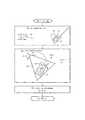
図1に示すように、画像ベース融合10は、解剖学的領域(例えば、腹部領域)を含む最小侵襲性プロシージャ内に組み込まれた内視鏡撮像フェーズ11、腹腔鏡超音波(LUS)撮像フェーズ12及び画像融合フェーズ13を含む。 As shown in FIG. 1, image-based
一般に、内視鏡撮像フェーズ11は、本開示の技術分野において周知のように、患者のポートを介して内視鏡を解剖学的領域に導入することを含み、これにより、内視鏡は、図2に関連して更に示されるように解剖学的領域(例えば、解剖学的領域内の器官の内視鏡ビュー)の内視鏡画像を生成するように操作される。 In general, the endoscopic imaging phase 11 involves introducing the endoscope into the anatomical region through the patient's port, as is known in the art of the present disclosure, whereby the endoscope is As further shown in connection with FIG. 2, it is manipulated to generate an endoscopic image of an anatomical region (eg, an endoscopic view of an organ within the anatomical region).
内視鏡撮像フェーズ11の前、同時または後に,LUS撮像フェーズ12は、一般に、本開示の技術分野で周知のように、患者の別のポートを通じたLUSプローブの解剖学的領域への導入を含み、それによりLUSプローブは、図2に関連して更に記載されるように、解剖学的領域の2D平面超音波画像(例えば、解剖学的領域内の器官の2D超音波視野)又は2D平面超音波画像の空間シーケンスからなる解剖学的領域の3Dスキャン超音波画像(例えば、解剖学的領域内の器官の3次元超音波ビュー)を生成するように操作される。 Prior to, simultaneously with, or after endoscopic imaging phase 11,
生成された内視鏡/超音波画像から、画像融合フェーズ13は、図2に関連して更に示されるように内視鏡の視野内のLUSプローブの検出を前提とした、本開示の本発明の原理による画像ベースの融合を含む。 From the generated endoscope / ultrasound image, the
内視鏡/超音波画像の最初の融合時に、LUSプローブは、本開示の技術分野において周知のように解剖学的領域から除去され、それにより外科的/診断的器具は解剖学的領域内に導入され、画像ベースの融合された内視鏡/超音波画像は、解剖学的領域内の手術/診断器具のナビゲーション及び操作をサポートする。その後、フェーズ11乃至13は最小侵襲性プロシージャを完了するために、必要に応じて個々に/まとめて繰り返されることができる。 At the first fusion of the endoscopic / ultrasound image, the LUS probe is removed from the anatomical area as known in the art of the present disclosure, whereby the surgical / diagnostic instrument is within the anatomical area. The introduced, image-based fused endoscope / ultrasound image supports the navigation and manipulation of surgical / diagnostic instruments within the anatomical region. Phases 11-13 can then be repeated individually / collectively as needed to complete the minimally invasive procedure.
画像ベースの融合10を実施するために、コントローラネットワーク20は、内視鏡コントローラ30、LUSプローブコントローラ40、画像融合コントローラ50、及び表示コントローラ60を使用する。 To implement image-based
一般に、内視鏡コントローラ30は、内視鏡画像を生成する際に内視鏡の動作を制御するために、本開示の技術分野で周知のように構造的に構成されており、LUSプローブコントローラ40は、超音波画像を生成する際のLUSプローブの動作を制御するために当該技術分野において周知のように構造的に構成され、表示コントローラ60は、ディスプレイ/モニタの動作を制御するために当該技術分野において周知のように構造的に構成される。 In general, the
画像融合コントローラ50は、図2に関連して本明細書でさらに説明するように内視鏡の視野内のLUSプローブの検出を前提とした、内視鏡画像と超音波画像との画像ベースの融合を制御するために、本開示の本発明の原理に従って構造的に構成される。 The
表示コントローラ60は、画像融合コントローラ50にユーザインタラクティブコマンドを提供するためにグラフィカルユーザインタフェースを表示し、それによって超音波画像及び内視鏡画像の画像ベースの融合の表示を操作するために、本開示の発明原理に従ってさらに構造的に構成されてもよい。 The
実際には、コントローラネットワーク20は、単一のワークステーション内に組み込まれてもよく、又は複数のワークステーション間で何れかの方法で分散されてもよい。 In practice, controller network 20 may be integrated within a single workstation or may be distributed in any manner among multiple workstations.
図2は、腹部領域ARを含む最小侵襲性プロシージャのためのコントローラネットワーク20による画像ベースの融合10の例示的な実装を示す。 FIG. 2 shows an exemplary implementation of image-based
図1及び図2を参照すると、内視鏡コントローラ30は、本開示の技術分野において周知のように内視鏡31による内視鏡画像の生成を制御する。より具体的には、内視鏡31は、内視鏡コントローラ30によって固定され、又は調整可能な視野32を有し、内視鏡コントローラ30は、内視鏡31からの内視鏡ビデオ信号を、内視鏡画像を示すコンピュータ可読時間フレームシーケンスに変換するためのビデオキャプチャ装置を使用する。実際には、ビデオキャプチャ装置は、内視鏡ビデオ信号から個々のデジタル静止内視鏡画像フレーム(「EIF」)33をキャプチャするための何れかのタイプのフレームグラバを使用することができる。 With reference to FIGS. 1 and 2, the
LUSプローブコントローラ40は、本開示の技術分野で周知のように、LUSプローブ41による1つ以上の超音波画像の生成を制御する。より詳細には、LUSプローブ41は、超音波の短パルスを撮像面42内で縦方向に送信し、超音波画像を示す反射音(「超音波エコー」)を受信するためのトランスデューサヘッド41hを有する。 LUSプローブ41は撮像中に静止して単一の2D平面超音波画像43をもたらすか、又はLUSプローブ41はポートに対してピボットされて2D平面超音波画像43の空間シーケンスからなる3Dスキャン超音波画像をもたらす。 The LUS probe controller 40 controls the generation of one or more ultrasound images by the
画像融合コントローラ50は、プローブ検出器51、画像変換器52及び画像インテグレータ53を使用する。 The
プローブ検出器51は、図3に関連してさらに説明するように、内視鏡画像フレーム33の処理を制御して、内視鏡31の視野32内の腹腔鏡超音波プローブ41を検出する。 The
画像変換器52は、内視鏡画像フレーム33及び超音波画像43の処理を制御して、内視鏡31の内視鏡画像空間(例えば、視野31又はその一部)と、図3に関連してさらに説明するように内視鏡31の視野内のLUSプローブ41のプローブ検出器51による検出から導出されるLUSプローブ41の超音波画像空間(例えば、撮像面42又はその一部)との間の画像変換ENDOSCOPETLUS PROBEを計算する。The
画像インテグレータ53は、内視鏡画像フレーム33及び超音波画像43の処理を制御して、図3に関連してさらに説明するように、画像変換器52によって計算された画像変換に基づいて内視鏡画像及び超音波画像を融合する。 The image integrator 53 controls the processing of the
表示コントローラ60は、個々に又は画像インテグレータ53によって融合されるように、内視鏡画像及び超音波画像43を示すために、本開示の技術分野で周知のようにディスプレイ/モニタ62の動作を制御する。融合される内視鏡画像/超音波画像に関して、画像インテグレータ52は、画像融合データ(「IFD」)54を表示コントローラ60に提供し、それによって表示コントローラ60は、ディスプレイ/モニタ62による表示のために融合される内視鏡画像/超音波画像(「FEUI」)61を生成する。インタラクティブであれば、表示コントローラ60は、ディスプレイ/モニタ62によって融合内視鏡画像/超音波画像61の表示を操作する画像インテグレータ53へのグラフィカルユーザインタフェース(図示せず)を介してインタラクティブ画像コマンド(「IIC」)63を提供する。
本開示のさらなる理解を容易にするために、図3の以下の説明は、図2の制御ネットワークと関連して、本開示の画像ベースの融合方法の基本的な発明原理を教示する。この説明から、当業者は、本開示の多数の追加の制御ネットワーク実施形態に画像ベースの融合方法の本発明の原理を適用する方法を理解するであろう。 To facilitate a further understanding of the present disclosure, the following description of FIG. 3, in conjunction with the control network of FIG. 2, teaches the basic inventive principles of the image-based fusion method of the present disclosure. From this description, those skilled in the art will understand how to apply the principles of the present invention of image-based fusion methods to numerous additional control network embodiments of the present disclosure.
図3は、本開示の1つの画像ベースの融合方法を表すフローチャート70を示す。 FIG. 3 shows a flow chart 70 representing one image-based fusion method of the present disclosure.
図3を参照すると、フローチャート70のステージS72は、内視鏡31の視野32内のLUSプローブ41を検出するプローブ検出器51(図2)を包含する。 Referring to FIG. 3, stage S 72 of flowchart 70 includes a probe detector 51 (FIG. 2) that detects
ステージS72の一実施形態では、プローブ検出器41は、トランスデューサヘッド41hのパターン、トランスデューサヘッド41の特定の形状/色/テクスチャ、又はトランスデューサヘッド41h上の補足/追加パターンの検出に基づいて当該技術分野で公知の技術を実行することによって、内視鏡31の視野32内のLUSプローブの遠位トランスデューサヘッド41hを自動的に検出する。 In one embodiment of stage S72,
ステージS72の第2の実施形態では、プローブ検出器41は、内視鏡画像及び/又は超音波画像(例えば、オプティカルフロー、背景抽出など)内での動きの検出に基づいて、本開示の技術分野で周知の検出技術を実行することによって、内視鏡31の視野32内のLUSプローブ41の遠位変換器ヘッド41hを自動的に検出する。 In a second embodiment of stage S72, the
フローチャート70のステージS74は、トランスデューサヘッド41hに基準フレーム44を取り付ける画像変換器52(図2)を含み、それにより、内視鏡31の内視鏡画像空間34とLUSプローブ41の超音波画像空間42との間の画像変換ENDOSCOPETLUS PROBEを計算するために当該技術分野において周知の2D-3Dレジストレーション(例えば、RANSACレジストレーション)を実行する。Stage S 74 of flowchart 70 includes an image converter 52 (FIG. 2) that attaches
フローチャート70のステージS76は、内視鏡画像と超音波画像とを融合させる画像インテグレータ53(図2)を包含し、これにより、限定されないが、超音波画像の内視鏡画像へのレジストレーションされたオーバーレイ又は内視鏡画像の表示に対する超音波画像のレジストレーションされたウィンドウ表示を含む、融合された内視鏡/超音波画像の同時表示を容易にする。 Stage S 76 of flowchart 70 includes an image integrator 53 (FIG. 2) that fuses the endoscopic image and the ultrasound image, thereby causing, but not limited to, registration of the ultrasound image to the endoscopic image. The present invention facilitates the simultaneous display of fused endoscope / ultrasound images, including the registration of window images of ultrasound images against the display of overlays or endoscope images.
ステージS76の一実施形態では、本開示の技術分野で周知の画像ブレンディング技術が画像インテグレータ53によって実行されることができ、これにより、この融合プロセスは、2D平面超音波画像の透視変換又は3Dスキャン超音波画像の3D変換を含むことができる。 In one embodiment of stage S76, image blending techniques well known in the art of the present disclosure may be performed by image integrator 53 such that the fusion process is a perspective transform or 3D scan of a 2D planar ultrasound image. It can include 3D transformation of ultrasound images.
実際には、ステージS72乃至S76は、解剖学的領域内のLUSプローブ41の各撮像位置、若しくは特定の時間マーカー(例えば5秒)でのLUSプローブ41の撮像位置、又はオペレータによって選択されたLUSプローブ41の撮像位置について実行され得る。 In practice, stages S72 to S76 are the imaging positions of
変換ENDOSCOPETLUSは、スキャン中のLUSプローブ41の各撮像位置又はオペレータによって選択されるLUSプローブ41の撮像位置について、超音波画像とともに画像融合コントローラ50によって保存されることができる。The transformENDOSCOPE TLUS may be stored by the
LUSプローブ41が解剖学的領域(例えば、図1に示される腹部領域AR)から除去されると、オペレータは、限定されないが、スクリーン上のマウス(又は他の入力装置)のクリック、保存される位置(例えば、A、B、C)を含む何れかの対話方法を利用することによって、又は割り当てられた名前によって、保存された変換ENDOSCOPETLUS、内視鏡画像及び超音波画像の組合せを介して、融合される内視鏡/超音波画像の表示を開始し得る。When the
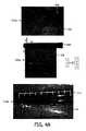
図4A及び図4Bは、以下を含むフローチャート70の例示的な実行を示す。
1.ステージS72a:肝臓の形態の解剖学的器官の内視鏡像を示す内視鏡画像33aの視野内のLUSプローブ41のトランスデューサヘッド41hの自動パターン検出。
2.ステージ74a:内視鏡31の内視鏡画像空間(ピクセル)と、肝臓のセグメントの超音波ビューを提供する超音波画像43aを生成するLUSプローブ41の超音波画像空間との間のマッピング。
3.ステージ74b:超音波画像43aの輪郭45の描画。
4A.ステージ76a1:内視鏡画像33a上の超音波画像43aの透視的オーバーレイの形態の内視鏡/超音波画像33a/43aの融合を表示する輪郭45の利用。
4B.ステージ76a2:内視鏡画像33aの左上隅の超音波画像43aのウィンドウ表示の形態の内視鏡/超音波画像33a/43aの融合を表示するための輪郭45の利用。4A and 4B illustrate an exemplary implementation of a flowchart 70 that includes the following.
1.
2.Stage 74a : Mapping between the endoscopic image space (pixels) of the
3.Stage 74b : Drawing of the
Stage 76a1 : Use of the
4B.Stage 76a2 : Use of the
再び図3を参照すると、フローチャート70のステージS76は、限定されないが、解剖学的領域のボリューム画像及び解剖学的領域内の解剖学的器官の解剖学的アトラスを含む解剖学的モデルへの、内視鏡/超音波画像の更なる融合を実行する画像統合53をさらに含むことができる。 Referring again to FIG. 3, stage S 76 of flowchart 70 is not limited to an anatomical model, including but not limited to a volumetric image of the anatomical region and an anatomical atlas of an anatomical organ within the anatomical region. It may further include image integration 53 to perform further fusion of endoscope / ultrasound images.
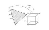
ボリューム画像レジストレーション。内視鏡ビューは、本開示の技術分野において周知の方法(例えば、米国特許第9095252B2号)を使用して術前3D画像(例えば、CT、XperCT、MRI、PETなど)にレジストレーションされることができる。例えば、図5は、術前CT画像80のボリュメトリック空間81と内視鏡31の内視鏡画像空間34との間のレジストレーションENDOSCOPETCTを示し、これにより、図7-16に関連してさらに説明されるように、内視鏡/超音波の融合に基づいて術前CT画像80からの3D画像及び構造が同時に表示されることができる。Volume image registration . Endoscopic views may be registered to pre-operative 3D images (eg, CT, XperCT, MRI, PET, etc.) using methods known in the art of the present disclosure (eg, US Pat. No. 9,095,252 B2) Can. For example, FIG. 5 shows registrationENDOSCOPECT between
ENDOSCOPETCTレジストレーションは、関心平面で取得される本開示の技術分野において周知の画像ベースのレジストレーション方法(例えば、相互情報)を使用して精緻化されることができる。ENDOSCOPETCT及びENDOSCOPETLUSから、超音波及びCT画像空間の間の変換は、
解剖学的アトラスレジストレーション。内視鏡/超音波画像の融合は、集団の間の解剖学的器官の形状を捕捉する解剖学的器官の解剖学的アトラスにレジストレーションされることができる。そのようなレジストレーションは、解剖学的器官に関してLUSプローブ41の大まかな局在化のみを可能にする。例えば、図6は、内視鏡画像にレジストレーションされる超音波画像43b乃至43dに示される、予め定義される迅速に識別可能な解剖学的基準点92のセットを使用することによって、肝臓の解剖学的アトラス90のモデル空間91と内視鏡検査との間のレジストレーションMODELTENDOSCOPEを示す。これらの基準点92は、器官特有の大きな血管の分岐部又は表面のランドマークであってもよい。Anatomic Atlas Registration . Fusion of endoscopic / ultrasound images can be registered to an anatomical atlas of anatomical organs that capture the shape of the anatomical organs between the populations. Such registration allows only a rough localization of the
本開示のさらなる理解を容易にするために、図5乃至16の以下の記載は、内視鏡ビュー又はベース画像としての役割を果たす解剖モデルによる、本開示の内視鏡画像及び超音波画像の画像融合の表示の基本的な発明原理を教示する。この説明から、当業者であれば、内視鏡画像及び超音波画像の画像融合を表示するための本開示の多数の追加の実施形態について本発明の原理を適用する方法を理解するであろう。 In order to facilitate a further understanding of the present disclosure, the following description of FIGS. 5-16 is for endoscopic images and ultrasound images of the present disclosure according to an anatomical model that serves as an endoscopic view or base image. The basic inventive principle of the display of image fusion is taught. From this description, one of ordinary skill in the art will understand how to apply the principles of the invention to a number of additional embodiments of the present disclosure for displaying image fusion of endoscopic and ultrasound images. .
超音波画像の深度。この表示の実施形態では、3Dスキャン超音波画像の特定の2D平面超音波画像はオペレータの好みに合わせて表示されることができる。より詳細には、オペレータは、3次元スキャン超音波画像の特定の2次元平面超音波画像を、内視鏡ビュー又はベース画像としての役割を果たす解剖学的モデル表示に重ね合わせることを決定することができる。Ultrasound image depth . In this display embodiment, a particular 2D planar ultrasound image of the 3D scan ultrasound image can be displayed to the operator's preference. More specifically, the operator decides to superimpose a particular two-dimensional planar ultrasound image of the three-dimensional scan ultrasound image on an anatomical model display that serves as an endoscopic view or base image. Can.
例えば、図7A及び図7Bが例示するように、オペレータは、肝臓のベース画像100(例えば、内視鏡ビュー又は解剖学的モデルビュー表示)と融合される肝臓の3Dスキャン超音波画像の特定の深度43b及び43cの間で選択するようにグラフィカルスライダ64を操作することができる。 For example, as FIGS. 7A and 7B illustrate, the operator may specify a 3D scan ultrasound image of the liver fused with the
超音波画像/器具ビュー。この表示の実施形態では、以前に記録され、保存された2D平面超音波画像は、プロシージャの間及び3Dスキャン超音波画像を生成する超音波スキャン後に器具下に表示されることができる。 2D平面超音波画像は、さらに、2D平面超音波画像を器具の透視で置くように変換されることができる。Ultrasound image / instrument view . In this display embodiment, previously recorded and stored 2D planar ultrasound images can be displayed under the instrument during the procedure and after ultrasound scanning to generate 3D scanning ultrasound images. The 2D planar ultrasound image can be further transformed to place the 2D planar ultrasound image in perspective of the instrument.
例えば、図8A及び8Bに例示されるように、肝臓の標的領域の予め記録及び保存される2D平面超音波画像43eは変換され、プロシージャ中及びスキャン後に器具46下にベース画像100(例えば、内視鏡ビュー、セグメント化されるボリュームビュー、又は解剖学的アトラスビュー)上のオーバーレイとして表示される。 For example, as illustrated in FIGS. 8A and 8B, a pre-recorded and stored 2D
超音波画像透視変換。この表示の実施形態では、スキャン中又はプロシージャ中のいずれかにおいて、超音波画像が歪みのない透視で示されるように、ベース画像(例えば、内視鏡ビュー、セグメント化ボリュームビュー又は解剖学的アトラスビュー)は再計算され、透視を用いて変換されることができる。これは、本開示の技術分野でよく知られている逆透視変換を使用して達成されることができる。Ultrasound image perspective transformation . In this display embodiment, the base image (e.g., an endoscopic view, a segmented volume view, or an anatomical atlas, as the ultrasound image is shown in perspective without distortion, either during scanning or during a procedure). The view can be recomputed and transformed using perspective. This can be achieved using inverse perspective transformation well known in the art of the present disclosure.
例えば、図9A及び図9Bは、歪みのない透視で超音波画像43eを示すように再計算及び変換される内視鏡画像33bを示す。 For example, FIGS. 9A and 9B show an
内視鏡ビューのモデル基準。この表示の実施形態では、前述の解剖学的モデル変換を使用して、各々のスキャンされる2D平面超音波画像(又はオペレータによって選択される各2D平面超音波画像)は、解剖学的モデル(例えば、術前CTモデル又は解剖学的アトラス)の内容で表示されてもよい。解剖学的モデルで選択される追加の基準面は、2D平面超音波画像のより良い使用及び選択を容易にするために表示されることができる。 2D平面超音波画像は、内視鏡ビュー、解剖学的モデルビュー、又はその両方で視覚化されることができる。Model reference for endoscopic view . In this display embodiment, each scanned 2D planar ultrasound image (or each 2D planar ultrasound image selected by the operator) is anatomical model For example, it may be displayed in the content of a preoperative CT model or an anatomical atlas. Additional reference planes selected in the anatomical model can be displayed to facilitate better use and selection of 2D planar ultrasound images. 2D planar ultrasound images can be visualized in endoscopic views, anatomical model views, or both.
例えば、図10Aは、内視鏡画像33c上の超音波画像43gと組み合わせて重畳される術前CT情報の基準面101a乃至101cを示しており、図10Bは、超音波画像43gに重畳される術前CT情報を備える超音波画像43gを示す。 For example, FIG. 10A shows
さらなる例として、図11は、CT画像83の基準面101a乃至101cに対応する内視鏡画像33dにおける基準面101d乃至101fを示している。 As a further example, FIG. 11 shows
LUSスキャニング。本開示の技術は、1回のスキャンの実行中又はスキャンの再訪中に、同じ/類似の平面の再訪を容易にする。オペレータは、超音波画像を配置するように、内視鏡ビューにおける保存LUSスキャン位置を使用することができる。内視鏡画像の2Dの性質のため、撮像の正しい面を見つけることは難しいことがある。図12に例示されるこの表示の実施例において、オペレータは、所望の撮像面(2D問題)に近い位置にLUSプローブヘッド41hを粗く位置決めする。配置後、オペレータは矢印で示すようにLUSプローブヘッドをピボットさせ、撮像融合コントローラ50は超音波画像のシーケンス43gを収集する。本開示の技術分野でよく知られている類似性メトリック(例えば、相互情報)を使用して、撮像融合コントローラ50は、所望の画像位置に最も類似した超音波画像を見つけ、いつピボットを停止するかをオペレータに通知する。LUS scanning . The techniques of this disclosure facilitate the revisit of the same / similar planes during the execution of one scan or revisit of the scan. The operator can use the saved LUS scan position in the endoscopic view to place the ultrasound image. Due to the 2D nature of endoscopic images, it may be difficult to find the correct plane of imaging. In the example of this display illustrated in FIG. 12, the operator roughly positions the
仮想LUSプローブ。この実施形態では、仮想プローブが解剖学的モデル(例えば、器官表面及び内部構造の3D再構成)と共に表示される。さらに(又はその代わりに)、超音波ボリューム/平面の輪郭は解剖学的モデルと併せて表示され、オペレータのためにより良好な空間方向決めを容易にすることができる。更に(又はその代わりに)、超音波画像又はボリュームは解剖学的モデル又は3D再構成の上に重ね合わされることができる。例えば、 図13は、そのとき解剖学的モデル104(例えば、CT画像又は解剖学的アトラス)に重ね合わされる仮想プローブ141の表示に後続される解剖学的構造103の3D再構成を示す。Virtual LUS probe . In this embodiment, a virtual probe is displayed with an anatomical model (eg, 3D reconstruction of organ surfaces and internal structures). Additionally (or alternatively), the contours of the ultrasound volume / plane can be displayed in conjunction with the anatomical model to facilitate better spatial orientation for the operator. Additionally (or alternatively), the ultrasound image or volume can be superimposed on top of the anatomical model or 3D reconstruction. For example, FIG. 13 shows a 3D reconstruction of the
外科的視覚化。この表示の実施形態では、外科プロシージャのプロセスは、腫瘍を含む現在及び以前に訪問/治療される基準面を視覚化することによって追跡される。最初に、内視鏡ビューが解剖学的モデル(例えば、図5及び図6に関連して先に説明したように術前3D画像又は解剖学的アトラス)にレジストレーションされる。第2に、このレジストレーションに基づいて、オペレータは手術中に基準面を取得し保存することによって腫瘍位置をマークする。第3に、システムは、現在及び/又は以前に治療される腫瘍を視覚化することによってプロシージャのプロセスを追跡する。現在の平面は、点滅している赤い平面として視覚化することができ、治療(切除)される腫瘍を含む平面は黒く表示することができる。Surgical visualization . In this display embodiment, the process of the surgical procedure is tracked by visualizing the current and previously visited / treated reference planes that include the tumor. Initially, an endoscopic view is registered to an anatomical model (eg, a preoperative 3D image or anatomical atlas as described above in connection with FIGS. 5 and 6). Second, based on this registration, the operator marks the tumor position by acquiring and storing a reference surface during surgery. Third, the system tracks the process of the procedure by visualizing the tumor currently and / or previously treated. The current plane can be visualized as a flashing red plane, and the plane containing the treated (excised) tumor can be displayed black.
例えば、図15A及び図15Bは、ベース画像100(例えば、内視鏡画像、セグメント化されるボリューム画像又は解剖学的アトラスビュー)上に重ね合わされる基準面101g乃至101iを示す。図15Aは、具体的には、現在の手術基準面として基準面101gを示し、図15Bは、具体的には、治療領域を表す基準面101gを示し、基準面101iは、現在の外科手術基準面である。 For example, FIGS. 15A and 15B show reference planes 101g-101i superimposed on a base image 100 (eg, an endoscopic image, a segmented volume image or an anatomical atlas view). 15A specifically shows the reference surface 101g as the current surgical reference surface, FIG. 15B specifically shows the reference surface 101g representing the treatment area, and the reference surface 101i is the current surgical standard. It is a face.
投影LUSビュー。所望の解剖学的領域又は病変を視覚化するために、腹腔鏡プローブは特定の位置及び方向に配置されなければならない。これは、LUSプローブ41、患者、及び解剖学的モデルビューの間の座標系の鏡像化される動き及び不一致に起因する最小侵襲的な設定における困難な課題になり得る。この表示実施形態は、関連するビュー、例えば図15に示される解剖学的モード画像104(例えば、セグメント化されるCT画像又は解剖学的アトラス)に対する投影位置111a乃至111d及び現在位置110を達成するプローブ位置及び方向のオーバーレイと共に解剖学的器官の解剖学的モデル例えば、セグメント化されるCT画像又は解剖学的アトラスを提供することによってこの困難を軽減する。これらの位置及び方向は、手動で以前に見つかったビューから、又は関心領域の位置の知識から計算されるビューから保存されることができる。さらに、腹腔鏡プローブが追跡される場合、現在の位置及び方向は、プローブの配置をさらに助けるために、アトラスに対して重ね合わされることができる。Projection LUS view . In order to visualize the desired anatomical area or lesion, the laparoscopic probe must be positioned at a specific position and orientation. This can be a difficult task in minimally invasive settings due to mirrored movements and inconsistencies of the coordinate system between the
変換投影LUSビュー。前の実施形態に続いて、アトラス視点は、現在位置110及び投影位置111a乃至111dとともに図16に示される解剖学的モデル画像104(例えば、セグメント化されるCT画像又は解剖学的アトラス)の鳥瞰図、ユーザコンソール視点、又は腹腔鏡視点などの直感的な透視に変換されることができる。このような変換により、臨床医は自身の基準フレームにプローブ運動を示すことができ、これらの方向は解剖学的モデル座標系の適切な動きに変換される。逆に、解剖学的モデル座標系において所望の視野を得るために必要なプローブの動きは、臨床医の基準のフレーム内の動きに変換されることができる。Transformed projection LUS view . Following the previous embodiment, the atlas viewpoint is a bird's-eye view of an anatomical model image 104 (eg, a segmented CT image or anatomical atlas) shown in FIG. 16 with the
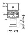
実際には、画像融合コントローラ50(図1)は、ワークステーション内に設置されてもよいし、ワークステーションにリンクされてもよい。 In practice, the image fusion controller 50 (FIG. 1) may be located within the workstation or linked to the workstation.
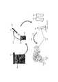
例えば、図17Aは、モニタ201、インタフェースプラットフォーム202(例えば、キーボード、ボタン、ダイヤル、ジョイスティックなど)、クライアントコンピュータ203、及びワークステーションコンピュータ203内に設置されるコントローラネットワーク204を使用する画像融合ワークステーション200を示す。 For example, FIG. 17A illustrates an
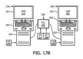
コントローラネットワーク204は、本開示の本発明の原理による内視鏡コントローラ205、LUSプローブコントローラ206、画像融合コントローラ207、及び表示コントローラ208を含む。実際には、コントローラ205乃至208は、クライアントコンピュータ203内の何れかの程度で分離及び/又は統合されることができる。代わりに図17Bに示されるように、内視鏡コントローラ205は、(モニタ211、インタフェースプラットフォーム212及びクライアントコンピュータ213を有する)内視鏡検査ワークステーション210内に設置され、LUSプローブコントローラ206は、(モニタ221、プラットフォーム222及びクライアントコンピュータ223を有する)n LUSワークステーション220内に設置され、画像融合コントローラ207及び表示コントローラ208は、ワークステーション210及び220にリンクされるワークステーションタブレット230内に設置される。 Controller network 204 includes an
図1乃至17を参照すると、当業者は、限定されるものではないが、解剖学的領域の超音波画像及び内視鏡画像の画像ベースの融合を含む、本開示の多くの利点を、解剖学的領域の超音波画像と内視鏡画像との追跡に基づく融合を含む最小侵襲性プロシージャに組み込まれる既存のシステム、ワークステーション、コントローラ及び方法に対する改良として理解するであろう。 With reference to FIGS. 1-17, one skilled in the art can dissect many of the benefits of the present disclosure, including but not limited to image-based fusion of ultrasound and endoscopic images of anatomical regions. It will be understood as an improvement over existing systems, workstations, controllers and methods incorporated into minimally invasive procedures including fusion based on tracking of ultrasound images of endoscopic regions and endoscopic images.
さらに、当業者であれば、本明細書で提供される教示に鑑みて、本開示/明細書及び/又は図面に記載される特徴、要素、構成要素などは、様々な組み合わせの電子ハードウェア、実行可能なソフトウェア及び実行可能なファームウェアを含み、単一の要素又は複数の要素に組み合わせることができる機能を提供する。例えば、図面に図示/図示/図示した様々な特徴、要素、構成要素等の機能は、専用のハードウェアならびに適切なソフトウェアに関連してソフトウェアを実行することができるハードウェアを使用して提供することができる。プロセッサによって提供される場合、機能は、単一の専用プロセッサ、単一の共有プロセッサ、又は複数の個別プロセッサによって提供されることができ、それらのうちのいくつかは共有及び/又は多重化することができる。さらに、「プロセッサ」という用語を明示的に使用することは、ソフトウェアを実行することができるハードウェアを排他的に指すものと解釈すべきではなく、暗黙的に、デジタル信号プロセッサ(DSP)ハードウェア、メモリ(例えば、ランダムアクセスメモリ「RAM」、不揮発性記憶装置など)及び実質的に何れかの手段及び/又は機械(ハードウェア、ソフトウェア、ファームウェア、回路、それらの組み合わせなどを含む)を格納するための「ROM」プロセスを実行(及び/又は制御)することができる及び/又は構成可能である。 Moreover, those skilled in the art, in view of the teachings provided herein, will appreciate that the features, elements, components, etc. described in the present disclosure / specification and / or drawings may be various combinations of electronic hardware, It includes executable software and executable firmware, and provides functionality that can be combined into a single element or multiple elements. For example, the functions of various features, elements, components, etc. shown / shown / shown in the drawings are provided using dedicated hardware as well as hardware capable of executing software in association with appropriate software. be able to. When provided by a processor, the functions may be provided by a single dedicated processor, a single shared processor, or multiple separate processors, some of which may be shared and / or multiplexed. Can. Furthermore, the explicit use of the term "processor" should not be interpreted as exclusively referring to hardware capable of executing software, and implicitly, digital signal processor (DSP) hardware , Memory (eg, random access memory "RAM", non-volatile storage, etc.) and virtually any means and / or machine (including hardware, software, firmware, circuits, combinations thereof, etc.) The “ROM” process can be implemented (and / or controlled) and / or configurable.
さらに、本発明の原理、態様及び実施形態、ならびにその特定の例を記載する本明細書におけるすべての記述は、それらの構造的及び機能的等価物の両方を包含するように意図される。さらに、そのような均等物には、現在知られている等価物及び将来開発される等価物(例えば、構造にかかわらず、同じ又は実質的に類似の機能を果たすことができるように開発される何れかの要素)が含まれることが意図される。したがって、例えば、本明細書で提示される何れかのブロック図が、本発明の原理を具体化する例示的なシステム構成要素及び/又は回路の概念図を表すことができることを、当業者は理解するであろう。同様に、当業者であれば、本明細書で提供される教示を考慮すれば、フローチャート、流れ図などは、コンピュータ可読記憶媒体に実質的に表現され、コンピュータ、プロセッサ又はそのようなコンピュータ又はプロセッサが明示的に示されるか否かにかかわらず、処理能力を有する他の装置を含む。 Moreover, all statements herein reciting the principles, aspects, and embodiments of the present invention, as well as specific examples thereof, are intended to encompass both their structural and functional equivalents. Furthermore, such equivalents are to be developed so as to be able to perform the same or substantially similar functions regardless of structure now known and equivalents to be developed in the future Any element is intended to be included. Thus, for example, one of ordinary skill in the art would understand that any block diagram presented herein may represent a conceptual view of exemplary system components and / or circuits embodying the principles of the present invention. Will do. Similarly, one of ordinary skill in the art, given the teachings provided herein, flowcharts, flowcharts, etc. are substantially represented in a computer readable storage medium, computer, processor or such computer or processor It includes other devices with processing capabilities, whether or not explicitly indicated.
さらに、本開示の例示的な実施形態は、プログラムコード及び/又は命令を提供するコンピュータ使用可能及び/又はコンピュータ可読記憶媒体からアクセス可能なコンピュータプログラム製品又はアプリケーションモジュールの形態をとることができる。 コンピュータ又は何れかの命令実行システムを含む。本開示によれば、コンピュータ使用可能又はコンピュータ読み取り可能な記憶媒体は、命令実行システム、装置又はシステムによって又はそれと関連して使用するために、例えばプログラムを格納、通信、伝播又は転送することができる何れかの装置であり得る。そのような例示的な媒体は、例えば、電子、磁気、光学、電磁気、赤外線又は半導体システム(又は装置又はデバイス)又は伝搬媒体であり得る。コンピュータ可読媒体の例には、例えば、半導体又はソリッドステートメモリ、磁気テープ、リムーバブルコンピュータディスケット、ランダムアクセスメモリ(RAM)、リードオンリメモリ(ROM)、フラッシュドライブ磁気ディスク、光ディスクなどが挙げられる。現在の光ディスクの例には、コンパクトディスクリードオンリメモリ(CD-ROM)、コンパクトディスクリードライト(CD-R/W)及びDVDが含まれる。さらに、今後開発される何れかの新しいコンピュータ可読媒体は、本開示の例示的な実施形態及び開示に従って使用又は参照され得るコンピュータ可読媒体と考えられるべきであることを理解される。 Further, the exemplary embodiments of the present disclosure may take the form of a computer program product or application module accessible from a computer useable and / or computer readable storage medium providing program code and / or instructions. Includes a computer or any instruction execution system. In accordance with the present disclosure, a computer usable or computer readable storage medium may, for example, store, communicate, propagate or transfer programs for use by or in connection with an instruction execution system, apparatus or system It may be any device. Such exemplary media may be, for example, electronic, magnetic, optical, electromagnetic, infrared or semiconductor systems (or devices or devices) or propagation media. Examples of computer readable media include, for example, semiconductor or solid state memory, magnetic tape, removable computer diskettes, random access memory (RAM), read only memory (ROM), flash drive magnetic disks, optical disks, and the like. Current examples of optical disks include compact disk read only memory (CD-ROM), compact disk read write (CD-R / W) and DVD. Further, it is understood that any new computer readable media developed in the future should be considered as computer readable media that can be used or referred to in accordance with the exemplary embodiments and disclosure of the present disclosure.
内視鏡画像と解剖学的領域の超音波画像との新規で発明的な画像ベースの融合(この実施形態は例示的であって限定的ではないことが意図される)の好ましい例示的な実施形態について説明したが、変更及び変形を行うことができる図面を含む本明細書で提供される教示に照らして当業者によって理解されるべきである。したがって、本明細書に開示される実施形態の範囲内にある本開示の好ましい実施形態及び例示的な実施形態に変更を加えることができることを理解される。 Preferred exemplary implementation of a novel and inventive image-based fusion of an endoscopic image and an ultrasound image of an anatomical region (this embodiment is intended to be illustrative and not limiting) While the form has been described, it should be understood by one of ordinary skill in the art in light of the teachings provided herein, including the drawings that may undergo changes and modifications. Thus, it is understood that changes can be made in the preferred and exemplary embodiments of the present disclosure which are within the scope of the embodiments disclosed herein.
さらに、本開示に従った装置において使用されるか又は実装され得る、装置を組み込む及び/又は実装する対応する及び/又は関連するシステムもまた、企図され、本開示の範囲内にあると考えられることが企図される。 さらに、本開示によるデバイス及び/又はシステムを製造及び/又は使用するための対応する及び/又は関連する方法もまた、企図され、本開示の範囲内にあるとみなされる。 Furthermore, corresponding and / or associated systems incorporating and / or implementing the apparatus, which may be used or implemented in the apparatus according to the present disclosure, are also contemplated and considered to be within the scope of the present disclosure. It is contemplated. Furthermore, corresponding and / or associated methods for making and / or using the devices and / or systems according to the present disclosure are also contemplated and considered to be within the scope of the present disclosure.
Claims (20)
Translated fromJapanese画像融合コントローラであって、
前記内視鏡画像及び前記超音波画像の通信に応答して、前記画像融合コントローラは、前記解剖学的領域の前記内視鏡の視野内の前記腹腔鏡超音波プローブの前記超音波融合コントローラによる検出から導出される前記腹腔鏡超音波プローブの超音波画像空間と前記内視鏡の内視鏡画像空間との間の画像変換に基づいて、前記内視鏡画像と前記超音波画像との間の前記融合を制御する、
画像融合コントローラと、
表示コントローラであって、
前記表示コントローラは、前記内視鏡画像及び前記超音波画像の前記画像融合コントローラによる前記融合の表示を制御する、
表示コントローラと
を有する、画像融合ワークステーション。An image fusion workstation for image-based fusion of an endoscopic image of an anatomical region generated by an endoscope with an ultrasound image of said anatomical region generated by a laparoscopic ultrasound probe And the image fusion workstation
An image fusion controller,
The image fusion controller is responsive to the ultrasound fusion controller for the laparoscopic ultrasound probe within the endoscopic field of view of the anatomic region in response to communication of the endoscopic image and the ultrasound image. Between the endoscopic image and the ultrasound image based on the image transformation between the ultrasound image space of the laparoscopic ultrasound probe derived from the detection and the endoscopic image space of the endoscope Control the fusion of
Image fusion controller,
A display controller,
The display controller controls the display of the fusion of the endoscopic image and the ultrasound image by the image fusion controller.
An image fusion workstation having a display controller.
請求項1に記載の画像融合ワークステーション。The image fusion controller and the display controller further control user interactive selection of the depth of the ultrasound image from the laparoscopic ultrasound probe.
An image fusion workstation according to claim 1.
請求項1に記載の画像融合ワークステーション。The image fusion controller and the display controller further control the display of the ultrasound image on an instrument inserted into the anatomical region.
An image fusion workstation according to claim 1.
請求項1に記載の画像融合ワークステーション。The image fusion controller and the display controller further control a perspective view of the display of the ultrasound image.
An image fusion workstation according to claim 1.
請求項1に記載の画像融合ワークステーション。In response to communication of an anatomical model of the anatomical region, the image fusion controller is configured to image the volumetric image space of the anatomical model and the endoscopic image space of the endoscope. Controlling the registration between the anatomical model of the anatomical region and the fusion of the ultrasound image and the endoscopic image based on the transformation;
An image fusion workstation according to claim 1.
請求項5に記載の画像融合ワークステーション。The anatomical model is a volumetric image of the anatomical region generated by an imaging modality,
An image fusion workstation according to claim 5.
請求項5に記載の画像融合ワークステーション。The anatomical model is an anatomical atlas of anatomical structures within the anatomical region,
An image fusion workstation according to claim 5.
請求項5に記載の画像融合ワークステーション。The image fusion controller and the display controller may be configured to superimpose the endoscopic image, the ultrasound image, and at least one display of the fusion of the endoscopic image with the ultrasound image. Further control the display of at least one reference plane view of the model,
An image fusion workstation according to claim 5.
請求項5に記載の画像融合ワークステーション。The image fusion controller and the display controller are configured to perform the laparoscopic analysis based on the registration between the anatomical model of the anatomical region and the fusion of the ultrasound image and the endoscopic image. Further controlling display of a target ultrasound image of the plurality of ultrasound images of the anatomical region generated by the ultrasound probe;
An image fusion workstation according to claim 5.
請求項5に記載の画像融合ワークステーション。The image fusion controller and the display controller are based on the registration between the anatomical model of the anatomical region and the fusion of the ultrasound image and the endoscopic image. Further controlling the display of the ultrasound image and the virtual laparoscopic probe as well as the display of the model,
An image fusion workstation according to claim 5.
請求項1に記載の画像融合ワークステーション。The image fusion controller and the display controller further control the display of the ultrasound image showing the status of a surgical procedure performed within the anatomical region.
An image fusion workstation according to claim 1.
請求項5に記載の画像融合ワークステーションThe image fusion controller and the display controller further control the display of at least one reference plane view of the anatomical model indicating the status of a surgical procedure performed within the anatomical region.
An image fusion workstation according to claim 5
請求項5に記載の画像融合ワークステーション。The image fusion controller and the display controller are based on the registration between the anatomical model of the anatomical region and the fusion of the ultrasound image and the endoscopic image. Further controlling a virtual display of at least one desired position of the laparoscopic ultrasound probe on a model,
An image fusion workstation according to claim 5.
前記内視鏡の視野内の前記腹腔鏡超音波プローブの検出を制御するプローブ検出器と、
前記内視鏡の前記視野内の前記腹腔鏡超音波プローブの前記プローブ検出器による前記検出から導出される前記腹腔鏡超音波プローブの超音波画像空間と前記内視鏡の内視鏡画像空間との間の画像変換の計算を制御する画像変換器と、
前記画像変換部により計算される前記画像変換に基づいて、前記内視鏡画像と前記超音波画像との前記融合を制御する画像インテグレータと
を有する、画像融合コントローラ。An image fusion controller for image based fusion of an endoscopic image of an anatomical region generated by an endoscope with an ultrasound image of said anatomical region generated by a laparoscopic ultrasound probe The image fusion controller
A probe detector for controlling the detection of the laparoscopic ultrasound probe within the field of view of the endoscope;
An ultrasound image space of the laparoscopic ultrasound probe derived from the detection by the probe detector of the laparoscopic ultrasound probe within the field of view of the endoscope and an endoscopic image space of the endoscope; An image converter, which controls the calculation of the image conversion between
An image fusion controller, comprising: an image integrator that controls the fusion of the endoscopic image and the ultrasound image based on the image conversion calculated by the image conversion unit.
請求項14に記載の画像融合コントローラ。In response to communication of an anatomical model of the anatomical region, the image integrator transforms the image between the volumetric image space of the anatomical model and the endoscopic image space of the endoscope Further control the registration between the anatomical model of the anatomical region and the fusion of the ultrasound image and the endoscopic image based on
The image fusion controller according to claim 14.
画像融合ワークステーションが、前記解剖学的領域の前記内視鏡の視野内で前記腹腔鏡超音波プローブを検出するステップと、
前記画像融合ワークステーションが、前記内視鏡の内視鏡画像空間と前記腹腔鏡超音波プローブの超音波画像空間との間の画像変換を計算するステップであって、
前記画像融合ワークステーションは、前記解剖学的領域の前記内視鏡の視野内の前記腹腔鏡超音波プローブの前記検出から前記画像変換を導出する、
ステップと、
前記画像変換ワークステーションが、前記画像変換に基づいて前記内視鏡画像と前記超音波画像とを融合するステップと
を有する、方法。A method for image-based fusion of an endoscopic image of an anatomical region generated by an endoscope with an ultrasound image of said anatomical region generated by a laparoscopic ultrasound probe, The method is
Detecting the laparoscopic ultrasound probe within the field of view of the endoscope of the anatomic region;
Said image fusion workstation calculating an image transformation between an endoscopic image space of said endoscope and an ultrasound image space of said laparoscopic ultrasound probe;
The image fusion workstation derives the image transformation from the detection of the laparoscopic ultrasound probe within the endoscopic field of view of the anatomical region.
Step and
Combining the endoscopic image and the ultrasound image based on the image conversion.
前記画像融合コントローラは、
前記腹腔鏡超音波プローブからの前記超音波画像の深度のユーザ選択、
前記超音波画像の前記表示の透視ビュー、
前記解剖学的領域内に挿入される器具に対する前記超音波画像の表示、及び
前記解剖学的領域内で行われる外科的プロシージャの状態を示す前記超音波画像の表示
の少なくとも1つを制御する、
ステップ
を更に有する、請求項16に記載の方法。The image fusion workstation displaying the fusion of the endoscopic image and the ultrasound image;
The image fusion controller is
User selection of the depth of the ultrasound image from the laparoscopic ultrasound probe;
Perspective view of the display of the ultrasound image,
Controlling at least one of the display of the ultrasound image for an instrument inserted in the anatomical region and the display of the ultrasound image indicating the status of a surgical procedure performed in the anatomical region.
The method of claim 16 further comprising the steps.
を更に有する、請求項16に記載の方法。The anatomical model of the anatomical region is based on an image transformation between the volumetric image space of the anatomical model and the endoscopic image space of the endoscope, the image fusion workstation. 17. The method of claim 16, further comprising: controlling registration between the and the fusion of the ultrasound image and the endoscopic image.
前記画像融合コントローラは、
前記内視鏡画像、前記超音波画像、及び前記内視鏡画像と前記超音波画像との前記融合の少なくとも1つの表示上に重ね合わされる前記解剖学的モデルの少なくとも1つの基準平面ビューの表示、
前記解剖学的領域の前記解剖学的モデルと、前記内視鏡画像及び前記超音波画像の前記融合との間の前記レジストレーションに基づいて、前記腹腔鏡超音波プローブによって生成される前記解剖学的領域の複数の超音波画像のうちの標的超音波画像の表示、
前記解剖学的領域の前記解剖学的モデルと、前記内視鏡画像及び前記超音波画像の前記融合との間の前記レジストレーションに基づく、前記解剖学的モデルの表示と一緒の仮想腹腔鏡プローブ及び前記超音波画像の表示、
前記解剖学的領域内で行われる外科的プロシージャの状態を示す前記解剖学的モデルの少なくとも1つの基準平面ビューの表示、及び
前記解剖学的領域の前記解剖学的モデルと、前記内視鏡画像及び前記超音波画像の前記融合との間の前記レジストレーションに基づく、前記解剖学的モデルに対する前記腹腔鏡的超音波プローブの少なくとも1つの所望の位置の仮想表示
の少なくとも1つを制御する、
ステップ
を更に有する、請求項18に記載の方法。The image fusion workstation displaying the registration of the anatomical model for fusion of the endoscopic image and the ultrasound image;
The image fusion controller is
Display of the endoscopic image, the ultrasound image, and at least one reference plane view of the anatomical model superimposed on at least one display of the fusion of the endoscopic image and the ultrasound image ,
The anatomy generated by the laparoscopic ultrasound probe based on the registration between the anatomical model of the anatomical region and the fusion of the endoscopic and ultrasound images. The target ultrasound image of multiple ultrasound images of the target area,
Virtual laparoscopic probe with display of the anatomical model based on the registration between the anatomical model of the anatomical region and the fusion of the endoscopic image and the ultrasound image And display of the ultrasonic image,
A display of at least one reference plane view of the anatomical model indicating the status of a surgical procedure performed within the anatomical region; the anatomical model of the anatomical region; and the endoscopic image Controlling at least one of a virtual representation of at least one desired position of the laparoscopic ultrasound probe relative to the anatomical model based on the registration between the ultrasound image and the fusion.
The method of claim 18, further comprising the step of:
請求項16に記載の方法。The endoscopic image space of the endoscope and the ultrasound image space of the laparoscopic ultrasound probe at different positions of the laparoscopic ultrasound probe with respect to the anatomical region. Calculate the image conversion between
The method of claim 16.
Applications Claiming Priority (3)
| Application Number | Priority Date | Filing Date | Title |
|---|---|---|---|
| US201662343339P | 2016-05-31 | 2016-05-31 | |
| US62/343,339 | 2016-05-31 | ||
| PCT/EP2017/063031WO2017207565A1 (en) | 2016-05-31 | 2017-05-30 | Image-based fusion of endoscopic image and ultrasound images |
Publications (3)
| Publication Number | Publication Date |
|---|---|
| JP2019517291Atrue JP2019517291A (en) | 2019-06-24 |
| JP2019517291A5 JP2019517291A5 (en) | 2020-07-02 |
| JP7133474B2 JP7133474B2 (en) | 2022-09-08 |
Family
ID=58873819
Family Applications (1)
| Application Number | Title | Priority Date | Filing Date |
|---|---|---|---|
| JP2018561635AActiveJP7133474B2 (en) | 2016-05-31 | 2017-05-30 | Image-based fusion of endoscopic and ultrasound images |
Country Status (5)
| Country | Link |
|---|---|
| US (1) | US20190290247A1 (en) |
| EP (1) | EP3463032B1 (en) |
| JP (1) | JP7133474B2 (en) |
| CN (1) | CN109219384B (en) |
| WO (1) | WO2017207565A1 (en) |
Cited By (3)
| Publication number | Priority date | Publication date | Assignee | Title |
|---|---|---|---|---|
| JP2022179221A (en)* | 2021-05-21 | 2022-12-02 | 富士フイルム株式会社 | Medical image processing system |
| JP2023509321A (en)* | 2019-12-12 | 2023-03-08 | コーニンクレッカ フィリップス エヌ ヴェ | Guided anatomical manipulation for endoscopic procedures |
| WO2023162657A1 (en)* | 2022-02-28 | 2023-08-31 | 富士フイルム株式会社 | Medical assistance device, medical assistance device operation method, and operation program |
Families Citing this family (24)
| Publication number | Priority date | Publication date | Assignee | Title |
|---|---|---|---|---|
| US10952705B2 (en)* | 2018-01-03 | 2021-03-23 | General Electric Company | Method and system for creating and utilizing a patient-specific organ model from ultrasound image data |
| US11123139B2 (en) | 2018-02-14 | 2021-09-21 | Epica International, Inc. | Method for determination of surgical procedure access |
| CN112584738B (en)* | 2018-08-30 | 2024-04-23 | 奥林巴斯株式会社 | Recording device, image observation device, observation system, control method of observation system, and storage medium |
| JP7148625B2 (en)* | 2018-09-18 | 2022-10-05 | 富士フイルム株式会社 | Medical image processing device, processor device, operating method of medical image processing device, and program |
| CN109115805A (en)* | 2018-10-25 | 2019-01-01 | 广东华中科技大学工业技术研究院 | Device and method for detecting defects of transparent component based on ultrasonic and optical dual-imaging |
| WO2020264003A1 (en)* | 2019-06-25 | 2020-12-30 | Intuitive Surgical Operations, Inc. | System and method related to registration for a medical procedure |
| CN110288653B (en)* | 2019-07-15 | 2021-08-24 | 中国科学院深圳先进技术研究院 | A multi-angle ultrasound image fusion method, system and electronic device |
| JP7284868B2 (en)* | 2020-03-03 | 2023-05-31 | オリンパス株式会社 | surgical system |
| EP4157132A1 (en)* | 2020-06-02 | 2023-04-05 | Intuitive Surgical Operations, Inc. | Anatomical scene visualization systems and methods |
| US12127890B1 (en)* | 2021-08-11 | 2024-10-29 | Navakanth Gorrepati | Mixed reality endoscopic retrograde cholangiopancreatopgraphy (ERCP) procedure |
| US20230062782A1 (en)* | 2021-09-02 | 2023-03-02 | Cilag Gmbh International | Ultrasound and stereo imaging system for deep tissue visualization |
| US11937799B2 (en) | 2021-09-29 | 2024-03-26 | Cilag Gmbh International | Surgical sealing systems for instrument stabilization |
| US20230098670A1 (en) | 2021-09-29 | 2023-03-30 | Cilag Gmbh International | Surgical devices, systems, and methods using multi-source imaging |
| US12295667B2 (en) | 2021-09-29 | 2025-05-13 | Cilag Gmbh International | Surgical devices, systems, and methods using multi-source imaging |
| JP2024541293A (en)* | 2021-11-09 | 2024-11-08 | ジェネシス メドテック (ユーエスエイ) インク. | An interactive augmented reality system for laparoscopic and video-assisted surgery |
| CN113940753B (en)* | 2021-11-12 | 2023-12-19 | 北京智愈医疗科技有限公司 | A multi-image information fusion method and system for automatic tissue cutting path planning |
| CN114062380A (en)* | 2021-11-18 | 2022-02-18 | 威海光子信息技术产业研究院有限公司 | Metal structure damage detection method based on fusion of endoscope and ultrasonic array |
| CN114601499B (en)* | 2022-02-24 | 2024-08-06 | 中国人民解放军总医院第一医学中心 | Multimode ultrasonic microprobe arthroscope imaging device and imaging system |
| CN115375595A (en)* | 2022-07-04 | 2022-11-22 | 武汉联影智融医疗科技有限公司 | Image fusion method, device, system, computer equipment and storage medium |
| CN115633926A (en)* | 2022-12-23 | 2023-01-24 | 山东百多安医疗器械股份有限公司 | Multi-mode ultrasonic electrocardio endoscope diagnosis and treatment instrument |
| CN115953377A (en)* | 2022-12-28 | 2023-04-11 | 中国科学院苏州生物医学工程技术研究所 | Digestive tract ultrasonic endoscope image fusion method and system |
| CN116098565A (en)* | 2022-12-30 | 2023-05-12 | 杭州华匠医学机器人有限公司 | Visual field control method and endoscope system |
| CN117495693B (en)* | 2023-10-24 | 2024-06-04 | 北京仁馨医疗科技有限公司 | Image fusion method, system, medium and electronic device for endoscope |
| CN117974475B (en)* | 2024-04-02 | 2024-06-18 | 华中科技大学同济医学院附属同济医院 | Method and system for fusion of lesion images under four-dimensional endoscopic ultrasound |
Citations (10)
| Publication number | Priority date | Publication date | Assignee | Title |
|---|---|---|---|---|
| JPH10146341A (en)* | 1996-09-18 | 1998-06-02 | Hitachi Ltd | Surgical equipment |
| JP2002017729A (en)* | 2000-07-11 | 2002-01-22 | Toshiba Corp | Ultrasound endoscopy diagnostic equipment |
| JP2011104079A (en)* | 2009-11-17 | 2011-06-02 | Univ Of Tokyo | Medical image processing system |
| US20110130659A1 (en)* | 2007-08-24 | 2011-06-02 | Endocontrol | Imaging System for Following a Surgical Tool in an Operation Field |
| JP2012235983A (en)* | 2011-05-13 | 2012-12-06 | Olympus Medical Systems Corp | Medical image display system |
| JP2014083237A (en)* | 2012-10-24 | 2014-05-12 | Olympus Corp | Probe position control device |
| US20140303491A1 (en)* | 2013-04-04 | 2014-10-09 | Children's National Medical Center | Device and method for generating composite images for endoscopic surgery of moving and deformable anatomy |
| JP2015505686A (en)* | 2011-12-03 | 2015-02-26 | コーニンクレッカ フィリップス エヌ ヴェ | Robot guidance of ultrasonic probe in endoscopic surgery |
| JP2015107268A (en)* | 2013-12-05 | 2015-06-11 | 国立大学法人名古屋大学 | Endoscopic observation support device |
| WO2015091226A1 (en)* | 2013-12-19 | 2015-06-25 | Koninklijke Philips N.V. | Laparoscopic view extended with x-ray vision |
Family Cites Families (23)
| Publication number | Priority date | Publication date | Assignee | Title |
|---|---|---|---|---|
| GB2333882B (en)* | 1998-01-26 | 2002-06-12 | Imperial College | Apparatus for and method of assessing surgical technique |
| US6602185B1 (en)* | 1999-02-18 | 2003-08-05 | Olympus Optical Co., Ltd. | Remote surgery support system |
| US6503195B1 (en)* | 1999-05-24 | 2003-01-07 | University Of North Carolina At Chapel Hill | Methods and systems for real-time structured light depth extraction and endoscope using real-time structured light depth extraction |
| US7500956B1 (en)* | 1999-06-29 | 2009-03-10 | Wilk Peter J | Apparatus and method for resonant destruction of tumors |
| JP4999012B2 (en)* | 2005-06-06 | 2012-08-15 | インチュイティブ サージカル,インコーポレイテッド | Laparoscopic ultrasonic robotic surgical system |
| US8398541B2 (en)* | 2006-06-06 | 2013-03-19 | Intuitive Surgical Operations, Inc. | Interactive user interfaces for robotic minimally invasive surgical systems |
| US7728868B2 (en)* | 2006-08-02 | 2010-06-01 | Inneroptic Technology, Inc. | System and method of providing real-time dynamic imagery of a medical procedure site using multiple modalities |
| CN107126182B (en)* | 2007-01-19 | 2020-06-16 | 桑尼布鲁克健康科学中心 | Scanning mechanism for imaging probe |
| US8989842B2 (en)* | 2007-05-16 | 2015-03-24 | General Electric Company | System and method to register a tracking system with intracardiac echocardiography (ICE) imaging system |
| US8090168B2 (en)* | 2007-10-15 | 2012-01-03 | General Electric Company | Method and system for visualizing registered images |
| IT1392888B1 (en)* | 2008-07-24 | 2012-04-02 | Esaote Spa | DEVICE AND METHOD OF GUIDANCE OF SURGICAL UTENSILS BY ECOGRAPHIC IMAGING. |
| CN102711650B (en) | 2010-01-13 | 2015-04-01 | 皇家飞利浦电子股份有限公司 | Image integration based registration and navigation for endoscopic surgery |
| MX2013015358A (en)* | 2011-07-01 | 2014-02-11 | Koninkl Philips Nv | Intra-operative image correction for image-guided interventions. |
| WO2013027202A2 (en)* | 2011-08-21 | 2013-02-28 | M.S.T. Medical Surgery Technologies Ltd. | Device and method for asissting laparoscopic surgery - rule based approach |
| CN104010587B (en)* | 2011-12-27 | 2017-09-05 | 皇家飞利浦有限公司 | To quality-monitoring in the art of tracing system |
| US10064545B2 (en)* | 2012-10-18 | 2018-09-04 | The Arizona Board Of Regents On Behalf Of The University Of Arizona | Multi-resolution foveated endoscope/laparoscope |
| JP2014132980A (en)* | 2013-01-10 | 2014-07-24 | Advanced Healthcare Kk | Trocar and surgery support system |
| CN103230283B (en)* | 2013-04-16 | 2014-11-05 | 清华大学 | Method for optimizing ultrasonic probe imaging plane space position calibration |
| CN103948432A (en)* | 2014-04-30 | 2014-07-30 | 深圳先进技术研究院 | Algorithm for augmented reality of three-dimensional endoscopic video and ultrasound image during operation |
| CN106572887B (en)* | 2014-07-15 | 2020-05-12 | 皇家飞利浦有限公司 | Image integration and robotic endoscope control in an X-ray suite |
| US10499996B2 (en)* | 2015-03-26 | 2019-12-10 | Universidade De Coimbra | Methods and systems for computer-aided surgery using intra-operative video acquired by a free moving camera |
| GB201506842D0 (en)* | 2015-04-22 | 2015-06-03 | Ucl Business Plc And Schooling Steven | Locally rigid vessel based registration for laparoscopic liver surgery |
| CN107667380A (en)* | 2015-06-05 | 2018-02-06 | 西门子公司 | The method and system of scene parsing and Model Fusion while for endoscope and laparoscopic guidance |
- 2017
- 2017-05-30USUS16/304,405patent/US20190290247A1/enactivePending
- 2017-05-30EPEP17726932.1Apatent/EP3463032B1/enactiveActive
- 2017-05-30CNCN201780033704.0Apatent/CN109219384B/enactiveActive
- 2017-05-30JPJP2018561635Apatent/JP7133474B2/enactiveActive
- 2017-05-30WOPCT/EP2017/063031patent/WO2017207565A1/ennot_activeCeased
Patent Citations (10)
| Publication number | Priority date | Publication date | Assignee | Title |
|---|---|---|---|---|
| JPH10146341A (en)* | 1996-09-18 | 1998-06-02 | Hitachi Ltd | Surgical equipment |
| JP2002017729A (en)* | 2000-07-11 | 2002-01-22 | Toshiba Corp | Ultrasound endoscopy diagnostic equipment |
| US20110130659A1 (en)* | 2007-08-24 | 2011-06-02 | Endocontrol | Imaging System for Following a Surgical Tool in an Operation Field |
| JP2011104079A (en)* | 2009-11-17 | 2011-06-02 | Univ Of Tokyo | Medical image processing system |
| JP2012235983A (en)* | 2011-05-13 | 2012-12-06 | Olympus Medical Systems Corp | Medical image display system |
| JP2015505686A (en)* | 2011-12-03 | 2015-02-26 | コーニンクレッカ フィリップス エヌ ヴェ | Robot guidance of ultrasonic probe in endoscopic surgery |
| JP2014083237A (en)* | 2012-10-24 | 2014-05-12 | Olympus Corp | Probe position control device |
| US20140303491A1 (en)* | 2013-04-04 | 2014-10-09 | Children's National Medical Center | Device and method for generating composite images for endoscopic surgery of moving and deformable anatomy |
| JP2015107268A (en)* | 2013-12-05 | 2015-06-11 | 国立大学法人名古屋大学 | Endoscopic observation support device |
| WO2015091226A1 (en)* | 2013-12-19 | 2015-06-25 | Koninklijke Philips N.V. | Laparoscopic view extended with x-ray vision |
Cited By (4)
| Publication number | Priority date | Publication date | Assignee | Title |
|---|---|---|---|---|
| JP2023509321A (en)* | 2019-12-12 | 2023-03-08 | コーニンクレッカ フィリップス エヌ ヴェ | Guided anatomical manipulation for endoscopic procedures |
| JP2022179221A (en)* | 2021-05-21 | 2022-12-02 | 富士フイルム株式会社 | Medical image processing system |
| JP7579750B2 (en) | 2021-05-21 | 2024-11-08 | 富士フイルム株式会社 | Medical Image Processing System |
| WO2023162657A1 (en)* | 2022-02-28 | 2023-08-31 | 富士フイルム株式会社 | Medical assistance device, medical assistance device operation method, and operation program |
Also Published As
| Publication number | Publication date |
|---|---|
| JP7133474B2 (en) | 2022-09-08 |
| CN109219384B (en) | 2022-04-12 |
| US20190290247A1 (en) | 2019-09-26 |
| CN109219384A (en) | 2019-01-15 |
| EP3463032B1 (en) | 2020-12-23 |
| WO2017207565A1 (en) | 2017-12-07 |
| EP3463032A1 (en) | 2019-04-10 |
Similar Documents
| Publication | Publication Date | Title |
|---|---|---|
| JP7133474B2 (en) | Image-based fusion of endoscopic and ultrasound images | |
| US11730562B2 (en) | Systems and methods for imaging a patient | |
| US10772684B2 (en) | Spatial visualization of internal mammary artery during minimally invasive bypass surgery | |
| JP6395995B2 (en) | Medical video processing method and apparatus | |
| CN102843972B (en) | Instrument-based image registration for fusing images with tubular structures | |
| US11278182B2 (en) | Enhanced visualization of blood vessels using a robotically steered endoscope | |
| CN103025227B (en) | Image processing device and method | |
| JP2019162339A (en) | Surgery supporting system and display method | |
| Wen et al. | Projection-based visual guidance for robot-aided RF needle insertion | |
| US20250268666A1 (en) | Systems and methods for providing surgical assistance based on operational context | |
| CN107847111B (en) | Endoscopic guidance of interactive planar slices from volumetric images | |
| JP2024541293A (en) | An interactive augmented reality system for laparoscopic and video-assisted surgery | |
| US11657547B2 (en) | Endoscopic surgery support apparatus, endoscopic surgery support method, and endoscopic surgery support system | |
| CN119053278A (en) | Two-stage instrument guidance for precision endoscopic surgery | |
| EP3782529A1 (en) | Systems and methods for selectively varying resolutions | |
| US12408992B2 (en) | Volumetric filter of fluoroscopic sweep video | |
| RU2816071C1 (en) | Combined intraoperative navigation system using ray tracing ultrasound image generation | |
| JP2024131034A (en) | Medical support device, operation method and operation program for medical support device | |
| JP2021045341A (en) | Arthroscopic surgery support device, arthroscopic surgery support method, and program |
Legal Events
| Date | Code | Title | Description |
|---|---|---|---|
| A521 | Request for written amendment filed | Free format text:JAPANESE INTERMEDIATE CODE: A523 Effective date:20200518 | |
| A621 | Written request for application examination | Free format text:JAPANESE INTERMEDIATE CODE: A621 Effective date:20200518 | |
| A977 | Report on retrieval | Free format text:JAPANESE INTERMEDIATE CODE: A971007 Effective date:20210426 | |
| A131 | Notification of reasons for refusal | Free format text:JAPANESE INTERMEDIATE CODE: A131 Effective date:20210601 | |
| A521 | Request for written amendment filed | Free format text:JAPANESE INTERMEDIATE CODE: A523 Effective date:20210826 | |
| A131 | Notification of reasons for refusal | Free format text:JAPANESE INTERMEDIATE CODE: A131 Effective date:20220125 | |
| A521 | Request for written amendment filed | Free format text:JAPANESE INTERMEDIATE CODE: A523 Effective date:20220421 | |
| TRDD | Decision of grant or rejection written | ||
| A01 | Written decision to grant a patent or to grant a registration (utility model) | Free format text:JAPANESE INTERMEDIATE CODE: A01 Effective date:20220816 | |
| A61 | First payment of annual fees (during grant procedure) | Free format text:JAPANESE INTERMEDIATE CODE: A61 Effective date:20220829 | |
| R150 | Certificate of patent or registration of utility model | Ref document number:7133474 Country of ref document:JP Free format text:JAPANESE INTERMEDIATE CODE: R150 | |
| R250 | Receipt of annual fees | Free format text:JAPANESE INTERMEDIATE CODE: R250 |