JP2019515740A - MRI-guided biopsy targeting set with launch obturator - Google Patents
MRI-guided biopsy targeting set with launch obturatorDownload PDFInfo
- Publication number
- JP2019515740A JP2019515740AJP2018556422AJP2018556422AJP2019515740AJP 2019515740 AJP2019515740 AJP 2019515740AJP 2018556422 AJP2018556422 AJP 2018556422AJP 2018556422 AJP2018556422 AJP 2018556422AJP 2019515740 AJP2019515740 AJP 2019515740A
- Authority
- JP
- Japan
- Prior art keywords
- obturator
- cannula
- targeting set
- biopsy
- targeting
- Prior art date
- Legal status (The legal status is an assumption and is not a legal conclusion. Google has not performed a legal analysis and makes no representation as to the accuracy of the status listed.)
- Pending
Links
- 238000001574biopsyMethods0.000titleclaimsabstractdescription127
- 230000008685targetingEffects0.000titleclaimsabstractdescription117
- 230000007246mechanismEffects0.000claimsabstractdescription58
- 238000010304firingMethods0.000claimsabstractdescription55
- 210000000481breastAnatomy0.000claimsabstractdescription28
- 238000002360preparation methodMethods0.000claimsdescription30
- 238000013519translationMethods0.000claimsdescription4
- 238000007689inspectionMethods0.000claimsdescription3
- 230000004044responseEffects0.000claimsdescription3
- 210000001519tissueAnatomy0.000description36
- 238000000034methodMethods0.000description24
- 238000002595magnetic resonance imagingMethods0.000description18
- 239000000523sampleSubstances0.000description13
- 239000000463materialSubstances0.000description12
- 239000012530fluidSubstances0.000description8
- 238000003384imaging methodMethods0.000description6
- 238000003780insertionMethods0.000description5
- 230000037431insertionEffects0.000description5
- 238000004891communicationMethods0.000description4
- 230000006870functionEffects0.000description4
- 238000012986modificationMethods0.000description4
- 230000004048modificationEffects0.000description4
- 238000005381potential energyMethods0.000description4
- 230000005855radiationEffects0.000description4
- XDTMQSROBMDMFD-UHFFFAOYSA-NC1CCCCC1Chemical compoundC1CCCCC1XDTMQSROBMDMFD-UHFFFAOYSA-N0.000description3
- 238000004140cleaningMethods0.000description3
- 238000006073displacement reactionMethods0.000description3
- 230000003902lesionEffects0.000description3
- 238000001356surgical procedureMethods0.000description3
- FAPWRFPIFSIZLT-UHFFFAOYSA-MSodium chlorideChemical compound[Na+].[Cl-]FAPWRFPIFSIZLT-UHFFFAOYSA-M0.000description2
- 239000004033plasticSubstances0.000description2
- 238000003825pressingMethods0.000description2
- 239000011780sodium chlorideSubstances0.000description2
- 210000004872soft tissueAnatomy0.000description2
- 239000007787solidSubstances0.000description2
- 238000012800visualizationMethods0.000description2
- LDXJRKWFNNFDSA-UHFFFAOYSA-N2-(2,4,6,7-tetrahydrotriazolo[4,5-c]pyridin-5-yl)-1-[4-[2-[[3-(trifluoromethoxy)phenyl]methylamino]pyrimidin-5-yl]piperazin-1-yl]ethanoneChemical compoundC1CN(CC2=NNN=C21)CC(=O)N3CCN(CC3)C4=CN=C(N=C4)NCC5=CC(=CC=C5)OC(F)(F)FLDXJRKWFNNFDSA-UHFFFAOYSA-N0.000description1
- 241000894006BacteriaSpecies0.000description1
- IAYPIBMASNFSPL-UHFFFAOYSA-NEthylene oxideChemical compoundC1CO1IAYPIBMASNFSPL-UHFFFAOYSA-N0.000description1
- 239000004775TyvekSubstances0.000description1
- 229920000690TyvekPolymers0.000description1
- 230000009471actionEffects0.000description1
- 238000013459approachMethods0.000description1
- 238000010420art techniqueMethods0.000description1
- 230000008901benefitEffects0.000description1
- 230000005540biological transmissionEffects0.000description1
- 239000000919ceramicSubstances0.000description1
- 230000008859changeEffects0.000description1
- 238000010276constructionMethods0.000description1
- 238000007796conventional methodMethods0.000description1
- 230000008878couplingEffects0.000description1
- 238000010168coupling processMethods0.000description1
- 238000005859coupling reactionMethods0.000description1
- 239000003814drugSubstances0.000description1
- 210000003811fingerAnatomy0.000description1
- 230000001788irregularEffects0.000description1
- 238000009607mammographyMethods0.000description1
- 239000003550markerSubstances0.000description1
- 239000002184metalSubstances0.000description1
- 230000008520organizationEffects0.000description1
- 230000007170pathologyEffects0.000description1
- 230000001954sterilising effectEffects0.000description1
- 238000004659sterilization and disinfectionMethods0.000description1
- 238000003860storageMethods0.000description1
- 229940124597therapeutic agentDrugs0.000description1
- 210000003813thumbAnatomy0.000description1
- 230000000451tissue damageEffects0.000description1
- 231100000827tissue damageToxicity0.000description1
- 238000002604ultrasonographyMethods0.000description1
Images


Classifications
- A—HUMAN NECESSITIES
- A61—MEDICAL OR VETERINARY SCIENCE; HYGIENE
- A61B—DIAGNOSIS; SURGERY; IDENTIFICATION
- A61B10/00—Instruments for taking body samples for diagnostic purposes; Other methods or instruments for diagnosis, e.g. for vaccination diagnosis, sex determination or ovulation-period determination; Throat striking implements
- A61B10/02—Instruments for taking cell samples or for biopsy
- A61B10/0233—Pointed or sharp biopsy instruments
- A—HUMAN NECESSITIES
- A61—MEDICAL OR VETERINARY SCIENCE; HYGIENE
- A61B—DIAGNOSIS; SURGERY; IDENTIFICATION
- A61B10/00—Instruments for taking body samples for diagnostic purposes; Other methods or instruments for diagnosis, e.g. for vaccination diagnosis, sex determination or ovulation-period determination; Throat striking implements
- A61B10/0041—Detection of breast cancer
- A—HUMAN NECESSITIES
- A61—MEDICAL OR VETERINARY SCIENCE; HYGIENE
- A61B—DIAGNOSIS; SURGERY; IDENTIFICATION
- A61B10/00—Instruments for taking body samples for diagnostic purposes; Other methods or instruments for diagnosis, e.g. for vaccination diagnosis, sex determination or ovulation-period determination; Throat striking implements
- A61B10/02—Instruments for taking cell samples or for biopsy
- A61B10/0233—Pointed or sharp biopsy instruments
- A61B10/0266—Pointed or sharp biopsy instruments means for severing sample
- A61B10/0275—Pointed or sharp biopsy instruments means for severing sample with sample notch, e.g. on the side of inner stylet
- A—HUMAN NECESSITIES
- A61—MEDICAL OR VETERINARY SCIENCE; HYGIENE
- A61B—DIAGNOSIS; SURGERY; IDENTIFICATION
- A61B17/00—Surgical instruments, devices or methods
- A61B17/34—Trocars; Puncturing needles
- A61B17/3417—Details of tips or shafts, e.g. grooves, expandable, bendable; Multiple coaxial sliding cannulas, e.g. for dilating
- A—HUMAN NECESSITIES
- A61—MEDICAL OR VETERINARY SCIENCE; HYGIENE
- A61B—DIAGNOSIS; SURGERY; IDENTIFICATION
- A61B17/00—Surgical instruments, devices or methods
- A61B17/34—Trocars; Puncturing needles
- A61B17/3494—Trocars; Puncturing needles with safety means for protection against accidental cutting or pricking, e.g. limiting insertion depth, pressure sensors
- A61B17/3496—Protecting sleeves or inner probes; Retractable tips
- A—HUMAN NECESSITIES
- A61—MEDICAL OR VETERINARY SCIENCE; HYGIENE
- A61B—DIAGNOSIS; SURGERY; IDENTIFICATION
- A61B10/00—Instruments for taking body samples for diagnostic purposes; Other methods or instruments for diagnosis, e.g. for vaccination diagnosis, sex determination or ovulation-period determination; Throat striking implements
- A61B10/02—Instruments for taking cell samples or for biopsy
- A61B2010/0208—Biopsy devices with actuators, e.g. with triggered spring mechanisms
- A—HUMAN NECESSITIES
- A61—MEDICAL OR VETERINARY SCIENCE; HYGIENE
- A61B—DIAGNOSIS; SURGERY; IDENTIFICATION
- A61B90/00—Instruments, implements or accessories specially adapted for surgery or diagnosis and not covered by any of the groups A61B1/00 - A61B50/00, e.g. for luxation treatment or for protecting wound edges
- A61B90/03—Automatic limiting or abutting means, e.g. for safety
- A61B2090/033—Abutting means, stops, e.g. abutting on tissue or skin
Landscapes
- Health & Medical Sciences (AREA)
- Life Sciences & Earth Sciences (AREA)
- Surgery (AREA)
- Biomedical Technology (AREA)
- General Health & Medical Sciences (AREA)
- Heart & Thoracic Surgery (AREA)
- Medical Informatics (AREA)
- Molecular Biology (AREA)
- Pathology (AREA)
- Animal Behavior & Ethology (AREA)
- Engineering & Computer Science (AREA)
- Public Health (AREA)
- Veterinary Medicine (AREA)
- Nuclear Medicine, Radiotherapy & Molecular Imaging (AREA)
- Oncology (AREA)
- Surgical Instruments (AREA)
- Magnetic Resonance Imaging Apparatus (AREA)
Abstract
Translated fromJapaneseDescription
Translated fromJapanese 優先権
本出願は、2016年4月29日に出願された、「MRI Guided Biopsy Targeting Set with Firing Obturator」と題する米国仮特許出願第62/329,305号に対する優先権を主張し、その開示内容全体を参照により本明細書で援用する。This application claims priority to US Provisional Patent Application No. 62 / 329,305, entitled "MRI Guided Biopsy Targeting Set with Firing Oscillator," filed April 29, 2016, the disclosure content of which is incorporated herein by reference. The entire content is incorporated herein by reference.
生検標本は、様々な装置を用いて開放方法及び経皮的方法を含む種々の医療処置において様々な方法で採取されている。例えば、一部の生検装置は、ユーザが片手を使用することによって完全に操作できるものであり、1回の挿入で、患者から1つ以上の生検標本を捕捉することができる。加えて、一部の生検装置は、流体(例えば、圧縮空気、生理食塩水、大気、真空など)の連通、電力の伝達、及び/またはコマンドの通信などのために、真空モジュール及び/または制御モジュールに繋げることができる。他の生検装置は、繋げることなく、あるいは別の方法で別の装置と接続することもなく、完全にまたは少なくとも一部分は操作可能にすることができる。生検装置は、定位ガイド下、超音波ガイド下、MRIガイド下、陽電子放射マンモグラフィ(「PEM」ガイド)下、乳房専用ガンマ線映像(「BSGI」)ガイド下または別の方法下で使用することができる。 Biopsy specimens have been taken in a variety of ways in a variety of medical procedures, including open and percutaneous methods, using various devices. For example, some biopsy devices can be fully manipulated by the user using one hand and can capture one or more biopsy specimens from a patient in a single insertion. In addition, some biopsy devices may be vacuum modules and / or for communication of fluid (eg, compressed air, saline, atmosphere, vacuum, etc.), power transmission, and / or command communication, etc. It can be connected to the control module. Other biopsy devices may be fully or at least partially operable without being tethered or otherwise connected to another device. The biopsy device may be used under stereotactic guidance, ultrasound guidance, MRI guidance, positron emission mammography ("PEM" guidance), breast-only gamma imaging ("BSGI") guidance or otherwise. it can.
乳房生検を行うための最新式の技術では、真空補助下乳房生検装置が使われる。この分野における現教科書は、「Vacuum−Assisted Breast Biopsy with Mammotome(登録商標)」(2012年11月11日市販、Devicor Medical Germany GmBhによる2013年著作権、Springer Medizin Verlagによりドイツで出版、Markus Hahn、Anne Tardivon及びJan Casselman著、ISBN 978−3−642−34270−7)である。 State-of-the-art techniques for performing breast biopsies use vacuum assisted breast biopsy devices. The current textbook in this field is “Vacuum-Assisted Breast Biopsy with Mammotome®” (commercially available on Nov. 11, 2012, Copyright 2013 by Devicor Medical Germany GmBh, published in Germany by Springer Medizin Verlag, Markus Hahn, Anne Tardivon and Jan Casselman, ISBN 978-3-642-34270-7).
単なる例示的な生検装置及び生検システムコンポーネントは、1996年6月18日に発行された「Method and Apparatus for Automated Biopsy and Collection of Soft Tissue」と題する米国特許第5,526,822号、1999年7月27日に発行された「Apparatus for Automated Biopsy and Collection of Soft Tissue」と題する米国特許第5,928,164号、2000年1月25日に発行された「Vacuum Control System and Method for Automated Biopsy Device」と題する米国特許第6,017,316号、2000年7月11日に発行された「Control Apparatus for an Automated Surgical Biopsy Device」と題する米国特許第6,086,544号、2000年12月19日に発行された「Fluid Collection Apparatus for a Surgical Device」と題する米国特許第6,162,187号、2002年8月13日に発行された「Method for Using a Surgical Biopsy System with Remote Control for Selecting an Operational Mode」と題する米国特許第6,432,065号、2003年9月11日に発行された「MRI Compatible Surgical Biopsy Device」と題する米国特許第6,626,849号、2004年6月22日に発行された「Surgical Biopsy System with Remote Control for Selecting an Operational Mode」と題する米国特許第6,752,768号、2008年10月8日に発行された「Remote Thumbwheel for a Surgical Biopsy Device」と題する米国特許第7,442,171号、2010年1月19日に発行された「Manually Rotatable Piercer」と題する米国特許第7,648,466号、2010年11月23日に発行された「Biopsy Device Tissue Port Adjustment」と題する米国特許第7,837,632号、2010年12月1日に発行された「Clutch and Valving System for Tetherless Biopsy Device」と題する米国特許第7,854,706号、2011年3月29日に発行された「Surgical Biopsy System with Remote Control for Selecting an Operational Mode」と題する米国特許第7,914,464号、2011年5月10日に発行された「Vacuum Timing Algorithm for Biopsy Device」と題する米国特許第7,938,786号、2011年12月21日に発行された「Tissue Biopsy Device with Rotatably Linked Thumbwheel and Tissue Sample Holder」と題する米国特許第8,083,687号、2012年2月1日に発行された「Biopsy Sample Storage」と題する米国特許第8,118,755号、2012年6月26日に発行された「Tetherless Biopsy Device with Reusable Portion」と題する米国特許第8,206,316号、2012年8月14日に発行された「Biopsy Device with Rotatable Tissue Sample Holder」と題する米国特許第8,241,226号、2012年8月28日に発行された「Revolving Tissue Sample Holder for Biopsy Device」と題する米国特許第8,251,916号、2009年5月21日に公開され、2013年6月4日に発行された「Icon−Based User Interface on Biopsy System Control Module」と題する米国特許第8,454,531号、2013年9月10日に発行された「Biopsy Marker Delivery Device」と題する米国特許第8,532,747号、2014年4月22日に発行された「Biopsy Device with Discrete Tissue Chambers」と題する米国特許第8,702,623号、2014年6月11日に発行された「Handheld Biopsy Device with Needle Firing」と題する米国特許第8,764,680号、2014年8月12日に発行された「Needle Assembly and Blade Assembly for Biopsy Device」と題する米国特許第8,801,742号、2014年10月14日に発行された「Biopsy Device with Motorized Needle Firing」と題する米国特許第8,858,465号、2015年1月20日に発行された「Access Chamber and Markers for Biopsy Device」と題する米国特許第8,938,285号、2015年8月4日に発行された「Biopsy System with Vacuum Control Module」と題する米国特許第9,095,326号、及び2015年8月4日に発行された「Biopsy System with Vacuum Control Module」と題する米国特許第9095326号に開示される。上記の米国特許のそれぞれの開示は、参照により本明細書に組み込まれる。 Merely exemplary biopsy devices and biopsy system components are described in US Pat. No. 5,526,822, entitled "Method and Apparatus for Automated Biopsy and Collection of Soft Tissue", issued Jun. 18, 1996. US Patent No. 5,928,164 entitled "Apparatus for Automated Biopsy and Collection of Soft Tissue" issued on July 27, 2008, "Vacuum Control System and Method for Automated Issued on January 25, 2000" U.S. Pat. No. 6,017,316 entitled "Biopsy Device", July 11, 2000 U.S. Patent No. 6,086,544 entitled "Control Apparatus for an Automated Surgical Biopsy Device" issued on the same day, and U.S. Patent entitled "Fluid Collection Apparatus for a Surgical Device" issued on December 19, 2000 No. 6,162,187, U.S. Pat. No. 6,432,065, issued Aug. 13, 2002 entitled "Method for Using a Surgical Biopsy System with Remote Control for Selecting an Operational Mode". "MRI Compatible Surgi issued on January 11 No. 6,626,849 entitled “cal Biopsy Device”, US Pat. No. 6,752,768 entitled “Surgical Biopsy System with Remote Control for Selecting an Operational Mode” issued on June 22, 2004 U.S. Patent No. 7,442,171 entitled "Remote Thumbwheel for a Surgical Biopsy Device", issued October 8, 2008, United States entitled "Manually Rotatable Piercer" issued January 19, 2010 Patent No. 7,648,466, issued November 23, 2010 "Biopsy Device Tissue Po U.S. Pat. No. 7,837,632 entitled "rt Adjustment", U.S. Pat. No. 7,854,706 entitled "Clutch and Valving System for Tetherless Biopsy Device" issued Dec. 1, 2010, 2011 3 US Patent No. 7,914,464 entitled "Surgical Biopsy System with Remote Control for Selecting an Operational Mode" issued on May 29, "Vacuum Timing Algorithm for Biopsy Device" issued May 10, 2011 U.S. Patent No. 7,938,786 entitled "Tiss issued December 21, 2011 U.S. Pat. No. 8,083,687 entitled "ue Biopsy Device with Rotatable Linked Thumbwheel and Tissue Sample Holder", U.S. Pat. No. 8,118,755 entitled "Biopsy Sample Storage" issued Feb. 1, 2012 U.S. Pat. No. 8,206,316 entitled "Tetherless Biopsy Device with Reusable Portion" issued on Jun. 26, 2012, "Biopsy Device with Rotatable Tissue Sample Holder" issued on Aug. 14, 2012 U.S. Pat. No. 8,241,226 entitled "The U.S. Pat. U.S. Pat. No. 8,251,916 entitled Revolving Tissue Sample Holder for Biopsy Device, published on May 21, 2009, issued on Jun. 4, 2013, "Icon-Based User Interface on Biopsy System Control" U.S. Patent No. 8,454,531 entitled "Module", U.S. Patent No. 8,532,747 entitled "Biopsy Marker Delivery Device" issued September 10, 2013, issued April 22, 2014 US Patent No. 8,702,623 entitled "Biopsy Device with Discrete Tissue Chambers" issued June 11, 2014 Patent No. 8,764,680 entitled “Handheld Biopsy Device with Needle Firing” US Patent No. 8,801 entitled “Needle Assembly and Blade Assembly for Biopsy Device” issued on August 12, 2014 No. 8, 742, U.S. Pat. No. 8,858,465 entitled "Biopsy Device with Motorized Needle Firing" issued Oct. 14, 2014, "Access Chamber and Markers for Jan. 20, 2015 U.S. Patent No. 8,938,285 entitled "Biopsy Device", issued on August 4, 2015, "Biopsy U.S. Pat. No. 9,095,326 entitled "System with Vacuum Control Module" and U.S. Pat. No. 9,095,326 entitled "Biopsy System with Vacuum Control Module" issued Aug. 4, 2015. The disclosure of each of the above-mentioned US Patents is incorporated herein by reference.
さらなる例示的な生検装置及び生検システムコンポーネントは、2006年4月6日に公開されて現在は放棄されている「Biopsy Apparatus and Method」と題する米国特許公開第2006/0074345号、2008年9月4日に公開された「Presentation of Biopsy Sample by Biopsy Device」と題する米国特許公開第2008/0214955号、2009年5月21日に公開されて現在は放棄されている「Graphical User Interface For Biopsy System Control Module」と題する米国特許公開第2009/0131821号、2010年6月17日に公開されて現在は放棄されている「Hand Actuated Tetherless Biopsy Device with Pistol Grip」と題する米国特許公開第2010/0152610号、2010年6月24日に公開されて現在は放棄されている「Biopsy Device with Central Thumbwheel」と題する米国特許公開第2010/0160819号、2013年2月28日に公開され、2016年5月3日に米国特許第9,326,755号として発行される「Biopsy Device Tissue Sample Holder with Bulk Chamber and Pathology Chamber」と題する米国特許公開第2013/0053724号、2013年6月6日に公開された「Biopsy Device With Slide−In Probe」と題する米国特許公開第2013/0144188号、及び2013年12月5日に公開された「Control for Biopsy Device」と題する米国特許公開第2013/0324882号に開示される。上記の米国特許出願公開、米国非仮特許出願、及び米国仮特許出願のそれぞれの開示は、参照により本明細書に組み込まれる。 Additional exemplary biopsy devices and biopsy system components are disclosed in U.S. Patent Publication No. 2006/0074345, entitled "Biopsy Apparatus and Method", published April 6, 2006 and now abandoned. US Patent Publication No. 2008/0214955 entitled "Presentation of Biopsy Sample by Biopsy Device", published on May 4, 2008, released on May 21, 2009, and now abandoned "Graphical User Interface For Biopsy System U.S. Patent Publication No. 2009/0131821 entitled "Control Module", published on June 17, 2010, and now abandoned. "Hand A US Patent Publication No. 2010/0152610 entitled "Ctuated Tetherless Biopsy Device with Pistol Grip", US Patent Publication No. 2010 / entitled "Biopsy Device with Central Thumbwheel", published on June 24, 2010 and now abandoned U.S. Pat. No. 0160819, published Feb. 28, 2013, issued May 3, 2016 as U.S. Pat. No. 9,326,755, entitled "Biopsy Device Tissue Sample Holder with Bulk Chamber and Pathology Chamber". Published “No. 2013/0053724, June 6, 2013“ Biopsy De ice With Slide-In Probe entitled "U.S. Patent Publication No. 2013/0144188, and are disclosed in U.S. Patent Publication No. 2013/0324882 entitled published Dec. 5, 2013," Control for Biopsy Device ". The respective disclosures of the above-mentioned U.S. Patent Application Publications, U.S. Non-provisional Patent Applications, and U.S. Provisional Patent Applications are incorporated herein by reference.
2010年10月20日に発行された米国特許第7,831,290号には、その開示が参照により本明細書に組み込まれる位置指定機構または固定具が記載されており、これは、開放型及び閉鎖型の磁気共鳴イメージング(MRI)装置の両方で腹臥位生検処置の際に、乳房を圧迫し、コア生検器具を誘導する乳房コイルと共に使用される。位置指定固定具は、MRI適合生検器具、特に、カニューレ/スリーブを、疑いがある組織または病変の生検部位に支持して指向させる、3次元直交座標方式で位置決め可能なガイドを備える。コア生検器具をガイドするために使用される他の単に例示に過ぎない位置指定機構が、2009年3月24日に発行された「Biopsy Cannula Adjustable Depth Stop」と題する米国特許第7,507,210号に開示されており、この開示は参照により本明細書に組み込まれる。この位置指定機構は、MRI適合生検器具を支持して指向させることができるガイドキューブを、取り外し可能で収容するように構成されたグリッドプレートを備える。例えば、MRIイメージングを使用して適切なポジショニングを確認して、オブチュレータ及びターゲティングカニューレ/スリーブの組合せを、ガイドキューブを介して乳房を通し、生検部位に導入することができる。次にオブチュレータを除去し、それから生検装置の針をターゲティングカニューレ/スリーブを通して挿入して、標的病変に到達させることができる。 U.S. Patent No. 7,831,290 issued October 20, 2010 describes a position designating mechanism or fixture, the disclosure of which is incorporated herein by reference, which is an open type And in closed magnetic resonance imaging (MRI) devices, used during breast prone biopsy procedures, with a breast coil that compresses the breast and guides the core biopsy instrument. The pointing fixture comprises an MRI compatible biopsy instrument, in particular a three-dimensional Cartesian coordinate positionable guide, which supports and points the cannula / sleeve to the biopsy site of the tissue or lesion in question. No. 7,507, entitled "Biopsy Cannula Adjustable Depth Stop," issued Mar. 24, 2009, which is another merely exemplary location specification mechanism used to guide a core biopsy instrument. No. 210, the disclosure of which is incorporated herein by reference. The positioning mechanism comprises a grid plate configured to removably receive a guide cube that can support and direct an MRI compatible biopsy instrument. For example, MRI imaging can be used to confirm proper positioning to introduce a combination of obturator and targeting cannula / sleeve through the breast through the guide cube to the biopsy site. The obturator can then be removed and then the needle of the biopsy device can be inserted through the targeting cannula / sleeve to reach the target lesion.
生検標本を採取する複数のシステム及び方法がなされ、使用されているが、本発明者に先立って、添付の特許請求の範囲に記載の発明をなした者、または使用した者はいないと思われる。 Although multiple systems and methods for taking biopsy specimens have been made and used, it is believed that no one has made or used the invention described in the appended claims prior to the inventor. Be
本明細書は、本発明を具体的に指し示し、それを明確に主張する特許請求の範囲で締めくくられるとはいえ、本発明は、添付の図面と併せて以下の特定の実施例の説明からよりよく理解されると思われる。図面中、同様の参照番号は、同一の要素を特定する。図面において、一部の構成要素、または構成要素の一部は、破線で描写された仮想線で示す。 While the specification refers to the invention and is intended to be concluded from the claims which specifically claim it, the invention will be better understood from the following description of specific embodiments in conjunction with the accompanying drawings. It seems to be well understood. Like reference numerals in the drawings identify the same elements. In the drawings, some components or parts of components are indicated by phantom lines drawn by broken lines.
図面は決して限定することを意図したものではなく、本発明の様々な実施形態は、図面に示されているとは限らないものを含めて、様々な他の方法で実施し得ることが企図されている。本明細書に組み込まれ、本明細書の一部を構成する添付の図面は、本発明のいくつかの態様を図で示し、本記述に加えて本発明の原理を説明するのに用いられる。ただし、本発明は、提示される厳密な構成に限定されないものと解する。 The drawings are not intended to be limiting in any way, and it is contemplated that the various embodiments of the invention may be practiced in various other ways, including those not necessarily shown in the drawings. ing. The accompanying drawings, which are incorporated in and constitute a part of this specification, illustrate several aspects of the present invention and are used to further explain the principles of the present invention in addition to the present description. However, it is understood that the present invention is not limited to the exact configuration presented.
本発明の特定の例の以下の記述は、本発明の範囲を限定することに用いられるべきではない。本発明の他の例、特徴、態様、実施形態、及び有利な点は、例証として、本発明を実施するに当たって検討される最良のモードの1つである以下の記述から、当業者には明らかになるであろう。理解されるように、本発明は、すべてが本発明から逸脱することがない、他の様々な自明の態様を示すことができる。したがって、図面及び記述は、例示的な性質のものとみなされるべきであり、限定的なものではない。 The following description of specific examples of the present invention should not be used to limit the scope of the present invention. Other examples, features, aspects, embodiments and advantages of the present invention will be apparent to those skilled in the art from the following description, which is by way of illustration one of the best modes contemplated in practicing the present invention. It will be. As will be realized, the invention is capable of other various obvious aspects, all without departing from the invention. Accordingly, the drawings and descriptions should be regarded as exemplary in nature and not limiting.
その開示内容全体を参照により本明細書で援用する米国特許第7,507,210号の図1、2、3、4、5、6、7、8及び9は、生検装置に遠隔接続された制御モジュールを備えるとともに、リング止めによって設定された所望の挿入深度に、生検装置のオブチュレータまたはプローブを位置決めするために、回転可能なキューブと併せて使用される側方グリッドプレートを有した位置指定固定具を備える生検システムの斜視図を示す。 Figures 1, 2, 3, 4, 5, 6, 7, 8 and 9 of U.S. Patent No. 7,507,210, the entire disclosure of which is incorporated herein by reference, is remotely connected to a biopsy device. Position with a control module and a side grid plate used in conjunction with a rotatable cube to position the obturator or probe of the biopsy device to the desired insertion depth set by the ring stop FIG. 7 shows a perspective view of a biopsy system with a designated fastener.
乳房生検処置の間、一般に患者の乳房は、それぞれ検査テーブルの乳房開口の中に入ってぶら下がる。便宜上、本明細書では、従来法を用いて、位置指定固定具を基準とする乳房組織内の直交座標によって、疑いがある病変の位置を特定し、その後、ホルスタ部分に係合して生検装置を構成するプローブの針などの器具を選択的に位置決めする。 During a breast biopsy procedure, the patient's breasts generally fall into the breast opening of the examination table, respectively. For convenience, herein, conventional methods are used to locate suspicious lesions by Cartesian coordinates within the breast tissue relative to the locating fixture, and then engage the holster portion for biopsy Selectively position the device, such as the needle of the probe that constitutes the device.
生検システムのハンズオフ使用を向上させるため、特にMRIマシンの閉ざされたボアの狭い領域内で繰り返される再撮像に備えて、生検システムは、カニューレによって包まれたオブチュレータを誘導することもできる。挿入の深さは、針またはカニューレのいずれかに長手方向に配置された深さ止め装置によって制御される。あるいは、挿入の深さは、他の任意の適切な方法で制御してもよい。 In order to improve the hands-off use of the biopsy system, and in particular for repeated re-imaging in the narrow area of the closed bore of the MRI machine, the biopsy system can also guide the cannulated obturator. The depth of insertion is controlled by a depth stop located longitudinally on either the needle or the cannula. Alternatively, the depth of insertion may be controlled in any other suitable manner.
典型的なMRI乳房生検処置では、カニューレ及びオブチュレータを備えたターゲティングセットがプローブを伴う。具体的には、オブチュレータをカニューレ内へ滑り込ませ、その組合せを、ガイドキューブを介して乳房組織内の生検部位に誘導する。その後、オブチュレータをカニューレから引き抜き、次にプローブの針をカニューレに挿入し、さらに生検装置を操作して、針によって乳房から1つ以上の組織標本を採取する。 In a typical MRI breast biopsy procedure, a targeting set with a cannula and an obturator is accompanied by a probe. Specifically, the obturator is slid into the cannula and the combination is guided to a biopsy site in breast tissue via a guide cube. The obturator is then withdrawn from the cannula and the needle of the probe is then inserted into the cannula and the biopsy device is operated to collect one or more tissue specimens from the breast with the needle.
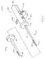
図1及び図2は、ターゲティングセットについて先に述べたのと同じように、プローブに伴って使用する例示的な代替のターゲティングセット(1000)を示す。ターゲティングセットと同様に、本例のターゲティングセット(1000)は、カニューレ(1010)及びオブチュレータ(1030)を備える。ただし、上述のターゲティングセットとは異なり、本例のターゲティングセット(1000)は、オブチュレータ作動アセンブリ(1100)を備える。以下にさらに詳細に説明するように、ターゲティングセット(1000)は、概して、オブチュレータ(1030)がカニューレ(1010)に対して独立して作動可能でありながら、カニューレ(1010)が深さ止め部材(図示せず)を介して長手方向に固定されたままであるように構成される。本明細書では、ターゲティングセット(1000)を、カニューレ(1010)と共に使用できるものとして説明しているが、本例のカニューレ(1010)は、一部の例では完全に省略できることが理解されるべきである。そのような例では、オブチュレータ(1010)と、オブチュレータ(1010)と関連するコンポーネントとは、本明細書中で特に断らない限り、実質的に同じ方法で概ね動作する。さらに他の例では、カニューレ(1010)を上記のカニューレ(94)と代替的に置き換えることができる。 Figures 1 and 2 show an exemplary alternative targeting set (1000) for use with the probe, as described above for targeting sets. Similar to the targeting set, the targeting set (1000) of the present example comprises a cannula (1010) and an obturator (1030). However, unlike the targeting set described above, the targeting set (1000) of the present example comprises an obturator actuation assembly (1100). As described in more detail below, the targeting set (1000) generally comprises a depth stop (not shown) for the cannula (1010) while the obturator (1030) is independently operable relative to the cannula (1010). (Not shown) is configured to remain longitudinally fixed. Although the targeting set (1000) is described herein as being usable with the cannula (1010), it should be understood that the cannula (1010) of the present example can be completely omitted in some instances It is. In such instances, the obturator (1010) and the components associated with the obturator (1010) generally operate in substantially the same manner, unless otherwise specified herein. In yet another example, the cannula (1010) can be substituted for the cannula (94) described above.
本例のカニューレ(1010)には、内腔(図示せず)が画定されており、開放末端部(1012)及び側方開口(1016)が含まれる。側方開口(1016)は、カニューレ(1010)によって画定された内腔と連通している。以下にさらに詳細に説明するように、側方開口(1016)が組織を受け入れて、その結果、組織が、カニューレ(1010)を通り抜け、生検装置(14)のオブチュレータ(1030)または針(90)のいずれかに入るように構成される。カニューレ(1010)の近位端は、ハブ(1014)に固定して動かないようにされる。図示していないが、一部の例では、ハブ(1014)は、接続機能(図示せず)及び/または接続ポート(図示せず)を備えることが理解されるべきである。そのような例では、接続機能は、オブチュレータ作動アセンブリ(1100)の部分へのハブ(1014)の結合を容易にすることができ、その一方でポートは、カニューレ(1010)によって画定された内腔との流体の連通を可能にし得る。ポートを備えた例では、そのようなポートは、流体源に随意に結合して、治療剤、生理食塩水、または他の流体を、内腔を通して生検部位に送り出すことができる。図示していないが、ハブ(1014)は、シール、サムホイール、流体チャネル、及び/または上述の円筒形のハブと同様の追加の内腔などの他の機能及び/または構成要素を含むことが理解されるべきである。 The cannula (1010) of the present example defines a lumen (not shown) and includes an open end (1012) and a side opening (1016). The side opening (1016) is in communication with the lumen defined by the cannula (1010). As described in further detail below, the side openings (1016) receive tissue so that the tissue passes through the cannula (1010) and the obturator (1030) or needle (90) of the biopsy device (14). Configured to enter one of the The proximal end of the cannula (1010) is fixedly secured to the hub (1014). Although not shown, it should be understood that in some instances the hub (1014) comprises a connection feature (not shown) and / or a connection port (not shown). In such instances, the connection feature may facilitate coupling of the hub (1014) to a portion of the obturator actuation assembly (1100) while the port is defined by the lumen defined by the cannula (1010). To allow fluid communication with the In examples with ports, such ports can optionally be coupled to a fluid source to deliver a therapeutic agent, saline, or other fluid through the lumen to the biopsy site. Although not shown, the hub (1014) may include other features and / or components such as seals, thumb wheels, fluid channels, and / or additional lumens similar to the cylindrical hub described above. It should be understood.
本例のオブチュレータ(1030)は、鋭利な遠位端(1034)と楕円形の横断面とを有した剛性の細長いシャフト(1032)とを備える。本例のシャフト(1032)は、セラミックまたはプラスチックなどの単一のMRI適合材料を含むが、そのような限定は意図されていない。例えば、他の例ではシャフト(1032)は、金属などの非MRI適合材料を含む。ただし、このような例では、MRIイメージング処置の間に、オブチュレータ(1030)をカニューレ(1010)から取り外すことができる。 The obturator (1030) of the present example comprises a rigid elongated shaft (1032) with a sharp distal end (1034) and an elliptical cross section. The shaft (1032) of the present example comprises a single MRI compatible material such as ceramic or plastic, but such limitation is not intended. For example, in another example, the shaft (1032) comprises a non-MRI compatible material such as metal. However, in such instances, the obturator (1030) can be removed from the cannula (1010) during the MRI imaging procedure.
シャフト(1032)は、鋭利な遠位端(1034)の近くに配置された側方開口(1036)をさらに備える。側方開口(1036)は、オブチュレータ(1030)がカニューレ(1010)内に完全に挿入されたときに、カニューレ(1010)の側方開口(1016)と整合するように、シャフト(1032)上に位置決めされている。側方開口(1036)は、シャフト(1032)の中へ横方向に広がって、その結果シャフト(1032)内にチャンバ、ノッチ、またはくぼみを形成する。以下にさらに詳細に説明するように、本構成は、オブチュレータ(1030)の側方開口(1036)がその中に組織を受け入れることを可能にして、それによってオブチュレータ(1030)及びカニューレ(1010)が患者内に配置されるとき、側方開口(1016、1036)の位置のMRI視覚化を提供する。図示していないが、一部の例では、シャフト(1032)は、側方開口(1036)からシャフト(1032)の近位端まで延びる1つ以上の内腔を備え得ることが理解されるべきである。シャフト(1032)がこのような内腔を備えている場合、内腔によって、操作者が流体を側方開口(1036)にまたは側方開口(1036)から、伝達させることができる。当然ながら、このような内腔は単なるオプションに過ぎず、一部の例では、シャフト(1032)は、側方開口(1036)によって形成されるチャンバ、くぼみ、またはノッチを除外した単なる固体である。さらに、一部の例では、側方開口(1036)を完全に省略することができ、したがってシャフト(1036)を完全に中実にすることができることを理解されるべきである。このような例では、オブチュレータ(1030)が組織を貫通するためにのみ使用され、オブチュレータ(1030)がカニューレ(1010)から取り外されると、別途の撮像素子がオブチュレータ(1030)の代わりに使用され得る。その後、この別途の撮像素子を使用して、カニューレ(1010)の側方開口(1016)の視覚化を促進することができる。 The shaft (1032) further comprises a side opening (1036) arranged near the sharp distal end (1034). The side opening (1036) is on the shaft (1032) to align with the side opening (1016) of the cannula (1010) when the obturator (1030) is fully inserted into the cannula (1010). It is positioned. The side openings (1036) extend laterally into the shaft (1032), thus forming a chamber, notch or recess in the shaft (1032). As described in further detail below, the present configuration allows the side opening (1036) of the obturator (1030) to receive tissue therein, whereby the obturator (1030) and the cannula (1010) Provides MRI visualization of the position of the side openings (1016, 1036) when placed in the patient. Although not shown, it should be understood that in some instances the shaft (1032) may comprise one or more lumens extending from the side opening (1036) to the proximal end of the shaft (1032) It is. If the shaft (1032) comprises such a lumen, the lumen allows the operator to transmit fluid to or from the side opening (1036). Of course, such lumens are merely optional, and in some instances the shaft (1032) is simply solid, excluding the chamber, recess or notch formed by the side opening (1036) . Furthermore, it should be understood that in some instances the side openings (1036) can be completely omitted, and thus the shaft (1036) can be completely solid. In such an example, the obturator (1030) is used only to penetrate tissue, and when the obturator (1030) is removed from the cannula (1010), a separate imaging device may be used instead of the obturator (1030) . This additional imaging element can then be used to facilitate visualization of the side opening (1016) of the cannula (1010).
図1は、オブチュレータ(1030)及びオブチュレータ作動アセンブリ(1100)を示す。図に示すように、オブチュレータ作動アセンブリ(1100)は、概して、外側ハウジング(1110)、弾性部材(1102)、ラッチ機構(1120)、及びリリース機構(1140)を備える。以下にさらに詳細に説明するように、ラッチ機構(1120)は、全体として、弾性部材(1102)に荷重をかけて位置エネルギーを負わせるように、外側ハウジング(1110)に対して選択的に移動でき、リリース機構(1140)を使用してオブチュレータ(1030)を遠位の1〜3cmに発射できるようにする。このような発射動作は、オブチュレータ(1030)の鋭利な先端(1034)が、組織を多くは変位させることなく、その組織を迅速に切り開いて貫通することを可能にする。当然のことながら、オブチュレータ(1030)の発射距離は、たいてい固定され、操作者によって変更することができないように予め定められる。しかしながら、一部の例では、操作者によるオブチュレータ(1030)の発射距離の選択的調整を可能にするように、いくつかの機能が付加されてもよい。 FIG. 1 shows an obturator (1030) and an obturator actuation assembly (1100). As shown, the obturator actuation assembly (1100) generally comprises an outer housing (1110), a resilient member (1102), a latching mechanism (1120), and a release mechanism (1140). As described in further detail below, the latch mechanism (1120) is selectively moved relative to the outer housing (1110) to generally load and exert potential energy on the resilient member (1102). The release mechanism (1140) can be used to fire the obturator (1030) to the distal 1-3 cm. Such firing action allows the sharpened tip (1034) of the obturator (1030) to rapidly cut open and penetrate the tissue without much displacement of the tissue. It will be appreciated that the launch distance of the obturator (1030) is usually fixed and predetermined so that it can not be changed by the operator. However, in some instances, several features may be added to allow the operator to selectively adjust the launch distance of the obturator (1030).
図2では、オブチュレータ(1030)の全長を見ることができる。図に示すように、オブチュレータ(1030)は、シャフト(1032)の近位端のところに配置された、1対の横方向に延びたアーム(1038)を備える。アーム(1038)は、概して対称であり、オブチュレータ(1030)のシャフト(1032)から外側に延びる。各アーム(1038)は、各アームが外向きに延びるにつれて、遠位に弓なりに曲げられる。当然のことながら、アーム(1038)は、操作者によって操作されて、オブチュレータ作動アセンブリ(1100)の外側ハウジング(1110)に対して、オブチュレータ(1030)を近位に引くように概して構成される。したがって、アーム(1038)の湾曲形状は、アーム(1038)を把持する際に操作者を支援し得ることが理解されるべきである。他の例では、アーム(1038)は、操作者の握り方を増加または減少させることができる多数の代替形状を含むことができる。したがって、アーム(1038)の湾曲形状は単なるオプションに過ぎず、一部の例では省略できることが理解されるべきである。 In FIG. 2 the full length of the obturator (1030) can be seen. As shown, the obturator (1030) comprises a pair of laterally extending arms (1038) disposed at the proximal end of the shaft (1032). The arms (1038) are generally symmetrical and extend outwardly from the shaft (1032) of the obturator (1030). Each arm (1038) is bowed distally as each arm extends outwardly. It will be appreciated that the arm (1038) is manipulated by the operator and is generally configured to pull the obturator (1030) proximally relative to the outer housing (1110) of the obturator actuation assembly (1100). Thus, it should be understood that the curved shape of the arm (1038) may assist the operator in gripping the arm (1038). In other examples, the arm (1038) can include a number of alternative shapes that can increase or decrease the operator's grip. Thus, it should be understood that the curved shape of the arm (1038) is merely an option and can be omitted in some instances.
オブチュレータ作動アセンブリ(1100)の外側ハウジング(1110)は、全般に中空の内部(1112)、1対のチャネル(1116)、1対のロックキャッチ(1118)、及び内壁(1119)を画定するおおむね円筒形のシェルを備える。中空内部(1112)は、遠位開口部(1113)及び近位開口部(1114)を介して、外側ハウジング(1110)の外部と連通している。遠位開口部(1113)は、シャフト(1032)が外側ハウジング(1110)を通って中空内部(1112)に入ることができるように、オブチュレータ(1030)のシャフト(1032)を受け入れる大きさとされる。近位開口部(1114)は、外側ハウジング(1110)の近位端に配置され、オブチュレータ(1100)の近位端と整合するように構成される。本例では、近位開口部(1114)を利用して、外側ハウジング(1110)に対するオブチュレータ(1030)のポジショニングを視覚的に確認することができる。例えば、以下にさらに詳細に説明するように、オブチュレータ(1030)の近位端は、近位開口部(1114)に向かって全体として移動可能である。オブチュレータ(1030)の近位端が近位開口部(1114)に近づくにつれて、近位端の少なくとも一部が操作者に見えるようになり得る。さらに、オブチュレータ(1100)が1つ以上の内腔を備える例において、近位開口部(1114)は、チューブ、導管、または他の流体取扱い装置を、外側ハウジング(1110)を介してオブチュレータ(1030)と連通させるために使用し得る場合がある。 The outer housing (1110) of the obturator actuation assembly (1100) is generally cylindrical, defining a generally hollow interior (1112), a pair of channels (1116), a pair of lock catches (1118), and an inner wall (1119). With a shell of the form. The hollow interior (1112) communicates with the exterior of the outer housing (1110) via the distal opening (1113) and the proximal opening (1114). The distal opening (1113) is sized to receive the shaft (1032) of the obturator (1030) such that the shaft (1032) can enter the hollow interior (1112) through the outer housing (1110) . The proximal opening (1114) is disposed at the proximal end of the outer housing (1110) and is configured to align with the proximal end of the obturator (1100). In this example, the proximal opening (1114) can be utilized to visually confirm the positioning of the obturator (1030) relative to the outer housing (1110). For example, as described in more detail below, the proximal end of the obturator (1030) is generally moveable towards the proximal opening (1114). As the proximal end of the obturator (1030) approaches the proximal opening (1114), at least a portion of the proximal end may become visible to the operator. Further, in the example where the obturator (1100) comprises one or more lumens, the proximal opening (1114) can be a tube, conduit or other fluid handling device via the outer housing (1110) to the obturator (1030). May be used to communicate with the
外側ハウジング(1110)の各チャネル(1116)は、外側ハウジング(1110)の向かい合っている側面において外側ハウジング(1110)に画定されたおおむね長方形の開口部を有する。図に示すように、各チャネル(1116)は、オブチュレータ(1030)の対応するアーム(1038)が、外側ハウジング(1110)の外側に延びるのを可能にするように構成される。この特徴は、外側ハウジング(1110)の外側から、操作者がアーム(1038)にアクセスできるようにする。各チャネル(1116)は、さらに、長手方向に伸長するように構成される。以下にさらに詳細に説明するように、この特徴は、オブチュレータ(1030)の各アーム(1038)を、外側ハウジング(1110)に対して近位及び遠位に動かすことを可能にして、その結果、オブチュレータ(1030)を、撃発準備位置と初期位置との間、または撃発準備位置と発射位置との間で動かすことができる。 Each channel (1116) of the outer housing (1110) has a generally rectangular opening defined in the outer housing (1110) on opposite sides of the outer housing (1110). As shown, each channel (1116) is configured to allow the corresponding arm (1038) of the obturator (1030) to extend outside the outer housing (1110). This feature allows the operator to access the arm (1038) from the outside of the outer housing (1110). Each channel (1116) is further configured to extend longitudinally. As described in further detail below, this feature allows each arm (1038) of the obturator (1030) to be moved proximally and distally with respect to the outer housing (1110) so that The obturator (1030) can be moved between the firing preparation position and the initial position, or between the firing preparation position and the firing position.
2つのロックキャッチ(1118)は、外側ハウジング(1110)の外側から、外側ハウジング(1110)の中空内部(1112)の中へ、内側に突出する。ロックキャッチ(1118)は長方形形状の突起を備える。以下にさらに詳細に説明するように、各ロックキャッチ(1118)は、ラッチ機構(1120)の対応する部分と係合して、ラッチ機構(1120)がオブチュレータ(1030)を撃発準備位置に選択的にロックできるように構成される。次いで、リリース機構(1140)を使用して、ロックキャッチ(1118)との係合からラッチ機構(1120)を解放することができる。ロックキャッチ(1118)は、主として長方形形状を有するものとして示されているが、他の例では、三角形、卵形、不規則形、複数の異なる形状の組合せ、または本明細書の教示に鑑みて当業者には明らかな他の任意の形状などの、多数の代替形状を使用できることが理解されるべきである。 Two lock catches (1118) project inwardly from the outside of the outer housing (1110) into the hollow interior (1 1 12) of the outer housing (1 1 10). The lock catch (1118) comprises a protrusion of rectangular shape. Each lock catch (1118) is engaged with the corresponding portion of the latch mechanism (1120) to selectively select the obturator (1030) to a strike ready position, as described in further detail below. It is configured to lock on. The release mechanism (1140) can then be used to release the latch mechanism (1120) from engagement with the lock catch (1118). The lock catch (1118) is mainly shown as having a rectangular shape, but in other examples it is triangular, ovoid, irregular, a combination of several different shapes, or in view of the teachings herein. It should be understood that a number of alternative shapes can be used, such as any other shape apparent to one skilled in the art.
内壁(1119)は、外側ハウジング(1110)の中空内部(1112)の中に配置され、中空内部(1112)を横切って横方向に延在する。内壁(1119)は、各チャネル(1116)の遠位に配置される。本内壁(1119)のポジショニングにより、内壁(1119)を、弾性部材(1102)の機械的な基盤として作用させる。さらに、内壁(1119)は、オブチュレータ(1030)が内壁(1119)を通過できるような、内壁(1119)を貫通する開口部(図示せず)を備える。以下にさらに詳細に説明するように、本構成は、内壁(1119)に対するオブチュレータ(1030)の移動を可能にし、一方、弾性部材(1102)の内壁(1119)を越えた近位への移動を防止する。当然のことながら、このことは、オブチュレータ(1030)が内壁(1119)に対して近位に動かされる間、弾性部材(1102)に位置エネルギーを蓄積させる。 The inner wall (1119) is disposed within the hollow interior (1112) of the outer housing (1110) and extends laterally across the hollow interior (1112). An inner wall (1119) is disposed distal to each channel (1116). Positioning the present inner wall (1119) causes the inner wall (1119) to act as a mechanical base for the elastic member (1102). Furthermore, the inner wall (1119) comprises an opening (not shown) through the inner wall (1119) such that the obturator (1030) can pass through the inner wall (1119). As described in further detail below, the present configuration allows movement of the obturator (1030) relative to the inner wall (1119) while proximal movement of the resilient member (1102) beyond the inner wall (1119) To prevent. Of course, this causes potential energy to build up in the resilient member (1102) while the obturator (1030) is moved proximally relative to the inner wall (1119).
内壁(1119)の開口部は、外側ハウジング(1110)内のオブチュレータ(1030)の軸方向の整合を維持する機能をさらに果たす。例えば、オブチュレータ(1030)が内壁(1119)の開口部を通って長手方向に移動するとき、オブチュレータ(1030)の横方向の変位はおおむね阻止される。同様に、図示していないが、一部の例では、外側ハウジング(1110)は、外側ハウジング(1110)内のオブチュレータ(1030)の軸方向の整合を維持することをさらに補助するための、追加の壁またはボスなどの他の構造を備え得ることが理解されるべきである。当然ながら、そのような構造は完全に任意のものであり、一部の例では省略することができる。 The openings in the inner wall (1119) further serve to maintain the axial alignment of the obturator (1030) in the outer housing (1110). For example, when the obturator (1030) moves longitudinally through the opening in the inner wall (1119), lateral displacement of the obturator (1030) is generally prevented. Similarly, although not shown, in some instances, the outer housing (1110) may be added to further assist in maintaining axial alignment of the obturator (1030) within the outer housing (1110). It should be understood that other structures such as walls or bosses may be provided. Of course, such a structure is completely arbitrary and can be omitted in some cases.
ラッチ機構(1120)は、完全に外側ハウジング(1110)内に配置される。上記の通り、ラッチ機構(1120)は、外側ハウジング(1110)のロックキャッチ(1118)と係合して、オブチュレータ(1030)を選択的に撃発準備位置に係止させるとともに、リリース機構(1140)の作動によって解放されるように構成される。ラッチ機構(1120)は、ベース(1122)と、近位に延びる2つのラッチアーム(1124)とを備える。本例のベース(1120)は、オブチュレータ(1030)に固定して動かないようにされる。一部の例では、オブチュレータ(1030)は、ベース(1120)をオブチュレータ(1030)に固定するのを補助するために、環状フランジ、くぼみ、及び/または他の幾何学的形体を含むことができる。さらに他の例では、ベース(1120)がオブチュレータ(1030)と一体であってもよく、ベース(1120)とオブチュレータ(1030)とが共に単一の部品を形成するようにする。いずれにせよ、ベース(1120)は、オブチュレータ(1030)から外側に延びて、ラッチアーム(1124)を支持する。 The latching mechanism (1120) is completely disposed within the outer housing (1110). As described above, the latch mechanism (1120) engages with the lock catch (1118) of the outer housing (1110) to selectively lock the obturator (1030) in the strike ready position and the release mechanism (1140) Configured to be released by actuation of The latch mechanism (1120) comprises a base (1122) and two latch arms (1124) extending proximally. The base (1120) of the present example is fixedly secured to the obturator (1030). In some instances, the obturator (1030) can include an annular flange, a recess, and / or other geometric features to assist in securing the base (1120) to the obturator (1030) . In yet another example, the base (1120) may be integral with the obturator (1030), such that the base (1120) and the obturator (1030) together form a single part. In any case, the base (1120) extends outwardly from the obturator (1030) to support the latch arm (1124).
各ラッチアーム(1124)は、ベース(1122)から近位に延びる。本例のラッチアーム(1124)は、ベース(1122)とラッチアーム(1124)とが単一の一体部分を形成するような、ベース(1122)と一体であるものとして示される。しかし、他の例では、ベース(1122)及びラッチアーム(1124)は、別々の部品であり得ることが理解されるべきである。ベース(1122)及びラッチアーム(1124)の特定の構成にかかわらず、本例のラッチアーム(1124)は、各ラッチアーム(1124)が概して剛性であるが変形可能であるような、概して弾性の材料を含むことが理解されるべきである。この材料特性により、各ラッチアーム(1124)は、外側ハウジング(1110)のそれぞれのロックキャッチ(1118)と選択的に係合したり、離脱したりすることができる。 Each latch arm (1124) extends proximally from the base (1122). The latch arm (1124) of the present example is shown as being integral with the base (1122) such that the base (1122) and the latch arm (1124) form a single integral part. However, it should be understood that in other examples, the base (1122) and the latch arm (1124) can be separate parts. Regardless of the specific configuration of the base (1122) and the latch arms (1124), the latch arms (1124) of the present example are generally resilient such that each latch arm (1124) is generally rigid but deformable. It should be understood to include materials. This material property allows each latch arm (1124) to selectively engage and disengage the respective lock catch (1118) of the outer housing (1110).
各ラッチアーム(1124)は、ラッチ部分(1126)及びリリース部分(1128)を画定する。各ラッチ部分(1126)は、そのそれぞれのラッチアーム(1124)から外側に延びて、概ね三角形の形状を画定する。この三角形は直角三角形を形成し、斜辺が近位に向けられ、直角を挟む辺の一方が遠位に向けられる。この各ラッチ部分(1126)の配向は、斜辺に斜面として機能させるとともに、遠位に向いた辺に留め具として機能させる。このようにして、斜辺は、オブチュレータ(1030)が近位に引っ込められるときに、各ラッチアーム(1124)をそれぞれのロックキャッチ(1118)から逸らすように機能し、その後、遠位に向いた辺がそれぞれのロックキャッチ(1118)の近位と係合するように強制される。 Each latch arm (1124) defines a latch portion (1126) and a release portion (1128). Each latch portion (1126) extends outwardly from its respective latch arm (1124) to define a generally triangular shape. The triangle forms a right triangle with the hypotenuse directed proximally and one of the sides flanking the right is distally directed. The orientation of each latch portion (1126) causes the hypotenuse to act as a bevel and as the distally facing side to act as a fastener. In this way, the hypotenuses function to deflect each latch arm (1124) away from the respective lock catch (1118) when the obturator (1030) is retracted proximally, and then the distally directed side Is forced into engagement with the proximal of each lock catch (1118).
各リリース部分(1128)は、所与のラッチ部分(1126)の近位に延びる。各リリース部分(1128)のポジショニングは、各リリース部分(1128)が、それぞれのロックキャッチ(1118)から横方向に離間されるようになされる。以下にさらに詳細に説明するように、これにより、各リリース部分(1128)は、オブチュレータ(1030)が近位に引っ込められるときに、それぞれのロックキャッチ(1118)を越えて妨害されずに通過して、リリース機構(1140)と係合することが可能になる。同様に、以下にさらに詳細に説明するように、各リリース部分(1128)は、リリース機構(1140)によって作用されて、各ラッチアーム(1124)を内側に偏向させ、それによってラッチ部分(1126)をロックキャッチ(1118)から解放するように構成される。 Each release portion (1128) extends proximal to a given latch portion (1126). The positioning of each release portion (1128) is such that each release portion (1128) is laterally spaced from the respective lock catch (1118). This causes each release portion (1128) to pass unhindered past the respective lock catch (1118) as the obturator (1030) is retracted proximally, as described in further detail below. Can be engaged with the release mechanism (1140). Similarly, as described in further detail below, each release portion (1128) is acted upon by the release mechanism (1140) to deflect each latch arm (1124) inwardly, thereby causing the latch portion (1126) to Configured to release from the lock catch (1118).
リリース機構は、外側ハウジング(1110)の各ロックキャッチ(1118)の近位に配置される。リリース機構は、外側ハウジング(1110)の両側で、外側ハウジング(1110)を貫通して延びる、2つのボタン(1142)を備える。各ボタン(1142)は、外側ハウジング(1110)の中空内部(1112)の中に延びる内向きの突起部(1144)を備える。本例では、ボタン(1142)と、対応する各突起部とは、外側ハウジング(1110)に対して一体的に移動可能である。一部の例では、この可動性は、若干の移動を可能にするために各ボタン(1142)を外側ハウジング(1110)に接続しながら、最終的には各ボタン(1142)を外側ハウジング(1110)に取り付けたままにするゴム製のガスケットまたは弾性部材によって促進させることができる。他の例では、この可動性は、各ボタン(1142)が、ボタン(1142)及び突起部(1144)が外側に移動できるように柔軟に構成されていることによって促進される。いずれにせよ、各ボタン(1142)と、各対応する突起(1144)とは、各ボタン(1142)がそれぞれのラッチアーム(1142)に選択的に係合できるように移動可能であることが理解されるべきである。以下にさらに詳細に説明するように、各ラッチアーム(1124)がロックキャッチ(1118)と係合したとき、操作者は、各ボタン(1142)を作動させて、各突起部(1144)を各ラッチアーム(1124)のリリース部分(1128)と係合させ、それによって各ラッチアーム(1124)を対応するロックキャッチ(1118)から解放することができる。 A release mechanism is disposed proximal to each lock catch (1118) of the outer housing (1110). The release mechanism comprises two buttons (1142) extending through the outer housing (1110) on either side of the outer housing (1 1 10). Each button (1142) comprises an inward projection (1144) extending into the hollow interior (1112) of the outer housing (1110). In this example, the button (1142) and corresponding projections are integrally moveable with respect to the outer housing (1110). In some instances, this mobility connects each button (1142) to the outer housing (1110) to allow for some movement, and ultimately each button (1142) to the outer housing (1110) Can be facilitated by a rubber gasket or resilient member that remains attached to the In another example, this mobility is facilitated by the fact that each button (1142) is flexibly configured to allow the button (1142) and the projection (1144) to move outward. In any event, it is understood that each button (1142) and each corresponding protrusion (1144) are movable such that each button (1142) can selectively engage the respective latch arm (1142). It should be. As described in further detail below, when each latch arm (1124) is engaged with the lock catch (1118), the operator actuates each button (1142) to each projection (1144). The release portions (1128) of the latch arms (1124) can be engaged, thereby releasing each latch arm (1124) from the corresponding lock catch (1118).
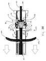
ターゲティングセット(1000)の例示的な使用法を、図3A〜図4Bに示す。図3Aに示すように、オブチュレータ(1030)は当初は初期位置で開始する。初期位置では、オブチュレータ(1030)は、その最も遠位の遠位位置に進められる。この位置では、オブチュレータ(1030)の鋭利な先端(1034)は、カニューレ(1010)の開放末端部(1012)から約3cmの距離だけ突出する。開放末端部(1012)から鋭利な先端(1034)が突き出た状態で、操作者はオブチュレータを使用して、オブチュレータ(1030)のアーム(1038)をつかみ、オブチュレータ(1030)及びカニューレ(1010)を、ガイドキューブ(104)を介して患者の組織に押し込むことによって、組織に最初に貫通させることができる。しかしながら、標的部位での組織の「スノープラウ」または「テンティング」を避けるために、操作者は、標的部位に到達する前の約2センチメートル以上のところで、オブチュレータ(1030)の前進を止めることができる。 An exemplary use of the targeting set (1000) is shown in FIGS. 3A-4B. As shown in FIG. 3A, the obturator (1030) initially starts at an initial position. In the initial position, the obturator (1030) is advanced to its most distal position. In this position, the sharpened tip (1034) of the obturator (1030) projects a distance of about 3 cm from the open end (1012) of the cannula (1010). With the sharp tip (1034) protruding from the open end (1012), the operator uses the obturator to grasp the arm (1038) of the obturator (1030), and the obturator (1030) and the cannula (1010) The tissue can first be penetrated by pushing it into the patient's tissue via the guide cube (104). However, to avoid "snow plow" or "tenting" of tissue at the target site, the operator must stop the advancement of the obturator (1030) at least about 2 centimeters before reaching the target site. Can.
オブチュレータ(1030)及びカニューレ(1010)を患者内の標的部位の近くに位置付けると、操作者は、迅速にオブチュレータ(1030)を発射して、患者の組織を通して鋭利な先端(1034)を駆動し、それにより組織の「スノープラウ」または「テンティング」を回避することを要求できる。発射シーケンスを始めるために、操作者は、図3B及び図4Aに示すように、オブチュレータ(1030)を撃発準備位置に動かすことによって開始する。オブチュレータ(1030)を撃発準備位置に動かすために、操作者は、オブチュレータ(1030)のアーム(1038)をつかんで、アーム(1038)を介してオブチュレータ(1030)を近位に引っ張る。オブチュレータ(1030)が、外側ハウジング(1110)に対してその最も遠位の近位位置に達するまで、オブチュレータ(1030)を近位に移動させる。また、カニューレ(1010)が省略された例では、患者に挿入する前に、オブチュレータ(1030)を撃発準備位置に代わりに移動させてよいことが理解されるべきである。つまり、カニューレ(1010)が省略された例では、操作者は、最初にアーム(1038)を近位に引っ張ってオブチュレータ(1030)の撃発準備をし、次いでオブチュレータ(1030)を患者の体内に挿入を進めて、オブチュレータ(1030)を標的部位に隣接させて位置決めすることができる。 With the obturator (1030) and cannula (1010) positioned near the target site in the patient, the operator can quickly fire the obturator (1030) to drive the sharpened tip (1034) through the patient's tissue, This may require that the organization "snow plow" or "tenting" be avoided. To begin the firing sequence, the operator starts by moving the obturator (1030) to the fire preparation position, as shown in FIGS. 3B and 4A. To move the obturator (1030) to the fire preparation position, the operator grasps the arm (1038) of the obturator (1030) and pulls the obturator (1030) proximally via the arm (1038). The obturator (1030) is moved proximally until the obturator (1030) reaches its most distal proximal position with respect to the outer housing (1110). Also, it should be appreciated that in the example where the cannula (1010) is omitted, the obturator (1030) may instead be moved to the firing ready position prior to insertion into the patient. That is, in the example where the cannula (1010) is omitted, the operator first pulls the arm (1038) proximally to prepare for firing the obturator (1030), and then inserts the obturator (1030) into the patient's body. To position the obturator (1030) adjacent to the target site.
オブチュレータ(1030)が近位に引っ張られると、ラッチ機構(1120)は、対応する距離だけ近位に同時に引っ込められる。具体的には、ラッチ機構(1120)のベース(1122)は、オブチュレータ(1030)に固定して動かないようにされているため、ベース(1122)及びラッチアーム(1124)は、オブチュレータ(1030)と共に近位に移動する。各ラッチアーム(1124)のラッチ部分(1126)が外側ハウジング(1110)のそれぞれのロックキャッチ(1118)に接触すると、三角形ラッチ部分(1126)の斜辺が作用して所与のラッチアーム(1124)を変形させる。その後、各ラッチ部分(1126)が各ロックキャッチ(1118)を越えて引っ張られるまで、各ラッチ部分(1126)は、各ロックキャッチ(1118)の内部に沿って移動する。これにより、各ラッチアーム(1124)は、その初期の非変形状態に弾性的に復帰し、それによって各ラッチ部分(1126)の辺を介して、各ロックキャッチの近位端と係合させることができる。その時、オブチュレータ(1030)は、ラッチアーム(1124)とロックキャッチ(1118)との間のこの係合によって、撃発準備位置に固定される。 When the obturator (1030) is pulled proximally, the latch mechanism (1120) is simultaneously retracted proximally by a corresponding distance. Specifically, the base (1122) of the latch mechanism (1120) is fixed to the obturator (1030) so as not to move, so the base (1122) and the latch arm (1124) are the obturator (1030). Move proximally with When the latch portion (1126) of each latch arm (1124) contacts the respective lock catch (1118) of the outer housing (1110), the oblique side of the triangular latch portion (1126) acts to provide a given latch arm (1124) Transform the. Thereafter, each latch portion (1126) moves along the interior of each lock catch (1118) until each latch portion (1126) is pulled past each lock catch (1118). This causes each latch arm (1124) to resiliently return to its initial undeformed state, thereby engaging the proximal end of each lock catch via the side of each latch portion (1126) Can. The obturator (1030) is then fixed in the firing ready position by this engagement between the latch arm (1124) and the lock catch (1118).
また、オブチュレータ(1030)の近位移動の間に、弾性部材(1102)は、外側ハウジング(1110)の内壁(1119)とラッチ機構(1120)のベース(1122)との間で圧縮され、それによって弾性部材(1102)に位置エネルギーを蓄積する。本例では、弾性部材(1102)は、オブチュレータ(1030)と同軸に配置されたコイルバネを備える。当然ながら、他の例では、弾性部材(1102)の代わりに、板ばね、圧縮ゴム、及び/または等の、他の適切な任意の弾性的機能を使用することができる。オブチュレータ(1030)が撃発準備位置に配置されると、弾性部材(1102)は完全に圧縮されるとともに、その結果、弾性部材(1102)は、ラッチ機構(1120)のベース(1122)を介して、オブチュレータ(1030)を外側ハウジング(1110)に対して遠位に駆動するように配置される。 Also, during proximal movement of the obturator (1030), the resilient member (1102) is compressed between the inner wall (1119) of the outer housing (1110) and the base (1122) of the latching mechanism (1120) Stores potential energy in the elastic member (1102). In the present example, the elastic member (1102) comprises a coil spring arranged coaxially with the obturator (1030). Of course, in other examples, instead of the elastic member (1102), any other suitable elastic function such as a leaf spring, compressed rubber and / or etc can be used. When the obturator (1030) is placed in the firing preparation position, the elastic member (1102) is fully compressed, and as a result, the elastic member (1102) is inserted through the base (1122) of the latch mechanism (1120). , Arranged to drive the obturator (1030) distally with respect to the outer housing (1110).
図4Aに最も良く示すように、オブチュレータ(1030)が引っ込められると、鋭利な先端(1034)は、カニューレ(1010)の開放末端部(1012)に対して近位に移動する。したがって、オブチュレータ(1030)が撃発準備位置に移動したとき、鋭利な先端(1034)は、少なくとも部分的にカニューレ(1010)の中に引き込まれる。鋭利な先端(1034)がカニューレ(1010)内に引っ込められると、カニューレ(1010)は、操作者によってさらに標的位置まで前進させることができる。前進すると、オブチュレータ(1030)の鋭利な先端(1034)が引っ込められるため、組織のさらなる係合は起こらない。しかし、オブチュレータ(1030)が発射されると、オブチュレータ(1030)は標的部位に位置決めされることを理解すべきである。カニューレ(1010)が省略された例では、そのような再ポジショニングステップは必要ではなく、オブチュレータ(1030)を直ちに発射して、標的部位にオブチュレータ(1030)の側方開口(1036)を位置決めすることができることを理解すべきである。実際、特定の状況では、カニューレ(1010)を用いずにオブチュレータ(1030)を使用することは、オブチュレータ(1030)の発射前に標的部位またはその近傍の組織の障害を最小限にするために望ましい場合がある。 As best shown in FIG. 4A, as the obturator (1030) is retracted, the sharpened tip (1034) moves proximally relative to the open end (1012) of the cannula (1010). Thus, when the obturator (1030) is moved to the strike-ready position, the sharpened tip (1034) is at least partially retracted into the cannula (1010). Once the sharpened tip (1034) is retracted into the cannula (1010), the cannula (1010) can be advanced further by the operator to the target position. When advanced, the sharp tip (1034) of the obturator (1030) is retracted so that no further tissue engagement occurs. However, it should be understood that the obturator (1030) is positioned at the target site when the obturator (1030) is fired. In the example where the cannula (1010) is omitted, such a repositioning step is not necessary and immediately fire the obturator (1030) to position the side opening (1036) of the obturator (1030) at the target site. It should be understood that In fact, in certain circumstances, using the obturator (1030) without the cannula (1010) is desirable to minimize tissue damage at or near the target site prior to firing the obturator (1030) There is a case.
オブチュレータ(1030)が標的部位の近くに位置決めされ、上述のように撃発準備されると、操作者は次にオブチュレータ(1030)の発射を開始することができる。発射を開始するためには、操作者は、外側ハウジング(1110)の両側のリリース機構(1140)の両方のボタン(1142)を単に押すだけである。図3Cに最も良く示すように、これにより、各ボタン(1142)の突起部(1144)に、各ラッチアーム(1124)のリリース部分(1128)を内側に押させる。そしてまた、これにより、ラッチアーム(1124)が内側に撓み、外側ハウジング(1110)のロックキャッチ(1118)との係合から解放される。本構成に起因して、発射を開始するには、両方のボタン(1142)が同時に押されなければならないことを理解すべきである。本例において、本特徴は、オブチュレータ(1030)の不意の発射を避けるために望まれ得る。しかし、他の例よりも理解されるべきであるが、オブチュレータ作動アセンブリ(1100)は、単一のボタン(1142)のみで使用するように再構成されてもよく、または代わりに、複数のボタン(1142)で構成されてもよいが、発射に必要なのは単一のボタン(1142)の押下のみである。 Once the obturator (1030) is positioned near the target site and prepared for firing as described above, the operator can then begin firing the obturator (1030). To initiate firing, the operator simply presses both buttons (1142) of the release mechanism (1140) on either side of the outer housing (1110). As best seen in FIG. 3C, this causes the projection (1144) of each button (1142) to push the release portion (1128) of each latch arm (1124) inward. And also, this causes the latch arm (1124) to flex inward and out of engagement with the lock catch (1118) of the outer housing (1110). It should be understood that due to the present configuration, both buttons (1142) must be pressed simultaneously to start firing. In this example, this feature may be desired to avoid accidental firing of the obturator (1030). However, as should be understood more than the other examples, the obturator actuation assembly (1100) may be reconfigured for use with only a single button (1142), or alternatively, multiple buttons Although it may be configured with (1142), only the pressing of a single button (1142) is required for firing.
ラッチ機構(1120)のラッチアーム(1124)が外側ハウジング(1110)のロックキャッチ(1118)から解放されると、オブチュレータ(1030)は自由に遠位に移動する。オブチュレータ(1030)が解放されると、撃発準備期間に弾性部材(1102)に蓄積された位置エネルギーが解放され、弾性部材(1102)が膨張するとき、オブチュレータ(1030)を遠位に急速に駆動する。具体的には、弾性部材(1102)の膨張により、ラッチ機構(1120)のベース(1122)が外側ハウジング(1110)の内壁(1119)から急速に押し出される。ベース(1122)はオブチュレータ(1030)に固定して動かないようにされているため、ベース(1122)の遠位への動きは、オブチュレータ(1030)の遠位への動きをもたらす。このオブチュレータ(1030)の比較的速い遠位への動きは、オブチュレータ(1030)の鋭利な先端(1034)を組織の中に約2cm押し込み、その一方では、その組織の、鋭利な先端(1034)に対する変位を充分に減少させる。図3Bに示すように、オブチュレータ(1030)をカニューレ(1010)と共に使用する例では、これにより、カニューレ(1010)の開放末端部(1012)から外へ1〜3cm突出する鋭利な先端(1034)がもたらされる。当然ながら、カニューレ(1010)が省略される例では、オブチュレータ(1030)は、患者の組織の中を単に移動する。いずれにせよ、オブチュレータ(1030)が標的部位に位置決めされ、操作者は、生検処置の実施に関係した様々なステップを開始することができる。 When the latch arm (1124) of the latch mechanism (1120) is released from the lock catch (1118) of the outer housing (1110), the obturator (1030) is free to move distally. When the obturator (1030) is released, the potential energy stored in the elastic member (1102) is released during the preparation for firing, and when the elastic member (1102) expands, the obturator (1030) is rapidly driven distally. Do. Specifically, expansion of the resilient member (1102) causes the base (1122) of the latch mechanism (1120) to be rapidly pushed out of the inner wall (1119) of the outer housing (1110). Because the base (1122) is fixedly secured to the obturator (1030), distal movement of the base (1122) results in distal movement of the obturator (1030). The relatively fast distal movement of the obturator (1030) pushes the sharp tip (1034) of the obturator (1030) into the tissue about 2 cm, while the sharp tip (1034) of the tissue Sufficiently reduce the displacement for In the example where an obturator (1030) is used with a cannula (1010), as shown in FIG. 3B, this results in a sharpened tip (1034) projecting 1 to 3 cm out of the open end (1012) of the cannula (1010). Is brought about. Of course, in the example where the cannula (1010) is omitted, the obturator (1030) simply moves through the patient's tissue. In any event, the obturator (1030) is positioned at the target site and the operator can initiate various steps related to performing a biopsy procedure.
時には、使い易さを促進させるために、上述のオブチュレータ(1030)またはオブチュレータ作動アセンブリ(1100)のある形体を変更することが望ましい場合がある。例えば、一部の例では、オブチュレータ作動アセンブリ(1100)にいくつかの部品を追加して、操作者の、オブチュレータ(1030)を撃発準備位置に移動させる能力を強化するのが望ましい場合がある。他の例では、オブチュレータ(1030)自体を変更することが望ましい場合がある。例えば、一部の例では、アーム(1038)の特定の形状を変更して、操作者の、オブチュレータ(1030)をつかむ能力を強化することができる。オブチュレータ作動アセンブリ(1100)及び/またはオブチュレータ(1030)の様々な変形例を以下に説明する。本明細書に具体的な例が記載されるが、本明細書の教示に鑑みて当業者にとって明らかな、様々な変更が望ましい場合があることを理解すべきである。 At times it may be desirable to modify certain features of the above-described obturator (1030) or obturator actuation assembly (1100) to facilitate ease of use. For example, in some instances, it may be desirable to add some components to the obturator actuation assembly (1100) to enhance the operator's ability to move the obturator (1030) to a fire ready position. In other examples, it may be desirable to change the obturator (1030) itself. For example, in some instances, the particular shape of the arm (1038) can be modified to enhance the operator's ability to grasp the obturator (1030). Various variations of the obturator actuation assembly (1100) and / or the obturator (1030) are described below. While specific examples are described herein, it should be understood that various modifications may be desirable which are apparent to those skilled in the art in view of the teachings herein.
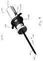
図5は、上述のターゲティングセット(1000)を示し、この例では、外側ハウジング(1110)に操作リング(1150)を装備している。操作リング(1150)を除いて、外側ハウジング(1110)の他のすべての構成要素は同じままであることを理解すべきである。操作リング(1150)は、オブチュレータ(1030)のアーム(1038)の遠位端に当接するように構成される。操作リング(1150)は、外側ハウジング(1110)の略円筒形状を同軸上に取り囲むようにさらに構成される。操作リング(1150)の形状は、概して、操作リング(1150)が近位に延びるにつれて、外径が連続的に拡大するリング形状である。この操作リング(1150)の連続的に拡大する外径は、外側ハウジング(1110)の外側の周囲の全側面から、操作者の握りを強化するように構成される。さらに、本例では、オブチュレータ(1030)が撃発準備位置に移行するまで、操作リング(1150)の長手方向の延長部分が、リリース機構(1140)のボタン(1142)を覆い隠すように構成してあることが理解されるべきである。この特徴は、オブチュレータ(1130)の撃発準備に先立ってボタン(1142)を不注意に押し下げることを防止するとともに、操作者に、オブチュレータ(1130)が撃発準備されているかどうかを判断させる物理的フィードバックを提供するために望ましい場合がある。 FIG. 5 shows the targeting set (1000) described above and in this example the outer housing (1110) is equipped with an operating ring (1150). It should be understood that, with the exception of the manipulation ring (1150), all other components of the outer housing (1110) remain the same. The manipulation ring (1150) is configured to abut the distal end of the arm (1038) of the obturator (1030). The manipulation ring (1150) is further configured to coaxially surround the generally cylindrical shape of the outer housing (1110). The shape of the manipulation ring (1150) is generally a ring shape in which the outer diameter continuously increases as the manipulation ring (1150) extends proximally. The continuously expanding outer diameter of the actuating ring (1150) is configured to enhance the operator's grip from all sides around the outside of the outer housing (1110). Furthermore, in this example, the longitudinal extension of the operation ring (1150) is configured to hide the button (1142) of the release mechanism (1140) until the obturator (1030) shifts to the strike preparation position. It should be understood that there is. This feature prevents the inadvertent pressing of the button (1142) prior to the preparation of the obturator (1130) to strike, and provides physical feedback to the operator to determine whether the obturator (1130) is prepared to strike. It may be desirable to provide
使用の際に、操作リング(1150)が装備されているとき、オブチュレータ作動アセンブリ(1100)は上記のように使用される。他方においては、操作者がオブチュレータ作動アセンブリ(1100)を撃発準備するとき、操作者は、アーム(1038)の代わりに操作リング(1150)を使用して、オブチュレータ(1030)を撃発準備位置へと駆動する。その時、操作者がアーム(1038)を直接つかむ代わりに、操作リング(1150)がオブチュレータ(1030)のアーム(1038)に作用する。本構成は、場合によっては、ターゲティングセット(1000)の操作性を高め得ることが理解されるべきである。例えば、操作リング(1150)は、オブチュレータ作動アセンブリ(1100)の外側ハウジング(1110)の全周に及ぶため、オブチュレータ作動アセンブリ(1100)のポジショニングにかかわらず、操作者が操作リング(1150)にアクセスすることができる。このように、場合によっては、オブチュレータ(1030)のアーム(1038)へのアクセスが、そうでない場合は妨害され得る操作リング(1150)を備えたオブチュレータ作動アセンブリ(1100)を使用することが望ましい場合がある。 In use, when the operating ring (1150) is equipped, the obturator actuation assembly (1100) is used as described above. On the other hand, when the operator prepares to strike the obturator actuation assembly (1100), the operator uses the operating ring (1150) instead of the arm (1038) to bring the obturator (1030) to the strike ready position. To drive. At that time, instead of the operator directly grasping the arm (1038), the operation ring (1150) acts on the arm (1038) of the obturator (1030). It should be understood that this configuration may, in some cases, enhance the operability of the targeting set (1000). For example, because the operating ring (1150) covers the entire circumference of the outer housing (1110) of the obturator operating assembly (1100), the operator accesses the operating ring (1150) regardless of the positioning of the obturator operating assembly (1100) can do. Thus, in some cases it may be desirable to use an obturator actuation assembly (1100) with an operating ring (1150) where access to the arm (1038) of the obturator (1030) may otherwise be impeded. There is.
図6は、上述のオブチュレータ(1030)のアーム(1038)に対して、代替構造を有したアーム(1238)を備えるオブチュレータ(1230)を示す。本明細書で別段の記載がない限り、オブチュレータ(1230)は、上述のオブチュレータ(1030)と実質的に同じであることが理解されるべきである。例えば、本例のオブチュレータ(1230)は、鋭利な遠位端(図示せず)と楕円形の横断面とを有した剛性の細長いシャフト(1232)を備える。しかし、オブチュレータ(1030)とは異なり、本例のオブチュレータ(1230)は、弓形のアーム(1038)ではなく、D字形のアーム(1238)を備えている。アーム(1238)のD字形状は、操作者の、アーム(1238)を把持する能力を強化するように概して構成される。把持技術は別として、アーム(1238)は、上述のアーム(1038)と完全に同じように使用されることを理解すべきである。 FIG. 6 shows an obturator (1230) comprising an arm (1238) with an alternative structure to the arm (1038) of the above-mentioned obturator (1030). It should be understood that the obturator (1230) is substantially the same as the above-described obturator (1030) unless otherwise stated herein. For example, the obturator (1230) of the present example comprises a rigid elongate shaft (1232) having a sharp distal end (not shown) and an elliptical cross section. However, unlike the obturator (1030), the obturator (1230) of the present example comprises a D-shaped arm (1238) rather than an arcuate arm (1038). The D-shape of arm (1238) is generally configured to enhance the operator's ability to grip arm (1238). It should be understood that apart from gripping techniques, arm (1238) is used in exactly the same manner as arm (1038) described above.
図7は、上述のオブチュレータ(1030)のアーム(1038)に対して、代替構造を有したアーム(1338)を備えるオブチュレータ(1330)を示す。本明細書で別段の記載がない限り、オブチュレータ(1330)は、上述のオブチュレータ(1030)と実質的に同じであることが理解されるべきである。例えば、本例のオブチュレータ(1330)は、鋭利な遠位端(図示せず)と楕円形の横断面とを有した剛性の細長いシャフト(1332)を備える。しかし、オブチュレータ(1030)とは異なり、本例のオブチュレータ(1330)は、弓形のアーム(1038)ではなく、指輪アーム(1338)を備えている。アーム(1338)に伴う指リングの追加は、操作者の、アーム(1338)を把持する能力を強化するように概して構成される。把持技術は別として、アーム(1338)は、上述のアーム(1038)と完全に同じように使用されることを理解すべきである。 FIG. 7 shows an obturator (1330) comprising an arm (1338) having an alternative structure to the arm (1038) of the above-mentioned obturator (1030). It should be understood that the obturator (1330) is substantially the same as the above-described obturator (1030) unless otherwise stated herein. For example, the obturator (1330) of the present example comprises a rigid elongated shaft (1332) with a sharp distal end (not shown) and an elliptical cross section. However, unlike the obturator (1030), the obturator (1330) of the present example comprises a ring arm (1338) rather than an arcuate arm (1038). The addition of the finger ring with the arm (1338) is generally configured to enhance the operator's ability to grip the arm (1338). It should be understood that apart from gripping techniques, arm (1338) is used in exactly the same manner as arm (1038) described above.
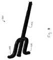
図8は、上述のオブチュレータ(1030)のアーム(1038)に対して、代替構造を有したアーム(1438)を備えるオブチュレータ(1430)を示す。本明細書で別段の記載がない限り、オブチュレータ(1430)は、上述のオブチュレータ(1030)と実質的に同じであることが理解されるべきである。例えば、本例のオブチュレータ(1430)は、鋭利な遠位端(図示せず)と楕円形の横断面とを有した剛性の細長いシャフト(1432)を備える。しかし、オブチュレータ(1030)とは異なり、本例のオブチュレータ(1430)は、弓形のアーム(1038)ではなく、近位に延びたアーム(1438)を備えている。具体的には、アーム(1438)は、オブチュレータ(1420)の近位端に至るまで、オブチュレータ(1420)に対して近位及び長手方向に延びるように構成される。オブチュレータ(1430)の近位端の近くで、アーム(1438)は方向を変えて、オブチュレータ(1430)から横方向及び外側に延びる。この上述のアーム(1438)の形体は、操作者の、アーム(1438)を把持する能力を強化するように概して構成される。把持技術は別として、アーム(1438)は、上述のアーム(1038)と完全に同じように使用されることを理解すべきである。 FIG. 8 shows an obturator (1430) comprising an arm (1438) with an alternative structure to the arm (1038) of the above-mentioned obturator (1030). It should be understood that the obturator (1430) is substantially the same as the above-described obturator (1030) unless otherwise stated herein. For example, the obturator (1430) of the present example comprises a rigid elongated shaft (1432) having a sharp distal end (not shown) and an elliptical cross section. However, unlike the obturator (1030), the obturator (1430) of the present example comprises a proximally extending arm (1438) rather than an arcuate arm (1038). Specifically, arm (1438) is configured to extend proximally and longitudinally relative to obturator (1420) to the proximal end of obturator (1420). Near the proximal end of the obturator (1430), the arm (1438) changes direction to extend laterally and outwardly from the obturator (1430). The configuration of this described arm (1438) is generally configured to enhance the operator's ability to grip the arm (1438). It should be understood that apart from gripping techniques, arm (1438) is used in exactly the same manner as arm (1038) described above.
以下の実施例は、本明細書の教示を組み合わせるか、または適用することができる、包括的ではない様々な方法に関する。以下の実施例は、本出願、または本出願の後の出願においていつでも提示することができる、いかなる請求の範囲も限定することを意図するものではないことが理解されるべきである。権利の放棄は意図していない。以下の実施例は単なる例示目的に過ぎない。本明細書の様々な教示は、他の数多くの方法に調えられ、適用され得ることが企図される。一部の変形は、以下の実施例で言及される特定の特徴を省略することができることも企図される。したがって、以下に言及する態様または特徴のいずれも、発明者、または発明者の利益の承継人が後日そのように明示的に示さない限り、重要であるとみなされるべきではない。本出願に記載される請求項、または本出願に関連する後の出願に、以下に述べるもの以外の追加の特徴が含まれる場合、これらの追加機能は、特許性に関わる何らかの理由により追加されたものと見なされるべきではない。 The following examples relate to various non-inclusive ways in which the teachings herein may be combined or otherwise applied. It should be understood that the following examples are not intended to limit any claims that may be presented at any time in this application or in later applications of this application. There is no intention of giving up the right. The following examples are for illustrative purposes only. It is contemplated that the various teachings herein may be arranged and applied in numerous other ways. It is also contemplated that some variations may omit certain features mentioned in the examples below. Thus, any of the aspects or features mentioned below should not be regarded as important unless the inventor, or the successor of the inventor's interests, so expressly indicates that date. When the claims described in the present application or the later applications related to the present application include additional features other than those described below, these additional functions are added for some reason related to patentability It should not be considered a thing.
実施例1
患者内で生検装置を位置決めする際に使用するターゲティングセットであって、(a)オブチュレータ、及び(b)発射アセンブリを備え、前記発射アセンブリが、(i)ハウジング、(ii)ラッチ機構、及び(iii)リリース機構を備え、前記発射アセンブリが、前記リリース機構に応答して、前記ラッチ機構を解放するとともに、前記オブチュレータを前記ハウジングに対して遠位に発射する、前記ターゲティングセット。Example 1
A targeting set for use in positioning a biopsy device in a patient, comprising: (a) an obturator, and (b) a launch assembly, the launch assembly comprising (i) a housing, (ii) a latch mechanism, and (Iii) The targeting set, including a release mechanism, wherein the firing assembly responds to the release mechanism to release the latch mechanism and fire the obturator distally relative to the housing.
実施例2
前記オブチュレータが、前記発射アセンブリの前記ハウジングの中を長手方向に延在する、実施例1のターゲティングセット。Example 2
The targeting set of Example 1 wherein the obturator extends longitudinally through the housing of the launch assembly.
実施例3
前記オブチュレータが、1対の横方向に延在するアームを備え、前記1対のアームが、前記オブチュレータを、初期位置から撃発準備位置へ近位に並進させるように構成された、実施例2のターゲティングセット。Example 3
2. The embodiment of Example 2 wherein the obturator comprises a pair of laterally extending arms, the pair of arms being configured to proximally translate the obturator from an initial position to a firing preparation position. Targeting set.
実施例4
前記オブチュレータの前記撃発準備位置への並進が、前記ラッチ機構と係合するように構成された、実施例3のターゲティングセット。Example 4
The targeting set of Example 3, wherein translation of the obturator to the strike preparation position is configured to engage the latch mechanism.
実施例5
前記ラッチ機構が、前記オブチュレータを前記撃発準備位置に選択的に維持するように構成された、実施例4のターゲティングセット。Example 5
The targeting set of Example 4 wherein the latching mechanism is configured to selectively maintain the obturator in the firing preparation position.
実施例6
前記横方向に延在するアームが、遠位に弓なりに曲げられた、実施例3〜5のいずれか1つ以上のターゲティングセット。Example 6
The targeting set of any one or more of Examples 3-5, wherein the laterally extending arms are bowed distally.
実施例7
前記横方向に延在するアームの各アームに、把持リングが画定された、実施例3〜5のいずれか1つ以上のターゲティングセット。Example 7
The targeting set of any one or more of Examples 3-5, wherein a gripping ring is defined on each arm of the laterally extending arms.
実施例8
カニューレアセンブリをさらに備え、前記カニューレアセンブリが、ハブと、前記ハブから遠位に延在するカニューレとを備えた、実施例1〜7のいずれか1つ以上のターゲティングセット。Example 8
The targeting set of any one or more of Examples 1-7, further comprising a cannula assembly, wherein the cannula assembly comprises a hub and a cannula extending distally from the hub.
実施例9
前記カニューレに、開放遠位端から前記ハブを通って長手方向に延在する内腔が画定され、前記内腔が、前記オブチュレータを受け入れるように構成された、実施例8のターゲティングセット。Example 9
The targeting set of Example 8, wherein the cannula defines a lumen extending longitudinally from the open distal end through the hub, the lumen configured to receive the obturator.
実施例10
前記オブチュレータが、前記カニューレの前記内腔の中で前記オブチュレータを後退させるために、前記カニューレに対して移動できる、実施例9のターゲティングセット。Example 10
The targeting set of Example 9, wherein the obturator is movable relative to the cannula to retract the obturator within the lumen of the cannula.
実施例11
前記カニューレが、第1の側方開口を備え、前記オブチュレータが、第2の側方開口を備え、前記第1及び第2の側方開口が、整合してその中に組織を受容するように構成された、実施例9のターゲティングセット。Example 11
The cannula includes a first side opening, the obturator includes a second side opening, and the first and second side openings are aligned to receive tissue therein. The configured targeting set of Example 9.
実施例12
前記オブチュレータが、鋭利な遠位端を備えた、実施例1〜11のいずれか1つ以上のターゲティングセット。Example 12
The targeting set of any one or more of Examples 1-11, wherein the obturator comprises a sharp distal end.
実施例13
前記発射アセンブリが、弾性部材をさらに備え、前記弾性部材が、前記オブチュレータを遠位に駆動するように構成された、実施例1〜12のいずれか1つ以上のターゲティングセット。Example 13
The targeting set of any one or more of Examples 1-12, wherein the firing assembly further comprises a resilient member, wherein the resilient member is configured to drive the obturator distally.
実施例14
前記弾性部材がコイルバネを備えた、実施例13のターゲティングセット。Example 14
The targeting set of example 13, wherein said resilient member comprises a coil spring.
実施例15
前記コイルバネが、前記オブチュレータと同軸に配置された、実施例14のターゲティングセット。Example 15
The targeting set of Example 14, wherein the coil spring is disposed coaxially with the obturator.
実施例16
(a)生検装置であって、(i)本体、(ii)針、及び(iii)カッターを備え、前記針が、前記カッターを使用して組織標本を収集するために、前記本体から延在する前記生検装置と、(b)ターゲティングセットであって、(i)カニューレ、(ii)細長いシャフトと鋭利な遠位端とを有したオブチュレータ、及び(iii)オブチュレータ作動アセンブリを備えた前記ターゲティングセットとを備え、前記カニューレに内腔が画定され、前記内腔が、前記生検装置の前記針と前記オブチュレータとを別々に受容するように構成され、前記オブチュレータ作動アセンブリが、前記オブチュレータを前記カニューレに対して遠位に発射して、前記オブチュレータを前記カニューレから外へ組織を通して突出させるように構成される、生検システム。Example 16
(A) a biopsy device comprising (i) a body, (ii) a needle, and (iii) a cutter, the needle extending from the body for collecting tissue specimens using the cutter The biopsy device present, (b) a targeting set comprising (i) a cannula, (ii) an obturator having an elongated shaft and a sharp distal end, and (iii) an obturator actuation assembly. A targeting set, wherein a lumen is defined in the cannula, the lumen being configured to separately receive the needle of the biopsy device and the obturator, the obturator actuating assembly including the obturator Firing distally relative to the cannula to cause the obturator to project through the tissue out of the cannula Biopsy system.
実施例17
前記オブチュレータ作動アセンブリが、初期位置と撃発準備位置との間で前記オブチュレータを駆動するように構成され、前記オブチュレータ作動アセンブリが、前記オブチュレータを前記撃発準備位置に選択的に維持するようにさらに構成された、実施例16の生検システム。Example 17
The obturator actuation assembly is configured to drive the obturator between an initial position and a strike preparation position, and the obturator actuation assembly is further configured to selectively maintain the obturator in the strike preparation position. The biopsy system of Example 16.
実施例18
前記オブチュレータ作動アセンブリが、ハウジング、ラッチ機構及びリリース機構を備え、前記ラッチ機構が、前記ハウジングの少なくとも一部と選択的に係合するように前記オブチュレータに固定された、実施例16の生検システム。Example 18
17. The biopsy system of Example 16 wherein the obturator actuation assembly comprises a housing, a latch mechanism and a release mechanism, the latch mechanism being secured to the obturator to selectively engage at least a portion of the housing. .
実施例19
前記リリース機構が、前記ラッチ機構を前記ハウジングから選択的に解放するように構成された、実施例18の生検システム。Example 19
The biopsy system of Example 18, wherein the release mechanism is configured to selectively release the latch mechanism from the housing.
実施例20
生検部位にターゲティングセットを配置する方法であって、前記ターゲティングセットが、オブチュレータ及びオブチュレータ作動アセンブリを備え、(a)前記オブチュレータを前記オブチュレータ作動アセンブリに対して近位に引っ張って、前記オブチュレータ及び前記オブチュレータ作動アセンブリを撃発準備構成に配置することと、(b)前記オブチュレータを患者の組織の中に挿入することと、(c)前記オブチュレータを、第1の位置へ前進させることとを含み、前記第1の位置が、前記生検部位の所定の距離の範囲内であり、さらに、(d)前記オブチュレータ作動アセンブリの指示に従って、前記オブチュレータを遠位に発射することとを含み、前記オブチュレータを遠位に発射することが、前記オブチュレータを前記生検部位へ前進させる、前記方法。Example 20
A method of placing a targeting set at a biopsy site, the targeting set comprising an obturator and an obturator actuation assembly, (a) pulling the obturator proximally with respect to the obturator actuation assembly, the obturator and the obturator. Placing the obturator actuation assembly in a firing preparation configuration, (b) inserting the obturator into the patient's tissue, and (c) advancing the obturator to a first position, The first position being within a predetermined distance of the biopsy site, and further comprising: (d) firing the obturator distally according to the instructions of the obturator actuation assembly; Firing the obturator onto the biopsy To advance to the position, said method.
実施例21
患者内で生検装置を位置決めする際に使用する発射オブチュレータを備えたMRIガイド下乳房生検ターゲティングセットであって、(a)生検装置の針の代わりにターゲティングカニューレの中に差込み可能なオブチュレータと、(b)発射アセンブリとを備え、前記発射アセンブリが、(i)ハウジング、(ii)ラッチ、及び(iii)リリースを備え、前記発射アセンブリが、前記リリースに応答して前記ラッチを解放するとともに、前記オブチュレータを前記ハウジングに対して遠位に発射する、前記ターゲティングセット。Example 21
An MRI guided breast biopsy targeting set with a firing obturator for use in positioning a biopsy device in a patient, comprising: (a) an obturator pluggable into a targeting cannula in place of a biopsy device needle And (b) a launch assembly, the launch assembly comprising (i) a housing, (ii) a latch, and (iii) a release, the launch assembly releasing the latch in response to the release. And the targeting set for firing the obturator distally with respect to the housing.
実施例22
前記オブチュレータが、前記発射アセンブリの前記ハウジングの中を長手方向に延在する、実施例21のターゲティングセット。Example 22
The targeting set of embodiment 21, wherein the obturator extends longitudinally through the housing of the launch assembly.
実施例23
前記オブチュレータが、1対の横方向に延在するアームを備え、前記1対のアームが、前記オブチュレータを、初期位置から撃発準備位置へ近位に並進させるように構成された、実施例22のターゲティングセット。Example 23
23. The embodiment of Example 22, wherein the obturator comprises a pair of laterally extending arms, wherein the pair of arms are configured to translate the obturator proximally from an initial position to a firing preparation position. Targeting set.
実施例24
前記オブチュレータの前記撃発準備位置への並進が、前記ラッチ機構と係合するように構成された、実施例23のターゲティングセット。Example 24
The targeting set of example 23, wherein translation of the obturator to the strike preparation position is configured to engage the latch mechanism.
実施例25
前記ラッチが、前記オブチュレータを前記撃発準備位置に選択的に維持するように構成された、実施例24のターゲティングセット。Example 25
The targeting set of Example 24, wherein the latch is configured to selectively maintain the obturator in the firing preparation position.
実施例26
前記横方向に延在するアームが、遠位に弓なりに曲げられた、実施例23のターゲティングセット。Example 26
The targeting set of Example 23, wherein the laterally extending arms are bowed distally.
実施例27
前記横方向に延在するアームに、把持リングが画定された、実施例23のターゲティングセット。Example 27
The targeting set of Example 23, wherein a gripping ring is defined on the laterally extending arm.
実施例28
カニューレアセンブリをさらに備え、前記カニューレアセンブリが、ハブと、前記ハブから遠位に延在するカニューレとを備えた、実施例21のターゲティングセット。Example 28
The targeting set of example 21, further comprising a cannula assembly, wherein the cannula assembly comprises a hub and a cannula extending distally from the hub.
実施例29
前記カニューレに、開放遠位端から前記ハブを通って長手方向に延在する内腔が画定され、前記内腔が、前記オブチュレータを受け入れるように構成された、実施例28のターゲティングセット。Example 29
29. The targeting set of Example 28, wherein the cannula defines a lumen extending longitudinally from the open distal end through the hub, the lumen configured to receive the obturator.
実施例30
前記オブチュレータが、前記カニューレの前記内腔の中で前記オブチュレータを後退させるために、前記カニューレに対して移動できる、実施例29のターゲティングセット。Example 30
30. The targeting set of example 29, wherein the obturator is moveable relative to the cannula to retract the obturator within the lumen of the cannula.
実施例31
前記カニューレが、第1の側方開口を備え、前記オブチュレータが、第2の側方開口を備え、前記第1及び第2の側方開口が、前記オブチュレータが非撃発準備位置にあるときに整合してその中に組織を受容するように構成された、実施例29のターゲティングセット。Example 31
The cannula comprises a first side opening, the obturator comprises a second side opening, and the first and second side openings are aligned when the obturator is in a non-fire prepared position. The targeting set of Example 29 configured to receive tissue therein.
実施例32
前記オブチュレータが、鋭利な遠位端を備えた、実施例21のターゲティングセット。Example 32
The targeting set of Example 21 wherein the obturator comprises a sharp distal end.
実施例33
前記発射アセンブリが、弾性部材をさらに備え、前記弾性部材が、前記オブチュレータを遠位に駆動するように構成された、実施例21のターゲティングセット。Example 33
The targeting set of example 21, wherein the firing assembly further comprises a resilient member, wherein the resilient member is configured to drive the obturator distally.
実施例34
前記弾性部材がコイルバネを備えた、実施例33のターゲティングセット。Example 34
34. The targeting set of example 33, wherein the resilient member comprises a coil spring.
実施例35
前記コイルバネが、前記オブチュレータと同軸に配置された、実施例34のターゲティングセット。Example 35
35. The targeting set of example 34, wherein the coil spring is disposed coaxially with the obturator.
実施例36
(a)生検装置であって、(i)本体、(ii)針、及び(iii)カッターを備え、前記針が、前記カッターを使用して組織標本を収集するために、前記本体から延在する前記生検装置と、(b)ターゲティングセットであって、(i)カニューレ、(ii)細長いシャフトと鋭利な遠位端とを有したオブチュレータ、及び(iii)オブチュレータ作動アセンブリを備えた前記ターゲティングセットとを備え、前記カニューレに内腔が画定され、前記内腔が、前記生検装置の前記針と前記オブチュレータとを別々に受容するように構成され、前記オブチュレータ作動アセンブリが、前記オブチュレータを前記カニューレに対して遠位に発射して、前記オブチュレータを前記カニューレから外へ組織を通して突出させるように構成される、MRIガイド下乳房生検システム。Example 36
(A) a biopsy device comprising (i) a body, (ii) a needle, and (iii) a cutter, the needle extending from the body for collecting tissue specimens using the cutter The biopsy device present, (b) a targeting set comprising (i) a cannula, (ii) an obturator having an elongated shaft and a sharp distal end, and (iii) an obturator actuation assembly. A targeting set, wherein a lumen is defined in the cannula, the lumen being configured to separately receive the needle of the biopsy device and the obturator, the obturator actuating assembly including the obturator Firing distally relative to the cannula to cause the obturator to project through the tissue out of the cannula RI-guided breast biopsy system.
実施例37
前記オブチュレータ作動アセンブリが、初期位置と撃発準備位置との間で前記オブチュレータを駆動するように構成され、前記オブチュレータ作動アセンブリが、前記オブチュレータを前記撃発準備位置に選択的に維持するようにさらに構成された、実施例36の生検システム。Example 37
The obturator actuation assembly is configured to drive the obturator between an initial position and a strike preparation position, and the obturator actuation assembly is further configured to selectively maintain the obturator in the strike preparation position. The biopsy system of Example 36.
実施例38
前記オブチュレータ作動アセンブリが、ハウジング、ラッチ機構及びリリース機構を備え、前記ラッチ機構が、前記ハウジングの少なくとも一部と選択的に係合するように前記オブチュレータに固定された、実施例36の生検システム。Example 38
37. The biopsy system of Example 36, wherein the obturator actuation assembly comprises a housing, a latch mechanism and a release mechanism, the latch mechanism being fixed to the obturator to selectively engage at least a portion of the housing. .
実施例39
前記リリース機構が、前記ラッチ機構を前記ハウジングから選択的に解放するように構成された、実施例38の生検システム。Example 39
40. The biopsy system of example 38, wherein the release mechanism is configured to selectively release the latch mechanism from the housing.
実施例40
患者内で生検装置を位置決めする際に使用する発射オブチュレータを備えたMRIガイド下乳房生検ターゲティングセットを、生検部位に配置する方法であって、前記ターゲティングセットが、長手方向に延びる内腔がその内部に画定されたターゲティングカニューレと、オブチュレータと、オブチュレータ作動アセンブリとを備え、(a)前記オブチュレータを前記オブチュレータ作動アセンブリに対して近位に引っ張って、前記オブチュレータ及び前記オブチュレータ作動アセンブリを撃発準備構成に配置することと、(b)前記オブチュレータを、前記ターゲティングカニューレの前記内腔の中に挿入することと、(c)前記オブチュレータを患者の組織の中に挿入することと、(d)前記オブチュレータを、第1の位置へ前進させることとを含み、前記第1の位置が、前記生検部位の所定の距離の範囲内であり、さらに、(e)前記オブチュレータ作動アセンブリの指示に従って、前記オブチュレータを遠位に発射することとを含み、前記オブチュレータを遠位に発射することが、前記オブチュレータを前記生検部位に対して前進させ、さらに、(f)前記ターゲティングカニューレの前記内腔から前記オブチュレータを取り去ることと、(g)生検装置の針を前記ターゲティングカニューレの前記内腔の中に挿入し、それによって前記オブチュレータを前記生検装置の前記針と取り替えることとを含む、前記方法。Example 40
A method of placing at a biopsy site an MRI guided breast biopsy targeting set comprising a firing obturator for use in positioning a biopsy device in a patient, said targeting set comprising a longitudinally extending lumen And (a) pulling the obturator proximally relative to the obturator actuating assembly to prepare the obturator and the obturator actuating assembly for firing. Placing in a configuration; (b) inserting the obturator into the lumen of the targeting cannula; (c) inserting the obturator into the patient's tissue; Advance the obturator to the first position And (e) firing the obturator distally according to the instruction of the obturator actuating assembly, the first position being within a predetermined distance of the biopsy site, and Firing the obturator distally advances the obturator relative to the biopsy site, and (f) removing the obturator from the lumen of the targeting cannula; Inserting a needle of a biopsy device into the lumen of the targeting cannula, thereby replacing the obturator with the needle of the biopsy device.
本明細書の様々な教示は、他の数多くの方法に調えられ、適用され得ることが企図される。一部の変形は、以下の実施例で言及される特定の特徴を省略することができることも企図される。したがって、以下に言及する態様または特徴のいずれも、発明者、または発明者の利益の承継人が後日そのように明示的に示さない限り、重要であるとみなされるべきではない。本出願に記載される請求項、または本出願に関連する後の出願に、以下に述べるもの以外の追加の特徴が含まれる場合、これらの追加機能は、特許性に関わる何らかの理由により追加されたものと見なされるべきではない。 It is contemplated that the various teachings herein may be arranged and applied in numerous other ways. It is also contemplated that some variations may omit certain features mentioned in the examples below. Thus, any of the aspects or features mentioned below should not be regarded as important unless the inventor, or the successor of the inventor's interests, so expressly indicates that date. When the claims described in the present application or the later applications related to the present application include additional features other than those described below, these additional functions are added for some reason related to patentability It should not be considered a thing.
参照により本明細書に全体または一部が組み込まれることが言及されるあらゆる特許、刊行物、または他の開示資料は、組み込まれる資料が既存の定義、記述、または本開示に記載される他の開示資料と矛盾しない範囲内でのみ本明細書に組み込まれることが理解されるべきである。したがって、また必要な範囲で、本明細書に記載の開示は、参照により本明細書に組み込まれるあらゆる矛盾する資料に優先する。参照によって本願に組み込まれることが言及されるが、しかし既存の定義、声明、または本開示に記載される他の開示資料と矛盾するあらゆる資料またはその一部分は、その組み込まれた資料と既存の開示資料との間に矛盾が発生しない範囲内でのみ組み込まれる。 Any patent, publication, or other disclosure material mentioned that is incorporated herein in its entirety or in part by reference, will have the material to be incorporated already defined, described or otherwise described in this disclosure. It should be understood that it is incorporated herein only to the extent not inconsistent with the disclosed material. Thus, and to the extent necessary, the disclosure set forth herein supersedes any conflicting material incorporated herein by reference. Any material or portion thereof that is referred to as incorporated herein by reference, but that conflicts with existing definitions, statements, or other disclosed material described in this disclosure, includes the incorporated material and the existing disclosure. It is incorporated only to the extent that no contradiction occurs with the data.
本発明の実施形態は、従来の内視鏡的及び直視下的な手術器具、ならびにロボット支援手術における用途を有する。 Embodiments of the present invention have applications in conventional endoscopic and direct surgical instruments, as well as in robotic assisted surgery.
ほんの一例として、本明細書に記載の実施形態は、手術前に処理することができる。最初に、新品または使用済みの器具を調達し、必要に応じて洗浄することができる。次いで、器具を滅菌してもよい。1つの滅菌技術では、プラスチックバッグまたはTYVEKバッグなどの密閉容器の中に器具を置く。次に、容器及び器具は、ガンマ線、X線、または高エネルギー電子などの、容器を透過することができる放射線の場に置くことができる。放射線は、器具上及び容器内の細菌を除菌することができる。次に、滅菌した器具を滅菌容器内に保存することができる。密封された容器は、医療施設内で開封されるまで器具を無菌状態に保つことができる。装置は、ベータ線もしくはガンマ線、エチレンオキシド、または蒸気を含むがこれらに限定されない、当技術分野で知られている他の技術を用いて滅菌することもできる。 By way of example only, the embodiments described herein can be treated before surgery. First, new or used equipment can be procured and cleaned as needed. The device may then be sterilized. In one sterilization technique, the device is placed in a closed container such as a plastic bag or TYVEK bag. The container and instrument can then be placed in a field of radiation that can penetrate the container, such as gamma radiation, x-rays, or high energy electrons. The radiation can eliminate bacteria on the device and in the container. The sterilized device can then be stored in a sterile container. The sealed container can keep the device sterile until it is opened in the medical facility. The device can also be sterilized using other techniques known in the art, including but not limited to beta or gamma radiation, ethylene oxide, or steam.
本明細書で開示される装置の実施形態は、少なくとも1回の使用の後に再使用のために再調整することができる。再調整には、装置の分解、その後の特定の部品の洗浄または交換、及びそれに続く再組立てのステップの任意の組合せが含まれ得る。特に、本明細書で開示される装置の実施形態は、分解することができて、任意の数の特定の装置部品または装置パーツを、任意の組合せで選択的に交換または除去してよい。特定のパーツの洗浄及び/または交換の際に、装置の実施形態は、再調整施設においてか、それとも外科処置の直前に外科チームによって、次の使用のために再組み立てすることができる。当業者であれば、装置の再調整が、分解、洗浄/交換、及び再組立てのために、様々な技術を利用し得ることを理解するであろう。そのような技術の使用、及び結果として再調整された装置は、すべて本願の範囲内にある。 Embodiments of the devices disclosed herein can be reconditioned for reuse after at least one use. Reconditioning may include any combination of the steps of disassembly of the device, subsequent cleaning or replacement of particular parts, and subsequent reassembly. In particular, embodiments of the devices disclosed herein may be disassembled, and any number of particular device parts or device parts may be selectively replaced or removed in any combination. At the time of cleaning and / or replacement of particular parts, embodiments of the device can be reassembled for subsequent use by the surgical team either at the realignment facility or just prior to the surgical procedure. Those skilled in the art will appreciate that reconditioning of the device may utilize various techniques for disassembly, cleaning / replacement, and reassembly. The use of such techniques, and the resulting reconditioned device, are all within the scope of the present application.
本発明の様々な実施形態を示し説明したので、本明細書に記載の方法及びシステムのさらなる改変は、本発明の範囲から逸脱することなく、当業者による適切な変更によって達成され得る。そのような潜在的な変更のいくつかが言及されており、その他は当業者には明らかであろう。例えば、上述の実施例、実施形態、幾何学的構成、材料、寸法、比率、ステップ等は例示であって必須ではない。したがって、本発明の範囲は、以下の特許請求の範囲の観点から検討されるべきであり、明細書及び図面に示され、かつ記載された構造及び動作の詳細に限定されないことが理解される。 Having described and illustrated various embodiments of the present invention, further modifications of the methods and systems described herein may be accomplished by appropriate modifications by those skilled in the art without departing from the scope of the present invention. Several such potential modifications are mentioned and others will be apparent to those skilled in the art. For example, the embodiments, embodiments, geometric configurations, materials, dimensions, ratios, steps, etc. described above are illustrative and not required. Accordingly, the scope of the present invention should be considered in terms of the following claims, and is understood not to be limited to the details of construction and operation as shown and described in the specification and drawings.
〔実施の態様〕
(1) 患者内で生検装置を位置決めする際に使用する発射オブチュレータを備えたMRIガイド下乳房生検ターゲティングセットであって、
(a)生検装置の針の代わりにターゲティングカニューレの中に差込み可能なオブチュレータと、
(b)発射アセンブリとを備え、前記発射アセンブリが、
(i)ハウジング、
(ii)ラッチ、及び
(iii)リリースを備え、前記発射アセンブリが、前記リリースに応答して前記ラッチを解放するとともに、前記オブチュレータを前記ハウジングに対して遠位に発射する、前記ターゲティングセット。
(2) 前記オブチュレータが、前記発射アセンブリの前記ハウジングの中を長手方向に延在する、実施態様1に記載のターゲティングセット。
(3) 前記オブチュレータが、1対の横方向に延在するアームを備え、前記1対のアームが、前記オブチュレータを、初期位置から撃発準備位置へ近位に並進させるように構成された、実施態様2に記載のターゲティングセット。
(4) 前記オブチュレータの前記撃発準備位置への並進が、前記ラッチ機構と係合するように構成された、実施態様3に記載のターゲティングセット。
(5) 前記ラッチが、前記オブチュレータを前記撃発準備位置に選択的に維持するように構成された、実施態様4に記載のターゲティングセット。[Aspect of embodiment]
(1) An MRI-guided breast biopsy targeting set comprising a firing obturator for use in positioning a biopsy device within a patient, comprising:
(A) an obturator that can be inserted into the targeting cannula instead of the biopsy device needle;
(B) a launch assembly, the launch assembly comprising:
(I) Housing,
The targeting set comprising: (ii) a latch, and (iii) a release, wherein the firing assembly releases the latch in response to the release and fires the obturator distally relative to the housing.
The targeting set of
(3) an implementation wherein the obturator comprises a pair of laterally extending arms, the pair of arms being configured to translate the obturator proximally from an initial position to a firing ready position The targeting set according to
The targeting set according to
The targeting set of claim 4, wherein the latch is configured to selectively maintain the obturator in the firing preparation position.
(6) 前記横方向に延在するアームが、遠位に弓なりに曲げられた、実施態様3に記載のターゲティングセット。
(7) 前記横方向に延在するアームの各アームに、把持リングが画定された、実施態様3に記載のターゲティングセット。
(8) カニューレアセンブリをさらに備え、前記カニューレアセンブリが、ハブと、前記ハブから遠位に延在するカニューレとを備えた、実施態様1に記載のターゲティングセット。
(9) 前記カニューレに、開放遠位端から前記ハブを通って長手方向に延在する内腔が画定され、前記内腔が、前記オブチュレータを受け入れるように構成された、実施態様8に記載のターゲティングセット。
(10) 前記オブチュレータが、前記カニューレの前記内腔の中で前記オブチュレータを後退させるために、前記カニューレに対して移動できる、実施態様9に記載のターゲティングセット。The targeting set according to
A targeting set according to
The targeting set according to
The cannula of
The targeting set of claim 9, wherein the obturator is movable relative to the cannula to retract the obturator within the lumen of the cannula.
(11) 前記カニューレが、第1の側方開口を備え、前記オブチュレータが、第2の側方開口を備え、前記第1及び第2の側方開口が、前記オブチュレータが非撃発準備位置にあるときに整合してその中に組織を受容するように構成された、実施態様9に記載のターゲティングセット。
(12) 前記オブチュレータが、鋭利な遠位端を備えた、実施態様1に記載のターゲティングセット。
(13) 前記発射アセンブリが、弾性部材をさらに備え、前記弾性部材が、前記オブチュレータを遠位に駆動するように構成された、実施態様1に記載のターゲティングセット。
(14) 前記弾性部材がコイルバネを備えた、実施態様13に記載のターゲティングセット。
(15) 前記コイルバネが、前記オブチュレータと同軸に配置された、実施態様14に記載のターゲティングセット。(11) The cannula includes a first side opening, the obturator includes a second side opening, and the first and second side openings are in a non-fire prepared position for the obturator. Embodiment 10. The targeting set according to embodiment 9, wherein the targeting set is configured to receive the tissue therein in timely alignment.
The targeting set according to
The targeting set according to
The targeting set according to
The targeting set according to claim 14, wherein the coil spring is disposed coaxially with the obturator.
(16) (a)生検装置であって、
(i)本体、
(ii)針、及び
(iii)カッターを備え、前記針が、前記カッターを使用して組織標本を収集するために、前記本体から延在する前記生検装置と、
(b)ターゲティングセットであって、
(i)カニューレ、
(ii)細長いシャフトと鋭利な遠位端とを有したオブチュレータ、及び
(iii)オブチュレータ作動アセンブリを備えた前記ターゲティングセットとを備え、前記カニューレに内腔が画定され、前記内腔が、前記生検装置の前記針と前記オブチュレータとを別々に受容するように構成され、前記オブチュレータ作動アセンブリが、前記オブチュレータを前記カニューレに対して遠位に発射して、前記オブチュレータを前記カニューレから外へ組織を通して突出させるように構成される、MRIガイド下乳房生検システム。
(17) 前記オブチュレータ作動アセンブリが、初期位置と撃発準備位置との間で前記オブチュレータを駆動するように構成され、前記オブチュレータ作動アセンブリが、前記オブチュレータを前記撃発準備位置に選択的に維持するようにさらに構成された、実施態様16に記載の生検システム。
(18) 前記オブチュレータ作動アセンブリが、ハウジング、ラッチ機構及びリリース機構を備え、前記ラッチ機構が、前記ハウジングの少なくとも一部と選択的に係合するように前記オブチュレータに固定された、実施態様16に記載の生検システム。
(19) 前記リリース機構が、前記ラッチ機構を前記ハウジングから選択的に解放するように構成された、実施態様18に記載の生検システム。
(20) 患者内で生検装置を位置決めする際に使用する発射オブチュレータを備えたMRIガイド下乳房生検ターゲティングセットを、生検部位に配置する方法であって、前記ターゲティングセットが、長手方向に延びる内腔がその内部に画定されたターゲティングカニューレと、オブチュレータと、オブチュレータ作動アセンブリとを備え、
(a)前記オブチュレータを前記オブチュレータ作動アセンブリに対して近位に引っ張って、前記オブチュレータ及び前記オブチュレータ作動アセンブリを撃発準備構成に配置することと、
(b)前記オブチュレータを、前記ターゲティングカニューレの前記内腔の中に挿入することと、
(c)前記オブチュレータを患者の組織の中に挿入することと、
(d)前記オブチュレータを、第1の位置へ前進させることとを含み、前記第1の位置が、前記生検部位の所定の距離の範囲内であり、さらに、
(e)前記オブチュレータ作動アセンブリの指示に従って、前記オブチュレータを遠位に発射することとを含み、前記オブチュレータを遠位に発射することが、前記オブチュレータを前記生検部位に対して前進させ、さらに、
(f)前記ターゲティングカニューレの前記内腔から前記オブチュレータを取り去ることと、
(g)生検装置の針を前記ターゲティングカニューレの前記内腔の中に挿入し、それによって前記オブチュレータを前記生検装置の前記針と取り替えることとを含む、前記方法。(16) (a) a biopsy device,
(I) Body,
(Ii) a needle comprising: a needle; and (iii) a cutter, the needle extending from the body for collecting a tissue sample using the cutter.
(B) a targeting set,
(I) cannula,
(Ii) an obturator having an elongated shaft and a sharp distal end, and (iii) the targeting set comprising an obturator actuation assembly, wherein a lumen is defined in the cannula, the lumen being Configured to separately receive the needle and the obturator of the inspection device, the obturator actuation assembly firing the obturator distally to the cannula to move the obturator out of the cannula and through the tissue An MRI guided breast biopsy system, configured to project.
(17) The obturator actuation assembly is configured to drive the obturator between an initial position and a strike preparation position, and the obturator actuation assembly selectively maintains the obturator in the strike preparation position. Embodiment 17. The biopsy system of embodiment 16, further configured.
Embodiment 18: The embodiment 16 wherein the obturator actuation assembly comprises a housing, a latch mechanism and a release mechanism, wherein the latch mechanism is fixed to the obturator to selectively engage at least a portion of the housing. Biopsy system as described.
The biopsy system according to
(20) A method of placing at a biopsy site an MRI guided breast biopsy targeting set comprising a firing obturator for use in positioning a biopsy device in a patient, said targeting set being longitudinal A targeting cannula having an extending lumen defined therein, an obturator, and an obturator actuation assembly;
(A) pulling the obturator proximally relative to the obturator actuating assembly to place the obturator and the obturator actuating assembly in a fire preparation configuration;
(B) inserting the obturator into the lumen of the targeting cannula;
(C) inserting the obturator into the patient's tissue;
(D) advancing the obturator to a first position, the first position being within a predetermined distance of the biopsy site, and
(E) firing the obturator distally according to the instructions of the obturator actuation assembly, wherein firing the obturator distally advances the obturator to the biopsy site, and
(F) removing the obturator from the lumen of the targeting cannula;
(G) inserting a needle of a biopsy device into the lumen of the targeting cannula, thereby replacing the obturator with the needle of the biopsy device.
Claims (19)
Translated fromJapanese(a)生検装置の針の代わりにターゲティングカニューレの中に差込み可能なオブチュレータと、
(b)発射アセンブリとを備え、前記発射アセンブリが、
(i)ハウジング、
(ii)ラッチ、及び
(iii)リリースを備え、前記発射アセンブリが、前記リリースに応答して前記ラッチを解放するとともに、前記オブチュレータを前記ハウジングに対して遠位に発射する、前記ターゲティングセット。An MRI guided breast biopsy targeting set comprising a firing obturator for use in positioning a biopsy device within a patient, comprising:
(A) an obturator that can be inserted into the targeting cannula instead of the biopsy device needle;
(B) a launch assembly, the launch assembly comprising:
(I) Housing,
The targeting set comprising: (ii) a latch, and (iii) a release, wherein the firing assembly releases the latch in response to the release and fires the obturator distally relative to the housing.
(i)本体、
(ii)針、及び
(iii)カッターを備え、前記針が、前記カッターを使用して組織標本を収集するために、前記本体から延在する前記生検装置と、
(b)ターゲティングセットであって、
(i)カニューレ、
(ii)細長いシャフトと鋭利な遠位端とを有したオブチュレータ、及び
(iii)オブチュレータ作動アセンブリを備えた前記ターゲティングセットとを備え、前記カニューレに内腔が画定され、前記内腔が、前記生検装置の前記針と前記オブチュレータとを別々に受容するように構成され、前記オブチュレータ作動アセンブリが、前記オブチュレータを前記カニューレに対して遠位に発射して、前記オブチュレータを前記カニューレから外へ組織を通して突出させるように構成される、MRIガイド下乳房生検システム。(A) a biopsy device,
(I) Body,
(Ii) a needle comprising: a needle; and (iii) a cutter, the needle extending from the body for collecting a tissue sample using the cutter.
(B) a targeting set,
(I) cannula,
(Ii) an obturator having an elongated shaft and a sharp distal end, and (iii) the targeting set comprising an obturator actuation assembly, wherein a lumen is defined in the cannula, the lumen being Configured to separately receive the needle and the obturator of the inspection device, the obturator actuation assembly firing the obturator distally to the cannula to move the obturator out of the cannula and through the tissue An MRI guided breast biopsy system, configured to project.
Applications Claiming Priority (3)
| Application Number | Priority Date | Filing Date | Title |
|---|---|---|---|
| US201662329305P | 2016-04-29 | 2016-04-29 | |
| US62/329,305 | 2016-04-29 | ||
| PCT/US2017/030066WO2017189968A2 (en) | 2016-04-29 | 2017-04-28 | Mri guided biopsy targeting set with firing obturator |
Publications (1)
| Publication Number | Publication Date |
|---|---|
| JP2019515740Atrue JP2019515740A (en) | 2019-06-13 |
Family
ID=59153262
Family Applications (1)
| Application Number | Title | Priority Date | Filing Date |
|---|---|---|---|
| JP2018556422APendingJP2019515740A (en) | 2016-04-29 | 2017-04-28 | MRI-guided biopsy targeting set with launch obturator |
Country Status (7)
| Country | Link |
|---|---|
| US (1) | US20170311933A1 (en) |
| EP (1) | EP3442429A2 (en) |
| JP (1) | JP2019515740A (en) |
| KR (1) | KR20190002479A (en) |
| CN (1) | CN109069135A (en) |
| HK (1) | HK1258979A1 (en) |
| WO (1) | WO2017189968A2 (en) |
Families Citing this family (10)
| Publication number | Priority date | Publication date | Assignee | Title |
|---|---|---|---|---|
| WO2017211493A1 (en)* | 2016-06-10 | 2017-12-14 | Fresenius Kabi Deutschland Gmbh | Cannulation device |
| CN108392294B (en)* | 2017-02-07 | 2020-05-19 | 先健科技(深圳)有限公司 | Puncture device and anchoring device |
| EP3566670A1 (en)* | 2018-05-07 | 2019-11-13 | Koninklijke Philips N.V. | Safety system for surgical robot |
| USD1066379S1 (en)* | 2023-01-13 | 2025-03-11 | Covidien Lp | Display screen with graphical user interface |
| USD1066404S1 (en)* | 2023-01-13 | 2025-03-11 | Covidien Lp | Display screen with graphical user interface |
| USD1066378S1 (en)* | 2023-01-13 | 2025-03-11 | Covidien Lp | Display screen with graphical user interface |
| USD1066381S1 (en)* | 2023-01-13 | 2025-03-11 | Covidien Lp | Display screen with graphical user interface |
| USD1066405S1 (en)* | 2023-01-13 | 2025-03-11 | Covidien Lp | Display screen with graphical user interface |
| USD1066382S1 (en)* | 2023-01-13 | 2025-03-11 | Covidien Lp | Display screen with graphical user interface |
| USD1066380S1 (en)* | 2023-01-13 | 2025-03-11 | Covidien Lp | Display screen with graphical user interface |
Family Cites Families (35)
| Publication number | Priority date | Publication date | Assignee | Title |
|---|---|---|---|---|
| US5025797A (en)* | 1989-03-29 | 1991-06-25 | Baran Gregory W | Automated biopsy instrument |
| US5526822A (en) | 1994-03-24 | 1996-06-18 | Biopsys Medical, Inc. | Method and apparatus for automated biopsy and collection of soft tissue |
| US6017316A (en) | 1997-06-18 | 2000-01-25 | Biopsys Medical | Vacuum control system and method for automated biopsy device |
| US6086544A (en) | 1999-03-31 | 2000-07-11 | Ethicon Endo-Surgery, Inc. | Control apparatus for an automated surgical biopsy device |
| US6162187A (en) | 1999-08-02 | 2000-12-19 | Ethicon Endo-Surgery, Inc. | Fluid collection apparatus for a surgical device |
| US6428487B1 (en) | 1999-12-17 | 2002-08-06 | Ethicon Endo-Surgery, Inc. | Surgical biopsy system with remote control for selecting an operational mode |
| US6432065B1 (en) | 1999-12-17 | 2002-08-13 | Ethicon Endo-Surgery, Inc. | Method for using a surgical biopsy system with remote control for selecting and operational mode |
| US6602203B2 (en) | 2000-10-13 | 2003-08-05 | Ethicon Endo-Surgery, Inc. | Remote thumbwheel for a surgical biopsy device |
| US6626849B2 (en) | 2001-11-01 | 2003-09-30 | Ethicon Endo-Surgery, Inc. | MRI compatible surgical biopsy device |
| US7001341B2 (en)* | 2003-08-13 | 2006-02-21 | Scimed Life Systems, Inc. | Marking biopsy sites |
| US7708751B2 (en) | 2004-05-21 | 2010-05-04 | Ethicon Endo-Surgery, Inc. | MRI biopsy device |
| US20060074345A1 (en) | 2004-09-29 | 2006-04-06 | Hibner John A | Biopsy apparatus and method |
| US7854707B2 (en) | 2005-08-05 | 2010-12-21 | Devicor Medical Products, Inc. | Tissue sample revolver drum biopsy device |
| US7507210B2 (en) | 2006-05-01 | 2009-03-24 | Ethicon Endo-Surgery, Inc. | Biopsy cannula adjustable depth stop |
| US8702623B2 (en) | 2008-12-18 | 2014-04-22 | Devicor Medical Products, Inc. | Biopsy device with discrete tissue chambers |
| US8251916B2 (en) | 2006-12-13 | 2012-08-28 | Devicor Medical Products, Inc. | Revolving tissue sample holder for biopsy device |
| US20130324882A1 (en) | 2012-05-30 | 2013-12-05 | Devicor Medical Products, Inc. | Control for biopsy device |
| US9345457B2 (en) | 2006-12-13 | 2016-05-24 | Devicor Medical Products, Inc. | Presentation of biopsy sample by biopsy device |
| US7938786B2 (en) | 2006-12-13 | 2011-05-10 | Devicor Medical Products, Inc. | Vacuum timing algorithm for biopsy device |
| US8454531B2 (en) | 2007-11-20 | 2013-06-04 | Devicor Medical Products, Inc. | Icon-based user interface on biopsy system control module |
| US20090131821A1 (en) | 2007-11-20 | 2009-05-21 | Speeg Trevor W V | Graphical User Interface For Biopsy System Control Module |
| US20090163870A1 (en)* | 2007-12-20 | 2009-06-25 | Jake Flagle | Targeting obturator |
| US7854706B2 (en) | 2007-12-27 | 2010-12-21 | Devicor Medical Products, Inc. | Clutch and valving system for tetherless biopsy device |
| US8532747B2 (en) | 2008-08-22 | 2013-09-10 | Devicor Medical Products, Inc. | Biopsy marker delivery device |
| US20100114031A1 (en)* | 2008-11-05 | 2010-05-06 | Jarial Inderjeet S | Introducer localization assemblies |
| US20100152610A1 (en) | 2008-12-16 | 2010-06-17 | Parihar Shailendra K | Hand Actuated Tetherless Biopsy Device with Pistol Grip |
| US20100160819A1 (en) | 2008-12-18 | 2010-06-24 | Parihar Shailendra K | Biopsy Device with Central Thumbwheel |
| US8083687B2 (en) | 2008-12-18 | 2011-12-27 | Devicor Medical Products, Inc. | Tissue biopsy device with rotatably linked thumbwheel and tissue sample holder |
| US8206316B2 (en) | 2009-06-12 | 2012-06-26 | Devicor Medical Products, Inc. | Tetherless biopsy device with reusable portion |
| US8764680B2 (en) | 2010-11-01 | 2014-07-01 | Devicor Medical Products, Inc. | Handheld biopsy device with needle firing |
| US8858465B2 (en) | 2011-04-14 | 2014-10-14 | Devicor Medical Products, Inc. | Biopsy device with motorized needle firing |
| US8801742B2 (en) | 2011-06-01 | 2014-08-12 | Devicor Medical Products, Inc. | Needle assembly and blade assembly for biopsy device |
| US8938285B2 (en) | 2011-08-08 | 2015-01-20 | Devicor Medical Products, Inc. | Access chamber and markers for biopsy device |
| US9326755B2 (en) | 2011-08-26 | 2016-05-03 | Devicor Medical Products, Inc. | Biopsy device tissue sample holder with bulk chamber and pathology chamber |
| US9486186B2 (en) | 2011-12-05 | 2016-11-08 | Devicor Medical Products, Inc. | Biopsy device with slide-in probe |
- 2017
- 2017-04-28JPJP2018556422Apatent/JP2019515740A/enactivePending
- 2017-04-28CNCN201780025140.6Apatent/CN109069135A/enactivePending
- 2017-04-28USUS15/581,210patent/US20170311933A1/ennot_activeAbandoned
- 2017-04-28HKHK19101462.6Apatent/HK1258979A1/enunknown
- 2017-04-28WOPCT/US2017/030066patent/WO2017189968A2/ennot_activeCeased
- 2017-04-28EPEP17732628.7Apatent/EP3442429A2/ennot_activeWithdrawn
- 2017-04-28KRKR1020187030844Apatent/KR20190002479A/ennot_activeWithdrawn
Also Published As
| Publication number | Publication date |
|---|---|
| KR20190002479A (en) | 2019-01-08 |
| WO2017189968A3 (en) | 2018-01-04 |
| WO2017189968A2 (en) | 2017-11-02 |
| CN109069135A (en) | 2018-12-21 |
| EP3442429A2 (en) | 2019-02-20 |
| US20170311933A1 (en) | 2017-11-02 |
| HK1258979A1 (en) | 2019-11-22 |
Similar Documents
| Publication | Publication Date | Title |
|---|---|---|
| JP2019515740A (en) | MRI-guided biopsy targeting set with launch obturator | |
| US11564668B2 (en) | Biopsy device | |
| EP2989994B1 (en) | Introducer for biopsy device | |
| JP6169622B2 (en) | Biopsy device valve assembly | |
| JP6169560B2 (en) | Biopsy device with needle firing motorized | |
| KR102365969B1 (en) | Tissue sample holder with bulk tissue collection feature | |
| US11202621B2 (en) | Adjustable targeting set for MRI guided biopsy procedure | |
| US20170311932A1 (en) | Depth stop device for use with biopsy targeting assembly | |
| KR20190089052A (en) | Multi-chamber tissue sample cup for biopsy devices | |
| US11202622B2 (en) | Tissue sample holder with enhanced fluid management | |
| JP7735443B2 (en) | Core needle biopsy device for collecting multiple samples with a single insertion | |
| HK1222111B (en) | Introducer for biopsy device |