JP2019514487A - Surgical staple cartridge having an aid at the edge of cut tissue - Google Patents
Surgical staple cartridge having an aid at the edge of cut tissueDownload PDFInfo
- Publication number
- JP2019514487A JP2019514487AJP2018555167AJP2018555167AJP2019514487AJP 2019514487 AJP2019514487 AJP 2019514487AJP 2018555167 AJP2018555167 AJP 2018555167AJP 2018555167 AJP2018555167 AJP 2018555167AJP 2019514487 AJP2019514487 AJP 2019514487A
- Authority
- JP
- Japan
- Prior art keywords
- folding
- buttress
- knife member
- deck
- sled
- Prior art date
- Legal status (The legal status is an assumption and is not a legal conclusion. Google has not performed a legal analysis and makes no representation as to the accuracy of the status listed.)
- Granted
Links
Images


Classifications
- A—HUMAN NECESSITIES
- A61—MEDICAL OR VETERINARY SCIENCE; HYGIENE
- A61B—DIAGNOSIS; SURGERY; IDENTIFICATION
- A61B17/00—Surgical instruments, devices or methods
- A61B17/10—Surgical instruments, devices or methods for applying or removing wound clamps, e.g. containing only one clamp or staple; Wound clamp magazines
- A61B17/105—Wound clamp magazines
- A—HUMAN NECESSITIES
- A61—MEDICAL OR VETERINARY SCIENCE; HYGIENE
- A61B—DIAGNOSIS; SURGERY; IDENTIFICATION
- A61B17/00—Surgical instruments, devices or methods
- A61B17/068—Surgical staplers, e.g. containing multiple staples or clamps
- A—HUMAN NECESSITIES
- A61—MEDICAL OR VETERINARY SCIENCE; HYGIENE
- A61B—DIAGNOSIS; SURGERY; IDENTIFICATION
- A61B17/00—Surgical instruments, devices or methods
- A61B17/068—Surgical staplers, e.g. containing multiple staples or clamps
- A61B17/072—Surgical staplers, e.g. containing multiple staples or clamps for applying a row of staples in a single action, e.g. the staples being applied simultaneously
- A61B17/07207—Surgical staplers, e.g. containing multiple staples or clamps for applying a row of staples in a single action, e.g. the staples being applied simultaneously the staples being applied sequentially
- A—HUMAN NECESSITIES
- A61—MEDICAL OR VETERINARY SCIENCE; HYGIENE
- A61B—DIAGNOSIS; SURGERY; IDENTIFICATION
- A61B17/00—Surgical instruments, devices or methods
- A61B17/068—Surgical staplers, e.g. containing multiple staples or clamps
- A61B17/072—Surgical staplers, e.g. containing multiple staples or clamps for applying a row of staples in a single action, e.g. the staples being applied simultaneously
- A61B17/07292—Reinforcements for staple line, e.g. pledgets
- A—HUMAN NECESSITIES
- A61—MEDICAL OR VETERINARY SCIENCE; HYGIENE
- A61B—DIAGNOSIS; SURGERY; IDENTIFICATION
- A61B17/00—Surgical instruments, devices or methods
- A61B17/32—Surgical cutting instruments
- A—HUMAN NECESSITIES
- A61—MEDICAL OR VETERINARY SCIENCE; HYGIENE
- A61B—DIAGNOSIS; SURGERY; IDENTIFICATION
- A61B17/00—Surgical instruments, devices or methods
- A61B2017/00477—Coupling
- A—HUMAN NECESSITIES
- A61—MEDICAL OR VETERINARY SCIENCE; HYGIENE
- A61B—DIAGNOSIS; SURGERY; IDENTIFICATION
- A61B17/00—Surgical instruments, devices or methods
- A61B17/068—Surgical staplers, e.g. containing multiple staples or clamps
- A61B17/072—Surgical staplers, e.g. containing multiple staples or clamps for applying a row of staples in a single action, e.g. the staples being applied simultaneously
- A61B2017/07214—Stapler heads
- A61B2017/07271—Stapler heads characterised by its cartridge
- A—HUMAN NECESSITIES
- A61—MEDICAL OR VETERINARY SCIENCE; HYGIENE
- A61B—DIAGNOSIS; SURGERY; IDENTIFICATION
- A61B17/00—Surgical instruments, devices or methods
- A61B17/068—Surgical staplers, e.g. containing multiple staples or clamps
- A61B17/072—Surgical staplers, e.g. containing multiple staples or clamps for applying a row of staples in a single action, e.g. the staples being applied simultaneously
- A61B2017/07214—Stapler heads
- A61B2017/07278—Stapler heads characterised by its sled or its staple holder
- A—HUMAN NECESSITIES
- A61—MEDICAL OR VETERINARY SCIENCE; HYGIENE
- A61B—DIAGNOSIS; SURGERY; IDENTIFICATION
- A61B17/00—Surgical instruments, devices or methods
- A61B17/068—Surgical staplers, e.g. containing multiple staples or clamps
- A61B17/072—Surgical staplers, e.g. containing multiple staples or clamps for applying a row of staples in a single action, e.g. the staples being applied simultaneously
- A61B2017/07214—Stapler heads
- A61B2017/07285—Stapler heads characterised by its cutter
Landscapes
- Health & Medical Sciences (AREA)
- Life Sciences & Earth Sciences (AREA)
- Surgery (AREA)
- Heart & Thoracic Surgery (AREA)
- Engineering & Computer Science (AREA)
- Biomedical Technology (AREA)
- Nuclear Medicine, Radiotherapy & Molecular Imaging (AREA)
- Medical Informatics (AREA)
- Molecular Biology (AREA)
- Animal Behavior & Ethology (AREA)
- General Health & Medical Sciences (AREA)
- Public Health (AREA)
- Veterinary Medicine (AREA)
- Surgical Instruments (AREA)
Abstract
Translated fromJapaneseDescription
Translated fromJapanese切開創を狭小化することで、術後の回復時間を短縮すると共に合併症を軽減し得ることから、一部の状況では、従来の開腹外科用装置よりも内視鏡外科用器具の方が好ましい場合がある。このため、内視鏡外科用器具の中には、トロカールのカニューレを通して所望の手術部位に遠位エンドエフェクタを配置するのに適したものがある。これらの遠位エンドエフェクタは、様々な形で組織と係合して診断又は治療効果を得ることができる(例えば、エンドカッター、把持具、カッター、ステープラ、クリップアプライヤ、アクセス装置、薬物/遺伝子治療送達装置、及び超音波振動、RF、レーザなどを使用するエネルギー送達装置など)。内視鏡外科用器具は、エンドエフェクタとハンドル部分との間に、臨床医によって操作されるシャフトを含み得る。かかるシャフトは、所望の深さへの挿入及びシャフトの長手方向軸を中心とした回転を可能にし、それにより患者の体内でエンドエフェクタの位置決めを行うのを促進する。エンドエフェクタの位置決めは、エンドエフェクタをシャフトの長手方向軸に対して選択的に関節動作させるか又は別の形で撓ませることを可能にする、1つ以上の関節ジョイント又は機構を含めることによって更に促進できる。 In some situations, endoscopic surgical instruments are preferred over conventional open surgical devices because the reduction in incisional wounds can reduce post-operative recovery time and reduce complications. It may be preferable. For this reason, some endoscopic surgical instruments are suitable for placing the distal end effector at the desired surgical site through the trocar cannula. These distal end effectors can be engaged with tissue in various ways to obtain diagnostic or therapeutic effects (eg, end cutters, graspers, cutters, staplers, clip appliers, access devices, drugs / genes) Treatment delivery devices, and energy delivery devices such as using ultrasonic vibration, RF, lasers, etc.). The endoscopic surgical instrument may include a shaft operated by the clinician between the end effector and the handle portion. Such shaft allows for insertion to the desired depth and rotation of the shaft about the longitudinal axis, thereby facilitating positioning of the end effector within the patient's body. Positioning of the end effector is further accomplished by including one or more articulating joints or mechanisms that allow the end effector to be selectively articulated or otherwise flexed with respect to the longitudinal axis of the shaft. It can be promoted.
内視鏡外科用器具の例として、外科用ステープラが挙げられる。いくつかのかかるステープラは、組織層を締めつけ、締めつけられた組織層を切断し、組織層を通してステープルを駆動することによって、組織層の切断された端部の近くで、切断された組織層同士を互いに実質的にシールするように動作可能である。あくまで例示的な外科用ステープラが、1989年2月21日に発行された「Pocket Configuration for Internal Organ Staplers」と題する米国特許第4,805,823号、1995年5月16日に発行された「Surgical Stapler and Staple Cartridge」と題する米国特許第5,415,334号、1995年11月14日に発行された「Surgical Stapler Instrument」と題する米国特許第5,465,895号、1997年1月28日に発行された「Surgical Stapler Instrument」と題する米国特許第5,597,107号、1997年5月27日に発行された「Surgical Instrument」と題する米国特許第5,632,432号、1997年10月7日に発行された「Surgical Instrument」と題する米国特許第5,673,840号、1998年1月6日に発行された「Articulation Assembly for Surgical Instruments」と題する米国特許第5,704,534号、1998年9月29日に発行された「Surgical Clamping Mechanism」と題する米国特許第5,814,055号、2005年12月27日に発行された「Surgical Stapling Instrument Incorporating an E−Beam Firing Mechanism」と題する米国特許第6,978,921号、2006年2月21日に発行された「Surgical Stapling Instrument Having Separate Distinct Closing and Firing Systems」と題する米国特許第7,000,818号、2006年12月5日に発行された「Surgical Stapling Instrument Having a Firing Lockout for an Unclosed Anvil」と題する米国特許第7,143,923号、2007年12月4日に発行された「Surgical Stapling Instrument Incorporating a Multi−Stroke Firing Mechanism with a Flexible Rack」と題する米国特許第7,303,108号、2008年5月6日に発行された「Surgical Stapling Instrument Incorporating a Multistroke Firing Mechanism Having a Rotary Transmission」と題する米国特許第7,367,485号、2008年6月3日に発行された「Surgical Stapling Instrument Having a Single Lockout Mechanism for Prevention of Firing」と題する米国特許第7,380,695号、2008年6月3日に発行された「Articulating Surgical Stapling Instrument Incorporating a Two−Piece E−Beam Firing Mechanism」と題する米国特許第7,380,696号、2008年7月29日に発行された「Surgical Stapling and Cutting Device」と題する米国特許第7,404,508号、2008年10月14日に発行された「Surgical Stapling Instrument Having Multistroke Firing with Opening Lockout」と題する米国特許第7,434,715号、2010年5月25日に発行された「Disposable Cartridge with Adhesive for Use with a Stapling Device」と題する米国特許第7,721,930号、2013年4月2日に発行された「Surgical Stapling Instrument with An Articulatable End Effector」と題する米国特許第8,408,439号、及び2013年6月4日に発行された「Motor−Driven Surgical Cutting Instrument with Electric Actuator Directional Control Assembly」と題する米国特許第8,453,914号に開示されている。上に引用した米国特許のそれぞれの開示内容は、本明細書において参照により援用されている。 Examples of endoscopic surgical instruments include surgical staplers. Some such staplers clamp tissue layers, cut the clamped tissue layers, and drive staples through the tissue layers to cut the cut tissue layers together near the cut ends of the tissue layers. It is operable to substantially seal one another. An exemplary surgical stapler is disclosed in U.S. Pat. No. 4,805,823, entitled "Pocket Configuration for Internal Organ Staplers", issued Feb. 21, 1989, May 16, 1995. U.S. Pat. No. 5,415,334 entitled Surgical Stapler and Staple Cartridge, U.S. Pat. No. 5,465,895 entitled "Surgical Stapler Instrument" issued November 14, 1995, Jan. 28, 1997 No. 5,597,107 entitled “Surgical Stapler Instrument” issued on the day of “Surgical In” issued May 27, 1997 U.S. Pat. No. 5,632,432 entitled "Strument", U.S. Pat. No. 5,673,840 entitled "Surgical Instrument" issued Oct. 7, 1997, issued Jan. 6, 1998 U.S. Pat. No. 5,704,534 entitled "Articulation Assembly for Surgical Instruments" U.S. Pat. No. 5,814,055, entitled "Surgical Clamping Mechanism" issued Sep. 29, 1998, December 2005 US Patent No. 6,978,9 entitled "Surgical Staging Instrument Incorporated an E-Beam Firing Mechanism" issued on the 27th US Patent No. 7,000,818 entitled "Surgical Staging Instrument Having Separate Distinct Closing and Firing Systems", issued on Feb. 21, 2006, "Surgical Stapping issued on Dec. 5, 2006" U.S. Patent No. 7,143,923 entitled "Instrument Having a Firing Lockout for an Unclosed Anvil", "Surgical Staging Instrument Incorporating a Multi-Stroke Firing Mechanism with a Flexible R", issued Dec. 4, 2007 No. 7,303,108 entitled “ck”, US Pat. No. 7,367,485 entitled “Surgical Staging Instrument Incorporating a Multistroke Firing Mechanism Having a Rotary Transmission” issued May 6, 2008, U.S. Patent No. 7,380,695 entitled "Surgical Stapping Instrument Having a Single Lockout Mechanism for Prevention of Firing", issued June 3, 2008, "Articulating Surgical Stapping issued June 3, 2008" Instrume No. 7,380,696 entitled “Incorporating a Two-Piece E-Beam Firing Mechanism”, US Pat. No. 7,404 entitled “Surgical Stapping and Cutting Device” issued on July 29, 2008 U.S. Pat. No. 7,434,715 entitled "Surgical Stapping Instrument Having Multistroke Firing with Opening Lockout" issued on Oct. 14, 2008, "Disposable Cartridge with Issued May 25, 2010". Adhesive for Use with a Stapling Devic U.S. Patent No. 7,721,930 entitled "Surgical Stapping Instrument with An Articulatable End Effector" issued April 2, 2013; and U.S. Patent Nos. 8,408,439 issued on April 2, 2013, and June 2013 It is disclosed in U.S. Pat. No. 8,453,914 entitled "Motor-Driven Surgical Cutting Instrument with Electric Actuator Directional Control Assembly" issued on the 4th. The disclosure content of each of the above-cited US patents is incorporated herein by reference.
上述した外科用ステープラは、内視鏡手術において使用されるものとして記載されているが、このような外科用ステープラは、開腹手技及び/又は他の非内視鏡手術でも使用することができることを理解されたい。ほんの一例にすぎないが、トロカールをステープラの導管として使用しない胸部外科手術では、外科用ステープラを開胸術によって患者の肋骨の間に挿入し、1つ以上の臓器に到達させることもできる。かかる手術では、肺につながる血管を切断及び閉鎖するためにステープラが使用される場合もある。例えば、臓器につながる血管を、胸腔から臓器を取り除くのに先立ってステープラによって切断し閉鎖することができる。外科用ステープラをその他の様々な状況及び手術で使用できることは言うまでもない。 Although the above described surgical staplers are described as being used in endoscopic surgery, such surgical staplers can also be used in open surgery and / or other non-endoscopic surgery I want you to understand. By way of example only, in thoracic surgery where the trocar is not used as a conduit for the stapler, the surgical stapler can be inserted between the ribs of the patient by thoracotomy to reach one or more organs. In such procedures, a stapler may be used to cut and close blood vessels leading to the lungs. For example, the blood vessels leading to the organ can be cut and closed by the stapler prior to removing the organ from the chest cavity. It will be appreciated that the surgical stapler can be used in a variety of other situations and procedures.
開胸術での使用に特に好適となり得る外科用ステープラの例が、米国特許出願公開第2014/0243801号、題名「Surgical Instrument End Effector Articulation Drive with Pinion and Opposing Racks」(2014年8月28日公開)、米国特許出願公開第2014/0239041号、題名「Lockout Feature for Movable Cutting Member of Surgical Instrument」(2014年8月28日公開)、米国特許出願公開第2014/0239042号、題名「Integrated Tissue Positioning and Jaw Alignment Features for Surgical Stapler」(2014年8月28日公開)、米国特許出願公開第2014/0239036号、題名「Jaw Closure Feature for End Effector of Surgical Instrument」(2014年8月28日公開)、米国特許出願公開第2014/0239040号、題名「Surgical Instrument with Articulation Lock having a Detenting Binary Spring」(2014年8月28日公開)、米国特許出願公開第2014/0239043号、題名「Distal Tip Features for End Effector of Surgical Instrument」(2014年8月28日公開)、米国特許出願公開第2014/0239037号、題名「Staple Forming Features for Surgical Stapling Instrument」(2014年8月28日公開)、米国特許出願公開第2014/0239038号、題名「Surgical Instrument with Multi−Diameter Shaft」(2014年8月28日公開)、及び米国特許出願公開第2014/0239044号、題名「Installation Features for Surgical Instrument End Effector Cartridge」(2014年8月28日公開)に開示されている。上に引用した米国特許出願公開のそれぞれの開示内容は、本明細書において参照により援用されている。 An example of a surgical stapler that may be particularly suitable for use in thoracotomy is US Patent Application Publication No. 2014/0243801, entitled "Surgical Instrument End Effector Articulation Drive with Pinion and Opposing Racks" (Apr. 28, 2014). U.S. Patent Application Publication No. 2014/0239041, entitled "Lockout Feature for Movable Cutting Member of Surgical Instrument" (August 28, 2014), U.S. Patent Application Publication No. 2014/0239042, entitled "Integrated Tissue Positioning and Jaw Alignment Feature for Surgical Stapler (released on August 28, 2014), US Patent Application Publication No. 2014/0239036, entitled "Jaw Closure Feature for End Effector of Surgical Instrument" (released on August 28, 2014), US Patent Application Release No. 2014/0239040, entitled "Surgical Instrument with Articulation Lock Having a Detenting Binary Spring" (published on August 28, 2014), U.S. Patent Application Publication No. 2014/0239043, entitled "Distal Tip Features for End Effector of Surgical Instrument" "( August 28, 2014), U.S. Patent Application Publication No. 2014/0239037, entitled "Staple Forming Features for Surgical Staging Instrument" (August 28, 2014 publication), U.S. Patent Application Publication No. 2014/0239038, entitled “Surgical Instrument with Multi-Diameter Shaft” (released on August 28, 2014), and US Patent Application Publication No. 2014/0239044, entitled “Installation Features for Surgical Instrument End Effector Cartridge” (released on August 28, 2014) Is disclosed in The disclosure content of each of the above-cited U.S. Patent Application Publications is incorporated herein by reference.
更なる外科用ステープル留め器具が、米国特許第8,801,735号、題名「Surgical Circular Stapler with Tissue Retention Arrangements」(2014年8月12日発行)、米国特許第8,141,762号、題名「Surgical Stapler and Staple Cartridge」(2012年3月27日発行)、米国特許第8,371,491号、題名「Surgical End Effector Having Buttress Retention Features」(2013年2月12日発行)、米国特許出願公開第2014/0263563号、題名「Method and Apparatus for Sealing End−to−End Anastomosis」(2014年9月18日公開)、米国特許出願公開第2014/0246473号、題名「Rotary Powered Surgical Instruments with Multiple Degrees of Freedom」(2014年9月4日公開)、米国特許出願公開第2013/0206813号、題名「Linear Stapler」(2013年8月15日公開)、米国特許出願公開第2008/0169328号、題名「Buttress Material for Use with a Surgical Stapler」(2008年7月17日公開)、米国特許出願公開第2015/0351754号、題名「Woven and Fibrous Materials for Reinforcing a Staple Line」(2015年12月10日公開)、米国特許出願公開第2015/0351763号、題名「Devices and Methods for Sealing Staples in Tissue」(2015年12月10日公開)、米国特許出願公開第2016/0089146号、題名「Radically Expandable Staple Line」(2016年3月31日公開)に開示されている。上に引用した米国特許及び米国特許出願公開のそれぞれの開示内容を参照により本明細書に援用するものとする。 A further surgical stapling instrument is disclosed in U.S. Patent No. 8,801,735 entitled "Surgical Circular Stapler with Tissue Retention Arrangements" (issued August 12, 2014), U.S. Patent No. 8,141,762, entitled "Surgical Stapler and Staple Cartridge" (issued March 27, 2012), U.S. Patent No. 8,371,491, entitled "Surgical End Effector Having Buttress Retention Features" (issued February 12, 2013), U.S. Patent Application Publication No. 2014/0263563, entitled "Method and Apparatus for Sealing End-to End Anastomosis (released on September 18, 2014), U.S. Patent Application Publication No. 2014/0246473, entitled "Rotary Powered Surgical Instruments with Multiple Degrees of Freedom" (released on September 4, 2014), U.S. Patent Application Publication No. 2013/0206813, entitled "Linear Stapler" (published on August 15, 2013), U.S. Patent Application Publication No. 2008/0169328, entitled "Buttress Material for Use with a Surgical Stapler" (published on July 17, 2008) U.S. Patent Application Publication No. 2015/0351754, entitled "Woven and Fibrous Material for Reinforcing a Staple Line, published Dec. 10, 2015, US Patent Application Publication No. 2015/0351763, entitled "Devices and Methods for Sealing Staples in Tissue", published Dec. 10, 2015, US Patent Application It is disclosed in the publication No. 2016/0089146, entitled "Radically Expandable Staple Line" (released on March 31, 2016). The disclosures of each of the above-cited U.S. Patents and U.S. Patent Application Publications are incorporated herein by reference.
場合によっては、ステープルによってもたらされる組織の機械的締結を補強するために、外科用ステープル留め器具にバットレス材料を備えることが望ましい場合がある。かかるバットレスは、適用されたステープルが組織から引き抜かれるのを防ぐことができ、ステープルの適用部位又はその付近で組織が裂けるリスクを別の方法で低減することができる。加えて又は代替的に、ステープル部位及び隣接する組織の切り込みにおける出血は、そのようなバットレスを介して抑えることが可能である。様々な種類の外科用ステープル留め器具及び関連構成要素が作製され使用されてきたが、本発明者(ら)以前には、添付の請求項に記載されている発明を誰も作製又は使用したことがないものと考えられる。 In some cases, it may be desirable to provide the surgical stapling instrument with a buttress material to reinforce the mechanical fastening of the tissue provided by the staples. Such a buttress can prevent applied staples from being pulled out of the tissue, and can otherwise reduce the risk of tissue tearing at or near the site of application of the staples. In addition or alternatively, bleeding at the staple site and the incision of the adjacent tissue can be suppressed via such a buttress. Although various types of surgical stapling instruments and related components have been made and used, no one has made or used the invention described in the appended claims before the present inventors. It is thought that there is no
本明細書に援用されると共にその一部をなす添付の図面は、本発明の実施形態を示すものであり、上記の本発明の一般的説明、及び以下の実施形態の詳細な説明と共に、本発明の原理を説明する役割を果たすものである。
図面は、決して限定することを意図しておらず、本発明の種々の実施形態は、図面に必ずしも描写されていないものを含め、他の様々な方式で実施し得ることが考えられる。本明細書に援用され、その一部をなす添付図面は、本発明のいくつかの態様を図示したものであり、本説明文と共に本発明の原理を説明する役割を果たすものである。しかしながら、本発明は示される正確な配置に限定されない点が理解される。 The drawings are not intended to be limiting in any way, and it is contemplated that the various embodiments of the invention may be practiced in various other manners, including those not necessarily depicted in the drawings. The accompanying drawings, which are incorporated in and constitute a part of this specification, illustrate several aspects of the present invention and, together with the description, serve to explain the principles of the present invention. However, it is understood that the invention is not limited to the exact arrangement shown.
本発明の特定の実施例の以下の説明文は、本発明の範囲を限定する目的で用いられるべきではない。本発明の他の実施例、特徴、態様、実施形態、及び利点は、本発明を実施するために想到される最良の形態の1つを実例として示す以下の説明文より当業者には明らかとなろう。理解されるように、本発明には、いずれも本発明から逸脱することなく、他の異なる、かつ明白な態様が可能である。したがって、図面及び説明は、限定的な性質のものではなく、例示的な性質のものと見なされるべきである。 The following descriptive text of certain embodiments of the present invention should not be used to limit the scope of the present invention. Other embodiments, features, aspects, embodiments and advantages of the invention will be apparent to those skilled in the art from the following description which illustrates, by way of illustration, one of the best modes contemplated for carrying out the invention. Become. As will be appreciated, the invention is capable of other different and obvious aspects, all without departing from the invention. Accordingly, the drawings and descriptions should be regarded as exemplary rather than as limiting.
I.例示的な外科用ステープラ
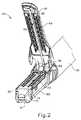
図1は、例示的な外科用ステープル留め及び切断器具(10)を表し、この器具は、ハンドル組立体(20)と、シャフト組立体(30)と、エンドエフェクタ(40)と、を含む。エンドエフェクタ(40)及びシャフト組立体(30)の遠位部分は、外科的処置を行うために、図1に描写されるような非関節動作状態で、トロカールカニューレを通って患者内の手術部位まで挿入するように寸法決めされている。単なる例示として、患者の腹部内に、患者の2本の肋骨の間に、又はその他の部位に、かかるトロカールを挿入できる。一部の状況では、器具(10)は、トロカールなしで使用される。例えば、エンドエフェクタ(40)及びシャフト組立体の遠位部分(30)を、開胸術又は他の種類の切開によって直接挿入することができる。本明細書では、「近位」及び「遠位」といった用語は、器具(10)のハンドル組立体(20)を握っている臨床医を基準として使用されていることを理解されたい。したがって、エンドエフェクタ(40)は、より近位にあるハンドル組立体(20)に対して遠位にある。便宜上、また説明を明確にするため、本明細書では「垂直」及び「水平」といった空間的用語が、図面に対して使用されている点も更に認識されるであろう。しかしながら、外科器具は、多くの向き及び位置で使用されるものであり、これらの用語は、限定的かつ絶対的なものであることを意図するものではない。I. Exemplary Surgical Stapler FIG. 1 depicts an exemplary surgical stapling and severing instrument (10) comprising a handle assembly (20), a shaft assembly (30), and an end effector (40). And). The end effector (40) and the distal portion of the shaft assembly (30) are operated in the patient's surgical site through the trocar cannula in an unarticulated manner as depicted in FIG. 1 to perform a surgical procedure. It is dimensioned to insert up to. By way of example only, such trocars can be inserted into the patient's abdomen, between the patient's two ribs, or elsewhere. In some situations, the instrument (10) is used without a trocar. For example, the end effector (40) and the distal portion (30) of the shaft assembly can be inserted directly by thoracotomy or other type of incision. It should be understood that, as used herein, the terms "proximal" and "distal" are used with reference to the clinician holding the handle assembly (20) of the instrument (10). Thus, the end effector (40) is distal to the more proximal handle assembly (20). It will be further appreciated that, for convenience and clarity of the description, spatial terms such as "vertical" and "horizontal" are used herein for the drawings. However, surgical instruments are used in many orientations and positions, and these terms are not intended to be limiting and absolute.
A.例示的なハンドル組立体及びシャフト組立体
図1に示すように、本実施例のハンドル組立体(20)は、ピストルグリップ(22)と、閉鎖トリガー(24)と、発射トリガー(26)と、を含む。各トリガー(24、26)は、以下により詳細に記載されるように、ピストルグリップ(22)に向かって、またそれから離れるように選択的に枢動可能である。ハンドル組立体(20)は、取外し式バッテリーパック(28)を更に含む。これらの構成要素についても、以下でより詳細に説明する。勿論、ハンドル組立体(20)は、上記したもののいずれかに加えて又はその代わりに、様々なその他の構成要素、特徴、及び動作性を有することができる。ハンドル組立体(20)の他の好適な構成は、本明細書の教示を考慮することで当業者には明らかとなるであろう。A. Exemplary Handle Assembly and Shaft Assembly As shown in FIG. 1, the handle assembly (20) of the present example comprises a pistol grip (22), a closure trigger (24), and a firing trigger (26). including. Each trigger (24, 26) is selectively pivotable towards and away from the pistol grip (22), as described in more detail below. The handle assembly (20) further includes a removable battery pack (28). These components are also described in more detail below. Of course, the handle assembly (20) may have various other components, features, and operability in addition to or instead of any of those described above. Other suitable configurations of the handle assembly (20) will be apparent to those skilled in the art in view of the teachings herein.
図1〜図2に示すように、本実施例のシャフト組立体(30)は、外側閉鎖管(32)と、関節運動部(34)と、閉鎖用リング(36)と、を含み、これは更にエンドエフェクタ(40)に連結される。閉鎖管(32)はシャフト組立体(30)の長さに沿って延在する。閉鎖用リング(36)は、関節運動部(34)の遠位に位置付けられている。閉鎖管(32)及び閉鎖用リング(36)は、ハンドル組立体(20)に対して長手方向に並進するように構成されている。閉鎖管(32)の長手方向の並進は、関節運動部(34)を介して閉鎖用リング(36)に伝達される。閉鎖管(32)及び閉鎖用リング(36)を長手方向に並進させるのに使用できる例示的機構は、以下により詳細に記載される。 As shown in FIGS. 1 and 2, the shaft assembly (30) of this embodiment includes an outer closing tube (32), an articulating portion (34), and a closing ring (36). Is further coupled to the end effector (40). The closure tube (32) extends along the length of the shaft assembly (30). A closure ring (36) is positioned distal of the articulating portion (34). The closure tube (32) and the closure ring (36) are configured to translate longitudinally with respect to the handle assembly (20). The longitudinal translation of the closure tube (32) is transmitted to the closure ring (36) via the articulating section (34). Exemplary mechanisms that can be used to longitudinally translate the closure tube (32) and the closure ring (36) are described in more detail below.
関節運動部(34)は、シャフト組立体(30)の長手方向軸(LA)から所望の角度(α)で横方向へ離れるように、閉鎖用リング(36)及びエンドエフェクタ(40)を横方向に偏向させるよう動作可能である。本実施例では、関節運動は、シャフト組立体(30)の近位端に位置する関節運動制御ノブ(35)によって制御される。閉鎖用リング(36)及びエンドエフェクタ(40)は、ノブ(35)の回転に応答してシャフト組立体(30)の長手方向軸(LA)に垂直な軸の周りを枢動する。関節運動部(34)は、関節運動部(34)が真っ直ぐな構成であるか、又は関節運動構成であるかにかかわらず、閉鎖管(32)が閉鎖用リング(36)まで長手方向に並進するのを伝達するように構成されている。単なる例として、関節運動部(34)及び/又は関節運動制御ノブ(35)が、その開示内容が参照によって本明細書に援用されている米国特許出願公開第2014/0243801号、題名「Surgical Instrument End Effector Articulation Drive with Pinion and Opposing Racks」(2014年8月28日公開)、及び/又はその開示内容が参照によって本明細書に援用されている米国特許出願公開第2015/0374360号、題名「Articulation Drive Features for Surgical Stapler」(2015年12月31日公開)の少なくとも一部に従って、並びに/あるいは以下の様々な教示に従って構成され動作可能となり得る。関節運動部(34)及び関節動作ノブ(35)が取り得るその他の好適な形態は、本明細書の教示を鑑みれば当業者には明らかとなるであろう。 The articulation section (34) laterally traverses the closure ring (36) and the end effector (40) so as to be laterally separated from the longitudinal axis (LA) of the shaft assembly (30) at the desired angle (α). It is operable to deflect in a direction. In the present example, articulation is controlled by an articulation control knob (35) located at the proximal end of the shaft assembly (30). The closure ring (36) and the end effector (40) pivot about an axis perpendicular to the longitudinal axis (LA) of the shaft assembly (30) in response to the rotation of the knob (35). The articulation section (34) translates the closed tube (32) longitudinally to the closure ring (36), regardless of whether the articulation section (34) is in a straight configuration or in an articulation configuration. It is configured to communicate the By way of example only, articulating section (34) and / or articulation control knob (35) is disclosed in US Patent Application Publication No. 2014/0243801, entitled "Surgical Instrument," the disclosure of which is incorporated herein by reference. U.S. Patent Application Publication No. 2015/0374360, entitled "Articulation," the disclosure of which is incorporated herein by reference, as "End Effector Articulation Drive with Pinion and Opposing Racks" (published on August 28, 2014), and / or the disclosure of which is incorporated herein by reference. In accordance with at least a part of “Drive Features for Surgical Stapler” (released on December 31, 2015) and / or according to the various teachings below Made that may be made operable. Other suitable forms that the articulating portion (34) and articulating knob (35) may take will be apparent to those skilled in the art in view of the teachings herein.
図1に示すように、本実施例のシャフト組立体(30)は、回転ノブ(31)を更に含む。回転ノブ(31)は、シャフト組立体(30)の長手方向軸(LA)の周りを、ハンドル組立体(20)に対して、全シャフト組立体(30)及びエンドエフェクタ(40)を回転させるように動作可能である。当然のことながら、シャフト組立体(30)は、上記のもののいずれかに加えて又はその代わりに、様々なその他の構成要素、特徴、及び動作性を有することができる。単に例として、シャフト組立体(30)の少なくとも一部分は、米国特許出願公開第2014/0239038号、題名「Surgical Instrument with Multi−Diameter Shaft」(2014年8月28日公開)の教示の少なくともいくらかに従って構成されている。シャフト組立体(30)のその他の好適な構成は、本明細書中の教示を考慮することにより当業者に明らかとなるであろう。 As shown in FIG. 1, the shaft assembly (30) of the present example further includes a rotation knob (31). The rotation knob (31) rotates the entire shaft assembly (30) and the end effector (40) about the longitudinal axis (LA) of the shaft assembly (30) and relative to the handle assembly (20) It is operable as. It will be appreciated that the shaft assembly (30) may have various other components, features and operability in addition to or instead of any of the ones described above. Merely by way of example, at least a portion of the shaft assembly (30) follows at least some of the teachings of US Patent Application Publication No. 2014/0239038, entitled "Surgical Instrument with Multi-Diameter Shaft", published August 28, 2014. It is configured. Other suitable configurations of the shaft assembly (30) will be apparent to one of ordinary skill in the art in view of the teachings herein.
B.例示的なエンドエフェクタ
図1〜3にも示されているように、本実施例のエンドエフェクタ(40)は、下側ジョー(50)及び枢動可能なアンビル(60)を含む。アンビル(60)は、下側ジョー(50)の対応する湾曲スロット(54)に配置されている一対の一体的な、外側に延在するピン(66)を含む。アンビル(60)は、開放位置(図2に示す)と閉鎖位置(図1に示す)との間で、下側ジョー(50)に向かって、また下側ジョー(50)から離れるように枢動可能である。「枢動可能」という用語(及び「枢動」を基体とした類義語)の使用は、必ずしも固定軸を中心とした枢動運動を必要とすると解釈すべきではない。例えば、本実施例において、アンビル(60)は、ピン(66)により画定される軸を中心に枢動し、このピンは、アンビル(60)が下側ジョー(50)に向かって動くと、下側ジョー(50)の湾曲スロット(54)に沿って摺動する。かかる形態では、枢動軸がスロット(54)によって画定された経路に沿って並進する一方で、アンビル(60)はその軸を中心として同時に枢動する。追加的にあるいは代替的に、まず枢動軸がスロット(54)に沿って摺動し、次いで枢動軸がスロット(54)に沿ってある一定の距離を摺動した後に、アンビル(60)が枢動軸を中心として枢動してもよい。そのような摺動/並進枢動運動は、「枢動」、「枢動する」「枢動の」、「枢動可能な」、「枢動している」などの用語内に包含されることを理解されたい。当然のことながら、一部の形態は、固定されたままでありスロット又はチャネルなどの内側を並進しない、軸を中心としたアンビル(60)の枢動運動を提供してもよい。B. Exemplary End Effector As also shown in FIGS. 1-3, the end effector (40) of the present example includes a lower jaw (50) and a pivotable anvil (60). The anvil (60) includes a pair of integral, outwardly extending pins (66) disposed in corresponding curved slots (54) of the lower jaw (50). The anvil (60) is pivoted towards and away from the lower jaw (50) between the open position (shown in FIG. 2) and the closed position (shown in FIG. 1). It is movable. The use of the term "pivotable" (and synonyms based on "pivot") is not necessarily to be construed as requiring a pivoting movement about a fixed axis. For example, in the present example, the anvil (60) pivots about an axis defined by the pin (66), which moves as the anvil (60) moves towards the lower jaw (50) Slide along the curved slot (54) of the lower jaw (50). In such a configuration, the anvil (60) simultaneously pivots about its axis while the pivot axis translates along the path defined by the slot (54). Additionally or alternatively, the anvil (60) may first slide the pivot along the slot (54) and then slide the pivot along the slot (54) a certain distance. May pivot about the pivot axis. Such sliding / translational pivoting motions are encompassed within the terms "pivotal", "pivoting", "pivoting", "pivotable", "pivoting", etc. I want you to understand that. It will be appreciated that some forms may provide pivotal movement of the anvil (60) about an axis that remains fixed and does not translate inside a slot or channel or the like.
図3にごく分かりやすく図示されているように、本実施例の下側ジョー(50)は、ステープルカートリッジ(70)を受容するように構成されたチャネル(52)を画定している。ステープルカートリッジ(70)はチャネル(52)に挿入することができ、エンドエフェクタ(40)を作動し、その後、ステープルカートリッジ(70)を取り外し、別のステープルカートリッジ(70)と交換することができる。したがって、下側ジョー(50)は、エンドエフェクタ(40)を作動させるためにアンビル(60)と位置合わせされてステープルカートリッジ(70)を解放可能に保持する。一部の変形形態では、下側ジョー(50)は、その開示内容が本明細書において参照により援用されている米国特許出願公開第2014/0239044号、題名「Installation Features for Surgical Instrument End Effector Cartridge」(2014年8月28日公開)の教示の少なくとも一部分に従って構成されている。下側ジョー(50)が取り得るその他の好適な形態は、本明細書の教示を鑑みれば当業者には明らかとなるであろう。 As best seen in FIG. 3, the lower jaw (50) of the present example defines a channel (52) configured to receive a staple cartridge (70). The staple cartridge (70) can be inserted into the channel (52) and the end effector (40) can be actuated after which the staple cartridge (70) can be removed and replaced with another staple cartridge (70). Thus, the lower jaw (50) is aligned with the anvil (60) to actuate the end effector (40) to releasably hold the staple cartridge (70). In some variations, the lower jaw (50) is described in US Patent Application Publication No. 2014/0239044, entitled "Installation Features for Surgical Instrument End Effector Cartridge," whose disclosure is incorporated herein by reference. It is configured in accordance with at least a portion of the teachings of (August 28, 2014 published). Other suitable forms that the lower jaw (50) may take will be apparent to those skilled in the art in view of the teachings herein.
図2〜3にごく分かりやすく図示されているように、本実施例のステープルカートリッジ(70)は、カートリッジ本体(71)と、カートリッジ本体(71)の下面に固定されたトレー(76)と、を備える。カートリッジ本体(71)の上面は、アンビル(60)が閉鎖位置にあるとき、組織を圧縮できるデッキ(73)を提供する。カートリッジ本体(71)は、長手方向に延在するチャネル(72)及び複数のステープルポケット(74)を更に画定する。ステープル(90)は各ステープルポケット(74)内に配置される。またステープルドライバ(75)は、各ステープルポケット(74)内で、対応するステープル(90)の下部、及びトレー(76)の上方に配置されている。以下でより詳細に説明されるように、ステープルドライバ(75)はステープルポケット(74)内で上向きに並進するよう動作可能であり、これによりステープル(90)をステープルポケット(74)を通って上向きに駆動させ、アンビル(60)と係合させる。ステープルドライバ(75)は、楔形スレッド(78)により上向きに駆動され、この楔形スレッドはカートリッジ本体(71)とトレー(76)との間に捕捉されており、これがカートリッジ本体(71)を通って長手方向に並進する。 As shown very clearly in FIGS. 2-3, the staple cartridge (70) of the present embodiment comprises a cartridge body (71) and a tray (76) fixed to the lower surface of the cartridge body (71). Equipped with The top surface of the cartridge body (71) provides a deck (73) that can compress tissue when the anvil (60) is in the closed position. The cartridge body (71) further defines a longitudinally extending channel (72) and a plurality of staple pockets (74). A staple (90) is disposed within each staple pocket (74). Also, a staple driver (75) is disposed within each staple pocket (74) below the corresponding staple (90) and above the tray (76). As described in more detail below, the staple driver (75) is operable to translate upwardly in the staple pocket (74) thereby causing the staple (90) to face upward through the staple pocket (74). Drive into engagement with the anvil (60). The staple driver (75) is driven upward by the wedge shaped thread (78), which is captured between the cartridge body (71) and the tray (76), which passes through the cartridge body (71) Translate longitudinally.
楔形スレッド(78)は、一対の斜角カム面(79)を含み、それらは、ステープルドライバ(75)と係合し、それによって、楔形スレッド(78)がカートリッジ(70)を通って長手方向に並進するにつれてステープルドライバ(75)を上方に駆動するように構成されている。例えば、楔形スレッド(78)が近位位置にあるとき、ステープルドライバ(75)は下方位置にあり、ステープル(90)はステープルポケット(74)内に位置する。ナイフ部材(80)の並進によって楔形スレッド(78)が遠位位置に駆動されると、楔形スレッド(78)はステープルドライバ(75)を上向きに駆動し、これによりステープル(90)をステープルポケット(74)から排出させ、アンビル(60)の下面(65)に形成されたステープル形成ポケット(64)内へと駆動する。よって、楔形スレッド(78)が水平寸法に沿って並進すると、ステープルドライバ(75)は垂直寸法に沿って並進する。 The wedge shaped thread (78) includes a pair of beveled cam surfaces (79) which engage the staple driver (75) thereby causing the wedge shaped thread (78) to extend longitudinally through the cartridge (70). Are configured to drive the staple driver (75) upward as it translates into For example, when the wedge shaped thread (78) is in the proximal position, the staple driver (75) is in the lower position and the staples (90) are located in the staple pocket (74). When the wedge shaped thread (78) is driven to the distal position by the translation of the knife member (80), the wedge shaped thread (78) drives the staple driver (75) upwards thereby causing the staples (90) 74) and drive into staple forming pockets (64) formed in the lower surface (65) of the anvil (60). Thus, as the wedge thread (78) translates along the horizontal dimension, the staple driver (75) translates along the vertical dimension.
一部の変形形態では、ステープルカートリッジ(70)は、その開示が本明細書において参照により援用されている米国特許出願公開第2014/0239042号、題名「Integrated Tissue Positioning and Jaw Alignment Features for Surgical Stapler」(2014年8月28日公開)の教示の少なくとも一部に従って構成され、動作可能である。追加的にあるいは代替的に、ステープルカートリッジ(70)は、その開示内容が本明細書において参照により援用されている米国特許出願公開第2014/0239044号、題名「Installation Features for Surgical Instrument End Effector Cartridge」(2014年8月28日公開)の教示の少なくとも一部分に従って構成され動作可能となり得る。ステープルカートリッジ(70)が取り得るその他の好適な形態は、本明細書の教示を鑑みれば当業者には明らかとなるであろう。 In some variations, a staple cartridge (70) is disclosed in US Patent Application Publication No. 2014/0239042, entitled "Integrated Tissue Positioning and Jaw Alignment Features for Surgical Stapler," the disclosure of which is incorporated herein by reference. It is configured and operable in accordance with at least a portion of the teachings of (August 28, 2014 published). Additionally or alternatively, the staple cartridge (70) is disclosed in US Patent Application Publication No. 2014/0239044, entitled "Installation Features for Surgical Instrument End Effector Cartridge", the disclosure of which is incorporated herein by reference. It may be configured and operable in accordance with at least a portion of the teachings of (August 28, 2014 published). Other suitable forms that the staple cartridge (70) may take will be apparent to those skilled in the art in view of the teachings herein.
図2にごく分かりやすく図示されているように、本実施例のアンビル(60)は、長手方向に延在するチャネル(62)と、複数のステープル形成ポケット(64)と、を備える。チャネル(62)は、アンビル(60)が閉鎖位置にあるとき、ステープルカートリッジ(70)のチャネル(72)と整列するように構成されている。各ステープル形成ポケット(64)は、アンビル(60)が閉鎖位置にあるとき、ステープルカートリッジ(70)の対応するステープルポケット(74)の上に置かれるように位置付けられている。ステープル形成ポケット(64)は、ステープル(90)が組織を通してアンビル(60)の中に駆動されると、ステープル(90)の脚部を変形させるように構成されている。特に、ステープル形成ポケット(64)は、形成されたステープル(90)を組織内に固定させるためにステープル(90)の脚部を曲げるように構成されている。アンビル(60)は、米国特許出願公開第2014/0239042号、題名「Integrated Tissue Positioning and Jaw Alignment Features for Surgical Stapler」(2014年8月28日公開)の教示の少なくとも一部、米国特許出願公開第2014/0239036号、題名「Jaw Closure Feature for End Effector of Surgical Instrument」(2014年8月28日公開)の教示の少なくとも一部、及び/又は米国特許出願公開第2014/0239037号、題名「Staple Forming Features for Surgical Stapling Instrument」(2014年8月28日公開)の教示の少なくとも一部に従って構成させることが可能である。アンビル(60)が取り得るその他の好適な形態は、本明細書の教示を鑑みれば当業者には明らかとなるであろう。 As best seen in FIG. 2, the anvil (60) of the present example comprises a longitudinally extending channel (62) and a plurality of staple forming pockets (64). Channel (62) is configured to align with channel (72) of staple cartridge (70) when anvil (60) is in the closed position. Each staple forming pocket (64) is positioned to rest on the corresponding staple pocket (74) of the staple cartridge (70) when the anvil (60) is in the closed position. The staple forming pocket (64) is configured to deform the legs of the staple (90) when the staple (90) is driven through tissue into the anvil (60). In particular, the staple forming pocket (64) is configured to bend the legs of the staple (90) to secure the formed staple (90) in tissue. Anvil (60) is disclosed in at least a portion of the teachings of US Patent Application Publication No. 2014/0239042, entitled "Integrated Tissue Positioning and Jaw Alignment Features for Surgical Stapler" (published August 28, 2014), US Patent Application Publication No. 2014/0239036, entitled "Jaw Closure Feature for End Effector of Surgical Instrument" (published on August 28, 2014), and / or U.S. Patent Application Publication No. 2014/0239037, entitled Title "Staple Forming Features for Surgical Staging Instrument It is possible to configure according to at least a part of the teaching of August 28, 2014). Other suitable forms that the anvil (60) may take will be apparent to those skilled in the art in view of the teachings herein.
本実施例では、ナイフ部材(80)は、エンドエフェクタ(40)を通って並進するように構成されている。図3にごく分かりやすく図示されているように、ナイフ部材(80)は発射ビーム(82)の遠位端に固定されており、この発射ビームは、シャフト組立体(30)の一部分を貫通して延在する。図2にごく分かりやすく図示されているように、ナイフ部材(80)は、アンビル(60)及びステープルカートリッジ(70)のチャネル(62、72)内に配置されている。ナイフ部材(80)は、ナイフ部材(80)がエンドエフェクタ(40)を通って遠位に並進するにつれて、アンビル(60)とステープルカートリッジ(70)のデッキ(73)との間で圧縮されている組織を切断するように構成されている、遠位に提供された切断縁部(84)を含む。上記のように、ナイフ部材(80)はまた、ナイフ部材(80)がエンドエフェクタ(40)を通って遠位に並進するときに楔形スレッド(78)を遠位に駆動し、それによってステープル(90)が組織を通ってアンビル(60)に対して駆動されて形成される。 In the present example, the knife member (80) is configured to translate through the end effector (40). As best seen in FIG. 3, the knife member (80) is secured to the distal end of the firing beam (82), which passes through a portion of the shaft assembly (30) Extend. As best seen in FIG. 2, the knife member (80) is disposed within the channels (62, 72) of the anvil (60) and the staple cartridge (70). The knife member (80) is compressed between the anvil (60) and the deck (73) of the staple cartridge (70) as the knife member (80) translates distally through the end effector (40) Includes a distally provided cutting edge (84) configured to cut tissue. As mentioned above, the knife member (80) also drives the wedge shaped thread (78) distally as the knife member (80) translates distally through the end effector (40), thereby causing the staple ( 90) is driven through the tissue and against the anvil (60).
C.エンドエフェクタの例示的な作動
本実施例において、アンビル(60)は、閉鎖用リング(36)をエンドエフェクタ(40)に対して遠位に前進させることによって、下側ジョー(50)に向かって駆動される。閉鎖用リング(36)は、カム作用を介してアンビル(60)と協働し、エンドエフェクタ(40)に対する閉鎖用リング(36)の遠位への並進に応答してアンビル(60)を下側ジョー(50)に向かって駆動する。同様に、閉鎖用リング(36)は、アンビル(60)と協働し、エンドエフェクタ(40)に対する閉鎖用リング(36)の近位への並進に応答してアンビル(60)を下側ジョー(50)から離れて開放することができる。単に例として、閉鎖用リング(36)及びアンビル(60)は、その開示内容が本明細書において参照により援用されている米国特許出願公開第2014/0239036号、題名「Jaw Closure Feature for End Effector of Surgical Instrument」(2014年8月28日公開)の教示の少なくとも一部、及び/又はその開示内容が本明細書において参照により援用されている米国特許出願公開第2015/0374373号、題名「Jaw Oparin Feature for Surgical Stapler」(2015年12月31日公開)の教示の少なくとも一部に従って相互作用し得る。C. Exemplary Operation of End Effector In the present example, the anvil (60) is directed towards the lower jaw (50) by advancing the closure ring (36) distally with respect to the end effector (40) It is driven. A closure ring (36) cooperates with the anvil (60) via camming action to lower the anvil (60) in response to distal translation of the closure ring (36) relative to the end effector (40). Drive towards the side jaws (50). Similarly, the closure ring (36) cooperates with the anvil (60) to lower the anvil (60) in response to proximal translation of the closure ring (36) relative to the end effector (40) It can be released away from (50). Merely by way of example, the closure ring (36) and the anvil (60) are disclosed in US Patent Application Publication No. 2014/0239036, whose title is incorporated herein by reference, entitled "Jaw Closure Feature for End Effector of U.S. Patent Application Publication No. 2015/0374373, entitled "Jaw Oparin," at least a portion of the teachings of Surgical Instrument "(published August 28, 2014), and / or the disclosure of which is incorporated herein by reference. It may interact in accordance with at least part of the teachings of the Feature for Surgical Stapler, published Dec. 31, 2015.
上記のように、ハンドル組立体(20)は、ピストルグリップ(22)と、閉鎖トリガー(22)と、を含む。また、上記のように、アンビル(60)は、閉鎖用リング(36)の遠位前進に応答して下側ジョー(50)に向かって閉鎖される。本実施例において、閉鎖トリガー(24)は、閉鎖管(32)及び閉鎖用リング(36)を遠位に駆動させるように、ピストルグリップ(22)に向かって枢動可能である。本明細書の教示を考慮することで、ピストルグリップ(22)に向かう閉鎖トリガー(24)の枢軸運動を、ハンドル組立体(20)に対する閉鎖管(32)及び閉鎖用リング(36)の遠位への並進に変換するのに使用され得る様々な好適な構成要素が、当業者には明らかとなるであろう。 As mentioned above, the handle assembly (20) includes a pistol grip (22) and a closure trigger (22). Also, as mentioned above, the anvil (60) is closed towards the lower jaw (50) in response to the distal advancement of the closure ring (36). In the present example, the closure trigger (24) is pivotable towards the pistol grip (22) to drive the closure tube (32) and the closure ring (36) distally. In view of the teachings herein, the pivoting movement of the closure trigger (24) towards the pistol grip (22) is accomplished by the closure tube (32) and the distal end of the closure ring (36) relative to the handle assembly (20). Various suitable components that may be used to translate into translation into one another will be apparent to those skilled in the art.
更に本実施例では、器具(10)は、発射ビーム(82)の電動制御を提供する。特に、器具(10)は、発射トリガー(26)のピストルグリップ(22)に向かう枢動に応答して発射ビーム(82)を遠位に駆動するように構成された、電動構成要素を含む。一部の形態では、モーター(図示せず)がピストルグリップ(22)内に含まれ、バッテリーパック(28)から電力を受信する。このモーターは、モーターの駆動シャフトの回転運動を、発射ビーム(82)の線形並進に変換する伝送組立体(図示せず)に連結される。あくまで一例として、発射ビーム(82)の電動化作動をもたらすように動作可能な機構は、その開示内容が本明細書において参照により援用されている米国特許第8,210,411号、題名「Motor−Driven Surgical Instrument」(2012年7月3日発行)、その開示内容が本明細書において参照により援用されている米国特許第8,453,914号、題名「Motor−Driven Surgical Cutting Instrument with Electric Actuator Directional Control Assembly」(2013年6月4日発行)、及び/又はその開示内容が本明細書において参照により援用されている米国特許出願公開第2015/0272575号、題名「Surgical Instrument Comprising a Sensor System」(2015年10月1日発行)の教示の少なくとも一部に従って構成され動作可能となり得る。 Furthermore, in the present example, the instrument (10) provides motorized control of the launch beam (82). In particular, the instrument (10) includes a motorized component configured to drive the firing beam (82) distally in response to pivoting towards the pistol grip (22) of the firing trigger (26). In some forms, a motor (not shown) is included in the pistol grip (22) and receives power from the battery pack (28). The motor is coupled to a transmission assembly (not shown) that converts the rotational motion of the drive shaft of the motor into a linear translation of the launch beam (82). By way of example only, a mechanism operable to provide motorized actuation of the launch beam (82) may be found in US Pat. No. 8,210,411, the disclosure of which is incorporated herein by reference, entitled “Motor Driven Surgical Instrument (issued July 3, 2012), U.S. Patent No. 8,453,914, the disclosure of which is incorporated herein by reference, entitled "Motor-Driven Surgical Cutting Instrument with Electric Actuator". “Directional Control Assembly” (issued June 4, 2013), and / or US Patent Application Publication 2015/027, the disclosure of which is incorporated herein by reference. No. 2575, may be configured and operable in accordance with at least a portion of the teachings of the 'Surgical Instrument Composing a Sensor System' (issued October 1, 2015).
器具(10)の他の任意の構成要素又は機構は、本明細書に引用される様々な参照文献のうちいずれかに従って構成され動作可能となり得ることも理解されたい。器具(10)に行うことができる更なる例示的な改変例について、以下により詳細に記載する。以下の教示を器具(10)に組み込むことができる様々な好適な方法が当業者には明らかとなるであろう。同様に、以下の教示を本明細書で引用された参考文献の様々な教示と組み合わせることができる様々な好適な方法が当業者には明らかとなるであろう。したがって、以下の教示が、本明細書に引用される様々な参考文献で教示されている様々な器具に容易に組み入れることができることを理解されたい。また、以下の教示は、器具(10)又は本明細書に引用される参考文献に教示される装置に限定されない点も理解されたい。以下の教示は、外科用ステープラとして分類されない器具を含むその他の様々な種類の器具に容易に応用することができる。以下の教示を適用することができる他の様々な好適な装置及び状況は、本明細書の教示を考慮すれば当業者には明らかとなるであろう。 It should also be understood that any other components or features of the instrument (10) may be constructed and operable in accordance with any of the various references cited herein. Further exemplary modifications that can be made to the device (10) are described in more detail below. It will be apparent to those skilled in the art various suitable ways in which the following teachings can be incorporated into the device (10). Likewise, various suitable methods will be apparent to those skilled in the art that can combine the following teachings with the various teachings of the references cited herein. Thus, it should be understood that the following teachings can be readily incorporated into the various instruments taught in the various references cited herein. It should also be understood that the following teachings are not limited to the device (10) or devices taught in the references cited herein. The following teachings can be readily applied to various other types of instruments, including instruments not classified as surgical staplers. Various other suitable devices and conditions to which the following teachings may apply will be apparent to those skilled in the art in view of the teachings herein.
II.外科用ステープラ用のバットレスを有する例示的なエンドエフェクタ
いくつかの事例では、エンドエフェクタ(40)にバットレス材料及び/又は他の種類の補助剤を装備させることが望ましい場合がある。そのようなバットレス材料及び/又は他の種類の補助剤は、ステープル(90)によってもたらされる組織の機械的締結の補強を含むがこれに限定されない様々な目的に役立ち得る。かかるバットレスは、適用されたステープル(90)が組織から引き抜かれるのを防ぐことができ、ステープル(90)の適用部位又はその付近で組織が裂けるリスクを別の方法で低減することができる。ステープル(90)のラインに対して構造的な支持及び完全性を提供することに加えて又はその代わりに、バットレス及び/又は他の補助剤によって、スペーシング又はギャップ充填(例えば、エンドエフェクタ(40)の長さ及び幅にわたって実質的に均一な圧縮力を促進するための、不均一の解剖学的表面により形成されるギャップの充填)、治療薬の投与(例えば、エンドエフェクタ(40)によって係合された組織における止血を促進)、並びに/あるいはその他の効果などの、様々なその他の種類の効果を実現することが可能である。「バットレス」という用語は、以下の説明全体にわたって使用されるが、「バットレス」という用語の使用は、バットレスの機能性に対して何ら制限を課すことを意図するものでないことを理解されたい。したがって、「バットレス」という用語は、エンドエフェクタ(40)に付属する任意の構造に適用され、エンドエフェクタ(40)に係合される組織に関して任意の好適な機能的目的を果たすものとして解釈すべきである。II. Exemplary End Effectors with Buttresses for Surgical Staples In some cases, it may be desirable to equip the end effector (40) with buttress material and / or other types of auxiliaries. Such buttress materials and / or other types of auxiliaries can serve various purposes including, but not limited to, reinforcing mechanical fastening of tissue provided by the staples (90). Such a buttress can prevent applied staples (90) from being pulled out of the tissue, and can otherwise reduce the risk of tissue tearing at or near the site of application of the staples (90). In addition to or instead of providing structural support and integrity to the lines of staples (90), spacing or gap filling (eg end effector (40) by buttresses and / or other adjuvants. A filling of the gap formed by the uneven anatomical surface to promote a substantially uniform compressive force across the length and width) of the treatment agent) (e.g., by the end effector (40) Various other types of effects can be realized, such as promoting hemostasis in the combined tissue, and / or other effects. The term "buttress" is used throughout the following description, but it should be understood that the use of the term "buttress" is not intended to impose any limitation on the functionality of the buttress. Thus, the term "buttress" applies to any structure attached to the end effector (40) and should be interpreted as serving any suitable functional purpose with respect to the tissue engaged with the end effector (40) It is.
場合によっては、バットレスは、ステープルカートリッジ(70)のデッキ(73)上に提供され得る。いくつかのその他の場合では、バットレスは、ステープルカートリッジ(70)に面するアンビル(60)の表面上に提供され得る。第1バットレスがステープルカートリッジ(70)のデッキ(73)上に提供され得る一方で、第2バットレスが同じエンドエフェクタ(40)のアンビル(60)上に提供されることも理解されたい。バットレスがステープルカートリッジ(70)又はアンビル(60)に固定され得る様々な方法も、以下により詳細に記載される。 In some cases, buttresses may be provided on the deck (73) of the staple cartridge (70). In some other cases, a buttress may be provided on the surface of the anvil (60) facing the staple cartridge (70). It should also be understood that while a first buttress can be provided on the deck (73) of the staple cartridge (70), a second buttress is provided on the anvil (60) of the same end effector (40). Various methods by which the buttress can be secured to the staple cartridge (70) or anvil (60) are also described in more detail below.
以下のバットレスは、その開示内容が本明細書において参照により援用されている米国特許9,044,227号、題名「Collapsible Fastener Cartridge」(2015年6月2日発行)、その開示内容が本明細書において参照により援用されている米国特許出願公開第2012/0241493号、題名「Tissue Thickness Compensator Comprising Controlled Release and Expansion」(2012年9月27日公開)、その開示内容が本明細書において参照により援用されている米国特許出願公開第2013/0068816号、題名「Surgical Instrument and Buttress Material」(2013年3月21日公開)、その開示内容が本明細書において参照により援用されている米国特許出願公開第2013/0062391号、題名「Surgical Instrument with Fluid Fillable Buttress」(2013年3月14日公開)、その開示内容が本明細書において参照により援用されている米国特許出願公開第2013/0068820号、題名「Fibrin Pad Matrix with Suspended Heat Activated Beads of Adhesive」(2013年3月21日公開)、その開示内容が本明細書において参照により援用されている米国特許出願公開第2013/0082086号、題名「Attachment of Surgical Staple Buttress to Cartridge」(2013年4月4日公開)、その開示内容が本明細書において参照により援用されている米国特許出願公開第2013/0037596号、題名「Device for Applying Adjunct in Endoscopic Procedure」(2013年2月14日公開)、その開示内容が本明細書において参照により援用されている、米国特許出願公開第2013/0062393号、題名「Resistive Heated Surgical Staple Cartridge with Phase Change Sealant」(2013年3月14日公開)、その開示内容が本明細書において参照により援用されている米国特許出願公開第2013/0075446号、題名「Surgical Staple Assembly with Hemostatic Feature」(2013年3月28日公開)、その開示内容が本明細書において参照により援用されている米国特許出願公開第2013/0062394号、題名「Surgical Staple Cartridge with Self−Dispensing Staple Buttress」(2013年3月14日公開)、その開示内容が本明細書において参照により援用されている米国特許出願公開第2013/0075445号、題名「Anvil Cartridge for Surgical Fastening Device」(2013年3月28日公開)、その開示内容が本明細書において参照により援用されている米国特許出願公開第2013/0075447号、題名「Adjunct Therapy for Applying Hemostatic Agent」(2013年3月28日公開)、その開示内容が本明細書において参照により援用されている米国特許出願公開第2013/0256367号、題名「Tissue Thickness Compensator Comprising a Plurality of Medicaments」(2013年10月3日公開)、その開示内容が本明細書において参照により援用されている2014年6月10日出願の米国特許出願第14/300,954号、題名「Adjunct Materials and Methods of Using Same in Surgical Methods for Tissue Sealing」(2014年6月10日出願)、その開示内容が本明細書において参照により援用されている2015年3月25日出願の米国特許出願第14/667,842号、題名「Method of Applying a Buttress to a Surgical Stapler」(2015年3月25日出願)、その開示内容が本明細書において参照により援用されている2015年8月17日出団の米国特許出願第14/827,856号、題名「Implantable Layers for a Surgical Instrument」(2015年8月17日出願)、その開示内容が本明細書において参照により援用されている米国特許出願第14/840,613号、題名「Drug Eluting Adjuncts and Methods of Using Drug Eluting Adjuncts」(2015年8月31日出願)、その開示内容が本明細書において参照により援用されている米国特許出願第14/871,071号、題名「Compressible Adjunct with Crossing Spacer Fibers」(2015年9月30日出願)、及び/又はその開示内容が本明細書において参照により援用されている2015年9月30日出願の米国特許出願第14/871,131号、題名「Method for Applying an Implantable Layer to a Fastener Cartridge」(2015年9月30日出願)の教示の少なくとも一部に従って構成され動作可能であり得ることを理解すべきである。代替的に、以下のバットレスは、他の任意の好適な方法で構築され動作可能であり得る。 The following buttresses are described in US Pat. No. 9,044,227, entitled “Collapsible Fastener Cartridge” (issued on June 2, 2015), the disclosure of which is incorporated herein by reference. Publication No. 2012/0241493, entitled “Tissue Thickness Compensator Compiling Controlled Release and Expansion” (published on September 27, 2012), the disclosure of which is incorporated herein by reference. US Patent Application Publication No. 2013/0068816, entitled "Surgical Instrument and Buttress Material" March 21, 013), US Patent Application Publication No. 2013/0062391, the disclosure of which is incorporated herein by reference, entitled "Surgical Instrument with Fluid Fillable Buttress", published March 14, 2013. US Patent Application Publication No. 2013/0068820, entitled “Fibrin Pad Matrix with Suspended Heat Activated Beads of Adhesives” (published on March 21, 2013), the disclosure of which is incorporated herein by reference. US Patent Application Publication No. 2013/0082086, entitled “Attachment of Surgica,” the disclosure of which is incorporated herein by reference. Staple Buttress to Cartridge (published April 4, 2013), US Patent Application Publication No. 2013/0037596, the disclosure of which is incorporated herein by reference, entitled "Device for Applying Adjunct in Endoscopic Procedure" ( No. 2013/0062393, published on Feb. 14, 2013), the disclosure of which is incorporated herein by reference, entitled "Resistive Heated Surgical Staple Cartridge with Phase Change Sealant" (2013 3) May 14), the disclosure of which is incorporated herein by reference. No. 013/0075446, entitled “Surgical Staple Assembly with Hemostatic Feature” (published on March 28, 2013), US Patent Application Publication No. 2013/0062394, entitled “Surgical Staple Assembly with Hemostatic Feature”, published March 28, 2013, the disclosure of which is incorporated herein by reference. Surgical Staple Cartridge with Self-Dispensing Staple Buttress ", published March 14, 2013, US Patent Application Publication No. 2013/0075445, the disclosure of which is incorporated herein by reference, entitled" Anvil Cartridge for Surgical ". "Fastening Device" (released on March 28, 2013), the disclosure content of which is incorporated herein by reference. US Patent Application Publication No. 2013/0075447, entitled "Adjunct Therapy for Applying Hemostatic Agent" (published on March 28, 2013), the disclosure of which is incorporated herein by reference. U.S. Patent Application Publication No. 2013/0256367, entitled "Tissue Thickness Compensator Composing a Plurality of Medicaments" (published on October 3, 2013), the disclosure of which is incorporated herein by reference on June 10, 2014 US Patent Application No. 14 / 300,954, filed in Japan, entitled "Adjunct Materials and Methods of Using Sa e in Surgical Methods for Tissue Sealing, filed June 10, 2014, US Patent Application No. 14 / 667,842, filed March 25, 2015, the disclosure of which is incorporated herein by reference. Entitled "Method of Applying a Buttress to a Surgical Stapler" (filed March 25, 2015), U.S. Patent Application No .: Aug. 17, 2015, the disclosure of which is incorporated herein by reference. No. 14 / 827,856, entitled "Implantable Layers for a Surgical Instrument" (filed on August 17, 2015), a US Patent Publication whose disclosure is incorporated herein by reference. No. 14 / 840,613, entitled "Drug Eluting Adjuncts and Methods of Using Drug Eluting Adjuncts" (filed on August 31, 2015), U.S. Patent Application No. 14 whose disclosure is incorporated herein by reference. No./871,071, entitled "Compressible Adjunct with Crossing Spacer Fibers" (filed on September 30, 2015), and / or the disclosure of the file on September 30, 2015, the disclosure content of which is incorporated herein by reference. U.S. Patent Application No. 14 / 871,131, entitled "Method for Applying an Impantable Layer to a Fastener Cartridge" It should be understood that the configuration may be operable in accordance with at least some of the teachings of the (September 30, 2015 filed). Alternatively, the following buttress may be constructed and operable in any other suitable manner.
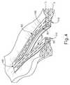
A.例示的なバットレス
カートリッジ(70)のデッキ(73)上の第1のバットレス(100)、及びアンビル(60)の下側(65)の第2のバットレス(110)がエンドエフェクタ(40)に装填され、エンドエフェクタ(40)は、組織の並置された層(T1、T2)を通してステープルを駆動し、更に組織の並置された層(T1、T2)も切断するように作動されている最終結果を、図4に示す。第1のバットレス(100)及び第2のバットレス(110)は、アンビル(60)のデッキ(73)及び下面(65)に接着剤で取り付けることもできるし、又は本明細書中の教示を鑑み当業者に公知の他の任意の適切な方法を用いて取り付けることもできる。上記引用文献のいくつかには、バットレス(100、110)をアンビル(73)のデッキ(65)及び下側(60)に取り付けることができる様々な好適な方法が教示されている。A. The first buttress (100) on the deck (73) of the exemplary buttress cartridge (70) and the second buttress (110) on the lower side (65) of the anvil (60) load the end effector (40) is, the end effector (40) drives the staple through the juxtaposed layers of tissue (T1, T2), is actuated to further juxtaposed layers (T1, T2) it is also cut tissue The final result is shown in FIG. The first buttress (100) and the second buttress (110) can be adhesively attached to the deck (73) and the lower surface (65) of the anvil (60), or in view of the teachings herein. It can also be attached using any other suitable method known to the person skilled in the art. Some of the above cited references teach various suitable ways in which buttresses (100, 110) can be attached to the deck (65) and lower side (60) of the anvil (73).
一連のステープル(90)によってバットレス(100、110)を同様に捕捉して、組織(T1、T2)の層に対して保持し、それにより、図4に図示されているように、バットレス(100、110)が組織(T1、T2)に固定されることを理解されたい。ステープル(90)及びバットレス(100、110)が配備された後、エンドエフェクタ(40)を組織(90)から牽引し、バットレス(100、110)をエンドエフェクタから係合解除することによって、バットレス(100、110)がステープル(90)により組織(T1、T2)に固定されたままに維持される。このようにして、ステープル(90)のラインがバットレス(100、110)によって構造的に補強される。やはり図4において見られるように、更にナイフ部材(80)がバットレス(100、110)の中央線を通して切り開き、各バットレス(100、110)を対応する一対のセクションに分離することによって、各セクションが組織(T1、T2)のそれぞれの切断領域に規定された状態に維持される。並置された組織層(T1、T2)の切断縁部はバットレス(100、110)と接触していないことを理解されたい。The buttress (100, 110) is similarly captured by a series of staples (90) and held against the layer of tissue (T1 , T2 ), thereby providing the buttress as illustrated in FIG. (100, 110) is to be understood that is secured to the tissue(T 1, T2). After the staples (90) and buttresses (100, 110) have been deployed, the end effector (40) is pulled from the tissue (90) and the buttress (100, 110) is disengaged from the
先の例では、バットレス組立体(100)は、下面(65)の全幅にわたって広がるように寸法を定められ、そのため、バットレス組立体(100)はチャネル(62)全体に広がる。したがって、ナイフ部材(80)は、上述のようにエンドエフェクタ(40)の作動中にバットレス組立体(100)を通して切断する。以下で説明する例など、いくつかの他の例では、バットレス組立体(100)は、2つの別々の横方向に離間した部分として提供され、一方のバットレス部分はチャネル(62)の一方の側の下面(65)に配設され、もう一方のバットレス部分はチャネル(62)のもう一方の側の下面(65)に配設される。そのような変形形態では、バットレス組立体(100)はチャネル(62)全体に広がることはなく、そのため、ナイフ部材(80)はエンドエフェクタ(40)の作動中にバットレス組立体(100)を通して切断することはない。 In the previous example, the buttress assembly (100) is dimensioned to extend across the entire width of the lower surface (65) so that the buttress assembly (100) extends across the channel (62). Thus, the knife member (80) cuts through the buttress assembly (100) during actuation of the end effector (40) as described above. In some other examples, such as the examples described below, the buttress assembly (100) is provided as two separate laterally spaced portions, one buttress portion being one side of the channel (62) And the other buttress portion is disposed on the lower surface (65) of the other side of the channel (62). In such variations, the buttress assembly (100) does not extend through the channel (62), so the knife member (80) cuts through the buttress assembly (100) during actuation of the end effector (40). There is nothing to do.
同様に、バットレス組立体(110)は、デッキ(73)の全幅にわたって広がるように寸法を定められてもよく、それにより、バットレス組立体(110)はチャネル(72)全体にわたって広がり、またナイフ部材(80)は、上述のようにエンドエフェクタ(40)の作動中にバットレス組立体(110)を通して切断する。あるいは、以下に記載するようないくつかの他の例では、バットレス組立体(110)は、2つの別々の横方向に離間した部分として提供されてもよく、一方のバットレス部分はチャネル(72)の一方の側でデッキ(73)上に配設され、もう一方のバットレス部分はチャネル(72)のもう一方の側でデッキ(73)上に配設され、それにより、バットレス組立体(110)はチャネル(72)全体に広がることはなく、またそれにより、ナイフ部材(80)はエンドエフェクタ(40)の作動中にバットレス組立体(110)を通して切断しない。 Similarly, the buttress assembly (110) may be sized to extend across the entire width of the deck (73) so that the buttress assembly (110) extends across the channel (72) and the knife member (80) cuts through the buttress assembly (110) during actuation of the end effector (40) as described above. Alternatively, in some other examples as described below, the buttress assembly (110) may be provided as two separate laterally spaced portions, one buttress portion being a channel (72) Is disposed on the deck (73) on one side and the other buttress portion is disposed on the deck (73) on the other side of the channel (72), whereby the buttress assembly (110) Does not extend through the channel (72), so that the knife member (80) does not cut through the buttress assembly (110) during operation of the end effector (40).
上記に加えて、本明細書で説明した様々なバットレス組立体のいずれもが、その開示内容が参照により本明細書に援用されている米国特許出願第14/667,842号、題名「Method of Applying a Buttress to a Surgical Stapler」(2015年3月25日出願)及び/又は本明細書に引用されている他の参考文献の教示の少なくとも一部に従って更に構成され動作可能となり得ることも理解されたい。 In addition to the above, any of the various buttress assemblies described herein may be referred to as US Patent Application No. 14 / 667,842, whose disclosure is incorporated herein by reference, entitled "Method of It is also understood that it may be further configured and operable in accordance with at least some of the teachings of Applying a Buttress to a Surgical Stapler (filed March 25, 2015) and / or other references cited herein. I want to.
B.切断された組織縁部にバットレスを適用するための代替的エンドエフェクタ
いくつかの事例では、ナイフ部材(80)を作動させることによって生じた組織(T1、T2)の切断縁部に、バットレス材料を適用することが望ましい場合がある。そのような場合は、新たに切断された組織(T1、T2)の縁部を更に治療するため、止血剤又はその他の補助剤をバットレス材料に含めることも望ましい場合がある。更に、バットレス材料の適用後にバットレス材料が組織(T1、T2)の切断縁部に確実に接触した状態のままに維持されるように、バットレス材料に接着剤を含めることが望ましい場合もある。組織(T1、T2)の切断縁部に直接的にバットレス材料を適用すると、出血量の低減、組織(T1、T2)の切断縁部の治癒促進、及び/又はその他の結果がもたらされ得る。B. Alternative End Effectors for Applying Buttresses to Cut Tissue Edges In some cases, cutting edges of tissue (T1 , T2 ) produced by actuation of the knife member (80) It may be desirable to apply the material. In such cases, it may also be desirable to include a hemostat or other adjuvant in the buttress material to further treat the edge of the freshly cut tissue (T1 , T2 ). In addition, it may be desirable to include an adhesive in the buttress material to ensure that the buttress material remains in contact with the cutting edge of the tissue (T1 , T2 ) after application of the buttress material . Applying directly buttress material to the cutting edge of the tissue (T1, T2), the reduction of blood loss, tissue (T1, T2) the cutting edge of healing, and / or other results of It can be introduced.
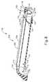
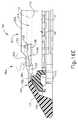
上述の器具(10)内に容易に組み込むことができる代替的エンドエフェクタ(140)を、図5に示す。本実施例のエンドエフェクタ(140)は、下側ジョー(150)と、枢動可能なアンビル(160)と、を含むが、これらは、上述した下側ジョー(50)及び枢動可能なアンビル(60)にそれぞれ実質的に類似している。したがって、アンビル(160)は、下側ジョー(150)の対応する湾曲スロット(154)内に配設されている一対の一体的な外側に延在するピン(166)を介して、下側ジョー(150)へ向かって及び離れた向きへ枢動可能である。 An alternative end effector (140) that can be easily incorporated into the above-described instrument (10) is shown in FIG. The end effector (140) of the present example comprises a lower jaw (150) and a pivotable anvil (160), which comprise the lower jaw (50) and the pivotable anvil described above. Each is substantially similar to (60). Thus, the anvil (160) is, via the pair of integral outwardly extending pins (166) disposed in the corresponding curved slot (154) of the lower jaw (150), the lower jaw It can be pivoted towards and away from (150).
ステープルカートリッジ(170)を受容するように構成されたチャネル(152)は、下側ジョー(150)によって画定されている。ステープルカートリッジ(170)は、上述のステープルカートリッジ(70)と実質的に同様であり、相違点の詳細は後述する。したがって、ステープルカートリッジ(170)はチャネル(152)に挿入し、エンドエフェクタ(140)を作動させ、その後、ステープルカートリッジ(170)を取り外し、別のステープルカートリッジ(170)と交換することができる。したがって、下側ジョー(150)は、エンドエフェクタ(40)を作動させるためにアンビル(160)と位置合わせされてステープルカートリッジ(170)を解放可能に保持する。下側ジョー(150)が取り得るその他の好適な形態は、本明細書中の教示を鑑みれば当業者に明らかとなるであろう。 A channel (152) configured to receive the staple cartridge (170) is defined by the lower jaw (150). The staple cartridge (170) is substantially similar to the staple cartridge (70) described above, the details of the differences will be described later. Thus, the staple cartridge (170) can be inserted into the channel (152), actuating the end effector (140), and then removing the staple cartridge (170) and replacing it with another staple cartridge (170). Thus, the lower jaw (150) is aligned with the anvil (160) to actuate the end effector (40) to releasably hold the staple cartridge (170). Other suitable forms that the lower jaw (150) may take will be apparent to those skilled in the art in view of the teachings herein.
本実施例のステープルカートリッジ(170)は、カートリッジ本体(171)と、このカートリッジ本体(171)の下面に固定されたトレー(176)と、を含む。カートリッジ本体(171)の上側にデッキ(173)を提供し、バットレス組立体(210)の一部を当接させて頂部に配置してもよい。詳細は後述する。カートリッジ本体(171)は、長手方向に延在するチャネル(172)及び複数のステープルポケット(174)を更に画定する。各ステープルポケット(174)内にはステープル(190)が位置付けられている。またステープルドライバ(175)も、各ステープルポケット(174)内に、対応するステープル(190)の下に、及びトレー(176)の上方に位置付けられている。以下に詳述されるように、ステープルドライバ(175)はステープルポケット(174)内で上向きに並進するよう動作可能であり、これによりステープル(190)をステープルポケット(174)及びバットレス組立体(210)を通って上向きに駆動させ、アンビル(160)と係合させる。ステープルドライバ(175)は、楔形スレッド(178)により上向きに駆動され、この楔形スレッドはカートリッジ本体(171)とトレー(176)との間に捕捉され、これがカートリッジ本体(171)を通って長手方向に並進する。 The staple cartridge (170) of the present embodiment includes a cartridge body (171) and a tray (176) fixed to the lower surface of the cartridge body (171). A deck (173) may be provided on the upper side of the cartridge body (171) and a portion of the buttress assembly (210) may abut and be placed on top. Details will be described later. The cartridge body (171) further defines a longitudinally extending channel (172) and a plurality of staple pockets (174). A staple (190) is positioned within each staple pocket (174). A staple driver (175) is also positioned within each staple pocket (174), under the corresponding staple (190) and above the tray (176). As detailed below, the staple driver (175) is operable to translate upwardly within the staple pocket (174), thereby causing the staple (190) to form the staple pocket (174) and the buttress assembly (210). Drive upward and engage the anvil (160). The staple driver (175) is driven upwards by the wedge shaped thread (178) which is captured between the cartridge body (171) and the tray (176), which is longitudinally passed through the cartridge body (171) Translate to
楔形スレッド(178)は、複数の斜角カム面(179)と、二次スレッドドライバ(177)と、を含む。以下に詳述するように、二次スレッドドライバ(177)は、折り畳みスレッド(120)に対して作動しこの折り畳みスレッドを駆動するように構成され、これにより、新たに切断された組織(T1、T2)の縁部とは反対方向にバットレス組立体(210)の一部が折り畳まれる。The wedge thread (178) includes a plurality of beveled cam surfaces (179) and a secondary thread driver (177). As described in more detail below, the secondary thread driver (177) is configured to operate on and drive the folding sled (120) such that the newly cut tissue (T1) , T2 ) in a direction opposite to the edge of the buttress assembly (210).
斜角カム面(179)は、カートリッジ(118)によって画定される長手方向のカムチャネル(171)内を並進するように寸法決めされる。長手方向カムチャネル(118)はステープルポケット(174)と連通していることを理解されたい。したがって、斜角カム面(179)は、ステープルドライバ(175)と係合し、それによって、楔形スレッド(178)がカートリッジ(170)を遠位に通って長手方向に並進するにつれてステープルドライバ(175)を上方に駆動するように構成されている。例えば、楔形スレッド(178)が近位位置にあるとき、ステープルドライバ(175)は下方位置にあり、ステープル(190)はステープルポケット(174)内に位置する。ナイフ部材(180)の並進によって楔形スレッド(178)が遠位位置に駆動されると、楔形スレッド(178)はステープルドライバ(175)を上向きに駆動し、これによりステープル(190)をステープルポケット(174)から排出させ、アンビル(160)の下面(165)に形成されたステープル形成ポケット(164)内へと駆動する。このようにして、楔形スレッド(178)が水平寸法に沿って並進すると、ステープルドライバ(175)は垂直寸法に沿って並進する。 The beveled cam surface (179) is sized to translate within the longitudinal cam channel (171) defined by the cartridge (118). It should be understood that the longitudinal cam channel (118) is in communication with the staple pocket (174). Thus, the beveled cam surface (179) engages the staple driver (175), thereby causing the staple driver (175) to translate longitudinally as the wedge shaped thread (178) distally passes through the cartridge (170). ) Is configured to be driven upward. For example, when the wedge shaped thread (178) is in the proximal position, the staple driver (175) is in the lower position and the staple (190) is located in the staple pocket (174). When the wedge shaped thread (178) is driven to the distal position by the translation of the knife member (180), the wedge shaped thread (178) drives the staple driver (175) upwards, thereby causing the staple (190) 174) and drive into staple forming pockets (164) formed in the lower surface (165) of the anvil (160). Thus, as the wedge thread (178) translates along the horizontal dimension, the staple driver (175) translates along the vertical dimension.
本実施例のアンビル(160)は、長手方向に延在するチャネル(162)と、複数のステープル形成ポケット(図示せず)と、を含み、これらはそれぞれ、上述の長手方向に延在するチャネル(62)及び複数のステープル形成ポケット(64)と実質的に同様である。したがって、ステープル(162)は、ステープル(172)が組織を通してアンビル(170)内に駆動されるとステープル(160)の脚部を変形させるように、アンビル(190)が閉鎖位置にあるとき、ステープルカートリッジ(190)のチャネル(160)と整列するように構成されている。特に、ステープル形成ポケット(図示せず)は、形成されたステープル(190)を組織内に固定させるためにステープル(190)の脚部を曲げるように構成されている。 The anvil (160) of the present example includes a longitudinally extending channel (162) and a plurality of staple forming pockets (not shown), each of which is the aforementioned longitudinally extending channel It is substantially similar to (62) and the plurality of staple forming pockets (64). Thus, the staples (162) are placed in the closed position when the anvil (190) is in the closed position such that the staples (172) deform the legs of the staples (160) as they are driven through the tissue and into the anvil (170). It is configured to align with the channel (160) of the cartridge (190). In particular, the staple forming pocket (not shown) is configured to bend the legs of the staple (190) to secure the formed staple (190) in tissue.
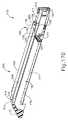
本実施例では、ナイフ部材(180)が、エンドエフェクタ(140)を通って長手方向に並進するように構成されている。ナイフ部材(180)は、上述のナイフ部材(80)と実質的に同様である。相違点の詳細は後述する。図5に最もよく見られるように、ナイフ部材(180)は発射ビーム(182)の遠位端に固定されており、この発射ビームは、シャフト組立体(30)の一部分を貫通して延在する。ナイフ部材(180)は、アンビル(160)及びカートリッジ(170)のチャネル(162、172)内に配置されている。ナイフ部材(180)は、ナイフ部材(180)がエンドエフェクタ(140)を通って遠位に並進するにつれて、アンビル(160)とステープルカートリッジ(170)のデッキ(173)との間で圧縮されている組織を切断するように構成されている、遠位に提供された切断縁部(184)を含む。上記のように、ナイフ部材(180)はまた、ナイフ部材(180)がエンドエフェクタ(140)を通って遠位に並進するときに楔形スレッド(178)を遠位に駆動し、それによってステープル(190)が組織を通ってアンビル(160)に対して駆動される。 In the present example, the knife member (180) is configured to translate longitudinally through the end effector (140). The knife member (180) is substantially similar to the knife member (80) described above. Details of the difference will be described later. As best seen in FIG. 5, the knife member (180) is secured to the distal end of the firing beam (182), which extends through a portion of the shaft assembly (30) Do. The knife member (180) is disposed within the anvil (160) and the channels (162, 172) of the cartridge (170). The knife member (180) is compressed between the anvil (160) and the deck (173) of the staple cartridge (170) as the knife member (180) translates distally through the end effector (140) Includes a distally provided cutting edge (184) configured to cut tissue. As mentioned above, the knife member (180) also drives the wedge shaped thread (178) distally as the knife member (180) translates distally through the end effector (140), thereby causing the staple ( 190) is driven through the tissue to the anvil (160).
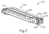
上述のように、カートリッジ本体(171)が長手方向チャネル(172)を画定する。図8及び図13に最もよく見られるように、長手方向チャネル(172)は、幅狭部分(110)と幅広部分(114)とを含む。幅狭部分(110)は、カートリッジ本体(171)の下側から一対の段(112)まで延在する幅狭垂直壁(111)によって画定される。幅広部分(114)は、段部(112)からデッキ(173)まで延在する幅広垂直壁(112)によって画定される。すなわち、段部(112)は、幅狭部分(110)と幅広部分(114)との間の遷移を画定する一助となる。 As mentioned above, the cartridge body (171) defines a longitudinal channel (172). As best seen in FIGS. 8 and 13, the longitudinal channel (172) includes narrow portions (110) and wide portions (114). The narrow portion (110) is defined by a narrow vertical wall (111) extending from the underside of the cartridge body (171) to the pair of steps (112). The wide portion (114) is defined by a wide vertical wall (112) extending from the step (112) to the deck (173). That is, the step (112) helps to define the transition between the narrow portion (110) and the wide portion (114).
上記のように、バットレス組立体(210)の一部はデッキ(173)の頂部上に載置される。図6〜図8及び図13に最もよく見られるように、バットレス組立体(202)は、一対の頂部バットレス(210)と、一対の底部折り畳みバットレス(204)と、を含む。頂部バットレス(202)の各下面は、対応する底部折り畳みバットレス(204)に接続されている。底部折り畳みバットレス(204)は、接着剤又は他の好適な接続部を用いて、頂部バットレス(202)の下面に固定してもよい。このことは、本明細書中の教示を考慮すれば当業者に明らかとなるであろう。いくつかの代替的変形形態では、折り畳みバットレス(204)の本体が、単に頂部バットレス(202)本体の下方に延在する部分となるように、バットレス(202、204)は共に一体に形成される。 As noted above, a portion of the buttress assembly (210) rests on top of the deck (173). As best seen in FIGS. 6-8 and 13, the buttress assembly (202) includes a pair of top buttresses (210) and a pair of bottom folded buttresses (204). Each lower surface of the top buttress (202) is connected to a corresponding bottom folding buttress (204). The bottom fold buttress (204) may be secured to the lower surface of the top buttress (202) using an adhesive or other suitable connection. This will be apparent to one of ordinary skill in the art in view of the teachings herein. In some alternative variations, the buttresses (202, 204) are integrally formed together such that the body of the folding buttress (204) is simply the downwardly extending portion of the top buttress (202) body .
各底部折り畳みバットレス(204)はまた、デッキ(173)、及び長手方向チャネル(172)の幅広部分(114)を画定している対応する幅広垂直壁(113)の両方に対して固定されている。本明細書の教示を考慮して、接着剤又は当業者に知られている他の任意の好適な手段を介して、各底部折り畳みバットレス(204)は、デッキ(173)及び幅広垂直壁(113)に取り外し可能に固定できる。ほんの一例にすぎないが、バットレスに関する本明細書中に引用されている様々な参考文献のいずれかにおける教示に従って、各底部折り畳みバットレス(204)のみを、デッキ(173)及び幅広垂直壁(113)に取り外し可能に固定させることも可能である。デッキ(173)に接続された底部折り畳みバットレス(204)の部分は、幅広垂直壁(113)に接続された折り畳みバットレス(204)の部分とは異なる手段で固着させることが可能なことを理解すべきである。本実施例において、底部折り畳みバットレス(204)の一部は、頂部バットレス(202)とデッキ(173)との両方に接続されているが、これは、任意選択的なものにすぎない。例えば、底部折り畳みバットレス(172)を、長手方向チャネル(204)に直接隣接する頂部バットレス(202)の部分に接続してもよい。このような例では、頂部バットレス(202)をデッキ(173)に直接接続してもよく、その一方で、底部折り畳みバットレス(202)は頂部バットレス(202)の縁部から幅広垂直壁(113)に向かって延在する。あるいは、頂部バットレス(202)を完全に省略しても差し支えない。 Each bottom fold buttress (204) is also fixed to both the deck (173) and the corresponding wide vertical wall (113) defining the wide portion (114) of the longitudinal channel (172) . In view of the teachings herein, each bottom fold buttress (204) can be provided with a deck (173) and wide vertical walls (113) via an adhesive or any other suitable means known to those skilled in the art. Can be removably fixed to By way of example only, each bottom fold buttress (204) alone, deck (173) and wide vertical wall (113) according to the teachings in any of the various references cited herein relating to buttresses. It is also possible to releasably fix it. It will be appreciated that the portion of the bottom folding buttress (204) connected to the deck (173) can be secured by means different from the portion of the folding buttress (204) connected to the wide vertical wall (113) It should. In the present example, a portion of the bottom folding buttress (204) is connected to both the top buttress (202) and the deck (173), but this is only optional. For example, the bottom fold buttress (172) may be connected to the portion of the top buttress (202) directly adjacent to the longitudinal channel (204). In such an example, the top buttress (202) may be connected directly to the deck (173) while the bottom folding buttress (202) extends from the edge of the top buttress (202) to a wide vertical wall (113). Extend towards. Alternatively, the top buttress (202) may be omitted entirely.
いくつかの事例において、幅広垂直壁(113)に接続された底部折り畳みバットレス(204)の部分は、幅広垂直壁(113)に固定されずに、単に長手方向チャネル(172)の幅広部分(114)に沿って延在しているだけでもよい。例えば、幅広垂直壁(113)に関連付けられた底部折り畳みバットレス(204)は、幅広垂直壁(113)に向かってデッキ(173)に対して折り畳んでもよい。加えて、幅広垂直壁(113)に関連付けられた底部折り畳みバットレス(204)の部分は、その折り畳まれた位置を、長手方向チャネル(172)の幅広部分(114)内に維持する程度に十分頑強である反面、外力に応答して折り畳まれる程度に十分柔軟であり得る。 In some cases, the portion of the bottom folding buttress (204) connected to the wide vertical wall (113) is merely fixed to the wide portion (114) of the longitudinal channel (172) without being fixed to the wide vertical wall (113). It may only extend along the). For example, the bottom folding buttress (204) associated with the wide vertical wall (113) may be folded against the deck (173) towards the wide vertical wall (113). In addition, the portion of the bottom folding buttress (204) associated with the wide vertical wall (113) is sufficiently robust to maintain its folded position within the wide portion (114) of the longitudinal channel (172) While it may be flexible enough to be folded in response to external forces.
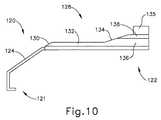
上述したように、カートリッジ(170)はまた、折り畳みスレッド(120)も含む。折り畳みスレッド(120)は、カートリッジ(170)の長手方向チャネル(172)内に摺動可能に配設されている。以下に詳述するように、折り畳みスレッド(120)は、ことによって、デッキ(173)の上方の幅広垂直壁(113)に関連付けられた底部折り畳みバットレス(204)の部分が折り畳まれて、底部折り畳みバットレス(204)が組織(T1、T2)の切断縁部に接触するように構成されている。 As mentioned above, the cartridge (170) also includes a folding sled (120). A folding sled (120) is slidably disposed within the longitudinal channel (172) of the cartridge (170). As will be described in more detail below, the folding sled (120) folds the bottom by folding the portion of the bottom folding buttress (204) associated with the upper wide vertical wall (113) of the deck (173) A buttress (204) is configured to contact the cutting edge of the tissue (T1, T2).
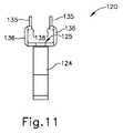
折り畳みスレッド(120)は、一対の細長いアーム(128)に連結部材(126)を介して連結された掛止突起(126)を含む。掛止突起(124)は折り畳みスレッド(120)の遠位部分(121)に位置する一方、細長いアーム(128)は、連結部材(126)から折り畳みスレッド(120)の近位部分(122)へと延在する。ナイフ部材(180)を通過させるためのスロット(125)が、連結部材(126)及び細長いアーム(128)によって画定される。詳細については後述する。 The folding sled (120) includes a locking projection (126) coupled to the pair of elongated arms (128) via a coupling member (126). The locking projection (124) is located at the distal portion (121) of the folding sled (120), while the elongated arm (128) is from the coupling member (126) to the proximal portion (122) of the folding sled (120) And extend. A slot (125) for passing the knife member (180) is defined by the connecting member (126) and the elongated arm (128). Details will be described later.
掛止突起(124)は、細長いアーム(128)間のギャップより幅狭である。掛止突起(124)は、長手方向チャネル(172)の狭幅部分(110)内に摺動可能に受容されるように寸法決めされる。以下に詳述するように、掛止突起(124)は、楔形スレッド(178)の二次スレッドドライバ(177)を受容するように寸法決めされているので、楔形スレッド(178)が長手方向に並進すると、折り畳みスレッド(120)も長手方向チャネル(172)に沿って並進する。 The locking projections (124) are narrower than the gap between the elongated arms (128). The locking projection (124) is dimensioned to be slidably received within the narrow portion (110) of the longitudinal channel (172). As detailed below, the retaining projection (124) is sized to receive the secondary thread driver (177) of the wedge thread (178) so that the wedge thread (178) is longitudinally oriented. When translated, the folding sled (120) also translates along the longitudinal channel (172).
上述のように、連結部材(126)が、掛止突起(124)と細長いアーム(128)とを連結する。連結部材(126)は、細長いアーム(128)が長手方向チャネル(172)の対応する段部(112)上に載置されるように寸法決めされている。このため、細長いアーム(128)は、長手方向チャネル(112)の段部(172)上を摺動し得る。細長いアーム(128)はそれぞれ、レール(132)と折り返し部(136)とを含む。レール(132)は、遠位端にて連結部材(126)から延出し、近位端にて折り返し部(136)に向かって延在する。レール(132)の遠位端は、遠位の傾斜面(130)内にて終端する。 As mentioned above, the coupling member (126) couples the locking projection (124) and the elongated arm (128). The coupling member (126) is dimensioned such that the elongated arms (128) rest on the corresponding shoulders (112) of the longitudinal channel (172). Thus, the elongated arm (128) may slide on the shoulder (172) of the longitudinal channel (112). The elongated arms (128) each include a rail (132) and a turnup (136). A rail (132) extends from the coupling member (126) at the distal end and extends towards the turnup (136) at the proximal end. The distal end of the rail (132) terminates in a distal ramp (130).
折り返し部(136)は、傾斜面(134)と、内方突起(138)と、フィン(135)と、を含む。傾斜面(134)は、レール(132)の近位端から内方突起(138)に向かって延在し、内方突起(138)は、この内方突起(138)の上方を延在するフィン(135)に接続されている。内方突起(138)は、互いに向かい合って、長手方向チャネル(172)を向いている。以下に詳述するように、フィン(135)及び内方突起(138)は、底部折り畳みバット(204)がデッキ(113)の上方でデッキ(204)に対して実質的に垂直に延在するように、幅広垂直壁(113)に関連付けられた底部折り畳みバットレス(204)の部分が幅広垂直壁(113)に対して確実に回転するように寸法決めされる。 The folded portion (136) includes an inclined surface (134), an inward protrusion (138), and a fin (135). The inclined surface (134) extends from the proximal end of the rail (132) towards the inward protrusion (138), the inward protrusion (138) extending above the inward protrusion (138) Connected to the fin (135). The inward projections (138) face each other and point to the longitudinal channel (172). As detailed below, the fins (135) and the inner projections (138) extend substantially perpendicularly to the deck (204) above the deck (113) the bottom folding butt (204) As such, the portion of the bottom folding buttress (204) associated with the wide vertical wall (113) is dimensioned to ensure rotation relative to the wide vertical wall (113).
本実施例において、フィン(135)は略平面かつ矩形である。しかしながら、本明細書中の教示を鑑みれば当業者に明らかとなるように、他の任意の好適な幾何学的形状を利用できる。例えば、フィン(135)は、略三角形又は菱形であり得る。以下に詳述するように、バットレス組立体(210)が幅広垂直壁(113)に対して相対的に回転するのを促すために様々な先細縁部を折り返し部(136)に具備させ得ることもまた理解されたい。本明細書中の教示を鑑みれば当業者に明らかとなるように、先細縁部の任意の好適な組み合わせ及び/又は幾何学的形状を利用できる。 In the present embodiment, the fins (135) are substantially planar and rectangular. However, any other suitable geometric shape may be utilized as would be apparent to one of ordinary skill in the art in view of the teachings herein. For example, the fins (135) may be approximately triangular or diamond shaped. Various tapered edges may be included in the fold back (136) to facilitate relative rotation of the buttress assembly (210) relative to the wide vertical wall (113), as described in detail below. Please also understand. Any suitable combination and / or geometry of tapered edges may be utilized, as will be apparent to those skilled in the art in view of the teachings herein.
図16A〜図16Eに、ナイフ部材(180)、楔形スレッド(178)の二次スレッドドライバ(177)、及びカートリッジ本体(171)の長手方向チャネル(172)内の近位位置から遠位位置に作動する折り畳みスレッド(20)のシーケンスを示す。同じシーケンスを図17A〜図17Eに示すが、これらの図では、ナイフ部材(180)を省略して図を簡素化してある。図16A〜図17Eでは、図を簡素化するためにアンビル(160)は図示されていないが、例示的な用途では、アンビル(160)はカートリッジ(170)に対して閉鎖位置にあることを理解されたい。加えて、図16A〜図17Eでは、図を簡素化するために上記ステープル(190)の発射を意図的に省略してあることも理解されたい。しかしながら、ステープル(190)は、対応するステープルポケット(174)の下方の斜角カム面(179)の長手方向の並進に応答して、デッキ(173)の上方及び頂部バットレス(202)を通って発射されることを理解されたい。 16A-16E, from the proximal position to the distal position within the longitudinal channel (172) of the knife member (180), the secondary thread driver (177) of the wedge shaped thread (178), and the cartridge body (171). The sequence of folding threads (20) activated is shown. The same sequence is shown in FIGS. 17A-17E, but in these figures the knife member (180) has been omitted to simplify the figure. While the anvil (160) is not shown in FIGS. 16A-17E to simplify the drawing, it is understood that in the exemplary application the anvil (160) is in a closed position relative to the cartridge (170). I want to be In addition, it should be understood that in Figures 16A-17E, firing of the staples (190) is intentionally omitted to simplify the figure. However, the staples (190) pass through the upper and top buttresses (202) of the deck (173) in response to longitudinal translation of the lower beveled cam surface (179) of the corresponding staple pocket (174). It should be understood that it will be launched.
初期非発射位置にある二次スレッドドライバ(177)及び折り畳みスレッド(120)を、図16A及び図17Aに示す。次いで、ユーザーは、長手方向チャネル(162、172)内部において遠位方向にあるナイフ部材(180)を遠位方向に作動させることができる。上述したように、楔形スレッド(178)はナイフ部材(180)と共に作動するように構成されているので、二次スレッドドライバ(177)も同様に、長手方向チャネル(172)内を遠位方向に作動する。楔形スレッド(178)が、図16A及び図17Aに示す位置から図16B及び図17Bへと作動しても、折り畳みスレッド(120)は長手方向チャネル(172)内に静止したままであることを理解されたい。このようにして、楔形スレッド(178)は、折り畳みスレッド(120)の対応する移動を生じることなく、第1の動作範囲にわたって並進する。 The secondary thread driver (177) and collapsing sled (120) in the initial non-firing position are shown in FIGS. 16A and 17A. The user can then actuate the knife member (180) distally within the longitudinal channel (162, 172) distally. As mentioned above, since the wedge shaped thread (178) is configured to operate with the knife member (180), the secondary thread driver (177) is likewise distally within the longitudinal channel (172). Operate. It is understood that the folding sled (120) remains stationary in the longitudinal channel (172) even if the wedge shaped sled (178) is actuated from the position shown in FIGS. 16A and 17A to FIGS. 16B and 17B. I want to be In this way, the wedge shaped thread (178) translates over the first range of motion without causing a corresponding movement of the folding thread (120).
いったん二次スレッドドライバ(177)が図16B及び図17Bに示す位置に達すると、二次スレッドドライバ(177)は掛止突起(124)と接触し、それにより、ナイフ部材(180)の作動を介してスレッドドライバ(177)が遠位に移動すると、それに対応して、折り畳みスレッド(120)が遠位に移動する。換言すれば、この時点で、楔形スレッド(170)及び折り畳みスレッド(120)は、遠位へ一体的に並進するようになる。ナイフ部材(180)の遠位に提供された切断縁部(184)は、折り畳みスレッド(120)のスロット(125)の内部において、折り畳みスレッド(120)の折り返し部(136)に対して遠位に位置することを理解されたい。したがって、遠位に提供された切断縁部(184)がアンビル(160)とカートリッジ(170)との間に捕捉された組織(T1、T2)を切断した後、折り畳みスレッド(120)はデッキ(173)の上方で底部折り畳みバットレス(204)の隣接部分を折り畳む。言い換えれば、遠位に提供された切断縁部(184)は折り返し部(136)に対して遠位にあるので、先に組織(T1、T2)が切断されて切断縁部が形成され、結果として、新たに切断された組織(T1、T2)の縁部に対して底部折り畳みバットレス(204)が折り畳まれ得る。ステープル(190)を組織(T1、T2)に貫通させて駆動した後、組織(T1、T2)が切断縁部(184)により切断されることもまた理解されたい。こうして、エンドエフェクタ(140)の作動中には、切断縁部(184)が被駆動ステープル(190)よりも遅延し、一方、エンドエフェクタ(140)の作動中には、折り返し部(136)が切断縁部(184)よりも遅延する。Once the secondary thread driver (177) reaches the position shown in FIGS. 16B and 17B, the secondary thread driver (177) contacts the retaining projection (124), thereby actuating the knife member (180). As the sled driver (177) moves distally, the folding sled (120) moves distally correspondingly. In other words, at this point, the wedge shaped thread (170) and the folding thread (120) become integrally translated distally. The cutting edge (184) provided distal to the knife member (180) is distal to the fold (136) of the folding sled (120) inside the slot (125) of the folding sled (120) It should be understood to be located in Thus, after the cutting edge (184) provided distally cuts the tissue (T1 , T2 ) captured between the anvil (160) and the cartridge (170), the folding sled (120) Fold the adjacent portion of the bottom folding buttress (204) above the deck (173). In other words, since the distally provided cutting edge (184) is distal to the fold (136), the tissue (T1 , T2 ) is first cut to form the cutting edge as a result, the bottom folding buttress (204) may be folded against the edge of the freshly cut tissue(T 1,T 2). After driving by penetrating the staple (190) to tissue(T 1,T 2), it is also to be understood that the tissue(T 1,T 2) is cut by the cutting edge (184). Thus, during operation of the end effector (140), the cutting edge (184) is delayed relative to the driven staple (190), while during operation of the end effector (140) the folding portion (136) is Delay more than the cutting edge (184).
図16A〜図16B及び図17A〜図17Bに最もよく見られるように、幅広垂直壁(113)に関連付けられた底部折り畳みバットレス(204)の近位端は、近位傾斜部分(206)を有する。折り畳みスレッド(120)が最初に、図17A〜図17Bに図示されている位置から遠位に並進すると、レール(132)の遠位傾斜面(130)が近位傾斜部分(206)を幅広垂直壁(113)から離れるように剥離又は折り畳むように、レール(132)の遠位傾斜面(130)が寸法決めされ得る。あるいは、レール(132)の一部は初期に、底部折り畳みバットレス(204)の近位傾斜部(206)と幅広垂直壁(113)との間に位置し得る。 As best seen in FIGS. 16A-16B and 17A-17B, the proximal end of the bottom folding buttress (204) associated with the wide vertical wall (113) has a proximal beveled portion (206) . As the folding sled (120) initially translates distally from the position illustrated in FIGS. 17A-17B, the distal bevel (130) of the rail (132) widens the proximal bevel (206) The distal beveled surface (130) of the rail (132) may be sized to peel off or fold away from the wall (113). Alternatively, a portion of the rail (132) may be initially located between the proximal bevel (206) of the bottom folding buttress (204) and the wide vertical wall (113).
図16B〜図16C及び図17B〜図17Cにごく分かりやすく図示されているように、ユーザーはナイフ部材(180)を遠位方向に更に作動させることによって、二次スレッドドライバ(177)及び折り畳みスレッド(120)を一体的に並進させることができる。具体的には、二次スレッドドライバ(177)を図16C及び図17Cに示す位置に並進させると、底部折り畳みバットレス(204)が、レール(132)を介して幅広垂直壁(113)から更に分離される。 As illustrated very clearly in FIGS. 16B-16C and FIGS. 17B-17C, the user may further activate the knife member (180) in the distal direction so that the secondary sled driver (177) and the folding sled are (120) can be translated integrally. Specifically, translating the secondary thread driver (177) to the position shown in FIGS. 16C and 17C further isolates the bottom fold buttress (204) from the wide vertical wall (113) via the rail (132). Be done.
この並進中に、斜角カム面(179)が長手方向に並進すると、ステープルドライバ(175)が垂直方向に並進し、これがバットレス組立体(210)及び(T1、T2)を介して並びにアンビル(160)に対してステープル(190)を駆動させて、ステープル(190)の脚部を組織(T1、T2)内に戻るように変形させ、加えて、遠位に提供された切断縁部(184)がその後、アンビル(160)とカートリッジ(170)との間に捕捉された組織を切断することを理解されたい。During this translation, the beveled cam surface (179) to longitudinally translate, translate vertically staple driver (175), which via a buttress assembly (210) and(T 1,T 2) and anvil (160) drives the staple (190) with respect to the leg portion is deformed back into the tissue(T 1,T 2) of the staple (190), in addition, cut provided in the distal It should be understood that the edge (184) then cuts the tissue captured between the anvil (160) and the cartridge (170).
ユーザーは更に、ナイフ部材(180)を図16D及び図17Dに示す位置まで、遠位方向に作動させることができる。この時点で、底部折り畳みバットレス(204)の一部が、折り畳みスレッド(120)に対して近位に配置されるようになる。図16D及び図17Dにおいても同様に見られるように、折り畳みスレッド(120)に対して近位にある底部折り畳みバットレス(204)の部分は、デッキ(173)に対して実質的に垂直な位置まで折り畳まれている。 The user can further actuate the knife member (180) in the distal direction to the position shown in FIGS. 16D and 17D. At this point, a portion of the bottom folding buttress (204) is positioned proximal to the folding sled (120). As can also be seen in FIGS. 16D and 17D, the portion of the bottom folding buttress (204) proximal to the folding sled (120) is to a position substantially perpendicular to the deck (173). It is folded.
折り返し部(136)の傾斜面(134)と底部折り畳みバットレス(204)との間の接触により、底部折り畳みバットレス(204)は更に垂直壁(113)から離れた向きに分離されて回転する。次いで、底部折り畳みバットレス(204)と内方突起(138)との接触により、底部折り畳みバットレス(204)は続いて、デッキ(173)と実質的に平行な位置まで更に回転する。次いで、底部折り畳みバットレス(204)がフィン(135)に接触し、それによって底部折り畳みバットレス(204)がデッキ(173)の上方に載置され、その結果、底部折り畳みバットレス(204)は、新たに切断された組織(T1、T2)の縁部に接触し得る。Contact between the beveled surface (134) of the fold (136) and the bottom folding buttress (204) further causes the bottom folding buttress (204) to separate and rotate away from the vertical wall (113). The bottom folding buttress (204) is then further rotated to a position substantially parallel to the deck (173) by contact between the bottom folding buttress (204) and the inward projection (138). The bottom folding buttress (204) then contacts the fins (135), which places the bottom folding buttress (204) above the deck (173) so that the bottom folding buttress (204) It can contact the edge of the tissue that has been cut (T1 , T2 ).
この並進中に、斜角カム面(179)が長手方向に並進すると、ステープルドライバ(175)が垂直方向に並進し、これがバットレス組立体(210)及び(T1、T2)を介して並びにアンビル(160)に対してステープル(190)を駆動させて、ステープル(190)の脚部を組織(T1、T2)内に戻るように変形させ、加えて、遠位に提供された切断縁部(184)が、その後、アンビル(160)とカートリッジ(170)との間に捕捉された組織(T1、T2)を切断し、次いで、折り畳みスレッド(120)が続いて、底部折り畳みバットレス(204)を、幅広垂直壁(113)から離れた向きに、デッキ(173)の上方で、切断された組織(T1、T2)の縁部とは反対方向に回転させる。デッキ(173)に隣接する折り畳みバットレス(204)の部分を既に組織(T1、T2)にステープル留めした状態で、折り畳みスレッド(120)によって、幅広縦壁(113)に関連付けられた折り畳みバットレス(204)の部分が回転する。During this translation, the beveled cam surface (179) to longitudinally translate, translate vertically staple driver (175), which via a buttress assembly (210) and(T 1,T 2) and anvil (160) drives the staple (190) with respect to the leg portion is deformed back into the tissue(T 1,T 2) of the staple (190), in addition, cut provided in the distal edge (184) is, then, an anvil (160) and to cut tissue captured(T 1,T 2) between the cartridge (170), then folding the thread (120) is followed by folding the bottom buttress (204), away orientation from the wide vertical wall (113), above the deck (173), is rotated in the opposite direction to the edges of the severed tissue(T 1,T 2). In a state where a portion of the already stapled tissue(T 1,T 2) deck (173) adjacent to the folding buttress (204), by folding the thread (120), buttress folding associated with wide vertical wall (113) The part of (204) rotates.
切断された組織(T1、T2)の縁部に接触させた底部折り畳みバットレス(204)の部分に対して接着剤をコーティングし、底部折り畳みバットレス(204)を更に推進させて、切断された組織(T1、T2)の縁部に対して固定できることを理解されたい。勿論、当業者に明らかとなるように、任意のその他の適切な方法を用いて、底部折り畳みバットレス(204)を切断された組織(T1、T2)の縁部に固定させてもよい。加えて、切断された組織(T1、T2)縁部に接触させた底部折り畳みバットレス(204)の部分は、止血を促進するように構成された物質、及び本明細書中の教示に鑑みて当業者に公知である他の任意の適切な治療剤コーティングしてもよい。Adhesive was applied to the portion of the bottom folding buttress (204) in contact with the edge of the cut tissue (T1 , T2 ), and the bottom folding buttress (204) was further propelled and cut It should be understood that it can be fixed relative to the edge of the tissue (T1 , T2 ). Of course, as will be apparent to those skilled in the art, using any other suitable method may be fixed to the edge of the bottom folding buttress (204) the severed tissue (T1, T2). In addition, the portion of the bottom folding buttress (204) in contact with the cut tissue (T1 , T2 ) edge is a material configured to promote hemostasis, and in light of the teachings herein. Any other suitable therapeutic agent coating known to those skilled in the art may be used.
図16E及び図17Eに示すように、ユーザーはナイフ部材(180)二次スレッドドライバ(177)、及び折り畳みスレッド(120)を遠位位置まで更に作動させることによって、折り畳みスレッド(120)に対して近位の底部折り畳みバットレス(204)の部分が、切断された組織(T1、T2)の縁部に対して折り畳まれる。図16E及び図17Eに、依然としてデッキ(173)上に載置されている頂部バットレス(202)の部分が図示されているが、上述のバットレス組立体(110)と同様、バットレス組立体(210)は、組織(T1、T2)に対してステープル(190)が形成されるとそれに応答してエンドエフェクタ(140)から係合解除されることを理解されたい。As shown in FIGS. 16E and 17E, the user may operate the knife member (180) secondary sled driver (177) and the folding sled (120) further to the distal position against the folding sled (120). portion of the buttress (204) folding the bottom of the proximal is folded against the edges of the severed tissue(T 1,T 2). 16E and 17E illustrate the portion of the top buttress (202) still mounted on the deck (173), but similar to the buttress assembly (110) described above, buttress assembly (210). It should be appreciated that in response to the formation of staples (190) against tissue (T1 , T2 ), they are disengaged from end effector (140) in response.
図18A〜図18Eに、カートリッジ本体(171)の一部の断面正面図を示す。折り畳みスレッド(120)は、カートリッジ本体(171)のその断面部分を貫通して長手方向に並進して、組織(T1、T2)の切断縁部に対して底部折り畳みバットレス(204)が折り畳まれる。図を見て分かるように、アンビル(160)は更に下面(165)にバットレス組立体(200)を有する。隣接組織(T1、T2)の層は、バットレス組立体(200、210)の間に位置する。18A to 18E show cross-sectional front views of part of the cartridge body (171). Folding thread (120) is to translate longitudinally through the cross section of the cartridge body (171), the tissue bottom folding buttress relative to the cutting edge of the(T 1,T 2) (204) is folded Be As can be seen in the figure, the anvil (160) further has a buttress assembly (200) on the lower surface (165). Layers of adjacent tissue (T1 , T2 ) are located between the buttress assemblies (200, 210).
特に、図18Aには、レール(132)に対して遠位にある連結部材(126)の部分のみが、底部折り畳みバットレス(204)の下部にある様子が図示されている。したがって、連結部材(126)は底部折り畳みバットレス(204)と接触していない。 In particular, FIG. 18A illustrates that only the portion of the coupling member (126) distal to the rail (132) is at the bottom of the bottom folding buttress (204). Thus, the connecting member (126) is not in contact with the bottom folding buttress (204).
図18Bには、折り畳みスレッド(120)が、幅広垂直壁(113)と底部折り畳みバットレス(204)との間にレール(132)が介在する位置まで作動した様子が図示されている。したがって、先に述べたように、図18Bに示す底部折り畳みバットレス(204)の部分は、幅広垂直壁(113)から離れるように回転する。図18Bに示すレール(132)の部分は、遠位に提供された切断縁部(184)に対して遠位にあり、組織(T1、T2)はまだ切断されていない。FIG. 18B illustrates that the folding sled (120) has been actuated to a position where the rail (132) intervenes between the wide vertical wall (113) and the bottom folding buttress (204). Thus, as mentioned earlier, the portion of the bottom folding buttress (204) shown in FIG. 18B rotates away from the wide vertical wall (113). The portion of the rail (132) shown in FIG. 18B is distal to the cutting edge (184) provided distally, and the tissue (T1 , T2 ) has not yet been cut.
図18Cには、折り畳みスレッド(120)が、幅広垂直壁(113)と底部折り畳みバットレス(204)との間に斜面(134)が介在する位置まで作動した様子が図示されている。したがって、先に述べたように、図18Cに示す底部折り畳みバットレス(204)の部分は、幅広垂直壁(113)から更に離れるように回転する。傾斜面(134)の部分は、遠位に提供された切断縁部(184)に対して近位にあり、そのため、組織(T1、T2)は切断されており、底部折り畳みバットレス(204)が折り畳まれることになる縁部が形成される。FIG. 18C shows the folding sled (120) activated to a position where a bevel (134) is interposed between the wide vertical wall (113) and the bottom folding buttress (204). Thus, as mentioned above, the portion of the bottom folding buttress (204) shown in FIG. 18C rotates further away from the wide vertical wall (113). Portion of the inclined surface (134) is located proximal to the cutting edge which is provided in the distal (184), therefore, the tissue(T 1,T 2) is cut, the bottom folding buttress (204 An edge is formed which is to be folded.
先に述べたように、デッキ173と実質的に平行な位置に対して内方突起(138)が底部折り畳みバットレス(204)を支持している位置に作動された折り畳みスレッド(120)を、図18Dに示す。組織(T1、T2)の切断縁部が依然として底部折り畳みバットレス(204)と接触していないことを理解されたい。As mentioned earlier, the figure shows the folding sled (120) activated to a position where the inward projection (138) supports the bottom folding buttress (204) to a position substantially parallel to the
フィン(135)が底部折り畳みバットレス(204)を、デッキ(173)と実質的に垂直でありかつデッキの上方の位置に回転させ、この位置に対して折り畳みスレッド(120)を作動させた様子が、図18Eに図示されている。加えて、フィン(135)は内方突起(138)の上部に位置するため、フィン(135)は、底部折り畳みバットレス(204)を組織(T1、T2)の切断された縁部に対して押圧する。フィン(135)はまた、折り畳みバットレス(204)及び組織(T1、T2)の切断縁部を、長手方向チャネル(172)から離れて横方向へ押圧する。フィン(135)は、折り畳みバットレス(204)を切断縁部に取り付けるのに十分な力を、底部折り畳みバットレス(204)及び組織(T1、T2)の切断縁部に対して供給できる。この実施例では、フィン(135)が垂直上方に延在している様子が図示されているが、変形形態によっては、斜めに外側に延在するフィン(135)を設けることも可能であり、それによって、フィンが折り畳みバットレス(204)に対して印加した外向きの圧力を増強させて、折り畳みバットレス(204)と組織(T1、T2)の切断縁部との間の接着が促進される。更に別の例示的な例にすぎないが、フィン(135)の変形形態によっては、外向きに湾曲するものもあれば、外向き傾斜角のものもあり、これにより、フィン(135)の遠位部分が印加する外向き圧力は、フィン(135)の近位部分が印加する圧力を下回るため、フィン(135)が組織(T1、T2)の切断縁部の所与領域に沿って移動すると、フィン(135)によって印加された外向き圧力は徐々に増加する。フィン(135)に対して提供可能な更に他の好適な構成は、本明細書中の教示を考慮することにより当業者に明らかとなるであろう。The fins (135) rotate the bottom folding buttress (204) to a position substantially perpendicular to the deck (173) and above the deck, to which the folding sled (120) is actuated , FIG. 18E. In addition, since the fin (135) is located above the inward projection (138), fin (135), compared cut edge of the tissue(T 1,T 2) the bottom folding buttress (204) Press. Fin (135) is also a cutting edge of the folding buttress (204) and tissue(T 1,T 2), it is pressed laterally away from the longitudinal channel (172). Fin (135) has a sufficient force for mounting the cutting edges of the buttress (204) folded, it can be supplied to the cutting edge of the bottom folding buttress (204) and tissue(T 1,T 2). In this embodiment, it is illustrated that the fins (135) extend vertically upward, but it is also possible, according to a variant, to provide fins (135) extending obliquely outward. whereby, by enhancing the outward pressure which is applied to the fin folding buttress (204), the adhesion between the cutting edges of the folded buttress (204) and the tissue (T1, T2) is promoted Ru. By way of further example only, some variations of the fins (135) may either curve outwards or may have an outward inclination angle, whereby the distance of the fins (135) may be increased. outward pressure position portion is applied, since below the pressure at which the proximal portion is applied fins (135), along a given region of the cutting edge of the fin (135) tissue (T1, T2) As it moves, the outward pressure applied by the fins (135) gradually increases. Still other suitable configurations that can be provided for fins (135) will be apparent to one of ordinary skill in the art in view of the teachings herein.
バットレス組立体(200、210)が組織(T1、T2)に取り付けられ、折り畳みボタンバットレス(204)が折り畳まれて、組織(T1、T2)の切断縁部に取り付けられた最終結果を、図19に示す。Buttress assembly (200, 210) is attached to the tissue(T 1,T 2), folding button buttress (204) is folded, tissue(T 1,T 2) the final result, which is attached to the cutting edge of the Is shown in FIG.
III.例示的な組み合わせ
以下の実施例は、本明細書の教示を組み合わせるか又は適用することができる、様々な非網羅的な方法に関する。以下の実施例は、本出願における又は本出願の後の出願におけるどの時点でも提示され得る、いずれの請求項の適用範囲をも制限することを目的としたものではないことを理解されたい。一切の棄権をも意図するものではない。以下の実施例は、単なる例示の目的で与えられるものにすぎない。本明細書の様々な教示は、その他の多くの方法で構成及び適用が可能であると考えられている。また、いくつかの変形形態では、以下の実施例において言及される特定の特徴を省略し得ることも考えられる。したがって、本発明者又は本発明者の利益の継承者により、後日そうである旨が明示的に示されない限り、以下に言及される態様又は特徴のいずれも必須なものとして見なされるべきではない。以下に言及される特徴以外の更なる特徴を含むいずれかの請求項が本出願において、又は本出願に関連する後の出願において示される場合、それらの更なる特徴は、特許性に関連するいずれかの理由により追加されたものとして仮定されるべきではない。III. Exemplary Combinations The following examples relate to various non-exhaustive methods that can combine or apply the teachings herein. It is to be understood that the following examples are not intended to limit the scope of any claims which may be presented at any time in the present application or in an application subsequent thereto. It does not mean any abstention. The following examples are given for the purpose of illustration only. The various teachings herein are believed to be capable of construction and application in many other ways. It is also contemplated that in some variations, certain features mentioned in the following examples may be omitted. Accordingly, none of the aspects or features mentioned below should be regarded as essential unless clearly indicated by the inventor or the inventor's interests at a later date. If any claims containing further features other than the features mentioned below are indicated in the present application or in a later application related to the present application, those further features are not related to patentability. It should not be assumed to be added for any reason.
(実施例1)
(a)本体組立体と、(b)本体組立体から遠位に延在するシャフトと、(c)シャフトに取り付けられたエンドエフェクタであって、
(i)ジョーと、
(ii)ジョーに対して開放位置から閉鎖位置へと枢動可能なアンビルと、
(iii)アンビルに対して並進して組織を切断するように構成されたナイフ部材と、
を具備する、エンドエフェクタと、
(d)長手方向チャネルを画定するカートリッジであって、ナイフ部材が長手方向チャネル内を並進するように構成され、カートリッジは、
(i)アンビルに向かって面する上面を備えるデッキと、
(ii)バットレス組立体であって、バットレス組立体の第1の部分がデッキの頂部に位置し、バットレス組立体の第2の部分が長手方向チャネル内に位置する、バットレス組立体と、
(iii)長手方向チャネル内を並進して、ナイフ部材の作動に応答してバットレス組立体の第2の部分をデッキの上方の位置に移動させるように構成された折り畳みスレッドと、
を具備する、カートリッジと、
を含んでなる、装置。Example 1
(A) a body assembly, (b) a shaft extending distally from the body assembly, and (c) an end effector attached to the shaft,
(I) With Joe
(Ii) an anvil pivotable from an open position to a closed position relative to the jaws;
(Iii) a knife member configured to translate tissue relative to the anvil to cut tissue;
An end effector,
(D) a cartridge defining a longitudinal channel, the knife member being configured to translate within the longitudinal channel, the cartridge being
(I) a deck comprising an upper surface facing towards the anvil;
(Ii) A buttress assembly wherein the first portion of the buttress assembly is located at the top of the deck and the second portion of the buttress assembly is located within the longitudinal channel;
(Iii) a folding sled configured to translate within the longitudinal channel to move the second portion of the buttress assembly to a position above the deck in response to actuation of the knife member;
Equipped with a cartridge,
An apparatus comprising:
(実施例2)
エンドエフェクタが、ナイフ部材と共に作動するように構成された楔形スレッドを更に具備し、カートリッジが、複数のステープルポケットと、複数のステープルポケット内に位置する複数のステープルと、を更に具備し、楔形スレッドが複数のステープルポケットを介して複数のステープルを駆動するように構成されている、実施例1に記載の装置。(Example 2)
The end effector further comprises a wedge shaped sled configured to operate with the knife member, the cartridge further comprising a plurality of staple pockets and a plurality of staples located within the plurality of staple pockets, the wedge shaped sled The apparatus according to claim 1, wherein the plurality of staple pockets are configured to drive a plurality of staples.
(実施例3)
折り畳みスレッドが突起を含み、ナイフ部材が突起を介して折り畳みスレッドを駆動するように構成されている、実施例1〜2の一項以上に記載の装置。(Example 3)
The apparatus according to one or more of the preceding embodiments, wherein the folding sled includes a projection and the knife member is configured to drive the folding sled through the projection.
(実施例4)
ナイフ部材が、第1の動作範囲及び第2の動作範囲にわたって並進するように構成され、ナイフ部材が第1の動作範囲にわたって並進している間、折り畳みスレッドが静止した状態に維持されるように構成されている、実施例3に記載の装置。(Example 4)
A knife member is configured to translate over the first range of motion and the second range of motion such that the folding sled remains stationary while the knife member translates over the first range of motion The device according to example 3, which is configured.
(実施例5)
ナイフ部材が第2の動作範囲にわたって並進したときに、折り畳みスレッドが、ナイフ部材と一体的に並進するように構成されている、実施例4に記載の装置。(Example 5)
The apparatus of embodiment 4 wherein the folding sled is configured to translate integrally with the knife member as the knife member translates over the second range of motion.
(実施例6)
折り畳みスレッドが、突起に対して近位に延在する折り畳みアームを更に備える、実施例3〜5のいずれか一項に記載の装置。(Example 6)
6. The apparatus according to any of the embodiments 3-5, wherein the folding sled further comprises a folding arm extending proximal to the protrusion.
(実施例7)
長手方向チャネルが、長手方向チャネルの幅狭部分及び長手方向チャネルの幅広部分を画定する段部を含み、突起が、長手方向チャネルの幅狭部分の内部に摺動可能に収容されている、実施例6に記載の装置。(Example 7)
The longitudinal channel includes a narrow portion of the longitudinal channel and a step defining a wide portion of the longitudinal channel, the protrusion being slidably received within the narrow portion of the longitudinal channel Device according to example 6.
(実施例8)
折り畳みアームが、段部の上及び長手方向チャネルの幅広部分の内部に載置されている、実施例7に記載の装置。(Example 8)
The device according to example 7, wherein the folding arm is mounted on the shoulder and inside the wide part of the longitudinal channel.
(実施例9)
折り畳みアームが近位端を含み、ナイフ部材が、折り畳みアームの近位端に対して遠位にある組織を切断するように構成されている、実施例6〜8の一項以上に記載の装置。(Example 9)
The apparatus according to one or more of Examples 6-8, wherein the folding arm includes a proximal end and the knife member is configured to cut tissue distal to the proximal end of the folding arm. .
(実施例10)
折り畳みアームが、バットレス組立体の第2の部分をデッキに対して回転させるように構成された傾斜面を更に含む、実施例6〜9の一項以上に記載の装置。(Example 10)
The apparatus according to one or more of Examples 6-9, wherein the folding arm further comprises an inclined surface configured to rotate the second portion of the buttress assembly relative to the deck.
(実施例11)
折り畳みアームが内方突起を更に含み、内方突起が、バットレス組立体の第2の部分をデッキに対して実質的に平行な位置に移動させるように構成されている、実施例10に記載の装置。(Example 11)
11. The apparatus of
(実施例12)
折り畳みアームが、内方突起の上方に延在するフィンを更に含み、フィンが、バットレス組立体の第2の部分を、デッキの上方であってデッキに対して実質的に垂直な位置に移動させるように構成されている、実施例11に記載の装置。(Example 12)
The folding arm further includes a fin extending above the inward protrusion, the fin moving the second portion of the buttress assembly to a position above the deck and substantially perpendicular to the deck The device according to example 11, configured as follows.
(実施例13)
バットレスの第2の部分が、切断された組織の第2の部分を取り付けるように構成された接着剤を含む、実施例12に記載の装置。(Example 13)
The apparatus according to example 12, wherein the second portion of the buttress comprises an adhesive configured to attach the second portion of cut tissue.
(実施例14)
アンビルが閉鎖位置にあるときにデッキに対向するように構成された下面を含み、アンビルが、下面に取り付けられたバットレス組立体を含む、実施例1〜13の一項以上に記載の装置。(Example 14)
The apparatus according to one or more of the preceding embodiments, including a lower surface configured to face the deck when the anvil is in the closed position, the anvil including a buttress assembly attached to the lower surface.
(実施例15)
第1の部分が第2の部分に一体的に連結されている、実施例1〜14の一項以上に記載の装置。(Example 15)
The apparatus according to one or more of the preceding embodiments, wherein the first part is integrally connected to the second part.
(実施例16)
ナイフ部材が、遠位に提供された切断縁部を具備し、折り畳みスレッドの第1の部分が、遠位に提供された切断縁部に対して近位にあり、折り畳みスレッドの第2の部分が、遠位に提供された切断縁部に対して遠位にある、実施例1〜15の一項以上に記載の装置。(Example 16)
A knife member has a cutting edge provided distally, and a first portion of the folding sled is proximal to the cutting edge provided distally, and a second portion of the folding sled The device according to one or more of examples 1-15, wherein is distal to a cutting edge provided distally.
(実施例17)
(a)本体組立体と、(b)本体組立体から遠位に延在するシャフトと、(c)シャフトに取り付けられたエンドエフェクタであって、(i)ジョーと、(ii)ジョーに対して開放位置から閉鎖位置へと枢動可能なアンビルと、(iii)アンビルに対して並進して組織を切断するように構成されたナイフ部材と、(iv)ナイフ部材と共に並進するように構成された楔形スレッドと、を具備する、エンドエフェクタと、(d)長手方向チャネルを画定するカートリッジであって、ナイフ部材が長手方向チャネル内を並進するように構成され、カートリッジは、(i)閉鎖位置にあるアンビルに向かって面する上面を備えるデッキと、(ii)複数のステープルポケットと、(iii)複数のステープルポケット内に位置する複数のステープルであって、楔形スレッドが、複数のステープルポケットから複数のステープルを駆動するように動作可能である、複数のステープルと、(iv)バットレス組立体であって、バットレス組立体の第1の部分がデッキの頂部に位置し、バットレス組立体の第2の部分が長手方向チャネル内に位置する、バットレス組立体と、(v)長手方向チャネル内を並進して、バットレス組立体の第2の部分をデッキの上方の位置に移動させるように構成された折り畳みスレッドと、を具備する、カートリッジと、を含んでなる、装置。(Example 17)
(A) a body assembly, (b) a shaft extending distally from the body assembly, (c) an end effector attached to the shaft, wherein (i) the jaws and (ii) the jaws Configured to translate with the anvil, which is pivotable from the open position to the closed position, (iii) a knife member configured to translate relative to the anvil to cut tissue, and (iv) the knife member An end effector comprising a wedge shaped thread, and (d) a cartridge defining a longitudinal channel, the knife member being configured to translate within the longitudinal channel, the cartridge being (i) in a closed position A deck with an upper surface facing towards the anvil, (ii) a plurality of staple pockets, and (iii) a plurality of stays located within the plurality of staple pockets A plurality of staples operable to drive a plurality of staples from a plurality of staple pockets, and (iv) a buttress assembly, the first portion of the buttress assembly being A buttress assembly, the second portion of the buttress assembly being located in the longitudinal channel, and (v) translating in the longitudinal channel, the second portion of the buttress assembly being located at the top of the deck A cartridge comprising: a folding sled configured to move the to a position above the deck.
(実施例18)
折り畳みスレッドが折り畳みアームと突起とを含み、突起が、楔形スレッドの一部分を受容するように構成され、折り畳みアームは、突起が楔形スレッドを受容した際、ナイフ部材の遠位端に対して近位になるように構成されている、実施例17に記載の装置。(Example 18)
The folding sled includes a folding arm and a protrusion, the protrusion configured to receive a portion of the wedge shaped sled, and the folding arm proximal to the distal end of the knife member when the protrusion receives the wedge shaped sled The device according to example 17, configured to be
(実施例19)
楔形スレッドが、折り畳みスレッドを駆動するように構成されている、実施例17〜18の一項以上に記載の装置。(Example 19)
The apparatus according to one or more of the embodiments 17-18, wherein the wedge shaped thread is configured to drive the folding thread.
(実施例20)
(a)本体組立体と、(b)本体組立体から遠位に延在するシャフトと、(c)シャフトに取り付けられたエンドエフェクタであって、(i)ジョーと、(ii)ジョーに対して開放位置から閉鎖位置へと枢動可能なアンビルと、(iii)アンビルに対して並進して組織を切断するように構成されたナイフ部材と、を具備する、エンドエフェクタと、(d)ジョーに解放可能に係合し長手方向チャネルを画定するカートリッジであって、ナイフ部材が長手方向チャネル内を並進するように構成され、カートリッジは、(i)アンビルに向かって面する上面を備えるデッキと、(ii)バットレス組立体であって、バットレス組立体の第1の部分がデッキの頂部に位置し、バットレス組立体の第2の部分が長手方向チャネル内に位置し、第1の部分と第2の部分とが互いに連結されている、バットレス組立体と、(iii)折り返し部材を備える折り畳みスレッドであって、折り返し部材がナイフ部材の遠位端に対して近位に長手方向チャネル内を並進してバットレス組立体の第2の部分をデッキの上方の位置に移動させるように構成された、折り畳みスレッドと、を具備する、カートリッジと、を含んでなる、装置。Example 20
(A) a body assembly, (b) a shaft extending distally from the body assembly, (c) an end effector attached to the shaft, wherein (i) the jaws and (ii) the jaws End effector comprising: an anvil pivotally movable from an open position to a closed position; and (iii) a knife member configured to translate tissue relative to the anvil, and (d) a jaw A cartridge releasably engaged with and defining a longitudinal channel, the knife member being configured to translate within the longitudinal channel, the cartridge comprising: (i) a deck having an upper surface facing towards the anvil; (Ii) a buttress assembly, wherein a first portion of the buttress assembly is located at the top of the deck and a second portion of the buttress assembly is located within the longitudinal channel; A buttress assembly in which the part and the second part are connected to one another, and (iii) a folding sled comprising a folding member, the folding member being proximal to the distal end of the knife member and longitudinal channel A folding sled configured to translate the interior to move the second portion of the buttress assembly to a position above the deck.
IV.その他
本明細書に記載の教示、表現要素、実施形態、実施例などのうちのいずれか1つ以上を、本明細書に記載のその他の教示、表現要素、実施形態、実施例などのうちのいずれか1つ以上と組み合わせることができる点を理解されたい。したがって、上記の教示、表現要素、実施形態、実施例などは、互いに対して独立して考慮されるべきではない。本明細書の教示を鑑みれば、本明細書の教示を組み合わせることができる様々な好適な方法が、当業者には直ちに明らかとなるであろう。このような改変及び変形形態は、特許請求の範囲内に含まれるものとする。IV. Others Any one or more of the teachings, presentation elements, embodiments, examples, etc., described herein may be one or more of the other teachings, presentation elements, embodiments, examples, etc., described herein. It should be understood that it can be combined with any one or more. Thus, the above teachings, presentation elements, embodiments, examples and the like should not be considered independently of one another. In view of the teachings herein, various suitable ways in which the teachings herein may be combined will be readily apparent to those skilled in the art. Such modifications and variations are intended to be included within the scope of the claims.
本明細書に参考により援用されていると言及されたいかなる特許、公報、又はその他の開示内容も、全体的に又は部分的に、援用されている内容が現行の定義、見解、又は本明細書に記載されるその他の開示内容とあくまで矛盾しない範囲でのみ本明細書に援用されている、と了解すべきである。それ自体、また必要な範囲で、本明細書に明瞭に記載される開示内容は、本明細書において参照により援用されているあらゆる矛盾する記載に優先するものとする。本明細書において参照により援用されているものとするが、現行の定義、見解、又は本明細書に記載されるその他の開示内容と矛盾するいかなる文献、又はそれらの部分も、援用される文献と現行の開示内容との間に矛盾が生じない範囲においてのみ援用されるものとする。 Any patent, publication, or other disclosure content mentioned as being incorporated herein by reference, in whole or in part, is incorporated by reference into the present definition, opinion, or specification. It is to be understood that the present disclosure is incorporated herein only to the extent not inconsistent with the other disclosure contents described in the above. As such, and to the extent necessary, the disclosure as explicitly set forth herein supersedes any conflicting description incorporated herein by reference. Any documents, or portions thereof, which are herein incorporated by reference and which conflict with the current definition, opinion, or other disclosure content described herein, are incorporated by reference. It shall be incorporated only to the extent that no contradiction arises with the current disclosure content.
上記の装置の変形形態は、医療専門家により行われる従来の治療及び処置における用途のみではなく、ロボット支援された治療及び処置における用途をも有し得る。ほんの一例にすぎないが、本明細書の様々な教示は、ロボット外科用システム、例えばIntuitive Surgical,Inc.(Sunnyvale,California)によるDAVINCI(商標)システムなどに容易に組み込むことができる。同様に、本明細書の様々な教示は、その開示が本明細書に参照により援用されている米国特許第6,783,524号、題名「Robotic Surgical Tool with Ultrasound Cauterizing and Cutting Instrument」(2004年8月31日公開)の様々な教示と容易に組み合わされ得ることを、当業者は理解するであろう。 Variations of the above-described apparatus may have applications not only in conventional treatments and treatments performed by medical professionals, but also in robot-assisted treatments and treatments. By way of example only, the various teachings herein may be applied to robotic surgical systems such as Intuitive Surgical, Inc. (Sunnyvale, California) can easily be incorporated into such systems as the DAVINCI (TM) system. Similarly, various teachings of the present specification may be found in US Pat. No. 6,783,524, the disclosure of which is incorporated herein by reference, entitled "Robotic Surgical Tool with Ultrasound Cauterizing and Cutting Instrument" (2004). Those skilled in the art will appreciate that they can be easily combined with the various teachings of August 31).
上述の装置の変形形態は、1回の使用後に処分されるように設計してもよいし、又は複数回使用されるように設計してもよい。一方又はその両方の場合において、変形形態は、少なくとも1回の使用後に再利用に備えて再調整することができる。再調整は、装置の分解工程、それに続く特定の部分の洗浄又は交換工程、及びその後の再組立て工程の、任意の組み合わせを含み得る。特に、装置のいくつかの変形形態は分解することができ、また、装置の任意の数の特定の部品若しくは部分を、任意の組み合わせで選択的に交換又は取り外してもよい。特定の部分の洗浄及び/又は交換の後、装置のいくつかの変形形態は、再調整用の施設にて、又は手術の直前に操作者により、のどちらかで、その後の使用に備えて再組立てすることができる。装置の再調整において、分解、洗浄/交換、及び再組立てのための様々な技術を利用することができることを、当業者は理解するであろう。かかる技術の使用、及び結果として得られる再調整された装置は、全て本出願の範囲内にある。 Variations of the above-described apparatus may be designed to be disposed of after a single use, or may be designed to be used multiple times. In one or both cases, the variant may be reconditioned in preparation for reuse after at least one use. Reconditioning can include any combination of the steps of disassembly of the device, followed by cleaning or replacement of particular parts, and subsequent reassembly. In particular, some variations of the device may be disassembled, and any number of particular parts or portions of the device may be selectively replaced or removed in any combination. After cleaning and / or replacement of certain parts, some variations of the device may be re-prepared for subsequent use, either at the readjustment facility or by the operator immediately prior to surgery. It can be assembled. Those skilled in the art will appreciate that various techniques for disassembly, cleaning / replacement, and reassembly can be used in reconditioning of the device. The use of such techniques, and the resulting reconditioned device, are all within the scope of the present application.
ほんの一例にすぎないが、本明細書に記載される変形形態は、手術の前及び/又は後に滅菌してもよい。1つの滅菌技術では、装置をプラスチック製又はTYVEK製のバックなどの閉鎖及び密封された容器に入れる。次いで、容器及び装置を、γ線、X線、又は高エネルギー電子線などの、容器を透過し得る放射線場に置いてもよい。放射線は、装置の表面及び容器内の細菌を死滅させ得る。次に、滅菌された装置を後の使用のために、滅菌容器中で保管し得る。また、装置は、β線若しくはγ線、エチレンオキシド、又は水蒸気が挙げられるがこれらに限定されない、当該技術分野で既知のその他の任意の技術を用いて滅菌してもよい。 By way of example only, the variants described herein may be sterilized prior to and / or after surgery. In one sterilization technique, the device is placed in a closed and sealed container, such as a plastic or TYVEK bag. The container and device may then be placed in a radiation field that can penetrate the container, such as gamma radiation, x-rays, or high energy electron beams. Radiation can kill bacteria on the surface of the device and in the container. The sterilized device may then be stored in a sterile container for later use. The device may also be sterilized using any other technique known in the art, including but not limited to beta or gamma radiation, ethylene oxide, or water vapor.
以上、本発明の様々な実施形態を図示及び説明したが、本発明の範囲から逸脱することなく、当業者による適切な改変により、本明細書に記載される方法及びシステムの更なる適合化を実現することができる。このような可能な改変のうちのいくつかについて述べたが、その他の改変も当業者には明らかとなるであろう。例えば、上記の実施例、実施形態、幾何学的形状、材料、寸法、比率、工程などは例示的なものであって、必須のものではない。したがって、本発明の範囲は、以下の特許請求の範囲の観点から考慮されるべきものであり、本明細書及び図面において図示され説明された構造及び動作の細部に限定されないものとして理解されたい。 While various embodiments of the present invention have been illustrated and described, further adaptations of the methods and systems described herein may be made by appropriate modifications by those skilled in the art without departing from the scope of the present invention. It can be realized. While some of such possible modifications have been described, other modifications will be apparent to those skilled in the art. For example, the examples, embodiments, geometric shapes, materials, dimensions, steps, and the like described above are illustrative and not required. Accordingly, the scope of the present invention should be considered in view of the following claims, and is understood not to be limited to the details of construction and operation as illustrated and described in the present specification and drawings.
〔実施の態様〕
(1) (a)本体組立体と、
(b)前記本体組立体から遠位方向に延在するシャフトと、
(c)前記シャフトに取り付けられたエンドエフェクタであって、
(i)ジョーと、
(ii)前記ジョーに対して開放位置から閉鎖位置へと枢動可能なアンビルと、
(iii)前記アンビルに対して並進して組織を切断するように構成されたナイフ部材と、
を具備する、前記エンドエフェクタと、
(d)長手方向チャネルを画定するカートリッジであって、前記ナイフ部材が前記長手方向チャネル内を並進するように構成され、前記カートリッジは、
(i)前記アンビルに向かって面する上面を備えるデッキと、
(ii)バットレス組立体であって、前記バットレス組立体の第1の部分が前記デッキの頂部に位置し、前記バットレス組立体の第2の部分が前記長手方向チャネル内に位置する、前記バットレス組立体と、
(iii)前記長手方向チャネル内を並進して、前記ナイフ部材の作動に応答して前記バットレス組立体の前記第2の部分を前記デッキの上方の位置に移動させるように構成された折り畳みスレッドと、
を具備する、前記カートリッジと、
を含んでなる、装置。
(2) 前記エンドエフェクタは、前記ナイフ部材と共に作動するように構成された楔形スレッドを更に具備し、前記カートリッジが、複数のステープルポケットと、前記複数のステープルポケット内に位置する複数のステープルと、を更に具備し、前記楔形スレッドが前記複数のステープルポケットを介して前記複数のステープルを駆動するように構成されている、実施態様1に記載の装置。
(3) 前記折り畳みスレッドが突起を含み、前記ナイフ部材が前記突起を介して前記折り畳みスレッドを駆動するように構成されている、実施態様1に記載の装置。
(4) 前記ナイフ部材が、第1の動作範囲及び第2の動作範囲にわたって並進するように構成され、前記ナイフ部材が前記第1の動作範囲にわたって並進している間、前記折り畳みスレッドが静止した状態に維持されるように構成されている、実施態様3に記載の装置。
(5) 前記ナイフ部材が前記第2の動作範囲にわたって並進したときに、前記折り畳みスレッドが、前記ナイフ部材と一体的に並進するように構成されている、実施態様4に記載の装置。[Aspect of embodiment]
(1) (a) body assembly,
(B) a shaft extending distally from the body assembly;
(C) an end effector attached to the shaft,
(I) With Joe
(Ii) an anvil pivotable from an open position to a closed position relative to the jaws;
(Iii) a knife member configured to translate tissue relative to the anvil;
The end effector comprising
(D) a cartridge defining a longitudinal channel, wherein the knife member is configured to translate within the longitudinal channel, the cartridge being
(I) a deck comprising an upper surface facing towards the anvil;
(Ii) A buttress assembly wherein the first portion of the buttress assembly is located at the top of the deck and the second portion of the buttress assembly is located within the longitudinal channel. Three-dimensional,
(Iii) a folding sled configured to translate within the longitudinal channel to move the second portion of the buttress assembly to a position above the deck in response to actuation of the knife member; ,
The cartridge, and
An apparatus comprising:
(2) The end effector further comprises a wedge shaped thread configured to operate with the knife member, the cartridge having a plurality of staple pockets and a plurality of staples located within the plurality of staple pockets; The apparatus according to claim 1, further comprising: a wedge shaped thread configured to drive the plurality of staples through the plurality of staple pockets.
The device according to claim 1, wherein the folding sled includes a protrusion and the knife member is configured to drive the folding sled through the protrusion.
(4) The knife member is configured to translate over a first range of motion and a second range of motion, and the folding sled is stationary while the knife member translates over the first range of motion Embodiment 4. The device according to embodiment 3, configured to be maintained in state.
5. The apparatus according to embodiment 4, wherein the folding sled is configured to translate integrally with the knife member when the knife member translates over the second range of motion.
(6) 前記折り畳みスレッドが、前記突起に対して近位に延在する折り畳みアームを更に備える、実施態様3に記載の装置。
(7) 前記長手方向チャネルが、前記長手方向チャネルの幅狭部分及び前記長手方向チャネルの幅広部分を画定する段部を含み、前記突起が、前記長手方向チャネルの前記幅狭部分の内部に摺動可能に収容されている、実施態様6に記載の装置。
(8) 前記折り畳みアームが、前記段部の上及び前記長手方向チャネルの前記幅広部分の内部に載置されている、実施態様7に記載の装置。
(9) 前記折り畳みアームが近位端を含み、前記ナイフ部材が、前記折り畳みアームの前記近位端に対して遠位にある組織を切断するように構成されている、実施態様6に記載の装置。
(10) 前記折り畳みアームが、前記バットレス組立体の前記第2の部分を前記デッキに対して回転させるように構成された傾斜面を更に含む、実施態様6に記載の装置。The device according to claim 3, wherein the folding sled further comprises a folding arm extending proximal to the protrusion.
(7) The longitudinal channel includes a narrow portion of the longitudinal channel and a step defining a wide portion of the longitudinal channel, and the projection slides within the narrow portion of the longitudinal channel. Embodiment 7. The device according to embodiment 6, housed movably.
The device according to claim 7, wherein the folding arm is mounted on the step and within the wide portion of the longitudinal channel.
The method according to claim 6, wherein the folding arm includes a proximal end, and the knife member is configured to cut tissue distal to the proximal end of the folding arm. apparatus.
The apparatus according to claim 6, wherein the folding arm further comprises an inclined surface configured to rotate the second portion of the buttress assembly relative to the deck.
(11) 前記折り畳みアームが内方突起を更に含み、前記内方突起が、前記バットレス組立体の前記第2の部分を前記デッキに対して実質的に平行な位置に移動させるように構成されている、実施態様10に記載の装置。
(12) 前記折り畳みアームが、前記内方突起の上方に延在するフィンを更に含み、前記フィンが、前記バットレス組立体の前記第2の部分を、前記デッキの上方であって前記デッキに対して実質的に垂直な位置に移動させるように構成されている、実施態様11に記載の装置。
(13) 前記バットレスの前記第2の部分が、切断された組織の前記第2の部分を取り付けるように構成された接着剤を含む、実施態様12に記載の装置。
(14) 前記アンビルが前記閉鎖位置にあるときに前記デッキに対向するように構成された下面を含み、前記アンビルが、前記下面に取り付けられたバットレス組立体を含む、実施態様1に記載の装置。
(15) 前記第1の部分が前記第2の部分に一体的に連結されている、実施態様1に記載の装置。(11) The folding arm further includes an inward projection, the inward projection being configured to move the second portion of the buttress assembly to a position substantially parallel to the deck 11. The apparatus of
(12) The folding arm further includes a fin extending above the inward protrusion, the fin extending the second portion of the buttress assembly above the deck and against the deck The apparatus according to claim 11, wherein the apparatus is configured to move to a substantially vertical position.
The apparatus according to claim 12, wherein the second portion of the buttress includes an adhesive configured to attach the second portion of cut tissue.
The apparatus according to claim 1, including a lower surface configured to face the deck when the anvil is in the closed position, the anvil including a buttress assembly attached to the lower surface. .
The device according to claim 1, wherein the first part is integrally connected to the second part.
(16) 前記ナイフ部材が、遠位に提供された切断縁部を具備し、前記折り畳みスレッドの第1の部分が、前記遠位に提供された切断縁部に対して近位にあり、前記折り畳みスレッドの第2の部分が、前記遠位に提供された切断縁部に対して遠位にある、実施態様1に記載の装置。
(17) (a)本体組立体と、
(b)前記本体組立体から遠位方向に延在するシャフトと、
(c)前記シャフトに取り付けられたエンドエフェクタであって、
(i)ジョーと、
(ii)前記ジョーに対して開放位置から閉鎖位置へと枢動可能なアンビルと、
(iii)前記アンビルに対して並進して組織を切断するように構成されたナイフ部材と、
(iv)前記ナイフ部材と共に並進するように構成された楔形スレッドと、を具備する、前記エンドエフェクタと、
(d)長手方向チャネルを画定するカートリッジであって、前記ナイフ部材が前記長手方向チャネル内を並進するように構成され、前記カートリッジは、
(i)前記閉鎖位置にて前記アンビルに向かって面する上面を備えるデッキと、
(ii)複数のステープルポケットと、
(iii)前記複数のステープルポケット内に位置する複数のステープルであって、前記楔形スレッドが、前記複数のステープルポケットから前記複数のステープルを駆動するように動作可能である、前記複数のステープルと、
(iv)バットレス組立体であって、前記バットレス組立体の第1の部分が前記デッキの頂部に位置し、前記バットレス組立体の第2の部分が前記長手方向チャネル内に位置する、前記バットレス組立体と、
(v)前記長手方向チャネル内を並進して、前記バットレス組立体の前記第2の部分を前記デッキの上方の位置に移動させるように構成された折り畳みスレッドと、
を具備する、前記カートリッジと、
を含んでなる、装置。
(18) 前記折り畳みスレッドが折り畳みアームと突起とを含み、前記突起が、前記楔形スレッドの一部分を受容するように構成され、前記折り畳みアームは、前記突起が前記楔形スレッドを受容した際、ナイフ部材の遠位端に対して近位になるように構成されている、実施態様17に記載の装置。
(19) 前記楔形スレッドが前記折り畳みスレッドを駆動するように構成されている、実施態様17に記載の装置。
(20) (a)本体組立体と、
(b)前記本体組立体から遠位に延在するシャフトと、
(c)前記シャフトに取り付けられたエンドエフェクタであって、
(i)ジョーと、
(ii)前記ジョーに対して開放位置から閉鎖位置へと枢動可能なアンビルと、
(iii)前記アンビルに対して並進して組織を切断するように構成されたナイフ部材と、
を具備する、前記エンドエフェクタと、
(d)前記ジョーに解放可能に係合し長手方向チャネルを画定するカートリッジであって、前記ナイフ部材が前記長手方向チャネル内を並進するように構成され、前記カートリッジは、
(i)前記アンビルに向かって面する上面を備えるデッキと、
(ii)バットレス組立体であって、前記バットレス組立体の第1の部分が前記デッキの頂部に位置し、前記バットレス組立体の第2の部分が前記長手方向チャネル内に位置し、前記第1の部分と前記第2の部分とが互いに連結されている、前記バットレス組立体と、
(iii)折り畳み部材を備える折り畳みスレッドであって、前記折り畳み部材が前記ナイフ部材の遠位端に対して近位に前記長手方向チャネル内を並進して前記バットレス組立体の前記第2の部分を前記デッキの上方の位置に移動させるように構成された、前記折り畳みスレッドと、
を具備する、前記カートリッジと、
を含んでなる、装置。(16) The knife member comprises a cutting edge provided distally, the first portion of the folding sled being proximal to the cutting edge provided distally; The apparatus according to claim 1, wherein a second portion of the folding sled is distal to the distal edge provided cutting edge.
(17) (a) Body assembly,
(B) a shaft extending distally from the body assembly;
(C) an end effector attached to the shaft,
(I) With Joe
(Ii) an anvil pivotable from an open position to a closed position relative to the jaws;
(Iii) a knife member configured to translate tissue relative to the anvil;
(Iv) a wedge shaped thread configured to translate with the knife member;
(D) a cartridge defining a longitudinal channel, wherein the knife member is configured to translate within the longitudinal channel, the cartridge being
(I) a deck comprising an upper surface facing towards the anvil in the closed position;
(Ii) with multiple staple pockets,
(Iii) a plurality of staples located within said plurality of staple pockets, said plurality of staples operable to drive said plurality of staples from said plurality of staple pockets;
(Iv) A buttress assembly wherein the first portion of the buttress assembly is located at the top of the deck and the second portion of the buttress assembly is located within the longitudinal channel. Three-dimensional,
(V) a folding sled configured to translate within the longitudinal channel to move the second portion of the buttress assembly to a position above the deck;
The cartridge, and
An apparatus comprising:
(18) The folding sled includes a folding arm and a protrusion, the protrusion configured to receive a portion of the wedge-shaped sled, and the folding arm when the protrusion receives the wedge-shaped sled, a knife member The device according to claim 17, configured to be proximal to the distal end of
19. The apparatus according to embodiment 17, wherein the wedge shaped thread is configured to drive the folding thread.
(20) (a) body assembly,
(B) a shaft extending distally from the body assembly;
(C) an end effector attached to the shaft,
(I) With Joe
(Ii) an anvil pivotable from an open position to a closed position relative to the jaws;
(Iii) a knife member configured to translate tissue relative to the anvil;
The end effector comprising
(D) a cartridge releasably engaged with the jaws to define a longitudinal channel, the knife member being configured to translate within the longitudinal channel, the cartridge being
(I) a deck comprising an upper surface facing towards the anvil;
(Ii) a buttress assembly, wherein a first portion of the buttress assembly is located at the top of the deck and a second portion of the buttress assembly is located within the longitudinal channel; The buttress assembly, wherein the part of and the second part are connected to each other,
(Iii) a folding sled including a folding member, wherein the folding member translates within the longitudinal channel proximally relative to the distal end of the knife member to move the second portion of the buttress assembly The folding sled configured to be moved to a position above the deck;
The cartridge, and
An apparatus comprising:
Claims (20)
Translated fromJapanese(b)前記本体組立体から遠位方向に延在するシャフトと、
(c)前記シャフトに取り付けられたエンドエフェクタであって、
(i)ジョーと、
(ii)前記ジョーに対して開放位置から閉鎖位置へと枢動可能なアンビルと、
(iii)前記アンビルに対して並進して組織を切断するように構成されたナイフ部材と、
を具備する、前記エンドエフェクタと、
(d)長手方向チャネルを画定するカートリッジであって、前記ナイフ部材が前記長手方向チャネル内を並進するように構成され、前記カートリッジは、
(i)前記アンビルに向かって面する上面を備えるデッキと、
(ii)バットレス組立体であって、前記バットレス組立体の第1の部分が前記デッキの頂部に位置し、前記バットレス組立体の第2の部分が前記長手方向チャネル内に位置する、前記バットレス組立体と、
(iii)前記長手方向チャネル内を並進して、前記ナイフ部材の作動に応答して前記バットレス組立体の前記第2の部分を前記デッキの上方の位置に移動させるように構成された折り畳みスレッドと、
を具備する、前記カートリッジと、
を含んでなる、装置。(A) body assembly,
(B) a shaft extending distally from the body assembly;
(C) an end effector attached to the shaft,
(I) With Joe
(Ii) an anvil pivotable from an open position to a closed position relative to the jaws;
(Iii) a knife member configured to translate tissue relative to the anvil;
The end effector comprising
(D) a cartridge defining a longitudinal channel, wherein the knife member is configured to translate within the longitudinal channel, the cartridge being
(I) a deck comprising an upper surface facing towards the anvil;
(Ii) A buttress assembly wherein the first portion of the buttress assembly is located at the top of the deck and the second portion of the buttress assembly is located within the longitudinal channel. Three-dimensional,
(Iii) a folding sled configured to translate within the longitudinal channel to move the second portion of the buttress assembly to a position above the deck in response to actuation of the knife member; ,
The cartridge, and
An apparatus comprising:
(b)前記本体組立体から遠位方向に延在するシャフトと、
(c)前記シャフトに取り付けられたエンドエフェクタであって、
(i)ジョーと、
(ii)前記ジョーに対して開放位置から閉鎖位置へと枢動可能なアンビルと、
(iii)前記アンビルに対して並進して組織を切断するように構成されたナイフ部材と、
(iv)前記ナイフ部材と共に並進するように構成された楔形スレッドと、を具備する、前記エンドエフェクタと、
(d)長手方向チャネルを画定するカートリッジであって、前記ナイフ部材が前記長手方向チャネル内を並進するように構成され、前記カートリッジは、
(i)前記閉鎖位置にて前記アンビルに向かって面する上面を備えるデッキと、
(ii)複数のステープルポケットと、
(iii)前記複数のステープルポケット内に位置する複数のステープルであって、前記楔形スレッドが、前記複数のステープルポケットから前記複数のステープルを駆動するように動作可能である、前記複数のステープルと、
(iv)バットレス組立体であって、前記バットレス組立体の第1の部分が前記デッキの頂部に位置し、前記バットレス組立体の第2の部分が前記長手方向チャネル内に位置する、前記バットレス組立体と、
(v)前記長手方向チャネル内を並進して、前記バットレス組立体の前記第2の部分を前記デッキの上方の位置に移動させるように構成された折り畳みスレッドと、
を具備する、前記カートリッジと、
を含んでなる、装置。(A) body assembly,
(B) a shaft extending distally from the body assembly;
(C) an end effector attached to the shaft,
(I) With Joe
(Ii) an anvil pivotable from an open position to a closed position relative to the jaws;
(Iii) a knife member configured to translate tissue relative to the anvil;
(Iv) a wedge shaped thread configured to translate with the knife member;
(D) a cartridge defining a longitudinal channel, wherein the knife member is configured to translate within the longitudinal channel, the cartridge being
(I) a deck comprising an upper surface facing towards the anvil in the closed position;
(Ii) with multiple staple pockets,
(Iii) a plurality of staples located within said plurality of staple pockets, said plurality of staples operable to drive said plurality of staples from said plurality of staple pockets;
(Iv) A buttress assembly wherein the first portion of the buttress assembly is located at the top of the deck and the second portion of the buttress assembly is located within the longitudinal channel. Three-dimensional,
(V) a folding sled configured to translate within the longitudinal channel to move the second portion of the buttress assembly to a position above the deck;
The cartridge, and
An apparatus comprising:
(b)前記本体組立体から遠位に延在するシャフトと、
(c)前記シャフトに取り付けられたエンドエフェクタであって、
(i)ジョーと、
(ii)前記ジョーに対して開放位置から閉鎖位置へと枢動可能なアンビルと、
(iii)前記アンビルに対して並進して組織を切断するように構成されたナイフ部材と、
を具備する、前記エンドエフェクタと、
(d)前記ジョーに解放可能に係合し長手方向チャネルを画定するカートリッジであって、前記ナイフ部材が前記長手方向チャネル内を並進するように構成され、前記カートリッジは、
(i)前記アンビルに向かって面する上面を備えるデッキと、
(ii)バットレス組立体であって、前記バットレス組立体の第1の部分が前記デッキの頂部に位置し、前記バットレス組立体の第2の部分が前記長手方向チャネル内に位置し、前記第1の部分と前記第2の部分とが互いに連結されている、前記バットレス組立体と、
(iii)折り畳み部材を備える折り畳みスレッドであって、前記折り畳み部材が前記ナイフ部材の遠位端に対して近位に前記長手方向チャネル内を並進して前記バットレス組立体の前記第2の部分を前記デッキの上方の位置に移動させるように構成された、前記折り畳みスレッドと、
を具備する、前記カートリッジと、
を含んでなる、装置。(A) body assembly,
(B) a shaft extending distally from the body assembly;
(C) an end effector attached to the shaft,
(I) With Joe
(Ii) an anvil pivotable from an open position to a closed position relative to the jaws;
(Iii) a knife member configured to translate tissue relative to the anvil;
The end effector comprising
(D) a cartridge releasably engaged with the jaws to define a longitudinal channel, the knife member being configured to translate within the longitudinal channel, the cartridge being
(I) a deck comprising an upper surface facing towards the anvil;
(Ii) a buttress assembly, wherein a first portion of the buttress assembly is located at the top of the deck and a second portion of the buttress assembly is located within the longitudinal channel; The buttress assembly, wherein the part of and the second part are connected to each other,
(Iii) a folding sled including a folding member, wherein the folding member translates within the longitudinal channel proximally relative to the distal end of the knife member to move the second portion of the buttress assembly The folding sled configured to be moved to a position above the deck;
The cartridge, and
An apparatus comprising:
Applications Claiming Priority (3)
| Application Number | Priority Date | Filing Date | Title |
|---|---|---|---|
| US15/133,407 | 2016-04-20 | ||
| US15/133,407US10258337B2 (en) | 2016-04-20 | 2016-04-20 | Surgical staple cartridge with severed tissue edge adjunct |
| PCT/US2017/028560WO2017184835A1 (en) | 2016-04-20 | 2017-04-20 | Surgical staple cartridge with severed tissue edge adjunct |
Publications (2)
| Publication Number | Publication Date |
|---|---|
| JP2019514487Atrue JP2019514487A (en) | 2019-06-06 |
| JP6911050B2 JP6911050B2 (en) | 2021-07-28 |
Family
ID=58664815
Family Applications (1)
| Application Number | Title | Priority Date | Filing Date |
|---|---|---|---|
| JP2018555167AActiveJP6911050B2 (en) | 2016-04-20 | 2017-04-20 | Surgical staple cartridge with auxiliaries at the edge of the cut tissue |
Country Status (6)
| Country | Link |
|---|---|
| US (2) | US10258337B2 (en) |
| EP (2) | EP3679868B1 (en) |
| JP (1) | JP6911050B2 (en) |
| CN (1) | CN109069149B (en) |
| BR (1) | BR112018071539B1 (en) |
| WO (1) | WO2017184835A1 (en) |
Cited By (8)
| Publication number | Priority date | Publication date | Assignee | Title |
|---|---|---|---|---|
| JP2022548130A (en)* | 2019-09-16 | 2022-11-16 | シラグ・ゲーエムベーハー・インターナショナル | Compressible non-fibrous backing material |
| US11540826B2 (en) | 2020-11-04 | 2023-01-03 | Cilag Gmbh International | Surgical stapler end effector sled having cartridge wall support feature |
| US11553912B2 (en) | 2020-11-04 | 2023-01-17 | Cilag Gmbh International | Surgical stapler end effector sled having multiple surface finishes |
| US11701112B2 (en) | 2020-11-04 | 2023-07-18 | Cilag Gmbh International | Surgical stapler end effector sled having staple driver support feature |
| US11832814B2 (en) | 2020-11-04 | 2023-12-05 | Cilag Gmbh International | Surgical stapler end effector sled having tapered distal end |
| US12064112B2 (en) | 2020-11-04 | 2024-08-20 | Cilag Gmbh International | Surgical stapler end effector sled having cartridge biasing feature |
| USD1072250S1 (en) | 2020-11-04 | 2025-04-22 | Cilag Gmbh International | Surgical stapler end effector sled |
| USD1084333S1 (en) | 2020-11-04 | 2025-07-15 | Cilag Gmbh International | Surgical stapler end effector sled |
Families Citing this family (42)
| Publication number | Priority date | Publication date | Assignee | Title |
|---|---|---|---|---|
| US10842485B2 (en) | 2009-10-15 | 2020-11-24 | Covidien Lp | Brachytherapy buttress |
| US9402627B2 (en)* | 2012-12-13 | 2016-08-02 | Covidien Lp | Folded buttress for use with a surgical apparatus |
| US9522002B2 (en)* | 2012-12-13 | 2016-12-20 | Covidien Lp | Surgical instrument with pressure distribution device |
| MX369672B (en) | 2013-12-17 | 2019-11-15 | Standard Bariatrics Inc | Resection line guide for a medical procedure and method of using same. |
| WO2015153324A1 (en) | 2014-03-29 | 2015-10-08 | Standard Bariatrics, Inc. | End effectors, surgical stapling devices, and methods of using same |
| AU2015241193B2 (en) | 2014-03-29 | 2020-01-02 | Standard Bariatrics, Inc. | End effectors surgical stapling devices, and methods of using same |
| WO2016037158A1 (en) | 2014-09-05 | 2016-03-10 | Standard Bariatrics, Inc. | Sleeve gastrectomy calibration tube and method of using same |
| US10285837B1 (en) | 2015-09-16 | 2019-05-14 | Standard Bariatrics, Inc. | Systems and methods for measuring volume of potential sleeve in a sleeve gastrectomy |
| KR20240129097A (en)* | 2016-10-11 | 2024-08-27 | 인튜어티브 서지컬 오퍼레이션즈 인코포레이티드 | Stapler cartridge with an integral knife |
| US10492784B2 (en)* | 2016-11-08 | 2019-12-03 | Covidien Lp | Surgical tool assembly with compact firing assembly |
| USD836199S1 (en)* | 2017-02-17 | 2018-12-18 | Ethicon Llc | End effector for a surgical stapler |
| US10368868B2 (en)* | 2017-03-09 | 2019-08-06 | Covidien Lp | Structure for attaching buttress material to anvil and cartridge of surgical stapling instrument |
| US10478185B2 (en)* | 2017-06-02 | 2019-11-19 | Covidien Lp | Tool assembly with minimal dead space |
| USD835785S1 (en) | 2017-06-27 | 2018-12-11 | Ethicon Llc | Handle for surgical stapler |
| US10912562B2 (en) | 2017-08-14 | 2021-02-09 | Standard Bariatrics, Inc. | End effectors, surgical stapling devices, and methods of using same |
| CA3034493A1 (en)* | 2018-04-12 | 2019-10-12 | Covidien Lp | Brachytherapy buttress |
| US11426163B2 (en)* | 2018-05-09 | 2022-08-30 | Covidien Lp | Universal linear surgical stapling buttress |
| USD914878S1 (en)* | 2018-08-20 | 2021-03-30 | Ethicon Llc | Surgical instrument anvil |
| US11478245B2 (en)* | 2019-05-08 | 2022-10-25 | Covidien Lp | Surgical stapling device |
| US12274635B2 (en) | 2019-11-04 | 2025-04-15 | Standard Bariatrics, Inc. | Systems and methods of performing surgery using laplace's law tension retraction during surgery |
| BR112022008009A2 (en) | 2019-11-04 | 2022-07-12 | Standard Bariatrics Inc | SYSTEMS AND METHODS OF PERFORMING SURGERY USING LAPLACE'S LAW TENSION RETRACTION DURING SURGERY |
| US11523824B2 (en) | 2019-12-12 | 2022-12-13 | Covidien Lp | Anvil buttress loading for a surgical stapling apparatus |
| US12156651B2 (en)* | 2020-02-03 | 2024-12-03 | Covidien Lp | Surgical stapling device |
| US11337699B2 (en)* | 2020-04-28 | 2022-05-24 | Covidien Lp | Magnesium infused surgical buttress for surgical stapler |
| CN115955943A (en) | 2020-06-30 | 2023-04-11 | 标准肥胖病研究公司 | Systems, devices, and methods for preventing or reducing insufflation loss during laparoscopic procedures |
| US11413040B2 (en) | 2020-09-16 | 2022-08-16 | Cilag Gmbh International | Apparatus and method to apply buttress to end effector of surgical stapler with authentication |
| US11559306B2 (en) | 2020-09-16 | 2023-01-24 | Cilag Gmbh International | Apparatus and method to detect full seating of buttress applicator in end effector of surgical stapler |
| US11564683B2 (en) | 2020-09-16 | 2023-01-31 | Cilag Gmbh International | Apparatus and method to apply buttress to end effector of surgical stapler via driven member |
| US11660093B2 (en)* | 2020-09-16 | 2023-05-30 | Cilag Gmbh International | Method of applying buttress to end effector of surgical stapler |
| US11419605B2 (en) | 2020-09-16 | 2022-08-23 | Cilag Gmbh International | Apparatus and method to close end effector of surgical stapler onto buttress |
| US11766261B2 (en)* | 2020-09-16 | 2023-09-26 | Cilag Gmbh International | Apparatus and method to apply buttress to end effector of surgical stapler via fixed base |
| US11452523B2 (en) | 2020-09-16 | 2022-09-27 | Cilag Gmbh International | Apparatus and method to apply buttresses separately to jaws of end effector of surgical stapler |
| AU2022242751B2 (en) | 2021-03-23 | 2024-05-02 | Standard Bariatrics, Inc. | Systems and methods for preventing tissue migration in surgical staplers |
| US11850332B2 (en) | 2021-03-30 | 2023-12-26 | Cilag Gmbh International | Method for treating tissue |
| US11896226B2 (en) | 2021-03-30 | 2024-02-13 | Cilag Gmbh International | Compressible adjuncts with healing-dependent degradation profile |
| US11786240B2 (en) | 2021-03-30 | 2023-10-17 | Cilag Gmbh International | Using smart packaging in adjusting use of tissue adjuncts |
| US11839374B2 (en)* | 2021-03-30 | 2023-12-12 | Cilag Gmbh International | Compressible adjuncts with drug release features |
| US11602341B2 (en) | 2021-03-30 | 2023-03-14 | Cilag Gmbh International | Compressible adjuncts with drug release features |
| US12059153B2 (en) | 2021-03-30 | 2024-08-13 | Cilag Gmbh International | Implantable adjuncts having adjustable degradation profile |
| US11627961B2 (en) | 2021-03-30 | 2023-04-18 | Cilag Gmbh International | Compressible adjuncts with different behavioral zones |
| US11864765B2 (en)* | 2021-03-30 | 2024-01-09 | Cilag Gmbh International | Compressible adjuncts with fluid control features |
| US11849950B2 (en) | 2021-03-30 | 2023-12-26 | Cilag Gmbh International | Compressible adjuncts with drug dosage control features |
Citations (2)
| Publication number | Priority date | Publication date | Assignee | Title |
|---|---|---|---|---|
| US20130214030A1 (en)* | 2010-09-30 | 2013-08-22 | Ethicon Endo-Surgery, Inc. | Actuator for releasing a tissue thickness compensator from a fastener cartridge |
| EP2764827A2 (en)* | 2013-02-08 | 2014-08-13 | Ethicon Endo-Surgery, Inc. | Multiple thickness implantable layers for surgical stapling devices |
Family Cites Families (105)
| Publication number | Priority date | Publication date | Assignee | Title |
|---|---|---|---|---|
| US4805823A (en) | 1988-03-18 | 1989-02-21 | Ethicon, Inc. | Pocket configuration for internal organ staplers |
| US5129570A (en) | 1990-11-30 | 1992-07-14 | Ethicon, Inc. | Surgical stapler |
| US5657429A (en) | 1992-08-10 | 1997-08-12 | Computer Motion, Inc. | Automated endoscope system optimal positioning |
| US5415334A (en) | 1993-05-05 | 1995-05-16 | Ethicon Endo-Surgery | Surgical stapler and staple cartridge |
| EP0699053B1 (en) | 1993-05-14 | 1999-03-17 | Sri International | Surgical apparatus |
| US5465895A (en) | 1994-02-03 | 1995-11-14 | Ethicon Endo-Surgery, Inc. | Surgical stapler instrument |
| US5597107A (en) | 1994-02-03 | 1997-01-28 | Ethicon Endo-Surgery, Inc. | Surgical stapler instrument |
| US5632432A (en) | 1994-12-19 | 1997-05-27 | Ethicon Endo-Surgery, Inc. | Surgical instrument |
| US5704534A (en) | 1994-12-19 | 1998-01-06 | Ethicon Endo-Surgery, Inc. | Articulation assembly for surgical instruments |
| US5782396A (en)* | 1995-08-28 | 1998-07-21 | United States Surgical Corporation | Surgical stapler |
| US5814055A (en) | 1995-09-19 | 1998-09-29 | Ethicon Endo-Surgery, Inc. | Surgical clamping mechanism |
| US5792135A (en) | 1996-05-20 | 1998-08-11 | Intuitive Surgical, Inc. | Articulated surgical instrument for performing minimally invasive surgery with enhanced dexterity and sensitivity |
| US6364888B1 (en) | 1996-09-09 | 2002-04-02 | Intuitive Surgical, Inc. | Alignment of master and slave in a minimally invasive surgical apparatus |
| US5769892A (en) | 1996-10-22 | 1998-06-23 | Mitroflow International Inc. | Surgical stapler sleeve for reinforcing staple lines |
| US6331181B1 (en) | 1998-12-08 | 2001-12-18 | Intuitive Surgical, Inc. | Surgical robotic tools, data architecture, and use |
| US6231565B1 (en) | 1997-06-18 | 2001-05-15 | United States Surgical Corporation | Robotic arm DLUs for performing surgical tasks |
| US6458147B1 (en) | 1998-11-06 | 2002-10-01 | Neomend, Inc. | Compositions, systems, and methods for arresting or controlling bleeding or fluid leakage in body tissue |
| US6459926B1 (en) | 1998-11-20 | 2002-10-01 | Intuitive Surgical, Inc. | Repositioning and reorientation of master/slave relationship in minimally invasive telesurgery |
| US6325810B1 (en) | 1999-06-30 | 2001-12-04 | Ethicon, Inc. | Foam buttress for stapling apparatus |
| US6273897B1 (en) | 2000-02-29 | 2001-08-14 | Ethicon, Inc. | Surgical bettress and surgical stapling apparatus |
| US6783524B2 (en) | 2001-04-19 | 2004-08-31 | Intuitive Surgical, Inc. | Robotic surgical tool with ultrasound cauterizing and cutting instrument |
| AU2002322374B2 (en) | 2001-06-29 | 2006-10-26 | Intuitive Surgical, Inc. | Platform link wrist mechanism |
| US7380695B2 (en) | 2003-05-20 | 2008-06-03 | Ethicon Endo-Surgery, Inc. | Surgical stapling instrument having a single lockout mechanism for prevention of firing |
| US7143923B2 (en) | 2003-05-20 | 2006-12-05 | Ethicon Endo-Surgery, Inc. | Surgical stapling instrument having a firing lockout for an unclosed anvil |
| US7380696B2 (en) | 2003-05-20 | 2008-06-03 | Ethicon Endo-Surgery, Inc. | Articulating surgical stapling instrument incorporating a two-piece E-beam firing mechanism |
| US9060770B2 (en) | 2003-05-20 | 2015-06-23 | Ethicon Endo-Surgery, Inc. | Robotically-driven surgical instrument with E-beam driver |
| US6978921B2 (en) | 2003-05-20 | 2005-12-27 | Ethicon Endo-Surgery, Inc. | Surgical stapling instrument incorporating an E-beam firing mechanism |
| US7434715B2 (en) | 2003-09-29 | 2008-10-14 | Ethicon Endo-Surgery, Inc. | Surgical stapling instrument having multistroke firing with opening lockout |
| US7303108B2 (en) | 2003-09-29 | 2007-12-04 | Ethicon Endo-Surgery, Inc. | Surgical stapling instrument incorporating a multi-stroke firing mechanism with a flexible rack |
| US7367485B2 (en) | 2004-06-30 | 2008-05-06 | Ethicon Endo-Surgery, Inc. | Surgical stapling instrument incorporating a multistroke firing mechanism having a rotary transmission |
| US20060062768A1 (en) | 2004-09-23 | 2006-03-23 | Olexander Hnojewyj | Biocompatible hydrogel compositions |
| US8579176B2 (en) | 2005-07-26 | 2013-11-12 | Ethicon Endo-Surgery, Inc. | Surgical stapling and cutting device and method for using the device |
| US8800838B2 (en) | 2005-08-31 | 2014-08-12 | Ethicon Endo-Surgery, Inc. | Robotically-controlled cable-based surgical end effectors |
| US20070128243A1 (en) | 2005-12-02 | 2007-06-07 | Xylos Corporation | Implantable microbial cellulose materials for various medical applications |
| US7845537B2 (en) | 2006-01-31 | 2010-12-07 | Ethicon Endo-Surgery, Inc. | Surgical instrument having recording capabilities |
| US20110295295A1 (en) | 2006-01-31 | 2011-12-01 | Ethicon Endo-Surgery, Inc. | Robotically-controlled surgical instrument having recording capabilities |
| US8992422B2 (en) | 2006-03-23 | 2015-03-31 | Ethicon Endo-Surgery, Inc. | Robotically-controlled endoscopic accessory channel |
| US20110087276A1 (en) | 2009-10-09 | 2011-04-14 | Ethicon Endo-Surgery, Inc. | Method for forming a staple |
| US7845533B2 (en) | 2007-06-22 | 2010-12-07 | Tyco Healthcare Group Lp | Detachable buttress material retention systems for use with a surgical stapling device |
| US7721930B2 (en) | 2006-11-10 | 2010-05-25 | Thicon Endo-Surgery, Inc. | Disposable cartridge with adhesive for use with a stapling device |
| US8684253B2 (en) | 2007-01-10 | 2014-04-01 | Ethicon Endo-Surgery, Inc. | Surgical instrument with wireless communication between a control unit of a robotic system and remote sensor |
| US20080169333A1 (en)* | 2007-01-11 | 2008-07-17 | Shelton Frederick E | Surgical stapler end effector with tapered distal end |
| US20080169328A1 (en) | 2007-01-11 | 2008-07-17 | Shelton Frederick E | Buttress material for use with a surgical stapler |
| EP3087929B1 (en)* | 2007-03-06 | 2020-04-29 | Covidien LP | Surgical stapling apparatus |
| US8931682B2 (en) | 2007-06-04 | 2015-01-13 | Ethicon Endo-Surgery, Inc. | Robotically-controlled shaft based rotary drive systems for surgical instruments |
| US7950561B2 (en) | 2007-06-18 | 2011-05-31 | Tyco Healthcare Group Lp | Structure for attachment of buttress material to anvils and cartridges of surgical staplers |
| US8408439B2 (en) | 2007-06-22 | 2013-04-02 | Ethicon Endo-Surgery, Inc. | Surgical stapling instrument with an articulatable end effector |
| US8573465B2 (en) | 2008-02-14 | 2013-11-05 | Ethicon Endo-Surgery, Inc. | Robotically-controlled surgical end effector system with rotary actuated closure systems |
| US9179912B2 (en) | 2008-02-14 | 2015-11-10 | Ethicon Endo-Surgery, Inc. | Robotically-controlled motorized surgical cutting and fastening instrument |
| US20090206141A1 (en) | 2008-02-15 | 2009-08-20 | Ethicon Endo-Surgery, Inc. | Buttress material having an activatable adhesive |
| US9585657B2 (en)* | 2008-02-15 | 2017-03-07 | Ethicon Endo-Surgery, Llc | Actuator for releasing a layer of material from a surgical end effector |
| US11272927B2 (en)* | 2008-02-15 | 2022-03-15 | Cilag Gmbh International | Layer arrangements for surgical staple cartridges |
| WO2010028332A2 (en) | 2008-09-08 | 2010-03-11 | Mayo Foundation For Medical Education And Research | Devices, kits and methods for surgical fastening |
| US9386983B2 (en) | 2008-09-23 | 2016-07-12 | Ethicon Endo-Surgery, Llc | Robotically-controlled motorized surgical instrument |
| US8210411B2 (en) | 2008-09-23 | 2012-07-03 | Ethicon Endo-Surgery, Inc. | Motor-driven surgical cutting instrument |
| US20110104280A1 (en) | 2009-05-20 | 2011-05-05 | Olexander Hnojewyj | Wound treatment systems, devices, and methods using biocompatible synthetic hydrogel compositions |
| US8220688B2 (en) | 2009-12-24 | 2012-07-17 | Ethicon Endo-Surgery, Inc. | Motor-driven surgical cutting instrument with electric actuator directional control assembly |
| US8801734B2 (en) | 2010-07-30 | 2014-08-12 | Ethicon Endo-Surgery, Inc. | Circular stapling instruments with secondary cutting arrangements and methods of using same |
| US9220501B2 (en) | 2010-09-30 | 2015-12-29 | Ethicon Endo-Surgery, Inc. | Tissue thickness compensators |
| US9277919B2 (en) | 2010-09-30 | 2016-03-08 | Ethicon Endo-Surgery, Llc | Tissue thickness compensator comprising fibers to produce a resilient load |
| US9016542B2 (en) | 2010-09-30 | 2015-04-28 | Ethicon Endo-Surgery, Inc. | Staple cartridge comprising compressible distortion resistant components |
| US9113862B2 (en) | 2010-09-30 | 2015-08-25 | Ethicon Endo-Surgery, Inc. | Surgical stapling instrument with a variable staple forming system |
| US9351730B2 (en) | 2011-04-29 | 2016-05-31 | Ethicon Endo-Surgery, Llc | Tissue thickness compensator comprising channels |
| US8348130B2 (en) | 2010-12-10 | 2013-01-08 | Covidien Lp | Surgical apparatus including surgical buttress |
| RU2013155713A (en) | 2011-07-06 | 2015-08-20 | Профибрикс Бв | COMPOSITIONS FOR TREATMENT OF THE RAS |
| US9492170B2 (en) | 2011-08-10 | 2016-11-15 | Ethicon Endo-Surgery, Inc. | Device for applying adjunct in endoscopic procedure |
| US9101359B2 (en) | 2011-09-13 | 2015-08-11 | Ethicon Endo-Surgery, Inc. | Surgical staple cartridge with self-dispensing staple buttress |
| US8998060B2 (en) | 2011-09-13 | 2015-04-07 | Ethicon Endo-Surgery, Inc. | Resistive heated surgical staple cartridge with phase change sealant |
| US9999408B2 (en) | 2011-09-14 | 2018-06-19 | Ethicon Endo-Surgery, Inc. | Surgical instrument with fluid fillable buttress |
| US20130068816A1 (en) | 2011-09-15 | 2013-03-21 | Venkataramanan Mandakolathur Vasudevan | Surgical instrument and buttress material |
| US8814025B2 (en) | 2011-09-15 | 2014-08-26 | Ethicon Endo-Surgery, Inc. | Fibrin pad matrix with suspended heat activated beads of adhesive |
| US20130075447A1 (en) | 2011-09-22 | 2013-03-28 | II William B. Weisenburgh | Adjunct therapy device for applying hemostatic agent |
| US9198644B2 (en) | 2011-09-22 | 2015-12-01 | Ethicon Endo-Surgery, Inc. | Anvil cartridge for surgical fastening device |
| US9393018B2 (en) | 2011-09-22 | 2016-07-19 | Ethicon Endo-Surgery, Inc. | Surgical staple assembly with hemostatic feature |
| US8899464B2 (en) | 2011-10-03 | 2014-12-02 | Ethicon Endo-Surgery, Inc. | Attachment of surgical staple buttress to cartridge |
| US9675351B2 (en) | 2011-10-26 | 2017-06-13 | Covidien Lp | Buttress release from surgical stapler by knife pushing |
| US20130206813A1 (en) | 2012-02-14 | 2013-08-15 | Ethicon Endo-Surgery, Inc. | Linear stapler |
| US8820606B2 (en)* | 2012-02-24 | 2014-09-02 | Covidien Lp | Buttress retention system for linear endostaplers |
| US9198662B2 (en) | 2012-03-28 | 2015-12-01 | Ethicon Endo-Surgery, Inc. | Tissue thickness compensator having improved visibility |
| US9421014B2 (en)* | 2012-10-18 | 2016-08-23 | Covidien Lp | Loading unit velocity and position feedback |
| US9402627B2 (en)* | 2012-12-13 | 2016-08-02 | Covidien Lp | Folded buttress for use with a surgical apparatus |
| US9386984B2 (en)* | 2013-02-08 | 2016-07-12 | Ethicon Endo-Surgery, Llc | Staple cartridge comprising a releasable cover |
| US9839421B2 (en) | 2013-02-28 | 2017-12-12 | Ethicon Llc | Jaw closure feature for end effector of surgical instrument |
| US9622746B2 (en) | 2013-02-28 | 2017-04-18 | Ethicon Endo-Surgery, Llc | Distal tip features for end effector of surgical instrument |
| US9717497B2 (en) | 2013-02-28 | 2017-08-01 | Ethicon Llc | Lockout feature for movable cutting member of surgical instrument |
| US10092292B2 (en) | 2013-02-28 | 2018-10-09 | Ethicon Llc | Staple forming features for surgical stapling instrument |
| US9808248B2 (en) | 2013-02-28 | 2017-11-07 | Ethicon Llc | Installation features for surgical instrument end effector cartridge |
| US9517065B2 (en) | 2013-02-28 | 2016-12-13 | Ethicon Endo-Surgery, Llc | Integrated tissue positioning and jaw alignment features for surgical stapler |
| US9867615B2 (en) | 2013-02-28 | 2018-01-16 | Ethicon Llc | Surgical instrument with articulation lock having a detenting binary spring |
| US20140239047A1 (en) | 2013-02-28 | 2014-08-28 | Covidien Lp | Adherence concepts for non-woven absorbable felt buttresses |
| US9186142B2 (en) | 2013-02-28 | 2015-11-17 | Ethicon Endo-Surgery, Inc. | Surgical instrument end effector articulation drive with pinion and opposing racks |
| US9795379B2 (en) | 2013-02-28 | 2017-10-24 | Ethicon Llc | Surgical instrument with multi-diameter shaft |
| US9468438B2 (en) | 2013-03-01 | 2016-10-18 | Eticon Endo-Surgery, LLC | Sensor straightened end effector during removal through trocar |
| US9597082B2 (en) | 2013-03-14 | 2017-03-21 | Ethicon Endo-Surgery, Llc | Method and apparatus for sealing end-to-end anastomosis |
| US20150173749A1 (en)* | 2013-12-23 | 2015-06-25 | Ethicon Endo-Surgery, Inc. | Surgical staples and staple cartridges |
| US9913642B2 (en) | 2014-03-26 | 2018-03-13 | Ethicon Llc | Surgical instrument comprising a sensor system |
| EP3123948B1 (en) | 2014-03-28 | 2020-01-15 | Olympus Corporation | Surgical instrument |
| FR3019961A1 (en) | 2014-04-11 | 2015-10-16 | Parrot | AUDIO HEADSET WITH ANC ACTIVE NOISE CONTROL WITH REDUCTION OF THE ELECTRICAL BREATH |
| US10327764B2 (en) | 2014-09-26 | 2019-06-25 | Ethicon Llc | Method for creating a flexible staple line |
| US9936954B2 (en) | 2014-06-10 | 2018-04-10 | Ethicon Llc | Devices and methods for sealing staples in tissue |
| US10172611B2 (en) | 2014-06-10 | 2019-01-08 | Ethicon Llc | Adjunct materials and methods of using same in surgical methods for tissue sealing |
| US9848871B2 (en) | 2014-06-10 | 2017-12-26 | Ethicon Llc | Woven and fibrous materials for reinforcing a staple line |
| US10335147B2 (en) | 2014-06-25 | 2019-07-02 | Ethicon Llc | Method of using lockout features for surgical stapler cartridge |
| US10314577B2 (en) | 2014-06-25 | 2019-06-11 | Ethicon Llc | Lockout engagement features for surgical stapler |
| US10349939B2 (en) | 2015-03-25 | 2019-07-16 | Ethicon Llc | Method of applying a buttress to a surgical stapler |
- 2016
- 2016-04-20USUS15/133,407patent/US10258337B2/enactiveActive
- 2016-05-06USUS15/147,942patent/US10265091B2/enactiveActive
- 2017
- 2017-04-19EPEP20154148.9Apatent/EP3679868B1/enactiveActive
- 2017-04-19EPEP17167158.9Apatent/EP3235450B1/enactiveActive
- 2017-04-20BRBR112018071539-5Apatent/BR112018071539B1/enactiveIP Right Grant
- 2017-04-20WOPCT/US2017/028560patent/WO2017184835A1/ennot_activeCeased
- 2017-04-20CNCN201780024528.4Apatent/CN109069149B/enactiveActive
- 2017-04-20JPJP2018555167Apatent/JP6911050B2/enactiveActive
Patent Citations (2)
| Publication number | Priority date | Publication date | Assignee | Title |
|---|---|---|---|---|
| US20130214030A1 (en)* | 2010-09-30 | 2013-08-22 | Ethicon Endo-Surgery, Inc. | Actuator for releasing a tissue thickness compensator from a fastener cartridge |
| EP2764827A2 (en)* | 2013-02-08 | 2014-08-13 | Ethicon Endo-Surgery, Inc. | Multiple thickness implantable layers for surgical stapling devices |
Cited By (12)
| Publication number | Priority date | Publication date | Assignee | Title |
|---|---|---|---|---|
| JP2022548130A (en)* | 2019-09-16 | 2022-11-16 | シラグ・ゲーエムベーハー・インターナショナル | Compressible non-fibrous backing material |
| JP7589239B2 (en) | 2019-09-16 | 2024-11-25 | シラグ・ゲーエムベーハー・インターナショナル | Compressible non-fibrous support material |
| US11540826B2 (en) | 2020-11-04 | 2023-01-03 | Cilag Gmbh International | Surgical stapler end effector sled having cartridge wall support feature |
| US11553912B2 (en) | 2020-11-04 | 2023-01-17 | Cilag Gmbh International | Surgical stapler end effector sled having multiple surface finishes |
| US11701112B2 (en) | 2020-11-04 | 2023-07-18 | Cilag Gmbh International | Surgical stapler end effector sled having staple driver support feature |
| US11832814B2 (en) | 2020-11-04 | 2023-12-05 | Cilag Gmbh International | Surgical stapler end effector sled having tapered distal end |
| US12064112B2 (en) | 2020-11-04 | 2024-08-20 | Cilag Gmbh International | Surgical stapler end effector sled having cartridge biasing feature |
| US12082810B2 (en) | 2020-11-04 | 2024-09-10 | Cilag Gmbh International | Surgical stapler end effector sled having staple driver support feature |
| US12089843B2 (en) | 2020-11-04 | 2024-09-17 | Cilag Gmbh International | Surgical stapler end effector sled having staple driver support feature |
| US12133647B2 (en) | 2020-11-04 | 2024-11-05 | Cilag Gmbh International | Surgical stapler end effector sled having cartridge wall support feature |
| USD1072250S1 (en) | 2020-11-04 | 2025-04-22 | Cilag Gmbh International | Surgical stapler end effector sled |
| USD1084333S1 (en) | 2020-11-04 | 2025-07-15 | Cilag Gmbh International | Surgical stapler end effector sled |
Also Published As
| Publication number | Publication date |
|---|---|
| EP3679868A1 (en) | 2020-07-15 |
| US20170303926A1 (en) | 2017-10-26 |
| EP3679868B1 (en) | 2023-06-07 |
| US10265091B2 (en) | 2019-04-23 |
| JP6911050B2 (en) | 2021-07-28 |
| CN109069149A (en) | 2018-12-21 |
| EP3235450A1 (en) | 2017-10-25 |
| EP3235450B1 (en) | 2020-01-29 |
| WO2017184835A1 (en) | 2017-10-26 |
| BR112018071539A2 (en) | 2019-02-26 |
| CN109069149B (en) | 2021-07-16 |
| US20170303952A1 (en) | 2017-10-26 |
| EP3679868C0 (en) | 2023-06-07 |
| US10258337B2 (en) | 2019-04-16 |
| BR112018071539B1 (en) | 2023-01-24 |
Similar Documents
| Publication | Publication Date | Title |
|---|---|---|
| JP6911050B2 (en) | Surgical staple cartridge with auxiliaries at the edge of the cut tissue | |
| US11166722B2 (en) | Surgical staple cartridge with compression feature at knife slot | |
| JP6776328B2 (en) | Surgical staple cartridge with outer edge compression mechanism | |
| JP6786589B2 (en) | Surgical stapler cartridge with a compressible mechanism at the edge of the stapler driver | |
| JP6938486B2 (en) | End effector for surgical staplers with fluctuating bends and tips | |
| RU2728723C2 (en) | Slide actuating the surgical stapling device with a drive stroke with a minimum distance from the distal staple | |
| US10639039B2 (en) | Surgical stapler buttress applicator with multi-zone platform for pressure focused release | |
| JP2018532495A (en) | Surgical stapler with end staple orientation crossing the center line | |
| CN108348236A (en) | Surgical stapler end effector with multi-staple driver across centerline | |
| RU2729530C2 (en) | Staple cartridge with variable width of staple head along curve | |
| CN109069153B (en) | Compliance compensation features for an end effector of a surgical stapling instrument |
Legal Events
| Date | Code | Title | Description |
|---|---|---|---|
| A621 | Written request for application examination | Free format text:JAPANESE INTERMEDIATE CODE: A621 Effective date:20200410 | |
| A131 | Notification of reasons for refusal | Free format text:JAPANESE INTERMEDIATE CODE: A131 Effective date:20210202 | |
| A521 | Request for written amendment filed | Free format text:JAPANESE INTERMEDIATE CODE: A523 Effective date:20210422 | |
| TRDD | Decision of grant or rejection written | ||
| A01 | Written decision to grant a patent or to grant a registration (utility model) | Free format text:JAPANESE INTERMEDIATE CODE: A01 Effective date:20210608 | |
| A61 | First payment of annual fees (during grant procedure) | Free format text:JAPANESE INTERMEDIATE CODE: A61 Effective date:20210707 | |
| R150 | Certificate of patent or registration of utility model | Ref document number:6911050 Country of ref document:JP Free format text:JAPANESE INTERMEDIATE CODE: R150 | |
| R250 | Receipt of annual fees | Free format text:JAPANESE INTERMEDIATE CODE: R250 | |
| R250 | Receipt of annual fees | Free format text:JAPANESE INTERMEDIATE CODE: R250 |