JP2019511328A - Intake synchronous fluid discharge device - Google Patents
Intake synchronous fluid discharge deviceDownload PDFInfo
- Publication number
- JP2019511328A JP2019511328AJP2018553995AJP2018553995AJP2019511328AJP 2019511328 AJP2019511328 AJP 2019511328AJP 2018553995 AJP2018553995 AJP 2018553995AJP 2018553995 AJP2018553995 AJP 2018553995AJP 2019511328 AJP2019511328 AJP 2019511328A
- Authority
- JP
- Japan
- Prior art keywords
- fluid
- container
- blocking
- intake
- metering valve
- Prior art date
- Legal status (The legal status is an assumption and is not a legal conclusion. Google has not performed a legal analysis and makes no representation as to the accuracy of the status listed.)
- Granted
Links
Images


Classifications
- A—HUMAN NECESSITIES
- A61—MEDICAL OR VETERINARY SCIENCE; HYGIENE
- A61M—DEVICES FOR INTRODUCING MEDIA INTO, OR ONTO, THE BODY; DEVICES FOR TRANSDUCING BODY MEDIA OR FOR TAKING MEDIA FROM THE BODY; DEVICES FOR PRODUCING OR ENDING SLEEP OR STUPOR
- A61M15/00—Inhalators
- A61M15/0091—Inhalators mechanically breath-triggered
- A61M15/0095—Preventing manual activation in absence of inhalation
- A—HUMAN NECESSITIES
- A61—MEDICAL OR VETERINARY SCIENCE; HYGIENE
- A61M—DEVICES FOR INTRODUCING MEDIA INTO, OR ONTO, THE BODY; DEVICES FOR TRANSDUCING BODY MEDIA OR FOR TAKING MEDIA FROM THE BODY; DEVICES FOR PRODUCING OR ENDING SLEEP OR STUPOR
- A61M15/00—Inhalators
- A61M15/0001—Details of inhalators; Constructional features thereof
- A61M15/0021—Mouthpieces therefor
- A—HUMAN NECESSITIES
- A61—MEDICAL OR VETERINARY SCIENCE; HYGIENE
- A61M—DEVICES FOR INTRODUCING MEDIA INTO, OR ONTO, THE BODY; DEVICES FOR TRANSDUCING BODY MEDIA OR FOR TAKING MEDIA FROM THE BODY; DEVICES FOR PRODUCING OR ENDING SLEEP OR STUPOR
- A61M15/00—Inhalators
- A61M15/0065—Inhalators with dosage or measuring devices
- A61M15/0068—Indicating or counting the number of dispensed doses or of remaining doses
- A61M15/008—Electronic counters
- A—HUMAN NECESSITIES
- A61—MEDICAL OR VETERINARY SCIENCE; HYGIENE
- A61M—DEVICES FOR INTRODUCING MEDIA INTO, OR ONTO, THE BODY; DEVICES FOR TRANSDUCING BODY MEDIA OR FOR TAKING MEDIA FROM THE BODY; DEVICES FOR PRODUCING OR ENDING SLEEP OR STUPOR
- A61M15/00—Inhalators
- A61M15/009—Inhalators using medicine packages with incorporated spraying means, e.g. aerosol cans
- A—HUMAN NECESSITIES
- A61—MEDICAL OR VETERINARY SCIENCE; HYGIENE
- A61M—DEVICES FOR INTRODUCING MEDIA INTO, OR ONTO, THE BODY; DEVICES FOR TRANSDUCING BODY MEDIA OR FOR TAKING MEDIA FROM THE BODY; DEVICES FOR PRODUCING OR ENDING SLEEP OR STUPOR
- A61M15/00—Inhalators
- A61M15/0001—Details of inhalators; Constructional features thereof
- A61M15/0021—Mouthpieces therefor
- A61M15/0025—Mouthpieces therefor with caps
- A—HUMAN NECESSITIES
- A61—MEDICAL OR VETERINARY SCIENCE; HYGIENE
- A61M—DEVICES FOR INTRODUCING MEDIA INTO, OR ONTO, THE BODY; DEVICES FOR TRANSDUCING BODY MEDIA OR FOR TAKING MEDIA FROM THE BODY; DEVICES FOR PRODUCING OR ENDING SLEEP OR STUPOR
- A61M16/00—Devices for influencing the respiratory system of patients by gas treatment, e.g. ventilators; Tracheal tubes
- A61M16/0003—Accessories therefor, e.g. sensors, vibrators, negative pressure
- A61M2016/0015—Accessories therefor, e.g. sensors, vibrators, negative pressure inhalation detectors
- A61M2016/0018—Accessories therefor, e.g. sensors, vibrators, negative pressure inhalation detectors electrical
- A61M2016/0021—Accessories therefor, e.g. sensors, vibrators, negative pressure inhalation detectors electrical with a proportional output signal, e.g. from a thermistor
- A—HUMAN NECESSITIES
- A61—MEDICAL OR VETERINARY SCIENCE; HYGIENE
- A61M—DEVICES FOR INTRODUCING MEDIA INTO, OR ONTO, THE BODY; DEVICES FOR TRANSDUCING BODY MEDIA OR FOR TAKING MEDIA FROM THE BODY; DEVICES FOR PRODUCING OR ENDING SLEEP OR STUPOR
- A61M2205/00—General characteristics of the apparatus
- A61M2205/27—General characteristics of the apparatus preventing use
- A61M2205/276—General characteristics of the apparatus preventing use preventing unwanted use
- A—HUMAN NECESSITIES
- A61—MEDICAL OR VETERINARY SCIENCE; HYGIENE
- A61M—DEVICES FOR INTRODUCING MEDIA INTO, OR ONTO, THE BODY; DEVICES FOR TRANSDUCING BODY MEDIA OR FOR TAKING MEDIA FROM THE BODY; DEVICES FOR PRODUCING OR ENDING SLEEP OR STUPOR
- A61M2205/00—General characteristics of the apparatus
- A61M2205/33—Controlling, regulating or measuring
- A61M2205/3331—Pressure; Flow
- A—HUMAN NECESSITIES
- A61—MEDICAL OR VETERINARY SCIENCE; HYGIENE
- A61M—DEVICES FOR INTRODUCING MEDIA INTO, OR ONTO, THE BODY; DEVICES FOR TRANSDUCING BODY MEDIA OR FOR TAKING MEDIA FROM THE BODY; DEVICES FOR PRODUCING OR ENDING SLEEP OR STUPOR
- A61M2205/00—General characteristics of the apparatus
- A61M2205/35—Communication
- A61M2205/3546—Range
- A61M2205/3553—Range remote, e.g. between patient's home and doctor's office
- A—HUMAN NECESSITIES
- A61—MEDICAL OR VETERINARY SCIENCE; HYGIENE
- A61M—DEVICES FOR INTRODUCING MEDIA INTO, OR ONTO, THE BODY; DEVICES FOR TRANSDUCING BODY MEDIA OR FOR TAKING MEDIA FROM THE BODY; DEVICES FOR PRODUCING OR ENDING SLEEP OR STUPOR
- A61M2205/00—General characteristics of the apparatus
- A61M2205/35—Communication
- A61M2205/3546—Range
- A61M2205/3561—Range local, e.g. within room or hospital
- A—HUMAN NECESSITIES
- A61—MEDICAL OR VETERINARY SCIENCE; HYGIENE
- A61M—DEVICES FOR INTRODUCING MEDIA INTO, OR ONTO, THE BODY; DEVICES FOR TRANSDUCING BODY MEDIA OR FOR TAKING MEDIA FROM THE BODY; DEVICES FOR PRODUCING OR ENDING SLEEP OR STUPOR
- A61M2205/00—General characteristics of the apparatus
- A61M2205/35—Communication
- A61M2205/3576—Communication with non implanted data transmission devices, e.g. using external transmitter or receiver
- A61M2205/3584—Communication with non implanted data transmission devices, e.g. using external transmitter or receiver using modem, internet or bluetooth
- A—HUMAN NECESSITIES
- A61—MEDICAL OR VETERINARY SCIENCE; HYGIENE
- A61M—DEVICES FOR INTRODUCING MEDIA INTO, OR ONTO, THE BODY; DEVICES FOR TRANSDUCING BODY MEDIA OR FOR TAKING MEDIA FROM THE BODY; DEVICES FOR PRODUCING OR ENDING SLEEP OR STUPOR
- A61M2205/00—General characteristics of the apparatus
- A61M2205/35—Communication
- A61M2205/3576—Communication with non implanted data transmission devices, e.g. using external transmitter or receiver
- A61M2205/3592—Communication with non implanted data transmission devices, e.g. using external transmitter or receiver using telemetric means, e.g. radio or optical transmission
- A—HUMAN NECESSITIES
- A61—MEDICAL OR VETERINARY SCIENCE; HYGIENE
- A61M—DEVICES FOR INTRODUCING MEDIA INTO, OR ONTO, THE BODY; DEVICES FOR TRANSDUCING BODY MEDIA OR FOR TAKING MEDIA FROM THE BODY; DEVICES FOR PRODUCING OR ENDING SLEEP OR STUPOR
- A61M2205/00—General characteristics of the apparatus
- A61M2205/50—General characteristics of the apparatus with microprocessors or computers
- A61M2205/502—User interfaces, e.g. screens or keyboards
- A—HUMAN NECESSITIES
- A61—MEDICAL OR VETERINARY SCIENCE; HYGIENE
- A61M—DEVICES FOR INTRODUCING MEDIA INTO, OR ONTO, THE BODY; DEVICES FOR TRANSDUCING BODY MEDIA OR FOR TAKING MEDIA FROM THE BODY; DEVICES FOR PRODUCING OR ENDING SLEEP OR STUPOR
- A61M2205/00—General characteristics of the apparatus
- A61M2205/50—General characteristics of the apparatus with microprocessors or computers
- A61M2205/52—General characteristics of the apparatus with microprocessors or computers with memories providing a history of measured variating parameters of apparatus or patient
Landscapes
- Health & Medical Sciences (AREA)
- Engineering & Computer Science (AREA)
- Life Sciences & Earth Sciences (AREA)
- Anesthesiology (AREA)
- Pulmonology (AREA)
- Biomedical Technology (AREA)
- Heart & Thoracic Surgery (AREA)
- Hematology (AREA)
- Bioinformatics & Cheminformatics (AREA)
- Animal Behavior & Ethology (AREA)
- General Health & Medical Sciences (AREA)
- Public Health (AREA)
- Veterinary Medicine (AREA)
- Biophysics (AREA)
- Containers And Packaging Bodies Having A Special Means To Remove Contents (AREA)
- Nozzles (AREA)
Abstract
Translated fromJapaneseDescription
Translated fromJapanese本発明は、吸気に同期して吐出を行う吸気同期式の流体吐出装置に関し、特に吸気同期式のエアゾール吸入器に関する。 BACKGROUND OF THE INVENTION Field of the Invention The present invention relates to an inspiratory synchronous fluid discharge device that discharges in synchronization with inspiratory, and more particularly to an inspiratory synchronous aerosol inhaler.
呼吸作動型吸入器(Breath Actuated Inhaler(BAI))は従来から公知である。この種の装置では、患者の吸気に流体の吐出を同期させるので、患者の気道に流体を適切に投与できることがその主な利点として挙げられる。そのため、推進用ガスを用いて流体を吐出するエアゾール装置の分野では、多種多様な呼吸作動型吸入器が提案されてきた。しかしながら、このような装置は、部品数が多いために製造および組立が複雑で高価であるという明らかに不利な欠点も有する。また、作動閾値を高くし過ぎることなく吸気のたびに確実に吸入させながら、それと同時に、予期せぬ吸入による事故が生じない程度にラッチを堅牢にすることも困難である。運悪くラッチが偶発的に解除されると、ユーザの意に反して装置が勝手に作動して流体が吐出されてしまう。 Breath actuated inhalers (BAI) are conventionally known. As this type of device synchronizes the discharge of fluid with the patient's inspiration, the ability to properly administer the fluid to the patient's airway is mentioned as its main advantage. As such, a wide variety of breath actuated inhalers have been proposed in the field of aerosol devices that use a propellant gas to eject fluid. However, such devices also have the distinct disadvantage of being complicated and expensive to manufacture and assemble due to the large number of parts. It is also difficult to make the latch robust to the extent that an accident due to unintended inhalation does not occur, while at the same time ensuring that the actuation threshold is not too high and each inhalation is reliably inhaled. Unfortunately, if the latch is released accidentally, the device will operate unintentionally to discharge the fluid against the user's will.
よって、流体を適切に投与するには、装置の作動を自動化することより、作動や起動が手動のままでもユーザの吸気に同期して流体を吐出することが重要である。 Therefore, in order to properly administer the fluid, it is important to discharge the fluid in synchronization with the user's intake even if the actuation and activation remain manual, rather than automating the operation of the device.
特許文献1には従来の装置が記載されている。 Patent Document 1 describes a conventional device.
本発明の目的は、上述した欠点のない、吸気同期式の流体吐出装置を提供することである。 The object of the present invention is to provide an air-intake synchronized fluid ejection device which does not have the drawbacks mentioned above.
本発明の他の目的は、吸気のたびに有効に作動することにより動作信頼性が改善された、吸気同期式の流体吐出装置を提供することである。 Another object of the present invention is to provide an intake-synchronized fluid discharge device having improved operational reliability by effectively operating on each intake.
本発明の他の目的は、偶発的な作動が生じる危険を最小限にとどめた、吸気同期式の流体吐出装置を提供することである。 Another object of the present invention is to provide an inspiratory synchronous fluid delivery system which minimizes the risk of accidental actuation.
本発明の他の目的は、作動閾値を過度に高く設定しないことにより、有病者や高齢者などの比較的身体が弱いユーザでも安全に信頼して使用できる、吸気同期式の流体吐出装置を提供することである。 Another object of the present invention is an inspiratory synchronous fluid discharger that can be used safely and reliably even by relatively weak users such as the sick and the elderly by not setting the operation threshold too high. It is to provide.
本発明の他の目的は、製造および組立が容易で安価な、吸気同期式の流体吐出装置を提供することである。 Another object of the present invention is to provide a suction synchronized fluid discharge device that is easy to manufacture and assemble and inexpensive.
よって本発明は、吸気同期式の流体吐出装置であって、マウスピースを有する本体と、本体の内部を軸方向に摺動し、流体および推進用ガスが入れられている流体用の容器と、容器に装着されており、流体を選択的に吐出する弁部材を含む計量弁と、計量弁が作動可能である非作動位置と計量弁が作動不可能である作動位置との間で移動および/または変形可能であるアクチュエータと、吸気に反応して移動および/または変形可能な吸気反応部材を含む吸気制御式トリガ機構とを備える流体吐出装置を提供する。吸気反応部材は、移動および/または変形することにより、アクチュエータを非作動位置から作動位置に向けて移動および/または変形させる。アクチュエータは、阻止部材として、非作動位置では、本体および容器とこの順で協働することにより、容器が本体の内部を軸方向に移動することを阻止する。 Therefore, the present invention is a suction-synchronized fluid discharge device, comprising: a main body having a mouthpiece; and a container for a fluid that slides axially in the interior of the main body and contains a fluid and a propulsion gas. Movement and / or movement between a metering valve mounted on the container and containing a valve member for selectively discharging fluid, an inoperative position in which the metering valve is operable and an operative position in which the metering valve is inoperable A fluid ejection device is provided that includes an actuator that can be deformed or an intake-controlled trigger mechanism that includes an intake-responsive member that can move and / or deform in response to intake. The intake reaction member moves and / or deforms the actuator from the non-operating position to the operating position by moving and / or deforming. The actuator, as a blocking member, in the non-actuated position, cooperates with the body and the container in this order to prevent the container from moving axially inside the body.
好ましくは、阻止部材は、阻止リングとして、容器に、具体的には留め具を用いて、固定されており、軸状のつまみを少なくとも1つ、具体的には3つ有し、つまみが本体の肩部と協働することにより、容器が本体の内部を軸方向に移動することを阻止する。 Preferably, the blocking member is fixed as a blocking ring to the container, in particular using fasteners, and has at least one, in particular three, axial knobs, the knobs being the body By cooperating with the shoulders of the container, the container is prevented from moving axially inside the body.
好ましくは、流体吐出装置はトリガ部材をさらに備え、阻止リングは、つまみが半径方向外側に変形することにより、非作動位置から作動位置へ向かって移動可能であり、トリガ部材はつまみを非作動位置に保持する。 Preferably, the fluid ejection device further comprises a trigger member, the blocking ring being movable from the non-actuated position towards the actuated position by radially outwardly deforming the knob, the trigger member being in the non-actuated position Hold on.
好ましくは、トリガ部材は、阻止リングの移動を非作動位置において阻止する阻止位置と阻止リングの移動を阻止しない解除位置との間を移動するように装着されている。 Preferably, the trigger member is mounted to move between a blocking position which blocks the movement of the blocking ring in the inoperative position and a release position which does not block the movement of the blocking ring.
好ましくは、吸気制御式トリガ機構は、変形可能な膜体を含み、膜体は、吸気中に変形する空気室を構成し、トリガ部材を阻止位置から解除位置に向けて移動させるようにトリガ部材に固定されている。 Preferably, the intake controlled trigger mechanism includes a deformable membrane body, the membrane body defining an air chamber that deforms during inspiration and the trigger member to move the trigger member from the blocking position towards the release position It is fixed to
好ましくは、本体には開口が少なくとも1つ設けられており、トリガ部材は、開口を通じてユーザによる操作が可能であることにより、吸気の有無に関わらず手動で解除位置に向かって移動可能である。 Preferably, the main body is provided with at least one opening, and the trigger member is manually movable toward the release position with or without intake by being operable by the user through the opening.
好ましくは、阻止部材は軸方向延伸部を有し、軸方向延伸部の下先端は、本体に対して半径方向および軸方向に固定されており、作動位置では、軸方向延伸部の上先端は容器と協働する。 Preferably, the blocking member has an axial extension and the lower tip of the axial extension is radially and axially fixed relative to the body, and in the operative position the upper tip of the axial extension is Work with the container.
好ましくは、吸気制御式トリガ機構は、チャンバの内部で静止位置と吸気位置の間を摺動するピストンを含む。 Preferably, the inlet controlled trigger mechanism includes a piston that slides inside the chamber between a rest position and an inlet position.
好ましくは、阻止部材はロッドに取り付けられており、ロッドは吸気中に半径方向に移動することにより、軸方向延伸部を作動位置に向けて移動および/または変形させる。 Preferably, the blocking member is attached to the rod, and the rod moves and / or deforms the axial extension towards the operative position by moving radially during intake.
好ましくは、流体吐出装置は電子ドーズカウンタをさらに備える。 Preferably, the fluid ejection device further comprises an electron dose counter.
好ましくは、流体吐出装置は、その作動に係る情報の通信を行うための信号送信手段をさらに備え、通信は具体的には遠隔通信である。 Preferably, the fluid ejection device further comprises signal transmission means for communicating information related to its operation, the communication being in particular telecommunication.
以下に示す詳細な説明および添付図面は、非限定的な例に基づいて本発明の特徴や利点を明確にするものである。
以下の説明では、用語「上」、「下」、「上方」および「下方」は、図1に具体的に示す吸入器が起立した状態での位置を表す。また、用語「軸方向」および「半径方向」は、図1に具体的に示す縦中心軸Aに対する方向を表す。さらに、用語「基端」および「先端」は、マウスピースに対する位置を表す。 In the following description, the terms "upper", "lower", "upper" and "lower" refer to the position of the inhaler shown in detail in FIG. 1 in the upright position. Further, the terms "axial direction" and "radial direction" indicate directions with respect to the longitudinal central axis A specifically shown in FIG. Furthermore, the terms "proximal" and "distal" denote a position relative to the mouthpiece.
本発明は、以下に詳述するとおり、エアゾール弁式の経口吸入器に特に適用されるが、経鼻吸入器のような他の種類の吸入器にも適用可能である。 The invention applies in particular to aerosol valve-type oral inhalers, as described in more detail below, but is also applicable to other types of inhalers, such as nasal inhalers.
本発明の望ましい実施形態を図面に示すが、下記の構成要素のうち1以上を、類似または同一の機能を提供しつつ何らかの方法で実施することが可能である。 While preferred embodiments of the present invention are illustrated in the drawings, one or more of the following components may be implemented in any way, providing similar or identical functionality.
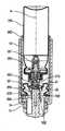
図面によれば、吸入器は本体10を備える。ユーザが吸入器を使用するには、本体10が有するマウスピース400の吸入口を介して吸入する。吸入器の保管時には特に、マウスピース400に取り外し可能な保護キャップ410を取り付けてもよい。ユーザは吸入器の使用時にこの保護キャップ410を取り外す。図1、図8および図9に示す保護キャップはいかなる形状でもよい。 According to the drawings, the inhaler comprises a
本体10は容器100を収容している。容器100には、吐出用の流体およびハイドロフルオロアルカン(HFA)類のような推進用ガスが入れられている。また、容器100には、流体を選択的に吐出するための計量弁200が装着されている。計量弁200は弁本体201および弁部材210を含む。吸入器が作動する間、弁部材210は、弁本体201ひいては容器100に対して、軸方向に移動可能である。計量弁200は適切であればいかなる形状でもよい。計量弁200は、留め具、好ましくはクリンプキャップ5を用いて容器100に固定されてもよい。この場合、クリンプキャップ5と容器100の間にはネックガスケット4を挿入することが好ましい。 The
吸入器が作動する間、弁部材210は本体10に対して静止し、容器100は待機位置である先端位置と基端位置の間で本体10に対して軸方向に移動することが好ましい。 Preferably, during operation of the inhaler, the
計量弁200の弁部材210の開口は、流路300を介してマウスピース400に連通している。ユーザは、このマウスピース400を介して、吐出される流体を吸入する。公知技術によれば、弁部材210は弁受け700に受け止められる。弁受け700には少なくとも部分的に流路300が含まれる。弁受け700は、図1〜図9の実施形態では本体10と一体形成されている一方で、図14〜図16の実施形態では本体10に対して軸方向に移動可能である。 The opening of the
本発明の吸入器はアクチュエータ500、500´を備える。アクチュエータ500、500´は、計量弁200の作動に係る非作動位置と作動位置の間で移動および/または変形可能である。計量弁200は、アクチュエータ500、500´が非作動位置にある間は作動不可能であり、アクチュエータ500、500´が作動位置にある間は作動可能である。吸入器が待機状態にあるときは、アクチュエータ500、500´は非作動位置にある。ユーザがマウスピース400を介して吸気すると、アクチュエータ500、500´は作動位置に向かって移動および/または変形する。つまり、ユーザが吸気しないかぎり、計量弁200を作動させることはできない。なお、計量弁200の作動は、ユーザが吸気しながら容器100の底部を手で押圧して行うことが好ましい。 The inhaler of the present invention comprises an
以下にさらに詳述するとおり、アクチュエータとしての阻止部材500、500´は、非作動位置では、容器100が本体10の内部を軸方向に移動することを阻止する。ユーザが吸気すると阻止部材500、500´は移動および/または変形するので、容器100は本体10の内部を軸方向に移動可能になる。吸気が完了すると、容器100が軸方向に移動して計量弁200が作動する。こうして、吸気に同期して1回分の流体が吐出される。 As described in more detail below, the blocking
したがって、ユーザが吸気していないのにもかかわらず吸入器が偶発的にまたは不完全に作動して有効な流体が失われるおそれはない。つまり、ユーザが吸気と同時に容器100を押圧して計量弁200を作動させないかぎり、流体は吐出されない。 Thus, there is no risk that the inhaler will accidentally or incompletely operate and lose effective fluid despite the fact that the user is not inhaling. That is, the fluid is not discharged unless the user presses the
吸入器は吸気制御式のトリガ機構を含む。ユーザがマウスピース400を介して吸気すると、トリガ機構は、アクチュエータ500、500´を非作動位置から作動位置に向けて移動および/または変形させる。 The inhaler includes an intake controlled trigger mechanism. When the user inhales through the
トリガ機構は、ユーザの吸気に反応して移動および/または変形可能な吸気反応部材60、65を含む。吸気反応部材60、65が移動および/または変形すると、アクチュエータ500、500´は非作動位置から作動位置に向かって移動および/または変形する。 The trigger mechanism includes an
以下にさらに詳述するとおり、吸気反応部材は、変形可能な蛇腹や袋などで構成した空気室60でもよい。 As will be described in more detail below, the intake reaction member may be an
図14〜図16に示すように、変形例として吸気反応部材はピストン65でもよい。ピストン65は円筒形状であることが好ましく、チャンバ66の内部を摺動する。チャンバ66は円筒形状であり変形不可能であることが好ましい。 As shown in FIGS. 14 to 16, as a modification, the intake reaction member may be a
図1〜図13に示す第1実施形態では、非作動位置は、容器100が本体10の内部における移動を阻止されている位置に対応する。容器100は、この位置ではアクチュエータ500、500´に移動を阻止され、ユーザの吸気中にのみ移動可能になる。 In the first embodiment shown in FIGS. 1 to 13, the inoperative position corresponds to the position in which the
図10に本体10を具体的に示すが、その形状は当然ながら図示した形状に限定されるものではない。 Although the
この実施形態では、アクチュエータとしての阻止部材は、好ましくは阻止リング500である。阻止リング500は、半径方向外側に弾性変形可能な軸状の阻止つまみ501を、少なくとも1つ、好ましくは3つ有する。図11は阻止リング500の斜視図である。阻止リング500は容器100に、具体的には留め具を用いて、固定されている。具体的には、計量弁200を容器100に固定しているクリンプキャップ5に対して、阻止リング500が固定されている。吸入器が待機状態にあるときは、阻止つまみ501は弁受け700の肩部710に載荷されている。肩部710は、好ましくは下方および半径方向外側に傾斜している。このように構成すれば、吸入器の作動中に容器100が本体10の内部を軸方向に摺動すると、軸状の阻止つまみ501は肩部710の傾斜面を摺動して半径方向外側に変形する。 In this embodiment, the blocking member as an actuator is preferably a
トリガ部材600は弁受け700の周囲に装着されており、阻止位置と解除位置の間を軸方向に摺動する。トリガ部材600は、阻止位置では阻止リング500の移動を非作動位置において阻止し、解除位置では阻止リング500の移動を阻止しない。具体的に図1〜図13に示す第1実施形態では、トリガ部材600は、阻止位置では阻止つまみ501と協働するので、阻止つまみ501の半径方向外側への変形を阻止する。よって、弁受け700の肩部710は阻止つまみ501の軸方向移動を阻止し続ける。そのため、容器100の軸方向移動ひいては計量弁200の作動も阻止される。なお、ユーザの吸気中にトリガ部材600が摺動しやすいように、トリガ部材600と弁受け700の間にボールのような摺動手段を挿入してもよい。 The
図12にさらに具体的に示すように、トリガ部材600は、中央スリーブ650および2つの軸状つまみ660を含むことが好ましい。中央スリーブ650は、中空であり、弁受け700を取り囲んだ状態で軸方向に摺動可能である。2つの軸状つまみ660は、直径の両側で対向しており、半径方向に延伸するスペーサ670を介して中央スリーブ650に接続している。軸状つまみ660はそれぞれ、本体10に設けられた対応する開口13と協働して、阻止位置では開口13を実質的に閉鎖し、解除位置では開口13を実質的に開放する。ユーザが吸気を開始する時点では開口13は閉鎖されている。よって、吸気流の大部分はトリガ機構に最初に到達する。この実施形態では、トリガ機構は変形可能な空気室60である。このように、吸気によってトリガを最適化できる。ユーザが吸気すると、トリガ部材600が解除位置に向かって軸方向に移動して、計量弁200が作動する。このとき、軸状つまみ660が本体10の開口13を開放するので、空気が流入して吸気流が増加する。このようにして流体を吐出させることができる。その結果、ユーザの吸気と流体の吐出が最適に同期できるので、流体が良好にユーザの肺に到達しやすくなる。 As shown more particularly in FIG. 12, the
好ましくは、ユーザは吸入器の外から開口13を通じて軸状つまみ660を操作可能である。このように構成すれば、ユーザは、必要に応じて吸入器の外からトリガ部材600を手動で移動させることにより、計量弁200を作動できる。したがって、ユーザが流体の服用を必要とするものの十分に吸気できない場合のように吸気がない場合でも、流体の吐出が可能になる。このように、軸状つまみ660は安全策である。この安全策の変形例として、軸方向延伸部(図示せず)をトリガ部材600に固定してもよい。軸方向延伸部は、例えば横方向に延伸しており、本体10の外からユーザにより操作可能でもよい。 Preferably, the user can operate the
図2からわかるように、軸状つまみ660は、本体10の第1肩部14と協働してトリガ部材600の阻止位置を決めることが好ましい。具体的には、軸状つまみ660は第1肩部14と軸方向に当接することにより、トリガ部材600が阻止位置より上方へ移動することを阻止する。同様に図5からわかるように、軸状つまみ660は、本体10の第2肩部15と協働してトリガ部材600の解除位置を決めることが好ましい。具体的には、軸状つまみ660は第2肩部15と軸方向に当接することにより、トリガ部材600が解除位置より下方へ移動することを阻止する。 As can be seen in FIG. 2, the
変形例(図示せず)として、トリガ部材600に軸状つまみ660を含めない、ひいては本体10に開口13を含めない構成としてもよい。この場合、中央スリーブ650に切り欠きを軸状に設けて空気流を通過させれば、吸気流は本体10の内部を弁受け700の周囲で軸方向に進行する。 As a modification (not shown), the
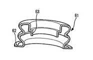
図1〜図13の実施形態では、吸気反応部材60は変形可能な空気室である。空気室は変形可能な膜体61からなることが好ましい。膜体61は本体10およびトリガ部材600に連通している。図1〜図9からわかるように、本体10に膜体担持スリーブ800を固定することが好ましい。膜体担持スリーブ800の底にある肩部810は、膜体61の第1端部62を本体10の部分17に押し付ける。膜体61の第2端部63は、トリガ部材600の管630に固定されてもよい。管630は、トリガ部材600の中空の中央スリーブ650に形成されることが好ましい。図13の断面図に示す膜体61は蛇腹であるが、その他の構造でもよい。具体的には、図8に示すような単なる袋やダイヤフラムなどでもよい。 In the embodiment of FIGS. 1-13, the
ユーザが吸気すると、その吸気で生じる吸引力によって、変形可能な膜体61が変形および/または収縮するので、トリガ部材600が阻止位置から解除位置に向かって移動する。そうすると、阻止つまみ501が変形するので、アクチュエータである阻止リング500が非作動位置から作動位置に向かって移動する。変形可能な膜体61は、図1〜図7では蛇腹である一方で、図8の変形例では袋またはダイヤフラムである。当然ながら、変形可能な膜体61はその他の構造でもよい。 When the user inhales, the attractive force generated by the inhalation deforms and / or contracts the
このように、ユーザの吸気中にのみ計量弁200が作動するので、吸気に同期して1回分の流体が吸入口を介して吐出される。 As described above, since the
ユーザが吸入器を使用するには、マウスピース400を口にくわえて、図面では容器100の上面にあたる、容器100の底部を手で押圧する。この時点では、阻止リング500の阻止つまみ501が弁受け700の肩部710に載荷されているので、容器100が本体10の内部を摺動することは阻止されている。なお、容器100は、その摺動を阻止される前に、計量弁200の作動はできない程度の短ストロークd1で移動してもよい。吸入器は、図1では待機状態にあり、図3では容器100が短ストロークd1で移動した後にその摺動が阻止されている状態にある。 To use the inhaler, the user holds the
図4からわかるように、ユーザがマウスピース400を介して吸気すると、変形可能な膜体61が変形して、この膜体61に固定されたトリガ部材600が摺動する。トリガ部材600が弁受け700に沿って移動するので、阻止リング500の阻止つまみ501は半径方向に移動可能になる。ユーザが容器100の底部を押圧すると、軸方向の力が生じて容器100から軸状の阻止つまみ501に伝達する。この軸方向の力によって、軸状の阻止つまみ501は半径方向外側に変形可能になり肩部710を通過する。こうして、容器100が吐出位置に向かって摺動して計量弁200が作動する。図5および図6は、容器100が吐出位置にあるときの吸入器を示す。 As can be seen from FIG. 4, when the user inhales through the
ユーザが吸気を終えると、トリガ部材600は膜体61の弾性力によって上方に戻る。図7は、トリガ部材600が膜体61の弾性力によって上方に戻ったものの、ユーザが容器100に対する押圧を解除していない状態の吸入器を示す。 When the user finishes inhaling, the
ユーザが容器100の底部に対する押圧を解除すると、容器100は計量弁200の戻しバネによって待機位置に戻る。これと同時に計量弁200の弁部材210も静止位置に戻るので、弁室が新たな1回分の流体で満たされる。このようにして吸入器は以後の使用に備える。 When the user releases the pressure on the bottom of the
図9は、図8の実施形態の変形例を示す。この変形例では電子モジュールを用いる。 FIG. 9 shows a variant of the embodiment of FIG. In this modification, an electronic module is used.
具体的には、電子ドーズカウンタ1000を、好ましくは本体10に装着することによって、吸入器に備える。電子ドーズカウンタ1000は、例えば接触センサ1010によって、容器100の移動を検知可能である。さらに、電子ドーズカウンタ1000を、吐出中の流体を検知するセンサに接続してもよい。このセンサは、具体的には膜体センサであり、例えば弁受け700に設けられている。電子ドーズカウンタ1000の作動は、例えば、弁本体201に対する弁部材210の移動を検知するような他の方法で行ってもよい。 Specifically, the
また、吸入器の作動に係る情報の通信を行う信号送信手段1100を、吸入器に備えることが好ましい。この通信は具体的には遠隔通信である。特に、基地局との遠隔通信を行う信号送信モジュールを本体10に含めてもよい。適切な電源手段を設けることが好ましい。 Preferably, the inhaler is provided with signal transmission means 1100 for communicating information related to the operation of the inhaler. This communication is specifically telecommunication. In particular, the
具体的には、電子モジュールに、パルス送信する電気スイッチがあるカードを含めることが好ましい。また、電子モジュールに表示装置を含めること、および/または、電子モジュールがBluetooth(登録商標)接続またはWi−Fi接続により情報を周辺機器に送信することも可能である。さらに、流速センサおよび/または圧力センサなどの適切なセンサを設けて、吸気流の各種パラメータを検知してもよい。 In particular, the electronic module preferably includes a card with an electrical switch that transmits pulses. It is also possible to include a display device in the electronic module and / or to transmit information to the peripheral device via Bluetooth® connection or Wi-Fi connection. Additionally, appropriate sensors such as flow rate sensors and / or pressure sensors may be provided to sense various parameters of the inspiratory flow.
本発明に係る吸気同期式の吸入器に、実投与回数を計数する電子ドーズカウンタ1000とともに信号送信手段1100を用いれば、医師やユーザによる吸入器の使用状況を監視したい者に対して、流体の投与のたびに確実に信号を送信できる。吸入器が吸気同期式であるので、ユーザは吸入器を作動させるたびに流体を吸入できる。また、電子ドーズカウンタ1000は、流体の投与のたびにその回数を、投与時刻のような投与に関連する各種のパラメータとともに記録できる。このようにすれば、ユーザによる吸入器の使用状況を、医師がきわめて正確に把握することができる。 If the signal transmission means 1100 is used together with the
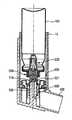
図14〜図16に示すように、変形例としてのアクチュエータは阻止部材500´である。阻止部材500´は、非作動位置では、容器100が本体10の内部を軸方向に移動することを阻止する。ユーザが吸気すると阻止部材500´は移動および/または変形するので、容器100が本体10の内部を軸方向に移動可能になる。吸気が完了すると、容器100が軸方向に移動して計量弁200が作動する。こうして、吸気に同期して1回分の流体が吐出される。 As shown in FIGS. 14-16, an alternative actuator is a blocking member 500 '. The blocking
この変形例では、吸気反応部材はピストン65である。ピストン65は、チャンバ66の内部で静止位置と吸気位置の間を摺動する。チャンバ66はマウスピース400に含まれることが好ましい。ピストン65にはロッド540が接続されている。ユーザがマウスピース400を介して吸入を終えると、ピストン65はバネ67によって静止位置に戻る。バネ67はチャンバ66に配されることが好ましい。 In this modification, the intake reaction member is a
ユーザがマウスピース400を介して吸気すると、その吸気で生じる吸引力によって、ピストン65は、(本体10の内部における容器100の移動軸に対して)チャンバ66の内部を半径方向に移動する。 When the user inhales through the
具体的には、阻止部材500´は、ピストン65に固定されたロッド540に装着されてもよい。また、阻止部材500´は軸方向延伸部505を含んでもよい。軸方向延伸部505は、非作動位置では、本体10の内部を軸方向に延伸して容器100と協働するので、容器100の軸方向移動が阻止される。ユーザが吸気すると、ロッド540が半径方向を左側に(図示する向きに)移動するので、軸方向延伸部505が変形して容器100が軸方向に移動可能になる。弁受け700は、図示した変形例では本体10の内部を移動可能に装着されているが、固定されてもよい。 Specifically, the blocking
軸方向延伸部505の下端部506は、本体10に対して半径方向および軸方向に固定されることが好ましい。このように構成すれば、ロッド540が半径方向に移動すると、軸方向延伸部505が半径方向に引っ張られて屈曲や旋回するなどして変形する。そうすると、軸方向延伸部505の上端部が容器100から外れるので、容器100が軸方向に移動可能になる。当然ながら、阻止部材500´は他の構成でもよい。具体的には、蝶番式のトグルを用いてもよい。 The
図16に示す変形例では、ユーザは吸入器の外から本体10の開口19を通じてロッド540を操作可能である。この構成によれば、ユーザは必要に応じて阻止部材500´を手動で移動させることができる。よって、ユーザが流体の服用を必要とするものの十分に吸気できない場合のように吸気がない場合でも、計量弁200の作動が可能になる。このように、ロッド540は安全策である。 In the variant shown in FIG. 16, the user can manipulate the
図14〜図16に示す吸入器に、図9を用いて説明した電子モジュールのような電子的手段を含めてもよいが、ここでの説明は省略する。 Although the inhaler shown in FIGS. 14 to 16 may include electronic means such as the electronic module described with reference to FIG. 9, the description here is omitted.
本発明は、サルブタモール、アクリジニウム、ホルモテロール、チオトロピウム、ブデソニド、フルチカゾン、インダカテロール、グリコピロニウム、サルメテロール、ウメクリジニウム臭化物、ビランテロール、およびオロダテロール(Striverdi(登録商標))の処方またはこれらの処方の組み合わせにより行われる、喘息発作や慢性閉塞性肺疾患(COPD)の治療に特に適用される。 The present invention is based on a formulation of salbutamol, acridinium, formoterol, tiotropium, budesonide, fluticasone, indacaterol, glycopironium, salmeterol, umeclidinium bromide, viranterol, and olodaterol (Striverdi (registered trademark)) or a combination of these formulations. It is particularly applied to the treatment of asthma attacks and chronic obstructive pulmonary disease (COPD).
本発明について、各種の有利な実施の形態および変形例に基づいて説明したが、当然ながら当業者は、添付の特許請求の範囲において定義した本発明の範囲を逸脱しない限りにおいて、変形を適用してもよい。 While the invention has been described on the basis of various advantageous embodiments and variants, it is understood that those skilled in the art will apply the variants without departing from the scope of the invention as defined in the appended claims. May be
Claims (11)
Translated fromJapaneseマウスピース(400)を有する本体(10)と、
前記本体(10)の内部を軸方向に摺動し、流体および推進用ガスが入れられている流体用の容器(100)と、
前記容器(100)に装着されており、前記流体を選択的に吐出する弁部材(210)を含む計量弁(200)と、
前記計量弁(200)が作動可能である非作動位置と前記計量弁(200)が作動不可能である作動位置との間で移動および/または変形可能であるアクチュエータ(500、500´)と、
吸気に反応して移動および/または変形可能な吸気反応部材(60)を含む吸気制御式トリガ機構と
を備え、
前記吸気反応部材(60)は、移動および/または変形することにより、前記アクチュエータ(500、500´)を前記非作動位置から前記作動位置に向けて移動および/または変形させ、
前記アクチュエータは、阻止部材(500、500´)として、
前記非作動位置では、前記本体(10)および前記容器(100)とこの順で協働することにより、前記容器(100)が前記本体(10)の内部を軸方向に移動することを阻止する
ことを特徴とする流体吐出装置。Intake synchronous fluid discharge device,
A body (10) having a mouthpiece (400);
A container (100) for fluid that slides axially inside the body (10) and contains a fluid and a propellant gas;
A metering valve (200) mounted on the container (100) and including a valve member (210) for selectively discharging the fluid;
An actuator (500, 500 ') movable and / or deformable between a non-actuated position in which the metering valve (200) is actuatable and an actuated position in which the metering valve (200) is inoperable;
An intake control trigger mechanism including an intake response member (60) movable and / or deformable in response to intake;
The intake reaction member (60) moves and / or deforms the actuator (500, 500 ') from the non-actuation position toward the actuation position by being moved and / or deformed.
The actuator is used as a blocking member (500, 500 ')
In the non-actuated position, the container (100) is prevented from axially moving inside the body (10) by cooperating with the body (10) and the container (100) in this order A fluid discharge device characterized by
前記容器(100)に、具体的には留め具を用いて、固定されており、
軸状のつまみ(501)を少なくとも1つ、具体的には3つ有し、
前記つまみ(501)が前記本体(10)の肩部(710)と協働することにより、前記容器(100)が前記本体(10)の内部を軸方向に移動することを阻止する
ことを特徴とする請求項1に記載の流体吐出装置。The blocking member is a blocking ring (500)
It is being fixed to the said container (100) specifically using a fastener.
Have at least one, in particular three, axial knobs (501),
The knob (501) cooperates with the shoulder (710) of the body (10) to prevent the container (100) from moving axially inside the body (10) The fluid ejection device according to claim 1.
前記阻止リング(500)は、前記つまみ(501)が半径方向外側に変形することにより、前記非作動位置から前記作動位置へ向かって移動可能であり、
前記トリガ部材(600)は、前記つまみ(501)を前記非作動位置に保持する
ことを特徴とする請求項2に記載の流体吐出装置。Further comprising a trigger member (600),
The blocking ring (500) is movable from the inoperative position toward the operative position by radially outward deformation of the knob (501);
The fluid ejection device according to claim 2, wherein the trigger member (600) holds the knob (501) in the inoperative position.
前記阻止リング(500)の移動を前記非作動位置において阻止する阻止位置と前記阻止リング(500)の移動を阻止しない解除位置との間を移動するように装着されている
ことを特徴とする請求項3に記載の流体吐出装置。The trigger member (600) is
The device is characterized in that it is mounted to move between a blocking position blocking the movement of the blocking ring (500) in the inoperative position and a release position not blocking the movement of the blocking ring (500) The fluid discharge device according to Item 3.
前記膜体(61)は、
吸気中に変形する空気室(60)を構成し、
前記トリガ部材(600)を前記阻止位置から前記解除位置に向けて移動させるように、前記トリガ部材(600)に固定されている
ことを特徴とする請求項4に記載の流体吐出装置。The inhalation controlled trigger mechanism comprises a deformable membrane (61),
The membrane body (61) is
Constitute an air chamber (60) that deforms during intake,
A fluid ejection device according to claim 4, characterized in that it is fixed to the trigger member (600) so as to move the trigger member (600) from the blocking position towards the release position.
前記トリガ部材(600)は、前記開口(13)を通じてユーザによる操作が可能であることにより、吸気の有無に関わらず、手動で前記解除位置に向かって移動可能である
ことを特徴とする請求項3から5までのいずれか1項に記載の流体吐出装置。The body (10) is provided with at least one opening (13),
The trigger member (600) is manually movable toward the release position regardless of the presence or absence of intake by being operable by the user through the opening (13). The fluid discharge device according to any one of 3 to 5.
前記軸方向延伸部(505)の下先端(506)は、前記本体(10)に対して半径方向および軸方向に固定されており、
前記作動位置では、前記軸方向延伸部(505)の上先端は、前記容器(100)と協働する
ことを特徴とする請求項1に記載の流体吐出装置。The blocking member (500 ') has an axial extension (505),
The lower tip (506) of the axial extension (505) is radially and axially fixed with respect to the body (10),
A fluid ejector according to claim 1, characterized in that in the operative position, the upper extremity of the axial extension (505) cooperates with the container (100).
ことを特徴とする請求項7に記載の流体吐出装置。The fluid ejection device according to claim 7, characterized in that the suction-controlled trigger mechanism comprises a piston (65) sliding between a rest position and a suction position inside the chamber (66).
前記ロッド(540)は吸気中に半径方向に移動することにより、前記軸方向延伸部(505)を前記作動位置に向けて移動および/または変形させる
ことを特徴とする請求項8に記載の流体吐出装置。The blocking member (500 ') is attached to a rod (540),
A fluid according to claim 8, characterized in that said rod (540) is moved radially during intake to move and / or deform said axial extension (505) towards said operative position. Discharge device.
ことを特徴とする請求項1から9までのいずれか1項に記載の流体吐出装置。10. A fluid ejector according to any one of the preceding claims, further comprising an electronic dose counter (1000).
前記通信は、具体的には遠隔通信である
ことを特徴とする請求項1から10までのいずれか1項に記載の流体吐出装置。It further comprises signal transmission means (1100) for communicating information related to the operation of the fluid ejection device,
11. A fluid ejection device according to any one of the preceding claims, characterized in that the communication is in particular a telecommunication.
Applications Claiming Priority (3)
| Application Number | Priority Date | Filing Date | Title |
|---|---|---|---|
| FR1653367 | 2016-04-15 | ||
| FR1653367AFR3050114B1 (en) | 2016-04-15 | 2016-04-15 | FLUID PRODUCT DISTRIBUTION DEVICE SYNCHRONIZED WITH INHALATION. |
| PCT/FR2017/050891WO2017178765A1 (en) | 2016-04-15 | 2017-04-13 | Device for inhalation-synchronised dispensing of a fluid product |
Publications (2)
| Publication Number | Publication Date |
|---|---|
| JP2019511328Atrue JP2019511328A (en) | 2019-04-25 |
| JP6921856B2 JP6921856B2 (en) | 2021-08-18 |
Family
ID=56087426
Family Applications (1)
| Application Number | Title | Priority Date | Filing Date |
|---|---|---|---|
| JP2018553995AActiveJP6921856B2 (en) | 2016-04-15 | 2017-04-13 | Intake synchronous fluid discharge device |
Country Status (6)
| Country | Link |
|---|---|
| US (2) | US12303639B2 (en) |
| EP (2) | EP3442633B1 (en) |
| JP (1) | JP6921856B2 (en) |
| CN (2) | CN109069765B (en) |
| FR (1) | FR3050114B1 (en) |
| WO (2) | WO2017178768A1 (en) |
Families Citing this family (18)
| Publication number | Priority date | Publication date | Assignee | Title |
|---|---|---|---|---|
| FR3050116B1 (en)* | 2016-04-15 | 2020-05-15 | Aptar France Sas | DEVICE FOR DISPENSING SYNCHRONIZED FLUID PRODUCT WITH INHALATION |
| FR3074051B1 (en)* | 2017-11-29 | 2019-11-22 | Aptar France Sas | DEVICE FOR DISPENSING FLUID PRODUCT SYNCHRONIZED WITH INHALATION |
| DE102018117106A1 (en)* | 2018-07-16 | 2020-01-16 | Alfred Von Schuckmann | Handheld device for portioned dispensing of sprayable substances |
| CA3119536A1 (en) | 2018-11-14 | 2020-05-22 | Loop Laboratories, LLC | Inhalant dispensing system and apparatus |
| USD955552S1 (en)* | 2018-11-14 | 2022-06-21 | Loop Laboratories, LLC | Inhalant dispenser |
| FR3089127B1 (en)* | 2018-11-30 | 2020-11-20 | Aptar France Sas | Fluid dispenser device synchronized with inhalation |
| FR3092251B1 (en)* | 2019-02-04 | 2021-01-22 | Aptar France Sas | Fluid dispenser device synchronized with inhalation and method of assembling said device |
| CA3140949A1 (en) | 2019-05-17 | 2020-11-26 | Norton (Waterford) Limited | Drug delivery device with electronics |
| JP2023514893A (en)* | 2019-05-24 | 2023-04-12 | ピュア サイエンティフィック テクノロジーズ インコーポレイテッド | dual metering inhaler |
| USD1061877S1 (en) | 2019-07-31 | 2025-02-11 | Reciprocal Labs Corporation | Modular adherence monitor for attachment to an inhaler |
| USD1046114S1 (en)* | 2019-07-31 | 2024-10-08 | Reciprocal Labs Corporation | Modular adherence monitor for attachment to an inhaler |
| US12233201B2 (en) | 2020-06-19 | 2025-02-25 | Norton (Waterford) Limited | Inhaler system |
| US11464923B2 (en) | 2020-06-19 | 2022-10-11 | Norton (Waterford) Limited | Inhaler system |
| USD1004849S1 (en) | 2021-06-08 | 2023-11-14 | Loop Laboratories, LLC | Compact atomizer |
| US12414916B2 (en) | 2021-06-10 | 2025-09-16 | Belhaven BioPharma Inc. | Dry powder formulations of epinephrine and associated methods |
| US11617716B2 (en) | 2021-06-10 | 2023-04-04 | Belhaven BioPharma Inc. | Dry powder formulations of epinephrine and associated methods |
| USD1026205S1 (en) | 2021-07-23 | 2024-05-07 | Reciprocal Labs Corporation | Modular inhaler adherence monitor |
| US12005185B2 (en) | 2021-12-17 | 2024-06-11 | Belhaven BioPharma Inc. | Medical counter measures including dry powder formulations and associated methods |
Citations (4)
| Publication number | Priority date | Publication date | Assignee | Title |
|---|---|---|---|---|
| US5027808A (en)* | 1990-10-31 | 1991-07-02 | Tenax Corporation | Breath-activated inhalation device |
| US6341603B1 (en)* | 1998-12-11 | 2002-01-29 | Bespak Plc | Inhalation apparatus |
| JP2002505163A (en)* | 1998-03-04 | 2002-02-19 | テブロ | Fluid product dosing device driven by inhalation operation |
| JP2003510736A (en)* | 1999-10-01 | 2003-03-18 | グラクソ グループ リミテッド | Drug delivery system |
Family Cites Families (41)
| Publication number | Priority date | Publication date | Assignee | Title |
|---|---|---|---|---|
| US3456644A (en)* | 1967-01-19 | 1969-07-22 | Dart Ind Inc | Inhalation-actuated aerosol dispensing device |
| US3732864A (en)* | 1971-06-07 | 1973-05-15 | Schering Corp | Inhalation coordinated aerosol dispensing device |
| DE3040641A1 (en) | 1980-10-29 | 1982-05-27 | C.H. Boehringer Sohn, 6507 Ingelheim | Mouthpiece for aerosol inhalation - with flat and slider for actuation by inspiration |
| GB8328808D0 (en)* | 1983-10-28 | 1983-11-30 | Riker Laboratories Inc | Inhalation responsive dispensers |
| US4819834A (en)* | 1986-09-09 | 1989-04-11 | Minnesota Mining And Manufacturing Company | Apparatus and methods for delivering a predetermined amount of a pressurized fluid |
| US5119806A (en)* | 1987-05-12 | 1992-06-09 | Glaxo Inc. | Inhalation device |
| GB8919131D0 (en)* | 1989-08-23 | 1989-10-04 | Riker Laboratories Inc | Inhaler |
| FR2658081B1 (en)* | 1990-02-09 | 1995-06-30 | Pesenti Yvan | AUTOMATION AND SYNCHRONIZATION DEVICE FOR AEROSOL APPARATUS WITH DOSING PUMP. |
| GB9015077D0 (en)* | 1990-07-09 | 1990-08-29 | Riker Laboratories Inc | Inhaler |
| US5060643A (en)* | 1990-08-07 | 1991-10-29 | Tenax Corporation | Breath-activated inhalation device |
| US5507281A (en)* | 1990-08-30 | 1996-04-16 | Boehringer Ingelheim Kg | Device for initiating a mechanical switching operation in synchronism with the breathing |
| FR2817247B1 (en)* | 2000-11-24 | 2003-02-14 | Valois Sa | FLUID PRODUCT DISPENSING DEVICE |
| GB0114175D0 (en)* | 2001-06-11 | 2001-08-01 | Glaxo Group Ltd | Medicament dispenser |
| FR2834277B1 (en)* | 2001-12-28 | 2004-06-11 | Valois Sa | FLUID PRODUCT DISPENSING DEVICE |
| GB0204829D0 (en)* | 2002-03-01 | 2002-04-17 | Glaxo Group Ltd | A fluid dispensing device |
| GB0222295D0 (en)* | 2002-09-25 | 2002-10-30 | 3M Innovative Properties Co | Breath actuated medicament dispensing devices |
| GB0304000D0 (en)* | 2003-02-21 | 2003-03-26 | Clinical Designs Ltd | Dispenser |
| US7543582B2 (en)* | 2004-09-20 | 2009-06-09 | Trudell Medical International | Dose indicating device with display elements attached to container |
| SE0402434D0 (en)* | 2004-10-08 | 2004-10-08 | Astrazeneca Ab | Inhaler valve |
| WO2006077486A1 (en)* | 2005-01-20 | 2006-07-27 | Trudell Medical International | Dispensing device |
| GB0518400D0 (en)* | 2005-09-09 | 2005-10-19 | Clinical Designs Ltd | Dispenser |
| GB0614621D0 (en)* | 2006-07-24 | 2006-08-30 | 3M Innovative Properties Co | Metered dose dispensers |
| RU2009105638A (en)* | 2006-08-22 | 2010-09-27 | Глакса Груп Лимитед (GB) | ACTUATOR FOR INHALER |
| US8225790B2 (en)* | 2007-01-02 | 2012-07-24 | Astrazeneca Ab | Inhaler 624 |
| US20080210231A1 (en)* | 2007-01-31 | 2008-09-04 | Abbott Laboratories | Metered dose inhaler cleaning method and apparatus |
| GB2451833A (en)* | 2007-08-13 | 2009-02-18 | Bespak Plc | Electrically actuated dose counter for dispensing apparatus |
| CN102131540B (en)* | 2008-07-10 | 2015-04-22 | 邦及奥卢夫森美迪康股份公司 | Inhaler and method of operating same |
| NZ591957A (en)* | 2008-10-08 | 2013-08-30 | Astrazeneca Ab | A breath activated inhaler |
| BR112012002716A2 (en)* | 2009-08-07 | 2020-08-04 | Kind Consumer Limited | inhaler |
| FR2973012B1 (en)* | 2011-03-21 | 2013-04-26 | Valois Sas | DEVICE FOR DISPENSING FLUID PRODUCT WITH SIDE ACTUATION. |
| GB201115870D0 (en)* | 2011-09-14 | 2011-10-26 | Astrazeneca Ab | Inhaler |
| GB201118845D0 (en)* | 2011-11-01 | 2011-12-14 | Euro Celtique Sa | Dispenser |
| GB201221063D0 (en)* | 2012-11-23 | 2013-01-09 | 3M Innovative Properties Co | Metered dose dispensing valve |
| GB201322677D0 (en)* | 2013-12-20 | 2014-02-05 | 3M Innovative Properties Co | Actuator for an inhaler |
| DE102014204939B3 (en)* | 2014-03-17 | 2014-12-24 | Aptar Radolfzell Gmbh | Dispenser with an electronic actuation recognition |
| EP3125821B1 (en)* | 2014-03-31 | 2023-06-07 | Boehringer Ingelheim Vetmedica GmbH | Insert for an inhaler |
| GB201408229D0 (en)* | 2014-05-09 | 2014-06-25 | Norton Waterford Ltd | Aerosol device |
| GB2535796A (en)* | 2015-02-27 | 2016-08-31 | 3M Innovative Properties Co | Improvements in or relating to metered dose inhalers |
| EP3443554B1 (en)* | 2016-04-12 | 2021-07-14 | Noble International, Inc. | Metered dose inhaler training device |
| FR3050116B1 (en)* | 2016-04-15 | 2020-05-15 | Aptar France Sas | DEVICE FOR DISPENSING SYNCHRONIZED FLUID PRODUCT WITH INHALATION |
| EP3578218A1 (en)* | 2018-06-08 | 2019-12-11 | Presspart Manufacturing S.A. | Inhaler |
- 2016
- 2016-04-15FRFR1653367Apatent/FR3050114B1/enactiveActive
- 2017
- 2017-04-13EPEP17723448.1Apatent/EP3442633B1/enactiveActive
- 2017-04-13EPEP17723446.5Apatent/EP3442631B1/enactiveActive
- 2017-04-13JPJP2018553995Apatent/JP6921856B2/enactiveActive
- 2017-04-13USUS16/086,103patent/US12303639B2/enactiveActive
- 2017-04-13WOPCT/FR2017/050895patent/WO2017178768A1/ennot_activeCeased
- 2017-04-13CNCN201780023116.9Apatent/CN109069765B/ennot_activeExpired - Fee Related
- 2017-04-13USUS16/093,305patent/US10967140B2/enactiveActive
- 2017-04-13WOPCT/FR2017/050891patent/WO2017178765A1/ennot_activeCeased
- 2017-04-13CNCN201780020161.9Apatent/CN108883239B/enactiveActive
Patent Citations (4)
| Publication number | Priority date | Publication date | Assignee | Title |
|---|---|---|---|---|
| US5027808A (en)* | 1990-10-31 | 1991-07-02 | Tenax Corporation | Breath-activated inhalation device |
| JP2002505163A (en)* | 1998-03-04 | 2002-02-19 | テブロ | Fluid product dosing device driven by inhalation operation |
| US6341603B1 (en)* | 1998-12-11 | 2002-01-29 | Bespak Plc | Inhalation apparatus |
| JP2003510736A (en)* | 1999-10-01 | 2003-03-18 | グラクソ グループ リミテッド | Drug delivery system |
Also Published As
| Publication number | Publication date |
|---|---|
| EP3442633B1 (en) | 2020-02-05 |
| JP6921856B2 (en) | 2021-08-18 |
| CN108883239B (en) | 2020-10-30 |
| FR3050114A1 (en) | 2017-10-20 |
| US20200297947A1 (en) | 2020-09-24 |
| EP3442633A1 (en) | 2019-02-20 |
| US10967140B2 (en) | 2021-04-06 |
| EP3442631B1 (en) | 2020-04-29 |
| CN109069765A (en) | 2018-12-21 |
| WO2017178765A1 (en) | 2017-10-19 |
| US20190175850A1 (en) | 2019-06-13 |
| US12303639B2 (en) | 2025-05-20 |
| FR3050114B1 (en) | 2021-12-03 |
| CN108883239A (en) | 2018-11-23 |
| WO2017178768A1 (en) | 2017-10-19 |
| EP3442631A1 (en) | 2019-02-20 |
| CN109069765B (en) | 2021-03-23 |
Similar Documents
| Publication | Publication Date | Title |
|---|---|---|
| JP6921856B2 (en) | Intake synchronous fluid discharge device | |
| JP6929871B2 (en) | Intake synchronous fluid discharge device | |
| CN113382762B (en) | Device for dispensing a fluid product in synchronism with inhalation and method for assembling a device | |
| JP6936249B2 (en) | Intake synchronous fluid discharge device | |
| CN113382761B (en) | Device for dispensing a fluid preparation in synchronism with inhalation | |
| CN113382760B (en) | Device for dispensing a fluid product in synchronism with inhalation | |
| JP7233420B2 (en) | Intake synchronous fluid ejection device | |
| JP7212043B2 (en) | Intake synchronous fluid ejection device | |
| CN111246905B (en) | Device for the synchronized dispensing of a fluid product by suction |
Legal Events
| Date | Code | Title | Description |
|---|---|---|---|
| A529 | Written submission of copy of amendment under article 34 pct | Free format text:JAPANESE INTERMEDIATE CODE: A529 Effective date:20181212 | |
| A621 | Written request for application examination | Free format text:JAPANESE INTERMEDIATE CODE: A621 Effective date:20200319 | |
| A977 | Report on retrieval | Free format text:JAPANESE INTERMEDIATE CODE: A971007 Effective date:20210226 | |
| A131 | Notification of reasons for refusal | Free format text:JAPANESE INTERMEDIATE CODE: A131 Effective date:20210302 | |
| A521 | Request for written amendment filed | Free format text:JAPANESE INTERMEDIATE CODE: A523 Effective date:20210528 | |
| TRDD | Decision of grant or rejection written | ||
| A01 | Written decision to grant a patent or to grant a registration (utility model) | Free format text:JAPANESE INTERMEDIATE CODE: A01 Effective date:20210629 | |
| A61 | First payment of annual fees (during grant procedure) | Free format text:JAPANESE INTERMEDIATE CODE: A61 Effective date:20210728 | |
| R150 | Certificate of patent or registration of utility model | Ref document number:6921856 Country of ref document:JP Free format text:JAPANESE INTERMEDIATE CODE: R150 |