JP2019510296A - Electronic device control and information display based on wireless ranging - Google Patents
Electronic device control and information display based on wireless rangingDownload PDFInfo
- Publication number
- JP2019510296A JP2019510296AJP2018539298AJP2018539298AJP2019510296AJP 2019510296 AJP2019510296 AJP 2019510296AJP 2018539298 AJP2018539298 AJP 2018539298AJP 2018539298 AJP2018539298 AJP 2018539298AJP 2019510296 AJP2019510296 AJP 2019510296A
- Authority
- JP
- Japan
- Prior art keywords
- wireless communication
- communication device
- wireless
- user
- physical
- Prior art date
- Legal status (The legal status is an assumption and is not a legal conclusion. Google has not performed a legal analysis and makes no representation as to the accuracy of the status listed.)
- Granted
Links
Images


Classifications
- H—ELECTRICITY
- H04—ELECTRIC COMMUNICATION TECHNIQUE
- H04W—WIRELESS COMMUNICATION NETWORKS
- H04W76/00—Connection management
- H04W76/10—Connection setup
- H04W76/14—Direct-mode setup
- G—PHYSICS
- G01—MEASURING; TESTING
- G01C—MEASURING DISTANCES, LEVELS OR BEARINGS; SURVEYING; NAVIGATION; GYROSCOPIC INSTRUMENTS; PHOTOGRAMMETRY OR VIDEOGRAMMETRY
- G01C21/00—Navigation; Navigational instruments not provided for in groups G01C1/00 - G01C19/00
- G01C21/20—Instruments for performing navigational calculations
- G—PHYSICS
- G06—COMPUTING OR CALCULATING; COUNTING
- G06F—ELECTRIC DIGITAL DATA PROCESSING
- G06F1/00—Details not covered by groups G06F3/00 - G06F13/00 and G06F21/00
- G06F1/16—Constructional details or arrangements
- G06F1/1613—Constructional details or arrangements for portable computers
- G06F1/1626—Constructional details or arrangements for portable computers with a single-body enclosure integrating a flat display, e.g. Personal Digital Assistants [PDAs]
- G—PHYSICS
- G06—COMPUTING OR CALCULATING; COUNTING
- G06F—ELECTRIC DIGITAL DATA PROCESSING
- G06F1/00—Details not covered by groups G06F3/00 - G06F13/00 and G06F21/00
- G06F1/16—Constructional details or arrangements
- G06F1/1613—Constructional details or arrangements for portable computers
- G06F1/163—Wearable computers, e.g. on a belt
- G—PHYSICS
- G06—COMPUTING OR CALCULATING; COUNTING
- G06F—ELECTRIC DIGITAL DATA PROCESSING
- G06F1/00—Details not covered by groups G06F3/00 - G06F13/00 and G06F21/00
- G06F1/16—Constructional details or arrangements
- G06F1/1613—Constructional details or arrangements for portable computers
- G06F1/1633—Constructional details or arrangements of portable computers not specific to the type of enclosures covered by groups G06F1/1615 - G06F1/1626
- G06F1/1684—Constructional details or arrangements related to integrated I/O peripherals not covered by groups G06F1/1635 - G06F1/1675
- G06F1/1694—Constructional details or arrangements related to integrated I/O peripherals not covered by groups G06F1/1635 - G06F1/1675 the I/O peripheral being a single or a set of motion sensors for pointer control or gesture input obtained by sensing movements of the portable computer
- G—PHYSICS
- G06—COMPUTING OR CALCULATING; COUNTING
- G06F—ELECTRIC DIGITAL DATA PROCESSING
- G06F1/00—Details not covered by groups G06F3/00 - G06F13/00 and G06F21/00
- G06F1/16—Constructional details or arrangements
- G06F1/1613—Constructional details or arrangements for portable computers
- G06F1/1633—Constructional details or arrangements of portable computers not specific to the type of enclosures covered by groups G06F1/1615 - G06F1/1626
- G06F1/1684—Constructional details or arrangements related to integrated I/O peripherals not covered by groups G06F1/1635 - G06F1/1675
- G06F1/1698—Constructional details or arrangements related to integrated I/O peripherals not covered by groups G06F1/1635 - G06F1/1675 the I/O peripheral being a sending/receiving arrangement to establish a cordless communication link, e.g. radio or infrared link, integrated cellular phone
- G—PHYSICS
- G06—COMPUTING OR CALCULATING; COUNTING
- G06F—ELECTRIC DIGITAL DATA PROCESSING
- G06F3/00—Input arrangements for transferring data to be processed into a form capable of being handled by the computer; Output arrangements for transferring data from processing unit to output unit, e.g. interface arrangements
- G06F3/01—Input arrangements or combined input and output arrangements for interaction between user and computer
- G06F3/011—Arrangements for interaction with the human body, e.g. for user immersion in virtual reality
- G—PHYSICS
- G06—COMPUTING OR CALCULATING; COUNTING
- G06F—ELECTRIC DIGITAL DATA PROCESSING
- G06F3/00—Input arrangements for transferring data to be processed into a form capable of being handled by the computer; Output arrangements for transferring data from processing unit to output unit, e.g. interface arrangements
- G06F3/01—Input arrangements or combined input and output arrangements for interaction between user and computer
- G06F3/016—Input arrangements with force or tactile feedback as computer generated output to the user
- G—PHYSICS
- G06—COMPUTING OR CALCULATING; COUNTING
- G06F—ELECTRIC DIGITAL DATA PROCESSING
- G06F3/00—Input arrangements for transferring data to be processed into a form capable of being handled by the computer; Output arrangements for transferring data from processing unit to output unit, e.g. interface arrangements
- G06F3/01—Input arrangements or combined input and output arrangements for interaction between user and computer
- G06F3/017—Gesture based interaction, e.g. based on a set of recognized hand gestures
- G—PHYSICS
- G06—COMPUTING OR CALCULATING; COUNTING
- G06F—ELECTRIC DIGITAL DATA PROCESSING
- G06F3/00—Input arrangements for transferring data to be processed into a form capable of being handled by the computer; Output arrangements for transferring data from processing unit to output unit, e.g. interface arrangements
- G06F3/01—Input arrangements or combined input and output arrangements for interaction between user and computer
- G06F3/03—Arrangements for converting the position or the displacement of a member into a coded form
- G06F3/033—Pointing devices displaced or positioned by the user, e.g. mice, trackballs, pens or joysticks; Accessories therefor
- G06F3/0346—Pointing devices displaced or positioned by the user, e.g. mice, trackballs, pens or joysticks; Accessories therefor with detection of the device orientation or free movement in a 3D space, e.g. 3D mice, 6-DOF [six degrees of freedom] pointers using gyroscopes, accelerometers or tilt-sensors
- G—PHYSICS
- G06—COMPUTING OR CALCULATING; COUNTING
- G06F—ELECTRIC DIGITAL DATA PROCESSING
- G06F3/00—Input arrangements for transferring data to be processed into a form capable of being handled by the computer; Output arrangements for transferring data from processing unit to output unit, e.g. interface arrangements
- G06F3/14—Digital output to display device ; Cooperation and interconnection of the display device with other functional units
- G—PHYSICS
- G06—COMPUTING OR CALCULATING; COUNTING
- G06T—IMAGE DATA PROCESSING OR GENERATION, IN GENERAL
- G06T19/00—Manipulating 3D models or images for computer graphics
- G—PHYSICS
- G06—COMPUTING OR CALCULATING; COUNTING
- G06T—IMAGE DATA PROCESSING OR GENERATION, IN GENERAL
- G06T19/00—Manipulating 3D models or images for computer graphics
- G06T19/006—Mixed reality
- G—PHYSICS
- G08—SIGNALLING
- G08C—TRANSMISSION SYSTEMS FOR MEASURED VALUES, CONTROL OR SIMILAR SIGNALS
- G08C17/00—Arrangements for transmitting signals characterised by the use of a wireless electrical link
- G08C17/02—Arrangements for transmitting signals characterised by the use of a wireless electrical link using a radio link
- H—ELECTRICITY
- H04—ELECTRIC COMMUNICATION TECHNIQUE
- H04M—TELEPHONIC COMMUNICATION
- H04M1/00—Substation equipment, e.g. for use by subscribers
- H04M1/72—Mobile telephones; Cordless telephones, i.e. devices for establishing wireless links to base stations without route selection
- H04M1/724—User interfaces specially adapted for cordless or mobile telephones
- H04M1/72448—User interfaces specially adapted for cordless or mobile telephones with means for adapting the functionality of the device according to specific conditions
- H04M1/72454—User interfaces specially adapted for cordless or mobile telephones with means for adapting the functionality of the device according to specific conditions according to context-related or environment-related conditions
- H—ELECTRICITY
- H04—ELECTRIC COMMUNICATION TECHNIQUE
- H04W—WIRELESS COMMUNICATION NETWORKS
- H04W4/00—Services specially adapted for wireless communication networks; Facilities therefor
- H04W4/02—Services making use of location information
- H04W4/023—Services making use of location information using mutual or relative location information between multiple location based services [LBS] targets or of distance thresholds
- G—PHYSICS
- G08—SIGNALLING
- G08C—TRANSMISSION SYSTEMS FOR MEASURED VALUES, CONTROL OR SIMILAR SIGNALS
- G08C2201/00—Transmission systems of control signals via wireless link
- G08C2201/30—User interface
- G08C2201/32—Remote control based on movements, attitude of remote control device
- Y—GENERAL TAGGING OF NEW TECHNOLOGICAL DEVELOPMENTS; GENERAL TAGGING OF CROSS-SECTIONAL TECHNOLOGIES SPANNING OVER SEVERAL SECTIONS OF THE IPC; TECHNICAL SUBJECTS COVERED BY FORMER USPC CROSS-REFERENCE ART COLLECTIONS [XRACs] AND DIGESTS
- Y02—TECHNOLOGIES OR APPLICATIONS FOR MITIGATION OR ADAPTATION AGAINST CLIMATE CHANGE
- Y02D—CLIMATE CHANGE MITIGATION TECHNOLOGIES IN INFORMATION AND COMMUNICATION TECHNOLOGIES [ICT], I.E. INFORMATION AND COMMUNICATION TECHNOLOGIES AIMING AT THE REDUCTION OF THEIR OWN ENERGY USE
- Y02D30/00—Reducing energy consumption in communication networks
- Y02D30/70—Reducing energy consumption in communication networks in wireless communication networks
Landscapes
- Engineering & Computer Science (AREA)
- Theoretical Computer Science (AREA)
- General Engineering & Computer Science (AREA)
- Physics & Mathematics (AREA)
- General Physics & Mathematics (AREA)
- Computer Hardware Design (AREA)
- Human Computer Interaction (AREA)
- Computer Networks & Wireless Communication (AREA)
- Remote Sensing (AREA)
- Radar, Positioning & Navigation (AREA)
- Signal Processing (AREA)
- Software Systems (AREA)
- Computer Graphics (AREA)
- Automation & Control Theory (AREA)
- Environmental & Geological Engineering (AREA)
- Telephone Function (AREA)
- User Interface Of Digital Computer (AREA)
- Mobile Radio Communication Systems (AREA)
- Multimedia (AREA)
- Selective Calling Equipment (AREA)
Abstract
Translated fromJapaneseDescription
Translated fromJapanese記載された実施形態は、無線測距などの、ジェスチャ及び指標を使用して電子デバイスを制御するシステム及び技術、並びに無線測距に少なくとも部分的に基づいて物理的現実情報又は拡張現実情報をユーザインターフェース上に表示するシステム及び技術を含む、電子デバイスとユーザインターフェースの間での無線通信に関する。 The described embodiments provide systems and techniques for controlling electronic devices using gestures and indicators, such as wireless ranging, and physical or augmented reality information based at least in part on wireless ranging. The present invention relates to wireless communication between an electronic device and a user interface, including systems and techniques for displaying on the interface.
ポータブル電子デバイス(携帯電話など)を含む多くの電子デバイスの有用性(したがって、人気)は、多くの場合、使いやすさによって左右される。特に、多くの電子デバイスの使いやすさは、通常、ユーザインターフェースによって決定される。ユーザインターフェースは、ユーザが電子デバイスの機能にアクセスしようとする試みを含むユーザのアクション又は行動が定義され、受信される、出入口である。したがって、ユーザインターフェースは、ユーザエクスペリエンス全体に不可欠である。 The usefulness (and therefore popularity) of many electronic devices, including portable electronic devices (such as cell phones), often depends on ease of use. In particular, the ease of use of many electronic devices is usually determined by the user interface. A user interface is an entry / exit where a user's actions or behaviors including a user's attempt to access the functionality of an electronic device are defined and received. Thus, the user interface is essential to the overall user experience.
しかし、既存のユーザインターフェース、特に小型携帯電子デバイス用のユーザインターフェースに関連する制限がある。例えば、多くの既存のユーザインターフェースは、ユーザが電子デバイスをアクティブ化又はオンにする必要性によって制約される。したがって、ユーザは、ユーザインターフェースがタッチ感知ディスプレイ上に表示されるなどの場合に、ユーザインターフェースと物理的に接触する必要があることがある。加えて、異なる種類の情報を直感的に互いに区別できるようにユーザインターフェースの情報を提示することは困難である可能性がある。したがって、多くの場合、ユーザインターフェースに表示可能な情報量が制限され、表示された情報によってユーザがしばしば混乱する。ユーザをいらいらさせたり、ユーザエクスペリエンスを低下させることに加えて、見逃された情報又は表示されない情報に関連する大きな機会費用が存在することが多い。したがって、多くの既存のユーザインターフェースは、ユーザエクスペリエンスを低下させる可能性のある、いらいらさせるユーザ対話を生み出す。 However, there are limitations associated with existing user interfaces, particularly user interfaces for small portable electronic devices. For example, many existing user interfaces are constrained by the need for a user to activate or turn on an electronic device. Thus, the user may need to make physical contact with the user interface, such as when the user interface is displayed on a touch-sensitive display. In addition, it may be difficult to present user interface information so that different types of information can be intuitively distinguished from each other. Therefore, in many cases, the amount of information that can be displayed on the user interface is limited, and the displayed information often confuses the user. In addition to annoying the user and degrading the user experience, there are often significant opportunity costs associated with missed or hidden information. Thus, many existing user interfaces create irritating user interactions that can degrade the user experience.
オブジェクトを制御する無線通信電子デバイスに関連する実施形態が開示される。動作中、無線通信デバイスは、オブジェクトを制御する意図を示す受信された意図ジェスチャを特定し、このオブジェクトは、環境内の無線通信デバイスに近接して配置されている。その後、無線通信デバイスは、無線測距を使用して、意図ジェスチャに関連付けられたオブジェクトを決定する。更に、無線通信デバイスは、無線通信デバイスに関連付けられた1つ以上のセンサからのセンサデータにアクセスし、アクセスされたセンサデータを解釈してコマンド値を決定し、このコマンド値が送信されて、オブジェクトを制御する。 Embodiments related to wireless communication electronic devices that control objects are disclosed. In operation, the wireless communication device identifies a received intent gesture that indicates an intention to control the object, and the object is located proximate to the wireless communication device in the environment. Thereafter, the wireless communication device uses wireless ranging to determine an object associated with the intent gesture. Further, the wireless communication device accesses sensor data from one or more sensors associated with the wireless communication device, interprets the accessed sensor data to determine a command value, and the command value is transmitted, Control the object.
オブジェクトが物理的オブジェクトであってよいということに注意する。例えば、物理的オブジェクトは、コンピューティングデバイス、ディスプレイ、プリンタ、通信デバイス、オーディオデバイス、器具、ウェアラブルデバイス、ホームオートメーションデバイス、環境制御、及び/又はアクセサリを含んでよい。あるいは、オブジェクトは仮想オブジェクトであってよい。更に、仮想オブジェクトは、コマンド値を物理的オブジェクトに関連付けるための代理として機能してよい。 Note that the object may be a physical object. For example, physical objects may include computing devices, displays, printers, communication devices, audio devices, appliances, wearable devices, home automation devices, environmental controls, and / or accessories. Alternatively, the object may be a virtual object. Further, the virtual object may function as a proxy for associating command values with physical objects.
更に、無線測距は、無線送信特性又は無線測距計算を使用して、無線通信デバイスとオブジェクトの間の距離を決定してよい。更に、アクセスされるセンサデータは、無線通信デバイスに対応する方位値を含んでよく、この方位値は、コンパス、加速度計、及び/又はジャイロスコープを使用して決定される。 Further, wireless ranging may use wireless transmission characteristics or wireless ranging calculations to determine the distance between the wireless communication device and the object. Further, the accessed sensor data may include an orientation value corresponding to the wireless communication device, which orientation value is determined using a compass, accelerometer, and / or gyroscope.
また、コマンド値は、無線通信デバイスをオブジェクトと組み合わせること、オブジェクトの動作設定を変更すること、及び/又は機能を実行することを行うためのコマンドを含んでよい。コマンド値が、オブジェクトに、センサ値を含んでいる応答を送信させてよく、かつ/又はリソースへのアクセスを要求してよいということに注意する。 The command value may also include a command for combining the wireless communication device with the object, changing the operation setting of the object, and / or performing a function. Note that the command value may cause the object to send a response containing the sensor value and / or request access to the resource.
いくつかの実施形態では、無線通信デバイスは、超音波チャープを使用して環境内のオブジェクトの近接を判定することができる。 In some embodiments, the wireless communication device can use ultrasonic chirp to determine the proximity of objects in the environment.
オブジェクトの位置を特定する無線通信電子デバイスに関連する実施形態も開示される。動作中、無線通信デバイスは、環境内の無線通信デバイスに近接して配置されたオブジェクトに関連付けられた識別子を含む送信を受信する。無線通信デバイスは、無線通信デバイスからのオブジェクトの範囲及び/又はオブジェクトに対する方向を決定し、この範囲、方向、又は両方は、無線測距を少なくとも部分的に使用して決定される。次に、無線通信デバイスは、この範囲及び/又は方向を示す出力情報を提示する。 Embodiments relating to wireless communication electronic devices that locate objects are also disclosed. In operation, the wireless communication device receives a transmission that includes an identifier associated with an object that is located proximate to a wireless communication device in the environment. The wireless communication device determines a range of objects from the wireless communication device and / or a direction to the object, the range, direction, or both being determined at least in part using wireless ranging. The wireless communication device then presents output information indicating this range and / or direction.
例えば、出力情報を提示することは、無線通信デバイス内のディスプレイに、環境内の近接領域のマップ(又は他の表現)を表示することと、オブジェクトを表す第1のインジケータをマップ上に表示することと、を含んでよい。代替的又は追加的に、出力情報を提示することは、無線通信デバイス内の撮像センサによってキャプチャされた環境内の近接領域の画像をディスプレイに表示することと、オブジェクトを表す第2のインジケータを画像上に表示することと、を含んでよい。いくつかの実施形態では、出力情報を提示することは、無線通信デバイスの向きに基づいて、オブジェクトを表す第1のインジケータを含む環境内の近接領域のマップをディスプレイに表示することと、オブジェクトに対応する第2のインジケータを含む近接領域のカメラキャプチャ画像をディスプレイに表示することとの間で遷移することを含む。オブジェクトが無線通信デバイスの視距離の範囲内にあるかどうか、又はそれ以外の方法で無線通信デバイスにとって可視であるかどうかに関わらず、第1のインジケータ及び/又は第2のインジケータが表示されてよいということに注意する。 For example, presenting output information may cause a display in the wireless communication device to display a map (or other representation) of the proximity region in the environment and a first indicator representing the object on the map. And may include. Alternatively or additionally, presenting the output information may include displaying an image of a proximity region in the environment captured by the imaging sensor in the wireless communication device on the display and displaying a second indicator representing the object. Displaying above. In some embodiments, presenting the output information includes displaying a map of a proximity region in the environment that includes a first indicator representing the object on a display based on the orientation of the wireless communication device; Transitioning between displaying a camera capture image of a near area including a corresponding second indicator on a display. The first indicator and / or the second indicator is displayed whether the object is within the viewing distance of the wireless communication device or otherwise visible to the wireless communication device. Note that it is good.
また、オブジェクトに関連付けられた識別子は、一意の識別子であってよい。更に、オブジェクトに関連付けられた識別子は、オブジェクトに対応するリソースクラスに関連付けられてよい。いくつかの実施形態では、異なる意味又は異なる解決可能性を有する複数の識別子が、同じオブジェクトに関連付けられ得る。 In addition, the identifier associated with the object may be a unique identifier. Further, the identifier associated with the object may be associated with a resource class corresponding to the object. In some embodiments, multiple identifiers with different meanings or different resolutions may be associated with the same object.
いくつかの実施形態では、無線通信デバイスは、受信された識別子を1つ以上の記憶されたターゲット識別子と比較して、(例えば、識別子を解決するために)一致を判定する。ターゲット識別子が、検索結果又はトランザクションと共に受信されていてよいということに注意する。代替的又は追加的に、ターゲット識別子は、無線通信デバイスによって維持される連絡先に対応してよい。 In some embodiments, the wireless communication device compares the received identifier with one or more stored target identifiers to determine a match (eg, to resolve the identifier). Note that the target identifier may be received with the search result or transaction. Alternatively or additionally, the target identifier may correspond to a contact maintained by the wireless communication device.
また、無線通信デバイスは、識別子に少なくとも部分的に基づいて、メッセージをオブジェクトに送信してよい。例えば、このメッセージは、実質的にオブジェクトに対応する位置のみで知覚可能なビーム形成されたオーディオメッセージとして送信されるオーディオメッセージを含んでよく、この位置は、オブジェクトに対する範囲及び/又は方向に少なくとも部分的に基づいて決定される。 The wireless communication device may also send a message to the object based at least in part on the identifier. For example, the message may include an audio message transmitted as a beamformed audio message that is perceptible only at a position substantially corresponding to the object, the position being at least partly in range and / or direction relative to the object. To be determined.
オブジェクトは、個人に関連付けられた電子デバイスであってよいということに注意する。代替的又は追加的に、オブジェクトは、パブリック(例えば、安全)リソース又はプライベート(例えば、商業)リソースなどの、環境内のリソースであってよい。 Note that an object may be an electronic device associated with an individual. Alternatively or additionally, the object may be a resource in the environment, such as a public (eg, secure) resource or a private (eg, commercial) resource.
更に、出力情報は、無線通信デバイス及び/又は別のデバイスを介して提示されてよい触覚出力を含んでよい。 Further, the output information may include a haptic output that may be presented via the wireless communication device and / or another device.
他の実施形態は、無線通信デバイスと共に使用するためのコンピュータプログラム製品を提供する。このコンピュータプログラム製品は、無線通信デバイスによって実行される動作の少なくともいくつかのための命令を含む。 Other embodiments provide a computer program product for use with a wireless communication device. The computer program product includes instructions for at least some of the operations performed by the wireless communication device.
更に他の実施形態は、無線通信デバイスによって実行される1つ以上の動作を含む方法を提供する。 Yet another embodiment provides a method that includes one or more operations performed by a wireless communication device.
この「発明の概要」は、本明細書に記載された主題のいくつかの態様の基本的理解を提供するように、いくつかの例示的実施形態を説明することを目的として提供される。したがって、上述の特徴は、単なる例であって、いかなる方式でも、本明細書で説明される主題の範囲又は趣旨を狭めるものとして解釈すべきではないことを理解されたい。本明細書で説明される主題の他の特徴、態様、及び利点は、以下の「発明を実施するための形態」、図、及び「特許請求の範囲」から明らかとなるであろう。 This “Summary of the Invention” is provided for the purpose of describing some exemplary embodiments so as to provide a basic understanding of some aspects of the subject matter described herein. Accordingly, it is to be understood that the above-described features are merely examples and should not be construed as limiting the scope or spirit of the subject matter described herein in any way. Other features, aspects, and advantages of the subject matter described herein will become apparent from the following Detailed Description, Figures, and Claims.
含まれる図面は、例示を目的としており、複数の関連するデバイス間の動作、制御、相互作用、及びその他の通信をインテリジェントかつ効率的に管理するため、並びにオブジェクトの位置を、例えば無線測距を使用して特定するための開示されたシステム及び技術の可能性のある構造及び構成の例を提供するためだけに機能する。これらの図面は、当業者により、本実施形態の趣旨及び範囲から逸脱することなく、本実施形態に対してなされ得る形態及び詳細のいかなる変更をも決して制限するものではない。本実施形態は、添付の図面と共に下記の「発明を実施するための形態」を読むことによって容易に理解でき、類似の参照番号は類似の構造要素を指す。 The drawings included are for illustrative purposes, to intelligently and efficiently manage operation, control, interaction, and other communications between multiple related devices, as well as the location of objects, such as wireless ranging. It only serves to provide examples of possible structures and configurations of the disclosed systems and techniques for use and identification. These drawings are in no way intended to limit any changes in form and detail that may be made to this embodiment by those skilled in the art without departing from the spirit and scope of this embodiment. The embodiments can be readily understood by reading the following detailed description in conjunction with the accompanying drawings, and like reference numerals designate like structural elements.
同様の参照番号は、図面全体を通して対応する部品を指すことに留意されたい。更には、同じ部品の複数の実例は、ダッシュによって実例番号から分離される、共通の接頭部によって指定される。 It should be noted that like reference numerals refer to corresponding parts throughout the drawings. Furthermore, multiple instances of the same part are specified by a common prefix, separated from the instance number by a dash.
開示された実施形態は、物理デバイス又は物理デバイスに関連付けられた仮想表現(又はプレースホルダ)などのオブジェクトを物理的な基準位置で遠隔制御するために1つ以上の測定(無線測距又は無線ベースの距離測定など)を使用する無線通信デバイス(スマートフォン又はスマートウォッチなど)に関連する。具体的には、無線通信デバイスは、1つ以上の測定が、オブジェクトの動作を(例えば、遠くから、一般的に物理的接触なしに)遠隔制御するために使用される、ユーザインターフェース技術を実装してよい。オブジェクトは、「制御可能なデバイス」又は「ターゲットデバイス」と呼ばれる場合があることに注意する。 The disclosed embodiments include one or more measurements (wireless ranging or wireless base) for remotely controlling an object, such as a physical device or a virtual representation (or placeholder) associated with a physical device, at a physical reference location. Related to wireless communication devices (such as smart phones or smart watches) that use distance measurements. Specifically, a wireless communication device implements a user interface technology in which one or more measurements are used to remotely control the movement of an object (eg, from a distance, typically without physical contact) You can do it. Note that an object may be referred to as a “controllable device” or “target device”.
このユーザインターフェース技術は、多くの既存のユーザインターフェースに関連する制約を除去することができる。例えば、オブジェクトを制御するために、ユーザが無線通信デバイスを(例えば、パスコード又は指紋などのバイオメトリック識別子を提供することによって)開くこと、又はロック解除することが必要でなくなることがある。同様に、このユーザインターフェース技術は、遠くからのオブジェクトの制御を容易にすることによって、ユーザがオブジェクト上の、又はオブジェクトに関連付けられた、ユーザインターフェースと物理的に接触する必要性をなくすことができる。その結果、このユーザインターフェース技術は、無線通信デバイス及びオブジェクトを使用するときのユーザエクスペリエンスを向上することができるため、顧客満足度を高め、顧客を維持することができる。 This user interface technology can remove the constraints associated with many existing user interfaces. For example, it may not be necessary for the user to open or unlock the wireless communication device (eg, by providing a biometric identifier such as a passcode or fingerprint) to control the object. Similarly, this user interface technology can ease the control of objects from a distance, thereby eliminating the need for the user to physically contact the user interface on or associated with the object. . As a result, this user interface technology can improve the user experience when using wireless communication devices and objects, thus increasing customer satisfaction and maintaining customers.
開示された実施形態は、物理デバイス(例えば、電子デバイス又はリソース)又は物理デバイスの仮想表現(又はプレースホルダ)などの環境内の近接するオブジェクトの位置を、物理的な基準位置で特定するために、1つ以上の測定(無線測距又は無線ベースの距離測定など)を使用する無線通信デバイス(スマートフォン又はスマートウォッチなど)に更に関連する。仮想表現は、物理的オブジェクト(例えばプレースホルダオブジェクト)又は完全に仮想的なオブジェクト(例えば、位置に対応する1つ以上の座標)であることができる。無線通信デバイスは、オブジェクトに関連付けられた識別子が無線で受信され、1つ以上の測定が使用されて、無線通信デバイスからのオブジェクトの範囲及び/又はオブジェクトに対する方向(例えば、ベクトル又は方位)を(例えば、遠くから、一般的に物理的接触なしに)無線で決定するユーザインターフェース技術を実装してよい。その後、無線通信デバイスは、この範囲及び/又は方向を示す出力情報を提示してよい。例えば、無線通信デバイスは、環境内の近接領域のマップを、マップ上のオブジェクトを表すインジケータと共に表示してよい。あるいは、無線通信デバイスは、(例えば、無線通信デバイスのカメラによってキャプチャされた)近接領域の画像を、画像上のオブジェクトを表すインジケータと共に表示してよい。 The disclosed embodiments are for identifying the position of a nearby object in an environment, such as a physical device (eg, an electronic device or resource) or a virtual representation (or placeholder) of a physical device, with a physical reference position. It further relates to a wireless communication device (such as a smartphone or smartwatch) that uses one or more measurements (such as wireless ranging or wireless based distance measurement). A virtual representation can be a physical object (eg, a placeholder object) or a completely virtual object (eg, one or more coordinates corresponding to a location). The wireless communication device receives an identifier associated with the object wirelessly and one or more measurements are used to determine the range of the object from the wireless communication device and / or the direction (eg, vector or orientation) to the object ( User interface technology may be implemented that determines wirelessly (eg, from a distance, typically without physical contact). Thereafter, the wireless communication device may present output information indicating this range and / or direction. For example, the wireless communication device may display a map of proximity areas in the environment with indicators representing objects on the map. Alternatively, the wireless communication device may display an image of the proximity area (eg, captured by the camera of the wireless communication device) with an indicator representing an object on the image.
この追加のユーザインターフェース技術は、多くの既存のユーザインターフェースに関連する制約を除去することができる。例えば、範囲及び/又は方向に従って出力情報が表示されてよい。これにより、表示された出力情報を直感的に配置することができ、他の方法では複雑なコンテンツになる可能性のある内容を、ユーザが素早く理解して使用できるようになることがある。また、この追加のユーザインターフェース技術は、ユーザにとって有用である場合にのみ出力情報を表示可能にすることができるため、関心のある情報の関連するサブセットのみが任意の時間に表示されるようになる。具体的には、周辺環境内の近接するオブジェクトの位置と、無線通信デバイスの向き又は無線通信デバイスが向けられた方向などの、ユーザの振舞いとの状況認識に基づいて、関連するサブセットが特定され得る。その結果、この追加のユーザインターフェース技術は、無線通信デバイスを使用するときのユーザエクスペリエンスを向上することができるため、顧客満足度を高め、顧客を維持することができる。 This additional user interface technology can remove the constraints associated with many existing user interfaces. For example, output information may be displayed according to range and / or direction. As a result, the displayed output information can be arranged intuitively, and the user may be able to quickly understand and use contents that may be complicated contents by other methods. This additional user interface technology can also allow output information to be displayed only when it is useful to the user, so that only a relevant subset of the information of interest is displayed at any given time. . Specifically, relevant subsets are identified based on situational awareness of the user's behavior, such as the location of nearby objects in the surrounding environment and the orientation of the wireless communication device or the direction in which the wireless communication device is directed. obtain. As a result, this additional user interface technology can improve the user experience when using wireless communication devices, thereby increasing customer satisfaction and maintaining customers.
なお、ユーザインターフェース技術における電子デバイス間の無線通信中に使用される通信は、米国電気電子学会(Institute of Electrical and Electronics Engineers、IEEE)802.11規格(Wi−Fiと呼ばれる場合がある)などの通信プロトコルに従ってよい。例えば、通信は、以下の説明において例として使用されるIEEE 802.11axと共に使用されてよい。ただし、ユーザインターフェース技術は、多様な他の通信プロトコルと共に、異なるサービス及び/又は機能を提供する異なる無線ネットワークを介した接続を提供するための複数の異なる無線アクセス技術(radio access technologies、RAT)を組み込むことができる電子デバイス(ポータブル電子デバイス又はモバイルデバイスなど)において使用されてもよい。 The communication used during wireless communication between electronic devices in the user interface technology is the Institute of Electrical and Electronics Engineers (IEEE) 802.11 standard (sometimes referred to as Wi-Fi). It may follow the communication protocol. For example, communication may be used with IEEE 802.11ax used as an example in the following description. However, user interface technology, together with a variety of other communication protocols, provides multiple different radio access technologies (RAT) to provide connectivity over different wireless networks that provide different services and / or functions. It may be used in electronic devices that can be incorporated (such as portable electronic devices or mobile devices).
具体的には、無線通信デバイスは、Bluetooth(登録商標)特別利益団体(ワシントン州カークランド)によって標準化された通信プロトコル及び/又はApple Wireless Direct Link(AWDL)と呼ばれるApple(カリフォルニア州クパチーノ)によって開発された通信プロトコルなどの、無線パーソナルエリアネットワーク(wireless personal area network、WPAN)通信プロトコルに従ってWPANをサポートするハードウェア及びソフトウェアを含むことができる。また、無線通信デバイスは、無線広域ネットワーク(wireless wide area network、WWAN)、無線メトロエリアネットワーク(wireless metro area network、WMAN)WLAN、近距離無線通信(near−field communication、NFC)、携帯電話又はデータネットワーク(第3世代(3G)通信プロトコル、第4世代(4G)通信プロトコル(例えば、ロングタームエボリューション又はLTE、LTEアドバンスト(LTE−A))、第5世代(5G)通信プロトコル、あるいはその他の現在開発されているか、又は将来開発される高度なセルラ通信プロトコルなどを使用する)、及び/あるいは別の通信プロトコルを介して通信することができる。 Specifically, the wireless communication device was developed by Apple (Cupuccino, CA), a communication protocol standardized by the Bluetooth® Special Interest Group (Kirkland, WA) and / or Apple Wireless Direct Link (AWDL). Hardware and software that support WPAN according to a wireless personal area network (WPAN) communication protocol, such as a communication protocol, may be included. The wireless communication device may be a wireless wide area network (WWAN), a wireless metro area network (WMAN) WLAN, a near-field communication (NFC), a mobile phone, or data. Network (3rd generation (3G) communication protocol, 4th generation (4G) communication protocol (eg, Long Term Evolution or LTE, LTE Advanced (LTE-A)), 5th generation (5G) communication protocol, or other current (E.g., using advanced cellular communication protocols that have been developed or will be developed in the future) and / or may communicate via another communication protocol.
いくつかの実施形態では無線通信デバイスは、無線通信システムの一部として動作することもでき、無線通信システムは、例えばWLANの一部としてアクセスポイントに相互接続され、かつ/又は、例えばWPAN及び/又はWi−Fi Direct接続などの「アドホック」無線ネットワークの一部として互いに相互接続された、ステーションとも呼ばれるクライアントデバイス、又はクライアント電子デバイスのセットを含むことができる。いくつかの実施形態では、クライアントデバイスは、例えば、WLAN通信プロトコルに従ってWLAN技術を介して通信可能な任意の電子デバイスであることができる。また、いくつかの実施形態では、WLAN技術は、Wi−Fi(又は、更に一般的にはWLAN)無線通信サブシステム又は無線を含むことができ、Wi−Fi無線は、IEEE 802.11a、IEEE 802.11b、IEEE 802.11g、IEEE 802.11−2007、IEEE 802.11n、IEEE 802.11−2012、IEEE 802.11ac、IEEE 802.11ax、又は現在開発されているか、又は将来開発されるIEEE 802.11技術のうちの1つ以上などの、米国電気電子学会(IEEE)802.11技術を実装することができる。 In some embodiments, the wireless communication device can also operate as part of a wireless communication system, which can be interconnected to an access point, eg, as part of a WLAN, and / or, eg, WPAN and / or Or it may include a set of client devices, also called stations, or client electronic devices interconnected with each other as part of an “ad hoc” wireless network, such as a Wi-Fi Direct connection. In some embodiments, the client device can be any electronic device capable of communicating via WLAN technology, eg, according to a WLAN communication protocol. Also, in some embodiments, WLAN technology can include a Wi-Fi (or more generally WLAN) wireless communication subsystem or radio, where the Wi-Fi radio is IEEE 802.11a, IEEE. 802.11b, IEEE 802.11g, IEEE 802.11-2007, IEEE 802.11n, IEEE 802.11-2012, IEEE 802.11ac, IEEE 802.11ax, or currently developed or developed in the future The Institute of Electrical and Electronics Engineers (IEEE) 802.11 technology may be implemented, such as one or more of the IEEE 802.11 technologies.
したがって、いくつかの実施形態では、無線通信デバイスは、WLAN及び/又はWWANへのアクセス、したがって無線通信デバイス上で実行される様々なアプリケーションがサポートできる多種多様のサービスへのアクセスを提供する通信ハブとして機能することができる。したがって、無線通信デバイスは、他の電子デバイスと(Wi−Fiなどを使用して)無線で通信し、IEEE 802.3(「イーサネット(登録商標)」と呼ばれる場合もある)を介した別のネットワーク(インターネットなど)へのアクセスを提供する、「アクセスポイント」を含んでよい。 Thus, in some embodiments, a wireless communication device provides a communication hub that provides access to a WLAN and / or WWAN and thus a wide variety of services that can be supported by various applications running on the wireless communication device. Can function as. Thus, a wireless communication device communicates wirelessly (using Wi-Fi, etc.) with other electronic devices, and another device via IEEE 802.3 (sometimes referred to as “Ethernet”). An “access point” that provides access to a network (such as the Internet) may be included.
それに加えて、本明細書で説明されている電子デバイスは、異なる3G及び/又は第2世代(2G)RATを介しても通信可能なマルチモード無線通信デバイスとして構成されてよいことを理解されたい。これらのシナリオでは、マルチモード電子デバイス又はUEは、より低いデータレートのスループットを提供する他の旧式の3Gネットワークに比べて、より高速なデータレートのスループットを提供するLTEネットワークへの接続を優先するように構成され得る。例えば、いくつかの実装形態では、マルチモード電子デバイスは、LTE及びLTE−Aネットワークが利用不可能なときに、旧式の3Gネットワーク、例えば、進化型高速パケットアクセス(Evolved High Speed Packet Access、HSPA+)ネットワーク又はコード分割多重アクセス(Code Division Multiple Access、CDMA)2000 Evolution−Data Only(EV−DO)ネットワークへとフォールバックするように構成される。 In addition, it should be understood that the electronic devices described herein may be configured as multi-mode wireless communication devices that can also communicate via different 3G and / or second generation (2G) RATs. . In these scenarios, the multi-mode electronic device or UE prefers connection to an LTE network that provides higher data rate throughput compared to other older 3G networks that provide lower data rate throughput. Can be configured as follows. For example, in some implementations, a multi-mode electronic device may be an older 3G network, such as Evolved High Speed Packet Access (HSPA +), when LTE and LTE-A networks are not available. It is configured to fall back to a network or Code Division Multiple Access (CDMA) 2000 Evolution-Data Only (EV-DO) network.
無線測距は、任意の標準又は専用の測距技術、あるいは標準及び/又は専用の測距技術の任意の組み合わせを使用して実行され得る。無線測距動作を実行して、デバイス間(例えば、イニシエータとレスポンダの間)の距離、又はデバイス間の方向、あるいはその両方を決定することができる。例えば、デバイス間の1つ以上のメッセージに関して、経過時間/到着時間(Time of Flight/Time of Arrival、ToF/ToA)を決定することができ、それらの値を使用して、距離の測定を確立することができる。1つ以上のメッセージは、任意のフォーマットを有することができ、任意の無線プロトコル(例えば、802.11プロトコル、Bluetooth(登録商標)など)を使用して送信され得る。いくつかの実施形態では、ToF/ToAは、2つ以上のメッセージの双方向交換を使用して決定され得る。また、いくつかの実施形態では、測距を実行するために使用される1つ以上のメッセージは、例えば、コンテンツの少なくとも一部を暗号化するか、又は他の方法で保護することによって、セキュリティ保護され得る。更にいくつかの実施形態では、1つ以上の無線信号のソースの方向は、到着角(Angle of Arrival、AoA)などの技術を使用して決定され得る。例えば、AoA推定は、複数の受信要素(例えば、アンテナアレイの要素)を使用して実行され、信号の到着の異なる時間(TDOA)及び/又は異なる位相(PDOA)を測定することができる。追加的又は代替的に、いくつかの実施形態では、指向性は、ドップラーシフトを測定して到着周波数差(frequency difference of arrival、FDOA)を確立することによって決定され得る。無線測距技術を個別に、又は組み合わせて適用して、単一の測距動作を行うことができる。更に、無線測距技術を個別に、又は組み合わせて適用して、連続的又は間欠的な測距などの、進行中の測距動作を実行することができ、測定の履歴をキャプチャして、範囲及び/又は方向に基づいた動作の実行において使用することができる。 Wireless ranging may be performed using any standard or dedicated ranging technique, or any combination of standard and / or dedicated ranging techniques. A wireless ranging operation can be performed to determine the distance between devices (eg, between an initiator and a responder), the direction between devices, or both. For example, for one or more messages between devices, the time of flight / time of arrival (ToF / ToA) can be determined and used to establish a distance measurement. can do. The one or more messages can have any format and can be sent using any wireless protocol (eg, 802.11 protocol, Bluetooth, etc.). In some embodiments, ToF / ToA may be determined using a bidirectional exchange of two or more messages. Also, in some embodiments, one or more messages used to perform ranging may be secured by, for example, encrypting or otherwise protecting at least a portion of the content. Can be protected. Further, in some embodiments, the direction of the source of one or more wireless signals may be determined using techniques such as Angle of Arrival (AoA). For example, AoA estimation can be performed using multiple receiving elements (eg, elements of an antenna array) to measure different times of arrival (TDOA) and / or different phases (PDOA) of the signal. Additionally or alternatively, in some embodiments, directivity may be determined by measuring a Doppler shift to establish a frequency difference of arrival (FDOA). Wireless ranging techniques can be applied individually or in combination to perform a single ranging operation. In addition, wireless ranging techniques can be applied individually or in combination to perform ongoing ranging operations such as continuous or intermittent ranging, capture measurement history, and range And / or can be used in performing direction-based operations.
本明細書において説明される種々の実施形態によれば、用語「無線通信デバイス」、「電子デバイス」、「モバイルデバイス」、「移動局」、「無線局」、「無線アクセスポイント」、「ステーション」、「アクセスポイント」、及び「ユーザ機器」(user equipment、UE)は、本開示の種々の実施形態に関連付けられた手順を実行することが可能であることがある1つ以上の消費者電子デバイスを説明するために、本明細書において使用されてよい。 According to various embodiments described herein, the terms “wireless communication device”, “electronic device”, “mobile device”, “mobile station”, “wireless station”, “wireless access point”, “station” , “Access point”, and “user equipment” (UE) may be able to perform one or more consumer electronics that may be able to perform procedures associated with various embodiments of the disclosure. It may be used herein to describe the device.
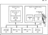
次に、ユーザインターフェース技術の諸実施形態について説明する。図1は、無線で通信する電子デバイスの例を説明するブロック図100を示している。具体的には、無線通信デバイス110(スマートフォン、ラップトップコンピュータ、ウェアラブル、又はタブレットなど)、及び物理デバイス112は、無線で通信してよい。これらの電子デバイスは、無線チャネルを走査することによって互いを検出している間、無線チャネル上でビーコン若しくはビーコンフレームを送信及び受信している間、(例えば、接続要求を送信することによって)接続を確立している間、並びに/又は(要求及び/又はデータなどの追加の情報をペイロードとして含んでもよい)パケット又はフレームを送信及び受信している間に、無線で通信してよい。更に、仮想表現114が物理的位置116に存在してよい。仮想表現114は、仮想表現114が物理デバイス118の代理として機能するように、物理デバイス118に対応することができ。この場合、無線通信デバイス110は、仮想表現114を特定して相互作用してよいが、物理デバイス118で受信される無線信号を送信してよい。例えば、仮想表現114はサーモスタットに関連付けられてよく、サーモスタットの無線通信デバイス110による調整は、仮想表現114との相互作用を介して提供されてよいが、環境ユニット(例えば物理デバイス118)によって受信され、実行されてよい。 Next, embodiments of user interface technology will be described. FIG. 1 shows a block diagram 100 illustrating an example of an electronic device that communicates wirelessly. Specifically, the wireless communication device 110 (such as a smartphone, laptop computer, wearable, or tablet) and the
なお、物理デバイス112及び/又は118は、器具(オーブンレンジ、トースター、冷蔵庫、食器洗浄機、又は洗濯機など)、別の電子デバイス(コンピュータ、ラップトップ、タブレット、又はコンピューティングデバイスなど)、エンタテインメントデバイス(テレビ、ディスプレイ、無線受信機、又はセットトップボックスなど)、オーディオデバイス、プロジェクタ、セキュリティデバイス(アラーム又はドアロックなど)、通信デバイス(スマートフォンなど)、監視デバイス(煙探知器又は一酸化炭素検知器など)、環境制御(サーモスタット、照明スイッチ、又はシェードなど)、アクセサリ(キーボード、マウス、又はスピーカなど)、プリンタ、ウェアラブルデバイス、ホームオートメーションデバイス、環境108内のリソース(輸送リソース、共有コンピューティングリソース、医療リソース、表示リソース、セキュリティリソース、アクセシビリティリソース、又は安全リソースなど)などを含んでよい。更に、仮想表現114は、ステッカー、画像、セラミック片、地理上のフェンス、位置を定義する1つ以上の座標などとして実装されてよい。いくつかの実施形態では、物理デバイス118は、照明スイッチ、サーモスタットなどを含む。 Note that the
図2を参照して下で更に説明されるように、無線通信デバイス110、物理デバイス112、及び/又は物理デバイス118は、ネットワーキングサブシステム、メモリサブシステム、及びプロセッササブシステムなどのサブシステムを含んでよい。加えて、無線通信デバイス110、物理デバイス112、及び/又は物理デバイス118は、ネットワーキングサブシステム内の無線機120を含んでよい。更に一般的には、無線通信デバイス110、物理デバイス112、及び/又は物理デバイス118は、無線通信デバイス110、物理デバイス112、及び/又は物理デバイス118が別の電子デバイスと無線で通信できるようにするネットワーキングサブシステムを有する任意の電子デバイスを含むことができる(又は、そのような電子デバイスに含まれ得る)。これは、電子デバイスが互いとの初期接触を行うこと又は互いを検出することを可能にするために、無線チャネル上でビーコンを送信すること、並びにそれに続き、接続(「Wi−Fi接続」と呼ばれる場合もある)の確立、セキュリティオプション(例えば、IPSec)の構成、接続を介したパケット若しくはフレームの送信及び受信、などのために、後続のデータ/管理フレーム(接続要求など)を交換することを含むことができる。 As further described below with reference to FIG. 2,
図1からわかるように、(ギザギザ線で表された)無線信号122が、無線通信デバイス110内の無線機120−1及び物理デバイス112内の無線通信デバイス120−2によって伝達される。例えば、無線通信デバイス110及び物理デバイス112は、無線パーソナルエリアネットワーク(WPAN)内のBluetooth(登録商標)プロトコル又は無線ローカルエリアネットワーク(WLAN)内のWi−Fiプロトコルを使用して、パケットを交換してよい。 As can be seen from FIG. 1, a radio signal 122 (represented by a jagged line) is transmitted by the radio 120-1 in the
具体的には、図3〜図5及び図8〜図16を参照して下で更に説明されるように、無線通信デバイス110は、送信時間を含むフレーム又はパケットを送信してよい。このフレーム又はパケットが物理デバイス112によって受信されるときに、到着時間が決定されてよい。経過時間(到着時間と送信時間の差)と伝播速度の積に基づいて、無線通信デバイス110と物理デバイス112の間の距離が計算され得る。この距離は、物理デバイス112又は物理デバイス112のユーザの識別子(一意の識別子など)と共に、物理デバイス112から無線通信デバイス110へのフレーム又はパケットのその後の送信において伝達されてよい。あるいは、物理デバイス112は、送信時間及び物理デバイス112の識別子を含むフレーム又はパケットを送信してよく、無線通信デバイス110は、経過時間(到着時間と送信時間の差)と伝播速度の積に基づいて、無線通信デバイス110と物理デバイス112の間の距離を決定してよい。なお、無線で通信する電子デバイス間の距離を動的に決定するこのアプローチは、「無線測距」呼ばれることがある。更に、無線測距を(コンパス、ジャイロスコープ、及び/又は加速度計などの他のセンサ入力とは別に、又はそれらのセンサ入力と共に)使用して、複数のターゲットデバイスが互いに近接して、又は同じ見通し線上に配置されることがある場合に、制御入力意図の曖昧さをなくすことができる。このアプローチに対する変形が使用されてよく、この変形において、無線通信デバイス110は、センサ入力(例えば、コンパス、ジャイロスコープ、及び/又は加速度計)を介して物理的位置116で指示されたジェスチャ入力を感知し、1つ以上の制御信号が、関連するデバイス(例えば、仮想表現114に関連付けられた物理デバイス118)に送信されるべきであるということを決定する。同様に、無線通信デバイス110が物理的位置116で反射されるフレーム又はパケットを送信する、このアプローチに対する別の変形が、無線通信デバイス110と仮想表現114の間の距離を動的に決定するために、任意選択的に使用されてよい。したがって、無線測距は、無線通信デバイス110によって、オブジェクト(物理デバイス112又は仮想表現114など)が環境108内で近接していることを決定するために使用されてよい。 Specifically, as described further below with reference to FIGS. 3-5 and 8-16, the
前の例では、無線通信デバイス110及び物理デバイス112においてクロックが同期される無線測距について説明したが、他の実施形態では、クロックが同期されない。例えば、無線通信デバイス110又は物理デバイス112の位置は、送信時間が未知であるか、又は使用できない場合でも、異なる既知の位置での複数の受信機における無線信号122の伝搬速度及び到着時間データ(「差動到着時間」と呼ばれることもある)に基づいて推定されてよい。より一般的には、様々な無線測位技術が使用されてよく、例えば、元の送信された信号強度(吸収、屈折、シャドーイング、及び/又は反射に関する補正を含んでよい)に対する受信信号強度インジケータ(received signal strength indicator、RSSI)の電力における差に基づいて距離を決定すること、指向性アンテナを使用するか、又は既知の位置(単数又は複数)でのアンテナのアレイにおける差動到着時間に基づいて、受信機での到着角を(非見通し線の受信を含めて)決定すること、後方散乱無線信号に基づいて距離を決定すること、及び/又は既知の位置を有する2つの受信機での到着角を決定すること(すなわち、三辺測量又はマルチラテレーション)などが挙げられる。無線信号122は、0.3m以内の距離(例えば、1フィート)を決定できる短い期間(例えば、約1nsなど)のパルスを生成するために、GHz又はマルチGHz帯域幅での送信を含んでよいということに注意する。いくつかの実施形態では、無線測距は、ローカル測位システム、全地球測位システム、及び/又は無線ネットワークによって決定又は指定される、図1の1つ以上の電子デバイスの位置などの位置情報を使用して容易に行われる。 In the previous example, the radio ranging in which the clock is synchronized in the
更に、無線通信デバイス110は、センサデータを測定(又は生成)する1つ以上のセンサを含んでよい。例えば、1つ以上のセンサは、無線通信デバイス110の向き(又は方位値)又は方向を測定する、1つ以上のコンパス、1つ以上の加速度計、及び/又は1つ以上のジャイロスコープ、無線通信デバイス110の加速度を測定する1つ以上の加速度計、無線通信デバイス110と別の電子デバイス(物理デバイス112、又は反射された無線信号が受信される実施形態では、無線通信デバイス110など)の間の無線通信を特徴付ける指標を決定する送受信機(無線機120−1など)、例えばタッチスクリーンを介してタッチ入力を受信するように構成された1つ以上のタッチセンサ、並びに/あるいは無線通信デバイス110の環境108内の周囲の音を測定する1つ以上のマイクロフォン若しくは音響トランスデューサを含んでよい。いくつかの実施形態では、無線通信デバイス110は、音響トランスデューサによって提供される超音波チャープを使用して環境108内のオブジェクトの近接を判定する。この超音波チャープは、人間の聴覚の範囲外であってよい。以下の説明では、電子デバイスの「近接」は、無線通信範囲内に存在することを少なくとも含むと理解されるべきであり、電子デバイスを、同じ室内又は所定の距離の範囲内(10m又は30m以内など)に存在するように更に制限してよい。 Further, the
図3〜図5を参照して下で更に説明されるように、ユーザインターフェース技術において、無線通信デバイス110は、無線測距及び/又はセンサデータを使用して、物理デバイス112及び/又は118を制御してよい。具体的には、無線通信デバイス110は、無線通信デバイス110のユーザの意図ジェスチャを特定してよい。例えば、ユーザは、無線通信デバイス110を物理的位置116(したがって、仮想表現114)又は物理デバイス112に向けてよく、無線通信デバイス110は、(物理デバイス112又は仮想表現114の位置及び/又は向きから分離されているか、又はそれらと相対的な)無線通信デバイス110の向き及び/又は無線通信デバイス110の移動(例えば、前方に伸ばす(又は押す)などの、所定の意図ジェスチャの動き)に基づいて「意図ジェスチャ」を特定してよい。次に、無線通信デバイス110は、無線測距を使用することを含めて、意図ジェスチャに関連付けられたオブジェクト(物理デバイス112又は仮想表現114など)を決定してよい。例えば、意図ジェスチャに対応するオブジェクトは、無線測距を使用して決定されたオブジェクトまでの距離及び向き(又は相対的な向き)に少なくとも部分的に基づいて決定されてよい。 As described further below with reference to FIGS. 3-5, in user interface technology, the
更に、その後、ユーザは、無線通信デバイス110を、例えば2次元内又は3次元内で移動することによって、「アクションジェスチャ」を実行してよい。このアクションジェスチャは、無線通信デバイス110内の、又は無線通信デバイス110に関連付けられた1つ以上のセンサによって取得される、検出/測定されたセンサデータにおいてキャプチャされてよい。次に、無線通信デバイス110は、センサデータを解釈して、アクションジェスチャ及びコマンド又はコマンド値を決定してよい。更に、無線通信デバイス110は、コマンド又はコマンド値を、対応する制御対象のデバイス(例えば、物理デバイス112又は物理デバイス118)に、フレーム又はパケットで送信してよい。 Further, after that, the user may perform an “action gesture” by moving the
下で更に説明されるように、コマンド値が、無線通信デバイス110をオブジェクトと組み合わせるか、又は関連付けること、オブジェクトの動作設定(光のオン又はオフ、あるいはサーモスタットの温度の変更、音量、チャネル、及び/又は再生の設定の調整など)を変更すること、データ(メディア又はテキストデータなど)を転送すること、及び/又は、任意のその他のそのような機能を実行することを行うコマンドを含んでよいということに注意する。コマンド値が、オブジェクトに、例えばセンサ値を含んでいる応答を無線通信デバイス110に返送させてよく、かつ/又はリソース(無線プリンタなど)へのアクセスを要求してよいということに注意する。 As described further below, the command value can be used to combine or associate the
したがって、このユーザインターフェース技術は、ユーザが無線通信デバイス110を開くこと、又はロック解除することがないということを含めて、無線通信デバイス110が遠くからオブジェクト(又はオブジェクトに関連付けられた機能)を制御できるようにしてよい。この能力は、オブジェクトの制御又はオブジェクトとの対話において、新しい自由度をユーザに提供してもよい。その結果、このユーザインターフェース技術は、無線通信デバイス110及びオブジェクトを使用するときのユーザエクスペリエンスを向上することができるため、ユーザの満足度を高め、ユーザを維持することができる。 Thus, this user interface technology allows the
記載されている実施形態において、無線通信デバイス110、物理デバイス112、及び/又は物理デバイス118のうちの1つにおいてパケット又はフレームを処理することは、パケット又はフレームをエンコードする無線信号122を受信することと、受信された無線信号122からパケット又はフレームをデコード/抽出してパケット又はフレームを取得することと、パケット又はフレームを処理して、パケット又はフレームに含まれている情報(ペイロード内のデータなど)を決定することと、を含む。 In the described embodiment, processing a packet or frame at one of the
一般に、ユーザインターフェース技術におけるWLANを介した通信は、様々な指標(又は通信性能指標)によって特徴付けられてよい。例えば、指標は、RSSI、データレート、正常な通信のデータレート(スループットと呼ばれることもある)、エラーレート(リトライ又は再送信のレートなど)、等化目標に対する等化信号の平均二乗誤差、符号間干渉、マルチパス干渉、信号対ノイズ比、アイパターンの幅、ある時間インターバル(1〜10秒など)内に伝達可能な推定最大バイト数に対する、その時間インターバル中に正常に伝達されたバイト数の比(伝達可能な推定最大バイト数は、通信チャネル又はリンクの「容量」と呼ばれることもある)、及び/又は推定データレートに対する実際のデータレートの比(「使用率」と呼ばれることもある)を含んでよい。 In general, communication over WLAN in user interface technology may be characterized by various indicators (or communication performance indicators). For example, the indicators include RSSI, data rate, normal communication data rate (sometimes referred to as throughput), error rate (retry or retransmission rate, etc.), mean square error of equalized signal with respect to equalization target, sign Interference, multipath interference, signal-to-noise ratio, eye pattern width, number of bytes successfully transmitted during the time interval against the estimated maximum number of bytes that can be transmitted within a certain time interval (1-10 seconds, etc.) Ratio (the estimated maximum number of bytes that can be transmitted is sometimes referred to as the “capacity” of the communication channel or link) and / or the ratio of the actual data rate to the estimated data rate (sometimes referred to as the “utilization”) ).
図8〜図16を参照して下で更に説明されるように、ユーザインターフェース技術において、無線通信デバイス110は、無線測距及び/又はセンサデータを使用して、環境108内のオブジェクトの位置を特定してよく、決定された位置に基づいて、オブジェクトに関する直感的な情報を提供してよい。具体的には、無線通信デバイス110は、環境108(建物内の部屋又は無線通信デバイス110の周囲の領域)内の無線通信デバイス110に近接して配置されたオブジェクト(例えば、物理デバイス112)に関連付けられた識別子を含む送信を受信してよい。例えば、識別子は、物理デバイス112の(したがって、物理デバイス112のユーザの)一意の識別子であってよい。代替的又は追加的に、識別子は、輸送リソース、共有コンピューティングリソース(例えば、プリンタ)、医療リソース、表示リソース、セキュリティリソース、アクセシビリティリソース、安全リソースなどの、物理デバイス112に対応するリソースクラスに関連付けられてよい。識別子が検索結果又はトランザクションと共に受信されていてよいということに注意する。代替的又は追加的に、識別子は、無線通信デバイス110のユーザの連絡先に対応してよい。いくつかの実装では、オブジェクト(例えば、物理デバイス112)は、受信側(例えば、無線通信デバイス110)で使用可能な情報に応じて異なって解決され得る複数の異なる識別子を、別々に送信することができる。 As described further below with reference to FIGS. 8-16, in user interface technology, the
それに応じて、無線通信デバイス110は、受信された識別子を1つ以上の記憶されたターゲット識別子と比較して、一致を判定してよい。その後、無線通信デバイス110は、無線測距を使用して、無線通信デバイス110からの物理デバイス112の範囲(又は距離)及び/又は物理デバイス112に対する方向を決定してよい。 In response, the
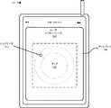
次に、無線通信デバイス110は、物理デバイス112に対する範囲及び/又は方向を示す出力情報を提示してよい。例えば、図9を参照して下で更に説明されるように、無線通信デバイス110は、環境108内の近接領域のマップを表示してよく、物理デバイス112を表す第1のインジケータをこのマップに表示してよい。代替的又は追加的に、図10を参照して下で更に説明されるように、無線通信デバイス110は、無線通信デバイス110内の撮像センサ(CMOS又はCCD撮像センサ及び、より一般的にはカメラなど)によってキャプチャされた環境108内の近接領域の画像を表示してよく、物理デバイス112を表す第2のインジケータ(第1のインジケータと同じであっても、異なっていてもよい)をこの画像に表示してよい。物理デバイス112が無線通信デバイス110の視距離の範囲内にあるかどうか、又はそれ以外の方法で無線通信デバイス110にとって可視であるかどうかに関わらず、第1のインジケータ及び/又は第2のインジケータが表示されてよいということに注意する。 Next, the
更に、図11で説明されているように、いくつかの実施形態では、ユーザは、無線通信デバイス110の向きを変えることによって、2つのユーザインターフェースモード間で直感的に切り替えるか、又は遷移することができる。具体的には、無線通信デバイス110は、測定された方位値に基づいて、マップの表示と画像の表示との間で選択的に遷移してよい。したがって、無線通信デバイス110が下方に(例えば水平に)向いている場合、第1のインジケータを含むマップが表示されてよく、無線通信デバイス110が物理デバイス112の方向に(例えば、垂直に)向いている場合、第2のインジケータを含む画像が表示されてよい。 Further, as illustrated in FIG. 11, in some embodiments, the user can intuitively switch or transition between the two user interface modes by changing the orientation of the
あるいは、図12で説明されているように、ユーザは、無線通信デバイス110のタッチ感知ディスプレイで、アイコンのストライク領域内に接触してから、接触を断つことなどによって、ユーザインターフェースモードを選択してよい。このようにして、ユーザは、無線通信デバイス110の周囲360°の視界を含むマップが表示され、異なる範囲及び方向にあるオブジェクト(物理デバイス112など)が、第1のインジケータ(シンボル、エモーティコン、又はグラフィカルアイコンなど)によってマップ上に表される、ユーザインターフェースモードを選択してよい。更に、ユーザは、無線通信デバイス110が物理デバイス112の方向を指すか、又は向いたときに、画像が表示され、物理デバイス112が第2のインジケータ(シンボル、エモーティコン、又はグラフィカルアイコンなど)によって表される、ユーザインターフェースモードを選択してよい。いくつかの実装では、無線通信デバイス110のディスプレイが近接領域の画像を表示しながら、1つ以上の他のグラフィカル要素(例えば、方向要素)も提示され得る。 Alternatively, as illustrated in FIG. 12, the user may select a user interface mode on the touch-sensitive display of the
いくつかの実施形態では、ユーザインターフェース技術は拡張現実を含む。具体的には、図13を参照して下で説明されるように、無線通信デバイス110上の前面カメラは、ユーザが無線通信デバイス110を顔の前に持っているときに、無線通信デバイス110によってマスクされる環境108の画像(又は動画)をキャプチャしてよい。その後、無線通信デバイス110が物理デバイス112の方向を向いているときに、それらの画像は、無線通信デバイス110がユーザにとって透明に見えるように、オブジェクト(物理デバイス112など)を表すインジケータと共に無線通信デバイス110上に表示されてよい。インジケータが、環境108内の位置で画像内に配置されてよく、オブジェクトまでの相対的な範囲に関する直感的情報を含む透視図を提供するようにサイズ設定されてよいということに注意する。したがって、無線通信デバイス110から(すなわち、ユーザから)遠く離れたオブジェクトは、無線通信デバイス110に近いオブジェクトよりも小さいインジケータによって表されてよい。 In some embodiments, the user interface technology includes augmented reality. Specifically, as described below with reference to FIG. 13, the front camera on the
更に、図14を参照して下で説明されるように、拡張現実は、いわゆる「X線ビジョン」を含んでよい。具体的には、物理デバイス112が、不透明なバリア(壁又は家具など)の向こう側に配置された場合、無線通信デバイス110上に表示された画像によって、ユーザは、不透明なバリアが存在しないか、又は不透明なバリアを通して見ることができるかのように、物理デバイス112を見ることができるようになってよい。例えば、ユーザが別の部屋にあるネットワークプリンタを探している場合、ユーザが無線通信デバイス110をネットワークプリンタの方向に向けたときに、ネットワークプリンタの画像が、ユーザがネットワークプリンタにアクセスできるようにする情報と共に、無線通信デバイス110上に表示されてよい。したがって、ユーザは、無線通信デバイス110上に表示されたユーザインターフェース内のネットワークプリンタに関連付けられたアイコンをタップすることによって、ネットワークプリンタと組み合わせるか、又は接続する(あるいは、その他の方法で相互作用する)ように、無線通信デバイス110に指示してよい。代替的又は追加的に、ユーザインターフェースは、ネットワークプリンタに到達する方法に関する命令(及び任意選択的に建物マップ)を含んでよい。 Furthermore, as described below with reference to FIG. 14, augmented reality may include so-called “X-ray vision”. Specifically, if the
同様に、図15を参照して下で更に説明されるように、ユーザインターフェース技術によって、ユーザは、(例えば、紛失を防ぐために)環境108内のオブジェクト(物理デバイス112など)の位置を追跡するか、又は環境108内の1つ以上の関連するオブジェクトに関するリマインダを取得することができるようになってよい。このようにして、親は、子供を追跡してよく、又は学校へ行く途中で何か(リュックサックなど)を決して置き忘れないようにしてよい。 Similarly, as described further below with reference to FIG. 15, user interface technology allows the user to track the location of an object (such as physical device 112) within environment 108 (eg, to prevent loss). Alternatively, it may be possible to obtain reminders for one or more related objects in the
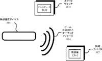
更に、図16を参照して下で更に説明されるように、ユーザインターフェース技術を使用して、多種多様なフィードバックが、環境108内のユーザ又は他の個人に提供されてよい。無線通信デバイス110は、前に説明された視覚情報に加えて、無線通信デバイス110上で直接的に、又は別の電子デバイス(ユーザのスマートウォッチなど)を介して間接的に、触覚フィードバックをユーザに提供してよい。このようにして、ユーザは、物理デバイス112の方向に向いているなどの場合に、環境に関するフィードバックを受け取ってよい。 Further, as described further below with reference to FIG. 16, a wide variety of feedback may be provided to users or other individuals within
更に、無線通信デバイス110は、テキスト又はオーディオメッセージなどのメッセージを物理デバイス112に送信してよい。例えば、メッセージは、実質的に物理デバイス112に対応する位置のみで知覚可能なビーム形成されたオーディオメッセージとして送信されるオーディオメッセージ(例えば、プライベートオーディオブロードキャスト)を含んでよい。このようにして、無線通信デバイス110のユーザは、他の個人と通信するための電子的手段を有していない場合(ユーザが受信者の電話番号又は電子メールアドレスを知らないなどの場合)でも、プライベートメッセージを範囲内にいる別の個人に送信することができる。追加的又は代替的に、無線通信デバイス110は、ビーム形成されたオーディオメッセージを、環境108内の人の名前、達成するべきタスク、次回の予約などの関連する情報と共に、ユーザに送信してよい。 Further, the
したがって、このユーザインターフェース技術は、ユーザが無線通信デバイス110を開くこと、又はロック解除することがないということを含めて、無線通信デバイス110が遠くからオブジェクト(又はオブジェクトに関連付けられた機能)を制御できるようにしてよい。このユーザインターフェース技術は、無線通信デバイス110が、環境108内のオブジェクトに関する状況認識を、直感的かつ有用な方法で提供できるようにしてもよい。これらの能力は、環境108内でオブジェクトと通信及び対話する方法において、新しい自由度をユーザに提供してもよい。その結果、このユーザインターフェース技術は、無線通信デバイス110を使用するときのユーザエクスペリエンスを向上することができるため、ユーザの満足度を高め、ユーザを維持することができる。 Thus, this user interface technology allows the
記載されている実施形態において、無線通信デバイス110、物理デバイス112、及び/又は物理デバイス118のうちの1つにおいてパケット又はフレームを処理することは、パケット又はフレームをエンコードする無線信号122を受信することと、受信された無線信号122からパケット又はフレームをデコード/抽出してパケット又はフレームを取得することと、パケット又はフレームを処理して、パケット又はフレームに含まれている情報(ペイロード内のデータなど)を決定することと、を含む。 In the described embodiment, processing a packet or frame at one of the
一般に、ユーザインターフェース技術におけるWLANを介した通信は、様々な指標(又は通信性能指標)によって特徴付けられてよい。例えば、指標は、RSSI、データレート、正常な通信のデータレート(スループットと呼ばれることもある)、エラーレート(リトライ又は再送信のレートなど)、等化目標に対する等化信号の平均二乗誤差、符号間干渉、マルチパス干渉、信号対ノイズ比、アイパターンの幅、ある時間インターバル(1〜10秒など)内に伝達可能な推定最大バイト数に対する、その時間インターバル中に正常に伝達されたバイト数の比(伝達可能な推定最大バイト数は、通信チャネル又はリンクの「容量」と呼ばれることもある)、及び/又は推定データレートに対する実際のデータレートの比(「使用率」と呼ばれることもある)を含んでよい。 In general, communication over WLAN in user interface technology may be characterized by various indicators (or communication performance indicators). For example, the indicators include RSSI, data rate, normal communication data rate (sometimes referred to as throughput), error rate (retry or retransmission rate, etc.), mean square error of equalized signal with respect to equalization target, sign Interference, multipath interference, signal-to-noise ratio, eye pattern width, number of bytes successfully transmitted during the time interval against the estimated maximum number of bytes that can be transmitted within a certain time interval (1-10 seconds, etc.) Ratio (the estimated maximum number of bytes that can be transmitted is sometimes referred to as the “capacity” of the communication channel or link) and / or the ratio of the actual data rate to the estimated data rate (sometimes referred to as the “utilization”) ).
本発明者らは、一例として図1に示されるネットワーク環境について説明しているが、代替実施形態では、異なる数又は種類の電子デバイスが存在してもよい。例えば、一部の実施形態は、より多くの電子デバイス、又はより少ない電子デバイスを含む。別の例として、別の実施形態では、異なる電子デバイスがパケット又はフレームを送信及び/又は受信することができる。 Although the inventors have described the network environment shown in FIG. 1 by way of example, in alternative embodiments, there may be a different number or type of electronic devices. For example, some embodiments include more or fewer electronic devices. As another example, in another embodiment, different electronic devices can transmit and / or receive packets or frames.
次に、本発明者らは電子デバイスの諸実施形態について説明する。図2は、電子デバイス200(ポータブル電子デバイス又はステーションであってよい)の例のブロック図を示している。例えば、電子デバイス200は、図1の無線通信デバイス110、物理デバイス112、及び/又は物理デバイス118のうちの1つであってもよい。電子デバイス200は、処理サブシステム210、メモリサブシステム212、ネットワーキングサブシステム214、表示サブシステム226、測定サブシステム230、及びユーザ対話サブシステム232を含んでよい。処理サブシステム210は、計算動作を実行するように構成されている1つ以上のデバイスを含む。例えば、処理サブシステム210は、1つ以上のマイクロプロセッサ、特定用途向け集積回路(application−specific integrated circuits、ASIC)、マイクロコントローラ、プログラム可能ロジックデバイス、及び/又は1つ以上のデジタル信号プロセッサ(digital signal processors、DSP)を含むことができる。 Next, the inventors describe various embodiments of the electronic device. FIG. 2 shows a block diagram of an example of an electronic device 200 (which may be a portable electronic device or station). For example, the
メモリサブシステム212は、処理サブシステム210及びネットワーキングサブシステム214に関するデータ及び/又は命令を記憶するための、1つ以上のデバイスを含む。例えば、メモリサブシステム212は、ダイナミックランダムアクセスメモリ(dynamic random access memory、DRAM)、スタティックランダムアクセスメモリ(static random access memory、SRAM)、読み出し専用メモリ(read-only memory、ROM)、フラッシュメモリ、及び/又は他のタイプのメモリを含むことができる。いくつかの実施形態では、メモリサブシステム212内の処理サブシステム210のための命令は、処理サブシステム210により実行され得る、1つ以上のプログラムモジュール又は命令のセット(プログラムモジュール222又はオペレーティングシステム224など)を含む。例えば、ROMは、実行されるプログラム、ユーティリティ、又はプロセスを不揮発に記憶することができ、DRAMは、揮発性データ記憶を提供することができ、電子デバイス200の動作に関係する命令を記憶してよい。1つ以上のコンピュータプログラムが、コンピュータプログラム機構又はソフトウェアを構成してよいということに注意する。更に、メモリサブシステム212内の様々なモジュール内の命令は、高水準手続き型言語、オブジェクト指向プログラミング言語、並びに/又はアセンブリ言語若しくは機械語で実装されてよい。更に、プログラミング言語は、処理サブシステム210によって実行されるようにコンパイル又は解釈されてよく、例えば、そのように構成可能であるか、又は構成されてよい(これらは本明細書において互換的に使用されてよい)。いくつかの実施形態では、1つ以上のコンピュータプログラムは、1つ以上のコンピュータプログラムを分散して記憶し、実行するように、ネットワーク結合されたコンピュータシステム上に分散している。 The memory subsystem 212 includes one or more devices for storing data and / or instructions regarding the processing subsystem 210 and the networking subsystem 214. For example, the memory subsystem 212 includes a dynamic random access memory (DRAM), a static random access memory (SRAM), a read-only memory (ROM), a flash memory, and / Or other types of memory may be included. In some embodiments, instructions for processing subsystem 210 in memory subsystem 212 may be executed by processing subsystem 210 by one or more program modules or sets of instructions (program module 222 or operating system 224). Etc.). For example, a ROM can store a program, utility, or process to be executed in a nonvolatile manner, and a DRAM can provide volatile data storage, storing instructions related to the operation of the
更には、メモリサブシステム212は、メモリへのアクセスを制御するための機構を含むことができる。いくつかの実施形態では、メモリサブシステム212は、電子デバイス200内のメモリに結合される、1つ以上のキャッシュを含むメモリ階層を含む。これらの実施形態のいくつかでは、キャッシュのうちの1つ以上は、処理サブシステム210内に配置される。 Further, the memory subsystem 212 can include a mechanism for controlling access to the memory. In some embodiments, the memory subsystem 212 includes a memory hierarchy that includes one or more caches coupled to memory in the
いくつかの実施形態では、メモリサブシステム212は、1つ以上の大容量の大記憶デバイス(図示せず)に結合される。例えば、メモリサブシステム212は、磁気若しくは光学ドライブ、ソリッドステートドライブ、又は別のタイプの大記憶デバイスに結合され得る。これらの実施形態では、メモリサブシステム212は、頻繁に使用されるデータ用の高速アクセス記憶装置として、電子デバイス200によって使用することができるが、その一方で、大記憶デバイスは、使用頻度の低いデータを記憶するために使用される。 In some embodiments, the memory subsystem 212 is coupled to one or more mass storage devices (not shown). For example, the memory subsystem 212 may be coupled to a magnetic or optical drive, a solid state drive, or another type of mass storage device. In these embodiments, the memory subsystem 212 can be used by the
ネットワーキングサブシステム214は、制御論理216、インターフェース回路218、及び種々の任意選択的なアンテナパターン又は「ビームパターン」を生成するために制御論理216によって選択的にオン及び/又はオフすることができる適応アレイ内のアンテナのセット220(又はアンテナ素子)を含む、有線ネットワーク及び/又は無線ネットワークに結合し、それらの上で通信するように(すなわち、ネットワークオペレーションを実行するように)構成された、1つ以上のデバイスを含む。(図2はアンテナのセット220を含んでいるが、いくつかの実施形態では、電子デバイス200は、アンテナのセット220に結合することができるノード208などの1つ以上のノード、例えば、パッドを含む。したがって、電子デバイス200は、アンテナのセット220を含んでも、あるいは含まなくてもよい。)例えば、ネットワーキングサブシステム214としては、Bluetooth(登録商標)ネットワーキングシステム、セルラネットワーキングシステム(例えば、UMTS、LTEなどの3G/4Gネットワーク)、ユニバーサルシリアルバス(universal serial bus、USB)ネットワーキングシステム、IEEE802.11に記載される標準規格に基づくネットワーキングシステム(例えば、Wi−Fi(登録商標)ネットワーキングシステム)、イーサネット(登録商標)ネットワーキングシステム、及び/又は別のネットワーキングシステムを挙げることができる。 Networking subsystem 214 may be selectively turned on and / or off by
ネットワーキングサブシステム214は、プロセッサ、コントローラ、無線機/アンテナ、ソケット/プラグ、及び/又は、サポートされている各ネットワーキングシステムに結合し、そのネットワーキングシステム上で通信し、そのネットワーキングシステムに関するデータ及びイベントを処理するために使用される、他のデバイスを含む。それぞれのネットワークシステムのための、ネットワークに結合し、その上で通信し、その上のデータ及びイベントを処理するために用いられる機構は、時として、まとめて、ネットワークシステムのための「ネットワークインターフェース」と呼ばれることに留意されたい。更に、いくつかの実施形態では、電子デバイス間の「ネットワーク」又は「接続」は、まだ存在しない。したがって、電子デバイス200は、電子デバイス間の単純な無線通信を実行するため、例えば、アドバタイジングフレーム若しくはビーコンフレームを送信し、かつ/又は他の電子デバイスによって送信されたアドバタイジングフレームをスキャンするために、ネットワーキングサブシステム214内の機構を使用してよい。 The networking subsystem 214 couples to, communicates on, and transmits data and events related to the networking system to the processor, controller, radio / antenna, socket / plug, and / or each supported networking system. Includes other devices used to process. For each network system, the mechanisms used to connect to, communicate over, and process data and events thereon are sometimes collectively referred to as a “network interface” for the network system. Note that it is called. Furthermore, in some embodiments, there is not yet a “network” or “connection” between electronic devices. Thus, the
電子デバイス200内で、処理サブシステム210、メモリサブシステム212、ネットワーキングサブシステム214、表示サブシステム226、測定サブシステム230、及びユーザ対話サブシステム232は、これらのコンポーネント間のデータ転送を容易にするバス228を使用して互いに結合される。バス228は、サブシステムが互いの間でコマンド及びデータを通信するために使用することができる電気的、光学的、及び/又は電気光学的接続を含んでよい。わかりやすくするために1本のバス228のみが示されているが、異なる実施形態は、異なる数又は構成の電気的、光学的、及び/又は電気光学的接続をサブシステム間に含むことができる。 Within
いくつかの実施形態では、電子デバイス200は、情報をディスプレイに表示するための表示サブシステム226を含んでおり、表示サブシステム226は、ディスプレイドライバ、及び液晶ディスプレイ、マルチタッチタッチスクリーンなどのディスプレイを含んでよい。表示サブシステム226は、情報(例えば、着信通信セッション、発信通信セッション、又はアクティブ通信セッションに関連する情報)をユーザに表示するように、処理サブシステム210によって制御されてよい。いくつかの実施形態では、表示サブシステム226は、非ネイティブディスプレイ(例えば、他のデバイスに関連付けられたディスプレイ)のための表示情報を生成するように構成され得る。 In some embodiments, the
電子デバイス200は、電子デバイス200が1つ以上のタイプの測定を実行できるようにする、1つ以上のセンサを含んでいる測定サブシステム230を含むこともできる。例えば、1つ以上のセンサは、1つ以上のコンパス、1つ以上の加速度計、1つ以上のジャイロスコープ、1つ以上のマイクロフォン又は音響トランスデューサ、1つ以上の環境センサ(温度センサ及び/又は高度計など)、1つ以上の光センサ(周辺光センサなど)、1つ以上のタッチセンサ(タッチスクリーンなど)、1つ以上のバイオメトリックセンサ(指紋センサなど)を含んでよい。1つ以上のセンサが、電子デバイス200内の物理センサ及び/又は仮想センサ(ソフトウェアにおいて少なくとも部分的に実装されるセンサなど)を含んでよいということに注意する。いくつかの実施形態では、1つ以上のセンサのうちの少なくとも一部が、リモート電子デバイスから受信された情報に基づいて、センサデータを決定する。 The
更に、電子デバイス200は、ユーザ対話サブシステム232を含んでよい。例えば、ユーザ対話サブシステム232は、ボタン、キーパッド、ダイヤル、タッチスクリーン、オーディオ入力インターフェース、視覚/画像キャプチャ入力インターフェース、センサデータの形態での入力などの、様々なユーザ入力デバイスを含むことができる。代替的又は追加的に、ユーザ対話サブシステム232は、1つ以上のスピーカ(指向性音響アレイを提供してよい)、触覚トランスデューサなどの、様々なユーザ出力デバイスを含んでよい。 Furthermore, the
電子デバイス200は、少なくとも1つのネットワークインターフェースを有する任意の電子デバイスであることができる(又は、該任意の電子デバイス内に含めることができる)。例えば、電子デバイス200は、携帯電話又はスマートフォン、タブレットコンピュータ、ラップトップコンピュータ、ノート型コンピュータ、パーソナル又はデスクトップコンピュータ、ネットブックコンピュータ、コンピューティングデバイス、共有コンピューティングデバイス(プリンタなど)、メディアプレイヤデバイス、電子書籍デバイス、スマートウォッチ、ウェアラブルコンピューティングデバイス、ウェアラブルデバイス、ポータブルコンピューティングデバイス、消費者電子デバイス、アクセスポイント、ルータ、スイッチ、通信機器又は通信デバイス、試験装置、器具、エンタテインメントデバイス、テレビ、ディスプレイ、無線受信機、セットトップボックス、オーディオデバイス、プロジェクタ、医療デバイス(自動体外式除細動器など)、セキュリティデバイス、警報、監視デバイス(例えば、煙探知器又は一酸化炭素検知器)、環境制御、サーモスタット、照明スイッチ、アクセサリ、キーボード、マウス、スピーカ、プリンタ、ホームオートメーションデバイス、車両、電子ロック、及び1つ以上の無線通信プロトコルを介した通信を含むことができる無線通信能力を有する任意のその他のタイプの電子コンピューティングデバイスを含んでよい。 The
電子デバイス200を説明するために特定の構成要素が用いられているが、代替実施形態では、異なる構成要素及び/又はサブシステムが電子デバイス200内に存在してよい。例えば、電子デバイス200は、1つ以上の追加の処理サブシステム、メモリサブシステム、ネットワーキングサブシステム、及び/又は表示サブシステムを含んでよい。更に、これらのサブシステムのうちの1つ以上は、電子デバイス200内に存在しなくてよい。更に、いくつかの実施形態では、電子デバイス200は、図2に示されていない1つ以上の追加的サブシステムを含んでよい。また、図2には、独立したサブシステムが示されているが、いくつかの実施形態では、所与のサブシステム又は構成要素の一部又はすべてが、電子デバイス200内の他のサブシステム又は構成要素(単数又は複数)のうちの1つ以上に統合され得る。例えば、いくつかの実施形態では、プログラムモジュール222がオペレーティングシステム224に含まれ、かつ/又は、制御論理216がインターフェース回路218内に含まれる。 Although specific components are used to describe the
更に、電子デバイス200内の回路及び構成要素は、バイポーラ、PMOS及び/又はNMOSゲート又はトランジスタを含む、アナログ及び/又はデジタル回路機構の任意の組み合わせを用いて実装されてよい。更に、これらの実施形態における信号は、ほぼ離散的な値を有するデジタル信号、及び/又は連続的な値を有するアナログ信号を含んでよい。加えて、構成要素及び回路はシングルエンド形又は差動形であってもよく、電源はユニポーラ形又はバイポーラ形であってもよい。 Further, the circuitry and components within the
集積回路(「通信回路」と呼ばれることがある)は、ネットワーキングサブシステム214の機能の一部又はすべてを実装してよい。この集積回路は、電子デバイス200から無線信号を送信し、電子デバイス200において他の電子デバイスから信号を受信するために使用されるハードウェア及び/又はソフトウェア機構を含んでよい。本明細書において説明されている機構を除いて、無線機は当技術分野において一般的に知られており、それゆえ、詳細には説明されない。一般に、ネットワーキングサブシステム214及び/又は集積回路は、任意の数の無線機を含むことができる。複数の無線機の実施形態における無線機は、記載されている単一の無線機の実施形態と同様に機能することに留意されたい。 An integrated circuit (sometimes referred to as a “communication circuit”) may implement some or all of the functions of the networking subsystem 214. The integrated circuit may include hardware and / or software mechanisms used to transmit wireless signals from the
いくつかの実施形態では、ネットワーキングサブシステム214及び/又は集積回路は、無線機(単数又は複数)を、所与の通信チャネル(例えば、所与の搬送周波数)上で送信及び/又は受信するように構成する(1つ以上のハードウェア及び/又はソフトウェア機構などの)構成機構を含む。例えば、いくつかの実施形態では、構成機構は、無線機を、所与の通信チャネル上における監視及び/又は送信から、異なる通信チャネル上における監視及び/又は送信へ切り替えるために用いることができる。(本明細書において使用されている「監視」が、他の電子デバイスからの信号を受信すること、及び場合によっては、受信された信号に対して1つ以上の処理動作を実行すること、例えば、無線測距を実行すること、などを含むことに留意されたい。) In some embodiments, the networking subsystem 214 and / or the integrated circuit is configured to transmit and / or receive the radio (s) on a given communication channel (eg, a given carrier frequency). A configuration mechanism (such as one or more hardware and / or software mechanisms). For example, in some embodiments, the configuration mechanism can be used to switch the radio from monitoring and / or transmission on a given communication channel to monitoring and / or transmission on a different communication channel. (As used herein, “monitoring” receives signals from other electronic devices and, in some cases, performs one or more processing operations on the received signals, eg Note that this includes performing wireless ranging, etc.)
いくつかの実施形態では、本明細書で説明された回路のうちの1つ以上を含む集積回路又は集積回路の一部分を設計するためのプロセスの出力は、例えば、プログラマブルメモリ、磁気テープ、あるいは光ディスク又は磁気ディスクなどのコンピュータ可読媒体であってよい。コンピュータ可読媒体は、データ構造、あるいは集積回路又は集積回路の一部分として物理的にインスタンス化され得る回路について説明する他の情報を用いて符号化され得る。そのような符号化のために種々のフォーマットが使用され得るが、これらのデータ構造は一般に、Caltech Intermediate Format(CIF)、Calma GDS II Stream Format(GDSII)又はElectronic Design Interchange Format(EDIF)で書かれている。集積回路設計の技術分野に精通している者は、上記に詳述したタイプの概略図及び対応する説明からそのようなデータ構造を開発することができ、データ構造をコンピュータ可読媒体上に符号化することができる。集積回路製造の技術分野に精通している者は、そのような符号化されたデータを使用して、本明細書で説明する回路のうちの1つ以上を含む集積回路を製造することができる。 In some embodiments, the output of a process for designing an integrated circuit or portion of an integrated circuit that includes one or more of the circuits described herein can be, for example, programmable memory, magnetic tape, or optical disc Alternatively, it may be a computer readable medium such as a magnetic disk. The computer-readable medium may be encoded using a data structure or other information describing an integrated circuit or a circuit that can be physically instantiated as part of an integrated circuit. Various formats may be used for such encoding, but these data structures are generally written in Caltech Intermediate Format (CIF), Calma GDS II Stream Format (GDSII) or Electronic Design Interchange Format (EDIF). ing. Those familiar with the technical field of integrated circuit design can develop such data structures from schematics of the type detailed above and corresponding descriptions, and encode the data structures on a computer readable medium. can do. Those skilled in the art of integrated circuit manufacturing can use such encoded data to manufacture an integrated circuit that includes one or more of the circuits described herein. .
ユーザインターフェース技術は、種々のネットワークインターフェースにおいて使用されてよい。更に、上記の諸実施形態における動作のいくつかはハードウェア又はソフトウェアの形で実施されたが、一般的には、上記の実施形態における動作は多種多様な構成及びアーキテクチャで実施することができる。したがって、上記の諸実施形態における動作の一部又はすべては、ハードウェアの形、ソフトウェアの形又はその両方の形で実行されてもよい。例えば、ユーザインターフェース技術における動作のうちの少なくともいくつかは、プログラムモジュール222、オペレーティングシステム224(インターフェース回路218のためのドライバなど)を使用して、又はインターフェース回路218内のファームウェアで実施されてよい。代替的又は追加的に、ユーザインターフェース技術における動作の少なくともいくつかは、インターフェース回路218内のハードウェアなどの、物理層内で実施されてよい。例示的な実施形態では、ユーザインターフェース技術は、インターフェース回路218内のMAC層で少なくとも部分的に実装される。 User interface technology may be used in various network interfaces. Furthermore, although some of the operations in the above embodiments have been implemented in hardware or software, in general, the operations in the above embodiments can be implemented in a wide variety of configurations and architectures. Thus, some or all of the operations in the embodiments described above may be performed in hardware, software, or both. For example, at least some of the operations in the user interface technology may be performed using program module 222, operating system 224 (such as a driver for interface circuit 218), or in firmware in interface circuit 218. Alternatively or additionally, at least some of the operations in the user interface technology may be performed in the physical layer, such as hardware in the interface circuit 218. In the exemplary embodiment, user interface technology is implemented at least in part at the MAC layer in interface circuit 218.
例示的な実施形態では、ユーザインターフェース技術は、方向制御を行うために使用される。具体的には、1つ以上の測定に基づいて、オブジェクトに対する無線通信デバイスの位置及び向きが決定された場合、無線通信デバイスで入力又は実行された1つ以上のジェスチャが、オブジェクトに対するコマンドとして解釈されてよい。更に下で説明されるように、無線測距及び(ジャイロスコープ、加速度計、コンパスなどからの)センサデータ入力が、オブジェクトを選択すること、オブジェクトと組み合わせること、及び/又は、オブジェクトに対して命令することのために使用されてよい。 In the exemplary embodiment, user interface technology is used to provide direction control. Specifically, if the position and orientation of the wireless communication device relative to the object is determined based on one or more measurements, one or more gestures entered or executed on the wireless communication device are interpreted as commands for the object. May be. As described further below, wireless ranging and sensor data input (from a gyroscope, accelerometer, compass, etc.) can select an object, combine with the object, and / or command the object May be used for doing.
例示的な実施形態では、ユーザインターフェース技術は、環境制御において1つ以上のオブジェクトに関する情報を直感的に提供するために使用される。具体的には、オブジェクトに対する範囲及び/又は方向が、無線通信デバイスによって、1つ以上の測定(無線測距及び/又は向きなど)に基づいて決定された場合、無線通信デバイスは、決定された範囲及び/又は方向を使用して、オブジェクトに関する出力情報を(ユーザインターフェースなどにおいて)直感的に提供してよい。
電子デバイスの制御In an exemplary embodiment, user interface technology is used to intuitively provide information about one or more objects in environmental control. Specifically, if the range and / or direction relative to the object is determined by the wireless communication device based on one or more measurements (such as wireless ranging and / or orientation), the wireless communication device is determined Range and / or orientation may be used to provide intuitive output information about the object (such as in a user interface).
Control of electronic devices
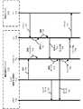
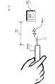
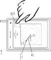
図3は、無線測距に少なくとも部分的に基づく、ジェスチャを使用したオブジェクトの制御の例を示す図面300を提供している。具体的には、ユーザインターフェース技術では、ユーザは、無線通信デバイス110を使用して、例えば、2次元内又は3次元内で1つ以上のジェスチャ又は動きを実行することによって、オブジェクトの仮想表現(例えば、仮想表現114)との対話を用いて、物理デバイス(例えば、物理デバイス112)を制御するか、又は物理デバイスの制御入力を生成してよい。実際のデバイス又は仮想表現であり得るオブジェクト310に対してジェスチャ入力を生成する、無線通信デバイス110が示されている。例えば、ユーザは、携帯電話を使用して、無線通信デバイス110を上から下(又は下から上)に移動するなどによって、ジェスチャを実行することにより、テレビの音量又は選択されるチャネルを制御してよく、あるいは室内照明を点灯又は消灯してよい。あるいは、ユーザは、部屋又は図1の環境108内の所定の物理的位置(図1の物理的位置116など)で照明スイッチの仮想表現を制御してよい(すなわち、所定の物理的位置に物理的照明スイッチが存在しなくてよい)。所定の物理的位置(及び、更に一般的には、3次元空間内の所定の物理的位置)が、トレーニングプロセスの間に、ユーザによって無線通信デバイス110を使用して指定されていてよく、例えば、無線通信デバイス110を物理的位置に近づけるか、又は接触させて、無線通信デバイス110上のタッチ感知ディスプレイに表示されたユーザインターフェース内の仮想コマンドアイコンをアクティブにすることによって、あるいは無線通信デバイス110を物理的位置に接触させて、コマンド又は命令を言葉で言い、それらのコマンド又は命令が無線通信デバイス110によって監視されて、音声認識技術を使用して解釈されることによって、指定されていてよいということに注意する。 FIG. 3 provides a drawing 300 illustrating an example of object control using gestures based at least in part on wireless ranging. Specifically, in user interface technology, a user uses a
ユーザインターフェース技術では、ユーザは、無線通信デバイス110をオブジェクト310の方、又は大まかな方向(例えば、オブジェクト310から5°以内など)に、伸ばすことなどによって、「意図ジェスチャ」312を使用してオブジェクト310を指定して(又は、その他の方法で示して)よい。その後、ユーザは、例えばオブジェクト310と相対的に無線通信デバイス110を移動することによって、「アクションジェスチャ」314を実行してよい。1つの例では、無線通信デバイス110は、例えば値における増加又は減少を伝えるために、オブジェクト310と相対的に、それぞれ上又は下に移動され得る。横方向の移動及び/又は回転移動を行うことなどによって、その他のジェスチャが使用されてもよい。更に、ジェスチャは、単純(例えば、垂直移動又は水平移動などの、1つの移動を伴う)であるか、又は複雑(例えば、水平移動、垂直移動、横方向の移動、及び/又は回転移動の組み合わせなどの、2つ以上の動きを伴う)であることができる。これらの動作は、ユーザが無線通信デバイス110をオブジェクト310の方、又は大まかな方向に向けている間に、実行されてよい。 In user interface technology, a user may use an “intention gesture” 312 to create an object, such as by extending the
意図的ジェスチャ312を検出するために、無線通信デバイス110は、オブジェクト310の位置又は場所に対する無線通信デバイス110の向きを測定してよい。例えば、オブジェクト310は、オブジェクト310によって伝達される一般的識別子又は一意の識別子に基づいて特定されてよく、その相対位置は、無線距離(例えば、無線信号122を使用する)、指標(RSSIなど)、及び/又は向きに基づいて、決定されてよい。更に、アクションジェスチャ314を検出するために、無線通信デバイス110は、例えばセンサ入力及び/又は無線測距を使用して、移動、加速度、及び/又は距離316を測定してよい。なお、無線測距は、2GHz無線帯域内、5GHz無線帯域内、ISM帯域内、60GHz無線帯域内、超広帯域内などの、周波数の1つ以上の帯域内で、実行されてよい。 In order to detect the
加えて、オブジェクト310が、(隣接する部屋でも、近隣の部屋でもない)同じ部屋などの、無線通信デバイス110と同じ環境108(図1)内にあるかどうかを判定するために、無線通信デバイス110によって周囲の音が使用されてよい。例えば、無線通信チャネル(WLANなど)を介して無線通信デバイス110と共有される、オブジェクト310によって記録された周囲の音が、無線通信デバイス110によって測定された周囲の音と比較されてよい。それらが同じである場合、無線通信デバイス110とオブジェクト310は同じ部屋にあることがある。代替的又は追加的に、無線通信デバイス110は、例えば介在する物理的障壁がない場合にオブジェクト310によって検出され得る1つ以上の音響チャープ又は音(単数又は複数)(人間が聴くことができる周波数の範囲外の周波数の帯域内であってよい)を出力してよい。 In addition, to determine whether the
更に一般的には、1つ以上の他のデバイス(物理デバイス118など)との間での、環境108(図1)内の1つ以上の潜在的なターゲットデバイス(オブジェクト310など)の曖昧さをなくすために、無線通信デバイス110によって実行される測定のうちの1つ以上が使用されてよい。例えば、無線通信デバイス110のユーザの方を向いているオブジェクト310は、環境内の別のオブジェクトと同じ向き、異なる高さ、及び/あるいは同じであるか、又は異なるRSSIを有してよい。距離316と共に、1つ以上の測定値が、すべての使用可能なデバイスからオブジェクト310を特定するために使用されてよい。更に、前述したように、周囲の音に基づいて、潜在的なターゲットデバイスが実行されてよい。例えば、周囲の音は、デバイスがポケット又は財布内にあることを示すことがあり、したがって、情報の組み合わせ又は共有のための、意図ジェスチャ312のターゲットになる可能性が低い。 More generally, the ambiguity of one or more potential target devices (such as object 310) in environment 108 (FIG. 1) with one or more other devices (such as physical device 118). One or more of the measurements performed by the
いくつかの実装では、例えばテーブルの下、又はポケット/バッグ内にある1つ以上の潜在的なターゲットデバイスが、意図ジェスチャ312によって指定されることが意図されている可能性が低い場合に、それらを除外するために、高度計が使用され得る。別の例では、無線通信デバイス310の一次無線範囲内又は無線近接性の範囲内にあるが、適切な物理空間又は物理的近接性の外部にある潜在的なターゲットデバイスを除外するために、1つ以上の超音波チャープ又は60GHzの送信が使用され得る(例えば、除外される潜在的なターゲットデバイスは、別の室内に配置されているか、又は容器の内部に格納されていてよい)。 In some implementations, for example, one or more potential target devices that are under a table or in a pocket / bag are unlikely to be intended to be specified by the
2つ以上の潜在的なターゲットデバイスを、これらの方法のうちの1つ以上において区別できない場合、無線通信デバイス110のユーザは、特定された潜在的なターゲットデバイスのセットのうちから選択するよう要求されてよい。例えば、潜在的なターゲットデバイスのリストを含むユーザインターフェースが、無線通信デバイス110のディスプレイ上に表示されてよい。その後、ユーザは、例えば意図ジェスチャ312の意図されたターゲットをインターフェースから選択し、所望のアクションジェスチャ314又はその他のそのような制御入力を提供することができる。 If two or more potential target devices cannot be distinguished in one or more of these ways, the user of
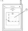
前の説明は意図ジェスチャ312及びアクションジェスチャ314の例示的な例を含んでいたが、一般的にこれらのジェスチャは、1つ以上の方向の直線運動、1つ以上の軸を中心とする回転、円弧に沿った動き、仮想タッピング、図形に基づくジェスチャ(例えば、8の字のジェスチャ)、文字又は数字の形状でのジェスチャ、直線運動(単数又は複数)と回転(単数又は複数)の組み合わせなどの、2次元又は3次元での多種多様な動き及び回転を含んでよい。更に一般的には、アクションジェスチャ314は、変更のタイプ又は所望の制御動作への直感的対応を有してよい。例えば、ジェスチャを使用するオブジェクトの制御の例を示す図面400を提供する図4に示されているように、上向き及び/又は下向きのアクションジェスチャ410が、ヒータ若しくはサーモスタットの温度設定、又はオブジェクト(窓の日よけ又は網戸など)の位置などの、値又は設定を増やす(又は減らす)ために使用されてよい。同様に、ジェスチャを使用するオブジェクトの制御の例を示す図面500を提供する図5に示されているように、アクションジェスチャ510は、エンタテインメントデバイスの音量などの値又は設定の変更に対応する、左回転及び/又は右回転を含んでよい。 The previous description included illustrative examples of
1つの例では、ユーザは、携帯電話をテレビに向けてよい。携帯電話は、無線測距によって、テレビが範囲内にある(すなわち、意図されたターゲットデバイスになることができるほど十分に近い)ということを決定してよい。加速度計及び/又はジャイロスコープ入力は、無線通信デバイス110がテレビ(例えば、オブジェクト310)に対して命令(例えば、アクションジェスチャ)を実行するために使用されていることを示す、意図ジェスチャ312として解釈され得る相対運動の更なる通知を提供してよい。更に、1つ以上のアクションジェスチャ(例えば、314、410、及び/又は510のいずれか)が、テレビを制御する1つ以上のコマンドを示すために、提供され得る。例えば、ユーザは、携帯電話を右に回して、テレビの音量を増やすか、又はチャネルを変更することができる。 In one example, the user may point the mobile phone at the television. The cell phone may determine by radio ranging that the television is in range (ie, close enough to be the intended target device). The accelerometer and / or gyroscope input is interpreted as an
ユーザインターフェース技術は、無線通信デバイス110を別の電子デバイスと直感的に組み合わせるために使用されてもよく、その後、組み合わせられた電子デバイスは、互いに通信できるようになる。例えば、ユーザは、意図ジェスチャ312及びアクションジェスチャ(314、410、及び/又は510)を実行することによって、物理デバイスと無線でデータを交換又は共有したいという要求を遠隔で示すことができてよい。これらの操作が実行されるときに、無線通信デバイス110及び/又は物理デバイスは、組み合わせることに対する確認及び/又は認可を要求するメッセージを、ユーザインターフェースに表示してよい。加えて、他の物理デバイスは、指定された時間インターバル(例えば、10分又は1時間)の間、組み合わせることに同意してよく、この時間インターバルの経過後、組み合わせが無効化されてよい。このようにして、無線通信デバイス110のユーザは、組み合わせプロセスの制御を維持してよく、組み合わせられる物理デバイスが同じ環境(同じ部屋など)内にあることを確認することなどによって、組み合わせが安全であることを保証できるようにしてもよい。無線通信デバイス110は、指向性意図及びアクションジェスチャを提供することによって、組み合わせることが意図されたオブジェクト310に電子的に成りすまそうとしているデバイスとの組み合わせを回避してよい。同様にして、指向性意図及びアクションジェスチャは、近接しているが、環境内の異なる位置又は高度にある、オブジェクト310以外のデバイスとの偶発的な組み合わせを回避することができる。このアプローチは、情報の共有及び/又は組み合わせの複雑さを低減することに役立つこともある。例えば、組み合わせプロセス中に、パスワードは必要とされなくてよい。いくつかの実施形態では、意図ジェスチャ及びアクションジェスチャ(単数又は複数)の後に、無線通信デバイス及び物理デバイスは、暗号キーを交換することができる。 User interface technology may be used to intuitively combine the
別の例では、無線通信デバイス110を、組み合わせるという意図が存在するか、又はコマンドの発行先にするという意図が存在するオブジェクトの方向に向けることができる。無線通信デバイス110のカメラは、視野内のすべてのオブジェクトの画像をキャプチャしてよく、1つ以上の候補デバイスを表示する選択可能な画面上のインターフェースを提示することができる。その後、ユーザは、組み合わせるべきデバイス(及び、任意選択的に、例えばプロトコル)を選択できる。 In another example, the
更に別の例では、リソースを要求するため、又は情報を取得するために、無線通信デバイス110をオブジェクト310に向けることができる。例えば、タクシーを呼び止めるために、(例えば、アクションジェスチャ314、410、及び/又は510を伴って、又は伴わずに、意図ジェスチャ312を使用して)無線通信デバイス110をタクシー(例えば、オブジェクト310)に向けることができる。更に、格付けを取得するため、又は予約するために、(例えば、アクションジェスチャ314、410、及び/又は510を伴って、又は伴わずに、意図ジェスチャ312を使用して)無線通信デバイス110をレストラン(又は、レストランに関連付けられたオブジェクト310)に向けることができる。同様に、無線通信デバイス110をプリンタに向けることによって、無線通信デバイス110は、プリンタと相互作用する(例えば、設定するか、又は印刷する)ことができる。例えば、意図ジェスチャ312、並びにアクションジェスチャ314、410、及び/又は510は、(例えば、印刷ジョブを開始するための)情報をプリンタに送信するため、又は1つ以上の設定/構成の制御を開始するために、無線通信デバイス110で提供され得る。 In yet another example, the
無線測距及び指向性が、1つ以上のセンサから情報を取得するために使用されてもよい。例えば、測定値を取得するために、無線通信デバイス110をセンサ(例えば、サーモスタット又はタイヤ圧力計)に向けることができる。いくつかの実施形態では、アクションジェスチャ314、410、及び/又は510を伴って、又は伴わずに、意図ジェスチャ312を使用して、センサデータの通信を開始することができる。同様に、ストア内のアイテム又はディスプレイを操作して、価格又は在庫情報などの属性を確認することなどによって、サーバから情報を取得するために、1つ以上の意図及び/又はアクションジェスチャを無線通信デバイス110で提供することができる。 Wireless ranging and directivity may be used to obtain information from one or more sensors. For example, the
更に、オブジェクト310によって選択的に送信される(一般的又は一意の)識別子によって、例えば無線通信デバイス110による、オブジェクト310の特定が容易になってよい。例えば、この識別子は、特定の電子デバイス(例えば、オブジェクト310)に関連付けられた、持続的な一意の識別子であってよい。無線通信デバイス110は、持続的な一意の識別子を(例えば、ローカルに、又はクラウド内に)記憶することができ、この識別子を、(連絡先情報内の)人、オブジェクト、又は位置に関連付けることができる。受信された無線通信において識別子が検出された場合、無線通信デバイス110は、既知の電子デバイス(例えば、オブジェクト310)が近接していることを示す通知を提供することができる。あるいは、識別子は、無線通信デバイス110又はオブジェクト312上で実行されるアプリケーションによって割り当てられる識別子などの、過渡的又は一時的な識別子であってよい。例えば、相乗りアプリケーションは、識別子を無線通信デバイス110に一時的に割り当ててよく、その後、この識別子をブロードキャストすることができる。更に、相乗りアプリケーションは、過渡的な識別子を、割り当てられた運転手に対応するデバイスに提供し、人を車で拾うことを容易にすることができる。同様に、運転手のデバイスに対応する(持続的又は過渡的な)識別子を無線通信デバイス110に提供して、運転手を検証することができる。過渡的な識別子は、1時間などの所定の時間の経過後、又はトランザクションの完了時に、有効期限が切れてよい。任意の数の持続的及び過渡的な識別子をデバイス又はオブジェクトに関連付けて、例えば、様々なシナリオにまたがる特定を容易にすることができる。 Further, an identifier (general or unique) selectively transmitted by the
更に、割り当てられた識別子は、ユーザのプライバシーを保護するため、及びセキュリティを提供するために、時間と共に変更されてよい。具体的には、識別子は、図1の任意選択的なサーバ126(有線ネットワーク又は無線ネットワークなどの、図1のネットワーク124を介してアクセスされてよい)によって割り当てられてよく、定期的に(時間インターバル(例えば、5分又は1日)が経過した後などに)更新されてよい。追加的又は代替的に、識別子は、例えば特定のトランザクションのための、1回限りの識別子として割り当てられてよい。いくつかの実施形態では、識別子は、デバイス又はオブジェクト(オブジェクト310など)に持続的に割り当てられ得る、匿名の識別子であることができる。その後、匿名の識別子は、匿名の識別子及び識別情報の項目が共有されている他のデバイスによってのみ解決され得る。 Furthermore, the assigned identifier may change over time to protect user privacy and to provide security. Specifically, the identifier may be assigned by the
消費電力を低減するために、無線通信デバイス110及び/又はオブジェクト312は、定期的にのみ、又はイベント(既知の連絡先に関連付けられた識別子の検出など)の発生時にのみ、1つ以上の識別子を送信してよい。追加的又は代替的に、無線通信デバイス110及び/又はオブジェクト312は、別の(既知又は未知の)デバイスに近接していること、別のデバイスを含んでいるトランザクションに関与していること、特定の領域内(例えば、地理上のフェンスで囲まれた領域内)に存在することなどの、1つ以上の条件が満たされたときにのみ、ユーザの入力に応じて、及び/又はイベント(例えば、約束又は会合)に基づいて、1つ以上の識別子の受信を試みてよい。例えば、Bluetooth(登録商標)低エネルギー(Bluetooth low energy、BLE)受信機は、例えばオブジェクト312からの識別子を含んでいる広告(又は、他のメッセージ)を定期的にスキャンしてよい。スキャン速度は、動き、時間、及び/又は利用可能な電力などの1つ以上の要因に基づいて、変化することができる。既知の識別子を検出することに応じて、無線通信デバイス110は、1つ以上の他の通信インターフェースをアクティブ化してよく、無線測距を有効化してよく、それによって、例えば、無線通信デバイス110は、オブジェクト312からメッセージを受信すること、並びに/あるいはオブジェクト312への方向及び/又はオブジェクト312までの距離316を決定することができるようになる。 To reduce power consumption, the
更に、前述したように、ユーザインターフェース技術は、仮想オブジェクトの使用を容易にしてよい。これらの実施形態は、仮想オブジェクトを定義すること、及び無線測距/方向制御入力を介して仮想オブジェクトを制御することを含んでよい。いくつかの実施形態では、仮想オブジェクト(例えば、仮想表現114)との対話は、無線測距を実行せずに、無線通信デバイス110の向き及び受信された意図ジェスチャに基づくことができる。 Further, as described above, user interface technology may facilitate the use of virtual objects. These embodiments may include defining a virtual object and controlling the virtual object via a wireless ranging / direction control input. In some embodiments, the interaction with the virtual object (eg, virtual representation 114) can be based on the orientation of the
例えば、仮想オブジェクト又は仮想表現は、ドアの近くの仮想照明スイッチ又は仮想サーモスタットなどの特定の物理的位置において、確立され得る。仮想オブジェクトは、1つ以上の座標のみに対応して、仮想アイテム(例えば、ステッカー)によって物理的に表されることが可能であり、又は純粋に仮想的であることができる。仮想オブジェクトは、関連する物理デバイスによって定義されてもよい。例えば、プロジェクタは、例えば壁で仮想コントロールを定義することができ、仮想コントロールの位置を宣伝することができ、他の電子デバイスが仮想コントロールを操作してプロジェクタへの実際の入力を実現できるようにする。 For example, a virtual object or virtual representation can be established at a particular physical location, such as a virtual light switch or virtual thermostat near a door. A virtual object can be physically represented by a virtual item (eg, a sticker) corresponding to only one or more coordinates, or can be purely virtual. A virtual object may be defined by an associated physical device. For example, a projector can define a virtual control, for example, on a wall, advertise the location of the virtual control, and allow other electronic devices to manipulate the virtual control to achieve the actual input to the projector To do.
前述したように、仮想オブジェクトを含む実施形態では、デバイス(例えば、無線通信デバイス110)が、特定の位置にある仮想デバイス(例えば、壁の特定の位置に対応する仮想コントロール)を定義してよい。仮想デバイスがより大きいシステムの一部として定義され得るということに注意する。例えば、施設は、すべての出入口に隣接する(例えば、照明スイッチで)仮想サーモスタットを定義してよい。あるいは、仮想デバイスは特定のデバイスによって定義されてよく、例えば、プロジェクタは、壁又はその他の表面上でコントロールを定義してよく、そのコントロールの位置を無線で宣伝してよく、それによって、他の電子デバイスが、仮想コントロールを現実であるかのように操作できるようにする。 As described above, in embodiments including virtual objects, a device (eg, wireless communication device 110) may define a virtual device at a particular location (eg, a virtual control corresponding to a particular location on the wall). . Note that virtual devices can be defined as part of a larger system. For example, a facility may define a virtual thermostat adjacent to all doorways (eg, with a light switch). Alternatively, a virtual device may be defined by a particular device, for example, a projector may define a control on a wall or other surface, and may advertise the location of that control wirelessly, thereby Allows electronic devices to manipulate virtual controls as if they were real.
このようにして、無線通信デバイス110(例えば、携帯電話又はウェアラブル)は、制御デバイス(例えば、動的な遠隔制御)として機能することができてよい。更に、無線通信デバイス110は、特定の入力機構を有するように構成されずに、ジェスチャを介して多種多様なオブジェクト(例えば、オブジェクト310)に制御入力を提供することができてよい。これによって、無線通信デバイス110のディスプレイは、より大きいモニタのための代理のタッチスクリーンとして機能することができてよく、コンパス、ジャイロスコープ、加速度計、高度計、タッチ入力、及び/又はマイクロフォンなどのセンサ/入力を使用して、このモニタに関連付けられた入力及び/又は出力を制御することができる。いくつかの実施形態では、無線通信デバイス110を、プライマリディスプレイに対応する第2の画面として使用することができる(第2の画面がプライマリディスプレイを正確に反映してもしなくてもよいということに注意する)。その後、プライマリディスプレイを制御するために、ジェスチャに基づく(タッチに基づくことを含む)制御(例えば、ピンチ、ズーム、スクロール、スワイプなど)が提供され得る。 In this way, the wireless communication device 110 (eg, mobile phone or wearable) may be able to function as a control device (eg, dynamic remote control). Further, the
更に、例えば無線通信デバイス110に対して、ジェスチャに基づく制御入力を使用して、電子デバイス間のコンテンツの転送などの機能を実行してよい。例えば、無線通信デバイス110に対して、1つ以上のジェスチャに基づく制御入力を使用して、コンテンツを第2の電子デバイスに送信する(例えば、「投げる」)こと、コンテンツを第2の電子デバイスから取得すること、第2の電子デバイスを制御する(例えば、コンピュータの所有権を受け取り、そのコンピュータに自分のコンテンツ/設定を複製する)ことなどを実行することができる。したがって、1つ以上のジェスチャに基づく入力(例えば、フリップ、プッシュ、擦り、スワイプ、又はタップ)を使用して、無線通信デバイス110から、より大きいディスプレイ又はコンピュータなどの別のデバイスへ(又は、別のデバイスから無線通信デバイス110へ)の転送を示すことができる。同様に、無線通信デバイス110に対して、ジェスチャに基づく入力を使用して、あるデバイスから別のデバイスへ、無線通信デバイス110をデータキャリアとして用いて何かを移動することができる。 Further, for example, functions such as transfer of content between electronic devices may be performed on the
いくつかの実装では、仮想オブジェクトは、例えばサービスのための、仮想キュー(又はライン)のような構造を包含してよい。例えば、仮想キューは、実体又はリソース(例えば、切符売り場又はストア)に関連して定義されることが可能であり、近接している電子デバイスは、仮想キューを維持しているホストデバイスに関連する識別子(例えば、一意の過渡的な識別子)を送信することによって、仮想キューに登録することができる。デバイス(例えば、無線通信デバイス110)の仮想キューの位置は、デバイスが仮想キューの物理的位置に近接したままである間、又はキューが処理されるまで、維持され得る。更に、仮想キュー内の位置は、登録されたデバイスに提示されることも可能であり、更新され得る。ホストデバイスは、(例えば、切符売り場で)登録されたデバイスの順番に達したとき、又は近づいたときに、そのことを登録されたデバイスに通知することができる。 In some implementations, a virtual object may include a structure, such as a virtual queue (or line), for example for services. For example, a virtual queue can be defined in relation to an entity or resource (eg, ticket office or store), and an adjacent electronic device is associated with a host device that maintains the virtual queue A virtual queue can be registered by sending an identifier (eg, a unique transient identifier). The location of the virtual queue of the device (eg, wireless communication device 110) may be maintained while the device remains in proximity to the physical location of the virtual queue or until the queue is processed. In addition, the location in the virtual queue can be presented to registered devices and can be updated. The host device can notify the registered device when it reaches or approaches the order of the registered devices (eg, at the ticket office).
コスト節約に加えて、仮想表現又は仮想オブジェクトを対応する物理デバイスに対して使用し、魅力の少ない物理デバイス(照明スイッチなど)を魅力的なプレースホルダ(セラミックオブジェクト)と交換するか、又は物理デバイスを一括して削除することによって、環境を更に見た目に美しくすることができることもある。このアプローチは、仮想表現に関連付けられた位置を簡単に再定義することによって、仮想表現を意のままに移動することもできる。その後、ユーザが、自分の電子デバイス(例えば、無線通信デバイス110)を新しい位置に向けたときに、意図ジェスチャ及びアクションジェスチャを実行した場合、関連する操作(単数又は複数)が実行されてよい。 In addition to cost savings, use a virtual representation or virtual object for the corresponding physical device to replace less attractive physical devices (such as lighting switches) with attractive placeholders (ceramic objects), or physical devices By deleting all of them in a batch, the environment can be made more visually appealing. This approach can also move the virtual representation at will by simply redefining the location associated with the virtual representation. If the user then performs an intent gesture and an action gesture when pointing the user's electronic device (eg, wireless communication device 110) to a new location, the associated operation (s) may be performed.
いくつかの実施形態では、関連する物理デバイスを制御するために使用されるジェスチャは、暗黙的であってよい。そのような実施形態では、無線測距によって決定された近接性が、関連する意図及びアクションジェスチャを伴うことなく、制御可能なデバイスを関与させるために使用されてよい。例えば、ユーザが仮想表現又は仮想オブジェクトに関連付けられた所定の位置の近くを歩いたときに、照明が点灯し(その後、消灯)してよい。同様に、ユーザデバイスがドアに近づいたときに、ドアロックが解除されてよく、ユーザデバイスが交差点に到着したときに、(条件が許可する場合に)信号機が緑色に変化してよい、などとなる。したがって、開示された技術は、近接性に基づく制御に使用されてよい。 In some embodiments, the gesture used to control the associated physical device may be implicit. In such embodiments, proximity determined by wireless ranging may be used to involve a controllable device without associated intent and action gestures. For example, the illumination may be turned on (and then turned off) when the user walks near a predetermined location associated with the virtual representation or virtual object. Similarly, when the user device approaches the door, the door lock may be released, and when the user device arrives at the intersection, the traffic light may turn green (if conditions permit), etc. Become. Thus, the disclosed techniques may be used for proximity-based control.
更に、開示された技術は、進行方向の前方にある電子デバイスがイベントを経験した(例えば、突然の減速を経験した)などの場合に、連携状況認識を提供するために使用されてもよい。電子デバイスは、例えばブロードキャストメッセージを介して、潜在的に危険な状況を他の電子デバイスに通知することができる。 Further, the disclosed techniques may be used to provide coordination status awareness, such as when an electronic device ahead of the direction of travel has experienced an event (eg, has experienced a sudden deceleration). An electronic device can notify other electronic devices of potentially dangerous situations, for example, via a broadcast message.
いくつかの実施形態では、開示された技術は、環境108(図1)において、任意選択的なタグ128(図1)などの1つ以上の任意選択的なタグによって、容易にされる。例えば、タグは、無線周波数エネルギーから電力を収集し、かつ/又は関連する電源を有する、低コストのシステムオンチップであってよい。タグ128は、例えば受信されたコマンドに応じて、1つ以上の信号を出力することができる。例えば、タグ128は、RF信号及び/又は音響信号(「チャープ」など)を出力することができる。 In some embodiments, the disclosed techniques are facilitated by one or more optional tags, such as optional tag 128 (FIG. 1), in environment 108 (FIG. 1). For example, the tag may be a low cost system on chip that collects power from radio frequency energy and / or has an associated power source. The
いくつかの実施形態では、環境108(図1)内のタグ128は、無線で電力を収集し(例えば、24GHzの信号の形態で電力を受信してよい)、短い信号又はチャープを介して(例えば、60GHzで信号を発することによって)通信する。この通信は、例えば100フィートまでの範囲を有してよく、指向性であってよい。いくつかの実装では、24GHzの電力信号は、信号内でエンコードされた識別子を有してよい。このような構成において、タグが識別子を認識していない場合、タグは応答しなくてよい。タグが(例えば、電力を供給されて動作可能になったことを示した後に)スタートパルスに応答するための時間は、既知であってよい。無線通信デバイスが、位相及び到着角を測定して方向を決定してよく、到着時間又は経過時間を使用して、無線通信デバイスとタグの間の距離を決定してよいということに注意する。したがって、タグ128は、無線測距計算を生成するため、又は補完するために、使用されてよい。 In some embodiments, the
図6は、図1の無線通信デバイス110などの無線通信デバイスを使用してオブジェクトを制御する方法の例600を示すフロー図である。動作中、無線通信デバイスは、無線通信デバイスに近接して配置されたオブジェクトを制御する意図を示す受信された意図ジェスチャを特定する(処理610)。その後、無線通信デバイスは、意図ジェスチャに関連付けられたオブジェクトを決定する(処理612)。例えば、無線通信デバイスは、例えば意図ジェスチャに少なくとも部分的に基づいて、無線測距を使用し、無線通信デバイスの位置及び/又は向きに対応する方向及び/又は高度にやはり配置されている、範囲内のオブジェクトを決定する。更に、無線通信デバイスは、無線通信デバイスの1つ以上のセンサに関連付けられたセンサデータにアクセスし(処理616)、センサデータを解釈してコマンド値を決定する(処理618)。例えば、無線通信デバイスは、(例えば、無線通信デバイスに記憶されたアクションジェスチャプロファイルに基づいて)センサデータを1つ以上のアクションジェスチャと比較して、1つ以上の意図されたコマンドを特定する。次に、無線通信デバイスは、例えば1つ以上のメッセージを使用して、コマンド値を生成して送信し、オブジェクトを制御する(処理620)。いくつかの実装において、オブジェクトによって宣伝されたか、又はその他の方法でオブジェクトに関連付けられた識別子に基づいて、1つ以上のメッセージがオブジェクトに送信され得る。 FIG. 6 is a flow diagram illustrating an
方法600のいくつかの実施形態では、追加の処理、異なる処理、及び/又はより少ない処理が存在してよい。更に、これらの処理の順序は変更されてよく、かつ/あるいは2つ以上の処理が単一の処理に結合されるか、又は並列に実行されてよい。 In some embodiments of the
ユーザインターフェース技術の実施形態が、図7に更に示されており、図7は、無線通信デバイス110と物理(又は電子)デバイス112(例として使用される)の間の通信を示している図面700を提示している。ユーザは、例えば無線通信デバイス110を物理デバイス112に向けるか、又は方向を合わせる710ことによって、意図ジェスチャ708を実行してよい。いくつかの実装では、意図ジェスチャ708は、無線通信デバイス110を物理デバイス112に向けて進める動きなどの、方位成分及び運動成分の両方を含んでよい。無線通信デバイス110内のプロセッサ714は、例えば、1つ以上のセンサ712(例えば、ジャイロスコープ、加速度計、及び/又はコンパス)によって測定された、向き710及び任意のその他の関連する動きに基づいて、意図ジェスチャ708を特定してよい。意図ジェスチャ708は、物理デバイス112を制御するユーザの意図として解釈されてよい。 An embodiment of user interface technology is further illustrated in FIG. 7, which illustrates communication between a
無線通信デバイス110内のインターフェース回路718は、物理デバイス112内のインターフェース回路716によって送信されたパケット720(又はフレーム)を受信する。パケット720は、物理デバイス112に関連付けられた識別子722を含んでいる。更に、パケット720は、パケット720の送信時間を規定する情報を含むことができる。インターフェース回路718(又はプロセッサ714)は、決定されたパケット720の到着時間と共に、(パケット720を伝達した無線信号の伝搬速度に基づいて)物理デバイス112までの距離724を決定してよい。追加的又は代替的に、無線通信デバイス110は、1つ以上の他のパケットを物理デバイス112と通信して、無線測距動作を実行することができる。プロセッサ714は、識別子722及び/又は距離724に基づいて、物理デバイス112を特定してよい。 The
更に、コマンド又はコマンド値に応じて、無線通信デバイス110においてアクションジェスチャが実行されてよい。1つ以上のセンサ712が、アクションジェスチャ中にセンサデータ726を測定し、測定されたセンサデータをメモリ728に記憶してよい。プロセッサ714は、(例えば、センサデータ726をセンサ712から受信すること、及び/又はメモリ728から取得することによって)センサデータ726にアクセスし、このセンサデータ726を解釈して、アクションジェスチャに対応するコマンド値730を決定してよい。更に、インターフェース回路718は、コマンド値730を含んでいるパケット732をインターフェース回路716に送信してよい。物理デバイス112は、パケット732の受信時に、コマンド値730を実行することができる。
拡張現実Further, an action gesture may be performed at the
Augmented reality
図8は、無線測距を使用して環境内のオブジェクトの位置を特定する例を示す図面800を提示している。具体的には、図1の環境108内で無線通信デバイス110に近接している物理デバイス112は、物理デバイス112に関連付けられた識別子を含むパケット(又はフレーム)を送信してよい。その後、無線通信デバイス110は、識別子を含んでいるこの送信を受信してよい。 FIG. 8 presents a drawing 800 illustrating an example of using wireless ranging to locate an object in an environment. Specifically, a
例えば、識別子は、物理デバイス112の(したがって、物理デバイス112のユーザの)一般的識別子又は一意の識別子のいずれかであってよい。あるいは、識別子は、輸送リソース、共有コンピューティングリソース(例えば、プリンタ)、医療リソース、表示リソース、セキュリティリソース、アクセシビリティリソース、又は安全リソースなどの、物理デバイス112に対応するリソースクラスに関連付けられてよい。(ユーザが、物理デバイス112に近接して、又は関連付けられて使用できる特定のアイテムを購入したいなどの場合に、)識別子が、検索結果又は所望の金融取引と連動して受信されていてよいということに注意する。具体的には、無線通信デバイス110のユーザがリソースクラスに関して(例えば検索エンジンを使用して)検索を実行し、送信が受信された場合、無線通信デバイス110は、下で更に説明されるように、識別子が受信されたときに、物理デバイス112に関連する位置情報を表示してよい。代替的又は追加的に、識別子は、無線通信デバイス110のユーザの連絡先に対応してよく、連絡先の例としては、ユーザの友人又は同僚(すなわち、ユーザがすでに知っている誰か)、あるいはユーザが図1の環境内108で会うことになっている(ユーザが知っていても、知らなくてもよい)誰か、などが挙げられる。例えば、会合を容易にするために、関係者のいずれか又は両方が、あらかじめ識別子を提供することができ、その後、各デバイスがこの識別子を監視できる。 For example, the identifier may be either a general identifier of the physical device 112 (and thus a user of the physical device 112) or a unique identifier. Alternatively, the identifier may be associated with a resource class corresponding to the
いくつかの実施形態では、識別子は、無線通信デバイス110に記憶された(又は、遠隔で記憶されたデータ構造内でアクセスされ得る)、(例えば、物理デバイス112に関連付けられた)別の人に関する持続的な連絡先情報に関連付けられ得る。その後、この識別子が無線通信デバイス110によって検出されたときに、識別子に対応する人の存在及び識別情報を伝えるインジケータが提供され得るあるいは、識別子は、無線通信デバイス110又は物理デバイス112上で実行されるアプリケーションによって割り当てられる識別子などの、過渡的又は一時的な識別子であってよい。例えば、相乗りアプリケーションは、識別子を無線通信デバイス110に一時的に割り当ててよく、その後、この識別子をブロードキャストすることができる。更に、相乗りアプリケーションは、過渡的な識別子を、割り当てられた運転手に対応するデバイス(例えば、物理デバイス112)に提供し、人を車で拾うことを容易にすることができる。同様に、運転手のデバイスに対応する(持続的又は過渡的な)識別子を無線通信デバイス110に提供して、運転手を検証することができる。過渡的な識別子は、1時間などの所定の時間の経過後、又はトランザクションの完了時に、有効期限が切れてよい。任意の数の持続的及び過渡的な識別子をデバイス又はオブジェクトに関連付けて、例えば、様々なシナリオにまたがる特定を容易にすることができる。 In some embodiments, the identifier is stored in the wireless communication device 110 (or can be accessed in a remotely stored data structure) and relates to another person (eg, associated with the physical device 112). Can be associated with persistent contact information. Thereafter, when this identifier is detected by the
更に、識別子は、ユーザのプライバシーを保護するため、及びセキュリティを提供するために、時間と共に変更されてよい。具体的には、識別子は、図1のネットワーク124(インターネットなど)を介してクラウドベースのサーバ126によって割り当てられてよく、定期的に(例えば5分の時間インターバルが経過した後など)に更新されてよく、又は例えばトランザクションに関連付けられた、1回限りの識別子であってよい。いくつかの実施形態では、識別子は、例えば物理デバイス112に持続的に割り当てられ得る、匿名の識別子である。ただし、匿名の識別子は、例えばローカルに記憶された関連付けに基づいて匿名の識別子を解決することができる、1人以上の連絡先に知られてよい。電子デバイスが、定期的に送信され得る複数の識別子を使用して構成されてよいということに注意する。この最後の能力は、先行する実施形態のうちの1つ以上において使用されてよい。 Further, the identifier may change over time to protect user privacy and to provide security. Specifically, the identifier may be assigned by the cloud-based
識別子を受信することに応じて、無線通信デバイス110は、識別子をローカル(又は、リモート)メモリ内の1つ以上の記憶されたターゲット識別子と比較して、一致を判定してよい。その後、無線通信デバイス110は、無線測距を使用して、無線通信デバイス110からの物理デバイス112の範囲(又は距離)810及び/又は物理デバイス112に対する方向812を決定してよい。代替的又は追加的に、無線通信デバイス110は、無線通信デバイス110の指標(RSSIなど)及び/又は向きに基づいて、範囲810及び/又は方向812を決定してよい。なお、無線測距は、2GHz無線帯域内、5GHz無線帯域内、ISM帯域内、60GHz無線帯域内、超広帯域内などの、周波数の1つ以上の帯域内で、実行されてよい。 In response to receiving the identifier, the
消費電力を低減するために、無線通信デバイス110及び/又は物理デバイス112は、一意の識別子(単数又は複数)又は一般的識別子(単数又は複数)を送信してよく、あるいは両方のデバイスが図1の環境108内に存在する場合(及び、更に一般的には、両方のデバイスが地理上のフェンスで囲まれた領域内に存在する場合)などの、各デバイスが近接している場合にのみ、かつ/又は無線通信デバイス110及び/又は物理デバイス112のユーザ間の約束又は会合の時間に基づいて、一意の識別子(単数又は複数)又は一般的識別子(単数又は複数)の受信を試みてよい。例えば、Bluetooth(登録商標)低エネルギー受信機を使用して、例えば物理デバイス112から、識別子を含んでいるメッセージを受信してよい。無線通信デバイス110は、このメッセージを受信することに基づいて、1つ以上の受信機を起動し、無線測距を開始することができるため、無線通信デバイス110は、物理デバイス112に対する範囲810及び/又は方向812を決定することができる。いくつかの実装では、無線通信デバイス110は、一意の識別子を含むメッセージを物理デバイス112から受信してもよい。 To reduce power consumption,
次に、図9〜図15を参照して下で更に説明されるように、無線通信デバイス110は、物理デバイス112などのオブジェクトに対する範囲及び/又は方向を示す出力情報を提示してよい。 Next, as described further below with reference to FIGS. 9-15, the
いくつかの実施形態では、物理デバイス112が、(隣接する部屋でも、近隣の部屋でもない)同じ部屋などの、無線通信デバイス110と同じ環境108(図1)内にあるかどうかを判定するために、無線通信デバイス110によって周囲の音が使用されてよい。例えば、無線通信チャネル(WLANなど)を介して無線通信デバイス110と共有される、物理デバイス112によって記録された周囲の音が、無線通信デバイス110によって測定された周囲の音と比較されてよい。周囲の音の測定値の比較結果が良好である場合、無線通信デバイス110及び物理デバイス112が同じ部屋に存在するということが、決定されてよい。代替的又は追加的に、無線通信デバイス110は、物理デバイス112によって検出、監視、及び/又は記録され得る1つ以上の音響チャープ又は音(人間が聴くことができる範囲外の周波数の帯域内であってよい)を出力してよい。 In some embodiments, to determine whether the
更に一般的には、1つ以上の他のデバイス/オブジェクトから物理デバイス112を区別するなど、環境108(図1)内の1つ以上の潜在的なターゲットデバイスの曖昧さをなくすために、無線通信デバイス110によって実行される1つ以上の測定が使用されてよい。例えば、無線通信デバイス110の方を向いているユーザのターゲットデバイスは、同じ向き、異なる高さ、及び/あるいは同じであるか、又は異なるRSSIを有してよい。識別子及び/又は範囲310と共に1つ以上の測定値を使用して、物理デバイス112を特定してよい。更に、前述したように、デバイスが誰かのポケットの中にあるため、情報の組み合わせ又は共有の対象になる可能性が低いということを示す場合のある周囲の音に基づいて、潜在的なターゲットデバイスが除外されてよい。 More generally, in order to disambiguate one or more potential target devices in environment 108 (FIG. 1), such as distinguishing
高度計又は到着角の情報を使用して、対象になる可能性のある領域の外部(例えば、テーブルの下、又はポケット/バッグの中が、配置される場所の候補になる可能性が低い場合、それらの場所)にある潜在的なターゲットデバイスを除外することもできる。別の例では、一次無線範囲内又は無線近接性の範囲内にあるが、適切な物理空間又は物理的近接性の外部にある潜在的なターゲットデバイスを除外するために、超音波チャープ又は60GHzの送信が使用され得る(例えば、除外される潜在的なターゲットデバイスは、別の室内に存在していてよい)。 Using altimeter or angle-of-arrival information, outside the area of interest (e.g., under the table or in the pocket / bag is unlikely to be a candidate location) Potential target devices at those locations can also be excluded. In another example, ultrasonic chirp or 60 GHz to exclude potential target devices that are within primary radio range or radio proximity, but outside the appropriate physical space or physical proximity. Transmission may be used (eg, potential target devices to be excluded may be in another room).
ただし、複数の潜在的なターゲットデバイスを、これらの方法のうちの1つ以上において区別できない場合、無線通信デバイス110のユーザは、特定された潜在的なターゲットデバイスのセットのうちから選択するよう要求されてよい。例えば、潜在的なターゲットデバイスのリストを含むユーザインターフェースが、無線通信デバイス110のディスプレイ上に提示されてよく、デバイスが、ユーザの入力によって選択され得る。 However, if multiple potential target devices cannot be distinguished in one or more of these ways, the user of
前述の説明では、物理デバイス112が例として使用されているが、他の実施形態では、環境108(図1)内のオブジェクトは、図1の物理デバイス118の仮想表現114などの、仮想表現であることができる。例えば、仮想表現は、部屋又は図1の環境108内の所定の物理的位置(図1の物理的位置116など)における物理デバイスの代理であってよい。所定の物理的位置(及び、更に一般的には、3次元空間内の所定の物理的位置)が、例えばトレーニングプロセスの間に、ユーザによって無線通信デバイス110を介して指定されていてよく、例えば、無線通信デバイス110を物理的位置に近づけるか、又は接触させて、無線通信デバイス110上のタッチ感知ディスプレイに表示されたユーザインターフェース内の仮想コマンドアイコンをアクティブにすることによって、あるいは無線通信デバイス110を物理的位置に接触させて、コマンド又は命令を言葉で言い、それらのコマンド又は命令が無線通信デバイス110によって監視されて、音声認識技術を使用して解釈されることによって、指定されていてよいということに注意する。 In the above description,
次に、環境内のオブジェクト(物理デバイス112など)の決定された位置に基づいて表示される情報の例について説明する。図9は、環境(及び、更に一般的には、環境のグラフィカル表現)内の近接領域のマップ910を表示する、ディスプレイ908上のユーザインターフェース900の例を示す図面を提示している。ユーザが無線通信デバイス110を掌に持っているときに、マップ910が表示されてよい。マップ910は、物理デバイス112などのオブジェクトの位置を表すインジケータ912を含むことができる。いくつかの実装では、インジケータ912の位置だけで、対応するオブジェクトに対する決定された範囲及び/又は方向を伝達することができる。いくつかの他の実装では、マップ910と共に、決定された範囲及び/又は距離を示す追加情報も提示され得る。 Next, an example of information displayed based on the determined position of an object (such as the physical device 112) in the environment will be described. FIG. 9 presents a drawing illustrating an example of a user interface 900 on a display 908 that displays a map 910 of proximate regions within the environment (and more generally a graphical representation of the environment). A map 910 may be displayed when the user holds the
マップ910が、無線通信デバイス110の周囲の環境内のオブジェクト(物理デバイス112など)及び相対的位置(単数又は複数)に関する直感的な状況認識を提供してよいということに注意する。例えば、ユーザインターフェース技術によって、ユーザは、消火器、救急箱、自動体外式除細動器、出口、及び/又は医療訓練を受けた人などの、環境内のリソースの位置を特定できるようになってよい。代替的又は追加的に、ユーザインターフェース技術は、進行路上の前方にある電子デバイスがイベント(例えば、突然の減速)を経験したときなどに、近接するオブジェクトに関する動的位置情報を提供してよい。この電子デバイスに近接する、例えば進行路上の1つ以上の電子デバイスに、このイベントが通知されてよい。 Note that the map 910 may provide intuitive contextual awareness of objects (such as the physical device 112) and relative position (s) in the environment surrounding the
図10は、ユーザインターフェースの例1000を示す図面を提示している。ユーザインターフェース1000は、無線通信デバイス110のディスプレイ908上に提示され、無線通信デバイス110の画像センサ(CMOS又はCCD撮像センサ、及びより一般的には、カメラなど)によってキャプチャされた近接領域の画像1010を表示してよい。無線通信デバイス110は、オブジェクト(例えば、物理デバイス112)を表す画像1010上に、重ね合わせられた注釈又はインジケータ1012(図9のインジケータ912と同じであっても、異なっていてもよい)を表示してもよい。オブジェクトは、無線送信において、無線通信デバイス110が識別子を受信した結果として、特定されていてよい。対応するオブジェクトが無線通信デバイス110の視距離の範囲内にあるかどうか、又はそれ以外の方法で無線通信デバイス110にとって可視であるかどうかに関わらず、インジケータ1012(及び/又は図9のインジケータ912)が表示されてよいということに注意する。例えば、無線通信デバイス110のユーザが、見にくいか、又はまだ見ることができないオブジェクトの位置を特定することを支援するために、インジケータ1012が提示されてよい。 FIG. 10 presents a drawing illustrating an
したがって、ユーザインターフェース技術は、拡張現実を含んでよく、又は使用してよい。具体的には、無線測距を使用して決定された位置情報(範囲及び/又は方向など)が、周囲の環境の画像上に重ね合わせられてよい。この拡張現実は、無線通信デバイス110のユーザが近くにある物、位置、リソース、及び/又は人を特定するのを支援するために、追加されたインテリジェンスを提供してよい。例えば、このアプローチは、会おうとしている人の位置を特定すること(人に基づく)、救急サービス又は無線の範囲などのリソースの位置を特定すること(リソースに基づく)、及び/又は建物若しくは道路などの、位置に基づく検索の結果を見つけること(検索に基づく)において、ユーザを支援するために使用されてよい。無線通信デバイス110のディスプレイは、対象のアイテムを表示するように拡張されたカメラ入力を含んでよい。 Thus, user interface technology may include or use augmented reality. Specifically, position information (such as range and / or direction) determined using wireless ranging may be superimposed on an image of the surrounding environment. This augmented reality may provide additional intelligence to help the user of
したがって、ユーザが混雑した環境内にいて、無線通信デバイス110をかざした場合、無線通信デバイス110が、ユーザが探している人(又は物理デバイス112などの、この人に関連する電子デバイス)に方向が合わせられるか、又は向けられたときに、この人の画像が環境の画像上に表示されてよい。更に、図16を参照して下で更に説明されるように、ユーザが(例えば、無線通信デバイス110の測定された向きに基づいて)回転したか、又は向きを変えたときに、ユーザが正しい方向(例えば、ユーザが探している人、オブジェクト、又はリソースの方向)を向いている場合、ユーザに関連するスマートウォッチ又はその他のそのようなウェアラブルデバイスが、触覚フィードバック(例えば、「タップ」、又はオーディオ出力などの別のタイプのフィードバック)を提供してよい。したがって、ユーザインターフェース技術は、混雑した環境においても、及びユーザが、自分が探している人にこれまで会ったことがない場合でも、社会的交流及び会合を容易にしてよい。 Thus, if the user is in a crowded environment and holds the
いくつかの実施形態では、無線通信デバイス110は、異なるユーザインターフェースモードを自動的に切り替える。このことが、無線通信デバイス110の向きに基づくユーザインターフェースの異なるモードの例を示す図面を提示する図11に示されている。具体的には、無線通信デバイス110のユーザがデバイスの向きを変えたときに、ジャイロスコープ又は加速度計が、方位値における変化を測定してよい。その後、無線通信デバイス110は、測定された方位値に基づいて、マップ910(図9)の表示と、画像1010(図10)の表示との間で、選択的に遷移してよい。したがって、無線通信デバイス110が、水平方向に向けられた(例えば、ユーザの掌にある)場合、マップ910(図9)を表示するマップビュー1110が表示されてよい。無線通信デバイス110が、垂直方向に向けられた(例えば、物理デバイス112の方向に向いた)場合、画像1010(図10)を表示するカメラビュー1112が表示されてよい。マップビュー1110インターフェースモードとカメラビュー1112インターフェースモードの間の遷移は、1つ以上のセンサ入力が閾値を超える向きの変化を示す場合に、開始され得る。代替的又は追加的に、物理デバイス112がユーザの視距離の範囲外にあるときに、マップビュー1110が表示されてよく、物理デバイス112が視距離の範囲内にあるときに、カメラビュー1112が表示されてよい。このようにして、ユーザは、無線通信デバイス110の向きを変えることによって、2つのユーザインターフェースモード間で直感的に切り替えるか、又は遷移してよい。 In some embodiments, the
あるいは、いくつかの実施形態では、無線通信デバイス110のユーザは、ユーザインターフェースモードを手動で選択又は指定することができる。このことが、ユーザインターフェース1200の異なるモードの例を示す図面を提示する図12に示されている。例えば、ユーザは、無線通信デバイス110のタッチ感知ディスプレイに対して、仮想アイコン708のストライク領域内でタッチ入力を行うことによって、例えば無線通信デバイス110の周囲360°の視界を表示するマップ1210を含んでいるマップビューを選択してよい。マップ1210は、インジケータ(インジケータ1216など)(例えば、テキスト、サムネイル、シンボル、エモーティコン、又はグラフィカルアイコンのいずれか、あるいはすべて)によって表される1つ以上のオブジェクト(物理デバイス112など)を、異なる範囲及び方向(範囲1212及び方向1214など)で描画することができる。更に、ユーザは、画像ビューを選択してよく、画像ビューでは、無線通信デバイス110が垂直方向に向けられて、物理デバイス112に向かう方向1214に向いたときに、画像1010(図10)などの画像が表示され、物理デバイス112がインジケータ1012(例えば、テキスト、サムネイル、シンボル、エモーティコン、又はグラフィカルアイコンのいずれか、あるいはすべて)によって表される。 Alternatively, in some embodiments, a user of the
いくつかの実施形態では、ユーザインターフェース技術は、拡張現実に対する変形を更に含むことができる。例えば、ユーザインターフェース1310における拡張現実の例を示す図面を提示する図13に示されているように、無線通信デバイス110の前面カメラは、無線通信デバイス110の前にある環境の画像(又は動画)をキャプチャしてよい。無線通信デバイス110がオブジェクト(単数又は複数)の方向に向いているときに、オブジェクト(物理デバイス112など)を表す1つ以上のインジケータ1314と共に、画像(画像1312など)が無線通信デバイス110上に表示されてよい。その結果、無線通信デバイス110は、追加情報で拡張される方法で、ユーザの前の環境を提示する。インジケータ1314が、それらに対応する環境108内のオブジェクトの各位置を表すように、画像1312内に配置されてよいということに注意する。更に、インジケータ1314は、対応するオブジェクトの相対的範囲に関する直感的な情報を含む透視図を提供するように、サイズ設定されてよい。したがって、無線通信デバイス110から(すなわち、ユーザから)遠く離れたオブジェクトは、無線通信デバイス110に近いオブジェクトよりも小さいインジケータによって表されてよい。 In some embodiments, the user interface technology can further include variations on augmented reality. For example, as shown in FIG. 13 presenting a drawing showing an example of augmented reality in the user interface 1310, the front camera of the
図14は、視界の外に配置されることがあるオブジェクトを描画することを含めて、環境内のオブジェクトに関する拡張された状況認識の例を示す図面を提示している。具体的には、オブジェクト(例えば、物理デバイス112)が、不透明なバリア(壁など)の向こう側に配置された場合、1つ以上の画像1410を無線通信デバイス110のユーザインターフェース1400内に表示することができ、それによってユーザは、不透明なバリアが存在しないかのように(又は、不透明なバリアを通して見ることができるかのように)、物理デバイス112を見ることができる。例えば、ユーザが別の部屋にあるリソース(プリンタなど)を探している場合、ユーザが無線通信デバイス110をリソースの方向に向けたときに、そのリソースを描画する画像1410がユーザインターフェース1400内に表示されてよい。いくつかの実装では、画像1410は、リソース(例えば、物理デバイス112)に関する追加情報を含むことができる。例えば、追加情報は、ユーザがリソースに物理的又は仮想的にアクセスできるようにすることができる。 FIG. 14 presents a drawing illustrating an example of expanded situational awareness for objects in the environment, including drawing objects that may be placed out of sight. Specifically, if an object (eg, physical device 112) is placed across an opaque barrier (such as a wall), one or more images 1410 are displayed in the user interface 1400 of the
したがって、ユーザインターフェースは、リソースに到達する方法に関する命令(及び任意選択的にマップ)を含んでよい。ディスプレイは、例えば、オブジェクトから識別子を受信して範囲及び/又は方向を決定することに基づいて、要求されたオブジェクトが配置されている位置を示すマップを提示することができる。代替的又は追加的に、検索によって位置情報が取得され得る。例えば、要求されたオブジェクトが視距離の範囲外にある場合、このアプローチを使用して、例えば空港を通って陸上輸送、税関などに至る経路を表示して、ユーザをオブジェクトまで誘導することができる。同様に、このアプローチを使用して、例えば目的のオブジェクト、リソース、又は位置への方向を含むようにマップ又はディスプレイを拡張することによって、ユーザがショッピングモール又はストア内を移動するのを支援することができる。更に、拡張現実のアプローチは、特定の通信事業者又はサービスプロバイダによって提供されるカバレッジなどの、Wi−Fiカバレッジを含む領域に注釈を付けることができる。拡張された情報が、個人ごと(例えば、ユーザが電話番号などの識別情報を持っている別の人と会合する)、検索ごと(例えば、ユーザが場所/物の座標を検索して取得する)、リソースごと(例えば、救急設備、警備室、トイレが、自らの位置、タクシー又はレストランの位置を宣伝してよい)、又はこれらの組み合わせごとに、適用され得るということに注意する。 Thus, the user interface may include instructions (and optionally a map) regarding how to reach the resource. The display can present a map showing the location where the requested object is located, for example, based on receiving an identifier from the object and determining the range and / or direction. Alternatively or additionally, location information can be obtained by searching. For example, if the requested object is outside the range of viewing distance, this approach can be used to guide the user to the object, for example, displaying the route from the airport to land transport, customs, etc. . Similarly, using this approach, helping users navigate through a shopping mall or store, for example by extending the map or display to include directions to the object, resource, or location of interest. Can do. Furthermore, augmented reality approaches can annotate areas that include Wi-Fi coverage, such as coverage provided by a particular carrier or service provider. Extended information for each individual (eg, the user meets with another person who has identification information such as a phone number), for each search (eg, the user retrieves the location / object coordinates to retrieve) Note that per resource (eg, emergency equipment, security room, toilet may advertise their location, taxi or restaurant location) or a combination thereof.
代替的又は追加的に、ユーザは、無線通信デバイス110上に表示されたユーザインターフェース1400内の物理デバイス112に関連付けられたアイコンをタップすることによって、物理デバイス112と組み合わせるか、又は接続するように、無線通信デバイス110に指示してよい。この直観的な組み合わせによって、その後、これらのデバイスは、互いに通信できるようになってよい。したがって、混雑した作業場にあるコンピュータなどのリソースが、ユーザインターフェース1400へのタッチ入力によって選択され得る。 Alternatively or additionally, the user may combine or connect with the
これらの操作が実行された場合、無線通信デバイス110及び/又は物理デバイス112は、ユーザインターフェース1400内にメッセージを表示してよく、これによって、無線通信デバイス110及び/又は物理デバイス112のユーザのいずれか又は両方が、組み合わせを確認できるようになる。加えて、物理デバイス112と組み合わせることは、指定された時間インターバル(10分又は1時間など)の間、行われてよく、この時間インターバルの経過後、組み合わせが解消されてよい。このようにして、ユーザ及び/又はリソースは、組み合わせプロセスの制御を維持してよく、組み合わせが同じ環境(同じ部屋など)内にある物理デバイスと行われることを確認することによって、組み合わせが安全であることを保証できるようにしてもよい。このように、ユーザは、別のデバイスに成りすましているか、又はその他の方法で別のデバイスのふりをしている近くのデバイスと不注意に組み合わせることを回避してよい。このアプローチは、情報の共有及び/又は組み合わせの複雑さを低減することに役立つこともある。例えば、組み合わせプロセス中に、パスワードは必要とされなくてよい。いくつかの実施形態では、前述の仮想的な組み合わせ動作の後に、無線通信デバイス110及び物理デバイス112などのデバイスは、暗号キーを交換することができる。 When these operations are performed, the
別の例では、無線通信デバイス110を、組み合わせられるオブジェクトの方向に向けることができる。無線通信デバイス110のカメラは、この方向にあるすべてのオブジェクトの画像をキャプチャしてよく、組み合わせの候補を示す選択可能な画面上のインジケータを提供してよい。例えば、無線で送信される関連する識別子及び1つ以上の測距動作に少なくとも部分的に基づいて、オブジェクトが決定され得る。次に、ユーザは、画面上のインジケータを使用して、組み合わせられるアイテム(及びプロトコル)を選択することができる。 In another example, the
図15に示されているように、ユーザインターフェース技術は、リマインダを提供するため、及び/又は環境内のオブジェクトを追跡するために使用されてもよい。例えば、ユーザインターフェース技術は、ユーザが環境内のオブジェクト(物理デバイス112など)の位置を追跡すること、又は環境内の関連するオブジェクトのグループに関するリマインダを取得することを、可能にしてよい。このようにして、親が子供を追跡してよく、又は人が1つ以上のオブジェクトを決して置き忘れないようにしてよい。 As shown in FIG. 15, user interface techniques may be used to provide reminders and / or track objects in the environment. For example, user interface technology may allow a user to track the location of an object (such as physical device 112) in the environment or to obtain a reminder for a group of related objects in the environment. In this way, the parent may track the child or the person may never leave one or more objects.
いくつかの実施形態では、ユーザは、タグ付けされた関連するアイテム(テント及び関連するテントの支柱など)のグループをまとめる。例えばユーザがアイテムを忘れた場合に、すべてのアイテムがグループ内に存在しない場合、フィードバック(警報など)がユーザに提供される。更に、ユーザインターフェース技術を使用して、一意の識別子でタグ付けされたアイテムを追跡してよい。例えば、演奏中のステージ上の子供を追跡するように、カメラが構成され得る。同様に、ユーザインターフェース技術は、ユーザがある領域を出発するときに、追跡/タグ付けされたアイテムを置き忘れないように、ユーザに思い出させるために使用されてよい。例えば、傘が閾値距離よりも遠くに離れた場合に、リマインダが発行され得る。更に、この技術を使用して、ある領域内のアイテムの位置/移動を追跡すること、ゲーム(例えば、仮想ペイントボール)の目的でユーザを追跡することなどを、行うことができる。例えば、ユーザが、タグ付けされたアイテムから所定の距離を超えて移動した場合、ユーザはリマインダを受け取ってよい。更に一般的には、この技術は、ユーザが見ている物(名前など)又はユーザが実行する必要のあること(用事など)に関してユーザに思い出させるために、拡張現実の使用を含んでよい。 In some embodiments, the user organizes a group of tagged related items (such as tents and related tent posts). For example, if the user forgets an item and all items are not in the group, feedback (such as an alert) is provided to the user. In addition, user interface technology may be used to track items tagged with a unique identifier. For example, the camera can be configured to track a child on the stage being played. Similarly, user interface technology may be used to remind the user not to miss tracked / tagged items when the user leaves an area. For example, a reminder may be issued when the umbrella is farther than a threshold distance. In addition, this technique can be used to track the position / movement of items within an area, track the user for game (eg, virtual paintball) purposes, and the like. For example, if the user moves beyond a predetermined distance from the tagged item, the user may receive a reminder. More generally, this technique may include the use of augmented reality to remind the user about what the user is looking at (such as a name) or what the user needs to do (such as an errand).
前述したように、対象のオブジェクト(物理デバイス118など)に含まれているか、又は近接している、環境108内の任意選択的なタグ1510などの1つ以上の任意選択的なタグによって、リマインダ機能が容易にされてよい。具体的には、任意選択的なタグ1510は、無線で電力を収集してよく(例えば、24GHzで信号を受信してよい)、チャープ又は短い送信を介して(例えば、60GHzで)通信してよい。この通信は、例えば100フィートまでの範囲を有してよく、指向性であってよい。24GHzの電力信号は、信号上でエンコードされた識別子を含んでもよい。任意選択的なタグ1510は、信号を認識しない場合、応答しなくてよい。任意選択的なタグ1510が(例えば、電力を供給されて動作可能になったことを示した後に)スタートパルスに応答するための時間は、既知であってよい。信号をタグ1510から受信する無線通信デバイス110が、位相及び到着角を測定して方向の測定値を決定してよく、到着時間又は経過時間を使用し、既知の応答時間に基づいて、無線通信デバイス110とタグ1510の間の範囲を決定してよいということに注意する。 As described above, one or more optional tags, such as optional tag 1510 in
ユーザインターフェース技術を使用して、多種多様なフィードバックが、環境内のユーザ又は他の個人に提供されてよい。このことが、ユーザインターフェースに関連付けられたフィードバックの異なるタイプの例を示す図面を提示する図16に示されている。具体的には、無線通信デバイス110は、決定された位置情報の視覚的表示に加えて、他のタイプのフィードバックをユーザに提供してよい。例えば、無線通信デバイス110は、無線通信デバイス110によって直接的に、又は別の電子デバイス(ユーザのスマートウォッチなど)を介して間接的に、触覚フィードバックを提供してよい。具体的には、無線通信デバイス110は、スマートウォッチ1610に対して、トランスデューサ(トランス)1612を介して触覚フィードバックを提供するように指示してよい。このようにして、ユーザは、探されているオブジェクト(物理デバイス112など)の方向に向いているときに、フィードバックを受け取ってよい。 Using user interface technology, a wide variety of feedback may be provided to users or other individuals in the environment. This is illustrated in FIG. 16, which presents a drawing illustrating examples of different types of feedback associated with a user interface. Specifically, the
更に、無線通信デバイス110は、テキスト又はオーディオメッセージなどのメッセージを物理デバイス112に送信してよい。例えば、メッセージは、実質的に物理デバイス112に対応する位置のみで知覚可能なビーム形成されたオーディオメッセージ1614として送信されるオーディオメッセージを含んでよい。このようにして、無線通信デバイス110のユーザは、範囲内の別の人(ユーザが見ることができる人など)に、その人に関連付けられた電子デバイスに関する従来の連絡先情報(電話番号又は電子メールアドレスなど)を持っていない場合でも、プライベートメッセージを送信することができる。例えば、ターゲットデバイスから、例えば広告ビーコンにおいて受信された識別子(例えば、匿名の識別子)に基づいて、メッセージをターゲットデバイスに向けることができる。その結果、この指向性通信は匿名であってもよい。いくつかの実施形態では、ビーム形成されたオーディオメッセージ1614は、建物又は構造物内のインフラを介して送信され得る。 Further, the
代替的又は追加的に、無線通信デバイス110は、環境内の人の名前、実行するべき用事、次回の約束などの役立つ情報を含むビーム形成されたオーディオメッセージを、無線通信デバイス110のユーザに送信してよい。したがって、無線通信デバイス110のユーザのみによって知覚され得る、例えば視覚的キュー及びビーム形成されたオーディオメッセージを介して、環境内の物をユーザに思い出させるために、指向性通信を使用して拡張現実が実装され得る。 Alternatively or additionally, the
指向性を確認することによって、触覚フィードバック及び/又はメッセージが検索機能を強化することができ、例えば、無線通信デバイス110が正しい向きに向けられたときに、無線通信デバイス110がブザー音及び/又はビープ音を発してよいということに注意する。代替的又は追加的に、触覚フィードバックは、第2のデバイス(例えば、関連するスマートウォッチ)から発してよい。第2のデバイスは、無線通信デバイス110が、探されているリソースの方向に向けられたとき、呼び止められた車両が近づいているとき、見えにくい記号/アドレスを強調表示するため、バス/列車が、ユーザが必要とするバス/列車であり、ユーザが行きたい場所に行く予定であるということを示すため、などの場合に、触覚フィードバックを出力して、条件又はイベントをユーザに通知することができる。 By confirming the directivity, tactile feedback and / or messages can enhance the search function, for example when the
いくつかの実施形態では、ユーザインターフェース技術は、位置に基づく匿名チャットルーム、デバイスのユーザのみが応答を知覚できる(例えば、聞くことができる)ように、検索に応答するか、又は電子メールを読み取ることができる、電子アシスタント、ユーザの友人が部屋の中にいるかどうかを判定すること、などの、追加の特徴を提供するために使用される。 In some embodiments, the user interface technology responds to a search or reads an email so that only the user of the device can perceive (eg, listen to) the response based on location-based anonymous chat rooms. It can be used to provide additional features, such as electronic assistants, determining if a user's friend is in the room, etc.
図17は、図1の無線通信デバイス110などの無線通信デバイスを使用してオブジェクトの位置を特定する方法の例1700を示すフロー図である。動作中、無線通信デバイスは、無線通信デバイスに近接して配置されたオブジェクトに関連付けられた識別子を含む送信を受信する(処理1710)。いくつかの実施形態では、無線通信デバイスは、任意選択的に、受信された識別子を1つ以上の記憶されたターゲット識別子と比較して(処理1712)、一致が存在するかどうかを判定する。 FIG. 17 is a flow diagram illustrating an example method 1700 for locating an object using a wireless communication device such as the
無線通信デバイスは、無線通信デバイスからオブジェクトまでの範囲及び/又は方向を決定する(処理1714)。この範囲又は方向あるいはその両方は、1つ以上の無線測距技術を少なくとも部分的に使用して決定される。次に、無線通信デバイスは、無線通信デバイスからのオブジェクトの範囲及び/又は方向を示す出力情報を提示する(処理1716)。例えば、無線通信デバイスは、オブジェクトを表す第1のインジケータを含むマップを表示するか、又はオブジェクトを表す第2のインジケータを含む画像を表示してよい。いくつかの実装において、無線通信デバイスは、例えばオブジェクトからの送信に含まれている識別子を使用して、メッセージをオブジェクトに送信してよい。 The wireless communication device determines a range and / or direction from the wireless communication device to the object (operation 1714). This range and / or direction is determined at least in part using one or more radio ranging techniques. Next, the wireless communication device presents output information indicating the range and / or direction of the object from the wireless communication device (operation 1716). For example, the wireless communication device may display a map that includes a first indicator that represents the object, or display an image that includes a second indicator that represents the object. In some implementations, the wireless communication device may send a message to the object using, for example, an identifier included in the transmission from the object.
方法1700のいくつかの実施形態では、追加の処理又はより少ない処理が存在してよい。例えば、いくつかの実施形態では、無線通信デバイスは、識別子を含む送信を受信しない(処理1710)。更に、これらの処理の順序は変更されてよく、かつ/あるいは2つ以上の処理が単一の処理に結合されるか、又は並列に実行されてよい。 In some embodiments of the method 1700, there may be additional processing or less processing. For example, in some embodiments, the wireless communication device does not receive a transmission that includes the identifier (operation 1710). Further, the order of these processes may be changed and / or two or more processes may be combined into a single process or performed in parallel.
ユーザインターフェース技術の実施形態が、図18に更に示されており、図18は、無線通信デバイス110と物理デバイス112(例として使用される)の間の通信を示している図面を提示している。無線通信デバイス110内のインターフェース回路(Interface circuit、IC)1812は、物理デバイス112内のインターフェース回路1808からメッセージ1810を受信してよい。このメッセージは、物理デバイス112及び/又は物理デバイス112のユーザに関連付けられた識別子1814を含んでよい。識別子1814は、プロセッサ1818に提供される。いくつかの実施形態では、プロセッサ1818は、メモリ1822内の1つ以上の記憶されたターゲット識別子1820に任意選択的にアクセスし、識別子1814を1つ以上の記憶されたターゲット識別子1820と任意選択的に比較して、一致1824が存在するかどうかを判定する。 An embodiment of user interface technology is further illustrated in FIG. 18, which presents a drawing illustrating communication between a
その後、インターフェース回路1812は、1つ以上の無線測距及び/又は到着角技術を使用して、物理デバイス112からの範囲1826及び/又は方向1828を決定してよい。範囲1826及び方向1828は、プロセッサ1818に提供される。
次に、プロセッサ1818が、範囲1826及び/又は方向1828を示す出力情報を提示してよい。例えば、プロセッサ1818は、物理デバイス112を表す第1のインジケータを含むマップ又は物理デバイス112を表す第2のインジケータを含む画像などの、情報1830をディスプレイ1832上に表示するか、又は表示命令をディスプレイ1832に提供してよい。代替的又は追加的に、プロセッサ1818は、触覚フィードバック情報1834をトランスデューサ1836に送信して、触覚フィードバック1838を生成することなどによって、別のタイプのフィードバックを任意選択的に提供してよい。いくつかの実施形態では、プロセッサ1818は、1つ以上の命令1840をインターフェース回路1812に提供し、インターフェース回路1812は、識別子1814に基づいて、メッセージ1842(例えば、テキストメッセージ)を物理デバイス112に送信する。メッセージ1842は、範囲1826及び/又は方向1828のいずれか又は両方を含む、情報の1つ以上の項目を含むことができる。
代表的な実施形態
Representative embodiment
いくつかの実施形態では、オブジェクトを制御するために無線通信デバイスによって実行される方法は、(i)無線通信デバイスによって、オブジェクトを制御する意図を示す意図ジェスチャを特定することであって、このオブジェクトが無線通信デバイスに近接して配置されている、ことと、(ii)無線通信デバイスによって、無線測距動作に少なくとも部分的に基づいて、意図ジェスチャに関連付けられたオブジェクトを決定することと、(iii)無線通信デバイスに関連付けられた1つ以上のセンサによって生成されたセンサデータにアクセスすることと、(iv)センサデータを解釈してコマンド値を決定することと、(v)このコマンド値を送信してオブジェクトを制御することと、を含む。 In some embodiments, the method performed by the wireless communication device to control the object is: (i) identifying an intent gesture that indicates the intention to control the object by the wireless communication device; (Ii) determining, by the wireless communication device, an object associated with the intent gesture based at least in part on a wireless ranging operation; iii) accessing sensor data generated by one or more sensors associated with the wireless communication device; (iv) interpreting the sensor data to determine a command value; and (v) the command value. Sending and controlling the object.
いくつかの実施形態では、オブジェクトは物理的オブジェクトを含む。いくつかの実施形態では、物理的オブジェクトは、コンピューティングデバイス、ディスプレイ、プリンタ、通信デバイス、オーディオデバイス、器具、ウェアラブルデバイス、ホームオートメーションデバイス、環境制御、又はアクセサリを含む。いくつかの実施形態では、オブジェクトは仮想オブジェクトを含む。いくつかの実施形態では、仮想オブジェクトは、異なる位置での物理的オブジェクトの代理を含む。いくつかの実施形態では、無線測距動作は、無線送信特性を使用して無線通信デバイスとオブジェクトの間の距離を決定することを含む。いくつかの実施形態では、アクセスされるセンサデータは、無線通信デバイスに対応する方位値を含んでおり、この方位値は、コンパス、加速度計、又はジャイロスコープのうちの少なくとも1つを使用して決定される。いくつかの実施形態では、コマンド値は、無線通信デバイスをオブジェクトと組み合わせるためのコマンドを含む。いくつかの実施形態では、コマンド値は、オブジェクトの動作設定を変更するためのコマンドを含む。いくつかの実施形態では、コマンド値は、機能を実行するためのコマンドを含む。いくつかの実施形態では、この方法は、超音波チャープを使用してオブジェクトの近接を判定することを更に含む。いくつかの実施形態では、この方法は、コマンド値に応じて、センサ値を含んでいる応答をオブジェクトから受信することを更に含む。いくつかの実施形態では、コマンド値は、リソースに対するアクセスの要求を含む。 In some embodiments, the object comprises a physical object. In some embodiments, the physical object includes a computing device, display, printer, communication device, audio device, appliance, wearable device, home automation device, environmental control, or accessory. In some embodiments, the object comprises a virtual object. In some embodiments, the virtual object includes a proxy for the physical object at a different location. In some embodiments, the wireless ranging operation includes determining a distance between the wireless communication device and the object using wireless transmission characteristics. In some embodiments, the accessed sensor data includes an orientation value corresponding to the wireless communication device, the orientation value using at least one of a compass, accelerometer, or gyroscope. It is determined. In some embodiments, the command value includes a command for combining the wireless communication device with the object. In some embodiments, the command value includes a command for changing the behavior settings of the object. In some embodiments, the command value includes a command to perform a function. In some embodiments, the method further includes determining the proximity of the object using an ultrasonic chirp. In some embodiments, the method further includes receiving a response including the sensor value from the object in response to the command value. In some embodiments, the command value includes a request for access to a resource.
いくつかの実施形態では、無線通信デバイスは、(i)少なくとも1つの無線通信プロトコルを使用してオブジェクトと無線で通信するように構成されたインターフェース回路と、(ii)センサデータを測定するように構成された1つ以上のセンサと、(iii)インターフェース回路及び1つ以上のセンサに通信によって結合されており、プログラムモジュールを実行するように構成されているプロセッサと、(iv)プロセッサに通信によって結合されており、プログラムモジュールを記憶するように構成されているメモリとを含んでおり、このプログラムモジュールは、無線通信デバイスによって、無線通信デバイスに近接して配置されているオブジェクトを制御する意図を示している意図ジェスチャを特定し、無線測距に少なくとも部分的に基づいて、意図ジェスチャに関連付けられたオブジェクトを決定し、1つ以上のセンサによって生成されたセンサデータにアクセスし、アクセスされたセンサデータを解釈してアクションジェスチャを特定し、インターフェース回路を使用してアクションジェスチャに対応するコマンド値を送信して、オブジェクトを制御する、命令を含む。 In some embodiments, a wireless communication device (i) an interface circuit configured to wirelessly communicate with an object using at least one wireless communication protocol; and (ii) to measure sensor data. One or more configured sensors; (iii) a processor coupled to the interface circuit and one or more sensors in communication and configured to execute the program module; and (iv) to the processor by communication. And a memory configured to store the program module, the program module intended to control an object disposed in proximity to the wireless communication device by the wireless communication device. Identify intent gestures shown and at least for wireless ranging Based in part on determining an object associated with the intent gesture, accessing sensor data generated by one or more sensors, interpreting the accessed sensor data to identify an action gesture, and Contains instructions that use to send command values corresponding to action gestures to control the object.
いくつかの実施形態では、アクションジェスチャは複合ジェスチャを含む。いくつかの実施形態では、オブジェクトを決定することは、オブジェクトに関連付けられた識別子を受信することに少なくとも部分的に更に基づく。いくつかの実施形態では、プログラムモジュールは、オブジェクトの組み合わせ動作を開始する命令を更に含む。 In some embodiments, the action gesture includes a composite gesture. In some embodiments, determining the object is further based at least in part on receiving an identifier associated with the object. In some embodiments, the program module further includes instructions for initiating an object combination operation.
いくつかの実施形態では、無線通信デバイスと共に使用するためのコンピュータプログラム製品は、非一時的コンピュータ可読記憶媒体と、オブジェクトを制御するために組み込まれたコンピュータプログラム機構とを含んでおり、このコンピュータプログラム機構は、(i)無線通信デバイスによって、オブジェクトを制御する意図を示している意図ジェスチャを特定する命令であって、このオブジェクトが無線通信デバイスに近接して配置されている、命令と、(ii)無線通信デバイスによって、無線測距に少なくとも部分的に基づいて、意図ジェスチャに関連付けられたオブジェクトを決定する命令と、(iii)無線通信デバイスによって、無線通信デバイスに関連付けられた1つ以上のセンサによって生成されたセンサデータにアクセスする命令と、(iv)アクセスされたセンサデータを解釈してアクションジェスチャを決定する命令と、(v)アクションジェスチャに対応するコマンドを送信してオブジェクトを制御する命令とを含む。 In some embodiments, a computer program product for use with a wireless communication device includes a non-transitory computer readable storage medium and a computer program mechanism embedded to control objects. The mechanism includes: (i) an instruction to identify an intent gesture indicating an intention to control an object by a wireless communication device, wherein the object is disposed proximate to the wireless communication device; and (ii) Instructions) by the wireless communication device to determine an object associated with the intended gesture based at least in part on wireless ranging; and (iii) one or more sensors associated with the wireless communication device by the wireless communication device Sensor data generated by Including instructions to access, the instructions for determining the action gesture by interpreting the sensor data (iv) access, and instructions for controlling the object by sending a command corresponding to (v) action gesture.
いくつかの実施形態では、オブジェクトを決定する命令は、無線通信デバイスに関連付けられた1つ以上のセンサによって生成されたセンサデータに少なくとも部分的に基づいて、無線通信デバイスの向きを決定する命令を更に含む。いくつかの実施形態では、オブジェクトを決定する命令は、無線通信デバイスの向き及び無線測距に少なくとも部分的に基づいて別のオブジェクトを無視する命令を更に含む。 In some embodiments, the instructions for determining the object include instructions for determining the orientation of the wireless communication device based at least in part on sensor data generated by one or more sensors associated with the wireless communication device. In addition. In some embodiments, the instructions for determining an object further include instructions for ignoring another object based at least in part on the orientation and wireless ranging of the wireless communication device.
いくつかの実施形態では、オブジェクトの位置を特定するために無線通信デバイスによって実行される方法は、(i)無線通信デバイスに近接して配置されたオブジェクトに関連付けられた匿名の識別子を含んでいる送信を受信することと、(ii)無線通信デバイスからのオブジェクトの範囲及び方向を決定することであって、これらの範囲及び方向が、無線測距動作を少なくとも部分的に使用して決定される、ことと、(iii)範囲及び方向に少なくとも部分的に基づいて、オブジェクトの位置を示す出力情報を提示することと、を実行する無線通信デバイスを含む。 In some embodiments, a method performed by a wireless communication device to locate an object includes (i) an anonymous identifier associated with an object located proximate to the wireless communication device. Receiving the transmission and (ii) determining the range and direction of the object from the wireless communication device, the range and direction being determined at least in part using a wireless ranging operation. And (iii) presenting output information indicative of the position of the object based at least in part on the range and direction.
いくつかの実施形態では、出力情報を提示することは、無線通信デバイスのディスプレイ上に、近接領域のマップを表示することと、このマップ上に、オブジェクトの位置を表すインジケータを表示することと、を含む。いくつかの実施形態では、オブジェクトが無線通信デバイスの視距離の範囲内にあるかどうかに関わらず、インジケータが表示される。いくつかの実施形態では、出力情報を提示することは、無線通信デバイスのディスプレイ上に、無線通信デバイスの画像センサによってキャプチャされた近接領域の画像を表示することと、この画像上に、オブジェクトの位置を表すインジケータを表示することと、を含む。いくつかの実施形態では、オブジェクトが無線通信デバイスの視距離の範囲内にあるかどうかに関わらず、インジケータが表示される。いくつかの実施形態では、オブジェクトに関連付けられた匿名の識別子は、過渡的な識別子を含む。いくつかの実施形態では、オブジェクトに関連付けられた匿名の識別子は、オブジェクトに対応するリソースクラスを特定する。いくつかの実施形態では、この方法は、受信された匿名の識別子を1つ以上の記憶されたターゲット識別子と比較して、一致を判定することを更に含む。いくつかの実施形態では、1つ以上の記憶されたターゲット識別子が、検索結果と共に受信されている。いくつかの実施形態では、1つ以上の記憶されたターゲット識別子のうちの少なくとも1つが、無線通信デバイスに記憶された連絡先に対応する。いくつかの実施形態では、出力情報を提示することは、無線通信デバイスの向きに基づいて、オブジェクトを表す第1のインジケータを含む近接領域のマップを表示することと、オブジェクトに対応する第2のインジケータを含む近接領域のカメラキャプチャ画像を表示することとの間で遷移することを更に含む。いくつかの実施形態では、インジケータが、範囲に従ってサイズ設定される。いくつかの実施形態では、この方法は、匿名の識別子を使用してメッセージをオブジェクトに送信することを更に含む。いくつかの実施形態では、このメッセージは、実質的にオブジェクトに対応する位置のみで知覚可能なビーム形成されたオーディオメッセージとして送信されるオーディオメッセージを含んでおり、この位置は、範囲及び方向に少なくとも部分的に基づいて決定される。いくつかの実施形態では、出力情報は触覚出力を含む。いくつかの実施形態では、触覚出力は、無線通信デバイスに関連付けられたデバイスによって提示される。 In some embodiments, presenting the output information includes displaying a map of the proximity region on a display of the wireless communication device and displaying an indicator representing the position of the object on the map; including. In some embodiments, the indicator is displayed regardless of whether the object is within the viewing distance of the wireless communication device. In some embodiments, presenting the output information includes displaying an image of the proximity area captured by the image sensor of the wireless communication device on the display of the wireless communication device, and on the image of the object. Displaying an indicator representing the position. In some embodiments, the indicator is displayed regardless of whether the object is within the viewing distance of the wireless communication device. In some embodiments, the anonymous identifier associated with the object includes a transient identifier. In some embodiments, the anonymous identifier associated with the object identifies the resource class corresponding to the object. In some embodiments, the method further includes comparing the received anonymous identifier with one or more stored target identifiers to determine a match. In some embodiments, one or more stored target identifiers are received along with the search results. In some embodiments, at least one of the one or more stored target identifiers corresponds to a contact stored on the wireless communication device. In some embodiments, presenting the output information includes displaying a map of a proximity region that includes a first indicator that represents the object based on an orientation of the wireless communication device and a second corresponding to the object. The method further includes transitioning between displaying a camera capture image of the near area including the indicator. In some embodiments, the indicator is sized according to the range. In some embodiments, the method further includes sending the message to the object using an anonymous identifier. In some embodiments, the message includes an audio message transmitted as a beamformed audio message that is perceptible only at a position substantially corresponding to the object, the position being at least in range and direction. Determined based in part. In some embodiments, the output information includes a haptic output. In some embodiments, the haptic output is presented by a device associated with the wireless communication device.
いくつかの実施形態では、無線通信デバイスは、(i)少なくとも1つの無線通信プロトコルを使用してオブジェクトと無線で通信するよう構成されたインターフェース回路と、(ii)インターフェース回路に通信によって結合されており、プログラムモジュールを実行するように構成されているプロセッサと、(iii)プロセッサに通信によって結合されており、プログラムモジュールを記憶するように構成されているメモリとを含んでおり、このプログラムモジュールは、インターフェース回路を介して、無線通信デバイスに近接して配置されたオブジェクトに関連付けられた匿名の識別子を含んでいる送信を受信し、インターフェース回路を介して、無線通信デバイスからのオブジェクトの範囲及び方向であって、これらの範囲及び方向が、無線測距動作を少なくとも部分的に使用して決定される、範囲及び方向を決定と、無線通信デバイスからのオブジェクトの範囲及び方向を示す出力情報を提示する、命令を含む。 In some embodiments, a wireless communication device is (i) an interface circuit configured to wirelessly communicate with an object using at least one wireless communication protocol; and (ii) communicatively coupled to the interface circuit. A processor configured to execute the program module; and (iii) a memory coupled to the processor in communication and configured to store the program module, the program module comprising: Receives a transmission containing an anonymous identifier associated with an object placed in proximity to the wireless communication device via the interface circuit, and the range and direction of the object from the wireless communication device via the interface circuit And these ranges and Direction is determined using a radio range finding operation, at least partially, and determine the range and direction, presents output information indicating the range and direction of an object from a wireless communication device, comprising instructions.
いくつかの実施形態では、出力情報を提示する命令が、オブジェクトを表す位置インジケータを含んでいるマップを提示する命令を更に含む。 In some embodiments, the instructions for presenting output information further include instructions for presenting a map that includes a location indicator representing the object.
いくつかの実施形態では、無線通信デバイスと共に使用するためのコンピュータプログラム製品は、非一時的コンピュータ可読記憶媒体と、オブジェクトの位置を特定するために組み込まれたコンピュータプログラム機構とを含んでおり、このコンピュータプログラム機構は、(i)無線通信デバイスによって、無線通信デバイスに近接して配置されたオブジェクトに関連付けられた匿名の識別子を含んでいる送信を受信する命令と、(ii)無線通信デバイスによって、無線通信デバイスからのオブジェクトの範囲及び方向を決定する命令であって、これらの範囲及び方向が、無線測距動作を少なくとも部分的に使用して決定される、命令と、(iii)無線通信デバイスからのオブジェクトの範囲及び方向を示す出力情報を提示する命令とを含む。 In some embodiments, a computer program product for use with a wireless communication device includes a non-transitory computer readable storage medium and a computer program mechanism embedded to locate the object, The computer program mechanism includes: (i) instructions for receiving a transmission including an anonymous identifier associated with an object located in proximity to the wireless communication device by the wireless communication device; and (ii) by the wireless communication device. Instructions for determining a range and direction of an object from a wireless communication device, wherein the range and direction are determined at least in part using a wireless ranging operation; and (iii) a wireless communication device Command to present output information indicating range and direction of object from Including the.
いくつかの実施形態では、提示する命令は、無線通信デバイスの向きに基づいて、オブジェクトを表す第1のインジケータを含む近接領域のマップを表示することと、オブジェクトに対応する第2のインジケータを含む近接領域のカメラキャプチャ画像を表示することとの間で遷移する命令を更に含む。 In some embodiments, the presenting instructions include displaying a map of a proximity region that includes a first indicator that represents the object based on the orientation of the wireless communication device and a second indicator that corresponds to the object. Further included is an instruction to transition between displaying a camera capture image of the proximity region.
前述の説明では、本発明者らは「いくつかの実施形態」に言及している。「いくつかの実施形態」とは、可能なすべての実施形態のサブセットについて説明しているが、必ずしも実施形態の同じサブセットを指定するわけではないことに留意されたい。 In the foregoing description, we refer to “some embodiments”. Note that “some embodiments” describes a subset of all possible embodiments, but does not necessarily specify the same subset of embodiments.
前述の説明は、あらゆる当業者が本開示を製作及び使用することを可能にすることが意図されており、特定の用途及びその要件との関連で提供される。更には、本開示の実施形態の前述の説明は、例示及び説明のみを目的として提示されている。それらの説明は、網羅的であること、又は、開示された形態に本開示を限定することを意図するものではない。したがって、多くの修正形態及び変形形態が、当業者には明らかとなり、本明細書で定義される一般原則は、本開示の趣旨と範囲から逸脱することなく、他の実施形態及び用途に適用することができる。更には、上述の実施形態の論考は、本開示を限定することを意図するものではない。それゆえ、本開示は、示される実施形態に限定されることを意図するものではなく、本明細書で開示される原理及び特徴と合致する最も広い範囲を与えられるものとする。 The foregoing description is intended to enable any person skilled in the art to make and use the disclosure, and is provided in the context of a particular application and its requirements. Moreover, the foregoing descriptions of embodiments of the present disclosure are presented for purposes of illustration and description only. They are not intended to be exhaustive or to limit the present disclosure to the forms disclosed. Accordingly, many modifications and variations will be apparent to practitioners skilled in this art, and the general principles defined herein may be applied to other embodiments and applications without departing from the spirit and scope of this disclosure. be able to. Further, the discussion of the above embodiments is not intended to limit the present disclosure. Accordingly, this disclosure is not intended to be limited to the embodiments shown, but is to be accorded the widest scope consistent with the principles and features disclosed herein.
Claims (40)
Translated fromJapanese前記無線通信デバイスによって、前記オブジェクトを制御する意図を示す意図ジェスチャを特定することであって、前記オブジェクトが前記無線通信デバイスに近接して配置されている、ことと、
前記無線通信デバイスによって、無線測距動作に少なくとも部分的に基づいて、前記意図ジェスチャに関連付けられた前記オブジェクトを決定することと、
前記無線通信デバイスに関連付けられた1つ以上のセンサによって生成されたセンサデータにアクセスすることと、
前記センサデータを解釈してコマンド値を決定することと、
前記コマンド値を送信して前記オブジェクトを制御することと、を含む、方法。A method performed by a wireless communication device to control an object, comprising:
Identifying an intent gesture that indicates an intention to control the object by the wireless communication device, the object being disposed in proximity to the wireless communication device;
Determining, by the wireless communication device, the object associated with the intent gesture based at least in part on a wireless ranging operation;
Accessing sensor data generated by one or more sensors associated with the wireless communication device;
Interpreting the sensor data to determine a command value;
Sending the command value to control the object.
少なくとも1つの無線通信プロトコルを使用してオブジェクトと無線で通信するように構成されたインターフェース回路と、
センサデータを測定するように構成された1つ以上のセンサと、
前記インターフェース回路及び前記1つ以上センサに通信によって結合されており、プログラムモジュールを実行するように構成されている、プロセッサと、
前記プロセッサに通信によって結合されており、前記プログラムモジュールを記憶するように構成されている、メモリと、を含んでおり、前記プログラムモジュールが、
前記無線通信デバイスによって、前記無線通信デバイスに近接して配置されている前記オブジェクトを制御する意図を示す意図ジェスチャを特定し、
無線測距に少なくとも部分的に基づいて、前記意図ジェスチャに関連付けられた前記オブジェクトを決定し、
前記1つ以上のセンサによって生成されたセンサデータにアクセスし、
前記アクセスされたセンサデータを解釈してアクションジェスチャを特定し、
前記インターフェース回路を使用して前記アクションジェスチャに対応するコマンド値を送信して、前記オブジェクトを制御する、命令と含む、無線通信デバイス。A wireless communication device, wherein the wireless communication device is
An interface circuit configured to wirelessly communicate with the object using at least one wireless communication protocol;
One or more sensors configured to measure sensor data;
A processor coupled to the interface circuit and the one or more sensors in communication and configured to execute a program module;
A memory coupled to the processor by communication and configured to store the program module, the program module comprising:
Identifying an intention gesture by the wireless communication device indicating an intention to control the object disposed in proximity to the wireless communication device;
Determining the object associated with the intent gesture based at least in part on wireless ranging;
Accessing sensor data generated by the one or more sensors;
Interpreting the accessed sensor data to identify an action gesture;
A wireless communication device including instructions for transmitting a command value corresponding to the action gesture using the interface circuit to control the object.
前記オブジェクトに関連付けられた識別子を受信することに少なくとも部分的に更に基づく、請求項14に記載の無線通信デバイス。Determining the object;
The wireless communication device of claim 14, further based at least in part on receiving an identifier associated with the object.
前記オブジェクトとの組み合わせ動作を開始する命令を更に含む、請求項14に記載の無線通信デバイス。The program module is
The wireless communication device of claim 14, further comprising instructions for initiating a combination operation with the object.
前記無線通信デバイスによって、前記オブジェクトを制御する意図を示す意図ジェスチャを特定する命令であって、前記オブジェクトが前記無線通信デバイスに近接して配置されている、命令と、
前記無線通信デバイスによって、無線測距に少なくとも部分的に基づいて、前記意図ジェスチャに関連付けられた前記オブジェクトを決定する命令と、
前記無線通信デバイスによって、前記無線通信デバイスに関連付けられた1つ以上のセンサによって生成されたセンサデータにアクセスする命令と、
前記アクセスされたセンサデータを解釈してアクションジェスチャを決定する命令と、
前記アクションジェスチャに対応するコマンドを送信して、前記オブジェクトを制御する命令と、を含む、コンピュータプログラム製品。A computer program product for use with a wireless communication device, the computer program product comprising a non-transitory computer readable storage medium and a computer program mechanism embedded to control an object, the computer The program mechanism
An instruction for specifying an intention gesture indicating an intention to control the object by the wireless communication device, wherein the object is disposed in proximity to the wireless communication device;
Instructions for determining, by the wireless communication device, the object associated with the intent gesture based at least in part on wireless ranging;
Instructions for accessing sensor data generated by the wireless communication device by one or more sensors associated with the wireless communication device;
Instructions to interpret the accessed sensor data to determine an action gesture;
A computer program product comprising: a command corresponding to the action gesture to transmit the command to control the object.
前記無線通信デバイスに関連付けられた前記1つ以上のセンサによって生成されたセンサデータに少なくとも部分的に基づいて、前記無線通信デバイスの向きを決定する命令を更に含む、請求項18に記載のコンピュータプログラム製品。The instructions for determining the object are:
The computer program product of claim 18, further comprising instructions for determining an orientation of the wireless communication device based at least in part on sensor data generated by the one or more sensors associated with the wireless communication device. Product.
前記無線通信デバイスの前記向き及び前記無線測距に少なくとも部分的に基づいて別のオブジェクトを無視する命令を更に含む、請求項19に記載のコンピュータプログラム製品。The instructions for determining the object are:
The computer program product of claim 19, further comprising instructions to ignore another object based at least in part on the orientation of the wireless communication device and the wireless ranging.
前記無線通信デバイスによって、
前記無線通信デバイスに近接して配置されたオブジェクトに関連付けられた匿名の識別子を含んでいる送信を受信することと、
前記無線通信デバイスからの前記オブジェクトの範囲及び方向を決定することであって、前記範囲及び前記方向が、無線測距動作を少なくとも部分的に使用して決定される、ことと、
前記範囲及び前記方向に少なくとも部分的に基づいて、前記オブジェクトの位置を示す出力情報を提示することと、を含む、方法。A method performed by a wireless communication device to locate an object, comprising:
By the wireless communication device,
Receiving a transmission that includes an anonymous identifier associated with an object located proximate to the wireless communication device;
Determining a range and direction of the object from the wireless communication device, wherein the range and the direction are determined at least in part using a wireless ranging operation;
Presenting output information indicating a position of the object based at least in part on the range and the direction.
近接領域のマップを前記無線通信デバイスのディスプレイ上に表示することと、
前記オブジェクトの前記位置を表すインジケータを前記マップ上に表示することと、を含む、請求項21に記載の方法。Presenting the output information,
Displaying a map of the proximity area on the display of the wireless communication device;
22. A method according to claim 21, comprising displaying an indicator representing the position of the object on the map.
前記無線通信デバイスの画像センサによってキャプチャされた近接領域の画像を前記無線通信デバイスのディスプレイ上に表示することと、
前記オブジェクトの前記位置を表すインジケータを前記画像上に表示することと、を含む、請求項21に記載の方法。Presenting the output information,
Displaying an image of a proximity area captured by an image sensor of the wireless communication device on a display of the wireless communication device;
22. A method according to claim 21, comprising displaying an indicator representing the position of the object on the image.
前記無線通信デバイスの向きに基づいて、前記オブジェクトを表す第1のインジケータを含む近接領域のマップを表示することと、前記オブジェクトに対応する第2のインジケータを含む前記近接領域のカメラキャプチャ画像を表示することとの間で遷移することを更に含む、請求項21に記載の方法。Presenting the output information,
Based on the orientation of the wireless communication device, displaying a map of a proximity area including a first indicator representing the object and displaying a camera capture image of the proximity area including a second indicator corresponding to the object The method of claim 21, further comprising transitioning between.
前記インターフェース回路に通信によって結合されており、プログラムモジュールを実行するように構成されている、プロセッサと、
前記プロセッサに通信によって結合されており、前記プログラムモジュールを記憶するように構成されている、メモリと、を備えている無線通信デバイスであって、前記プログラムモジュールが、
前記インターフェース回路を介して、前記無線通信デバイスに近接して配置されたオブジェクトに関連付けられた匿名の識別子を含んでいる送信を受信し、
前記インターフェース回路を介して、前記無線通信デバイスからの前記オブジェクトの範囲及び方向であって、前記範囲及び前記方向が、無線測距動作を少なくとも部分的に使用して決定される、範囲及び方向を決定し
前記無線通信デバイスからの前記オブジェクトの前記範囲及び前記方向を示す出力情報を提示する、命令を含む、無線通信デバイス。An interface circuit configured to communicate with an object wirelessly using at least one wireless communication protocol;
A processor coupled to the interface circuit by communication and configured to execute a program module;
A wireless communication device coupled to the processor by communication and configured to store the program module, the program module comprising:
Receiving a transmission including an anonymous identifier associated with an object located proximate to the wireless communication device via the interface circuit;
A range and direction of the object from the wireless communication device via the interface circuit, wherein the range and the direction are determined at least in part using a wireless ranging operation; A wireless communication device comprising instructions for determining and presenting output information indicating the range and the direction of the object from the wireless communication device.
前記無線通信デバイスによって、前記無線通信デバイスに近接して配置されたオブジェクトに関連付けられた匿名の識別子を含んでいる送信を受信する命令と、
前記無線通信デバイスによって、前記無線通信デバイスからの前記オブジェクトの範囲及び方向を決定する命令であって、前記範囲及び前記方向が、無線測距動作を少なくとも部分的に使用して決定される、命令と、
前記無線通信デバイスからの前記オブジェクトの前記範囲及び前記方向を示す出力情報を提示する命令と、を含む、コンピュータプログラム製品。A computer program product for use with a wireless communication device, the computer program product comprising a non-transitory computer readable storage medium and a computer program mechanism embedded to locate an object; The computer program mechanism is
Instructions for receiving by the wireless communication device a transmission that includes an anonymous identifier associated with an object located proximate to the wireless communication device;
Instructions for determining, by the wireless communication device, a range and direction of the object from the wireless communication device, wherein the range and the direction are determined at least in part using a wireless ranging operation; When,
A computer program product comprising: instructions for presenting output information indicating the range and the direction of the object from the wireless communication device.
前記無線通信デバイスの向きに基づいて、前記オブジェクトを表す第1のインジケータを含む近接領域のマップを表示することと、前記オブジェクトに対応する第2のインジケータを含む前記近接領域のカメラキャプチャ画像を表示することとの間で遷移する命令を更に含む、請求項39に記載のコンピュータプログラム製品。The instruction to present is
Based on the orientation of the wireless communication device, displaying a map of a proximity area including a first indicator representing the object and displaying a camera capture image of the proximity area including a second indicator corresponding to the object 40. The computer program product of claim 39, further comprising instructions for transitioning between.
Applications Claiming Priority (3)
| Application Number | Priority Date | Filing Date | Title |
|---|---|---|---|
| US201662291504P | 2016-02-04 | 2016-02-04 | |
| US62/291,504 | 2016-02-04 | ||
| PCT/US2017/016478WO2017136705A1 (en) | 2016-02-04 | 2017-02-03 | Controlling electronic devices and displaying information based on wireless ranging |
Related Child Applications (1)
| Application Number | Title | Priority Date | Filing Date |
|---|---|---|---|
| JP2020157320ADivisionJP7082651B2 (en) | 2016-02-04 | 2020-09-18 | Control of electronic devices and display of information based on wireless ranging |
Publications (2)
| Publication Number | Publication Date |
|---|---|
| JP2019510296Atrue JP2019510296A (en) | 2019-04-11 |
| JP6810748B2 JP6810748B2 (en) | 2021-01-06 |
Family
ID=59497838
Family Applications (3)
| Application Number | Title | Priority Date | Filing Date |
|---|---|---|---|
| JP2018539298AActiveJP6810748B2 (en) | 2016-02-04 | 2017-02-03 | Control of electronic devices and display of information based on wireless ranging |
| JP2020157320AActiveJP7082651B2 (en) | 2016-02-04 | 2020-09-18 | Control of electronic devices and display of information based on wireless ranging |
| JP2022086623AActiveJP7382448B2 (en) | 2016-02-04 | 2022-05-27 | Control of electronic devices and display of information based on wireless ranging |
Family Applications After (2)
| Application Number | Title | Priority Date | Filing Date |
|---|---|---|---|
| JP2020157320AActiveJP7082651B2 (en) | 2016-02-04 | 2020-09-18 | Control of electronic devices and display of information based on wireless ranging |
| JP2022086623AActiveJP7382448B2 (en) | 2016-02-04 | 2022-05-27 | Control of electronic devices and display of information based on wireless ranging |
Country Status (7)
| Country | Link |
|---|---|
| US (7) | US10602556B2 (en) |
| EP (2) | EP3398038B1 (en) |
| JP (3) | JP6810748B2 (en) |
| KR (5) | KR102515013B1 (en) |
| CN (2) | CN108604129B (en) |
| AU (3) | AU2017214547B2 (en) |
| WO (1) | WO2017136705A1 (en) |
Cited By (3)
| Publication number | Priority date | Publication date | Assignee | Title |
|---|---|---|---|---|
| JP2022541534A (en)* | 2019-09-09 | 2022-09-26 | アップル インコーポレイテッド | Position synchronization between virtual and physical cameras |
| JP2022547319A (en)* | 2019-09-11 | 2022-11-11 | サバント システムズ インコーポレイテッド | User interface based on 3D virtual room for home automation system |
| JP2023537028A (en)* | 2020-08-06 | 2023-08-30 | 華為技術有限公司 | Activating Cross-Device Interactions Using Pointing Gesture Recognition |
Families Citing this family (91)
| Publication number | Priority date | Publication date | Assignee | Title |
|---|---|---|---|---|
| JP6008617B2 (en)* | 2012-06-29 | 2016-10-19 | キヤノン株式会社 | COMMUNICATION DEVICE, ITS CONTROL METHOD, AND PROGRAM |
| US9779596B2 (en) | 2012-10-24 | 2017-10-03 | Apple Inc. | Devices and methods for locating accessories of an electronic device |
| GB201410612D0 (en)* | 2014-06-13 | 2014-07-30 | Tomtom Int Bv | Methods and systems for generating route data |
| WO2017059307A1 (en) | 2015-09-30 | 2017-04-06 | Sonifi Solutions, Inc. | Methods and systems for enabling communications between devices |
| EP3398038B1 (en) | 2016-02-04 | 2024-01-17 | Apple Inc. | Controlling electronic devices and displaying information based on wireless ranging |
| US10327035B2 (en)* | 2016-03-15 | 2019-06-18 | Sonifi Solutions, Inc. | Systems and methods for associating communication devices with output devices |
| US11047702B1 (en)* | 2016-09-16 | 2021-06-29 | Apple Inc. | Tracking systems for electronic devices |
| WO2018058686A1 (en)* | 2016-09-30 | 2018-04-05 | 华为技术有限公司 | Handover method, apparatus and system |
| EP3319361A1 (en)* | 2016-11-03 | 2018-05-09 | Alcatel Lucent | Method and apparatus for a radio communication network |
| DE102016124275A1 (en)* | 2016-12-13 | 2018-06-14 | Brose Fahrzeugteile Gmbh & Co. Kommanditgesellschaft, Bamberg | Method for controlling a motor-driven closure element arrangement of a motor vehicle |
| JP6836223B2 (en)* | 2016-12-14 | 2021-03-03 | 株式会社デンソー | Methods and systems for establishing microlocation zones |
| CA3048430A1 (en) | 2016-12-22 | 2018-06-28 | Sonifi Solutions, Inc. | Methods and systems for implementing legacy remote and keystroke redirection |
| US12314638B2 (en) | 2017-02-22 | 2025-05-27 | Middle Chart, LLC | Methods and apparatus for secure persistent location based digital content associated with a three-dimensional reference |
| US12400048B2 (en) | 2020-01-28 | 2025-08-26 | Middle Chart, LLC | Methods and apparatus for two dimensional location based digital content |
| US10403276B2 (en)* | 2017-03-17 | 2019-09-03 | Microsoft Technology Licensing, Llc | Voice enabled features based on proximity |
| US10600252B2 (en) | 2017-03-30 | 2020-03-24 | Microsoft Technology Licensing, Llc | Coarse relocalization using signal fingerprints |
| US10531065B2 (en) | 2017-03-30 | 2020-01-07 | Microsoft Technology Licensing, Llc | Coarse relocalization using signal fingerprints |
| CN110800028A (en)* | 2017-05-03 | 2020-02-14 | 开利公司 | On-demand access control authorization using mobile devices |
| US10811136B2 (en) | 2017-06-27 | 2020-10-20 | Stryker Corporation | Access systems for use with patient support apparatuses |
| US11382812B2 (en) | 2017-06-27 | 2022-07-12 | Stryker Corporation | Patient support systems and methods for assisting caregivers with patient care |
| US11484451B1 (en) | 2017-06-27 | 2022-11-01 | Stryker Corporation | Patient support apparatus user interfaces |
| US11337872B2 (en) | 2017-06-27 | 2022-05-24 | Stryker Corporation | Patient support systems and methods for assisting caregivers with patient care |
| US11096850B2 (en) | 2017-06-27 | 2021-08-24 | Stryker Corporation | Patient support apparatus control systems |
| US11202729B2 (en) | 2017-06-27 | 2021-12-21 | Stryker Corporation | Patient support apparatus user interfaces |
| US11810667B2 (en) | 2017-06-27 | 2023-11-07 | Stryker Corporation | Patient support systems and methods for assisting caregivers with patient care |
| US10733799B2 (en)* | 2017-07-26 | 2020-08-04 | Daqri, Llc | Augmented reality sensor |
| EP3451572B1 (en)* | 2017-08-30 | 2021-09-29 | Rohde & Schwarz GmbH & Co. KG | Wireless communication device, wireless communication system and wireless communication method |
| US10063303B1 (en)* | 2017-09-18 | 2018-08-28 | Integrated Device Technology, Inc. | Fast memory access control for phase and gain |
| US10616121B2 (en)* | 2017-11-16 | 2020-04-07 | Distech Controls Inc. | Inference server and environment control device for inferring an optimal wireless data transfer rate |
| US11510097B2 (en) | 2017-11-16 | 2022-11-22 | Distech Controls Inc. | Environment control device and method for inferring an optimal wireless data transfer rate using a neural network |
| US11771283B2 (en)* | 2017-12-06 | 2023-10-03 | BISSELL , Inc. | Method and system for manual control of autonomous floor cleaner |
| US10375504B2 (en) | 2017-12-13 | 2019-08-06 | Qualcomm Incorporated | Mechanism to output audio to trigger the natural instincts of a user |
| CN108482276A (en)* | 2018-02-02 | 2018-09-04 | 斑马网络技术有限公司 | Vehicle screen method for information display and its system |
| US11102616B2 (en)* | 2018-08-31 | 2021-08-24 | Carrier Corporation | Method of tracking objects using thermostat |
| US11641563B2 (en) | 2018-09-28 | 2023-05-02 | Apple Inc. | System and method for locating wireless accessories |
| KR102537915B1 (en) | 2018-09-28 | 2023-05-26 | 애플 인크. | Ranging between mobile devices |
| US20200126047A1 (en)* | 2018-10-17 | 2020-04-23 | Bank Of America Corporation | Digital Check Generation and Processing Platform |
| US11023624B2 (en)* | 2018-10-31 | 2021-06-01 | Kyocera Document Solutions Inc. | Method and apparatus for locating tracked items using a multipart sensor |
| EP3979219A1 (en) | 2018-11-02 | 2022-04-06 | Assa Abloy AB | System, methods, and devices for access control |
| US11354728B2 (en)* | 2019-03-24 | 2022-06-07 | We.R Augmented Reality Cloud Ltd. | System, device, and method of augmented reality based mapping of a venue and navigation within a venue |
| JP7395609B2 (en) | 2019-03-25 | 2023-12-11 | アッサ アブロイ アーベー | Physical access control system with intent detection based on location estimation |
| AU2020247386B2 (en) | 2019-03-25 | 2023-07-06 | Assa Abloy Ab | Ultra-wide band device for access control reader system |
| US11863671B1 (en) | 2019-04-17 | 2024-01-02 | Apple Inc. | Accessory assisted account recovery |
| US11540137B2 (en)* | 2019-04-17 | 2022-12-27 | Apple Inc. | Pairing devices based on distance |
| CN120676312A (en)* | 2019-04-17 | 2025-09-19 | 苹果公司 | Location data collection and trimming for wireless accessory devices |
| WO2020214708A1 (en)* | 2019-04-17 | 2020-10-22 | Prestacom Services Llc | Finding a target device using augmented reality |
| EP4418694A1 (en) | 2019-04-17 | 2024-08-21 | Apple Inc. | Separation notifications for wireless accessories |
| US10735900B1 (en)* | 2019-05-06 | 2020-08-04 | Apple Inc. | Ranging measurements for spatially-aware user interface of a mobile device |
| US11210932B2 (en) | 2019-05-21 | 2021-12-28 | Apple Inc. | Discovery of and connection to remote devices |
| EP3748646A1 (en) | 2019-06-04 | 2020-12-09 | Liko Research & Development AB | Wireless link pairing authentication |
| KR102257994B1 (en)* | 2019-09-02 | 2021-05-31 | 삼성전자주식회사 | Method and apparatus for determining proximity |
| US11229002B2 (en)* | 2019-09-05 | 2022-01-18 | Apple Inc. | Ranging with a mobile cellular device |
| WO2021061275A1 (en) | 2019-09-24 | 2021-04-01 | Arkh, Llc | Smart ring |
| CN114730304A (en)* | 2019-09-25 | 2022-07-08 | 诺得技术公司 | Augmented reality by using radio to capture signals |
| US11448747B2 (en)* | 2019-09-26 | 2022-09-20 | Apple Inc. | Time-of-flight determination of user intent |
| KR102823157B1 (en) | 2019-09-26 | 2025-06-20 | 아싸 아브로이 에이비 | Ultra-wide band antenna configuration for physical access control system |
| US11875209B2 (en) | 2019-10-01 | 2024-01-16 | Assa Abloy Ab | Connection and service discovery for fine ranging applications |
| KR102721088B1 (en) | 2019-11-07 | 2024-10-22 | 아싸 아브로이 에이비 | High-layer device architecture for ultra-wideband enabled devices |
| KR102404893B1 (en)* | 2019-12-19 | 2022-06-02 | 경남대학교 산학협력단 | Apparatus and method for controlling device |
| KR20210079061A (en)* | 2019-12-19 | 2021-06-29 | 엘지전자 주식회사 | Information processing method and apparatus therefor |
| US11012967B1 (en)* | 2020-01-31 | 2021-05-18 | Disney Enterprises, Inc. | System for determining precise location of a sought device by solving the last mile problem |
| US11755111B2 (en) | 2020-03-16 | 2023-09-12 | Arkh, Inc. | Spatially aware computing hub and environment |
| US12416967B2 (en) | 2020-03-16 | 2025-09-16 | Arkh, Inc. | Spatially aware computing hub and environment |
| CN113447917A (en)* | 2020-03-27 | 2021-09-28 | 苹果公司 | Wireless ranging using physical and virtual responders |
| JP7453410B2 (en) | 2020-04-10 | 2024-03-19 | アッサ アブロイ アーベー | Ultra-wideband radar for tailgating detection in access control systems |
| KR102258735B1 (en) | 2020-05-11 | 2021-05-28 | 아주대학교산학협력단 | Object location measurement method and augmented reality service providing device using the same |
| CN111917918B (en)* | 2020-07-24 | 2021-09-21 | 腾讯科技(深圳)有限公司 | Augmented reality-based event reminder management method and device and storage medium |
| CN112087649B (en) | 2020-08-05 | 2022-04-15 | 华为技术有限公司 | Equipment searching method and electronic equipment |
| US11889302B2 (en) | 2020-08-28 | 2024-01-30 | Apple Inc. | Maintenance of wireless devices |
| WO2022086248A1 (en)* | 2020-10-22 | 2022-04-28 | 삼성전자 주식회사 | Electronic device and method supporting zoom function |
| US11683584B2 (en) | 2020-10-22 | 2023-06-20 | Samsung Electronics Co., Ltd | Electronic device and method for supporting zoom functionality |
| US12235348B2 (en)* | 2020-11-02 | 2025-02-25 | Samsung Electronics Co., Ltd. | Interactive control with ranging and gesturing between devices |
| US12022537B2 (en) | 2020-11-06 | 2024-06-25 | Hill-Rom Services, Inc. | Wireless link pairing authentication |
| CN112702725A (en)* | 2020-11-27 | 2021-04-23 | 深圳市思讯通信技术有限公司 | Actual experience sense data test system of wearable audio equipment of wireless bluetooth |
| CN112492517A (en)* | 2020-12-07 | 2021-03-12 | Oppo广东移动通信有限公司 | UWB-based interaction method and device, UWB-based interaction equipment, UWB-based interaction storage medium and UWB-based interaction system |
| US11979817B2 (en)* | 2020-12-08 | 2024-05-07 | Arris Enterprises Llc | Device and method for monitoring social distancing and contact tracing |
| US12367725B2 (en) | 2020-12-14 | 2025-07-22 | Assa Abloy Ab | Trajectory and intent prediction |
| US12137388B2 (en) | 2020-12-18 | 2024-11-05 | Samsung Electronics Co., Ltd. | Coverage extension for device localization through collaborative ranging |
| CN112784193A (en)* | 2021-01-27 | 2021-05-11 | 维沃移动通信有限公司 | Accessory information display method and device, electronic equipment and readable storage medium |
| US11893551B2 (en) | 2021-04-15 | 2024-02-06 | Bank Of America Corporation | Information security system and method for augmented reality check generation |
| US12073705B2 (en) | 2021-05-07 | 2024-08-27 | Apple Inc. | Separation alerts for notification while traveling |
| US12143895B2 (en)* | 2021-06-04 | 2024-11-12 | Apple Inc. | Pairing groups of accessories |
| US12279227B2 (en) | 2021-06-04 | 2025-04-15 | Apple Inc. | Device location finding |
| CN115914097B (en)* | 2021-08-11 | 2025-01-07 | 深圳智岩科技股份有限公司 | Method for controlling light emitting device and related device |
| US11585917B1 (en)* | 2021-08-24 | 2023-02-21 | Google Llc | Systems and methods for generating three-dimensional maps of an indoor space |
| US11914093B2 (en) | 2021-12-07 | 2024-02-27 | Microsoft Technology Licensing, Llc | RF antenna scanning for human movement classification |
| US20230337003A1 (en)* | 2022-04-19 | 2023-10-19 | Plantronics, Inc. | Speaker Identification Based Device Pairing |
| US12235777B2 (en)* | 2022-07-08 | 2025-02-25 | Dell Products, L.P. | Managing peripheral device connectivity based on context |
| US20240040008A1 (en)* | 2022-07-29 | 2024-02-01 | Apple Inc. | Hardware Pairing Communication for Streaming Service |
| US20240196161A1 (en)* | 2022-12-08 | 2024-06-13 | Meta Platforms Technologies, Llc | Systems and methods of using wireless signatures |
| KR20250005813A (en)* | 2023-07-03 | 2025-01-10 | 주식회사 솔루엠 | A method, a system, and a user terminal for editing product-related information displayed on electronic shelf lables based on customer code |
Citations (9)
| Publication number | Priority date | Publication date | Assignee | Title |
|---|---|---|---|---|
| JP2004040806A (en)* | 2002-07-06 | 2004-02-05 | Samsung Electronics Co Ltd | User anonymity assurance method and wireless LAN system therefor |
| JP2004320209A (en)* | 2003-04-14 | 2004-11-11 | Sony Corp | Communication apparatus, display method thereof, computer program, and communication method |
| JP2008232907A (en)* | 2007-03-22 | 2008-10-02 | Kyushu Ten:Kk | Ranging system and its ranging method |
| JP2010282401A (en)* | 2009-06-04 | 2010-12-16 | Kddi Corp | POSITION INFORMATION MANAGEMENT SYSTEM, POSITION INFORMATION MANAGEMENT METHOD, AND PROGRAM |
| JP2011114796A (en)* | 2009-11-30 | 2011-06-09 | Ntt Docomo Inc | Position estimation system, communication terminal, and position estimation method |
| JP2013533956A (en)* | 2010-05-26 | 2013-08-29 | クゥアルコム・インコーポレイテッド | Two-way ranging messaging method |
| JP2014123906A (en)* | 2012-12-21 | 2014-07-03 | Oki Electric Ind Co Ltd | Communication control device, terminal device, program and communication control method |
| JP2014191367A (en)* | 2013-03-26 | 2014-10-06 | Mitsubishi Electric Information Systems Corp | Building display device, building display system, building display method and building display program |
| JP2015531130A (en)* | 2012-08-16 | 2015-10-29 | アルカテル−ルーセント | A method for supplying information associated with an event to a person |
Family Cites Families (94)
| Publication number | Priority date | Publication date | Assignee | Title |
|---|---|---|---|---|
| DE3804841A1 (en) | 1988-02-17 | 1989-08-31 | Hoechst Ag | CEPHALOSPORINE DERIVATIVES AND METHOD FOR THEIR PRODUCTION |
| US5646593A (en)* | 1995-02-02 | 1997-07-08 | Hewlett Electronics | Child proximity detector |
| US5694335A (en)* | 1996-03-12 | 1997-12-02 | Hollenberg; Dennis D. | Secure personal applications network |
| JPH10232757A (en) | 1997-02-19 | 1998-09-02 | Sharp Corp | Media selection device |
| JPH11249778A (en) | 1998-02-26 | 1999-09-17 | Hitachi Ltd | Mobile management system |
| DE19914402A1 (en)* | 1999-03-30 | 2000-10-12 | Bosch Gmbh Robert | Call forwarding method and telecommunications terminal |
| US6396523B1 (en) | 1999-07-29 | 2002-05-28 | Interlink Electronics, Inc. | Home entertainment device remote control |
| US6127931A (en)* | 1999-08-16 | 2000-10-03 | Mohr; Robert | Device for monitoring the movement of a person |
| US6791467B1 (en) | 2000-03-23 | 2004-09-14 | Flextronics Semiconductor, Inc. | Adaptive remote controller |
| US7062279B2 (en)* | 2000-06-22 | 2006-06-13 | Openwave Systems Inc. | Anonymous positioning of a wireless unit for data network location-based services |
| US7421466B2 (en)* | 2001-10-29 | 2008-09-02 | Hewlett-Packard Development Company, L.P. | Dynamic mapping of wireless network devices |
| JP4123494B2 (en)* | 2003-07-28 | 2008-07-23 | 有限会社アール・シー・エス | Mobile object search system |
| CN1969197A (en)* | 2004-02-17 | 2007-05-23 | 加迪公司 | Ultra wide band navigation system with mobile base stations |
| WO2005103863A2 (en) | 2004-03-23 | 2005-11-03 | Fujitsu Limited | Distinguishing tilt and translation motion components in handheld devices |
| US20050212760A1 (en)* | 2004-03-23 | 2005-09-29 | Marvit David L | Gesture based user interface supporting preexisting symbols |
| CN1939009A (en)* | 2004-03-31 | 2007-03-28 | 皇家飞利浦电子股份有限公司 | Method for locating wireless medical devices using short-range radio frequency technology |
| US7259671B2 (en) | 2004-06-21 | 2007-08-21 | Christine Ganley | Proximity aware personal alert system |
| US8417215B2 (en) | 2004-07-28 | 2013-04-09 | Koninklijke Philips Electronics N.V. | Method for positioning of wireless medical devices with short-range radio frequency technology |
| US20060265664A1 (en) | 2005-05-17 | 2006-11-23 | Hitachi, Ltd. | System, method and computer program product for user interface operations for ad-hoc sensor node tracking |
| TWI316195B (en) | 2005-12-01 | 2009-10-21 | Ind Tech Res Inst | Input means for interactive devices |
| US20090091658A1 (en) | 2006-04-17 | 2009-04-09 | Matsushita Electric Industrial Co., Ltd. | Av system |
| US8718548B2 (en)* | 2007-07-10 | 2014-05-06 | Qualcomm Incorporated | Method and apparatus for adaptive partitioning of links |
| US9582937B2 (en)* | 2008-01-02 | 2017-02-28 | Nokia Technologies Oy | Method, apparatus and computer program product for displaying an indication of an object within a current field of view |
| US8059111B2 (en)* | 2008-01-21 | 2011-11-15 | Sony Computer Entertainment America Llc | Data transfer using hand-held device |
| JP2009289192A (en) | 2008-05-30 | 2009-12-10 | Aisin Aw Co Ltd | Carpool system |
| WO2009150581A1 (en) | 2008-06-11 | 2009-12-17 | Koninklijke Philips Electronics N.V. | A wireless, remotely controlled, device selection system and method |
| WO2010064167A2 (en) | 2008-12-04 | 2010-06-10 | Koninklijke Philips Electronics N.V. | Methods for selecting and controlling devices |
| US20100171635A1 (en) | 2009-01-02 | 2010-07-08 | Ewig Industries Macao Commerical Offshore, Ltd. | System And Method For Motion-Sensitive Remote Control For Audio-Visual Entertainment System |
| KR20100126628A (en)* | 2009-05-24 | 2010-12-02 | 엘지전자 주식회사 | Low Load Mode Operation Method Considering Femtocell Type |
| KR20100132427A (en)* | 2009-06-09 | 2010-12-17 | 엘지전자 주식회사 | Low load mode operation method of femto base station |
| JP2012532555A (en)* | 2009-07-02 | 2012-12-13 | エレクトロニクス アンド テレコミュニケーションズ リサーチ インスチチュート | Operation method of femto base station in mobile radio access system |
| US9439736B2 (en) | 2009-07-22 | 2016-09-13 | St. Jude Medical, Atrial Fibrillation Division, Inc. | System and method for controlling a remote medical device guidance system in three-dimensions using gestures |
| US9571625B2 (en) | 2009-08-11 | 2017-02-14 | Lg Electronics Inc. | Electronic device and control method thereof |
| US8482678B2 (en) | 2009-09-10 | 2013-07-09 | AFA Micro Co. | Remote control and gesture-based input device |
| US20110060652A1 (en) | 2009-09-10 | 2011-03-10 | Morton Timothy B | System and method for the service of advertising content to a consumer based on the detection of zone events in a retail environment |
| US8593576B2 (en) | 2009-10-15 | 2013-11-26 | At&T Intellectual Property I, L.P. | Gesture-based remote control |
| US8665075B2 (en)* | 2009-10-26 | 2014-03-04 | At&T Intellectual Property I, L.P. | Gesture-initiated remote control programming |
| US11042816B2 (en) | 2009-10-30 | 2021-06-22 | Getaround, Inc. | Vehicle access control services and platform |
| CN102083236A (en)* | 2009-11-27 | 2011-06-01 | 中国科学院自动化研究所 | Underground positioning and safety monitoring system on basis of communication network |
| KR101556796B1 (en)* | 2009-12-22 | 2015-10-01 | 삼성전자주식회사 | Method and system for sleep period management of base stations |
| US8756532B2 (en) | 2010-01-21 | 2014-06-17 | Cisco Technology, Inc. | Using a gesture to transfer an object across multiple multi-touch devices |
| EP2534774A4 (en)* | 2010-02-09 | 2016-03-02 | Nokia Technologies Oy | Method and apparatus providing for transmission of a content package |
| US9684989B2 (en)* | 2010-06-16 | 2017-06-20 | Qualcomm Incorporated | User interface transition between camera view and map view |
| US8150384B2 (en) | 2010-06-16 | 2012-04-03 | Qualcomm Incorporated | Methods and apparatuses for gesture based remote control |
| JP4857406B1 (en) | 2010-06-25 | 2012-01-18 | パナソニック株式会社 | Control device and script conversion method |
| US20120000431A1 (en)* | 2010-07-05 | 2012-01-05 | Kamran Khoshkish | Electronic Pet Containment System |
| US8464184B1 (en) | 2010-11-30 | 2013-06-11 | Symantec Corporation | Systems and methods for gesture-based distribution of files |
| KR101744723B1 (en)* | 2010-12-20 | 2017-06-20 | 한국전자통신연구원 | Indoor location position system and method for recognizing indoor location position using the same |
| US10045321B2 (en)* | 2010-12-30 | 2018-08-07 | Staton Techiya, Llc | Information processing using a population of data acquisition devices |
| US20120293630A1 (en)* | 2011-05-19 | 2012-11-22 | Qualcomm Incorporated | Method and apparatus for multi-camera motion capture enhancement using proximity sensors |
| US20130033418A1 (en) | 2011-08-05 | 2013-02-07 | Qualcomm Incorporated | Gesture detection using proximity or light sensors |
| JP6035014B2 (en) | 2011-08-31 | 2016-11-30 | サターン ライセンシング エルエルシーSaturn Licensing LLC | Wireless operation device, wireless operation system, and wireless operation method |
| KR101343587B1 (en)* | 2011-10-13 | 2013-12-19 | 엘지전자 주식회사 | Data transfering method using direction information and mobile device using the method |
| EP2602691A1 (en) | 2011-12-05 | 2013-06-12 | Alcatel Lucent | Method for gesture control, gesture server device and sensor input device |
| US8704657B2 (en) | 2012-02-21 | 2014-04-22 | Htc Corporation | Method for reminding objects being away and communication device and computer readable medium using the same method |
| US8981938B2 (en) | 2012-03-08 | 2015-03-17 | Linquet Technologies, Inc. | Comprehensive system and method of universal real-time linking of real objects to a machine, network, internet, or software service |
| WO2013154476A1 (en)* | 2012-04-12 | 2013-10-17 | Telefonaktiebolaget L M Ericsson (Publ) | Pairing a mobile terminal with a wireless device |
| CN103379431B (en) | 2012-04-19 | 2017-06-30 | 阿里巴巴集团控股有限公司 | A kind of guard method of account safety and device |
| US9031543B2 (en)* | 2012-06-06 | 2015-05-12 | Qualcomm Incorporated | Visualization of network members based on location and direction |
| US9041622B2 (en) | 2012-06-12 | 2015-05-26 | Microsoft Technology Licensing, Llc | Controlling a virtual object with a real controller device |
| US9031283B2 (en)* | 2012-07-12 | 2015-05-12 | Qualcomm Incorporated | Sensor-aided wide-area localization on mobile devices |
| US9235241B2 (en)* | 2012-07-29 | 2016-01-12 | Qualcomm Incorporated | Anatomical gestures detection system using radio signals |
| US8823507B1 (en) | 2012-09-19 | 2014-09-02 | Amazon Technologies, Inc. | Variable notification alerts |
| WO2014062611A1 (en)* | 2012-10-15 | 2014-04-24 | Yang Shaofeng | Real-time location tracking with map-in-map |
| US20140363168A1 (en)* | 2012-10-24 | 2014-12-11 | Google Inc. | Use of visible connection between devices to represent connections and interactions between the devices |
| US9453904B2 (en)* | 2013-07-18 | 2016-09-27 | Golba Llc | Hybrid multi-camera based positioning |
| KR102008458B1 (en) | 2013-08-30 | 2019-08-07 | 삼성전자주식회사 | Apparatus and method for discovering wireless devices in a wireless communicationsystem |
| WO2015038568A1 (en) | 2013-09-10 | 2015-03-19 | Marvell World Trade Ltd. | Secure device bootstrap identity |
| KR20150032101A (en)* | 2013-09-17 | 2015-03-25 | 삼성전자주식회사 | Apparatus and Method for Display Images |
| EP3050260A2 (en)* | 2013-09-24 | 2016-08-03 | Fibar Group S.A. | Touch-less swipe control |
| JP6446967B2 (en) | 2013-11-13 | 2019-01-09 | 沖電気工業株式会社 | Information processing apparatus, information processing method, and program |
| US10339795B2 (en) | 2013-12-24 | 2019-07-02 | Lutron Technology Company Llc | Wireless communication diagnostics |
| JP2015179493A (en) | 2014-02-27 | 2015-10-08 | 株式会社ログバー | gesture input system |
| CN103813449B (en)* | 2014-03-03 | 2017-12-15 | 宇龙计算机通信科技(深圳)有限公司 | The method and relevant device that a kind of wireless telecommunications quickly access |
| EP3123751B1 (en) | 2014-03-28 | 2019-11-06 | AutoGraph, Inc. | Beacon based privacy centric network communication, sharing, relevancy tools and other tools |
| US9575560B2 (en) | 2014-06-03 | 2017-02-21 | Google Inc. | Radar-based gesture-recognition through a wearable device |
| JP6366093B2 (en) | 2014-06-20 | 2018-08-01 | 日本電気通信システム株式会社 | Short-range communication system, short-range communication method, communication processing device, communication processing device control program, and portable terminal application program |
| US9900091B2 (en)* | 2014-06-24 | 2018-02-20 | Samsung Electronics Co., Ltd. | Method and apparatus for pairing electronic device and lighting device |
| EP3167349A4 (en)* | 2014-07-09 | 2018-02-14 | Nokia Technologies OY | Device control |
| ES2762684T3 (en) | 2014-07-22 | 2020-05-25 | Danielles Buddy Inc | Improved positional location and perception system for people with cognitive impairment and their caregivers |
| US9392398B2 (en)* | 2014-09-30 | 2016-07-12 | Apple Inc. | Wireless proximity pairing of user-interface devices |
| GB2532452B (en)* | 2014-11-19 | 2016-11-02 | F Secure Corp | Preventing browser-originating attacks |
| US20160187995A1 (en)* | 2014-12-30 | 2016-06-30 | Tyco Fire & Security Gmbh | Contextual Based Gesture Recognition And Control |
| US10484827B2 (en)* | 2015-01-30 | 2019-11-19 | Lutron Technology Company Llc | Gesture-based load control via wearable devices |
| US11238397B2 (en) | 2015-02-09 | 2022-02-01 | Fedex Corporate Services, Inc. | Methods, apparatus, and systems for generating a corrective pickup notification for a shipped item using a mobile master node |
| US9756387B2 (en) | 2015-02-13 | 2017-09-05 | Google Inc. | Systems and methods for using a remote control for presence detection |
| KR20160133305A (en)* | 2015-05-12 | 2016-11-22 | 삼성전자주식회사 | Gesture recognition method, a computing device and a control device |
| US9536421B2 (en) | 2015-06-02 | 2017-01-03 | Qualcomm Technologies International, Ltd. | Intuitive way to point, access and control appliances and other objects in building interiors |
| US10215574B2 (en) | 2015-08-06 | 2019-02-26 | Uber Technologies, Inc. | Facilitating rider pick-up for a transport service |
| US9525971B1 (en) | 2015-11-11 | 2016-12-20 | Tile, Inc. | Leash notification for tracking device |
| US9739617B2 (en) | 2015-11-23 | 2017-08-22 | Telenav, Inc. | Navigation system with prompt mechanism and method of operation thereof |
| US11023049B2 (en) | 2015-11-24 | 2021-06-01 | Ford Global Technologies, Llc | Methods and systems for enabling gesture control for a vehicle feature |
| EP3398038B1 (en) | 2016-02-04 | 2024-01-17 | Apple Inc. | Controlling electronic devices and displaying information based on wireless ranging |
| CN105979523A (en)* | 2016-06-29 | 2016-09-28 | 北京小米移动软件有限公司 | Network connection method and device |
- 2017
- 2017-02-03EPEP17748261.9Apatent/EP3398038B1/enactiveActive
- 2017-02-03KRKR1020227019017Apatent/KR102515013B1/enactiveActive
- 2017-02-03EPEP24150583.3Apatent/EP4328708A3/enactivePending
- 2017-02-03KRKR1020207027200Apatent/KR102288504B1/enactiveActive
- 2017-02-03CNCN201780009457.0Apatent/CN108604129B/enactiveActive
- 2017-02-03USUS15/424,408patent/US10602556B2/enactiveActive
- 2017-02-03KRKR1020187021505Apatent/KR20180089907A/ennot_activeCeased
- 2017-02-03CNCN202111466610.7Apatent/CN114138116B/enactiveActive
- 2017-02-03KRKR1020237010046Apatent/KR102603634B1/enactiveActive
- 2017-02-03KRKR1020217024715Apatent/KR102407613B1/enactiveActive
- 2017-02-03AUAU2017214547Apatent/AU2017214547B2/enactiveActive
- 2017-02-03WOPCT/US2017/016478patent/WO2017136705A1/ennot_activeCeased
- 2017-02-03USUS15/424,394patent/US10368378B2/enactiveActive
- 2017-02-03JPJP2018539298Apatent/JP6810748B2/enactiveActive
- 2019
- 2019-07-29USUS16/525,408patent/US10912136B2/enactiveActive
- 2020
- 2020-03-23USUS16/827,610patent/US11601993B2/enactiveActive
- 2020-05-06AUAU2020203003Apatent/AU2020203003B2/enactiveActive
- 2020-09-18JPJP2020157320Apatent/JP7082651B2/enactiveActive
- 2021
- 2021-01-05USUS17/142,171patent/US11425767B2/enactiveActive
- 2022
- 2022-05-27JPJP2022086623Apatent/JP7382448B2/enactiveActive
- 2022-07-13AUAU2022205199Apatent/AU2022205199B2/enactiveActive
- 2022-08-22USUS17/821,460patent/US12219631B2/enactiveActive
- 2023
- 2023-03-06USUS18/179,252patent/US20230319914A1/enactivePending
Patent Citations (9)
| Publication number | Priority date | Publication date | Assignee | Title |
|---|---|---|---|---|
| JP2004040806A (en)* | 2002-07-06 | 2004-02-05 | Samsung Electronics Co Ltd | User anonymity assurance method and wireless LAN system therefor |
| JP2004320209A (en)* | 2003-04-14 | 2004-11-11 | Sony Corp | Communication apparatus, display method thereof, computer program, and communication method |
| JP2008232907A (en)* | 2007-03-22 | 2008-10-02 | Kyushu Ten:Kk | Ranging system and its ranging method |
| JP2010282401A (en)* | 2009-06-04 | 2010-12-16 | Kddi Corp | POSITION INFORMATION MANAGEMENT SYSTEM, POSITION INFORMATION MANAGEMENT METHOD, AND PROGRAM |
| JP2011114796A (en)* | 2009-11-30 | 2011-06-09 | Ntt Docomo Inc | Position estimation system, communication terminal, and position estimation method |
| JP2013533956A (en)* | 2010-05-26 | 2013-08-29 | クゥアルコム・インコーポレイテッド | Two-way ranging messaging method |
| JP2015531130A (en)* | 2012-08-16 | 2015-10-29 | アルカテル−ルーセント | A method for supplying information associated with an event to a person |
| JP2014123906A (en)* | 2012-12-21 | 2014-07-03 | Oki Electric Ind Co Ltd | Communication control device, terminal device, program and communication control method |
| JP2014191367A (en)* | 2013-03-26 | 2014-10-06 | Mitsubishi Electric Information Systems Corp | Building display device, building display system, building display method and building display program |
Cited By (6)
| Publication number | Priority date | Publication date | Assignee | Title |
|---|---|---|---|---|
| JP2022541534A (en)* | 2019-09-09 | 2022-09-26 | アップル インコーポレイテッド | Position synchronization between virtual and physical cameras |
| JP7385733B2 (en) | 2019-09-09 | 2023-11-22 | アップル インコーポレイテッド | Position synchronization between virtual and physical cameras |
| US12354294B2 (en) | 2019-09-09 | 2025-07-08 | Apple Inc. | Positional synchronization of virtual and physical cameras |
| JP2022547319A (en)* | 2019-09-11 | 2022-11-11 | サバント システムズ インコーポレイテッド | User interface based on 3D virtual room for home automation system |
| JP2023537028A (en)* | 2020-08-06 | 2023-08-30 | 華為技術有限公司 | Activating Cross-Device Interactions Using Pointing Gesture Recognition |
| JP7640672B2 (en) | 2020-08-06 | 2025-03-05 | 華為技術有限公司 | Activating Cross-Device Interactions Using Pointing Gesture Recognition |
Also Published As
Similar Documents
| Publication | Publication Date | Title |
|---|---|---|
| JP7382448B2 (en) | Control of electronic devices and display of information based on wireless ranging | |
| US9462108B2 (en) | Mobile terminal and method for controlling the mobile terminal | |
| CN111896940A (en) | Ranging measurements for spatially aware user interfaces for mobile devices | |
| KR20170004225A (en) | Alarm device and method for informing location of objects thereof | |
| KR101680667B1 (en) | Mobile device and method for controlling the mobile device | |
| KR101556179B1 (en) | Mobile device and method for controlling the mobile device | |
| KR20160008342A (en) | Mobile terminal |
Legal Events
| Date | Code | Title | Description |
|---|---|---|---|
| A521 | Request for written amendment filed | Free format text:JAPANESE INTERMEDIATE CODE: A523 Effective date:20180727 | |
| A621 | Written request for application examination | Free format text:JAPANESE INTERMEDIATE CODE: A621 Effective date:20180727 | |
| A977 | Report on retrieval | Free format text:JAPANESE INTERMEDIATE CODE: A971007 Effective date:20190729 | |
| A131 | Notification of reasons for refusal | Free format text:JAPANESE INTERMEDIATE CODE: A131 Effective date:20190826 | |
| A521 | Request for written amendment filed | Free format text:JAPANESE INTERMEDIATE CODE: A523 Effective date:20191115 | |
| A02 | Decision of refusal | Free format text:JAPANESE INTERMEDIATE CODE: A02 Effective date:20200518 | |
| A521 | Request for written amendment filed | Free format text:JAPANESE INTERMEDIATE CODE: A523 Effective date:20200918 | |
| C60 | Trial request (containing other claim documents, opposition documents) | Free format text:JAPANESE INTERMEDIATE CODE: C60 Effective date:20200918 | |
| A911 | Transfer to examiner for re-examination before appeal (zenchi) | Free format text:JAPANESE INTERMEDIATE CODE: A911 Effective date:20200930 | |
| C21 | Notice of transfer of a case for reconsideration by examiners before appeal proceedings | Free format text:JAPANESE INTERMEDIATE CODE: C21 Effective date:20201001 | |
| TRDD | Decision of grant or rejection written | ||
| A01 | Written decision to grant a patent or to grant a registration (utility model) | Free format text:JAPANESE INTERMEDIATE CODE: A01 Effective date:20201112 | |
| A61 | First payment of annual fees (during grant procedure) | Free format text:JAPANESE INTERMEDIATE CODE: A61 Effective date:20201211 | |
| R150 | Certificate of patent or registration of utility model | Ref document number:6810748 Country of ref document:JP Free format text:JAPANESE INTERMEDIATE CODE: R150 | |
| R250 | Receipt of annual fees | Free format text:JAPANESE INTERMEDIATE CODE: R250 | |
| R250 | Receipt of annual fees | Free format text:JAPANESE INTERMEDIATE CODE: R250 |