JP2019508143A - Improved laryngoscope - Google Patents
Improved laryngoscopeDownload PDFInfo
- Publication number
- JP2019508143A JP2019508143AJP2018545830AJP2018545830AJP2019508143AJP 2019508143 AJP2019508143 AJP 2019508143AJP 2018545830 AJP2018545830 AJP 2018545830AJP 2018545830 AJP2018545830 AJP 2018545830AJP 2019508143 AJP2019508143 AJP 2019508143A
- Authority
- JP
- Japan
- Prior art keywords
- laryngoscope
- sensor
- handle
- electronic component
- detection
- Prior art date
- Legal status (The legal status is an assumption and is not a legal conclusion. Google has not performed a legal analysis and makes no representation as to the accuracy of the status listed.)
- Pending
Links
Images


Classifications
- A—HUMAN NECESSITIES
- A61—MEDICAL OR VETERINARY SCIENCE; HYGIENE
- A61B—DIAGNOSIS; SURGERY; IDENTIFICATION
- A61B10/00—Instruments for taking body samples for diagnostic purposes; Other methods or instruments for diagnosis, e.g. for vaccination diagnosis, sex determination or ovulation-period determination; Throat striking implements
- A61B10/0045—Devices for taking samples of body liquids
- A—HUMAN NECESSITIES
- A61—MEDICAL OR VETERINARY SCIENCE; HYGIENE
- A61B—DIAGNOSIS; SURGERY; IDENTIFICATION
- A61B1/00—Instruments for performing medical examinations of the interior of cavities or tubes of the body by visual or photographical inspection, e.g. endoscopes; Illuminating arrangements therefor
- A61B1/00002—Operational features of endoscopes
- A61B1/00004—Operational features of endoscopes characterised by electronic signal processing
- A61B1/00009—Operational features of endoscopes characterised by electronic signal processing of image signals during a use of endoscope
- A61B1/000094—Operational features of endoscopes characterised by electronic signal processing of image signals during a use of endoscope extracting biological structures
- A—HUMAN NECESSITIES
- A61—MEDICAL OR VETERINARY SCIENCE; HYGIENE
- A61B—DIAGNOSIS; SURGERY; IDENTIFICATION
- A61B1/00—Instruments for performing medical examinations of the interior of cavities or tubes of the body by visual or photographical inspection, e.g. endoscopes; Illuminating arrangements therefor
- A61B1/00064—Constructional details of the endoscope body
- A61B1/00066—Proximal part of endoscope body, e.g. handles
- A—HUMAN NECESSITIES
- A61—MEDICAL OR VETERINARY SCIENCE; HYGIENE
- A61B—DIAGNOSIS; SURGERY; IDENTIFICATION
- A61B1/00—Instruments for performing medical examinations of the interior of cavities or tubes of the body by visual or photographical inspection, e.g. endoscopes; Illuminating arrangements therefor
- A61B1/00064—Constructional details of the endoscope body
- A61B1/00071—Insertion part of the endoscope body
- A61B1/0008—Insertion part of the endoscope body characterised by distal tip features
- A61B1/00091—Nozzles
- A—HUMAN NECESSITIES
- A61—MEDICAL OR VETERINARY SCIENCE; HYGIENE
- A61B—DIAGNOSIS; SURGERY; IDENTIFICATION
- A61B1/00—Instruments for performing medical examinations of the interior of cavities or tubes of the body by visual or photographical inspection, e.g. endoscopes; Illuminating arrangements therefor
- A61B1/00064—Constructional details of the endoscope body
- A61B1/00071—Insertion part of the endoscope body
- A61B1/0008—Insertion part of the endoscope body characterised by distal tip features
- A61B1/00094—Suction openings
- A—HUMAN NECESSITIES
- A61—MEDICAL OR VETERINARY SCIENCE; HYGIENE
- A61B—DIAGNOSIS; SURGERY; IDENTIFICATION
- A61B1/00—Instruments for performing medical examinations of the interior of cavities or tubes of the body by visual or photographical inspection, e.g. endoscopes; Illuminating arrangements therefor
- A61B1/00064—Constructional details of the endoscope body
- A61B1/00105—Constructional details of the endoscope body characterised by modular construction
- A—HUMAN NECESSITIES
- A61—MEDICAL OR VETERINARY SCIENCE; HYGIENE
- A61B—DIAGNOSIS; SURGERY; IDENTIFICATION
- A61B1/00—Instruments for performing medical examinations of the interior of cavities or tubes of the body by visual or photographical inspection, e.g. endoscopes; Illuminating arrangements therefor
- A61B1/00112—Connection or coupling means
- A61B1/00121—Connectors, fasteners and adapters, e.g. on the endoscope handle
- A61B1/00124—Connectors, fasteners and adapters, e.g. on the endoscope handle electrical, e.g. electrical plug-and-socket connection
- A—HUMAN NECESSITIES
- A61—MEDICAL OR VETERINARY SCIENCE; HYGIENE
- A61B—DIAGNOSIS; SURGERY; IDENTIFICATION
- A61B1/00—Instruments for performing medical examinations of the interior of cavities or tubes of the body by visual or photographical inspection, e.g. endoscopes; Illuminating arrangements therefor
- A61B1/012—Instruments for performing medical examinations of the interior of cavities or tubes of the body by visual or photographical inspection, e.g. endoscopes; Illuminating arrangements therefor characterised by internal passages or accessories therefor
- A61B1/015—Control of fluid supply or evacuation
- A—HUMAN NECESSITIES
- A61—MEDICAL OR VETERINARY SCIENCE; HYGIENE
- A61B—DIAGNOSIS; SURGERY; IDENTIFICATION
- A61B1/00—Instruments for performing medical examinations of the interior of cavities or tubes of the body by visual or photographical inspection, e.g. endoscopes; Illuminating arrangements therefor
- A61B1/012—Instruments for performing medical examinations of the interior of cavities or tubes of the body by visual or photographical inspection, e.g. endoscopes; Illuminating arrangements therefor characterised by internal passages or accessories therefor
- A61B1/018—Instruments for performing medical examinations of the interior of cavities or tubes of the body by visual or photographical inspection, e.g. endoscopes; Illuminating arrangements therefor characterised by internal passages or accessories therefor for receiving instruments
- A—HUMAN NECESSITIES
- A61—MEDICAL OR VETERINARY SCIENCE; HYGIENE
- A61B—DIAGNOSIS; SURGERY; IDENTIFICATION
- A61B1/00—Instruments for performing medical examinations of the interior of cavities or tubes of the body by visual or photographical inspection, e.g. endoscopes; Illuminating arrangements therefor
- A61B1/04—Instruments for performing medical examinations of the interior of cavities or tubes of the body by visual or photographical inspection, e.g. endoscopes; Illuminating arrangements therefor combined with photographic or television appliances
- A61B1/05—Instruments for performing medical examinations of the interior of cavities or tubes of the body by visual or photographical inspection, e.g. endoscopes; Illuminating arrangements therefor combined with photographic or television appliances characterised by the image sensor, e.g. camera, being in the distal end portion
- A—HUMAN NECESSITIES
- A61—MEDICAL OR VETERINARY SCIENCE; HYGIENE
- A61B—DIAGNOSIS; SURGERY; IDENTIFICATION
- A61B1/00—Instruments for performing medical examinations of the interior of cavities or tubes of the body by visual or photographical inspection, e.g. endoscopes; Illuminating arrangements therefor
- A61B1/06—Instruments for performing medical examinations of the interior of cavities or tubes of the body by visual or photographical inspection, e.g. endoscopes; Illuminating arrangements therefor with illuminating arrangements
- A—HUMAN NECESSITIES
- A61—MEDICAL OR VETERINARY SCIENCE; HYGIENE
- A61B—DIAGNOSIS; SURGERY; IDENTIFICATION
- A61B1/00—Instruments for performing medical examinations of the interior of cavities or tubes of the body by visual or photographical inspection, e.g. endoscopes; Illuminating arrangements therefor
- A61B1/267—Instruments for performing medical examinations of the interior of cavities or tubes of the body by visual or photographical inspection, e.g. endoscopes; Illuminating arrangements therefor for the respiratory tract, e.g. laryngoscopes, bronchoscopes
Landscapes
- Health & Medical Sciences (AREA)
- Life Sciences & Earth Sciences (AREA)
- Surgery (AREA)
- Engineering & Computer Science (AREA)
- Public Health (AREA)
- Veterinary Medicine (AREA)
- Heart & Thoracic Surgery (AREA)
- Medical Informatics (AREA)
- Molecular Biology (AREA)
- Pathology (AREA)
- Animal Behavior & Ethology (AREA)
- General Health & Medical Sciences (AREA)
- Biomedical Technology (AREA)
- Physics & Mathematics (AREA)
- Biophysics (AREA)
- Nuclear Medicine, Radiotherapy & Molecular Imaging (AREA)
- Optics & Photonics (AREA)
- Radiology & Medical Imaging (AREA)
- Otolaryngology (AREA)
- Physiology (AREA)
- Pulmonology (AREA)
- Hematology (AREA)
- Signal Processing (AREA)
- Endoscopes (AREA)
Abstract
Translated fromJapaneseDescription
Translated fromJapanese背景
救急医療の分野では、挿管のプロセスは、血液または粘液などの過剰な流体、ならびに負傷の結果または患者の体型である解剖学的特徴の存在によって邪魔されることが多い。そのために、本明細書では、従来のツールを用いては難しいであろう臨床状況において挿管の成功という結果に向けて操作者を支援することができる改善された喉頭鏡が開示される。BACKGROUND In the field of emergency care, the process of intubation is often hampered by excess fluid such as blood or mucus, as well as the result of injury or the presence of anatomical features that are the patient's body type. To that end, disclosed herein is an improved laryngoscope that can assist the operator in the outcome of successful intubation in a clinical setting that would be difficult using conventional tools.
開示の概要
本開示のある実施形態によれば、別個のブレード部分とハンドル部分とを有する喉頭鏡が開示され、ブレード部分は少なくとも1つの入口を含み、ハンドル部分は少なくとも1つの出口を含み、少なくとも1つの内部通路が、少なくとも1つの入口と少なくとも1つの出口との流体連絡のためにブレード部分内に形成され、かつハンドルの断面の少なくとも一部を通って延びるようにさらに構成され、ハンドル部分は、取り外し可能な電子部品モジュールに任意で結合されるようにサイズ決め及び成形され、取り外し可能な電子部品モジュールは、pHの検知、CO2の検知、音響の検知、静電容量の検知、インダクタンスの検知、温度の検知、特定分子の検知、両眼画像の検知、単眼画像の検知、配列された画像の検知、環境色の検知、または光を生成して周囲によって反射された光の周波数を測定すること、のうちの少なくとも1つの機能を提供する。SUMMARY OF THE DISCLOSURE According to one embodiment of the present disclosure, a laryngoscope having separate blade and handle portions is disclosed, the blade portion including at least one inlet, the handle portion including at least one outlet, at least one One internal passage is formed in the blade portion for fluid communication between the at least one inlet and the at least one outlet, and is further configured to extend through at least a portion of the cross section of the handle, the handle portion being The removable electronic component module, which is sized and shaped to be optionally coupled to the removable electronic component module, includes pH sensing, CO2 sensing, acoustic sensing, capacitance sensing, inductance Detection, detection of temperature, detection of specific molecule, detection of binocular image, detection of monocular image, detection of arrayed image, environment Detection, or to generate a light for measuring the frequency of the light reflected by the surrounding it, provides at least one function of the.
本開示のある実施形態によれば、別個のブレード部分とハンドル部分とを有する喉頭鏡が開示され、ブレード部分は少なくとも1つの入口を含み、ハンドル部分は少なくとも1つの出口を含み、少なくとも1つの内部通路が、少なくとも1つの入口と少なくとも1つの出口との流体連絡のためにブレード部分内に形成され、かつハンドルの断面の少なくとも一部を通って延びるようにさらに構成され、ハンドル部分は、電子部品モジュールに任意で結合されるようにサイズ決め及び成形され、電子部品モジュールは、pHの検知、CO2の検知、音響の検知、静電容量の検知、インダクタンスの検知、温度の検知、特定分子の検知、両眼画像の検知、単眼画像の検知、配列された画像の検知、環境色の検知、または光を生成して周囲によって反射された光の周波数を測定すること、のうちの少なくとも1つの機能を提供する。According to one embodiment of the present disclosure, a laryngoscope having separate blade and handle portions is disclosed, the blade portion including at least one inlet, the handle portion including at least one outlet, and at least one interior A passageway is formed in the blade portion for fluid communication between the at least one inlet and the at least one outlet and is further configured to extend through at least a portion of the cross section of the handle, the handle portion being an electronic component Sizing and shaping to be optionally coupled to the module, the electronic component module is for pH detection, CO2 detection, acoustic detection, capacitance detection, inductance detection, temperature detection, specific molecule Detection, detection of binocular images, detection of monocular images, detection of arrayed images, detection of environmental colors, or generation of light by surrounding Providing at least one function of measuring the frequency of the reflected light.
喉頭鏡はさらに、以下の気道の特徴の定常状態または状態変化を検出するように構成された少なくとも1つのセンサを含んでいてもよい:pH、CO2、音響フィードバック、流体及び/または組織の静電容量、流体及び/または組織のインダクタンス、周囲温度、特定分子(複数可)、両眼画像データ、単眼画像データ、配列された画像のデータ、または環境色、処理のために電子部品モジュールに送るべきセンサデータ。センサはまた、光を生成して光の周波数を測定してもよい。 The laryngoscope may further include at least one sensor configured to detect a steady state or state change of the following airway features: pH, CO2, acoustic feedback, electrostatics of fluid and / or tissue. Volume, fluid and / or tissue inductance, ambient temperature, specific molecule (s), binocular image data, monocular image data, arrayed image data, or environmental color, to be sent to the electronics module for processing Sensor data. The sensor may also generate light and measure the frequency of the light.
本開示のさらなる実施形態によれば、電子部品モジュールは、少なくとも1つのセンサの出力を増幅するためのオンボード回路、少なくとも1つのセンサの出力を調整するためのオンボード回路、少なくとも1つのセンサの出力を機械可読なフォーマットに変換するためのオンボード回路、少なくとも1つのセンサの出力を喉頭鏡とは別個のリモートデバイスに物理ワイヤを介して送信するためのオンボード回路、少なくとも1つのセンサの出力を喉頭鏡とは別個のリモートデバイスに無線を介して送信するためのオンボード回路、少なくとも1つのセンサの出力を喉頭鏡とは別個のリモートデバイスにBluetooth(登録商標)を介して送信するためのオンボード回路、少なくとも1つのセンサの出力を喉頭鏡とは別個のリモートデバイスにWIFIを介して送信するためのオンボード回路のうちの少なくとも1つを含んでいてもよい。 According to a further embodiment of the present disclosure, the electronic component module comprises an on-board circuit for amplifying the output of the at least one sensor, an on-board circuit for adjusting the output of the at least one sensor, of the at least one sensor. On-board circuitry for converting the output into a machine-readable format, on-board circuitry for transmitting the output of the at least one sensor via a physical wire to a remote device separate from the laryngoscope, the output of the at least one sensor An on-board circuit for wirelessly transmitting to a remote device separate from the laryngoscope, for transmitting the output of at least one sensor via Bluetooth® to a remote device separate from the laryngoscope On-board circuitry, remote control of the output of at least one sensor separate from the laryngoscope It may include at least one of the on-board circuitry for transmission over the WIFI the chair.
本開示のさらなる実施形態によれば、電子部品モジュールは、2.4ghz Wi−Fi周波数接続、5.0ghz Wi−Fi周波数接続、Bluetooth(登録商標)接続、アナログデータ無線接続、3gモバイルデータネットワーク接続、4gモバイルデータネットワーク接続、4gLTEモバイルデータネットワーク接続、及び5gモバイルデータネットワーク接続のうちの少なくとも1つの機能を提供する少なくとも1つの一体化ワイヤレス通信無線機を含んでいてもよい。 According to a further embodiment of the present disclosure, the electronic component module has a 2.4 ghz Wi-Fi frequency connection, a 5.0 ghz Wi-Fi frequency connection, a Bluetooth connection, an analog data wireless connection, a 3g mobile data network connection , 4g mobile data network connection, 4g LTE mobile data network connection, and 5g mobile data network connection may include at least one integrated wireless communication radio.
本開示のさらなる実施形態によれば、電子部品モジュールは、ハードウェアビデオ符号化、一般的なデータ処理、ファームウェアの記憶及び管理、データ暗号化、オーディオ符号化、可視スペクトル光及び不可視スペクトル光の分析、電流分析、または画像深度処理のうちの少なくとも1つの機能を提供するように構成された少なくとも1つのデータ処理ユニットを含んでいてもよい。 According to a further embodiment of the present disclosure, the electronics module comprises hardware video coding, general data processing, firmware storage and management, data encryption, audio coding, visible spectrum light and invisible spectrum light analysis. At least one data processing unit configured to provide at least one function of: current analysis, or image depth processing.
本開示のさらなる実施形態によれば、データ処理ユニットは、縮小命令セットコンピュータ(RISC)、Microprocessor without Interlocked Pipeline Stages(MIPS)、Advanced RISC Machine(ARM)、ARM32ビット(AArch32)、ARM64ビット(AArch64)、単一命令複数データ(SIMD)、単一命令複数スレッド(SIMT)、複数命令ストリーム複数データストリーム(MIMD)、x86、またはx86 Atomのうちの少なくとも1つのアーキテクチャを利用してもよい。 According to a further embodiment of the present disclosure, the data processing unit is a reduced instruction set computer (RISC), Microprocessor without Interlocked Pipeline Stages (MIPS), Advanced RISC Machine (ARM), ARM 32-bit (AArch32), ARM 64-bit (AArch64) At least one architecture of single instruction multiple data (SIMD), single instruction multiple thread (SIMT), multiple instruction stream multiple data stream (MIMD), x86, or x86 Atom may be utilized.
本開示のさらなる実施形態によれば、少なくとも1つのデータ処理ユニットは、ビデオデータを、MJPEG、H.264、HEVC、H.265、MPEG−4、またはMJPEGのうちの少なくとも1つのコーデック標準に符号化してもよい。 According to a further embodiment of the present disclosure, the at least one data processing unit transmits the video data as H.264, HEVC, H. It may be encoded to at least one codec standard of H.265, MPEG-4, or MJPEG.
本開示のさらなる実施形態によれば、少なくとも1つのセンサからの未加工のビデオデータを、一体化ハードウェア符号器を用いて符号化してもよい。 According to a further embodiment of the present disclosure, raw video data from at least one sensor may be encoded using an integrated hardware encoder.
本開示のさらなる実施形態によれば、電子部品モジュールは、そのセンサ(複数可)及び付随する部品の電力消費の必要性のためのオンボードバッテリを含んでいてもよい。 According to a further embodiment of the present disclosure, the electronic component module may include an onboard battery for the power consumption needs of its sensor (s) and associated components.
本開示のさらなる実施形態によれば、電子部品モジュールは、喉頭鏡とは別個のデバイスから電力を受け取るための別個の導体を含んでいてもよい。 According to a further embodiment of the present disclosure, the electronic component module may include a separate conductor for receiving power from a device separate from the laryngoscope.
本開示のさらなる実施形態によれば、電子部品モジュールを、喉頭鏡内に存在するLEDまたは照明導体(複数可)から電流を引き込むように構成してもよく、喉頭鏡のLEDまたは照明機能は電子部品モジュールの存在から独立している。 According to a further embodiment of the present disclosure, the electronics module may be configured to draw current from the LED or illumination conductor (s) present in the laryngoscope, the LED or illumination function of the laryngoscope being electronic Independent of the presence of component modules.
本開示のさらなる実施形態によれば、電子部品モジュールは、喉頭鏡のハンドルの頭部に結合されるようにサイズ決め及び成形されたボディを含んでいてもよい。 According to a further embodiment of the present disclosure, the electronic component module may include a body sized and shaped to be coupled to the head of the laryngoscope handle.
本開示のさらなる実施形態によれば、電子部品モジュールは、ハンドルの近位面に結合されるようにサイズ決め及び成形されていてもよい。 According to a further embodiment of the present disclosure, the electronic component module may be sized and shaped to be coupled to the proximal surface of the handle.
本開示のさらなる実施形態によれば、電子部品モジュールは、喉頭鏡の「ヒール」に結合されるようにサイズ決め及び成形されていてもよく、「ヒール」はハンドルとブレード部分との間の接合部付近の部分である。 According to a further embodiment of the present disclosure, the electronic component module may be sized and shaped to be coupled to the "heel" of the laryngoscope, the "heel" being the junction between the handle and the blade portion It is a part near the club.
本開示のさらなる実施形態によれば、電子部品モジュールは、喉頭鏡のハンドル上に配置されたドアを介して喉頭鏡に結合され、それによって内部のキャビティを露出させてもよい。 According to a further embodiment of the present disclosure, the electronic component module may be coupled to the laryngoscope via a door disposed on the handle of the laryngoscope, thereby exposing the internal cavity.
本開示のさらなる実施形態によれば、ドアとハンドルとの結合は、取り外し可能なドア、スライディングドア、機械的にヒンジで連結されたドア、またはリビングヒンジで連結された(live hinged)ドアのうちの1つから選択してもよい。 According to a further embodiment of the present disclosure, the connection between the door and the handle may be a removable door, a sliding door, a mechanically hinged door, or a live hinged door. You may choose from one of
本開示のさらなる実施形態によれば、喉頭鏡は、ハンドルの表面上に配置された移動可能な「進入」面を含んでいてもよく、そのため、電子部品モジュールが進入面に対して付勢されたときに、ハンドル内に配置された相補的な嵌合メカニズムに電子部品モジュールが結合されるまで進入面及び電子部品モジュールがハンドル内へと平行移動し、それによって電子部品モジュールがハンドルに機械的に結合されてもよい。 According to a further embodiment of the present disclosure, the laryngoscope may include a moveable "entry" surface disposed on the surface of the handle, such that the electronics module is biased against the entry surface. When doing so, the access surface and the electronic component module translate into the handle until the electronic component module is coupled to the complementary mating mechanism located in the handle, whereby the electronic component module is mechanically coupled to the handle May be combined with
本開示のさらなる実施形態によれば、喉頭鏡は、その端部にセンサを有するチューブを含んでいてもよく、チューブは電子部品モジュールの尾側端部から延び、そのため、電子部品モジュールが喉頭鏡に結合されたときに、チューブは喉頭鏡内のキャビティとブレード部分の実質的な部分とを通って延び、それによってチューブの端部が、ブレード部分上に配置されたウィンドウまたは開口部のうちの一方の付近に方向付けられる。 According to a further embodiment of the present disclosure, the laryngoscope may include a tube having a sensor at its end, the tube extending from the caudal end of the electronic component module, such that the electronic component module is the laryngoscope When coupled to the tube, the tube extends through the cavity in the laryngoscope and a substantial portion of the blade portion, such that the end of the tube is out of the window or opening disposed on the blade portion. It is directed near one side.
本開示の別の実施形態では、検知機能は喉頭鏡内にすでに存在していて、電子部品モジュールの存在によって可能になってもよく、たとえばカメラまたはインダクタンスセンサがブレード部分内に組み込まれていて、電子部品モジュールの存在下でのみその情報を送信することができる場合などである。 In another embodiment of the present disclosure, the sensing function is already present in the laryngoscope and may be enabled by the presence of the electronics module, eg a camera or an inductance sensor is integrated in the blade part, For example, the information can be transmitted only in the presence of the electronic component module.
本開示のさらなる実施形態によれば、喉頭鏡は、ブレード部分の先端部付近に任意の吸引入口を含んでいてもよく、吸引は、たとえば不要な流体の存在を示す静電容量、温度、または画像読み取りなどの少なくとも1つのセンサ入力のうちの1つの状態に応じて自動的に作動されるかまたは作動解除される。 According to a further embodiment of the present disclosure, the laryngoscope may include an optional suction inlet near the tip of the blade portion, the suction being for example a capacitance, a temperature or an indication of the presence of unwanted fluid. It is automatically activated or de-activated in response to the status of one of the at least one sensor input, such as image reading.
本開示のさらなる実施形態によれば、ブレード部分はヒンジで連結され、それによって従来の喉頭鏡または高角度の喉頭鏡として構成されることができてもよい。 According to further embodiments of the present disclosure, the blade portions may be hingedly connected, thereby being able to be configured as a conventional laryngoscope or a high angle laryngoscope.
本開示のさらなる実施形態によれば、ヒンジ連結作用を電子部品モジュールの存在または非存在によって調整してもよい。 According to a further embodiment of the present disclosure, the hinged action may be adjusted by the presence or absence of the electronic component module.
本開示のさらなる実施形態によれば、特定分子検知機能は、O2、N2、CO2、HCl、NaCl、及びKClのうちの少なくとも1つを認識するように構成された微小電気機械システム(MEMS)を用いて実現してもよい。According to a further embodiment of the present disclosure, the specific molecule detection function is configured to recognize at least one of O2 , N2 , CO2 , HCl, NaCl, and KCl (micro-electro-mechanical system ( (MEMS) may be used.
本開示のさらなる実施形態によれば、MEMSを、接触センサまたは存在する周囲のガスを測定するためのセンサのうちの1つから選択してもよい。 According to a further embodiment of the present disclosure, the MEMS may be selected from one of a contact sensor or a sensor for measuring the ambient gas present.
本開示のある実施形態によれば、喉頭鏡は、別個のブレード部分とハンドル部分とを有する喉頭鏡を含み、流体チャネルがハンドルの断面の少なくとも一部を通って延び、ハンドル部分は、取り外し可能な電子部品モジュールに結合されるようにサイズ決め及び成形され、電子部品モジュールは以下の出力:pHの検知、CO2の検知、音響の検知、静電容量の検知、インダクタンスの検知、温度の検知、特定分子の検知、両眼画像の検知、単眼画像の検知、配列された画像の検知、環境色の検知、または光を生成して周囲によって反射された光の周波数を測定すること、のうちの少なくとも1つを収集して分析するように構成され、電子部品モジュールは、リモートデバイスに該出力を送るように構成され、リモートデバイスは、電子部品モジュールの出力から得られた二次情報を喉頭鏡の操作者に伝達する、音響フィードバック、触覚フィードバック、及び視覚フィードバックのうちの1つから選択されるユーザインターフェースを含んでいる。According to an embodiment of the present disclosure, the laryngoscope includes a laryngoscope having separate blade and handle portions, the fluid channel extending through at least a portion of the cross-section of the handle, the handle portion being removable. Sizing and shaping to be coupled to a flexible electronic component module, the electronic component module has the following outputs: pH sensing, CO2 sensing, acoustic sensing, capacitance sensing, inductance sensing, temperature sensing Detection of specific molecules, detection of binocular images, detection of monocular images, detection of arrayed images, detection of environmental colors, or generation of light to measure the frequency of light reflected by the surroundings. Are configured to collect and analyze at least one of the electronic component modules, and the electronic component module is configured to send the output to the remote device; It includes a user interface selected from one of acoustic feedback, tactile feedback, and visual feedback for communicating to the laryngoscope operator secondary information obtained from the output of the module.
本開示のさらなる実施形態によれば、視覚フィードバックは、少なくとも1つの選択的に照光するLED、無反射型eインク型ディスプレイ、または反射型LCD型ディスプレイのうちの1つによって提供されてもよい。 According to a further embodiment of the present disclosure, visual feedback may be provided by one of at least one selectively illuminated LED, a non-reflective e-ink type display, or a reflective LCD type display.
本開示のさらなる実施形態によれば、LEDまたはディスプレイをデバイスのボディ上に配置してもよい。 According to further embodiments of the present disclosure, an LED or display may be disposed on the body of the device.
本開示のさらなる実施形態によれば、LEDまたはディスプレイを喉頭鏡とは別個のボディ内に配置してもよい。 According to further embodiments of the present disclosure, the LED or display may be disposed in a body separate from the laryngoscope.
本開示のさらなる実施形態によれば、喉頭鏡とは別個のボディは電子部品モジュールを含んでいてもよく、LED、LEDアレイ、またはディスプレイは、モジュールが喉頭鏡のボディに接続されるかまたは挿入されるまで喉頭鏡とは別個のままである。 According to a further embodiment of the present disclosure, the body separate from the laryngoscope may comprise an electronic component module, the LED, the LED array, or the display, the module being connected or inserted into the body of the laryngoscope Remains separate from the laryngoscope until it is
本開示のさらなる実施形態によれば、二次情報は、解剖学的ランドマークに対する位置、相対位置の可能性、または所定のセンサ状態の存在のうちの少なくとも1つから選択されてもよい。 According to further embodiments of the present disclosure, the secondary information may be selected from at least one of position relative to an anatomical landmark, possibility of relative position, or presence of a predetermined sensor condition.
本開示のさらなる実施形態によれば、電子部品モジュールは、臼歯、軟口蓋、口蓋舌弓、口蓋垂、口蓋扁桃、口蓋咽頭弓、中咽頭、喉頭蓋、食道、声門、楔状結節、小角結節、真声帯、仮声帯、開いた声帯、または閉じた声帯のうちの少なくとも1つを含む解剖学的マーカーを、その外観に基づいて特定するように構成してもよい。 According to a further embodiment of the present disclosure, the electronic component module includes: molars, soft palate, palatal tongue arch, uvula, palatine tonsil, palatopharyngeal arch, oropharynx, epiglottis, esophagus, glottis, scaly nodules, small horn nodules, true vocal cords, Anatomical markers comprising at least one of a false vocal cord, an open vocal cord, or a closed vocal cord may be configured to be identified based on its appearance.
本開示のさらなる実施形態によれば、電子部品モジュールは、ブレード部分が所与の解剖学的位置にあることの確実性を向上させるために、たとえば気管の音、食道のより低いpH、または声帯のUV反射率を含む複数センサの読み取り値を統合するように構成してもよい。 According to a further embodiment of the present disclosure, the electronic component module may, for example, improve the certainty of the blade portion being at a given anatomical position, for example the sound of trachea, lower pH of the esophagus, or vocal cords It may be configured to integrate multiple sensor readings, including UV reflectance of
本開示のさらなる実施形態によれば、特定分子検知機能は、O2、N2、CO2、HCl、NaCl、及びKClのうちの少なくとも1つを認識するように構成されたMEMSを用いて実現してもよい。According to a further embodiment of the present disclosure, the specific molecule sensing function is realized using a MEMS configured to recognize at least one of O2 , N2 , CO2 , HCl, NaCl, and KCl. You may
本開示のさらなる実施形態によれば、MEMSを、接触センサまたは存在する周囲のガスを測定するためのセンサのうちの1つから選択してもよい。 According to a further embodiment of the present disclosure, the MEMS may be selected from one of a contact sensor or a sensor for measuring the ambient gas present.
本開示のさらなる実施形態によれば、視覚フィードバックは、ブレード部分の先端部付近のカメラからのライブ画像上のオーバーレイとして提供されてもよい。 According to a further embodiment of the present disclosure, visual feedback may be provided as an overlay on a live image from a camera near the tip of the blade portion.
本開示のさらなる実施形態によれば、視覚フィードバックは、関連性のある解剖学的特徴及び操作者がたどるべき進路のライブワイヤーフレーム型アウトラインを提供することによって提供されてもよい。 According to a further embodiment of the present disclosure, visual feedback may be provided by providing relevant anatomical features and a live wireframe outline of the path the operator is to follow.
本開示のさらなる実施形態によれば、電子部品モジュールは、操作者が促したときに、または異なる場所もしくはセンサ状態を認識したときに自動的に、センサ状態から得られる場所に関するフィードバックを提供するように構成してもよい。 According to a further embodiment of the present disclosure, the electronic component module provides feedback on the location obtained from the sensor status when prompted by the operator or automatically when recognizing a different location or sensor status You may configure it.
本開示のさらなる実施形態によれば、電子部品モジュールは、挿管が成功する進路に操作者を導くためにフィードバックを提供するように構成してもよい。 According to a further embodiment of the present disclosure, the electronics module may be configured to provide feedback to direct the operator to a successful course of intubation.
本開示のさらなる実施形態によれば、電子部品モジュールは、操作者がすでに取った以前のステップを検証するために前記フィードバックを提供するように構成してもよい。 According to a further embodiment of the present disclosure, the electronic component module may be configured to provide the feedback to verify previous steps that the operator has already taken.
本開示のさらなる実施形態によれば、電子部品モジュールは、手技の経過の記録を取るために少なくとも1つのセンサからの未加工データと位置に関する統合された想定との両方を記録するように構成してもよい。 According to a further embodiment of the present disclosure, the electronic component module is configured to record both the raw data from the at least one sensor and the integrated assumptions about the position to keep track of the procedure. May be
本開示のさらなる実施形態によれば、記録は、たとえば取り付けられたネットワークまたはクラウドストレージサーバなどの、喉頭鏡とは別個だがそれと電子的に連絡しているデバイス上で行われる。 According to a further embodiment of the present disclosure, the recording is performed on a device that is separate from but in electronic communication with the laryngoscope, such as, for example, an attached network or cloud storage server.
本開示のさらなる実施形態によれば、無線機は、起動時にデバイスの周りの半径50ft内の最も低い利用周波数チャネルを見つける試験を実行して、少なくとも1つのセンサからデータをストリーミングするために最も低い利用周波数チャネルを選択するように構成してもよい。 According to a further embodiment of the present disclosure, the radio performs a test to find the lowest available frequency channel within a radius of 50 ft around the device at start-up, the lowest to stream data from at least one sensor It may be configured to select a used frequency channel.
本開示のさらなる実施形態によれば、無線機は、2.4ghz周波数内のチャネル1、6、及び11の利用試験を実行して、2.5%未満の利用差が見出された場合に、少なくとも1つのセンサからデータをストリーミングするために、利用される最も低いものを選択するかまたはデフォルトでチャネル11にするように構成してもよい。 According to a further embodiment of the present disclosure, the radio performs a usage test of channels 1, 6, and 11 within the 2.4 ghz frequency and finds a usage difference of less than 2.5%. In order to stream data from at least one sensor, it may be configured to select the lowest available or to default to channel 11.
本開示のさらなる実施形態によれば、無線機は、5.0ghz周波数内のすべてのチャネルの利用試験を実行して、2.5%未満の利用差が見出された場合に、少なくとも1つのセンサからデータをストリーミングするために、利用される最も低いものを選択するかまたはデフォルトで予め設定されたチャネルにするように構成してもよい。 According to a further embodiment of the present disclosure, the radio performs a utilization test of all the channels within the 5.0 ghz frequency and at least one if a utilization difference of less than 2.5% is found. In order to stream data from the sensor, it may be configured to select the lowest available or to default to a preset channel.
本開示のさらなる実施形態によれば、ワイヤレス無線機は、2.4ghz周波数内のすべてのチャネルの利用試験を実行して、2.5%未満の利用差が見出された場合に、少なくとも1つのセンサからデータをストリーミングするために、利用される最も低いものを選択するかまたはデフォルトでチャネル11にする。 According to a further embodiment of the present disclosure, the wireless radio performs a utilization test of all the channels within the 2.4 ghz frequency and at least one if a utilization difference of less than 2.5% is found. In order to stream data from one sensor, select the lowest available or channel 11 by default.
本開示のさらなる実施形態によれば、電子センサモジュールは、Linux(登録商標)組込み開発環境(Linux(登録商標) Embedded Development Environment(LEDE))を用いてオンボード回路のうちの少なくとも1つを管理してもよい。 According to a further embodiment of the present disclosure, the electronic sensor module manages at least one of the on-board circuits using Linux (R) Embedded Development Environment (Linux (R) Embedded Development Environment (LEDE)). You may
本開示のさらなる実施形態によれば、電子センサモジュールは、ストリーマまたはRTP上のUDPのうちの少なくとも1つを用いてユーザインターフェースにビデオデータをストリームしてもよい。 According to further embodiments of the present disclosure, the electronic sensor module may stream video data to the user interface using at least one of streamer or UDP over RTP.
本開示のさらなる実施形態によれば、ビデオデータストリームを、Advanced Encryption Standard(AES)128ビット、192ビット、または256ビットなどの対称暗号化プロトコルを介して暗号化してもよい。 According to further embodiments of the present disclosure, the video data stream may be encrypted via a symmetric encryption protocol such as Advanced Encryption Standard (AES) 128 bits, 192 bits, or 256 bits.
本開示のさらなる実施形態によれば、ハンドルとブレード部分との交差部の近位面は、半径が2.15in以下かつ1.40in以上の曲線を形成してもよい。 According to a further embodiment of the present disclosure, the proximal surface of the intersection of the handle and the blade portion may form a curve with a radius of 2.15 inches or less and 1.40 inches or more.
本開示のさらなる実施形態によれば、ハンドルとブレード部分との交差部の遠位面は、半径が0.85in以下かつ0.25in以上の曲線を形成してもよい。 According to a further embodiment of the present disclosure, the distal surface of the intersection of the handle and the blade portion may form a curve with a radius of 0.85 inches or less and 0.25 inches or more.
本開示のさらなる実施形態によれば、ハンドルの近位面は奥行きの変化が10mm以下かつ2mm以上であることを特徴とする。 According to a further embodiment of the present disclosure, the proximal surface of the handle is characterized by a change in depth of 10 mm or less and 2 mm or more.
本開示のさらなる実施形態によれば、ハンドルの遠位面は奥行きの変化が18mm以下かつ8mm以上であることを特徴とする。 According to a further embodiment of the present disclosure, the distal surface of the handle is characterized by a change in depth of 18 mm or less and 8 mm or more.
本開示のさらなる実施形態によれば、ハンドルはバルブボタンを含んでいてもよく、バルブボタンは、ハンドルのベースから4.20インチ以下かつ3.75インチ以上に位置している。 According to a further embodiment of the present disclosure, the handle may include a valve button, which is located 4.20 inches or less and 3.75 inches or more from the base of the handle.
本開示のさらなる実施形態によれば、ユーザインターフェースは、前向きのカメラまたは光センサを用いて高い周囲光状態を自動的に検出してスクリーンの明るさ、画像コントラスト、または画像彩色のうちの少なくとも1つを調整する、タブレットまたはスマートフォンアプリケーションである。 According to a further embodiment of the present disclosure, the user interface automatically detects high ambient light conditions using a forward facing camera or light sensor to detect at least one of screen brightness, image contrast or image coloration. Is a tablet or smartphone application that adjusts one.
本開示のさらなる実施形態によれば、ユーザインターフェースは、各喉頭鏡のSSIDに対する固有のパスワードを生成するためのアルゴリズムを用いるタブレットまたはスマートフォンアプリケーションである。 According to a further embodiment of the present disclosure, the user interface is a tablet or smartphone application that uses an algorithm to generate a unique password for each laryngoscope SSID.
本開示のさらなる実施形態によれば、少なくとも1つのデータプロセッサは、コンピュータビジョンアルゴリズムを用いてセンサデータストリームを分析して、ユーザに二次的なガイダンス情報を提供する。 According to a further embodiment of the present disclosure, at least one data processor analyzes the sensor data stream using a computer vision algorithm to provide the user with secondary guidance information.
本開示のさらなる実施形態によれば、少なくとも1つのデータプロセッサは、コンピュータビジョンアルゴリズムを用いてMJPEGビデオストリームを分析して、他のビデオコーデックと比べて増加したキーフレーム数に起因してより多くの二次的なガイダンス情報をユーザに提供する。 According to a further embodiment of the present disclosure, the at least one data processor analyzes the MJPEG video stream using computer vision algorithms to increase the number of keyframes compared to other video codecs due to the increased number. Provide secondary guidance information to the user.
選択された実施形態
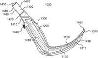
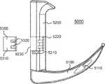
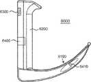
実施形態1。最上部、最下部、及び少なくとも1つの出口を含む、ハンドルと、遠位先端部及び近位部分を有し、前記近位部分は前記ハンドルの前記最下部に接続されている、ブレードと、前記ハンドル及び前記ブレードの断面の少なくとも一部を通って延びるように構成された少なくとも1つの流体チャネルと、前記ブレードの前記近位部分と前記遠位先端部との間に位置し、患者に挿管されたときに未加工データを検出するようにさらに構成された少なくとも1つのセンサと、電子部品モジュールと、を含む喉頭鏡であって、前記ブレードは、前記ハンドルから前記遠位先端部まで実質的に垂直な角度で外向きに突出するように構成され、前記ブレードは、(a)前記遠位先端部付近の少なくとも1つの入口と、(b)前記遠位先端部と近位先端部との間の少なくとも1つの入口と、をさらに含み、前記ハンドルは、前記電子部品モジュールに結合されるようにサイズ決め及び成形され、前記電子部品モジュールは、pHの検知、CO2の検知、音響の検知、静電容量の検知、インダクタンスの検知、温度の検知、特定分子の検知、両眼画像の検知、単眼画像の検知、配列された画像の検知、環境色の検知、USBビデオデバイスクラス(UVC)、光を生成してその周囲によって反射された光の周波数を測定すること、またはそれらの任意の組み合わせのうちの少なくとも1つの機能を提供する集積回路を含み、前記少なくとも1つの出口、前記遠位先端部付近の前記少なくとも1つの入口、前記遠位先端部と前記近位先端部との間の前記少なくとも1つの入口、及び前記少なくとも1つの流体チャネルは、互いに流体連絡するように構成されている、前記喉頭鏡。Selected Embodiments Embodiment 1. A blade comprising a handle comprising a top, a bottom and at least one outlet, a distal tip and a proximal portion, said proximal portion being connected to said bottom of said handle, Located between the proximal portion of the blade and the distal tip and cannulated with a patient, and at least one fluid channel configured to extend through at least a portion of the handle and the cross-section of the blade; A laryngoscope comprising at least one sensor further configured to detect raw data as it occurs, and an electronic component module, the blade extending substantially from the handle to the distal tip The blade is configured to project outwardly at a vertical angle, the blade comprising (a) at least one inlet near the distal tip, (b) the distal tip and the proximal tip Further comprising at least one inlet, the between, wherein the handle, the is sized and shaped to be coupled to an electronic component module, the electronic component module, the detection of the pH, the detection of CO2, the detection of acoustic Capacitance detection, inductance detection, temperature detection, specific molecule detection, binocular image detection, monocular image detection, arrayed image detection, environmental color detection, USB video device class (UVC) Said integrated circuit providing at least one function of generating light and measuring the frequency of light reflected by its surroundings, said at least one outlet, said distal The at least one inlet near the tip, the at least one inlet between the distal tip and the proximal tip, and the at least one Fluid channels is configured to be in fluid communication with one another, the laryngoscope.
実施形態2。前記未加工データは、ビデオファイル、pHレベル、CO2レベル、温度、特定分子、気管の音、食道のより低いpH、声帯のUV反射率、またはそれらの任意の組み合わせのうちの少なくとも1つを含む、実施形態1の喉頭鏡。Embodiment 2. The raw data, video files, pH levels, CO2 level, temperature, specific molecule, the sound of the trachea, lower pH of the esophagus, UV reflectance of the vocal cords, or at least one of any combination thereof The laryngoscope of embodiment 1, including.
実施形態3。前記ハンドル内に位置し、前記少なくとも1つの入口と、前記少なくとも1つの出口と、少なくとも1つの吸引チャネルとの間の流体連絡を制御するように構成された少なくとも1つのバルブをさらに含む、実施形態1の喉頭鏡。 Embodiment 3. Embodiment further comprising at least one valve located within the handle and configured to control fluid communication between the at least one inlet, the at least one outlet, and the at least one aspiration channel. 1 laryngoscope.
実施形態4。前記電子部品モジュールから前記少なくとも1つのセンサまで延びるように構成された、前記ハンドル及び前記ブレード内のセンサキャビティをさらに含む、実施形態1の喉頭鏡。 Embodiment 4. The laryngoscope of embodiment 1, further comprising a sensor cavity in the handle and the blade configured to extend from the electronics module to the at least one sensor.
実施形態5。データを前記少なくとも1つのセンサから前記電子部品モジュールに送信するために前記電子部品モジュールを前記少なくとも1つのセンサに接続するように構成されたフレキシブルセンサチューブをさらに含む、実施形態3の喉頭鏡。 Embodiment 5. 4. The laryngoscope of embodiment 3, further comprising a flexible sensor tube configured to connect the electronics module to the at least one sensor to transmit data from the at least one sensor to the electronics module.
実施形態6。前記少なくとも1つのセンサによって検出される前記未加工データは、pH、CO2、音響、静電容量、インダクタンス、温度、特定分子、両眼画像、単眼画像、配列された画像、環境色、またはそれらの任意の組み合わせのうちの少なくとも1つを含む、実施形態1の喉頭鏡。Embodiment 6. The raw data detected by the at least one sensor may be pH, CO2 , acoustics, capacitance, inductance, temperature, specific molecules, binocular images, monocular images, arrayed images, environmental colors, or the like The laryngoscope of embodiment 1, comprising at least one of any combinations of.
実施形態7。前記電子部品モジュールは、(a)センサチューブを通して前記電子部品モジュール及び前記少なくとも1つのセンサに電力を提供するバッテリと、(b)前記少なくとも1つのセンサから受信した前記未加工データを符号化して、符号化データをデータ処理ユニットへ送信する感覚データ符号器と、(c)符号化データを処理する前記データ処理ユニットと、(d)前記データ処理ユニットから処理データを受信して、前記処理データを外部ソースへ送信するように構成されたネットワーク無線機と、をさらに含む、実施形態1の喉頭鏡。 Embodiment 7. The electronic component module encodes (a) a battery that provides power to the electronic component module and the at least one sensor through a sensor tube; and (b) encoding the raw data received from the at least one sensor. A sensory data encoder for transmitting encoded data to the data processing unit, (c) the data processing unit for processing the encoded data, and (d) receiving the processed data from the data processing unit, and processing the processed data The laryngoscope of embodiment 1, further comprising: a network radio configured to transmit to an external source.
実施形態8。前記外部ソースは、リモートデバイス、システムコンピュータ、サーバ、データベース、またはそれらの任意の組み合わせのうちの少なくとも1つを含む、実施形態7の喉頭鏡。 Embodiment 8. 8. The laryngoscope of embodiment 7, wherein the external source comprises at least one of a remote device, a system computer, a server, a database, or any combination thereof.
実施形態9。前記ネットワーク無線機は、前記喉頭鏡の使用に関してユーザから命令を受信するように構成されている、実施形態7の喉頭鏡。 Embodiment 9. 8. The laryngoscope of embodiment 7, wherein the network radio is configured to receive instructions from a user regarding use of the laryngoscope.
実施形態10。前記命令は、流体の収集を開始すること、流体の収集を停止すること、前記流体連絡を減速させること、データを送信すること、前記電子部品モジュール上の電源を入れること、前記電子部品モジュール上の電源を切ること、またはそれらの任意の組み合わせのうちの少なくとも1つを含む、実施形態9の喉頭鏡。 Embodiment 10. The instructions may include: starting collection of fluid, stopping collection of fluid, decelerating the fluid communication, transmitting data, powering on the electronic component module, on the electronic component module The laryngoscope of embodiment 9, comprising at least one of powering off, or any combination thereof.
実施形態11。前記ハンドルは接点をさらに含む、実施形態1の喉頭鏡。 Embodiment 11. The laryngoscope of embodiment 1, wherein the handle further comprises a contact point.
実施形態12。前記ブレードは、前記少なくとも1つの入口付近に誘導性検知モジュールをさらに含む、実施形態11の喉頭鏡。 Embodiment 12. 12. The laryngoscope of embodiment 11, wherein the blade further comprises an inductive sensing module near the at least one inlet.
実施形態13。前記誘導性検知モジュールは、電気リード、誘導コイル、またはそれらの任意の組み合わせのうちの少なくとも1つを含む、実施形態12の喉頭鏡。 Embodiment 13. The laryngoscope of claim 12, wherein the inductive sensing module comprises at least one of an electrical lead, an inductive coil, or any combination thereof.
実施形態14。前記接点及び前記誘導性検知モジュールは、前記電子部品モジュールが前記ハンドルに取り付けられたときに電気的連絡を確立するように構成されている、実施形態13の喉頭鏡。 Embodiment 14. The laryngoscope of claim 13, wherein the contacts and the inductive sensing module are configured to establish electrical communication when the electronic component module is attached to the handle.
実施形態15。前記電子部品モジュールは、前記ハンドルから取り外し可能であるように構成されている、実施形態1の喉頭鏡。 Embodiment 15. The laryngoscope of embodiment 1, wherein the electronics module is configured to be removable from the handle.
実施形態16。前記遠位先端部と前記近位先端部との間の前記少なくとも1つの入口は、前記少なくとも1つのセンサに近接近して位置している、実施形態1の喉頭鏡。 Embodiment 16: The laryngoscope of embodiment 1, wherein the at least one inlet between the distal tip and the proximal tip is located in close proximity to the at least one sensor.
実施形態17。前記遠位先端部と前記近位先端部との間の前記少なくとも1つの入口は、前記少なくとも1つのセンサをクリーニングするために空気を作用させるように構成されている、実施形態16の喉頭鏡。 Embodiment 17: 17. The laryngoscope according to embodiment 16, wherein the at least one inlet between the distal tip and the proximal tip is configured to apply air to clean the at least one sensor.
実施形態18。前記遠位先端部と前記近位先端部との間の前記少なくとも1つの入口は、前記少なくとも1つのセンサをクリーニングするために前記少なくとも1つの流体チャネルを介して前記喉頭鏡内を循環する流体を作用させるように構成されている、実施形態16の喉頭鏡。 Embodiment 18: The at least one inlet between the distal tip and the proximal tip may circulate fluid circulating in the laryngoscope through the at least one fluid channel to clean the at least one sensor. Embodiment 17. The laryngoscope of embodiment 16 configured to operate.
実施形態19。前記集積回路は少なくとも1つの一体化ワイヤレス通信無線機を収容している、実施形態1の喉頭鏡。 Embodiment 19: The laryngoscope of claim 1, wherein the integrated circuit houses at least one integrated wireless communication radio.
実施形態20。前記少なくとも1つの一体化ワイヤレス通信無線機は、2.4ghz wifi周波数接続、5.0ghz wifi周波数接続、Bluetooth(登録商標)接続、アナログデータ無線接続、3gモバイルデータネットワーク接続、4gモバイルデータネットワーク接続、4gLTEモバイルデータネットワーク接続、及び5gモバイルデータネットワーク接続のうちの少なくとも1つの機能を提供するように構成されている、実施形態19の喉頭鏡。 Embodiment 20. The at least one integrated wireless communication radio has a 2.4 ghz wifi frequency connection, a 5.0 ghz wifi frequency connection, a Bluetooth® connection, an analog data wireless connection, a 3g mobile data network connection, a 4g mobile data network connection, 20. The laryngoscope of embodiment 19, configured to provide a function of at least one of a 4g LTE mobile data network connection and a 5g mobile data network connection.
実施形態21。前記集積回路は、前記少なくとも1つのセンサの出力を増幅するためのオンボード回路、前記少なくとも1つのセンサの出力を調整するためのオンボード回路、前記少なくとも1つのセンサの出力を機械可読なフォーマットに変換するためのオンボード回路、前記少なくとも1つのセンサの出力を前記喉頭鏡とは別個のリモートデバイスに物理ワイヤを介して送信するためのオンボード回路、前記少なくとも1つのセンサの出力を前記喉頭鏡とは別個のリモートデバイスに前記少なくとも1つの一体化ワイヤレス通信無線機を介して送信するためのオンボード回路、前記センサの出力を前記喉頭鏡とは別個のリモートデバイスに通信ネットワークを介して送信するためのオンボード回路、またはそれらの任意の組み合わせのうちの少なくとも1つを含む、実施形態19の喉頭鏡。 Embodiment 21. The integrated circuit includes an on-board circuit for amplifying an output of the at least one sensor, an on-board circuit for adjusting an output of the at least one sensor, and an output of the at least one sensor in a machine-readable format. An on-board circuit for converting, an on-board circuit for transmitting the output of the at least one sensor via a physical wire to a remote device separate from the laryngoscope, the laryngoscope an output of the at least one sensor On-board circuitry for transmitting to the remote device separate from the at least one integrated wireless communication radio, transmitting the output of the sensor to the remote device separate from the laryngoscope via the communication network For at least one of the on-board circuits, or any combination thereof One containing, laryngoscope embodiment 19.
実施形態22。前記電子部品モジュールは、ハードウェアビデオ符号化、一般的なデータ処理、ファームウェアの記憶及び管理、データ暗号化、オーディオ符号化、可視スペクトル光及び不可視スペクトル光の分析、電流分析、画像深度処理、またはそれらの任意の組み合わせのうちの少なくとも1つの機能を提供するように構成された少なくとも1つのデータ処理ユニットを提供する、実施形態2の喉頭鏡。 Embodiment 22. The electronic component module may be hardware video coding, general data processing, firmware storage and management, data encryption, audio coding, analysis of visible and invisible spectral light, current analysis, image depth processing, or Embodiment 2. The laryngoscope according to embodiment 2, providing at least one data processing unit configured to provide at least one function of any combination thereof.
実施形態23。前記データ処理ユニットのうちの少なくとも1つは、縮小命令セットコンピュータ(RISC)、Microprocessor without Interlocked Pipeline Stages(MIPS)、Advanced RISC Machine(ARM)、ARM32ビット(AArch32)、ARM64ビット(AArch64)、単一命令複数データ(SIMD)、単一命令複数スレッド(SIMT)、複数命令ストリーム複数データストリーム(MIMD)、x86、もしくはx86 Atom、またはそれらの任意の組み合わせのうちの少なくとも1つのアーキテクチャを利用する、実施形態22の喉頭鏡。 Embodiment 23. At least one of the data processing units is a reduced instruction set computer (RISC), Microprocessor without Interlocked Pipeline Stages (MIPS), Advanced RISC Machine (ARM), ARM 32-bit (AArch 32), ARM 64-bit (AArch 64), single An implementation utilizing at least one architecture of instruction multiple data (SIMD), single instruction multiple thread (SIMT), multiple instruction stream multiple data stream (MIMD), x86 or x86 Atom, or any combination thereof Form 22 laryngoscope.
実施形態24。前記少なくとも1つのデータ処理ユニットは、前記未加工データを、MJPEG、H.264、HEVC、H.265、もしくはMPEG−4、またはそれらの任意の組み合わせのうちの少なくとも1つのコーデック標準に符号化する、実施形態23の喉頭鏡。 Embodiment 24. The at least one data processing unit processes the raw data as H.264, HEVC, H. 24. The laryngoscope of embodiment 23, encoding at least one codec standard of H.265, or MPEG-4, or any combination thereof.
実施形態25。前記未加工データは一体化ハードウェア符号器を用いて符号化される、実施形態22の喉頭鏡。 Embodiment 25. 23. The laryngoscope of embodiment 22, wherein said raw data is encoded using an integrated hardware encoder.
実施形態26。前記集積回路は、前記少なくとも1つのセンサの電力消費の必要性のためのオンボードバッテリを含む、実施形態1の喉頭鏡。 Embodiment 26. The laryngoscope of embodiment 1, wherein the integrated circuit comprises an onboard battery for the power consumption needs of the at least one sensor.
実施形態27。前記電子部品モジュールは、前記喉頭鏡とは別個のデバイスから電力を受け取るための別個の導体を含む、実施形態1の喉頭鏡。 Embodiment 27. The laryngoscope of claim 1, wherein the electronics module includes a separate conductor for receiving power from a device separate from the laryngoscope.
実施形態28。LED、照明導体、またはそれらの任意の組み合わせのうちの少なくとも1つをさらに含む、実施形態1の喉頭鏡。 Embodiment 28. The laryngoscope of embodiment 1, further comprising at least one of an LED, a lighting conductor, or any combination thereof.
実施形態29。前記LEDは前記電子部品モジュールとは独立して機能する、実施形態1の喉頭鏡。 Embodiment 29. The laryngoscope of embodiment 1, wherein the LED functions independently of the electronic component module.
実施形態30。前記電子部品モジュールは、前記LED、前記照明導体、またはそれらの任意の組み合わせのうちの少なくとも1つから電流を引き込むように構成されている、実施形態28の喉頭鏡。 Embodiment 30. 29. The laryngoscope of embodiment 28, wherein the electronics module is configured to draw current from at least one of the LED, the lighting conductor, or any combination thereof.
実施形態31。前記電子部品モジュールは、前記喉頭鏡のハンドルに結合されるようにサイズ決め及び成形されるように構成されている、実施形態1の喉頭鏡。 Embodiment 31. The laryngoscope of embodiment 1, wherein the electronics module is configured to be sized and shaped to be coupled to a handle of the laryngoscope.
実施形態32。前記電子部品モジュールは、前記ハンドルの前記最下部に結合されるようにサイズ決め及び成形されている、実施形態1の喉頭鏡。 Embodiment 32. The laryngoscope of claim 1, wherein the electronics module is sized and shaped to be coupled to the lowermost portion of the handle.
実施形態33。前記電子部品モジュールは、前記ハンドル上に配置されたドアを介して前記喉頭鏡に結合されるように構成され、それによって内部のキャビティを露出させている、実施形態1の喉頭鏡。 Embodiment 33. The laryngoscope of embodiment 1, wherein the electronics module is configured to be coupled to the laryngoscope through a door disposed on the handle, thereby exposing an internal cavity.
実施形態34。前記ドアと前記ハンドルとの結合は、取り外し可能なドア、スライディングドア、機械的にヒンジで連結されたドア、またはリビングヒンジで連結された(live hinged)ドアのうちの1つから選択される、実施形態33の喉頭鏡。 Embodiment 34. The connection between the door and the handle is selected from one of a removable door, a sliding door, a mechanically hinged door, or a living hinged door. 34. The laryngoscope of embodiment 33.
実施形態35。前記ハンドルは、移動可能な進入面を前記ハンドルの外面上に含み、そのため、前記電子部品モジュールが前記進入面に対して付勢されたときに、前記ハンドル内に配置された相補的な嵌合メカニズムに前記電子部品モジュールが結合されるまで前記進入面及び電子部品モジュールが前記ハンドル内へと平行移動し、それによって前記電子部品モジュールが前記ハンドルに機械的に結合される、実施形態1の喉頭鏡。 Embodiment 35. The handle includes a moveable entry surface on an outer surface of the handle, such that when the electronic component module is biased against the entry surface, a complementary fit disposed within the handle The larynx of embodiment 1, wherein the access surface and the electronics module translate into the handle until the electronics module is coupled to a mechanism, whereby the electronics module is mechanically coupled to the handle mirror.
実施形態36。前記ブレードはヒンジで連結され、それによって従来の喉頭鏡または高角度の喉頭鏡のいずれかとして構成され得る、実施形態1の喉頭鏡。 Embodiment 36. The laryngoscope of embodiment 1, wherein the blades are hinged and thereby can be configured as either a conventional laryngoscope or a high angle laryngoscope.
実施形態37。前記ヒンジ連結は、前記電子部品モジュールの存在によって調整される、実施形態36の喉頭鏡。 Embodiment 37. 37. The laryngoscope of embodiment 36, wherein said hinged connection is adjusted by the presence of said electronic component module.
実施形態38。前記ヒンジ連結は、前記電子部品モジュールの非存在によって調整される、実施形態36の喉頭鏡。 Embodiment 38. 37. The laryngoscope of embodiment 36, wherein said hinged connection is adjusted by the absence of said electronic component module.
実施形態39。前記ヒンジ連結は、前記少なくとも1つのセンサによって過剰な流体が検出されると調整される、実施形態36の喉頭鏡。 Embodiment 39. 37. The laryngoscope according to embodiment 36, wherein the hinged connection is adjusted when excess fluid is detected by the at least one sensor.
実施形態40。前記ヒンジ連結は、前記少なくとも1つのセンサによって前記患者内の異常な解剖学的構造が検出されると調整される、実施形態36の喉頭鏡。 Embodiment 40. 37. The laryngoscope according to embodiment 36, wherein the hinged connection is adjusted when an abnormal anatomical structure in the patient is detected by the at least one sensor.
実施形態41。前記特定分子検知機能は、O2、N2、CO2、HCl、NaCl、及びKClのうちの少なくとも1つを認識するように構成された前記少なくとも1つのセンサを用いて実現される、実施形態1の喉頭鏡。Embodiment 41. Embodiment 1. The specific molecule detection function is realized using the at least one sensor configured to recognize at least one of O2 , N2 , CO 2, HCl, NaCl, and KCl. Laryngoscope.
実施形態42。前記少なくとも1つのセンサは、接触センサ、存在する周囲のガスを測定するためのセンサ、またはそれらの任意の組み合わせのうちの少なくとも1つを含む、実施形態41の喉頭鏡。 Embodiment 42. 42. The laryngoscope according to embodiment 41, wherein the at least one sensor comprises at least one of a contact sensor, a sensor for measuring the ambient gas present, or any combination thereof.
実施形態43。前記遠位先端部と前記近位先端部との間の前記少なくとも1つの入口は、前記少なくとも1つのセンサが流体または組織によって覆われたときに前記少なくとも1つの出口に真空を適用することによって前記少なくとも1つのセンサを清掃するように方向付けられている、実施形態1の喉頭鏡。 Embodiment 43. The at least one inlet between the distal tip and the proximal tip by applying a vacuum to the at least one outlet when the at least one sensor is covered by fluid or tissue. The laryngoscope of embodiment 1, wherein the laryngoscope is oriented to clean at least one sensor.
実施形態44。前記電子部品モジュールは、前記少なくとも1つのセンサが検出した前記未加工データに基づいて前記患者内の少なくとも1つの解剖学的マーカーを特定する視覚フィードバックを生成することができる、実施形態2の喉頭鏡。 Embodiment 44. The laryngoscope according to embodiment 2, wherein the electronic component module can generate visual feedback identifying at least one anatomical marker in the patient based on the raw data detected by the at least one sensor .
実施形態45。前記解剖学的マーカーは、臼歯、軟口蓋、口蓋舌弓、口蓋垂、口蓋扁桃、口蓋咽頭弓、中咽頭、喉頭蓋、食道、声門、楔状結節、小角結節(conciculate tubercle)、真声帯、仮声帯、開いた声帯、閉じた声帯、またはそれらの任意の組み合わせのうちの少なくとも1つを含む、実施形態44の喉頭鏡。 Embodiment 45. The anatomical markers include molar teeth, soft palate, palatal tongue arch, uvula, tonsillar palate, palatopharyngeal arch, oropharynx, epiglottis, esophagus, glottis, scaly nodules, small horn nodules, vocal cords, false vocal cords, open Embodiment 45. The laryngoscope according to embodiment 44, comprising at least one of the following: vocal cords, closed vocal cords, or any combination thereof.
実施形態46。前記電子部品モジュールは、前記少なくとも1つのセンサのうちの2つ以上からの未加工データを統合して、前記ブレードが前記患者内の所与の解剖学的マーカー内にあることの確実性を向上させることができる、実施形態44の喉頭鏡。 Embodiment 46. The electronics module integrates raw data from two or more of the at least one sensor to improve the certainty that the blade is within a given anatomical marker in the patient Embodiment 45. The laryngoscope according to embodiment 44, which can be
実施形態47。前記視覚フィードバックを表示するための視覚ディスプレイである、照光LED、選択的照光LEDアレイ、無反射型eインク型ディスプレイ、または反射型LCD型ディスプレイのうちの少なくとも1つをさらに含む、実施形態44の喉頭鏡。 Embodiment 47. 45. The embodiment of 44 further comprising at least one of: an illuminated LED, a selectively illuminated LED array, a non-reflective e-ink type display, or a reflective LCD type display, which is a visual display for displaying the visual feedback. Laryngoscope.
実施形態48。前記電子部品モジュールは、リモートデバイス、サーバ、データベース、システムコンピュータ、またはそれらの任意の組み合わせのうちの少なくとも1つに前記視覚フィードバックを送信するように構成されている、実施形態44の喉頭鏡。 Embodiment 48. 45. The laryngoscope according to embodiment 44, wherein the electronics module is configured to send the visual feedback to at least one of a remote device, a server, a database, a system computer, or any combination thereof.
実施形態49。前記視覚フィードバックは、前記ブレードの前記先端部付近のカメラからのライブ画像上のオーバーレイとして提供される、実施形態48の喉頭鏡。 Embodiment 49. 49. The laryngoscope according to embodiment 48, wherein the visual feedback is provided as an overlay on a live image from a camera near the tip of the blade.
実施形態50。前記視覚フィードバックは、解剖学的特徴及び前記患者内で前記ブレードがたどるべき進路のライブワイヤーフレーム型アウトラインを提供することによって提供される、実施形態49の喉頭鏡。 Embodiment 50. 50. The laryngoscope according to embodiment 49, wherein the visual feedback is provided by providing an anatomical feature and a live wireframe type outline of the path the blade is to follow in the patient.
実施形態51。前記視覚フィードバックは、ユーザが前記喉頭鏡を挿管が成功する進路に向けて前記患者内で導くことを助けるように、ユーザインターフェース内に表示される、実施形態44の喉頭鏡。 Embodiment 51. Embodiment 45. The laryngoscope according to embodiment 44, wherein the visual feedback is displayed in the user interface to help the user guide the laryngoscope in the patient towards a successful intubation path.
実施形態52。電子センサモジュールは、前記集積回路を管理するためにLinux(登録商標)組込み開発環境(Linux(登録商標) Embedded Development Environment(LEDE))を用いる、実施形態1の喉頭鏡。 Embodiment 52. The laryngoscope of embodiment 1, wherein the electronic sensor module uses Linux® Embedded Development Environment (LEDE) to manage the integrated circuit.
実施形態53。測定し少なくとも1つの出力信号を送信する喉頭鏡と、前記喉頭鏡から前記少なくとも1つの出力信号を受信して、前記少なくとも1つの出力信号をリアルタイムで表示するように構成されたコンピューティングデバイスと、ユーザが前記少なくとも1つの出力信号をモニタするためのオプションを見てカスタマイズすることを可能にする、前記コンピューティングデバイス上のグラフィカルユーザインターフェースと、を含む、喉頭鏡の挿管のためのシステムであって、前記喉頭鏡と前記コンピューティングデバイスとは通信ネットワークを介して互いに通信可能に接続されている、前記システム。 Embodiment 53. A laryngoscope for measuring and transmitting at least one output signal; and a computing device configured to receive the at least one output signal from the laryngoscope and to display the at least one output signal in real time. A system for laryngoscope intubation, comprising: a graphical user interface on the computing device that allows a user to view and customize options for monitoring the at least one output signal. Said system wherein said laryngoscope and said computing device are communicatively connected to each other via a communication network.
実施形態54。前記喉頭鏡は、最上部、最下部、及び少なくとも1つの出口を含む、ハンドルと、遠位先端部及び近位部分を有し、前記近位部分は前記ハンドルの前記最下部に接続されている、ブレードと、前記ハンドル及び前記ブレードの断面の少なくとも一部を通って延びるように構成された少なくとも1つの吸引チャネルと、前記ブレードの前記近位部分と前記遠位先端部との間に位置し、患者に挿管されたときに未加工データを検出するようにさらに構成された少なくとも1つのセンサと、前記未加工データを前記少なくとも1つの出力に変換するように構成された電子部品モジュールと、を含み、前記ブレードは、前記ハンドルから前記遠位先端部まで実質的に垂直な角度で外向きに突出するように構成され、前記ブレードは、(a)前記遠位先端部付近の少なくとも1つの入口と、(b)前記遠位先端部と近位先端部との間の少なくとも1つの入口と、をさらに含み、前記ハンドルは、前記電子部品モジュールに結合されるようにサイズ決め及び成形され、前記電子部品モジュールは集積回路を含み、前記少なくとも1つの出口、前記遠位先端部付近の前記少なくとも1つの入口、前記遠位先端部と前記近位先端部との間の前記少なくとも1つの入口、及び少なくとも1つの流体チャネルは、互いに流体連絡するように構成されている、実施形態53のシステム。 Embodiment 54. The laryngoscope comprises a handle including a top, a bottom and at least one outlet, a distal tip and a proximal portion, the proximal portion being connected to the bottom of the handle A blade, at least one suction channel configured to extend through the handle and at least a portion of a cross section of the blade, and between the proximal portion of the blade and the distal tip At least one sensor further configured to detect raw data when intubated into a patient, and an electronic component module configured to convert the raw data to the at least one output. Said blade is configured to project outwardly at an angle substantially perpendicular from said handle to said distal tip, said blade comprising: (a) said distal tip And at least one inlet between the distal tip and the proximal tip, the handle being coupled to the electronic component module Sized and shaped, said electronic component module comprises an integrated circuit, said at least one outlet, said at least one inlet near said distal tip, between said distal tip and said proximal tip 54. The system of embodiment 53, wherein the at least one inlet and the at least one fluid channel are configured to be in fluid communication with one another.
実施形態55。(i)前記少なくとも1つの出力信号を記憶して分析するように構成され、かつ(ii)前記通信ネットワークを介してローカルデバイス及び前記コンピューティングデバイスに接続される、ホスト型サーバをさらに含む、実施形態53のシステム。 Embodiment 55. (I) further comprising a hosted server configured to store and analyze said at least one output signal, and (ii) connected to a local device and said computing device via said communication network, The system of form 53.
実施形態56。前記ホスト型サーバは、(i)患者内での前記喉頭鏡の現在の解剖学的位置を決定するように、(ii)前記患者内の好ましい解剖学的位置までの経路を決定するように、かつ(iii)ユーザが前記喉頭鏡を前記好ましい解剖学的位置まで導くことができるよう前記ユーザが従うべきデジタルガイダンスを提供するように、さらに構成されている、実施形態55のシステム。 Embodiment 56. The host server may (i) determine a current anatomical position of the laryngoscope in the patient, (ii) determine a path to a preferred anatomical position in the patient. And (iii) the system of embodiment 55 further configured to provide digital guidance that the user should follow so that the user can direct the laryngoscope to the preferred anatomical position.
実施形態57。前記現在の解剖学的位置、前記好ましい解剖学的位置、前記好ましい解剖学的位置までの前記経路、及び前記デジタルガイダンスは、確率アルゴリズム、機械学習アルゴリズム、またはそれらの組み合わせのうちの少なくとも1つによって決定される、実施形態55のシステム。 Embodiment 57. The current anatomical location, the preferred anatomical location, the path to the preferred anatomical location, and the digital guidance may be at least one of a probability algorithm, a machine learning algorithm, or a combination thereof. 56. The system of embodiment 55 determined.
実施形態58。確率アルゴリズムまたは機械学習アルゴリズムは前記コンピューティングデバイス内に記憶されている、実施形態57のシステム。 Embodiment 58. 58. The system of embodiment 57, wherein a probability algorithm or a machine learning algorithm is stored in the computing device.
実施形態59。確率アルゴリズムまたは機械学習アルゴリズムは前記喉頭鏡内に記憶されている、実施形態57のシステム。 Embodiment 59. 58. The system of embodiment 57, wherein a probability algorithm or machine learning algorithm is stored in the laryngoscope.
実施形態60。前記集積回路は、pHの検知、CO2の検知、音響の検知、静電容量の検知、インダクタンスの検知、温度の検知、特定分子の検知、両眼画像の検知、単眼画像の検知、配列された画像の検知、環境色の検知、USBビデオデバイスクラス(UVC)、光を生成してその周囲によって反射された光の周波数を測定すること、またはそれらの任意の組み合わせのうちの少なくとも1つの機能を提供する、実施形態54のシステム。 Embodiment 60. The integrated circuit includes pH detection, CO 2 detection, sound detection, capacitance detection, inductance detection, temperature detection, specific molecule detection, binocular image detection, monocular image detection, array Image detection, environmental color detection, USB video device class (UVC), generating light and measuring the frequency of the light reflected by its surroundings, or at least one function of any combination thereof 55. The system of embodiment 54, which provides.
実施形態61。最上部、最下部、及び少なくとも1つの出口を含む、ハンドルと、遠位先端部及び近位部分を有し、前記近位部分は前記ハンドルの前記最下部に接続されている、ブレードと、前記ハンドル及び前記ブレードの断面の少なくとも一部を通って延びるように構成された少なくとも1つの流体チャネルと、前記ブレードの前記近位部分と前記遠位先端部との間に位置し、患者に挿管されたときに未加工データを検出するようにさらに構成された少なくとも1つのセンサと、電子部品モジュールと、を含む喉頭鏡であって、前記ブレードは、前記ハンドルから前記遠位先端部まで実質的に垂直な角度で外向きに突出するように構成され、前記ブレードは、(a)前記遠位先端部付近の少なくとも1つの入口と、(b)前記遠位先端部と近位先端部との間の少なくとも1つの入口と、をさらに含み、前記ハンドルは、前記電子部品モジュールに結合されるようにサイズ決め及び成形され、前記電子部品モジュールは少なくとも1つの集積回路を含み、前記少なくとも1つの出口、前記遠位先端部付近の前記少なくとも1つの入口、前記遠位先端部と前記近位先端部との間の前記少なくとも1つの入口、及び前記少なくとも1つの流体チャネルは、互いに流体連絡するように構成されている、前記喉頭鏡。 Embodiment 61. A blade comprising a handle comprising a top, a bottom and at least one outlet, a distal tip and a proximal portion, said proximal portion being connected to said bottom of said handle, Located between the proximal portion of the blade and the distal tip and cannulated with a patient, and at least one fluid channel configured to extend through at least a portion of the handle and the cross-section of the blade; A laryngoscope comprising at least one sensor further configured to detect raw data as it occurs, and an electronic component module, the blade extending substantially from the handle to the distal tip The blade is configured to project outwardly at a vertical angle, the blade comprising (a) at least one inlet near the distal tip, (b) the distal tip and the proximal tip And at least one inlet between, said handle being sized and shaped to be coupled to said electronic component module, said electronic component module comprising at least one integrated circuit, said at least one outlet The at least one inlet near the distal tip, the at least one inlet between the distal tip and the proximal tip, and the at least one fluid channel in fluid communication with one another Said laryngoscope being configured.
実施形態62。前記少なくとも1つの集積回路は、pHの検知、CO2の検知、音響の検知、静電容量の検知、インダクタンスの検知、温度の検知、特定分子の検知、両眼画像の検知、単眼画像の検知、配列された画像の検知、環境色の検知、USBビデオデバイスクラス(UVC)、光を生成してその周囲によって反射された光の周波数を測定すること、またはそれらの任意の組み合わせのうちの少なくとも1つの機能を提供する、実施形態61の喉頭鏡。 Embodiment 62. The at least one integrated circuit includes pH detection, CO 2 detection, sound detection, capacitance detection, inductance detection, temperature detection, specific molecule detection, binocular image detection, monocular image detection, Detection of arrayed images, detection of environmental colors, USB video device class (UVC), generating light and measuring the frequency of light reflected by its surroundings, or at least one of any combination thereof 61. The laryngoscope of embodiment 61, wherein the laryngoscope provides two functions.
実施形態63。コンピュータ可読命令を有するコンピュータ可読プログラムコードを有形に具現化するコンピュータ可読記憶媒体であって、前記コンピュータ可読命令は、実行されると、喉頭鏡がユーザによって患者に挿管されたときに前記喉頭鏡上の少なくとも1つのセンサによって前記患者の少なくとも1つの解剖学的特徴を検出するステップと、前記少なくとも1つの解剖学的特徴を電子部品モジュールに送信するステップと、前記電子部品モジュールによって前記患者内での前記喉頭鏡の好ましい経路を決定するステップと、前記好ましい経路を、グラフィックユーザインターフェース上に解剖学的オーバーレイとして表示されるようにリモートデバイスに送るステップと、前記解剖学的オーバーレイにより前記喉頭鏡を前記患者内の前記好ましい経路に設けるステップと、をコンピュータに行わせる、前記コンピュータ可読記憶媒体。 Embodiment 63. A computer readable storage medium tangibly embodying computer readable program code having computer readable instructions, wherein the computer readable instructions, when executed, on the laryngoscope when the laryngoscope is intubated by the user into the patient. Detecting at least one anatomical feature of the patient by at least one sensor, transmitting the at least one anatomical feature to an electronic component module, and by the electronic component module within the patient Determining the preferred path of the laryngoscope, sending the preferred path to a remote device to be displayed as an anatomical overlay on a graphic user interface, the laryngoscope with the anatomical overlay Said preferred in the patient Causing a step of providing the road, to the computer, the computer readable storage medium.
実施形態64。前記少なくとも1つの解剖学的特徴は、pH、CO2、音響、静電容量、インダクタンス、温度、特定分子、両眼画像、単眼画像、配列された画像、環境色などのうちの少なくとも1つを含む、実施形態63の方法。Embodiment 64. The at least one anatomical feature includes at least one of pH, CO2 , acoustics, capacitance, inductance, temperature, specific molecules, binocular images, monocular images, arrayed images, environmental colors, etc. 64. The method of embodiment 63 comprising.
図は必ずしも一定の比率で描かれてはおらず、いくつかの図にわたって同様の数字は実質的に同様の構成部品を記述している。図面は、一例として、しかし限定としてではなく、本明細書の特許請求の範囲に記載された種々の実施形態を全般的に例示している。 The figures are not necessarily drawn to scale, and like numerals describe substantially similar components throughout the several views. The drawings generally illustrate, by way of example but not limitation, various embodiments recited in the claims of the present specification.
開示の詳細な説明
開示内容ならびにその種々の特徴及び有利な詳細を、添付の図面に記載及び/または例示されて以下の説明で詳述される非限定的な実施態様及び例を参照してより十分に説明する。なお、図面に例示した特徴は必ずしも一定の比率で描かれてはおらず、ある実施態様の特徴が他の実施態様とともに用いてもよいことは、本明細書において明示的に述べられていなくても、当業者であれば分かることである。周知の構成部品及び処理技術の説明は、開示内容の実施態様を不必要に不明瞭にしないために省略する場合がある。本明細書で用いる例は単に、開示内容を実施し得る方法の理解を容易にして、さらに当業者が開示内容の実施態様を実施することを可能にすることを意図している。したがって、本明細書における例及び実施態様は、開示内容の範囲を限定するものと解釈してはならない。DETAILED DESCRIPTION OF THE DISCLOSURE The disclosure content, as well as various features and advantageous details thereof, will be more fully described with reference to the non-limiting embodiments and examples described and / or illustrated in the accompanying drawings and detailed in the following description. Explain enough. It is noted that the features illustrated in the drawings are not necessarily drawn to scale, and features of one embodiment may be used in conjunction with other embodiments, even if not explicitly stated herein. Those skilled in the art will understand. Descriptions of well-known components and processing techniques may be omitted so as to not unnecessarily obscure the disclosed embodiments. The examples used herein are merely intended to facilitate an understanding of the manner in which the disclosure may be practiced and to further enable one skilled in the art to practice the embodiments of the disclosure. Accordingly, the examples and embodiments herein should not be construed as limiting the scope of the disclosure.
明細書及び特許請求の範囲の全体を通して、以下の用語は、文脈からそうでないと示される場合を除いて、少なくとも本明細書で明示的に対応付けられる意味を取る。以下に特定する意味は必ずしも用語を限定するわけではなく、しかし用語に対する例示的な例を単に提供するだけである。「a」、「an」、及び「the」の意味は複数形に対する言及を含んでいてもよく、「in」の意味は「in」及び「on」を含んでいてもよい。語句「ある実施態様において」は、本明細書で用いる場合、必ずしも同じ実施態様を指すわけではない。 Throughout the specification and claims, the following terms have at least the meanings explicitly associated herein, except where the context indicates otherwise. The meanings specified below do not necessarily limit the terms, but merely provide exemplary examples for the terms. The meanings of "a", "an" and "the" may include references to the plural and the meaning of "in" may include "in" and "on". The phrase "in one embodiment" as used herein does not necessarily refer to the same embodiment.
用語「結合された」は少なくとも、接続された物品間の直接的な電気接続または1つ以上の受動的もしくは能動的な中継装置を通した間接的な接続のいずれかを意味する。用語「回路」は少なくとも、単一の部品、または所望の機能を提供するように互いに結合された多数部品(能動的及び/または受動的)のいずれかを意味する。用語「信号」は、本明細書で用いる場合、当業者によって理解され得る任意の意味を含んでいてもよく、少なくとも電流、電圧、電荷、温度、データの電気的もしくは磁気的表現、または1つ以上の伝送媒体上で表現され、全般的に、送信し、受信し、記憶し、比較し、結合し、またはそうでなければ任意の同等な方法で操作することができる1つ以上のメモリ位置の状態を含む。 The term "coupled" means at least either a direct electrical connection between connected articles or an indirect connection through one or more passive or active relays. The term "circuit" means either at least a single component or multiple components (active and / or passive) coupled together to provide a desired function. The term "signal" as used herein may include any meaning that can be understood by those skilled in the art, at least a current, a voltage, a charge, a temperature, an electrical or magnetic representation of data, or one One or more memory locations represented on the above transmission medium and generally capable of transmitting, receiving, storing, comparing, combining, or otherwise manipulating in any equivalent manner Including the state of
たとえば「提供する」、「処理する」、「供給する」、「決定する」、「計算する」などの用語は、少なくとも、コンピュータシステム、コンピュータプログラム、信号プロセッサ、論理回路、または代替的なアナログもしくはデジタル電子デバイスの動作であって、自動で開始されようと手動で開始されようと、物理量として表された信号を変化させ得る動作を指してもよい。 For example, the terms “provide”, “process”, “supply”, “determine”, “calculate”, etc. refer at least to a computer system, computer program, signal processor, logic circuit, or alternative analog or The operation of a digital electronic device may refer to an operation that may change a signal represented as a physical quantity, whether automatically initiated or manually initiated.
「コンピュータ」は、本開示で用いる場合、1つ以上の命令に従ってデータを操作することができる任意のマシン、デバイス、回路、構成部品、もしくはモジュール、またはマシン、デバイス、回路、構成部品、モジュールなどの任意のシステム、たとえば、非限定的に、プロセッサ、マイクロプロセッサ、中央演算処理装置、汎用コンピュータ、クラウド、スーパーコンピュータ、パーソナルコンピュータ、ラップトップコンピュータ、パームトップコンピュータ、モバイルデバイス、タブレットコンピュータ、ノートブックコンピュータ、デスクトップコンピュータ、ワークステーションコンピュータ、サーバなど、またはプロセッサ、マイクロプロセッサ、中央演算処理装置、汎用コンピュータ、スーパーコンピュータ、パーソナルコンピュータ、ラップトップコンピュータ、パームトップコンピュータ、モバイルデバイス、タブレットコンピュータ、ノートブックコンピュータ、デスクトップコンピュータ、ワークステーションコンピュータ、サーバなどのアレイなどを意味する。 "Computer," as used in the present disclosure, is any machine, device, circuit, component or module capable of manipulating data according to one or more instructions, or a machine, device, circuit, component, module etc. Any system of, for example, without limitation, processor, microprocessor, central processing unit, general purpose computer, cloud, super computer, personal computer, laptop computer, palmtop computer, mobile device, tablet computer, notebook computer , Desktop computer, workstation computer, server, etc., or processor, microprocessor, central processing unit, general purpose computer, super computer, personal computer Computer, laptop computer, palm-top computer, a mobile device, tablet computer, notebook computer, desktop computer, workstation computer, means such as an array, such as a server.
「サーバ」は、本開示で用いる場合、クライアント−サーバアーキテクチャの一部として接続クライアントに対するサービスを実行するための少なくとも1つのアプリケーション及び/または少なくとも1つのコンピュータなどのソフトウェア及び/またはハードウェアの任意の組み合わせを意味する。少なくとも1つのサーバアプリケーションは、限定されるものではないが、たとえば、クライアントに応答を送り返すことによってクライアントからのサービス要求に対する接続を承認することができるアプリケーションプログラムを含んでいてもよい。サーバは、少なくとも1つのアプリケーションを、多くの場合に重い作業負荷の下で、無人で、長期間、最少の人間の命令で実行するように構成してもよい。サーバは、構成された複数のコンピュータを含んでいてもよく、少なくとも1つのアプリケーションは作業負荷に応じてコンピュータ間で分割される。たとえば、軽い負荷の下では、少なくとも1つのアプリケーションを単一のコンピュータ上で実行することができる。しかし、重い負荷の下では、少なくとも1つのアプリケーションを実行するために複数のコンピュータが必要となる場合がある。サーバ、またはもしそのコンピュータであれば任意のものは、ワークステーションとして用いてもよい。 “Server” as used in this disclosure is any software and / or hardware such as at least one application and / or at least one computer for performing services to connected clients as part of a client-server architecture Means a combination. At least one server application may include, but is not limited to, an application program that can authorize a connection to a service request from a client, for example, by sending a response back to the client. The server may be configured to execute at least one application, often under heavy workload, unattended, for a long time, with minimal human instruction. The server may include a plurality of configured computers, wherein at least one application is divided among the computers according to the workload. For example, under light loads, at least one application can be run on a single computer. However, under heavy loads, multiple computers may be required to run at least one application. The server, or anything if that computer, may be used as a workstation.
「データベース」は、本開示で用いる場合、少なくとも1つのアプリケーション及び/または少なくとも1つのコンピュータなどのソフトウェア及び/またはハードウェアの任意の組み合わせを意味する。データベースは、たとえば、限定されるものではないが、関係モデル、階層モデル、ネットワークモデル等のうちの少なくとも1つなどのデータベースモデルに従って組織化された記録またはデータの構造化収集を含んでいてもよい。データベースは、当該技術分野で知られるように、データベース管理システムアプリケーション(DBMS)を含んでいてもよい。少なくとも1つのアプリケーションは、限定されるものではないが、たとえば、クライアントに応答を送り返すことによってクライアントからのサービス要求に対する接続を承認することができるアプリケーションプログラムを含んでいてもよい。データベースは、少なくとも1つのアプリケーションを、多くの場合に重い作業負荷の下で、無人で、長期間、最少の人間の命令で実行するように構成してもよい。 "Database" as used in this disclosure means any combination of software and / or hardware, such as at least one application and / or at least one computer. The database may include, for example, structured collection of records or data organized according to a database model such as, but not limited to, at least one of a relational model, a hierarchical model, a network model, etc. . The database may include a database management system application (DBMS), as known in the art. At least one application may include, but is not limited to, an application program that can authorize a connection to a service request from a client, for example, by sending a response back to the client. The database may be configured to execute at least one application, often under heavy workload, unattended, for a long time, with minimal human instruction.
「通信ネットワーク」は、本開示で用いる場合、少なくとも2点間でデータまたは情報を伝える有線及び/または無線媒体を意味する。有線または無線媒体は、たとえば、非限定的に、金属導体リンク、無線周波数(RF)通信リンク、赤外線(IR)通信リンク、電気通信ネットワーク、光通信リンク、インターネット(無線及び有線)などを含んでいてもよい。RF通信リンクは、たとえば、WiFi、WiMAX、IEEE802.11、DECT、0G、1G、2G、3G、4G、5Gまたは将来のセルラー規格、Bluetooth(登録商標)、Bluetooth(登録商標) Low Energy、NFC、超音波、誘導、レーザ(または同様の光伝送)などを含んでいてもよい。 "Communication network" as used in this disclosure means a wired and / or wireless medium that carries data or information between at least two points. Wired or wireless media include, for example and without limitation, metal conductor links, radio frequency (RF) communication links, infrared (IR) communication links, telecommunications networks, optical communication links, the Internet (wireless and wired), etc. It may be The RF communication link may be, for example, WiFi, WiMAX, IEEE 802.11, DECT, 0G, 1G, 2G, 3G, 4G, 5G or future cellular standards, Bluetooth (registered trademark), Bluetooth (registered trademark) Low Energy, NFC, It may include ultrasound, guidance, lasers (or similar light transmission) and the like.
「コンピュータ可読記憶媒体」は、本開示で用いる場合、コンピュータが読み取り得るデータ(たとえば、命令)を提供することに関与する任意の媒体を意味する。このような媒体は、不揮発性媒体、揮発性媒体、及び伝送媒体などの多くの形態を取ってもよい。不揮発性媒体は、たとえば、光または磁気ディスク、フラッシュメモリ、及び他の永続的なメモリを含んでいてもよい。揮発性媒体は、ダイナミックランダムアクセスメモリ(DRAM)を含んでいてもよい。伝送媒体は、プロセッサに結合されたシステムバスを含むワイヤなどの、同軸ケーブル、銅ワイヤ、及び光ファイバを含んでいてもよい。伝送媒体は、音波、光波、及び電磁放射、たとえば、無線周波数(RF)及び赤外線(IR)データ通信の間に発生するものを含んでいてもよいしまたはそれらを伝えてもよい。コンピュータ可読媒体の一般的な形式としては、たとえば以下が挙げられる:フロッピーディスク、フレキシブルディスク、ハードディスク、磁気テープ、任意の他の磁気媒体、CD−ROM、DVD、任意の他の光媒体、パンチカード、紙テープ、孔のパターンを有する任意の他の物理媒体、RAM、PROM、EPROM、フラッシュEEPROM、任意の他のメモリチップまたはカートリッジ、以下に記載する搬送波、またはコンピュータが読み取ることができる任意の他の媒体。コンピュータ可読媒体は、複数(たとえば、数千)のコンピュータ上の複数(たとえば、数千)のメモリキャッシュに渡るファイルの分配を含む「クラウド」を含んでいてもよい。 "Computer readable storage medium" as used in the present disclosure means any medium that participates in providing data (eg, instructions) that can be read by a computer. Such a medium may take many forms, such as non-volatile media, volatile media, and transmission media. Non-volatile media may include, for example, optical or magnetic disks, flash memory, and other permanent memory. Volatile media may include dynamic random access memory (DRAM). Transmission media may include coaxial cables, copper wire and fiber optics, such as wires including a system bus coupled to a processor. Transmission media may include or convey acoustic waves, light waves, and electromagnetic radiation, such as those generated during radio frequency (RF) and infrared (IR) data communications. Common forms of computer readable media include, for example: floppy disks, flexible disks, hard disks, magnetic tapes, any other magnetic media, CD-ROM, DVD, any other optical media, punch cards , Paper tape, any other physical medium having a pattern of holes, RAM, PROM, EPROM, flash EEPROM, any other memory chip or cartridge, carrier described below, or any other computer readable medium Medium. A computer readable medium may include a "cloud" that includes the distribution of files across multiple (eg, thousands) of memory caches on multiple (eg, thousands of) computers.
種々の形態のコンピュータ可読媒体が、コンピュータに命令のシーケンスを運ぶのに関与していてもよい。たとえば、命令のシーケンスを(i)RAMからプロセッサに送出してもよく、(ii)無線伝送媒体を介して伝えてもよく、及び/または(iii)たとえば、WiFi、WiMAX、IEEE802.11、DECT、0G、1G、2G、3Gもしくは4Gセルラー規格、Bluetooth(登録商標)などを含む多くのフォーマット、規格もしくはプロトコルに従ってフォーマットしてもよい。 Various forms of computer readable media may be involved in carrying a sequence of instructions to a computer. For example, the sequence of instructions may (i) be sent from the RAM to the processor, (ii) be communicated via a wireless transmission medium, and / or (iii) for example, WiFi, WiMAX, IEEE 802.11, DECT. It may be formatted according to a number of formats, standards or protocols, including 0G, 1G, 2G, 3G or 4G cellular standards, Bluetooth® and the like.
「ネットワーク」は、本開示で用いる場合、限定されるものではないが、たとえばローカルエリアネットワーク(LAN)、ワイドエリアネットワーク(WAN)、メトロポリタンエリアネットワーク(MAN)、パーソナルエリアネットワーク(PAN)、キャンパスエリアネットワーク、企業エリアネットワーク、グローバルエリアネットワーク(GAN)、ブロードバンドエリアネットワーク(BAN)、セルラーネットワーク、インターネット、クラウドネットワークなど、または前述したものの任意の組み合わせのうちの少なくとも1つを意味し、これらのいずれも、無線及び/または有線通信媒体を介してデータを伝達するように構成してもよい。これらのネットワークは、TCP/IP、IRC、SSL、TLS、UDP、またはHTTPに限定されない種々のプロトコルを実行してもよい。 "Network", as used in this disclosure, includes, but is not limited to, local area network (LAN), wide area network (WAN), metropolitan area network (MAN), personal area network (PAN), campus area, for example. Means at least one of a network, a corporate area network, a global area network (GAN), a broadband area network (BAN), a cellular network, the Internet, a cloud network etc, or any combination of the foregoing, any of which The data may be configured to be communicated via a wireless and / or wired communication medium. These networks may run various protocols not limited to TCP / IP, IRC, SSL, TLS, UDP, or HTTP.
用語「センサ」は、pHの検知、CO2の検知、音響の検知、静電容量の検知、インダクタンスの検知、温度の検知、特定分子の検知、または環境色の検知が可能であり、その検知の出力を、相補型電子機器が次いで読み取り得る電気信号として提示することが可能な、電子デバイス、電気化学デバイス、電気機械デバイス、または微小電気機械システム(MEMS)デバイスを意味すると理解すべきである。前述の「センサ」の定義はまた、単一の場所または複数の場所に配置された画像取込用にデザインされた電子デバイスを含むと理解されるものとする。画像取込センサには、可視、IR、及びUVスペクトルに応答性のものが含まれるものとする。前述の「センサ」の定義はまた、対になったエネルギー放出部及び受取部を含むものとし、たとえば、周囲によって反射された光を記録及び測定する電子機器と対になった照光LED、及び周囲によって反射された音エネルギーを記録する電子機器と対になったスピーカまたは圧電性物質などの音響エネルギー放出部を含む。互いに連絡しているデバイスは、特に明白な規定のない限り、互いに連続的に連絡している必要はない。加えて、互いに連絡しているデバイスは、直接的にまたは1つ以上の媒介物を通して間接的に連絡してもよい。The term “sensor” is capable of pH detection, CO2 detection, acoustic detection, capacitance detection, inductance detection, temperature detection, specific molecule detection, or environmental color detection, It should be understood to mean an electronic device, an electrochemical device, an electro-mechanical device or a micro-electro-mechanical system (MEMS) device, which can be presented as an electrical signal that the complementary electronics can then read . The definition of "sensor" above is also to be understood to include electronic devices designed for image capture located at a single location or multiple locations. Image capture sensors are intended to include those responsive in the visible, IR, and UV spectra. The definition of “sensor” above also includes paired energy emitting and receiving parts, for example an illuminated LED paired with electronics that record and measure light reflected by the surroundings, and by the surroundings It includes an acoustic energy emitting portion such as a loudspeaker or piezoelectric material paired with an electronic device for recording the reflected sound energy. Devices in communication with each other need not be in continuous communication with each other, unless expressly specified otherwise. In addition, devices in communication with each other may communicate directly or indirectly through one or more agents.
プロセスステップ、方法ステップ、アルゴリズムなどが順番に記載される場合があるが、このようなプロセス、方法、及びアルゴリズムは代替的な順番で動作するように構成してもよい。言い換えれば、記載され得るステップのどんな順序または順番も、必ずしもステップをその順序で行うべきという要件を示すものではない。本明細書で説明するプロセス、方法、またはアルゴリズムのステップは、実用的な任意の順番で行ってもよい。さらに、いくつかのステップは同時に行ってもよい。 Although the process steps, method steps, algorithms, etc. may be described in order, such processes, methods, and algorithms may be configured to operate in alternate orders. In other words, any order or order of steps that may be described does not necessarily indicate a requirement that the steps be performed in that order. The steps of a process, method or algorithm described herein may be performed in any order practical. Furthermore, some steps may be performed simultaneously.
単一のデバイスまたは物品について本明細書で説明するとき、単一のデバイスまたは物品の代わりに2つ以上のデバイスまたは物品を用いてもよいことが容易に明らかである。同様に、2つ以上のデバイスまたは物品について本明細書で説明するとき、2つ以上のデバイスまたは物品の代わりに単一のデバイスまたは物品を用いてもよいことが容易に明らかである。デバイスの機能または特徴を代替的に、このような機能または特徴を有すると明示的には記載されていない1つ以上の他のデバイスによって具体化してもよい。 It will be readily apparent that two or more devices or articles may be used in place of a single device or article as described herein for a single device or article. Similarly, when two or more devices or articles are described herein, it is readily apparent that a single device or article may be used instead of two or more devices or articles. The features or characteristics of the device may alternatively be embodied by one or more other devices not explicitly described as having such features or characteristics.
図1A及び1Bを同時に参照すると、喉頭鏡1000は、ハンドル1200、ブレード1100、少なくとも1つのセンサ1430、及び少なくとも1つの流体チャネル1300を含み、ハンドル1200は、(a)取り外し可能な電子部品モジュール1400を保持するように構成された最上部と、(b)ブレード部分1100に交差部1120で接続されるように構成された最下部とを含み、ブレード部分1100は、近位面1110と遠位先端部1490とを含み、(a)近位面1110は、ハンドル1200の最下部と接続するように構成され、(b)遠位先端部1490は、少なくとも1つの遠位流体入口1320を含み、少なくとも1つのセンサ1430は、遠位先端部1490付近に位置するように構成され、遠位先端部1490は、少なくとも1つのセンサ1430付近の少なくとも1つの近位流体入口1330を含み、少なくとも1つの流体チャネル1300は、(a)少なくとも1つの遠位流体入口1320及び(b)少なくとも1つの近位流体入口1330と流体連絡するように構成された少なくとも1つの流体出口1310を含んでいる。本開示の一実施形態では、ハンドル1200とブレード1100とは1つの単一ユニットとなるように構成してもよい。本開示の別の実施形態では、ハンドル1200とブレード1100とは、たとえばネジ、釘、留め具、接着剤、粘着剤などによって結合した別個のユニットであってもよい。 Referring simultaneously to FIGS. 1A and 1B, the
喉頭鏡1000はまた、少なくとも1つの流体出口1310付近に位置し、かつ少なくとも1つの流体出口1310と少なくとも1つの遠位流体入口1320との間の流体連絡を制御する(または閉じる)ように構成された、バルブシステム1340を含んでいてもよい。 The
喉頭鏡1000はさらに、ハンドル1200及びブレード部分1100内のセンサチューブキャビティ1130を通るフレキシブルセンサチューブ1410によって少なくとも1つのセンサ1430に取り外し可能な電子部品モジュール1400を接続するように構成された、フレキシブルセンサチューブ1410を含んでいてもよい。 The
本開示の一実施形態では、喉頭鏡1000はさらに、ハンドル1200の最上部からブレード1100を通って内部で延び、少なくとも1つの遠位流体入口1320及び少なくとも1つの近位流体入口1330において終わる、少なくとも1つの流体チャネル1300を含んでいてもよく、少なくとも1つの近位流体入口1330は、少なくとも1つのセンサ1430付近に(または少なくとも1つのセンサ1430に)位置し、少なくとも1つの流体チャネル1300、少なくとも1つの遠位流体入口1320、及び少なくとも1つの近位流体入口1330は、少なくとも1つの流体チャネル1300を介して、ハンドル1200の最上部付近に(またはハンドル1200の最上部に)位置する少なくとも1つの流体出口1310と流体連絡している。 In one embodiment of the present disclosure, the
喉頭鏡の一実施形態では、ハンドル1200は接点1470を含んでいてもよく、ブレード1100は遠位流体入口1320付近に誘導性検知モジュール1460を含んでいる。誘導性検知モジュール1460は、少なくとも1つの遠位流体入口1320付近の領域内に埋め込まれた電気リードまたは誘導コイルから形成されていてもよい。取り外し可能な電子部品モジュール1400がハンドル1200に結合されたときに、ハンドル1200上の接点1470と誘導性検知モジュール1460との間に電気的連絡が確立されてもよい。ブレード1100の遠位先端部1490付近の流体の有無を検出するように構成された少なくとも1つのセンサ1430が報告するある特定の容量状態または誘導状態の存在により、取り外し可能な電子モジュール1400は、バルブシステム1340をアクティブ化または非アクティブ化させて、それによって過剰な流体を排出することができる。 In one embodiment of the laryngoscope, the
本開示のさらなる実施形態によれば、電子部品モジュール1400は以下を含んでいてもよい:(a)電子部品モジュール1400に(及びセンサチューブ1410を通して少なくとも1つのセンサ1430に)電力を提供するバッテリ1450と、(b)少なくとも1つのセンサ1430から受信した流体に関するデータ(または任意の他の生体内情報)を処理するデータ処理ユニット1480と、(c)データを符号化する感覚データ符号器1440と、(a)感覚データ符号器1440から符号化データを受信して、前記データをリモートデバイス、サーバ、またはデータベースに送信するように構成されたネットワーク無線機1420。本開示の一実施形態では、感覚データ符号器1440は、たとえばシステム管理者、医師、看護師などから、喉頭鏡1000の使用に関する命令、たとえば流体の収集を開始または停止すること、流体に関するデータを送信すること、電子部品モジュール1400(または少なくとも1つのセンサ1430)上の電源を入れる(または電源を切る)こと、少なくとも1つのセンサ1430からの未加工データまたは分析データの記録を制御することなどを受信するように構成してもよい。 According to further embodiments of the present disclosure, the
本開示の一実施形態では、少なくとも1つのセンサ1430は、処理のために電子部品モジュールに送るべきpH、CO2、音響、静電容量、インダクタンス、温度、特定分子、両眼画像、単眼画像、配列された画像、または環境色を検出するように構成してもよい。またセンサは、光を生成して光の周波数を測定してもよい。In one embodiment of the present disclosure, the at least one
次に図2A、2B、2C、及び2Dを参照して、喉頭鏡2000の別の実施形態を開示する。喉頭鏡2000は、ハンドル2200、ブレード2100、電子部品モジュール2400、少なくとも1つのセンサ2430、流体出口2310、少なくとも1つの流体チャネル2360、遠位流体入口2320、及び近位流体入口2330を含み、ハンドル2200は、(a)ハンドル2200から突出する流体出口2310を収容する(または囲む)ように構成された最上部と、(b)ブレード2100と接続するように構成された最下部と、(c)流体連絡のために遠位流体入口2320まで内部で延びるように構成された遠位流体チャネル2360を収容する(または囲む)ように構成された遠位ハンドル面2220と、(d)流体連絡のために近位流体入口2330まで内部で延びるように構成された近位流体チャネル2350を収容する(または囲む)ように構成された近位ハンドル面2210とを含み、ブレード部分2100は、ハンドル2200の最下部に結合されるように構成され、さらに近位先端部2480と遠位先端部2490とを含み、(a)近位先端部2480は、近位流体入口2330及び少なくとも1つのセンサ2430に(またはその付近に)位置し、(b)遠位先端部2490は、遠位流体入口2320に(またはその付近に)位置し、少なくとも1つのセンサ2430は、ブレード部分2100内に収容されて、遠位先端部2490付近に位置するようにさらに構成され、電子部品モジュール2400は、ハンドル2200の内部に収容(または封入)され、ハンドル2200の最上部と最下部との間に固定して(または取り外し可能に)結合されるように構成されている。本開示の一実施形態では、ハンドル2200とブレード2100とは1つの単一ユニットとなるように構成してもよい。本開示の別の実施形態では、ハンドル2200とブレード2100とは、たとえばネジ、釘、留め具、接着剤、粘着剤などによって結合した別個のユニットであってもよい。 Referring now to FIGS. 2A, 2B, 2C, and 2D, another embodiment of a
喉頭鏡2000はまた、流体出口2310付近のチャネル2470に挿入されたバルブシステム2340を含んでいてもよい。バルブシステム2340はさらに、流体出口2310と、遠位流体入口2320と、近位流体入口2330との間の流体連絡を制御する(または閉じる)ように構成してもよい。バルブシステムは、流体連絡を、たとえば締結メカニズムによって開いても(または閉じても)よい。 The
喉頭鏡2000はさらに、ハンドル2200及びブレード部分2100内のセンサチューブキャビティ(図示せず)を通るフレキシブルセンサチューブによって少なくとも1つのセンサ2430に電子部品モジュール2400を接続するように構成された、フレキシブルセンサチューブ(図示せず)を含んでいてもよい。これによって、少なくとも1つのセンサ2430は、電子部品モジュール2400からバッテリパワーを引き込むことができ、及び/または電子部品モジュール2400に収集データを送信することができる。代替的に、少なくとも1つのセンサ2430はそれ自体のバッテリ源を含んでいてもよい。少なくとも1つのセンサ2430はまた、収集された(またはモニタされた)データを電子部品モジュール2400に(またはリモートデバイス、サーバ、データベースなどに)通信ネットワークを介してワイヤレスで送信するワイヤレス送信部を含んでいてもよい。少なくとも1つのセンサ2430はまた、電子部品モジュール2400の一部である(または電子部品モジュール2400とは別個の)ネットワーク無線機2420を介してデータを送信してもよい。 The
喉頭鏡の一実施形態では、ハンドル2200は接点(図示せず)を含んでいてもよく、ブレード2100は遠位流体入口2320付近に誘導性検知モジュール2460を含んでいてもよい。誘導性検知モジュール2460は、遠位流体入口2320付近の領域内に埋め込まれた電気リードまたは誘導コイルから形成されてもよい。電子部品モジュール2400がハンドル2200に取り外し可能に(または固定して)結合されたときに、ハンドル2200上の接点と誘導性検知モジュール2460との間に電気的連絡が確立されてもよい。ブレード2100の遠位先端部2490付近の流体の有無(または他の因子、たとえば、pH、CO2、音響、静電容量、インダクタンス、温度、特定分子、両眼画像、単眼画像、配列された画像、環境色など)を検出するように構成された少なくとも1つのセンサ2430が報告するある特定の容量状態または誘導状態の存在により、取り外し可能な電子モジュール2400は、バルブシステム2340をアクティブ化または非アクティブ化させて、それによって過剰な流体を排出することができる。In one embodiment of the laryngoscope, the
本開示の別の実施形態では、近位流体入口2330は、入口を通る体液またはサンプルを収集することに加えて、少なくとも1つのセンサ2430が生体内でより明瞭に観察またはモニタすることができるように少なくとも1つのセンサ2430をクリーニングする(または少なくとも1つのセンサ2430の前方にある障害物を取り除く)ために空気または流体を作用させてもよい。本開示のさらに他の実施形態では、遠位流体入口2320から取り入れられた液体が、遠位流体チャネル2360及び近位流体チャネル2350を通って循環して、最終的に近位流体入口2330を出て近位流体入口2330を清掃し、それによって少なくとも1つのセンサ2430をクリーニングしてもよい。 In another embodiment of the present disclosure, the
本開示のさらなる実施形態によれば、電子部品モジュール2400は以下を含んでいてもよい:(a)電子部品モジュール2400に(及びセンサチューブを通して少なくとも1つのセンサ2430に)電力を提供するバッテリ2450と、(b)少なくとも1つのセンサ2430から受信した、モニタされた/収集された流体に関する未加工データ(または任意の他の生体内情報)を符号化して、符号化データをデータ処理ユニット2410に送信する感覚データ符号器2440と、(c)符号化データを処理するデータ処理ユニット2410と、(d)データ処理ユニット2410から処理データを受信して、処理データをたとえばリモートデバイス、サーバ、データベースなどに送信するように構成されたネットワーク無線機2420。本開示の一実施形態では、ネットワーク無線機2420は、たとえばシステム管理者、医師、看護師などから、喉頭鏡2000の使用に関する命令、たとえば流体の収集を開始または停止すること、流体に関するデータを送信すること、電子部品モジュール2400(または少なくとも1つのセンサ2430)上の電源を入れる(または電源を切る)ことなどを受信するように構成してもよい。このような命令は、たとえば、電気部品モジュール2400、少なくとも1つのセンサ2430、バルブシステム2430などに埋め込まれた機械読取可能なコードによって行われてもよい。 According to further embodiments of the present disclosure, the
本開示の一実施形態では、少なくとも1つのセンサ2430は、処理のために電子部品モジュールに送るべきpH、CO2、音響、静電容量、インダクタンス、温度、特定分子、両眼画像、単眼画像、配列された画像、または環境色を検出するように構成してもよい。またセンサは、光を生成して光の周波数を測定してもよい。In one embodiment of the present disclosure, the at least one
任意の実施形態では、電気リードまたは誘導コイルから形成された誘導性検知モジュール2460が、遠位流体入口2490付近の領域内に埋め込まれていてもよい。 In any embodiment, an
次に図3A及び3Bを共に参照して、本開示により構成された喉頭鏡3000のさらに別の例を開示する。喉頭鏡には以下が含まれる:最上部、最下部、近位面3600、及び遠位面3500を有するハンドル3200と、ハンドル3200の最下部に取り付けられ、そこから遠位面3500の方向と実質的に垂直な角度で外向きに突出するブレード3100と、電気部品モジュール3400を保持するように構成された、近位面3600(ブレード3100の突出方向と反対側のハンドルの面)上に配置された電子部品モジュールキャビティ3310と、電子部品モジュールキャビティ3310からブレード3100の端部に向かって延びるように構成された、ハンドル3200及びブレード3100内のセンサチューブキャビティ3130と、ブレード3100の端部付近にある少なくとも1つのセンサ(図示せず)と、センサチューブキャビティ3110内を延びて、たとえば電力、データ送信、無線または有線命令などのために少なくとも1つのセンサを電気部品モジュール3400と接続するセンサチューブ。 Referring now together to FIGS. 3A and 3B, yet another example of a
本開示の一実施形態では、電子部品モジュールドア3300は、電子部品モジュールドア3300の少なくとも1つの端部内にモールドされたバネ負荷リビングヒンジ(live hinge)によって所定の位置に保持された取り外し可能なフェースプレート(図示せず)を含んでいてもよい。操作者がヒンジに加圧すると、ドア3300が任意で取り外され、それによって相補的な電子部品モジュール3400を保持するようにサイズ決め及び成形された電子部品モジュールキャビティ3310が露出されてもよい。キャビティ3310内に挿入されたとき、ハンドルから突出している電子部品モジュールの部分はドア3300の形状に実質的に近い。 In one embodiment of the present disclosure, electronic
喉頭鏡3000はさらに、たとえば図1〜2に記載したように、入口(複数可)、出口(複数可)、バルブシステム、または他の構成部品を含んでいてもよい。喉頭鏡3000はさらに、たとえば図1〜2に記載したように、流体及び関連データを収集し、送信し、及び/または分析する方法を行うように構成してもよい。 The
次に図4を参照して、本開示の原理によるさらに別の喉頭鏡4000を開示する。喉頭鏡4000は、最上部及び最下部を有するハンドル4200と、ハンドル4200の最下部に接続され、ハンドル4200からたとえば図1〜3に示したのと同様に実質的に垂直な角度で突出するようにさらに構成されたブレード4100とを含む。 Referring now to FIG. 4, yet another
喉頭鏡4000はさらに、ハンドル4200の最下部とブレード4100とが交わる交差部で任意で結合されるようにサイズ決め及び成形された電子部品モジュール4400を含んでいる。 The
電子部品モジュール4400は、電子部品モジュール4400からブレード部分3100内の相補的なキャビティ4105内へと遠位方向に延びるバッテリ電源4420を含んでいてもよい。 The
電子部品モジュール4400は、ブレード4100内のキャビティ4110内に延びるセンサチューブ4440を含んでいてもよい。キャビティ4110は、センサチューブ4420の先端に配置されたセンサ4430の機能を可能にするようにデザインされたウィンドウ4115において終わってもよい。たとえば、センサ4430が音響センサ、画像センサ、ガスセンサ、または流体センサである場合、ウィンドウ4115は、そのセンサがブレード4100のボディの外側を検出することを可能にする材料、たとえば、それぞれ、音響的に透明な膜、光学的に透明な膜、ガス透過性膜もしくはメッシュ、または流体透過性膜もしくはメッシュから選択される。 The
次に図5A及び5Bを同時に参照して、改善された喉頭鏡5000のさらに別の例を開示する。喉頭鏡5000は、たとえば図1〜4に示したのと同様の方法で共に結合されたハンドル部分5200とブレード部分5100とを含む。ハンドルは、図5A及び5Bに示す2つの構成間で摺動することができるように動作可能に構成されたスライディングドア5230、ならびに電子接点5220及びメカニカルキャッチ5210によって占められるスライディングドア5230の背後のキャビティを含んでいてもよい。電子接点5220は、ブレード部分5100の先端付近に配置された少なくとも1つのセンサ5110と電気的に連絡している。メカニカルキャッチ5210は、電子部品モジュール5300における相補的な凹部5310上に一時的に嵌合するようにサイズ決め及び成形されたバネ負荷のキャッチメントであってもよい。電子部品モジュール5300は、電子接点5320と共に一体化ボディハウジング及び電子機器パッケージを含んでいてもよい。 Referring now simultaneously to FIGS. 5A and 5B, yet another example of an
操作者が電子部品モジュール5300を図5Aの矢印が示す方向にドア5230に対して付勢すると、ドア5230が移動して、キャッチ5210が凹部5310上に嵌合して接点5320と5220とが互いに連絡するまで、電子部品モジュール5300をハンドル部分5200内に挿入することができる。このような構成の例をたとえば図5Bに示す。電子部品モジュール5300内の電子機器パッケージは、以下を行うより大きな全体システムの一部として働くように構成してもよい:(1)センサ5110から入力を受信し、(2)その入力を処理して解剖学的場所情報にし、(3)その入力から得られた場所情報をユーザ(または操作者、医師など)に伝達し、(4)データを記憶し、(5)データ及び場所情報の両方を、たとえばリモートデバイス、データベース、サーバ、アドミニストレイティブコンピュータなどに送信し、(6)情報から得られたデータに基づいて所定の動作を取ること。種々の機能(1)〜(6)を電子部品モジュール5000内で選択的に行ってもよいし、または電子部品モジュール5000から離れてたとえばコンピュータ上で選択的に行ってもよい。 When the operator biases the
たとえば、センサ5110がカメラまたは他の撮像装置である場合、本開示のある実施形態の電子機器パッケージは、画像センサの出力を取り込んで調整するための適切なマイクロプロセッサ、ならびにその出力を通信ネットワークを介して物理接続またはワイヤレス接続でリモートワークステーション(またはコンピュータ、サーバ、データベースなど)に送信するための電子機器を含むであろう。このような構成では、ワークステーションは、扁桃または声帯などの解剖学的ランドマークを特定し、その情報をたとえば図9A、9B、及び10に示すようにディスプレイまたは他のユーザインターフェースを介して操作者に伝達するようにさらに構成される。 For example, if the
この例の場合、ステップ(1)及び(5)を電子部品モジュールの内部で行ってもよく、一方、残りの電力及びプロセッサ集約的ステップ(2)、(3)、及び(4)をワークステーション(またはコンピュータ、サーバ、データベースなど)上で行ってもよい。 In this example, steps (1) and (5) may be performed inside the electronics module while the remaining power and processor intensive steps (2), (3) and (4) are workstations. (Or computer, server, database, etc.).
本開示の一実施形態では、喉頭鏡はそのブレードの先端に容量性流体センサを含んでいてもよい。この例では、電子部品モジュールはそのボディ(ハンドルまたはブレード)上に、容量性流体センサが十分な流体を検出したときに照光するインジケータLEDを含んでいてもよい。電子部品モジュールはまた、信号を喉頭鏡に付随する(または接続された)吸引ポンプに(通信ネットワークを介して)送信して、所定のまたはユーザが設定したセンサ出力閾値に基づいてポンプをアクティブ化または非アクティブ化させることができてもよい。この例では、前述したステップ(1)〜(6)はすべて、電子部品モジュール上で直接実行することができてもよい。 In one embodiment of the present disclosure, the laryngoscope may include a capacitive fluid sensor at the tip of its blade. In this example, the electronics module may include an indicator LED on its body (handle or blade) that illuminates when the capacitive fluid sensor detects sufficient fluid. The electronics module also sends a signal to (or is connected to) a suction pump attached (or connected) to the laryngoscope to activate the pump based on a predetermined or user-set sensor output threshold Or it may be possible to deactivate. In this example, all the steps (1) to (6) described above may be able to be performed directly on the electronic component module.
図6に、改善された喉頭鏡6000のさらに別の例を示す。喉頭鏡6000はハンドル部分6200とブレード部分6100とを含んでおり、センサ6410がブレード6100の遠位端付近にあり、制御モジュール6400がハンドル6200内に配置されている。喉頭鏡6000はさらに、想定される位置的場所を表示するためにセンサ6410及び制御モジュール6400と電子的に連絡している、ハンドル6200内に配置されたLED6300を含んでいてもよい。たとえば、センサ6410がpHセンサである場合、制御モジュール6400を、口腔及び気管について想定されるpHの閾値と、たとえば食道などの身体の他の領域内に存在すると想定されるより低い(またはより高い)pH値とを認識または検出するようにプログラムしてもよい。pH値が口腔/気管パラメータ内にある間、LED6300はある特定の色(たとえば、緑色)を表示してもよい。LED6300は次に、センサ6410が別の場所、たとえば食道を示す読み取り値を取得した場合に、別の色(たとえば、赤色)に切り換わってもよい。場所に関する同様の推論はカメラセンサから得ることもでき、該カメラセンサは、特定の幾何学的形状を特定するが、次にその情報を、挿管が成功裏に進んでいるかどうかについての操作者に伝達される単純化されたブール値として伝達する。 Figure 6 shows yet another example of the
図7に、本開示の原理により構成された改善された喉頭鏡7000の例を示す。喉頭鏡7100、電子部品モジュール7200、及びボディ上に配置された音響スピーカ7300を有する、喉頭鏡7000が図示されている。本開示のある実施形態によれば、電子部品モジュール7200内のアルゴリズム(またはプログラミング)は、スピーカ7300の出力を制御して、有用な情報をデバイスの操作者(たとえば、医師、看護師など)に提供してもよい。これはセンサ7110からの直接的な情報、たとえば、スピーカが出力する音色を、たとえばセンサが特定したCO2濃度、pH、酸素などに直接関連づけることなどであってもよい。出力はまた、たとえば、ガイダンス、たとえば「喉頭鏡のブレードを尾側に動かす」などをもたらす特徴特定型画像処理などの、他の形態の検知から得られる二次情報であってもよい。FIG. 7 shows an example of an
図8に示すのは、患者の治療部位に対して本開示の喉頭鏡の使用を提供する、本開示の原理により構成されたシステム8000の例であり、これは、命令、たとえば、観察を開始/終了すること、吸引を開始/終了すること、治療を施すこと、収集データを別の場所に通信ネットワークを介して移すことなどを受信しそれらのワイヤレス送信を行う。システム8000は、少なくとも1つの喉頭鏡8100、ネットワーク8300、モニタ(たとえば、システムマネージャ)コンピュータ(またはコンピューティングデバイス)8400、ホスト型サーバ(またはコンピュータ)8500、及びデータベース8600を含み、これらはすべて通信リンク8200を介して互いに結合していてもよい。たとえば、ホスト型サーバ8500及びデータベース8600を、互いに及び/またはネットワーク8300に1つ以上の通信リンク8200を介して接続してもよい。少なくとも1つの喉頭鏡8100及びモニタコンピュータ8400を、通信リンク8200を介してネットワーク8300に結合してもよい。たとえば、少なくとも1つの喉頭鏡8100が用いられている患者の許可ユーザ(たとえば、医師、看護師など)が、少なくとも1つの喉頭鏡8100を用いてもよい。少なくとも1つの喉頭鏡8100が液体を収集したら、該液体を次に、微生物分析のために好気性及び/または嫌気性滅菌チューブに即座に移してもよい。 Illustrated in FIG. 8 is an example of a system 8000 configured in accordance with the principles of the present disclosure to provide use of the laryngoscope of the present disclosure to a treatment site of a patient, which initiates an instruction, eg, observation Receive / terminate their wireless transmissions by receiving / terminating, starting / terminating aspiration, applying therapy, transferring collected data to another location via a communication network, etc. System 8000 includes at least one
本開示の一実施形態では、少なくとも1つの喉頭鏡8100は、そのセンサ(たとえば、図1〜7に示す)を介して患者から収集したデータを、たとえば観察、記憶、分析などのために、モニタコンピュータ8400、ホスト型サーバ8500、またはデータベース8600に送信してもよい。このようなデータ観察は、たとえば、モニタコンピュータ8400、ホスト型サーバ8500、またはデータベース8600上のグラフィックユーザインターフェース上に表示されるように構成されてもよい。データは、少なくとも1つの喉頭鏡8100のセンサからのたとえば身体部分として示されてもよく、これを次に分析して、たとえば図9A、9B、10A、及び10Bに示すようにシステム8000内の記憶データまたは命令からの拡張現実のオーバーレイを含める(異なる身体部分を特定する)。 In one embodiment of the present disclosure, at least one
少なくとも1つの喉頭鏡8100からの収集データはまた、少なくとも1つの喉頭鏡8100が設置される患者の身体におけるpH、CO2、音響、静電容量、インダクタンス、温度、特定分子、両眼画像、単眼画像、配列された画像、または環境色を含んでいてもよい。収集データは、患者の身体内のある特定の因子、たとえばpHの変化、酸素、血液などを検出するために、さらに集約して分析してもよい。集約して分析したデータは、ある特定の身体的異常を検出するためのベースラインとして機能してもよいし、またはある特定の身体的疾患を予測するために用いてもよい。さらに、このようなデータを、モニタコンピュータ8400(またはホスト型サーバ8500、データベース8600、または少なくとも1つの喉頭鏡8100)に記憶された機械学習アルゴリズムとともに用いて、ある特定の身体的特徴(たとえば、臼歯、扁桃、喉頭など)を特定してもよく、これは、たとえば図9A、9B、10A、及び10Bに示すように少なくとも1つの喉頭鏡を正確な場所に導くのに有用であり得る。このようにデータを用いる例を図11及び12にも示す。The collected data from the at least one
さらに、少なくとも1つの喉頭鏡8100、モニタコンピュータ8400、ホスト型サーバ8500、及びデータベース8600はそれぞれ、本明細書で開示したプロセスを行うために実行されてもよいコンピュータプログラムなどのコンピュータ可読媒体を含んでいてもよい。コンピュータ可読媒体は、本明細書で開示した各ステップを行なうためのコードセクションまたはコードセグメントを含んでいてもよい。これらのステップのいくつかの例を図8及び11〜12に示す。 Additionally, at least one
図9Aに、本開示の原理により構成された拡張現実オーバーレイ9100の例を示す。図示したように、スクリーン上の図の大部分は本開示の喉頭鏡内の画像センサから直接取ってもよい。このような画像は、臼歯、扁桃、及び口蓋垂などの解剖学的ランドマークを表示してもよい。本開示の一実施形態によれば、挿管のための正確な進路を示すオーバーレイ9000が提供される。視野内の他の要素に対するオーバーレイ9000の場所及び方向は、画像処理技術を用いて、本明細書で列記したものなどの既知の解剖学的ランドマークを特定することによって計算してもよい。 FIG. 9A illustrates an example augmented reality overlay 9100 configured in accordance with the principles of the present disclosure. As shown, most of the views on the screen may be taken directly from the image sensor in the laryngoscope of the present disclosure. Such images may display anatomical landmarks such as molars, tonsils, and uvula. According to one embodiment of the present disclosure, an
図9Bに、食道と気管との接合部が「矢印」オーバーレイを用いてアルゴリズムによって視覚化され強調されている9200、典型的な図を示す。本開示のある実施形態によれば、このような特定は、奥行きが周辺組織のそれよりも長い2つの導管を特定するためにエコロケーション(eco−location)型検知または他の反射エネルギー型検知を用いることによって行ってもよい。 FIG. 9B shows a
たとえば図9A及び9Bに示すのと同様のメカニズムで、開示したシステムのアルゴリズム(または計算、事前記憶データなど)によって加えられる拡張現実オーバーレイの例を図10に示す。図示したように、拡張現実オーバーレイを、リモートデバイス、たとえば、パーソナルコンピュータ、タブレット、スマートフォンデバイスなどの上に示すことができる。拡張現実オーバーレイは、開示した喉頭鏡を、矢印(複数可)オーバーレイ1020によって好ましい方向に向けてもよく、また記号1030によってある特定の方向を阻止してもよい。喉頭鏡の好ましい方向または阻止される方向のこのようなインジケータは、本明細書で以前に開示したように光または音響音によって示されてもよい。 An example of an augmented reality overlay that is added by the disclosed system algorithm (or calculations, pre-stored data, etc.), for example, with a mechanism similar to that shown in FIGS. 9A and 9B is shown in FIG. As shown, the augmented reality overlay can be shown on a remote device, such as a personal computer, a tablet, a smart phone device, etc. The augmented reality overlay may direct the disclosed laryngoscope to a preferred direction by means of arrow (s)
図11に、患者内での本開示の喉頭鏡の使用を提供する、本開示の原理により構成されたフローチャート11000の例を示す。電気ワイヤ(または通信ネットワーク)11120を介してCPU11130及び無線機11140に電気的に接続されたカメラ(または任意の他のセンサ)11110を含む喉頭鏡11100は、ユーザ(たとえば、医師、看護師など)11090によって患者上にあってもよい。カメラ11110が、カメラ11110を用いて生体内のデータ(たとえば、画像)を収集したら、次に収集データは、無線機11140を介してリモートデバイス(またはサーバ、データベースなど)11200に通信ネットワークを介して送られてもよい。収集データがリモートデバイス11200によって受信されたら、収集データは次に、他の許可ユーザ11010によって観察されてもよいし、またはクラウドサーバ11300(またはデータベース)内にアップロードされてもよく、そこからデータが許可ユーザのハードドライブ11310上にダウンロードされてもよいしまたは電子健康記録11320に送られてもよい。 FIG. 11 illustrates an example of a flowchart 11000 configured in accordance with the principles of the present disclosure to provide use of the disclosed laryngoscope in a patient. A
図12に、本明細書で開示したようなシステムを構成するためのフローチャートの別の例を示す。上部の(オフライン学習)プロセスでは、成功した挿管の記録されたビデオセッションが一通り再生され、経験豊富な操作者が関連性のある解剖学的特徴を手動で強調表示させる一方で、たとえば喉頭鏡、サーバ、リモートデバイス、データベースなどにおける機械学習アルゴリズムが解剖学的特徴を観察してそれらを互いに区別することを試みる。最終的には、機械学習アルゴリズムはそこで、実際の挿管中の喉頭鏡上のカメラからの供給物において関連性のある解剖学的特徴を特定できてもよく、これらの特徴の存在及び場所の知見を、たとえば図9A、9B、10、及び11に示すような種々の形態のユーザフィードバックを介する操作者のためのガイダンスとして用いてもよい。 FIG. 12 shows another example of a flowchart for configuring a system as disclosed herein. In the upper (off-line learning) process, a recorded video session of successful intubation is replayed through, while an experienced operator manually highlights relevant anatomical features while, for example, laryngoscope Machine learning algorithms in servers, remote devices, databases etc try to observe anatomical features and distinguish them from each other. Finally, the machine learning algorithm may then be able to identify relevant anatomical features in the feeding from the camera on the laryngoscope during actual intubation, knowledge of the presence and location of these features May be used as guidance for the operator via various forms of user feedback as shown for example in FIGS. 9A, 9B, 10 and 11.
本開示の別の実施形態では、開示した喉頭鏡、方法、及びシステムを、気管内チューブ、喉頭マスク気道デバイス、声門上気道デバイス、コンビチューブ、及び他の体腔内で用いてもよい。 In another embodiment of the present disclosure, the disclosed laryngoscopes, methods and systems may be used in endotracheal tubes, laryngeal mask airway devices, supraglottic airway devices, combination tubes, and other body cavities.
当然のことながら、本明細書で開示した本出願の実施形態は本出願の実施形態の原理を例示している。使用できる他の変更を本出願の範囲内とすることができる。したがって、一例として、しかし限定としてではなく、本出願の実施形態の代替的な構成を本明細書の教示により用いることができる。したがって、本出願の実施形態は、まさに図示及び記載したものに限定されることはない。説明した実施形態は、本発明の原理及びその実際の応用例を説明するとともに、当業者が、本発明を種々の実施形態で、また考えられる特定の使用に適した種々の変更を伴って使用できるようにするのに役立つ。したがって、本発明は、本発明を行うために開示した特定の実施形態には限定されないことが意図されている。 It will be appreciated that the embodiments of the present application disclosed herein illustrate the principles of the embodiments of the present application. Other modifications that can be used can be within the scope of the present application. Thus, by way of example, but not of limitation, alternative configurations of the embodiments of the present application may be used in accordance with the teachings herein. Thus, embodiments of the present application are not limited to what has just been shown and described. The described embodiments illustrate the principles of the present invention and its practical applications and the use of the present invention in various embodiments and with various modifications suitable for the particular use envisaged. Help to make it possible. Thus, it is intended that the invention not be limited to the specific embodiments disclosed for carrying out the invention.
本発明の種々の実施形態について本明細書で説明している。これらの説明では前述の実施形態を直接説明しているが、当然のことながら、当業者であれば、本明細書で図示し説明した特定の実施形態に対する変更及び/または変形を考え得る。この説明の範囲に含まれる任意のこのような変更または変形も、そこに含まれることが意図されている。特に示さない限り、明細書及び特許請求の範囲における用語及び語句に、適用可能な技術(複数可)における当業者にとって普通の習慣的な意味を与えることを、発明者は意図している。 Various embodiments of the present invention are described herein. While the foregoing directly describes the foregoing embodiments, it will be appreciated by those skilled in the art that variations and / or modifications to the specific embodiments shown and described herein may be considered. Any such changes or variations that fall within the scope of this description are intended to be included therein. The inventors intend for the terms and phrases in the specification and claims to be given the customary meaning to one of ordinary skill in the applicable art (s), unless indicated otherwise.
本発明の特定の実施形態について図示し説明してきたが、当業者には明らかなように、本明細書における教示に基づいて、本発明及びそのより広い態様から逸脱することなく変形及び変更を行ってもよく、したがって、添付の特許請求の範囲には、それらの範囲内に、本発明の真の趣旨及び範囲内にあるすべての変形及び変更が包含される。 While specific embodiments of the present invention have been shown and described, it is obvious to those skilled in the art that changes and modifications may be made without departing from the invention and its broader aspects based on the teachings herein. Therefore, within the scope of the appended claims, all changes and modifications that come within the true spirit and scope of the present invention are embraced.
Claims (64)
Translated fromJapanese遠位先端部及び近位部分を有し、前記近位部分は前記ハンドルの前記最下部に接続されている、ブレードと、
前記ハンドル及び前記ブレードの断面の少なくとも一部を通って延びるように構成された少なくとも1つの流体チャネルと、
前記ブレードの前記近位部分と前記遠位先端部との間に位置し、患者に挿管されたときに未加工データを検出するようにさらに構成された少なくとも1つのセンサと、
電子部品モジュールと
を含む喉頭鏡であって、
前記ブレードは、前記ハンドルから前記遠位先端部まで実質的に垂直な角度で外向きに突出するように構成され、
前記ブレードは、
(a)前記遠位先端部付近の少なくとも1つの入口と、
(b)前記遠位先端部と近位先端部との間の少なくとも1つの入口と
をさらに含み、
前記ハンドルは、前記電子部品モジュールに結合されるようにサイズ決め及び成形され、
前記電子部品モジュールは、pHの検知、CO2の検知、音響の検知、静電容量の検知、インダクタンスの検知、温度の検知、特定分子の検知、両眼画像の検知、単眼画像の検知、配列された画像の検知、環境色の検知、USBビデオデバイスクラス(UVC)、光を生成してその周囲によって反射された光の周波数を測定すること、またはそれらの任意の組み合わせのうちの少なくとも1つの機能を提供する集積回路を含み、
前記少なくとも1つの出口、前記遠位先端部付近の前記少なくとも1つの入口、前記遠位先端部と前記近位先端部との間の前記少なくとも1つの入口、及び前記少なくとも1つの流体チャネルは、互いに流体連絡するように構成されている、前記喉頭鏡。A handle including a top, a bottom, and at least one outlet;
A blade having a distal tip and a proximal portion, the proximal portion being connected to the lowermost portion of the handle;
At least one fluid channel configured to extend through at least a portion of the handle and the cross section of the blade;
At least one sensor located between the proximal portion of the blade and the distal tip and further configured to detect raw data when intubated into a patient;
A laryngoscope comprising an electronic component module,
The blade is configured to project outwardly at a substantially vertical angle from the handle to the distal tip.
The blade is
(A) at least one inlet near the distal tip;
(B) further comprising at least one inlet between the distal tip and the proximal tip;
The handle is sized and shaped to be coupled to the electronic component module,
The electronic component module, the detection of the pH, the detection of CO2, the detection of the acoustic detection of the capacitance detection of the inductance detection of the temperature, the detection of the specific molecule, the detection of the binocular image, the detection of monocular images, sequences At least one of detected images, environmental color detection, USB video device class (UVC), generating light and measuring the frequency of light reflected by its surroundings, or any combination thereof Including integrated circuits that provide functionality,
The at least one outlet, the at least one inlet near the distal tip, the at least one inlet between the distal tip and the proximal tip, and the at least one fluid channel The laryngoscope, which is configured to be in fluid communication.
(a)センサチューブを通して前記電子部品モジュール及び前記少なくとも1つのセンサに電力を提供するバッテリと、
(b)前記少なくとも1つのセンサから受信した前記未加工データを符号化して、符号化データをデータ処理ユニットへ送信する感覚データ符号器と、
(c)符号化データを処理する前記データ処理ユニットと、
(d)前記データ処理ユニットから処理データを受信して、前記処理データを外部ソースへ送信するように構成されたネットワーク無線機と
をさらに含む、請求項1に記載の喉頭鏡。The electronic component module is
(A) a battery providing power to the electronic component module and the at least one sensor through a sensor tube;
(B) a sensory data encoder for encoding the raw data received from the at least one sensor and transmitting the encoded data to a data processing unit;
(C) the data processing unit which processes encoded data;
The laryngoscope according to claim 1, further comprising: (d) a network radio configured to receive processing data from the data processing unit and transmit the processing data to an external source.
前記喉頭鏡から前記少なくとも1つの出力信号を受信して、前記少なくとも1つの出力信号をリアルタイムで表示するように構成されたコンピューティングデバイスと、
ユーザが前記少なくとも1つの出力信号をモニタするためのオプションを見てカスタマイズすることを可能にする、前記コンピューティングデバイス上のグラフィカルユーザインターフェースと
を含む、喉頭鏡の挿管のためのシステムであって、
前記喉頭鏡と前記コンピューティングデバイスとは通信ネットワークを介して互いに通信可能に接続されている、前記システム。A laryngoscope measuring and transmitting at least one output signal;
A computing device configured to receive the at least one output signal from the laryngoscope and to display the at least one output signal in real time;
A system for laryngoscope intubation comprising: a graphical user interface on the computing device that allows a user to view and customize options for monitoring the at least one output signal,
Said system wherein said laryngoscope and said computing device are communicatively connected to each other via a communication network.
最上部、最下部、及び少なくとも1つの出口を含む、ハンドルと、
遠位先端部及び近位部分を有し、前記近位部分は前記ハンドルの前記最下部に接続されている、ブレードと、
前記ハンドル及び前記ブレードの断面の少なくとも一部を通って延びるように構成された少なくとも1つの吸引チャネルと、
前記ブレードの前記近位部分と前記遠位先端部との間に位置し、患者に挿管されたときに未加工データを検出するようにさらに構成された少なくとも1つのセンサと、
前記未加工データを前記少なくとも1つの出力に変換するように構成された電子部品モジュールと
を含み、
前記ブレードは、前記ハンドルから前記遠位先端部まで実質的に垂直な角度で外向きに突出するように構成され、
前記ブレードは、
(a)前記遠位先端部付近の少なくとも1つの入口と、
(b)前記遠位先端部と近位先端部との間の少なくとも1つの入口と
をさらに含み、
前記ハンドルは、前記電子部品モジュールに結合されるようにサイズ決め及び成形され、
前記電子部品モジュールは集積回路を含み、
前記少なくとも1つの出口、前記遠位先端部付近の前記少なくとも1つの入口、前記遠位先端部と前記近位先端部との間の前記少なくとも1つの入口、及び少なくとも1つの流体チャネルは、互いに流体連絡するように構成されている、請求項53に記載のシステム。The laryngoscope is
A handle including a top, a bottom, and at least one outlet;
A blade having a distal tip and a proximal portion, the proximal portion being connected to the lowermost portion of the handle;
At least one suction channel configured to extend through at least a portion of the handle and the cross section of the blade;
At least one sensor located between the proximal portion of the blade and the distal tip and further configured to detect raw data when intubated into a patient;
An electronic component module configured to convert the raw data into the at least one output;
The blade is configured to project outwardly at a substantially vertical angle from the handle to the distal tip.
The blade is
(A) at least one inlet near the distal tip;
(B) further comprising at least one inlet between the distal tip and the proximal tip;
The handle is sized and shaped to be coupled to the electronic component module,
The electronic component module comprises an integrated circuit,
The at least one outlet, the at least one inlet near the distal tip, the at least one inlet between the distal tip and the proximal tip, and the at least one fluid channel are in fluid communication with one another 54. The system of claim 53, wherein the system is configured to contact.
(ii)前記通信ネットワークを介してローカルデバイス及び前記コンピューティングデバイスに接続される
ホスト型サーバをさらに含む、請求項53に記載のシステム。The host server (i) configured to store and analyze the at least one output signal, and (ii) a hosted server connected to the local device and the computing device via the communication network. The system described in 53.
(i)患者内での前記喉頭鏡の現在の解剖学的位置を決定するように、
(ii)前記患者内の好ましい解剖学的位置までの経路を決定するように、かつ
(iii)ユーザが前記喉頭鏡を前記好ましい解剖学的位置まで導くことができるよう前記ユーザが従うべきデジタルガイダンスを提供するように
さらに構成されている、請求項55に記載のシステム。The host server is
(I) to determine the current anatomical position of the laryngoscope in the patient,
(Ii) digital guidance to be followed by the user to determine a path to a preferred anatomical position in the patient, and (iii) to allow the user to guide the laryngoscope to the preferred anatomical position 56. The system of claim 55, further configured to provide:
遠位先端部及び近位部分を有し、前記近位部分は前記ハンドルの前記最下部に接続されている、ブレードと、
前記ハンドル及び前記ブレードの断面の少なくとも一部を通って延びるように構成された少なくとも1つの流体チャネルと、
前記ブレードの前記近位部分と前記遠位先端部との間に位置し、患者に挿管されたときに未加工データを検出するようにさらに構成された少なくとも1つのセンサと、
電子部品モジュールと
を含む喉頭鏡であって、
前記ブレードは、前記ハンドルから前記遠位先端部まで実質的に垂直な角度で外向きに突出するように構成され、
前記ブレードは、
(a)前記遠位先端部付近の少なくとも1つの入口と、
(b)前記遠位先端部と近位先端部との間の少なくとも1つの入口と
をさらに含み、
前記ハンドルは、前記電子部品モジュールに結合されるようにサイズ決め及び成形され、
前記電子部品モジュールは少なくとも1つの集積回路を含み、
前記少なくとも1つの出口、前記遠位先端部付近の前記少なくとも1つの入口、前記遠位先端部と前記近位先端部との間の前記少なくとも1つの入口、及び前記少なくとも1つの流体チャネルは、互いに流体連絡するように構成されている、前記喉頭鏡。A handle including a top, a bottom, and at least one outlet;
A blade having a distal tip and a proximal portion, the proximal portion being connected to the lowermost portion of the handle;
At least one fluid channel configured to extend through at least a portion of the handle and the cross section of the blade;
At least one sensor located between the proximal portion of the blade and the distal tip and further configured to detect raw data when intubated into a patient;
A laryngoscope comprising an electronic component module,
The blade is configured to project outwardly at a substantially vertical angle from the handle to the distal tip.
The blade is
(A) at least one inlet near the distal tip;
(B) further comprising at least one inlet between the distal tip and the proximal tip;
The handle is sized and shaped to be coupled to the electronic component module,
The electronic component module comprises at least one integrated circuit,
The at least one outlet, the at least one inlet near the distal tip, the at least one inlet between the distal tip and the proximal tip, and the at least one fluid channel The laryngoscope, which is configured to be in fluid communication.
喉頭鏡がユーザによって患者に挿管されたときに前記喉頭鏡上の少なくとも1つのセンサによって前記患者の少なくとも1つの解剖学的特徴を検出するステップと、
前記少なくとも1つの解剖学的特徴を電子部品モジュールに送信するステップと、
前記電子部品モジュールによって前記患者内での前記喉頭鏡の好ましい経路を決定するステップと、
前記好ましい経路を、グラフィックユーザインターフェース上に解剖学的オーバーレイとして表示されるようにリモートデバイスに送るステップと、
前記解剖学的オーバーレイにより前記喉頭鏡を前記患者内の前記好ましい経路に設けるステップと
をコンピュータに行わせる、前記コンピュータ可読記憶媒体。A computer readable storage medium tangibly embodying computer readable program code having computer readable instructions, the computer readable instructions when executed.
Detecting at least one anatomical feature of the patient by the at least one sensor on the laryngoscope when the laryngoscope is intubated by the user into the patient;
Sending the at least one anatomical feature to an electronic component module;
Determining a preferred path of the laryngoscope in the patient by the electronic component module;
Sending the preferred path to a remote device to be displayed as an anatomical overlay on a graphic user interface;
The computer readable storage medium causing a computer to perform the steps of: providing the laryngoscope to the preferred path in the patient with the anatomical overlay.
Applications Claiming Priority (5)
| Application Number | Priority Date | Filing Date | Title |
|---|---|---|---|
| US201662301635P | 2016-03-01 | 2016-03-01 | |
| US201662301634P | 2016-03-01 | 2016-03-01 | |
| US62/301,634 | 2016-03-01 | ||
| US62/301,635 | 2016-03-01 | ||
| PCT/US2017/020242WO2017151796A1 (en) | 2016-03-01 | 2017-03-01 | Improved laryngoscope |
Publications (1)
| Publication Number | Publication Date |
|---|---|
| JP2019508143Atrue JP2019508143A (en) | 2019-03-28 |
Family
ID=59744407
Family Applications (1)
| Application Number | Title | Priority Date | Filing Date |
|---|---|---|---|
| JP2018545830APendingJP2019508143A (en) | 2016-03-01 | 2017-03-01 | Improved laryngoscope |
Country Status (7)
| Country | Link |
|---|---|
| US (1) | US11064877B2 (en) |
| EP (1) | EP3422925A4 (en) |
| JP (1) | JP2019508143A (en) |
| CN (1) | CN108697318A (en) |
| CA (1) | CA3015226A1 (en) |
| MX (1) | MX2018010350A (en) |
| WO (1) | WO2017151796A1 (en) |
Cited By (3)
| Publication number | Priority date | Publication date | Assignee | Title |
|---|---|---|---|---|
| CN114599264A (en)* | 2019-10-22 | 2022-06-07 | 梅德斯尼佩尔有限责任公司 | Laryngoscope for oral tracheal intubation |
| JP2023532751A (en)* | 2020-07-06 | 2023-07-31 | パヴィスス アーエス | video laryngoscope device |
| JP2024546715A (en)* | 2021-12-10 | 2024-12-26 | 稼志 曾 | Method and system for processing images of tracheal intubation, and method for evaluating the effect of tracheal intubation |
Families Citing this family (12)
| Publication number | Priority date | Publication date | Assignee | Title |
|---|---|---|---|---|
| CN106132281A (en) | 2014-01-31 | 2016-11-16 | 路易斯威尔大学研究基金会有限公司 | There is integration and can the laryngoscope of control and suck |
| WO2017024007A1 (en) | 2015-08-05 | 2017-02-09 | Inscope Medical Solutions, Inc. | Medical device with an airway insertion member |
| JP2019508143A (en) | 2016-03-01 | 2019-03-28 | インスコープ メディカル ソリューションズ インコーポレイテッド | Improved laryngoscope |
| BR102017022831A2 (en)* | 2017-10-23 | 2019-05-07 | Gilberto Clemente Pereira | MECHANICAL LARINGOSCOPE WITH AUTOMATIC MECHANISM OR LEVER MANUAL FOR FACILITATION OF TRACHAL INTUBATION |
| JP7368074B2 (en) | 2018-03-28 | 2023-10-24 | 日本光電工業株式会社 | intubation device |
| JP7037410B2 (en) | 2018-03-28 | 2022-03-16 | 日本光電工業株式会社 | Intubation system |
| CN110575592B (en)* | 2019-09-25 | 2024-08-23 | 夏敏 | Laryngeal mask with monitoring of perilaryngeal muscle relaxation and monitoring of regurgitation |
| CN110478584B (en)* | 2019-09-25 | 2024-12-24 | 合肥达米医疗科技有限公司 | An integrated smart laryngeal mask with pH and temperature monitoring functions |
| WO2021133936A1 (en)* | 2019-12-23 | 2021-07-01 | The Trustees Of Columbia University In The City Of New York | A medical apparatus for insertion into a body passage and methods for use |
| CN116328130A (en)* | 2021-12-24 | 2023-06-27 | 上海兰甲医疗科技有限公司 | High-order visual laryngeal mask |
| US11832800B2 (en) | 2022-02-09 | 2023-12-05 | Visurraga Enterprises Llc | Medical visualization and intubation systems |
| CN117503039B (en)* | 2024-01-08 | 2024-04-12 | 北京大学第三医院(北京大学第三临床医学院) | Curved electric laryngoscope |
Citations (12)
| Publication number | Priority date | Publication date | Assignee | Title |
|---|---|---|---|---|
| JPH04357927A (en)* | 1991-01-14 | 1992-12-10 | Olympus Optical Co Ltd | Endoscope image display device |
| WO2003068056A1 (en)* | 2002-02-15 | 2003-08-21 | Yoshinori Iwase | Laryngoscope |
| JP2005538779A (en)* | 2002-09-13 | 2005-12-22 | カール ストルツ イメージング インコーポレイテッド | Video recording and image capture device |
| JP2008253783A (en)* | 2007-04-04 | 2008-10-23 | Karl Storz Endovision Inc | Video blade laryngoscope |
| JP2009519786A (en)* | 2005-12-19 | 2009-05-21 | テックミン ピーティーワイ リミテッド | Inductive coil detection |
| JP2010528820A (en)* | 2007-06-12 | 2010-08-26 | エーブイエヌ・メディカル・テクノロジーズ,エルエルシー | Airway management |
| US20110263935A1 (en)* | 2010-04-21 | 2011-10-27 | Chunyuan Qiu | Intubation systems and methods based on airway pattern identification |
| JP2012506749A (en)* | 2008-10-30 | 2012-03-22 | インディアン オーシャン メディカル インコーポレイテッド | Laryngoscope |
| JP2012523944A (en)* | 2009-04-20 | 2012-10-11 | エンビジョニア メディカル テクノロジーズ インコーポレイテッド | Imaging system |
| JP2013512046A (en)* | 2009-11-30 | 2013-04-11 | キング システムズ コーポレイション | Imaging device |
| US20140194684A1 (en)* | 2011-06-15 | 2014-07-10 | Medizinische Hochschule Hannover | Medical Device for Conducting a Medical Examination and/or Intervention Within a Human or Animal Body |
| WO2015116900A1 (en)* | 2014-01-31 | 2015-08-06 | University Of Louisville Research Foundation, Inc. | Laryngoscope with integrated and controllable suction |
Family Cites Families (24)
| Publication number | Priority date | Publication date | Assignee | Title |
|---|---|---|---|---|
| US3848587A (en) | 1972-11-21 | 1974-11-19 | B Mcdonald | Ear, nose and throat examining instrument |
| US5702351A (en) | 1995-08-23 | 1997-12-30 | Bar-Or; David | Laryngoscope and disposable blade therefor |
| US5897489A (en) | 1997-05-27 | 1999-04-27 | Urbanowicz; Cynthia | Snap-on suction tube for laryngoscope |
| US6543447B2 (en) | 1997-12-01 | 2003-04-08 | Saturn Biomedical Systems Inc | Intubation instrument |
| US8636648B2 (en)* | 1999-03-01 | 2014-01-28 | West View Research, Llc | Endoscopic smart probe |
| US6652453B2 (en) | 1999-03-03 | 2003-11-25 | Vincent A. Smith | Portable video laryngoscope |
| US6679834B2 (en) | 2000-09-22 | 2004-01-20 | Pilling Weck Incorporated | Endoscopic suction-irrigation instrument for surgery |
| US7608040B1 (en) | 2003-02-24 | 2009-10-27 | City Of Hope | Device to aid in placing tracheal tubes |
| US8827899B2 (en) | 2004-09-24 | 2014-09-09 | Vivid Medical, Inc. | Disposable endoscopic access device and portable display |
| US20070287888A1 (en) | 2006-06-09 | 2007-12-13 | Dp Medical | Integrated laryngoscope and suction device |
| US8419634B2 (en)* | 2007-06-12 | 2013-04-16 | University Hospitals Of Cleveland | Apparatus and method for airway management |
| US8998804B2 (en) | 2008-11-12 | 2015-04-07 | Board Of Regents Of The University Of Nebraska | Suction catheter assembly for a laryngoscope |
| WO2010114621A2 (en) | 2009-04-02 | 2010-10-07 | University Of Pittsburgh - Of The Commonwealth System Of Higher Education | Articulating laryngoscope |
| US8548564B2 (en) | 2009-04-03 | 2013-10-01 | Covidien Lp | Tracheal tube locating system and method |
| US20100261967A1 (en) | 2009-04-14 | 2010-10-14 | Verathon Inc. | Video laryngoscope system and devices |
| US9320420B2 (en) | 2009-10-21 | 2016-04-26 | Rachel A. Goldstein | Video laryngoscope providing suction |
| CA2781059A1 (en) | 2009-11-16 | 2011-05-19 | Verathon Inc. | Channel laryngoscopes and systems |
| US9445714B2 (en) | 2010-03-29 | 2016-09-20 | Endoclear Llc | Endotracheal tube coupling adapters |
| WO2011141749A1 (en) | 2010-05-13 | 2011-11-17 | Aircraft Medical Limited | Laryngoscopes, laryngoscope arms and methods of manufacture |
| US9622651B2 (en) | 2012-01-27 | 2017-04-18 | Kbport Llc | Wireless laryngoscope simulator with onboard event recording adapted for laryngoscopy training |
| WO2014105649A1 (en)* | 2012-12-26 | 2014-07-03 | Ecoclinix, Inc. | Transformable medical device |
| US20160000300A1 (en)* | 2014-07-07 | 2016-01-07 | Integrated Medical Systems International, Inc. | System and Method for Wirelessly Transmitting Operational Data From an Endoscope to a Remote Device |
| WO2017024007A1 (en) | 2015-08-05 | 2017-02-09 | Inscope Medical Solutions, Inc. | Medical device with an airway insertion member |
| JP2019508143A (en) | 2016-03-01 | 2019-03-28 | インスコープ メディカル ソリューションズ インコーポレイテッド | Improved laryngoscope |
- 2017
- 2017-03-01JPJP2018545830Apatent/JP2019508143A/enactivePending
- 2017-03-01CACA3015226Apatent/CA3015226A1/ennot_activeAbandoned
- 2017-03-01WOPCT/US2017/020242patent/WO2017151796A1/ennot_activeCeased
- 2017-03-01USUS16/071,412patent/US11064877B2/ennot_activeExpired - Fee Related
- 2017-03-01CNCN201780011991.5Apatent/CN108697318A/enactivePending
- 2017-03-01EPEP17760734.8Apatent/EP3422925A4/ennot_activeWithdrawn
- 2017-03-01MXMX2018010350Apatent/MX2018010350A/enunknown
Patent Citations (12)
| Publication number | Priority date | Publication date | Assignee | Title |
|---|---|---|---|---|
| JPH04357927A (en)* | 1991-01-14 | 1992-12-10 | Olympus Optical Co Ltd | Endoscope image display device |
| WO2003068056A1 (en)* | 2002-02-15 | 2003-08-21 | Yoshinori Iwase | Laryngoscope |
| JP2005538779A (en)* | 2002-09-13 | 2005-12-22 | カール ストルツ イメージング インコーポレイテッド | Video recording and image capture device |
| JP2009519786A (en)* | 2005-12-19 | 2009-05-21 | テックミン ピーティーワイ リミテッド | Inductive coil detection |
| JP2008253783A (en)* | 2007-04-04 | 2008-10-23 | Karl Storz Endovision Inc | Video blade laryngoscope |
| JP2010528820A (en)* | 2007-06-12 | 2010-08-26 | エーブイエヌ・メディカル・テクノロジーズ,エルエルシー | Airway management |
| JP2012506749A (en)* | 2008-10-30 | 2012-03-22 | インディアン オーシャン メディカル インコーポレイテッド | Laryngoscope |
| JP2012523944A (en)* | 2009-04-20 | 2012-10-11 | エンビジョニア メディカル テクノロジーズ インコーポレイテッド | Imaging system |
| JP2013512046A (en)* | 2009-11-30 | 2013-04-11 | キング システムズ コーポレイション | Imaging device |
| US20110263935A1 (en)* | 2010-04-21 | 2011-10-27 | Chunyuan Qiu | Intubation systems and methods based on airway pattern identification |
| US20140194684A1 (en)* | 2011-06-15 | 2014-07-10 | Medizinische Hochschule Hannover | Medical Device for Conducting a Medical Examination and/or Intervention Within a Human or Animal Body |
| WO2015116900A1 (en)* | 2014-01-31 | 2015-08-06 | University Of Louisville Research Foundation, Inc. | Laryngoscope with integrated and controllable suction |
Cited By (5)
| Publication number | Priority date | Publication date | Assignee | Title |
|---|---|---|---|---|
| CN114599264A (en)* | 2019-10-22 | 2022-06-07 | 梅德斯尼佩尔有限责任公司 | Laryngoscope for oral tracheal intubation |
| JP2022552769A (en)* | 2019-10-22 | 2022-12-20 | メドスナイパー エス.アール.エル. | laryngoscope for orotracheal intubation |
| JP7585597B2 (en) | 2019-10-22 | 2024-11-19 | メドスナイパー エス.アール.エル. | Laryngoscope for oral tracheal intubation |
| JP2023532751A (en)* | 2020-07-06 | 2023-07-31 | パヴィスス アーエス | video laryngoscope device |
| JP2024546715A (en)* | 2021-12-10 | 2024-12-26 | 稼志 曾 | Method and system for processing images of tracheal intubation, and method for evaluating the effect of tracheal intubation |
Also Published As
| Publication number | Publication date |
|---|---|
| EP3422925A4 (en) | 2019-10-30 |
| WO2017151796A1 (en) | 2017-09-08 |
| EP3422925A1 (en) | 2019-01-09 |
| US11064877B2 (en) | 2021-07-20 |
| CN108697318A (en) | 2018-10-23 |
| CA3015226A1 (en) | 2017-09-08 |
| MX2018010350A (en) | 2018-11-09 |
| US20200170498A1 (en) | 2020-06-04 |
Similar Documents
| Publication | Publication Date | Title |
|---|---|---|
| JP2019508143A (en) | Improved laryngoscope | |
| US11297285B2 (en) | Dental and medical loupe system for lighting control, streaming, and augmented reality assisted procedures | |
| US20220047160A1 (en) | Ceiling ai health monitoring apparatus and remote medical-diagnosis method using the same | |
| US8423123B2 (en) | System and method for in-vivo feature detection | |
| CN107115123B (en) | System and method for remotely adjusting sound collection sensor parameters | |
| EP2185058A2 (en) | Capsule-type endoscope capable of controlling frame rate of image | |
| JP5873230B2 (en) | In-vivo imaging device and method of operating in-vivo imaging device | |
| US20150313445A1 (en) | System and Method of Scanning a Body Cavity Using a Multiple Viewing Elements Endoscope | |
| US20090023993A1 (en) | System and method for combined display of medical devices | |
| US8854444B2 (en) | Information processing apparatus and capsule endoscope system | |
| US20070078300A1 (en) | System and method for detecting content in-vivo | |
| JP2021516567A (en) | Medical imaging system and how to detect its position | |
| KR20200133486A (en) | The device using skin condition measuring and care, and the system comprising thereof | |
| US11839482B2 (en) | Monitoring swallowing in a subject | |
| JP2019170667A (en) | Intubation system | |
| US11627243B2 (en) | Handheld wireless endoscope image streaming apparatus | |
| KR200487869Y1 (en) | Portable endoscope equipped keeping tray | |
| EP4391727A1 (en) | Light pollution reduction techniques for medical environments | |
| KR100907487B1 (en) | Endoscopy device and diagnostic system using the same | |
| US20250120586A1 (en) | Oral health self-monitoring system | |
| US12419509B1 (en) | Camera accessory device for a laryngoscope and an artificial intelligence and pattern recognition system using the collected images | |
| US11925331B2 (en) | Camera accessory device for a laryngoscope and an artificial intelligence and pattern recognition system using the collected images | |
| WO2024186443A1 (en) | Computer-aided diagnosis system | |
| Lee | Application of Artificial Intelligence (AI) in Laryngeal Cancer | |
| WO2024177848A1 (en) | Automatic annotation of endoscopic videos |
Legal Events
| Date | Code | Title | Description |
|---|---|---|---|
| A521 | Request for written amendment filed | Free format text:JAPANESE INTERMEDIATE CODE: A821 Effective date:20180831 | |
| A621 | Written request for application examination | Free format text:JAPANESE INTERMEDIATE CODE: A621 Effective date:20200214 | |
| A977 | Report on retrieval | Free format text:JAPANESE INTERMEDIATE CODE: A971007 Effective date:20210108 | |
| A131 | Notification of reasons for refusal | Free format text:JAPANESE INTERMEDIATE CODE: A131 Effective date:20210118 | |
| RD04 | Notification of resignation of power of attorney | Free format text:JAPANESE INTERMEDIATE CODE: A7424 Effective date:20210308 | |
| A601 | Written request for extension of time | Free format text:JAPANESE INTERMEDIATE CODE: A601 Effective date:20210415 | |
| A02 | Decision of refusal | Free format text:JAPANESE INTERMEDIATE CODE: A02 Effective date:20210922 |