JP2019503801A - Bone transfer system - Google Patents
Bone transfer systemDownload PDFInfo
- Publication number
- JP2019503801A JP2019503801AJP2018539429AJP2018539429AJP2019503801AJP 2019503801 AJP2019503801 AJP 2019503801AJP 2018539429 AJP2018539429 AJP 2018539429AJP 2018539429 AJP2018539429 AJP 2018539429AJP 2019503801 AJP2019503801 AJP 2019503801A
- Authority
- JP
- Japan
- Prior art keywords
- bone
- adjustable length
- implant
- housing
- rod
- Prior art date
- Legal status (The legal status is an assumption and is not a legal conclusion. Google has not performed a legal analysis and makes no representation as to the accuracy of the status listed.)
- Granted
Links
Images


Classifications
- A—HUMAN NECESSITIES
- A61—MEDICAL OR VETERINARY SCIENCE; HYGIENE
- A61B—DIAGNOSIS; SURGERY; IDENTIFICATION
- A61B17/00—Surgical instruments, devices or methods
- A61B17/56—Surgical instruments or methods for treatment of bones or joints; Devices specially adapted therefor
- A61B17/58—Surgical instruments or methods for treatment of bones or joints; Devices specially adapted therefor for osteosynthesis, e.g. bone plates, screws or setting implements
- A61B17/68—Internal fixation devices, including fasteners and spinal fixators, even if a part thereof projects from the skin
- A61B17/72—Intramedullary devices, e.g. pins or nails
- A61B17/7216—Intramedullary devices, e.g. pins or nails for bone lengthening or compression
- A61B17/7225—Intramedullary devices, e.g. pins or nails for bone lengthening or compression for bone compression
- A—HUMAN NECESSITIES
- A61—MEDICAL OR VETERINARY SCIENCE; HYGIENE
- A61B—DIAGNOSIS; SURGERY; IDENTIFICATION
- A61B17/00—Surgical instruments, devices or methods
- A61B17/56—Surgical instruments or methods for treatment of bones or joints; Devices specially adapted therefor
- A61B17/58—Surgical instruments or methods for treatment of bones or joints; Devices specially adapted therefor for osteosynthesis, e.g. bone plates, screws or setting implements
- A61B17/68—Internal fixation devices, including fasteners and spinal fixators, even if a part thereof projects from the skin
- A61B17/72—Intramedullary devices, e.g. pins or nails
- A61B17/7216—Intramedullary devices, e.g. pins or nails for bone lengthening or compression
- A—HUMAN NECESSITIES
- A61—MEDICAL OR VETERINARY SCIENCE; HYGIENE
- A61B—DIAGNOSIS; SURGERY; IDENTIFICATION
- A61B17/00—Surgical instruments, devices or methods
- A61B17/56—Surgical instruments or methods for treatment of bones or joints; Devices specially adapted therefor
- A61B17/58—Surgical instruments or methods for treatment of bones or joints; Devices specially adapted therefor for osteosynthesis, e.g. bone plates, screws or setting implements
- A61B17/60—Surgical instruments or methods for treatment of bones or joints; Devices specially adapted therefor for osteosynthesis, e.g. bone plates, screws or setting implements for external osteosynthesis, e.g. distractors, contractors
- A61B17/62—Ring frames, i.e. devices extending around the bones to be positioned
- A—HUMAN NECESSITIES
- A61—MEDICAL OR VETERINARY SCIENCE; HYGIENE
- A61B—DIAGNOSIS; SURGERY; IDENTIFICATION
- A61B17/00—Surgical instruments, devices or methods
- A61B17/56—Surgical instruments or methods for treatment of bones or joints; Devices specially adapted therefor
- A61B17/58—Surgical instruments or methods for treatment of bones or joints; Devices specially adapted therefor for osteosynthesis, e.g. bone plates, screws or setting implements
- A61B17/60—Surgical instruments or methods for treatment of bones or joints; Devices specially adapted therefor for osteosynthesis, e.g. bone plates, screws or setting implements for external osteosynthesis, e.g. distractors, contractors
- A61B17/66—Alignment, compression or distraction mechanisms
- A—HUMAN NECESSITIES
- A61—MEDICAL OR VETERINARY SCIENCE; HYGIENE
- A61B—DIAGNOSIS; SURGERY; IDENTIFICATION
- A61B17/00—Surgical instruments, devices or methods
- A61B17/56—Surgical instruments or methods for treatment of bones or joints; Devices specially adapted therefor
- A61B17/58—Surgical instruments or methods for treatment of bones or joints; Devices specially adapted therefor for osteosynthesis, e.g. bone plates, screws or setting implements
- A61B17/68—Internal fixation devices, including fasteners and spinal fixators, even if a part thereof projects from the skin
- A61B17/80—Cortical plates, i.e. bone plates; Instruments for holding or positioning cortical plates, or for compressing bones attached to cortical plates
- A61B17/8004—Cortical plates, i.e. bone plates; Instruments for holding or positioning cortical plates, or for compressing bones attached to cortical plates with means for distracting or compressing the bone or bones
- A61B17/8019—Cortical plates, i.e. bone plates; Instruments for holding or positioning cortical plates, or for compressing bones attached to cortical plates with means for distracting or compressing the bone or bones where the means are a separate tool rather than being part of the plate
- A—HUMAN NECESSITIES
- A61—MEDICAL OR VETERINARY SCIENCE; HYGIENE
- A61B—DIAGNOSIS; SURGERY; IDENTIFICATION
- A61B17/00—Surgical instruments, devices or methods
- A61B17/16—Instruments for performing osteoclasis; Drills or chisels for bones; Trepans
- A61B17/17—Guides or aligning means for drills, mills, pins or wires
- A61B17/171—Guides or aligning means for drills, mills, pins or wires for external fixation
- A—HUMAN NECESSITIES
- A61—MEDICAL OR VETERINARY SCIENCE; HYGIENE
- A61B—DIAGNOSIS; SURGERY; IDENTIFICATION
- A61B17/00—Surgical instruments, devices or methods
- A61B17/56—Surgical instruments or methods for treatment of bones or joints; Devices specially adapted therefor
- A61B17/58—Surgical instruments or methods for treatment of bones or joints; Devices specially adapted therefor for osteosynthesis, e.g. bone plates, screws or setting implements
- A61B17/60—Surgical instruments or methods for treatment of bones or joints; Devices specially adapted therefor for osteosynthesis, e.g. bone plates, screws or setting implements for external osteosynthesis, e.g. distractors, contractors
- A61B17/64—Devices extending alongside the bones to be positioned
- A—HUMAN NECESSITIES
- A61—MEDICAL OR VETERINARY SCIENCE; HYGIENE
- A61B—DIAGNOSIS; SURGERY; IDENTIFICATION
- A61B17/00—Surgical instruments, devices or methods
- A61B17/56—Surgical instruments or methods for treatment of bones or joints; Devices specially adapted therefor
- A61B17/58—Surgical instruments or methods for treatment of bones or joints; Devices specially adapted therefor for osteosynthesis, e.g. bone plates, screws or setting implements
- A61B17/88—Osteosynthesis instruments; Methods or means for implanting or extracting internal or external fixation devices
- A61B17/8866—Osteosynthesis instruments; Methods or means for implanting or extracting internal or external fixation devices for gripping or pushing bones, e.g. approximators
- A—HUMAN NECESSITIES
- A61—MEDICAL OR VETERINARY SCIENCE; HYGIENE
- A61B—DIAGNOSIS; SURGERY; IDENTIFICATION
- A61B17/00—Surgical instruments, devices or methods
- A61B2017/00367—Details of actuation of instruments, e.g. relations between pushing buttons, or the like, and activation of the tool, working tip, or the like
- A61B2017/00398—Details of actuation of instruments, e.g. relations between pushing buttons, or the like, and activation of the tool, working tip, or the like using powered actuators, e.g. stepper motors, solenoids
- A61B2017/00402—Piezo electric actuators
- A—HUMAN NECESSITIES
- A61—MEDICAL OR VETERINARY SCIENCE; HYGIENE
- A61B—DIAGNOSIS; SURGERY; IDENTIFICATION
- A61B17/00—Surgical instruments, devices or methods
- A61B2017/00831—Material properties
- A61B2017/00876—Material properties magnetic
- A—HUMAN NECESSITIES
- A61—MEDICAL OR VETERINARY SCIENCE; HYGIENE
- A61B—DIAGNOSIS; SURGERY; IDENTIFICATION
- A61B17/00—Surgical instruments, devices or methods
- A61B17/56—Surgical instruments or methods for treatment of bones or joints; Devices specially adapted therefor
- A61B17/58—Surgical instruments or methods for treatment of bones or joints; Devices specially adapted therefor for osteosynthesis, e.g. bone plates, screws or setting implements
- A61B17/68—Internal fixation devices, including fasteners and spinal fixators, even if a part thereof projects from the skin
- A61B2017/681—Alignment, compression, or distraction mechanisms
- A—HUMAN NECESSITIES
- A61—MEDICAL OR VETERINARY SCIENCE; HYGIENE
- A61L—METHODS OR APPARATUS FOR STERILISING MATERIALS OR OBJECTS IN GENERAL; DISINFECTION, STERILISATION OR DEODORISATION OF AIR; CHEMICAL ASPECTS OF BANDAGES, DRESSINGS, ABSORBENT PADS OR SURGICAL ARTICLES; MATERIALS FOR BANDAGES, DRESSINGS, ABSORBENT PADS OR SURGICAL ARTICLES
- A61L2430/00—Materials or treatment for tissue regeneration
- A61L2430/02—Materials or treatment for tissue regeneration for reconstruction of bones; weight-bearing implants
Landscapes
- Health & Medical Sciences (AREA)
- Orthopedic Medicine & Surgery (AREA)
- Surgery (AREA)
- Life Sciences & Earth Sciences (AREA)
- Heart & Thoracic Surgery (AREA)
- Veterinary Medicine (AREA)
- Engineering & Computer Science (AREA)
- Biomedical Technology (AREA)
- Nuclear Medicine, Radiotherapy & Molecular Imaging (AREA)
- Medical Informatics (AREA)
- Molecular Biology (AREA)
- Animal Behavior & Ethology (AREA)
- General Health & Medical Sciences (AREA)
- Public Health (AREA)
- Neurology (AREA)
- Surgical Instruments (AREA)
- Prostheses (AREA)
- Transplanting Machines (AREA)
Abstract
Translated fromJapaneseDescription
Translated fromJapanese (関連出願の相互参照)
本特許出願は、2016年1月28日に出願された継続中の米国仮特許出願第62/288,348号の優先権及び出願日の利益を主張する。(Cross-reference of related applications)
This patent application claims the priority and benefit of the filing date of pending US Provisional Patent Application No. 62 / 288,348, filed Jan. 28, 2016.
仮骨延長術は、様々な欠陥を有する患者において新しい骨を成長させるために用いられてきた技術である。例えば、肢延長術は、骨の長さ(例えば、大腿骨又は脛骨)を増加させることができる技術である。骨の切開である、皮質骨切除術(corticotomy)、又は、骨切り術(osteotomy)を骨に形成した後、骨の2つの結果として生じる部分が、1日当たり1(1.0)mmのような特定の速度で離して動かされることができる。新しい骨は、それらが離して動かされるとき、骨の2つの部分の間で再生されることがある。肢延長のこの技術は、一方の肢が他方よりも長い場合、例えば、以前の骨折が正しく治癒しなかった患者、又は成熟前に成長板が病気にかかった又は損傷した患者において使用することができる。一部の患者では、身長の延長が望ましく、患者の身長を高めるために両方の大腿骨及び/又は両方の脛骨を延長することによって達成されることができる。 Callus distraction is a technique that has been used to grow new bone in patients with various defects. For example, limb extension is a technique that can increase bone length (eg, femur or tibia). After forming a bone incision, corticotomy or osteotomy, on the bone, the two resulting parts of the bone appear to be 1 (1.0) mm per day Can be moved away at any particular speed. New bone may be regenerated between the two parts of the bone as they are moved apart. This technique of limb extension may be used when one limb is longer than the other, for example, in patients whose previous fractures did not heal correctly or whose growth plate was ill or damaged before maturation. it can. In some patients, lengthening is desirable and can be achieved by extending both femurs and / or both tibias to increase patient height.
骨移動(術)(Bone transport)は、骨形成を利用する点で同様の処置である。しかし、骨の端部の間の距離を増やす代わりに、骨移動術は間で喪失した骨を埋める。かなりの量の骨が喪失するいくつかの理由がある。例えば、骨折からのような、骨の以前の偽関節が、感染し、感染した部分の除去を必要とする可能性がある。また、部分的欠陥が存在することがあり、骨の大部分が重篤な損傷を受けた場合に欠陥はしばしば重度の外傷から生じる。他の種類の骨感染又は骨肉腫は、大きな骨片の除去を必要とすることがある(自然の骨の一部が喪失することを引き起こす)。 Bone transport is a similar procedure in that it utilizes bone formation. However, instead of increasing the distance between the ends of the bone, bone migration fills the lost bone in between. There are several reasons for losing a significant amount of bone. For example, a previous pseudo-joint of bone, such as from a fracture, can become infected and require removal of the infected part. Also, partial defects may exist and defects often result from severe trauma when the majority of bone is severely damaged. Other types of bone infection or osteosarcoma may require the removal of large pieces of bone (causing the loss of some of the natural bone).
歴史的に、肢延長術はしばしば外固定を用いて行われた。外固定プロセスは、経皮ピン(すなわち、皮膚を通過する)によって骨の2つ(又はそれより多い)の別個のセクションに取り付けられることができる外部延長フレームを含む。ピンベースの方法にはいくつかの欠点がある。例えば、ピン配置部位は治療プロセス全体を通して多少開放創「ピントラクト(pin tract)」のままであるため、ピンは感染部位となり得るとともに、患者にとってしばしば痛い。外固定フレームもかさばり、患者が快適に座ったり、寝たり、動かすことを困難にし得る。また、本明細書に参照により組み込まれる特許文献1に記載されているような、髄内延長器具も存在する。 Historically, limb extension has often been performed using external fixation. The external fixation process includes an external extension frame that can be attached to two (or more) separate sections of bone by percutaneous pins (ie, through the skin). The pin-based method has several drawbacks. For example, since the pin placement site remains somewhat open wound “pin tract” throughout the treatment process, the pin can be an infection site and is often painful for the patient. The external fixation frame is also bulky and can make it difficult for the patient to sit comfortably, sleep and move. There is also an intramedullary extension device as described in US Pat.
骨移動術は、外固定、又は骨移植によって頻繁に行われる。外固定骨移動術では、骨セグメントは骨の残りの部分から切断され、結果として生じる再生骨が欠損部を満たすまで、通常は1日当たり1(1.0)mmに近い速度で、外固定によって動かされる。外固定ベースの骨移動処置におけるピントラクトから引き起こされる傷は、外固定肢伸長処置によって生成されるものよりもしばしばより悪い。ピンは、ピンが皮膚に対して動かされるにつれて、傷をより大きく開き始める。骨移植では、新しい骨成長のための格子(lattice)を作成するために、(患者からの)自家移植片又は(別の人からの)同種移植片が典型的に使用される。骨移植は、外固定ピンの装着よりも複雑及び/又は高価になり得る。 Bone transfer is frequently performed by external fixation or bone grafting. In external fixation bone transfer, the bone segments are cut from the rest of the bone and the resulting regenerated bone fills the defect, usually by external fixation at a rate close to 1 (1.0) mm per day. Moved. Wounds caused by pin tracts in external fixation-based bone movement procedures are often worse than those produced by external fixation limb extension procedures. The pin begins to open the wound more widely as the pin is moved relative to the skin. In bone grafts, autografts (from a patient) or allografts (from another person) are typically used to create a lattice for new bone growth. Bone grafting can be more complex and / or expensive than mounting external fixation pins.
本開示は、不完全な骨を有する患者内の骨の一部を移動させる方法を提供するものであって、髄内配置のために構成されるとともに、骨に結合されるように構成される第1の端部と骨に結合されるように構成される第2の端部とを有する調節可能な長さのインプラントを提供するステップであって、第1の端部及び第2の端部は、長手方向軸に沿って互いに対して移動可能である、ステップと、調節可能な長さのインプラントを、少なくとも部分的に被験者の骨の髄管内に配置するステップであって、骨は、第1及び第2の端部を有するとともに、間に空間を有する少なくとも第1及び第2の部分を有し、骨の第1の部分は骨の第1の端部を含み、骨の第2の部分は骨の第2の端部を含む、ステップと、骨の第1の部分又は骨の第2の部分のいずれかのうちの少なくともいくつかを分離させることによって骨の第3の部分を作るステップであって、骨の第3の部分は、骨の第1の端部又は骨の第2の端部を含まない、ステップと、支持部材の第1の端部を骨の第1の部分の外部表面に結合するとともに支持部材の第2の端部を骨の第2の部分の外部表面に結合することによって第1及び第2の端部を有する支持部材を骨に結合するステップと、調節可能な長さのインプラントの第1の端部を骨の第1及び第2の部分のうちの1つに結合するステップと、調節可能な長さのインプラントの第2の端部を骨の第3の部分に結合するステップと、を含み、調節可能な長さのインプラントは、骨の第3の部分が骨の第1及び第2の部分に対して長手方向軸に沿って動かされる一方、骨の第1の部分及び骨の第2の部分は互いに対して動かされないように、調節可能な長さのインプラントの第1の端部と第2の端部との間の距離が制御可能に変更されるように、非侵襲的に作動される駆動要素を含む。 The present disclosure provides a method of moving a portion of bone in a patient having incomplete bone, configured for intramedullary placement and configured to be coupled to bone Providing an adjustable length implant having a first end and a second end configured to be coupled to bone, the first end and the second end Are movable relative to each other along a longitudinal axis and placing an adjustable length implant at least partially within the medullary canal of the subject's bone, Having at least first and second portions having a first and second end and a space therebetween, wherein the first portion of the bone includes the first end of the bone and the second of the bone The portion includes a second end of the bone, the step of the first portion of the bone or the second portion of the bone; Making a third portion of the bone by separating at least some of the shifts, wherein the third portion of the bone includes the first end of the bone or the second end of the bone. Not including the step of coupling the first end of the support member to the outer surface of the first portion of the bone and coupling the second end of the support member to the outer surface of the second portion of the bone Coupling a support member having first and second ends to the bone with the first end of the adjustable length implant into one of the first and second portions of the bone. And coupling the second end of the adjustable length implant to the third portion of the bone, wherein the adjustable length implant has the third portion of the bone Moved along the longitudinal axis relative to the first and second parts of the bone, while the first of the bone The distance between the first end and the second end of the adjustable length implant is controllably changed so that the part and the second part of the bone are not moved relative to each other. A non-invasively actuated drive element.
本開示は、さらに、骨移動のためのシステムを提供し、システムは、調節可能な長さのインプラントであって、髄内配置のために構成され、骨に結合されるように構成される第1の端部及び骨に結合されるように構成される第2の端部であって、第1の端部及び第2の端部は長手方向軸に沿って互いに対して変位可能である、第1の端部及び第2の端部と、調節可能な長さのインプラントの第1の端部と第2の端部との間の距離が長手方向軸に沿って制御可能になるように非侵襲的に作動されるように構成される駆動要素とを有する、調節可能な長さのインプラント、並びに第1の端部及び第2の端部を有する支持部材であって、支持部材は、支持部材の第1の端部と第2の端部との間に配置された長手方向に延びるスロットを含み、スロットは第1の端部及び第2の端部を有し、スロットは、細長いアンカーがスロットの第1の端部と第2の端部との間で摺動可能であるように、細長いアンカーを通す(pass)ように構成される、支持部材、を含む。 The present disclosure further provides a system for bone movement, the system being an adjustable length implant configured for intramedullary placement and configured to be coupled to bone. A first end and a second end configured to be coupled to the bone, wherein the first end and the second end are displaceable relative to each other along the longitudinal axis; The distance between the first and second ends and the first and second ends of the adjustable length implant can be controlled along the longitudinal axis. An adjustable length implant having a drive element configured to be actuated non-invasively and a support member having a first end and a second end, the support member comprising: Including a longitudinally extending slot disposed between the first end and the second end of the support member; Has a first end and a second end, and the slot has an elongate anchor such that the elongate anchor is slidable between the first end and the second end of the slot. A support member configured to pass.
本開示はさらに、不完全な骨を有する患者内の骨の一部分を移動させる方法を提供し、髄内配置のために構成されるとともに、骨に結合されるように構成される第1の端部と骨に結合されるように構成される第2の端部とを有する調節可能な長さのインプラントを提供するステップであって、第1の端部及び第2の端部は、長手方向軸に沿って互いに対して移動可能である、ステップと、調節可能な長さのインプラントを、少なくとも部分的に被験者の骨の髄管内に配置するステップであって、骨は、第1及び第2の端部を有するとともに、間に空間を有する少なくとも第1及び第2の部分を有し、骨の第1の部分は骨の第1の端部を含み、骨の第2の部分は骨の第2の端部を含む、ステップと、骨の第1の部分又は骨の第2の部分のいずれかのうちの少なくともいくつかを分離させることによって骨の第3の部分を作るステップであって、骨の第3の部分は、骨の第1の端部又は骨の第2の端部を含まない、ステップと、外部固定具は、外部ベース、第1のピン及び第2のピンを有する外部固定具の第1のピンを骨の第1の部分に結合するとともに外部固定具の第2のピンを骨の第2の部分に結合することによって、外部固定具を骨に結合するステップと、調節可能な長さのインプラントの第2の端部を骨の第3の部分に結合するステップと、を含み、調節可能な長さのインプラントは、骨の第3の部分が骨の第1及び第2の部分に対して長手方向軸に沿って動かされる一方、骨の第1の部分及び骨の第2の部分は互いに対して動かされないように、調節可能な長さのインプラントの第1の端部と第2の端部との間の距離が制御可能に変更されるように、非侵襲的に作動される駆動要素を含む。 The present disclosure further provides a method for moving a portion of bone in a patient having incomplete bone, a first end configured for intramedullary placement and configured to be coupled to bone Providing an adjustable length implant having a portion and a second end configured to be coupled to bone, wherein the first end and the second end are longitudinal. Placing the implant of adjustable length at least partially within the medullary canal of the subject's bone, wherein the bone is first and second And having at least first and second portions with a space therebetween, the first portion of the bone including the first end of the bone, and the second portion of the bone being the bone A step including a second end, and either the first part of the bone or the second part of the bone Making a third portion of bone by separating at least some of the bone, the third portion of bone not including the first end of the bone or the second end of the bone A step and an external fixator coupling the first pin of the external fixator having an external base, a first pin and a second pin to the first portion of the bone and the second pin of the external fixator Coupling an external fixator to the bone by coupling the second end of the implant to the bone; and coupling the second end of the adjustable length implant to the third portion of the bone; The adjustable length implant includes a third portion of bone that is moved along a longitudinal axis relative to the first and second portions of bone, while the first portion of bone and the bone Adjustable length in-plan so that the second parts are not moved relative to each other As the distance between the first end and the second end portion is changed controllably, and including non-invasively operated by the drive element.
本明細書では、患者の骨格系の一部を変更又はそれに影響を与える/作用することができる体内に埋め込むための様々な調節可能な装置を開示する。いくつかの実施形態では、調節可能なインプラントは、骨の欠損部分を置き換えるために骨のセグメントを移動するように構成される。骨の欠損部分を置き換えるために骨のセグメントを移動するための調節可能なインプラントを使用する方法もまた提供される。いくつかの実施形態では、この方法は、1つ又は複数のプレートを組み込むことができる。調節可能な装置は、伸延装置又は退縮装置(distraction or retraction devices)、例えば、脊柱側弯症、肢延長術、骨移動術、棘突起伸延(spinous process distraction)、腰椎前弯調節(lumbar lordosis adjustment)、脛骨楔骨切り術の調整(tibial wedge osteotomy adjustment)、及び脊柱すべり症を含むがそれらに限定されない、整形外科用途のために構成された伸延装置又は退縮装置を含み得る。骨移動術のために構成された調節可能な装置は、髄内肢延長装置を含み得る。 Disclosed herein are various adjustable devices for implantation in the body that can alter or influence / act part of a patient's skeletal system. In some embodiments, the adjustable implant is configured to move a segment of bone to replace a bone defect. A method of using an adjustable implant to move a bone segment to replace a bone defect is also provided. In some embodiments, the method can incorporate one or more plates. Adjustable devices include distraction or retraction devices such as scoliosis, limb extension, bone transfer, spinous process distraction, lumbar lordosis adjustment May include a distractor or retractor configured for orthopedic applications, including but not limited to tibial wedge osteotomy adjustment, and spinal spondylolisthesis. An adjustable device configured for bone transfer may include an intramedullary limb extension device.
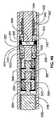
図1及び2は、伸延ロッド302及びハウジング304を有する髄内装置300(例えば、髄内延長装置)を示す。ハウジング304は、図3の断面図でよりよく理解され得るように、第1の端部310と第2の端部312との間に延びる。ハウジング304は、継ぎ目又は接合部のない一体構造として形成され得る。代替的には、ハウジング304は、継ぎ目又は接合部で一緒に融合された部分で形成されてもよい。図3に示すように、伸延ロッド302は、第1の端部318及び第2の端部320を有し、ハウジング304に対して(例えば、ハウジング304内で)伸縮自在に伸長可能及び退縮可能であるように構成される。ハウジング304と同様に、伸延ロッド302は、様々な副構成要素を接続する継ぎ目又は接合部のない一体構造であり得る。代替的には、伸延ロッド302は、継ぎ目又は接合部で一緒に融合された部分で形成されてもよい。伸延ロッド302及びハウジング304の両方は、チタン、例えばチタン−6AL−4V、コバルトクロム合金、及びステンレス鋼を含むいくつかの生体適合性材料のいずれかから作られ得る。伸延ロッド302及びハウジング304は、髄内装置300の主要な荷重支持部材(load bearing members)であり、またいずれの外部周囲溶接部(複数可)も有さないので、髄内装置300は、従来の髄内肢延長装置と比較して、改良された荷重の課題(improved loading challenges)に耐えることができる。ハウジング304は、髄内装置300を骨に取り付けるために、骨ねじを通すための少なくとも1つの横孔(transverse hole)(例えば、2つの横孔301)を含む。伸延ロッド302は、骨ねじの通過のための少なくとも1つの横孔(例えば、3つの横孔303)を含む。容易に理解されるように、横孔301、303の数及び向きは、必要に応じて、有用に、又は任意の所与の用途に所望されるように変更され得る。ハウジング304の第2の端部312において、結合機構323は、ドリルガイドのような、挿入器具と解放可能に係合するためのインタフェースを提供する。ドリルガイドは、雄ねじ部を含み得るとともに、結合機構323は、相補的な又は噛み合う雌ねじ部を有し得る。髄内装置300は、磁石ハウジング340内に接合され、ラジアルベアリング344とスラストベアリング342(図4Aにさらに明確に示される)との間の回転のために構成される磁石338を含む。スラストベアリング342と磁石ハウジング340との間には、少なくとも1つの遊星歯車段(planetary gear stage)(例えば、図4Aに示すように3つの遊星歯車段305、307、309)がある。各遊星歯車段(例えば、遊星歯車段305、307、309)は、太陽歯車(例えば、太陽歯車311A、311B、311C)及び複数の遊星歯車(例えば、3つの遊星歯車313)を含み、これらの複数の遊星歯車は、ピン317によってフレーム315内に回転可能に保持される。太陽歯車311は、遊星歯車段305の太陽歯車311Aの場合のように、磁石ハウジング340の一部、又は、歯車段307の太陽歯車311B及び歯車段309の太陽歯車311Cのように、フレーム315の一部のいずれかである。遊星歯車313の回転は、遊星歯車313が回転し、リングギアインサート319の内歯321に沿って追従することを引き起こす。各歯車段は(例えば、4:1の)減速比を有し、これは、総減速(例えば、総減速比64:1−それぞれ4:1の減速比を有する3つの遊星歯車段によって提供される)をもたらす。他の歯車減速、及び段数が使用され得ることが理解されるべきである。 1 and 2 show an intramedullary device 300 (eg, an intramedullary extension device) having a
最終歯車段(例えば、歯車段309)のフレーム315は、スラストベアリング342を通過し、最終歯車段309のフレーム315の回転が、リードスクリューカプラ366の1対1回転を引き起こすようにリードスクリューカプラ366に取り付けられる。リードスクリューカプラ366及びリードスクリュー358はそれぞれ横孔を含み、それを通ってロックピン368が配置され、したがって、リードスクリュー358を最終歯車段(例えば、歯車段309)に回転結合する。ロックピン保持器350は、リードスクリューカプラ366の上を摺動し、ロックピン368を所定の位置に半径方向に維持/保持するために、リードスクリューカプラ366に固定される(例えば、タック溶接される)。伸延ロッド302は、ナット360の外部ねじ部(雄ねじ部)(external threads)365がねじ込まれ、例えばエポキシで接合される、内部ねじ付き端部(internally threaded end)363を有する。ナット360は、リードスクリュー358の外部ねじ部325と螺合するように構成された内部ねじ部(雌ねじ部)(internal threads)367を有し、それによってリードスクリュー358を第1の方向の回転を可能にして、伸延ロッド302をハウジング304に対して伸延又は伸長させる。リードスクリュー358の第2の(反対の)方向への回転は、ハウジング304に対して伸延ロッド302を後退させる又は引き戻す。磁石338及び磁石ハウジング340の回転は、リードスクリューの回転を引き起こす。含まれる歯車装置(gearing)に依存して、磁石338及び磁石ハウジング340の回転は、回転速度の1/64だが、著しく増加したトルク(64倍、摩擦損失を引いたもの)、したがって増幅された伸延力又は伸展力でのリードスクリュー358の回転を引き起こす。Oリング362が、伸延ロッド302の外側のリング溝388内に配置され、体液から内部内容物を保護する伸延ロッド302とハウジング304との間の動的シールを形成する。伸延ロッド302とリードスクリューカプラ366との間に配置されたスプリットワッシャストップ(split washer stop)364が、例えば、髄内装置300が高トルク(例えば、外部移動磁界によって加えられる高トルク)で完全に収縮される場合に、伸延ロッド302がリードスクリューカプラ366に近づくときに生じ得るジャミング(jamming)を防止する。 The frame 315 of the final gear stage (eg, gear stage 309) passes through the
透磁性材料(例えば、400シリーズのステンレス鋼)で作られた湾曲プレートを含むメンテナンス部材346が、(例えば、エポキシ、接着剤、抵抗溶接、又は適切なプロセスを用いて)、ハウジング304の内壁に固定又はその内壁の中に接合される。メンテナンス部材346は、磁石338の極を引き寄せ、したがって、患者の動きによって肢延長装置300が誤って調整されるのを防ぐ。しかし、当技術分野で知られている磁気調整装置によって印加されるような強い移動磁界は、磁石338のメンテナンス部材346への引力を克服し、磁石338を回転させ、それによって髄内装置の長さを調整することができる。メンテナンス部材346は、約0.015インチ(約0.381ミリメートル)の厚さを有することができ、約180°未満の円弧(例えば、例示的な円弧は99°である)に及ぶことができる。もちろん、作動されていないときに磁石338を適所に適切に保持するために磁石338に十分な吸引力を提供する限り、メンテナンス部材346の他の寸法も考えられる。 A maintenance member 346 comprising a curved plate made of a magnetically permeable material (eg, 400 series stainless steel) is applied to the inner wall of the housing 304 (eg, using epoxy, adhesive, resistance welding, or a suitable process). Fixed or joined in the inner wall. The maintenance member 346 attracts the poles of the
伸延ロッド302及びハウジング304は、例えば手動又は自動旋盤を組み入れる機械加工プロセスによって個々に製造され得る。この製造作業には、ハウジング304内に軸方向に延びるキャビティを形成することが含まれ得る。ビードブラスト(bead
blasting)、パッシベーション(passivation)、及び/又は陽極酸化処理(anodizing)などの後処理がこの操作に含まれ得る。次に、伸延ロッド302及びハウジング304は、係合(mating)のために準備される。この動作では、ナット360は、伸延ロッド302の中に接合され、Oリング362は、上述のようにリング溝388内に配置される。メンテナンス部材346はハウジング304に接合される。次に、磁石338がハウジング304のキャビティ390内に配置される。この動作では、磁石338と磁石ハウジング340とが一緒に接合され、次にラジアルベアリング344を用いてハウジング304(図3参照)の中に組み立てられる。ラジアルベアリング344をハウジング304に組み立てる前に、ハウジング304のキャビティ390の長手方向の深さが測定され、必要に応じて1つ又は複数のシムがラジアルベアリング344の前に配置され得る。理想的には、組み立てられた構成要素の軸方向の遊びは、拘束(binding)を引き起こすほど低くはないが、分解の危険にさらすほど高くはない。次に、リードスクリュー358は、ハウジング304のキャビティ390内にある磁石338に結合するために準備される。この動作では、リングギアインサート319は、出っ張り(ledge)392に当接するまで、ハウジング304のキャビティ390内にスライドされる。第1及び第2の遊星歯車段305、307は、次に、図4Aに見られるようにアセンブリ内に配置される。ロックピン保持器350は、リードスクリューカプラ366を最終遊星歯車段309に溶接する前に、リードスクリューカプラ366の上に予荷重を与えられ(preloaded)、次に、ロックピン368が配置された後にロックピン368の上を定位置に摺動される。最終遊星歯車段309はスラストベアリング342を通って挿入され、リードスクリューカプラ366に溶接され、スラストベアリング342の幾分軸方向の遊びを可能にする。スプリットワッシャストップ364は次にリードスクリュー358上に配置される。リードスクリュー358は、次にロックピン368でリードスクリューカプラ366に取り付けられ、次いでロックピン保持器350がロックピン368の端部の一部の上を摺動されてリードスクリューカプラ366に仮付け溶接される。スラストベアリング保持器354、356は、スラストベアリング342及びリードスクリューカプラ366の周りに円筒形のクラムシェルを形成する2つの適合する部品である。ハウジング304の内径は、スラストベアリング保持器354、356のそれぞれの外側半分の直径面と同様に、はんだでスズメッキされる。次に、スラストベアリング保持器354、356は、スラストベアリング342、リードスクリューカプラ366、遊星歯車段309、及びリードスクリュー358を有するアセンブリ上にクランプされ、スラストベアリング保持器354、356は、例えばスラストベアリング保持器354、356の面取り部352に押し付けられるツールを用いて、ハウジング304内の場所に一緒に押し込まれる。最終遊星歯車段309の太陽歯車311Cは、最終遊星歯車段309の遊星歯車317と噛合し、次に、スラストベアリング保持器354、356の面取りされた縁部394がリングギアインサート319の面取り部348に押し付けられ、圧縮力が保持される。次に、スラストベアリング342及び磁石338が軸方向に保持される。この動作では、スラストベアリング保持器354、356は、スズメッキされた部分でハウジング304にはんだ付けされ、したがって圧縮力を維持する。これは、誘導加熱を用いて達成されることができる。リングギアインサート319の対向する端部に対する出っ張り392と面取りされた縁部394の摩擦、並びに、面取りされた縁部394と面取り部348との間の楔止めは、回転に対する抵抗を作り、したがって、リングギアインサート319をハウジングに対して回転的に静止して保持する。代替的には、リングギアインサート319がハウジング304に対して回転しないようにするために、リングギアインサート319は、ハウジング304内の対応するキー付き構造(keyed feature)に嵌合するキー付き構造を有してもよい(これは、リングギアインサート319の端部上の摩擦がリングギアインサート319を静止状態に保持するのに十分でない場合/ときに有用であり得る)。The
Post-treatments such as blasting, passivation, and / or anodizing can be included in this operation. Next, the
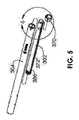
次いで、伸延ロッド302はリードスクリュー358と係合されることができる。この動作では、高速回転磁石のようなアセンブリ工具が、磁石338を作製するために使用され、結果としてリードスクリュー358が回転し、リードスクリュー358が、伸延ロッド302のナット360に対して係合し且つ変位する間に、伸延ロッド302はハウジング304内に挿入される。伸延ロッド302が上述のようにハウジング304内に挿入され、少なくとも幾分引っ込められた後、伸延ロッド302は、ハウジング304に対して依然として自由に回転する。伸延される骨片の安定性のために、伸延ロッド302とハウジング304との間の回転を抑制することが望ましい場合がある。そうする1つの可能な方法及び構造は、図5及び6に関連して記載される。伸延ロッド302は、伸延ロッド302に沿って伸びる溝372に、各側に1つの突起374を係合させることによって伸延ロッド302の上に回転防止リング370を配置し、次いで、回転防止リング370をハウジング304の先細の内側縁部376まで摺動させることによって、ハウジング304に対して回転的にロックされ得る。次いで、回転防止リング370及び伸延ロッド302は、ガイドフィン382がハウジング304の端部のガイドカット(guide cuts)380の中に挿入(例えば摺動)されることができるまで回転され得る。回転防止リング370は、回転防止リング370の平坦な縁部384がアンダーカット378によって捉えられるように、ハウジング304の中に軸方向にスナップ止め(snapped)されることができる。アンダーカット378は、回転防止リング370の平坦な縁部384の外径より小さい最小直径を有し、スナップ止めプロセス中に一時的に強制的に開蹴けられる。組み立てられると、回転防止リング370、ハウジング304及び伸延ロッド302は、全て、互いに対して実質的に回転的に静止して保持される。加えて、髄内装置300がその最大伸延長さに達するとき、溝372の端部386が突起374に当接し、それによって伸延ロッド302がハウジング304から脱落するのを防止する。 The
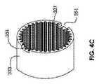
図1乃至4Aの髄内装置300の代替実施形態が、図4Bに断面図で示される。この実施形態の多くは、図1乃至4Aに示される実施形態と類似又は同一であり得る。しかし、この実施形態は、スラストベアリング保持器354、356を有する必要がない点で少なくとも異なる。代わりに、外部テーパ端部347を有するスラストベアリングフェルール(thrust bearing ferrule)335を組み込み得る。スラストベアリング保持器337、ロックピン保持器341、及びスラストベアリングフェルール335がスラストベアリング342上に配置され、リードスクリューカプラ339及び最終遊星歯車段309がスラストベアリング342を通って挿入され、リードスクリューカプラ339に溶接される。図4Dに示すように、ロックピン保持器341は、ロックピン368の通過を可能にするレリーフ(relief)361を有する。ロックピン368が配置された後、ロックピン保持器341は、回転して、レリーフ361がもはやロックピン368の上に直接なく、ロックピン保持器341が他の方法によってリードスクリューカプラ339に仮付け溶接又は固定され、したがってロックピン368を保持するように、回転され得る。次に、これらの組み立てられた構成要素は、ハウジング304のキャビティ390の中に挿入され、ここで最終遊星歯車段309は、他の遊星歯車段305、307及び磁石338に結合されている。この実施形態では、リングギアインサート333(図4C)は、各側に窪み351(例えば、ノッチ)を有する。スラストベアリングフェルール335の各側のタブ349が各窪み351に挿入され、スラストベアリングフェルール335がハウジング304に係合されると、ハウジング304に対するリングギアインサート333の回転を阻止する。この実施形態においても、ハウジング304は、内部ねじ部343を含む。スラストベアリングフェルール335の係合は、スラストベアリング保持器337の外部ねじ部345をハウジング304の内部ねじ部343に締め付けることによって達成される。ツール(図示せず)が、スラストベアリング保持器337の片側又は両側の切欠き357の中に係合されることができ、スラストベアリング保持器337をハウジング304の内部ねじ部343に螺合するために使用される。図4Bに示すように、これはスラストベアリング保持器337の内部テーパ353をスラストベアリングフェルール335の外部テーパ端部347に押し付け(wedges)、スラストベアリングフェルール335がリングギアインサート333に制御された荷重を加えることを可能にし、リングギアインサート333をハウジング304に対して軸方向及び回転方向にロックする。スラストベアリング保持器337は、反対側に軸方向分割部(axial split)を含む(図示せず)。スラストベアリング保持器337の分割部は、ハウジング304の内部部分が挿入中に傷つかないように、スラストベアリング保持器337の外径が、ねじ込まれる前にハウジング304に挿入されている間に、(圧縮によって)わずかに減少されることを可能にする。出っ張り355は、図4Dにおいてリードスクリューカプラ339上に見える。先に述べたように、スプリットワッシャストップ364は、伸延ロッド302が完全に後退したときに、この出っ張り355に突き当たり、ジャミングを防止する。 An alternative embodiment of the
図1乃至4Aの髄内装置300の代替実施形態が、図7の断面図に示される。メンテナンス部材397が、湾曲したプレートメンテナンス部材346に取って代わる。メンテナンス部材397は、肢延長装置300のハウジング304内の磁石338に対して軸方向に間隔を置いて配置されているが、磁石338に近接しているので、メンテナンス部材397は、磁石338の磁極を依然として引き付けることができ、したがって、患者の動きによって肢延長装置300が誤って調整されることを防止する。メンテナンス部材397は、ボディ395及び固定部分(securement portion)391を有する。固定部分391は、ハウジング304のキャビティ379の半径よりも大きな外径をそれぞれ有する、4つのタブ393を有するものとして図示されている。タブ393とキャビティ379の間のインタフェースは、ハウジング304に対して回転又は軸方向に移動できないように、メンテナンス部材397を定位置に保持するのに十分である。代替的には、固定部分391は、キャビティ379に接着接合、溶接、又は別の手段によって固定されてもよい。メンテナンス部材397は、ラジアルベアリング344を据え付ける(seat)ように構成された出っ張り(ledge)381を含む。図1−4Dの実施形態と同様に、磁石ハウジング340のノーズ377が、ラジアルベアリング344の内孔に圧入される。図7及び8の実施形態では、メンテナンス部材397の貫通孔399が、磁石ハウジング340のノーズ377の非接触式伸長を可能にするように構成され、したがって、磁石ハウジング340、及び磁石338が自由に回転することを可能にする。耳部387、389が、ギャップ383、385によって分離され、透磁性材料(例えば、400シリーズステンレス鋼、鉄、μ−金属、又は磁石338の磁極を引き付けることができる別の同様の材料)を含む。各耳部387、389のエッジ375は、最大量の材料が磁石338に近接して位置することを可能にするために、平坦であり得る。 An alternative embodiment of the
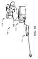
図18は、本明細書に記載の装置及びシステムを非侵襲的に調整するために使用される外部調節装置1180を示す。外部調節装置1180は、磁気ハンドピース1178、制御ボックス1176及び電源1174を有する。制御ボックス1176は、1つ又は複数の制御装置(ボタン、スイッチ又は触覚、運動、音声又は光センサ)及びディスプレイ1184を有する制御パネル1182を含む。ディスプレイ1184は、視覚的、聴覚的、触覚的、類似の又は前述の構成のいくつかの組み合わせであり得る。外部調節装置1180は、医師によるプログラミングを可能にするソフトウェアを含み得る。 FIG. 18 illustrates an
図19は、外部調節装置1180の磁気ハンドピース1178の詳細を示す。円筒形状を有する複数、例えば、2つの磁石1186がある(他の形状も可能である)。いくつかの実施形態では、磁気ハンドピース1178は、1つの磁石1186のみを有する。いくつかの実施形態では、磁気ハンドピース1178は、1つ又は複数の電磁石を使用する。磁石1186は、(ネオジム−鉄−ホウ素のような)希土類磁石から製造することができ、いくつかの実施形態では、半径方向に分極されることができる。磁石1186は、磁石カップ1187内に接合されるか、さもなければ固定される。磁石カップ1187はそれぞれシャフト1198を含み、その一方は第1の磁石ギア1212に取り付けられ、他方は第2の磁石ギア1214に取り付けられる。2つの磁石1186のそれぞれの極の向きは、(第1の磁石ギア1212と第2の磁石ギア1214の両方に噛み合うセンターギア1210の使用による)ギアリングシステムによって互いに対して維持されている。一実施形態では、磁石1186のうちの1つのN極は、完全な回転を通じて一致するクロック位置で、他の磁石1186のS極と同期して回転する。この構成は、例えば磁石338へのトルクの改善された伝達を提供することが知られている。本発明の髄内装置300を調整するために使用され得る方法及び外部調節装置の実施形態又は他の実施形態の例は、米国特許第8,382,756号及び米国特許出願第13/172,598号に記載され、これらはいずれも参照により本明細書に組み込まれる。 FIG. 19 shows details of the
磁気ハンドピース1178の構成要素は、磁石プレート1190と前部プレート1192との間に一緒に保持される。構成要素のほとんどは、カバー1216によって保護される。磁石1186は、静止磁石カバー1188内で回転するので、磁気ハンドピース1178は、患者の外面に動きを与えないで、患者の上に直接置かれ得る。髄内延長器具1110を伸ばす前に、操作者は、磁石338の位置付近の患者の上に磁気ハンドピース1178を配置する。2つの磁石1186の間に介在する磁石スタンドオフ1194は、配置するのを助けるために、観察窓1196を含む。例えば、観察窓1196を介して、患者の皮膚上の適切な位置に消えないマーカを有するマークを見ることができる。伸延を行うために、オペレータは、磁気ハンドピース1178をそのハンドル1200によって保持し、伸延スイッチ1228を押し、モータ1202を第1の方向に駆動させる。モータ1202は、出力ギア1204の回転速度をモータ1202の回転速度とは異なる速度(例えば、より遅い速度)にするギアボックス1206を有する。そして、出力ギア1204は、センターギア1210と噛み合う減速ギア1208を回転させ、減速ギア1208とは異なる回転速度で回転させる。センターギア1210は、第1の磁石ギア1212と第2の磁石ギア1214の両方に噛み合い、それらをそれぞれ同じ速度で回転させる。外部調節装置1180の磁石1186が配置されている身体の部分に応じて、磁石1186及び磁石338によって組織及び体液を通して与えられる誘導電流密度を最小にするために、この速度を制御することが望ましい。例えば、60RPM以下の磁石回転速度が考えられるが、他の速度、例えば35RPM以下が使用されてもよい。患者が装置を保持する領域に重大な痛み又はのしびれを感じる場合に望ましいことができる、収縮スイッチ1230を押すことによって、いつでも、伸延を軽減することができる。 The components of the
提示された実施形態を通して、磁石338が、髄内装置300内で遠隔的に動きを生成するための駆動要素として使用される。図9−12は、永久磁石の代わりに他のタイプのエネルギ伝達が使用される、4つの代替の実施形態を概略的に示す。 Through the presented embodiment, the
図9は、第1のインプラント部分1302及び第2のインプラント部分1304を有するインプラント1306を有する髄内装置1300を示し、第2のインプラント部分1304は、第1のインプラント部分1302に対して非侵襲的に移動可能である。患者191内で第1のインプラント部分1302は第1の骨部分197に固定され、第2のインプラント部分1304は第2の骨部分199に固定される。モータ1308は、第1のインプラント部分1302及び第2のインプラント部分1304を互いに対して変位させるように動作可能である。外部調節装置1310は、オペレータによる入力のための制御パネル1312と、ディスプレイ1314と、トランスミッタ1316とを有する。トランスミッタ1316は、患者191の皮膚195を通って埋め込まれたレシーバ1320に制御信号1318を送信する。埋め込まれたレシーバ1320は、導体1322を介してモータ1308と通信する。モータ1308は、埋め込み可能なバッテリによって電力供給されてもよく、又は誘導結合によって電力供給されてもよい。 FIG. 9 shows an
図10は、第1のインプラント部分1402及び第2のインプラント部分1404を有するインプラント1406を有する髄内装置1400を示し、第2のインプラント部分1404は、第1のインプラント部分1402に対して非侵襲的に移動可能である。患者191内で、第1のインプラント部分1402は第1の骨部分197に固定され、第2のインプラント部分1404は第2の骨部分199に固定される。超音波モータ1408が、第1のインプラント部分1402及び第2のインプラント部分1404を互いに対して変位させるように動作可能である(例えば、圧電アクチュエータ)。外部調節装置1410は、オペレータによる入力のための制御パネル1412と、ディスプレイ1414と、患者191の皮膚195に結合された超音波トランスデューサ1416とを有する。超音波トランスデューサ1416は、患者191の皮膚195を通過する超音波1418を発生させ、超音波モータ1408を動作させる。 FIG. 10 shows an intramedullary device 1400 having an
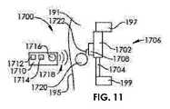
図11は、第1のインプラント部分1702及び第2のインプラント部分1704を有するインプラント1706を有する髄内装置1700を示し、第2のインプラント部分1704は、第1のインプラント部分1702に対して非侵襲的に移動可能である。患者191内で、第1のインプラント部分1702は、第1の骨部分197に固定され、第2のインプラント部分1704は、第2の骨部分199に固定される。形状記憶アクチュエータ1708が、第1のインプラント部分1702及び第2のインプラント部分1704を互いに対して変位させるように動作可能である。外部調節装置1710が、オペレータによる入力のための制御パネル1712、ディスプレイ1714及びトランスミッタ1716を有する。トランスミッタ1716は、制御信号1718を患者191の皮膚195を通って埋め込まれたレシーバ1720に送信する。埋め込まれたレシーバ1720は、導体1722を介して形状記憶アクチュエータ1708と通信する。形状記憶アクチュエータ1708は、埋め込み可能な電池によって電力供給されてもよく、又は誘導結合によって電力供給されてもよい。 FIG. 11 shows an intramedullary device 1700 having an
図12は、第1のインプラント部分1802及び第2のインプラント部分1804を有するインプラント1806を有する髄内装置1800を示し、第2のインプラント部分1804は、第1のインプラント部分1802に対して非侵襲的に移動可能である。患者191内で、第1のインプラント部分1802は第1の骨部分197に固定され、第2のインプラント部分1804は、第2の骨部分199に固定される。液圧ポンプ1808が、第1のインプラント部分1802及び第2のインプラント部分1804を互いに対して変位させるように動作可能である。外部調節装置1810は、オペレータによる入力のための制御パネル1812と、ディスプレイ1814と、トランスミッタ1816とを有する。トランスミッタ1816は、制御信号1818を患者191の皮膚195を通って埋め込まれたレシーバ1820に送信する。埋め込まれたレシーバ1820は、導体1822を介して液圧ポンプ1808と通信する。液圧ポンプ1808は、埋め込み可能なバッテリによって電力供給されてもよく、誘導結合によって電力供給されてもよい。液圧ポンプ1808は代替的には空気圧ポンプと置き換えられてもよい。 FIG. 12 shows an intramedullary device 1800 having an implant 1806 having a
図13は、不完全であり一部を欠いている骨100を示している。骨100は、近位部分102及び遠位部分104を含む。骨100は、近位端部106及び遠位端部108と、2つの間に延びる髄管(medullary canal)110とを有する。骨100は、いくつかの異なる長骨、例えば、大腿骨、脛骨、腓骨、上腕骨、又は他の、又はさらに他の骨(例えば、下顎骨)を表すことができる。近位部分102と遠位部分104との間の開放領域112は、欠けている骨を表す。開放領域112は、いくつかの理由のいずれかのために存在し得る。例えば、骨100のその部分は、外傷性事故又は外傷性事故後の1つまたは複数の外科的処置の間に失われた可能性がある。又は、それは、癌性骨の部分、例えば、1つ又は複数のタイプの肉腫によって引き起こされる腫瘍の除去と共に取り除かれている可能性がある。 FIG. 13 shows a
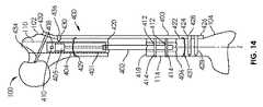
図14では、骨移動のためのシステム400が骨100に取り付けられて示されている。骨移動のためのシステムは、調節可能な長さのインプラント401及び支持部材403を有する。調節可能な長さのインプラント401は、いくつかの実施形態では、図1−8の髄内装置300又は図9−12に示される任意の実施形態のような、髄内肢延長装置を有し得る。調節可能なインプラント401は、ハウジング404から伸縮式に変位可能なロッド402を有する。ロッド402は、駆動要素405によってハウジング404から伸ばされ得る又はハウジング404の中に引き込まれ得る。使用時に、調節可能な長さのインプラント401は、髄管110が材料を除去するため又はその内径を増大させるために穿孔又はリーマ加工された後に、骨100の髄管110の中に埋め込まれ得る。調節可能な長さのインプラント401の植え込みの前又は後に、骨100の移動部分114を生成するために、切開、切断などによって、骨切り術406が行われることができる。図14では、移動部分114は、骨100の遠位部分104から形成される。他の場合には、移動部分114は、骨100の近位部分102から作られ得る。図14では、調節可能な長さのインプラント401は、骨100の近位端部106から(すなわち、順行性の方法で(antegrade manner))挿入される。しかし、他の場合には、調節可能な長さのインプラント401は遠位端部108から(すなわち、逆行性の方法で(retrograde manner))挿入されることができる。移動部分114が骨切り術406によって骨100の遠位部分104から分離された状態で、移動部分114及び近位部分102は、近位部分102及び遠位部分104に対して移動部分114を動かすために、調節可能な長さのインプラント401に結合され得る。骨100の片を取り付けるために、骨100の近位部分102は、ハウジング404内の1つ又は複数の孔410を通って軸上に穿孔されてもよく、1つ又は複数の骨ねじ408が、1つ又は複数の孔410を通って配置され、骨100の近位部分102に固定される。骨100の移動部分114は、ロッド402の1つ又は複数の孔412を通って軸上に穿孔され、1つ又は複数の骨ねじ414が、1つ又は複数の孔412を通って配置されることができ、骨100の移動部分114に固定されることができる。次いで、移動部分114は、調節可能な長さのインプラント401の長手方向軸Zに沿って非侵襲的に移動され得る。図14に描かれたような調節可能な長さのインプラント401は、完全に又はほとんど延ばされた状態で(ロッド402がハウジング404から完全に又は実質的に伸延した状態で)ユーザに与えられることができるので、移動プロセスは、移動部分114を遠位部分104から離れて、近位部分102に向かって動かす。この牽引方式では、移動部分114は押されずに引っ張られる。移動部分114を引っ張ることは、移動部分114が動かされるときに増大した寸法の安定性及び小さいドリフトを提供する傾向がある。仮骨(callus)が骨切り術406において受容可能に形成され始めると、移動プロセスが開始され得る。例えば、移動部分114は、約0.5mm/日と約1.50mm/日の間、又は約0.75mm/日と約1.25mm/日との間、又は約1.00mm/日で動かされ得る。毎日の伸延量は、1日に1回の非侵襲的調整で達成されてもよく、又は2、3、又はそれより多い別々の調整(例えば、それぞれ約0.33mmの3回の調整)に分割されてもよい。移動部分114の制御された輸送中に起こり得る骨形成のために、新しい骨部分416が形成される。骨移動が、移動部分114の近位端部418が近位部分102の遠位端部420に達するような程度に進むとき、移動部分114及び近位部分102に圧縮力が加えられ得る。そのような圧縮力は、移動部分114を近位部分に融着又は付着させるのに役立ち、それが移動部分114を引っ張ることによって適用されるという事実によって助長される。 In FIG. 14, a
上述したように、骨移動のためのシステム400は、骨100の外表面422上の位置に固定されるように構成される骨プレートを有し得る、支持部材403も含み得る。骨プレートは、皮質骨プレートを含み得る。支持部材403は、1つ又は複数の骨ねじ428の配置のために、その遠位端部426に1つ又は複数の孔424を含み得る。支持部材403はまた、1つ又は複数の骨ねじ434、436の配置のために、その近位端部432に1つ又は複数の孔430を含み得る。骨ねじ434、428は、両皮質(bicortical)骨ねじであってもよく、骨ねじ436は、単皮質(unicortical)骨ねじであってもよい。両皮質骨ねじは、調節可能な長さのインプラント401の近位又は遠位の骨100上の位置で有利に使用され得る一方、単皮質骨ねじは、調節可能な長さのインプラント401に隣接する骨100の上の位置で有利に使用され得る。支持部材403を骨100に固定するために使用される骨ねじ428、434、436は、ねじ山付きシャフトが骨材料と係合し、テーパねじ山付きヘッドが支持部材403のテーパ付きねじ孔(例えば、1つ又は複数の孔424、430)と係合するように構成される、ねじ山付きシャフト及びテーパねじ山付きヘッドを有し得る。支持部材403は、骨100の近位部分102及び遠位部分104を互いに対して静止し且つ安定して維持し、それにより、近位部分102及び遠位部分104に関して動かされるとき移動部分114の移動の正確さを最適にするために使用され得る。1つ又は複数の締結部(cerclages)429、431が、システムを定位置にさらに固定するために、例えば、支持部材403を骨100に固定するために、使用され得る。締結部429、431は図15において省略されているが、それらは、本明細書に記載された装置又は方法の任意の実施形態と共に使用され得ることが理解されるべきである。いくつかの実施形態では、支持部材403は、骨ねじの配置のためのかなり多くの孔を含み得る。例えば、大腿骨の近位端部に配置されるように構成される支持部材403の一部は、骨に固定され且つ1つ又は複数の骨片を含む、大腿骨頚部、大転子、又は大腿骨の他の部分の中に延びるように構成される骨ねじの配置のための、3、4、又はより多くの孔を有してもよい。 As described above, the
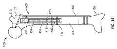
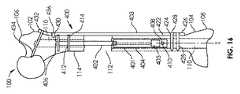
図16及び17は、骨100に固定された骨移動のためのシステム400を示している。しかし、調節可能な長さのインプラント401は、骨の遠位端部108から(すなわち逆行性の方法で)髄管110に挿入される。従って、骨切り術406は、骨100の近位部分102で行われ、移動部分114は、骨の近位部分102から引き離される。移動部分114は、骨100の近位部分102から離れて且つ骨100の遠位部分104に向かって移動させられて、新しい骨部分416を生成する。 FIGS. 16 and 17 illustrate a
代替的な解剖学的構成(anatomical setup)が、調節可能な長さのインプラント401を図14のものと同様の向きに配置する(例えば、ロッド402が遠位に向けられる又は下方に向けられ、ハウジング404が近位に延びる又は上方に向けられる)が、図16に示されるように、それを逆行に(すなわち、骨100の遠位端部108から)挿入することによって、手術中に作成されてもよい。さらに別の代替的な解剖学的構成は、調節可能な長さのインプラント401を図16と同様の向きに配置する(例えば、ロッド402が近位に延びる又は上方に向けられ、ハウジング404が遠位に延びる又は下方に向けられる)が、図16に示すように、順行に(すなわち、骨100の近位端部106から)挿入することによって、手術で作成されてもよい。 An alternative anatomical setup places the
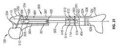
図20は、骨移動のためのシステム500を示している。骨移動のためのシステムは、調節可能な長さのインプラント501及び支持部材503(例えば、プレート)を含む。調節可能な長さのインプラント501は、いくつかの実施形態では、図1−8の髄内装置300又は図9−12の代替実施形態のいずれかのような、髄内肢延長装置を有し得る。調節可能なインプラント501は、ハウジング504から伸縮式に変位可能である、ロッド502を有し得る。ロッド502は、駆動要素505(図21−22に示す)によってハウジング504の外に伸ばされ得る又はハウジング504内に引き込まれ得る。使用時には、調節可能な長さのインプラント501は、髄管110が、材料を除去するか又はその内径を増大させるために、穿孔又はリーマ加工された後、骨100の髄管110内に埋め込まれる。これの前又は後に、切断、鋸引きなどによって骨切り術406が行われて、骨100の移動部分114が形成される。図21では、移動部分114は、骨100の遠位部分104から作られる。他の場合には、移動部分114は、骨100の近位部分102から作られてもよい。図21は、順行性の方法で挿入された後の調節可能な長さのインプラント501を示す。しかし、他の場合には、調節可能な長さのインプラント501は逆行性の方法で挿入されてもよい。移動部分114の骨100の遠位部分104からの分離(例えば、骨切り術406によって)の後、移動部分114及び近位部分102は、移動部分114を近位部分102及び遠位部分104に対して動かすために、調節可能な長さのインプラント501に結合され得る。骨100の近位部分102は、ハウジング504の1つ又は複数の孔510を通って軸上に穿孔されることができ、1つ又は複数の骨ねじ508が、1つ又は複数の孔510を通って配置され且つ骨100の近位部分102に固定されることができる。骨100の移動部分114は、ロッド502内の1つ又は複数の孔512を通る軸上に穿孔されることができ、1つ又は複数の骨ねじ514が、1つ又は複数の孔512を通って配置され、骨100の移動部分114に固定される。次いで、移動部分114は、調節可能な長さのインプラント501の長手方向軸Zに沿って非侵襲的に移動され得る。図21に描かれた調節可能な長さのインプラント501は、完全に又はほとんど延ばされた状態で(ロッド502がハウジング504から完全に又は実質的に伸延された状態で)ユーザに与えられ得るので、移動プロセスは、移動部分114を遠位部分104離れて且つ近位部分102に向かって動かす。この牽引方式では、移動部分114は引っ張られ、押されない。移動部分114を引っ張ることは、移動部分114が移動されるとき、増大した寸法の安定性及び小さいドリフトを提供する傾向がある。支持部材503は、支持部材503が、近位スロット端部589と遠位スロット端部597との間に延びる長手方向スロット587を有する点を除いて、図14−17の支持部材403と同様である。スロット587は、支持部材503の近位端部532と遠位端部526との間に位置する。図14−17に示す実施形態でのように、支持部材503は、1つ又は複数の両皮質骨ねじ528、534(孔524、530を通って配置されることができる)及び1つ又は複数の単皮質骨ねじ536(孔524、530を通って配置される)を用いて、骨100に固定され得る。図20に示されるように、特定の孔524a、524cは、支持部材503の中心線599の一方の側にオフセットされ得る一方、他の孔524bは、支持部材503の中心線599の別の側にオフセットされ得る。調節可能な長さのインプラント501が孔524a−cのレベルまで延在する場合、この方法で孔をオフセットすることは、両皮質骨ねじの配置の助けとなり得る。孔524a−cのオフセット位置は、例えば、両皮質骨ねじがロッド502を越えてロッド502の両側に延びることを可能にし得る。骨100の移動部分114は、骨ねじ514が固定されたとき、支持部材503のスロット587の外部位置593から、スロット587を通って、移動部分114の骨100の中に延びるように、孔512の軸に沿って、移動部分において骨100を穿孔することによって、骨ねじ514によってロッド502に固定されることができる。骨ねじ514は、ロッド502がハウジング504に対して非侵襲的に並進移動されるとき、骨ねじ514のシャフト597がスロット587内を摺動するように、整列(位置合わせ)される。容易に理解されるように、骨ねじ514のシャフト597の直径は、スロット587の幅より小さい。いくつかの実施形態では、骨ねじ514の頭部595の直径は、スロットの幅より大きく、これにより、移動部分114をさらに安定させ、x軸に沿って変位する能力を制限する。図22に戻ると、移動部分114自体が支持部材503によって規制されているので、移動部分114は正のx方向に実質的に並進(ドリフト)しないようになっている。移動部分114はまた、移動部分の長手方向調整の間、又は休止のときのいずれかにおいて、移動部分114が負のx方向に実質的に並進しないように、骨ねじ514の頭部595によって制限されてもよい。 FIG. 20 shows a
骨の移動又は肢の伸長において、移動又は伸延の長さは、処置ごと及び/又は患者ごとに大きく変わり得る。骨の移動処置において、移動長さは、欠損している骨の長さと、手術中に生成される移動部分114の関数であり得る。調節可能な長さのインプラントキット600(図23に示されている)は、処置されるべき患者の特定の移動長さ又は伸延長に適合される、調節可能な長さのインプラント、例えば図24の調節可能な長さのインプラント601をユーザが作成することを可能にするように構成され得る。調節可能な長さのインプラントキット600は、ハウジング604を有するベースアクチュエータ605と、ベースロッド602と、1つ又は複数のロッド延長部(例えば、ロッド延長部606、608、610)とを含み得る。ベースロッド602は、(本明細書の他の箇所に記載されているように)ハウジング604内で伸縮式に動くことができ、内部ねじ部612を有する。ロッド延長部606,608,610の夫々は、ベースロッド602の内部ねじ部612にねじ込まれるように構成される外部ねじ部614を有する。ユーザ(例えば、外科医又は医師)は、特定の患者に対して適切なロッド延長部606,608,610を選択し得る。例えば、比較的長い移動又は伸延の長さが必要な場合には、ロッド延長部606が選択されることができ、比較的短い移動又は伸延の長さが必要な場合は、ロッド延長部610が選択されることができる。ロッド延長部606,608,610は、限定するものではないが、アンカー孔616の数;アンカー孔616の軸方向配向(axial orientation);アンカー孔直径(例えば、異なる直径の骨ねじとの使用のため);等を含む、変化する特性を有し得る。ロッド延長部606,608,610は、中空部分を含み得る。例えば、内部通路618は、外部ねじ部614を有するロッド延長部610(又は任意の他のロッド延長部606,608)の端部を通過し得る。この方法では、リードスクリュー(図示せず)は、例えば、リードスクリューがベースロッド602の内部から延びる場合、内部通路618の中に延び得る。いくつかの実施形態では、リードスクリューは、伸長可能であり得る(すなわち、リードスクリューの延長部分によって増大され得る端部を有し得る)。内部ねじ部612及び外部ねじ部614は、ベースロッド602にロッド延長部606,608,610が結合される(例えば、一緒にねじ込まれる)とき、ロッド延長部606,608,610及びベースロッドを固定する、例えば、ラッチ、スナップ、戻り止め、フック、又は摩擦嵌合機構を組み込んだ、ロック機構をそれぞれ有し得る。代替実施形態では、ベースロッド602は外部ねじ部を含み得るとともに、ロッド延長部606,608,610は、それぞれ、内部ねじ部を含み得る。図23−24の調節可能な長さのインプラントキット600は、標準的な肢伸長処置において、又は本明細書に記載のものを含むがこれらに限定されない骨移動処置において使用され得る。調節可能な長さのインプラントキット600を手術中に利用可能にすることにより、外科医又は医師は、治療される患者に最も適切な装置をより容易に選択及び/又は構築し得る。いくつかの実施形態では、ロッド延長部606,608,610は、特にベースアクチュエータ605が供給者によって無菌状態で供給されなければならない場合、容易に滅菌(例えば蒸気滅菌/オートクレーブ、ガス)されることができ、これは処置のコストを低下させ得る。使用中、外科医又は医師(外科医又は医師の管理又は指導の下にあるような任意の他の医療専門家を含むと理解されるべきである)は、1つのロッド延長部を取り付け、それが患者に適切に適合しない場合、それを取り除き、それを他と交換し得る。代替的な実施形態及び方法では、支持部材403、503は、患者の外部に位置するように構成されるベースと、一端がベースに取り付けられ他端が骨の第1の部分に結合されるように構成される第1のピンと、一端がベースに取り付けられ、他端が骨の第2の部分に結合されるように構成される第2のピンとを含む、外部固定器によって置き換えられてもよい。 In bone movement or limb extension, the length of movement or distraction can vary greatly from treatment to treatment and / or from patient to patient. In a bone movement procedure, the movement length can be a function of the length of the missing bone and the moving
本発明は、特定の好ましい実施形態及び実施例の文脈で開示されているが、本発明は、具体的に開示された実施形態を超えて本発明の他の代替実施形態及び/又は使用並びにそれらの明らかな変形及び均等物に拡張されることが当業者には理解されるであろう。加えて、いくつかの本発明の多くの変形例が示され、詳細に説明されているが、本発明の範囲内にある他の変形は、この開示に基づいて当業者に容易に明らかになるであろう。実施形態の特定の特徴及び態様の様々な組合せ又は部分的な組み合わせが、なされ得るとともにそれでもなお本発明の範囲内に入ることも考えられる。したがって、開示された実施形態の様々な特徴及び態様は、開示された発明の様々な形態を形成するために、互いに組み合わせるか、又は互いに置き換えることができることが理解されるべきである。したがって、本明細書に開示された本発明の範囲は、上記の特定の開示された実施形態によって限定されるべきではなく、以下の特許請求の範囲を公正に読むことによってのみ決定されるべきであることが意図される。 Although the present invention is disclosed in the context of certain preferred embodiments and examples, the present invention extends beyond the specifically disclosed embodiments to other alternative embodiments and / or uses of the present invention and to them. Those skilled in the art will appreciate that the present invention extends to obvious variations and equivalents of In addition, although many variations of the invention have been shown and described in detail, other variations within the scope of the invention will be readily apparent to those skilled in the art based on the disclosure. Will. It is contemplated that various combinations or subcombinations of specific features and aspects of the embodiments may be made and still fall within the scope of the invention. Thus, it should be understood that various features and aspects of the disclosed embodiments can be combined with each other or replaced with each other to form various forms of the disclosed invention. Accordingly, the scope of the invention disclosed herein is not to be limited by the particular disclosed embodiments described above, but should only be determined by reading the following claims fairly. It is intended to be.
同様に、この開示の方法は、請求項がその請求項に明記されているより多くの特徴を必要とするという意図を反映するものと解釈されるべきではない。むしろ、以下の特許請求の範囲が反映するように、本発明の態様は、前述のいずれかの開示された実施形態の全ての特徴よりも少ない組み合わせにある。したがって、詳細な説明に続く請求項は、この詳細な説明に明示的に組み込まれ、各請求項は別個の実施形態として自立する。 Similarly, the methods of this disclosure should not be interpreted as reflecting an intention that a claim requires more features than are expressly recited in that claim. Rather, as the following claims reflect, aspects of the invention are in fewer combinations than all features of any of the disclosed embodiments described above. Thus, the claims following the detailed description are hereby expressly incorporated into this detailed description, with each claim standing on its own as a separate embodiment.
Claims (20)
Translated fromJapanese骨に結合されるように構成される第1の端部及び骨に結合されるように構成される第2の端部であって、前記第1の端部及び前記第2の端部は互いに対して長手方向軸に沿って変位可能である、第1の端部及び第2の端部と、
前記第1の端部及び前記第2の端部を互いに対して前記長手方向軸に沿って変位させるよう非侵襲的に作動されるように構成される駆動要素と;を有する、
調節可能な長さのインプラント;並びに
遠位端部及び近位端部を有する支持部材であって、前記支持部材は、前記支持部材の前記遠位端部と前記近位端部との間に配置される長手方向に延びるスロットを含み、前記スロットは対向する端部を有し、前記スロットは、細長いアンカーが前記スロットの第1の端部と第2の端部との間で摺動可能であるように、前記細長いアンカーを通すように構成される、支持部材;を有する、
骨移動のためのシステム。An adjustable length implant configured for intramedullary placement:
A first end configured to be coupled to the bone and a second end configured to be coupled to the bone, wherein the first end and the second end are A first end and a second end being displaceable along the longitudinal axis;
A drive element configured to be actuated non-invasively to displace the first end and the second end along the longitudinal axis with respect to each other;
An implant of adjustable length; and a support member having a distal end and a proximal end, wherein the support member is between the distal end and the proximal end of the support member. A longitudinally extending slot disposed, the slot having opposing ends, the slot being slidable between a first end and a second end of the slot A support member configured to pass the elongate anchor such that
A system for bone movement.
請求項1に記載のシステム。The drive element comprises a permanent magnet;
The system of claim 1.
請求項2に記載のシステム。The permanent magnet includes a rare earth magnet polarized in a radial direction,
The system according to claim 2.
請求項2に記載のシステム。The drive element comprises a motor;
The system according to claim 2.
請求項4に記載のシステム。The drive element comprises an inductively coupled motor;
The system according to claim 4.
請求項1に記載のシステム。The drive element comprises an ultrasonically actuated motor;
The system of claim 1.
請求項1に記載のシステム。The drive element comprises a piezoelectric element;
The system of claim 1.
請求項1に記載のシステム。The drive element comprises a subcutaneous hydraulic pump;
The system of claim 1.
請求項1に記載のシステム。The drive element comprises a shape memory drive actuator;
The system of claim 1.
請求項1に記載のシステム。The support member has one or more holes in one or more of the distal end and the proximal end, each of the one or more holes passing a bone screw. Composed,
The system of claim 1.
請求項10に記載のシステム。Each of the one or more holes has an internal thread portion configured to engage with an external thread portion provided on a bone screw head;
The system according to claim 10.
請求項1に記載のシステム。The adjustable length implant is a distance between the first end and the second end of the adjustable length implant when the drive element is actuated non-invasively. Is configured to be controllably shortened,
The system of claim 1.
請求項1に記載のシステム。The adjustable length implant further comprises a housing and a distraction rod configured to be telescopically movable relative to the housing.
The system of claim 1.
請求項1に記載のシステム。The adjustable length implant allows the distance between the first end and the second end of the adjustable length implant to be varied by at least about 20 mm. Composed of,
The system of claim 1.
請求項14に記載のシステム。The adjustable length implant allows the distance between the first end and the second end of the adjustable length implant to be varied by at least about 75 mm. Composed of,
The system according to claim 14.
請求項1に記載のシステム。The adjustable length implant further comprises a housing and a threaded base configured to be telescopically movable relative to the housing.
The system of claim 1.
請求項16に記載のシステム。The method further comprises a rod having a first end and a second end, wherein the first end is configured for securing the adjustable length implant to the threaded base. Having a threaded part,
The system of claim 16.
請求項17に記載のシステム。The threaded portion of the first end of the rod has an external thread;
The system of claim 17.
請求項17に記載のシステム。The threaded portion of the first end of the rod has an internal thread;
The system of claim 17.
請求項17に記載のシステム。The second end of the rod has one or more anchor holes configured to pass one or more bone anchors;
The system of claim 17.
Priority Applications (1)
| Application Number | Priority Date | Filing Date | Title |
|---|---|---|---|
| JP2021084291AJP7101848B2 (en) | 2016-01-28 | 2021-05-19 | System for bone movement |
Applications Claiming Priority (3)
| Application Number | Priority Date | Filing Date | Title |
|---|---|---|---|
| US201662288348P | 2016-01-28 | 2016-01-28 | |
| US62/288,348 | 2016-01-28 | ||
| PCT/US2017/015555WO2017132646A1 (en) | 2016-01-28 | 2017-01-30 | Systems for bone transport |
Related Child Applications (1)
| Application Number | Title | Priority Date | Filing Date |
|---|---|---|---|
| JP2021084291ADivisionJP7101848B2 (en) | 2016-01-28 | 2021-05-19 | System for bone movement |
Publications (2)
| Publication Number | Publication Date |
|---|---|
| JP2019503801Atrue JP2019503801A (en) | 2019-02-14 |
| JP6888015B2 JP6888015B2 (en) | 2021-06-16 |
Family
ID=58046758
Family Applications (2)
| Application Number | Title | Priority Date | Filing Date |
|---|---|---|---|
| JP2018539429AActiveJP6888015B2 (en) | 2016-01-28 | 2017-01-30 | System for bone movement |
| JP2021084291AActiveJP7101848B2 (en) | 2016-01-28 | 2021-05-19 | System for bone movement |
Family Applications After (1)
| Application Number | Title | Priority Date | Filing Date |
|---|---|---|---|
| JP2021084291AActiveJP7101848B2 (en) | 2016-01-28 | 2021-05-19 | System for bone movement |
Country Status (10)
| Country | Link |
|---|---|
| US (2) | US10918425B2 (en) |
| EP (2) | EP3656323B1 (en) |
| JP (2) | JP6888015B2 (en) |
| KR (1) | KR20180107173A (en) |
| CN (2) | CN113598921B (en) |
| AU (3) | AU2017212806B2 (en) |
| BR (1) | BR112018015504A2 (en) |
| DK (1) | DK3407812T3 (en) |
| ES (2) | ES2879405T3 (en) |
| WO (1) | WO2017132646A1 (en) |
Cited By (1)
| Publication number | Priority date | Publication date | Assignee | Title |
|---|---|---|---|---|
| JP2023531778A (en)* | 2020-07-03 | 2023-07-25 | オッセオインテグレーション インターナショナル ビー.ヴイ. | bone nail device |
Families Citing this family (34)
| Publication number | Priority date | Publication date | Assignee | Title |
|---|---|---|---|---|
| AU2009310439B2 (en)* | 2008-10-31 | 2016-05-26 | Implantica Patent Ltd. | Device and method for bone adjustment with anchoring function |
| US9179938B2 (en)* | 2013-03-08 | 2015-11-10 | Ellipse Technologies, Inc. | Distraction devices and method of assembling the same |
| BR112018015504A2 (en)* | 2016-01-28 | 2018-12-18 | Nuvasive Specialized Orthopedics, Inc. | bone transport systems |
| US12262917B2 (en) | 2016-05-19 | 2025-04-01 | Auctus Surgical, Inc. | Spinal curvature modulation systems and methods |
| CN109152596B (en) | 2016-05-19 | 2022-07-08 | 奥图斯外科手术股份有限公司 | Spinal curvature adjustment system |
| WO2018144386A1 (en)* | 2017-02-02 | 2018-08-09 | Smith & Nephew, Inc. | Implantable bone adjustment devices |
| EP3491998B1 (en) | 2017-11-30 | 2021-03-31 | Endotact | Implantable distraction device |
| JP2022521180A (en) | 2019-02-13 | 2022-04-06 | ザ トラスティーズ オブ ザ ユニバーシティ オブ ペンシルバニア | Smart implantable skull-systems and methods for chin facial extension devices |
| DE102019122354A1 (en)* | 2019-08-20 | 2021-02-25 | Orthofix Srl | Intramedullary nail for distraction of a long bone |
| CN110840624A (en)* | 2019-12-04 | 2020-02-28 | 北京爱康宜诚医疗器材有限公司 | Bone filling prosthesis |
| US20210186643A1 (en)* | 2019-12-20 | 2021-06-24 | Endotact | Distraction device with reflector |
| CN111150478B (en)* | 2020-01-02 | 2022-04-05 | 赣南医学院 | A biomedical degradable magnesium alloy bone plate |
| WO2022015898A1 (en) | 2020-07-17 | 2022-01-20 | Nuvasive Specialized Orthopedics, Inc. | Extramedullary device and system |
| US12213708B2 (en)* | 2020-09-08 | 2025-02-04 | Nuvasive Specialized Orthopedics, Inc. | Remote control module for adjustable implants |
| CN112263317B (en)* | 2020-11-16 | 2025-06-06 | 河南科科生物科技有限公司 | A new type of bone transport intramedullary nail |
| CN112656497B (en)* | 2020-12-31 | 2024-06-18 | 黄立辉 | Tibia transverse bone moving device |
| US20220265326A1 (en) | 2021-02-23 | 2022-08-25 | Nuvasive Specialized Orthopedics, Inc. | Adjustable implant, system and methods |
| US20220304730A1 (en)* | 2021-03-26 | 2022-09-29 | Nuvasive Specialized Orthopedics, Inc. | Intramedullary device for ankle fusion |
| US11986223B2 (en)* | 2021-06-04 | 2024-05-21 | Nuvasive Specialized Orthopedics, Inc. | Adjustable implant with advanced sealing and retention |
| US20240130764A1 (en)* | 2021-07-07 | 2024-04-25 | Surgical Design Innovations Ii, Llc | Bone fracture fixation device and related systems and methods |
| CA3225984A1 (en)* | 2021-07-07 | 2023-01-12 | Surgical Design Innovations Ii, Llc | Bone fracture fixation device and related systems and methods |
| EP4380480A1 (en)* | 2021-08-03 | 2024-06-12 | NuVasive Specialized Orthopedics, Inc. | Adjustable implant |
| JP2024545100A (en) | 2021-12-07 | 2024-12-05 | ニューベイシブ スペシャライズド オーソペディックス,インコーポレイテッド | Adjustable implant with cycloid gear |
| US20230190342A1 (en)* | 2021-12-17 | 2023-06-22 | Mark Robert BRINKER | Surgical device |
| US11540924B1 (en)* | 2022-02-14 | 2023-01-03 | Ezat EL-SAID | Remotely adjustable orthopedic prostheses |
| EP4268740A1 (en)* | 2022-04-26 | 2023-11-01 | Stryker European Operations Limited | Plunging/linkage screw |
| US20230338070A1 (en)* | 2022-04-26 | 2023-10-26 | Stryker European Operations Limited | Retrograde Nail with Bone Plate |
| WO2024025719A1 (en) | 2022-07-26 | 2024-02-01 | Nuvasive Specialized Orthopedics, Inc. | Bone transport implant |
| US20240122624A1 (en)* | 2022-10-14 | 2024-04-18 | Globus Medical, Inc. | External fixation system with multi-pin clamp and attachment post |
| US20240225704A9 (en) | 2022-10-21 | 2024-07-11 | Nuvasive Specialized Orthopedics, Inc. | Extramedullary device |
| US12232790B2 (en) | 2022-12-30 | 2025-02-25 | IvyTech Design LLC | Adjustable angle orthopedic distractor, compressor, and distractor-compressor |
| US20240366273A1 (en) | 2023-05-03 | 2024-11-07 | Nuvasive Specialized Orthopedics, Inc. | Adjustable implant |
| WO2024243409A1 (en)* | 2023-05-23 | 2024-11-28 | Vertical Orthopaedics, Inc. | Bone growth device |
| US20250221822A1 (en)* | 2024-01-04 | 2025-07-10 | Arthrex, Inc. | Hydraulic taper separator for orthopaedic implant systems and methods of disassembly |
Citations (7)
| Publication number | Priority date | Publication date | Assignee | Title |
|---|---|---|---|---|
| JP2001507608A (en)* | 1997-01-07 | 2001-06-12 | ベッツ アウグスティン | Distraction device for separating two parts of a bone from each other |
| US6514253B1 (en)* | 2000-11-22 | 2003-02-04 | Meei-Huei Yao | Apparatus for locating interlocking intramedullary nails |
| US7056322B2 (en)* | 2002-03-28 | 2006-06-06 | Depuy Orthopaedics, Inc. | Bone fastener targeting and compression/distraction device for an intramedullary nail and method of use |
| US20090076597A1 (en)* | 2007-09-19 | 2009-03-19 | Jonathan Micheal Dahlgren | System for mechanical adjustment of medical implants |
| US20140236311A1 (en)* | 2011-06-27 | 2014-08-21 | University Of Cape Town | Endoprosthesis |
| US20140250674A1 (en)* | 2013-03-08 | 2014-09-11 | Ellipse Technologies, Inc. | Distraction devices and method of assembling the same |
| JP2015164554A (en)* | 2009-09-04 | 2015-09-17 | エリプス テクノロジーズ, インク.Ellipse Technologies, Inc. | Bone growth apparatus and method |
Family Cites Families (851)
| Publication number | Priority date | Publication date | Assignee | Title |
|---|---|---|---|---|
| DE213290C (en) | ||||
| US1599538A (en) | 1919-12-06 | 1926-09-14 | Mintrop Ludger | Geological testing method |
| US3111945A (en) | 1961-01-05 | 1963-11-26 | Solbrig Charles R Von | Bone band and process of applying the same |
| US3377576A (en) | 1965-05-03 | 1968-04-09 | Metcom Inc | Gallium-wetted movable electrode switch |
| US3397928A (en) | 1965-11-08 | 1968-08-20 | Edward M. Galle | Seal means for drill bit bearings |
| SE344275B (en) | 1966-02-10 | 1972-04-10 | R Gruenert | |
| US3372476A (en) | 1967-04-05 | 1968-03-12 | Amp Inc | Method of making permanent connections between interfitting parts |
| FR1556730A (en) | 1967-06-05 | 1969-02-07 | ||
| US3866510A (en) | 1967-06-05 | 1975-02-18 | Carl B H Eibes | Self-tapping threaded bushings |
| USRE28907E (en) | 1967-06-05 | 1976-07-20 | Self-tapping threaded bushings | |
| US3512901A (en) | 1967-07-28 | 1970-05-19 | Carrier Corp | Magnetically coupled pump with slip detection means |
| CH492447A (en)* | 1968-06-17 | 1970-06-30 | Xavier Halloran William | Fixation device for broken bones |
| US3527220A (en) | 1968-06-28 | 1970-09-08 | Fairchild Hiller Corp | Implantable drug administrator |
| FR2086747A5 (en) | 1970-04-07 | 1971-12-31 | Cotton De Bennetot M | |
| US3655968A (en) | 1970-06-29 | 1972-04-11 | Kermath Mfg Corp | X-ray examination chair |
| US3726279A (en) | 1970-10-08 | 1973-04-10 | Carolina Medical Electronics I | Hemostatic vascular cuff |
| US3810259A (en) | 1971-01-25 | 1974-05-14 | Fairchild Industries | Implantable urinary control apparatus |
| US3750194A (en) | 1971-03-16 | 1973-08-07 | Fairchild Industries | Apparatus and method for reversibly closing a natural or implanted body passage |
| US3840018A (en) | 1973-01-31 | 1974-10-08 | M Heifetz | Clamp for occluding tubular conduits in the human body |
| DE2314573C2 (en) | 1973-03-23 | 1986-12-18 | Werner Dipl.-Ing. 8000 München Kraus | Device for promoting healing processes |
| GB1467248A (en) | 1973-07-30 | 1977-03-16 | Horstmann Magnetics Ltd | Electric motors |
| CH581988A5 (en) | 1974-04-09 | 1976-11-30 | Messerschmitt Boelkow Blohm | |
| US3900025A (en) | 1974-04-24 | 1975-08-19 | Jr Walter P Barnes | Apparatus for distracting or compressing longitudinal bone segments |
| FI53062C (en) | 1975-05-30 | 1978-02-10 | Erkki Einari Nissinen | |
| US4010758A (en) | 1975-09-03 | 1977-03-08 | Medtronic, Inc. | Bipolar body tissue electrode |
| US4068821A (en) | 1976-09-13 | 1978-01-17 | Acf Industries, Incorporated | Valve seat ring having a corner groove to receive an elastic seal ring |
| SU715082A1 (en) | 1977-01-24 | 1980-02-15 | Всесоюзный научно-исследовательский и испытательный институт медицинской техники | Surgical suturing apparatus |
| US4118805A (en) | 1977-02-28 | 1978-10-10 | Codman & Shurtleff, Inc. | Artificial sphincter |
| CH625384B (en) | 1977-12-20 | Ebauches Electroniques Sa | STEP MOTOR NON-ROTATION DETECTION DEVICE FOR CLOCKWORK PART AND LOST STEPS CATCHING UP. | |
| US4286584A (en) | 1978-06-16 | 1981-09-01 | Infusaid Corporation | Septum locating apparatus |
| US4222374A (en) | 1978-06-16 | 1980-09-16 | Metal Bellows Corporation | Septum locating apparatus |
| US4235246A (en) | 1979-02-05 | 1980-11-25 | Arco Medical Products Company | Epicardial heart lead and assembly and method for optimal fixation of same for cardiac pacing |
| US4256094A (en) | 1979-06-18 | 1981-03-17 | Kapp John P | Arterial pressure control system |
| US4357946A (en) | 1980-03-24 | 1982-11-09 | Medtronic, Inc. | Epicardial pacing lead with stylet controlled helical fixation screw |
| DE3035670A1 (en) | 1980-09-22 | 1982-04-29 | Siemens AG, 1000 Berlin und 8000 München | DEVICE FOR INFUSING LIQUIDS IN HUMAN OR ANIMAL BODIES |
| US4386603A (en) | 1981-03-23 | 1983-06-07 | Mayfield Jack K | Distraction device for spinal distraction systems |
| US4448191A (en) | 1981-07-07 | 1984-05-15 | Rodnyansky Lazar I | Implantable correctant of a spinal curvature and a method for treatment of a spinal curvature |
| FR2514250A1 (en) | 1981-10-08 | 1983-04-15 | Artus | HANDPIECE WITH INTEGRATED MOTOR |
| FR2523232B1 (en) | 1982-03-09 | 1985-09-20 | Thomson Csf | TELESCOPIC COLUMN WITH CYLINDRICAL TUBES |
| CH648723GA3 (en) | 1982-09-10 | 1985-04-15 | ||
| DE3340596A1 (en) | 1982-11-16 | 1984-05-24 | Tokyo Electric Co., Ltd., Tokyo | MATRIX PRINTER |
| IL67773A (en) | 1983-01-28 | 1985-02-28 | Antebi E | Tie for tying live tissue and an instrument for performing said tying operation |
| DE3306657C2 (en) | 1983-02-25 | 1986-12-11 | Fa. Heinrich C. Ulrich, 7900 Ulm | Spine correction implant with a distraction rod |
| US4501266A (en) | 1983-03-04 | 1985-02-26 | Biomet, Inc. | Knee distraction device |
| US4595007A (en) | 1983-03-14 | 1986-06-17 | Ethicon, Inc. | Split ring type tissue fastener |
| FR2551350B1 (en) | 1983-09-02 | 1985-10-25 | Buffet Jacques | FLUID INJECTION DEVICE, SUITABLE FOR IMPLANTATION |
| US4522501A (en) | 1984-04-06 | 1985-06-11 | Northern Telecom Limited | Monitoring magnetically permeable particles in admixture with a fluid carrier |
| US4573454A (en) | 1984-05-17 | 1986-03-04 | Hoffman Gregory A | Spinal fixation apparatus |
| SE448812B (en) | 1985-02-01 | 1987-03-23 | Astra Meditec Ab | SURGICAL DEVICE FOR CONNECTING THE TAGS OF A PATIENT |
| DE8515687U1 (en) | 1985-05-29 | 1985-10-24 | Aesculap-Werke Ag Vormals Jetter & Scheerer, 7200 Tuttlingen | Distraction device for extension osteotomy |
| US4592339A (en) | 1985-06-12 | 1986-06-03 | Mentor Corporation | Gastric banding device |
| US4642257A (en) | 1985-06-13 | 1987-02-10 | Michael Chase | Magnetic occluding device |
| US4696288A (en) | 1985-08-14 | 1987-09-29 | Kuzmak Lubomyr I | Calibrating apparatus and method of using same for gastric banding surgery |
| US4931055A (en) | 1986-05-30 | 1990-06-05 | John Bumpus | Distraction rods |
| US4700091A (en) | 1986-08-22 | 1987-10-13 | Timex Corporation | Bipolar stepping motor rotor with drive pinion and method of manufacture |
| SE460301B (en) | 1986-10-15 | 1989-09-25 | Sandvik Ab | CUTTING ROD FOR STOCKING DRILLING MACHINE |
| US4760837A (en) | 1987-02-19 | 1988-08-02 | Inamed Development Company | Apparatus for verifying the position of needle tip within the injection reservoir of an implantable medical device |
| DE8704134U1 (en) | 1987-03-19 | 1987-07-16 | Zielke, Klaus, Dr.med., 3590 Bad Wildungen | Implant designed as a distraction and compression rod |
| DE3711091A1 (en) | 1987-04-02 | 1988-10-13 | Kluger Patrick | DEVICE FOR SETTING UP A SPINE WITH A DAMAGED SPINE |
| DE3728686A1 (en) | 1987-08-27 | 1989-03-09 | Draenert Klaus | PREDICTABLE SURGICAL NETWORK |
| WO1989006940A1 (en) | 1988-02-03 | 1989-08-10 | Biomet, Inc. | Variable length fixation device |
| US4940467A (en) | 1988-02-03 | 1990-07-10 | Tronzo Raymond G | Variable length fixation device |
| FR2632514B1 (en) | 1988-06-09 | 1990-10-12 | Medinov Sarl | PROGRESSIVE CENTRO-MEDULAR NAIL |
| US4904861A (en) | 1988-12-27 | 1990-02-27 | Hewlett-Packard Company | Optical encoder using sufficient inactive photodetectors to make leakage current equal throughout |
| US4998013A (en) | 1988-12-27 | 1991-03-05 | Hewlett-Packard Company | Optical encoder with inactive photodetectors |
| US4973331A (en) | 1989-03-08 | 1990-11-27 | Autogenesis Corporation | Automatic compression-distraction-torsion method and apparatus |
| US5180380A (en) | 1989-03-08 | 1993-01-19 | Autogenesis Corporation | Automatic compression-distraction-torsion method and apparatus |
| JPH0620466B2 (en) | 1989-03-31 | 1994-03-23 | 有限会社田中医科器械製作所 | Spinal column correction device |
| US5092889A (en) | 1989-04-14 | 1992-03-03 | Campbell Robert M Jr | Expandable vertical prosthetic rib |
| US5222976A (en) | 1989-05-16 | 1993-06-29 | Inbae Yoon | Suture devices particularly useful in endoscopic surgery |
| US5053047A (en) | 1989-05-16 | 1991-10-01 | Inbae Yoon | Suture devices particularly useful in endoscopic surgery and methods of suturing |
| DE3921972C2 (en) | 1989-07-04 | 1994-06-09 | Rainer Dr Med Baumgart | Intramedullary nail |
| US4978323A (en) | 1989-08-10 | 1990-12-18 | George Freedman | System and method for preventing closure of passageways |
| US5176618A (en) | 1989-08-10 | 1993-01-05 | George Freedman | System for preventing closure of passageways |
| IT1236172B (en) | 1989-11-30 | 1993-01-11 | Franco Mingozzi | EXTERNAL FIXER FOR THE TREATMENT OF LONG BONE FRACTURES OF THE LIMBS. |
| US5142407A (en) | 1989-12-22 | 1992-08-25 | Donnelly Corporation | Method of reducing leakage current in electrochemichromic solutions and solutions based thereon |
| SE464558B (en) | 1990-03-22 | 1991-05-13 | Hepar Ab | IMPLANTABLE DEVICE FOR SUSPENSION OF A CHANNEL IN THE BODY OF A LIVE BEING |
| US5030235A (en) | 1990-04-20 | 1991-07-09 | Campbell Robert M Jr | Prosthetic first rib |
| US5290289A (en) | 1990-05-22 | 1994-03-01 | Sanders Albert E | Nitinol spinal instrumentation and method for surgically treating scoliosis |
| US5156605A (en) | 1990-07-06 | 1992-10-20 | Autogenesis Corporation | Automatic internal compression-distraction-method and apparatus |
| US5074868A (en) | 1990-08-03 | 1991-12-24 | Inamed Development Company | Reversible stoma-adjustable gastric band |
| US5133716A (en) | 1990-11-07 | 1992-07-28 | Codespi Corporation | Device for correction of spinal deformities |
| US5226429A (en) | 1991-06-20 | 1993-07-13 | Inamed Development Co. | Laparoscopic gastric band and method |
| US5399168A (en) | 1991-08-29 | 1995-03-21 | C. R. Bard, Inc. | Implantable plural fluid cavity port |
| US5360407A (en) | 1991-08-29 | 1994-11-01 | C. R. Bard, Inc. | Implantable dual access port with tactile ridge for position sensing |
| JP3068683B2 (en) | 1991-10-21 | 2000-07-24 | マグネット製造株式会社 | Non-magnetic metal separator |
| US5433721A (en) | 1992-01-17 | 1995-07-18 | Ethicon, Inc. | Endoscopic instrument having a torsionally stiff drive shaft for applying fasteners to tissue |
| AU4630393A (en) | 1992-06-08 | 1994-01-04 | Robert M. Campbell Jr. | Segmental rib carriage instrumentation and associated methods |
| US5437266A (en) | 1992-07-02 | 1995-08-01 | Mcpherson; William | Coil screw surgical retractor |
| DE4221692A1 (en) | 1992-07-02 | 1994-01-05 | Siemens Ag | Method and device for determining a mixture proportion of a gas mixture |
| US5676651A (en) | 1992-08-06 | 1997-10-14 | Electric Boat Corporation | Surgically implantable pump arrangement and method for pumping body fluids |
| US5381943A (en) | 1992-10-09 | 1995-01-17 | Ethicon, Inc. | Endoscopic surgical stapling instrument with pivotable and rotatable staple cartridge |
| US5601224A (en) | 1992-10-09 | 1997-02-11 | Ethicon, Inc. | Surgical instrument |
| US5466261A (en) | 1992-11-19 | 1995-11-14 | Wright Medical Technology, Inc. | Non-invasive expandable prosthesis for growing children |
| US5306275A (en) | 1992-12-31 | 1994-04-26 | Bryan Donald W | Lumbar spine fixation apparatus and method |
| US5498262A (en) | 1992-12-31 | 1996-03-12 | Bryan; Donald W. | Spinal fixation apparatus and method |
| US5336223A (en) | 1993-02-04 | 1994-08-09 | Rogers Charles L | Telescoping spinal fixator |
| US5356424A (en) | 1993-02-05 | 1994-10-18 | American Cyanamid Co. | Laparoscopic suturing device |
| US5429638A (en) | 1993-02-12 | 1995-07-04 | The Cleveland Clinic Foundation | Bone transport and lengthening system |
| US5626579A (en) | 1993-02-12 | 1997-05-06 | The Cleveland Clinic Foundation | Bone transport and lengthening system |
| US5536269A (en) | 1993-02-18 | 1996-07-16 | Genesis Orthopedics | Bone and tissue lengthening device |
| US5356411A (en) | 1993-02-18 | 1994-10-18 | Spievack Alan R | Bone transporter |
| US5449368A (en) | 1993-02-18 | 1995-09-12 | Kuzmak; Lubomyr I. | Laparoscopic adjustable gastric banding device and method for implantation and removal thereof |
| US5516335A (en) | 1993-03-24 | 1996-05-14 | Hospital For Joint Diseases Orthopaedic Institute | Intramedullary nail for femoral lengthening |
| US5364396A (en) | 1993-03-29 | 1994-11-15 | Robinson Randolph C | Distraction method and apparatus |
| US5334202A (en) | 1993-04-06 | 1994-08-02 | Carter Michael A | Portable bone distraction apparatus |
| US5527309A (en) | 1993-04-21 | 1996-06-18 | The Trustees Of Columbia University In The City Of New York | Pelvo-femoral fixator |
| US5403322A (en) | 1993-07-08 | 1995-04-04 | Smith & Nephew Richards Inc. | Drill guide and method for avoiding intramedullary nails in the placement of bone pins |
| FR2709246B1 (en) | 1993-08-27 | 1995-09-29 | Martin Jean Raymond | Dynamic implanted spinal orthosis. |
| US5468030A (en) | 1994-01-04 | 1995-11-21 | Caterpillar Inc. | Tube clamp and coupling |
| AU1011595A (en) | 1994-01-13 | 1995-07-20 | Ethicon Inc. | Spiral surgical tack |
| US5762599A (en) | 1994-05-02 | 1998-06-09 | Influence Medical Technologies, Ltd. | Magnetically-coupled implantable medical devices |
| WO1998008454A1 (en) | 1994-05-25 | 1998-03-05 | Jackson Roger P | Apparatus and method for spinal fixation and correction of spinal deformities |
| US7255851B2 (en) | 1994-07-01 | 2007-08-14 | The Board Of Trustees Of The Leland Stanford Junior University | Non-invasive localization of a light-emitting conjugate in a mammal |
| US6217847B1 (en) | 1994-07-01 | 2001-04-17 | The Board Of Trustees Of The Leland Stanford Junior University | Non-invasive localization of a light-emitting conjugate in a mammal |
| EP0769928B1 (en) | 1994-07-11 | 1999-02-24 | Dacomed Corporation | Vessel occlusive apparatus |
| US5620445A (en) | 1994-07-15 | 1997-04-15 | Brosnahan; Robert | Modular intramedullary nail |
| US5509888A (en) | 1994-07-26 | 1996-04-23 | Conceptek Corporation | Controller valve device and method |
| IT1268313B1 (en) | 1994-07-28 | 1997-02-27 | Orthofix Srl | MECHANICAL EQUIPMENT FOR CENTERING BLIND HOLES FOR BONE SCREWS OF INTRAMIDOLLAR NAILS |
| US5582616A (en) | 1994-08-05 | 1996-12-10 | Origin Medsystems, Inc. | Surgical helical fastener with applicator |
| US5573012A (en) | 1994-08-09 | 1996-11-12 | The Regents Of The University Of California | Body monitoring and imaging apparatus and method |
| US5549610A (en) | 1994-10-31 | 1996-08-27 | Smith & Nephew Richards Inc. | Femoral intramedullary nail |
| WO1996015377A1 (en) | 1994-11-16 | 1996-05-23 | Soubeiran Arnaud Andre | Device for mutually moving two bodies |
| US5659217A (en) | 1995-02-10 | 1997-08-19 | Petersen; Christian C. | Permanent magnet d.c. motor having a radially-disposed working flux gap |
| US5874796A (en) | 1995-02-10 | 1999-02-23 | Petersen; Christian C. | Permanent magnet D.C. motor having a radially-disposed working flux gap |
| FR2730406B1 (en) | 1995-02-13 | 1997-08-14 | Medinov Sa | IMPROVED LENGTHENING DEVICE FOR LONG BONES |
| US5575790A (en) | 1995-03-28 | 1996-11-19 | Rensselaer Polytechnic Institute | Shape memory alloy internal linear actuator for use in orthopedic correction |
| US5536296A (en) | 1995-05-03 | 1996-07-16 | Alumax Inc. | Process for treating molten aluminum with chlorine gas and sulfur hexafluoride to remove impurities |
| US5626613A (en) | 1995-05-04 | 1997-05-06 | Arthrex, Inc. | Corkscrew suture anchor and driver |
| US5628888A (en) | 1996-03-28 | 1997-05-13 | Rscecat, Usa, Inc. | Apparatus for electrochemical treatment of water and/or water solutions |
| US5662683A (en) | 1995-08-22 | 1997-09-02 | Ortho Helix Limited | Open helical organic tissue anchor and method of facilitating healing |
| JP3338944B2 (en) | 1995-08-25 | 2002-10-28 | 有限会社田中医科器械製作所 | Spinal deformity correction device |
| EP0769282B1 (en) | 1995-09-22 | 2000-05-03 | Kirk Promotions Limited | Device for reducing the food intake of a patient |
| US6102922A (en) | 1995-09-22 | 2000-08-15 | Kirk Promotions Limited | Surgical method and device for reducing the food intake of patient |
| SE505513C2 (en) | 1995-11-14 | 1997-09-08 | Elekta Ab | Device for repositioning a patient |
| EP0865258B1 (en) | 1995-12-01 | 2000-06-21 | David A. Walker | Telescopic bone plate for use in bone lengthening by distraction osteogenesis |
| US5672177A (en) | 1996-01-31 | 1997-09-30 | The General Hospital Corporation | Implantable bone distraction device |
| US5704938A (en) | 1996-03-27 | 1998-01-06 | Volunteers For Medical Engineering | Implantable bone lengthening apparatus using a drive gear mechanism |
| WO1998050309A1 (en) | 1996-03-27 | 1998-11-12 | Bakhir Vitold M | Apparatus for electrochemical treatment of water and/or water solutions |
| US5985110A (en) | 1996-03-28 | 1999-11-16 | Bakhir; Vitold M. | Apparatus for electrochemical treatment of water and/or water solutions |
| US5704939A (en) | 1996-04-09 | 1998-01-06 | Justin; Daniel F. | Intramedullary skeletal distractor and method |
| US5979456A (en) | 1996-04-22 | 1999-11-09 | Magovern; George J. | Apparatus and method for reversibly reshaping a body part |
| US5954915A (en) | 1996-05-24 | 1999-09-21 | Voorwood Company | Surface finishing apparatus |
| US5700263A (en) | 1996-06-17 | 1997-12-23 | Schendel; Stephen A. | Bone distraction apparatus |
| WO1997048438A2 (en) | 1996-06-17 | 1997-12-24 | Lucent Medical Systems, Inc. | Medical tube for insertion and detection within the body of a patient |
| DE19626230A1 (en) | 1996-06-29 | 1998-01-02 | Inst Physikalische Hochtech Ev | Device for determining the position of magnetic marker through Magen-Darm tract |
| US6835207B2 (en) | 1996-07-22 | 2004-12-28 | Fred Zacouto | Skeletal implant |
| US6500110B1 (en) | 1996-08-15 | 2002-12-31 | Neotonus, Inc. | Magnetic nerve stimulation seat device |
| US5830221A (en) | 1996-09-20 | 1998-11-03 | United States Surgical Corporation | Coil fastener applier |
| US5810815A (en) | 1996-09-20 | 1998-09-22 | Morales; Jose A. | Surgical apparatus for use in the treatment of spinal deformities |
| US6058323A (en) | 1996-11-05 | 2000-05-02 | Lemelson; Jerome | System and method for treating select tissue in a living being |
| US5743910A (en) | 1996-11-14 | 1998-04-28 | Xomed Surgical Products, Inc. | Orthopedic prosthesis removal instrument |
| DE19652608C1 (en) | 1996-12-18 | 1998-08-27 | Eska Implants Gmbh & Co | Prophylaxis implant against fractures of osteoporotically affected bone segments |
| NL1004873C2 (en) | 1996-12-23 | 1998-06-24 | Univ Twente | Device for moving two objects together. |
| IT1293934B1 (en) | 1997-01-21 | 1999-03-11 | Orthofix Srl | ENDOMIDOLLAR NAIL FOR THE TREATMENT OF HIP FRACTURES |
| US5997490A (en) | 1997-02-12 | 1999-12-07 | Exogen, Inc. | Method and system for therapeutically treating bone fractures and osteoporosis |
| US5827286A (en) | 1997-02-14 | 1998-10-27 | Incavo; Stephen J. | Incrementally adjustable tibial osteotomy fixation device and method |
| DE19708279C2 (en) | 1997-02-28 | 1999-10-14 | Rainer Baumgart | Distraction system for a long bone |
| US6034296A (en) | 1997-03-11 | 2000-03-07 | Elvin; Niell | Implantable bone strain telemetry sensing system and method |
| US6033412A (en) | 1997-04-03 | 2000-03-07 | Losken; H. Wolfgang | Automated implantable bone distractor for incremental bone adjustment |
| FR2761876B1 (en) | 1997-04-09 | 1999-08-06 | Materiel Orthopedique En Abreg | INSTRUMENTATION OF LUMBAR OSTEOSYNTHESIS FOR CORRECTION OF SPONDYLOLISTHESIS BY POSTERIOR PATHWAY |
| US5938669A (en) | 1997-05-07 | 1999-08-17 | Klasamed S.A. | Adjustable gastric banding device for contracting a patient's stomach |
| DE19751733A1 (en) | 1997-06-09 | 1998-12-10 | Arnold Dipl Ing Dr Med Pier | Gastric band that can be used laparoscopically |
| GB9713018D0 (en) | 1997-06-20 | 1997-08-27 | Secr Defence | Optical fibre bend sensor |
| DE69827680D1 (en) | 1997-07-16 | 2004-12-23 | Syngenta Ltd | Tetrazolinone herbicide compositions and antidotes therefor |
| DE19741757A1 (en) | 1997-09-22 | 1999-03-25 | Sachse Hans E | Implantable hydraulic bone expansion device |
| US6138681A (en) | 1997-10-13 | 2000-10-31 | Light Sciences Limited Partnership | Alignment of external medical device relative to implanted medical device |
| DE19745654A1 (en) | 1997-10-16 | 1999-04-22 | Hans Peter Prof Dr Med Zenner | Port for subcutaneous infusion |
| GB9723194D0 (en) | 1997-11-03 | 1998-01-07 | Isis Innovation | Electromechanical transducer |
| FR2771280B1 (en) | 1997-11-26 | 2001-01-26 | Albert P Alby | RESILIENT VERTEBRAL CONNECTION DEVICE |
| US5935127A (en) | 1997-12-17 | 1999-08-10 | Biomet, Inc. | Apparatus and method for treatment of a fracture in a long bone |
| US6336929B1 (en) | 1998-01-05 | 2002-01-08 | Orthodyne, Inc. | Intramedullary skeletal distractor and method |
| US6331744B1 (en) | 1998-02-10 | 2001-12-18 | Light Sciences Corporation | Contactless energy transfer apparatus |
| US5945762A (en) | 1998-02-10 | 1999-08-31 | Light Sciences Limited Partnership | Movable magnet transmitter for inducing electrical current in an implanted coil |
| US7468060B2 (en) | 1998-02-19 | 2008-12-23 | Respiratory Diagnostic, Inc. | Systems and methods for treating obesity and other gastrointestinal conditions |
| DE19807663A1 (en) | 1998-02-24 | 1999-09-09 | Baur | Connection means for releasably connecting a first component and a second component and method for releasing a connection of a first component and a second component |
| US6343568B1 (en) | 1998-03-25 | 2002-02-05 | Mcclasky David R. | Non-rotating telescoping pole |
| US6009837A (en) | 1998-03-25 | 2000-01-04 | Mcclasky; David R. | Purple martin birdhouse and telescoping pole |
| GB9806999D0 (en) | 1998-04-02 | 1998-06-03 | Univ Birmingham | Distraction device |
| US6074341A (en) | 1998-06-09 | 2000-06-13 | Timm Medical Technologies, Inc. | Vessel occlusive apparatus and method |
| US6283156B1 (en) | 1998-06-17 | 2001-09-04 | Halliburton Energy Services, Inc. | Expandable O-ring seal, method of sealing and apparatus having such seals |
| DE29811479U1 (en) | 1998-06-26 | 1998-09-03 | orto MAQUET GmbH & Co. KG, 76437 Rastatt | Plate arrangement for osteosynthesis |
| DE19829523A1 (en) | 1998-07-02 | 2000-01-05 | Michael Butsch | Distraction device for moving apart a one- or two-part, possibly separate bone |
| US6126660A (en) | 1998-07-29 | 2000-10-03 | Sofamor Danek Holdings, Inc. | Spinal compression and distraction devices and surgical methods |
| US6067991A (en) | 1998-08-13 | 2000-05-30 | Forsell; Peter | Mechanical food intake restriction device |
| US6210347B1 (en) | 1998-08-13 | 2001-04-03 | Peter Forsell | Remote control food intake restriction device |
| US6460543B1 (en) | 1998-08-13 | 2002-10-08 | Obtech Medical Ag | Non-injection port food intake restriction device |
| FR2783153B1 (en) | 1998-09-14 | 2000-12-01 | Jerome Dargent | GASTRIC CONSTRICTION DEVICE |
| US6494879B2 (en) | 1998-10-15 | 2002-12-17 | Scimed Life Systems, Inc. | Treating urinary retention |
| DE19856062A1 (en) | 1998-12-04 | 2000-06-15 | Wittenstein Gmbh & Co Kg | Distraction device |
| US6139316A (en) | 1999-01-26 | 2000-10-31 | Sachdeva; Rohit C. L. | Device for bone distraction and tooth movement |
| US6315784B1 (en) | 1999-02-03 | 2001-11-13 | Zarija Djurovic | Surgical suturing unit |
| DE19906423A1 (en) | 1999-02-16 | 2000-08-17 | Wittenstein Gmbh & Co Kg | Active marrow spike for drawing out sections of bone consists of two elements moving against each other and electrically operated driving element to supply spike with electrical energy via detachable plug-in element. |
| IL129032A (en) | 1999-03-17 | 2006-12-31 | Moshe Dudai | Gastric band |
| US6162223A (en) | 1999-04-09 | 2000-12-19 | Smith & Nephew, Inc. | Dynamic wrist fixation apparatus for early joint motion in distal radius fractures |
| US6296643B1 (en) | 1999-04-23 | 2001-10-02 | Sdgi Holdings, Inc. | Device for the correction of spinal deformities through vertebral body tethering without fusion |
| US6325805B1 (en) | 1999-04-23 | 2001-12-04 | Sdgi Holdings, Inc. | Shape memory alloy staple |
| US6299613B1 (en) | 1999-04-23 | 2001-10-09 | Sdgi Holdings, Inc. | Method for the correction of spinal deformities through vertebral body tethering without fusion |
| US7008425B2 (en) | 1999-05-27 | 2006-03-07 | Jonathan Phillips | Pediatric intramedullary nail and method |
| FR2794357B1 (en) | 1999-06-01 | 2001-09-14 | Frederic Fortin | DISTRACTION DEVICE FOR BONES OF CHILDREN HAVING HANGING AND ADJUSTMENT MEANS FOR TRACKING GROWTH |
| US6221074B1 (en) | 1999-06-10 | 2001-04-24 | Orthodyne, Inc. | Femoral intramedullary rod system |
| US7018380B2 (en) | 1999-06-10 | 2006-03-28 | Cole J Dean | Femoral intramedullary rod system |
| JP3962254B2 (en) | 1999-06-21 | 2007-08-22 | フィッシャー アンド ペイケル アプライアンシーズ リミテッド | Linear motor |
| US6358283B1 (en) | 1999-06-21 | 2002-03-19 | Hoegfors Christian | Implantable device for lengthening and correcting malpositions of skeletal bones |
| US20050192629A1 (en) | 1999-06-25 | 2005-09-01 | Usgi Medical Inc. | Methods and apparatus for creating and regulating a gastric stoma |
| US6626899B2 (en) | 1999-06-25 | 2003-09-30 | Nidus Medical, Llc | Apparatus and methods for treating tissue |
| AU5884400A (en) | 1999-06-25 | 2001-01-31 | Vahid Saadat | Apparatus and methods for treating tissue |
| US7160312B2 (en) | 1999-06-25 | 2007-01-09 | Usgi Medical, Inc. | Implantable artificial partition and methods of use |
| US6587719B1 (en) | 1999-07-01 | 2003-07-01 | Cyberonics, Inc. | Treatment of obesity by bilateral vagus nerve stimulation |
| US6409175B1 (en) | 1999-07-13 | 2002-06-25 | Grant Prideco, Inc. | Expandable joint connector |
| EP1072282A1 (en) | 1999-07-19 | 2001-01-31 | EndoArt S.A. | Flow control device |
| AUPQ202699A0 (en) | 1999-08-04 | 1999-08-26 | University Of Melbourne, The | Prosthetic device for incontinence |
| FR2797181B1 (en) | 1999-08-05 | 2002-05-03 | Richard Cancel | REMOTE GASTRIC BAND DEVICE FOR FORMING A RESTRICTED STOMA OPENING IN THE ESTOMAC |
| US6234956B1 (en) | 1999-08-11 | 2001-05-22 | Hongping He | Magnetic actuation urethral valve |
| US6450173B1 (en) | 1999-08-12 | 2002-09-17 | Obtech Medical Ag | Heartburn and reflux disease treatment with controlled wireless energy supply |
| US6482145B1 (en) | 2000-02-14 | 2002-11-19 | Obtech Medical Ag | Hydraulic anal incontinence treatment |
| IL147963A0 (en) | 1999-08-12 | 2002-09-12 | Potencia Medical Ag | Medical implant apparatus with wireless energy transmission |
| US6471635B1 (en) | 2000-02-10 | 2002-10-29 | Obtech Medical Ag | Anal incontinence disease treatment with controlled wireless energy supply |
| US6453907B1 (en) | 1999-08-12 | 2002-09-24 | Obtech Medical Ag | Food intake restriction with energy transfer device |
| US6454698B1 (en) | 1999-08-12 | 2002-09-24 | Obtech Medical Ag | Anal incontinence treatment with energy transfer device |
| EP1211988B1 (en) | 1999-08-12 | 2010-02-17 | Potencia Medical AG | Stoma opening forming apparatus |
| US6454701B1 (en) | 1999-08-12 | 2002-09-24 | Obtech Medical Ag | Heartburn and reflux disease treatment apparatus with energy transfer device |
| US6464628B1 (en) | 1999-08-12 | 2002-10-15 | Obtech Medical Ag | Mechanical anal incontinence |
| US6454699B1 (en) | 2000-02-11 | 2002-09-24 | Obtech Medical Ag | Food intake restriction with controlled wireless energy supply |
| US6673079B1 (en) | 1999-08-16 | 2004-01-06 | Washington University | Device for lengthening and reshaping bone by distraction osteogenesis |
| FR2799118B1 (en) | 1999-10-01 | 2002-07-12 | Medical Innovation Dev | ADJUSTABLE GASTRIC IMPLANT |
| WO2001024697A1 (en) | 1999-10-06 | 2001-04-12 | Orthodyne, Inc. | Device and method for measuring skeletal distraction |
| US6926719B2 (en) | 1999-10-21 | 2005-08-09 | Gary W. Sohngen | Modular intramedullary nail |
| US6626917B1 (en) | 1999-10-26 | 2003-09-30 | H. Randall Craig | Helical suture instrument |
| US6583630B2 (en) | 1999-11-18 | 2003-06-24 | Intellijoint Systems Ltd. | Systems and methods for monitoring wear and/or displacement of artificial joint members, vertebrae, segments of fractured bones and dental implants |
| IT1315260B1 (en) | 1999-12-07 | 2003-02-03 | Valerio Cigaina | REMOVABLE GASTRIC BANDAGE |
| US20030208212A1 (en) | 1999-12-07 | 2003-11-06 | Valerio Cigaina | Removable gastric band |
| FR2802406B1 (en) | 1999-12-21 | 2002-12-13 | Rc Medical | PNEUMATIC CLOSING GASTROPLASTY RING |
| FR2802407B1 (en) | 1999-12-21 | 2002-12-13 | Rc Medical | DESERRABLE GASTROPLASTY RING |
| US6702732B1 (en) | 1999-12-22 | 2004-03-09 | Paracor Surgical, Inc. | Expandable cardiac harness for treating congestive heart failure |
| US6386083B1 (en) | 1999-12-23 | 2002-05-14 | Ber-Fong Hwang | Vertically movable foam sponge cutting apparatus |
| US7296577B2 (en) | 2000-01-31 | 2007-11-20 | Edwards Lifescience Ag | Transluminal mitral annuloplasty with active anchoring |
| US6527702B2 (en) | 2000-02-01 | 2003-03-04 | Abbeymoor Medical, Inc. | Urinary flow control device and method |
| WO2001058336A2 (en) | 2000-02-03 | 2001-08-16 | Alphatec Manufacturing, Inc. | Intramedullary interlock screw |
| US6353949B1 (en) | 2000-02-04 | 2002-03-12 | Michael G. Falbo | Tilt table for disease diagnosis |
| US6454700B1 (en) | 2000-02-09 | 2002-09-24 | Obtech Medical Ag | Heartburn and reflux disease treatment apparatus with wireless energy supply |
| CN1679453B (en) | 2000-02-10 | 2010-12-01 | 阿布多米卡股份公司 | Anal incontinence treatment apparatus |
| US6463935B1 (en) | 2000-02-10 | 2002-10-15 | Obtech Medical Ag | Controlled heartburn and reflux disease treatment |
| EP1253881B1 (en) | 2000-02-10 | 2005-09-14 | Potencia Medical AG | Anal incontinence treatment with controlled wireless energy supply |
| DE60136183D1 (en) | 2000-02-10 | 2008-11-27 | Obtech Medical Ag | CONTROLLED DEVICE FOR THE TREATMENT OF SODBRENCES AND ACIDES |
| ATE391468T1 (en) | 2000-02-10 | 2008-04-15 | Potencia Medical Ag | MECHANICAL DEVICE FOR IMPOTENCY TREATMENT |
| US6470892B1 (en) | 2000-02-10 | 2002-10-29 | Obtech Medical Ag | Mechanical heartburn and reflux treatment |
| US6450946B1 (en) | 2000-02-11 | 2002-09-17 | Obtech Medical Ag | Food intake restriction with wireless energy transfer |
| EP1284691B1 (en) | 2000-02-11 | 2006-12-20 | Potencia Medical AG | Urinary incontinence treatment apparatus |
| ATE293941T1 (en) | 2000-02-14 | 2005-05-15 | Potencia Medical Ag | HYDRAULIC DEVICE FOR TREATING URINARY INCONTINENCE |
| US6475136B1 (en) | 2000-02-14 | 2002-11-05 | Obtech Medical Ag | Hydraulic heartburn and reflux treatment |
| US7776068B2 (en) | 2003-10-23 | 2010-08-17 | Trans1 Inc. | Spinal motion preservation assemblies |
| US7601171B2 (en) | 2003-10-23 | 2009-10-13 | Trans1 Inc. | Spinal motion preservation assemblies |
| US7938836B2 (en) | 2003-10-23 | 2011-05-10 | Trans1, Inc. | Driver assembly for simultaneous axial delivery of spinal implants |
| US20070260270A1 (en) | 2000-02-16 | 2007-11-08 | Trans1 Inc. | Cutter for preparing intervertebral disc space |
| FR2805451B1 (en) | 2000-02-29 | 2002-04-19 | Arnaud Andre Soubeiran | IMPROVED DEVICE FOR MOVING TWO BODIES IN RELATION TO ONE ANOTHER, PARTICULARLY FOR REALIZING IMPLANTABLE SYSTEMS IN THE HUMAN BODY |
| US20030220644A1 (en) | 2002-05-23 | 2003-11-27 | Thelen Sarah L. | Method and apparatus for reducing femoral fractures |
| WO2001067985A1 (en) | 2000-03-10 | 2001-09-20 | Paracor Surgical, Inc. | Expandable cardiac harness for treating congestive heart failure |
| US6423061B1 (en) | 2000-03-14 | 2002-07-23 | Amei Technologies Inc. | High tibial osteotomy method and apparatus |
| US6309391B1 (en) | 2000-03-15 | 2001-10-30 | Sdgi Holding, Inc. | Multidirectional pivoting bone screw and fixation system |
| GB0009107D0 (en) | 2000-04-13 | 2000-05-31 | Univ London | Surgical distraction device |
| US6510345B1 (en) | 2000-04-24 | 2003-01-21 | Medtronic, Inc. | System and method of bridging a transreceiver coil of an implantable medical device during non-communication periods |
| US7241300B2 (en) | 2000-04-29 | 2007-07-10 | Medtronic, Inc, | Components, systems and methods for forming anastomoses using magnetism or other coupling means |
| US8518062B2 (en) | 2000-04-29 | 2013-08-27 | Medtronic, Inc. | Devices and methods for forming magnetic anastomoses between vessels |
| US20020072758A1 (en) | 2000-12-13 | 2002-06-13 | Reo Michael L. | Processes for producing anastomotic components having magnetic properties |
| US20050080439A1 (en) | 2000-04-29 | 2005-04-14 | Carson Dean F. | Devices and methods for forming magnetic anastomoses and ports in vessels |
| US6802847B1 (en) | 2000-04-29 | 2004-10-12 | Ventrica, Inc. | Devices and methods for forming magnetic anastomoses and ports in vessels |
| US7232449B2 (en) | 2000-04-29 | 2007-06-19 | Medtronic, Inc. | Components, systems and methods for forming anastomoses using magnetism or other coupling means |
| US6656135B2 (en) | 2000-05-01 | 2003-12-02 | Southwest Research Institute | Passive and wireless displacement measuring device |
| US6387096B1 (en)* | 2000-06-13 | 2002-05-14 | Edward R. Hyde, Jr. | Magnetic array implant and method of treating adjacent bone portions |
| HU223454B1 (en) | 2000-07-21 | 2004-07-28 | László Bodó | Strain-setting device for tendonrekonstruction or replacement and introductionspipe for implant a tension-adjusting device |
| US7114501B2 (en) | 2000-08-14 | 2006-10-03 | Spine Wave, Inc. | Transverse cavity device and method |
| US6554831B1 (en) | 2000-09-01 | 2003-04-29 | Hopital Sainte-Justine | Mobile dynamic system for treating spinal disorder |
| FR2813786B1 (en) | 2000-09-11 | 2003-03-14 | Medical Innovation Dev | METHOD AND DEVICE FOR CONTROLLING THE INFLATION OF AN INFLATABLE PROSTHETIC BODY AND PROSTHESIS USING THE SAME |
| US6432040B1 (en) | 2000-09-14 | 2002-08-13 | Nizam N. Meah | Implantable esophageal sphincter apparatus for gastroesophageal reflux disease and method |
| DE10142544B4 (en) | 2000-09-15 | 2010-05-27 | Heidelberger Druckmaschinen Ag | Gear transmission stage with tensioning moment |
| US20080091264A1 (en) | 2002-11-26 | 2008-04-17 | Ample Medical, Inc. | Devices, systems, and methods for reshaping a heart valve annulus, including the use of magnetic tools |
| US8784482B2 (en) | 2000-09-20 | 2014-07-22 | Mvrx, Inc. | Method of reshaping a heart valve annulus using an intravascular device |
| US8956407B2 (en) | 2000-09-20 | 2015-02-17 | Mvrx, Inc. | Methods for reshaping a heart valve annulus using a tensioning implant |
| US7691144B2 (en) | 2003-10-01 | 2010-04-06 | Mvrx, Inc. | Devices, systems, and methods for reshaping a heart valve annulus |
| US20090287179A1 (en) | 2003-10-01 | 2009-11-19 | Ample Medical, Inc. | Devices, systems, and methods for reshaping a heart valve annulus, including the use of magnetic tools |
| US7381220B2 (en) | 2000-09-20 | 2008-06-03 | Ample Medical, Inc. | Devices, systems, and methods for supplementing, repairing, or replacing a native heart valve leaflet |
| US6527701B1 (en) | 2000-09-29 | 2003-03-04 | Precision Medical Devices, Inc. | Body fluid flow control device |
| US7011621B2 (en) | 2000-09-29 | 2006-03-14 | Precision Medical Devices, Inc. | Body fluid flow control method and device |
| US6537196B1 (en) | 2000-10-24 | 2003-03-25 | Stereotaxis, Inc. | Magnet assembly with variable field directions and methods of magnetically navigating medical objects |
| DE10054236A1 (en) | 2000-11-02 | 2002-07-25 | Okin Ges Fuer Antriebstechnik | telescopic arm |
| DE10055519A1 (en) | 2000-11-09 | 2002-06-06 | Wittenstein Gmbh & Co Kg | distraction |
| US6582313B2 (en) | 2000-12-22 | 2003-06-24 | Delphi Technologies, Inc. | Constant velocity stroking joint having recirculating spline balls |
| US6609025B2 (en) | 2001-01-02 | 2003-08-19 | Cyberonics, Inc. | Treatment of obesity by bilateral sub-diaphragmatic nerve stimulation |
| JP3910020B2 (en) | 2001-03-08 | 2007-04-25 | 敏行 ▲高▼木 | Artificial sphincter |
| GB0106588D0 (en) | 2001-03-16 | 2001-05-09 | Finsbury Dev Ltd | Tissue distracter |
| US6802844B2 (en) | 2001-03-26 | 2004-10-12 | Nuvasive, Inc | Spinal alignment apparatus and methods |
| SE523852C2 (en) | 2001-04-10 | 2004-05-25 | Azad Al-Najjar | Heart prosthesis |
| US7787958B2 (en) | 2001-04-13 | 2010-08-31 | Greatbatch Ltd. | RFID detection and identification system for implantable medical lead systems |
| US6565573B1 (en) | 2001-04-16 | 2003-05-20 | Smith & Nephew, Inc. | Orthopedic screw and method of use |
| FR2823663B1 (en) | 2001-04-18 | 2004-01-02 | Cousin Biotech | DEVICE FOR TREATING MORBID OBESITY |
| US20040173222A1 (en) | 2001-04-24 | 2004-09-09 | Kim Young D. | Magnetic pellets and external electromagnetic device for assisting left ventricular contraction, method of pellet insertion, and method of ventricular electromagnetic assistance |
| EP1395186A1 (en) | 2001-05-23 | 2004-03-10 | Yona Kosashvili | Magnetically-actuable intramedullary device |
| US8439926B2 (en) | 2001-05-25 | 2013-05-14 | Conformis, Inc. | Patient selectable joint arthroplasty devices and surgical tools |
| EP1260188B1 (en) | 2001-05-25 | 2014-09-17 | Zimmer GmbH | Femoral bone nail for implantation in the knee |
| US6558400B2 (en) | 2001-05-30 | 2003-05-06 | Satiety, Inc. | Obesity treatment tools and methods |
| US7083629B2 (en) | 2001-05-30 | 2006-08-01 | Satiety, Inc. | Overtube apparatus for insertion into a body |
| FR2825264B1 (en) | 2001-06-01 | 2004-04-02 | Surgical Diffusion | GASTROPLASTY RING |
| US7041105B2 (en) | 2001-06-06 | 2006-05-09 | Sdgi Holdings, Inc. | Dynamic, modular, multilock anterior cervical plate system having detachably fastened assembleable and moveable segments |
| US6511490B2 (en) | 2001-06-22 | 2003-01-28 | Antoine Jean Henri Robert | Gastric banding device and method |
| SE0102313D0 (en) | 2001-06-28 | 2001-06-28 | Obtech Medical Ag | Intestine dysfunction treatment apparatus |
| CA2494237C (en) | 2001-06-28 | 2008-03-25 | Halliburton Energy Services, Inc. | Drill tool shaft-to-housing locking device |
| FR2827756B1 (en) | 2001-07-25 | 2005-01-14 | Patrick Rat | IMPROVED LAKES AND ASSOCIATED APPLICATORS USED IN ENDOSCOPIC SURGERY |
| US6627206B2 (en) | 2001-07-25 | 2003-09-30 | Greg A. Lloyd | Method and apparatus for treating obesity and for delivering time-released medicaments |
| US6375682B1 (en) | 2001-08-06 | 2002-04-23 | Lewis W. Fleischmann | Collapsible, rotatable and expandable spinal hydraulic prosthetic device |
| JP2003059558A (en) | 2001-08-09 | 2003-02-28 | Tokai Rika Co Ltd | Connector for printed circuit board |
| EP1435884A1 (en) | 2001-09-05 | 2004-07-14 | Potencia Medical AG | Stoma opening forming apparatus with connection device |
| AU2002349962B2 (en) | 2001-10-19 | 2006-04-06 | Baylor College Of Medicine | Bone compression devices and systems and methods of contouring and using same |
| US20040172040A1 (en) | 2001-10-19 | 2004-09-02 | Heggeness Michael H. | Bone compression devices and systems and methods of contouring and using same |
| US7194297B2 (en) | 2001-11-13 | 2007-03-20 | Boston Scientific Scimed, Inc. | Impedance-matching apparatus and construction for intravascular device |
| US7001346B2 (en) | 2001-11-14 | 2006-02-21 | Michael R. White | Apparatus and methods for making intraoperative orthopedic measurements |
| DE10156316A1 (en) | 2001-11-19 | 2003-06-05 | Wittenstein Ag | distraction |
| DE10158545B4 (en) | 2001-11-29 | 2004-05-19 | Gkn Driveline Deutschland Gmbh | Longitudinal displacement unit with hollow profile pin |
| US7601156B2 (en) | 2001-12-05 | 2009-10-13 | Randolph C. Robinson | Limb lengthener |
| CN2517395Y (en)* | 2001-12-13 | 2002-10-23 | 天津市天津医院 | Internal and external joint fixing locator for bone |
| US20030114731A1 (en) | 2001-12-14 | 2003-06-19 | Cadeddu Jeffrey A. | Magnetic positioning system for trocarless laparoscopic instruments |
| US6852113B2 (en) | 2001-12-14 | 2005-02-08 | Orthopaedic Designs, Llc | Internal osteotomy fixation device |
| FR2834631B1 (en) | 2002-01-15 | 2004-10-22 | Cie Euro Etude Rech Paroscopie | GASTROPLASTY RING IN VARIABLE HARDNESS ELASTOMERIC MATERIAL |
| US20040019353A1 (en) | 2002-02-01 | 2004-01-29 | Freid James M. | Spinal plate system for stabilizing a portion of a spine |
| US9101422B2 (en) | 2002-02-01 | 2015-08-11 | Zimmer Spine, Inc. | Spinal plate system for stabilizing a portion of a spine |
| US7678136B2 (en) | 2002-02-04 | 2010-03-16 | Spinal, Llc | Spinal fixation assembly |
| US7105029B2 (en) | 2002-02-04 | 2006-09-12 | Zimmer Spine, Inc. | Skeletal fixation device with linear connection |
| FR2835734B1 (en) | 2002-02-11 | 2004-10-29 | Scient X | CONNECTION SYSTEM BETWEEN A SPINAL ROD AND A CROSS BAR |
| US7163538B2 (en) | 2002-02-13 | 2007-01-16 | Cross Medical Products, Inc. | Posterior rod system |
| US20040006342A1 (en) | 2002-02-13 | 2004-01-08 | Moti Altarac | Posterior polyaxial plate system for the spine |
| UA75048C2 (en) | 2002-02-18 | 2006-03-15 | Товариство З Обмеженою Відповідальністю "Кримський Центр Травматології І Ортопедії Імені О.І. Блискунова-"Абас" | Blyskunov's device for extending long bones |
| US6607363B1 (en) | 2002-02-20 | 2003-08-19 | Terumo Cardiovascular Systems Corporation | Magnetic detent for rotatable knob |
| US7311690B2 (en) | 2002-02-25 | 2007-12-25 | Novashunt Ag | Implantable fluid management system for the removal of excess fluid |
| US7011658B2 (en) | 2002-03-04 | 2006-03-14 | Sdgi Holdings, Inc. | Devices and methods for spinal compression and distraction |
| EP1343112A1 (en) | 2002-03-08 | 2003-09-10 | EndoArt S.A. | Implantable device |
| US20100168751A1 (en) | 2002-03-19 | 2010-07-01 | Anderson D Greg | Method, Implant & Instruments for Percutaneous Expansion of the Spinal Canal |
| US6774624B2 (en) | 2002-03-27 | 2004-08-10 | Ge Medical Systems Global Technology Company, Llc | Magnetic tracking system |
| US7717959B2 (en) | 2002-03-30 | 2010-05-18 | Lytton William | Intervertebral device and method of use |
| US6761503B2 (en) | 2002-04-24 | 2004-07-13 | Torque-Traction Technologies, Inc. | Splined member for use in a slip joint and method of manufacturing the same |
| US7445010B2 (en) | 2003-01-29 | 2008-11-04 | Torax Medical, Inc. | Use of magnetic implants to treat issue structures |
| US6749556B2 (en) | 2002-05-10 | 2004-06-15 | Scimed Life Systems, Inc. | Electroactive polymer based artificial sphincters and artificial muscle patches |
| US20030220643A1 (en) | 2002-05-24 | 2003-11-27 | Ferree Bret A. | Devices to prevent spinal extension |
| FR2840193B1 (en) | 2002-05-31 | 2005-02-11 | Textile Hi Tec | GASTRIC BAND |
| US20050165440A1 (en) | 2002-06-13 | 2005-07-28 | Richard Cancel | System for treating obesity and implant for a system of this type |
| US7175589B2 (en) | 2002-07-02 | 2007-02-13 | The Foundry Inc. | Methods and devices for luminal and sphincter augmentation |
| WO2004005872A2 (en) | 2002-07-10 | 2004-01-15 | Orthodata Technologies Llc | Strain sensing system |
| US7357037B2 (en) | 2002-07-10 | 2008-04-15 | Orthodata Technologies Llc | Strain sensing system |
| US7060075B2 (en) | 2002-07-18 | 2006-06-13 | Biosense, Inc. | Distal targeting of locking screws in intramedullary nails |
| US20040133219A1 (en) | 2002-07-29 | 2004-07-08 | Peter Forsell | Multi-material constriction device for forming stoma opening |
| FR2843538B1 (en) | 2002-08-13 | 2005-08-12 | Frederic Fortin | DEVICE FOR DISTRACTING AND DAMPING ADJUSTABLE TO THE GROWTH OF THE RACHIS |
| ATE551971T1 (en) | 2002-08-13 | 2012-04-15 | Allergan Inc | REMOTELY ADJUSTABLE GASTRIC BANDING DEVICE |
| US7338433B2 (en) | 2002-08-13 | 2008-03-04 | Allergan, Inc. | Remotely adjustable gastric banding method |
| EP1389453B1 (en) | 2002-08-16 | 2007-03-07 | AMI Agency for Medical Innovations GmbH | Band to produce an artificial reduction in the gastrointestinal tract |
| US6667725B1 (en) | 2002-08-20 | 2003-12-23 | The United States Of America As Represented By The Administrator Of The National Aeronautics And Space Administration | Radio frequency telemetry system for sensors and actuators |
| DK1553878T3 (en) | 2002-08-28 | 2010-05-31 | Allergan Inc | Fatigue resistant gastric banding device |
| EP1531762B1 (en) | 2002-08-29 | 2010-04-14 | St. Jude Medical, Cardiology Division, Inc. | Implantable devices for controlling the internal circumference of an anatomic orifice or lumen |
| US8758372B2 (en) | 2002-08-29 | 2014-06-24 | St. Jude Medical, Cardiology Division, Inc. | Implantable devices for controlling the size and shape of an anatomical structure or lumen |
| FR2843875B1 (en) | 2002-08-30 | 2004-10-08 | Arnaud Andre Soubeiran | IMPLANTABLE DEVICE FOR TRANSFORMING ON DEMAND ALTERNATE COUPLES APPLIED BY MUSCLE FORCE BETWEEN TWO WORKPIECES IN A MOVEMENT OF TWO BODIES RELATIVELY TO ONE ANOTHER |
| ES2291405T3 (en) | 2002-09-04 | 2008-03-01 | Endoart S.A. | SURGICAL RING PROVIDED WITH A REMOTE CONTROL SYSTEM AND REVERSIBLE IN THE VARIATION OF YOUR DIAMETER. |
| US7972346B2 (en) | 2002-09-04 | 2011-07-05 | Allergan Medical S.A. | Telemetrically controlled band for regulating functioning of a body organ or duct, and methods of making, implantation and use |
| US7901419B2 (en) | 2002-09-04 | 2011-03-08 | Allergan, Inc. | Telemetrically controlled band for regulating functioning of a body organ or duct, and methods of making, implantation and use |
| ES2295272T3 (en) | 2002-09-04 | 2008-04-16 | Endoart S.A. | CLOSURE SYSTEM FOR SURGICAL RING. |
| US7441559B2 (en) | 2002-09-06 | 2008-10-28 | Koninklijke Philips Electronics N.V. | Devices, systems, and methods to fixate tissue within the regions of body, such as the pharyngeal conduit |
| US20080066764A1 (en) | 2002-09-06 | 2008-03-20 | Apneon, Inc. | Implantable devices, systems, and methods for maintaining desired orientations in targeted tissue regions |
| US7360542B2 (en) | 2002-09-06 | 2008-04-22 | Apneon, Inc. | Devices, systems, and methods to fixate tissue within the regions of body, such as the pharyngeal conduit |
| US7216648B2 (en) | 2002-09-06 | 2007-05-15 | Apneon, Inc. | Systems and methods for moving and/or restraining tissue in the upper respiratory system |
| US8522790B2 (en) | 2002-09-06 | 2013-09-03 | Koninklijke Philips N.V. | Stabilized magnetic force devices, systems and methods |
| US7845356B2 (en) | 2002-09-06 | 2010-12-07 | Koninklijke Philips Electronics N.V. | Implantable devices, systems, and methods for maintaining desired orientations in targeted tissue regions |
| US20120312307A1 (en) | 2002-09-06 | 2012-12-13 | Koninklijke Philips Electronics N.V. | Implantable devices, systems, and methods for maintaining desired orientations in targeted tissue regions |
| US20070256693A1 (en) | 2002-09-06 | 2007-11-08 | Apneon, Inc. | Devices, systems, and methods using magnetic force systems in or on soft palate tissue |
| US8074654B2 (en) | 2002-09-06 | 2011-12-13 | Koninklijke Philips Electronics N.V. | Implantable devices, systems, and methods for maintaining desired orientations in targeted tissue regions |
| US20060289014A1 (en) | 2002-09-06 | 2006-12-28 | Apneon, Inc. | Devices, systems, and methods using magnetic force systems in or on tissue in an airway |
| US8707959B2 (en) | 2002-09-06 | 2014-04-29 | Koninklijke Philips N.V. | Implantable devices, systems, and methods for maintaining desired orientations in targeted tissue regions |
| WO2004021870A2 (en) | 2002-09-06 | 2004-03-18 | Apneon, Inc. | Magnetic force devices, systems, and methods for resisting tissue collapse within the pharyngal conduit |
| US7188627B2 (en) | 2002-09-06 | 2007-03-13 | Apneon, Inc. | Magnetic force devices, systems, and methods for resisting tissue collapse within the pharyngeal conduit |
| DE60319106T2 (en) | 2002-09-20 | 2009-02-05 | Potencia Medical Ag | HARMLESS WIRELESS ENERGY TRANSMISSION TO AN IMPLANT |
| US20040055610A1 (en) | 2002-09-25 | 2004-03-25 | Peter Forsell | Detection of implanted wireless energy receiving device |
| AU2003277118A1 (en) | 2002-10-01 | 2004-04-23 | Ample Medical, Inc. | Devices for retaining native heart valve leaflet |
| US20040064030A1 (en) | 2002-10-01 | 2004-04-01 | Peter Forsell | Detection of implanted injection port |
| CA2500845C (en) | 2002-10-03 | 2012-07-31 | Virginia Tech Intellectual Properties, Inc. | Magnetic targeting device |
| US20100249782A1 (en) | 2002-10-03 | 2010-09-30 | Durham Alfred A | Intramedullary nail targeting device |
| US7794447B2 (en) | 2002-11-01 | 2010-09-14 | Valentx, Inc. | Gastrointestinal sleeve device and methods for treatment of morbid obesity |
| US9060844B2 (en) | 2002-11-01 | 2015-06-23 | Valentx, Inc. | Apparatus and methods for treatment of morbid obesity |
| US7837669B2 (en) | 2002-11-01 | 2010-11-23 | Valentx, Inc. | Devices and methods for endolumenal gastrointestinal bypass |
| US6656194B1 (en) | 2002-11-05 | 2003-12-02 | Satiety, Inc. | Magnetic anchoring devices |
| EP1560525B1 (en) | 2002-11-07 | 2009-01-14 | NMT Medical, Inc. | Patent foramen ovale (pfo) closure with magnetic force |
| US8187324B2 (en) | 2002-11-15 | 2012-05-29 | Advanced Cardiovascular Systems, Inc. | Telescoping apparatus for delivering and adjusting a medical device in a vessel |
| AU2003292221A1 (en) | 2002-12-11 | 2004-06-30 | Christoph Miethke Gmbh And Co Kg | Adjustable hydrocephalus valve |
| US6918910B2 (en) | 2002-12-16 | 2005-07-19 | John T. Smith | Implantable distraction device |
| US7481224B2 (en) | 2003-01-22 | 2009-01-27 | Koninklijke Philips Electronics N.V. | Magnetic force device, systems, and methods for resisting tissue collapse within the pharyngeal conduit |
| US6752754B1 (en) | 2003-02-04 | 2004-06-22 | Imagine Enterprise, Inc. | Artificial rectum and related method |
| US20040158254A1 (en) | 2003-02-12 | 2004-08-12 | Sdgi Holdings, Inc. | Instrument and method for milling a path into bone |
| US20070043376A1 (en) | 2003-02-21 | 2007-02-22 | Osteobiologics, Inc. | Bone and cartilage implant delivery device |
| US7618435B2 (en) | 2003-03-04 | 2009-11-17 | Nmt Medical, Inc. | Magnetic attachment systems |
| US20040193266A1 (en) | 2003-03-31 | 2004-09-30 | Meyer Rudolf Xaver | Expansible prosthesis and magnetic apparatus |
| IL155222A0 (en) | 2003-04-03 | 2003-11-23 | Hadasit Med Res Service | An implant for treating idiopathic scoliosis and a method for using the same |
| US6961553B2 (en) | 2003-04-11 | 2005-11-01 | Motorola, Inc. | Bidirectional distributed amplifier |
| DE10317776A1 (en) | 2003-04-16 | 2004-11-04 | Wittenstein Ag | Device for lengthening bones or parts of bones |
| US20050182401A1 (en) | 2003-05-02 | 2005-08-18 | Timm Jens P. | Systems and methods for spine stabilization including a dynamic junction |
| US20050177164A1 (en) | 2003-05-02 | 2005-08-11 | Carmen Walters | Pedicle screw devices, systems and methods having a preloaded set screw |
| US7713287B2 (en) | 2003-05-02 | 2010-05-11 | Applied Spine Technologies, Inc. | Dynamic spine stabilizer |
| CA2524145A1 (en) | 2003-05-02 | 2004-11-18 | Yale University | Dynamic spine stabilizer |
| US7635379B2 (en) | 2003-05-02 | 2009-12-22 | Applied Spine Technologies, Inc. | Pedicle screw assembly with bearing surfaces |
| US8652175B2 (en) | 2003-05-02 | 2014-02-18 | Rachiotek, Llc | Surgical implant devices and systems including a sheath member |
| US20050171543A1 (en) | 2003-05-02 | 2005-08-04 | Timm Jens P. | Spine stabilization systems and associated devices, assemblies and methods |
| US7615068B2 (en) | 2003-05-02 | 2009-11-10 | Applied Spine Technologies, Inc. | Mounting mechanisms for pedicle screws and related assemblies |
| JP4391762B2 (en) | 2003-05-08 | 2009-12-24 | オリンパス株式会社 | Surgical instrument |
| AT413475B (en) | 2003-06-04 | 2006-03-15 | Ami Gmbh | DEVICE FOR GENERATING ARTIFICIAL FENCING IN THE GASTRO-INTESTINAL TRACT |
| US7561916B2 (en) | 2005-06-24 | 2009-07-14 | Ethicon Endo-Surgery, Inc. | Implantable medical device with indicator |
| US7862546B2 (en) | 2003-06-16 | 2011-01-04 | Ethicon Endo-Surgery, Inc. | Subcutaneous self attaching injection port with integral moveable retention members |
| US8715243B2 (en) | 2003-06-16 | 2014-05-06 | Ethicon Endo-Surgery, Inc. | Injection port applier with downward force actuation |
| US7850660B2 (en) | 2003-12-19 | 2010-12-14 | Ethicon Endo-Surgery, Inc. | Implantable medical device with simultaneous attachment mechanism and method |
| US7374557B2 (en) | 2003-06-16 | 2008-05-20 | Ethicon Endo-Surgery, Inc. | Subcutaneous self attaching injection port with integral fasteners |
| US20050131352A1 (en) | 2003-06-16 | 2005-06-16 | Conlon Sean P. | Subcutaneous injection port for applied fasteners |
| US20060184240A1 (en) | 2003-06-25 | 2006-08-17 | Georgia Tech Research Corporation | Annuloplasty chain |
| US7494459B2 (en) | 2003-06-26 | 2009-02-24 | Biophan Technologies, Inc. | Sensor-equipped and algorithm-controlled direct mechanical ventricular assist device |
| US7951067B2 (en) | 2003-06-27 | 2011-05-31 | Ethicon Endo-Surgery, Inc. | Implantable band having improved attachment mechanism |
| US20050002984A1 (en) | 2003-06-27 | 2005-01-06 | Byrum Randal T. | Implantable band with attachment mechanism having dissimilar material properties |
| US7218232B2 (en) | 2003-07-11 | 2007-05-15 | Depuy Products, Inc. | Orthopaedic components with data storage element |
| EP1646332B1 (en) | 2003-07-18 | 2015-06-17 | Edwards Lifesciences AG | Remotely activated mitral annuloplasty system |
| US8048169B2 (en) | 2003-07-28 | 2011-11-01 | Baronova, Inc. | Pyloric valve obstructing devices and methods |
| US9498366B2 (en) | 2003-07-28 | 2016-11-22 | Baronova, Inc. | Devices and methods for pyloric anchoring |
| US9700450B2 (en) | 2003-07-28 | 2017-07-11 | Baronova, Inc. | Devices and methods for gastrointestinal stimulation |
| US20090259236A2 (en) | 2003-07-28 | 2009-10-15 | Baronova, Inc. | Gastric retaining devices and methods |
| US7794476B2 (en) | 2003-08-08 | 2010-09-14 | Warsaw Orthopedic, Inc. | Implants formed of shape memory polymeric material for spinal fixation |
| US8037871B2 (en) | 2003-08-12 | 2011-10-18 | Cameron International Corporation | Seal assembly for a pressurized fuel feed system for an internal combustion engine |
| US7371244B2 (en) | 2003-08-25 | 2008-05-13 | Ethicon, Inc. | Deployment apparatus for suture anchoring device |
| WO2005027763A1 (en) | 2003-08-28 | 2005-03-31 | Wittenstein Ag | Planetary roll system, in particular for a device for extending bones |
| DE10340025A1 (en) | 2003-08-28 | 2005-03-24 | Wittenstein Ag | Surgical device for bone extension, comprising planetary gear acting on outer sleeve serving as ring gear |
| CA2537761A1 (en) | 2003-09-04 | 2005-03-17 | Texas Scottish Rite Hospital For Children | Method for the correction of spinal deformities using rod-plates anterior system |
| EP1514518A1 (en) | 2003-09-11 | 2005-03-16 | SDGI Holdings, Inc. | Impulsive percussion instruments for endplate preparation |
| JP4722850B2 (en) | 2003-09-15 | 2011-07-13 | アラーガン、インコーポレイテッド | Implantable device clamping system and method of use |
| US7901381B2 (en) | 2003-09-15 | 2011-03-08 | Allergan, Inc. | Implantable device fastening system and methods of use |
| US8026729B2 (en) | 2003-09-16 | 2011-09-27 | Cardiomems, Inc. | System and apparatus for in-vivo assessment of relative position of an implant |
| US7255714B2 (en) | 2003-09-30 | 2007-08-14 | Michel H. Malek | Vertically adjustable intervertebral disc prosthesis |
| US20050070937A1 (en) | 2003-09-30 | 2005-03-31 | Jambor Kristin L. | Segmented gastric band |
| US7485149B1 (en) | 2003-10-06 | 2009-02-03 | Biomet Manufacturing Corporation | Method and apparatus for use of a non-invasive expandable implant |
| US20050090823A1 (en) | 2003-10-28 | 2005-04-28 | Bartimus Christopher S. | Posterior fixation system |
| US20050261779A1 (en) | 2003-11-17 | 2005-11-24 | Meyer Rudolf X | Expansible rod-type prosthesis and external magnetic apparatus |
| WO2005051292A2 (en) | 2003-11-20 | 2005-06-09 | Apneon, Inc. | Devices systems, and methods to fixate tissue within the regions of the body, such as the pharyngeal conduit |
| US7775099B2 (en) | 2003-11-20 | 2010-08-17 | Schlumberger Technology Corporation | Downhole tool sensor system and method |
| US7862586B2 (en) | 2003-11-25 | 2011-01-04 | Life Spine, Inc. | Spinal stabilization systems |
| US7429259B2 (en) | 2003-12-02 | 2008-09-30 | Cadeddu Jeffrey A | Surgical anchor and system |
| US20050120479A1 (en) | 2003-12-03 | 2005-06-09 | Innovision Medica Technologies, Llc | Body positioning mattress |
| AU2004235622A1 (en) | 2003-12-17 | 2005-07-07 | Ethicon Endo-Surgery, Inc. | Mechanically adjustable gastric band |
| US8162897B2 (en) | 2003-12-19 | 2012-04-24 | Ethicon Endo-Surgery, Inc. | Audible and tactile feedback |
| US7833228B1 (en) | 2004-01-05 | 2010-11-16 | Biomet Manufacturing Corp. | Method and instrumentation for performing minimally invasive hip arthroplasty |
| US7789912B2 (en) | 2004-01-08 | 2010-09-07 | Spine Wave, Inc. | Apparatus and method for injecting fluent material at a distracted tissue site |
| FR2865129B1 (en) | 2004-01-16 | 2006-05-19 | Medical Innovation Dev | GASTRIC BELT |
| US20050159754A1 (en) | 2004-01-21 | 2005-07-21 | Odrich Ronald B. | Periosteal distraction bone growth |
| US20050159755A1 (en) | 2004-01-21 | 2005-07-21 | Odrich Ronald B. | Bone growth via periosteal distraction |
| JP2007527279A (en) | 2004-01-23 | 2007-09-27 | アラーガン、インコーポレイテッド | One-piece adjustable gastric band that can be fixed removably |
| US7442196B2 (en) | 2004-02-06 | 2008-10-28 | Synvasive Technology, Inc. | Dynamic knee balancer |
| US8758355B2 (en) | 2004-02-06 | 2014-06-24 | Synvasive Technology, Inc. | Dynamic knee balancer with pressure sensing |
| US8328854B2 (en) | 2004-02-10 | 2012-12-11 | Atlas Spine, Inc. | Cervical plate ratchet pedicle screws |
| US8002809B2 (en) | 2004-02-10 | 2011-08-23 | Atlas Spine, Inc. | Dynamic cervical plate |
| US8636802B2 (en) | 2004-03-06 | 2014-01-28 | DePuy Synthes Products, LLC | Dynamized interspinal implant |
| US7458981B2 (en) | 2004-03-09 | 2008-12-02 | The Board Of Trustees Of The Leland Stanford Junior University | Spinal implant and method for restricting spinal flexion |
| US20050272976A1 (en) | 2004-03-15 | 2005-12-08 | Olympus Corporation | Endoscope insertion aiding device |
| US20050234448A1 (en) | 2004-03-19 | 2005-10-20 | Mccarthy James | Implantable bone-lengthening device |
| US7909852B2 (en) | 2004-03-31 | 2011-03-22 | Depuy Spine Sarl | Adjustable-angle spinal fixation element |
| US7993397B2 (en) | 2004-04-05 | 2011-08-09 | Edwards Lifesciences Ag | Remotely adjustable coronary sinus implant |
| US7489495B2 (en) | 2004-04-15 | 2009-02-10 | Greatbatch-Sierra, Inc. | Apparatus and process for reducing the susceptibility of active implantable medical devices to medical procedures such as magnetic resonance imaging |
| US7531002B2 (en) | 2004-04-16 | 2009-05-12 | Depuy Spine, Inc. | Intervertebral disc with monitoring and adjusting capabilities |
| US8236034B2 (en)* | 2004-04-19 | 2012-08-07 | Globus Medical, Inc. | Bone fixation plate |
| US7678139B2 (en) | 2004-04-20 | 2010-03-16 | Allez Spine, Llc | Pedicle screw assembly |
| FR2869218B1 (en) | 2004-04-21 | 2006-06-09 | Europlak Sa | GASTRIC CERCLING DEVICE OR MOTORIZED "GASTRIC RING" HAVING AT LEAST ONE RECEIVED ANTENNA FOR DELIVERY, REMOTE CONTROL AND DATA SENDING BY INDUCTION |
| US7763080B2 (en) | 2004-04-30 | 2010-07-27 | Depuy Products, Inc. | Implant system with migration measurement capacity |
| US7333013B2 (en) | 2004-05-07 | 2008-02-19 | Berger J Lee | Medical implant device with RFID tag and method of identification of device |
| US20080091059A1 (en) | 2004-05-14 | 2008-04-17 | Ample Medical, Inc. | Devices, systems, and methods for reshaping a heart valve annulus, including the use of a bridge implant having an adjustable bridge stop |
| US7314372B2 (en) | 2004-05-19 | 2008-01-01 | Orthovisage, Inc. | System and method to bioengineer facial form in adults |
| US7909839B2 (en) | 2004-05-26 | 2011-03-22 | Bariatec Corporation | Gastric bypass band and surgical method |
| US7390294B2 (en) | 2004-05-28 | 2008-06-24 | Ethicon Endo-Surgery, Inc. | Piezo electrically driven bellows infuser for hydraulically controlling an adjustable gastric band |
| US7351240B2 (en) | 2004-05-28 | 2008-04-01 | Ethicon Endo—Srugery, Inc. | Thermodynamically driven reversible infuser pump for use as a remotely controlled gastric band |
| US7481763B2 (en) | 2004-05-28 | 2009-01-27 | Ethicon Endo-Surgery, Inc. | Metal bellows position feedback for hydraulic control of an adjustable gastric band |
| US7351198B2 (en) | 2004-06-02 | 2008-04-01 | Ethicon Endo-Surgery, Inc. | Implantable adjustable sphincter system |
| US7243719B2 (en) | 2004-06-07 | 2007-07-17 | Pathfinder Energy Services, Inc. | Control method for downhole steering tool |
| JP4874970B2 (en) | 2004-06-07 | 2012-02-15 | ジンテス ゲゼルシャフト ミット ベシュレンクテル ハフツング | Orthopedic implant with sensor |
| US7191007B2 (en) | 2004-06-24 | 2007-03-13 | Ethicon Endo-Surgery, Inc | Spatially decoupled twin secondary coils for optimizing transcutaneous energy transfer (TET) power transfer characteristics |
| US20070135913A1 (en) | 2004-06-29 | 2007-06-14 | Micardia Corporation | Adjustable annuloplasty ring activation system |
| US7481841B2 (en) | 2004-06-30 | 2009-01-27 | Depuy Products, Inc. | Adjustable orthopaedic prosthesis and associated method |
| US7776091B2 (en) | 2004-06-30 | 2010-08-17 | Depuy Spine, Inc. | Adjustable posterior spinal column positioner |
| DE102004032012B4 (en) | 2004-07-01 | 2008-09-18 | Siemens Ag | Device for placing a patient |
| WO2006010037A2 (en) | 2004-07-08 | 2006-01-26 | Deborah Schenberger | Strain monitoring system and apparatus |
| US7402134B2 (en) | 2004-07-15 | 2008-07-22 | Micardia Corporation | Magnetic devices and methods for reshaping heart anatomy |
| DE602005020304D1 (en) | 2004-07-15 | 2010-05-12 | Micardia Corp | FORM MEMORY DEVICES FOR SHAPING THE HEART ANATOMY |
| US7285087B2 (en) | 2004-07-15 | 2007-10-23 | Micardia Corporation | Shape memory devices and methods for reshaping heart anatomy |
| US7875033B2 (en) | 2004-07-19 | 2011-01-25 | Synthes Usa, Llc | Bone distraction apparatus |
| GB0417005D0 (en) | 2004-07-29 | 2004-09-01 | Finsbury Dev Ltd | Auto-extensible device |
| US20060036259A1 (en) | 2004-08-03 | 2006-02-16 | Carl Allen L | Spine treatment devices and methods |
| US7658753B2 (en) | 2004-08-03 | 2010-02-09 | K Spine, Inc. | Device and method for correcting a spinal deformity |
| WO2006017641A2 (en) | 2004-08-03 | 2006-02-16 | Vertech Innovations, L.L.C. | Spinous process reinforcement device and method |
| US20060036323A1 (en) | 2004-08-03 | 2006-02-16 | Carl Alan L | Facet device and method |
| US8114158B2 (en) | 2004-08-03 | 2012-02-14 | Kspine, Inc. | Facet device and method |
| US8414648B2 (en) | 2004-08-09 | 2013-04-09 | Si-Bone Inc. | Apparatus, systems, and methods for achieving trans-iliac lumbar fusion |
| US20060036251A1 (en) | 2004-08-09 | 2006-02-16 | Reiley Mark A | Systems and methods for the fixation or fusion of bone |
| US8444693B2 (en) | 2004-08-09 | 2013-05-21 | Si-Bone Inc. | Apparatus, systems, and methods for achieving lumbar facet fusion |
| US8425570B2 (en) | 2004-08-09 | 2013-04-23 | Si-Bone Inc. | Apparatus, systems, and methods for achieving anterior lumbar interbody fusion |
| US8470004B2 (en) | 2004-08-09 | 2013-06-25 | Si-Bone Inc. | Apparatus, systems, and methods for stabilizing a spondylolisthesis |
| US8388667B2 (en) | 2004-08-09 | 2013-03-05 | Si-Bone, Inc. | Systems and methods for the fixation or fusion of bone using compressive implants |
| US9717537B2 (en) | 2004-08-30 | 2017-08-01 | Globus Medical, Inc. | Device and method for treatment of spinal deformity |
| US7763053B2 (en) | 2004-08-30 | 2010-07-27 | Gordon Jeffrey D | Implant for correction of spinal deformity |
| US7255682B1 (en) | 2004-09-09 | 2007-08-14 | Bartol Jr Robert J | Spot locator device |
| US7887566B2 (en) | 2004-09-16 | 2011-02-15 | Hynes Richard A | Intervertebral support device with bias adjustment and related methods |
| US7302858B2 (en) | 2004-09-24 | 2007-12-04 | Kevin Walsh | MEMS capacitive cantilever strain sensor, devices, and formation methods |
| US7776061B2 (en) | 2004-09-28 | 2010-08-17 | Garner Dean L | Fluid adjustable band |
| US8142454B2 (en) | 2004-09-29 | 2012-03-27 | The Regents Of The University Of California, San Francisco | Apparatus and method for magnetic alteration of anatomical features |
| US20060079897A1 (en) | 2004-09-29 | 2006-04-13 | Harrison Michael R | Apparatus and methods for magnetic alteration of anatomical features |
| US8439915B2 (en) | 2004-09-29 | 2013-05-14 | The Regents Of The University Of California | Apparatus and methods for magnetic alteration of anatomical features |
| US8623036B2 (en) | 2004-09-29 | 2014-01-07 | The Regents Of The University Of California | Magnamosis |
| US8915915B2 (en) | 2004-09-29 | 2014-12-23 | The Regents Of The University Of California | Apparatus and methods for magnetic alteration of anatomical features |
| US20060271107A1 (en) | 2004-09-29 | 2006-11-30 | Harrison Michael R | Apparatus and methods for magnetic alteration of anatomical features |
| US8043290B2 (en) | 2004-09-29 | 2011-10-25 | The Regents Of The University Of California, San Francisco | Apparatus and methods for magnetic alteration of deformities |
| US7559951B2 (en) | 2004-09-30 | 2009-07-14 | Depuy Products, Inc. | Adjustable, remote-controllable orthopaedic prosthesis and associated method |
| US20100331883A1 (en) | 2004-10-15 | 2010-12-30 | Schmitz Gregory P | Access and tissue modification systems and methods |
| US20100004654A1 (en) | 2008-07-01 | 2010-01-07 | Schmitz Gregory P | Access and tissue modification systems and methods |
| US20070239159A1 (en) | 2005-07-22 | 2007-10-11 | Vertiflex, Inc. | Systems and methods for stabilization of bone structures |
| US8267969B2 (en) | 2004-10-20 | 2012-09-18 | Exactech, Inc. | Screw systems and methods for use in stabilization of bone structures |
| US8226690B2 (en) | 2005-07-22 | 2012-07-24 | The Board Of Trustees Of The Leland Stanford Junior University | Systems and methods for stabilization of bone structures |
| AU2005302633A1 (en) | 2004-10-28 | 2006-05-11 | Axial Biotech, Inc. | Apparatus and method for concave scoliosis expansion |
| US7105968B2 (en) | 2004-12-03 | 2006-09-12 | Edward William Nissen | Magnetic transmission |
| US20060136062A1 (en) | 2004-12-17 | 2006-06-22 | Dinello Alexandre | Height-and angle-adjustable motion disc implant |
| US20060142767A1 (en) | 2004-12-27 | 2006-06-29 | Green Daniel W | Orthopedic device and method for correcting angular bone deformity |
| US7601162B2 (en) | 2005-01-14 | 2009-10-13 | Ethicon Endo-Surgery, Inc. | Actuator for an implantable band |
| US8496662B2 (en) | 2005-01-31 | 2013-07-30 | Arthrex, Inc. | Method and apparatus for forming a wedge-like opening in a bone for an open wedge osteotomy |
| US7942908B2 (en) | 2005-02-02 | 2011-05-17 | Depuy Spine, Inc. | Adjustable length implant |
| US7927357B2 (en) | 2005-02-02 | 2011-04-19 | Depuy Spine, Inc. | Adjustable length implant |
| WO2006086627A2 (en) | 2005-02-11 | 2006-08-17 | Micardia Corporation | Dynamically adjustable gastric implants and methods of treating obesity using dynamically adjustable gastric implants |
| US8029567B2 (en) | 2005-02-17 | 2011-10-04 | Kyphon Sarl | Percutaneous spinal implants and methods |
| US8092459B2 (en) | 2005-02-17 | 2012-01-10 | Kyphon Sarl | Percutaneous spinal implants and methods |
| US8057513B2 (en) | 2005-02-17 | 2011-11-15 | Kyphon Sarl | Percutaneous spinal implants and methods |
| US8096995B2 (en) | 2005-02-17 | 2012-01-17 | Kyphon Sarl | Percutaneous spinal implants and methods |
| US8038698B2 (en) | 2005-02-17 | 2011-10-18 | Kphon Sarl | Percutaneous spinal implants and methods |
| US20070055237A1 (en) | 2005-02-17 | 2007-03-08 | Edidin Avram A | Percutaneous spinal implants and methods |
| US20070276372A1 (en) | 2005-02-17 | 2007-11-29 | Malandain Hugues F | Percutaneous Spinal Implants and Methods |
| US20070276373A1 (en) | 2005-02-17 | 2007-11-29 | Malandain Hugues F | Percutaneous Spinal Implants and Methods |
| US8097018B2 (en) | 2005-02-17 | 2012-01-17 | Kyphon Sarl | Percutaneous spinal implants and methods |
| US7998208B2 (en) | 2005-02-17 | 2011-08-16 | Kyphon Sarl | Percutaneous spinal implants and methods |
| US20060184248A1 (en) | 2005-02-17 | 2006-08-17 | Edidin Avram A | Percutaneous spinal implants and methods |
| US20070276493A1 (en) | 2005-02-17 | 2007-11-29 | Malandain Hugues F | Percutaneous spinal implants and methods |
| US7988709B2 (en) | 2005-02-17 | 2011-08-02 | Kyphon Sarl | Percutaneous spinal implants and methods |
| US8157841B2 (en) | 2005-02-17 | 2012-04-17 | Kyphon Sarl | Percutaneous spinal implants and methods |
| WO2006089085A2 (en) | 2005-02-17 | 2006-08-24 | Kyphon Inc. | Percutaneous spinal implants and methods |
| US7927354B2 (en) | 2005-02-17 | 2011-04-19 | Kyphon Sarl | Percutaneous spinal implants and methods |
| US7993342B2 (en) | 2005-02-17 | 2011-08-09 | Kyphon Sarl | Percutaneous spinal implants and methods |
| US7998174B2 (en) | 2005-02-17 | 2011-08-16 | Kyphon Sarl | Percutaneous spinal implants and methods |
| US8100943B2 (en) | 2005-02-17 | 2012-01-24 | Kyphon Sarl | Percutaneous spinal implants and methods |
| US20060195102A1 (en) | 2005-02-17 | 2006-08-31 | Malandain Hugues F | Apparatus and method for treatment of spinal conditions |
| US8034080B2 (en) | 2005-02-17 | 2011-10-11 | Kyphon Sarl | Percutaneous spinal implants and methods |
| WO2006090380A2 (en) | 2005-02-22 | 2006-08-31 | Orthogon Technologies 2003 Ltd. | Device and method for vertebral column distraction and oscillation |
| WO2008024937A2 (en) | 2006-08-23 | 2008-02-28 | Pioneer Surgical Technology, Inc. | Minimally invasive surgical system |
| US7699770B2 (en) | 2005-02-24 | 2010-04-20 | Ethicon Endo-Surgery, Inc. | Device for non-invasive measurement of fluid pressure in an adjustable restriction device |
| US7775215B2 (en) | 2005-02-24 | 2010-08-17 | Ethicon Endo-Surgery, Inc. | System and method for determining implanted device positioning and obtaining pressure data |
| US20070021644A1 (en) | 2005-03-02 | 2007-01-25 | Woolson Steven T | Noninvasive methods, apparatus, kits, and systems for intraoperative position and length determination |
| JP2006250178A (en) | 2005-03-08 | 2006-09-21 | Nsk Ltd | Wheel support bearing unit and manufacturing method thereof |
| US7189005B2 (en) | 2005-03-14 | 2007-03-13 | Borgwarner Inc. | Bearing system for a turbocharger |
| US8864823B2 (en) | 2005-03-25 | 2014-10-21 | StJude Medical, Cardiology Division, Inc. | Methods and apparatus for controlling the internal circumference of an anatomic orifice or lumen |
| EP2767260B1 (en) | 2005-03-25 | 2019-07-03 | St. Jude Medical, Cardiology Division, Inc. | Apparatus for controlling the internal circumference of an anatomic orifice or lumen |
| JP4647365B2 (en) | 2005-03-31 | 2011-03-09 | 日本シャーウッド株式会社 | Medical connection device |
| DE202005009809U1 (en) | 2005-03-31 | 2005-08-25 | Stryker Trauma Gmbh | Patient data transmission system for use with implant, has downlink between internal transmission and receiving units, and uplink between external transmission and receiving units controlling measurement and internal transmission units |
| US20060235424A1 (en) | 2005-04-01 | 2006-10-19 | Foster-Miller, Inc. | Implantable bone distraction device and method |
| CN101170966A (en) | 2005-04-01 | 2008-04-30 | 科罗拉多州立大学董事会 | Graft fixation devices and methods |
| US20060276812A1 (en) | 2005-04-04 | 2006-12-07 | Hill James W | Dynamic reinforcement of the lower esophageal sphincter |
| US7708762B2 (en) | 2005-04-08 | 2010-05-04 | Warsaw Orthopedic, Inc. | Systems, devices and methods for stabilization of the spinal column |
| US7942903B2 (en) | 2005-04-12 | 2011-05-17 | Moskowitz Ahmnon D | Bi-directional fixating transvertebral body screws and posterior cervical and lumbar interarticulating joint calibrated stapling devices for spinal fusion |
| US7704279B2 (en) | 2005-04-12 | 2010-04-27 | Moskowitz Mosheh T | Bi-directional fixating transvertebral body screws, zero-profile horizontal intervertebral miniplates, expansile intervertebral body fusion devices, and posterior motion-calibrating interarticulating joint stapling device for spinal fusion |
| US7846188B2 (en) | 2005-04-12 | 2010-12-07 | Moskowitz Nathan C | Bi-directional fixating transvertebral body screws, zero-profile horizontal intervertebral miniplates, total intervertebral body fusion devices, and posterior motion-calibrating interarticulating joint stapling device for spinal fusion |
| US9848993B2 (en) | 2005-04-12 | 2017-12-26 | Nathan C. Moskowitz | Zero-profile expandable intervertebral spacer devices for distraction and spinal fusion and a universal tool for their placement and expansion |
| US7972363B2 (en) | 2005-04-12 | 2011-07-05 | Moskowitz Ahmnon D | Bi-directional fixating/locking transvertebral body screw/intervertebral cage stand-alone constructs and posterior cervical and lumbar interarticulating joint stapling guns and devices for spinal fusion |
| US8257370B2 (en) | 2005-04-12 | 2012-09-04 | Moskowitz Ahmnon D | Posterior cervical and lumbar interarticulating joint staples, stapling guns, and devices for spinal fusion |
| US8251888B2 (en) | 2005-04-13 | 2012-08-28 | Mitchell Steven Roslin | Artificial gastric valve |
| US20060235299A1 (en) | 2005-04-13 | 2006-10-19 | Martinelli Michael A | Apparatus and method for intravascular imaging |
| US20060241746A1 (en) | 2005-04-21 | 2006-10-26 | Emanuel Shaoulian | Magnetic implants and methods for reshaping tissue |
| US7799080B2 (en) | 2005-04-22 | 2010-09-21 | Doty Keith L | Spinal disc prosthesis and methods of use |
| US7361192B2 (en) | 2005-04-22 | 2008-04-22 | Doty Keith L | Spinal disc prosthesis and methods of use |
| US7811328B2 (en) | 2005-04-29 | 2010-10-12 | Warsaw Orthopedic, Inc. | System, device and methods for replacing the intervertebral disc with a magnetic or electromagnetic prosthesis |
| US7727141B2 (en) | 2005-05-04 | 2010-06-01 | Ethicon Endo-Surgery, Inc. | Magnetic resonance imaging (MRI) safe remotely adjustable artifical sphincter |
| US20060249914A1 (en) | 2005-05-06 | 2006-11-09 | Dulin Robert D | Enhanced reliability sealing system |
| US20070264605A1 (en) | 2005-05-19 | 2007-11-15 | Theodore Belfor | System and method to bioengineer facial form in adults |
| US7390007B2 (en) | 2005-06-06 | 2008-06-24 | Ibis Tek, Llc | Towbar system |
| WO2006138439A2 (en) | 2005-06-14 | 2006-12-28 | Fell Barry M | System and method for joint restoration by extracapsular means |
| US7918844B2 (en) | 2005-06-24 | 2011-04-05 | Ethicon Endo-Surgery, Inc. | Applier for implantable medical device |
| US7651483B2 (en) | 2005-06-24 | 2010-01-26 | Ethicon Endo-Surgery, Inc. | Injection port |
| US7708737B2 (en) | 2005-07-12 | 2010-05-04 | Intramed Systems Ltd | Intramedullar distraction device with user actuated distraction |
| US7367937B2 (en) | 2005-07-15 | 2008-05-06 | Ethicon Endo-Surgey, Inc. | Gastric band |
| US8298133B2 (en) | 2005-07-15 | 2012-10-30 | Ethicon Endo-Surgery, Inc. | Gastric band composed of different hardness materials |
| US8182411B2 (en) | 2005-07-15 | 2012-05-22 | Ethicon Endo-Surgery, Inc. | Gastric band with mating end profiles |
| US7364542B2 (en) | 2005-07-15 | 2008-04-29 | Ethicon Endo-Surgery, Inc. | Gastric band suture tab extender |
| US7416528B2 (en) | 2005-07-15 | 2008-08-26 | Ethicon Endo-Surgery, Inc. | Latching device for gastric band |
| US20070015955A1 (en) | 2005-07-15 | 2007-01-18 | Mark Tsonton | Accordion-like gastric band |
| US7615001B2 (en) | 2005-07-15 | 2009-11-10 | Ethicon Endo-Surgery, Inc. | Precurved gastric band |
| US8523865B2 (en) | 2005-07-22 | 2013-09-03 | Exactech, Inc. | Tissue splitter |
| AU2006273679B2 (en) | 2005-07-26 | 2012-05-03 | Menachem P. Weiss | Extending intrabody capsule |
| US7353747B2 (en) | 2005-07-28 | 2008-04-08 | Ethicon Endo-Surgery, Inc. | Electroactive polymer-based pump |
| US7766815B2 (en) | 2005-07-28 | 2010-08-03 | Ethicon Endo-Surgery, Inc. | Electroactive polymer actuated gastric band |
| EP1915099A2 (en) | 2005-08-01 | 2008-04-30 | Orthogon Technologies 2003 Ltd. | An implantable magnetically activated actuator |
| US20070031131A1 (en) | 2005-08-04 | 2007-02-08 | Mountain Engineering Ii, Inc. | System for measuring the position of an electric motor |
| JP5258153B2 (en) | 2005-08-17 | 2013-08-07 | 柴田科学株式会社 | Organic synthesizer |
| US20070050030A1 (en) | 2005-08-23 | 2007-03-01 | Kim Richard C | Expandable implant device with interchangeable spacer |
| AU2006282828B2 (en) | 2005-08-23 | 2013-01-31 | Smith & Nephew, Inc | Telemetric orthopaedic implant |
| US20070055368A1 (en) | 2005-09-07 | 2007-03-08 | Richard Rhee | Slotted annuloplasty ring |
| DE102005045070A1 (en) | 2005-09-21 | 2007-04-05 | Siemens Ag | Bone implant, in particular femoral neck prosthesis |
| US8070813B2 (en) | 2005-09-26 | 2011-12-06 | Coalign Innovations, Inc. | Selectively expanding spine cage, hydraulically controllable in three dimensions for vertebral body replacement |
| US9028550B2 (en) | 2005-09-26 | 2015-05-12 | Coalign Innovations, Inc. | Selectively expanding spine cage with enhanced bone graft infusion |
| US7985256B2 (en) | 2005-09-26 | 2011-07-26 | Coalign Innovations, Inc. | Selectively expanding spine cage, hydraulically controllable in three dimensions for enhanced spinal fusion |
| US20070123989A1 (en) | 2005-10-21 | 2007-05-31 | Synthes (U.S.A.) | Method and instruments to treat spondylolisthesis by an anterior minimally invasive approach of the spine |
| FR2892617B1 (en) | 2005-11-02 | 2008-09-26 | Frederic Fortin | DAMPING DISPLACEMENT DEVICE AND CORRECTION ADJUSTABLE TO THE GROWTH OF THE RACHIS |
| JP2007136199A (en) | 2005-11-16 | 2007-06-07 | Micardia Corp | Device with magnetically engaged catheter which can be embedded |
| WO2007061890A2 (en) | 2005-11-17 | 2007-05-31 | Calypso Medical Technologies, Inc. | Apparatus and methods for using an electromagnetic transponder in orthopedic procedures |
| US20070173837A1 (en) | 2005-11-18 | 2007-07-26 | William Marsh Rice University | Bone fixation and dynamization devices and methods |
| US8494805B2 (en) | 2005-11-28 | 2013-07-23 | Orthosensor | Method and system for assessing orthopedic alignment using tracking sensors |
| US7749224B2 (en) | 2005-12-08 | 2010-07-06 | Ebi, Llc | Foot plate fixation |
| CN101495061A (en) | 2006-01-04 | 2009-07-29 | 阿勒根公司 | Self-interacting stomach belt |
| US8043206B2 (en) | 2006-01-04 | 2011-10-25 | Allergan, Inc. | Self-regulating gastric band with pressure data processing |
| US7798954B2 (en) | 2006-01-04 | 2010-09-21 | Allergan, Inc. | Hydraulic gastric band with collapsible reservoir |
| EP1971282A2 (en) | 2006-01-10 | 2008-09-24 | Life Spine, Inc. | Pedicle screw constructs and spinal rod attachment assemblies |
| WO2007084416A2 (en) | 2006-01-13 | 2007-07-26 | Kim Richard C | Magnetic spinal implant device |
| EP1983917B1 (en) | 2006-01-27 | 2014-06-25 | Spinal Ventures, LLC | Low pressure delivery system for delivering a solid and liquid mixture into a target site for medical treatment |
| US7776075B2 (en) | 2006-01-31 | 2010-08-17 | Warsaw Orthopedic, Inc. | Expandable spinal rods and methods of use |
| US7727240B1 (en)* | 2006-02-15 | 2010-06-01 | Blake Benton | Method and system for securing an intramedullary nail |
| US9173661B2 (en) | 2006-02-27 | 2015-11-03 | Biomet Manufacturing, Llc | Patient specific alignment guide with cutting surface and laser indicator |
| US8241293B2 (en) | 2006-02-27 | 2012-08-14 | Biomet Manufacturing Corp. | Patient specific high tibia osteotomy |
| US8323290B2 (en) | 2006-03-03 | 2012-12-04 | Biomet Manufacturing Corp. | Tensor for use in surgical navigation |
| US7431692B2 (en) | 2006-03-09 | 2008-10-07 | Edwards Lifesciences Corporation | Apparatus, system, and method for applying and adjusting a tensioning element to a hollow body organ |
| US20070213751A1 (en) | 2006-03-13 | 2007-09-13 | Scirica Paul A | Transdermal magnetic coupling gastric banding |
| WO2007118177A2 (en) | 2006-04-06 | 2007-10-18 | Synthes (U.S.A.) | Remotely adjustable tissue displacement device |
| US8016837B2 (en) | 2006-04-06 | 2011-09-13 | Synthes Usa, Llc | Remotely adjustable tissue displacement device |
| US20070255088A1 (en) | 2006-04-11 | 2007-11-01 | Jacobson Andrew D | Implantable, magnetic actuator |
| WO2007121320A2 (en) | 2006-04-12 | 2007-10-25 | Spinalmotion, Inc. | Posterior spinal device and method |
| JP2009535161A (en) | 2006-04-29 | 2009-10-01 | ボード・オブ・リージエンツ,ザ・ユニバーシテイ・オブ・テキサス・システム | Device for use in transmural and intraluminal surgery |
| US7708779B2 (en) | 2006-05-01 | 2010-05-04 | Warsaw Orthopedic, Inc. | Expandable intervertebral spacers and methods of use |
| FR2900563B1 (en) | 2006-05-05 | 2008-08-08 | Frederic Fortin | ADJUSTABLE SCOLIOSIS RECTIFIER DEVICE |
| US8147517B2 (en) | 2006-05-23 | 2012-04-03 | Warsaw Orthopedic, Inc. | Systems and methods for adjusting properties of a spinal implant |
| US20070276369A1 (en) | 2006-05-26 | 2007-11-29 | Sdgi Holdings, Inc. | In vivo-customizable implant |
| US7727143B2 (en) | 2006-05-31 | 2010-06-01 | Allergan, Inc. | Locator system for implanted access port with RFID tag |
| US7780590B2 (en) | 2006-05-31 | 2010-08-24 | Allergan, Inc. | Method for locating an implanted fluid access port |
| US20070288024A1 (en) | 2006-06-06 | 2007-12-13 | Sohrab Gollogly | Bone fixation |
| WO2007146075A2 (en) | 2006-06-07 | 2007-12-21 | Cherik Bulkes | Analog signal transition detector |
| FR2901991B1 (en) | 2006-06-13 | 2021-07-09 | Arnaud Andre Soubeiran | INTRACORPAL EXTENSION DEVICE MOUNTED IN TENSILE SCREW |
| CA2654294C (en) | 2006-06-22 | 2016-09-20 | Ams Research Corporation | Adjustable tension incontinence sling assemblies |
| US20080033431A1 (en) | 2006-06-29 | 2008-02-07 | Searete Llc, A Limited Liability Corporation Of The State Of Delaware | Position augmenting mechanism |
| US20100179601A1 (en) | 2006-06-29 | 2010-07-15 | Jung Edward K Y | Threadless position augmenting mechanism |
| US8241292B2 (en) | 2006-06-30 | 2012-08-14 | Howmedica Osteonics Corp. | High tibial osteotomy system |
| GB0613240D0 (en) | 2006-07-04 | 2006-08-09 | Univ Birmingham | Distraction device |
| US20080015577A1 (en) | 2006-07-11 | 2008-01-17 | Alexander Loeb | Spinal Correction Device |
| US8475499B2 (en) | 2006-07-14 | 2013-07-02 | DePuy Synthes Products, LLC. | Rod to rod connectors and methods of adjusting the length of a spinal rod construct |
| US20080021456A1 (en) | 2006-07-21 | 2008-01-24 | Depuy Spine, Inc. | Sacral or iliac cross connector |
| US20080021455A1 (en) | 2006-07-21 | 2008-01-24 | Depuy Spine, Inc. | Articulating Sacral or Iliac Connector |
| US20080021454A1 (en) | 2006-07-21 | 2008-01-24 | Depuy Spine, Inc. | Sacral or iliac connector |
| US20080051784A1 (en) | 2006-08-03 | 2008-02-28 | Sohrab Gollogly | Bone repositioning apparatus and methodology |
| WO2008015679A2 (en) | 2006-08-03 | 2008-02-07 | Intellimedi Ltd. | System and method for monitoring displacements of in vivo objects |
| US8403958B2 (en) | 2006-08-21 | 2013-03-26 | Warsaw Orthopedic, Inc. | System and method for correcting spinal deformity |
| US20080086128A1 (en) | 2006-09-07 | 2008-04-10 | David Warren Lewis | Method and apparatus for treatment of scoliosis |
| US8685091B2 (en) | 2006-09-29 | 2014-04-01 | DePuy Synthes Products, LLC | System, method, and device for monitoring orthopaedic implant data over a cellular network |
| FR2906453B1 (en) | 2006-10-03 | 2009-03-06 | Arnaud Andre Soubeiran | INTRA-BODY LIFTING DEVICE WITH PERMANENT MAGNET. |
| US20100145462A1 (en) | 2006-10-24 | 2010-06-10 | Trans1 Inc. | Preformed membranes for use in intervertebral disc spaces |
| US20080108995A1 (en) | 2006-11-06 | 2008-05-08 | Janet Conway | Internal bone transport |
| US8043299B2 (en) | 2006-11-06 | 2011-10-25 | Janet Conway | Internal bone transport |
| CA2568078C (en) | 2006-11-14 | 2014-03-18 | Unifor S.P.A. | Telescopic table support |
| US20100286791A1 (en) | 2006-11-21 | 2010-11-11 | Goldsmith David S | Integrated system for the ballistic and nonballistic infixion and retrieval of implants |
| US20140163664A1 (en) | 2006-11-21 | 2014-06-12 | David S. Goldsmith | Integrated system for the ballistic and nonballistic infixion and retrieval of implants with or without drug targeting |
| US7793583B2 (en) | 2006-12-06 | 2010-09-14 | Schaeffler Kg | Mechanical tappet in particular for a fuel pump of an internal combustion engine |
| US20080177319A1 (en) | 2006-12-09 | 2008-07-24 | Helmut Schwab | Expansion Rod, Self-Adjusting |
| DE102006059225A1 (en) | 2006-12-13 | 2008-06-26 | Wittenstein Ag | Medical device for determining the position of intracorporeal implants |
| US20080167685A1 (en) | 2007-01-05 | 2008-07-10 | Warsaw Orthopedic, Inc. | System and Method For Percutanously Curing An Implantable Device |
| US8435268B2 (en) | 2007-01-19 | 2013-05-07 | Reduction Technologies, Inc. | Systems, devices and methods for the correction of spinal deformities |
| US20080177326A1 (en) | 2007-01-19 | 2008-07-24 | Matthew Thompson | Orthosis to correct spinal deformities |
| US8523866B2 (en) | 2007-02-09 | 2013-09-03 | Christopher G. Sidebotham | Modular tapered hollow reamer for medical applications |
| US20080255615A1 (en) | 2007-03-27 | 2008-10-16 | Warsaw Orthopedic, Inc. | Treatments for Correcting Spinal Deformities |
| US8469908B2 (en) | 2007-04-06 | 2013-06-25 | Wilson T. Asfora | Analgesic implant device and system |
| JP2010158259A (en) | 2007-04-19 | 2010-07-22 | Keio Gijuku | Bone forming device and bone forming method |
| US7655041B2 (en) | 2007-05-01 | 2010-02-02 | Moximed, Inc. | Extra-articular implantable mechanical energy absorbing systems and implantation method |
| US9907645B2 (en) | 2007-05-01 | 2018-03-06 | Moximed, Inc. | Adjustable absorber designs for implantable device |
| US8123805B2 (en) | 2007-05-01 | 2012-02-28 | Moximed, Inc. | Adjustable absorber designs for implantable device |
| US8709090B2 (en) | 2007-05-01 | 2014-04-29 | Moximed, Inc. | Adjustable absorber designs for implantable device |
| US8409281B2 (en) | 2007-05-01 | 2013-04-02 | Moximed, Inc. | Adjustable absorber designs for implantable device |
| US20080275567A1 (en) | 2007-05-01 | 2008-11-06 | Exploramed Nc4, Inc. | Extra-Articular Implantable Mechanical Energy Absorbing Systems |
| US20080272928A1 (en) | 2007-05-03 | 2008-11-06 | Shuster Gary S | Signaling light with motion-sensing light control circuit |
| WO2008140756A2 (en) | 2007-05-09 | 2008-11-20 | Vertiflex, Inc. | Systems and methods for posterior dynamic stabilization of the spine |
| FR2916622B1 (en) | 2007-05-28 | 2009-09-04 | Arnaud Andre Soubeiran | IMPLANTABLE DISTRACTOR WITH MODIFIABLE LENGTH WITHOUT REOPERATION IN J-SHAPE |
| EP2155086B1 (en) | 2007-06-06 | 2016-05-04 | K2M, Inc. | Medical device to correct deformity |
| US8366628B2 (en) | 2007-06-07 | 2013-02-05 | Kenergy, Inc. | Signal sensing in an implanted apparatus with an internal reference |
| US7753915B1 (en) | 2007-06-14 | 2010-07-13 | August Eksler | Bi-directional bone length adjustment system |
| US9204908B2 (en) | 2007-07-26 | 2015-12-08 | Dynamic Spine, Llc | Segmental orthopedic device for spinal elongation and for treatment of scoliosis |
| US8790380B2 (en) | 2007-07-26 | 2014-07-29 | Dynamic Spine, Llc | Segmental orthopaedic device for spinal elongation and for treatment of scoliosis |
| US20090131987A1 (en)* | 2007-09-18 | 2009-05-21 | Anthem Orthopaedics Llc | Bone reduction device and method utilizing same |
| US20090082815A1 (en) | 2007-09-20 | 2009-03-26 | Zimmer Gmbh | Spinal stabilization system with transition member |
| WO2009042721A1 (en) | 2007-09-25 | 2009-04-02 | Neosync, Inc. | Systems and methods for neuro-eeg synchronization therapy |
| US20090088803A1 (en) | 2007-10-01 | 2009-04-02 | Warsaw Orthopedic, Inc. | Flexible members for correcting spinal deformities |
| WO2009046024A1 (en) | 2007-10-01 | 2009-04-09 | Physical Sciences, Inc. | Distraction osteogenesis methods and devices |
| US20090093890A1 (en) | 2007-10-04 | 2009-04-09 | Daniel Gelbart | Precise control of orthopedic actuators |
| US20090192514A1 (en) | 2007-10-09 | 2009-07-30 | Feinberg Stephen E | Implantable distraction osteogenesis device and methods of using same |
| US20090093820A1 (en) | 2007-10-09 | 2009-04-09 | Warsaw Orthopedic, Inc. | Adjustable spinal stabilization systems |
| US20090112262A1 (en)* | 2007-10-30 | 2009-04-30 | Scott Pool | Skeletal manipulation system |
| AU2008318535B2 (en) | 2007-10-31 | 2014-06-19 | Wright Medical Technology, Inc. | Orthopedic device |
| DE102007053362B4 (en) | 2007-11-06 | 2014-06-05 | Universität Rostock | Magnetically stored artificial joint |
| US8241331B2 (en) | 2007-11-08 | 2012-08-14 | Spine21 Ltd. | Spinal implant having a post-operative adjustable dimension |
| US7983763B2 (en) | 2007-11-20 | 2011-07-19 | Greatbatch Ltd. | Implanted lead sleeve having RFID tag |
| JP5366974B2 (en) | 2007-12-21 | 2013-12-11 | マイクロベンション インコーポレイテッド | System and method for determining the position of a separation zone of a separable implant |
| US20090171356A1 (en) | 2008-01-02 | 2009-07-02 | International Business Machines Corporation | Bone Repositioning Apparatus and System |
| US20090177203A1 (en) | 2008-01-04 | 2009-07-09 | Inbone Technologies, Inc. | Devices, systems and methods for re-alignment of bone |
| US8092499B1 (en) | 2008-01-11 | 2012-01-10 | Roth Herbert J | Skeletal flexible/rigid rod for treating skeletal curvature |
| US8425608B2 (en) | 2008-01-18 | 2013-04-23 | Warsaw Orthopedic, Inc. | Lordotic expanding vertebral body spacer |
| CN101981821B (en) | 2008-02-01 | 2015-06-03 | 史密夫和内修有限公司 | System and method for communicating with an implant |
| JP2011511676A (en) | 2008-02-07 | 2011-04-14 | ケー2エム, インコーポレイテッド | Automatic expansion bone fixation device |
| FI123247B (en) | 2008-03-19 | 2013-01-15 | Aalto Korkeakoulusaeaetioe | Intracorporeal bone distribution device |
| WO2009146089A2 (en) | 2008-04-01 | 2009-12-03 | Cardiomems, Inc. | System and apparatus for in-vivo assessment of relative position of an implant |
| KR101045933B1 (en) | 2008-05-02 | 2011-07-01 | 김가브리엘민 | Calibration device |
| US8211149B2 (en) | 2008-05-12 | 2012-07-03 | Warsaw Orthopedic | Elongated members with expansion chambers for treating bony members |
| EP2293727A1 (en) | 2008-05-28 | 2011-03-16 | Kerflin Orthopedic Innovations, Llc | Fluid-powered elongation instrumentation for correcting orthopedic deformities |
| US8414584B2 (en) | 2008-07-09 | 2013-04-09 | Icon Orthopaedic Concepts, Llc | Ankle arthrodesis nail and outrigger assembly |
| EP2339976B1 (en) | 2008-07-09 | 2016-03-16 | Icon Orthopaedic Concepts, LLC | Ankle arthrodesis nail and outrigger assembly |
| EP2304445B1 (en) | 2008-07-09 | 2020-06-10 | Micropoint Bioscience Inc | Analytical cartridge with fluid flow control |
| WO2010017649A1 (en) | 2008-08-15 | 2010-02-18 | Ao Technology Ag | Bone fixation device |
| US20100057127A1 (en) | 2008-08-26 | 2010-03-04 | Mcguire Brian | Expandable Laminoplasty Fixation System |
| ES2557496T3 (en) | 2008-09-02 | 2016-01-26 | Innovative In Vivo Sensing, Llc | Microelectromechanical system sensor used in the biological field (BIOMEMS) and related devices and procedures |
| DE102008050233A1 (en) | 2008-10-02 | 2010-04-08 | Copf jun., Franz, Dr. | Instrument for measuring the distraction pressure between vertebral bodies |
| US8790343B2 (en) | 2008-10-11 | 2014-07-29 | Epix Orthopaedics, Inc. | Intramedullary rod with pivotable and fixed fasteners and method for using same |
| US7987241B2 (en) | 2008-10-15 | 2011-07-26 | Xerox Corporation | Sharing EIP service applications across a fleet of multi-function document reproduction devices in a peer-aware network |
| US8095317B2 (en) | 2008-10-22 | 2012-01-10 | Gyrodata, Incorporated | Downhole surveying utilizing multiple measurements |
| US20100100185A1 (en) | 2008-10-22 | 2010-04-22 | Warsaw Orthopedic, Inc. | Intervertebral Disc Prosthesis Having Viscoelastic Properties |
| WO2010048396A2 (en) | 2008-10-23 | 2010-04-29 | Linares Maedical Devices, Llc | Support insert associated with spinal vertebrae |
| US20100106192A1 (en) | 2008-10-27 | 2010-04-29 | Barry Mark A | System and method for aligning vertebrae in the amelioration of aberrant spinal column deviation condition in patients requiring the accomodation of spinal column growth or elongation |
| US20100106193A1 (en) | 2008-10-27 | 2010-04-29 | Barry Mark A | System and method for aligning vertebrae in the amelioration of aberrant spinal column deviation conditions in patients requiring the accomodation of spinal column growth or elongation |
| AU2009310439B2 (en) | 2008-10-31 | 2016-05-26 | Implantica Patent Ltd. | Device and method for bone adjustment with anchoring function |
| US20100114103A1 (en) | 2008-11-06 | 2010-05-06 | The Regents Of The University Of California | Apparatus and methods for alteration of anatomical features |
| US8382756B2 (en) | 2008-11-10 | 2013-02-26 | Ellipse Technologies, Inc. | External adjustment device for distraction device |
| EG25692A (en) | 2008-11-11 | 2012-05-20 | Hazem Bayoumi Elsebaie | Self expandable vertebral instrumentation system with apical deformity control |
| US8828058B2 (en) | 2008-11-11 | 2014-09-09 | Kspine, Inc. | Growth directed vertebral fixation system with distractible connector(s) and apical control |
| US8147549B2 (en) | 2008-11-24 | 2012-04-03 | Warsaw Orthopedic, Inc. | Orthopedic implant with sensor communications antenna and associated diagnostics measuring, monitoring, and response system |
| US20100137872A1 (en) | 2008-12-03 | 2010-06-03 | Linvatec Corporation | Drill guide for cruciate ligament repair |
| US8043338B2 (en) | 2008-12-03 | 2011-10-25 | Zimmer Spine, Inc. | Adjustable assembly for correcting spinal abnormalities |
| US20100147314A1 (en) | 2008-12-16 | 2010-06-17 | Kevin Lees | System and method for providing body treatment |
| US8133280B2 (en) | 2008-12-19 | 2012-03-13 | Depuy Spine, Inc. | Methods and devices for expanding a spinal canal |
| US8556911B2 (en) | 2009-01-27 | 2013-10-15 | Vishal M. Mehta | Arthroscopic tunnel guide for rotator cuff repair |
| WO2010088621A1 (en) | 2009-02-02 | 2010-08-05 | Simpirica Spine, Inc. | Sacral tether anchor and methods of use |
| WO2010094032A2 (en) | 2009-02-16 | 2010-08-19 | Aoi Medical Inc. | Trauma nail accumulator |
| US8197490B2 (en) | 2009-02-23 | 2012-06-12 | Ellipse Technologies, Inc. | Non-invasive adjustable distraction system |
| DE102009011661A1 (en) | 2009-03-04 | 2010-09-09 | Wittenstein Ag | growing prosthesis |
| WO2010104975A1 (en) | 2009-03-10 | 2010-09-16 | Simpirica Spine, Inc. | Surgical tether apparatus and methods of use |
| WO2010104935A1 (en) | 2009-03-10 | 2010-09-16 | Simpirica Spine, Inc. | Surgical tether apparatus and methods of use |
| EP2405840B1 (en) | 2009-03-10 | 2024-02-21 | Empirical Spine, Inc. | Surgical tether apparatus |
| US8357182B2 (en) | 2009-03-26 | 2013-01-22 | Kspine, Inc. | Alignment system with longitudinal support features |
| US8668719B2 (en) | 2009-03-30 | 2014-03-11 | Simpirica Spine, Inc. | Methods and apparatus for improving shear loading capacity of a spinal segment |
| EP2413832A1 (en) | 2009-04-02 | 2012-02-08 | Avedro, INC. | Eye therapy system |
| WO2010117572A2 (en) | 2009-04-08 | 2010-10-14 | Virginia Commonwealth University | Combining predictive capabilities of transcranial doppler (tcd) with electrocardiogram (ecg) to predict hemorrhagic shock |
| US9095436B2 (en) | 2009-04-14 | 2015-08-04 | The Invention Science Fund I, Llc | Adjustable orthopedic implant and method for treating an orthopedic condition in a subject |
| US20100318129A1 (en) | 2009-06-16 | 2010-12-16 | Kspine, Inc. | Deformity alignment system with reactive force balancing |
| US8394124B2 (en) | 2009-06-18 | 2013-03-12 | The University Of Toledo | Unidirectional rotatory pedicle screw and spinal deformity correction device for correction of spinal deformity in growing children |
| FR2947170B1 (en) | 2009-06-24 | 2011-07-22 | Jean Marc Guichet | ELONGATION NUTS FOR LONG OR SIMILAR BONES |
| US8105360B1 (en) | 2009-07-16 | 2012-01-31 | Orthonex LLC | Device for dynamic stabilization of the spine |
| US8915917B2 (en) | 2009-08-13 | 2014-12-23 | Cork Institute Of Technology | Intramedullary nails for long bone fracture setting |
| CA2771332C (en) | 2009-08-27 | 2020-11-10 | Cotera, Inc. | Method and apparatus for force redistribution in articular joints |
| US9668868B2 (en) | 2009-08-27 | 2017-06-06 | Cotera, Inc. | Apparatus and methods for treatment of patellofemoral conditions |
| WO2014040013A1 (en) | 2012-09-10 | 2014-03-13 | Cotera, Inc. | Method and apparatus for treating canine cruciate ligament disease |
| US9278004B2 (en) | 2009-08-27 | 2016-03-08 | Cotera, Inc. | Method and apparatus for altering biomechanics of the articular joints |
| US8657856B2 (en) | 2009-08-28 | 2014-02-25 | Pioneer Surgical Technology, Inc. | Size transition spinal rod |
| GB0915382D0 (en) | 2009-09-03 | 2009-10-07 | Dalmatic As | Expansion devices |
| US20110057756A1 (en) | 2009-09-04 | 2011-03-10 | Electron Energy Corporation | Rare Earth Composite Magnets with Increased Resistivity |
| FR2949662B1 (en) | 2009-09-09 | 2011-09-30 | Arnaud Soubeiran | INTRA-BODY DEVICE FOR MOVING TISSUE |
| US9168071B2 (en) | 2009-09-15 | 2015-10-27 | K2M, Inc. | Growth modulation system |
| PL215752B1 (en) | 2009-09-28 | 2014-01-31 | Lfc Spolka Z Ograniczona Odpowiedzialnoscia | Equipment for surgical vertebra movement |
| MX2009010782A (en) | 2009-10-05 | 2010-05-03 | Ruben Fernando Sayago | Remote control hydraulic internal distractor for correcting backbone deformities or for lengthening of long human bones. |
| US20110098748A1 (en) | 2009-10-26 | 2011-04-28 | Warsaw Orthopedic, Inc. | Adjustable vertebral rod system and methods of use |
| US8211151B2 (en) | 2009-10-30 | 2012-07-03 | Warsaw Orthopedic | Devices and methods for dynamic spinal stabilization and correction of spinal deformities |
| US8470003B2 (en) | 2009-10-30 | 2013-06-25 | DePuy Synthes Products, LLC | Laminoplasty plates and methods of expanding the spinal canal |
| BR112012012498B1 (en) | 2009-11-24 | 2020-09-24 | Spine21 Ltd. | SPINAL IMPLANT |
| JP2013512040A (en) | 2009-11-25 | 2013-04-11 | スパイン21エル・ティー・ディー | Spinal rod with adjustable dimensions after surgery |
| US8568457B2 (en) | 2009-12-01 | 2013-10-29 | DePuy Synthes Products, LLC | Non-fusion scoliosis expandable spinal rod |
| US8556901B2 (en) | 2009-12-31 | 2013-10-15 | DePuy Synthes Products, LLC | Reciprocating rasps for use in an orthopaedic surgical procedure |
| US8506569B2 (en) | 2009-12-31 | 2013-08-13 | DePuy Synthes Products, LLC | Reciprocating rasps for use in an orthopaedic surgical procedure |
| US8585740B1 (en) | 2010-01-12 | 2013-11-19 | AMB Surgical, LLC | Automated growing rod device |
| US8632547B2 (en) | 2010-02-26 | 2014-01-21 | Biomet Sports Medicine, Llc | Patient-specific osteotomy devices and methods |
| US8758347B2 (en) | 2010-03-19 | 2014-06-24 | Nextremity Solutions, Inc. | Dynamic bone plate |
| CN102917659B (en) | 2010-03-19 | 2016-04-20 | 史密夫和内修有限公司 | Telescoping Intramedullary Nails and Actuation Mechanisms |
| US8777947B2 (en) | 2010-03-19 | 2014-07-15 | Smith & Nephew, Inc. | Telescoping IM nail and actuating mechanism |
| FR2957776B1 (en) | 2010-03-23 | 2013-02-15 | Arnaud Andre Soubeiran | DEVICE FOR MOVING TISSUES INSIDE THE ORGANISM, ESPECIALLY BONE TISSUES, WITH FIXED TRACTION SCREWS AND ROTATING NUT |
| US20130138017A1 (en) | 2010-03-24 | 2013-05-30 | Jonathon Jundt | Ultrasound guided automated wireless distraction osteogenesis |
| GB201006173D0 (en) | 2010-04-14 | 2010-06-02 | Depuy Ireland | A distractor |
| EP2563250B1 (en)* | 2010-04-27 | 2017-11-15 | Synthes GmbH | Bone fixation system including k-wire compression |
| US20110284014A1 (en) | 2010-05-19 | 2011-11-24 | The Board Of Regents Of The University Of Texas System | Medical Devices That Include Removable Magnet Units and Related Methods |
| FI123991B (en) | 2010-05-24 | 2014-01-31 | Synoste Oy | Intrinsic treatment device |
| US8641723B2 (en) | 2010-06-03 | 2014-02-04 | Orthonex LLC | Skeletal adjustment device |
| CN105877829B (en) | 2010-06-07 | 2018-06-22 | 卡波菲克斯整形有限公司 | Composite material bone implant |
| FR2960766B1 (en) | 2010-06-07 | 2012-06-15 | Tornier Sa | MODULAR PROSTHESIS AND SURGICAL KIT COMPRISING AT LEAST ONE SUCH MODULAR PROSTHESIS |
| US8771272B2 (en) | 2010-06-18 | 2014-07-08 | Kettering University | Easily implantable and stable nail-fastener for skeletal fixation and method |
| US8287540B2 (en) | 2010-06-18 | 2012-10-16 | Kettering University | Easily implantable and stable nail-fastener for skeletal fixation and method |
| FR2961386B1 (en) | 2010-06-21 | 2012-07-27 | Arnaud Soubeiran | INTRA-MEDALLIC DEVICE FOR THE RELATIVE MOVEMENT OF TWO LOCKED BONE PORTIONS BY THE MEDULLARY CHANNEL. |
| US9248043B2 (en) | 2010-06-30 | 2016-02-02 | Ellipse Technologies, Inc. | External adjustment device for distraction device |
| US20120019341A1 (en) | 2010-07-21 | 2012-01-26 | Alexandr Gabay | Composite permanent magnets made from nanoflakes and powders |
| US20120019342A1 (en) | 2010-07-21 | 2012-01-26 | Alexander Gabay | Magnets made from nanoflake precursors |
| US20120271353A1 (en) | 2010-08-16 | 2012-10-25 | Mark Barry | System and method for aligning vertebrae in the amelioration of aberrant spinal column deviation conditions in patients requiring the accomodation of spinal column growth or elongation |
| DE102010047738A1 (en) | 2010-08-26 | 2012-03-01 | Wittenstein Ag | Actuator for scoliosis correction |
| US20120088953A1 (en) | 2010-10-08 | 2012-04-12 | Jerry King | Fractured Bone Treatment Methods And Fractured Bone Treatment Assemblies |
| US8282671B2 (en) | 2010-10-25 | 2012-10-09 | Orthonex | Smart device for non-invasive skeletal adjustment |
| US20120109207A1 (en) | 2010-10-29 | 2012-05-03 | Warsaw Orthopedic, Inc. | Enhanced Interfacial Conformance for a Composite Rod for Spinal Implant Systems with Higher Modulus Core and Lower Modulus Polymeric Sleeve |
| AU2011331999B2 (en) | 2010-11-22 | 2016-07-21 | Synthes Gmbh | Non-fusion scoliosis expandable spinal rod |
| US8636771B2 (en) | 2010-11-29 | 2014-01-28 | Life Spine, Inc. | Spinal implants for lumbar vertebra to sacrum fixation |
| DE102010055431B4 (en) | 2010-12-10 | 2014-09-11 | Celgen Ag | Distraction device for bone regeneration in the jaw area |
| WO2012083101A1 (en) | 2010-12-17 | 2012-06-21 | Synthes Usa, Llc | Methods and systems for minimally invasive posterior arch expansion |
| US9168076B2 (en) | 2011-01-25 | 2015-10-27 | Bridging Medical, Llc | Bone compression screw |
| US8585595B2 (en) | 2011-01-27 | 2013-11-19 | Biomet Manufacturing, Llc | Method and apparatus for aligning bone screw holes |
| US8486076B2 (en) | 2011-01-28 | 2013-07-16 | DePuy Synthes Products, LLC | Oscillating rasp for use in an orthopaedic surgical procedure |
| CA2825444C (en) | 2011-02-08 | 2016-01-12 | Stryker Trauma Gmbh | Implant system for bone fixation |
| WO2012112396A2 (en)* | 2011-02-14 | 2012-08-23 | Ellipse Technologies, Inc. | Device and method for treating fractured bones |
| US8591549B2 (en) | 2011-04-08 | 2013-11-26 | Warsaw Orthopedic, Inc. | Variable durometer lumbar-sacral implant |
| PL218347B1 (en) | 2011-05-12 | 2014-11-28 | Lfc Spółka Z Ograniczoną Odpowiedzialnością | Intervertebral implant for positioning of adjacent vertebrae |
| BR112013029376A2 (en) | 2011-05-16 | 2017-01-31 | Smith & Nephew Inc | skeleton extension measurement |
| US9572910B2 (en) | 2011-05-19 | 2017-02-21 | Northwestern University | pH responsive self-healing hydrogels formed by boronate-catechol complexation |
| JP6158176B2 (en) | 2011-06-03 | 2017-07-05 | ケイツーエム インコーポレイテッドK2M,Inc. | Spine correction system |
| US9173715B2 (en) | 2011-06-22 | 2015-11-03 | DePuy Synthes Products, Inc. | Ultrasound CT registration for positioning |
| US20130013066A1 (en) | 2011-07-06 | 2013-01-10 | Moximed, Inc. | Methods and Devices for Joint Load Control During Healing of Joint Tissue |
| US20130178903A1 (en) | 2011-07-07 | 2013-07-11 | Samy Abdou | Devices and methods to prevent or limit spondlylolisthesis and other aberrant movements of the vertebral bones |
| US8636770B2 (en) | 2011-08-08 | 2014-01-28 | Zimmer Spine, Inc. | Bone anchoring device |
| DE102011053638A1 (en) | 2011-09-15 | 2013-03-21 | Wittenstein Ag | Mark Nagel |
| US8920422B2 (en) | 2011-09-16 | 2014-12-30 | Stryker Trauma Gmbh | Method for tibial nail insertion |
| US8968402B2 (en) | 2011-10-18 | 2015-03-03 | Arthrocare Corporation | ACL implants, instruments, and methods |
| ES2676696T3 (en) | 2011-10-21 | 2018-07-24 | Innovative Surgical Designs Inc. | Surgical implants for percutaneous lengthening of the spinal pedicles to correct spinal stenosis |
| US9022917B2 (en) | 2012-07-16 | 2015-05-05 | Sophono, Inc. | Magnetic spacer systems, devices, components and methods for bone conduction hearing aids |
| US9949761B2 (en) | 2011-12-12 | 2018-04-24 | Children's Hospital Medical Center Of Akron | Noninvasive device for adjusting fastener |
| US10016226B2 (en) | 2011-12-12 | 2018-07-10 | Children's Hospital Medical Center Of Akron | Noninvasive device for adjusting fastener |
| US8617220B2 (en) | 2012-01-04 | 2013-12-31 | Warsaw Orthopedic, Inc. | System and method for correction of a spinal disorder |
| US9848894B2 (en) | 2012-01-05 | 2017-12-26 | Pivot Medical, Inc. | Flexible drill bit and angled drill guide for use with the same |
| WO2013119528A1 (en) | 2012-02-07 | 2013-08-15 | Io Surgical, Llc | Sensor system, implantable sensor and method for remote sensing of a stimulus in vivo |
| US20140052134A1 (en) | 2012-02-08 | 2014-02-20 | Bruce Orisek | Limb lengthening apparatus and methods |
| US9561062B2 (en) | 2012-03-19 | 2017-02-07 | Alphatec Spine, Inc. | Spondylolisthesis reduction system |
| US20130253587A1 (en) | 2012-03-20 | 2013-09-26 | Warsaw Orthopedic, Inc. | Spinal systems and methods for correction of spinal disorders |
| US9339197B2 (en) | 2012-03-26 | 2016-05-17 | Medtronic, Inc. | Intravascular implantable medical device introduction |
| CN202505467U (en)* | 2012-04-05 | 2012-10-31 | 郑华 | Self-locking intramedullary needle |
| US8945188B2 (en) | 2012-04-06 | 2015-02-03 | William Alan Rezach | Spinal correction system and method |
| US8870881B2 (en) | 2012-04-06 | 2014-10-28 | Warsaw Orthopedic, Inc. | Spinal correction system and method |
| AU2013249305B2 (en) | 2012-04-17 | 2017-05-11 | Aurora Spine, Llc | A dynamic and non-dynamic interspinous fusion implant and bone growth stimulation system |
| US20130325006A1 (en) | 2012-05-30 | 2013-12-05 | Acumed Llc | Articulated intramedullary nail |
| US20130325071A1 (en) | 2012-05-30 | 2013-12-05 | Marcin Niemiec | Aligning Vertebral Bodies |
| US9393123B2 (en) | 2012-07-17 | 2016-07-19 | Clemson University Research Foundation | Lockable implants |
| US20140058450A1 (en) | 2012-08-22 | 2014-02-27 | Warsaw Orthopedic, Inc. | Spinal correction system and method |
| US9044281B2 (en)* | 2012-10-18 | 2015-06-02 | Ellipse Technologies, Inc. | Intramedullary implants for replacing lost bone |
| EP2911616B1 (en)* | 2012-10-29 | 2020-10-07 | NuVasive Specialized Orthopedics, Inc. | Adjustable devices for treating arthritis of the knee |
| US9339300B2 (en) | 2012-11-05 | 2016-05-17 | University of Medical Center of Johannes Guten University Mainz | Dynamic stabilizing device for bones |
| US8790409B2 (en) | 2012-12-07 | 2014-07-29 | Cochlear Limited | Securable implantable component |
| US9138268B2 (en)* | 2013-02-27 | 2015-09-22 | Biomet C.V. | Periprosthetic fracture repair system including discrete stabilized crimp lugs for cerclage cable and tool therefor |
| WO2014134669A1 (en)* | 2013-03-08 | 2014-09-12 | Bateman Edward Richard | Apparatus for humeral fracture repair |
| WO2014150786A1 (en) | 2013-03-15 | 2014-09-25 | Moximed, Inc. | Implantation approach and instrumentality for an energy absorbing system |
| US9439797B2 (en) | 2013-04-08 | 2016-09-13 | Elwha Llc | Apparatus, system, and method for controlling movement of an orthopedic joint prosthesis in a mammalian subject |
| US10420666B2 (en) | 2013-04-08 | 2019-09-24 | Elwha Llc | Apparatus, system, and method for controlling movement of an orthopedic joint prosthesis in a mammalian subject |
| US20140358150A1 (en) | 2013-05-29 | 2014-12-04 | Children's National Medical Center | Surgical distraction device with external activation |
| WO2015057814A1 (en) | 2013-10-15 | 2015-04-23 | XpandOrtho, Inc. | Actuated positioning device for arthroplasty and methods of use |
| CN106456215B (en) | 2014-04-28 | 2020-04-10 | 诺威适骨科专科公司 | External adjustment device for adjusting a medical implant |
| CN204744374U (en)* | 2015-06-26 | 2015-11-11 | 陈伟 | Pelvis fracture marrow internal fixation device of wicresoft |
| US10687874B2 (en)* | 2015-08-27 | 2020-06-23 | Globus Medical, Inc | Proximal humeral stabilization system |
| BR112018015504A2 (en) | 2016-01-28 | 2018-12-18 | Nuvasive Specialized Orthopedics, Inc. | bone transport systems |
- 2017
- 2017-01-30BRBR112018015504-7Apatent/BR112018015504A2/ennot_activeApplication Discontinuation
- 2017-01-30DKDK17705517.5Tpatent/DK3407812T3/enactive
- 2017-01-30EPEP19219300.1Apatent/EP3656323B1/enactiveActive
- 2017-01-30EPEP17705517.5Apatent/EP3407812B1/enactiveActive
- 2017-01-30CNCN202110928533.6Apatent/CN113598921B/enactiveActive
- 2017-01-30JPJP2018539429Apatent/JP6888015B2/enactiveActive
- 2017-01-30CNCN201780020777.6Apatent/CN108882953B/enactiveActive
- 2017-01-30AUAU2017212806Apatent/AU2017212806B2/enactiveActive
- 2017-01-30ESES19219300Tpatent/ES2879405T3/enactiveActive
- 2017-01-30WOPCT/US2017/015555patent/WO2017132646A1/ennot_activeCeased
- 2017-01-30KRKR1020187024369Apatent/KR20180107173A/ennot_activeCeased
- 2017-01-30ESES17705517Tpatent/ES2805657T3/enactiveActive
- 2018
- 2018-07-26USUS16/046,909patent/US10918425B2/enactiveActive
- 2020
- 2020-12-29USUS17/136,993patent/US20210113247A1/enactivePending
- 2021
- 2021-05-19JPJP2021084291Apatent/JP7101848B2/enactiveActive
- 2021-07-12AUAU2021204968Apatent/AU2021204968B2/enactiveActive
- 2023
- 2023-07-19AUAU2023206144Apatent/AU2023206144B2/enactiveActive
Patent Citations (7)
| Publication number | Priority date | Publication date | Assignee | Title |
|---|---|---|---|---|
| JP2001507608A (en)* | 1997-01-07 | 2001-06-12 | ベッツ アウグスティン | Distraction device for separating two parts of a bone from each other |
| US6514253B1 (en)* | 2000-11-22 | 2003-02-04 | Meei-Huei Yao | Apparatus for locating interlocking intramedullary nails |
| US7056322B2 (en)* | 2002-03-28 | 2006-06-06 | Depuy Orthopaedics, Inc. | Bone fastener targeting and compression/distraction device for an intramedullary nail and method of use |
| US20090076597A1 (en)* | 2007-09-19 | 2009-03-19 | Jonathan Micheal Dahlgren | System for mechanical adjustment of medical implants |
| JP2015164554A (en)* | 2009-09-04 | 2015-09-17 | エリプス テクノロジーズ, インク.Ellipse Technologies, Inc. | Bone growth apparatus and method |
| US20140236311A1 (en)* | 2011-06-27 | 2014-08-21 | University Of Cape Town | Endoprosthesis |
| US20140250674A1 (en)* | 2013-03-08 | 2014-09-11 | Ellipse Technologies, Inc. | Distraction devices and method of assembling the same |
Cited By (2)
| Publication number | Priority date | Publication date | Assignee | Title |
|---|---|---|---|---|
| JP2023531778A (en)* | 2020-07-03 | 2023-07-25 | オッセオインテグレーション インターナショナル ビー.ヴイ. | bone nail device |
| AU2021300772B2 (en)* | 2020-07-03 | 2025-08-07 | Osseointegration International B.V. | Bone nail device |
Also Published As
| Publication number | Publication date |
|---|---|
| AU2021204968B2 (en) | 2023-04-20 |
| CN108882953B (en) | 2021-09-03 |
| KR20180107173A (en) | 2018-10-01 |
| CN113598921B (en) | 2024-08-16 |
| BR112018015504A2 (en) | 2018-12-18 |
| JP7101848B2 (en) | 2022-07-15 |
| AU2023206144A1 (en) | 2023-08-10 |
| CN108882953A (en) | 2018-11-23 |
| EP3407812B1 (en) | 2020-07-01 |
| US10918425B2 (en) | 2021-02-16 |
| CN113598921A (en) | 2021-11-05 |
| ES2805657T3 (en) | 2021-02-15 |
| JP2021137599A (en) | 2021-09-16 |
| JP6888015B2 (en) | 2021-06-16 |
| US20210113247A1 (en) | 2021-04-22 |
| EP3656323B1 (en) | 2021-06-23 |
| AU2021204968A1 (en) | 2021-08-05 |
| AU2017212806A1 (en) | 2018-08-09 |
| EP3656323A1 (en) | 2020-05-27 |
| AU2023206144B2 (en) | 2024-11-14 |
| AU2017212806B2 (en) | 2021-04-15 |
| US20190015138A1 (en) | 2019-01-17 |
| EP3407812A1 (en) | 2018-12-05 |
| WO2017132646A1 (en) | 2017-08-03 |
| DK3407812T3 (en) | 2020-09-21 |
| ES2879405T3 (en) | 2021-11-22 |
Similar Documents
| Publication | Publication Date | Title |
|---|---|---|
| AU2023206144B2 (en) | Systems for bone transport | |
| US12290290B2 (en) | System and method for altering rotational alignment of bone sections | |
| US20240238024A1 (en) | Systems and methods for distraction |
Legal Events
| Date | Code | Title | Description |
|---|---|---|---|
| A621 | Written request for application examination | Free format text:JAPANESE INTERMEDIATE CODE: A621 Effective date:20200114 | |
| A131 | Notification of reasons for refusal | Free format text:JAPANESE INTERMEDIATE CODE: A131 Effective date:20201222 | |
| A977 | Report on retrieval | Free format text:JAPANESE INTERMEDIATE CODE: A971007 Effective date:20201225 | |
| A521 | Request for written amendment filed | Free format text:JAPANESE INTERMEDIATE CODE: A523 Effective date:20210318 | |
| TRDD | Decision of grant or rejection written | ||
| A01 | Written decision to grant a patent or to grant a registration (utility model) | Free format text:JAPANESE INTERMEDIATE CODE: A01 Effective date:20210420 | |
| A61 | First payment of annual fees (during grant procedure) | Free format text:JAPANESE INTERMEDIATE CODE: A61 Effective date:20210519 | |
| R150 | Certificate of patent or registration of utility model | Ref document number:6888015 Country of ref document:JP Free format text:JAPANESE INTERMEDIATE CODE: R150 | |
| R250 | Receipt of annual fees | Free format text:JAPANESE INTERMEDIATE CODE: R250 | |
| R250 | Receipt of annual fees | Free format text:JAPANESE INTERMEDIATE CODE: R250 |