JP2019206965A - Guide vane arrangement for use in turbine - Google Patents
Guide vane arrangement for use in turbineDownload PDFInfo
- Publication number
- JP2019206965A JP2019206965AJP2019091136AJP2019091136AJP2019206965AJP 2019206965 AJP2019206965 AJP 2019206965AJP 2019091136 AJP2019091136 AJP 2019091136AJP 2019091136 AJP2019091136 AJP 2019091136AJP 2019206965 AJP2019206965 AJP 2019206965A
- Authority
- JP
- Japan
- Prior art keywords
- guide vane
- flow
- flow path
- angle
- fluid flow
- Prior art date
- Legal status (The legal status is an assumption and is not a legal conclusion. Google has not performed a legal analysis and makes no representation as to the accuracy of the status listed.)
- Granted
Links
- 239000012530fluidSubstances0.000claimsdescription97
- 230000007704transitionEffects0.000claimsdescription31
- 238000004519manufacturing processMethods0.000claimsdescription26
- 238000000034methodMethods0.000claimsdescription19
- 230000007423decreaseEffects0.000claimsdescription9
- DWPVVZZGGGCRRM-UHFFFAOYSA-N(4-methoxyphenyl)-(4-methylpiperazin-1-yl)methanoneChemical compoundC1=CC(OC)=CC=C1C(=O)N1CCN(C)CC1DWPVVZZGGGCRRM-UHFFFAOYSA-N0.000claimsdescription3
- 230000003247decreasing effectEffects0.000claims1
- 239000000654additiveSubstances0.000description7
- 230000000996additive effectEffects0.000description7
- 239000000843powderSubstances0.000description5
- RTAQQCXQSZGOHL-UHFFFAOYSA-NTitaniumChemical compound[Ti]RTAQQCXQSZGOHL-UHFFFAOYSA-N0.000description2
- 230000005855radiationEffects0.000description2
- 239000002994raw materialSubstances0.000description2
- 239000010936titaniumSubstances0.000description2
- 238000011144upstream manufacturingMethods0.000description2
- 229910000838Al alloyInorganic materials0.000description1
- 229910000851Alloy steelInorganic materials0.000description1
- 229910000990Ni alloyInorganic materials0.000description1
- 229910001069Ti alloyInorganic materials0.000description1
- 230000001133accelerationEffects0.000description1
- XAGFODPZIPBFFR-UHFFFAOYSA-NaluminiumChemical compound[Al]XAGFODPZIPBFFR-UHFFFAOYSA-N0.000description1
- 230000015572biosynthetic processEffects0.000description1
- 230000001419dependent effectEffects0.000description1
- 238000010438heat treatmentMethods0.000description1
- 238000002844meltingMethods0.000description1
- 230000008018meltingEffects0.000description1
- 229910052751metalInorganic materials0.000description1
- 239000002184metalSubstances0.000description1
- 239000007769metal materialSubstances0.000description1
- 229920012128methyl methacrylate acrylonitrile butadiene styrenePolymers0.000description1
- 239000002245particleSubstances0.000description1
- 230000000149penetrating effectEffects0.000description1
- 238000005245sinteringMethods0.000description1
- 229910052719titaniumInorganic materials0.000description1
Images


Classifications
- F—MECHANICAL ENGINEERING; LIGHTING; HEATING; WEAPONS; BLASTING
- F01—MACHINES OR ENGINES IN GENERAL; ENGINE PLANTS IN GENERAL; STEAM ENGINES
- F01D—NON-POSITIVE DISPLACEMENT MACHINES OR ENGINES, e.g. STEAM TURBINES
- F01D5/00—Blades; Blade-carrying members; Heating, heat-insulating, cooling or antivibration means on the blades or the members
- F01D5/12—Blades
- F01D5/14—Form or construction
- F01D5/141—Shape, i.e. outer, aerodynamic form
- B—PERFORMING OPERATIONS; TRANSPORTING
- B33—ADDITIVE MANUFACTURING TECHNOLOGY
- B33Y—ADDITIVE MANUFACTURING, i.e. MANUFACTURING OF THREE-DIMENSIONAL [3-D] OBJECTS BY ADDITIVE DEPOSITION, ADDITIVE AGGLOMERATION OR ADDITIVE LAYERING, e.g. BY 3-D PRINTING, STEREOLITHOGRAPHY OR SELECTIVE LASER SINTERING
- B33Y10/00—Processes of additive manufacturing
- B—PERFORMING OPERATIONS; TRANSPORTING
- B33—ADDITIVE MANUFACTURING TECHNOLOGY
- B33Y—ADDITIVE MANUFACTURING, i.e. MANUFACTURING OF THREE-DIMENSIONAL [3-D] OBJECTS BY ADDITIVE DEPOSITION, ADDITIVE AGGLOMERATION OR ADDITIVE LAYERING, e.g. BY 3-D PRINTING, STEREOLITHOGRAPHY OR SELECTIVE LASER SINTERING
- B33Y40/00—Auxiliary operations or equipment, e.g. for material handling
- B33Y40/20—Post-treatment, e.g. curing, coating or polishing
- B—PERFORMING OPERATIONS; TRANSPORTING
- B33—ADDITIVE MANUFACTURING TECHNOLOGY
- B33Y—ADDITIVE MANUFACTURING, i.e. MANUFACTURING OF THREE-DIMENSIONAL [3-D] OBJECTS BY ADDITIVE DEPOSITION, ADDITIVE AGGLOMERATION OR ADDITIVE LAYERING, e.g. BY 3-D PRINTING, STEREOLITHOGRAPHY OR SELECTIVE LASER SINTERING
- B33Y80/00—Products made by additive manufacturing
- F—MECHANICAL ENGINEERING; LIGHTING; HEATING; WEAPONS; BLASTING
- F01—MACHINES OR ENGINES IN GENERAL; ENGINE PLANTS IN GENERAL; STEAM ENGINES
- F01D—NON-POSITIVE DISPLACEMENT MACHINES OR ENGINES, e.g. STEAM TURBINES
- F01D15/00—Adaptations of machines or engines for special use; Combinations of engines with devices driven thereby
- F01D15/08—Adaptations for driving, or combinations with, pumps
- F—MECHANICAL ENGINEERING; LIGHTING; HEATING; WEAPONS; BLASTING
- F01—MACHINES OR ENGINES IN GENERAL; ENGINE PLANTS IN GENERAL; STEAM ENGINES
- F01D—NON-POSITIVE DISPLACEMENT MACHINES OR ENGINES, e.g. STEAM TURBINES
- F01D5/00—Blades; Blade-carrying members; Heating, heat-insulating, cooling or antivibration means on the blades or the members
- F01D5/12—Blades
- F01D5/14—Form or construction
- F01D5/141—Shape, i.e. outer, aerodynamic form
- F01D5/142—Shape, i.e. outer, aerodynamic form of the blades of successive rotor or stator blade-rows
- F—MECHANICAL ENGINEERING; LIGHTING; HEATING; WEAPONS; BLASTING
- F01—MACHINES OR ENGINES IN GENERAL; ENGINE PLANTS IN GENERAL; STEAM ENGINES
- F01D—NON-POSITIVE DISPLACEMENT MACHINES OR ENGINES, e.g. STEAM TURBINES
- F01D5/00—Blades; Blade-carrying members; Heating, heat-insulating, cooling or antivibration means on the blades or the members
- F01D5/12—Blades
- F01D5/14—Form or construction
- F01D5/141—Shape, i.e. outer, aerodynamic form
- F01D5/146—Shape, i.e. outer, aerodynamic form of blades with tandem configuration, split blades or slotted blades
- F—MECHANICAL ENGINEERING; LIGHTING; HEATING; WEAPONS; BLASTING
- F01—MACHINES OR ENGINES IN GENERAL; ENGINE PLANTS IN GENERAL; STEAM ENGINES
- F01D—NON-POSITIVE DISPLACEMENT MACHINES OR ENGINES, e.g. STEAM TURBINES
- F01D5/00—Blades; Blade-carrying members; Heating, heat-insulating, cooling or antivibration means on the blades or the members
- F01D5/12—Blades
- F01D5/14—Form or construction
- F01D5/147—Construction, i.e. structural features, e.g. of weight-saving hollow blades
- F—MECHANICAL ENGINEERING; LIGHTING; HEATING; WEAPONS; BLASTING
- F01—MACHINES OR ENGINES IN GENERAL; ENGINE PLANTS IN GENERAL; STEAM ENGINES
- F01D—NON-POSITIVE DISPLACEMENT MACHINES OR ENGINES, e.g. STEAM TURBINES
- F01D9/00—Stators
- F01D9/02—Nozzles; Nozzle boxes; Stator blades; Guide conduits, e.g. individual nozzles
- F01D9/04—Nozzles; Nozzle boxes; Stator blades; Guide conduits, e.g. individual nozzles forming ring or sector
- F01D9/041—Nozzles; Nozzle boxes; Stator blades; Guide conduits, e.g. individual nozzles forming ring or sector using blades
- F—MECHANICAL ENGINEERING; LIGHTING; HEATING; WEAPONS; BLASTING
- F05—INDEXING SCHEMES RELATING TO ENGINES OR PUMPS IN VARIOUS SUBCLASSES OF CLASSES F01-F04
- F05D—INDEXING SCHEME FOR ASPECTS RELATING TO NON-POSITIVE-DISPLACEMENT MACHINES OR ENGINES, GAS-TURBINES OR JET-PROPULSION PLANTS
- F05D2220/00—Application
- F05D2220/30—Application in turbines
- F—MECHANICAL ENGINEERING; LIGHTING; HEATING; WEAPONS; BLASTING
- F05—INDEXING SCHEMES RELATING TO ENGINES OR PUMPS IN VARIOUS SUBCLASSES OF CLASSES F01-F04
- F05D—INDEXING SCHEME FOR ASPECTS RELATING TO NON-POSITIVE-DISPLACEMENT MACHINES OR ENGINES, GAS-TURBINES OR JET-PROPULSION PLANTS
- F05D2230/00—Manufacture
- F05D2230/30—Manufacture with deposition of material
- F—MECHANICAL ENGINEERING; LIGHTING; HEATING; WEAPONS; BLASTING
- F05—INDEXING SCHEMES RELATING TO ENGINES OR PUMPS IN VARIOUS SUBCLASSES OF CLASSES F01-F04
- F05D—INDEXING SCHEME FOR ASPECTS RELATING TO NON-POSITIVE-DISPLACEMENT MACHINES OR ENGINES, GAS-TURBINES OR JET-PROPULSION PLANTS
- F05D2240/00—Components
- F05D2240/10—Stators
- F05D2240/12—Fluid guiding means, e.g. vanes
- F05D2240/121—Fluid guiding means, e.g. vanes related to the leading edge of a stator vane
- F—MECHANICAL ENGINEERING; LIGHTING; HEATING; WEAPONS; BLASTING
- F05—INDEXING SCHEMES RELATING TO ENGINES OR PUMPS IN VARIOUS SUBCLASSES OF CLASSES F01-F04
- F05D—INDEXING SCHEME FOR ASPECTS RELATING TO NON-POSITIVE-DISPLACEMENT MACHINES OR ENGINES, GAS-TURBINES OR JET-PROPULSION PLANTS
- F05D2240/00—Components
- F05D2240/10—Stators
- F05D2240/12—Fluid guiding means, e.g. vanes
- F05D2240/122—Fluid guiding means, e.g. vanes related to the trailing edge of a stator vane
Landscapes
- Engineering & Computer Science (AREA)
- Mechanical Engineering (AREA)
- General Engineering & Computer Science (AREA)
- Physics & Mathematics (AREA)
- Fluid Mechanics (AREA)
- Chemical & Material Sciences (AREA)
- Manufacturing & Machinery (AREA)
- Materials Engineering (AREA)
- Architecture (AREA)
- Turbine Rotor Nozzle Sealing (AREA)
- Structures Of Non-Positive Displacement Pumps (AREA)
Abstract
Description
Translated fromJapanese本発明は、タービンにおいて使用するための案内羽根装置と、案内羽根装置の運転方法と、案内羽根装置の製造方法と、案内羽根装置を具備するタービンと、に関する。 The present invention relates to a guide blade device for use in a turbine, a method of operating the guide blade device, a method of manufacturing the guide blade device, and a turbine including the guide blade device.
例えばターボポンプにおいて使用するためのタービン等の、タービンは一般的に、タービンの回転子の上流に配置されていて且つ流体流れが供給される前に流体流れを加速及び偏向させるように機能する、案内羽根装置又は案内格子を備える。特に、案内羽根装置は、回転子がその設計条件において動作することを可能にする、角度及び流速において流体流れが回転子翼に衝突するような状態で流体流れを加速及び偏向させる。 A turbine, such as a turbine for use in a turbopump, is generally located upstream of a turbine rotor and functions to accelerate and deflect the fluid flow before the fluid flow is supplied, A guide blade device or a guide grid is provided. In particular, the guide vane device accelerates and deflects the fluid flow such that the fluid flow impinges on the rotor blades at angles and flow rates that allow the rotor to operate at its design conditions.
ターボポンプタービンにおいて使用するための案内羽根装置は、多段階式製造工程において製造される。第1の手順において、案内羽根及び、同様に案内羽根装置のキャリア(支持部)構成要素、例えばタービンマニホールド管の管本体又はタービンハウジング等は、お互いに別々に鋳造又は機械加工される。その後、個別の構成要素は、お互いに溶接される。 Guide vane devices for use in turbo pump turbines are manufactured in a multi-stage manufacturing process. In the first procedure, the guide vanes and also the carrier components of the guide vane device, such as the tube body of the turbine manifold tube or the turbine housing, are cast or machined separately from each other. The individual components are then welded together.
本発明は、その複雑な幾何学的形状にも係わらず、簡単で且つ費用効果の高い方法で製造可能な案内羽根装置を特定することを目的とする。更に、本発明は、この種の案内羽根装置を運転する方法を提供することを目的とする。更に、本発明は、この種の案内羽根装置を簡単で且つ費用効果の高い方法で製造することを可能にする、方法を提供することを目的とする。最後に、本発明は、この種の案内羽根装置を備えた、タービンを特定することを目的とする。 The present invention aims to identify a guide vane device that can be manufactured in a simple and cost-effective manner, despite its complex geometry. It is a further object of the present invention to provide a method for operating such a guide vane device. It is a further object of the present invention to provide a method which makes it possible to manufacture such a guide vane device in a simple and cost-effective manner. Finally, the invention aims to identify a turbine with this kind of guide vane device.
この目的は、請求項1の特徴を有する案内羽根装置と、請求項9の特徴を有する案内羽根装置を運転する方法と、請求項12の特徴を有する案内羽根装置を製造するための方法と、請求項15の特徴を有するタービンと、により達成される。 This object consists of a guide vane device having the features of claim 1, a method for operating the guide vane device having the features of claim 9, and a method for producing the guide vane device having the features of
特にターボポンプにおける使用のために適した、案内羽根装置は、第1の案内羽根と第2の案内羽根とを具備する。第2の案内羽根は、流路が、第1の案内羽根の前面と第2の案内羽根の後面との間において画定されるように、第1の案内羽根に隣接して配置される。案内羽根装置は、例えば回転対称な案内格子を形成するように配置されてもよい、複数の第1と第2案内羽根を具備することが好ましい。案内格子は、タービン回転子の上流でタービンマニホールド内に設置されてもよく、そして回転子シャフト(軸)の周りにおいて回転対称な状態で伸びてもよい。案内羽根装置の案内羽根は、隣接する案内羽根の間に画定された流路を介してタービン回転子に供給されるべき流体流れを、流体流れが所望の速度及び所望の角度において回転子の回転子翼に衝突するように制御する、即ち偏向させ且つ加速させる、ように機能する。 A guide vane device, particularly suitable for use in a turbo pump, comprises a first guide vane and a second guide vane. The second guide vane is disposed adjacent to the first guide vane such that the flow path is defined between the front surface of the first guide vane and the rear surface of the second guide vane. The guide vane device preferably comprises a plurality of first and second guide vanes that may be arranged, for example, to form a rotationally symmetric guide grid. The guide grid may be installed in the turbine manifold upstream of the turbine rotor and may extend in a rotationally symmetrical manner about the rotor shaft (axis). The guide vanes of the guide vane device direct the fluid flow to be supplied to the turbine rotor via a flow path defined between adjacent guide vanes, the rotation of the rotor at the desired speed and desired angle. It functions to control, i.e. deflect and accelerate, to strike the child wings.
第1と第2の案内羽根は、同一の形状を有することが好ましい。従って、本明細書において1つの隣接する「第2の案内羽根」に対して「第1の案内羽根」と指定される、案内羽根はまた、別の隣接する「第1の案内羽根」に対して「第2の案内羽根」を構成する。 The first and second guide vanes preferably have the same shape. Thus, a guide vane, designated herein as a “first guide vane” for one adjacent “second guide vane” is also relative to another adjacent “first guide vane”. To constitute a “second guide vane”.
第2の案内羽根の後面は、第2の案内羽根の後縁部に隣接して配置されていて且つ第1の案内羽根の後縁部と第2の案内羽根の後縁部とにより画定される、仮想平面に対して第1の角度において配置される、後部分を具備する。具体的には、後部分と仮想平面とによって画定される第1の角度は、流体流れが仮想平面に対して所望の流れ角度において流路から出るように、流路を介して流れる流体流れが制御されるように選択される。一般的には、後部分と仮想平面とにより画定される第1の角度は、流路を出る時に、流体流れが仮想平面と画定する、所望の流れ角度に実質的に対応する。 The rear surface of the second guide vane is disposed adjacent to the rear edge of the second guide vane and is defined by the rear edge of the first guide vane and the rear edge of the second guide vane. A rear portion disposed at a first angle relative to the virtual plane. Specifically, the first angle defined by the rear portion and the virtual plane is such that the fluid flow flowing through the flow path is such that the fluid flow exits the flow path at a desired flow angle relative to the virtual plane. Selected to be controlled. In general, the first angle defined by the back portion and the virtual plane substantially corresponds to the desired flow angle that the fluid flow defines from the virtual plane upon exiting the flow path.
第2の案内羽根の後面は、第2の案内羽根の前縁部に隣接して配置されていて且つ第1の案内羽根の後縁部と第2の案内羽根の後縁部とにより画定される、仮想平面に対して第2の角度において配置される、前部分を更に具備する。第2の角度は、第1の角度より大きい。従って、流路に入った後に、流体流れは、前部分に沿って流れ、それにより流路を出る時の流体流れの所望の流れ角度よりも大きい、仮想平面との流れ角度を画定するように偏向される。 The rear surface of the second guide vane is disposed adjacent to the front edge of the second guide vane and is defined by the rear edge of the first guide vane and the rear edge of the second guide vane. And further comprising a front portion disposed at a second angle relative to the virtual plane. The second angle is greater than the first angle. Thus, after entering the flow path, the fluid flow flows along the front portion, thereby defining a flow angle with the virtual plane that is greater than the desired flow angle of the fluid flow as it exits the flow path. Deflected.
従って、第2の案内羽根の後面はまた、後部分と前部分との間に配置されていて且つ第1の案内羽根の前縁部と第2の案内羽根の後縁部により画定される、仮想平面に対して第3の角度(αinter)において配置される、中間部分を備える。第3の角度は、第1の角度よりも小さい。従って、中間部分に沿って流れる時に、流体流れは、流路を出る時の流体流れの所望の流れ角度よりも小さい、仮想平面との流れ角度を画定するように偏向される。Accordingly, the rear surface of the second guide vane is also disposed between the rear portion and the front portion and is defined by the front edge of the first guide vane and the rear edge of the second guide vane. An intermediate portion disposed at a third angle (αinter ) with respect to the virtual plane. The third angle is smaller than the first angle. Thus, when flowing along the intermediate portion, the fluid flow is deflected to define a flow angle with an imaginary plane that is less than the desired flow angle of the fluid flow as it exits the flow path.
第2の案内羽根の後面の上述の設計は、第2の案内羽根の後面の前部分が、従来技術の設計よりも大きな角度である、案内羽根の後縁部により画定される仮想平面に対する角度で伸びることを可能にする。結果として、例えば前部分に表面仕上げを施すために、又は付加製造法中に前部分を支持するために付加製造法により形成された支持構造を取り外すために、前部分への接近可能性は改善される。案内羽根装置の設計に応じて、場合によっては、支持構造もまた完全に回避されてもよい。結果として、案内羽根装置は、付加製造法により費用効果の高い方法で製造可能である。 The above design of the rear face of the second guide vane is the angle to the virtual plane defined by the trailing edge of the guide vane, where the front part of the rear face of the second guide vane is at a larger angle than the prior art design Makes it possible to stretch at. As a result, accessibility to the front portion is improved, for example, to provide a surface finish to the front portion or to remove the support structure formed by the additive manufacturing method to support the front portion during the additive manufacturing method. Is done. Depending on the design of the guide vane device, in some cases the support structure may also be avoided completely. As a result, the guide vane device can be manufactured in a cost-effective manner by an additive manufacturing method.
特に、案内羽根装置は、粉末原料から生成的層形成法により製造可能である。具体的には、原料粉末層は、キャリア(支持部)に塗布されてもよく、そして生成されるべき案内羽根装置の所望の幾何学形状に応じて、選択された位置においてレーザー放射を受けてもよい。レーザーは、CADデータにより制御される。粉末層を貫通するレーザー放射は、原料粉末粒子の加熱、ひいては溶融又は焼結を引き起こす。続いて、案内羽根配置が所望の形状及び寸法を有するまで、キャリア上の既に放射された層に、順次更なる原料粉末層が塗布される。例えば、案内羽根装置は、金属、特にチタン、あるいはチタン又はニッケル合金で構成されてもよい。 In particular, the guide blade device can be manufactured from a powder raw material by a generative layer forming method. Specifically, the raw powder layer may be applied to a carrier (support) and subjected to laser radiation at selected locations depending on the desired geometry of the guide vane device to be generated. Also good. The laser is controlled by CAD data. Laser radiation penetrating the powder layer causes heating, and hence melting or sintering, of the raw powder particles. Subsequently, further raw material powder layers are successively applied to the already radiated layer on the carrier until the guide vane arrangement has the desired shape and dimensions. For example, the guide vane device may be made of metal, in particular titanium, or titanium or nickel alloy.
それとは別に、案内羽根装置はまた、しかしながら、例えばアルミニウム又は鋼合金等の別の金属材料から製作されてもよい。 Alternatively, the guide vane device may however also be made from another metallic material, such as for example aluminum or steel alloy.
第1の案内羽根の前面は、第1の案内羽根の前縁部に隣接して配置されていて且つ流路の中心軸線に対して、第2の案内羽根の後面の前部分に対向して配置される、入口部分を具備してもよい。第1の案内羽根の前面の入口部分及び第2の案内羽根の後面の前部分は、流路の制限部分を画定してもよい。流路の制限部分は、流路を介して流れる流体流れの流れ方向において減少する、流れ断面を有してもよい。流路の制限部を介して流れる時に、流体流れは加速される。 The front surface of the first guide vane is disposed adjacent to the front edge of the first guide vane and faces the front portion of the rear surface of the second guide vane with respect to the central axis of the flow path. An inlet portion may be provided. The inlet portion on the front surface of the first guide vane and the front portion on the rear surface of the second guide vane may define a restricted portion of the flow path. The restricted portion of the flow path may have a flow cross section that decreases in the flow direction of the fluid flow flowing through the flow path. When flowing through the restriction of the flow path, the fluid flow is accelerated.
更に、第1の案内羽根の前面は、第1の案内羽根の後縁部に隣接して配置された、出口部分を具備してもよい。第2の案内羽根の後面の前部分の仮想平面への投影は、第1の案内羽根の前面の出口部分の仮想平面への投影と少なくとも部分的に一致することが好ましい。従って、案内羽根の後縁部の方向から見た時に、第2の案内羽根の後面の前部分は、第1の案内羽根の前面の出口部分により少なくとも部分的に覆われる。 Furthermore, the front surface of the first guide vane may comprise an outlet portion arranged adjacent to the rear edge of the first guide vane. Preferably, the projection of the front portion of the rear surface of the second guide vane onto the virtual plane at least partially coincides with the projection of the exit portion of the front surface of the first guide vane onto the virtual plane. Accordingly, when viewed from the direction of the rear edge of the guide vane, the front portion of the rear surface of the second guide vane is at least partially covered by the outlet portion on the front surface of the first guide vane.
反対に、第2の案内羽根の後面の中間部分の仮想平面への投影は、第1の案内羽根の前面の出口部分の仮想平面への投影と一致しないことが好ましい。これとは別に又はそれに加えてやはり、第2の案内羽根の後面の後部分の仮想平面への投影は、第1の案内羽根の前面の出口部分の仮想平面への投影と一致しないことが好ましい。 On the contrary, it is preferable that the projection of the intermediate portion of the rear surface of the second guide blade onto the virtual plane does not coincide with the projection of the exit portion of the front surface of the first guide blade onto the virtual plane. Alternatively or in addition, the projection of the rear portion of the rear surface of the second guide vane onto the virtual plane preferably does not coincide with the projection of the exit portion of the front surface of the first guide vane onto the virtual plane. .
仮想平面に対する前部分の増大する角度は、後部分と仮想平面との間に画定される角度よりも更により小さい、仮想平面に対する角度で伸びる、中間部分の存在を必要とする。しかしながら、第2の案内羽根の上記の設計は、案内羽根の後縁部の方向から見た時に、第2の案内羽根の後面の中間部分及び/又は後部分が第1の案内羽根の前面の出口部分により覆われないこと、及び従って例えば、表面仕上げを提供するために、又は中間部分及び/又は後部分を支持するための案内羽根装置の付加製造中に形成される、支持構造を除去するために、容易に接近可能であることを保証する。 The increasing angle of the front portion relative to the virtual plane requires the presence of an intermediate portion that extends at an angle relative to the virtual plane that is even smaller than the angle defined between the rear portion and the virtual plane. However, the above design of the second guide vane is such that when viewed from the direction of the trailing edge of the guide vane, the middle part and / or the rear part of the rear face of the second guide vane is the front of the first guide vane. To remove the support structure which is not covered by the outlet part and thus formed, for example, during the additional manufacture of the guide vane device to provide a surface finish or to support the intermediate part and / or the rear part In order to ensure that it is easily accessible.
第2の案内羽根の後面は、前部分と中間部分との間に配置される第1の移行部分を更に具備してもよい。流路の中心軸線に対して、第1の移行部分は、第1の案内羽根の前面の出口部分に対向して配置されてもよい。第1の移行部分は、流路の中心軸線に対して凸状曲率を有することが好ましい。 The rear surface of the second guide vane may further comprise a first transition portion disposed between the front portion and the intermediate portion. With respect to the central axis of the flow path, the first transition portion may be disposed to face the outlet portion on the front surface of the first guide vane. The first transition portion preferably has a convex curvature with respect to the central axis of the flow path.
案内羽根装置の第1と第2案内羽根との間に画定された流路は、特に、流路を出る時に、流体流れが所望の第1の流速において流れるように設計される。第1の移行部分及び第1の案内羽根の前面の出口部分は、流路の膨張部分を画定してもよい。流路の膨張部分は、流路を介して流れる流体流れの流れ方向において増大する、流れ断面を有してもよい。流路の膨張部分を介して流れる時に、流体流れは加速される。第1の移行部分と第1の案内羽根の前面の出口部分とにより画定される膨張部分は、しかしながら、膨張部分を介して流れる時に、流体流れが所望の第1の流速よりも高い第2の流速まで加速されるように設計されてもよい。従って、膨張部分は、流体流れを過膨張させる。 The flow path defined between the first and second guide vanes of the guide vane device is specifically designed such that when exiting the flow path, the fluid flow flows at a desired first flow rate. The first transition portion and the exit portion of the front face of the first guide vane may define an inflated portion of the flow path. The expanded portion of the flow path may have a flow cross section that increases in the flow direction of the fluid flow flowing through the flow path. When flowing through the expanded portion of the flow path, the fluid flow is accelerated. The expansion portion defined by the first transition portion and the exit portion of the front face of the first guide vane, however, when the fluid flow through the expansion portion, the second fluid flow is higher than the desired first flow rate. It may be designed to be accelerated to a flow rate. Thus, the expansion portion overexpands the fluid flow.
第2の案内羽根の後面は、中間部分と後部分との間に配置される、第2の移行部分を更に具備することが好ましい。第2の移行部分は、流路の中心軸線に対して、凹状の曲率を有することが好ましい。案内羽根装置の好適な実施の形態において、第2の移行部分は、流路を介して流れる流体流れの流れ方向において減少する、流れ断面を有する、流路の再圧縮部分を画定する。特に、第2の移行部分により画定される再圧縮部分は、流体流れが、再圧縮部分を介して流れる際に、膨張部分を出る時で且つ第2の案内羽根の後面の中間部分に沿って流れる間に、流体流れが流れる第2の速度から、流路の出口における所望の第1の流速まで減速されるように設計される。目的は、後縁部30及び34により画定される、出口平面Pにおいて平均設計流速及び平均設計角度を生成することである。出口流れ角度及び出口速度の両方の所望の平均値を達成するように、αinter及びαoutの値は、設定されなければならない。Preferably, the rear surface of the second guide vane further comprises a second transition portion disposed between the intermediate portion and the rear portion. The second transition portion preferably has a concave curvature with respect to the central axis of the flow path. In a preferred embodiment of the guide vane device, the second transition portion defines a recompressed portion of the flow path having a flow cross section that decreases in the flow direction of the fluid flow flowing through the flow path. In particular, the recompression portion defined by the second transition portion is such that when fluid flow exits the expansion portion and flows along the middle portion of the rear surface of the second guide vane as it flows through the recompression portion. While flowing, it is designed to be decelerated from a second velocity at which the fluid flow flows to a desired first flow velocity at the outlet of the flow path. The purpose is to generate an average design flow velocity and average design angle at the exit plane P, defined by the trailing
案内羽根配置の好適な実施の形態において、第2の角度、即ち、第2の案内羽根の後面の前部分と、第1と第2の案内羽根の後縁部により画定される仮想平面と、により画定される角度は、取り外し可能な支持構造により支持されることなく、付加製造法により前部分の製造を可能にするように選択される。好適には、第2の角度は、25度よりも大きく、特に30度よりも大きく、そして特に好適には35度よりも大きい。それ(第2の案内羽根の後面の前部分)が案内羽根装置の付加製造中に支持をもはや必要としないような状態で、第2の案内羽根の後面の前部分を設計することにより、付加製造法の効率は、更に向上可能である。 In a preferred embodiment of the guide vane arrangement, a second angle, i.e. a front plane of the rear surface of the second guide vane, and an imaginary plane defined by the rear edges of the first and second guide vanes, The angle defined by is selected to allow the front part to be manufactured by an additive manufacturing method without being supported by a removable support structure. Preferably, the second angle is greater than 25 degrees, in particular greater than 30 degrees, and particularly preferably greater than 35 degrees. By designing the front part of the rear face of the second guide vane so that it (the front part of the rear face of the second guide vane) no longer needs support during the additional manufacture of the guide vane device The efficiency of the manufacturing method can be further improved.
第2の案内羽根の後面の後部分と、第1と第2の案内羽根の後縁部により画定される仮想平面と、により画定される第1の角度は、好適には10〜35度又は15〜35度の範囲内であり、好適には20〜30度の範囲内にあり、そして特には約25度である。第2の案内羽根の後面の前部分と、第1と第2の案内羽根の後縁部により画定される仮想平面と、により画定される第2の角度は、好適には50〜70度の範囲内にあり、好適には55〜65度の範囲内にあり、そして特には約60度である。第2の案内羽根の後面の中間部分と、第1と第2の案内羽根の後縁部により画定される仮想平面と、により画定される第3の角度は、好適には1〜15度又は5〜15度の範囲内にあり、好適には7〜13度の範囲内にあり、そして特には約10度である。 The first angle defined by the rear portion of the rear surface of the second guide vane and the imaginary plane defined by the rear edges of the first and second guide vanes is preferably 10 to 35 degrees or It is in the range of 15 to 35 degrees, preferably in the range of 20 to 30 degrees and in particular about 25 degrees. The second angle defined by the front portion of the rear surface of the second guide vane and the imaginary plane defined by the rear edges of the first and second guide vanes is preferably between 50 and 70 degrees. Is in the range, preferably in the range of 55 to 65 degrees, and in particular about 60 degrees. The third angle defined by the middle portion of the rear surface of the second guide vane and the imaginary plane defined by the rear edges of the first and second guide vanes is preferably 1-15 degrees or It is in the range of 5 to 15 degrees, preferably in the range of 7 to 13 degrees and in particular about 10 degrees.
案内羽根装置の特に好適な実施の形態において、第1と第2案内羽根は、お互いに及びキャリア構造と一体的に形成される。キャリア構造は、例えば、タービンマニホールド及び/又はタービンハウジングにより画定されてもよい。案内羽根は、案内羽根装置を画定するように、お互いに隣接してキャリア構造に取り付けられてもよい。特に、キャリア構造と案内羽根と、好適には複数の第1と第2の案内羽根と、を具備する一体型の案内羽根装置は、付加製造法により製造される。 In a particularly preferred embodiment of the guide vane device, the first and second guide vanes are formed integrally with each other and with the carrier structure. The carrier structure may be defined by, for example, a turbine manifold and / or a turbine housing. The guide vanes may be attached to the carrier structure adjacent to each other so as to define a guide vane device. In particular, an integral guide vane device comprising a carrier structure and guide vanes, and preferably a plurality of first and second guide vanes, is manufactured by an additive manufacturing method.
案内羽根装置を運転する方法において、第1の案内羽根の前面と第2の案内羽根の後面との間に画定された流路に流体流れを供給する。流体流れは、第2の案内羽根の後縁部に隣接して配置された、第2の案内羽根の後面の後部分に沿って案内されており、そしてそれにより、流体流れは、第1の案内羽根の後縁部と第2の案内羽根の後縁部とにより画定される、仮想平面に対して第1の流れ角度において流路を流体流れが出るように偏向される。後面の後部分に沿って案内される前に、第2の案内羽根の前縁部に隣接して配置された、第2の案内羽根の後面の前部分に沿って流体流れが案内されており、それにより流体流れが第1の案内羽根の後縁部と第2の案内羽根の後縁部とにより画定される、仮想平面に対して第2の流れ角度において流れるように、流体流れは偏向される。第2の流れ角度は、第1の流れ角度よりも大きい。その後、流体流れは、後部分と前部分との間に配置された、第2の案内羽根の後面の中間部分に沿って案内されており、それにより第1の案内羽根の後縁部と第2の案内羽根の後縁部とにより画定される、仮想平面に対して第3流れ角度において、流体流れが流れるように偏向される。第3の流れ角度は、第1の流れ角度よりも小さい。 In a method of operating a guide vane device, fluid flow is supplied to a flow path defined between a front surface of a first guide vane and a rear surface of a second guide vane. The fluid flow is guided along a rear portion of the rear surface of the second guide vane disposed adjacent to the rear edge of the second guide vane, so that the fluid flow is The fluid flow is deflected out of the flow path at a first flow angle relative to an imaginary plane defined by the trailing edge of the guide vane and the trailing edge of the second guide vane. The fluid flow is guided along the front part of the rear surface of the second guide vane, arranged adjacent to the front edge of the second guide vane, before being guided along the rear part of the rear surface The fluid flow is deflected such that the fluid flow flows at a second flow angle with respect to an imaginary plane defined by the trailing edge of the first guide vane and the trailing edge of the second guide vane. Is done. The second flow angle is greater than the first flow angle. Thereafter, the fluid flow is guided along an intermediate portion of the rear surface of the second guide vane disposed between the rear portion and the front portion, whereby the first guide vane rear edge and the first guide vane The fluid flow is deflected to flow at a third flow angle relative to the imaginary plane defined by the trailing edge of the two guide vanes. The third flow angle is smaller than the first flow angle.
第1の案内羽根の前面は、第1の案内羽根の前縁部に隣接して配置されていて且つ流路の中心軸線に対して第2の案内羽根の後面の前部分に対向して配置される、入口部分を具備することが好ましい。流体流れの流速は、第1の案内羽根の前面の入口部分と第2の案内羽根の後面の前部分とにより画定されていて且つ流路を介して流れる流体流れの流れ方向において減少する流れ断面を有する、流路の制限部分を介して案内される時に加速されてもよい。 The front surface of the first guide vane is disposed adjacent to the front edge of the first guide vane and is opposed to the front portion of the rear surface of the second guide vane with respect to the central axis of the flow path. Preferably having an inlet portion. The flow velocity of the fluid flow is defined by the front inlet portion of the first guide vane and the front portion of the rear surface of the second guide vane and decreases in the flow direction of the fluid flow flowing through the flow path. May be accelerated when guided through the restricted portion of the flow path.
第2の案内羽根の後面は、第1の移行部分を更に具備することが好ましく、第1の移行部分は、前部分と中間部分との間に配置されており、流路の中心軸線に対して、第1の案内羽根の後縁部に隣接して配置される、第1の案内羽根の前面の出口部分に対向して配置されており、及び/又は流路の中心軸線に対して、凸状曲率を有する。流路内の流体流れの流速は、流路を出る時に流体流れが所望の第1の流速において流れるように制御されることが好ましい。流体流れの流速は、第1の移行部分と第1の案内羽根の前面の出口部分とにより画定されていて且つ流路を介して流れる流体流れの流れ方向において増大する流れ断面を有する、流路の膨張部分を介して案内される時に、所望の第1の流速より高い、第2の流速まで加速されることが好ましい。 The rear surface of the second guide vane preferably further comprises a first transition part, the first transition part being arranged between the front part and the intermediate part and relative to the central axis of the flow path Arranged adjacent to the rear edge of the first guide vane, opposite the front exit portion of the first guide vane and / or with respect to the central axis of the flow path, Has a convex curvature. The flow rate of the fluid flow in the flow path is preferably controlled such that the fluid flow flows at the desired first flow rate upon exiting the flow path. The flow rate of the fluid flow is defined by the first transition portion and the exit portion of the front face of the first guide vane and has a flow cross section that increases in the flow direction of the fluid flow flowing through the flow channel When guided through the inflated portion, it is preferably accelerated to a second flow rate that is higher than the desired first flow rate.
第2の案内羽根の後面は、第2の移行部分を更に具備することが好ましく、第2の移行部分は、中間部分と後部分との間に配置されており、及び/又は流路の中心軸線に対して凹状曲率を有する。流体流れの流速は、第2の移行部分により画定されていて且つ流路を介して流れる流体流れの流れ方向において減少する流れ断面を有する、流路の再圧縮部分を介して案内される時に、所望の第1の流速まで減速されることが好ましい。 The rear face of the second guide vane preferably further comprises a second transition part, the second transition part being arranged between the intermediate part and the rear part and / or the center of the flow path It has a concave curvature with respect to the axis. When the fluid flow velocity is guided through the recompression portion of the flow path, defined by the second transition portion and having a flow cross section that decreases in the flow direction of the fluid flow flowing through the flow path, It is preferred to decelerate to the desired first flow rate.
上述の案内羽根装置の製造方法において、案内羽根装置は、付加製造法により製造される。 In the above-described method for manufacturing the guide blade device, the guide blade device is manufactured by an additional manufacturing method.
案内羽根装置を層状に形成する時に、少なくとも中間部分及び選択可能に後部分もまた、支持構造により支持されてもよい。 When forming the guide vane device in layers, at least the middle part and optionally the rear part may also be supported by the support structure.
案内羽根装置の層状形成が完了した後に、支持構造は、取り外されてもよい。 After the layering of the guide vane device is complete, the support structure may be removed.
ターボポンプにおける使用に特に適したタービンは、上述の案内羽根装置を具備する。 A turbine that is particularly suitable for use in a turbo pump comprises the guide vane device described above.
本発明の好適な実施の形態はここで、添付の概略図を用いてより詳細に説明される。 Preferred embodiments of the invention will now be described in more detail using the accompanying schematic drawings.
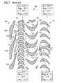
図1は、第1の段階102と第2の段階104とを具備する、従来の二段階式タービン100を示す。第1のタービン段階102は、複数の第1の案内羽根106aと、複数の第1の回転子翼108aを有する第1の回転子108と、を有する第1の案内羽根装置106を具備する。第2のタービン段階104は、複数の第2の案内羽根110aと、複数の第2の回転子翼112aを有する第2の回転子112と、を有する第2の案内羽根装置110を具備する。第1と第2の案内羽根装置106、110の案内羽根106a、110aがタービンマニホールド及び/又はタービンハウジング(図示せず)内に静止して設置される一方で、第1と第2の回転子108、112の回転子翼108a、112aは、回転可能なシャフト(軸)(図示せず)に取り付けられるので、従って流体流れFが回転子翼108a、112aに衝突してタービン回転子108、112を駆動する時に、タービンマニホールド及び/又はタービンハウジングに対して回転可能である。 FIG. 1 shows a conventional two-
第1の案内羽根装置106は、第1の回転子108に供給される、流体流れFを制御するように機能する。具体的には、流体流れFは、第1の案内羽根装置106の隣接する案内羽根106aの間に画定される、チャネル(流路)114を介して配向されると偏向されて更に、第1の回転子108がその設計条件において駆動されることを可能にする、角度及び流速において第1の回転子108の回転子翼108aに、流体流れFが供給されるように加速される。同様に、第2の案内羽根装置110は、第2の回転子112に供給される流体流れF’を制御するように機能する。具体的には、流体流れF'は、第2の案内羽根装置110の隣接する案内羽根110aの間に画定される、チャネル116を介して配向されると偏向されて更に、流体流れFが第2の回転子112の回転子翼112aに、第2の回転子112がその設計条件において駆動されることを可能にする、流れ角度及び流速において供給されるように加速されてもよい。 The first
案内羽根装置106、110のチャネル114、116内の流体流れF、F’の偏向及び加速は、案内羽根装置106、110の設計、即ち個々の案内羽根106a、110aの形状及び寸法、並びに隣接する案内羽根106a、110aの間の間隔に依存する。第1の案内羽根装置106において、隣接する案内羽根106aの間に画定されたチャネル114は、1つの案内羽根106aの前面119の一部と隣接する案内羽根の後面120の一部との間に画定された流れ膨張領域118を具備する。流れ膨張領域118を介して流れると、第1の回転子108に供給されるべき流体流れFは、所望の速度まで、図示の例においてMABS=1.10 / MREL=0.73まで加速される。 The deflection and acceleration of the fluid flows F, F ′ in the
加えて、図2から明らかになるように、流体流れFは、それ(流体流れF)が流体流れFと案内羽根106aの後縁部122により画定される仮想平面Pとの間に画定される、流れ角度αFoutにおいて流路114から出るように偏向される。一般的に、流体流れFと仮想平面Pとの間に画定される流れ角度αFoutは、案内羽根106aの後面120と案内羽根106aの後縁部122により画定される仮想平面Pとの間に画定される、角度αoutに実質的に対応する。図1に示される例示的なタービン100において、約20度の流れ角度αFoutにおいて第1の案内羽根装置106から出る流体流れFは、流体流れFが第1の回転子108の回転子翼108aにα=67.2度及びβ=58.0度の所望の流れ角度で供給されることを確保する。In addition, as will be apparent from FIG. 2, the fluid flow F is defined between the fluid flow F and a virtual plane P defined by the trailing
第1の案内羽根装置106において、案内羽根106aの後面120と案内羽根106aの後縁部122により画定される仮想平面Pとの間に画定される角度αoutは、約15度、即ち<25度である。しかしながら、それは、角度が25度よりも大きい場合であってもよい。結果として、付加製造法により第1の案内羽根装置106を製造することは、図2において参照番号124により指定される、支持構造の提供を必要とする。特に、チャネル114の流れの横断面が小さいことにより、チャネル114の流れ膨張領域118において及びそれに隣接して伸びる、支持構造124の一部分124aを取り外すことは非常に困難である。In the first
本発明による案内羽根装置10は、図3に示される。案内羽根装置10は、第1の案内羽根12と第2の案内羽根14とを具備する。流路16が第1の案内羽根12の前面18と第2の案内羽根14の後面20との間に画定されるように、第2の案内羽根14は、第1の案内羽根12に隣接して配置される。案内羽根装置10がタービン内に設置される時に、案内羽根装置10の下流に設置される、回転子の回転子翼に流体流れFを案内するように、流路16は機能する。 A
図3は、単一の第1の案内羽根12と単一の第2の案内羽根14のみを示す。しかしながら、案内羽根装置10は、お互いに隣接するように配置されて複数の流路114を画定する、複数の第1と第2の案内羽根12、14を備える。案内羽根装置10の案内羽根12、14は、同一の形状及び寸法である。従って、図3の構成において、第1の案内羽根12の右側に配置された第2の案内羽根14に対して第1の案内羽根12を構成する、案内羽根は、第1の案内羽根12左側に配置された別の案内羽根(図3に示されない)に対して第2の案内羽根を構成する。 FIG. 3 shows only a single
第1と第2の案内羽根12、14は、お互いに、且つ図3において点線で概略的に示されるキャリア(支持部)構造22と、一体的に形成される。キャリア構造22は、例えば、回転対称なタービンマニホールド及び/又はタービンハウジングの形態で設計されてもよく、それ(タービンマニホールド及び/又はタービンハウジング)に対して、案内羽根装置10の個々の案内羽根12、14は、案内羽根装置10の下流のタービン内に設置されるべき回転子に供給されるべき、流体流れFのための案内格子を形成するように取り付けられる。 The first and
第1の案内羽根12の前面18は、第1の案内羽根12の前縁部26に隣接して配置された入口部分24と、第1の案内羽根12の後縁部30に隣接して配置された出口部分28と、を具備する。第1の案内羽根12の前面18と共に流路16を画定する、第2の案内羽根14の後面20は、第2の案内羽根14の後縁部34に隣接して配置された後部分32と、第2の案内羽根14の前縁部38に隣接して配置された前部分36と、後部分32と前部分36との間に配置された中間部分40と、を具備する。 The
第1の案内羽根12の前面18の入口部分24は、流路18の中心軸線Cに対して、第2の案内羽根14の後面20の前部分36に対向して配置されており、そして第2の案内羽根14の後面20の前部分36と共に、流路16の制限部分42を画定する。流路16の制限部分42は、流路16を介して流れる流体流れFの流れ方向において減少する、流れ断面を有する。従って、流体流れFは、制限部分42を介して案内される時に加速される、即ち制限部分42を出る時に、流体流れFは、第1と第2の案内羽根12、14の前縁部26、38の領域内の流路16に入る時の流体流れFの流速よりも速い流速を有する。 The
図3から明らかになるように、第2の案内羽根14の後面20の後部分32は、第1と第2の案内羽根12、14の後縁部30、34により画定される仮想平面Pに対して第1の角度αoutにおいて伸びる。案内羽根装置10の運転中に、流体流れFは、後部分32に沿って案内され、それにより、流体流れFは、第1の角度αoutに実質的に対応する、仮想平面Pに対する第1の流れ角度αFoutにおいて流路16から出るように偏向される。As can be seen from FIG. 3, the
第2の案内羽根14の後面20の前部分36は、第1と第2の案内羽根12、14の後縁部30、34により画定される仮想平面Pに対して第2の角度αinで伸びる。案内羽根装置10の運転中に、流体流れFは、後部分32に沿って案内される前に、前部分36に沿って案内され、それにより、前部分36の領域において、第2の角度αinに実質的に対応する、仮想平面Pに対する第2の流れ角度αFinにおいて、流体流れFが流れるように偏向される。The
第2の案内羽根14の後面20の中間部分40は、第1と第2の案内羽根12、14の後縁部30、34により画定される仮想平面Pに対して第3の角度αinterにおいて伸びる。案内羽根装置10の運転中に、流体流れFは、中間部分40に沿って案内され、それにより、中間部分40の領域内において、流体流れFが第3の角度αinterに実質的に対応する、仮想平面Pに対する第3の流れ角度αFinterにおいて流れるように偏向される。The intermediate portion 40 of the
第2の角度αinは、第1の角度αoutより大きく、第3の角度αinterは、第1の角度αoutより小さい。同様に、第2の流れ角度αFinは、第1の流れ角度αFoutより大きく、第3の流れ角度αFinterは、第1の流れ角度αFoutより小さい。図3に示される案内羽根装置10の例示的な実施の形態において、第1の角度αout及び第1の流れ角度αFoutは約25度であり、第2の角度αin及び第2の流れ角度αFinは約60度であり、そして第3の角度αinter及び第3の流れ角度αFinterは約10度である。The second angle αin is larger than the first angle αout , and the third angle αinter is smaller than the first angle αout . Similarly, the second flow angle αFin is larger than the first flow angle αFout , and the third flow angle αFinter is smaller than the first flow angle αFout . In the exemplary embodiment of the
更に、案内羽根12、14は、第2の案内羽根14の後面20の前部分36の仮想平面Pへの投影PR1が、第1の案内羽根12の前面18の出口部分28の仮想平面Pへの投影PR0と実質的に一致する一方で、第2の案内羽根14の後面20の中間部分40及び後部分32の仮想平面の投影PRi、PRtが、第1の案内羽根12の前面18の出口部分28の仮想平面Pへの投影と一致しないようにお互いに対して設計され且つ配置される。従って、案内羽根12、14の後縁部30、34の方向から見た時に、第2の案内羽根14の後面20の前部分36だけが第1の案内羽根14の前面18の出口部分28により覆われるのに反して、第2の案内羽根14の後面20の中間部分40及び後部分32は、自由に接近可能である。 Further, the projections PR1 of the
第2の案内羽根14の後面20は更に、第1の移行部分44を備える。第1の移行部分44は、前部分36と中間部分40との間において配置されており、及び流路の中心軸線Cに対して、第1の案内羽根12の前面18の出口部分28に対向して配置される。流路16の中心軸線Cに対して、第1の移行部分44は、凸状の曲率を有する。第1の移行部分44及び第1の案内羽根12の前面18の出口部分28は、流体流れFの流れ方向において増大する、流れ断面を有する、流路16の膨張部分46を画定する。 The
流路16は一般的に、流体流れFが、流路16を出る時に所望の第1の流速Moutで流れることを確保する設計を有する。しかしながら、膨張部分46は、流体流れFが膨張部分46を流れる時に所望の第1の流速Moutよりも速い第2の流速Mexpまで加速されるように設計される。言い換えれば、膨張部分46は、流体流れFの過膨張をもたらす。The
最後に、第2の案内羽根14の後面20は、中間部分40と後部分32との間に配置されていて且つ流路16の中心軸線Cに対して凹状の曲率を有する、第2の移行部分48を備える。案内羽根装置10はまた、44と後縁部34との間において後面20の全長に沿って伸びる、緩やかな曲線により設計されてもよい。その場合において、部分40及び32は、一点に落ち込み、そして角度αinter及びαoutは、移行部分48の始点及び終点における壁の傾斜を画定する。Finally, the
第2の移行部分48は、流路16を介して流れる流体流れFの流れ方向において減少する、流れ断面を有する再圧縮部分50を画定する。再圧縮部分50は、流体流れFが再圧縮部分50を介して流れる時に、所望の第1の流速Moutまで減速されるように設計される。従って、再圧縮部分50は、膨張部分46内の流体流れFの過膨張の補償を提供する。The second
案内羽根装置10の作動中に、制限部分42と膨張部分46と再圧縮部分50は、流体流れFが所望の第1の流速Moutにおいて流路16を出ることを確保するように流体流れFの流速を制御する。同時に、案内羽根12、14の設計により、付加製造法による案内羽根装置10の製造が可能になる。特に、図3に示される案内羽根装置10の例示的な実施の形態において約60度である、第2の角度αinは、支持構造による支持なしで、付加製造法により第2の案内羽根14の後面20の前部分36の製造を可能にする。従って、第2の案内羽根14の後面20の前部分36を、第1の案内羽根12の前面18の出口部分28により覆うことにより接近することが困難である、支持構造を取り外す手順は、省略可能である。During operation of the
それとは反対に、付加製造法において案内羽根装置10を層状に形成すると、少なくとも低角度の中間部分40、及び必要であれば、第2の案内羽根14の後面20の後部分32もまた、取り外し可能な支持構造Sにより支持される。しかしながら、案内羽根装置10の設計は、第2の案内羽根14の後面20の中間部分40及び後部分32への妨げられない接近を可能にするので、支持構造Sは、案内羽根装置10の層状形成の完成後に容易に取り外すことができる。付加製造法により、キャリア構造22及び案内羽根12、14は、一体的に製造可能である。 On the contrary, when the
図3に示されるような本発明による案内羽根装置10は、超音速タービンにおける使用に適しており、そして同じ基本原理を用いること(後縁部30及び34により画定される、出口平面Pにおける平均設計流速及び平均設計角度を得るように、後面20に沿って輪郭を調整すること)は、亜音速タービンにも同様に適用可能である。 The
Claims (15)
Translated fromJapanese第1の案内羽根(12)と、
第2の案内羽根(14)であって、前記第2の案内羽根(14)が前記第1の案内羽根(12)に隣接して配置されるので、流路(16)が、前記第1の案内羽根(12)の前面(18)と前記第2の案内羽根(14)の後面(20)との間に画定される、第2の案内羽根(14)と、を具備する案内羽根装置において、
前記第2の案内羽根(14)の前記後面(20)が、
前記第2の案内羽根(14)の後縁部(34)に隣接して配置されていて且つ前記第1の案内羽根(12)の後縁部(30)と前記第2の案内羽根(14)の前記後縁部(34)とにより画定される、仮想平面(P)に対して第1の角度(αout)において配置される、後部分(32)と、
前記第2の案内羽根(14)の前縁部(38)に隣接して配置されていて且つ前記第1の案内羽根(12)の前記後縁部(30)と前記第2の案内羽根(14)の前記後縁部(34)とにより画定される、前記仮想平面(P)に対して第2の角度(αin)において配置される、前部分(36)であって、前記第2の角度(αin)が前記第1の角度(αout)より大きい、前部分(36)と、
前記後部分(32)と前記前部分(36)との間に配置されていて且つ前記第1の案内羽根(12)の前記後縁部(30)と前記第2の案内羽根(14)の前記後縁部(34)により画定される、前記仮想平面(P)に対して第3の角度(αinter)において配置される、中間部分(40)であって、前記第3の角度(αinter)が前記第1の角度(αout)よりも小さい、中間部分(40)と、を具備することを特徴とする案内羽根装置(10)。A guide vane device (10), in particular for use in a turbo pump, which device (10)
A first guide vane (12);
A second guide vane (14), wherein the second guide vane (14) is disposed adjacent to the first guide vane (12); A guide vane device comprising a second guide vane (14) defined between a front surface (18) of the guide vane (12) and a rear surface (20) of the second guide vane (14). In
The rear surface (20) of the second guide vane (14) is
The second guide vane (14) is arranged adjacent to the rear edge (34), and the first guide vane (12) has a rear edge (30) and the second guide vane (14). A rear portion (32) disposed at a first angle (αout ) relative to the imaginary plane (P), defined by said rear edge (34) of
The second guide vane (14) is disposed adjacent to the front edge (38) and the rear edge (30) of the first guide vane (12) and the second guide vane ( A front portion (36) disposed at a second angle (αin ) with respect to the virtual plane (P) defined by the trailing edge (34) of The front portion (36), wherein the angle (αin ) is greater than the first angle (αout );
Between the rear portion (32) and the front portion (36) and of the rear edge (30) of the first guide vane (12) and the second guide vane (14). An intermediate portion (40) disposed at a third angle (αinter ) relative to the imaginary plane (P) defined by the trailing edge (34), wherein the third angle (αThe guide vane device (10), comprising an intermediate portion (40), wherein theinter ) is smaller than the first angle (αout ).
前記第1の案内羽根(12)の前縁部(26)に隣接して配置されていて且つ前記流路(16)の中心軸線(C)に対して、前記第2の案内羽根(14)の前記後面(20)の前記前部分(36)に対向して配置される、入口部分(24)であって、前記第1の案内羽根(12)の前記前面(18)の前記入口部分(24)及び前記第2の案内羽根(14)の前記後面(20)の前記前部分(36)が、前記流路(16)を介して流れる流体流れ(F)の流れ方向において減少する、流れ断面を有する前記流路(16)の制限部分(42)を画定することが好ましい、入口部分(24)と、
前記第1の案内羽根(12)の後縁部(30)に隣接して配置された出口部分(28)であって、前記第2の案内羽根(14)の前記後面(20)の前記前部分(36)の前記仮想平面(P)への投影は、前記第1の案内羽根(12)の前記前面(18)の前記出口部分(28)の前記仮想平面(P)への投影と少なくとも部分的に一致することが好ましい、出口部分(28)との内の少なくとも1つを具備する、ことを特徴とする請求項1に記載の案内羽根装置。The front surface (18) of the first guide vane (12) is
The second guide vane (14) disposed adjacent to the front edge (26) of the first guide vane (12) and with respect to the central axis (C) of the flow path (16). An inlet portion (24) disposed opposite the front portion (36) of the rear surface (20) of the first guide vane (12), the inlet portion (24) of the front surface (18). 24) and the front portion (36) of the rear surface (20) of the second guide vane (14) decreases in the flow direction of the fluid flow (F) flowing through the flow path (16). An inlet portion (24), preferably defining a restricting portion (42) of the flow path (16) having a cross-section;
An outlet portion (28) disposed adjacent to a rear edge (30) of the first guide vane (12), the front of the rear surface (20) of the second guide vane (14) Projection of the portion (36) onto the virtual plane (P) is at least as projected onto the virtual plane (P) of the outlet portion (28) of the front surface (18) of the first guide vane (12). 2. A guide vane device according to claim 1, characterized in that it comprises at least one of an outlet part (28), preferably partly coincident.
前記第1の移行部分(44)は、前記前部分(36)と前記中間部分(40)との間に配置されており、前記流路(16)の前記中心軸線(C)に対して、前記第1の案内羽根(12)の前記前面(18)の前記出口部分(28)に対向して配置されており、及び/又は、前記流路(16)の前記中心軸線(C)に対して凸状曲率を有しており、
前記流路(16)は、特に、前記流路(16)を出る時に、前記流体流れ(F)が所望の第1の流速(Mout)において流れるように設計されており、
前記第1の移行部分(44)及び前記第1の案内羽根(12)の前記前面(18)の前記出口部分(28)は、前記流路(16)を介して流れる前記流体流れの流れ方向において増大する、流れ断面を有する、前記流路(16)の膨張部分(46)を画定することが好ましく、更に、
前記膨張部分(46)は、特に、前記膨張部分(46)を介して流れる時に、前記流体流れ(F)が前記所望の第1の流速(Mout)よりも高い第2の流速(Mexp)まで加速されるように設計される、ことを特徴とする請求項1〜3のいずれか一項に記載の案内羽根装置。The rear face (20) of the second guide vane (14) further comprises a first transition part (44);
The first transition portion (44) is disposed between the front portion (36) and the intermediate portion (40), and with respect to the central axis (C) of the flow path (16), The first guide vane (12) is disposed opposite the outlet portion (28) of the front face (18) and / or with respect to the central axis (C) of the flow path (16) And has a convex curvature,
The flow path (16) is specifically designed such that upon exiting the flow path (16), the fluid flow (F) flows at a desired first flow rate (Mout );
The outlet direction (28) of the front face (18) of the first transition part (44) and the first guide vane (12) is flow direction of the fluid flow flowing through the flow path (16). Preferably defining an inflated portion (46) of the flow path (16) having a flow cross section that increases at
The expansion portion (46) has a second flow rate (Mexp) in which the fluid flow (F) is higher than the desired first flow rate (Mout ), particularly when flowing through the expansion portion (46). The guide vane device according to any one of claims 1 to 3, wherein the guide vane device is designed to be accelerated to a maximum.
前記第2の移行部分(48)は、前記中間部分(40)と前記後部分(32)との間に配置されており、及び/又は、前記流路(16)の前記中心軸線(C)に対して凹状の曲率を有しており、
前記第2の移行部分(48)は、前記流路(16)を介して流れる前記流体流れ(F)の流れ方向において減少する、流れ断面を有する、前記流路(16)の再圧縮部分(50)を画定することが好ましく、
前記再圧縮部分(50)は、特に、前記流体流れ(F)が、前記再圧縮部分(50)を介して流れる際に、前記所望の第1の流速(Mout)まで減速されるように設計される、ことを特徴とする請求項1〜4のいずれか一項に記載の案内羽根装置。The rear face (20) of the second guide vane (14) further comprises a second transition portion (48);
The second transition portion (48) is disposed between the intermediate portion (40) and the rear portion (32) and / or the central axis (C) of the flow path (16). With a concave curvature,
The second transitional portion (48) has a flow cross-section, a recompressed portion of the flow path (16) that decreases in the flow direction of the fluid flow (F) flowing through the flow path (16) 50) is preferably defined,
The recompressing portion (50) is particularly slowed down to the desired first flow rate (Mout ) as the fluid flow (F) flows through the recompressing portion (50). It is designed, The guide blade apparatus as described in any one of Claims 1-4 characterized by the above-mentioned.
前記第2の角度(αin)は、特に、25度よりも大きく、好適には30度よりも大きく、そして特に好適には35度よりも大きい、ことを特徴とする請求項1〜5のいずれか一項に記載の案内羽根装置。The second angle (αin ) is not supported by a detachable support structure, but by an additional manufacturing method of the front portion (36) of the rear surface (20) of the second guide vane (14). Have been selected to enable manufacturing,
The second angle (αin ) is in particular greater than 25 degrees, preferably greater than 30 degrees and particularly preferably greater than 35 degrees. A guide vane device given in any 1 paragraph.
第1の案内羽根(12)の前面(18)と第2の案内羽根(14)の後面(20)との間に画定された、流路(16)に流体流れ(F)を供給する手順と、
前記第2の案内羽根(14)の後縁部(34)に隣接して配置された、前記第2の案内羽根(14)の前記後面(20)の後部分(32)に沿って前記流体流れ(F)を案内する手順であって、それにより前記流体流れ(F)が前記第1の案内羽根(12)の後縁部(30)と前記第2の案内羽根(14)の前記後縁部(34)とにより画定される、仮想平面(P)に対して第1の流れ角度(αFout)において流路(16)を出るように、前記流体流れ(F)を偏向させる手順と、を具備する方法において、
前記流体流れ(F)は、前記後面(20)の前記後部分(32)に沿って案内される前に、前記第2の案内羽根(14)の前縁部(38)に隣接して配置された、前記第2の案内羽根(14)の前記後面(20)の前部分(36)に沿って、前記流体流れ(F)が案内されており、それにより前記流体流れ(F)が前記第1の案内羽根(12)の前記後縁部(30)と前記第2の案内羽根(14)の前記後縁部(34)とにより画定される、前記仮想平面(P)に対して第2の流れ角度(αFin)において流れるように偏向されており、前記第2の流れ角度(αFin)は、前記第1の流れ角度(αFout)より大きく、
そしてその後、前記流体流れ(F)は、前記後部分(32)と前記前部分(36)との間に配置された、第2の案内羽根(14)の前記後面(20)の中間部分(40)に沿って案内されており、それにより前記第1の案内羽根(12)の前記後縁部(30)と前記第2の案内羽根(14)の前記後縁部(34)とにより画定される、前記仮想平面(P)に対して第3の流れ角度(αFinter)において、前記流体流れ(F)が流れるように偏向されており、前記第3の流れ角度(αFinter)は、前記第1の流れ角度(αFout)よりも小さい、ことを特徴とする案内羽根装置の運転方法。A method of operating the guide vane device (10),
Procedure for supplying fluid flow (F) to the flow path (16) defined between the front surface (18) of the first guide vane (12) and the rear surface (20) of the second guide vane (14). When,
The fluid along the rear portion (32) of the rear surface (20) of the second guide vane (14), which is disposed adjacent to the rear edge (34) of the second guide vane (14). A procedure for guiding a flow (F), whereby the fluid flow (F) causes the rear edge (30) of the first guide vane (12) and the rear of the second guide vane (14). Deflecting said fluid flow (F) to exit the flow path (16) at a first flow angle (αFout ) relative to an imaginary plane (P) defined by an edge (34); In a method comprising:
The fluid flow (F) is disposed adjacent to the front edge (38) of the second guide vane (14) before being guided along the rear portion (32) of the rear surface (20). The fluid flow (F) is guided along the front portion (36) of the rear surface (20) of the second guide vane (14), whereby the fluid flow (F) is With respect to the virtual plane (P) defined by the trailing edge (30) of the first guide vane (12) and the trailing edge (34) of the second guide vane (14). 2 flow angle (alphaFin) are deflected to flow in, the second flow angle (alphaFin), the first flow angle (alphaFout) greater than,
And after that, the fluid flow (F) flows between the rear surface (20) of the second guide vane (14) disposed between the rear portion (32) and the front portion (36) ( 40) and thereby defined by the rear edge (30) of the first guide vane (12) and the rear edge (34) of the second guide vane (14). The fluid flow (F) is deflected so as to flow at a third flow angle (αFilter ) with respect to the virtual plane (P), and the third flow angle (αFilter ) is The operation method of the guide vane device, characterized in that it is smaller than the first flow angle (αFout ).
前記流体流れ(F)の流速は、前記第1の案内羽根(12)の前記前面(18)の前記入口部分(24)と前記第2の案内羽根(14)の前記後面(20)の前記前部分(36)とにより画定されていて且つ前記流路(16)を介して流れる前記流体流れ(F)の流れ方向において減少する、流れ断面を有する、前記流路(16)の制限部分(42)を介して案内される時に加速される、ことを特徴とする請求項8に記載の方法。The front surface (18) of the first guide vane (12) is disposed adjacent to the front edge (26) of the first guide vane (12) and is the center of the flow path (16). An inlet portion (24) disposed opposite the front portion (36) of the rear surface (20) of the second guide vane (14) with respect to the axis (C); and The flow rate of the fluid flow (F) is such that the inlet portion (24) of the front face (18) of the first guide vane (12) and the rear face (20) of the second guide vane (14) are the same. A restricting portion of the flow path (16) having a flow cross section defined by a front portion (36) and decreasing in the flow direction of the fluid flow (F) flowing through the flow path (16) 42. The method according to claim 8, wherein the vehicle is accelerated when guided through 42). Law.
前記前部分(36)と前記中間部分(40)との間に配置されており、
前記流路(16)の前記中心軸線(C)に対して、前記第1の案内羽根(12)の後縁部(30)に隣接して配置される、前記第1の案内羽根(12)の前記前面(18)の出口部分(28)に対向して配置されており、及び/又は、
前記流路(16)の前記中心軸線(C)に対して、凸状曲率を有しており、
前記流路(16)内の前記流体流れ(F)の流速は、前記流路(16)を出る時に前記流体流れ(F)が所望の第1の流速(Mout)において流れるように制御されており、そして、
前記流体流れ(F)の流速は、前記第1の移行部分(44)と前記第1の案内羽根(12)の前記前面(18)の前記出口部分(28)とにより画定されていて且つ前記流路(16)を介して流れる前記流体流れ(F)の前記流れ方向において増大する流れ断面を有する、前記流路(16)の膨張部分(46)を介して案内される時に、前記所望の第1の流速(Mout)より高い、第2の流速(Mexp)まで加速される、ことを特徴とする請求項8又は9に記載の方法。The rear surface (20) of the second guide vane (14) further comprises a first transition portion (44), the first transition portion (44)
Disposed between the front portion (36) and the intermediate portion (40);
The first guide vane (12) disposed adjacent to the rear edge (30) of the first guide vane (12) with respect to the central axis (C) of the flow path (16). Disposed opposite the outlet portion (28) of the front surface (18) and / or
It has a convex curvature with respect to the central axis (C) of the flow path (16),
The flow rate of the fluid flow (F) in the flow path (16) is controlled such that the fluid flow (F) flows at a desired first flow rate (Mout ) upon exiting the flow path (16). And
The flow velocity of the fluid flow (F) is defined by the first transition portion (44) and the outlet portion (28) of the front surface (18) of the first guide vane (12) and When guided through an expansion portion (46) of the flow path (16) having a flow cross-section increasing in the flow direction of the fluid flow (F) flowing through the flow path (16), the desired flow first higher flow rate(M out), is accelerated to a second flow rate (Mexp), the method of claim 8 or 9, characterized in that.
前記第2の移行部分(48)は、前記中間部分(40)と前記後部(32)との間に配置されており、及び/又は、前記流路(16)の前記中心軸線(C)に対して、凹状曲率を有しており、
前記流体流れ(F)の前記流速は、前記第2の移行部分(48)により画定されていて且つ前記流路(16)を介して流れる前記流体流れ(F)の前記流れ方向において減少する流れ断面を有する、前記流路(16)の再圧縮部分(50)を介して案内される時に、前記所望の第1の流速(Mout)まで減速される、ことを特徴とする請求項8〜10のいずれか一項に記載の方法。The rear face (20) of the second guide vane (14) further comprises a second transition portion (48);
The second transition part (48) is arranged between the intermediate part (40) and the rear part (32) and / or on the central axis (C) of the flow path (16). On the other hand, it has a concave curvature,
The flow velocity of the fluid flow (F) is defined by the second transition portion (48) and decreases in the flow direction of the fluid flow (F) flowing through the flow path (16). The decelerated to the desired first flow rate (Mout ) when guided through a recompressing portion (50) of the flow path (16) having a cross-section. The method according to any one of 10 above.
Applications Claiming Priority (2)
| Application Number | Priority Date | Filing Date | Title |
|---|---|---|---|
| EP18172093.9AEP3569817B1 (en) | 2018-05-14 | 2018-05-14 | Guide vane arrangement for use in a turbine |
| EP18172093.9 | 2018-05-14 |
Publications (2)
| Publication Number | Publication Date |
|---|---|
| JP2019206965Atrue JP2019206965A (en) | 2019-12-05 |
| JP7461111B2 JP7461111B2 (en) | 2024-04-03 |
Family
ID=62165441
Family Applications (1)
| Application Number | Title | Priority Date | Filing Date |
|---|---|---|---|
| JP2019091136AActiveJP7461111B2 (en) | 2018-05-14 | 2019-05-14 | Guide vane arrangement for use in a turbine - Patents.com |
Country Status (3)
| Country | Link |
|---|---|
| US (1) | US11536146B2 (en) |
| EP (1) | EP3569817B1 (en) |
| JP (1) | JP7461111B2 (en) |
Families Citing this family (2)
| Publication number | Priority date | Publication date | Assignee | Title |
|---|---|---|---|---|
| US11033992B2 (en) | 2018-10-05 | 2021-06-15 | Pratt & Whitney Canada Corp. | Double row compressor stators |
| GB202301166D0 (en)* | 2023-01-27 | 2023-03-15 | Rolls Royce Plc | A gas turbine engine |
Citations (4)
| Publication number | Priority date | Publication date | Assignee | Title |
|---|---|---|---|---|
| JPH08232603A (en)* | 1994-12-27 | 1996-09-10 | Soc Europ Propulsion <Sep> | Supersonic distributor for inlet step of turbomachinery |
| US20050079060A1 (en)* | 2003-10-11 | 2005-04-14 | Macmanus David | Turbine blades |
| JP2006177341A (en)* | 2004-12-21 | 2006-07-06 | United Technol Corp <Utc> | Guide vane and stator vane of turbine engine |
| WO2017085383A1 (en)* | 2015-11-17 | 2017-05-26 | Safran Aircraft Engines | Method for manufacturing a blade preform, a blade and a nozzle segment by selective powder-bed fusion |
Family Cites Families (14)
| Publication number | Priority date | Publication date | Assignee | Title |
|---|---|---|---|---|
| US901228A (en)* | 1907-01-28 | 1908-10-13 | Guy B Collier | Turbo-pump. |
| BE529689A (en)* | 1953-06-18 | |||
| CH427851A (en)* | 1965-04-01 | 1967-01-15 | Bbc Brown Boveri & Cie | Blade ring for transonic flow |
| JPS55123301A (en)* | 1979-03-16 | 1980-09-22 | Hitachi Ltd | Turbine blade |
| US4609328A (en)* | 1980-06-18 | 1986-09-02 | Ctp Partners | Method and apparatus for total energy systems |
| US5073335A (en)* | 1990-07-10 | 1991-12-17 | General Electric Company | Bwr turbopump recirculation system |
| US5697767A (en)* | 1991-08-23 | 1997-12-16 | Boeing North American, Inc. | Integrated turbine and pump assembly |
| US6116856A (en)* | 1998-09-18 | 2000-09-12 | Patterson Technique, Inc. | Bi-directional fan having asymmetric, reversible blades |
| JP3047292B1 (en)* | 1998-11-24 | 2000-05-29 | セイコー精機株式会社 | Turbo molecular pump and vacuum device |
| JP4519185B2 (en)* | 2008-07-22 | 2010-08-04 | 株式会社大阪真空機器製作所 | Turbo molecular pump |
| JP5603800B2 (en)* | 2011-02-22 | 2014-10-08 | 株式会社日立製作所 | Turbine stationary blade and steam turbine equipment using the same |
| GB201419951D0 (en)* | 2014-11-10 | 2014-12-24 | Rolls Royce Plc | A guide vane |
| EP3025809B1 (en)* | 2014-11-28 | 2017-11-08 | Ansaldo Energia IP UK Limited | Method for manufacturing a component using an additive manufacturing process |
| US10376958B2 (en)* | 2016-09-15 | 2019-08-13 | General Electric Company | Removable support for additive manufacture |
- 2018
- 2018-05-14EPEP18172093.9Apatent/EP3569817B1/enactiveActive
- 2019
- 2019-05-13USUS16/410,329patent/US11536146B2/enactiveActive
- 2019-05-14JPJP2019091136Apatent/JP7461111B2/enactiveActive
Patent Citations (4)
| Publication number | Priority date | Publication date | Assignee | Title |
|---|---|---|---|---|
| JPH08232603A (en)* | 1994-12-27 | 1996-09-10 | Soc Europ Propulsion <Sep> | Supersonic distributor for inlet step of turbomachinery |
| US20050079060A1 (en)* | 2003-10-11 | 2005-04-14 | Macmanus David | Turbine blades |
| JP2006177341A (en)* | 2004-12-21 | 2006-07-06 | United Technol Corp <Utc> | Guide vane and stator vane of turbine engine |
| WO2017085383A1 (en)* | 2015-11-17 | 2017-05-26 | Safran Aircraft Engines | Method for manufacturing a blade preform, a blade and a nozzle segment by selective powder-bed fusion |
Also Published As
| Publication number | Publication date |
|---|---|
| EP3569817B1 (en) | 2020-10-14 |
| US11536146B2 (en) | 2022-12-27 |
| JP7461111B2 (en) | 2024-04-03 |
| EP3569817A1 (en) | 2019-11-20 |
| US20190345834A1 (en) | 2019-11-14 |
Similar Documents
| Publication | Publication Date | Title |
|---|---|---|
| US11098601B2 (en) | Diffuser-deswirler for a gas turbine engine | |
| US3904308A (en) | Supersonic centrifugal compressors | |
| US11480106B2 (en) | Acoustic liner with obliquely angled slots | |
| US9011084B2 (en) | Steam turbine stator vane and steam turbine using the same | |
| US3184152A (en) | Supersonic compressors | |
| US10767489B2 (en) | Component for a turbine engine with a hole | |
| GB2465337A (en) | Cooling arrangement for a gas turbine engine component | |
| RU2670650C9 (en) | Turbine blade | |
| JP2016501341A (en) | Angel Wing of Turbine Blade with Pump Mechanism | |
| JP2019206965A (en) | Guide vane arrangement for use in turbine | |
| JPH08232603A (en) | Supersonic distributor for inlet step of turbomachinery | |
| JP2016539276A (en) | Curved diffusion channel section of centrifugal compressor | |
| WO2015072256A1 (en) | Vane structure for axial flow turbomachine and gas turbine engine | |
| US11708762B2 (en) | Film cooling structure and turbine blade for gas turbine engine | |
| US20240209738A1 (en) | Turbomachine cooling trench | |
| JP2017198200A (en) | Gas turbine engine transition duct and turbine center frame | |
| US11162613B2 (en) | Flow conditioner for a valve assembly | |
| US3610775A (en) | Turbine wheel | |
| JP3578692B2 (en) | Turbo compressor | |
| WO2000061918A2 (en) | Airfoil leading edge vortex elimination device | |
| JP5427900B2 (en) | Mixed flow turbine | |
| JPH04334798A (en) | Diffuser for centrifugal fluid machinery | |
| JP5470285B2 (en) | Axial flow turbine | |
| JPH09158703A (en) | Axial turbine | |
| CN116615375A (en) | Nacelle air intakes for aircraft propulsion assemblies facilitating thrust reversal phases |
Legal Events
| Date | Code | Title | Description |
|---|---|---|---|
| A621 | Written request for application examination | Free format text:JAPANESE INTERMEDIATE CODE: A621 Effective date:20220316 | |
| A977 | Report on retrieval | Free format text:JAPANESE INTERMEDIATE CODE: A971007 Effective date:20221221 | |
| A131 | Notification of reasons for refusal | Free format text:JAPANESE INTERMEDIATE CODE: A131 Effective date:20230110 | |
| A601 | Written request for extension of time | Free format text:JAPANESE INTERMEDIATE CODE: A601 Effective date:20230407 | |
| A521 | Request for written amendment filed | Free format text:JAPANESE INTERMEDIATE CODE: A523 Effective date:20230707 | |
| A131 | Notification of reasons for refusal | Free format text:JAPANESE INTERMEDIATE CODE: A131 Effective date:20230919 | |
| A521 | Request for written amendment filed | Free format text:JAPANESE INTERMEDIATE CODE: A523 Effective date:20231214 | |
| TRDD | Decision of grant or rejection written | ||
| A01 | Written decision to grant a patent or to grant a registration (utility model) | Free format text:JAPANESE INTERMEDIATE CODE: A01 Effective date:20240312 | |
| A61 | First payment of annual fees (during grant procedure) | Free format text:JAPANESE INTERMEDIATE CODE: A61 Effective date:20240322 | |
| R150 | Certificate of patent or registration of utility model | Ref document number:7461111 Country of ref document:JP Free format text:JAPANESE INTERMEDIATE CODE: R150 |