JP2019205915A - Fiber optic sensor guided navigation for vascular visualization and monitoring - Google Patents
Fiber optic sensor guided navigation for vascular visualization and monitoringDownload PDFInfo
- Publication number
- JP2019205915A JP2019205915AJP2019162613AJP2019162613AJP2019205915AJP 2019205915 AJP2019205915 AJP 2019205915AJP 2019162613 AJP2019162613 AJP 2019162613AJP 2019162613 AJP2019162613 AJP 2019162613AJP 2019205915 AJP2019205915 AJP 2019205915A
- Authority
- JP
- Japan
- Prior art keywords
- blood vessel
- shape
- processor
- blood
- image
- Prior art date
- Legal status (The legal status is an assumption and is not a legal conclusion. Google has not performed a legal analysis and makes no representation as to the accuracy of the status listed.)
- Granted
Links
Images


Classifications
- A—HUMAN NECESSITIES
- A61—MEDICAL OR VETERINARY SCIENCE; HYGIENE
- A61B—DIAGNOSIS; SURGERY; IDENTIFICATION
- A61B5/00—Measuring for diagnostic purposes; Identification of persons
- A61B5/0033—Features or image-related aspects of imaging apparatus, e.g. for MRI, optical tomography or impedance tomography apparatus; Arrangements of imaging apparatus in a room
- A61B5/0036—Features or image-related aspects of imaging apparatus, e.g. for MRI, optical tomography or impedance tomography apparatus; Arrangements of imaging apparatus in a room including treatment, e.g., using an implantable medical device, ablating, ventilating
- A—HUMAN NECESSITIES
- A61—MEDICAL OR VETERINARY SCIENCE; HYGIENE
- A61B—DIAGNOSIS; SURGERY; IDENTIFICATION
- A61B1/00—Instruments for performing medical examinations of the interior of cavities or tubes of the body by visual or photographical inspection, e.g. endoscopes; Illuminating arrangements therefor
- A61B1/00002—Operational features of endoscopes
- A61B1/00004—Operational features of endoscopes characterised by electronic signal processing
- A61B1/00009—Operational features of endoscopes characterised by electronic signal processing of image signals during a use of endoscope
- A61B1/000094—Operational features of endoscopes characterised by electronic signal processing of image signals during a use of endoscope extracting biological structures
- A—HUMAN NECESSITIES
- A61—MEDICAL OR VETERINARY SCIENCE; HYGIENE
- A61B—DIAGNOSIS; SURGERY; IDENTIFICATION
- A61B17/00—Surgical instruments, devices or methods
- A61B17/00008—Vein tendon strippers
- A—HUMAN NECESSITIES
- A61—MEDICAL OR VETERINARY SCIENCE; HYGIENE
- A61B—DIAGNOSIS; SURGERY; IDENTIFICATION
- A61B17/00—Surgical instruments, devices or methods
- A61B17/0057—Implements for plugging an opening in the wall of a hollow or tubular organ, e.g. for sealing a vessel puncture or closing a cardiac septal defect
- A—HUMAN NECESSITIES
- A61—MEDICAL OR VETERINARY SCIENCE; HYGIENE
- A61B—DIAGNOSIS; SURGERY; IDENTIFICATION
- A61B17/00—Surgical instruments, devices or methods
- A61B17/068—Surgical staplers, e.g. containing multiple staples or clamps
- A—HUMAN NECESSITIES
- A61—MEDICAL OR VETERINARY SCIENCE; HYGIENE
- A61B—DIAGNOSIS; SURGERY; IDENTIFICATION
- A61B34/00—Computer-aided surgery; Manipulators or robots specially adapted for use in surgery
- A61B34/20—Surgical navigation systems; Devices for tracking or guiding surgical instruments, e.g. for frameless stereotaxis
- A—HUMAN NECESSITIES
- A61—MEDICAL OR VETERINARY SCIENCE; HYGIENE
- A61B—DIAGNOSIS; SURGERY; IDENTIFICATION
- A61B34/00—Computer-aided surgery; Manipulators or robots specially adapted for use in surgery
- A61B34/30—Surgical robots
- A—HUMAN NECESSITIES
- A61—MEDICAL OR VETERINARY SCIENCE; HYGIENE
- A61B—DIAGNOSIS; SURGERY; IDENTIFICATION
- A61B5/00—Measuring for diagnostic purposes; Identification of persons
- A61B5/0002—Remote monitoring of patients using telemetry, e.g. transmission of vital signals via a communication network
- A61B5/0026—Remote monitoring of patients using telemetry, e.g. transmission of vital signals via a communication network characterised by the transmission medium
- A—HUMAN NECESSITIES
- A61—MEDICAL OR VETERINARY SCIENCE; HYGIENE
- A61B—DIAGNOSIS; SURGERY; IDENTIFICATION
- A61B5/00—Measuring for diagnostic purposes; Identification of persons
- A61B5/0059—Measuring for diagnostic purposes; Identification of persons using light, e.g. diagnosis by transillumination, diascopy, fluorescence
- A61B5/0082—Measuring for diagnostic purposes; Identification of persons using light, e.g. diagnosis by transillumination, diascopy, fluorescence adapted for particular medical purposes
- A61B5/0084—Measuring for diagnostic purposes; Identification of persons using light, e.g. diagnosis by transillumination, diascopy, fluorescence adapted for particular medical purposes for introduction into the body, e.g. by catheters
- A—HUMAN NECESSITIES
- A61—MEDICAL OR VETERINARY SCIENCE; HYGIENE
- A61B—DIAGNOSIS; SURGERY; IDENTIFICATION
- A61B5/00—Measuring for diagnostic purposes; Identification of persons
- A61B5/02—Detecting, measuring or recording for evaluating the cardiovascular system, e.g. pulse, heart rate, blood pressure or blood flow
- A61B5/02007—Evaluating blood vessel condition, e.g. elasticity, compliance
- A—HUMAN NECESSITIES
- A61—MEDICAL OR VETERINARY SCIENCE; HYGIENE
- A61B—DIAGNOSIS; SURGERY; IDENTIFICATION
- A61B5/00—Measuring for diagnostic purposes; Identification of persons
- A61B5/02—Detecting, measuring or recording for evaluating the cardiovascular system, e.g. pulse, heart rate, blood pressure or blood flow
- A61B5/026—Measuring blood flow
- A61B5/0261—Measuring blood flow using optical means, e.g. infrared light
- A—HUMAN NECESSITIES
- A61—MEDICAL OR VETERINARY SCIENCE; HYGIENE
- A61B—DIAGNOSIS; SURGERY; IDENTIFICATION
- A61B5/00—Measuring for diagnostic purposes; Identification of persons
- A61B5/06—Devices, other than using radiation, for detecting or locating foreign bodies ; Determining position of diagnostic devices within or on the body of the patient
- A61B5/065—Determining position of the probe employing exclusively positioning means located on or in the probe, e.g. using position sensors arranged on the probe
- A—HUMAN NECESSITIES
- A61—MEDICAL OR VETERINARY SCIENCE; HYGIENE
- A61B—DIAGNOSIS; SURGERY; IDENTIFICATION
- A61B5/00—Measuring for diagnostic purposes; Identification of persons
- A61B5/103—Measuring devices for testing the shape, pattern, colour, size or movement of the body or parts thereof, for diagnostic purposes
- A61B5/107—Measuring physical dimensions, e.g. size of the entire body or parts thereof
- A61B5/1076—Measuring physical dimensions, e.g. size of the entire body or parts thereof for measuring dimensions inside body cavities, e.g. using catheters
- A—HUMAN NECESSITIES
- A61—MEDICAL OR VETERINARY SCIENCE; HYGIENE
- A61B—DIAGNOSIS; SURGERY; IDENTIFICATION
- A61B5/00—Measuring for diagnostic purposes; Identification of persons
- A61B5/103—Measuring devices for testing the shape, pattern, colour, size or movement of the body or parts thereof, for diagnostic purposes
- A61B5/107—Measuring physical dimensions, e.g. size of the entire body or parts thereof
- A61B5/1079—Measuring physical dimensions, e.g. size of the entire body or parts thereof using optical or photographic means
- A—HUMAN NECESSITIES
- A61—MEDICAL OR VETERINARY SCIENCE; HYGIENE
- A61B—DIAGNOSIS; SURGERY; IDENTIFICATION
- A61B5/00—Measuring for diagnostic purposes; Identification of persons
- A61B5/48—Other medical applications
- A61B5/4887—Locating particular structures in or on the body
- A61B5/489—Blood vessels
- A—HUMAN NECESSITIES
- A61—MEDICAL OR VETERINARY SCIENCE; HYGIENE
- A61B—DIAGNOSIS; SURGERY; IDENTIFICATION
- A61B5/00—Measuring for diagnostic purposes; Identification of persons
- A61B5/68—Arrangements of detecting, measuring or recording means, e.g. sensors, in relation to patient
- A61B5/6846—Arrangements of detecting, measuring or recording means, e.g. sensors, in relation to patient specially adapted to be brought in contact with an internal body part, i.e. invasive
- A61B5/6847—Arrangements of detecting, measuring or recording means, e.g. sensors, in relation to patient specially adapted to be brought in contact with an internal body part, i.e. invasive mounted on an invasive device
- A—HUMAN NECESSITIES
- A61—MEDICAL OR VETERINARY SCIENCE; HYGIENE
- A61B—DIAGNOSIS; SURGERY; IDENTIFICATION
- A61B5/00—Measuring for diagnostic purposes; Identification of persons
- A61B5/72—Signal processing specially adapted for physiological signals or for diagnostic purposes
- A61B5/7235—Details of waveform analysis
- A61B5/7264—Classification of physiological signals or data, e.g. using neural networks, statistical classifiers, expert systems or fuzzy systems
- A—HUMAN NECESSITIES
- A61—MEDICAL OR VETERINARY SCIENCE; HYGIENE
- A61B—DIAGNOSIS; SURGERY; IDENTIFICATION
- A61B17/00—Surgical instruments, devices or methods
- A61B2017/00743—Type of operation; Specification of treatment sites
- A61B2017/00778—Operations on blood vessels
- A—HUMAN NECESSITIES
- A61—MEDICAL OR VETERINARY SCIENCE; HYGIENE
- A61B—DIAGNOSIS; SURGERY; IDENTIFICATION
- A61B34/00—Computer-aided surgery; Manipulators or robots specially adapted for use in surgery
- A61B34/20—Surgical navigation systems; Devices for tracking or guiding surgical instruments, e.g. for frameless stereotaxis
- A61B2034/2046—Tracking techniques
- A61B2034/2061—Tracking techniques using shape-sensors, e.g. fiber shape sensors with Bragg gratings
- A—HUMAN NECESSITIES
- A61—MEDICAL OR VETERINARY SCIENCE; HYGIENE
- A61B—DIAGNOSIS; SURGERY; IDENTIFICATION
- A61B34/00—Computer-aided surgery; Manipulators or robots specially adapted for use in surgery
- A61B34/30—Surgical robots
- A61B2034/303—Surgical robots specifically adapted for manipulations within body lumens, e.g. within lumen of gut, spine, or blood vessels
- A—HUMAN NECESSITIES
- A61—MEDICAL OR VETERINARY SCIENCE; HYGIENE
- A61B—DIAGNOSIS; SURGERY; IDENTIFICATION
- A61B90/00—Instruments, implements or accessories specially adapted for surgery or diagnosis and not covered by any of the groups A61B1/00 - A61B50/00, e.g. for luxation treatment or for protecting wound edges
- A61B90/36—Image-producing devices or illumination devices not otherwise provided for
- A61B2090/364—Correlation of different images or relation of image positions in respect to the body
- A61B2090/365—Correlation of different images or relation of image positions in respect to the body augmented reality, i.e. correlating a live optical image with another image
- A—HUMAN NECESSITIES
- A61—MEDICAL OR VETERINARY SCIENCE; HYGIENE
- A61B—DIAGNOSIS; SURGERY; IDENTIFICATION
- A61B5/00—Measuring for diagnostic purposes; Identification of persons
- A61B5/06—Devices, other than using radiation, for detecting or locating foreign bodies ; Determining position of diagnostic devices within or on the body of the patient
- A61B5/065—Determining position of the probe employing exclusively positioning means located on or in the probe, e.g. using position sensors arranged on the probe
- A61B5/066—Superposing sensor position on an image of the patient, e.g. obtained by ultrasound or x-ray imaging
- A—HUMAN NECESSITIES
- A61—MEDICAL OR VETERINARY SCIENCE; HYGIENE
- A61B—DIAGNOSIS; SURGERY; IDENTIFICATION
- A61B5/00—Measuring for diagnostic purposes; Identification of persons
- A61B5/68—Arrangements of detecting, measuring or recording means, e.g. sensors, in relation to patient
- A61B5/6846—Arrangements of detecting, measuring or recording means, e.g. sensors, in relation to patient specially adapted to be brought in contact with an internal body part, i.e. invasive
- A61B5/6867—Arrangements of detecting, measuring or recording means, e.g. sensors, in relation to patient specially adapted to be brought in contact with an internal body part, i.e. invasive specially adapted to be attached or implanted in a specific body part
- A61B5/6876—Blood vessel
Landscapes
- Health & Medical Sciences (AREA)
- Life Sciences & Earth Sciences (AREA)
- Engineering & Computer Science (AREA)
- Surgery (AREA)
- Medical Informatics (AREA)
- Public Health (AREA)
- Biomedical Technology (AREA)
- Heart & Thoracic Surgery (AREA)
- Veterinary Medicine (AREA)
- Molecular Biology (AREA)
- Animal Behavior & Ethology (AREA)
- General Health & Medical Sciences (AREA)
- Physics & Mathematics (AREA)
- Biophysics (AREA)
- Pathology (AREA)
- Nuclear Medicine, Radiotherapy & Molecular Imaging (AREA)
- Radiology & Medical Imaging (AREA)
- Robotics (AREA)
- Vascular Medicine (AREA)
- Cardiology (AREA)
- Physiology (AREA)
- Signal Processing (AREA)
- Human Computer Interaction (AREA)
- Dentistry (AREA)
- Artificial Intelligence (AREA)
- Oral & Maxillofacial Surgery (AREA)
- Optics & Photonics (AREA)
- Mathematical Physics (AREA)
- Rheumatology (AREA)
- Evolutionary Computation (AREA)
- Hematology (AREA)
- Fuzzy Systems (AREA)
- Computer Vision & Pattern Recognition (AREA)
- Psychiatry (AREA)
- Computer Networks & Wireless Communication (AREA)
- Endoscopes (AREA)
- Measuring Pulse, Heart Rate, Blood Pressure Or Blood Flow (AREA)
- Media Introduction/Drainage Providing Device (AREA)
- Length Measuring Devices By Optical Means (AREA)
Abstract
Translated fromJapaneseDescription
Translated fromJapanese本開示は、医療機器に関し、より詳細には、内腔の分岐を識別しアクセスする医療的応用における形状検知光ファイバに関する。 The present disclosure relates to medical devices, and more particularly to shape sensing optical fibers in medical applications that identify and access lumen branches.
冠状動脈バイパス移植(coronary artery bypass grafting:CABG)は、閉塞した冠動脈の血管再開通術のための外科的処置である。従来の手術では、患者の胸骨が開かれ、心臓が完全に露出される。この手術の重要な部分は、患者の身体からの血管の除去である。この血管は、次に、冠動脈内の1又は複数のアテローム性狭窄をバイパスするために用いられる。最も一般的に用いられる血管は、胸部内にある内胸動脈(Internal Mammary Artery:IMA)である。使用される多の血管は、伏在静脈(脚)及び橈骨動脈(腕)を含む。 Coronary artery bypass grafting (CABG) is a surgical procedure for revascularization of an obstructed coronary artery. In conventional surgery, the patient's sternum is opened and the heart is fully exposed. An important part of this surgery is the removal of blood vessels from the patient's body. This blood vessel is then used to bypass one or more atherosclerotic stenosis in the coronary artery. The most commonly used blood vessel is the internal mammary artery (IMA) located in the chest. The many blood vessels used include the saphenous vein (leg) and the radial artery (arm).
侵襲の少ない(minimally invasive:MI)バイパス手術は、(例えば、完全な内視鏡的処置のための約5mmの及びMI直接バイパス手術のための約50乃至60mmの開口大を有する)小さなポートを通じて実行される。MI心臓バイパス手術中、バイパスでの置換に用いられる血管への直接アクセスはできず、血管は、ポートに挿入される長い器具を用いて除去される。MI手術中、外科の助手は内視鏡を保持し、又は内視鏡はロボットの誘導を用いて保持され得る。ロボットの誘導の場合には、視覚的サーボ機構が、特定の場所にロボットを移動するために用いられ得る。視覚的サーボ機構は、内視鏡画像上の点を選択することを含み、ロボットは画像の中心に該点を維持するよう移動する。 Minimally invasive (MI) bypass surgery is performed through a small port (eg, having an opening size of about 5 mm for full endoscopic procedures and about 50-60 mm for MI direct bypass procedures). Executed. During MI cardiac bypass surgery, there is no direct access to the blood vessel used for replacement with the bypass, and the blood vessel is removed using a long instrument inserted into the port. During MI surgery, the surgical assistant holds the endoscope, or the endoscope can be held using robotic guidance. In the case of robot guidance, a visual servomechanism can be used to move the robot to a specific location. The visual servomechanism involves selecting a point on the endoscopic image and the robot moves to maintain the point at the center of the image.
心臓血管再開通術で用いられる血管は、脂肪又は筋膜に埋まっている場合が多い。それらの血管の除去のために、該血管は、周囲の組織から注意深く摘出される必要がある。さらに、血管は多くの小さな分岐を見せる。これらの分岐は、一度バイパスが実行されれば血管を通じた漏れを防ぐために、ステープル又は焼灼を用いて切り取り、シーリング(seal)される必要がある。これは、特にMI手術中は、手術の非常に要求の厳しい部分であり、最も時間を消費する場合が多い。この部分の間の視覚は、専ら胸部ポートを通じて挿入される内視鏡を通じて提供される。これらの制約の下では、分岐は見逃される場合が多く、血管は適切な方法でステープル又は焼灼されずに不注意に切り取られてしまう。これは、これらの副分岐を通じた血液の漏れを生じ、繰り返しの血管再開通術及び更なる手術を必要とする場合が多い。 The blood vessels used in cardiovascular recanalization are often buried in fat or fascia. In order to remove these blood vessels, they need to be carefully removed from the surrounding tissue. In addition, blood vessels show many small branches. These branches need to be cut and sealed using staples or cautery to prevent leakage through the blood vessel once bypass is performed. This is a very demanding part of the surgery, especially during MI surgery, and is often the most time consuming. The vision during this part is provided through an endoscope that is inserted exclusively through the chest port. Under these constraints, bifurcations are often missed and blood vessels are inadvertently cut without being stapled or cauterized in an appropriate manner. This results in blood leakage through these sub-branches and often requires repeated revascularization and further surgery.
本開示は、血管の視覚化及び監視のための光ファイバセンサ誘導ナビゲーションを提供する。 The present disclosure provides fiber optic sensor guided navigation for blood vessel visualization and monitoring.
本発明の原理によると、内腔の分岐にアクセスし及び/又は監視する方法は、内腔に光ファイバ形状検知装置を挿入するステップと、前記光ファイバ形状検知装置内に、前記内腔内のフローの変化により誘起される歪みに基づき、前記内腔内の分岐を決定するステップと、を有する。分岐の場所は、前記内腔のレンダリングの上に示される。機器は、前記レンダリング上に示された分岐の場所へ誘導される。 In accordance with the principles of the present invention, a method for accessing and / or monitoring a lumen bifurcation includes the steps of inserting a fiber optic shape sensing device into a lumen, and within the fiber optic shape sensing device within the lumen. Determining bifurcations in the lumen based on distortions induced by flow changes. The location of the bifurcation is shown above the rendering of the lumen. The device is directed to the branch location indicated on the rendering.
別の実施形態では、分岐のある内腔内のフローを視覚化し、アクセスし、及び/又は監視する方法は、内腔に光ファイバ形状検知装置を挿入するステップと、前記光ファイバ形状検知装置により測定される、歪みによる変動から生じる前記内腔内のフローの変化に基づき、前記内腔の位置及び前記内腔からの分岐の場所を決定するステップと、リアルタイム画像を提供するために、前記内腔の一部を画像化するステップと、前記リアルタイム画像に、前記光ファイバ形状検知装置により測定される前記内腔の前記位置をレジストレーションするステップと、前記内腔の前記位置及び分岐の前記位置を前記リアルタイム画像上に示すオーバレイ画像を生成するステップと、を有する。 In another embodiment, a method for visualizing, accessing, and / or monitoring a flow in a bifurcated lumen includes inserting a fiber optic shape sensing device into the lumen; and Determining a position of the lumen and a location of a branch from the lumen based on a measured change in flow within the lumen resulting from variation due to distortion, and providing a real-time image Imaging a portion of the cavity; registering the position of the lumen measured by the optical fiber shape sensing device in the real-time image; and the position of the lumen and the position of the branch Generating an overlay image showing on the real-time image.
血管を監視するシステムは、プロセッサと、前記プロセッサに結合されるメモリと、前記メモリに格納される検知及び解釈モジュールであって、血管に挿入される光ファイバ形状検知装置からの光ファイバ形状検知データを解釈するよう構成され、前記形状検知データは前記血管の分岐を決定する、検知及び解釈モジュールと、を有する。画像生成モジュールは、前記メモリに格納され、前記光ファイバ形状検知データに基づきオーバレイ画像を生成し、前記血管の形状及び前記血管からの前記分岐の場所を示するよう構成される。ディスプレイは、前記血管の前記分岐の発見及び操作のための誘導を提供するために、前記血管のレンダリングの上に前記オーバレイ画像をレンダリングするよう構成される。 A system for monitoring a blood vessel includes a processor, a memory coupled to the processor, and a detection and interpretation module stored in the memory, the optical fiber shape detection data from an optical fiber shape detection device inserted into the blood vessel. And the shape detection data includes a detection and interpretation module that determines the bifurcation of the blood vessel. The image generation module is configured to generate an overlay image stored in the memory and based on the optical fiber shape detection data to indicate the shape of the blood vessel and the location of the branch from the blood vessel. A display is configured to render the overlay image over the rendering of the blood vessel to provide guidance for the discovery and manipulation of the bifurcation of the blood vessel.
本開示の上述の及び他の目的、特徴及び利点は、添付の図面と関連して読まれるべき本開示の説明のための実施形態の以下の詳細な説明から明らかになるだろう。s The above and other objects, features and advantages of the present disclosure will become apparent from the following detailed description of illustrative embodiments of the present disclosure which should be read in conjunction with the accompanying drawings. s
本開示は、以下の図面を参照して以下の好適な実施形態の説明で詳細に示される。
本発明の原理によると、冠状動脈バイパス移植(coronary artery bypass grafting:CABG)又は他の外科手術を改善し簡略化するために、光ファイバ形状検知及び位置特定(Fiber Optic Shape Sensing and Localization:FOSSL)技術を用いるシステム及び方法が提供される。FOSSL技術又は他の光ファイバ形状検知は、光ファイバを歪み及び温度に敏感にする。フロー、炎症、組織圧/腫脹、組織接触、等のような代理変数は、間接的に(フローの場合には、例えば指示物質の希釈の温度勾配を用いて)測定できる。ファイバは、血管に埋め込まれるとき、血管系の3D形状及び動力学、並びにフロー情報を提供でき、分岐及び分岐点を検出するのを助ける。 In accordance with the principles of the present invention, Fiber Optic Shape Sensing and Localization (FOSSL) to improve and simplify coronary artery bypass grafting (CABG) or other surgical procedures. Systems and methods using techniques are provided. FOSSL technology or other optical fiber shape sensing makes the optical fiber sensitive to strain and temperature. Surrogate variables such as flow, inflammation, tissue pressure / swelling, tissue contact, etc. can be measured indirectly (in the case of flow, eg, using a temperature gradient of indicator dilution). When implanted in a blood vessel, the fiber can provide 3D shape and dynamics of the vasculature and flow information, helping to detect bifurcations and bifurcation points.
一実施形態では、手術は、例えば左内胸動脈(Left Internal Mammary Artery:LIMA)を解体するために血管に挿入され腔内に配置される形状検知光ファイバ装置を用いて実行される。(形状検知ファイバから得られるような)血管の形状及びフロー情報の3次元(3D)再構成が得られ、副分岐の場所を特定するための計算を可能にする。形状検知座標フレームとロボット内視鏡座標フレームとの間のレジストレーションは、形状センサに基づく3D再構成データを有する解体されるべき血管及びその分岐を、内視鏡画像にオーバレイするために行うことができる。内視鏡画像上の選択点に基づくロボット内視鏡の視覚的サーボ、又は3D形状センサの点に基づく再構成が実行できる。 In one embodiment, the surgery is performed using a shape sensing fiber optic device that is inserted into a blood vessel and placed in a cavity, for example, to disassemble the Left Internal Mammary Artery (LIMA). A three-dimensional (3D) reconstruction of the vessel shape and flow information (as obtained from the shape sensing fiber) is obtained, allowing calculations to identify the location of the secondary branch. Registration between the shape detection coordinate frame and the robot endoscope coordinate frame is performed to overlay the endoscopic image of the vessel to be disassembled and its branch with 3D reconstruction data based on the shape sensor Can do. A visual servo of the robot endoscope based on the selected point on the endoscopic image, or a reconstruction based on the point of the 3D shape sensor can be performed.
理解されるべきことに、本発明は、バイパス手術又は他の移植手術を実行する医療機器の観点で記載されるが、本発明の教示は遙かに広く、いかなる内部手術にも適用できる。幾つかの実施形態では、本発明の原理は、複雑な生物系又は機械系を追跡又は分析する際に用いられる。特に、本発明の原理は、生体系の内部追跡手順、肺、消化管、排出器、血管、等のような身体の全ての領域における手順に適用できる。図中に示す要素は、ハードウェア及びソフトウェアの種々の組合せで実装され、単一要素又は複数要素に組合せられ得る機能を提供しても良い。 It should be understood that although the present invention is described in terms of a medical device performing a bypass operation or other transplant operation, the teachings of the present invention are much broader and can be applied to any internal operation. In some embodiments, the principles of the present invention are used in tracking or analyzing complex biological or mechanical systems. In particular, the principles of the present invention are applicable to procedures in all areas of the body such as internal tracking procedures of biological systems, lungs, gastrointestinal tracts, evacuators, blood vessels, etc. The elements shown in the figures may be implemented in various combinations of hardware and software and provide functionality that can be combined into a single element or multiple elements.
図中に示された種々の要素の機能は、専用ハードウェア及び適切なソフトウェアと関連してソフトウェアを実行可能なハードウェアの使用を通じて提供されうる。プロセッサにより提供されるとき、機能は、単一の専用プロセッサにより、単一の共有プロセッサにより、又はいくつかが共有され得る複数の個々のプロセッサにより、提供できる。さらに、用語「プロセッサ」又は「制御部」の明示的な使用は、ソフトウェアを実行可能なハードウェアを排他的に表すと考えられるべきではなく、デジタル信号プロセッサ(「digital signal processor:DSP」)ハードウェア、ソフトウェアを格納する読み出し専用メモリ(「read−only memory:ROM」)、ランダムアクセスメモリ(「random access memory:RAM」)、不揮発性記憶装置、等を黙示的に包含するがこれらに限定されない。 The functionality of the various elements shown in the figures may be provided through the use of dedicated hardware and hardware capable of executing software in conjunction with appropriate software. When provided by a processor, functionality can be provided by a single dedicated processor, by a single shared processor, or by multiple individual processors, some of which can be shared. Furthermore, the explicit use of the term “processor” or “control unit” should not be considered to represent exclusively hardware capable of executing software, but rather “digital signal processor (DSP”) hardware. Implicitly including, but not limited to, read-only memory (“ROM”), random access memory (“RAM”), non-volatile storage, etc. .
さらに、本願明細書における本発明の原理、態様、及び実施形態及びそれらの特定の例を引用する全ての記載は、それらの構造的及び機能的等価物の両方を包含すると考えられる。さらに、このような等価物は、現在知られている等価物及び将来に開発される等価物(つまりいかなる開発される要素であって同一の機能を実行するもの)を構造に関係なく包含すると考えられる。したがって、例えば、当業者により、本願明細書で提示されるブロック図は本発明の原理を具現化する説明のためのシステムコンポーネント及び/又は回路の概念図を提示するものであることが理解される。同様に、いかなるフローチャート、フロー図、等は種々の処理を表し、コンピュータ可読記憶媒体に実質的に表現されてもよく、したがってコンピュータ又はプロセッサにより実行されてもよく、該コンピュータ又はプロセッサが明示されているか否かを問題としないことが理解される。
さらに、本発明の実施形態は、コンピュータ又は任意の命令実行システムにより又はそれと関連して使用するためのプログラムコードを提供するコンピュータにより使用可能な又はコンピュータ可読記憶媒体からアクセス可能なコンピュータプログラムの形式を取り得る。本説明の目的のために、コンピュータ使用可能又はコンピュータ可読記憶媒体は、命令実行システム、機器又は装置により若しくはそれらと関連して使用するためのプログラムを有し、格納し、通信し、伝達し又は転送することが可能な任意の機器であっても良い。媒体は、電子、磁気、光、電磁気、赤外線、又は半導体システム(又は装置若しくは素子)又は伝搬媒体であっても良い。コンピュータ可読記憶媒体の例は、半導体若しくは固体メモリ、磁気テープ、取り外し可能コンピュータディスク、RAM(random access memory)、ROM(read-only memory)、固定磁気ディスク、光ディスクを含む。光ディスクの現在の例は、コンパクトディスク、CD-ROM(compact disk-read only memory)、CD−R/W(compact disk-read/write)、Blu−Ray(登録商標)、DVDを含む。Moreover, all statements herein reciting principles, aspects, and embodiments of the invention and specific examples thereof are considered to encompass both their structural and functional equivalents. Further, such equivalents are considered to encompass any equivalents now known and future developed (ie any developed element that performs the same function) regardless of structure. It is done. Thus, for example, those skilled in the art will understand that the block diagrams presented herein present conceptual diagrams of illustrative system components and / or circuits that embody the principles of the invention. . Similarly, any flowchart, flow diagram, etc. represents various processes and may be substantially represented on a computer-readable storage medium and thus executed by a computer or processor, with the computer or processor specified. It is understood that it does not matter whether or not.
Further, embodiments of the present invention provide a computer program form usable by a computer or computer readable storage medium that provides program code for use by or in connection with any instruction execution system. I can take it. For the purposes of this description, a computer usable or computer readable storage medium comprises, stores, communicates, communicates, or transmits a program for use by or in connection with an instruction execution system, apparatus or device. Any device that can transfer data may be used. The medium may be an electronic, magnetic, optical, electromagnetic, infrared, or semiconductor system (or apparatus or element) or a propagation medium. Examples of computer readable storage media include semiconductor or solid state memory, magnetic tape, removable computer disks, random access memory (RAM), read-only memory (ROM), fixed magnetic disks, optical disks. Current examples of optical disks include compact disks, compact disk-read only memory (CD-ROM), compact disk-read / write (CD-R / W), Blu-Ray (registered trademark), and DVD.
図面を参照する。図中の類似の参照符号は同一又は同様の要素を表す。先ず、図1を参照すると、形状検知可能装置を用いて血管のような内腔を監視するシステム100が一実施形態に従って示される。システム100は、ワークステーション又はコンソール112を有しても良い。ワークステーション又はコンソール112から、手術が監督され及び/又は管理される。ワークステーション112は、望ましくは、1又は複数のプロセッサ114と、プログラム及びアプリケーションを格納するメモリ116と、を有する。メモリ116は、形状検知装置又はシステム104からの光フィードバック信号を解釈するよう構成される光検知及び解釈モジュール115を格納しても良い。光検知モジュール115は、光信号フィードバック(及びいかなる他のフィードバック、例えば電磁(electromagnetic:EM)追跡)を用いて、医用装置若しくは機器102及び/又はその周囲領域に関連する変形、偏向、及び他の変化を再構成するよう構成される。医療装置102は、カテーテル、ガイドワイヤ、プローブ、内視鏡、ロボット、電極、フィルタ装置、気球装置、又は他の医用コンポーネント、等を有しても良い。 Reference is made to the drawings. Similar reference numbers in the Figures represent the same or similar elements. Referring first to FIG. 1, a
光検知モジュール115は、形状検知装置又はシステム104の幾何学的関係及び状態を提供するために形状検知データを評価するモデル及び/又は統計的方法140を有しても良い。統計的方法140は、評価中の構造のフロー及び他の特性を決定するために形状検知データを評価するよう適応される知られているアルゴリズムを有しても良い。装置102上の形状検知システム104は、セットパターン又は複数のパターンで装置102に結合される1又は複数の光ファイバ126を有する。光ファイバ126は、ケーブル127を通じてワークステーション112に結合する。ケーブル127は、必要に応じて、光ファイバ、電気結合、他の機器、等を有しても良い。 The
光ファイバを有する形状検知システム104は、光ファイバブラッグ格子センサに基づいても良い。光ファイバブラッグ格子(fiber optic Bragg grating:FBG)は、光の特定の波長を反射し他の全ての送信する短い区間の光ファイバである。これは、波長特有の誘電体反射鏡を生成する、ファイバコア内の屈折率の周期的変動を加えることにより達成される。したがって、ファイバブラッグ格子は、特定の波長を遮断するためのインライン光ファイバとして、又は波長特有の反射体として用いることができる。 The
ファイバブラッグ格子の動作の背後にある基本原理は、屈折率が変化している接触面の各々におけるフレネル反射である。幾つかの波長では、種々の期間の反射光は同相なので、反射に対して建設的干渉が存在し、したがって、送信に対して相殺的干渉が存在する。ブラッグ波長は、ゆがみ及び温度に敏感である。これは、ブラッグ格子が、光ファイバセンサ内の検知要素として使用可能であることを意味する。FBGセンサでは、測定量(例えば、ひずみ)は、ブラッグ波長のシフトを生じる。 The basic principle behind the operation of a fiber Bragg grating is Fresnel reflection at each of the contact surfaces where the refractive index is changing. At some wavelengths, the reflected light for various periods is in phase, so there is constructive interference for reflection, and therefore destructive interference for transmission. The Bragg wavelength is sensitive to distortion and temperature. This means that the Bragg grating can be used as a sensing element in a fiber optic sensor. In an FBG sensor, the measured quantity (eg, strain) causes a Bragg wavelength shift.
この技術の1つの利点は、種々のセンサ要素がファイバの長さに渡り分散され得ることである。構造内に組み込まれるファイバの長さに沿った種々のセンサ(計測器)を有する3個以上のコアを組み込むことは、このような構造の3次元的外形を、標準的に1mmより良好な精度で正確に決定可能にする。ファイバの長さに沿って、種々の位置に、多数のFBGセンサを配置できる(例えば、3個以上のファイバ検知コア)。各FBGのひずみ測定から、その位置において構造の湾曲が推定できる。多数の測定位置から、全体の3次元的外形が決定される。 One advantage of this technique is that the various sensor elements can be distributed over the length of the fiber. Incorporating three or more cores with various sensors (measuring instruments) along the length of the fiber incorporated into the structure makes the three-dimensional outline of such a structure typically better than 1 mm accurate Makes it possible to determine accurately. Multiple FBG sensors can be placed at various locations along the length of the fiber (eg, three or more fiber sensing cores). From the strain measurement of each FBG, the curvature of the structure can be estimated at that position. From a large number of measurement positions, the overall three-dimensional profile is determined.
光ファイバブラッグ格子の代替として、従来の光ファイバ内の固有後方散乱が利用できる。1つのこのようなアプローチは、標準的なシングルモード通信ファイバ内のレーリー散乱を用いることである。レーリー散乱は、ファイバコア内の反射のインデックスのランダムな揺らぎの結果として生じる。これらのランダムな揺らぎは、格子長に沿って振幅及び位相のランダムな変動を有するブラッグ格子としてモデル化できる。単一長のマルチコアファイバ内の3個以上のコアにおけるこの効果を用いることにより、関心のある表面の3D形状及び動力学が理解できる。 As an alternative to fiber optic Bragg gratings, intrinsic backscatter in conventional optical fibers can be used. One such approach is to use Rayleigh scattering in standard single mode communication fibers. Rayleigh scattering occurs as a result of random fluctuations in the index of reflection within the fiber core. These random fluctuations can be modeled as a Bragg grating with random variations in amplitude and phase along the grating length. By using this effect on more than two cores in a single length multi-core fiber, the 3D shape and dynamics of the surface of interest can be understood.
装置102は、内腔、例えば血管131に挿入されても良い。例えば、血管131は、内胸動脈(internal mammary artery:IMA)、伏在静脈、橈骨動脈、又はいかなる他の適切な血管のような摘出されるべき血管を有しても良い。ポート及び/又は切り口は、内腔の内部にアクセスし、検知ファイバ126を備える形状検知装置104を含む装置102を挿入するために用いられても良い。形状検知装置104は、血管131の位置データを集める。これは、血流に起因する動き及び血流に起因する温度変動の監視を含む。血流により引き起こされる変化又は変動は、分岐162のマップを提供するために、時間に渡り監視され及び/又は蓄積され得る。光検知モジュール115内の統計的方法又はモデル140は、血管131にある分岐162の位置を間接的に計算しても良い。 Device 102 may be inserted into a lumen, such as blood vessel 131. For example, the blood vessel 131 may comprise a blood vessel to be removed, such as an internal mammary artery (IMA), saphenous vein, radial artery, or any other suitable blood vessel. The ports and / or cuts may be used to access the interior of the lumen and insert a device 102 that includes a
一実施形態では、内視鏡又はロボットにより駆動される内視鏡150は、ディスプレイ118に内部画像を送信する、搭載されたカメラ156を有する。内視鏡150及び/又はカメラ156は、患者160に設けられるポート158又は切り口を通じて挿入されても良い。内視鏡150又はカメラ156は、座標系152を有する。形状検知装置104は、自身の座標系138を有する。これらの座標系138及び152はレジストレーションされ、形状検知装置からのデータフィードバックが内視鏡又はロボットにより駆動される内視鏡150をナビゲートするために用いることができるようにする。 In one embodiment, an endoscope or robot-driven
一例では、レジストレーションモジュール136により又はそれに関連して実行されるレジストレーション方法は、装置104の検知ファイバ126からの情報を内視鏡画像142にレジストレーションするために用いられても良い。この場合、ファイバ座標フレーム138は、カメラ156が較正された後に、内視鏡カメラ156の座標フレーム152にレジストレーションされる。これを行う1つの方法は、内視鏡150を3D幻像に向け、次に、3D再構成方法(従来知られている多くの方法がある)を用いて幻像の表面を再構成することである。検知ファイバ126は、次に、自身の3D形状を再構成する同じ幻像表面上に「ブラシをかける」ために用いられ得る。両方の形状は、次に、2つの点群間の差を最小化するために用いられる例えば反復最近点(Iterative Closest Point:ICP)法のような方法を用いてレジストレーションモジュール136によりレジストレーションされ得る。ICPは、異なるスキャンからの2D又は3D表面を共同レジストレーション解剖学的モデルに再構成する等のために用いられる場合が多い。ICPは、2つの座標フレーム間の変換行列を提供する。他のレジストレーション方法も考えられる。 In one example, a registration method performed by or in connection with registration module 136 may be used to register information from sensing
手術中、形状検知装置104を備えられた装置102は、血管131に挿入され、検知装置104が血管131内にいた場所の位置データを蓄積する。動的変化が記録される。動的変化は、温度差、血管の動き、血管の剛性、等を用いて間接的に測定されても良い。本発明の原理によると、形状検知装置104により得られた形状検知データは、後述するように、外科医が血管131から延在する隠された分岐を視覚化するのを容易にする。 During the operation, the device 102 equipped with the
ワークステーション112は、患者160の、血管131の検知データオーバレイを有する内部画像を閲覧するディスプレイ118を有する。オーバレイ画像134は、画像生成モジュール148により生成されても良い。画像生成モジュール148は、光検知モジュール115から形状検知データを取り入れ、データをリアルタイムで動的にオーバレイ画像134に変換する。オーバレイ画像134は、レジストレーションモジュール136を用いてカメラ156により取り込まれた内視鏡画像142と共にレジストレーションされる。オーバレイ画像134は、血管131について分岐162がどこに存在するかを外科医又はロボットに示すために、道標又は他の指示子を有しても良い。外科医が分岐162を切り取り焼灼する又はステープルで止めるとき、オーバレイ画像134は、形状検知装置104により集められた血流データに基づき更新される。このように、外科医は、処理すべき分岐162が残っているか否か、又はいかなる前に切り取った分岐162が未だ出血していて更に注意が必要か否かが容易に分かる。 The
オーバレイが実行されると、外科医は分岐場所を選択でき、ロボット164は内視鏡150を移動できる。したがって、分岐場所は表示画像の中央に置かれる(例えば、視覚サーボ)。一実施形態では、ロボット164は、血管131に沿って内視鏡150を移動し、各分岐162に注意を払い、各分岐162のシーリングが完了することを保証できる。別の実施形態では、内視鏡150は、先ず動脈の一方の側に沿って、次に他方の側に沿って移動しても良い。別の実施形態では、光形状検知装置104により検知される分岐の数は、内視鏡画像142内に、ディスプレイ118上で表示できる(例えば、シーリングされた分岐の数(又は総数)が画像内に表示されても良い)。フロー測定は連続的なので、外科医が副分岐をシーリングすると、数が更新され得る。 Once the overlay is performed, the surgeon can select the bifurcation location and the robot 164 can move the
さらに、外科医は、3D術前画像(例えば、CTスキャン)上の分岐場所を選択でき、ロボット164は、分岐が内視鏡画像142の中心にあるように、内視鏡150を移動できる。この場合には、医師は、ファイバセンサからの血管131の3D表現又はオーバレイ画像134(フロー測定からの分岐場所を含み得る)上で場所を選択し、内視鏡150は、分岐が画像の中心にあるように移動し得る。この方法では、分岐が直接見えない場合でも、外科医は、分岐が脂肪及び筋膜の下にあることが分かり、分岐を器具により見付けることができる。 In addition, the surgeon can select a bifurcation location on the 3D pre-operative image (eg, CT scan) and the robot 164 can move the
別の実施形態では、所望の移植血管長及び形状は、例えば画像システム110を用いてX線冠動脈造影図又はCTスキャンのような術前画像から得ることができる。術前画像は、システム100の画像システム110を用いることにより、又は異なる場所にある術前画像を集めることにより、又は異なるシステムを用いて、前もって集められても良い。摘出中、形状検知装置104を用いるファイバセンサ測定は、所定の血管移植希望リストを前提として理想的な解体血管区間を見付けるために用いることができる。直径は、装置104により調べることができ、誘導線又は他の装置(102)に含められる。これは、形状検知装置104を有する装置102が血管131内を操縦されている間に、点群を取得する。点群の中の点の空間的広がりは、解体する血管の直径の推定を提供し得る。 In another embodiment, the desired graft vessel length and shape can be obtained from a pre-operative image, such as an x-ray coronary angiogram or CT scan, for example using the
更に別の実施形態では、形状検知可能装置102、例えば誘導線は、検出可能(可視又は近赤外(infrared:IR))光を放射しても良い。この光は、内視鏡カメラ(例えば、CCDカメラ)156で検出でき、例えば摘出された動脈検査サンプルに適用される光コヒーレントトモグラフィ(optical coherence tomography:OCT)プルバックで生体外追跡を実行されても良い。OCTは、光学散乱媒体(例えば、生体組織)からマイクロメータの分解能の3次元画像をキャプチャする光信号取得及び処理方法である。この方法では、装置102の端位置は、摘出血管組織を通じて見ることができ、装置102の操縦及び最終位置決めの間に場所を示す。これは、摘出される組織への損傷を防ぐために、異なる座標空間、摘出制約をレジストレーションする追加方法として、又は「立ち入り禁止」領域を示すために用いることができる。 In yet another embodiment, the shape-detectable device 102, e.g., a guide wire, may emit detectable (visible or infrared (IR)) light. This light can be detected by an endoscopic camera (e.g., CCD camera) 156, e.g., performed in vitro with an optical coherence tomography (OCT) pullback applied to the removed arterial sample. Also good. OCT is an optical signal acquisition and processing method that captures a three-dimensional image with micrometer resolution from an optical scattering medium (eg, biological tissue). In this manner, the end position of the device 102 can be viewed through the extracted vascular tissue, indicating the location during the steering and final positioning of the device 102. This can be used to prevent damage to the extracted tissue, as an additional method of registering different coordinate spaces, extraction constraints, or to indicate "no entry" areas.
システム100は、他の装置及び器具に含まれても良く又はそれと一緒に用いられても良い。例えば、焼灼器具166は、統合された形状検知ファイバ168を有しても良い。器具166は、単一場所で又は血管長に沿って空間的に分散して動作できる、血管内の可撓性で細長い無線周波数(RF)又はレーザ焼灼装置を有しても良い。統合されたファイバ168からのフロー/形状測定に基づき、焼灼マニホールド(配置可能なバルーン、フィルタ、メッシュ又は歯)は、副分岐162に限定されるRF又は光凝固術の標的分配のために血管131の内腔の形状に(半)自動的に適合でき、同時に主血管の内腔開放を保っている。 The
別の実施形態では、形状検知ファイバ170は、血管生体構造及び生理機能に関する追加フィードバックを提供する小型血管内画像プローブ172に統合されても良い。このプローブ172は、組織分光法並びに脂肪及び血管を他の組織からの区別、等のための血管造影、超音波センサ、赤外センサに極めて敏感な光音響センサ174を有しても良い。形状及びフロー検知ファイバのフィードバックは、副分岐の焼灼のためのロボット制御腔内装置(図示しない)の動きを作動するために用いることができる。 In another embodiment,
ディスプレイ118は、ユーザにワークステーション112、そのコンポーネント及び機能、又はシステム100内のいかなる他の要素と相互作用させても良い。これは、さらに、キーボード、マウス、ジョイスティック、触覚装置、又はいかなる他の周辺機器を含みユーザにワークステーション112からフィードバックさせ及びワークステーション112と相互作用させるよう制御しても良いインタフェース120により実現される。
図2を参照すると、患者160の胸郭218を示す図は、一実施形態による例示的な組み立てを示す。患者は肉体を有しないで示されるので、内部特徴のみが見える。胸骨208の下に心臓202がある。左内胸動脈(Left Internal Mammary Artery:LIMA)206及び静脈205は肋骨204の下を走り、多数の分岐210を有することが示される。LIMA206及び静脈205は、多くの場合、肋骨204の下を走る。LIMA206は、心臓バイパスで用いられるために、胸壁から除去される必要がある。 Referring to FIG. 2, a diagram illustrating a
光ファイバ形状検知装置216は、LIMA206に挿入され、侵襲の少ない心臓バイパス手術の間に、解体された血管内で役立つ。形状検知装置216は、バイパス移植のために除去され用いられる血管206に導入される。理解されるべきことに、本発明の原理は、心臓バイパス又は他のバイパス手術で一般に用いられる他の血管にも適用できる。LIMA206の例では、装置216は、ハイブリッド外科腔内アプローチを用いて導入され得る。装置216は、侵襲の少ない(MI)手術における1又は複数のポートを通じて導入できるカテーテルを有しても良い。動脈内の小切開は、装置216を動脈206に押し込むために用いることができる。 A fiber optic
装置216が配置されると、装置216は、血管206の3D形状に関する情報、並びに装置216内の光ファイバの各点におけるフロー情報を提供する。分岐210の存在は、主血管206からフローの一部を除去するので、装置216の光ファイバセンサを用いて正確に検出できる。具体的には、光ファイバは、その長さに沿った分散型体積流量検知が可能である。 Once the
分岐点を有しない単一の血管では、体積流量率は、定常状態条件下では、長さに沿って連続的であり、血管中心線に沿って均一である。副分岐が存在する場合、体積流量率は、ファイバセンサの長さに沿って降下する。変化検出のための統計的方法は、各副分岐場所の上流及び下流のセグメントを識別するために、センサの長さに沿って分散型体積流量測定に適用できる。このように、分岐の場所と一緒に血管の3D再構成は、上述のように得られる。 For a single vessel that does not have a bifurcation point, the volume flow rate is continuous along the length and uniform along the vessel centerline under steady state conditions. If there is a secondary branch, the volume flow rate drops along the length of the fiber sensor. Statistical methods for change detection can be applied to distributed volume flow measurements along the length of the sensor to identify the upstream and downstream segments of each sub-branch location. Thus, a 3D reconstruction of the blood vessel along with the branch location is obtained as described above.
例えば、内視鏡214は、血管206の画像を提供するために、ポート212に挿入されても良い。形状検知データは、外科医が各分岐210を発見し評価できるように、表示画像内にオーバレイされ、分岐210を示しても良い。この情報は動的なので、LIMA解体が行われるとき、動脈の焼灼の品質を評価することも可能である。したがって、外科医は、分岐が完全にシーリングされたかどうかをリアルタイムに知ることができる。 For example,
血管206のフロー及び3D形状情報は、レジストレーション手順により内視鏡画像にオーバレイされる。このように、外科医がポート(例えば212)に挿入された長い器具を用いて胸壁からの血管の解体に進むとき、血管の形状及び分岐210の場所は内視鏡画像上で見え、血管が解体されるのを支援し、全ての分岐210が適切に切り取られシーリングされるのを保証する。 The flow and 3D shape information of the
使用可能な内視鏡画像に血管をオーバレイする幾つかのレジストレーション方法がある。例えば、較正されない内視鏡ビデオにおける拡張現実の方法は、他の画像モダリティからの構造及び3Dモデルをオーバレイすることにより用いることができる。これは、形状検知情報からLIMA血管の3D画像を再構成すること、及びフローの減少する点に分岐の場所を示すこと、を用いる。この再構成された3D血管は、次に、内視鏡画像にオーバレイされる。 There are several registration methods that overlay blood vessels on available endoscopic images. For example, augmented reality methods in uncalibrated endoscopic video can be used by overlaying structures and 3D models from other image modalities. This uses reconstructing a 3D image of the LIMA blood vessel from the shape detection information and indicating the location of the branch at the point where the flow decreases. This reconstructed 3D vessel is then overlaid on the endoscopic image.
内視鏡214がロボットシステム220に機械的に結合できるとき(図2に代表例を示す)、ロボット座標フレーム内の内視鏡画像の相対位置は、従来知られている内視鏡較正手順を通じて導出できる。手術中のワークフローの問題を導入し得る較正の代替として、ロボットシステム220は、未較正方法を用いて操舵できる。 When the
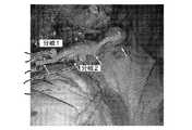
図3Aを参照すると、LIMA302の内視鏡ビューが、図示の白矢印と共に示される。LIMA302の分岐のうちの幾つかは筋膜310の下に隠されている。心臓バイパス手術の間、LIMA302のような血管は、患者の身体から除去され、冠状動脈内のアテローム性狭窄をバイパスするために用いられる。この手術の重要なステップは、バイパス移植で用いられるべき、胸部、脚、又は腕にある場合の多い血管の解体である。血管は、バイパス後の適切な血流を保証するために、解体中良好に保存される必要がある。侵襲の少ない心臓バイパスでは、これらの血管への直接アクセスは出来ず、それらの血管はポートに挿入される長い器具を用いて除去される。これらの血管は、バイパスが生じるとき起こり得る漏れを止めるために、多数の分岐を切り取られステープル止めされる必要がある。これらの血管は脂肪及び筋膜310に埋まっている場合が多いので、分岐は見逃される場合が多い。したがって、それらの血管はステープル止め又は閉鎖されずに不注意に切り取られてしまう。 Referring to FIG. 3A, an endoscopic view of
図3Bを参照すると、LIMA302の別の内視鏡ビューが、図示の白矢印と共に示される。LIMA302のオーバレイ画像306は、分岐を示す道標304及び308を有する。ロボット誘導又は手動誘導を用いて、道標304及び308を有するオーバレイ画像306は、埋まってしまい又は組織により遮られ得る分岐を視覚化し又は標的にするために用いられる。オーバレイ画像306は、LIMA302内に挿入される形状検知装置からの形状検知フィードバックを用いて生成される。 Referring to FIG. 3B, another endoscopic view of
本願明細書に記載の実施形態は侵襲の少ない冠動脈バイパス術を対象としているが、内視鏡手術が血管に対して行われ又は患者の身体からの血管の除去のために用いられる他の用途及び状況も考えられる。さらに、本発明の原理は、身体の他の部分の他の外科手術、又は訓練モデル、エンジン、配管システム、等を含む機械的システムにも用いることができる。 While the embodiments described herein are directed to less invasive coronary artery bypass grafting, other applications where endoscopic surgery is performed on blood vessels or used to remove blood vessels from a patient's body and The situation is also conceivable. Furthermore, the principles of the present invention can be used in other surgical procedures in other parts of the body, or in mechanical systems including training models, engines, piping systems, etc.
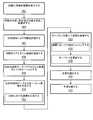
図4を参照すると、説明のための実施形態により、分岐した内腔を視覚化する方法が示される。分岐した内腔は血管を含むが、分岐した内腔は他の構造も含み得ることが理解されるべきである。例えば、分岐した内腔は他の生体組織(例えば、気管支)又は機械的構造(例えば、配管、等)を含み得る。図4に関して説明される説明のための実施形態は、外科手術、特に血管の解体を参照する。ブロック402で、適切な準備の後、光ファイバ形状検知装置は、血管等の内腔に挿入される。光ファイバ形状検知装置は、摘出されるべき血管内に位置決めされる。 Referring to FIG. 4, a method for visualizing a bifurcated lumen is shown according to an illustrative embodiment. It should be understood that the branched lumen includes blood vessels, but the branched lumen can also include other structures. For example, a bifurcated lumen may include other biological tissues (eg, bronchi) or mechanical structures (eg, tubing, etc.). The illustrative embodiment described with respect to FIG. 4 refers to surgery, particularly blood vessel disassembly. At
ブロック404で、内腔の位置、及び内腔からの分岐の場所は、内腔内のフローの変化に基づき決定される。これらの変化は、光ファイバ形状検知装置により測定される、歪みに起因する変動から生じる。一実施形態では、内腔の幾何学及び/又は形状は、分岐を含む3次元構造として再構成される。統計的方法は、分岐を検出するために、内腔の長さに沿ったフローの変化を検出するために用いられても良い。 At
一実施形態では、ブロック405で、血管は、血管再開通手術に適する血管の位置を決定するために、光ファイバ形状検知装置を用いて評価されても良い。血管又は他の内腔の他の選択基準が用いられても良い。 In one embodiment, at
ブロック406で、内腔の少なくとも一部は、リアルタイム画像を提供するために画像化される。画像化は、カメラ又は他の画像化装置を有する顕微鏡(又は内視鏡)を用いて提供されても良い。顕微鏡は、ポートを通じて画像を集めるために、患者に挿入される。顕微鏡は、ロボット制御であっても良い。ブロック208で、リアルタイム画像は、光ファイバ形状検知装置により測定される内腔の位置(形状検知データ)にレジストレーションされる。ブロック410で、内腔の位置及び分岐の場所を示すオーバレイ画像は、リアルタイム画像上で生成される。これは、ディスプレイでレンダリングされても良い。一実施形態では、内腔は、バイパス手術のために摘出されるべき分岐した血管を有する。内腔は、周囲の組織により見えない分岐を有しても良い。ブロック412で、オーバレイ画像は、分岐を可視的にレンダリングするために、分岐の場所においてオーバレイ上に道標を提供する。 At block 406, at least a portion of the lumen is imaged to provide a real-time image. Imaging may be provided using a microscope (or endoscope) having a camera or other imaging device. A microscope is inserted into the patient to collect images through the port. The microscope may be robot controlled. At
ブロック414で、ツールは、オーバレイに示される分岐の場所のうちの少なくとも1つへとロボット誘導されても良い。分岐の場所に誘導されると、複数の異なる手順又は操作が実行されても良い。ロボット誘導は、オーバレイ画像上の中央に内視鏡画像を置くために、視覚的サーボ方法を用いても良い。ロボット又は人間誘導は、内腔を追跡するために他の技術を用いても良い。一例では、ブロック416、オーバレイにより示される内腔内の分岐がシーリングされる。これは、血管の分岐の焼灼、ステープル止め、等を有しても良い。オーバレイ画像は、分岐場所情報を含む形状検知データにより駆動されるので、ブロック418で、オーバレイは、分岐がシーリングされたか否かを示すために、形状検知データを用いて更新されても良い。ブロック420で、血管は、摘出され、バイパスにおける血管再開通術又は他の外科手術のために準備される。ブロック422で、解体又は他のタスクを完了するために、手順は継続する。 At block 414, the tool may be robotically guided to at least one of the branch locations shown in the overlay. When directed to a branch location, a number of different procedures or operations may be performed. Robot guidance may use a visual servo method to place the endoscopic image in the center on the overlay image. Robot or human guidance may use other techniques to track the lumen. In one example, block 416, the branch in the lumen indicated by the overlay is sealed. This may include vessel branch cauterization, stapling, and the like. Since the overlay image is driven by shape detection data including branch location information, at block 418, the overlay may be updated with shape detection data to indicate whether the branch has been sealed. At block 420, the blood vessel is removed and prepared for a revascularization or other surgical procedure in the bypass. At
添付の請求の範囲を解釈する際に、以下のことが理解されるべきである。
a)用語「有する(comprising)」は、所与の請求項中に列挙された以外の要素又は動作の存在を排除するものではない。
b)要素の前にある単数を表す語(「a」、「an」)は、このような要素の複数の存在を排除しない。
c)請求項中のいかなる参照符号も、請求項の範囲を制限しない。
d)幾つかの「手段(means)」は、同じアイテム又はハードウェア若しくはソフトウェアで実装される構造若しくは機能により表現されても良い。
e)いかなる特定の動作シーケンスも、特に示されない限り、要求されることを意図しない。In interpreting the appended claims, the following should be understood.
a) The term “comprising” does not exclude the presence of elements or acts other than those listed in a given claim.
b) Words representing the singular preceding an element (“a”, “an”) do not exclude the presence of a plurality of such elements.
c) any reference signs in the claims do not limit the scope of the claims;
d) Several “means” may be expressed by the same items or structures or functions implemented in hardware or software.
e) No particular operational sequence is intended to be required unless specifically indicated.
(説明のためであり限定を意図しない)血管視覚化及び監視のための光ファイバセンサにより誘導されるナビゲーションの好適な実施形態を記載したが、留意すべきことに、変更及び変形は、上述の教示を考慮して当業者により行われ得る。したがって、理解されるべきことに、変更は、本開示の特定の実施形態で行われても良く、添付の請求の範囲により概説されるように、本願明細書に開示の実施形態の範囲内に包含される。したがって、特許法の要求により詳細事項及び特殊性を記載したが、特許証により何が請求され保護を要求されるかは、添付の請求の範囲に記載される。 Although a preferred embodiment of navigation guided by fiber optic sensors for vascular visualization and monitoring (for purposes of illustration and not limitation) has been described, it should be noted that changes and modifications are described above. This can be done by one skilled in the art in view of the teachings. Accordingly, it should be understood that changes may be made in particular embodiments of the present disclosure and, as outlined by the appended claims, are within the scope of the embodiments disclosed herein. Is included. Therefore, although details and specialities have been described according to the requirements of the patent law, what is claimed and required protection by the patent certificate is set forth in the appended claims.
102 装置
104 形状検知
106 光源
108 光学取調
110 画像システム
112 ワークステーション
114 プロセッサ
115 光検知及び解釈モジュール
116 メモリ
118 ディスプレイ
120 インタフェース
126 ファイバ
131 血管
134 オーバレイ画像
136 レジストレーションモジュール
140 統計的方法
142 顕微鏡画像
148 画像生成
164 ロボットDESCRIPTION OF SYMBOLS 102
Claims (1)
Translated fromJapaneseプロセッサと、
前記プロセッサに結合されるメモリと、
血管内の血流を示す形状検知データを提供するために前記血管に挿入されるよう構成される光ファイバ形状検知装置と、
ディスプレイと、
を含み、前記メモリは、前記プロセッサにより実行されると、前記プロセッサを、
前記血流の変化に基づき前記血管の分岐をマッピングし、
前記形状検知データに基づきオーバレイ画像を生成し、前記オーバレイ画像は前記血管の形状及び前記分岐の位置を示し、
シーリングされた分岐の数のカウントを決定し、
前記ディスプレイに前記オーバレイ画像を前記血管のレンダリングの上にレンダリングさせて、前記血管の前記分岐を視覚化する誘導を提供し、及びシーリングされた分岐の数の前記カウントを表示するために前記オーバレイ画像を更新する、
よう構成する、システム。A system for monitoring blood vessels,
A processor;
A memory coupled to the processor;
An optical fiber shape sensing device configured to be inserted into the blood vessel to provide shape sensing data indicative of blood flow in the blood vessel;
Display,
And when the memory is executed by the processor, the processor
Mapping the vessel bifurcation based on the change in blood flow,
Generating an overlay image based on the shape detection data, the overlay image showing the shape of the blood vessel and the position of the branch;
Determine the count of the number of branches sealed,
Causing the display to render the overlay image on top of the rendering of the blood vessel to provide guidance for visualizing the branches of the blood vessel and to display the count of the number of sealed branches Update,
Configure the system as follows.
Applications Claiming Priority (3)
| Application Number | Priority Date | Filing Date | Title |
|---|---|---|---|
| US201261665387P | 2012-06-28 | 2012-06-28 | |
| US61/665,387 | 2012-06-28 | ||
| JP2015519420AJP6633391B2 (en) | 2012-06-28 | 2013-06-20 | Fiber optic sensor guided navigation for blood vessel visualization and monitoring |
Related Parent Applications (1)
| Application Number | Title | Priority Date | Filing Date |
|---|---|---|---|
| JP2015519420ADivisionJP6633391B2 (en) | 2012-06-28 | 2013-06-20 | Fiber optic sensor guided navigation for blood vessel visualization and monitoring |
Publications (2)
| Publication Number | Publication Date |
|---|---|
| JP2019205915Atrue JP2019205915A (en) | 2019-12-05 |
| JP6899878B2 JP6899878B2 (en) | 2021-07-07 |
Family
ID=49034129
Family Applications (2)
| Application Number | Title | Priority Date | Filing Date |
|---|---|---|---|
| JP2015519420AActiveJP6633391B2 (en) | 2012-06-28 | 2013-06-20 | Fiber optic sensor guided navigation for blood vessel visualization and monitoring |
| JP2019162613AActiveJP6899878B2 (en) | 2012-06-28 | 2019-09-06 | Fiber optic sensor-guided navigation for vascular visualization and monitoring |
Family Applications Before (1)
| Application Number | Title | Priority Date | Filing Date |
|---|---|---|---|
| JP2015519420AActiveJP6633391B2 (en) | 2012-06-28 | 2013-06-20 | Fiber optic sensor guided navigation for blood vessel visualization and monitoring |
Country Status (7)
| Country | Link |
|---|---|
| US (1) | US10194801B2 (en) |
| EP (1) | EP2866642B1 (en) |
| JP (2) | JP6633391B2 (en) |
| CN (1) | CN104427927B (en) |
| BR (1) | BR112014031981A2 (en) |
| RU (1) | RU2686954C2 (en) |
| WO (1) | WO2014001977A2 (en) |
Families Citing this family (437)
| Publication number | Priority date | Publication date | Assignee | Title |
|---|---|---|---|---|
| US20070084897A1 (en) | 2003-05-20 | 2007-04-19 | Shelton Frederick E Iv | Articulating surgical stapling instrument incorporating a two-piece e-beam firing mechanism |
| US9060770B2 (en) | 2003-05-20 | 2015-06-23 | Ethicon Endo-Surgery, Inc. | Robotically-driven surgical instrument with E-beam driver |
| US8215531B2 (en) | 2004-07-28 | 2012-07-10 | Ethicon Endo-Surgery, Inc. | Surgical stapling instrument having a medical substance dispenser |
| US11890012B2 (en) | 2004-07-28 | 2024-02-06 | Cilag Gmbh International | Staple cartridge comprising cartridge body and attached support |
| US9072535B2 (en) | 2011-05-27 | 2015-07-07 | Ethicon Endo-Surgery, Inc. | Surgical stapling instruments with rotatable staple deployment arrangements |
| US11998198B2 (en) | 2004-07-28 | 2024-06-04 | Cilag Gmbh International | Surgical stapling instrument incorporating a two-piece E-beam firing mechanism |
| US11246590B2 (en) | 2005-08-31 | 2022-02-15 | Cilag Gmbh International | Staple cartridge including staple drivers having different unfired heights |
| US7669746B2 (en) | 2005-08-31 | 2010-03-02 | Ethicon Endo-Surgery, Inc. | Staple cartridges for forming staples having differing formed staple heights |
| US11484312B2 (en) | 2005-08-31 | 2022-11-01 | Cilag Gmbh International | Staple cartridge comprising a staple driver arrangement |
| US9237891B2 (en) | 2005-08-31 | 2016-01-19 | Ethicon Endo-Surgery, Inc. | Robotically-controlled surgical stapling devices that produce formed staples having different lengths |
| US10159482B2 (en) | 2005-08-31 | 2018-12-25 | Ethicon Llc | Fastener cartridge assembly comprising a fixed anvil and different staple heights |
| US7934630B2 (en) | 2005-08-31 | 2011-05-03 | Ethicon Endo-Surgery, Inc. | Staple cartridges for forming staples having differing formed staple heights |
| US20070106317A1 (en) | 2005-11-09 | 2007-05-10 | Shelton Frederick E Iv | Hydraulically and electrically actuated articulation joints for surgical instruments |
| US11224427B2 (en) | 2006-01-31 | 2022-01-18 | Cilag Gmbh International | Surgical stapling system including a console and retraction assembly |
| US8820603B2 (en) | 2006-01-31 | 2014-09-02 | Ethicon Endo-Surgery, Inc. | Accessing data stored in a memory of a surgical instrument |
| US11278279B2 (en) | 2006-01-31 | 2022-03-22 | Cilag Gmbh International | Surgical instrument assembly |
| US20110295295A1 (en) | 2006-01-31 | 2011-12-01 | Ethicon Endo-Surgery, Inc. | Robotically-controlled surgical instrument having recording capabilities |
| US11793518B2 (en) | 2006-01-31 | 2023-10-24 | Cilag Gmbh International | Powered surgical instruments with firing system lockout arrangements |
| US20110024477A1 (en) | 2009-02-06 | 2011-02-03 | Hall Steven G | Driven Surgical Stapler Improvements |
| US20120292367A1 (en) | 2006-01-31 | 2012-11-22 | Ethicon Endo-Surgery, Inc. | Robotically-controlled end effector |
| US8186555B2 (en) | 2006-01-31 | 2012-05-29 | Ethicon Endo-Surgery, Inc. | Motor-driven surgical cutting and fastening instrument with mechanical closure system |
| US7845537B2 (en) | 2006-01-31 | 2010-12-07 | Ethicon Endo-Surgery, Inc. | Surgical instrument having recording capabilities |
| US7753904B2 (en) | 2006-01-31 | 2010-07-13 | Ethicon Endo-Surgery, Inc. | Endoscopic surgical instrument with a handle that can articulate with respect to the shaft |
| US8708213B2 (en) | 2006-01-31 | 2014-04-29 | Ethicon Endo-Surgery, Inc. | Surgical instrument having a feedback system |
| US8992422B2 (en) | 2006-03-23 | 2015-03-31 | Ethicon Endo-Surgery, Inc. | Robotically-controlled endoscopic accessory channel |
| US8322455B2 (en) | 2006-06-27 | 2012-12-04 | Ethicon Endo-Surgery, Inc. | Manually driven surgical cutting and fastening instrument |
| US10568652B2 (en) | 2006-09-29 | 2020-02-25 | Ethicon Llc | Surgical staples having attached drivers of different heights and stapling instruments for deploying the same |
| US11980366B2 (en) | 2006-10-03 | 2024-05-14 | Cilag Gmbh International | Surgical instrument |
| US8632535B2 (en) | 2007-01-10 | 2014-01-21 | Ethicon Endo-Surgery, Inc. | Interlock and surgical instrument including same |
| US8684253B2 (en) | 2007-01-10 | 2014-04-01 | Ethicon Endo-Surgery, Inc. | Surgical instrument with wireless communication between a control unit of a robotic system and remote sensor |
| US11291441B2 (en) | 2007-01-10 | 2022-04-05 | Cilag Gmbh International | Surgical instrument with wireless communication between control unit and remote sensor |
| US20080169333A1 (en) | 2007-01-11 | 2008-07-17 | Shelton Frederick E | Surgical stapler end effector with tapered distal end |
| US11039836B2 (en) | 2007-01-11 | 2021-06-22 | Cilag Gmbh International | Staple cartridge for use with a surgical stapling instrument |
| US7673782B2 (en) | 2007-03-15 | 2010-03-09 | Ethicon Endo-Surgery, Inc. | Surgical stapling instrument having a releasable buttress material |
| US11564682B2 (en) | 2007-06-04 | 2023-01-31 | Cilag Gmbh International | Surgical stapler device |
| US8931682B2 (en) | 2007-06-04 | 2015-01-13 | Ethicon Endo-Surgery, Inc. | Robotically-controlled shaft based rotary drive systems for surgical instruments |
| US7753245B2 (en) | 2007-06-22 | 2010-07-13 | Ethicon Endo-Surgery, Inc. | Surgical stapling instruments |
| US11849941B2 (en) | 2007-06-29 | 2023-12-26 | Cilag Gmbh International | Staple cartridge having staple cavities extending at a transverse angle relative to a longitudinal cartridge axis |
| US8636736B2 (en) | 2008-02-14 | 2014-01-28 | Ethicon Endo-Surgery, Inc. | Motorized surgical cutting and fastening instrument |
| US7866527B2 (en) | 2008-02-14 | 2011-01-11 | Ethicon Endo-Surgery, Inc. | Surgical stapling apparatus with interlockable firing system |
| US8758391B2 (en) | 2008-02-14 | 2014-06-24 | Ethicon Endo-Surgery, Inc. | Interchangeable tools for surgical instruments |
| US11986183B2 (en) | 2008-02-14 | 2024-05-21 | Cilag Gmbh International | Surgical cutting and fastening instrument comprising a plurality of sensors to measure an electrical parameter |
| US9179912B2 (en) | 2008-02-14 | 2015-11-10 | Ethicon Endo-Surgery, Inc. | Robotically-controlled motorized surgical cutting and fastening instrument |
| US8573465B2 (en) | 2008-02-14 | 2013-11-05 | Ethicon Endo-Surgery, Inc. | Robotically-controlled surgical end effector system with rotary actuated closure systems |
| JP5410110B2 (en) | 2008-02-14 | 2014-02-05 | エシコン・エンド−サージェリィ・インコーポレイテッド | Surgical cutting / fixing instrument with RF electrode |
| US7819298B2 (en) | 2008-02-14 | 2010-10-26 | Ethicon Endo-Surgery, Inc. | Surgical stapling apparatus with control features operable with one hand |
| US9585657B2 (en) | 2008-02-15 | 2017-03-07 | Ethicon Endo-Surgery, Llc | Actuator for releasing a layer of material from a surgical end effector |
| US8210411B2 (en) | 2008-09-23 | 2012-07-03 | Ethicon Endo-Surgery, Inc. | Motor-driven surgical cutting instrument |
| US9386983B2 (en) | 2008-09-23 | 2016-07-12 | Ethicon Endo-Surgery, Llc | Robotically-controlled motorized surgical instrument |
| US11648005B2 (en) | 2008-09-23 | 2023-05-16 | Cilag Gmbh International | Robotically-controlled motorized surgical instrument with an end effector |
| US9005230B2 (en) | 2008-09-23 | 2015-04-14 | Ethicon Endo-Surgery, Inc. | Motorized surgical instrument |
| US8608045B2 (en) | 2008-10-10 | 2013-12-17 | Ethicon Endo-Sugery, Inc. | Powered surgical cutting and stapling apparatus with manually retractable firing system |
| US8517239B2 (en) | 2009-02-05 | 2013-08-27 | Ethicon Endo-Surgery, Inc. | Surgical stapling instrument comprising a magnetic element driver |
| RU2525225C2 (en) | 2009-02-06 | 2014-08-10 | Этикон Эндо-Серджери, Инк. | Improvement of drive surgical suturing instrument |
| US8220688B2 (en) | 2009-12-24 | 2012-07-17 | Ethicon Endo-Surgery, Inc. | Motor-driven surgical cutting instrument with electric actuator directional control assembly |
| US8851354B2 (en) | 2009-12-24 | 2014-10-07 | Ethicon Endo-Surgery, Inc. | Surgical cutting instrument that analyzes tissue thickness |
| US8672837B2 (en) | 2010-06-24 | 2014-03-18 | Hansen Medical, Inc. | Methods and devices for controlling a shapeable medical device |
| US8783543B2 (en) | 2010-07-30 | 2014-07-22 | Ethicon Endo-Surgery, Inc. | Tissue acquisition arrangements and methods for surgical stapling devices |
| US12213666B2 (en) | 2010-09-30 | 2025-02-04 | Cilag Gmbh International | Tissue thickness compensator comprising layers |
| US10945731B2 (en) | 2010-09-30 | 2021-03-16 | Ethicon Llc | Tissue thickness compensator comprising controlled release and expansion |
| US11925354B2 (en) | 2010-09-30 | 2024-03-12 | Cilag Gmbh International | Staple cartridge comprising staples positioned within a compressible portion thereof |
| US11298125B2 (en) | 2010-09-30 | 2022-04-12 | Cilag Gmbh International | Tissue stapler having a thickness compensator |
| US9629814B2 (en) | 2010-09-30 | 2017-04-25 | Ethicon Endo-Surgery, Llc | Tissue thickness compensator configured to redistribute compressive forces |
| US9351730B2 (en) | 2011-04-29 | 2016-05-31 | Ethicon Endo-Surgery, Llc | Tissue thickness compensator comprising channels |
| US9788834B2 (en) | 2010-09-30 | 2017-10-17 | Ethicon Llc | Layer comprising deployable attachment members |
| US9016542B2 (en) | 2010-09-30 | 2015-04-28 | Ethicon Endo-Surgery, Inc. | Staple cartridge comprising compressible distortion resistant components |
| US11812965B2 (en) | 2010-09-30 | 2023-11-14 | Cilag Gmbh International | Layer of material for a surgical end effector |
| US9386988B2 (en) | 2010-09-30 | 2016-07-12 | Ethicon End-Surgery, LLC | Retainer assembly including a tissue thickness compensator |
| US8695866B2 (en) | 2010-10-01 | 2014-04-15 | Ethicon Endo-Surgery, Inc. | Surgical instrument having a power control circuit |
| AU2012250197B2 (en) | 2011-04-29 | 2017-08-10 | Ethicon Endo-Surgery, Inc. | Staple cartridge comprising staples positioned within a compressible portion thereof |
| US11207064B2 (en) | 2011-05-27 | 2021-12-28 | Cilag Gmbh International | Automated end effector component reloading system for use with a robotic system |
| BR112014024098B1 (en) | 2012-03-28 | 2021-05-25 | Ethicon Endo-Surgery, Inc. | staple cartridge |
| MX358135B (en) | 2012-03-28 | 2018-08-06 | Ethicon Endo Surgery Inc | Tissue thickness compensator comprising a plurality of layers. |
| JP6224070B2 (en) | 2012-03-28 | 2017-11-01 | エシコン・エンド−サージェリィ・インコーポレイテッドEthicon Endo−Surgery,Inc. | Retainer assembly including tissue thickness compensator |
| US9101358B2 (en) | 2012-06-15 | 2015-08-11 | Ethicon Endo-Surgery, Inc. | Articulatable surgical instrument comprising a firing drive |
| US9282974B2 (en) | 2012-06-28 | 2016-03-15 | Ethicon Endo-Surgery, Llc | Empty clip cartridge lockout |
| US20140001231A1 (en) | 2012-06-28 | 2014-01-02 | Ethicon Endo-Surgery, Inc. | Firing system lockout arrangements for surgical instruments |
| BR112014032776B1 (en) | 2012-06-28 | 2021-09-08 | Ethicon Endo-Surgery, Inc | SURGICAL INSTRUMENT SYSTEM AND SURGICAL KIT FOR USE WITH A SURGICAL INSTRUMENT SYSTEM |
| US12383267B2 (en) | 2012-06-28 | 2025-08-12 | Cilag Gmbh International | Robotically powered surgical device with manually-actuatable reversing system |
| US9289256B2 (en) | 2012-06-28 | 2016-03-22 | Ethicon Endo-Surgery, Llc | Surgical end effectors having angled tissue-contacting surfaces |
| US11278284B2 (en) | 2012-06-28 | 2022-03-22 | Cilag Gmbh International | Rotary drive arrangements for surgical instruments |
| JP6290201B2 (en) | 2012-06-28 | 2018-03-07 | エシコン・エンド−サージェリィ・インコーポレイテッドEthicon Endo−Surgery,Inc. | Lockout for empty clip cartridge |
| US9408606B2 (en) | 2012-06-28 | 2016-08-09 | Ethicon Endo-Surgery, Llc | Robotically powered surgical device with manually-actuatable reversing system |
| BR112015021082B1 (en) | 2013-03-01 | 2022-05-10 | Ethicon Endo-Surgery, Inc | surgical instrument |
| RU2672520C2 (en) | 2013-03-01 | 2018-11-15 | Этикон Эндо-Серджери, Инк. | Hingedly turnable surgical instruments with conducting ways for signal transfer |
| US9057600B2 (en) | 2013-03-13 | 2015-06-16 | Hansen Medical, Inc. | Reducing incremental measurement sensor error |
| US9808244B2 (en) | 2013-03-14 | 2017-11-07 | Ethicon Llc | Sensor arrangements for absolute positioning system for surgical instruments |
| US9629629B2 (en) | 2013-03-14 | 2017-04-25 | Ethicon Endo-Surgey, LLC | Control systems for surgical instruments |
| US9629595B2 (en) | 2013-03-15 | 2017-04-25 | Hansen Medical, Inc. | Systems and methods for localizing, tracking and/or controlling medical instruments |
| US9271663B2 (en) | 2013-03-15 | 2016-03-01 | Hansen Medical, Inc. | Flexible instrument localization from both remote and elongation sensors |
| US9014851B2 (en) | 2013-03-15 | 2015-04-21 | Hansen Medical, Inc. | Systems and methods for tracking robotically controlled medical instruments |
| US9826976B2 (en) | 2013-04-16 | 2017-11-28 | Ethicon Llc | Motor driven surgical instruments with lockable dual drive shafts |
| BR112015026109B1 (en) | 2013-04-16 | 2022-02-22 | Ethicon Endo-Surgery, Inc | surgical instrument |
| US11020016B2 (en) | 2013-05-30 | 2021-06-01 | Auris Health, Inc. | System and method for displaying anatomy and devices on a movable display |
| US9775609B2 (en) | 2013-08-23 | 2017-10-03 | Ethicon Llc | Tamper proof circuit for surgical instrument battery pack |
| MX369362B (en) | 2013-08-23 | 2019-11-06 | Ethicon Endo Surgery Llc | Firing member retraction devices for powered surgical instruments. |
| US9962161B2 (en) | 2014-02-12 | 2018-05-08 | Ethicon Llc | Deliverable surgical instrument |
| US20150272580A1 (en) | 2014-03-26 | 2015-10-01 | Ethicon Endo-Surgery, Inc. | Verification of number of battery exchanges/procedure count |
| BR112016021943B1 (en) | 2014-03-26 | 2022-06-14 | Ethicon Endo-Surgery, Llc | SURGICAL INSTRUMENT FOR USE BY AN OPERATOR IN A SURGICAL PROCEDURE |
| US10004497B2 (en) | 2014-03-26 | 2018-06-26 | Ethicon Llc | Interface systems for use with surgical instruments |
| US10013049B2 (en) | 2014-03-26 | 2018-07-03 | Ethicon Llc | Power management through sleep options of segmented circuit and wake up control |
| US12232723B2 (en) | 2014-03-26 | 2025-02-25 | Cilag Gmbh International | Systems and methods for controlling a segmented circuit |
| JP5924363B2 (en)* | 2014-03-31 | 2016-05-25 | 株式会社Aze | MEDICAL IMAGE DIAGNOSIS SUPPORT DEVICE, ITS CONTROL METHOD, AND PROGRAM |
| US20150297225A1 (en) | 2014-04-16 | 2015-10-22 | Ethicon Endo-Surgery, Inc. | Fastener cartridges including extensions having different configurations |
| BR112016023825B1 (en) | 2014-04-16 | 2022-08-02 | Ethicon Endo-Surgery, Llc | STAPLE CARTRIDGE FOR USE WITH A SURGICAL STAPLER AND STAPLE CARTRIDGE FOR USE WITH A SURGICAL INSTRUMENT |
| US10470768B2 (en) | 2014-04-16 | 2019-11-12 | Ethicon Llc | Fastener cartridge including a layer attached thereto |
| CN106456176B (en) | 2014-04-16 | 2019-06-28 | 伊西康内外科有限责任公司 | Fastener Cartridge Including Extensions With Different Configurations |
| US10327764B2 (en) | 2014-09-26 | 2019-06-25 | Ethicon Llc | Method for creating a flexible staple line |
| CN106456159B (en) | 2014-04-16 | 2019-03-08 | 伊西康内外科有限责任公司 | Fastener Cartridge Assembly and Nail Retainer Cover Arrangement |
| BR112017004361B1 (en) | 2014-09-05 | 2023-04-11 | Ethicon Llc | ELECTRONIC SYSTEM FOR A SURGICAL INSTRUMENT |
| US10135242B2 (en) | 2014-09-05 | 2018-11-20 | Ethicon Llc | Smart cartridge wake up operation and data retention |
| US11311294B2 (en) | 2014-09-05 | 2022-04-26 | Cilag Gmbh International | Powered medical device including measurement of closure state of jaws |
| US10499813B2 (en)* | 2014-09-12 | 2019-12-10 | Lightlab Imaging, Inc. | Methods, systems and apparatus for temporal calibration of an intravascular imaging system |
| US10105142B2 (en) | 2014-09-18 | 2018-10-23 | Ethicon Llc | Surgical stapler with plurality of cutting elements |
| CN107427300B (en) | 2014-09-26 | 2020-12-04 | 伊西康有限责任公司 | Surgical suture buttresses and auxiliary materials |
| US11523821B2 (en) | 2014-09-26 | 2022-12-13 | Cilag Gmbh International | Method for creating a flexible staple line |
| US10076325B2 (en) | 2014-10-13 | 2018-09-18 | Ethicon Llc | Surgical stapling apparatus comprising a tissue stop |
| US9924944B2 (en) | 2014-10-16 | 2018-03-27 | Ethicon Llc | Staple cartridge comprising an adjunct material |
| US10517594B2 (en) | 2014-10-29 | 2019-12-31 | Ethicon Llc | Cartridge assemblies for surgical staplers |
| US11141153B2 (en) | 2014-10-29 | 2021-10-12 | Cilag Gmbh International | Staple cartridges comprising driver arrangements |
| US9844376B2 (en) | 2014-11-06 | 2017-12-19 | Ethicon Llc | Staple cartridge comprising a releasable adjunct material |
| US10736636B2 (en) | 2014-12-10 | 2020-08-11 | Ethicon Llc | Articulatable surgical instrument system |
| US9987000B2 (en) | 2014-12-18 | 2018-06-05 | Ethicon Llc | Surgical instrument assembly comprising a flexible articulation system |
| US9844375B2 (en) | 2014-12-18 | 2017-12-19 | Ethicon Llc | Drive arrangements for articulatable surgical instruments |
| US9844374B2 (en) | 2014-12-18 | 2017-12-19 | Ethicon Llc | Surgical instrument systems comprising an articulatable end effector and means for adjusting the firing stroke of a firing member |
| US10085748B2 (en) | 2014-12-18 | 2018-10-02 | Ethicon Llc | Locking arrangements for detachable shaft assemblies with articulatable surgical end effectors |
| US9943309B2 (en) | 2014-12-18 | 2018-04-17 | Ethicon Llc | Surgical instruments with articulatable end effectors and movable firing beam support arrangements |
| MX389118B (en) | 2014-12-18 | 2025-03-20 | Ethicon Llc | SURGICAL INSTRUMENT WITH AN ANVIL THAT CAN BE SELECTIVELY MOVED ON A DISCRETE, NON-MOBILE AXIS RELATIVE TO A STAPLE CARTRIDGE. |
| EP3247301B1 (en)* | 2015-01-22 | 2020-10-28 | Koninklijke Philips N.V. | Endograft visualization with optical shape sensing |
| JP2018511353A (en) | 2015-01-22 | 2018-04-26 | コーニンクレッカ フィリップス エヌ ヴェKoninklijke Philips N.V. | Device visualization by optical shape sensing of guide wires |
| US10939967B2 (en) | 2015-01-22 | 2021-03-09 | Koninklijke Philips N.V. | Robotic control of an endovascular deployment device with optical shape sensing feedback |
| US11154301B2 (en) | 2015-02-27 | 2021-10-26 | Cilag Gmbh International | Modular stapling assembly |
| US9993248B2 (en) | 2015-03-06 | 2018-06-12 | Ethicon Endo-Surgery, Llc | Smart sensors with local signal processing |
| US9901342B2 (en) | 2015-03-06 | 2018-02-27 | Ethicon Endo-Surgery, Llc | Signal and power communication system positioned on a rotatable shaft |
| US10687806B2 (en) | 2015-03-06 | 2020-06-23 | Ethicon Llc | Adaptive tissue compression techniques to adjust closure rates for multiple tissue types |
| JP2020121162A (en) | 2015-03-06 | 2020-08-13 | エシコン エルエルシーEthicon LLC | Time dependent evaluation of sensor data to determine stability element, creep element and viscoelastic element of measurement |
| US10441279B2 (en) | 2015-03-06 | 2019-10-15 | Ethicon Llc | Multiple level thresholds to modify operation of powered surgical instruments |
| US10617412B2 (en) | 2015-03-06 | 2020-04-14 | Ethicon Llc | System for detecting the mis-insertion of a staple cartridge into a surgical stapler |
| US10245033B2 (en) | 2015-03-06 | 2019-04-02 | Ethicon Llc | Surgical instrument comprising a lockable battery housing |
| US10548504B2 (en) | 2015-03-06 | 2020-02-04 | Ethicon Llc | Overlaid multi sensor radio frequency (RF) electrode system to measure tissue compression |
| US10433844B2 (en) | 2015-03-31 | 2019-10-08 | Ethicon Llc | Surgical instrument with selectively disengageable threaded drive systems |
| US10835249B2 (en) | 2015-08-17 | 2020-11-17 | Ethicon Llc | Implantable layers for a surgical instrument |
| JP6824967B2 (en) | 2015-09-18 | 2021-02-03 | オーリス ヘルス インコーポレイテッド | Tubular net navigation |
| US10238386B2 (en) | 2015-09-23 | 2019-03-26 | Ethicon Llc | Surgical stapler having motor control based on an electrical parameter related to a motor current |
| US10105139B2 (en) | 2015-09-23 | 2018-10-23 | Ethicon Llc | Surgical stapler having downstream current-based motor control |
| US10299878B2 (en) | 2015-09-25 | 2019-05-28 | Ethicon Llc | Implantable adjunct systems for determining adjunct skew |
| US10433846B2 (en) | 2015-09-30 | 2019-10-08 | Ethicon Llc | Compressible adjunct with crossing spacer fibers |
| US10980539B2 (en) | 2015-09-30 | 2021-04-20 | Ethicon Llc | Implantable adjunct comprising bonded layers |
| US11890015B2 (en) | 2015-09-30 | 2024-02-06 | Cilag Gmbh International | Compressible adjunct with crossing spacer fibers |
| US10478188B2 (en) | 2015-09-30 | 2019-11-19 | Ethicon Llc | Implantable layer comprising a constricted configuration |
| US10058393B2 (en) | 2015-10-21 | 2018-08-28 | P Tech, Llc | Systems and methods for navigation and visualization |
| US10143526B2 (en) | 2015-11-30 | 2018-12-04 | Auris Health, Inc. | Robot-assisted driving systems and methods |
| CN108472082B (en)* | 2015-12-29 | 2021-08-10 | 皇家飞利浦有限公司 | Registration system for medical navigation and method of operation thereof |
| US10292704B2 (en) | 2015-12-30 | 2019-05-21 | Ethicon Llc | Mechanisms for compensating for battery pack failure in powered surgical instruments |
| US10265068B2 (en) | 2015-12-30 | 2019-04-23 | Ethicon Llc | Surgical instruments with separable motors and motor control circuits |
| US10368865B2 (en) | 2015-12-30 | 2019-08-06 | Ethicon Llc | Mechanisms for compensating for drivetrain failure in powered surgical instruments |
| BR112018016098B1 (en) | 2016-02-09 | 2023-02-23 | Ethicon Llc | SURGICAL INSTRUMENT |
| US11213293B2 (en) | 2016-02-09 | 2022-01-04 | Cilag Gmbh International | Articulatable surgical instruments with single articulation link arrangements |
| EP4375934A3 (en)* | 2016-02-12 | 2024-07-31 | Intuitive Surgical Operations, Inc. | Systems and methods of pose estimation and calibration of perspective imaging system in image guided surgery |
| US10448948B2 (en) | 2016-02-12 | 2019-10-22 | Ethicon Llc | Mechanisms for compensating for drivetrain failure in powered surgical instruments |
| US11224426B2 (en) | 2016-02-12 | 2022-01-18 | Cilag Gmbh International | Mechanisms for compensating for drivetrain failure in powered surgical instruments |
| US10335145B2 (en) | 2016-04-15 | 2019-07-02 | Ethicon Llc | Modular surgical instrument with configurable operating mode |
| US10426467B2 (en) | 2016-04-15 | 2019-10-01 | Ethicon Llc | Surgical instrument with detection sensors |
| US10492783B2 (en) | 2016-04-15 | 2019-12-03 | Ethicon, Llc | Surgical instrument with improved stop/start control during a firing motion |
| US10828028B2 (en) | 2016-04-15 | 2020-11-10 | Ethicon Llc | Surgical instrument with multiple program responses during a firing motion |
| US10456137B2 (en) | 2016-04-15 | 2019-10-29 | Ethicon Llc | Staple formation detection mechanisms |
| US10357247B2 (en) | 2016-04-15 | 2019-07-23 | Ethicon Llc | Surgical instrument with multiple program responses during a firing motion |
| US11179150B2 (en) | 2016-04-15 | 2021-11-23 | Cilag Gmbh International | Systems and methods for controlling a surgical stapling and cutting instrument |
| US11607239B2 (en) | 2016-04-15 | 2023-03-21 | Cilag Gmbh International | Systems and methods for controlling a surgical stapling and cutting instrument |
| US20170296173A1 (en) | 2016-04-18 | 2017-10-19 | Ethicon Endo-Surgery, Llc | Method for operating a surgical instrument |
| US11317917B2 (en) | 2016-04-18 | 2022-05-03 | Cilag Gmbh International | Surgical stapling system comprising a lockable firing assembly |
| US10363037B2 (en) | 2016-04-18 | 2019-07-30 | Ethicon Llc | Surgical instrument system comprising a magnetic lockout |
| CN109310338B (en) | 2016-06-29 | 2021-11-19 | 皮科洛医疗公司 | Device and method for vessel navigation, evaluation and/or diagnosis |
| CN105942960B (en)* | 2016-07-01 | 2017-06-16 | 华中科技大学 | An endoscopic system and method capable of indicating the position of the ureter |
| US10500000B2 (en) | 2016-08-16 | 2019-12-10 | Ethicon Llc | Surgical tool with manual control of end effector jaws |
| US10485543B2 (en) | 2016-12-21 | 2019-11-26 | Ethicon Llc | Anvil having a knife slot width |
| JP7010956B2 (en) | 2016-12-21 | 2022-01-26 | エシコン エルエルシー | How to staple tissue |
| JP2020501815A (en) | 2016-12-21 | 2020-01-23 | エシコン エルエルシーEthicon LLC | Surgical stapling system |
| JP6983893B2 (en) | 2016-12-21 | 2021-12-17 | エシコン エルエルシーEthicon LLC | Lockout configuration for surgical end effectors and replaceable tool assemblies |
| US10582928B2 (en) | 2016-12-21 | 2020-03-10 | Ethicon Llc | Articulation lock arrangements for locking an end effector in an articulated position in response to actuation of a jaw closure system |
| US10973516B2 (en) | 2016-12-21 | 2021-04-13 | Ethicon Llc | Surgical end effectors and adaptable firing members therefor |
| US20180168625A1 (en) | 2016-12-21 | 2018-06-21 | Ethicon Endo-Surgery, Llc | Surgical stapling instruments with smart staple cartridges |
| US11419606B2 (en) | 2016-12-21 | 2022-08-23 | Cilag Gmbh International | Shaft assembly comprising a clutch configured to adapt the output of a rotary firing member to two different systems |
| US10898186B2 (en) | 2016-12-21 | 2021-01-26 | Ethicon Llc | Staple forming pocket arrangements comprising primary sidewalls and pocket sidewalls |
| US11090048B2 (en) | 2016-12-21 | 2021-08-17 | Cilag Gmbh International | Method for resetting a fuse of a surgical instrument shaft |
| US10568625B2 (en) | 2016-12-21 | 2020-02-25 | Ethicon Llc | Staple cartridges and arrangements of staples and staple cavities therein |
| US11134942B2 (en) | 2016-12-21 | 2021-10-05 | Cilag Gmbh International | Surgical stapling instruments and staple-forming anvils |
| US10813638B2 (en) | 2016-12-21 | 2020-10-27 | Ethicon Llc | Surgical end effectors with expandable tissue stop arrangements |
| US20180168615A1 (en) | 2016-12-21 | 2018-06-21 | Ethicon Endo-Surgery, Llc | Method of deforming staples from two different types of staple cartridges with the same surgical stapling instrument |
| US10758229B2 (en) | 2016-12-21 | 2020-09-01 | Ethicon Llc | Surgical instrument comprising improved jaw control |
| US10695055B2 (en) | 2016-12-21 | 2020-06-30 | Ethicon Llc | Firing assembly comprising a lockout |
| US10980536B2 (en) | 2016-12-21 | 2021-04-20 | Ethicon Llc | No-cartridge and spent cartridge lockout arrangements for surgical staplers |
| JP7010957B2 (en) | 2016-12-21 | 2022-01-26 | エシコン エルエルシー | Shaft assembly with lockout |
| MX2019007295A (en) | 2016-12-21 | 2019-10-15 | Ethicon Llc | Surgical instrument system comprising an end effector lockout and a firing assembly lockout. |
| US10542982B2 (en) | 2016-12-21 | 2020-01-28 | Ethicon Llc | Shaft assembly comprising first and second articulation lockouts |
| CN110087565A (en) | 2016-12-21 | 2019-08-02 | 爱惜康有限责任公司 | Surgical stapling system |
| US10244926B2 (en) | 2016-12-28 | 2019-04-02 | Auris Health, Inc. | Detecting endolumenal buckling of flexible instruments |
| WO2018183727A1 (en) | 2017-03-31 | 2018-10-04 | Auris Health, Inc. | Robotic systems for navigation of luminal networks that compensate for physiological noise |
| US10881399B2 (en) | 2017-06-20 | 2021-01-05 | Ethicon Llc | Techniques for adaptive control of motor velocity of a surgical stapling and cutting instrument |
| USD890784S1 (en) | 2017-06-20 | 2020-07-21 | Ethicon Llc | Display panel with changeable graphical user interface |
| US10980537B2 (en) | 2017-06-20 | 2021-04-20 | Ethicon Llc | Closed loop feedback control of motor velocity of a surgical stapling and cutting instrument based on measured time over a specified number of shaft rotations |
| US10646220B2 (en) | 2017-06-20 | 2020-05-12 | Ethicon Llc | Systems and methods for controlling displacement member velocity for a surgical instrument |
| US11382638B2 (en) | 2017-06-20 | 2022-07-12 | Cilag Gmbh International | Closed loop feedback control of motor velocity of a surgical stapling and cutting instrument based on measured time over a specified displacement distance |
| US11071554B2 (en) | 2017-06-20 | 2021-07-27 | Cilag Gmbh International | Closed loop feedback control of motor velocity of a surgical stapling and cutting instrument based on magnitude of velocity error measurements |
| US10307170B2 (en) | 2017-06-20 | 2019-06-04 | Ethicon Llc | Method for closed loop control of motor velocity of a surgical stapling and cutting instrument |
| USD879809S1 (en) | 2017-06-20 | 2020-03-31 | Ethicon Llc | Display panel with changeable graphical user interface |
| US11517325B2 (en) | 2017-06-20 | 2022-12-06 | Cilag Gmbh International | Closed loop feedback control of motor velocity of a surgical stapling and cutting instrument based on measured displacement distance traveled over a specified time interval |
| US10779820B2 (en) | 2017-06-20 | 2020-09-22 | Ethicon Llc | Systems and methods for controlling motor speed according to user input for a surgical instrument |
| US11090046B2 (en) | 2017-06-20 | 2021-08-17 | Cilag Gmbh International | Systems and methods for controlling displacement member motion of a surgical stapling and cutting instrument |
| US11653914B2 (en) | 2017-06-20 | 2023-05-23 | Cilag Gmbh International | Systems and methods for controlling motor velocity of a surgical stapling and cutting instrument according to articulation angle of end effector |
| US10888321B2 (en) | 2017-06-20 | 2021-01-12 | Ethicon Llc | Systems and methods for controlling velocity of a displacement member of a surgical stapling and cutting instrument |
| US10022192B1 (en) | 2017-06-23 | 2018-07-17 | Auris Health, Inc. | Automatically-initialized robotic systems for navigation of luminal networks |
| US11324503B2 (en) | 2017-06-27 | 2022-05-10 | Cilag Gmbh International | Surgical firing member arrangements |
| US10993716B2 (en) | 2017-06-27 | 2021-05-04 | Ethicon Llc | Surgical anvil arrangements |
| US10856869B2 (en) | 2017-06-27 | 2020-12-08 | Ethicon Llc | Surgical anvil arrangements |
| US11266405B2 (en) | 2017-06-27 | 2022-03-08 | Cilag Gmbh International | Surgical anvil manufacturing methods |
| US11090049B2 (en) | 2017-06-27 | 2021-08-17 | Cilag Gmbh International | Staple forming pocket arrangements |
| US10765427B2 (en) | 2017-06-28 | 2020-09-08 | Ethicon Llc | Method for articulating a surgical instrument |
| US10903685B2 (en) | 2017-06-28 | 2021-01-26 | Ethicon Llc | Surgical shaft assemblies with slip ring assemblies forming capacitive channels |
| US11246592B2 (en) | 2017-06-28 | 2022-02-15 | Cilag Gmbh International | Surgical instrument comprising an articulation system lockable to a frame |
| US11564686B2 (en) | 2017-06-28 | 2023-01-31 | Cilag Gmbh International | Surgical shaft assemblies with flexible interfaces |
| US10758232B2 (en) | 2017-06-28 | 2020-09-01 | Ethicon Llc | Surgical instrument with positive jaw opening features |
| US11484310B2 (en) | 2017-06-28 | 2022-11-01 | Cilag Gmbh International | Surgical instrument comprising a shaft including a closure tube profile |
| US11259805B2 (en) | 2017-06-28 | 2022-03-01 | Cilag Gmbh International | Surgical instrument comprising firing member supports |
| US10716614B2 (en) | 2017-06-28 | 2020-07-21 | Ethicon Llc | Surgical shaft assemblies with slip ring assemblies with increased contact pressure |
| EP3420947B1 (en) | 2017-06-28 | 2022-05-25 | Cilag GmbH International | Surgical instrument comprising selectively actuatable rotatable couplers |
| USD906355S1 (en) | 2017-06-28 | 2020-12-29 | Ethicon Llc | Display screen or portion thereof with a graphical user interface for a surgical instrument |
| US11007022B2 (en) | 2017-06-29 | 2021-05-18 | Ethicon Llc | Closed loop velocity control techniques based on sensed tissue parameters for robotic surgical instrument |
| US10898183B2 (en) | 2017-06-29 | 2021-01-26 | Ethicon Llc | Robotic surgical instrument with closed loop feedback techniques for advancement of closure member during firing |
| US10932772B2 (en) | 2017-06-29 | 2021-03-02 | Ethicon Llc | Methods for closed loop velocity control for robotic surgical instrument |
| US11304695B2 (en) | 2017-08-03 | 2022-04-19 | Cilag Gmbh International | Surgical system shaft interconnection |
| US11974742B2 (en) | 2017-08-03 | 2024-05-07 | Cilag Gmbh International | Surgical system comprising an articulation bailout |
| US11944300B2 (en) | 2017-08-03 | 2024-04-02 | Cilag Gmbh International | Method for operating a surgical system bailout |
| US11471155B2 (en) | 2017-08-03 | 2022-10-18 | Cilag Gmbh International | Surgical system bailout |
| US10765429B2 (en) | 2017-09-29 | 2020-09-08 | Ethicon Llc | Systems and methods for providing alerts according to the operational state of a surgical instrument |
| USD907648S1 (en) | 2017-09-29 | 2021-01-12 | Ethicon Llc | Display screen or portion thereof with animated graphical user interface |
| US11399829B2 (en) | 2017-09-29 | 2022-08-02 | Cilag Gmbh International | Systems and methods of initiating a power shutdown mode for a surgical instrument |
| USD907647S1 (en) | 2017-09-29 | 2021-01-12 | Ethicon Llc | Display screen or portion thereof with animated graphical user interface |
| USD917500S1 (en) | 2017-09-29 | 2021-04-27 | Ethicon Llc | Display screen or portion thereof with graphical user interface |
| US10743872B2 (en) | 2017-09-29 | 2020-08-18 | Ethicon Llc | System and methods for controlling a display of a surgical instrument |
| US10555778B2 (en) | 2017-10-13 | 2020-02-11 | Auris Health, Inc. | Image-based branch detection and mapping for navigation |
| US11058493B2 (en) | 2017-10-13 | 2021-07-13 | Auris Health, Inc. | Robotic system configured for navigation path tracing |
| US11134944B2 (en) | 2017-10-30 | 2021-10-05 | Cilag Gmbh International | Surgical stapler knife motion controls |
| US11090075B2 (en) | 2017-10-30 | 2021-08-17 | Cilag Gmbh International | Articulation features for surgical end effector |
| US10779903B2 (en) | 2017-10-31 | 2020-09-22 | Ethicon Llc | Positive shaft rotation lock activated by jaw closure |
| US10842490B2 (en) | 2017-10-31 | 2020-11-24 | Ethicon Llc | Cartridge body design with force reduction based on firing completion |
| US11510736B2 (en) | 2017-12-14 | 2022-11-29 | Auris Health, Inc. | System and method for estimating instrument location |
| US11006955B2 (en) | 2017-12-15 | 2021-05-18 | Ethicon Llc | End effectors with positive jaw opening features for use with adapters for electromechanical surgical instruments |
| US11071543B2 (en) | 2017-12-15 | 2021-07-27 | Cilag Gmbh International | Surgical end effectors with clamping assemblies configured to increase jaw aperture ranges |
| US10779825B2 (en) | 2017-12-15 | 2020-09-22 | Ethicon Llc | Adapters with end effector position sensing and control arrangements for use in connection with electromechanical surgical instruments |
| US10779826B2 (en) | 2017-12-15 | 2020-09-22 | Ethicon Llc | Methods of operating surgical end effectors |
| US10828033B2 (en) | 2017-12-15 | 2020-11-10 | Ethicon Llc | Handheld electromechanical surgical instruments with improved motor control arrangements for positioning components of an adapter coupled thereto |
| US10687813B2 (en) | 2017-12-15 | 2020-06-23 | Ethicon Llc | Adapters with firing stroke sensing arrangements for use in connection with electromechanical surgical instruments |
| US10743875B2 (en) | 2017-12-15 | 2020-08-18 | Ethicon Llc | Surgical end effectors with jaw stiffener arrangements configured to permit monitoring of firing member |
| US10743874B2 (en) | 2017-12-15 | 2020-08-18 | Ethicon Llc | Sealed adapters for use with electromechanical surgical instruments |
| US10869666B2 (en) | 2017-12-15 | 2020-12-22 | Ethicon Llc | Adapters with control systems for controlling multiple motors of an electromechanical surgical instrument |
| US11197670B2 (en) | 2017-12-15 | 2021-12-14 | Cilag Gmbh International | Surgical end effectors with pivotal jaws configured to touch at their respective distal ends when fully closed |
| US10966718B2 (en) | 2017-12-15 | 2021-04-06 | Ethicon Llc | Dynamic clamping assemblies with improved wear characteristics for use in connection with electromechanical surgical instruments |
| US11033267B2 (en) | 2017-12-15 | 2021-06-15 | Ethicon Llc | Systems and methods of controlling a clamping member firing rate of a surgical instrument |
| WO2019125964A1 (en) | 2017-12-18 | 2019-06-27 | Auris Health, Inc. | Methods and systems for instrument tracking and navigation within luminal networks |
| US10835330B2 (en) | 2017-12-19 | 2020-11-17 | Ethicon Llc | Method for determining the position of a rotatable jaw of a surgical instrument attachment assembly |
| USD910847S1 (en) | 2017-12-19 | 2021-02-16 | Ethicon Llc | Surgical instrument assembly |
| US11045270B2 (en) | 2017-12-19 | 2021-06-29 | Cilag Gmbh International | Robotic attachment comprising exterior drive actuator |
| US10716565B2 (en) | 2017-12-19 | 2020-07-21 | Ethicon Llc | Surgical instruments with dual articulation drivers |
| US10729509B2 (en) | 2017-12-19 | 2020-08-04 | Ethicon Llc | Surgical instrument comprising closure and firing locking mechanism |
| US11020112B2 (en) | 2017-12-19 | 2021-06-01 | Ethicon Llc | Surgical tools configured for interchangeable use with different controller interfaces |
| US12336705B2 (en) | 2017-12-21 | 2025-06-24 | Cilag Gmbh International | Continuous use self-propelled stapling instrument |
| US11129680B2 (en) | 2017-12-21 | 2021-09-28 | Cilag Gmbh International | Surgical instrument comprising a projector |
| US11076853B2 (en) | 2017-12-21 | 2021-08-03 | Cilag Gmbh International | Systems and methods of displaying a knife position during transection for a surgical instrument |
| US11311290B2 (en) | 2017-12-21 | 2022-04-26 | Cilag Gmbh International | Surgical instrument comprising an end effector dampener |
| US11179151B2 (en) | 2017-12-21 | 2021-11-23 | Cilag Gmbh International | Surgical instrument comprising a display |
| WO2019191144A1 (en) | 2018-03-28 | 2019-10-03 | Auris Health, Inc. | Systems and methods for registration of location sensors |
| JP7225259B2 (en) | 2018-03-28 | 2023-02-20 | オーリス ヘルス インコーポレイテッド | Systems and methods for indicating probable location of instruments |
| US10905499B2 (en) | 2018-05-30 | 2021-02-02 | Auris Health, Inc. | Systems and methods for location sensor-based branch prediction |
| JP7371026B2 (en) | 2018-05-31 | 2023-10-30 | オーリス ヘルス インコーポレイテッド | Path-based navigation of tubular networks |
| KR102567087B1 (en) | 2018-05-31 | 2023-08-17 | 아우리스 헬스, 인코포레이티드 | Robotic systems and methods for navigation of luminal networks detecting physiological noise |
| MX2020012904A (en) | 2018-05-31 | 2021-02-26 | Auris Health Inc | Image-based airway analysis and mapping. |
| WO2020033318A1 (en)* | 2018-08-07 | 2020-02-13 | Auris Health, Inc. | Combining strain-based shape sensing with catheter control |
| US10842492B2 (en) | 2018-08-20 | 2020-11-24 | Ethicon Llc | Powered articulatable surgical instruments with clutching and locking arrangements for linking an articulation drive system to a firing drive system |
| US11207065B2 (en) | 2018-08-20 | 2021-12-28 | Cilag Gmbh International | Method for fabricating surgical stapler anvils |
| US20200054321A1 (en) | 2018-08-20 | 2020-02-20 | Ethicon Llc | Surgical instruments with progressive jaw closure arrangements |
| US10856870B2 (en) | 2018-08-20 | 2020-12-08 | Ethicon Llc | Switching arrangements for motor powered articulatable surgical instruments |
| USD914878S1 (en) | 2018-08-20 | 2021-03-30 | Ethicon Llc | Surgical instrument anvil |
| US11253256B2 (en) | 2018-08-20 | 2022-02-22 | Cilag Gmbh International | Articulatable motor powered surgical instruments with dedicated articulation motor arrangements |
| US11045192B2 (en) | 2018-08-20 | 2021-06-29 | Cilag Gmbh International | Fabricating techniques for surgical stapler anvils |
| US11324501B2 (en) | 2018-08-20 | 2022-05-10 | Cilag Gmbh International | Surgical stapling devices with improved closure members |
| US11083458B2 (en) | 2018-08-20 | 2021-08-10 | Cilag Gmbh International | Powered surgical instruments with clutching arrangements to convert linear drive motions to rotary drive motions |
| US10912559B2 (en) | 2018-08-20 | 2021-02-09 | Ethicon Llc | Reinforced deformable anvil tip for surgical stapler anvil |
| US11291440B2 (en) | 2018-08-20 | 2022-04-05 | Cilag Gmbh International | Method for operating a powered articulatable surgical instrument |
| US10779821B2 (en) | 2018-08-20 | 2020-09-22 | Ethicon Llc | Surgical stapler anvils with tissue stop features configured to avoid tissue pinch |
| US11039834B2 (en) | 2018-08-20 | 2021-06-22 | Cilag Gmbh International | Surgical stapler anvils with staple directing protrusions and tissue stability features |
| JP7449866B2 (en)* | 2018-09-10 | 2024-03-14 | 古河電気工業株式会社 | optical probe |
| CN119366875A (en)* | 2018-09-27 | 2025-01-28 | 史赛克公司 | System and method for pipeline fluid characterization |
| CN112804959B (en) | 2018-09-28 | 2025-01-28 | 奥瑞斯健康公司 | Robotic systems and methods for accompanying endoscopic and percutaneous medical procedures |
| CN109674509B (en)* | 2018-12-25 | 2021-03-30 | 齐有菊 | Liver and gall blood vessel blocking and positioning treatment device |
| US20230338094A1 (en)* | 2019-03-05 | 2023-10-26 | Fbgs Technologies Gmbh | Position determination of an elongated medical device taking into account confinement |
| US11172929B2 (en) | 2019-03-25 | 2021-11-16 | Cilag Gmbh International | Articulation drive arrangements for surgical systems |
| US11147553B2 (en) | 2019-03-25 | 2021-10-19 | Cilag Gmbh International | Firing drive arrangements for surgical systems |
| US11147551B2 (en) | 2019-03-25 | 2021-10-19 | Cilag Gmbh International | Firing drive arrangements for surgical systems |
| US11696761B2 (en) | 2019-03-25 | 2023-07-11 | Cilag Gmbh International | Firing drive arrangements for surgical systems |
| CN109938749B (en)* | 2019-04-03 | 2021-09-14 | 李�浩 | Artery position detection device and using method thereof |
| WO2020214970A1 (en)* | 2019-04-17 | 2020-10-22 | University Of Pittsburgh - Of The Commonwealth System Of Higher Education | Endovascular orifice detection for fenestrated stent graft deployment |
| US11253254B2 (en) | 2019-04-30 | 2022-02-22 | Cilag Gmbh International | Shaft rotation actuator on a surgical instrument |
| US11648009B2 (en) | 2019-04-30 | 2023-05-16 | Cilag Gmbh International | Rotatable jaw tip for a surgical instrument |
| US11471157B2 (en) | 2019-04-30 | 2022-10-18 | Cilag Gmbh International | Articulation control mapping for a surgical instrument |
| US11903581B2 (en) | 2019-04-30 | 2024-02-20 | Cilag Gmbh International | Methods for stapling tissue using a surgical instrument |
| US11426251B2 (en) | 2019-04-30 | 2022-08-30 | Cilag Gmbh International | Articulation directional lights on a surgical instrument |
| US11432816B2 (en) | 2019-04-30 | 2022-09-06 | Cilag Gmbh International | Articulation pin for a surgical instrument |
| US11452528B2 (en) | 2019-04-30 | 2022-09-27 | Cilag Gmbh International | Articulation actuators for a surgical instrument |
| US11224497B2 (en) | 2019-06-28 | 2022-01-18 | Cilag Gmbh International | Surgical systems with multiple RFID tags |
| US11478241B2 (en) | 2019-06-28 | 2022-10-25 | Cilag Gmbh International | Staple cartridge including projections |
| US11523822B2 (en) | 2019-06-28 | 2022-12-13 | Cilag Gmbh International | Battery pack including a circuit interrupter |
| US11399837B2 (en) | 2019-06-28 | 2022-08-02 | Cilag Gmbh International | Mechanisms for motor control adjustments of a motorized surgical instrument |
| US11219455B2 (en) | 2019-06-28 | 2022-01-11 | Cilag Gmbh International | Surgical instrument including a lockout key |
| US11660163B2 (en) | 2019-06-28 | 2023-05-30 | Cilag Gmbh International | Surgical system with RFID tags for updating motor assembly parameters |
| US11298132B2 (en) | 2019-06-28 | 2022-04-12 | Cilag GmbH Inlernational | Staple cartridge including a honeycomb extension |
| US11259803B2 (en) | 2019-06-28 | 2022-03-01 | Cilag Gmbh International | Surgical stapling system having an information encryption protocol |
| US11627959B2 (en) | 2019-06-28 | 2023-04-18 | Cilag Gmbh International | Surgical instruments including manual and powered system lockouts |
| US11684434B2 (en) | 2019-06-28 | 2023-06-27 | Cilag Gmbh International | Surgical RFID assemblies for instrument operational setting control |
| US11497492B2 (en) | 2019-06-28 | 2022-11-15 | Cilag Gmbh International | Surgical instrument including an articulation lock |
| US11553971B2 (en) | 2019-06-28 | 2023-01-17 | Cilag Gmbh International | Surgical RFID assemblies for display and communication |
| US11771419B2 (en) | 2019-06-28 | 2023-10-03 | Cilag Gmbh International | Packaging for a replaceable component of a surgical stapling system |
| US11638587B2 (en) | 2019-06-28 | 2023-05-02 | Cilag Gmbh International | RFID identification systems for surgical instruments |
| US11241235B2 (en) | 2019-06-28 | 2022-02-08 | Cilag Gmbh International | Method of using multiple RFID chips with a surgical assembly |
| US12004740B2 (en) | 2019-06-28 | 2024-06-11 | Cilag Gmbh International | Surgical stapling system having an information decryption protocol |
| US11464601B2 (en) | 2019-06-28 | 2022-10-11 | Cilag Gmbh International | Surgical instrument comprising an RFID system for tracking a movable component |
| US11051807B2 (en) | 2019-06-28 | 2021-07-06 | Cilag Gmbh International | Packaging assembly including a particulate trap |
| US11376098B2 (en) | 2019-06-28 | 2022-07-05 | Cilag Gmbh International | Surgical instrument system comprising an RFID system |
| US11426167B2 (en) | 2019-06-28 | 2022-08-30 | Cilag Gmbh International | Mechanisms for proper anvil attachment surgical stapling head assembly |
| US11246678B2 (en) | 2019-06-28 | 2022-02-15 | Cilag Gmbh International | Surgical stapling system having a frangible RFID tag |
| US11291451B2 (en) | 2019-06-28 | 2022-04-05 | Cilag Gmbh International | Surgical instrument with battery compatibility verification functionality |
| US11298127B2 (en) | 2019-06-28 | 2022-04-12 | Cilag GmbH Interational | Surgical stapling system having a lockout mechanism for an incompatible cartridge |
| US11147633B2 (en) | 2019-08-30 | 2021-10-19 | Auris Health, Inc. | Instrument image reliability systems and methods |
| US11207141B2 (en) | 2019-08-30 | 2021-12-28 | Auris Health, Inc. | Systems and methods for weight-based registration of location sensors |
| US11464512B2 (en) | 2019-12-19 | 2022-10-11 | Cilag Gmbh International | Staple cartridge comprising a curved deck surface |
| US11559304B2 (en) | 2019-12-19 | 2023-01-24 | Cilag Gmbh International | Surgical instrument comprising a rapid closure mechanism |
| US11607219B2 (en) | 2019-12-19 | 2023-03-21 | Cilag Gmbh International | Staple cartridge comprising a detachable tissue cutting knife |
| US11576672B2 (en) | 2019-12-19 | 2023-02-14 | Cilag Gmbh International | Surgical instrument comprising a closure system including a closure member and an opening member driven by a drive screw |
| US11529137B2 (en) | 2019-12-19 | 2022-12-20 | Cilag Gmbh International | Staple cartridge comprising driver retention members |
| US12035913B2 (en) | 2019-12-19 | 2024-07-16 | Cilag Gmbh International | Staple cartridge comprising a deployable knife |
| US11844520B2 (en) | 2019-12-19 | 2023-12-19 | Cilag Gmbh International | Staple cartridge comprising driver retention members |
| US11291447B2 (en) | 2019-12-19 | 2022-04-05 | Cilag Gmbh International | Stapling instrument comprising independent jaw closing and staple firing systems |
| US11931033B2 (en) | 2019-12-19 | 2024-03-19 | Cilag Gmbh International | Staple cartridge comprising a latch lockout |
| US11504122B2 (en) | 2019-12-19 | 2022-11-22 | Cilag Gmbh International | Surgical instrument comprising a nested firing member |
| US11234698B2 (en) | 2019-12-19 | 2022-02-01 | Cilag Gmbh International | Stapling system comprising a clamp lockout and a firing lockout |
| US11446029B2 (en) | 2019-12-19 | 2022-09-20 | Cilag Gmbh International | Staple cartridge comprising projections extending from a curved deck surface |
| US11701111B2 (en) | 2019-12-19 | 2023-07-18 | Cilag Gmbh International | Method for operating a surgical stapling instrument |
| US11911032B2 (en) | 2019-12-19 | 2024-02-27 | Cilag Gmbh International | Staple cartridge comprising a seating cam |
| US11529139B2 (en) | 2019-12-19 | 2022-12-20 | Cilag Gmbh International | Motor driven surgical instrument |
| US11304696B2 (en) | 2019-12-19 | 2022-04-19 | Cilag Gmbh International | Surgical instrument comprising a powered articulation system |
| WO2021137108A1 (en) | 2019-12-31 | 2021-07-08 | Auris Health, Inc. | Alignment interfaces for percutaneous access |
| WO2021137109A1 (en) | 2019-12-31 | 2021-07-08 | Auris Health, Inc. | Alignment techniques for percutaneous access |
| EP4084721B1 (en) | 2019-12-31 | 2025-10-01 | Auris Health, Inc. | Anatomical feature identification and targeting |
| US11737663B2 (en) | 2020-03-30 | 2023-08-29 | Auris Health, Inc. | Target anatomical feature localization |
| USD975850S1 (en) | 2020-06-02 | 2023-01-17 | Cilag Gmbh International | Staple cartridge |
| USD967421S1 (en) | 2020-06-02 | 2022-10-18 | Cilag Gmbh International | Staple cartridge |
| USD976401S1 (en) | 2020-06-02 | 2023-01-24 | Cilag Gmbh International | Staple cartridge |
| USD974560S1 (en) | 2020-06-02 | 2023-01-03 | Cilag Gmbh International | Staple cartridge |
| USD966512S1 (en) | 2020-06-02 | 2022-10-11 | Cilag Gmbh International | Staple cartridge |
| USD975278S1 (en) | 2020-06-02 | 2023-01-10 | Cilag Gmbh International | Staple cartridge |
| USD975851S1 (en) | 2020-06-02 | 2023-01-17 | Cilag Gmbh International | Staple cartridge |
| US11871925B2 (en) | 2020-07-28 | 2024-01-16 | Cilag Gmbh International | Surgical instruments with dual spherical articulation joint arrangements |
| CN111973864B (en)* | 2020-08-31 | 2021-07-23 | 尚华 | Optical function guide wire, detection system and detection method |
| CN111973865A (en)* | 2020-08-31 | 2020-11-24 | 尚华 | Optical fiber guide wire, optical fiber guide wire detection system and method |
| CN111956934B (en)* | 2020-08-31 | 2021-09-10 | 尚华 | Medical guide wire |
| USD1013170S1 (en) | 2020-10-29 | 2024-01-30 | Cilag Gmbh International | Surgical instrument assembly |
| US11452526B2 (en) | 2020-10-29 | 2022-09-27 | Cilag Gmbh International | Surgical instrument comprising a staged voltage regulation start-up system |
| US11779330B2 (en) | 2020-10-29 | 2023-10-10 | Cilag Gmbh International | Surgical instrument comprising a jaw alignment system |
| US12053175B2 (en) | 2020-10-29 | 2024-08-06 | Cilag Gmbh International | Surgical instrument comprising a stowed closure actuator stop |
| US11896217B2 (en) | 2020-10-29 | 2024-02-13 | Cilag Gmbh International | Surgical instrument comprising an articulation lock |
| US11844518B2 (en) | 2020-10-29 | 2023-12-19 | Cilag Gmbh International | Method for operating a surgical instrument |
| US11717289B2 (en) | 2020-10-29 | 2023-08-08 | Cilag Gmbh International | Surgical instrument comprising an indicator which indicates that an articulation drive is actuatable |
| USD980425S1 (en) | 2020-10-29 | 2023-03-07 | Cilag Gmbh International | Surgical instrument assembly |
| US11931025B2 (en) | 2020-10-29 | 2024-03-19 | Cilag Gmbh International | Surgical instrument comprising a releasable closure drive lock |
| US11617577B2 (en) | 2020-10-29 | 2023-04-04 | Cilag Gmbh International | Surgical instrument comprising a sensor configured to sense whether an articulation drive of the surgical instrument is actuatable |
| US11517390B2 (en) | 2020-10-29 | 2022-12-06 | Cilag Gmbh International | Surgical instrument comprising a limited travel switch |
| US11534259B2 (en) | 2020-10-29 | 2022-12-27 | Cilag Gmbh International | Surgical instrument comprising an articulation indicator |
| US11944296B2 (en) | 2020-12-02 | 2024-04-02 | Cilag Gmbh International | Powered surgical instruments with external connectors |
| US11737751B2 (en) | 2020-12-02 | 2023-08-29 | Cilag Gmbh International | Devices and methods of managing energy dissipated within sterile barriers of surgical instrument housings |
| US11849943B2 (en) | 2020-12-02 | 2023-12-26 | Cilag Gmbh International | Surgical instrument with cartridge release mechanisms |
| US11627960B2 (en) | 2020-12-02 | 2023-04-18 | Cilag Gmbh International | Powered surgical instruments with smart reload with separately attachable exteriorly mounted wiring connections |
| US11653915B2 (en) | 2020-12-02 | 2023-05-23 | Cilag Gmbh International | Surgical instruments with sled location detection and adjustment features |
| US11678882B2 (en) | 2020-12-02 | 2023-06-20 | Cilag Gmbh International | Surgical instruments with interactive features to remedy incidental sled movements |
| US11653920B2 (en) | 2020-12-02 | 2023-05-23 | Cilag Gmbh International | Powered surgical instruments with communication interfaces through sterile barrier |
| US11890010B2 (en) | 2020-12-02 | 2024-02-06 | Cllag GmbH International | Dual-sided reinforced reload for surgical instruments |
| US11744581B2 (en) | 2020-12-02 | 2023-09-05 | Cilag Gmbh International | Powered surgical instruments with multi-phase tissue treatment |
| US12426954B2 (en) | 2021-01-26 | 2025-09-30 | Bard Access Systems, Inc. | Fiber optic shape sensing system associated with port placement |
| US11950779B2 (en) | 2021-02-26 | 2024-04-09 | Cilag Gmbh International | Method of powering and communicating with a staple cartridge |
| US11812964B2 (en) | 2021-02-26 | 2023-11-14 | Cilag Gmbh International | Staple cartridge comprising a power management circuit |
| US12324580B2 (en) | 2021-02-26 | 2025-06-10 | Cilag Gmbh International | Method of powering and communicating with a staple cartridge |
| US11749877B2 (en) | 2021-02-26 | 2023-09-05 | Cilag Gmbh International | Stapling instrument comprising a signal antenna |
| US11793514B2 (en) | 2021-02-26 | 2023-10-24 | Cilag Gmbh International | Staple cartridge comprising sensor array which may be embedded in cartridge body |
| US11950777B2 (en) | 2021-02-26 | 2024-04-09 | Cilag Gmbh International | Staple cartridge comprising an information access control system |
| US11723657B2 (en) | 2021-02-26 | 2023-08-15 | Cilag Gmbh International | Adjustable communication based on available bandwidth and power capacity |
| US12108951B2 (en) | 2021-02-26 | 2024-10-08 | Cilag Gmbh International | Staple cartridge comprising a sensing array and a temperature control system |
| US11744583B2 (en) | 2021-02-26 | 2023-09-05 | Cilag Gmbh International | Distal communication array to tune frequency of RF systems |
| US11925349B2 (en) | 2021-02-26 | 2024-03-12 | Cilag Gmbh International | Adjustment to transfer parameters to improve available power |
| US11701113B2 (en) | 2021-02-26 | 2023-07-18 | Cilag Gmbh International | Stapling instrument comprising a separate power antenna and a data transfer antenna |
| US11751869B2 (en) | 2021-02-26 | 2023-09-12 | Cilag Gmbh International | Monitoring of multiple sensors over time to detect moving characteristics of tissue |
| US11730473B2 (en) | 2021-02-26 | 2023-08-22 | Cilag Gmbh International | Monitoring of manufacturing life-cycle |
| US11980362B2 (en) | 2021-02-26 | 2024-05-14 | Cilag Gmbh International | Surgical instrument system comprising a power transfer coil |
| US11696757B2 (en) | 2021-02-26 | 2023-07-11 | Cilag Gmbh International | Monitoring of internal systems to detect and track cartridge motion status |
| US11806011B2 (en) | 2021-03-22 | 2023-11-07 | Cilag Gmbh International | Stapling instrument comprising tissue compression systems |
| US11759202B2 (en) | 2021-03-22 | 2023-09-19 | Cilag Gmbh International | Staple cartridge comprising an implantable layer |
| US11717291B2 (en) | 2021-03-22 | 2023-08-08 | Cilag Gmbh International | Staple cartridge comprising staples configured to apply different tissue compression |
| US11737749B2 (en) | 2021-03-22 | 2023-08-29 | Cilag Gmbh International | Surgical stapling instrument comprising a retraction system |
| US11826012B2 (en) | 2021-03-22 | 2023-11-28 | Cilag Gmbh International | Stapling instrument comprising a pulsed motor-driven firing rack |
| US11826042B2 (en) | 2021-03-22 | 2023-11-28 | Cilag Gmbh International | Surgical instrument comprising a firing drive including a selectable leverage mechanism |
| US11723658B2 (en) | 2021-03-22 | 2023-08-15 | Cilag Gmbh International | Staple cartridge comprising a firing lockout |
| US11786243B2 (en) | 2021-03-24 | 2023-10-17 | Cilag Gmbh International | Firing members having flexible portions for adapting to a load during a surgical firing stroke |
| US11849944B2 (en) | 2021-03-24 | 2023-12-26 | Cilag Gmbh International | Drivers for fastener cartridge assemblies having rotary drive screws |
| US11832816B2 (en) | 2021-03-24 | 2023-12-05 | Cilag Gmbh International | Surgical stapling assembly comprising nonplanar staples and planar staples |
| US11896218B2 (en) | 2021-03-24 | 2024-02-13 | Cilag Gmbh International | Method of using a powered stapling device |
| US11786239B2 (en) | 2021-03-24 | 2023-10-17 | Cilag Gmbh International | Surgical instrument articulation joint arrangements comprising multiple moving linkage features |
| US11744603B2 (en) | 2021-03-24 | 2023-09-05 | Cilag Gmbh International | Multi-axis pivot joints for surgical instruments and methods for manufacturing same |
| US11944336B2 (en) | 2021-03-24 | 2024-04-02 | Cilag Gmbh International | Joint arrangements for multi-planar alignment and support of operational drive shafts in articulatable surgical instruments |
| US11903582B2 (en) | 2021-03-24 | 2024-02-20 | Cilag Gmbh International | Leveraging surfaces for cartridge installation |
| US11793516B2 (en) | 2021-03-24 | 2023-10-24 | Cilag Gmbh International | Surgical staple cartridge comprising longitudinal support beam |
| US11849945B2 (en) | 2021-03-24 | 2023-12-26 | Cilag Gmbh International | Rotary-driven surgical stapling assembly comprising eccentrically driven firing member |
| US12102323B2 (en) | 2021-03-24 | 2024-10-01 | Cilag Gmbh International | Rotary-driven surgical stapling assembly comprising a floatable component |
| US11857183B2 (en) | 2021-03-24 | 2024-01-02 | Cilag Gmbh International | Stapling assembly components having metal substrates and plastic bodies |
| US11896219B2 (en) | 2021-03-24 | 2024-02-13 | Cilag Gmbh International | Mating features between drivers and underside of a cartridge deck |
| US11826047B2 (en) | 2021-05-28 | 2023-11-28 | Cilag Gmbh International | Stapling instrument comprising jaw mounts |
| US12127890B1 (en)* | 2021-08-11 | 2024-10-29 | Navakanth Gorrepati | Mixed reality endoscopic retrograde cholangiopancreatopgraphy (ERCP) procedure |
| US12053150B2 (en) | 2021-08-11 | 2024-08-06 | Terumo Cardiovascular Systems Corporation | Endoscopic vessel harvesting with thermal management and augmented reality display |
| US20230053189A1 (en)* | 2021-08-11 | 2023-02-16 | Terumo Cardiovascular Systems Corporation | Augmented-reality endoscopic vessel harvesting |
| CN115868960A (en)* | 2021-09-27 | 2023-03-31 | 巴德阿克塞斯系统股份有限公司 | Medical device shape filtering system and method |
| US11980363B2 (en) | 2021-10-18 | 2024-05-14 | Cilag Gmbh International | Row-to-row staple array variations |
| US11877745B2 (en) | 2021-10-18 | 2024-01-23 | Cilag Gmbh International | Surgical stapling assembly having longitudinally-repeating staple leg clusters |
| US11957337B2 (en) | 2021-10-18 | 2024-04-16 | Cilag Gmbh International | Surgical stapling assembly with offset ramped drive surfaces |
| US12239317B2 (en) | 2021-10-18 | 2025-03-04 | Cilag Gmbh International | Anvil comprising an arrangement of forming pockets proximal to tissue stop |
| US12419694B2 (en) | 2021-10-25 | 2025-09-23 | Bard Access Systems, Inc. | Reference plane for medical device placement |
| US12089841B2 (en) | 2021-10-28 | 2024-09-17 | Cilag CmbH International | Staple cartridge identification systems |
| US12432790B2 (en) | 2021-10-28 | 2025-09-30 | Cilag Gmbh International | Method and device for transmitting UART communications over a security short range wireless communication |
| US11937816B2 (en) | 2021-10-28 | 2024-03-26 | Cilag Gmbh International | Electrical lead arrangements for surgical instruments |
| CN114027984B (en)* | 2022-01-06 | 2022-03-11 | 极限人工智能有限公司 | Tortuous blood vessel crossing control device and vascular robot system |
| US20230149102A1 (en)* | 2022-09-26 | 2023-05-18 | BEIJING WEMED MEDICAL EQUIPMENT Co.,Ltd. | Interventional surgical robot system, control method and medium |
Citations (7)
| Publication number | Priority date | Publication date | Assignee | Title |
|---|---|---|---|---|
| JPH01285255A (en)* | 1988-05-12 | 1989-11-16 | Olympus Optical Co Ltd | Blood vessel closure jig |
| JPH07178086A (en)* | 1993-12-21 | 1995-07-18 | Toshiba Corp | Ultrasonic diagnostic device and ultrasonic diagnostic method |
| US20030191392A1 (en)* | 2002-04-05 | 2003-10-09 | Haldeman Paul Craig | Doppler guiding catheter using sensed blood turbulence levels |
| JP2005157902A (en)* | 2003-11-27 | 2005-06-16 | Olympus Corp | Image analyzing method |
| JP2010500085A (en)* | 2006-08-11 | 2010-01-07 | コーニンクレッカ フィリップス エレクトロニクス エヌ ヴィ | Ultrasound system for cerebral blood flow imaging and microbubble improvement thrombus resolution |
| WO2011101754A1 (en)* | 2010-02-18 | 2011-08-25 | Koninklijke Philips Electronics N.V. | System and method for tumor motion simulation and motion compensation using tracked bronchoscopy |
| WO2012042413A1 (en)* | 2010-09-30 | 2012-04-05 | Koninklijke Philips Electronics N.V. | Detection of bifurcations using traceable imaging device and imaging tool |
Family Cites Families (33)
| Publication number | Priority date | Publication date | Assignee | Title |
|---|---|---|---|---|
| CA2244164A1 (en)* | 1996-01-24 | 1997-07-31 | Albert K. Chin | Tissue separation cannula with dissection probe and method |
| US5871496A (en) | 1996-03-20 | 1999-02-16 | Cardiothoracic Systems, Inc. | Surgical instrument for facilitating the detachment of an artery and the like |
| US7343195B2 (en)* | 1999-05-18 | 2008-03-11 | Mediguide Ltd. | Method and apparatus for real time quantitative three-dimensional image reconstruction of a moving organ and intra-body navigation |
| GB0021976D0 (en)* | 2000-09-07 | 2000-10-25 | Optomed As | Multi-parameter fiber optic probes |
| JP4125550B2 (en)* | 2002-06-03 | 2008-07-30 | オリンパス株式会社 | Biological tissue collection device |
| RU2218191C2 (en)* | 2002-04-11 | 2003-12-10 | Научно-исследовательский институт радиоэлектроники и лазерной техники Московского государственного технического университета им. Н.Э.Баумана | Endovasal mini robot |
| US7697972B2 (en) | 2002-11-19 | 2010-04-13 | Medtronic Navigation, Inc. | Navigation system for cardiac therapies |
| US8090164B2 (en)* | 2003-08-25 | 2012-01-03 | The University Of North Carolina At Chapel Hill | Systems, methods, and computer program products for analysis of vessel attributes for diagnosis, disease staging, and surgical planning |
| US7331971B2 (en)* | 2003-10-31 | 2008-02-19 | Olympus Corporation | Living-body tissue removing apparatus |
| US7901348B2 (en)* | 2003-12-12 | 2011-03-08 | University Of Washington | Catheterscope 3D guidance and interface system |
| US7515969B2 (en) | 2004-08-31 | 2009-04-07 | Cardiac Pacemakers, Inc. | Sensor guided epicardial lead |
| US8608789B2 (en)* | 2005-05-24 | 2013-12-17 | Trireme Medical, Inc. | Delivery system for bifurcation stents |
| US8303505B2 (en)* | 2005-12-02 | 2012-11-06 | Abbott Cardiovascular Systems Inc. | Methods and apparatuses for image guided medical procedures |
| US7930065B2 (en) | 2005-12-30 | 2011-04-19 | Intuitive Surgical Operations, Inc. | Robotic surgery system including position sensors using fiber bragg gratings |
| US20080139915A1 (en)* | 2006-12-07 | 2008-06-12 | Medtronic Vascular, Inc. | Vascular Position Locating and/or Mapping Apparatus and Methods |
| US20080154141A1 (en)* | 2006-12-26 | 2008-06-26 | Cardiac Pacemakers, Inc. | Intravascular Flow Sensor |
| JP5100261B2 (en)* | 2007-08-29 | 2012-12-19 | 株式会社東芝 | Tumor diagnosis support system |
| JP2009095447A (en)* | 2007-10-16 | 2009-05-07 | Olympus Corp | Method and apparatus for intravascular visualization |
| US8218847B2 (en) | 2008-06-06 | 2012-07-10 | Superdimension, Ltd. | Hybrid registration method |
| US20100030063A1 (en)* | 2008-07-31 | 2010-02-04 | Medtronic, Inc. | System and method for tracking an instrument |
| JP2010042182A (en)* | 2008-08-18 | 2010-02-25 | Fujifilm Corp | Laser treatment device |
| US8611629B2 (en)* | 2008-12-10 | 2013-12-17 | Koninklijke Philips N.V. | Vessel analysis |
| KR101903307B1 (en) | 2009-03-26 | 2018-10-01 | 인튜어티브 서지컬 오퍼레이션즈 인코포레이티드 | System for providing visual guidance for steering a tip of an endoscopic device towards one or more landmarks and assisting an operator in endoscopic navigation |
| US8934003B2 (en) | 2010-01-08 | 2015-01-13 | Koninklijkle Philips N.V. | Uncalibrated visual servoing using real-time velocity optimization |
| JP2011189074A (en)* | 2010-03-16 | 2011-09-29 | Olympus Medical Systems Corp | Medical device |
| JP4931027B2 (en)* | 2010-03-29 | 2012-05-16 | 富士フイルム株式会社 | Medical image diagnosis support apparatus and method, and program |
| WO2011137336A1 (en)* | 2010-04-30 | 2011-11-03 | President And Fellows Of Harvard College | Motion compensating catheter device |
| BR112013005879A2 (en) | 2010-09-15 | 2016-05-10 | Konink Philps Electronics Nv | '' Robot guidance system, control units for an endoscope and robot guidance method '' |
| US20120071752A1 (en)* | 2010-09-17 | 2012-03-22 | Sewell Christopher M | User interface and method for operating a robotic medical system |
| US10391277B2 (en)* | 2011-02-18 | 2019-08-27 | Voxel Rad, Ltd. | Systems and methods for 3D stereoscopic angiovision, angionavigation and angiotherapeutics |
| JP6174017B2 (en)* | 2011-06-10 | 2017-08-02 | ボード オブ リージェンツ オブ ザ ユニバーシティ オブ ネブラスカ | In vivo vascular seal end effector and in vivo robotic device |
| EP2742321A1 (en)* | 2011-09-02 | 2014-06-18 | Koninklijke Philips N.V. | Rapid dense point cloud imaging using probabilistic voxel maps |
| CN104010560A (en) | 2011-12-21 | 2014-08-27 | 皇家飞利浦有限公司 | Overlay and motion compensation of structures from volumetric modalities onto video of uncalibrated endoscope |
- 2013
- 2013-06-20RURU2015102571Apatent/RU2686954C2/enactive
- 2013-06-20BRBR112014031981Apatent/BR112014031981A2/ennot_activeApplication Discontinuation
- 2013-06-20USUS14/407,970patent/US10194801B2/enactiveActive
- 2013-06-20CNCN201380034379.1Apatent/CN104427927B/enactiveActive
- 2013-06-20EPEP13752936.8Apatent/EP2866642B1/enactiveActive
- 2013-06-20JPJP2015519420Apatent/JP6633391B2/enactiveActive
- 2013-06-20WOPCT/IB2013/055064patent/WO2014001977A2/enactiveApplication Filing
- 2019
- 2019-09-06JPJP2019162613Apatent/JP6899878B2/enactiveActive
Patent Citations (10)
| Publication number | Priority date | Publication date | Assignee | Title |
|---|---|---|---|---|
| JPH01285255A (en)* | 1988-05-12 | 1989-11-16 | Olympus Optical Co Ltd | Blood vessel closure jig |
| JPH07178086A (en)* | 1993-12-21 | 1995-07-18 | Toshiba Corp | Ultrasonic diagnostic device and ultrasonic diagnostic method |
| US20030191392A1 (en)* | 2002-04-05 | 2003-10-09 | Haldeman Paul Craig | Doppler guiding catheter using sensed blood turbulence levels |
| JP2005157902A (en)* | 2003-11-27 | 2005-06-16 | Olympus Corp | Image analyzing method |
| JP2010500085A (en)* | 2006-08-11 | 2010-01-07 | コーニンクレッカ フィリップス エレクトロニクス エヌ ヴィ | Ultrasound system for cerebral blood flow imaging and microbubble improvement thrombus resolution |
| US20100160780A1 (en)* | 2006-08-11 | 2010-06-24 | Koninklijke Philips Electronics N.V. | Ultrasound System for Cerebral Blood Flow Imaging and Microbubble-Enhanced Blood Clot Lysis |
| WO2011101754A1 (en)* | 2010-02-18 | 2011-08-25 | Koninklijke Philips Electronics N.V. | System and method for tumor motion simulation and motion compensation using tracked bronchoscopy |
| JP2013519486A (en)* | 2010-02-18 | 2013-05-30 | コーニンクレッカ フィリップス エレクトロニクス エヌ ヴィ | System and method for tumor motion simulation and motion correction using tracking bronchoscopy |
| WO2012042413A1 (en)* | 2010-09-30 | 2012-04-05 | Koninklijke Philips Electronics N.V. | Detection of bifurcations using traceable imaging device and imaging tool |
| JP2014500043A (en)* | 2010-09-30 | 2014-01-09 | コーニンクレッカ フィリップス エヌ ヴェ | Bifurcation detection using traceable imaging devices and imaging tools |
Also Published As
| Publication number | Publication date |
|---|---|
| US20150141808A1 (en) | 2015-05-21 |
| RU2686954C2 (en) | 2019-05-06 |
| US10194801B2 (en) | 2019-02-05 |
| JP6899878B2 (en) | 2021-07-07 |
| EP2866642B1 (en) | 2017-09-13 |
| WO2014001977A2 (en) | 2014-01-03 |
| WO2014001977A3 (en) | 2014-03-06 |
| CN104427927A (en) | 2015-03-18 |
| EP2866642A2 (en) | 2015-05-06 |
| CN104427927B (en) | 2018-04-13 |
| BR112014031981A2 (en) | 2017-06-27 |
| JP2015529477A (en) | 2015-10-08 |
| RU2015102571A (en) | 2016-08-20 |
| JP6633391B2 (en) | 2020-01-22 |
Similar Documents
| Publication | Publication Date | Title |
|---|---|---|
| JP6899878B2 (en) | Fiber optic sensor-guided navigation for vascular visualization and monitoring | |
| AU2020239702B2 (en) | Intravascular imaging system interfaces and shadow detection methods | |
| JP6649260B2 (en) | Visualization of blood vessel depth and position and robot-guided visualization of blood vessel cross-section | |
| CN103415255B (en) | Non-rigid body deformation of blood vessel images using intravascular device shape | |
| JP6902533B2 (en) | Hub for device placement with shape detection system | |
| JP6411459B2 (en) | Shape-sensitive ultrasound probe for coronary flow reserve ratio simulation | |
| EP2744407B1 (en) | Curved multi-planar reconstruction using fiber optic shape data | |
| US20150141764A1 (en) | Distributed sensing device for referencing of physiological features | |
| JP6706576B2 (en) | Shape-Sensitive Robotic Ultrasound for Minimally Invasive Interventions | |
| JP6242394B2 (en) | Accurate and rapid point mapping from ultrasound image to tracking system | |
| CA3000948A1 (en) | Intravascular imaging system and methods to determine cut plane view angle of side branch | |
| CN106030656A (en) | Spatial visualization of the internal mammary artery during minimally invasive bypass surgery | |
| US20200163584A1 (en) | Non-rigid-body morphing of vessel image using intravascular device shape | |
| JP2017500935A5 (en) |
Legal Events
| Date | Code | Title | Description |
|---|---|---|---|
| A621 | Written request for application examination | Free format text:JAPANESE INTERMEDIATE CODE: A621 Effective date:20190906 | |
| A977 | Report on retrieval | Free format text:JAPANESE INTERMEDIATE CODE: A971007 Effective date:20200826 | |
| A131 | Notification of reasons for refusal | Free format text:JAPANESE INTERMEDIATE CODE: A131 Effective date:20200908 | |
| RD03 | Notification of appointment of power of attorney | Free format text:JAPANESE INTERMEDIATE CODE: A7423 Effective date:20201005 | |
| RD04 | Notification of resignation of power of attorney | Free format text:JAPANESE INTERMEDIATE CODE: A7424 Effective date:20201112 | |
| A601 | Written request for extension of time | Free format text:JAPANESE INTERMEDIATE CODE: A601 Effective date:20201207 | |
| A521 | Request for written amendment filed | Free format text:JAPANESE INTERMEDIATE CODE: A523 Effective date:20210225 | |
| A521 | Request for written amendment filed | Free format text:JAPANESE INTERMEDIATE CODE: A523 Effective date:20210225 | |
| TRDD | Decision of grant or rejection written | ||
| A01 | Written decision to grant a patent or to grant a registration (utility model) | Free format text:JAPANESE INTERMEDIATE CODE: A01 Effective date:20210608 | |
| A61 | First payment of annual fees (during grant procedure) | Free format text:JAPANESE INTERMEDIATE CODE: A61 Effective date:20210615 | |
| R150 | Certificate of patent or registration of utility model | Ref document number:6899878 Country of ref document:JP Free format text:JAPANESE INTERMEDIATE CODE: R150 | |
| R250 | Receipt of annual fees | Free format text:JAPANESE INTERMEDIATE CODE: R250 |