JP2019193887A - Repositionable endoluminal support structure and its applications - Google Patents
Repositionable endoluminal support structure and its applicationsDownload PDFInfo
- Publication number
- JP2019193887A JP2019193887AJP2019148737AJP2019148737AJP2019193887AJP 2019193887 AJP2019193887 AJP 2019193887AJP 2019148737 AJP2019148737 AJP 2019148737AJP 2019148737 AJP2019148737 AJP 2019148737AJP 2019193887 AJP2019193887 AJP 2019193887A
- Authority
- JP
- Japan
- Prior art keywords
- valve
- stent
- item
- strut
- support structure
- Prior art date
- Legal status (The legal status is an assumption and is not a legal conclusion. Google has not performed a legal analysis and makes no representation as to the accuracy of the status listed.)
- Pending
Links
- 230000007246mechanismEffects0.000abstractdescription105
- 230000033001locomotionEffects0.000abstractdescription29
- 238000010586diagramMethods0.000abstractdescription3
- 238000000034methodMethods0.000description67
- 239000000463materialSubstances0.000description37
- 239000010410layerSubstances0.000description36
- 238000002513implantationMethods0.000description28
- 230000006835compressionEffects0.000description26
- 238000007906compressionMethods0.000description26
- 210000001519tissueAnatomy0.000description26
- 230000008901benefitEffects0.000description22
- 210000002216heartAnatomy0.000description12
- 229910001000nickel titaniumInorganic materials0.000description12
- 210000003516pericardiumAnatomy0.000description12
- 230000017531blood circulationEffects0.000description10
- 230000036772blood pressureEffects0.000description10
- 210000001124body fluidAnatomy0.000description10
- 230000008878couplingEffects0.000description10
- 238000010168coupling processMethods0.000description10
- 238000005859coupling reactionMethods0.000description10
- 230000006870functionEffects0.000description10
- 210000003709heart valveAnatomy0.000description10
- HLXZNVUGXRDIFK-UHFFFAOYSA-Nnickel titaniumChemical compound[Ti].[Ti].[Ti].[Ti].[Ti].[Ti].[Ti].[Ti].[Ti].[Ti].[Ti].[Ni].[Ni].[Ni].[Ni].[Ni].[Ni].[Ni].[Ni].[Ni].[Ni].[Ni].[Ni].[Ni].[Ni]HLXZNVUGXRDIFK-UHFFFAOYSA-N0.000description10
- 230000002441reversible effectEffects0.000description10
- 210000001765aortic valveAnatomy0.000description8
- 230000006793arrhythmiaEffects0.000description8
- 206010003119arrhythmiaDiseases0.000description8
- 210000001367arteryAnatomy0.000description8
- 238000004519manufacturing processMethods0.000description8
- 239000000560biocompatible materialSubstances0.000description6
- 239000008280bloodSubstances0.000description6
- 210000004369bloodAnatomy0.000description6
- 230000000747cardiac effectEffects0.000description6
- 238000006073displacement reactionMethods0.000description6
- 239000010935stainless steelSubstances0.000description6
- 229910001220stainless steelInorganic materials0.000description6
- 238000001356surgical procedureMethods0.000description6
- 230000008467tissue growthEffects0.000description6
- 230000002792vascularEffects0.000description6
- 206010011086Coronary artery occlusionDiseases0.000description4
- 230000005856abnormalityEffects0.000description4
- 210000001105femoral arteryAnatomy0.000description4
- 238000005304joiningMethods0.000description4
- 238000002355open surgical procedureMethods0.000description4
- 229920003023plasticPolymers0.000description4
- 239000004033plasticSubstances0.000description4
- 229920000642polymerPolymers0.000description4
- 239000004810polytetrafluoroethyleneSubstances0.000description4
- 229920001343polytetrafluoroethylenePolymers0.000description4
- 230000008569processEffects0.000description4
- 238000004904shorteningMethods0.000description4
- 206010002915Aortic valve incompetenceDiseases0.000description2
- 229910000684Cobalt-chromeInorganic materials0.000description2
- SXRSQZLOMIGNAQ-UHFFFAOYSA-NGlutaraldehydeChemical compoundO=CCCCC=OSXRSQZLOMIGNAQ-UHFFFAOYSA-N0.000description2
- 208000034906Medical device complicationDiseases0.000description2
- 241001465754MetazoaSpecies0.000description2
- 208000003430Mitral Valve ProlapseDiseases0.000description2
- 208000011682Mitral valve diseaseDiseases0.000description2
- 206010027727Mitral valve incompetenceDiseases0.000description2
- RTAQQCXQSZGOHL-UHFFFAOYSA-NTitaniumChemical compound[Ti]RTAQQCXQSZGOHL-UHFFFAOYSA-N0.000description2
- WAIPAZQMEIHHTJ-UHFFFAOYSA-N[Cr].[Co]Chemical compound[Cr].[Co]WAIPAZQMEIHHTJ-UHFFFAOYSA-N0.000description2
- HZEWFHLRYVTOIW-UHFFFAOYSA-N[Ti].[Ni]Chemical compound[Ti].[Ni]HZEWFHLRYVTOIW-UHFFFAOYSA-N0.000description2
- 230000009471actionEffects0.000description2
- 210000003484anatomyAnatomy0.000description2
- 206010002906aortic stenosisDiseases0.000description2
- 201000002064aortic valve insufficiencyDiseases0.000description2
- 238000013459approachMethods0.000description2
- 239000012620biological materialSubstances0.000description2
- 239000010839body fluidSubstances0.000description2
- 239000010952cobalt-chromeSubstances0.000description2
- 238000004891communicationMethods0.000description2
- 230000006378damageEffects0.000description2
- 230000034994deathEffects0.000description2
- 231100000517deathToxicity0.000description2
- 230000003247decreasing effectEffects0.000description2
- 230000007812deficiencyEffects0.000description2
- 230000003412degenerative effectEffects0.000description2
- 239000003814drugSubstances0.000description2
- 238000012377drug deliveryMethods0.000description2
- 229910000701elgiloys (Co-Cr-Ni Alloy)Inorganic materials0.000description2
- 238000005538encapsulationMethods0.000description2
- 210000001035gastrointestinal tractAnatomy0.000description2
- 239000007943implantSubstances0.000description2
- 238000007373indentationMethods0.000description2
- 208000015181infectious diseaseDiseases0.000description2
- 238000003780insertionMethods0.000description2
- 230000037431insertionEffects0.000description2
- 230000001788irregularEffects0.000description2
- 230000014759maintenance of locationEffects0.000description2
- 229910001092metal group alloyInorganic materials0.000description2
- 238000002324minimally invasive surgeryMethods0.000description2
- 210000004165myocardiumAnatomy0.000description2
- 230000037361pathwayEffects0.000description2
- 229920000728polyesterPolymers0.000description2
- 238000011084recoveryMethods0.000description2
- 230000008439repair processEffects0.000description2
- 238000009256replacement therapyMethods0.000description2
- 230000004044responseEffects0.000description2
- 229910001285shape-memory alloyInorganic materials0.000description2
- 239000002356single layerSubstances0.000description2
- 229910052715tantalumInorganic materials0.000description2
- GUVRBAGPIYLISA-UHFFFAOYSA-Ntantalum atomChemical compound[Ta]GUVRBAGPIYLISA-UHFFFAOYSA-N0.000description2
- 229940124597therapeutic agentDrugs0.000description2
- 238000002560therapeutic procedureMethods0.000description2
- 210000000779thoracic wallAnatomy0.000description2
- 229910052719titaniumInorganic materials0.000description2
- 239000010936titaniumSubstances0.000description2
- 230000007704transitionEffects0.000description2
- -1ELGILOY)Chemical compound0.000description1
Images


Classifications
- A—HUMAN NECESSITIES
- A61—MEDICAL OR VETERINARY SCIENCE; HYGIENE
- A61F—FILTERS IMPLANTABLE INTO BLOOD VESSELS; PROSTHESES; DEVICES PROVIDING PATENCY TO, OR PREVENTING COLLAPSING OF, TUBULAR STRUCTURES OF THE BODY, e.g. STENTS; ORTHOPAEDIC, NURSING OR CONTRACEPTIVE DEVICES; FOMENTATION; TREATMENT OR PROTECTION OF EYES OR EARS; BANDAGES, DRESSINGS OR ABSORBENT PADS; FIRST-AID KITS
- A61F2/00—Filters implantable into blood vessels; Prostheses, i.e. artificial substitutes or replacements for parts of the body; Appliances for connecting them with the body; Devices providing patency to, or preventing collapsing of, tubular structures of the body, e.g. stents
- A61F2/02—Prostheses implantable into the body
- A61F2/24—Heart valves ; Vascular valves, e.g. venous valves; Heart implants, e.g. passive devices for improving the function of the native valve or the heart muscle; Transmyocardial revascularisation [TMR] devices; Valves implantable in the body
- A61F2/2427—Devices for manipulating or deploying heart valves during implantation
- A—HUMAN NECESSITIES
- A61—MEDICAL OR VETERINARY SCIENCE; HYGIENE
- A61F—FILTERS IMPLANTABLE INTO BLOOD VESSELS; PROSTHESES; DEVICES PROVIDING PATENCY TO, OR PREVENTING COLLAPSING OF, TUBULAR STRUCTURES OF THE BODY, e.g. STENTS; ORTHOPAEDIC, NURSING OR CONTRACEPTIVE DEVICES; FOMENTATION; TREATMENT OR PROTECTION OF EYES OR EARS; BANDAGES, DRESSINGS OR ABSORBENT PADS; FIRST-AID KITS
- A61F2/00—Filters implantable into blood vessels; Prostheses, i.e. artificial substitutes or replacements for parts of the body; Appliances for connecting them with the body; Devices providing patency to, or preventing collapsing of, tubular structures of the body, e.g. stents
- A61F2/02—Prostheses implantable into the body
- A61F2/24—Heart valves ; Vascular valves, e.g. venous valves; Heart implants, e.g. passive devices for improving the function of the native valve or the heart muscle; Transmyocardial revascularisation [TMR] devices; Valves implantable in the body
- A61F2/2409—Support rings therefor, e.g. for connecting valves to tissue
- A—HUMAN NECESSITIES
- A61—MEDICAL OR VETERINARY SCIENCE; HYGIENE
- A61F—FILTERS IMPLANTABLE INTO BLOOD VESSELS; PROSTHESES; DEVICES PROVIDING PATENCY TO, OR PREVENTING COLLAPSING OF, TUBULAR STRUCTURES OF THE BODY, e.g. STENTS; ORTHOPAEDIC, NURSING OR CONTRACEPTIVE DEVICES; FOMENTATION; TREATMENT OR PROTECTION OF EYES OR EARS; BANDAGES, DRESSINGS OR ABSORBENT PADS; FIRST-AID KITS
- A61F2/00—Filters implantable into blood vessels; Prostheses, i.e. artificial substitutes or replacements for parts of the body; Appliances for connecting them with the body; Devices providing patency to, or preventing collapsing of, tubular structures of the body, e.g. stents
- A61F2/02—Prostheses implantable into the body
- A61F2/24—Heart valves ; Vascular valves, e.g. venous valves; Heart implants, e.g. passive devices for improving the function of the native valve or the heart muscle; Transmyocardial revascularisation [TMR] devices; Valves implantable in the body
- A61F2/2412—Heart valves ; Vascular valves, e.g. venous valves; Heart implants, e.g. passive devices for improving the function of the native valve or the heart muscle; Transmyocardial revascularisation [TMR] devices; Valves implantable in the body with soft flexible valve members, e.g. tissue valves shaped like natural valves
- A61F2/2418—Scaffolds therefor, e.g. support stents
- A—HUMAN NECESSITIES
- A61—MEDICAL OR VETERINARY SCIENCE; HYGIENE
- A61F—FILTERS IMPLANTABLE INTO BLOOD VESSELS; PROSTHESES; DEVICES PROVIDING PATENCY TO, OR PREVENTING COLLAPSING OF, TUBULAR STRUCTURES OF THE BODY, e.g. STENTS; ORTHOPAEDIC, NURSING OR CONTRACEPTIVE DEVICES; FOMENTATION; TREATMENT OR PROTECTION OF EYES OR EARS; BANDAGES, DRESSINGS OR ABSORBENT PADS; FIRST-AID KITS
- A61F2/00—Filters implantable into blood vessels; Prostheses, i.e. artificial substitutes or replacements for parts of the body; Appliances for connecting them with the body; Devices providing patency to, or preventing collapsing of, tubular structures of the body, e.g. stents
- A61F2/02—Prostheses implantable into the body
- A61F2/24—Heart valves ; Vascular valves, e.g. venous valves; Heart implants, e.g. passive devices for improving the function of the native valve or the heart muscle; Transmyocardial revascularisation [TMR] devices; Valves implantable in the body
- A61F2/2427—Devices for manipulating or deploying heart valves during implantation
- A61F2/243—Deployment by mechanical expansion
- A—HUMAN NECESSITIES
- A61—MEDICAL OR VETERINARY SCIENCE; HYGIENE
- A61F—FILTERS IMPLANTABLE INTO BLOOD VESSELS; PROSTHESES; DEVICES PROVIDING PATENCY TO, OR PREVENTING COLLAPSING OF, TUBULAR STRUCTURES OF THE BODY, e.g. STENTS; ORTHOPAEDIC, NURSING OR CONTRACEPTIVE DEVICES; FOMENTATION; TREATMENT OR PROTECTION OF EYES OR EARS; BANDAGES, DRESSINGS OR ABSORBENT PADS; FIRST-AID KITS
- A61F2/00—Filters implantable into blood vessels; Prostheses, i.e. artificial substitutes or replacements for parts of the body; Appliances for connecting them with the body; Devices providing patency to, or preventing collapsing of, tubular structures of the body, e.g. stents
- A61F2/02—Prostheses implantable into the body
- A61F2/24—Heart valves ; Vascular valves, e.g. venous valves; Heart implants, e.g. passive devices for improving the function of the native valve or the heart muscle; Transmyocardial revascularisation [TMR] devices; Valves implantable in the body
- A61F2/2469—Heart valves ; Vascular valves, e.g. venous valves; Heart implants, e.g. passive devices for improving the function of the native valve or the heart muscle; Transmyocardial revascularisation [TMR] devices; Valves implantable in the body with resilient valve members, e.g. conical spiral
- A—HUMAN NECESSITIES
- A61—MEDICAL OR VETERINARY SCIENCE; HYGIENE
- A61F—FILTERS IMPLANTABLE INTO BLOOD VESSELS; PROSTHESES; DEVICES PROVIDING PATENCY TO, OR PREVENTING COLLAPSING OF, TUBULAR STRUCTURES OF THE BODY, e.g. STENTS; ORTHOPAEDIC, NURSING OR CONTRACEPTIVE DEVICES; FOMENTATION; TREATMENT OR PROTECTION OF EYES OR EARS; BANDAGES, DRESSINGS OR ABSORBENT PADS; FIRST-AID KITS
- A61F2/00—Filters implantable into blood vessels; Prostheses, i.e. artificial substitutes or replacements for parts of the body; Appliances for connecting them with the body; Devices providing patency to, or preventing collapsing of, tubular structures of the body, e.g. stents
- A61F2/82—Devices providing patency to, or preventing collapsing of, tubular structures of the body, e.g. stents
- A61F2/844—Devices providing patency to, or preventing collapsing of, tubular structures of the body, e.g. stents folded prior to deployment
- A—HUMAN NECESSITIES
- A61—MEDICAL OR VETERINARY SCIENCE; HYGIENE
- A61F—FILTERS IMPLANTABLE INTO BLOOD VESSELS; PROSTHESES; DEVICES PROVIDING PATENCY TO, OR PREVENTING COLLAPSING OF, TUBULAR STRUCTURES OF THE BODY, e.g. STENTS; ORTHOPAEDIC, NURSING OR CONTRACEPTIVE DEVICES; FOMENTATION; TREATMENT OR PROTECTION OF EYES OR EARS; BANDAGES, DRESSINGS OR ABSORBENT PADS; FIRST-AID KITS
- A61F2/00—Filters implantable into blood vessels; Prostheses, i.e. artificial substitutes or replacements for parts of the body; Appliances for connecting them with the body; Devices providing patency to, or preventing collapsing of, tubular structures of the body, e.g. stents
- A61F2/02—Prostheses implantable into the body
- A61F2/24—Heart valves ; Vascular valves, e.g. venous valves; Heart implants, e.g. passive devices for improving the function of the native valve or the heart muscle; Transmyocardial revascularisation [TMR] devices; Valves implantable in the body
- A61F2/2421—Heart valves ; Vascular valves, e.g. venous valves; Heart implants, e.g. passive devices for improving the function of the native valve or the heart muscle; Transmyocardial revascularisation [TMR] devices; Valves implantable in the body with non-pivoting rigid closure members
- A—HUMAN NECESSITIES
- A61—MEDICAL OR VETERINARY SCIENCE; HYGIENE
- A61F—FILTERS IMPLANTABLE INTO BLOOD VESSELS; PROSTHESES; DEVICES PROVIDING PATENCY TO, OR PREVENTING COLLAPSING OF, TUBULAR STRUCTURES OF THE BODY, e.g. STENTS; ORTHOPAEDIC, NURSING OR CONTRACEPTIVE DEVICES; FOMENTATION; TREATMENT OR PROTECTION OF EYES OR EARS; BANDAGES, DRESSINGS OR ABSORBENT PADS; FIRST-AID KITS
- A61F2/00—Filters implantable into blood vessels; Prostheses, i.e. artificial substitutes or replacements for parts of the body; Appliances for connecting them with the body; Devices providing patency to, or preventing collapsing of, tubular structures of the body, e.g. stents
- A61F2/82—Devices providing patency to, or preventing collapsing of, tubular structures of the body, e.g. stents
- A61F2/94—Stents retaining their form, i.e. not being deformable, after placement in the predetermined place
- A—HUMAN NECESSITIES
- A61—MEDICAL OR VETERINARY SCIENCE; HYGIENE
- A61F—FILTERS IMPLANTABLE INTO BLOOD VESSELS; PROSTHESES; DEVICES PROVIDING PATENCY TO, OR PREVENTING COLLAPSING OF, TUBULAR STRUCTURES OF THE BODY, e.g. STENTS; ORTHOPAEDIC, NURSING OR CONTRACEPTIVE DEVICES; FOMENTATION; TREATMENT OR PROTECTION OF EYES OR EARS; BANDAGES, DRESSINGS OR ABSORBENT PADS; FIRST-AID KITS
- A61F2210/00—Particular material properties of prostheses classified in groups A61F2/00 - A61F2/26 or A61F2/82 or A61F9/00 or A61F11/00 or subgroups thereof
- A61F2210/0076—Particular material properties of prostheses classified in groups A61F2/00 - A61F2/26 or A61F2/82 or A61F9/00 or A61F11/00 or subgroups thereof multilayered, e.g. laminated structures
- A—HUMAN NECESSITIES
- A61—MEDICAL OR VETERINARY SCIENCE; HYGIENE
- A61F—FILTERS IMPLANTABLE INTO BLOOD VESSELS; PROSTHESES; DEVICES PROVIDING PATENCY TO, OR PREVENTING COLLAPSING OF, TUBULAR STRUCTURES OF THE BODY, e.g. STENTS; ORTHOPAEDIC, NURSING OR CONTRACEPTIVE DEVICES; FOMENTATION; TREATMENT OR PROTECTION OF EYES OR EARS; BANDAGES, DRESSINGS OR ABSORBENT PADS; FIRST-AID KITS
- A61F2220/00—Fixations or connections for prostheses classified in groups A61F2/00 - A61F2/26 or A61F2/82 or A61F9/00 or A61F11/00 or subgroups thereof
- A61F2220/0025—Connections or couplings between prosthetic parts, e.g. between modular parts; Connecting elements
- A61F2220/0041—Connections or couplings between prosthetic parts, e.g. between modular parts; Connecting elements using additional screws, bolts, dowels or rivets, e.g. connecting screws
- A—HUMAN NECESSITIES
- A61—MEDICAL OR VETERINARY SCIENCE; HYGIENE
- A61F—FILTERS IMPLANTABLE INTO BLOOD VESSELS; PROSTHESES; DEVICES PROVIDING PATENCY TO, OR PREVENTING COLLAPSING OF, TUBULAR STRUCTURES OF THE BODY, e.g. STENTS; ORTHOPAEDIC, NURSING OR CONTRACEPTIVE DEVICES; FOMENTATION; TREATMENT OR PROTECTION OF EYES OR EARS; BANDAGES, DRESSINGS OR ABSORBENT PADS; FIRST-AID KITS
- A61F2220/00—Fixations or connections for prostheses classified in groups A61F2/00 - A61F2/26 or A61F2/82 or A61F9/00 or A61F11/00 or subgroups thereof
- A61F2220/0025—Connections or couplings between prosthetic parts, e.g. between modular parts; Connecting elements
- A61F2220/0075—Connections or couplings between prosthetic parts, e.g. between modular parts; Connecting elements sutured, ligatured or stitched, retained or tied with a rope, string, thread, wire or cable
- A—HUMAN NECESSITIES
- A61—MEDICAL OR VETERINARY SCIENCE; HYGIENE
- A61F—FILTERS IMPLANTABLE INTO BLOOD VESSELS; PROSTHESES; DEVICES PROVIDING PATENCY TO, OR PREVENTING COLLAPSING OF, TUBULAR STRUCTURES OF THE BODY, e.g. STENTS; ORTHOPAEDIC, NURSING OR CONTRACEPTIVE DEVICES; FOMENTATION; TREATMENT OR PROTECTION OF EYES OR EARS; BANDAGES, DRESSINGS OR ABSORBENT PADS; FIRST-AID KITS
- A61F2230/00—Geometry of prostheses classified in groups A61F2/00 - A61F2/26 or A61F2/82 or A61F9/00 or A61F11/00 or subgroups thereof
- A61F2230/0002—Two-dimensional shapes, e.g. cross-sections
- A61F2230/0028—Shapes in the form of latin or greek characters
- A61F2230/0054—V-shaped
- A—HUMAN NECESSITIES
- A61—MEDICAL OR VETERINARY SCIENCE; HYGIENE
- A61F—FILTERS IMPLANTABLE INTO BLOOD VESSELS; PROSTHESES; DEVICES PROVIDING PATENCY TO, OR PREVENTING COLLAPSING OF, TUBULAR STRUCTURES OF THE BODY, e.g. STENTS; ORTHOPAEDIC, NURSING OR CONTRACEPTIVE DEVICES; FOMENTATION; TREATMENT OR PROTECTION OF EYES OR EARS; BANDAGES, DRESSINGS OR ABSORBENT PADS; FIRST-AID KITS
- A61F2230/00—Geometry of prostheses classified in groups A61F2/00 - A61F2/26 or A61F2/82 or A61F9/00 or A61F11/00 or subgroups thereof
- A61F2230/0063—Three-dimensional shapes
- A61F2230/0091—Three-dimensional shapes helically-coiled or spirally-coiled, i.e. having a 2-D spiral cross-section
- A—HUMAN NECESSITIES
- A61—MEDICAL OR VETERINARY SCIENCE; HYGIENE
- A61F—FILTERS IMPLANTABLE INTO BLOOD VESSELS; PROSTHESES; DEVICES PROVIDING PATENCY TO, OR PREVENTING COLLAPSING OF, TUBULAR STRUCTURES OF THE BODY, e.g. STENTS; ORTHOPAEDIC, NURSING OR CONTRACEPTIVE DEVICES; FOMENTATION; TREATMENT OR PROTECTION OF EYES OR EARS; BANDAGES, DRESSINGS OR ABSORBENT PADS; FIRST-AID KITS
- A61F2250/00—Special features of prostheses classified in groups A61F2/00 - A61F2/26 or A61F2/82 or A61F9/00 or A61F11/00 or subgroups thereof
- A61F2250/0004—Special features of prostheses classified in groups A61F2/00 - A61F2/26 or A61F2/82 or A61F9/00 or A61F11/00 or subgroups thereof adjustable
- A61F2250/001—Special features of prostheses classified in groups A61F2/00 - A61F2/26 or A61F2/82 or A61F9/00 or A61F11/00 or subgroups thereof adjustable for adjusting a diameter
- Y—GENERAL TAGGING OF NEW TECHNOLOGICAL DEVELOPMENTS; GENERAL TAGGING OF CROSS-SECTIONAL TECHNOLOGIES SPANNING OVER SEVERAL SECTIONS OF THE IPC; TECHNICAL SUBJECTS COVERED BY FORMER USPC CROSS-REFERENCE ART COLLECTIONS [XRACs] AND DIGESTS
- Y10—TECHNICAL SUBJECTS COVERED BY FORMER USPC
- Y10T—TECHNICAL SUBJECTS COVERED BY FORMER US CLASSIFICATION
- Y10T29/00—Metal working
- Y10T29/49—Method of mechanical manufacture
- Y10T29/49826—Assembling or joining
Landscapes
- Health & Medical Sciences (AREA)
- Cardiology (AREA)
- Engineering & Computer Science (AREA)
- Biomedical Technology (AREA)
- Life Sciences & Earth Sciences (AREA)
- Transplantation (AREA)
- Heart & Thoracic Surgery (AREA)
- Vascular Medicine (AREA)
- Oral & Maxillofacial Surgery (AREA)
- Animal Behavior & Ethology (AREA)
- General Health & Medical Sciences (AREA)
- Public Health (AREA)
- Veterinary Medicine (AREA)
- Mechanical Engineering (AREA)
- Prostheses (AREA)
- Media Introduction/Drainage Providing Device (AREA)
Abstract
Translated fromJapaneseDescription
Translated fromJapanese (関連出願の相互参照)
本願は、米国仮特許出願第61/082,489号(名称「Prosthetic Valve with Rotating Leaflets and Retrievable Support」、2008年7月21日出願、出願人「Jennifer K. White」)の利益を主張する。この出願の全教示は、本明細書に参考として援用される。(Cross-reference of related applications)
This application claims the benefit of US Provisional Patent Application No. 61 / 082,489 (named “Prosthetic Valve with Rotating Leaflets and Retrievable Support”, filed July 21, 2008, applicant “Jennifer K. White”). The entire teachings of this application are incorporated herein by reference.
管腔内ステントは、患者の管腔または管に移植され、開放管腔の維持に役立つことができる。また、ステントをフレームとして使用して、人工器官を支持すること、または治療薬を送達することもできる。ステントは、開放手術処置または閉鎖手術処置のいずれかによって移植され得る。選択できる場合、概して、低侵襲性の閉鎖処置が好まれ、これは、ステントが大腿動脈等の体内管腔を通って、その所望の部位に案内され得るからである。閉鎖処置は、一般的には、2つの技法のうちの1つを使用する。 Intraluminal stents can be implanted in a patient's lumen or tube to help maintain an open lumen. A stent can also be used as a frame to support a prosthesis or to deliver a therapeutic agent. The stent can be implanted by either an open surgical procedure or a closed surgical procedure. If selected, a less invasive closure procedure is generally preferred because the stent can be guided through a body lumen such as the femoral artery to its desired site. Closure procedures typically use one of two techniques.
一方の閉鎖処置は、拡張型ステントが膨張型バルーンを包囲するバルーンカテーテル法を用いる。この処置では、ステントは、バルーンを膨張させて、これによりステントが拡張することによって移植される。ステントの実際の位置決めは、バルーンの収縮後まで決定することができず、ステントが誤留置される場合、この過程を逆行してステントを再配置することはできない。 One closure procedure uses balloon catheterization in which an expandable stent surrounds an inflatable balloon. In this procedure, the stent is implanted by inflating the balloon, thereby expanding the stent. The actual positioning of the stent cannot be determined until after the balloon is deflated, and if the stent is misplaced, the process cannot be reversed to reposition the stent.
他方の閉鎖処置は、着脱可能なシースによって包囲された圧縮ステントを用いる。この処置では、ニチノール等の形状記憶合金から作製されたステントが、シースによって圧縮状態に保持される。ステントは、シースを引き込み、これによってステントをその公称形状に拡張することによって移植される。これもまた、ステントが誤留置される場合、この過程を逆行してステントを再配置することはできない。 The other closure procedure uses a compressed stent surrounded by a removable sheath. In this procedure, a stent made from a shape memory alloy such as nitinol is held in a compressed state by a sheath. The stent is implanted by retracting the sheath, thereby expanding the stent to its nominal shape. Again, if the stent is misplaced, the process cannot be reversed to reposition the stent.
ステントを使用して心臓弁を支持する場合、位置決め誤差は特に危険である。入手可能なステント装着型弁を使用する体内の移植部位における弁の位置異常に起因して、深刻な合併症および患者の死亡が発生している。弁の位置異常は、大量の弁傍漏出、デバイスの移動、および冠状動脈閉塞をもたらしている。これらの合併症の大部分は、避けられないものであるが、処置時に検出される。しかしながら、デバイスの再配置または回収が不可能であるため、これらの問題は、処置中に逆行または軽減することが不可能である。 Positioning errors are particularly dangerous when using a stent to support a heart valve. Serious complications and patient deaths have occurred due to valve position abnormalities at the implantation site in the body using available stent-mounted valves. Valve position abnormalities have resulted in massive paravalvular leakage, device movement, and coronary artery occlusion. Most of these complications are unavoidable but are detected at the time of treatment. However, these problems cannot be reversed or alleviated during the procedure because device relocation or recovery is not possible.
本発明の一定の実施形態に従う管腔内支持構造またはステントは、従来技術に見られる一定の欠陥を解決する。具体的には、支持構造を体内管腔内に再配置するか、または管腔から回収することができる。 Intraluminal support structures or stents according to certain embodiments of the present invention solve certain deficiencies found in the prior art. Specifically, the support structure can be repositioned within the body lumen or retrieved from the lumen.
本発明の特定の実施形態は、生体管腔内に移植可能である支持装置を含む。支持装置は、複数のスイベルジョイントによって相互連結される複数の細長いストラット部材を含むことができ、スイベルジョイントは、圧縮配向と拡張配向との間で成形構造を調整可能に画定するためにステント部材と協力することができる。 Certain embodiments of the present invention include a support device that is implantable within a biological lumen. The support device can include a plurality of elongate strut members interconnected by a plurality of swivel joints, the swivel joints including a stent member to adjustably define a molded structure between a compression orientation and an expanded orientation. Can cooperate.
より具体的には、成形構造は、円筒形状、円錐形状、または砂時計形状のうちの1つであることができる。スイベルジョイントは、第1のストラット部材および第2のストラット部材によってハサミ機構を形成することができる。さらに、ストラット部材は、一連の連結されたハサミ機構として構成されることができる。本装置は、運動範囲内でスイベルジョイントを付勢する作動機構をさらに含むことができる。 More specifically, the forming structure can be one of a cylindrical shape, a conical shape, or an hourglass shape. The swivel joint can form a scissor mechanism by the first strut member and the second strut member. Further, the strut member can be configured as a series of connected scissor mechanisms. The apparatus can further include an actuation mechanism that biases the swivel joint within the range of motion.
また、本装置は、成形構造に結合される人工弁も含むことができる。 The apparatus can also include a prosthetic valve coupled to the molded structure.
本発明の別の特定の実施形態は、生体管腔内に移植可能である医療用ステントを含むことができる。医療用ステントは、第1のストラット部材および第2のストラットを含む、複数の細長いストラット部材と、第1のストラット部材および第2のストラット部材を接続するスイベルジョイントとを含むことができる。 Another particular embodiment of the present invention can include a medical stent that is implantable within a biological lumen. The medical stent can include a plurality of elongated strut members including a first strut member and a second strut and a swivel joint connecting the first strut member and the second strut member.
具体的には、スイベルジョイントは、第1のストラット部材および第2のストラット部材でハサミ機構を形成することができる。スイベルジョイントは、第1のストラット部材および第2のストラット部材を2等分することができる。スイベルジョイントは、第1のストラット部材の第1の端部を第2のストラット部材の第1の端部に相互接続することができる。 Specifically, the swivel joint can form a scissor mechanism with the first strut member and the second strut member. The swivel joint can bisect the first strut member and the second strut member. The swivel joint can interconnect the first end of the first strut member to the first end of the second strut member.
複数のストラット部材は、一連の連結されたハサミ機構として構成されることができる。また、ストラット部材は、非直線であることができる。ストラット部材は、円筒形状、円錐形状、または砂時計形状のうちの1つを形成するように構成されることができる。 The plurality of strut members can be configured as a series of connected scissor mechanisms. Also, the strut member can be non-linear. The strut member can be configured to form one of a cylindrical shape, a conical shape, or an hourglass shape.
ステントは、運動範囲内でスイベルジョイントの周りにストラット部材を付勢する力を作用させる調整機構をさらに含むことができる。 The stent may further include an adjustment mechanism that applies a force that biases the strut member about the swivel joint within a range of motion.
ステントは、ストラット部材に結合される人工弁を含むことができる。 The stent can include a prosthetic valve coupled to the strut member.
本発明の具体的な実施形態は、回転可能または従来の人工弁を含むことができる。 Specific embodiments of the invention can include rotatable or conventional prosthetic valves.
回転可能な人工弁は、ストラット部材に結合される第1の構造部材と、第1の構造部材に対して回転可能である第2の構造部材と、第1の構造部材に対する第2の構造部材の回転が、開放状態と閉鎖状態との間で弁部材を付勢するように、第1の構造部材を第2の構造部材に接続する複数の柔軟な弁部材とを含むことができる。具体的には、第2の構造部材の回転は、体液の自然の流れに応答することができる。 The rotatable prosthetic valve includes a first structural member coupled to the strut member, a second structural member rotatable relative to the first structural member, and a second structural member relative to the first structural member. A plurality of flexible valve members connecting the first structural member to the second structural member such that the rotation of the first structural member biases the valve member between an open state and a closed state. Specifically, the rotation of the second structural member can respond to the natural flow of body fluid.
従来の人工弁は、2つのストラット部材の交点に合わせ目を有する複数の柔軟な弁尖を含むことができる。人工弁は、ストラット部材に結合されるスカート材料をさらに含むことができる。 Conventional prosthetic valves can include a plurality of flexible leaflets that have seams at the intersection of two strut members. The prosthetic valve can further include a skirt material coupled to the strut member.
本発明の実施形態に従う支持構造の特定の利点は、人工弁を体内に容易に回収および再配置することが可能になることである。配備後に、弁が位置異常または機能不全であると考えられる場合、支持構造によって、弁を、新しい移植部位に容易に再配置および再配備するか、または体内から完全に取り除くことが可能になる。デバイスのこの特徴は、体内の位置異常デバイスの修復を可能にすることによって、深刻な合併症を予防し、かつ命を救うことができる。
(項目1)
生体管腔内に移植可能である支持装置であって、
複数のスイベルジョイントによって相互連結される複数の細長いストラット部材であって、該スイベルジョイントは、ステント部材と協力して、圧縮配向と拡張配向との間で成形構造を調整可能に画定する、ストラット部材
を備える、支持装置。
(項目2)
運動範囲内で前記スイベルジョイントを付勢する作動機構をさらに備える、項目1に記載の装置。
(項目3)
スイベルジョイントは、第1のストラット部材および第2のストラット部材によってハサミ機構を形成する、項目1に記載の装置。
(項目4)
前記ストラット部材は、一連の連結されたハサミ機構として構成される、項目3に記載の装置。
(項目5)
前記成形構造に結合される人工弁をさらに備える、項目1に記載の装置。
(項目6)
前記人工弁は、
前記ストラット部材に結合される第1の構造部材と、
該第1の構造部材に対して回転可能である第2の構造部材と、
該第1の構造部材を該第2の構造部材に接続する複数の柔軟な弁部材であって、該接続により、該第1の構造部材に対する該第2の構造部材の回転が、開放状態と閉鎖状態との間において該弁部材を付勢する、複数の柔軟な弁部材と
を備える、項目5に記載の装置。
(項目7)
前記第2の構造部材の回転は、体液の自然の流れに応答する、項目6に記載の装置。
(項目8)
前記人工弁は、2つのストラット部材の交点に合わせ目を有する複数の柔軟な弁尖を含む、項目5に記載の装置。
(項目9)
前記人工弁は、前記ストラット部材に結合されるスカート材料を含む、項目8に記載の装置。
(項目10)
前記成形構造は、円筒形状、円錐形状、または砂時計形状のうちの1つである、項目1に記載の装置。
(項目11)
生体管腔内に移植可能である医療用ステントであって、
第1のストラット部材および第2のストラットを含む、複数の細長いストラット部材と、
該第1のストラット部材および該第2のストラット部材を接続するスイベルジョイントと
を備える、医療用ステント。
(項目12)
前記スイベルジョイントは、前記第1のストラット部材および前記第2のストラット部材によってハサミ機構を形成する、項目11に記載のステント。
(項目13)
前記スイベルジョイントは、前記第1のストラット部材および前記第2のストラット部材を2等分する、項目12に記載のステント。
(項目14)
前記複数のストラット部材は、一連の連結されたハサミ機構として構成される、項目12に記載のステント。
(項目15)
前記スイベルジョイントは、前記第1のストラット部材の第1の端部を前記第2のストラット部材の第1の端部に相互接続する、項目11に記載のステント。
(項目16)
運動範囲内で前記スイベルジョイントの周りに前記ストラット部材を付勢する力を作用させる調整機構をさらに備える、項目11に記載のステント。
(項目17)
前記ストラット部材は、非直線である、項目11に記載のステント。
(項目18)
前記ストラット部材に結合される人工弁をさらに備える、項目11に記載のステント。
(項目19)
前記人工弁は、
前記ストラット部材に結合される第1の構造部材と、
該第1の構造部材に対して回転可能である第2の構造部材と、
該第1の構造部材を該第2の構造部材に接続する複数の柔軟な弁部材であって、該接続により、該第1の構造部材に対する該第2の構造部材の回転が、開放状態と閉鎖状態との間において該弁部材を付勢する、複数の柔軟な弁部材と
を備える、項目18に記載のステント。
(項目20)
前記第2の構造部材の回転は、体液の自然の流れに応答する、項目19に記載のステント。
(項目21)
前記人工弁は、2つのストラット部材の交点に合わせ目を有する複数の柔軟な弁尖を含む、項目18に記載のステント。
(項目22)
前記人工弁は、前記ストラット部材に結合されるスカート材料を含む、項目21に記載のステント。
(項目23)
前記ストラット部材は、円筒形状、円錐形状、または砂時計形状のうちの1つを形成するように構成される、項目11に記載のステント。
(項目24)
生体管腔内に移植可能である人工弁アセンブリであって、
複数のスイベルジョイントによって相互連結される複数の細長いストラット部材を備える支持構造であって、該スイベルジョイントは、ステント部材と協力して、圧縮配向と拡張配向との間において成形構造を調整可能に画定する、支持構造と、
該支持構造に接続される人工弁と
を備える、人工弁アセンブリ。
(項目25)
運動範囲内で前記スイベルジョイントを付勢する作動機構をさらに備える、項目24に記載のアセンブリ。
(項目26)
スイベルジョイントは、第1のストラット部材および第2のストラット部材によってハサミ機構を形成する、項目24に記載のアセンブリ。
(項目27)
前記ストラット部材は、一連の連結されたハサミ機構として構成される、項目26に記載のアセンブリ。
(項目28)
前記人工弁は、
前記ストラット部材に結合される第1の構造部材と、
該第1の構造部材に対して回転可能である第2の構造部材と、
該第1の構造部材を該第2の構造部材に接続する複数の柔軟な弁部材であって、該接続により、該第1の構造部材に対する該第2の構造部材の回転が、開放状態と閉鎖状態との間で該弁部材を付勢する、複数の柔軟な弁部材と
を備える、項目24に記載のアセンブリ。
(項目29)
前記第2の構造部材の回転は、体液の自然の流れに応答する、項目28に記載のアセンブリ。
(項目30)
前記人工弁は、2つのストラット部材の交点に合わせ目を有する複数の柔軟な弁尖を含む、項目24に記載のアセンブリ。
(項目31)
前記人工弁は、前記ストラット部材に結合されるスカート材料を含む、項目30に記載のアセンブリ。
(項目32)
前記成形構造は、円筒形状、円錐形状、または砂時計形状のうちの1つである、項目24に記載のアセンブリ。
(項目33)
生体管腔内に移植可能である人工弁アセンブリであって、
医療用ステントであって、
第1のストラット部材および第2のストラットを含む、複数の細長いストラット部材と、
該第1のストラット部材および該第2のストラット部材を接続するスイベルジョイントと
を備える、医療用ステントと、
支持構造に接続される人工弁と
を備える、人工弁アセンブリ。
(項目34)
前記スイベルジョイントは、前記第1のストラット部材および前記第2のストラット部材によってハサミ機構を形成する、項目33に記載のアセンブリ。
(項目35)
前記スイベルジョイントは、前記第1のストラット部材および前記第2のストラット部材を2等分する、項目34に記載のアセンブリ。
(項目36)
前記複数のストラット部材は、一連の連結されたハサミ機構として構成される、項目34に記載のアセンブリ。
(項目37)
前記スイベルジョイントは、前記第1のストラット部材の第1の端部を前記第2のストラット部材の第1の端部に相互接続する、項目33に記載のアセンブリ。
(項目38)
運動範囲内で前記スイベルジョイントの周りに前記ストラット部材を付勢する力を作用させる調整機構をさらに備える、項目33に記載のアセンブリ。
(項目39)
前記ストラット部材は、非直線である、項目33に記載のアセンブリ。
(項目40)
前記人工弁は、
前記ストラット部材に結合される第1の構造部材と、
該第1の構造部材に対して回転可能である第2の構造部材と、
該第1の構造部材を該第2の構造部材に接続する複数の柔軟な弁部材であって、該接続により、該第1の構造部材に対する該第2の構造部材の回転が、開放状態と閉鎖状態との間で該弁部材を付勢する、複数の柔軟な弁部材と
を備える、項目33に記載のアセンブリ。
(項目41)
前記第2の構造部材の回転は、体液の自然の流れに応答する、項目40に記載のアセンブリ。
(項目42)
前記人工弁は、2つのストラット部材の交点に合わせ目を有する複数の柔軟な弁尖を含む、項目33に記載のアセンブリ。
(項目43)
前記人工弁は、前記ストラット部材に結合されるスカート材料を含む、項目42に記載のアセンブリ。
(項目44)
前記ストラット部材は、円筒形状、円錐形状、または砂時計形状のうちの1つである、項目33に記載のアセンブリ。
(項目45)
生体管腔内に移植可能である支持装置を製作する方法であって、
複数の細長いストラット部材を複数のスイベルジョイントと相互連結することであって、該相互連結により、該スイベルジョイントは、ステント部材と協力して、圧縮配向と拡張配向との間において成形構造を調整可能に画定する、ことを含む、方法。
(項目46)
運動範囲内で前記スイベルジョイントを付勢する作動機構を結合することをさらに含む、項目45に記載の方法。
(項目47)
人工弁を前記成形構造に結合することをさらに含む、項目45に記載の方法。
(項目48)
前記人工弁は、
前記ストラット部材に結合される第1の構造部材と、
該第1の構造部材に対して回転可能である第2の構造部材と、
該第1の構造部材を該第2の構造部材に接続する複数の柔軟な弁部材であって、該接続により、該第1の構造部材に対する該第2の構造部材の回転は、開放状態と閉鎖状態との間において該弁部材を付勢する、複数の柔軟な弁部材と
を備える、項目47に記載の方法。
(項目49)
生体管腔内に移植可能な医療用ステントを製作する方法であって、
第1のストラット部材および第2のストラット部材を含む、複数の細長いストラット部材を製作することと、
スイベルジョイントを該第1のストラット部材および該第2のストラット部材と接続することと
を含む、方法。
(項目50)
運動範囲内で前記スイベルジョイントの周りに前記ストラット部材を付勢する力を作用させる調整機構を該ストラット部材に結合することをさらに含む、項目49に記載の方法。
(項目51)
人工弁を前記ストラット部材に結合することをさらに含む、項目49に記載の方法。
(項目52)
前記人工弁は、
前記ストラット部材に結合される第1の構造部材と、
該第1の構造部材に対して回転可能である第2の構造部材と、
該第1の構造部材を該第2の構造部材に接続する複数の柔軟な弁部材であって、該接続により、該第1の構造部材に対する該第2の構造部材の回転が、開放状態と閉鎖状態との間において該弁部材を付勢する、複数の柔軟な弁部材と
を備える、項目51に記載の方法。
(項目53)
生体管腔内に移植可能である人工弁アセンブリを製作する方法であって、
複数のスイベルジョイントによって相互連結される複数の細長いストラット部材を備える支持構造を製作することであって、該スイベルジョイントは、ステント部材と協力して、圧縮配向と拡張配向との間において成形構造を調整可能に画定する、ことと、
人工弁を支持構造に結合することと
を含む、方法。
(項目54)
運動範囲内で前記スイベルジョイントを付勢する作動機構を含有することをさらに含む、項目53に記載の方法。
(項目55)
前記人工弁は、
前記ストラット部材に結合される第1の構造部材と、
該第1の構造部材に対して回転可能である第2の構造部材と、
該第1の構造部材を該第2の構造部材に接続する複数の柔軟な弁部材であって、該接続により、該第1の構造部材に対する該第2の構造部材の回転が、開放状態と閉鎖状態との間において該弁部材を付勢する、複数の柔軟な弁部材と
を備える、項目53に記載の方法。
(項目56)
生体管腔内に移植可能な人工弁アセンブリを製作する方法であって、
医療用ステントを製作することであって、該医療用ステントは、
第1のストラット部材および第2のストラット部材を含む、複数の細長いストラット部材と、
該第1のストラット部材および該第2のストラット部材に接続するスイベルジョイントと
を備える、ことと、
人工弁を支持構造に接続することと
を含む、方法。
(項目57)
運動範囲内で前記スイベルジョイントの周りに前記ストラット部材を付勢する力を作用させる調整機構を製作することをさらに含む、項目56に記載の方法。
(項目58)
前記人工弁は、
該ストラット部材に結合される第1の構造部材と、
該第1の構造部材に対して回転可能である第2の構造部材と、
該第1の構造部材を該第2の構造部材に接続する複数の柔軟な弁部材であって、該接続により、該第1の構造部材に対する該第2の構造部材の回転が、開放状態と閉鎖状態との間において該弁部材を付勢する、複数の柔軟な弁部材と
を備える、項目56に記載の方法。A particular advantage of the support structure according to embodiments of the present invention is that the prosthetic valve can be easily retrieved and repositioned in the body. If after deployment, the valve is considered misaligned or dysfunctional, the support structure allows the valve to be easily repositioned and redeployed to a new implantation site or removed completely from the body. This feature of the device can prevent serious complications and save lives by allowing repair of misplaced devices in the body.
(Item 1)
A support device implantable in a body lumen,
A plurality of elongate strut members interconnected by a plurality of swivel joints, the swivel joints cooperating with the stent members to definitively define the forming structure between a compression orientation and an expansion orientation. A support device comprising:
(Item 2)
The apparatus of
(Item 3)
The apparatus according to
(Item 4)
The apparatus of
(Item 5)
The apparatus of
(Item 6)
The artificial valve is
A first structural member coupled to the strut member;
A second structural member rotatable relative to the first structural member;
A plurality of flexible valve members for connecting the first structural member to the second structural member, the rotation of the second structural member relative to the first structural member in an open state by the connection; The apparatus of
(Item 7)
(Item 8)
6. The apparatus of
(Item 9)
The apparatus of claim 8, wherein the prosthetic valve includes a skirt material coupled to the strut member.
(Item 10)
The apparatus of
(Item 11)
A medical stent implantable in a body lumen,
A plurality of elongated strut members including a first strut member and a second strut;
And a swivel joint connecting the first strut member and the second strut member.
(Item 12)
Item 12. The stent according to
(Item 13)
The stent according to item 12, wherein the swivel joint bisects the first strut member and the second strut member.
(Item 14)
13. The stent of item 12, wherein the plurality of strut members are configured as a series of connected scissor mechanisms.
(Item 15)
Item 12. The stent of
(Item 16)
Item 12. The stent according to
(Item 17)
Item 12. The stent of
(Item 18)
12. The stent of
(Item 19)
The artificial valve is
A first structural member coupled to the strut member;
A second structural member rotatable relative to the first structural member;
A plurality of flexible valve members for connecting the first structural member to the second structural member, the rotation of the second structural member relative to the first structural member in an open state by the connection; 19. A stent according to item 18, comprising a plurality of flexible valve members biasing the valve member between closed states.
(Item 20)
Item 20. The stent of
(Item 21)
19. A stent according to item 18, wherein the prosthetic valve includes a plurality of flexible leaflets having seams at the intersection of two strut members.
(Item 22)
Item 22. The stent of item 21, wherein the prosthetic valve includes a skirt material coupled to the strut member.
(Item 23)
Item 12. The stent of
(Item 24)
A prosthetic valve assembly implantable in a body lumen,
A support structure comprising a plurality of elongate strut members interconnected by a plurality of swivel joints, wherein the swivel joint cooperates with the stent member to definitively define a forming structure between a compression orientation and an expansion orientation. A supporting structure;
A prosthetic valve assembly connected to the support structure.
(Item 25)
25. The assembly of item 24, further comprising an actuation mechanism that biases the swivel joint within a range of motion.
(Item 26)
25. The assembly of item 24, wherein the swivel joint forms a scissor mechanism with the first strut member and the second strut member.
(Item 27)
27. An assembly according to item 26, wherein the strut member is configured as a series of connected scissor mechanisms.
(Item 28)
The artificial valve is
A first structural member coupled to the strut member;
A second structural member rotatable relative to the first structural member;
A plurality of flexible valve members for connecting the first structural member to the second structural member, the rotation of the second structural member relative to the first structural member in an open state by the connection; 25. The assembly of claim 24, comprising a plurality of flexible valve members that bias the valve members between closed states.
(Item 29)
30. The assembly of item 28, wherein the rotation of the second structural member is responsive to a natural flow of bodily fluid.
(Item 30)
25. An assembly according to item 24, wherein the prosthetic valve includes a plurality of flexible leaflets having a seam at the intersection of two strut members.
(Item 31)
32. The assembly of
(Item 32)
25. The assembly of item 24, wherein the forming structure is one of a cylindrical shape, a conical shape, or an hourglass shape.
(Item 33)
A prosthetic valve assembly implantable in a body lumen,
A medical stent,
A plurality of elongated strut members including a first strut member and a second strut;
A medical stent, comprising: a swivel joint connecting the first strut member and the second strut member;
A prosthetic valve assembly comprising: a prosthetic valve connected to a support structure.
(Item 34)
34. The assembly of item 33, wherein the swivel joint forms a scissor mechanism with the first strut member and the second strut member.
(Item 35)
35. The assembly of
(Item 36)
35. The assembly of
(Item 37)
34. The assembly of item 33, wherein the swivel joint interconnects a first end of the first strut member to a first end of the second strut member.
(Item 38)
34. The assembly of item 33, further comprising an adjustment mechanism that applies a force to bias the strut member about the swivel joint within a range of motion.
(Item 39)
34. The assembly of item 33, wherein the strut member is non-linear.
(Item 40)
The artificial valve is
A first structural member coupled to the strut member;
A second structural member rotatable relative to the first structural member;
A plurality of flexible valve members for connecting the first structural member to the second structural member, the rotation of the second structural member relative to the first structural member in an open state by the connection; 34. The assembly of claim 33, comprising a plurality of flexible valve members that bias the valve member between closed states.
(Item 41)
41. The assembly of
(Item 42)
34. The assembly of item 33, wherein the prosthetic valve includes a plurality of flexible leaflets having seams at the intersection of two strut members.
(Item 43)
45. The assembly of
(Item 44)
34. The assembly of item 33, wherein the strut member is one of a cylindrical shape, a conical shape, or an hourglass shape.
(Item 45)
A method of making a support device that is implantable within a body lumen, comprising:
Interconnecting a plurality of elongate strut members with a plurality of swivel joints so that the swivel joint can cooperate with the stent member to adjust the forming structure between a compression orientation and an expanded orientation; Defining a method.
(Item 46)
46. The method of item 45, further comprising coupling an actuation mechanism that biases the swivel joint within a range of motion.
(Item 47)
46. The method of item 45, further comprising coupling a prosthetic valve to the molded structure.
(Item 48)
The artificial valve is
A first structural member coupled to the strut member;
A second structural member rotatable relative to the first structural member;
A plurality of flexible valve members connecting the first structural member to the second structural member, wherein the connection causes rotation of the second structural member relative to the first structural member to an open state; 48. A method according to item 47, comprising: a plurality of flexible valve members biasing the valve member between closed states.
(Item 49)
A method for producing a medical stent that can be implanted in a body lumen, comprising:
Making a plurality of elongated strut members including a first strut member and a second strut member;
Connecting a swivel joint to the first strut member and the second strut member.
(Item 50)
50. The method of
(Item 51)
50. The method of
(Item 52)
The artificial valve is
A first structural member coupled to the strut member;
A second structural member rotatable relative to the first structural member;
A plurality of flexible valve members for connecting the first structural member to the second structural member, the rotation of the second structural member relative to the first structural member in an open state by the connection; 52. The method of item 51, comprising a plurality of flexible valve members that bias the valve members between closed states.
(Item 53)
A method of fabricating a prosthetic valve assembly that is implantable within a biological lumen, comprising:
Creating a support structure comprising a plurality of elongated strut members interconnected by a plurality of swivel joints, wherein the swivel joint cooperates with a stent member to form a molded structure between a compression orientation and an expanded orientation; Definably adjustable, and
Coupling the prosthetic valve to the support structure.
(Item 54)
54. The method of item 53, further comprising including an actuation mechanism that biases the swivel joint within a range of motion.
(Item 55)
The artificial valve is
A first structural member coupled to the strut member;
A second structural member rotatable relative to the first structural member;
A plurality of flexible valve members for connecting the first structural member to the second structural member, the rotation of the second structural member relative to the first structural member in an open state by the connection; 54. The method of item 53, comprising a plurality of flexible valve members that bias the valve member between closed states.
(Item 56)
A method of making a prosthetic valve assembly implantable in a biological lumen, comprising:
Producing a medical stent, the medical stent comprising:
A plurality of elongated strut members including a first strut member and a second strut member;
A swivel joint connected to the first strut member and the second strut member;
Connecting the prosthetic valve to the support structure.
(Item 57)
57. The method of item 56, further comprising fabricating an adjustment mechanism that exerts a force biasing the strut member about the swivel joint within a range of motion.
(Item 58)
The artificial valve is
A first structural member coupled to the strut member;
A second structural member rotatable relative to the first structural member;
A plurality of flexible valve members for connecting the first structural member to the second structural member, the rotation of the second structural member relative to the first structural member in an open state by the connection; 57. A method according to item 56, comprising a plurality of flexible valve members biasing the valve member between closed states.
本発明に関する前述および他の目的、特徴、利点は、添付の図面において図示するように、本発明の特定の実施形態に関するより具体的な説明により明らかになり、添付の図面において、同一参照文字は、異なる図面において同一の部分を言及する。本図面は、必ずしも一定の縮尺であるとは限らず、代わりに、本発明の原理を図示することが強調されている。
本発明の特定の実施形態は、管腔内支持構造(ステント)および人工弁を含む。 Certain embodiments of the invention include an endoluminal support structure (stent) and a prosthetic valve.
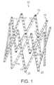
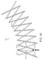
図1は、特定の管腔内支持構造の斜視図である。図示するように、支持構造10は、複数のスイベルジョイント15により相互接続される複数の長手方向ストラット部材11を含む医療用ステントである。具体的には、スイベルジョイント15によって、相互接続されたストラット部材11は、相互に対して回転可能になる。図示するように、18個のストラット11が存在する。 FIG. 1 is a perspective view of a particular intraluminal support structure. As shown, the
ストラット部材11は、プラスチックまたは他のポリマーならびにステンレス鋼、タンタル、チタン、ニッケル−チタン(例えば、ニチノール)、およびコバルト−クロム(例えば、ELGILOY)を含む金属合金等の、剛性または半剛性の生体適合性材料から製作される。各ストラットの寸法は、その所望の使用に従って選択されることができる。特定の実施形態では、各ストラット部材は、0.005〜0.020インチの厚さのステンレス鋼から作製される。より具体的には、各ストラットは、0.010インチの厚さの300シリーズステンレス鋼である。全てのストラット11は、一様な厚さを有するように示されるが、ストラットの厚さは、ストラットの長さに沿って徐々に厚さが増加または減少する等、ストラットによって変動することができる。さらに、個々のストラットは、同一の支持構造における他の個々のストラットとは異なる厚さを有することができる。 The
図示するように、各ストラット部材11は、棒形状であり、前面11fおよび裏面11bを有する。しかしながら、ストラット部材は、異なる幾何学的形状を有することができる。例えば、幅が均一である代わりに、ストラットの幅が、その長さに沿って変動することができる。さらに、個々のストラットは、同一支持構造における別のストラットとは異なる幅を有することができる。同様に、ストラットの長さは、同一支持構造内のストラットによって変動することができる。特定の寸法は、移植部位に基づいて選択されることができる。 As shown in the figure, each
さらに、ストラットは、非平坦構造であることができる。具体的には、ストラットは、ステント構造の内径に対して凹状または凸状等の湾曲を含むことができる。また、ストラットは、ねじれ状であることもできる。ストラットの非平坦性または平坦性は、ストラットが構成される材料の特性であることができる。例えば、ストラットは、種々の状態中に、ストラットに対する形状記憶または熱応答の形状変化を呈する。このような状態は、圧縮構成または拡張構成にあるステントによって規定されることができる。 Furthermore, the struts can be non-planar structures. Specifically, the strut can include a curvature such as concave or convex with respect to the inner diameter of the stent structure. The struts can also be twisted. Strut non-flatness or flatness can be a property of the material from which the strut is constructed. For example, struts exhibit shape memory or shape changes in thermal response to the struts during various states. Such a condition can be defined by a stent in a compressed or expanded configuration.
さらに、ストラット部材11は、平滑面性状または粗面性状を有することができる。具体的には、窪みのある方面は、引張強度をストラットに提供することができる。加えて、粗さまたは窪みは、追加の摩擦を提供し、移植部位における支持構造の固定に役立つことができ、かつ組織成長による支持構造10の不規則なカプセル化が、移植部位において支持構造10を経時的にさらに安定化させることを促すことができる。 Furthermore, the
一定の事例では、ステントは、相互に積み重なる複数の部材であるストラットから構成され得る。同一のステント内において、多層構成において相互に積み重なる細長い部材を含むストラットもあれば、単一厚さの部材から構成される単一層であるストラットもあり得る。単一のストラット内において、部材の単層および多層の積層範囲が存在することができる。 In certain instances, a stent may be composed of struts that are members that are stacked on top of each other. Within the same stent, some struts may include elongate members stacked on top of each other in a multi-layer configuration, while others may be single layer struts composed of a single thickness member. Within a single strut, there can be single and multi-layer stacking ranges of members.
また、各ストラット部材11は、ストラット部材11の長さに沿って離間する複数のオリフィス13も含む。前面11f上では、オリフィスは、締結具の頭部を収容する座ぐり17である。特定の実施形態では、各ストラット部材11の長さに沿って、13個の同等に離間したオリフィス13が存在するが、より多いまたは少ないオリフィスを使用することができる。オリフィス13は、ストラット部材11に沿って一様な直径および一様な間隔を有するように示されるが、いずれも必須ではない。 Each
ストラット部材11は、4つの棒の連結の連鎖として構成される。ストラット部材11は、整合されたオリフィス13を貫通するリベット等の旋回可能な旋回締結具25によって、相互接続される。ネジ、ボルト、玉継ぎ手構造、くぎ、または小穴等の他の旋回可能な締結具25を用いることができることと、窪みまたはオリフィスと相互作用するピーニング加工された半球体、または雄雌結合具等の締結具をストラット11に一体型に形成することができることとを理解されたい。締結具を収容することに加え、オリフィス13はまた、支持構造10を経時的に安定化させ、かつカプセル化するために、組織成長のための追加の経路も提供する。 The
図2は、図1のステントの4つのストラット区画の斜視図である。図示するように、2つの外側ストラット部材11−1、11−3は、2つの内側ストラット部材11−2、11−4に重なり、これらの裏面が相互に連通している状態である。 FIG. 2 is a perspective view of the four strut sections of the stent of FIG. As shown in the drawing, the two outer strut members 11-1 and 11-3 overlap the two inner strut members 11-2 and 11-4, and the back surfaces thereof are in communication with each other.
具体的には、第1のストラット部材11−1は、リベット25−1を使用して、中央スイベルジョイント15−1によって、第2のストラット部材11−1に旋回可能に接続され、中央スイベルジョイント15−1は、ストラット部材11−1、11−2を2等分するオリフィス13を利用する。同様に、第3のストラット部材11−3は、リベット25−7を使用して、中央スイベルジョイント15−7によって、第4のストラット部材11−4を2等分するように旋回可能に接続される。中央スイベルジョイント15−1、15−7が、ハサミ連結または機構におけるハサミ接合部として機能することを理解されたい。図示するように、結果として得られたハサミのアームは、同等の長さを有する。また、中央接合部15−1、15−7が、接合されたストラット部材を2等分する必要はなく、代わりに、ストラット部材の長手方向中心から相殺されるオリフィス13を利用して、同等ではないアームの長さをもたらすことも理解されたい。 Specifically, the first strut member 11-1 is pivotally connected to the second strut member 11-1 by a central swivel joint 15-1 using a rivet 25-1, and the central swivel joint 11-1. 15-1 uses an
中央ハサミ接合部15−1に加え、第1のストラット部材11−1は、ストラット部材11−1、11−3の遠位端付近に位置する遠位アンカースイベルジョイント15−5によって、第3のストラット部材11−3に旋回可能に接続される。同様に、第1のストラット部材11−1は、ストラット部材11−1、11−4の近位端付近に位置する近位アンカースイベルジョイント15−3によって、第4のストラット部材11−4に旋回可能に接続される。アンカーリベット25−3、25−5に対する応力を低減するために、ストラット11の遠位端および近位端は、接合されたストラットの間に平らな境界面を提供するように、湾曲状またはねじれ状であることができる。 In addition to the central scissor joint 15-1, the first strut member 11-1 is connected to the third by a distal anchor swivel joint 15-5 located near the distal end of the strut members 11-1, 11-3. The strut member 11-3 is pivotally connected. Similarly, the first strut member 11-1 is pivoted to the fourth strut member 11-4 by a proximal anchor swivel joint 15-3 located near the proximal end of the strut members 11-1, 11-4. Connected as possible. In order to reduce stress on the anchor rivets 25-3, 25-5, the distal and proximal ends of the
図示されるように、支持構造10(図1)は、連続したハサミ機構の連鎖を連結することによって製作される。ついで、この連鎖は、最後のハサミ機構を最初のハサミ機構に連鎖して接合するように巻き付けられる。連結を作動させることによって、輪を開放または閉鎖することができ、これによって、ステント10(図1)の拡張または圧縮がもたらされる。 As shown, the support structure 10 (FIG. 1) is fabricated by connecting a chain of successive scissor mechanisms. This chain is then wrapped to join the last scissor mechanism in a chain with the first scissor mechanism. By actuating the connection, the annulus can be opened or closed, which results in expansion or compression of the stent 10 (FIG. 1).
図1を再び参照すると、スイベルジョイント15を利用することによって、ステントの直径を圧縮して、動脈等の生体管腔に挿入することができる。次いで、ステントを拡張して、管腔内の選択された位置にステントを固定することができる。さらに、拡張後、ステントを再び圧縮して、身体から取り外すか、または管腔内に再配置することができる。 Referring again to FIG. 1, by utilizing the swivel joint 15, the stent diameter can be compressed and inserted into a biological lumen such as an artery. The stent can then be expanded to secure the stent at a selected location within the lumen. Further, after expansion, the stent can be compressed again and removed from the body or repositioned within the lumen.
図3は、圧縮された図1の支持構造の斜視図である。圧縮時に、ステント10は、その最大長さおよび最小直径にある。最大長さは、ストラット部材の長さによって限定され、特定の実施形態では、15mmである。最小直径は、ストラット部材の幅によって限定され、特定の実施形態では、0.052インチである。 3 is a perspective view of the compressed support structure of FIG. Upon compression, the
図4は、完全に拡張された状態における図1の支持構造の斜視図である。図示するように、完全に拡張された支持構造10は、弁形成リングとして使用可能であるリングを形成する。 4 is a perspective view of the support structure of FIG. 1 in a fully expanded state. As shown, the fully expanded
具体的には、ステント円周の一方の端部が、組織に取り付けられる場合、ステントの圧縮により、組織を締め付けることが可能になる。ステントは、増分および可逆的圧縮または拡張を有する能力を有するため、本デバイスを使用して、心臓弁の能力を高めるように組織の個別の締め付けを提供することができる。これは、僧帽弁逆流または僧帽弁逸脱等の僧帽弁疾患に有用な処置であり得る。 Specifically, when one end of the stent circumference is attached to the tissue, the tissue can be clamped by compression of the stent. Because the stent has the ability to have incremental and reversible compression or expansion, the device can be used to provide individual tightening of tissue to enhance the capacity of the heart valve. This can be a useful treatment for mitral valve disease such as mitral regurgitation or mitral valve prolapse.
支持構造10は、開放手術処置中に患者に移植されることができるが、閉鎖処置が、多くの場合、より望ましい。したがって、支持構造10は、作動機構を含むことができ、これによって、外科医は、移植部位から遠隔の位置から支持構造を拡張または圧縮することが可能になる。円筒状に巻き付けられるハサミ連結の特性に起因して(図1)、作動機構は、隣接するハサミ接合部間の距離を増加させること、およびアンカー接合部間の距離を減少させることのいずれかによって、ステント直径を拡張するように機能することができる。 Although the
図5は、特定のアクチュエータ機構を有する図2の支持構造の斜視図である。図示するように、アクチュエータ機構30は、支持構造10(図1)の内部に位置付けられる2重ネジ山付きロッド32を含む。しかしながら、アクチュエータ機構30を代わりに支持構造10の外部に位置付けてもよいことを理解されたい。位置付けられるのが内部または外部にかかわらず、アクチュエータ機構30は、同様に動作する。 FIG. 5 is a perspective view of the support structure of FIG. 2 having a particular actuator mechanism. As shown, the
ロッドは、その近位端に右方向ネジ山34Rと、その遠位端に左方向ネジ山34Lとを含む。ロッド32は、一対のネジ山付き低プロファイル支持装着具35−3、35−5を使用して、アンカー点15−3、15−5に装着される。ロッド32の各端部は、6角ドライバ(図示せず)を収容するための6角頭37−3、37−5によって終端となる。理解されるように、ロッド32を一方の方向に回転させることによって、アンカー点25−3、25−5が外側に付勢されて連結を圧縮し、ロッド32を反対の方向に回転させることによって、アンカー点25−3、25−5が内側に付勢されて連結を拡張する。 The rod includes a right-hand thread 34R at its proximal end and a left-
図6は、別の特定のアクチュエータ機構を有する図2の支持構造の斜視図である。図示するように、アクチュエータ機構30’は、支持構造10(図1)の内部に位置付けられる単一ネジ山付きロッド32’を含む。ロッド32’は、その両端のうちの片方の上にネジ山34’を含む。ロッド32’は、一対の支持装着具35’−3、35’−5を使用して、低プロファイルアンカー点15−3、15−5に装着され、支持装着具35’−3、35’−5のうちの1つは、ロッドネジ山34’と嵌合するようにネジ山を有する。ロッド32’のネジ山の無い端部は、支持構造を圧縮するように支持装着具35’−5に対して位置する保持止め具39’を含む。ロッド32’の各端部は、6角ドライバ(図示せず)を収容するための6角頭37’−3、37’−5によって終端となる。前述のように、ロッド32’を一方の方向に回転させることによって、アンカー点25−3、25−5が外側に付勢されて連結を圧縮し、ロッド32’を反対の方向に回転させることによって、アンカー点25−3、25−5が内側に付勢されて連結を拡張する。 6 is a perspective view of the support structure of FIG. 2 having another specific actuator mechanism. As shown, the actuator mechanism 30 'includes a single threaded rod 32' positioned within the support structure 10 (FIG. 1). The rod 32 'includes a thread 34' on one of its ends. The rod 32 'is attached to the low profile anchor points 15-3, 15-5 using a pair of support attachments 35'-3, 35'-5, and the support attachments 35'-3, 35'-. One of the five has a thread to mate with the rod thread 34 '. The unthreaded end of the rod 32 'includes a retention stop 39' positioned against the support fitting 35'-5 so as to compress the support structure. Each end of the rod 32 'is terminated by a hexagon head 37'-3, 37'-5 for accommodating a hexagon driver (not shown). As described above, by rotating the rod 32 'in one direction, the anchor points 25-3, 25-5 are biased outward, compressing the connection, and rotating the rod 32' in the opposite direction. As a result, the anchor points 25-3 and 25-5 are urged inward to expand the connection.
加えて、ストラットが重なるため、一方のストラットが他方のストラットに対して摺動する間に利用するように、ラチェット機構を組み込むことができる。例えば、ステントは、各ストラットの一体部品である特徴的な境界面に起因して、増分直径でロックすることができる。このような特徴の例は、2つのストラットが相互に摺動して通過するような、隣接するストラット表面上の雌構成要素(例えば、穴)と嵌合する一方のストラット表面上の雄構成要素(例えば、隆起)であり得る。このような構造は、ステントの拡張時にステントを拡張構成に増分的にロックするような配向を有するように製作され得る。このようなステントは、従来のバルーンまたは本出願に説明する他の作動機構を使用して拡張され得る。 In addition, since the struts overlap, a ratchet mechanism can be incorporated for use while one strut slides relative to the other strut. For example, the stent can lock in incremental diameters due to the characteristic interface that is an integral part of each strut. An example of such a feature is a male component on one strut surface that mates with a female component (eg, a hole) on an adjacent strut surface such that two struts slide past each other. (Eg, a bump). Such a structure can be fabricated to have an orientation that incrementally locks the stent to the expanded configuration when the stent is expanded. Such stents can be expanded using conventional balloons or other actuation mechanisms described in this application.
図5および図6の支持構造10は、閉鎖手術処置中に移植されることを意図するため、アクチュエータ機構は、外科医によって遠隔制御される。一般的な処置では、支持構造10は、係留型管腔内カテーテルを使用して、大腿動脈等の体内管腔を通して移植される。したがって、アクチュエータ機構30は、カテーテルを介して制御され得る。 Since the
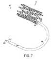
図7は、図5および図6のアクチュエータ機構とともに使用可能である特定の支持構造および制御カテーテルアセンブリの斜視図である。制御カテーテル40は、ヒトの動脈等の生体管腔を通って、支持構造とともに挿入されるような寸法を有する。図示するように、制御カテーテル40は、アクチュエータ機構(図5および図6)の6角頭37、37’と着脱可能に嵌合するその遠位端上にドライバ44を有する可撓性駆動ケーブル42を含む。ケーブル42の近位端は、6角頭46を含む。操作中、ケーブル42の近位6角頭46は、サムホイールまたは他の適切なマニピュレータ(図示せず)を使用して、外科医によって回転される。6角頭46の回転は、ケーブル42によってドライバヘッド44に伝達され、アクチュエータロッド30、30’(図5および図6)を回転する。 FIG. 7 is a perspective view of a particular support structure and control catheter assembly that can be used with the actuator mechanism of FIGS. 5 and 6. The
ケーブル42は、可撓性外側シース48によって包封される。外側シース48の遠位端は、支持構造10と相互作用するような形状を有する唇部または突起49を含む。ケーブル42が回転すると、外側シース唇部49は、支持構造10と相互作用して、結果として生じるトルクに対抗する。
ネジ山を用いることによって、ロッドは、支持構造を所望の直径に維持するように自動ロック式である。特定の実施形態では、ロッド32、32’は、1.0mmの直径と、240回転/インチのネジ山数とを有する。ネジ山付きロッドおよび駆動機構について説明されるが、特定の手術応用に応じて、連結を作動させるように他の手法を用いてもよい。例えば、アクチュエータ機構を、ステントの内部または外部の代わりに、ストラット部材の厚さ内に配置してもよい。例えば、当技術分野において既知であるように、ウォーム歯車またはラックアンドピニオン機構を用いてもよい。当業者は、他の管腔内作動技法を認識するはずである。他の状況では、支持構造は、開放処置中に移植されることができ、この場合、外部作動機構は必要とされ得ない。 By using threads, the rod is self-locking to maintain the support structure at the desired diameter. In a particular embodiment, the
薬物送達等の、上述の支持構造の他の使用が存在するが、特定の実施形態は、人工弁を支持する。具体的には、支持構造は、大動脈弁置換術等のために、人工弁と組み合わせて使用される。 While there are other uses for the support structure described above, such as drug delivery, certain embodiments support a prosthetic valve. Specifically, the support structure is used in combination with an artificial valve for aortic valve replacement or the like.
図8は、特定の回転人工弁アセンブリの斜視図である。人工弁100は、開放位置において示される3つの弁尖構成を備える。弁尖は、動物の心膜(例えば、ウシ、ブタ、ウマ)、ヒトの心膜、化学処理した心膜、グルタルアルデヒド処理した心膜、組織工学的に作製された材料、組織工学的に作製された材料のための足場、自家心膜、死体心膜、ニチノール、ポリマー、プラスチック、PTFE、または当技術分野において既知である任意の他の材料等の、生体適合性材料由来である。 FIG. 8 is a perspective view of a particular rotary prosthetic valve assembly. The
弁尖101a、101b、101cは、定常円筒状部材105および非定常円筒状部材107に取り付けられる。各弁尖101の1つの側面は、非定常円筒状部材107に取り付けられる。各弁尖101の反対の側面は、定常円筒状部材105に取り付けられる。各弁尖101の取り付けは、円筒状部材105、107の長手方向軸に対して略垂直である方向である。本実施形態では、各弁尖101は、柔軟で、略長方形であり、定常部材105および非定常部材107へのその取り付けの間で180度のねじれを有する。各弁尖101は、内縁102および外縁103を有し、1つの弁尖101cの縁102c、103cは、図面において参照されている。当技術分野において既知であるように、弁尖は、生物学的材料もしくは非生物学的材料、またはそれらの組み合わせのいずれかから製作されることができる。 The
弁を閉鎖させる作動法の1つは、心周期の通常の血流または血圧の変化により及ぼされる力を利用することによる。より具体的には、心臓は、図8に示す矢印の方向に、完全に開放した弁を通して血液を吐出する。その直後に、遠位または下流の血圧は、弁において、近位の圧力に対して上昇し始め、弁に背圧を生成する。 One method of closing the valve is by utilizing the force exerted by changes in normal blood flow or blood pressure during the cardiac cycle. More specifically, the heart discharges blood through a fully open valve in the direction of the arrow shown in FIG. Immediately thereafter, the distal or downstream blood pressure begins to rise relative to the proximal pressure at the valve, creating a back pressure at the valve.
図9は、閉鎖中の図8の弁アセンブリの斜視図である。矢印の方向に沿ったこの背圧によって、弁尖101および非定常部材107の定常円筒状部材105に向かう軸方向の変位が引き起こされる。弁尖101が長手方向軸に対して垂直から水平平面に移動する際、正味の反時計回りトルク力が、非定常部材107および弁尖101に及ぼされる。トルク力は、求心力を弁尖101に作用させる。 FIG. 9 is a perspective view of the valve assembly of FIG. 8 during closure. This back pressure along the direction of the arrow causes axial displacement of the leaflet 101 and the
図10は、完全に閉鎖した後の図8の弁アセンブリの斜視図である。図示するように、弁尖101が弁の中心に変位し、非定常円筒状部材107が定常部材105の上に存在する際に、弁100の完全な閉鎖が発生する。 FIG. 10 is a perspective view of the valve assembly of FIG. 8 after full closure. As shown, complete closure of the
弁100開放の機能については、弁閉鎖のステップの逆を順守することによって、つまり、図10から図8の図の順に従って、理解することができる。 The function of opening the
大動脈弁置換術として弁100を考察すると、弁は、心臓が収縮期に入るまで、図10に示すように閉鎖状態のままであり得る。収縮期中、心筋が強く収縮する際、弁の近位側(心臓に最も近い側面)に及ぼされる血圧は、閉鎖した弁の遠位側(下流)の圧力よりも大きい。この圧力勾配によって、弁尖101および非定常円筒状部材107は、軸平面に沿って定常部材105から離隔して変位する。弁100は、簡潔に言うと、図9に示す半閉鎖移行状態を帯びる。 Considering
弁尖101が軸平面に沿って水平配向から垂直配向へ伸長する際、正味のトルク力が、弁尖101および非定常円筒状部材107に及ぼされる。弁100が開放するため、閉鎖とは対照的に、弁を開放するように及ぼされるトルク力は、弁を閉鎖するように及ぼされる力とは反対である。図9に示す実施形態の構成を考えると、弁を開放するトルク力は、時計回りの方向であり得る。 As the leaflet 101 extends from the horizontal orientation to the vertical orientation along the axial plane, a net torque force is exerted on the leaflet 101 and the unsteady
トルク力によって、弁尖101は、弁100の長手方向軸を中心に非定常部材107とともに回転する。次いで、これは、各弁尖101に遠心力を作用させる。弁尖101は、中心から離隔する半径方向変位を受け、弁を効果的に開放し、図8の矢印が示す方向に、血液が心臓から離隔して流れることを可能にする。 Due to the torque force, the leaflet 101 rotates with the
要約すると、弁は、3つの力を連結することによって、一方向の血流を提供するように受動的に機能する。軸方向トルク力および半径方向力は、順次的かつ可逆的方式で変換されるとともに、前の運動の方向性をコード化する。最初に、血流および血圧の軸方向力によって、軸平面に沿った、定常部材105に対する弁尖101および非定常部材107の変位が引き起こされる。これは、弁尖101および非定常部材107に対する回転力に変換される。次いで、トルク力は、半径方向平面に沿って、弁の中心に向かって、または弁の中心から離隔して弁尖101を変位し、弁100を閉鎖または開放する。弁100は、心周期により弁に最初に印加された軸方向力の方向に応じて、開放または閉鎖の経路を受動的に追従する。 In summary, the valve functions passively to provide unidirectional blood flow by connecting three forces. Axial torque forces and radial forces are converted in a sequential and reversible manner and encode the direction of previous motion. Initially, axial forces of blood flow and blood pressure cause displacement of the leaflet 101 and the
体内において、定常円筒状部材105は、移植部位における適所に固定および固着されることができ、非定常部材107および弁尖101の遠位端は、軸平面に沿って自由に変位する。大動脈弁置換術として人工弁を使用する際、定常部材105は、大動脈基部に固定され得る。心臓からの血圧または血流が増加する際、弁100は、血液が弁100から吐出している状態で、その閉鎖構成から開放構成に変化する。 Within the body, the stationary
図8〜図10の回転弁の具体的な利点は、さらなる実施形態とともに、上記に組み込まれた特許の仮特許出願に説明される。 Specific advantages of the rotary valve of FIGS. 8-10, as well as further embodiments, are illustrated in the provisional patent application of the above incorporated patent.
図11は、図1の支持構造と組み合わせた図8〜図10の弁の斜視図である。閉鎖位置で示されるように、弁の定常部材105は、支持構造10に取り付けられる。弁の非定常部材107は、支持構造10に取り付けられていない。これにより、非定常部材107は、弁の開放または閉鎖中に、軸平面に沿って、弁尖101とともに変位することが可能になる。この特定の実施形態では、弁100は、図示するように、支持構造10の一方の端部に近い位置を占める。 11 is a perspective view of the valve of FIGS. 8-10 in combination with the support structure of FIG. As shown in the closed position, the valve
図12は、開放位置にある図11の弁の斜視図である。上述のように、非定常部材107は、支持構造10に取り付けられていないため、軸平面に沿って、弁尖101とともに自由に変位する。この特定の実施形態では、完全に開放している間、非定常部材107および弁尖101は、支持構造10内にとどまる。 12 is a perspective view of the valve of FIG. 11 in the open position. As described above, since the
ステント型弁110は、上述のように、閉鎖処置中に移植されることができる。しかしながら、ステントの本体内の非定常部材の動作に起因して、ステントを圧縮および拡張するアクチュエータ機構は、ステント内に配置され得ない。 The stent-
ステント型弁110のさらなる実施形態、本体内の弁の位置決め、および移植の処置は、上記に組み込まれる特許の仮特許出願に説明される。加えて、組織弁が、支持構造上にドレープされ得る。追加の実施形態は、当業者に明白であるはずである。 Further embodiments of the stent-
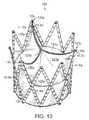
図13は、図1の支持構造に装着される従来の組織弁の斜視図である。図示するように、ステント型弁120は、上述の支持構造等の支持構造10に取り付けられる人工組織弁121を含む。 FIG. 13 is a perspective view of a conventional tissue valve mounted on the support structure of FIG. As shown, the stent-
組織弁121は、3つの柔軟な半円形弁尖121a、121b、121cを含み、これらの弁尖は、図8に関連して述べたように、生体適合性材料由来であることができる。隣接する弁尖は、対になって、支持構造10上の合わせ目123x、123y、123zに取り付けられる。具体的には、合わせ目123x、123y、123zは、支持構造10上の離間する遠位アンカー点13x、13y、13zに対応する。18個のストラットステントでは、合わせ目は、2つの遠位アンカー点おきに、対応する締結具25を介して構造10に取り付けられる。 The tissue valve 121 includes three flexible
合わせ目から、弁尖側面は、隣接する斜めストラットに接続される。すなわち、第1の弁尖121aの側面は、ストラット11−Xaおよび11−Zaにそれぞれ縫合され、第2の弁尖121bの側面は、ストラット11−Xbおよび11−Ybにそれぞれ縫合され、第3の弁尖121cの側面は、ストラット11−Ycおよび11−Zcにそれぞれ縫合される。これらの縫合は、斜めストラット上のハサミ旋回点において終端となる。 From the seam, the leaflet side is connected to adjacent diagonal struts. That is, the side surface of the
図示する構成では、隣接するストラット11は、ステントの端部において複数のアーチ128を作成するように、相互に取り付けられる。弁尖取り付けのための柱または合わせ目は、適切なアーチ128x、128y、128zを画定するストラットの各々に、隣接する弁尖を取り付けることによって形成される。図示する構成では、3つの弁尖121a、121b、121cが存在し、その各々は、その反対の境界のうちの2つに沿ってストラットに取り付けられる。合わせ目は、ステントにおける3つの等間隔アーチ128x、128y、128zによって形成される。 In the illustrated configuration,
その隣接するストラットに関連付けられるストラットの傾斜配向によって、弁尖121a、121b、121cは、三角形構成でステントに取り付けられる。この三角形構成は、自然大動脈弁尖の傾斜取り付けをシミュレーションする。自然弁では、これは、内側弁尖三角部として知られる弁尖間の解剖学的構造を作成する。解剖学的内側弁尖三角部は、ヒトの自然大動脈弁尖に構造的完全性および耐久性を提供すると考えられることから、人工弁においてこの構造をシミュレーションすることは有利である。 The
弁尖をストラットに取り付ける一方法は、多層ストラット間に弁尖を挟むことである。次いで、多数の層は、縫合によってまとめて保持される。ストラット間に弁尖を挟むことは、弁尖に対する力の消散および弁尖を通る縫合の裂けの防止に役立つ。 One way to attach the leaflets to the struts is to sandwich the leaflets between multilayer struts. The multiple layers are then held together by stitching. Holding the leaflets between the struts helps dissipate force on the leaflets and prevent tearing of the sutures through the leaflets.
各弁尖121a、121b、121cの残りの側面は、弁尖の縫い目によって示されるように、中間ストラット部材を環状に横断して縫合される。ストラット間の残りの開放空間は、移植部位に対する弁の封止、ひいては弁傍漏出の制限に役立つように、生体適合性スカート125によってドレープされる。図示するように、スカート125は、弁尖の下および弁尖の間のステントのこれらの部分を被覆するような形状を有する。 The remaining sides of each leaflet 121a, 121b, 121c are sutured annularly across the intermediate strut member as indicated by the leaflet seam. The remaining open space between the struts is draped by the
より詳細には、弁の基部におけるスカート125は、ステント壁を裏打ちする薄い材料層である。スカート材料は、心膜組織、ポリエステル、PTFE、または成長する組織を受け入れるのに適切な他の材料もしくは材料の組み合わせであることが可能であり、組織成長を促進するか、または感染を阻止する化学処理した材料が含まれる。スカート層は、弁の周囲の漏出、つまり弁傍漏出を低減または排除するように機能する。このために、以下を含む、スカート材料層をステントに取り付ける多数の方法が存在する:
・スカート層は、ステントの内部または外部上に存在することができる;
・スカート層は、ステントの下側部分を占めることができる;
・スカート層は、ステントの下側および上側部分を占めることができる;
・スカート層は、ステントの上側部分のみを占めることができる;
・スカート層は、合わせ目の柱を画定するストラット間の範囲を占めることができる;
・ スカート層は、弁尖材料と連続的であることができる;
・ スカート層は、ストラットまたは多数の部位に縫合されることができる;または、
・ スカート層は、ステントの下側部分に固定され、体内への配備中にステントの外部を被覆するように引張または押圧されることができる。More particularly, the
The skirt layer can be on the inside or the outside of the stent;
The skirt layer can occupy the lower part of the stent;
The skirt layer can occupy the lower and upper portions of the stent;
The skirt layer can occupy only the upper part of the stent;
The skirt layer can occupy the area between the struts defining the column of seams;
The skirt layer can be continuous with the leaflet material;
The skirt layer can be sutured to struts or multiple sites; or
The skirt layer can be secured to the lower portion of the stent and pulled or pressed to cover the exterior of the stent during deployment into the body.
当業者が具体的な用途について代替のドレープ技法を認識できるため、上記に列挙したものは、必ずしも限定的ではない。 The above list is not necessarily limiting, as one skilled in the art can recognize alternative drape techniques for specific applications.
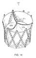
図14は、完全な内側スカートを有する図13の弁構造の斜視図である。ステント型弁120’は、支持構造10に取り付けられる3つの弁尖121a’、121b’、121c’を有する人工組織弁121’を含む。スカート層125’は、ステント10の内面を被覆する。したがって、弁尖121a’、121b’、121c’は、スカート層125’に縫合される。 14 is a perspective view of the valve structure of FIG. 13 having a complete inner skirt. The stent-
図15は、完全な外側スカートを有する図13の弁構造の斜視図である。ステント型弁120”は、図13において説明するような、支持構造10に取り付けられる3つの弁尖121a”、121b”、121c”を有する人工組織弁121”を含む。スカート層125”は、ステント10の外面を被覆する。 FIG. 15 is a perspective view of the valve structure of FIG. 13 having a complete outer skirt. The stent-
また、組織弁構造120、120’,120”は、上述のように、閉鎖処置中に移植されることができる。しかしながら、ステントを圧縮および拡張するアクチュエータ機構は、アクチュエータ機構をステント10の外面に装着する等によって合わせ目点を回避し、かつスカート層125、125’、125”に対する損傷を制限するように取り付けられ得る。 Also, the
上述の実施形態は、線状ストラット棒および同等長さのハサミアームを有する支持構造を取り上げているが、他の幾何学的形状を用いてもよい。結果として生じる形状は、円筒状以外のものであり、一定の用途においてより良好な性能を有することができる。 While the above-described embodiments address a support structure having a linear strut bar and an equal length scissor arm, other geometric shapes may be used. The resulting shape is other than cylindrical and can have better performance in certain applications.
図16は、円錐形支持構造構成におけるストラット部材の配置の斜視図である。円錐構造10’では、ストラット部材11は、中央ハサミ旋回部がストラットを2等分しないこと以外は、図2に示すように配置される。具体的には、中央ハサミ旋回部(例えば、15’−1、15’−7)は、接合されたストラット部材(例えば、11’−1、11’−2および11’−3、11’4)を、5/12長さおよび7/12長さの同等ではない区画に分割する。完全に組み立てられると、結果として生じる支持構造は、拡張時に円錐形状に一致する。例示目的のために、ステント10’は、単一ネジ山付きアクチュエータロッド32’(図6)を含んで示されるが、このステント実施形態に必須の要素ではない。 FIG. 16 is a perspective view of the arrangement of strut members in a conical support structure configuration. In the
また、ステント10’は、凸状または凹状の湾曲を、ステント10’を備える個々のストラット部材11に与えることによって、その拡張された構成において円錐形状も帯びることができる。これは、形状記憶または温度感受性ニチノール等の、記憶を有する材料を使用することによって達成され得る。 The stent 10 'can also assume a conical shape in its expanded configuration by imparting a convex or concave curvature to the
弁は、弁の基部が、円錐形ステントの狭い方の部分にあり、弁の基部でない部分が円錐の広い方の部分にあるように、円錐形ステント10’で配向されることができる。代替として、弁の基部は、ステントの最も広い部分に位置し、弁の基部でない部分は、それよりも広くない部分にあることができる。 The valve can be oriented with the conical stent 10 'so that the base of the valve is in the narrow portion of the conical stent and the non-base portion of the valve is in the wide portion of the cone. Alternatively, the base of the valve may be located at the widest portion of the stent and the non-base portion of the valve may be at a portion that is not wider.
体内における円錐形ステント10’の配向は、血流の流れに向かうか、またはその流れから離隔するかのいずれかであることができる。他の体内管腔(例えば、気道または消化管)では、ステントは、軸平面に関連していずれかの方向に配向され得る。 The orientation of the conical stent 10 'in the body can either be towards or away from the blood flow. In other body lumens (eg, airways or gastrointestinal tract), the stent can be oriented in either direction relative to the axial plane.
図17は、砂時計形支持構造構成の斜視図である。本構成では、中央旋回点15”−1、15”−7、15”−9(くびれ部)の周囲の円周は、ステント10”の両端における円周よりも小さい。図示するように、砂時計形支持構造10”は、ストラット部材11”の数を6個に減らして、前の実施形態に比べてストラット部材11”を短くすることによって達成される。短くしたことにより、ストラット部材11”当たりのオリフィス13”の数が少なくなる。ストラットの数および幾何学的形状により、各ストラット部材11”は、3つの長手方向平面に沿った点19”においてねじれを含む。このねじれは、接合されたストラット15”−3間に平らな境界面を提供する。 FIG. 17 is a perspective view of an hourglass-shaped support structure configuration. In this configuration, the circumference around the central pivot points 15 ″ -1, 15 ″ -7, 15 ″ -9 (necked portion) is smaller than the circumference at both ends of the
また、砂時計ステント構成は、個々の棒11”に凸状または凹状湾曲を与えることによって達成され得る。この湾曲は、材料の特性(例えば、形状記憶または感熱ニチノール)であり得る。湾曲は、圧縮されたステント状態では存在せず、ステントがその拡張された状態にある場合に出現する。 An hourglass stent configuration can also be achieved by imparting a convex or concave curvature to the
上述の支持構造のうちのいずれかが、ステントの両端のうちのいずれかにおけるアンカー接合点を超えて延出可能であることに留意されたい。一連のステントを末端間連鎖様式で結合することによって、追加のステントの長さおよび幾何学的形状を製作することができる。具体的には、砂時計形ステントは、2つの円錐形ステントをその2つの狭い端部で接合することによって達成され得る。また、砂時計形状は、図14に示すように、中央ハサミ旋回部を分解することによって修正されることができる。 Note that any of the support structures described above can extend beyond the anchor junction at either of the ends of the stent. Additional stent lengths and geometries can be fabricated by joining a series of stents in an end-to-end linkage fashion. Specifically, an hourglass stent can be achieved by joining two conical stents at their two narrow ends. Also, the hourglass shape can be corrected by disassembling the central scissor swivel as shown in FIG.
本発明の特定の実施形態は、その構造および用途を含む従来技術を上回る明らかな利点を提供する。一定の利点について以下に要約するが、追加の利点が存在し得るため、要約は、必ずしも完全なリストではない。 Certain embodiments of the present invention provide clear advantages over the prior art including its structure and application. Although certain advantages are summarized below, the summaries are not necessarily a complete list because additional advantages may exist.
本デバイスによって、使用者は、経皮的心臓弁移植中に発生し得る深刻な合併症を避けることが可能になる。本デバイスは、体内への移植中に回収可能および再配置可能であることから、外科医は、移植中の弁の位置異常または移動に起因する深刻な合併症を回避することができる。これらの合併症の例として、冠状動脈の閉塞、大量弁傍漏出、または不整脈が挙げられる。 The device allows the user to avoid serious complications that can occur during percutaneous heart valve implantation. Because the device is retrievable and repositionable during implantation into the body, the surgeon can avoid serious complications due to valve misplacement or movement during implantation. Examples of these complications include coronary artery occlusion, massive paravalvular leakage, or arrhythmia.
また、本デバイスは、デバイスの狭い挿入プロファイルに起因して、血管アクセス合併症も減少させることができる。デバイスのプロファイルは、その独特の幾何学的形状に部分的に起因して低く、これにより、ステントにおける隣接するストラットが、ステントの圧縮中に重なることができる。デバイスの低プロファイルは、バルーンまたはシースの必要性を排除することによって、さらに補強される。本デバイスの狭いプロファイルは、患者における血管アクセス経路選択肢を広げる利点を提供する。例えば、本デバイスによって、患者の脚の動脈を通る人工弁の送達が可能になり、以前であれば、この患者は、胸壁を通るより侵襲的な手法を受けていたであろう。ゆえに、本デバイスは、血管アクセス不良の患者における大きいプロファイルのデバイスの使用に関連する合併症を減少させることを目的とする。 The device can also reduce vascular access complications due to the narrow insertion profile of the device. The device profile is low due in part to its unique geometry, which allows adjacent struts in the stent to overlap during stent compression. The low profile of the device is further reinforced by eliminating the need for a balloon or sheath. The narrow profile of the device offers the advantage of expanding vascular access pathway options in patients. For example, the device allows for the delivery of a prosthetic valve through the artery of the patient's leg, and previously the patient would have undergone a more invasive procedure through the chest wall. The device is therefore aimed at reducing the complications associated with the use of large profile devices in patients with poor vascular access.
組織弁の実施形態は、弁尖の可撓性合わせ目柱への取り付けを可能にすることによって、耐久性の改善を提供することができる。可撓性柱によって、心周期により弁尖に与えられる応力および歪みの消散が可能になる。多重層ストラットの使用によって、弁尖を、ストラット間に挟むことが可能になり、弁尖取り付けが再び実施され、縫合の裂けが防止される。さらに、弁は、望ましい弁尖形態を帯び、この弁尖形態によって、弁尖に対する応力および歪みが低減する。すなわち、ステントへの傾斜弁尖の取り付けは、自然のヒトの大動脈弁の弁尖間内側三角部パターンに類似する。これらの特性によって、経皮的心臓弁置置換治療の寿命が大幅に改善される。 Tissue valve embodiments can provide improved durability by allowing attachment of a leaflet to a flexible joint. The flexible column allows the dissipation of stress and strain applied to the leaflets by the cardiac cycle. The use of multi-layer struts allows the leaflets to be sandwiched between struts, the leaflet attachment is performed again, and sutures are prevented from tearing. In addition, the valve assumes the desired leaflet shape, which reduces stress and strain on the leaflet. That is, the attachment of a beveled leaflet to a stent is similar to the intervertebral inner triangular pattern of natural human aortic valves. These properties greatly improve the lifetime of percutaneous heart valve replacement therapy.
このデバイスは、ステントの増分拡張または圧縮に起因して、不整脈合併症を低減または排除し得る。ステントは、配備するためにネジ機構を用いることができ、ネジ機構によって、ステントは、全半径において自動ロックまたはロック解除することが可能になる。これにより、より制御された配備と、各患者におけるデバイスの拡張または圧縮を個別化する可能性とが可能になる。デバイスの拡張または圧縮が、処置中の任意の段階において可逆的であることから、外科医は、不整脈を軽減するために、本デバイスの拡張を容易に逆行させることができる。加えて、移植中に不整脈が検出される場合、デバイスを再配置して、問題をさらに排除することができる。 This device may reduce or eliminate arrhythmia complications due to incremental expansion or compression of the stent. The stent can use a screw mechanism for deployment, which allows the stent to automatically lock or unlock at all radii. This allows for more controlled deployment and the possibility of individualizing device expansion or compression in each patient. Because the expansion or compression of the device is reversible at any stage during the procedure, the surgeon can easily reverse the expansion of the device to reduce arrhythmias. In addition, if an arrhythmia is detected during implantation, the device can be repositioned to further eliminate the problem.
このデバイスは、正確に配置され、かつ必要に応じて再配置されるデバイスの能力に起因して弁傍漏出を低減または排除することができる。これにより、弁傍漏出の発生および重度を大幅に減少させることができる。 This device can reduce or eliminate paravalvular leakage due to the ability of the device to be accurately positioned and repositioned as needed. As a result, the occurrence and severity of paravalvular leakage can be greatly reduced.
このデバイスは、バルーン関連合併症を排除する。配備のネジ機構は、ネジの機械的利点を活用する。これは、ステントの強力な膨張を提供する。ステントのハサミ連結におけるストラットの旋回により作成されるレバーアームは、さらなる拡張力をステントに伝達する。ステントは、バルーンを必要とせずに拡張される。加えて、強力に膨張されるデバイスの能力は、患者における移植処置中にバルーン処理前または処理後の必要性を軽減または排除する。 This device eliminates balloon-related complications. The deployment screw mechanism takes advantage of the mechanical advantages of screws. This provides for strong expansion of the stent. A lever arm created by the pivoting of the struts in the stent scissors connection transmits further expansion force to the stent. The stent is expanded without the need for a balloon. In addition, the ability of the device to be strongly inflated reduces or eliminates the need before or after ballooning during the implantation procedure in the patient.
このデバイスは、圧縮位置と拡張位置とにおけるステントの高さの差異が小さいことから、体内において、より予測可能であり、かつ正確な位置決めを有する。この「この減少した短縮化」は、外科医が、体内の望ましい位置にデバイスを位置決めするのに役に立つ。体内においてデバイスを再配置する能力は、各個人においてデバイスを正確に位置付ける能力をさらに与える。 This device has a more predictable and accurate positioning within the body due to the small difference in stent height between the compressed and expanded positions. This “reduced shortening” helps the surgeon position the device at the desired location in the body. The ability to reposition the device within the body further provides the ability to accurately position the device in each individual.
機械的利点に加え、本デバイスによって、より広範の患者集団が、弁置換のための低侵襲的手段によって処置されることが可能になる。例えば、本デバイスによって、開胸手術弁置換に適応しない併存疾患を有する患者に、処置選択肢を提供することが可能になる。また、狭いプロファイルを帯びるデバイス能力によって、血管アクセスの不良(例えば、蛇行性動脈、石灰化動脈、または小動脈)に起因して以前処置を拒否された患者に、処置選択肢を提供することが可能になる。弁の耐久性によって、低侵襲的処置の使用は、拒否されなければ開胸手術弁置換に適応し得る健康な患者集団に拡大するはずである。強力に拡張するか、または砂時計形状もしくは円錐形状を帯びる本デバイスの能力によって、デバイスの用途は、大動脈弁閉鎖不全症ならびに大動脈弁狭窄症と診断された患者の治療に潜在的に拡大する。 In addition to mechanical advantages, the device allows a wider patient population to be treated by minimally invasive means for valve replacement. For example, the device can provide treatment options for patients with co-morbidities that are not amenable to open heart valve replacement. In addition, the device's ability to take on a narrow profile can provide treatment options for patients who have previously been denied treatment due to poor vascular access (eg, tortuous, calcified, or small arteries) become. Due to the durability of the valve, the use of minimally invasive procedures should expand to a healthy patient population that can accommodate open heart surgery valve replacement if not refused. The ability of the device to expand strongly or assume an hourglass or conical shape potentially expands the device's application to the treatment of patients diagnosed with aortic regurgitation as well as aortic stenosis.
また、本デバイスは、「バルブインバルブ」処置を提供することによって、従来の移植片からの変性人工器官を有する患者に低侵襲的治療を提供することもできる。本デバイスは、患者の変形人工器官を除去せずに、不全弁の内部に正確に位置付けられ得る。これは、「再実行」動作およびそれに関連するリスクを含まずに、機能弁置換を提供することによって、患者を助ける。 The device can also provide a minimally invasive therapy to patients with degenerative prostheses from conventional implants by providing a “valve-in-valve” procedure. The device can be accurately positioned inside the failure valve without removing the patient's deformed prosthesis. This helps the patient by providing functional valve replacement without including the “redo” action and associated risks.
本発明は、特定の実施形態に関連して具体的に図示および説明されているが、添付の請求項により包含される本発明の内容から逸脱することなく、形式および詳細について種々の変更を実施形態に加えてもよいことを当業者により理解されたい。 Although the invention has been particularly shown and described with reference to specific embodiments, various changes can be made in form and detail without departing from the scope of the invention as encompassed by the appended claims. It should be understood by those skilled in the art that it may be added to the form.
(関連出願の相互参照)
本願は、米国仮特許出願第61/082,489号(名称「Prosthetic Valve with Rotating Leaflets and Retrievable Support」、2008年7月21日出願、出願人「Jennifer K. White」)の利益を主張する。この出願の全教示は、本明細書に参考として援用される。(Cross-reference of related applications)
This application claims the benefit of US Provisional Patent Application No. 61 / 082,489 (named “Prosthetic Valve with Rotating Leaflets and Retrievable Support”, filed July 21, 2008, applicant “Jennifer K. White”). The entire teachings of this application are incorporated herein by reference.
管腔内ステントは、患者の管腔または管に移植され、開放管腔の維持に役立つことができる。また、ステントをフレームとして使用して、人工器官を支持すること、または治療薬を送達することもできる。ステントは、開放手術処置または閉鎖手術処置のいずれかによって移植され得る。選択できる場合、概して、低侵襲性の閉鎖処置が好まれ、これは、ステントが大腿動脈等の体内管腔を通って、その所望の部位に案内され得るからである。閉鎖処置は、一般的には、2つの技法のうちの1つを使用する。 Intraluminal stents can be implanted in a patient's lumen or tube to help maintain an open lumen. A stent can also be used as a frame to support a prosthesis or to deliver a therapeutic agent. The stent can be implanted by either an open surgical procedure or a closed surgical procedure. If selected, a less invasive closure procedure is generally preferred because the stent can be guided through a body lumen such as the femoral artery to its desired site. Closure procedures typically use one of two techniques.
一方の閉鎖処置は、拡張型ステントが膨張型バルーンを包囲するバルーンカテーテル法を用いる。この処置では、ステントは、バルーンを膨張させて、これによりステントが拡張することによって移植される。ステントの実際の位置決めは、バルーンの収縮後まで決定することができず、ステントが誤留置される場合、この過程を逆行してステントを再配置することはできない。 One closure procedure uses balloon catheterization in which an expandable stent surrounds an inflatable balloon. In this procedure, the stent is implanted by inflating the balloon, thereby expanding the stent. The actual positioning of the stent cannot be determined until after the balloon is deflated, and if the stent is misplaced, the process cannot be reversed to reposition the stent.
他方の閉鎖処置は、着脱可能なシースによって包囲された圧縮ステントを用いる。この処置では、ニチノール(登録商標)等の形状記憶合金から作製されたステントが、シースによって圧縮状態に保持される。ステントは、シースを引き込み、これによってステントをその公称形状に拡張することによって移植される。これもまた、ステントが誤留置される場合、この過程を逆行してステントを再配置することはできない。The other closure procedure uses a compressed stent surrounded by a removable sheath. This treatment,Nitinol stents made of shape memory alloy or the like is held in a compressed state by a sheath. The stent is implanted by retracting the sheath, thereby expanding the stent to its nominal shape. Again, if the stent is misplaced, the process cannot be reversed to reposition the stent.
ステントを使用して心臓弁を支持する場合、位置決め誤差は特に危険である。入手可能なステント装着型弁を使用する体内の移植部位における弁の位置異常に起因して、深刻な合併症および患者の死亡が発生している。弁の位置異常は、大量の弁傍漏出、デバイスの移動、および冠状動脈閉塞をもたらしている。これらの合併症の大部分は、避けられないものであるが、処置時に検出される。しかしながら、デバイスの再配置または回収が不可能であるため、これらの問題は、処置中に逆行または軽減することが不可能である。 Positioning errors are particularly dangerous when using a stent to support a heart valve. Serious complications and patient deaths have occurred due to valve position abnormalities at the implantation site in the body using available stent-mounted valves. Valve position abnormalities have resulted in massive paravalvular leakage, device movement, and coronary artery occlusion. Most of these complications are unavoidable but are detected at the time of treatment. However, these problems cannot be reversed or alleviated during the procedure because device relocation or recovery is not possible.
本発明の一定の実施形態に従う管腔内支持構造またはステントは、従来技術に見られる一定の欠陥を解決する。具体的には、支持構造を体内管腔内に再配置するか、または管腔から回収することができる。 Intraluminal support structures or stents according to certain embodiments of the present invention solve certain deficiencies found in the prior art. Specifically, the support structure can be repositioned within the body lumen or retrieved from the lumen.
本発明の特定の実施形態は、生体管腔内に移植可能である支持装置を含む。支持装置は、複数のスイベルジョイントによって相互連結される複数の細長いストラット部材を含むことができ、スイベルジョイントは、圧縮配向と拡張配向との間で成形構造を調整可能に画定するためにステント部材と協力することができる。 Certain embodiments of the present invention include a support device that is implantable within a biological lumen. The support device can include a plurality of elongate strut members interconnected by a plurality of swivel joints, the swivel joints including a stent member to adjustably define a molded structure between a compression orientation and an expanded orientation. Can cooperate.
より具体的には、成形構造は、円筒形状、円錐形状、または砂時計形状のうちの1つであることができる。スイベルジョイントは、第1のストラット部材および第2のストラット部材によってハサミ機構を形成することができる。さらに、ストラット部材は、一連の連結されたハサミ機構として構成されることができる。本装置は、運動範囲内でスイベルジョイントを付勢する作動機構をさらに含むことができる。 More specifically, the forming structure can be one of a cylindrical shape, a conical shape, or an hourglass shape. The swivel joint can form a scissor mechanism by the first strut member and the second strut member. Further, the strut member can be configured as a series of connected scissor mechanisms. The apparatus can further include an actuation mechanism that biases the swivel joint within the range of motion.
また、本装置は、成形構造に結合される人工弁も含むことができる。 The apparatus can also include a prosthetic valve coupled to the molded structure.
本発明の別の特定の実施形態は、生体管腔内に移植可能である医療用ステントを含むことができる。医療用ステントは、第1のストラット部材および第2のストラットを含む、複数の細長いストラット部材と、第1のストラット部材および第2のストラット部材を接続するスイベルジョイントとを含むことができる。 Another particular embodiment of the present invention can include a medical stent that is implantable within a biological lumen. The medical stent can include a plurality of elongated strut members including a first strut member and a second strut and a swivel joint connecting the first strut member and the second strut member.
具体的には、スイベルジョイントは、第1のストラット部材および第2のストラット部材でハサミ機構を形成することができる。スイベルジョイントは、第1のストラット部材および第2のストラット部材を2等分することができる。スイベルジョイントは、第1のストラット部材の第1の端部を第2のストラット部材の第1の端部に相互接続することができる。 Specifically, the swivel joint can form a scissor mechanism with the first strut member and the second strut member. The swivel joint can bisect the first strut member and the second strut member. The swivel joint can interconnect the first end of the first strut member to the first end of the second strut member.
複数のストラット部材は、一連の連結されたハサミ機構として構成されることができる。また、ストラット部材は、非直線であることができる。ストラット部材は、円筒形状、円錐形状、または砂時計形状のうちの1つを形成するように構成されることができる。 The plurality of strut members can be configured as a series of connected scissor mechanisms. Also, the strut member can be non-linear. The strut member can be configured to form one of a cylindrical shape, a conical shape, or an hourglass shape.
ステントは、運動範囲内でスイベルジョイントの周りにストラット部材を付勢する力を作用させる調整機構をさらに含むことができる。 The stent may further include an adjustment mechanism that applies a force that biases the strut member about the swivel joint within a range of motion.
ステントは、ストラット部材に結合される人工弁を含むことができる。 The stent can include a prosthetic valve coupled to the strut member.
本発明の具体的な実施形態は、回転可能または従来の人工弁を含むことができる。 Specific embodiments of the invention can include rotatable or conventional prosthetic valves.
回転可能な人工弁は、ストラット部材に結合される第1の構造部材と、第1の構造部材に対して回転可能である第2の構造部材と、第1の構造部材に対する第2の構造部材の回転が、開放状態と閉鎖状態との間で弁部材を付勢するように、第1の構造部材を第2の構造部材に接続する複数の柔軟な弁部材とを含むことができる。具体的には、第2の構造部材の回転は、体液の自然の流れに応答することができる。 The rotatable prosthetic valve includes a first structural member coupled to the strut member, a second structural member rotatable relative to the first structural member, and a second structural member relative to the first structural member. A plurality of flexible valve members connecting the first structural member to the second structural member such that the rotation of the first structural member biases the valve member between an open state and a closed state. Specifically, the rotation of the second structural member can respond to the natural flow of body fluid.
従来の人工弁は、2つのストラット部材の交点に合わせ目を有する複数の柔軟な弁尖を含むことができる。人工弁は、ストラット部材に結合されるスカート材料をさらに含むことができる。 Conventional prosthetic valves can include a plurality of flexible leaflets that have seams at the intersection of two strut members. The prosthetic valve can further include a skirt material coupled to the strut member.
本発明の実施形態に従う支持構造の特定の利点は、人工弁を体内に容易に回収および再配置することが可能になることである。配備後に、弁が位置異常または機能不全であると考えられる場合、支持構造によって、弁を、新しい移植部位に容易に再配置および再配備するか、または体内から完全に取り除くことが可能になる。デバイスのこの特徴は、体内の位置異常デバイスの修復を可能にすることによって、深刻な合併症を予防し、かつ命を救うことができる。
(項目1)
生体管腔内に移植可能である支持装置であって、
複数のスイベルジョイントによって相互連結される複数の細長いストラット部材であって、該スイベルジョイントは、ステント部材と協力して、圧縮配向と拡張配向との間で成形構造を調整可能に画定する、ストラット部材
を備える、支持装置。
(項目2)
運動範囲内で前記スイベルジョイントを付勢する作動機構をさらに備える、項目1に記載の装置。
(項目3)
スイベルジョイントは、第1のストラット部材および第2のストラット部材によってハサミ機構を形成する、項目1に記載の装置。
(項目4)
前記ストラット部材は、一連の連結されたハサミ機構として構成される、項目3に記載の装置。
(項目5)
前記成形構造に結合される人工弁をさらに備える、項目1に記載の装置。
(項目6)
前記人工弁は、
前記ストラット部材に結合される第1の構造部材と、
該第1の構造部材に対して回転可能である第2の構造部材と、
該第1の構造部材を該第2の構造部材に接続する複数の柔軟な弁部材であって、該接続により、該第1の構造部材に対する該第2の構造部材の回転が、開放状態と閉鎖状態との間において該弁部材を付勢する、複数の柔軟な弁部材と
を備える、項目5に記載の装置。
(項目7)
前記第2の構造部材の回転は、体液の自然の流れに応答する、項目6に記載の装置。
(項目8)
前記人工弁は、2つのストラット部材の交点に合わせ目を有する複数の柔軟な弁尖を含む、項目5に記載の装置。
(項目9)
前記人工弁は、前記ストラット部材に結合されるスカート材料を含む、項目8に記載の装置。
(項目10)
前記成形構造は、円筒形状、円錐形状、または砂時計形状のうちの1つである、項目1に記載の装置。
(項目11)
生体管腔内に移植可能である医療用ステントであって、
第1のストラット部材および第2のストラットを含む、複数の細長いストラット部材と、
該第1のストラット部材および該第2のストラット部材を接続するスイベルジョイントと
を備える、医療用ステント。
(項目12)
前記スイベルジョイントは、前記第1のストラット部材および前記第2のストラット部材によってハサミ機構を形成する、項目11に記載のステント。
(項目13)
前記スイベルジョイントは、前記第1のストラット部材および前記第2のストラット部材を2等分する、項目12に記載のステント。
(項目14)
前記複数のストラット部材は、一連の連結されたハサミ機構として構成される、項目12に記載のステント。
(項目15)
前記スイベルジョイントは、前記第1のストラット部材の第1の端部を前記第2のストラット部材の第1の端部に相互接続する、項目11に記載のステント。
(項目16)
運動範囲内で前記スイベルジョイントの周りに前記ストラット部材を付勢する力を作用させる調整機構をさらに備える、項目11に記載のステント。
(項目17)
前記ストラット部材は、非直線である、項目11に記載のステント。
(項目18)
前記ストラット部材に結合される人工弁をさらに備える、項目11に記載のステント。
(項目19)
前記人工弁は、
前記ストラット部材に結合される第1の構造部材と、
該第1の構造部材に対して回転可能である第2の構造部材と、
該第1の構造部材を該第2の構造部材に接続する複数の柔軟な弁部材であって、該接続により、該第1の構造部材に対する該第2の構造部材の回転が、開放状態と閉鎖状態との間において該弁部材を付勢する、複数の柔軟な弁部材と
を備える、項目18に記載のステント。
(項目20)
前記第2の構造部材の回転は、体液の自然の流れに応答する、項目19に記載のステント。
(項目21)
前記人工弁は、2つのストラット部材の交点に合わせ目を有する複数の柔軟な弁尖を含む、項目18に記載のステント。
(項目22)
前記人工弁は、前記ストラット部材に結合されるスカート材料を含む、項目21に記載のステント。
(項目23)
前記ストラット部材は、円筒形状、円錐形状、または砂時計形状のうちの1つを形成するように構成される、項目11に記載のステント。
(項目24)
生体管腔内に移植可能である人工弁アセンブリであって、
複数のスイベルジョイントによって相互連結される複数の細長いストラット部材を備える支持構造であって、該スイベルジョイントは、ステント部材と協力して、圧縮配向と拡張配向との間において成形構造を調整可能に画定する、支持構造と、
該支持構造に接続される人工弁と
を備える、人工弁アセンブリ。
(項目25)
運動範囲内で前記スイベルジョイントを付勢する作動機構をさらに備える、項目24に記載のアセンブリ。
(項目26)
スイベルジョイントは、第1のストラット部材および第2のストラット部材によってハサミ機構を形成する、項目24に記載のアセンブリ。
(項目27)
前記ストラット部材は、一連の連結されたハサミ機構として構成される、項目26に記載のアセンブリ。
(項目28)
前記人工弁は、
前記ストラット部材に結合される第1の構造部材と、
該第1の構造部材に対して回転可能である第2の構造部材と、
該第1の構造部材を該第2の構造部材に接続する複数の柔軟な弁部材であって、該接続により、該第1の構造部材に対する該第2の構造部材の回転が、開放状態と閉鎖状態との間で該弁部材を付勢する、複数の柔軟な弁部材と
を備える、項目24に記載のアセンブリ。
(項目29)
前記第2の構造部材の回転は、体液の自然の流れに応答する、項目28に記載のアセンブリ。
(項目30)
前記人工弁は、2つのストラット部材の交点に合わせ目を有する複数の柔軟な弁尖を含む、項目24に記載のアセンブリ。
(項目31)
前記人工弁は、前記ストラット部材に結合されるスカート材料を含む、項目30に記載のアセンブリ。
(項目32)
前記成形構造は、円筒形状、円錐形状、または砂時計形状のうちの1つである、項目24に記載のアセンブリ。
(項目33)
生体管腔内に移植可能である人工弁アセンブリであって、
医療用ステントであって、
第1のストラット部材および第2のストラットを含む、複数の細長いストラット部材と、
該第1のストラット部材および該第2のストラット部材を接続するスイベルジョイントと
を備える、医療用ステントと、
支持構造に接続される人工弁と
を備える、人工弁アセンブリ。
(項目34)
前記スイベルジョイントは、前記第1のストラット部材および前記第2のストラット部材によってハサミ機構を形成する、項目33に記載のアセンブリ。
(項目35)
前記スイベルジョイントは、前記第1のストラット部材および前記第2のストラット部材を2等分する、項目34に記載のアセンブリ。
(項目36)
前記複数のストラット部材は、一連の連結されたハサミ機構として構成される、項目34に記載のアセンブリ。
(項目37)
前記スイベルジョイントは、前記第1のストラット部材の第1の端部を前記第2のストラット部材の第1の端部に相互接続する、項目33に記載のアセンブリ。
(項目38)
運動範囲内で前記スイベルジョイントの周りに前記ストラット部材を付勢する力を作用させる調整機構をさらに備える、項目33に記載のアセンブリ。
(項目39)
前記ストラット部材は、非直線である、項目33に記載のアセンブリ。
(項目40)
前記人工弁は、
前記ストラット部材に結合される第1の構造部材と、
該第1の構造部材に対して回転可能である第2の構造部材と、
該第1の構造部材を該第2の構造部材に接続する複数の柔軟な弁部材であって、該接続により、該第1の構造部材に対する該第2の構造部材の回転が、開放状態と閉鎖状態との間で該弁部材を付勢する、複数の柔軟な弁部材と
を備える、項目33に記載のアセンブリ。
(項目41)
前記第2の構造部材の回転は、体液の自然の流れに応答する、項目40に記載のアセンブリ。
(項目42)
前記人工弁は、2つのストラット部材の交点に合わせ目を有する複数の柔軟な弁尖を含む、項目33に記載のアセンブリ。
(項目43)
前記人工弁は、前記ストラット部材に結合されるスカート材料を含む、項目42に記載のアセンブリ。
(項目44)
前記ストラット部材は、円筒形状、円錐形状、または砂時計形状のうちの1つである、項目33に記載のアセンブリ。
(項目45)
生体管腔内に移植可能である支持装置を製作する方法であって、
複数の細長いストラット部材を複数のスイベルジョイントと相互連結することであって、該相互連結により、該スイベルジョイントは、ステント部材と協力して、圧縮配向と拡張配向との間において成形構造を調整可能に画定する、ことを含む、方法。
(項目46)
運動範囲内で前記スイベルジョイントを付勢する作動機構を結合することをさらに含む、項目45に記載の方法。
(項目47)
人工弁を前記成形構造に結合することをさらに含む、項目45に記載の方法。
(項目48)
前記人工弁は、
前記ストラット部材に結合される第1の構造部材と、
該第1の構造部材に対して回転可能である第2の構造部材と、
該第1の構造部材を該第2の構造部材に接続する複数の柔軟な弁部材であって、該接続により、該第1の構造部材に対する該第2の構造部材の回転は、開放状態と閉鎖状態との間において該弁部材を付勢する、複数の柔軟な弁部材と
を備える、項目47に記載の方法。
(項目49)
生体管腔内に移植可能な医療用ステントを製作する方法であって、
第1のストラット部材および第2のストラット部材を含む、複数の細長いストラット部材を製作することと、
スイベルジョイントを該第1のストラット部材および該第2のストラット部材と接続することと
を含む、方法。
(項目50)
運動範囲内で前記スイベルジョイントの周りに前記ストラット部材を付勢する力を作用させる調整機構を該ストラット部材に結合することをさらに含む、項目49に記載の方法。
(項目51)
人工弁を前記ストラット部材に結合することをさらに含む、項目49に記載の方法。
(項目52)
前記人工弁は、
前記ストラット部材に結合される第1の構造部材と、
該第1の構造部材に対して回転可能である第2の構造部材と、
該第1の構造部材を該第2の構造部材に接続する複数の柔軟な弁部材であって、該接続により、該第1の構造部材に対する該第2の構造部材の回転が、開放状態と閉鎖状態との間において該弁部材を付勢する、複数の柔軟な弁部材と
を備える、項目51に記載の方法。
(項目53)
生体管腔内に移植可能である人工弁アセンブリを製作する方法であって、
複数のスイベルジョイントによって相互連結される複数の細長いストラット部材を備える支持構造を製作することであって、該スイベルジョイントは、ステント部材と協力して、圧縮配向と拡張配向との間において成形構造を調整可能に画定する、ことと、
人工弁を支持構造に結合することと
を含む、方法。
(項目54)
運動範囲内で前記スイベルジョイントを付勢する作動機構を含有することをさらに含む、項目53に記載の方法。
(項目55)
前記人工弁は、
前記ストラット部材に結合される第1の構造部材と、
該第1の構造部材に対して回転可能である第2の構造部材と、
該第1の構造部材を該第2の構造部材に接続する複数の柔軟な弁部材であって、該接続により、該第1の構造部材に対する該第2の構造部材の回転が、開放状態と閉鎖状態との間において該弁部材を付勢する、複数の柔軟な弁部材と
を備える、項目53に記載の方法。
(項目56)
生体管腔内に移植可能な人工弁アセンブリを製作する方法であって、
医療用ステントを製作することであって、該医療用ステントは、
第1のストラット部材および第2のストラット部材を含む、複数の細長いストラット部材と、
該第1のストラット部材および該第2のストラット部材に接続するスイベルジョイントと
を備える、ことと、
人工弁を支持構造に接続することと
を含む、方法。
(項目57)
運動範囲内で前記スイベルジョイントの周りに前記ストラット部材を付勢する力を作用させる調整機構を製作することをさらに含む、項目56に記載の方法。
(項目58)
前記人工弁は、
該ストラット部材に結合される第1の構造部材と、
該第1の構造部材に対して回転可能である第2の構造部材と、
該第1の構造部材を該第2の構造部材に接続する複数の柔軟な弁部材であって、該接続により、該第1の構造部材に対する該第2の構造部材の回転が、開放状態と閉鎖状態との間において該弁部材を付勢する、複数の柔軟な弁部材と
を備える、項目56に記載の方法。A particular advantage of the support structure according to embodiments of the present invention is that the prosthetic valve can be easily retrieved and repositioned in the body. If after deployment, the valve is considered misaligned or dysfunctional, the support structure allows the valve to be easily repositioned and redeployed to a new implantation site or removed completely from the body. This feature of the device can prevent serious complications and save lives by allowing repair of misplaced devices in the body.
(Item 1)
A support device implantable in a body lumen,
A plurality of elongate strut members interconnected by a plurality of swivel joints, the swivel joints cooperating with the stent members to definitively define the forming structure between a compression orientation and an expansion orientation. A support device comprising:
(Item 2)
The apparatus of
(Item 3)
The apparatus according to
(Item 4)
The apparatus of
(Item 5)
The apparatus of
(Item 6)
The artificial valve is
A first structural member coupled to the strut member;
A second structural member rotatable relative to the first structural member;
A plurality of flexible valve members for connecting the first structural member to the second structural member, the rotation of the second structural member relative to the first structural member in an open state by the connection; The apparatus of
(Item 7)
(Item 8)
6. The apparatus of
(Item 9)
The apparatus of claim 8, wherein the prosthetic valve includes a skirt material coupled to the strut member.
(Item 10)
The apparatus of
(Item 11)
A medical stent implantable in a body lumen,
A plurality of elongated strut members including a first strut member and a second strut;
And a swivel joint connecting the first strut member and the second strut member.
(Item 12)
Item 12. The stent according to
(Item 13)
The stent according to item 12, wherein the swivel joint bisects the first strut member and the second strut member.
(Item 14)
13. The stent of item 12, wherein the plurality of strut members are configured as a series of connected scissor mechanisms.
(Item 15)
Item 12. The stent of
(Item 16)
Item 12. The stent according to
(Item 17)
Item 12. The stent of
(Item 18)
12. The stent of
(Item 19)
The artificial valve is
A first structural member coupled to the strut member;
A second structural member rotatable relative to the first structural member;
A plurality of flexible valve members for connecting the first structural member to the second structural member, the rotation of the second structural member relative to the first structural member in an open state by the connection; 19. A stent according to item 18, comprising a plurality of flexible valve members biasing the valve member between closed states.
(Item 20)
Item 20. The stent of
(Item 21)
19. A stent according to item 18, wherein the prosthetic valve includes a plurality of flexible leaflets having seams at the intersection of two strut members.
(Item 22)
Item 22. The stent of item 21, wherein the prosthetic valve includes a skirt material coupled to the strut member.
(Item 23)
Item 12. The stent of
(Item 24)
A prosthetic valve assembly implantable in a body lumen,
A support structure comprising a plurality of elongate strut members interconnected by a plurality of swivel joints, wherein the swivel joint cooperates with the stent member to definitively define a forming structure between a compression orientation and an expansion orientation. A supporting structure;
A prosthetic valve assembly connected to the support structure.
(Item 25)
25. The assembly of item 24, further comprising an actuation mechanism that biases the swivel joint within a range of motion.
(Item 26)
25. The assembly of item 24, wherein the swivel joint forms a scissor mechanism with the first strut member and the second strut member.
(Item 27)
27. An assembly according to item 26, wherein the strut member is configured as a series of connected scissor mechanisms.
(Item 28)
The artificial valve is
A first structural member coupled to the strut member;
A second structural member rotatable relative to the first structural member;
A plurality of flexible valve members for connecting the first structural member to the second structural member, the rotation of the second structural member relative to the first structural member in an open state by the connection; 25. The assembly of claim 24, comprising a plurality of flexible valve members that bias the valve members between closed states.
(Item 29)
30. The assembly of item 28, wherein the rotation of the second structural member is responsive to a natural flow of bodily fluid.
(Item 30)
25. An assembly according to item 24, wherein the prosthetic valve includes a plurality of flexible leaflets having a seam at the intersection of two strut members.
(Item 31)
32. The assembly of
(Item 32)
25. The assembly of item 24, wherein the forming structure is one of a cylindrical shape, a conical shape, or an hourglass shape.
(Item 33)
A prosthetic valve assembly implantable in a body lumen,
A medical stent,
A plurality of elongated strut members including a first strut member and a second strut;
A medical stent, comprising: a swivel joint connecting the first strut member and the second strut member;
A prosthetic valve assembly comprising: a prosthetic valve connected to a support structure.
(Item 34)
34. The assembly of item 33, wherein the swivel joint forms a scissor mechanism with the first strut member and the second strut member.
(Item 35)
35. The assembly of
(Item 36)
35. The assembly of
(Item 37)
34. The assembly of item 33, wherein the swivel joint interconnects a first end of the first strut member to a first end of the second strut member.
(Item 38)
34. The assembly of item 33, further comprising an adjustment mechanism that applies a force to bias the strut member about the swivel joint within a range of motion.
(Item 39)
34. The assembly of item 33, wherein the strut member is non-linear.
(Item 40)
The artificial valve is
A first structural member coupled to the strut member;
A second structural member rotatable relative to the first structural member;
A plurality of flexible valve members for connecting the first structural member to the second structural member, the rotation of the second structural member relative to the first structural member in an open state by the connection; 34. The assembly of claim 33, comprising a plurality of flexible valve members that bias the valve member between closed states.
(Item 41)
41. The assembly of
(Item 42)
34. The assembly of item 33, wherein the prosthetic valve includes a plurality of flexible leaflets having seams at the intersection of two strut members.
(Item 43)
45. The assembly of
(Item 44)
34. The assembly of item 33, wherein the strut member is one of a cylindrical shape, a conical shape, or an hourglass shape.
(Item 45)
A method of making a support device that is implantable within a body lumen, comprising:
Interconnecting a plurality of elongate strut members with a plurality of swivel joints so that the swivel joint can cooperate with the stent member to adjust the forming structure between a compression orientation and an expanded orientation; Defining a method.
(Item 46)
46. The method of item 45, further comprising coupling an actuation mechanism that biases the swivel joint within a range of motion.
(Item 47)
46. The method of item 45, further comprising coupling a prosthetic valve to the molded structure.
(Item 48)
The artificial valve is
A first structural member coupled to the strut member;
A second structural member rotatable relative to the first structural member;
A plurality of flexible valve members connecting the first structural member to the second structural member, wherein the connection causes rotation of the second structural member relative to the first structural member to an open state; 48. A method according to item 47, comprising: a plurality of flexible valve members biasing the valve member between closed states.
(Item 49)
A method for producing a medical stent that can be implanted in a body lumen, comprising:
Making a plurality of elongated strut members including a first strut member and a second strut member;
Connecting a swivel joint to the first strut member and the second strut member.
(Item 50)
50. The method of
(Item 51)
50. The method of
(Item 52)
The artificial valve is
A first structural member coupled to the strut member;
A second structural member rotatable relative to the first structural member;
A plurality of flexible valve members for connecting the first structural member to the second structural member, the rotation of the second structural member relative to the first structural member in an open state by the connection; 52. The method of item 51, comprising a plurality of flexible valve members that bias the valve members between closed states.
(Item 53)
A method of fabricating a prosthetic valve assembly that is implantable within a biological lumen, comprising:
Creating a support structure comprising a plurality of elongated strut members interconnected by a plurality of swivel joints, wherein the swivel joint cooperates with a stent member to form a molded structure between a compression orientation and an expanded orientation; Definably adjustable, and
Coupling the prosthetic valve to the support structure.
(Item 54)
54. The method of item 53, further comprising including an actuation mechanism that biases the swivel joint within a range of motion.
(Item 55)
The artificial valve is
A first structural member coupled to the strut member;
A second structural member rotatable relative to the first structural member;
A plurality of flexible valve members for connecting the first structural member to the second structural member, the rotation of the second structural member relative to the first structural member in an open state by the connection; 54. The method of item 53, comprising a plurality of flexible valve members that bias the valve member between closed states.
(Item 56)
A method of making a prosthetic valve assembly implantable in a biological lumen, comprising:
Producing a medical stent, the medical stent comprising:
A plurality of elongated strut members including a first strut member and a second strut member;
A swivel joint connected to the first strut member and the second strut member;
Connecting the prosthetic valve to the support structure.
(Item 57)
57. The method of item 56, further comprising fabricating an adjustment mechanism that exerts a force biasing the strut member about the swivel joint within a range of motion.
(Item 58)
The artificial valve is
A first structural member coupled to the strut member;
A second structural member rotatable relative to the first structural member;
A plurality of flexible valve members for connecting the first structural member to the second structural member, the rotation of the second structural member relative to the first structural member in an open state by the connection; 57. A method according to item 56, comprising a plurality of flexible valve members biasing the valve member between closed states.
本発明に関する前述および他の目的、特徴、利点は、添付の図面において図示するように、本発明の特定の実施形態に関するより具体的な説明により明らかになり、添付の図面において、同一参照文字は、異なる図面において同一の部分を言及する。本図面は、必ずしも一定の縮尺であるとは限らず、代わりに、本発明の原理を図示することが強調されている。
本発明の特定の実施形態は、管腔内支持構造(ステント)および人工弁を含む。 Certain embodiments of the invention include an endoluminal support structure (stent) and a prosthetic valve.
図1は、特定の管腔内支持構造の斜視図である。図示するように、支持構造10は、複数のスイベルジョイント15により相互接続される複数の長手方向ストラット部材11を含む医療用ステントである。具体的には、スイベルジョイント15によって、相互接続されたストラット部材11は、相互に対して回転可能になる。図示するように、18個のストラット11が存在する。 FIG. 1 is a perspective view of a particular intraluminal support structure. As shown, the
ストラット部材11は、プラスチックまたは他のポリマーならびにステンレス鋼、タンタル、チタン、ニッケル−チタン(例えば、ニチノール(登録商標))、およびコバルト−クロム(例えば、ELGILOY)を含む金属合金等の、剛性または半剛性の生体適合性材料から製作される。各ストラットの寸法は、その所望の使用に従って選択されることができる。特定の実施形態では、各ストラット部材は、0.005〜0.020インチ(0.127〜0.508mm)の厚さのステンレス鋼から作製される。より具体的には、各ストラットは、0.010インチ(0.254mm)の厚さの300シリーズステンレス鋼である。全てのストラット11は、一様な厚さを有するように示されるが、ストラットの厚さは、ストラットの長さに沿って徐々に厚さが増加または減少する等、ストラットによって変動することができる。さらに、個々のストラットは、同一の支持構造における他の個々のストラットとは異なる厚さを有することができる。
図示するように、各ストラット部材11は、棒形状であり、前面11fおよび裏面11bを有する。しかしながら、ストラット部材は、異なる幾何学的形状を有することができる。例えば、幅が均一である代わりに、ストラットの幅が、その長さに沿って変動することができる。さらに、個々のストラットは、同一支持構造における別のストラットとは異なる幅を有することができる。同様に、ストラットの長さは、同一支持構造内のストラットによって変動することができる。特定の寸法は、移植部位に基づいて選択されることができる。 As shown in the figure, each
さらに、ストラットは、非平坦構造であることができる。具体的には、ストラットは、ステント構造の内径に対して凹状または凸状等の湾曲を含むことができる。また、ストラットは、ねじれ状であることもできる。ストラットの非平坦性または平坦性は、ストラットが構成される材料の特性であることができる。例えば、ストラットは、種々の状態中に、ストラットに対する形状記憶または熱応答の形状変化を呈する。このような状態は、圧縮構成または拡張構成にあるステントによって規定されることができる。 Furthermore, the struts can be non-planar structures. Specifically, the strut can include a curvature such as concave or convex with respect to the inner diameter of the stent structure. The struts can also be twisted. Strut non-flatness or flatness can be a property of the material from which the strut is constructed. For example, struts exhibit shape memory or shape changes in thermal response to the struts during various states. Such a condition can be defined by a stent in a compressed or expanded configuration.
さらに、ストラット部材11は、平滑面性状または粗面性状を有することができる。具体的には、窪みのある方面は、引張強度をストラットに提供することができる。加えて、粗さまたは窪みは、追加の摩擦を提供し、移植部位における支持構造の固定に役立つことができ、かつ組織成長による支持構造10の不規則なカプセル化が、移植部位において支持構造10を経時的にさらに安定化させることを促すことができる。 Furthermore, the
一定の事例では、ステントは、相互に積み重なる複数の部材であるストラットから構成され得る。同一のステント内において、多層構成において相互に積み重なる細長い部材を含むストラットもあれば、単一厚さの部材から構成される単一層であるストラットもあり得る。単一のストラット内において、部材の単層および多層の積層範囲が存在することができる。 In certain instances, a stent may be composed of struts that are members that are stacked on top of each other. Within the same stent, some struts may include elongate members stacked on top of each other in a multi-layer configuration, while others may be single layer struts composed of a single thickness member. Within a single strut, there can be single and multi-layer stacking ranges of members.
また、各ストラット部材11は、ストラット部材11の長さに沿って離間する複数のオリフィス13も含む。前面11f上では、オリフィスは、締結具の頭部を収容する座ぐり17である。特定の実施形態では、各ストラット部材11の長さに沿って、13個の同等に離間したオリフィス13が存在するが、より多いまたは少ないオリフィスを使用することができる。オリフィス13は、ストラット部材11に沿って一様な直径および一様な間隔を有するように示されるが、いずれも必須ではない。 Each
ストラット部材11は、4つの棒の連結の連鎖として構成される。ストラット部材11は、整合されたオリフィス13を貫通するリベット等の旋回可能な旋回締結具25によって、相互接続される。ネジ、ボルト、玉継ぎ手構造、くぎ、または小穴等の他の旋回可能な締結具25を用いることができることと、窪みまたはオリフィスと相互作用するピーニング加工された半球体、または雄雌結合具等の締結具をストラット11に一体型に形成することができることとを理解されたい。締結具を収容することに加え、オリフィス13はまた、支持構造10を経時的に安定化させ、かつカプセル化するために、組織成長のための追加の経路も提供する。 The
図2は、図1のステントの4つのストラット区画の斜視図である。図示するように、2つの外側ストラット部材11−1、11−3は、2つの内側ストラット部材11−2、11−4に重なり、これらの裏面が相互に連通している状態である。 FIG. 2 is a perspective view of the four strut sections of the stent of FIG. As shown in the drawing, the two outer strut members 11-1 and 11-3 overlap the two inner strut members 11-2 and 11-4, and the back surfaces thereof are in communication with each other.
具体的には、第1のストラット部材11−1は、リベット25−1を使用して、中央スイベルジョイント15−1によって、第2のストラット部材11−1に旋回可能に接続され、中央スイベルジョイント15−1は、ストラット部材11−1、11−2を2等分するオリフィス13を利用する。同様に、第3のストラット部材11−3は、リベット25−7を使用して、中央スイベルジョイント15−7によって、第4のストラット部材11−4を2等分するように旋回可能に接続される。中央スイベルジョイント15−1、15−7が、ハサミ連結または機構におけるハサミ接合部として機能することを理解されたい。図示するように、結果として得られたハサミのアームは、同等の長さを有する。また、中央接合部15−1、15−7が、接合されたストラット部材を2等分する必要はなく、代わりに、ストラット部材の長手方向中心から相殺されるオリフィス13を利用して、同等ではないアームの長さをもたらすことも理解されたい。 Specifically, the first strut member 11-1 is pivotally connected to the second strut member 11-1 by a central swivel joint 15-1 using a rivet 25-1, and the central swivel joint 11-1. 15-1 uses an
中央ハサミ接合部15−1に加え、第1のストラット部材11−1は、ストラット部材11−1、11−3の遠位端付近に位置する遠位アンカースイベルジョイント15−5によって、第3のストラット部材11−3に旋回可能に接続される。同様に、第1のストラット部材11−1は、ストラット部材11−1、11−4の近位端付近に位置する近位アンカースイベルジョイント15−3によって、第4のストラット部材11−4に旋回可能に接続される。アンカーリベット25−3、25−5に対する応力を低減するために、ストラット11の遠位端および近位端は、接合されたストラットの間に平らな境界面を提供するように、湾曲状またはねじれ状であることができる。 In addition to the central scissor joint 15-1, the first strut member 11-1 is connected to the third by a distal anchor swivel joint 15-5 located near the distal end of the strut members 11-1, 11-3. The strut member 11-3 is pivotally connected. Similarly, the first strut member 11-1 is pivoted to the fourth strut member 11-4 by a proximal anchor swivel joint 15-3 located near the proximal end of the strut members 11-1, 11-4. Connected as possible. In order to reduce stress on the anchor rivets 25-3, 25-5, the distal and proximal ends of the
図示されるように、支持構造10(図1)は、連続したハサミ機構の連鎖を連結することによって製作される。ついで、この連鎖は、最後のハサミ機構を最初のハサミ機構に連鎖して接合するように巻き付けられる。連結を作動させることによって、輪を開放または閉鎖することができ、これによって、ステント10(図1)の拡張または圧縮がもたらされる。 As shown, the support structure 10 (FIG. 1) is fabricated by connecting a chain of successive scissor mechanisms. This chain is then wrapped to join the last scissor mechanism in a chain with the first scissor mechanism. By actuating the connection, the annulus can be opened or closed, which results in expansion or compression of the stent 10 (FIG. 1).
図1を再び参照すると、スイベルジョイント15を利用することによって、ステントの直径を圧縮して、動脈等の生体管腔に挿入することができる。次いで、ステントを拡張して、管腔内の選択された位置にステントを固定することができる。さらに、拡張後、ステントを再び圧縮して、身体から取り外すか、または管腔内に再配置することができる。 Referring again to FIG. 1, by utilizing the swivel joint 15, the stent diameter can be compressed and inserted into a biological lumen such as an artery. The stent can then be expanded to secure the stent at a selected location within the lumen. Further, after expansion, the stent can be compressed again and removed from the body or repositioned within the lumen.
図3は、圧縮された図1の支持構造の斜視図である。圧縮時に、ステント10は、その最大長さおよび最小直径にある。最大長さは、ストラット部材の長さによって限定され、特定の実施形態では、15mmである。最小直径は、ストラット部材の幅によって限定され、特定の実施形態では、0.052インチ(1.32mm)である。3 is a perspective view of the compressed support structure of FIG. Upon compression, the
図4は、完全に拡張された状態における図1の支持構造の斜視図である。図示するように、完全に拡張された支持構造10は、弁形成リングとして使用可能であるリングを形成する。 4 is a perspective view of the support structure of FIG. 1 in a fully expanded state. As shown, the fully expanded
具体的には、ステント円周の一方の端部が、組織に取り付けられる場合、ステントの圧縮により、組織を締め付けることが可能になる。ステントは、増分および可逆的圧縮または拡張を有する能力を有するため、本デバイスを使用して、心臓弁の能力を高めるように組織の個別の締め付けを提供することができる。これは、僧帽弁逆流または僧帽弁逸脱等の僧帽弁疾患に有用な処置であり得る。 Specifically, when one end of the stent circumference is attached to the tissue, the tissue can be clamped by compression of the stent. Because the stent has the ability to have incremental and reversible compression or expansion, the device can be used to provide individual tightening of tissue to enhance the capacity of the heart valve. This can be a useful treatment for mitral valve disease such as mitral regurgitation or mitral valve prolapse.
支持構造10は、開放手術処置中に患者に移植されることができるが、閉鎖処置が、多くの場合、より望ましい。したがって、支持構造10は、作動機構を含むことができ、これによって、外科医は、移植部位から遠隔の位置から支持構造を拡張または圧縮することが可能になる。円筒状に巻き付けられるハサミ連結の特性に起因して(図1)、作動機構は、隣接するハサミ接合部間の距離を増加させること、およびアンカー接合部間の距離を減少させることのいずれかによって、ステント直径を拡張するように機能することができる。 Although the
図5は、特定のアクチュエータ機構を有する図2の支持構造の斜視図である。図示するように、アクチュエータ機構30は、支持構造10(図1)の内部に位置付けられる2重ネジ山付きロッド32を含む。しかしながら、アクチュエータ機構30を代わりに支持構造10の外部に位置付けてもよいことを理解されたい。位置付けられるのが内部または外部にかかわらず、アクチュエータ機構30は、同様に動作する。 FIG. 5 is a perspective view of the support structure of FIG. 2 having a particular actuator mechanism. As shown, the
ロッドは、その近位端に右方向ネジ山34Rと、その遠位端に左方向ネジ山34Lとを含む。ロッド32は、一対のネジ山付き低プロファイル支持装着具35−3、35−5を使用して、アンカー点15−3、15−5に装着される。ロッド32の各端部は、6角ドライバ(図示せず)を収容するための6角頭37−3、37−5によって終端となる。理解されるように、ロッド32を一方の方向に回転させることによって、アンカー点25−3、25−5が外側に付勢されて連結を圧縮し、ロッド32を反対の方向に回転させることによって、アンカー点25−3、25−5が内側に付勢されて連結を拡張する。 The rod includes a right-hand thread 34R at its proximal end and a left-
図6は、別の特定のアクチュエータ機構を有する図2の支持構造の斜視図である。図示するように、アクチュエータ機構30’は、支持構造10(図1)の内部に位置付けられる単一ネジ山付きロッド32’を含む。ロッド32’は、その両端のうちの片方の上にネジ山34’を含む。ロッド32’は、一対の支持装着具35’−3、35’−5を使用して、低プロファイルアンカー点15−3、15−5に装着され、支持装着具35’−3、35’−5のうちの1つは、ロッドネジ山34’と嵌合するようにネジ山を有する。ロッド32’のネジ山の無い端部は、支持構造を圧縮するように支持装着具35’−5に対して位置する保持止め具39’を含む。ロッド32’の各端部は、6角ドライバ(図示せず)を収容するための6角頭37’−3、37’−5によって終端となる。前述のように、ロッド32’を一方の方向に回転させることによって、アンカー点25−3、25−5が外側に付勢されて連結を圧縮し、ロッド32’を反対の方向に回転させることによって、アンカー点25−3、25−5が内側に付勢されて連結を拡張する。 6 is a perspective view of the support structure of FIG. 2 having another specific actuator mechanism. As shown, the actuator mechanism 30 'includes a single threaded rod 32' positioned within the support structure 10 (FIG. 1). The rod 32 'includes a thread 34' on one of its ends. The rod 32 'is attached to the low profile anchor points 15-3, 15-5 using a pair of support attachments 35'-3, 35'-5, and the support attachments 35'-3, 35'-. One of the five has a thread to mate with the rod thread 34 '. The unthreaded end of the rod 32 'includes a retention stop 39' positioned against the support fitting 35'-5 so as to compress the support structure. Each end of the rod 32 'is terminated by a hexagon head 37'-3, 37'-5 for accommodating a hexagon driver (not shown). As described above, by rotating the rod 32 'in one direction, the anchor points 25-3, 25-5 are biased outward, compressing the connection, and rotating the rod 32' in the opposite direction. As a result, the anchor points 25-3 and 25-5 are urged inward to expand the connection.
加えて、ストラットが重なるため、一方のストラットが他方のストラットに対して摺動する間に利用するように、ラチェット機構を組み込むことができる。例えば、ステントは、各ストラットの一体部品である特徴的な境界面に起因して、増分直径でロックすることができる。このような特徴の例は、2つのストラットが相互に摺動して通過するような、隣接するストラット表面上の雌構成要素(例えば、穴)と嵌合する一方のストラット表面上の雄構成要素(例えば、隆起)であり得る。このような構造は、ステントの拡張時にステントを拡張構成に増分的にロックするような配向を有するように製作され得る。このようなステントは、従来のバルーンまたは本出願に説明する他の作動機構を使用して拡張され得る。 In addition, since the struts overlap, a ratchet mechanism can be incorporated for use while one strut slides relative to the other strut. For example, the stent can lock in incremental diameters due to the characteristic interface that is an integral part of each strut. An example of such a feature is a male component on one strut surface that mates with a female component (eg, a hole) on an adjacent strut surface such that two struts slide past each other. (Eg, a bump). Such a structure can be fabricated to have an orientation that incrementally locks the stent to the expanded configuration when the stent is expanded. Such stents can be expanded using conventional balloons or other actuation mechanisms described in this application.
図5および図6の支持構造10は、閉鎖手術処置中に移植されることを意図するため、アクチュエータ機構は、外科医によって遠隔制御される。一般的な処置では、支持構造10は、係留型管腔内カテーテルを使用して、大腿動脈等の体内管腔を通して移植される。したがって、アクチュエータ機構30は、カテーテルを介して制御され得る。 Since the
図7は、図5および図6のアクチュエータ機構とともに使用可能である特定の支持構造および制御カテーテルアセンブリの斜視図である。制御カテーテル40は、ヒトの動脈等の生体管腔を通って、支持構造とともに挿入されるような寸法を有する。図示するように、制御カテーテル40は、アクチュエータ機構(図5および図6)の6角頭37、37’と着脱可能に嵌合するその遠位端上にドライバ44を有する可撓性駆動ケーブル42を含む。ケーブル42の近位端は、6角頭46を含む。操作中、ケーブル42の近位6角頭46は、サムホイールまたは他の適切なマニピュレータ(図示せず)を使用して、外科医によって回転される。6角頭46の回転は、ケーブル42によってドライバヘッド44に伝達され、アクチュエータロッド30、30’(図5および図6)を回転する。 FIG. 7 is a perspective view of a particular support structure and control catheter assembly that can be used with the actuator mechanism of FIGS. 5 and 6. The
ケーブル42は、可撓性外側シース48によって包封される。外側シース48の遠位端は、支持構造10と相互作用するような形状を有する唇部または突起49を含む。ケーブル42が回転すると、外側シース唇部49は、支持構造10と相互作用して、結果として生じるトルクに対抗する。
ネジ山を用いることによって、ロッドは、支持構造を所望の直径に維持するように自動ロック式である。特定の実施形態では、ロッド32、32’は、1.0mmの直径と、240回転/インチ(9.4回転/mm)のネジ山数とを有する。ネジ山付きロッドおよび駆動機構について説明されるが、特定の手術応用に応じて、連結を作動させるように他の手法を用いてもよい。例えば、アクチュエータ機構を、ステントの内部または外部の代わりに、ストラット部材の厚さ内に配置してもよい。例えば、当技術分野において既知であるように、ウォーム歯車またはラックアンドピニオン機構を用いてもよい。当業者は、他の管腔内作動技法を認識するはずである。他の状況では、支持構造は、開放処置中に移植されることができ、この場合、外部作動機構は必要とされ得ない。By using threads, the rod is self-locking to maintain the support structure at the desired diameter. In a particular embodiment, the
薬物送達等の、上述の支持構造の他の使用が存在するが、特定の実施形態は、人工弁を支持する。具体的には、支持構造は、大動脈弁置換術等のために、人工弁と組み合わせて使用される。 While there are other uses for the support structure described above, such as drug delivery, certain embodiments support a prosthetic valve. Specifically, the support structure is used in combination with an artificial valve for aortic valve replacement or the like.
図8は、特定の回転人工弁アセンブリの斜視図である。人工弁100は、開放位置において示される3つの弁尖構成を備える。弁尖は、動物の心膜(例えば、ウシ、ブタ、ウマ)、ヒトの心膜、化学処理した心膜、グルタルアルデヒド処理した心膜、組織工学的に作製された材料、組織工学的に作製された材料のための足場、自家心膜、死体心膜、ニチノール(登録商標)、ポリマー、プラスチック、PTFE、または当技術分野において既知である任意の他の材料等の、生体適合性材料由来である。FIG. 8 is a perspective view of a particular rotary prosthetic valve assembly. The
弁尖101a、101b、101cは、定常円筒状部材105および非定常円筒状部材107に取り付けられる。各弁尖101の1つの側面は、非定常円筒状部材107に取り付けられる。各弁尖101の反対の側面は、定常円筒状部材105に取り付けられる。各弁尖101の取り付けは、円筒状部材105、107の長手方向軸に対して略垂直である方向である。本実施形態では、各弁尖101は、柔軟で、略長方形であり、定常部材105および非定常部材107へのその取り付けの間で180度のねじれを有する。各弁尖101は、内縁102および外縁103を有し、1つの弁尖101cの縁102c、103cは、図面において参照されている。当技術分野において既知であるように、弁尖は、生物学的材料もしくは非生物学的材料、またはそれらの組み合わせのいずれかから製作されることができる。 The
弁を閉鎖させる作動法の1つは、心周期の通常の血流または血圧の変化により及ぼされる力を利用することによる。より具体的には、心臓は、図8に示す矢印の方向に、完全に開放した弁を通して血液を吐出する。その直後に、遠位または下流の血圧は、弁において、近位の圧力に対して上昇し始め、弁に背圧を生成する。 One method of closing the valve is by utilizing the force exerted by changes in normal blood flow or blood pressure during the cardiac cycle. More specifically, the heart discharges blood through a fully open valve in the direction of the arrow shown in FIG. Immediately thereafter, the distal or downstream blood pressure begins to rise relative to the proximal pressure at the valve, creating a back pressure at the valve.
図9は、閉鎖中の図8の弁アセンブリの斜視図である。矢印の方向に沿ったこの背圧によって、弁尖101および非定常部材107の定常円筒状部材105に向かう軸方向の変位が引き起こされる。弁尖101が長手方向軸に対して垂直から水平平面に移動する際、正味の反時計回りトルク力が、非定常部材107および弁尖101に及ぼされる。トルク力は、求心力を弁尖101に作用させる。 FIG. 9 is a perspective view of the valve assembly of FIG. 8 during closure. This back pressure along the direction of the arrow causes axial displacement of the leaflet 101 and the
図10は、完全に閉鎖した後の図8の弁アセンブリの斜視図である。図示するように、弁尖101が弁の中心に変位し、非定常円筒状部材107が定常部材105の上に存在する際に、弁100の完全な閉鎖が発生する。 FIG. 10 is a perspective view of the valve assembly of FIG. 8 after full closure. As shown, complete closure of the
弁100開放の機能については、弁閉鎖のステップの逆を順守することによって、つまり、図10から図8の図の順に従って、理解することができる。 The function of opening the
大動脈弁置換術として弁100を考察すると、弁は、心臓が収縮期に入るまで、図10に示すように閉鎖状態のままであり得る。収縮期中、心筋が強く収縮する際、弁の近位側(心臓に最も近い側面)に及ぼされる血圧は、閉鎖した弁の遠位側(下流)の圧力よりも大きい。この圧力勾配によって、弁尖101および非定常円筒状部材107は、軸平面に沿って定常部材105から離隔して変位する。弁100は、簡潔に言うと、図9に示す半閉鎖移行状態を帯びる。 Considering
弁尖101が軸平面に沿って水平配向から垂直配向へ伸長する際、正味のトルク力が、弁尖101および非定常円筒状部材107に及ぼされる。弁100が開放するため、閉鎖とは対照的に、弁を開放するように及ぼされるトルク力は、弁を閉鎖するように及ぼされる力とは反対である。図9に示す実施形態の構成を考えると、弁を開放するトルク力は、時計回りの方向であり得る。 As the leaflet 101 extends from the horizontal orientation to the vertical orientation along the axial plane, a net torque force is exerted on the leaflet 101 and the unsteady
トルク力によって、弁尖101は、弁100の長手方向軸を中心に非定常部材107とともに回転する。次いで、これは、各弁尖101に遠心力を作用させる。弁尖101は、中心から離隔する半径方向変位を受け、弁を効果的に開放し、図8の矢印が示す方向に、血液が心臓から離隔して流れることを可能にする。 Due to the torque force, the leaflet 101 rotates with the
要約すると、弁は、3つの力を連結することによって、一方向の血流を提供するように受動的に機能する。軸方向トルク力および半径方向力は、順次的かつ可逆的方式で変換されるとともに、前の運動の方向性をコード化する。最初に、血流および血圧の軸方向力によって、軸平面に沿った、定常部材105に対する弁尖101および非定常部材107の変位が引き起こされる。これは、弁尖101および非定常部材107に対する回転力に変換される。次いで、トルク力は、半径方向平面に沿って、弁の中心に向かって、または弁の中心から離隔して弁尖101を変位し、弁100を閉鎖または開放する。弁100は、心周期により弁に最初に印加された軸方向力の方向に応じて、開放または閉鎖の経路を受動的に追従する。 In summary, the valve functions passively to provide unidirectional blood flow by connecting three forces. Axial torque forces and radial forces are converted in a sequential and reversible manner and encode the direction of previous motion. Initially, axial forces of blood flow and blood pressure cause displacement of the leaflet 101 and the
体内において、定常円筒状部材105は、移植部位における適所に固定および固着されることができ、非定常部材107および弁尖101の遠位端は、軸平面に沿って自由に変位する。大動脈弁置換術として人工弁を使用する際、定常部材105は、大動脈基部に固定され得る。心臓からの血圧または血流が増加する際、弁100は、血液が弁100から吐出している状態で、その閉鎖構成から開放構成に変化する。 Within the body, the stationary
図8〜図10の回転弁の具体的な利点は、さらなる実施形態とともに、上記に組み込まれた特許の仮特許出願に説明される。 Specific advantages of the rotary valve of FIGS. 8-10, as well as further embodiments, are illustrated in the provisional patent application of the above incorporated patent.
図11は、図1の支持構造と組み合わせた図8〜図10の弁の斜視図である。閉鎖位置で示されるように、弁の定常部材105は、支持構造10に取り付けられる。弁の非定常部材107は、支持構造10に取り付けられていない。これにより、非定常部材107は、弁の開放または閉鎖中に、軸平面に沿って、弁尖101とともに変位することが可能になる。この特定の実施形態では、弁100は、図示するように、支持構造10の一方の端部に近い位置を占める。 11 is a perspective view of the valve of FIGS. 8-10 in combination with the support structure of FIG. As shown in the closed position, the valve
図12は、開放位置にある図11の弁の斜視図である。上述のように、非定常部材107は、支持構造10に取り付けられていないため、軸平面に沿って、弁尖101とともに自由に変位する。この特定の実施形態では、完全に開放している間、非定常部材107および弁尖101は、支持構造10内にとどまる。 12 is a perspective view of the valve of FIG. 11 in the open position. As described above, since the
ステント型弁110は、上述のように、閉鎖処置中に移植されることができる。しかしながら、ステントの本体内の非定常部材の動作に起因して、ステントを圧縮および拡張するアクチュエータ機構は、ステント内に配置され得ない。 The stent-
ステント型弁110のさらなる実施形態、本体内の弁の位置決め、および移植の処置は、上記に組み込まれる特許の仮特許出願に説明される。加えて、組織弁が、支持構造上にドレープされ得る。追加の実施形態は、当業者に明白であるはずである。 Further embodiments of the stent-
図13は、図1の支持構造に装着される従来の組織弁の斜視図である。図示するように、ステント型弁120は、上述の支持構造等の支持構造10に取り付けられる人工組織弁121を含む。 FIG. 13 is a perspective view of a conventional tissue valve mounted on the support structure of FIG. As shown, the stent-
組織弁121は、3つの柔軟な半円形弁尖121a、121b、121cを含み、これらの弁尖は、図8に関連して述べたように、生体適合性材料由来であることができる。隣接する弁尖は、対になって、支持構造10上の合わせ目123x、123y、123zに取り付けられる。具体的には、合わせ目123x、123y、123zは、支持構造10上の離間する遠位アンカー点13x、13y、13zに対応する。18個のストラットステントでは、合わせ目は、2つの遠位アンカー点おきに、対応する締結具25を介して構造10に取り付けられる。 The tissue valve 121 includes three flexible
合わせ目から、弁尖側面は、隣接する斜めストラットに接続される。すなわち、第1の弁尖121aの側面は、ストラット11−Xaおよび11−Zaにそれぞれ縫合され、第2の弁尖121bの側面は、ストラット11−Xbおよび11−Ybにそれぞれ縫合され、第3の弁尖121cの側面は、ストラット11−Ycおよび11−Zcにそれぞれ縫合される。これらの縫合は、斜めストラット上のハサミ旋回点において終端となる。 From the seam, the leaflet side is connected to adjacent diagonal struts. That is, the side surface of the
図示する構成では、隣接するストラット11は、ステントの端部において複数のアーチ128を作成するように、相互に取り付けられる。弁尖取り付けのための柱または合わせ目は、適切なアーチ128x、128y、128zを画定するストラットの各々に、隣接する弁尖を取り付けることによって形成される。図示する構成では、3つの弁尖121a、121b、121cが存在し、その各々は、その反対の境界のうちの2つに沿ってストラットに取り付けられる。合わせ目は、ステントにおける3つの等間隔アーチ128x、128y、128zによって形成される。 In the illustrated configuration,
その隣接するストラットに関連付けられるストラットの傾斜配向によって、弁尖121a、121b、121cは、三角形構成でステントに取り付けられる。この三角形構成は、自然大動脈弁尖の傾斜取り付けをシミュレーションする。自然弁では、これは、内側弁尖三角部として知られる弁尖間の解剖学的構造を作成する。解剖学的内側弁尖三角部は、ヒトの自然大動脈弁尖に構造的完全性および耐久性を提供すると考えられることから、人工弁においてこの構造をシミュレーションすることは有利である。 The
弁尖をストラットに取り付ける一方法は、多層ストラット間に弁尖を挟むことである。次いで、多数の層は、縫合によってまとめて保持される。ストラット間に弁尖を挟むことは、弁尖に対する力の消散および弁尖を通る縫合の裂けの防止に役立つ。 One way to attach the leaflets to the struts is to sandwich the leaflets between multilayer struts. The multiple layers are then held together by stitching. Holding the leaflets between the struts helps dissipate force on the leaflets and prevent tearing of the sutures through the leaflets.
各弁尖121a、121b、121cの残りの側面は、弁尖の縫い目によって示されるように、中間ストラット部材を環状に横断して縫合される。ストラット間の残りの開放空間は、移植部位に対する弁の封止、ひいては弁傍漏出の制限に役立つように、生体適合性スカート125によってドレープされる。図示するように、スカート125は、弁尖の下および弁尖の間のステントのこれらの部分を被覆するような形状を有する。 The remaining sides of each leaflet 121a, 121b, 121c are sutured annularly across the intermediate strut member as indicated by the leaflet seam. The remaining open space between the struts is draped by the
より詳細には、弁の基部におけるスカート125は、ステント壁を裏打ちする薄い材料層である。スカート材料は、心膜組織、ポリエステル、PTFE、または成長する組織を受け入れるのに適切な他の材料もしくは材料の組み合わせであることが可能であり、組織成長を促進するか、または感染を阻止する化学処理した材料が含まれる。スカート層は、弁の周囲の漏出、つまり弁傍漏出を低減または排除するように機能する。このために、以下を含む、スカート材料層をステントに取り付ける多数の方法が存在する:
・スカート層は、ステントの内部または外部上に存在することができる;
・スカート層は、ステントの下側部分を占めることができる;
・スカート層は、ステントの下側および上側部分を占めることができる;
・スカート層は、ステントの上側部分のみを占めることができる;
・スカート層は、合わせ目の柱を画定するストラット間の範囲を占めることができる;
・ スカート層は、弁尖材料と連続的であることができる;
・ スカート層は、ストラットまたは多数の部位に縫合されることができる;または、
・ スカート層は、ステントの下側部分に固定され、体内への配備中にステントの外部を被覆するように引張または押圧されることができる。More particularly, the
The skirt layer can be on the inside or the outside of the stent;
The skirt layer can occupy the lower part of the stent;
The skirt layer can occupy the lower and upper portions of the stent;
The skirt layer can occupy only the upper part of the stent;
The skirt layer can occupy the area between the struts defining the column of seams;
The skirt layer can be continuous with the leaflet material;
The skirt layer can be sutured to struts or multiple sites; or
The skirt layer can be secured to the lower portion of the stent and pulled or pressed to cover the exterior of the stent during deployment into the body.
当業者が具体的な用途について代替のドレープ技法を認識できるため、上記に列挙したものは、必ずしも限定的ではない。 The above list is not necessarily limiting, as one skilled in the art can recognize alternative drape techniques for specific applications.
図14は、完全な内側スカートを有する図13の弁構造の斜視図である。ステント型弁120’は、支持構造10に取り付けられる3つの弁尖121a’、121b’、121c’を有する人工組織弁121’を含む。スカート層125’は、ステント10の内面を被覆する。したがって、弁尖121a’、121b’、121c’は、スカート層125’に縫合される。 14 is a perspective view of the valve structure of FIG. 13 having a complete inner skirt. The stent-
図15は、完全な外側スカートを有する図13の弁構造の斜視図である。ステント型弁120”は、図13において説明するような、支持構造10に取り付けられる3つの弁尖121a”、121b”、121c”を有する人工組織弁121”を含む。スカート層125”は、ステント10の外面を被覆する。 FIG. 15 is a perspective view of the valve structure of FIG. 13 having a complete outer skirt. The stent-
また、組織弁構造120、120’,120”は、上述のように、閉鎖処置中に移植されることができる。しかしながら、ステントを圧縮および拡張するアクチュエータ機構は、アクチュエータ機構をステント10の外面に装着する等によって合わせ目点を回避し、かつスカート層125、125’、125”に対する損傷を制限するように取り付けられ得る。 Also, the
上述の実施形態は、線状ストラット棒および同等長さのハサミアームを有する支持構造を取り上げているが、他の幾何学的形状を用いてもよい。結果として生じる形状は、円筒状以外のものであり、一定の用途においてより良好な性能を有することができる。 While the above-described embodiments address a support structure having a linear strut bar and an equal length scissor arm, other geometric shapes may be used. The resulting shape is other than cylindrical and can have better performance in certain applications.
図16は、円錐形支持構造構成におけるストラット部材の配置の斜視図である。円錐構造10’では、ストラット部材11は、中央ハサミ旋回部がストラットを2等分しないこと以外は、図2に示すように配置される。具体的には、中央ハサミ旋回部(例えば、15’−1、15’−7)は、接合されたストラット部材(例えば、11’−1、11’−2および11’−3、11’4)を、5/12長さおよび7/12長さの同等ではない区画に分割する。完全に組み立てられると、結果として生じる支持構造は、拡張時に円錐形状に一致する。例示目的のために、ステント10’は、単一ネジ山付きアクチュエータロッド32’(図6)を含んで示されるが、このステント実施形態に必須の要素ではない。 FIG. 16 is a perspective view of the arrangement of strut members in a conical support structure configuration. In the
また、ステント10’は、凸状または凹状の湾曲を、ステント10’を備える個々のストラット部材11に与えることによって、その拡張された構成において円錐形状も帯びることができる。これは、形状記憶または温度感受性ニチノール(登録商標)等の、記憶を有する材料を使用することによって達成され得る。The stent 10 'can also assume a conical shape in its expanded configuration by imparting a convex or concave curvature to the
弁は、弁の基部が、円錐形ステントの狭い方の部分にあり、弁の基部でない部分が円錐の広い方の部分にあるように、円錐形ステント10’で配向されることができる。代替として、弁の基部は、ステントの最も広い部分に位置し、弁の基部でない部分は、それよりも広くない部分にあることができる。 The valve can be oriented with the conical stent 10 'so that the base of the valve is in the narrow portion of the conical stent and the non-base portion of the valve is in the wide portion of the cone. Alternatively, the base of the valve may be located at the widest portion of the stent and the non-base portion of the valve may be at a portion that is not wider.
体内における円錐形ステント10’の配向は、血流の流れに向かうか、またはその流れから離隔するかのいずれかであることができる。他の体内管腔(例えば、気道または消化管)では、ステントは、軸平面に関連していずれかの方向に配向され得る。 The orientation of the conical stent 10 'in the body can either be towards or away from the blood flow. In other body lumens (eg, airways or gastrointestinal tract), the stent can be oriented in either direction relative to the axial plane.
図17は、砂時計形支持構造構成の斜視図である。本構成では、中央旋回点15”−1、15”−7、15”−9(くびれ部)の周囲の円周は、ステント10”の両端における円周よりも小さい。図示するように、砂時計形支持構造10”は、ストラット部材11”の数を6個に減らして、前の実施形態に比べてストラット部材11”を短くすることによって達成される。短くしたことにより、ストラット部材11”当たりのオリフィス13”の数が少なくなる。ストラットの数および幾何学的形状により、各ストラット部材11”は、3つの長手方向平面に沿った点19”においてねじれを含む。このねじれは、接合されたストラット15”−3間に平らな境界面を提供する。 FIG. 17 is a perspective view of an hourglass-shaped support structure configuration. In this configuration, the circumference around the central pivot points 15 ″ -1, 15 ″ -7, 15 ″ -9 (necked portion) is smaller than the circumference at both ends of the
また、砂時計ステント構成は、個々の棒11”に凸状または凹状湾曲を与えることによって達成され得る。この湾曲は、材料の特性(例えば、形状記憶または感熱ニチノール(登録商標))であり得る。湾曲は、圧縮されたステント状態では存在せず、ステントがその拡張された状態にある場合に出現する。Further, hourglass stent configuration may be achieved by providing a convex or concave curved
上述の支持構造のうちのいずれかが、ステントの両端のうちのいずれかにおけるアンカー接合点を超えて延出可能であることに留意されたい。一連のステントを末端間連鎖様式で結合することによって、追加のステントの長さおよび幾何学的形状を製作することができる。具体的には、砂時計形ステントは、2つの円錐形ステントをその2つの狭い端部で接合することによって達成され得る。また、砂時計形状は、図14に示すように、中央ハサミ旋回部を分解することによって修正されることができる。 Note that any of the support structures described above can extend beyond the anchor junction at either of the ends of the stent. Additional stent lengths and geometries can be fabricated by joining a series of stents in an end-to-end linkage fashion. Specifically, an hourglass stent can be achieved by joining two conical stents at their two narrow ends. Also, the hourglass shape can be corrected by disassembling the central scissor swivel as shown in FIG.
本発明の特定の実施形態は、その構造および用途を含む従来技術を上回る明らかな利点を提供する。一定の利点について以下に要約するが、追加の利点が存在し得るため、要約は、必ずしも完全なリストではない。 Certain embodiments of the present invention provide clear advantages over the prior art including its structure and application. Although certain advantages are summarized below, the summaries are not necessarily a complete list because additional advantages may exist.
本デバイスによって、使用者は、経皮的心臓弁移植中に発生し得る深刻な合併症を避けることが可能になる。本デバイスは、体内への移植中に回収可能および再配置可能であることから、外科医は、移植中の弁の位置異常または移動に起因する深刻な合併症を回避することができる。これらの合併症の例として、冠状動脈の閉塞、大量弁傍漏出、または不整脈が挙げられる。 The device allows the user to avoid serious complications that can occur during percutaneous heart valve implantation. Because the device is retrievable and repositionable during implantation into the body, the surgeon can avoid serious complications due to valve misplacement or movement during implantation. Examples of these complications include coronary artery occlusion, massive paravalvular leakage, or arrhythmia.
また、本デバイスは、デバイスの狭い挿入プロファイルに起因して、血管アクセス合併症も減少させることができる。デバイスのプロファイルは、その独特の幾何学的形状に部分的に起因して低く、これにより、ステントにおける隣接するストラットが、ステントの圧縮中に重なることができる。デバイスの低プロファイルは、バルーンまたはシースの必要性を排除することによって、さらに補強される。本デバイスの狭いプロファイルは、患者における血管アクセス経路選択肢を広げる利点を提供する。例えば、本デバイスによって、患者の脚の動脈を通る人工弁の送達が可能になり、以前であれば、この患者は、胸壁を通るより侵襲的な手法を受けていたであろう。ゆえに、本デバイスは、血管アクセス不良の患者における大きいプロファイルのデバイスの使用に関連する合併症を減少させることを目的とする。 The device can also reduce vascular access complications due to the narrow insertion profile of the device. The device profile is low due in part to its unique geometry, which allows adjacent struts in the stent to overlap during stent compression. The low profile of the device is further reinforced by eliminating the need for a balloon or sheath. The narrow profile of the device offers the advantage of expanding vascular access pathway options in patients. For example, the device allows for the delivery of a prosthetic valve through the artery of the patient's leg, and previously the patient would have undergone a more invasive procedure through the chest wall. The device is therefore aimed at reducing the complications associated with the use of large profile devices in patients with poor vascular access.
組織弁の実施形態は、弁尖の可撓性合わせ目柱への取り付けを可能にすることによって、耐久性の改善を提供することができる。可撓性柱によって、心周期により弁尖に与えられる応力および歪みの消散が可能になる。多重層ストラットの使用によって、弁尖を、ストラット間に挟むことが可能になり、弁尖取り付けが再び実施され、縫合の裂けが防止される。さらに、弁は、望ましい弁尖形態を帯び、この弁尖形態によって、弁尖に対する応力および歪みが低減する。すなわち、ステントへの傾斜弁尖の取り付けは、自然のヒトの大動脈弁の弁尖間内側三角部パターンに類似する。これらの特性によって、経皮的心臓弁置置換治療の寿命が大幅に改善される。 Tissue valve embodiments can provide improved durability by allowing attachment of a leaflet to a flexible joint. The flexible column allows the dissipation of stress and strain applied to the leaflets by the cardiac cycle. The use of multi-layer struts allows the leaflets to be sandwiched between struts, the leaflet attachment is performed again, and sutures are prevented from tearing. In addition, the valve assumes the desired leaflet shape, which reduces stress and strain on the leaflet. That is, the attachment of a beveled leaflet to a stent is similar to the intervertebral inner triangular pattern of a natural human aortic valve. These properties greatly improve the lifetime of percutaneous heart valve replacement therapy.
このデバイスは、ステントの増分拡張または圧縮に起因して、不整脈合併症を低減または排除し得る。ステントは、配備するためにネジ機構を用いることができ、ネジ機構によって、ステントは、全半径において自動ロックまたはロック解除することが可能になる。これにより、より制御された配備と、各患者におけるデバイスの拡張または圧縮を個別化する可能性とが可能になる。デバイスの拡張または圧縮が、処置中の任意の段階において可逆的であることから、外科医は、不整脈を軽減するために、本デバイスの拡張を容易に逆行させることができる。加えて、移植中に不整脈が検出される場合、デバイスを再配置して、問題をさらに排除することができる。 This device may reduce or eliminate arrhythmia complications due to incremental expansion or compression of the stent. The stent can use a screw mechanism for deployment, which allows the stent to automatically lock or unlock at all radii. This allows for more controlled deployment and the possibility of individualizing device expansion or compression in each patient. Because the expansion or compression of the device is reversible at any stage during the procedure, the surgeon can easily reverse the expansion of the device to reduce arrhythmias. In addition, if an arrhythmia is detected during implantation, the device can be repositioned to further eliminate the problem.
このデバイスは、正確に配置され、かつ必要に応じて再配置されるデバイスの能力に起因して弁傍漏出を低減または排除することができる。これにより、弁傍漏出の発生および重度を大幅に減少させることができる。 This device can reduce or eliminate paravalvular leakage due to the ability of the device to be accurately positioned and repositioned as needed. As a result, the occurrence and severity of paravalvular leakage can be greatly reduced.
このデバイスは、バルーン関連合併症を排除する。配備のネジ機構は、ネジの機械的利点を活用する。これは、ステントの強力な膨張を提供する。ステントのハサミ連結におけるストラットの旋回により作成されるレバーアームは、さらなる拡張力をステントに伝達する。ステントは、バルーンを必要とせずに拡張される。加えて、強力に膨張されるデバイスの能力は、患者における移植処置中にバルーン処理前または処理後の必要性を軽減または排除する。 This device eliminates balloon-related complications. The deployment screw mechanism takes advantage of the mechanical advantages of screws. This provides for strong expansion of the stent. A lever arm created by the pivoting of the struts in the stent scissors connection transmits further expansion force to the stent. The stent is expanded without the need for a balloon. In addition, the ability of the device to be strongly inflated reduces or eliminates the need before or after ballooning during the implantation procedure in the patient.
このデバイスは、圧縮位置と拡張位置とにおけるステントの高さの差異が小さいことから、体内において、より予測可能であり、かつ正確な位置決めを有する。この「この減少した短縮化」は、外科医が、体内の望ましい位置にデバイスを位置決めするのに役に立つ。体内においてデバイスを再配置する能力は、各個人においてデバイスを正確に位置付ける能力をさらに与える。 This device has a more predictable and accurate positioning within the body due to the small difference in stent height between the compressed and expanded positions. This “reduced shortening” helps the surgeon position the device at the desired location in the body. The ability to reposition the device within the body further provides the ability to accurately position the device in each individual.
機械的利点に加え、本デバイスによって、より広範の患者集団が、弁置換のための低侵襲的手段によって処置されることが可能になる。例えば、本デバイスによって、開胸手術弁置換に適応しない併存疾患を有する患者に、処置選択肢を提供することが可能になる。また、狭いプロファイルを帯びるデバイス能力によって、血管アクセスの不良(例えば、蛇行性動脈、石灰化動脈、または小動脈)に起因して以前処置を拒否された患者に、処置選択肢を提供することが可能になる。弁の耐久性によって、低侵襲的処置の使用は、拒否されなければ開胸手術弁置換に適応し得る健康な患者集団に拡大するはずである。強力に拡張するか、または砂時計形状もしくは円錐形状を帯びる本デバイスの能力によって、デバイスの用途は、大動脈弁閉鎖不全症ならびに大動脈弁狭窄症と診断された患者の治療に潜在的に拡大する。 In addition to mechanical advantages, the device allows a wider patient population to be treated by minimally invasive means for valve replacement. For example, the device can provide treatment options for patients with co-morbidities that are not amenable to open heart valve replacement. In addition, the device's ability to take on a narrow profile can provide treatment options for patients who have previously been denied treatment due to poor vascular access (eg, tortuous, calcified, or small arteries) become. Due to the durability of the valve, the use of minimally invasive procedures should expand to a healthy patient population that can accommodate open heart surgery valve replacement if not refused. The ability of the device to expand strongly or assume an hourglass or conical shape potentially extends the use of the device to the treatment of patients diagnosed with aortic regurgitation as well as aortic stenosis.
また、本デバイスは、「バルブインバルブ」処置を提供することによって、従来の移植片からの変性人工器官を有する患者に低侵襲的治療を提供することもできる。本デバイスは、患者の変形人工器官を除去せずに、不全弁の内部に正確に位置付けられ得る。これは、「再実行」動作およびそれに関連するリスクを含まずに、機能弁置換を提供することによって、患者を助ける。 The device can also provide a minimally invasive therapy to patients with degenerative prostheses from conventional implants by providing a “valve-in-valve” procedure. The device can be accurately positioned inside the failure valve without removing the patient's deformed prosthesis. This helps the patient by providing functional valve replacement without including the “redo” action and associated risks.
本発明は、特定の実施形態に関連して具体的に図示および説明されているが、添付の請求項により包含される本発明の内容から逸脱することなく、形式および詳細について種々の変更を実施形態に加えてもよいことを当業者により理解されたい。 Although the invention has been particularly shown and described with reference to specific embodiments, various changes can be made in form and detail without departing from the scope of the invention as encompassed by the appended claims. It should be understood by those skilled in the art that it may be added to the form.
Claims (1)
Translated fromJapaneseApplications Claiming Priority (2)
| Application Number | Priority Date | Filing Date | Title |
|---|---|---|---|
| US8248908P | 2008-07-21 | 2008-07-21 | |
| US61/082,489 | 2008-07-21 |
Related Parent Applications (1)
| Application Number | Title | Priority Date | Filing Date |
|---|---|---|---|
| JP2017094616ADivisionJP2017148607A (en) | 2008-07-21 | 2017-05-11 | Repositionable intraluminal support structure and its application |
Publications (1)
| Publication Number | Publication Date |
|---|---|
| JP2019193887Atrue JP2019193887A (en) | 2019-11-07 |
Family
ID=41570838
Family Applications (7)
| Application Number | Title | Priority Date | Filing Date |
|---|---|---|---|
| JP2011520148AExpired - Fee RelatedJP6023427B2 (en) | 2008-07-21 | 2009-07-21 | Repositionable intraluminal support structure and its application |
| JP2015087321AWithdrawnJP2015154974A (en) | 2008-07-21 | 2015-04-22 | Repositionable endoluminal support structure and its applications |
| JP2017094617APendingJP2017131750A (en) | 2008-07-21 | 2017-05-11 | Repositionable endoluminal support structure and its applications |
| JP2017094616AWithdrawnJP2017148607A (en) | 2008-07-21 | 2017-05-11 | Repositionable intraluminal support structure and its application |
| JP2019148737APendingJP2019193887A (en) | 2008-07-21 | 2019-08-14 | Repositionable endoluminal support structure and its applications |
| JP2019148736AWithdrawnJP2019213897A (en) | 2008-07-21 | 2019-08-14 | Repositionable endoluminal support structure and its applications |
| JP2021204871APendingJP2022027970A (en) | 2008-07-21 | 2021-12-17 | Relocatable intraluminal support structure and its application |
Family Applications Before (4)
| Application Number | Title | Priority Date | Filing Date |
|---|---|---|---|
| JP2011520148AExpired - Fee RelatedJP6023427B2 (en) | 2008-07-21 | 2009-07-21 | Repositionable intraluminal support structure and its application |
| JP2015087321AWithdrawnJP2015154974A (en) | 2008-07-21 | 2015-04-22 | Repositionable endoluminal support structure and its applications |
| JP2017094617APendingJP2017131750A (en) | 2008-07-21 | 2017-05-11 | Repositionable endoluminal support structure and its applications |
| JP2017094616AWithdrawnJP2017148607A (en) | 2008-07-21 | 2017-05-11 | Repositionable intraluminal support structure and its application |
Family Applications After (2)
| Application Number | Title | Priority Date | Filing Date |
|---|---|---|---|
| JP2019148736AWithdrawnJP2019213897A (en) | 2008-07-21 | 2019-08-14 | Repositionable endoluminal support structure and its applications |
| JP2021204871APendingJP2022027970A (en) | 2008-07-21 | 2021-12-17 | Relocatable intraluminal support structure and its application |
Country Status (9)
| Country | Link |
|---|---|
| US (11) | US8685080B2 (en) |
| EP (2) | EP2334261B1 (en) |
| JP (7) | JP6023427B2 (en) |
| CN (2) | CN102245129B (en) |
| AU (1) | AU2009274131B2 (en) |
| CA (1) | CA2731551C (en) |
| ES (1) | ES2851152T3 (en) |
| IL (2) | IL210762A (en) |
| WO (1) | WO2010011699A2 (en) |
Families Citing this family (302)
| Publication number | Priority date | Publication date | Assignee | Title |
|---|---|---|---|---|
| US7381220B2 (en)* | 2000-09-20 | 2008-06-03 | Ample Medical, Inc. | Devices, systems, and methods for supplementing, repairing, or replacing a native heart valve leaflet |
| US6893460B2 (en)* | 2001-10-11 | 2005-05-17 | Percutaneous Valve Technologies Inc. | Implantable prosthetic valve |
| US8758372B2 (en) | 2002-08-29 | 2014-06-24 | St. Jude Medical, Cardiology Division, Inc. | Implantable devices for controlling the size and shape of an anatomical structure or lumen |
| EP1531762B1 (en) | 2002-08-29 | 2010-04-14 | St. Jude Medical, Cardiology Division, Inc. | Implantable devices for controlling the internal circumference of an anatomic orifice or lumen |
| US7959666B2 (en) | 2003-12-23 | 2011-06-14 | Sadra Medical, Inc. | Methods and apparatus for endovascularly replacing a heart valve |
| US20050137687A1 (en) | 2003-12-23 | 2005-06-23 | Sadra Medical | Heart valve anchor and method |
| DE102005003632A1 (en) | 2005-01-20 | 2006-08-17 | Fraunhofer-Gesellschaft zur Förderung der angewandten Forschung e.V. | Catheter for the transvascular implantation of heart valve prostheses |
| US8608797B2 (en) | 2005-03-17 | 2013-12-17 | Valtech Cardio Ltd. | Mitral valve treatment techniques |
| EP2767260B1 (en) | 2005-03-25 | 2019-07-03 | St. Jude Medical, Cardiology Division, Inc. | Apparatus for controlling the internal circumference of an anatomic orifice or lumen |
| US8864823B2 (en) | 2005-03-25 | 2014-10-21 | StJude Medical, Cardiology Division, Inc. | Methods and apparatus for controlling the internal circumference of an anatomic orifice or lumen |
| US8333777B2 (en) | 2005-04-22 | 2012-12-18 | Benvenue Medical, Inc. | Catheter-based tissue remodeling devices and methods |
| US8951285B2 (en) | 2005-07-05 | 2015-02-10 | Mitralign, Inc. | Tissue anchor, anchoring system and methods of using the same |
| US9585743B2 (en) | 2006-07-31 | 2017-03-07 | Edwards Lifesciences Cardiaq Llc | Surgical implant devices and methods for their manufacture and use |
| EP3360509B1 (en) | 2006-07-31 | 2022-06-22 | Syntheon TAVR, LLC | Sealable endovascular implants |
| US9408607B2 (en) | 2009-07-02 | 2016-08-09 | Edwards Lifesciences Cardiaq Llc | Surgical implant devices and methods for their manufacture and use |
| US9883943B2 (en) | 2006-12-05 | 2018-02-06 | Valtech Cardio, Ltd. | Implantation of repair devices in the heart |
| US11259924B2 (en) | 2006-12-05 | 2022-03-01 | Valtech Cardio Ltd. | Implantation of repair devices in the heart |
| CA2674485A1 (en) | 2007-01-03 | 2008-07-17 | Mitralsolutions, Inc. | Implantable devices for controlling the size and shape of an anatomical structure or lumen |
| US9192471B2 (en) | 2007-01-08 | 2015-11-24 | Millipede, Inc. | Device for translumenal reshaping of a mitral valve annulus |
| US11660190B2 (en) | 2007-03-13 | 2023-05-30 | Edwards Lifesciences Corporation | Tissue anchors, systems and methods, and devices |
| US7896915B2 (en) | 2007-04-13 | 2011-03-01 | Jenavalve Technology, Inc. | Medical device for treating a heart valve insufficiency |
| US9566178B2 (en)* | 2010-06-24 | 2017-02-14 | Edwards Lifesciences Cardiaq Llc | Actively controllable stent, stent graft, heart valve and method of controlling same |
| US9814611B2 (en) | 2007-07-31 | 2017-11-14 | Edwards Lifesciences Cardiaq Llc | Actively controllable stent, stent graft, heart valve and method of controlling same |
| EP3443938B1 (en) | 2007-09-26 | 2024-01-24 | St. Jude Medical, LLC | Collapsible prosthetic heart valves |
| US9532868B2 (en) | 2007-09-28 | 2017-01-03 | St. Jude Medical, Inc. | Collapsible-expandable prosthetic heart valves with structures for clamping native tissue |
| ES2781686T3 (en) | 2007-12-14 | 2020-09-04 | Edwards Lifesciences Corp | Leaflet Junction Frame for a Prosthetic Valve |
| BR112012021347A2 (en) | 2008-02-26 | 2019-09-24 | Jenavalve Tecnology Inc | stent for positioning and anchoring a valve prosthesis at an implantation site in a patient's heart |
| US9044318B2 (en) | 2008-02-26 | 2015-06-02 | Jenavalve Technology Gmbh | Stent for the positioning and anchoring of a valvular prosthesis |
| US8382829B1 (en) | 2008-03-10 | 2013-02-26 | Mitralign, Inc. | Method to reduce mitral regurgitation by cinching the commissure of the mitral valve |
| PL4223257T3 (en) | 2008-06-06 | 2024-09-23 | Edwards Lifesciences Corporation | LOW-PROFILE TRANSCATHETIC HEART VALVE |
| EP2296744B1 (en) | 2008-06-16 | 2019-07-31 | Valtech Cardio, Ltd. | Annuloplasty devices |
| EP2815724B2 (en) | 2008-07-15 | 2024-03-13 | St. Jude Medical, Inc. | Collapsible and re-expandable prosthetic heart valve cuff designs and complementary technological applications |
| CN102245129B (en) | 2008-07-21 | 2015-03-18 | 詹妮弗·K·怀特 | Repositionable intraluminal support structures and their applications |
| US9039756B2 (en) | 2008-07-21 | 2015-05-26 | Jenesis Surgical, Llc | Repositionable endoluminal support structure and its applications |
| US9314335B2 (en) | 2008-09-19 | 2016-04-19 | Edwards Lifesciences Corporation | Prosthetic heart valve configured to receive a percutaneous prosthetic heart valve implantation |
| US8241351B2 (en) | 2008-12-22 | 2012-08-14 | Valtech Cardio, Ltd. | Adjustable partial annuloplasty ring and mechanism therefor |
| US8911494B2 (en) | 2009-05-04 | 2014-12-16 | Valtech Cardio, Ltd. | Deployment techniques for annuloplasty ring |
| US10517719B2 (en) | 2008-12-22 | 2019-12-31 | Valtech Cardio, Ltd. | Implantation of repair devices in the heart |
| WO2010073246A2 (en) | 2008-12-22 | 2010-07-01 | Valtech Cardio, Ltd. | Adjustable annuloplasty devices and adjustment mechanisms therefor |
| US8715342B2 (en) | 2009-05-07 | 2014-05-06 | Valtech Cardio, Ltd. | Annuloplasty ring with intra-ring anchoring |
| US9011530B2 (en) | 2008-12-22 | 2015-04-21 | Valtech Cardio, Ltd. | Partially-adjustable annuloplasty structure |
| JP2012515624A (en) | 2009-01-22 | 2012-07-12 | セント・ジュード・メディカル,カーディオロジー・ディヴィジョン,インコーポレイテッド | Postoperative adjustment tool, minimally invasive mounting device, and adjustable tricuspid valve ring |
| US8353956B2 (en) | 2009-02-17 | 2013-01-15 | Valtech Cardio, Ltd. | Actively-engageable movement-restriction mechanism for use with an annuloplasty structure |
| AU2010218384B2 (en) | 2009-02-27 | 2014-11-20 | St. Jude Medical, Inc. | Stent features for collapsible prosthetic heart valves |
| US9968452B2 (en) | 2009-05-04 | 2018-05-15 | Valtech Cardio, Ltd. | Annuloplasty ring delivery cathethers |
| US9180007B2 (en) | 2009-10-29 | 2015-11-10 | Valtech Cardio, Ltd. | Apparatus and method for guide-wire based advancement of an adjustable implant |
| US10098737B2 (en) | 2009-10-29 | 2018-10-16 | Valtech Cardio, Ltd. | Tissue anchor for annuloplasty device |
| US8734467B2 (en) | 2009-12-02 | 2014-05-27 | Valtech Cardio, Ltd. | Delivery tool for implantation of spool assembly coupled to a helical anchor |
| US8870950B2 (en) | 2009-12-08 | 2014-10-28 | Mitral Tech Ltd. | Rotation-based anchoring of an implant |
| US10058323B2 (en) | 2010-01-22 | 2018-08-28 | 4 Tech Inc. | Tricuspid valve repair using tension |
| US9307980B2 (en) | 2010-01-22 | 2016-04-12 | 4Tech Inc. | Tricuspid valve repair using tension |
| US8475525B2 (en) | 2010-01-22 | 2013-07-02 | 4Tech Inc. | Tricuspid valve repair using tension |
| US8795354B2 (en) | 2010-03-05 | 2014-08-05 | Edwards Lifesciences Corporation | Low-profile heart valve and delivery system |
| US20110224785A1 (en) | 2010-03-10 | 2011-09-15 | Hacohen Gil | Prosthetic mitral valve with tissue anchors |
| US8579964B2 (en) | 2010-05-05 | 2013-11-12 | Neovasc Inc. | Transcatheter mitral valve prosthesis |
| US10856978B2 (en) | 2010-05-20 | 2020-12-08 | Jenavalve Technology, Inc. | Catheter system |
| WO2011147849A1 (en) | 2010-05-25 | 2011-12-01 | Jenavalve Technology Inc. | Prosthetic heart valve and transcatheter delivered endoprosthesis comprising a prosthetic heart valve and a stent |
| US11653910B2 (en) | 2010-07-21 | 2023-05-23 | Cardiovalve Ltd. | Helical anchor implantation |
| US9763657B2 (en) | 2010-07-21 | 2017-09-19 | Mitraltech Ltd. | Techniques for percutaneous mitral valve replacement and sealing |
| US20120053680A1 (en) | 2010-08-24 | 2012-03-01 | Bolling Steven F | Reconfiguring Heart Features |
| AU2011300644B2 (en) | 2010-09-10 | 2015-08-20 | Symetis Sa | Valve replacement devices and a system comprising the valve replacement device and a delivery device therefor |
| DK4233795T3 (en) | 2010-10-05 | 2024-08-26 | Edwards Lifesciences Corp | Prosthetic heart valve |
| EP2438872B1 (en)* | 2010-10-08 | 2020-11-04 | Biotronik AG | Medical implant, in particular a stent, for implantation in an animal body and/or human body |
| AU2011343755A1 (en) | 2010-12-14 | 2013-06-06 | Colibri Heart Valve Llc | Percutaneously deliverable heart valve including folded membrane cusps with integral leaflets |
| AU2016203520B2 (en)* | 2010-12-29 | 2017-11-30 | Edwards Lifesciences Cardiaq Llc | Improved surgical implant devices and methods for their manufacture and use |
| US20140025163A1 (en)* | 2011-01-25 | 2014-01-23 | Emory University | Systems, devices and methods for surgical and precutaneous replacement of a valve |
| US9155619B2 (en) | 2011-02-25 | 2015-10-13 | Edwards Lifesciences Corporation | Prosthetic heart valve delivery apparatus |
| CN102091375A (en)* | 2011-03-09 | 2011-06-15 | 王志刚 | Throat breath guide catheter |
| EP2688516B1 (en) | 2011-03-21 | 2022-08-17 | Cephea Valve Technologies, Inc. | Disk-based valve apparatus |
| US9308087B2 (en) | 2011-04-28 | 2016-04-12 | Neovasc Tiara Inc. | Sequentially deployed transcatheter mitral valve prosthesis |
| US9554897B2 (en) | 2011-04-28 | 2017-01-31 | Neovasc Tiara Inc. | Methods and apparatus for engaging a valve prosthesis with tissue |
| US9918840B2 (en) | 2011-06-23 | 2018-03-20 | Valtech Cardio, Ltd. | Closed band for percutaneous annuloplasty |
| EP3345573B1 (en) | 2011-06-23 | 2020-01-29 | Valtech Cardio, Ltd. | Closure element for use with annuloplasty structure |
| US10792152B2 (en) | 2011-06-23 | 2020-10-06 | Valtech Cardio, Ltd. | Closed band for percutaneous annuloplasty |
| US20140324164A1 (en) | 2011-08-05 | 2014-10-30 | Mitraltech Ltd. | Techniques for percutaneous mitral valve replacement and sealing |
| US8852272B2 (en) | 2011-08-05 | 2014-10-07 | Mitraltech Ltd. | Techniques for percutaneous mitral valve replacement and sealing |
| WO2013021374A2 (en) | 2011-08-05 | 2013-02-14 | Mitraltech Ltd. | Techniques for percutaneous mitral valve replacement and sealing |
| EP2739214B1 (en) | 2011-08-05 | 2018-10-10 | Cardiovalve Ltd | Percutaneous mitral valve replacement and sealing |
| DE102014102653A1 (en)* | 2014-02-28 | 2015-09-03 | Highlife Sas | Transcatheter valve prosthesis |
| JP6184963B2 (en) | 2011-10-05 | 2017-08-23 | ボストン サイエンティフィック サイムド,インコーポレイテッドBoston Scientific Scimed,Inc. | Thin seal material for replacement heart valve and method of forming the same |
| US12364596B2 (en) | 2011-10-21 | 2025-07-22 | Edwards Lifesciences Cardiaq Llc | Actively controllable stent, stent graft, heart valve and method of controlling same |
| US9827093B2 (en)* | 2011-10-21 | 2017-11-28 | Edwards Lifesciences Cardiaq Llc | Actively controllable stent, stent graft, heart valve and method of controlling same |
| US8858623B2 (en) | 2011-11-04 | 2014-10-14 | Valtech Cardio, Ltd. | Implant having multiple rotational assemblies |
| EP3656434B1 (en) | 2011-11-08 | 2021-10-20 | Valtech Cardio, Ltd. | Controlled steering functionality for implant-delivery tool |
| EP2881083B1 (en) | 2011-12-12 | 2017-03-22 | David Alon | Heart valve repair device |
| EP2606855A1 (en)* | 2011-12-23 | 2013-06-26 | Ludwig-Maximilians-Universität München | Prosthetic heart valve |
| EP2802290B1 (en)* | 2012-01-10 | 2018-07-11 | Jenesis Surgical, LLC | Articulated support structure with secondary strut features |
| WO2013112586A1 (en)* | 2012-01-24 | 2013-08-01 | Smith & Nephew, Inc. | Porous structure and methods of making same |
| EP3424469A1 (en)* | 2012-02-22 | 2019-01-09 | Syntheon TAVR, LLC | Actively controllable stent, stent graft and heart valve |
| CN104363861B (en)* | 2012-04-12 | 2016-11-23 | 加州理工学院 | The cardiac valve delivery system of percutaneous |
| US9345573B2 (en) | 2012-05-30 | 2016-05-24 | Neovasc Tiara Inc. | Methods and apparatus for loading a prosthesis onto a delivery system |
| US8961594B2 (en) | 2012-05-31 | 2015-02-24 | 4Tech Inc. | Heart valve repair system |
| WO2013184895A1 (en) | 2012-06-07 | 2013-12-12 | Boston Scientific Scimed, Inc. | Apparatus for replacing a native heart valve |
| US9610156B2 (en) | 2012-09-14 | 2017-04-04 | Millipede, Inc. | Mitral valve inversion prostheses |
| US10543088B2 (en) | 2012-09-14 | 2020-01-28 | Boston Scientific Scimed, Inc. | Mitral valve inversion prostheses |
| US10849755B2 (en) | 2012-09-14 | 2020-12-01 | Boston Scientific Scimed, Inc. | Mitral valve inversion prostheses |
| US9216018B2 (en) | 2012-09-29 | 2015-12-22 | Mitralign, Inc. | Plication lock delivery system and method of use thereof |
| EP2911593B1 (en) | 2012-10-23 | 2020-03-25 | Valtech Cardio, Ltd. | Percutaneous tissue anchor techniques |
| WO2014064694A2 (en) | 2012-10-23 | 2014-05-01 | Valtech Cardio, Ltd. | Controlled steering functionality for implant-delivery tool |
| US8628571B1 (en) | 2012-11-13 | 2014-01-14 | Mitraltech Ltd. | Percutaneously-deliverable mechanical valve |
| WO2014087402A1 (en) | 2012-12-06 | 2014-06-12 | Valtech Cardio, Ltd. | Techniques for guide-wire based advancement of a tool |
| CA2892521C (en) | 2012-12-31 | 2019-05-21 | Edwards Lifesciences Corporation | Surgical heart valves adapted for post-implant expansion |
| US10543085B2 (en) | 2012-12-31 | 2020-01-28 | Edwards Lifesciences Corporation | One-piece heart valve stents adapted for post-implant expansion |
| CN105007832B (en) | 2013-01-09 | 2018-01-23 | 4科技有限公司 | Organize ancora equipment |
| US20150351906A1 (en) | 2013-01-24 | 2015-12-10 | Mitraltech Ltd. | Ventricularly-anchored prosthetic valves |
| EP2961351B1 (en) | 2013-02-26 | 2018-11-28 | Mitralign, Inc. | Devices for percutaneous tricuspid valve repair |
| US9398951B2 (en) | 2013-03-12 | 2016-07-26 | St. Jude Medical, Cardiology Division, Inc. | Self-actuating sealing portions for paravalvular leak protection |
| US10271949B2 (en) | 2013-03-12 | 2019-04-30 | St. Jude Medical, Cardiology Division, Inc. | Paravalvular leak occlusion device for self-expanding heart valves |
| US9339274B2 (en) | 2013-03-12 | 2016-05-17 | St. Jude Medical, Cardiology Division, Inc. | Paravalvular leak occlusion device for self-expanding heart valves |
| EP2967849B1 (en) | 2013-03-12 | 2025-08-13 | St. Jude Medical, Cardiology Division, Inc. | Self-actuating sealing portions for paravalvular leak protection |
| CN107184292B (en) | 2013-03-13 | 2020-07-10 | 爱德华兹生命科学卡迪尔克有限责任公司 | Articulating commissure valve stents and methods |
| US9326856B2 (en) | 2013-03-14 | 2016-05-03 | St. Jude Medical, Cardiology Division, Inc. | Cuff configurations for prosthetic heart valve |
| US10449333B2 (en) | 2013-03-14 | 2019-10-22 | Valtech Cardio, Ltd. | Guidewire feeder |
| US9907681B2 (en) | 2013-03-14 | 2018-03-06 | 4Tech Inc. | Stent with tether interface |
| CN105283214B (en) | 2013-03-15 | 2018-10-16 | 北京泰德制药股份有限公司 | Translate conduit, system and its application method |
| CN105473105B (en)* | 2013-03-15 | 2019-03-22 | 心脏结构导航公司 | Catheter-guided valve replacement device and method |
| AU2014233505B2 (en)* | 2013-03-15 | 2019-09-12 | Twelve, Inc. | Prosthetic heart valve devices, prosthetic mitral valves and associated systems and methods |
| US9572665B2 (en) | 2013-04-04 | 2017-02-21 | Neovasc Tiara Inc. | Methods and apparatus for delivering a prosthetic valve to a beating heart |
| EP2789312A1 (en) | 2013-04-09 | 2014-10-15 | Epygon Sasu | Expandable stent-valve and method for manufacturing a stent |
| GB2514135B (en)* | 2013-05-14 | 2015-04-15 | Cook Medical Technologies Llc | Implantable flow diverter |
| CA2919221C (en)* | 2013-06-17 | 2021-09-21 | Alan HELDMAN | Prosthetic heart valve with linking element and methods for implanting same |
| WO2014204807A1 (en) | 2013-06-19 | 2014-12-24 | Aga Medical Corporation | Collapsible valve having paravalvular leak protection |
| US8870948B1 (en) | 2013-07-17 | 2014-10-28 | Cephea Valve Technologies, Inc. | System and method for cardiac valve repair and replacement |
| CA3199859A1 (en) | 2013-08-12 | 2015-02-19 | Mitral Valve Technologies Sarl | Apparatus and methods for implanting a replacement heart valve |
| GB2519932B (en)* | 2013-08-13 | 2015-10-21 | Cook Medical Technologies Llc | Implantable flow adjuster |
| CN105491978A (en) | 2013-08-30 | 2016-04-13 | 耶拿阀门科技股份有限公司 | Radially collapsible frame for a prosthetic valve and method for manufacturing such a frame |
| US10070857B2 (en) | 2013-08-31 | 2018-09-11 | Mitralign, Inc. | Devices and methods for locating and implanting tissue anchors at mitral valve commissure |
| US10117742B2 (en) | 2013-09-12 | 2018-11-06 | St. Jude Medical, Cardiology Division, Inc. | Stent designs for prosthetic heart valves |
| WO2015059699A2 (en) | 2013-10-23 | 2015-04-30 | Valtech Cardio, Ltd. | Anchor magazine |
| US10022114B2 (en) | 2013-10-30 | 2018-07-17 | 4Tech Inc. | Percutaneous tether locking |
| WO2015063580A2 (en) | 2013-10-30 | 2015-05-07 | 4Tech Inc. | Multiple anchoring-point tension system |
| US10052095B2 (en) | 2013-10-30 | 2018-08-21 | 4Tech Inc. | Multiple anchoring-point tension system |
| US9913715B2 (en) | 2013-11-06 | 2018-03-13 | St. Jude Medical, Cardiology Division, Inc. | Paravalvular leak sealing mechanism |
| EP2870946B1 (en) | 2013-11-06 | 2018-10-31 | St. Jude Medical, Cardiology Division, Inc. | Paravalvular leak sealing mechanism |
| EP4176844B1 (en) | 2013-11-06 | 2025-08-20 | St. Jude Medical, Cardiology Division, Inc. | Reduced profile prosthetic heart valve |
| CR20160240A (en)* | 2013-11-11 | 2016-08-04 | Edwards Lifesciences Cardiaq Llc | SYSTEMS AND METHODS FOR THE MANUFACTURE OF THE FRAME OF A CANNULA |
| WO2015077274A1 (en) | 2013-11-19 | 2015-05-28 | St. Jude Medical, Cardiology Division, Inc. | Sealing structures for paravalvular leak protection |
| US10098734B2 (en) | 2013-12-05 | 2018-10-16 | Edwards Lifesciences Corporation | Prosthetic heart valve and delivery apparatus |
| US9610162B2 (en) | 2013-12-26 | 2017-04-04 | Valtech Cardio, Ltd. | Implantation of flexible implant |
| US20150209141A1 (en) | 2014-01-24 | 2015-07-30 | St. Jude Medical, Cardiology Division, Inc. | Stationary intra-annular halo designs for paravalvular leak (pvl) reduction-passive channel filling cuff designs |
| US9820852B2 (en) | 2014-01-24 | 2017-11-21 | St. Jude Medical, Cardiology Division, Inc. | Stationary intra-annular halo designs for paravalvular leak (PVL) reduction—active channel filling cuff designs |
| PL4062874T4 (en) | 2014-02-18 | 2024-03-04 | Edwards Lifesciences Corporation | Flexible commissure frame |
| WO2015126712A1 (en) | 2014-02-18 | 2015-08-27 | St. Jude Medical, Cardiology Division, Inc. | Bowed runners for paravalvular leak protection |
| BR102014006114B1 (en)* | 2014-03-14 | 2022-05-10 | Antônio Francisco Neves Filho | Mechanical or biological heart valve stent for minimally invasive valve replacement procedure and stent delivery device |
| EP3122289A1 (en) | 2014-03-26 | 2017-02-01 | St. Jude Medical, Cardiology Division, Inc. | Transcatheter mitral valve stent frames |
| WO2015152980A1 (en) | 2014-03-31 | 2015-10-08 | St. Jude Medical, Cardiology Division, Inc. | Paravalvular sealing via extended cuff mechanisms |
| US9757230B2 (en) | 2014-05-16 | 2017-09-12 | St. Jude Medical, Cardiology Division, Inc. | Stent assembly for use in prosthetic heart valves |
| EP3142604B1 (en) | 2014-05-16 | 2024-01-10 | St. Jude Medical, Cardiology Division, Inc. | Transcatheter valve with paravalvular leak sealing ring |
| ES2795358T3 (en) | 2014-05-16 | 2020-11-23 | St Jude Medical Cardiology Div Inc | Subannular sealing for paravalvular leak protection |
| CN104000677B (en)* | 2014-06-16 | 2016-03-16 | 河南科技大学 | A kind of scalable inner support being used for the treatment of esophagostenosis |
| CN104000676B (en)* | 2014-06-16 | 2015-11-11 | 河南科技大学 | A kind of scalable inner support for esophagus |
| WO2015193728A2 (en) | 2014-06-19 | 2015-12-23 | 4Tech Inc. | Cardiac tissue cinching |
| US9180005B1 (en)* | 2014-07-17 | 2015-11-10 | Millipede, Inc. | Adjustable endolumenal mitral valve ring |
| EP3174502B1 (en) | 2014-07-30 | 2022-04-06 | Cardiovalve Ltd | Apparatus for implantation of an articulatable prosthetic valve |
| US10016272B2 (en) | 2014-09-12 | 2018-07-10 | Mitral Valve Technologies Sarl | Mitral repair and replacement devices and methods |
| EP3922213A1 (en) | 2014-10-14 | 2021-12-15 | Valtech Cardio, Ltd. | Leaflet-restraining techniques |
| US9907547B2 (en) | 2014-12-02 | 2018-03-06 | 4Tech Inc. | Off-center tissue anchors |
| WO2016093877A1 (en) | 2014-12-09 | 2016-06-16 | Cephea Valve Technologies, Inc. | Replacement cardiac valves and methods of use and manufacture |
| US9974651B2 (en) | 2015-02-05 | 2018-05-22 | Mitral Tech Ltd. | Prosthetic valve with axially-sliding frames |
| CN110141399B (en) | 2015-02-05 | 2021-07-27 | 卡迪尔维尔福股份有限公司 | Prosthetic valve with axial sliding frame |
| US9848983B2 (en) | 2015-02-13 | 2017-12-26 | Millipede, Inc. | Valve replacement using rotational anchors |
| US20160256269A1 (en) | 2015-03-05 | 2016-09-08 | Mitralign, Inc. | Devices for treating paravalvular leakage and methods use thereof |
| EP3270825B1 (en) | 2015-03-20 | 2020-04-22 | JenaValve Technology, Inc. | Heart valve prosthesis delivery system |
| US9962260B2 (en) | 2015-03-24 | 2018-05-08 | St. Jude Medical, Cardiology Division, Inc. | Prosthetic mitral valve |
| CN107847320B (en) | 2015-04-30 | 2020-03-17 | 瓦尔泰克卡迪欧有限公司 | Valvuloplasty techniques |
| US10709555B2 (en) | 2015-05-01 | 2020-07-14 | Jenavalve Technology, Inc. | Device and method with reduced pacemaker rate in heart valve replacement |
| EP3294220B1 (en) | 2015-05-14 | 2023-12-06 | Cephea Valve Technologies, Inc. | Cardiac valve delivery devices and systems |
| AU2016262564B2 (en) | 2015-05-14 | 2020-11-05 | Cephea Valve Technologies, Inc. | Replacement mitral valves |
| WO2018136959A1 (en) | 2017-01-23 | 2018-07-26 | Cephea Valve Technologies, Inc. | Replacement mitral valves |
| US10603195B1 (en) | 2015-05-20 | 2020-03-31 | Paul Sherburne | Radial expansion and contraction features of medical devices |
| CN107847323B (en)* | 2015-06-01 | 2020-04-24 | 爱德华兹生命科学公司 | Heart valve repair device configured for percutaneous delivery |
| CA2990872C (en) | 2015-06-22 | 2022-03-22 | Edwards Lifescience Cardiaq Llc | Actively controllable heart valve implant and methods of controlling same |
| US10092400B2 (en)* | 2015-06-23 | 2018-10-09 | Edwards Lifesciences Cardiaq Llc | Systems and methods for anchoring and sealing a prosthetic heart valve |
| CN107920894B (en) | 2015-07-02 | 2020-04-28 | 爱德华兹生命科学公司 | Integrated hybrid heart valve |
| CA2989437C (en) | 2015-07-02 | 2023-08-08 | Edwards Lifesciences Corporation | Hybrid heart valves adapted for post-implant expansion |
| US10327892B2 (en) | 2015-08-11 | 2019-06-25 | Boston Scientific Scimed Inc. | Integrated adaptive seal for prosthetic heart valves |
| US10335275B2 (en) | 2015-09-29 | 2019-07-02 | Millipede, Inc. | Methods for delivery of heart valve devices using intravascular ultrasound imaging |
| CN111329541B (en) | 2015-11-17 | 2023-09-19 | 波士顿科学国际有限公司 | Implantable devices and delivery systems for reshaping cardiac annulus |
| AU2016362474B2 (en)* | 2015-12-03 | 2021-04-22 | Tendyne Holdings, Inc. | Frame features for prosthetic mitral valves |
| CA3007660A1 (en) | 2015-12-15 | 2017-06-22 | Neovasc Tiara Inc. | Transseptal delivery system |
| US10828160B2 (en) | 2015-12-30 | 2020-11-10 | Edwards Lifesciences Corporation | System and method for reducing tricuspid regurgitation |
| US10751182B2 (en) | 2015-12-30 | 2020-08-25 | Edwards Lifesciences Corporation | System and method for reshaping right heart |
| US10433952B2 (en) | 2016-01-29 | 2019-10-08 | Neovasc Tiara Inc. | Prosthetic valve for avoiding obstruction of outflow |
| EP3410984B1 (en)* | 2016-02-04 | 2023-03-29 | Boston Scientific Scimed, Inc. | Mitral valve inversion prostheses |
| US10531866B2 (en) | 2016-02-16 | 2020-01-14 | Cardiovalve Ltd. | Techniques for providing a replacement valve and transseptal communication |
| CN108882980B (en) | 2016-03-24 | 2020-12-08 | 爱德华兹生命科学公司 | Delivery system for prosthetic heart valve |
| WO2017195125A1 (en) | 2016-05-13 | 2017-11-16 | Jenavalve Technology, Inc. | Heart valve prosthesis delivery system and method for delivery of heart valve prosthesis with introducer sheath and loading system |
| CA3001624A1 (en)* | 2016-05-19 | 2017-11-23 | Vermeer Manufacturing Company | Systems for encasing articles in a protective wrap |
| US10702274B2 (en) | 2016-05-26 | 2020-07-07 | Edwards Lifesciences Corporation | Method and system for closing left atrial appendage |
| WO2017218877A1 (en) | 2016-06-17 | 2017-12-21 | Cephea Valve Technologies, Inc. | Cardiac valve delivery devices and systems |
| GB201611910D0 (en) | 2016-07-08 | 2016-08-24 | Valtech Cardio Ltd | Adjustable annuloplasty device with alternating peaks and troughs |
| US11096781B2 (en) | 2016-08-01 | 2021-08-24 | Edwards Lifesciences Corporation | Prosthetic heart valve |
| US20190231525A1 (en) | 2016-08-01 | 2019-08-01 | Mitraltech Ltd. | Minimally-invasive delivery systems |
| WO2018026904A1 (en) | 2016-08-03 | 2018-02-08 | Spence Paul A | Devices, systems and methods to improve placement and prevent heart block with percutaneous aortic valve replacement |
| CA3031187A1 (en) | 2016-08-10 | 2018-02-15 | Cardiovalve Ltd. | Prosthetic valve with concentric frames |
| USD800908S1 (en) | 2016-08-10 | 2017-10-24 | Mitraltech Ltd. | Prosthetic valve element |
| US10548722B2 (en) | 2016-08-26 | 2020-02-04 | St. Jude Medical, Cardiology Division, Inc. | Prosthetic heart valve with paravalvular leak mitigation features |
| US10456249B2 (en) | 2016-09-15 | 2019-10-29 | St. Jude Medical, Cardiology Division, Inc. | Prosthetic heart valve with paravalvular leak mitigation features |
| EP3531977B1 (en) | 2016-10-28 | 2024-06-26 | St. Jude Medical, Cardiology Division, Inc. | Prosthetic mitral valve |
| US10463484B2 (en) | 2016-11-17 | 2019-11-05 | Edwards Lifesciences Corporation | Prosthetic heart valve having leaflet inflow below frame |
| US10973631B2 (en) | 2016-11-17 | 2021-04-13 | Edwards Lifesciences Corporation | Crimping accessory device for a prosthetic valve |
| CA3042588A1 (en) | 2016-11-21 | 2018-05-24 | Neovasc Tiara Inc. | Methods and systems for rapid retraction of a transcatheter heart valve delivery system |
| US10603165B2 (en) | 2016-12-06 | 2020-03-31 | Edwards Lifesciences Corporation | Mechanically expanding heart valve and delivery apparatus therefor |
| AU2018203053B2 (en) | 2017-01-23 | 2020-03-05 | Cephea Valve Technologies, Inc. | Replacement mitral valves |
| US11013600B2 (en) | 2017-01-23 | 2021-05-25 | Edwards Lifesciences Corporation | Covered prosthetic heart valve |
| US11185406B2 (en) | 2017-01-23 | 2021-11-30 | Edwards Lifesciences Corporation | Covered prosthetic heart valve |
| US11654023B2 (en) | 2017-01-23 | 2023-05-23 | Edwards Lifesciences Corporation | Covered prosthetic heart valve |
| WO2018138658A1 (en) | 2017-01-27 | 2018-08-02 | Jenavalve Technology, Inc. | Heart valve mimicry |
| US10548731B2 (en) | 2017-02-10 | 2020-02-04 | Boston Scientific Scimed, Inc. | Implantable device and delivery system for reshaping a heart valve annulus |
| WO2018157177A1 (en)* | 2017-02-27 | 2018-08-30 | Thuy Pham | Novel transcatheter valve replacement device |
| US11045627B2 (en) | 2017-04-18 | 2021-06-29 | Edwards Lifesciences Corporation | Catheter system with linear actuation control mechanism |
| USD889653S1 (en) | 2017-05-15 | 2020-07-07 | St. Jude Medical, Cardiology Division, Inc. | Stent having tapered struts |
| USD875250S1 (en) | 2017-05-15 | 2020-02-11 | St. Jude Medical, Cardiology Division, Inc. | Stent having tapered aortic struts |
| USD875935S1 (en) | 2017-05-15 | 2020-02-18 | St. Jude Medical, Cardiology Division, Inc. | Stent having tapered struts |
| CN114631913A (en) | 2017-05-22 | 2022-06-17 | 爱德华兹生命科学公司 | Valve anchor and installation method |
| US12064341B2 (en) | 2017-05-31 | 2024-08-20 | Edwards Lifesciences Corporation | Sealing member for prosthetic heart valve |
| US11026785B2 (en) | 2017-06-05 | 2021-06-08 | Edwards Lifesciences Corporation | Mechanically expandable heart valve |
| US10869759B2 (en)* | 2017-06-05 | 2020-12-22 | Edwards Lifesciences Corporation | Mechanically expandable heart valve |
| US10918473B2 (en) | 2017-07-18 | 2021-02-16 | Edwards Lifesciences Corporation | Transcatheter heart valve storage container and crimping mechanism |
| US10888421B2 (en) | 2017-09-19 | 2021-01-12 | Cardiovalve Ltd. | Prosthetic heart valve with pouch |
| US10537426B2 (en) | 2017-08-03 | 2020-01-21 | Cardiovalve Ltd. | Prosthetic heart valve |
| US11246704B2 (en) | 2017-08-03 | 2022-02-15 | Cardiovalve Ltd. | Prosthetic heart valve |
| US11793633B2 (en) | 2017-08-03 | 2023-10-24 | Cardiovalve Ltd. | Prosthetic heart valve |
| US10575948B2 (en) | 2017-08-03 | 2020-03-03 | Cardiovalve Ltd. | Prosthetic heart valve |
| US12064347B2 (en) | 2017-08-03 | 2024-08-20 | Cardiovalve Ltd. | Prosthetic heart valve |
| WO2019032992A2 (en) | 2017-08-11 | 2019-02-14 | Edwards Lifesciences Corportion | Sealing element for prosthetic heart valve |
| US11083575B2 (en) | 2017-08-14 | 2021-08-10 | Edwards Lifesciences Corporation | Heart valve frame design with non-uniform struts |
| US10932903B2 (en) | 2017-08-15 | 2021-03-02 | Edwards Lifesciences Corporation | Skirt assembly for implantable prosthetic valve |
| US10898319B2 (en) | 2017-08-17 | 2021-01-26 | Edwards Lifesciences Corporation | Sealing member for prosthetic heart valve |
| US10973628B2 (en) | 2017-08-18 | 2021-04-13 | Edwards Lifesciences Corporation | Pericardial sealing member for prosthetic heart valve |
| US10722353B2 (en) | 2017-08-21 | 2020-07-28 | Edwards Lifesciences Corporation | Sealing member for prosthetic heart valve |
| CA3073834A1 (en) | 2017-08-25 | 2019-02-28 | Neovasc Tiara Inc. | Sequentially deployed transcatheter mitral valve prosthesis |
| US10973629B2 (en) | 2017-09-06 | 2021-04-13 | Edwards Lifesciences Corporation | Sealing member for prosthetic heart valve |
| US11147667B2 (en) | 2017-09-08 | 2021-10-19 | Edwards Lifesciences Corporation | Sealing member for prosthetic heart valve |
| US20190083242A1 (en)* | 2017-09-19 | 2019-03-21 | Cardiovalve Ltd. | Systems and methods for implanting a prosthetic valve within a native heart valve |
| IL274054B2 (en)* | 2017-10-19 | 2024-12-01 | Anteris Tech Corporation | Replacement heart valve with reduced suturing |
| US11382751B2 (en) | 2017-10-24 | 2022-07-12 | St. Jude Medical, Cardiology Division, Inc. | Self-expandable filler for mitigating paravalvular leak |
| US10835221B2 (en) | 2017-11-02 | 2020-11-17 | Valtech Cardio, Ltd. | Implant-cinching devices and systems |
| US11135062B2 (en) | 2017-11-20 | 2021-10-05 | Valtech Cardio Ltd. | Cinching of dilated heart muscle |
| GB201720803D0 (en) | 2017-12-13 | 2018-01-24 | Mitraltech Ltd | Prosthetic Valve and delivery tool therefor |
| GB201800399D0 (en) | 2018-01-10 | 2018-02-21 | Mitraltech Ltd | Temperature-control during crimping of an implant |
| CN116531147A (en) | 2018-01-24 | 2023-08-04 | 爱德华兹生命科学创新(以色列)有限公司 | Contraction of annuloplasty structures |
| EP4248904A3 (en) | 2018-01-26 | 2023-11-29 | Edwards Lifesciences Innovation (Israel) Ltd. | Techniques for facilitating heart valve tethering and chord replacement |
| EP3758651B1 (en) | 2018-02-26 | 2022-12-07 | Boston Scientific Scimed, Inc. | Embedded radiopaque marker in adaptive seal |
| US11813413B2 (en) | 2018-03-27 | 2023-11-14 | St. Jude Medical, Cardiology Division, Inc. | Radiopaque outer cuff for transcatheter valve |
| US11318011B2 (en) | 2018-04-27 | 2022-05-03 | Edwards Lifesciences Corporation | Mechanically expandable heart valve with leaflet clamps |
| CN112584797A (en) | 2018-05-18 | 2021-03-30 | 安特瑞斯技术公司 | Inverted heart valve for transcatheter valve replacement |
| US11925549B2 (en) | 2018-05-18 | 2024-03-12 | Anteris Technologies Corporation | Heart valve with gathered sealing region |
| EP3793482A4 (en) | 2018-05-18 | 2022-03-16 | Anteris Technologies Corporation | HEART VALVE REPLACEMENT ARRANGEMENT WITH A VALVE DISTALLY STENT LOADED |
| CN108670510B (en)* | 2018-05-22 | 2020-03-27 | 淮阴工学院 | An intracranial vascular stent with excellent flexibility |
| USD944398S1 (en) | 2018-06-13 | 2022-02-22 | Edwards Lifesciences Corporation | Expanded heart valve stent |
| EP3820406B1 (en) | 2018-07-12 | 2023-12-20 | Edwards Lifesciences Innovation (Israel) Ltd. | Annuloplasty systems and locking tools therefor |
| US12161551B2 (en) | 2018-08-30 | 2024-12-10 | Edwards Lifesciences Corporation | Systems and methods for sizing and implanting prosthetic heart valves |
| WO2020060828A1 (en) | 2018-09-20 | 2020-03-26 | St. Jude Medical, Cardiology Division, Inc. | Attachment of leaflets to prosthetic heart valve |
| US11364117B2 (en) | 2018-10-15 | 2022-06-21 | St. Jude Medical, Cardiology Division, Inc. | Braid connections for prosthetic heart valves |
| KR20210082188A (en) | 2018-10-19 | 2021-07-02 | 에드워즈 라이프사이언시스 코포레이션 | Artificial heart valve with non-cylindrical frame |
| US12310847B2 (en)* | 2018-10-19 | 2025-05-27 | Edwards Lifesciences Corporation | Prosthetic heart valve having non-cylindrical frame |
| JP7395598B2 (en) | 2018-10-30 | 2023-12-11 | エドワーズ ライフサイエンシーズ コーポレイション | Monitoring valve diameter and force of prosthetic valves |
| CN113271890B (en) | 2018-11-08 | 2024-08-30 | 内奥瓦斯克迪亚拉公司 | Ventricular deployment of transcatheter mitral valve prosthesis |
| WO2020117887A1 (en) | 2018-12-06 | 2020-06-11 | Edwards Lifesciences Corporation | Mechanically expandable prosthetic heart valve and delivery apparatus |
| US11471277B2 (en) | 2018-12-10 | 2022-10-18 | St. Jude Medical, Cardiology Division, Inc. | Prosthetic tricuspid valve replacement design |
| EP3902503B1 (en) | 2018-12-26 | 2025-01-29 | St. Jude Medical, Cardiology Division, Inc. | Elevated outer cuff for reducing paravalvular leakage and increasing stent fatigue life |
| WO2020150378A1 (en) | 2019-01-17 | 2020-07-23 | Edwards Lifesciences Corporation | Frame for prosthetic heart valve |
| CN119857008A (en) | 2019-01-28 | 2025-04-22 | 爱德华兹生命科学公司 | Prosthetic valve |
| CA3127232A1 (en)* | 2019-02-04 | 2020-08-13 | Edwards Lifesciences Corporation | Reinforced regenerative heart valves |
| WO2020167531A1 (en) | 2019-02-13 | 2020-08-20 | Edwards Lifesciences Corporation | Heart valve frame design with non-uniform struts |
| JP7541023B2 (en) | 2019-03-04 | 2024-08-27 | エドワーズ ライフサイエンシーズ コーポレイション | Commissure attachment for artificial valves |
| CA3132873A1 (en) | 2019-03-08 | 2020-09-17 | Neovasc Tiara Inc. | Retrievable prosthesis delivery system |
| JP7520034B2 (en) | 2019-03-26 | 2024-07-22 | エドワーズ ライフサイエンシーズ コーポレイション | Artificial Heart Valves |
| CA3135753C (en) | 2019-04-01 | 2023-10-24 | Neovasc Tiara Inc. | Controllably deployable prosthetic valve |
| US11491006B2 (en) | 2019-04-10 | 2022-11-08 | Neovasc Tiara Inc. | Prosthetic valve with natural blood flow |
| EP4467102A1 (en) | 2019-04-11 | 2024-11-27 | Edwards Lifesciences Corporation | Method of assembling a prosthetic heart valve |
| US11439504B2 (en) | 2019-05-10 | 2022-09-13 | Boston Scientific Scimed, Inc. | Replacement heart valve with improved cusp washout and reduced loading |
| US11779742B2 (en) | 2019-05-20 | 2023-10-10 | Neovasc Tiara Inc. | Introducer with hemostasis mechanism |
| SG11202112651QA (en) | 2019-05-29 | 2021-12-30 | Valtech Cardio Ltd | Tissue anchor handling systems and methods |
| JP7520897B2 (en) | 2019-06-20 | 2024-07-23 | ニオバスク ティアラ インコーポレイテッド | Thin prosthetic mitral valve |
| CA3141139A1 (en) | 2019-07-03 | 2021-01-07 | Edwards Lifesciences Corporation | Force limiting mechanism for prosthetic heart valve delivery apparatus |
| EP3999000A1 (en) | 2019-07-19 | 2022-05-25 | Edwards Lifesciences Corporation | Crimping devices for prosthetic heart valves |
| US12364606B2 (en) | 2019-07-23 | 2025-07-22 | Edwards Lifesciences Innovation (Israel) Ltd. | Fluoroscopic visualization of heart valve anatomy |
| JP2022546160A (en) | 2019-08-30 | 2022-11-04 | エドワーズ ライフサイエンシーズ イノベーション (イスラエル) リミテッド | Anchor channel tip |
| EP4034042A1 (en) | 2019-09-25 | 2022-08-03 | Cardiac Implants LLC | Cardiac valve annulus reduction system |
| EP4193934A1 (en) | 2019-10-29 | 2023-06-14 | Edwards Lifesciences Innovation (Israel) Ltd. | Annuloplasty and tissue anchor technologies |
| EP4069149A1 (en)* | 2019-12-06 | 2022-10-12 | Edwards Lifesciences Corporation | Prosthetic heart valve having non-linear struts |
| EP4061283B1 (en) | 2020-01-10 | 2024-12-04 | Edwards Lifesciences Corporation | Assembly methods for a prosthetic heart valve leaflet |
| CN115052560A (en)* | 2020-02-19 | 2022-09-13 | 爱德华兹生命科学公司 | Prosthetic heart valve |
| CN115426980A (en) | 2020-03-03 | 2022-12-02 | 爱德华兹生命科学公司 | Prosthetic heart valve leaflet commissure assemblies and methods |
| US12023247B2 (en) | 2020-05-20 | 2024-07-02 | Edwards Lifesciences Corporation | Reducing the diameter of a cardiac valve annulus with independent control over each of the anchors that are launched into the annulus |
| EP4167911B1 (en) | 2020-06-18 | 2024-10-30 | Edwards Lifesciences Corporation | Crimping methods |
| CA3182316A1 (en) | 2020-06-19 | 2021-12-23 | Edwards Lifesciences Innovation (Israel) Ltd. | Self-stopping tissue anchors |
| EP4175706A1 (en) | 2020-07-03 | 2023-05-10 | Clearstream Technologies Limited | Medical device for dilating an endovascular lumen |
| US20230248513A1 (en) | 2020-07-07 | 2023-08-10 | Anteris Technologies Corporation | Expandable frame for improved hemodynamic performance of transcatheter replacement heart valve |
| EP4185244B1 (en)* | 2020-07-23 | 2025-01-29 | St. Jude Medical, Cardiology Division, Inc. | Low profile expandable heart valve |
| US12016773B2 (en)* | 2020-09-04 | 2024-06-25 | Michael B. McDonald | Heart replacement valve with leaflet inversion and replacement procedure of a heart valve |
| WO2022072564A1 (en)* | 2020-09-30 | 2022-04-07 | Edwards Lifesciences Corporation | Delivery apparatus for mechanically expandable valve |
| EP4243734A1 (en) | 2020-11-12 | 2023-09-20 | Edwards Lifesciences Corporation | Prosthetic heart valve leaflet assemblies and methods |
| US12357459B2 (en) | 2020-12-03 | 2025-07-15 | Cardiovalve Ltd. | Transluminal delivery system |
| EP4281014A1 (en) | 2021-01-20 | 2023-11-29 | Edwards Lifesciences Corporation | Connecting skirt for attaching a leaflet to a frame of a prosthetic heart valve |
| KR20230160297A (en) | 2021-03-23 | 2023-11-23 | 에드워즈 라이프사이언시스 코포레이션 | Artificial heart valve with elongated sealing member |
| GB2607878B (en)* | 2021-06-10 | 2024-07-10 | Cook Medical Technologies Llc | Implantable medical device and assembly |
| USD1054562S1 (en) | 2022-08-31 | 2024-12-17 | Edwards Lifesciences Corporation | Leaflet for a prosthetic heart valve |
| US11622853B1 (en) | 2022-09-30 | 2023-04-11 | Anteris Technologies Corporation | Prosthetic heart valves |
| WO2024102411A1 (en) | 2022-11-09 | 2024-05-16 | Jenavalve Technology, Inc. | Catheter system for sequential deployment of an expandable implant |
Family Cites Families (148)
| Publication number | Priority date | Publication date | Assignee | Title |
|---|---|---|---|---|
| US3548417A (en)* | 1967-09-05 | 1970-12-22 | Ronnie G Kischer | Heart valve having a flexible wall which rotates between open and closed positions |
| JPS5262850A (en)* | 1975-11-17 | 1977-05-24 | Iga Kousan Kk | Extendable structure |
| US4289123A (en)* | 1980-03-31 | 1981-09-15 | Dunn Harold K | Orthopedic appliance |
| JPS598499U (en)* | 1982-07-07 | 1984-01-19 | 四国化成工業株式会社 | telescopic door |
| JPS6483251A (en)* | 1987-09-24 | 1989-03-29 | Terumo Corp | Instrument for securing inner diameter of cavity of tubular organ |
| US5242451A (en) | 1987-09-24 | 1993-09-07 | Terumo Kabushiki Kaisha | Instrument for retaining inner diameter of tubular organ lumen |
| JP2709964B2 (en) | 1989-08-07 | 1998-02-04 | 住友電装株式会社 | connector |
| JP2920541B2 (en)* | 1989-09-29 | 1999-07-19 | 日本ゼオン株式会社 | Living organ dilator |
| US5122154A (en) | 1990-08-15 | 1992-06-16 | Rhodes Valentine J | Endovascular bypass graft |
| US5171278A (en) | 1991-02-22 | 1992-12-15 | Madhavan Pisharodi | Middle expandable intervertebral disk implants |
| US5370685A (en) | 1991-07-16 | 1994-12-06 | Stanford Surgical Technologies, Inc. | Endovascular aortic valve replacement |
| US5280789A (en) | 1992-01-31 | 1994-01-25 | Potts Richard A | Apparatus and method for measuring fluid pressure in a medical patient |
| JP3118078B2 (en) | 1992-04-14 | 2000-12-18 | キヤノン株式会社 | Process cartridge |
| JPH05317204A (en)* | 1992-05-22 | 1993-12-03 | Bridgestone Corp | Copying device for wall surface ascending/descending device |
| DE69308568T2 (en) | 1992-08-06 | 1997-10-02 | Cook William Europ | PROSTHESIS FOR SUPPORTING A BLOOD VESSEL OR A LUMEN OF A CAVE ORGAN |
| JP3071573B2 (en) | 1992-08-26 | 2000-07-31 | 帝人株式会社 | Polyester film for metal plate lamination processing |
| FR2695171B1 (en) | 1992-08-27 | 1994-09-30 | Ghawi Roger | Collet pliers on an elongated member. |
| US5339810A (en) | 1993-05-03 | 1994-08-23 | Marquette Electronics, Inc. | Pulse oximetry sensor |
| JP2571928Y2 (en)* | 1993-06-15 | 1998-05-20 | 株式会社豊田自動織機製作所 | Forklift pusher device |
| JP3305423B2 (en) | 1993-06-17 | 2002-07-22 | 川崎製鉄株式会社 | Steel strip levitation transfer device |
| AU1091095A (en) | 1993-11-08 | 1995-05-29 | Harrison M. Lazarus | Intraluminal vascular graft and method |
| IT1269443B (en) | 1994-01-19 | 1997-04-01 | Stefano Nazari | VASCULAR PROSTHESIS FOR THE REPLACEMENT OR INTERNAL COATING OF MEDIUM AND LARGE DIAMETER BLOOD VESSELS AND DEVICE FOR ITS APPLICATION WITHOUT INTERRUPTION OF BLOOD FLOW |
| US6051020A (en) | 1994-02-09 | 2000-04-18 | Boston Scientific Technology, Inc. | Bifurcated endoluminal prosthesis |
| US5503497A (en) | 1994-09-19 | 1996-04-02 | Op-D-Op, Inc. | Ratchet link |
| RU2157146C2 (en) | 1995-06-13 | 2000-10-10 | ВИЛЬЯМ КУК Европа, A/S | Device for performing implantation in blood vessels and hollow organs |
| US6261318B1 (en) | 1995-07-25 | 2001-07-17 | Medstent Inc. | Expandable stent |
| IL123039A (en) | 1995-07-25 | 2002-02-10 | Medstent Inc | Expandible stent |
| US5797951A (en) | 1995-08-09 | 1998-08-25 | Mueller; Edward Gene | Expandable support member |
| US5735842A (en) | 1995-09-11 | 1998-04-07 | St. Jude Medical, Inc. | Low profile manipulators for heart valve prostheses |
| US6929659B2 (en) | 1995-11-07 | 2005-08-16 | Scimed Life Systems, Inc. | Method of preventing the dislodgment of a stent-graft |
| US5593417A (en) | 1995-11-27 | 1997-01-14 | Rhodes; Valentine J. | Intravascular stent with secure mounting means |
| JP3430768B2 (en)* | 1996-01-17 | 2003-07-28 | 三菱電機株式会社 | Alignment adjustment device and adjustment method |
| CA2199890C (en) | 1996-03-26 | 2002-02-05 | Leonard Pinchuk | Stents and stent-grafts having enhanced hoop strength and methods of making the same |
| US6152956A (en) | 1997-01-28 | 2000-11-28 | Pierce; George E. | Prosthesis for endovascular repair of abdominal aortic aneurysms |
| US5827321A (en) | 1997-02-07 | 1998-10-27 | Cornerstone Devices, Inc. | Non-Foreshortening intraluminal prosthesis |
| US5855565A (en) | 1997-02-21 | 1999-01-05 | Bar-Cohen; Yaniv | Cardiovascular mechanically expanding catheter |
| US6245102B1 (en)* | 1997-05-07 | 2001-06-12 | Iowa-India Investments Company Ltd. | Stent, stent graft and stent valve |
| CA2424551A1 (en) | 1997-05-27 | 1998-11-27 | Schneider (Usa) Inc. | Stent and stent-graft for treating branched vessels |
| IL121771A0 (en) | 1997-09-15 | 1998-02-22 | Gaber Benny | Stent with changeable cross-sectional area |
| WO1999016499A1 (en) | 1997-10-01 | 1999-04-08 | Boston Scientific Corporation | Dilation systems and related methods |
| EP1049425B1 (en) | 1997-12-29 | 2009-11-25 | Cleveland Clinic Foundation The | System for minimally invasive insertion of a bioprosthetic heart valve |
| US6530952B2 (en) | 1997-12-29 | 2003-03-11 | The Cleveland Clinic Foundation | Bioprosthetic cardiovascular valve system |
| US6224626B1 (en) | 1998-02-17 | 2001-05-01 | Md3, Inc. | Ultra-thin expandable stent |
| US5938697A (en) | 1998-03-04 | 1999-08-17 | Scimed Life Systems, Inc. | Stent having variable properties |
| US6036706A (en) | 1998-03-13 | 2000-03-14 | Cardiothoracic Systems, Inc. | Vascular clamp and method for using the same |
| US6626938B1 (en) | 2000-11-16 | 2003-09-30 | Cordis Corporation | Stent graft having a pleated graft member |
| WO1999055257A1 (en)* | 1998-04-30 | 1999-11-04 | The Board Of Trustees Of The Leland Stanford Junior University | Expandable space frame |
| US7452371B2 (en) | 1999-06-02 | 2008-11-18 | Cook Incorporated | Implantable vascular device |
| US6113612A (en) | 1998-11-06 | 2000-09-05 | St. Jude Medical Cardiovascular Group, Inc. | Medical anastomosis apparatus |
| US6214036B1 (en) | 1998-11-09 | 2001-04-10 | Cordis Corporation | Stent which is easily recaptured and repositioned within the body |
| US6183517B1 (en)* | 1998-12-16 | 2001-02-06 | Loubert Suddaby | Expandable intervertebral fusion implant and applicator |
| US6666885B2 (en) | 1999-04-16 | 2003-12-23 | Carbomedics Inc. | Heart valve leaflet |
| US6245101B1 (en) | 1999-05-03 | 2001-06-12 | William J. Drasler | Intravascular hinge stent |
| EP1095635A4 (en) | 1999-05-06 | 2007-06-20 | Kanji Inoue | Apparatus for folding instrument and use of the same apparatus |
| US6890350B1 (en) | 1999-07-28 | 2005-05-10 | Scimed Life Systems, Inc. | Combination self-expandable, balloon-expandable endoluminal device |
| DE19951475A1 (en) | 1999-10-26 | 2001-05-10 | Biotronik Mess & Therapieg | Stent |
| US6689150B1 (en) | 1999-10-27 | 2004-02-10 | Atritech, Inc. | Filter apparatus for ostium of left atrial appendage |
| US6872226B2 (en) | 2001-01-29 | 2005-03-29 | 3F Therapeutics, Inc. | Method of cutting material for use in implantable medical device |
| US6348061B1 (en) | 2000-02-22 | 2002-02-19 | Powermed, Inc. | Vessel and lumen expander attachment for use with an electromechanical driver device |
| JP3071573U (en)* | 2000-03-07 | 2000-09-14 | 直樹 杉山 | Containers and components using bags of a wide range of sizes |
| US6454799B1 (en) | 2000-04-06 | 2002-09-24 | Edwards Lifesciences Corporation | Minimally-invasive heart valves and methods of use |
| US6419696B1 (en) | 2000-07-06 | 2002-07-16 | Paul A. Spence | Annuloplasty devices and related heart valve repair methods |
| US8956407B2 (en)* | 2000-09-20 | 2015-02-17 | Mvrx, Inc. | Methods for reshaping a heart valve annulus using a tensioning implant |
| US6461382B1 (en) | 2000-09-22 | 2002-10-08 | Edwards Lifesciences Corporation | Flexible heart valve having moveable commissures |
| US6685737B1 (en) | 2000-10-31 | 2004-02-03 | Advanced Cardiovascular Systems, Inc. | Endoluminal stent cross section for optimum biocompatibility |
| US6565599B1 (en) | 2000-12-28 | 2003-05-20 | Advanced Cardiovascular Systems, Inc. | Hybrid stent |
| WO2002054989A2 (en) | 2001-01-15 | 2002-07-18 | Terumo Corp | Stent |
| KR100360585B1 (en) | 2001-02-14 | 2002-11-13 | 주식회사 유진지엔이 | Method and apparatus of recognition putting direction of golf ball |
| US6733525B2 (en) | 2001-03-23 | 2004-05-11 | Edwards Lifesciences Corporation | Rolled minimally-invasive heart valves and methods of use |
| US7374571B2 (en) | 2001-03-23 | 2008-05-20 | Edwards Lifesciences Corporation | Rolled minimally-invasive heart valves and methods of manufacture |
| US7556646B2 (en) | 2001-09-13 | 2009-07-07 | Edwards Lifesciences Corporation | Methods and apparatuses for deploying minimally-invasive heart valves |
| US6773456B1 (en) | 2001-03-23 | 2004-08-10 | Endovascular Technologies, Inc. | Adjustable customized endovascular graft |
| US6761733B2 (en) | 2001-04-11 | 2004-07-13 | Trivascular, Inc. | Delivery system and method for bifurcated endovascular graft |
| US7056338B2 (en) | 2003-03-28 | 2006-06-06 | Conor Medsystems, Inc. | Therapeutic agent delivery device with controlled therapeutic agent release rates |
| US7097658B2 (en) | 2001-08-22 | 2006-08-29 | Hasan Semih Oktay | Flexible MEMS actuated controlled expansion stent |
| US6893460B2 (en) | 2001-10-11 | 2005-05-17 | Percutaneous Valve Technologies Inc. | Implantable prosthetic valve |
| US6945994B2 (en) | 2001-12-05 | 2005-09-20 | Boston Scientific Scimed, Inc. | Combined balloon-expanding and self-expanding stent |
| US7147661B2 (en) | 2001-12-20 | 2006-12-12 | Boston Scientific Santa Rosa Corp. | Radially expandable stent |
| GB0206061D0 (en) | 2002-03-14 | 2002-04-24 | Angiomed Ag | Metal structure compatible with MRI imaging, and method of manufacturing such a structure |
| DE10221076A1 (en)* | 2002-05-11 | 2003-11-27 | Ruesch Willy Gmbh | stent |
| AU2003256499A1 (en) | 2002-07-11 | 2004-02-02 | Setagon, Inc. | Expandable body having deployable microstructures and related methods |
| US7141063B2 (en) | 2002-08-06 | 2006-11-28 | Icon Medical Corp. | Stent with micro-latching hinge joints |
| US7041132B2 (en) | 2002-08-16 | 2006-05-09 | 3F Therapeutics, Inc, | Percutaneously delivered heart valve and delivery means thereof |
| EP1531762B1 (en) | 2002-08-29 | 2010-04-14 | St. Jude Medical, Cardiology Division, Inc. | Implantable devices for controlling the internal circumference of an anatomic orifice or lumen |
| US7458985B2 (en) | 2003-01-27 | 2008-12-02 | Frank Madda | Spiral stent assembly |
| US7438721B2 (en) | 2003-04-25 | 2008-10-21 | Medtronic Vascular, Inc. | Universal modular stent graft assembly to accommodate flow to collateral branches |
| US7625398B2 (en)* | 2003-05-06 | 2009-12-01 | Abbott Laboratories | Endoprosthesis having foot extensions |
| US7007396B2 (en) | 2003-05-29 | 2006-03-07 | Plc Medical Systems, Inc. | Replacement heart valve sizing device |
| US7491227B2 (en) | 2003-06-16 | 2009-02-17 | Boston Scientific Scimed, Inc. | Coiled-sheet stent with flexible mesh design |
| WO2005045547A1 (en)* | 2003-11-10 | 2005-05-19 | Tokyo Denki University | Solar photovoltaic power generation apparatus |
| US7186265B2 (en) | 2003-12-10 | 2007-03-06 | Medtronic, Inc. | Prosthetic cardiac valves and systems and methods for implanting thereof |
| US8603160B2 (en)* | 2003-12-23 | 2013-12-10 | Sadra Medical, Inc. | Method of using a retrievable heart valve anchor with a sheath |
| EP2529699B1 (en)* | 2003-12-23 | 2014-01-29 | Sadra Medical, Inc. | Repositionable heart valve |
| US7445631B2 (en) | 2003-12-23 | 2008-11-04 | Sadra Medical, Inc. | Methods and apparatus for endovascularly replacing a patient's heart valve |
| US7329279B2 (en) | 2003-12-23 | 2008-02-12 | Sadra Medical, Inc. | Methods and apparatus for endovascularly replacing a patient's heart valve |
| US8840663B2 (en) | 2003-12-23 | 2014-09-23 | Sadra Medical, Inc. | Repositionable heart valve method |
| US7780725B2 (en) | 2004-06-16 | 2010-08-24 | Sadra Medical, Inc. | Everting heart valve |
| US7381219B2 (en) | 2003-12-23 | 2008-06-03 | Sadra Medical, Inc. | Low profile heart valve and delivery system |
| US7824443B2 (en)* | 2003-12-23 | 2010-11-02 | Sadra Medical, Inc. | Medical implant delivery and deployment tool |
| DE102004003093B4 (en) | 2004-01-21 | 2009-01-29 | Admedes Schuessler Gmbh | Stent for insertion and expansion in a lumen |
| US7479158B2 (en) | 2004-02-20 | 2009-01-20 | Boston Scientific Scimed, Inc. | Stent with nested flexible connectors for flexibility and crimpability |
| CA2813136A1 (en)* | 2004-02-27 | 2005-09-15 | Aortx, Inc. | Prosthetic heart valve delivery systems and methods |
| WO2005094952A1 (en) | 2004-03-30 | 2005-10-13 | N-Hitech Co., Ltd. | Putting line aiming method and apparatus thereof |
| US8377110B2 (en)* | 2004-04-08 | 2013-02-19 | Endologix, Inc. | Endolumenal vascular prosthesis with neointima inhibiting polymeric sleeve |
| EP1737391A2 (en) | 2004-04-13 | 2007-01-03 | Cook Incorporated | Implantable frame with variable compliance |
| BRPI0510107A (en)* | 2004-04-23 | 2007-09-25 | 3F Therapeutics Inc | implantable protein valve |
| US7276078B2 (en)* | 2004-06-30 | 2007-10-02 | Edwards Lifesciences Pvt | Paravalvular leak detection, sealing, and prevention |
| US6951571B1 (en) | 2004-09-30 | 2005-10-04 | Rohit Srivastava | Valve implanting device |
| JP4888914B2 (en) | 2004-12-08 | 2012-02-29 | イノベーショナル・ホールディングス・エルエルシー | Expandable medical device with different hinge performance |
| US7758640B2 (en) | 2004-12-16 | 2010-07-20 | Valvexchange Inc. | Cardiovascular valve assembly |
| EP2767260B1 (en) | 2005-03-25 | 2019-07-03 | St. Jude Medical, Cardiology Division, Inc. | Apparatus for controlling the internal circumference of an anatomic orifice or lumen |
| GB0508094D0 (en)* | 2005-04-22 | 2005-06-01 | Lenighan Peter | Improvements to showers and baths |
| WO2006116761A2 (en) | 2005-04-27 | 2006-11-02 | Stout Medical Group, L.P. | Expandable support device and methods of use |
| US7914569B2 (en) | 2005-05-13 | 2011-03-29 | Medtronics Corevalve Llc | Heart valve prosthesis and methods of manufacture and use |
| US9149378B2 (en) | 2005-08-02 | 2015-10-06 | Reva Medical, Inc. | Axially nested slide and lock expandable device |
| US7404823B2 (en) | 2005-10-31 | 2008-07-29 | Boston Scientific Scimed, Inc. | Stent configurations |
| US8147541B2 (en) | 2006-02-27 | 2012-04-03 | Aortx, Inc. | Methods and devices for delivery of prosthetic heart valves and other prosthetics |
| US8828077B2 (en) | 2006-03-15 | 2014-09-09 | Medinol Ltd. | Flat process of preparing drug eluting stents |
| US7591848B2 (en) | 2006-04-06 | 2009-09-22 | Medtronic Vascular, Inc. | Riveted stent valve for percutaneous use |
| US8585594B2 (en) | 2006-05-24 | 2013-11-19 | Phoenix Biomedical, Inc. | Methods of assessing inner surfaces of body lumens or organs |
| WO2007138608A1 (en) | 2006-06-01 | 2007-12-06 | Baskaran Chandrasekar | A temporary, retrievable stent device system for use in a body conduit |
| US8500799B2 (en) | 2006-06-20 | 2013-08-06 | Cardiacmd, Inc. | Prosthetic heart valves, support structures and systems and methods for implanting same |
| US20080004696A1 (en) | 2006-06-29 | 2008-01-03 | Valvexchange Inc. | Cardiovascular valve assembly with resizable docking station |
| JP2008029506A (en)* | 2006-07-27 | 2008-02-14 | Toshin Partners Co Ltd | Carrying bag for refuge |
| EP3360509B1 (en) | 2006-07-31 | 2022-06-22 | Syntheon TAVR, LLC | Sealable endovascular implants |
| WO2008015257A2 (en) | 2006-08-02 | 2008-02-07 | Syntach Ag | Luminal implant with large expansion ratio |
| US20080051881A1 (en)* | 2006-08-24 | 2008-02-28 | Feng James Q | Medical devices comprising porous layers for the release of therapeutic agents |
| US20100087918A1 (en) | 2006-10-23 | 2010-04-08 | Ivan Vesely | Cardiovascular valve and assembly |
| JP5593545B2 (en)* | 2006-12-06 | 2014-09-24 | メドトロニック シーブイ ルクセンブルク エス.アー.エール.エル. | System and method for transapical delivery of a self-expanding valve secured to an annulus |
| US8460369B2 (en) | 2007-01-18 | 2013-06-11 | Valvexchange Inc. | Tools for removal and installation of exchangeable cardiovascular valves |
| US7704275B2 (en) | 2007-01-26 | 2010-04-27 | Reva Medical, Inc. | Circumferentially nested expandable device |
| US9566178B2 (en) | 2010-06-24 | 2017-02-14 | Edwards Lifesciences Cardiaq Llc | Actively controllable stent, stent graft, heart valve and method of controlling same |
| CA2696055C (en) | 2007-08-21 | 2013-12-10 | Valvexchange Inc. | Method and apparatus for prosthetic valve removal |
| US8066755B2 (en) | 2007-09-26 | 2011-11-29 | Trivascular, Inc. | System and method of pivoted stent deployment |
| EP2211773A4 (en) | 2007-11-30 | 2015-07-29 | Reva Medical Inc | Axially-radially nested expandable device |
| WO2009091965A1 (en) | 2008-01-18 | 2009-07-23 | Med Institute, Inc. | Intravascular device attachment system having tubular expandable body |
| EP3912597A1 (en) | 2008-02-29 | 2021-11-24 | Edwards Lifesciences Corporation | Expandable member for deploying a prosthetic device |
| US8313525B2 (en) | 2008-03-18 | 2012-11-20 | Medtronic Ventor Technologies, Ltd. | Valve suturing and implantation procedures |
| CN102245129B (en) | 2008-07-21 | 2015-03-18 | 詹妮弗·K·怀特 | Repositionable intraluminal support structures and their applications |
| US9039756B2 (en) | 2008-07-21 | 2015-05-26 | Jenesis Surgical, Llc | Repositionable endoluminal support structure and its applications |
| US8449599B2 (en) | 2009-12-04 | 2013-05-28 | Edwards Lifesciences Corporation | Prosthetic valve for replacing mitral valve |
| WO2011120050A1 (en) | 2010-03-26 | 2011-09-29 | Thubrikar Aortic Valve, Inc. | Valve component, frame component and prosthetic valve device including the same for implantation in a body lumen |
| AU2011300644B2 (en) | 2010-09-10 | 2015-08-20 | Symetis Sa | Valve replacement devices and a system comprising the valve replacement device and a delivery device therefor |
| EP2438872B1 (en) | 2010-10-08 | 2020-11-04 | Biotronik AG | Medical implant, in particular a stent, for implantation in an animal body and/or human body |
| US8945209B2 (en) | 2011-05-20 | 2015-02-03 | Edwards Lifesciences Corporation | Encapsulated heart valve |
| US8726483B2 (en) | 2011-07-29 | 2014-05-20 | Abbott Cardiovascular Systems Inc. | Methods for uniform crimping and deployment of a polymer scaffold |
| EP2802290B1 (en) | 2012-01-10 | 2018-07-11 | Jenesis Surgical, LLC | Articulated support structure with secondary strut features |
| CA2960858C (en) | 2014-09-17 | 2022-12-13 | Soft Robotics, Inc. | Soft robotic actuator attachment hub and grasper assembly, reinforced actuators, and electroadhesive actuators |
- 2009
- 2009-07-21CNCN200980136513.2Apatent/CN102245129B/ennot_activeExpired - Fee Related
- 2009-07-21CNCN201510082196.8Apatent/CN104771248B/enactiveActive
- 2009-07-21AUAU2009274131Apatent/AU2009274131B2/ennot_activeCeased
- 2009-07-21WOPCT/US2009/051324patent/WO2010011699A2/enactiveApplication Filing
- 2009-07-21EPEP09800911.1Apatent/EP2334261B1/enactiveActive
- 2009-07-21USUS13/055,441patent/US8685080B2/enactiveActive
- 2009-07-21JPJP2011520148Apatent/JP6023427B2/ennot_activeExpired - Fee Related
- 2009-07-21CACA2731551Apatent/CA2731551C/enactiveActive
- 2009-07-21EPEP21150990.6Apatent/EP3878408B1/enactiveActive
- 2009-07-21ESES09800911Tpatent/ES2851152T3/enactiveActive
- 2010
- 2010-04-15USUS12/761,295patent/US8226707B2/enactiveActive
- 2011
- 2011-01-20ILIL210762Apatent/IL210762A/enactiveIP Right Grant
- 2011-05-19USUS13/111,855patent/US9005272B2/enactiveActive
- 2011-05-23USUS13/113,887patent/US8852261B2/enactiveActive
- 2011-05-23USUS13/113,890patent/US9364323B2/enactiveActive
- 2011-06-10USUS13/158,232patent/US9259314B2/enactiveActive
- 2013
- 2013-12-31ILIL230266Apatent/IL230266A/enactiveIP Right Grant
- 2014
- 2014-02-11USUS14/178,223patent/US9801714B2/enactiveActive
- 2015
- 2015-04-22JPJP2015087321Apatent/JP2015154974A/ennot_activeWithdrawn
- 2016
- 2016-05-17USUS15/157,337patent/US10292842B2/enactiveActive
- 2017
- 2017-05-11JPJP2017094617Apatent/JP2017131750A/enactivePending
- 2017-05-11JPJP2017094616Apatent/JP2017148607A/ennot_activeWithdrawn
- 2017-11-01USUS15/801,212patent/US11039918B2/enactiveActive
- 2019
- 2019-08-14JPJP2019148737Apatent/JP2019193887A/enactivePending
- 2019-08-14JPJP2019148736Apatent/JP2019213897A/ennot_activeWithdrawn
- 2020
- 2020-02-07USUS16/785,502patent/US11857414B2/enactiveActive
- 2021
- 2021-12-17JPJP2021204871Apatent/JP2022027970A/enactivePending
- 2023
- 2023-11-30USUS18/524,318patent/US20240091005A1/enactivePending
Also Published As
Similar Documents
| Publication | Publication Date | Title |
|---|---|---|
| JP6023427B2 (en) | Repositionable intraluminal support structure and its application | |
| US9039756B2 (en) | Repositionable endoluminal support structure and its applications | |
| JP6250553B2 (en) | Articulated support structure using second strut features | |
| AU2015221535B2 (en) | Repositionable endoluminal support structure and its applications |
Legal Events
| Date | Code | Title | Description |
|---|---|---|---|
| A521 | Request for written amendment filed | Free format text:JAPANESE INTERMEDIATE CODE: A523 Effective date:20190814 | |
| A621 | Written request for application examination | Free format text:JAPANESE INTERMEDIATE CODE: A621 Effective date:20190814 | |
| A131 | Notification of reasons for refusal | Free format text:JAPANESE INTERMEDIATE CODE: A131 Effective date:20200901 | |
| A601 | Written request for extension of time | Free format text:JAPANESE INTERMEDIATE CODE: A601 Effective date:20201130 | |
| A02 | Decision of refusal | Free format text:JAPANESE INTERMEDIATE CODE: A02 Effective date:20210803 |