JP2019188152A - System for removing implantable medical device having split tube - Google Patents
System for removing implantable medical device having split tubeDownload PDFInfo
- Publication number
- JP2019188152A JP2019188152AJP2019085271AJP2019085271AJP2019188152AJP 2019188152 AJP2019188152 AJP 2019188152AJP 2019085271 AJP2019085271 AJP 2019085271AJP 2019085271 AJP2019085271 AJP 2019085271AJP 2019188152 AJP2019188152 AJP 2019188152A
- Authority
- JP
- Japan
- Prior art keywords
- tube
- distal
- medical device
- proximal
- implantable medical
- Prior art date
- Legal status (The legal status is an assumption and is not a legal conclusion. Google has not performed a legal analysis and makes no representation as to the accuracy of the status listed.)
- Granted
Links
Images


Classifications
- A—HUMAN NECESSITIES
- A61—MEDICAL OR VETERINARY SCIENCE; HYGIENE
- A61B—DIAGNOSIS; SURGERY; IDENTIFICATION
- A61B17/00—Surgical instruments, devices or methods
- A61B17/12—Surgical instruments, devices or methods for ligaturing or otherwise compressing tubular parts of the body, e.g. blood vessels or umbilical cord
- A61B17/12022—Occluding by internal devices, e.g. balloons or releasable wires
- A61B17/12099—Occluding by internal devices, e.g. balloons or releasable wires characterised by the location of the occluder
- A61B17/12109—Occluding by internal devices, e.g. balloons or releasable wires characterised by the location of the occluder in a blood vessel
- A—HUMAN NECESSITIES
- A61—MEDICAL OR VETERINARY SCIENCE; HYGIENE
- A61M—DEVICES FOR INTRODUCING MEDIA INTO, OR ONTO, THE BODY; DEVICES FOR TRANSDUCING BODY MEDIA OR FOR TAKING MEDIA FROM THE BODY; DEVICES FOR PRODUCING OR ENDING SLEEP OR STUPOR
- A61M25/00—Catheters; Hollow probes
- A61M25/01—Introducing, guiding, advancing, emplacing or holding catheters
- A61M25/09—Guide wires
- A61M25/0905—Guide wires extendable, e.g. mechanisms for extension
- A—HUMAN NECESSITIES
- A61—MEDICAL OR VETERINARY SCIENCE; HYGIENE
- A61B—DIAGNOSIS; SURGERY; IDENTIFICATION
- A61B17/00—Surgical instruments, devices or methods
- A61B17/12—Surgical instruments, devices or methods for ligaturing or otherwise compressing tubular parts of the body, e.g. blood vessels or umbilical cord
- A61B17/12022—Occluding by internal devices, e.g. balloons or releasable wires
- A—HUMAN NECESSITIES
- A61—MEDICAL OR VETERINARY SCIENCE; HYGIENE
- A61B—DIAGNOSIS; SURGERY; IDENTIFICATION
- A61B17/00—Surgical instruments, devices or methods
- A61B17/00234—Surgical instruments, devices or methods for minimally invasive surgery
- A—HUMAN NECESSITIES
- A61—MEDICAL OR VETERINARY SCIENCE; HYGIENE
- A61B—DIAGNOSIS; SURGERY; IDENTIFICATION
- A61B17/00—Surgical instruments, devices or methods
- A61B17/12—Surgical instruments, devices or methods for ligaturing or otherwise compressing tubular parts of the body, e.g. blood vessels or umbilical cord
- A61B17/12022—Occluding by internal devices, e.g. balloons or releasable wires
- A61B17/12131—Occluding by internal devices, e.g. balloons or releasable wires characterised by the type of occluding device
- A61B17/12163—Occluding by internal devices, e.g. balloons or releasable wires characterised by the type of occluding device having a string of elements connected to each other
- A—HUMAN NECESSITIES
- A61—MEDICAL OR VETERINARY SCIENCE; HYGIENE
- A61F—FILTERS IMPLANTABLE INTO BLOOD VESSELS; PROSTHESES; DEVICES PROVIDING PATENCY TO, OR PREVENTING COLLAPSING OF, TUBULAR STRUCTURES OF THE BODY, e.g. STENTS; ORTHOPAEDIC, NURSING OR CONTRACEPTIVE DEVICES; FOMENTATION; TREATMENT OR PROTECTION OF EYES OR EARS; BANDAGES, DRESSINGS OR ABSORBENT PADS; FIRST-AID KITS
- A61F2/00—Filters implantable into blood vessels; Prostheses, i.e. artificial substitutes or replacements for parts of the body; Appliances for connecting them with the body; Devices providing patency to, or preventing collapsing of, tubular structures of the body, e.g. stents
- A61F2/95—Instruments specially adapted for placement or removal of stents or stent-grafts
- A61F2/9522—Means for mounting a stent or stent-graft onto or into a placement instrument
- A—HUMAN NECESSITIES
- A61—MEDICAL OR VETERINARY SCIENCE; HYGIENE
- A61M—DEVICES FOR INTRODUCING MEDIA INTO, OR ONTO, THE BODY; DEVICES FOR TRANSDUCING BODY MEDIA OR FOR TAKING MEDIA FROM THE BODY; DEVICES FOR PRODUCING OR ENDING SLEEP OR STUPOR
- A61M25/00—Catheters; Hollow probes
- A61M25/0043—Catheters; Hollow probes characterised by structural features
- A61M25/0054—Catheters; Hollow probes characterised by structural features with regions for increasing flexibility
- A—HUMAN NECESSITIES
- A61—MEDICAL OR VETERINARY SCIENCE; HYGIENE
- A61M—DEVICES FOR INTRODUCING MEDIA INTO, OR ONTO, THE BODY; DEVICES FOR TRANSDUCING BODY MEDIA OR FOR TAKING MEDIA FROM THE BODY; DEVICES FOR PRODUCING OR ENDING SLEEP OR STUPOR
- A61M25/00—Catheters; Hollow probes
- A61M25/0067—Catheters; Hollow probes characterised by the distal end, e.g. tips
- A61M25/0074—Dynamic characteristics of the catheter tip, e.g. openable, closable, expandable or deformable
- A—HUMAN NECESSITIES
- A61—MEDICAL OR VETERINARY SCIENCE; HYGIENE
- A61B—DIAGNOSIS; SURGERY; IDENTIFICATION
- A61B17/00—Surgical instruments, devices or methods
- A61B17/12—Surgical instruments, devices or methods for ligaturing or otherwise compressing tubular parts of the body, e.g. blood vessels or umbilical cord
- A61B17/12022—Occluding by internal devices, e.g. balloons or releasable wires
- A61B17/12131—Occluding by internal devices, e.g. balloons or releasable wires characterised by the type of occluding device
- A61B17/1214—Coils or wires
- A—HUMAN NECESSITIES
- A61—MEDICAL OR VETERINARY SCIENCE; HYGIENE
- A61B—DIAGNOSIS; SURGERY; IDENTIFICATION
- A61B17/00—Surgical instruments, devices or methods
- A61B17/00234—Surgical instruments, devices or methods for minimally invasive surgery
- A61B2017/00292—Surgical instruments, devices or methods for minimally invasive surgery mounted on or guided by flexible, e.g. catheter-like, means
- A61B2017/003—Steerable
- A61B2017/00305—Constructional details of the flexible means
- A61B2017/00309—Cut-outs or slits
- A—HUMAN NECESSITIES
- A61—MEDICAL OR VETERINARY SCIENCE; HYGIENE
- A61B—DIAGNOSIS; SURGERY; IDENTIFICATION
- A61B17/00—Surgical instruments, devices or methods
- A61B17/00234—Surgical instruments, devices or methods for minimally invasive surgery
- A61B2017/00292—Surgical instruments, devices or methods for minimally invasive surgery mounted on or guided by flexible, e.g. catheter-like, means
- A61B2017/003—Steerable
- A61B2017/00305—Constructional details of the flexible means
- A61B2017/00314—Separate linked members
- A—HUMAN NECESSITIES
- A61—MEDICAL OR VETERINARY SCIENCE; HYGIENE
- A61B—DIAGNOSIS; SURGERY; IDENTIFICATION
- A61B17/00—Surgical instruments, devices or methods
- A61B2017/00526—Methods of manufacturing
- A—HUMAN NECESSITIES
- A61—MEDICAL OR VETERINARY SCIENCE; HYGIENE
- A61B—DIAGNOSIS; SURGERY; IDENTIFICATION
- A61B17/00—Surgical instruments, devices or methods
- A61B2017/00831—Material properties
- A61B2017/00862—Material properties elastic or resilient
- A—HUMAN NECESSITIES
- A61—MEDICAL OR VETERINARY SCIENCE; HYGIENE
- A61B—DIAGNOSIS; SURGERY; IDENTIFICATION
- A61B17/00—Surgical instruments, devices or methods
- A61B2017/00831—Material properties
- A61B2017/00867—Material properties shape memory effect
- A—HUMAN NECESSITIES
- A61—MEDICAL OR VETERINARY SCIENCE; HYGIENE
- A61B—DIAGNOSIS; SURGERY; IDENTIFICATION
- A61B17/00—Surgical instruments, devices or methods
- A61B17/12—Surgical instruments, devices or methods for ligaturing or otherwise compressing tubular parts of the body, e.g. blood vessels or umbilical cord
- A61B17/12022—Occluding by internal devices, e.g. balloons or releasable wires
- A61B2017/1205—Introduction devices
- A61B2017/12054—Details concerning the detachment of the occluding device from the introduction device
- A—HUMAN NECESSITIES
- A61—MEDICAL OR VETERINARY SCIENCE; HYGIENE
- A61F—FILTERS IMPLANTABLE INTO BLOOD VESSELS; PROSTHESES; DEVICES PROVIDING PATENCY TO, OR PREVENTING COLLAPSING OF, TUBULAR STRUCTURES OF THE BODY, e.g. STENTS; ORTHOPAEDIC, NURSING OR CONTRACEPTIVE DEVICES; FOMENTATION; TREATMENT OR PROTECTION OF EYES OR EARS; BANDAGES, DRESSINGS OR ABSORBENT PADS; FIRST-AID KITS
- A61F2/00—Filters implantable into blood vessels; Prostheses, i.e. artificial substitutes or replacements for parts of the body; Appliances for connecting them with the body; Devices providing patency to, or preventing collapsing of, tubular structures of the body, e.g. stents
- A61F2/95—Instruments specially adapted for placement or removal of stents or stent-grafts
- A61F2002/9505—Instruments specially adapted for placement or removal of stents or stent-grafts having retaining means other than an outer sleeve, e.g. male-female connector between stent and instrument
- A—HUMAN NECESSITIES
- A61—MEDICAL OR VETERINARY SCIENCE; HYGIENE
- A61M—DEVICES FOR INTRODUCING MEDIA INTO, OR ONTO, THE BODY; DEVICES FOR TRANSDUCING BODY MEDIA OR FOR TAKING MEDIA FROM THE BODY; DEVICES FOR PRODUCING OR ENDING SLEEP OR STUPOR
- A61M25/00—Catheters; Hollow probes
- A61M25/0067—Catheters; Hollow probes characterised by the distal end, e.g. tips
- A61M25/0074—Dynamic characteristics of the catheter tip, e.g. openable, closable, expandable or deformable
- A61M2025/0079—Separate user-activated means, e.g. guidewires, guide tubes, balloon catheters or sheaths, for sealing off an orifice, e.g. a lumen or side holes, of a catheter
Landscapes
- Health & Medical Sciences (AREA)
- Life Sciences & Earth Sciences (AREA)
- Engineering & Computer Science (AREA)
- Biomedical Technology (AREA)
- Veterinary Medicine (AREA)
- Public Health (AREA)
- Heart & Thoracic Surgery (AREA)
- Animal Behavior & Ethology (AREA)
- General Health & Medical Sciences (AREA)
- Surgery (AREA)
- Vascular Medicine (AREA)
- Nuclear Medicine, Radiotherapy & Molecular Imaging (AREA)
- Medical Informatics (AREA)
- Molecular Biology (AREA)
- Reproductive Health (AREA)
- Anesthesiology (AREA)
- Pulmonology (AREA)
- Biophysics (AREA)
- Hematology (AREA)
- Cardiology (AREA)
- Oral & Maxillofacial Surgery (AREA)
- Transplantation (AREA)
- Prostheses (AREA)
- Media Introduction/Drainage Providing Device (AREA)
- Surgical Instruments (AREA)
Abstract
Translated fromJapaneseDescription
Translated fromJapanese本発明は概して、ヒト被験体の身体の血管を介してナビゲート可能な介入的医療装置システムに関する。より具体的には、本発明は、植え込み可能医療装置を身体の血管の標的位置に配置するための取り外しシステムと、その使用方法に関する。 The present invention generally relates to an interventional medical device system that can be navigated through the blood vessels of a human subject's body. More specifically, the present invention relates to a removal system for placing an implantable medical device at a target location in a body vessel and a method of using the same.
人体の血管構造の中に治療装置(例えば拡張バルーン、ステント及び塞栓コイル)を位置決めして配置するためのカテーテル送達システムを使用することは、血管内疾患を治療するための標準手技となっている。そのような装置は、特に、従来の手術手技が不可能である場合、又は患者に大きな危険をもたらす領域を治療する場合、例えば脳血管の中の動脈瘤を治療する場合に有効であることが見出されている。脳血管を囲む繊細な組織、特に、例えば脳組織のために、脳血管の欠陥を治療するための外科手技を実行することは、非常に難しく、しばしば危険である。カテーテル配置システムの進歩によって、このような場合に代替となる治療が提供されている。カテーテル送達システムの利点として挙げられるのは、周囲の組織への外傷のリスクを低減することが見出されているアプローチによって血管を治療するための方法を提供すること、及び過去に手術不能であると考えられていた血管の治療を可能にすることである。 The use of catheter delivery systems to position and place therapeutic devices (eg, dilatation balloons, stents and embolic coils) within the vasculature of the human body has become a standard procedure for treating intravascular disease . Such a device may be particularly effective when conventional surgical procedures are not possible, or when treating an area that poses a great risk to the patient, eg, treating an aneurysm in a cerebral blood vessel. Has been found. It is very difficult and often dangerous to perform a surgical procedure to treat a cerebral vascular defect due to the delicate tissue surrounding the cerebral blood vessel, especially for example brain tissue. Advances in catheter placement systems have provided alternative treatments in such cases. Advantages of catheter delivery systems include providing a method for treating blood vessels by approaches that have been found to reduce the risk of trauma to surrounding tissue and are inoperable in the past It is possible to treat blood vessels that were thought to be.
一般的に、これらの手技は、送達カテーテルの遠位端部を患者の血管構造の中に挿入することと、それを血管構造を通して所定の送達部位まで導くことと、を含む。塞栓コイルのような血管閉塞装置は、送達部材の端部に取り付けられ、これがカテーテルを通してコイルを押し、カテーテルの遠位端から送達部位へと押し出す。これらの手技に伴う問題のうちのいくつかは、コイルの完全な解放及び配置を確実にすることに関する。例えば、米国特許第5,250,071号(Palermo)(参照により本明細書に組み込まれる)は、システム及びコイルのインターロック留め金がコントロールワイヤにより合わせて保持される取り外しシステムについて記述している。コントロールワイヤが、近位に移動されると、留め金が互いに解放される。しかしながらこのシステムは、解放された留め金を互いから分離するための確実な手段を含んでおらず、そのため、コントロールワイヤを単に引き戻すだけでは、コイルの解放及び配置が確実には行われない。現在使用されている多数の他の取り外しシステムが、同様の問題を抱えている。 In general, these procedures include inserting the distal end of a delivery catheter into a patient's vasculature and directing it through the vasculature to a predetermined delivery site. A vaso-occlusive device, such as an embolic coil, is attached to the end of the delivery member, which pushes the coil through the catheter and pushes it from the distal end of the catheter to the delivery site. Some of the problems with these procedures relate to ensuring complete release and placement of the coil. For example, US Pat. No. 5,250,071 (Palermo) (incorporated herein by reference) describes a removal system in which the system and coil interlock clasps are held together by a control wire. . When the control wires are moved proximally, the clasps are released from each other. However, this system does not include a reliable means for separating the released clasps from each other, so that simply pulling back the control wire does not ensure coil release and placement. Many other removal systems currently in use have similar problems.
加えて、米国特許第8,062,325号は血管閉塞装置を送達及び配置するための単一の管状担体を開示しているが、これは単一の圧縮可能部分のみを有する。 In addition, US Pat. No. 8,062,325 discloses a single tubular carrier for delivering and deploying a vaso-occlusive device, which has only a single compressible portion.
したがって、植え込み可能医療装置の解放及び配置を確実にすることができる、より迅速な解放取り外しシステム又は方法のニーズが依然として存在する。単純かつ安価な係止及び配置システムを組み込んだ取り外しシステム又は方法により、更なる利点が実現する可能性がある。 Accordingly, there remains a need for a faster release removal system or method that can ensure the release and placement of an implantable medical device. Additional advantages may be realized by a removal system or method that incorporates a simple and inexpensive locking and positioning system.
取り外しシステムは、略中空の遠位側チューブにより、植え込み可能医療装置を身体の血管の標的位置に送達する。この遠位側チューブは、近位端と、遠位端と、近位端と遠位端との間にある、圧縮状態から延伸状態へと軸方向に移動可能である、遠位側チューブ自体の圧縮可能部分とを有する。近位端及び遠位端を有する略中空の近位側チューブであって、近位側チューブと遠位側チューブとが接合される、近位側チューブと、遠位側チューブの遠位端に係合された植え込み可能医療装置に係合し、かつこれを配置する係合システムと、が更に含まれる。この係合システムは、植え込み可能医療装置に係合しているとき、圧縮可能部分を圧縮状態へと動かし、植え込み可能医療装置を配置し、圧縮可能部分を解放して延伸状態にする。 The removal system delivers the implantable medical device to a target location on the body vessel through a generally hollow distal tube. The distal tube itself is axially movable from a compressed state to a stretched state between the proximal end, the distal end, and the proximal and distal ends, the distal tube itself A compressible portion. A substantially hollow proximal tube having a proximal end and a distal end, wherein the proximal tube and the distal tube are joined, and a proximal tube and a distal end of the distal tube; Further included is an engagement system that engages and positions the engaged implantable medical device. This engagement system, when engaged with an implantable medical device, moves the compressible portion into a compressed state, positions the implantable medical device, and releases the compressible portion into an extended state.
別の一実施例において、この係合システムは、植え込み可能医療装置に係合しているとき、遠位側チューブの近位端に取り外し可能に固定されて、圧縮状態を維持することができる。更に、この係合システムは、植え込み可能医療装置に係合しているとき、近位側チューブの近位端に取り外し可能に固定され得る。 In another example, the engagement system can be removably secured to the proximal end of the distal tube to maintain compression when engaged with an implantable medical device. Further, the engagement system can be removably secured to the proximal end of the proximal tube when engaged with the implantable medical device.
一実施例の係合システムは、係止部材、及びループワイヤを有する。ループワイヤが係止部材と相互作用して植え込み可能医療装置に係合しているとき、ループワイヤへの力によって圧縮可能部分が圧縮状態へと動かされ、ループワイヤは遠位側チューブの近位端に溶接されていて係合システムを取り外し可能に固定している。係止部材への力によってループワイヤが解放され、植え込み可能医療装置を外し、圧縮可能部分が延伸状態に戻れるようになる。 One example engagement system includes a locking member and a loop wire. When the loop wire interacts with the locking member and engages the implantable medical device, a force on the loop wire causes the compressible portion to move into a compressed state, and the loop wire is proximal to the distal tube. It is welded to the end to removably secure the engagement system. The force on the locking member releases the loop wire, removes the implantable medical device and allows the compressible portion to return to the stretched state.
他の実施例では、遠位側チューブの螺旋状カット部分となっている遠位側チューブの圧縮可能部分を有する。この圧縮可能部分は、圧縮可能部分が延伸状態へ移動するとき、係合システムによって係合されている植え込み可能医療装置を配置するよう適合させることができる。更に、遠位側チューブの圧縮可能部分は、係合システムが植え込み可能医療装置から外れているとき、延伸状態へと自動的/弾性的に移動するよう適合される。近位側チューブはまた、近位端と遠位端との間に、近位側チューブ自体の、可撓性である可撓性部分を含んでよく、かつ、遠位側チューブは、近位端と圧縮可能部分との間に、遠位側チューブ自体の、可撓性である可撓性部分を含み得る。 In another embodiment, it has a compressible portion of the distal tube that is a helical cut portion of the distal tube. The compressible portion can be adapted to place an implantable medical device that is engaged by the engagement system when the compressible portion moves to the extended state. Further, the compressible portion of the distal tube is adapted to automatically / elastically move to the extended state when the engagement system is disengaged from the implantable medical device. The proximal tube may also include a flexible portion of the proximal tube itself that is flexible between the proximal and distal ends, and the distal tube is proximal Between the end and the compressible portion may include a flexible portion of the distal tube itself that is flexible.
上述の実施例を用いて植え込み可能医療装置を取り外す方法は、遠位側チューブ上の近位端と遠位端との間に圧縮可能部分を形成する工程と、植え込み可能医療装置を係合システムに係合させる工程と、圧縮可能部分を圧縮するために係合システムに力を印加する工程と、係合システムを遠位側チューブに固定して圧縮状態を維持する工程と、遠位側チューブと近位側チューブとを合わせて接合する工程とを含み得る。上述のように、係合システムは遠位側チューブの近位端に取り外し可能に固定され得る。 A method of removing an implantable medical device using the embodiments described above includes forming a compressible portion between a proximal end and a distal end on a distal tube, and engaging the implantable medical device with a system Engaging the engagement system, applying a force to the engagement system to compress the compressible portion, securing the engagement system to the distal tube and maintaining compression, and the distal tube And joining the proximal tube together. As described above, the engagement system can be removably secured to the proximal end of the distal tube.
取り外し方法の一実施形態は、植え込み可能医療装置に係合しているとき、係合システムを近位側チューブの近位端に取り外し可能に固定する工程を更に含み得る。この係合工程は、係止部材と共にループワイヤを用いて植え込み可能医療装置を係合させる工程を含んでよく、この力を印加する工程は、ループワイヤに力を印加して圧縮可能部分を圧縮状態へと動かす工程を更に含む。他の例示的な工程には、係止部材に力を印加する工程と、植え込み可能医療装置を外す工程と、圧縮可能部分を延伸状態に戻らせる工程とが含まれる。 One embodiment of the removal method may further comprise removably securing the engagement system to the proximal end of the proximal tube when engaged with the implantable medical device. The engaging step may include engaging the implantable medical device using a loop wire with a locking member, and applying the force applies a force to the loop wire to compress the compressible portion. The method further includes moving to a state. Other exemplary steps include applying a force to the locking member, removing the implantable medical device, and returning the compressible portion to the stretched state.
この形成工程の実施例には、遠位側チューブの一部分を螺旋状カットする工程が含まれてよく、更に、圧縮可能部分を延伸状態に動かすことにより、係合された植え込み可能医療装置を配置する工程を有し得る。加えて、遠位側チューブの圧縮可能部分は、係合システムが植え込み可能医療装置から外れているとき、延伸状態へと自動的/弾性的に移動するよう適合され得る。 Examples of this forming step may include helically cutting a portion of the distal tube, and further placing the engaged implantable medical device by moving the compressible portion into the stretched state. There may be a step of: In addition, the compressible portion of the distal tube can be adapted to automatically / elastically move to an extended state when the engagement system is disengaged from the implantable medical device.
更に、接合工程は、溶接帯において近位側チューブを遠位側チューブに溶接する工程を更に有する。 Further, the joining step further comprises the step of welding the proximal tube to the distal tube at the weld zone.
本発明の上述の態様及び更なる態様は、添付図面と共に以下の説明を参照することによって更に詳しく説明され、添付図面において、種々の図の同様の数字は同様の構造要素及び特徴を示す。図面は、必ずしも縮尺どおりではなく、代わりに、本発明の原理を例示することに主眼が置かれている。図は、限定としてではなく単なる例示として、本発明の装置の1つ又は2つ以上の実現例を描写している。
図は、本発明による略中空又は管状の構造を示す。本明細書で使用されるとき、用語「管状」及び「管」は、広義に解釈されるものとし、直円柱構造や、断面が厳密に円形である構造、長さにわたって均一な断面である構造に制限されるものではない。例えば、管状構造又は管状系は、一般に、実質的に直円柱構造として図示される。しかしながら、管状系は、本発明の範囲から逸脱することなく、テーパ状又は湾曲した外面を有し得る。 The figure shows a generally hollow or tubular structure according to the invention. As used herein, the terms “tubular” and “tube” are to be interpreted broadly and include a right circular cylinder structure, a structure with a strictly circular cross section, or a structure with a uniform cross section over length. It is not limited to. For example, a tubular structure or tubular system is generally illustrated as a substantially right cylindrical structure. However, the tubular system may have a tapered or curved outer surface without departing from the scope of the present invention.
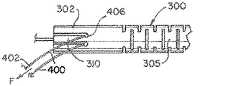
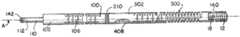
図1A、図1B、及び図2に示すように、本発明の取り外しシステム10の一実施例は、近位側の細長い送達ハイポチューブアセンブリ100及び遠位側送達チューブ300を有し得る。植え込み可能医療装置12が、遠位送達チューブ300の一端に係合される。植え込み可能医療装置12は塞栓コイルであり得るが、ただし実質的には、本発明による取り外しシステム10によって、あらゆる植え込み可能医療装置12を送達及び配置し得ることが理解されよう。医療装置12は、係止部材140及びループワイヤ400を用いてシステムに係合される。医療装置12は、係合システム140、400に接合する係止部分18を有する。 As shown in FIGS. 1A, 1B, and 2, one embodiment of the
近位側送達チューブ100は、近位端部分102と、遠位端部分104と、それらの間にある可撓性部分106とを有し得る。近位側送達チューブ100はその中に軸方向管腔108を形成する。近位端102は、軸方向管腔108に沿って、より小さい直径のチューブ110に係合している(図5A、図6〜図8を参照)。遠位側送達チューブ300は、近位端部分302と、遠位端部分304と、これら2つの間にある圧縮可能部分306とを有し得る。一実施例において、圧縮可能部分306は遠位端部分304に近づいていてよく、近位端部分302と圧縮可能部分306の間は可撓性部分305であり得る。遠位側送達チューブ300はその中に軸方向管腔308を形成する。
送達チューブ100、300は、生体適合性材料(例えばステンレス鋼)で製造され得る。チューブ100、300は典型的に約0.010インチ〜約0.018インチの直径を有してよく、好ましいチューブは約0.0145インチの直径を有し得る。これらのチューブ寸法の例は、神経血管系内の標的位置(典型的には動脈瘤)に塞栓コイルを送達及び配置するのに好適である。別の用途には、他の材料からなる別の寸法のチューブ100、300が有用であり得、これらも本発明の範囲内である。
可撓性部分106、305によって、送達チューブ100、300は屈曲し撓むことが可能になる。このことは、カテーテルを通して、ヒトの血管構造を通る曲がりくねった経路を通ってシステム10をトラッキングするのを支援する。可撓性部分106、306は、干渉螺旋状カットを備えて形成することができる。これらのカットにより、屈曲を可能にする隙間が得られるが、一実施例において、これらのカットは螺旋状カットばねとして作用しない。すなわち、屈曲し撓むことはできるが、圧縮はされない。
圧縮可能部分306は延伸状態と圧縮状態との間で軸方向に調節可能である。好ましくは、圧縮可能部分306は、レーザー切断操作により形成されたチューブ300の螺旋状カット部分から形成される。ただし、軸方向調節を可能にするような軸方向調節任意の他の配列(例えば、巻かれたワイヤ又は螺旋状リボン)もまた、本発明による取り外しシステムと共に使用するのに好適である。最も好ましくは、圧縮可能部分306は静止時に延伸状態にあり、他に拘束がない限り、圧縮状態から延伸状態に自動的又は弾性的に戻る。圧縮可能部分306の機能が以下により詳細に説明される。 The
図3A、図3B、図4は、ループワイヤ400の例を示す。いくつかの実施形態において、ループワイヤ400は比較的小さく、毛髪の太さを有していてよく、よって、誤って接触することによる損傷を防ぐため、遠位側送達チューブ300の遠位端304により完全に遮蔽されていることが望ましい可能性がある。ループワイヤ400は、図3Aに示すように、ループ状になった細長いワイヤであり得る。ループワイヤ400aは更に、図3Bに示すように、開口部405を備えた単一の細長いワイヤであり得る。開口部405は、ループワイヤ400aをゆるく半分に折り曲げることによって形成することができる。別の一実施形態において、ループワイヤ400bは、遠位部分に開口部405aを画定する平坦なリボン形状を含み、開口部405bは、植え込み可能医療装置12の端に係合するのに好適な上向き状態であり得る。ループワイヤ400、400a、400bの実施例は、上向き状態へと弾性的に変形可能であってよく、これにより、他に拘束がないとき、実質的に平坦な状態に戻る。ループワイヤ400、400a、400bは、ニチノール及びステンレス鋼を含む任意の数の材料で形成することができる。 3A, 3B, and 4 show examples of the
取り外しシステム10を搭載するために、係止部材140が、両チューブ100、300の管腔108、208、308内に、軸方向に挿入される。ループワイヤ400の遠位端404は、遠位側チューブ300の近位端302にあるアンカー部分310を通って遠位側送達チューブ300内へと挿入され、管腔308を通って遠位端304に至る。次にループワイヤ404の遠位端は、ループ状になって開口部405を形成することができる。開口部405は係止部分18を通過し、係止部材140は開口部405を通過して、医療装置12を係合させる。図1A及び図11Aを参照されたい。 To mount the
ループワイヤ400はループワイヤ402の近位端で緊張して引っ張られ、継続的な力Fにより圧縮可能部分306を圧縮する。圧縮の程度は、医療装置12が遠位側チューブ300の遠位端304に取り付けられた後、ループワイヤ400の近位端402に印加される力Fの量によって制御することができる。図2及び図11Aは、取り付けられた医療装置12と、圧縮状態にある遠位側チューブ300を示す。遠位側チューブ300が適切な程度圧縮されたら、ループワイヤ400は、ワイヤ溶接点406(近位端402と遠位端404との間)で、遠位側送達チューブ300のアンカー部分310又はその近くの近位端302に(すなわち圧縮可能部分306の背後に)、アンカー溶接408される。図5A及び図5Bを参照されたい。遠位側送達チューブ300の圧縮レベルは、ループワイヤ400をアンカー溶接部408で定位置に固定する前に、ループワイヤ400に対する力Fの量を変えることにより調節される。
図6及び図7は、近位側送達チューブ100と遠位側送達チューブ300とを用いた接合を示す。図6は、近位側チューブ100の遠位端104が、遠位側チューブ300の近位端302に向かって引っ張られ、いくつかの実施例では、これに接触していることを示す。この実施例において、近位側チューブ及び遠位側チューブ100、300は、接触してはいないが、隙間として溶接帯206を残している。2本のチューブ100、300は次に、溶接帯206で円周方向に溶接部210で接合されて、一体型の装置10を形成する。 6 and 7 show the joining using the
2本のチューブ100、300を溶接する前に、係止部材140(上述)が、近位側チューブ管腔108と、小さいチューブ110とを介して引っ張られる。小さいチューブ110の近位側開口部112(近位側チューブ100の近位端102の反対側)で、係止部材140が小さいチューブ110に溶接142される。これを図8に示す。 Prior to welding the two
図9は、取り外しシステム10を組み立てる方法の一実施例を示す。この方法は、遠位側チューブ300に圧縮可能部分306を形成すること(工程1000)と、近位側チューブ100に可撓性部分106を形成すること(工程1002)とを含む。工程1002は更に、遠位側チューブ300に可撓性部分305を形成することを含み得る。圧縮可能部分306は、遠位側チューブ300を螺旋状カットすることにより、又は任意の他の手段により、形成することができ、これにより、圧縮することができ、その後に非圧縮状態に素早く戻ることができるようなチューブを形成することができる。近位側チューブ100の可撓性部分106は干渉カットであってよく、又は、近位側チューブ100の可撓性を高めるような任意の他の手段によるものであってよい。少なくとも遠位側チューブ300の準備ができたら、医療装置12を係合システム140、400に係合させることができ(工程1004)、係合システム140、400に力Fを印加して、圧縮可能部分306を圧縮することができる(工程1006)。ここで、上述の実施例は、係止部材140及びループワイヤ400を係合システムとして使用して示されているが、当業者には、圧縮可能部分306に対する解放可能な力(係合システム140、400が医療装置12から外れたときに解放される)を印加しながら、医療装置12を固定するような、別の方法が認識され得ることに、注意されたい。次に、係合システム140、400の部分406が、遠位側チューブ300に係合し、圧縮可能部分306の圧縮状態を維持する(工程1008)。係合システム140、400の一部分が、近位側チューブ100内に通される(工程1010)。遠位側チューブ300及び近位側チューブ100が、合わせて接合される(工程1012)。ここで、この実施例において、チューブ100、300の端104、302は合わせて溶接210される。次に、係合システム140、400の端が、近位側チューブ100の近位端102に接合され(工程1014)、装置10を完成することができる。 FIG. 9 illustrates one embodiment of a method for assembling the
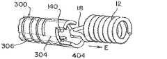
図10A〜図10Dを参照すると、医療装置12の取り外しがより詳細に示されている。図10Aは、医療装置12の係止部分18に係止された係合システム140、400を示す。ループワイヤ400の開口部405は、係止部分18を通して配置され得る。係止部材140が開口部405を通して配置されると、これで医療装置12が固定される。遠位側チューブ300を圧縮状態にするために、力Fは事前に印加されている。図10Bは、医療装置12の解放順序を開始するために、近位側に引っ張られつつある係止部材140を示す。図10Cは、係止部材140が開口部405から出て、ループワイヤ400がない状態で引っ張られる時点を示す。ループワイヤ400の遠位端404は脱落し、又はその事前形成された形状に戻り(上述のように)、係止部分18から出る。図から分かるように、これで医療装置12を取り外しシステム10に保持しているものは何もない。図10Dは、解放順序の終了時を示す。ここで、圧縮可能部分306は元の形状に拡張し、又は戻り、前方に「弾ける」。遠位側チューブ300の遠位端304により弾性力Eが医療装置12に付与され、これを「押し出し」、医療装置12のクリーンな分離と送達を確実に行う。 10A-10D, the removal of the
図11は、医療装置12を伴っていないが、圧縮可能部分306が軸方向に短くなって圧縮状態になっている遠位側チューブ300を示す。具体的には、圧縮可能部分306が延伸状態から圧縮状態に移動し、遠位側チューブ300が軸方向に短縮される距離「D」が示されている。この圧縮は軸Aに沿って起こり得る。図12は、取り外し時点の医療装置12の別の図を示す。係止部材140は近位側に引っ張られ、これによりループワイヤ400から分離されており、よって遠位側圧縮部分306が拡張する際に医療装置12が分離でき、医療装置12を送達システム10から更に引き離す。矢印「E」は、医療装置12を遠位端304から離れるよう「押す」弾性力を示し、これにより、クリーンな分離と、患者体内の標的部位への送達が確実に行われる。弾性力Eは管腔308の軸Aに作用し、医療装置12を軸Aに沿って「押す」(図8及び図11を参照)。 FIG. 11 shows the
本明細書に含まれる記述は、本発明の実施形態の例であり、本発明の範囲を何ら制限するものではない。本明細書に記載されているように、本発明は、多数の構成、多数の剛性特性、及びそれを送達する方法を含む、血管閉塞装置のための本発明の送達及び解放システムの数多くの変形例及び改変例が企図される。また、材料及び解放機構の構成において、多くの可能な変形例がある。これらの改変は、本発明が関連する当技術分野の当業者に明らかであろうし、かつ、以下の特許請求項の範囲内であることが意図される。 The descriptions included in this specification are examples of embodiments of the present invention and do not limit the scope of the present invention. As described herein, the present invention provides numerous variations of the delivery and release system of the present invention for vaso-occlusive devices, including multiple configurations, multiple rigid properties, and methods of delivering the same. Examples and modifications are contemplated. There are also many possible variations in the construction of the material and release mechanism. These modifications will be apparent to those skilled in the art to which this invention pertains and are intended to be within the scope of the following claims.
〔実施の態様〕
(1) 植え込み可能医療装置を身体の血管の標的位置に送達するための取り外しシステムであって、
略中空の遠位側チューブであって、
近位端と、
遠位端と、
前記近位端と前記遠位端との間にある、圧縮状態から延伸状態へと軸方向に移動可能である、前記遠位側チューブ自体の圧縮可能部分と、
を含む遠位側チューブと、
近位端及び遠位端を有する略中空の近位側チューブと、
前記遠位側チューブの前記近位端と前記近位側チューブの前記遠位端との間に配設されて前記近位側チューブと前記遠位側チューブとを接合している溶接部と、
前記遠位側チューブの前記遠位端に係合された前記植え込み可能医療装置に係合し、かつこれを配置する係合システムと、
を含み、
前記係合システムは、前記植え込み可能医療装置に係合しているとき、前記圧縮可能部分を前記圧縮状態へと動かし、
前記係合システムは、前記植え込み可能医療装置を配置し、前記圧縮可能部分を解放して前記延伸状態にする、取り外しシステム。
(2) 前記係合システムが、前記植え込み可能医療装置に係合しているとき、前記遠位側チューブの前記近位端に取り外し可能に固定されて、前記圧縮状態を維持する、実施態様1に記載の取り外しシステム。
(3) 前記係合システムが、前記植え込み可能医療装置に係合しているとき、前記近位側チューブの前記近位端に取り外し可能に固定される、実施態様2に記載の取り外しシステム。
(4) 前記係合システムが、
係止部材、及び
ループワイヤを含み、
前記ループワイヤが前記係止部材と相互作用して前記植え込み可能医療装置に係合しているとき、前記ループワイヤへの力によって前記圧縮可能部分が前記圧縮状態へと動かされ、
前記ループワイヤが前記遠位側チューブの前記近位端に溶接されていて前記係合システムを取り外し可能に固定している、実施態様2に記載の取り外しシステム。
(5) 前記係止部材への力によって前記ループワイヤが解放され、前記植え込み可能医療装置を外し、前記圧縮可能部分が前記延伸状態に戻れるようになる、実施態様4に記載の取り外しシステム。Embodiment
(1) A removal system for delivering an implantable medical device to a target location in a body vessel,
A generally hollow distal tube,
A proximal end;
The distal end;
A compressible portion of the distal tube itself, which is axially movable from a compressed state to an extended state, between the proximal end and the distal end;
A distal tube comprising:
A generally hollow proximal tube having a proximal end and a distal end;
A weld disposed between the proximal end of the distal tube and the distal end of the proximal tube to join the proximal tube and the distal tube;
An engagement system for engaging and positioning the implantable medical device engaged with the distal end of the distal tube;
Including
The engagement system moves the compressible portion to the compressed state when engaged with the implantable medical device;
The detachment system wherein the engagement system places the implantable medical device and releases the compressible portion into the extended state.
(2) Embodiment 1 wherein the engagement system is removably secured to the proximal end of the distal tube to maintain the compressed state when engaged with the implantable medical device. The removal system described in.
The removal system of
(4) The engagement system comprises:
Including a locking member and a loop wire,
When the loop wire interacts with the locking member and engages the implantable medical device, a force on the loop wire causes the compressible portion to move to the compressed state;
The removal system of
5. The removal system of embodiment 4, wherein the force on the locking member releases the loop wire, removes the implantable medical device, and allows the compressible portion to return to the stretched state.
(6) 前記遠位側チューブの前記圧縮可能部分が、前記遠位側チューブの螺旋状カット部分である、実施態様1に記載の取り外しシステム。
(7) 前記圧縮可能部分は、前記圧縮可能部分が前記延伸状態へ移動するとき、前記係合システムによって係合されている前記植え込み可能医療装置を配置するよう適合されている、実施態様1に記載の取り外しシステム。
(8) 前記遠位側チューブの前記圧縮可能部分は、前記係合システムが前記植え込み可能医療装置から外れているとき、前記延伸状態へと自動的/弾性的に移動するよう適合されている、実施態様1に記載の取り外しシステム。
(9) 前記近位側チューブと前記遠位側チューブとの間の隙間は、前記近位側チューブを前記遠位側チューブに溶接する溶接帯を含む、ことを更に含む、実施態様1に記載の取り外しシステム。
(10) 前記遠位側チューブの前記近位端と前記近位側チューブの前記遠位端とが、溶接されたときに互いに接触する、実施態様1に記載の取り外しシステム。6. The removal system according to embodiment 1, wherein the compressible portion of the distal tube is a helical cut portion of the distal tube.
(7) In embodiment 1, wherein the compressible portion is adapted to place the implantable medical device engaged by the engagement system when the compressible portion moves to the extended state. The removal system described.
(8) the compressible portion of the distal tube is adapted to automatically / elastically move to the extended state when the engagement system is disengaged from the implantable medical device;
The gap between the proximal tube and the distal tube further comprises a weld band that welds the proximal tube to the distal tube. Removal system.
10. The removal system of embodiment 1, wherein the proximal end of the distal tube and the distal end of the proximal tube contact each other when welded.
(11) 前記近位側チューブが、前記近位端と前記遠位端との間に、前記近位側チューブ自体の、可撓性である可撓性部分を含み、かつ、
前記遠位側チューブが、前記近位端と前記圧縮可能部分との間に、前記遠位側チューブ自体の、可撓性である可撓性部分を含む、実施態様1に記載の取り外しシステム。
(12) 近位端及び遠位端を有する中空の遠位側チューブと、近位端及び遠位端を有する中空の近位側チューブと、を含む植え込み可能医療装置の取り外し方法であって、
前記遠位側チューブ上の前記近位端と前記遠位端との間に圧縮可能部分を形成する工程と、
前記植え込み可能医療装置を係合システムに係合させる工程と、
前記圧縮可能部分を圧縮するために前記係合システムに力を印加する工程と、
前記係合システムを前記遠位側チューブに固定して圧縮状態を維持する工程と、
前記遠位側チューブと前記近位側チューブとを合わせて接合する工程と、
を含む、取り外し方法。
(13) 前記係合システムが、前記遠位側チューブの前記近位端に取り外し可能に固定される、実施態様12に記載の取り外し方法。
(14) 前記植え込み可能医療装置に係合しているとき、前記係合システムを前記近位側チューブの前記近位端に取り外し可能に固定する工程を更に含む、実施態様13に記載の取り外し方法。
(15) 前記係合システムが、係止部材及びループワイヤを含み、
前記係合工程が、前記係止部材と共に前記ループワイヤを用いて前記植え込み可能医療装置を係合させる工程を更に含み、
前記印加する工程が、前記ループワイヤに力を印加して前記圧縮可能部分を前記圧縮状態へと動かす工程を更に含む、実施態様13に記載の取り外し方法。(11) The proximal tube includes a flexible portion of the proximal tube itself that is flexible between the proximal end and the distal end; and
The removal system according to embodiment 1, wherein the distal tube includes a flexible portion of the distal tube itself that is flexible between the proximal end and the compressible portion.
(12) A method for removing an implantable medical device comprising: a hollow distal tube having a proximal end and a distal end; and a hollow proximal tube having a proximal end and a distal end,
Forming a compressible portion between the proximal end and the distal end on the distal tube;
Engaging the implantable medical device with an engagement system;
Applying a force to the engagement system to compress the compressible portion;
Securing the engagement system to the distal tube and maintaining compression;
Joining the distal tube and the proximal tube together;
Including removal method.
The removal method of
14. The removal method of embodiment 13, further comprising the step of removably securing the engagement system to the proximal end of the proximal tube when engaged with the implantable medical device. .
(15) The engagement system includes a locking member and a loop wire,
The engaging step further includes engaging the implantable medical device with the loop member using the loop wire;
14. The removal method according to embodiment 13, wherein the applying step further comprises applying a force to the loop wire to move the compressible portion to the compressed state.
(16) 前記係止部材に力を印加する工程と、
前記植え込み可能医療装置を外す工程と、
前記圧縮可能部分を延伸状態に戻らせる工程と、を更に含む、実施態様15に記載の取り外し方法。
(17) 前記形成工程が、前記遠位側チューブの一部分を螺旋状カットする工程を含む、実施態様12に記載の取り外し方法。
(18) 前記圧縮可能部分を前記延伸状態に動かすことにより、係合された前記植え込み可能医療装置を配置する工程を更に含む、実施態様12に記載の取り外し方法。
(19) 前記遠位側チューブの前記圧縮可能部分は、前記係合システムが前記植え込み可能医療装置から外れているとき、前記延伸状態へと自動的/弾性的に移動するよう適合されている、実施態様12に記載の取り外し方法。
(20) 前記接合工程が、
前記近位側チューブと前記遠位側チューブとの間に溶接帯を含む隙間を形成する工程と、
前記溶接帯で前記近位側チューブを前記遠位側チューブに溶接する工程と、を更に含む、実施態様12に記載の取り外し方法。(16) applying a force to the locking member;
Removing the implantable medical device;
The removal method according to embodiment 15, further comprising the step of returning the compressible portion to a stretched state.
(17) The removal method according to
The removal method according to
(19) The compressible portion of the distal tube is adapted to automatically / elastically move to the extended state when the engagement system is disengaged from the implantable medical device; The removal method according to
(20) The joining step includes
Forming a gap including a weld band between the proximal tube and the distal tube;
The removal method according to
Claims (20)
Translated fromJapanese略中空の遠位側チューブであって、
近位端と、
遠位端と、
前記近位端と前記遠位端との間にある、圧縮状態から延伸状態へと軸方向に移動可能である、前記遠位側チューブ自体の圧縮可能部分と、
を含む遠位側チューブと、
近位端及び遠位端を有する略中空の近位側チューブと、
前記遠位側チューブの前記近位端と前記近位側チューブの前記遠位端との間に配設されて前記近位側チューブと前記遠位側チューブとを接合している溶接部と、
前記遠位側チューブの前記遠位端に係合された前記植え込み可能医療装置に係合し、かつこれを配置する係合システムと、
を含み、
前記係合システムは、前記植え込み可能医療装置に係合しているとき、前記圧縮可能部分を前記圧縮状態へと動かし、
前記係合システムは、前記植え込み可能医療装置を配置し、前記圧縮可能部分を解放して前記延伸状態にする、取り外しシステム。A removal system for delivering an implantable medical device to a target location in a body vessel,
A generally hollow distal tube,
A proximal end;
The distal end;
A compressible portion of the distal tube itself, which is axially movable from a compressed state to an extended state, between the proximal end and the distal end;
A distal tube comprising:
A generally hollow proximal tube having a proximal end and a distal end;
A weld disposed between the proximal end of the distal tube and the distal end of the proximal tube to join the proximal tube and the distal tube;
An engagement system for engaging and positioning the implantable medical device engaged with the distal end of the distal tube;
Including
The engagement system moves the compressible portion to the compressed state when engaged with the implantable medical device;
The detachment system wherein the engagement system places the implantable medical device and releases the compressible portion into the extended state.
係止部材、及び
ループワイヤを含み、
前記ループワイヤが前記係止部材と相互作用して前記植え込み可能医療装置に係合しているとき、前記ループワイヤへの力によって前記圧縮可能部分が前記圧縮状態へと動かされ、
前記ループワイヤが前記遠位側チューブの前記近位端に溶接されていて前記係合システムを取り外し可能に固定している、請求項2に記載の取り外しシステム。The engagement system comprises:
Including a locking member and a loop wire,
When the loop wire interacts with the locking member and engages the implantable medical device, a force on the loop wire causes the compressible portion to move to the compressed state;
The removal system of claim 2, wherein the loop wire is welded to the proximal end of the distal tube to removably secure the engagement system.
前記遠位側チューブが、前記近位端と前記圧縮可能部分との間に、前記遠位側チューブ自体の、可撓性である可撓性部分を含む、請求項1に記載の取り外しシステム。The proximal tube includes a flexible portion of the proximal tube itself that is flexible between the proximal end and the distal end; and
The removal system of claim 1, wherein the distal tube includes a flexible portion of the distal tube itself that is flexible between the proximal end and the compressible portion.
前記遠位側チューブ上の前記近位端と前記遠位端との間に圧縮可能部分を形成する工程と、
前記植え込み可能医療装置を係合システムに係合させる工程と、
前記圧縮可能部分を圧縮するために前記係合システムに力を印加する工程と、
前記係合システムを前記遠位側チューブに固定して圧縮状態を維持する工程と、
前記遠位側チューブと前記近位側チューブとを合わせて接合する工程と、
を含む、取り外し方法。A method of removing an implantable medical device comprising: a hollow distal tube having a proximal end and a distal end; and a hollow proximal tube having a proximal end and a distal end;
Forming a compressible portion between the proximal end and the distal end on the distal tube;
Engaging the implantable medical device with an engagement system;
Applying a force to the engagement system to compress the compressible portion;
Securing the engagement system to the distal tube and maintaining compression;
Joining the distal tube and the proximal tube together;
Including removal method.
前記係合工程が、前記係止部材と共に前記ループワイヤを用いて前記植え込み可能医療装置を係合させる工程を更に含み、
前記印加する工程が、前記ループワイヤに力を印加して前記圧縮可能部分を前記圧縮状態へと動かす工程を更に含む、請求項13に記載の取り外し方法。The engagement system includes a locking member and a loop wire;
The engaging step further includes engaging the implantable medical device with the loop member using the loop wire;
The removal method according to claim 13, wherein the applying further comprises applying a force to the loop wire to move the compressible portion to the compressed state.
前記植え込み可能医療装置を外す工程と、
前記圧縮可能部分を延伸状態に戻らせる工程と、を更に含む、請求項15に記載の取り外し方法。Applying a force to the locking member;
Removing the implantable medical device;
The removal method according to claim 15, further comprising the step of returning the compressible portion to a stretched state.
前記近位側チューブと前記遠位側チューブとの間に溶接帯を含む隙間を形成する工程と、
前記溶接帯で前記近位側チューブを前記遠位側チューブに溶接する工程と、を更に含む、請求項12に記載の取り外し方法。The joining step includes
Forming a gap including a weld band between the proximal tube and the distal tube;
The method of claim 12, further comprising welding the proximal tube to the distal tube with the weld band.
Applications Claiming Priority (2)
| Application Number | Priority Date | Filing Date | Title |
|---|---|---|---|
| US15/964,857 | 2018-04-27 | ||
| US15/964,857US10806461B2 (en) | 2018-04-27 | 2018-04-27 | Implantable medical device detachment system with split tube |
Publications (2)
| Publication Number | Publication Date |
|---|---|
| JP2019188152Atrue JP2019188152A (en) | 2019-10-31 |
| JP7362290B2 JP7362290B2 (en) | 2023-10-17 |
Family
ID=66290307
Family Applications (1)
| Application Number | Title | Priority Date | Filing Date |
|---|---|---|---|
| JP2019085271AActiveJP7362290B2 (en) | 2018-04-27 | 2019-04-26 | Implantable Medical Device Removal System with Split Tube |
Country Status (5)
| Country | Link |
|---|---|
| US (1) | US10806461B2 (en) |
| EP (1) | EP3560439A1 (en) |
| JP (1) | JP7362290B2 (en) |
| CN (1) | CN110403647B (en) |
| BR (1) | BR102019008433A2 (en) |
Families Citing this family (53)
| Publication number | Priority date | Publication date | Assignee | Title |
|---|---|---|---|---|
| US11076860B2 (en) | 2014-03-31 | 2021-08-03 | DePuy Synthes Products, Inc. | Aneurysm occlusion device |
| US11154302B2 (en) | 2014-03-31 | 2021-10-26 | DePuy Synthes Products, Inc. | Aneurysm occlusion device |
| US9918718B2 (en) | 2014-08-08 | 2018-03-20 | DePuy Synthes Products, Inc. | Embolic coil delivery system with retractable mechanical release mechanism |
| CN109789292B (en)* | 2016-10-05 | 2022-11-01 | 祥丰医疗私人有限公司 | Modular vascular catheter |
| CN110545739A (en) | 2017-02-23 | 2019-12-06 | 德普伊新特斯产品公司 | aneurysm devices and delivery systems |
| US10806462B2 (en) | 2017-12-21 | 2020-10-20 | DePuy Synthes Products, Inc. | Implantable medical device detachment system with split tube and cylindrical coupling |
| US10905430B2 (en) | 2018-01-24 | 2021-02-02 | DePuy Synthes Products, Inc. | Aneurysm device and delivery system |
| US11596412B2 (en) | 2018-05-25 | 2023-03-07 | DePuy Synthes Products, Inc. | Aneurysm device and delivery system |
| US11058430B2 (en) | 2018-05-25 | 2021-07-13 | DePuy Synthes Products, Inc. | Aneurysm device and delivery system |
| US10939915B2 (en) | 2018-05-31 | 2021-03-09 | DePuy Synthes Products, Inc. | Aneurysm device and delivery system |
| US11051825B2 (en) | 2018-08-08 | 2021-07-06 | DePuy Synthes Products, Inc. | Delivery system for embolic braid |
| US11123077B2 (en) | 2018-09-25 | 2021-09-21 | DePuy Synthes Products, Inc. | Intrasaccular device positioning and deployment system |
| US11076861B2 (en) | 2018-10-12 | 2021-08-03 | DePuy Synthes Products, Inc. | Folded aneurysm treatment device and delivery method |
| US11147562B2 (en) | 2018-12-12 | 2021-10-19 | DePuy Synthes Products, Inc. | Systems and methods for embolic implant detachment |
| US11406392B2 (en) | 2018-12-12 | 2022-08-09 | DePuy Synthes Products, Inc. | Aneurysm occluding device for use with coagulating agents |
| US11272939B2 (en) | 2018-12-18 | 2022-03-15 | DePuy Synthes Products, Inc. | Intrasaccular flow diverter for treating cerebral aneurysms |
| US11134953B2 (en) | 2019-02-06 | 2021-10-05 | DePuy Synthes Products, Inc. | Adhesive cover occluding device for aneurysm treatment |
| US11337706B2 (en) | 2019-03-27 | 2022-05-24 | DePuy Synthes Products, Inc. | Aneurysm treatment device |
| US11413046B2 (en) | 2019-05-21 | 2022-08-16 | DePuy Synthes Products, Inc. | Layered braided aneurysm treatment device |
| US11672542B2 (en) | 2019-05-21 | 2023-06-13 | DePuy Synthes Products, Inc. | Aneurysm treatment with pushable ball segment |
| US10653425B1 (en) | 2019-05-21 | 2020-05-19 | DePuy Synthes Products, Inc. | Layered braided aneurysm treatment device |
| US11607226B2 (en) | 2019-05-21 | 2023-03-21 | DePuy Synthes Products, Inc. | Layered braided aneurysm treatment device with corrugations |
| US11278292B2 (en) | 2019-05-21 | 2022-03-22 | DePuy Synthes Products, Inc. | Inverting braided aneurysm treatment system and method |
| US11497504B2 (en) | 2019-05-21 | 2022-11-15 | DePuy Synthes Products, Inc. | Aneurysm treatment with pushable implanted braid |
| US11602350B2 (en) | 2019-12-05 | 2023-03-14 | DePuy Synthes Products, Inc. | Intrasaccular inverting braid with highly flexible fill material |
| US11253265B2 (en) | 2019-06-18 | 2022-02-22 | DePuy Synthes Products, Inc. | Pull wire detachment for intravascular devices |
| US11426174B2 (en) | 2019-10-03 | 2022-08-30 | DePuy Synthes Products, Inc. | Medical device delivery member with flexible stretch resistant mechanical release |
| US11207494B2 (en)* | 2019-07-03 | 2021-12-28 | DePuy Synthes Products, Inc. | Medical device delivery member with flexible stretch resistant distal portion |
| US12376859B2 (en) | 2019-09-17 | 2025-08-05 | DePuy Synthes Products, Inc. | Embolic coil proximal connecting element and stretch resistant fiber |
| US11439403B2 (en) | 2019-09-17 | 2022-09-13 | DePuy Synthes Products, Inc. | Embolic coil proximal connecting element and stretch resistant fiber |
| US11376013B2 (en) | 2019-11-18 | 2022-07-05 | DePuy Synthes Products, Inc. | Implant delivery system with braid cup formation |
| US11457926B2 (en) | 2019-12-18 | 2022-10-04 | DePuy Synthes Products, Inc. | Implant having an intrasaccular section and intravascular section |
| US11457922B2 (en) | 2020-01-22 | 2022-10-04 | DePuy Synthes Products, Inc. | Medical device delivery member with flexible stretch resistant distal portion |
| US11432822B2 (en) | 2020-02-14 | 2022-09-06 | DePuy Synthes Products, Inc. | Intravascular implant deployment system |
| US11951026B2 (en) | 2020-06-30 | 2024-04-09 | DePuy Synthes Products, Inc. | Implantable medical device detachment system with flexible braid section |
| EP4199840A4 (en)* | 2020-08-21 | 2024-07-24 | Shape Memory Medical, Inc. | Mechanical detachment system for transcatheter devices |
| US12127743B2 (en) | 2020-09-23 | 2024-10-29 | DePuy Synthes Products, Inc. | Inverting braided aneurysm implant with dome feature |
| KR20220050060A (en) | 2020-10-15 | 2022-04-22 | 디퍼이 신테스 프로덕츠, 인코포레이티드 | Inverting braided aneurysm treatment system and method |
| EP4066752B1 (en) | 2021-03-31 | 2025-04-30 | DePuy Synthes Products, Inc. | Medical device delivery member with flexible stretch resistant distal portion |
| US11998213B2 (en) | 2021-07-14 | 2024-06-04 | DePuy Synthes Products, Inc. | Implant delivery with modified detachment feature and pull wire engagement |
| KR20230011880A (en) | 2021-07-14 | 2023-01-25 | 디퍼이 신테스 프로덕츠, 인코포레이티드 | Embolic coil proximal connecting element and stretch resistant fiber |
| KR20230037457A (en)* | 2021-09-09 | 2023-03-16 | 디퍼이 신테스 프로덕츠, 인코포레이티드 | Implantable medical device detachment system with split tube and cylindrical coupling |
| US11937824B2 (en)* | 2021-12-30 | 2024-03-26 | DePuy Synthes Products, Inc. | Implant detachment systems with a modified pull wire |
| US11844490B2 (en) | 2021-12-30 | 2023-12-19 | DePuy Synthes Products, Inc. | Suture linkage for inhibiting premature embolic implant deployment |
| US20230210535A1 (en)* | 2021-12-31 | 2023-07-06 | DePuy Synthes Products, Inc. | Medical device delivery systems with twisting loop wires |
| US12011171B2 (en) | 2022-01-06 | 2024-06-18 | DePuy Synthes Products, Inc. | Systems and methods for inhibiting premature embolic implant deployment |
| US11937825B2 (en) | 2022-03-02 | 2024-03-26 | DePuy Synthes Products, Inc. | Hook wire for preventing premature embolic implant detachment |
| US12137915B2 (en) | 2022-03-03 | 2024-11-12 | DePuy Synthes Products, Inc. | Elongating wires for inhibiting premature implant detachment |
| US11937826B2 (en) | 2022-03-14 | 2024-03-26 | DePuy Synthes Products, Inc. | Proximal link wire for preventing premature implant detachment |
| WO2023175451A1 (en) | 2022-03-15 | 2023-09-21 | DePuy Synthes Products, Inc. | Semispherical braided aneurysm treatment system and method |
| WO2023199147A1 (en) | 2022-04-15 | 2023-10-19 | DePuy Synthes Products, Inc. | Medical device delivery member with positioning window |
| US12402886B2 (en) | 2022-06-23 | 2025-09-02 | DePuy Synthes Products, Inc. | Detachment indicator for implant deployment |
| US12396730B2 (en) | 2022-09-28 | 2025-08-26 | DePuy Synthes Products, Inc. | Braided implant with detachment mechanism |
Citations (3)
| Publication number | Priority date | Publication date | Assignee | Title |
|---|---|---|---|---|
| US20080097462A1 (en)* | 2006-07-31 | 2008-04-24 | Vladimir Mitelberg | Implantable medical device detachment system and methods of using the same |
| JP2012192177A (en)* | 2011-02-28 | 2012-10-11 | Sumitomo Bakelite Co Ltd | Medical equipment and method of manufacturing the same |
| JP2014140565A (en)* | 2013-01-25 | 2014-08-07 | Kaneka Corp | Method for manufacturing medical tube and catheter |
Family Cites Families (132)
| Publication number | Priority date | Publication date | Assignee | Title |
|---|---|---|---|---|
| US3429408A (en) | 1967-04-25 | 1969-02-25 | Associated Spring Corp | Actuator sleeves for spring clutch |
| US5636639A (en)* | 1992-02-18 | 1997-06-10 | Symbiosis Corporation | Endoscopic multiple sample bioptome with enhanced biting action |
| US5250071A (en) | 1992-09-22 | 1993-10-05 | Target Therapeutics, Inc. | Detachable embolic coil assembly using interlocking clasps and method of use |
| US5569221A (en) | 1994-07-07 | 1996-10-29 | Ep Technologies, Inc. | Catheter component bond and method |
| US6391037B1 (en) | 2000-03-02 | 2002-05-21 | Prodesco, Inc. | Bag for use in the intravascular treatment of saccular aneurysms |
| US8715312B2 (en) | 2001-07-20 | 2014-05-06 | Microvention, Inc. | Aneurysm treatment device and method of use |
| US8252040B2 (en) | 2001-07-20 | 2012-08-28 | Microvention, Inc. | Aneurysm treatment device and method of use |
| US8425549B2 (en)* | 2002-07-23 | 2013-04-23 | Reverse Medical Corporation | Systems and methods for removing obstructive matter from body lumens and treating vascular defects |
| US7371228B2 (en) | 2003-09-19 | 2008-05-13 | Medtronic Vascular, Inc. | Delivery of therapeutics to treat aneurysms |
| US9308382B2 (en) | 2004-06-10 | 2016-04-12 | Medtronic Urinary Solutions, Inc. | Implantable pulse generator systems and methods for providing functional and/or therapeutic stimulation of muscles and/or nerves and/or central nervous system tissue |
| US9655633B2 (en) | 2004-09-10 | 2017-05-23 | Penumbra, Inc. | System and method for treating ischemic stroke |
| WO2006052322A2 (en) | 2004-09-22 | 2006-05-18 | Guterman Lee R | Cranial aneurysm treatment arrangement |
| US20060089637A1 (en) | 2004-10-14 | 2006-04-27 | Werneth Randell L | Ablation catheter |
| US8562672B2 (en) | 2004-11-19 | 2013-10-22 | Medtronic, Inc. | Apparatus for treatment of cardiac valves and method of its manufacture |
| US7708754B2 (en)* | 2005-06-02 | 2010-05-04 | Codman & Shurtleff, Pc | Stretch resistant embolic coil delivery system with mechanical release mechanism |
| US9636115B2 (en) | 2005-06-14 | 2017-05-02 | Stryker Corporation | Vaso-occlusive delivery device with kink resistant, flexible distal end |
| EP2759276A1 (en) | 2005-06-20 | 2014-07-30 | Medtronic Ablation Frontiers LLC | Ablation catheter |
| US8066036B2 (en) | 2005-11-17 | 2011-11-29 | Microvention, Inc. | Three-dimensional complex coil |
| US9757260B2 (en) | 2006-03-30 | 2017-09-12 | Medtronic Vascular, Inc. | Prosthesis with guide lumen |
| US9615832B2 (en) | 2006-04-07 | 2017-04-11 | Penumbra, Inc. | Aneurysm occlusion system and method |
| CA2655026C (en) | 2006-06-15 | 2016-08-02 | Microvention, Inc. | Embolization device constructed from expansible polymer |
| US8366720B2 (en) | 2006-07-31 | 2013-02-05 | Codman & Shurtleff, Inc. | Interventional medical device system having an elongation retarding portion and method of using the same |
| US20080281350A1 (en) | 2006-12-13 | 2008-11-13 | Biomerix Corporation | Aneurysm Occlusion Devices |
| US8197442B2 (en) | 2007-04-27 | 2012-06-12 | Codman & Shurtleff, Inc. | Interventional medical device system having a slotted section and radiopaque marker and method of making the same |
| WO2009086208A2 (en) | 2007-12-21 | 2009-07-09 | Microvention, Inc. | Hydrogel filaments for biomedical uses |
| US8974518B2 (en) | 2008-03-25 | 2015-03-10 | Medtronic Vascular, Inc. | Eversible branch stent-graft and deployment method |
| EP2192947A1 (en) | 2008-04-30 | 2010-06-09 | Medtronic, Inc. | Techniques for placing medical leads for electrical stimulation of nerve tissue |
| US20090312748A1 (en) | 2008-06-11 | 2009-12-17 | Johnson Kirk L | Rotational detachment mechanism |
| US8070694B2 (en) | 2008-07-14 | 2011-12-06 | Medtronic Vascular, Inc. | Fiber based medical devices and aspiration catheters |
| US8333796B2 (en) | 2008-07-15 | 2012-12-18 | Penumbra, Inc. | Embolic coil implant system and implantation method |
| US9232992B2 (en) | 2008-07-24 | 2016-01-12 | Aga Medical Corporation | Multi-layered medical device for treating a target site and associated method |
| US8721714B2 (en) | 2008-09-17 | 2014-05-13 | Medtronic Corevalve Llc | Delivery system for deployment of medical devices |
| US9717500B2 (en) | 2009-04-15 | 2017-08-01 | Microvention, Inc. | Implant delivery system |
| US8758423B2 (en) | 2009-06-18 | 2014-06-24 | Graftcraft I Goteborg Ab | Device and method for treating ruptured aneurysms |
| US8911487B2 (en) | 2009-09-22 | 2014-12-16 | Penumbra, Inc. | Manual actuation system for deployment of implant |
| AU2011240927B2 (en) | 2010-04-14 | 2015-07-16 | Microvention, Inc. | Implant delivery device |
| US8764811B2 (en) | 2010-04-20 | 2014-07-01 | Medtronic Vascular, Inc. | Controlled tip release stent graft delivery system and method |
| US8876878B2 (en) | 2010-07-23 | 2014-11-04 | Medtronic, Inc. | Attachment mechanism for stent release |
| US8616040B2 (en) | 2010-09-17 | 2013-12-31 | Medtronic Vascular, Inc. | Method of forming a drug-eluting medical device |
| WO2012088162A1 (en) | 2010-12-20 | 2012-06-28 | Microvention, Inc. | Polymer stents and methods of manufacture |
| US20120283768A1 (en) | 2011-05-05 | 2012-11-08 | Sequent Medical Inc. | Method and apparatus for the treatment of large and giant vascular defects |
| US9486604B2 (en) | 2011-05-12 | 2016-11-08 | Medtronic, Inc. | Packaging and preparation tray for a delivery system |
| WO2012158668A1 (en) | 2011-05-17 | 2012-11-22 | Stryker Corporation | Method of fabricating an implantable medical device that includes one or more thin film polymer support layers |
| WO2012166467A1 (en) | 2011-05-27 | 2012-12-06 | Stryker Corporation | Assembly for percutaneously inserting an implantable medical device, steering the device to a target location and deploying the device |
| US9750565B2 (en) | 2011-09-30 | 2017-09-05 | Medtronic Advanced Energy Llc | Electrosurgical balloons |
| CA2867181C (en) | 2012-03-16 | 2020-08-11 | Microvention, Inc. | Stent and stent delivery device |
| US9717421B2 (en) | 2012-03-26 | 2017-08-01 | Medtronic, Inc. | Implantable medical device delivery catheter with tether |
| US9833625B2 (en) | 2012-03-26 | 2017-12-05 | Medtronic, Inc. | Implantable medical device delivery with inner and outer sheaths |
| US9155540B2 (en) | 2012-03-30 | 2015-10-13 | DePuy Synthes Products, Inc. | Embolic coil detachment mechanism with heating element and kicker |
| US9242290B2 (en) | 2012-04-03 | 2016-01-26 | Medtronic Vascular, Inc. | Method and apparatus for creating formed elements used to make wound stents |
| US9549832B2 (en) | 2012-04-26 | 2017-01-24 | Medtronic Vascular, Inc. | Apparatus and methods for filling a drug eluting medical device via capillary action |
| US9700399B2 (en) | 2012-04-26 | 2017-07-11 | Medtronic Vascular, Inc. | Stopper to prevent graft material slippage in a closed web stent-graft |
| US9149190B2 (en) | 2012-07-17 | 2015-10-06 | Stryker Corporation | Notification system of deviation from predefined conditions |
| EP2882350B1 (en) | 2012-08-13 | 2019-09-25 | MicroVention, Inc. | Shaped removal device |
| US20140058435A1 (en) | 2012-08-21 | 2014-02-27 | Donald K. Jones | Implant delivery and release system |
| US9504476B2 (en) | 2012-10-01 | 2016-11-29 | Microvention, Inc. | Catheter markers |
| EP2906254B1 (en) | 2012-10-15 | 2020-01-08 | Microvention, Inc. | Polymeric treatment compositions |
| US10327781B2 (en) | 2012-11-13 | 2019-06-25 | Covidien Lp | Occlusive devices |
| US9539022B2 (en) | 2012-11-28 | 2017-01-10 | Microvention, Inc. | Matter conveyance system |
| WO2014089392A1 (en) | 2012-12-07 | 2014-06-12 | Medtronic, Inc. | Minimally invasive implantable neurostimulation system |
| US9943313B2 (en) | 2013-01-03 | 2018-04-17 | Empirilon Technology Llc | Detachable coil release system and handle assembly |
| US10342546B2 (en) | 2013-01-14 | 2019-07-09 | Microvention, Inc. | Occlusive device |
| US9539382B2 (en) | 2013-03-12 | 2017-01-10 | Medtronic, Inc. | Stepped catheters with flow restrictors and infusion systems using the same |
| EP2967573B1 (en) | 2013-03-14 | 2021-04-21 | Stryker Corporation | Vaso-occlusive device delivery system |
| CN105228534B (en) | 2013-03-14 | 2018-03-30 | 斯瑞克公司 | Vaso-Occlusive Device Delivery System |
| WO2014150824A1 (en) | 2013-03-14 | 2014-09-25 | Stryker Corporation | Vaso-occlusive device delivery system |
| US9398966B2 (en) | 2013-03-15 | 2016-07-26 | Medtronic Vascular, Inc. | Welded stent and stent delivery system |
| BR112015023602A2 (en) | 2013-03-15 | 2017-07-18 | Microvention Inc | embolic protection device |
| WO2014151123A1 (en) | 2013-03-15 | 2014-09-25 | Microvention, Inc. | Multi-component obstruction removal system and method |
| US9662425B2 (en) | 2013-04-22 | 2017-05-30 | Stryker European Holdings I, Llc | Method for drug loading hydroxyapatite coated implant surfaces |
| US9445928B2 (en) | 2013-05-30 | 2016-09-20 | Medtronic Vascular, Inc. | Delivery system having a single handed deployment handle for a retractable outer sheath |
| US9662120B2 (en) | 2013-08-23 | 2017-05-30 | Cook Medical Technologies Llc | Detachable treatment device delivery system utilizing compression at attachment zone |
| US9675782B2 (en) | 2013-10-10 | 2017-06-13 | Medtronic Vascular, Inc. | Catheter pull wire actuation mechanism |
| US9955978B2 (en) | 2013-10-25 | 2018-05-01 | Medtronic Vascular, Inc. | Tissue compression device with multi-chamber bladder |
| EP3082939B1 (en) | 2013-12-20 | 2020-12-02 | MicroVention, Inc. | Delivery adapter |
| KR102211335B1 (en) | 2013-12-20 | 2021-02-03 | 마이크로벤션, 인코포레이티드 | Device delivery system |
| US9788839B2 (en) | 2014-02-14 | 2017-10-17 | Cook Medical Technologies Llc | Stable screw-type detachment mechanism |
| WO2015157181A1 (en) | 2014-04-08 | 2015-10-15 | Stryker Corporation | Implant delivery system |
| WO2015167997A1 (en) | 2014-04-30 | 2015-11-05 | Stryker Corporation | Implant delivery system and method of use |
| US9060777B1 (en) | 2014-05-28 | 2015-06-23 | Tw Medical Technologies, Llc | Vaso-occlusive devices and methods of use |
| US9668898B2 (en) | 2014-07-24 | 2017-06-06 | Medtronic Vascular, Inc. | Stent delivery system having dynamic deployment and methods of manufacturing same |
| US9770577B2 (en) | 2014-09-15 | 2017-09-26 | Medtronic Xomed, Inc. | Pressure relief for a catheter balloon device |
| US9579484B2 (en) | 2014-09-19 | 2017-02-28 | Medtronic Vascular, Inc. | Sterile molded dispenser |
| US9692557B2 (en) | 2015-02-04 | 2017-06-27 | Stryker European Holdings I, Llc | Apparatus and methods for administering treatment within a bodily duct of a patient |
| US9717503B2 (en) | 2015-05-11 | 2017-08-01 | Covidien Lp | Electrolytic detachment for implant delivery systems |
| US10307168B2 (en) | 2015-08-07 | 2019-06-04 | Terumo Corporation | Complex coil and manufacturing techniques |
| US10154905B2 (en) | 2015-08-07 | 2018-12-18 | Medtronic Vascular, Inc. | System and method for deflecting a delivery catheter |
| US10492938B2 (en) | 2015-08-11 | 2019-12-03 | Terumo Corporation | System and method for implant delivery |
| EP3349669B1 (en) | 2015-09-18 | 2020-10-21 | Terumo Corporation | Vessel prosthesis |
| CN113952095B (en) | 2015-09-18 | 2025-06-06 | 微仙美国有限公司 | Implant retention, detachment and delivery systems |
| JP6854282B2 (en) | 2015-09-18 | 2021-04-07 | テルモ株式会社 | Pressable implant delivery system |
| JP6816126B2 (en) | 2015-09-18 | 2021-01-20 | マイクロベンション インコーポレイテッドMicrovention, Inc. | Releasable delivery system |
| CN108024821B (en) | 2015-09-21 | 2020-10-30 | 斯瑞克公司 | Embolectomy device |
| JP6591664B2 (en) | 2015-09-21 | 2019-10-16 | ストライカー コーポレイションStryker Corporation | Embolization removal device |
| US10172632B2 (en) | 2015-09-22 | 2019-01-08 | Medtronic Vascular, Inc. | Occlusion bypassing apparatus with a re-entry needle and a stabilization tube |
| US10327791B2 (en) | 2015-10-07 | 2019-06-25 | Medtronic Vascular, Inc. | Occlusion bypassing apparatus with a re-entry needle and a distal stabilization balloon |
| WO2017062383A1 (en) | 2015-10-07 | 2017-04-13 | Stryker Corporation | Multiple barrel clot removal devices |
| US10786302B2 (en) | 2015-10-09 | 2020-09-29 | Medtronic, Inc. | Method for closure and ablation of atrial appendage |
| US10271873B2 (en) | 2015-10-26 | 2019-04-30 | Medtronic Vascular, Inc. | Sheathless guide catheter assembly |
| WO2017087816A1 (en) | 2015-11-19 | 2017-05-26 | Penumbra, Inc. | Systems and methods for treatment of stroke |
| US10631946B2 (en) | 2015-11-30 | 2020-04-28 | Penumbra, Inc. | System for endoscopic intracranial procedures |
| EP3386580B1 (en) | 2015-12-09 | 2023-11-01 | Medtronic Vascular Inc. | Catheter with a lumen shaped as an identification symbol |
| US10500046B2 (en) | 2015-12-14 | 2019-12-10 | Medtronic, Inc. | Delivery system having retractable wires as a coupling mechanism and a deployment mechanism for a self-expanding prosthesis |
| US10159568B2 (en) | 2015-12-14 | 2018-12-25 | Medtronic, Inc. | Delivery system having retractable wires as a coupling mechanism and a deployment mechanism for a self-expanding prosthesis |
| WO2017117284A1 (en) | 2015-12-30 | 2017-07-06 | Stryker Corporation | Embolic devices and methods of manufacturing same |
| US20170189033A1 (en) | 2016-01-06 | 2017-07-06 | Microvention, Inc. | Occlusive Embolic Coil |
| US10070950B2 (en) | 2016-02-09 | 2018-09-11 | Medtronic Vascular, Inc. | Endoluminal prosthetic assemblies, and associated systems and methods for percutaneous repair of a vascular tissue defect |
| KR102837372B1 (en) | 2016-02-10 | 2025-07-24 | 마이크로벤션, 인코포레이티드 | Intravascular treatment site access |
| AU2017218115B2 (en) | 2016-02-10 | 2020-03-05 | Microvention, Inc. | Devices for vascular occlusion |
| US10188500B2 (en) | 2016-02-12 | 2019-01-29 | Medtronic Vascular, Inc. | Stent graft with external scaffolding and method |
| US10485579B2 (en)* | 2016-02-25 | 2019-11-26 | Indian Wells Medical, Inc. | Steerable endoluminal punch |
| US20170258476A1 (en) | 2016-03-08 | 2017-09-14 | Terumo Kabushiki Kaisha | Blood vessel treatment method |
| US20170281331A1 (en) | 2016-03-31 | 2017-10-05 | Medtronic Vascular, Inc. | Endoluminal prosthetic devices having fluid-absorbable compositions for repair of a vascular tissue defect |
| CN114432008A (en) | 2016-03-31 | 2022-05-06 | 美敦力瓦斯科尔勒公司 | Expandable introducer sheath with steering mechanism |
| US10695542B2 (en) | 2016-04-04 | 2020-06-30 | Medtronic Vascular, Inc. | Drug coated balloon |
| US10252024B2 (en) | 2016-04-05 | 2019-04-09 | Stryker Corporation | Medical devices and methods of manufacturing same |
| US10441407B2 (en) | 2016-04-12 | 2019-10-15 | Medtronic Vascular, Inc. | Gutter filling stent-graft and method |
| US9987122B2 (en) | 2016-04-13 | 2018-06-05 | Medtronic Vascular, Inc. | Iliac branch device and method |
| US10010403B2 (en) | 2016-04-18 | 2018-07-03 | Medtronic Vascular, Inc. | Stent-graft prosthesis and method of manufacture |
| US20170304097A1 (en) | 2016-04-21 | 2017-10-26 | Medtronic Vascular, Inc. | Stent-graft delivery system having an inner shaft component with a loading pad or covering on a distal segment thereof for stent retention |
| EP3448276B1 (en) | 2016-04-25 | 2020-03-04 | Stryker Corporation | Clot-engulfing mechanical thrombectomy apparatuses |
| US10517711B2 (en) | 2016-04-25 | 2019-12-31 | Medtronic Vascular, Inc. | Dissection prosthesis system and method |
| EP3590446B1 (en) | 2016-04-25 | 2021-01-06 | Stryker Corporation | Anti-jamming and macerating thrombectomy apparatuses |
| US10940294B2 (en) | 2016-04-25 | 2021-03-09 | Medtronic Vascular, Inc. | Balloon catheter including a drug delivery sheath |
| WO2017189591A1 (en) | 2016-04-25 | 2017-11-02 | Stryker Corporation | Inverting mechanical thrombectomy apparatuses and methods of use in the vasculature |
| US10191615B2 (en) | 2016-04-28 | 2019-01-29 | Medtronic Navigation, Inc. | Method and apparatus for image-based navigation |
| US10406011B2 (en) | 2016-04-28 | 2019-09-10 | Medtronic Vascular, Inc. | Implantable medical device delivery system |
| US11147952B2 (en) | 2016-04-28 | 2021-10-19 | Medtronic Vascular, Inc. | Drug coated inflatable balloon having a thermal dependent release layer |
| US10292844B2 (en) | 2016-05-17 | 2019-05-21 | Medtronic Vascular, Inc. | Method for compressing a stented prosthesis |
| US10786659B2 (en) | 2016-06-01 | 2020-09-29 | Microvention, Inc. | Reinforced balloon catheter |
| CN109561903B (en) | 2016-06-03 | 2021-07-27 | 斯瑞克公司 | Flip thrombectomy device |
| US10806462B2 (en)* | 2017-12-21 | 2020-10-20 | DePuy Synthes Products, Inc. | Implantable medical device detachment system with split tube and cylindrical coupling |
- 2018
- 2018-04-27USUS15/964,857patent/US10806461B2/enactiveActive
- 2019
- 2019-04-25BRBR102019008433-2Apatent/BR102019008433A2/ennot_activeApplication Discontinuation
- 2019-04-26JPJP2019085271Apatent/JP7362290B2/enactiveActive
- 2019-04-26EPEP19171368.4Apatent/EP3560439A1/ennot_activeWithdrawn
- 2019-04-26CNCN201910344292.3Apatent/CN110403647B/enactiveActive
Patent Citations (3)
| Publication number | Priority date | Publication date | Assignee | Title |
|---|---|---|---|---|
| US20080097462A1 (en)* | 2006-07-31 | 2008-04-24 | Vladimir Mitelberg | Implantable medical device detachment system and methods of using the same |
| JP2012192177A (en)* | 2011-02-28 | 2012-10-11 | Sumitomo Bakelite Co Ltd | Medical equipment and method of manufacturing the same |
| JP2014140565A (en)* | 2013-01-25 | 2014-08-07 | Kaneka Corp | Method for manufacturing medical tube and catheter |
Also Published As
| Publication number | Publication date |
|---|---|
| CN110403647A (en) | 2019-11-05 |
| US20190328398A1 (en) | 2019-10-31 |
| EP3560439A1 (en) | 2019-10-30 |
| BR102019008433A2 (en) | 2019-10-29 |
| CN110403647B (en) | 2024-12-24 |
| JP7362290B2 (en) | 2023-10-17 |
| KR20190125203A (en) | 2019-11-06 |
| US10806461B2 (en) | 2020-10-20 |
Similar Documents
| Publication | Publication Date | Title |
|---|---|---|
| JP7362290B2 (en) | Implantable Medical Device Removal System with Split Tube | |
| US20230338038A1 (en) | Implantable medical device detachment system with split tube and cylindrical coupling | |
| US20240115267A1 (en) | Embolic coil delivery system with retractable mechanical release mechanism | |
| JP7532117B2 (en) | Medical device delivery member having a flexible stretch-resistant distal portion - Patents.com | |
| US11457922B2 (en) | Medical device delivery member with flexible stretch resistant distal portion | |
| EP3113697B1 (en) | Intravascular thromboembolectomy device having a plurality of clot engaging elements | |
| CN111565653A (en) | Intravascular thromboembolic ablation device and method | |
| US20060276828A1 (en) | Stretch resistant embolic coil delivery system with mechanical release mechanism | |
| CN113855166A (en) | Implantable medical device detachment system with flexible braid segments | |
| US20220054136A1 (en) | Implantable medical device detachment system with split tube and cylindrical coupling | |
| KR102873210B1 (en) | Implantable medical device detachment system with split tube and method of detaching implantable medical device | |
| EP4147650A1 (en) | Implantable medical device detachment system with split tube and cylindrical coupling | |
| US11937825B2 (en) | Hook wire for preventing premature embolic implant detachment | |
| CN112168263B (en) | Medical device delivery member having a flexible, stretch-resistant distal portion |
Legal Events
| Date | Code | Title | Description |
|---|---|---|---|
| A621 | Written request for application examination | Free format text:JAPANESE INTERMEDIATE CODE: A621 Effective date:20220425 | |
| A977 | Report on retrieval | Free format text:JAPANESE INTERMEDIATE CODE: A971007 Effective date:20230329 | |
| A131 | Notification of reasons for refusal | Free format text:JAPANESE INTERMEDIATE CODE: A131 Effective date:20230418 | |
| A521 | Request for written amendment filed | Free format text:JAPANESE INTERMEDIATE CODE: A523 Effective date:20230714 | |
| TRDD | Decision of grant or rejection written | ||
| A01 | Written decision to grant a patent or to grant a registration (utility model) | Free format text:JAPANESE INTERMEDIATE CODE: A01 Effective date:20230905 | |
| A61 | First payment of annual fees (during grant procedure) | Free format text:JAPANESE INTERMEDIATE CODE: A61 Effective date:20231004 | |
| R150 | Certificate of patent or registration of utility model | Ref document number:7362290 Country of ref document:JP Free format text:JAPANESE INTERMEDIATE CODE: R150 |