JP2019184475A - Discharge accident detection structure - Google Patents
Discharge accident detection structureDownload PDFInfo
- Publication number
- JP2019184475A JP2019184475AJP2018077248AJP2018077248AJP2019184475AJP 2019184475 AJP2019184475 AJP 2019184475AJP 2018077248 AJP2018077248 AJP 2018077248AJP 2018077248 AJP2018077248 AJP 2018077248AJP 2019184475 AJP2019184475 AJP 2019184475A
- Authority
- JP
- Japan
- Prior art keywords
- discharge accident
- noise
- frequency band
- discharge
- detection structure
- Prior art date
- Legal status (The legal status is an assumption and is not a legal conclusion. Google has not performed a legal analysis and makes no representation as to the accuracy of the status listed.)
- Pending
Links
Images


Landscapes
- Testing Of Short-Circuits, Discontinuities, Leakage, Or Incorrect Line Connections (AREA)
- Testing Relating To Insulation (AREA)
Abstract
Translated fromJapaneseDescription
Translated fromJapanese本発明は、放電事故検出構造に関するものである。 The present invention relates to a discharge accident detection structure.
特許文献1に記載されているように、電路に発生する高周波電流を検出し、部分放電の発生を検知する方法が知られている。 As described in
ところで、特許文献1が検出しようとしている周波数帯域には、家電製品などが動作中に発生するノイズが含まれる。このため、部分放電の発生を精度良く検知することができない虞があった。 By the way, the frequency band which
本件の発明者は、この点について鋭意検討することにより、解決を試みた。本発明の課題は、放電事故によらないノイズがもたらす誤検知を抑制することである。 The inventor of the present case tried to solve the problem by diligently examining this point. An object of the present invention is to suppress false detection caused by noise not caused by a discharge accident.
上記課題を解決するため、配線路上に発生する放電事故を検出する放電事故検出構造であって、ターゲット周波数帯域のノイズを取り出すフィルタ部と、フィルタ部で取り出したノイズを増幅する増幅部と、増幅したノイズのレベルが第1の閾値を超えた場合に放電事故が発生したと判定可能となる判定部と、放電事故が発生したと判定したことを出力する出力部と、を備え、フィルタ部が、ターゲット周波数帯域に隣接する周波数帯域のノイズを減衰する放電事故検出構造とする。 In order to solve the above problems, a discharge accident detection structure for detecting a discharge accident occurring on a wiring path, a filter unit for extracting noise in a target frequency band, an amplification unit for amplifying noise extracted by the filter unit, and amplification A determination unit capable of determining that a discharge accident has occurred when the noise level exceeds a first threshold, and an output unit that outputs that it has been determined that a discharge accident has occurred. The discharge accident detection structure attenuates noise in a frequency band adjacent to the target frequency band.
また、判定部は、増幅したノイズが第1の閾値を超えた時間が所定時間を超えた場合に放電事故が発生したと判定可能となる構成とすることが好ましい。 Moreover, it is preferable that the determination unit is configured to be able to determine that a discharge accident has occurred when the time when the amplified noise exceeds the first threshold exceeds a predetermined time.
本発明では、放電事故によらないノイズがもたらす誤検知を抑制することが可能となる。 In the present invention, it is possible to suppress false detection caused by noise not caused by a discharge accident.
以下に発明を実施するための形態を示す。本実施形態の放電事故検出構造1は、配線路2上に発生する放電事故を検出する。図1に示されていることから理解されるように、この放電事故検出構造1は、ターゲット周波数帯域TaBaのノイズを取り出すフィルタ部3と、フィルタ部3で取り出したノイズを増幅する増幅部4と、増幅したノイズのレベルが第1の閾値Th1を超えた場合に放電事故が発生したと判定可能となる判定部5と、放電事故が発生したと判定したことを出力する出力部6と、を備えている。また、このフィルタ部3は、ターゲット周波数帯域TaBaに隣接する周波数帯域AdBaのノイズを減衰する。このため、放電事故によらないノイズがもたらす誤検知を抑制することが可能となる。なお、配線路2上に発生する放電事故とは、プラグ72やコンセント73のトラッキングや、プラグ72の接触不良による放電、配線路2の断線、地絡事故などによって生じる火花放電やアーク放電を言う。 The form for implementing this invention is shown below. The discharge
ここで、フィルタ部3について説明する。実施形態のフィルタ部3は、図2に示すようなフィルタ回路31を備える。このフィルタ回路31は、複数のコンデンサ32と抵抗33、コイルを備えたRLC素子34から構成される。このフィルタ回路31は、低い周波数に対しては減衰させ、高い周波数は通過させるものであるが、特に、特定のターゲット周波数帯域TaBaに隣接する周波数帯域AdBaに対しては、減衰させるといった周波数特性を有する。ここで、ターゲット周波数とは、放電事故によって発生するノイズを検出するために、ターゲットとする周波数のことをいう。そのため、放電事故によって発生する周波数のノイズが含まれるターゲット周波数帯域TaBaについては、通過させ、配線路2に接続される電気機器などの運転時に発生するノイズであって、ターゲット周波数帯域TaBaに隣接する帯域の周波数を含むノイズについては、減衰させることができる。なお、フィルタ部3で検出したノイズは、小さいため、判定部5で判定できるレベルまで増幅部4で増幅する。 Here, the
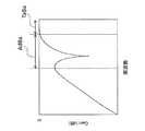
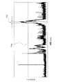
本実施形態のフィルタ回路31は、各素子の値を任意に設定することで、図3及び図4に示すようなターゲット周波数帯域TaBaに隣接する周波数帯域AdBaを減衰する周波数特性を持つフィルタ回路31となる。より具体的には、このフィルタ回路31は、ターゲット周波数帯域TaBaに隣接する、ターゲット周波数帯域TaBaよりも低い周波数帯域AdBaを減衰する周波数特性を持つフィルタ回路31となる。なお、素子の値を変更することによって、グラフの傾きや減衰する帯域の位置や減衰量を変更することができる。例えば、ターゲット周波数帯域TaBaよりも高い周波数帯域を減衰することもできるし、ターゲット周波数帯域TaBaよりも低い周波数帯域と高い周波数帯域の両方を減衰するようにしてもよい。 The
ターゲット周波数帯域TaBaは、放射ノイズの周波数帯域であることが好ましく、この場合、配線路2上での放電事故によって生じた放射ノイズが配線路2内を伝達してきたものをフィルタ回路31で取り出す。ターゲット周波数帯域TaBaを放射ノイズの周波数帯域とした場合、その隣接する周波数帯域AdBaには、FMラジオ放送や、アマチュア無線、電話などに起因した周波数が配線路2に重畳することで、放電事故が生じたと誤検知する虞がある。そこで、本発明では、ターゲット周波数帯域TaBaに隣接する周波数帯域AdBaを減衰させることで、誤検知を抑制し、検出精度を向上させる。 The target frequency band TaBa is preferably a frequency band of radiation noise. In this case, the
次に判定部5について説明する。判定部5には、ノイズレベルで放電事故の有無を判定する第1の閾値Th1が設定される(図5参照)。フィルタ部3で取り出され、増幅部4で増幅されたノイズのノイズレベルが第1の閾値Th1を超える場合に、放電事故が発生したと判定させることができる。第1の閾値Th1は、任意の値でよい。第1の閾値Th1はFMラジオ放送や、アマチュア無線、電話などに起因した周波数が配線路2に重畳することによるノイズのノイズレベルよりも高い値で設定されることが好ましいが、それに限定されるものではない。 Next, the
ところで、配線路2に接続される電気機器のスイッチをオンした場合など、ターゲット周波数帯域TaBaのノイズが瞬間的に発生し、そのノイズレベルが第1の閾値Th1を超える場合がある。その場合には、誤検知となる。そこで、実施形態では、更に検出精度を向上させるために、ノイズの継続時間で放電事故の有無を判定する所定時間Th2を設定する(図5参照)。判定部5は、増幅したノイズが第1の閾値Th1を超えた時間が所定時間Th2を超えた場合に放電事故が発生したと判定可能となる。つまり、実施形態では、フィルタ部3で取り出され、増幅部4で増幅されたノイズのレベルが、第1の閾値Th1を連続して超えている時間が、所定時間Th2を超えている場合に、放電事故が発生したと判定する。このようにすることで、瞬間的にノイズレベルが第1の閾値Th1を超えることによる誤検知をなくすことができる。 By the way, when the switch of the electric device connected to the
次に出力部6について説明する。出力部6は、判定部5によって放電事故が発生したと判定された場合に、その旨を表示する。出力部6の表示手段としては各種のものが採用できる。例えば、放電事故検出構造1を備える放電事故検出装置に表示ランプを設け、点灯させてもよいし、文字や音声を出力してもよい。また、通信部を備えたものとし、放電事故の発生を外部へ通信できるようにしてもよい。なお、表示と同時に、配線路2に接続される電気機器への電力供給を遮断するために、配線路2上の回路遮断器71などに信号を出力し、電路を遮断してもよい。 Next, the
図1に示す例では、プラグ72が差し込まれるコンセント73と電源74の間に、放電事故検出構造1のフィルタ部3を組み込むように構成しているが、図6に示すことから理解されるように、回路遮断器71と負荷75の間にフィルタ部3を組み込むようにしても良い。この場合、放電事故検出構造1から回路遮断器71に信号を送ることで、電路を遮断できるようにしても良い。 In the example shown in FIG. 1, the
また、図7に示すことから理解されるように、放電事故検出構造1を回路遮断器71内に組み込んでも良い。この場合、放電事故検出構造1から遮断部76に信号を送ることで、電路を遮断できるようにしても良い。 Further, as can be understood from FIG. 7, the discharge
また、図8に示すことから理解されるように、分電盤9内にフィルタ部3を組み込むようにしても良い。例えば、主幹ブレーカ91と分岐ブレーカ92の間にフィルタ部3を組み込むように構成しても良い。なお、増幅部4や判定部5や出力部6の全て若しくは何れかを分電盤9の外に設けるようにしても良い。 Further, as understood from FIG. 8, the
以上、実施形態を例に挙げて本発明について説明してきたが、本発明は上記実施形態に限定されることはなく、各種の態様とすることが可能である。 As described above, the present invention has been described by taking the embodiment as an example. However, the present invention is not limited to the above-described embodiment, and various aspects can be adopted.
1 放電事故検出構造
2 配線路
3 フィルタ部
4 増幅部
5 判定部
6 出力部DESCRIPTION OF
Claims (2)
Translated fromJapaneseターゲット周波数帯域のノイズを取り出すフィルタ部と、
フィルタ部で取り出したノイズを増幅する増幅部と、
増幅したノイズのレベルが第1の閾値を超えた場合に放電事故が発生したと判定可能となる判定部と、
放電事故が発生したと判定したことを出力する出力部と、
を備え、
フィルタ部が、ターゲット周波数帯域に隣接する周波数帯域のノイズを減衰する放電事故検出構造。A discharge accident detection structure for detecting a discharge accident occurring on a wiring path,
A filter unit for extracting noise in the target frequency band;
An amplifying unit for amplifying the noise extracted by the filter unit;
A determination unit capable of determining that a discharge accident has occurred when the amplified noise level exceeds the first threshold;
An output unit for outputting that it is determined that a discharge accident has occurred;
With
A discharge accident detection structure in which the filter unit attenuates noise in a frequency band adjacent to the target frequency band.
Priority Applications (1)
| Application Number | Priority Date | Filing Date | Title |
|---|---|---|---|
| JP2018077248AJP2019184475A (en) | 2018-04-13 | 2018-04-13 | Discharge accident detection structure |
Applications Claiming Priority (1)
| Application Number | Priority Date | Filing Date | Title |
|---|---|---|---|
| JP2018077248AJP2019184475A (en) | 2018-04-13 | 2018-04-13 | Discharge accident detection structure |
Publications (2)
| Publication Number | Publication Date |
|---|---|
| JP2019184475Atrue JP2019184475A (en) | 2019-10-24 |
| JP2019184475A5 JP2019184475A5 (en) | 2021-08-26 |
Family
ID=68340829
Family Applications (1)
| Application Number | Title | Priority Date | Filing Date |
|---|---|---|---|
| JP2018077248APendingJP2019184475A (en) | 2018-04-13 | 2018-04-13 | Discharge accident detection structure |
Country Status (1)
| Country | Link |
|---|---|
| JP (1) | JP2019184475A (en) |
Cited By (3)
| Publication number | Priority date | Publication date | Assignee | Title |
|---|---|---|---|---|
| KR20210084817A (en)* | 2019-12-30 | 2021-07-08 | 주식회사 스마트파워서플라이 | Method of dc arc fault detector for dc distribution systems |
| WO2022030466A1 (en)* | 2020-08-06 | 2022-02-10 | 日東工業株式会社 | Discharge detection device |
| JP2023074050A (en)* | 2021-11-17 | 2023-05-29 | 日東工業株式会社 | Discharge detector |
Citations (7)
| Publication number | Priority date | Publication date | Assignee | Title |
|---|---|---|---|---|
| JPH0455770A (en)* | 1990-06-26 | 1992-02-24 | Fuji Electric Co Ltd | Partial discharge monitoring device |
| JPH04269671A (en)* | 1991-02-26 | 1992-09-25 | Kansai Electric Power Co Inc:The | Amplifier for measuring partial discharge of power cable |
| JPH0627182A (en)* | 1992-07-10 | 1994-02-04 | Toshiba Corp | Partial discharge monitoring device |
| US6034611A (en)* | 1997-02-04 | 2000-03-07 | Square D Company | Electrical isolation device |
| JP2001324536A (en)* | 2000-05-16 | 2001-11-22 | Furukawa Electric Co Ltd:The | Partial discharge measurement method for power cable lines |
| JP2005283523A (en)* | 2004-03-31 | 2005-10-13 | Tempearl Ind Co Ltd | Device for detecting occurrence of partial discharge |
| JP2008166277A (en)* | 2006-12-28 | 2008-07-17 | General Electric Co <Ge> | Serial arc fault-current breaker and method |
- 2018
- 2018-04-13JPJP2018077248Apatent/JP2019184475A/enactivePending
Patent Citations (7)
| Publication number | Priority date | Publication date | Assignee | Title |
|---|---|---|---|---|
| JPH0455770A (en)* | 1990-06-26 | 1992-02-24 | Fuji Electric Co Ltd | Partial discharge monitoring device |
| JPH04269671A (en)* | 1991-02-26 | 1992-09-25 | Kansai Electric Power Co Inc:The | Amplifier for measuring partial discharge of power cable |
| JPH0627182A (en)* | 1992-07-10 | 1994-02-04 | Toshiba Corp | Partial discharge monitoring device |
| US6034611A (en)* | 1997-02-04 | 2000-03-07 | Square D Company | Electrical isolation device |
| JP2001324536A (en)* | 2000-05-16 | 2001-11-22 | Furukawa Electric Co Ltd:The | Partial discharge measurement method for power cable lines |
| JP2005283523A (en)* | 2004-03-31 | 2005-10-13 | Tempearl Ind Co Ltd | Device for detecting occurrence of partial discharge |
| JP2008166277A (en)* | 2006-12-28 | 2008-07-17 | General Electric Co <Ge> | Serial arc fault-current breaker and method |
Cited By (8)
| Publication number | Priority date | Publication date | Assignee | Title |
|---|---|---|---|---|
| KR20210084817A (en)* | 2019-12-30 | 2021-07-08 | 주식회사 스마트파워서플라이 | Method of dc arc fault detector for dc distribution systems |
| KR102293865B1 (en)* | 2019-12-30 | 2021-08-26 | 주식회사 스마트파워서플라이 | Method of dc arc fault detector for dc distribution systems |
| WO2022030466A1 (en)* | 2020-08-06 | 2022-02-10 | 日東工業株式会社 | Discharge detection device |
| JP2022029917A (en)* | 2020-08-06 | 2022-02-18 | 日東工業株式会社 | Discharge detection system |
| JP7527724B2 (en) | 2020-08-06 | 2024-08-05 | 日東工業株式会社 | Discharge Detection System |
| EP4195433A4 (en)* | 2020-08-06 | 2024-08-07 | Nitto Kogyo Corporation | DISCHARGE DETECTION DEVICE |
| US12259423B2 (en) | 2020-08-06 | 2025-03-25 | Nitto Kogyo Corporation | Discharge detector with learning mode for resetting settings to detecting occurrence of discharge |
| JP2023074050A (en)* | 2021-11-17 | 2023-05-29 | 日東工業株式会社 | Discharge detector |
Similar Documents
| Publication | Publication Date | Title |
|---|---|---|
| CN102332699B (en) | Ground wire safety voltage control system | |
| JP5334685B2 (en) | Partial discharge detection device and partial discharge detection method | |
| JP7337441B2 (en) | Discharge detection unit | |
| KR101244877B1 (en) | Apparatus for detecting arc fault using arc pulse timing | |
| JP2019184475A (en) | Discharge accident detection structure | |
| MX2015013007A (en) | Self-testing auto monitor ground fault circuit interrupter (gfci) with power denial. | |
| GB2461205A (en) | Power cutoff device automatically operated upon occurrence of spark on electric wire | |
| MY122232A (en) | Electrical fault detection system | |
| KR101823600B1 (en) | Apparatus for detecting arc and method for detecting parallel arc using acr detecing apparatus | |
| EP2879152A1 (en) | Relay welding detector, relay equipment incorporating the same, and relay welding detecting method | |
| JP2019184475A5 (en) | ||
| JP2021015047A (en) | Discharge detector and distribution board | |
| KR101953683B1 (en) | The distribution board including arc detecting apparatus | |
| CN110632472A (en) | DC system discharge fault detection method and system | |
| WO2018217883A3 (en) | Arc fault circuit interrupter | |
| JP2008305764A (en) | Connection failure detecting circuit of electric wire and circuit breaker | |
| KR102096471B1 (en) | A power-line proximity warning safety device | |
| JP6343926B2 (en) | Breaker | |
| CN218995560U (en) | Arc signal processing circuit and electrical equipment | |
| WO2024114610A1 (en) | Arc signal processing circuit and method, and electrical device | |
| KR20180076611A (en) | system and method for detecting arc using current change and high frequency noise | |
| TWI618934B (en) | Partial discharge detecting devices and methods thereof | |
| US8228103B2 (en) | Circuit breaker | |
| RU2011123884A (en) | FAULT CURRENT PROTECTION AUTOMATIC | |
| JP2005283523A (en) | Device for detecting occurrence of partial discharge |
Legal Events
| Date | Code | Title | Description |
|---|---|---|---|
| A621 | Written request for application examination | Free format text:JAPANESE INTERMEDIATE CODE: A621 Effective date:20210222 | |
| A521 | Request for written amendment filed | Free format text:JAPANESE INTERMEDIATE CODE: A523 Effective date:20210719 | |
| A977 | Report on retrieval | Free format text:JAPANESE INTERMEDIATE CODE: A971007 Effective date:20220124 | |
| A131 | Notification of reasons for refusal | Free format text:JAPANESE INTERMEDIATE CODE: A131 Effective date:20220201 | |
| A521 | Request for written amendment filed | Free format text:JAPANESE INTERMEDIATE CODE: A523 Effective date:20220323 | |
| A02 | Decision of refusal | Free format text:JAPANESE INTERMEDIATE CODE: A02 Effective date:20220614 |