JP2019174984A - Display controller and control method thereof and program and storage media - Google Patents
Display controller and control method thereof and program and storage mediaDownload PDFInfo
- Publication number
- JP2019174984A JP2019174984AJP2018060528AJP2018060528AJP2019174984AJP 2019174984 AJP2019174984 AJP 2019174984AJP 2018060528 AJP2018060528 AJP 2018060528AJP 2018060528 AJP2018060528 AJP 2018060528AJP 2019174984 AJP2019174984 AJP 2019174984A
- Authority
- JP
- Japan
- Prior art keywords
- display
- wide
- field image
- axis
- range
- Prior art date
- Legal status (The legal status is an assumption and is not a legal conclusion. Google has not performed a legal analysis and makes no representation as to the accuracy of the status listed.)
- Granted
Links
Images


Classifications
- H—ELECTRICITY
- H04—ELECTRIC COMMUNICATION TECHNIQUE
- H04N—PICTORIAL COMMUNICATION, e.g. TELEVISION
- H04N13/00—Stereoscopic video systems; Multi-view video systems; Details thereof
- H04N13/30—Image reproducers
- H04N13/398—Synchronisation thereof; Control thereof
- G—PHYSICS
- G06—COMPUTING OR CALCULATING; COUNTING
- G06F—ELECTRIC DIGITAL DATA PROCESSING
- G06F3/00—Input arrangements for transferring data to be processed into a form capable of being handled by the computer; Output arrangements for transferring data from processing unit to output unit, e.g. interface arrangements
- G06F3/01—Input arrangements or combined input and output arrangements for interaction between user and computer
- G06F3/048—Interaction techniques based on graphical user interfaces [GUI]
- G06F3/0481—Interaction techniques based on graphical user interfaces [GUI] based on specific properties of the displayed interaction object or a metaphor-based environment, e.g. interaction with desktop elements like windows or icons, or assisted by a cursor's changing behaviour or appearance
- G06F3/04815—Interaction with a metaphor-based environment or interaction object displayed as three-dimensional, e.g. changing the user viewpoint with respect to the environment or object
- G—PHYSICS
- G06—COMPUTING OR CALCULATING; COUNTING
- G06F—ELECTRIC DIGITAL DATA PROCESSING
- G06F3/00—Input arrangements for transferring data to be processed into a form capable of being handled by the computer; Output arrangements for transferring data from processing unit to output unit, e.g. interface arrangements
- G06F3/01—Input arrangements or combined input and output arrangements for interaction between user and computer
- G06F3/048—Interaction techniques based on graphical user interfaces [GUI]
- G06F3/0484—Interaction techniques based on graphical user interfaces [GUI] for the control of specific functions or operations, e.g. selecting or manipulating an object, an image or a displayed text element, setting a parameter value or selecting a range
- G06F3/04845—Interaction techniques based on graphical user interfaces [GUI] for the control of specific functions or operations, e.g. selecting or manipulating an object, an image or a displayed text element, setting a parameter value or selecting a range for image manipulation, e.g. dragging, rotation, expansion or change of colour
- G—PHYSICS
- G06—COMPUTING OR CALCULATING; COUNTING
- G06F—ELECTRIC DIGITAL DATA PROCESSING
- G06F3/00—Input arrangements for transferring data to be processed into a form capable of being handled by the computer; Output arrangements for transferring data from processing unit to output unit, e.g. interface arrangements
- G06F3/01—Input arrangements or combined input and output arrangements for interaction between user and computer
- G06F3/048—Interaction techniques based on graphical user interfaces [GUI]
- G06F3/0484—Interaction techniques based on graphical user interfaces [GUI] for the control of specific functions or operations, e.g. selecting or manipulating an object, an image or a displayed text element, setting a parameter value or selecting a range
- G06F3/0485—Scrolling or panning
- G—PHYSICS
- G06—COMPUTING OR CALCULATING; COUNTING
- G06F—ELECTRIC DIGITAL DATA PROCESSING
- G06F3/00—Input arrangements for transferring data to be processed into a form capable of being handled by the computer; Output arrangements for transferring data from processing unit to output unit, e.g. interface arrangements
- G06F3/01—Input arrangements or combined input and output arrangements for interaction between user and computer
- G06F3/048—Interaction techniques based on graphical user interfaces [GUI]
- G06F3/0487—Interaction techniques based on graphical user interfaces [GUI] using specific features provided by the input device, e.g. functions controlled by the rotation of a mouse with dual sensing arrangements, or of the nature of the input device, e.g. tap gestures based on pressure sensed by a digitiser
- G06F3/0488—Interaction techniques based on graphical user interfaces [GUI] using specific features provided by the input device, e.g. functions controlled by the rotation of a mouse with dual sensing arrangements, or of the nature of the input device, e.g. tap gestures based on pressure sensed by a digitiser using a touch-screen or digitiser, e.g. input of commands through traced gestures
- G06F3/04883—Interaction techniques based on graphical user interfaces [GUI] using specific features provided by the input device, e.g. functions controlled by the rotation of a mouse with dual sensing arrangements, or of the nature of the input device, e.g. tap gestures based on pressure sensed by a digitiser using a touch-screen or digitiser, e.g. input of commands through traced gestures for inputting data by handwriting, e.g. gesture or text
- G—PHYSICS
- G06—COMPUTING OR CALCULATING; COUNTING
- G06F—ELECTRIC DIGITAL DATA PROCESSING
- G06F3/00—Input arrangements for transferring data to be processed into a form capable of being handled by the computer; Output arrangements for transferring data from processing unit to output unit, e.g. interface arrangements
- G06F3/14—Digital output to display device ; Cooperation and interconnection of the display device with other functional units
- G06F3/147—Digital output to display device ; Cooperation and interconnection of the display device with other functional units using display panels
- G—PHYSICS
- G06—COMPUTING OR CALCULATING; COUNTING
- G06T—IMAGE DATA PROCESSING OR GENERATION, IN GENERAL
- G06T3/00—Geometric image transformations in the plane of the image
- G06T3/08—Projecting images onto non-planar surfaces, e.g. geodetic screens
- G—PHYSICS
- G09—EDUCATION; CRYPTOGRAPHY; DISPLAY; ADVERTISING; SEALS
- G09G—ARRANGEMENTS OR CIRCUITS FOR CONTROL OF INDICATING DEVICES USING STATIC MEANS TO PRESENT VARIABLE INFORMATION
- G09G3/00—Control arrangements or circuits, of interest only in connection with visual indicators other than cathode-ray tubes
- G09G3/20—Control arrangements or circuits, of interest only in connection with visual indicators other than cathode-ray tubes for presentation of an assembly of a number of characters, e.g. a page, by composing the assembly by combination of individual elements arranged in a matrix no fixed position being assigned to or needed to be assigned to the individual characters or partial characters
- H—ELECTRICITY
- H04—ELECTRIC COMMUNICATION TECHNIQUE
- H04N—PICTORIAL COMMUNICATION, e.g. TELEVISION
- H04N13/00—Stereoscopic video systems; Multi-view video systems; Details thereof
- H04N13/30—Image reproducers
- H04N13/349—Multi-view displays for displaying three or more geometrical viewpoints without viewer tracking
- H—ELECTRICITY
- H04—ELECTRIC COMMUNICATION TECHNIQUE
- H04N—PICTORIAL COMMUNICATION, e.g. TELEVISION
- H04N23/00—Cameras or camera modules comprising electronic image sensors; Control thereof
- H04N23/60—Control of cameras or camera modules
- H04N23/698—Control of cameras or camera modules for achieving an enlarged field of view, e.g. panoramic image capture
- G—PHYSICS
- G06—COMPUTING OR CALCULATING; COUNTING
- G06F—ELECTRIC DIGITAL DATA PROCESSING
- G06F3/00—Input arrangements for transferring data to be processed into a form capable of being handled by the computer; Output arrangements for transferring data from processing unit to output unit, e.g. interface arrangements
- G06F3/01—Input arrangements or combined input and output arrangements for interaction between user and computer
- G06F3/03—Arrangements for converting the position or the displacement of a member into a coded form
- G06F3/033—Pointing devices displaced or positioned by the user, e.g. mice, trackballs, pens or joysticks; Accessories therefor
- G—PHYSICS
- G06—COMPUTING OR CALCULATING; COUNTING
- G06F—ELECTRIC DIGITAL DATA PROCESSING
- G06F3/00—Input arrangements for transferring data to be processed into a form capable of being handled by the computer; Output arrangements for transferring data from processing unit to output unit, e.g. interface arrangements
- G06F3/01—Input arrangements or combined input and output arrangements for interaction between user and computer
- G06F3/048—Interaction techniques based on graphical user interfaces [GUI]
- G06F3/0487—Interaction techniques based on graphical user interfaces [GUI] using specific features provided by the input device, e.g. functions controlled by the rotation of a mouse with dual sensing arrangements, or of the nature of the input device, e.g. tap gestures based on pressure sensed by a digitiser
- G06F3/0488—Interaction techniques based on graphical user interfaces [GUI] using specific features provided by the input device, e.g. functions controlled by the rotation of a mouse with dual sensing arrangements, or of the nature of the input device, e.g. tap gestures based on pressure sensed by a digitiser using a touch-screen or digitiser, e.g. input of commands through traced gestures
Landscapes
- Engineering & Computer Science (AREA)
- Theoretical Computer Science (AREA)
- General Engineering & Computer Science (AREA)
- Physics & Mathematics (AREA)
- General Physics & Mathematics (AREA)
- Human Computer Interaction (AREA)
- Multimedia (AREA)
- Signal Processing (AREA)
- Computer Hardware Design (AREA)
- User Interface Of Digital Computer (AREA)
- Controls And Circuits For Display Device (AREA)
- Camera Bodies And Camera Details Or Accessories (AREA)
Abstract
Translated fromJapaneseDescription
Translated fromJapanese本発明は、表示制御装置、その制御方法、プログラム及び記憶媒体に関する。 The present invention relates to a display control device, a control method thereof, a program, and a storage medium.
全方位カメラ(全天球カメラ)で撮像された画像を仮想的な球体の表面にマッピングし、球体の中心に位置する視点から球体表面にマッピングされた画像を見ているかのような表示を行う技術が普及している。以下、仮想球面にマッピングされた画像を広視野画像という。広視野画像の表示技術として、ポインティングデバイスによるユーザ操作入力やヘッドマウントディスプレイの姿勢情報等に応じて、広視野画像のうちディスプレイに表示する範囲を変化させる技術がある。特許文献1では、ディスプレイの表示領域を複数に分割し、全天球カメラにより撮像して得られた広視野画像を各領域に表示し、領域毎に異なる表示制御を行う技術が提案されている。 An image captured by an omnidirectional camera (omnidirectional camera) is mapped onto the surface of a virtual sphere, and a display is made as if the image mapped on the surface of the sphere is viewed from a viewpoint located at the center of the sphere. Technology is widespread. Hereinafter, an image mapped to the virtual spherical surface is referred to as a wide field image. As a technique for displaying a wide-field image, there is a technique for changing a range to be displayed on a display in a wide-field image in accordance with a user operation input by a pointing device, posture information of a head mounted display, or the like.
広視野画像の表示においては、例えば、ユーザが右方向の移動操作(例えばタッチパネル上でのスライド操作(タッチムーブ)やマウスによるドラッグ操作)を行った場合には、ユーザ操作に追従してディスプレイに表示される画像が右に移動する。このような表示は、視線を固定した状態で、広視野画像をマッピングした仮想球体を回転させたと考えて、広視野画像のうちディスプレイに表示する範囲を変更することにより実現される。或いは、広視野画像(仮想球体)を固定し、ユーザ操作に応じてユーザが視線の向きを変化させたと考えて、広視野画像のうちディスプレイに表示する範囲を変更することにより、ユーザ操作に追従した表示が実現される。
従来の広視野画像の表示制御では、ユーザ操作方向に対し広視野画像の回転方向は一意に決定されていた。例えば、ユーザが右方向の移動操作を行った場合には、タッチ位置にかかわらず常に、広視野画像(仮想球体)が鉛直方向に対し時計回りに回転したと考えて、広視野画像のうちディスプレイに表示する範囲を変更していた。In the display of a wide-field image, for example, when the user performs a rightward movement operation (for example, a slide operation (touch move) on the touch panel or a drag operation with a mouse), the user follows the user operation and displays it on the display. The displayed image moves to the right. Such a display is realized by changing the range of the wide-field image to be displayed on the display, assuming that the virtual sphere mapped with the wide-field image is rotated with the line of sight fixed. Alternatively, it is possible to follow the user operation by fixing the wide-field image (virtual sphere) and changing the range of the wide-field image displayed on the display, assuming that the user changes the direction of the line of sight according to the user operation. Display is realized.
In conventional display control of a wide-field image, the rotation direction of the wide-field image is uniquely determined with respect to the user operation direction. For example, when the user performs a rightward movement operation, the wide-field image (virtual sphere) is always rotated clockwise with respect to the vertical direction regardless of the touch position. The range displayed in was changed.
しかし、このような表示制御を行うと、広視野画像のうち鉛直方向の頂点(天頂(zenith)又は天底(nadir))を含む範囲がディスプレイに表示されている状態では、ユーザ
の操作に追従しない表示が行われる場合がある。例えば広視野画像の天底が表示範囲に含まれている状態で、ディスプレイにおける広視野画像の表示領域において、天底の位置よりも下側の位置を起点に右方向にスライド操作を行った場合を考える。このとき、上記のように広視野画像を鉛直軸に対し時計回りに回転することにより広視野画像のうちディスプレイに表示する範囲を変更すると、ディスプレイに表示される画像は左に移動する。広視野画像(仮想球体)が鉛直方向上から見て時計回りに回転した場合、天底より奥側(画像表示領域では天底より下側)は右へ移動し、天底より手前側(画像表示領域では天底より上側)は左へ移動するからである。よって、ユーザによる右方向の操作とは逆向きに画像が移動することになる。このように、スライド操作の起点の位置によってポインティング手段の動き方向と表示画像の動き方向とが同じ方向であったり、逆向きであったり、両者の関係が一定でなくなるため、ユーザは違和感を覚える可能性がある。However, when such display control is performed, in the state where the range including the vertical apex (zenith or nadir) of the wide-field image is displayed on the display, it follows the user's operation. May not be displayed. For example, when the nadir of the wide-field image is included in the display range and the slide operation is performed in the right direction starting from the position below the nadir in the display area of the wide-field image on the display think of. At this time, if the range of the wide-field image displayed on the display is changed by rotating the wide-field image clockwise with respect to the vertical axis as described above, the image displayed on the display moves to the left. When a wide-field image (virtual sphere) is rotated clockwise as viewed from above in the vertical direction, the far side from the nadir (below the nadir in the image display area) moves to the right and the near side from the nadir (image This is because (in the display area, above the nadir) moves to the left. Therefore, the image moves in the opposite direction to the right operation by the user. Thus, the user feels uncomfortable because the direction of movement of the pointing means and the direction of movement of the display image are the same or opposite depending on the position of the starting point of the slide operation. there is a possibility.
そこで本発明は、広視野画像の表示を制御する表示制御装置において、広視野画像の表
示範囲を移動する操作を行った場合にユーザが違和感を覚えることを抑制する技術を提供することを目的とする。SUMMARY OF THE INVENTION An object of the present invention is to provide a technique for suppressing a user from feeling uncomfortable when an operation for moving a display range of a wide-field image is performed in a display control device that controls display of a wide-field image. To do.
本発明は、
広視野画像の一部範囲を表示手段に表示するように制御する表示制御手段と、
前記広視野画像の表示領域に対する位置を入力する入力手段と、
前記広視野画像の一部範囲を表示範囲として表示しており、第1の軸回りの回転の中心位置が表示範囲に含まれている状態において、
前記入力手段で、前記表示領域に対する第1の方向への移動操作を受け付けたことに応じて、前記広視野画像の表示範囲を、前記第1の軸回りに時計回りに回転する方向に変更し、
前記入力手段で、前記表示領域に対する、前記第1の方向と逆方向である第2の方向への移動操作を受け付けたことに応じて、前記広視野画像の表示範囲を、前記第1の軸回りに反時計回りに回転する方向に変更し、
前記広視野画像の一部範囲を表示範囲として表示しており、前記中心位置が表示範囲に含まれている状態において、
前記入力手段で、前記表示領域に対する前記第1の方向への移動操作を受け付けたことに応じて、前記第1の方向と垂直な軸方向における該移動操作の起点と前記中心位置の位置関係に応じて、前記第1の軸回りの異なる回転方向に前記広視野画像の表示範囲を変更する
ように制御する制御手段と
を有することを特徴とする表示制御装置である。The present invention
Display control means for controlling to display a partial range of the wide-field image on the display means;
Input means for inputting a position with respect to the display area of the wide-field image;
In a state where a partial range of the wide-field image is displayed as a display range, and the center position of rotation around the first axis is included in the display range,
In response to accepting a movement operation in the first direction with respect to the display area by the input means, the display range of the wide-field image is changed to a direction that rotates clockwise around the first axis. ,
In response to accepting a movement operation in the second direction that is opposite to the first direction with respect to the display area by the input means, the display range of the wide-field image is changed to the first axis. Change the direction to rotate counterclockwise,
In a state where a partial range of the wide-field image is displayed as a display range, and the center position is included in the display range,
In response to receiving the movement operation in the first direction with respect to the display area by the input means, the positional relationship between the starting point of the movement operation and the center position in the axial direction perpendicular to the first direction is determined. And a control unit that controls to change the display range of the wide-field image in different rotation directions around the first axis.
本発明によれば、広視野画像の表示を制御する表示制御装置において、広視野画像の表示範囲を移動する操作を行った場合にユーザが違和感を覚えることを抑制することができる。 ADVANTAGE OF THE INVENTION According to this invention, in the display control apparatus which controls the display of a wide field image, when an operation which moves the display range of a wide field image is performed, it can suppress that a user feels uncomfortable.
以下、図面を参照して本発明の好適な実施形態を説明する。ここでは、表示手段に広視野画像を表示する制御を行う表示制御装置に本発明を適用した一例を説明する。 Preferred embodiments of the present invention will be described below with reference to the drawings. Here, an example in which the present invention is applied to a display control apparatus that performs control to display a wide-field image on the display means will be described.
広視野画像とは、上下方向(垂直角度、天頂からの角度、仰角、俯角、高度角)と左右方向(水平角度、方位角度)にそれぞれ180度以上(±90度)の視野角(範囲)の被写体の情報(画像情報)を有する画像である。広視野画像の有効画像範囲(映像範囲)は、最大で上下方向360度、左右方向360度であるが、有効画像範囲が上下方向360度未満、左右方向360度未満の画像も広視野画像に含まれる。例えば、左右方向(水平
角度、方位角度)360度、天頂を中心として上下方向210度の有効画像範囲を有する画像は広視野画像である。広視野画像は、人間が一度に視認できる範囲よりも広い視野角を有する画像であり、通常のカメラで撮像して得られる画像の画角(視野角)よりも広い画角の画像情報を持つ画像である。広視野画像は、表示手段に一度に表示できる映像範囲より広い映像範囲の画像情報を持つ画像である。本発明は、映像範囲内に少なくとも天頂(zenith)若しくは真上、又は、天頂の反対側である天底(nadir)若しくは真下のいず
れかの頂点を含む画像情報を有する広視野画像の表示を制御する表示制御装置に適用できる。A wide-field image is a viewing angle (range) of 180 degrees or more (± 90 degrees) in the vertical direction (vertical angle, angle from the zenith, elevation angle, depression angle, altitude angle) and horizontal direction (horizontal angle, azimuth angle). It is an image which has the information (image information) of the subject. The effective image range (video range) of the wide-field image is 360 degrees in the vertical direction and 360 degrees in the horizontal direction. included. For example, an image having an effective image range of 360 degrees in the left-right direction (horizontal angle, azimuth angle) and 210 degrees in the vertical direction around the zenith is a wide-field image. A wide-field image is an image having a wider viewing angle than the range that a human can view at a time, and has image information having a wider angle of view than the angle of view (viewing angle) of an image obtained by capturing with a normal camera. It is an image. A wide-field image is an image having image information in a video range wider than the video range that can be displayed on the display means at a time. The present invention controls the display of a wide-field image having image information including at least a zenith or directly above the image range, or a vertex on either the nadir or directly below the zenith It can be applied to a display control device.
広視野画像は、全方位カメラや全天球カメラで撮像して得られた視野角180度以上の全方位画像や全天球画像、パノラマ画像、VR画像等を含む。また、カメラで撮像して得られた画像に限らず、コンピュータグラフィックスス(CG)を用いて作成された視野角180度以上のVR画像等も広視野画像に含まれる。また、静止画像だけではなく、動画像や撮像装置からほぼリアルタイムで取得されるライブビュー画像も広視野画像に含まれる。 The wide-field image includes an omnidirectional image having a viewing angle of 180 degrees or more, an omnidirectional image, a panoramic image, a VR image, and the like obtained by imaging with an omnidirectional camera or an omnidirectional camera. Further, not only images obtained by imaging with a camera, but also VR images with a viewing angle of 180 degrees or more created using computer graphics (CG) are included in the wide-field images. Further, not only a still image but also a live view image acquired in real time from a moving image or an imaging device is included in the wide-field image.
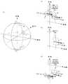
図1は実施例1の表示制御装置において表示する対象とする広視野画像を説明する図である。広視野画像の表示制御では、例えば全天球カメラで撮像して得られた正距円筒図法による全天球画像(全方位画像)を、図1(A)に示すような仮想的な球体の表面にマッピングする。そして、中心の視点から球体表面を見たかのように、広視野画像の一部範囲をディスプレイに表示することで、例えばVR画像表示が実現される。
広視野画像の表示制御では、仮想的な球体の表面を見る視線の向き及び視野(範囲)を基準(固定)とし、仮想的な球体を回転させた場合に、仮想的な球体の中心に位置する視点から見える画像の変化が、ディスプレイに表示されるように表示画像を変更する。
この表示制御は、仮想球体を基準(固定)とし、仮想球体の表面を見る視線の向き及び視野(範囲)を変化させた場合に、仮想球体の中心に位置する視点から見える画像の変化が、ディスプレイに表示されるように表示画像を変更する、と捉えることもできる。
これら「視線の回転」や「仮想球体の回転」は、画像の表示制御を説明するための概念であり、「視線を回転させたような表示」又は「仮想球体を回転させたような表示」を実現するための具体的な座標変換等の計算方法等を限定しない。
本明細書では、「広視野画像」といった場合、上記の意味で正距円筒図法等による元画像を仮想球体にマッピングしたものを意味するものとする。また、「広視野画像の回転」は、広視野画像がマッピングされた仮想球体を回転させることにより、広視野画像のうちディスプレイに表示する範囲を変更することを意味するものとする。また、「広視野画像の表示範囲の回転」は、広視野画像(仮想球体)を基準(固定)として、広視野画像を見る視線の向き及び視野(範囲)を変化させることにより、広視野画像のうちディスプレイに表示する一部範囲を変更することを意味するものとする。FIG. 1 is a diagram for explaining a wide-field image to be displayed in the display control apparatus according to the first embodiment. In the display control of the wide-field image, for example, an omnidirectional image (omnidirectional image) obtained by imaging with an omnidirectional camera by an equirectangular projection is converted into a virtual sphere as shown in FIG. Map to the surface. Then, for example, VR image display is realized by displaying a partial range of the wide-field image on the display as if the sphere surface was viewed from the central viewpoint.
In the display control of a wide-field image, when the virtual sphere is rotated with the direction of the line of sight and the visual field (range) looking at the surface of the virtual sphere as the reference (fixed), it is positioned at the center of the virtual sphere. The display image is changed so that a change in the image seen from the viewpoint to be displayed is displayed on the display.
This display control uses the virtual sphere as a reference (fixed), and when the direction of the line of sight and the field of view (range) of viewing the surface of the virtual sphere are changed, the change in the image seen from the viewpoint located at the center of the virtual sphere is: It can also be understood that the display image is changed so as to be displayed on the display.
These “rotation of the line of sight” and “rotation of the virtual sphere” are concepts for explaining the display control of the image, and “display that rotates the line of sight” or “display that rotates the virtual sphere” The calculation method such as a specific coordinate transformation for realizing the above is not limited.
In the present specification, “wide-field image” means an image obtained by mapping an original image by equirectangular projection or the like onto a virtual sphere in the above sense. In addition, “rotation of a wide-field image” means that a range to be displayed on a display in the wide-field image is changed by rotating a virtual sphere on which the wide-field image is mapped. In addition, “rotation of the display range of the wide-field image” refers to a wide-field image by changing the direction of the line of sight and the visual field (range) of viewing the wide-field image with the wide-field image (virtual sphere) as a reference (fixed). It means that the partial range displayed on the display is changed.
図1(A)に示すように、広視野画像は、第1軸方向及び第1軸に垂直な第2軸方向の所定範囲の視野の画像であり、所定範囲には、少なくとも第1軸の正方向の頂点(第1頂点)及び第1軸の負方向の頂点(第2頂点)のいずれかが含まれる。図1では、第1軸は鉛直軸であり、第1軸の正方向は上方向、負方向は下方向である。第2軸は水平軸であり、第2軸の正方向は右方向、負方向は左方向である。また、第1軸の正方向の頂点(第1頂点)は天頂P1であり、負方向の頂点(第2頂点)は天底P2である。第1軸の正方向の頂点(天頂又は真上)及び第1軸の負方向の頂点(天底又は真下)は、第1軸回りの回転の中心位置である。 As shown in FIG. 1A, a wide-field image is an image of a visual field in a predetermined range in a first axis direction and a second axis direction perpendicular to the first axis, and the predetermined range includes at least the first axis. One of a positive vertex (first vertex) and a negative vertex (second vertex) of the first axis is included. In FIG. 1, the first axis is a vertical axis, and the positive direction of the first axis is upward and the negative direction is downward. The second axis is a horizontal axis, the positive direction of the second axis is the right direction, and the negative direction is the left direction. The positive vertex (first vertex) of the first axis is the zenith P1, and the negative vertex (second vertex) is the nadir P2. The vertex in the positive direction of the first axis (the zenith or directly above) and the vertex in the negative direction of the first axis (the nadir or directly below) are the center positions of rotation around the first axis.
表示制御装置は、このような広視野画像の一部範囲を表示装置に表示する。図1(A)において、表示範囲Bは、広視野画像のうち、第1軸の正方向(上方向)の頂点である第1頂点(天頂)P1を含む範囲を示す。表示範囲Cは、広視野画像のうち、第1軸の正方
向(上方向)の頂点(天頂)P1も負方向(下方向)の頂点(天底)P2も含まない範囲を示す。表示範囲Dは、広視野画像のうち、第1軸の負方向(下方向)の頂点である第2頂点(天底)P2を含む範囲を示す。The display control device displays a partial range of such a wide-field image on the display device. In FIG. 1A, a display range B indicates a range including a first vertex (zenith) P1 that is a vertex in the positive direction (upward) of the first axis in the wide-field image. The display range C indicates a range of the wide-field image that does not include the positive (upper) vertex (zenith) P1 or the negative (downward) vertex (nadir) P2 of the first axis. The display range D indicates a range including a second vertex (nadir) P2 that is a vertex in the negative direction (downward) of the first axis in the wide-field image.
表示制御装置は、表示手段に表示されている広視野画像に対するユーザの操作指示の入力を受け付ける。表示制御装置は、入力手段に第2軸方向(左右方向)の移動操作が入力された場合、広視野画像を第1軸回り(鉛直軸の回り)に回転させることにより、表示手段に表示される広視野画像の表示範囲を変更する制御を行う。 The display control apparatus receives an input of a user operation instruction for the wide-field image displayed on the display unit. When a movement operation in the second axis direction (left-right direction) is input to the input unit, the display control device displays the image on the display unit by rotating the wide-field image around the first axis (around the vertical axis). To change the display range of the wide-field image.
図1(B)は、表示範囲Bの拡大図であり、表示範囲Bが表示手段に表示されている状態で、ユーザによる移動操作が入力された場合の広視野画像の回転方向を説明する図である。図1(B)は、広視野画像のうち第1頂点(天頂)P1を含む一部範囲が表示手段に表示されている状態を示す。
この状態で、第1頂点(天頂)P1よりも第1軸方向(上下方向)D1で正の位置にある第1点K1を起点として第2軸の正方向(右方向)の移動操作S1が入力されたとする。この場合、表示制御装置は、広視野画像を第1軸回りに反時計回りM1に回転させることにより、表示手段に表示される広視野画像の表示範囲を変更する。広視野画像の表示範囲は第1軸の回りに時計回りに回転し、表示手段における第1頂点(天頂)P1よりも第1軸方向(上下方向)D1で正方向側の表示画像は右に移動する。第1頂点(天頂)P1よりも第1軸方向(上下方向)D1で負方向側の表示画像は左に移動する。逆に、第1点K1を起点として第2軸の負方向(左方向)の移動操作(S1の逆)が入力された場合、表示制御装置は、広視野画像を第1軸の回りに時計回りに回転させる(M1の逆)ことにより、表示手段に表示される広視野画像の表示範囲を変更する。広視野画像の表示範囲は第1軸の回りに反時計回りに回転し、表示手段における第1頂点(天頂)P1よりも第1軸方向(上下方向)D1で正方向側の表示画像は左に移動する。第1頂点(天頂)P1よりも第1軸方向(上下方向)D1で負方向側の表示画像は右に移動する。第1点K1は、第1頂点(天頂)P1よりも、第1の方向及び第2の方向(表示手段における画像の表示向きに対する左右方向)と垂直な第3の方向側(上側)の位置にある。第1軸は、第3の方向及びその逆方向の第4の方向(上下方向)に平行な軸である。FIG. 1B is an enlarged view of the display range B, and is a diagram for explaining the rotation direction of the wide-field image when a moving operation is input by the user while the display range B is displayed on the display unit. It is. FIG. 1B shows a state in which a partial range including the first vertex (zenith) P1 in the wide-field image is displayed on the display means.
In this state, the movement operation S1 in the positive direction (right direction) of the second axis is started from the first point K1 that is in the positive position in the first axis direction (vertical direction) D1 relative to the first vertex (zenith) P1. Suppose that it is input. In this case, the display control device changes the display range of the wide-field image displayed on the display unit by rotating the wide-field image counterclockwise M1 about the first axis. The display range of the wide-field image rotates clockwise around the first axis, and the display image on the positive direction side in the first axis direction (vertical direction) D1 with respect to the first vertex (zenith) P1 in the display means is to the right. Moving. The display image on the negative direction side moves to the left in the first axial direction (vertical direction) D1 from the first vertex (zenith) P1. Conversely, when a movement operation in the negative direction (leftward) of the second axis (reverse to S1) is input starting from the first point K1, the display control device displays the wide-field image around the first axis. By rotating it around (the reverse of M1), the display range of the wide-field image displayed on the display means is changed. The display range of the wide-field image rotates counterclockwise around the first axis, and the display image on the positive direction side in the first axis direction (vertical direction) D1 with respect to the first vertex (zenith) P1 in the display means is left. Move to. The display image on the negative direction side moves to the right in the first axial direction (vertical direction) D1 from the first vertex (zenith) P1. The first point K1 is a position on the third direction side (upper side) perpendicular to the first direction and the second direction (left-right direction with respect to the image display direction on the display means) from the first vertex (zenith) P1. It is in. The first axis is an axis parallel to the third direction and the fourth direction (vertical direction) opposite to the third direction.
また、第1頂点(天頂)P1よりも第1軸方向(上下方向)D1で負の位置にある第2点K2を起点として第2軸の正方向(右方向)の移動操作S2が入力された場合、表示制御装置は、以下のように制御する。すなわち、広視野画像を第1軸の回りに時計回りM2に回転させることにより、表示手段に表示される広視野画像の表示範囲を変更する。広視野画像の表示範囲は第1軸の回りに反時計回りに回転し、表示手段における第1頂点(天頂)P1よりも第1軸方向(上下方向)D1で負方向側の表示画像は右に移動する。第1頂点(天頂)P1よりも第1軸方向(上下方向)D1で正方向側の表示画像は左に移動する。逆に、第2点K2を起点として第2軸の負方向(左方向)の移動操作(S2の逆)が入力された場合、表示制御装置は、広視野画像を第1軸の回りに反時計回りに回転させる(M2の逆)ことにより、表示手段に表示される広視野画像の表示範囲を変更する。広視野画像の表示範囲は第1軸の回りに時計回りに回転し、表示手段における第1頂点(天頂)P1よりも第1軸方向(上下方向)D1で負方向側の表示画像は左に移動する。第1頂点(天頂)P1よりも第1軸方向(上下方向)D1で正方向側の表示画像は右に移動する。第2点K2は、第1頂点(天頂)P1よりも、第1の方向及び第2の方向(表示手段における画像の表示向きに対する左右方向)と垂直な第3の方向(上方向)と逆方向である第4の方向側(下側)の位置にある。第1軸は、第3の方向及びその逆方向の第4の方向(上下方向)に平行な軸である。 Also, a movement operation S2 in the positive direction (right direction) of the second axis is input starting from the second point K2 that is in a negative position in the first axis direction (vertical direction) D1 relative to the first vertex (zenith) P1. In such a case, the display control device controls as follows. That is, the display range of the wide-field image displayed on the display unit is changed by rotating the wide-field image clockwise about the first axis M2. The display range of the wide-field image rotates counterclockwise around the first axis, and the display image on the negative direction side in the first axis direction (vertical direction) D1 from the first vertex (zenith) P1 in the display means is right Move to. The display image on the positive direction side moves to the left in the first axial direction (vertical direction) D1 from the first vertex (zenith) P1. Conversely, when a movement operation in the negative direction (leftward) of the second axis (reverse of S2) is input starting from the second point K2, the display control device returns the wide-field image around the first axis. By rotating clockwise (the reverse of M2), the display range of the wide-field image displayed on the display means is changed. The display range of the wide-field image rotates clockwise around the first axis, and the display image on the negative direction side in the first axis direction (vertical direction) D1 with respect to the first vertex (zenith) P1 in the display means is on the left. Moving. The display image on the positive direction side moves to the right in the first axial direction (vertical direction) D1 from the first vertex (zenith) P1. The second point K2 is opposite to the third direction (upward direction) perpendicular to the first direction and the second direction (left-right direction with respect to the display direction of the image on the display means), rather than the first vertex (zenith) P1. It is in the position on the fourth direction side (lower side) which is the direction. The first axis is an axis parallel to the third direction and the fourth direction (vertical direction) opposite to the third direction.
図1(B)に示すように、いずれの場合も、ユーザの操作方向(S1,S2)と広視野画像の回転方向(M1,M2)は一致しており、上述のようにユーザの操作方向と表示手
段における操作部分の表示画像の移動方向が一致している。従って、広視野画像の天頂を含む範囲が表示手段に表示されている状態でユーザが移動操作を行っても、ユーザが違和感を覚えることを抑制できる。As shown in FIG. 1B, in any case, the user's operation direction (S1, S2) matches the rotation direction (M1, M2) of the wide-field image, and the user's operation direction as described above. And the moving direction of the display image of the operation part in the display means coincide. Therefore, even if the user performs a moving operation in a state where the range including the zenith of the wide-field image is displayed on the display unit, the user can be prevented from feeling uncomfortable.
従来は、広視野画像のうち天頂P1を含む範囲が表示手段に表示されている状態で、例えば右方向の移動操作が入力された場合、次のような表示制御が行われていた。すなわち、移動操作の起点の位置によらず常に広視野画像を第1軸の回りに時計回りに回転させることにより、表示手段に表示される広視野画像の表示範囲を変更する制御を行っていた。従って、天頂P1より上にある第1点K1を起点として右方向の移動操作S1が入力された場合は、図1(B)に示すように、操作方向S1と広視野画像の回転方向M1Xが逆となる。従ってユーザの操作方向と表示手段における操作部分の表示画像の移動方向が一致しない。この場合、例えばユーザが右方向にタッチムーブ操作を行っている部分で画像は左方向に動くため、ユーザは違和感を覚えることがあった。 Conventionally, in the state in which the range including the zenith P1 in the wide-field image is displayed on the display unit, for example, when a rightward movement operation is input, the following display control is performed. That is, control is performed to change the display range of the wide-field image displayed on the display means by always rotating the wide-field image clockwise around the first axis regardless of the position of the starting point of the moving operation. . Accordingly, when a rightward movement operation S1 is input starting from the first point K1 above the zenith P1, as shown in FIG. 1B, the operation direction S1 and the rotation direction M1X of the wide-field image are determined as follows. The reverse is true. Therefore, the operation direction of the user does not match the movement direction of the display image of the operation portion on the display means. In this case, for example, the image moves to the left in the part where the user is performing the touch move operation in the right direction, so the user may feel uncomfortable.
なお、ここで「第1頂点P1よりも第1軸方向D1で正の位置にある」とは、第1頂点P1よりも矢印D1で示す方向に離れた位置にあることを意味する。また、「第1頂点P1よりも第1軸方向D1で負の位置にある」とは、第1頂点P1よりも矢印D1で示す方向とは逆方向に離れた位置にあることを意味する。図1(B)に示すように、矢印D1で示す「第1軸方向で正の方向」は、第2軸の回り(水平軸の回り)の反時計回り方向である。しかしながら表示手段に表示された画像内では、矢印D1で示す方向は上下方向であり、第1点K1は第1頂点P1よりも上に表示される。そのため、第1点K1の位置を、第1頂点P1よりも第1軸方向(上下方向)で正の位置、と表現する。このことは次のようにも説明することができる。広視野画像の水平方向を向いている状態、すなわち表示範囲Cが表示手段に表示されている状態から、天頂を向く方向に視線を動かしていく場合、視線の移動方向は矢印D1で示す方向となる。広視野画像の水平方向を向いている状態では、矢印D1で示す方向(第2軸の回りの反時計回り方向)は上下方向に平行になる。よって、表示手段に表示された画像においては、矢印10で示す方向は上下方向と認識される。 Here, “being at a positive position in the first axial direction D1 relative to the first vertex P1” means being located away from the first vertex P1 in the direction indicated by the arrow D1. Further, “being in a negative position in the first axial direction D1 from the first vertex P1” means being in a position away from the direction indicated by the arrow D1 from the first vertex P1. As shown in FIG. 1B, the “positive direction in the first axis direction” indicated by the arrow D1 is a counterclockwise direction around the second axis (around the horizontal axis). However, in the image displayed on the display means, the direction indicated by the arrow D1 is the vertical direction, and the first point K1 is displayed above the first vertex P1. Therefore, the position of the first point K1 is expressed as a positive position in the first axial direction (vertical direction) with respect to the first vertex P1. This can also be explained as follows. When moving the line of sight from the state of facing the horizontal direction of the wide-field image, that is, the state where the display range C is displayed on the display means, to the direction of the zenith, the movement direction of the line of sight is the direction indicated by the arrow D1. Become. In the state of facing the horizontal direction of the wide-field image, the direction indicated by the arrow D1 (counterclockwise direction around the second axis) is parallel to the vertical direction. Therefore, in the image displayed on the display means, the direction indicated by the arrow 10 is recognized as the up-down direction.
図1(C)は、表示範囲Cの拡大図であり、表示範囲Cが表示手段に表示されている状態で、ユーザによる移動操作が入力された場合の広視野画像の回転方向を説明する図である。図1(C)は、広視野画像のうち、第1頂点(天頂)P1も第2頂点(天底)P2も含まない範囲が表示手段に表示されている状態を示す。
この状態で、第2軸の正方向(右方向)の移動操作S5が入力された場合、表示制御装置は、広視野画像を第1軸の回りに時計回りM5に回転させることにより、表示手段に表示される広視野画像の表示範囲を変更する。広視野画像の表示範囲は第1軸の回りに反時計回りに回転し、表示手段における表示画像は右に移動する。逆に、第2軸の負方向(左方向)の移動操作(S5の逆)が入力された場合、表示制御装置は、広視野画像を第1軸の回りに反時計回りに回転させる(M5の逆)ことにより、表示手段に表示される広視野画像の表示範囲を変更する。広視野画像の表示範囲は第1軸の回りに時計回りに回転し、表示手段における表示画像は左に移動する。
図1(C)に示すように、ユーザの操作方向S5と広視野画像の回転方向M5は一致しており、ユーザの操作方向と表示手段における表示画像の移動方向が一致している。FIG. 1C is an enlarged view of the display range C, and is a diagram for explaining the rotation direction of the wide-field image when a moving operation is input by the user while the display range C is displayed on the display unit. It is. FIG. 1C shows a state in which, in the wide-field image, a range that does not include the first vertex (zenith) P1 and the second vertex (nadir) P2 is displayed on the display means.
In this state, when the movement operation S5 in the positive direction (right direction) of the second axis is input, the display control device rotates the wide-field image around the first axis clockwise M5, thereby displaying the display unit. The display range of the wide-field image displayed on is changed. The display range of the wide-field image rotates counterclockwise around the first axis, and the display image on the display means moves to the right. Conversely, when a movement operation in the negative direction (left direction) of the second axis (reverse of S5) is input, the display control apparatus rotates the wide-field image counterclockwise around the first axis (M5). Thus, the display range of the wide-field image displayed on the display means is changed. The display range of the wide-field image rotates clockwise around the first axis, and the display image on the display means moves to the left.
As shown in FIG. 1C, the user's operation direction S5 and the wide-field image rotation direction M5 match, and the user's operation direction matches the display image movement direction on the display means.
図1(D)は、表示範囲Dの拡大図であり、表示範囲Dが表示手段に表示されている状態で、ユーザによる移動操作が入力された場合の広視野画像の回転方向を説明する図である。図1(D)は、広視野画像のうち第2頂点(天底)P2を含む範囲が表示手段に表示されている状態を示す。
この状態で、第2頂点(天底)P2よりも第1軸方向(上下方向)D1で正の位置にある第3点K3を起点として第2軸の正方向(右方向)の移動操作S3が入力されたとする
。この場合、表示制御装置は、広視野画像を第1軸の回りに時計回りM3に回転させることにより、表示手段に表示される広視野画像の表示範囲を変更する。広視野画像の表示範囲は第1軸の回りに反時計回りに回転し、表示手段における第2頂点(天底)P2よりも第1軸方向(上下方向)D1で正方向側の表示画像は右に移動する。表示手段における第2頂点(天底)P2よりも第1軸方向(上下方向)D1で負方向側の表示画像は左に移動する。逆に、第3点K3を起点として第2軸の負方向(左方向)の移動操作(S3の逆)が入力された場合、表示制御装置は、広視野画像を第1軸の回りに反時計回りに回転させる(M3の逆)ことにより、表示手段に表示される広視野画像の表示範囲を変更する。広視野画像の表示範囲は第1軸の回りに時計回りに回転し、表示手段における表示手段における第2頂点(天底)P2よりも第1軸方向(上下方向)D1で正方向側の表示画像は左に移動する。表示手段における第2頂点(天底)P2よりも第1軸方向(上下方向)D1で負方向側の表示画像は右に移動する。第3点K3は、第2頂点(天底)P2よりも、第1の方向及び第2の方向(表示手段における画像の表示向きに対する左右方向)と垂直な第3の方向側(上側)の位置にある。第1軸は、第3の方向及びその逆方向の第4の方向(上下方向)に平行な軸である。FIG. 1D is an enlarged view of the display range D, and is a diagram for explaining the rotation direction of the wide-field image when a moving operation is input by the user while the display range D is displayed on the display unit. It is. FIG. 1D shows a state in which the range including the second vertex (nadir) P2 in the wide-field image is displayed on the display means.
In this state, the moving operation S3 in the positive direction (right direction) of the second axis starts from the third point K3 that is located in the positive position in the first axis direction (vertical direction) D1 relative to the second vertex (nadir) P2. Is entered. In this case, the display control apparatus changes the display range of the wide-field image displayed on the display unit by rotating the wide-field image clockwise M3 about the first axis. The display range of the wide-field image rotates counterclockwise around the first axis, and the display image on the positive direction side in the first axis direction (vertical direction) D1 from the second vertex (nadir) P2 of the display means is Move to the right. The display image on the negative direction side in the first axial direction (vertical direction) D1 moves to the left from the second vertex (nadir) P2 of the display means. Conversely, when a movement operation in the negative direction (leftward) of the second axis (reverse of S3) is input starting from the third point K3, the display control device returns the wide-field image around the first axis. By rotating clockwise (the reverse of M3), the display range of the wide-field image displayed on the display means is changed. The display range of the wide-field image rotates clockwise around the first axis, and is displayed on the positive direction side in the first axis direction (vertical direction) D1 from the second vertex (nadir) P2 of the display means in the display means. The image moves to the left. The display image on the negative direction side moves to the right in the first axial direction (vertical direction) D1 from the second vertex (nadir) P2 of the display means. The third point K3 is on the third direction side (upper side) perpendicular to the first direction and the second direction (left-right direction with respect to the image display direction on the display means) from the second vertex (nadir) P2. In position. The first axis is an axis parallel to the third direction and the fourth direction (vertical direction) opposite to the third direction.
また、第2頂点(天底)P2よりも第1軸方向(上下方向)D1で負の位置にある第4点K4を起点として第2軸の正方向(右方向)の移動操作S4が入力されたとする。この場合、表示制御装置は、広視野画像を第1軸の回りに反時計回りM4に回転させることにより、表示手段に表示される広視野画像の表示範囲を変更する。広視野画像の表示範囲は第1軸の回りに時計回りに回転し、表示手段における第2頂点(天底)P2よりも第1軸方向(上下方向)D1で負方向側の表示画像は右に移動する。第2頂点(天底)P2よりも第1軸方向(上下方向)D1で正方向側の表示画像は左に移動する。逆に、第4点K4を起点として第2軸の負方向(左方向)の移動操作(S4の逆)が入力された場合、表示制御装置は、広視野画像を第1軸の回りに時計回りに回転させる(M4の逆)ことにより、表示手段に表示される広視野画像の表示範囲を変更する。広視野画像の表示範囲は第1軸の回りに反時計回りに回転し、表示手段における第2頂点(天底)P2よりも第1軸方向(上下方向)D1で負方向側の表示画像は左に移動する。第2頂点(天底)P2よりも第1軸方向(上下方向)D1で正方向側の表示画像は右に移動する。第4点K4は、第2頂点(天底)P2よりも、第1の方向及び第2の方向(表示手段における画像の表示向きに対する左右方向)と垂直な第3の方向(上方向)と逆方向である第4の方向側(下側)の位置にある。第1軸は、第3の方向及びその逆方向の第4の方向(上下方向)に平行な軸である。 Also, a moving operation S4 in the positive direction (right direction) of the second axis is input starting from the fourth point K4 that is in a negative position in the first axis direction (vertical direction) D1 relative to the second vertex (nadir) P2. Suppose that In this case, the display control apparatus changes the display range of the wide-field image displayed on the display unit by rotating the wide-field image counterclockwise M4 around the first axis. The display range of the wide-field image rotates clockwise around the first axis, and the display image on the negative direction side in the first axis direction (vertical direction) D1 from the second vertex (nadir) P2 of the display means is right. Move to. The display image on the positive direction side moves to the left in the first axial direction (vertical direction) D1 from the second vertex (nadir) P2. Conversely, when a movement operation in the negative direction (leftward) of the second axis (reverse to S4) is input starting from the fourth point K4, the display control device displays the wide-field image around the first axis. By rotating it around (the reverse of M4), the display range of the wide-field image displayed on the display means is changed. The display range of the wide-field image rotates counterclockwise around the first axis, and the display image on the negative direction side in the first axis direction (vertical direction) D1 from the second vertex (nadir) P2 of the display means is Move to the left. The display image on the positive direction side moves to the right in the first axial direction (vertical direction) D1 from the second vertex (nadir) P2. The fourth point K4 has a third direction (upward direction) perpendicular to the first direction and the second direction (left-right direction with respect to the display direction of the image on the display means) from the second vertex (nadir) P2. It is in the position on the fourth direction side (lower side) which is the reverse direction. The first axis is an axis parallel to the third direction and the fourth direction (vertical direction) opposite to the third direction.
図1(D)に示すように、いずれの場合も、ユーザの操作方向(S3,S4)と広視野画像の回転方向(M3,M4)は一致しており、上述のようにユーザの操作方向と表示手段における操作部分の表示画像の移動方向が一致している。従って、広視野画像の天底を含む範囲が表示手段に表示されている状態でユーザが移動操作を行っても、ユーザが違和感を覚えることを抑制できる。 As shown in FIG. 1D, in any case, the user's operation direction (S3, S4) and the rotation direction (M3, M4) of the wide-field image coincide, and the user's operation direction as described above. And the moving direction of the display image of the operation part in the display means coincide. Therefore, even if the user performs a moving operation in a state where the range including the nadir of the wide-field image is displayed on the display unit, the user can be prevented from feeling uncomfortable.
従来は、広視野画像のうち天底P2を含む範囲が表示手段に表示されている状態で、例えば右方向の移動操作が入力された場合、次のような表示制御が行われていた。すなわち、移動操作の起点の位置によらず常に広視野画像を第1軸の回りに時計回りに回転させることにより、表示手段に表示される広視野画像の表示範囲を変更する制御を行っていた。従って、天底P2より下にある第4点K4を起点として右方向の移動操作S4が入力された場合は、図1(D)に示すように、操作方向S4と広視野画像の回転方向M4Xが逆となる。従ってユーザの操作方向と表示手段における操作部分の表示画像の移動方向が一致しない。この場合、例えばユーザが右方向にタッチムーブ操作を行っている部分で画像は左方向に動くため、ユーザは違和感を覚えることがあった。 Conventionally, in the state where the range including the nadir P2 in the wide-field image is displayed on the display means, for example, when a rightward movement operation is input, the following display control is performed. That is, control is performed to change the display range of the wide-field image displayed on the display means by always rotating the wide-field image clockwise around the first axis regardless of the position of the starting point of the moving operation. . Therefore, when a rightward movement operation S4 is input starting from the fourth point K4 below the nadir P2, as shown in FIG. 1D, the operation direction S4 and the rotation direction M4X of the wide-field image are displayed. Is the opposite. Therefore, the operation direction of the user does not match the movement direction of the display image of the operation portion on the display means. In this case, for example, the image moves to the left in the part where the user is performing the touch move operation in the right direction, so the user may feel uncomfortable.
天頂P1を含む範囲が表示されている場合、左右方向の移動操作S1,S2の起点が天頂P1よりも上にあるときと下にあるときとで広視野画像を逆方向M1,M2に回転させることにより、表示手段に表示される広視野画像の表示範囲を変更する。これにより、天頂P1を含む範囲が表示されている状態では、左右方向の移動操作S1,S2の起点が天頂P1よりも上にある場合と下にある場合のいずれにおいても、ユーザによる移動操作の方向と表示手段に表示される画像の移動方向とが同じになる。 When the range including the zenith P1 is displayed, the wide-field image is rotated in the reverse directions M1 and M2 when the start point of the left and right movement operations S1 and S2 is above and below the zenith P1. Thus, the display range of the wide-field image displayed on the display means is changed. Thereby, in the state where the range including the zenith P1 is displayed, the movement operation by the user can be performed regardless of whether the starting point of the left and right movement operations S1 and S2 is above or below the zenith P1. The direction and the moving direction of the image displayed on the display means are the same.
天底P2を含む範囲が表示されている場合、左右方向の移動操作S3,S4の起点が天底P2よりも下にあるときと上にあるときとで広視野画像を逆方向M3,M4に回転させることにより、表示手段に表示される広視野画像の表示範囲を変更する。これにより、天底P2を含む範囲が表示されている状態では、左右方向の移動操作S3,S4の起点が天底P2よりも下にある場合と上にある場合のいずれにおいても、ユーザによる移動操作の方向と表示手段に表示される画像の移動方向とが同じになる。 When the range including the nadir P2 is displayed, the wide-field images are displayed in the reverse directions M3 and M4 when the starting point of the left and right moving operations S3 and S4 is below and above the nadir P2. By rotating, the display range of the wide-field image displayed on the display means is changed. Thereby, in the state where the range including the nadir P2 is displayed, the movement by the user is performed both when the starting point of the left and right moving operations S3 and S4 is below and above the nadir P2. The direction of operation and the moving direction of the image displayed on the display means are the same.
表示制御装置は、ユーザから入力される移動操作を受け付けたことに応じて表示手段に表示されている広視野画像を移動させる制御を行う。この制御において、広視野画像の頂点(天頂又は天底)が表示手段に表示されている範囲に含まれる場合、表示制御装置は、以下のように処理する。ユーザから第1の方向の移動操作の入力を受け付けたことに応じて表示手段において生じる広視野画像の移動方向が、少なくとも移動操作が行われた位置において、移動操作の起点と天頂又は天底との位置関係によらず、第1の方向と一定の関係になるようにする。第1の方向と一定の関係になるとは、例えば、第1の方向と同じ方向、又は、第1の方向と逆方向となることである。広視野画像の移動方向とユーザの移動操作の方向とが、少なくとも移動操作が行われた位置において、一定の関係になる。これにより、ユーザが移動操作を行った位置では、移動操作の起点の位置によらず常に、移動操作方向と一定の関係にある方向に、広視野画像が移動する。例えば、ユーザがタッチムーブをした位置においては、タッチムーブの起点のタッチダウン位置によらず、常に、タッチムーブの方向と同じ方向に広視野画像が動く。 The display control device performs control to move the wide-field image displayed on the display unit in response to receiving a moving operation input from the user. In this control, when the vertex (the zenith or the nadir) of the wide-field image is included in the range displayed on the display unit, the display control device performs the following process. The moving direction of the wide-field image generated in the display unit in response to receiving the input of the moving operation in the first direction from the user is the starting point of the moving operation and the zenith or nadir at least at the position where the moving operation is performed. Regardless of the positional relationship, a constant relationship with the first direction is obtained. To be in a certain relationship with the first direction is, for example, the same direction as the first direction or a direction opposite to the first direction. The moving direction of the wide-field image and the direction of the moving operation of the user have a certain relationship at least at the position where the moving operation is performed. As a result, at the position where the user has performed the moving operation, the wide-field image is always moved in a direction that has a fixed relationship with the moving operation direction, regardless of the position of the starting point of the moving operation. For example, at the position where the user performs the touch move, the wide-field image always moves in the same direction as the touch move direction regardless of the touch-down position of the start point of the touch move.
このような表示を実現するために、表示制御装置は、以下のような方法で表示制御を行う。すなわち、頂点を含む範囲が表示されている状態で第2軸方向(左右方向)の移動操作が入力された場合、移動操作の起点と頂点との第1軸方向(上下方向)の位置関係に応じて、広視野画像を第1軸の回りに回転させる方向を決定する。
これにより、広視野画像のうち頂点を含む範囲が表示手段に表示されている状態でユーザが移動操作を行った場合に、移動操作の起点の位置によらず、移動操作の方向と、表示手段に表示される画像の移動方向との関係が一定になる。従って、移動操作の起点の位置によらず、ユーザが意図した方向に、表示手段に表示される画像が移動するようになるため、移動操作を行ったときにユーザが違和感を覚えることを抑制できる。In order to realize such display, the display control device performs display control by the following method. That is, when a movement operation in the second axis direction (left-right direction) is input while a range including the vertex is displayed, the positional relationship in the first axis direction (vertical direction) between the starting point of the movement operation and the vertex is Accordingly, the direction in which the wide-field image is rotated around the first axis is determined.
Accordingly, when the user performs a moving operation in a state where the range including the vertex of the wide-field image is displayed on the display unit, the direction of the moving operation and the display unit regardless of the position of the starting point of the moving operation. The relationship with the moving direction of the image displayed on the screen becomes constant. Accordingly, the image displayed on the display means moves in the direction intended by the user regardless of the position of the starting point of the moving operation, so that the user can be prevented from feeling uncomfortable when the moving operation is performed. .
頂点P1,P2を含まない範囲が表示されている場合、表示制御装置は、左右方向の移動操作S5の起点K5の位置によらず、広視野画像を移動操作の方向に応じた方向M5に回転させることにより、表示手段に表示される広視野画像の表示範囲を変更する。これにより、ユーザによる移動操作の方向と表示手段に表示される画像の移動方向とが一致するため、移動操作を行ったときにユーザが違和感を覚えることを抑制できる。 When the range not including the vertices P1 and P2 is displayed, the display control device rotates the wide-field image in the direction M5 corresponding to the direction of the moving operation regardless of the position of the starting point K5 of the moving operation S5 in the left-right direction. By doing so, the display range of the wide-field image displayed on the display means is changed. Thereby, since the direction of the moving operation by the user matches the moving direction of the image displayed on the display unit, the user can be prevented from feeling uncomfortable when the moving operation is performed.
以下、本発明に係る表示制御装置を適用した具体例を図面を参照して説明する。
図2は、本発明に係る表示制御装置を適用する電子機器100の概略構成を示す図である。電子機器100は、例えばスマートフォンやコンピュータである。電子機器100は、広視野画像をディスプレイ105に表示することが可能である。Hereinafter, specific examples to which the display control device according to the present invention is applied will be described with reference to the drawings.
FIG. 2 is a diagram showing a schematic configuration of an
図2(A)に示すように、電子機器100は、内部バス150に対してCPU101、
メモリ102、不揮発性メモリ103、画像処理部104、ディスプレイ105、操作部106、記録媒体I/F107、外部I/F109が接続される。また、内部バス150に対して通信I/F110、音声出力部112、姿勢検出部113も接続されている。内部バス150に接続される各部は、内部バス150を介して互いにデータのやりとりを行うことができる。As shown in FIG. 2A, the
A
CPU101は、電子機器100の全体を制御する制御部であり、少なくとも1つのプロセッサからなる。メモリ102は、例えばRAM(半導体素子を利用した揮発性のメモリ等)からなる。CPU101は、例えば不揮発性メモリ103に格納されるプログラムに従い、メモリ102をワークメモリとして用いて、電子機器100の各部を制御する。不揮発性メモリ103には、画像データ、音声データ、その他のデータ、及びCPU101が実行するための各種プログラム等が記憶されている。不揮発性メモリ103は例えばフラッシュメモリやROM等で構成される。また、CPU101は、記録媒体(記憶媒体)108に格納されたプログラムを読み出して実行することにより、電子機器100の制御を行う。 The
画像処理部104は、CPU101の制御に基づいて、不揮発性メモリ103や記録媒体108に記憶された画像データや、外部I/F109を介して取得される画像データ、通信I/F110を介して取得される画像データ等に対して各種画像処理を施す。画像処理部104が行う画像処理には、A/D変換処理、D/A変換処理、画像データの符号化処理、圧縮処理、デコード処理、拡大/縮小処理(リサイズ)、ノイズ低減処理、色変換処理等が含まれる。また、画像処理部104は、広視野画像に対する各種処理を行う。全方位画像(全天球画像)又は全方位ではないにせよ広い映像範囲(例えば視野角180度以上)のデータを有するVR画像等の広範囲画像のパノラマ展開やマッピング処理、変換等の各種画像処理も行う。画像処理部104は特定の画像処理を施す機能を有する専用の回路ブロックで構成しても良い。また、画像処理の種別によっては画像処理部104を用いずにCPU101がプログラムに従って画像処理を施すことも可能である。 Based on the control of the
ディスプレイ105は、CPU101の制御に基づいて、画像やGUI(Graphical User Interface)を構成するGUI画面等を表示する。CPU101は、プログラムに従いディスプレイ105に表示するための画像データを生成し、画像データに基づき表示制御信号をディスプレイ105に出力するように電子機器100の各部を制御するコンピュータである。ディスプレイ105は入力された表示制御信号に基づいて画像を表示する。なお、ここでは電子機器100がディスプレイ105を備えた構成を例示したが、ディスプレイ105を備えず、外部の表示手段(テレビやモニタ等)に表示制御信号を出力するインタフェースを備える構成としても良い。 The
操作部106は、ユーザから電子機器100への操作指示の入力を受け付ける入力手段である。操作部106は、例えば、キーボード等の文字情報入力デバイス、マウスやタッチパネル等のポインティングデバイス、ボタン、ダイヤル、ジョイスティック、タッチセンサ、タッチパッド等である。なお、タッチパネルは、ユーザのタッチ操作による指示入力を検知するタッチ検知手段であり、ディスプレイ105に重ね合わせて平面的に構成され、ユーザがタッチした位置を検知し、タッチ位置に応じた情報を出力する。実施例1では、操作部106は、表示手段であるディスプレイ105に表示されている広視野画像に対する、ポインティングデバイス等によるユーザからの操作指示の入力を受け付ける入力手段である。 The
記録媒体I/F107は、メモリーカード、CD、DVD等の記録媒体(記憶媒体)108を着脱又は接続可能なインタフェースである。記録媒体I/F107は、CPU101の制御に基づき、装着又は接続された記録媒体(記憶媒体)108から記録媒体108
に格納されたプログラムやデータの読み出しや、当該記録媒体108に対するデータの書き込み(格納)を行う。
外部I/F109は、外部機器を有線又は無線によって接続可能なインタフェースである。外部I/F109は、外部機器や外部ネットワーク111との間で画像データ、音声データ、ファイル、コマンド等の各種データのやりとりを行う。The recording medium I /
The program and data stored in the storage medium are read and the data is written (stored) in the recording medium.
The external I /
音声出力部は112は、動画像データや音楽データを再生して得られる音声、操作音、着信音、各種通知音等を出力する。音声出力部112には、イヤホン等を接続する音声出力部112a、スピーカー112bが含まれる。音声出力部112は、無線通信等で音声出力を行っても良い。 The
姿勢検出部113は、重力方向に対する電子機器100の姿勢を検出する。姿勢検出部113で検出された姿勢に基づいて、CPU101は、電子機器100が保持されている向き(縦、横、上、下、斜め等)等を判定することができる。姿勢検出部113は、加速度センサ、ジャイロセンサ、地磁気センサ、方位センサ等の各種センサの1又は複数の組み合わせにより構成される。 The
なお操作部106には、タッチ検知手段であるタッチパネル106aが含まれる。CPU101はタッチパネル106aへの以下の操作又は状態を検知できる。 The
・タッチパネル106aにタッチしていなかった指やペンが新たにタッチパネル106aにタッチしたこと、すなわち、タッチの開始(以下、タッチダウン(Touch−Down)と称する)
・タッチパネル106aを指やペンがタッチしている状態であること(以下、タッチオン(Touch−On)と称する)
・指やペンがタッチパネル106aをタッチしたまま移動していること(以下、タッチムーブ(Touch−Move)と称する)
・タッチパネル106aへタッチしていた指やペンがタッチパネル106aから離れたこと、すなわち、タッチの終了(以下、タッチアップ(Touch−Up)と称する)
・タッチパネル106aに何もタッチしていない状態(以下、タッチオフ(Touch−Off)と称する)A finger or pen that has not touched the
The
-A finger or pen is moving while touching the
-The finger or pen that touched the
A state where nothing is touched on the
タッチダウンが検知されると、同時にタッチオンも検知される。タッチダウンの後、タッチアップが検知されない限りは、通常はタッチオンが検知され続ける。タッチムーブが検知された場合も、同時にタッチオンが検知される。タッチオンが検知されていても、タッチ位置が移動していなければタッチムーブは検知されない。タッチしていた全ての指やペンがタッチアップしたことが検知されると、タッチオフが検知される。 When touch-down is detected, touch-on is also detected at the same time. After touch-down, touch-on usually continues to be detected unless touch-up is detected. When a touch move is detected, touch-on is detected at the same time. Even if the touch-on is detected, the touch move is not detected unless the touch position is moved. When it is detected that all fingers or pens that have been touched are touched up, touch-off is detected.
これらの操作・状態や、タッチ検知手段であるタッチパネル106a上に指やペンがタッチしている位置座標は内部バス150を通じてCPU101に通知される。CPU101は通知された情報に基づいてタッチパネル106a上にどのような操作(タッチ操作)が行われたかを判定する。タッチムーブについてはタッチパネル106a上で移動する指やペンの移動方向についても、位置座標の変化に基づいて、タッチパネル106a上の垂直成分・水平成分毎に判定できる。所定距離以上をタッチムーブしたことが検出された場合はスライド操作が行われたと判定するものとする。タッチパネル106a上に指をタッチしたままある程度の距離だけ素早く動かして、そのまま離す操作をフリックと呼ぶ。フリックは、言い換えればタッチパネル106a上を指ではじくように素早くなぞる操作である。所定距離以上を、所定速度以上でタッチムーブしたことが検出され、そのままタッチアップが検出されるとフリックが行われたと判定できる(スライド操作に続いてフリックがあったものと判定できる)。さらに、複数箇所(例えば2点)を同時にタッチして、
互いのタッチ位置を近づけるタッチ操作をピンチイン、互いのタッチ位置を遠ざけるタッチ操作をピンチアウトと称する。ピンチアウトとピンチインを総称してピンチ操作(又は単にピンチ)と称する。タッチパネル106aは、抵抗膜方式や静電容量方式、表面弾性波方式、赤外線方式、電磁誘導方式、画像認識方式、光センサ方式等、様々な方式のタッチパネルのうちいずれの方式のものを用いても良い。タッチパネルに対する接触があったことでタッチがあったと検出する方式や、タッチパネルに対する指やペンの接近があったことでタッチがあったと検出する方式があるが、いずれの方式でも良い。The
A touch operation for bringing the touch positions closer to each other is called pinch-in, and a touch operation for moving the touch positions away from each other is called pinch-out. Pinch-out and pinch-in are collectively referred to as pinch operation (or simply pinch). The
図2(B)は、電子機器100の外観の一例を示す図である。ディスプレイ105は、画像や各種情報を表示する表示手段である。ディスプレイ105はタッチ検知手段であるタッチパネル106aと一体的に構成されており、ディスプレイ105の表示面に対するタッチ操作を検出可能である。操作部106には操作部106b、106c、106d、106eが含まれる。操作部106bは、電子機器100の電源のオンとオフを切り替える操作を受け付ける電源ボタンである。操作部106cと操作部106dは、音声出力部112から出力する音声の大きさを増減するボリュームボタンである。操作部106eは、ディスプレイ105にホーム画面を表示させる指示を入力するためのホームボタンである。 FIG. 2B is a diagram illustrating an example of the appearance of the
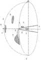
図3に、実施例1の表示制御装置である電子機器100が表示制御を行う広視野画像の一例を示す。電子機器100のCPU101は、広視野画像をディスプレイ105に表示する場合、広視野画像のうち初期状態で予め定められた範囲を表示する。CPU101は、初期状態の表示を行った後、ディスプレイ105に表示する広視野画像の範囲を変更する操作の入力を受け付け、入力された操作に応じて、ディスプレイ105に表示する広視野画像の範囲を制御する。 FIG. 3 illustrates an example of a wide-field image in which the
図3において広視野画像301として示す球体の表面は、垂直方向360度、水平方向360度の視野を撮像可能な全天球カメラ(全方位カメラ)の撮像によって得られた例えば正距円筒図法による元画像がマッピングされている仮想球体の表面を概念的に示す。なお、全天球カメラの撮像によって得られる画像形式は正距円筒図法に基づくものに限らず、例えばデュアルフィッシュアイ形式等でも良い。広視野画像301は、第1軸であるヨー軸302方向(垂直方向、上下方向)及び第1軸に垂直な第2軸であるピッチ軸303方向(水平方向、左右方向)の所定範囲の視野の画像である。所定範囲には少なくとも第1軸の正方向の頂点(天頂)及び負方向の頂点(天底)のいずれかが含まれる広視野画像を表示制御の対象とする。第1軸の正方向の頂点(天頂又は真上)及び第1軸の負方向の頂点(天底又は真下)は、第1軸回りの回転の中心位置である。実施例1では、所定範囲は、垂直方向360度、水平方向360度であり、広視野画像301は天頂及び天底の両者を含む全天球画像(全方位画像)である。 The surface of the sphere shown as the wide-
実施例1では、入力手段に入力される移動操作は、タッチパネル106aに入力される左右方向又は上下方向のスライド操作(タッチムーブ)である。実施例1では、CPU101は、タッチパネル106aに左右方向のスライド操作が入力された場合、広視野画像301がマッピングされた仮想球体をヨー軸302回りに回転させることにより、ディスプレイ105に表示する画像を変更する。詳細は図4のS406、S408で説明する。また、CPU101は、タッチパネル106aに上下方向のスライド操作が入力された場合に、広視野画像301がマッピングされた仮想球体をピッチ軸303回りに回転させることにより、ディスプレイ105に表示する画像を変更する。詳細は図4のS410、S412で説明する。 In the first embodiment, the movement operation input to the input unit is a horizontal or vertical slide operation (touch move) input to the
撮像位置304は、広視野画像301を撮像したカメラの位置を示している。 The
人物305は、撮像位置304の天底側の位置におり、人物305はヨー軸302とピッチ軸303とが交わる位置に立っている。人物305は、人物306の方向を向いており、図3は人物305の背中側から見た図である。雲309は、人物305の右前方上方に位置している。一方、雲310は人物305の頭上に位置している。 The
天頂311は広視野画像301の第1軸の正方向(上方向)の頂点であり、撮像位置304の真上に位置する。天頂311(真上)は、第1軸回りの回転の中心位置である。天底312は広視野画像301の第1軸の負方向(下方向)の頂点であり、撮像位置304の天底に位置する。天底312(真下)は、第1軸回りの回転の中心位置である。 The
<実施例1>
以下図4〜図8を参照して、本発明の実施例1の動作を説明する。
実施例1は、広視野画像301のうち第1軸方向の頂点である天頂311又は天底312を含む範囲がディスプレイ105に表示されている状態における表示制御に特徴を有する。すなわち、タッチパネル106aに第2軸方向である左右方向の移動操作が入力された場合の表示制御に特徴を有する。CPU101は、広視野画像301を第1軸の回りに回転させることにより、表示手段に表示される広視野画像の表示範囲を変更する表示制御を行う。CPU101は、左右方向の移動操作であるスライド操作の起点(タッチダウン位置)と、頂点である天頂311又は天底312との第1軸方向(上下方向)における位置関係に応じて、広視野画像301を第1軸の回りに回転させる方向を決定する。具体的には、CPU101は、表示範囲に天頂311又は天底312が含まれている場合に、次のような制御を行う。すなわち、スライド操作の起点であるタッチダウン位置が天頂311又は天底312よりも上に位置しているか、又は下に位置しているかを判定して、広視野画像301の回転方向を決定する。<Example 1>
The operation of the first embodiment of the present invention will be described below with reference to FIGS.
The first embodiment has a feature in display control in a state where a range including the zenith 311 or the
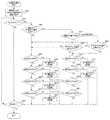
図4は、実施例1の電子機器100で行われる広視野画像の表示制御の処理の流れを示すフローチャートである。このフローチャートで示す処理は、不揮発性メモリ103に記録されたプログラムをメモリ102に展開してCPU101が実行することで実現される。電子機器100の電源がオンとなり、記録媒体(記憶媒体)108や外部ネットワーク111から広視野画像データを取得してディスプレイ105に表示する指示が入力されると、図4のフローチャートで示す処理が開始される。 FIG. 4 is a flowchart illustrating a flow of processing for display control of a wide-field image performed by the
S401では、CPU101は、記録媒体108又は通信I/F110を介した外部ネットワーク111から、広視野画像の画像データを取得し、広視野画像の一部をディスプレイ105に表示する。また、CPU101は、広視野画像の画像データに属性情報として付帯する有効画像範囲を示す情報を取得する。有効画像範囲を示す情報とは、広視野画像が有する上下方向及び左右方向の画像の範囲(視野角)の情報である。有効画像範囲を示す情報は、広視野画像の有効画像範囲を特定できる情報であれば良い。例えば、有効画像範囲を示す情報は、画角、視野角、方位角、仰角、俯角、高度角度、ステラジアン等によって表される角度情報や、上下方向及び左右方向の画素数や座標等で表される位置情報を含み得る。また、有効画像範囲を示す情報は、広視野画像を撮像したカメラの情報、例えば撮像可能な範囲の情報と関連付けられたカメラの機種の情報や、撮像時の光学情報(ズーム倍率、レンズ画角等)の情報等を含み得る。CPU101は、有効画像範囲を示す情報を取得すると、上下方向360度又は左右方向360度と有効画像範囲との差分を算出することで、無効画像範囲(非画像範囲)を取得する。なお、CPU101は、広視野画像の属性情報から無効画像範囲を示す情報を取得し、その情報に基づき有効画像範囲を算出しても良いし、有効画像範囲を示す情報と無効画像範囲を示す情報の双方を広視野画像の属性情報から取得しても良い。 In step S <b> 401, the
広視野画像の元画像(画像データ)は、例えば正距円筒図法を用いた歪んだ画像であり
、各画素の位置が球体の表面の座標と対応づけることが可能な形式の画像である。S401ではこの広視野画像の元画像を球体にマッピングし、一部を切り出して表示する。すなわち、S401で表示される画像は広視野画像の一部を切り出して拡大した画像であり、かつ、元画像の歪みを除去(あるいは低減)した画像である。なお、S401での広視野画像の表示向き(ディスプレイ105に対して表示される向き)は、電子機器100が横姿勢である場合と縦姿勢である場合とで90°異なる向きとすることができる。以下で説明するスライド操作の方向(タッチムーブの方向)は、表示向きに対する方向であるものとする。例えば、右方向へのスライド操作とは、表示対象(広視野画像や文字、アイコンなど)の表示された上下方向に対する右方向である。The original image (image data) of the wide-field image is a distorted image using, for example, equirectangular projection, and is an image in a format in which the position of each pixel can be associated with the coordinates of the surface of the sphere. In S401, the original image of the wide-field image is mapped onto a sphere, and a part is cut out and displayed. In other words, the image displayed in S401 is an image obtained by cutting out and enlarging a part of the wide-field image and removing (or reducing) the distortion of the original image. Note that the display direction of the wide-field image (the direction displayed on the display 105) in S401 can be different by 90 ° between the case where the
S402では、CPU101は、タッチパネル106aから通知された情報に基づいて、タッチパネル106a上のうち、広視野画像の表示された領域(画像表示領域)に対するタッチダウンが行われたか否かを判定する。タッチダウンが行われている場合はS404に進み、タッチダウンが行われていない場合はS403に進む。 In S402, based on the information notified from the
S403では、CPU101は、S401で開始した広視野画像の表示を終了する指示が入力されたか否かを判定する。表示終了の指示入力が行われた場合、CPU101は、広視野画像の表示を終了し、表示終了の指示入力が行われていない場合、S402に進む。 In step S403, the
S404では、CPU101は、広視野画像のうち第1軸の正方向の頂点である第1頂点(天頂)又は負方向の頂点である第2頂点(天底)を含む範囲がディスプレイ105の広視野画像の画像表示領域に表示されているか否かを判定する。第1頂点又は第2頂点を含む範囲が表示されている場合はS413に進み、第1頂点及び第2頂点のいずれも含まない範囲が表示されている場合はS405に進む。実施例1では、天頂311又は天底312を含む範囲がディスプレイ105の広視野画像の画像表示領域に表示されている場合に、CPU101は、広視野画像のうち第1頂点又は第2頂点を含む範囲が表示されていると判定する。 In step S <b> 404, the
<<表示範囲に天頂及び天底を含まない場合>>
<右方向のスライド操作が行われた場合>
S405では、CPU101は、タッチパネル106a上で第2軸方向の正方向の移動操作である右向きのスライド操作(右向きのタッチムーブ)が行われたか否かを判定する。右向きのスライド操作が行われた場合はS406に進み、右向きのスライド操作が行われなかった場合にはS407に進む。<< When the display range does not include the zenith and nadir >>
<When a slide operation in the right direction is performed>
In step S405, the
S406では、CPU101は、広視野画像を、第1軸の回りであるヨー軸302(垂直軸)回りに、S405で検出した第2軸方向の移動操作の方向に応じた方向に回転させることにより、ディスプレイ105に表示する広視野画像の表示範囲を変更する。実施例1では、CPU101は、広視野画像を、S405で検出した右向きのスライド量に応じた回転量で、ヨー軸302を中心に、右向きスライド操作の方向に応じた方向である時計回りに回転(上から見て右回転)させる。これによって、表示されていた画像は右向きに移動し、より左側が表示されるようになる(表示範囲は左側に移動する)。 In S406, the
なお、以下、「回転させる」というのは、図1、図3で説明した概念図において表示範囲を固定したものとして(すなわち表示範囲を基準として)、広視野画像を回転させることである。すなわち、広視野画像を回転させることにより、表示範囲に収まる広視野画像の範囲が変更されると考えて、表示範囲を変更(移動、スクロール)する制御であるものとする。この処理には、未表示であった画像領域を表示させるための表示処理、歪補正処理(例えば、正距円筒図法で描画された元画像から表示範囲に該当する部分を読み出し、
表示するにあたって歪みを打ち消すようにマッピングして表示する処理)等を含む。また、「広視野画像の範囲を回転させる」というのは、視線方向(すなわち表示範囲)を基準として、表示範囲に収まる画像を回転させることであるものとする。画像を基準にして視線方向が回転移動するものと解釈した場合は、回転方向は逆向きとなる。すなわち、S406の例では、右向きのスライドに応じて、画像は右回転し、表示範囲は相対的に逆向きである左回転する。In the following, “rotate” means to rotate the wide-field image assuming that the display range is fixed in the conceptual diagrams described with reference to FIGS. 1 and 3 (that is, based on the display range). That is, it is assumed that the display range is changed (moved or scrolled) on the assumption that the range of the wide-field image within the display range is changed by rotating the wide-field image. In this processing, display processing for displaying an image area that has not been displayed, distortion correction processing (for example, a portion corresponding to the display range is read from an original image drawn by equirectangular projection,
And processing for mapping and displaying so as to cancel distortion). In addition, “rotate the range of the wide-field image” is to rotate the image that falls within the display range with reference to the viewing direction (that is, the display range). When it is interpreted that the line-of-sight direction rotates with respect to the image, the rotation direction is reversed. That is, in the example of S406, the image is rotated to the right in accordance with the rightward slide, and the display range is rotated to the left which is relatively opposite.
図5(a1)、図5(a2)を用いて、S405、S406の処理について説明する。<水平方向に視線を向けている場合>
図5(a1)、図5(a2)で、広視野画像301のうち天頂311も天底312も含まない範囲であって、水平方向に視線を向けた場合の範囲が表示されている状態で、S405、S406の処理が行われた場合について説明する。視線を水平方向に向けた表示とは、図1で第1軸(上下方向)と第2軸(左右方向)に垂直な奥行き方向に視線を向けた場合の表示である。The processes of S405 and S406 will be described with reference to FIGS. 5 (a1) and 5 (a2). <If you are looking in the horizontal direction>
5 (a1) and 5 (a2), the wide-
図5(a1)は、視線を水平方向に向けた場合の広視野画像301の表示例である。図5(a1)では、右向きのスライド操作501が入力されているため、S405で右向きのスライド操作が行われたと判断される。 FIG. 5A1 is a display example of the wide-
図5(a2)は、図5(a1)の表示が行われている状態で、第2軸の正方向の移動動作である右向きのスライド操作が行われ、S406の処理が行われた場合の表示例である。すなわち、S406において広視野画像を第1軸であるヨー軸302回りに時計回りに回転(上から見て右回転)させることにより、ディスプレイ105に表示する広視野画像の表示範囲を変更した場合の表示例である。広視野画像の表示範囲は、ヨー軸302回りに反時計回りに回転(上から見て左回転)される。図5(a2)では、図5(a1)の状態から広視野画像がヨー軸302中心に上から見て右回転したことによって、ディスプレイ105に表示される画像は左から右に移動し、図5(a1)では表示範囲内に収まっていた人物306が表示範囲から外れている。表示範囲は相対的に左回転しているため、広視野画像のうち、図5(a1)の表示範囲よりも左側の範囲が図5(a2)で表示されている。 FIG. 5 (a2) shows a state where the display of FIG. 5 (a1) is being performed, and a rightward sliding operation that is a movement operation in the positive direction of the second axis is performed, and the process of S406 is performed. It is a display example. That is, when the display range of the wide-field image displayed on the
<左方向のスライド操作が行われた場合>
S407では、CPU101は、タッチパネル106a上で第2軸方向の負方向の移動動作である左向きのスライド操作(左向きのタッチムーブ)が行われたか否かを判定する。左向きのスライド操作が行われた場合はS408に進み、左向きのスライド操作が行われなかった場合にはS409に進む。<When leftward slide operation is performed>
In S407, the
S408では、CPU101は、広視野画像を、第1軸の回りであるヨー軸302(垂直軸)回りに、S407で検出した第2軸方向の移動操作の方向に応じた方向に回転させることにより、ディスプレイ105に表示する広視野画像の表示範囲を変更する。実施例1では、CPU101は、広視野画像を、S407で検出した左向きのスライド量に応じた回転量で、ヨー軸302中心に、左向きスライド操作の方向に応じた方向である反時計回りに回転(上から見て左回転)させる。これによって、表示されていた画像は左向きに移動し、より右側が表示されるようになる(表示範囲は右側に移動する)。 In S408, the
図5(b1)、図5(b2)を用いて、S407、S408の処理について説明する。<水平方向に視線を向けている場合>
図5(b1)、図5(b2)で、広視野画像301のうち天頂311も天底312も含まない範囲であって、水平方向に視線を向けた場合の範囲が表示されている状態で、S407、S408の処理が行われた場合について説明する。The processing of S407 and S408 will be described with reference to FIGS. 5B1 and 5B2. <If you are looking in the horizontal direction>
5 (b1) and 5 (b2), the wide-
図5(b1)は、視線を水平方向に向けた場合の広視野画像301の表示例である。図5(b1)では、左向きのスライド操作502が入力されているため、S407で左向きのスライド操作が行われたと判断される。 FIG. 5B1 is a display example of the wide-
図5(b2)は、図5(b1)の表示が行われている状態で、第2軸の負方向の移動操作である左向きのスライド動作が行われ、S408の処理が行われた場合の表示例である。すなわちS408において広視野画像を第1軸であるヨー軸302回りに反時計回りに回転(上から見て左回転)させることにより、ディスプレイ105に表示する広視野画像の表示範囲を変更した場合の表示例である。広視野画像の表示範囲は、ヨー軸302回りに時計回りに回転(上から見て右回転)される。図5(b2)では、図5(b1)の状態から広視野画像がヨー軸302中心に上から見て左回転したことによって、ディスプレイ105に表示される画像は右から左に移動し、図5(b1)では表示範囲内に収まっていた山307が表示範囲から外れている。表示範囲は相対的に右回転しているため、広視野画像のうち、図5(b1)の表示範囲よりも右側の範囲が図5(b2)で表示されている。 FIG. 5 (b2) shows a state where the display of FIG. 5 (b1) is being performed, and a leftward sliding operation, which is a movement operation in the negative direction of the second axis, is performed, and the process of S408 is performed. It is a display example. That is, in S408, the display range of the wide-field image displayed on the
<上方向のスライド操作が行われた場合>
S409では、CPU101は、タッチパネル106a上で第1軸方向の正方向の移動操作である上向きのスライド操作(上向きのタッチムーブ)が行われたか否かを判定する。上向きのスライド操作が行われた場合はS410に進み、上向きのスライド操作が行われなかった場合にはS411に進む。<When an upward slide operation is performed>
In S409, the
S410では、CPU101は、広視野画像を、第2軸の回りであるピッチ軸303(水平軸)回りに、S409で検出した第1軸方向の移動操作の方向に応じた方向に回転させることにより、ディスプレイ105に表示する広視野画像の表示範囲を変更する。実施例1では、CPU101は、広視野画像を、S409で検出した上向きのスライド量に応じた回転量で、ピッチ軸303を中心に、上向きスライド操作の方向に応じた方向である反時計回りに回転(仰角方向に回転、右手側から見て左回転)させる。広視野画像の表示範囲は、ピッチ軸303回りに時計回りに回転(俯角方向に回転、右手側から見て右回転)される。これによって、表示されていた画像は上向きに移動し、より下側が表示されるようになる(表示範囲は下側に移動する)。つまり、視線を水平方向に向けている場合には、下方向を見下ろすように視線を移動させる。既に天底に近い方向を向いている場合には、それ以上視線を下に動かせなくなる。より詳しくは、天底312が、表示範囲のうち上下方向の所定位置(例えば上下中央)よりも上に移動しないように、表示範囲の上下方向の移動を制限する。 In S410, the
図5(c1)、図5(c2)、図6(a1)、図6(a2)を用いて、S409、S410の処理について説明する。
<水平方向に視線を向けている場合>
まず図5(c1)、図5(c2)で、広視野画像301のうち天頂311も天底312も含まない範囲であって、水平方向に視線を向けた場合の範囲が表示されている状態で、S409、S410の処理が行われた場合について説明する。The processes of S409 and S410 will be described with reference to FIGS. 5C1, 5C2, 6A1, and 6A2.
<If you are looking in the horizontal direction>
First, in FIGS. 5 (c1) and 5 (c2), the wide-
図5(c1)は、視線を水平方向に向けた場合の広視野画像301の表示例である。図5(c1)では、上向きのスライド操作503が入力されているため、S409で上向きのスライド操作が行われたと判断される。 FIG. 5C1 is a display example of the wide-
図5(c2)は、図5(c1)の表示が行われている状態で、第1軸の正方向の移動操作である上向きのスライド操作が行われ、S410の処理が行われた場合の表示例である
。すなわち、S410において広視野画像を第2軸であるピッチ軸303の回りに反時計回りに回転(仰角方向に回転、右手側から見て左回転)させることにより、ディスプレイ105に表示する広視野画像の表示範囲を変更した場合の表示例である。広視野画像の表示範囲は、ピッチ軸303回りに時計回りに回転(俯角方向に回転、右手側から見て右回転)される。図5(c2)では、図5(c1)の状態から広視野画像がピッチ軸303中心に仰角方向に回転したことによって、ディスプレイ105に表示される画像は上に移動する。図5(c1)では表示範囲に収まっていなかった人物305、天底312が画面内(表示範囲内)に収まっている。表示範囲は相対的に下回転(俯角方向に回転)しているため、広視野画像のうち、図5(c1)の表示範囲よりも下側の範囲が図5(c2)で表示されている。FIG. 5C2 shows a state where the display of FIG. 5C1 is being performed, and an upward slide operation that is a forward movement operation of the first axis is performed, and the process of S410 is performed. It is a display example. That is, in S410, the wide-field image displayed on the
<下向きに視線を向けている場合>
次に図6(a1)、図6(a2)で、広視野画像301のうち下向きに視線を向けた場合の範囲が表示されている状態で、S409、S410の処理が行われた場合について説明する。<If you are looking down>
Next, the case where the processing of S409 and S410 is performed in the state in which the range when the line of sight is directed downward in the wide-
図6(a1)は、視線を下向きに向けた場合の広視野画像301の表示例である。図6(a1)では、上向きのスライド操作605が入力されているため、S409で上向きのスライド操作が行われたと判断される。 FIG. 6A1 is a display example of the wide-
図6(a2)は、図6(a1)の表示が行われている状態で、第1軸の正方向の移動操作である上向きのスライド操作が行われ、S410の処理が行われた場合の表示例である。すなわちS410において広視野画像を第2軸であるピッチ軸303回りに反時計回りに回転(仰角方向に回転)させることにより、ディスプレイ105に表示する広視野画像の表示範囲を変更した場合の表示例である。広視野画像の表示範囲は、ピッチ軸303周りに時計回りに回転(俯角方向に回転、右手側から見て右回転)される。図6(a1)のように天底に近い方向を向いている状態の場合(天底312が、表示範囲のうち上下方向の所定位置(例えば上下中央)まで移動した場合)には、広視野画像はこれ以上、仰角方向に回転はしない(表示範囲はこれ以上、俯角方向に回転しない)。つまり、図6(a1)と図6(a2)とでは表示範囲は大きく変化しない。なお、図6(a1)では、天底312が表示範囲に含まれている。しかしながら、上向きのスライド操作が行われた場合(左右スライド成分が無い場合)、スライド操作の起点に関わらず、表示範囲の変更は同じ方向(広視野画像を第2軸であるピッチ軸303回りに仰角方向に回転させる方向)に行われる。 FIG. 6 (a2) shows a state where the display of FIG. 6 (a1) is being performed, and an upward slide operation that is a forward movement operation of the first axis is performed, and the process of S410 is performed. It is a display example. That is, a display example when the display range of the wide-field image displayed on the
<下方向のスライド操作が行われた場合>
S411では、CPU101は、タッチパネル106a上で第1軸方向の負方向の移動操作である下向きのスライド操作(下向きのタッチムーブ)が行われたか否かを判定する。下向きのスライド操作が行われた場合はS412に進み、下向きのスライド操作が行われなかった場合にはS403に進む。<When a downward sliding operation is performed>
In S411, the
S412では、CPU101は、広視野画像を、第2軸の回りであるピッチ軸303(水平軸)回りに、S411で検出した第1軸方向の移動操作の方向に応じた方向に回転させることにより、ディスプレイ105に表示する広視野画像の表示範囲を変更する。実施例1では、CPU101は、広視野画像を、S411で検出した下向きのスライド量に応じた回転量で、ピッチ軸303を中心に、下向きスライド操作の方向に応じた方向である時計回りに回転(俯角方向に回転、右手側から見て右回転)させる。広視野画像の表示範囲は、ピッチ軸303回りに反時計回りに回転(仰角方向に回転、右手側から見て左回転)される。これによって、表示されていた画像は下向きに移動し、より上側が表示されるようになる(表示範囲は上側に移動する)。つまり、視線を水平方向に向けている場合に
は、上方向を仰ぎ見るように視線を移動させる。既に天頂に近い方向を向いている場合には、それ以上視線を上に動かせなくなる。より詳しくは、天頂311が、表示範囲のうち上下方向の所定位置(例えば上下中央)よりも下に移動しないように、表示範囲の上下方向の移動を制限する。In S412, the
図5(d1)、図5(d2)、図6(b1)、図6(b2)を用いて、S411、S412の処理について説明する。
<水平方向に視線を向けている場合>
まず図5(d1)、図5(d2)で、広視野画像301のうち天頂311も天底312も含まない範囲であって、水平方向に視線を向けた場合の範囲が表示されている状態で、S411、S412の処理が行われた場合について説明する。The processing of S411 and S412 will be described with reference to FIGS. 5 (d1), 5 (d2), 6 (b1), and 6 (b2).
<If you are looking in the horizontal direction>
First, in FIGS. 5 (d1) and 5 (d2), the wide-
図5(d1)は、視線を水平方向に向けた場合の広視野画像301の表示例である。図5(d1)では、下向きのスライド操作504が入力されているため、S411で下向きのスライド操作が行われたと判断される。 FIG. 5D1 is a display example of the wide-
図5(d2)は、図5(d1)の表示が行われている状態で、第1軸の負方向の移動操作である下向きのスライド操作が行われ、S412の処理が行われた場合の表示例である。すなわち、S412において広視野画像を第2軸であるピッチ軸303の回りに時計回りに回転(俯角方向に回転、右手側から見て右回転)させることにより、ディスプレイ105に表示する広視野画像の表示範囲を変更した場合の表示例である。広視野画像の表示範囲は、ピッチ軸303回りに反時計回りに回転(仰角方向に回転、右手側から見て左回転)される。図5(d2)では、図5(d1)の状態から広視野画像がピッチ軸303中心に俯角方向に回転したことによって、ディスプレイ105に表示される画像は上に移動する。図5(d1)では表示範囲に収まっていなかった雲310、天頂311が画面内に収まっている。表示範囲は相対的に上回転(仰角方向に回転)しているため、広視野画像のうち、図5(d1)の表示範囲よりも上側の表示範囲が図5(d2)で表示されている。 FIG. 5 (d2) shows a state where the display of FIG. 5 (d1) is being performed, and a downward slide operation that is a negative direction movement operation of the first axis is performed, and the process of S412 is performed. It is a display example. That is, in S412, the wide-field image is rotated clockwise around the
<下向きに視線を向けている場合>
次に図6(b1)、図6(b2)で、広視野画像301のうち下向きに視線を向けた場合の範囲が表示されている状態で、S411、S412の処理が行われた場合について説明する。<If you are looking down>
Next, in FIG. 6B1 and FIG. 6B2, the case where the processing of S411 and S412 is performed in a state where the range when the line of sight is directed downward is displayed in the wide-
図6(b1)は、視線を下向きに向けた場合の広視野画像301の表示例である。図6(b1)では、下向きのスライド操作606が入力されているため、S411で下向きのスライド操作が行われたと判断される。 FIG. 6B1 is a display example of the wide-
図6(b2)は、図6(b1)の表示が行われている状態で、第1軸の負方向の移動操作である下向きのスライド操作が行われ、S412の処理が行われた場合の表示例である。すなわちS412において広視野画像を第2軸であるピッチ軸303回りに時計回りに回転(俯角方向に回転、右手側から見て右回転)させることにより、ディスプレイ105に表示する広視野画像の表示範囲を変更した場合の表示例である。広視野画像の表示範囲は、ピッチ軸303回りに反時計回りに回転(仰角方向に回転、右手側から見て左回転)される。図6(b2)では、図6(b1)の状態からピッチ軸303中心に広視野画像が俯角方向に回転したことによって、図6(b1)では表示範囲に収まっていなかった人物306が画面内に収まっている。逆に人物305は表示範囲から外れている。表示範囲は相対的に上回転(俯角方向に回転)しているため、広視野画像のうち、図6(b1)の表示範囲よりも上側の表示範囲が図6(b2)で表示されている。なお、図6(b1)では、天底312が表示範囲に含まれている。しかしながら、下向きのスライド操作が行われ
た場合(左右スライド成分が無い場合)、スライド操作の起点に関わらず、表示範囲の変更は同じ方向に行われる。すなわち、表示範囲の変更は、第2軸であるピッチ軸303回りに広視野画像を俯角方向に、表示範囲を仰角方向に回転させる方向に行われる。FIG. 6 (b2) shows a state where the display of FIG. 6 (b1) is being performed and a downward slide operation that is a negative direction movement operation of the first axis is performed, and the process of S412 is performed. It is a display example. That is, the display range of the wide-field image displayed on the
<<表示範囲に天頂又は天底を含む場合>>
S413では、CPU101は、広視野画像のうち第1軸の負方向の頂点である第2頂点(天底)を含む範囲がディスプレイ105の広視野画像の画像表示領域に表示されているか否かを判定する。表示範囲に天底312が含まれている場合にはS414に進み、表示範囲に天底312が含まれていない場合はS415に進む。言い換えると、広視野画像のうち第1軸の正方向の頂点である第1頂点(天頂311)を含む範囲がディスプレイ105に表示されている場合、S415に進む。<< When the display range includes the zenith or nadir >>
In S <b> 413, the
<表示範囲に天底を含む場合>
S414では、CPU101は、広視野画像のうち第2頂点(天底312)よりも第1軸方向(上下方向)で負の位置を起点として第2軸方向(左右方向)の移動操作(スライド操作)が入力されたか否かを判定する。実施例1では、CPU101は、S402で検出されたディスプレイ105に対するタッチダウン位置が、天底312よりも下に位置しているか判定する。タッチダウン位置が天底312よりも下に位置している場合はS416に進み、タッチダウン位置が天底312よりも下に位置していない場合はS405に進む。<When the display range includes the nadir>
In S414, the
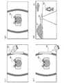
<右方向のスライド>
図7(a1)、図7(c1)を用いてS414を説明する。
<天底より上を右方向にスライド操作した場合>
図7(a1)では、広視野画像のうち第1軸の負方向の頂点である第2頂点(天底)を含む範囲がディスプレイ105に表示されている。図7(a1)は、この状態で、第2軸の正方向の移動操作である右向きのスライド操作(右向きのタッチムーブ)702が入力された様子を示している。この右向きのスライド操作702の起点であるタッチダウン位置701は、第2頂点(天底312)よりも第1軸方向で正の位置(上下方向で上)にある。そのため、S414で、CPU101は、タッチダウン位置が天底312よりも下に位置していないと判断する(S414:No)。<Right slide>
S414 will be described with reference to FIGS. 7A1 and 7C1.
<When sliding above the nadir to the right>
In FIG. 7A1, a range including the second vertex (the nadir) that is the vertex in the negative direction of the first axis in the wide-field image is displayed on the
<天底より下を右方向にスライド操作した場合>
図7(c1)では、広視野画像のうち第1軸の負方向の頂点である第2頂点(天底)を含む範囲がディスプレイ105に表示されている。図7(c1)は、この状態で、第2軸の正方向の移動操作である右向きのスライド操作(右向きのタッチムーブ)708が入力された様子を示している。この右向きのスライド操作708の起点であるタッチダウン位置707は、第2頂点(天底312)よりも第1軸方向で負の位置(上下方向で下)にある。そのため、S414で、CPU101は、タッチダウン位置が天底312よりも下に位置していると判断する(S414:Yes)。<When sliding below the nadir to the right>
In FIG. 7C1, a range including a second vertex (nadir) that is a vertex in the negative direction of the first axis in the wide-field image is displayed on the
<表示範囲に天頂を含む場合>
S415では、CPU101は、広視野画像のうち第1頂点(天頂311)よりも第1軸方向(上下方向)で正の位置を起点として第2軸方向(左右方向)の移動操作(スライド操作)が入力されたか否かを判定する。実施例1では、CPU101は、S402で検出されたディスプレイ105に対するタッチダウン位置が、天頂311よりも上に位置しているか判定する。タッチダウン位置が天頂311よりも上に位置している場合はS416に進み、タッチダウン位置が天頂311よりも上に位置していない場合はS405に進む。<When the display range includes the zenith>
In step S415, the
<右方向のスライド>
図8(a1)、図8(c1)を用いてS415を説明する。
<天頂より上を右方向にスライド操作した場合>
図8(a1)では、広視野画像のうち第1軸の正方向の頂点である第1頂点(天頂)を含む範囲がディスプレイ105に表示されている。図8(a1)は、この状態で、第2軸の正方向の移動操作である右向きのスライド操作(右向きのタッチムーブ)802が入力された様子を示している。この右向きのスライド操作802の起点であるタッチダウン位置801は、第1頂点(天頂311)よりも第1軸方向で正の位置(上下方向で上)にある。そのため、S415で、CPU101は、タッチダウン位置が天頂311よりも上に位置していると判断する(S415:Yes)。<Right slide>
S415 will be described with reference to FIGS. 8A1 and 8C1.
<When sliding rightward from the top of the zenith>
In FIG.
<天頂より下を右方向にスライド操作した場合>
図8(c1)では、広視野画像のうち第1軸の正方向の頂点である第1頂点(天頂)を含む範囲がディスプレイ105に表示されている。図8(c1)は、この状態で、第2軸の正方向の移動操作である右向きのスライド操作(右向きのタッチムーブ)808が入力された様子を示している。この右向きのスライド操作808の起点であるタッチダウン位置807は、第1頂点(天頂311)よりも第1軸方向で負の位置(上下方向で下)にある。そのため、S415で、CPU101は、タッチダウン位置が天頂311よりも上に位置していないと判断する(S415:No)。<When sliding below the zenith to the right>
In FIG.
S416では、CPU101は、タッチパネル106a上で第2軸方向の正方向の移動操作である右向きのスライド操作(右向きのタッチムーブ)が行われたか否かを判定する。右向きのスライド操作が行われた場合はS417に進み、右向きのスライド操作が行われなかった場合にはS418に進む。 In S416, the
S417では、CPU101は、広視野画像を、第1軸の回りであるヨー軸302(垂直軸)回りに反時計回りに回転させることにより、ディスプレイ105に表示する広視野画像の表示範囲を変更する。実施例1では、CPU101は、広視野画像を、S416で検出した右向きのスライド量に応じた回転量で、ヨー軸302を中心に反時計回りに回転(上から見て左回転)させる。 In S417, the
<表示範囲に天底が含まれ、天底より下を右方向にスライド操作した場合>
図7(c1)、図7(c2)を用いて、S414でタッチダウン位置が天底312より下と判定されて、S416及びS417が実行された場合について説明する。<When the nadir is included in the display range and you slide to the right below the nadir>
A case where the touchdown position is determined to be below the
図7(c1)では、広視野画像301のうち第1軸の負方向の頂点である第2頂点(天底312)を含む範囲がディスプレイ105の広視野画像の画像表示領域に表示されている。図7(c2)は、この状態で、第2頂点(天底312)よりも第1軸方向で負の位置(上下方向で下)にあるタッチダウン位置707を起点として、第2軸の正方向の移動操作(右向きのスライド操作708)が行われた様子を示す。図7(c2)は、S417において、広視野画像301を第1軸であるヨー軸302回りに反時計回りに回転(上から見て左回転709)させることにより、ディスプレイ105における広視野画像の表示を変更した場合の表示例である。ディスプレイ105における広視野画像の表示は、表示領域全体では反時計回りに画像が回転するが、特にスライド操作708が行われた位置に着目すると、スライド操作708の向きと同じ向きである右向きに画像が移動する。前述のように、従来は、表示領域全体で時計回りに画像が回転するため、右向きのスライド操作708の位置で画像が左向きに移動することになり、ユーザが違和感を覚える可能性があったが、実施例1ではユーザの違和感を抑制できる。 In FIG. 7C1, a range including the second vertex (the nadir 312) which is the vertex in the negative direction of the first axis in the wide-
<表示範囲に天底が含まれ、天底より上を右方向にスライド操作した場合>
図7(a1)、図7(a2)を用いて、S414でタッチダウン位置が天底312より下ではないと判定された場合の、右向きスライド操作について説明する。<When the nadir is included in the display range and you slide to the right above the nadir>
With reference to FIGS. 7A1 and 7A2, the rightward sliding operation when it is determined in S414 that the touchdown position is not below the
図7(a1)では、広視野画像301のうち第1軸の負方向の頂点である第2頂点(天底312)を含む範囲がディスプレイ105の広視野画像の画像表示領域に表示されている。図7(a2)は、この状態で、第2頂点(天底312)よりも第1軸方向で正の位置(上下方向で上)にあるタッチダウン位置701を起点として、第2軸の正方向の移動操作(右向きのスライド操作702)が行われた様子を示す。図7(a2)は、S406において、広視野画像301を第1軸であるヨー軸302回りに時計回りに回転(上から見て右回転703)させることにより、ディスプレイ105における広視野画像の表示を変更した場合の表示例である。ディスプレイ105における広視野画像の表示は、表示領域全体では時計回りに画像が回転するが、特にスライド操作702が行われた位置に着目すると、スライド操作702の向きと同じ向きである右向きに画像が移動するので、ユーザの違和感を抑制できる。 In FIG. 7A1, the range including the second vertex (the nadir 312) which is the vertex in the negative direction of the first axis in the wide-
<表示範囲に天頂が含まれ、天頂より上を右方向にスライド操作した場合>
図8(a1)、図8(a2)を用いて、S415でタッチダウン位置が天頂311より上と判定されて、S416及びS417が実行された場合について説明する。<When the zenith is included in the display range, and you slide it to the right above the zenith>
A case where the touchdown position is determined to be above the zenith 311 in S415 and S416 and S417 are executed will be described with reference to FIGS. 8A1 and 8A2.
図8(a1)では、広視野画像301のうち第1軸の正方向の頂点である第1頂点(天頂311)を含む範囲がディスプレイ105の広視野画像の画像表示領域に表示されている。図8(a2)は、この状態で、第1頂点(天頂311)よりも第1軸方向で正の位置(上下方向で上)にあるタッチダウン位置801を起点として、第2軸の正方向の移動操作(右向きのスライド操作802)が行われた様子を示す。図8(a2)は、S417において、広視野画像301を第1軸であるヨー軸302回りに反時計回りに回転(上から見て左回転803)させることにより、ディスプレイ105における広視野画像の表示を変更した場合の表示例である。図8(a2)は天頂311を下(仮想球体の中心側)から見た図であるため、ディスプレイ105における広視野画像の表示は、表示領域全体では時計回りに画像が回転する。特にスライド操作802が行われた位置に着目すると、スライド操作802の向きと同じ向きである右向きに画像が移動する。前述のように、従来は、広視野画像が上から見て時計回りに回転するため、天頂311を下から見た場合の表示では、表示領域全体で反時計回りに画像が回転する。そのため、右向きのスライド操作802の位置で画像が左向きに移動することになり、ユーザが違和感を覚える可能性があったが、実施例1ではユーザの違和感を抑制できる。 In FIG.
<表示範囲に天頂が含まれ、天頂より下を右方向にスライド操作した場合>
図8(c1)、図8(c2)を用いて、S415でタッチダウン位置が天頂311より上ではないと判定された場合の、右向きスライド操作について説明する。<When the zenith is included in the display range and you slide it to the right below the zenith>
With reference to FIG. 8C1 and FIG. 8C2, the rightward sliding operation when it is determined in S415 that the touchdown position is not above the zenith 311 will be described.
図8(c1)では、広視野画像301のうち第1軸の正方向の頂点である第1頂点(天頂311)を含む範囲がディスプレイ105の広視野画像の画像表示領域に表示されている状態を示す。図8(c2)は、この状態で、第1頂点(天頂311)よりも第1軸方向で負の位置(上下方向で下)にあるタッチダウン位置807を起点として、第2軸の正方向の移動操作(右向きのスライド操作808)が行われた様子を示す。図8(c2)は、S406において、広視野画像301を第1軸であるヨー軸302回りに時計回りに回転(上から見て右回転809)させることにより、ディスプレイ105における広視野画像の表示を変更した場合の表示例である。図8(c2)は天頂311を下(仮想球体の中心側)から見た図であるため、ディスプレイ105における広視野画像の表示は、表示領域全体では反時計回りに画像が回転する。特にスライド操作808が行われた位置に着目すると、スライド操作808の向きと同じ向きである右向きに画像が移動するので、ユーザ
の違和感を抑制できる。In FIG.
S418では、CPU101は、タッチパネル106a上で第2軸方向の負方向の移動操作である左向きのスライド操作(左向きのタッチムーブ)が行われたか否かを判定する。左向きのスライド操作が行われた場合はS419に進み、左向きのスライド操作が行われなかった場合にはS420に進む。 In S418, the
S419では、CPU101は、広視野画像を、第1軸の回りであるヨー軸302(垂直軸)回りに時計回りに回転させることにより、ディスプレイ105に表示する広視野画像の表示範囲を変更する。実施例1では、CPU101は、広視野画像を、S418で検出した左向きのスライド量に応じた回転量で、ヨー軸302を中心に時計回りに回転(上から見て右回転)させる。 In S419, the
<表示範囲に天底が含まれ、天底より下を左スライド操作した場合>
図7(d1)、図7(d2)を用いて、S414でタッチダウン位置が天底312より下と判定されて、S418及びS419が実行された場合について説明する。<When the nadir is included in the display range and the left slide operation is performed below the nadir>
A case where the touchdown position is determined to be lower than the
図7(d1)では、広視野画像301のうち第1軸の負方向の頂点である第2頂点(天底312)を含む範囲がディスプレイ105に表示されている。図7(d2)は、この状態で、第2頂点(天底312)よりも第1軸方向で負の位置(上下方向で下)にあるタッチダウン位置711を起点として、第2軸の負方向の移動操作(左向きのスライド操作710)が行われた様子を示す。図7(d2)は、S419において、広視野画像301を第1軸であるヨー軸302回りに時計回りに回転(上から見て右回転712)させることにより、ディスプレイ105における広視野画像の表示を変更した場合の表示例である。ディスプレイ105における広視野画像の表示は、表示領域全体では時計回りに画像が回転するが、特にスライド操作710が行われた位置に着目すると、スライド操作710の向きと同じ向きである左向きに画像が移動する。前述のように、従来は、表示領域全体で反時計回りに画像が回転するため、左向きのスライド操作710の位置で画像が右向きに移動することになり、ユーザが違和感を覚える可能性があったが、実施例1ではユーザの違和感を抑制できる。 In FIG.
<表示範囲に天底が含まれ、天底より上を左スライド操作した場合>
図7(b1)、図7(b2)を用いて、S414でタッチダウン位置が天底312より下ではないと判定された場合の、左向きスライド操作について説明する。<When the nadir is included in the display range and the left slide operation is performed above the nadir>
With reference to FIGS. 7B1 and 7B2, the left-side sliding operation when it is determined in S414 that the touchdown position is not below the
図7(b1)では、広視野画像301のうち第1軸の負方向の頂点である第2頂点(天底312)を含む範囲がディスプレイ105に表示されている。図7(b2)は、この状態で、第2頂点(天底312)よりも第1軸方向で正の位置(上下方向で上)にあるタッチダウン位置704を起点として、第2軸の負方向の移動操作(左向きのスライド操作705)が行われた様子を示す。図7(b2)は、S408において、広視野画像301を第1軸であるヨー軸302回りに反時計回りに回転(上から見て左回転706)させることにより、ディスプレイ105における広視野画像の表示を変更した場合の表示例である。ディスプレイ105における広視野画像の表示は、表示領域全体では反時計回りに画像が回転するが、特にスライド操作705が行われた位置に着目すると、スライド操作705の向きと同じ向きである左向きに画像が移動するので、ユーザの違和感を抑制できる。 In FIG.
<表示範囲に天頂が含まれ、天頂より上を左スライド操作した場合>
図8(b1)、図8(b2)を用いて、S415でタッチダウン位置が天頂311より上と判定されて、S418及びS419が実行された場合について説明する。<When the zenith is included in the display range and the left slide operation is performed above the zenith>
A case where the touchdown position is determined to be above the zenith 311 in S415 and S418 and S419 are executed will be described with reference to FIGS. 8B1 and 8B2.
図8(b1)では、広視野画像301のうち第1軸の正方向の頂点である第1頂点(天頂311)を含む範囲がディスプレイ105に表示されている。図8(b2)は、この状態で、第1頂点(天頂311)よりも第1軸方向で正の位置(上下方向で上)にあるタッチダウン位置804を起点として、第2軸の負方向の移動操作(左向きのスライド操作805)が行われた様子を示す。図8(b2)は、S419において、広視野画像301を第1軸であるヨー軸302回りに時計回りに回転(上から見て右回転806)させることにより、ディスプレイ105における広視野画像の表示を変更した場合の表示例である。図8(b2)は天頂311を下(仮想球体の中心側)から見た図であるため、ディスプレイ105における広視野画像の表示は、表示領域全体では反時計回りに画像が回転する。特にスライド操作805が行われた位置に着目すると、スライド操作805の向きと同じ向きである左向きに画像が移動する。前述のように、従来は、広視野画像が上から見て反時計回りに回転するため、天頂311を下から見た場合の表示では、表示領域全体で時計回りに画像が回転する。そのため、左向きのスライド操作805の位置で画像が右向きに移動することになり、ユーザが違和感を覚える可能性があったが、実施例1ではユーザの違和感を抑制できる。 In FIG.
<表示範囲に天頂が含まれ、天頂より下を左スライド操作した場合>
図8(d1)、図8(d2)を用いて、S415でタッチダウン位置が天頂311より上ではないと判定された場合の、左向きスライド操作について説明する。<When the zenith is included in the display range and the left slide operation is performed below the zenith>
With reference to FIG. 8D1 and FIG. 8D2, the left-side sliding operation when it is determined in S415 that the touchdown position is not above the zenith 311 will be described.
図8(d1)では、広視野画像301のうち第1軸の正方向の頂点である第1頂点(天頂311)を含む範囲がディスプレイ105に表示されている。図8(d2)は、この状態で、第1頂点(天頂311)よりも第1軸方向で負の位置(上下方向で下)にあるタッチダウン位置810を起点として、第2軸の負方向の移動操作(左向きのスライド操作812)が行われた様子を示す。図8(d2)は、S408において、広視野画像301を第1軸であるヨー軸302回りに反時計回りに回転(上から見て左回転813)させることにより、ディスプレイ105における広視野画像の表示を変更した場合の表示例である。図8(d2)は天頂311を下(仮想球体の中心側)から見た図であるため、ディスプレイ105における広視野画像の表示は、表示領域全体では時計回りに画像が回転する。特にスライド操作812が行われた位置に着目すると、スライド操作812の向きと同じ向きである左向きに画像が移動するので、ユーザの違和感を抑制できる。 In FIG.
S420、S421はS409、S411と同様の処理なので省略する。 Since S420 and S421 are the same as S409 and S411, they are omitted.
以上、実施例1の電子機器100により行われる広視野画像の表示制御によれば、天頂311又は天底312を含む範囲がディスプレイ105に表示されている状態で、タッチパネル106aに対し左右方向のスライド操作(タッチムーブ)の入力を受け付ける。そして、入力されたスライド操作の起点と天頂311又は天底312との位置関係に応じて、広視野画像がマッピングされた仮想球体をヨー軸302回りに回転させる方向を異ならせる。これにより、ディスプレイ105に表示される広視野画像の表示範囲を変更する方向を異ならせる。具体的には、天頂311よりも上にある点を起点としてスライド操作が行われた場合と、天頂311よりも下にある点を起点としてスライド操作が行われた場合とで、広視野画像がマッピングされた仮想球体をヨー軸302回りに回転させる方向を逆方向にする。これにより、ディスプレイ105に表示される広視野画像の表示範囲を変更する方向を逆方向にする。また、天底312よりも上にある点を起点としてスライド操作が行われた場合と、天底312よりも下にある点を起点としてスライド操作が行われた場合とで、広視野画像がマッピングされた仮想球体をヨー軸302回りに回転させる方向を逆方向にする。これにより、ディスプレイ105に表示される広視野画像の表示範囲を変更する方向を逆方向にする。このような表示制御を行うことで、表示範囲に天頂311又は天底312が含まれている状態でスライド操作を行った場合に、スライド操作の起点の
位置によらず、スライド操作方向とディスプレイ105における画像の移動方向とが一定の関係となる。実施例1では、スライド操作方向とディスプレイ105における画像の移動方向とが一致する関係となる場合を例示した。従って、タッチパネル106aのうち、広視野画像の表示された領域(画像表示領域)のどの位置をタッチダウンしてスライド操作を開始しても、ペン先や指先の動きに広視野画像の動きが常に追従するので、ユーザが違和感を覚えることを抑制できる。As described above, according to the display control of the wide-field image performed by the
なお、スライド操作方向とディスプレイ105における画像の移動方向とが逆向きになる関係を維持することもできる。例えば、図7(a1)で右方向のスライド操作702に対し図7(a2)で表示画像が反時計回り(左回転)し、図7(c1)で右方向のスライド操作708に対し図7(c2)で表示画像が時計回り(右回転)するようにしても良い。この場合も、タッチパネル106aのどの位置をタッチダウンしてスライド操作を開始しても、ペン先や指先の動きに対し常に逆向きに広視野画像が移動するので、ユーザが違和感を覚えることを抑制できる。 It is also possible to maintain a relationship in which the slide operation direction and the moving direction of the image on the
<実施例2>
以下図9〜図10を参照して、本発明の実施例2の動作を説明する。実施例2は、広視野画像301のうち第1軸方向の頂点である天頂311又は天底312を含む範囲がディスプレイ105に表示されている状態で、タッチパネル106aに第2軸方向である左右方向の移動操作が入力された場合の表示制御に特徴を有する。CPU101は、左右方向の移動操作であるスライド操作の起点(タッチダウン位置)と、頂点である天頂311又は天底312との第1軸方向(上下方向)における位置関係に応じて、広視野画像301を第1軸の回りに回転させる方向を異ならせる。具体的には、CPU110は、表示範囲に天頂311が含まれている場合、スライド操作の起点が天頂311よりも所定距離以上離れて上にあるか、所定距離以上離れず上にあるか、又は天頂311よりも下にあるかを判定して、広視野画像の回転方向を決定する。また、CPU110は、表示範囲に天底312が含まれている場合、スライド操作の起点が天底312よりも所定距離以上離れて下にあるか、所定距離以上離れず下にあるか、又は天底312よりも上にあるかを判定して、広視野画像の回転方向を決定する。<Example 2>
The operation of the second embodiment of the present invention will be described below with reference to FIGS. In the second embodiment, in the state where the range including the zenith 311 or the
図9は、実施例2の電子機器100で行われる広視野画像の表示制御の処理の流れを示すフローチャートである。このフローチャートで示す処理は、不揮発性メモリ103に記録されたプログラムをメモリ102に展開してCPU101が実行することで実現される。電子機器100の電源がオンとなり、記録媒体(記憶媒体)108や外部ネットワーク111から広視野画像の画像データを取得してディスプレイ105に表示する指示が入力されると、図9のフローチャートで示す処理が開始される。なお、図9のS901〜S915、S918〜S923は、実施例1で説明した図4のS401〜S421と同様の処理なので説明を省略する。 FIG. 9 is a flowchart illustrating the flow of display control processing of a wide-field image performed by the
S916では、CPU101は、S914で判定したタッチダウン位置と天底312の距離が所定距離以上離れているか否かを判定する。S914で判定したタッチダウン位置と天底312の距離が所定距離以上離れている場合はS918に進み、所定距離以上離れていない場合はS905に進む。 In S916, the
S917では、CPU101は、S915で判定したタッチダウン位置と天頂311の距離が所定距離以上離れているか否かを判定する。S915で判定したタッチダウン位置と天頂311の距離が所定距離以上離れている場合はS918に進み、所定距離以上離れていない場合はS905に進む。 In S917, the
図10(a1)、図10(a2)、図10(b1)、図10(b2)を用いてS916
の処理の説明を、図10(c1)、図10(c2)、図10(d1)、図10(d2)を用いてS917の処理について説明する。Using FIG. 10 (a1), FIG. 10 (a2), FIG. 10 (b1), and FIG. 10 (b2), S916
The process of S917 will be described with reference to FIG. 10C1, FIG. 10C2, FIG. 10D1, and FIG. 10D2.
図10(a1)は、広視野画像301のうち第1軸の負方向の頂点である第2頂点(天底312)を含む範囲がディスプレイ105の広視野画像の画像表示領域に表示されている状態を示す。この状態で、第2頂点(天底312)よりも第1軸方向で負の位置(上下方向で下)に所定距離以上の距離aの位置にあるタッチダウン位置1001を起点として、第2軸の正方向の移動操作(右向きのスライド操作1002)が行われている。図10(a2)は、S918を経てS919の処理が行われ、広視野画像301を第1軸であるヨー軸302回りに反時計回りに回転(上から見て左回転1006)させることにより、ディスプレイ105における広視野画像の表示を変更した場合の表示例である。ディスプレイ105における広視野画像の表示は、表示領域全体では反時計回りに画像が回転するが、特にスライド操作1002が行われた位置に着目すると、スライド操作1002の向きと同じ向きである右向きに画像が移動する。前述のように、従来は、表示領域全体で時計回りに画像が回転するため、右向きのスライド操作1002の位置で画像が左向きに移動することになり、ユーザが違和感を覚える可能性があったが、実施例2ではユーザの違和感を抑制できる。 10A1, the range including the second vertex (the nadir 312) that is the vertex in the negative direction of the first axis in the wide-
図10(b1)は、広視野画像301のうち第1軸の負方向の頂点である第2頂点(天底312)を含む範囲がディスプレイ105の広視野画像の画像表示領域に表示されている状態を示す。この状態で、第2頂点(天底312)よりも第1軸方向で負の位置(上下方向で下)に所定距離以上離れない距離bの位置にあるタッチダウン位置1004を起点として、第2軸の正方向の移動操作(右向きのスライド操作1005)が行われている。図10(b2)は、S905を経てS906の処理が行われ、広視野画像301を第1軸であるヨー軸302回りに時計回りに回転(上から見て右回転1003)させることにより、ディスプレイ105における広視野画像の表示を変更した場合の表示例である。ディスプレイ105における広視野画像の表示は、表示領域全体では時計回りに画像が回転する。スライド操作1005の起点であるタッチダウン位置1004は天底312より下にあるものの、天底312に近い。そのため、ユーザの操作意図としては、天底312付近でスライド操作を行おうとしてたまたま天底312より下をタッチダウンした可能性がある。この場合、タッチダウン位置が天底312より上の場合の表示制御、すなわち広視野画像を時計回りに回転させることによってディスプレイ105における広視野画像の表示を変更する方が、ユーザの意図に合った画像の動きになる可能性が高い。図10(b2)の例ではディスプレイ105における広視野画像の表示は、表示領域全体で時計回りに画像が回転するため、ユーザの意図に合った画像の動きとなり、ユーザの違和感を抑制できる。 In FIG.
図10(c1)は、広視野画像301のうち第1軸の正方向の頂点である第1頂点(天頂311)を含む範囲がディスプレイ105の広視野画像の画像表示領域に表示されている状態を示す。この状態で、第1頂点(天頂311)よりも第1軸方向で正の位置(上下方向で上)に所定距離以上の距離cの位置にあるタッチダウン位置1007を起点として、第2軸の正方向の移動操作(右向きのスライド操作1008)が行われている。図10(c2)は、S918を経てS919の処理が行われ、広視野画像301を第1軸であるヨー軸302回りに反時計回りに回転(上から見て左回転1009)させることにより、ディスプレイ105における広視野画像の表示を変更した場合の表示例である。図10(c2)は天頂311を下(仮想球体の中心側)から見た図であるため、ディスプレイ105における広視野画像の表示は、表示領域全体では時計回りに画像が回転する。特にスライド操作1008が行われた位置に着目すると、スライド操作1008の向きと同じ向きである右向きに画像が移動する。前述のように、従来は、広視野画像が上から見て時計回りに回転するため、天頂311を下から見た場合の表示では、表示領域全体で反時計回り
に画像が回転する。そのため、右向きのスライド操作1008の位置で画像が左向きに移動することになり、ユーザが違和感を覚える可能性があったが、実施例2ではユーザの違和感を抑制できる。FIG. 10C1 shows a state in which the range including the first vertex (the zenith 311) which is the positive vertex of the first axis in the wide-
図10(d1)は、広視野画像301のうち第1軸の正方向の頂点である第1頂点(天頂311)を含む範囲がディスプレイ105の広視野画像の画像表示領域に表示されている状態を示す。この状態で、第1頂点(天頂311)よりも第1軸方向で正の位置(上下方向で上)に所定距離以上離れない距離dの位置にあるタッチダウン位置1010を起点として、第2軸の正方向の移動操作(右向きのスライド操作1011)が行われている。図10(d2)は、S905を経てS906の処理が行われ、広視野画像301を第1軸であるヨー軸302回りに時計回りに回転(上から見て右回転1012)させることにより、ディスプレイ105における広視野画像の表示を変更した場合の表示例である。図10(d2)は天頂311を下(仮想球体の中心)から見た図であるため、ディスプレイ105における広視野画像の表示は、表示領域全体では反時計回りに画像が回転する。スライド操作1011の起点であるタッチダウン位置1010は天頂311よりも上にあるものの、天頂311に近い。そのため、ユーザの操作意図としては、天頂311付近でスライド操作を行うとしてたまたま天頂311より上をタッチダウンした可能性がある。この場合、タッチダウン位置が天頂311より下の場合の表示制御、すなわち広視野画像を時計回りに回転させることによってディスプレイ105における広視野画像の表示を変更する(天頂311を下から見た場合、反時計回りに回転させる)制御を行う。この方が、ユーザの意図に合った画像の動きになる可能性が高い。図10(d2)の例ではディスプレイ105における広視野画像の表示は、表示領域全体で反時計回りに画像が回転するため、ユーザの意図に合った画像の動きとなり、ユーザの違和感を抑制できる。 FIG. 10D1 shows a state in which the range including the first vertex (the zenith 311) which is the positive vertex of the first axis in the wide-
以上、実施例2の電子機器100により行われる広視野画像の表示制御によれば、天頂311又は天底312から所定距離以上離れた位置を起点としてスライド操作が行われた場合にのみ、スライド操作の方向と広視野画像の回転方向とを合わせる処理を行う。これにより、ユーザが意図的に天頂311より上や天底312より下(広視野画像の上端又は下端付近)を起点としてスライド操作を行っている場合にのみ、本発明の特有の処理を行う。すなわち、スライド操作の方向と広視野画像の回転方向とを逆向きにすることにより、ディスプレイ105における広視野画像の表示がスライド操作の方向と同じ向きに変化するようにする処理を行う。従って、ユーザの意図と異なる態様で画像が回転することを抑制することができ、ユーザが違和感を覚えることをより確実に抑制することができる。 As described above, according to the display control of the wide-field image performed by the
なお、実施例1、2では、スライド操作として、右向き、左向き、上向き、下向きの4方向について説明したが、斜め方向へのスライド操作に応じても表示範囲は変更される。その場合には、スライド操作の移動成分別に、右向き成分、左向き成分、上向き成分、下向き成分について、それぞれ、上述の右向きのスライド操作、左向きのスライド操作、上向きのスライド操作、下向きのスライド操作で説明した処理が行われる。例えば、表示範囲に天底312を含み、天底312より上を起点とした右斜め下方向へのスライド操作が行われた場合、そのスライド操作の右向き移動成分の分だけヨー軸中心に広視野画像が右回転する分の移動量で表示範囲が左に移動する。この場合、ディスプレイの表示画像はスライド操作の右向き成分に沿って右に移動する。同時に、そのスライド操作の下向き移動成分の分だけピッチ軸中心に広視野画像が右回転する分の移動量で表示範囲が上に移動し、ディスプレイの表示画像はスライド操作の下向き成分に沿って下に移動する。また、例えば、表示範囲に天底312を含み、天底312から所定距離以上、下を起点とした右斜め下方向へのスライド操作が行われた場合、そのスライド操作の右向き移動成分の分だけヨー軸中心に広視野画像が左回転する分の移動量で表示範囲が右に移動する。この場合、ディスプレイの表示画像は表示領域全体では左回転するがスライド操作の位置に着目するとスライド操作の右向き成分に沿って右に移動する。同時に、そのスライド操作の下向き
移動成分の分だけピッチ軸中心に広視野画像が右回転する分の移動量で表示範囲が上に移動し、ディスプレイの表示画像はスライド操作の下向き成分に沿って下に移動する。In the first and second embodiments, the four directions of rightward, leftward, upward, and downward are described as the slide operation. However, the display range is also changed according to the slide operation in the oblique direction. In that case, the right component, left component, upward component, and downward component for each moving component of the slide operation are described in the above-described right slide operation, left slide operation, upward slide operation, and downward slide operation, respectively. Processing is performed. For example, when the display range includes the
また、実施例1、2では、広視野画像の表示された領域に対するスライド操作があった場合に、スライド操作の起点と、回転軸(天頂又は天底)との位置関係によって、スライド操作に応じた広視野画像の回転方向を逆にする例を説明した。これは、スライド操作と画像の移動方向との違和感を低減するための処理である。しかし、スライド操作によって移動する広視野画像の表示された画像表示領域とは異なる領域に対するスライド操作であれば、違和感は生じない状況である。よって、この場合、スライド操作の起点と、回転軸(天頂又は天底)との位置関係に関わらず、スライド方向に対する回転方向は同じ方向とする。ここでいう画像表示領域とは、広視野画像の一部を切り出して拡大表示された領域であり、スライド操作によって表示範囲が変わるようにスクロールが起こる表示領域である。例えば、画像表示領域の周りに備えられたスクロールバーは画像表示領域とは異なる領域である。従って、スクロールバーに対するスライド操作については、スライド操作の起点と、回転軸(天頂又は天底)との位置関係に関わらず、スライド方向に対する回転方向(スクロール方向)は同じ方向とする。また、画像表示領域とは異なる位置に設けられた、表示範囲の位置指定用の表示領域に対するスライド操作については、次のように処理する。すなわち、スライド操作の起点と、回転軸(天頂又は天底)との位置関係に関わらず、スライド方向に対する回転方向(スクロール方向)は同じ方向とする。表示範囲の位置指定用の表示領域としては、例えば、座標指定のための升目状の表示領域、球体を模した表示領域、広視野画像の全体を位置指定用として表示した領域等が考えられる。表示範囲の位置指定用の表示領域には、位置指定用の指示枠が表示され、指示枠をスライド操作によって移動可能であり、指示枠の背景はスライド操作に応じては移動しない。指示枠を移動させると、指示枠の位置に応じて、広視野画像のうち画像表示領域において表示される範囲が変更される。 In the first and second embodiments, when a slide operation is performed on a region where a wide-field image is displayed, the slide operation is performed depending on the positional relationship between the starting point of the slide operation and the rotation axis (zenith or nadir). An example in which the rotation direction of the wide-field image is reversed has been described. This is a process for reducing the uncomfortable feeling between the slide operation and the moving direction of the image. However, if the slide operation is performed on an area different from the image display area on which the wide-field image that is moved by the slide operation is displayed, there is no sense of incongruity. Therefore, in this case, the rotation direction with respect to the slide direction is the same regardless of the positional relationship between the starting point of the slide operation and the rotation axis (the zenith or the nadir). The image display area referred to here is an area in which a part of the wide-field image is cut out and enlarged and is a display area where scrolling occurs so that the display range is changed by a slide operation. For example, a scroll bar provided around the image display area is an area different from the image display area. Therefore, for the slide operation on the scroll bar, the rotation direction (scroll direction) with respect to the slide direction is the same regardless of the positional relationship between the starting point of the slide operation and the rotation axis (zenith or nadir). Further, the slide operation for the display area for designating the position of the display range provided at a position different from the image display area is processed as follows. That is, the rotation direction (scroll direction) with respect to the slide direction is the same regardless of the positional relationship between the starting point of the slide operation and the rotation axis (the zenith or nadir). As the display area for designating the position of the display range, for example, a grid-like display area for designating coordinates, a display area imitating a sphere, an area in which the entire wide-field image is displayed for designating positions, and the like can be considered. A position designation instruction frame is displayed in the display area for position designation of the display range, the instruction frame can be moved by a slide operation, and the background of the instruction frame does not move in response to the slide operation. When the instruction frame is moved, the range displayed in the image display area of the wide-field image is changed according to the position of the instruction frame.
また、実施例1、2では、画像表示領域に対する移動操作の例として、タッチによるスライド操作(タッチムーブ)の例を説明したが、これに限るものではない。画像表示領域に対する位置を指定して、移動操作をできるものであれば他の操作でも同様に本願を適用することができる。例えば、マウスによる、画像表示領域に対するドラッグ操作によって広視野画像の表示範囲を変更することができる場合、ドラッグ操作を上述のスライド操作と同様に扱って本願を適用することができる。また、他のポインティングデバイスによる、画像表示領域の位置をポイントして、ポイントした位置を移動する操作においても本願を適用可能である。 In the first and second embodiments, the example of the sliding operation (touch move) by touch is described as an example of the moving operation with respect to the image display area, but the present invention is not limited to this. The present application can be applied to other operations in the same manner as long as it can be moved by designating a position with respect to the image display area. For example, when the display range of the wide-field image can be changed by a drag operation on the image display area with the mouse, the present application can be applied by treating the drag operation in the same manner as the above-described slide operation. The present application can also be applied to an operation of pointing the position of the image display area by another pointing device and moving the pointed position.
本発明の特有の効果は、ユーザが入力するスライド操作(タッチムーブ)の方向とディスプレイに表示される画像の動きの方向との関係が、スライド操作のタッチダウン位置と天頂又は天底との位置関係によらず、一定となることである。実施例1、2では、特に、スライド操作方向と画像の動き方向と、がタッチダウン位置と天頂又は天底との位置関係によらず、同じ方向になるように制御する例を示した。しかしながら、これはスライド操作方向と画像の動き方向との関係が、タッチダウン位置と天頂又は天底との位置関係によらず、一定であるということの一例であってこれに限られない。例えば、スライド操作方向と画像の動き方向とが、タッチダウン位置と天頂又は天底との位置関係によらず、逆向きになるように制御する場合も本発明に含まれる。この場合も、広視野画像のどの位置を起点として表示範囲の移動操作を行った場合でも、ディスプレイに表示される画像は常に移動操作方向と逆方向に動くので、ユーザが違和感を覚えることを抑制できる。 A unique effect of the present invention is that the relationship between the direction of the slide operation (touch move) input by the user and the direction of movement of the image displayed on the display is the position between the touch-down position of the slide operation and the zenith or nadir. It is constant regardless of the relationship. In the first and second embodiments, the example in which the slide operation direction and the moving direction of the image are controlled to be in the same direction regardless of the positional relationship between the touchdown position and the zenith or the nadir is shown. However, this is an example that the relationship between the slide operation direction and the moving direction of the image is constant irrespective of the positional relationship between the touchdown position and the zenith or nadir, and is not limited thereto. For example, the present invention includes a case where the slide operation direction and the image movement direction are controlled so as to be opposite to each other regardless of the positional relationship between the touchdown position and the zenith or nadir. In this case as well, regardless of the position of the wide-field image that is used as the starting point, the display range moves, and the image displayed on the display always moves in the direction opposite to the direction of the moving operation, thus preventing the user from feeling uncomfortable. it can.
なお、CPU101が行うものとして説明した上述の各種制御は1つのハードウェアが行っても良いし、複数のハードウェア(例えば、複数のプロセッサや回路)が処理を分担することで、装置全体の制御を行っても良い。 Note that the various controls described as being performed by the
また、本発明をその好適な実施形態に基づいて詳述してきたが、本発明はこれら特定の実施形態に限られるものではなく、この発明の要旨を逸脱しない範囲の様々な形態も本発明に含まれる。さらに、上述した各実施形態は本発明の一実施形態を示すものにすぎず、各実施形態を適宜組み合わせることも可能である。 Although the present invention has been described in detail based on the preferred embodiments thereof, the present invention is not limited to these specific embodiments, and various forms without departing from the gist of the present invention are also included in the present invention. included. Furthermore, each embodiment mentioned above shows only one embodiment of this invention, and it is also possible to combine each embodiment suitably.
また、上述した実施形態においては、本発明をスマートフォン等の電子機器に適用した場合を例にして説明した。しかし、これはこの例に限定されず広視野画像に対する操作指示の入力を受け付ける入力手段と、操作指示の入力に応じて表示手段に表示する広視野画像の範囲を制御する制御手段とを有する装置であれば適用可能である。すなわち、本発明はパーソナルコンピュータやPDA、携帯電話端末や携帯型の画像ビューワ、ディスプレイを備えるプリンタ装置や腕時計に適用可能である。また、本発明は、VRビューア、デジタルフォトフレーム、音楽プレーヤー、ゲーム機、電子ブックリーダー、ビューア機能を有する撮像装置等に適用可能である。 Moreover, in embodiment mentioned above, the case where this invention was applied to electronic devices, such as a smart phone, was demonstrated to the example. However, this is not limited to this example, and an apparatus having an input unit that receives an input of an operation instruction for a wide-field image and a control unit that controls the range of the wide-field image displayed on the display unit in response to the input of the operation instruction. If so, it is applicable. That is, the present invention can be applied to a personal computer, a PDA, a mobile phone terminal, a portable image viewer, a printer device including a display, and a wristwatch. Further, the present invention can be applied to a VR viewer, a digital photo frame, a music player, a game machine, an electronic book reader, an imaging device having a viewer function, and the like.
(他の実施形態)
本発明は、以下の処理を実行することによっても実現される。即ち、上述した実施形態の機能を実現するソフトウェア(プログラム)をネットワーク又は各種記憶媒体を介してシステム又は装置に供給し、そのシステム又は装置のコンピュータ(又はCPUやMPU等)がプログラムコードを読み出して実行する処理である。この場合、そのプログラム、及び該プログラムを記憶した記憶媒体は本発明を構成することになる。また、1以上の機能を実現する回路(例えば、ASIC)によっても実現可能である。(Other embodiments)
The present invention is also realized by executing the following processing. That is, software (program) that realizes the functions of the above-described embodiments is supplied to a system or apparatus via a network or various storage media, and a computer (or CPU, MPU, etc.) of the system or apparatus reads the program code. It is a process to be executed. In this case, the program and the storage medium storing the program constitute the present invention. It can also be realized by a circuit (for example, ASIC) that realizes one or more functions.
100:電子機器、101:CPU、106:操作部100: Electronic equipment, 101: CPU, 106: Operation unit
Claims (21)
Translated fromJapanese前記広視野画像の表示領域に対する位置を入力する入力手段と、
前記広視野画像の一部範囲を表示範囲として表示しており、第1の軸回りの回転の中心位置が表示範囲に含まれている状態において、
前記入力手段で、前記表示領域に対する第1の方向への移動操作を受け付けたことに応じて、前記広視野画像の表示範囲を、前記第1の軸回りに時計回りに回転する方向に変更し、
前記入力手段で、前記表示領域に対する、前記第1の方向と逆方向である第2の方向への移動操作を受け付けたことに応じて、前記広視野画像の表示範囲を、前記第1の軸回りに反時計回りに回転する方向に変更し、
前記広視野画像の一部範囲を表示範囲として表示しており、前記中心位置が表示範囲に含まれている状態において、
前記入力手段で、前記表示領域に対する前記第1の方向への移動操作を受け付けたことに応じて、前記第1の方向と垂直な軸方向における該移動操作の起点と前記中心位置の位置関係に応じて、前記第1の軸回りの異なる回転方向に前記広視野画像の表示範囲を変更する
ように制御する制御手段と
を有することを特徴とする表示制御装置。Display control means for controlling to display a partial range of the wide-field image on the display means;
Input means for inputting a position with respect to the display area of the wide-field image;
In a state where a partial range of the wide-field image is displayed as a display range, and the center position of rotation around the first axis is included in the display range,
In response to accepting a movement operation in the first direction with respect to the display area by the input means, the display range of the wide-field image is changed to a direction that rotates clockwise around the first axis. ,
In response to accepting a movement operation in the second direction that is opposite to the first direction with respect to the display area by the input means, the display range of the wide-field image is changed to the first axis. Change the direction to rotate counterclockwise,
In a state where a partial range of the wide-field image is displayed as a display range, and the center position is included in the display range,
In response to receiving the movement operation in the first direction with respect to the display area by the input means, the positional relationship between the starting point of the movement operation and the center position in the axial direction perpendicular to the first direction is determined. And a control unit that controls to change the display range of the wide-field image in different rotation directions around the first axis.
前記表示領域のうち、該中心位置よりも前記第1の方向と垂直な第3の方向側の位置を起点とした前記第1の方向への移動操作を受け付けた場合と、
前記表示領域のうち、該中心位置よりも前記第3の方向と逆方向である第4の方向側の位置を起点とした前記第1の方向への移動操作を受け付けた場合とで、
前記第1の軸回りの互いに逆の回転方向に前記広視野画像の表示範囲を変更する
ように制御することを特徴とする請求項1に記載の表示制御装置。The control means displays a partial range of the wide-field image as a display range, and when the center position is included in the display range,
When a movement operation in the first direction starting from a position on the third direction side perpendicular to the first direction from the center position in the display area is received,
In the display area, when a movement operation in the first direction starting from a position on the fourth direction side opposite to the third direction from the center position is received,
The display control apparatus according to claim 1, wherein control is performed so as to change a display range of the wide-field image in directions opposite to each other about the first axis.
前記表示領域のうち、該中心位置よりも前記第1の方向と垂直な第3の方向側の位置を起点とした前記第1の方向への移動操作を受け付けた場合と、
前記表示領域のうち、該中心位置よりも所定距離以上、前記第3の方向と逆方向である第4の方向側の位置を起点とした前記第1の方向への移動操作を受け付けた場合とで、
前記第1の軸回りの互いに逆の回転方向に前記広視野画像の表示範囲を変更する
ように制御することを特徴とする請求項1に記載の表示制御装置。The control means displays a partial range of the wide-field image as a display range, and when the center position is included in the display range,
When a movement operation in the first direction starting from a position on the third direction side perpendicular to the first direction from the center position in the display area is received,
When a movement operation in the first direction starting from a position on the fourth direction side, which is a direction opposite to the third direction, is more than a predetermined distance from the center position in the display area, and so,
The display control apparatus according to claim 1, wherein control is performed so as to change a display range of the wide-field image in directions opposite to each other about the first axis.
前記第4の方向は、前記表示向きに対する上であることを特徴とする請求項4に記載の表示制御装置。The central position is at the zenith or directly above;
The display control apparatus according to claim 4, wherein the fourth direction is upward with respect to the display direction.
前記第4の方向は、前記表示向きに対する下であることを特徴とする請求項4に記載の表示制御装置。The central position is at the nadir or directly below;
The display control apparatus according to claim 4, wherein the fourth direction is downward with respect to the display direction.
前記制御手段が前記広視野画像の表示範囲を前記第1の軸の回りに時計回りに回転させた場合、前記表示手段に表示される広視野画像は前記第2の方向に移動し、
前記制御手段が前記広視野画像の表示範囲を前記第1の軸の回りに反時計回りに回転させた場合、前記表示手段に表示される広視野画像は前記第1の方向に移動することを特徴とする請求項1乃至9のいずれか1項に記載の表示制御装置。In a state where the range that does not include the center position of the wide-field image is a display range,
When the control means rotates the display range of the wide-field image clockwise around the first axis, the wide-field image displayed on the display means moves in the second direction,
When the control unit rotates the display range of the wide-field image counterclockwise around the first axis, the wide-field image displayed on the display unit moves in the first direction. The display control apparatus according to claim 1, wherein the display control apparatus is a display control apparatus.
前記広視野画像の表示領域に対する位置を入力する入力手段と、
前記入力手段から前記表示領域に対する移動操作を受け付けたことに応じて、前記表示手段に表示されている前記広視野画像を移動させる制御手段と、
を備え、
前記制御手段は、前記広視野画像のうち前記表示手段に表示されている範囲に前記広視野画像の天頂又は天底が含まれている場合、前記入力手段から第1の方向の移動操作の入力を受け付けたことに応じた前記広視野画像の移動方向が、少なくとも前記移動操作が行われた位置において、前記移動操作の起点と前記天頂又は天底との位置関係によらず、前記第1の方向と一定の関係にある方向になるように、前記表示手段に表示される広視野画像を移動させることを特徴とする表示制御装置。Display control means for controlling to display a partial range of the wide-field image on the display means;
Input means for inputting a position with respect to the display area of the wide-field image;
Control means for moving the wide-field image displayed on the display means in response to receiving a movement operation for the display area from the input means;
With
The control means is configured to input a movement operation in a first direction from the input means when the zenith or nadir of the wide-field image is included in a range of the wide-field image displayed on the display means. The movement direction of the wide-field image in response to accepting the image is at least at the position where the movement operation is performed, regardless of the positional relationship between the starting point of the movement operation and the zenith or nadir. A display control apparatus, characterized in that a wide-field image displayed on the display means is moved so as to be in a direction having a fixed relationship with the direction.
前記広視野画像は、仮想的な球体の表面にマッピングされた画像であり、前記球体の第1軸方向及び前記第1軸に垂直な第2軸方向の所定範囲の画像情報を有し、前記所定範囲には、少なくとも前記第1軸の正方向の頂点及び負方向の頂点のいずれかが含まれ、
前記表示制御装置は、
前記表示手段に表示されている前記広視野画像を移動させる操作指示の入力を受け付ける入力手段と、
前記入力手段に前記第2軸方向の移動操作が入力された場合、前記広視野画像を前記第1軸の回りに回転させることにより前記表示手段に表示される広視野画像を移動させる制御手段と、
を有し、
前記制御手段は、前記広視野画像のうち前記頂点を含む範囲が前記表示手段に表示されている状態で前記入力手段に前記第2軸方向の移動操作が入力された場合、前記移動操作の起点と前記頂点との前記第1軸方向における位置関係に応じて、前記広視野画像を前記第1軸の回りに回転させる方向を決定することにより、前記移動操作の方向と前記表示手段に表示される広視野画像の移動方向との関係が、前記移動操作の起点と前記頂点との位置関係によらず一定となるように制御することを特徴とする表示制御装置。A display control device that performs control to display a wide-field image on a display means,
The wide-field image is an image mapped on the surface of a virtual sphere, and has a predetermined range of image information in a first axis direction of the sphere and a second axis direction perpendicular to the first axis, The predetermined range includes at least one of a positive vertex and a negative vertex of the first axis,
The display control device includes:
An input means for receiving an operation instruction for moving the wide-field image displayed on the display means;
Control means for moving the wide-field image displayed on the display means by rotating the wide-field image around the first axis when a movement operation in the second axis direction is input to the input means; ,
Have
The control means, when a movement operation in the second axis direction is input to the input means in a state where the range including the vertex of the wide-field image is displayed on the display means, the starting point of the movement operation By determining the direction in which the wide-field image is rotated around the first axis in accordance with the positional relationship between the image and the vertex in the first axis direction, the direction of the movement operation and the display means are displayed. A display control apparatus that controls so that a relationship with a moving direction of a wide-field image is constant regardless of a positional relationship between a starting point of the moving operation and the vertex.
前記広視野画像の表示領域に対する位置の入力を受け付ける入力ステップと、
前記広視野画像の一部範囲を表示範囲として表示しており、第1の軸回りの回転の中心位置が表示範囲に含まれている状態において、
前記入力ステップで、前記表示領域に対する第1の方向への移動操作を受け付けたことに応じて、前記広視野画像の表示範囲を、前記第1の軸回りに時計回りに回転する方向に変更し、
前記入力ステップで、前記表示領域に対する、前記第1の方向と逆方向である第2の方向への移動操作を受け付けたことに応じて、前記広視野画像の表示範囲を、前記第1の軸回りに反時計回りに回転する方向に変更し、
前記広視野画像の一部範囲を表示範囲として表示しており、前記中心位置が表示範囲に含まれている状態において、
前記入力ステップで、前記表示領域に対する前記第1の方向への移動操作を受け付けたことに応じて、前記第1の方向と垂直な軸方向における該移動操作の起点と前記中心位置の位置関係に応じて、前記第1の軸回りの異なる回転方向に前記広視野画像の表示範囲を変更する
ように制御する制御ステップと
を有することを特徴とする表示制御装置の制御方法。A display control step for controlling to display a partial range of the wide-field image on the display means;
An input step of receiving an input of a position with respect to a display area of the wide-field image;
In a state where a partial range of the wide-field image is displayed as a display range, and the center position of rotation around the first axis is included in the display range,
In response to accepting a movement operation in the first direction with respect to the display area in the input step, the display range of the wide-field image is changed to a direction that rotates clockwise around the first axis. ,
The display range of the wide-field image is changed to the first axis in response to receiving a movement operation in a second direction opposite to the first direction with respect to the display area in the input step. Change the direction to rotate counterclockwise,
In a state where a partial range of the wide-field image is displayed as a display range, and the center position is included in the display range,
In the input step, in response to accepting a movement operation in the first direction with respect to the display area, the positional relationship between the starting point of the movement operation and the center position in the axial direction perpendicular to the first direction is determined. And a control step of controlling to change the display range of the wide-field image in different rotation directions around the first axis.
前記広視野画像の表示領域に対する位置の入力を受け付ける入力ステップと、
前記入力ステップで前記表示領域に対する移動操作を受け付けたことに応じて、前記表示手段に表示されている前記広視野画像を移動させる制御ステップと、
を有し、
前記制御ステップでは、前記広視野画像のうち前記表示手段に表示されている範囲に前記広視野画像の天頂又は天底が含まれている場合、前記入力ステップで第1の方向の移動操作の入力を受け付けたことに応じた前記広視野画像の移動方向が、少なくとも前記移動操作が行われた位置において、前記移動操作の起点と前記天頂又は天底との位置関係によらず、前記第1の方向と一定の関係にある方向になるように、前記表示手段に表示される広視野画像を移動させることを特徴とする表示制御装置の制御方法。A display control step for controlling to display a partial range of the wide-field image on the display means;
An input step of receiving an input of a position with respect to a display area of the wide-field image;
A control step of moving the wide-field image displayed on the display means in response to receiving a movement operation for the display area in the input step;
Have
In the control step, when the zenith or nadir of the wide-field image is included in the range displayed on the display unit in the wide-field image, the input operation of the moving operation in the first direction is performed in the input step. The movement direction of the wide-field image in response to accepting the image is at least at the position where the movement operation is performed, regardless of the positional relationship between the starting point of the movement operation and the zenith or nadir. A control method for a display control apparatus, characterized in that a wide-field image displayed on the display means is moved so as to be in a direction having a fixed relationship with the direction.
前記広視野画像は、仮想的な球体の表面にマッピングされた画像であり、前記球体の第1軸方向及び前記第1軸に垂直な第2軸方向の所定範囲の画像情報を有し、前記所定範囲には、少なくとも前記第1軸の正方向の頂点及び負方向の頂点のいずれかが含まれ、
前記制御方法は、
前記表示手段に表示されている前記広視野画像を移動させる操作指示の入力を受け付ける入力ステップと、
前記入力ステップで前記第2軸方向の移動操作が入力された場合、前記広視野画像を前記第1軸の回りに回転させることにより前記表示手段に表示される広視野画像を移動させる制御ステップと、
を有し、
前記制御ステップでは、前記広視野画像のうち前記頂点を含む範囲が前記表示手段に表示されている状態で前記入力ステップで前記第2軸方向の移動操作が入力された場合、前記移動操作の起点と前記頂点との前記第1軸方向における位置関係に応じて、前記広視野画像を前記第1軸の回りに回転させる方向を決定することにより、前記移動操作の方向と前記表示手段に表示される広視野画像の移動方向との関係が、前記移動操作の起点と前記頂点との位置関係によらず一定となるように制御することを特徴とする制御方法。A control method of a display control device that performs control to display a wide-field image on a display means,
The wide-field image is an image mapped on the surface of a virtual sphere, and has a predetermined range of image information in a first axis direction of the sphere and a second axis direction perpendicular to the first axis, The predetermined range includes at least one of a positive vertex and a negative vertex of the first axis,
The control method is:
An input step of accepting an input of an operation instruction for moving the wide-field image displayed on the display means;
A control step of moving the wide-field image displayed on the display means by rotating the wide-field image around the first axis when a movement operation in the second axis direction is input in the input step; ,
Have
In the control step, when the movement operation in the second axis direction is input in the input step in a state where the range including the vertex of the wide-field image is displayed on the display means, the starting point of the movement operation By determining the direction in which the wide-field image is rotated around the first axis in accordance with the positional relationship between the image and the vertex in the first axis direction, the direction of the movement operation and the display means are displayed. And controlling so that the relationship with the moving direction of the wide-field image is constant regardless of the positional relationship between the starting point of the moving operation and the vertex.
Priority Applications (4)
| Application Number | Priority Date | Filing Date | Title |
|---|---|---|---|
| JP2018060528AJP7154789B2 (en) | 2018-03-27 | 2018-03-27 | Display control device, its control method, program and storage medium |
| EP19162451.9AEP3547098B1 (en) | 2018-03-27 | 2019-03-13 | Display control apparatus and control method |
| US16/363,308US10979700B2 (en) | 2018-03-27 | 2019-03-25 | Display control apparatus and control method |
| CN201910233320.4ACN110308832B (en) | 2018-03-27 | 2019-03-26 | Display control apparatus, control method thereof, and storage medium |
Applications Claiming Priority (1)
| Application Number | Priority Date | Filing Date | Title |
|---|---|---|---|
| JP2018060528AJP7154789B2 (en) | 2018-03-27 | 2018-03-27 | Display control device, its control method, program and storage medium |
Publications (3)
| Publication Number | Publication Date |
|---|---|
| JP2019174984Atrue JP2019174984A (en) | 2019-10-10 |
| JP2019174984A5 JP2019174984A5 (en) | 2021-05-06 |
| JP7154789B2 JP7154789B2 (en) | 2022-10-18 |
Family
ID=65812044
Family Applications (1)
| Application Number | Title | Priority Date | Filing Date |
|---|---|---|---|
| JP2018060528AActiveJP7154789B2 (en) | 2018-03-27 | 2018-03-27 | Display control device, its control method, program and storage medium |
Country Status (4)
| Country | Link |
|---|---|
| US (1) | US10979700B2 (en) |
| EP (1) | EP3547098B1 (en) |
| JP (1) | JP7154789B2 (en) |
| CN (1) | CN110308832B (en) |
Families Citing this family (6)
| Publication number | Priority date | Publication date | Assignee | Title |
|---|---|---|---|---|
| JP7098342B2 (en)* | 2018-02-06 | 2022-07-11 | キヤノン株式会社 | Image processing equipment, imaging equipment, image processing methods, and programs |
| JP2021015417A (en)* | 2019-07-11 | 2021-02-12 | 株式会社ソニー・インタラクティブエンタテインメント | Image processing apparatus, image distribution system, and image processing method |
| CN110989884A (en)* | 2019-11-29 | 2020-04-10 | 北京市商汤科技开发有限公司 | Image positioning operation display method and device, electronic equipment and storage medium |
| US11538231B2 (en)* | 2020-04-06 | 2022-12-27 | Nvidia Corporation | Projecting images captured using fisheye lenses for feature detection in autonomous machine applications |
| WO2022239881A1 (en)* | 2021-05-11 | 2022-11-17 | 엘지전자 주식회사 | Display device |
| CN113920224A (en)* | 2021-09-29 | 2022-01-11 | 北京达佳互联信息技术有限公司 | Material display method and device, electronic equipment and storage medium |
Citations (4)
| Publication number | Priority date | Publication date | Assignee | Title |
|---|---|---|---|---|
| JP2011086035A (en)* | 2009-10-14 | 2011-04-28 | Nec Corp | Portable device, and image display control method, and device therefor |
| JP2012169723A (en)* | 2011-02-10 | 2012-09-06 | Panasonic Corp | Display device and computer program |
| JP2014099150A (en)* | 2012-11-14 | 2014-05-29 | Avisonic Technology Corp | Method of controlling vehicle image display using touch panel, and related vehicle image system |
| JP2017107549A (en)* | 2016-11-02 | 2017-06-15 | 株式会社リコー | Program, method, information processing apparatus and video display system |
Family Cites Families (26)
| Publication number | Priority date | Publication date | Assignee | Title |
|---|---|---|---|---|
| DE69419291T2 (en)* | 1993-09-03 | 1999-12-30 | Canon K.K., Tokio/Tokyo | Form measuring apparatus |
| US6768563B1 (en)* | 1995-02-24 | 2004-07-27 | Canon Kabushiki Kaisha | Image input system |
| JP5222856B2 (en)* | 2007-11-20 | 2013-06-26 | パナソニック株式会社 | Image display device, display method thereof, program, integrated circuit, eyeglass-type head-mounted display, automobile, binoculars, and desktop display |
| US20120224062A1 (en)* | 2009-08-07 | 2012-09-06 | Light Blue Optics Ltd | Head up displays |
| JP5230684B2 (en)* | 2010-05-13 | 2013-07-10 | パナソニック株式会社 | Electronic device, display method, and program |
| JP5780755B2 (en)* | 2010-12-24 | 2015-09-16 | 任天堂株式会社 | GAME SYSTEM, GAME DEVICE, GAME PROGRAM, AND GAME PROCESSING METHOD |
| KR101887453B1 (en)* | 2011-12-15 | 2018-08-10 | 엘지전자 주식회사 | Mobile terminal and control method thereof |
| US9562764B2 (en)* | 2012-07-23 | 2017-02-07 | Trimble Inc. | Use of a sky polarization sensor for absolute orientation determination in position determining systems |
| JP6044328B2 (en)* | 2012-12-26 | 2016-12-14 | 株式会社リコー | Image processing system, image processing method, and program |
| JP6231757B2 (en)* | 2013-03-27 | 2017-11-15 | キヤノン株式会社 | Imaging apparatus, information processing apparatus, control method therefor, and program |
| US10533850B2 (en)* | 2013-07-12 | 2020-01-14 | Magic Leap, Inc. | Method and system for inserting recognized object data into a virtual world |
| US10203762B2 (en)* | 2014-03-11 | 2019-02-12 | Magic Leap, Inc. | Methods and systems for creating virtual and augmented reality |
| CN103914083B (en)* | 2014-03-28 | 2017-05-03 | 中国科学院上海技术物理研究所 | Wide view field imaging structure for recombining stabilized platform functions and control method thereof |
| WO2015174501A1 (en)* | 2014-05-16 | 2015-11-19 | 株式会社ユニモト | 360-degree video-distributing system, 360-degree video distribution method, image-processing device, and communications terminal device, as well as control method therefor and control program therefor |
| JP6428053B2 (en)* | 2014-08-26 | 2018-11-28 | カシオ計算機株式会社 | Graph display device, program, and server device |
| JP6562627B2 (en)* | 2014-12-10 | 2019-08-21 | キヤノン株式会社 | Microscope system |
| JP6560490B2 (en)* | 2014-12-10 | 2019-08-14 | キヤノン株式会社 | Microscope system |
| WO2016174659A1 (en)* | 2015-04-27 | 2016-11-03 | Snapaid Ltd. | Estimating and using relative head pose and camera field-of-view |
| KR102351500B1 (en)* | 2015-05-12 | 2022-01-17 | 엘지전자 주식회사 | Mobile terminal and method for controlling the same |
| JP2017040687A (en)* | 2015-08-17 | 2017-02-23 | 株式会社リコー | Image display system, information processing apparatus, image display method, and program |
| JP6757140B2 (en)* | 2016-01-08 | 2020-09-16 | キヤノン株式会社 | Display control device and its control method, program, and storage medium |
| US11255663B2 (en)* | 2016-03-04 | 2022-02-22 | May Patents Ltd. | Method and apparatus for cooperative usage of multiple distance meters |
| KR102352933B1 (en)* | 2016-09-09 | 2022-01-20 | 삼성전자주식회사 | Method and apparatus for processing 3 dimensional image |
| US10614606B2 (en)* | 2016-11-30 | 2020-04-07 | Ricoh Company, Ltd. | Information processing apparatus for creating an animation from a spherical image |
| JP7040466B2 (en)* | 2017-02-13 | 2022-03-23 | ソニーグループ株式会社 | Image processing device and image processing method |
| CN107133559B (en)* | 2017-03-14 | 2019-11-08 | 湖北工业大学 | A moving object detection method based on 360-degree panorama |
- 2018
- 2018-03-27JPJP2018060528Apatent/JP7154789B2/enactiveActive
- 2019
- 2019-03-13EPEP19162451.9Apatent/EP3547098B1/enactiveActive
- 2019-03-25USUS16/363,308patent/US10979700B2/enactiveActive
- 2019-03-26CNCN201910233320.4Apatent/CN110308832B/enactiveActive
Patent Citations (4)
| Publication number | Priority date | Publication date | Assignee | Title |
|---|---|---|---|---|
| JP2011086035A (en)* | 2009-10-14 | 2011-04-28 | Nec Corp | Portable device, and image display control method, and device therefor |
| JP2012169723A (en)* | 2011-02-10 | 2012-09-06 | Panasonic Corp | Display device and computer program |
| JP2014099150A (en)* | 2012-11-14 | 2014-05-29 | Avisonic Technology Corp | Method of controlling vehicle image display using touch panel, and related vehicle image system |
| JP2017107549A (en)* | 2016-11-02 | 2017-06-15 | 株式会社リコー | Program, method, information processing apparatus and video display system |
Also Published As
| Publication number | Publication date |
|---|---|
| EP3547098B1 (en) | 2021-06-16 |
| US10979700B2 (en) | 2021-04-13 |
| CN110308832A (en) | 2019-10-08 |
| JP7154789B2 (en) | 2022-10-18 |
| US20190306491A1 (en) | 2019-10-03 |
| CN110308832B (en) | 2024-02-20 |
| EP3547098A1 (en) | 2019-10-02 |
Similar Documents
| Publication | Publication Date | Title |
|---|---|---|
| JP7154789B2 (en) | Display control device, its control method, program and storage medium | |
| US10948993B2 (en) | Picture-taking within virtual reality | |
| CN109739361B (en) | Method and electronic device for improving visibility based on eye tracking | |
| JP7005161B2 (en) | Electronic devices and their control methods | |
| US20200294316A1 (en) | Information processing apparatus, information processing method, and program | |
| CN109448050A (en) | A kind of method for determining position and terminal of target point | |
| JP2012217101A (en) | Information processor, control method of the same, program, and storage medium | |
| JP7187307B2 (en) | Electronic device and its control method | |
| KR102278229B1 (en) | Electronic device and its control method | |
| JP7005160B2 (en) | Electronic devices and their control methods | |
| JP7080711B2 (en) | Electronic devices, control methods, programs, and storage media for electronic devices | |
| JP2021036401A (en) | Display device, display method and program | |
| US11036287B2 (en) | Electronic device, control method for electronic device, and non-transitory computer readable medium | |
| JP2021089382A (en) | Electronic apparatus, method for controlling electronic apparatus, program, and storage medium | |
| CN111381750B (en) | Electronic device, control method thereof, and computer-readable storage medium | |
| JP7278773B2 (en) | Electronic device and its control method | |
| WO2019102885A1 (en) | Electronic device with changeable image display section | |
| US20250315194A1 (en) | Image processing apparatus with vr image display control function, image processing system, non-transitory computer-readable medium, and control method of image processing apparatus | |
| JP2019096305A (en) | Electronic apparatus and control method, program, and recording medium thereof | |
| JP6362110B2 (en) | Display control device, control method therefor, program, and recording medium | |
| JP2025158865A (en) | Image processing device, image processing system, image processing program, and image processing method | |
| JP2025121046A (en) | Electronic device, control method thereof, and program | |
| CN120786051A (en) | Image processing apparatus having VR image display control function, image processing system, non-transitory computer-readable storage medium, and control method of image processing apparatus | |
| JP2021128234A (en) | Electronic apparatus and control method for the same |
Legal Events
| Date | Code | Title | Description |
|---|---|---|---|
| RD02 | Notification of acceptance of power of attorney | Free format text:JAPANESE INTERMEDIATE CODE: A7422 Effective date:20181116 | |
| A521 | Request for written amendment filed | Free format text:JAPANESE INTERMEDIATE CODE: A523 Effective date:20210325 | |
| A621 | Written request for application examination | Free format text:JAPANESE INTERMEDIATE CODE: A621 Effective date:20210325 | |
| A977 | Report on retrieval | Free format text:JAPANESE INTERMEDIATE CODE: A971007 Effective date:20220208 | |
| A131 | Notification of reasons for refusal | Free format text:JAPANESE INTERMEDIATE CODE: A131 Effective date:20220222 | |
| A521 | Request for written amendment filed | Free format text:JAPANESE INTERMEDIATE CODE: A523 Effective date:20220418 | |
| TRDD | Decision of grant or rejection written | ||
| A01 | Written decision to grant a patent or to grant a registration (utility model) | Free format text:JAPANESE INTERMEDIATE CODE: A01 Effective date:20220906 | |
| A61 | First payment of annual fees (during grant procedure) | Free format text:JAPANESE INTERMEDIATE CODE: A61 Effective date:20221005 | |
| R151 | Written notification of patent or utility model registration | Ref document number:7154789 Country of ref document:JP Free format text:JAPANESE INTERMEDIATE CODE: R151 |