Movatterモバイル変換


[0]ホーム

URL:


JP2019174162A - Scanning device and ranging device - Google Patents

Scanning device and ranging device
Download PDF

Info

Publication number
JP2019174162A
JP2019174162AJP2018059848AJP2018059848AJP2019174162AJP 2019174162 AJP2019174162 AJP 2019174162AJP 2018059848 AJP2018059848 AJP 2018059848AJP 2018059848 AJP2018059848 AJP 2018059848AJP 2019174162 AJP2019174162 AJP 2019174162A
Authority
JP
Japan
Prior art keywords
light
scanning
oscillating
oscillating mirror
reflected light
Prior art date
Legal status (The legal status is an assumption and is not a legal conclusion. Google has not performed a legal analysis and makes no representation as to the accuracy of the status listed.)
Pending
Application number
JP2018059848A
Other languages
Japanese (ja)
Inventor
加園 修
Osamu Kasono
修 加園
Current Assignee (The listed assignees may be inaccurate. Google has not performed a legal analysis and makes no representation or warranty as to the accuracy of the list.)
Pioneer Corp
Original Assignee
Pioneer Electronic Corp
Priority date (The priority date is an assumption and is not a legal conclusion. Google has not performed a legal analysis and makes no representation as to the accuracy of the date listed.)
Filing date
Publication date
Application filed by Pioneer Electronic CorpfiledCriticalPioneer Electronic Corp
Priority to JP2018059848ApriorityCriticalpatent/JP2019174162A/en
Publication of JP2019174162ApublicationCriticalpatent/JP2019174162A/en
Pendinglegal-statusCriticalCurrent

Links

Images

Landscapes

Abstract

To provide a scanning device and ranging device, which allow for reducing the size of a photosensitive element and yet are capable of accurately and reliably receiving light reflected from a target object to offer accurate scanning and ranging.SOLUTION: A scanning device is provided, comprising: a light source 11; a first deflection element 12 configured to deflect outgoing light from the light source in a variable direction to project the light toward a predetermined area as scanning light; a photosensitive element 14 configured to receive reflected light, the scanning light reflected by a target object lying within the predetermined area and deflected by the first deflection element; and a second deflection element 13 disposed between the first deflection element and the photosensitive element in an optical path of the reflected light and configured to deflect the reflected light coming in via the first deflection element in a variable direction.SELECTED DRAWING: Figure 1

Description

Translated fromJapanese

本発明は、光走査を行う走査装置、及び光測距を行う測距装置に関する。  The present invention relates to a scanning device that performs optical scanning and a distance measuring device that performs optical ranging.

従来から、光を対象物に照射し、当該対象物によって反射された光を検出することで、当該対象物までの距離を光学的に測定する測距装置が知られている。また、所定の領域に対して光走査を行い、当該領域内に存在する種々の物体までの距離を測定する走査型の測距装置が知られている。例えば、特許文献1には、測定対象物に対し照射光パルスを投光する投光部と、測定対象物で反射された反射光パルスを受光する複数の受光画素を有する受光部と、を含む光学的測距装置が開示されている。  2. Description of the Related Art Conventionally, distance measuring apparatuses that optically measure the distance to an object by irradiating the object with light and detecting the light reflected by the object are known. There is also known a scanning type distance measuring device that performs optical scanning on a predetermined area and measures distances to various objects existing in the area. For example, Patent Document 1 includes a light projecting unit that projects an irradiation light pulse onto a measurement object, and a light receiving unit that has a plurality of light receiving pixels that receive reflected light pulses reflected by the measurement object. An optical ranging device is disclosed.

特開2016-176750号公報JP 2016-176750 A

走査型の測距装置は、例えば、パルス光を方向可変に偏向しつつ所定の領域に向けて投光することで、当該所定の領域の走査を行う走査装置を有する。また、当該走査装置は、当該パルス光が当該所定の領域内の対象物で反射した光を受光する受光部を有する。この場合、走査に用いられるパルス光の投光方向が変化する。従って、対象物による反射光の走査装置への入射方向が変化する。  The scanning distance measuring device includes, for example, a scanning device that scans a predetermined region by projecting pulsed light toward a predetermined region while deflecting the pulsed light in a variable direction. In addition, the scanning device includes a light receiving unit that receives the light reflected by the object in the predetermined region. In this case, the light projection direction of the pulsed light used for scanning changes. Therefore, the incident direction of the reflected light from the object to the scanning device changes.

また、例えば、測距装置が車両などの移動体に搭載される場合、測距可能な距離範囲は広いことが好ましい。従って、対象物までの距離が大きく異なる場合でも、正確に測距できることが好ましい。従って、パルス光が投光されてから走査装置に戻って来るまでの時間、すなわち受光部が当該対象物からの反射光を受光するタイミングが当該対象物の位置によって大きく異なることを考慮する必要がある。  Further, for example, when the distance measuring device is mounted on a moving body such as a vehicle, it is preferable that the distance range in which the distance can be measured is wide. Therefore, it is preferable that the distance can be accurately measured even when the distance to the object is greatly different. Therefore, it is necessary to consider that the time from when the pulsed light is projected until it returns to the scanning device, that is, the timing at which the light receiving unit receives the reflected light from the target object varies greatly depending on the position of the target object. is there.

これらを考慮すると、種々の方向から種々のタイミングで入射する光を受光できるように、走査装置には、十分に大きな受光面を有する受光素子が設けられる傾向にある。しかし、受光面が大きな受光素子を設ける場合、ノイズとなる他の光を受光しやすくなる。従って、装置が大型化されるのみならず、複雑な信号処理回路が設けられなければならない場合がある。  In consideration of these, the scanning device tends to be provided with a light receiving element having a sufficiently large light receiving surface so that light incident from various directions at various timings can be received. However, when a light receiving element having a large light receiving surface is provided, it becomes easy to receive other light that becomes noise. Therefore, not only the apparatus is increased in size but also a complicated signal processing circuit may have to be provided.

本発明は上記した点に鑑みてなされたものであり、受光素子を小型化しつつ対象物からの反射光を正確かつ確実に受光でき、正確な走査及び測距を行うことが可能な走査装置及び測距装置を提供することを課題の1つとしている。  The present invention has been made in view of the above points, a scanning device capable of accurately and reliably receiving reflected light from an object while reducing the size of a light receiving element, and capable of performing accurate scanning and ranging. It is an object to provide a distance measuring device.

請求項1に記載の発明は、光源と、光源からの出射光を方向可変に偏向しつつ走査光として所定の領域に向けて投光する第1の偏向素子と、走査光が所定の領域内の対象物によって反射し、第1の偏向素子を経た反射光を受光する受光素子と、第1の偏向素子と受光素子との間の反射光の光路上に設けられ、第1の偏向素子を経た反射光を方向可変に偏向する第2の偏向素子と、を有することを特徴とする。  The invention according to claim 1 is a light source, a first deflecting element that projects light toward a predetermined area as scanning light while deflecting light emitted from the light source in a variable direction, and the scanning light is within a predetermined area. And a light receiving element that receives the reflected light that has passed through the first deflecting element and an optical path of the reflected light between the first deflecting element and the light receiving element. And a second deflecting element that deflects the reflected light passing through in a variable direction.

また、請求項6に記載の発明は、請求項1に記載の走査装置と、受光素子による反射光の受光結果に基づいて対象物までの距離を測定する測距部と、を有することを特徴とする。  The invention described in claim 6 includes the scanning device according to claim 1, and a distance measuring unit that measures the distance to the object based on the light reception result of the reflected light by the light receiving element. And

実施例1に係る測距装置の構成例を示す図である。1 is a diagram illustrating a configuration example of a distance measuring apparatus according to Embodiment 1. FIG.実施例1に係る測距装置の第1の偏向素子の上面図である。6 is a top view of a first deflection element of the distance measuring apparatus according to Embodiment 1. FIG.実施例1に係る測距装置の第2の偏向素子の上面図である。6 is a top view of a second deflection element of the distance measuring apparatus according to Embodiment 1. FIG.実施例1に係る測距装置の第1及び第2の偏向素子の動作例を示す図である。FIG. 6 is a diagram illustrating an operation example of first and second deflection elements of the distance measuring apparatus according to the first embodiment.実施例1に係る測距装置の受光素子の上面図である。3 is a top view of a light receiving element of the distance measuring apparatus according to Embodiment 1. FIG.実施例1に係る測距装置の受光素子の上面図である。3 is a top view of a light receiving element of the distance measuring apparatus according to Embodiment 1. FIG.比較例1に係る測距装置の受光素子の上面図である。6 is a top view of a light receiving element of a distance measuring device according to Comparative Example 1. FIG.比較例1に係る測距装置の受光素子の上面図である。6 is a top view of a light receiving element of a distance measuring device according to Comparative Example 1. FIG.実施例1に係る測距装置の第1及び第2の偏向素子の他の動作例を示す図である。FIG. 10 is a diagram illustrating another operation example of the first and second deflection elements of the distance measuring apparatus according to the first embodiment.実施例1に係る測距装置の第1及び第2の偏向素子の他の動作例を示す図である。FIG. 10 is a diagram illustrating another operation example of the first and second deflection elements of the distance measuring apparatus according to the first embodiment.実施例1の変形例1に係る測距装置の構成例を示す図である。It is a figure which shows the structural example of the ranging apparatus which concerns on the modification 1 of Example 1. FIG.実施例1の変形例2に係る測距装置における走査装置の第1の偏向素子の上面図である。6 is a top view of a first deflection element of a scanning device in a distance measuring apparatus according to a second modification of the first embodiment. FIG.実施例1の変形例2に係る測距装置における走査装置の第2の偏向素子の上面図である。6 is a top view of a second deflection element of a scanning device in a distance measuring apparatus according to a second modification of the first embodiment. FIG.実施例1の変形例2に係る測距装置における受光素子に入射する光の位置の例を示す図である。It is a figure which shows the example of the position of the light which injects into the light receiving element in the ranging apparatus which concerns on the modification 2 of Example 1. FIG.比較例2に係る測距装置における受光素子に入射する光の位置の例を示す図である。It is a figure which shows the example of the position of the light which injects into the light receiving element in the ranging apparatus which concerns on the comparative example 2. FIG.

以下に本発明の実施例について詳細に説明する。  Examples of the present invention will be described in detail below.

図1は、実施例1に係る測距装置10の模式的な配置図である。測距装置10は、所定の領域(以下、走査領域と称する)R0の光走査を行い、走査領域R0内に存在する対象物OBまでの距離を測定する走査型の測距装置である。測距装置10は、投受光ユニットUN及びその駆動部16からなる走査装置SCと、測距部15と、を含む。  FIG. 1 is a schematic layout diagram of thedistance measuring apparatus 10 according to the first embodiment. The distance measuringdevice 10 is a scanning distance measuring device that performs optical scanning of a predetermined region (hereinafter referred to as a scanning region) R0 and measures the distance to the object OB existing in the scanning region R0. The distance measuringdevice 10 includes a scanning device SC including a light projecting / receiving unit UN and its driving unit 16, and adistance measuring unit 15.

走査装置SCは、パルス化された光(以下、出射光と称する)L1を生成及び出射する光源11を有する。本実施例においては、光源11は、赤外領域にピーク波長を有するパルス化されたレーザ光を出射光L1として出射する。また、本実施例においては、光源11が点状(ドット状)のビーム形状を有するレーザ光を出射光L1として出射する場合について説明する。  The scanning device SC includes alight source 11 that generates and emits pulsed light (hereinafter referred to as emission light) L1. In the present embodiment, thelight source 11 emits pulsed laser light having a peak wavelength in the infrared region as outgoing light L1. In the present embodiment, the case where thelight source 11 emits laser light having a dot-like (dot-like) beam shape as emitted light L1 will be described.

走査装置SCは、光源11からの出射光L1を方向可変に偏向しつつ走査光L2として走査領域R0に向けて投光する偏向素子(以下、第1の偏向素子と称する)12を有する。第1の偏向素子12は、出射光L1の偏向方向を連続的かつ周期的に変化させる。第1の偏向素子12によって偏向された光は、走査光L2として、走査領域R0に向けて投光方向を変化させつつ投光される。  The scanning device SC includes a deflection element (hereinafter referred to as a first deflection element) 12 that projects the emitted light L1 from thelight source 11 toward the scanning region R0 as the scanning light L2 while deflecting the emitted light L1 in a variable direction. Thefirst deflection element 12 continuously and periodically changes the deflection direction of the emitted light L1. The light deflected by thefirst deflection element 12 is projected as the scanning light L2 while changing the light projecting direction toward the scanning region R0.

本実施例においては、第1の偏向素子12は、光源11からの出射光L1を走査領域R0に向けて反射させる揺動ミラー(以下、第1の揺動ミラーと称する)12Aを有する。例えば、第1の揺動ミラー12Aは、少なくとも1つの揺動軸の周りに揺動するように構成されている。  In the present embodiment, the first deflectingelement 12 includes a swinging mirror (hereinafter referred to as a first swinging mirror) 12A that reflects the emitted light L1 from thelight source 11 toward the scanning region R0. For example, the first oscillatingmirror 12A is configured to oscillate around at least one oscillating shaft.

なお、走査領域R0は、第1の偏向素子12における走査光L2の偏向可能範囲に対応する角度範囲と、走査光L2が測距可能な強度を維持できる距離に対応する奥行を有する仮想の3次元空間である。図1には、走査領域R0の外縁の一部を破線で示した。  Note that the scanning region R0 is an imaginary 3 having an angle range corresponding to the deflectable range of the scanning light L2 in thefirst deflecting element 12, and a depth corresponding to a distance at which the scanning light L2 can maintain a rangeable intensity. It is a dimensional space. In FIG. 1, a part of the outer edge of the scanning region R0 is indicated by a broken line.

例えば、図1に示すように、走査領域R0内における走査光L2の光路上に対象物OBが存在する場合、対象物OBに走査光L2が照射される。また、対象物OBが走査光L2に対して反射性を有する物体である場合、対象物OBによって走査光L2が反射する。  For example, as shown in FIG. 1, when the object OB exists on the optical path of the scanning light L2 in the scanning region R0, the object OB is irradiated with the scanning light L2. When the object OB is an object having reflectivity with respect to the scanning light L2, the scanning light L2 is reflected by the object OB.

走査装置SCは、走査光L2が対象物OBによって反射した光(以下、反射光と称する)L3を方向可変に偏向する偏向素子(以下、第2の偏向素子と称する)13を有する。本実施例においては、第2の偏向素子13は、第1の偏向素子12を経た反射光L3を方向可変に偏向する。  The scanning device SC includes a deflection element (hereinafter referred to as a second deflection element) 13 that deflects light (hereinafter referred to as reflected light) L3 reflected by the object OB from the scanning light L2 in a variable direction. In the present embodiment, thesecond deflection element 13 deflects the reflected light L3 that has passed through thefirst deflection element 12 in a variable direction.

本実施例においては、第2の偏向素子13は、反射光L3を反射させる揺動ミラー(以下、第2の揺動ミラーと称する)13Aを有する。また、例えば、第2の揺動ミラー13Aは、第1の揺動ミラー12Aと同様に、少なくとも1つの揺動軸の周りに揺動するように構成されている。  In the present embodiment, thesecond deflection element 13 includes a swinging mirror (hereinafter referred to as a second swinging mirror) 13A that reflects the reflected light L3. Further, for example, the second oscillatingmirror 13A is configured to oscillate around at least one oscillating shaft, similarly to the first oscillatingmirror 12A.

走査装置SCは、第2の偏向素子13によって偏向された反射光L3Aを受光する受光素子14を有する。受光素子14は、反射光L3Aに対して光電変換を行い、反射光L3Aに応じた電気信号(以下、受光信号と称する)SRを生成する。受光素子14は、反射光L3Aを受光する受光面14Aを有する。例えば、受光面14Aは、例えば反射光L3Aを検出する検出素子の検出面である。受光素子14は、受光信号SRを反射光L3Aの受光結果として出力する。  The scanning device SC includes alight receiving element 14 that receives the reflected light L3A deflected by thesecond deflecting element 13. Thelight receiving element 14 performs photoelectric conversion on the reflected light L3A, and generates an electric signal (hereinafter referred to as a light receiving signal) SR corresponding to the reflected light L3A. Thelight receiving element 14 has alight receiving surface 14A that receives the reflected light L3A. For example, thelight receiving surface 14A is a detection surface of a detection element that detects the reflected light L3A, for example. Thelight receiving element 14 outputs the light reception signal SR as a light reception result of the reflected light L3A.

なお、本実施例においては、走査装置SCは、第1及び第2の偏向素子12及び13間における出射光L1及び反射光L3の光路上に設けられた光分離器SPを有する。光分離器SPは、例えばビームスプリッタである。本実施例においては、光源11からの出射光L1は、光分離器SPによって反射され、第1の偏向素子12に導かれる。一方、対象物OBによる反射光L3は、第1の偏向素子12によって反射された後、光分離器SPを透過して第2の偏向素子13に導かれる。  In this embodiment, the scanning device SC includes a light separator SP provided on the optical path of the emitted light L1 and the reflected light L3 between the first andsecond deflecting elements 12 and 13. The optical separator SP is, for example, a beam splitter. In the present embodiment, the emitted light L1 from thelight source 11 is reflected by the light separator SP and guided to thefirst deflecting element 12. On the other hand, the reflected light L3 from the object OB is reflected by thefirst deflecting element 12, and then passes through the light separator SP and is guided to thesecond deflecting element 13.

このように、走査装置SCは、投受光ユニットUNによって、走査光L2を走査領域R0に向けて投光し、かつ対象物OBによる反射光L3を受光する。そして、走査装置SCは、反射光L3の受光結果、すなわち走査領域R0の走査結果を受光信号SRとして出力する。  In this way, the scanning device SC projects the scanning light L2 toward the scanning region R0 and receives the reflected light L3 from the object OB by the light projecting / receiving unit UN. Then, the scanning device SC outputs the light reception result of the reflected light L3, that is, the scanning result of the scanning region R0 as the light reception signal SR.

測距装置10は、走査装置SCによって生成された受光信号SRに基づいて、対象物OBまでの距離を測定する測距部15を有する。本実施例においては、測距部15は、走査装置SCと対象物OBとの間の距離を測定し、その測定結果を測距装置10と対象物OBとの間の距離として出力する。  Thedistance measuring device 10 includes adistance measuring unit 15 that measures the distance to the object OB based on the light reception signal SR generated by the scanning device SC. In the present embodiment, thedistance measuring unit 15 measures the distance between the scanning device SC and the object OB, and outputs the measurement result as the distance between thedistance measuring device 10 and the object OB.

例えば、測距部15は、受光信号SRを解析して反射光L3Aを示す光パルスを検出する。また、測距部15は、出射光L1の出射タイミングと反射光L3の受光タイミングとの間の時間差に基づくタイムオブフライト法によって、対象物OB(又はその一部の表面領域)までの距離を測定する。また、測距部15は、測定した距離情報を示すデータ(測距データ)を生成する。  For example, thedistance measurement unit 15 analyzes the light reception signal SR and detects a light pulse indicating the reflected light L3A. In addition, thedistance measuring unit 15 calculates the distance to the object OB (or a partial surface region thereof) by a time-of-flight method based on the time difference between the emission timing of the emitted light L1 and the light reception timing of the reflected light L3. taking measurement. Thedistance measuring unit 15 generates data (ranging data) indicating the measured distance information.

また、本実施例においては、測距部15は、走査領域R0を複数の測距点に区別し、当該複数の測距点の各々の当該測距データを画素とした走査領域R0の画像データ(測距画像データ)を生成する。本実施例においては、測距部15は、当該測距データと第1の偏向素子12の揺動ミラー12Aの向きを示す情報とを対応付け、走査領域R0の2次元マップ又は3次元マップを示す画像データを生成する。  In the present embodiment, thedistance measuring unit 15 distinguishes the scanning area R0 into a plurality of distance measuring points, and image data of the scanning area R0 using the distance measurement data of each of the plurality of distance measuring points as pixels. (Ranging image data) is generated. In the present embodiment, thedistance measurement unit 15 associates the distance measurement data with information indicating the direction of theoscillating mirror 12A of thefirst deflection element 12, and uses a two-dimensional map or a three-dimensional map of the scanning region R0. The image data shown is generated.

例えば、測距部15は、第1の偏向素子12による走査光L2の投光方向の変化周期、すなわち走査装置SCが走査領域R0を走査する周期である走査周期を測距画像データの生成周期とし、当該走査周期毎に1つの測距画像データを生成する。  For example, thedistance measuring unit 15 uses a change period of the projection direction of the scanning light L2 by thefirst deflecting element 12, that is, a scanning period in which the scanning device SC scans the scanning region R0 as a generation period of the distance image data One ranging image data is generated for each scanning cycle.

なお、走査周期とは、例えば、走査領域R0に対する光走査を周期的に行う場合において、走査装置SCの任意の走査状態(例えば第1の偏向素子12における第1の揺動ミラー12Aの向き)の時点から、その後に再度当該走査状態に戻る時点までの期間をいう。なお、測距部15は、複数の測距画像を時系列に沿って動画として表示する表示部(図示せず)を有していてもよい。  Note that the scanning cycle is, for example, an arbitrary scanning state of the scanning device SC (for example, the direction of the firstoscillating mirror 12A in the first deflecting element 12) when optical scanning is periodically performed on the scanning region R0. The period from the point of time until the point of returning to the scanning state again after that. Thedistance measurement unit 15 may include a display unit (not shown) that displays a plurality of distance measurement images as moving images in time series.

また、測距装置10は、投受光ユニットUN(光源11、第1の偏向素子12、第2の偏向素子13及び受光素子14)の駆動及びその制御を行う駆動部16を有する。例えば、本実施例においては、駆動部16は、光源11に駆動信号SLを供給し、光源11による出射光L1の出射動作を制御する光源駆動部16Aを有する。  In addition, thedistance measuring device 10 includes a drive unit 16 that drives and controls the light projecting / receiving unit UN (thelight source 11, thefirst deflection element 12, thesecond deflection element 13, and the light receiving element 14). For example, in the present embodiment, the drive unit 16 includes a lightsource drive unit 16A that supplies a drive signal SL to thelight source 11 and controls the emission operation of the emitted light L1 by thelight source 11.

また、駆動部16は、第1の偏向素子12に駆動信号(以下、第1の駆動信号と称する)SD1を供給し、第1の偏向素子12による出射光L1の偏向動作を制御する第1の偏向素子駆動部16Bを有する。また、駆動部16は、第2の偏向素子13に駆動信号(以下、第2の駆動信号と称する)SD2を供給し、第2の偏向素子13による反射光L3の偏向動作を制御する第2の偏向素子駆動部16Cを有する。  The drive unit 16 also supplies a drive signal (hereinafter referred to as a first drive signal) SD1 to thefirst deflection element 12, and controls the deflection operation of the emitted light L1 by thefirst deflection element 12. Deflectionelement driving section 16B. In addition, the drive unit 16 supplies a drive signal (hereinafter referred to as a second drive signal) SD2 to thesecond deflection element 13, and controls the deflection operation of the reflected light L3 by thesecond deflection element 13. The deflectionelement driving unit 16C is provided.

例えば、第1及び第2の偏向素子駆動部16B及び16Cは、それぞれ、第1の揺動ミラー12A及び第2の揺動ミラー13Aを揺動させる信号を第1及び第2の駆動信号SD1及びSD2として第1及び第2の偏向素子12及び13に供給する。  For example, the first and second deflectingelement driving units 16B and 16C respectively send signals for oscillating the firstoscillating mirror 12A and the secondoscillating mirror 13A to the first and second driving signals SD1 and SD1. This is supplied to the first andsecond deflecting elements 12 and 13 as SD2.

図2は、第1の偏向素子12の上面図である。本実施例においては、第1の偏向素子12は、MEMS(Micro Electro Mechanical System)ミラーである。まず、本実施例においては、第1の偏向素子12は、フレーム部21と、フレーム部21によって支持され、第1の揺動軸AX1の周りに揺動する揺動部22とを有する。揺動部22は、一端がフレーム部21の内周部に固定され、第1の揺動軸AX1に沿って延び、かつ第1の揺動軸AX1の周方向の弾性を有する一対のトーションバーTX1を有する。  FIG. 2 is a top view of thefirst deflection element 12. In the present embodiment, thefirst deflection element 12 is a MEMS (Micro Electro Mechanical System) mirror. First, in the present embodiment, thefirst deflection element 12 includes aframe portion 21 and aswing portion 22 that is supported by theframe portion 21 and swings around the first swing axis AX1. The swingingportion 22 has one end fixed to the inner peripheral portion of theframe portion 21, extends along the first swinging shaft AX1, and has a pair of torsion bars having elasticity in the circumferential direction of the first swinging shaft AX1. Has TX1.

また、揺動部22は、一対のトーションバーTX1の内側において第1の揺動軸AX1の周りに揺動可能なように一対のトーションバーTX1の他端に接続された揺動板SX1を有する。揺動板SX1は、一対のトーションバーTX1が第1の揺動軸AX1の周方向に沿ってねじれることで、第1の揺動軸AX1の周りに揺動する。  The swingingpart 22 has a swinging plate SX1 connected to the other end of the pair of torsion bars TX1 so as to be swingable around the first swinging axis AX1 inside the pair of torsion bars TX1. . The swing plate SX1 swings around the first swing axis AX1 by twisting the pair of torsion bars TX1 along the circumferential direction of the first swing axis AX1.

第1の偏向素子12は、例えば、電磁気的、静電気的、圧電的又は熱的に揺動板SX1を揺動させる揺動力(すなわち第1の偏向素子12の駆動力)を生成する駆動力生成部(図示せず)に接続された端子23を有する。駆動部16の第1の偏向素子駆動部16Bは、端子23に接続されている。第1の偏向素子12の揺動部22は、第1の偏向素子駆動部16Bから供給される第1の駆動信号SD1に従って揺動する。  For example, thefirst deflection element 12 generates a driving force that generates a swinging force (that is, a driving force of the first deflection element 12) that swings the swinging plate SX1 electromagnetically, electrostatically, piezoelectrically, or thermally. A terminal 23 connected to a portion (not shown). The first deflection element driving unit 16 </ b> B of the driving unit 16 is connected to the terminal 23. Theoscillating portion 22 of thefirst deflection element 12 oscillates according to the first drive signal SD1 supplied from the first deflectionelement driving portion 16B.

また、第1の偏向素子12は、揺動板SX1上に形成された光反射膜24を有する。光反射膜24は、揺動板SX1の揺動に従って、第1の揺動軸AX1の周りに揺動する。本実施例においては、光反射膜24は、揺動板SX1に垂直な方向から見たときに第1の揺動軸AX1上に中心軸AC1を有する円板形状を有する。本実施例においては、光反射膜24は、第1の偏向素子12における第1の揺動ミラー12Aとして機能する。  Thefirst deflection element 12 has alight reflecting film 24 formed on the swing plate SX1. Thelight reflecting film 24 swings around the first swing axis AX1 as the swing plate SX1 swings. In the present embodiment, thelight reflecting film 24 has a disk shape having the central axis AC1 on the first swing axis AX1 when viewed from the direction perpendicular to the swing plate SX1. In the present embodiment, thelight reflecting film 24 functions as the firstoscillating mirror 12 </ b> A in thefirst deflecting element 12.

図3は、第2の偏向素子13の上面図である。本実施例においては、第2の偏向素子13は、MEMSミラーである。本実施例においては、第2の偏向素子13は、フレーム部31と、フレーム部31によって支持され、第2の揺動軸AX2の周りに揺動する揺動部32とを有する。揺動部32は、一端がフレーム部31の内周部に固定され、第2の揺動軸AX2に沿って延び、かつ第2の揺動軸AX2の周方向の弾性を有する一対のトーションバーTX2を有する。  FIG. 3 is a top view of thesecond deflection element 13. In the present embodiment, thesecond deflection element 13 is a MEMS mirror. In the present embodiment, thesecond deflection element 13 includes aframe portion 31 and aswing portion 32 that is supported by theframe portion 31 and swings around the second swing axis AX2. The swingingportion 32 has one end fixed to the inner peripheral portion of theframe portion 31, extends along the second swinging axis AX2, and has a pair of torsion bars having elasticity in the circumferential direction of the second swinging shaft AX2. Has TX2.

また、揺動部32は、一対のトーションバーTX2の内側において第2の揺動軸AX2の周りに揺動可能なように一対のトーションバーTX2の他端に接続された揺動板SX2を有する。揺動板SX2は、一対のトーションバーTX2が第2の揺動軸AX2の周方向に沿ってねじれることで、第2の揺動軸AX2の周りに揺動する。  The swingingpart 32 has a swinging plate SX2 connected to the other end of the pair of torsion bars TX2 so as to be swingable around the second swinging axis AX2 inside the pair of torsion bars TX2. . The swing plate SX2 swings around the second swing axis AX2 by twisting the pair of torsion bars TX2 along the circumferential direction of the second swing axis AX2.

第2の偏向素子13は、例えば、電磁気的、静電気的、圧電的又は熱的に揺動板SX2を揺動させる揺動力(すなわち第2の偏向素子13の駆動力)を生成する駆動力生成部(図示せず)に接続された端子33を有する。駆動部16の第2の偏向素子駆動部16Cは、端子33に接続されている。第2の偏向素子13の揺動部32は、第2の偏向素子駆動部16Cから供給される第2の駆動信号SD2に従って揺動する。  Thesecond deflection element 13 generates, for example, a driving force that generates a swinging force (that is, a driving force of the second deflection element 13) that swings the swinging plate SX2 electromagnetically, electrostatically, piezoelectrically, or thermally. And a terminal 33 connected to a portion (not shown). The second deflection element driving unit 16 </ b> C of the driving unit 16 is connected to the terminal 33. Theoscillating part 32 of thesecond deflection element 13 oscillates according to the second drive signal SD2 supplied from the second deflectionelement driving part 16C.

また、第2の偏向素子13は、揺動板SX2上に形成された光反射膜34を有する。光反射膜34は、揺動板SX2の揺動に従って、第2の揺動軸AX2の周りに揺動する。光反射膜34は、揺動板SX2に垂直な方向から見たときに第2の揺動軸AX2上に中心軸AC2を有する円板形状を有する。本実施例においては、光反射膜34は、第2の偏向素子13における第2の揺動ミラー13Aとして機能する。  Thesecond deflection element 13 has alight reflecting film 34 formed on the swing plate SX2. Thelight reflecting film 34 swings around the second swing axis AX2 as the swing plate SX2 swings. Thelight reflecting film 34 has a disc shape having a central axis AC2 on the second swing axis AX2 when viewed from a direction perpendicular to the swing plate SX2. In the present embodiment, thelight reflecting film 34 functions as the secondoscillating mirror 13 </ b> A in thesecond deflecting element 13.

図4は、第1及び第2の偏向素子12及び13の動作態様の一例を示す図である。図4は、第1の揺動ミラー12Aの変位動作及び第2の揺動ミラー13Aの変位動作の態様を示す図である。  FIG. 4 is a diagram illustrating an example of operation modes of the first andsecond deflection elements 12 and 13. FIG. 4 is a diagram illustrating the displacement operation of the firstoscillating mirror 12A and the displacement operation of the secondoscillating mirror 13A.

本実施例においては、第1及び第2の偏向素子12及び13は同様の材料及び形状を有する。また、第1及び第2の駆動信号SD1及びSD2は、それぞれ第1及び第2の揺動ミラー12A及び13Aの共振周波数に対応する互いに等しい周波数の信号である。  In the present embodiment, the first andsecond deflecting elements 12 and 13 have the same material and shape. The first and second drive signals SD1 and SD2 are signals having the same frequency corresponding to the resonance frequencies of the first and second oscillating mirrors 12A and 13A, respectively.

図4に示すように、まず、本実施例においては、第1の揺動ミラー12Aは、非駆動時の位置を基準位置(変位量が0となる位置)としたとき、基準位置からの最大変位量が±A1であり、またその変位速度(揺動速度)及び変位方向(揺動速度の方向)が周期的に変化するように、第1の揺動軸AX1周りの共振周波数で揺動する。  As shown in FIG. 4, first, in the present embodiment, the firstoscillating mirror 12A has a maximum from the reference position when the non-driving position is the reference position (position where the displacement amount is 0). The displacement is ± A1, and the oscillation is performed at the resonance frequency around the first oscillation axis AX1 so that the displacement speed (oscillation speed) and the displacement direction (direction of the oscillation speed) periodically change. To do.

なお、本実施例においては、第1の揺動ミラー12Aの変位量とは、当該基準位置における第1の揺動ミラー12Aのミラー面(光反射面)の垂線と、変位時における第1の揺動ミラー12Aの当該ミラー面の垂線と、がなす角度をいうものとする。  In the present embodiment, the amount of displacement of the firstoscillating mirror 12A is the normal of the mirror surface (light reflecting surface) of the firstoscillating mirror 12A at the reference position and the first amount at the time of displacement. The angle formed by the perpendicular to the mirror surface of theoscillating mirror 12A is assumed.

従って、本実施例においては、第1の揺動ミラー12Aは、当該基準位置の角度を0°とし、当該準位置から第1の揺動軸AX1の周方向における一方の方向(以下、正の方向と称する場合がある)に角度A1(+A1)だけ傾斜した位置と、当該基準位置から他方の方向(以下、負の方向と称する場合がある)に角度A1(−A1)だけ傾斜した位置との間で揺動する。また、第1の揺動ミラー12Aは、周期的かつ連続的に揺動速度を変化させつつ揺動する。従って、第1の揺動ミラー12Aの位置は、図4に示すように、正弦波の変位に従って変化する。  Therefore, in the present embodiment, the firstoscillating mirror 12A has an angle of the reference position of 0 °, and the direction from the quasi-position to one direction (hereinafter, positive) A position that is inclined by an angle A1 (+ A1) in a direction (which may be referred to as a direction), and a position that is inclined by an angle A1 (−A1) in the other direction (hereinafter also referred to as a negative direction) from the reference position Swing between. The firstoscillating mirror 12A oscillates while changing the oscillation speed periodically and continuously. Therefore, the position of the firstoscillating mirror 12A changes according to the displacement of the sine wave as shown in FIG.

次に、本実施例においては、第2の揺動ミラー13Aは、非駆動時の位置を基準位置(変位量が0となる位置)とし、当該基準位置から第2の揺動軸AX2の周方向に沿って揺動する。また、例えば、第2の揺動ミラー13Aは、当該基準位置から第2の揺動軸AX2の周方向における一方の方向(以下、正の方向と称する場合がある)に所定の変位量だけ変位した位置と、他方の方向(以下、正の方向と称する場合がある)に所定の変位量だけ変位した位置との間で揺動する。  Next, in the present embodiment, the secondoscillating mirror 13A has a non-driving position as a reference position (a position where the displacement amount becomes 0), and the second oscillating axis AX2 is rotated from the reference position to the circumference of the second oscillating shaft AX2. Swing along the direction. Further, for example, the secondoscillating mirror 13A is displaced by a predetermined displacement amount from the reference position in one direction in the circumferential direction of the second oscillating shaft AX2 (hereinafter, sometimes referred to as a positive direction). And a position displaced by a predetermined displacement amount in the other direction (hereinafter sometimes referred to as a positive direction).

例えば、第2の揺動ミラー13Aは、最大変位量(最大揺動角度)が±A2(<A1)であり、第1の揺動ミラー12Aの変位を示す正弦波からπ/2だけ進んだ位相の正弦波の変位に従った変位量で第2の揺動軸AX2周りの共振周波数で揺動する。従って、第2の揺動ミラー13Aは、周期的かつ連続的に揺動速度を変化させつつ揺動する。  For example, the secondoscillating mirror 13A has a maximum displacement amount (maximum oscillating angle) of ± A2 (<A1), and is advanced by π / 2 from a sine wave indicating the displacement of the firstoscillating mirror 12A. It swings at a resonance frequency around the second swing axis AX2 with a displacement amount according to the displacement of the phase sine wave. Therefore, the secondoscillating mirror 13A oscillates while changing the oscillating speed periodically and continuously.

なお、第2の揺動ミラー13Aの変位量とは、第1の揺動ミラー12Aの変位量と同様に、第2の揺動ミラー13Aの非駆動時の位置を基準位置としたときの当該基準位置における第2の揺動ミラー13Aのミラー面の垂線と変位時における第2の揺動ミラー13Aの当該ミラー面の垂線と、がなす角度をいう。  The amount of displacement of the secondoscillating mirror 13A is the same as the amount of displacement of the firstoscillating mirror 12A when the position when the secondoscillating mirror 13A is not driven is the reference position. The angle formed by the perpendicular of the mirror surface of the secondoscillating mirror 13A at the reference position and the perpendicular of the mirror surface of the secondoscillating mirror 13A at the time of displacement.

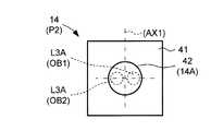
図5Aは、受光素子14の受光面14A及び受光面14Aに入射する対象物OBからの反射光L3Aを模式的に示す図である。なお、図5Aには、図4に示した期間P1、すなわち第1の揺動ミラー12Aの変位速度(揺動速度)が正の方向に大きい期間において、比較的近距離の対象物OB1からの反射光L3Aの受光素子14への入射位置と、比較的遠距離の対象物OB2からの反射光L3Aの受光素子14への入射位置と、を破線で示している。  FIG. 5A is a diagram schematically illustrating thelight receiving surface 14A of thelight receiving element 14 and the reflected light L3A from the object OB incident on thelight receiving surface 14A. In FIG. 5A, in the period P1 shown in FIG. 4, that is, the period during which the displacement speed (swinging speed) of the firstoscillating mirror 12A is large in the positive direction, The incident position of the reflected light L3A to thelight receiving element 14 and the incident position of the reflected light L3A from the object OB2 at a relatively long distance to thelight receiving element 14 are indicated by broken lines.

まず、本実施例においては、受光素子14は、基板41と、基板41上に形成され、反射光L3Aを検出する検出素子42とを含む。例えば、検出素子42は、少なくとも1つの光電変換素子を含む。検出素子42の第2の偏向素子13に対向する表面は、受光素子14の受光面14Aとして機能する。  First, in the present embodiment, thelight receiving element 14 includes asubstrate 41 and adetection element 42 that is formed on thesubstrate 41 and detects the reflected light L3A. For example, thedetection element 42 includes at least one photoelectric conversion element. The surface of thedetection element 42 facing thesecond deflection element 13 functions as thelight receiving surface 14 </ b> A of thelight receiving element 14.

次に、図4、図5A及び図5Bを用いて、対象物OBによる反射光L3Aの受光面14Aへの入射位置について説明する。図5Bは、図4に示した期間P2、すなわち第1の揺動ミラー12Aの揺動速度が負の方向に大きい期間における近距離の対象物OB1及び遠距離の対象物OB2の各々からの反射光L3Aの受光素子14への入射位置を破線で示している。  Next, the incident position of the reflected light L3A from the object OB on thelight receiving surface 14A will be described with reference to FIGS. 4, 5A, and 5B. FIG. 5B shows the reflection from each of the short-distance object OB1 and the long-distance object OB2 in the period P2 shown in FIG. 4, that is, the period in which the rocking speed of thefirst rocking mirror 12A is large in the negative direction. The incident position of the light L3A on thelight receiving element 14 is indicated by a broken line.

本実施例においては、まず、図4に示すように、期間P1及びP2においては、第1の偏向素子12の第1の揺動ミラー12Aは、最も速い速度で揺動している。この期間P1及びP2では、走査光L2が第1の揺動ミラー12Aによって投光されてから、対象物OBによって反射して反射光L3として第1の揺動ミラー12Aに戻ってくるまでの間に、第1の揺動ミラー12Aの位置(角度)が最も大きく変化する。  In this embodiment, first, as shown in FIG. 4, in the periods P1 and P2, the firstoscillating mirror 12A of thefirst deflecting element 12 oscillates at the fastest speed. In this period P1 and P2, the period from when the scanning light L2 is projected by the firstoscillating mirror 12A until it is reflected by the object OB and returned to the firstoscillating mirror 12A as reflected light L3. In addition, the position (angle) of the firstoscillating mirror 12A changes most greatly.

特に、比較的遠距離に対象物OBが存在している場合、走査光L2が反射光L3となって第1の揺動ミラー12Aに戻ってくるまでに比較的長い時間がかかる。従って、第1の揺動ミラー12Aに戻って来た反射光L3は、その大きく変位した第1の揺動ミラー12Aによって、比較的近距離の対象物OBからの反射光L3に比べて大きく異なる方向に反射されることが想定される。  In particular, when the object OB exists at a relatively long distance, it takes a relatively long time for the scanning light L2 to return to the firstoscillating mirror 12A as reflected light L3. Therefore, the reflected light L3 that has returned to the firstoscillating mirror 12A differs greatly from the reflected light L3 from the object OB at a relatively short distance due to the largely displaced first oscillatingmirror 12A. It is assumed to be reflected in the direction.

これに対し、第2の偏向素子13の第2の揺動ミラー13Aは、第1の揺動ミラー12Aの変位に追従しかつ第1の揺動ミラー12Aの変位による反射光L3の偏向方向のずれを相殺する(補正する)ように揺動する。従って、第2の揺動ミラー13Aによって、反射された反射光L3Aは、受光面14Aの設計上の中心の近傍に入射する。  On the other hand, the secondoscillating mirror 13A of thesecond deflecting element 13 follows the displacement of the firstoscillating mirror 12A and in the deflection direction of the reflected light L3 due to the displacement of the firstoscillating mirror 12A. It swings so as to cancel (correct) the deviation. Therefore, the reflected light L3A reflected by the secondoscillating mirror 13A enters the vicinity of the design center of thelight receiving surface 14A.

例えば、期間P1においては、第2の偏向素子13の第2の揺動ミラー13Aは、最も大きな変位量(揺動角度)で正の方向に変位している。従って、期間P1では、第1の揺動ミラー12Aを経た対象物OBからの反射光L3は、第2の揺動ミラー13Aによって大きく偏向されることとなる。従って、例えば、図5Aに示すように、期間P1において、比較的近距離の対象物OB1からの反射光L3Aと、比較的遠距離の対象物OB2からの反射光L3Aと、の両方が受光面14Aの設計上の中心近傍に入射することとなる。  For example, in the period P1, the secondoscillating mirror 13A of thesecond deflection element 13 is displaced in the positive direction with the largest displacement amount (oscillation angle). Therefore, in the period P1, the reflected light L3 from the object OB that has passed through the firstoscillating mirror 12A is largely deflected by the secondoscillating mirror 13A. Therefore, for example, as shown in FIG. 5A, in the period P1, both the reflected light L3A from the object OB1 at a relatively short distance and the reflected light L3A from the object OB2 at a relatively long distance are both light receiving surfaces. It will be incident near the design center of 14A.

一方、図4に示すように、期間P2においては、第1の揺動ミラー12Aは、最も速い速度で負の方向に揺動している。この期間P2においては、第2の揺動ミラー13Aは、負の方向に最も大きな変位量で変位している。この場合、対象物OB1からの反射光L3A(OB1)及び対象物OB2からの反射光L3A(OB2)の各々は、受光面14Aにおける設計上の中心近傍において期間P1とは逆転した位置関係を持って入射することとなる。  On the other hand, as shown in FIG. 4, in the period P2, the firstoscillating mirror 12A oscillates in the negative direction at the fastest speed. During this period P2, the secondoscillating mirror 13A is displaced by the largest displacement amount in the negative direction. In this case, each of the reflected light L3A (OB1) from the object OB1 and the reflected light L3A (OB2) from the object OB2 has a positional relationship that is reversed from the period P1 in the vicinity of the design center of thelight receiving surface 14A. Will be incident.

具体的には、図5Bにおける左右方向において、反射光L3A(OB1)及びL3A(OB2)の受光面14Aへの入射位置の関係が図5Aに示す関係から入れ替わる。しかし、反射光L3A(OB1)及びL3A(OB2)の各々は、受光面14Aにおける設計上の中心近傍に入射することとなる。  Specifically, in the left-right direction in FIG. 5B, the relationship between the incident positions of the reflected light L3A (OB1) and L3A (OB2) on thelight receiving surface 14A is switched from the relationship shown in FIG. 5A. However, each of the reflected lights L3A (OB1) and L3A (OB2) is incident near the design center of thelight receiving surface 14A.

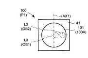
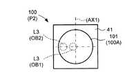
図6A及び図6Bは、比較例として、第2の偏向素子13を有さない走査装置における受光素子100の受光面100Aを示す図である。受光素子100は、受光面100Aを構成する検出素子101を有する。図6A及び図6Bは、比較例に係る走査装置において、受光素子100が第1の偏向素子12を経た反射光L3を受光する場合の反射光L3の入射位置を模式的に示す図である。  6A and 6B are diagrams showing alight receiving surface 100A of alight receiving element 100 in a scanning device that does not have thesecond deflecting element 13 as a comparative example. Thelight receiving element 100 includes adetection element 101 that constitutes thelight receiving surface 100A. 6A and 6B are diagrams schematically illustrating an incident position of the reflected light L3 when thelight receiving element 100 receives the reflected light L3 that has passed through thefirst deflecting element 12 in the scanning device according to the comparative example.

なお、図6A及び図6Bには、比較例に係る走査装置の第1の偏向素子12が図4の期間P1及びP2に対応する揺動状態となった際において、それぞれ近距離の対象物OB1及び遠距離の対象物OB2からの反射光L3の各々が受光面101Aに入射する位置を破線で示している。  6A and 6B, when thefirst deflection element 12 of the scanning device according to the comparative example is in the swinging state corresponding to the periods P1 and P2 in FIG. The positions at which each of the reflected lights L3 from the object OB2 at a long distance are incident on the light receiving surface 101A are indicated by broken lines.

比較例の走査装置においては、例えば第1の揺動ミラー12Aが走査光L2の往復時間中に変位した場合、第1の揺動ミラー12Aを経た反射光L3の方向は、当該往復時間中の第1の揺動ミラー12Aの変位、すなわち第1の揺動ミラー12Aの揺動速度及びその方向の影響を忠実に受ける。  In the scanning device of the comparative example, for example, when the firstoscillating mirror 12A is displaced during the reciprocating time of the scanning light L2, the direction of the reflected light L3 that has passed through the firstoscillating mirror 12A is The displacement of the firstoscillating mirror 12A, that is, the influence of the oscillating speed and direction of the firstoscillating mirror 12A is faithfully affected.

従って、図6A及び図6Bに示すように、比較例においては、対象物OBからの反射光L3は、期間P1及びP2間で、受光面100A上における第1の揺動ミラー12Aの揺動軸AX1に対応する軸を対称軸として対称的な位置(図では左右対称な位置)に入射する。  Therefore, as shown in FIGS. 6A and 6B, in the comparative example, the reflected light L3 from the object OB is the swing axis of thefirst swing mirror 12A on thelight receiving surface 100A during the periods P1 and P2. The light beam is incident on a symmetrical position (symmetrical position in the figure) with the axis corresponding to AX1 as the axis of symmetry.

すなわち、まず、比較的近距離の対象物OB1からの反射光L3は、期間P1及びP2の両方で、受光面100Aの中心近傍に入射する。しかし、その一方で、比較的遠距離の対象物OB2からの反射光L3は、期間P1及びP2間で、受光面100Aの中心から互いに反対方向に離れた位置に入射することとなる。  That is, first, the reflected light L3 from the object OB1 at a relatively short distance enters the vicinity of the center of thelight receiving surface 100A in both periods P1 and P2. However, on the other hand, the reflected light L3 from the object OB2 at a relatively long distance enters the positions separated in the opposite directions from the center of thelight receiving surface 100A during the periods P1 and P2.

従って、受光素子100に受光面101を形成する検出素子101を設ける場合、図6に示すように、これらを全て受光するために大きなサイズの検出素子101を設ける必要がある。  Therefore, when thedetection element 101 for forming thelight receiving surface 101 is provided in thelight receiving element 100, it is necessary to provide a largesize detection element 101 in order to receive all of them as shown in FIG.

これに対し、本実施例においては、第1の揺動ミラー12Aの変位状態に応じて揺動する第2の揺動ミラー13Aを受光素子14と第1の揺動ミラー12Aとの間に設けている。従って、種々の位置の対象物OBからの反射光L3を受光面14A内の設計上の中心に近い位置に導くことができる。  In contrast, in this embodiment, a secondoscillating mirror 13A that oscillates according to the displacement state of the firstoscillating mirror 12A is provided between the light receivingelement 14 and the firstoscillating mirror 12A. ing. Therefore, the reflected light L3 from the object OB at various positions can be guided to a position near the design center in thelight receiving surface 14A.

従って、第2の揺動ミラー13A(第2の偏向素子13)を設けない場合(比較例)に比べて、受光素子14のサイズを大幅に縮小することができる。従って、意図しないノイズ光の受光が大幅に抑制される。従って、対象物OBからの反射光L3を正確かつ確実に受光でき、正確な走査及び測距を行うことが可能な走査装置SC及び測距装置10を提供することができる。  Therefore, the size of thelight receiving element 14 can be greatly reduced as compared with the case where the secondoscillating mirror 13A (second deflecting element 13) is not provided (comparative example). Therefore, unintended noise light reception is greatly suppressed. Therefore, it is possible to provide the scanning device SC and thedistance measuring device 10 that can accurately and surely receive the reflected light L3 from the object OB and can perform accurate scanning and distance measuring.

なお、第2の揺動ミラー13Aの最大変位量A2は、想定される測距環境及び走査環境に応じて調節されることができる。例えば、走査領域R0内の比較的遠距離に対象物OBが存在することが予め予測できる場合、又は外部からその情報を取得した場合、第2の揺動ミラー13Aの最大変位量A2を比較的大きくすることで、反射光L3Aの受光位置のずれを大きく補正することができる。一方、比較的近距離に対象物OBが存在することを示す情報を取得した場合は、最大変位量A2を比較的小さくしても十分に反射光L3の受光位置のずれを補正することができる。  Note that the maximum displacement amount A2 of the secondoscillating mirror 13A can be adjusted according to the assumed ranging environment and scanning environment. For example, when it can be predicted in advance that the object OB exists at a relatively long distance in the scanning region R0, or when the information is acquired from the outside, the maximum displacement A2 of the secondoscillating mirror 13A is relatively set. By making it larger, it is possible to greatly correct the shift in the light receiving position of the reflected light L3A. On the other hand, when information indicating that the object OB exists at a relatively short distance is acquired, even if the maximum displacement amount A2 is relatively small, the shift of the light receiving position of the reflected light L3 can be sufficiently corrected. .

また、本実施例では、第1及び第2の偏向素子12及び13が互いに同一の材料で形成され、かつ互いに同一の形状を有する。また、本実施例においては、第1及び第2に揺動ミラー12A及び13Aが共振するように互いに同一の周波数を有する第1及び第2の駆動信号SD1及びSD2によって駆動される場合について説明した。しかし、第1及び第2の揺動ミラー12A及び13Aは、共振周波数に対応する周波数の信号によって駆動される場合に限定されない。  In the present embodiment, the first andsecond deflecting elements 12 and 13 are made of the same material and have the same shape. In the present embodiment, the case where the first and second oscillating mirrors 12A and 13A are driven by the first and second drive signals SD1 and SD2 having the same frequency so as to resonate has been described. . However, the first and second oscillating mirrors 12A and 13A are not limited to being driven by a signal having a frequency corresponding to the resonance frequency.

例えば、第2の揺動ミラー13Aを第1の揺動ミラー12よりも高い共振周波数を有するように設計してもよい。また、この場合、例えば、第2の揺動ミラー13Aをその共振周波数よりも低い第1の揺動ミラー12Aの共振周波数に対応する周波数の第2の駆動信号SD2によって駆動されてもよい。  For example, the secondoscillating mirror 13A may be designed to have a higher resonance frequency than the firstoscillating mirror 12. In this case, for example, the secondoscillating mirror 13A may be driven by the second drive signal SD2 having a frequency corresponding to the resonance frequency of the firstoscillating mirror 12A lower than the resonance frequency.

この場合、駆動時において、第1の揺動ミラー12Aは共振し、第2の揺動ミラー13Aは共振しないような揺動態様となる。この場合、第1の揺動ミラー12Aの変位の位相が第1の駆動信号SD1の位相に対してπ/2遅れることを考慮すれば、第1及び第2の駆動信号SD1及びSD2は同位相の信号とすることもできる。  In this case, during driving, the firstoscillating mirror 12A resonates and the secondoscillating mirror 13A does not resonate. In this case, considering that the phase of displacement of the firstoscillating mirror 12A is delayed by π / 2 with respect to the phase of the first drive signal SD1, the first and second drive signals SD1 and SD2 have the same phase. The signal can also be

図7は、第2の揺動ミラー13Aの他の動作例を示す図である。例えば、第2の揺動ミラー13Aは、矩形波の変位に従うように揺動されてもよい。この場合、図7に示すように、第2の揺動ミラー13Aは、第1の揺動ミラー12Aの揺動速度及びその揺動方向に応じて、位置を変化させるように揺動されればよい。  FIG. 7 is a diagram illustrating another operation example of the secondoscillating mirror 13A. For example, the secondoscillating mirror 13A may be oscillated so as to follow the displacement of the rectangular wave. In this case, as shown in FIG. 7, if the secondoscillating mirror 13A is oscillated so as to change its position in accordance with the oscillating speed and the oscillating direction of the firstoscillating mirror 12A. Good.

具体的には、第1の揺動ミラー12Aによって反射した反射光L3の方向がずれる方向は、走査光L2の往復時間中の第1の揺動ミラー12Aの揺動速度の向きに対応する。従って、第1の揺動ミラー12Aの揺動速度の向きとは反対方向に偏向させるように、第2の揺動ミラー13Aの位置(角度)を制御すればよい。従って、例えば図7に示すように、一定の位置で第2の揺動ミラー13Aを保持するような駆動を行っても、対象物OBからの反射光L3の受光面14A上の入射位置のずれを補正することができる。  Specifically, the direction in which the direction of the reflected light L3 reflected by the firstoscillating mirror 12A deviates corresponds to the direction of the oscillating speed of the firstoscillating mirror 12A during the reciprocating time of the scanning light L2. Accordingly, the position (angle) of the secondoscillating mirror 13A may be controlled so as to deflect in the direction opposite to the direction of the oscillating speed of the firstoscillating mirror 12A. Therefore, for example, as shown in FIG. 7, even if driving is performed so as to hold the secondoscillating mirror 13A at a certain position, the incident position on thelight receiving surface 14A of the reflected light L3 from the object OB is shifted. Can be corrected.

図8は、第2の揺動ミラー13Aの他の動作例を示す図である。第2の揺動ミラー13Aは、図8に示す波形の変位に従うように揺動されてもよい。このような変位を示すように第2の揺動ミラー13Aを揺動させる場合であっても、例えば図7に示す例と同様の効果を得ることができる。  FIG. 8 is a diagram illustrating another operation example of the secondoscillating mirror 13A. The secondoscillating mirror 13A may be oscillated so as to follow the waveform displacement shown in FIG. Even when the secondoscillating mirror 13A is oscillated so as to exhibit such a displacement, for example, the same effect as in the example shown in FIG. 7 can be obtained.

図9は、実施例1の変形例1に係る測距装置10Aの配置図である。測距装置10Aは、走査装置SC1の構成を除いては、測距装置10と同様の構成を有する。走査装置SC1は、投受光ユニットUN0の構成を除いては、走査装置SCと同様の構成を有する。投受光ユニットUN0は、第2の偏向素子13Lの構成を除いては、投受光ユニットUNと同様の構成を有する。本変形例においては、第2の偏向素子13Lが可動レンズを含む。  FIG. 9 is a layout diagram of thedistance measuring apparatus 10A according to the first modification of the first embodiment. The rangingdevice 10A has the same configuration as the rangingdevice 10 except for the configuration of the scanning device SC1. The scanning device SC1 has the same configuration as the scanning device SC except for the configuration of the light projecting / receiving unit UN0. The light projecting / receiving unit UN0 has the same configuration as that of the light projecting / receiving unit UN, except for the configuration of thesecond deflection element 13L. In the present modification, thesecond deflection element 13L includes a movable lens.

具体的には、本実施例においては、投受光ユニットUNの第2の偏向素子13が揺動ミラー13Aを有する場合について説明した。しかし、第2の偏向素子13は揺動ミラー13Aを有する場合に限定されない。第2の偏向素子13は、第1の偏向素子12を経た反射光L3を偏向することが可能な構成を有していればよい。  Specifically, in the present embodiment, the case where thesecond deflection element 13 of the light projecting / receiving unit UN has theoscillating mirror 13A has been described. However, thesecond deflecting element 13 is not limited to the case where it has theoscillating mirror 13A. Thesecond deflecting element 13 only needs to have a configuration capable of deflecting the reflected light L3 that has passed through thefirst deflecting element 12.

本変形例においては、第2の偏向素子13Lは第1の揺動ミラー12Aの揺動状態に応じて受光素子14に対する位置が変化する可動レンズを含む。例えば、可動レンズは、所定の方向に沿って回動若しくは旋回し、又は平行移動するように構成されている。この場合であっても、第1の揺動ミラー12Aを経た反射光L3を受光素子14の好ましい位置に導くように反射光L3を偏向することができる。  In the present modification, thesecond deflection element 13L includes a movable lens whose position relative to thelight receiving element 14 changes according to the swinging state of thefirst swinging mirror 12A. For example, the movable lens is configured to rotate or turn along a predetermined direction, or to translate. Even in this case, the reflected light L3 can be deflected so that the reflected light L3 that has passed through the firstoscillating mirror 12A is guided to a preferred position of thelight receiving element 14.

なお、第2の偏向素子13は、MEMSミラー及び可動レンズ以外の他の光学素子を有していてもよい。例えば、第2の偏向素子13は、ポリゴンミラー、ガルバノミラー又は液晶素子を有していてもよい。  Note that thesecond deflection element 13 may have an optical element other than the MEMS mirror and the movable lens. For example, thesecond deflection element 13 may have a polygon mirror, a galvanometer mirror, or a liquid crystal element.

また、上記した第2の偏向素子13又は13Lの動作は一例に過ぎない。第1の偏向素子12を経た反射光L3を受光素子14の好ましい位置に入射させることを考慮すると、第2の偏向素子13は、例えば、第1の揺動ミラー12Aの揺動速度の向きに基づいた方向に、第1の揺動ミラー12Aを経た反射光L3を偏向するように構成されていればよい。また、例えば、第2の偏向素子13は、第1の揺動ミラー12Aの揺動速度に基づいた方向に、第1の揺動ミラー12Aを経た反射光L3を偏向するように構成されていればよい。  Further, the operation of thesecond deflection element 13 or 13L described above is merely an example. Considering that the reflected light L3 having passed through thefirst deflecting element 12 is incident on a preferred position of thelight receiving element 14, thesecond deflecting element 13 is, for example, in the direction of the swing speed of thefirst swing mirror 12A. What is necessary is just to be comprised so that the reflected light L3 which passed 12 A of 1st rocking | swiveling mirrors may be deflected in the direction based. Further, for example, thesecond deflection element 13 is configured to deflect the reflected light L3 that has passed through the firstoscillating mirror 12A in a direction based on the oscillating speed of the firstoscillating mirror 12A. That's fine.

図10は、実施例1の変形例2に係る測距装置10Bにおける走査装置SC2の第1の偏向素子12Mの上面図である。また、図11は、走査装置SC2の第2の偏向素子13Mの上面図である。図10及び図11を用いて、測距装置10B及び走査装置SC2について説明する。  FIG. 10 is a top view of thefirst deflection element 12M of the scanning device SC2 in thedistance measuring device 10B according to the second modification of the first embodiment. FIG. 11 is a top view of thesecond deflection element 13M of the scanning device SC2. Thedistance measuring device 10B and the scanning device SC2 will be described with reference to FIGS.

測距装置10Bは、走査装置SC2が2次元走査に対応する第1の偏向素子12Mを有する点、第2の偏向素子13Mが反射光L3を2次元的に偏向する構成を有する点、及び駆動部16M(第1及び第2の偏向素子駆動部16MB及び16MC)の構成を除いては、走査装置SCと同様の構成を有する。  Thedistance measuring device 10B has a point in which the scanning device SC2 has afirst deflection element 12M corresponding to two-dimensional scanning, a point in which thesecond deflection element 13M has a configuration to two-dimensionally deflect the reflected light L3, and driving. Except for the configuration of theunit 16M (first and second deflection element driving units 16MB and 16MC), the configuration is the same as that of the scanning device SC.

まず、図10に示すように、第1の偏向素子12Mは、互いに直交する第1及び第3の揺動軸AX1及びAY1の周りに揺動する揺動ミラー12MAを有する。本変形例においては、第1の偏向素子12Mは、フレーム部21と、フレーム部21に揺動可能に支持され、第1及び第3の揺動軸AX1及びAY1の周りに揺動する揺動部22Mとを有する。  First, as shown in FIG. 10, thefirst deflecting element 12M has a swinging mirror 12MA that swings around first and third swinging axes AX1 and AY1 orthogonal to each other. In the present modification, thefirst deflection element 12M is swingably supported by theframe portion 21 and theframe portion 21 and swings around the first and third swing axes AX1 and AY1.Part 22M.

揺動部22Mは、一端がフレーム部21の内周部に固定され、第3の揺動軸AY1に沿って延び、第3の揺動軸AY1の周方向の弾性を有する一対のトーションバーTY1を有する。また、揺動部22Mは、一対のトーションバーTY1の他端に接続され、第3の揺動軸AY1の周りに揺動する揺動枠SY1を有する。  One end of the swingingportion 22M is fixed to the inner peripheral portion of theframe portion 21, extends along the third swinging shaft AY1, and has a pair of torsion bars TY1 having elasticity in the circumferential direction of the third swinging shaft AY1. Have The swingingpart 22M has a swinging frame SY1 that is connected to the other end of the pair of torsion bars TY1 and swings around the third swinging axis AY1.

また、揺動部22Mは、一端が揺動枠SY1の内周部に接続され、揺動部22と同様の一対のトーションバーTX1及び揺動板SX1を有する。従って、揺動部22Mの揺動板SX1は、第1及び第3の揺動軸AX1及びAY1の周りに揺動する。  The swingingpart 22M has one end connected to the inner peripheral part of the swinging frame SY1, and has a pair of torsion bars TX1 and a swinging plate SX1 similar to the swingingpart 22. Accordingly, the swing plate SX1 of theswing portion 22M swings around the first and third swing axes AX1 and AY1.

また、第1の偏向素子12Mは、揺動部22Mの揺動板SX1上に形成された光反射膜24Mを有する。光反射膜24Mは、揺動板SX1の揺動に従って、第1及び第3の揺動軸AX1及びAY1の周りに揺動する。  Thefirst deflection element 12M has alight reflecting film 24M formed on the swing plate SX1 of theswing portion 22M. Thelight reflecting film 24M swings around the first and third swing axes AX1 and AY1 as the swing plate SX1 swings.

光反射膜24Mは、揺動板SX1に垂直な方向から見たときに第1及び第3の揺動軸AX1及びAY1の交点上に中心軸AC1を有する円板形状を有する。揺動部22Mの光反射膜24Mは、第1の偏向素子12Mにおける第1の揺動ミラー12MAとして機能する。  Thelight reflecting film 24M has a disk shape having a central axis AC1 on the intersection of the first and third swing axes AX1 and AY1 when viewed from the direction perpendicular to the swing plate SX1. Thelight reflecting film 24M of theoscillating portion 22M functions as the first oscillating mirror 12MA in thefirst deflecting element 12M.

また、本変形例においては、走査装置SC2の駆動部16Mは、第1の揺動ミラー12MAが第1の揺動軸AX1の周りに揺動するための揺動力を生成する揺動力生成部(図示せず)に駆動信号SD1Xを供給し、第1の揺動ミラー12MAが第3の揺動軸AY1の周りに揺動するための揺動力を生成する揺動力生成部(図示せず)に駆動信号SD1Yを供給する第1の偏向素子駆動部16MBを有する。第1の揺動ミラー12MAは、駆動信号SD1X及びSD1Yによって、第1及び第3の揺動軸AX1及びAY1の周りに揺動する。  In the present modification, the drivingunit 16M of the scanning device SC2 includes a swinging force generation unit (for generating a swinging force for the first swinging mirror 12MA to swing around the first swinging axis AX1). (Not shown) is supplied with a drive signal SD1X to a swinging force generator (not shown) that generates a swinging force for the first swinging mirror 12MA to swing around the third swinging axis AY1. The first deflecting element driving unit 16MB that supplies the driving signal SD1Y is provided. The first oscillating mirror 12MA oscillates around the first and third oscillating axes AX1 and AY1 by the drive signals SD1X and SD1Y.

また、図11に示すように、第2の偏向素子13Mは、互いに直交する第2及び第4の揺動軸AX2及びAY2の周りに揺動する揺動ミラー13MAを有する。本変形例においては、第2の偏向素子13Mは、フレーム部31と、フレーム部31に揺動可能に支持され、第2及び第4の揺動軸AX2及びAY2の周りに揺動する揺動部32Mとを有する。  As shown in FIG. 11, thesecond deflection element 13M includes a swing mirror 13MA that swings around second and fourth swing axes AX2 and AY2 orthogonal to each other. In the present modification, thesecond deflection element 13M is swingably supported by theframe portion 31 and theframe portion 31, and swings around the second and fourth swing axes AX2 and AY2.Part 32M.

揺動部32Mは、一端がフレーム部31の内周部に固定され、第4の揺動軸AY2に沿って延び、第4の揺動軸AY2の周方向の弾性を有する一対のトーションバーTY2を有する。また、揺動部32Mは、一対のトーションバーTY2の他端に接続され、第4の揺動軸AY2の周りに揺動する揺動枠SY2を有する。  Theswing part 32M has one end fixed to the inner peripheral part of theframe part 31, extends along the fourth swing axis AY2, and has a pair of torsion bars TY2 having elasticity in the circumferential direction of the fourth swing axis AY2. Have Further, theswing part 32M has a swing frame SY2 that is connected to the other end of the pair of torsion bars TY2 and swings around the fourth swing axis AY2.

また、揺動部32Mは、一端が揺動枠SY2の内周部に接続され、揺動部32と同様の一対のトーションバーTX2及び揺動板SX2を有する。従って、揺動部32Mの揺動板SX2は、第2及び第4の揺動軸AX2及びAY2の周りに揺動する。  The swingingpart 32M is connected at one end to the inner peripheral part of the swinging frame SY2, and has a pair of torsion bars TX2 and a swinging plate SX2 similar to the swingingpart 32. Therefore, the swing plate SX2 of theswing portion 32M swings around the second and fourth swing axes AX2 and AY2.

また、第2の偏向素子13Mは、揺動部32Mの揺動板SX2上に形成された光反射膜34Mを有する。光反射膜34Mは、揺動板SX2の揺動に従って、第2及び第4の揺動軸AX2及びAY2の周りに揺動する。  Thesecond deflecting element 13M has alight reflecting film 34M formed on the swing plate SX2 of theswing portion 32M. Thelight reflecting film 34M swings around the second and fourth swing axes AX2 and AY2 according to the swing of the swing plate SX2.

光反射膜34は、揺動板SX2に垂直な方向から見たときに第2及び第4の揺動軸AX2及びAY2の交点上に中心軸AC2を有する円板形状を有する。揺動部32Mの光反射膜34Mは、第2の偏向素子13Mにおける第2の揺動ミラー13MAとして機能する。  Thelight reflecting film 34 has a disk shape having a central axis AC2 on the intersection of the second and fourth swing axes AX2 and AY2 when viewed from a direction perpendicular to the swing plate SX2. Thelight reflecting film 34M of theoscillating portion 32M functions as the second oscillating mirror 13MA in thesecond deflecting element 13M.

また、本変形例においては、走査装置SC2の駆動部16Mは、第2の揺動ミラー13MAが第2の揺動軸AX2の周りに揺動するための揺動力を生成する揺動力生成部(図示せず)に駆動信号SD2Xを供給し、第2の揺動ミラー13MAが第4の揺動軸AY2の周りに揺動するための揺動力を生成する揺動力生成部(図示せず)に駆動信号SD2Yを供給する第2の偏向素子駆動部16MCを有する。第2の揺動ミラー13MAは、駆動信号SD2X及びSD2Yによって、第2及び第4の揺動軸AX2及びAY2の周りに揺動する。  In the present modification, the drivingunit 16M of the scanning device SC2 includes a swinging force generating unit (for generating a swinging force for the second swinging mirror 13MA to swing around the second swinging axis AX2). (Not shown) is supplied with a driving signal SD2X, and a swinging force generator (not shown) that generates a swinging force for the second swinging mirror 13MA to swing around the fourth swinging axis AY2 is supplied. A second deflection element driving unit 16MC that supplies the driving signal SD2Y is provided. The second oscillating mirror 13MA oscillates around the second and fourth oscillating axes AX2 and AY2 by the drive signals SD2X and SD2Y.

また、本変形例においては、第1の偏向素子駆動部16MBは、駆動信号SD1Xとして第1の揺動ミラー12Mの第1の揺動軸AX1周りの共振周波数の正弦波の信号を、また駆動信号SD1Yとして第1の揺動ミラー12Mの第3の揺動軸AY1周りの共振周波数の正弦波の信号を、それぞれ第1の偏向素子12Mに供給する。  In the present modification, the first deflection element driving unit 16MB also drives a sine wave signal having a resonance frequency around the first oscillating axis AX1 of the firstoscillating mirror 12M as the driving signal SD1X. A sine wave signal having a resonance frequency around the third oscillating axis AY1 of the firstoscillating mirror 12M is supplied to thefirst deflecting element 12M as the signal SD1Y.

また、第2の偏向素子駆動部16MCは、駆動信号SD2X及びSD2Yとして、第1の揺動ミラー12Mの揺動に追従して第2の揺動ミラー13Mが揺動するような正弦波の信号を第2の偏向素子13Mに供給する。例えば、第1及び第2の偏向素子12M及び13Mが同様の材料及び形状を有する場合、第2の偏向素子駆動部16MCは、駆動信号SD2X及びSD2Yとして、駆動信号SD1X及びSD1Yのそれぞれからπ/2だけ位相をずらした正弦波の信号を第2の偏向素子13Mに供給する。  Further, the second deflecting element driving unit 16MC uses, as drive signals SD2X and SD2Y, a sine wave signal that causes the secondoscillating mirror 13M to oscillate following the oscillation of the firstoscillating mirror 12M. Is supplied to thesecond deflection element 13M. For example, when the first andsecond deflecting elements 12M and 13M have the same material and shape, the second deflecting element driving unit 16MC obtains the driving signals SD2X and SD2Y from each of the driving signals SD1X and SD1Y by π / A sine wave signal whose phase is shifted by 2 is supplied to thesecond deflection element 13M.

従って、変形例においては、第1及び第2の揺動ミラー12M及び13Mにおける第1及び第2の揺動軸AX1及びAX2の周りの揺動角度は、図4と同様の推移を行う。また、第1及び第2の揺動ミラー12M及び13Mにおける第3及び第4の揺動軸AY1及びAY2の周りの揺動角度は、周波数及び振幅は異なるものの、図4と同様の推移を行う。  Therefore, in the modification, the swing angles around the first and second swing axes AX1 and AX2 in the first and second swing mirrors 12M and 13M change in the same manner as in FIG. Further, the swing angles around the third and fourth swing axes AY1 and AY2 in the first and second swing mirrors 12M and 13M change in the same manner as in FIG. .

図12は、走査装置SC2における受光素子14の受光面14Aを模式的に示す上面図である。図12は、同一タイミングで投光された走査光L2が互いに異なる距離の対象物OBによって反射されたことによる反射光L3の受光面14A上の受光位置を模式的に示す図である。  FIG. 12 is a top view schematically showing thelight receiving surface 14A of thelight receiving element 14 in the scanning device SC2. FIG. 12 is a diagram schematically illustrating a light receiving position on thelight receiving surface 14A of the reflected light L3 that is obtained when the scanning light L2 projected at the same timing is reflected by the object OB at different distances.

本変形例においては、第2の偏向素子13M(第2の揺動ミラー13MA)は、走査光L2の往復時間中における第1の揺動ミラー12MAの第1及び第3の揺動軸AX1及びAY1の周りの変位の両方の影響を相殺するように揺動する。従って、第2の揺動ミラー13MAを経た反射光L30Aは、受光面14Aにおける設計上の中心の近傍に入射することとなる。従って、設計上の距離よりも近い距離の対象物OB1からの反射光L30Aや、当該設計上の距離よりも遠い距離の対象物OB2からの反射光L30Aであっても、受光面14Aにおける設計上の中心の近傍に入射する可能性が高い。  In the present modification, thesecond deflection element 13M (second oscillating mirror 13MA) includes the first and third oscillating axes AX1 of the first oscillating mirror 12MA during the reciprocating time of the scanning light L2. Swing to cancel out the effects of both displacements around AY1. Therefore, the reflected light L30A that has passed through the second oscillating mirror 13MA is incident near the design center of thelight receiving surface 14A. Therefore, the reflected light L30A from the object OB1 that is closer than the design distance and the reflected light L30A from the object OB2 that is farther than the design distance are designed on thelight receiving surface 14A. There is a high possibility that the light enters the vicinity of the center.

一方、図13は、比較例として、第2の偏向素子13Mを有さない走査装置における受光素子100の受光面100Aが第1の偏向素子12Mを経た反射光L3を受光する場合の反射光L3の入射位置を模式的に示す図である。当該比較例に係る走査装置においては、例えば第1の揺動ミラー12MAが走査光L2の往復時間中に変位した場合、第1の揺動ミラー12MAを経た反射光L3の方向は、当該往復時間中の第1の揺動ミラー12MAの変位の影響を2次元的に受けることとなる。  On the other hand, FIG. 13 shows, as a comparative example, reflected light L3 when thelight receiving surface 100A of thelight receiving element 100 in the scanning apparatus that does not have thesecond deflecting element 13M receives the reflected light L3 that has passed through thefirst deflecting element 12M. It is a figure which shows typically the incident position. In the scanning device according to the comparative example, for example, when the first oscillating mirror 12MA is displaced during the reciprocating time of the scanning light L2, the direction of the reflected light L3 passing through the first oscillating mirror 12MA is the reciprocating time. The influence of the displacement of the first first oscillating mirror 12MA is received two-dimensionally.

従って、図13に示すように、比較的近距離の対象物OB1からの反射光L3は受光面100Aの中心付近に入射し、比較的遠距離の対象物OB2からの反射光L3は受光面100Aの周辺に入射する。また、遠距離の対象物OB2からの反射光L3は、第1の揺動ミラー12MAの揺動速度の向きに応じた方向に沿って受光面100Aの中心から離れた位置に入射する。従って、受光素子100に受光面101を形成する検出素子101を設ける場合、図13に示すように、これらを全て受光するために2次元的に大きなサイズの検出素子101を設ける必要がある。  Accordingly, as shown in FIG. 13, the reflected light L3 from the object OB1 at a relatively short distance is incident near the center of thelight receiving surface 100A, and the reflected light L3 from the object OB2 at a relatively long distance is received by thelight receiving surface 100A. Incident to the periphery. Further, the reflected light L3 from the object OB2 at a long distance is incident on a position away from the center of thelight receiving surface 100A along a direction corresponding to the direction of the swing speed of the first swing mirror 12MA. Therefore, when thedetection element 101 for forming thelight receiving surface 101 is provided in thelight receiving element 100, it is necessary to provide thedetection element 101 having a two-dimensionally large size in order to receive all of them as shown in FIG.

これに対し、本変形例のように2軸走査を行う場合においても、第1の揺動ミラー12MAの変位状態に応じて揺動する第2の揺動ミラー13MAが受光素子14と第1の揺動ミラー12MAとの間に設けられている。従って、種々の位置の対象物OBからの反射光L3を受光面14Aの設計上の中心に近い位置に導くことができる。  On the other hand, even when biaxial scanning is performed as in this modification, the second oscillating mirror 13MA that oscillates according to the displacement state of the first oscillating mirror 12MA It is provided between the oscillating mirror 12MA. Therefore, the reflected light L3 from the object OB at various positions can be guided to a position near the design center of thelight receiving surface 14A.

従って、本変形例においても、第2の揺動ミラー13MA(第2の偏向素子13M)を設けない場合(比較例)に比べて、受光素子14のサイズを大幅に縮小することができる。従って、測距装置10B及び走査装置SC2の小型化を図ることができ、また意図しないノイズ光を受光することが大幅に抑制される。従って、対象物OBからの反射光L3を正確かつ確実に受光でき、正確な走査及び測距を行うことが可能な走査装置SC2及び測距装置10Bを提供することができる。  Therefore, also in this modification, the size of thelight receiving element 14 can be significantly reduced as compared with the case where the second oscillating mirror 13MA (second deflectingelement 13M) is not provided (comparative example). Accordingly, thedistance measuring device 10B and the scanning device SC2 can be reduced in size, and unintentional noise light can be significantly suppressed. Therefore, it is possible to provide the scanning device SC2 and thedistance measuring device 10B that can accurately and reliably receive the reflected light L3 from the object OB and can perform accurate scanning and distance measuring.

なお、上記した第2の偏向素子13及び13Mの駆動構成(すなわち変位動作)は一例に過ぎない。第2の偏向素子13又は13Mは、第1の偏向素子12又は12Mと受光素子14との間の反射光L3の光路上に設けられ、反射光L3を方向可変に偏向するように構成されていればよい。  The drive configuration (that is, the displacement operation) of thesecond deflection elements 13 and 13M described above is only an example. Thesecond deflection element 13 or 13M is provided on the optical path of the reflected light L3 between thefirst deflection element 12 or 12M and thelight receiving element 14, and is configured to deflect the reflected light L3 in a variable direction. Just do it.

このように、本実施例及びその種々の変形例に示したように、例えば、測距装置10は、光源11、光源11からの出射光L1を方向可変に偏向しつつ走査光L2として走査領域(所定の領域)R0に向けて投光する第1の偏向素子12、走査光L2が走査領域R0内の対象物OBによって反射し、第1の偏向素子12を通過した反射光L3を受光する受光素子14、及び受光素子14による反射光L3(反射光L3A)の受光結果に基づいて対象物OBまでの距離を測定する測距部15を有する。また、測距装置10は、第1の偏向素子12と受光素子14との間の反射光L3の光路上に設けられ、第1の反射光L3を方向可変に偏向する第2の偏向素子13を有する。  Thus, as shown in the present embodiment and various modifications thereof, for example, thedistance measuring device 10 uses thelight source 11 and the scanning region as the scanning light L2 while deflecting the emitted light L1 from thelight source 11 in a variable direction. (Predetermined area) Thefirst deflection element 12 and the scanning light L2 that project toward R0 are reflected by the object OB in the scanning area R0, and the reflected light L3 that has passed through thefirst deflection element 12 is received. Thelight receiving element 14 and thedistance measuring unit 15 that measures the distance to the object OB based on the light reception result of the reflected light L3 (reflected light L3A) by thelight receiving element 14 are provided. Thedistance measuring device 10 is provided on the optical path of the reflected light L3 between thefirst deflecting element 12 and thelight receiving element 14, and thesecond deflecting element 13 deflects the first reflected light L3 in a variable direction. Have

また、測距装置10から測距部15を除いた構成に対応する走査装置SCは、正確な反射光L3の受光結果である受光信号SRを種々の用途に応じた走査情報として出力する走査装置として機能する。従って、受光素子14を小型化しつつ対象物OBからの反射光L3を正確かつ確実に受光でき、正確な走査及び測距を行うことが可能な走査装置SC及び測距装置10を提供することができる。  The scanning device SC corresponding to the configuration obtained by removing thedistance measuring unit 15 from thedistance measuring device 10 outputs a light reception signal SR, which is an accurate light reception result of the reflected light L3, as scanning information corresponding to various applications. Function as. Accordingly, it is possible to provide the scanning device SC and thedistance measuring device 10 that can accurately and reliably receive the reflected light L3 from the object OB while reducing the size of thelight receiving element 14, and that can perform accurate scanning and distance measurement. it can.

10、10A、10B 測距装置
SC、SC1、SC2 走査装置
11 光源
12 第1の偏向素子
13 第2の偏向素子
14 受光素子
15 測距部
16 駆動部
10, 10A, 10B Distance measuring devices SC, SC1,SC2 Scanning device 11Light source 12First deflecting element 13Second deflecting element 14Light receiving element 15 Distance measuring unit 16 Driving unit

Claims (6)

Translated fromJapanese
光源と、
前記光源からの出射光を方向可変に偏向しつつ走査光として所定の領域に向けて投光する第1の偏向素子と、
前記走査光が前記所定の領域内の対象物によって反射し、前記第1の偏向素子を経た反射光を受光する受光素子と、
前記第1の偏向素子と前記受光素子との間の前記反射光の光路上に設けられ、前記第1の偏向素子を経た前記反射光を方向可変に偏向する第2の偏向素子と、を有することを特徴とする走査装置。
A light source;
A first deflecting element that projects light toward a predetermined region as scanning light while deflecting light emitted from the light source in a variable direction;
A light receiving element that reflects the scanning light reflected by an object in the predetermined region and receives the reflected light that has passed through the first deflection element;
A second deflecting element provided on an optical path of the reflected light between the first deflecting element and the light receiving element and deflecting the reflected light passing through the first deflecting element in a variable direction. A scanning device characterized by that.
前記第1の偏向素子は、前記光源からの前記出射光を反射させ、かつ少なくとも第1の揺動軸の周りに揺動する第1の揺動ミラーを含み、
前記第2の偏向素子は、前記第1の揺動ミラーの揺動速度の向きに基づいた方向に、前記第1の揺動ミラーを経た前記反射光を偏向することを特徴とする請求項1に記載の走査装置。
The first deflection element includes a first oscillating mirror that reflects the emitted light from the light source and oscillates around at least a first oscillating shaft;
2. The second deflecting element deflects the reflected light that has passed through the first oscillating mirror in a direction based on the direction of the oscillating speed of the first oscillating mirror. The scanning device according to 1.
前記第2の偏向素子は、前記第1の揺動ミラーの揺動速度に基づいた方向に、前記第1の揺動ミラーを経た前記反射光を偏向することを特徴とする請求項2に記載の走査装置。  The second deflecting element deflects the reflected light that has passed through the first oscillating mirror in a direction based on an oscillating speed of the first oscillating mirror. Scanning device. 前記第2の偏向素子は、前記第1の揺動ミラーを経た前記反射光を反射させ、かつ少なくとも第2の揺動軸の周りに揺動する第2の揺動ミラーを有することを特徴とする請求項2又は3に記載の走査装置。  The second deflection element includes a second oscillating mirror that reflects the reflected light that has passed through the first oscillating mirror and that oscillates at least about the second oscillating axis. The scanning device according to claim 2 or 3. 前記第2の偏向素子は、前記第1の揺動ミラーの揺動状態に応じて前記受光素子に対する位置が変化する可動レンズを含むことを特徴とする請求項2又は3に記載の走査装置。  4. The scanning device according to claim 2, wherein the second deflection element includes a movable lens whose position changes with respect to the light receiving element according to a swinging state of the first swinging mirror. 請求項1乃至5のいずれか1つに記載の走査装置と、
前記受光素子による前記反射光の受光結果に基づいて前記対象物までの距離を測定する測距部と、を有することを特徴とする測距装置。
A scanning device according to any one of claims 1 to 5;
And a distance measuring unit that measures a distance to the object based on a result of receiving the reflected light by the light receiving element.
JP2018059848A2018-03-272018-03-27Scanning device and ranging devicePendingJP2019174162A (en)

Priority Applications (1)

Application NumberPriority DateFiling DateTitle
JP2018059848AJP2019174162A (en)2018-03-272018-03-27Scanning device and ranging device

Applications Claiming Priority (1)

Application NumberPriority DateFiling DateTitle
JP2018059848AJP2019174162A (en)2018-03-272018-03-27Scanning device and ranging device

Publications (1)

Publication NumberPublication Date
JP2019174162Atrue JP2019174162A (en)2019-10-10

Family

ID=68170191

Family Applications (1)

Application NumberTitlePriority DateFiling Date
JP2018059848APendingJP2019174162A (en)2018-03-272018-03-27Scanning device and ranging device

Country Status (1)

CountryLink
JP (1)JP2019174162A (en)

Citations (6)

* Cited by examiner, † Cited by third party
Publication numberPriority datePublication dateAssigneeTitle
JP2007316016A (en)*2006-05-292007-12-06Mitsubishi Electric Corp Radar equipment
JP2010122183A (en)*2008-11-212010-06-03Sanyo Electric Co LtdObject detecting device and information acquiring device
WO2014024508A1 (en)*2012-08-082014-02-13三菱電機株式会社Radar device
JP2015213251A (en)*2014-05-022015-11-26株式会社IhiBehavior analyzer, monitoring system and amusement system
WO2017085799A1 (en)*2015-11-182017-05-26三菱電機株式会社Laser radar apparatus
JP6222409B1 (en)*2017-01-112017-11-01三菱電機株式会社 Laser radar equipment

Patent Citations (6)

* Cited by examiner, † Cited by third party
Publication numberPriority datePublication dateAssigneeTitle
JP2007316016A (en)*2006-05-292007-12-06Mitsubishi Electric Corp Radar equipment
JP2010122183A (en)*2008-11-212010-06-03Sanyo Electric Co LtdObject detecting device and information acquiring device
WO2014024508A1 (en)*2012-08-082014-02-13三菱電機株式会社Radar device
JP2015213251A (en)*2014-05-022015-11-26株式会社IhiBehavior analyzer, monitoring system and amusement system
WO2017085799A1 (en)*2015-11-182017-05-26三菱電機株式会社Laser radar apparatus
JP6222409B1 (en)*2017-01-112017-11-01三菱電機株式会社 Laser radar equipment

Similar Documents

PublicationPublication DateTitle
CN111108406B (en)Lidar transmitter with re-imager
US6800844B2 (en)Two-dimensional optical scanner and method of driving the same
CN107843886B (en)Non-mechanical scanning laser radar optical device and laser radar system
JP6641031B2 (en) System and method for light beam position detection
JP2011089874A (en)Distance image data acquisition device
JP6222409B1 (en) Laser radar equipment
WO2020114229A1 (en)Laser radar optical system and scanning method
JP6724663B2 (en) Scanner mirror
US11947113B2 (en)Movable device, image projection apparatus, head-up display, laser headlamp, head-mounted display, object recognition device, and vehicle
CN111175721B (en) LIDAR sensor and method for LIDAR sensor
CN107450060A (en)A kind of laser scanning device
JP2022159464A (en) rangefinder
JP2022097530A (en)Methods for manufacturing ranging device and scanning device
JP2021170033A (en)Scanner
JP2022165971A (en) scanner and rangefinder
JP7152147B2 (en) rangefinder
US20210382151A1 (en)Scanning lidar systems with scanning fiber
JP2000098027A (en)Laser radar equipment
JP2019174162A (en)Scanning device and ranging device
JP2019174163A (en)Scanning device and ranging device
JP2014085646A (en)Optical scanner and measuring system
JP2022022390A (en)Ranging device
US20050200929A1 (en)Out of plane start of scan
JP2020003451A (en)Scanner, scanner drive method, program, recording medium, and distance measuring device
JP2020194116A (en)Laser scanning type video device

Legal Events

DateCodeTitleDescription
A621Written request for application examination

Free format text:JAPANESE INTERMEDIATE CODE: A621

Effective date:20210127

A977Report on retrieval

Free format text:JAPANESE INTERMEDIATE CODE: A971007

Effective date:20211119

A131Notification of reasons for refusal

Free format text:JAPANESE INTERMEDIATE CODE: A131

Effective date:20211221

A521Request for written amendment filed

Free format text:JAPANESE INTERMEDIATE CODE: A523

Effective date:20220218

A02Decision of refusal

Free format text:JAPANESE INTERMEDIATE CODE: A02

Effective date:20220628


[8]ページ先頭

©2009-2025 Movatter.jp