JP2019166238A - Operation simulation support system and device - Google Patents
Operation simulation support system and deviceDownload PDFInfo
- Publication number
- JP2019166238A JP2019166238AJP2018057885AJP2018057885AJP2019166238AJP 2019166238 AJP2019166238 AJP 2019166238AJP 2018057885 AJP2018057885 AJP 2018057885AJP 2018057885 AJP2018057885 AJP 2018057885AJP 2019166238 AJP2019166238 AJP 2019166238A
- Authority
- JP
- Japan
- Prior art keywords
- person
- imitator
- series data
- time
- data
- Prior art date
- Legal status (The legal status is an assumption and is not a legal conclusion. Google has not performed a legal analysis and makes no representation as to the accuracy of the status listed.)
- Pending
Links
- 238000004088simulationMethods0.000title1
- 230000033001locomotionEffects0.000claimsdescription90
- 230000009471actionEffects0.000claimsdescription38
- 230000003278mimic effectEffects0.000claimsdescription36
- 230000029058respiratory gaseous exchangeEffects0.000claimsdescription25
- 238000012937correctionMethods0.000claimsdescription11
- 238000004364calculation methodMethods0.000claimsdescription4
- 238000003384imaging methodMethods0.000abstract1
- 238000013075data extractionMethods0.000description16
- 238000000034methodMethods0.000description16
- 238000010586diagramMethods0.000description15
- 238000012986modificationMethods0.000description14
- 230000004048modificationEffects0.000description14
- 230000005484gravityEffects0.000description13
- 210000003128headAnatomy0.000description11
- 230000008569processEffects0.000description9
- 239000000284extractSubstances0.000description8
- 238000005259measurementMethods0.000description8
- 230000000241respiratory effectEffects0.000description8
- 238000004891communicationMethods0.000description7
- 239000012141concentrateSubstances0.000description6
- 238000012545processingMethods0.000description6
- 238000005516engineering processMethods0.000description4
- 210000001503jointAnatomy0.000description4
- 210000000707wristAnatomy0.000description4
- 208000037656Respiratory SoundsDiseases0.000description3
- 230000005540biological transmissionEffects0.000description3
- 230000006870functionEffects0.000description3
- 125000002066L-histidyl groupChemical group[H]N1C([H])=NC(C([H])([H])[C@](C(=O)[*])([H])N([H])[H])=C1[H]0.000description2
- 210000003423ankleAnatomy0.000description2
- 230000037237body shapeEffects0.000description2
- 210000004556brainAnatomy0.000description2
- 230000035807sensationEffects0.000description2
- 230000006399behaviorEffects0.000description1
- 238000006243chemical reactionMethods0.000description1
- 238000010276constructionMethods0.000description1
- 238000010411cookingMethods0.000description1
- 230000007423decreaseEffects0.000description1
- 238000006073displacement reactionMethods0.000description1
- 210000001513elbowAnatomy0.000description1
- 210000002683footAnatomy0.000description1
- 210000001624hipAnatomy0.000description1
- 210000004394hip jointAnatomy0.000description1
- 230000010365information processingEffects0.000description1
- 210000003127kneeAnatomy0.000description1
- 238000004519manufacturing processMethods0.000description1
- 230000003340mental effectEffects0.000description1
- 210000003739neckAnatomy0.000description1
- 230000003287optical effectEffects0.000description1
- 230000004044responseEffects0.000description1
- 210000002832shoulderAnatomy0.000description1
Images


Landscapes
- Processing Or Creating Images (AREA)
- Controls And Circuits For Display Device (AREA)
Abstract
Description
Translated fromJapanese本発明は、スポーツ等の動作の模倣を支援するための技術に関する。 The present invention relates to a technology for supporting imitation of sports or the like.
従来、VR技術を用いて、スポーツ等の動作の模倣を支援するための装置が知られている。例えば、特許文献1には、模倣者の頭部に装着されるヘッドマウントディスプレイ(以下、「HMD」と呼ぶ。)であって、被模倣者が動作する映像を表示するHMDが記載されている。 2. Description of the Related Art Conventionally, an apparatus for supporting imitation of an operation such as a sport using VR technology is known. For example, Patent Document 1 describes a HMD that is a head-mounted display (hereinafter referred to as “HMD”) that is worn on the head of a mimic and displays an image in which the person to be imitated operates. .
しかし、特許文献1に記載の発明には、模倣者と被模倣者の体格が異なり両者の目線の高さが異なる場合に、模倣者が自身の動作と被模倣者の動作の一致度を把握しづらいという問題があった。 However, in the invention described in Patent Document 1, when the imitator and the person to be imitated have different physiques and the heights of their eyes are different, the imitator grasps the degree of coincidence between his own action and the person to be imitated. There was a problem that it was difficult.
本発明はこのような事情に鑑みてなされたものであり、模倣者が自身の動作と被模倣者の動作の一致度を把握しやすくすることを目的とする。 This invention is made | formed in view of such a situation, and it aims at making it easy for a mimic to grasp | ascertain the coincidence degree of an own person's operation | movement and an imitation person's operation | movement.
上記の課題を解決するため、本発明に係る動作模倣支援システムは、被模倣者の動作を表す、3次元の仮想空間の座標の第1時系列データを取得する第1取得部と、前記被模倣者の身体のサイズを特定する第1特定部と、模倣者の身体のサイズを特定する第2特定部と、前記被模倣者の身体のサイズと前記模倣者の身体のサイズの差異に基づいて、前記第1時系列データにより表される動作が前記模倣者の身体のサイズに応じたものとなるように、前記第1時系列データを補正する補正部と、前記補正された第1時系列データにより表される動作を前記仮想空間内において行う人物の画像のうち、前記仮想空間に設定される仮想カメラにより撮影される部分を、前記模倣者が装着する頭部装着型表示装置において現実空間の景色に重ねて表示させる表示制御部とを備え、前記仮想カメラの撮影方向は、前記頭部装着型表示装置の向きに応じて変化し、前記仮想空間における前記人物の頭部の高さは、前記仮想カメラの高さと略同一であることを特徴とする。 In order to solve the above-described problem, a motion imitation support system according to the present invention includes a first acquisition unit that acquires first time-series data of coordinates in a three-dimensional virtual space that represents an imitation person's movement; Based on a first specifying unit for specifying the size of the body of the mimic, a second specifying unit for specifying the size of the body of the mimic, and a difference between the size of the body of the imitator and the size of the body of the mimic A correction unit that corrects the first time-series data so that the motion represented by the first time-series data corresponds to the size of the body of the mimic, and the corrected first time A part of an image of a person who performs an operation represented by series data in the virtual space, which is captured by a virtual camera set in the virtual space, is real in a head-mounted display device worn by the mimic Overlaid on the scenery of the space A shooting control direction of the virtual camera is changed according to a direction of the head-mounted display device, and a height of the head of the person in the virtual space is a height of the virtual camera. And substantially the same.
上記の動作模倣支援システムにおいて、前記仮想空間における前記人物の頭部の水平方向の位置は、前記仮想カメラの水平方向の位置と略同一であってもよい。 In the motion imitation support system, the horizontal position of the person's head in the virtual space may be substantially the same as the horizontal position of the virtual camera.
上記の動作模倣支援システムは、前記補正された第1時系列データより表される動作を模倣する前記模倣者の身体の動きを表す、前記仮想空間の座標の第2時系列データを取得する第2取得部と、前記補正された第1時系列データを構成する第1座標と、前記第2時系列データを構成し、前記第1座標に対応する第2座標の差分を算出する算出部と、
前記算出された差分が所定の閾値よりも大きい場合に、前記模倣者に対して所定の通知を行う第1通知部とをさらに備えてもよい。The motion imitation support system obtains second time-series data of the coordinates of the virtual space representing the body movement of the mimic who imitates the motion represented by the corrected first time-series data. 2 acquisition unit, a first coordinate constituting the corrected first time series data, a calculation unit constituting the second time series data and calculating a difference between the second coordinates corresponding to the first coordinate, ,
When the calculated difference is larger than a predetermined threshold, the information processing apparatus may further include a first notification unit that performs a predetermined notification to the imitator.
上記の動作模倣支援システムにおいて、前記第1通知部は、前記模倣者に対して所定の力覚を提示してもよい。 In the motion imitation support system, the first notification unit may present a predetermined force sense to the imitator.
上記の動作模倣支援システムは、前記被模倣者が、前記第1時系列データにより表される動作を行う際の呼吸又は心拍間隔の波形を取得する第3取得部と、前記呼吸又は心拍間隔の波形において接線の傾きの絶対値が所定の閾値以上となるタイミングを特定する第3特定部と、前記補正された第1時系列データにより表される動作を模倣する前記模倣者に対して、前記特定されたタイミングの到来を通知する第2通知部とをさらに備えてもよい。 The motion imitation support system includes a third acquisition unit that acquires a waveform of a breath or a heartbeat interval when the person to be imitated performs an action represented by the first time-series data; A third specifying unit that specifies the timing at which the absolute value of the tangent slope is equal to or greater than a predetermined threshold in the waveform, and the mimic that mimics the operation represented by the corrected first time-series data, You may further provide the 2nd notification part which notifies arrival of the specified timing.
また、本発明に係る動作模倣支援装置は、被模倣者の動作を表す、3次元の仮想空間の座標の第1時系列データを取得する第1取得部と、前記被模倣者の身体のサイズを特定する第1特定部と、模倣者の身体のサイズを特定する第2特定部と、前記被模倣者の身体のサイズと前記模倣者の身体のサイズの差異に基づいて、前記第1時系列データにより表される動作が前記模倣者の身体のサイズに応じたものとなるように、前記第1時系列データを補正する補正部と、前記補正された第1時系列データを、前記模倣者が装着する頭部装着型表示装置に対して送信する送信部とを備え、前記頭部装着型表示装置は、前記補正された第1時系列データにより表される動作を前記仮想空間内において行う人物の画像のうち、前記仮想空間に設定される仮想カメラにより撮影される部分を、現実空間の景色に重ねて表示させ、前記仮想カメラの撮影方向は、前記頭部装着型表示装置の向きに応じて変化し、前記仮想空間における前記人物の頭部の高さは、前記仮想カメラの高さと略同一であることを特徴とする。 In addition, the motion imitation support device according to the present invention includes a first acquisition unit that acquires first time-series data of coordinates in a three-dimensional virtual space representing the imitation person's movement, and the body size of the imitation person A first specifying unit that specifies the size of the body of the imitator, a second specifying unit that specifies the size of the body of the imitator, and the difference between the size of the body of the person to be imitated and the size of the body of the imitator. A correction unit that corrects the first time-series data, and the imitation of the corrected first time-series data so that an action represented by the series data corresponds to a size of the body of the mimic A transmission unit that transmits to a head-mounted display device worn by a person, and the head-mounted display device performs an operation represented by the corrected first time-series data in the virtual space. Among the images of the person to perform, set in the virtual space A portion photographed by a virtual camera is displayed overlaid on a scene in the real space, and the photographing direction of the virtual camera changes according to the orientation of the head-mounted display device, and the head of the person in the virtual space The height of the part is substantially the same as the height of the virtual camera.
本発明によれば、模倣者が自身の動作と被模倣者の動作の一致度を把握しやすくなる。 According to the present invention, it becomes easy for the imitator to grasp the degree of coincidence between the action of the imitator and the action of the person to be imitated.
1.実施形態
1−1.動作模倣支援システム1の構成
本発明の一実施形態に係る動作模倣支援システム1について説明する。動作模倣支援システム1は、VR技術を用いて、被模倣者によるスポーツ等の動作を、模倣者が模倣することを支援するためのシステムである。言い換えると、模倣者の当該動作の上達を支援するためのシステムである。1. Embodiment 1-1. Configuration of Operation Imitation Support System 1 The operation imitation support system 1 according to an embodiment of the present invention will be described. The motion imitation support system 1 is a system for assisting the imitator to imitate motions such as sports performed by the person to be imitated using the VR technology. In other words, it is a system for assisting the imitator in improving the operation.
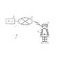
図1は、動作模倣支援システム1の構成の一例を示す概略図である。図2は、動作模倣支援システム1の機能構成の一例を示すブロック図である。これらの図に示す動作模倣支援システム1は、模倣者が装着するHMD2及び複数のウェアラブル端末3と、HMD2の動作を支援するサーバ4を備える。HMD2とサーバ4は、無線LANやインターネット等の通信回線5を介して通信可能に接続される。 FIG. 1 is a schematic diagram illustrating an example of the configuration of the operation imitation support system 1. FIG. 2 is a block diagram illustrating an example of a functional configuration of the operation imitation support system 1. The operation imitation support system 1 shown in these drawings includes an
1−2.サーバ4の構成
サーバ4は、CPU等のプロセッサと、HDD等の記憶装置と、HMD2と通信するためのネットワーク通信部を備える。サーバ4の記憶装置は、図2に示す各データベースを記憶する。1-2. Configuration of Server 4 The server 4 includes a processor such as a CPU, a storage device such as an HDD, and a network communication unit for communicating with the
モデル属性DB41は、被模倣者の属性データを格納するデータベースである。図3は、モデル属性DB41に格納されるモデル属性データの一例を示す図である。同図に示すモデル属性データは、被模倣者の識別情報であるモデルIDと、被模倣者の名称であるモデル名と、被模倣者の身長及び体重と、被模倣者の標準関節位置座標と、被模倣者のモデル動作データの識別情報である動作IDにより構成される。ここで、被模倣者の標準関節位置座標とは、3次元の仮想空間の座標であって、標準姿勢(例えば、直立不動の姿勢。以下同じ。)にある被模倣者の各関節(例えば、首、肩、肘、手首、腰、股関節、膝、足首。以下同じ。)の位置を示す座標である。図4は、3次元の仮想空間の一例を示す図である。同図に示す3次元の仮想空間は、被模倣者Pの左右方向をx軸とし、前後方向をy軸とし、高さ方向をz軸とし、被模倣者Pの頭部を原点oとする仮想空間である。このような仮想空間の座標である標準関節位置座標は、例えば、被模倣者がHMD2とウェアラブル端末3を装着して測定する。 The model attribute DB 41 is a database that stores attribute data of the person to be imitated. FIG. 3 is a diagram illustrating an example of model attribute data stored in the
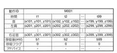
モデル動作DB42は、被模倣者のモデル動作データを格納するデータベースである。図5は、モデル動作DB42に格納されるモデル動作データの一例を示す図である。同図に示すモデル動作データは、所定の動作を行う被模倣者の各関節の位置座標の時系列データ(以下、「関節座標時系列データ」という。)と、所定の動作を行う被模倣者の呼吸波形データと、所定の動作時において呼吸量が変化するタイミング(言い換えると、集中すべきタイミング)を示す呼吸フラグデータと、所定の動作時において模倣者に対してアドバイスを通知すべきタイミングと通知すべきアドバイスの識別情報とを示すアドバイスデータにより構成される。ここで、被模倣者の関節座標時系列データとは、3次元の仮想空間の座標の時系列データであって、所定の動作を行う被模倣者の各関節の動きを示すデータである。3次元の仮想空間の一例は、図4に示す通りである。この関節座標時系列データは、例えば、被模倣者がHMD2とウェアラブル端末3を装着して、所定の動作を行うことで測定される。次に、被模倣者の呼吸波形データは、このデータも、例えば、被模倣者がHMD2とウェアラブル端末3を装着して、所定の動作を行うことで測定される。そして、モデル動作DB42に格納される。次に、呼吸フラグデータは、呼吸波形データが示す波形において接線の傾きの絶対値が所定の閾値以上となるタイミングを示すデータである。言い換えると、同波形について2階微分した値が所定の閾値以上となるタイミングを示すデータである。図6は、呼吸波形データの一例を示す図である。同図に示す波形では、時間「t1」が、集中すべきタイミングとして特定される。特定されたタイミングは、変数「1」と対応付けられ、それ以外のタイミングは変数「0」と対応付けられる。この呼吸フラグデータは、呼吸波形データに基づいてサーバ4において生成される。最後に、アドバイスデータは、被模倣者により生成される。アドバイスの内容は、動作時の注意事項である。 The model operation DB 42 is a database that stores model operation data of the person to be imitated. FIG. 5 is a diagram illustrating an example of model motion data stored in the
ユーザ属性DB43は、模倣者の属性データを格納するデータベースである。図7は、このユーザ属性DB43に格納されるユーザ属性データの一例を示す図である。同図に示すユーザ属性データは、模倣者の識別情報であるユーザIDと、模倣者の名称であるユーザ名と、模倣者の身長及び体重と、模倣者の標準関節位置座標と、模倣者のユーザ動作データの識別情報である動作IDにより構成される。ここで、模倣者の標準関節位置座標とは、3次元の仮想空間の座標であって、標準姿勢にある模倣者の各関節の位置を示す座標である。3次元の仮想空間の一例は、図4に示す通りである。模倣者の標準関節位置座標は、例えば、模倣者がHMD2とウェアラブル端末3を装着して測定する。 The user attribute DB 43 is a database that stores imitator attribute data. FIG. 7 is a diagram illustrating an example of user attribute data stored in the
ユーザ動作DB44は、模倣者の動作データを格納するデータベースである。図8は、このユーザ動作DB44に格納されるユーザ動作データの一例を示す図である。同図に示すユーザ動作データは、被模倣者の所定の動作を模倣する模倣者の関節座標時系列データと、被模倣者の関節座標時系列データと模倣者の関節座標時系列データの間の座標距離の時系列データ(以下、「動作ズレデータ」という。)と、被模倣者の所定の動作を模倣する模倣者の呼吸波形データにより構成される。ここで、模倣者の関節座標時系列データとは、3次元の仮想空間の座標の時系列データであって、被模倣者の所定の動作を模倣する模倣者の各関節の動きを示すデータである。3次元の仮想空間の一例は、図4に示す通りである。この関節座標時系列データは、模倣者がHMD2とウェアラブル端末3を装着して、所定の動作を模倣することで測定される。次に、動作ズレデータは、各関節について、被模倣者と模倣者の対応する関節位置座標間の距離を時系列で並べたデータである。例えば、図8に示す距離「d101」は、首についての、被模倣者と模倣者の、時間「t1」に対応する関節位置座標間の距離を示している。この動作ズレデータは、後述するように、HMD2において生成される。最後に、模倣者の呼吸波形データは、このデータも、模倣者がHMD2とウェアラブル端末3を装着して、所定の動作を模倣することで測定される。 The
サーバ4のプロセッサが、記憶装置に記憶されているプログラムを実行すると、図2に示す各機能が実現される。なお、このプログラムは、インターネット等のネットワークや非一時的な記録媒体を介して頒布可能なプログラムである。 When the processor of the server 4 executes a program stored in the storage device, each function shown in FIG. 2 is realized. This program can be distributed via a network such as the Internet or a non-temporary recording medium.
モデル属性データ抽出部45は、HMD2を装着する模倣者により選択されたモデルIDを検索キーとして、モデル属性DB41から被模倣者の標準関節位置座標を抽出する。 The model attribute
モデル動作データ抽出部46は、HMD2を装着する模倣者により選択された動作IDを検索キーとして、モデル動作DB42からモデル動作データを抽出する。 The model motion
ユーザ属性データ抽出部47は、HMD2から送信されるユーザIDを検索キーとして、ユーザ属性DB43から模倣者の標準関節位置座標を抽出する。 The user attribute
キャリブレーション部48は、モデル属性データ抽出部45により抽出される被模倣者の標準関節位置座標と、ユーザ属性データ抽出部47により抽出される模倣者の標準関節位置座標の比較結果に基づいて、モデル動作データ抽出部46により抽出されたモデル動作データ(具体的には、関節座標時系列データ)を、当該データにより表される動作が模倣者の身体のサイズに応じたものとなるように補正する。言い換えると、抽出されたモデル動作データを、被模倣者が模倣者と同じ体型を有すると仮定した場合に、当該被模倣者が所定の動作を行ったときに測定されるであろうデータとなるように補正する。具体的には、キャリブレーション部48は、関節座標時系列データが示す各関節の位置座標を、隣接する関節の位置座標間の距離が、被模倣者に対する模倣者の同関節の標準位置座標間の距離の比率を乗じた値となるように補正する。例えば、首と右肩の位置座標を補正する場合には、まず、被模倣者の首と右肩の標準位置座標間の距離を第1距離として算出し、模倣者の首と右肩の標準位置座標間の距離を第2距離として算出する。そして、関節座標時系列データが示す首と右肩の位置座標を、これらの位置座標間の距離が、当該距離に第1距離に対する第2距離の比率を乗じた値となるように補正する。キャリブレーション部48により補正されたモデル動作データ(以下、「補正動作データ」という。)は、HMD2に送信される。 The
スコア判定部49は、HMD2から送信されるユーザ動作データをユーザ動作DB44に格納する。また、ユーザ動作DB44に格納したユーザ動作データ(具体的には、動作ズレデータ)に基づいて、模倣者の動作のスコアを算出する。スコアの算出方法としては、例えば、所定の値から、動作ズレデータが示す距離の総計を減算する方法がある。この方法の場合、模倣者の動作が被模倣者の動作と乖離しているほどスコアの値が小さくなる。このように算出されたスコアは、HMD2に通知される。 The
1−3.HMD2の構成
HMD2は、CPU等のプロセッサと、フラッシュメモリ等のメモリと、ユーザの両眼の前方を覆うように配置される光学透過型のディスプレイと、タッチパネル等の入力装置と、モーションセンサと、呼吸音センサ(具体的には、マイクロフォン)と、スピーカと、サーバ4と通信するためのネットワーク通信部と、ウェアラブル端末3と通信するための近距離無線通信部を備える。HMD2のプロセッサが、メモリに記憶されているプログラムを実行すると、図2に示す各機能が実現される。なお、このプログラムは、インターネット等のネットワークや非一時的な記録媒体を介して頒布可能なプログラムである。1-3. Configuration of
重畳映像生成部21は、サーバ4から提供される補正動作データ(具体的には、関節座標時系列データ)を取得し、模倣者により動画の再生が指示されると、取得した関節座標時系列データにより表される動作を行う人物(例えば、棒人間や、ポリゴンの人物モデル)の動画を、ディスプレイにおいて現実空間の景色に重ねて表示させる。より具体的には、取得した関節座標時系列データにより表される動作を3次元の仮想空間内で行う人物の動画のうち、当該仮想空間に設定される仮想カメラにより撮影される部分をディスプレイに表示させる。図9は、3次元の仮想空間の一例を示す図である。同図に示す3次元の仮想空間は、図4に示す仮想空間と同様に直交座標系により定義され、仮想カメラCの撮影地点を原点oとする仮想空間である。この仮想空間は、仮想カメラCの撮影地点を原点oとするため、仮想カメラCの仮想空間内の位置は、図4に示す被模倣者Pの頭部と重なる。すなわち、仮想カメラCの仮想空間内の高さと水平方向の位置は被模倣者Pの頭部と同一又は略同一となる。そのため、重畳映像生成部21により表示される映像は、被模倣者Pの頭部位置から見た映像(すなわち、被模倣者Pの本人視点の映像)となる。この仮想空間に設定される仮想カメラCの撮影方向は、モーションセンサにより検出される向きに応じて変化する。すなわち、HMD2の向きに応じて変化する。したがって、例えば、HMD2を装着する模倣者が右方向を向くと、仮想空間においてx軸の正方向を向いた仮想カメラCにより撮影された動画がディスプレイに表示され、同模倣者が左方向を向くと、仮想空間においてx軸の負方向を向いた仮想カメラCにより撮影された動画がディスプレイに表示される。 The superimposed
音声出力制御部22は、サーバ4から提供される補正動作データ(具体的には、呼吸フラグデータとアドバイスデータ)を取得し、重畳映像生成部21により動画の再生が開始されると、取得した呼吸フラグデータとアドバイスデータに基づいてスピーカから音声メッセージを出力させる。具体的には、取得した呼吸フラグデータに基づいて、集中タイミングが到来する直前に、当該タイミングが到来することを通知する音声メッセージをスピーカから出力させる。出力される音声メッセージは、模倣者に集中を促すメッセージとなっており、当該メッセージの出力が完了するタイミングで集中タイミングが到来するように出力される。また、音声出力制御部22は、取得したアドバイスデータに基づいて、アドバイス通知タイミングが到来する直前に、アドバイスを通知する音声メッセージをスピーカから出力させる。アドバイスを通知する音声メッセージは、当該メッセージの出力が完了するタイミングでアドバイス通知タイミングが到来するように出力される。 The audio
動作ズレ判定部23は、重畳映像生成部21により動画の再生が開始されると、各ウェアラブル端末3に対して測定開始指示を送信する。そして、各ウェアラブル端末3から順次送信される関節位置座標を時系列で動作テーブル24に記録する。すなわち、模倣者の関節座標時系列データを生成する。同時に、動作ズレ判定部23は、ウェアラブル端末3から関節位置座標を受信すると、被模倣者の関節座標時系列データにおいて、当該受信時のタイミングと、当該端末が装着されている関節とに対応付けられている位置座標を特定し、特定した位置座標と、受信した関節位置座標との距離を算出して、当該タイミングと対応付けて動作テーブル24に記録する。すなわち、動作ズレデータを生成する。例えば、首に装着されたウェアラブル端末3から、動画の再生後「t1」のタイミングで関節位置座標を受信した場合には、タイミング「t1」と関節「首」とに対応付けられている被模倣者の位置座標を特定し、特定した位置座標と、受信した関節位置座標との距離を算出して、タイミング「t1」と対応付けて動作テーブル24に記録する。さらに、動作ズレ判定部23は、算出した位置座標間の距離が所定の閾値以上である場合には、処理対象となった位置座標を送信してきたウェアラブル端末3に対して振動発生指示を送信する。その際、算出した距離と閾値との差分に比例する振動の強さ又は長さを指定するようにしてもよい。なお、振動を発生させるか否かを決定する所定の閾値は、模倣者により任意に設定されてよい。動作ズレ判定部23は、重畳映像生成部21による動画の再生が終了されると、各ウェアラブル端末3に対して測定終了指示を送信する。 The operation
呼吸波形記録部25は、重畳映像生成部21により動画の再生が開始されると、動画の再生が終了するまでの間、呼吸音センサにより順次出力される測定値を時系列で動作テーブル24に記録する。すなわち、模倣者の呼吸波形データを生成する。 When the superimposed
スコア画像生成部26は、重畳映像生成部21による動画の再生が終了すると、動作テーブル24に格納されている関節座標時系列データと動作ズレデータと呼吸波形データを、模倣者のユーザIDと対応付けて、ユーザ動作データとしてサーバ4に送信する。このユーザ動作データに対する応答としてサーバ4からスコアを受信すると、受信したスコアを通知するスコア画面をディスプレイに表示させる。 When the reproduction of the moving image by the superimposed
1−4.ウェアラブル端末3の構成
ウェアラブル端末3は、本体部と、本体部が取り付けられるバンド部を備える。本体部は、CPU等のプロセッサと、フラッシュメモリ等のメモリと、モーションセンサと、振動装置と、HMD2と通信するための近距離無線通信部を備える。バンド部は、模倣者の関節に巻きつけられて、ウェアラブル端末3を当該関節に固定する。1-4. Configuration of
このウェアラブル端末3は、HMD2から測定開始指示を受信すると、測定終了指示を受信するまでの間、モーションセンサにより測定された位置座標をHMD2に対して定期的に送信する。その際、端末IDも送信し、HMD2はこの端末IDに基づいて、どの関節に装着されたウェアラブル端末3から送信された位置座標かを判別する。送信される位置座標のセンサ座標系から図9に示す座標系への変換は、ウェアラブル端末3で行われてもよいし、HMD2で行われてもよい。また、ウェアラブル端末3は、HMD2から振動発生指示を受信すると、振動装置を所定の期間、振動させることで、模倣者に対して力覚を提示する。 When receiving the measurement start instruction from the
1−5.動作模倣支援システム1の動作
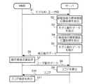
図10は、動作模倣支援システム1により実行される処理の一例を示すシーケンスチャートである。
HMD2は、入力装置を用いて模倣者によりモデルIDと動作IDが選択されると、選択されたモデルIDを、模倣者のユーザIDとともにサーバ4に送信する(S1)。1-5. Operation of Operation Imitation Support System 1 FIG. 10 is a sequence chart showing an example of processing executed by the operation imitation support system 1.
When the model ID and the action ID are selected by the imitator using the input device, the
サーバ4のモデル属性データ抽出部45は、模倣者により選択されたモデルIDを検索キーとして、モデル属性DB41から被模倣者の標準関節位置座標を抽出する(S2)。サーバ4のモデル動作データ抽出部46は、模倣者により選択された動作IDを検索キーとして、モデル動作DB42からモデル動作データを抽出する(S3)。サーバ4のユーザ属性データ抽出部47は、HMD2から送信されるユーザIDを検索キーとして、ユーザ属性DB43から模倣者の標準関節位置座標を抽出する(S4)。サーバ4のキャリブレーション部48は、ステップS2で抽出された被模倣者の標準関節位置座標と、ステップS4で抽出された模倣者の標準関節位置座標の比較結果に基づいて、ステップS3で抽出されたモデル動作データ(具体的には、関節座標時系列データ)を補正する(S5)。具体的な補正方法については上述した通りである。補正後、キャリブレーション部48は、補正動作データをHMD2に対して送信する(S6)。 The model attribute
HMD2は、サーバ4から補正動作データを受信し、入力装置を用いて模倣者により動画の再生が指示されると、動作模倣支援処理を実行する(S7)。
具体的には、重畳映像生成部21は、取得した関節座標時系列データにより表される動作を行う人物の動画を、ディスプレイにおいて現実空間の景色に重ねて表示させる。より具体的には、取得した関節座標時系列データにより表される動作を3次元の仮想空間内で行う人物の動画のうち、当該仮想空間に設定される仮想カメラにより撮影される部分をディスプレイに表示させる。仮想カメラの撮影方向は、モーションセンサにより検出される向きに応じて変化する。The
Specifically, the superimposed
また、音声出力制御部22は、取得した呼吸フラグデータとアドバイスデータに基づいてスピーカから音声メッセージを出力させる。具体的には、取得した呼吸フラグデータに基づいて、集中タイミングが到来する直前に、当該タイミングが到来することを通知する音声メッセージをスピーカから出力させる。また、取得したアドバイスデータに基づいて、アドバイス通知タイミングが到来する直前に、アドバイスを通知する音声メッセージをスピーカから出力させる。 Moreover, the audio | voice
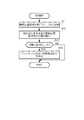
また、動作ズレ判定部23は、各ウェアラブル端末3に対して測定開始指示を送信する。そして、ウェアラブル端末3から関節位置座標を受信すると、リアルタイムで動作ズレ判定処理を実行する。図11は、動作ズレ判定処理の一例を示すフローチャートである。 Further, the operation
動作ズレ判定部23は、ウェアラブル端末3から受信した関節位置座標を、当該受信時のタイミングと、当該端末が装着されている関節とに対応付けて、動作テーブル24に記録する(S71)。例えば、首に装着されたウェアラブル端末3から、動画の再生後「t1」のタイミングで関節位置座標を受信した場合には、タイミング「t1」と関節「首」とに対応付けて、受信した関節位置座標を動作テーブル24に記録する。 The motion
記録後、動作ズレ判定部23は、被模倣者の関節座標時系列データにおいて、上記受信時のタイミングと、上記端末が装着されている関節とに対応付けられている位置座標を特定し、特定した位置座標と、記録した関節位置座標との距離を算出して、当該タイミングと対応付けて動作テーブル24に記録する(S72)。例えば、首に装着されたウェアラブル端末3から、動画の再生後「t1」のタイミングで関節位置座標を受信した場合には、タイミング「t1」と関節「首」とに対応付けられている被模倣者の位置座標を特定し、特定した位置座標と、受信した関節位置座標との距離を算出して、タイミング「t1」と対応付けて動作テーブル24に記録する。 After the recording, the motion
記録後、動作ズレ判定部23は、算出した位置座標間の距離が所定の閾値以上であるか否かを判定する(S73)。この判定の結果、算出した距離が所定の閾値以上でない場合には(S73のNO)、動作ズレ判定部23は本処理を終了する。一方、この判定の結果、算出した距離が所定の閾値以上である場合には(S73のYES)、動作ズレ判定部23は、ウェアラブル端末3に対して振動発生指示を送信する(S74)。この振動発生指示を受信したウェアラブル端末3は、振動装置を所定の期間、振動させる。
以上が、動作ズレ判定処理についての説明である。After recording, the motion
The above is the description of the operation deviation determination process.
また、動作模倣支援処理では、呼吸波形記録部25は、呼吸音センサにより順次出力される測定値を時系列で動作テーブル24に記録する。 In the motion imitation support process, the respiration
動作支援処理が終了すると、HMD2のスコア画像生成部26は、動作テーブル24に格納されている関節座標時系列データと動作ズレデータと呼吸波形データを、模倣者のユーザIDと対応付けて、ユーザ動作データとしてサーバ4に送信する(図10のS8)。 When the motion support process is completed, the score
サーバ4のスコア判定部49は、HMD2から送信されたユーザ動作データをユーザ動作DB44に格納する。また、ユーザ動作DB44に格納したユーザ動作データ(具体的には、動作ズレデータ)に基づいて、模倣者の動作のスコアを算出する(S9)。スコアを算出後、算出したスコアをHMD2に対して通知する(S10)。 The
HMD2のスコア画像生成部26は、サーバ4から受信したスコアを通知するスコア画面をディスプレイに表示させる(S11)。
以上が、動作模倣支援システム1の処理についての説明である。The score
The above is the description of the processing of the operation imitation support system 1.
以上説明した動作模倣支援システム1では、被模倣者のモデル動作データが模倣者の体型に合わせてキャリブレーションされ、かつ、被模倣者と模倣者の頭部の高さ及び目線の向きが等しくなるようにモデル動作が表示される。そのため、模倣者にとって、自身の動作と被模倣者の動作の一致度の把握が容易になる。さらに本システムでは、被模倣者の頭部位置から見たモデル動作が光学透過型のディスプレイに表示される。そのため、模倣者は、モデル動作を自身の身体に重ねて見ることで、モデル動作と自身の動作の一致度をより容易に把握することができる。また、本システムでは、動作中に集中すべきタイミングが模倣者に通知されるようになっている。そのため、模倣者は、被模倣者の精神面も模倣することができる。また、本システムでは、模倣者と被模倣者の関節位置のズレが所定の閾値以上となると、当該関節に装着されたウェアラブル端末3が振動するようになっている。そのため、模倣者は、自身の足首等の見えづらい位置であっても、被模倣者との一致度を把握することができる。 In the motion imitation support system 1 described above, the model motion data of the person to be imitated is calibrated according to the body shape of the person imitated, and the height of the head and the direction of the eyes of the person to be imitated are equal. Model behavior is displayed as follows. Therefore, it becomes easy for the imitator to grasp the degree of coincidence between the user's action and the person to be imitated. Furthermore, in this system, the model operation viewed from the head position of the person to be imitated is displayed on the optical transmission type display. Therefore, the imitator can more easily grasp the degree of coincidence between the model action and the own action by seeing the model action on the body. In this system, the imitator is notified of the timing to concentrate during operation. Therefore, the imitator can also imitate the mental aspect of the person to be imitated. Further, in this system, when the displacement of the joint position between the imitator and the person to be imitated exceeds a predetermined threshold, the
2.変形例
上記の実施形態は下記のように変形してもよい。なお、以下に記載する2以上の変形例は互いに組み合わせてもよい。2. Modifications The above embodiment may be modified as follows. Note that two or more modifications described below may be combined with each other.
2−1.変形例1
動作模倣支援システム1は、野球やゴルフ等のスポーツの動作の模倣を支援することを主に想定しているが、演技や工芸等の技芸や、料理や工事等の作業の動作の模倣支援に使用されてもよい。2-1. Modification 1
The motion imitation support system 1 is mainly assumed to support imitation of the motion of sports such as baseball and golf. However, the motion imitation support system 1 is used for imitation support of skills such as performances and crafts, and operations such as cooking and construction. May be used.
2−2.変形例2
サーバ4のキャリブレーション部48は、上記の実施形態とは異なる方法でモデル動作データを補正してもよい。例えば、被模倣者に対する模倣者の関節間の距離の比率に代えて、被模倣者に対する模倣者の身長の比率に基づいてモデル動作データを補正してもよい。その場合、モデル属性データ抽出部45は、モデル属性DB41から被模倣者の身長を抽出し、ユーザ属性データ抽出部47は、ユーザ属性DB43から模倣者の身長を抽出する。そして、キャリブレーション部48は、関節座標時系列データが示す各関節の位置座標を、隣接する関節の位置座標間の距離が、被模倣者に対する模倣者の身長の比率を乗じた値となるように補正する。2-2.
The
また別の例として、被模倣者に対する模倣者の身体重心の高さの比率に基づいてモデル動作データを補正してもよい。身体重心の高さは、例えば、身長に「0.56」を乗じて算出する。この場合、キャリブレーション部48は、関節座標時系列データが示す各関節の位置座標を、隣接する関節の位置座標間の距離が、被模倣者に対する模倣者の重心の高さの比率を乗じた値となるように補正する。 As another example, the model motion data may be corrected based on the ratio of the height of the body center of gravity of the mimic to the person to be imitated. The height of the body center of gravity is calculated by, for example, multiplying the height by “0.56”. In this case, the
2−3.変形例3
サーバ4に記憶されるモデル動作データは、呼吸波形データに代えて、心拍間隔の波形データを含んでもよい。その場合、モデル動作データは、呼吸フラグデータに代えて、所定の動作時において心拍間隔が変化するタイミング(言い換えると、集中すべきタイミング)を示す心拍間隔フラグデータを含むことになる。心拍間隔フラグデータは、心拍間隔の波形データが示す波形において接線の傾きの絶対値が所定の閾値以上となるタイミングを示すデータである。言い換えると、同波形について2階微分した値が所定の閾値以上となるタイミングを示すデータである。この心拍間隔フラグデータがHMD2に提供された場合、HMD2の音声出力制御部22は、取得した心拍間隔フラグデータに基づいて、集中タイミングが到来する直前に、当該タイミングが到来することを通知する音声メッセージをスピーカから出力させる。2-3.
The model movement data stored in the server 4 may include heartbeat interval waveform data instead of the respiration waveform data. In this case, the model motion data includes heart rate interval flag data indicating the timing at which the heart rate interval changes (in other words, the timing to concentrate) in place of the breathing flag data. The heartbeat interval flag data is data indicating the timing at which the absolute value of the slope of the tangent line is equal to or greater than a predetermined threshold in the waveform indicated by the heartbeat interval waveform data. In other words, it is data indicating the timing at which the second-order differentiated value of the waveform is equal to or greater than a predetermined threshold. When this heartbeat interval flag data is provided to the HMD2, the audio
また別の例として、モデル動作データは、呼吸波形データに代えて、脳波波形データを含んでもよい。その場合、モデル動作データは、呼吸フラグデータに代えて、所定の動作時において脳波が急激に変化するタイミング(言い換えると、集中すべきタイミング)を示す脳波フラグデータを含むことになる。脳波フラグデータは、脳波波形データが示す波形において接線の傾きの絶対値が所定の閾値以上となるタイミングを示すデータである。言い換えると、同波形について2階微分した値が所定の閾値以上となるタイミングを示すデータである。この脳波フラグデータがHMD2に提供された場合、HMD2の音声出力制御部22は、取得した脳波フラグデータに基づいて、集中タイミングが到来する直前に、当該タイミングが到来することを通知する音声メッセージをスピーカから出力させる。 As another example, the model motion data may include electroencephalogram waveform data instead of the respiration waveform data. In this case, the model motion data includes brain wave flag data indicating the timing at which the brain wave changes rapidly during a predetermined motion (in other words, the timing to concentrate) instead of the breath flag data. The electroencephalogram flag data is data indicating the timing at which the absolute value of the tangent slope is equal to or greater than a predetermined threshold in the waveform indicated by the electroencephalogram waveform data. In other words, it is data indicating the timing at which the second-order differentiated value of the waveform is equal to or greater than a predetermined threshold. When this electroencephalogram flag data is provided to the
2−4.変形例4
サーバ4が実行する処理の一部又は全部をHMD2側で実行するようにしてもよい。具体的には、モデル属性データ抽出部45、モデル動作データ抽出部46、ユーザ属性データ抽出部47、キャリブレーション部48及びスコア判定部49が実行する処理の一部又は全部をHMD2側で実行するようにしてもよい。2-4. Modification 4
Part or all of the processing executed by the server 4 may be executed on the
2−5.変形例5
HMD2が備えるディスプレイは、ビデオ透過型のディスプレイであってもよい。すなわち、被模倣者のモデル動作を、HMD2のカメラにより撮影された景色の画像に重ねて表示してもよい。2-5. Modification 5
The display provided in the
2−6.変形例6
HMD2の重畳映像生成部21は、上記の被模倣者の本人視点の映像を、模倣者の指示に応じて、第三者視点の映像に切り替えてもよい。ここで、第三者視点の映像とは、被模倣者のモデル動作を離れた位置から見た映像である。第三者視点の映像を表示する際には、仮想空間に設定される仮想カメラC(図9参照)の位置が、原点oから水平方向に移動させられる。2-6. Modification 6
The superimposed
2−7.変形例7
HMD2の動作ズレ判定部23は、模倣者と被模倣者の関節位置のズレが所定の閾値以上となった場合に、振動以外の方法で模倣者にその旨を通知するようにしてもよい。例えば、ズレが検出された関節を通知するメッセージをスピーカから出力させたり、ディスプレイに表示させたりしてよい。2-7. Modification 7
The movement
2−8.変形例8
HMD2の動作ズレ判定部23は、模倣者と被模倣者の間で関節位置のズレを判定するのに加えて、足裏の重心位置のズレを判定するようにしてもよい。その場合、サーバ4からHMD2に提供されるモデル動作データには、所定の動作を行う被模倣者の足裏の重心位置の時系列データ(以下、「重心時系列データ」という。)を含める。また、模倣者の両足の靴には、足裏の重心位置を測定するために、複数の圧力センサ、振動装置及び近距離無線通信装置を備える中敷が挿入される。そして、動作ズレ判定部23は、中敷から順次送信される圧力値から足裏の重心位置を算出して、時系列で動作テーブル24に記録する。足裏の重心位置の算出方法については、例えば特開2012−011136号公報を参照のこと。同時に、動作ズレ判定部23は、足裏の重心位置を算出すると、取得した重心時系列データにおいて、当該算出時のタイミングに対応付けられている重心位置を特定し、特定した重心位置と、算出した重心位置との距離を算出して、当該タイミングと対応付けて動作テーブル24に記録する。さらに、動作ズレ判定部23は、算出した重心位置間の距離が所定の閾値以上である場合には、中敷に対して振動発生指示を送信する。振動発生指示を受信した中敷は、振動装置を所定の期間、振動させる。その結果、模倣者は、自身の足裏の重心位置が被模倣者とズレていることを知ることができる。2-8. Modification 8
The motion
2−9.変形例9
HMD2の動作ズレ判定部23が実行する処理をサーバ4側で実行するようにしてもよい。その場合、ウェアラブル端末3は、サーバ4と直接データのやり取りを行ってもよいし、HMD2を介してサーバ4とデータのやり取りを行ってもよい。2-9. Modification 9
The process executed by the operation
2−10.変形例10
HMD2は、上記の実施形態とは異なる方法で呼吸波形データを生成してもよい。例えば、HMD2に呼吸音センサを備えさせる代わりに、模倣者の身体に圧電フィルム等の周知の呼吸センサを装着させ、呼吸波形記録部25は、この呼吸センサから順次出力される測定値を時系列で動作テーブル24に記録するようにしてもよい。2-10. Modification 10
The
2−11.変形例11
ウェアラブル端末3は、模倣者の関節以外の部位(例えば、頭部やつま先)に装着されてもよい。その場合、サーバ4からHMD2に提供される関節座標時系列データには、ウェアラブル端末3が装着される、関節以外の部位の時系列データが含まれてよい。2-11. Modification 11
2−12.変形例12
ウェアラブル端末3は、振動装置として、方向性のある外力が加わっているかのような感覚を模倣者に提示する擬似力覚提示装置を備えてもよい。この擬似力覚提示装置については、雨宮智浩他,“指でつまむと引っ張られる感覚を生み出す装置「ぶるなび3」”,NTT技術ジャーナル,2014年9月,Vol. 26,No. 9,pp. 23-26.を参照のこと。ウェアラブル端末3がこの擬似力覚提示装置を備える場合には、HMD2の動作ズレ判定部23は、関節位置を修正すべき方向に外力が加わっているような感覚を模倣者に提示するように当該装置を制御するようにしてもよい。例えば、模倣者の右手首の位置が被模倣者の右手首の位置よりも低かった場合には、上方向に外力が加わっているような感覚を模倣者に提示するように、模倣者の右手首に装着されているウェアラブル端末3を制御するようにしてもよい。2-12. Modification 12
The
1…動作模倣支援システム、2…HMD、3…ウェアラブル端末、4…サーバ、5…通信回線、21…重畳映像生成部、22…音声出力制御部、23…動作ズレ判定部、24…動作テーブル、25…呼吸波形記録部、26…スコア画像生成部、41…モデル属性DB、42…モデル動作DB、43…ユーザ属性DB、44…ユーザ動作DB、45…モデル属性データ抽出部、46…モデル動作データ抽出部、47…ユーザ属性データ抽出部、48…キャリブレーション部、49…スコア判定部DESCRIPTION OF SYMBOLS 1 ... Operation imitation support system, 2 ... HMD, 3 ... Wearable terminal, 4 ... Server, 5 ... Communication line, 21 ... Superimposed video production | generation part, 22 ... Audio | voice output control part, 23 ... Operation deviation determination part, 24 ... Operation table 25 ... Respiratory waveform recording unit, 26 ... Score image generation unit, 41 ... Model attribute DB, 42 ... Model action DB, 43 ... User attribute DB, 44 ... User action DB, 45 ... Model attribute data extraction part, 46 ... Model Operation data extraction unit, 47... User attribute data extraction unit, 48... Calibration unit, 49.
Claims (6)
Translated fromJapanese前記被模倣者の身体のサイズを特定する第1特定部と、
模倣者の身体のサイズを特定する第2特定部と、
前記被模倣者の身体のサイズと前記模倣者の身体のサイズの差異に基づいて、前記第1時系列データにより表される動作が前記模倣者の身体のサイズに応じたものとなるように、前記第1時系列データを補正する補正部と、
前記補正された第1時系列データにより表される動作を前記仮想空間内において行う人物の画像のうち、前記仮想空間に設定される仮想カメラにより撮影される部分を、前記模倣者が装着する頭部装着型表示装置において現実空間の景色に重ねて表示させる表示制御部と
を備え、
前記仮想カメラの撮影方向は、前記頭部装着型表示装置の向きに応じて変化し、
前記仮想空間における前記人物の頭部の高さは、前記仮想カメラの高さと略同一である
ことを特徴とする動作模倣支援システム。A first acquisition unit that acquires first time-series data of coordinates in a three-dimensional virtual space representing the behavior of the person imitated;
A first specifying unit for specifying the body size of the person to be imitated;
A second specifying unit for specifying the size of the body of the imitator;
Based on the difference between the size of the imitator's body and the size of the imitator's body, the action represented by the first time series data is in accordance with the size of the imitator's body, A correction unit for correcting the first time-series data;
A head on which the imitator wears a portion of an image of a person who performs an operation represented by the corrected first time-series data in the virtual space, taken by a virtual camera set in the virtual space. A display control unit for displaying on a real space in a part-mounted display device,
The shooting direction of the virtual camera changes according to the direction of the head-mounted display device,
The height of the head of the person in the virtual space is substantially the same as the height of the virtual camera.
前記補正された第1時系列データを構成する第1座標と、前記第2時系列データを構成し、前記第1座標に対応する第2座標の差分を算出する算出部と、
前記算出された差分が所定の閾値よりも大きい場合に、前記模倣者に対して所定の通知を行う第1通知部と
をさらに備えることを特徴とする請求項1又は2に記載の動作模倣支援システム。A second acquisition unit that acquires second time-series data of the coordinates of the virtual space, representing a movement of the body of the mimic that imitates the movement represented by the corrected first time-series data;
A first coordinate that constitutes the corrected first time-series data, a calculation unit that constitutes the second time-series data and calculates a difference between the second coordinates corresponding to the first coordinate;
The motion imitation support according to claim 1, further comprising: a first notification unit that performs a predetermined notification to the imitator when the calculated difference is greater than a predetermined threshold. system.
前記呼吸又は心拍間隔の波形において接線の傾きの絶対値が所定の閾値以上となるタイミングを特定する第3特定部と、
前記補正された第1時系列データにより表される動作を模倣する前記模倣者に対して、前記特定されたタイミングの到来を通知する第2通知部と
をさらに備えることを特徴とする請求項1乃至4のいずれか1項に記載の動作模倣支援システム。A third acquisition unit that acquires a waveform of breathing or a heartbeat interval when the imitator performs an operation represented by the first time-series data;
A third specifying unit for specifying a timing at which an absolute value of a tangent slope is equal to or greater than a predetermined threshold in the waveform of the breathing or heartbeat interval;
The apparatus further comprises: a second notification unit that notifies the imitator imitating the operation represented by the corrected first time-series data of arrival of the specified timing. 5. The operation imitation support system according to any one of items 1 to 4.
前記被模倣者の身体のサイズを特定する第1特定部と、
模倣者の身体のサイズを特定する第2特定部と、
前記被模倣者の身体のサイズと前記模倣者の身体のサイズの差異に基づいて、前記第1時系列データにより表される動作が前記模倣者の身体のサイズに応じたものとなるように、前記第1時系列データを補正する補正部と、
前記補正された第1時系列データを、前記模倣者が装着する頭部装着型表示装置に対して送信する送信部と
を備え、
前記頭部装着型表示装置は、前記補正された第1時系列データにより表される動作を前記仮想空間内において行う人物の画像のうち、前記仮想空間に設定される仮想カメラにより撮影される部分を、現実空間の景色に重ねて表示させ、
前記仮想カメラの撮影方向は、前記頭部装着型表示装置の向きに応じて変化し、
前記仮想空間における前記人物の頭部の高さは、前記仮想カメラの高さと略同一である
ことを特徴とする動作模倣支援装置。A first acquisition unit that acquires first time-series data of coordinates in a three-dimensional virtual space representing the behavior of the person imitated;
A first specifying unit for specifying the body size of the person to be imitated;
A second specifying unit for specifying the size of the body of the imitator;
Based on the difference between the size of the imitator's body and the size of the imitator's body, the action represented by the first time series data is in accordance with the size of the imitator's body, A correction unit for correcting the first time-series data;
A transmitter that transmits the corrected first time-series data to a head-mounted display device worn by the imitator,
The head-mounted display device is a portion photographed by a virtual camera set in the virtual space, among images of a person who performs an operation represented by the corrected first time-series data in the virtual space. Is displayed over the real space scenery,
The shooting direction of the virtual camera changes according to the direction of the head-mounted display device,
The motion imitation support apparatus, wherein the height of the head of the person in the virtual space is substantially the same as the height of the virtual camera.
Priority Applications (1)
| Application Number | Priority Date | Filing Date | Title |
|---|---|---|---|
| JP2018057885AJP2019166238A (en) | 2018-03-26 | 2018-03-26 | Operation simulation support system and device |
Applications Claiming Priority (1)
| Application Number | Priority Date | Filing Date | Title |
|---|---|---|---|
| JP2018057885AJP2019166238A (en) | 2018-03-26 | 2018-03-26 | Operation simulation support system and device |
Publications (1)
| Publication Number | Publication Date |
|---|---|
| JP2019166238Atrue JP2019166238A (en) | 2019-10-03 |
Family
ID=68105703
Family Applications (1)
| Application Number | Title | Priority Date | Filing Date |
|---|---|---|---|
| JP2018057885APendingJP2019166238A (en) | 2018-03-26 | 2018-03-26 | Operation simulation support system and device |
Country Status (1)
| Country | Link |
|---|---|
| JP (1) | JP2019166238A (en) |
Cited By (1)
| Publication number | Priority date | Publication date | Assignee | Title |
|---|---|---|---|---|
| JP2023530560A (en)* | 2020-04-22 | 2023-07-19 | ウィズイン アンリミテッド,インコーポレイテッド | virtual and augmented reality personalized and customized fitness training activities or games, methods, devices and systems; |
Citations (17)
| Publication number | Priority date | Publication date | Assignee | Title |
|---|---|---|---|---|
| JP2006302122A (en)* | 2005-04-22 | 2006-11-02 | Nippon Telegr & Teleph Corp <Ntt> | Exercise support system, user terminal device thereof, and exercise support program |
| JP2008237495A (en)* | 2007-03-27 | 2008-10-09 | Konami Digital Entertainment:Kk | GAME DEVICE, GAME PROCESSING METHOD, AND PROGRAM |
| JP2008302053A (en)* | 2007-06-08 | 2008-12-18 | Square Enix Holdings Co Ltd | Training system, training device, program recording medium, and training program |
| JP2011152333A (en)* | 2010-01-28 | 2011-08-11 | Nagasakiken Koritsu Daigaku Hojin | Body skill learning support device and body skill learning support method |
| JP2012120579A (en)* | 2010-12-06 | 2012-06-28 | Seiko Epson Corp | Motion analyzer |
| JP2013103010A (en)* | 2011-11-15 | 2013-05-30 | Sony Corp | Image processing device, image processing method, and program |
| JP2013223558A (en)* | 2012-04-20 | 2013-10-31 | Seiko Epson Corp | Device, method and program for supporting exercise |
| JP2015146980A (en)* | 2014-02-07 | 2015-08-20 | セイコーエプソン株式会社 | Exercise support system, exercise support device, and exercise support method |
| JP2015166816A (en)* | 2014-03-04 | 2015-09-24 | 富士通株式会社 | Display device, display control program, and display control method |
| JP2015186531A (en)* | 2014-03-26 | 2015-10-29 | 国立大学法人 東京大学 | Motion information processing apparatus and program |
| JP2016034482A (en)* | 2014-07-31 | 2016-03-17 | セイコーエプソン株式会社 | Exercise analysis device, exercise analysis method, exercise analysis program, and exercise analysis system |
| JP2016131782A (en)* | 2015-01-21 | 2016-07-25 | セイコーエプソン株式会社 | Head wearable display device, detection device, control method for head wearable display device, and computer program |
| JP2016209233A (en)* | 2015-05-07 | 2016-12-15 | セイコーエプソン株式会社 | Biological information processing system, server system, biological information processing apparatus, and biological information processing method |
| JP2017506523A (en)* | 2013-10-24 | 2017-03-09 | ▲華▼▲為▼▲終▼端有限公司 | Image display method and apparatus |
| WO2017115740A1 (en)* | 2015-12-28 | 2017-07-06 | 大和ハウス工業株式会社 | Image display device and image display method |
| JP2017136142A (en)* | 2016-02-02 | 2017-08-10 | セイコーエプソン株式会社 | Information terminal, motion evaluation system, motion evaluation method, motion evaluation program, and recording medium |
| JP2017156267A (en)* | 2016-03-03 | 2017-09-07 | セイコーエプソン株式会社 | Performance monitoring device, performance monitoring method, and performance monitoring program |
- 2018
- 2018-03-26JPJP2018057885Apatent/JP2019166238A/enactivePending
Patent Citations (17)
| Publication number | Priority date | Publication date | Assignee | Title |
|---|---|---|---|---|
| JP2006302122A (en)* | 2005-04-22 | 2006-11-02 | Nippon Telegr & Teleph Corp <Ntt> | Exercise support system, user terminal device thereof, and exercise support program |
| JP2008237495A (en)* | 2007-03-27 | 2008-10-09 | Konami Digital Entertainment:Kk | GAME DEVICE, GAME PROCESSING METHOD, AND PROGRAM |
| JP2008302053A (en)* | 2007-06-08 | 2008-12-18 | Square Enix Holdings Co Ltd | Training system, training device, program recording medium, and training program |
| JP2011152333A (en)* | 2010-01-28 | 2011-08-11 | Nagasakiken Koritsu Daigaku Hojin | Body skill learning support device and body skill learning support method |
| JP2012120579A (en)* | 2010-12-06 | 2012-06-28 | Seiko Epson Corp | Motion analyzer |
| JP2013103010A (en)* | 2011-11-15 | 2013-05-30 | Sony Corp | Image processing device, image processing method, and program |
| JP2013223558A (en)* | 2012-04-20 | 2013-10-31 | Seiko Epson Corp | Device, method and program for supporting exercise |
| JP2017506523A (en)* | 2013-10-24 | 2017-03-09 | ▲華▼▲為▼▲終▼端有限公司 | Image display method and apparatus |
| JP2015146980A (en)* | 2014-02-07 | 2015-08-20 | セイコーエプソン株式会社 | Exercise support system, exercise support device, and exercise support method |
| JP2015166816A (en)* | 2014-03-04 | 2015-09-24 | 富士通株式会社 | Display device, display control program, and display control method |
| JP2015186531A (en)* | 2014-03-26 | 2015-10-29 | 国立大学法人 東京大学 | Motion information processing apparatus and program |
| JP2016034482A (en)* | 2014-07-31 | 2016-03-17 | セイコーエプソン株式会社 | Exercise analysis device, exercise analysis method, exercise analysis program, and exercise analysis system |
| JP2016131782A (en)* | 2015-01-21 | 2016-07-25 | セイコーエプソン株式会社 | Head wearable display device, detection device, control method for head wearable display device, and computer program |
| JP2016209233A (en)* | 2015-05-07 | 2016-12-15 | セイコーエプソン株式会社 | Biological information processing system, server system, biological information processing apparatus, and biological information processing method |
| WO2017115740A1 (en)* | 2015-12-28 | 2017-07-06 | 大和ハウス工業株式会社 | Image display device and image display method |
| JP2017136142A (en)* | 2016-02-02 | 2017-08-10 | セイコーエプソン株式会社 | Information terminal, motion evaluation system, motion evaluation method, motion evaluation program, and recording medium |
| JP2017156267A (en)* | 2016-03-03 | 2017-09-07 | セイコーエプソン株式会社 | Performance monitoring device, performance monitoring method, and performance monitoring program |
Non-Patent Citations (1)
| Title |
|---|
| 雨宮 智浩,伊藤 翔,五味 裕章,高椋 慎也: "指でつまむと引っ張られる感覚を生み出す装置「ぶるなび3」", NTT技術ジャーナル, vol. 第26巻,第9号, JPN6018048648, September 2014 (2014-09-01), JP, pages 23 - 26, ISSN: 0003936210* |
Cited By (1)
| Publication number | Priority date | Publication date | Assignee | Title |
|---|---|---|---|---|
| JP2023530560A (en)* | 2020-04-22 | 2023-07-19 | ウィズイン アンリミテッド,インコーポレイテッド | virtual and augmented reality personalized and customized fitness training activities or games, methods, devices and systems; |
Similar Documents
| Publication | Publication Date | Title |
|---|---|---|
| US11638853B2 (en) | Augmented cognition methods and apparatus for contemporaneous feedback in psychomotor learning | |
| US10755466B2 (en) | Method and apparatus for comparing two motions | |
| US8282481B2 (en) | System and method for cyber training of martial art on network | |
| US20180357472A1 (en) | Systems and methods for creating target motion, capturing motion, analyzing motion, and improving motion | |
| CN1168057C (en) | Method for tracking and displaying the position and orientation of a user in space, method for presenting a virtual environment to a user and system for implementing these methods | |
| JP6332830B2 (en) | Exercise support system, exercise support method, and exercise support program | |
| US20180188284A1 (en) | Systems and methods for real-time data quantification, acquisition, analysis and feedback | |
| JP2017136142A (en) | Information terminal, motion evaluation system, motion evaluation method, motion evaluation program, and recording medium | |
| RU2107328C1 (en) | Method for tracing and displaying of position and orientation of user in three-dimensional space and device which implements said method | |
| US20110270135A1 (en) | Augmented reality for testing and training of human performance | |
| JPH09120464A (en) | Rehabilitation support device | |
| US20220277506A1 (en) | Motion-based online interactive platform | |
| US20230240594A1 (en) | Posture assessment program, posture assessment apparatus, posture assessment method, and posture assessment system | |
| WO2019043928A1 (en) | Practice support program, practice support method and practice support system | |
| JP5761730B2 (en) | Physical skill acquisition support device | |
| JP7741729B2 (en) | Image generation device | |
| JP2006320424A (en) | Action teaching apparatus and method | |
| CN111539245B (en) | CPR (CPR) technology training evaluation method based on virtual environment | |
| JP7160669B2 (en) | Program, Information Processing Apparatus, and Method | |
| CN114253393A (en) | Information processing apparatus, terminal, method, and computer-readable recording medium | |
| WO2019235338A1 (en) | Information processing device, information processing method, and program | |
| RU2106695C1 (en) | Method for representation of virtual space for user and device which implements said method | |
| JP2019166238A (en) | Operation simulation support system and device | |
| EP2409736A1 (en) | Method for operating a training device | |
| JPWO2020026443A1 (en) | Tactile expression vibration control system, tactile expression vibration generator, tactile expression vibration control device, and tactile expression vibration control method |
Legal Events
| Date | Code | Title | Description |
|---|---|---|---|
| A621 | Written request for application examination | Free format text:JAPANESE INTERMEDIATE CODE: A621 Effective date:20180326 | |
| A131 | Notification of reasons for refusal | Free format text:JAPANESE INTERMEDIATE CODE: A131 Effective date:20181211 | |
| A521 | Request for written amendment filed | Free format text:JAPANESE INTERMEDIATE CODE: A523 Effective date:20190206 | |
| A02 | Decision of refusal | Free format text:JAPANESE INTERMEDIATE CODE: A02 Effective date:20190723 |