JP2019161864A - Pulse power transmission device - Google Patents
Pulse power transmission deviceDownload PDFInfo
- Publication number
- JP2019161864A JP2019161864AJP2018045876AJP2018045876AJP2019161864AJP 2019161864 AJP2019161864 AJP 2019161864AJP 2018045876 AJP2018045876 AJP 2018045876AJP 2018045876 AJP2018045876 AJP 2018045876AJP 2019161864 AJP2019161864 AJP 2019161864A
- Authority
- JP
- Japan
- Prior art keywords
- power
- pulse
- waveform
- transmission
- filter
- Prior art date
- Legal status (The legal status is an assumption and is not a legal conclusion. Google has not performed a legal analysis and makes no representation as to the accuracy of the status listed.)
- Abandoned
Links
Images


Classifications
- H—ELECTRICITY
- H02—GENERATION; CONVERSION OR DISTRIBUTION OF ELECTRIC POWER
- H02J—CIRCUIT ARRANGEMENTS OR SYSTEMS FOR SUPPLYING OR DISTRIBUTING ELECTRIC POWER; SYSTEMS FOR STORING ELECTRIC ENERGY
- H02J1/00—Circuit arrangements for DC mains or DC distribution networks
- H02J1/02—Arrangements for reducing harmonics or ripples
- B—PERFORMING OPERATIONS; TRANSPORTING
- B60—VEHICLES IN GENERAL
- B60R—VEHICLES, VEHICLE FITTINGS, OR VEHICLE PARTS, NOT OTHERWISE PROVIDED FOR
- B60R16/00—Electric or fluid circuits specially adapted for vehicles and not otherwise provided for; Arrangement of elements of electric or fluid circuits specially adapted for vehicles and not otherwise provided for
- B60R16/02—Electric or fluid circuits specially adapted for vehicles and not otherwise provided for; Arrangement of elements of electric or fluid circuits specially adapted for vehicles and not otherwise provided for electric constitutive elements
- B60R16/0207—Wire harnesses
- B—PERFORMING OPERATIONS; TRANSPORTING
- B60—VEHICLES IN GENERAL
- B60R—VEHICLES, VEHICLE FITTINGS, OR VEHICLE PARTS, NOT OTHERWISE PROVIDED FOR
- B60R16/00—Electric or fluid circuits specially adapted for vehicles and not otherwise provided for; Arrangement of elements of electric or fluid circuits specially adapted for vehicles and not otherwise provided for
- B60R16/02—Electric or fluid circuits specially adapted for vehicles and not otherwise provided for; Arrangement of elements of electric or fluid circuits specially adapted for vehicles and not otherwise provided for electric constitutive elements
- B60R16/023—Electric or fluid circuits specially adapted for vehicles and not otherwise provided for; Arrangement of elements of electric or fluid circuits specially adapted for vehicles and not otherwise provided for electric constitutive elements for transmission of signals between vehicle parts or subsystems
- B—PERFORMING OPERATIONS; TRANSPORTING
- B60—VEHICLES IN GENERAL
- B60R—VEHICLES, VEHICLE FITTINGS, OR VEHICLE PARTS, NOT OTHERWISE PROVIDED FOR
- B60R16/00—Electric or fluid circuits specially adapted for vehicles and not otherwise provided for; Arrangement of elements of electric or fluid circuits specially adapted for vehicles and not otherwise provided for
- B60R16/02—Electric or fluid circuits specially adapted for vehicles and not otherwise provided for; Arrangement of elements of electric or fluid circuits specially adapted for vehicles and not otherwise provided for electric constitutive elements
- B60R16/03—Electric or fluid circuits specially adapted for vehicles and not otherwise provided for; Arrangement of elements of electric or fluid circuits specially adapted for vehicles and not otherwise provided for electric constitutive elements for supply of electrical power to vehicle subsystems or for
- G—PHYSICS
- G07—CHECKING-DEVICES
- G07C—TIME OR ATTENDANCE REGISTERS; REGISTERING OR INDICATING THE WORKING OF MACHINES; GENERATING RANDOM NUMBERS; VOTING OR LOTTERY APPARATUS; ARRANGEMENTS, SYSTEMS OR APPARATUS FOR CHECKING NOT PROVIDED FOR ELSEWHERE
- G07C9/00—Individual registration on entry or exit
- H—ELECTRICITY
- H01—ELECTRIC ELEMENTS
- H01M—PROCESSES OR MEANS, e.g. BATTERIES, FOR THE DIRECT CONVERSION OF CHEMICAL ENERGY INTO ELECTRICAL ENERGY
- H01M10/00—Secondary cells; Manufacture thereof
- H01M10/42—Methods or arrangements for servicing or maintenance of secondary cells or secondary half-cells
- H01M10/44—Methods for charging or discharging
- H—ELECTRICITY
- H02—GENERATION; CONVERSION OR DISTRIBUTION OF ELECTRIC POWER
- H02J—CIRCUIT ARRANGEMENTS OR SYSTEMS FOR SUPPLYING OR DISTRIBUTING ELECTRIC POWER; SYSTEMS FOR STORING ELECTRIC ENERGY
- H02J1/00—Circuit arrangements for DC mains or DC distribution networks
- H02J1/10—Parallel operation of DC sources
- H02J1/102—Parallel operation of DC sources being switching converters
- H—ELECTRICITY
- H02—GENERATION; CONVERSION OR DISTRIBUTION OF ELECTRIC POWER
- H02J—CIRCUIT ARRANGEMENTS OR SYSTEMS FOR SUPPLYING OR DISTRIBUTING ELECTRIC POWER; SYSTEMS FOR STORING ELECTRIC ENERGY
- H02J13/00—Circuit arrangements for providing remote indication of network conditions, e.g. an instantaneous record of the open or closed condition of each circuitbreaker in the network; Circuit arrangements for providing remote control of switching means in a power distribution network, e.g. switching in and out of current consumers by using a pulse code signal carried by the network
- H02J13/00001—Circuit arrangements for providing remote indication of network conditions, e.g. an instantaneous record of the open or closed condition of each circuitbreaker in the network; Circuit arrangements for providing remote control of switching means in a power distribution network, e.g. switching in and out of current consumers by using a pulse code signal carried by the network characterised by the display of information or by user interaction, e.g. supervisory control and data acquisition systems [SCADA] or graphical user interfaces [GUI]
- H—ELECTRICITY
- H02—GENERATION; CONVERSION OR DISTRIBUTION OF ELECTRIC POWER
- H02J—CIRCUIT ARRANGEMENTS OR SYSTEMS FOR SUPPLYING OR DISTRIBUTING ELECTRIC POWER; SYSTEMS FOR STORING ELECTRIC ENERGY
- H02J13/00—Circuit arrangements for providing remote indication of network conditions, e.g. an instantaneous record of the open or closed condition of each circuitbreaker in the network; Circuit arrangements for providing remote control of switching means in a power distribution network, e.g. switching in and out of current consumers by using a pulse code signal carried by the network
- H02J13/00006—Circuit arrangements for providing remote indication of network conditions, e.g. an instantaneous record of the open or closed condition of each circuitbreaker in the network; Circuit arrangements for providing remote control of switching means in a power distribution network, e.g. switching in and out of current consumers by using a pulse code signal carried by the network characterised by information or instructions transport means between the monitoring, controlling or managing units and monitored, controlled or operated power network element or electrical equipment
- H02J13/00007—Circuit arrangements for providing remote indication of network conditions, e.g. an instantaneous record of the open or closed condition of each circuitbreaker in the network; Circuit arrangements for providing remote control of switching means in a power distribution network, e.g. switching in and out of current consumers by using a pulse code signal carried by the network characterised by information or instructions transport means between the monitoring, controlling or managing units and monitored, controlled or operated power network element or electrical equipment using the power network as support for the transmission
- H02J13/00009—Circuit arrangements for providing remote indication of network conditions, e.g. an instantaneous record of the open or closed condition of each circuitbreaker in the network; Circuit arrangements for providing remote control of switching means in a power distribution network, e.g. switching in and out of current consumers by using a pulse code signal carried by the network characterised by information or instructions transport means between the monitoring, controlling or managing units and monitored, controlled or operated power network element or electrical equipment using the power network as support for the transmission using pulsed signals
- H—ELECTRICITY
- H02—GENERATION; CONVERSION OR DISTRIBUTION OF ELECTRIC POWER
- H02M—APPARATUS FOR CONVERSION BETWEEN AC AND AC, BETWEEN AC AND DC, OR BETWEEN DC AND DC, AND FOR USE WITH MAINS OR SIMILAR POWER SUPPLY SYSTEMS; CONVERSION OF DC OR AC INPUT POWER INTO SURGE OUTPUT POWER; CONTROL OR REGULATION THEREOF
- H02M1/00—Details of apparatus for conversion
- H02M1/44—Circuits or arrangements for compensating for electromagnetic interference in converters or inverters
- H—ELECTRICITY
- H02—GENERATION; CONVERSION OR DISTRIBUTION OF ELECTRIC POWER
- H02M—APPARATUS FOR CONVERSION BETWEEN AC AND AC, BETWEEN AC AND DC, OR BETWEEN DC AND DC, AND FOR USE WITH MAINS OR SIMILAR POWER SUPPLY SYSTEMS; CONVERSION OF DC OR AC INPUT POWER INTO SURGE OUTPUT POWER; CONTROL OR REGULATION THEREOF
- H02M3/00—Conversion of DC power input into DC power output
- H02M3/02—Conversion of DC power input into DC power output without intermediate conversion into AC
- H02M3/04—Conversion of DC power input into DC power output without intermediate conversion into AC by static converters
- H02M3/10—Conversion of DC power input into DC power output without intermediate conversion into AC by static converters using discharge tubes with control electrode or semiconductor devices with control electrode
- H02M3/145—Conversion of DC power input into DC power output without intermediate conversion into AC by static converters using discharge tubes with control electrode or semiconductor devices with control electrode using devices of a triode or transistor type requiring continuous application of a control signal
- H02M3/155—Conversion of DC power input into DC power output without intermediate conversion into AC by static converters using discharge tubes with control electrode or semiconductor devices with control electrode using devices of a triode or transistor type requiring continuous application of a control signal using semiconductor devices only
- H—ELECTRICITY
- H04—ELECTRIC COMMUNICATION TECHNIQUE
- H04B—TRANSMISSION
- H04B10/00—Transmission systems employing electromagnetic waves other than radio-waves, e.g. infrared, visible or ultraviolet light, or employing corpuscular radiation, e.g. quantum communication
- H04B10/50—Transmitters
- H04B10/516—Details of coding or modulation
- H04B10/524—Pulse modulation
- H—ELECTRICITY
- H02—GENERATION; CONVERSION OR DISTRIBUTION OF ELECTRIC POWER
- H02J—CIRCUIT ARRANGEMENTS OR SYSTEMS FOR SUPPLYING OR DISTRIBUTING ELECTRIC POWER; SYSTEMS FOR STORING ELECTRIC ENERGY
- H02J2310/00—The network for supplying or distributing electric power characterised by its spatial reach or by the load
- H02J2310/40—The network being an on-board power network, i.e. within a vehicle
- H02J2310/46—The network being an on-board power network, i.e. within a vehicle for ICE-powered road vehicles
- H—ELECTRICITY
- H02—GENERATION; CONVERSION OR DISTRIBUTION OF ELECTRIC POWER
- H02M—APPARATUS FOR CONVERSION BETWEEN AC AND AC, BETWEEN AC AND DC, OR BETWEEN DC AND DC, AND FOR USE WITH MAINS OR SIMILAR POWER SUPPLY SYSTEMS; CONVERSION OF DC OR AC INPUT POWER INTO SURGE OUTPUT POWER; CONTROL OR REGULATION THEREOF
- H02M1/00—Details of apparatus for conversion
- H02M1/0003—Details of control, feedback or regulation circuits
- H02M1/0012—Control circuits using digital or numerical techniques
- H—ELECTRICITY
- H02—GENERATION; CONVERSION OR DISTRIBUTION OF ELECTRIC POWER
- H02M—APPARATUS FOR CONVERSION BETWEEN AC AND AC, BETWEEN AC AND DC, OR BETWEEN DC AND DC, AND FOR USE WITH MAINS OR SIMILAR POWER SUPPLY SYSTEMS; CONVERSION OF DC OR AC INPUT POWER INTO SURGE OUTPUT POWER; CONTROL OR REGULATION THEREOF
- H02M1/00—Details of apparatus for conversion
- H02M1/0083—Converters characterised by their input or output configuration
- H02M1/009—Converters characterised by their input or output configuration having two or more independently controlled outputs
- H—ELECTRICITY
- H02—GENERATION; CONVERSION OR DISTRIBUTION OF ELECTRIC POWER
- H02M—APPARATUS FOR CONVERSION BETWEEN AC AND AC, BETWEEN AC AND DC, OR BETWEEN DC AND DC, AND FOR USE WITH MAINS OR SIMILAR POWER SUPPLY SYSTEMS; CONVERSION OF DC OR AC INPUT POWER INTO SURGE OUTPUT POWER; CONTROL OR REGULATION THEREOF
- H02M1/00—Details of apparatus for conversion
- H02M1/14—Arrangements for reducing ripples from DC input or output
- H02M1/15—Arrangements for reducing ripples from DC input or output using active elements
- Y—GENERAL TAGGING OF NEW TECHNOLOGICAL DEVELOPMENTS; GENERAL TAGGING OF CROSS-SECTIONAL TECHNOLOGIES SPANNING OVER SEVERAL SECTIONS OF THE IPC; TECHNICAL SUBJECTS COVERED BY FORMER USPC CROSS-REFERENCE ART COLLECTIONS [XRACs] AND DIGESTS
- Y02—TECHNOLOGIES OR APPLICATIONS FOR MITIGATION OR ADAPTATION AGAINST CLIMATE CHANGE
- Y02E—REDUCTION OF GREENHOUSE GAS [GHG] EMISSIONS, RELATED TO ENERGY GENERATION, TRANSMISSION OR DISTRIBUTION
- Y02E60/00—Enabling technologies; Technologies with a potential or indirect contribution to GHG emissions mitigation
- Y02E60/10—Energy storage using batteries
Landscapes
- Engineering & Computer Science (AREA)
- Power Engineering (AREA)
- Physics & Mathematics (AREA)
- Electromagnetism (AREA)
- Mechanical Engineering (AREA)
- General Physics & Mathematics (AREA)
- Chemical Kinetics & Catalysis (AREA)
- Chemical & Material Sciences (AREA)
- Manufacturing & Machinery (AREA)
- Electrochemistry (AREA)
- General Chemical & Material Sciences (AREA)
- Signal Processing (AREA)
- Computer Networks & Wireless Communication (AREA)
- Human Computer Interaction (AREA)
- Cable Transmission Systems, Equalization Of Radio And Reduction Of Echo (AREA)
- Dc Digital Transmission (AREA)
- Supply And Distribution Of Alternating Current (AREA)
Abstract
Translated fromJapaneseDescription
Translated fromJapanese本発明は、例えば車両上などで電力供給を行うために利用可能なパルス電力伝送装置に関する。 The present invention relates to a pulse power transmission device that can be used to supply power on a vehicle, for example.
一般的に、車両上においては、主電源である車載バッテリやオルタネータ(発電機)と、車両上の様々な箇所に配置されている様々な種類の電装品とが、電線の集合体であるワイヤハーネスを経由してそれぞれ接続されている。したがって、車載バッテリが蓄積している電力が、電源電力として様々な電装品に供給されるようになっている。 In general, on a vehicle, an in-vehicle battery or alternator (generator) as a main power source and various types of electrical components arranged at various locations on the vehicle are wires that are aggregates of electric wires. Each is connected via a harness. Therefore, the power stored in the in-vehicle battery is supplied to various electrical components as power supply power.
一方、例えば特許文献1には、電力をパケット化して送配電するための技術が開示されている。特許文献1に記載の電力ルータは、受信した電力パケットの電力を蓄える複数の蓄電部と、受信した電力パケットを当該複数の蓄電部に振り分けるスイッチ部と、当該複数の蓄電部が蓄電した電力に基づいて電力パケットを生成する出力部とを有している。 On the other hand, for example, Patent Document 1 discloses a technique for packetizing power and transmitting and distributing power. The power router described in Patent Literature 1 includes a plurality of power storage units that store power of received power packets, a switch unit that distributes the received power packets to the plurality of power storage units, and power stored by the plurality of power storage units. And an output unit for generating a power packet based on the output packet.
ところで、自動車用部品においては、部品およびワイヤハーネスからの放射ノイズに対し厳しい制限が定められている。具体的には、自動車用部品は、国際無線障害特別委員会(CISPR)が定めた規格CISPR25(車載受信器の保護のための妨害特性の許容値及び測定法)に従う必要がある。 By the way, in automobile parts, severe restrictions are set against radiation noise from parts and wire harnesses. Specifically, automotive parts need to comply with the standard CISPR25 (Tolerances and measurement methods for interference characteristics for protecting on-vehicle receivers) established by the International Special Committee on Radio Interference (CISPR).
また、特許文献1に示されているような電力パケット伝送技術を車両に搭載された機器に採用する場合には、周波数の高いパルス状の電力がワイヤハーネスを介して伝送されることになるので、ワイヤハーネスからの放射ノイズが問題になる。特に、パルス状の波形は、基本周波数の他にその整数倍の周波数の高調波成分も含むため、この高調波成分の影響が懸念される。 In addition, when the power packet transmission technology as shown in Patent Document 1 is adopted in a device mounted on a vehicle, pulsed power having a high frequency is transmitted through the wire harness. The radiation noise from the wire harness becomes a problem. In particular, since the pulse-like waveform includes a harmonic component having an integral multiple of the fundamental frequency in addition to the fundamental frequency, there is a concern about the influence of this harmonic component.
例えば、規格CISPR25では周波数が高くなると放射ノイズの許容値が小さくなるよう規定されているため、高調波成分の比率が大きいパルス状の電力を伝送する場合には、周波数の高い領域で、規格を満たすように放射ノイズを抑制することが困難になる。特に、電源電力のように大きな電力を伝送する場合には、電力が大きくなるほどワイヤハーネスからの放射ノイズが大きくなる可能性があるので、放射ノイズの低減が難しい。 For example, the standard CISPR25 stipulates that the allowable value of radiation noise decreases as the frequency increases, so when transmitting pulsed power with a high ratio of harmonic components, the standard must be set in a high frequency region. It becomes difficult to suppress radiation noise so as to satisfy. In particular, when transmitting a large amount of power such as power supply power, the radiation noise from the wire harness may increase as the power increases, so it is difficult to reduce the radiation noise.
一般的には、部品やワイヤハーネスの様々な箇所に様々なフィルタを接続することにより、高周波成分の放射ノイズを低減することができる。しかし、特許文献1のような電力パケット伝送技術を利用する場合には、フィルタの接続によって伝送するパルス電力波形の立ち上がりや立ち下がりに悪影響が発生することが予想される。特に、電力パケットのヘッダやフッタにより伝送されるデジタル情報の波形に歪みが発生し、その情報を正しく伝送できない可能性が高くなる。 Generally, radiation noise of high frequency components can be reduced by connecting various filters to various parts of a component or a wire harness. However, when a power packet transmission technique such as that of Patent Document 1 is used, it is expected that an adverse effect will occur on the rise and fall of the pulse power waveform transmitted by the connection of the filter. In particular, the waveform of digital information transmitted by the header and footer of the power packet is distorted, and there is a high possibility that the information cannot be transmitted correctly.
本発明は、上述した事情に鑑みてなされたものであり、その目的は、ワイヤハーネス等の伝送路で発生する放射ノイズの低減を容易にすると共に、電力伝送制御を容易にすることが可能なパルス電力伝送装置を提供することにある。 The present invention has been made in view of the above-described circumstances, and an object thereof is to facilitate reduction of radiation noise generated in a transmission path such as a wire harness and facilitate power transmission control. The object is to provide a pulse power transmission device.
前述した目的を達成するために、本発明に係るパルス電力伝送装置は、下記(1)〜(4)を特徴としている。
(1) パルス状の電源電力を所定の伝送路に送出する電力送出部と、
前記電力送出部が前記伝送路に送出する電源電力波形の高調波成分を低減するフィルタ回路と、
前記フィルタ回路の機能のオンオフを切り替えるスイッチ回路と、
前記スイッチ回路を制御するスイッチ制御部と、を備え、
前記スイッチ制御部は、前記電力送出部がパルス状の電源電力を前記伝送路に送出するときには前記フィルタ回路の機能をオンにし、前記パルス状の電源電力を前記伝送路に送出しないときには前記フィルタ回路の機能をオフにする、
ことを特徴とするパルス電力伝送装置。In order to achieve the above-described object, the pulse power transmission device according to the present invention is characterized by the following (1) to (4).
(1) a power transmission unit for transmitting pulsed power to a predetermined transmission line;
A filter circuit for reducing a harmonic component of a power source power waveform sent to the transmission line by the power sending unit;
A switch circuit for switching on and off the function of the filter circuit;
A switch control unit for controlling the switch circuit,
The switch control unit turns on the function of the filter circuit when the power sending unit sends pulsed power to the transmission line, and the filter circuit when the pulse sending power is not sent to the transmission line. Turn off
A pulse power transmission device characterized by that.
上記(1)の構成のパルス電力伝送装置によれば、パルス状の電源電力を前記伝送路に送出するときにフィルタ回路の機能をオンにするので、この伝送波形に含まれる高調波成分を低減し、伝送路からの放射ノイズを低減することが容易になる。また、パルス状の電源電力が伝送路に送出されないときにフィルタ回路の機能をオフにするので、伝送する電力以外のデジタル情報を伝送路に送出するときに、デジタル情報の波形がフィルタの影響で歪むのを避けることができる。また、伝送路に送出されるデジタル情報は電力が小さいので、フィルタをオフにしても大きな放射ノイズは発生しない。 According to the pulse power transmission device having the configuration (1), the function of the filter circuit is turned on when pulsed power supply is sent to the transmission path, so that the harmonic components contained in the transmission waveform are reduced. And it becomes easy to reduce the radiation noise from a transmission line. In addition, the function of the filter circuit is turned off when pulsed power is not sent to the transmission line, so when sending digital information other than the transmitted power to the transmission line, the waveform of the digital information is affected by the filter. It is possible to avoid distortion. In addition, since the digital information sent to the transmission line has low power, no large radiation noise is generated even when the filter is turned off.
(2) 前記電力送出部は、パルス状の電源電力波形の前後の少なくとも一方に、前記電源電力に関連するデジタル情報を付加して電力パケットを生成し、
前記スイッチ制御部は、前記電力パケットに付加した前記デジタル情報を送出するタイミングでは、前記フィルタ回路の機能をオフに制御する、
ことを特徴とする上記(1)に記載のパルス電力伝送装置。(2) The power transmission unit generates a power packet by adding digital information related to the power supply power to at least one of the front and rear of the pulsed power supply power waveform,
The switch control unit controls the function of the filter circuit to be off at a timing of sending the digital information added to the power packet.
The pulse power transmission device according to (1) above, wherein
上記(2)の構成のパルス電力伝送装置によれば、伝送されるそれぞれの電力パケットが前記デジタル情報を含んでいるので、パケット単位で電力を管理することが容易になる。しかも、デジタル情報を送出するタイミングでフィルタ回路がオフになるので、デジタル情報の波形が歪むのを防止できる。 According to the pulse power transmission device having the configuration (2), since each transmitted power packet includes the digital information, it becomes easy to manage power in units of packets. In addition, since the filter circuit is turned off at the timing of sending the digital information, it is possible to prevent the waveform of the digital information from being distorted.
(3) 前記伝送路が、車両に搭載されたワイヤハーネスである、
ことを特徴とする上記(1)または(2)に記載のパルス電力伝送装置。(3) The transmission path is a wire harness mounted on a vehicle.
The pulse power transmission device according to (1) or (2) above, wherein
上記(3)の構成のパルス電力伝送装置によれば、パルス状の電力を伝送する際に、車両に搭載されたワイヤハーネスから放射される放射ノイズを車両用の規格を満たすように低減することが容易になる。 According to the pulse power transmission device having the above configuration (3), when transmitting pulsed power, the radiation noise radiated from the wire harness mounted on the vehicle is reduced so as to satisfy the vehicle standards. Becomes easier.
(4) 前記デジタル情報は、該当する電力パケットの種類、および電力消費先の少なくとも一方を表す情報を含む、
ことを特徴とする上記(2)に記載のパルス電力伝送装置。(4) The digital information includes information indicating at least one of a type of a corresponding power packet and a power consumption destination.
The pulse power transmission device according to (2) above, wherein
上記(4)の構成のパルス電力伝送装置によれば、電力パケットの種類を表す情報をデジタル情報に含めることにより、電圧などの種類が異なる複数の電力パケットを扱うことが可能になる。また、電力消費先を表す情報をデジタル情報に含めることにより、配電経路を電力パケット毎に切り替えることが容易になる。 According to the pulse power transmission device configured as described in (4) above, it is possible to handle a plurality of power packets having different types such as voltage by including information indicating the type of power packet in the digital information. Further, by including information indicating the power consumption destination in the digital information, it becomes easy to switch the power distribution path for each power packet.
本発明のパルス電力伝送装置によれば、伝送するパルス電力波形の高調波成分をフィルタで低減できるので、ワイヤハーネス等の伝送路で発生する放射ノイズを低減できる。また、パルス電力以外のデジタル情報がフィルタの影響を受けないので、デジタル情報の伝送により電力伝送制御が容易になる。 According to the pulse power transmission device of the present invention, the harmonic component of the pulse power waveform to be transmitted can be reduced by the filter, so that radiation noise generated in a transmission path such as a wire harness can be reduced. Further, since digital information other than pulse power is not affected by the filter, transmission of digital information facilitates power transmission control.
以上、本発明について簡潔に説明した。更に、以下に説明される発明を実施するための形態(以下、「実施形態」という。)を添付の図面を参照して通読することにより、本発明の詳細は更に明確化されるであろう。 The present invention has been briefly described above. Further, the details of the present invention will be further clarified by reading through a mode for carrying out the invention described below (hereinafter referred to as “embodiment”) with reference to the accompanying drawings. .
本発明に関する具体的な実施形態について、各図を参照しながら以下に説明する。
<システムの構成例>
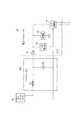
図1は、本発明の実施形態におけるパルス電力伝送システムの主要部の構成例を示すブロック図である。また、図2は、ワイヤハーネスおよびルータの構成例を示すブロック図である。Specific embodiments relating to the present invention will be described below with reference to the drawings.
<System configuration example>
FIG. 1 is a block diagram illustrating a configuration example of a main part of a pulse power transmission system according to an embodiment of the present invention. FIG. 2 is a block diagram illustrating a configuration example of a wire harness and a router.
図1に示したパルス電力伝送システムは、車両に搭載され、車載バッテリー等から供給される電源電力を車両上の様々な負荷、すなわち車載電装品に向けて配電するために利用することを想定している。勿論、車載システム以外の用途で利用してもよく、また、細部の構成については必要に応じて適宜変更してもよい。 The pulse power transmission system shown in FIG. 1 is assumed to be installed in a vehicle and used to distribute power supplied from an in-vehicle battery to various loads on the vehicle, that is, in-vehicle electrical components. ing. Of course, you may utilize for uses other than a vehicle-mounted system, and about a detailed structure, you may change suitably as needed.
図1に示したパルス電力伝送システムは、電力パケットを生成するミキサ10と、電力パケットを配電するルータ30および31とを備えている。ミキサ10とルータ30とは、ワイヤハーネスWHを介して接続されている。 The pulse power transmission system shown in FIG. 1 includes a
したがって、比較的大きな電力が伝送路であるワイヤハーネスWHを介して伝送されることになり、ワイヤハーネスWHから比較的大きな放射ノイズが発生することが予想される。車載システムの場合には、ワイヤハーネスWHからの放射ノイズが、例えば規格CISPR25の許容値を満たすように抑制される必要がある。特に、周波数が高い領域では許容値の制限が厳しいので、高周波の放射ノイズが十分に抑制されなければならない。 Therefore, relatively large electric power is transmitted through the wire harness WH that is a transmission path, and it is expected that relatively large radiation noise is generated from the wire harness WH. In the case of an in-vehicle system, the radiation noise from the wire harness WH needs to be suppressed so as to satisfy an allowable value of the standard CISPR25, for example. In particular, since the limit of the allowable value is severe in a high frequency region, high-frequency radiation noise must be sufficiently suppressed.
ワイヤハーネスWHは、ミキサ10により生成された電力パケットを伝送することが可能である。パルス電力伝送システムは、例えば矩形波のような波形を用いて電力をミキサ10からルータ30および31に間欠的に伝送することによって、パケット単位で電力を管理することが可能である。したがって、配電管理が容易になる。しかし、矩形波のような波形は基本波の周波数の整数倍の周波数に現れる高調波成分を多く含んでいる。そのため、特別な対策をせずに矩形波を伝送した場合は、送電する電力パケットの高調波成分の影響で許容値を上回る高周波の放射ノイズが発生する可能性がある。 The wire harness WH can transmit the power packet generated by the
図1に示したミキサ10は、送電パルス生成部11、ヘッダ生成部12、送電フィルタ13、フィルタ制御部14、インバータ15、電源ライン16、およびアースライン17を備えている。送電フィルタ13は、コンデンサC1、コイルL1、スイッチ部SW1、およびSW2を含んでいる。 The
送電パルス生成部11は、電源21、22のいずれかから供給される直流の電源電力を選択して周期的にスイッチングし、電力パケットとして電源ライン16へ供給するパルス状の電源電力を生成する。 The power
なお、複数の電源21、22は、例えばメインバッテリーとサブバッテリーのように同じ電圧の電力を出力するものであってもよいし、例えば12[V]と48[V]のように、互いに異なる電源電圧を出力するものであってもよい。 Note that the plurality of
ヘッダ生成部12は、上位制御部20が出力する送電指示信号SG1の指示に従い、該当する電力パケットのタイミングを表すパルスタイミング信号SG2を生成すると共に、この電力パケットに付加するヘッダのデジタル情報を生成する。ヘッダ生成部12により生成されたパルスタイミング信号SG2は、送電パルス生成部11およびフィルタ制御部14に供給され、デジタル情報は、電源ライン16に供給される。パルスタイミング信号SG2は、電力パケットに含まれるペイロードのタイミングを表す二値信号である。 The
送電パルス生成部11は、パルスタイミング信号SG2のタイミングに同期して、パルス状の電源電力を生成する。フィルタ制御部14は、パルスタイミング信号SG2に従ってフィルタ制御信号SG3を生成する。インバータ15は、フィルタ制御信号SG3を反転したフィルタ制御信号SG4を生成する。なお、パルスタイミング信号SG2をそのままフィルタ制御信号SG3として使用する場合は、フィルタ制御部14は不要である。 The power
送電フィルタ13は、送電パルス生成部11により生成されたパルス状の電源電力の高調波成分を低減するために利用されるフィルタ回路である。例えば、送電パルス生成部11から出力されるパルスの基本周波数がf0[kHz]の場合には、f0[kHz]以下の周波数成分はほとんど減衰せず、且つ2f0[kHz]以上の周波数成分が十分に減衰するように、コンデンサC1、およびコイルL1の時定数が決定される。The
スイッチ部SW1、およびSW2は、それぞれフィルタ制御信号SG3、およびSG4に従って開閉する半導体スイッチング素子である。スイッチ部SW1が閉じるとコイルL1の端子間が短絡され、スイッチ部SW1が開くとコイルL1がこの回路に接続される。また、スイッチ部SW2が閉じるとコンデンサC1がこの回路に接続され、スイッチ部SW2が開くとコンデンサC1がこの回路から切り離される。 The switch units SW1 and SW2 are semiconductor switching elements that open and close according to the filter control signals SG3 and SG4, respectively. When the switch SW1 is closed, the terminals of the coil L1 are short-circuited, and when the switch SW1 is opened, the coil L1 is connected to this circuit. When the switch unit SW2 is closed, the capacitor C1 is connected to this circuit, and when the switch unit SW2 is opened, the capacitor C1 is disconnected from this circuit.
実際には、後述するように、各電力パケットのペイロードが現れるタイミングでスイッチ部SW1が開、SW2が閉になり、送電フィルタ13の機能がオンになる。それ以外のタイミングでは、スイッチ部SW1が閉、SW2が開になり、送電フィルタ13の機能がオフになる。 Actually, as will be described later, at the timing when the payload of each power packet appears, the switch unit SW1 is opened and SW2 is closed, and the function of the
図1に示した例では、ミキサ10の出力端子10a、10bにワイヤハーネスWHを介してルータ30が接続されている。ワイヤハーネスWHは、図2に示したように、等価的な電気回路として、インダクタンス成分L2、およびキャパシタンス成分C2を含んでいる。 In the example shown in FIG. 1, the
但し、インダクタンス成分L2、およびキャパシタンス成分C2により構成される時定数回路の時定数は、送電フィルタ13と比べて十分に小さい。したがって、ワイヤハーネスWHはパルス状の電源電力に限らず、比較的周波数が高い信号もそのまま伝送することが可能である。 However, the time constant of the time constant circuit configured by the inductance component L2 and the capacitance component C2 is sufficiently smaller than that of the
図2に示したルータ30は、ダイオード41、蓄電部42、ヘッダ抽出部43、および出力制御部44を備えている。なお、図1に示したように、蓄電部32がルータ30の外側に接続されていてもよい。 The
ダイオード41は、電流の逆流を防止する。蓄電部42は、例えば大容量のコンデンサにより構成され、ワイヤハーネスWHにより伝送された電力パケットから電力を取り出して一時的に蓄積する。 The
ヘッダ抽出部43は、ワイヤハーネスWHにより伝送された電力パケットからヘッダに含まれるデジタル情報を抽出し、このデジタル情報を出力制御部44に与える。出力制御部44は、蓄電部42に蓄積されている電力を必要に応じて取り出し、図1に示した各負荷33、34に供給したり、新たな電力パケットを生成して他のルータ31に送電することができる。 The
例えば、出力制御部44がヘッダ抽出部43から取得したヘッダのデジタル情報の中に、当該電力を消費する宛先の情報が含まれている場合には、この宛先に応じて出力制御部44は負荷33、34、およびルータ31のいずれかを選択することができる。また、例えば電源電圧の種類(12、48[V]など)を表す送電電力情報が含まれている場合には、該当する電源電圧を必要とする負荷に対して選択的に電力を供給したり、適切な配電先の経路を選択することができる。 For example, in the case where the header digital information acquired from the
<制御の概要>
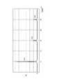
図3は、送出する電力パケットとフィルタ制御信号との関係の例を示すタイムチャートである。
図3に示した例では、ミキサ10がワイヤハーネスWHに送出する電力パケット50は、ヘッダ51およびペイロード52により構成されている。<Outline of control>
FIG. 3 is a time chart illustrating an example of a relationship between a power packet to be transmitted and a filter control signal.
In the example shown in FIG. 3, the power packet 50 sent from the
ペイロード52は、下流側に供給する電源電力を格納する領域を表す。ヘッダ51は、この電力パケット50の先頭に配置されており、このパケットを管理する上で必要なデジタル情報を格納する領域を表す。ペイロード52は、ヘッダ51の後方に配置されている。なお、例えばペイロード52の後方にフッタの領域を付加してもよい。 The
図1に示した送電パルス生成部11は、各電力パケット50のペイロード52内となるタイミングで、パルス状の電源電力を電源ライン16に送出する。また、ヘッダ生成部12は、各電力パケット50のヘッダ51のタイミングで、必要なデジタル情報を電源ライン16に送出する。 The power transmission
図3の例では、ヘッダ51の中に同期信号51a、宛先情報51b、および送電電力情報51cが含まれている。同期信号51aは、例えば下流側のルータ30が電力パケット50の先頭のタイミングを正確に把握するために利用される。宛先情報51bは、例えば該当する電力パケット50で伝送した電力を消費すべき負荷や配電経路などを特定可能な識別子である。送電電力情報51cは、例えば該当する電力パケット50で伝送する電源電力の種類(12、48[V]など)を表す情報を伝送するために利用される。 In the example of FIG. 3, the
図1に示したフィルタ制御部14は、ルータ30が送出する電力パケット50に同期したフィルタ制御信号SG3を出力する。このフィルタ制御信号SG3は、図3に示したように、各電力パケット50のペイロード52が始まる時刻t1、t3で低レベルから高レベルに変化し、ペイロード52が終了した時刻t2、t4で高レベルから低レベルに変化する。 The
フィルタ制御信号SG3が高レベルの時には、送電フィルタ13内のスイッチ部SW1が開になり、スイッチ部SW2が閉になる。したがって、ペイロード52が現れている区間では、送電フィルタ13の機能が有効(オン)になる。これにより、パルス電力伝送システムは、送電電力にほとんど影響を及ぼすことなく、パルス状の電源電力波形に含まれる高調波成分のみを低減し、ワイヤハーネスWHからの放射ノイズを低減できる。 When the filter control signal SG3 is at a high level, the switch unit SW1 in the
また、フィルタ制御信号SG3が低レベルの時には、送電フィルタ13内のスイッチ部SW1が閉になり、スイッチ部SW2が開になる。したがって、ペイロード52が現れている区間以外では、送電フィルタ13の機能が無効(オフ)になる。送電フィルタ13の機能を無効にすることにより、ヘッダ51等のタイミングで現れるデジタル情報の伝送波形が送電フィルタ13の影響を受けることがなくなる。したがって、パルス電力伝送システムは、デジタル情報を伝送する際のビットレートを下げなくても、伝送エラーの発生を抑制できる。また、デジタル情報を伝送する際には電流がほとんど流れないので、高調波成分を含む信号を伝送する場合であっても、ワイヤハーネスWHから大きな放射ノイズは発生しない。 When the filter control signal SG3 is at a low level, the switch unit SW1 in the
<特性の具体例>
−<送電電力に対する特性>
図4は、本発明の実施形態において、パルス状波形で送電する場合の電圧および電流の波形の例を示すタイムチャートである。図4において、横軸は時間、縦軸は電圧または電流を表す。<Specific examples of characteristics>
-<Characteristics for transmission power>
FIG. 4 is a time chart showing an example of voltage and current waveforms when power is transmitted in a pulse waveform in the embodiment of the present invention. In FIG. 4, the horizontal axis represents time, and the vertical axis represents voltage or current.
図4に示した電圧V1の波形は、ルータ30がワイヤハーネスWHから電力パケット50のペイロード52の領域を受け取ったタイミングにおけるルータ30の入力での電力パケット50の電圧の変化を表している。また、図4に示した各電流i1、i2の波形は、電圧V1の波形に伴って流れる各部の電流値の変化を表している。 The waveform of the voltage V1 shown in FIG. 4 represents a change in the voltage of the power packet 50 at the input of the
また、図4の例ではパルス状の電源電力波形の基本周波数がf0[kHz]であり、所定長さのワイヤハーネスWHにおけるインダクタンス成分L2が1[μH]、キャパシタンス成分C2が50[pF]の場合を想定してシミュレーションを行った結果を表している。また、送電フィルタ13の時定数については、このパルス状の電源電力波形に対して適切なフィルタ特性を持つように定めてある。In the example of FIG. 4, the fundamental frequency of the pulsed power supply power waveform is f0 [kHz], the inductance component L2 in the wire harness WH having a predetermined length is 1 [μH], and the capacitance component C2 is 50 [pF]. The result of having performed simulation assuming the case of is shown. Further, the time constant of the
一方、パルス状波形で送電する場合の電圧および電力の波形に含まれる周波数成分の分布例を図5および図6にそれぞれ示す。すなわち、図4と同じ条件において、電圧V1の波形をフーリエ解析(FFT)した結果を図5に示し、電圧V1および電流i1により定まる電力波形をフーリエ解析した結果を図6に示す。図5および図6の横軸は周波数f[kHz]を表し、図5の縦軸は電圧Vs[V]を表し、図6の縦軸は電力Ws[W]を表す。 On the other hand, FIG. 5 and FIG. 6 show distribution examples of frequency components included in the voltage and power waveforms when power is transmitted in a pulse waveform. That is, FIG. 5 shows the result of Fourier analysis (FFT) of the waveform of the voltage V1 under the same conditions as FIG. 4, and FIG. 6 shows the result of Fourier analysis of the power waveform determined by the voltage V1 and the current i1. The horizontal axis of FIGS. 5 and 6 represents the frequency f [kHz], the vertical axis of FIG. 5 represents the voltage Vs [V], and the vertical axis of FIG. 6 represents the power Ws [W].
図5に示した各電圧Vs1、Vs2、Vs3、Vs4、およびVs5は、それぞれ電圧V1の波形に対する基本周波数成分、2倍高調波成分、3倍高調波成分、4倍高調波成分、および5倍高調波成分を表している。また、図6に示した各電力Ws1、Ws2、Ws3、Ws4、およびWs5は、それぞれ該当電力波形に対する基本周波数成分、2倍高調波成分、3倍高調波成分、4倍高調波成分、および5倍高調波成分を表している。 The voltages Vs1, Vs2, Vs3, Vs4, and Vs5 shown in FIG. 5 are the fundamental frequency component, the second harmonic component, the third harmonic component, the fourth harmonic component, and the fifth time, respectively, with respect to the waveform of the voltage V1. Represents harmonic components. Further, each of the electric powers Ws1, Ws2, Ws3, Ws4, and Ws5 shown in FIG. 6 has a fundamental frequency component, a second harmonic component, a third harmonic component, a fourth harmonic component, and 5 for the corresponding power waveform, respectively. It represents the double harmonic component.
図4に示した例では、電圧V1の波形は、正弦波に近く比較的緩やかに変化する波形になっている。但し、図1に示した送電パルス生成部11が電源ライン16に送出する電源電力の電圧波形は、送電パルス生成部11内におけるスイッチングにより発生した矩形波である。つまり、送電パルス生成部11が出力する矩形波に含まれる周波数成分のうち、周波数の高い高調波成分が送電フィルタ13の機能により低減され、その結果として図4に示した電圧V1の波形が得られている。 In the example shown in FIG. 4, the waveform of the voltage V <b> 1 is a waveform that is close to a sine wave and changes relatively slowly. However, the voltage waveform of the power supply power sent to the
これにより、図5の電圧および図6の電力のいずれについても、高調波成分(Vs2〜Vs5、Ws2〜Ws5)の比率が基本波成分(Vs1、Ws1)に比べて少なくなっている。したがって、図1に示したミキサ10が送電フィルタ13を使用する場合には、電力パケット50に対してワイヤハーネスWHから発生する放射ノイズを高調波の周波数領域で許容値内に制限することができる。 Accordingly, the ratio of the harmonic components (Vs2 to Vs5, Ws2 to Ws5) is smaller than the fundamental wave components (Vs1, Ws1) for both the voltage in FIG. 5 and the power in FIG. Therefore, when the
−<デジタル情報に対する特性>
図7は、本発明の実施形態において、デジタル情報を伝送する場合の電圧波形の例を示すタイムチャートである。図7において、横軸は時間、縦軸は電圧または電流を表す。-<Characteristics for digital information>
FIG. 7 is a time chart showing an example of a voltage waveform when digital information is transmitted in the embodiment of the present invention. In FIG. 7, the horizontal axis represents time, and the vertical axis represents voltage or current.
図7に示した電圧V2の波形は、ルータ30がワイヤハーネスWHから電力パケット50のヘッダ51の領域を受け取ったタイミングにおけるルータ30の入力での電力パケット50の電圧の変化例を表している。 The waveform of the voltage V2 shown in FIG. 7 represents an example of a change in the voltage of the power packet 50 at the input of the
また、図7の例ではヘッダ51内でデジタル情報を伝送する際に使用するパルスの波形の基本周波数がf0[kHz]である場合を想定している。また、ワイヤハーネスWHの長さ、インダクタンス成分L2、キャパシタンス成分C2等の条件については図4の例と同じである。In the example of FIG. 7, it is assumed that the fundamental frequency of the pulse waveform used when transmitting digital information in the
一方、図7に示したデジタル情報の電圧V2および電力の波形に含まれる周波数成分の分布例を図8および図9にそれぞれ示す。すなわち、図7と同じ条件において、電圧V2の波形をフーリエ解析した結果を図8に示し、この電圧V2と実際に流れる電流とで定まる電力波形をフーリエ解析した結果を図9に示す。図8および図9の横軸は周波数f[kHz]を表し、図8の縦軸は電圧Vs[V]を表し、図9の縦軸は電力Ws[W]を表す。 On the other hand, distribution examples of frequency components included in the voltage V2 and power waveforms of the digital information shown in FIG. 7 are shown in FIGS. 8 and 9, respectively. That is, FIG. 8 shows the result of Fourier analysis of the waveform of the voltage V2 under the same conditions as FIG. 7, and FIG. 9 shows the result of Fourier analysis of the power waveform determined by this voltage V2 and the actual flowing current. 8 and 9 represents the frequency f [kHz], the vertical axis in FIG. 8 represents the voltage Vs [V], and the vertical axis in FIG. 9 represents the power Ws [W].
図8に示した各電圧Vs1、Vs3、およびVs5は、それぞれ電圧V1の波形に対する基本周波数成分、3倍高調波成分、および5倍高調波成分を表している。また、図9に示した各電力Ws1、Ws3、およびWs5は、それぞれ該当電力波形に対する基本周波数成分、3倍高調波成分、および5倍高調波成分を表している。 Each voltage Vs1, Vs3, and Vs5 shown in FIG. 8 represents a fundamental frequency component, a third harmonic component, and a fifth harmonic component with respect to the waveform of the voltage V1, respectively. Moreover, each electric power Ws1, Ws3, and Ws5 shown in FIG. 9 represents a fundamental frequency component, a third harmonic component, and a fifth harmonic component for the corresponding power waveform, respectively.
図7に示した例では、電圧V2の波形は矩形波であり、レベル変化の立ち上がり及び立ち下がりが急峻になっている。したがって、高レベル/低レベルの識別が容易であり、信号波形の高レベル/低レベルが切り替わってからその変化が受信側で検知されるまでの遅延時間もほとんど生じない。そのため、高いビットレートでデジタル情報を伝送する場合であっても、伝送エラーを生じることなく、ミキサ10とルータ30との間でデジタル情報を伝送することが可能になる。 In the example shown in FIG. 7, the waveform of the voltage V2 is a rectangular wave, and the rise and fall of the level change are steep. Therefore, it is easy to identify the high level / low level, and there is almost no delay time until the change is detected on the receiving side after the high / low level of the signal waveform is switched. Therefore, even when digital information is transmitted at a high bit rate, digital information can be transmitted between the
すなわち、図3に示したように、電力パケット50のペイロード52が現れている区間以外のタイミングでは、フィルタ制御信号SG3により送電フィルタ13の機能がオフになる。したがって、ヘッダ生成部12が電源ライン16に送出したヘッダ51の情報は、矩形波の波形を維持したまま、送電フィルタ13を通過し、ワイヤハーネスWHを経由してルータ30に届くことになる。 That is, as shown in FIG. 3, the function of the
例えば、図8に示した電圧の比率「Vs3/Vs1」は、図5に示した電圧の比率「Vs3/Vs1」と比べて大きくなっている。つまり、図8に示した3倍高調波成分Vs3の電圧は、送電フィルタ13の影響を受けていないので、図5に示した3倍高調波成分Vs3の電圧よりも比率が大きくなっている。 For example, the voltage ratio “Vs3 / Vs1” shown in FIG. 8 is larger than the voltage ratio “Vs3 / Vs1” shown in FIG. That is, since the voltage of the third harmonic component Vs3 shown in FIG. 8 is not affected by the
また、図9に示した電力の比率「Ws3/Ws1」も、図6の場合の電力の比率「Ws3/Ws1」よりも大きくなっている。しかし、デジタル情報を伝送するときには電流がほとんど流れないので、各高調波成分の出力電力は非常に小さい。つまり、デジタル情報を伝送する場合の電力の比率「Ws3/Ws1」が大きくても、ワイヤハーネスWHで発生する放射ノイズのレベルは非常に小さい。 Further, the power ratio “Ws3 / Ws1” shown in FIG. 9 is also larger than the power ratio “Ws3 / Ws1” in the case of FIG. However, since almost no current flows when transmitting digital information, the output power of each harmonic component is very small. That is, even if the power ratio “Ws3 / Ws1” when transmitting digital information is large, the level of radiation noise generated in the wire harness WH is very small.
なお、図3に示した例では、デジタル情報が電力パケット50に含まれている場合を想定しているが、例えばルータ30が電力パケット50を送信していないタイミングでデジタル情報をワイヤハーネスWHを経由してミキサ10に向けて送信する場合にも、同じ制御を適用できる。すなわち、電力パケット50のペイロード52が現れていないタイミングでミキサ10内の送電フィルタ13の機能をオフにすることで、デジタル情報の伝送波形に送電フィルタ13の影響が現れるのを防止できる。 In the example illustrated in FIG. 3, it is assumed that the digital information is included in the power packet 50. For example, the digital information is transmitted to the wire harness WH at a timing when the
<パルス電力伝送システムの利点>
図1に示したパルス電力伝送システムにおいては、ミキサ10が生成した電力パケット50を用い、ワイヤハーネスWHを介してルータ30側に電力を伝送するので、電源電力の管理が容易である。すなわち、パケット単位で電力の消費先の負荷や伝送経路を切り替えることが可能である。また、このような電力パケットの利用に伴い、高周波領域におけるワイヤハーネスWHからの放射ノイズの増大が懸念されるが、送電フィルタ13の機能を利用することにより、パルス状の電源電力波形に対する高調波成分を低減し、放射ノイズを抑制できる。更に、電力パケット50のペイロード52以外のタイミングでは、送電フィルタ13の機能をオフにするので、デジタル情報の伝送波形が変形するのを避けることができ、デジタル情報の伝送を高いビットレートで行うことが可能になる。<Advantages of pulse power transmission system>
In the pulse power transmission system shown in FIG. 1, since power is transmitted to the
ここで、上述した本発明の実施形態に係るパルス電力伝送装置の特徴をそれぞれ以下[1]〜[4]に簡潔に纏めて列記する。
[1] パルス状の電源電力を所定の伝送路に送出する電力送出部(送電パルス生成部11)と、
前記電力送出部が前記伝送路に送出する電源電力波形の高調波成分を低減するフィルタ回路(送電フィルタ13)と、
前記フィルタ回路の機能のオンオフを切り替えるスイッチ回路(スイッチ部SW1、SW2)と、
前記スイッチ回路を制御するスイッチ制御部(フィルタ制御部14)と、を備え、
前記スイッチ制御部は、前記電力送出部がパルス状の電源電力を前記伝送路に送出するときには前記フィルタ回路の機能をオンにし、前記パルス状の電源電力を前記伝送路に送出しないときには前記フィルタ回路の機能をオフにする(図3参照)、
ことを特徴とするパルス電力伝送装置(ミキサ10)。Here, the features of the above-described pulse power transmission device according to the embodiment of the present invention will be briefly summarized and listed in the following [1] to [4], respectively.
[1] A power transmission unit (power transmission pulse generation unit 11) for transmitting pulsed power to a predetermined transmission line;
A filter circuit (a power transmission filter 13) that reduces a harmonic component of a power source power waveform that the power transmission unit transmits to the transmission line;
A switch circuit (switch unit SW1, SW2) for switching on and off the function of the filter circuit;
A switch control unit (filter control unit 14) for controlling the switch circuit,
The switch control unit turns on the function of the filter circuit when the power sending unit sends pulsed power to the transmission line, and the filter circuit when the pulse sending power is not sent to the transmission line. (See Fig. 3)
The pulse power transmission device (mixer 10) characterized by the above.
[2] 前記電力送出部(ヘッダ生成部12)は、パルス状の電源電力波形の前後の少なくとも一方に、前記電源電力に関連するデジタル情報(ヘッダ51)を付加して電力パケット(50)を生成し、
前記スイッチ制御部は、前記電力パケットに付加した前記デジタル情報を送出するタイミングでは、前記フィルタ回路の機能をオフに制御する(図3参照)、
ことを特徴とする上記[1]に記載のパルス電力伝送装置。[2] The power transmission unit (header generation unit 12) adds digital information (header 51) related to the power supply power to at least one of the front and rear of the pulsed power supply power waveform to generate a power packet (50). Generate
The switch control unit controls the function of the filter circuit to be off at a timing of sending the digital information added to the power packet (see FIG. 3).
The pulse power transmission device according to [1] above, wherein
[3] 前記伝送路が、車両に搭載されたワイヤハーネス(WH)である、
ことを特徴とする上記[1]または[2]に記載のパルス電力伝送装置。[3] The transmission path is a wire harness (WH) mounted on a vehicle.
The pulse power transmission device according to [1] or [2] above, wherein
[4] 前記デジタル情報は、該当する電力パケットの種類(送電電力情報51c)、および電力消費先(宛先情報51b)の少なくとも一方を表す情報を含む、
ことを特徴とする上記[2]に記載のパルス電力伝送装置。[4] The digital information includes information indicating at least one of a type of the corresponding power packet (
The pulse power transmission device according to [2] above, wherein
10 ミキサ
10a,10b 出力端子
11 送電パルス生成部
12 ヘッダ生成部
13 送電フィルタ
14 フィルタ制御部
15 インバータ
16 電源ライン
17 アースライン
20 上位制御部
21,22 電源
30,31 ルータ
32 蓄電部
33,34 負荷
41 ダイオード
42 蓄電部
43 ヘッダ抽出部
44 出力制御部
50 電力パケット
51 ヘッダ
51a 同期信号
51b 宛先情報
51c 送電電力情報
52 ペイロード
SG1 送電指示信号
SG2 パルスタイミング信号
SG3,SG4 フィルタ制御信号
SW1,SW2 スイッチ部
L1 コイル
L2 インダクタンス成分
C1 コンデンサ
C2 キャパシタンス成分
WH ワイヤハーネスDESCRIPTION OF
Claims (4)
Translated fromJapanese前記電力送出部が前記伝送路に送出する電源電力波形の高調波成分を低減するフィルタ回路と、
前記フィルタ回路の機能のオンオフを切り替えるスイッチ回路と、
前記スイッチ回路を制御するスイッチ制御部と、を備え、
前記スイッチ制御部は、前記電力送出部がパルス状の電源電力を前記伝送路に送出するときには前記フィルタ回路の機能をオンにし、前記パルス状の電源電力を前記伝送路に送出しないときには前記フィルタ回路の機能をオフにする、
ことを特徴とするパルス電力伝送装置。A power sending unit for sending pulsed power to a predetermined transmission line;
A filter circuit for reducing a harmonic component of a power source power waveform sent to the transmission line by the power sending unit;
A switch circuit for switching on and off the function of the filter circuit;
A switch control unit for controlling the switch circuit,
The switch control unit turns on the function of the filter circuit when the power sending unit sends pulsed power to the transmission line, and the filter circuit when the pulse sending power is not sent to the transmission line. Turn off
A pulse power transmission device characterized by that.
前記スイッチ制御部は、前記電力パケットに付加した前記デジタル情報を送出するタイミングでは、前記フィルタ回路の機能をオフに制御する、
ことを特徴とする請求項1に記載のパルス電力伝送装置。The power transmission unit generates a power packet by adding digital information related to the power source power to at least one of the front and rear of the pulsed power source power waveform,
The switch control unit controls the function of the filter circuit to be off at a timing of sending the digital information added to the power packet.
The pulse power transmission device according to claim 1.
ことを特徴とする請求項1または請求項2に記載のパルス電力伝送装置。The transmission path is a wire harness mounted on a vehicle.
The pulse power transmission device according to claim 1 or 2, characterized by the above.
ことを特徴とする請求項2に記載のパルス電力伝送装置。The digital information includes information indicating at least one of the type of the corresponding power packet and the power consumption destination,
The pulse power transmission device according to claim 2.
Priority Applications (4)
| Application Number | Priority Date | Filing Date | Title |
|---|---|---|---|
| JP2018045876AJP2019161864A (en) | 2018-03-13 | 2018-03-13 | Pulse power transmission device |
| EP19160925.4AEP3540891B1 (en) | 2018-03-13 | 2019-03-06 | Pulsed power transmission apparatus |
| US16/297,814US10819146B2 (en) | 2018-03-13 | 2019-03-11 | Pulsed power transmission apparatus |
| CN201910185334.3ACN110277906B (en) | 2018-03-13 | 2019-03-12 | Pulse Power Transmission Device |
Applications Claiming Priority (1)
| Application Number | Priority Date | Filing Date | Title |
|---|---|---|---|
| JP2018045876AJP2019161864A (en) | 2018-03-13 | 2018-03-13 | Pulse power transmission device |
Publications (1)
| Publication Number | Publication Date |
|---|---|
| JP2019161864Atrue JP2019161864A (en) | 2019-09-19 |
Family
ID=65766806
Family Applications (1)
| Application Number | Title | Priority Date | Filing Date |
|---|---|---|---|
| JP2018045876AAbandonedJP2019161864A (en) | 2018-03-13 | 2018-03-13 | Pulse power transmission device |
Country Status (4)
| Country | Link |
|---|---|
| US (1) | US10819146B2 (en) |
| EP (1) | EP3540891B1 (en) |
| JP (1) | JP2019161864A (en) |
| CN (1) | CN110277906B (en) |
Families Citing this family (1)
| Publication number | Priority date | Publication date | Assignee | Title |
|---|---|---|---|---|
| DE102018129415B4 (en)* | 2018-11-22 | 2024-07-04 | Dr. Ing. H.C. F. Porsche Aktiengesellschaft | Charging device for a vehicle and vehicle with a charging device |
Citations (3)
| Publication number | Priority date | Publication date | Assignee | Title |
|---|---|---|---|---|
| US20020001211A1 (en)* | 1999-11-15 | 2002-01-03 | Colin Huggett | Active filter for a converter having a dc line |
| JP2008123051A (en)* | 2006-11-08 | 2008-05-29 | Sony Corp | Power supply system, power supply method, and power supply program |
| WO2015163312A1 (en)* | 2014-04-21 | 2015-10-29 | 山口 作太郎 | Wire harness system, device, and power feeding method |
Family Cites Families (9)
| Publication number | Priority date | Publication date | Assignee | Title |
|---|---|---|---|---|
| US5377272A (en)* | 1992-08-28 | 1994-12-27 | Thomson Consumer Electronics, Inc. | Switched signal processing circuit |
| US6178101B1 (en)* | 1997-08-15 | 2001-01-23 | Unitron, Inc. | Power supply regulation |
| CN102177651B (en)* | 2008-10-10 | 2014-09-10 | 谋友(Iom)有限公司 | A power supply system and method for controlling a mechanically commutated electric motor |
| EP2709285A1 (en)* | 2012-09-17 | 2014-03-19 | ST-Ericsson SA | A method of and receiver for communication during wireless power transmission |
| WO2014077191A1 (en) | 2012-11-14 | 2014-05-22 | 国立大学法人京都大学 | Power router and power network |
| US9787090B2 (en)* | 2013-05-21 | 2017-10-10 | Kyoto University | Power packet generation device, power router, and power network |
| CN104506026B (en)* | 2015-01-04 | 2018-06-05 | 华为技术有限公司 | A kind of active filter and communication system |
| MY181704A (en)* | 2016-02-05 | 2021-01-04 | Guangdong Oppo Mobile Telecommunications Corp Ltd | Charge method, adapter and mobile terminal |
| CN106374971A (en)* | 2016-08-27 | 2017-02-01 | 成都云材智慧数据科技有限公司 | Pulse regulating type wireless audio data acquisition and storage system |
- 2018
- 2018-03-13JPJP2018045876Apatent/JP2019161864A/ennot_activeAbandoned
- 2019
- 2019-03-06EPEP19160925.4Apatent/EP3540891B1/enactiveActive
- 2019-03-11USUS16/297,814patent/US10819146B2/ennot_activeExpired - Fee Related
- 2019-03-12CNCN201910185334.3Apatent/CN110277906B/ennot_activeExpired - Fee Related
Patent Citations (3)
| Publication number | Priority date | Publication date | Assignee | Title |
|---|---|---|---|---|
| US20020001211A1 (en)* | 1999-11-15 | 2002-01-03 | Colin Huggett | Active filter for a converter having a dc line |
| JP2008123051A (en)* | 2006-11-08 | 2008-05-29 | Sony Corp | Power supply system, power supply method, and power supply program |
| WO2015163312A1 (en)* | 2014-04-21 | 2015-10-29 | 山口 作太郎 | Wire harness system, device, and power feeding method |
Also Published As
| Publication number | Publication date |
|---|---|
| CN110277906A (en) | 2019-09-24 |
| CN110277906B (en) | 2021-02-19 |
| EP3540891A1 (en) | 2019-09-18 |
| EP3540891B1 (en) | 2021-02-17 |
| US20190288552A1 (en) | 2019-09-19 |
| US10819146B2 (en) | 2020-10-27 |
Similar Documents
| Publication | Publication Date | Title |
|---|---|---|
| CN104348689B (en) | LIN bus module | |
| RU2708510C9 (en) | Subscriber station for bus system and method for increasing immunity to electromagnetic interference for subscriber station | |
| US7804188B2 (en) | Termination circuit, vehicle-mounted control apparatus, and vehicle-mounted communication system | |
| US10056653B2 (en) | Battery management device and power supply device | |
| US9929566B2 (en) | Power electronic circuit and system comprising the same | |
| CN109714234B (en) | Transceiver unit for transmitting data via a differential bus | |
| CN102668395B (en) | Method for transmitting data from a transmitter to a receiver in an alternating voltage network and device for data transmission in an alternating voltage network | |
| Jeschke et al. | Impact of HV battery cables’ emissions on the signal integrity of 2-wire ethernet communication in automotive application | |
| JP2015204519A (en) | communication system | |
| EP3002879A1 (en) | Digital-to-analog converter (dac), method for operating a dac and transceiver circuit | |
| JP2019161864A (en) | Pulse power transmission device | |
| KR100840137B1 (en) | Transmitter for controlled-type switched signal on communication line | |
| US12273024B2 (en) | Common mode electromagnetic interference mitigation | |
| CN108282172B (en) | Power adapter | |
| JP3770613B2 (en) | Auxiliary power control device for vehicle | |
| JP4608576B2 (en) | Twisted pair communication system, apparatus, and method therefor | |
| JP2003518908A (en) | EMI reduction insulated bus system | |
| US11515876B2 (en) | Driver for a shared bus, in particular a LIN bus | |
| JP3999374B2 (en) | Bus station and bus system | |
| CN113348647B (en) | Bidirectional current modulation network communication system for transmitting data | |
| Saponara et al. | Improving electromagnetic compatibility of integrated switching converters for hybrid/electric vehicles | |
| TWI327848B (en) | Transmitter for a controlled-shape switched signal on a communication line | |
| JP7251775B2 (en) | Signal transmission device, signal transmission method and signal transmission error suppression device | |
| DE102019206667A1 (en) | Motor vehicle with an electrical distribution network for transmitting an electrical supply voltage and a method for coordinating the operation of components of the motor vehicle | |
| JPH0697784A (en) | Constitution unit for pulse shaping |
Legal Events
| Date | Code | Title | Description |
|---|---|---|---|
| A621 | Written request for application examination | Free format text:JAPANESE INTERMEDIATE CODE: A621 Effective date:20210218 | |
| A977 | Report on retrieval | Free format text:JAPANESE INTERMEDIATE CODE: A971007 Effective date:20211116 | |
| A131 | Notification of reasons for refusal | Free format text:JAPANESE INTERMEDIATE CODE: A131 Effective date:20211207 | |
| A762 | Written abandonment of application | Free format text:JAPANESE INTERMEDIATE CODE: A762 Effective date:20220124 |