JP2019144147A - Robot, robot controller, robot system, and force detector - Google Patents
Robot, robot controller, robot system, and force detectorDownload PDFInfo
- Publication number
- JP2019144147A JP2019144147AJP2018029432AJP2018029432AJP2019144147AJP 2019144147 AJP2019144147 AJP 2019144147AJP 2018029432 AJP2018029432 AJP 2018029432AJP 2018029432 AJP2018029432 AJP 2018029432AJP 2019144147 AJP2019144147 AJP 2019144147A
- Authority
- JP
- Japan
- Prior art keywords
- detection unit
- robot
- axis
- unit
- coordinate
- Prior art date
- Legal status (The legal status is an assumption and is not a legal conclusion. Google has not performed a legal analysis and makes no representation as to the accuracy of the status listed.)
- Pending
Links
Images


Landscapes
- Force Measurement Appropriate To Specific Purposes (AREA)
- Manipulator (AREA)
Abstract
Translated fromJapaneseDescription
Translated fromJapaneseこの発明は、ロボット、ロボット制御装置、ロボットシステム、及び力検出器に関する。 The present invention relates to a robot, a robot control device, a robot system, and a force detector.
力制御によってロボットに作業を行わせる技術の研究や開発が行われている。ここで、力制御は、力検出部から出力された出力値に基づく制御のことである。力検出部は、ロボットの部位のうち予め決められた部位である力検出部位に作用した外力を検出するセンサーである。力検出部は、例えば、力センサー、トルクセンサー等のことである。当該外力には、力検出部位に作用した並進力、力検出部位に作用した回転モーメントが含まれる。 Research and development of technologies that allow robots to perform work by force control are being conducted. Here, force control is control based on the output value output from the force detection unit. The force detection unit is a sensor that detects an external force that has acted on a force detection part that is a predetermined part among parts of the robot. The force detection unit is, for example, a force sensor or a torque sensor. The external force includes a translational force acting on the force detection site and a rotational moment acting on the force detection site.
これに関し、ロボットアームと、力覚センサーと、ロボットアームの作動を制御する制御部と、を備え、制御部は、ロボットアームが減速を開始した後に力覚センサーの初期化を開始し、ロボットアームの速度が等速度のときに、力覚センサーの初期化状態を解除するロボットが知られている(特許文献1参照)。 In this regard, a robot arm, a force sensor, and a control unit that controls the operation of the robot arm are provided. The control unit starts initialization of the force sensor after the robot arm starts decelerating, and the robot arm There is known a robot that cancels the initialization state of the force sensor when the speed of the sensor is equal (see Patent Document 1).
このようなロボットでは、力覚センサーから出力される出力値は、力覚センサーの加速又は減速によって力覚センサーに作用する慣性力に応じて、変化してしまう。そこで、当該ロボットは、ロボットが備える各関節のエンコーダーから出力される出力値に基づいて当該慣性力の大きさ及び方向を算出し、算出した当該慣性力の大きさ及び方向に基づいて力覚センサーから出力される出力値を補正することができる。しかしながら、当該エンコーダーから出力される出力値に基づいて算出された慣性力の大きさ及び方向は、実際に力覚センサーに作用した慣性力の大きさ及び方向と異なる場合が多い。その結果、当該ロボットは、力覚センサーから出力される出力値の補正を精度よく行うことができず、力制御による作業を精度よく行うことができない場合があった。 In such a robot, the output value output from the force sensor changes depending on the inertial force acting on the force sensor due to acceleration or deceleration of the force sensor. Therefore, the robot calculates the magnitude and direction of the inertial force based on the output value output from the encoder of each joint included in the robot, and the force sensor based on the calculated magnitude and direction of the inertial force. The output value output from can be corrected. However, the magnitude and direction of the inertial force calculated based on the output value output from the encoder are often different from the magnitude and direction of the inertial force actually acting on the force sensor. As a result, the robot cannot correct the output value output from the force sensor with high accuracy, and may not be able to accurately perform work by force control.
上記課題を解決するために本発明の一態様は、第1部材と、第2部材と、前記第1部材と前記第2部材とを接続し、駆動部が設けられた関節と、並進力と回転モーメントとのいずれか一方又は両方を検出する第1検出部と、角速度と加速度とのいずれか一方又は両方を検出する第2検出部と、前記第1検出部から出力された出力値を、前記第2検出部から出力された出力値に基づいて補正する補正部と、を備え、前記第1検出部は、前記第1部材と前記第2部材と前記関節とのいずれかに設けられ、前記第2検出部は、前記第1部材と前記第2部材と前記関節とのいずれかに設けられた、ロボットである。 In order to solve the above-described problem, an embodiment of the present invention includes a first member, a second member, a joint in which the first member and the second member are connected, a drive unit provided, and a translational force. A first detector that detects one or both of the rotational moments, a second detector that detects one or both of angular velocity and acceleration, and an output value output from the first detector, A correction unit that corrects based on the output value output from the second detection unit, the first detection unit is provided in any of the first member, the second member, and the joint, The second detection unit is a robot provided in any one of the first member, the second member, and the joint.
また、本発明の一態様は、上記に記載のロボットを制御する、ロボット制御装置である。 Another embodiment of the present invention is a robot control device that controls the robot described above.
また、本発明の一態様は、上記に記載のロボットと、前記ロボットを制御するロボット制御装置と、を備えるロボットシステムである。 Another embodiment of the present invention is a robot system including the robot described above and a robot control device that controls the robot.
また、本発明の一態様は、並進力と回転モーメントとのいずれか一方又は両方を検出する力検出器であって、角速度と加速度とのいずれか一方又は両方を検出する検出部を内蔵する、力検出器である。 One embodiment of the present invention is a force detector that detects either or both of a translational force and a rotational moment, and includes a detection unit that detects either or both of an angular velocity and an acceleration. It is a force detector.
<実施形態>
以下、本発明の実施形態について、図面を参照して説明する。<Embodiment>
Hereinafter, embodiments of the present invention will be described with reference to the drawings.
<ロボットシステムの構成>
まず、ロボットシステム1の構成について説明する。
図1は、実施形態に係るロボットシステム1の構成の一例を示す図である。ロボットシステム1は、ロボット20と、ロボット制御装置30を備える。なお、ロボットシステム1は、撮像部、撮像部を制御する画像処理装置、ロボット制御装置30を制御する情報処理装置、ロボット制御装置30にロボット20の動作を教示する教示装置等を備える構成であってもよい。<Robot system configuration>
First, the configuration of the
FIG. 1 is a diagram illustrating an example of a configuration of a
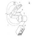
ロボット20は、アームAと、アームAを支持する基台Bを備える単腕ロボットである。単腕ロボットは、この一例におけるアームAのような1本の腕(アーム)を備えるロボットである。 The
アームAは、エンドエフェクターEと、マニピュレーターMと、第1検出部FSと、第2検出部ISを備える。なお、アームAは、エンドエフェクターEを備えない構成であってもよい。 The arm A includes an end effector E, a manipulator M, a first detection unit FS, and a second detection unit IS. The arm A may be configured without the end effector E.
エンドエフェクターEは、物体を保持するエンドエフェクターである。この一例において、エンドエフェクターEは、指部を備え、当該指部によって物体を挟んで持つことにより当該物体を保持する。 The end effector E is an end effector that holds an object. In this example, the end effector E includes a finger portion, and holds the object by holding the object by the finger portion.
マニピュレーターMは、6つのリンク(アーム部材)である第1リンク〜第6リンクと、6つの関節である第1関節〜第6関節とを備える。ここで、第1関節は、基台Bと第1リンクとの間を接続する関節である。第2関節は、第1リンクと第2リンクとの間を接続する関節である。第3関節は、第2リンクと第3リンクとの間を接続する関節である。第4関節は、第3リンクと第4リンクとの間を接続する関節である。第5関節は、第4リンクと第5リンクとの間を接続する関節である。第6関節は、第5リンクと第6リンクとの間を接続する関節である。そして、第6リンクが有する端部のうち第6関節と逆側の端部に設けられたフランジには、直接的又は間接的にエンドエフェクターEが設けられる。当該フランジに間接的にエンドエフェクターEが設けられる場合、当該フランジとエンドエフェクターEとの間には、何らかの部材が設けられる。当該部材は、例えば、後述する第1検出部FS等である。 The manipulator M includes first to sixth links that are six links (arm members), and first to sixth joints that are six joints. Here, the first joint is a joint connecting the base B and the first link. The second joint is a joint that connects between the first link and the second link. The third joint is a joint connecting the second link and the third link. The fourth joint is a joint that connects the third link and the fourth link. The fifth joint is a joint connecting the fourth link and the fifth link. The sixth joint is a joint connecting the fifth link and the sixth link. And the end effector E is provided directly or indirectly in the flange provided in the edge part on the opposite side to a 6th joint among the edge parts which a 6th link has. When the end effector E is indirectly provided on the flange, some member is provided between the flange and the end effector E. The member is, for example, a first detection unit FS described later.
また、第1関節〜第6関節はそれぞれ、図示しないアクチュエーターを備える。すなわち、マニピュレーターMを備えるアームAは、6軸垂直多関節型のアームである。アームAは、基台Bと、エンドエフェクターEと、マニピュレーターMと、マニピュレーターMが備える第1関節〜第6関節それぞれのアクチュエーターとによる連携した動作によって6軸の自由度の動作を行う。なお、アームAは、5軸以下の自由度で動作する構成であってもよく、7軸以上の自由度で動作する構成であってもよい。 The first to sixth joints each include an actuator (not shown). That is, the arm A including the manipulator M is a 6-axis vertical articulated arm. The arm A performs an operation with six degrees of freedom by a coordinated operation by the base B, the end effector E, the manipulator M, and the actuators of the first joint to the sixth joint included in the manipulator M. The arm A may be configured to operate with a degree of freedom of 5 axes or less, or may be configured to operate with a degree of freedom of 7 axes or more.
ここで、エンドエフェクターEと、マニピュレーターMが備える6つのアクチュエーターのそれぞれとは、ケーブルによってロボット制御装置30と通信可能に接続されている。これにより、エンドエフェクターEと、マニピュレーターMが備える6つのアクチュエーターのそれぞれとは、ロボット制御装置30から取得される制御信号に基づく動作を行う。なお、ケーブルを介した有線通信は、例えば、イーサネット(登録商標)やUSB(Universal Serial Bus)等の規格によって行われる。また、エンドエフェクターEは、Wi−Fi(登録商標)等の通信規格により行われる無線通信によってロボット制御装置30と接続される構成であってもよい。また、マニピュレーターMが備える6つのアクチュエーターのうちの一部又は全部は、Wi−Fi(登録商標)等の通信規格により行われる無線通信によってロボット制御装置30と接続される構成であってもよい。 Here, the end effector E and each of the six actuators included in the manipulator M are communicably connected to the
第1検出部FSは、第1検出部FSに作用する並進力と回転モーメントとのいずれか一方又は両方を、第1検出部FSに作用する外力として検出する。以下では、一例として、第1検出部FSに作用する並進力と回転モーメントとの両方を当該外力として検出する場合について説明する。第1検出部FSは、例えば、力センサー(力覚センサー)である。第1検出部FSは、この一例において、エンドエフェクターEとマニピュレーターMの間に備えられる。すなわち、第1検出部FSは、第6リンクが有するフランジとエンドエフェクターEとの間に設けられる。また、第1検出部FSは、当該間に設けられることにより、第1検出部FSに作用する外力を、ロボット20の図示しないハンドに作用した外力として検出する。当該ハンドは、エンドエフェクターE、又はエンドエフェクターEにより保持された物体のことである。すなわち、当該外力には、当該ハンドを並進させる並進力が含まれる。より具体的には、当該並進力には、第1座標系におけるX軸、Y軸、Z軸それぞれの方向に作用する3つの並進力が含まれている。第1座標系は、第1検出部FSに対応付けられた三次元座標系であり、第1検出部FSによる検出において基準となる三次元座標系のことである。また、当該外力には、当該ハンドを回転させる回転モーメント(トルク)が含まれる。より具体的には、当該回転モーメントには、当該X軸、当該Y軸、当該Z軸それぞれの周りに作用する3つの回転モーメントが含まれている。すなわち、第1検出部FSは、当該3つの並進力と当該3つの回転モーメントとのそれぞれを当該外力として検出し、検出した当該3つの並進力のそれぞれに応じた信号と、検出した当該3つの回転モーメントのそれぞれに応じた信号とのそれぞれを、第1検出部FSから出力される出力値として出力する。 The first detection unit FS detects one or both of the translational force and the rotational moment acting on the first detection unit FS as an external force acting on the first detection unit FS. Below, the case where both the translational force and the rotational moment which act on the 1st detection part FS are detected as the said external force as an example is demonstrated. The first detection unit FS is, for example, a force sensor (force sensor). In this example, the first detection unit FS is provided between the end effector E and the manipulator M. That is, the first detection unit FS is provided between the flange included in the sixth link and the end effector E. In addition, the first detection unit FS is provided between them, and detects an external force acting on the first detection unit FS as an external force acting on a hand (not shown) of the
第1検出部FSから出力される出力値は、ロボット制御装置30によるロボット20の力制御に用いられる。力制御は、第1検出部FSから出力された出力値に基づく制御であり、例えば、インピーダンス制御等のコンプライアントモーション制御のことである。 The output value output from the first detection unit FS is used for force control of the
第2検出部ISは、第2検出部ISの角速度と加速度とのいずれか一方又は両方を検出する。第2検出部ISは、例えば、慣性センサー、加速度センサー、ジャイロセンサー等である。以下では、一例として、第2検出部ISの角速度と加速度との両方を検出する場合について説明する。 The second detection unit IS detects one or both of the angular velocity and acceleration of the second detection unit IS. The second detection unit IS is, for example, an inertial sensor, an acceleration sensor, a gyro sensor, or the like. Below, the case where both the angular velocity and acceleration of 2nd detection part IS are detected as an example is demonstrated.
また、第2検出部ISは、この一例において、第1検出部FSに内蔵されている。これにより、第2検出部ISは、第2検出部ISの角速度と加速度との両方を、第1検出部FSの角速度と加速度との両方として精度よく検出することができる。なお、この一例では、前述した通り、第6リンクが有するフランジとエンドエフェクターEとの間に第1検出部FSが設けられている。このため、第2検出部ISは、第2検出部ISの角速度と加速度との両方を、ハンドの角速度と加速度との両方として検出すると換言することができる。より具体的には、当該角速度には、第2座標系におけるX軸、Y軸、Z軸のそれぞれ周りの3つの角速度が含まれている。第2座標系は、第2検出部ISに対応付けられた三次元座標系であり、第2検出部ISによる検出において基準となる三次元座標系のことである。また、当該加速度には、当該X軸、当該Y軸、当該Z軸それぞれの方向に向かう3つの加速度が含まれている。すなわち、第2検出部ISは、当該3つの角速度と当該3つの加速度とのそれぞれを検出し、検出した当該3つの角速度のそれぞれに応じた信号と、検出した当該3つの加速度のそれぞれに応じた信号とのそれぞれを、第2検出部ISから出力される出力値として出力する。なお、本実施形態では、加速度と称した場合、加速度又は減速度を意味する。 Further, the second detection unit IS is built in the first detection unit FS in this example. Thereby, the second detection unit IS can accurately detect both the angular velocity and the acceleration of the second detection unit IS as both the angular velocity and the acceleration of the first detection unit FS. In this example, as described above, the first detection unit FS is provided between the flange of the sixth link and the end effector E. For this reason, it can be said that the second detection unit IS detects both the angular velocity and the acceleration of the second detection unit IS as both the angular velocity and the acceleration of the hand. More specifically, the angular velocity includes three angular velocities around the X axis, the Y axis, and the Z axis in the second coordinate system. The second coordinate system is a three-dimensional coordinate system associated with the second detection unit IS and is a reference three-dimensional coordinate system in detection by the second detection unit IS. Further, the acceleration includes three accelerations directed in the respective directions of the X axis, the Y axis, and the Z axis. That is, the second detection unit IS detects each of the three angular velocities and the three accelerations, and according to each of the detected three accelerations, a signal corresponding to each of the detected three angular velocities. Each of the signals is output as an output value output from the second detection unit IS. In the present embodiment, when referred to as acceleration, it means acceleration or deceleration.
また、第1検出部FSと第2検出部ISとのいずれか一方は、この一例において、取得部23と、補正部24を備える。以下では、一例として、第1検出部FSが取得部23と補正部24を備える場合について説明する。なお、補正部24と取得部23は、例えば、FPGA(Field-Programmable Gate Array)、ASIC(Application Specific Integrated Circuit)等のハードウェア機能部である。すなわち、この一例では、第1検出部FSは、当該ハードウェア機能部を備える。なお、補正部24と取得部23のいずれか一方又は両方は、CPU(Central Processing Unit)等のプロセッサーがメモリーから読み出したプログラムを実行することによって実現されたソフトウェア機能部であってもよい。この場合、第1検出部FSは、当該プロセッサーを備える。 In addition, any one of the first detection unit FS and the second detection unit IS includes an
取得部23は、第1検出部FSからの出力値の取得と、第2検出部ISからの出力値の取得とを行う。より具体的には、取得部23は、第1検出部FSから出力される出力値を予め決められた取得周期で取得するとともに、第2検出部ISから出力される出力値を当該取得周期で取得する。当該取得周期は、すなわち、サンプリング周期のことである。また、取得部23では、第1検出部FSから出力される出力値を取得する取得周期と、第2検出部ISから出力される出力値を取得する取得周期とが同期されている。すなわち、取得部23では、第1検出部FSから出力される出力値を取得するタイミングと、第2検出部ISから出力される出力値を取得するタイミングとが同期されている。当該取得周期は、例えば、100ミリ秒程度である。なお、当該取得周期は、100ミリ秒より短い周期であってもよく、100ミリ秒より長い周期であってもよい。 The
補正部24は、取得部23が第1検出部FSから取得した出力値を、当該出力値を取得部23が取得したタイミングと同じタイミングで取得部23が第2検出部ISから取得した出力値に基づいて補正する。より具体的には、補正部24は、取得部23が第2検出部ISから取得した出力値に基づいて、第1検出部FSに作用した慣性力を算出する。当該慣性力には、第1座標系におけるX軸、Y軸、Z軸それぞれの方向に作用する並進力としての3つの慣性力と、当該X軸、当該Y軸、当該Z軸のそれぞれ回りに作用する回転モーメントとしての3つの慣性力とが含まれている。また、補正部24は、当該出力値を取得部23が取得したタイミングと同じタイミングで取得部23が第2検出部ISから取得した出力値に基づいて、第1検出部FSに作用した外力を算出する。前述した通り、当該外力には、当該X軸、当該Y軸、当該Z軸それぞれの方向に作用する並進力と、当該X軸、当該Y軸、当該Z軸のそれぞれ回りに作用する回転モーメントとが含まれている。補正部24は、算出した慣性力に基づいて、算出した外力を補正する。具体的には、補正部24は、算出した慣性力のうち当該X軸の方向に並進力として作用した慣性力を、算出した外力のうち当該X軸の方向に作用した並進力から差し引いた値を、外力として当該X軸の方向に作用した並進力として特定する。また、補正部24は、算出した慣性力のうち当該Y軸の方向に並進力として作用した慣性力を、算出した外力のうち当該Y軸の方向に作用した並進力から差し引いた値を、外力として当該Y軸の方向に作用した並進力として特定する。また、補正部24は、算出した慣性力のうち当該Z軸の方向に並進力として作用した慣性力を、算出した外力のうち当該Z軸の方向に作用した並進力から差し引いた値を、外力として当該Z軸の方向に作用した並進力として特定する。また、補正部24は、算出した慣性力のうち当該X軸周りに回転モーメントとして作用した慣性力を、算出した外力のうち当該X軸周りに作用した回転モーメントから差し引いた値を、外力として当該X軸周りに作用した回転モーメントとして特定する。また、補正部24は、算出した慣性力のうち当該Y軸周りに回転モーメントとして作用した慣性力を、算出した外力のうち当該Y軸周りに作用した回転モーメントから差し引いた値を、外力として当該Y軸周りに作用した回転モーメントとして特定する。また、補正部24は、算出した慣性力のうち当該Z軸周りに回転モーメントとして作用した慣性力を、算出した外力のうち当該Z軸周りに作用した回転モーメントから差し引いた値を、外力として当該Z軸周りに作用した回転モーメントとして特定する。補正部24は、特定した3つの並進力と、特定した3つの回転モーメントとを示す情報を、第1検出部FSに作用した外力を示す外力情報としてロボット制御装置30に出力する。 The
ここで、第1検出部FSと、第2検出部ISとは、ケーブルによってロボット制御装置30と通信可能に接続されている。これにより、第1検出部FSと、第2検出部ISとは、ロボット制御装置30から取得される制御信号に基づく動作を行う。なお、ケーブルを介した有線通信は、例えば、イーサネット(登録商標)やUSB等の規格によって行われる。また、第1検出部FSと、第2検出部ISのいずれか一方又は両方は、Wi−Fi(登録商標)等の通信規格により行われる無線通信によってロボット制御装置30と接続される構成であってもよい。 Here, the first detection unit FS and the second detection unit IS are communicably connected to the
ロボット制御装置30は、ロボット20を制御するロボットコントローラーである。ロボット制御装置30は、ロボット制御装置30が備えるメモリーに予め記憶された動作プログラムに基づいて、ロボット20に予め決められた作業を行わせる。なお、当該メモリーは、図1において図示していない。 The
より具体的には、ロボット制御装置30は、前述の補正部24から外力情報を取得し、取得した外力情報に基づく力制御によってアームAを動作させる。すなわち、この一例における力制御は、当該外力情報が示す3つの並進力と、当該外力情報が示す3つの回転モーメントとに基づく制御である。また、当該力制御は、当該3つの並進力と、当該3つの回転モーメントとに基づくインピーダンス制御である。ロボット制御装置30は、当該力制御によってアームAを動作させる。なお、ロボット制御装置30は、位置制御、又は位置制御と力制御との組み合わせによってもアームAを動作させる。しかし、本実施形態では、ロボット制御装置30が位置制御、又は位置制御と力制御との組み合わせによってアームAを動作させる処理については、省略する。 More specifically, the
ロボット制御装置30は、力制御によってアームAを動作させ、予め決められた作業をロボット20に行わせる。予め決められた作業は、力制御による動作によって行われる作業であれば如何なる作業であってもよい。例えば、予め決められた作業は、物体を力制御によってエンドエフェクターEに把持させる作業、エンドエフェクターEによって保持された物体を力制御によって予め決められた領域に載置する作業等である。 The
ロボット制御装置30は、力制御において、前述のハンドに作用した外力が予め決められた終了条件を満たすように制御点Tを移動させる。当該外力は、すなわち、ロボット制御装置30が補正部24から取得した外力情報が示す3つの並進力と、当該外力情報が示す3つの回転モーメントとのことである。そして、ロボット制御装置30は、終了条件が満たされた場合、力制御によるロボット20の動作を終了させる。終了条件は、当該外力についての条件であれば如何なる条件であってもよい。例えば、終了条件は、ロボット20のハンドに対して、第1座標系におけるZ軸の正方向に向かって予め決められた大きさの並進力が作用し、第1座標系におけるX軸、Y軸それぞれに沿った方向に並進力が作用せず、当該X軸、当該Y軸、当該Z軸のそれぞれの周りに回転モーメントが作用しないこと等、である。 In the force control, the
<第1検出部内における第2検出部の配置>
以下、図2及び図3を参照し、本実施形態に係る第1検出部FS内における第2検出部ISの配置について説明する。<Arrangement of second detection unit in first detection unit>
Hereinafter, the arrangement of the second detection unit IS in the first detection unit FS according to the present embodiment will be described with reference to FIGS.
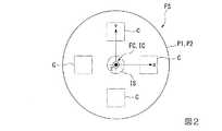
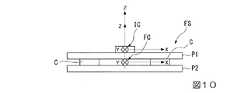
図2は、第1検出部FSの構成の一例を示す上面図である。また、図3は、図2に示した第1検出部FSの側面図である。図2及び図3に示したように、第1検出部FSは、第1プレートP1と、第2プレートP2と、4つの力検出素子Cと、第2検出部ISを備える。また、図2及び図3に示した第1座標系FCは、前述の第1座標系の一例である。また、図2及び図3に示した第2座標系ICは、第2座標系の一例である。なお、図2及び図3では、第1検出部FS内における第2検出部ISの配置を明確に示すため、取得部23及び補正部24が省略されている。また、図3では、図を簡略化するため、4つの力検出素子Cのうち2つの力検出素子Cのみが示されている。 FIG. 2 is a top view illustrating an example of the configuration of the first detection unit FS. FIG. 3 is a side view of the first detection unit FS shown in FIG. As shown in FIGS. 2 and 3, the first detection unit FS includes a first plate P1, a second plate P2, four force detection elements C, and a second detection unit IS. The first coordinate system FC shown in FIGS. 2 and 3 is an example of the first coordinate system described above. The second coordinate system IC shown in FIGS. 2 and 3 is an example of the second coordinate system. 2 and 3, the
図2に示した例では、第1プレートP1及び第2プレートP2のそれぞれは、円板状の部材である。そして、4つの力検出素子Cのそれぞれは、図3に示したように、第1プレートP1と第2プレートP2に挟まれている。第1プレートP1と第2プレートP2は、4つの力検出素子Cのそれぞれを挟んだまま図示しない複数の与圧ボルトによって固定される。これにより、4つの力検出素子Cのそれぞれには、第1プレートP1及び第2プレートP2から所定の圧力が加えられている。この結果、4つの力検出素子Cのそれぞれは、ハンドに外力が作用した際に加わる剪断力に比例した大きさの信号を出力する。なお、当該信号に基づいて第1検出部FSに作用した外力を検出する方法は、既知の方法であってもよく、これから開発される方法であってもよい。 In the example shown in FIG. 2, each of the first plate P1 and the second plate P2 is a disk-shaped member. Each of the four force detection elements C is sandwiched between the first plate P1 and the second plate P2 as shown in FIG. The first plate P1 and the second plate P2 are fixed by a plurality of pressurizing bolts (not shown) while sandwiching each of the four force detection elements C. Thus, a predetermined pressure is applied to each of the four force detection elements C from the first plate P1 and the second plate P2. As a result, each of the four force detection elements C outputs a signal having a magnitude proportional to the shearing force applied when an external force is applied to the hand. In addition, the method of detecting the external force which acted on the 1st detection part FS based on the said signal may be a known method, and may be a method developed from now on.
また、第2プレートP2上には、4つの力検出素子Cのそれぞれが配置されている。4つの力検出素子Cのそれぞれは、図2に示した第2プレートP2上において、第2プレートの中心から予め決められた半径だけ離れた位置に配置されている。当該半径は、如何なる半径であってもよい。また、4つの力検出素子Cのそれぞれは、図2に示した第2プレートP2上において当該中心周りに互いに90°回転した位置に配置されている。すなわち、4つの力検出素子Cのそれぞれの重心を直線で結んだ場合、正四角形が形成される。 In addition, each of the four force detection elements C is arranged on the second plate P2. Each of the four force detection elements C is disposed on the second plate P2 shown in FIG. 2 at a position away from the center of the second plate by a predetermined radius. The radius may be any radius. Further, each of the four force detection elements C is arranged at a position rotated by 90 ° around the center on the second plate P2 shown in FIG. That is, when the center of gravity of each of the four force detection elements C is connected by a straight line, a regular square is formed.
なお、第1検出部FSの構成は、図2及び図3に示した構成に代えて、他の如何なる構造であってもよい。 Note that the configuration of the first detection unit FS may be any other configuration instead of the configuration illustrated in FIGS. 2 and 3.
ここで、第1検出部FSの構成が図2及び図3に示した構成である場合、第2プレートP2が有する面のうち第1プレートP1側の面である上面の中心部分には、何らかの部材を配置することができる空間が存在する。そこで、この一例における第1検出部FSには、図2及び図3に示したように、当該中心部分に第2検出部ISが配置されている。より具体的には、図2及び図3に示した例では、第2検出部ISは、第1座標系FCの原点と第2座標系ICの原点とが一致し、第1座標系FCにおけるX軸と第2座標系ICにおけるX軸とが重なり、第1座標系FCにおけるY軸と第2座標系ICにおけるY軸とが重なり、第1座標系FCにおけるZ軸と第2座標系ICにおけるZ軸とが重なるように、当該中心部分に配置されている。これにより、ロボット20は、第1検出部FSの角速度及び加速度を第2検出部ISが検出する際の誤差を小さくすることができる。また、これにより、ロボット20は、補正部24が行う補正の処理を単純にすることができる。 Here, when the configuration of the first detection unit FS is the configuration illustrated in FIGS. 2 and 3, the center portion of the upper surface, which is the surface on the first plate P1 side, of the surface of the second plate P2 has some There is a space where members can be placed. Therefore, in the first detection unit FS in this example, as shown in FIGS. 2 and 3, the second detection unit IS is arranged at the center portion. More specifically, in the example shown in FIGS. 2 and 3, the second detection unit IS matches the origin of the first coordinate system FC with the origin of the second coordinate system IC, and the first coordinate system FC The X axis and the X axis in the second coordinate system IC overlap, the Y axis in the first coordinate system FC and the Y axis in the second coordinate system IC overlap, and the Z axis and the second coordinate system IC in the first coordinate system FC. Is arranged in the central portion so as to overlap with the Z axis. Thereby, the
<ロボット制御装置のハードウェア構成>
以下、ロボット制御装置30のハードウェア構成について説明する。図4は、ロボット制御装置30のハードウェア構成の一例を示す図である。<Hardware configuration of robot controller>
Hereinafter, the hardware configuration of the
ロボット制御装置30は、例えば、プロセッサー31と、メモリー32と、通信部34を備える。また、ロボット制御装置30は、通信部34を介してロボット20と通信を行う。これらの構成要素は、バスを介して相互に通信可能に接続されている。 The
プロセッサー31は、例えば、CPUである。なお、プロセッサー31は、CPUに代えて、FPGA等の他のプロセッサーであってもよい。プロセッサー31は、メモリー32に格納された各種のプログラムを実行する。
メモリー32は、例えば、HDD(Hard Disk Drive)やSSD(Solid State Drive)、EEPROM(Electrically Erasable Programmable Read−Only Memory)、ROM(Read−Only Memory)、RAM(Random Access Memory)等を含む。なお、メモリー32は、ロボット制御装置30に内蔵されるものに代えて、USB等のデジタル入出力ポート等によって接続された外付け型の記憶装置であってもよい。メモリー32は、ロボット制御装置30が処理する各種の情報、各種の画像、動作プログラム等を格納する。ここで、メモリー32は、前述のメモリーの一例である。
通信部34は、例えば、USB等のデジタル入出力ポートやイーサネット(登録商標)ポート等を含んで構成される。The
The
The
なお、ロボット制御装置30は、キーボード、マウス、タッチパッド等の入力装置と、ディスプレイを有する表示装置とのいずれか一方又は両方を備える構成であってもよい。 The
<ロボット制御装置の機能構成>
以下、図5を参照し、ロボット制御装置30の機能構成について説明する。図5は、ロボット制御装置30の機能構成の一例を示す図である。<Functional configuration of robot controller>
Hereinafter, the functional configuration of the
ロボット制御装置30は、メモリー32と、通信部34と、制御部36を備える。 The
制御部36は、ロボット制御装置30の全体を制御する。制御部36は、ロボット制御部361を備える。制御部36が備えるこれらの機能部は、例えば、プロセッサー31が、メモリー32に記憶された各種の指令を実行することにより実現される。また、当該機能部のうちの一部又は全部は、LSI(Large Scale Integration)、ASIC等のハードウェア機能部であってもよい。 The
ロボット制御部361は、メモリー32に予め記憶された動作プログラムに基づいてロボット20を動作させる。この際、ロボット制御部361は、補正部24から外力情報を取得する。ロボット制御部361は、取得した外力情報に基づく力制御によってロボット20を動作させる。 The
<第1検出部が外力情報をロボット制御装置へ出力する処理>
以下、図6を参照し、第1検出部FSが外力情報をロボット制御装置30へ出力する処理について説明する。図6は、第1検出部FSが外力情報をロボット制御装置30へ出力する処理の流れの一例を示す図である。第1検出部FSは、例えば、第1検出部FSの電源がオンにされた場合、図6に示したフローチャートのステップS110の処理を開始する。また、以下では、一例として、第2検出部ISの電源が、第1検出部FSの電源と連動している場合について説明する。すなわち、第2検出部ISの電源は、第1検出部FSの電源がオンにされた場合にオンになり、第1検出部FSの電源がオフにされた場合にオフになる。なお、第2検出部ISの電源は、これに代えて、第1検出部FSの電源と連動していない構成であってもよい。<Process in which first detection unit outputs external force information to robot controller>
Hereinafter, the process in which the first detection unit FS outputs the external force information to the
取得部23は、第1検出部FSの電源がオンにされてからオフにされるまでの間において前述の取得周期が経過する毎に、ステップS120〜ステップS150の処理を繰り返し実行する(ステップS110)。 The
ステップS110において取得周期が経過したと判定された場合、取得部23は、第1検出部FSから出力される出力値を第1検出部FSから取得するとともに、第2検出部ISから出力される出力値を第2検出部ISから取得する(ステップS120)。ここで、図6に示したフローチャートでは、第1検出部FSから出力される出力値を第1出力値として示し、第2検出部ISから出力される出力値を第2出力値として示している。 When it is determined in step S110 that the acquisition cycle has elapsed, the
次に、補正部24は、ステップS120において取得部23が第1検出部FSから取得した出力値に基づいて第1検出部FSに作用した外力を算出するとともに、ステップS120において取得部23が第2検出部ISから取得した出力値に基づいて第1検出部FSに作用した慣性力を算出する(ステップS130)。第1検出部FSから取得した出力値に基づいて当該外力を補正部24が算出する方法は、既知の方法であってもよく、これから開発される方法であってもよい。また、第2検出部ISから取得した出力値に基づいて当該慣性力を補正部24が算出する方法は、既知の方法であってもよく、これから開発される方法であってもよい。 Next, the
次に、補正部24は、ステップS130において算出した慣性力に基づいて、ステップS130において算出した外力を補正する(ステップS140)。当該慣性力に基づいて当該外力を補正部24が補正する方法は、上記において説明済みであるため、説明を省略する。 Next, the correcting
次に、補正部24は、ステップS140において補正した外力を示す外力情報を生成し、生成した外力情報をロボット制御装置30へ出力する(ステップS150)。 Next, the
なお、取得部23及び補正部24は、第1検出部FSの電源がオフにされた場合、当該電源がオフにされたタイミングにおいて処理を終了する。 In addition, when the power supply of the 1st detection part FS is turned off, the
以上のように、第1検出部FSは、第1検出部FSに作用した慣性力に基づいて、第1検出部FSに作用した外力を補正し、補正した外力を示す外力情報をロボット制御装置30へ出力する。これにより、第1検出部FSは、ロボット制御装置30が力制御によってロボット20に行わせる作業の精度を向上させることができる。また、第1検出部FSが出力する外力情報は、予め当該慣性力によって補正された外力を示す。このため、第1検出部FSは、ロボット制御装置30が当該慣性力に基づいて当該外力を補正する処理に係る負荷を低減することができる。また、第1検出部FSは、当該慣性力に基づく当該外力の補正について意識させることなく、ロボット20の動作プログラムをユーザーに作成させることができる。 As described above, the first detection unit FS corrects the external force applied to the first detection unit FS based on the inertial force applied to the first detection unit FS, and transmits the external force information indicating the corrected external force to the robot control device. Output to 30. Thereby, the 1st detection part FS can improve the precision of the operation | work which the
なお、このように第1検出部FSが外力情報をロボット制御装置30へ出力する場合、ロボット制御装置30の制御部36が備えるロボット制御部361は、動作プログラムによって指定されたタイミングにおいて補正部24から外力情報を取得し、取得した外力情報が示す外力に基づく力制御によってロボット20に予め決められた作業を行わせる。これにより、ロボット20は、力制御による作業を精度よく行うことができる。また、ロボット20は、第1検出部FSに作用した外力から、第1検出部FSに作用した慣性力を差し引かれた当該外力に基づく力制御によってロボット制御装置30により制御される。このため、ロボット20は、ハンドの動き出しのように大きい慣性力が第1検出部FSに作用する場合が多い動作において、当該慣性力による誤動作を生じさせることなくハンドの加速度を大きくすることができる。換言すると、ロボット20は、高速動作を行うことができる。その結果、ロボット20は、予め決められた作業を効率よく行うことができる。このような事情から、当該慣性力に基づく当該外力の補正は、質量の大きな物体をロボット20が保持している場合、前述の終了条件に係る目標力が小さい場合等において、特に重要となる。 When the first detection unit FS outputs the external force information to the
<実施形態の変形例1>
以下、図7及び図8を参照し、実施形態の変形例1について説明する。なお、実施形態の変形例1では、実施形態と同様な構成部に対して同じ符号を付して説明を省略する。<
Hereinafter, a first modification of the embodiment will be described with reference to FIGS. 7 and 8. In addition, in the
実施形態の変形例1では、第1検出部FSが取得部23及び補正部24を備えず、ロボット制御装置30の制御部36が取得部23及び補正部24を備える。図7は、実施形態の変形例1に係るロボット制御装置30の構成の一例を示す図である。図7に示したように、制御部36は、ロボット制御部361に加えて、取得部23と補正部24を備える。 In the first modification of the embodiment, the first detection unit FS does not include the
制御部36が取得部23及び補正部24を備える場合、ロボット制御部361は、図8に示したフローチャートの処理による力制御によってロボット20に予め決められた作業を行わせる。 When the
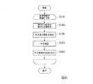
図8は、ロボット制御装置30が力制御によってロボット20に予め決められた作業を行わせる処理の一例を示す図である。以下では、一例として、図8に示したフローチャートのステップS210の処理が、力制御によってロボット20を動作させ始める操作をロボット制御装置30が受け付けた後のタイミングにおいて実行される場合について説明する。なお、ステップS210の処理は、これに代えて、他のタイミングにおいて実行される構成であってもよい。 FIG. 8 is a diagram illustrating an example of processing in which the
取得部23は、第1検出部FSから出力される出力値を第1検出部FSから取得するとともに、第2検出部ISから出力される出力値を第2検出部ISから取得する(ステップS210)。 The
次に、補正部24は、ステップS210において取得部23が第1検出部FSから取得した出力値に基づいて第1検出部FSに作用した外力を算出するとともに、ステップS210において取得部23が第2検出部ISから取得した出力値に基づいて第1検出部FSに作用した慣性力を算出する(ステップS220)。 Next, the
次に、補正部24は、ステップS220において算出した慣性力に基づいて、ステップS220において算出した外力を補正する(ステップS230)。 Next, the
次に、ロボット制御部361は、ステップS230において補正部24が補正した外力に基づいて、予め決められた前述の終了条件が満たされたか否かを判定する(ステップS240)。終了条件が満たされたと判定した場合(ステップS240−YES)、ロボット制御部361は、処理を終了する。一方、終了条件が満たされていないと判定した場合(ステップS240−NO)、ロボット制御部361は、終了条件を満たす外力が第1検出部FSに作用するようにアームAを動作させる(ステップS250)。そして、取得部23は、ステップS210に遷移し、第1検出部FSから出力される出力値を第1検出部FSから再び取得するとともに、第2検出部ISから出力される出力値を第2検出部ISから再び取得する。このようにして、ロボット制御部361は、力制御によってロボット20を動作させ、ロボット20に予め決められた作業を行わせる。 Next, the
以上のように、実施形態の変形例2では、第1検出部FSに作用した外力の補正を、ロボット制御装置30が行う。これにより、ロボット20は、第1検出部FSと第2検出部ISとの少なくとも一方の製造コストが補正部24の分だけ増大してしまうことを抑制することができる。また、実施形態の変形例2においても、ロボット20は、ハンドの動き出しのように大きい慣性力が第1検出部FSに作用する場合が多い動作において、当該慣性力による誤動作を生じさせることなくハンドの加速度を大きくすることができる。その結果、ロボット20は、予め決められた作業を効率よく行うことができる。 As described above, in the second modification of the embodiment, the
<実施形態の変形例2>
以下、図9を参照し、実施形態の変形例2について説明する。なお、実施形態の変形例2では、実施形態と同様な構成部に対して同じ符号を付して説明を省略する。<Modification 2 of Embodiment>
Hereinafter, a second modification of the embodiment will be described with reference to FIG. In the second modification of the embodiment, the same reference numerals are given to the same components as those in the embodiment, and the description thereof is omitted.
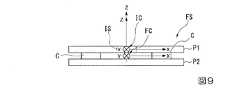
実施形態の変形例2では、第1検出部FS内における第2検出部ISの配置が、図2及び図3に示した配置と異なる。図9は、実施形態の変形例2に係る第1検出部FS内における第2検出部ISの配置の一例を示す側面図である。 In the second modification of the embodiment, the arrangement of the second detection unit IS in the first detection unit FS is different from the arrangement shown in FIGS. 2 and 3. FIG. 9 is a side view illustrating an example of the arrangement of the second detection units IS in the first detection unit FS according to Modification Example 2 of the embodiment.
この一例では、第2検出部ISは、図9に示したように、第1座標系FCにおけるZ軸の正方向から不方向に向かって第1検出部FSを見た場合において、第1座標系FCの原点と第2座標系ICの原点とが一致し、第1座標系FCにおけるX軸と第2座標系ICにおけるX軸とが平行となり、第1座標系FCにおけるY軸と第2座標系ICにおけるY軸とが平行となり、第1座標系FCにおけるZ軸と第2座標系ICにおけるZ軸とが重なるように、第1検出部FS内に配置される。図9に示した例では、第1プレートP1の中心部分に開口部が形成されており、第2検出部ISは、当該開口部に配置されている。これにより、ロボット20は、第2プレートP2の上面の中心部分に第2検出部ISを配置する空間が存在しない場合であっても、第1検出部FS内に第2検出部ISを設けることができ、その結果、第1検出部FSの角速度及び加速度を第2検出部ISが検出する際の誤差を小さくすることができる。ただし、この場合、補正部24は、メモリー32に予め記憶された情報のうち第1座標系FCと第2座標系ICとの間の相対的な位置及び姿勢を示す情報に基づいて、第1検出部FSに作用した外力、及び第1検出部FSに作用した慣性力のそれぞれを算出する。 In this example, as illustrated in FIG. 9, the second detection unit IS has the first coordinates when the first detection unit FS is viewed from the positive direction of the Z axis toward the non-direction in the first coordinate system FC. The origin of the system FC and the origin of the second coordinate system IC coincide, the X axis in the first coordinate system FC and the X axis in the second coordinate system IC are parallel, and the Y axis in the first coordinate system FC and the second axis The Y axis in the coordinate system IC is parallel to the first detection unit FS so that the Z axis in the first coordinate system FC and the Z axis in the second coordinate system IC overlap each other. In the example shown in FIG. 9, an opening is formed in the center portion of the first plate P1, and the second detection unit IS is disposed in the opening. Thereby, the
なお、この一例において、第2検出部ISは、第1座標系FCにおけるZ軸の正方向から不方向に向かって第1検出部FSを見た場合において、第1座標系FCの原点と第2座標系ICの原点とが一致しないように、第1検出部FS内に配置される構成であってもよい。すなわち、第2検出部ISは、第1座標系FCにおけるZ軸と第2座標系ICにおけるZ軸とが重ならないように、第1検出部FS内に配置される構成であってもよい。また、第2検出部ISは、第1座標系FCにおけるX軸と第2座標系ICにおけるX軸とが非平行となり、第1座標系FCにおけるY軸と第2座標系ICにおけるY軸とが非平行となるように、第1検出部FS内に配置される構成であってもよい。また、第2検出部ISは、第1座標系FCにおけるZ軸と第2座標系ICにおけるZ軸とが非平行となるように、第1検出部FS内に配置される構成であってもよい。 In this example, when the second detection unit IS looks at the first detection unit FS from the positive direction of the Z axis toward the non-direction in the first coordinate system FC, The configuration may be arranged in the first detection unit FS so that the origin of the two coordinate system IC does not coincide. That is, the second detection unit IS may be arranged in the first detection unit FS so that the Z axis in the first coordinate system FC and the Z axis in the second coordinate system IC do not overlap. Further, the second detection unit IS is configured such that the X axis in the first coordinate system FC and the X axis in the second coordinate system IC are not parallel, and the Y axis in the first coordinate system FC and the Y axis in the second coordinate system IC are May be arranged in the first detection unit FS so as to be non-parallel. In addition, the second detection unit IS may be arranged in the first detection unit FS so that the Z axis in the first coordinate system FC and the Z axis in the second coordinate system IC are non-parallel. Good.
<実施形態の変形例3>
以下、図10を参照し、実施形態の変形例3について説明する。なお、実施形態の変形例3では、実施形態と同様な構成部に対して同じ符号を付して説明を省略する。<Modification 3 of embodiment>
Hereinafter, a third modification of the embodiment will be described with reference to FIG. In addition, in the modification 3 of embodiment, the same code | symbol is attached | subjected with respect to the component similar to embodiment, and description is abbreviate | omitted.
実施形態の変形例3では、第2検出部ISが、第1検出部FSの外部に配置される。図10は、実施形態の変形例3に係る第1検出部FSと第2検出部ISとの相対的な位置関係の一例を示す側面図である。 In the third modification of the embodiment, the second detection unit IS is disposed outside the first detection unit FS. FIG. 10 is a side view illustrating an example of a relative positional relationship between the first detection unit FS and the second detection unit IS according to Modification Example 3 of the embodiment.
この一例では、第2検出部ISは、第1座標系FCにおけるZ軸の正方向から不方向に向かって第1検出部FSを見た場合において、第1座標系FCの原点と第2座標系ICの原点とが一致し、第1座標系FCにおけるX軸と第2座標系ICにおけるX軸とが平行となり、第1座標系FCにおけるY軸と第2座標系ICにおけるY軸とが平行となり、第1座標系FCにおけるZ軸と第2座標系ICにおけるZ軸とが重なるように、第1検出部FSの外部に配置される。当該外部は、第1検出部FSの外周部分のことである。図10に示した例では、第2検出部ISは、第1プレートP1が有する面のうち第2プレートP2と反対側の面である上面の中心部分に配置されている。これにより、ロボット20は、第1検出部FS内に第2検出部ISを配置する空間が存在しない場合であっても、第1検出部FSの外部に第2検出部ISを設けることができ、その結果、第1検出部FSの角速度及び加速度を第2検出部ISが検出する際の誤差を小さくすることができる。ただし、この場合、補正部24は、メモリー32に予め記憶された情報のうち第1座標系FCと第2座標系ICとの間の相対的な位置及び姿勢を示す情報に基づいて、第1検出部FSに作用した外力、及び第1検出部FSに作用した慣性力のそれぞれを算出する。 In this example, when the second detection unit IS looks at the first detection unit FS from the positive direction of the Z axis toward the non-direction in the first coordinate system FC, the second detection unit IS and the second coordinate unit FC The origin of the system IC coincides, the X axis in the first coordinate system FC and the X axis in the second coordinate system IC are parallel, and the Y axis in the first coordinate system FC and the Y axis in the second coordinate system IC are They are parallel and are arranged outside the first detection unit FS so that the Z axis in the first coordinate system FC and the Z axis in the second coordinate system IC overlap. The outside is an outer peripheral portion of the first detection unit FS. In the example illustrated in FIG. 10, the second detection unit IS is disposed at the center portion of the upper surface that is the surface opposite to the second plate P2 among the surfaces of the first plate P1. Accordingly, the
なお、この一例において、第2検出部ISは、第1座標系FCにおけるZ軸の正方向から不方向に向かって第1検出部FSを見た場合において、第1座標系FCの原点と第2座標系ICの原点とが一致しないように、第1検出部FSの外部に配置される構成であってもよい。すなわち、第2検出部ISは、第1座標系FCにおけるZ軸と第2座標系ICにおけるZ軸とが重ならないように、第1検出部FSの外部に配置される構成であってもよい。また、第2検出部ISは、第1座標系FCにおけるX軸と第2座標系ICにおけるX軸とが非平行となり、第1座標系FCにおけるY軸と第2座標系ICにおけるY軸とが非平行となるように、第1検出部FSの外部に配置される構成であってもよい。また、第2検出部ISは、第1座標系FCにおけるZ軸と第2座標系ICにおけるZ軸とが非平行となるように、第1検出部FSの外部に配置される構成であってもよい。 In this example, when the second detection unit IS looks at the first detection unit FS from the positive direction of the Z axis toward the non-direction in the first coordinate system FC, The arrangement may be such that the origin of the two-coordinate system IC does not coincide with the origin of the first detection unit FS. That is, the second detection unit IS may be arranged outside the first detection unit FS so that the Z axis in the first coordinate system FC and the Z axis in the second coordinate system IC do not overlap. . Further, the second detection unit IS is configured such that the X axis in the first coordinate system FC and the X axis in the second coordinate system IC are not parallel, and the Y axis in the first coordinate system FC and the Y axis in the second coordinate system IC are May be arranged outside the first detection unit FS so that they are non-parallel. Further, the second detection unit IS is arranged outside the first detection unit FS so that the Z axis in the first coordinate system FC and the Z axis in the second coordinate system IC are non-parallel. Also good.
<実施形態の変形例4>
以下、図11を参照し、実施形態の変形例4について説明する。なお、実施形態の変形例4では、実施形態と同様な構成部に対して同じ符号を付して説明を省略する。<Modification 4 of embodiment>
Hereinafter, a fourth modification of the embodiment will be described with reference to FIG. In addition, in the modification 4 of embodiment, the same code | symbol is attached | subjected with respect to the component similar to embodiment, and description is abbreviate | omitted.
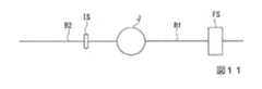
実施形態の変形例4では、第2検出部ISが、第1検出部FSの近傍に配置される。第1検出部FSの近傍は、第1検出部FSが設けられた部材に応じて決まる。具体的には、ロボット20が備えるアームAにおいて、第1関節〜第6関節のいずれかの関節に接続された第1部材と、第1部材に接続された関節と接続された第2部材と、当該関節とのいずれかに第1検出部FSが設けられている場合、第1検出部FSの近傍には、第1部材と、当該関節と、第2部材とが含まれる。この一例において、第1検出部FSは、第6リンクに設けられている。この場合、第2検出部ISを第6リンク、第6関節、第5リンクのいずれかに設けることは、第2検出部ISを第1検出部FSの近傍に設けることを意味する。当該場合、第6リンクは、第1部材又は第2部材の一例である。第6リンクが第1部材の一例である場合、第5リンクは、第2部材の一例である。また、第6リンクが第2部材の一例である場合、第5リンクは、第1部材の一例である。また、当該場合、第6関節は、当該関節の一例である。 In the fourth modification of the embodiment, the second detection unit IS is disposed in the vicinity of the first detection unit FS. The vicinity of the first detection unit FS is determined according to the member provided with the first detection unit FS. Specifically, in the arm A included in the
図11は、実施形態の変形例4に係る第1検出部FSと第2検出部ISとの相対的な位置関係の一例を示す図である。図11に示した部材B1は、第1部材を示す。図11に示した部材B2は、第2部材を示す。図11に示した関節Jは、第1部材と第2部材とを接続する関節を示す。図11に示した例では、第1検出部FSが、部材B1に設けられている。すなわち、当該例では、第1検出部FSの近傍には、部材B1と、関節Jと、部材B2とが含まれる。そして、当該例では、第2検出部ISは、部材B2に設けられている。 FIG. 11 is a diagram illustrating an example of a relative positional relationship between the first detection unit FS and the second detection unit IS according to Modification Example 4 of the embodiment. A member B1 illustrated in FIG. 11 represents a first member. A member B2 illustrated in FIG. 11 represents a second member. A joint J shown in FIG. 11 is a joint that connects the first member and the second member. In the example illustrated in FIG. 11, the first detection unit FS is provided in the member B1. That is, in this example, the member B1, the joint J, and the member B2 are included in the vicinity of the first detection unit FS. In the example, the second detection unit IS is provided on the member B2.
ここで、1つの関節を介して繋がる2つの部材、すなわち第1部材と第2部材との間の相対的な位置及び姿勢は、2つ以上の関節を介して繋がる2つの部材間の相対的な位置及び姿勢を算出する場合と比較して、当該1つの関節の回動角に基づいて精度よく算出することができる。このため、図11に示したように、第1検出部FSが部材B1に設けられている場合、第1検出部FSの近傍には、部材B1と、関節Jと、部材B2とが含まれる。 Here, the relative position and posture between two members connected via one joint, that is, the first member and the second member are relative between two members connected via two or more joints. As compared with the case of calculating the correct position and orientation, it is possible to calculate with high accuracy based on the rotation angle of the one joint. For this reason, as shown in FIG. 11, when the first detection unit FS is provided in the member B1, the member B1, the joint J, and the member B2 are included in the vicinity of the first detection unit FS. .
なお、上記において説明したアクチュエーターは、駆動部の一例である。
また、上記において説明した第1検出部FSは、力検出器の一例である。The actuator described above is an example of a drive unit.
The first detection unit FS described above is an example of a force detector.
また、上記において説明した補正部24は、第1検出部FSから出力された出力値に基づいて算出した外力について、第2検出部ISから出力される出力値に基づいて算出した慣性力に基づく補正とともに、重力補償を行う構成であってもよい。補正部24が重力補償を行う方法は、既知の方法であってもよく、これから開発される方法であってもよい。 Further, the
また、上記において説明したロボット20は、単腕ロボットに代えて、複腕ロボットであってもよい。複腕ロボットは、2本以上の腕を備えるロボットである。当該2本以上の腕は、例えば、2本以上のアームAである。ここで、複腕ロボットのうち、2本の腕を備えるロボットは、双腕ロボットとも称される。すなわち、ロボット20は、2本の腕を備える双腕ロボットであってもよく、3本以上の腕を備える複腕ロボットであってもよい。当該2本の腕は、例えば、2本のアームAである。当該3本以上の腕は、例えば、3本以上のアームAである。また、ロボット20は、スカラロボット(水平多関節ロボット)、直交座標ロボット、円筒型ロボット等の他のロボットであってもよい。直交座標ロボットは、例えば、ガントリロボットである。 Further, the
また、上記において説明したエンドエフェクターEは、空気の吸引や磁力、他の治具等によって物体を持ち上げることにより当該物体を保持する構成であってもよい。なお、この一例において、保持するとは、物体を持ち上げることが可能な状態にすることを意味する。 Further, the end effector E described above may be configured to hold the object by lifting the object by air suction, magnetic force, other jigs, or the like. In this example, holding means that the object can be lifted.
また、上記において説明した第1検出部FSは、エンドエフェクターEに作用した外力、又はエンドエフェクターEにより保持された物体に作用した外力を検出するトルクセンサーであってもよい。また、第1検出部FSは、エンドエフェクターEに作用した外力、又は当該物体に作用した外力を検出する他のセンサーであってもよい。また、第1検出部FSは、エンドエフェクターEとマニピュレーターMの間に備えられる構成に代えて、ロボット20の他の部位に備えられる構成であってもよい。この場合、第1検出部FSは、当該部位に作用する外力を検出する。 Further, the first detection unit FS described above may be a torque sensor that detects an external force applied to the end effector E or an external force applied to an object held by the end effector E. The first detection unit FS may be another sensor that detects an external force acting on the end effector E or an external force acting on the object. Further, the first detection unit FS may be configured to be provided in another part of the
また、上記において説明した基台Bが第1部材の一例である場合、第1関節が関節の一例であり、第1リンクが第2部材の一例である。
また、上記において説明した第1リンクが第1部材の一例である場合、第2関節が関節の一例であり、第2リンクが第2部材の一例である。
また、上記において説明した第2リンクが第1部材の一例である場合、第3関節が関節の一例であり、第3リンクが第2部材の一例である。
また、上記において説明した第3リンクが第1部材の一例である場合、第4関節が関節の一例であり、第4リンクが第2部材の一例である。
また、上記において説明した第4リンクが第1部材の一例である場合、第5関節が関節の一例であり、第5リンクが第2部材の一例である。
また、上記において説明した第5リンクが第1部材の一例である場合、第6関節が関節の一例であり、第6リンクが第2部材の一例である。なお、当該場合、第2部材の一例には、エンドエフェクターEが含まれてもよい。
また、上記において説明した第6リンクが第1部材の一例である場合、第6関節が関節の一例であり、第5リンクが第2部材の一例である。なお、当該場合、第1部材の一例には、エンドエフェクターEが含まれてもよい。
また、上記において説明した第5リンクが第1部材の一例である場合、第5関節が関節の一例であり、第4リンクが第2部材の一例である。
また、上記において説明した第4リンクが第1部材の一例である場合、第4関節が関節の一例であり、第3リンクが第2部材の一例である。
また、上記において説明した第3リンクが第1部材の一例である場合、第3関節が関節の一例であり、第2リンクが第2部材の一例である。
また、上記において説明した第2リンクが第1部材の一例である場合、第2関節が関節の一例であり、第1リンクが第2部材の一例である。
また、上記において説明した第1リンクが第1部材の一例である場合、第1関節が関節の一例であり、基台Bが第2部材の一例である。Moreover, when the base B demonstrated above is an example of a 1st member, a 1st joint is an example of a joint and a 1st link is an example of a 2nd member.
Moreover, when the 1st link demonstrated in the above is an example of a 1st member, a 2nd joint is an example of a joint and a 2nd link is an example of a 2nd member.
Moreover, when the 2nd link demonstrated above is an example of a 1st member, a 3rd joint is an example of a joint, and a 3rd link is an example of a 2nd member.
Moreover, when the 3rd link demonstrated above is an example of a 1st member, a 4th joint is an example of a joint and a 4th link is an example of a 2nd member.
Moreover, when the 4th link demonstrated above is an example of a 1st member, a 5th joint is an example of a joint and a 5th link is an example of a 2nd member.
Moreover, when the 5th link demonstrated above is an example of a 1st member, a 6th joint is an example of a joint and a 6th link is an example of a 2nd member. In this case, the end effector E may be included as an example of the second member.
Moreover, when the 6th link demonstrated above is an example of a 1st member, a 6th joint is an example of a joint and a 5th link is an example of a 2nd member. In this case, the end effector E may be included as an example of the first member.
Moreover, when the 5th link demonstrated above is an example of a 1st member, a 5th joint is an example of a joint and a 4th link is an example of a 2nd member.
Moreover, when the 4th link demonstrated above is an example of a 1st member, a 4th joint is an example of a joint and a 3rd link is an example of a 2nd member.
Moreover, when the 3rd link demonstrated above is an example of a 1st member, a 3rd joint is an example of a joint, and a 2nd link is an example of a 2nd member.
Moreover, when the 2nd link demonstrated above is an example of a 1st member, a 2nd joint is an example of a joint and a 1st link is an example of a 2nd member.
Moreover, when the 1st link demonstrated above is an example of a 1st member, a 1st joint is an example of a joint and the base B is an example of a 2nd member.
また、上記において説明した第1座標系におけるX軸が第11座標軸の一例である場合、第1座標系におけるY軸が第12座標軸の一例、及び第1座標系におけるZ軸が第13座標軸の一例であってもよく、当該Z軸が第12座標軸の一例、及び当該Y軸が第13座標軸の一例であってもよい。
また、上記において説明した第1座標系におけるY軸が第11座標軸の一例である場合、第1座標系におけるX軸が第12座標軸の一例、及び第1座標系におけるZ軸が第13座標軸の一例であってもよく、当該Z軸が第12座標軸の一例、及び当該X軸が第13座標軸の一例であってもよい。
また、上記において説明した第1座標系におけるZ軸が第11座標軸の一例である場合、第1座標系におけるX軸が第12座標軸の一例、及び第1座標系におけるY軸が第13座標軸の一例であってもよく、当該Y軸が第12座標軸の一例、及び当該X軸が第13座標軸の一例であってもよい。
また、上記において説明した第2座標系におけるX軸が第21座標軸の一例である場合、第2座標系におけるY軸が第22座標軸の一例、及び第2座標系におけるZ軸が第23座標軸の一例であってもよく、当該Z軸が第22座標軸の一例、及び当該Y軸が第23座標軸の一例であってもよい。
また、上記において説明した第2座標系におけるY軸が第21座標軸の一例である場合、第2座標系におけるX軸が第22座標軸の一例、及び第2座標系におけるZ軸が第23座標軸の一例であってもよく、当該Z軸が第22座標軸の一例、及び当該X軸が第23座標軸の一例であってもよい。
また、上記において説明した第2座標系におけるZ軸が第21座標軸の一例である場合、第2座標系におけるX軸が第22座標軸の一例、及び第2座標系におけるY軸が第23座標軸の一例であってもよく、当該Y軸が第22座標軸の一例、及び当該X軸が第23座標軸の一例であってもよい。When the X axis in the first coordinate system described above is an example of the eleventh coordinate axis, the Y axis in the first coordinate system is an example of the twelfth coordinate axis, and the Z axis in the first coordinate system is the thirteenth coordinate axis. For example, the Z axis may be an example of a twelfth coordinate axis, and the Y axis may be an example of a thirteenth coordinate axis.
When the Y axis in the first coordinate system described above is an example of the eleventh coordinate axis, the X axis in the first coordinate system is an example of the twelfth coordinate axis, and the Z axis in the first coordinate system is the thirteenth coordinate axis. For example, the Z axis may be an example of a twelfth coordinate axis, and the X axis may be an example of a thirteenth coordinate axis.
Further, when the Z axis in the first coordinate system described above is an example of the eleventh coordinate axis, the X axis in the first coordinate system is an example of the twelfth coordinate axis, and the Y axis in the first coordinate system is the thirteenth coordinate axis. For example, the Y axis may be an example of a twelfth coordinate axis, and the X axis may be an example of a thirteenth coordinate axis.
When the X axis in the second coordinate system described above is an example of the 21st coordinate axis, the Y axis in the second coordinate system is an example of the 22nd coordinate axis, and the Z axis in the second coordinate system is the 23rd coordinate axis. For example, the Z axis may be an example of a 22nd coordinate axis, and the Y axis may be an example of a 23rd coordinate axis.
In addition, when the Y axis in the second coordinate system described above is an example of the 21st coordinate axis, the X axis in the second coordinate system is an example of the 22nd coordinate axis, and the Z axis in the second coordinate system is the 23rd coordinate axis. The Z axis may be an example of a 22nd coordinate axis, and the X axis may be an example of a 23rd coordinate axis.
Further, when the Z axis in the second coordinate system described above is an example of the 21st coordinate axis, the X axis in the second coordinate system is an example of the 22nd coordinate axis, and the Y axis in the second coordinate system is the 23rd coordinate axis. For example, the Y axis may be an example of a 22nd coordinate axis, and the X axis may be an example of a 23rd coordinate axis.
以上のように、ロボットは、第1部材と、第2部材と、第1部材と第2部材とを接続し、駆動部が設けられた関節と、並進力と回転モーメントとのいずれか一方又は両方を検出する第1検出部と、角速度と加速度とのいずれか一方又は両方を検出する第2検出部と、第1検出部から出力された出力値を、第2検出部から出力された出力値に基づいて補正する補正部と、を備え、第1検出部は、第1部材と第2部材と関節とのいずれかに設けられ、第2検出部は、第1部材と第2部材と関節とのいずれかに設けられた、
ロボット。これにより、ロボットは、力制御による作業を精度よく行うことができる。また、ロボットは、第1検出部と第2検出部との少なくとも一方の製造コストが、補正部の分だけ増大してしまうことを抑制することができる。ここで、ロボットは、この一例において、ロボット20のことである。第1部材は、この一例において、第6リンクのことである。第2部材は、この一例において、第5リンクのことである。当該関節は、この一例において、第6関節のことである。第1検出部は、この一例において、第1検出部FSのことである。第2検出部は、この一例において、第2検出部ISのことである。補正部は、この一例において、補正部24のことである。As described above, the robot connects the first member, the second member, the first member and the second member, and has either one of the joint provided with the drive unit, the translational force and the rotational moment, or A first detection unit that detects both, a second detection unit that detects one or both of angular velocity and acceleration, and an output value output from the first detection unit. A correction unit that corrects based on the value, the first detection unit is provided in any of the first member, the second member, and the joint, and the second detection unit includes the first member and the second member Provided in one of the joints,
robot. Thereby, the robot can perform the work by force control with high accuracy. Further, the robot can suppress an increase in the manufacturing cost of at least one of the first detection unit and the second detection unit by the amount corresponding to the correction unit. Here, the robot is the
また、ロボットでは、第1検出部による検出において基準となる三次元座標系である第1座標系が有する3つの座標軸のうちの第11座標軸と、第2検出部による検出において基準となる三次元座標系である第2座標系が有する3つの座標軸のうちの第21座標軸とが重なっている。これにより、ロボットは、第1検出部の角速度と加速度とのいずれか一方又は両方を、第2検出部により精度よく検出することができる。ここで、第11座標軸は、この一例において、第1座標軸におけるZ軸のことである。第21座標軸は、この一例において、第2座標軸におけるZ軸のことである。 In the robot, the eleventh coordinate axis among the three coordinate axes of the first coordinate system which is a reference three-dimensional coordinate system in detection by the first detection unit and the reference three-dimensional in detection by the second detection unit. The 21st coordinate axis of the 3 coordinate axes which the 2nd coordinate system which is a coordinate system has has overlapped. Thereby, the robot can detect either one or both of the angular velocity and acceleration of the first detection unit with high accuracy by the second detection unit. Here, the eleventh coordinate axis is the Z axis in the first coordinate axis in this example. In this example, the twenty-first coordinate axis is the Z-axis in the second coordinate axis.
また、ロボットでは、第1座標系が有する3つの座標軸のうち第11座標軸と異なる第12座標軸と、第2座標系が有する3つの座標軸のうち第21座標軸と異なる第22座標軸とが重なっており、第1座標系が有する3つの座標軸のうち第11座標軸及び第12座標軸のそれぞれと異なる第13座標軸と、第2座標系が有する3つの座標軸のうち第21座標軸及び第22座標軸のそれぞれと異なる第23座標軸とが重なっている。これにより、ロボットは、第1検出部の角速度と加速度とのいずれか一方又は両方を、第2検出部により更に精度よく検出することができる。ここで、第12座標軸は、この一例において、第1座標軸におけるX軸のことである。第13座標軸は、この一例において、第1座標軸におけるY軸のことである。第22座標軸は、この一例において、第2座標軸におけるX軸のことである。第23座標軸は、この一例において、第2座標軸におけるY軸のことである。 In the robot, among the three coordinate axes of the first coordinate system, the twelfth coordinate axis different from the eleventh coordinate axis and the twenty-second coordinate axis different from the twenty-first coordinate axis among the three coordinate axes of the second coordinate system overlap. The first coordinate system has three coordinate axes that are different from the eleventh coordinate axis and the twelfth coordinate axis, and the third coordinate system has three coordinate axes that are different from the twenty-first coordinate axis and the twenty-second coordinate axis. The 23rd coordinate axis overlaps. Thereby, the robot can detect either one or both of the angular velocity and acceleration of the first detection unit with higher accuracy by the second detection unit. Here, the twelfth coordinate axis is the X axis in the first coordinate axis in this example. In this example, the thirteenth coordinate axis is the Y axis in the first coordinate axis. In this example, the 22nd coordinate axis is the X axis in the second coordinate axis. In this example, the 23rd coordinate axis is the Y axis in the second coordinate axis.
また、ロボットでは、第1検出部は、第2検出部を内蔵している。これにより、ロボットは、小型化と省配線化との少なくとも一方を図ることができる。 In the robot, the first detection unit includes a second detection unit. Thereby, the robot can achieve at least one of size reduction and wiring saving.
また、ロボットでは、第1検出部が補正部を備える。これにより、ロボットは、ロボットを制御する装置が行う処理のうち力制御によってロボットを動作させる処理に係る負荷を低減することができる。 In the robot, the first detection unit includes a correction unit. As a result, the robot can reduce the load related to the process of operating the robot by force control among the processes performed by the device that controls the robot.
また、ロボットでは、第1部材と、第2部材と、関節とを備えたアームと、アームを動作させる制御部と、を備える。また、ロボットでは、制御部は、補正部を備える。これにより、ロボットは、制御部が行う処理のうち力制御によってロボットを動作させる処理に係る負荷を低減することができる。 The robot also includes an arm having a first member, a second member, and a joint, and a control unit that operates the arm. In the robot, the control unit includes a correction unit. Thereby, the robot can reduce the load concerning the process of operating the robot by force control among the processes performed by the control unit.
また、ロボットでは、制御部は、第1検出部からの出力値の取得と、第2検出部からの出力値の取得とを行う取得部を備える。また、ロボットでは、取得部が第1検出部から出力値を取得する周期と、取得部が第2検出部から出力値を取得する周期とが、同期している。これにより、ロボットは、第1検出部による検出時における第1検出部の角速度と加速度とのいずれか一方又は両方を取得することができる。その結果、ロボットは、力制御による作業を、更に精度よく行うことができる。 In the robot, the control unit includes an acquisition unit that acquires the output value from the first detection unit and the output value from the second detection unit. In the robot, the cycle in which the acquisition unit acquires the output value from the first detection unit and the cycle in which the acquisition unit acquires the output value from the second detection unit are synchronized. Thereby, the robot can acquire either one or both of the angular velocity and acceleration of the 1st detection part at the time of the detection by a 1st detection part. As a result, the robot can perform work by force control with higher accuracy.
また、ロボットでは、制御部は、第1検出部からの出力値の取得と、第2検出部からの出力値の取得とを行う取得部を備える。また、ロボットでは、取得部が第1検出部から出力値を取得する周期と、取得部が第2検出部から出力値を取得する周期とが、同期している。これにより、ロボットは、第1検出部による検出時における第1検出部の角速度と加速度とのいずれか一方又は両方を取得することができる。その結果、ロボットは、力制御による作業を、更に精度よく行うことができる。 In the robot, the control unit includes an acquisition unit that acquires the output value from the first detection unit and the output value from the second detection unit. In the robot, the cycle in which the acquisition unit acquires the output value from the first detection unit and the cycle in which the acquisition unit acquires the output value from the second detection unit are synchronized. Thereby, the robot can acquire either one or both of the angular velocity and acceleration of the 1st detection part at the time of the detection by a 1st detection part. As a result, the robot can perform work by force control with higher accuracy.
以上、この発明の実施形態を、図面を参照して詳述してきたが、具体的な構成はこの実施形態に限られるものではなく、この発明の要旨を逸脱しない限り、変更、置換、削除等されてもよい。 The embodiment of the present invention has been described in detail with reference to the drawings. However, the specific configuration is not limited to this embodiment, and changes, substitutions, deletions, and the like are possible without departing from the gist of the present invention. May be.
また、以上に説明した装置における任意の構成部の機能を実現するためのプログラムを、コンピューター読み取り可能な記録媒体に記録し、そのプログラムをコンピューターシステムに読み込ませて実行するようにしてもよい。当該装置は、例えば、ロボット制御装置30、取得部23及び補正部24を備えた第1検出部FS等である。なお、ここでいう「コンピューターシステム」とは、OS(Operating System)や周辺機器等のハードウェアを含むものとする。また、「コンピューター読み取り可能な記録媒体」とは、フレキシブルディスク、光磁気ディスク、ROM、CD(Compact Disk)−ROM等の可搬媒体、コンピューターシステムに内蔵されるハードディスク等の記憶装置のことをいう。さらに「コンピューター読み取り可能な記録媒体」とは、インターネット等のネットワークや電話回線等の通信回線を介してプログラムが送信された場合のサーバーやクライアントとなるコンピューターシステム内部の揮発性メモリー(RAM)のように、一定時間プログラムを保持しているものも含むものとする。 Further, a program for realizing the function of any component in the above-described apparatus may be recorded on a computer-readable recording medium, and the program may be read into a computer system and executed. The apparatus is, for example, a first detection unit FS including a
また、上記のプログラムは、このプログラムを記憶装置等に格納したコンピューターシステムから、伝送媒体を介して、あるいは、伝送媒体中の伝送波により他のコンピューターシステムに伝送されてもよい。ここで、プログラムを伝送する「伝送媒体」は、インターネット等のネットワーク(通信網)や電話回線等の通信回線(通信線)のように情報を伝送する機能を有する媒体のことをいう。
また、上記のプログラムは、前述した機能の一部を実現するためのものであってもよい。さらに、上記のプログラムは、前述した機能をコンピューターシステムにすでに記録されているプログラムとの組み合わせで実現できるもの、いわゆる差分ファイル、差分プログラム等であってもよい。In addition, the above program may be transmitted from a computer system storing the program in a storage device or the like to another computer system via a transmission medium or by a transmission wave in the transmission medium. Here, the “transmission medium” for transmitting the program refers to a medium having a function of transmitting information, such as a network (communication network) such as the Internet or a communication line (communication line) such as a telephone line.
Further, the above program may be for realizing a part of the functions described above. Further, the program may be a program that can realize the above-described functions in combination with a program already recorded in a computer system, a so-called difference file, a difference program, or the like.
1…ロボットシステム、20…ロボット、23…取得部、24…補正部、30…ロボット制御装置、31…プロセッサー、32…メモリー、34…通信部、36…制御部、361…ロボット制御部、A…アーム、B1、B2…部材、FC…第1座標系、IC…第2座標系、FS…第1検出部、IS…第2検出部、J…関節DESCRIPTION OF
Claims (12)
Translated fromJapanese第2部材と、
前記第1部材と前記第2部材とを接続し、駆動部が設けられた関節と、
並進力と回転モーメントとのいずれか一方又は両方を検出する第1検出部と、
角速度と加速度とのいずれか一方又は両方を検出する第2検出部と、
前記第1検出部から出力された出力値を、前記第2検出部から出力された出力値に基づいて補正する補正部と、
を備え、
前記第1検出部は、前記第1部材と前記第2部材と前記関節とのいずれかに設けられ、
前記第2検出部は、前記第1部材と前記第2部材と前記関節とのいずれかに設けられた、
ロボット。A first member;
A second member;
A joint that connects the first member and the second member and is provided with a drive unit;
A first detector for detecting either or both of a translational force and a rotational moment;
A second detection unit for detecting one or both of angular velocity and acceleration;
A correction unit that corrects the output value output from the first detection unit based on the output value output from the second detection unit;
With
The first detection unit is provided in any of the first member, the second member, and the joint,
The second detection unit is provided in any of the first member, the second member, and the joint,
robot.
請求項1に記載のロボット。An eleventh coordinate axis among the three coordinate axes of the first coordinate system, which is a reference three-dimensional coordinate system in detection by the first detection unit, and a reference three-dimensional coordinate system in detection by the second detection unit The 21st coordinate axis of the 3 coordinate axes that a certain second coordinate system has overlaps,
The robot according to claim 1.
前記第1座標系が有する3つの座標軸のうち前記第11座標軸及び前記第12座標軸のそれぞれと異なる第13座標軸と、前記第2座標系が有する3つの座標軸のうち前記第21座標軸及び前記第22座標軸のそれぞれと異なる第23座標軸とが重なっている、
請求項2に記載のロボット。Of the three coordinate axes that the first coordinate system has, a twelfth coordinate axis that is different from the eleventh coordinate axis and a twenty-second coordinate axis that differs from the twenty-first coordinate axis among the three coordinate axes that the second coordinate system has,
Of the three coordinate axes of the first coordinate system, a thirteenth coordinate axis different from each of the eleventh coordinate axis and the twelfth coordinate axis, and among the three coordinate axes of the second coordinate system, the twenty-first coordinate axis and the twenty-second coordinate axis. 23rd coordinate axes that are different from each of the coordinate axes overlap,
The robot according to claim 2.
請求項1から3のうちいずれか一項に記載のロボット。The first detection unit includes the second detection unit,
The robot according to any one of claims 1 to 3.
請求項1から4のうちいずれか一項に記載のロボット。The first detection unit includes the correction unit;
The robot according to any one of claims 1 to 4.
前記アームを動作させる制御部と、
を備え、
前記制御部は、
前記補正部を備える、
請求項1から4のうちいずれか一項に記載のロボット。An arm including the first member, the second member, and the joint;
A control unit for operating the arm;
With
The controller is
Comprising the correction unit,
The robot according to any one of claims 1 to 4.
前記第1検出部からの出力値の取得と、前記第2検出部からの出力値の取得とを行う取得部を備え、
前記取得部が前記第1検出部から出力値を取得する周期と、前記取得部が前記第2検出部から出力値を取得する周期とが、同期している、
請求項6に記載のロボット。The controller is
An acquisition unit that performs acquisition of an output value from the first detection unit and acquisition of an output value from the second detection unit;
The cycle in which the acquisition unit acquires the output value from the first detection unit and the cycle in which the acquisition unit acquires the output value from the second detection unit are synchronized,
The robot according to claim 6.
ロボット制御装置。Controlling the robot according to any one of claims 1 to 5,
Robot control device.
前記制御部を備える、
ロボット制御装置。Controlling the robot according to claim 6 or 7,
Comprising the control unit,
Robot control device.
前記ロボットを制御するロボット制御装置と、
を備えるロボットシステム。A robot according to any one of claims 1 to 5;
A robot controller for controlling the robot;
A robot system comprising:
前記ロボットを制御し、前記制御部を備えるロボット制御装置と、
を備えるロボットシステム。A robot according to claim 6 or 7,
A robot control device that controls the robot and includes the control unit;
A robot system comprising:
角速度と加速度とのいずれか一方又は両方を検出する検出部を内蔵する、
力検出器。A force detector for detecting either or both of a translational force and a rotational moment,
Built-in detection unit that detects one or both of angular velocity and acceleration,
Force detector.
Priority Applications (1)
| Application Number | Priority Date | Filing Date | Title |
|---|---|---|---|
| JP2018029432AJP2019144147A (en) | 2018-02-22 | 2018-02-22 | Robot, robot controller, robot system, and force detector |
Applications Claiming Priority (1)
| Application Number | Priority Date | Filing Date | Title |
|---|---|---|---|
| JP2018029432AJP2019144147A (en) | 2018-02-22 | 2018-02-22 | Robot, robot controller, robot system, and force detector |
Publications (1)
| Publication Number | Publication Date |
|---|---|
| JP2019144147Atrue JP2019144147A (en) | 2019-08-29 |
Family
ID=67772213
Family Applications (1)
| Application Number | Title | Priority Date | Filing Date |
|---|---|---|---|
| JP2018029432APendingJP2019144147A (en) | 2018-02-22 | 2018-02-22 | Robot, robot controller, robot system, and force detector |
Country Status (1)
| Country | Link |
|---|---|
| JP (1) | JP2019144147A (en) |
- 2018
- 2018-02-22JPJP2018029432Apatent/JP2019144147A/enactivePending
Similar Documents
| Publication | Publication Date | Title |
|---|---|---|
| US10434646B2 (en) | Robot control apparatus, robot, and robot system | |
| US11090814B2 (en) | Robot control method | |
| US10532461B2 (en) | Robot and robot system | |
| US10773399B2 (en) | Control device and robot system | |
| EP3403774A1 (en) | Robot hand, robot apparatus, and control method for robot hand | |
| US10377043B2 (en) | Robot control apparatus, robot, and robot system | |
| US20180093379A1 (en) | Robot control apparatus, robot, and robot system | |
| US10882182B2 (en) | Robot apparatus, control method of robot apparatus, and recording medium | |
| US20170277167A1 (en) | Robot system, robot control device, and robot | |
| US10195744B2 (en) | Control device, robot, and robot system | |
| US10773391B2 (en) | Control device and robot system | |
| JP2018075672A (en) | Control device, robot, and robot system | |
| JP6696341B2 (en) | Control method | |
| JP2015186834A (en) | Robot control apparatus, holding unit control device, robot, holding unit, robot control method and program | |
| US20180085920A1 (en) | Robot control device, robot, and robot system | |
| JP2021003771A (en) | Robot system | |
| JP6003312B2 (en) | Robot system | |
| JP2017205819A (en) | Robot, control device and robot system | |
| JP2013144325A (en) | Robot apparatus, and failure detection method | |
| JPWO2017175340A1 (en) | Optimization device and vertical articulated robot having the same | |
| US11541541B2 (en) | Gripping system | |
| JP2015085499A (en) | Robot, robot system, control apparatus and control method | |
| JP2019144147A (en) | Robot, robot controller, robot system, and force detector | |
| JP6958091B2 (en) | Robot system and robot control method | |
| JP2019010700A (en) | Robot, robot system, and control method thereof |
Legal Events
| Date | Code | Title | Description |
|---|---|---|---|
| RD05 | Notification of revocation of power of attorney | Free format text:JAPANESE INTERMEDIATE CODE: A7425 Effective date:20180910 | |
| RD03 | Notification of appointment of power of attorney | Free format text:JAPANESE INTERMEDIATE CODE: A7423 Effective date:20190920 | |
| RD07 | Notification of extinguishment of power of attorney | Free format text:JAPANESE INTERMEDIATE CODE: A7427 Effective date:20200806 |