JP2019141373A - Brain function measurement device - Google Patents
Brain function measurement deviceDownload PDFInfo
- Publication number
- JP2019141373A JP2019141373AJP2018029431AJP2018029431AJP2019141373AJP 2019141373 AJP2019141373 AJP 2019141373AJP 2018029431 AJP2018029431 AJP 2018029431AJP 2018029431 AJP2018029431 AJP 2018029431AJP 2019141373 AJP2019141373 AJP 2019141373A
- Authority
- JP
- Japan
- Prior art keywords
- light source
- unit
- source unit
- ventilation
- head
- Prior art date
- Legal status (The legal status is an assumption and is not a legal conclusion. Google has not performed a legal analysis and makes no representation as to the accuracy of the status listed.)
- Withdrawn
Links
Images


Landscapes
- Measurement Of The Respiration, Hearing Ability, Form, And Blood Characteristics Of Living Organisms (AREA)
Abstract
Description
Translated fromJapanese本発明は、近赤外分光法を用いた脳機能測定装置に関するものである。 The present invention relates to a brain function measuring apparatus using near infrared spectroscopy.
特許文献1には、近赤外分光法を用いて、頭部に向けて光源から光を照射し、脳によって拡散された光を受光部により検出し、この検出結果から脳機能を測定する脳機能測定装置が記載されている。 Patent Document 1 discloses a brain that uses near infrared spectroscopy to irradiate light from a light source toward the head, detect light diffused by the brain with a light receiving unit, and measure brain function from the detection result. A functional measuring device is described.
しかし、頭部には毛髪があるため、毛髪が光を遮ることにより、脳機能を正しく測定できない虞があった。この他に、脳機能を正しく測定できない原因として、頭部に脳機能測定装置が正しく装着されていないことが挙げられる。 However, since there is hair on the head, there is a possibility that the brain function cannot be measured correctly because the hair blocks light. In addition to this, the reason why the brain function cannot be correctly measured is that the brain function measuring device is not correctly mounted on the head.
本発明は、上述の課題の少なくとも一部を解決するためになされたものであり、以下の形態(aspect)として実現することが可能である。 SUMMARY An advantage of some aspects of the invention is to solve at least a part of the problems described above, and the invention can be implemented as the following aspects.
(1)本発明の第1の形態によれば、脳機能測定装置が提供される。この脳機能測定装置は、頭部に向けて近赤外光を照射する光源部を備える光源ユニットと、脳によって拡散された前記近赤外光を検出する検出部を備える検出ユニットと、前記光源ユニットと前記検出ユニットとを前記頭部に固定するホルダーと、前記光源ユニットと前記検出ユニットとを制御する制御部と、を備え、前記光源ユニットは、前記光源部の周囲に設けられ、風を送り出す第1の通風部を備え、前記検出ユニットは、前記検出部の周囲に設けられ、風を送り出す第2の通風部を備える。
この脳機能測定装置によれば、第1の通風部と第2の通風部とを備えることにより、毛髪が光を遮ることにより、脳機能を正しく測定できないことを抑制できる。(1) According to the first aspect of the present invention, a brain function measuring apparatus is provided. The brain function measuring apparatus includes a light source unit including a light source unit that irradiates near infrared light toward the head, a detection unit including a detection unit that detects the near infrared light diffused by the brain, and the light source. A holder that fixes the unit and the detection unit to the head, and a control unit that controls the light source unit and the detection unit. The light source unit is provided around the light source unit, and A first ventilation unit that sends out the air is provided, and the detection unit includes a second ventilation unit that is provided around the detection unit and that sends out the wind.
According to this brain function measuring device, by providing the first ventilation section and the second ventilation section, it is possible to suppress that the brain function cannot be measured correctly because the hair blocks light.
(2)上記脳機能測定装置において、前記第1の通風部は、空気を吸い込むことにより前記頭部と前記光源ユニットとを密着させる機能を備え、前記第2の通風部は、前記検出部の周囲に設けられ、空気を吸い込むことにより前記頭部と前記検出ユニットとを密着させる機能を備えてもよい。
この脳機能測定装置によれば、第1の通風部と第2の通風部とを備えることにより、光源ユニットと検出ユニットとを頭部に密着させ、脳機能を正しく測定できる。(2) In the brain function measuring apparatus, the first ventilation unit has a function of bringing the head and the light source unit into close contact with each other by inhaling air, and the second ventilation unit is provided on the detection unit. It may be provided around and may have a function of bringing the head and the detection unit into close contact by sucking air.
According to this brain function measuring apparatus, by providing the first ventilation part and the second ventilation part, the light source unit and the detection unit are brought into close contact with the head, and the brain function can be measured correctly.
(3)上記脳機能測定装置において、前記制御部は、前記第1の通風部と前記第2の通風部との少なくとも一方から前記頭部へ空気を送り出す送風制御と、前記送風制御の後に、前記第1の通風部から空気を吸い込むことにより、前記頭部と前記光源ユニットとを密着させる制御と、前記第2の通風部から空気を吸い込むことにより、前記頭部と前記検出ユニットとを密着させる制御との少なくとも一方の吸引制御を行ってもよい。
この脳機能測定装置によれば、毛髪が光を遮ること抑制した後に、脳機能測定装置を確実に頭部へ装着させることができる。(3) In the above brain function measuring apparatus, the control unit performs a ventilation control for sending air from at least one of the first ventilation unit and the second ventilation unit to the head, and after the ventilation control, Control of bringing the head and the light source unit into close contact with each other by sucking air from the first ventilation portion, and bringing the head and the detection unit into close contact with each other by sucking air from the second ventilation portion. You may perform at least one suction control with the control to perform.
According to this brain function measuring device, the brain function measuring device can be securely attached to the head after the hair is prevented from blocking light.
(4)上記脳機能測定装置において、前記制御部は、前記光源部が照射した前記近赤外光を前記検出部によって検出させた検出強度が、予め定められた閾値未満の場合、前記送風制御と、前記吸引制御を行い、前記検出強度が前記閾値以上である場合、前記送風制御と、前記吸引制御を行わなくてもよい。
この脳機能測定装置によれば、不要な制御を行わなくて済む。(4) In the brain function measuring apparatus, the control unit is configured to control the air flow when a detection intensity obtained by detecting the near-infrared light emitted by the light source unit by the detection unit is less than a predetermined threshold. And when the said suction control is performed and the said detection intensity is more than the said threshold value, it is not necessary to perform the said ventilation control and the said suction control.
According to this brain function measuring apparatus, unnecessary control is not required.
(5)上記脳機能測定装置において、前記制御部は、前記検出強度が前記閾値未満の場合、前記送風制御と前記吸引制御とを、前記検出強度が前記閾値以上となるまで繰り返してもよい。
この脳機能測定装置によれば、脳機能を正しく測定できないことを効果的に抑制できる。(5) In the above brain function measuring device, when the detected intensity is less than the threshold value, the control unit may repeat the air blowing control and the suction control until the detected intensity becomes equal to or higher than the threshold value.
According to this brain function measuring apparatus, it is possible to effectively prevent the brain function from being correctly measured.
(6)本発明の他の形態によれば、脳機能測定装置が提供される。この脳機能測定装置は、頭部に向けて光を照射する光源部を備える光源ユニットと、脳によって拡散された前記光を検出する検出部を備える検出ユニットと、前記光源ユニットと前記検出ユニットとを前記頭部に固定するホルダーと、前記光源ユニットと前記検出ユニットとを制御する制御部と、を備え、前記光源ユニットは、前記光源部の周囲に設けられ、空気を吸い込むことにより前記頭部と前記光源ユニットとを密着させる第1の通風部を備え、前記検出ユニットは、前記検出部の周囲に設けられ、空気を吸い込むことにより前記頭部と前記検出ユニットとを密着させる第2の通風部を備える。
この脳機能測定装置によれば、第1の通風部と第2の通風部とを備えることにより、光源ユニットと検出ユニットとを頭部に密着させ、脳機能を正しく測定できる。(6) According to another aspect of the present invention, a brain function measuring device is provided. The brain function measuring apparatus includes a light source unit including a light source unit that emits light toward a head, a detection unit including a detection unit that detects the light diffused by the brain, the light source unit, and the detection unit. And a control unit for controlling the light source unit and the detection unit, and the light source unit is provided around the light source unit and sucks air to suck the head. And a first ventilation portion that closely contacts the light source unit, and the detection unit is provided around the detection portion, and a second ventilation that closes the head and the detection unit by sucking air. A part.
According to this brain function measuring apparatus, by providing the first ventilation part and the second ventilation part, the light source unit and the detection unit are brought into close contact with the head, and the brain function can be measured correctly.
本発明は、上記以外の種々の形態で実現することも可能である。例えば、脳機能測定装置の装着方法や、この方法の機能を実現するためのコンピュータプログラム、そのコンピュータプログラムを記録した一時的でない記録媒体(non-transitory storage medium)等の形態で実現することができる。 The present invention can be implemented in various forms other than the above. For example, it can be realized in the form of a brain function measuring device mounting method, a computer program for realizing the function of this method, a non-transitory storage medium recording the computer program, or the like. .
A.第1実施形態
図1は、一実施形態における脳機能測定装置10を説明する図である。脳機能測定装置10は、近赤外分光法(Near Infrared Spectroscopy)を用いて脳機能を測定する機器である。例えば、脳機能測定装置10は、血液中のヘモグロビンの酸素状態を測定することにより、脳の活動状態を測定することができる。A. First Embodiment FIG. 1 is a diagram illustrating a brain
脳機能測定装置10は、頭部に向けて近赤外光(以下、単に「光」と呼ぶ)を照射する光源ユニット100と、脳によって拡散された光を検出する検出ユニット200と、光源ユニット100と検出ユニット200とを頭部に固定するホルダー300と、光源ユニット100と検出ユニット200とを制御する制御部400と、を備える。近赤外光としては、例えば、700nmから1000nmの波長を有する光が挙げられる。 The brain
図2は、ホルダー300の模式図である。ホルダー300には、光源ユニット100を挿入して固定するための複数の孔H1と、検出ユニット200を挿入して固定するための複数の孔H2とを備える。本実施形態では、孔H1と孔H2とは交互に配置されている。 FIG. 2 is a schematic diagram of the
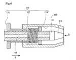
図3は、光源ユニット100の外観図であり、図4は、光源ユニット100の断面図である。図3に示されるとおり、光源ユニット100の側面には、突起部150が設けられている。光源ユニット100のホルダー300への固定は、ホルダー300の孔H1に光源ユニット100が挿入されることによって、孔H1に設けられた凹部(図示せず)に光源ユニット100の突起部150が係止されることにより完了する。 FIG. 3 is an external view of the
光源ユニット100は、光源部110と、光源部110が照射した光を集めるレンズ115と、第1の通風部120とを備える。光源部110は、頭部に向けて光を照射する部分である。本実施形態では、光源部110として固体発光素子を用い、光源部110は配線112と接続されているが、これに限られず、例えば、外部の光源と光ファイバーで接続されている構成としてもよい。 The
図4に示すように、第1の通風部120は、ボタン125とバネ127とを備える。第1の通風部120は、風を送り出す機能を備える。試験者もしくはホルダー300の装着者によって、ボタン125を光源ユニット100の先端側(矢印Bの方向)に押されることによって、空気流路124から矢印Bの方向に風が送り出される。この風に頭部の毛髪が吹かれることにより、光源ユニット100と頭部との間に毛髪が挟まることを抑制できる。 As shown in FIG. 4, the
本実施形態では、第1の通風部120は、空気を吸い込むことにより、頭部と光源ユニット100とを密着させる機能についても備える。具体的には、ボタン125が押された後、バネ127の力により矢印Bとは反対方向にボタン125が戻る。この際に発生する力により、空気が光源ユニット100内部に吸い込まれるとともに、頭部が光源ユニット100内部に吸引され、頭部と光源ユニット100とが密着する。 In the present embodiment, the
図5は、図4に記載の矢印Aの方向から光源ユニット100を見た図である。第1の通風部120は、光源部110の周囲に設けられている。本実施形態では、第1の通風部120の開口部Apは、光源部110の周りを途切れなく囲んでいる。 FIG. 5 is a view of the
図6は、検出ユニット200の断面図である。検出ユニット200の構成は、光源ユニット100の構成と比較して、光源部110の変わりに検出部210を備える点が大きく異なるが、それ以外の基本的な構成は同様である。具体的には、検出ユニット200は、検出部210と、脳によって拡散された光を集めるレンズ215と、第2の通風部220とを備える。検出部210は、脳によって拡散された光を検出する部分である。本実施形態では、検出部210として受光素子を用い、検出部210は配線212と接続されているが、これに限られず、外部の受光センサーと光ファイバーで接続されている構成としてもよい。 FIG. 6 is a cross-sectional view of the
図6に示すように、第2の通風部220は、空気流路224とボタン225とバネ227とを備える。第2の通風部220の送風メカニズムは、第1の通風部120の送風メカニズムと同様である。具体的には、試験者もしくはホルダー300の装着者によって、ボタン225を検出ユニット200の先端側(矢印Cの方向)に押されることによって、空気流路224から矢印Cの方向に風が送り出される。この風に頭部の毛髪が吹かれることにより、検出ユニット200と頭部との間に毛髪が挟まることを抑制できる。 As shown in FIG. 6, the
本実施形態では、第2の通風部220は、空気を吸い込むことにより、頭部と検出ユニット200とを密着させる機能についても備える。具体的には、ボタン225が押された後、バネ227の力により矢印Cとは反対方向にボタン225が戻る。この際に発生する力により、空気が検出ユニット200内部に吸い込まれるとともに、頭部が検出ユニット200内部に吸引され、頭部と検出ユニット200とが密着する。 In the present embodiment, the
本実施形態の脳機能測定装置10によれば、風を送り出す第1の通風部120及び第2の通風部220とを備えることにより、毛髪が光を遮ることにより、脳機能を正しく測定できないことを抑制できる。 According to the brain
また、本実施形態の脳機能測定装置10によれば、第1の通風部120を備えることにより、光源ユニット100と頭部とを密着させることができ、第2の通風部220を備えることにより、検出ユニット200と頭部とを密着させることができる。この結果として、脳機能測定装置10によれば、光源ユニット100と検出ユニット200とを頭部へ確実に固定することができる。 Moreover, according to the brain
B.第2実施形態
第1実施形態では風の送り出し及び空気の吸い込みを手動により行うが、第2実施形態では自動で行う点が異なる。B. Second Embodiment In the first embodiment, wind is sent out and air is sucked in manually, but the second embodiment is different in that it is automatically performed.
図7は、第2実施形態における光源ユニット100Aの断面図である。第2実施形態の光源ユニット100Aは、第1実施形態の光源ユニット100と比較して、空気流路124Aが通風を行う通風系と接続されている。 FIG. 7 is a cross-sectional view of the
図8は、通風系20を説明するための構成図である。通風系20は、先端T側から順に、第1三方弁51と、コンプレッサー53と、第2の三方弁55と、第3の三方弁57とを備える。第1三方弁51と第3の三方弁57とは接続されており、第2の三方弁55は光源ユニット100の外に接続されている。送風時には、矢印D1に示されるように、空気流路124Aの空気は、第1三方弁51、コンプレッサー53、第2の三方弁55、第3の三方弁57の順に送られていき光源ユニット100Aの先端Tに送り出される。一方、吸引時には、矢印D2に示されるように、光源ユニット100Aの先端Tから、第1三方弁51、コンプレッサー53、第2の三方弁55を通って、空気は外部に放出される。なお、本実施形態の構成に限られず、送風と吸引を行う構成は、他の構成を用いてもよい。 FIG. 8 is a configuration diagram for explaining the
第2実施形態の構成では、例えば、以下の第1装着処理から第3装着処理までの装着処理を実施可能である。 In the configuration of the second embodiment, for example, the following mounting process from the first mounting process to the third mounting process can be performed.
(i)第1装着処理
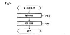
図9は、第1装着処理を説明するためのフローチャートである。このフローチャートは、複数の光源ユニット100と複数の検出ユニット200とがホルダー300に固定された状態により開始される。例えば、脳機能測定装置10に固定完了ボタンが設けられており、このボタンが押下されることにより、この処理が開始されてもよい。(I) First Mounting Process FIG. 9 is a flowchart for explaining the first mounting process. This flowchart is started when a plurality of
まず、制御部400は、第1の通風部120及び第2の通風部220から頭部へ風を送り出す送風制御を行う(工程P110)。このようにすることにより、光源ユニット100と頭部との間や検出ユニット200と頭部との間に毛髪が入ることを抑制できる。なお、第1の通風部120及び第2の通風部220の両方から送風を行うのでなく、どちらか一方のみから行ってもよい。 First, the
次に、制御部400は、第1の通風部120及び第2の通風部220から空気を吸い込ませる吸引制御を行う(工程P120)。このようにすることにより、光源ユニット100及び検出ユニット200と頭部とを固定させることができる。なお、第1の通風部120及び第2の通風部220の両方から吸引を行うのでなく、どちらか一方のみから行ってもよい。 Next, the
(ii)第2装着処理
図10は、第2装着処理を説明するためのフローチャートである。第2装着処理は、第1装着処理と比較して、工程P110の前に工程P105を備える点が異なるが、それ以外は同じである。(Ii) Second Mounting Process FIG. 10 is a flowchart for explaining the second mounting process. The second mounting process is different from the first mounting process in that the process P105 is provided before the process P110, but the other processes are the same.
工程P105では、制御部400は、光源部110によって照射させた光を検出部210によって検出させ、その検出強度が予め定められた閾値(例えば、検出部210の想定限界)未満か否かを判定する。 In step P105, the
検出強度が予め定められた閾値未満の場合(工程P105:YES)、制御部400は、送風制御(工程P110)及び吸引制御(工程P120)を行う。一方、検出強度が予め定められた閾値以上の場合(工程P105:NO)、制御部400は、送風制御(工程P110)及び吸引制御(工程P120)を行わず、フローは終了する。このようにすることにより、頭部と脳機能測定装置10との間に毛髪が挟まっていると考えられる場合にのみ、送風制御(工程P110)と吸引制御(工程P120)が行われ、それ以外の場合は不要な制御をしなくて済む。なお、本処理では、全ての第1の通風部120及び第2の通風部220が、送風及び吸引を行うが、これに限られず、例えば、検出強度が閾値未満となった検出ユニット200内の第2の通風部220と、その検出ユニット200と隣接する光源ユニット100内の第1の通風部120とによってのみ、送風及び吸引が行われてもよい。このようにすることにより、不要な制御を行わなくて済む。 When the detected intensity is less than a predetermined threshold (process P105: YES), the
(iii)第3装着処理
図11は、第3装着処理を説明するためのフローチャートである。第3装着処理は、第2装着処理と比較して、検出強度が予め定められた閾値Th未満の場合、送風制御(工程P110)と吸引制御(P120)とを、検出強度が閾値Th以上となるまで繰り返される点が異なるが、それ以外は同じである。このようにすることにより、脳機能を正しく測定できないことを効果的に抑制できる。(Iii) Third Mounting Process FIG. 11 is a flowchart for explaining the third mounting process. In the third mounting process, when the detected intensity is less than a predetermined threshold value Th, the ventilation control (process P110) and the suction control (P120) are compared with the second mounting process, and the detected intensity is equal to or higher than the threshold value Th. It is the same except that it is repeated until it becomes. By doing in this way, it can suppress effectively that a brain function cannot be measured correctly.
C.他の実施形態
上述の実施形態では、第1の通風部120は、風を送り出す機能と空気を吸い込む機能を備えるが、これに限られず、これらの機能のうち少なくとも一方を備えていればよい。同様に、第2の通風部220は、風を送り出す機能と空気を吸い込む機能を備えるが、これに限られず、これらの機能のうち少なくとも一方を備えていればよい。C. Other Embodiments In the above-described embodiment, the
上述の実施形態では、図5に示すように、空気流路124の開口部Apは、光源部110の周りを途切れなく囲んでいたが、これに限られない。 In the above-described embodiment, as illustrated in FIG. 5, the opening Ap of the
図12は、開口部Apの他の形態を示す図である。図12に示すように、複数の開口部Ap1が、光源部110の周りに点在していてもよいし、1つの開口部Ap1が光源部110の隣に設けられていてもよい。図12では、光源ユニット100の開口部Apを示したが、検出ユニット200の開口部Apにおいても同様である。 FIG. 12 is a diagram showing another form of the opening Ap. As shown in FIG. 12, a plurality of openings Ap <b> 1 may be scattered around the
本発明は、上述の実施形態や実施例に限られるものではなく、その趣旨を逸脱しない範囲において種々の構成で実現することができる。例えば、発明の概要の欄に記載した各形態中の技術的特徴に対応する実施形態、実施例中の技術的特徴は、上述の課題の一部又は全部を解決するために、あるいは、上述の効果の一部又は全部を達成するために、適宜、差し替えや、組み合わせを行うことが可能である。また、その技術的特徴が本明細書中に必須なものとして説明されていなければ、適宜、削除することが可能である。 The present invention is not limited to the above-described embodiments and examples, and can be realized with various configurations without departing from the spirit thereof. For example, the technical features in the embodiments and examples corresponding to the technical features in each embodiment described in the summary section of the invention may be used to solve part or all of the above-described problems, or In order to achieve part or all of the effects, replacement or combination can be performed as appropriate. Further, if the technical feature is not described as essential in the present specification, it can be deleted as appropriate.
10…脳機能測定装置、20…通風系、51…第1三方弁、53…コンプレッサー、55…第2の三方弁、57…第3の三方弁、100…光源ユニット、100A…光源ユニット、110…光源部、112…配線、115…レンズ、120…第1の通風部、124…空気流路、124A…空気流路、125…ボタン、127…バネ、150…突起部、200…検出ユニット、210…検出部、212…配線、215…レンズ、220…第2の通風部、224…空気流路、225…ボタン、227…バネ、300…ホルダー、400…制御部、A…矢印、Ap、Ap1…開口部、B…矢印、C…矢印、D1、D2…矢印、H1、H2…孔、T…先端 DESCRIPTION OF
Claims (6)
Translated fromJapanese脳によって拡散された前記近赤外光を検出する検出部を備える検出ユニットと、
前記光源ユニットと前記検出ユニットとを前記頭部に固定するホルダーと、
前記光源ユニットと前記検出ユニットとを制御する制御部と、を備え、
前記光源ユニットは、前記光源部の周囲に設けられ、風を送り出す第1の通風部を備え、
前記検出ユニットは、前記検出部の周囲に設けられ、風を送り出す第2の通風部を備える、脳機能測定装置。A light source unit including a light source unit that irradiates near infrared light toward the head;
A detection unit comprising a detection unit for detecting the near infrared light diffused by the brain;
A holder for fixing the light source unit and the detection unit to the head;
A control unit for controlling the light source unit and the detection unit,
The light source unit includes a first ventilation unit that is provided around the light source unit and sends out the wind.
The said detection unit is a brain function measuring apparatus provided with the 2nd ventilation part which is provided around the said detection part and sends out a wind.
前記第1の通風部は、空気を吸い込むことにより前記頭部と前記光源ユニットとを密着させる機能を備え、
前記第2の通風部は、前記検出部の周囲に設けられ、空気を吸い込むことにより前記頭部と前記検出ユニットとを密着させる機能を備える、脳機能測定装置。The brain function measuring device according to claim 1,
The first ventilation portion has a function of bringing the head and the light source unit into close contact by sucking air,
The second ventilation unit is a brain function measuring device provided around the detection unit and having a function of bringing the head and the detection unit into close contact with each other by sucking air.
前記制御部は、
前記第1の通風部と前記第2の通風部との少なくとも一方から前記頭部へ空気を送り出す送風制御と、
前記送風制御の後に、前記第1の通風部から空気を吸い込むことにより、前記頭部と前記光源ユニットとを密着させる制御と、前記第2の通風部から空気を吸い込むことにより、前記頭部と前記検出ユニットとを密着させる制御との少なくとも一方の吸引制御を行う、脳機能測定装置。The brain function measuring device according to claim 2,
The controller is
Blower control for sending air from at least one of the first ventilation part and the second ventilation part to the head;
After the air blowing control, the head and the light source unit are brought into close contact with each other by sucking air from the first ventilation part, and the head is drawn by sucking air from the second ventilation part. A brain function measuring apparatus that performs at least one suction control with control to bring the detection unit into close contact with each other.
前記制御部は、
前記光源部が照射した前記近赤外光を前記検出部によって検出させた検出強度が、予め定められた閾値未満の場合、前記送風制御と、前記吸引制御を行い、
前記検出強度が前記閾値以上である場合、前記送風制御と、前記吸引制御を行わない、脳機能測定装置。The brain function measuring device according to claim 3,
The controller is
If the detection intensity of the near-infrared light emitted by the light source unit detected by the detection unit is less than a predetermined threshold value, the air blowing control and the suction control are performed,
The brain function measuring device which does not perform the ventilation control and the suction control when the detected intensity is equal to or greater than the threshold value.
前記制御部は、前記検出強度が前記閾値未満の場合、前記送風制御と前記吸引制御とを、前記検出強度が前記閾値以上となるまで繰り返す、脳機能測定装置。The brain function measuring device according to claim 4,
The said control part is a brain function measuring apparatus which repeats the said ventilation control and the said suction control until the said detection intensity becomes more than the said threshold value, when the said detection intensity is less than the said threshold value.
脳によって拡散された前記近赤外光を検出する検出部を備える検出ユニットと、
前記光源ユニットと前記検出ユニットとを前記頭部に固定するホルダーと、
前記光源ユニットと前記検出ユニットとを制御する制御部と、を備え、
前記光源ユニットは、前記光源部の周囲に設けられ、空気を吸い込むことにより前記頭部と前記光源ユニットとを密着させる第1の通風部を備え、
前記検出ユニットは、前記検出部の周囲に設けられ、空気を吸い込むことにより前記頭部と前記検出ユニットとを密着させる第2の通風部を備える、脳機能測定装置。A light source unit including a light source unit that irradiates near infrared light toward the head;
A detection unit comprising a detection unit for detecting the near infrared light diffused by the brain;
A holder for fixing the light source unit and the detection unit to the head;
A control unit for controlling the light source unit and the detection unit,
The light source unit is provided around the light source unit, and includes a first ventilation unit that in close contact with the light source unit by sucking air,
The said detection unit is a brain function measuring apparatus provided with the 2nd ventilation part provided in the circumference | surroundings of the said detection part, and adhering the said head and the said detection unit by inhaling air.
Priority Applications (1)
| Application Number | Priority Date | Filing Date | Title |
|---|---|---|---|
| JP2018029431AJP2019141373A (en) | 2018-02-22 | 2018-02-22 | Brain function measurement device |
Applications Claiming Priority (1)
| Application Number | Priority Date | Filing Date | Title |
|---|---|---|---|
| JP2018029431AJP2019141373A (en) | 2018-02-22 | 2018-02-22 | Brain function measurement device |
Publications (1)
| Publication Number | Publication Date |
|---|---|
| JP2019141373Atrue JP2019141373A (en) | 2019-08-29 |
Family
ID=67770610
Family Applications (1)
| Application Number | Title | Priority Date | Filing Date |
|---|---|---|---|
| JP2018029431AWithdrawnJP2019141373A (en) | 2018-02-22 | 2018-02-22 | Brain function measurement device |
Country Status (1)
| Country | Link |
|---|---|
| JP (1) | JP2019141373A (en) |
Citations (8)
| Publication number | Priority date | Publication date | Assignee | Title |
|---|---|---|---|---|
| JPH09117437A (en)* | 1995-10-27 | 1997-05-06 | Hitachi Ltd | Non-invasive biochemical sensor |
| JP2002502653A (en)* | 1998-02-11 | 2002-01-29 | ノン−インヴェイシヴ テクノロジイ,インク. | Image formation and feature display of brain tissue |
| JP2004024514A (en)* | 2002-06-25 | 2004-01-29 | Matsushita Electric Works Ltd | Pickup implement for measuring biomedical signal and biomedical signal measuring instrument |
| JP2008104838A (en)* | 2006-09-25 | 2008-05-08 | Matsushita Electric Works Ltd | Biosignal measuring device, and biosignal measuring method using the same |
| JP2009183636A (en)* | 2008-02-08 | 2009-08-20 | Gifu Univ | Biological data measuring device |
| KR20140089973A (en)* | 2013-01-08 | 2014-07-16 | 한림대학교 산학협력단 | Medical sensor mounting apparatus |
| JP2016198415A (en)* | 2015-04-14 | 2016-12-01 | セイコーエプソン株式会社 | Biological information acquisition apparatus and biological information acquisition method |
| JP2017042200A (en)* | 2015-08-24 | 2017-03-02 | 株式会社日立国際八木ソリューションズ | Biometric device |
- 2018
- 2018-02-22JPJP2018029431Apatent/JP2019141373A/ennot_activeWithdrawn
Patent Citations (8)
| Publication number | Priority date | Publication date | Assignee | Title |
|---|---|---|---|---|
| JPH09117437A (en)* | 1995-10-27 | 1997-05-06 | Hitachi Ltd | Non-invasive biochemical sensor |
| JP2002502653A (en)* | 1998-02-11 | 2002-01-29 | ノン−インヴェイシヴ テクノロジイ,インク. | Image formation and feature display of brain tissue |
| JP2004024514A (en)* | 2002-06-25 | 2004-01-29 | Matsushita Electric Works Ltd | Pickup implement for measuring biomedical signal and biomedical signal measuring instrument |
| JP2008104838A (en)* | 2006-09-25 | 2008-05-08 | Matsushita Electric Works Ltd | Biosignal measuring device, and biosignal measuring method using the same |
| JP2009183636A (en)* | 2008-02-08 | 2009-08-20 | Gifu Univ | Biological data measuring device |
| KR20140089973A (en)* | 2013-01-08 | 2014-07-16 | 한림대학교 산학협력단 | Medical sensor mounting apparatus |
| JP2016198415A (en)* | 2015-04-14 | 2016-12-01 | セイコーエプソン株式会社 | Biological information acquisition apparatus and biological information acquisition method |
| JP2017042200A (en)* | 2015-08-24 | 2017-03-02 | 株式会社日立国際八木ソリューションズ | Biometric device |
Similar Documents
| Publication | Publication Date | Title |
|---|---|---|
| JP5820396B2 (en) | Blood glucose measuring device | |
| CN103424343B (en) | Optical particle detecting device and particle detecting method | |
| US9615774B2 (en) | CO2 sensor and CO2 measuring apparatus | |
| JP2013541990A5 (en) | ||
| CN103328953B (en) | Optical measurement system, optical measurement device, calibration member, and calibration method | |
| US20210267436A1 (en) | Endoscope hood and endoscope system | |
| JP6930736B2 (en) | Alcohol measuring system and alcohol measuring device | |
| EP2526851A1 (en) | Probe and optical measurement device | |
| CN103301540A (en) | Airway adaptor and biological information acquiring system | |
| KR101926731B1 (en) | Sensing device of mask reusing | |
| JP2019141373A (en) | Brain function measurement device | |
| US20170304647A1 (en) | Portable irradiation device and method for manufacturing the same | |
| TW201241701A (en) | Composite optical lens and touch control device using the same | |
| US9211053B2 (en) | Medical apparatus, disposable medical device, and medical system | |
| JPWO2006109453A1 (en) | Puncture device and puncture tip | |
| WO2017104048A1 (en) | Endoscope illumination device and endoscope system | |
| US10485480B2 (en) | Probe | |
| US20160367116A1 (en) | Connector | |
| KR102656444B1 (en) | ear thermometer | |
| US20100113877A1 (en) | Medical apparatus | |
| CN110072570B (en) | Device for extracorporeal blood-gas exchange | |
| CN104411232A (en) | Jaundice meter | |
| TWM547946U (en) | Handheld illumination device for sigmoidoscopy | |
| JP2012147910A (en) | Oral cavity observing device | |
| US10390126B2 (en) | Earphone for audiometer, and audiometer |
Legal Events
| Date | Code | Title | Description |
|---|---|---|---|
| RD05 | Notification of revocation of power of attorney | Free format text:JAPANESE INTERMEDIATE CODE: A7425 Effective date:20180910 | |
| RD03 | Notification of appointment of power of attorney | Free format text:JAPANESE INTERMEDIATE CODE: A7423 Effective date:20190920 | |
| RD07 | Notification of extinguishment of power of attorney | Free format text:JAPANESE INTERMEDIATE CODE: A7427 Effective date:20200806 | |
| A621 | Written request for application examination | Free format text:JAPANESE INTERMEDIATE CODE: A621 Effective date:20201209 | |
| A131 | Notification of reasons for refusal | Free format text:JAPANESE INTERMEDIATE CODE: A131 Effective date:20210713 | |
| A761 | Written withdrawal of application | Free format text:JAPANESE INTERMEDIATE CODE: A761 Effective date:20210913 |