JP2019139481A - Management program and management method - Google Patents
Management program and management methodDownload PDFInfo
- Publication number
- JP2019139481A JP2019139481AJP2018021940AJP2018021940AJP2019139481AJP 2019139481 AJP2019139481 AJP 2019139481AJP 2018021940 AJP2018021940 AJP 2018021940AJP 2018021940 AJP2018021940 AJP 2018021940AJP 2019139481 AJP2019139481 AJP 2019139481A
- Authority
- JP
- Japan
- Prior art keywords
- information
- service providing
- request
- response
- user
- Prior art date
- Legal status (The legal status is an assumption and is not a legal conclusion. Google has not performed a legal analysis and makes no representation as to the accuracy of the status listed.)
- Granted
Links
Images


Classifications
- H—ELECTRICITY
- H04—ELECTRIC COMMUNICATION TECHNIQUE
- H04L—TRANSMISSION OF DIGITAL INFORMATION, e.g. TELEGRAPHIC COMMUNICATION
- H04L67/00—Network arrangements or protocols for supporting network services or applications
- H04L67/50—Network services
- H04L67/60—Scheduling or organising the servicing of application requests, e.g. requests for application data transmissions using the analysis and optimisation of the required network resources
- H—ELECTRICITY
- H04—ELECTRIC COMMUNICATION TECHNIQUE
- H04L—TRANSMISSION OF DIGITAL INFORMATION, e.g. TELEGRAPHIC COMMUNICATION
- H04L41/00—Arrangements for maintenance, administration or management of data switching networks, e.g. of packet switching networks
- H04L41/50—Network service management, e.g. ensuring proper service fulfilment according to agreements
- H04L41/5032—Generating service level reports
- H—ELECTRICITY
- H04—ELECTRIC COMMUNICATION TECHNIQUE
- H04L—TRANSMISSION OF DIGITAL INFORMATION, e.g. TELEGRAPHIC COMMUNICATION
- H04L41/00—Arrangements for maintenance, administration or management of data switching networks, e.g. of packet switching networks
- H04L41/50—Network service management, e.g. ensuring proper service fulfilment according to agreements
- H04L41/5061—Network service management, e.g. ensuring proper service fulfilment according to agreements characterised by the interaction between service providers and their network customers, e.g. customer relationship management
- H04L41/5064—Customer relationship management
- H—ELECTRICITY
- H04—ELECTRIC COMMUNICATION TECHNIQUE
- H04L—TRANSMISSION OF DIGITAL INFORMATION, e.g. TELEGRAPHIC COMMUNICATION
- H04L41/00—Arrangements for maintenance, administration or management of data switching networks, e.g. of packet switching networks
- H04L41/50—Network service management, e.g. ensuring proper service fulfilment according to agreements
- H04L41/5061—Network service management, e.g. ensuring proper service fulfilment according to agreements characterised by the interaction between service providers and their network customers, e.g. customer relationship management
- H04L41/5067—Customer-centric QoS measurements
- H—ELECTRICITY
- H04—ELECTRIC COMMUNICATION TECHNIQUE
- H04L—TRANSMISSION OF DIGITAL INFORMATION, e.g. TELEGRAPHIC COMMUNICATION
- H04L67/00—Network arrangements or protocols for supporting network services or applications
- H04L67/50—Network services
- H04L67/60—Scheduling or organising the servicing of application requests, e.g. requests for application data transmissions using the analysis and optimisation of the required network resources
- H04L67/61—Scheduling or organising the servicing of application requests, e.g. requests for application data transmissions using the analysis and optimisation of the required network resources taking into account QoS or priority requirements
Landscapes
- Engineering & Computer Science (AREA)
- Computer Networks & Wireless Communication (AREA)
- Signal Processing (AREA)
- Business, Economics & Management (AREA)
- General Business, Economics & Management (AREA)
- Management, Administration, Business Operations System, And Electronic Commerce (AREA)
- Telephonic Communication Services (AREA)
Abstract
Description
Translated fromJapanese本発明は、管理プログラム及び管理方法に関する。 The present invention relates to a management program and a management method.
利用者に対して各種サービスを提供する事業者(以下、単に事業者とも呼ぶ)は、例えば、利用者からのリクエストに対応する情報を出力するサービス(以下、マッチングサービスとも呼ぶ)の提供を行う。 A provider that provides various services to users (hereinafter also simply referred to as a provider) provides, for example, a service that outputs information corresponding to a request from a user (hereinafter also referred to as a matching service). .
このようなマッチングサービスでは、利用者からのリクエストがあった場合、そのリクエストに含まれる条件に対応する情報を利用者に対して提示する。そして、利用者は、提示された情報の中に利用者の嗜好に合った情報が含まれていた場合、その情報を採用する旨の決定を行う。具体的に、マッチングサービスには、例えば、利用者から宿泊施設に関する条件が入力された場合に、その条件に合致する宿泊施設を示す情報を利用者に対して提示するものが含まれる。 In such a matching service, when there is a request from a user, information corresponding to a condition included in the request is presented to the user. Then, when the information that matches the user's preference is included in the presented information, the user decides to adopt the information. Specifically, the matching service includes, for example, a case where, when a condition regarding an accommodation facility is input from a user, information indicating an accommodation facility that matches the condition is presented to the user.
上記のようなマッチングサービスの提供を新たに開始する場合、事業者は、例えば、他のマッチングサービスにおいて既に開発されている機能(以下、単に機能とも呼ぶ)を用いることによって、マッチングサービスの提供に必要な業務システムの構築を行う。これにより、事業者は、新たなマッチングサービスの提供を開始する際に要する開発時間を短縮することが可能になる(例えば、特許文献1及び2参照)。 In the case of newly starting the provision of the matching service as described above, the business operator can provide the matching service by using, for example, a function that has already been developed in another matching service (hereinafter also simply referred to as a function). Build the necessary business system. Accordingly, the business operator can shorten the development time required to start providing a new matching service (see, for example,
ここで、例えば、利用者の趣味嗜好が時間の経過とともに変化する場合、マッチングサービスでは、利用者が満足する確率の高い情報を効率的に提供することができなくなり、利用者に提示した情報の採用確率(以下、マッチングの成立率とも呼ぶ)が徐々に低下する場合がある。そのため、事業者は、必要に応じて、マッチングサービスにおいて用いられている機能を他の機能に変更する。これにより、事業者は、低下したマッチングの成立率の回復を図ることが可能になる。 Here, for example, when the user's hobbies and preferences change over time, the matching service cannot efficiently provide information with a high probability that the user will be satisfied, and the information presented to the user There are cases where the employment probability (hereinafter also referred to as “matching establishment rate”) gradually decreases. For this reason, the business operator changes the function used in the matching service to another function as necessary. As a result, the business operator can recover the reduced establishment rate of matching.
しかしながら、マッチングサービスにおいて用いられる機能の変更が頻繁に行われる場合、業務システムの開発コスト(維持コスト)は膨大になる。そのため、事業者は、機能の変更の頻度を抑えつつ、マッチングの成立率を高い水準で維持することが好ましい。 However, when the function used in the matching service is frequently changed, the development cost (maintenance cost) of the business system becomes enormous. Therefore, it is preferable that the business operator maintains the matching establishment rate at a high level while suppressing the frequency of the function change.
そこで、一つの側面では、本発明は、各利用者が満足する情報を提供することを可能とする管理プログラム及び管理方法を提供することを目的とする。 Therefore, in one aspect, an object of the present invention is to provide a management program and a management method that can provide information satisfying each user.
実施の形態の一態様では、リクエストを行った利用者が該リクエストに対する応答について満足したか否かを示す満足情報を記憶部に蓄積し、蓄積した前記満足情報に基づいて、前記利用者ごとに、リクエストに対する応答を生成する複数のサービス提供機能のうち、リクエストに対して生成した応答の満足度が所定の条件を満たす特定のサービス提供機能を、各利用者からのリクエストに対する応答を生成する際に優先して用いるサービス提供機能として特定する、処理をコンピュータに実行させる。 In one aspect of the embodiment, satisfaction information indicating whether the user who made the request is satisfied with respect to the response to the request is accumulated in the storage unit, and for each user based on the accumulated satisfaction information When generating a response to a request from each user for a specific service providing function that satisfies the predetermined satisfaction level of the response generated for the request among the multiple service providing functions that generate a response to the request The computer is caused to execute a process specified as a service providing function to be used with priority over the above.
一つの側面によれば、各利用者が満足する情報を提供することを可能とする。 According to one aspect, it is possible to provide information satisfying each user.
[情報処理システムの構成]
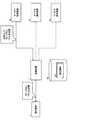
図1は、情報処理システム10の構成を示す図である。図1に示す情報処理システム10は、マッチングサービスを提供する業務システムであり、管理装置1と、サービス提供装置2a、2b及び2c(以下、これらを総称してサービス提供装置2とも呼ぶ)と、ネットワークNWを介して管理装置1と接続する端末装置3a、3b及び3c(以下、端末装置3とも呼ぶ)と、管理装置1の内部または外部に設けられた記憶部130とを有する。以下、端末装置3a、3b及び3cは、それぞれ異なる利用者によって利用される端末装置であるものとして説明を行う。[Configuration of information processing system]
FIG. 1 is a diagram illustrating a configuration of the
管理装置1は、1台以上の物理マシンによって構成され、利用者に対してマッチングサービスを提供するための処理を実行する。具体的に、管理装置1は、例えば、利用者が端末装置3を介して宿泊施設に関する条件の入力を行った場合、記憶部130に記憶された各種情報を参照し、入力された条件に対応するサービス提供装置2を特定する。そして、管理装置1は、特定したサービス提供装置2に対して条件の送信を行う。 The
サービス提供装置2は、それぞれ1台以上の物理マシンによって構成され、管理装置1から送信された条件に合致する情報の特定を行う機能(以下、サービス提供機能とも呼ぶ)を有する。具体的に、サービス提供装置2は、管理装置1から宿泊施設に関する条件を受信した場合、受信した条件に合致する1以上の宿泊施設の特定を行う。そして、サービス提供装置2は、特定した1以上の宿泊施設を示す情報を管理装置1に送信する。 Each of the
その後、管理装置1は、サービス提供装置2から条件に合致する情報を受信した場合、受信した情報を端末装置3(利用者が条件の入力を行った端末装置3)に対して送信する。 Thereafter, when receiving information that matches the condition from the
ここで、例えば、利用者の趣味嗜好が時間の経過とともに変化する場合、上記のような情報処理システム10では、利用者が満足する確率の高い情報を効率的に提供することができなくなり、マッチングの成立率が徐々に低下する場合がある。 Here, for example, when the user's hobbies and preferences change with the passage of time, the
そのため、事業者は、例えば、サービス提供装置2において用いられている機能を必要に応じて他の機能に変更する。これにより、事業者は、低下したマッチングの成立率の回復を図ることが可能になる。 Therefore, for example, the business operator changes the function used in the
しかしながら、サービス提供装置2において用いられる機能の変更が頻繁に行われる場合、業務システムの開発コスト(維持コスト)は膨大になる。そのため、事業者は、機能の変更の頻度を可能な限り抑えつつ、マッチングの成立率を高い水準で維持することが好ましい。 However, when the function used in the
そこで、本実施の形態における管理装置1は、リクエストを行った利用者がリクエストに対する応答について満足したか否かを示す情報(以下、満足情報とも呼ぶ)を記憶部130に蓄積する。そして、管理装置1は、蓄積した満足情報に基づいて、利用者ごとに、リクエストに対する応答を生成する複数のサービス提供装置2のうち、リクエストに対して生成した応答の満足度が所定の条件を満たす特定のサービス提供装置2を、各利用者からのリクエストに対する応答を生成する際に優先して用いるサービス提供装置2として特定する。 Therefore, the
すなわち、管理装置1は、例えば、リクエストに対する応答を受信した利用者が情報の採用を行ったか否かを示す満足情報を、リクエストが発生するごとに取得して蓄積する。そして、管理装置1は、満足情報を参照することにより、利用者ごとに、利用者の満足度が高い応答を生成することができるサービス提供装置2を特定する。 That is, for example, the
これにより、管理装置1は、利用者ごとに、マッチングの成立率を高めることができるサービス提供装置2に対して優先的にリクエストの送信を行うことが可能になる。そのため、管理装置1は、機能の変更の頻度を抑えながら、マッチングの成立率を高い水準で維持することが可能になる。 Thereby, the
[情報処理システムのハードウエア構成]
次に、情報処理システム10のハードウエア構成について説明する。図2は、管理装置1のハードウエア構成を示す図である。また、図3は、サービス提供装置2のハードウエア構成を示す図である。さらに、図4は、端末装置3のハードウエア構成を示す図である。[Hardware configuration of information processing system]
Next, the hardware configuration of the
管理装置1は、図2に示すように、プロセッサであるCPU101と、メモリ102と、外部インターフェース103(以下、I/Oユニット103とも呼ぶ)と、記憶媒体104とを有する。各部は、バス105を介して互いに接続される。 As shown in FIG. 2, the
記憶媒体104は、例えば、記憶媒体104内のプログラム格納領域(図示しない)に、リクエストに対する応答の生成等を行う処理(以下、管理処理とも呼ぶ)を行うためのプログラム110を記憶する。記憶媒体104は、例えば、HDD(Hard Disk Drive)であってよい。 The
また、記憶媒体104は、例えば、管理処理を行う際に用いられる情報を記憶する記憶部130(以下、情報格納領域130とも呼ぶ)を有する。 In addition, the
CPU101は、記憶媒体104からメモリ102にロードされたプログラム110を実行して管理処理を行う。 The
外部インターフェース103は、例えば、サービス提供装置2や端末装置3と通信を行う。 The
そして、サービス提供装置2は、図3に示すように、プロセッサであるCPU201と、メモリ202と、外部インターフェース203(以下、I/Oユニット203とも呼ぶ)と、記憶媒体204とを有する。各部は、バス205を介して互いに接続される。 As illustrated in FIG. 3, the
記憶媒体204は、例えば、記憶媒体204内のプログラム格納領域(図示しない)に、管理処理を行うためのプログラム210を記憶する。記憶媒体204は、例えば、HDDであってよい。 The
また、記憶媒体204は、例えば、管理処理を行う際に用いられる情報を記憶する記憶部230(以下、情報格納領域230とも呼ぶ)を有する。 The
CPU201は、記憶媒体204からメモリ202にロードされたプログラム210を実行して管理処理を行う。 The
外部インターフェース203は、例えば、管理装置1や端末装置3と通信を行う。 The
さらに、端末装置3は、図4に示すように、プロセッサであるCPU301と、メモリ302と、外部インターフェース303(以下、I/Oユニット303とも呼ぶ)と、記憶媒体304とを有する。各部は、バス305を介して互いに接続される。 Further, as shown in FIG. 4, the
記憶媒体304は、例えば、記憶媒体304内のプログラム格納領域(図示しない)に、管理処理を行うためのプログラム310を記憶する。記憶媒体304は、例えば、HDDであってよい。 The
また、記憶媒体304は、例えば、管理処理を行う際に用いられる情報を記憶する記憶部330(以下、情報格納領域330とも呼ぶ)を有する。 The
CPU301は、記憶媒体304からメモリ302にロードされたプログラム310を実行して管理処理を行う。 The
外部インターフェース303は、例えば、サービス提供装置2や端末装置3と通信を行う。 The
[情報処理システムの機能]
次に、情報処理システム10の機能について説明する。図5は、端末装置3の機能ブロック図である。また、図6は、管理装置1の機能ブロック図である。さらに、図7は、サービス提供装置2の機能ブロック図である。[Information processing system functions]
Next, functions of the
初めに、端末装置3の機能ブロック図について説明を行う。 First, a functional block diagram of the
端末装置3は、CPU301やメモリ302等のハードウエアとプログラム310とが有機的に協働することにより、図5に示すように、リクエスト受付部311と、リクエスト送信部312と、応答受信部313と、情報出力部314と、情報受付部315と、情報生成部316と、情報送信部317とを含む各種機能を実現する。また、端末装置3は、図5に示すように、満足情報331を情報格納領域330に記憶する。 In the
リクエスト受付部311は、利用者がキーボード等の入力装置(図示しない)を介して端末装置3に入力したリクエストを受け付ける。 The
リクエスト送信部312は、リクエスト受付部311が受け付けたリクエストを管理装置1に対して送信する。 The
応答受信部313は、管理装置1が送信した応答(リクエストに対する応答)を受信する。 The
情報出力部314は、応答受信部313が受信した応答に含まれる情報を、モニター等の出力装置(図示しない)に出力する。 The
情報受付部315は、情報出力部314が出力した情報を採用する旨の情報を受け付ける。 The
情報生成部316は、応答受信部313が受信した応答に含まれる情報と、情報受付部315が受け付けた情報とを対応付けることによって、リクエストに対する応答の内容を利用者が満足しているか否かを示す満足情報331を生成する。その後、情報生成部316は、生成した満足情報331を情報格納領域330に記憶する。満足情報331の具体例については後述する。 The
情報送信部317は、情報生成部316が生成した満足情報331を管理装置1に送信する。具体的に、情報送信部317は、例えば、情報生成部316が満足情報331を生成するごとに、生成された満足情報331を管理装置1に送信する。 The
次に、管理装置1の機能ブロック図について説明を行う。 Next, a functional block diagram of the
管理装置1は、CPU101やメモリ102等のハードウエアとプログラム110とが有機的に協働することにより、図6に示すように、情報受信部111と、機能特定部112と、リクエスト受信部113と、リクエスト変換部114と、リクエスト送信部115と、応答受信部116と、応答変換部117と、応答集約部118と、応答送信部119とを含む各種機能を実現する。また、管理装置1は、図6に示すように、設定情報131と、振分情報132と、満足情報331(端末装置3から送信された満足情報331)とを情報格納領域130に記憶する。 As shown in FIG. 6, the
情報受信部111は、端末装置3が送信した満足情報331を受信する。そして、情報受信部111は、受信した満足情報331を情報格納領域130に記憶(蓄積)する。 The
機能特定部112は、情報格納領域130に記憶された満足情報331に基づいて、利用者ごとに、複数のサービス提供装置2のそれぞれが生成した応答に対する利用者の満足度を算出する。そして、機能特定部112は、利用者ごとに、算出した満足度が所定の条件を満たす特定のサービス提供装置2を、各利用者からのリクエストに対する応答を生成する際に優先して用いる特定のサービス提供装置2として特定する。 Based on the
その後、機能特定部112は、利用者ごとに特定した特定のサービス提供装置2を示す情報である振分情報132を生成する。そして、機能特定部112は、生成した振分情報132を情報格納領域130に記憶する。振分情報132の具体例については後述する。 Thereafter, the
リクエスト受信部113は、端末装置3が送信したリクエスト(利用者が端末装置3に入力したリクエスト)を受信する。 The
リクエスト変換部114は、情報格納領域130に記憶された設定情報131及び振分情報132を参照し、リクエスト受信部113が受信したリクエストの送信先のサービス提供装置2を特定する。設定情報131は、管理処理を行う際に参照される情報であり、例えば、事業者によって予め情報格納領域130に記憶される情報である。そして、リクエスト変換部114は、リクエスト受信部113が受信したリクエストに含まれる情報を、送信先のサービス提供装置2が処理を行うことができる形式(送信先のサービス提供装置2が認識することができる形式)に変換する。設定情報131の具体例については後述する。 The
リクエスト送信部115は、リクエスト変換部114によって形式の変換が行われたリクエストを、送信先のサービス提供装置2に送信する。 The
応答受信部116は、サービス提供装置2から送信された応答(利用者が行ったリクエストに対する応答)を受信する。 The
応答変換部117は、応答受信部116が受信した応答を、端末装置3(リクエストを送信した端末装置3)が処理を行うことができる形式(端末装置3が認識することができる形式)に変換(再変換)する。 The
応答集約部118は、リクエスト送信部115が複数のサービス提供装置2にリクエストを送信したことに伴って応答受信部116が複数のサービス提供装置2からの応答を受信した場合、応答変換部117が再変換した応答のそれぞれを集約する。 When the
応答送信部119は、応答変換部117が再変換した応答または応答集約部118が集約した応答を端末装置3に送信する。 The
なお、リクエスト受信部113、リクエスト変換部114、リクエスト送信部115、応答受信部116、応答変換部117、応答集約部118及び応答送信部119は、管理装置1と異なる他の装置(他の1以上の物理マシン)において実現される機能であってもよい。この場合、管理装置1は、機能特定部112が生成した振分情報132を他の装置に送信するものであってよい。 The
次に、サービス提供装置2の機能ブロック図について説明を行う。 Next, a functional block diagram of the
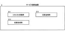
サービス提供装置2は、CPU201やメモリ202等のハードウエアとプログラム210とが有機的に協働することにより、図7に示すように、リクエスト受信部211と、応答生成部212と、応答送信部213とを含む各種機能を実現する。 As shown in FIG. 7, the
リクエスト受信部211は、管理装置1から送信されたリクエストを受信する。 The
応答生成部212は、リクエスト受信部211が受信したリクエストに対応する応答を生成する。具体的に、応答生成部212は、例えば、条件に合致した宿泊施設についての情報を要求するリクエストを受信した場合、その条件に合致した宿泊施設についての情報を含む応答の生成を行う。 The
応答送信部213は、応答生成部212が生成した応答を管理装置1に送信する。 The
[第1の実施の形態の概略]
次に、第1の実施の形態の概略について説明する。図8及び図9は、第1の実施の形態における管理処理の概略を説明するフローチャート図である。図10から図14は、第1の実施の形態における管理処理の概略を説明する図である。図10から図14を参照しながら、図8及び図9の管理処理の詳細を説明する。[Outline of First Embodiment]
Next, an outline of the first embodiment will be described. 8 and 9 are flowcharts for explaining the outline of the management processing in the first embodiment. 10 to 14 are diagrams for explaining the outline of the management processing in the first embodiment. Details of the management processing of FIGS. 8 and 9 will be described with reference to FIGS. 10 to 14.
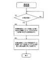
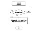
管理装置1は、図8に示すように、情報蓄積タイミングになるまで待機する(S1のNO)。情報蓄積タイミングは、例えば、端末装置3から満足情報331を受信したタイミングであってよい。 As shown in FIG. 8, the
そして、情報蓄積タイミングになった場合(S1のYES)、管理装置1は、リクエストを行った利用者がリクエストに対する応答について満足したか否かを示す満足情報331を情報格納領域130に蓄積する(S2)。具体的に、管理装置1は、例えば、端末装置3から満足情報331を受信するごとに、満足情報331の蓄積を行う。 When it is time to accumulate information (YES in S1), the
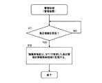
また、管理装置1は、図9に示すように、機能特定タイミングになるまで待機する(S11のNO)。機能特定タイミングは、例えば、利用者ごとのリクエストが所定回数行われるごとに到達するタイミングや、所定時間が経過するごとに到達するタイミングであってよい。 Further, as shown in FIG. 9, the
そして、機能特定タイミングになった場合(S11のYES)、管理装置1は、S2の処理で蓄積した満足情報331に基づいて、利用者ごとに、リクエストに対する応答を生成する複数のサービス提供装置2のうち、満足度が所定の条件を満たす特定のサービス提供装置2を特定する(S12)。 When the function specifying timing comes (YES in S11), the
続いて、管理装置1は、利用者ごとに、S12の処理で特定した特定のサービス提供装置2を、各利用者からのリクエストに対する応答を生成する際に優先して用いるサービス提供装置2として特定する(S13)。具体的に、管理装置1は、図10に示すように、情報格納領域130に記憶された満足情報331を参照し、各利用者からのリクエストに対する応答を生成する際に優先して用いるサービス提供装置2の特定を行う。 Subsequently, for each user, the
これにより、管理装置1は、利用者ごとに、マッチングの成立率を高めることができるサービス提供装置2に対して優先的にリクエストの送信を行うことが可能になる。そのため、管理装置1は、機能の変更の頻度を抑えながら、マッチングの成立率を高い水準で維持することが可能になる。 Thereby, the
[端末装置からリクエストを受信した場合の具体例(1)]
次に、S13の処理の後、管理装置1が端末装置3からリクエストを受信した場合の具体例について説明を行う。[Specific example when request is received from terminal device (1)]
Next, a specific example when the
管理装置1は、S13の処理の後、端末装置3からリクエストを受信した場合、例えば、S12の処理で特定した特定のサービス提供装置2に対してリクエストを送信する割合が、他のサービス提供装置2に対してリクエストを送信する割合よりも高くなるように、いずれかのサービス提供装置2に対してリクエストの送信を行う。具体的に、管理装置1は、例えば、サービス提供装置2aが特定のサービス提供装置2として特定されている場合、図11に示すように、サービス提供装置2aのみに対してリクエストの送信を行う。 When the
その後、管理装置1は、リクエストを送信したサービス提供装置2から応答を受信した場合、受信した応答を端末装置3(管理装置1に対してリクエストを送信した端末装置3)に対して送信する。具体的に、管理装置1は、例えば、図12に示すように、「R1」、「R2」及び「R3」を含む応答をサービス提供装置2aから受信した場合、受信した応答をそのまま端末装置3に送信する。 Thereafter, when the
[端末装置からリクエストを受信した場合の具体例(2)]
次に、S13の処理の後、管理装置1が端末装置3からリクエストを受信した場合の他の具体例について説明を行う。[Specific example when request is received from terminal device (2)]
Next, another specific example when the
管理装置1は、S13の処理の後、端末装置3からリクエストを受信した場合、例えば、受信したリクエストを全てのサービス提供装置2に送信する。具体的に、管理装置1は、例えば、図13に示すように、受信したリクエストをサービス提供装置2a、2b及び2cにそれぞれ送信する。 When the
その後、管理装置1は、リクエストを送信したサービス提供装置2のそれぞれからリクエストに対する応答を受信した場合、S13の処理で特定したサービス提供装置2から受信した応答から取得する情報が、他のサービス提供装置2から受信した応答から取得する情報よりも多くなるように、各応答から情報の取得を行う。そして、管理装置1は、各応答からそれぞれ取得した情報を端末装置3に送信する。具体的に、管理装置1は、例えば、図14に示すように、「R1」、「R2」及び「R3」を含む応答をサービス提供装置2aから受信し、「R4」、「R5」及び「R6」を含む応答をサービス提供装置2bから受信し、「R7」、「R8」及び「R9」を含む応答をサービス提供装置2cから受信した場合において、サービス提供装置2aが特定のサービス提供装置2として特定されている場合、例えば、「R1」、「R2」、「R4」及び「R7」をそれぞれ取得して端末装置3に送信する。 Thereafter, when the
なお、以下、図11及び図12で説明した処理を切換送信処理と呼び、図13及び図14で説明した処理を分配送信処理と呼ぶ。 Hereinafter, the process described with reference to FIGS. 11 and 12 is referred to as a switching transmission process, and the process described with reference to FIGS. 13 and 14 is referred to as a distributed transmission process.
[切換送信処理を行う場合の管理処理の詳細]
次に、切換送信処理を行う場合における第1の実施の形態の詳細について説明する。図15から図21は、切換送信処理を行う場合における管理処理の詳細を説明するフローチャート図である。また、図22及び図23は、切換送信処理を行う場合における管理処理の詳細を説明する図である。[Details of management processing when switching transmission processing is performed]
Next, details of the first embodiment when the switching transmission process is performed will be described. FIGS. 15 to 21 are flowcharts for explaining the details of the management process when the switching transmission process is performed. 22 and 23 are diagrams for explaining the details of the management process when the switching transmission process is performed.
[端末装置における管理処理(1)]
初めに、端末装置3における管理処理のうちの一部の処理について説明を行う。図15は、端末装置3における管理処理のうちの一部の処理を説明するフローチャート図である。[Management processing in terminal device (1)]
First, a part of the management process in the
端末装置3のリクエスト受付部311は、図15に示すように、リクエストを受け付けるまで待機する(S21のNO)。具体的に、リクエスト受付部311は、利用者が端末装置3に対してリクエストの入力を行うまで待機する。 As shown in FIG. 15, the
そして、リクエストを受け付けた場合(S21のYES)、端末装置3のリクエスト送信部312は、S21の処理で受け付けたリクエストを管理装置1に送信する(S22)。 When a request is received (YES in S21), the
[管理装置における管理処理(1)]
次に、管理装置1における管理処理のうちの一部の処理について説明を行う。図16は、管理装置1における管理処理のうちの一部の処理を説明するフローチャート図である。[Management Process (1) in Management Device]
Next, a part of the management process in the
管理装置1のリクエスト受信部113は、図16に示すように、リクエストを受信するまで待機する(S31のNO)。具体的に、リクエスト受信部113は、端末装置3が送信したリクエストを受信するまで待機する。 The
そして、リクエストを受信した場合(S31のYES)、管理装置1のリクエスト変換部114は、情報格納領域130に記憶された設定情報131及び振分情報132を参照し、S31の処理で受信したリクエストを送信するサービス提供装置2を特定する(S32)。以下、設定情報131及び振分情報132の具体例について説明を行う。 When the request is received (YES in S31), the
[設定情報の具体例]
初めに、設定情報131の具体例について説明を行う。[Specific example of setting information]
First, a specific example of the setting
図22は、設定情報131及び振分情報132の具体例を説明する図である。具体的に、図22(A)は、設定情報131の具体例を説明する図である。また、図22(B)は、振分情報132の具体例を説明する図である。 FIG. 22 is a diagram for explaining a specific example of the setting
図22(A)に示す設定情報131は、設定情報131に含まれる各情報を識別する「項番」と、特定のサービス提供装置2の切り換えを行うか否かの判定に用いられる情報が設定される「再決定種別」と、特定のサービス提供装置2の切り換えを行うタイミングが設定される「再決定タイミング」とを項目として有する。また、図22(A)に示す設定情報131は、リクエストの振り分け方法が設定される「処理方法」と、特定のサービス提供装置2として最初に用いられるサービス提供装置2を示す情報が設定される「メインエンジン識別情報」と、特定のサービス提供装置2に対してリクエストを送信する頻度が設定される「リクエスト送信頻度」とを項目として有する。「処理方法」には、図12及び図13で説明した処理を示す「切換送信」、または、図14及び図15で説明した処理を示す「分配送信」が設定される。 In the setting
具体的に、図22(A)に示す設定情報131において、「項番」が「1」である情報には、「再決定種別」として「リクエスト数」が設定され、「再決定タイミング」として「1000(回)」が設定されている。すなわち、図22(A)に示す設定情報131は、利用者ごとのリクエストのうちのいずれかが1000(回)に到達するごとに、その利用者に対応する特定のサービス提供装置2の再決定を行うことを示している。 Specifically, in the setting
なお、全ての利用者に対応する特定のサービス提供装置2の再決定は、所定の時間間隔ごと(例えば、1時間ごと)に行われるものであってもよい。この場合、設定情報131には、例えば、「再決定種別」として、全ての利用者に対応する特定のサービス提供装置2の再決定が時間の経過に応じて行われることを示す「時間」が設定され、「再決定タイミング」として、「1(時間)」が設定されるものであってよい。 The redetermination of the specific
そして、図22(A)に示す設定情報131において、「項番」が「1」である情報には、「処理方法」として切換送信処理を示す「切換送信」が設定され、「メインエンジン識別情報」として「2a」が設定され、「リクエスト送信頻度」として「0.5」が設定されている。 In the setting
すなわち、図22(A)に示す設定情報131は、特定のサービス提供装置2として最初に用いられるサービス提供装置2がサービス提供装置2aであることを示している。また、図22(A)に示す設定情報131は、各利用者からのリクエストを特定のサービス提供装置2に振り分ける割合が50(%)であることを示している。なお、各利用者からのリクエストを特定のサービス提供装置2以外のサービス提供装置2のそれぞれに振り分ける割合は、特定のサービス提供装置2に振り分ける割合以外の割合を均等に分けたものであってよい。 That is, the setting
[振分情報の具体例]
次に、振分情報132の具体例について説明を行う。[Specific example of distribution information]
Next, a specific example of the
図22(B)は、振分情報132の具体例を説明する図である。図22(B)に示す振分情報132は、振分情報132に含まれる各情報を識別する「項番」と、各利用者(各利用者が使用する端末装置3)を識別する「利用者識別情報」と、特定のサービス提供装置2として現在用いられているサービス提供装置2を示す情報が設定される「メインエンジン識別情報」とを項目として有している。 FIG. 22B is a diagram for explaining a specific example of the
具体的に、図22(B)に示す振分情報132において、「項番」が「1」である情報には、「利用者識別情報」として、端末装置3aを示す「3a」が設定され、「メインエンジン識別情報」として、サービス提供装置2aを示す「2a」が設定されている。すなわち、図20に示す振分情報132は、端末装置3aから送信されたリクエストが、サービス提供装置2aに対して優先的に振り分けられることを示している。 Specifically, in the
また、図22(B)に示す振分情報132において、「項番」が「2」である情報には、「利用者識別情報」として、端末装置3bを示す「3b」が設定され、「メインエンジン識別情報」として、サービス提供装置2cを示す「2c」が設定されている。すなわち、図20に示す振分情報132は、端末装置3bから送信されたリクエストが、サービス提供装置2cに対して優先的に振り分けられることを示している。図22(B)に含まれる他の情報についての説明は省略する。 Further, in the
そのため、リクエスト変換部114は、例えば、端末装置3aからのリクエストを受信した場合、S32の処理において、図22(B)で説明した振分情報132を参照し、「利用者識別情報」に「3a」が設定された情報の「メインエンジン識別情報」に設定された情報である「2a」を特定する。そして、リクエスト変換部114は、図22(A)で説明した設定情報131を参照し、サービス提供装置2aに振り分けるリクエストの割合と、サービス提供装置2bに振り分けられるリクエストの割合と、サービス提供装置2cに振り分けられるリクエストの割合との比率が、50:25:25(2:1:1)になるように、端末装置3aから送信されたリクエストを送信するサービス提供装置2の決定を行う。 Therefore, for example, when receiving a request from the
図13に戻り、リクエスト変換部114は、S31の処理で受信したリクエストを、S32の処理で特定したサービス提供装置2によって処理が可能な状態に変換する(S33)。 Returning to FIG. 13, the
その後、リクエスト送信部115は、S33の処理で変換したリクエストを、S32の処理で特定したサービス提供装置2に対して送信する(S34)。 Thereafter, the
[サービス提供装置における管理処理]
次に、サービス提供装置2における管理処理のうちの一部の処理について説明を行う。図17は、サービス提供装置2における管理処理のうちの一部の処理を説明するフローチャート図である。[Management processing in service provider]
Next, a part of the management process in the
サービス提供装置2のリクエスト受信部211は、図17に示すように、リクエストを受信するまで待機する(S41のNO)。具体的に、リクエスト受信部211は、管理装置1が送信したリクエストを受信するまで待機する。 As shown in FIG. 17, the
そして、リクエストを受信した場合(S41のYES)、サービス提供装置2の応答生成部212は、S41の処理で受信したリクエストに対する応答を生成する(S42)。具体的に、応答生成部212は、例えば、条件に合致した宿泊施設についての情報を要求するリクエストを受信した場合、その条件に合致した宿泊施設についての情報を含む応答の生成を行う。 When a request is received (YES in S41), the
その後、サービス提供装置2の応答送信部213は、S42の処理で生成した応答を管理装置1に対して送信する(S43)。 Thereafter, the
[管理装置における管理処理(2)]
次に、管理装置1における管理処理のうちの一部の処理について説明を行う。図18は、管理装置1における管理処理のうちの一部の処理を説明するフローチャート図である。[Management Process (2) in Management Device]
Next, a part of the management process in the
管理装置1の応答受信部116は、図18に示すように、リクエストに対する応答を受信するまで待機する(S51のNO)。具体的に、応答受信部116は、サービス提供装置2が送信した応答を受信するまで待機する。 As shown in FIG. 18, the
そして、応答を受信した場合(S51のYES)、管理装置1の応答変換部117は、S51の処理で受信した応答に含まれる情報について、S33の処理で行われた変換に対応する再変換を行う(S52)。 And when a response is received (YES of S51), the
その後、応答変換部117は、S52の処理で再変換を行った応答を、S31の処理で受信したリクエストを送信した端末装置3に対して送信する(S53)。 After that, the
[端末装置における管理処理(2)]
次に、端末装置3における管理処理のうちの一部の処理について説明を行う。図19は、端末装置3における管理処理のうちの一部の処理を説明するフローチャート図である。[Management processing in terminal device (2)]
Next, a part of the management process in the
端末装置3の応答受信部313は、図19に示すように、応答を受信するまで待機する(S61)。具体的に、応答受信部313は、管理装置1が送信した応答を受信するまで待機する。 As shown in FIG. 19, the
そして、端末装置3の情報出力部314は、S61の処理で受信した応答に含まれる情報を出力装置(図示しない)に対して出力する(S62)。すなわち、情報出力部314は、リクエストを行った利用者に対して、そのリクエストに対する応答に含まれる情報の提示を行う。 And the
その後、端末装置3の情報受付部315は、S62の処理で出力した情報に対する利用者の入力を受け付けるまで待機する(S63)。具体的に、情報受付部315は、例えば、S62の処理で出力した情報のうちのいずれかを採用する旨の入力、または、S62の処理で出力した情報から情報の採用を行わない旨の入力を受け付けるまで待機する。 Thereafter, the
そして、端末装置3の情報生成部316は、S61の処理で受信した応答に含まれる情報と、S63の処理で受け付けた入力の内容とから満足情報331を生成する(S64)。なお、情報生成部316は、生成した満足情報331を情報格納領域330に記憶するものであってもよい。以下、満足情報331の具体例について説明を行う。 Then, the
[満足情報の具体例]
図23は、満足情報331の具体例を説明する図である。具体的に、図23(A)は、端末装置3で生成された満足情報331の具体例を説明する図である。[Specific examples of satisfaction information]
FIG. 23 is a diagram for explaining a specific example of the
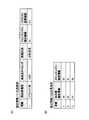
図23(A)に示す満足情報331は、満足情報331に含まれる各情報を識別する「項番」と、自装置(端末装置3)を識別する「利用者識別情報」と、リクエストに対する応答を生成したサービス提供装置2を示す情報(例えば、リクエストに対する応答に含まれる情報)が設定される「エンジン識別情報」とを項目として有している。また、図23(A)に示す満足情報331は、リクエストに対する応答に含まれる情報を利用者が採用したか否かを示す情報が設定される「採用可否」を項目として有している。「採用可否」には、利用者が応答に含まれるいずれかの情報を採用したことを示す「TRUE」、または、利用者が応答に含まれる情報を採用しなかったことを示す「FAULT」が設定される。 The
具体的に、情報生成部316は、図23(A)に示すように、「項番」が「1」である情報の「利用者識別情報」として「3a」を設定し、「エンジン識別情報」として「2a」を設定し、「採用可否」として「TRUE」を設定する。 Specifically, as illustrated in FIG. 23A, the
図19に戻り、端末装置3の情報送信部317は、S64の処理で生成した満足情報331を管理装置1に送信する(S65)。 Returning to FIG. 19, the
[管理装置における管理処理(3)]
次に、管理装置1における管理処理のうちの一部の処理について説明を行う。図20は、管理装置1における管理処理のうちの一部の処理を説明するフローチャート図である。[Management Process (3) in Management Device]
Next, a part of the management process in the
情報受信部111は、図20に示すように、満足情報331を受信するまで待機する(S71のNO)。具体的に、情報受信部111は、端末装置3が送信した満足情報331を受信するまで待機する。 As shown in FIG. 20, the
そして、満足情報331を受信した場合(S71のYES)、情報受信部111は、S71で受信した満足情報331を情報格納領域130に記憶(蓄積)する(S72)。以下、情報格納領域130に蓄積された満足情報331の具体例について説明を行う。 When the
[蓄積された満足情報の具体例]
図23(B)は、情報格納領域130に蓄積された満足情報331の具体例について説明する図である。[Specific examples of accumulated satisfaction information]
FIG. 23B is a diagram for describing a specific example of the
図23(B)に示す満足情報331は、図22(A)で説明した満足情報331と同様に、「項番」、「利用者識別情報」及び「エンジン識別情報」を項目として有している。また、図26に示す満足情報331は、端末装置3から受信した満足情報331のうち、「採用可否」に「TRUE」が設定されていた情報の数が設定される「採用数」と、端末装置3から受信した満足情報331の数が設定される「受信数」とを項目として有している。 The
具体的に、図23(B)に示す満足情報331において、「項番」が「1」である情報には、「利用者識別情報」として「3a」が設定され、「エンジン識別情報」として「2a」が設定され、「採用数」として「8」が設定され、「受信数」として「20」が設定される。 Specifically, in the
また、図23(B)に示す満足情報331において、「項番」が「2」である情報には、「利用者識別情報」として「3a」が設定され、「エンジン識別情報」として「2b」が設定され、「採用数」として「3」が設定され、「受信数」として「10」が設定される。図23(B)に含まれる他の情報についての説明は省略する。 In the
[管理装置における管理処理(4)]
次に、管理装置1における管理処理のうちの一部の処理について説明を行う。図21は、管理装置1における管理処理のうちの一部の処理を説明するフローチャート図である。[Management Process (4) in Management Device]
Next, a part of the management process in the
機能特定部112は、図21に示すように、機能特定タイミングになるまで待機する(S81のNO)。 As shown in FIG. 21, the
具体的に、図22(A)に示す設定情報131において、「項番」が「1」である情報には、「再決定種別」として「リクエスト数」が設定され、「再決定タイミング」として「1000(回)」が設定されている。そのため、この場合、機能特定タイミングは、利用者ごとのリクエストのいずれかが1000回の倍数に到達したタイミングになる。 Specifically, in the setting
そして、機能特定タイミングになった場合(S81のYES)、機能特定部112は、情報格納領域130に記憶(蓄積)された満足情報331を参照し、利用者ごとであって複数のサービス提供装置2ごとに、各サービス提供装置2から送信された応答について満足した旨の情報の入力が各利用者によって行われた割合である入力割合を特定する(S82)。 Then, when the function specifying timing comes (YES in S81), the
すなわち、機能特定部112は、例えば、利用者ごとであって複数のサービス提供装置2ごとに、端末装置3から送信された満足情報331のうち、「採用可否」に「TRUE」が設定された情報の割合を入力割合として特定する。 That is, for example, the
具体的に、図23(B)に示す満足情報331において、「利用者識別情報」に「3a」が設定され、「エンジン識別情報」に「2a」が設定された情報(「項番」が「1」である情報)の「採用数」及び「受信数」には、それぞれ「8」及び「20」が設定されている。そのため、機能特定部112は、この場合、例えば、端末装置3a及びサービス提供装置2aに対応する入力割合として、「8」を「20」で除算した値である「0.4」を算出する。同様に、機能特定部112は、例えば、端末装置3a及びサービス提供装置2bに対応する入力割合として「0.3」を算出し、端末装置3a及びサービス提供装置2cに対応する入力割合として「0.2」を算出する。 Specifically, in the
続いて、機能特定部112は、利用者ごとに、S82の処理で特定した入力割合のうち、最も大きい入力割合に対応するサービス提供装置2を特定のサービス提供装置2として特定する(S83)。 Subsequently, the
具体的に、例えば、端末装置3aに対応する入力割合として「0.4」、「0.3」及び「0.2」が算出された場合、最も大きい入力割合である「0.4」に対応するサービス提供装置2aを特定のサービス提供装置2として特定する。 Specifically, for example, when “0.4”, “0.3”, and “0.2” are calculated as the input ratios corresponding to the
なお、S83の処理において、特定のサービス提供装置2が変更された利用者が存在していると判定された場合、機能特定部112は、情報格納領域130に記憶された振分情報132の更新を行う。 In the process of S83, when it is determined that there is a user whose specific
その後、機能特定部112は、S83の処理で特定した特定のサービス提供装置2に対応する割合が他のサービス提供装置2に対応する割合よりも高い割合になるように、複数のサービス提供装置2のそれぞれに対してリクエストを振り分ける頻度の比率を決定する(S84)。 Thereafter, the
具体的に、図22(A)で説明した設定情報131には、「リクエスト送信頻度」として「0.5」が設定されている。そのため、S83の処理で特定した特定のサービス提供装置2がサービス提供装置2aである場合、機能特定部112は、例えば、サービス提供装置2aに振り分けるリクエストの割合と、サービス提供装置2bに振り分けられるリクエストの割合と、サービス提供装置2cに振り分けられるリクエストの割合との比率が、50:25:25(2:1:1)になるように、端末装置3aから送信されたリクエストを送信するサービス提供装置2の決定を行う。 Specifically, “0.5” is set as the “request transmission frequency” in the setting
これにより、管理装置1は、特定のサービス提供装置2が変更された利用者が存在する場合であっても、特定のサービス提供装置2の変更を迅速に行うことが可能になる。そのため、管理装置1は、機能の変更の頻度をより抑えながら、マッチングの成立率を高い水準で維持することが可能になる。 As a result, the
[分配送信処理を行う場合の管理処理の詳細]
次に、分配送信処理を行う場合における第1の実施の形態の詳細について説明する。図24から図27は、分配送信処理を行う場合における管理処理の詳細を説明するフローチャート図である。また、図28及び図29は、分配送信処理を行う場合における管理処理の詳細を説明する図である。具体的に、図28は、設定情報131及び振分情報132の具体例を説明する図であり、図29は、満足情報331の具体例を説明する図である。以下、切換送信処理を行う場合における第1の実施の形態の詳細と異なる処理についてのみ説明を行う。[Details of management processing when distributed transmission processing is performed]
Next, details of the first embodiment when performing distributed transmission processing will be described. FIGS. 24 to 27 are flowcharts for explaining the details of the management process in the case of performing the distributed transmission process. FIG. 28 and FIG. 29 are diagrams for explaining the details of the management process when the distributed transmission process is performed. Specifically, FIG. 28 is a diagram illustrating a specific example of the setting
[管理装置における管理処理(1)]
初めに、管理装置1における管理処理のうちの一部の処理について説明を行う。図24は、管理装置1における管理処理のうちの一部の処理を説明するフローチャート図である。[Management Process (1) in Management Device]
First, a part of the management process in the
リクエスト受信部113は、図24に示すように、リクエストを受信するまで待機する(S101のNO)。具体的に、リクエスト受信部113は、端末装置3が送信したリクエストを受信するまで待機する。 As shown in FIG. 24, the
そして、リクエストを受信した場合(S101のYES)、リクエスト変換部114は、情報格納領域130に記憶された設定情報131及び振分情報132を参照し、S101の処理で受信したリクエストを送信するサービス提供装置2を特定する(S102)。 If the request is received (YES in S101), the
続いて、リクエスト変換部114は、S101の処理で受信したリクエストを、各サービス提供装置2によって処理が可能な状態にそれぞれ変換する(S103)。 Subsequently, the
その後、リクエスト送信部115は、S103の処理で変換したリクエストを、各サービス提供装置2に対してそれぞれ送信する(S104)。 Thereafter, the
すなわち、管理装置1は、この場合、切換送信処理を行う場合と異なり、端末装置3から受信したリクエストを各サービス提供装置2が処理を行うことができる形式にそれぞれ変換し、変換したリクエストを各サービス提供装置2に対してそれぞれ送信する。 That is, in this case, unlike the case of performing the switching transmission process, the
[管理装置における管理処理(2)]
次に、管理装置1における管理処理のうちの一部の処理について説明を行う。図25は、管理装置1における管理処理のうちの一部の処理を説明するフローチャート図である。[Management Process (2) in Management Device]
Next, a part of the management process in the
応答受信部116は、図25に示すように、リクエストに対する応答を受信するまで待機する(S111のNO)。具体的に、応答受信部116は、S104の処理でリクエストを送信したサービス提供装置2のいずれかから応答を受信するまで待機する。 As shown in FIG. 25, the
そして、応答を受信した場合(S111のYES)、応答変換部117は、S111の処理で受信した応答に含まれる情報について、S103の処理で行われた変換に対応する再変換を行う(S112)。 When a response is received (YES in S111), the
続いて、管理装置1の応答集約部118は、S111の処理において全てのサービス提供装置2から応答を受信したか否かを判定する(S113)。 Subsequently, the
その結果、全てのサービス提供装置2から応答を受信していないと判定した場合(S113のNO)、応答受信部116は、S111以降の処理を再度行う。 As a result, when it is determined that responses have not been received from all the service providing apparatuses 2 (NO in S113), the
一方、全てのサービス提供装置2から応答を受信していると判定した場合(S113のYES)、応答集約部118は、情報格納領域130に記憶された設定情報131及び振分情報132を参照し、S111の処理で受信した応答のそれぞれから情報を取得して集約する(S114)。 On the other hand, when it is determined that responses have been received from all the service providing apparatuses 2 (YES in S113), the
具体的に、図28(B)に示す振分情報132において、「利用者識別情報」に「3a」が設定された情報(「項番」が「1」である情報)の「メインエンジン識別情報」には、「2a」が設定されている。また、図28(A)で説明した設定情報131には、「リクエスト送信頻度」として「0.5」が設定されている。そのため、例えば、S101の処理で受信したリクエストの送信元が端末装置3aである場合、応答集約部118は、サービス提供装置2aに対応する応答から取得した情報量と、サービス提供装置2bに対応する応答から取得した情報量と、サービス提供装置2cに対応する応答から取得した情報量との比率が、50:25:25(2:1:1)に従うように、かつ、各サービス提供装置2から取得した情報量の合計が端末装置3に送信する情報量として予め決められた情報量と等しくなるように、各応答から情報を取得して集約する。 Specifically, in the
その後、応答変換部117は、S114の処理で集約を行った応答を、S101の処理で受信したリクエストを送信した端末装置3に対して送信する(S115)。 Thereafter, the
[管理装置における管理処理(3)]
次に、管理装置1における管理処理のうちの一部の処理について説明を行う。図26は、管理装置1における管理処理のうちの一部の処理を説明するフローチャート図である。[Management Process (3) in Management Device]
Next, a part of the management process in the
情報受信部111は、図26に示すように、満足情報331を受信するまで待機する(S121のNO)。具体的に、情報受信部111は、端末装置3が送信した満足情報331を受信するまで待機する。 As shown in FIG. 26, the
そして、満足情報331を受信した場合(S121のYES)、情報受信部111は、S121で受信した満足情報331を情報格納領域130に記憶(蓄積)する(S122)。以下、情報格納領域130に蓄積された満足情報331の具体例について説明を行う。 When the
[蓄積された満足情報の具体例]
図29は、情報格納領域130に蓄積された満足情報331の具体例について説明する図である。[Specific examples of accumulated satisfaction information]
FIG. 29 is a diagram illustrating a specific example of the
図29に示す満足情報331は、図23(B)で説明した満足情報331と同様に、「項番」と、「利用者識別情報」と「メインエンジン識別情報」と「採用数」とを項目として有している。一方、図29に示す満足情報331は、図23(B)で説明した満足情報331と異なり、項目として「受信数」を有していない。 Similar to the
具体的に、図29に示す満足情報331において、「項番」が「1」である情報には、「利用者識別情報」として「3a」が設定され、「エンジン識別情報」として「2a」が設定され、「採用数」として「10」が設定される。 Specifically, in the
また、図29に示す満足情報331において、「項番」が「2」である情報には、「利用者識別情報」として「3a」が設定され、「エンジン識別情報」として「2b」が設定され、「採用数」として「7」が設定される。図29に含まれる他の情報についての説明は省略する。 Also, in the
[管理装置における管理処理(4)]
次に、管理装置1における管理処理のうちの一部の処理について説明を行う。図27は、管理装置1における管理処理のうちの一部の処理を説明するフローチャート図である。[Management Process (4) in Management Device]
Next, a part of the management process in the
機能特定部112は、図27に示すように、機能特定タイミングになるまで待機する(S131のNO)。 As shown in FIG. 27, the
具体的に、図28(A)に示す設定情報131において、「項番」が「1」である情報には、「再決定種別」として「リクエスト数」が設定され、「再決定タイミング」として「1000(回)」が設定されている。そのため、この場合、機能特定タイミングは、利用者ごとのリクエストのいずれかが1000回の倍数に到達したタイミングになる。 Specifically, in the setting
そして、機能特定タイミングになった場合(S131のYES)、機能特定部112は、情報格納領域130に記憶(蓄積)された満足情報331を参照し、利用者ごとであって複数のサービス提供装置2ごとに、各利用者が満足した情報として選択した情報のうち、各サービス提供装置2から送信された応答に含まれる情報の割合である選択割合を特定する(S132)。 Then, when the function specifying timing comes (YES in S131), the
具体的に、図29に示す満足情報331において、「利用者識別情報」に「3a」が設定された情報(「項番」が「1」から「3」である情報)の「採用数」には、それぞれ「10」、「7」及び「3」が設定されている。そのため、機能特定部112は、例えば、端末装置3a及びサービス提供装置2aに対応する選択割合として、「10」を「10」、「7」及び「3」の和である「20」で除算した値である「0.5」を特定する。また、機能特定部112は、例えば、端末装置3a及びサービス提供装置2bに対応する選択割合として、「7」を「20」で除算した値である「0.35」を特定する。さらに、機能特定部112は、例えば、端末装置3a及びサービス提供装置2cに対応する選択割合として、「3」を「20」で除算した値である「0.15」を特定する。 Specifically, in the
続いて、機能特定部112は、利用者ごとに、S132の処理で特定した選択割合のうち、最も大きい選択割合に対応するサービス提供装置2を特定のサービス提供装置2として特定する(S133)。 Subsequently, the
具体的に、例えば、端末装置3aに対応する選択割合として「0.5」、「0.35」及び「0.15」が算出された場合、最も大きい入力割合である「0.5」に対応するサービス提供装置2aを特定のサービス提供装置2として特定する。 Specifically, for example, when “0.5”, “0.35”, and “0.15” are calculated as the selection ratio corresponding to the
なお、S133の処理において、特定のサービス提供装置2が変更された利用者が存在していると判定された場合、機能特定部112は、情報格納領域130に記憶された振分情報132の更新を行う。 In the process of S133, when it is determined that there is a user whose specific
その後、機能特定部112は、S133の処理で特定した特定のサービス提供装置2に対応する割合が他のサービス提供装置2に対応する割合よりも高い割合になるように、複数のサービス提供装置2のそれぞれに対してリクエストを振り分ける頻度の比率を決定する(S134)。 Thereafter, the
具体的に、図28(A)で説明した設定情報131には、「リクエスト送信頻度」として「0.5」が設定されている。そのため、S133の処理で特定した特定のサービス提供装置2がサービス提供装置2aである場合、機能特定部112は、例えば、サービス提供装置2aに振り分けるリクエストの割合と、サービス提供装置2bに振り分けられるリクエストの割合と、サービス提供装置2cに振り分けられるリクエストの割合との比率が、50:25:25(2:1:1)になるように、端末装置3aから送信されたリクエストを送信するサービス提供装置2の決定を行う。 Specifically, “0.5” is set as the “request transmission frequency” in the setting
これにより、管理装置1は、特定のサービス提供装置2が変更された利用者が存在する場合であっても、特定のサービス提供装置2の変更を迅速に行うことが可能になる。そのため、管理装置1は、機能の変更の頻度をより抑えながら、マッチングの成立率を高い水準で維持することが可能になる。 As a result, the
このように、本実施の形態における管理装置1は、リクエストを行った利用者がリクエストに対する応答について満足したか否かを示す満足情報331を情報格納領域130に蓄積する。そして、管理装置1は、蓄積した満足情報331に基づいて、利用者ごとに、リクエストに対する応答を生成する複数のサービス提供装置2のうち、満足度が所定の条件を満たす特定のサービス提供装置2を、各利用者からのリクエストに対する応答を生成する際に優先して用いるサービス提供装置2として特定する。 As described above, the
すなわち、管理装置1は、例えば、リクエストに対する応答を受信した利用者が情報の採用を行ったか否かを示す満足情報331を、リクエストが発生するごとに取得して蓄積する。そして、管理装置1は、満足情報331を参照することにより、利用者ごとに、利用者の満足度が高い応答を生成することができるサービス提供装置2を特定する。 That is, for example, the
これにより、管理装置1は、利用者ごとに、マッチングの成立率を高めることができるサービス提供装置2に対して優先的にリクエストの送信を行うことが可能になる。そのため、管理装置1は、機能の変更の頻度を抑えながら、マッチングの成立率を高い水準で維持することが可能になる。 Thereby, the
以上の実施の形態をまとめると、以下の付記のとおりである。 The above embodiment is summarized as follows.
(付記1)
リクエストを行った利用者が該リクエストに対する応答について満足したか否かを示す満足情報を記憶部に蓄積し、
蓄積した前記満足情報に基づいて、前記利用者ごとに、リクエストに対する応答を生成する複数のサービス提供機能のうち、リクエストに対して生成した応答の満足度が所定の条件を満たす特定のサービス提供機能を、各利用者からのリクエストに対する応答を生成する際に優先して用いるサービス提供機能として特定する、
処理をコンピュータに実行させることを特徴とする管理プログラム。(Appendix 1)
The satisfaction information indicating whether or not the user who made the request is satisfied with the response to the request is stored in the storage unit,
Of a plurality of service providing functions for generating a response to the request for each user based on the accumulated satisfaction information, a specific service providing function for which the satisfaction degree of the response generated for the request satisfies a predetermined condition Is specified as a service providing function to be used preferentially when generating a response to a request from each user.
A management program for causing a computer to execute processing.
(付記2)
付記1において、
前記特定する処理では、前記特定のサービス提供機能に対応する割合が他のサービス提供機能に対応する割合よりも高い割合になるように、前記複数のサービス提供機能のそれぞれに対してリクエストを振り分ける頻度の比率を決定し、さらに、
前記利用者から特定のリクエストが行われた場合、前記複数のサービス提供機能のそれぞれに対して振り分けられるリクエストの頻度が前記比率に従うように、前記複数のサービス提供機能のうちのいずれかに対して前記特定のリクエストの振り分けを行い、
前記複数のサービス提供機能のうちのいずれかから前記特定のリクエストに対する応答を受信した場合、受信した前記応答を前記利用者に提示する情報として出力する、
処理をコンピュータに実行させることを特徴とする管理プログラム。(Appendix 2)
In
In the specifying process, a frequency of distributing requests to each of the plurality of service providing functions so that a ratio corresponding to the specific service providing function is higher than a ratio corresponding to another service providing function. Determine the ratio of
When a specific request is made from the user, for any one of the plurality of service providing functions, the frequency of requests distributed to each of the plurality of service providing functions follows the ratio. Sort the specific request,
When a response to the specific request is received from any of the plurality of service providing functions, the received response is output as information to be presented to the user.
A management program for causing a computer to execute processing.
(付記3)
付記2において、
前記満足情報は、前記利用者がリクエストに対する応答について満足した旨の入力を行ったか否かを示す情報であり、
前記特定する処理では、
前記満足情報を参照し、前記利用者ごとであって前記複数のサービス提供機能ごとに、各サービス提供機能から送信された応答について満足した旨の情報の入力が各利用者によって行われた割合である入力割合を特定し、
前記利用者ごとに、最も大きい前記入力割合に対応するサービス提供機能を前記特定のサービス提供機能として特定する、
ことを特徴とする管理プログラム。(Appendix 3)
In
The satisfaction information is information indicating whether or not the user has made an input indicating that the response to the request is satisfied,
In the process of specifying,
With reference to the satisfaction information, for each of the plurality of service providing functions, for each of the plurality of service providing functions, information indicating that the response transmitted from each service providing function is satisfied is performed by each user. Identify an input percentage,
For each user, a service providing function corresponding to the largest input ratio is specified as the specific service providing function.
A management program characterized by that.
(付記4)
付記1において、
前記特定する処理では、前記特定のサービス提供機能に対応する割合が他のサービス提供機能に対応する割合よりも高い割合になるように、前記複数のサービス提供機能のそれぞれに対してリクエストを振り分ける頻度の比率を決定し、さらに、
前記利用者から特定のリクエストが行われた場合、前記複数のサービス提供機能のそれぞれに対して前記特定のリクエストの振り分けを行い、
前記複数のサービス提供機能のそれぞれから前記特定のリクエストに対する応答を受信した場合、前記特定のリクエストに対する応答のそれぞれから取得した情報量が前記比率に従うように、前記特定のリクエストに対する応答のそれぞれから情報を取得し、
取得した前記情報のそれぞれを前記利用者に提示する情報として出力する、
処理をコンピュータに実行させることを特徴とする管理プログラム。(Appendix 4)
In
In the specifying process, a frequency of distributing requests to each of the plurality of service providing functions so that a ratio corresponding to the specific service providing function is higher than a ratio corresponding to another service providing function. Determine the ratio of
When a specific request is made from the user, the specific request is distributed to each of the plurality of service providing functions,
When a response to the specific request is received from each of the plurality of service providing functions, information is acquired from each of the responses to the specific request so that the amount of information acquired from each of the responses to the specific request follows the ratio. Get
Outputting each of the acquired information as information to be presented to the user;
A management program for causing a computer to execute processing.
(付記5)
付記4において、
前記満足情報は、前記利用者が満足した情報として選択した情報を含む応答を送信したサービス提供機能を示す情報であり、
前記特定する処理では、
前記満足情報を参照し、前記利用者ごとであって前記複数のサービス提供機能ごとに、各利用者が満足した情報として選択した情報のうち、各サービス提供機能から送信された応答に含まれる情報の割合である選択割合を特定し、
前記利用者ごとに、最も大きい前記選択割合に対応するサービス提供機能を前記特定のサービス提供機能として特定する、
ことを特徴とする管理プログラム。(Appendix 5)
In
The satisfaction information is information indicating a service providing function that has transmitted a response including information selected as information satisfied by the user,
In the process of specifying,
Information included in a response transmitted from each service providing function among information selected as information satisfied by each user for each of the plurality of service providing functions with reference to the satisfaction information. The selection percentage that is the percentage of
For each user, a service providing function corresponding to the largest selection ratio is specified as the specific service providing function.
A management program characterized by that.
(付記6)
付記1において、
前記特定する処理は、定期的な間隔で行われる、
ことを特徴とする管理プログラム。(Appendix 6)
In
The specified process is performed at regular intervals.
A management program characterized by that.
(付記7)
付記1において、
前記特定する処理は、各利用者が所定回数のリクエストを行うごとに、所定回数のリクエストを行った利用者について行われる、
ことを特徴とする管理プログラム。(Appendix 7)
In
The process of specifying is performed for a user who has made a predetermined number of requests each time each user makes a predetermined number of requests.
A management program characterized by that.
(付記8)
リクエストを行った利用者が該リクエストに対する応答について満足したか否かを示す満足情報を記憶部に蓄積し、
蓄積した前記満足情報に基づいて、前記利用者ごとに、リクエストに対する応答を生成する複数のサービス提供機能のうち、リクエストに対して生成した応答の満足度が所定の条件を満たす特定のサービス提供機能を、各利用者からのリクエストに対する応答を生成する際に優先して用いるサービス提供機能として特定する、
ことを特徴とする管理方法。(Appendix 8)
The satisfaction information indicating whether or not the user who made the request is satisfied with the response to the request is stored in the storage unit,
Of a plurality of service providing functions for generating a response to the request for each user based on the accumulated satisfaction information, a specific service providing function for which the satisfaction degree of the response generated for the request satisfies a predetermined condition Is specified as a service providing function to be used preferentially when generating a response to a request from each user.
A management method characterized by that.
(付記9)
付記8において、
前記特定する工程では、前記特定のサービス提供機能に対応する割合が他のサービス提供機能に対応する割合よりも高い割合になるように、前記複数のサービス提供機能のそれぞれに対してリクエストを振り分ける頻度の比率を決定し、さらに、
前記利用者から特定のリクエストが行われた場合、前記複数のサービス提供機能のそれぞれに対して振り分けられるリクエストの頻度が前記比率に従うように、前記複数のサービス提供機能のうちのいずれかに対して前記特定のリクエストの振り分けを行い、
前記複数のサービス提供機能のうちのいずれかから前記特定のリクエストに対する応答を受信した場合、受信した前記応答を前記利用者に提示する情報として出力する、
ことを特徴とする管理方法。(Appendix 9)
In
In the specifying step, the frequency of distributing requests to each of the plurality of service providing functions so that the ratio corresponding to the specific service providing function is higher than the ratio corresponding to the other service providing functions. Determine the ratio of
When a specific request is made from the user, for any one of the plurality of service providing functions, the frequency of requests distributed to each of the plurality of service providing functions follows the ratio. Sort the specific request,
When a response to the specific request is received from any of the plurality of service providing functions, the received response is output as information to be presented to the user.
A management method characterized by that.
(付記10)
付記9において、
前記満足情報は、前記利用者がリクエストに対する応答について満足した旨の入力を行ったか否かを示す情報であり、
前記特定する工程では、
前記満足情報を参照し、前記利用者ごとであって前記複数のサービス提供機能ごとに、各サービス提供機能から送信された応答について満足した旨の情報の入力が各利用者によって行われた割合である入力割合を特定し、
前記利用者ごとに、最も大きい前記入力割合に対応するサービス提供機能を前記特定のサービス提供機能として特定する、
ことを特徴とする管理方法。(Appendix 10)
In
The satisfaction information is information indicating whether or not the user has made an input indicating that the response to the request is satisfied,
In the identifying step,
With reference to the satisfaction information, for each of the plurality of service providing functions, for each of the plurality of service providing functions, information indicating that the response transmitted from each service providing function is satisfied is performed by each user. Identify an input percentage,
For each user, a service providing function corresponding to the largest input ratio is specified as the specific service providing function.
A management method characterized by that.
(付記11)
付記8において、
前記特定する工程では、前記特定のサービス提供機能に対応する割合が他のサービス提供機能に対応する割合よりも高い割合になるように、前記複数のサービス提供機能のそれぞれに対してリクエストを振り分ける頻度の比率を決定し、
前記利用者から特定のリクエストが行われた場合、前記複数のサービス提供機能のそれぞれに対して前記特定のリクエストの振り分けを行い、
前記複数のサービス提供機能のそれぞれから前記特定のリクエストに対する応答を受信した場合、前記特定のリクエストに対する応答のそれぞれから取得した情報量が前記比率に従うように、前記特定のリクエストに対する応答のそれぞれから情報を取得し、
取得した前記情報のそれぞれを前記利用者に提示する情報として出力する、
ことを特徴とする管理方法。(Appendix 11)
In
In the specifying step, the frequency of distributing requests to each of the plurality of service providing functions so that the ratio corresponding to the specific service providing function is higher than the ratio corresponding to the other service providing functions. Determine the ratio of
When a specific request is made from the user, the specific request is distributed to each of the plurality of service providing functions,
When a response to the specific request is received from each of the plurality of service providing functions, information is acquired from each of the responses to the specific request so that the amount of information acquired from each of the responses to the specific request follows the ratio. Get
Outputting each of the acquired information as information to be presented to the user;
A management method characterized by that.
(付記12)
付記11において、
前記満足情報は、前記利用者が満足した情報として選択した情報を含む応答を送信したサービス提供機能を示す情報であり、
前記特定する工程では、
前記満足情報を参照し、前記利用者ごとであって前記複数のサービス提供機能ごとに、各利用者が満足した情報として選択した情報のうち、各サービス提供機能から送信された応答に含まれる情報の割合である選択割合を特定し、
前記利用者ごとに、最も大きい前記選択割合に対応するサービス提供機能を前記特定のサービス提供機能として特定する、
ことを特徴とする管理方法。(Appendix 12)
In
The satisfaction information is information indicating a service providing function that has transmitted a response including information selected as information satisfied by the user,
In the identifying step,
Information included in a response transmitted from each service providing function among information selected as information satisfied by each user for each of the plurality of service providing functions with reference to the satisfaction information. The selection percentage that is the percentage of
For each user, a service providing function corresponding to the largest selection ratio is specified as the specific service providing function.
A management method characterized by that.
1:管理装置 2a:サービス提供装置
2b:サービス提供装置 2c:サービス提供装置
3a:端末装置 3b:端末装置
3c:端末装置330:記憶部
NW:ネットワーク1:
Claims (8)
Translated fromJapanese蓄積した前記満足情報に基づいて、前記利用者ごとに、リクエストに対する応答を生成する複数のサービス提供機能のうち、リクエストに対して生成した応答の満足度が所定の条件を満たす特定のサービス提供機能を、各利用者からのリクエストに対する応答を生成する際に優先して用いるサービス提供機能として特定する、
処理をコンピュータに実行させることを特徴とする管理プログラム。The satisfaction information indicating whether or not the user who made the request is satisfied with the response to the request is stored in the storage unit,
Of a plurality of service providing functions for generating a response to the request for each user based on the accumulated satisfaction information, a specific service providing function for which the satisfaction degree of the response generated for the request satisfies a predetermined condition Is specified as a service providing function to be used preferentially when generating a response to a request from each user.
A management program for causing a computer to execute processing.
前記特定する処理では、前記特定のサービス提供機能に対応する割合が他のサービス提供機能に対応する割合よりも高い割合になるように、前記複数のサービス提供機能のそれぞれに対してリクエストを振り分ける頻度の比率を決定し、さらに、
前記利用者から特定のリクエストが行われた場合、前記複数のサービス提供機能のそれぞれに対して振り分けられるリクエストの頻度が前記比率に従うように、前記複数のサービス提供機能のうちのいずれかに対して前記特定のリクエストの振り分けを行い、
前記複数のサービス提供機能のうちのいずれかから前記特定のリクエストに対する応答を受信した場合、受信した前記応答を前記利用者に提示する情報として出力する、
処理をコンピュータに実行させることを特徴とする管理プログラム。In claim 1,
In the specifying process, a frequency of distributing requests to each of the plurality of service providing functions so that a ratio corresponding to the specific service providing function is higher than a ratio corresponding to another service providing function. Determine the ratio of
When a specific request is made from the user, for any one of the plurality of service providing functions, the frequency of requests distributed to each of the plurality of service providing functions follows the ratio. Sort the specific request,
When a response to the specific request is received from any of the plurality of service providing functions, the received response is output as information to be presented to the user.
A management program for causing a computer to execute processing.
前記満足情報は、前記利用者がリクエストに対する応答について満足した旨の入力を行ったか否かを示す情報であり、
前記特定する処理では、
前記満足情報を参照し、前記利用者ごとであって前記複数のサービス提供機能ごとに、各サービス提供機能から送信された応答について満足した旨の情報の入力が各利用者によって行われた割合である入力割合を特定し、
前記利用者ごとに、最も大きい前記入力割合に対応するサービス提供機能を前記特定のサービス提供機能として特定する、
ことを特徴とする管理プログラム。In claim 2,
The satisfaction information is information indicating whether or not the user has made an input indicating that the response to the request is satisfied,
In the process of specifying,
With reference to the satisfaction information, for each of the plurality of service providing functions, for each of the plurality of service providing functions, information indicating that the response transmitted from each service providing function is satisfied is performed by each user. Identify an input percentage,
For each user, a service providing function corresponding to the largest input ratio is specified as the specific service providing function.
A management program characterized by that.
前記特定する処理では、前記特定のサービス提供機能に対応する割合が他のサービス提供機能に対応する割合よりも高い割合になるように、前記複数のサービス提供機能のそれぞれに対してリクエストを振り分ける頻度の比率を決定し、さらに、
前記利用者から特定のリクエストが行われた場合、前記複数のサービス提供機能のそれぞれに対して前記特定のリクエストの振り分けを行い、
前記複数のサービス提供機能のそれぞれから前記特定のリクエストに対する応答を受信した場合、前記特定のリクエストに対する応答のそれぞれから取得した情報量が前記比率に従うように、前記特定のリクエストに対する応答のそれぞれから情報を取得し、
取得した前記情報のそれぞれを前記利用者に提示する情報として出力する、
処理をコンピュータに実行させることを特徴とする管理プログラム。In claim 1,
In the specifying process, a frequency of distributing requests to each of the plurality of service providing functions so that a ratio corresponding to the specific service providing function is higher than a ratio corresponding to another service providing function. Determine the ratio of
When a specific request is made from the user, the specific request is distributed to each of the plurality of service providing functions,
When a response to the specific request is received from each of the plurality of service providing functions, information is acquired from each of the responses to the specific request so that the amount of information acquired from each of the responses to the specific request follows the ratio. Get
Outputting each of the acquired information as information to be presented to the user;
A management program for causing a computer to execute processing.
前記満足情報は、前記利用者が満足した情報として選択した情報を含む応答を送信したサービス提供機能を示す情報であり、
前記特定する処理では、
前記満足情報を参照し、前記利用者ごとであって前記複数のサービス提供機能ごとに、各利用者が満足した情報として選択した情報のうち、各サービス提供機能から送信された応答に含まれる情報の割合である選択割合を特定し、
前記利用者ごとに、最も大きい前記選択割合に対応するサービス提供機能を前記特定のサービス提供機能として特定する、
ことを特徴とする管理プログラム。In claim 4,
The satisfaction information is information indicating a service providing function that has transmitted a response including information selected as information satisfied by the user,
In the process of specifying,
Information included in a response transmitted from each service providing function among information selected as information satisfied by each user for each of the plurality of service providing functions with reference to the satisfaction information. The selection percentage that is the percentage of
For each user, a service providing function corresponding to the largest selection ratio is specified as the specific service providing function.
A management program characterized by that.
前記特定する処理は、定期的な間隔で行われる、
ことを特徴とする管理プログラム。In claim 1,
The specified process is performed at regular intervals.
A management program characterized by that.
前記特定する処理は、各利用者が所定回数のリクエストを行うごとに、所定回数のリクエストを行った利用者について行われる、
ことを特徴とする管理プログラム。In claim 1,
The process of specifying is performed for a user who has made a predetermined number of requests each time each user makes a predetermined number of requests.
A management program characterized by that.
蓄積した前記満足情報に基づいて、前記利用者ごとに、リクエストに対する応答を生成する複数のサービス提供機能のうち、リクエストに対して生成した応答の満足度が所定の条件を満たす特定のサービス提供機能を、各利用者からのリクエストに対する応答を生成する際に優先して用いるサービス提供機能として特定する、
ことを特徴とする管理方法。The satisfaction information indicating whether or not the user who made the request is satisfied with the response to the request is stored in the storage unit,
Of a plurality of service providing functions for generating a response to the request for each user based on the accumulated satisfaction information, a specific service providing function for which the satisfaction degree of the response generated for the request satisfies a predetermined condition Is specified as a service providing function to be used preferentially when generating a response to a request from each user.
A management method characterized by that.
Priority Applications (2)
| Application Number | Priority Date | Filing Date | Title |
|---|---|---|---|
| JP2018021940AJP7025638B2 (en) | 2018-02-09 | 2018-02-09 | Management program and management method |
| US16/258,742US10904110B2 (en) | 2018-02-09 | 2019-01-28 | Management method of matching service and information processing apparatus |
Applications Claiming Priority (1)
| Application Number | Priority Date | Filing Date | Title |
|---|---|---|---|
| JP2018021940AJP7025638B2 (en) | 2018-02-09 | 2018-02-09 | Management program and management method |
Publications (2)
| Publication Number | Publication Date |
|---|---|
| JP2019139481Atrue JP2019139481A (en) | 2019-08-22 |
| JP7025638B2 JP7025638B2 (en) | 2022-02-25 |
Family
ID=67541201
Family Applications (1)
| Application Number | Title | Priority Date | Filing Date |
|---|---|---|---|
| JP2018021940AActiveJP7025638B2 (en) | 2018-02-09 | 2018-02-09 | Management program and management method |
Country Status (2)
| Country | Link |
|---|---|
| US (1) | US10904110B2 (en) |
| JP (1) | JP7025638B2 (en) |
Citations (4)
| Publication number | Priority date | Publication date | Assignee | Title |
|---|---|---|---|---|
| JP2005228355A (en)* | 2003-05-26 | 2005-08-25 | Matsushita Electric Ind Co Ltd | Operation history usage system |
| CN1795465A (en)* | 2003-05-26 | 2006-06-28 | 松下电器产业株式会社 | Operation history utilization system |
| JP2007012077A (en)* | 1998-01-23 | 2007-01-18 | Emc Corp | Access to content addressable data via network |
| US20130282519A1 (en)* | 2011-10-25 | 2013-10-24 | Amazon Technologies, Inc. | Recommendation system with user interface for exposing downstream effects of paricular rating actions |
Family Cites Families (19)
| Publication number | Priority date | Publication date | Assignee | Title |
|---|---|---|---|---|
| US6460036B1 (en)* | 1994-11-29 | 2002-10-01 | Pinpoint Incorporated | System and method for providing customized electronic newspapers and target advertisements |
| JP2001282952A (en)* | 2000-03-30 | 2001-10-12 | Namco Ltd | Client computer, server computer, network ranking system, network ranking method, task processing method, and recording medium |
| US20020082988A1 (en)* | 2000-12-27 | 2002-06-27 | Kazuyuki Ujiie | Server device for evaluating quality of service, service providing method and medium |
| US20020103692A1 (en)* | 2000-12-28 | 2002-08-01 | Rosenberg Sandra H. | Method and system for adaptive product recommendations based on multiple rating scales |
| US8538803B2 (en)* | 2001-06-14 | 2013-09-17 | Frank C. Nicholas | Method and system for providing network based target advertising and encapsulation |
| US20070039018A1 (en) | 2005-08-09 | 2007-02-15 | Verance Corporation | Apparatus, systems and methods for broadcast advertising stewardship |
| EP1897045A2 (en) | 2005-04-26 | 2008-03-12 | Governing Dynamics Inc. | A method of digital good placement in a dynamic, real time environment |
| US9071859B2 (en)* | 2007-09-26 | 2015-06-30 | Time Warner Cable Enterprises Llc | Methods and apparatus for user-based targeted content delivery |
| US9659299B2 (en)* | 2008-04-30 | 2017-05-23 | Hartford Fire Insurance Company | Computer system and method for interim transaction diagnosis for selective remediation and customer loyalty enhancement |
| US8250207B2 (en)* | 2009-01-28 | 2012-08-21 | Headwater Partners I, Llc | Network based ambient services |
| WO2010053981A2 (en)* | 2008-11-05 | 2010-05-14 | Eric Bosco | Systems and methods for adverrtising on content-screened web pages |
| US8539359B2 (en)* | 2009-02-11 | 2013-09-17 | Jeffrey A. Rapaport | Social network driven indexing system for instantly clustering people with concurrent focus on same topic into on-topic chat rooms and/or for generating on-topic search results tailored to user preferences regarding topic |
| US8751427B1 (en)* | 2011-01-05 | 2014-06-10 | Google Inc. | Location-centric recommendation service for users |
| US20130204676A1 (en)* | 2012-01-26 | 2013-08-08 | Flywheel Software, Inc. | Method and system for dynamically categorizing service providers |
| US20130290234A1 (en)* | 2012-02-02 | 2013-10-31 | Visa International Service Association | Intelligent Consumer Service Terminal Apparatuses, Methods and Systems |
| US9904579B2 (en)* | 2013-03-15 | 2018-02-27 | Advanced Elemental Technologies, Inc. | Methods and systems for purposeful computing |
| US10057282B2 (en)* | 2015-05-07 | 2018-08-21 | Cyberark Software Ltd. | Detecting and reacting to malicious activity in decrypted application data |
| US10360512B2 (en)* | 2015-05-29 | 2019-07-23 | International Business Machines Corporation | Intelligent service request classification and assignment |
| US20180209803A1 (en)* | 2017-01-25 | 2018-07-26 | Via Transportation, Inc. | Dynamic Route Planning |
- 2018
- 2018-02-09JPJP2018021940Apatent/JP7025638B2/enactiveActive
- 2019
- 2019-01-28USUS16/258,742patent/US10904110B2/ennot_activeExpired - Fee Related
Patent Citations (4)
| Publication number | Priority date | Publication date | Assignee | Title |
|---|---|---|---|---|
| JP2007012077A (en)* | 1998-01-23 | 2007-01-18 | Emc Corp | Access to content addressable data via network |
| JP2005228355A (en)* | 2003-05-26 | 2005-08-25 | Matsushita Electric Ind Co Ltd | Operation history usage system |
| CN1795465A (en)* | 2003-05-26 | 2006-06-28 | 松下电器产业株式会社 | Operation history utilization system |
| US20130282519A1 (en)* | 2011-10-25 | 2013-10-24 | Amazon Technologies, Inc. | Recommendation system with user interface for exposing downstream effects of paricular rating actions |
Also Published As
| Publication number | Publication date |
|---|---|
| US10904110B2 (en) | 2021-01-26 |
| US20190253327A1 (en) | 2019-08-15 |
| JP7025638B2 (en) | 2022-02-25 |
Similar Documents
| Publication | Publication Date | Title |
|---|---|---|
| JP6563936B2 (en) | Method, system, and computer-readable medium for cloud-based virtual orchestrator | |
| US20190098517A1 (en) | Systems and methods for networking and wirelessly routing communications | |
| US8943205B2 (en) | Generalized coordinate system and metric-based resource selection framework | |
| WO2016095516A1 (en) | Complex event processing method, apparatus and system | |
| CN104243405B (en) | A kind of request processing method, apparatus and system | |
| US11102665B2 (en) | Supplemental voltage controller for radio frequency (RF) antennas | |
| CN109309698B (en) | Data processing system, method and device | |
| CN109729115B (en) | Method, device, proxy server and terminal equipment for realizing distributed computation | |
| US9848089B2 (en) | Methods and apparatus to generate an overall performance index | |
| CN109561403A (en) | A kind of short message dispatching method, equipment and storage medium | |
| WO2018061825A1 (en) | Distributed processing system, distributed processing method, and recording medium | |
| CN105072139A (en) | Recommended Methods and Apparatus | |
| CN109120527B (en) | A method and system for transmitting service traffic | |
| JP2018081515A (en) | Resource search apparatus and resource search method | |
| US20150172389A1 (en) | Session management system, session management apparatus, and non-transitory computer readable medium | |
| US9928370B2 (en) | Communication device, communication method, computer program product, and communication system | |
| CN110620722A (en) | Order processing method and device | |
| JP2019139481A (en) | Management program and management method | |
| JPWO2015114713A1 (en) | COMMUNICATION SYSTEM, COMMON SERVICE CONTROL DEVICE, DATA COLLECTION METHOD, AND PROGRAM | |
| JP6229710B2 (en) | Information receiving apparatus, information receiving system, and information receiving method | |
| JP6813773B2 (en) | Data collection program, data collection system and data collection method | |
| JP5140692B2 (en) | Polling transmission system, polling transmission method, and polling transmission program | |
| CN105659218A (en) | Communication system, shared service control unit, data transmission method, and non-transitory computer-readable medium | |
| JPWO2014006669A1 (en) | COMMUNICATION SYSTEM, GUI DEVICE, AND SERVICE DEVICE | |
| KR102451832B1 (en) | Method for allocating resources in a cellular communication network and its nodes |
Legal Events
| Date | Code | Title | Description |
|---|---|---|---|
| A621 | Written request for application examination | Free format text:JAPANESE INTERMEDIATE CODE: A621 Effective date:20201110 | |
| A977 | Report on retrieval | Free format text:JAPANESE INTERMEDIATE CODE: A971007 Effective date:20210924 | |
| A131 | Notification of reasons for refusal | Free format text:JAPANESE INTERMEDIATE CODE: A131 Effective date:20211005 | |
| A521 | Request for written amendment filed | Free format text:JAPANESE INTERMEDIATE CODE: A523 Effective date:20211201 | |
| TRDD | Decision of grant or rejection written | ||
| A01 | Written decision to grant a patent or to grant a registration (utility model) | Free format text:JAPANESE INTERMEDIATE CODE: A01 Effective date:20220111 | |
| A61 | First payment of annual fees (during grant procedure) | Free format text:JAPANESE INTERMEDIATE CODE: A61 Effective date:20220124 | |
| R150 | Certificate of patent or registration of utility model | Ref document number:7025638 Country of ref document:JP Free format text:JAPANESE INTERMEDIATE CODE: R150 |