JP2019138812A - Distance measuring device, distance measuring system, and method for measuring distance - Google Patents
Distance measuring device, distance measuring system, and method for measuring distanceDownload PDFInfo
- Publication number
- JP2019138812A JP2019138812AJP2018023541AJP2018023541AJP2019138812AJP 2019138812 AJP2019138812 AJP 2019138812AJP 2018023541 AJP2018023541 AJP 2018023541AJP 2018023541 AJP2018023541 AJP 2018023541AJP 2019138812 AJP2019138812 AJP 2019138812A
- Authority
- JP
- Japan
- Prior art keywords
- distance
- output
- information
- acquisition unit
- sound wave
- Prior art date
- Legal status (The legal status is an assumption and is not a legal conclusion. Google has not performed a legal analysis and makes no representation as to the accuracy of the status listed.)
- Pending
Links
Images


Classifications
- A—HUMAN NECESSITIES
- A63—SPORTS; GAMES; AMUSEMENTS
- A63B—APPARATUS FOR PHYSICAL TRAINING, GYMNASTICS, SWIMMING, CLIMBING, OR FENCING; BALL GAMES; TRAINING EQUIPMENT
- A63B69/00—Training appliances or apparatus for special sports
- A63B69/36—Training appliances or apparatus for special sports for golf
- G—PHYSICS
- G01—MEASURING; TESTING
- G01S—RADIO DIRECTION-FINDING; RADIO NAVIGATION; DETERMINING DISTANCE OR VELOCITY BY USE OF RADIO WAVES; LOCATING OR PRESENCE-DETECTING BY USE OF THE REFLECTION OR RERADIATION OF RADIO WAVES; ANALOGOUS ARRANGEMENTS USING OTHER WAVES
- G01S11/00—Systems for determining distance or velocity not using reflection or reradiation
- G01S11/02—Systems for determining distance or velocity not using reflection or reradiation using radio waves
- G—PHYSICS
- G01—MEASURING; TESTING
- G01S—RADIO DIRECTION-FINDING; RADIO NAVIGATION; DETERMINING DISTANCE OR VELOCITY BY USE OF RADIO WAVES; LOCATING OR PRESENCE-DETECTING BY USE OF THE REFLECTION OR RERADIATION OF RADIO WAVES; ANALOGOUS ARRANGEMENTS USING OTHER WAVES
- G01S11/00—Systems for determining distance or velocity not using reflection or reradiation
- G01S11/14—Systems for determining distance or velocity not using reflection or reradiation using ultrasonic, sonic, or infrasonic waves
- G—PHYSICS
- G01—MEASURING; TESTING
- G01S—RADIO DIRECTION-FINDING; RADIO NAVIGATION; DETERMINING DISTANCE OR VELOCITY BY USE OF RADIO WAVES; LOCATING OR PRESENCE-DETECTING BY USE OF THE REFLECTION OR RERADIATION OF RADIO WAVES; ANALOGOUS ARRANGEMENTS USING OTHER WAVES
- G01S7/00—Details of systems according to groups G01S13/00, G01S15/00, G01S17/00
- G01S7/52—Details of systems according to groups G01S13/00, G01S15/00, G01S17/00 of systems according to group G01S15/00
- G01S7/539—Details of systems according to groups G01S13/00, G01S15/00, G01S17/00 of systems according to group G01S15/00 using analysis of echo signal for target characterisation; Target signature; Target cross-section
- A—HUMAN NECESSITIES
- A63—SPORTS; GAMES; AMUSEMENTS
- A63B—APPARATUS FOR PHYSICAL TRAINING, GYMNASTICS, SWIMMING, CLIMBING, OR FENCING; BALL GAMES; TRAINING EQUIPMENT
- A63B2220/00—Measuring of physical parameters relating to sporting activity
- A63B2220/20—Distances or displacements
- G—PHYSICS
- G01—MEASURING; TESTING
- G01S—RADIO DIRECTION-FINDING; RADIO NAVIGATION; DETERMINING DISTANCE OR VELOCITY BY USE OF RADIO WAVES; LOCATING OR PRESENCE-DETECTING BY USE OF THE REFLECTION OR RERADIATION OF RADIO WAVES; ANALOGOUS ARRANGEMENTS USING OTHER WAVES
- G01S5/00—Position-fixing by co-ordinating two or more direction or position line determinations; Position-fixing by co-ordinating two or more distance determinations
- G01S5/02—Position-fixing by co-ordinating two or more direction or position line determinations; Position-fixing by co-ordinating two or more distance determinations using radio waves
- G01S5/0205—Details
- G01S5/0221—Receivers
- G01S5/02213—Receivers arranged in a network for determining the position of a transmitter
- G01S5/02216—Timing or synchronisation of the receivers
Landscapes
- Engineering & Computer Science (AREA)
- Physics & Mathematics (AREA)
- General Physics & Mathematics (AREA)
- Radar, Positioning & Navigation (AREA)
- Remote Sensing (AREA)
- Health & Medical Sciences (AREA)
- General Health & Medical Sciences (AREA)
- Physical Education & Sports Medicine (AREA)
- Computer Networks & Wireless Communication (AREA)
- Measurement Of Velocity Or Position Using Acoustic Or Ultrasonic Waves (AREA)
- Radar Systems Or Details Thereof (AREA)
Abstract
Translated fromJapaneseDescription
Translated fromJapanese本発明は、距離測定装置、距離測定システム及び距離測定方法に関する。 The present invention relates to a distance measuring device, a distance measuring system, and a distance measuring method.
例えばゴルフ、テニス及び野球等の各種の運動競技では、競技者は最も合理的とされる姿勢やフォームを修練によって習得することで一定の上達を図る。特にゴルフでは、飛球方向の正確性がスコアに直接的に影響するという競技の性質上、正確なスイングフォームを身につけることが要求される。 For example, in various athletic competitions such as golf, tennis, and baseball, the athlete strives for a certain level of improvement by learning the most rational posture and form through training. In golf, in particular, it is required to wear an accurate swing form because of the nature of the game that the accuracy of the flying ball direction directly affects the score.
ゴルフのスイング動作において、競技者が腕の動作制御を精度良く行い、その運動効率を向上させるためには、インパクト(クラブフェース面がボールに当たる瞬間)前後のスイングやフォームが重要である。インパクト前後のスイングやフォームを検証する手段として、加速度計、ひずみ計、画像及びGPS(Global Positioning System)等を使った方法が知られている(例えば、非特許文献1参照)。 In golf swing motions, swings and forms before and after impact (the moment when the club face surface hits the ball) are important for the athlete to accurately control the motion of the arms and improve the exercise efficiency. As means for verifying a swing and a form before and after impact, a method using an accelerometer, a strain gauge, an image, a GPS (Global Positioning System), or the like is known (for example, see Non-Patent Document 1).
加速度計及びひずみ計は、各計測器が取り付けられた部位における絶対的な物理量を測定するものである。そのため、ゴルフのスイング動作に重要な2つ以上の部位の物理量を比較、分析することは困難である。画像は、マーカーを取り付けた2つ以上の部位の物理量、例えば距離や動作スピードの差を比較することは可能である。しかしながら、競技者の動作や障害物等によりマーカーが隠れてしまうと測定できなくなってしまう。GPSによる測定は、GPS衛星との通信ができる環境下、すなわち屋外の見通しの良い場所でしか行うことができない。
上記に示した従来の手法では、競技者の動作や障害物によっては測定できなくなってしまったり、測定環境が限られてしまうため、競技者の動作中における複数の部位間の距離をより簡便に測定することができないという問題があった。なお、このような問題は、ゴルフに限らず、運動競技全般に共通する問題である。An accelerometer and a strain meter measure absolute physical quantities at a site where each measuring instrument is attached. Therefore, it is difficult to compare and analyze physical quantities of two or more parts that are important for golf swing motion. Images can compare physical quantities of two or more parts to which markers are attached, for example, differences in distance and operation speed. However, if the marker is hidden by an athlete's movement or an obstacle, measurement cannot be performed. Measurement by GPS can be performed only in an environment where communication with a GPS satellite is possible, that is, in a place with a good outdoor view.
In the conventional method shown above, measurement may not be possible depending on the athlete's movements and obstacles, and the measurement environment will be limited. There was a problem that it could not be measured. Such a problem is not limited to golf but is common to athletics.
上記事情に鑑み、本発明は、被測定者の動作中における複数の部位間の距離をより簡便に測定することができる技術の提供を目的としている。 In view of the above circumstances, an object of the present invention is to provide a technique capable of more easily measuring the distance between a plurality of parts during the operation of the measurement subject.
本発明の一態様は、基準となる部位に取り付けられ、音波又は電波を出力する第1機器から出力された前記音波又は電波を取得する、前記基準となる部位との距離の測定対象となる部位に取り付けられた第2機器から出力される情報と、前記第1機器の出力に関する情報とを取得する情報取得部と、取得された前記情報に基づいて前記第1機器と前記第2機器との距離を取得する距離取得部と、を備える距離測定装置である。 One aspect of the present invention is a part that is attached to a reference part and obtains the sound wave or radio wave output from a first device that outputs a sound wave or radio wave, and is a target for measuring a distance from the reference part. An information acquisition unit that acquires information output from the second device attached to the device, information related to the output of the first device, and the first device and the second device based on the acquired information It is a distance measuring device provided with a distance acquisition part which acquires distance.
本発明の一態様は、上記の距離測定装置であって、前記第2機器から出力される情報は、前記第1機器から出力された前記音波を示す取得音波情報であり、前記第1機器の出力に関する情報は、前記第1機器が出力する前記音波を示す出力音波情報であり、前記距離取得部は、前記取得音波情報と前記出力音波情報とに基づいて前記第1機器と前記第2機器との距離を取得する。 One aspect of the present invention is the distance measuring device, wherein the information output from the second device is acquired sound wave information indicating the sound wave output from the first device, The information regarding the output is output sound wave information indicating the sound wave output from the first device, and the distance acquisition unit is configured to use the first device and the second device based on the acquired sound wave information and the output sound wave information. And get the distance.
本発明の一態様は、上記の距離測定装置であって、前記距離取得部は、前記取得音波情報で示される音の波形と前記出力音波情報で示される音の波形との位相差に基づいて前記第1機器と前記第2機器との距離を取得する。 One aspect of the present invention is the distance measurement device, wherein the distance acquisition unit is based on a phase difference between a sound waveform indicated by the acquired sound wave information and a sound waveform indicated by the output sound wave information. A distance between the first device and the second device is acquired.
本発明の一態様は、上記の距離測定装置であって、前記第2機器から出力される情報は、前記第1機器から出力された前記電波を取得した時刻を示す取得時刻情報であり、前記第1機器の出力に関する情報は、前記第1機器が前記音波又は電波を出力した時刻を示す出力時刻情報であり、前記距離取得部は、前記取得時刻情報と前記出力時刻情報とに基づいて前記第1機器と前記第2機器との距離を取得する。 One aspect of the present invention is the distance measurement device, wherein the information output from the second device is acquisition time information indicating a time at which the radio wave output from the first device is acquired, The information related to the output of the first device is output time information indicating the time when the first device outputs the sound wave or the radio wave, and the distance acquisition unit is configured based on the acquisition time information and the output time information. The distance between the first device and the second device is acquired.
本発明の一態様は、上記の距離測定装置であって、前記距離取得部は、前記取得時刻情報で示される時刻と前記出力時刻情報で示される時刻との時刻差に基づいて前記第1機器と前記第2機器との距離を取得する。 One aspect of the present invention is the above-described distance measurement device, wherein the distance acquisition unit includes the first device based on a time difference between a time indicated by the acquisition time information and a time indicated by the output time information. And the distance between the second device.
本発明の一態様は、基準となる部位に取り付けられ、音波又は電波を出力する第1機器と、前記基準となる部位との距離の測定対象となる部位に取り付けられ、前記第1機器から出力された前記音波又は電波を取得する第2機器と、第2機器から出力される情報と、前記第1機器の出力に関する情報とを取得する情報取得部と、取得された前記情報に基づいて前記第1機器と前記第2機器との距離を取得する距離取得部と、を備える距離測定システムである。 One embodiment of the present invention is attached to a part to be measured for a distance between a first device that is attached to a reference part and outputs a sound wave or a radio wave and the reference part, and is output from the first device. A second device for acquiring the sound wave or radio wave, an information output unit for acquiring information output from the second device, and information relating to the output of the first device, and the information based on the acquired information. A distance measurement system comprising: a distance acquisition unit that acquires a distance between a first device and the second device.
本発明の一態様は、基準となる部位に取り付けられ、音波又は電波を出力する第1機器から出力された前記音波又は電波を取得する、前記基準となる部位との距離の測定対象となる部位に取り付けられた第2機器から出力される情報と、前記第1機器の出力に関する情報とを取得する情報取得ステップと、取得された前記情報に基づいて前記第1機器と前記第2機器との距離を取得する距離取得ステップと、を有する距離測定方法である。 One aspect of the present invention is a part that is attached to a reference part and obtains the sound wave or radio wave output from a first device that outputs a sound wave or radio wave, and is a target for measuring a distance from the reference part. An information acquisition step of acquiring information output from the second device attached to the device, information relating to the output of the first device, and the first device and the second device based on the acquired information A distance acquisition method for acquiring a distance.
本発明により、被測定者の動作中における複数の部位間の距離をより簡便に測定することが可能となる。 According to the present invention, it is possible to more easily measure the distance between a plurality of parts during the operation of the measurement subject.
以下、本発明の一実施形態を、図面を参照しながら説明する。
図1は、本発明における距離測定システム100のシステム構成を表す構成図である。距離測定システム100は、第1機器10、第2機器20及び距離測定装置30を備える。第1機器10と距離測定装置30及び第2機器20と距離測定装置30は、有線で接続されていてもよいし、無線で接続されていてもよい。
なお、以下の説明では、距離測定システム100が適用される運動競技としてゴルフを例に説明するが、距離測定システム100はゴルフに限らず、テニス、及び野球等の各種の運動競技全般においても適用可能である。Hereinafter, an embodiment of the present invention will be described with reference to the drawings.
FIG. 1 is a configuration diagram showing a system configuration of a
In the following description, golf is described as an example of an athletic competition to which the
第1機器10、第2機器20及び距離測定装置30は、被測定者1の体に取り付けられる。より具体的には、第1機器10及び第2機器20は、2地点間の距離の測定対象となる各部位にそれぞれ取り付けられる。例えば、第1機器10は基準となる部位に取り付けられ、第2機器20は基準となる部位との距離の測定対象となる部位に取り付けられる。図1に示す例では、第1機器10が右肘に取り付けられ、第2機器20が体幹(腹部)に取り付けられている例を示している。また、距離測定装置30は、第1機器10及び第2機器20と接続可能であれば被測定者1の体のどの部位に取り付けられていてもよいし、被測定者1の体に取り付けられていなくてもよい。 The
第1機器10は、音波又は電波を出力する。例えば、第1機器10は、スピーカー又は送信機である。
第2機器20は、第1機器10が出力した音波又は電波を入力する。例えば、第2機器20は、マイク又は受信機である。
距離測定装置30は、第2機器20に入力された音波又は電波に基づいて、第1機器10と第2機器20との間の距離の情報を取得する。例えば、距離測定装置30は、第2機器20に入力された音波又は電波に基づいて、第1機器10と第2機器20との間の距離を測定することによって距離の情報を取得する。
以下、本発明における距離測定システム100の具体的な構成例(第1の実施形態及び第2の実施形態)について説明する。The
The
The distance measuring
Hereinafter, a specific configuration example (first embodiment and second embodiment) of the
(第1の実施形態)
第1の実施形態では、第1機器10がスピーカーであり、第2機器20がマイクである場合について説明する。第1の実施形態の場合、スピーカーは音を出力し、マイクは集音する。
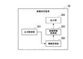
図2は、第1の実施形態における距離測定装置30の機能構成を表す概略ブロック図である。
距離測定装置30は、バスで接続されたCPU(Central Processing Unit)やメモリや補助記憶装置などを備え、距離測定プログラムを実行する。距離測定プログラムの実行によって、距離測定装置30は、出力制御部301、情報取得部302、距離情報取得部303、出力部304を備える装置として機能する。なお、距離測定装置30の各機能の全て又は一部は、ASIC(Application Specific Integrated Circuit)やPLD(Programmable Logic Device)やFPGA(Field Programmable Gate Array)等のハードウェアを用いて実現されてもよい。また、距離測定プログラムは、コンピュータ読み取り可能な記録媒体に記録されてもよい。コンピュータ読み取り可能な記録媒体とは、例えばフレキシブルディスク、光磁気ディスク、ROM、CD−ROM等の可搬媒体、コンピュータシステムに内蔵されるハードディスク等の記憶装置である。また、距離測定プログラムは、電気通信回線を介して送受信されてもよい。(First embodiment)
In the first embodiment, a case where the
FIG. 2 is a schematic block diagram illustrating a functional configuration of the distance measuring
The distance measuring
出力制御部301は、スピーカーの出力タイミングを制御する。具体的には、出力制御部301は、スピーカーに対して出力させる音を生成し、生成した音をスピーカーに出力させることによってスピーカーの出力タイミングを制御する。また、出力制御部301は、生成した音の情報を距離情報取得部303に出力する。
情報取得部302は、マイクによって集音された音波の情報を取得する。The
The
距離情報取得部303は、情報取得部302によって取得された音波の情報と、出力制御部301から出力された音の情報とに基づいて、スピーカーとマイクとの間の距離を取得する。
出力部304は、距離情報取得部303による測定結果を出力する。The distance
The
図3は、第1の実施形態における距離測定システム100の処理の流れを示すシーケンス図である。
出力制御部301は、第1のタイミングで音を生成する(ステップS101)。第1のタイミングとは、外部から音の生成指示がなされたタイミングであってもよいし、起動してから所定の時間が経過したタイミングであってもよいし、その他のタイミングであってもよい。出力制御部301は、生成した音を出力させる指示を含む制御指示をスピーカーに出力する(ステップS102)。FIG. 3 is a sequence diagram illustrating a processing flow of the
The
スピーカーは、距離測定装置30から出力された制御指示を取得する。スピーカーは、取得した制御指示に従って音を出力する(ステップS103)。例えば、スピーカーは、パルス状あるいは正弦波状の音を出力する。
スピーカーから出力された音は、音波として空気中を伝搬する(ステップS104)。マイクは、集音する(ステップS105)。マイクは、集音した音波の情報を電気信号に変換して距離測定装置30に出力する(ステップS106)。The speaker acquires a control instruction output from the
The sound output from the speaker propagates in the air as a sound wave (step S104). The microphone collects sound (step S105). The microphone converts the collected sound wave information into an electrical signal and outputs it to the distance measuring device 30 (step S106).
情報取得部302は、マイクから出力された電気信号を取得する。情報取得部302は、取得した電気信号を距離情報取得部303に出力する。距離情報取得部303は、ステップS101の処理で生成された音の波形と、情報取得部302から出力された電気信号の波形との位相ずれに基づいて距離を測定する(ステップS107)。具体的には、まず距離情報取得部303は、ステップS101の処理で生成された音の波形と、情報取得部302から出力された電気信号の波形とを用いて音のピーク等の位相のずれΔtを算出する。次に、距離情報取得部303は、ある気温Tにおける音速v(T)を算出する。そして、2地点間の距離をD1とすると、距離情報取得部303は、以下の式1に基づいてスピーカーとマイクとの間の距離D1を測定する。 The

距離情報取得部303は、演算結果であるスピーカーとマイクとの間の距離D1の情報を出力部304に出力する。出力部304は、外部の表示装置に距離D1の情報を出力する(ステップS108)。 The distance
以上のように構成された距離測定システム100によれば、基準となる部位と被測定部位との間の距離を伝搬時間の差をもとに算出するため、測定環境及び被測定者の動作や障害物によらず、被測定者の動作中における複数の部位間の距離をより簡便に測定することが可能になる。 According to the
<変形例>
本実施形態では、マイクを1つの部位に取り付ける構成を示したが、複数の被測定部位それぞれにマイクを設置するように構成されてもよい。このように構成される場合、距離情報取得部303は、マイクの識別情報に基づいて各マイクから得られる音波の情報を判別し、スピーカーと各マイクとの間の距離を測定する。
これにより、基準となる部位と複数の被測定部位の距離を同時に測定することができる。<Modification>
In the present embodiment, the configuration in which the microphone is attached to one site has been shown, but the microphone may be installed in each of a plurality of measured sites. When configured in this way, the distance
Thereby, the distance of the site | part used as a reference | standard and several to-be-measured site | parts can be measured simultaneously.
距離情報取得部303は、ゴルフの場合、クラブフェース面がボールに当たる瞬間に生ずる音に基づいてインパクトの時刻を測定するように構成されてもよい。クラブフェース面がボールに当たる瞬間に生ずる音の情報は、距離情報取得部303にあらかじめ記憶されていてもよい。 In the case of golf, the distance
距離情報取得部303は、位相のずれΔtと、ある気温Tにおける音速v(T)と、2地点間の距離をD1とを対応付けたテーブルに基づいて2地点間の距離を取得するように構成されてもよい。
距離測定装置30が備える各機能部(出力制御部301、情報取得部302、距離情報取得部303及び出力部304)の一部は、他の装置に備えられていてもよい。The distance
A part of each functional unit (the
(第2の実施形態)
第2の実施形態では、第1機器10が送信機であり、第2機器20が受信機である場合について説明する。第1の実施形態の場合、送信機はパケットを送信し、受信機はパケットを受信する。
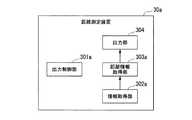
図4は、第2の実施形態における距離測定装置30aの機能構成を表す概略ブロック図である。
距離測定装置30aは、バスで接続されたCPUやメモリや補助記憶装置などを備え、距離測定プログラムを実行する。距離測定プログラムの実行によって、距離測定装置30aは、出力制御部301a、情報取得部302a、距離情報取得部303a、出力部304を備える装置として機能する。なお、距離測定装置30aの各機能の全て又は一部は、ASICやPLDやFPGA等のハードウェアを用いて実現されてもよい。また、距離測定プログラムは、コンピュータ読み取り可能な記録媒体に記録されてもよい。コンピュータ読み取り可能な記録媒体とは、例えばフレキシブルディスク、光磁気ディスク、ROM、CD−ROM等の可搬媒体、コンピュータシステムに内蔵されるハードディスク等の記憶装置である。また、距離測定プログラムは、電気通信回線を介して送受信されてもよい。(Second Embodiment)
In the second embodiment, a case where the
FIG. 4 is a schematic block diagram showing a functional configuration of the
The
距離測定装置30aは、出力制御部301、情報取得部302及び距離情報取得部303に代えて出力制御部301a、情報取得部302a及び距離情報取得部303aを備える点で距離測定装置30と構成が異なる。距離測定装置30aは、他の構成については距離測定装置30と同様である。そのため、距離測定装置30a全体の説明は省略し、出力制御部301a、情報取得部302a及び距離情報取得部303aについて説明する。 The
出力制御部301aは、送信機の出力タイミングを制御する。具体的には、出力制御部301aは、送信機である送信機に対してパケットを送信させることによって送信機の出力タイミングを制御する。
情報取得部302aは、受信機によって受信されたパケットを取得する。
距離情報取得部303aは、情報取得部302aによって取得されたパケットに基づいて、送信機と受信機との間の距離を取得する。The
The
The distance information acquisition unit 303a acquires the distance between the transmitter and the receiver based on the packet acquired by the
図5は、第2の実施形態における距離測定システム100の処理の流れを示すシーケンス図である。
出力制御部301aは、第2のタイミングで、パケットを送信させる指示を含む制御指示を送信機に出力する(ステップS201)。第2のタイミングとは、外部からパケットの生成指示がなされたタイミングであってもよいし、起動してから所定の時間が経過したタイミングであってもよいし、その他のタイミングであってもよい。
送信機は、距離測定装置30aから出力された制御指示を取得する。送信機は、取得した制御指示に従ってパケットを生成する(ステップS202)。そして、送信機は、生成したパケットを受信機に送信する(ステップS203)。FIG. 5 is a sequence diagram illustrating a processing flow of the
The
The transmitter acquires a control instruction output from the
また、送信機は、パケットの送信時刻の情報を含むパケットを生成する(ステップS204)。送信機は、ステップS204の処理で生成したパケットを距離測定装置30aに送信する(ステップS205)。
受信機は、送信機から送信されたパケットを受信する(ステップS206)。受信機は、パケットを受信した時刻を取得する。その後、受信機は、取得した受信時刻の情報を含むパケットを生成し、生成したパケットを距離測定装置30aに出力する(ステップS207)。Further, the transmitter generates a packet including information on the transmission time of the packet (step S204). The transmitter transmits the packet generated by the process of step S204 to the
The receiver receives the packet transmitted from the transmitter (step S206). The receiver acquires the time when the packet is received. Thereafter, the receiver generates a packet including the acquired reception time information, and outputs the generated packet to the
情報取得部302aは、送信機から送信されたパケットと、受信機から送信されたパケットとを取得する(ステップS208)。情報取得部302aは、取得したパケットを距離情報取得部303aに出力する。距離情報取得部303aは、情報取得部302aから出力されたパケットに基づいて距離を測定する(ステップS209)。具体的には、まず距離情報取得部303aは、送信機から得られたパケットに含まれる送信時刻の情報と、受信機から得られたパケットに含まれる受信時刻の情報とを用いて、送信時刻と受信時刻との差を取ることによってパケットの送受信に要する時間Δtを算出する。次に、距離情報取得部303aは、パケットの空気中の伝搬速度vを算出する。そして、2地点間の距離をD2とすると、距離情報取得部303aは、以下の式2に基づいて送信機と受信機との間の距離D2を測定する。 The
距離情報取得部303aは、演算結果である送信機と受信機との間の距離D2の情報を出力部304に出力する。出力部304は、外部の表示装置に距離D2の情報を出力する(ステップS210)。 The distance information acquisition unit 303a outputs information on the distance D2 between the transmitter and the receiver, which is the calculation result, to the
以上のように構成された距離測定システム100によれば、基準となる部位と被測定部位との間の距離を伝搬時間の差をもとに算出するため、測定環境及び被測定者の動作や障害物によらず、被測定者の動作中における複数の部位間の距離をより簡便に測定することが可能になる。 According to the
<変形例>
送信機は、パケットの送信時刻の情報を含むパケットを受信機に送信し、受信機がパケットの送信時刻の情報を含むパケットを距離測定装置30aに送信するように構成されてもよい。
距離測定装置30aが備える各機能部(出力制御部301a、情報取得部302a、距離情報取得部303a及び出力部304)の一部は、他の装置に備えられていてもよい。<Modification>
The transmitter may be configured to transmit a packet including information on the transmission time of the packet to the receiver, and the receiver transmits a packet including information on the transmission time of the packet to the
Some of the functional units (the
距離情報取得部303aは、パケットの送受信に要する時間Δtと、パケットの空気中の伝搬速度vと、2地点間の距離をD2とを対応付けたテーブルに基づいて2地点間の距離を取得するように構成されてもよい。 The distance information acquisition unit 303a acquires the distance between two points based on a table in which the time Δt required for packet transmission / reception, the propagation speed v of the packet in the air, and the distance between the two points are associated with D2. It may be configured as follows.
本実施形態では、受信機を1つの部位に取り付ける構成を示したが、複数の被測定部位それぞれに受信機を設置するように構成されてもよい。このように構成される場合、距離情報取得部303は、受信機の識別情報に基づいて各受信機から得られるパケットを判別し、送信機と各受信機との間の距離を測定する。
これにより、基準となる部位と複数の被測定部位の距離を同時に測定することができる。In the present embodiment, the configuration in which the receiver is attached to one part is shown, but the receiver may be installed in each of a plurality of parts to be measured. When configured in this way, the distance
Thereby, the distance of the site | part used as a reference | standard and several to-be-measured site | parts can be measured simultaneously.
以上、この発明の実施形態について図面を参照して詳述してきたが、具体的な構成はこの実施形態に限られるものではなく、この発明の要旨を逸脱しない範囲の設計等も含まれる。 The embodiment of the present invention has been described in detail with reference to the drawings. However, the specific configuration is not limited to this embodiment, and includes designs and the like that do not depart from the gist of the present invention.
10…第1機器, 20…第2機器, 30、30a…距離測定装置, 301、301a…出力制御部, 302、302a…情報取得部, 303、303a…距離情報取得部, 304…出力部DESCRIPTION OF
Claims (7)
Translated fromJapanese取得された前記情報に基づいて前記第1機器と前記第2機器との距離を取得する距離取得部と、
を備える距離測定装置。A second device attached to a reference site and acquiring the sound wave or radio wave output from the first device that outputs sound waves or radio waves, and attached to a site to be measured for the distance from the reference site. An information acquisition unit that acquires information output from the first device and information related to the output of the first device;
A distance acquisition unit that acquires a distance between the first device and the second device based on the acquired information;
A distance measuring device comprising:
前記第1機器の出力に関する情報は、前記第1機器が出力する前記音波を示す出力音波情報であり、
前記距離取得部は、前記取得音波情報と前記出力音波情報とに基づいて前記第1機器と前記第2機器との距離を取得する、請求項1に記載の距離測定装置。The information output from the second device is acquired sound wave information indicating the sound wave output from the first device,
The information related to the output of the first device is output sound wave information indicating the sound wave output from the first device,
The distance measuring device according to claim 1, wherein the distance acquisition unit acquires a distance between the first device and the second device based on the acquired sound wave information and the output sound wave information.
前記第1機器の出力に関する情報は、前記第1機器が前記音波又は電波を出力した時刻を示す出力時刻情報であり、
前記距離取得部は、前記取得時刻情報と前記出力時刻情報とに基づいて前記第1機器と前記第2機器との距離を取得する、請求項1に記載の距離測定装置。The information output from the second device is acquisition time information indicating the time at which the radio wave output from the first device is acquired.
The information related to the output of the first device is output time information indicating the time when the first device outputs the sound wave or radio wave,
The distance measuring device according to claim 1, wherein the distance acquisition unit acquires a distance between the first device and the second device based on the acquisition time information and the output time information.
前記基準となる部位との距離の測定対象となる部位に取り付けられ、前記第1機器から出力された前記音波又は電波を取得する第2機器と、
第2機器から出力される情報と、前記第1機器の出力に関する情報とを取得する情報取得部と、
取得された前記情報に基づいて前記第1機器と前記第2機器との距離を取得する距離取得部と、
を備える距離測定システム。A first device attached to a reference site and outputting sound waves or radio waves;
A second device that is attached to a site to be measured for a distance to the reference site and that acquires the sound wave or radio wave output from the first device;
An information acquisition unit that acquires information output from the second device and information related to the output of the first device;
A distance acquisition unit that acquires a distance between the first device and the second device based on the acquired information;
A distance measurement system comprising:
取得された前記情報に基づいて前記第1機器と前記第2機器との距離を取得する距離取得ステップと、
を有する距離測定方法。A second device attached to a reference site and acquiring the sound wave or radio wave output from the first device that outputs sound waves or radio waves, and attached to a site to be measured for the distance from the reference site. An information acquisition step of acquiring information output from and information relating to the output of the first device;
A distance acquisition step of acquiring a distance between the first device and the second device based on the acquired information;
A distance measuring method.
Priority Applications (3)
| Application Number | Priority Date | Filing Date | Title |
|---|---|---|---|
| JP2018023541AJP2019138812A (en) | 2018-02-13 | 2018-02-13 | Distance measuring device, distance measuring system, and method for measuring distance |
| US16/968,837US20210003686A1 (en) | 2018-02-13 | 2019-02-13 | Distance measurement device, distance measurement system, and distance measurement method |
| PCT/JP2019/005032WO2019159947A1 (en) | 2018-02-13 | 2019-02-13 | Distance measuring device, distance measuring system, and distance measuring method |
Applications Claiming Priority (1)
| Application Number | Priority Date | Filing Date | Title |
|---|---|---|---|
| JP2018023541AJP2019138812A (en) | 2018-02-13 | 2018-02-13 | Distance measuring device, distance measuring system, and method for measuring distance |
Publications (1)
| Publication Number | Publication Date |
|---|---|
| JP2019138812Atrue JP2019138812A (en) | 2019-08-22 |
Family
ID=67618613
Family Applications (1)
| Application Number | Title | Priority Date | Filing Date |
|---|---|---|---|
| JP2018023541APendingJP2019138812A (en) | 2018-02-13 | 2018-02-13 | Distance measuring device, distance measuring system, and method for measuring distance |
Country Status (3)
| Country | Link |
|---|---|
| US (1) | US20210003686A1 (en) |
| JP (1) | JP2019138812A (en) |
| WO (1) | WO2019159947A1 (en) |
Cited By (2)
| Publication number | Priority date | Publication date | Assignee | Title |
|---|---|---|---|---|
| JP2021089691A (en)* | 2019-12-06 | 2021-06-10 | 未來市股▲ふん▼有限公司 | Action tracking system and method for tracking actions |
| US12289096B2 (en)* | 2019-08-06 | 2025-04-29 | Murata Manufacturing Co., Ltd. | Acoustic wave filter device |
Citations (3)
| Publication number | Priority date | Publication date | Assignee | Title |
|---|---|---|---|---|
| JPH10267622A (en)* | 1997-03-26 | 1998-10-09 | Omron Corp | Object shape detector and vehicle shape detector |
| JP2002267740A (en)* | 2001-03-12 | 2002-09-18 | Kazuhiro Watanabe | Tool with transmitter or receiver and its position detection system and work monitoring system |
| JP2017205213A (en)* | 2016-05-17 | 2017-11-24 | ソニー株式会社 | Information processing device, information processing method and program |
Family Cites Families (20)
| Publication number | Priority date | Publication date | Assignee | Title |
|---|---|---|---|---|
| US5221088A (en)* | 1991-01-22 | 1993-06-22 | Mcteigue Michael H | Sports training system and method |
| US5570094A (en)* | 1995-10-10 | 1996-10-29 | Armstrong; Brian S. R. | Three dimensional tracking by array doppler radar |
| US6118376A (en)* | 1999-02-01 | 2000-09-12 | Regester; Mark Christian | Golf club tracking device and method |
| US6327219B1 (en)* | 1999-09-29 | 2001-12-04 | Vi&T Group | Method and system for directing a following device toward a movable object |
| US6674687B2 (en)* | 2002-01-25 | 2004-01-06 | Navcom Technology, Inc. | System and method for navigation using two-way ultrasonic positioning |
| CA2578653A1 (en)* | 2004-07-29 | 2006-02-09 | Kevin Ferguson | A human movement measurement system |
| US7978081B2 (en)* | 2006-01-09 | 2011-07-12 | Applied Technology Holdings, Inc. | Apparatus, systems, and methods for communicating biometric and biomechanical information |
| FR2897680B1 (en)* | 2006-02-17 | 2008-12-05 | Commissariat Energie Atomique | MOTION CAPTURE DEVICE AND ASSOCIATED METHOD |
| US7628074B2 (en)* | 2007-03-15 | 2009-12-08 | Mitsubishi Electric Research Laboratories, Inc. | System and method for motion capture in natural environments |
| EP1970005B1 (en)* | 2007-03-15 | 2012-10-03 | Xsens Holding B.V. | A system and a method for motion tracking using a calibration unit |
| WO2009074189A1 (en)* | 2007-12-12 | 2009-06-18 | Rangetainment Gmbh | A golf diagnosis apparatus and a method of performing golf diagnosis |
| DE102009020169A1 (en)* | 2009-05-07 | 2010-11-11 | Fraunhofer-Gesellschaft zur Förderung der angewandten Forschung e.V. | Method for tracking and/or controlling person during sports, involves coupling electromagnetic beams with identification patterns, respectively, and emitting electromagnetic beams as identifiable beams |
| CA2698078A1 (en)* | 2010-03-26 | 2011-09-26 | Applied Technology Holdings, Inc. | Apparatus, systems and methods for gathering and processing biometric and biomechanical data |
| FR2965060B1 (en)* | 2010-09-16 | 2012-10-05 | Commissariat Energie Atomique | METHOD AND DEVICE FOR COOPERATIVE LOCATION OF TRANSMITTERS AND / OR RECEIVERS INCLUDED BY A MOBILE BODY |
| CN105210084B (en)* | 2013-03-15 | 2019-03-12 | 耐克创新有限合伙公司 | Feedback signal from image data of athletic performance |
| US9723381B2 (en)* | 2013-12-23 | 2017-08-01 | Nike, Inc. | Athletic monitoring system having automatic pausing of media content |
| US10415975B2 (en)* | 2014-01-09 | 2019-09-17 | Xsens Holding B.V. | Motion tracking with reduced on-body sensors set |
| WO2015170703A1 (en)* | 2014-05-09 | 2015-11-12 | アルプス電気株式会社 | Movement detection program, object movement detection device and method therefor |
| WO2016196265A1 (en)* | 2015-05-29 | 2016-12-08 | Nike Innovate C.V. | Activity monitoring device with assessment of exercise intensity |
| CN105629241A (en)* | 2015-12-22 | 2016-06-01 | 浙江大学 | Robot positioning method based on split ultrasonic wave and radio frequency combination |
- 2018
- 2018-02-13JPJP2018023541Apatent/JP2019138812A/enactivePending
- 2019
- 2019-02-13USUS16/968,837patent/US20210003686A1/ennot_activeAbandoned
- 2019-02-13WOPCT/JP2019/005032patent/WO2019159947A1/ennot_activeCeased
Patent Citations (3)
| Publication number | Priority date | Publication date | Assignee | Title |
|---|---|---|---|---|
| JPH10267622A (en)* | 1997-03-26 | 1998-10-09 | Omron Corp | Object shape detector and vehicle shape detector |
| JP2002267740A (en)* | 2001-03-12 | 2002-09-18 | Kazuhiro Watanabe | Tool with transmitter or receiver and its position detection system and work monitoring system |
| JP2017205213A (en)* | 2016-05-17 | 2017-11-24 | ソニー株式会社 | Information processing device, information processing method and program |
Cited By (2)
| Publication number | Priority date | Publication date | Assignee | Title |
|---|---|---|---|---|
| US12289096B2 (en)* | 2019-08-06 | 2025-04-29 | Murata Manufacturing Co., Ltd. | Acoustic wave filter device |
| JP2021089691A (en)* | 2019-12-06 | 2021-06-10 | 未來市股▲ふん▼有限公司 | Action tracking system and method for tracking actions |
Also Published As
| Publication number | Publication date |
|---|---|
| WO2019159947A1 (en) | 2019-08-22 |
| US20210003686A1 (en) | 2021-01-07 |
Similar Documents
| Publication | Publication Date | Title |
|---|---|---|
| US10642368B2 (en) | Body posture detection system, suit and method | |
| EP3380809B1 (en) | Tracking system and method for determining relative movement of a player within a playing arena and court based player tracking system. | |
| US20170043212A1 (en) | System and method for analyzing stroking motions in water sports | |
| US11351436B2 (en) | Hybrid golf launch monitor | |
| US7140248B1 (en) | Speed measuring device and method | |
| US20110054782A1 (en) | Method and apparatus of measuring and analyzing user movement | |
| US20110028231A1 (en) | Method and system for shot tracking | |
| US11577125B2 (en) | Sensor device-equipped golf shoes | |
| CN1984698A (en) | A swing diagnostic device for ball games | |
| US20180065019A1 (en) | Hit ball direction teaching apparatus, hit ball direction teaching method, and hit ball direction teaching system | |
| WO2006014459A3 (en) | Method and system for golf swing analysis and training for putters | |
| CN106178481A (en) | The analytical equipment of a kind of billiard training, system and the method for analysis | |
| WO2019159947A1 (en) | Distance measuring device, distance measuring system, and distance measuring method | |
| CN108888918B (en) | System and method for measuring multi-target motion speed under complex path | |
| US20150145728A1 (en) | High frequency transmitter and receiver tracking system | |
| WO2019046269A1 (en) | Ear-wearable device providing golf advice data | |
| KR20050072558A (en) | Wearable computer system | |
| KR20180000581A (en) | sports action coating apparatus and method therefor | |
| KR100749383B1 (en) | Golf Swing Diagnostic Device | |
| US10773141B2 (en) | Exercise analyzing device, exercise analyzing system, and exercise analyzing method | |
| US20180250571A1 (en) | Motion analysis device, motion analysis method, motion analysis system, and display method | |
| JP6531366B2 (en) | Counting system, counting method, program | |
| KR100856426B1 (en) | Exercise device trajectory measuring device using a plurality of acceleration sensors and method | |
| KORYAHIN et al. | Hardware operational control of spatial and temporal parameters of athlete's movement. | |
| US20200114202A1 (en) | Video acoustical method and system for determining an impact point of a thrown body on a landing area |
Legal Events
| Date | Code | Title | Description |
|---|---|---|---|
| A621 | Written request for application examination | Free format text:JAPANESE INTERMEDIATE CODE: A621 Effective date:20200221 | |
| A131 | Notification of reasons for refusal | Free format text:JAPANESE INTERMEDIATE CODE: A131 Effective date:20201020 | |
| A521 | Request for written amendment filed | Free format text:JAPANESE INTERMEDIATE CODE: A523 Effective date:20201221 | |
| A02 | Decision of refusal | Free format text:JAPANESE INTERMEDIATE CODE: A02 Effective date:20210302 |