JP2019136820A - Driving tool - Google Patents
Driving toolDownload PDFInfo
- Publication number
- JP2019136820A JP2019136820AJP2018022481AJP2018022481AJP2019136820AJP 2019136820 AJP2019136820 AJP 2019136820AJP 2018022481 AJP2018022481 AJP 2018022481AJP 2018022481 AJP2018022481 AJP 2018022481AJP 2019136820 AJP2019136820 AJP 2019136820A
- Authority
- JP
- Japan
- Prior art keywords
- combustion chamber
- compressed air
- fuel
- air
- control unit
- Prior art date
- Legal status (The legal status is an assumption and is not a legal conclusion. Google has not performed a legal analysis and makes no representation as to the accuracy of the status listed.)
- Granted
Links
- 238000002485combustion reactionMethods0.000claimsabstractdescription182
- 239000000446fuelSubstances0.000claimsabstractdescription124
- 239000000203mixtureSubstances0.000claimsabstractdescription29
- 238000001514detection methodMethods0.000claimsdescription12
- 230000003213activating effectEffects0.000claims1
- 238000009529body temperature measurementMethods0.000claims1
- 230000002000scavenging effectEffects0.000abstractdescription46
- 238000002347injectionMethods0.000description158
- 239000007924injectionSubstances0.000description158
- 239000007789gasSubstances0.000description58
- 238000000034methodMethods0.000description10
- 230000004048modificationEffects0.000description10
- 238000012986modificationMethods0.000description10
- 230000008569processEffects0.000description9
- 230000005856abnormalityEffects0.000description8
- 230000002159abnormal effectEffects0.000description5
- 230000008859changeEffects0.000description5
- 238000007599dischargingMethods0.000description5
- 230000007246mechanismEffects0.000description5
- 230000004044responseEffects0.000description5
- 238000010586diagramMethods0.000description4
- 230000002093peripheral effectEffects0.000description4
- 239000004071sootSubstances0.000description4
- 238000001816coolingMethods0.000description3
- 238000003825pressingMethods0.000description3
- 230000000740bleeding effectEffects0.000description2
- 239000000567combustion gasSubstances0.000description2
- 230000007423decreaseEffects0.000description2
- WHXSMMKQMYFTQS-UHFFFAOYSA-NLithiumChemical compound[Li]WHXSMMKQMYFTQS-UHFFFAOYSA-N0.000description1
- 229910000831SteelInorganic materials0.000description1
- 230000001133accelerationEffects0.000description1
- 238000009530blood pressure measurementMethods0.000description1
- 244000145845chatteringSpecies0.000description1
- 238000006243chemical reactionMethods0.000description1
- 230000006835compressionEffects0.000description1
- 238000007906compressionMethods0.000description1
- 230000003111delayed effectEffects0.000description1
- 238000006073displacement reactionMethods0.000description1
- 229910052602gypsumInorganic materials0.000description1
- 239000010440gypsumSubstances0.000description1
- 229910052744lithiumInorganic materials0.000description1
- 230000005389magnetismEffects0.000description1
- 238000002156mixingMethods0.000description1
- 238000007789sealingMethods0.000description1
- 238000005507sprayingMethods0.000description1
- 230000000087stabilizing effectEffects0.000description1
- 239000010959steelSubstances0.000description1
- 239000002699waste materialSubstances0.000description1
- 239000002023woodSubstances0.000description1
Images


Classifications
- B—PERFORMING OPERATIONS; TRANSPORTING
- B25—HAND TOOLS; PORTABLE POWER-DRIVEN TOOLS; MANIPULATORS
- B25C—HAND-HELD NAILING OR STAPLING TOOLS; MANUALLY OPERATED PORTABLE STAPLING TOOLS
- B25C1/00—Hand-held nailing tools; Nail feeding devices
- B25C1/08—Hand-held nailing tools; Nail feeding devices operated by combustion pressure
Landscapes
- Engineering & Computer Science (AREA)
- Chemical & Material Sciences (AREA)
- Combustion & Propulsion (AREA)
- Mechanical Engineering (AREA)
- Portable Nailing Machines And Staplers (AREA)
Abstract
Description
Translated fromJapanese本発明は、打ち込み工具に関する。 The present invention relates to a driving tool.
従来から、燃料と空気からなる混合物を利用した打ち込み工具が広く普及している。この種の打ち込み工具では、燃焼室に燃料及び空気からなる混合物を生成した後、混合物を点火・燃焼させて高圧の燃焼圧を発生させることでシリンダ内のピストンを駆動し、ノーズに供給された釘をピストンに一体形成されるドライバにより打撃して打ち出すように構成されている。 Conventionally, driving tools using a mixture of fuel and air have been widely used. In this type of driving tool, after a mixture of fuel and air is generated in the combustion chamber, the mixture is ignited and burned to generate a high combustion pressure, thereby driving the piston in the cylinder and supplying it to the nose. The nail is struck and driven by a driver formed integrally with the piston.
一般的な打ち込み工具では、打ち込み動作後に、燃焼室内に排気ガスの一部が残留する。燃焼室内に排気ガスが残留した状態で、次の打ち込み動作を行うと、次の打ち込み出力や、燃焼室内の混合物の着火性能が低下してしまうという問題がある。そこで、従来から、打ち込み動作後において、燃焼室内の排気ガスを外部に排出する掃気が実施されている。 In a general driving tool, a part of the exhaust gas remains in the combustion chamber after the driving operation. If the next driving operation is performed with the exhaust gas remaining in the combustion chamber, there is a problem that the next driving output and the ignition performance of the mixture in the combustion chamber are deteriorated. Therefore, conventionally, scavenging is performed to exhaust the exhaust gas in the combustion chamber to the outside after the driving operation.
例えば、特許文献1には、ピストン/ドライバの移動する際に、ピストン/ドライバの下方にある空気の一部を利用して排気弁を作動させることにより、燃焼室からの燃焼生成物(排気ガス)を大気中に排出する打ち込み工具が開示されている。 For example, Patent Document 1 discloses that when a piston / driver moves, a combustion product (exhaust gas) from a combustion chamber is obtained by operating an exhaust valve using a part of air below the piston / driver. ) Is discharged into the atmosphere.
しかしながら、上記特許文献1に記載の打ち込み工具では、ピストンのリターン時に、掃気が行われる場合が想定される。このような場合、ピストンに送風される空気によりピストンの動作を阻害してしまうため、ピストンのリターンが遅れたり、ピストンが初期位置に戻れない場合があった。これにより、ピストンが障害となって新しい釘の供給ができなかったり、次の打ち込み動作を安定して実施することができないという問題があった。 However, in the driving tool described in Patent Document 1, it is assumed that scavenging is performed when the piston returns. In such a case, since the air blown to the piston impedes the operation of the piston, the return of the piston may be delayed or the piston may not return to the initial position. As a result, there is a problem that a new nail cannot be supplied due to an obstacle of the piston or that the next driving operation cannot be stably performed.
そこで、本発明は、上記課題に鑑みてなされたものであり、その目的は、燃料および空気を利用した打ち込み工具において、掃気を確実に行うことにより、安定した打ち込み動作を行うことが可能な打ち込み工具を提供することにある。 Accordingly, the present invention has been made in view of the above problems, and an object of the present invention is to provide a driving tool capable of performing a stable driving operation by reliably performing scavenging in a driving tool using fuel and air. To provide a tool.
本発明に係る打ち込み工具は、燃料および圧縮空気が供給される燃焼室と、前記燃焼室に充填された燃料及び空気からなる混合物を点火したときの燃焼圧により駆動するピストンを移動可能に収容するシリンダと、前記燃焼室内に圧縮空気を供給する経路を開閉するための弁と、前記ピストンのリターンが完了したと判断した場合に前記燃焼室に圧縮空気を供給するよう前記弁を制御する制御部と、を備えるものである。 The driving tool according to the present invention movably accommodates a combustion chamber to which fuel and compressed air are supplied and a piston driven by combustion pressure when a mixture of fuel and air filled in the combustion chamber is ignited. A cylinder, a valve for opening and closing a path for supplying compressed air into the combustion chamber, and a control unit for controlling the valve to supply compressed air to the combustion chamber when it is determined that the return of the piston is completed Are provided.
また、本発明に係る打ち込み工具は、燃料および圧縮空気が供給される燃焼室と、前記燃焼室に充填された燃料及び空気からなる混合物を点火したときの燃焼圧により駆動するピストンを移動可能に収容するシリンダと、前記燃焼室内に圧縮空気を供給する経路を開閉するための弁と、
前記燃焼室に充填される燃料及び圧縮空気からなる混合物を燃焼させるために点火装置を作動させるトリガと、被打込部材に接触して前記トリガの操作を有効にするコンタクト部材と、前記コンタクト部材のオン後、前記トリガがオンせずに前記コンタクト部材がオフしたと判断した場合に、前記燃焼室に圧縮空気を供給するよう前記弁を制御する制御部と、を備えるものである。The driving tool according to the present invention can move a combustion chamber supplied with fuel and compressed air, and a piston driven by combustion pressure when a mixture of fuel and air filled in the combustion chamber is ignited. A cylinder for accommodating, and a valve for opening and closing a path for supplying compressed air into the combustion chamber;
A trigger that activates an ignition device to burn a mixture of fuel and compressed air filled in the combustion chamber; a contact member that makes contact with a driven member to enable the operation of the trigger; and the contact member A controller that controls the valve to supply compressed air to the combustion chamber when it is determined that the contact member has been turned off without turning on the trigger.
本発明によれば、打ち込み動作の完了後に燃焼室内の掃気を行うので、ピストンのリターン不良を防止することができ、打ち込み動作の安定化を図ることができる。 According to the present invention, scavenging in the combustion chamber is performed after the completion of the driving operation, so that it is possible to prevent a return failure of the piston and to stabilize the driving operation.
以下に添付図面を参照しながら、本発明の好適な実施の形態について詳細に説明する。なお、図面の寸法比率は、説明の都合上拡張されており、実際の比率と異なる場合がある。 Exemplary embodiments of the present invention will be described below in detail with reference to the accompanying drawings. In addition, the dimension ratio of drawing is expanded on account of description and may differ from an actual ratio.
<第1の実施の形態>
[打ち込み工具10の構成例]
図1及び図2は、本発明の一実施の形態に係る打ち込み工具10の構成の一例を示している。なお、図1及び図2では、釘の打ち込み方向を下方とし、その反対側を上方とする。また、図1及び図2では、工具本体12側を前方とし、バッテリ70側を後方とし、コンタクトアーム52側を下方とし、シリンダヘッド30側を上方とする。また、打ち込み工具10の前後方向及び上下方向に直交する方向において、前方向を基準としたときの右側を打ち込み工具10の右側とすると共に左側を打ち込み工具10の左側とする。<First Embodiment>
[Configuration Example of Driving Tool 10]
FIG.1 and FIG.2 has shown an example of the structure of the
図1及び図2に示すように、打ち込み工具10は、釘、ステープル、ピン等のファスナを、木材、石膏ボード、鋼板、コンクリート等の被打込部材に打ち込む工具であって、工具本体12と、ノーズ50とコンタクトアーム52とグリップ60とトリガ62とバッテリ装着部68とガスカートリッジ収納部64とマガジン54とを備えている。 As shown in FIGS. 1 and 2, a
工具本体12は細長の略円筒形状により構成され、工具本体12の内部には打ち込み動作を行う駆動機構20が収納されている。 The
駆動機構20は、シリンダ22と、ヘッドバルブ24と、スリーブ26と、ばね28と、シリンダヘッド30と、ピストン34と、ドライバ36とを有している。 The
シリンダ22は、工具本体12よりも小さい径を有する円筒形状により構成され、工具本体12の内側に配置されている。シリンダ22内の上部側には、燃料及び圧縮空気のそれぞれが充填される燃焼室32が設けられている。燃焼室32は、シリンダ22の内周面と、スリーブ26の外周面と、スリーブ26の下面部とで区画された空間部である。 The
ピストン34は、シリンダ22の内側であってスリーブ26の下方側である初期位置に配置され、燃焼室32内に充填される燃料及び圧縮空気からなる混合物を点火したときに生じる燃焼圧に伴ってシリンダ22を上下方向に摺動可能とされる。ここで、ピストン34の初期位置とは、シリンダ22内においてピストン34がスリーブ26の下面に接触する位置であり、燃焼室32内の混合物を点火したときの燃焼圧によりピストン34がシリンダ22内を下方に移動する前の停止位置である。ドライバ36は、ピストン34の下端部に一体的に形成され、ピストン34の移動に伴ってノーズ50を移動してマガジン54から供給される釘を被打込部材に打ち込む。 The piston 34 is disposed at an initial position inside the
スリーブ26は、円筒体から構成され、燃焼室32内に配設されている。スリーブ26の底面部には、ピストン34の上部空間に連通する第1の開口部26aが設けられている。スリーブ26の円筒部の下端には、燃焼室32と第1の開口部26aとを連通する第2の開口部26bが設けられている。 The sleeve 26 is formed of a cylindrical body and is disposed in the combustion chamber 32. A
ヘッドバルブ24は、上端が開口されると共に下端が閉塞された円筒体から構成され、スリーブ26の内側であってピストン34の上方側に配設されている。ヘッドバルブ24の外周部の上部及び下部のそれぞれには、スリーブ26との隙間をシールするためのシール部材38,39が設けられている。シール部材38は、シール部材39よりも径方向に突出している。ヘッドバルブ24は、燃焼室32での混合物の燃焼時における燃焼圧によりスリーブ26内を上下方向に移動可能に構成され、第1の開口部26a及び第2の開口部26bを介して燃焼室32内からピストン34が配置されるシリンダ22内に燃焼圧が流入できるようになっている。 The
ばね28は、圧縮ばねから構成され、ヘッドバルブ24の内側であってドライバ36と同軸上に配置されている。ばね28は、その上端がシリンダヘッド30に当接すると共にその下端がヘッドバルブ24の底面部に当接しており、ヘッドバルブ24を下方側に付勢している。 The
シリンダヘッド30は、燃焼室32の上端開口を閉塞するようにシリンダ22の上端部に取り付けられている。シリンダヘッド30には、燃焼室32内に燃料を噴射するための燃料噴射口(図示省略)と、燃焼室32内に圧縮空気を噴射するための空気噴射口(図示省略)とがそれぞれ設けられている。 The
燃料噴射弁130は、燃料ホース132の流路を開閉するものであり、燃焼室32内への燃料の供給量を制御する。燃料噴射弁130は、燃料ホース132の途中に設置されると共に、シリンダ22の上部後方側に配置されている。燃料ホース132の一端部はシリンダヘッド30の燃料噴射口に接続され、燃料ホース132の他端部はガスカートリッジ収納部64に接続されている。 The
空気噴射弁140は、エアホース142の流路を開閉するものであり、燃焼室32内への圧縮空気の供給量を制御する。空気噴射弁140は、エアホース142の途中に設置されると共に、シリンダ22の上部後方側であって燃料噴射弁130の図1中左側に並列に配置されている。空気噴射弁140を燃料噴射弁130と並列に配置することにより、打ち込み工具10全体の小型化を図ることができる。また、グリップ60を持つ際に邪魔にならない。また、燃料噴射弁130と空気噴射弁140をシリンダ22上方の燃焼室32近くに配置しているので、燃焼室32内に燃料や圧縮空気を充填させる際のレスポンスがよい。エアホース142の一端部はシリンダヘッド30の空気噴射口に接続され、エアホース142の他端部はエアプラグ144に接続されている。エアプラグ144には例えばエアコンプレッサや圧縮空気を溜めたエアタンクなどが接続され、打ち込み工具10の外部から燃焼室32内に圧縮空気を取り込み可能に構成される。 The
ノーズ50は、工具本体12の下端部に一体的に形成されている。ノーズ50の中心には、上下方向に延びると共にシリンダ22内に連通する射出口51が設けられている。射出口51は、ドライバ36(ピストン34)を上下方向に沿って案内する。 The
コンタクトアーム52は、ノーズ50の先端外周部に取り付けられ、被打込部材に押し付けたときにノーズ50に対して相対的に上方に移動可能に構成されている。コンタクトアーム52が、押し付け動作により所定の位置まで移動するとトリガ62の操作が有効になるようになっている。 The
グリップ60は、作業者が把持し易い略円柱状からなり、工具本体12の上下方向(長手方向)の略中央側面部から後方側に向かって延設されている。バッテリ装着部68は、グリップ60の後端部に設けられている。バッテリ装着部68には、バッテリ70が着脱可能に取り付けられている。バッテリ70としては、例えば、電圧14.4Vのリチウム電池など、二次電池を内蔵したバッテリを用いることができる。 The
トリガ62は、作業者が釘の打ち込み動作を操作するための部位であり、グリップ60の前方下面側であってマガジン54側に突出するように設けられている。 The
ガスカートリッジ収納部64は、グリップ60とマガジン54との間に配設され、工具本体12の側面部からグリップ60に対して略並行に延設されている。ガスカートリッジ収納部64には、ガス缶が着脱可能に取り付けられている。 The gas
マガジン54は、ノーズ50の後部側に取り付けられ、複数本の釘が装填可能に構成されている。マガジン54は、ノーズ50の射出口51に連通しており、ノーズ50に釘を供給できるように構成されている。 The
[打ち込み工具10のブロック図]
図3は、本発明に係る打ち込み工具10の機能構成の一例を示すブロック図である。図3に示すように、打ち込み工具10は、工具全体の動作を制御するための制御部100を備えている。制御部100は、CPU、ROM及びRAMを有している。CPUは、ROMに格納されたプログラムをRAMに展開して実行することにより、燃料及び圧縮空気の噴射タイミングの制御を含む所定の打ち込み動作を実現する。より具体的には、制御部100は、コンタクトアーム52の被打込部材への押し当てによりコンタクトスイッチ110がオンされたときに燃料の噴射を開始させ、トリガ62の操作によりトリガスイッチ112がオンされた後に圧縮空気の噴射を完了させる制御を実行する。[Block diagram of driving tool 10]
FIG. 3 is a block diagram illustrating an example of a functional configuration of the driving
制御部100には、コンタクトスイッチ110、トリガスイッチ112、ガス缶検出スイッチ114、温度センサ116、圧力センサ118,120、燃料噴射弁130、空気噴射弁140、点火プラグ150、及び制御部100等に電力を供給するバッテリ70のそれぞれが接続されている。なお、温度センサ116及び圧力センサ118,120を使用しない構成とした場合には、これらを省略して打ち込み工具10を構成することもできる。 The
コンタクトスイッチ110は、コンタクトアーム52にリンク部材を介して接続され、コンタクトアーム52が被打込部材への押し当てによりノーズ50に対して所定位置まで移動するとオンし、コンタクトアーム52がオンしたことを示すオン信号を制御部100に出力する。 The
トリガスイッチ112は、トリガ62の近傍に設けられ、作業者によるトリガ62の引き操作に伴ってオンし、トリガ62がオンしたことを示すオン信号を制御部100に出力する。 The
ガス缶検出スイッチ114は、ガスカートリッジ収納部64の入口側に設けられ、ガスカートリッジ収納部64にガス缶が装着されるとオンし、ガス缶が装着されたことを示すオン信号を制御部100に出力する。 The gas can detection switch 114 is provided on the inlet side of the gas
温度センサ116は、例えば、燃焼室32内や燃焼室32の近傍に設置されている。温度センサ116は、工具本体12内の機械温度や打ち込み工具10周辺の環境温度を検出し、これらの温度情報を制御部100に出力する。 The
圧力センサ118は、例えば、エアプラグ144と空気噴射弁140との間に延設されるエアホース142に設置されている。圧力センサ118は、エアプラグ144にコンプレッサー等の空気源が接続されているか否かを検出したり、コンプレッサー等の空気源から供給される空気圧に異常がないか否かを検出し、これらの圧力情報を制御部100に供給する。 For example, the
圧力センサ120は、例えば、燃焼室32内や燃焼室32と空気噴射弁140との間に延設されるエアホース142に設置されている。圧力センサ120は、燃焼室32内の空気充填圧の異常を検出し、検出した圧力情報を制御部100に供給する。燃焼室32と圧力センサ120の間に、逆止弁(図示せず)を設けてもよい。 The
燃料噴射弁130は、制御部100から供給される駆動信号に基づいて作動(開閉)し、弁内の計量室に充填される燃料を燃焼室32内に供給する。 The
空気噴射弁140は、制御部100から供給される駆動信号に基づいて作動(開閉)し、所定量の圧縮空気を燃焼室32内に噴射する。 The
イグナイタユニットの点火装置スイッチ152は、制御部100から供給される制御信号に基づいてオンし、点火プラグ150を点火することで燃焼室32内に充填されている混合物を燃焼させる。 The
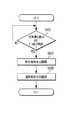
[打ち込み工具10の動作例]
図4は、本発明に係る打ち込み工具10の打ち込み時における制御部100の動作の一例を示すフローチャートである。[Operation example of driving tool 10]
FIG. 4 is a flowchart showing an example of the operation of the
図4に示すように、ステップS100において、制御部100は、トリガスイッチ112がオフでかつコンタクトアーム52の被打込部材への押し付けによりコンタクトスイッチ110がオンになったか否かを判断する。制御部100は、コンタクトスイッチ110及びトリガスイッチ112がオフの場合、コンタクトスイッチ110等の状態を継続して監視する。一方、制御部100は、トリガスイッチ112がオフでかつコンタクトスイッチ110がオンになったと判断すると、ステップS110に進む。 As shown in FIG. 4, in step S <b> 100, the
ステップS110において、制御部100は、燃料噴射弁130にオン信号を出力して燃料噴射弁130を作動させて開き、所定時間経過したら燃料噴射弁130を閉じる。これにより、燃焼室32内に所定量の燃料が噴射される。ステップS110が終了すると、ステップS120に進む。 In step S110, the
ステップS120において、制御部100は、コンタクトアーム52が被打込部材から離れることによりコンタクトスイッチ110がオフになっていないか、つまりコンタクトスイッチ110がオン状態か否かを判断する。制御部100は、コンタクトスイッチ110が継続してオンの場合、ステップS130に進む。一方、制御部100は、コンタクトスイッチ110がオフになった場合、ステップS170に進む。 In step S120, the
ステップS130において、制御部100は、コンタクトスイッチ110及びトリガスイッチ112の両方がオンであるか否かを判断する。制御部100は、コンタクトスイッチ110及びトリガスイッチ112の少なくとも一つがオフであると判断した場合、ステップS120に戻る。一方、制御部100は、コンタクトスイッチ110及びトリガスイッチ112の両方がオンであると判断した場合、ステップS140に進む。 In step S130, the
ステップS140において、制御部100は、空気噴射弁140にオン信号を出力して空気噴射弁140を作動させて開き、所定時間経過したら燃料噴射弁130を閉じる。これにより、燃焼室32内に所定量の圧縮空気が噴射され、圧縮空気の噴射により燃焼室32内が撹拌されることで、燃料及び圧縮空気からなる混合物が生成される。本実施の形態では、燃焼室32内に燃料、圧縮空気の順で噴射するので、燃焼室32内で燃料と圧縮空気が均等に混合される。これにより、燃焼室32内の混合比の偏りがなくなるので、異常燃焼の発生を防止できる。ステップS140が終了すると、ステップS150に進む。 In step S140, the
ステップS150において、制御部100は、混合物の点火を行う前に、さらにコンタクトスイッチ110及びトリガスイッチ112の両方がオンであるか否かを判断する。制御部100は、コンタクトスイッチ110及びトリガスイッチ112の両方がオンでないと判断した場合、ステップS170に進む。ステップS180において、制御部100は、上述したように、燃焼室32内に残留した燃料や混合物を外部に排出するための掃気を実行する。 In step S150, the
一方、制御部100は、コンタクトスイッチ110及びトリガスイッチ112の両方がオンであると判断した場合、ステップS160に進む。 On the other hand, when the
ステップS160において、制御部100は、点火装置スイッチ152を起動することにより、点火プラグ150をスパークさせて燃焼室32内に充填された混合物を燃焼させる。これにより、ヘッドバルブ24が開き、燃焼室32から流入する燃焼圧によってピストン34がシリンダ22内を往復移動し、打ち込み動作が行われる。ステップS160が終了したら、ステップS170に進む。 In step S <b> 160, the
ステップS170において、制御部100は、コンタクトスイッチ110がオフでピストン34のリターンを検出、コンタクトスイッチ110とトリガスイッチ112がオフでピストン34のリターンを検出、又はトリガスイッチ112がオフでリターンを検出したか否かを判断する。ピストン34のリターンは、例えば、トリガ62のオンから所定時間が経過したかにより判断したり、点火装置スイッチ152にスパーク信号を出力してから所定時間が経過したか等により判断できる。制御部100は、これらのうち何れかの条件を満たすまで監視する。 In step S170, the
一方、制御部100は、コンタクトスイッチ110がオフでかつピストン34が初期位置にリターン等したと判断した場合、ステップS180に進む。ステップS180において、制御部100は、燃焼室32内に残留している燃料(混合物)や、燃焼後の排気ガスを、燃焼室32内から外部に排出するための掃気を実行する。本実施の形態では、このような処理を繰り返し実行する。なお、ステップS170の条件を満たしてからすぐにステップS180を実行せず、所定時間経過後、ステップS180(掃気)を実施すると、掃気開始前に燃焼室32内に残留していた燃料や排気ガスがある程度排出されて、掃気に用いる空気の消費量を抑えることができる。 On the other hand, when determining that the
[打ち込み工具10の動作時におけるタイミングチャート]
図5は、本発明に係る打ち込み工具10の打ち込み動作時の各装置におけるタイミングチャートの一例を示している。[Timing chart during operation of driving tool 10]
FIG. 5 shows an example of a timing chart in each apparatus during the driving operation of the driving
図5に示すように、時刻t1において、作業者によりガスカートリッジ収納部64にガス缶66が装着されると、ガス缶検出スイッチ114がハイレベルからローレベルに切り替わり、ガス缶検出スイッチ114がオンする。 As shown in FIG. 5, when the gas can 66 is attached to the gas
時刻t2において、作業者によりコンタクトアーム52が被打込部材に押し込まれると、コンタクトアーム52がノーズ50に対して相対的に上方に移動し、コンタクトスイッチ110がハイレベルからローレベルに切り替わることでコンタクトスイッチ110がオンする。 When the
コンタクトアーム52が期間p1の間継続してオンすると、時刻t3において、燃料噴射弁130に出力される駆動信号がローレベルからハイレベルに切り替わる。これにより、燃料噴射弁130が開き、予め計算により求められた噴出時間、シリンダヘッド30の燃料噴射口から燃焼室32内に燃料が噴射される。 When the
時刻t4において、燃料噴射弁130に供給される駆動信号がハイレベルからローレベルに切り替わる。これにより、燃料噴射弁130が閉じ、シリンダヘッド30の燃料噴射口からの燃焼室32内への燃料の噴射が停止する。 At time t4, the drive signal supplied to the
時刻t5において、コンタクトアーム52がオンの状態で作業者によりトリガ62が引き操作されると、トリガスイッチ112がハイレベルからローレベルに切り替わり、トリガスイッチ112がオンする。 At time t5, when the
コンタクトスイッチ110及びトリガスイッチ112の両方が期間p2の間継続してオンすると、時刻t6において、空気噴射弁140に供給される駆動信号がローレベルからハイレベルに切り替わる。これにより、空気噴射弁140が開き、設定された出力エネルギーに応じた噴出時間、シリンダヘッド30の空気噴射口から燃焼室32内に圧縮空気が噴射される。なお、出力エネルギーは、バッテリ装着部68付近に設けたスイッチにより弱、中、強のうちいずれかのレベルを選択することができる。 When both the
時刻t7において、点火装置スイッチ152に供給される駆動信号がハイレベルからローレベルに切り替わり、点火プラグ150への電圧の昇圧が開始される。時刻t9において、点火プラグ150の放電電圧までの昇圧が完了し、燃焼室32内の混合物に点火する。点火のタイミングは、点火プラグ150の放電電圧までの昇圧時間を考慮して設定されると共に、圧縮空気の噴射終了直後に燃焼室32内の混合物に点火して打ち込み動作を開始できるように設定される。 At time t7, the drive signal supplied to the
時刻t8において、予め設定された空気噴射時間が経過すると、空気噴射弁140に供給される駆動信号がハイレベルからローレベルに切り替わる。これにより、空気噴射弁140が閉じ、シリンダヘッド30の空気噴射口からの燃焼室32内への圧縮空気の噴射が停止する。 When a preset air injection time elapses at time t8, the drive signal supplied to the
時刻t9において、燃焼室32内の混合物が点火する。これにより、圧縮空気の噴射終了直後に燃焼室32内の混合物が燃焼し、その燃焼時に発生する燃焼圧によりヘッドバルブ24が開き、その燃焼圧がシリンダ22内に流入することでピストン34がシリンダ22内を下方に移動することで打ち込み動作が行われる。 At time t9, the mixture in the combustion chamber 32 is ignited. As a result, the mixture in the combustion chamber 32 burns immediately after the injection of the compressed air, the
時刻t10において、被打込部材への釘の打ち込みが完了し、作業者の指がトリガ62から離されると、トリガスイッチ112がローレベルからハイレベルに切り替わり、トリガスイッチ112がオフする。 At time t10, when the nail driving into the driven member is completed and the operator's finger is released from the
時刻t11において、コンタクトアーム52が被打込部材から離間して初期位置(先端がノーズ50から突出する位置)まで戻ると、コンタクトスイッチ110がローレベルからハイレベルに切り替わり、コンタクトスイッチ110がオフする。 At time t11, when the
コンタクトスイッチ110がオフした後の時刻t12において、空気噴射弁140に供給される駆動信号がローレベルからハイレベルに切り替わる。これにより、空気噴射弁140が開き、予め設定された噴出時間、シリンダヘッド30の空気噴射口から燃焼室32内に圧縮空気が噴射されることで燃焼室32内の排気ガスを排出するための掃気が実施される。掃気は、ピストン34のリターン動作に影響しないように、ピストン34のリターンが完了して初期位置に停止した状態で行うことが好ましい。圧縮空気を噴射する掃気は、ピストン34のリターン動作を妨げる虞があるが、ピストン34のリターンが確実に完了していれば、ピストン34のリターンに影響を与えることはない。また、ピストン34のリターンの完了後であれば、排気ガスを掃気すべき容積が少なくなる。そのため、掃気に要する時間や、噴出する圧縮空気の量を削減できる。さらに、掃気すべき容積が小さければ、排気ガスが残留する可能性も下げることができ、それにより、次の打ち込み動作への排気ガスの影響を低減できる。 At time t12 after the
なお、掃気は、上述したタイミング以外にも実施することができる。例えば、温度センサ116により測定される燃焼室32内の温度が予め設定された基準温度を超える場合に、空気噴射弁140を開閉制御して燃焼室32内に圧縮空気を噴射させることで、燃焼室32内やその周辺を自動的に冷却する冷却モードを実行するようにしてもよい。基準温度は、あらかじめ設定された数値を用いるか、又は作業者が任意の数値を設定することができる。また、冷却モードを選択するための操作部を打ち込み工具10に設け、作業者が冷却モードを手動で実行するようにしてもよい。つまり、作業者が任意のタイミングで操作部を操作することにより、燃焼室32内に圧縮空気を噴射可能にしてもよい。 Note that scavenging can be performed at other timings than those described above. For example, when the temperature in the combustion chamber 32 measured by the
以上説明したように、第1の実施の形態によれば、コンタクトアーム52の操作で燃料を噴射した後にトリガ62の操作で圧縮空気を噴射するので、トリガ62の操作で燃料及び圧縮空気を順番に噴射する場合と比較して、トリガ62のオンから釘の打ち込みまでの時間を短縮することができ、打ち込み工具10におけるトリガレスポンスの向上を図ることができる。 As described above, according to the first embodiment, since fuel is injected by operating the
また、圧縮空気の噴射開始をトリガ62の操作と連動させることで、位置決めのためにコンタクトを入れ直した場合でも、空気を消費しなくて済むため、無駄な空気の消費を抑えることができ、作業量の向上を図ることができる。また、コンタクトアーム52のオンでは圧縮空気の噴射は行わず、トリガ62のオン後に圧縮空気の噴射を完了させるため、コンタクトアーム52の操作だけでは、燃焼に必要となる圧縮空気が燃焼室32内に供給されていないので、燃料(ガス)の濃度が高くなったとしても、燃焼室32内に規定以上の燃焼圧が発生することを防止できる。これにより、燃焼圧の安定による打ち込み力の安定化や、打ち込み工具10の耐久性の確保を図ることができる。 In addition, by linking the start of compressed air injection with the operation of the
また、本実施の形態によれば、コンタクトスイッチ110がオンしたときに燃焼室32内に燃料を噴射し、続けてトリガスイッチ112がオンしたときに燃焼室32内に圧縮空気を噴射するので、燃焼室32内に噴射する圧縮空気によって燃焼室32内の燃料を攪拌することができる。これにより、燃料と圧縮空気が均等に混合されるので、打ち込み動作のスパーク時の燃焼効率を向上させることができる。 Further, according to the present embodiment, fuel is injected into the combustion chamber 32 when the
また、点火プラグ150の点火タイミングを、点火プラグ150の放電電圧、つまり電圧が昇圧する時間を考慮して設定するので、最適なタイミング(圧縮空気の噴射が終了した直後)で燃料の点火を行うことができる。その結果、燃料効率及びトリガレスポンスの向上を図ることができる。 In addition, since the ignition timing of the
さらに、出力エネルギーを可変するなどの理由で、圧縮空気の噴射時間が調整される場合であっても、圧縮空気の噴射が終了した直後に合わせて最適なタイミングで燃料の点火を行うことができ、燃焼効率及びトリガレスポンスの向上を図ることができる。 Furthermore, even when the injection time of the compressed air is adjusted for reasons such as changing the output energy, the fuel can be ignited at an optimal timing immediately after the injection of the compressed air is completed. Further, the combustion efficiency and the trigger response can be improved.
[第1の実施の形態の第1の変形例]
次に、コンタクトスイッチ110のオン後に、燃料の噴射及び圧縮空気の噴射の両方を行う場合の制御の一例について説明する。図6は、本発明に係る打ち込み工具10の打ち込み動作時における第2のタイミングチャートの一例を示している。[First Modification of First Embodiment]
Next, an example of control in the case where both fuel injection and compressed air injection are performed after the
図6に示すように、時刻t1において、作業者によりコンタクトアーム52が被打込部材に押し込まれると、コンタクトアーム52がノーズ50に対して相対的に上方に移動し、コンタクトスイッチ110がハイレベルからローレベルに切り替わり、コンタクトスイッチ110がオンする。 As shown in FIG. 6, when the
コンタクトアーム52が所定の時間継続してオンすると、時刻t2において、燃料噴射弁130に出力される駆動信号がローレベルからハイレベルに切り替わる。これにより、燃料噴射弁130が開き、予め計算により求められた噴出時間、シリンダヘッド30の燃料噴射口から燃焼室32内に燃料が噴射される。 When the
時刻t3において、燃料噴射弁130に供給される駆動信号がハイレベルからローレベルに切り替わる。これにより、燃料噴射弁130が閉じ、シリンダヘッド30の燃料噴射口からの燃焼室32内への燃料の噴射が停止する。 At time t3, the drive signal supplied to the
時刻t4において、空気噴射弁140に供給される駆動信号がローレベルからハイレベルに切り替わる。これにより、空気噴射弁140が開き、設定された出力エネルギーに応じた噴出時間、シリンダヘッド30の空気噴射口から燃焼室32内に圧縮空気が噴射される。 At time t4, the drive signal supplied to the
時刻t5において、予め設定された空気噴射時間が経過すると、空気噴射弁140に供給される駆動信号がハイレベルからローレベルに切り替わる。これにより、空気噴射弁140が閉じ、シリンダヘッド30の空気噴射口からの燃焼室32内への圧縮空気の噴射が停止する。 When a preset air injection time elapses at time t5, the drive signal supplied to the
時刻t6において、コンタクトアーム52がオンの状態で作業者によりトリガ62が引き操作されると、トリガスイッチ112がハイレベルからローレベルに切り替わり、トリガスイッチ112がオンする。 At time t6, when the
時刻t7〜t8において、点火装置スイッチ152に供給される駆動信号がハイレベルからローレベルに切り替わり、点火プラグ150が点火する。これにより、打ち込み動作が行われる。 From time t7 to t8, the drive signal supplied to the
このように、第1の実施の形態の第1の変形例では、コンタクトスイッチ110のオンをトリガとして、燃料の噴射及び圧縮空気の噴射の両方を行うように制御している。このような制御によっても、トリガ62のオン後であって圧縮空気の噴射直後に打ち込み動作を行うことができるので、トリガ62のオンから釘の打ち込みまでの時間を短縮することができ、打ち込み工具10の操作性の向上を図ることができる。 As described above, in the first modification of the first embodiment, control is performed so that both fuel injection and compressed air injection are performed with the
[第1の実施の形態の第2の変形例]
次に、圧縮空気の噴射を2回に分けて分割して行う場合の制御の一例について説明する。図7は、本発明に係る打ち込み工具10の打ち込み動作時の各装置におけるタイミングチャートの一例を示している。[Second Modification of First Embodiment]
Next, an example of control in the case where the injection of compressed air is performed in two divided portions will be described. FIG. 7 shows an example of a timing chart in each apparatus during the driving operation of the driving
図7に示すように、時刻t1において、作業者によりコンタクトアーム52が被打込部材に押し込まれると、コンタクトアーム52がノーズ50に対して相対的に上方に移動し、コンタクトスイッチ110がハイレベルからローレベルに切り替わることでコンタクトスイッチ110がオンする。 As shown in FIG. 7, when the
コンタクトアーム52が所定の時間継続してオンすると、時刻t2において、燃料噴射弁130に出力される駆動信号がローレベルからハイレベルに切り替わる。これにより、燃料噴射弁130が開き、予め計算により求められた噴出時間、シリンダヘッド30の燃料噴射口から燃焼室32内に燃料が噴射される。 When the
時刻t3において、燃料噴射弁130に供給される駆動信号がハイレベルからローレベルに切り替わる。これにより、燃料噴射弁130が閉じ、シリンダヘッド30の燃料噴射口からの燃焼室32内への燃料の噴射が停止する。 At time t3, the drive signal supplied to the
時刻t4において、空気噴射弁140に供給される駆動信号がローレベルからハイレベルに切り替わる。これにより、空気噴射弁140が開き、シリンダヘッド30の空気噴射口から燃焼室32内に第1回目の圧縮空気の噴射が行われる。例えば、第1回目の圧縮空気の噴射では、全体の噴射時間のうち1/4時間噴射を行う。 At time t4, the drive signal supplied to the
時刻t5において、予め設定された空気噴射時間が経過すると、空気噴射弁140に供給される駆動信号がハイレベルからローレベルに切り替わる。これにより、空気噴射弁140が閉じ、シリンダヘッド30の空気噴射口からの燃焼室32内への圧縮空気の噴射が停止する。 When a preset air injection time elapses at time t5, the drive signal supplied to the
時刻t6において、コンタクトアーム52がオンの状態で作業者によりトリガ62が引き操作されると、トリガスイッチ112がハイレベルからローレベルに切り替わり、トリガスイッチ112がオンする。 At time t6, when the
時刻t7において、空気噴射弁140に供給される駆動信号がローレベルからハイレベルに切り替わる。これにより、空気噴射弁140が開き、シリンダヘッド30の空気噴射口から燃焼室32内に第2回目の圧縮空気の噴射が行われる。例えば、第2回目の圧縮空気の噴射では、全体の噴射時間のうち残りの3/4時間噴射を行う。 At time t7, the drive signal supplied to the
時刻t8において、予め設定された空気噴射時間が経過すると、空気噴射弁140に供給される駆動信号がハイレベルからローレベルに切り替わる。これにより、空気噴射弁140が閉じ、シリンダヘッド30の空気噴射口からの燃焼室32内への圧縮空気の噴射が停止する。 When a preset air injection time elapses at time t8, the drive signal supplied to the
時刻t9〜t10において、点火装置スイッチ152に供給される駆動信号がハイレベルからローレベルに切り替わり、点火プラグ150がオンする。これにより、これにより、打ち込み動作が行われる。 From time t9 to t10, the drive signal supplied to the
このように、第1の実施の形態の第2の変形例では、コンタクトスイッチ110がオンしたときに第1回目の圧縮空気の噴射を行い、トリガスイッチ112がオンしたときに2回目の圧縮空気の噴射を行うように制御している。このような制御によっても、トリガ62のオン後であって圧縮空気の噴射直後に打ち込み動作を行うことができるので、トリガ62のオンから釘の打ち込みまでの時間を短縮することができ、打ち込み工具10の操作性の向上を図ることができる。 As described above, in the second modification of the first embodiment, when the
<第2の実施の形態>
第2の実施の形態では、打ち込み工具10の掃気について詳しく説明する。なお、打ち込み工具10の基本的な構成及び動作は、第1の実施の形態と共通するため、共通の構成要素には同一の符号を付し、詳細な説明は省略する。<Second Embodiment>
In the second embodiment, scavenging of the driving
[打ち込み工具10の動作時におけるタイミングチャート]
図8は、本発明に係る打ち込み工具10の打ち込み動作時における各装置のタイミングチャート及び燃焼室32内の圧力の変動のグラフを示している。なお、グラフにおいて、縦軸は圧力であり、横軸は時間である。[Timing chart during operation of driving tool 10]
FIG. 8 shows a timing chart of each device and a graph of pressure fluctuation in the combustion chamber 32 during the driving operation of the driving
図8に示すように、時刻t1において、作業者によりコンタクトアーム52が被打込部材に押し込まれると、コンタクトアーム52がノーズ50に対して相対的に上方に移動し、コンタクトスイッチ110がハイレベルからローレベルに切り替わり、コンタクトスイッチ110がオンする。 As shown in FIG. 8, when the operator pushes the
コンタクトスイッチ110がオンすると、燃料噴射弁130に出力される駆動信号がローレベルからハイレベルに切り替わる。これにより、燃料噴射弁130が開き、シリンダヘッド30の燃料噴射口から燃焼室32内に燃料が噴射される。時刻t2において、燃料噴射弁130に供給される駆動信号がハイレベルからローレベルに切り替わる。これにより、燃料噴射弁130が閉じ、シリンダヘッド30の燃料噴射口からの燃焼室32内への燃料の噴射が停止する。 When the
時刻t3において、コンタクトアーム52がオンの状態で作業者によりトリガ62が引き操作されると、トリガスイッチ112がハイレベルからローレベルに切り替わり、トリガスイッチ112がオンする。 At time t3, when the
コンタクトスイッチ110及びトリガスイッチ112の両方がオンすると、空気噴射弁140に供給される駆動信号がローレベルからハイレベルに切り替わる。これにより、空気噴射弁140が開き、シリンダヘッド30の空気噴射口から燃焼室32内に圧縮空気が噴射される。 When both the
時刻t4〜t5において、点火装置スイッチ152がハイレベルからローレベルに切り替わり、点火装置スイッチ152がオンする。これにより、点火プラグ150への電圧の昇圧が開始される。 From time t4 to t5, the
時刻t6において、予め設定された空気噴射時間が経過すると、空気噴射弁140に供給される駆動信号がハイレベルからローレベルに切り替わる。これにより、空気噴射弁140が閉じ、シリンダヘッド30の空気噴射口からの燃焼室32内への圧縮空気の噴射が停止する。 When the preset air injection time has elapsed at time t6, the drive signal supplied to the
燃焼室32内の圧力は、図8のグラフに示すように、燃焼室32内に圧縮空気が噴射されると、圧縮空気の噴射量に伴って燃焼室32内の圧力が徐々に上昇していく。 As shown in the graph of FIG. 8, when the compressed air is injected into the combustion chamber 32, the pressure in the combustion chamber 32 gradually increases with the amount of compressed air injected. Go.
時刻t4で点火装置スイッチ152がオンすると、時刻t7において、点火プラグの放電電圧までの昇圧が完了し、燃焼室32内の混合物が点火する。これにより、燃焼室32内の混合物が燃焼することにより圧力が急激に増加し、その燃焼圧のピーク値を示す時刻t8においてヘッドバルブ24が開き、その燃焼圧でピストン34がシリンダ22内を下方に移動する。ピストン34の移動に伴い、燃焼室32内やシリンダ22内(ピストン34上方)の燃焼ガスの排出が開始される。 When the
時刻t8以降は、燃焼圧がシリンダ22内に流れ込むことで燃焼室32内の圧力が急激に減少していく。 After the time t8, the combustion pressure flows into the
時刻t9付近において、ピストン34が着地して被打込部材に対して打ち込み動作が行われる。このとき、打ち込み工具10において衝撃が発生し、これに伴って燃焼室32内の圧力が上下に振動する。 In the vicinity of time t9, the piston 34 lands and a driving operation is performed on the driven member. At this time, an impact is generated in the
時刻t10において、ピストン34がシリンダ22内を上方に移動していき初期位置に戻る。つまり、ピストン34の初期位置へのリターンが完了する。打ち込み後、燃焼室32内やシリンダ22内の燃焼ガスが排気される。 At time t10, the piston 34 moves upward in the
本実施の形態において制御部100は、トリガ62のオンから所定時間が経過したときにピストン34のリターンが完了したと判断する。これは、圧縮空気の噴射時間やピストン34の移動時間等は予め計算により求めることができるからである。また、上記以外のピストン34のリターンの検出方法としては、制御部100が点火装置スイッチ152にスパーク信号を出力してから所定時間が経過したかにより判断したり、打ち込み動作時に発生する特有の音、加速度、歪の検出時から所定時間が経過したかにより判断してもよい。また、ピストン34の初期位置へのリターンの完了を検出するための位置検出手段を、例えばピストン34に取り付けたマグネット及びシリンダ22等に取り付けたホールセンサで構成し、制御部100によりホールセンサの出力変化を検出することでピストン34のリターンの完了(打ち込み動作の完了)を判断するようにしても良い。また、燃焼室32内の圧力等の変化を、燃焼室32内に設置された位置検出手段としての圧力センサ等を用いて検出し、燃焼室32内の圧力変化に基づいてピストン34のリターンの完了を判断することもできる。また、位置検出手段としての磁気やレーザー等を用いてピストン34の位置を検出することでピストン34のリターンの完了を判断することもできる。さらに、制御部100は、燃焼室32からの排気が開始されてから所定時間経過後に、ピストン34のリターンが完了したと判断して燃焼室32に圧縮空気を供給するようにしても良い。排気の開始の有無は、例えば、上述した燃焼室32内やシリンダ22内の圧力変化により判断したり、ピストン34の位置の変化を検出することにより判断できる。 In the present embodiment, the
時刻t11において、被打込部材への釘の打ち込みが完了し、作業者の指がトリガ62から離されると、トリガスイッチ112がローレベルからハイレベルに切り替わり、トリガスイッチ112がオフする。 When the driving of the nail into the driven member is completed at time t11 and the operator's finger is released from the
時刻t12において、コンタクトアーム52が被打込部材から離間して初期位置まで戻ると、コンタクトスイッチ110がローレベルからハイレベルに切り替わり、コンタクトスイッチ110がオフする。 When the
コンタクトスイッチ110がオフすると、所定時間経過後の時刻t13において、空気噴射弁140に供給される駆動信号がローレベルからハイレベルに切り替わる。これにより、空気噴射弁140が開き、予め設定された噴出時間、シリンダヘッド30の空気噴射口から燃焼室32内に圧縮空気が噴射されることで燃焼室32内の排気ガスを排出するための掃気が実施される。このように、本実施の形態では、制御部100は、コンタクトスイッチ110のオフを検出し、かつ、ピストン34のリターンを検出した場合、すなわち、被打込部材への釘の打ち込みが完了した後に掃気を実行する。 When the
以上説明したように、第2の実施の形態によれば、打ち込み動作の終了後に、燃焼室32内の掃気を自動で行い、燃焼室32内の排気ガスを排出するので、燃焼室32内をクリーンな状態とすることができ、次回の打ち込み動作の出力を安定させることができる。また、混合物に対する着火性及び作業性の向上を図ることができる。 As described above, according to the second embodiment, after the driving operation is completed, scavenging in the combustion chamber 32 is automatically performed and exhaust gas in the combustion chamber 32 is discharged. A clean state can be achieved, and the output of the next driving operation can be stabilized. In addition, the ignitability and workability of the mixture can be improved.
また、釘を打ち込んだ反動で打ち込み工具10が持ち上がり、ピストン34がリターンしきる前にコンタクトオフとなることは十分想定される。本実施の形態によれば、ピストン34のリターンが完了してから、空気噴射弁140を作動させて掃気を行うので、確実な掃気とピストン34のリターンの不良を抑制することができる。また、ピストン34のリターン動作が阻害されることもないので、より安定した打ち込み動作を実現することができる。 Further, it is sufficiently assumed that the driving
一般的な打ち込み工具10においては、例えば低温環境下では、着火性能に与える影響が大きくなるため、燃焼室32内のより確実な掃気が必要となる。本実施の形態によれば、打ち込み動作の終了後に掃気を実施することができるので、着火性能の低下を確実に防止することができる。また、掃気時間を可変な構成とすることで、空気消費量の低減を図ることができる。 In the
また、トリガ62のオンから所定時間が経過したらピストン34のリターン完了と判断する場合には、ピストン34の変位検出等を不要とすることができ、打ち込み工具10の構造の簡略化を図ることができる。 Further, when it is determined that the return of the piston 34 is completed after a predetermined time has elapsed since the
また、コンタクトアーム52のオン動作のみを行った場合に、燃焼室32内に噴射される燃料の排出や、何らかの理由で不着火となった場合に燃焼室32内に残留する混合物も掃気することができる。これにより、次の燃焼が、最適な燃料と空気の比率で行われるので、打ち込み動作の出力の安定化や燃料ホース132や燃焼室32内でのススの発生を抑制することができる。 Also, when only the ON operation of the
さらに、本実施の形態によれば、ファン及びこれを駆動するモータを使用する必要することなく掃気を行うことができるので、打ち込み工具10の構造の簡略化を図ることができる。 Furthermore, according to the present embodiment, scavenging can be performed without the need to use a fan and a motor for driving the fan, so that the structure of the driving
なお、掃気は、コンタクトスイッチ110がオフで、ピストン34のリターンを検出した場合以外にも実施できる。例えば、制御部100は、コンタクトアーム52がオンされた後、トリガ62がオンされずにコンタクトアーム52がオフされたことを検出したときに掃気を行うようにしても良い。これにより、速やかに掃気を行うことができる。また、再度コンタクトアーム52がオンされたときに、燃焼室32内に過剰な燃料が供給されることがなくなるので、燃焼の安定化を図ることができる。 In addition, scavenging can be performed other than when the
[第2の実施の形態の第1の変形例]
図9は、先にガス缶を装着し、次に空気源を装着した場合の掃気動作の一例を示すフローチャートである。[First Modification of Second Embodiment]
FIG. 9 is a flowchart showing an example of the scavenging operation when the gas can is first attached and then the air source is attached.
図9に示すように、ステップS200において、制御部100は、ガス缶66がガスカートリッジ収納部64に装着されたか否かをガス缶検出スイッチ114の出力に基づいて判断する。制御部100は、ガス缶66がガスカートリッジ収納部64に装着されていないと判断した場合、ガス缶66のガスカートリッジ収納部64への装着の有無を継続して監視する。一方、制御部100は、ガス缶66がガスカートリッジ収納部64に装着されたと判断した場合、ステップS210に進む。 As shown in FIG. 9, in step S <b> 200, the
ステップS210において、制御部100は、燃料噴射弁130を開閉制御することで、燃料ホース132内や燃料噴射弁130内に予め溜まっている空気を燃焼室32内に排出する。つまり、燃料噴射弁130のエア抜きを実施する。制御部100は、燃料ホース132等内の空気の排出が終了したら、燃料噴射弁130の作動を停止させる。ステップS210が終了したら、ステップS220に進む。 In step S <b> 210, the
ステップS220において、例えばエアコンプレッサ等の空気源のエアプラグ144への接続が検出されたか否かを圧力センサ118の出力に基づいて判断する。制御部100は、空気源のエアプラグ144への接続が検出されていないと判断した場合、空気源のエアプラグ144への接続を継続して監視する。一方、制御部100は、空気源のエアプラグ144への接続が検出されたと判断した場合、ステップS230に進む。 In step S220, for example, it is determined based on the output of the
ステップS230において、制御部100は、空気噴射弁140を開閉制御することで、所定量の圧縮空気を燃焼室32内に噴射させて掃気を行う。制御部100は、所定時間掃気を行った後、空気噴射弁140の作動を停止させる。 In step S <b> 230, the
本変形例によれば、ガス缶66の装着時にエア抜きを行い、空気源の装着時に掃気を行うので、打ち込み時に燃焼室32内をクリーンな状態に保持することができる。これにより、安定した打ち込み動作を行うことができると共に、燃料が濃くなることによるススの発生も抑制することができる。 According to this modification, air is vented when the gas can 66 is mounted, and scavenging is performed when the air source is mounted, so that the combustion chamber 32 can be kept clean when driven. Thereby, it is possible to perform a stable driving operation and to suppress the generation of soot due to thick fuel.
[第2の実施の形態の第2の変形例]
図10は、先に空気源を装着し、次にガス缶を装着した場合における掃気動作の一例を示すフローチャートである。[Second Modification of Second Embodiment]
FIG. 10 is a flowchart showing an example of the scavenging operation when the air source is first attached and then the gas can is attached.
図10に示すように、ステップS300において、制御部100は、エアコンプレッサ等の空気源がエアプラグ144に装着されたか否かを圧力センサ118の出力に基づいて判断する。制御部100は、空気源がエアプラグ144に装着されていないと判断した場合、空気源のエアプラグ144への装着の有無を継続して監視する。一方、制御部100は、空気源がエアプラグ144に装着されたと判断した場合、ステップS310に進む。 As shown in FIG. 10, in step S <b> 300, the
ステップS310において、制御部100は、空気噴射弁140を開閉制御することで、所定量の圧縮空気を燃焼室32内に噴射させて掃気を行う。制御部100は、所定時間掃気を行った後、空気噴射弁140の作動を停止させる。ステップS310が終了したら、ステップS320に進む。 In step S <b> 310, the
ステップS320において、制御部100は、ガス缶66がガスカートリッジ収納部64に装着されたか否かをガス缶検出スイッチ114の出力に基づいて判断する。制御部100は、ガス缶66がガスカートリッジ収納部64に装着されていないと判断した場合、ガス缶66のガスカートリッジ収納部64への装着の有無を継続して監視する。一方、制御部100は、ガス缶66がガスカートリッジ収納部64に装着されたと判断した場合、ステップS330に進む。 In step S320, the
ステップS330において、制御部100は、燃料噴射弁130を開閉制御することで、燃料ホース132内や燃料噴射弁130内に予め溜まっている空気を燃焼室32内に排出してエア抜きを行う。制御部100は、燃料ホース132等内の空気の排出が終了したら、燃料噴射弁130の作動を停止させる。ステップS330が終了したら、ステップS340に進む。 In step S <b> 330, the
ステップS340において、制御部100は、空気噴射弁140を開閉制御することで、所定量の圧縮空気を燃焼室32内に噴射させて掃気を行う。これにより、燃焼室32内に溜まった燃料が外部に排気される。制御部100は、所定時間掃気を行った後、空気噴射弁140の作動を停止させる。 In step S <b> 340, the
本変形例によっても、空気源の装着後のガス缶66の装着時にエア抜き及び掃気を行うので、打ち込み時に燃焼室32内をクリーンな状態に保持することができる。これにより、安定した打ち込み動作を行うことができると共に、燃料が濃くなることによるススの発生も抑制することができる。 Also according to this modified example, air removal and scavenging are performed when the gas can 66 is mounted after the air source is mounted, so that the combustion chamber 32 can be kept clean when driven. Thereby, it is possible to perform a stable driving operation and to suppress the generation of soot due to thick fuel.
[第2の実施の形態の第3の変形例]
図11は、空気源及びガス缶の両方を装着後に掃気を行う場合の動作の一例を示すフローチャートである。[Third Modification of Second Embodiment]
FIG. 11 is a flowchart showing an example of the operation when scavenging is performed after both the air source and the gas can are attached.
図11に示すように、ステップS400において、制御部100は、エアコンプレッサ等の空気源がエアプラグ144に装着され、かつ、ガス缶66がガスカートリッジ収納部64に装着されたか否かを判断する。制御部100は、空気源がエアプラグ144に装着され、かつ、ガス缶66がガスカートリッジ収納部64に装着されていないと判断した場合、これらの装着の有無を継続して監視する。一方、制御部100は、空気源がエアプラグ144に装着され、かつ、ガス缶66がガスカートリッジ収納部64に装着されたと判断した場合、ステップS410に進む。 As shown in FIG. 11, in step S <b> 400, the
ステップS410において、制御部100は、燃料噴射弁130を開閉制御することで、燃料ホース132内や燃料噴射弁130内に予め溜まっている空気を燃焼室32内に排出してエア抜きを行う。制御部100は、燃料ホース132等内の空気の排出が終了したら、燃料噴射弁130の作動を停止させる。ステップS410が終了したら、ステップS420に進む。 In step S <b> 410, the
ステップS420において、制御部100は、空気噴射弁140を開閉制御することで、所定量の圧縮空気を燃焼室32内に噴射させて掃気を行う。これにより、燃焼室32内に溜まった燃料が外部に排気される。制御部100は、所定時間掃気を行った後、空気噴射弁140の作動を停止させる。 In step S420, the
本変形例によっても、空気源及びガス缶66の装着時にエア抜き及び掃気を行うので、打ち込み時に燃焼室32内をクリーンな状態に保持することができる。これにより、安定した打ち込み動作を行うことができると共に、燃料が濃くなることによるススの発生も抑制することができる。 Also according to this modification, air is vented and scavenged when the air source and the gas can 66 are mounted, so that the combustion chamber 32 can be kept clean when driven. Thereby, it is possible to perform a stable driving operation and to suppress the generation of soot due to thick fuel.
<第3の実施の形態>
第3の実施の形態では、打ち込み工具10の状態情報に基づいて機械の動作を制御している。なお、打ち込み工具10の基本的な構成及び機能は、上記第1の実施の形態と共通するため、共通の構成要素には同一の符号を付し、詳細な説明は省略する。<Third Embodiment>
In the third embodiment, the operation of the machine is controlled based on the state information of the driving
図12は、打ち込み工具10における機械の異常を判断する場合の動作の一例を示すフローチャートである。図12に示すように、ステップS500において、温度センサ116により工具本体12内の駆動機構20等の温度が検出(取得)され、制御部100は、打ち込み工具10における例えば駆動機構20等の機械(機構部)の温度情報を温度センサ116から取得する。ステップS500が終了したら、ステップS510に進む。 FIG. 12 is a flowchart illustrating an example of an operation when determining a machine abnormality in the
ステップS510において、制御部100は、打ち込み工具10の機械の温度が予め設定された規定値の範囲内であるか否かを判断する。制御部100は、打ち込み工具10の機械の温度が規定値の範囲内である場合、打ち込み工具10の機械は正常に動作していると判断し、打ち込み工具10の機械の温度を継続して監視する。一方、制御部100は、打ち込み工具10の機械の温度が規定値の範囲内でない場合、打ち込み工具10の機械に異常が発生していると判断し、ステップS520に進む。 In step S510, the
ステップS520において、制御部100は、打ち込み工具10の機械の動作を停止させる。具体的には、制御部100は、燃料噴射弁130、空気噴射弁140及び点火プラグ150のうちで少なくとも1つ以上を動作させない制御を行い、打ち込み動作を停止させる。ステップS520が終了すると、ステップS530に進む。 In step S520, the
ステップS530において、制御部100は、作業者に対して打ち込み工具10の機械に異常が発生していることを報知する。報知手段の一例としては、所定の色で点灯したり所定パターンで点灯するLED等の発光素子(発光体)や、警告音や音声案内を行う音声出力部を用いることができる。また、点灯パターンや警告音の出力パターンについては、異常内容に対応した複数の異なる報知パターンをそれぞれ設定することもできる。これにより、作業者は、警告音や発光パターンによって、打ち込み工具10おいてどのような異常が発生しているかを正確に把握することができる。 In step S530, the
なお、上述した例では、打ち込み工具10の状態情報として、打ち込み工具10の温度情報を用いた例について説明したが、これに限定されることはない。例えば、制御部100は、打ち込み工具10に供給される圧縮空気の圧力値、圧縮空気が噴射される燃焼室32内の圧力値、及びバッテリ70の電圧値の少なくとも一つの情報を用い、これらの情報が予め設定された基準値の範囲内であるか否かに基づいて機械の異常の有無を判断することができる。ここで、打ち込み工具10に供給される圧縮空気の圧力値は圧力センサ118により検出でき、燃焼室32内の圧力値は圧力センサ120により検出でき、バッテリ70の電圧値は電圧測定器を設けることで検出できる。 In the above-described example, the example in which the temperature information of the driving
このように、第3の実施の形態によれば、打ち込み工具10の連続使用により機械の温度が上昇した場合でも、この温度上昇を異常と判断して打ち込み動作を停止させるので、打ち込み動作の安定化を図ることができる。また、燃焼室32内の圧力や空気源からの供給圧力等が異常か否かも判断するので、燃焼室32や空気噴射弁140等の機械の破損を防止することができ、耐久性の向上も図ることができる。さらに、本実施の形態によれば、打ち込み工具10の異常な動作の発生を防止できるので、打ち込み工具10の安全性をより一層向上させることができる。 As described above, according to the third embodiment, even when the temperature of the machine rises due to continuous use of the driving
ここで、打ち込み動作時の衝撃によりスイッチのチャタリングが発生し、スイッチの誤検出が生じる場合がある。これに対しては、ハードフィルタやスイッチのハイ又はロー信号が所定時間以上連続したら判定するソフトフィルタ、トリガ62のオンや点火の指令の出力から所定時間が経過するまでスイッチの検出を行わない等の制御を行うことによりスイッチの誤検出を防止することができる。 Here, the chattering of the switch occurs due to the impact during the driving operation, and the switch may be erroneously detected. For this, a hard filter or a soft filter that determines if a high or low signal of a switch continues for a predetermined time or longer, a switch detection is not performed until a predetermined time elapses after the
なお、本発明の技術範囲は、上述した実施形態に限定されるものではなく、本発明の趣旨を逸脱しない範囲において、上述した実施形態に種々の変更を加えたものを含む。また、本明細書においてフローチャート及びシーケンス図を用いて説明した処理は、必ずしも図示された順序で実行されなくてもよい。また、追加的な処理ステップが採用されても良く、一部の処理ステップが省略されてもよい。 It should be noted that the technical scope of the present invention is not limited to the above-described embodiments, and includes those in which various modifications are made to the above-described embodiments without departing from the spirit of the present invention. Further, the processing described with reference to the flowcharts and sequence diagrams in this specification may not necessarily be executed in the order shown. Further, additional processing steps may be employed, and some processing steps may be omitted.
上述した実施の形態では、一例として、コンタクトスイッチ110がオンしたときに燃焼室32内に燃料を噴射し、続けてトリガスイッチ112がオンしたときに燃焼室32内に圧縮空気を噴射するようにしたが、これに限定されることはない。例えば、コンタクトアーム52が被打込部材に押し付けられてコンタクトスイッチ110がオンしたときに空気噴射弁140を開いて燃焼室32内に圧縮空気を噴射し、続けて、トリガ62が引き操作されてトリガスイッチ112がオンしたときに燃料噴射弁130を開いて燃焼室32内に燃料を噴射するように制御してもよい。このような制御によれば、上述した作動レスポンスの向上を図るだけでなく、コンタクトアーム52のオンを繰り返した場合でも、燃料が噴射することはないので、燃料の無駄使いを防止することができる。 In the above-described embodiment, as an example, fuel is injected into the combustion chamber 32 when the
10 打ち込み工具
12 工具本体
32 燃焼室
52 コンタクトアーム(コンタクト部材)
62 トリガ
100 制御部
120 圧力センサ(圧力測定部)
130 燃料噴射弁
140 空気噴射弁(弁)
150 点火プラグ(点火装置)10
62
130
150 Spark plug (ignition device)
Claims (8)
Translated fromJapanese前記燃焼室に充填された燃料及び空気からなる混合物を点火したときの燃焼圧により駆動するピストンを移動可能に収容するシリンダと、
前記燃焼室内に圧縮空気を供給する経路を開閉するための弁と、
前記ピストンのリターンが完了したと判断した場合に前記燃焼室に圧縮空気を供給するよう前記弁を制御する制御部と、
を備える打ち込み工具。A combustion chamber supplied with fuel and compressed air;
A cylinder that movably accommodates a piston driven by combustion pressure when a mixture of fuel and air filled in the combustion chamber is ignited;
A valve for opening and closing a path for supplying compressed air into the combustion chamber;
A control unit that controls the valve to supply compressed air to the combustion chamber when it is determined that the return of the piston is completed;
A driving tool comprising
前記制御部は、前記トリガのオン操作から所定時間経過後に、前記ピストンのリターンが完了したと判断して前記燃焼室に圧縮空気を供給する
請求項1に記載の打ち込み工具。A trigger for igniting the mixture;
The driving tool according to claim 1, wherein the control unit determines that the return of the piston is completed after a predetermined time has elapsed since the trigger is turned on, and supplies compressed air to the combustion chamber.
請求項1に記載の打ち込み工具。The driving tool according to claim 1, wherein the control unit determines that the return of the piston is completed after a predetermined time has elapsed since the exhaust from the combustion chamber is started, and supplies compressed air to the combustion chamber.
前記制御部は、前記位置検出手段による位置情報によって、前記ピストンのリターンが完了したと判断して前記燃焼室に圧縮空気を供給する
請求項1から3のいずれか一項に記載の打ち込み工具。A position detecting means for detecting the position of the piston;
The driving tool according to any one of claims 1 to 3, wherein the control unit determines that the return of the piston is completed based on position information by the position detection unit and supplies compressed air to the combustion chamber.
前記制御部は、前記装着部に前記ガス缶が装着されたと判断した場合に、前記弁を制御して前記燃焼室に圧縮空気を供給する
請求項1から4のいずれか一項に記載の打ち込み工具。A mounting part to which a gas can for supplying fuel is mounted,
5. The driving according to claim 1, wherein the control unit controls the valve to supply compressed air to the combustion chamber when it is determined that the gas can is mounted on the mounting unit. tool.
前記制御部は、前記温度測定部により測定される前記燃焼室の温度が所定の温度を超える場合に、前記弁を制御して前記燃焼室に圧縮空気を供給する
請求項1から5の何れか一項に記載の打ち込み工具。A temperature measuring unit for measuring the temperature of the combustion chamber;
The control unit supplies the compressed air to the combustion chamber by controlling the valve when the temperature of the combustion chamber measured by the temperature measurement unit exceeds a predetermined temperature. The driving tool according to one item.
請求項1から6の何れか一項に記載の打ち込み工具。The driving tool according to any one of claims 1 to 6, further comprising an operation unit that opens and closes the valve.
前記燃焼室に充填された燃料及び空気からなる混合物を点火したときの燃焼圧により駆動するピストンを移動可能に収容するシリンダと、
前記燃焼室内に圧縮空気を供給する経路を開閉するための弁と、
前記燃焼室に充填される燃料及び圧縮空気からなる混合物を燃焼させるために点火装置を作動させるトリガと、
被打込部材に接触して前記トリガの操作を有効にするコンタクト部材と、
前記コンタクト部材のオン後、前記トリガがオンせずに前記コンタクト部材がオフしたと判断した場合に、前記燃焼室に圧縮空気を供給するよう前記弁を制御する制御部と、
を備える打ち込み工具。A combustion chamber supplied with fuel and compressed air;
A cylinder that movably accommodates a piston driven by combustion pressure when a mixture of fuel and air filled in the combustion chamber is ignited;
A valve for opening and closing a path for supplying compressed air into the combustion chamber;
A trigger for activating an ignition device to burn a mixture of fuel and compressed air filled in the combustion chamber;
A contact member that makes contact with the driven member and enables the operation of the trigger;
A controller that controls the valve to supply compressed air to the combustion chamber when it is determined that the contact member is turned off without the trigger being turned on after the contact member is turned on;
A driving tool comprising
Priority Applications (30)
| Application Number | Priority Date | Filing Date | Title |
|---|---|---|---|
| JP2018022481AJP7183543B2 (en) | 2018-02-09 | 2018-02-09 | driving tool |
| US16/251,321US20190224833A1 (en) | 2018-01-19 | 2019-01-18 | Driving tool |
| EP19152478.4AEP3575039B1 (en) | 2018-01-19 | 2019-01-18 | Driving tool |
| NZ750050ANZ750050A (en) | 2018-01-19 | 2019-01-18 | Driving tool |
| TW108101978ATWI753231B (en) | 2018-01-19 | 2019-01-18 | Break in tool |
| DK19152501.3TDK3572189T3 (en) | 2018-01-19 | 2019-01-18 | Recovery tool |
| US16/251,259US11338422B2 (en) | 2018-01-19 | 2019-01-18 | Driving tool |
| EP19152498.2AEP3524390B1 (en) | 2018-01-19 | 2019-01-18 | Driving tool |
| EP20157219.5AEP3677384B1 (en) | 2018-01-19 | 2019-01-18 | Driving tool |
| KR1020190007083AKR102303861B1 (en) | 2018-01-19 | 2019-01-18 | Driving tool |
| AU2019200363AAU2019200363B2 (en) | 2018-01-19 | 2019-01-18 | Driving tool |
| CN201910047487.1ACN110053000A (en) | 2018-01-19 | 2019-01-18 | Driver |
| EP19152499.0AEP3575040A1 (en) | 2018-01-19 | 2019-01-18 | Driving tool |
| US16/251,282US20190224831A1 (en) | 2018-01-19 | 2019-01-18 | Driving tool |
| NZ750054ANZ750054A (en) | 2018-01-19 | 2019-01-18 | Driving tool |
| CA3030703ACA3030703C (en) | 2018-01-19 | 2019-01-18 | Driving tool |
| US16/251,250US10898997B2 (en) | 2018-01-19 | 2019-01-18 | Driving tool |
| EP19152504.7AEP3659750A1 (en) | 2018-01-19 | 2019-01-18 | Driving tool |
| KR1020190007060AKR102375298B1 (en) | 2018-01-19 | 2019-01-18 | Driving tool |
| EP19152501.3AEP3572189B1 (en) | 2018-01-19 | 2019-01-18 | Driving tool |
| DK20157219.5TDK3677384T3 (en) | 2018-01-19 | 2019-01-18 | RECOVERY TOOL |
| US16/251,302US20190224832A1 (en) | 2018-01-19 | 2019-01-18 | Driving tool |
| AU2019200366AAU2019200366B2 (en) | 2018-01-19 | 2019-01-18 | Driving tool |
| CA3030700ACA3030700C (en) | 2018-01-19 | 2019-01-18 | Driving tool |
| TW108101980ATW201936341A (en) | 2018-01-19 | 2019-01-18 | Driving tool |
| EP19152496.6AEP3524392B1 (en) | 2018-01-19 | 2019-01-18 | Driving tool |
| CN201910048652.5ACN110053001A (en) | 2018-01-19 | 2019-01-18 | Driver |
| US16/251,222US10940579B2 (en) | 2018-01-19 | 2019-01-18 | Driving tool |
| DK19152496.6TDK3524392T3 (en) | 2018-01-19 | 2019-01-18 | POWER TOOL |
| US17/166,043US11911885B2 (en) | 2018-01-19 | 2021-02-03 | Driving tool |
Applications Claiming Priority (1)
| Application Number | Priority Date | Filing Date | Title |
|---|---|---|---|
| JP2018022481AJP7183543B2 (en) | 2018-02-09 | 2018-02-09 | driving tool |
Publications (2)
| Publication Number | Publication Date |
|---|---|
| JP2019136820Atrue JP2019136820A (en) | 2019-08-22 |
| JP7183543B2 JP7183543B2 (en) | 2022-12-06 |
Family
ID=67692791
Family Applications (1)
| Application Number | Title | Priority Date | Filing Date |
|---|---|---|---|
| JP2018022481AActiveJP7183543B2 (en) | 2018-01-19 | 2018-02-09 | driving tool |
Country Status (1)
| Country | Link |
|---|---|
| JP (1) | JP7183543B2 (en) |
Citations (9)
| Publication number | Priority date | Publication date | Assignee | Title |
|---|---|---|---|---|
| JP2004074296A (en)* | 2002-08-09 | 2004-03-11 | Hitachi Koki Co Ltd | Combustion driving tool |
| JP2004314263A (en)* | 2003-04-18 | 2004-11-11 | Hitachi Koki Co Ltd | Combustion type power tool |
| JP2006000956A (en)* | 2004-06-16 | 2006-01-05 | Makita Corp | Combustion type working tool |
| WO2007048006A2 (en)* | 2005-10-21 | 2007-04-26 | Black & Decker Inc. | Combustion-powered driving tool |
| JP2007222989A (en)* | 2006-02-23 | 2007-09-06 | Max Co Ltd | Drive piston holding structure in gas nailer |
| JP2008036800A (en)* | 2006-08-09 | 2008-02-21 | Max Co Ltd | Valve device of combustion chamber in gas combustion type driving tool |
| JP2009045676A (en)* | 2007-08-15 | 2009-03-05 | Max Co Ltd | Gas combustion driving tool |
| JP2009248302A (en)* | 2008-04-01 | 2009-10-29 | Hilti Ag | Combustion power driven type driver |
| JP2016525454A (en)* | 2013-07-16 | 2016-08-25 | ヒルティ アクチエンゲゼルシャフト | Control method and hand-held tool |
- 2018
- 2018-02-09JPJP2018022481Apatent/JP7183543B2/enactiveActive
Patent Citations (9)
| Publication number | Priority date | Publication date | Assignee | Title |
|---|---|---|---|---|
| JP2004074296A (en)* | 2002-08-09 | 2004-03-11 | Hitachi Koki Co Ltd | Combustion driving tool |
| JP2004314263A (en)* | 2003-04-18 | 2004-11-11 | Hitachi Koki Co Ltd | Combustion type power tool |
| JP2006000956A (en)* | 2004-06-16 | 2006-01-05 | Makita Corp | Combustion type working tool |
| WO2007048006A2 (en)* | 2005-10-21 | 2007-04-26 | Black & Decker Inc. | Combustion-powered driving tool |
| JP2007222989A (en)* | 2006-02-23 | 2007-09-06 | Max Co Ltd | Drive piston holding structure in gas nailer |
| JP2008036800A (en)* | 2006-08-09 | 2008-02-21 | Max Co Ltd | Valve device of combustion chamber in gas combustion type driving tool |
| JP2009045676A (en)* | 2007-08-15 | 2009-03-05 | Max Co Ltd | Gas combustion driving tool |
| JP2009248302A (en)* | 2008-04-01 | 2009-10-29 | Hilti Ag | Combustion power driven type driver |
| JP2016525454A (en)* | 2013-07-16 | 2016-08-25 | ヒルティ アクチエンゲゼルシャフト | Control method and hand-held tool |
Also Published As
| Publication number | Publication date |
|---|---|
| JP7183543B2 (en) | 2022-12-06 |
Similar Documents
| Publication | Publication Date | Title |
|---|---|---|
| KR102375298B1 (en) | Driving tool | |
| JP4021523B2 (en) | Power fastener drive tool | |
| US7444963B2 (en) | Combustion power tool | |
| EP3524390B1 (en) | Driving tool | |
| US6886730B2 (en) | Combustion-powered driving tool | |
| RU2463153C2 (en) | Electrically driven drive tool | |
| JP5370302B2 (en) | Fluid supply control device and gas fuel supply control device in gas combustion type nailer | |
| JP2006095638A (en) | Combustion type driving tool | |
| US8561867B2 (en) | Gas combustion type fastener driving machine | |
| JP4720551B2 (en) | Combustion power tool | |
| JP7043868B2 (en) | Driving tool | |
| JP7091687B2 (en) | Driving tool | |
| AU2004260754B2 (en) | Gas combustion type impact tool | |
| JP2009045676A (en) | Gas combustion driving tool | |
| JP7183543B2 (en) | driving tool | |
| JP2005046976A (en) | Firing control device of gas combustion type impact tool | |
| US20050098123A1 (en) | Combustion power tool | |
| JP4485263B2 (en) | Combustion work tool | |
| JP2005144608A (en) | Combustion type working tool |
Legal Events
| Date | Code | Title | Description |
|---|---|---|---|
| A621 | Written request for application examination | Free format text:JAPANESE INTERMEDIATE CODE: A621 Effective date:20201203 | |
| A977 | Report on retrieval | Free format text:JAPANESE INTERMEDIATE CODE: A971007 Effective date:20210714 | |
| A131 | Notification of reasons for refusal | Free format text:JAPANESE INTERMEDIATE CODE: A131 Effective date:20210817 | |
| A521 | Request for written amendment filed | Free format text:JAPANESE INTERMEDIATE CODE: A523 Effective date:20211018 | |
| RD02 | Notification of acceptance of power of attorney | Free format text:JAPANESE INTERMEDIATE CODE: A7422 Effective date:20220114 | |
| A131 | Notification of reasons for refusal | Free format text:JAPANESE INTERMEDIATE CODE: A131 Effective date:20220308 | |
| A521 | Request for written amendment filed | Free format text:JAPANESE INTERMEDIATE CODE: A523 Effective date:20220502 | |
| A131 | Notification of reasons for refusal | Free format text:JAPANESE INTERMEDIATE CODE: A131 Effective date:20220802 | |
| A521 | Request for written amendment filed | Free format text:JAPANESE INTERMEDIATE CODE: A523 Effective date:20220901 | |
| TRDD | Decision of grant or rejection written | ||
| A01 | Written decision to grant a patent or to grant a registration (utility model) | Free format text:JAPANESE INTERMEDIATE CODE: A01 Effective date:20221025 | |
| A61 | First payment of annual fees (during grant procedure) | Free format text:JAPANESE INTERMEDIATE CODE: A61 Effective date:20221107 | |
| R150 | Certificate of patent or registration of utility model | Ref document number:7183543 Country of ref document:JP Free format text:JAPANESE INTERMEDIATE CODE: R150 |