JP2019132373A - Automatic transmission controller - Google Patents
Automatic transmission controllerDownload PDFInfo
- Publication number
- JP2019132373A JP2019132373AJP2018016393AJP2018016393AJP2019132373AJP 2019132373 AJP2019132373 AJP 2019132373AJP 2018016393 AJP2018016393 AJP 2018016393AJP 2018016393 AJP2018016393 AJP 2018016393AJP 2019132373 AJP2019132373 AJP 2019132373A
- Authority
- JP
- Japan
- Prior art keywords
- solenoid
- target
- current
- solenoids
- cycle
- Prior art date
- Legal status (The legal status is an assumption and is not a legal conclusion. Google has not performed a legal analysis and makes no representation as to the accuracy of the status listed.)
- Granted
Links
- 230000005540biological transmissionEffects0.000titleclaimsabstractdescription46
- 230000007246mechanismEffects0.000claimsabstractdescription38
- 230000008859changeEffects0.000claimsdescription55
- 238000000034methodMethods0.000description20
- 238000001514detection methodMethods0.000description19
- 230000008569processEffects0.000description17
- 230000004043responsivenessEffects0.000description10
- 230000006870functionEffects0.000description9
- 238000010586diagramMethods0.000description8
- 230000007423decreaseEffects0.000description5
- 239000003921oilSubstances0.000description4
- 238000012986modificationMethods0.000description3
- 230000004048modificationEffects0.000description3
- 230000001133accelerationEffects0.000description2
- 230000003247decreasing effectEffects0.000description2
- 238000005259measurementMethods0.000description2
- 230000004044responseEffects0.000description2
- 230000002411adverseEffects0.000description1
- 238000002485combustion reactionMethods0.000description1
- 230000000994depressogenic effectEffects0.000description1
- 239000010720hydraulic oilSubstances0.000description1
- 239000007788liquidSubstances0.000description1
- 238000004519manufacturing processMethods0.000description1
- 230000007935neutral effectEffects0.000description1
- 230000010349pulsationEffects0.000description1
- 230000007704transitionEffects0.000description1
Images


Classifications
- F—MECHANICAL ENGINEERING; LIGHTING; HEATING; WEAPONS; BLASTING
- F16—ENGINEERING ELEMENTS AND UNITS; GENERAL MEASURES FOR PRODUCING AND MAINTAINING EFFECTIVE FUNCTIONING OF MACHINES OR INSTALLATIONS; THERMAL INSULATION IN GENERAL
- F16H—GEARING
- F16H61/00—Control functions within control units of change-speed- or reversing-gearings for conveying rotary motion ; Control of exclusively fluid gearing, friction gearing, gearings with endless flexible members or other particular types of gearing
- F16H61/02—Control functions within control units of change-speed- or reversing-gearings for conveying rotary motion ; Control of exclusively fluid gearing, friction gearing, gearings with endless flexible members or other particular types of gearing characterised by the signals used
- F16H61/0202—Control functions within control units of change-speed- or reversing-gearings for conveying rotary motion ; Control of exclusively fluid gearing, friction gearing, gearings with endless flexible members or other particular types of gearing characterised by the signals used the signals being electric
- F16H61/0204—Control functions within control units of change-speed- or reversing-gearings for conveying rotary motion ; Control of exclusively fluid gearing, friction gearing, gearings with endless flexible members or other particular types of gearing characterised by the signals used the signals being electric for gearshift control, e.g. control functions for performing shifting or generation of shift signal
- F16H61/0206—Layout of electro-hydraulic control circuits, e.g. arrangement of valves
- F—MECHANICAL ENGINEERING; LIGHTING; HEATING; WEAPONS; BLASTING
- F16—ENGINEERING ELEMENTS AND UNITS; GENERAL MEASURES FOR PRODUCING AND MAINTAINING EFFECTIVE FUNCTIONING OF MACHINES OR INSTALLATIONS; THERMAL INSULATION IN GENERAL
- F16H—GEARING
- F16H61/00—Control functions within control units of change-speed- or reversing-gearings for conveying rotary motion ; Control of exclusively fluid gearing, friction gearing, gearings with endless flexible members or other particular types of gearing
- F16H61/02—Control functions within control units of change-speed- or reversing-gearings for conveying rotary motion ; Control of exclusively fluid gearing, friction gearing, gearings with endless flexible members or other particular types of gearing characterised by the signals used
- F16H61/0202—Control functions within control units of change-speed- or reversing-gearings for conveying rotary motion ; Control of exclusively fluid gearing, friction gearing, gearings with endless flexible members or other particular types of gearing characterised by the signals used the signals being electric
- F16H61/0251—Elements specially adapted for electric control units, e.g. valves for converting electrical signals to fluid signals
- F—MECHANICAL ENGINEERING; LIGHTING; HEATING; WEAPONS; BLASTING
- F16—ENGINEERING ELEMENTS AND UNITS; GENERAL MEASURES FOR PRODUCING AND MAINTAINING EFFECTIVE FUNCTIONING OF MACHINES OR INSTALLATIONS; THERMAL INSULATION IN GENERAL
- F16H—GEARING
- F16H61/00—Control functions within control units of change-speed- or reversing-gearings for conveying rotary motion ; Control of exclusively fluid gearing, friction gearing, gearings with endless flexible members or other particular types of gearing
- F16H61/02—Control functions within control units of change-speed- or reversing-gearings for conveying rotary motion ; Control of exclusively fluid gearing, friction gearing, gearings with endless flexible members or other particular types of gearing characterised by the signals used
- F16H61/0202—Control functions within control units of change-speed- or reversing-gearings for conveying rotary motion ; Control of exclusively fluid gearing, friction gearing, gearings with endless flexible members or other particular types of gearing characterised by the signals used the signals being electric
- F16H61/0204—Control functions within control units of change-speed- or reversing-gearings for conveying rotary motion ; Control of exclusively fluid gearing, friction gearing, gearings with endless flexible members or other particular types of gearing characterised by the signals used the signals being electric for gearshift control, e.g. control functions for performing shifting or generation of shift signal
- F16H61/0206—Layout of electro-hydraulic control circuits, e.g. arrangement of valves
- F16H2061/0209—Layout of electro-hydraulic control circuits, e.g. arrangement of valves with independent solenoid valves modulating the pressure individually for each clutch or brake
- F—MECHANICAL ENGINEERING; LIGHTING; HEATING; WEAPONS; BLASTING
- F16—ENGINEERING ELEMENTS AND UNITS; GENERAL MEASURES FOR PRODUCING AND MAINTAINING EFFECTIVE FUNCTIONING OF MACHINES OR INSTALLATIONS; THERMAL INSULATION IN GENERAL
- F16H—GEARING
- F16H61/00—Control functions within control units of change-speed- or reversing-gearings for conveying rotary motion ; Control of exclusively fluid gearing, friction gearing, gearings with endless flexible members or other particular types of gearing
- F16H61/02—Control functions within control units of change-speed- or reversing-gearings for conveying rotary motion ; Control of exclusively fluid gearing, friction gearing, gearings with endless flexible members or other particular types of gearing characterised by the signals used
- F16H61/0202—Control functions within control units of change-speed- or reversing-gearings for conveying rotary motion ; Control of exclusively fluid gearing, friction gearing, gearings with endless flexible members or other particular types of gearing characterised by the signals used the signals being electric
- F16H61/0251—Elements specially adapted for electric control units, e.g. valves for converting electrical signals to fluid signals
- F16H2061/0255—Solenoid valve using PWM or duty-cycle control
Landscapes
- Engineering & Computer Science (AREA)
- General Engineering & Computer Science (AREA)
- Mechanical Engineering (AREA)
- Control Of Transmission Device (AREA)
Abstract
Description
Translated fromJapanese本発明は、自動変速機制御装置に関する。 The present invention relates to an automatic transmission control device.
従来、自動変速機制御装置は、ドライブフィーリングを向上するため、油圧制御用のリニアソレノイドバルブ(以下、ソレノイドと称す)に電流制御することで自動変速機を制御している(例えば、特許文献1参照)。特許文献1記載の制御装置は、ソレノイドに電流制御するときにディザチョッパ制御することで応答性を向上している。 2. Description of the Related Art Conventionally, an automatic transmission control device controls an automatic transmission by performing current control on a linear solenoid valve (hereinafter referred to as a solenoid) for hydraulic control in order to improve drive feeling (for example, Patent Documents). 1). The control device described in
近年、自動変速機の変速段が多段化しているため、制御対象のソレノイドも多くなってきており、多くのソレノイドに対する電流制御応答性を向上することが望まれている。この種の課題を解決するため、制御装置がソレノイドに印加する電流のフィードバック周期を極力短くすることが考えられる。しかしながら、全てのソレノイドに電流フィードバック周期を短くすると、制御装置の処理負荷が増大してしまう。このような事情を勘案すると、全ての多くのソレノイドを短周期の電流フィードバック周期で制御するためには、高処理性能のマイクロコンピュータを必要としてしまう。この場合、制御装置自体が高コスト化してしまうため望ましくない。 In recent years, since the shift stages of an automatic transmission have become multistage, the number of solenoids to be controlled has increased, and it is desired to improve the current control response to many solenoids. In order to solve this type of problem, it is conceivable to shorten the feedback period of the current applied to the solenoid by the control device as much as possible. However, if the current feedback period is shortened for all solenoids, the processing load on the control device increases. In consideration of such circumstances, a microcomputer with high processing performance is required to control all the many solenoids with a short current feedback period. In this case, the control device itself is expensive, which is not desirable.
本開示の目的は、処理負荷を低減できるようにした自動変速機制御装置を提供することにある。 An object of the present disclosure is to provide an automatic transmission control apparatus that can reduce a processing load.
請求項1記載の発明によれば、電流制御部は、変速機構のギヤ段を所定の複数段の何れかのギヤ段に形成するため、複数段のギヤ段に対応して設けられた複数のソレノイドのうち何れか一つ以上のソレノイドに電流フィードバック制御する。 According to the first aspect of the present invention, since the current control unit forms the gear stage of the speed change mechanism at any one of a plurality of predetermined gear stages, a plurality of gear stages corresponding to the plurality of gear stages are provided. Current feedback control is performed on one or more solenoids.
区別部は、ギヤ段を複数段のうちの変更元ギヤ段から変更先ギヤ段に変更中のとき又は変更可能性のあるときに、変更先ギヤ段に対応して設けられたソレノイドのうち当該変更元ギヤ段から変更先ギヤ段に変更するときに操作対象となる対象ソレノイドと対象ソレノイドの他の非対象ソレノイドとを区別する。 The distinguishing unit is configured to change the gear stage among the solenoids provided corresponding to the change-destination gear stage when the gear stage is being changed from the change-source gear stage to the change-destination gear stage. The target solenoid to be operated when changing from the change source gear stage to the change destination gear stage is distinguished from other non-target solenoids of the target solenoid.
そして電流制御部は、区別部により区別された対象ソレノイド及び非対象ソレノイドの間で電流フィードバック周期を変更して電流フィードバック制御する。これにより、一律一定の電流フィードバック周期により電流制御する場合と比較して、比較的長周期で電流フィードバック制御可能になり、この場合の処理負荷を低減できる。 The current control unit performs current feedback control by changing the current feedback period between the target solenoid and the non-target solenoid distinguished by the distinguishing unit. As a result, the current feedback control can be performed in a relatively long cycle as compared with the case where the current control is performed with a uniform current feedback cycle, and the processing load in this case can be reduced.
以下、車両制御システムを構成する自動変速機制御装置の幾つかの実施形態を説明する。以下の実施形態中では、各実施形態間で同一機能または類似機能を備えた部分に同一符号を付して説明を行い、第2,第3実施形態においては必要に応じて説明を省略する。
(第1実施形態)Hereinafter, some embodiments of the automatic transmission control device constituting the vehicle control system will be described. In the following embodiments, portions having the same function or similar functions are denoted by the same reference numerals in the embodiments, and the description is omitted as necessary in the second and third embodiments.
(First embodiment)
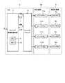
図1から図11は、第1実施形態の説明図を示す。図1には車両制御システム1の一部を示している。この図1に示すように、車両制御システム1は、原動機となるエンジンシステム2と、このエンジンシステム2の出力軸の回転駆動トルクを図示しない車輪に伝達する自動変速機3と、を主として備える。自動変速機3は、トルクコンバータ3a及び変速機構3bを備え、TCU(Transmission Control Unit)4を接続して構成される。また、このTCU4には、例えば車内ネットワークNを通じて、レンジ検出装置5a、センサ信号検出装置5bが接続されている。その他、TCU4には、トルクコンバータ3aから変速機構3bに入力される入力回転軸の回転数を検出する入力回転数センサSa、自動変速機3から出力される出力回転軸の回転数、回転トルクを検出する出力回転数センサSb、が接続されている。 1 to 11 are explanatory diagrams of the first embodiment. FIG. 1 shows a part of the
エンジンシステム2は、図示しない電子制御スロットルシステムにより運転者によるアクセルの操作量等に応じて電子スロットル弁を制御することでエンジン出力の吸入空気量を制御し、エンジン出力軸の回転駆動力を制御する。このエンジンシステム2は、例えばガソリンエンジン又はディーゼルエンジン等の内燃機関である。エンジンシステム2の出力軸の回転駆動力は自動変速機3の入力軸に伝達される。トルクコンバータ4は、エンジンシステム2の出力軸の回転駆動力を液体(図示せず)を通じて変速機構3bの入力軸に伝達する。 The
変速機構3bは、その入力軸と出力軸との変速比を切り替えるための遊星歯車を用いた複数のギヤ、これらの各ギヤに連結された複数のクラッチ6a〜6d(図2参照)を備え、図2に示すように、油圧回路4aがクラッチ6a〜6dの係合/解放を制御することにより入出力軸の変速比を切り替える構成である。 The
図1に示すように、レンジ検出装置5aは、例えば運転者により操作されたシフトレバーの位置に対応したレンジを検出し、この検出情報を運転者の操作状態としてネットワークNに出力する。このシフトレバーの位置は、例えばMTモード付のAT車の場合、パーキング(P)レンジ、リバース(R)レンジ、ニュートラル(N)レンジ、Dレンジ(D)と共に、Mモードにおける「+」「−」などである。TCU4は、このレンジ検出装置5aの検出レンジの情報をネットワークNを通じて入力する。 As shown in FIG. 1, the
センサ信号検出装置5bは、運転者が操作するアクセルの開度に応じて変化するアクセル開度センサのアクセル開度信号、及び、スロットル開度センサによるスロットル開度信号、などの各種センサ信号を車両内の車両状態として検出し、ネットワークNに出力する。なお、センサ信号検出装置5bは、各種センサ信号を統括又は個別に入力する1又は複数の電子制御装置(ECU)を統一して説明の便宜上示している。TCU4は、ネットワークNを通じてこれらのセンサ信号を取得することで車両内の車両状態を入力できる。 The sensor
図2に示すように、TCU4は、ソレノイド駆動制御装置(以下、制御装置と略す)7及びソレノイドドライバ8を備える。制御装置7は、CPU9と、RAM、ROM、フラッシュメモリ等のメモリ10とを備える1又は複数のマイクロコンピュータを主として構成される。メモリ10は非遷移的実体的記録媒体として用いられており、後述のMモード変速線、Dレンジ変速線(後述の図6、図7参照)が記憶されている。制御装置7は、CPU9がメモリ10に記憶されているプログラムを実行することで各種機能(例えば、電流制御部、区別部、入力部としての機能)を実現する。制御装置7は、回転数センサSa,Sbのセンサ信号、又は/及び、センサ信号検出装置5bのセンサ信号を用いて現在の車速を算出でき、この車速の時間変化から加速度を算出可能になっている。 As shown in FIG. 2, the TCU 4 includes a solenoid drive control device (hereinafter abbreviated as a control device) 7 and a
TCU4は、レンジ検出装置5aにより検出されたレンジの検出結果により、Mモード(手動変速モード)では「+」の指示を受け付けると変速機構3bのギヤ段を順次上げ、「−」の指示を受け付けると変速機構3bのギヤ段を順次下げる。TCU4は、Dレンジ(ドライブレンジ:自動変速レンジ)ではメモリ10に記憶されているDレンジ変速線を用いて、1thレンジ〜6thレンジを1又は複数段毎に切替える。 When the
図2に示すように、TCU4の制御装置7は、ソレノイドドライバ8に各クラッチ6a〜6dの駆動用のPWM信号を出力し、油圧回路4aに設けられたリニアソレノイドバルブ(以下、ソレノイドと略す)11a〜11dによりプランジャの動作を油圧制御することで各クラッチ6a〜6dの各係合/解放状態を制御する。ソレノイド11a〜11dは、自動変速機3の油圧アクチュエータに供給される作動油の圧力制御に用いられるスプール式の油圧制御弁である。 As shown in FIG. 2, the
<クラッチ6a〜6dの係合/解放状態と自動変速機3のギヤ段との関係>
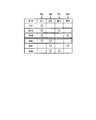
ここで、クラッチ6a〜6dの係合/解放状態と自動変速機3のギヤ段との関係性を説明する。図3にはクラッチ6a〜6dの係合/解放状態と自動変速機3のギヤ段の対応表を表している。この図3において、1st,2nd,3rd,4th,5th及び6thは、それぞれ前進変速段(1速〜6速)を示し、「マル」が各クラッチの係合状態を示し、「無記載」が非係合状態、すなわち解放状態、を示している。<Relationship between engaged / released states of
Here, the relationship between the engaged / released state of the
TCU4は、自動変速機3の多段のギヤ段のうち、レンジ検出装置5aにより検出されたレンジにより要求されるギヤ段を実現するように、そのギヤ段に対応したクラッチ6a〜6dに係る係合/解放状態の組合せを実行する。
例えば、レンジ検出装置5aがDレンジを検出し、この情報がTCU4に伝えられると、TCU4は、1thから順に6thまでギヤ段を切り替える。
このときTCU4は、前進3速段において3rdレンジに移行したときには、前進3速段3rdに対応してクラッチ6a〜6dの係合/解放状態を切り替え、この3rdにおいて、クラッチ6a(C1),6d(B2)を係合状態とし、クラッチ6b(C2),6c(B1)を解放状態とする。The
For example, when the
At this time, when the
例えば3rdにおいて、制御装置7は、係合するクラッチ6a(C1),6d(B2)に対応したソレノイド11a,11dには、印加直流電流の標準電流値(基本電流値)を目標電流となる高値Ihi(例えば、直流制御範囲の最高値Imax)として印加すると共に、出力するPWM信号に合わせてPWM電流を高値Ihiに重畳するようにソレノイド11a、11dに印加する。制御装置7は、当該ソレノイド11a、11dの通電電流をA/D変換器(図示せず)により検出し、この検出電流を目標電流にするためPWM電流の振幅を操作制御する。このようにして電流フィードバック制御する。この電流フィードバック制御の中でもディザチョッパ制御を行うようにしても良い。このディザチョッパ制御は、目標電流値を一定値とする細かい制御パルス周期を設定すると共にさらに当該制御パルス周期よりも長いディザ周期で周期的に段階的に変化する値を目標電流値とし、この目標電流値に合わせてPWM電流により電流フィードバック制御することで行われる。 For example, at 3rd, the
例えば3rdにおいて、制御装置7は、解放するクラッチ6b、6cに対応したソレノイド11b、11cには、印加直流電流を目標電流となる低値Ilo(例えば直流制御範囲の最低値Imin)にすると共に、出力するPWM信号に対応したPWM電流を低値Iloに重畳するようにソレノイド11b、11cに印加し、当該ソレノイドの通電電流をA/D変換器(図示せず)で検出し、この検出電流を目標電流にするためにPWM電流の振幅を操作制御する。このようにして電流フィードバック制御する。制御装置7が、PWM信号をソレノイドドライバ8に出力し、ソレノイドドライバ8によりソレノイド11a〜11dに電流フィードバック制御することで目標電流値に制御電流を制御できるようになり、この結果、正確に油圧制御できる。3rdにおける方法を説明したが、その他の変速段でも同様に電流フィードバック制御が行われる。 For example, at 3rd, the
<電流フィードバック周期の切替方法>
また本実施形態では、制御装置7は、ソレノイド11a〜11dに電流フィードバック制御するためのPWM信号の周期を調整制御可能になっている。例えば、制御装置7が、ソレノイド11a〜11dに印加するPWM電流の電流フィードバック周期を短くすると、ソレノイド11a〜11dの制御応答性を高めることができる。この結果、クラッチ6a〜6dの係合/解放状態の追従性能を高めることができ、ドライブフィーリングを向上できる。<Switching method of current feedback cycle>
Moreover, in this embodiment, the
全てのソレノイド11a〜11dの制御応答性を高めると、制御装置7を構成するCPU9の処理負荷が大幅に増加してしまうため、このCPU9の処理負荷を減らすため、全ソレノイドを対象ソレノイドと非対象ソレノイドとに区別して別々に電流フィードバック制御することが望ましい。 If the control responsiveness of all the
以下、この電流フィードバック周期の切替方法の詳細について、図4及び図5を参照しながら説明する。
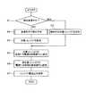
図4に示すように、制御装置7は、レンジ検出装置5a、回転数センサSa,Sb及びセンサ信号検出装置5bにより検出される各種センサ信号により、運転者の操作状態及び車両状態を判断し、現在変速中であるか否かを判定する(S1)。そして、制御装置7は、現在変速中であると判定したときには、操作中となる対象ソレノイドと操作しない非対象ソレノイドとを区別する(S2)。すなわち、例えば、制御装置7が、ギヤ段を変更元ギヤ段3rdから変更先ギヤ段4thに変更している最中であるときには、図3の対応表に示すように、操作中のソレノイド11b、11dを対象ソレノイドとし、操作していないソレノイド11a、11cを非対象ソレノイドとして区別する。Hereinafter, the details of the current feedback cycle switching method will be described with reference to FIGS. 4 and 5. FIG.
As shown in FIG. 4, the
また制御装置7は、S1において現在変速中ではないと判定したときにも(S1でNO)、変速先ギヤ段を予測し(S3)、この変速先ギヤ段に対応した対象ソレノイドを非対象ソレノイドと区別する(S4)。この場合、制御装置7は、対象ソレノイドを駆動する電流フィードバック周期を比較的短い短周期Tsに設定し(S5)、非対象ソレノイドを駆動する電流フィードバック周期を比較的長い長周期Tlに設定し(S6)、各ソレノイド11a〜11dに電流出力処理する(S7)。 Also, when the
ここで、S5の短周期Tsは、ソレノイド11a〜11dの特性から決定されるものであり、ソレノイド11a〜11dの制御応答性を最大にできる所定周期(例えば、5msec)に定められている。また長周期Tlは、油圧回路4aにより油圧を調整するときの油圧脈動を許容範囲内に収めることができると共に、制御装置7のCPU9の処理負荷に悪影響を及ぼさない程度の所定周期(例えば、10msec)に定められている。 Here, the short period Ts of S5 is determined from the characteristics of the
次に図5を参照し、S3の変速先のギヤ段の予測処理を説明する。この図5に示すように、制御装置7は、センサ信号検出装置5bにより検出された現在のアクセル開度から所定時間以内に到達可能なアクセル開度域R1を推定する(T1)。ここでは、アクセル開度域R1を用いて説明するが、アクセル開度が大きくなれば電子スロットル開度も概ね線形的に大きくなるため、ここで推定する開度域は電子スロットル開度域と言い換えても良い。これは、この現タイミングにおいて、運転者によりアクセルが踏み込まれたときに所定時間内に到達可能なアクセル開度を想定することで求められる。
また制御装置7は、センサ信号検出装置5bにより検出された現在の車速情報及び加速度情報から所定時間以内に到達可能な車速域V1を推定する(T2)。Next, with reference to FIG. 5, the process of predicting the gear position of the shift destination in S3 will be described. As shown in FIG. 5, the
Further, the
その後、制御装置7は、DレンジであるかMモードであるかを判定し(T3)、Mモードであるときには、シフト操作により変更可能なギヤ段と車速域V1から出力可能なギヤ段を判断し(T4)、変更可能性のあるギヤ段を1又は複数段に絞る。例えば、制御装置7は、現在の車速を車速V0と取得した場合、メモリ10から図6に示すMモード変速線を参照し2nd〜6thのギヤ段まで出力可能であると判断する。このMモード変速線は、車速と対応した出力可能ギヤ段(上限ギヤ段、下限ギヤ段)との関係を示している。 Thereafter, the
また、制御装置7は、レンジ検出装置5aによりDレンジであると判定すると、Dレンジ変速線(図7参照)と、アクセル開度域R1と、車速域V1と、から出力可能なギヤ段を1又は複数段に絞る(T5)。 Moreover, if the
図7に示すように、メモリ10にはDレンジ変速線が記憶されている。メモリ10には、シフトアップ(例えば1st→2nd、2nd→3rd、3rd→4th)、及び、シフトダウン(例えば2nd→1st、3rd→2nd、4th→3rd)に伴う、必要な車速とアクセル開度(電子スロットル開度)との関係が予め記憶されている。 As shown in FIG. 7, the D range shift line is stored in the
この図7に示すように、ギヤ段が3rdであったときに、制御装置7は、現在の車速と現在のアクセル開度の関係を、図7に示す現在点P1のように検出したときには、この現在点P1を中心点とし、当該現在点P1から図示左右に想定される車速域V1と、現在点P1から図示上下に想定されるアクセル開度域R1とを定め、これらの領域がDレンジ変速線に重なる領域(図7中の一点鎖線の領域)を定める。これにより、将来的に出力可能なギヤ段を予測できる。制御装置7は、出力可能と判断されたギヤ段から出力可能性のある変速パターンを特定する(T6)。 As shown in FIG. 7, when the gear stage is 3rd, the
制御装置7は、例えば現在のギヤ段を3rdとし、車速域V1とアクセル開度域R1とがDレンジ変速線(3rd→2nd、3rd→4th)に跨っているときには、出力可能なギヤ段を2ndと4thと予測判断し、出力可能性のある変速パターンを「3rd→2nd」、「3rd→4th」と特定する。 For example, when the current gear stage is set to 3rd and the vehicle speed range V1 and the accelerator opening range R1 straddle the D range shift line (3rd → 2nd, 3rd → 4th), the
そして制御装置7は、出力可能なギヤ段を2ndと4thと予測したときには、図3に示したように、変速パターン3rd→2ndの変速操作において解放→係合する操作クラッチをクラッチ6c(B1)と特定し、また係合→解放する操作クラッチをクラッチ6d(B2)と特定する。 When the
また図3に示したように、制御装置7は、変速パターン3rd→4thの変速操作において、解放→係合する操作クラッチをクラッチ6b(C2)と特定し、また係合→解放する操作クラッチをクラッチ6d(B2)と特定する。このため、3rdからシフトアップ/シフトダウンするときに、これらのクラッチ6b,6c,6dが操作可能性のあるクラッチであると特定できる。 As shown in FIG. 3, the
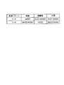
この場合、制御装置7は、変速機構3bの入力軸に係る現在の入力タービントルクを検出し、この現在の入力トルクから変速機構3bの入力軸が駆動体、被駆動体、又はその中間となるか(図8の「駆動」「被駆動」「中間」)を判定し(T7)、変速初期に操作する対象クラッチを特定する(T8)ようにしても良い。なお、このステップT7、T8の処理は、必要に応じて省略しても良い。すなわち、変速機構3bの入力軸の入力タービントルクを考慮することなく、図5のT1〜T6の処理を用いて、図4のS4において対象ソレノイドを区別するようにしても良い。 In this case, the
ここでは、T7、T8の処理を説明する。図8に示される対応表は、制御装置7の製造出荷段階から予めメモリ10に不揮発的に記憶されている。
図8に示す「駆動」「被駆動」とは、エンジンシステム2から変速機構3bにかけてスリップ係合する際に、変速機構3bの入力軸が駆動体となるか被駆動体となるかの関係を示すものであり、「駆動」とは、エンジンシステム2の出力軸の回転数が上昇し変速機構3bの入力軸のタービン回転数が上昇している場合の条件を示しており、変速機構3bの入力トルクが所定範囲より高い場合の条件を示している。この条件は、例えばアクセル開度が所定範囲の上限値よりも高いときに満たされる条件である。以下では、必要に応じて「駆動」と称す。Here, the processes of T7 and T8 will be described. The correspondence table shown in FIG. 8 is stored in the
“Drive” and “driven” shown in FIG. 8 indicate the relationship between whether the input shaft of the
また図8の「被駆動」とは、エンジンシステム2の出力軸の回転数が下降し変速機構3bの入力軸のタービン回転数が下降している場合の条件を示しており、変速機構3bの入力トルクが所定範囲より低い場合の条件を示している。この条件は、例えばアクセル開度が所定範囲の下限値よりも低いときに満たされる条件である。以下では、必要に応じて「被駆動」と称す。「中間」は、その中間領域である場合を示し、変速機構3bの入力トルクが所定範囲内にある場合の条件を示している。 Further, “driven” in FIG. 8 indicates a condition when the rotational speed of the output shaft of the
<変速機構3bの入力軸が駆動体となるときのダウンシフト(3rd→2nd)の場合「駆動」>
この種の車両制御システム1では、自動変速機3がダウンシフト(例えば3rd→2nd)するときには、変速機構3bの入力軸のタービン回転数は上昇する。このため、この入力軸のタービン回転数の上昇により、変速機構3bは外部から補助を受けて迅速に駆動できるようになるため、制御装置7が自主的に油圧制御する制御迅速性を低下させても良い。このため、制御装置7は、変速機構3bの入力トルクが所定範囲より高いときには、図8のダウンシフト(3rd→2nd)において、係合状態から解放させるクラッチ6d(B2)だけを変速初期の変速出力予測期間T1(図9参照)に操作する対象クラッチ6d(B2)とすると良い。<In the case of a downshift (3rd → 2nd) when the input shaft of the
In this type of
そして制御装置7は、図4のS4に処理を戻し、対象クラッチ6d(B2)に対応したソレノイド11dだけを対象ソレノイドとして区別し、その他のソレノイド11a〜11cを非対象ソレノイドとして区別する。すると、図4のS5〜S7に示すように、制御装置7が、対象ソレノイド11dの電流フィードバック周期だけを短周期Tsに設定し、非対象ソレノイド11a〜11cの電流フィードバック周期を長周期Tlに設定する。このため、制御応答性を適切な状態にできる。 Then, the
<変速機構3bの入力軸が被駆動体となるときのダウンシフト(3rd→2nd)の場合「被駆動」>
逆に、変速機構3bの入力トルクが所定範囲より低いときには、変速機構3bの入力軸がエンジンシステム2の側から駆動されているときよりも制御迅速性に劣ることになる。このため、係合又は解放するクラッチ6c,6d(B1,B2)の両者を変速初期の変速出力予測期間T1に操作する対象クラッチに区別すると良い。そして制御装置7は、図4のS4に処理を戻し、対象クラッチ6c,6dに対応したソレノイド11c,11d(B1,B2)を対象ソレノイドとして区別し、その他のソレノイド11a,11bを非対象ソレノイドとして区別する。すると図4のS5〜S7に示すように、制御装置7が、対象ソレノイド11c、11dの電流フィードバック周期を短周期Tsにすることになる。このため、制御応答性を適切な状態にできる。<In the case of downshift (3rd → 2nd) when the input shaft of the
Conversely, when the input torque of the
<前述の中間におけるダウンシフト(3rd→2nd)の場合「中間」>
制御装置7は、その中間条件においても対象クラッチをクラッチ6c(B1),6d(B2)としている。このため、この対象クラッチ6c(B1),6d(B2)に対応した対象ソレノイド11c(B1),11d(B2)の電流フィードバック周期を短周期Tsにすることで制御応答性を適切な状態にできる。<In the case of the above-described intermediate downshift (3rd → 2nd) “intermediate”>
The
<変速機構3bの入力軸が駆動体となるときのアップシフト(3rd→4th)の場合>
また、自動変速機3がアップシフト(例えば3rd→4th)するときには、変速機構3bの入力軸に係るタービン回転数は下降する。このため、このタービン回転数の下降に伴い、外部のエンジンシステム2から補助を受けなくなるため、制御装置7が変速処理時に自主的に実行する制御迅速性を高めることが望ましい。このため制御装置7は、自動変速機3の入力トルクが所定範囲より高いときには、係合/解放動作させるクラッチ6b(C2),6d(B2)の両者を変速初期の変速出力予測期間T1に操作する対象クラッチとすると良い。<Upshift (3rd → 4th) when the input shaft of the
Further, when the
<変速機構3bの入力軸が被駆動体となるときのアップシフト(3rd→4th)の場合>
自動変速機3がアップシフト(例えば3rd→4th)するときには、変速機構3bの入力軸に係るタービン回転数は下降する。また変速機構3bの入力トルクが所定範囲の下限値より低いときには、このタービン回転数が自然に下降することになるため、制御装置7が、変速処理時に自主的に制御迅速性を高めなくても良い。このため、変速処理に伴い解放するクラッチ6d(B2)だけを変速初期の変速出力予測期間T1に操作する対象クラッチとすると良い。<Upshift (3rd → 4th) when input shaft of
When the
<その中間におけるアップシフト(3rd→4th)の場合>
制御装置7は、図8に示すように、これらの中間においても対象クラッチをクラッチ6b(C2)、6d(B2)としているため、この対象クラッチ6b(C2)、6d(B2)に対応した対象ソレノイド11b、11dの電流フィードバック周期を短周期Tsにすることで、制御応答性を適切な状態にできる。<Upshift in the middle (3rd → 4th)>
As shown in FIG. 8, the
<標準的な実例>
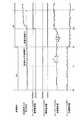
図9は、自動変速機3のギヤ段が変速パターン3rd→4thに変速指示を受け付ける前後の標準的な実例をタイミングチャートにより示している。この図9に示す例では、変速機構3bの入力軸に係る入力トルクの状態に無関係に、ギヤ段の変更可能性のあるときに操作対象となる対象ソレノイドと非対象ソレノイドとを区別する例を示している。すなわち、図5のT1〜T6の処理を行うものの、T7〜T8の処理を行うことなく対象ソレノイドと非対象ソレノイドとを区別して制御する例を示している。<Standard example>
FIG. 9 is a timing chart showing a standard example before and after the gear stage of the
この図9に示すように、制御装置7が、自動変速機3のギヤ段を3rdに制御する定常状態t0〜t1の間、各ソレノイド11a〜11dの目標電流値の直流成分をそれぞれ高値Ihi、低値Ilo、低値Ilo、高値Ihiとし、この直流成分にPWM電流を重畳させて電流フィードバック制御する。制御装置7は、この期間t0〜t1の間、各ソレノイド11a〜11dを通常の長周期Tlにより電流フィードバック制御する。 As shown in FIG. 9, during the steady state t0 to t1 in which the
制御装置7は、図4に示す処理を実行するが、図4のS3において変速先のギヤ段を予測した結果、変速先のギヤ段を例えば2th又は4thとすると、ソレノイド11b(C2)、11c(B1)、11d(B2)を対象ソレノイドとし、変速指示が与えられるタイミングt2の前の変速出力予測期間T1(=t1〜t2)の間に、これらの対象ソレノイド11b(C2)、11c(B1)、11d(B2)の電流フィードバック周期を短周期Tsとし、その他の非対象ソレノイド11a(C1)の電流フィードバック周期を長周期Tlとしている。 The
このため、その後のタイミングt2において、制御装置7が、例えば3rd→4thへ変速制御することになったとしても、ソレノイド11b(C2)、11c(B1)、11d(B2)の制御応答性を事前に高めているため、4thに変速するときに係合操作対象となるクラッチ6b(C2)に対応したソレノイド11b(C2)の通電電流を迅速に上昇制御でき、当該ソレノイド11b(C2)により操作される油圧アクチュエータの出力油圧を極力素早く上昇できる。
同様に、制御装置7は、4thに変速するときに解放操作対象となるクラッチ6d(B2)に対応したソレノイド11d(B2)の通電電流も迅速に下降制御でき、当該ソレノイド11d(B2)により操作される油圧アクチュエータの出力油圧を極力素早く下降させることができる。この結果、3rd→4thへのシフトアップの変速に対して迅速に対応できる。3rd→2thへのシフトダウンの変速に対しても同様に迅速に対応できる。For this reason, at the subsequent timing t2, even if the
Similarly, the
<「駆動」と「被駆動」とを比較>
また図10及び図11は、変速機構3bの入力軸に係る入力トルクに基づいて対象ソレノイドを特定する例を示し、前述した「駆動」と「被駆動」におけるシフトアップ時のタイミングチャートを対比して示している。この場合、制御装置7は、図5のT1〜T8の処理を行い、対象ソレノイドと非対象ソレノイドとを区別して制御する。<Comparison between "driven" and "driven">
FIGS. 10 and 11 show an example in which the target solenoid is specified based on the input torque related to the input shaft of the
前述した「駆動」においては、図10に示すように、制御装置7が、自動変速機3の変速出力予測期間t1〜t2において、ソレノイド11b(C2)、11d(B2)を共に短周期Tsで電流フィードバック制御する。これにより、その後のタイミングt2においてシフトアップ変速指示を入力すると、ソレノイド11b(C2)、11d(B2)の目標電流値の直流成分を概ね同時に変化させることができる。このとき、制御装置7は、ソレノイド11b(C2)、11d(B2)を共に短周期Tsにより電流フィードバック制御しているため、迅速に目標電流値に制御できる。 In the above-described “drive”, as shown in FIG. 10, the
また「被駆動」においては、制御装置7が、自動変速機3の変速出力予測期間t1〜t2においてソレノイド11d(B2)だけを短周期Tsで電流フィードバック制御する。これにより、その後のタイミングt2において変速指示を受け付けたときには、ソレノイド11d(B2)の目標電流値の直流成分をタイミングt2にて変化させてから、ソレノイド11b(C2)の目標電流値の直流成分をt2後のタイミングt2aにて変化させる。 Further, in “driven”, the
このとき、制御装置7は、変速指示を受け付けて変速中期間T2(t2〜t3)に入ると図4のS1にてYESと判定し、S2にてソレノイド11b(C2)、11d(B2)を対象ソレノイドとして区別し、タイミングt2にてソレノイド11b(C2)の電流フィードバック周期を短周期Tsに切り替える。このため、タイミングt2の後のタイミングt2aにおいて目標電流値に迅速に制御できる。 At this time, the
以上、本実施形態によれば、制御装置7は、ギヤ段を変更可能性のあるとき又は変更中のときに操作対象となる対象ソレノイド(例えば11b〜11d)と非対象ソレノイド(例えば11a)とを区別し、これらの対象及び非対象ソレノイドの電流フィードバック周期を変更して電流フィードバック制御している。このため、変速処理時の制御迅速性を対象ソレノイドと被対象ソレノイドとで互いに変更することができ、変速指示を入力する前に変更可能性のあるソレノイド(例えば11b〜11d)の制御迅速性を予め高めることができる。また変速指示を受け付けた後、変速中における制御迅速性も高めることができる。制御装置7は、対象ソレノイド(例えば11b〜11d)と非対象ソレノイド(例えば11a)との間で電流フィードバック周期を変更しているため、一律一定のF/B周期で電流制御をする場合と比較して、比較的長周期Tlで電流フィードバック制御することで処理負荷を低減できる。 As described above, according to the present embodiment, the
特に、制御装置7が、変速先のギヤ段に変速中及び変速可能性のあるギヤ段に関する対象ソレノイド(例えば11b〜11d)に対する電流フィードバック周期を短周期Tsにすることで制御迅速性を高めることができ、その他の非対象ソレノイド(例えば11a)に対する電流フィードバック周期を長周期Tlにすることで処理負荷を低減できる。 In particular, the
制御装置7は、運転者の操作状態及び車両内の車両状態に基づいて変更可能性のあるギヤ段を1又は複数段に絞っているため、全てのギヤ段への変更可能性を考慮する必要がなくなり、全てのソレノイド11a〜11dの制御迅速性を高める必要がなくなる。この結果、操作対象となる対象ソレノイドを絞ることができ、処理負荷を低減できる。 Since the
制御装置7は、エンジンシステム2から変速機構3bにかけてスリップ係合する際の駆動/被駆動の状態により操作対象となる対象ソレノイドと非対象ソレノイドとを区別するようにしているため、変速機構3bの入力トルクの状態に合わせて対象ソレノイドを絞り込むことができるようになる。 Since the
(第2実施形態)
図12〜図14は、第2実施形態の追加説明図を示している。本実施形態においては、油圧センサにより検出される実油圧の変化量により電流フィードバック周期を短周期/長周期に変更する形態を示す。図12は、図2に代わる機能ブロック図を示している。図12に示すように、油圧回路4aには油圧センサ12a〜12dが実装されている。(Second Embodiment)
12-14 has shown the additional explanatory drawing of 2nd Embodiment. In the present embodiment, a mode in which the current feedback cycle is changed to a short cycle / long cycle according to the change amount of the actual hydraulic pressure detected by the hydraulic sensor is shown. FIG. 12 shows a functional block diagram instead of FIG. As shown in FIG. 12,
これらの油圧センサ12a〜12dは、油圧回路4aのソレノイド11a〜11dに対応してそれぞれ設けられている。これらの油圧センサ12a〜12dは、ソレノイド11a〜11dにより油圧制御された油圧値をそれぞれ検出可能になっている。 These
本実施形態では、制御装置7は、CPU9がメモリ10に記憶されているプログラムを実行することで各種機能(例えば、周期変更部、油圧変化量比較部としての機能)を実現するようになっている。その他の構成は、第1実施形態と同様であるためその説明を省略する。 In the present embodiment, the
上記構成の作用、動作を説明する。図13は、ソレノイド(例えば6a〜6d)の電流フィードバック周期を変速中期間T2(図9〜図11参照)にて短周期Tsに制御している最中に処理する処理内容を概略的に示すフローチャートである。 The operation and operation of the above configuration will be described. FIG. 13 schematically shows the processing contents to be processed while the current feedback cycle of the solenoid (for example, 6a to 6d) is controlled to the short cycle Ts in the shifting period T2 (see FIGS. 9 to 11). It is a flowchart.
基本的に、電流フィードバック周期を短周期Tsにすることで高精度、高制御応答性を実現できるが、この高精度、高制御応答性が求められるのは、標準電流値を低値Iloから高値Ihi、または、高値Ihiから低値Iloに切替制御し、制御電流値が目標電流値に追従し油圧制御を完了するまでの過渡的な時間領域だけである。このため、この時間領域を推定することで、電流フィードバック周期を短周期Tsとする時間を限定することができ、処理負荷の増加を必要最小限に抑制できる。 Basically, high accuracy and high control responsiveness can be realized by setting the current feedback cycle to a short cycle Ts, but this high accuracy and high control responsiveness is required because the standard current value is increased from a low value Ilo to a high value. This is only a transitional time region in which the switching control is performed from Ihi or the high value Ihi to the low value Ilo and the control current value follows the target current value to complete the hydraulic control. For this reason, by estimating this time region, it is possible to limit the time for which the current feedback cycle is set to the short cycle Ts, and it is possible to suppress an increase in processing load to the minimum necessary.
油圧センサ12a〜12dの検出実油圧の時間当たり変化量が所定値以上となっているときには、ソレノイド11a〜11dにより油圧制御する実油圧が変化している途中であることから、標準電流値が低値Iloから高値Ihiまたは高値Ihiから低値Iloに遷移してまもなくであり未だ油圧制御途中であると推定できる(図9〜図11の変速中期間T2の出力油圧参照)。 When the amount of change per hour of the actual hydraulic pressure detected by the
このため、図13に示すように、制御装置7は、全ソレノイド11a〜11dを対象として、各油圧センサ12a〜12dの検出値の時間当たり変化量が所定値以上となるときには(T11でYES)、電流フィードバック周期を短周期Tsとし(T12)、各油圧センサ12a〜12dの検出値の時間当たり変化量が所定値未満となるときには(T11でNO)、電流フィードバック周期を長周期Tlとする(T13)。そして、制御装置7は、これらの周期を全ソレノイド11a〜11dに設定した後、全ソレノイド11a〜11dへ電流出力する。これにより、全ソレノイド11a〜11dの電流フィードバック周期を変更して電流フィードバック制御できる。 Therefore, as shown in FIG. 13, the
図14に示すように、制御装置7が、タイミングt2において変速指示を入力しソレノイド11d(B2)の標準電流値を高値Ihiから低値Iloに制御すると、タイミングt2以降に油圧センサ12d(B2)の検出油圧が大きく変化するものの、時間経過に伴い徐々に検出油圧の変化量が少なくなる。このため、タイミングt2bにおいて検出油圧の変化量が所定値未満となると、制御装置7は、このタイミングt2bにおいてソレノイド11d(B2)の電流フィードバック周期を短周期Tsから長周期Tlに戻す。これにより、処理負荷の増加を必要最小限に抑制できる。また、この処理を行うことで、ギヤ段を変更先ギヤ段に変更中であるか変更完了したかを判定する指標として用いることもできる。 As shown in FIG. 14, when the
(第3実施形態)
図15は、第3実施形態の追加説明図を示している。この図15は、図13に代わるフローチャートであり、異なる点は、ステップT11に代えてステップT11aを設けているところにある。本実施形態では、制御装置7は、CPU9がメモリ10に記憶されているプログラムを実行することで各種機能(例えば、時間計測部としての機能)を実現するようになっている。(Third embodiment)
FIG. 15 shows an additional explanatory diagram of the third embodiment. FIG. 15 is a flowchart in place of FIG. 13, and the difference is that step T11a is provided instead of step T11. In this embodiment, the
制御装置7は、このT11aにおいて標準電流値の切替後の所定時間以内であるときには(T11aでYES)、電流フィードバック周期を短周期Tsとし(T12)、所定時間を超えたときには(T11aでNO)、電流フィードバック周期を長周期Tlに戻している。すなわち、図14を参酌して説明すれば、タイミングt2からt2bの所定時間を経過したことを条件として、電流フィードバック周期を長周期Tlに戻す。これにより、処理負荷の増加を必要最低限に抑制できる。 The
(他の実施形態)
本開示は、上記実施形態に限定されるものではなく、例えば、以下に示す変形又は拡張が可能である。(Other embodiments)
The present disclosure is not limited to the above-described embodiment. For example, the following modifications or expansions are possible.
前述した複数の実施形態の構成、機能を組み合わせても良い。前述実施形態の一部を、課題を解決できる限りにおいて省略した態様も実施形態と見做すことが可能である。また、特許請求の範囲に記載した文言によって特定される発明の本質を逸脱しない限度において考え得るあらゆる態様も実施形態と見做すことが可能である。 You may combine the structure and function of several embodiment mentioned above. An aspect in which a part of the above-described embodiment is omitted as long as the problem can be solved can be regarded as the embodiment. Moreover, all the aspects which can be considered in the limit which does not deviate from the essence of the invention specified by the wording described in the claims can be regarded as the embodiment.
本開示は、前述した実施形態に準拠して記述したが、本開示は当該実施形態や構造に限定されるものではないと理解される。本開示は、様々な変形例や均等範囲内の変形をも包含する。加えて、様々な組み合わせや形態、さらには、それらに一要素、それ以上、あるいはそれ以下、を含む他の組み合わせや形態をも、本開示の範畴や思想範囲に入るものである。 Although the present disclosure has been described based on the above-described embodiments, it is understood that the present disclosure is not limited to the embodiments and structures. The present disclosure includes various modifications and modifications within the equivalent range. In addition, various combinations and forms, as well as other combinations and forms including one element, more or less, are within the scope and spirit of the present disclosure.
図面中、3は自動変速機、3bは変速機構、4はTCU(自動変速機制御装置)、4aは油圧回路、7はソレノイド駆動制御装置(電流制御部、入力部、区別部、周期変更部、油圧変化量比較部、時間計測部)、11a〜11dはリニアソレノイドバルブ(ソレノイド)、1st〜6thはギヤ段、を示す。 In the drawings, 3 is an automatic transmission, 3b is a speed change mechanism, 4 is a TCU (automatic transmission control unit), 4a is a hydraulic circuit, 7 is a solenoid drive control unit (current control unit, input unit, distinction unit, cycle change unit) , Hydraulic pressure change comparison unit, time measurement unit), 11a to 11d are linear solenoid valves (solenoids), and 1st to 6th are gear stages.
Claims (5)
Translated fromJapanese前記ギヤ段を前記複数段のうちの変更元ギヤ段から変更先ギヤ段に変更中のとき又は変更可能性のあるときに、前記変更先ギヤ段に対応して設けられた前記ソレノイドのうち当該変更元ギヤ段から前記変更先ギヤ段に変更するときに操作対象となる対象ソレノイドと前記対象ソレノイドの他の非対象ソレノイドとを区別する区別部(7,S3〜S4)と、を備え、
前記電流制御部は、前記区別部により区別された前記対象ソレノイド及び前記非対象ソレノイドの間で電流フィードバック周期を変更して電流フィードバック制御する自動変速機制御装置。Any of a plurality of solenoids (11a to 11d) provided corresponding to the plurality of gear stages in order to configure the gear stage of the speed change mechanism (3b) to any one of the predetermined plurality of gear stages. A current control unit (7, S5 to S7) for performing current feedback control on one or more solenoids;
When the gear stage is being changed from the change source gear stage of the plurality of stages to the change destination gear stage or when there is a possibility of change, the solenoid among the solenoids provided corresponding to the change destination gear stage A distinguishing section (7, S3 to S4) for distinguishing between a target solenoid to be operated when changing from a change source gear stage to the change destination gear stage and other non-target solenoids of the target solenoid;
The automatic transmission control device, wherein the current control unit performs current feedback control by changing a current feedback period between the target solenoid and the non-target solenoid distinguished by the distinguishing unit.
前記区別部が、前記対象ソレノイドを前記非対象ソレノイドと区別するときに、前記入力部に入力された前記運転者の操作状態及び前記車両内の車両状態に基づいて前記変更可能性のある前記変更先ギヤ段を1又は複数段に絞る(T1〜T5)請求項1記載の自動変速機制御装置。An input unit (7) for inputting a driver's operation state and a vehicle state in the vehicle;
When the distinguishing unit distinguishes the target solenoid from the non-target solenoid, the change that may be changed based on the operation state of the driver and the vehicle state in the vehicle input to the input unit. The automatic transmission control device according to claim 1, wherein the first gear stage is reduced to one or a plurality of stages (T1 to T5).
前記ソレノイドに電流制御することで変化する実油圧の変化量を所定値と比較する油圧変化量比較部(T11)と、を備え、
前記周期変更部は、前記油圧変化量比較部により実油圧の変化量が所定値未満となると判定されると前記ソレノイドの電流フィードバック周期を前記短周期から長周期に変更する請求項1記載の自動変速機制御装置。A period changing unit (T12, T14) for changing the current feedback period of the solenoid to a short period;
A hydraulic pressure change amount comparison unit (T11) that compares a change amount of the actual hydraulic pressure that is changed by controlling the current of the solenoid with a predetermined value;
The automatic cycle according to claim 1, wherein the cycle changing unit changes the current feedback cycle of the solenoid from the short cycle to a long cycle when the change amount of the actual hydraulic pressure is determined to be less than a predetermined value by the hydraulic pressure change amount comparing unit. Transmission control device.
前記ソレノイドに通電する標準電流値を切替えてから所定時間を計測する時間計測部(T11a)と、をさらに備え、
前記周期変更部は、前記時間計測部により所定時間を経過したことを条件として前記ソレノイドの電流フィードバック周期を前記短周期から長周期に変更する請求項1記載の自動変速機制御装置。A period changing unit (T12, T14) for changing the current feedback period of the solenoid to a short period;
A time measuring unit (T11a) for measuring a predetermined time after switching a standard current value for energizing the solenoid,
The automatic transmission control device according to claim 1, wherein the cycle changing unit changes the current feedback cycle of the solenoid from the short cycle to a long cycle on condition that a predetermined time has elapsed by the time measuring unit.
Priority Applications (2)
| Application Number | Priority Date | Filing Date | Title |
|---|---|---|---|
| JP2018016393AJP7206596B2 (en) | 2018-02-01 | 2018-02-01 | automatic transmission controller |
| US16/257,281US10663059B2 (en) | 2018-02-01 | 2019-01-25 | Automatic transmission controller |
Applications Claiming Priority (1)
| Application Number | Priority Date | Filing Date | Title |
|---|---|---|---|
| JP2018016393AJP7206596B2 (en) | 2018-02-01 | 2018-02-01 | automatic transmission controller |
Publications (2)
| Publication Number | Publication Date |
|---|---|
| JP2019132373Atrue JP2019132373A (en) | 2019-08-08 |
| JP7206596B2 JP7206596B2 (en) | 2023-01-18 |
Family
ID=67391983
Family Applications (1)
| Application Number | Title | Priority Date | Filing Date |
|---|---|---|---|
| JP2018016393AActiveJP7206596B2 (en) | 2018-02-01 | 2018-02-01 | automatic transmission controller |
Country Status (2)
| Country | Link |
|---|---|
| US (1) | US10663059B2 (en) |
| JP (1) | JP7206596B2 (en) |
Cited By (7)
| Publication number | Priority date | Publication date | Assignee | Title |
|---|---|---|---|---|
| JP2021016646A (en)* | 2019-07-23 | 2021-02-15 | 株式会社三洋物産 | Game machine |
| JP2021016456A (en)* | 2019-07-18 | 2021-02-15 | 株式会社三洋物産 | Game machine |
| JP2021016645A (en)* | 2019-07-23 | 2021-02-15 | 株式会社三洋物産 | Game machine |
| JP2021016457A (en)* | 2019-07-18 | 2021-02-15 | 株式会社三洋物産 | Game machine |
| JP2021016644A (en)* | 2019-07-23 | 2021-02-15 | 株式会社三洋物産 | Game machine |
| JP2021016459A (en)* | 2019-07-18 | 2021-02-15 | 株式会社三洋物産 | Game machine |
| JP2021016647A (en)* | 2019-07-23 | 2021-02-15 | 株式会社三洋物産 | Game machine |
Citations (2)
| Publication number | Priority date | Publication date | Assignee | Title |
|---|---|---|---|---|
| JP2006230038A (en)* | 2005-02-15 | 2006-08-31 | Hitachi Ltd | Linear solenoid drive circuit |
| JP2015179723A (en)* | 2014-03-19 | 2015-10-08 | アイシン精機株式会社 | Solenoid driving device |
Family Cites Families (8)
| Publication number | Priority date | Publication date | Assignee | Title |
|---|---|---|---|---|
| JP3011544B2 (en)* | 1992-08-10 | 2000-02-21 | 三菱電機株式会社 | Control device for automatic transmission |
| JP3614928B2 (en)* | 1995-04-05 | 2005-01-26 | 本田技研工業株式会社 | Shift control device for automatic transmission |
| JPH09170467A (en) | 1995-12-20 | 1997-06-30 | Denso Corp | Fuel feeder for internal combustion engine |
| JP4934173B2 (en)* | 2009-07-29 | 2012-05-16 | 本田技研工業株式会社 | Hydraulic control device for automatic transmission |
| JP2011052737A (en) | 2009-09-01 | 2011-03-17 | Hitachi Automotive Systems Ltd | Control method for transmission, and control method for solenoid valve |
| US8781697B2 (en)* | 2011-08-31 | 2014-07-15 | GM Global Technology Operations LLC | Adaptive control systems and methods for transmission solenoids |
| JP5761580B2 (en) | 2013-03-06 | 2015-08-12 | 株式会社デンソー | Current control device and current control program |
| JP6323271B2 (en) | 2014-09-11 | 2018-05-16 | 株式会社デンソー | Control device for automatic transmission |
- 2018
- 2018-02-01JPJP2018016393Apatent/JP7206596B2/enactiveActive
- 2019
- 2019-01-25USUS16/257,281patent/US10663059B2/enactiveActive
Patent Citations (2)
| Publication number | Priority date | Publication date | Assignee | Title |
|---|---|---|---|---|
| JP2006230038A (en)* | 2005-02-15 | 2006-08-31 | Hitachi Ltd | Linear solenoid drive circuit |
| JP2015179723A (en)* | 2014-03-19 | 2015-10-08 | アイシン精機株式会社 | Solenoid driving device |
Cited By (7)
| Publication number | Priority date | Publication date | Assignee | Title |
|---|---|---|---|---|
| JP2021016456A (en)* | 2019-07-18 | 2021-02-15 | 株式会社三洋物産 | Game machine |
| JP2021016457A (en)* | 2019-07-18 | 2021-02-15 | 株式会社三洋物産 | Game machine |
| JP2021016459A (en)* | 2019-07-18 | 2021-02-15 | 株式会社三洋物産 | Game machine |
| JP2021016646A (en)* | 2019-07-23 | 2021-02-15 | 株式会社三洋物産 | Game machine |
| JP2021016645A (en)* | 2019-07-23 | 2021-02-15 | 株式会社三洋物産 | Game machine |
| JP2021016644A (en)* | 2019-07-23 | 2021-02-15 | 株式会社三洋物産 | Game machine |
| JP2021016647A (en)* | 2019-07-23 | 2021-02-15 | 株式会社三洋物産 | Game machine |
Also Published As
| Publication number | Publication date |
|---|---|
| JP7206596B2 (en) | 2023-01-18 |
| US10663059B2 (en) | 2020-05-26 |
| US20190234513A1 (en) | 2019-08-01 |
Similar Documents
| Publication | Publication Date | Title |
|---|---|---|
| JP2019132373A (en) | Automatic transmission controller | |
| US7429233B2 (en) | Method for shifting from a source gear to a target gear in a twin clutch transmission | |
| KR100506234B1 (en) | Gear-shift control apparatus for automatic transmission and gear-shift control method | |
| EP2299146B1 (en) | Line pressure controller for automatic transmission | |
| JP2009103170A (en) | Shift control device for in-vehicle stepped automatic transmission | |
| JP2008530469A (en) | Control device and control method for automatic transmission in automobile | |
| CN110753807B (en) | Abnormality diagnostic device for shift device and abnormality diagnostic method for shift device | |
| WO2018095006A1 (en) | Gear shifting intervention control method for two-gear x-by-wire automatic transmission of electric car | |
| JP6935768B2 (en) | Automatic transmission control device | |
| US7610137B2 (en) | Shift control method and system for an automatic transmission | |
| US20220325789A1 (en) | Method of and system for controlling gear shifting in response to change of driving mode | |
| ITTO20011002A1 (en) | METHOD OF CONTROL OF AN AUTOMATED TRANSMISSION OF A MOTOR VEHICLE. | |
| CN103597253A (en) | Method for adaptation of gearshifts | |
| JP4456812B2 (en) | Sequential shift control device and method for coordinating sequential shift | |
| JP4330952B2 (en) | Shift control device for automatic transmission | |
| JP2003314593A (en) | Automatic transmission clutch control device | |
| JP2010025277A (en) | Device and method for controlling vehicle | |
| JP7268456B2 (en) | automatic transmission controller | |
| JP2931001B2 (en) | Control device for automatic transmission for vehicles | |
| KR102794339B1 (en) | Apparatus for controlling clutch actuator of double clutch transmission and method therof | |
| KR20100088801A (en) | Method for controlling transmission of vehicle | |
| KR100354032B1 (en) | Shift controlling method for automatic transmission of vehicle | |
| US20170074397A1 (en) | Method for controlling gear actuator for vehicles | |
| KR101806645B1 (en) | Method for controlling the up shift of vehicle | |
| CN106555877A (en) | The gear line traffic control automatic transmission upshift intervention control method of electric automobile two |
Legal Events
| Date | Code | Title | Description |
|---|---|---|---|
| A621 | Written request for application examination | Free format text:JAPANESE INTERMEDIATE CODE: A621 Effective date:20201209 | |
| A131 | Notification of reasons for refusal | Free format text:JAPANESE INTERMEDIATE CODE: A131 Effective date:20220208 | |
| A521 | Request for written amendment filed | Free format text:JAPANESE INTERMEDIATE CODE: A523 Effective date:20220315 | |
| A131 | Notification of reasons for refusal | Free format text:JAPANESE INTERMEDIATE CODE: A131 Effective date:20220712 | |
| A521 | Request for written amendment filed | Free format text:JAPANESE INTERMEDIATE CODE: A523 Effective date:20220830 | |
| TRDD | Decision of grant or rejection written | ||
| A01 | Written decision to grant a patent or to grant a registration (utility model) | Free format text:JAPANESE INTERMEDIATE CODE: A01 Effective date:20221206 | |
| A61 | First payment of annual fees (during grant procedure) | Free format text:JAPANESE INTERMEDIATE CODE: A61 Effective date:20221219 | |
| R151 | Written notification of patent or utility model registration | Ref document number:7206596 Country of ref document:JP Free format text:JAPANESE INTERMEDIATE CODE: R151 |