JP2019117237A - Head-mounted display - Google Patents
Head-mounted displayDownload PDFInfo
- Publication number
- JP2019117237A JP2019117237AJP2017250225AJP2017250225AJP2019117237AJP 2019117237 AJP2019117237 AJP 2019117237AJP 2017250225 AJP2017250225 AJP 2017250225AJP 2017250225 AJP2017250225 AJP 2017250225AJP 2019117237 AJP2019117237 AJP 2019117237A
- Authority
- JP
- Japan
- Prior art keywords
- mirror
- head mounted
- display unit
- disposed
- display
- Prior art date
- Legal status (The legal status is an assumption and is not a legal conclusion. Google has not performed a legal analysis and makes no representation as to the accuracy of the status listed.)
- Pending
Links
Images


Classifications
- G—PHYSICS
- G02—OPTICS
- G02B—OPTICAL ELEMENTS, SYSTEMS OR APPARATUS
- G02B25/00—Eyepieces; Magnifying glasses
- G02B25/001—Eyepieces
- G—PHYSICS
- G02—OPTICS
- G02B—OPTICAL ELEMENTS, SYSTEMS OR APPARATUS
- G02B27/00—Optical systems or apparatus not provided for by any of the groups G02B1/00 - G02B26/00, G02B30/00
- G02B27/0018—Optical systems or apparatus not provided for by any of the groups G02B1/00 - G02B26/00, G02B30/00 with means for preventing ghost images
- G—PHYSICS
- G02—OPTICS
- G02B—OPTICAL ELEMENTS, SYSTEMS OR APPARATUS
- G02B27/00—Optical systems or apparatus not provided for by any of the groups G02B1/00 - G02B26/00, G02B30/00
- G02B27/01—Head-up displays
- G02B27/017—Head mounted
- G—PHYSICS
- G02—OPTICS
- G02B—OPTICAL ELEMENTS, SYSTEMS OR APPARATUS
- G02B27/00—Optical systems or apparatus not provided for by any of the groups G02B1/00 - G02B26/00, G02B30/00
- G02B27/01—Head-up displays
- G02B27/017—Head mounted
- G02B27/0172—Head mounted characterised by optical features
- G—PHYSICS
- G02—OPTICS
- G02B—OPTICAL ELEMENTS, SYSTEMS OR APPARATUS
- G02B27/00—Optical systems or apparatus not provided for by any of the groups G02B1/00 - G02B26/00, G02B30/00
- G02B27/10—Beam splitting or combining systems
- G—PHYSICS
- G02—OPTICS
- G02B—OPTICAL ELEMENTS, SYSTEMS OR APPARATUS
- G02B27/00—Optical systems or apparatus not provided for by any of the groups G02B1/00 - G02B26/00, G02B30/00
- G02B27/28—Optical systems or apparatus not provided for by any of the groups G02B1/00 - G02B26/00, G02B30/00 for polarising
- G02B27/283—Optical systems or apparatus not provided for by any of the groups G02B1/00 - G02B26/00, G02B30/00 for polarising used for beam splitting or combining
- G—PHYSICS
- G02—OPTICS
- G02B—OPTICAL ELEMENTS, SYSTEMS OR APPARATUS
- G02B3/00—Simple or compound lenses
- G02B3/02—Simple or compound lenses with non-spherical faces
- G02B3/08—Simple or compound lenses with non-spherical faces with discontinuous faces, e.g. Fresnel lens
- G—PHYSICS
- G02—OPTICS
- G02B—OPTICAL ELEMENTS, SYSTEMS OR APPARATUS
- G02B5/00—Optical elements other than lenses
- G02B5/30—Polarising elements
- G—PHYSICS
- G02—OPTICS
- G02B—OPTICAL ELEMENTS, SYSTEMS OR APPARATUS
- G02B5/00—Optical elements other than lenses
- G02B5/30—Polarising elements
- G02B5/3083—Birefringent or phase retarding elements
- G—PHYSICS
- G02—OPTICS
- G02F—OPTICAL DEVICES OR ARRANGEMENTS FOR THE CONTROL OF LIGHT BY MODIFICATION OF THE OPTICAL PROPERTIES OF THE MEDIA OF THE ELEMENTS INVOLVED THEREIN; NON-LINEAR OPTICS; FREQUENCY-CHANGING OF LIGHT; OPTICAL LOGIC ELEMENTS; OPTICAL ANALOGUE/DIGITAL CONVERTERS
- G02F1/00—Devices or arrangements for the control of the intensity, colour, phase, polarisation or direction of light arriving from an independent light source, e.g. switching, gating or modulating; Non-linear optics
- G02F1/01—Devices or arrangements for the control of the intensity, colour, phase, polarisation or direction of light arriving from an independent light source, e.g. switching, gating or modulating; Non-linear optics for the control of the intensity, phase, polarisation or colour
- G02F1/13—Devices or arrangements for the control of the intensity, colour, phase, polarisation or direction of light arriving from an independent light source, e.g. switching, gating or modulating; Non-linear optics for the control of the intensity, phase, polarisation or colour based on liquid crystals, e.g. single liquid crystal display cells
- G02F1/133—Constructional arrangements; Operation of liquid crystal cells; Circuit arrangements
- G02F1/1333—Constructional arrangements; Manufacturing methods
- G02F1/1335—Structural association of cells with optical devices, e.g. polarisers or reflectors
- G02F1/13363—Birefringent elements, e.g. for optical compensation
- G—PHYSICS
- G02—OPTICS
- G02B—OPTICAL ELEMENTS, SYSTEMS OR APPARATUS
- G02B27/00—Optical systems or apparatus not provided for by any of the groups G02B1/00 - G02B26/00, G02B30/00
- G02B27/01—Head-up displays
- G02B27/0101—Head-up displays characterised by optical features
- G02B2027/011—Head-up displays characterised by optical features comprising device for correcting geometrical aberrations, distortion
- G—PHYSICS
- G02—OPTICS
- G02B—OPTICAL ELEMENTS, SYSTEMS OR APPARATUS
- G02B27/00—Optical systems or apparatus not provided for by any of the groups G02B1/00 - G02B26/00, G02B30/00
- G02B27/01—Head-up displays
- G02B27/0101—Head-up displays characterised by optical features
- G02B2027/0118—Head-up displays characterised by optical features comprising devices for improving the contrast of the display / brillance control visibility
- G—PHYSICS
- G02—OPTICS
- G02B—OPTICAL ELEMENTS, SYSTEMS OR APPARATUS
- G02B27/00—Optical systems or apparatus not provided for by any of the groups G02B1/00 - G02B26/00, G02B30/00
- G02B27/01—Head-up displays
- G02B27/0101—Head-up displays characterised by optical features
- G02B2027/0123—Head-up displays characterised by optical features comprising devices increasing the field of view
- G—PHYSICS
- G02—OPTICS
- G02B—OPTICAL ELEMENTS, SYSTEMS OR APPARATUS
- G02B27/00—Optical systems or apparatus not provided for by any of the groups G02B1/00 - G02B26/00, G02B30/00
- G02B27/01—Head-up displays
- G02B27/0101—Head-up displays characterised by optical features
- G02B2027/0138—Head-up displays characterised by optical features comprising image capture systems, e.g. camera
- G—PHYSICS
- G02—OPTICS
- G02B—OPTICAL ELEMENTS, SYSTEMS OR APPARATUS
- G02B27/00—Optical systems or apparatus not provided for by any of the groups G02B1/00 - G02B26/00, G02B30/00
- G02B27/01—Head-up displays
- G02B27/0101—Head-up displays characterised by optical features
- G02B2027/0147—Head-up displays characterised by optical features comprising a device modifying the resolution of the displayed image
- G—PHYSICS
- G02—OPTICS
- G02B—OPTICAL ELEMENTS, SYSTEMS OR APPARATUS
- G02B27/00—Optical systems or apparatus not provided for by any of the groups G02B1/00 - G02B26/00, G02B30/00
- G02B27/01—Head-up displays
- G02B27/0149—Head-up displays characterised by mechanical features
- G02B2027/015—Head-up displays characterised by mechanical features involving arrangement aiming to get less bulky devices
- G—PHYSICS
- G02—OPTICS
- G02B—OPTICAL ELEMENTS, SYSTEMS OR APPARATUS
- G02B27/00—Optical systems or apparatus not provided for by any of the groups G02B1/00 - G02B26/00, G02B30/00
- G02B27/01—Head-up displays
- G02B27/017—Head mounted
- G02B2027/0178—Eyeglass type
- G—PHYSICS
- G02—OPTICS
- G02B—OPTICAL ELEMENTS, SYSTEMS OR APPARATUS
- G02B27/00—Optical systems or apparatus not provided for by any of the groups G02B1/00 - G02B26/00, G02B30/00
- G02B27/10—Beam splitting or combining systems
- G02B27/14—Beam splitting or combining systems operating by reflection only
- G—PHYSICS
- G02—OPTICS
- G02F—OPTICAL DEVICES OR ARRANGEMENTS FOR THE CONTROL OF LIGHT BY MODIFICATION OF THE OPTICAL PROPERTIES OF THE MEDIA OF THE ELEMENTS INVOLVED THEREIN; NON-LINEAR OPTICS; FREQUENCY-CHANGING OF LIGHT; OPTICAL LOGIC ELEMENTS; OPTICAL ANALOGUE/DIGITAL CONVERTERS
- G02F1/00—Devices or arrangements for the control of the intensity, colour, phase, polarisation or direction of light arriving from an independent light source, e.g. switching, gating or modulating; Non-linear optics
- G02F1/01—Devices or arrangements for the control of the intensity, colour, phase, polarisation or direction of light arriving from an independent light source, e.g. switching, gating or modulating; Non-linear optics for the control of the intensity, phase, polarisation or colour
- G02F1/13—Devices or arrangements for the control of the intensity, colour, phase, polarisation or direction of light arriving from an independent light source, e.g. switching, gating or modulating; Non-linear optics for the control of the intensity, phase, polarisation or colour based on liquid crystals, e.g. single liquid crystal display cells
- G02F1/133—Constructional arrangements; Operation of liquid crystal cells; Circuit arrangements
- G02F1/1333—Constructional arrangements; Manufacturing methods
- G02F1/1335—Structural association of cells with optical devices, e.g. polarisers or reflectors
- G02F1/13363—Birefringent elements, e.g. for optical compensation
- G02F1/133638—Waveplates, i.e. plates with a retardation value of lambda/n
Landscapes
- Physics & Mathematics (AREA)
- General Physics & Mathematics (AREA)
- Optics & Photonics (AREA)
- Nonlinear Science (AREA)
- Mathematical Physics (AREA)
- Chemical & Material Sciences (AREA)
- Crystallography & Structural Chemistry (AREA)
Abstract
Description
Translated fromJapanese本発明は、小型で装着可能なディスプレイに関し、特にヘッドマウントディスプレイに関する。 The present invention relates to a compact and wearable display, and more particularly to a head mounted display.
レンズアレイを使用して軽量なヘッドマウントディスプレイを得る方法が従来技術として知られている。 Methods for obtaining lightweight head mounted displays using lens arrays are known in the prior art.
特許文献1は、ディスプレイを眼に投影するための二つのビームスプリッタのアプローチを開示している。このアプローチは、現実的応用が増大する視野角(FOV、Field Of View)が制限される。 U.S. Pat. No. 5,958,015 discloses a two beam splitter approach for projecting a display onto the eye. This approach limits the field of view (FOV) for which practical applications are increased.
特許文献2は、トップダウン(又は、側方)装着マイクロディスプレイを眼に反射するための自由形状表面を有する単一プリズム要素を教示している。 U.S. Pat. No. 5,958,095 teaches a single prismatic element having a freeform surface for reflecting a top down (or side) mounted microdisplay to the eye.
特許文献3は、トップダウン装着ディスプレイからの光を反射する多数のディスプレイを有する多数のプリズム表面を開示している。 U.S. Pat. No. 5,958,015 discloses multiple prism surfaces having multiple displays that reflect light from a top-down mounted display.
特許文献4は、パネルの光を特定の順番で反射/屈折させるプリズムを有するディスプレイを教示している。 U.S. Pat. No. 5,958,015 teaches a display having prisms that reflect / reflect light of the panel in a particular order.
特許文献5は、二つの映像パネルが一つの映像として結合される仮想ディスプレイ装置を開示している。
軽量で視野角(FOV)が広いヘッドマウントディスプレイが求められている。従来の仮想現実(VR、Virtual Reality)技術では、仮想映像の位置を決定するディスプレイが接眼レンズの前方に装着される。このため、ディスプレイと接眼レンズとを保持する保持機構が重く大型なヘッドセットになり、短い時間装着しても不快であった。寸法は、適正な倍率と仮想映像距離とを獲得する基本光学系により制限される。 There is a need for a head mounted display that is lightweight and has a wide viewing angle (FOV). In conventional virtual reality (VR) technology, a display for determining the position of a virtual image is mounted in front of the eyepiece. For this reason, the holding mechanism for holding the display and the eyepiece becomes a heavy, large-sized headset, which is uncomfortable even when worn for a short time. The dimensions are limited by the basic optics that obtain the correct magnification and virtual image distance.
ヘッドマウントディスプレイの寸法と重量とを低減するために、寸法を低減するための偏光反射アプローチが知られている。しかしながら、このアプローチは、ゴースト映像が形成される。 In order to reduce the size and weight of head mounted displays, polarized light reflective approaches to reduce the size are known. However, this approach produces ghost images.
必要な拡大を改変する映像を重ねる多数の小さなレンズを使用する方法も知られている。しかしながら、このような構成は、解像度が低く、映像の重なりの視認性が損なわれる。 It is also known to use a large number of small lenses to overlay images that alter the necessary magnification. However, such a configuration has a low resolution, and the visibility of the image overlap is lost.
本発明の一態様は、表示ユニットと接眼レンズとを保持しながらコンパクト性が改善されたヘッドマウントディスプレイを実現することを目的とする。 An aspect of the present invention aims to realize a head mounted display with improved compactness while holding a display unit and an eyepiece.
上記の課題を解決するために、本発明の一態様に係るヘッドマウントディスプレイは、表示面に映像を表示する表示ユニットと、前記表示ユニットの表示面の法線方向から見た場合、前記表示ユニットと重ならずに前記表示ユニットの下方又は上方に配置された接眼レンズと、前記表示面に表示された映像に基づく光を反射して前記接眼レンズに導くミラーユニットとを備えたことを特徴とする。 In order to solve the above problems, a head mounted display according to an aspect of the present invention is a display unit that displays an image on a display surface, and the display unit when viewed from the normal direction of the display surface of the display unit. And an eyepiece lens disposed below or above the display unit, and a mirror unit that reflects light based on an image displayed on the display surface and guides the light to the eyepiece lens. Do.
本発明の一態様によれば、表示ユニットと接眼レンズとを保持しながらコンパクト性が改善されたヘッドマウントディスプレイを実現することができる。 According to one aspect of the present invention, it is possible to realize a head mounted display with improved compactness while holding the display unit and the eyepiece.
〔実施形態1〕
以下、本発明の一実施形態について、詳細に説明する。図1は比較例に係るヘッドマウントディスプレイの模式図である。比較例のヘッドマウントディスプレイの基本的な配置を図1は示している。この比較例のヘッドマウントディスプレイは、液晶表示ユニット2と、この液晶表示ユニット2に表示される映像を遠景に投影して良好な眺めを可能にする接眼レンズ3とを備える。液晶表示ユニット2は接眼レンズ3の前方に配置される。Embodiment 1
Hereinafter, an embodiment of the present invention will be described in detail. FIG. 1 is a schematic view of a head mounted display according to a comparative example. FIG. 1 shows the basic arrangement of the head mounted display of the comparative example. The head mounted display of the comparative example includes a liquid
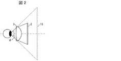
図2はヘッドマウントディスプレイの視野角(FOV)を説明するための模式図である。視野角(FOV、Field Of View)とは、人が画像を見ることができる角度範囲のことを言う。ヘッドマウントディスプレイ(HMD、Head Mount Display)においては、眼の回転角度によってその角度範囲は変化するが、一般的には眼が正面を向いた際に見える範囲、即ち、瞳に光が入ってくる範囲、を言う。図2に示す例では角度θがヘッドマウントディスプレイの視野角に相当する。液晶表示ユニット2に表示される映像に基づく光は接眼レンズ3により屈折されてヘッドマウントディスプレイの装着者の眼に入射する。視野角が広くなればなるほど、液晶表示ユニット2に表示される映像に対応する虚像15が拡大され、良好な眺めが可能になる。 FIG. 2 is a schematic view for explaining the viewing angle (FOV) of the head mounted display. Field of view (FOV, Field Of View) refers to an angular range in which a person can view an image. In a head mount display (HMD), the angle range changes depending on the rotation angle of the eye, but in general, light enters the area that can be seen when the eye faces the front, that is, the pupil Range, say. In the example shown in FIG. 2, the angle θ corresponds to the viewing angle of the head mounted display. The light based on the image displayed on the liquid
広い視野角を得て、眼から十分遠い距離に仮想映像を得るための十分な拡大を確実にするために、この比較例のヘッドマウントディスプレイのコンパクト化は制限される。また、液晶表示ユニット2が目から遠く離れるので、このヘッドマウントディスプレイは、落ちないように使用者の頭に結び付けなければならない。また、このヘッドマウントディスプレイの重心は使用者の前方の遠くにあるので、長い時間眺めていると使用者の顔と首が疲れてくる。 The compactification of the head mounted display of this comparative example is limited in order to obtain a wide viewing angle and to ensure a sufficient enlargement for obtaining a virtual image at a sufficient distance from the eye. Also, since the liquid
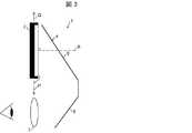
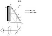
図3は実施形態1に係るヘッドマウントディスプレイ1の模式図である。ヘッドマウントディスプレイ1は、前方に向かって形成された表示面7に映像を表示する液晶表示ユニット2(表示ユニット)と、液晶表示ユニット2の下方に配置された接眼レンズ3と、液晶表示ユニット2の表示面7に表示された映像に基づく光を反射して接眼レンズ3に導くミラーユニット4とを備える。 FIG. 3 is a schematic view of the head mounted display 1 according to the first embodiment. The head mounted display 1 includes a liquid crystal display unit 2 (display unit) for displaying an image on a
ここで、液晶表示ユニット2の下方とは、液晶表示ユニット2に対して図3の矢印Pにより示される側を意味し、液晶表示ユニット2の上方とは、液晶表示ユニット2に対して矢印Qにより示される側を意味する。ヘッドマウントディスプレイ1が使用者に装着されている場合には、液晶表示ユニット2の下方は、液晶表示ユニット2に対して重力の作用する方向側に概ね対応する。接眼レンズ3は、表示ユニット2の表示面7の法線Rに対応する方向から表示ユニット2を見た場合、表示ユニット2と重ならずに表示ユニット2の矢印Pにより示される側に配置される。 Here, the lower side of the liquid
このミラーユニット4が、表示面7に表示された映像に基づく光を反射する第1ミラー5と、第1ミラー5により反射された光を接眼レンズ3に向けて反射する第2ミラー6とを含む。第1ミラー5と第2ミラー6とがV字形状に配置される。V字形状に配置する際に、ミラーは第1ミラー5と第2ミラー6との2枚で配置しても良いし、一体成形した1枚のミラーを配置しても良い。接眼レンズ3は、ヘッドマウントディスプレイ1を装着する使用者の眼の前に配置される。 The
接眼レンズ3は、第2ミラー6により反射された光に基づいて、表示ユニット2の表示面7に表示された映像を映し出すために設けられる。 The
このヘッドマウントディスプレイ1の重心は、使用者の頭の近くに配置される。このため、ヘッドマウントディスプレイ1の装着により使用者の頭と首に生じるトルクが軽減し、ヘッドマウントディスプレイ1が落ちないように頭に結び付けなければならない必要性も低減する。 The center of gravity of the head mounted display 1 is disposed near the head of the user. For this reason, the torque generated on the head and the neck of the user due to the mounting of the head mounted display 1 is reduced, and the need to be tied to the head so that the head mounted display 1 does not fall is also reduced.
液晶表示ユニット2に表示される映像に基づく光は第1ミラー5及び第2ミラー6の2枚のミラーにより反射されるので、接眼レンズ3に入射する光に基づく映像は左右反転しない。 Since the light based on the image displayed on the liquid
接眼レンズ3は、液晶表示ユニット2の上方に配置されてもよい。 The
接眼レンズ3は、公知の曲面レンズであってもよいし、角度が付いた公知の構造的フレネルレンズであってもよいし、1枚以上のレンズを含む公知のレンズ構造を有してもよい。 The
〔実施形態2〕
本発明の実施形態2について、以下に説明する。なお、説明の便宜上、上記実施形態にて説明した部材と同じ機能を有する部材については、同じ符号を付記し、その説明を繰り返さない。Second Embodiment
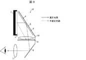
図4は実施形態2に係るヘッドマウントディスプレイ1Aの模式図である。ヘッドマウントディスプレイ1Aは、第1ミラー5の表面に配置された四分の一波長板(QWP、Quarter Wave Plate)8と、四分の一波長板8を通って第1ミラー5により反射された光を透過し、液晶表示ユニット2の表示面7から直接入射された光の透過を防止する偏光板9とを備える。 FIG. 4 is a schematic view of a head mounted
四分の一波長板8は、off axis動作のために最適化された単一の層から構成されていてもよいし、例えば二分の一波長板と二分の一波長板とのとの二つの層から構成されていてもよい。 The quarter-
偏光板9は、液晶表示ユニット2から直接入射する光を遮断するように方向付けられる。 The
液晶表示ユニット2は、スマートフォンであり得る。 The liquid
接眼レンズ3は使用者の各眼に一つずつ設けられ、ヘッドマウントディスプレイ1Aは2個の接眼レンズ3を備える。2個の接眼レンズ3の間に、クロストークを防止するためのシールド部材(図示せず)が設けられる。液晶表示ユニット2は、各眼のための両接眼レンズ3に共通に例えばスマートフォンが1個だけ設けられてもよい。そして、二つの別々の映像が単一の液晶表示ユニット2の表示面7に表示されてもよい。 One
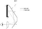
図5は迷光の問題を説明するための模式図である。液晶表示ユニット2を接眼レンズ3の上方に配置し、第1ミラー5及び第2ミラー6を設けると、第1ミラー5及び第2ミラー6により反射されて接眼レンズ3に入射する光(図4に実線矢印で示す適正光路を通る光)の他に、液晶表示ユニット2から直接第2ミラー6に入射して反射されて接眼レンズ3に入射する光(図4に破線矢印で示す不適正光路を通る光)が発生する場合がある。 FIG. 5 is a schematic view for explaining the problem of stray light. When the liquid
実施形態2の図4に示す構成によれば、液晶表示ユニット2から直接第2ミラー6に向かう光が発生しても、当該光は偏光板9により遮光され、接眼レンズ3に当該光が入射することが防止される。 According to the configuration shown in FIG. 4 of the second embodiment, even if light directed from the liquid
図6(a)実施形態2に係る他のヘッドマウントディスプレイ1Bの模式図であり、(b)は実施形態2に係るさらに他のヘッドマウントディスプレイ1Cの模式図である。 6 (a) is a schematic view of another head mounted
図4を参照して前述したヘッドマウントディスプレイ1Aでは、偏光板9は第1ミラー5と第2ミラー6との間に第1ミラー5及び第2ミラー6から離れて配置されていた。しかしながら、本発明はこれに限定されない。図6(a)に示すようにヘッドマウントディスプレイ1Bでは、偏光板9が第2ミラー6の表面に配置されてもよい。そして、図6(b)に示すようにヘッドマウントディスプレイ1Cでは、偏光板9が接眼レンズ3の第2ミラー6側の表面に配置されてもよい。 In the head mounted
〔実施形態3〕
本発明の実施形態3について、以下に説明する。なお、説明の便宜上、上記実施形態にて説明した部材と同じ機能を有する部材については、同じ符号を付記し、その説明を繰り返さない。Third Embodiment
The third embodiment of the present invention will be described below. In addition, about the member which has the same function as the member demonstrated in the said embodiment for convenience of explanation, the same code | symbol is appended, and the description is not repeated.
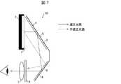
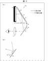
図7は実施形態3に係るヘッドマウントディスプレイ1Dの模式図である。ヘッドマウントディスプレイ1Dでは、二枚の四分の一波長板8(第1四分の一波長板、第2四分の一波長板)が第1ミラー5の表面と第2ミラー6の表面とにそれぞれ配置される。そして、偏光板9が接眼レンズ3の第2ミラー6側の表面に配置される。偏光板9は、第1ミラー5により反射されて、第2ミラー6の表面に配置された四分の一波長板8を通って第2ミラー6により反射された光を透過し、表示面7から直接第2ミラー6に入射されて第2ミラー6により反射された光の透過を防止する。 FIG. 7 is a schematic view of a head mounted
二枚の四分の一波長板8をこのような配置にすると、液晶表示ユニットからミラーユニット4により反射されて接眼レンズ3に向かう光の散乱が最小化される。 Such an arrangement of the two
〔実施形態4〕
本発明の実施形態4について、以下に説明する。なお、説明の便宜上、上記実施形態にて説明した部材と同じ機能を有する部材については、同じ符号を付記し、その説明を繰り返さない。Embodiment 4
The fourth embodiment of the present invention will be described below. In addition, about the member which has the same function as the member demonstrated in the said embodiment for convenience of explanation, the same code | symbol is appended, and the description is not repeated.
図8は実施形態4に係るヘッドマウントディスプレイ1Eの模式図である。ヘッドマウントディスプレイ1Eに設けられる表示ユニット2Eは、液晶表示ユニット以外の任意のタイプの表示ユニットである。例えば、表示ユニット2EはOLED(Organic Light Emitting Diode:有機発光ダイオード)を備えた表示ユニットであり得る。この表示ユニット2Eの表示面7に偏光板9が配置される。第1ミラー5と第2ミラー6との間に他の偏光板9が配置される。 FIG. 8 is a schematic view of a head mounted
第1ミラー5と第2ミラー6との間に配置された他の偏光板9は、四分の一波長板8を通って第1ミラー5により反射された光を透過し、表示面7に配置された偏光板9を通って表示面7から入射された光の透過を防止する。即ち、表示ユニット2Eの表示面7から偏光板9を通って直接第2ミラー6へ向う光は、第1ミラー5と第2ミラー6との間に配置された他の偏光板9により遮光される。 The other
〔実施形態5〕
本発明の実施形態5について、以下に説明する。なお、説明の便宜上、上記実施形態にて説明した部材と同じ機能を有する部材については、同じ符号を付記し、その説明を繰り返さない。Fifth Embodiment
The fifth embodiment of the present invention will be described below. In addition, about the member which has the same function as the member demonstrated in the said embodiment for convenience of explanation, the same code | symbol is appended, and the description is not repeated.
図9は実施形態5に係るヘッドマウントディスプレイ1Fの模式図である。ヘッドマウントディスプレイ1Fでは、図9に示されるように、第1ミラー5と第2ミラー6との間に配置された偏光板9に収差レンズ10が設けられる。この収差レンズ10は、曲面レンズ、自由形状構造のレンズ、又は、フレネル構造のレンズであり得る。収差レンズ10は、偏光板9に接着されてもよいし、偏光板9の上方又は下方に設けられてもよい。このように収差レンズ10を設けることにより、色収差、歪曲収差が補正され、接眼レンズ3を通して視認される映像の歪みが最小化され、映像収差が低減される。 FIG. 9 is a schematic view of a head mounted
〔実施形態6〕
本発明の実施形態6について、以下に説明する。なお、説明の便宜上、上記実施形態にて説明した部材と同じ機能を有する部材については、同じ符号を付記し、その説明を繰り返さない。Sixth Embodiment
The sixth embodiment of the present invention will be described below. In addition, about the member which has the same function as the member demonstrated in the said embodiment for convenience of explanation, the same code | symbol is appended, and the description is not repeated.
図10(a)は実施形態6に係るヘッドマウントディスプレイ1Gの模式図であり、(b)は(a)に示されるA部拡大図である。ヘッドマウントディスプレイ1Gでは、第2ミラー6の表面にフレネル構造11が形成される。このフレネル構造11はプリズム状の形状が同心円状に形成される。このフレネル構造11の形成により、ヘッドマウントディスプレイ1Gの視野角が改善される。このように視野角が広くなると、追加の歪が発生する。この歪は、収差レンズを使用することにより修正することができる。そして、接眼レンズ3の正のパワー(屈折力)において対応する増大が生じる。 Fig.10 (a) is a schematic diagram of the head mounted
〔実施形態7〕
本発明の実施形態7について、以下に説明する。なお、説明の便宜上、上記実施形態にて説明した部材と同じ機能を有する部材については、同じ符号を付記し、その説明を繰り返さない。Seventh Embodiment
Seventh Embodiment A seventh embodiment of the present invention will be described below. In addition, about the member which has the same function as the member demonstrated in the said embodiment for convenience of explanation, the same code | symbol is appended, and the description is not repeated.
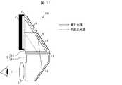
図11は実施形態7に係るヘッドマウントディスプレイ1Hの模式図である。ヘッドマウントディスプレイ1Hでは、液晶表示ユニット2の表示面7を出射して第1ミラー5及び第2ミラー6により反射されて接眼レンズ3に向かう光を透過する透明屈折部材12が設けられる。透明屈折部材12は、液晶表示ユニット2と四分の一波長板8と偏光板9とによって囲まれる第1屈折部13と、偏光板9と第2ミラー6と接眼レンズ3とによって囲まれる第2屈折部14とを含む。この透明屈折部材12は、PMMA(ポリメタクリル酸メチル樹脂(Polymethyl methacrylate))のような透明屈折材用により構成される。透明屈折部材12の屈折率は空気よりも高い。 FIG. 11 is a schematic view of a head mounted
このような透明屈折部材12を用いることで、同一視野角の設計であっても透明屈折部材12中の光の通過領域は空気中の場合よりも一般的に小さくなる。これは高屈折率材料の方が、屈折角が小さくなることによる。これにより、同一サイズのヘッドマウントディスプレイで視野角を拡大する設計が可能となる。 By using such a transparent refracting
第1屈折部13は、液晶表示ユニット2と四分の一波長板8と偏光板9とによって囲まれる領域に適合する形状に形成することができる。第2屈折部14は、偏光板9と第2ミラー6と接眼レンズ3とによって囲まれる領域に適合する形状に形成することができる。 The first refracting
第1屈折部13は、液晶表示ユニット2に接着する態様に形成されてもよいし、液晶表示ユニット2から離れる態様に形成されてもよい。液晶表示ユニット2がヘッドマウントディスプレイ1Hから着脱可能なスマートフォンである場合は、第1屈折部13が液晶表示ユニット2に接着される必要はない。 The first refracting
四分の一波長板8と偏光板9とは、透明屈折部材12に接着されることが、ゴースト映像を低減する観点から好ましい。 The quarter-
光が通過する透明屈折部材12の磨かれた表面に反射防止コーティングが形成されると、やはりゴースト映像が低減され、効率が改善される。 The formation of an antireflective coating on the polished surface of the transparent
接眼レンズ3は、透明屈折部材12の曲面形状の部分であってもよいし、透明屈折部材12に接着される別の部材であってもよい。 The
図12は実施形態7に係る他のヘッドマウントディスプレイ1Iの模式図である。図11を参照して前述したヘッドマウントディスプレイ1Hでは偏光板9が透明屈折部材12の第1屈折部13と第2屈折部14との間に配置されていた。しかしながら本発明はこれに限定されない。透明屈折部材12Iを一体に構成し、偏光板9を接眼レンズ3と透明屈折部材12Iとの間に配置してもよい。また、偏光板9は、接眼レンズ3に対して透明屈折部材12Iと反対側に配置してもよい。 FIG. 12 is a schematic view of another head mounted display 1I according to the seventh embodiment. In the head mounted
また、図10で前述したフレネル構造11を第2ミラー6に形成してもよいし、図7で前述したように2枚目の四分の一波長板8を第2ミラー6に形成してもよい。 Alternatively, the
図13は実施形態7に係るさらに他のヘッドマウントディスプレイ1Jの模式図である。ヘッドマウントディスプレイ1Jでは、収差レンズ10が偏光板9と第1屈折部13との間に配置される。収差レンズ10は第1屈折部13に接着されてもよい。低い接着係数及びフレネル構造が使用されているか、又は、収差レンズ10がブロックに対して著しく異なる屈折率を有していれば、両方のブロックに接着することが可能である。偏光板9は、第1屈折部13と第2屈折部14との間に配置されてもよいし、第1ミラー5の表面上又は第2ミラー6の表面上に配置されてもよいし、接眼レンズ3に設けられてもよい。偏光板9は、第1ミラー5と第2ミラー6との一方又は双方に四分の一波長板8とともに設けられてもよい。 FIG. 13 is a schematic view of still another head mounted
〔まとめ〕
本発明の態様1に係るヘッドマウントディスプレイ1・1A〜1Jは、表示面7に映像を表示する表示ユニット(液晶表示ユニット2・表示ユニット2E)と、前記表示ユニット(液晶表示ユニット2・表示ユニット2E)の表示面7の法線方向から見た場合、前記表示ユニット(液晶表示ユニット2・表示ユニット2E)と重ならずに前記表示ユニット(液晶表示ユニット2・表示ユニット2E)の下方又は上方に配置された接眼レンズ3と、前記表示面7に表示された映像に基づく光を反射して前記接眼レンズ3に導くミラーユニット4とを備えている。[Summary]
The head mounted displays 1 · 1A to 1J according to aspect 1 of the present invention include a display unit (liquid
上記の構成によれば、表示ユニットの表示面に表示された映像に基づく光がミラーユニットにより反射されて、表示ユニットの下方又は上方に配置された接眼レンズに導かれる。このため、表示ユニットと接眼レンズとを保持しながらコンパクト性が改善されたヘッドマウントディスプレイを実現することができる。 According to the above configuration, the light based on the image displayed on the display surface of the display unit is reflected by the mirror unit and is guided to the eyepiece lens disposed below or above the display unit. Therefore, it is possible to realize a head mounted display whose compactness is improved while holding the display unit and the eyepiece.
本発明の態様2に係るヘッドマウントディスプレイ1・1A〜1Jは、上記態様1において、前記ミラーユニット4が、前記映像に基づく光を反射する第1ミラー5と、前記第1ミラー5により反射された光を前記接眼レンズ3に向けて反射する第2ミラー6とを含み、前記第1ミラー5と前記第2ミラー6とがV字形状に配置されてもよい。 In the head mounted
上記の構成によれば、第1ミラーと第2ミラー(6)とがV字形状に配置されることにより、ヘッドマウントディスプレイのコンパクト性がより一層改善される。 According to the above configuration, the compactness of the head mounted display is further improved by arranging the first mirror and the second mirror (6) in a V shape.
本発明の態様3に係るヘッドマウントディスプレイ1A〜1D・1F〜1Jは、上記態様2において、前記表示ユニットが液晶表示ユニット2であり、前記第1ミラー5の表面に配置された四分の一波長板8と、前記四分の一波長板8を通って前記第1ミラー5により反射された光を透過し、前記表示面7から直接入射された光の透過を防止する偏光板9とをさらに備えてもよい。 In the head mounted displays 1A to 1D and 1F to 1J according to
上記の構成によれば、接眼レンズへの迷光の入射を防止することができる。 According to the above configuration, it is possible to prevent stray light from entering the eyepiece.
本発明の態様4に係るヘッドマウントディスプレイ1A〜1D・1F〜1Jは、上記態様3において、前記偏光板9が、前記第1ミラー5と前記第2ミラー6との間と、前記第2ミラー6の表面と、前記接眼レンズ3との何れかに配置されてもよい。 In the head mounted displays 1A to 1D and 1F to 1J according to the fourth aspect of the present invention, in the third aspect, the
上記の構成によれば、接眼レンズへの迷光の入射を防止することができる。 According to the above configuration, it is possible to prevent stray light from entering the eyepiece.
本発明の態様5に係るヘッドマウントディスプレイ1Dは、上記態様2において、前記表示ユニットが液晶表示ユニット2であり、前記第1ミラー5の表面に配置された第1四分の一波長板(四分の一波長板8)と、前記第2ミラー6の表面に配置された第2四分の一波長板(四分の一波長板8)と、前記第2四分の一波長板(四分の一波長板8)を通って前記第2ミラー6により反射された光を透過し、前記表示面7から直接前記第2ミラー6に入射されて前記第2ミラー6により反射された光の透過を防止するために前記接眼レンズ3に配置された偏光板9とをさらに備えてもよい。 In the head mounted
上記の構成によれば、二枚の四分の一波長板の配置により、表示面から第1ミラー、第2ミラーを介して接眼レンズへ向う光の散乱が最小化される。 According to the above configuration, the arrangement of the two quarter-wave plates minimizes the scattering of light from the display surface toward the eyepiece through the first mirror and the second mirror.
本発明の態様6に係るヘッドマウントディスプレイ1Eは、上記態様2において、前記表示ユニット2Eの表示面7に配置された第1偏光板(偏光板9)と、前記第1ミラー5の表面に配置された四分の一波長板8と、前記四分の一波長板8を通って前記第1ミラー5により反射された光を透過し、前記表示面7から前記第1偏光板(偏光板9)を通って入射された光の透過を防止する第2偏光板(偏光板9)とをさらに備えてもよい。 In the head mounted
上記の構成によれば、例えばOLEDを備えた表示ユニットのような液晶表示ユニット以外の任意のタイプの表示ユニットに本発明を適用することができる。 According to the above configuration, the present invention can be applied to any type of display unit other than a liquid crystal display unit such as a display unit having an OLED, for example.
本発明の態様7に係るヘッドマウントディスプレイ1Fは、上記態様2において、前記第1ミラー5と前記第2ミラー6との間に配置された収差レンズ10をさらに備えてもよい。 The head mounted
上記の構成によれば、収差レンズを設けることで、接眼レンズを通して視認される映像の歪みが最小化され、映像収差が低減される。 According to the above configuration, by providing the aberration lens, distortion of an image visually recognized through the eyepiece is minimized, and image aberration is reduced.
本発明の態様8に係るヘッドマウントディスプレイ1Gは、上記態様3において、前記第2ミラー6の表面にフレネル構造11が形成されてもよい。 In the head mounted
上記の構成によれば、ヘッドマウントディスプレイの視野角が改善される。 According to the above configuration, the viewing angle of the head mounted display is improved.
本発明の態様9に係るヘッドマウントディスプレイ1H・1I・1Jは、上記態様3において、前記表示面7を出射して前記第1及び第2ミラー5・6により反射されて前記接眼レンズ3に向かう光を透過する透明屈折部材12をさらに備えてもよい。 The head mounted displays 1H, 1I and 1J according to
上記の構成によれば、ヘッドマウントディスプレイの視野角が改善されるとともに、接眼レンズを通して視認されるゴースト映像が低減される。 According to the above configuration, the viewing angle of the head mounted display is improved, and the ghost image viewed through the eyepiece is reduced.
本発明の態様10に係るヘッドマウントディスプレイ1H・1Jは、上記態様9において、前記偏光板9が、前記第1ミラー5と前記第2ミラー6との間に配置され、前記透明屈折部材12が、前記第1ミラー5と前記偏光板9との間に配置される第1屈折部13と、前記第2ミラー6と前記偏光板9との間に配置される第2屈折部14とを含んでもよい。 In the head mounted
上記の構成によれば、第1ミラーと前記第2ミラーとの間に配置される偏光板が、接眼レンズへの迷光の入射を防止する。 According to said structure, the polarizing plate arrange | positioned between a 1st mirror and a said 2nd mirror prevents the incident of the stray light to an eyepiece.
本発明の態様11に係るヘッドマウントディスプレイ1Jは、上記態様10において、前記第1屈折部13と前記第2屈折部14との間に配置された収差レンズ10をさらに備えてもよい。 The head mounted
上記の構成によれば、収差レンズを設けることで、接眼レンズを通して視認される映像の歪みが最小化され、映像収差が低減される。 According to the above configuration, by providing the aberration lens, distortion of an image visually recognized through the eyepiece is minimized, and image aberration is reduced.
本発明は上述した各実施形態に限定されるものではなく、請求項に示した範囲で種々の変更が可能であり、異なる実施形態にそれぞれ開示された技術的手段を適宜組み合わせて得られる実施形態についても本発明の技術的範囲に含まれる。さらに、各実施形態にそれぞれ開示された技術的手段を組み合わせることにより、新しい技術的特徴を形成することができる。 The present invention is not limited to the above-described embodiments, and various modifications can be made within the scope of the claims, and embodiments obtained by appropriately combining the technical means disclosed in the different embodiments. Is also included in the technical scope of the present invention. Furthermore, new technical features can be formed by combining the technical means disclosed in each embodiment.
1 ヘッドマウントディスプレイ
2 液晶表示ユニット(表示ユニット)
3 接眼レンズ
4 ミラーユニット
5 第1ミラー(ミラーユニット)
6 第2ミラー(ミラーユニット)
7 表示面
8 四分の一波長板(第1四分の一波長板、第2四分の一波長板)
9 偏光板(第1偏光板、第2偏光板)
10 収差レンズ
11 フレネル構造
12 透明屈折部材
13 第1屈折部
14 第2屈折部1 Head mounted
3 eyepiece 4
6 Second mirror (mirror unit)
7
9 Polarizing plate (first polarizing plate, second polarizing plate)
DESCRIPTION OF
Claims (11)
Translated fromJapanese前記表示ユニットの表示面の法線方向から見た場合、前記表示ユニットと重ならずに前記表示ユニットの下方又は上方に配置された接眼レンズと、
前記表示面に表示された映像に基づく光を反射して前記接眼レンズに導くミラーユニットとを備えたことを特徴とするヘッドマウントディスプレイ。A display unit for displaying an image on the display surface;
An eyepiece lens disposed below or above the display unit without overlapping with the display unit when viewed from the normal direction of the display surface of the display unit;
And a mirror unit configured to reflect light based on the image displayed on the display surface and guide the light to the eyepiece.
前記第1ミラーにより反射された光を前記接眼レンズに向けて反射する第2ミラーとを含み、
前記第1ミラーと前記第2ミラーとがV字形状に配置される請求項1に記載のヘッドマウントディスプレイ。A first mirror that reflects light based on the image, the mirror unit;
A second mirror for reflecting light reflected by the first mirror toward the eyepiece;
The head mounted display according to claim 1, wherein the first mirror and the second mirror are arranged in a V shape.
前記第1ミラーの表面に配置された四分の一波長板と、
前記四分の一波長板を通って前記第1ミラーにより反射された光を透過し、前記表示面から直接入射された光の透過を防止する偏光板とをさらに備える請求項2に記載のヘッドマウントディスプレイ。The display unit is a liquid crystal display unit,
A quarter wave plate disposed on the surface of the first mirror;
The head according to claim 2, further comprising: a polarizing plate that transmits the light reflected by the first mirror through the quarter-wave plate and prevents transmission of light directly incident from the display surface. Mount display.
前記第1ミラーの表面に配置された第1四分の一波長板と、
前記第2ミラーの表面に配置された第2四分の一波長板と、
前記第2四分の一波長板を通って前記第2ミラーにより反射された光を透過し、前記表示面から直接前記第2ミラーに入射されて前記第2ミラーにより反射された光の透過を防止するために前記接眼レンズに配置された偏光板とをさらに備える請求項2に記載のヘッドマウントディスプレイ。The display unit is a liquid crystal display unit,
A first quarter wave plate disposed on the surface of the first mirror;
A second quarter wave plate disposed on the surface of the second mirror;
The light reflected by the second mirror is transmitted through the second quarter-wave plate, transmitted directly from the display surface to the second mirror, and transmitted by the second mirror. 3. The head mounted display according to claim 2, further comprising: a polarizing plate disposed on the eyepiece lens to prevent the light.
前記第1ミラーの表面に配置された四分の一波長板と、
前記四分の一波長板を通って前記第1ミラーにより反射された光を透過し、前記表示面から前記第1偏光板を通って入射された光の透過を防止する第2偏光板とをさらに備える請求項2に記載のヘッドマウントディスプレイ。A first polarizing plate disposed on the display surface of the display unit;
A quarter wave plate disposed on the surface of the first mirror;
A second polarizing plate for transmitting light reflected by the first mirror through the quarter-wave plate and preventing transmission of light incident from the display surface through the first polarizing plate; The head mounted display according to claim 2, further comprising:
請求項2に記載のヘッドマウントディスプレイ。The head mounted display according to claim 2, further comprising an aberration lens disposed between the first mirror and the second mirror.
前記透明屈折部材が、前記第1ミラーと前記偏光板との間に配置される第1屈折部と、
前記第2ミラーと前記偏光板との間に配置される第2屈折部とを含む請求項9に記載のヘッドマウントディスプレイ。The polarizing plate is disposed between the first mirror and the second mirror,
A first refracting portion in which the transparent refracting member is disposed between the first mirror and the polarizing plate;
The head mounted display according to claim 9, further comprising: a second refracting portion disposed between the second mirror and the polarizing plate.
請求項10に記載のヘッドマウントディスプレイ。The head mounted display according to claim 10, further comprising an aberration lens disposed between the first refracting portion and the second refracting portion.
Priority Applications (3)
| Application Number | Priority Date | Filing Date | Title |
|---|---|---|---|
| JP2017250225AJP2019117237A (en) | 2017-12-26 | 2017-12-26 | Head-mounted display |
| US16/192,701US20190196194A1 (en) | 2017-12-26 | 2018-11-15 | Head-mounted display |
| CN201811368866.2ACN109960037A (en) | 2017-12-26 | 2018-11-16 | head mounted display |
Applications Claiming Priority (1)
| Application Number | Priority Date | Filing Date | Title |
|---|---|---|---|
| JP2017250225AJP2019117237A (en) | 2017-12-26 | 2017-12-26 | Head-mounted display |
Publications (1)
| Publication Number | Publication Date |
|---|---|
| JP2019117237Atrue JP2019117237A (en) | 2019-07-18 |
Family
ID=66951065
Family Applications (1)
| Application Number | Title | Priority Date | Filing Date |
|---|---|---|---|
| JP2017250225APendingJP2019117237A (en) | 2017-12-26 | 2017-12-26 | Head-mounted display |
Country Status (3)
| Country | Link |
|---|---|
| US (1) | US20190196194A1 (en) |
| JP (1) | JP2019117237A (en) |
| CN (1) | CN109960037A (en) |
Cited By (1)
| Publication number | Priority date | Publication date | Assignee | Title |
|---|---|---|---|---|
| JPWO2021200428A1 (en)* | 2020-04-01 | 2021-10-07 |
Families Citing this family (1)
| Publication number | Priority date | Publication date | Assignee | Title |
|---|---|---|---|---|
| US11892761B2 (en) | 2019-12-19 | 2024-02-06 | Lumus Ltd. | Image projector using a phase image generator |
Family Cites Families (10)
| Publication number | Priority date | Publication date | Assignee | Title |
|---|---|---|---|---|
| JP3697919B2 (en)* | 1998-12-18 | 2005-09-21 | コニカミノルタホールディングス株式会社 | Video display device using reflective display element |
| US7158096B1 (en)* | 1999-06-21 | 2007-01-02 | The Microoptical Corporation | Compact, head-mountable display device with suspended eyepiece assembly |
| US9519092B1 (en)* | 2012-03-21 | 2016-12-13 | Google Inc. | Display method |
| CN103869467A (en)* | 2012-12-17 | 2014-06-18 | 联想(北京)有限公司 | Display device and wearable spectacle equipment |
| US9063331B2 (en)* | 2013-02-26 | 2015-06-23 | Microsoft Technology Licensing, Llc | Optical system for near-eye display |
| CN105068251A (en)* | 2015-09-01 | 2015-11-18 | 上海科沁机电有限公司 | Embedded 3D head mount display |
| US10473933B2 (en)* | 2016-02-19 | 2019-11-12 | Microsoft Technology Licensing, Llc | Waveguide pupil relay |
| CN106842579A (en)* | 2017-03-29 | 2017-06-13 | 核桃智能科技(常州)有限公司 | A kind of eyepiece for near-to-eye optical system |
| CN107329271A (en)* | 2017-08-26 | 2017-11-07 | 核桃智能科技(常州)有限公司 | A kind of wear-type near-eye display device |
| KR102568792B1 (en)* | 2017-12-04 | 2023-08-21 | 삼성전자주식회사 | Multi-image display apparatus including diffractive optical element |
- 2017
- 2017-12-26JPJP2017250225Apatent/JP2019117237A/enactivePending
- 2018
- 2018-11-15USUS16/192,701patent/US20190196194A1/ennot_activeAbandoned
- 2018-11-16CNCN201811368866.2Apatent/CN109960037A/enactivePending
Cited By (4)
| Publication number | Priority date | Publication date | Assignee | Title |
|---|---|---|---|---|
| JPWO2021200428A1 (en)* | 2020-04-01 | 2021-10-07 | ||
| JP7427077B2 (en) | 2020-04-01 | 2024-02-02 | 富士フイルム株式会社 | Optical elements, image display units and head-mounted displays |
| US12032167B2 (en) | 2020-04-01 | 2024-07-09 | Fujifilm Corporation | Optical element, image display unit, and head-mounted display |
| US12242072B2 (en) | 2020-04-01 | 2025-03-04 | Fujifilm Corporation | Optical element, image display unit, and head-mounted display |
Also Published As
| Publication number | Publication date |
|---|---|
| CN109960037A (en) | 2019-07-02 |
| US20190196194A1 (en) | 2019-06-27 |
Similar Documents
| Publication | Publication Date | Title |
|---|---|---|
| JP7131145B2 (en) | head mounted display | |
| US9740013B2 (en) | Collimating optical device and system | |
| US8767305B2 (en) | Method and apparatus for a near-to-eye display | |
| US8000020B2 (en) | Substrate-guided imaging lens | |
| CN108501722B (en) | Vehicle-mounted display system | |
| US10527863B2 (en) | Compact head-mounted display system | |
| JP2017058400A (en) | Image display device | |
| JP2019117237A (en) | Head-mounted display | |
| JP2018066799A (en) | Image display device and optical see-through display | |
| US20250004276A1 (en) | Virtual image display device and optical unit | |
| US20250138321A1 (en) | Virtual-image display device and optical unit | |
| US20250004278A1 (en) | Virtual image display device and optical unit |