JP2019113815A - Electronic apparatus, luminance control method and program - Google Patents
Electronic apparatus, luminance control method and programDownload PDFInfo
- Publication number
- JP2019113815A JP2019113815AJP2018051324AJP2018051324AJP2019113815AJP 2019113815 AJP2019113815 AJP 2019113815AJP 2018051324 AJP2018051324 AJP 2018051324AJP 2018051324 AJP2018051324 AJP 2018051324AJP 2019113815 AJP2019113815 AJP 2019113815A
- Authority
- JP
- Japan
- Prior art keywords
- unit
- brightness
- display unit
- display
- determines
- Prior art date
- Legal status (The legal status is an assumption and is not a legal conclusion. Google has not performed a legal analysis and makes no representation as to the accuracy of the status listed.)
- Granted
Links
Images


Classifications
- G—PHYSICS
- G06—COMPUTING OR CALCULATING; COUNTING
- G06F—ELECTRIC DIGITAL DATA PROCESSING
- G06F1/00—Details not covered by groups G06F3/00 - G06F13/00 and G06F21/00
- G06F1/16—Constructional details or arrangements
- G06F1/1613—Constructional details or arrangements for portable computers
- G06F1/163—Wearable computers, e.g. on a belt
- G—PHYSICS
- G04—HOROLOGY
- G04G—ELECTRONIC TIME-PIECES
- G04G21/00—Input or output devices integrated in time-pieces
- G04G21/02—Detectors of external physical values, e.g. temperature
- G—PHYSICS
- G04—HOROLOGY
- G04G—ELECTRONIC TIME-PIECES
- G04G21/00—Input or output devices integrated in time-pieces
- G04G21/02—Detectors of external physical values, e.g. temperature
- G04G21/025—Detectors of external physical values, e.g. temperature for measuring physiological data
- G—PHYSICS
- G04—HOROLOGY
- G04G—ELECTRONIC TIME-PIECES
- G04G21/00—Input or output devices integrated in time-pieces
- G04G21/04—Input or output devices integrated in time-pieces using radio waves
- G—PHYSICS
- G04—HOROLOGY
- G04G—ELECTRONIC TIME-PIECES
- G04G9/00—Visual time or date indication means
- G04G9/0017—Visual time or date indication means in which the light emitting display elements may be activated at will or are controlled in accordance with the ambient light
- G—PHYSICS
- G04—HOROLOGY
- G04R—RADIO-CONTROLLED TIME-PIECES
- G04R20/00—Setting the time according to the time information carried or implied by the radio signal
- G04R20/02—Setting the time according to the time information carried or implied by the radio signal the radio signal being sent by a satellite, e.g. GPS
- G—PHYSICS
- G06—COMPUTING OR CALCULATING; COUNTING
- G06F—ELECTRIC DIGITAL DATA PROCESSING
- G06F1/00—Details not covered by groups G06F3/00 - G06F13/00 and G06F21/00
- G06F1/16—Constructional details or arrangements
- G06F1/1613—Constructional details or arrangements for portable computers
- G06F1/1633—Constructional details or arrangements of portable computers not specific to the type of enclosures covered by groups G06F1/1615 - G06F1/1626
- G06F1/1637—Details related to the display arrangement, including those related to the mounting of the display in the housing
- G—PHYSICS
- G06—COMPUTING OR CALCULATING; COUNTING
- G06F—ELECTRIC DIGITAL DATA PROCESSING
- G06F1/00—Details not covered by groups G06F3/00 - G06F13/00 and G06F21/00
- G06F1/16—Constructional details or arrangements
- G06F1/1613—Constructional details or arrangements for portable computers
- G06F1/1633—Constructional details or arrangements of portable computers not specific to the type of enclosures covered by groups G06F1/1615 - G06F1/1626
- G06F1/1684—Constructional details or arrangements related to integrated I/O peripherals not covered by groups G06F1/1635 - G06F1/1675
- G—PHYSICS
- G06—COMPUTING OR CALCULATING; COUNTING
- G06F—ELECTRIC DIGITAL DATA PROCESSING
- G06F1/00—Details not covered by groups G06F3/00 - G06F13/00 and G06F21/00
- G06F1/26—Power supply means, e.g. regulation thereof
- G06F1/32—Means for saving power
- G06F1/3203—Power management, i.e. event-based initiation of a power-saving mode
- G06F1/3234—Power saving characterised by the action undertaken
- G06F1/325—Power saving in peripheral device
- G06F1/3265—Power saving in display device
- G—PHYSICS
- G06—COMPUTING OR CALCULATING; COUNTING
- G06F—ELECTRIC DIGITAL DATA PROCESSING
- G06F3/00—Input arrangements for transferring data to be processed into a form capable of being handled by the computer; Output arrangements for transferring data from processing unit to output unit, e.g. interface arrangements
- G06F3/01—Input arrangements or combined input and output arrangements for interaction between user and computer
- G06F3/03—Arrangements for converting the position or the displacement of a member into a coded form
- G06F3/041—Digitisers, e.g. for touch screens or touch pads, characterised by the transducing means
- G06F3/0416—Control or interface arrangements specially adapted for digitisers
- G—PHYSICS
- G09—EDUCATION; CRYPTOGRAPHY; DISPLAY; ADVERTISING; SEALS
- G09G—ARRANGEMENTS OR CIRCUITS FOR CONTROL OF INDICATING DEVICES USING STATIC MEANS TO PRESENT VARIABLE INFORMATION
- G09G3/00—Control arrangements or circuits, of interest only in connection with visual indicators other than cathode-ray tubes
- G09G3/20—Control arrangements or circuits, of interest only in connection with visual indicators other than cathode-ray tubes for presentation of an assembly of a number of characters, e.g. a page, by composing the assembly by combination of individual elements arranged in a matrix no fixed position being assigned to or needed to be assigned to the individual characters or partial characters
- G09G3/22—Control arrangements or circuits, of interest only in connection with visual indicators other than cathode-ray tubes for presentation of an assembly of a number of characters, e.g. a page, by composing the assembly by combination of individual elements arranged in a matrix no fixed position being assigned to or needed to be assigned to the individual characters or partial characters using controlled light sources
- G09G3/30—Control arrangements or circuits, of interest only in connection with visual indicators other than cathode-ray tubes for presentation of an assembly of a number of characters, e.g. a page, by composing the assembly by combination of individual elements arranged in a matrix no fixed position being assigned to or needed to be assigned to the individual characters or partial characters using controlled light sources using electroluminescent panels
- G09G3/32—Control arrangements or circuits, of interest only in connection with visual indicators other than cathode-ray tubes for presentation of an assembly of a number of characters, e.g. a page, by composing the assembly by combination of individual elements arranged in a matrix no fixed position being assigned to or needed to be assigned to the individual characters or partial characters using controlled light sources using electroluminescent panels semiconductive, e.g. using light-emitting diodes [LED]
- G09G3/3208—Control arrangements or circuits, of interest only in connection with visual indicators other than cathode-ray tubes for presentation of an assembly of a number of characters, e.g. a page, by composing the assembly by combination of individual elements arranged in a matrix no fixed position being assigned to or needed to be assigned to the individual characters or partial characters using controlled light sources using electroluminescent panels semiconductive, e.g. using light-emitting diodes [LED] organic, e.g. using organic light-emitting diodes [OLED]
- G—PHYSICS
- G09—EDUCATION; CRYPTOGRAPHY; DISPLAY; ADVERTISING; SEALS
- G09G—ARRANGEMENTS OR CIRCUITS FOR CONTROL OF INDICATING DEVICES USING STATIC MEANS TO PRESENT VARIABLE INFORMATION
- G09G2320/00—Control of display operating conditions
- G09G2320/06—Adjustment of display parameters
- G09G2320/0626—Adjustment of display parameters for control of overall brightness
- G—PHYSICS
- G09—EDUCATION; CRYPTOGRAPHY; DISPLAY; ADVERTISING; SEALS
- G09G—ARRANGEMENTS OR CIRCUITS FOR CONTROL OF INDICATING DEVICES USING STATIC MEANS TO PRESENT VARIABLE INFORMATION
- G09G2330/00—Aspects of power supply; Aspects of display protection and defect management
- G09G2330/02—Details of power systems and of start or stop of display operation
- G09G2330/021—Power management, e.g. power saving
- G—PHYSICS
- G09—EDUCATION; CRYPTOGRAPHY; DISPLAY; ADVERTISING; SEALS
- G09G—ARRANGEMENTS OR CIRCUITS FOR CONTROL OF INDICATING DEVICES USING STATIC MEANS TO PRESENT VARIABLE INFORMATION
- G09G2354/00—Aspects of interface with display user
- G—PHYSICS
- G09—EDUCATION; CRYPTOGRAPHY; DISPLAY; ADVERTISING; SEALS
- G09G—ARRANGEMENTS OR CIRCUITS FOR CONTROL OF INDICATING DEVICES USING STATIC MEANS TO PRESENT VARIABLE INFORMATION
- G09G2360/00—Aspects of the architecture of display systems
- G09G2360/14—Detecting light within display terminals, e.g. using a single or a plurality of photosensors
- G09G2360/144—Detecting light within display terminals, e.g. using a single or a plurality of photosensors the light being ambient light
- G—PHYSICS
- G09—EDUCATION; CRYPTOGRAPHY; DISPLAY; ADVERTISING; SEALS
- G09G—ARRANGEMENTS OR CIRCUITS FOR CONTROL OF INDICATING DEVICES USING STATIC MEANS TO PRESENT VARIABLE INFORMATION
- G09G5/00—Control arrangements or circuits for visual indicators common to cathode-ray tube indicators and other visual indicators
- G09G5/10—Intensity circuits
- Y—GENERAL TAGGING OF NEW TECHNOLOGICAL DEVELOPMENTS; GENERAL TAGGING OF CROSS-SECTIONAL TECHNOLOGIES SPANNING OVER SEVERAL SECTIONS OF THE IPC; TECHNICAL SUBJECTS COVERED BY FORMER USPC CROSS-REFERENCE ART COLLECTIONS [XRACs] AND DIGESTS
- Y02—TECHNOLOGIES OR APPLICATIONS FOR MITIGATION OR ADAPTATION AGAINST CLIMATE CHANGE
- Y02D—CLIMATE CHANGE MITIGATION TECHNOLOGIES IN INFORMATION AND COMMUNICATION TECHNOLOGIES [ICT], I.E. INFORMATION AND COMMUNICATION TECHNOLOGIES AIMING AT THE REDUCTION OF THEIR OWN ENERGY USE
- Y02D10/00—Energy efficient computing, e.g. low power processors, power management or thermal management
Landscapes
- Engineering & Computer Science (AREA)
- Theoretical Computer Science (AREA)
- Physics & Mathematics (AREA)
- General Physics & Mathematics (AREA)
- Computer Hardware Design (AREA)
- General Engineering & Computer Science (AREA)
- Human Computer Interaction (AREA)
- Microelectronics & Electronic Packaging (AREA)
- Radar, Positioning & Navigation (AREA)
- Physiology (AREA)
- Biophysics (AREA)
- Life Sciences & Earth Sciences (AREA)
- Health & Medical Sciences (AREA)
- Remote Sensing (AREA)
- General Health & Medical Sciences (AREA)
- Liquid Crystal Display Device Control (AREA)
- Control Of Indicators Other Than Cathode Ray Tubes (AREA)
- Controls And Circuits For Display Device (AREA)
- Devices For Indicating Variable Information By Combining Individual Elements (AREA)
- Liquid Crystal (AREA)
- Control Of El Displays (AREA)
- Electroluminescent Light Sources (AREA)
Abstract
Translated fromJapaneseDescription
Translated fromJapanese本発明は、電子機器、輝度制御方法及びプログラムに関する。 The present invention relates to an electronic device, a brightness control method, and a program.
従来、表示部の光照射面の裏側に照度センサを置き、その照度センサが検出した外光量によって、表示部の光量調整を行なう技術が知られている(特許文献1参照)。 Conventionally, a technique is known in which an illuminance sensor is placed on the back side of the light irradiation surface of the display unit, and the light amount adjustment of the display unit is adjusted by the external light amount detected by the illuminance sensor (see Patent Document 1).
しかしながら、上記のような構成において、表示部が何らかの障害物によって一時的に覆われると、外光に変化が無いにもかかわらず、照度センサへ入射する外光量は一時的に低減する。このときの照度センサは正確に外光を検出することができず、表示部の輝度調整を適切に出来ない場合があった。 However, in the configuration as described above, when the display unit is temporarily covered by any obstacle, the amount of external light incident on the illuminance sensor is temporarily reduced although there is no change in the external light. The illuminance sensor at this time can not accurately detect the outside light, and the luminance adjustment of the display unit may not be properly adjusted.
本発明は、このような状況に鑑みてなされたものであり、表示部の裏側に照度センサを配置されてなる電子機器において、適切な輝度調整を行うことができる電子機器を提供することを目的とする。 The present invention has been made in view of such a situation, and it is an object of the present invention to provide an electronic device capable of performing appropriate luminance adjustment in an electronic device in which an illuminance sensor is disposed on the back side of a display unit. I assume.
上記目的を達成するため、本発明の一態様の電子機器は、
表示部と、
前記表示部の表示面の背面側に配置された光検出部と、
前記光検出部によって検出された光に関する情報に基づいて、前記表示部の輝度を制御する輝度制御部と、
前記光検出部が検出する光に関する情報の確度を判定する判定部と、を備え、
前記輝度制御部は、前記判定部によって前記光に関する情報の確度が所定値以上であると判定された場合に、前記表示部の輝度の制御をし、
前記輝度制御部は、前記判定部によって前記光に関する情報の確度が所定値未満であると判定された場合に、前記表示部の輝度の制御を抑制する、
ことを特徴とする。In order to achieve the above object, an electronic device of one embodiment of the present invention is
A display unit,
A light detection unit disposed on the back side of the display surface of the display unit;
A brightness control unit configured to control the brightness of the display unit based on information on light detected by the light detection unit;
A determination unit that determines the accuracy of information on light detected by the light detection unit;
The luminance control unit controls the luminance of the display unit when the determination unit determines that the accuracy of the information related to the light is equal to or greater than a predetermined value.
The brightness control unit suppresses control of the brightness of the display unit when the determination unit determines that the accuracy of the information related to the light is less than a predetermined value.
It is characterized by
本発明によれば、表示部の裏側に照度センサを配置されてなる電子機器において、適切な輝度調整を行うことができる電子機器を提供することができる。 According to the present invention, it is possible to provide an electronic device capable of performing appropriate luminance adjustment in an electronic device in which an illuminance sensor is disposed on the back side of a display unit.
本発明の電子機器は、表示部と、照度センサと、輝度制御部と、を備えている。照度センサは、表示部の表示面の背面側に配置されている。輝度制御部は、照度センサによって検出された光に関する情報と、この光に関する情報の確からしさの度合いを示す確度とに基づいて、表示部の輝度を制御する。 The electronic device of the present invention includes a display unit, an illuminance sensor, and a luminance control unit. The illuminance sensor is disposed on the back side of the display surface of the display unit. The brightness control unit controls the brightness of the display unit based on the information on the light detected by the illuminance sensor and the accuracy indicating the degree of certainty of the information on the light.
第1の実施形態では、照度センサによって検出された照度と、表示部のタッチパネルの操作の有無に応じて判定された確度とに基づいて輝度が制御される。例えば、輝度制御部は、タッチパネルの操作が行われていない場合、確度が所定値以上と判定され、照度センサによって検出された照度に基づいて輝度の制御が行われる。一方で、例えば、輝度制御部は、タッチパネルの操作が行われた場合、確度が所定値未満と判定され、照度センサによって検出された照度に基づいた輝度の制御を抑制する。即ち、確度が所定値未満と判定された場合、輝度制御部は輝度の制御を行わない。又は、輝度制御部は、確度が所定値未満と判定された場合、タッチパネルの操作によって生じる照度の変化量(減量)を推測し、その変化量を考慮した輝度の制御をする。
第2の実施形態では、照度センサによって検出された照度と、液晶表示画面の状態に応じて判定された確度とに基づいて輝度が制御される。例えば、液晶表示画面が透過状態にある場合、確度が所定値以上と判定され、照度センサによって検出された照度に基づいて輝度の制御が行われる。一方で、例えば、輝度制御部は、液晶表示画面が透過状態にない場合、確度が所定値未満と判定され、照度センサによって検出された照度に基づいた輝度の制御を抑制する。即ち、確度が所定値未満と判定された場合、輝度制御部は輝度の制御を行わない。又は、輝度制御部は、確度が所定値未満と判定された場合、液晶表示画面が透過状態にないことによって生じる照度の変化量(減量)を推測し、その変化量を考慮した輝度の制御をする。
このように、各実施形態における輝度制御部は、照度センサが検出する、光に関する情報の確度が所定値以上である場合に、表示部の輝度を制御する。即ち、照度センサ29によって検出された光量等の確度が判定され、確度が高いと判定された場合、表示部の輝度が調整される。また、確度が低いと判定された場合、高いと判定された場合と比べて、表示部の輝度の制御は抑制される。これにより適切な輝度調整が行われる。In the first embodiment, the luminance is controlled based on the illuminance detected by the illuminance sensor and the accuracy determined according to the presence or absence of the operation on the touch panel of the display unit. For example, when the operation of the touch panel is not performed, the luminance control unit determines that the accuracy is equal to or higher than a predetermined value, and the luminance control is performed based on the illuminance detected by the illuminance sensor. On the other hand, for example, when the touch panel is operated, the brightness control unit determines that the accuracy is less than the predetermined value, and suppresses the control of the brightness based on the illuminance detected by the illuminance sensor. That is, when it is determined that the accuracy is less than the predetermined value, the brightness control unit does not control the brightness. Alternatively, when it is determined that the accuracy is less than the predetermined value, the brightness control unit estimates the change amount (loss) of the illuminance caused by the operation of the touch panel, and controls the brightness in consideration of the change amount.
In the second embodiment, the luminance is controlled based on the illuminance detected by the illuminance sensor and the accuracy determined according to the state of the liquid crystal display screen. For example, when the liquid crystal display screen is in the transmission state, the accuracy is determined to be equal to or higher than the predetermined value, and the control of the luminance is performed based on the illuminance detected by the illuminance sensor. On the other hand, for example, when the liquid crystal display screen is not in the transmission state, the luminance control unit determines that the accuracy is less than the predetermined value, and suppresses the control of the luminance based on the illuminance detected by the illuminance sensor. That is, when it is determined that the accuracy is less than the predetermined value, the brightness control unit does not control the brightness. Alternatively, when it is determined that the accuracy is less than the predetermined value, the brightness control unit estimates a variation (loss) in illuminance caused by the liquid crystal display screen not in the transmission state, and controls the brightness in consideration of the variation. Do.
As described above, the luminance control unit in each embodiment controls the luminance of the display unit when the accuracy of the information related to light detected by the illuminance sensor is equal to or more than the predetermined value. That is, the accuracy of the light amount detected by the
以下、本発明の実施形態について、図面を用いて説明する。
[構成]
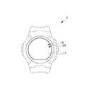
図1は、本発明の第1実施形態である電子機器1の概略図である。
図1に示すように、本実施形態の電子機器1は、腕時計型の装置(スマートウォッチ等)として構成されている。また、電子機器1は、第1表示部18及び第2表示部24(後述)を備えており、第1表示部18の上に第2表示部24が積層されている。さらに、第2表示部24の上には、後述するタッチパネル17が設けられている。このため、電子機器1においては、第1表示部18の表示に第2表示部24の表示を重ね合わせて表示することが可能であると共に、表示内容にタッチ操作することが可能となっている。Hereinafter, embodiments of the present invention will be described using the drawings.
[Constitution]
FIG. 1 is a schematic view of an electronic device 1 according to a first embodiment of the present invention.
As shown in FIG. 1, the electronic device 1 of the present embodiment is configured as a watch-type device (smart watch or the like). The electronic device 1 further includes a
図2は、電子機器1のハードウェア構成を示すブロック図である。
図2に示すように、電子機器1は、CPU(Central Processin Unit)11と、ROM(Read Only Memory)12と、RAM(Random Access Memory)13と、記憶部14と、RTC(Real Time Clock)部15と、ドライブ16と、タッチパネル17と、第1表示部18と、第1入力部19と、ブルートゥース(登録商標)用アンテナ20と、ブルートゥース(登録商標)モジュール21と、無線LAN(Local Area Network)アンテナ22と、無線LANモジュール23と、第2表示部24と、脈拍センサ25と、地磁気センサ26と、加速度センサ27と、ジャイロセンサ28と、照度センサ29と、第2入力部30と、GPS(Global Positioning System)アンテナ31と、GPSモジュール32と、を備えている。FIG. 2 is a block diagram showing the hardware configuration of the electronic device 1.
As shown in FIG. 2, the electronic device 1 includes a central process unit (CPU) 11, a read only memory (ROM) 12, a random access memory (RAM) 13, a
CPU11は、第1CPU11Aと、第2CPU11Bとによって構成される。
第1CPU11Aは、各種演算処理を行い、OSの処理を実行することにより、電子機器1におけるスマートフォンに類する機能を制御する。本実施形態において、第1CPU11Aは、ブルートゥース(登録商標)モジュール21あるいは無線LANモジュール23を介して受信した電子メールの着信や気象情報に関するメッセージ等を第1表示部18に表示させたり、タッチパネル17を介して入力される操作を受け付けたりする。また、第1CPU11Aは、第1入力部19を介して入力される音声を認識したり、その他、スマートフォンに類する機能として実装された各種機能に係る処理を行ったりする。
また、本実施形態において、第1CPU11Aは、RTC部15から所定タイミングで時刻信号を取得する。The CPU 11 is configured of a
The first CPU 11 </ b> A performs various types of arithmetic processing, and controls the function similar to the smartphone in the electronic device 1 by executing the processing of the OS. In the present embodiment, the
Further, in the present embodiment, the
第2CPU11Bは、特定のプログラムの処理を実行することにより、第2表示部24に対する表示の指示を行ったり、各種センサの検出結果を取得したり、その他、腕時計の機能として実装された各種機能に係る処理を行ったりする。本実施形態において、第2CPU11Bは、第1CPU11Aから入力された時刻信号を基準として、時刻を計算したり、時刻、曜日あるいは日付等を第2表示部24に表示させたりする。第2CPU11Bが実行する特定のプログラムの処理(時刻の計算等)は、第1CPU11Aが実行するOSの処理に比べて単純な動作であることから処理負荷が小さく、低消費電力で実行可能である。また、そのため、第2CPU11Bに要求されるハードウェアのスペックは、第1CPU11Aに比べて低いもので足りる。 The
ROM12は、第1CPU11A及び第2CPU11Bそれぞれからデータの読み出しが可能であり、第1CPU11A及び第2CPU11Bが実行する種々のプログラムや初期設定データを格納する。例えば、ROM12は、第1CPU11Aが実行するOSのプログラムやOSの管理下で実行される各種プログラム、あるいは、第2CPU11Bが実行する特定のプログラム(ここでは、腕時計の機能を実現する組み込み用プログラム)のプログラムを格納する。 The
RAM13は、第1CPU11A及び第2CPU11Bそれぞれからデータの読み出し及び書き込みが可能であり、第1CPU11A及び第2CPU11Bに作業用のメモリ空間を提供し、作業用の一時データを記憶する。例えば、RAM13は、第1CPU11AがOSを実行する際のシステム領域やワークエリアを提供したり、第2CPU11Bが特定のプログラムを実行する際の記憶領域を提供したりする。 The
記憶部14は、第1CPU11A及び第2CPU11Bそれぞれからデータの読み出し及び書き込みが可能な不揮発性のメモリであり、例えば、フラッシュメモリやEEPROM(Electrically Erasable and Programmable Read Only Memory)である。記憶部14には、スマートフォンに類する各種機能や腕時計の機能等において生成された各種データ(各種設定内容のデータ等)が記憶される。 The
ドライブ16には、磁気ディスク、光ディスク、光磁気ディスク、あるいは半導体メモリ等よりなる、リムーバブルメディア41が適宜装着される。リムーバブルメディア41は、各種センサによって検出されたデータ等の各種データを記憶することができる。
タッチパネル17は、第2表示部24の表示画面上に設けられた静電容量方式または抵抗膜式等のタッチパネルである。タッチパネル17は、操作面に対するユーザのタッチ操作位置と操作内容とを検出して当該操作に応じた信号を発生させて、入力信号として第1CPU11Aに出力する。A
The
第1表示部18は、有機ELディスプレイ(Organic Light Emitting Diode)によって構成され、第1CPU11Aの制御に従って、各種情報を表示画面に表示する。
第1入力部19は、音声を電気信号に変換するマイクを備え、入力された音声(操作のための音声コマンド等)を示す信号を第1CPU11Aに出力する。The
The
ブルートゥース(登録商標)用アンテナ20は、ブルートゥース(登録商標)の規格に基づく電磁波を送受信するアンテナであり、例えばモノポールアンテナ等によって構成される。ブルートゥース(登録商標)用アンテナ20は、ブルートゥース(登録商標)モジュール21から入力された無線通信の電気信号を電磁波として送信したり、受信した電磁波を電気信号に変換してブルートゥース(登録商標)モジュール21に出力したりする。
ブルートゥース(登録商標)モジュール21は、第1CPU11Aの指示に従って、ブルートゥース(登録商標)用アンテナ20を介して他の装置に信号を送信する。また、ブルートゥース(登録商標)モジュール21は、他の装置から送信された信号を受信し、受信した信号が示す情報を第1CPU11Aに出力する。The Bluetooth (registered trademark)
The Bluetooth (registered trademark)
無線LANアンテナ22は、無線LANモジュール23によって利用される無線通信に対応した周波数の電波を受信可能なアンテナであり、例えばループアンテナやロッドアンテナによって構成される。無線LANアンテナ22は、無線LANモジュール23から入力された無線通信の電気信号を電磁波として送信したり、受信した電磁波を電気信号に変換して無線LANモジュール23に出力したりする。
無線LANモジュール23は、第1CPU11Aの指示に従って、無線LANアンテナ22を介して他の装置に信号を送信する。また、無線LANモジュール23は、他の装置から送信された信号を受信し、受信した信号が示す情報を第1CPU11Aに出力する。The
The
第2表示部24は、部分的にまたは全体的に光を透過可能なPN(Polymer Network)液晶ディスプレイから構成され、第2CPU11Bの制御に従って、各種情報を表示画面に表示(ここではセグメント表示)する。
本実施形態において、第2表示部24であるPN液晶ディスプレイは、図3Bに示すように、上述した第1表示部18である有機ELディスプレイの表示画面上に積層されている。このPN液晶ディスプレイは、電位が掛けられていない部位では液晶分子が不規則に並び、光を反射するようになっている。つまり、この電位が掛けられていない部位において、PN液晶ディスプレイによる表示がなされることとなる。一方、電位が掛けられた部位では、液晶分子が表示画面に対して垂直に整列するので、光を透過可能となっている。つまり、この電位が掛けられた部位では、上述の有機ELディスプレイからの光を透過可能となるので、当該PN液晶ディスプレイを介して当該有機ELディスプレイによる表示を視認することができる。即ち、電子機器1の表示領域では、第1表示部18による表示に第2表示部24による表示を重ね合わせた状態で表示することができるようになっている。
このように、液晶分子の整列/不整列を引き起こす機能によって、光の透過が阻害される。この機能に因んで、本実施形態におけるPN液晶ディスプレイの構成を「液晶シャッタ」と称する。また、液晶分子によって光が反射され得る状態を「液晶シャッタの閉状態」と称し、液晶分子によって光が透過する状態を「液晶シャッタの開状態」と称する。The
In the present embodiment, as shown in FIG. 3B, the PN liquid crystal display as the
Thus, the function of causing alignment / misalignment of liquid crystal molecules inhibits light transmission. Due to this function, the configuration of the PN liquid crystal display in this embodiment is referred to as "liquid crystal shutter". Further, a state in which light can be reflected by liquid crystal molecules is referred to as “closed state of liquid crystal shutter”, and a state in which light is transmitted by liquid crystal molecules is referred to as “open state of liquid crystal shutter”.
脈拍センサ25は、電子機器1の裏面側(ユーザの腕に面する側)に設置され、電子機器1が装着されたユーザの脈拍を検出する。
地磁気センサ26は、地磁気の方向を検出し、検出した地磁気の方向を示す情報を第2CPU11Bに出力する。
加速度センサ27は、電子機器1における3軸方向の加速度を検出し、検出した加速度を示す情報を第2CPU11Bに出力する。
ジャイロセンサ28は、電子機器1における3軸方向の角速度を検出し、検出した角速度を示す情報を第2CPU11Bに出力する。The
The
The
The
照度センサ29は、第1表示部18の裏面側の所定箇所に設置され、電子機器1の表示領域における明るさ(照度)を検出し、検出した明るさを示す情報を第2CPU11Bに出力する。第1CPU11Aは、後述するように、照度センサ29によって検出された明るさに基づいて、第1表示部18の表示画面の輝度を調整する処理(後述する第1輝度制御処理、及び第2輝度制御処理)を実行する。 The
図3Aは、電子機器1の表示領域における照度センサ29の設置形態を示す模式図である。また、図3Bは、図3AにおけるX−X’断面を示す模式図である。
図3Aに示すように、照度センサ29は、第1表示部18及び第2表示部24の表示領域における所定箇所(図3Bにおいては、破線で示す中央右下の位置)に設置される。
また、図3Bに示すように、電子機器1の表示領域は、表面側からカバーガラスCG、タッチパネル17、第2表示部24、第1表示部18、黒色シートBS、メイン基板MBの順に積層された断面構造を有している。FIG. 3A is a schematic view showing the installation mode of the
As shown to FIG. 3A, the
Further, as shown in FIG. 3B, the display area of the electronic device 1 is stacked in the order of the cover glass CG, the
これらのうち、黒色シートBSは、第2表示部24及び第1表示部18を透過して視認した場合の発色を調整する部材であり、本実施形態では、黒色が視認される構成となっている。また、黒色シートBSの一部には、貫通穴Hが形成されており、この貫通穴Hの中に照度センサ29が設置されている。そのため、照度センサ29には、電子機器1の表示領域における表面側から光が入射する構造となっており、電子機器1が明るい外光下に置かれ、表示領域の照度が高くなっていることや、電子機器1のタッチパネル17をユーザが指で操作し、指によって覆われることで表示領域の照度が低くなっていること等を検出することができる。 Among these, the black sheet BS is a member for adjusting the coloring when viewed through the
図2に戻り、第2入力部30は、各種ボタンで構成され、ユーザの指示操作に応じて各種情報を入力する。
GPSアンテナ31は、GPSにおける衛星から発信される電波を受信して電気信号に変換し、変換した電気信号(以下、「GPS信号」と称する。)をGPSモジュール32に出力する。
GPSモジュール32は、GPSアンテナ31から入力されたGPS信号に基づいて、電子機器1の位置(緯度、経度、高度)及びGPSによって示される現在時刻を検出する。また、GPSモジュール32は、検出した位置及び現在時刻を示す情報を第2CPU11Bに出力する。Returning to FIG. 2, the
The
The
[第1実施形態の機能的構成]
次に、電子機器1の機能的構成について説明する。
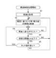
図4は、図2の電子機器1の機能的構成のうち、第1輝度制御処理を実行するための機能的構成を示す機能ブロック図である。
第1輝度制御処理とは、照度センサ29によって検出された照度に基づいて、第1表示部18の表示画面の輝度を制御する一連の処理である。[Functional configuration of the first embodiment]
Next, the functional configuration of the electronic device 1 will be described.
FIG. 4 is a functional block diagram showing a functional configuration for executing the first luminance control process among the functional configurations of the electronic device 1 of FIG.
The first brightness control process is a series of processes for controlling the brightness of the display screen of the
第1輝度制御処理が実行される場合、図4に示すように、第1CPU11Aにおいて、照度情報取得部51と、操作判定部52と、輝度制御部53と、が機能し、第2CPU11Bにおいて、センサ情報取得部61が機能する。
照度情報取得部51は、第2CPU11Bのセンサ情報取得部61によって検出された照度を取得する。
操作判定部52は、タッチパネル17の検出結果に基づいて、電子機器1の表示領域において、ユーザがタッチ操作を行っているか否かの判定を行う。このとき、操作判定部52は、表示領域において、ユーザがタッチ操作を行っている位置を検出する。When the first brightness control process is performed, as shown in FIG. 4, in the
The illuminance
The
輝度制御部53は、照度情報取得部51によって取得された照度に基づいて、第1表示部18の輝度を制御する。即ち、輝度制御部53は、電子機器1が明るい(照度が高い)環境に置かれている場合、表示画面が相対的に暗くなり、視認し難くなること防ぐため、検出された照度に応じた高い輝度に第1表示部18の輝度を制御する。一方、輝度制御部53は、電子機器1が暗い(照度が低い)環境に置かれている場合、表示画面が過度に明るくなり、視認し難くなること防ぐため、検出された照度に応じた低い輝度に第1表示部18の輝度を制御する。なお、照度に対応する輝度の値は、例えば、テーブル形式のデータあるいは所定の関数として電子機器1に保持されており、輝度制御部53は、これらテーブル形式のデータまたは所定の関数を適宜参照して輝度を制御する。 The
また、輝度制御部53は、照度情報取得部51によって取得された照度及び操作判定部52の判定結果に基づいて、第1表示部18の輝度を制御する。例えば、輝度制御部53は、電子機器1の表示領域における照度が予め設定された閾値Lth以下である場合、ユーザがタッチ操作を行っているか否かの判定を行う。そして、ユーザがタッチ操作を行っている場合、ユーザの操作(指や手等)によって電子機器1の表示領域が覆われ、一時的に照度が低下していると推定されることから、輝度制御部53は、第1表示部18の輝度を調整することなく、従前の輝度(例えば、タッチ操作が検出される直前の輝度)を維持する。一方、ユーザがタッチ操作を行っていない場合、電子機器1の環境自体が暗くなり、照度が低下していると推定されることから、輝度制御部53は、第1表示部18の輝度を調整し、照度情報取得部51によって取得された照度に応じて輝度を低くする。なお、閾値Lthは、第1表示部18の表示領域においてユーザがタッチ操作している際の照度を実験によって求めて設定すること等が可能である。
センサ情報取得部61は、照度センサによって検出された照度等、各種センサによって検出された検出値を取得する。Further, the
The sensor
[第1実施形態の動作]
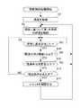
図5は、図4の機能的構成を有する図1の電子機器1が実行する第1輝度制御処理の流れを説明するフローチャートである。
第1輝度制御処理は、電子機器1の電源投入と共に開始され、電子機器1の電源をオフする操作が行われた場合に終了する。
ステップS1において、照度情報取得部51は、第2CPU11Bのセンサ情報取得部61によって検出された照度を取得する。
ステップS2において、輝度制御部53は、取得された照度に基づいて、第1表示部18の輝度を制御する。Operation of First Embodiment
FIG. 5 is a flowchart for explaining the flow of the first brightness control process performed by the electronic device 1 of FIG. 1 having the functional configuration of FIG. 4.
The first brightness control process is started when the power of the electronic device 1 is turned on, and ends when an operation to turn off the power of the electronic device 1 is performed.
In step S1, the illuminance
In step S2, the
ステップS3において、輝度制御部53は、照度に変化が生じているか否かの判定を行う。このとき、例えば、予め設定された変化量の閾値以上、照度が変化している場合に、照度に変化が生じていると判定することができる。
照度に変化が生じていない場合、ステップS3においてNOと判定されて、ステップS3の処理が繰り返される。
一方、照度に変化が生じている場合、ステップS3においてYESと判定されて、処理はステップS4に移行する。In step S3, the
If no change occurs in the illuminance, it is determined as NO in step S3, and the process of step S3 is repeated.
On the other hand, if a change occurs in the illuminance, it is determined as YES in step S3, and the process proceeds to step S4.
ステップS4において、輝度制御部53は、照度が予め設定された閾値Lth以下であるか否かの判定を行う。
照度が予め設定された閾値Lth以下でない場合、ステップS4においてNOと判定されて、処理はステップS2に移行する。即ち、第1表示部18の表示領域においてユーザがタッチ操作している場合に想定される照度よりも高い場合、輝度調整が実行される。
一方、照度が予め設定された閾値Lth以下である場合、ステップS4においてYESと判定されて、処理はステップS5に移行する。In step S4, the
If the illuminance is not equal to or less than the preset threshold Lth, it is determined as NO in step S4, and the process proceeds to step S2. That is, if the illuminance is higher than the illuminance assumed when the user performs the touch operation in the display area of the
On the other hand, if the illuminance is equal to or less than the preset threshold Lth, YES is determined in step S4, and the process proceeds to step S5.
ステップS5において、操作判定部52は、タッチパネル17の検出結果に基づいて、電子機器1の表示領域において、ユーザがタッチ操作を行っているか否かの判定を行う。
電子機器1の表示領域において、ユーザがタッチ操作を行っていない場合、ステップS5においてNOと判定されて、処理はステップS2に移行する。この場合、電子機器1の環境自体が暗くなっていると推定されるため、輝度調整が実行される。
一方、電子機器1の表示領域において、ユーザがタッチ操作を行っている場合、ステップS5においてYESと判定されて、処理はステップS3に移行する。この場合、ユーザがタッチ操作を行っているために、ユーザの操作(指や手等)によって電子機器1の表示領域が覆われ、一時的に照度が低下していると推定されるため、輝度調整が行われない。
即ち、輝度制御部53は、照度センサ29が検出する光に関する情報の確度を、タッチパネル17の検出結果に基づいて判定し、輝度制御部53は、その確度が所定値以上であると判定した場合、輝度調整を行う。
ここで、確度が所定値以上の場合とは、ユーザがタッチ操作を行っていない場合(ステップS5においてNOと判定される場合)である。In step S5, the
In the display area of the electronic device 1, when the user does not perform the touch operation, it is determined as NO in step S5, and the process proceeds to step S2. In this case, since it is estimated that the environment itself of the electronic device 1 is dark, luminance adjustment is performed.
On the other hand, if the user is performing a touch operation in the display area of the electronic device 1, YES is determined in step S5, and the process proceeds to step S3. In this case, since the user is performing the touch operation, it is estimated that the display area of the electronic device 1 is covered by the user's operation (a finger, a hand, etc.) and the illuminance is temporarily reduced. No adjustment is made.
That is, the
Here, the case where the certainty is equal to or more than the predetermined value is the case where the user does not perform the touch operation (when it is determined as NO in step S5).
このような処理により、電子機器1においては、表示領域の照度に応じて、第1表示部18の表示画面の輝度が調整されると共に、表示領域における照度が予め設定された閾値Lth以下となった場合には、ユーザがタッチ操作を行っているか否かの判定が行われる。そして、ユーザがタッチ操作を行っている場合には、ユーザの操作(指や手等)によって電子機器1の表示領域が覆われ、一時的に照度が低下していると推定されることから、第1表示部18の輝度が調整されることなく、従前の輝度が維持される。
したがって、第1表示部18の裏側に照度センサ29を配置されてなる電子機器1において、ユーザがタッチパネル17の操作を行ったとしても、誤った第1表示部18の輝度調整となることを抑制することができる。According to such processing, in the electronic device 1, the luminance of the display screen of the
Therefore, in the electronic device 1 in which the
[第2実施形態の機能的構成]
図6は、図2の電子機器1の機能的構成のうち、第2輝度制御処理を実行するための機能的構成を示す機能ブロック図である。
以下、図6を参照して、第2実施形態に係る電子機器1の機能的構成を説明する。第1実施形態との違いは、第2CPU11Bに透過率制御部62が更に設けられることである。第1実施形態では、タッチパネルの操作の有無に応じて輝度調整を抑制するが、第2実施形態では、透過率制御部62による液晶シャッタの開/閉状態に応じて、輝度調整を抑制する。
なお、第1実施形態と第2実施形態とのハードウェア構成は同一であるため説明は省略する。ハードウェア構成及び機能的構成において、第1実施形態と同一の要素には同一の符号が付されている。[Functional Configuration of Second Embodiment]
FIG. 6 is a functional block diagram showing a functional configuration for executing the second luminance control process among the functional configurations of the electronic device 1 of FIG.
Hereinafter, the functional configuration of the electronic device 1 according to the second embodiment will be described with reference to FIG. The difference from the first embodiment is that a
The hardware configurations of the first embodiment and the second embodiment are the same, and thus the description thereof is omitted. In the hardware configuration and the functional configuration, the same elements as those of the first embodiment are denoted by the same reference numerals.
センサ情報取得部61の機能は、第1実施形態と同じであるため、説明を省略する。
透過率制御部62は、第2表示部24であるPN液晶ディスプレイの透過率を制御する。上述のように、PN液晶ディスプレイは、電位が掛けられた部位では入射光を透過し、電位が掛けられていない部位では入射光を透過しない。
透過率制御部62は、第2入力部30に対する操作に応じて、第2表示部24に電位を掛け、又は、電位を掛けない制御を行う。この入力操作が行われると、例えば、第2表示部24の表示内容の表示色である白黒が反転する等、表示内容のデザインが変わる。Since the function of the sensor
The
The
第2輝度制御処理が実行される場合、図6に示すように、第1CPU11Aにおいて、照度情報取得部51と、操作判定部52と、輝度制御部53と、が機能し、第2CPU11Bにおいて、センサ情報取得部61、及び透過率制御部62が機能する。
照度情報取得部51は、第2CPU11Bのセンサ情報取得部61によって検出された照度を取得する。
操作判定部52は、第2入力部30に対するユーザの入力操作を検出することによって、第2表示部24において、液晶シャッタが開状態、又は閉状態のいずれの状態にあるかの判定を行う。
透過率制御部62は、第2入力部30に対するユーザの入力操作が検出されると、第2表示部24のPN液晶ディスプレイの透過率を変更する。透過率は、例えば、液晶シャッタの開状態(透過状態)又は閉状態(相対的に透過しない状態)の二値である。When the second brightness control process is performed, as shown in FIG. 6, in the
The illuminance
The
When the user's input operation to the
[第2実施形態の動作]
図7は、図6の機能的構成を有する図1の電子機器1が実行する第2の輝度制御処理の流れを説明するフローチャートである。
ステップS1〜S3の動作は、第1実施形態と同様である。即ち、ステップS1において、照度情報取得部51は、照度を取得し、ステップS2において、輝度制御部53は、取得された照度に基づいて、第1表示部18の輝度を制御する。
ステップS3において、輝度制御部53は、照度に変化が生じているか否かの判定を行う。照度に変化が生じていない場合、ステップS3の処理が繰り返され、一方、照度に変化が生じている場合、処理はステップS14に移行する。[Operation of Second Embodiment]
FIG. 7 is a flowchart for explaining the flow of a second brightness control process performed by the electronic device 1 of FIG. 1 having the functional configuration of FIG.
The operations in steps S1 to S3 are the same as in the first embodiment. That is, in step S1, the illuminance
In step S3, the
ステップS14において、輝度制御部53は、照度が予め設定された第2閾値Lth以下であるか否かの判定を行う。照度が予め設定された第2閾値Lth以下でない場合、ステップS14においてNOと判定されて、処理はステップS2に移行する。
ここで、第2閾値Lthは、例えば、液晶シャッタが閉状態の場合に想定される照度である。第2閾値Lthは、例えば、複数条件下における実測値から導出された値であって、出荷時等に予め記録される。
即ち、ステップS14では、照度情報取得部51で取得される照度から、第2表示部24の液晶シャッタが開状態にあるか否かを推定する。輝度制御部53は、照度が、液晶シャッタが閉状態にある場合に想定される照度よりも高い場合、液晶シャッタは開状態にあるものと推定し、ステップS2に移行して、取得された照度に基づいて第1表示部18の輝度調整を行う。
一方、照度が予め設定された第2閾値Lth以下である場合、ステップS14においてYESと判定されて、処理はステップS5に移行する。In step S14, the
Here, the second threshold Lth is, for example, illuminance assumed when the liquid crystal shutter is closed. The second threshold Lth is, for example, a value derived from measured values under a plurality of conditions, and is recorded in advance at the time of shipping or the like.
That is, in step S14, it is estimated from the illuminance acquired by the illuminance
On the other hand, if the illuminance is equal to or less than the second threshold Lth set in advance, YES is determined in step S14, and the process proceeds to step S5.
ステップS15において、操作判定部52は、透過率制御部62の制御に基づいて、第2表示部24の透過率、即ち、液晶シャッタの開閉状態を判定する。
操作判定部52が、液晶シャッタが開状態であると判定したとき、ステップS15においてNOと判定し、処理はステップS2に移行する。この場合、電子機器1の環境自体が暗くなっていると推定されるため、輝度調整が実行される。
一方、操作判定部52が、液晶シャッタが閉状態であると判定したとき、ステップS15においてYESと判定されて、処理はステップS16に移行する。この場合、液晶シャッタが閉状態であることによって、電子機器1の表示領域が液晶シャッタに覆われ、照度が低下していると推定される。換言すれば、液晶シャッタによって照度センサの入射光の一部が遮られている状態であるため、照度が低下していると推定される。このようにシャッタが閉状態のままでは、輝度制御部53は、環境に応じた正確な外光量を検出することが出来ないため、輝度制御部53は輝度調整を行わず、処理はステップS16へ進む。
即ち、操作判定部52は、照度センサ29が検出する光に関する情報の確度を、液晶シャッタの開閉状態の検出結果に基づいて判定し、輝度制御部53は、その確度が所定値以上であると判定された場合に輝度調整を行う。
ここで、確度が所定値以上の場合とは、液晶シャッタが開状態の場合(ステップS15においてNOと判定される場合)である。In step S <b> 15, the
When the
On the other hand, when the
That is, the
Here, the case where the accuracy is equal to or more than the predetermined value is the case where the liquid crystal shutter is in the open state (when it is determined as NO in step S15).
ステップS16において、操作判定部52が、電子機器1が所定の条件を満たすと判定したとき、処理はステップS17へ進む。ステップS17において、透過率制御部62は、液晶シャッタを一時的に開状態とする。
所定の条件とは、例えば、ユーザが電子機器1に対して所謂チルトを生じさせた場合、第2入力部30がユーザから液晶シャッタを開状態とする操作を受け付けた場合、或いは、第2入力部30が所定の時間なんら操作を受け付けていない場合である。In step S16, when the
The predetermined condition is, for example, when the user causes a so-called tilt with respect to the electronic device 1, the
ステップS17において、液晶シャッタが一時的に開状態となることにより、照度センサ29には、液晶シャッタに遮られない外光が入射する。液晶シャッタが開状態となっている間、照度センサ29は、電子機器1の環境に応じた外光に基づく照度をより正確に取得することが可能となる。 In step S17, when the liquid crystal shutter is temporarily opened, external light which is not blocked by the liquid crystal shutter is incident on the
[変形例1]
上述の第1実施形態において、電子機器1の表示領域における照度が閾値Lth以下であり、操作判定部52によって、電子機器1の表示領域に対してユーザがタッチ操作を行っていると判定された場合に、輝度制御部53による第1表示部18の輝度の制御を行わないものとして説明した。
これに対し、電子機器1の表示領域における照度が閾値Lth以下である場合に、操作判定部52が、電子機器1の表示領域のうち、照度センサ29が設置されている表示領域(以下、「影響領域」と称する。)に対してユーザがタッチ操作を行っているか否かを判定し、影響領域にユーザがタッチ操作を行ったと判定された場合に、輝度制御部53による第1表示部18の輝度の制御を行わないこととしてもよい。
このような制御を行うことにより、ユーザの操作(指や手等)によって電子機器1の表示領域が覆われ、一時的に照度が低下している状況をより適確に検出し、第1表示部18の輝度調整に反映させることが可能となる。[Modification 1]
In the first embodiment described above, the illuminance in the display area of the electronic device 1 is equal to or less than the threshold Lth, and the
On the other hand, when the illuminance in the display area of the electronic device 1 is equal to or less than the threshold Lth, the
By performing such control, the display area of the electronic device 1 is covered by the user's operation (a finger, a hand, etc.), and the situation where the illuminance is temporarily reduced is detected more appropriately and the first display It becomes possible to reflect on the brightness adjustment of the
[変形例2]
上述の第1実施形態において、輝度制御部53が第1表示部18の輝度を制御する場合、第1表示部18自身が現在の表示内容によって発光している光量を輝度制御部53によって判定し、その光量によって生じている照度の検出結果の変動を補正した上で、第1輝度制御処理を実行することとしてもよい。即ち、上述の実施形態においては、照度情報取得部51によって取得された照度と、ユーザがタッチ操作を行っているか否かの判定結果に基づいて、第1表示部18の輝度の調整を行う、または、第1表示部18の輝度を調整することなく、従前の輝度を維持するものとした。これに対し、本変形例においては、照度センサ29の配置位置に対応する領域で第1表示部18によって表示される表示内容は、電子機器1において把握されていることから、その表示内容に基づく照射光がユーザの指等に反射して照度センサ29の検出結果に影響する成分を推定する。そして、検出される照度の変化全体のうち、第1表示部18の表示内容に基づく照度の変化の成分を照度センサ29の検出結果から差し引いた上で、第1表示部18の表示領域における照度の変化を判定する。
これにより、第1表示部18の表示内容の影響を抑制して、第1表示部18の輝度調整を行うことができる。
なお、本変形例のような構成は、上述のようにタッチパネル17上に指があるか否か(ユーザがタッチ操作を行っているか否か)を判定する場合に限って適用されるものではない。即ち、輝度制御部53が第1表示部18の輝度を制御するにあたり、外光を検出する際には、第1表示部18自身の発光による光量を輝度制御部53が常に判定し、照度センサ29が検出した照度から、当該第1表示部18自身の発光による光の成分を差し引いた検出結果に基づいて、第1表示部18の輝度を制御するようにしてもよい。このようにすることで、第1表示部18自身の発光の影響を抑制した正確な照度に基づいて、第1表示部18の輝度調整を行うことができる。[Modification 2]
In the first embodiment described above, when the
Thereby, the influence of the display content of the
The configuration as in this modification is not applied only when it is determined whether or not the finger is on the touch panel 17 (whether or not the user is performing the touch operation) as described above. . That is, when the
[変形例3]
上述の第2実施形態において、図7のステップS16における検出条件は、チルトが生じた場合などであったが、他の実施例として、以下の場合であってもよい。
例えば、照度センサ29において、常時取得している照度が急激に変化した場合であってもよい。この場合、ステップS16において照度が急激に変化すると、処理はステップS17に進む。ステップS17において、照度センサ29は、液晶シャッタが開状態で照度を検出する。これにより、照度センサ29は、環境の変化に応じて正確な照度を検出することが出来る。[Modification 3]
In the above-described second embodiment, the detection condition in step S16 of FIG. 7 is, for example, when tilt occurs, but as another example, the following case may be employed.
For example, in the
[変形例4]
上述の実施形態では、図2等に示されるように、電子機器1は、第1の表示部18及び第2の表示部24が備えられているが、第1の表示部18を備えない構成であってもよい。この場合、輝度制御部53は、照度センサ29によって検出された照度に基づいて、第2表示部24の輝度を調整する。
即ち、本変形例の電子機器1は、第1表示部18を備えず、第2表示部24が液晶シャッタとバックライトで構成される構成であってもよい。この場合、照度センサ29は、第2の表示部24の裏面に配置されて、光に関する情報を検出する。操作判定部52は、光に関する情報の確度が所定値以上であると判定した場合、輝度制御部53は、第2表示部24のバックライトの輝度を調整する。[Modification 4]
In the above embodiment, as shown in FIG. 2 and the like, the electronic device 1 includes the
That is, the electronic device 1 of the present modification may not include the
[変形例5]
他の変形例として、第1の表示部18が、表示部ではなくバックライトとして機能する構成としてもよい。この場合、表示内容を表示する表示部は、第2の表示部24であり、図中の第1表示部18であるOLEDはバックライトとして機能する。この場合、照度センサ29は、第2の表示部24の裏面に配置されて、光に関する情報を検出する。操作判定部52は、光に関する情報の確度が所定値以上であると判定した場合、輝度制御部53は、OLEDの輝度を調整する。[Modification 5]
As another modification, the
[変形例6]
他の変形例として、第1の実施形態のステップS5においてYESと判定される場合、即ち、ユーザがタッチパネル17を操作している場合、輝度制御部53は、輝度の制御を抑制してもよい。この場合、ROM12には、タッチパネル17が操作されていない状態から操作されている状態になることによって生じる照度の減量値が予め保持されており、輝度の制御においてこの減量値が用いられる。例えば、輝度制御部53は、タッチパネル17が操作されている状態で検出した照度に対して、予め保持されている減量値に相当する照度を加算することによって、タッチパネル17が操作されていない状態での照度を推定する。輝度制御部53は、推定された照度に基づいて、第1表示部18の輝度を制御する。このように、輝度制御部53は、タッチ操作がないときの通常の輝度制御を抑制し、異なる制御を行ってもよい。[Modification 6]
As another modification, when it is determined YES in step S5 of the first embodiment, that is, when the user operates the
[変形例7]
他の変形例として、第2の実施形態のステップS16においてYESと判定される場合、即ち、液晶シャッタが閉状態である場合、輝度制御部53は、輝度の制御を抑制してもよい。この場合、ROM12には、液晶シャッタが開状態から閉状態になることによって生じる照度の減量値が予め保持されており、輝度の制御においてこの減量値が用いられる。例えば、輝度制御部53は、液晶シャッタの閉状態で検出した照度に対して、予め保持されている減量値に相当する照度を加算することによって、液晶シャッタの開状態での照度を推定する。輝度制御部53は、推定された照度に基づいて、第1表示部18の輝度を制御する。このように、輝度制御部53は、液晶シャッタが開状態であるときの通常の輝度制御を抑制し、異なる制御を行ってもよい。[Modification 7]
As another modification, when it is determined YES in step S16 of the second embodiment, that is, when the liquid crystal shutter is in the closed state, the
以上のように構成される電子機器1は、第1表示部18又は第2表示部24と、照度センサ29と、輝度制御部53と、操作判定部52と、を備える。
照度センサ29は、表示部の表示面の背面側に配置される。輝度制御部53は、照度センサ29によって検出された光に関する情報に基づいて、例えば、第1表示部18の輝度を制御する。操作判定部52は、照度センサ29が検出する光に関する情報の確度を判定する。
輝度制御部53は、操作判定部52によって光に関する情報の確度が所定値以上であると判定された場合に、例えば、第1表示部18の輝度の制御をし、
輝度制御部53は、操作判定部52によって光に関する情報の確度が所定値未満であると判定された場合に、例えば、第1表示部18の輝度の制御を抑制する。
これにより、照度センサ29によって検出された光量の確からしさが判定され、確かであると判定された場合に、表示部の輝度が調整されるため、適切な輝度調整が行われる。例えば、照度センサ29によって検出される照度が低下した場合、照度の低下が、照度センサ29の入射光を遮るように表れた偶発的な障害物による一時的な現象か、又は、電子機器1の環境が暗くなったのかを判定出来るため、表示面の輝度がより精度よく調整される。The electronic device 1 configured as described above includes the
The
The
The
Thereby, the certainty of the light amount detected by the
電子機器1は、第1表示部18又は第2表示部24の表面側に配置されたタッチパネル17をさらに備え、
操作判定部52は、タッチパネル17がユーザに操作されているか否かを判定し、
輝度制御部53は、操作判定部52によって、タッチパネル17がユーザに操作されていないと判定された場合に、確度が所定値以上であると判定し、第1表示部18の輝度の制御をし、
輝度制御部53は、操作判定部52によって、タッチパネル17がユーザに操作されていると判定された場合に、確度が所定値未満であると判定され、第1表示部18の輝度の制御を抑制する。
これにより、ユーザのタッチパネル17の操作により、一時的に照度が低下したか、又は、電子機器の環境が暗くなったのかを判定することができる。タッチパネルの操作の有無を判定することにより、照度センサ29は、より正確に第1表示部18の輝度を制御することが出来る。The electronic device 1 further includes a
The
When the
When the
Thereby, it is possible to determine whether the illuminance has temporarily decreased or the environment of the electronic device has become dark due to the operation of the
電子機器1の第1表示部18は、第2表示部24を含み、
輝度制御部53は、第2表示部24の液晶シャッタが透過状態になっているか否かを判定し、
輝度制御部53は、操作判定部52によって、液晶シャッタが透過状態になっていると判定された場合に、確度が所定値以上であると判定し、第1表示部18の輝度を制御し、
輝度制御部53は、操作判定部52によって、液晶シャッタが透過状態になっていないと判定された場合に、確度が所定値未満であると判定され、第1表示部18の輝度の制御を抑制する。
これにより、液晶シャッタの透過率、即ち、上述の液晶シャッタの開閉の状態に応じて、適切な照度を検出することが出来る。液晶シャッタが開状態であるとき、照度センサ29によって照度が検出されることにより、電子機器1の環境の照度をより正確に検出することが出来る。The
The
When the
When the
Thereby, appropriate illuminance can be detected according to the transmittance of the liquid crystal shutter, that is, the open / close state of the liquid crystal shutter described above. When the liquid crystal shutter is in the open state, the
第1表示部18は、第2表示部24の背面側に配置されたOLEDを含み、
照度センサ29はOLEDの背面側に配置され、
輝度制御部53は、操作判定部52によって、液晶シャッタが透過状態になっていると判定された場合に、確度が所定値以上であると判定し、第1表示部18の輝度の制御をし、
輝度制御部53は、操作判定部52によって、液晶シャッタが透過状態になっていないと判定された場合に、確度が所定値未満であると判定され、OLEDの輝度の制御を抑制する。
これにより、液晶シャッタが透過状態となっている場合に照度が検出されるため、より正確に第1表示部18の輝度が制御される。The
An
When the
When the
Thus, the illuminance is detected when the liquid crystal shutter is in the transmission state, so that the luminance of the
操作判定部52は、タッチパネル17のうち、照度センサ29が配置されている領域に対応する影響領域をユーザがタッチしたか否かを判定する。
輝度制御部53は、操作判定部52によって、影響領域をユーザがタッチしていないと判定された場合に、確度が所定値以上であると判定され、第1表示部18の輝度の制御を制御し、
輝度制御部53は、操作判定部52によって、影響領域をユーザがタッチしたと判定された場合に、確度が所定値未満であると判定し、輝度制御部53による第1表示部18の輝度の制御を抑制する。
これにより、ユーザの操作(指や手等)によって電子機器1の表示領域が覆われ、一時的に照度が低下している状況をより適確に検出し、第1表示部18の輝度調整に反映させることが可能となる。The
When the
When the
As a result, the display area of the electronic device 1 is covered by the user's operation (a finger, a hand, etc.), and the situation where the illuminance is temporarily reduced is detected more appropriately and the luminance adjustment of the
輝度制御部53は、操作判定部52がタッチパネル17をユーザが操作していると判定された場合に、第1表示部18の輝度を、タッチパネル17の操作を検出した直前の輝度のままで維持する。
これにより、ユーザの操作(指や手等)によって電子機器1の表示領域が覆われ、一時的に照度が低下していると推定される場合に、第1表示部18の輝度を維持することができる。When it is determined that the
Thereby, when it is estimated that the display area of the electronic device 1 is covered by the user's operation (a finger, a hand, etc.) and the illuminance is temporarily reduced, the luminance of the
第1表示部18は、OLEDである。
これにより、自発光する素子によって構成された第1表示部18において、照度に基づく輝度の調整をより適切に行うことが可能となる。The
As a result, in the
制御対象の第1表示部18又は第2表示部24は、バックライトを含む。
これにより、バックライトが第2表示部であるPN液晶ディスプレイの輝度を調整することが可能となる。The
This makes it possible to adjust the luminance of the PN liquid crystal display whose backlight is the second display unit.
輝度制御部53は、照度センサ29が検出した情報のうち、第1表示部18自身が発する光量の影響による変動を補正した情報に基づいて、第1表示部18の輝度の制御を行う。
これにより、第1表示部18の表示内容の影響を抑制して、第1表示部18の輝度調整を行うことができる。The
Thereby, the influence of the display content of the
なお、本発明は、上述の実施形態に限定されるものではなく、本発明の目的を達成できる範囲での変形、改良等は本発明に含まれるものである。 The present invention is not limited to the above-described embodiment, and modifications, improvements, and the like in the range in which the object of the present invention can be achieved are included in the present invention.
上述の実施形態では、電子機器1の表示領域における照度が閾値Lth以下であり、操作判定部52によって、電子機器1の表示領域に対してユーザがタッチ操作を行っていると判定された場合に、輝度制御部53による第1表示部18の輝度の制御を行わないものとしたが、これに限られない。例えば、電子機器1の表示領域における照度が閾値Lth以下であり、操作判定部52によって、電子機器1の表示領域に対してユーザがタッチ操作を行っていると判定された場合に、タッチパネル17がタッチ操作されていない場合に比べて、輝度制御部53による第1表示部18の輝度の調整量を低下させることとしてもよい。即ち、輝度の調整を抑制(停止または低下)することでも、上述の実施形態と同様の効果を得ることができる。 In the above embodiment, the illuminance in the display area of the electronic device 1 is equal to or less than the threshold Lth, and it is determined by the
また、上述の実施形態では、電子機器1は第1表示部18と第2表示部24とを備えるものとしたが、それに限らず、電子機器1は第1表示部18のみ、又は第2表示部24のみを備えるものであってもよい。この場合、照度センサ29の位置は表示部の裏面にあればよい。なお、第1表示部18及び第2表示部24を備える構成においては、照度センサ29は、第1表示部18と第2表示部24との間に設けられる構成であってもよい。
また、上述の実施形態では、電子機器1のCPU11は第1CPU11Aと第2CPU11Bとからなるものとしたが、それに限らず、CPU11は第1CPU11Aの機能と第2CPU11Bの機能の両方を備える1つのCPUであってもよい。Moreover, in the above-mentioned embodiment, although the electronic device 1 shall be provided with the
Moreover, in the above-mentioned embodiment, although CPU11 of electronic equipment 1 shall consist of 1st CPU11A and 2nd CPU11B, not only it but CPU11 is one CPU provided with both the function of 1st CPU11A and the function of 2nd CPU11B. It may be.
また、上述の実施形態では、本発明が適用される電子機器1は、デジタルカメラ腕時計型の装置(スマートウォッチ等)を例として説明したが、特にこれに限定されない。
例えば、本発明は、輝度調整機能を有する電子機器一般に適用することができる。具体的には、例えば、本発明は、ノート型のパーソナルコンピュータ、プリンタ、テレビジョン受像機、ビデオカメラ、携帯型ナビゲーション装置、携帯電話機、スマートフォン、ポータブルゲーム機等に適用可能である。Moreover, in the above-mentioned embodiment, although the electronic device 1 to which this invention is applied was demonstrated as an example the apparatus (smart watch etc.) of a digital camera wristwatch type, it is not specifically limited to this.
For example, the present invention can be generally applied to electronic devices having a brightness adjustment function. Specifically, for example, the present invention is applicable to a laptop personal computer, a printer, a television receiver, a video camera, a portable navigation device, a mobile phone, a smartphone, a portable game machine, and the like.
上述した一連の処理は、ハードウェアにより実行させることもできるし、ソフトウェアにより実行させることもできる。
換言すると、図4の機能的構成は例示に過ぎず、特に限定されない。即ち、上述した一連の処理を全体として実行できる機能が電子機器1に備えられていれば足り、この機能を実現するためにどのような機能ブロックを用いるのかは特に図4の例に限定されない。
また、1つの機能ブロックは、ハードウェア単体で構成してもよいし、ソフトウェア単体で構成してもよいし、それらの組み合わせで構成してもよい。
本実施形態における機能的構成は、演算処理を実行するプロセッサによって実現され、本実施形態に用いることが可能なプロセッサには、シングルプロセッサ、マルチプロセッサ及びマルチコアプロセッサ等の各種処理装置単体によって構成されるものの他、これら各種処理装置と、ASIC(Application Specific Integrated Circuit)やFPGA(Field‐Programmable Gate Array)等の処理回路とが組み合わせられたものを含む。The series of processes described above can be performed by hardware or software.
In other words, the functional configuration of FIG. 4 is merely an example and is not particularly limited. That is, it is sufficient if the electronic device 1 is provided with a function capable of executing the above-described series of processes as a whole, and what functional block is used to realize this function is not particularly limited to the example of FIG.
Further, one functional block may be configured by hardware alone, may be configured by software alone, or may be configured by a combination of them.
The functional configuration in the present embodiment is realized by a processor that executes arithmetic processing, and the processors that can be used in the present embodiment include various processing devices such as a single processor, a multiprocessor, and a multi-core processor alone. In addition to the above, those including various processing devices and processing circuits such as an application specific integrated circuit (ASIC) and a field-programmable gate array (FPGA) are included.
一連の処理をソフトウェアにより実行させる場合には、そのソフトウェアを構成するプログラムが、コンピュータ等にネットワークや記録媒体からインストールされる。
コンピュータは、専用のハードウェアに組み込まれているコンピュータであってもよい。また、コンピュータは、各種のプログラムをインストールすることで、各種の機能を実行することが可能なコンピュータ、例えば汎用のパーソナルコンピュータであってもよい。When the series of processes are executed by software, a program that configures the software is installed on a computer or the like from a network or a recording medium.
The computer may be a computer incorporated in dedicated hardware. The computer may be a computer capable of executing various functions by installing various programs, for example, a general-purpose personal computer.
このようなプログラムを含む記録媒体は、ユーザにプログラムを提供するために装置本体とは別に配布される図2のリムーバブルメディア41により構成されるだけでなく、装置本体に予め組み込まれた状態でユーザに提供される記録媒体等で構成される。リムーバブルメディア41は、例えば、磁気ディスク(フロッピディスクを含む)、光ディスク、または光磁気ディスク等により構成される。光ディスクは、例えば、CD−ROM(Compact Disk−Read Only Memory),DVD(Digital Versatile Disk),Blu−ray(登録商標) Disc(ブルーレイディスク)等により構成される。光磁気ディスクは、MD(Mini−Disk)等により構成される。また、装置本体に予め組み込まれた状態でユーザに提供される記録媒体は、例えば、プログラムが記録されている図2のROM12や、図2の記憶部14に含まれる半導体メモリ等で構成される。 The recording medium including such a program is not only configured by the
なお、本明細書において、記録媒体に記録されるプログラムを記述するステップは、その順序に沿って時系列的に行われる処理はもちろん、必ずしも時系列的に処理されなくとも、並列的あるいは個別に実行される処理をも含むものである。
また、第2実施形態のステップS14の処理は、必ずしも行われる必要はなく、省略されてもよい。In the present specification, in the step of describing the program to be recorded on the recording medium, the processing performed chronologically along the order is, of course, parallel or individually not necessarily necessarily chronologically processing. It also includes the processing to be performed.
In addition, the process of step S14 of the second embodiment does not necessarily have to be performed, and may be omitted.
以上、本発明のいくつかの実施形態について説明したが、これらの実施形態は、例示に過ぎず、本発明の技術的範囲を限定するものではない。本発明はその他の様々な実施形態を取ることが可能であり、さらに、本発明の要旨を逸脱しない範囲で、省略や置換等種々の変更を行うことができる。これら実施形態やその変形は、本明細書等に記載された発明の範囲や要旨に含まれると共に、特許請求の範囲に記載された発明とその均等の範囲に含まれる。 While some embodiments of the present invention have been described above, these embodiments are merely illustrative and do not limit the technical scope of the present invention. The present invention can take other various embodiments, and furthermore, various changes such as omissions and substitutions can be made without departing from the scope of the present invention. These embodiments and modifications thereof are included in the scope and the gist of the invention described in the present specification, etc., and are included in the invention described in the claims and the equivalent scope thereof.
以下に、本願の出願当初の特許請求の範囲に記載された発明を付記する。
[付記1]
表示部と、
前記表示部の表示面の背面側に配置された光検出部と、
前記光検出部によって検出された光に関する情報に基づいて、前記表示部の輝度を制御する輝度制御部と、
前記光検出部が検出する光に関する情報の確度を判定する判定部と、を備え、
前記輝度制御部は、前記判定部によって前記光に関する情報の確度が所定値以上であると判定された場合に、前記表示部の輝度の制御をし、
前記輝度制御部は、前記判定部によって前記光に関する情報の確度が所定値未満であると判定された場合に、前記表示部の輝度の制御を抑制する、
ことを特徴とする電子機器。
[付記2]
前記表示部の表面側に配置されたタッチパネル部をさらに備え、
前記判定部は、前記タッチパネル部がユーザに操作されているか否かを判定し、
前記輝度制御部は、前記判定部によって、前記タッチパネル部がユーザに操作されていないと判定された場合に、前記確度が所定値以上であると判定し、前記表示部の輝度の制御をし、
前記輝度制御部は、前記判定部によって、前記タッチパネル部がユーザに操作されていると判定された場合に、前記確度が所定値未満であると判定され、前記表示部の輝度の制御を抑制する、
ことを特徴とする付記1に記載の電子機器。
[付記3]
前記表示部は、液晶表示装置を含み、
前記判定部は、前記液晶表示装置の液晶シャッタが透過状態になっているか否かを判定し、
前記輝度制御部は、前記判定部によって、前記液晶シャッタが透過状態になっていると判定された場合に、前記確度が所定値以上であると判定し、前記表示部の輝度の制御をし、
前記輝度制御部は、前記判定部によって、前記液晶シャッタが透過状態になっていないと判定された場合に、前記確度が所定値未満であると判定され、前記表示部の輝度の制御を抑制する、
ことを特徴とする付記1に記載の電子機器。
[付記4]
前記表示部は、前記液晶表示装置の背面側に配置されたOLEDを含み、
前記光検出部は前記OLEDの背面側に配置され、
前記輝度制御部は、前記判定部によって、前記液晶シャッタが透過状態になっていると判定された場合に、前記確度が所定値以上であると判定し、前記OLEDの輝度の制御をし、
前記輝度制御部は、前記判定部によって、前記液晶シャッタが透過状態になっていないと判定された場合に、前記確度が所定値未満であると判定され、前記OLEDの輝度の制御を抑制する、
ことを特徴とする付記3に記載の電子機器。
[付記5]
前記判定部は、前記タッチパネル部のうち、前記光検出部が配置されている領域に対応する影響領域をユーザがタッチしたか否か判定し、
前記輝度制御部は、前記判定部によって、前記影響領域をユーザがタッチしていないと判定された場合に、前記確度が所定値以上であると判定され、前記輝度制御部による前記表示部の輝度の制御をし、
前記輝度制御部は、前記判定部によって、前記影響領域をユーザがタッチしたと判定された場合に、前記確度が所定値未満であると判定され、前記輝度制御部による前記表示部の輝度の制御を抑制する、
ことを特徴とする付記2に記載の電子機器。
[付記6]
前記輝度制御部は、前記判定部によって前記確度が所定値以上であると判定された場合に、前記表示部の輝度を、前記タッチパネル部の操作を検出した直前の輝度のままで維持することを特徴とする付記5に記載の電子機器。
[付記7]
制御対象の前記表示部は、OLEDを含むことを特徴とする付記1乃至6の何れか一に記載の電子機器。
[付記8]
制御対象の前記表示部は、バックライトを含むことを特徴とする付記1乃至7のいずれか一に記載の電子機器。
[付記9]
前記輝度制御部は、前記光検出部が検出した情報のうち、前記表示部自身が発する光量の影響による変動を補正した情報に基づいて、前記表示部の輝度の制御を行うことを特徴とする付記1乃至8の何れか一に記載の電子機器。
[付記10]
表示部と、
前記表示部の表示面の背面側に配置された光検出部と、
前記光検出部によって検出された光に関する情報に基づいて、前記表示部の輝度を制御する輝度制御部と、
前記光検出部が検出する光に関する情報の確度を判定する判定部と、を備える電子機器が行う輝度制御方法であって、
前記判定部によって前記光に関する情報の確度が所定値以上であると判定された場合に、前記表示部の輝度の制御をし、
前記判定部によって前記光に関する情報の確度が所定値未満であると判定された場合に、前記表示部の輝度の制御を抑制する、
することを特徴とする輝度制御方法。
[付記11]
表示部と、
前記表示部の表示面の背面側に配置された光検出部と、
前記光検出部によって検出された光に関する情報に基づいて、前記表示部の輝度を制御する輝度制御部と、
前記光検出部が検出する光に関する情報の確度を判定する判定部と、を有する電子機器を制御するコンピュータに、
前記輝度制御部は、前記判定部によって前記光に関する情報の確度が所定値以上であると判定された場合に、前記表示部の輝度の制御をする機能と、
前記輝度制御部は、前記判定部によって前記光に関する情報の確度が所定値未満であると判定された場合に、前記表示部の輝度の制御を抑制する機能と、を実現させることを特徴とするプログラム。The invention described in the claims at the beginning of the application of the present application is appended below.
[Supplementary Note 1]
A display unit,
A light detection unit disposed on the back side of the display surface of the display unit;
A brightness control unit configured to control the brightness of the display unit based on information on light detected by the light detection unit;
A determination unit that determines the accuracy of information on light detected by the light detection unit;
The luminance control unit controls the luminance of the display unit when the determination unit determines that the accuracy of the information related to the light is equal to or greater than a predetermined value.
The brightness control unit suppresses control of the brightness of the display unit when the determination unit determines that the accuracy of the information related to the light is less than a predetermined value.
An electronic device characterized by
[Supplementary Note 2]
The touch panel further includes a touch panel disposed on the front side of the display unit.
The determination unit determines whether the touch panel unit is operated by the user,
When the determination unit determines that the touch panel unit is not operated by the user, the brightness control unit determines that the certainty is equal to or higher than a predetermined value, and controls the brightness of the display unit.
When the determination unit determines that the touch panel unit is operated by the user, the brightness control unit determines that the accuracy is less than a predetermined value, and suppresses the control of the brightness of the display unit. ,
The electronic device according to Additional Note 1, characterized in that
[Supplementary Note 3]
The display unit includes a liquid crystal display device.
The determination unit determines whether a liquid crystal shutter of the liquid crystal display device is in a transmission state.
When the determination unit determines that the liquid crystal shutter is in the transmission state, the brightness control unit determines that the accuracy is equal to or greater than a predetermined value, and controls the brightness of the display unit.
When the determination unit determines that the liquid crystal shutter is not in the transmission state, the brightness control unit determines that the accuracy is less than a predetermined value, and suppresses the control of the brightness of the display unit. ,
The electronic device according to Additional Note 1, characterized in that
[Supplementary Note 4]
The display unit includes an OLED disposed on the back side of the liquid crystal display device.
The light detection unit is disposed on the back side of the OLED,
When the determination unit determines that the liquid crystal shutter is in the transmission state, the brightness control unit determines that the accuracy is equal to or higher than a predetermined value, and controls the brightness of the OLED.
When the determination unit determines that the liquid crystal shutter is not in the transmission state, the brightness control unit determines that the accuracy is less than a predetermined value and suppresses control of the brightness of the OLED.
The electronic device according to Additional Note 3, characterized in that
[Supplementary Note 5]
The determination unit determines whether the user has touched an influence area corresponding to an area in which the light detection unit is disposed in the touch panel unit,
When the determination unit determines that the user does not touch the affected area, the brightness control unit determines that the certainty is equal to or greater than a predetermined value, and the brightness control unit is configured to control the brightness of the display unit. Control of the
When the determination unit determines that the user has touched the affected area, the brightness control unit determines that the certainty is less than a predetermined value, and controls the brightness of the display unit by the brightness control unit. Suppress
The electronic device according to Appendix 2, characterized in that
[Supplementary Note 6]
The luminance control unit maintains the luminance of the display unit as it is immediately before the operation of the touch panel unit is detected when the determination unit determines that the certainty is equal to or more than a predetermined value. The electronic device according to supplementary note 5, characterized in that
[Supplementary Note 7]
The electronic device according to any one of appendices 1 to 6, wherein the display unit to be controlled includes an OLED.
[Supplementary Note 8]
The electronic device according to any one of appendices 1 to 7, wherein the display unit to be controlled includes a backlight.
[Supplementary Note 9]
The brightness control unit controls the brightness of the display unit based on the information detected from the light detection unit and information obtained by correcting the fluctuation due to the influence of the light amount emitted by the display unit itself. The electronic device according to any one of appendices 1 to 8.
[Supplementary Note 10]
A display unit,
A light detection unit disposed on the back side of the display surface of the display unit;
A brightness control unit configured to control the brightness of the display unit based on information on light detected by the light detection unit;
And a determination unit that determines the accuracy of information related to light detected by the light detection unit.
Controlling the luminance of the display unit when the determination unit determines that the certainty of the information related to the light is equal to or greater than a predetermined value;
When the determination unit determines that the accuracy of the information on the light is less than a predetermined value, the control of the luminance of the display unit is suppressed.
A brightness control method characterized in that.
[Supplementary Note 11]
A display unit,
A light detection unit disposed on the back side of the display surface of the display unit;
A brightness control unit configured to control the brightness of the display unit based on information on light detected by the light detection unit;
A computer configured to control an electronic device including: a determination unit that determines the accuracy of information on light detected by the light detection unit;
The brightness control unit has a function of controlling the brightness of the display unit when the determination unit determines that the certainty of the information related to the light is equal to or greater than a predetermined value.
The brightness control unit may realize a function of suppressing control of the brightness of the display unit when the determination unit determines that the accuracy of the information related to the light is less than a predetermined value. program.
1・・・電子機器,11・・・CPU,11A・・・第1CPU,11B・・・第2CPU,12・・・ROM,13・・・RAM,14・・・記憶部,15・・・RTC部,16・・・ドライブ,17・・・タッチパネル,18・・・第1表示部,19・・・第1入力部,20・・・ブルートゥース(登録商標)用アンテナ,21・・・ブルートゥース(登録商標)モジュール,22・・・無線LANアンテナ,23・・・無線LANモジュール,24・・・第2表示部,25・・・脈拍センサ,26・・・地磁気センサ,27・・・加速度センサ,28・・・ジャイロセンサ,29・・・照度センサ,30・・・第2入力部,31・・・GPSアンテナ,32・・・GPSモジュール,41・・・リムーバブルメディア,CG・・・カバーガラス,BS・・・黒色シート,MB・・・メイン基板,H・・・貫通穴,51・・・照度情報取得部,52・・・操作判定部,53・・・輝度制御部,61・・・センサ情報取得部,62・・・透過率制御部 DESCRIPTION OF SYMBOLS 1 ... electronic device, 11 ... CPU, 11A ... 1st CPU, 11B ... 2nd CPU, 12 ... ROM, 13 ... RAM, 14 ... memory | storage part, 15 ... RTC unit, 16 ... drive, 17 ... touch panel, 18 ... first display unit, 19 ... first input unit, 20 ... Bluetooth (registered trademark) antenna, 21 ... Bluetooth (Registered Trademark) module, 22 ... wireless LAN antenna, 23 ... wireless LAN module, 24 ... second display unit, 25 ... pulse sensor, 26 ... geomagnetic sensor, 27 ... acceleration Sensor 28: Gyro sensor 29: Illuminance sensor 30: Second input unit 31: GPS antenna 32: GPS module 41: Removable media, CG: CG Hippo Glass, BS: black sheet, MB: main substrate, H: through hole, 51: illuminance information acquisition unit, 52: operation determination unit, 53: luminance control unit, 61 · · Sensor information acquisition unit, 62 · · · transmittance control unit
Claims (11)
Translated fromJapanese前記表示部の表示面の背面側に配置された光検出部と、
前記光検出部によって検出された光に関する情報に基づいて、前記表示部の輝度を制御する輝度制御部と、
前記光検出部が検出する光に関する情報の確度を判定する判定部と、を備え、
前記輝度制御部は、前記判定部によって前記光に関する情報の確度が所定値以上であると判定された場合に、前記表示部の輝度の制御をし、
前記輝度制御部は、前記判定部によって前記光に関する情報の確度が所定値未満であると判定された場合に、前記表示部の輝度の制御を抑制する、
ことを特徴とする電子機器。A display unit,
A light detection unit disposed on the back side of the display surface of the display unit;
A brightness control unit configured to control the brightness of the display unit based on information on light detected by the light detection unit;
A determination unit that determines the accuracy of information on light detected by the light detection unit;
The luminance control unit controls the luminance of the display unit when the determination unit determines that the accuracy of the information related to the light is equal to or greater than a predetermined value.
The brightness control unit suppresses control of the brightness of the display unit when the determination unit determines that the accuracy of the information related to the light is less than a predetermined value.
An electronic device characterized by
前記判定部は、前記タッチパネル部がユーザに操作されているか否かを判定し、
前記輝度制御部は、前記判定部によって、前記タッチパネル部がユーザに操作されていないと判定された場合に、前記確度が所定値以上であると判定し、前記表示部の輝度の制御をし、
前記輝度制御部は、前記判定部によって、前記タッチパネル部がユーザに操作されていると判定された場合に、前記確度が所定値未満であると判定され、前記表示部の輝度の制御を抑制する、
ことを特徴とする請求項1に記載の電子機器。The touch panel further includes a touch panel disposed on the front side of the display unit.
The determination unit determines whether the touch panel unit is operated by the user,
When the determination unit determines that the touch panel unit is not operated by the user, the brightness control unit determines that the certainty is equal to or higher than a predetermined value, and controls the brightness of the display unit.
When the determination unit determines that the touch panel unit is operated by the user, the brightness control unit determines that the accuracy is less than a predetermined value, and suppresses the control of the brightness of the display unit. ,
The electronic device according to claim 1,
前記判定部は、前記液晶表示装置の液晶シャッタが透過状態になっているか否かを判定し、
前記輝度制御部は、前記判定部によって、前記液晶シャッタが透過状態になっていると判定された場合に、前記確度が所定値以上であると判定し、前記表示部の輝度の制御をし、
前記輝度制御部は、前記判定部によって、前記液晶シャッタが透過状態になっていないと判定された場合に、前記確度が所定値未満であると判定され、前記表示部の輝度の制御を抑制する、
ことを特徴とする請求項1に記載の電子機器。The display unit includes a liquid crystal display device.
The determination unit determines whether a liquid crystal shutter of the liquid crystal display device is in a transmission state.
When the determination unit determines that the liquid crystal shutter is in the transmission state, the brightness control unit determines that the accuracy is equal to or greater than a predetermined value, and controls the brightness of the display unit.
When the determination unit determines that the liquid crystal shutter is not in the transmission state, the brightness control unit determines that the accuracy is less than a predetermined value, and suppresses the control of the brightness of the display unit. ,
The electronic device according to claim 1,
前記光検出部は前記OLEDの背面側に配置され、
前記輝度制御部は、前記判定部によって、前記液晶シャッタが透過状態になっていると判定された場合に、前記確度が所定値以上であると判定し、前記OLEDの輝度の制御をし、
前記輝度制御部は、前記判定部によって、前記液晶シャッタが透過状態になっていないと判定された場合に、前記確度が所定値未満であると判定され、前記OLEDの輝度の制御を抑制する、
ことを特徴とする請求項3に記載の電子機器。The display unit includes an OLED disposed on the back side of the liquid crystal display device.
The light detection unit is disposed on the back side of the OLED,
When the determination unit determines that the liquid crystal shutter is in the transmission state, the brightness control unit determines that the accuracy is equal to or higher than a predetermined value, and controls the brightness of the OLED.
When the determination unit determines that the liquid crystal shutter is not in the transmission state, the brightness control unit determines that the accuracy is less than a predetermined value and suppresses control of the brightness of the OLED.
The electronic device according to claim 3, characterized in that:
前記輝度制御部は、前記判定部によって、前記影響領域をユーザがタッチしていないと判定された場合に、前記確度が所定値以上であると判定され、前記輝度制御部による前記表示部の輝度の制御をし、
前記輝度制御部は、前記判定部によって、前記影響領域をユーザがタッチしたと判定された場合に、前記確度が所定値未満であると判定され、前記輝度制御部による前記表示部の輝度の制御を抑制する、
ことを特徴とする請求項2に記載の電子機器。The determination unit determines whether the user has touched an influence area corresponding to an area in which the light detection unit is disposed in the touch panel unit,
When the determination unit determines that the user does not touch the affected area, the brightness control unit determines that the certainty is equal to or greater than a predetermined value, and the brightness control unit is configured to control the brightness of the display unit. Control of the
When the determination unit determines that the user has touched the affected area, the brightness control unit determines that the certainty is less than a predetermined value, and controls the brightness of the display unit by the brightness control unit. Suppress
The electronic device according to claim 2,
前記表示部の表示面の背面側に配置された光検出部と、
前記光検出部によって検出された光に関する情報に基づいて、前記表示部の輝度を制御する輝度制御部と、
前記光検出部が検出する光に関する情報の確度を判定する判定部と、を備える電子機器が行う輝度制御方法であって、
前記判定部によって前記光に関する情報の確度が所定値以上であると判定された場合に、前記表示部の輝度の制御をし、
前記判定部によって前記光に関する情報の確度が所定値未満であると判定された場合に、前記表示部の輝度の制御を抑制する、
することを特徴とする輝度制御方法。A display unit,
A light detection unit disposed on the back side of the display surface of the display unit;
A brightness control unit configured to control the brightness of the display unit based on information on light detected by the light detection unit;
And a determination unit that determines the accuracy of information related to light detected by the light detection unit.
Controlling the luminance of the display unit when the determination unit determines that the certainty of the information related to the light is equal to or greater than a predetermined value;
When the determination unit determines that the accuracy of the information on the light is less than a predetermined value, the control of the luminance of the display unit is suppressed.
A brightness control method characterized in that.
前記表示部の表示面の背面側に配置された光検出部と、
前記光検出部によって検出された光に関する情報に基づいて、前記表示部の輝度を制御する輝度制御部と、
前記光検出部が検出する光に関する情報の確度を判定する判定部と、を有する電子機器を制御するコンピュータに、
前記輝度制御部は、前記判定部によって前記光に関する情報の確度が所定値以上であると判定された場合に、前記表示部の輝度の制御をする機能と、
前記輝度制御部は、前記判定部によって前記光に関する情報の確度が所定値未満であると判定された場合に、前記表示部の輝度の制御を抑制する機能と、を実現させることを特徴とするプログラム。A display unit,
A light detection unit disposed on the back side of the display surface of the display unit;
A brightness control unit configured to control the brightness of the display unit based on information on light detected by the light detection unit;
A computer configured to control an electronic device including: a determination unit that determines the accuracy of information on light detected by the light detection unit;
The brightness control unit has a function of controlling the brightness of the display unit when the determination unit determines that the certainty of the information related to the light is equal to or greater than a predetermined value.
The brightness control unit may realize a function of suppressing control of the brightness of the display unit when the determination unit determines that the accuracy of the information related to the light is less than a predetermined value. program.
Priority Applications (4)
| Application Number | Priority Date | Filing Date | Title |
|---|---|---|---|
| EP18891995.5AEP3731224A4 (en) | 2017-12-21 | 2018-12-14 | ELECTRONIC DEVICE, BRIGHTNESS CONTROL METHOD AND RECORDING MEDIUM |
| CN201880083088.4ACN111542870B (en) | 2017-12-21 | 2018-12-14 | Electronic device, luminance control method, and storage medium |
| PCT/JP2018/046176WO2019124272A1 (en) | 2017-12-21 | 2018-12-14 | Electronic device, brightness control method, and recording medium |
| US16/957,076US11081084B2 (en) | 2017-12-21 | 2018-12-14 | Electronic apparatus, luminance control method, and storage medium |
Applications Claiming Priority (2)
| Application Number | Priority Date | Filing Date | Title |
|---|---|---|---|
| JP2017245306 | 2017-12-21 | ||
| JP2017245306 | 2017-12-21 |
Publications (3)
| Publication Number | Publication Date |
|---|---|
| JP2019113815Atrue JP2019113815A (en) | 2019-07-11 |
| JP2019113815A5 JP2019113815A5 (en) | 2019-08-22 |
| JP6733694B2 JP6733694B2 (en) | 2020-08-05 |
Family
ID=67221513
Family Applications (1)
| Application Number | Title | Priority Date | Filing Date |
|---|---|---|---|
| JP2018051324AActiveJP6733694B2 (en) | 2017-12-21 | 2018-03-19 | Electronic device, brightness control method and program |
Country Status (4)
| Country | Link |
|---|---|
| US (1) | US11081084B2 (en) |
| EP (1) | EP3731224A4 (en) |
| JP (1) | JP6733694B2 (en) |
| CN (1) | CN111542870B (en) |
Cited By (1)
| Publication number | Priority date | Publication date | Assignee | Title |
|---|---|---|---|---|
| US12228967B2 (en) | 2019-09-05 | 2025-02-18 | Samsung Electronics Co., Ltd. | Electronic device including photosensor module |
Families Citing this family (2)
| Publication number | Priority date | Publication date | Assignee | Title |
|---|---|---|---|---|
| CN115831078A (en)* | 2022-12-16 | 2023-03-21 | 京东方科技集团股份有限公司 | Display device, brightness adjusting method thereof and electronic product |
| CN117440556B (en)* | 2023-12-20 | 2024-02-23 | 常州海图信息科技股份有限公司 | LED control system and switch protection circuit thereof |
Citations (6)
| Publication number | Priority date | Publication date | Assignee | Title |
|---|---|---|---|---|
| JP2007079113A (en)* | 2005-09-14 | 2007-03-29 | Alpine Electronics Inc | Monitor device with dimming function |
| JP2007232882A (en)* | 2006-02-28 | 2007-09-13 | Casio Comput Co Ltd | Display device and electronic device |
| JP2012137859A (en)* | 2010-12-24 | 2012-07-19 | Kyocera Corp | Portable terminal, luminance control method and program |
| JP2014238967A (en)* | 2013-06-07 | 2014-12-18 | 富士通株式会社 | Terminal device, terminal device control method and program thereof |
| JP2017003613A (en)* | 2015-06-04 | 2017-01-05 | シャープ株式会社 | Display device |
| US20170045918A1 (en)* | 2015-08-13 | 2017-02-16 | Samsung Electronics Co., Ltd. | Electronic device including display and sensor |
Family Cites Families (16)
| Publication number | Priority date | Publication date | Assignee | Title |
|---|---|---|---|---|
| JP2005181562A (en)* | 2003-12-18 | 2005-07-07 | Pioneer Electronic Corp | Dimmer controller, its method, its program, recording medium recording the program, and display controller |
| US7423705B2 (en)* | 2004-09-15 | 2008-09-09 | Avago Technologies Ecbu Ip Pte Ltd | Color correction of LCD lighting for ambient illumination |
| JP4702263B2 (en)* | 2006-03-24 | 2011-06-15 | ソニー株式会社 | Display device and electronic device |
| KR101496844B1 (en)* | 2008-07-28 | 2015-02-27 | 삼성디스플레이 주식회사 | Touch screen display device and driving method of the same |
| JP2013026745A (en)* | 2011-07-19 | 2013-02-04 | Sony Corp | Image display device, and image display method |
| US8947627B2 (en)* | 2011-10-14 | 2015-02-03 | Apple Inc. | Electronic devices having displays with openings |
| US9024530B2 (en) | 2012-11-13 | 2015-05-05 | Apple Inc. | Synchronized ambient light sensor and display |
| US9310843B2 (en)* | 2013-01-02 | 2016-04-12 | Apple Inc. | Electronic devices with light sensors and displays |
| JP2014215749A (en)* | 2013-04-24 | 2014-11-17 | 株式会社東芝 | Electronic device, control method, and program |
| US9264138B2 (en)* | 2013-05-16 | 2016-02-16 | Disney Enterprises, Inc. | Reliable visibile light communication with dark light synchronization |
| JP6229338B2 (en)* | 2013-07-12 | 2017-11-15 | セイコーエプソン株式会社 | Photodetection unit and biological information detection apparatus |
| KR20150057863A (en)* | 2013-11-20 | 2015-05-28 | 삼성전자주식회사 | Portable apparatus and method for controlling a screen brightness |
| TWI543147B (en)* | 2014-09-12 | 2016-07-21 | 致伸科技股份有限公司 | Method for adjusting luminance of monitor of electrical device |
| JP6727622B2 (en)* | 2015-09-28 | 2020-07-22 | 華為技術有限公司Huawei Technologies Co.,Ltd. | Method for detecting brightness of terminal and ambient light |
| US10217439B2 (en)* | 2016-02-04 | 2019-02-26 | Apple Inc. | Electronic device with ambient light sensor system |
| GB2558000B (en)* | 2016-12-21 | 2020-06-10 | Apical Ltd | Display control |
- 2018
- 2018-03-19JPJP2018051324Apatent/JP6733694B2/enactiveActive
- 2018-12-14EPEP18891995.5Apatent/EP3731224A4/enactivePending
- 2018-12-14USUS16/957,076patent/US11081084B2/enactiveActive
- 2018-12-14CNCN201880083088.4Apatent/CN111542870B/enactiveActive
Patent Citations (6)
| Publication number | Priority date | Publication date | Assignee | Title |
|---|---|---|---|---|
| JP2007079113A (en)* | 2005-09-14 | 2007-03-29 | Alpine Electronics Inc | Monitor device with dimming function |
| JP2007232882A (en)* | 2006-02-28 | 2007-09-13 | Casio Comput Co Ltd | Display device and electronic device |
| JP2012137859A (en)* | 2010-12-24 | 2012-07-19 | Kyocera Corp | Portable terminal, luminance control method and program |
| JP2014238967A (en)* | 2013-06-07 | 2014-12-18 | 富士通株式会社 | Terminal device, terminal device control method and program thereof |
| JP2017003613A (en)* | 2015-06-04 | 2017-01-05 | シャープ株式会社 | Display device |
| US20170045918A1 (en)* | 2015-08-13 | 2017-02-16 | Samsung Electronics Co., Ltd. | Electronic device including display and sensor |
Cited By (1)
| Publication number | Priority date | Publication date | Assignee | Title |
|---|---|---|---|---|
| US12228967B2 (en) | 2019-09-05 | 2025-02-18 | Samsung Electronics Co., Ltd. | Electronic device including photosensor module |
Also Published As
| Publication number | Publication date |
|---|---|
| EP3731224A4 (en) | 2021-08-25 |
| US11081084B2 (en) | 2021-08-03 |
| EP3731224A1 (en) | 2020-10-28 |
| CN111542870B (en) | 2022-10-18 |
| JP6733694B2 (en) | 2020-08-05 |
| CN111542870A (en) | 2020-08-14 |
| US20200349904A1 (en) | 2020-11-05 |
Similar Documents
| Publication | Publication Date | Title |
|---|---|---|
| CN110264978B (en) | Light intensity correction method, light intensity correction device, and electronic apparatus | |
| JP7468737B2 (en) | Electronic device, audio input sensitivity control method, and audio input sensitivity control program | |
| KR102049783B1 (en) | Method and apparatus for controlling screen brightness corresponding to variation of illumination | |
| US10908672B2 (en) | Information processing device equipped with operating system | |
| US11081084B2 (en) | Electronic apparatus, luminance control method, and storage medium | |
| JP7652316B2 (en) | Electronic device, control method, and program | |
| JP7613530B2 (en) | Display device, display method, and program | |
| EP3161611A1 (en) | Controlling brightness of a remote display | |
| JP2023024596A (en) | Display device, screen burn-in suppression method, and screen burn-in suppression program | |
| US12181843B2 (en) | Electronic apparatus, information processing method, and storage medium storing information processing program | |
| JP7210934B2 (en) | Information processing device, information processing method and information processing program | |
| JP7052460B2 (en) | Electronic devices, brightness control methods and programs | |
| WO2019124272A1 (en) | Electronic device, brightness control method, and recording medium | |
| JP7035692B2 (en) | Electronic devices, brightness control methods and programs | |
| JP7067195B2 (en) | Electronic devices, illuminance detection methods, and illuminance detection programs | |
| JP7205150B2 (en) | Electronic device, information processing method and information processing program | |
| US20200302880A1 (en) | Electronic device |
Legal Events
| Date | Code | Title | Description |
|---|---|---|---|
| A521 | Request for written amendment filed | Free format text:JAPANESE INTERMEDIATE CODE: A523 Effective date:20190522 | |
| A621 | Written request for application examination | Free format text:JAPANESE INTERMEDIATE CODE: A621 Effective date:20190522 | |
| A131 | Notification of reasons for refusal | Free format text:JAPANESE INTERMEDIATE CODE: A131 Effective date:20200204 | |
| A521 | Request for written amendment filed | Free format text:JAPANESE INTERMEDIATE CODE: A523 Effective date:20200401 | |
| TRDD | Decision of grant or rejection written | ||
| A01 | Written decision to grant a patent or to grant a registration (utility model) | Free format text:JAPANESE INTERMEDIATE CODE: A01 Effective date:20200609 | |
| A61 | First payment of annual fees (during grant procedure) | Free format text:JAPANESE INTERMEDIATE CODE: A61 Effective date:20200622 | |
| R150 | Certificate of patent or registration of utility model | Ref document number:6733694 Country of ref document:JP Free format text:JAPANESE INTERMEDIATE CODE: R150 |