JP2019095892A - Vehicle drive supporting device and vehicle drive supporting program - Google Patents
Vehicle drive supporting device and vehicle drive supporting programDownload PDFInfo
- Publication number
- JP2019095892A JP2019095892AJP2017222665AJP2017222665AJP2019095892AJP 2019095892 AJP2019095892 AJP 2019095892AJP 2017222665 AJP2017222665 AJP 2017222665AJP 2017222665 AJP2017222665 AJP 2017222665AJP 2019095892 AJP2019095892 AJP 2019095892A
- Authority
- JP
- Japan
- Prior art keywords
- driver
- sight
- line
- unit
- gaze
- Prior art date
- Legal status (The legal status is an assumption and is not a legal conclusion. Google has not performed a legal analysis and makes no representation as to the accuracy of the status listed.)
- Pending
Links
Images


Classifications
- G—PHYSICS
- G06—COMPUTING OR CALCULATING; COUNTING
- G06V—IMAGE OR VIDEO RECOGNITION OR UNDERSTANDING
- G06V20/00—Scenes; Scene-specific elements
- G06V20/50—Context or environment of the image
- G06V20/59—Context or environment of the image inside of a vehicle, e.g. relating to seat occupancy, driver state or inner lighting conditions
- G06V20/597—Recognising the driver's state or behaviour, e.g. attention or drowsiness
- B—PERFORMING OPERATIONS; TRANSPORTING
- B60—VEHICLES IN GENERAL
- B60R—VEHICLES, VEHICLE FITTINGS, OR VEHICLE PARTS, NOT OTHERWISE PROVIDED FOR
- B60R16/00—Electric or fluid circuits specially adapted for vehicles and not otherwise provided for; Arrangement of elements of electric or fluid circuits specially adapted for vehicles and not otherwise provided for
- B60R16/02—Electric or fluid circuits specially adapted for vehicles and not otherwise provided for; Arrangement of elements of electric or fluid circuits specially adapted for vehicles and not otherwise provided for electric constitutive elements
- B60R16/037—Electric or fluid circuits specially adapted for vehicles and not otherwise provided for; Arrangement of elements of electric or fluid circuits specially adapted for vehicles and not otherwise provided for electric constitutive elements for occupant comfort, e.g. for automatic adjustment of appliances according to personal settings, e.g. seats, mirrors, steering wheel
- G—PHYSICS
- G06—COMPUTING OR CALCULATING; COUNTING
- G06F—ELECTRIC DIGITAL DATA PROCESSING
- G06F3/00—Input arrangements for transferring data to be processed into a form capable of being handled by the computer; Output arrangements for transferring data from processing unit to output unit, e.g. interface arrangements
- G06F3/01—Input arrangements or combined input and output arrangements for interaction between user and computer
- G06F3/011—Arrangements for interaction with the human body, e.g. for user immersion in virtual reality
- G06F3/013—Eye tracking input arrangements
- G—PHYSICS
- G06—COMPUTING OR CALCULATING; COUNTING
- G06V—IMAGE OR VIDEO RECOGNITION OR UNDERSTANDING
- G06V40/00—Recognition of biometric, human-related or animal-related patterns in image or video data
- G06V40/10—Human or animal bodies, e.g. vehicle occupants or pedestrians; Body parts, e.g. hands
- G06V40/18—Eye characteristics, e.g. of the iris
- G06V40/19—Sensors therefor
Landscapes
- Engineering & Computer Science (AREA)
- Theoretical Computer Science (AREA)
- General Physics & Mathematics (AREA)
- Physics & Mathematics (AREA)
- General Engineering & Computer Science (AREA)
- Human Computer Interaction (AREA)
- Multimedia (AREA)
- Health & Medical Sciences (AREA)
- General Health & Medical Sciences (AREA)
- Ophthalmology & Optometry (AREA)
- Mechanical Engineering (AREA)
- Fittings On The Vehicle Exterior For Carrying Loads, And Devices For Holding Or Mounting Articles (AREA)
- Traffic Control Systems (AREA)
- Eye Examination Apparatus (AREA)
Abstract
Translated fromJapaneseDescription
Translated fromJapanese本発明は、車両用運転支援装置、および車両用運転支援プログラムに関する。 The present invention relates to a vehicle driving support device and a vehicle driving support program.
従来、運転者の状態を検知し、居眠りやよそ見運転等を警告する運転支援装置が知られている(例えば、特許文献1参照)。特許文献1に記載の運転支援装置では、運転者の運転中のデータを蓄積し、統計的手法により運転者の状態を検知して、運転者に居眠りやよそ見運転等を警告している。また、運転者の顔の向きから運転者の視線を推定する技術も知られている(例えば、特許文献2参照)。 2. Description of the Related Art Conventionally, there is known a driving support device that detects the state of a driver and warns of a nap or looking away, etc. (see, for example, Patent Document 1). In the driving support device described in Patent Document 1, data during driving of the driver is accumulated, the state of the driver is detected by a statistical method, and the driver is warned of dozing or looking away. There is also known a technique for estimating the line of sight of the driver from the direction of the driver's face (see, for example, Patent Document 2).
しかしながら、上述のような従来技術は、運転直後から運転者の視線を高品位に検出することができないという問題がある。 However, the above-described conventional techniques have a problem that the driver's gaze can not be detected with high quality immediately after driving.
本発明の一態様は、運転直後から運転者の視線を高品位に検出することができる技術を実現することを目的とする。 An object of one aspect of the present invention is to realize a technology capable of detecting the line of sight of a driver with high quality immediately after driving.
上記の課題を解決するために、本発明の一態様に係る車両用運転支援装置は、車両の運転者を撮像する撮像部と、上記撮像部が撮像した画像から上記運転者の視線情報を検出する視線検出部と、上記運転者による運転開始前に、上記運転者の視線を所定箇所に誘導する視線誘導部と、を備え、上記視線検出部は、上記視線誘導部によって上記所定箇所に視線が誘導された上記運転者の撮像画像から上記運転者固有の視線情報を検出し、検出した上記運転者固有の視線情報を校正値として用いて、運転中に検出する上記運転者の視線情報を校正する構成である。 In order to solve the above-mentioned subject, the driving support device for vehicles concerning one mode of the present invention detects the driver's gaze information from the image pick-up part which picturizes the driver of vehicles, and the picture which the image pick-up part picturized. The visual axis detection unit, and the visual axis guidance unit for guiding the visual axis of the driver to a predetermined location before the driver starts driving, and the visual axis detection unit performs visual axis detection on the predetermined area by the visual axis guidance unit The driver's line-of-sight information detected during driving is detected by detecting the driver's line-of-sight information specific to the driver from the captured image of the driver induced and using the detected driver-specific line-of-sight information as a calibration value. It is the structure to calibrate.
本発明の一態様によれば、運転直後から運転者の視線を高品位に検出することができる。 According to one aspect of the present invention, it is possible to detect the line of sight of the driver with high quality immediately after driving.
〔実施形態1〕
以下、本発明の実施形態1について、詳細に説明する。図1は、実施形態1に係る車両用運転支援装置100の概略構成を示すブロック図である。車両用運転支援装置100は、運転者が居眠り運転や、よそ見運転等の危険運転をしていないか監視する為に、車両の運転者の視線を検出する装置である。Embodiment 1
Hereinafter, Embodiment 1 of the present invention will be described in detail. FIG. 1 is a block diagram showing a schematic configuration of a vehicle
〔車両用運転支援装置100の構成〕
図1に示すように、車両用運転支援装置100は、制御部30、撮像部10、光源20、表示部70を含んでいる。車両用運転支援装置100の各部は、詳細については後述するが、車両の内部に適宜に配設されている。[Configuration of
As shown in FIG. 1, the vehicle
制御部30は、車両用運転支援装置100の各部を統括的に制御する機能を備えている演算装置である。制御部30は、例えば1つ以上のプロセッサ(例えばCPUなど)が、1つ以上のメモリ(例えばRAMやROMなど)に記憶されているプログラムを実行することで車両用運転支援装置100の各構成要素を制御する。 The
撮像部10は、例えばCMOSやCCD等のイメージセンサと、レンズとが組み合わされたモジュールである。また、撮像部10は、光源20の照射光と、周囲光との波長を分離するためのバンドパスフィルターを搭載していてもよい。なお、撮像部10のイメージセンサには、光源20が照射する光の波長を撮像可能なイメージセンサが用いられる。 The imaging unit 10 is a module in which an image sensor such as a CMOS or a CCD, for example, and a lens are combined. Moreover, the imaging part 10 may mount the band pass filter for isolate | separating the irradiation light of the
光源20は、撮像部10で車両の運転者を撮像するための光源であり、車両の運転者にとって、運転に支障のない800〜1000nmの近赤外波長の光を照射する。 The
表示部70は、後述する表示制御部34の制御に応じて画像をディスプレイ表示することができるディスプレイデバイスである。 The
〔制御部30の構成〕
制御部30は、撮像制御部31、視線誘導部32、視線検出部33、表示制御部34を含んでいる。[Configuration of Control Unit 30]
The
撮像制御部31は、光源20の発光と、撮像部10による撮像と、を制御する。撮像制御部31は、光源20の発光を制御して、光源20からの光を撮像対象である車両の運転者、特に運転者の眼球に向けて照射する。撮像制御部31は、光源20からの光が照射された運転者、特に運転者の眼球を撮像する。 The
視線誘導部32は、運転者による車両の運転開始前に、運転者の視線を所定箇所に誘導する。視線誘導部32は、例えば、表示制御部34の機能により表示部70に表示する、運転者の視線を所定箇所に誘導するための誘導情報を生成する。視線誘導部32は、例えば、メーターパネル部90、バックミラー部40、右サイドミラー部50、左サイドミラー部60、メーターパネル部90(図2参照)と順に運転者の視線を誘導するための誘導情報を生成する。 The
視線検出部33は、撮像部10が撮像した画像から運転者の視線情報を検出する。また、視線検出部33は、詳細については後述するが、視線誘導部32によって所定箇所に視線が誘導された運転開始前の運転者の撮像画像から運転者固有の視線情報を検出する。視線検出部33は、運転開始前の運転者の撮像画像から検出した運転者固有の視線情報を運転者の視線の初期値とする。視線検出部33は、この運転者の視線の初期値を校正値として用いて、運転中に検出する運転者の視線情報を校正する。 The
視線検出部33は、例えば、視線誘導部32によって視線が誘導された各所定箇所での運転者の撮像画像から検出した視線の、誘導箇所間での視線の移動量を記憶する。そして、視線検出部33は、各誘導箇所間での視線の移動量に基づいて、運転者の視野(例えば180度)における視線移動校正値を算出する。 The line-of-
視線検出部33は、例えば、バックミラー部40と左右のサイドミラー部50,60とに視線が誘導されたときの運転者の視線の移動量からその間の視線移動量を外挿することにより校正値を算出してもよい。そして、視線検出部33は、この外挿を含む値である視線移動校正値に基づいて、視線移動の判定を実施(コリレーション)し、校正値を運転中の視線移動量に適用することで、判定品位を向上する。 The line-of-
表示制御部34は、視線誘導部32生成した運転者の視線を所定箇所に誘導するための誘導情報を表示部70に出力してディスプレイ表示する制御を行う。 The
〔車両における各部の配置構成〕
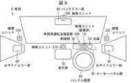
図2は、車両8における車両用運転支援装置100の各部の配置構成を模式的に示した図である。図2に示すように、車両8は、スピードメータ、油圧、バッテーリ電圧、およびその他アラートを表示する部分であるメーターパネル部90と、ハンドル装置80とを備えている。また、車両8には、バックミラー部40、右サイドミラー部50、左サイドミラー部60、およびメーターパネル部90を含む運転補助装置が備えられている。[Arrangement configuration of each part in vehicle]
FIG. 2 is a view schematically showing an arrangement configuration of each part of the vehicle
メーターパネル部90は、運転者の顔より下方向に配設されている。バックミラー部40は、運転者の顔より上方向に配設されている。右サイドミラー部50は、運転者の顔より右方向に配設されている。左サイドミラー部60は、運転者の顔より左方向に配設されている。 The meter panel unit 90 is disposed below the driver's face. The rearview mirror unit 40 is disposed above the driver's face. The right
撮像部10は、ハンドル装置80を操作する運転手の顔が対向する位置に設けられているのが望ましい。撮像部10は、例えば、メーターパネル部90内に配置することができる。撮像部10をメーターパネル部90内に配置する構成では、撮像部10は、運転者の顔より下方向から運転者を撮像する。 It is desirable that the imaging unit 10 be provided at a position where the face of the driver who operates the
光源20は、撮像部10の近傍に設けられ、撮像部10の撮像対象に向けて光を照射する。 The
制御部30は、例えばメーターパネル部90の近傍のインストルメントパネル内部に配置されている。 The
表示部70は、例えばセンターコンソールに設けられている。 The
〔校正値を算出する処理〕
車両用運転支援装置100は、車両8の運転を運転者が開始する前に、まず、運転中に検出する運転者の視線情報を校正するための校正値を算出する。図3(a)〜(e)は、校正値を算出する際に撮像部10によって撮像された同一運転者の撮像画像の例を示す図である。図4(a)、(b)は異なる運転者の撮像画像の例を示す図である。[Process of calculating calibration value]
Before the driver starts driving the vehicle 8, the vehicle driving
制御部30は、視線誘導部32の機能より、運転者による運転開始前に、運転者の視線を所定の複数箇所に順に誘導するとともに、各箇所に所定時間(例えば1秒から10秒の間の任意の時間)視線を送るように指示する。視線誘導部32は、例えば、1番目にメーターパネル部90に運転者の視線を誘導する。また、この際に撮像制御部31は、光源20により近赤外光を運転者の眼球に照射し、撮像部10により運転者を撮像する。図3(a)は、メーターパネル部90に視線が誘導された運転者の撮像画像の例を示している。 The
視線誘導部32は、2番目にバックミラー部40に運転者の視線を誘導し、3番目に右サイドミラー部50に運転者の視線を誘導し、4番目に左サイドミラー部60に運転者の視線を誘導し、最後にメーターパネル部90に運転者の視線を誘導することで、運転者の視線が一巡するべく誘導する。また、視線誘導部32は、すべての誘導箇所への運転者の視線の誘導を完了した後、視線誘導動作が完了した旨を表示部70に表示する情報によって運転者に通知してもよい。 The
撮像制御部31は、視線誘導部32による各誘導箇所において、光源20により近赤外光を運転者の眼球に照射し、撮像部10により運転者を撮像する。 The
図3(b)は、バックミラー部40に視線が誘導された運転者の撮像画像の例を示している。図3(c)は、右サイドミラー部50に視線が誘導された運転者の撮像画像の例を示している。図3(d)は、左サイドミラー部60に視線が誘導された運転者の撮像画像の例を示している。そして、図3(e)は、最後に再びメーターパネル部90に視線が誘導された運転者の撮像画像の例を示している。 FIG. 3B illustrates an example of a captured image of the driver whose line of sight is guided by the rearview mirror unit 40. FIG. 3C illustrates an example of a captured image of the driver whose line of sight is guided to the right
視線検出部33は、各誘導箇所に視線が誘導された運転者の撮像画像から運転者の左右の眼球の向きや、眼球の動きを含む視線情報を検出する。メーターパネル部90、バックミラー部40、右サイドミラー部50、左サイドミラー部60の位置は既知である。そのため、視線検出部33は、これらの位置と、左右の眼球の向き、および動きの少なくともいずれか一方を参照して、運転者の視線情報を検出する。 The line-of-
メーターパネル部90、バックミラー部40、右サイドミラー部50、および左サイドミラー部60に視線を送り、各部を確認する一連の動作は、運転者の運転開始前に行う通常の点検作業として違和感がない。よって、運転開始前の運転者の視線情報を検出するための上記の一連の処理を、自動車運行前の点検を促す内容として運転者に提示することによって運転者の視線をこれらの所定箇所に誘導し、点検の際の眼球の動きを視線情報として検出することで、運転者の負荷となる事なく、運転者の視線の初期値である校正値の検出を行うことができる。 A series of operations to send sight lines to the meter panel unit 90, the rear view mirror unit 40, the right
なお、視線誘導部32が運転者の視線を誘導する箇所は、表示部70、およびハンドル装置80を含んでもよい。また、視線誘導部32が運転者の視線を複数個所に誘導する際の誘導する順番は、任意の順番にて構成されてもよい。なお、視線誘導部32が運転者の視線を誘導する箇所は、任意のマーク(例えば星印等)で分かりやすく表示されていてもよい。 The position at which the sight
視線検出部33は、各誘導箇所で撮像した画像から検出した視線情報である運転者固有の眼球の動き(眼球の移動量)を校正値として登録する。なお、視線検出部33は、運転開始前には毎回、運転者固有の校正値を上記一連の処理を行って算出してもよい。また、視線検出部33は、校正値を運転者と対応付けて記憶し、撮像部10が撮像した運転者の撮像画像から運転者を特定し、既存の運転者であれば、改めて校正値を算出することなく、2回目以降の運転開始時には、登録済みの校正値を用いる構成であってもよい。 The
図4(a)、(b)は、バックミラー部40に視線が誘導されている異なる運転者の撮像画像の例を示す図である。図4(a)はある運転者の視線情報を示しており、図4(b)は他の運転者の視線情報を示す。このように、各運転補助装置に視線を送った際の視線の移動量は運転者の座高や頭の動かし方などにより運転者毎に異なる。そのため、運転者固有の視線情報を校正値として用いることでより高品位に運転者の視線情報を検出することができる。 FIGS. 4A and 4B are diagrams showing examples of captured images of different drivers whose line of sight is guided by the rearview mirror unit 40. FIG. FIG. 4A shows line-of-sight information of a certain driver, and FIG. 4B shows line-of-sight information of another driver. As described above, the amount of movement of the sight line when the sight line is sent to each driving assistance device differs depending on the driver's sitting height, how to move the head, and the like for each driver. Therefore, the driver's gaze information can be detected with higher quality by using the driver's own gaze information as the calibration value.
また、同一運転者でも、座席の設定位置や座り方等により各運転補助装置に視線を送った際の視線の移動量が運転回毎に異なる場合がある。よって、制御部30は運転開始前に毎回校正値を算出する構成とすることで、より高品位に運転者の視線を検出することができる。 Further, even with the same driver, the movement amount of the sight line when the sight line is sent to each driving assistance device may differ for each driving cycle depending on the setting position of the seat and the way of sitting. Therefore, the
また、視線誘導部32は、自動車運行前に、運転者に座席の前後や高さ位置の調整を促す内容の誘導情報を提示することによって、運転者の視線をメーターパネル部90、バックミラー部40、右サイドミラー部50、および左サイドミラー部60等の所定箇所に誘導してもよい。そして、視線検出部33は、運転者による座席の調整の際の眼球の動きを視線情報として検出し、運転者の視線の初期値である校正値とする構成であってもよい。 In addition, the sight
視線誘導部32は、自動車運行前に、運転者にバックミラー部40や左右のサイドミラー部50,60の位置の調整を促す内容の誘導情報を提示することによって、運転者の視線を所定箇所に誘導してもよい。そして、視線検出部33は、運転者によるバックミラー部40や左右のサイドミラー部50,60の調整の際の眼球の動きを視線情報として検出し、運転者の視線の初期値である校正値とする構成であってもよい。 The sight
また、制御部30は、複数の運転者毎に、各運転者の視線の初期値である校正値を記憶するとともに、各運転者の運転中に視線検出部33の機能により検出した視線情報を蓄積する構成であってもよい。制御部30は、蓄積した運転者の視線情報を参照して、各運転者の視線の癖などを分析し、分析結果に基づいて、安全運転へのアドバイス等の情報提供を行ってもよい。また、複数の運転者毎に視線情報が蓄積されるため、車両8の所有者は、車両8を家族や友人に貸し出した時や、運転を交代してもらった時に、他の運転者がどの様な運転をしているかを視線情報を振り返ることで知ることが可能となる。 Further, the
また、車両用運転支援装置100と、ナビゲーションシステムとを連携する事で、地図上のわき見をしやすい箇所、見通しの悪い箇所、事故多発箇所等の安全補助を行う必要がある箇所を特定し、その箇所に近づいたら運転者の視線情報を検出して、適切な安全運転へのアドバイス等の情報提供を行ってもよい。 In addition, by linking the vehicle driving
このように車両用運転支援装置100では、視線誘導部32によって所定箇所に視線が誘導された運転開始前の運転者の撮像画像から運転者固有の視線情報が検出され、検出された運転者固有の視線情報が運転者の視線の初期値とされる。そして、視線検出部33は、この運転者の視線の初期値を校正値として用いて、運転中に検出する運転者の視線情報を校正する。これにより、運転者固有の初期値を正確に取得することができる。また、運転者固有の初期値を校正値として用いて、運転中に検出する運転者の視線情報を校正することにより運転中の視線の計算量が軽減されるとともに、運転開始直後から、高品位に運転者の視線情報を検出することができる。よって、運転開始直後から、品位の高い運転者情報を運転者に提供することができる。 As described above, in the vehicle driving
また、高品位に運転者の視線情報を検出することができるため、例えば交通事故を起こした際の運転者の視線情報を解析することで、運転者がよそ見運転をしていたのか等の事故解析が可能となる。また、高品位に運転者の視線情報を検出することができるため、例えば居眠り運転をしている等の運転者の運転状況の解析が可能となり、安全運転へのアドバイス等の情報提供が可能となる。 In addition, since the line-of-sight information of the driver can be detected with high quality, for example, by analyzing the line-of-sight information of the driver at the time of a traffic accident, an accident such as whether the driver was driving looking away Analysis is possible. In addition, since the line-of-sight information of the driver can be detected with high quality, it is possible to analyze the driving situation of the driver such as, for example, a drowsy driving, and to provide information such as advice to safe driving Become.
例えば、高速道路上を運転中に運転者の視線が正面からズレてきていることが視線検出部33によって検出された場合には、疲労によって運転者の姿勢が変化している等といった運転者の運転状況の解析が可能となる。また、例えば、運転中に運転者の視線が定まっていないことが視線検出部33によって検出された場合には、運転者がイライラを感じているといった運転者の運転状況の解析が可能となる。そして、運転者の運転状況の解析結果に基づいて、よそ見の警告や休憩を促すアナウンスを流す等、安全運転の補助をきめ細かく実行することができる。 For example, when it is detected by the
〔実施形態2〕
本発明の実施形態2について、以下に説明する。なお、説明の便宜上、上記実施形態にて説明した部材と同じ機能を有する部材については、同じ符号を付記し、その説明を繰り返さない。また、実施形態2に係る車両用運転支援装置200の概略構成は、図1に示した車両用運転支援装置100と同様であり、その説明を省略する。Second Embodiment
Embodiment 2 of the present invention will be described below. In addition, about the member which has the same function as the member demonstrated in the said embodiment for convenience of explanation, the same code | symbol is appended, and the description is not repeated. Further, the schematic configuration of the vehicle driving support device 200 according to the second embodiment is the same as that of the vehicle driving
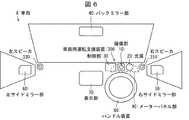
図5は、車両8における、車両用運転支援装置200の各部の配置構成を模式的に示した図である。 FIG. 5 is a view schematically showing an arrangement configuration of each part of the vehicle driving support device 200 in the vehicle 8. As shown in FIG.
図5に示すように、車両用運転支援装置200は、撮像部が複数の撮像ユニット10、210、220、230を含んで構成されている点で実施形態1の車両用運転支援装置100とは異なる。 As shown in FIG. 5, the vehicle driving support apparatus 200 is different from the vehicle driving
車両用運転支援装置200は、運転者に対向する位置に配置された撮像ユニット10に加え、例えば、表示部70の上部に配置された撮像ユニット210、右サイドミラー部50の上部(ピラー部)に配置された撮像ユニット220、左サイドミラー部60の上部(ピラー部)に配置された撮像ユニット230、バックミラー部40に配置された撮像ユニット240を備えている。 In addition to the imaging unit 10 disposed at a position facing the driver, for example, the imaging support unit 210 disposed at the upper part of the
このように、撮像部10で運転者を撮像するよりも、運転者をあらゆる角度から撮像することが可能となる。なお、複数の撮像ユニット10,210,220,230,240のそれぞれは、運転者を撮像可能な位置に設けられていれば良く、その設置位置、または設置数は上述した位置及び数に限定されない。 As described above, the driver can be imaged from any angle rather than imaging the driver by the imaging unit 10. Note that each of the plurality of
撮像制御部31は、複数の撮像ユニット10,210,220,230,240が互いに同期して撮像動作を行うように制御する。 The
視線検出部33は、複数の撮像ユニット10,210,220,230,240のそれぞれが同じタイミングで撮像した、別角度からの撮像画像を用いて、運転者固有の視線情報を検出することができる。よって、校正値をより高精度に求めることができ、高品位に運転者の視線情報を検出することができる。 The sight
〔実施形態3〕
本発明の実施形態3について、以下に説明する。なお、説明の便宜上、上記実施形態にて説明した部材と同じ機能を有する部材については、同じ符号を付記し、その説明を繰り返さない。また、実施形態3に係る車両用運転支援装置300の概略構成は、図1に示した車両用運転支援装置100と同様であり、その説明を省略する。Third Embodiment
The third embodiment of the present invention will be described below. In addition, about the member which has the same function as the member demonstrated in the said embodiment for convenience of explanation, the same code | symbol is appended, and the description is not repeated. The schematic configuration of the vehicle driving support device 300 according to the third embodiment is the same as that of the vehicle driving
図6は、車両8における、車両用運転支援装置300の各部の配置構成を模式的に示した図である。 FIG. 6 is a view schematically showing an arrangement configuration of each part of the vehicle driving support device 300 in the vehicle 8. As shown in FIG.
図6に示すように、車両用運転支援装置300は、音声出力部である右スピーカ部310、および左スピーカ部320を含んで構成されている点で実施形態1の車両用運転支援装置100とは異なる。 As shown in FIG. 6, the vehicle driving support apparatus 300 includes the
視線誘導部32は、表示部70に表示する誘導情報によって運転者の視線を所定箇所に誘導する、および、左右のスピーカ部310,320から出力する音声ガイダンスによって運転者の視線を所定箇所に誘導する、の少なくとも何れか一方の誘導方法で、運転者の視線を所定箇所に誘導する。表示部70に表示する誘導情報によって運転者の視線を所定箇所に誘導する方法では、運転者は所定箇所に視線を送った後、次に視線を送る箇所を確認する為に、表示部70の表示を確認する必要がある。一方で、左右のスピーカ部310,320から出力する音声ガイダンスによって運転者の視線を所定箇所に誘導する方法では、運転者は表示部70の表示を確認することなく、音声ガイダンスに従って視線を所定箇所に送ることができる。左右のスピーカ部310,320から出力する音声ガイダンスによって運転者の視線を所定箇所に誘導する方法を採用することで、複数個所に運転者の視線を誘導する一巡の動作にかかる時間を短縮することができる。よって、運転者による運転開始前に、より短い時間で視線情報を校正するための校正値を算出することができる。 The
なお、図示は省略するが、撮像部10や、バックミラー部、左右のサイドミラー部50,60、及び、メーターパネル部90等の各視線誘導箇所の近傍に、パイロットランプを設置してもよい。そして、視線誘導部32は、これらのパイロットランプを順次点灯させることで運転者の視線を誘導しても良い。このように、表示部70に表示する誘導情報、および、左右のスピーカ部310,320から出力する音声ガイダンスの少なくとも何れか一方に、パイロットランプの点灯を併用することにより、より確実に運転者の視線を所定箇所へ誘導することができる。 Although illustration is omitted, a pilot lamp may be installed in the vicinity of each line of sight guidance point such as the imaging unit 10, the back mirror unit, the left and right
〔実施形態4〕
本発明の実施形態4について、以下に説明する。なお、説明の便宜上、上記実施形態にて説明した部材と同じ機能を有する部材については、同じ符号を付記し、その説明を繰り返さない。Embodiment 4
The fourth embodiment of the present invention will be described below. In addition, about the member which has the same function as the member demonstrated in the said embodiment for convenience of explanation, the same code | symbol is appended, and the description is not repeated.
図7は、車両用運転支援装置400の概略構成を示すブロック図である。図8は、車両8における、車両用運転支援装置400の各部の配置構成を模式的に示した図である。 FIG. 7 is a block diagram showing a schematic configuration of the vehicle driving
図7および図8に示すように、車両用運転支援装置400は、制御部430がバックミラー制御部435を含むとともに、バックミラー部410と、左サイドミラー撮像部440と含んで構成されている点で実施形態1の車両用運転支援装置100とは異なる。 As shown in FIGS. 7 and 8, in the vehicle driving
制御部430は、バックミラー制御部435の機能により、バックミラー部410の後述する左サイドミラー視線検知時作動部411と、ウィンカー作動時作動部412と、の作動を制御する。 The
左サイドミラー撮像部440は、撮像部10と同様、例えばCMOSやCCD等のイメージセンサと、レンズとが組み合わされたモジュールである。左サイドミラー撮像部440は、撮像制御部31の制御に応じて、左サイドミラー部60に映る鏡像と同一の画像を撮像する。 Similar to the imaging unit 10, the left side
なお、ハンドル装置80が車両8の進行方向に対して左側に配置されている車両においては、左サイドミラー撮像部440に代えて、右サイドミラー部50の近傍に撮像部が設けられているのが望ましい。 In a vehicle in which the
バックミラー部410は、左サイドミラー視線検知時作動部411と、ウィンカー作動時作動部412と、を含んでいる。左サイドミラー視線検知時作動部411、およびウィンカー作動時作動部412は、バックミラー部410に内蔵された、例えば液晶ディスプレイ等の表示装置である。左サイドミラー視線検知時作動部411、およびウィンカー作動時作動部412は、バックミラー制御部435の制御に応じて、画像を表示可能に構成されている。 The
(車両用運転支援装置400の動作)
車両用運転支援装置400は、実施形態1で説明した車両用運転支援装置100と同様に、運転者による運転開始前に、運転者固有の視線情報を校正値として検出する一連の動作を実行する。運転者による車両8の運転中には、運転開始前に算出した校正値を用いて、高品位に運転中の運転者の視線情報が検出される。(Operation of Driving Assist Device for Vehicle 400)
Similarly to the vehicle driving
制御部430は、視線検出部33の機能により、車両8を運転中の運転者が左サイドミラー部60に所定時間(例えば、1秒から3秒)視線を送っていることを検出すると、撮像制御部31の機能により、左サイドミラー撮像部440の撮像画像を取得する。制御部430は、バックミラー制御部435の機能により、左サイドミラー撮像部440の撮像画像をバックミラー部410の一部である左サイドミラー視線検知時作動部411に表示する。バックミラー制御部435は、左サイドミラー視線検知時作動部411への左サイドミラー撮像部440の撮像画像の表示動作を所定時間(例えば1秒から10秒)保持する。 When the
このように、左サイドミラー部60の鏡像と同様の画像を左サイドミラー撮像部440により撮像し、撮像画像をバックミラー部410の少なくとも一部に表示することができる。よって、運転者にとって確認し難い、運転者から遠い左横方向および左横後方の情報をバックミラー部410に表示された左サイドミラー撮像部440により撮像画像により確認することが出来、運転の安全性が向上する。 As described above, the left side
また、運転者が左車線への車線変更のためにウィンカーを作動した場合、制御部430は、左サイドミラー撮像部440の撮像画像を、バックミラー部410の一部であるウィンカー作動時作動部412に表示する。ウィンカー作動時作動部412は、図8に示すように、左サイドミラー視線検知時作動部411よりも広い表示領域を有する。 In addition, when the driver operates the blinker for lane change to the left lane, the
この構成によれば、左車線への車線変更時に、運転者にとって確認し難い、運転者から遠い左横方向および左横後方の情報を、ウィンカー作動時作動部412に表示された左サイドミラー撮像部440の撮像画像により確認することができる。よって、運転者は車線変更側の情報を容易に確認することができ、より安全な車線変更およびカーブが可能となる。 According to this configuration, when the driver changes lanes to the left lane, it is difficult for the driver to confirm information on the left lateral direction and left lateral back, which is far from the driver, displayed on the left side mirror image displayed on the
なお、ウィンカー作動時作動部412への左サイドミラー撮像部440の撮像画像の表示は、視線検出部33により、運転者が左サイドミラー部60に所定時間(例えば、1秒から3秒)視線を送っていることを検出した後に行われてもよい。これにより、運転者が左サイドミラー部60をきちんと確認したうえで左車線への車線変更を行おうとしていることを確認することができ、安全運転の補助を適切に行うことができる。 In addition, the display of the captured image of the left side
〔ソフトウェアによる実現例〕
車両用運転支援装置100の制御ブロック(特に撮像制御部31、視線誘導部32、視線検出部33、および表示制御部34)は、集積回路(ICチップ)等に形成された論理回路(ハードウェア)によって実現してもよいし、ソフトウェアによって実現してもよい。[Example of software implementation]
The control blocks (in particular, the
後者の場合、車両用運転支援装置100は、各機能を実現するソフトウェアであるプログラムの命令を実行するコンピュータを備えている。このコンピュータは、例えば少なくとも1つのプロセッサ(制御装置)を備えていると共に、上記プログラムを記憶したコンピュータ読み取り可能な少なくとも1つの記録媒体を備えている。そして、上記コンピュータにおいて、上記プロセッサが上記プログラムを上記記録媒体から読み取って実行することにより、本発明の目的が達成される。上記プロセッサとしては、例えばCPU(Central Processing Unit)を用いることができる。上記記録媒体としては、「一時的でない有形の媒体」、例えば、ROM(Read Only Memory)等の他、テープ、ディスク、カード、半導体メモリ、プログラマブルな論理回路などを用いることができる。また、上記プログラムを展開するRAM(Random Access Memory)などをさらに備えていてもよい。また、上記プログラムは、該プログラムを伝送可能な任意の伝送媒体(通信ネットワークや放送波等)を介して上記コンピュータに供給されてもよい。なお、本発明の一態様は、上記プログラムが電子的な伝送によって具現化された、搬送波に埋め込まれたデータ信号の形態でも実現され得る。 In the latter case, the vehicle driving
〔まとめ〕
本発明の態様1に係る車両用運転支援装置(100)は、車両(8)の運転者を撮像する撮像部(10)と、上記撮像部(10)が撮像した画像から上記運転者の視線情報を検出する視線検出部(33)と、上記運転者による運転開始前に、上記運転者の視線を所定箇所に誘導する視線誘導部(32)と、を備え、上記視線検出部(33)は、上記視線誘導部(32)によって上記所定箇所に視線が誘導された上記運転者の撮像画像から上記運転者固有の視線情報を検出し、検出した上記運転者固有の視線情報を校正値として用いて、運転中に検出する上記運転者の視線情報を校正する構成である。[Summary]
The vehicle driving support apparatus (100) according to aspect 1 of the present invention includes an imaging unit (10) for imaging a driver of a vehicle (8), and a line of sight of the driver from an image imaged by the imaging unit (10). A gaze detection unit (33) for detecting information; and a gaze guidance unit (32) for guiding the driver's gaze to a predetermined location before the driver starts driving, the gaze detection unit (33) The visual axis information unique to the driver is detected from the captured image of the driver whose visual axis is guided to the predetermined location by the visual line guidance unit (32), and the detected visual axis information unique to the driver is used as a calibration value. The configuration is used to calibrate the line-of-sight information of the driver detected during driving.
上記の構成によれば、運転開始前に校正値を算出し、算出した校正値を用いて運転中に検出する運転者の視線情報を校正するため、運転直後から運転者の視線を高品位に検出することができる。 According to the above configuration, the calibration value is calculated before the start of driving, and the calculated calibration value is used to calibrate the driver's line-of-sight information detected during driving. It can be detected.
本発明の態様2に係る車両用運転支援装置(100)は、上記の態様1において、上記視線誘導部(32)は、車両(8)におけるバックミラー部(40)、サイドミラー部(50,60)、表示部(70)、およびメーターパネル部(90)を含む運転補助装置に、上記運転者の視線を誘導する構成としてもよい。 In the vehicle driving support device (100) according to aspect 2 of the present invention, in the above aspect 1, the sight-line guiding portion (32) is a rearview mirror portion (40), a side mirror portion (50, 50) in the vehicle (8). 60) The driving assistance apparatus including the display unit (70) and the meter panel unit (90) may be configured to guide the line of sight of the driver.
上記の構成によれば、運転者が運転中に目視で確認する運転補助装置のそれぞれに運転者の視線を誘導して校正値を算出するため、運転者固有の校正値を精度良く算出することができる。よって、運転直後から運転者の視線を高品位に検出することができる。 According to the above configuration, the driver-specific calibration value is accurately calculated because the driver's sight line is guided to each of the driving assistance devices that the driver visually confirms during driving to calculate the calibration value. Can. Thus, the driver's gaze can be detected with high quality immediately after driving.
本発明の態様3に係る車両用運転支援装置(100)は、上記の態様1または2において、上記運転者の眼球に向けて近赤外光を照射する光源(20)を備え、上記撮像部(10)は、近赤外波長を撮像可能なイメージセンサを備えている構成としてもよい。 The vehicle driving support apparatus (100) according to aspect 3 of the present invention includes the light source (20) for emitting near-infrared light toward the eyeball of the driver in the above aspect 1 or 2, and the imaging unit (10) may be configured to include an image sensor capable of imaging a near infrared wavelength.
上記の構成によれば、運転者の運転の妨げとなることなく、運転者の眼球に向けて光源(20)の光を照射して、眼球の画像を撮像することができ、眼球の動きや移動量を正確に検出することができる。 According to the above configuration, it is possible to irradiate the light of the light source (20) toward the eyeball of the driver without disturbing the driver's driving, and to capture an image of the eyeball, so that the movement of the eyeball The movement amount can be accurately detected.
本発明の態様4に係る車両用運転支援装置(200)は、上記の態様1から3の何れか一項において、上記撮像部(10)は、上記運転者を撮像可能な位置にそれぞれ配置された複数の撮像ユニット(10,210,220,230,240)を備えている構成としてもよい。 In the vehicle driving support device (200) according to aspect 4 of the present invention, in any one of aspects 1 to 3 above, the imaging unit (10) is disposed at a position where the driver can be imaged. A plurality of imaging units (10, 210, 220, 230, 240) may be provided.
上記の構成によれば、別角度からの撮像画像を用いて、運転者固有の視線情報を検出することができる。よって、校正値をより高精度に求めることができ、運転直後から運転者の視線を高品位に検出することができる。 According to the above configuration, it is possible to detect the line-of-sight information unique to the driver using the captured image from another angle. Therefore, the calibration value can be obtained with higher accuracy, and the driver's line of sight can be detected with high quality immediately after driving.
本発明の態様5に係る車両用運転支援装置(200)は、上記の態様4において、上記複数の撮像ユニット(10,210,220,230,240)は、互いに同期して動作する構成としてもよい。 In the vehicle driving support device (200) according to aspect 5 of the present invention, in the above aspect 4, the plurality of imaging units (10, 210, 220, 230, 240) operate in synchronization with each other. Good.
上記の構成によれば、同じタイミングで撮像した、別角度からの撮像画像を用いて、運転者固有の視線情報を検出することができるため、運転直後から運転者の視線を高品位に検出することができる。 According to the above configuration, it is possible to detect the line-of-sight information unique to the driver using the captured image from another angle, which is captured at the same timing, and therefore the line of sight of the driver is detected with high quality immediately after driving. be able to.
本発明の態様6に係る車両用運転支援装置は、上記の態様2から5の何れか一項において、上記視線誘導部は、上記表示部に表示する誘導情報によって上記運転者の視線を所定箇所に誘導する構成としてもよい。 The driving assistance apparatus for a vehicle according to aspect 6 of the present invention is any one of aspects 2 to 5 above, wherein the sight-line guiding unit is configured to set the sight line of the driver according to the guidance information displayed on the display unit. It may be configured to be
上記の構成によれば、運転者にとって分かりやすく、運転者の視線を、所定箇所に誘導することができる。 According to the above configuration, the driver can easily understand the line of sight of the driver to a predetermined location.
本発明の態様7に係る車両用運転支援装置は、上記の態様1から6の何れか一項において、上記視線誘導部は、音声出力部を介して出力する音声ガイダンスによって、上記運転者の視線を所定箇所に誘導する構成としてもよい。 The driving assistance apparatus for a vehicle according to aspect 7 of the present invention is any one of the above aspects 1 to 6, wherein the line-of-sight guidance unit outputs the voice guidance of the driver by voice guidance output via a voice output unit. May be guided to a predetermined location.
上記の構成によれば、運転者にとって分かりやすく、運転者の視線を、所定箇所に誘導することができる。また、複数個所の運転者の視線を誘導する際には、誘導時間を短縮することができ、運転開始前の校正値の算出動作の時間短縮を図ることができる。 According to the above configuration, the driver can easily understand the line of sight of the driver to a predetermined location. In addition, when the line of sight of the driver at a plurality of locations is guided, the induction time can be shortened, and the time of calculation operation of the calibration value before the start of driving can be shortened.
本発明の態様8に係る車両用運転支援装置(100)は、上記の態様1から7の何れか一項において、上記視線誘導部(32)は、自動車運行前の点検及び座席の調整の少なくとも何れかを促す内容を提示することによって上記運転者の視線を所定箇所に誘導し、上記視線検出部は、上記運転者による上記点検及び座席の調整の少なくとも何れかの際の眼球の動きを上記視線情報として検出し、検出した上記視線情報を上記校正値として用いる構成としてもよい。 The vehicle driving support apparatus (100) according to aspect 8 of the present invention is any one of the above aspects 1 to 7, wherein the sight-line guiding unit (32) performs at least inspection and adjustment of the seat before the vehicle is operated. The line of sight of the driver is guided to a predetermined location by presenting a content prompting any one, and the line of sight detection unit performs the movement of the eyeball during the inspection and / or the adjustment of the seat by the driver. The line-of-sight information detected and detected as line-of-sight information may be used as the calibration value.
上記の構成によれば、校正値をより高精度に求めることができ、運転直後から運転者の視線を高品位に検出することができる。 According to the above configuration, the calibration value can be obtained with higher accuracy, and the driver's gaze can be detected with high quality immediately after driving.
本発明の各態様に係る車両用運転支援装置は、コンピュータによって実現してもよく、この場合には、コンピュータを上記車両用運転支援装置が備える各部(ソフトウェア要素)として動作させることにより上記車両用運転支援装置をコンピュータにて実現させる車両用運転支援装置の制御プログラム、およびそれを記録したコンピュータ読み取り可能な記録媒体も、本発明の範疇に入る。 The vehicle driving support device according to each aspect of the present invention may be realized by a computer, and in this case, the computer is operated as each unit (software element) included in the vehicle driving support device. A control program of a vehicle driving support device for realizing the driving support device by a computer, and a computer readable recording medium recording the same also fall within the scope of the present invention.
本発明は上述した各実施形態に限定されるものではなく、請求項に示した範囲で種々の変更が可能であり、異なる実施形態にそれぞれ開示された技術的手段を適宜組み合わせて得られる実施形態についても本発明の技術的範囲に含まれる。さらに、各実施形態にそれぞれ開示された技術的手段を組み合わせることにより、新しい技術的特徴を形成することができる。 The present invention is not limited to the above-described embodiments, and various modifications can be made within the scope of the claims, and embodiments obtained by appropriately combining the technical means disclosed in the different embodiments. Is also included in the technical scope of the present invention. Furthermore, new technical features can be formed by combining the technical means disclosed in each embodiment.
8 車両
10、210、220、230、240 撮像ユニット
10 撮像部
20 光源
30、430 制御部
70 表示部
31 撮像制御部
33 視線検出部
32 視線誘導部
40、410 バックミラー部
50 右サイドミラー部
60 左サイドミラー部
90 メーターパネル部
100、200、300、400 車両用運転支援装置
310 右スピーカ部(音声出力部)
320 左スピーカ部(音声出力部)8
320 Left speaker (audio output unit)
Claims (9)
Translated fromJapanese上記撮像部が撮像した画像から上記運転者の視線情報を検出する視線検出部と、
上記運転者による運転開始前に、上記運転者の視線を所定箇所に誘導する視線誘導部と、を備え、
上記視線検出部は、
上記視線誘導部によって上記所定箇所に視線が誘導された上記運転者の撮像画像から上記運転者固有の視線情報を検出し、検出した上記運転者固有の視線情報を校正値として用いて、運転中に検出する上記運転者の視線情報を校正する
ことを特徴とする車両用運転支援装置。An imaging unit for imaging a driver of a vehicle;
A gaze detection unit that detects gaze information of the driver from an image captured by the imaging unit;
A gaze guidance unit for guiding the gaze of the driver to a predetermined location before the driver starts driving;
The gaze detection unit
Line-of-sight information unique to the driver is detected from the captured image of the driver whose line-of-sight is guided to the predetermined location by the line-of-sight guidance unit, and the driver's own line-of-sight information detected is used as a calibration value during driving A vehicle driving support apparatus characterized by calibrating the line-of-sight information of the driver detected on the vehicle.
上記撮像部は、近赤外波長を撮像可能なイメージセンサを備えていることを特徴とする請求項1または2に記載の車両用運転支援装置。A light source for emitting near-infrared light to the driver's eyes;
The said imaging part is provided with the image sensor which can image near-infrared wavelength, The driving assistance apparatus for vehicles of Claim 1 or 2 characterized by the above-mentioned.
上記視線検出部は、上記運転者による上記点検及び座席の調整の少なくとも何れかの際の眼球の動きを上記視線情報として検出し、検出した上記視線情報を上記校正値として用いることを特徴とする請求項1から7の何れか一項に記載の車両用運転支援装置。The gaze guidance unit guides the gaze of the driver to a predetermined location by presenting contents prompting at least one of inspection before seat operation and adjustment of the seat.
The gaze detection unit detects, as the gaze information, movement of the eyeball during the inspection and / or seat adjustment by the driver, and uses the detected gaze information as the calibration value. A driving support system for a vehicle according to any one of claims 1 to 7.
Priority Applications (3)
| Application Number | Priority Date | Filing Date | Title |
|---|---|---|---|
| JP2017222665AJP2019095892A (en) | 2017-11-20 | 2017-11-20 | Vehicle drive supporting device and vehicle drive supporting program |
| US16/147,728US20190156133A1 (en) | 2017-11-20 | 2018-09-29 | Vehicle driving support apparatus and vehicle driving support program |
| CN201811341131.0ACN109866683A (en) | 2017-11-20 | 2018-11-12 | Driving assist apparatuses and methods |
Applications Claiming Priority (1)
| Application Number | Priority Date | Filing Date | Title |
|---|---|---|---|
| JP2017222665AJP2019095892A (en) | 2017-11-20 | 2017-11-20 | Vehicle drive supporting device and vehicle drive supporting program |
Publications (1)
| Publication Number | Publication Date |
|---|---|
| JP2019095892Atrue JP2019095892A (en) | 2019-06-20 |
Family
ID=66533061
Family Applications (1)
| Application Number | Title | Priority Date | Filing Date |
|---|---|---|---|
| JP2017222665APendingJP2019095892A (en) | 2017-11-20 | 2017-11-20 | Vehicle drive supporting device and vehicle drive supporting program |
Country Status (3)
| Country | Link |
|---|---|
| US (1) | US20190156133A1 (en) |
| JP (1) | JP2019095892A (en) |
| CN (1) | CN109866683A (en) |
Cited By (1)
| Publication number | Priority date | Publication date | Assignee | Title |
|---|---|---|---|---|
| JP2021157523A (en)* | 2020-03-27 | 2021-10-07 | 日本電気株式会社 | Image processing equipment, image processing methods and programs |
Families Citing this family (2)
| Publication number | Priority date | Publication date | Assignee | Title |
|---|---|---|---|---|
| US20190367038A1 (en)* | 2018-06-04 | 2019-12-05 | Sharp Kabushiki Kaisha | Driver monitoring device |
| CN115297230B (en)* | 2022-07-01 | 2024-05-14 | 智己汽车科技有限公司 | System and method for multiplexing electronic exterior rearview mirror and intelligent driving side rearview camera |
Family Cites Families (23)
| Publication number | Priority date | Publication date | Assignee | Title |
|---|---|---|---|---|
| US7006881B1 (en)* | 1991-12-23 | 2006-02-28 | Steven Hoffberg | Media recording device with remote graphic user interface |
| US6668221B2 (en)* | 2002-05-23 | 2003-12-23 | Delphi Technologies, Inc. | User discrimination control of vehicle infotainment system |
| US7835834B2 (en)* | 2005-05-16 | 2010-11-16 | Delphi Technologies, Inc. | Method of mitigating driver distraction |
| US8214105B2 (en)* | 2009-08-21 | 2012-07-03 | Metra Electronics Corporation | Methods and systems for automatic detection of steering wheel control signals |
| CN102656613B (en)* | 2009-12-18 | 2015-02-11 | 本田技研工业株式会社 | A predictive human-machine interface using eye gaze technology, blind spot indicators and driver experience |
| US9292471B2 (en)* | 2011-02-18 | 2016-03-22 | Honda Motor Co., Ltd. | Coordinated vehicle response system and method for driver behavior |
| US8731736B2 (en)* | 2011-02-22 | 2014-05-20 | Honda Motor Co., Ltd. | System and method for reducing driving skill atrophy |
| EP2564765B1 (en)* | 2011-09-02 | 2017-12-13 | Volvo Car Corporation | System and method for improving a performance estimation of an operator of a vehicle |
| US20140310075A1 (en)* | 2013-04-15 | 2014-10-16 | Flextronics Ap, Llc | Automatic Payment of Fees Based on Vehicle Location and User Detection |
| JP2014120111A (en)* | 2012-12-19 | 2014-06-30 | Aisin Aw Co Ltd | Travel support system, travel support method, and computer program |
| US9342986B2 (en)* | 2013-02-25 | 2016-05-17 | Honda Motor Co., Ltd. | Vehicle state prediction in real time risk assessments |
| US9050980B2 (en)* | 2013-02-25 | 2015-06-09 | Honda Motor Co., Ltd. | Real time risk assessment for advanced driver assist system |
| US20140257659A1 (en)* | 2013-03-11 | 2014-09-11 | Honda Motor Co., Ltd. | Real time risk assessments using risk functions |
| US9285587B2 (en)* | 2013-03-15 | 2016-03-15 | Inrix, Inc. | Window-oriented displays for travel user interfaces |
| US9434389B2 (en)* | 2013-11-18 | 2016-09-06 | Mitsubishi Electric Research Laboratories, Inc. | Actions prediction for hypothetical driving conditions |
| US9244650B2 (en)* | 2014-01-15 | 2016-01-26 | Microsoft Technology Licensing, Llc | Post-drive summary with tutorial |
| US9365213B2 (en)* | 2014-04-30 | 2016-06-14 | Here Global B.V. | Mode transition for an autonomous vehicle |
| US9440658B2 (en)* | 2014-05-05 | 2016-09-13 | GM Global Technology Operations LLC | System and method for controlling an automobile using eye gaze data |
| WO2015190204A1 (en)* | 2014-06-09 | 2015-12-17 | 国立大学法人静岡大学 | Pupil detection system, gaze detection system, pupil detection method, and pupil detection program |
| JP6303907B2 (en)* | 2014-08-08 | 2018-04-04 | 株式会社デンソー | Driver monitoring device |
| US9530065B2 (en)* | 2014-10-15 | 2016-12-27 | GM Global Technology Operations LLC | Systems and methods for use at a vehicle including an eye tracking device |
| CN107072524B (en)* | 2014-11-19 | 2018-11-30 | 夏普株式会社 | eye movement detection device |
| CN105235595A (en)* | 2015-10-30 | 2016-01-13 | 浪潮集团有限公司 | Auxiliary driving method, automobile data recorder, display device and system |
- 2017
- 2017-11-20JPJP2017222665Apatent/JP2019095892A/enactivePending
- 2018
- 2018-09-29USUS16/147,728patent/US20190156133A1/ennot_activeAbandoned
- 2018-11-12CNCN201811341131.0Apatent/CN109866683A/enactivePending
Cited By (1)
| Publication number | Priority date | Publication date | Assignee | Title |
|---|---|---|---|---|
| JP2021157523A (en)* | 2020-03-27 | 2021-10-07 | 日本電気株式会社 | Image processing equipment, image processing methods and programs |
Also Published As
| Publication number | Publication date |
|---|---|
| CN109866683A (en) | 2019-06-11 |
| US20190156133A1 (en) | 2019-05-23 |
Similar Documents
| Publication | Publication Date | Title |
|---|---|---|
| JP6454368B2 (en) | Vehicle display system and method for controlling vehicle display system | |
| US11440473B2 (en) | Driving assistance apparatus | |
| CN108621923B (en) | Display system for vehicle and control method for display system for vehicle | |
| JP5088669B2 (en) | Vehicle periphery monitoring device | |
| KR101867915B1 (en) | Method for executing vehicle function using wearable device and vehicle for carrying out the same | |
| US20150238087A1 (en) | Biological information measurement device and input device utilizing same | |
| JP7712774B2 (en) | Attention-based notifications | |
| TWI522257B (en) | Vehicle safety system and its operation method | |
| CN107010077B (en) | Method and adaptive driver assistance system for transmitting information to a driver of a motor vehicle | |
| CN105711511A (en) | Method for operating a head-up display, presentation apparatus, vehicle | |
| JP2010033106A (en) | Driver support device, driver support method, and driver support processing program | |
| JPH07117593A (en) | Vehicle alarm system | |
| JP2019095892A (en) | Vehicle drive supporting device and vehicle drive supporting program | |
| JP2018121287A (en) | Display control apparatus for vehicle, display system for vehicle, display control method for vehicle, and program | |
| JP4857891B2 (en) | Driving support device and program | |
| JP2018148530A (en) | Vehicle display controller, vehicle display system, vehicle display control method, and program | |
| JP2011086125A (en) | Visual recognition detection device | |
| WO2015092977A1 (en) | Sight line detection device and sight line detection method | |
| US11685411B2 (en) | Travel controller and method for travel control | |
| CN117622183A (en) | Notification device and notification method | |
| JP4720979B2 (en) | Vehicle monitoring device | |
| JP2019031176A (en) | Display device for vehicle | |
| JP2018013812A (en) | Driver state guide device and driver state guide program | |
| JP7609277B2 (en) | Driver's face recognition device and face recognition program | |
| KR20140141285A (en) | Device for Passenger tracking in a car |