JP2019088391A - Blood collection apparatus and method - Google Patents
Blood collection apparatus and methodDownload PDFInfo
- Publication number
- JP2019088391A JP2019088391AJP2017218375AJP2017218375AJP2019088391AJP 2019088391 AJP2019088391 AJP 2019088391AJP 2017218375 AJP2017218375 AJP 2017218375AJP 2017218375 AJP2017218375 AJP 2017218375AJP 2019088391 AJP2019088391 AJP 2019088391A
- Authority
- JP
- Japan
- Prior art keywords
- target site
- blood collection
- puncture target
- puncture
- blood
- Prior art date
- Legal status (The legal status is an assumption and is not a legal conclusion. Google has not performed a legal analysis and makes no representation as to the accuracy of the status listed.)
- Granted
Links
Images


Classifications
- A—HUMAN NECESSITIES
- A61—MEDICAL OR VETERINARY SCIENCE; HYGIENE
- A61B—DIAGNOSIS; SURGERY; IDENTIFICATION
- A61B5/00—Measuring for diagnostic purposes; Identification of persons
- A61B5/02—Detecting, measuring or recording for evaluating the cardiovascular system, e.g. pulse, heart rate, blood pressure or blood flow
- A61B5/026—Measuring blood flow
- A—HUMAN NECESSITIES
- A61—MEDICAL OR VETERINARY SCIENCE; HYGIENE
- A61B—DIAGNOSIS; SURGERY; IDENTIFICATION
- A61B5/00—Measuring for diagnostic purposes; Identification of persons
- A61B5/15—Devices for taking samples of blood
- A61B5/151—Devices specially adapted for taking samples of capillary blood, e.g. by lancets, needles or blades
Landscapes
- Health & Medical Sciences (AREA)
- Life Sciences & Earth Sciences (AREA)
- Molecular Biology (AREA)
- Surgery (AREA)
- Biophysics (AREA)
- Pathology (AREA)
- Engineering & Computer Science (AREA)
- Biomedical Technology (AREA)
- Heart & Thoracic Surgery (AREA)
- Medical Informatics (AREA)
- Hematology (AREA)
- Physics & Mathematics (AREA)
- Animal Behavior & Ethology (AREA)
- General Health & Medical Sciences (AREA)
- Public Health (AREA)
- Veterinary Medicine (AREA)
- Cardiology (AREA)
- Physiology (AREA)
- Measurement Of The Respiration, Hearing Ability, Form, And Blood Characteristics Of Living Organisms (AREA)
- Measuring Pulse, Heart Rate, Blood Pressure Or Blood Flow (AREA)
Abstract
Translated fromJapaneseDescription
Translated fromJapanese本開示は、採血装置および採血方法に関する。 The present disclosure relates to a blood collection apparatus and a blood collection method.
健康的な生活を送るためには、定期的に健康診断を受診することが重要である。健康診断にて一般的によく実施されている検査の一つが、被検者から採血し血液の成分を分析することで全身の組織や臓器の状態を診断する血液検査である。一般的な血液検査は医療機関で実施することが多いが、血糖値のように測定項目を限定した自己検査として、家庭内で実施することも多い。 In order to live a healthy life, it is important to have a regular medical checkup. One of the commonly performed tests in a medical checkup is a blood test that diagnoses the condition of tissues and organs throughout the body by collecting blood from a subject and analyzing the components of the blood. Although a general blood test is often performed in a medical institution, it is often performed in the home as a self-test in which measurement items are limited like blood sugar level.
血糖値測定などの自己検査のための採血として実施されることが多い採血方法が、毛細血管採血である。毛細血管採血は、被検者の指に専用の皮膚穿刺用器具を押し当てることで指の毛細血管を穿刺し、流出した血液を採血する方法である。毛細血管採血は、静脈血採血よりも簡便な採血方法である。しかし、確保することのできる血量が少ないため、採血量を確保するためには、採血の際に指を圧迫し絞るなどの煩雑な作業を必要とする。 Capillary blood collection is a blood collection method often performed as blood collection for self-examination such as blood sugar level measurement. Capillary blood collection is a method of puncturing a capillary of a finger by pressing a dedicated skin puncturing device against the finger of a subject, and collecting the drained blood. Capillary blood collection is a simpler method of blood collection than venous blood collection. However, since the amount of blood that can be secured is small, in order to secure the amount of blood collection, a complicated operation such as pressing and squeezing a finger at the time of blood collection is required.
例えば、特許文献1は、指からの採血を自動化する採血装置について開示する。この採血装置は、穿刺器、採血管、絆創膏を保持するカートリッジと、カートリッジの位置を変化させ、かつ穿刺器、容器、シールを指先に押し当てる動作をするための駆動機構と、指先の一部を固定するための固定機構と、指の根元を圧迫するための圧迫機構を備えていることを特徴とし、指の根元を圧迫したのち穿刺器で被検者の指先を穿孔し、穿刺痕から採血管に血液を採取し、圧迫を解放したのち絆創膏で穿刺痕を止血する。 For example,
また、例えば、特許文献2は、検査に必要な量の血液を採取する採血装置について開示する。この採血装置は、指先の穿刺後に指先から遠い締め付け部材から穿刺部位に近い締付け部材へと順番に圧迫部位を移すことで、血液を指先に押し出し、穿刺部位から血液を絞り出すことにより、採取する血量を増加させている。 Also, for example, Patent Document 2 discloses a blood collection apparatus for collecting an amount of blood necessary for a test. This blood collection apparatus pushes blood to the fingertip by sequentially transferring the compression site from the clamping member far from the fingertip to the clamping member close to the puncture site after puncturing the fingertip, and collects blood by squeezing the blood from the puncture site. The amount is increasing.
さらに、例えば、特許文献3は、毛細血管を識別・抽出する採血装置について開示する。この採血装置は、被採血部位に赤外線など長波長域の光を照射し、反射された光を受光することで毛細血管の密集度を判定し、採血者に告知する。採血者は、告知を受けて採血動作を実施することができるようになる。 Furthermore, for example, Patent Document 3 discloses a blood collection device that identifies and extracts capillaries. The blood collection apparatus irradiates light of a long wavelength region such as infrared light to a portion to be collected, and receives the reflected light to determine the density of capillaries and notify the blood collection person. The blood collector can receive the notification and perform the blood collection operation.
上記特許文献1から3に記載の採血装置は何れも、被採血者(被検者とも言う)が煩雑な作業をせずに指先からの採血の実施を可能にするという利点を有している。 The blood collection apparatuses described in
一方、被採血者の体質には個人差があり、また被採血者の体調も変化するため、どのような被検者に対しても常に安定した採血を実現するためには、これらの差に対するロバスト性を有した採血装置が求められる。 On the other hand, since there is individual difference in the constitution of the subject, and also the physical condition of the subject changes, in order to always obtain stable blood collection for any subject, it is necessary to There is a need for a robust blood collection device.
しかしながら、特許文献1から3に記載の採血装置においては、このような被採血者による個別事情についてまで対応して採血を行うことができるものではない。 However, in the blood collection apparatuses described in
本開示は上述のような状況に鑑みてなされたものであり、各被検者の個別事情に合わせて安全かつ簡便に指先からの採血を実現する採血技術を提供する。 The present disclosure has been made in view of the above-described circumstances, and provides a blood collection technique for realizing blood collection from a fingertip safely and easily according to the individual circumstances of each subject.
上記課題を解決するために、本開示による採血装置は、生体の穿刺対象部位の状態を検知する検知部と、検知部の検知結果に基づいて、穿刺対象部位に対する採血動作を制御する制御部と、を備える。 In order to solve the above problems, a blood collection device according to the present disclosure includes a detection unit that detects a state of a puncture target site of a living body, and a control unit that controls a blood collection operation for the puncture target site based on the detection result of the detection unit. And.
本開示に関連する更なる特徴は、本明細書の記述、添付図面から明らかになるものである。また、本開示の態様は、要素及び多様な要素の組み合わせ及び以降の詳細な記述と添付される特許請求の範囲の様態により達成され実現される。 Further features related to the present disclosure will be apparent from the description of the present specification and the accompanying drawings. Also, aspects of the present disclosure are achieved and realized by means of the elements and combinations of various elements and the following detailed description and the appended claims.
本明細書の記述は典型的な例示に過ぎず、本開示の特許請求の範囲又は適用例を如何なる意味に於いても限定するものではないことを理解する必要がある。 It should be understood that the description of the present specification is merely exemplary and does not limit the scope of the claims or application of the present disclosure in any way.
本開示によれば、各被検者の個別事情に合わせて安全かつ簡便に指先からの採血を実現することができるようになる。 According to the present disclosure, blood can be collected from the fingertip safely and easily according to the individual circumstances of each subject.
全身の組織や臓器の状態を診断することができる血液検査は健康的な生活を維持する上で重要な検査であり、医療機関の他、家庭内でも実施されることが増えると考えられている。血液検査の実施には被検者からの採血は必須であるため、家庭での実施のためには、誰でも簡単・安全に採血することができることが好ましい。 A blood test that can diagnose the condition of tissues and organs throughout the body is an important test for maintaining a healthy life, and it is thought that it will be more frequently performed at home as well as at medical institutions. . Since blood collection from a subject is essential for conducting a blood test, it is preferable for anyone at home to be able to collect blood easily and safely.
そこで、本開発者らは、自動採血ための方法及びシステムを種々検討した結果、本開示の実施形態に至った。本開示の実施形態による採血装置は、例えば、被採血者(被検者)によって一定時間内に採取できる血量が異なることに鑑みてなされたものであり、被採血者における採血箇所の状態をモニタリングして採血動作を制御することにより、各被採血者の個別事情に合わせて採血を実行する。 Thus, as a result of various investigations on the method and system for automatic blood collection, the present developers came to an embodiment of the present disclosure. The blood collection apparatus according to the embodiment of the present disclosure is, for example, made in view of the fact that the blood volume that can be collected within a fixed time varies depending on the subject (subject), the condition of the blood collection point in the subject By monitoring and controlling the blood collection operation, blood collection is performed according to the individual circumstances of each subject.
以下、添付図面を参照して本開示の実施形態について詳細に説明する。添付図面では、機能的に同じ要素は同じ番号で表示される場合もある。添付図面は本開示の原理に則った具体的な実施形態(実装例)を示しているが、これらは本開示の理解のためのものであり、決して本開示を限定的に解釈するために用いられるものではない。 Hereinafter, embodiments of the present disclosure will be described in detail with reference to the accompanying drawings. In the attached drawings, functionally the same elements may be denoted by the same numbers. Although the attached drawings show specific embodiments (implementation examples) in accordance with the principles of the present disclosure, these are only for the understanding of the present disclosure, and are not used for limiting interpretation of the present disclosure. It is not something that can be done.
本実施形態では、当業者が本開示を実施するのに十分詳細にその説明がなされているが、他の実装・形態も可能で、本開示の技術的思想の範囲と精神を逸脱することなく構成・構造の変更や多様な要素の置き換えが可能であることを理解する必要がある。従って、以降の記述をこれに限定して解釈してはならない。なお、実施形態は単なる一例であって、各要素同士の組み合わせ、公知又は周知の技術との組み合わせや置換による他の態様も可能であることは言うまでもない。 While this embodiment is described in sufficient detail to enable those skilled in the art to practice the present disclosure, other implementations are possible, without departing from the scope and spirit of the technical idea of the present disclosure. It is necessary to understand that it is possible to change the configuration / structure and replace various elements. Therefore, the following description should not be interpreted in a limited manner. It is needless to say that the embodiment is merely an example, and that other embodiments by combination of respective elements, combination with known or known techniques, and substitution are also possible.
<採決装置の基本構成>
始めに、図1を用いて、本開示の実施形態による採血装置1の基本構成について説明する。図1は、本実施形態による採血装置1の基本構成を示す図である。採血装置1は、穿刺針(穿孔針)を有する穿刺器112、採血管114、および絆創膏116を含むカートリッジ11と、カートリッジ11の移動を制御する駆動機構12と、指156の周囲を締め付けるカフ151を備えた指締め付け機構15と、指先1561の血量を計測するための血量測定機構19と、血量測定機構19の出力値に応じて指締め付け機構15の動作を制御するための制御機構(制御装置:例えば、コンピュータ(プロセッサ)で構成される)16と、を備えている。<Basic configuration of voting device>
First, a basic configuration of a
駆動機構12は、水平方向駆動機構120と垂直方向駆動機構121とによって構成される。水平方向駆動機構120は、カートリッジ11を水平方向(紙面のx方向)に移動させ、指先1561の直下に穿刺器112、採血管114、または絆創膏116が位置するようにする。垂直方向駆動機構121は、指先1561の直下に配置された穿刺器112、採血管114または絆創膏116を、垂直方向(紙面のy方向)に移動させ、指先1561に近づけるか、もしくは押し付ける。穿刺器112を指先1561に押し付けることで指先1561を穿刺し、採血管114を指先1561に近づけることで、穿刺箇所から出た血液を周囲に飛散させずに回収し、絆創膏116を指先1561に押し付けることで、穿刺箇所を止血することができる。 The
指締め付け機構15は、カフ151と、カフ151の内圧を制御するためのバルブ153及びポンプ154と、内圧を計測する圧力センサ155とによって構成される。カフ151の内圧を制御することで指156の締め付け圧を調整することができるように構成されている。 The
血量測定機構19は、受光器190と、光源191とによって構成される。血量測定機構19は、光源191から近赤外光1911を指先1561に照射し、受光器190で指先1561からの反射光(照射された近赤外光のうちヘモグロビンで吸収されずに戻ってきた戻り光)1901の光量を計測するように構成される。照射された近赤外光1911は血液中のヘモグロビンによって吸収される。このため、指先1561の血量が多いほど、受光器190が検出する反射光(戻り光)1901の光量は低下する。本実施形態では、受光器190として光センサを用いているが、指先1561全体の情報が必要なときはカメラを使用してもよい。また、本実施形態では照射光として近赤外光を利用しているが、指先1561の色の変化を捉えることが可能であれば、光源191に白色光源、受光器190に可視光用の光センサもしくはカメラを使用しても良い。 The blood
<採血動作の手順(概要)>
次に、図1および図2を用いて、採血装置1による指156の圧迫、穿刺、採血までの手順について説明する。図2は、受光器190が計測した近赤外光の光量に応じたカフ151および穿刺器112の動作内容を示す概念図であり、また、各動作における採血量の変移も示す図である。<Procedure of blood collection operation (outline)>
Next, the procedure from compression of the
(1)指156の圧迫から穿刺まで
指156をカフ151で圧迫すると指先1561が鬱血し、指先1561内の血量は増大する。そのため、光源191から発せられる近赤外光1911が指先1561で吸収される割合は増大し、受光器190が検出する反射光(戻り光)1901の光量は低下する(図2の期間P1参照)。その後、鬱血が安定するに伴い、受光量も一定値に近づく。受光量が穿刺前に設定した穿刺の基準値Aを下回った場合、制御機構16は、指先1561が十分に鬱血していると判断し、垂直方向駆動機構121を動作させ、穿刺器112で指先1561を穿刺する(図2のポイントP2参照)。穿刺後、制御機構16は、垂直方向駆動機構121により穿刺器112を下方に移動させた後、水平方向駆動機構120によりカートリッジを水平方向に移動させ、採血管114を指先1561の直下まで移動させる。穿刺箇所から流出する血液が採血管114によって採取される。(1) From Compression of
近赤外光の受講料が穿刺の基準値Aを下回らなかった場合は、制御機構16は、カフ151の内圧を下げて指156の締め付けを開放したのち、再度カフ151で指156を圧迫する(図2)。 If the near infrared light food does not fall below the puncturing reference value A, the
(2)穿刺から指156の開放まで
穿刺すると、穿刺箇所から出血するため、指先1561内の血量は減少する。そのため、光源191から発せられる近赤外光1911が指先1561で吸収される割合は減少し、受光器190が検出する反射光(指先からの戻り光)1901の光量は増加する(図2の期間P3参照)。その後、出血の減少に伴い、光量も一定値に近づく(図2の期間P4参照)。光量が穿刺前に設定したカフ開放の基準値Bを上回るか、穿刺時点から一定時間が経過した場合、制御機構16は、指先1561の血量が少ないと判断し、カフ151の内圧を下げて指156の締め付けを開放する(図2の期間P4参照)。(2) From Pricking to Opening of the
(3)指156の開放から指156の圧迫まで
締め付けの開放とともに指156の動脈も開き、指先1561に血液が流れ込むため、受光器190が検出する反射光(戻り光)1901の光量は低下する(図2の期間P5)。その後、光量も所定値に近づく(図2のポイントP6参照)。光量が穿刺前に設定したカフ圧迫の基準値Cを下回るか、開放時点から一定時間経過した場合、制御機構16は、カフ151の内圧を上げて指156を圧迫する。指156の圧迫により、穿刺箇所から再び血液は流出し、流出した血液を採血管114で採取する(図2の期間P7)。以降(2)と(3)を繰り返すことで採血量を増大することができる。(3) From the release of the
決まった手順により指採血を実施した場合、被採血者の体質や体調の差異により、採血量が大きく異なる可能性がある。しかし、本実施形態の血量測定機構19および制御機構16により、指先1561の血量に応じて、穿刺器112による穿刺のタイミングと、カフ151による指156の圧迫および開放のタイミングとを制御することにより、被採血者の体質や体調の差異による採血量のばらつきを抑え、採血量を増大することが可能になる。 When finger blood collection is performed according to a fixed procedure, the amount of blood collection may greatly differ due to the difference in the constitution or physical condition of the subject. However, the blood
以上のように、本実施形態では、指先1561の血量を光学的方法により計測し、指先1561の血量の変化から、穿刺のタイミング、カフ151による指156の圧迫・開放のタイミングを制御し、被採血者の体質や体調の差異による採血量のばらつきを抑え、採血量を増やしている。また、本実施形態では、指先1561の血量計測を利用することにより、装置の動作開始、指の固定、指の穿刺、指の採血、指の止血までの動作を自動化している。 As described above, in the present embodiment, the blood volume of the
<採決装置の外観および内部構成>
図3は、本実施形態による採血装置1の外観構成と内部構成例を示す図である。図3では、採血装置1の内部構成を示すため、採血装置1のケース100と指置き蓋101は断面表示としている。<Appearance and internal configuration of voting device>
FIG. 3 is a view showing an appearance configuration and an internal configuration example of the
採血装置1は、穿刺器112、採血管114および絆創膏116(図4参照)を内蔵する使い捨てのカートリッジ11と、カートリッジ11を保持するカートリッジホルダ122と、カートリッジホルダ122を水平方向(x方向)に移動させるための水平方向駆動機構120と、穿刺器112、採血管114または絆創膏116を、垂直方向(y方向)に移動させる垂直方向駆動機構121と、指の先端甲側を固定するための指押さえ機構13と、指156の周囲を締め付けるカフ151と、カフ151内の空気圧を調整するためのポンプ154、バルブ153と圧力センサ155を有する指締め付け機構15と、指押さえ機構13に固定された指先1561の血量を計測するための血量測定機構19と、血量測定機構19の出力値に応じて、水平方向駆動機構120、垂直方向駆動機構121、および指締め付け機構15の動作を制御する制御機構16と、制御機構16への指示内容の入力や制御機構16からの出力結果を表示するための入出力器と、を備えている。なお、入出力器は図示していないが、採血装置1に連結したパソコンやタブレットPCを用いることができる。例えば、制御機構16としてコンピュータを用いる場合、制御機構16の構成の一部として入出力器が設けられるようにしてもよい。 The
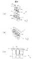
<カートリッジの構成>
次に、図4を用いて、本実施形態による採血装置1で用いられるカートリッジ11の構成について説明する。図4(a)、図4(b)および図4(c)はそれぞれ、カートリッジ11の組図、外観図および断面図である。<Configuration of cartridge>
Next, the configuration of the
カートリッジ11は、穿刺器112を保持する穿刺器ホルダ111と、採血管114を保持する採血管ホルダ113と、絆創膏116を保持する絆創膏ホルダ115を、カートリッジケース110内の穿刺器ホルダ用保持穴1110、採血管ホルダ用保持穴1130、絆創膏ホルダ用保持穴1150で保持する。穿刺器ホルダ用保持穴1110、採血管ホルダ用保持穴1130、絆創膏ホルダ用保持穴1150は貫通穴であるが、底側の直径が穿刺器ホルダ111、採血管ホルダ113、絆創膏ホルダ115の直径より小さいため、穿刺器ホルダ111、採血管ホルダ113、絆創膏ホルダ115は穿刺器ホルダ用保持穴1110、採血管ホルダ用保持穴1130、絆創膏ホルダ用保持穴1150から落下することはない。 The
穿刺器112は穿刺針(穿孔針)と穿刺針(穿孔針)を内蔵するホルダで構成されている一回使用の皮膚穿刺用器具であり、穿刺器112の先1120を指に押し付けると、穿刺針が一瞬飛び出し指の皮膚及び毛細血管を穿刺する。採血管114は血液を吸収するための吸収パッド1140と容器で構成されている血液採取用の容器であり、指の穿刺箇所(穿孔箇所)に吸収パッド1140を押しつけることで、穿刺箇所(穿孔箇所)から出血した血液を採取する。絆創膏116は、粘着性のシートの中心に吸収性のパッドを備え、粘着面を上向きにして絆創膏ホルダ115に取り付ける。 The
<採血装置の動作(詳細)>
図5は、本実施形態の採血装置1を用いた場合の、指からの採血動作を説明するためのフローチャートである。フローチャートには各工程に対応する図番が記載されている。図5に示されるように、採血装置1による採血動作は、(1)動作チェックプロセス、(2)指セットプロセス、(3)穿刺プロセス、(4)採血プロセス、および(5)止血プロセスの順に実施される。なお、採血装置1の操作は、被検者自らあるいは被検者以外の者によって行われる。なお、採血動作の主体は、制御機構(制御装置)16である。制御機構16は、例えば、図示しないメモリに格納された図5のフローチャートに相当するプログラムを当該メモリにアクセスして読み込み、図示しない内部メモリに読み込んだプログラムを展開して、各ステップの動作を実行する。<Operation of blood collection device (detail)>
FIG. 5 is a flowchart for explaining the blood collecting operation from the finger when the
(1)動作チェックプロセス
(i)ステップ501からステップ505
被検者などによる採決装置の電源ONを検知する(S501)と、制御機構16は、水平方向駆動機構120及び垂直方向駆動機構121を動作させ(S502)、それぞれの駆動機構の動作確認を実施する(S503)。動作確認に異常がある場合は動作を中止し(S504)、異常が無ければ被採血者のIDの入力を受け付ける(S505)。(1) Operation check process (i) Steps 501 to 505
When the power on of the voting apparatus by the subject or the like is detected (S501), the
(ii)ステップ506
制御機構16は、入出力器から入力された被採血者のIDに基づいて、当該被採血者に採血条件が定められているか(例えば、図示しないメモリに当該被採血者の採血条件が格納されているか)確認する(S506)。被採血者ごとに採血条件が異なる場合があり、そのような場合には対象とする当該被採血者に対して個別に採血条件が設定されていることがあるためである。ただし、例えば、初回の採血のときにはデフォルト値を設定された条件として採血を開始しても良い。そして、採血回数を重ねることにより、徐々に当該被採血者の身体的特徴等に合わせて採血条件を最適化していくようにしてもよい。(Ii)
The
被採血者の採血条件が装置のメモリに記録されている場合(S506でYesの場合)、処理はステップ507に移行し、被採血者の採血条件が装置のメモリに記録されていない場合(S506でNoの場合)、処理はステップ508に移行する。 If the blood collection conditions of the subject are recorded in the memory of the device (if Yes in S506), the process proceeds to step 507, and if the blood collection conditions of the subject are not recorded in the memory of the device (S506) And the process proceeds to step 508).
(iii)ステップ507からステップ509
ステップ507において、制御機構16は、図示しないメモリから採血条件を読み込む。採血条件は、例えば、穿刺からの経過時間T1と、バルブ153の開放時間(指156を開放する時間に相当)T2と、バルブ153を閉じてからの時間(指156を圧迫する時間に相当)T3と、圧迫および開放の繰り返し回数Nと、を含む。そして、制御機構16は、メモリから読み込んだ採血条件の変更がないか、オペレータ(被採血者とは異なる者、あるいは被採血者自身)による指示に基づいて判断する。採血条件の変更がない場合(ステップ509でNo)、処理はステップ510に移行する。採血条件の変更がある場合(ステップ509でYesの場合)、処理はステップ508に移行する。(Iii)
In
一方、ステップ508において、制御機構16は、オペレータが入力する採血条件(新たな条件、あるいは変更された条件。採血条件としては、例えば、上述のように、T1、T2、T3、およびNが含まれる)を受け付ける。 On the other hand, at
(iv)ステップ510からステップ512
制御機構16は、指締め付け機構15の蓋(図示せず)が開かれたことを検知する(S510:例えば、指置き蓋101の開閉を検知するセンサが設けられており、当該センサから制御機構16が通知を受けるようにしてもよい)。また、制御機構16は、カートリッジ11がカートリッジホルダ122にセットされたことを検知する(S511:例えば、カートリッジホルダ122にセンサを設けて当該センサから制御機構16に通知してもよいし、オペレータがカートリッジホルダ122へのカートリッジ11のセット完了を示す信号を入力してもよい)。さらに、制御機構16は、指締め付け機構15に指が置かれ、指締め付け機構15の蓋(図示せず)が閉じられたことを検知する(S512:例えば、指置き蓋101の開閉を検知するセンサから制御機構16が通知を受けるようにしてもよい)。(Iv) Steps 510 to 512
The
図6は、採血装置1へのカートリッジ11の取り付け手順を示す図である。オペレータ(被採血者とは異なる者、あるいは被採血者自身)が指置き蓋101を開け、カートリッジ11をカートリッジホルダ122にセットする。また、オペレータは、カートリッジ11をカートリッジホルダ122にセットした後、指置き蓋101を閉じる。カートリッジのセット後、カートリッジのチェック動作(S513から515)に移る。 FIG. 6 is a view showing the procedure for attaching the
(v)ステップ513から515
制御機構16は、セットされたカートリッジ11に異常があるか否かチェックする。例えば、制御機構16は、水平方向駆動機構120および垂直方向駆動機構121が動作し、カートリッジ11の穿刺器ホルダ111、採血管ホルダ113、および絆創膏ホルダ115が水平方向に異常なく(スムーズに)動作するか否かチェックする。制御機構16がカートリッジ11の動作に異常が無いと判断した場合(ステップ514でNoの場合)、処理は指セットプロセスに移行する。制御機構16がカートリッジ11の動作に異常があると判断した場合(ステップ514でYesの場合)、処理はステップ515に移行し、制御機構16は採血動作を中止する。(V) Steps 513 to 515
The
(2)指セットプロセス
(i)ステップ516からステップ520
制御機構16は、オペレータによって採血開始ボタンが押下されたことを検知する(S516)と、血量測定機構19の動作を開始する(S517)。(2) Finger setting process (i) Steps 516 to 520
When the
また、制御機構16は、指が正常に固定されているかチェックする(S518)。指先1561が正しく固定されていない場合、光源191からの近赤外光が指先1561に正しく照射されず、また受光器190で反射(戻り)光を受光することができないため、血量の計測値は、人の指を計測したときの計測値の範囲(許容値)から大きく外れる。そのため指の固定状態をチェックしている。制御機構16は、血量の計測値が許容値内であれば、指先1561は採血窓140に固定されていると判断する。 Further, the
例えば、図7を参照して指156の固定手順について説明する。まず、オペレータは、指押さえ機構13を開いた後、指156を指締め付け機構15の穴に挿入し、指先1561を指置き蓋101内の穴である採血窓140に置く。指先1561を採血窓140に置いたのち、オペレータが指押さえ機構13を閉じることで指先1561が採血窓140に固定される。指先1561が固定された後、指の固定状態のチェック動作に移ることになる。 For example, the fixing procedure of the
指156の固定状態がOKの場合(S518でYesの場合)、制御機構16は、指の固定状態に問題ない(指の固定状態OK)ことを通知(例えば、表示)する(S519)。指が正しく固定された後、血量の基準値設定に移る。 When the fixed state of the
指156の固定状態がNGの場合(S518でNoの場合)、制御機構16は、指156の固定状態が不十分であることを警告(例えば、表示)し、指の再固定を指示する(S520)。 When the fixation state of the
(ii)ステップ521およびステップ522
制御機構16は、指先1561の血量を再度計測し(S521)、近赤外光の反射(戻り)光量から、穿刺の基準値A、カフ開放の基準値B、およびカフ圧迫の基準値Cを設定する(S522:各基準値の意味については図2参照)。各基準値を設定した後、穿刺プロセスに移る。(Ii)
The
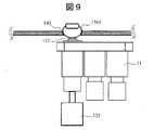
(3)穿刺プロセス
(i)ステップ523からステップ525
制御機構16は、ポンプ154の動作を開始させる指示(S523)とバルブ153を閉状態にする指示(S524)を出すことにより、カフ151の内圧を一定圧力まで上げ、指156を圧迫する。圧迫により指先1561は鬱血し、血量測定機構19で計測した指先1561の反射(戻り)光量は減少する。なお、図8および図9に、穿刺プロセスのときの指先1561、穿刺器112、カートリッジ11、垂直方向駆動機構121の位置関係が示されている。(3) Puncture process (i)
The
制御機構16は、圧力センサ155の値が所定圧力閾値Pより大きいか否か判定する。圧力センサ155の値が所定圧力閾値Pより大きい場合(S525でYesの場合)、処理はステップ526に移行する。圧力センサ155の値が所定圧力閾値P以下の場合(S525でNoの場合)、処理はステップ523に戻り、再度カフ151の内圧が上げられ、指が圧迫される。 The
(ii)ステップ526
制御機構16は、指先1561の戻り光量が基準値Aを下回ったか否か(指先1561の血量が第1所定値よりも大きいか否か)判断する。戻り光量が基準値Aを下回ったら穿刺するタイミングとして適切であると判断するためである。(Ii) Step 526
The
戻り光量が基準値Aを下回ったと判断された場合(S526でYesの場合)、処理はステップ527に移行する。一方、戻り光量が基準値Aを下回らずに戻り光量がほぼ一定(図2の光量のグラフがほぼ水平)となったと判断された場合(S526でNoの場合)、処理はステップ523に戻り、再度カフ151の内圧が上げられ、指が圧迫される。 If it is determined that the amount of return light is less than the reference value A (Yes at S526), the process proceeds to step 527. On the other hand, when it is determined that the amount of return light is not less than the reference value A and the amount of return light is almost constant (the graph of the light amount in FIG. 2 is almost horizontal) (No in S526), the process returns to step 523. The internal pressure of the
(iii)ステップ527
制御機構16は、戻り光量が基準値Aを下回っているときを穿刺のタイミングと判断し、垂直方向駆動機構121に駆動の指示を出す。制御機構16からの指示に応答して、垂直方向駆動機構121は、穿刺器112を指先1561に押し付けることで、指先1561を穿刺する。その後、垂直方向駆動機構121は穿刺器112を下げ、穿刺プロセスは終了する。穿刺プロセスが終了した後、採血プロセスに移る。(Iii)
The
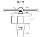
(4)採血プロセス
採血プロセスのとき、指先1561、採血管114、カートリッジ11、および垂直方向駆動機構121の位置関係は、図10に示されるような関係になる。(4) Blood Collection Process At the time of the blood collection process, the positional relationship between the
(i)ステップ528およびステップ529
制御機構16は、水平方向駆動機構120および垂直方向駆動機構121に対して、駆動の指示を送ると、その指示に応答して、水平方向駆動機構120は、指先1561の直下の位置に採血管114が配置するようにカートリッジ11を移動させ(S528)、続いて垂直方向駆動機構121は、採血管114を垂直方向に動かし、指先1561に採血管114を近づける(S529)。(I)
When the
穿刺箇所(穿孔箇所)からの血液1560の流出により、指先1561の戻り光量は上昇する。血量(ヘモグロビン量)の減少に伴い、照射された近赤外光がヘモグロビンに吸収される量が減少するからである。 The return light quantity of the
(ii)ステップ530
制御機構16は、指先1561の戻り光量が基準値Bよりも大きいか否か(指先1561の血量が第2所定値よりも小さいか否か)判断する(S530)。指先1561の戻り光量が基準値Bよりも大きいと判断された場合(S530でYesの場合)、処理はステップ531に移行する。指先1561の戻り光量が基準値B以下の場合(S530でNoの場合)処理はステップ532に移行する。(Ii)
The
(iii)ステップ531
穿刺プロセスから引き続き、指156はカフ151によって圧迫された状態だが、前述したように、制御機構16は、指先1561の戻り光量が基準値Bを上回ったときをカフ151の開放のタイミングと判断し、バルブ153(図1)を開状態にする指示を出す。当該指示により、バルブ153は開状態となり、カフ151の内圧は大気圧まで下がり、指156は開放される。開放とともに指156の動脈が開き、指先1561に血液が流れ込み、指先1561の血量が再び増加する。(Iii)
After the puncturing process, the
(iv)ステップ532
制御機構16は、指先1561に穿刺してからの時間を計測し、基準時間T1を経過したか否か判断する。ステップ530で血量が十分でない(戻り光が十分でない)と判断された場合には、時間をさらに掛けて指先1561からの血量を確保する趣旨である。(Iv) Step 532
The
基準時間T1を経過していない場合(S532でNoの場合)、処理はステップ530に戻る。基準時間T1を経過した場合(S532でYesの場合)、処理はステップ531に移行する。 If the reference time T1 has not passed (No in S532), the process returns to step 530. If the reference time T1 has elapsed (Yes in S532), the process proceeds to step 531.
(v)ステップ533
制御機構16は、指先1561の戻り光量が基準値Cを下回ったか否か(指先1561の血量が第3所定値よりも大きいか否か)判断する(S533)。制御機構16は、指先1561の戻り光量が基準値Cを下回ったときをカフ151の圧迫のタイミングと判断し、バルブ153を閉状態にする指示を出す。(V)
The
戻り光量が基準値Cを下回っている場合(S533でYesの場合:指先1561の血量が第3所定値よりも大きい場合)、処理はステップ535に移行する。指先1561の戻り光量が基準値C以上の場合(S538でNoの場合)処理はステップ534に移行する。 If the amount of return light is less than the reference value C (in the case of Yes in S533: the blood volume of the
(vi)ステップ534
制御機構16は、ステップ531でバルブ153を開放してからの時間を計測し、基準時間T2を経過したか否か判断する。(Vi)
The
基準時間T2を経過していない場合(S534でNoの場合)、処理はステップ531に戻る。基準時間T2を経過した場合(S534でYesの場合)、処理はステップ535に移行する。 If the reference time T2 has not passed (No in S534), the process returns to step 531. If the reference time T2 has elapsed (Yes in S534), the process proceeds to step 535.
(vii)ステップ535およびステップ536
制御機構16からの指示によりバルブ153は閉状態となり、カフ151の内圧は一定圧力まで上昇し、指156は圧迫される。圧迫により指先1561は再び鬱血し、穿刺箇所から血液1560が流出する。(Vii) Step 535 and
In response to an instruction from the
そして、制御機構16は、当該圧迫動作の回数nをカウントしており(S535)、圧迫回数が採血条件において設定されている設定回数Nに達したか否か判断する。nがNに達したと判断された場合(S536でYesの場合)、処理はステップ541(止血プロセス)に移行する。nがNに達していないと判断された場合(S536でNoの場合)、処理はステップ537に移行する。 Then, the
(viii)ステップ537からステップ540
ステップ537からステップ540、およびステップ531からステップ534の動作を実行することにより、カフ151による指156の開放と圧迫が繰り返され、繰返し回数が設定したN回となった後、止血プロセスに処理が移行することになる。(Viii) Steps 537 to 540
By performing the operations of step 537 to step 540 and step 531 to step 534, the release and compression of the
制御機構16は、指を再度圧迫するためにバルブ153を閉じ(S537)、カフ151の圧力を監視してカフ151の圧力値が所定の圧力値Pより大きくなったか否か判断する(S538)。カフ151の圧力が圧力値Pよりも大きくなった場合(S538でYesの場合)、処理はステップ539に移行し、カフ151の圧力が圧力値P以下の場合(S538でNoの場合)、指先1561の圧迫は継続される。 The
そして、制御機構16は、指先1561からの戻り光量がバルブ153開放の基準値Bより大きいか否か判断する(S539)。指先1561からの戻り光量がバルブ153開放の基準値Bより大きい場合(S539でYesの場合)、処理はステップ531に移行し、指先の圧迫→開放動作が繰り返される。指先1561からの戻り光量がバルブ153開放の基準値B以下の場合(S539でNoの場合)、処理はステップ540に移行する。 Then, the
ステップ540では、制御機構16は、バルブ153を閉じてからの経過時間を計測し、当該経過時間が基準時間T3(採血条件で設定された値)よりも大きいか判断する。バルブ153を閉じてからの経過時間が基準時間T3よりも大きい場合(S540でYesの場合)、処理は止血プロセス(S541)に移行する。バルブ153を閉じてからの経過時間が基準時間T3以下の場合(S540でNoの場合)、処理はステップ539に戻り、指先1561の圧迫動作が継続され、戻り光量と基準値Bとの比較が再度実行される。 In step 540, the
(5)止血プロセス
止血プロセスのとき、指先1561、絆創膏116、カートリッジ11、および垂直方向駆動機構121の位置関係は、図11に示されるような関係になる。(5) Hemostasis Process At the time of the hemostasis process, the positional relationship between the
(i)ステップ541からステップ543
制御機構16が水平方向駆動機構120および垂直方向駆動機構121に対して駆動の指示を送る。垂直方向駆動機構121は、当該指示に応答して、採血のために使用していた採血管114を下降させ、指先1561から採血管114を離す(S541)。そして、水平方向駆動機構120は、当該指示に応答して、指先1561の直下の位置に絆創膏116が配置するようにカートリッジ11を移動させる(S542)。(I) Steps 541 to 543
The
続いて、垂直方向駆動機構121は、上記指示に応答して、絆創膏116を垂直方向に動かし、絆創膏116を指先1561に押し付け、穿刺箇所を絆創膏116で封止する(S543)。 Subsequently, in response to the instruction, the
(ii)ステップ544
制御機構16は、止血動作(S541からS543)後、入出力器に対して、採血終了の表示を出力するように指示し、採血管の取り出し動作に移行する。(Ii) step 544
After the hemostasis operation (S 541 to S 543), the
(iii)ステップ545
制御機構16は、入出力器に採血終了の表示を出すように指示した後、被採血者によって指押さえ機構13が開かれ、指156が指締め付け機構15の穴から抜かれたこと(図7参照)を検知する。(Iii)
After the
指156が採血窓140から外れるため、血量測定機構19の計測値が人の指を計測したときの計測値の範囲(許容値)から大きく外れることになる。そこで、制御機構16は、血量の計測値が許容値外であれば採血窓140から指先1561が外れたと判断し、許容値内であれば採血窓140から指先1561が外れていないと判断する。 Since the
(iv)ステップ546
制御機構16は、採血窓140から指先1561が外れたか否か判断する。採血窓140から指先1561が外れていない場合(S546でNoの場合)、制御機構16は、入出力器にアラートを表示し、指の取り外しを操作者に指示する(促す)。採血窓140から指先1561が外れている場合(S546でYesの場合)、処理はステップ548に移行する。(Iv)
The
(v)ステップ548
制御機構16は、指の取り外しが完了した場合、入出力器に完了の表示を行う。それを受けて、オペレータは、採血装置1の指置き蓋101を開け、採血管114を取り出すことができるようになる。(V) Step 548
When the removal of the finger is completed, the
<まとめ>
本実施形態では、指先の血流計測機構、指の圧迫開放機構、穿刺器、採血容器を使用する採血装置を提供することで、どのような被検者でも常に安定した採血を実現することができるようになる。例えば、本実施形態の採血装置は、生体の穿刺対象部位(例えば、被採血者の指先)の状態(例えば、血量や部位の色(部位の色は、例えば、カメラやCOMSなどの撮像部を設けることにより検知可能))を検知し、その検知結果に基づいて、穿刺対象部位に対する採血動作(例えば、指先に針を穿刺する穿刺動作、指が挿入されたカフの収縮および伸長により指先を圧迫したり開放したりする動作)を制御する。このように被採血者の特定部位の状態に応じて採血動作を制御することにより、被採血者の身体的特徴に合わせて適切に採血を実施することができる。採血を実施したのに採血量が少なすぎてやり直しをしなければならなかったり、必要量以上に採血してしまったりする事態を避けられるため、被採血者の負担も軽減することができるようになる。<Summary>
In this embodiment, by providing a blood flow measurement mechanism using a finger tip, a finger compression release mechanism, a puncturing device, and a blood collection apparatus using a blood collection container, stable blood collection can always be realized for any subject. become able to. For example, in the blood collection device of the present embodiment, the state of a puncture target site (for example, a fingertip of a person to be collected) of a living body (for example, blood volume or color of the site (color of the site Detection), and based on the detection result, the blood collecting operation (for example, puncturing operation of puncturing the finger with the fingertip), contraction and extension of the cuff into which the finger is inserted Control the movement of compression and release. By controlling the blood collection operation according to the condition of the specific site of the blood collection subject in this manner, blood collection can be appropriately performed according to the physical characteristics of the blood collection subject. It is also possible to reduce the burden on the subject, as it is possible to avoid a situation where blood collection is too small and blood should be retried even if blood collection is performed or blood collection is more than necessary. Become.
当該採血装置は、穿刺対象部位に対して光(例えば、近赤外光)を照射し、穿刺対象部位で吸収されずに戻ってきた戻り光を検知することにより、穿刺対象部位の状態を検知する。近赤外光はヘモグロビンに吸収されるという性質があるため、対象部位における血量が多くなると戻り光の量が少なくなる。このように戻り光の量を検出することにより、簡単な構成で穿刺対象部位の状態を検知することができる。そして、採血装置は、この戻り光の量に基づいて、穿刺対象部位に対する、カフによる圧迫および開放のタイミング、または穿刺対象部位に対する穿刺のタイミングを制御する。 The blood collection apparatus irradiates light (for example, near infrared light) to the puncture target site, and detects the state of the puncture target site by detecting return light that is not absorbed by the puncture target site and returns. Do. Because near-infrared light has the property of being absorbed by hemoglobin, the amount of return light decreases as the blood volume at the target site increases. By detecting the amount of return light in this manner, the state of the region to be punctured can be detected with a simple configuration. Then, the blood collection apparatus controls the timing of compression and release by the cuff with respect to the puncture target site or the timing of puncture with respect to the puncture target site based on the amount of the return light.
採血装置は、穿刺対象部位を圧迫部(例えば、カフ)によって圧迫した後、穿刺対象部位の血量が第1基準値よりも増加したこと(戻り光量で表現すると、戻り光量が基準値Aよりも少なくなったこと)を検知した場合に、穿刺対象部位を穿刺するように穿刺部(例えば、針を有する穿刺器とその駆動機構)を制御する。また、採血装置は、穿刺対象部位を、圧迫部によって圧迫し、穿刺部によって穿刺した後、穿刺対象部位の血量が第2基準値にまで減少したこと(戻り光量が基準値Bまで達したこと)を検知した場合に、穿刺対象部位に対する圧迫を開放するように圧迫部(例えば、カフおよびポンプやバルブ)を制御する。さらに、採血装置は、穿刺対象部位を、圧迫部によって圧迫し、穿刺部によって穿刺し、さらに圧迫部によって開放した後、穿刺対象部位の血量が第3基準値よりも増加したこと(戻り光が基準値Cよりも少なくなったこと)を検知した場合に、穿刺対象部位を再度圧迫するように圧迫部を制御する。以上のような動作を実行することにより、被採血者を不快にさせずに、適切な血量を採取することができるようになる。 In the blood collection apparatus, after the puncture target site is compressed by the compression unit (for example, a cuff), the blood volume at the puncture target site is increased above the first reference value (when expressed as return light quantity, return light quantity is When it detects that it has decreased, the puncturing unit (for example, a puncturing device having a needle and its driving mechanism) is controlled so as to puncture the region to be punctured. In addition, the blood collection device squeezes the puncture target site with the compression section and punctures with the puncture section, and then the blood volume of the puncture target site decreases to the second reference value (the return light amount reaches the reference value B Control the compression part (eg, cuff and pump or valve) so as to release the compression on the puncture target site. Furthermore, the blood collection device squeezes the puncturing target site with the compression section, punctures with the puncturing section, and then releasing by the compression section, the blood volume of the puncturing target area increases more than the third reference value (return light Controls the compression portion so as to compress the puncture target site again when it detects that the value is smaller than the reference value C). By performing the above-described operation, it is possible to collect an appropriate blood volume without making the subject being annoyed.
1 採血装置
11 カートリッジ
12 駆動機構
13 指押さえ機構
15 指締め付け機構
16 制御機構
19 血量測定機構
100 ケース
101 指置き蓋
110 カートリッジケース
111 穿刺器ホルダ
112 穿刺器
113 採血管ホルダ
114 採血管
115 絆創膏ホルダ
116 絆創膏
120 水平方向駆動機構
121 垂直方向駆動機構
122 カートリッジホルダ
140 採血窓
151 カフ
153 バルブ
154 ポンプ
155 圧力センサ
156 指
190 受光器
191 光源
1110 穿刺器ホルダ用保持穴
1120 穿刺器の先
1130 採血管ホルダ用保持穴
1140 吸収パッド
1150 絆創膏ホルダ用保持穴
1560 血液
1561 指先
1901 反射光(戻り光)
1911 近赤外光DESCRIPTION OF
1911 Near infrared light
Claims (13)
Translated fromJapanese前記検知部の検知結果に基づいて、前記穿刺対象部位に対する採血動作を制御する制御部と、
を備える、採血装置。A detection unit that detects a state of a puncture target site of a living body;
A control unit that controls a blood collection operation for the puncture target site based on the detection result of the detection unit;
, A blood collection device.
前記検知部は、前記穿刺対象部位に対して光を照射することにより得られる前記穿刺対象部位からの戻り光を検知する、採血装置。In claim 1,
The detection unit detects a return light from the puncture target site obtained by irradiating light to the puncture target site.
前記制御部は、前記戻り光の量に基づいて、前記穿刺対象部位の圧迫および開放のタイミング、または前記穿刺対象部位に対する穿刺のタイミングを制御する、採血装置。In claim 2,
The control unit controls the timing of compression and release of the puncture target site or the timing of puncturing of the puncture target site based on the amount of the return light.
前記検知部は、前記穿刺対象部位の血量を検知する、採血装置。In claim 1,
The detection unit detects a blood volume of the puncture target site.
前記穿刺対象部位を圧迫部によって圧迫した後、前記検知部が前記穿刺対象部位の血量が第1基準値よりも増加したことを検知した場合に、前記制御部は、前記穿刺対象部位を穿刺するように穿刺部を制御する、採血装置。In claim 4,
The control unit punctures the puncture target site when the detection unit detects that the blood volume of the puncture target site has increased beyond a first reference value after the puncture target site is compressed by the compression unit. The blood collection device that controls the puncture unit to
前記穿刺対象部位を、前記圧迫部によって圧迫し、前記穿刺部によって穿刺した後、前記検知部が前記穿刺対象部位の血量が第2基準値にまで減少したことを検知した場合に、前記制御部は、前記穿刺対象部位に対する圧迫を開放するように前記圧迫部を制御する、採血装置。In claim 5,
The control is performed when the puncture target site is compressed by the compression unit and punctured by the puncture section, and then the detection unit detects that the blood volume of the puncture target site has decreased to a second reference value. The blood collection apparatus, wherein the unit controls the compression unit to release compression on the puncture target site.
前記穿刺対象部位を、前記圧迫部によって圧迫し、前記穿刺部によって穿刺し、前記圧迫部によって開放した後、前記検知部が前記穿刺対象部位の血量が第3基準値よりも増加したことを検知した場合に、前記制御部は、前記穿刺対象部位を再度圧迫するように前記圧迫部を制御する、採血装置。In claim 6,
After the puncturing target site is compressed by the pressing section, punctured by the puncturing section, and opened by the pressing section, the detection section may increase the blood volume of the puncturing target site above a third reference value. When it detects, the control unit controls the compression unit so as to compress the puncture target site again.
前記穿刺部は、前記穿刺対象部位を穿刺する穿孔針を含み、
前記圧迫部は、前記穿刺対象部位の一部を圧迫するための圧迫機構で構成され、
前記採血装置は、さらに、
前記穿刺対象部位の穿刺痕より流出する体液を捕集する容器と、
前記穿刺痕を封止するシールと、
前記穿刺対象部位と、前記穿孔針、前記容器および前記シールとの水平方向の相対位置を変化させ、かつ、前記穿刺対象部位と、前記穿孔針、前記容器および前記シールとの垂直方向の相対位置を変化させる駆動機構と、を備え、
前記制御部は、前記検知部の検知結果に基づいて、前記駆動機構と前記圧迫機構の動作を制御する、採血装置。In claim 7,
The puncturing unit includes a piercing needle for piercing the puncture target site,
The compression unit is configured of a compression mechanism for compressing a part of the puncture target site,
The blood collection apparatus further includes
A container for collecting the body fluid flowing out from the puncture mark of the puncture target site;
A seal for sealing the puncture mark;
The relative positions of the puncture target site, the piercing needle, the container and the seal in the horizontal direction are changed, and the relative positions of the puncture target site, the piercing needle, the container and the seal in the vertical direction Drive mechanism for changing
The control unit controls the operation of the drive mechanism and the compression mechanism based on the detection result of the detection unit.
前記穿刺対象部位の一部を露出させる孔を有する台を備え、
前記制御部は、前記検知部の検知結果に基づいて、前記孔からの前記穿刺対象部位の一部の露出状態を判断する、採血装置。In claim 8, further,
And a table having a hole exposing a part of the puncture target site,
The control unit determines the exposed state of a part of the puncture target site from the hole based on the detection result of the detection unit.
制御部が、前記検知部の検知結果に基づいて、前記穿刺対象部位に対する採血動作を制御することと、
を含む、採血方法。Detecting the state of the puncture target site of the living body by the detection unit;
Controlling a blood collection operation for the puncture target site based on the detection result of the detection unit;
Blood collection methods, including:
前記検知部は、前記穿刺対象部位に対して光を照射することにより得られる前記穿刺対象部位からの戻り光を検知する、採血方法。In claim 10,
The detection unit detects the return light from the puncture target site obtained by irradiating light to the puncture target site.
前記制御部は、前記戻り光の量に基づいて、前記穿刺対象部位の圧迫および開放のタイミング、または前記穿刺対象部位に対する穿刺のタイミングを制御する、採血方法。In claim 11,
The control unit controls the timing of compression and release of the puncture target site or the timing of puncturing of the puncture target site based on the amount of the return light.
前記検知部は、前記穿刺対象部位の血量を検知する、採血方法。In claim 10,
The detection unit detects a blood volume of the puncture target site.
Priority Applications (2)
| Application Number | Priority Date | Filing Date | Title |
|---|---|---|---|
| JP2017218375AJP6994910B2 (en) | 2017-11-13 | 2017-11-13 | How to operate the blood collection device and blood collection device |
| PCT/JP2018/039419WO2019093124A1 (en) | 2017-11-13 | 2018-10-24 | Blood collecting device and blood collecting method |
Applications Claiming Priority (1)
| Application Number | Priority Date | Filing Date | Title |
|---|---|---|---|
| JP2017218375AJP6994910B2 (en) | 2017-11-13 | 2017-11-13 | How to operate the blood collection device and blood collection device |
Publications (2)
| Publication Number | Publication Date |
|---|---|
| JP2019088391Atrue JP2019088391A (en) | 2019-06-13 |
| JP6994910B2 JP6994910B2 (en) | 2022-01-14 |
Family
ID=66438441
Family Applications (1)
| Application Number | Title | Priority Date | Filing Date |
|---|---|---|---|
| JP2017218375AActiveJP6994910B2 (en) | 2017-11-13 | 2017-11-13 | How to operate the blood collection device and blood collection device |
Country Status (2)
| Country | Link |
|---|---|
| JP (1) | JP6994910B2 (en) |
| WO (1) | WO2019093124A1 (en) |
Cited By (7)
| Publication number | Priority date | Publication date | Assignee | Title |
|---|---|---|---|---|
| JP2022109441A (en)* | 2021-01-15 | 2022-07-28 | 株式会社日立ハイテク | Blood collection device |
| JP2022148503A (en)* | 2021-03-24 | 2022-10-06 | カシオ計算機株式会社 | Information processing device, program, biometric information acquisition system, and biometric information acquisition method |
| WO2023053808A1 (en)* | 2021-09-29 | 2023-04-06 | 株式会社日立製作所 | Blood collection system and blood collection method |
| WO2024214578A1 (en)* | 2023-04-11 | 2024-10-17 | 株式会社日立ハイテク | Blood collection device and method |
| WO2025063020A1 (en)* | 2023-09-21 | 2025-03-27 | 株式会社日立ハイテク | Blood collection method and blood collection device |
| WO2025142023A1 (en)* | 2023-12-25 | 2025-07-03 | 株式会社日立ハイテク | Automated blood drawing device and automated blood drawing method |
| WO2025154528A1 (en)* | 2024-01-16 | 2025-07-24 | 株式会社日立ハイテク | Blood collection device and blood collection method |
Families Citing this family (3)
| Publication number | Priority date | Publication date | Assignee | Title |
|---|---|---|---|---|
| JP7157711B2 (en)* | 2019-07-19 | 2022-10-20 | 株式会社日立ハイテク | Blood collection device |
| CN110384509B (en)* | 2019-07-29 | 2022-02-11 | 重庆医药高等专科学校 | Multifunctional device for venous blood sampling |
| US20240315619A1 (en)* | 2021-06-29 | 2024-09-26 | Becton, Dickinson And Company | Blood Collection Kit With Blood Collection Devices of Multiple Sizes and Associated Sizing Systems and Methods |
Citations (11)
| Publication number | Priority date | Publication date | Assignee | Title |
|---|---|---|---|---|
| JPH09168530A (en)* | 1995-10-17 | 1997-06-30 | Dainippon Printing Co Ltd | Body fluid collecting device and body fluid analyzer using the same |
| WO2001041643A1 (en)* | 1999-12-13 | 2001-06-14 | Arkray, Inc. | Body fluid measuring apparatus with lancet and lancet holder used for the measuring apparatus |
| JP2003159238A (en)* | 2001-10-10 | 2003-06-03 | Lifescan Inc | Instrument for sampling physiological fluid |
| JP2005095521A (en)* | 2003-09-26 | 2005-04-14 | Terumo Corp | Puncture instrument, blood sugar level measuring instrument, and light irradiation device for puncture instrument |
| JP2005152620A (en)* | 2003-10-29 | 2005-06-16 | Arkray Inc | Puncture device |
| JP2005278740A (en)* | 2004-03-29 | 2005-10-13 | Citizen Watch Co Ltd | Blood collecting apparatus |
| JP2008212264A (en)* | 2007-03-01 | 2008-09-18 | Fujifilm Corp | Puncture device |
| JP2010510012A (en)* | 2006-11-24 | 2010-04-02 | エブオン | Medical miniature injection and sample collection device |
| WO2011122484A1 (en)* | 2010-03-27 | 2011-10-06 | ニプロ株式会社 | Blood sampling device |
| WO2016203853A1 (en)* | 2015-06-17 | 2016-12-22 | 株式会社 日立ハイテクノロジーズ | Blood collector |
| WO2017221698A1 (en)* | 2016-06-21 | 2017-12-28 | 株式会社 日立ハイテクノロジーズ | Blood collecting device and blood collecting method |
- 2017
- 2017-11-13JPJP2017218375Apatent/JP6994910B2/enactiveActive
- 2018
- 2018-10-24WOPCT/JP2018/039419patent/WO2019093124A1/ennot_activeCeased
Patent Citations (11)
| Publication number | Priority date | Publication date | Assignee | Title |
|---|---|---|---|---|
| JPH09168530A (en)* | 1995-10-17 | 1997-06-30 | Dainippon Printing Co Ltd | Body fluid collecting device and body fluid analyzer using the same |
| WO2001041643A1 (en)* | 1999-12-13 | 2001-06-14 | Arkray, Inc. | Body fluid measuring apparatus with lancet and lancet holder used for the measuring apparatus |
| JP2003159238A (en)* | 2001-10-10 | 2003-06-03 | Lifescan Inc | Instrument for sampling physiological fluid |
| JP2005095521A (en)* | 2003-09-26 | 2005-04-14 | Terumo Corp | Puncture instrument, blood sugar level measuring instrument, and light irradiation device for puncture instrument |
| JP2005152620A (en)* | 2003-10-29 | 2005-06-16 | Arkray Inc | Puncture device |
| JP2005278740A (en)* | 2004-03-29 | 2005-10-13 | Citizen Watch Co Ltd | Blood collecting apparatus |
| JP2010510012A (en)* | 2006-11-24 | 2010-04-02 | エブオン | Medical miniature injection and sample collection device |
| JP2008212264A (en)* | 2007-03-01 | 2008-09-18 | Fujifilm Corp | Puncture device |
| WO2011122484A1 (en)* | 2010-03-27 | 2011-10-06 | ニプロ株式会社 | Blood sampling device |
| WO2016203853A1 (en)* | 2015-06-17 | 2016-12-22 | 株式会社 日立ハイテクノロジーズ | Blood collector |
| WO2017221698A1 (en)* | 2016-06-21 | 2017-12-28 | 株式会社 日立ハイテクノロジーズ | Blood collecting device and blood collecting method |
Cited By (10)
| Publication number | Priority date | Publication date | Assignee | Title |
|---|---|---|---|---|
| JP2022109441A (en)* | 2021-01-15 | 2022-07-28 | 株式会社日立ハイテク | Blood collection device |
| JP7526681B2 (en) | 2021-01-15 | 2024-08-01 | 株式会社日立ハイテク | Blood collection device |
| JP2022148503A (en)* | 2021-03-24 | 2022-10-06 | カシオ計算機株式会社 | Information processing device, program, biometric information acquisition system, and biometric information acquisition method |
| WO2023053808A1 (en)* | 2021-09-29 | 2023-04-06 | 株式会社日立製作所 | Blood collection system and blood collection method |
| JP2023049080A (en)* | 2021-09-29 | 2023-04-10 | 株式会社日立製作所 | Blood collection system and blood collection method |
| JP7660051B2 (en) | 2021-09-29 | 2025-04-10 | 株式会社日立製作所 | Blood collection system and blood collection method |
| WO2024214578A1 (en)* | 2023-04-11 | 2024-10-17 | 株式会社日立ハイテク | Blood collection device and method |
| WO2025063020A1 (en)* | 2023-09-21 | 2025-03-27 | 株式会社日立ハイテク | Blood collection method and blood collection device |
| WO2025142023A1 (en)* | 2023-12-25 | 2025-07-03 | 株式会社日立ハイテク | Automated blood drawing device and automated blood drawing method |
| WO2025154528A1 (en)* | 2024-01-16 | 2025-07-24 | 株式会社日立ハイテク | Blood collection device and blood collection method |
Also Published As
| Publication number | Publication date |
|---|---|
| JP6994910B2 (en) | 2022-01-14 |
| WO2019093124A1 (en) | 2019-05-16 |
Similar Documents
| Publication | Publication Date | Title |
|---|---|---|
| WO2019093124A1 (en) | Blood collecting device and blood collecting method | |
| JP6735161B2 (en) | Blood collection device and method of operating blood collection device | |
| EP1450686B1 (en) | Device for sampling blood droplets under vacuum conditions | |
| US9456782B2 (en) | Systems for withdrawing body fluid and methods for configuring systems for withdrawing body fluids | |
| RU2343833C2 (en) | Integral sample gauge | |
| US7247144B2 (en) | Methods and apparatus for sampling and analyzing body fluid | |
| US5951492A (en) | Methods and apparatus for sampling and analyzing body fluid | |
| JP6297777B2 (en) | Puncture device having a bowl-shaped tip | |
| WO2009081405A2 (en) | Devices and methods for reduced-pain blood sampling | |
| JP2010502278A (en) | Body fluid monitoring and collection device and method | |
| CN111281400B (en) | Auxiliary operation device and method by means of non-contact blood vessel visualization equipment | |
| WO2021128154A1 (en) | Peripheral blood collection device | |
| CN215017550U (en) | Artery and vein positioning blood sampling device | |
| CN107928684A (en) | Blood drawing robot | |
| CN108056779A (en) | The automatic device for taking blood | |
| US12419554B2 (en) | Precise arterial blood sampling device | |
| CN118378449B (en) | Blood sampling action evaluation system | |
| CN107811645A (en) | Extract the machine of blood in blood vessel | |
| JP2009039264A (en) | Non-invasive biological information measuring device | |
| JP2024168144A (en) | Finger blood sampling device and puncturing method | |
| WO2024190055A1 (en) | Blood collection device | |
| JP2009000143A (en) | Hematology analyzer |
Legal Events
| Date | Code | Title | Description |
|---|---|---|---|
| A621 | Written request for application examination | Free format text:JAPANESE INTERMEDIATE CODE: A621 Effective date:20200717 | |
| A131 | Notification of reasons for refusal | Free format text:JAPANESE INTERMEDIATE CODE: A131 Effective date:20210316 | |
| A521 | Request for written amendment filed | Free format text:JAPANESE INTERMEDIATE CODE: A523 Effective date:20210421 | |
| A131 | Notification of reasons for refusal | Free format text:JAPANESE INTERMEDIATE CODE: A131 Effective date:20210629 | |
| A521 | Request for written amendment filed | Free format text:JAPANESE INTERMEDIATE CODE: A523 Effective date:20210802 | |
| TRDD | Decision of grant or rejection written | ||
| A01 | Written decision to grant a patent or to grant a registration (utility model) | Free format text:JAPANESE INTERMEDIATE CODE: A01 Effective date:20211207 | |
| A61 | First payment of annual fees (during grant procedure) | Free format text:JAPANESE INTERMEDIATE CODE: A61 Effective date:20211214 | |
| R150 | Certificate of patent or registration of utility model | Ref document number:6994910 Country of ref document:JP Free format text:JAPANESE INTERMEDIATE CODE: R150 |