JP2019084890A - Vehicle part mounting structure - Google Patents
Vehicle part mounting structureDownload PDFInfo
- Publication number
- JP2019084890A JP2019084890AJP2017213001AJP2017213001AJP2019084890AJP 2019084890 AJP2019084890 AJP 2019084890AJP 2017213001 AJP2017213001 AJP 2017213001AJP 2017213001 AJP2017213001 AJP 2017213001AJP 2019084890 AJP2019084890 AJP 2019084890A
- Authority
- JP
- Japan
- Prior art keywords
- vehicle
- mounting structure
- backbone
- battery pack
- fuel tank
- Prior art date
- Legal status (The legal status is an assumption and is not a legal conclusion. Google has not performed a legal analysis and makes no representation as to the accuracy of the status listed.)
- Pending
Links
Images


Landscapes
- Cooling, Air Intake And Gas Exhaust, And Fuel Tank Arrangements In Propulsion Units (AREA)
- Body Structure For Vehicles (AREA)
- Arrangement Or Mounting Of Propulsion Units For Vehicles (AREA)
Abstract
Description
Translated fromJapanese本発明は、車両の部品搭載構造に関する。 The present invention relates to a component mounting structure of a vehicle.
近年、走行用モータで駆動輪を駆動させる車両(EV)や、走行用モータと内燃機関(エンジン)とを組み合わせて車両の駆動力を得るようにしたハイブリッド車両が開発され、実用化が進んでいる。ハイブリッド車両としては、発電機をエンジンにより駆動させて発電し、走行用モータに給電を行う電池パックの電池(バッテリ)を充電する車両(HEV)や、バッテリを外部の商用電源でも充電可能な車両(PHEV)の実用化が進んでいる。 In recent years, a vehicle (EV) in which driving wheels are driven by a traveling motor, and a hybrid vehicle in which a traveling motor and an internal combustion engine (engine) are combined to obtain the driving force of the vehicle have been developed. There is. As a hybrid vehicle, a vehicle (HEV) that charges a battery of a battery pack that generates power by driving a generator with an engine and that supplies power to a traveling motor (HEV), and a vehicle that can charge the battery even with an external commercial power supply Commercialization of (PHEV) is in progress.
EVやHEV、PHEVは、走行用モータやエンジンを備えているため、エンジンの燃料を貯める燃料タンクや、走行用モータ等に電力を供給するバッテリ等が部品として搭載されている。車両のコストを抑えるため、EVやHEV、PHEVの車両フレームの共用化が進められ、車両の部品を最適に搭載できる技術が種々提案されている(例えば、特許文献1、特許文献2参照)。 Since EVs, HEVs, and PHEVs include a traveling motor and an engine, a fuel tank for storing engine fuel, a battery for supplying electric power to the traveling motor, and the like are mounted as components. In order to reduce the cost of vehicles, sharing of vehicle frames of EVs, HEVs, and PHEVs has been promoted, and various techniques for optimally mounting vehicle parts have been proposed (see, for example, Patent Document 1 and Patent Document 2).
特許文献1の技術では、座席の下やクロスビームの下側に電池パック、燃料タンクを配し、居住性を損なうことなく、バッテリ部品と燃料タンク部品の搭載スペースを確保している。また、特許文献2の技術では、前後の座席の下に部品の搭載スペースを確保し、エンジンのみを備える車両とエンジンとモータの両方を備える車両とで車両フレームを共用できるようにしている。 In the technology of Patent Document 1, a battery pack and a fuel tank are disposed under the seat and under the cross beam, and a mounting space for battery parts and fuel tank parts is secured without impairing the habitability. Further, in the technology of
しかし、特許文献1、特許文献2の技術では、前席を含む座席の下に(車幅方向に亘り)電池パックや燃料タンクの搭載スペースを確保しているので、足元のスペースに制約を受けてしまうのが現状である。 However, in the technology of Patent Document 1 and
また、近年では、車両の大型化に伴い、車両の前後方向に延びるトンネル状に形成されたバックボーンを備えて剛性を確保する車両が増えてきている。バックボーンは車両の前後方向に延びて形成されているため、座席の下に(車幅方向に亘り)電池パックや燃料タンクの搭載スペースを確保する構造を採用することが困難であり、車両フレームの共用化が進まない状況にあるのが実情である。 Further, in recent years, with the increase in size of vehicles, vehicles having a tunnel-shaped backbone extending in the front-rear direction of the vehicles to secure rigidity have been increasing. Since the backbone is formed extending in the longitudinal direction of the vehicle, it is difficult to adopt a structure that secures a mounting space for the battery pack and the fuel tank under the seat (across the vehicle width direction). The reality is that sharing is not progressing.
本発明は上記状況に鑑みてなされたもので、バックボーンを備えた車両であっても、電池パック、燃料タンクを含む車両の部品を適切に搭載することができる車両の部品搭載構造を提供することを目的とする。 The present invention has been made in view of the above situation, and provides a vehicle component mounting structure capable of properly mounting vehicle components including a battery pack and a fuel tank even if the vehicle has a backbone. With the goal.
上記目的を達成するための請求項1に係る本発明の車両の部品搭載構造は、内燃機関及び電動機を備えた車両の部品搭載構造であって、前記車両のフロアの車幅方向中央部において、上方に突出して前記車両の前後方向に延びるトンネル状に形成されたバックボーンと、前後の車軸の間における前記バックボーンの下側の車室外に配され、前記内燃機関の燃料が貯められる燃料タンクと、前後の車軸の間における後席の下側の車室内に配され、前記電動機の電源となる電池パックとを備えたことを特徴とする。 A part mounting structure of a vehicle according to a first aspect of the present invention for achieving the above object is a part mounting structure of a vehicle provided with an internal combustion engine and an electric motor, wherein the central part in the vehicle width direction of the floor of the vehicle A tunnel-shaped backbone projecting upward and extending in the front-rear direction of the vehicle, and a fuel tank disposed outside the vehicle exterior below the backbone between the front and rear axles and storing the fuel of the internal combustion engine; A battery pack disposed in a lower passenger compartment of a rear seat between the front and rear axles and serving as a power source of the motor.
請求項1に係る本発明では、前後の車軸の間で、形状の自由度が高い燃料タンクをバックボーンの下側の車室外に配したので、剛性を確保した車両で、乗員の空間を確保した状態で、形状の変更を最小限に抑えて燃料タンクを変形しにくい場所に安全に搭載することができる。また、燃料タンク自体を変形抑制部材として機能させることができる。そして、前後の車軸の間で、電池パックを後席の下側の車室内に配したので、車室の空調装置を利用して電池パックの温度管理を行うことができ、専用の温度管理装置を用いることなく電池パックの劣化を抑制することができる。 In the present invention according to the first aspect, since the fuel tank having a high degree of freedom in shape is disposed outside the vehicle exterior below the backbone between the front and rear axles, the vehicle having a secured rigidity secures a space for the passenger. In the state, it is possible to safely mount the fuel tank in a place where deformation of the fuel tank is difficult while minimizing the change in shape. Further, the fuel tank itself can function as a deformation suppressing member. Since the battery pack is disposed in the lower passenger compartment of the rear seat between the front and rear axles, the temperature control of the battery pack can be performed using the air conditioner in the passenger compartment, and a dedicated temperature management device The deterioration of the battery pack can be suppressed without using the
このため、バックボーンを備えた車両であっても、電池パック、燃料タンクを含む車両の部品を適切に搭載することが可能になる。 For this reason, even in a vehicle provided with a backbone, it is possible to properly mount the components of the vehicle including the battery pack and the fuel tank.
そして、請求項2に係る本発明の車両の部品搭載構造は、請求項1に記載の車両の部品搭載構造において、前記車両の幅方向左右両側で前後方向に延設される一対のサイドメンバと、前記サイドメンバと前記バックボーンの間における車室外に配され、前記内燃機関の排気が送られる排気管とを備えたことを特徴とする。 And the parts mounting structure of the vehicle according to the second aspect of the present invention is the parts mounting structure of the vehicle according to the first aspect, comprising a pair of side members extending in the front and rear direction on both left and right sides in the width direction of the vehicle And an exhaust pipe disposed outside the vehicle between the side member and the backbone and to which exhaust gas of the internal combustion engine is sent.
請求項2に係る本発明では、サイドメンバとバックボーンの間に排気管が備えられるので、排気管を最短の長さにすることができると共に、排気管の中央部位がサイドメンバの内側に配される状態になり、外部から見えにくくなると共に、外から接触しにくくなり、見栄えの向上と安全確保を図ることができる。 In the present invention according to
また、請求項3に係る本発明の車両の部品搭載構造は、請求項2に記載の車両の部品搭載構造において、前記バックボーンの側部に連結されるクロスメンバを備えたことを特徴とする。 A parts mounting structure of a vehicle according to a third aspect of the present invention is characterized in that, in the parts mounting structure of the vehicle according to the second aspect, the cross member connected to the side of the backbone is provided.
請求項3に係る本発明では、燃料タンクが配されたバックボーンの部位をクロスメンバで補強することができる。 In the present invention according to
また、請求項4に係る本発明の車両の部品搭載構造は、請求項1から請求項3のいずれか一項に記載の車両の部品搭載構造おいて、前記電池パックのケースは、車室のフロアパネルの一部であることを特徴とする。 According to a fourth aspect of the present invention, there is provided a parts mounting structure of a vehicle according to the fourth aspect of the present invention, in the parts mounting structure of the vehicle according to any one of the first to third aspects, It is characterized by being part of a floor panel.
請求項4に係る本発明では、電池パックのケースが車室のフロアパネルの一部であるので、防水シート、トレー、カバー、固定用ブラケット等の電池パックの専用部品の一部を削減して、コストを抑制することができる。 In the present invention according to claim 4, since the case of the battery pack is a part of the floor panel of the compartment, some of the dedicated parts of the battery pack such as a waterproof sheet, tray, cover, fixing bracket etc. are eliminated The cost can be reduced.
本発明の車両の部品搭載構造は、バックボーンを備えた車両であっても、電池パック、燃料タンクを含む車両の部品を適切に搭載することが可能になる。 The component mounting structure of the vehicle according to the present invention can appropriately mount the components of the vehicle including the battery pack and the fuel tank even if the vehicle has a backbone.
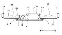
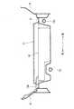
図1には本発明の一実施例に係る車両の部品搭載構造を説明するために車室を前方側から見た概略状況、図2には本発明の一実施例に係る車両の部品搭載構造を説明するために車室を上から見た状況(電池パックのカバーは省略してある)、図3には本発明の一実施例に係る車両の部品搭載構造を説明するために車室を車両の下側から見た状況、図4には燃料タンクの部位の車幅方向の断面を説明する図2、図3中のIV−IV線矢視の状況、図5には電池パックの部位の車幅方向の断面を説明する図2、図3中のV−V線矢視の状況、図6には乗員スペースを説明する図2中のVI−VI線矢視の状況を示してある。 FIG. 1 is a schematic view of a vehicle compartment viewed from the front side to explain a component mounting structure of a vehicle according to an embodiment of the present invention, and FIG. 2 is a component mounting structure of a vehicle according to an embodiment of the present invention. The situation where the cabin is viewed from above (the cover of the battery pack is omitted) in order to explain the vehicle compartment, FIG. 3 illustrates the vehicle compartment in order to explain the component mounting structure of the vehicle according to an embodiment of the present invention. The situation seen from the lower side of the vehicle, FIG. 4 illustrates the cross section of the portion of the fuel tank in the vehicle width direction, the situation of the IV-IV line arrow in FIG. 2 and 3 illustrate the cross section in the vehicle width direction of the vehicle, and FIG. 6 illustrates the situation of the VI-VI line in FIG. 2 illustrating the occupant space. .
主に図1から図4に示すように、車両の下部の幅方向両側部には、車両の前後方向に延びる骨格部材であるサイドメンバ1が左右一対で車幅方向の左右両側に配されている。左右一対のサイドメンバ1は、その前端部が車両の幅方向に延びるフロントエンドクロスメンバ(図示省略)に接続されている。 Mainly as shown in FIG. 1 to FIG. 4, side members 1 which are frame members extending in the front-rear direction of the vehicle are disposed on the left and right sides in the vehicle width direction on both sides in the width direction of the lower part of the vehicle. There is. Front ends of the pair of left and right side members 1 are connected to a front end cross member (not shown) extending in the width direction of the vehicle.
サイドメンバ1の下側には車幅方向に延びるクロスメンバ2が車両の前後方向に複数備えられている。サイドメンバ1の上側にはフロントフロアパン3が備えられ、フロントフロアパン3の車両の後端にはフロアクロスメンバが備えられている。フロアクロスメンバを挟んでフロントフロアパン3の反対側(後側)には後席が配されるリヤフロアパン5が備えられている。 A plurality of
フロントフロアパン3の前側は、車室Sと車室Sの前方の領域(例えば、エンジンルーム)とを仕切るダッシュパネル(図示省略)に接続されている。フロントフロアパン3には、後側に延びるバックボーン11が設けられている。バックボーン11はフロントフロアパン3の車幅方向中央部に配され、上方に突出して車両前後方向に延設されるトンネル状に形成されている。即ち、主に図3に示すように、バックボーン11は、断面が車幅方向に延びる上面部11aと、上面部11aの車幅方向両端から下方へ延びる側面部11bとを有する台形状に形成されている。 The front side of the
前輪の車軸21と後輪の車軸22の間におけるバックボーン11の下側のクロスメンバ2の上部(車室の外側:車室外)には内燃機関(エンジン)の燃料が貯められる燃料タンク12が配されている。燃料タンク12は液体を貯めるもので形状の自由度が高いので、バックボーン11の形状に合わせて車両の前後方向に延びて配される、台形状の矩形容器とされている。燃料タンク12にはパイプ12aを介して給油口12bが接続され、給油口12bは車両の右側のパネルに開口している。 A
前後の車軸21、22の間で、形状の自由度が高い燃料タンク12をバックボーン11の下側の車室外に配したので、バックボーン11により剛性が確保された車両で、乗員の空間を確保することができる。つまり、バックボーン11の車幅方向の両側のフロントフロアパン3の上面の足元10の空間を確保することができる。この状態で、形状の変更を最小限に抑えて燃料タンク12を変形しにくい場所に安全に搭載することができる。また、燃料タンク12自体を変形抑制部材として機能させることができる。 Since the
また、燃料タンク12が配された部位のバックボーン11と、サイドパネル6の下側のサイドシル7とにわたりフロントフロアクロスメンバ8が連結されている。フロントフロアクロスメンバ8を備えたことで、燃料タンク12が配されたバックボーン11の部位をクロスメンバで補強することができる。 Further, the front
一方、フロントフロアパン3の下側(車両の外側:車室外)で、サイドメンバ1とバックボーン11の一方(図3中右側)の側面部11bの間には、エンジンの排気が送られる排気管13が配されている。高温となる排気管13の上側には、断熱部材14が配されている。 On the other hand, on the lower side of the front floor pan 3 (outside of the vehicle: outside the vehicle), the exhaust pipe to which the exhaust gas of the engine is sent between the
サイドメンバ1とバックボーン11の間に排気管13が備えられるので、排気管13を最短の長さにすることができると共に、排気管13の中央部位がサイドメンバ1の車両の幅方向の中央部側(内側)に配される状態になり、外部から排気管13が見えにくくなると共に、手等が外から排気管13に接触しにくくなり、見栄えの向上と安全確保を図ることができる。また、泥水等が接触した際に蒸発により生じる匂い等も車室Sに進入し難くなる。 Since the
そして、主に、図1、図2、図3、図5、図6に示すように、後輪の車軸22の前側におけるリヤフロアパン5(フロアパネル)には下側に凹む凹部16が形成され、凹部16の内側には防水処理が施され、凹部16には、電動機の電源となる電池パック(電池関連部品を含む部材)18が収容されている。 And as shown mainly in FIG.1, FIG.2, FIG.3, FIG.5 and FIG. 6, the recessed
そして、電池パック18が収容された凹部16の上側には、防塵のためのカバー17が設けられている。カバー17には必要に応じて通気手段が備えられる。つまり、電池パック18は、前後の車軸21、22の間における後席25の下側の車室内に配されている。そして、電池パック18のケースが、車室のフロアパネルの一部で構成された状態になっている。 A
電池パック18には充電ケーブル18aを介して充電口18bが接続され、充電口18bは車両の左側のパネルに開口している。 The
前後の車軸21、22の間で、電池パック18を後席25の下側の車室内に配したので、車室の空調装置を利用して電池パック18の温度管理を行うことができる。このため、専用の温度管理装置を用いることなく電池パック18を所定の温度状態に維持することができ、電池パック18の劣化を抑制することができる。 Since the
そして、電池パック18が収容されるケースが車室のリヤフロアパン5の凹部16とカバー17とで構成されているので、フロアパネルの一部に電池パック18を収容することができ、防水シート、トレー、カバー、固定用ブラケット等の電池パック18の専用部品の一部を削減して、コストを抑制することができる。 And, since the case in which the
以上、上記説明のように、本発明の車両の部品搭載構造は、エンジン及び電動機を備えた車両の前後の車軸21、22の間で、車両のフロントフロアパン3に形成されたバックボーン11の下側の車室外に、形状の自由度が高い燃料タンク12を備え、後席25の下側の車室内に電池パック18を備えている。 As described above, the component mounting structure of the vehicle according to the present invention is provided under the
これにより、剛性を確保した車両で、乗員の空間を確保した状態で、形状の変更を最小限に抑えて燃料タンク12を変形しにくい場所に安全に搭載することができる。また、燃料タンク12自体を変形抑制部材として機能させることができる。そして、車室の空調装置を利用して電池パック18の温度管理を行うことができ、専用の温度管理装置を用いることなく電池パック18の劣化を抑制することができる。 As a result, in the vehicle in which the rigidity is secured and the space for the occupant is secured, the change in the shape can be minimized, and the
このため、バックボーン11を備えた車両であっても、電池パック18、燃料タンク12を含む車両の部品を適切に搭載することが可能になり、EVやHEV、PHEV等、走行用モータやエンジンを備えて大型になり易い車両で、車両フレームの共用化が進めやすくなり、EVやHEV、PHEV等の部品を最適に搭載して、コストを大幅に低減し、EVやHEV、PHEV等を低コストで普及することが可能になる。 Therefore, even in a vehicle provided with the
尚、本発明は上記の実施形態に限定されるものではなく、本発明の趣旨を逸脱しない範囲で種々変形することが可能である。 The present invention is not limited to the above embodiment, and various modifications can be made without departing from the spirit of the present invention.
本発明は、車両の部品搭載構造の産業分野で利用することができる。 The present invention can be used in the industrial field of vehicle component mounting structure.
1 サイドメンバ
2 クロスメンバ
3 フロントフロアパン
5 リヤフロアパン
6 サイドパネル
7 サイドシル
8 フロントフロアクロスメンバ
11 バックボーン
12 燃料タンク
13 排気管
14 断熱部材
16 凹部
17 カバー
18 電池パック
21、22 車軸
Reference Signs List 1
Claims (4)
Translated fromJapanese前記車両のフロアの車幅方向中央部において、上方に突出して前記車両の前後方向に延びるトンネル状に形成されたバックボーンと、
前後の車軸の間における前記バックボーンの下側の車室外に配され、前記内燃機関の燃料が貯められる燃料タンクと、
前後の車軸の間における後席の下側の車室内に配され、前記電動機の電源となる電池パックとを備えた
ことを特徴とする車両の部品搭載構造。A component mounting structure of a vehicle provided with an internal combustion engine and a motor,
A tunnel-shaped backbone projecting upward and extending in the longitudinal direction of the vehicle at a central portion in the vehicle width direction of the floor of the vehicle;
A fuel tank disposed outside the vehicle compartment below the backbone between the front and rear axles and storing the fuel of the internal combustion engine;
A component mounting structure of a vehicle comprising: a battery pack disposed in a lower passenger compartment of a rear seat between front and rear axles and serving as a power source of the motor.
前記車両の幅方向左右両側で前後方向に延設される一対のサイドメンバと、
前記サイドメンバと前記バックボーンの間における車室外に配され、前記内燃機関の排気が送られる排気管とを備えた
ことを特徴とする車両の部品搭載構造。In the component mounting structure of a vehicle according to claim 1,
A pair of side members extending in the front-rear direction on both left and right sides in the width direction of the vehicle;
A part mounting structure of a vehicle comprising: an exhaust pipe disposed outside the vehicle between the side member and the backbone and to which exhaust gas of the internal combustion engine is sent.
前記バックボーンの側部に連結されるクロスメンバを備えた
ことを特徴とする車両の部品搭載構造。In the parts mounting structure of a vehicle according to claim 2,
A component mounting structure of a vehicle comprising a cross member connected to a side of the backbone.
前記電池パックのケースは、車室のフロアパネルの一部である
ことを特徴とする車両の部品搭載構造。
In the parts mounting structure of a vehicle according to any one of claims 1 to 3,
The component mounting structure of a vehicle, wherein a case of the battery pack is a part of a floor panel of a cabin.
Priority Applications (1)
| Application Number | Priority Date | Filing Date | Title |
|---|---|---|---|
| JP2017213001AJP2019084890A (en) | 2017-11-02 | 2017-11-02 | Vehicle part mounting structure |
Applications Claiming Priority (1)
| Application Number | Priority Date | Filing Date | Title |
|---|---|---|---|
| JP2017213001AJP2019084890A (en) | 2017-11-02 | 2017-11-02 | Vehicle part mounting structure |
Publications (1)
| Publication Number | Publication Date |
|---|---|
| JP2019084890Atrue JP2019084890A (en) | 2019-06-06 |
Family
ID=66762087
Family Applications (1)
| Application Number | Title | Priority Date | Filing Date |
|---|---|---|---|
| JP2017213001APendingJP2019084890A (en) | 2017-11-02 | 2017-11-02 | Vehicle part mounting structure |
Country Status (1)
| Country | Link |
|---|---|
| JP (1) | JP2019084890A (en) |
Cited By (1)
| Publication number | Priority date | Publication date | Assignee | Title |
|---|---|---|---|---|
| CN115716416A (en)* | 2021-08-27 | 2023-02-28 | 本田技研工业株式会社 | vehicle |
- 2017
- 2017-11-02JPJP2017213001Apatent/JP2019084890A/enactivePending
Cited By (1)
| Publication number | Priority date | Publication date | Assignee | Title |
|---|---|---|---|---|
| CN115716416A (en)* | 2021-08-27 | 2023-02-28 | 本田技研工业株式会社 | vehicle |
Similar Documents
| Publication | Publication Date | Title |
|---|---|---|
| US8978617B2 (en) | Mounting structure for battery and fuel tank of gasoline-electric hybrid vehicle | |
| JP5360689B2 (en) | Vehicle high-voltage cable routing structure | |
| US11458829B2 (en) | Hybrid vehicle | |
| CN102892603B (en) | Vehicle charger mounting structure | |
| WO2012017935A1 (en) | Rear protective structure of vehicle | |
| JP5929609B2 (en) | In-vehicle structure of battery pack | |
| US8662239B2 (en) | Series-hybrid vehicle | |
| JP5459511B2 (en) | Vehicle battery mounting structure | |
| EP2447099A1 (en) | Hybrid vehicle structure | |
| CN110785306B (en) | electric vehicle | |
| JP5760992B2 (en) | Vehicle battery mounting structure | |
| US20130065099A1 (en) | Cooling device of vehicle battery | |
| CN108367660A (en) | The loading structure of high voltage control device unit | |
| JP2008155828A (en) | Vehicle body structure | |
| CN104684753A (en) | electric vehicle | |
| JP2008155830A (en) | Vehicle body structure | |
| JP2011111124A (en) | Rear structure of vehicle | |
| JP2017114153A (en) | Service car | |
| US9714606B2 (en) | Vehicle power generating apparatus | |
| JP7279677B2 (en) | vehicle undercarriage | |
| JP2019084890A (en) | Vehicle part mounting structure | |
| JP2015168380A (en) | electric vehicle | |
| JP7596747B2 (en) | Vehicle undercarriage | |
| JP6021676B2 (en) | Body structure of electric powered vehicle | |
| JP6175335B2 (en) | Vehicle with electric drive device |