JP2019071088A - System, method and apparatus for electronic patient care - Google Patents
System, method and apparatus for electronic patient careDownload PDFInfo
- Publication number
- JP2019071088A JP2019071088AJP2018239526AJP2018239526AJP2019071088AJP 2019071088 AJP2019071088 AJP 2019071088AJP 2018239526 AJP2018239526 AJP 2018239526AJP 2018239526 AJP2018239526 AJP 2018239526AJP 2019071088 AJP2019071088 AJP 2019071088A
- Authority
- JP
- Japan
- Prior art keywords
- patient
- monitoring client
- parameter
- care
- monitoring
- Prior art date
- Legal status (The legal status is an assumption and is not a legal conclusion. Google has not performed a legal analysis and makes no representation as to the accuracy of the status listed.)
- Granted
Links
Images


Classifications
- G—PHYSICS
- G16—INFORMATION AND COMMUNICATION TECHNOLOGY [ICT] SPECIALLY ADAPTED FOR SPECIFIC APPLICATION FIELDS
- G16H—HEALTHCARE INFORMATICS, i.e. INFORMATION AND COMMUNICATION TECHNOLOGY [ICT] SPECIALLY ADAPTED FOR THE HANDLING OR PROCESSING OF MEDICAL OR HEALTHCARE DATA
- G16H40/00—ICT specially adapted for the management or administration of healthcare resources or facilities; ICT specially adapted for the management or operation of medical equipment or devices
- G16H40/60—ICT specially adapted for the management or administration of healthcare resources or facilities; ICT specially adapted for the management or operation of medical equipment or devices for the operation of medical equipment or devices
- G16H40/67—ICT specially adapted for the management or administration of healthcare resources or facilities; ICT specially adapted for the management or operation of medical equipment or devices for the operation of medical equipment or devices for remote operation
- G—PHYSICS
- G16—INFORMATION AND COMMUNICATION TECHNOLOGY [ICT] SPECIALLY ADAPTED FOR SPECIFIC APPLICATION FIELDS
- G16H—HEALTHCARE INFORMATICS, i.e. INFORMATION AND COMMUNICATION TECHNOLOGY [ICT] SPECIALLY ADAPTED FOR THE HANDLING OR PROCESSING OF MEDICAL OR HEALTHCARE DATA
- G16H20/00—ICT specially adapted for therapies or health-improving plans, e.g. for handling prescriptions, for steering therapy or for monitoring patient compliance
- G16H20/10—ICT specially adapted for therapies or health-improving plans, e.g. for handling prescriptions, for steering therapy or for monitoring patient compliance relating to drugs or medications, e.g. for ensuring correct administration to patients
- G16H20/17—ICT specially adapted for therapies or health-improving plans, e.g. for handling prescriptions, for steering therapy or for monitoring patient compliance relating to drugs or medications, e.g. for ensuring correct administration to patients delivered via infusion or injection
- G—PHYSICS
- G16—INFORMATION AND COMMUNICATION TECHNOLOGY [ICT] SPECIALLY ADAPTED FOR SPECIFIC APPLICATION FIELDS
- G16H—HEALTHCARE INFORMATICS, i.e. INFORMATION AND COMMUNICATION TECHNOLOGY [ICT] SPECIALLY ADAPTED FOR THE HANDLING OR PROCESSING OF MEDICAL OR HEALTHCARE DATA
- G16H40/00—ICT specially adapted for the management or administration of healthcare resources or facilities; ICT specially adapted for the management or operation of medical equipment or devices
- G16H40/60—ICT specially adapted for the management or administration of healthcare resources or facilities; ICT specially adapted for the management or operation of medical equipment or devices for the operation of medical equipment or devices
- G16H40/63—ICT specially adapted for the management or administration of healthcare resources or facilities; ICT specially adapted for the management or operation of medical equipment or devices for the operation of medical equipment or devices for local operation
- G—PHYSICS
- G16—INFORMATION AND COMMUNICATION TECHNOLOGY [ICT] SPECIALLY ADAPTED FOR SPECIFIC APPLICATION FIELDS
- G16H—HEALTHCARE INFORMATICS, i.e. INFORMATION AND COMMUNICATION TECHNOLOGY [ICT] SPECIALLY ADAPTED FOR THE HANDLING OR PROCESSING OF MEDICAL OR HEALTHCARE DATA
- G16H50/00—ICT specially adapted for medical diagnosis, medical simulation or medical data mining; ICT specially adapted for detecting, monitoring or modelling epidemics or pandemics
- G16H50/20—ICT specially adapted for medical diagnosis, medical simulation or medical data mining; ICT specially adapted for detecting, monitoring or modelling epidemics or pandemics for computer-aided diagnosis, e.g. based on medical expert systems
- G—PHYSICS
- G16—INFORMATION AND COMMUNICATION TECHNOLOGY [ICT] SPECIALLY ADAPTED FOR SPECIFIC APPLICATION FIELDS
- G16H—HEALTHCARE INFORMATICS, i.e. INFORMATION AND COMMUNICATION TECHNOLOGY [ICT] SPECIALLY ADAPTED FOR THE HANDLING OR PROCESSING OF MEDICAL OR HEALTHCARE DATA
- G16H70/00—ICT specially adapted for the handling or processing of medical references
- G16H70/40—ICT specially adapted for the handling or processing of medical references relating to drugs, e.g. their side effects or intended usage
- H—ELECTRICITY
- H04—ELECTRIC COMMUNICATION TECHNIQUE
- H04L—TRANSMISSION OF DIGITAL INFORMATION, e.g. TELEGRAPHIC COMMUNICATION
- H04L63/00—Network architectures or network communication protocols for network security
- H04L63/10—Network architectures or network communication protocols for network security for controlling access to devices or network resources
- H04L63/105—Multiple levels of security
Landscapes
- Engineering & Computer Science (AREA)
- Health & Medical Sciences (AREA)
- Medical Informatics (AREA)
- Public Health (AREA)
- Biomedical Technology (AREA)
- General Health & Medical Sciences (AREA)
- Epidemiology (AREA)
- Primary Health Care (AREA)
- Chemical & Material Sciences (AREA)
- Bioinformatics & Cheminformatics (AREA)
- Medicinal Chemistry (AREA)
- Computer Security & Cryptography (AREA)
- General Business, Economics & Management (AREA)
- Business, Economics & Management (AREA)
- Computer Hardware Design (AREA)
- Computing Systems (AREA)
- General Engineering & Computer Science (AREA)
- Computer Networks & Wireless Communication (AREA)
- Signal Processing (AREA)
- Pharmacology & Pharmacy (AREA)
- Toxicology (AREA)
- Data Mining & Analysis (AREA)
- Databases & Information Systems (AREA)
- Pathology (AREA)
- Infusion, Injection, And Reservoir Apparatuses (AREA)
- Measuring And Recording Apparatus For Diagnosis (AREA)
- Medical Treatment And Welfare Office Work (AREA)
- Electrotherapy Devices (AREA)
- Surgical Instruments (AREA)
- Accommodation For Nursing Or Treatment Tables (AREA)
Abstract
Translated fromJapaneseDescription
Translated fromJapanese関連出願の相互参照
本出願は、2012年12月21日出願の「通信データ用のシステム、方法および装置
」という名称の米国仮特許出願第61/740,474号(代理人整理番号:J80)の
優先権を主張する非仮特許出願であり、同出願は全体を参照として本明細書に援用する。CROSS-REFERENCE TO RELATED APPLICATIONS This application, "System for communication data, a method and apparatus" filed Dec. 21, 2012 entitled U.S. Provisional Patent Application No. 61 / 740,474 (Attorney Docket No.: J80) Non-provisional patent applications claiming the priority of US patent application Ser.
本出願はまた、2012年12月21日出願の「電子患者介護用のシステム、方法およ
び装置」という名称の米国特許出願第13/723,253号であり、その後2013年
7月25日に公開された米国特許出願公開第2013−0191413A1号(代理人整
理番号:J85)の一部継続出願であり、この出願は、以下の出願の優先権を主張する:
2011年12月21日出願の「輸液用のシステム、方法および装置」という名称の米
国仮特許出願第61/578,649号(代理人整理番号:J02);
2011年12月21日出願の「輸液送達量推定用のシステム、方法および装置」とい
うの米国仮特許出願第61/578,658号(代理人整理番号:J04);
2011年12月21日出願の「経口薬投与用のシステム、方法および装置」という名
称の米国仮特許出願第61/578,674号(代理人整理番号:J05);
2012年5月24日出願の「電子患者介護用のシステム、方法および装置」という名
称の米国仮特許出願第61/651,322号(代理人整理番号:J46);および
2012年8月3日出願の「輸液流の監視、調節または制御用のシステム、方法および
装置」という名称の米国仮特許出願第61/679,117号(代理人整理番号:J30
)。上記出願のそれぞれは全体を参照として本明細書に援用する。
米国特許出願第13/723,253号は、2011年12月21日出願の「電子患者
介護用のシステム、方法および装置」という名称の米国特許出願第13/333,574
号であり、その後2012年7月19日に公開された米国特許出願公開第2012−01
85267A1号(代理人整理番号:J97)および
2011年12月21日出願の「電子患者介護用のシステム、方法および装置」という
名称のPCT出願第PCT/US11/66588号(代理人整理番号:I97WO)、
の一部継続出願であり、これらの両方は全体を参照として本明細書に援用する。
米国特許出願第13/333,574号は、2011年1月21日出願の「電子患者監
視システム」という名称の米国特許出願第13/011,543号であり、その後201
1年12月22日に公開された米国特許出願公開第2011−0313789A1号(代
理人整理番号:I52)、の一部継続出願であり、この出願は、2010年1月22日出
願の「医療用設備用の電子指示仲介システム」という名称の米国仮特許出願第61/29
7,544号(代理人整理番号:H53)の優先権の利益を主張しており、これらの両方
は全体を参照として本明細書に援用する。This application is also a U.S. patent application Ser. No. 13 / 723,253 entitled "System, Method and Apparatus for Electronic Patient Care" filed Dec. 21, 2012 and subsequently published on Jul. 25, 2013. No. 2013-0191413 A1 (Attorney Docket Number: J85), a continuation-in-part application, which claims priority to the following applications:
US Provisional Patent Application No. 61 / 578,649, entitled “System, Method and Apparatus for Infusion” filed Dec. 21, 2011 (Attorney Docket No: J02);
US Provisional Patent Application No. 61 / 578,658, entitled "System, Method and Apparatus for Infusion Delivery Estimation" filed Dec. 21, 2011 (Attorney Docket No .: J04);
US Provisional Patent Application No. 61 / 578,674, entitled “Systems, Methods and Devices for Oral Drug Administration,” filed Dec. 21, 2011 (Attorney Docket No: J05);
US Provisional Patent Application No. 61 / 651,322 entitled "System, method and apparatus for electronic patient care" filed May 24, 2012 (Attorney Docket Number: J46); and August 3, 2012 US Provisional Patent Application No. 61 / 679,117, entitled “System, Method and Apparatus for Monitoring, Regulating, or Controlling Infusion Flow,” filed on Application Ser.
). Each of the above applications is incorporated herein by reference in its entirety.
U.S. Patent Application No. 13 / 723,253 is a U.S. Patent Application No. 13 / 333,574 entitled "Systems, Methods and Apparatus for Electronic Patient Care" filed Dec. 21, 2011.
Patent Application Publication No. 2012-01, which was published on July 19, 2012,
PCT Application No. PCT / US11 / 66588 entitled "System, method and apparatus for electronic patient care" filed on Dec. 21, 2011 and filed on Dec. 21, 2011 (department reference number: I97 WO) ),
Application, both of which are incorporated herein by reference in their entirety.
U.S. patent application Ser. No. 13 / 333,574 is a U.S. patent application Ser. No. 13 / 011,543 entitled "Electronic Patient Monitoring System" filed Jan. 21, 2011, and then 201
No. 2011-0313789 A1 (Attorney Docket Number: I52), published Dec. 22, 2012, which is a continuation-in-part of US patent application publication no. 2011-0313789 A1, filed Dec. 22, 2010 US Provisional Patent Application No. 61/29 entitled "Electronic Instructions Intermediary System for Commercial Equipment"
No. 7,544 (Attorney Docket No: H53) claims the benefit of priority, both of which are incorporated herein by reference in their entirety.
本出願はまた、2012年12月21日出願の「電子患者介護用のシステム、方法およ
び装置」という名称の米国特許出願第13/723,239号であり、その後2013年
11月7日に公開された米国特許出願公開第2013−0297330A1号(代理人整
理番号:J77)の一部継続出願であり、この出願は、以下の出願の優先権を主張する:
2011年12月21日出願の「輸液用のシステム、方法および装置」という名称の米
国仮特許出願第61/578,649号(代理人整理番号:J02);
2011年12月21日出願の「輸液送達量推定用のシステム、方法および装置」とい
う名称の米国仮特許出願第61/578,658号(代理人整理番号:J04);
2011年12月21日出願の「経口薬投与用のシステム、方法および装置」という名
称の米国仮特許出願第61/578,674号(代理人整理番号:J05);
2012年5月24日出願の「電子患者介護用のシステム、方法および装置」という名
称の米国仮特許出願第61/651,322号(代理人整理番号:J46);および
2012年8月3日出願の「輸液流の監視、調節または制御用のシステム、方法および
装置」という名称の米国仮特許出願第61/679,117号(代理人整理番号:J30
)。上記のそれぞれは全体を参照として本明細書に援用する。
米国特許出願第13/723,239号は、以下の出願の優先権を主張し、また以下の
出願の一部継続出願である:
2011年12月21日出願の「電子患者介護用のシステム、方法および装置」という
名称の米国特許出願第13/333,574号であり、その後2012年7月19日に公
開された米国特許出願公開第2012−0185267A1号(代理人整理番号:J97
)。この出願は、2011年1月21日出願の「電子患者監視システム」という名称の米
国特許出願第13/011,543号であり、その後2011年12月22日に公開され
た米国特許出願公開第2011−0313789A1号(代理人整理番号:I52)の一
部継続出願であり、これは2010年1月22日出願の「医療用設備用の電子指示仲介シ
ステム」という名称の米国仮特許出願第61/297,544号(代理人整理番号:H5
3)の優先権を主張するもの;および
2011年12月21日出願の「電子患者介護用のシステム、方法および装置」という
名称のPCT出願第PCT/US11/66588号であり、その後2013年9月12
日に公開された国際出願公開第WO2013/095459号(代理人整理番号:I97
WO)。これらのそれぞれは全体を参照として本明細書に援用する。This application is also a U.S. Patent Application Serial No. 13 / 723,239 entitled "Systems, Methods and Apparatus for Electronic Patient Care" filed Dec. 21, 2012, and subsequently published on Nov. 7, 2013. No. 2013-0297330 A1 (Attorney Docket Number: J77), which is a continuation-in-part of US patent application publication no. 2013-0297330 A1, which claims priority to the following applications:
US Provisional Patent Application No. 61 / 578,649, entitled “System, Method and Apparatus for Infusion” filed Dec. 21, 2011 (Attorney Docket No: J02);
US Provisional Patent Application No. 61 / 578,658, entitled “System, Method and Apparatus for Infusion Delivery Estimation” filed Dec. 21, 2011 (Attorney Docket No: J04);
US Provisional Patent Application No. 61 / 578,674, entitled “Systems, Methods and Devices for Oral Drug Administration,” filed Dec. 21, 2011 (Attorney Docket No: J05);
US Provisional Patent Application No. 61 / 651,322 entitled "System, method and apparatus for electronic patient care" filed May 24, 2012 (Attorney Docket Number: J46); and August 3, 2012 US Provisional Patent Application No. 61 / 679,117, entitled “System, Method and Apparatus for Monitoring, Regulating, or Controlling Infusion Flow,” filed on Application Ser.
). Each of the above is incorporated herein by reference in its entirety.
US patent application Ser. No. 13 / 723,239 claims priority to the following applications and is a continuation-in-part of the following applications:
US patent application Ser. No. 13 / 333,574 entitled “System, method and apparatus for electronic patient care” filed Dec. 21, 2011, and subsequently published on Jul. 19, 2012 Publication No. 2012-0185267 A1 (agent number: J97
). This application is US patent application Ser. No. 13 / 011,543 entitled “Electronic Patient Monitoring System” filed on Jan. 21, 2011, and subsequently published on Dec. 22, 2011. 2011-0313789 A1 (Attorney Docket No .: I52), a continuation-in-part application, filed on January 22, 2010, entitled US Provisional Patent Application Ser. / 297,544 (agent representative number: H5
Those claiming priority to 3); and PCT Application No. PCT / US11 / 66588, entitled "Systems, methods and apparatus for electronic patient care" filed Dec. 21, 2011;
International Application Publication No. WO 2013/095459 (Agent Accession Number: I97 published on the
WO). Each of these is incorporated herein by reference in its entirety.
本出願はまた、2012年12月21日出願の「電子患者介護用のシステム、方法およ
び装置」という名称の米国特許出願第13/723,242号であり、その後2013年
11月28日に公開された米国特許出願公開第2013−0317753A1号(代理人
整理番号:J78)の一部継続出願であり、この出願は、以下の出願の優先権を主張する
:
2012年5月24日出願の「電子患者介護用のシステム、方法および装置」という名
称の米国特許出願第61/651,322号(代理人整理番号:J46)。これは全体を
参照として本明細書に援用する。This application is also a U.S. patent application Ser. No. 13 / 723,242 entitled "System, Method and Apparatus for Electronic Patient Care" filed Dec. 21, 2012 and subsequently published on Nov. 28, 2013. No. 2013-0317753 A1 (Attorney Docket Number: J78), which is a continuation-in-part of US Patent Application Publication No. 2013-0317753 Al, which claims priority to the following applications:
U.S. Patent Application No. 61 / 651,322 entitled "Systems, Methods and Apparatus for Electronic Patient Care", filed May 24, 2012 (Attorney Docket Number: J46). This is incorporated herein by reference in its entirety.
本出願はまた、2013年5月23日出願の「電子患者介護用のシステム、方法および
装置」という名称の米国特許出願第13/900,655号であり、その後2013年1
1月28日に公開された米国特許出願公開第2013−0317837A1号(代理人整
理番号:K66)の一部継続出願であり、この出願は、2012年5月24日出願の「電
子患者介護用のシステム、方法および装置」という名称の米国仮特許出願第61/651
,322号(代理人整理番号:J46)の優先権を主張し、これらの両方は全体を参照と
して本明細書に援用する。
米国特許出願第13/900,655号もまた一部継続出願であり、これは以下の出願
の優先権を主張する:
2012年5月24日出願の「血液処理システムおよび方法」という名称の米国特許出
願第13/480,444号であり、その後2013年2月14日に公開された米国特許
出願公開第2013−0037485A1号(代理人整理番号:J43);および
2012年5月24日出願の「血液処理システムおよび方法」という名称のPCT出願
第PCT/US12/00257号でであり、その後2012年11月29日に公開され
た国際公開第WO2012/161744号(代理人整理番号:J43WO)。This application is also a U.S. Patent Application Serial No. 13 / 900,655, entitled "System, Method and Apparatus for Electronic Patient Care", filed May 23, 2013,
This application is a continuation-in-part of US Patent Application Publication No. 2013-0317837A1 (Attorney Docket No .: K66) published on January 28, which application is filed on May 24, 2012 and is for electronic patient care US Provisional Patent Application No. 61/651, entitled "System, method and apparatus for
No. 322 (Attorney Docket Number: J46), both of which are incorporated herein by reference in their entirety.
US patent application Ser. No. 13 / 900,655 is also a partial continuation application, which claims priority to the following applications:
US patent application Ser. No. 13 / 480,444 entitled “Blood Processing System and Method”, filed May 24, 2012, and subsequently published on Feb. 14, 2013 US Patent Application Publication No. 2013-0037485A1 And PCT Application No. PCT / US12 / 00257 entitled “Blood Processing System and Method” filed May 24, 2012, and subsequently on November 29, 2012. Published International Publication No. WO 2012/161744 (Agent Assigned Number: J43WO).
本出願はまた、2013年5月23日出願の「電子患者介護のためのシステム、方法お
よび装置」という名称のPCT出願第PCT/US13/42350号(代理人整理番号
:K66WO)の一部継続出願であり、この出願は、「電子患者介護用のシステム、方法
および装置」という名称の米国仮特許出願第61/651,322号(代理人整理番号:
J46)の優先権を主張し、これらの両方は全体を参照として本明細書に援用する。
PCT出願第PCT/US13/42350号もまた一部継続出願であり、これは以下
の出願の優先権を主張する:
2012年5月24日出願の「血液処理システムおよび方法」という名称の米国特許出
願第13/480,444号であり、その後2013年2月14日に公開された米国特許
出願公開第2013−0037485A1号(代理人整理番号:J43);および
2012年5月24日出願の「血液処理システムおよび方法」という名称のPCT出願
第PCT/US12/00257号であり、その後2012年11月29日に公開された
国際公開第WO2012/161744号(代理人整理番号:J43WO)。This application is also a continuation-in-part of PCT Application No. PCT / US13 / 42350 (Attorney Docket No: K66WO), entitled “System, method and apparatus for electronic patient care” filed May 23, 2013. No. 61 / 651,322, entitled “System, Method and Apparatus for Electronic Patient Care,” which is an application, which application is entitled
J46), both of which are incorporated herein by reference in their entirety.
PCT Application No. PCT / US13 / 42350 is also a partial continuation application, which claims priority to the following applications:
US patent application Ser. No. 13 / 480,444 entitled “Blood Processing System and Method”, filed May 24, 2012, and subsequently published on Feb. 14, 2013 US Patent Application Publication No. 2013-0037485A1 And PCT Application No. PCT / US12 / 00257 entitled “Blood Processing System and Method” filed May 24, 2012, and subsequently published on November 29, 2012. International Publication No. WO 2012/161744 (Attorney Docket Number: J43WO).
本出願はまた、2012年12月21日出願の以下の特許出願のうちの1つ以上に関連
することがあり、これらのすべては全体を参照として本明細書に援用する:
「クランピング用のシステム、方法および装置」に関する米国非仮特許出願第13/7
23,238号(代理人整理番号:J47);
「経口薬投与用のシステム、方法および装置」に関する米国非仮特許出願第13/72
3,235号(代理人整理番号:J74);
「経口薬投与用のシステム、方法および装置」に関するPCT出願第PCT/US12
/71131号(代理人整理番号:J74WO);
「輸液送達量推定用のシステム、方法および装置」に関する米国非仮特許出願第13/
724,568号(代理人整理番号:J75);
「輸液用のシステム、方法および装置」に関する米国非仮特許出願第13/725,7
90号(代理人整理番号:J76);
「輸液用のシステム、方法および装置」に関するPCT出願第PCT/US12/71
490号(代理人整理番号:J76WO);
「輸液流の監視、調節または制御用のシステム、方法および装置」に関する米国非仮特
許出願第13/723,244号(代理人整理番号:J79);
「輸液流の監視、調節または制御用のシステム、方法および装置」に関するPCT出願
第PCT/US12/71142号(代理人整理番号:J79WO);
「輸液送達量推定用のシステム、方法および装置」に関する米国非仮特許出願第13/
723,251号(代理人整理番号:J81);および
「輸液送達量推定用のシステム、方法および装置」に関するPCT出願第PCT/US
12/71112号(代理人整理番号:J81WO)。This application may also be related to one or more of the following patent applications filed on December 21, 2012, all of which are incorporated herein by reference in their entirety:
US Non-Provisional Patent Application No. 13/7 for "System, method and apparatus for clamping"
23, 238 (Agent deputy number: J47);
US Non-Provisional Patent Application No. 13/72 for "Systems, Methods and Devices for Oral Drug Administration"
No. 3,235 (Delegation number: J74);
PCT Application No. PCT / US12 for "Systems, Methods and Devices for Oral Drug Administration"
/ 71131 (agent representative number: J74WO);
US Non-Provisional Patent Application No. 13 / "System, method and apparatus for fluid delivery delivery estimation"
724, 568 (Deputy number: J75);
US Non-Provisional Patent Application No. 13 / 725,7 "Systems, methods and devices for infusion"
No. 90 (agent representative number: J76);
PCT Application No. PCT / US12 / 71 for "Systems, methods and devices for infusion"
No. 490 (deputy number: J76WO);
US Non-Provisional Patent Application No. 13 / 723,244 (Attorney Docket Number: J79) relating to "Systems, Methods and Devices for Monitoring, Regulating or Controlling Infusion Flow"
PCT Application No. PCT / US12 / 71142 (Attorney Docket Number: J79 WO) relating to "Systems, methods and devices for monitoring, regulating or controlling infusion flow";
US Non-Provisional Patent Application No. 13 / "System, method and apparatus for fluid delivery delivery estimation"
PCT Application No. PCT / US for "System, method and apparatus for fluid delivery volume estimation";
12/71112 (agent representative number: J81 WO).
本出願はまた、以下の特許出願のうちの1つ以上に関連することがあり、これらのすべ
ては全体を参照として本明細書に援用する:
2012年12月18日出願の「活性整流を使用する液体ライン中の空気検知用のシス
テム、方法および装置」という名称の米国仮特許出願第61/738,447号(代理人
整理番号:J32);
2013年3月15日出願の「輸液用のシステム、方法および装置」という名称の米国
特許出願第13/840,339号(代理人整理番号:K14);
2013年3月15日出願の「輸液用のシステム、方法および装置」という名称のPC
T出願第PCT/US13/32445号(代理人整理番号:K14WO);
2013年3月15日出願の「シリンジ・ポンプおよび関連する方法」という名称の米
国特許出願第13/833,432号(代理人整理番号:K21);
2013年3月15日出願の「電子患者介護用のシステムおよび装置」という名称の米
国特許出願第13/836,497号(代理人整理番号:K22);
2013年3月15日出願の「クランピングのためのシステム、方法および装置」とい
う名称の米国特許出願第13/833,712号(代理人整理番号:K23);
2013年3月15日出願の「輸液流の監視、調節または制御用のシステム、方法およ
び装置」という名称の米国特許出願第13/834,030号(代理人整理番号:K28
);
2013年7月31日出願の「分割リング共振回路を使用する液体ライン中の泡検知用
のシステム、方法および装置」という名称の米国仮特許出願第61/860,398号(
代理人整理番号:J31);
2013年11月6日出願の「輸液流の監視、調節または制御用のシステム、方法およ
び装置」という名称の米国仮特許出願第61/900,431号(代理人整理番号:K5
2);
2013年10月23日出願の「シリンジ・ポンプおよび関連する方法」という名称の
米国仮特許出願第61/894,801号(代理人整理番号:K88);
2013年7月8日出願の「クランピングのためのシステム、方法および装置」という
名称の米国仮特許出願第61/843,574号(代理人整理番号:K74);
2013年8月20日出願の「電子的患者監視システム」という名称の米国特許出願第
13/971,258号(代理人整理番号:K84);
2013年11月14日出願の「シリンジ・ポンプおよび関連する方法」という名称の
米国仮特許出願第61/904,123号(代理人整理番号:L33);
2013年12月10日出願の「分割リング共振回路を使用する液体ライン中の泡検知
用のシステム、方法および装置」という名称の米国特許出願第14/101,848号(
代理人整理番号:L05);
2013年12月20日出願の「データ通信用のシステム、方法および装置」に関する
米国特許出願(代理人整理番号:L49);
2013年12月20日出願の「データ通信用のシステム、方法および装置」に関する
PCT出願(代理人整理番号:L49WO);
2013年12月20日出願の「電子患者介護用の、コンピュータで実現された方法、
システムおよび装置」に関する米国特許出願(代理人整理番号:K50);
2013年12月20日出願の「電子患者介護用の、コンピュータで実現された方法、
システムおよび装置」に関するPCT出願(代理人整理番号:K50WO);および
2013年12月20日出願の「電子患者介護用のシステム、方法および装置」に関す
る米国特許出願(代理人整理番号:L52)。The present application may also relate to one or more of the following patent applications, all of which are incorporated herein by reference in their entirety:
US Provisional Patent Application No. 61 / 738,447, entitled “System, Method and Apparatus for Air Detection in Liquid Lines Using Active Rectification,” filed Dec. 18, 2012 (Attorney Docket No: J32) ;
US patent application Ser. No. 13 / 840,339, entitled “System, Method and Apparatus for Infusion” filed Mar. 15, 2013 (Attorney Docket No: K14);
PC named “System, method and apparatus for infusion” filed on March 15, 2013
T Application No. PCT / US13 / 32445 (Attorney Docket Number: K14WO);
US patent application Ser. No. 13 / 833,432 entitled “syringe pump and related method” filed Mar. 15, 2013 (Attorney Docket No: K21);
US patent application Ser. No. 13 / 836,497, entitled “System and Device for Electronic Patient Care,” filed Mar. 15, 2013 (Attorney Docket No. K22);
US patent application Ser. No. 13 / 833,712 entitled “System, method and apparatus for clamping” filed Mar. 15, 2013 (Attorney Docket No. K23);
US patent application Ser. No. 13 / 834,030, entitled “System, Method and Apparatus for Monitoring, Regulating or Controlling Infusion Flow,” filed Mar. 15, 2013 (Attorney Docket No: K28
);
US Provisional Patent Application No. 61 / 860,398 entitled “System, Method and Apparatus for Bubble Detection in Liquid Lines Using Split Ring Resonant Circuits” filed on July 31, 2013
Agent number: J31);
US Provisional Patent Application No. 61 / 900,431, entitled “System, Method and Apparatus for Monitoring, Regulating, or Controlling Infusion Flow,” filed November 6, 2013 (Attorney Docket No. K5)
2);
US Provisional Patent Application No. 61 / 894,801, entitled “Syringe Pump and Related Methods,” filed October 23, 2013 (Attorney Docket No: K88);
US Provisional Patent Application No. 61 / 843,574 entitled “System, method and apparatus for clamping” filed Jul. 8, 2013 (Attorney Docket No: K74);
US patent application Ser. No. 13 / 971,258 entitled “Electronic Patient Monitoring System” filed on Aug. 20, 2013 (Attorney Docket No. K84);
US Provisional Patent Application No. 61 / 904,123, entitled “Syringe Pump and Related Methods,” filed November 14, 2013 (Attorney Docket No. L33);
No. 14 / 101,848 entitled “System, Method and Apparatus for Bubble Detection in Liquid Lines Using Split Ring Resonant Circuits” filed Dec. 10, 2013
Agent number: L05);
US Patent Application for "System, method and apparatus for data communication" filed Dec. 20, 2013 (Attorney Docket No. L49);
PCT application for "System, method and apparatus for data communication" filed on December 20, 2013 (agent accession number: L49 WO);
Computer-implemented method for electronic patient care filed December 20, 2013,
US Patent Application for "System and Device" (Attorney Docket Number: K50);
Computer-implemented method for electronic patient care filed December 20, 2013,
PCT Application for "Systems and Devices" (Attorney Docket No .: K50 WO); and US Patent Application for "Systems, Methods, and Devices for Electronic Patient Care" filed on December 20, 2013 (Attorney Docket No .: L52).
技術分野
本開示は、患者介護に関する。より詳細には、本開示は、電子患者介護用のシステム、
方法および装置に関する。TECHNICAL FIELD The present disclosure relates to patient care. More particularly, the present disclosure is a system for electronic patient care,
Method and apparatus
病院において患者介護を提供することは一般的に、多くの専門家および介護人(例えば
、医師、看護師、薬剤師、技術者、ナース・プラクティショナなど)、および所与の患者
の治療に必要な多数の医療デバイス/システムの相互作用を必要とする。Providing patient care in a hospital is generally required to treat many professionals and carers (eg, doctors, nurses, pharmacists, technicians, nurse practitioners, etc.) and given patients. Requires multiple medical device / system interactions.
電子診療録(EMR)およびコンピュータ化プロバイダ指示エントリ(CPOE)を組
み込んだもののような介護過程を容易にすることを意図したシステムの存在にも関わらず
、投薬などの診療を指示および送達することを含む総合的介護を患者に提供する過程は、
いくつかの重要な問題が関連している。Instructing and delivering medical care such as medication despite the presence of systems intended to facilitate the care process such as those incorporating electronic medical records (EMRs) and computerized provider directed entries (CPOEs) The process of providing comprehensive care to the patient, including
Several important issues are relevant.
薬剤の指示および投与に関連する例示的な実施形態では、電子患者介護システムは、第
1のデータ収集モジュール(例えば、監視クライアント)、指示を伝達しまたは患者関連
情報を受信するためのユーザ・インターフェースを有する第2の指示入力モジュール(例
えば、固定またはポータブル監視クライアント)を備えることができる。第1のモジュー
ルは、血圧、心拍数、心調律、温度、酸素化、呼吸数または換気量などの、患者の現在の
状態(例えば、患者状態パラメータ)に関する測定パラメータを受信しおよび記憶するよ
うに構成されてもよい。第1のモジュールはまた、例えば、薬剤アレルギーまたは過敏症
、患者の組織中に存在する他の現在投与されている薬剤、年齢、体重、身長、腎臓または
肝臓機能などの患者状態パラメータを含む、第1のデータベース(例えば、患者に関する
情報を含むEHRデータベース)から、患者に関連する既存のパラメータに関する情報を
受信するように構成されてもよい。第1のモジュールは、例えば、血圧、脈拍、心調律ま
たは呼吸に関する既知の薬剤相互作用、薬剤の効果、または既存の薬剤などの第2のデー
タベース(例えば、薬物情報データベース)からの指示された薬剤および/または既存の
薬剤に関する薬剤情報を得るように構成することもできる。第1のモジュールは、患者の
現在測定した患者状態パラメータおよび受信した既存の患者状態パラメータを既知の通常
範囲と比較し、通常範囲外であることが分かった患者状態パラメータのテーブルを作成す
るように構成することができる。第1のモジュールはその後、患者状態パラメータのテー
ブルを薬物情報データベースから得られた対応するパラメータのテーブルと比較すること
ができる。患者状態パラメータのテーブルと対応するパラメータのテーブルとの間に一致
が存在することが分かった場合、第1のモジュールはその後、第2の(指示入力)モジュ
ールに伝達するために、1つ以上の予め入力され、記憶されたメッセージを読み出すこと
ができる。これらのメッセージは、例えば、指示された特定の薬剤、患者の既存の薬剤お
よび患者の現在および既存の病状に適切な第2のモジュールのユーザへの警告を含むこと
ができる。任意選択では、警告が第2のモジュールによって受信され、警告がユーザ・イ
ンターフェースからの入力シグナルを通して第2のモジュールのユーザによって確認され
ると、警告のさらなる繰り返しを避けることができる。In an exemplary embodiment relating to medication instruction and administration, the electronic patient care system comprises a first data collection module (eg, a monitoring client), a user interface for communicating instructions or receiving patient related information. A second instruction input module (e.g., a fixed or portable surveillance client) can be provided. The first module is to receive and store measurement parameters regarding the patient's current condition (eg, patient condition parameters), such as blood pressure, heart rate, heart rhythm, temperature, oxygenation, respiration rate or ventilation volume. It may be configured. The first module also includes, for example, drug allergy or hypersensitivity, other currently administered drugs present in the patient's tissue, patient condition parameters such as age, weight, height, kidney or liver function, etc. From one database (e.g., an EHR database that includes information about the patient), it may be configured to receive information regarding existing parameters associated with the patient. The first module is, for example, a known drug interaction on blood pressure, pulse, cardiac rhythm or respiration, an effect of a drug, or an indicated drug from a second database (eg, drug information database) such as an existing drug And / or may be configured to obtain drug information regarding existing drugs. The first module compares the patient's currently measured patient condition parameters and the received existing patient condition parameters to the known normal range and creates a table of patient condition parameters that are found to be outside the normal range. It can be configured. The first module may then compare the table of patient condition parameters to the corresponding parameter table obtained from the drug information database. If it is found that a match exists between the table of patient status parameters and the table of corresponding parameters, the first module may then transmit one or more to the second (instruction input) module. Pre-input and stored messages can be read out. These messages can include, for example, alerts to the user of the specific medication indicated, the patient's existing medication and the second module appropriate for the patient's current and existing medical condition. Optionally, if the alert is received by the second module and the alert is confirmed by the user of the second module through input signals from the user interface, further repetition of the alert can be avoided.
他の実施形態では、電子患者介護システムは、ユーザに薬物情報データベースから得ら
れた標準的な投薬および投与ガイドラインから導き出された編集可能なデフォルト値を提
供することができ、患者の現在および既存の病状、アレルギー、既存の薬剤または他の患
者状態パラメータに基づいて示すことができる変更をユーザに警戒を発することができる
。電子患者介護システムは、ユーザがタイピング入力する量を最小限に抑えることが好ま
しい。In another embodiment, the electronic patient care system can provide the user with editable default values derived from standard dosing and dosing guidelines obtained from drug information databases, and the patient's current and existing The user can be alerted of changes that can be indicated based on medical conditions, allergies, existing medications or other patient condition parameters. The electronic patient care system preferably minimizes the amount of typing input by the user.
他の実施形態では、電子患者介護システムの第1のモジュールまたは他のモジュールを
使用して、患者のベッドサイドに(例えば、バーコードおよびリーダ、またはRFIDタ
グおよびスキャナを通して)送達される指示された薬剤を識別し、適切な薬剤および投与
量が調製され、患者に送達されていることを検証することもできる。1つの実施形態では
、第1のモジュールはまた、注入ポンプまたは丸薬ディスペンサなどの、治療を施す患者
介護デバイスと有線または無線の通信リンクを通して相互作用することができる。注入ポ
ンプの場合、第1のモジュールまたは別の接続モジュールは、注入ポンプに、注入速度ま
たは注入圧力を含む注入設定値などの患者治療パラメータを提供し、そこから例えば、注
入ライン内の空気の存在、接続されている静脈内バッグ内に残っている溶液の量、または
注入ライン内の流体の圧力などの様々な動作パラメータを受信することができる。動作パ
ラメータが異常であることが分かった場合、第1のモジュールは、注入ポンプにシグナル
を送って注入を中断させることによって応答する、機械的閉塞にシグナルを送って静脈ラ
インを閉塞することによって応答する、注入速度を変更する、および/または第1のモジ
ュール内に組み込まれたアラームにより直接、または第2のモジュールへのアラームの伝
達によってのいずれかで、ヘルスケア・プロバイダなどに異常の警戒を発するように構成
することができる。別の実施形態では、第1のモジュールはまた、患者の状態を監視し、
例えば、血圧モニタ、ECGモニタ、パルス・オキシメトリ・モニタ、温度モニタなどの
患者状態パラメータを決定するために使用される様々な患者介護デバイスと通信するよう
に構成することができる。測定される様々なパラメータは、携帯デバイスによっておよび
/またはEMR内で、監視するおよび/または記録することができる。いくつかの場合に
は、第1のモジュールは、監視した患者状態パラメータが所定の範囲外にある場合に、患
者または他の人に警戒を発するようにプログラムすることができる。いくつかの実施形態
では、第1のモジュールは、シグナルを監視クライアントに伝達して、患者介護デバイス
によってスケジュールされていない測定を行なって、別の患者状態パラメータを得ること
ができる。第1のモジュールは、様々な位置で様々なヘルスケア・プロバイダと通信する
ことができ、1つの実施形態では、第1のモジュールが割り当てられた患者に異常を知ら
せることが可能であり、例えば、可聴警戒または記録されたメッセージにより修正動作を
勧めることができる。In other embodiments, the first module or other module of the electronic patient-care system is instructed to be delivered (eg, through a barcode and reader, or RFID tag and scanner) to the bedside of the patient Drugs can also be identified, and appropriate drugs and dosages can be prepared and verified to be delivered to the patient. In one embodiment, the first module may also interact through a wired or wireless communication link with a patient-care device to be treated, such as an infusion pump or pill dispenser. In the case of an infusion pump, the first module or another connection module provides the infusion pump with patient treatment parameters, such as infusion settings or infusion settings including infusion pressure, from which, for example, the presence of air in the infusion line Various operating parameters can be received, such as the amount of solution remaining in the connected intravenous bag, or the pressure of the fluid in the infusion line. If the operating parameter is found to be abnormal, the first module responds by sending a signal to the infusion pump to interrupt the infusion, sending a signal to the mechanical occlusion to block the venous line Alert the health care provider, etc. to abnormal conditions either by changing the infusion rate and / or directly by an alarm built into the first module or by transmitting an alarm to the second module It can be configured to emit. In another embodiment, the first module also monitors the condition of the patient,
For example, it may be configured to communicate with various patient care devices used to determine patient condition parameters, such as blood pressure monitors, ECG monitors, pulse oximetry monitors, temperature monitors, and the like. The various parameters measured can be monitored and / or recorded by the mobile device and / or within the EMR. In some cases, the first module can be programmed to alert the patient or others if the monitored patient condition parameter is outside of a predetermined range. In some embodiments, the first module can communicate a signal to the monitoring client to perform unscheduled measurements by the patient-care device to obtain other patient condition parameters. The first module can communicate with different healthcare providers at different locations, and in one embodiment, can notify the patient to whom the first module is assigned an anomaly, eg, An audible alert or a recorded message may suggest corrective action.
1つの実施形態では、マイクロインフュージョン・ポンプを準備するシステムは、監視
クライアント、薬局コンピュータ、配合ロボット、マイクロインフュージョン・ポンプ、
およびデータ・ダウンロード・デバイスを備えている。監視クライアントは、ユーザ・イ
ンターフェースを介して処方箋指示を通信するように構成されている。薬局コンピュータ
は、監視クライアントと動作可能に通信して、処方箋指示を受信する。配合ロボットは、
処方箋を処方箋指示に対応する少なくとも1つの液体へと調製するように構成されている
。マイクロインフュージョン・ポンプは、処方箋指示に対応する少なくとも1つの液体を
受け取るように構成されている。データ・ダウンロード・デバイスは、処方箋指示をマイ
クロインフュージョン・ポンプのメモリ内にダウンロードするように構成されている。In one embodiment, a system for preparing a micro infusion pump includes a monitoring client, a pharmacy computer, a compounding robot, a micro infusion pump,
And a data download device. The monitoring client is configured to communicate prescription instructions via the user interface. The pharmacy computer is in operative communication with the monitoring client to receive prescription instructions. The compounding robot is
It is configured to prepare the prescription into at least one liquid corresponding to the prescription instructions. The microinfusion pump is configured to receive at least one liquid corresponding to the prescription instruction. The data download device is configured to download the prescription instructions into the memory of the micro infusion pump.
いくつかの実施形態では、配合ロボットは、マイクロインフュージョン・ポンプに少な
くとも1つの液体を充填する。配合ロボットは、データ・ダウンロード・デバイスと動作
可能に通信することができ、配合ロボットは、データ・ダウンロード・デバイスに、処方
箋指示をマイクロインフュージョン・ポンプのメモリ内にダウンロードするように指示し
てもよい。データ・ダウンロード・デバイスは、処方箋指示を、配合ロボットおよび/ま
たは薬局コンピュータから受信することができる。いくつかの実施形態では、配合ロボッ
トは、薬局コンピュータから処方箋指示を受信する。In some embodiments, the blending robot fills the microinfusion pump with at least one liquid. The compounding robot can be in operative communication with the data download device, and the compounding robot also instructs the data download device to download the prescription instructions into the memory of the micro infusion pump Good. The data download device may receive prescription instructions from the compounding robot and / or the pharmacy computer. In some embodiments, the compounding robot receives prescription instructions from the pharmacy computer.
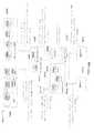
本開示の1つの実施形態では、システムはハブを備えている。ハブは、患者介護デバイ
スを監視するように構成されている。ハブは、(プロセッサ実行ソフトウェアとして具体
化することができる)オペレーティング・システム・コンポーネントと、(プロセッサ実
行ソフトウェアとして具体化することができる)サンドボックス・コンポーネントとを備
えている。オペレーティング・システム・コンポーネントは、ハブのハードウェア・リソ
ースおよびハブのソフトウェア・リソースのうちの少なくとも1つにアクセスするように
構成されている。In one embodiment of the present disclosure, the system comprises a hub. The hub is configured to monitor the patient-care device. The hub comprises an operating system component (which may be embodied as processor executing software) and a sandbox component (which may be embodied as processor executing software). The operating system component is configured to access at least one of hub hardware resources and hub software resources.
サンドボックス・コンポーネントは、ハードウェア・リソースおよびソフトウェア・リ
ソースのうちの少なくとも1つに対するアクセスを制御するように構成されている。ハブ
は、患者介護デバイスを識別し、アプリケーションを実行して、患者介護デバイスを監視
するようにさらに構成されている。ハブは、サンドボックス・コンポーネント内でアプリ
ケーションを実行することができ、それによりアプリケーションが、サンドボックス・コ
ンポーネントを通じてハードウェア・リソースおよびソフトウェア・リソースのうちの少
なくとも1つにアクセスする。The sandbox component is configured to control access to at least one of hardware resources and software resources. The hub is further configured to identify a patient-care device, execute an application, and monitor the patient-care device. The hub may execute an application within the sandbox component, such that the application accesses at least one of hardware and software resources through the sandbox component.
ハブは、患者介護デバイスを制御するようにさらに構成されてもよい。患者介護デバイ
スは、注入ポンプ、丸薬ディスペンサ、マイクロインフュージョン・ポンプ、ECGモニ
タ、血圧モニタ、パルス・オキシメータ、CO2カプノメータ、静脈内バッグ、および/
または点滴流量計の1つ以上であってもよい。The hub may be further configured to control the patient-care device. Patient care devices, infusion pumps, pills dispenser, micro infusion pump, ECG monitor, blood pressure monitor, a pulse oximeter, CO2 capnometers, intravenous bags, and /
Or it may be one or more of drip flowmeters.
ハブは、患者介護デバイスから識別情報(例えば、シリアル番号、(暗号化されたまた
は暗号化されていない)コード、または他の識別値)を受信し、識別情報に関連付けられ
たサーバからアプリケーションをダウンロードするように構成されてもよい。また、ハブ
は、患者介護デバイスから識別情報を受信し、識別情報に関連付けられたサーバからのア
プリケーションを更新するように構成されてもよい。The hub receives identification information (eg, serial number, (encrypted or unencrypted) code, or other identification value) from the patient-care device and downloads the application from the server associated with the identification information It may be configured to The hub may also be configured to receive the identification information from the patient-care device and update the application from the server associated with the identification information.
ハードウェア・リソースは、ディスク・ドライブ、メモリ、ブザー、マイクロフォン、
スピーカ、およびカメラであってもよい。ソフトウェア・リソースは、変数、セキュアな
データ・オブジェクト、セキュアな変数、保護付きAPI、APIおよびハードウェア・
コンポーネントのソフトウェア表現のうちの1つであってもよい。Hardware resources include disk drive, memory, buzzer, microphone,
It may be a speaker and a camera. Software resources include variables, secure data objects, secure variables, protected APIs, APIs and hardware
It may be one of the software representations of the components.
さらに別の実施形態では、電子患者介護用のシステムは、ハブを備えている。ハブは、
患者介護デバイスを監視するように構成されている。サンドボックスは、ハードウェア・
リソースおよびソフトウェア・リソースのうちの少なくとも1つに対するアクセスを制御
するように構成することができる。ハブは、患者介護デバイスを識別し、アプリケーショ
ンを実行して、患者介護デバイスを監視するようにさらに構成されている。ハブは、サン
ドボックス・コンポーネント内でアプリケーションを実行し、それによりアプリケーショ
ンが、サンドボックス・コンポーネントを通じてハードウェア・リソースおよびソフトウ
ェア・リソースのうちの少なくとも1つにアクセスする。ハブは、患者介護デバイスを制
御するようにさらに構成されてもよい。ハブは、患者介護デバイスから識別情報を受信し
、識別情報に関連付けられたサーバからアプリケーションをダウンロードするようにさら
に構成されてもよい。ハブは、患者介護デバイスから識別情報を受信し、識別情報に関連
付けられたサーバからのアプリケーションを更新するようにさらに構成されてもよい。In yet another embodiment, a system for electronic patient care comprises a hub. The hub is
It is configured to monitor a patient-care device. Sandbox is hardware
Resources and software resources may be configured to control access to at least one of the resources. The hub is further configured to identify a patient-care device, execute an application, and monitor the patient-care device. The hub executes an application in a sandbox component, whereby the application accesses at least one of hardware and software resources through the sandbox component. The hub may be further configured to control the patient-care device. The hub may be further configured to receive the identification information from the patient-care device and download the application from a server associated with the identification information. The hub may be further configured to receive the identification information from the patient-care device and update the application from the server associated with the identification information.
ハードウェア・リソースは、ディスク・ドライブ、メモリ、ブザー、マイクロフォン、
スピーカ、およびカメラであってもよい。ソフトウェア・リソースは、変数、セキュアな
データ・オブジェクト、セキュアな変数、保護付きAPI、APIおよびハードウェア・
コンポーネントのソフトウェア表現のうちの1つであってもよい。Hardware resources include disk drive, memory, buzzer, microphone,
It may be a speaker and a camera. Software resources include variables, secure data objects, secure variables, protected APIs, APIs and hardware
It may be one of the software representations of the components.
さらに別の実施形態では、電子患者介護用のシステムは、監視クライアントを備えてい
る。監視クライアントは、患者介護デバイスを監視するように構成されている。監視クラ
イアントは、監視クライアントのハードウェア・リソースおよび監視クライアントのソフ
トウェア・リソースのうちの少なくとも1つにアクセスするように構成されたオペレーテ
ィング・システム・コンポーネントを備えている。サンドボックス・コンポーネントは、
ハードウェア・リソースおよびソフトウェア・リソースのうちの少なくとも1つに対する
アクセスを制御するように構成されている。監視クライアントは、患者介護デバイスを識
別し、アプリケーションを実行して、患者介護デバイスを監視するようにさらに構成され
てもよい。監視クライアントは、サンドボックス・コンポーネント内でアプリケーション
を実行し、それによりアプリケーションが、サンドボックス・コンポーネントを通じてハ
ードウェア・リソースおよびソフトウェア・リソースのうちの少なくとも1つにアクセス
する。監視クライアントは、患者介護デバイスを制御するようにさらに構成されている。In yet another embodiment, a system for electronic patient care comprises a monitoring client. The monitoring client is configured to monitor the patient-care device. The monitoring client comprises an operating system component configured to access at least one of a monitoring client hardware resource and a monitoring client software resource. Sandbox components are
It is configured to control access to at least one of hardware resources and software resources. The monitoring client may be further configured to identify the patient-care device, execute the application, and monitor the patient-care device. The monitoring client executes the application in the sandbox component, whereby the application accesses at least one of the hardware resource and the software resource through the sandbox component. The monitoring client is further configured to control the patient-care device.
患者介護デバイスは、注入ポンプ、丸薬ディスペンサ、マイクロインフュージョン・ポ
ンプ、ECGモニタ、血圧モニタ、パルス・オキシメータおよび/またはCO2カプノメ
ータ、静脈内バッグ、および点滴流量計であってもよい。Patient care devices, infusion pumps, pills dispenser, micro infusion pump, ECG monitor, blood pressure monitor, a pulse oximeter and / or CO2 capnometers, may be an intravenous bag, and infusion flow meter.
監視クライアントは、患者介護デバイスから識別情報を受信し、識別情報に関連付けら
れたサーバからアプリケーションをダウンロードするようにさらに構成されてもよい。監
視クライアントは、患者介護デバイスから識別情報を受信し、識別情報に関連付けられた
サーバからのアプリケーションを更新するようにさらに構成されてもよい。The monitoring client may be further configured to receive the identification information from the patient-care device and download the application from a server associated with the identification information. The monitoring client may be further configured to receive the identification information from the patient-care device and to update the application from the server associated with the identification information.
ハードウェア・リソースは、ディスク・ドライブ、メモリ、ブザー、マイクロフォン、
スピーカおよびカメラであってもよい。ソフトウェア・リソースは、変数、セキュアなデ
ータ・オブジェクト、セキュアな変数、保護付きAPI、APIおよびハードウェア・コ
ンポーネントのソフトウェア表現であってもよい。Hardware resources include disk drive, memory, buzzer, microphone,
It may be a speaker and a camera. Software resources may be variables, secure data objects, secure variables, protected APIs, software representations of APIs and hardware components.
さらに別の実施形態では、電子患者介護用のシステムは、患者介護デバイスを監視する
ように構成された監視クライアントを備えている。監視クライアントは、ハードウェア・
リソースおよびソフトウェア・リソースのうちの少なくとも1つに対するアクセスを制御
するように構成されたサンドボックス・コンポーネントを備えている。監視クライアント
は、患者介護デバイスを識別し、アプリケーションを実行して、患者介護デバイスを監視
するようにさらに構成されてもよい。監視クライアントは、サンドボックス・コンポーネ
ント内でアプリケーションを実行し、それによりアプリケーションが、サンドボックス・
コンポーネントを通じてハードウェア・リソースおよびソフトウェア・リソースのうちの
少なくとも1つにアクセスする。監視クライアントは、患者介護デバイスを制御するよう
にさらに構成されてもよい。In yet another embodiment, a system for electronic patient care comprises a monitoring client configured to monitor a patient care device. The monitoring client is hardware
A sandbox component configured to control access to at least one of resources and software resources. The monitoring client may be further configured to identify the patient-care device, execute the application, and monitor the patient-care device. The monitoring client runs the application in the sandbox component, which causes the application to
Access at least one of hardware resources and software resources through the components. The monitoring client may be further configured to control the patient-care device.
患者介護デバイスは、注入ポンプ、丸薬ディスペンサ、マイクロインフュージョン・ポ
ンプ、ECGモニタ、血圧モニタ、パルス・オキシメータおよび/またはCO2カプノメ
ータ、静脈内バッグ、および点滴流量計であってもよい。Patient care devices, infusion pumps, pills dispenser, micro infusion pump, ECG monitor, blood pressure monitor, a pulse oximeter and / or CO2 capnometers, may be an intravenous bag, and infusion flow meter.
監視クライアントは、患者介護デバイスから識別情報を受信し、識別情報に関連付けら
れたサーバからアプリケーションをダウンロードするようにさらに構成されてもよい。監
視クライアントは、患者介護デバイスから識別情報を受信し、識別情報に関連付けられた
サーバからのアプリケーションを更新するようにさらに構成されてもよい。The monitoring client may be further configured to receive the identification information from the patient-care device and download the application from a server associated with the identification information. The monitoring client may be further configured to receive the identification information from the patient-care device and to update the application from the server associated with the identification information.
ハードウェア・リソースは、ディスク・ドライブ、メモリ、ブザー、マイクロフォン、
スピーカおよびカメラであってもよい。ソフトウェア・リソースは、変数、セキュアなデ
ータ・オブジェクト、セキュアな変数、保護付きAPI、APIおよびハードウェア・コ
ンポーネントのソフトウェア表現のうちの1つであってもよい。Hardware resources include disk drive, memory, buzzer, microphone,
It may be a speaker and a camera. The software resource may be one of a variable, a secure data object, a secure variable, a protected API, an API and a software representation of the hardware component.
別の実施形態では、電子患者介護用のシステムは、電子診療録と通信するように構成さ
れたハブと、患者介護デバイスとを備えている。ハブは、患者および患者介護デバイス(
例えば、注入ポンプ)を識別するように構成されている。ハブはまた、電子診療録から少
なくとも1つの治療パラメータ(例えば、注入薬物、および/または注入速度もしくは速
度プロファイルなど)をダウンロードし、少なくとも1つの治療パラメータで患者介護デ
バイスをプログラムするように構成されている。ハブは、RFID呼掛器を使用してRF
IDタグを読み取ること、マイクロフォンに結合された音声認識ソフトウェアを使用する
音声、カメラに結合された顔認識ソフトウェアを使用する顔、バイオメトリック読み取り
のバイオメトリック・パラメータ、識別情報、バーコード・リーダによるバーコード読み
取りのうちの少なくとも1つに従って患者を識別する。特定の1つの実施形態では、ハブ
は、本明細書に記載した識別技術の1つ以上を使用して、少なくとも1つの治療パラメー
タをダウンロードすることができる。In another embodiment, a system for electronic patient care comprises a hub configured to communicate with an electronic medical record and a patient care device. The hub is used for patient and patient
For example, it is configured to identify the infusion pump. The hub is also configured to download at least one treatment parameter (e.g., infusion drug, and / or infusion rate or rate profile, etc.) from the electronic medical record and to program the patient-care device with the at least one treatment parameter There is. The hub uses an RFID interrogator to RF
Reading ID tags, speech using voice recognition software coupled to a microphone, face using face recognition software coupled to a camera, biometric parameters of biometric reading, identification information, bar by bar code reader Identify the patient according to at least one of the code readings. In one particular embodiment, the hub can download at least one treatment parameter using one or more of the identification techniques described herein.
別の実施形態では、電子患者介護用のシステムは、電子診療録と通信するように構成さ
れた監視クライアントと、患者介護デバイスとを備えている。監視クライアントは、患者
および患者介護デバイス(例えば、注入ポンプ)を識別するように構成されている。監視
クライアントはまた、電子診療録から少なくとも1つの治療パラメータ(例えば、注入薬
物、および/または注入速度もしくは速度プロファイルなど)をダウンロードし、少なく
とも1つの治療パラメータで患者介護デバイスをプログラムするように構成されている。
監視クライアントは、RFID呼掛器を使用してRFIDタグを読み取ること、マイクロ
フォンに結合された音声認識ソフトウェアを使用する音声、カメラに結合された顔認識ソ
フトウェアを使用する顔、バイオメトリック読み取りのバイオメトリック・パラメータ、
識別情報、バーコード・リーダによるバーコード読み取りのうちの少なくとも1つに従っ
て患者を識別する。特定の1つの実施形態では、監視クライアントは、本明細書に記載す
る識別技術の1つ以上を使用して、少なくとも1つの治療パラメータをダウンロードする
ことができる。In another embodiment, a system for electronic patient care comprises a monitoring client configured to communicate with an electronic medical record and a patient care device. The monitoring client is configured to identify the patient and a patient-care device (eg, an infusion pump). The monitoring client is also configured to download at least one treatment parameter (e.g., an infusion drug, and / or an infusion rate or rate profile, etc.) from the electronic medical record and to program the patient-care device with the at least one treatment parameter. ing.
Monitoring client reads RFID tag using RFID interrogator, voice using voice recognition software coupled to microphone, face using face recognition software coupled to camera, biometric reading biometric Parameters
The patient is identified according to at least one of the identification information, the barcode reading by the barcode reader. In one particular embodiment, the monitoring client can download at least one treatment parameter using one or more of the identification techniques described herein.
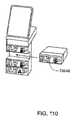
さらに別の実施形態では、電子患者介護用のシステムは、監視クライアント、監視クラ
イアント・ドック、患者介護デバイスおよびデバイス・ドックを備えている。監視クライ
アントは、少なくとも1つの患者介護パラメータを通信するように構成されている。監視
クライアント・ドックは、監視クライアントをそこにドッキングさせるために、患者用ク
ライアントを受信するように構成されている。患者介護デバイスは、少なくとも1つの患
者介護パラメータを通信するように構成されている。デバイス・ドックは、患者介護デバ
イスをそこにドッキングするために、患者介護デバイスを受信するように構成されている
。In yet another embodiment, a system for electronic patient care comprises a monitoring client, a monitoring client dock, a patient care device and a device dock. The monitoring client is configured to communicate at least one patient care parameter. The monitoring client dock is configured to receive a patient client for docking the monitoring client thereto. The patient-care device is configured to communicate at least one patient-care parameter. The device dock is configured to receive a patient-care device to dock the patient-care device thereto.
1つの実施形態では、監視クライアント・ドックおよびデバイス・ドックは、無線で、
および監視クライアント・ドックおよびデバイス・ドックに動作可能に結合されたケーブ
ルを通しての一方で通信するように構成されている。In one embodiment, the monitoring client dock and the device dock are wireless
And the monitoring client dock and the device dock are configured to communicate one way through a cable operably coupled to the dock and the device dock.
別の実施形態では、監視クライアントは、少なくとも1つの患者介護パラメータを無線
で通信するように構成されている。In another embodiment, the monitoring client is configured to communicate at least one patient-care parameter wirelessly.
別の実施形態では、監視クライアント・ドックは、監視クライアントと無線で通信する
ように構成されており、監視クライアントは、少なくとも1つの患者介護パラメータを監
視クライアント・ドックと無線で、ケーブルを通してドックに、またドッキングされた患
者介護デバイスに通信することによって、患者介護デバイスと動作可能に通信する。In another embodiment, the monitoring client dock is configured to communicate wirelessly with the monitoring client, and the monitoring client monitors the at least one patient-care parameter to the dock via the monitoring client dock and wirelessly through the cable, Also in operable communication with the patient-care device by communicating to the docked patient-care device.
別の実施形態では、監視クライアントは、ケーブルを通した通信が利用可能ではない、
および監視クライアントが監視クライアント・ドックからドッキングを外された、のうち
の少なくとも一方であると監視クライアントが判断したときに、監視クライアント・ドッ
クとの無線通信を利用して、少なくとも1つの患者介護パラメータを動作可能に通信する
。In another embodiment, the monitoring client does not have communication available through the cable.
And at least one patient-care parameter using wireless communication with the monitoring client dock when the monitoring client determines that the monitoring client is at least one of: the monitoring client dock is undocked from the monitoring client dock Communicate in an operational manner.
別の実施形態では、デバイス・ドックは、監視クライアントと無線通信するように構成
されており、監視クライアントは、デバイス・ドックと無線で通信して少なくとも1つの
患者介護パラメータを、ドッキングされた患者介護デバイスに送ることによって、患者介
護デバイスと動作可能に通信する。In another embodiment, the device dock is configured to wirelessly communicate with the monitoring client, and the monitoring client wirelessly communicates with the device dock to dock at least one patient care parameter with the patient care docked. Operatively communicating with the patient-care device by sending to the device.
別の実施形態では、監視クライアントは、ケーブルを通した通信が利用可能ではない、
監視クライアントと監視クライアント・ドックの間の通信が利用可能ではない、および監
視クライアントが監視クライアント・ドックからドッキングを外された、のうちの少なく
とも1つであると監視クライアントが判断したときに、デバイス・ドックとの無線通信を
利用して、少なくとも1つの患者介護パラメータを動作可能に通信する。In another embodiment, the monitoring client does not have communication available through the cable.
A device when communication between the monitoring client and the monitoring client dock is not available, and the monitoring client determines that the monitoring client is at least one of undocked from the monitoring client dock Operatably communicating at least one patient-care parameter using wireless communication with the dock.
別の実施形態では、患者介護デバイスは、監視クライアントと無線通信するように構成
されており、監視クライアントは、少なくとも1つの患者介護パラメータを患者介護デバ
イスと無線通信する。In another embodiment, the patient-care device is configured to wirelessly communicate with the monitoring client, and the monitoring client wirelessly communicates at least one patient-care parameter to the patient-care device.
別の実施形態では、監視クライアントは、ケーブルを通した通信が利用可能ではない、
監視クライアントと監視クライアント・ドックの間の通信が利用可能ではない、デバイス
・ドックと患者介護デバイスの間の通信が利用可能ではない、および監視クライアントが
監視クライアント・ドックからドッキングを外された、のうちの少なくとも1つであると
監視クライアントが判断したときに、患者介護デバイスと無線で、少なくとも1つの患者
介護パラメータを動作可能に通信する。In another embodiment, the monitoring client does not have communication available through the cable.
Communication between the monitoring client and the monitoring client dock is not available, communication between the device dock and the patient-care device is not available, and the monitoring client has been undocked from the monitoring client dock At least one patient-care parameter is operably communicated wirelessly with the patient-care device when the monitoring client determines that it is at least one of the following.
別の実施形態では、監視クライアント・ドックおよびデバイス・ドックは、少なくとも
1つの患者パラメータを無線で通信するように構成されている。システムはさらに、監視
クライアント・ドックおよびデバイス・ドックに動作可能に結合されたケーブルを備えて
おり、監視クライアント・ドックおよびデバイス・ドックは、デバイス・ドック、監視ク
ライアント・ドックおよび監視クライアントの少なくとも1つが、ケーブルが通信リンク
として利用可能ではないと判断したときに、無線で通信するように構成されている。In another embodiment, the monitoring client dock and the device dock are configured to wirelessly communicate at least one patient parameter. The system further comprises a cable operably coupled to the monitoring client dock and the device dock, wherein the monitoring client dock and the device dock comprise at least one of the device dock, the monitoring client dock and the monitoring client And when it is determined that the cable is not available as a communication link, it is configured to communicate wirelessly.
別の実施形態では、監視クライアントは、複数の通信リンクを介して患者介護デバイス
と通信するように構成されており、監視クライアントは、複数の通信リンクのうちの動作
可能なものを介して通信する。In another embodiment, the monitoring client is configured to communicate with the patient-care device via the plurality of communication links, and the monitoring client communicates via the operable one of the plurality of communication links. .
別の実施形態では、患者介護デバイスは、注入ポンプ、丸薬ディスペンサ、マイクロイ
ンフュージョン・ポンプ、ECGモニタ、血圧モニタ、パルス・オキシメータ、CO2カ
プノメータ、静脈内バッグおよび点滴流量計のうちの1つである。In another embodiment, the patient care devices, infusion pumps, pills dispenser, one of the micro infusion pump, ECG monitor, blood pressure monitor, a pulse oximeter, CO2 capnometers, intravenous bags and infusion flow meter It is.
別の実施形態では、患者介護パラメータは、静脈内ポンプ流量パラメータ、ECGパラ
メータ、血圧パラメータ、パルス・オキシメータ・パラメータ、CO2カプノメータ・パ
ラメータ、静脈内バッグ・パラメータおよび点滴流量計値の少なくとも1つである。患者
介護パラメータは、患者状態パラメータおよび/または患者治療パラメータであってもよ
い。In another embodiment, the patient-care parameter is at least one of an intravenous pump flow parameter, an ECG parameter, a blood pressure parameter, a pulse oximeter parameter, a CO2 capnometer parameter, an intravenous bag parameter and a drip flow meter value It is. The patient care parameters may be patient condition parameters and / or patient treatment parameters.
別の実施形態では、患者介護デバイスは、メッシュ・ネットワークのノードとして無線
通信するように構成されている。In another embodiment, the patient-care device is configured to wirelessly communicate as a node of the mesh network.
別の実施形態では、ケーブルは監視クライアント・ドックおよびデバイス・ドックに動
作可能に結合され、患者介護デバイスがデバイス・ドックにドッキングされ、監視クライ
アントが監視クライアント・ドックにドッキングされている場合に、監視クライアントは
、ケーブルを通して少なくとも1つの患者介護パラメータを患者介護デバイスと通信する
ように構成されている。In another embodiment, the cable is operatively coupled to the monitoring client dock and the device dock, and the monitoring is performed when the patient care device is docked to the device dock and the monitoring client is docked to the monitoring client dock The client is configured to communicate at least one patient-care parameter with the patient-care device through the cable.
さらに別の実施形態では、電子患者介護用のシステムは、監視クライアント、患者介護
デバイスおよびデバイス・ドックを備えている。監視クライアントは、少なくとも1つの
患者介護パラメータを通信するように構成されている。患者介護デバイスは、少なくとも
1つの患者介護パラメータを通信するように構成されている。デバイス・ドックは、患者
介護デバイスをそこにドッキングするために患者介護デバイスを受け、監視クライアント
をそこにドッキングするために監視クライアントを受けるように構成されている。In yet another embodiment, a system for electronic patient care comprises a monitoring client, a patient care device and a device dock. The monitoring client is configured to communicate at least one patient care parameter. The patient-care device is configured to communicate at least one patient-care parameter. The device dock is configured to receive the patient-care device to dock the patient-care device thereon and to receive the monitoring client to dock the monitoring client thereto.
さらに別の実施形態では、電子患者介護用のシステムは、少なくとも1つの患者介護パ
ラメータを通信するように構成された患者介護デバイスと、少なくとも1つの患者介護パ
ラメータを通信するように構成された監視クライアントと、患者介護デバイスをそこにド
ッキングするために患者介護デバイスを受けるように構成されたデバイス・ドックとを備
えている。デバイス・ドックおよび監視クライアントは、一緒に一体化されている。In yet another embodiment, a system for electronic patient care comprises a patient care device configured to communicate at least one patient care parameter and a monitoring client configured to communicate at least one patient care parameter. And a device dock configured to receive the patient-care device for docking the patient-care device thereto. The device dock and the monitoring client are integrated together.
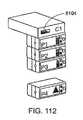
さらに別の実施形態では、電子患者介護用のシステムは、少なくとも1つの患者介護パ
ラメータを通信するように構成された積み重ね可能な監視クライアントと、少なくとも1
つの患者介護パラメータを通信するように構成された積み重ね可能な患者介護デバイスと
を備えている。積み重ね可能な監視クライアントおよび積み重ね可能な患者介護デバイス
は、デイジー・チェーン通信リンクを介しておよび/またはバックプレーンを使用して、
少なくとも1つの患者介護パラメータを通信してもよい。In yet another embodiment, a system for electronic patient care comprises at least one stackable monitoring client configured to communicate at least one patient care parameter.
A stackable patient care device configured to communicate two patient care parameters. The stackable monitoring client and the stackable patient care device may be via a daisy chain communication link and / or using a backplane
At least one patient care parameter may be communicated.
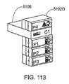
さらに別の実施形態では、電子患者介護用のシステムは、少なくとも1つの患者介護パ
ラメータを通信するように構成された患者介護デバイスと、少なくとも1つの患者介護パ
ラメータを通信するように構成されたハブ・クライアントと、患者介護デバイスをそこに
ドッキングするために患者介護デバイスを受けるように構成されたデバイス・ドックとを
備えている。ハブは、デバイス・ドックに差し込まれて、両者間に通信リンクを確立する
ことができる。システムはさらに、ハブと動作可能に通信する監視クライアントを備えて
、少なくとも1つの患者介護パラメータを受信してもよい。患者治療パラメータは、ハブ
に動作可能に通信されることができ、ハブは、患者治療パラメータを患者介護デバイスに
通信する。In yet another embodiment, a system for electronic patient care comprises a patient care device configured to communicate at least one patient care parameter and a hub configured to communicate at least one patient care parameter. A client and a device dock configured to receive a patient-care device for docking the patient-care device thereto. The hub can be plugged into the device dock to establish a communication link between the two. The system may further include a monitoring client in operative communication with the hub to receive at least one patient-care parameter. Patient treatment parameters may be operatively communicated to the hub, which communicates patient treatment parameters to the patient-care device.
特定の実施形態では、ハブはユーザ・インターフェースを備えてもよく、ハブは、患者
治療パラメータを患者介護デバイスに送信する前に、ユーザ認証を要求してもよい。In certain embodiments, the hub may comprise a user interface, and the hub may require user authentication prior to transmitting patient treatment parameters to the patient-care device.
特定の実施形態では、監視クライアントはユーザ・インターフェースを備えることがで
き、監視クライアントは、ハブを通して患者介護デバイスに患者治療パラメータを送信す
る前に、ユーザ認証を要求してもよい。In particular embodiments, the monitoring client may comprise a user interface, and the monitoring client may require user authentication prior to transmitting patient treatment parameters to the patient-care device through the hub.
特定の実施形態では、患者介護デバイスはユーザ・インターフェースを備えることがで
き、患者介護デバイスは、患者を治療する前に、患者治療パラメータのユーザ認証を要求
してもよい。In certain embodiments, the patient-care device may comprise a user interface, and the patient-care device may require user authentication of patient treatment parameters prior to treating the patient.
ハブは、患者介護デバイスを監視するように構成することができる。特定の実施形態で
は、ハブは、ハードウェア・リソースおよびソフトウェア・リソースの少なくとも1つに
対するアクセスを制御するように構成されたサンドボックス・コンポーネントを備えても
よい。The hub can be configured to monitor a patient-care device. In particular embodiments, the hub may comprise a sandbox component configured to control access to at least one of hardware resources and software resources.
ハブはさらに、患者介護デバイスを識別し、アプリケーションを実行して、患者介護デ
バイスを監視するように構成することができる。ハブは、サンドボックス・コンポーネン
ト内でアプリケーションを実行することができ、それによりアプリケーションが、サンド
ボックス・コンポーネントを通じてハードウェア・リソースおよびソフトウェア・リソー
スのうちの少なくとも1つにアクセスする。The hub may further be configured to identify a patient-care device, execute an application, and monitor the patient-care device. The hub may execute an application within the sandbox component, such that the application accesses at least one of hardware and software resources through the sandbox component.
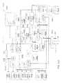
別の実施形態では、電子患者介護用のシステムは、以下のものを備えている:少なくと
も1つの患者パラメータを監視するのに適合化された少なくとも1つの患者モニタ;少な
くとも1つの患者モニタと動作可能に通信して、少なくとも1つの患者パラメータをそれ
から受信する監視クライアント;および監視クライアントと動作可能に通信して、該監視
クライアントから少なくとも1つの患者パラメータを受信する監視サーバ。In another embodiment, a system for electronic patient care comprises: at least one patient monitor adapted to monitor at least one patient parameter; operable with at least one patient monitor A monitoring client in communication with and receiving at least one patient parameter therefrom; and a monitoring server in operative communication with the monitoring client to receive at least one patient parameter from the monitoring client.
別の実施形態では、システムはさらに、少なくとも1つの患者モニタと動作可能に通信
して、少なくとも1つの患者パラメータを受信する遠隔コミュニケータを備えてもよい。In another embodiment, the system may further comprise a remote communicator in operative communication with the at least one patient monitor to receive the at least one patient parameter.
少なくとも1つの患者モニタは、心電図モニタ、血圧モニタ、パルス・オキシメータ・
モニタおよびCO2カプノメータの少なくとも1つを備えることができる。監視クライア
ントは、指定された固有の患者識別子に従って患者情報をダウンロードするように構成す
ることができる。固有の患者識別子は、リスト・バンド上に配置されたバーコード上でコ
ード化することができる。固有の患者識別子は、リスト・バンドに結合されたRFIDタ
グ(例えば、RFID呼掛器)上でコード化することができる。患者情報は、患者状態ま
たは患者介護パラメータを含む。独自の患者識別子は、監視サーバに動作可能に送信され
て、患者特有のデータを通信するための電子許可を得ることができる。患者特有のデータ
のサブセットは、監視クライアントのメモリ内に記憶されてもよい。監視クライアントは
、新しい指示がメモリ内に記憶された患者特有のデータのサブセットに基づく所定の基準
を満たすかどうか判定するように適合されてもよい。At least one patient monitor includes an electrocardiogram monitor, a blood pressure monitor, a pulse oximeter
A monitor and at least one of a CO2 capnometer can be provided. The monitoring client may be configured to download patient information according to the specified unique patient identifier. The unique patient identifier can be encoded on a barcode placed on the wrist band. The unique patient identifier may be encoded on an RFID tag (e.g., an RFID interrogator) coupled to the wrist band. Patient information includes patient status or patient care parameters. The unique patient identifier may be operatively transmitted to the monitoring server to obtain electronic authorization to communicate patient specific data. A subset of patient specific data may be stored in the monitoring client's memory. The monitoring client may be adapted to determine whether the new indication meets predetermined criteria based on a subset of patient specific data stored in memory.
別の実施形態では、システムはさらに、新しい指示を監視クライアントに提示するよう
に適合されたポータブル監視クライアントを備えている。監視クライアントおよび/また
は遠隔コミュニケータの少なくとも1つは、新しい指示を監視サーバに通信するように適
合されてもよく、監視サーバは、新しい指示が別の所定の基準を満たしているかどうか判
定するように適合されてもよい。In another embodiment, the system further comprises a portable surveillance client adapted to present the new indication to the surveillance client. At least one of the monitoring client and / or the remote communicators may be adapted to communicate the new indication to the monitoring server, such that the monitoring server determines whether the new indication meets another predetermined criterion. May be adapted to
別の実施形態では、新しい指示は、薬剤の指示であってもよく、監視サーバは、薬剤の
指示が現在処方されている薬剤に禁忌でないかどうか判定することによって、新しい指示
が別の所定の基準を満たしているかどうか判定するように適合されてもよい。監視サーバ
は、データベースと通信して、新しい指示が別の所定の基準を満たしているかどうか判定
することができる。監視サーバは、新しい指示が別の所定の基準を満たしていないとき、
監視クライアントに警戒を送信するように構成されてもよい。In another embodiment, the new indication may be an indication of a drug, and the monitoring server determines whether the indication of the drug is not a contraindication to the currently prescribed drug so that the new indication is another predetermined indication. It may be adapted to determine if it meets the criteria. The monitoring server may communicate with the database to determine if the new indication meets another predetermined criterion. The monitoring server may, when the new indication does not meet another predetermined criterion,
It may be configured to send an alert to the monitoring client.
別の実施形態では、システムは、監視クライアントおよび監視サーバの少なくとも1つ
と動作可能に通信するように適合された遠隔通信を備えることができる。In another embodiment, the system can comprise telecommunications adapted to operatively communicate with at least one of the monitoring client and the monitoring server.
別の実施形態では、監視クライアントは、デスク・ベースのデバイス、ポータブル・デ
バイス、手持ち式コントローラ、ノートブックPC、ネットブックPC、タブレットPC
、およびスマートフォンの1つであってもよい。監視クライアントはタッチスクリーンを
備えている。In another embodiment, the monitoring client may be a desk based device, a portable device, a handheld controller, a notebook PC, a netbook PC, a tablet PC
, And may be one of smartphones. The surveillance client is equipped with a touch screen.
別の実施形態では、システムはさらに注入ポンプを備えることができ、監視クライアン
トは、注入ポンプと動作可能に通信する。注入ポンプは、監視クライアントに取り付け可
能であってもよい。注入ポンプは、監視クライアントから取り外し可能であってもよい。In another embodiment, the system can further comprise an infusion pump, wherein the monitoring client is in operative communication with the infusion pump. The infusion pump may be attachable to the monitoring client. The infusion pump may be removable from the monitoring client.
別の実施形態では、システムはさらに、監視クライアントを注入ポンプにドッキングさ
せるように構成されたドックを備えている。In another embodiment, the system further comprises a dock configured to dock the monitoring client to the infusion pump.
別の実施形態では、監視クライアントは、無線リンクを介して注入ポンプと動作可能に
通信する。In another embodiment, the monitoring client is in operative communication with the infusion pump via a wireless link.
別の実施形態では、監視サーバは、複数のデータベースと通信するように構成されてお
り、複数のデータベースの少なくとも1つは、該複数のデータベースのうちの別のデータ
ベースとは異なるデータ・フォーマットまたは通信プロトコルを含む。In another embodiment, the monitoring server is configured to communicate with a plurality of databases, and at least one of the plurality of databases has a different data format or communication than another database of the plurality of databases. Including protocols.
別の実施形態では、監視サーバは、複数のデータベースからのデータをフォーマットし
て、該データを監視クライアントにダウンロードするように適合されている。任意選択で
は、またいくつかの特定の実施形態では、監視クライアントは、少なくとも1つの患者パ
ラメータを監視サーバに通信してもよい。特定の実施形態では、患者パラメータは、注入
ポンプの治療の進行、心電図シグナル、血圧シグナル、パルス・オキシメータシグナル、
CO2カプノメータシグナル、および/または温度シグナルのうちの1つ以上であり、お
よび/または少なくともこれらの1つを含むことができる。In another embodiment, the monitoring server is adapted to format data from a plurality of databases and download the data to the monitoring client. Optionally, and in some specific embodiments, the monitoring client may communicate at least one patient parameter to the monitoring server. In certain embodiments, patient parameters include: progress of infusion pump therapy, electrocardiogram signal, blood pressure signal, pulse oximeter signal
It may be one or more of, and / or include at least one of a CO2 capnometer signal, and / or a temperature signal.
別の実施形態では、監視サーバは、監視クライアントを介して動作指示を注入ポンプに
ダウンロードするように構成されてもよい。In another embodiment, the monitoring server may be configured to download the operation instructions to the infusion pump via the monitoring client.
監視クライアントは、ユーザ・要求を受信して、患者パラメータを読み取ることができ
、また監視デバイスに問い合わせて、患者パラメータを受信することができる。The monitoring client can receive the user request, read patient parameters, and can query the monitoring device to receive patient parameters.
別の実施形態では、システムはさらに、ポータブル監視クライアントを備えてもよい。
ポータブル監視クライアントは、監視クライアントと動作可能に通信して、患者情報を直
接通信し、それによって監視サーバをバイパスしてもよい。ポータブル監視クライアント
は、注入ポンプの少なくとも1つのパラメータを変更し、その少なくとも1つの変更され
たパラメータを監視サーバに通信するように構成されてもよい。In another embodiment, the system may further comprise a portable surveillance client.
The portable surveillance client may be in operative communication with the surveillance client to communicate patient information directly, thereby bypassing the surveillance server. The portable monitoring client may be configured to change at least one parameter of the infusion pump and to communicate the at least one changed parameter to the monitoring server.
ポータブル監視クライアントを介して提示される患者指示の変更は、別のポータブル監
視クライアントに伝達することができる。Changes in patient instructions presented via the portable surveillance client can be communicated to another portable surveillance client.
別の実施形態では、監視クライアントは、監視サーバへの情報を定期的にアップロード
して、患者特有のデータベース内に記憶するように構成されている。In another embodiment, the monitoring client is configured to periodically upload information to the monitoring server for storage in a patient specific database.
システムはさらに、患者特有のデータベースから情報を受信するように適合された別の
監視クライアントを備えることができる。The system may further comprise another monitoring client adapted to receive information from a patient specific database.
情報は、患者指示、患者投薬、進行ノート、患者モニタからの監視データ、および取り
付けられたデバイスからの治療データの少なくとも1つを含むことができる。The information may include at least one of patient instructions, patient dosing, progress notes, monitoring data from a patient monitor, and treatment data from an attached device.
監視サーバは、電子健康記録データベースに問い合わせて、患者情報をそこから受信す
るように構成することができる。監視サーバはさらに、患者情報に従って、所定のセット
の情報を監視クライアントに入力するように構成することができる。The monitoring server can be configured to query the electronic health record database and receive patient information therefrom. The monitoring server may be further configured to input a predetermined set of information to the monitoring client according to the patient information.
所定のセットの情報は、患者の年齢、身長、体重、診断、現在の薬剤、薬剤カテゴリ、
薬剤アレルギーおよび過敏症の少なくとも1つを含んでいてもよい。The predetermined set of information includes the patient's age, height, weight, diagnosis, current drug, drug category,
It may include at least one of drug allergy and hypersensitivity.
別の実施形態では、遠隔ポータブル監視クライアントは、監視サーバを介して監視クラ
イアントと通信するように適合されている。遠隔ポータブル監視クライアントは、タブレ
ットPC、ネットブックおよびPCの1つであってもよい。遠隔ポータブル監視クライア
ントは、タッチスクリーンを備えることができる。In another embodiment, the remote portable monitoring client is adapted to communicate with the monitoring client via the monitoring server. The remote portable surveillance client may be one of a tablet PC, a netbook and a PC. The remote portable surveillance client can comprise a touch screen.
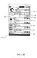
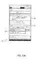
別の実施形態では、電子患者介護用の方法は以下の工程を含む:ディスプレイ上に複数
の患者を表示する工程;ディスプレイ上に複数の患者のうちの1人の患者に関連付けられ
た少なくとも1つの患者パラメータを表示する工程;ディスプレイ上に該患者に関連付け
られた少なくとも1つの警戒を表示する工程;および複数の患者から該患者を選択する工
程。In another embodiment, a method for electronic patient care includes the steps of: displaying a plurality of patients on a display; at least one associated with a patient of the plurality of patients on the display Displaying patient parameters; displaying at least one alert associated with the patient on a display; and selecting the patient from a plurality of patients.
上記の方法は、いくつかの特定の実施形態では、監視クライアントからディスプレイを
有するポータブル遠隔コミュニケータ・デバイスに警戒を送信する工程をさらに含んでい
てもよい。The above method may further include, in some specific embodiments, transmitting an alert from the monitoring client to a portable remote communicator device having a display.
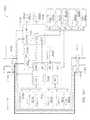
さらに別の実施形態では、電子患者介護システムは以下を備えている:少なくとも1つ
の患者介護パラメータを通信するように構成された監視クライアント;少なくとも1つの
患者介護パラメータを通信するように構成された患者介護デバイス;および少なくとも1
つの患者介護デバイスの存在を発見し、そのデバイスからの通信シグナルを監視クライア
ントに関連付けられた通信プロトコルに変換することによって、監視クライアントと少な
くとも1つの患者介護デバイスとの間の通信を容易にするように構成された通信インター
フェース。In yet another embodiment, the electronic patient-care system comprises: a monitoring client configured to communicate at least one patient-care parameter; a patient configured to communicate the at least one patient-care parameter A care device; and at least one
Facilitate communication between a monitoring client and at least one patient care device by discovering the presence of two patient care devices and converting the communication signals from that device into the communication protocol associated with the monitoring client Communication interface configured in.
特定の実施形態では、通信インターフェースはさらに、互いに異なる追加の他の患者介
護デバイスの存在を発見し、これらのデバイスからの通信シグナルを監視クライアントに
関連付けられた通信プロトコルに変換するように構成されている。In certain embodiments, the communication interface is further configured to discover the presence of additional other patient-care devices that are different from one another, and to translate communication signals from these devices into a communication protocol associated with the monitoring client. There is.
別の特定の実施形態では、通信インターフェースはさらに、各デバイスに適した電源を
提供するように構成されている。さらに別の特定の実施形態では、システムはさらに、患
者情報の中央記憶の少なくとも1つを考慮に入れた監視クライアントによってアクセス可
能な1つ以上のデータベース、および/または監視クライアントに関連付けられた患者の
治療に使用することができるダウンロード情報を備えている。In another particular embodiment, the communication interface is further configured to provide a suitable power supply for each device. In yet another specific embodiment, the system further comprises one or more databases accessible by the monitoring client taking into account at least one of the central stores of patient information, and / or the patient's associated with the monitoring client. It has download information that can be used for treatment.
さらに別の特定の実施形態では、通信インターフェースはさらに、以下の少なくとも1
つに対するフォルトチェックを行なうように構成されている:患者介護デバイスとの通信
のデータ整合性を評価する;監視クライアントが適切に機能しているかどうか評価する;
患者介護デバイスが適切に機能しているかどうか評価する;および/または通信インター
フェースが適切に機能しているかどうか評価する。In yet another specific embodiment, the communication interface further comprises at least one of:
Configured to perform fault checks on one server: assess data integrity of communication with the patient-care device; assess whether the monitoring client is functioning properly;
Assess if the patient-care device is functioning properly; and / or if the communication interface is functioning properly.
さらに別の実施形態では、電子患者介護システムは以下を備えている:少なくとも1つ
の患者介護パラメータを通信するように構成されたハブ・クライアント;少なくとも1つ
の患者介護パラメータを通信するように構成された患者介護デバイス;および少なくとも
1つの患者介護デバイスの存在を発見し、そのデバイスからの通信シグナルをハブに関連
付けられた通信プロトコルに変換することによって、ハブと少なくとも1つの患者介護デ
バイスとの間の通信を容易にするように構成された通信インターフェース。In yet another embodiment, the electronic patient-care system comprises: a hub client configured to communicate at least one patient-care parameter; configured to communicate the at least one patient-care parameter Communication between the hub and the at least one patient care device by discovering the presence of the patient care device; and the at least one patient care device and converting communication signals from the device into a communication protocol associated with the hub Communication interface configured to facilitate.
特定の実施形態では、通信インターフェースはさらに、互いに異なる追加の他の患者介
護デバイスの存在を発見し、そのデバイスからの通信シグナルをハブに関連付けられた通
信プロトコルに変換するように構成されている。In certain embodiments, the communication interface is further configured to discover the presence of additional other patient-care devices that are different from one another and to convert communication signals from that device into a communication protocol associated with the hub.
別の特定の実施形態では、通信インターフェースはさらに、各デバイスに適した電源を
提供するように構成されている。さらに別の特定の実施形態では、システムはさらに、患
者情報の中央記憶の少なくとも1つを考慮に入れたハブによってアクセス可能な1つ以上
のデータベース、および/またはハブに関連付けられた患者の治療に使用することができ
るダウンロード情報を備えている。In another particular embodiment, the communication interface is further configured to provide a suitable power supply for each device. In yet another specific embodiment, the system further comprises one or more databases accessible by the hub taking into account at least one of the central memories of patient information, and / or treatment of patients associated with the hub It has download information that can be used.
さらに別の特定の実施形態では、通信インターフェースはさらに、次の少なくとも1つ
に対するフォルトチェックを行なうように構成されている:患者介護デバイスとの通信の
データ整合性を評価する;監視クライアントが適切に機能しているかどうか評価する;患
者介護デバイスが適切に機能しているかどうか評価する;および/または通信インターフ
ェースが適切に機能しているかどうか評価する。In yet another specific embodiment, the communication interface is further configured to perform a fault check on at least one of: evaluating data integrity of communication with the patient-care device; the monitoring client appropriately Assess if functioning; assess whether the patient-care device is functioning properly; and / or assess if the communication interface is functioning properly.
さらに別の実施形態では、電子患者介護システムは以下を備えている:少なくとも1つ
の患者介護パラメータを通信するように構成されているドック;少なくとも1つの患者介
護パラメータを通信するように構成された患者介護デバイス;および少なくとも1つの患
者介護デバイスの存在を発見し、そのデバイスからの通信シグナルをドックに関連付けら
れた通信プロトコルに変換することによって、ドックと少なくとも1つの患者介護デバイ
スの間の通信を容易にするように構成された通信インターフェース。In yet another embodiment, the electronic patient-care system comprises: a dock configured to communicate at least one patient-care parameter; a patient configured to communicate at least one patient-care parameter Facilitating communication between the dock and the at least one patient care device by discovering the presence of the care device; and the at least one patient care device and converting the communication signals from the device to the communication protocol associated with the dock Communication interface configured to be.
特定の実施形態では、通信インターフェースはさらに、互いに異なる追加の他の患者介
護デバイスの存在を発見し、そのデバイスからの通信シグナルをドックに関連付けられた
通信プロトコルに変換するように構成されている。In certain embodiments, the communication interface is further configured to discover the presence of additional other patient-care devices that are different from one another and to convert communication signals from that device into the communication protocol associated with the dock.
別の特定の実施形態では、通信インターフェースはさらに、各デバイスに適した電源を
提供するように構成されている。さらに別の特定の実施形態では、システムはさらに、患
者情報の中央記憶の少なくとも1つを考慮に入れたドックによってアクセス可能な1つ以
上のデータベース、および/またはドックに関連付けられた患者の治療に使用することが
できるダウンロード情報を備えている。In another particular embodiment, the communication interface is further configured to provide a suitable power supply for each device. In yet another specific embodiment, the system further comprises one or more databases accessible by the dock taking into account at least one of the central stores of patient information, and / or treatment of the patient associated with the dock It has download information that can be used.
さらに別の特定の実施形態では、通信インターフェースはさらに、次の少なくとも1つ
に対するフォルトチェックを行なうように構成されている:患者介護デバイスとの通信の
データ整合性を評価する;監視クライアントが適切に機能しているかどうか評価する;患
者介護デバイスが適切に機能しているかどうか評価する;および/または通信インターフ
ェースが適切に機能しているかどうか評価する。In yet another specific embodiment, the communication interface is further configured to perform a fault check on at least one of: evaluating data integrity of communication with the patient-care device; the monitoring client appropriately Assess if functioning; assess whether the patient-care device is functioning properly; and / or assess if the communication interface is functioning properly.
1つの実施形態では、患者介護デバイスは以下を備えている:本体;支柱を受けるよう
に構成された本体内の管路;および本体に結合され、管路内で本体を支柱に摩擦力で係止
するように構成された2つの摩擦部材。In one embodiment, the patient-care device comprises: a body; a conduit within the body configured to receive the struts; and a body coupled to the body for frictionally engaging the body with the struts within the conduit. Two friction members configured to stop.
1つの実施形態では、ハブは以下を備えている:患者介護デバイス・インターフェース
;患者介護デバイス・インターフェースに結合され、患者介護デバイスに電力を供給する
ように構成された電源;プロセッサ;およびプロセッサと患者介護デバイスとの間で通信
を可能にするように構成された患者介護デバイス・インターフェースに結合されたトラン
シーバ。プロセッサは、いくつかの特定の実施形態では、アラーム状態にある場合に、患
者介護デバイスを無効にするように構成されてもよい。In one embodiment, the hub comprises: a patient-care device interface; a power supply coupled to the patient-care device interface and configured to supply power to the patient-care device; a processor; and the processor and the patient A transceiver coupled to a patient-care device interface configured to allow communication with a care device. The processor may be configured to disable the patient-care device when in an alarm condition in some specific embodiments.
1つの実施形態では、ドックは以下を備えている:患者介護デバイス・インターフェー
ス;患者介護デバイス・インターフェースに結合され、患者介護デバイスに電力を供給す
るように構成された電源;プロセッサ;およびプロセッサと患者介護デバイスとの間の通
信を可能にするように構成された患者介護デバイス・インターフェースに結合されたトラ
ンシーバ。プロセッサは、いくつかの特定の実施形態では、アラーム状態にある場合に、
患者介護デバイスを無効にするように構成されてもよい。In one embodiment, the dock comprises: a patient-care device interface; a power supply coupled to the patient-care device interface and configured to supply power to the patient-care device; a processor; A transceiver coupled to a patient-care device interface configured to enable communication with a care device. The processor, in some specific embodiments, is in an alarm state:
It may be configured to disable the patient-care device.
1つの実施形態では、通信モジュールは以下を備えている:患者介護デバイス・インタ
ーフェース;患者介護デバイス・インターフェースに結合され、患者介護デバイスに電力
を供給するように構成された電源;プロセッサ;および患者介護デバイスおよび別のデバ
イスに対する通信を可能にするように構成された患者介護デバイス・インターフェースに
結合されたトランシーバ。プロセッサは、いくつかの特定の実施形態では、アラーム状態
にある場合に、患者介護デバイスを無効にするように構成されてもよい。In one embodiment, the communication module comprises: a patient-care device interface; a power supply coupled to the patient-care device interface and configured to supply power to the patient-care device; a processor; A transceiver coupled to a patient-care device interface configured to allow communication to a device and another device. The processor may be configured to disable the patient-care device when in an alarm condition in some specific embodiments.
別の実施形態では、患者介護システムは以下を備えている:ドック;ドックにドッキン
グするように構成された複数のモジュール式患者介護デバイス;および監視クライアント
の格納式ディスプレイ。モジュール式患者介護デバイスは、互い違いに、またはコネクタ
を介して、水平面に沿ってドックとインターフェース接続されてもよい。In another embodiment, the patient-care system comprises: a dock; a plurality of modular patient-care devices configured to dock to the dock; and a retractable display of the monitoring client. The modular patient care devices may be interfaced with the dock along a horizontal plane, alternately or via connectors.
さらに別の実施形態では、電子患者介護システムは、患者に関する情報を受信および記
憶するように構成された第1のモジュールであって、当該情報が患者に接続されたデバイ
スによって測定された患者の第1のパラメータに関連するデータ、および患者に関する情
報を含む第1のデータベースから受信した患者の第2のパラメータに関連するデータを含
む第1のモジュールと、第2のモジュールに関連付けられたユーザ・インターフェースを
介してユーザから薬剤指示を受信するように構成され、さらに当該治療指示を第1のモジ
ュールに伝達するように構成された第2のモジュールとを備えており、当該第1のモジュ
ールはさらに、a)第2のデータベースから当該薬剤または他の薬物に関する薬剤情報で
あって、このような薬剤が一般的に投与される際の制限事項を提供するデータを含む薬剤
情報を取得すること、b)薬剤指示を、薬剤情報、第1のパラメータの値、および第2の
パラメータの値に基づいて第2のモジュールによって(この特定の実施形態では)確認し
なければならないかどうか判定すること、およびc)ユーザ・インターフェース上に表示
するために、予め決められたメッセージを第1のモジュールから第2のモジュールに伝達
することであって、当該メッセージが当該薬剤指示の受容性を確認し、またはそれに関し
て警告するものである、伝達すること、をするように構成されている。In yet another embodiment, the electronic patient-care system is a first module configured to receive and store information about a patient, wherein the information is measured by a device connected to the patient. A first module containing data related to one parameter and data related to a second parameter of the patient received from a first database containing information about the patient, and a user interface associated with the second module And a second module configured to receive a drug instruction from the user via the device, and further configured to communicate the treatment instruction to the first module, the first module further comprising: a) Drug information related to the drug or other drug from the second database, and such drug is generally Obtaining drug information including data providing limitations upon administration to the patient, b) drug instruction, based on the drug information, the value of the first parameter, and the value of the second parameter. Determining whether a module (in this particular embodiment) has to be verified and c) displaying a predetermined message from the first module to the second module for display on the user interface Communicating, wherein the message is configured to confirm, or warn regarding the acceptability of the medication indication.
薬剤情報としては、薬物相互作用情報、薬物アレルギー情報、血圧作用情報、心拍数作
用情報、心調律作用情報または呼吸作用情報を挙げることができ、第1のパラメータまた
は第2のパラメータは、患者の現在投与されている薬物、知られている薬物アレルギー、
現在の血圧、現在の心拍数、現在の心調律、現在の呼吸数または現在の換気量に関するデ
ータを含む。The drug information may include drug interaction information, drug allergy information, blood pressure action information, heart rate action information, cardiac rhythm action information or respiratory action information, and the first parameter or the second parameter may be the patient's Currently administered drugs, known drug allergies,
It includes data on current blood pressure, current heart rate, current heart rhythm, current respiratory rate or current ventilation volume.
予め決められたメッセージは、指示された薬剤の潜在的な作用に関する警告を含むこと
ができ、当該警告は、第1のパラメータに関する測定されたデータ、第2のパラメータに
関する受信されたデータまたは第1のモジュールによって得られた薬剤情報を含む。The predetermined message may include an alert on the potential action of the indicated agent, which alert may be measured data on the first parameter, received data on the second parameter or the first Containing drug information obtained by the
第1のモジュールは、予め決められたメッセージが伝達された後で、かつ、ユーザ・イ
ンターフェースからの入力シグナルによって始動された、第2のモジュールからの確認シ
グナルを受信した後に、薬物指示または修正された薬物指示が処理されることになるとの
シグナルを作成するように構成されてもよい。The first module is drug instructed or modified after a predetermined message has been communicated and after receiving a confirmation signal from the second module triggered by an input signal from the user interface The drug instruction may be configured to generate a signal that it is to be processed.
別の実施形態では、患者介護デバイスは、第1の通信リンクおよび第2の通信リンクを
備えており、ドックは、第1の通信リンクおよび第2の通信リンクを備えている。患者介
護デバイスがドックから所定の範囲内にある場合、患者介護デバイスおよびドックは、第
1の通信リンクを使用してペアリングされ、ペアリングの後は第2の通信リンクを使用し
て通信できる状態を保つ。第1の通信リンクを使用して行われるペアリングは、第2の通
信リンクに対して患者介護デバイスおよびドックをペアリングすることであってもよい。
第1の通信リンクは、近距離無線通信であってもよく、第2の通信リンクは、ブルートゥ
ース、ブルートゥース・ロー・エネルギー、WiFi、または他の通信リンクであっても
よい。In another embodiment, the patient-care device comprises a first communication link and a second communication link, and the dock comprises a first communication link and a second communication link. If the patient-care device is within a predetermined range of the dock, the patient-care device and the dock may be paired using the first communication link and may communicate using the second communication link after pairing Keep the state. The pairing performed using the first communication link may be to pair the patient-care device and the dock to the second communication link.
The first communication link may be near field communication, and the second communication link may be Bluetooth, Bluetooth low energy, WiFi, or other communication link.
別の実施形態では、患者介護デバイスは、第1の通信リンクおよび第2の通信リンクを
備えており、監視クライアントは、第1の通信リンクおよび第2の通信リンクを備えてい
る。患者介護デバイスが監視クライアントで所定の範囲内にある場合、患者介護デバイス
および監視クライアントは、第1の通信リンクを使用してペアリングされ、ペアリングの
後に、第2の通信リンクを使用して通信したままになる。第1の通信リンクを使用して起
こるペアリングは、第2の通信リンクに対して、患者介護デバイスおよび監視クライアン
トをペアリングすることができる。第1の通信リンクは、近距離無線通信であってもよく
、第2の通信リンクは、ブルートゥース(Bluetooth)、ブルートゥース・ロー
・エネルギー、WiFi、または他の通信リンクであってもよい。In another embodiment, the patient-care device comprises a first communication link and a second communication link, and the monitoring client comprises a first communication link and a second communication link. If the patient-care device is within the predetermined range at the surveillance client, the patient-care device and the surveillance client are paired using the first communication link, and using the second communication link after the pairing Stay in communication. The pairing that occurs using the first communication link can pair the patient-care device and the monitoring client to the second communication link. The first communication link may be near field communication, and the second communication link may be Bluetooth, Bluetooth low energy, WiFi, or other communication link.
いくつかの実施形態では、患者介護デバイスは、ユーザ・インターフェース・テンプレ
ートが中に格納されたメモリを備えている。ユーザ・インターフェース・テンプレートは
、ドック、ハブおよび/または監視クライアントと通信して、ドック、ハブおよび/また
は監視クライアントのユーザ・インターフェース上に表示することができる。ユーザ・イ
ンターフェース・テンプレートは、患者介護デバイスから受信した1つ以上の患者介護パ
ラメータを(例えば、リアルタイムで)表示するように構成されてもよい。In some embodiments, the patient-care device comprises a memory in which a user interface template is stored. The user interface template may be in communication with the dock, hub and / or monitoring client and displayed on the dock, hub and / or monitoring client user interface. The user interface template may be configured to display (eg, in real time) one or more patient care parameters received from a patient care device.
さらに別の実施形態では、注入ポンプは、取り付け可能な電子コンポーネントを備えて
いる。取り付け可能な電子コンポーネントは、少なくとも1つのプロセッサ、電源レギュ
レータ、および制御システムを備えている。In yet another embodiment, the infusion pump comprises attachable electronic components. The attachable electronic component comprises at least one processor, a power supply regulator, and a control system.
1つの実施形態では、通信モジュールは、少なくとも1つのプロセッサと、トランシーバ
、電池、および電源装置の1つ以上とを備えて、通信能力および電源の少なくとも1つを
患者介護デバイスに提供する。In one embodiment, the communication module comprises at least one processor and one or more of a transceiver, a battery, and a power supply to provide at least one of communication capability and power to a patient-care device.
さらに別の実施形態では、ウェアラブル・システム・モニタは、ウォッチドッグ・コン
ポーネントおよびトランシーバを備えている。ウェアラブル・システム・モニタは、ウォ
ッチドッグ・コンポーネントおよびトランシーバに結合されたプロセッサを備えて、少な
くとも1つのペアリングされたデバイスに対してウォッチドッグ機能を発揮することがで
きる。ペアリングされたデバイスは、ドック、ハブ、監視クライアントおよび/または患
者介護デバイスの少なくとも1つであってもよい。In yet another embodiment, the wearable system monitor comprises a watchdog component and a transceiver. The wearable system monitor can include a processor coupled to the watchdog component and the transceiver to exert a watchdog function on at least one paired device. The paired device may be at least one of a dock, a hub, a monitoring client and / or a patient-care device.
さらに別の実施形態では、方法は以下の工程の1つ以上を含む:患者介護デバイスと監
視サーバとの間に通信リンクを確立する工程;患者介護パラメータを監視サーバに通信す
る工程;患者介護パラメータを非識別化する工程;および/または監視サーバ内に非識別
化された患者介護パラメータを記憶する工程。In yet another embodiment, the method includes one or more of the following steps: establishing a communication link between the patient-care device and the monitoring server; communicating a patient-care parameter to the monitoring server; patient-care parameters De-identifying; and / or storing de-identified patient-care parameters in the monitoring server.
さらに別の実施形態では、方法は以下の工程の1つ以上を含む:監視サーバと複数の患
者に関連付けられた複数の患者介護デバイスの間に通信リンクを確立する工程;複数の患
者介護パラメータを複数の患者介護デバイスから監視サーバに通信する工程;患者介護パ
ラメータを非識別化する工程;監視サーバ内に患者介護パラメータを記憶する工程;複数
の患者を治療する工程;および複数の患者に関連付けられた複数の患者介護パラメータの
サブセットを分析して、治療の有効性を判定する工程。In yet another embodiment, the method comprises one or more of the following steps: establishing a communication link between the monitoring server and a plurality of patient care devices associated with a plurality of patients; a plurality of patient care parameters Communicating from the plurality of patient-care devices to the monitoring server; de-identifying patient-care parameters; storing patient-care parameters in the monitoring server; treating the plurality of patients; and being associated with the plurality of patients Analyzing a subset of the plurality of patient care parameters to determine the effectiveness of the treatment.
さらに別の実施形態では、患者介護デバイス(例えば、注入ポンプ)は、ドック、ハブ
および/または監視クライアント接続の少なくとも1つにおいてホットスワップ可能であ
る。In yet another embodiment, the patient-care device (e.g., infusion pump) is hot-swappable at at least one of the dock, hub and / or monitoring client connection.
さらに別の実施形態では、ホットスワップ可能な患者介護デバイス、例えば注入ポンプ
を有する方法は、以下の工程の1つ以上を含む:患者介護デバイスに関連付けられた1つ
以上の患者介護パラメータを受信する工程;患者介護デバイスの不揮発性メモリ内に1つ
以上の患者介護パラメータを記憶する工程;作動しているメモリ内に1つ以上の患者介護
パラメータをロードする工程;および患者介護デバイスの動作を再開する工程。該方法は
、追加の実施形態では、患者介護デバイスの動作が再開することができると決定する工程
を含んでいてもよい。In yet another embodiment, a method having a hot-swappable patient-care device, such as an infusion pump, includes one or more of the following steps: Receiving one or more patient-care parameters associated with a patient-care device Storing one or more patient care parameters in the non-volatile memory of the patient care device; loading one or more patient care parameters into a working memory; and resuming operation of the patient care device Process. The method may include, in an additional embodiment, determining that the operation of the patient-care device can resume.
さらに別の実施形態では、ホットスワップ可能な患者介護デバイス、例えば注入ポンプ
を有する方法は、以下の工程の1つ以上を含む:患者介護デバイスに関連付けられた1つ
以上の動作パラメータを算出する工程;患者介護デバイスの不揮発性メモリ内に1つ以上
の動作パラメータを記憶する工程;動作しているメモリ内に1つ以上の動作パラメータを
ロードする工程;および患者介護デバイスの動作を再開する工程。該方法は、追加の実施
形態では、患者介護デバイスの動作が再開することができると決定する工程を含んでいて
もよい。In yet another embodiment, a method having a hot-swappable patient-care device, such as an infusion pump, includes one or more of the following steps: calculating one or more operating parameters associated with the patient-care device Storing the one or more operating parameters in the non-volatile memory of the patient-care device; loading the one or more operating parameters into the operating memory; and resuming the operation of the patient-care device. The method may include, in an additional embodiment, determining that the operation of the patient-care device can resume.
さらに別の実施形態では、ペアリングする方法は以下の工程を含む:監視クライアント
および/またはユーザ・インターフェースを有するハブを患者介護デバイス(例えば、注
入ポンプ)の動作距離内に配置する工程;患者介護デバイスの識別情報をユーザ・インタ
ーフェース上に表示する工程;ユーザ・インターフェースを使用してペアリングするため
に患者介護デバイスを選択する工程;患者介護デバイスを監視クライアントおよび/また
はハブにペアリングする工程;ならびに/または患者介護パラメータを監視クライアント
および/もしくはハブに通信する工程。さらに別の実施形態では、また任意選択では、該
方法は、追加の患者介護パラメータを患者介護デバイスを通して別の患者介護デバイスと
動作可能に通信して、例えば監視クライアントおよび/またはハブに伝える工程を含むこ
とができる。In yet another embodiment, the method of pairing comprises the steps of: placing a hub having a monitoring client and / or a user interface within the working distance of a patient care device (e.g. an infusion pump); patient care Displaying the identification of the device on the user interface; selecting the patient-care device for pairing using the user interface; pairing the patient-care device to the monitoring client and / or the hub; And / or communicating patient care parameters to the monitoring client and / or hub. In yet another embodiment, and optionally, the method operably communicating the additional patient-care parameter with another patient-care device through the patient-care device, for example, communicating the monitoring client and / or the hub Can be included.
さらに別の実施形態では、方法は以下の工程を含む:患者介護デバイスをドック内にド
ッキングする工程;患者介護デバイスを識別する工程;患者介護デバイスを制御するため
のアプリケーションをサーバに照会する工程;アプリケーションをドック、ハブ、および
/または監視クライアント内にダウンロードする工程;ドック、ハブ、および/または監
視クライアントを使用してアプリケーションを実行する工程;およびアプリケーションを
使用して患者介護デバイスを制御する工程。In yet another embodiment, the method comprises the steps of: docking a patient-care device in a dock; identifying a patient-care device; querying a server for an application for controlling the patient-care device; Downloading the application into the dock, hub and / or monitoring client; executing the application using the dock, hub and / or monitoring client; and controlling the patient-care device using the application.
さらに別の実施形態では、方法は、患者介護デバイスをハブと動作可能に通信するよう
に配置する工程を含み、該ハブは、患者介護デバイスを識別することができ、患者介護デ
バイスを制御するためのアプリケーションをサーバに照会することができ、アプリケーシ
ョンをハブ内にダウンロードすることができ、アプリケーションを実行することができ、
およびアプリケーションを使用して患者介護デバイスを制御することができる。In yet another embodiment, the method includes placing a patient-care device in operable communication with a hub, which can identify the patient-care device and control the patient-care device Applications can be queried to the server, applications can be downloaded into the hub, and applications can be run,
And the application can be used to control the patient care device.
さらに別の実施形態では、方法は、患者介護デバイスをドックと動作可能に通信するよ
うに配置する工程を含み、該ドックは、患者介護デバイスを識別することができ、患者介
護デバイスを制御するためのアプリケーションをサーバに照会することができ、アプリケ
ーションをドック内にダウンロードすることができ、アプリケーションを実行することが
でき、およびアプリケーションを使用して患者介護デバイスを制御することができる。In yet another embodiment, the method includes placing a patient-care device in operable communication with the dock, wherein the dock can identify the patient-care device and control the patient-care device Applications can be queried to the server, applications can be downloaded into the dock, applications can be executed, and applications can be used to control patient-care devices.
さらに別の実施形態では、方法は、患者介護デバイスを監視クライアントと動作可能に
通信するように配置する工程を含み、該監視クライアントは、患者介護デバイスを識別す
ることができ、患者介護デバイスを制御するためのアプリケーションをサーバに照会する
ことができ、アプリケーションを監視クライアントにダウンロードすることができ、アプ
リケーションを実行することができ、およびアプリケーションを使用して患者介護デバイ
スを制御することができる。In yet another embodiment, the method includes placing a patient-care device in operable communication with a monitoring client, which can identify the patient-care device and control the patient-care device The application can be queried to the server, the application can be downloaded to the monitoring client, the application can be executed, and the application can be used to control a patient-care device.
さらに別の実施形態では、方法は以下の工程を含むことができる:通信デバイスのユー
ザ・インターフェース上に要求を提示する工程;要求を確認する工程;要求を送信する工
程;チェック値で要求を受信する工程;およびチェック値が送信前の要求に従っているこ
とを確認する工程。In yet another embodiment, the method may include the steps of: presenting the request on a user interface of the communication device; verifying the request; transmitting the request; receiving the request with a check value And confirming that the check value is in accordance with the requirements prior to transmission.
さらに別の実施形態では、ハブは、患者介護デバイスを受けるためのドックと、別の患
者介護デバイスを受けるように構成された、開いているドアに結合された少なくとも1つ
のコネクタとを備えている。In yet another embodiment, the hub comprises a dock for receiving a patient-care device and at least one connector coupled to the open door configured to receive another patient-care device .
さらに別の実施形態では、ハブは、患者介護デバイスを制御および/または監視するた
めに、電子診療録、DERS、CPOEおよび/またはインターネットの少なくとも1つ
と動作可能に通信する。In yet another embodiment, the hub is in operative communication with at least one of the electronic medical record, DERS, CPOE, and / or the Internet to control and / or monitor the patient-care device.
別の実施形態では、ハブは、クレードルに接続するように適合されて、該クレードルに
結合された1つ以上の患者介護デバイスを制御する。In another embodiment, the hub is adapted to connect to a cradle to control one or more patient care devices coupled to the cradle.
さらに別の実施形態では、バッテリ・パックは、患者介護デバイス・インターフェース
、電池、および該電池を使用して患者介護デバイスに電力を供給するように構成された調
整電源を備えている。電池は、いくつかの実施形態では、DC電源を使用して再充電する
ことができる。In yet another embodiment, the battery pack comprises a patient-care device interface, a battery, and a regulated power supply configured to provide power to the patient-care device using the battery. The battery can be recharged using a DC power supply in some embodiments.
1つの実施形態では、患者介護デバイスは、スクリーンおよび加速度計を備えている。
患者介護デバイスは、加速度計を使用して決定された直立位置でスクリーンを表示するよ
うに構成されている。In one embodiment, the patient-care device comprises a screen and an accelerometer.
The patient-care device is configured to display the screen in an upright position determined using the accelerometer.
さらに別の実施形態では、電子患者介護システムは、監視クライアント、および支柱に
結合するように構成されたドックを備えている。アダプタがドックに結合されてもよい。
アダプタは、少なくとも1つの電子カプラーを備えて、患者介護デバイスを監視クライア
ントと動作可能に通信するように配置することができる。患者介護デバイスはアダプタ内
にスライドしてもよい。In yet another embodiment, the electronic patient-care system comprises a monitoring client and a dock configured to couple to a pole. An adapter may be coupled to the dock.
The adapter can include at least one electronic coupler to position the patient-care device in operative communication with the monitoring client. The patient-care device may slide into the adapter.
さらに別の実施形態では、電子患者介護システムは、監視クライアント、患者介護デバ
イスおよび通信モジュールを備えている。患者介護デバイスおよび/または通信モジュー
ルは、監視クライアントにフォールト・トレラントである。例えば、監視クライアントは
、患者介護デバイスに、安全でない動作を行なうことを指示することができない。In yet another embodiment, the electronic patient care system comprises a monitoring client, a patient care device and a communication module. The patient-care device and / or the communication module are fault tolerant to the monitoring client. For example, the monitoring client can not instruct the patient-care device to perform an unsafe operation.
以下に続く実施形態のためにいうと、ベースとは、医療デバイス、ドック、クレードル
、ハブ、丸薬ディスペンサ、シリンジ・ポンプ、注入ポンプ、マイクロインフュージョン
・ポンプ、通信モジュール、ECGモニタ、血圧モニタ、パルス・オキシメータ、CO2
カプノメータ、通信リレーなどであってもよい。For the embodiments that follow, the base refers to medical devices, docks, cradles, hubs, pill dispensers, syringe pumps, infusion pumps, micro infusion pumps, communication modules, ECG monitors, blood pressure monitors, pulses.・ Oximeter, CO2
It may be a capnometer, a communication relay or the like.
別の実施形態では、プロセッサ実行可能な指示の動作可能な1セットによって実現され
る方法は、監視クライアントが物理的接続を通してベースに接続されているかどうかを判
定する工程、該物理的接続を通して監視クライアントとベースとの間の通信リンクを確立
する工程、必要ならば、第1の通信リンクを通して監視クライアントおよびベース上のイ
ンターフェースプログラムを更新する工程、第1の通信リンクを使用して監視クライアン
トとベースとの間に第2の通信リンクを確立する工程、および第2の通信リンクを使用し
てベースから監視クライアントにデータを通信する工程を含む。In another embodiment, a method implemented by an operable set of processor executable instructions comprises determining whether a monitoring client is connected to the base through a physical connection, the monitoring client through the physical connection Establishing a communication link between the client and the base, updating the monitoring client and the interface program on the base through the first communication link, if necessary, using the first communication link to the monitoring client and the base Establishing a second communication link, and communicating data from the base to the monitoring client using the second communication link.
別の実施形態では、プロセッサ実行可能な指示の動作可能な1セットによって実現され
る方法は、プロセッサが監視クライアント上に位置している場合に行われる。In another embodiment, the method implemented by the operable set of processor executable instructions is performed when the processor is located on a monitoring client.
別の実施形態では、プロセッサ実行可能な指示の動作可能な1セットによって実現され
る方法は、プロセッサがベース上に位置している場合に行われる。In another embodiment, the method implemented by the operable set of processor executable instructions is performed when the processor is located on a base.
別の実施形態では、プロセッサ実行可能な指示の動作可能な1セットによって実現され
る方法は、第2の通信リンクを使用してベースから監視クライアントにデータを通信する
行為が、第2の通信リンクを使用して、該ベースによって、該データを監視クライアント
に送信する工程を含む場合に行われる。In another embodiment, a method implemented by an operable set of processor-executable instructions comprises the act of communicating data from a base to a monitoring client using a second communication link, the second communication link Using the base to send the data to the monitoring client.
別の実施形態では、プロセッサ実行可能な指示の動作可能な1セットによって実現され
る方法は、第2の通信リンクを使用してベースから監視クライアントにデータを通信する
行為が、第2の通信リンクを使用して、該監視クライアントによって、該データが受信さ
れる工程を含む場合に行われる。In another embodiment, a method implemented by an operable set of processor-executable instructions comprises the act of communicating data from a base to a monitoring client using a second communication link, the second communication link Is performed by the monitoring client if it includes the step of receiving the data.
別の実施形態では、プロセッサ実行可能な指示の動作可能な1セットによって実現され
る方法は、ベースから通信されたデータに従って監視クライアントに該データを表示する
工程をさらに含む。In another embodiment, the method implemented by the operational set of processor executable instructions further comprises the step of displaying the data to the monitoring client according to the data communicated from the base.
別の実施形態では、プロセッサ実行可能な指示の動作可能な1セットによって実現され
る方法は、監視クライアントを使用して患者の治療を初期化する工程をさらに含む。In another embodiment, the method implemented by the operational set of processor-executable instructions further comprises the step of initiating treatment of the patient using the monitoring client.
別の実施形態では、監視クライアントを使用して患者の治療を初期化する工程をさらに
含む、プロセッサ実行可能な指示の動作可能な1セットによって実現される方法はまた、
ベースを使用して患者を治療する工程もさらに含む。In another embodiment, the method implemented by the operable set of processor executable instructions further comprising the step of initializing treatment of the patient using the monitoring client
The method further includes treating the patient using the base.
別の実施形態では、監視クライアントを使用して患者の治療を初期化する工程をさらに
含む、プロセッサ実行可能な指示の動作可能な1セットによって実現される方法はまた、
ベースとして血液透析システムを使用して患者を治療する工程もさらに含む。In another embodiment, the method implemented by the operable set of processor executable instructions further comprising the step of initializing treatment of the patient using the monitoring client
It further includes the step of treating the patient using a hemodialysis system as a basis.
別の実施形態では、プロセッサ実行可能な指示の動作可能な1セットによって実現され
る方法は、監視クライアントがベースに開始治療シグナルを送る工程を含む。In another embodiment, the method implemented by the operational set of processor executable instructions includes the monitoring client sending an initiation therapy signal to the base.
別の実施形態では、プロセッサ実行可能な指示の動作可能な1セットによって実現され
る方法は、監視クライアントとベースとの間の物理的接続を取り除く工程をさらに含む。In another embodiment, the method implemented by the operational set of processor executable instructions further comprises removing the physical connection between the monitoring client and the base.
別の実施形態では、プロセッサ実行可能な指示の動作可能な1セットによって実現され
る方法は、監視クライアントとベースとの間の物理的接続を取り除く工程をさらに含み、
また第2の通信リンクを使用して監視クライアントとベースとの間の通信を続ける工程を
さらに含む。In another embodiment, the method implemented by the operational set of processor executable instructions further comprises the step of removing the physical connection between the monitoring client and the base;
The method further includes continuing communication between the monitoring client and the base using the second communication link.
別の実施形態では、プロセッサ実行可能な指示の動作可能な1セットによって実現され
る方法は、監視クライアントとベースとの間の物理的接続を取り除く工程をさらに含み、
また第2の通信リンクを使用して監視クライアントとベースとの間の通信を続ける工程を
さらに含み、さらにまた第2の通信リンクのリンク品質値を監視する工程をさらに含む。In another embodiment, the method implemented by the operational set of processor executable instructions further comprises the step of removing the physical connection between the monitoring client and the base;
The method further includes the step of continuing communication between the monitoring client and the base using the second communication link, and further including the step of monitoring the link quality value of the second communication link.
別の実施形態では、プロセッサ実行可能な指示の動作可能な1セットによって実現され
る方法は、リンク品質値が所定の閾値を超えている限り監視クライアントとベースとの間
でデータを通信する工程をさらに含む。In another embodiment, a method implemented by an operable set of processor executable instructions comprises the step of communicating data between a monitoring client and a base as long as the link quality value exceeds a predetermined threshold. Further include.
別の実施形態では、プロセッサ実行可能な指示の動作可能な1セットによって実現され
る方法は、リンク品質値が第1の所定の閾値未満に下る場合に、監視クライアントをスク
リーン表示がない状態に入れる工程をさらに含む。In another embodiment, a method implemented by an operational set of processor-executable instructions puts the monitoring client in the absence of a screen display if the link quality value falls below a first predetermined threshold. The method further includes a process.
別の実施形態では、プロセッサ実行可能な指示の動作可能な1セットによって実現され
る方法は、リンク品質値が第1の所定の閾値未満に下る場合に、監視クライアントをスク
リーン表示がない状態に入れる工程をさらに含み、その場合に、監視クライアントは、ス
クリーン表示がない状態に応答するメッセージをユーザインターフェースに表示する。In another embodiment, a method implemented by an operational set of processor-executable instructions puts the monitoring client in the absence of a screen display if the link quality value falls below a first predetermined threshold. The method further comprises the step of the monitoring client displaying a message on the user interface responsive to the absence of the screen display.
別の実施形態では、プロセッサ実行可能な指示の動作可能な1セットによって実現され
る方法は、リンク品質値が第1の所定の閾値未満に下る場合に、監視クライアントをスク
リーン表示がない状態に入れる工程を含み、その場合に、メッセージがユーザに監視クラ
イアントをベースにもっと近づけるように指示する。In another embodiment, a method implemented by an operational set of processor-executable instructions puts the monitoring client in the absence of a screen display if the link quality value falls below a first predetermined threshold. A process is included, in which case a message instructs the user to bring the monitoring client closer to the base.
別の実施形態では、リンク品質値が第1の所定の閾値未満に下る場合に監視クライアン
トをスクリーン表示がない状態に入れる工程を含む、プロセッサ実行可能な指示の動作可
能な1セットによって実現される方法は、それぞれのリンク品質値を一定期間ごとに測定
して、該それぞれのリンク品質値が第1の所定の閾値を超えているかどうか判定する工程
をさらに含む。In another embodiment, implemented by an operable set of processor executable instructions including placing the monitoring client in the absence of a screen display if the link quality value falls below a first predetermined threshold. The method further includes measuring each link quality value at regular intervals to determine whether the respective link quality value exceeds a first predetermined threshold.
別の実施形態では、リンク品質値が第1の所定の閾値未満に下る場合に監視クライアン
トをスクリーン表示がない状態に入れる工程を含む、プロセッサ実行可能な指示の動作可
能な1セットによって実現される方法は、リンク品質値が第1の所定の閾値を超えている
ときは該スクリーン表示がない状態をそのままにする工程をさらに含む。In another embodiment, implemented by an operable set of processor executable instructions including placing the monitoring client in the absence of a screen display if the link quality value falls below a first predetermined threshold. The method further includes the step of leaving the absence of the screen display when the link quality value exceeds a first predetermined threshold.
別の実施形態では、リンク品質値が第1の所定の閾値未満に下る場合に監視クライアン
トをスクリーン表示がない状態に入れる工程を含む、プロセッサ実行可能な指示の動作可
能な1セットによって実現される方法は、リンク品質値が第1の所定の閾値より大きい第
2の所定の閾値を超えているときは該スクリーン表示がない状態をそのままにする工程を
さらに含む。In another embodiment, implemented by an operable set of processor executable instructions including placing the monitoring client in the absence of a screen display if the link quality value falls below a first predetermined threshold. The method further includes the step of leaving the absence of the screen display when the link quality value exceeds a second predetermined threshold greater than the first predetermined threshold.
別の実施形態では、プロセッサ実行可能な指示の動作可能な1セットによって実現され
る方法は、必要であれば、第1の通信リンクを通して監視クライアント上のインターフェ
ースプログラムを更新する行為を含み、該行為は、第1の通信リンクを通して監視クライ
アントからベースにインターフェースプログラムのバージョン番号を伝える工程、監視ク
ライアント上のインターフェースプログラムが最新バージョンであるかどうか判定する工
程、サーバからのインターフェースプログラムの最新バージョンをベースによって取り込
む工程、およびインターフェースプログラムをインターフェースプログラムの最新バージ
ョンで上書きする工程を含む。In another embodiment, the method implemented by the operable set of processor executable instructions includes, if necessary, the act of updating the interface program on the monitoring client through the first communication link Transmitting the version number of the interface program from the monitoring client to the base through the first communication link, determining whether the interface program on the monitoring client is the latest version, based on the latest version of the interface program from the server The steps of capturing and overwriting the interface program with the latest version of the interface program.
別の実施形態では、プロセッサ実行可能な指示の動作可能な1セットによって実現され
る方法は、第1の通信リンクを使用して監視クライアントとベースとの間に第2の通信リ
ンクを確立する行為が、ベースが別の監視クライアントとペアにされているかどうか判定
する工程、必要であれば、該別の監視クライアントとベースとの間のペアリングを中断す
る工程、ベースを使用して構成ファイルを作成する工程、該構成ファイルを第1の通信リ
ンクを使用してベースから監視クライアントに通信する工程、ベースから受信した構成フ
ァイルを監視クライアントによって読む工程、および無線通信のためにベースを監視クラ
イアントにペアリングして、該構成ファイルに従って監視クライアントとベースとの間に
第2の通信リンクを確立する工程を含む場合に行われる。In another embodiment, a method implemented by an operational set of processor-executable instructions comprises the act of establishing a second communication link between a monitoring client and a base using a first communication link Determining whether the base is paired with another monitoring client, interrupting pairing between the other monitoring client and the base, if necessary, using the configuration file Creating the configuration file, communicating the configuration file from the base to the monitoring client using the first communication link, reading the configuration file received from the base by the monitoring client, and monitoring the base for wireless communication The technique of pairing and establishing a second communication link between the monitoring client and the base according to the configuration file It carried out in the case, including.
別の実施形態では、プロセッサ実行可能な指示の動作可能な1セットによって実現され
る方法は、リンク品質値が所定の閾値未満に下る場合に監視クライアントをスクリーン表
示がない状態に入れる工程、ベースと監視クライアントとの間のデータの通信を中断する
工程、およびユーザに監視クライアントをベースにもっと近づけるように要求するメッセ
ージをグラフィカルユーザインターフェースに表示する工程を含む。In another embodiment, a method implemented by an operable set of processor-executable instructions comprises: placing the monitoring client in the absence of a screen display if the link quality value falls below a predetermined threshold. Interrupting data communication with the monitoring client, and displaying on the graphical user interface a message requesting the user to bring the monitoring client closer to the base.
別の実施形態では、プロセッサ実行可能な指示の動作可能な1セットによって実現され
る方法は、リンク品質値が所定の閾値未満に下る場合にベースをスクリーン表示がない状
態に入れる工程、ベースと監視クライアントとの間のデータの通信を中断する工程、およ
びベースがスクリーン表示がない状態へ入ったことを表示する工程を含む。In another embodiment, a method implemented by an operable set of processor-executable instructions comprises: putting the base in the absence of screen display when the link quality value falls below a predetermined threshold, the base and the monitoring Interrupting the communication of data with the client, and indicating that the base has entered a state without screen display.
別の実施形態では、プロセッサによって実行されるように構成された、プロセッサ実行
可能な指示の動作可能な1セットによって実現される方法は、リンク品質値が所定の閾値
を超えている限り監視クライアントとベースとの間でデータを通信する工程、リンク品質
値が所定の閾値未満に下る場合にスクリーン表示がない状態に入る工程、リンク品質値が
所定の閾値未満に留まる限りスクリーン表示がない状態に留まる工程、リンク品質値が所
定の閾値超に戻るかどうか判定する工定、およびリンク品質値が所定の閾値超に戻ったと
きにスクリーン表示がない状態から脱する工程を含む。In another embodiment, a method implemented by an operable set of processor executable instructions configured to be executed by a processor may be implemented with a monitoring client as long as the link quality value exceeds a predetermined threshold. Communicating data with the base, entering no screen display when the link quality value falls below a predetermined threshold, leaving no screen display as long as the link quality value remains below the predetermined threshold The process includes determining whether the link quality value returns above a predetermined threshold, and leaving the screen display absent when the link quality value returns above the predetermined threshold.
別の実施形態では、プロセッサによって実行されるように構成された、プロセッサ実行
可能な指示の動作可能な1セットによって実現される方法は、リンク品質値が第1の所定
の閾値を超えている限り監視クライアントとベースとの間でデータを通信する工程、リン
ク品質値が第1の所定の閾値未満に下る場合にスクリーン表示がない状態に入る工程、リ
ンク品質値が所定の第2の閾値未満に留まる限りスクリーン表示がない状態に留まる工程
、リンク品質値が第2の所定の閾値超にまで増加するかどうか判定する工程、およびリン
ク品質値が第2の所定の閾値を越える場合にスクリーン表示がない状態から脱する工程を
含む。In another embodiment, a method implemented by an operable set of processor executable instructions configured to be executed by a processor is used as long as the link quality value exceeds a first predetermined threshold. Communicating data between the monitoring client and the base, entering no screen display if the link quality value falls below a first predetermined threshold, and the link quality value is below a second predetermined threshold Staying There is a step of staying without screen display, a step of determining whether the link quality value increases above a second predetermined threshold, and a screen display if the link quality value exceeds a second predetermined threshold. Including the step of taking it out of the absence state.
本開示の1つの実施形態では、監視クライアントとベースとの間で通信するためのシス
テムは、通信コンポーネントを有するベースを備え、該通信コンポーネントは以下のこと
をするように構成される:リンク品質値が所定の閾値を超えている限り監視クライアント
とベースとの間でデータを通信すること;リンク品質値が所定の閾値未満に下る場合にス
クリーン表示がない状態へ入ること;リンク品質値が所定の閾値未満に留まる限りスクリ
ーン表示がない状態に留まること;リンク品質値が所定の閾値超に戻るかどうか判定する
こと;およびリンク品質値が所定の閾値超に戻った場合にスクリーン表示がない状態から
脱すること。In one embodiment of the present disclosure, a system for communicating between a monitoring client and a base comprises a base having a communication component, wherein the communication component is configured to: link quality value Communicating data between the monitoring client and the base as long as the threshold exceeds a predetermined threshold; entering into no screen display when the link quality value falls below the predetermined threshold; the link quality value is predetermined Staying without screen display as long as it is below the threshold value; Determining whether the link quality value returns above the predetermined threshold value; and Starting from no screen display condition when the link quality value returns above the predetermined threshold value Take off.
本開示の1つの実施形態では、監視クライアントとベースとの間で通信するためのシス
テムは、通信コンポーネントを有するベースを含み、該通信コンポーネントは以下のこと
をするように構成される:リンク品質値が第1の所定の閾値を超えている限り監視クライ
アントとベースとの間でデータを通信すること;リンク品質値が第1の所定の閾値未満に
下る場合にスクリーン表示がない状態へ入ること;リンク品質値が第2の所定の閾値未満
に留まる限りスクリーン表示がない状態に留まること;リンク品質値が第2の所定の閾値
超に増加するかどうか判定すること;およびリンク品質値が第2の所定の閾値を超える場
合にスクリーン表示がない状態から脱すること。In one embodiment of the present disclosure, a system for communicating between a monitoring client and a base includes a base having a communication component, the communication component being configured to: link quality value Communicating data between the monitoring client and the base as long as the value exceeds the first predetermined threshold; entering into no screen display if the link quality value falls below the first predetermined threshold; Staying without screen display as long as the link quality value remains below the second predetermined threshold; determining whether the link quality value increases above the second predetermined threshold; and the link quality value is second Removing from the state where there is no screen display when the predetermined threshold of is exceeded.
本開示の1つの実施形態では、監視クライアントとベースとの間で通信するためのシス
テムは、更新コンポーネントを有するベースを含み、該更新コンポーネントは以下のこと
をするように構成される:監視クライアントが物理的接続を通してベースに接続されてい
るかどうか判定すること;物理的接続を通して監視クライアントとベースとの間の第1の
通信リンクを確立すること;必要であれば、第1の通信リンクを通して監視クライアント
およびベース上のインターフェースプログラムを更新すること;第1の通信リンクを使用
して監視クライアントとベースとの間に第2の通信リンクを確立すること;および第2の
通信リンクを使用してベースから監視クライアントにデータを通信すること。In one embodiment of the present disclosure, a system for communicating between a monitoring client and a base includes a base having an updating component, wherein the updating component is configured to: Determining if it is connected to the base through the physical connection; establishing a first communication link between the monitoring client and the base through the physical connection; if necessary, the monitoring client through the first communication link And updating the interface program on the base; establishing a second communication link between the monitoring client and the base using the first communication link; and from the base using the second communication link Communicate data to monitoring clients.
本開示の1つの実施形態では、ベースは、医療デバイス、ドック、クレードル、ハブ、
丸薬ディスペンサ、シリンジ・ポンプ、注入ポンプ、マイクロインフュージョン・ポンプ
、通信モジュール、ECGモニタ、血圧モニタ、パルス・オキシメータ、CO2カプノメ
ータおよび通信リレーのうちの1つである。In one embodiment of the present disclosure, the base comprises a medical device, a dock, a cradle, a hub,
Pill dispenser syringe pump, infusion pump, micro infusion pump, the communication module, ECG monitor, blood pressure monitor, a pulse oximeter, is one of the CO2 capnometer and communications relay.
本開示の1つの実施形態では、更新コンポーネントは、サンドボックス内で実行される
。いくつかの実施形態では、サンドボックスはハブ、ドックおよびクレードルの少なくと
も1つの内にあることができる。In one embodiment of the present disclosure, the update component is implemented in a sandbox. In some embodiments, the sandbox can be within at least one of a hub, a dock and a cradle.
本開示の1つの実施形態では、電子患者介護を可能にするシステムは、物理的接続を通
してベースに接続された監視クライアントを備え、該監視クライアントおよびベースの少
なくとも1つが、以下の少なくとも1つをするように構成されたプロセッサを有する:物
理的接続を通して監視クライアントとベースとの間に第1の通信リンクを確立すること;
第1の通信リンクを通して監視クライアントおよびベース上のインターフェースプログラ
ムを更新すること;および監視クライアントとベースとの間に、第1の通信リンクを使用
する第2の通信リンクを確立すること。In one embodiment of the present disclosure, a system that enables electronic patient care comprises a monitoring client connected to a base through a physical connection, wherein the monitoring client and at least one of the bases do at least one of the following: Having the processor configured as: establishing a first communication link between the monitoring client and the base through a physical connection;
Updating the monitoring client and the interface program on the base through the first communication link; and establishing a second communication link between the monitoring client and the base using the first communication link.
本開示の1つの実施形態では、プロセッサは監視クライアント上に置かれる。本開示の
1つの実施形態では、プロセッサはベース上に置かれる。本開示の1つの実施形態では、
第2の通信リンクはベースから監視クライアントにデータを送信する。本開示の1つの実
施形態では、監視クライアントは第2の通信リンクを使用してデータを受け取る。本開示
の1つの実施形態では、監視クライアントはベースから通信されたデータを表示するよう
に構成される。本開示の1つの実施形態では、監視クライアントは患者の治療を初期化す
るように構成される。本開示の1つの実施形態では、ベースは患者を治療するように構成
される。本開示の1つの実施形態では、ベースは血液透析システムである。In one embodiment of the present disclosure, the processor is located on the monitoring client. In one embodiment of the present disclosure, the processor is located on a base. In one embodiment of the present disclosure,
The second communication link transmits data from the base to the monitoring client. In one embodiment of the present disclosure, the monitoring client receives data using the second communication link. In one embodiment of the present disclosure, the monitoring client is configured to display data communicated from the base. In one embodiment of the present disclosure, the monitoring client is configured to initialize treatment of the patient. In one embodiment of the present disclosure, the base is configured to treat a patient. In one embodiment of the present disclosure, the base is a hemodialysis system.
本開示の1つの実施形態では、ベースは患者ケアデバイスである。本開示の1つの実施
形態では、患者ケアデバイスは、注入ポンプ、丸薬ディスペンサ、マイクロインフュージ
ョン・ポンプ、ECGモニター、血圧モニター、パルスオキシメーター、CO2カプノメ
ータ、静脈内バッグおよび点滴流量計から成る群から選ばれる。In one embodiment of the present disclosure, the base is a patient care device. In one embodiment of the present disclosure, a patient care device is an infusion pump, pill dispenser, micro infusion pump, ECG monitor, blood pressure monitor, a pulse oximeter, CO2 capnometer, the group consisting of intravenous bag and drip flow meter It is chosen from
本開示の1つの実施形態では、システムはさらに、開始治療シグナルをベースに送るよ
うに構成された監視クライアントを備える。本開示の1つの実施形態では、監視クライア
ントとベースとの間の通信リンクは無線である。本開示の1つの実施形態では、ベースは
第2の通信リンクのリンク品質値を監視するように構成される。本開示の1つの実施形態
では、システムは、リンク品質値が所定の閾値を超えている限り、監視クライアントとベ
ースとの間でデータを通信するように構成される。In one embodiment of the present disclosure, the system further comprises a monitoring client configured to send the initiation therapy signal to the base. In one embodiment of the present disclosure, the communication link between the monitoring client and the base is wireless. In one embodiment of the present disclosure, the base is configured to monitor the link quality value of the second communication link. In one embodiment of the present disclosure, the system is configured to communicate data between the monitoring client and the base as long as the link quality value exceeds a predetermined threshold.
本開示の1つの実施形態では、監視クライアントは、リンク品質値が第1の所定の閾値
未満に下る場合にスクリーン表示がない状態へ入るように構成される。本開示の1つの実
施形態では、監視クライアントは、スクリーン表示がない状態に応答してユーザインター
フェースにメッセージを表示するように構成される。本開示の1つの実施形態では、メッ
セージは、ユーザに監視クライアントをベースにもっと近づけるように指示する。本開示
の1つの実施形態では、ベースは、それぞれのリンク品質値を一定期間ごとに測定して、
該それぞれのリンク品質値が第1の所定の閾値を超えているかどうか判定するように構成
される。In one embodiment of the present disclosure, the monitoring client is configured to enter a state without screen display if the link quality value falls below a first predetermined threshold. In one embodiment of the present disclosure, the monitoring client is configured to display a message on the user interface in response to the absence of the screen display. In one embodiment of the present disclosure, the message instructs the user to bring the monitoring client closer to the base. In one embodiment of the present disclosure, the base measures each link quality value at regular intervals, and
It is configured to determine whether the respective link quality value exceeds a first predetermined threshold.
本開示の1つの実施形態では、ベースは、リンク品質値が第1の所定の閾値を超えてい
る場合は、スクリーン表示がない状態をそのままにするように構成される。本開示の1つ
の実施形態では、ベースは、リンク品質値が第1の所定の閾値より大きい第2の所定の閾
値を超えている場合は、スクリーン表示がない状態をそのままにするように構成される。In one embodiment of the present disclosure, the base is configured to leave no screen display when the link quality value exceeds a first predetermined threshold. In one embodiment of the present disclosure, the base is configured to leave the absence of screen display if the link quality value exceeds a second predetermined threshold greater than the first predetermined threshold. Ru.
本開示の1つの実施形態では、監視クライアントおよびベースの少なくとも1つは、第
1の通信リンクを通してインターフェースプログラムを更新するように、以下の少なくと
も1つであるように構成される:監視クライアントが、第1の通信リンクを通してインタ
ーフェースプログラムのバージョン番号をベースに伝えるように構成される;監視クライ
アントが、監視クライアント上のインターフェースプログラムが最新バージョンであるか
どうか判定するようにさらに構成される;ベースが、インターフェースプログラムの最新
バージョンをサーバから読み出すように構成される;およびベースが、インターフェース
プログラムにインターフェースプログラムの最新バージョンを上書きするようにさらに構
成される。In one embodiment of the present disclosure, at least one of the monitoring client and the base is configured to be at least one of the following to update the interface program through the first communication link: Configured to communicate based on the version number of the interface program through the first communication link; the monitoring client is further configured to determine whether the interface program on the monitoring client is the latest version; The latest version of the interface program is configured to be read from the server; and the base is further configured to overwrite the interface program with the latest version of the interface program.
本開示の1つの実施形態では、システムは、第1の通信リンクを使用して監視クライア
ントとベースとの間の第2の通信リンクを確立するように、以下の少なくとも1つである
ように構成される:プロセッサが、ベースが別の監視クライアントとペアにされているか
どうか判定するように構成される;必要であればプロセッサが、別の監視クライアントと
ベースとのペアリングを中断するようにさらに構成される;ベースが、構成ファイルを作
成するように構成される;第1の通信リンクが、構成ファイルをベースから監視クライア
ントに伝えるように構成される;監視クライアントが、ベースから受け取った構成ファイ
ルを読むように構成される;およびベースが、無線通信のために監視クライアントとペア
にされて、該無線通信のために監視クライアントとペアにされたベースが構成ファイルに
従って監視クライアントとベースとの間に第2の通信リンクを確立する。In one embodiment of the present disclosure, the system is configured to be at least one of the following to establish a second communication link between the monitoring client and the base using the first communication link: Yes: the processor is configured to determine if the base is paired with another monitoring client; if necessary the processor is further to suspend pairing with another monitoring client with the base Configured; the base is configured to create a configuration file; the first communication link is configured to convey the configuration file from the base to the monitoring client; the configuration file received by the monitoring client from the base And the base is paired with a monitoring client for wireless communication, and for the wireless communication Base that is the client and the pair viewing to establish a second communication link between the monitoring client and a base according to the configuration file.
さらに別の実施形態では、タブレットは1台以上のプロセッサおよび1つのメモリを備
える。メモリは、1台以上のプロセッサに以下のことをさせるように構成された、プロセ
ッサ実行可能な指示の動作可能な1セットを有する:タブレットが物理的接続を通してベ
ースに接続されているかどうか判定すること;物理的接続を通してタブレットとベースと
の間の第1の通信リンクを確立すること;必要であれば、第1の通信リンクを通してタブ
レット上のインターフェースプログラムを更新すること;第1の通信リンクを使用してタ
ブレットとベースとの間の第2の通信リンクを確立すること;および第2の通信リンクを
使用してベースからタブレットにデータを伝えること。In yet another embodiment, the tablet comprises one or more processors and one memory. The memory has an operable set of processor executable instructions configured to cause one or more processors to: determine whether the tablet is connected to the base through a physical connection Establishing a first communication link between the tablet and the base through a physical connection; updating the interface program on the tablet through the first communication link, if necessary; using the first communication link Establishing a second communication link between the tablet and the base; and communicating data from the base to the tablet using the second communication link.
タブレットは以下のことをするように構成されてもよい:(1)ベースの動作を監視す
ること; (2)ベースの動作を制御すること;(3)ベースからエラー状態を受信する
こと;(4)ベースの動作を監視して、何らかのエラー状態が存在するかどうか判定する
こと;(5)ベースの動作を監視して、安全でない状態が存在するかどうか判定すること
; (6)エラーまたは動作パラメータを格納して、サーバに送信すること;(7)エラ
ーまたは動作パラメータを格納して、ベース内に格納するためにベースに送信すること;
(8)エラーまたは動作パラメータを格納して、サーバへの中継のためにベースに送信
すること;および/または(9)患者が治療を受けている間、ビデオゲーム、映画、予め
録画された歌およびウェブ閲覧から成るグループから選ばれた患者娯楽を提供すること。The tablet may be configured to: (1) monitor the activity of the base; (2) control the activity of the base; (3) receive an error condition from the base; 4) monitoring the operation of the base to determine whether any error condition exists; (5) monitoring the operation of the base to determine whether an unsafe condition exists; (6) error or Storing operating parameters and sending them to the server; (7) storing errors or operating parameters and sending them to the base for storage in the base;
(8) storing errors or operating parameters and transmitting to the base for relaying to the server; and / or (9) video games, movies, pre-recorded songs while the patient is undergoing treatment Providing patient entertainment selected from the group consisting of: and web browsing.
これらのおよびその他の態様は、図面を参照して、本開示の様々な実施形態の以下の詳
細な説明からより明らかになろう。These and other aspects will become more apparent from the following detailed description of various embodiments of the present disclosure, with reference to the drawings.
患者介護を容易にする技術が開示される。この技術は、例えば、例示的な一実施形態
による、監視クライアントに通信可能に結合された1つ以上の患者介護デバイスを有する
システムにおいて実施することができる。患者介護デバイスは、あらゆる数の多様な機能
を備えることができ、および/または異なる製造業者によって製造することができる。こ
のような1つの場合では、クライアント監視局と様々な多様な患者介護デバイスとの間の
通信インターフェースは、発見およびプロトコル変換とともに、様々な他の機能、例えば
いくつか挙げると、電源プロビジョニング、各種規格の順守およびユーザ・インターフェ
ースなどをも可能にする。患者介護デバイスは、注入ポンプ、マイクロインフュージョン
・ポンプ、インスリン・ポンプ、シリンジ・ポンプ、丸薬ディスペンサ、透析器、人工呼
吸器、超音波診断器、ECGモニタ、血圧モニタ、パルス・オキシメータ、CO2カプノ
メータ、点滴カウンタ、点滴流量計、光学ドップラー・デバイス、心拍数モニタ、静脈内
バッグ、血液透析器、腹膜透析器、腸透析器、患者体温計および/または他のベッドサイ
ド患者介護デバイスであってもよい。SUMMARY Techniques for facilitating patient care are disclosed. This technique may be implemented, for example, in a system having one or more patient care devices communicatively coupled to a monitoring client, according to one illustrated embodiment. The patient-care device can be provided with any number of different functions and / or can be manufactured by different manufacturers. In one such case, the communication interface between the client monitoring station and the various diverse patient-care devices along with the discovery and protocol conversion, as well as various other functions, such as power provisioning, various standards, to name but a few Enable compliance and user interface etc. Patient care devices include infusion pumps, micro infusion pumps, insulin pumps, syringe pumps, pill dispensers, dialyzers, ventilators, ultrasound diagnostics, ECG monitors, blood pressure monitors, pulse oximeters, CO2 Capnometer, Drip Counter, Drip Flowmeter, Optical Doppler Device, Heart Rate Monitor, Intravenous Bag, Hemodialyzer, Peritoneal Dialyzer, Intestinal Dialyzer, Patient Thermometer and / or Other Bedside Patient Care Device Good.
2007年2月9日出願の「流体送達システムおよび方法」という名称の米国特許出
願第11/704,899号であり、その後2007年10月4日に公開された米国特許
出願公開第2007−0228071A1号(代理人整理番号:E70)、2007年2
月9日出願の「ポンプ流体送達システムおよび力を加えるアセンブリを使用する方法」と
いう名称の米国特許出願第11/704,896号であり、その後2007年9月20日
に公開された米国特許出願公開第2007−0219496号(代理人整理番号:E71
)、2007年2月9日出願の「パッチ・サイズ流体送達システムおよび方法」という名
称の米国特許出願第11/704,886号であり、その後2007年9月20日に公開
された米国特許出願公開第2007−0219481号(代理人整理番号:E72)、2
007年2月7日出願の「接着材および周辺システムおよび医療デバイス用の方法」とい
う名称の米国特許出願第11/704,897号であり、その後2007年9月20日に
公開された米国特許出願公開第2007−0219597号(代理人整理番号:E73)
、2008年12月31日出願の「注入ポンプ・アセンブリ」という名称の米国特許出願
第12/347,985号であり、その後2009年12月3日に公開された米国特許出
願公開第2009−0299277号(代理人整理番号:G75)、2008年12月3
1日出願の「ウェアラブル・ポンプ・アセンブリ」という名称の米国特許出願第12/3
47,982号であり、その後2009年11月12日に公開された米国特許出願公開第
2009−0281497号(代理人整理番号:G76)、2008年12月31日出願
の「注入ポンプ・アセンブリ」という名称の米国特許出願第12/347,981号であ
り、その後2009年11月5日に公開された米国特許出願公開第2009−02758
96号(代理人整理番号:G77)、2008年12月31日出願の「スイッチを備えた
ポンプ・アセンブリ」という名称の米国特許出願第12/347,984号であり、その
後2009年12月3日に公開された米国特許出願公開第2009−0299289号(
代理人整理番号:G79)、2008年10月10日出願の「注入ポンプ・アセンブリ」
という名称の米国特許出願第12/249,882号であり、その後2010年4月15
日に公開された米国特許出願公開第2010−0094222号(代理人整理番号:F5
1)、2008年10月10日出願の「注入可能流体を投与するためのシステムおよび方
法」という名称の米国特許出願第12/249,636号であり、その後2010年4月
15日に公開された米国特許出願公開第2010−0094261号(代理人整理番号:
F52)、2008年10月10日出願の「閉塞検出システムおよび方法」という名称の
米国特許出願第12/249,621号であり、その後2010年4月15日に公開され
た米国特許出願公開第2010−0090843号(代理人整理番号:F53)、200
8年10月10日出願の「マルチ言語/マルチ・プロセッサ注入ポンプ・アセンブリ」と
いう名称の米国特許出願第12/249,600号であり、その後2010年4月15日
に公開された米国特許出願公開第2010−0094221号(代理人整理番号:F54
)、2011年11月29日発行の「バックアップ電源を備えた注入ポンプ・アセンブリ
」という名称の米国特許第8,066,672号(代理人整理番号:F55)、2011
年9月13日発行の「取り外し可能なカバー・アセンブリを備えたポンプ・アセンブリ」
という名称の米国特許第8,016,789号(代理人整理番号:F56)、2007年
12月11日発行の「注入ポンプ用ロード機構」という名称の米国特許第7,306,5
78号(代理人整理番号:C54)の以上の全ては、その全体を参照として本明細書に援
用する。これらの技術を使用して、シームレス通信およびフェイルセーフ動作を可能にす
ることができる。多数の他の特徴、機能および応用例が、本開示に照らして自明であろう
。U.S. Patent Application Publication No. 2007-0228071 A1 filed Feb. 9, 2007, entitled "Fluid Delivery System and Method", U.S. Patent Application No. 11 / 704,899, and subsequently published on October 4, 2007; Issue No. (Delegation number: E70), 2007 2
U.S. Patent Application Serial No. 11 / 704,896, entitled "Pump Fluid Delivery System and Method of Using a Forced Assembly", filed on January 9, and subsequently published on September 20, 2007; Publication No. 2007-0219496 (Agent Assigned Number: E71
U.S. Patent Application No. 11 / 704,886, entitled "Patch Size Fluid Delivery System and Method", filed February 9, 2007, and subsequently published on September 20, 2007; Publication No. 2007-0219481 (Agent Assigned Number: E72), 2
US patent application Ser. No. 11 / 704,897, entitled “Adhesives and Peripheral Systems and Methods for Medical Devices,” filed Feb. 7, 007, and subsequently published on September 20, 2007 Application Publication No. 2007-0219597 (agent representative number: E73)
, U.S. Patent Application Serial No. 12 / 347,985, entitled "Infusion Pump Assembly", filed December 31, 2008, and subsequently published December 3, 2009, U.S. Patent Application Publication 2009-0299277; No. (Attorney Docket Number: G75), December 3, 2008
U.S. Patent Application No. 12/3 entitled "Wearable Pump Assembly" filed on the 1st
U.S. Patent Application Publication No. 2009-0281497 (Attorney Docket Number: G76), published on Nov. 12, 2009, entitled "Infusion Pump Assembly", filed Dec. 31, 2008; U.S. Patent Application Publication No. 2009-02758, which is U.S. Patent Application Serial No. 12 / 347,981 and then published November 5, 2009;
U.S. patent application Ser. No. 12 / 347,984, entitled "Pump Assembly with Switch", filed Dec. 31, 2008, filed Dec. 31, 2008, and subsequently Dec. 3, 2009; US Patent Application Publication No. 2009-0299289 (published on
Attorney Docket Number: G79), "Infusion pump assembly" filed October 10, 2008
US patent application Ser. No. 12 / 249,882, entitled
U.S. Patent Application Publication No. 2010-0094222, published on Dec.
1) US patent application Ser. No. 12 / 249,636, entitled “System and Method for Administering Injectable Fluids,” filed Oct. 10, 2008, and subsequently published on Apr. 15, 2010; U.S. Patent Application Publication No. 2010-0094261 (Attorney Docket Number:
F 52) U.S. Patent Application Serial No. 12 / 249,621, entitled "Occlusion Detection System and Method," filed October 10, 2008, and subsequently published on April 15, 2010; No. 2010-0090843 (agent representative number: F53), 200
U.S. Patent Application Serial No. 12 / 249,600 entitled "Multi-Language / Multi-Processor Infusion Pump Assembly", filed October 10, 2008, and subsequently published on April 15, 2010 Publication No. 2010-0094221 (agent representative number: F54
), U.S. Pat. No. 8,066,672 entitled "Infusion Pump Assembly with Backup Power Supply", published on Nov. 29, 2011 (Attorney Docket No: F55), 2011
September 13, 2008 "Pump assembly with removable cover assembly"
U.S. Pat. No. 8,016,789 (attorney Docket No .: F56), entitled "Loading Mechanism for Infusion Pumps", U.S. Pat. No. 7,306,5, issued Dec. 11, 2007
No. 78 (Attorney Docket Number: C54), all of which is incorporated herein by reference in its entirety. These techniques can be used to enable seamless communication and failsafe operation. Many other features, functions, and applications will be apparent in light of the present disclosure.
全般的概要
上記したように、総合的介護を患者に提供する過程、例えば治療を指示し、送達するこ
とは、いくつかの重要な問題と関連している。例えば、重要な情報が誤って通信されるこ
と、治療決定が完全な情報に直ちにアクセスすることなしに行なわれること、および/ま
たは不必要なほどに冗長かつ非効率な手続きに起因する処方箋の実施の遅れ、が生じる大
きい可能性が存在する。General Overview As noted above, the process of providing comprehensive care to a patient, such as directing and delivering therapy, is associated with several important issues. For example, important information may be communicated incorrectly, treatment decisions may be made without immediate access to complete information, and / or prescriptions resulting from unnecessarily redundant and inefficient procedures. There is a great possibility that delays will occur.
さらに詳細には、投薬過誤は、数百件の死の原因となることがあり、米国だけでも毎年
、数千またはさらには数百万人を苦しめている可能性がある。財政的圧迫を受けている病
院は、多くの投薬過誤の事故を経験している可能性がある。最も危険な過誤につながる投
薬としては、インスリン、麻薬、ヘパリンおよび化学療法が挙げられる。投薬過誤の原因
としては、誤った薬剤を投与すること、誤った濃度の薬剤を投薬すること、誤った速度で
薬剤を送達すること、または誤った経路により薬剤を送達すること(薬剤は、経口で、静
脈に、筋肉に、皮下に、直腸内に、皮膚、眼または耳に対して局所的に、髄腔内に、腹腔
内に、またはさらには膀胱内に投与することができる)が挙げられる。適切な指示および
適切なラベル付をしても、判読できない手書き、薬剤の処方箋の誤った伝達、および同じ
ような名前を有する薬剤の誤った発音により、薬剤はなお不適切に投与される可能性があ
る。投薬過誤の事故を減らすために、電子医療録(EMR)および薬剤用のバーコード・
システムを使用する傾向が現れてきた。EMRシステムは、例えば患者の診断、アレルギ
ー、体重および/または年齢に適合しないコンピュータ・プロバイダ指示入力(CPOE
)およびフラグ処方箋を拙速に進めることがある。しかし、これらのシステムは幅広く採
用されるまでには至っておらず、また、その実施は、薬剤を指示、調製、および投与する
際のかなりの遅延および非効率性をもたらす可能性がある。More specifically, medication errors can cause hundreds of deaths and may plague thousands or even millions of people each year in the United States alone. Hospitals under financial pressure may have experienced many medication error incidents. The medications leading to the most dangerous errors include insulin, narcotics, heparin and chemotherapy. The causes of medication error include administering the wrong drug, dosing the wrong concentration of drug, delivering the drug at the wrong rate, or delivering the drug by the wrong route (drug is orally Can be administered in veins, muscles, subcutaneously, rectally, topically to skin, eyes or ears, intrathecal, intraperitoneal, or even intravesically. Be Drugs may still be administered improperly due to illegible handwriting, incorrect delivery of drug prescriptions, and incorrect pronunciation of drugs with similar names, even with proper instructions and labels. There is. Electronic medical records (EMR) and bar codes for medicines to reduce the risk of medication errors
There has been a trend towards using the system. The EMR system may, for example, enter computer
And flag prescriptions may progress quickly. However, these systems have not been widely adopted, and their implementation can result in considerable delays and inefficiencies in directing, preparing, and administering drugs.
加えて、薬剤注入デバイス、例えば、注入ポンプは、かなりの損傷につながる全ての投
薬過誤のうちの相当数(例えば、最大3分の1)に関連するものである。誤った薬剤が吊
り下げられる、正しくないパラメータ(例えば、薬剤濃度または注入速度)が入力される
、または既存の注入パラメータが不適切に変更される可能性がある。注入ポンプに関連す
る死亡のうち、半分近くはユーザの過誤によるものであり、これらの過誤の多くは注入ポ
ンプをプログラムする際の過誤によるものであることがある。In addition, drug infusion devices, such as infusion pumps, are associated with a significant number (e.g., up to one third) of all medication errors leading to significant damage. An incorrect drug may be suspended, an incorrect parameter (eg, drug concentration or infusion rate) may be entered, or an existing infusion parameter may be altered improperly. Of the deaths associated with infusion pumps, nearly half are due to user error, and many of these errors may be due to errors in programming the infusion pump.
有効な監視システムは、薬剤の指示および投与過程のいずれの局面も監視し不一致をな
くして、その治療からもたらされる可能性がある多くの有害事象のうちのいずれをも最小
化するのを支援することができる。薬剤治療過程は概念的に、3つの段階、処方段階、薬
剤調製段階、および薬剤投与段階に分けることができる。薬剤の処方箋が書かれるまたは
入力されるとき、薬剤が使用のために読み出され、または溶液に混合されるとき、または
薬剤が患者に投与されるときに、過誤が起こる可能性がある。An effective monitoring system monitors and eliminates any discrepancies in any aspect of the drug indication and administration process, helping to minimize any of the many adverse events that may result from the treatment. be able to. The drug treatment process can be conceptually divided into three phases: formulation phase, drug preparation phase, and drug administration phase. Errors can occur when a prescription for a drug is written or entered, when the drug is read out for use or mixed into a solution, or when the drug is administered to a patient.
したがって、本開示の実施形態によると、少なくとも1つの患者介護パラメータを通信
するように構成された監視クライアント、少なくとも1つの患者介護パラメータを通信す
るように構成された患者介護デバイス、および少なくとも1つの患者介護デバイスの存在
を発見し、そのデバイスからの通信シグナルを監視クライアントに関連付けられた通信プ
ロトコルに変換することによって、監視クライアントと少なくとも1つの患者介護デバイ
スとの間の通信を容易にするように構成された通信インターフェースを備えた、電子患者
介護システムが開示される。いくつかの実施形態では、監視クライアントは、患者介護デ
バイスの動作を受動的に監視する。通信インターフェースは、以下に記載した通信モジュ
ールによって実施することができる。通信インターフェースはさらに、互いに異なる他の
追加の患者介護デバイス(例えば、多様な製造業者、機能、および/または通信プロトコ
ルなど)の存在を発見し、これらのデバイスからの通信シグナルを監視クライアントまた
はハブに関連付けられた通信プロトコルに変換するように構成することができる。したが
って、通信インターフェースにより、タブレット・コンピュータなどの監視クライアント
を、監視クライアントに関連付けられた患者に治療を提供する場合にヘルスケア・プロバ
イダが使用することができる共通の一般的ユーザ・インターフェースとして効果的に使用
することが可能になる。監視クライアントによってアクセス可能な1つ以上のデータベー
スは、(ヘルスケア設備またはデータベース保守管理業者によって所望の、あらゆるフォ
ーマットおよびデータベース構造で)患者情報の中央記憶と、監視クライアントに関連付
けられた患者の治療の際にヘルスケア・プロバイダによって使用することができる情報の
ダウンロードを可能にする。通信インターフェースは、有線および/または無線技術を使
用して、いくつかの方法で実施することができ、多数の患者介護デバイスのシームレス通
信およびフェイルセーフ動作を可能にする。いくつかの患者介護デバイス、ハブ、ドック
、および/または監視クライアントは、2つ以上の通信リンク上で同時に、および/また
は2つの周波数チャネル上で同時に通信することができる(いくつかの実施形態では、デ
ータは冗長である可能性がある)。いくつかの実施形態では、通信モジュールは、例えば
患者介護デバイス、例えば注入ポンプなどの移動動作用の電池および十分な回路を備える
ことによって、該患者介護デバイスがポータブルに使用されることを可能にする。それに
加えて、または代替として、患者リスト・バンドは、通信モジュールに差し込むことがで
きる電池を備えて、患者介護デバイスに動力を与えることができる(または、いくつかの
実施形態では、患者介護デバイスに直接差し込むことができる)。通信モジュールは、無
線で充電することができる。Thus, according to embodiments of the present disclosure, a monitoring client configured to communicate at least one patient-care parameter, a patient-care device configured to communicate at least one patient-care parameter, and at least one patient Configured to facilitate communication between the monitoring client and at least one patient-care device by discovering the presence of the care device and converting the communication signals from that device into the communication protocol associated with the monitoring client SUMMARY An electronic patient-care system is disclosed that includes an integrated communication interface. In some embodiments, the monitoring client passively monitors the operation of the patient-care device. The communication interface may be implemented by the communication module described below. The communication interface further discovers the presence of other additional patient-care devices (eg, various manufacturers, functions, and / or communication protocols, etc.) that are different from one another, and transmits communication signals from these devices to the monitoring client or hub It can be configured to convert to an associated communication protocol. Thus, the communication interface effectively enables the monitoring client, such as a tablet computer, to be a common, general user interface that healthcare providers can use when providing treatment to a patient associated with the monitoring client. It becomes possible to use. One or more databases accessible by the monitoring client (in any format and database structure desired by the healthcare facility or database maintainer) central storage of patient information and treatment of the patient associated with the monitoring client Enables the download of information that can be used by the healthcare provider at the time. The communication interface may be implemented in several ways, using wired and / or wireless technologies, to enable seamless communication and failsafe operation of multiple patient care devices. Several patient care devices, hubs, docks, and / or surveillance clients can communicate simultaneously on two or more communication links and / or simultaneously on two frequency channels (in some embodiments, , Data may be redundant). In some embodiments, the communication module enables the patient-care device to be used portablely, for example by providing a patient-care device, for example a battery for mobile operation and sufficient circuitry such as an infusion pump . Additionally or alternatively, the patient wrist band can include a battery that can be plugged into the communication module to power the patient care device (or, in some embodiments, to the patient care device) Can be plugged directly). The communication module can be charged wirelessly.
いくつかの実施形態では、患者介護パラメータ(例えば、いくつかの実施形態では、リ
アルタイム・パラメータ)などのデータを、記憶のためにクラウド・サーバに伝達するこ
とができ、非識別化することができる。In some embodiments, data such as patient-care parameters (eg, real-time parameters in some embodiments) can be communicated to the cloud server for storage and can be unidentified .
システム・アーキテクチャ
図1に示すように、電子患者介護システム100は、それぞれ個別の患者2に割り当て
られ患者2に物理的に近接していることができる1つ以上の監視クライアント1、4と、
いくつかの様々な監視クライアント1、4から情報をアップロードし、様々なソースから
監視クライアント1、4に情報および指示をダウンロードする遠隔監視サーバ3とを備え
ている。患者の部屋に居るときは、ヘルスケア・プロバイダは、監視クライアント1と直
接相互作用して、患者2に関する情報を得、または患者2に関する指示を入力することが
できる。多数の監視クライアント1は、1つの監視サーバ3と相互作用することができる
。監視サーバ3は、ミドルウェア(例えば、図1の監視サーバ3上のミドルウェア)を備
えることができる。それに加えて、または代替として、遠隔位置(例えば、医師の診察室
、ナース・ステーション5、病院の薬局6)に居るプロバイダは、監視サーバ3との通信
リンクを通して、または各監視クライアント1、4をノードとして有する病院ローカル・
エリア・ネットワークを介して直接、個別の監視クライアント1と相互作用することがで
きる。System Architecture As shown in FIG. 1, the electronic patient-
A
It is possible to interact with
遠隔コミュニケータ11、他の監視クライアント4、ナース・ステーション5、または
医師の診察室は、患者のパーソナルEHR19を更新するために送信されたまたは調剤の
ために薬局6に送信された処方箋を入力してもよい。処方箋は、丸薬のため、流体を注入
するためまたは他の治療のための処方箋であってもよい。処方箋は、注入ポンプ7、シリ
ンジ・ポンプ126またはマイクロインフュージョン・ポンプ130を使用して流体を注
入するための、または丸薬ディスペンサ128を使用して丸薬を分配するための処方箋で
あってもよい。
薬局6は、ネットワーク、例えばインターネットに接続された1つ以上のコンピュータ
を備えて、処方箋を受信し、該処方箋を該1つ以上のコンピュータ内の待ち行列に入れる
ことができる。薬局は該処方箋を使用して以下のことをすることができる:(1)(例え
ば、該1つ以上のコンピュータに結合された、流体を配合しまたは丸薬を生成することが
できる自動配合デバイスを使用して、または該1つ以上のコンピュータの待ち行列を監視
する薬剤師によって手動で)薬物を配合する;(2)シリンジ・ポンプ126の流体リザ
ーバを予め充填する;(3)シリンジ・ポンプ126をプログラムする(例えば、治療計
画がシリンジ・ポンプ126内にプログラムされる);(4)マイクロインフュージョン
・ポンプ130を予め充填する;(5)マイクロインフュージョン・ポンプ130をプロ
グラムする;(6)静脈内バッグ170を予め充填する;(7)注入ポンプ7をプログラ
ムする;(8)丸薬ディスペンサ128を予め充填する;または(9)処方箋に従って薬
局で丸薬ディスペンサ128をプログラムする。自動配合デバイスは、シリンジ・ポンプ
126、静脈内バッグ170またはマイクロインフュージョン・ポンプ130の1つ以上
に流体を自動的に充填することができる、および/または丸薬ディスペンサ128に丸薬
を自動的に充填することができる。自動配合デバイスは、バーコード、RFIDタグおよ
び/またはデータを生成することができる。バーコード、RFIDタグおよび/またはデ
ータ内の情報としては、治療計画、処方箋、および/または患者情報を挙げることができ
る。The pharmacy 6 can include one or more computers connected to a network, eg, the Internet, to receive a prescription and queue the prescription in the one or more computers. The pharmacy can use the prescription to do the following: (1) (e.g., an automatic compounding device coupled to the one or more computers, capable of compounding a fluid or generating a pill) Formulate the drug using or manually by a pharmacist who monitors the queue of the one or more computers; (2) prefilling the fluid reservoir of the
自動配合デバイスは、(1)バーコードを注入ポンプ7、シリンジ・ポンプ126、マ
イクロインフュージョン・ポンプ130、丸薬ディスペンサ128または静脈内バッグ1
70に取り付ける、(2)RFIDタグを注入ポンプ7、シリンジ・ポンプ126、マイ
クロインフュージョン・ポンプ130、丸薬ディスペンサ128または静脈内バッグ17
0に取り付ける、および/または(3)情報またはデータで注入ポンプ7、シリンジ・ポ
ンプ126、マイクロインフュージョン・ポンプ130、丸薬ディスペンサ128、また
は静脈内バッグ170内のRFIDタグまたはメモリをプログラムすることができる。デ
ータまたは情報は、例えば、バーコード、RFIDタグ、またはメモリ内のシリアル番号
または他の識別情報を使用して、処方箋を注入ポンプ7、シリンジ・ポンプ126、マイ
クロインフュージョン・ポンプ130、丸薬ディスペンサ128または静脈内バッグ17
0に関連付けるデータベース(例えば、患者のEHR19または患者のパーソナルEHR
19’)に送信することができる。The automatic compounding device includes: (1) injection of
(2) RFID tag attached to injection pump 7,
0, and / or (3) program the RFID tag or memory in the
Database relating to 0 (e.g. patient's
19 ') can be sent.
注入ポンプ7、シリンジ・ポンプ126、マイクロインフュージョン・ポンプ130ま
たは丸薬ディスペンサ128は、(1)シリンジ・ポンプ126または静脈内バッグ17
0が正しい流体を有するかどうか、(2)マイクロインフュージョン・ポンプ130が正
しい流体を有するかどうか、(3)丸薬ディスペンサ128が正しい丸薬を有するかどう
か、(4)注入ポンプ7、シリンジ・ポンプ126、マイクロインフュージョン・ポンプ
130または静脈内バッグ170内にプログラムされた治療が、シリンジ・ポンプ126
、マイクロインフュージョン・ポンプ130または静脈内バッグ170内の流体に対応し
ているかどうか、(5)丸薬ディスペンサ128内にプログラムされた治療が、丸薬ディ
スペンサ128内の丸薬に対応しているかどうか、および/または(6)注入ポンプ7、
シリンジ・ポンプ126、マイクロインフュージョン・ポンプ130または丸薬ディスペ
ンサ128内にプログラムされた治療が、(例えば、患者のバーコード、RFIDまたは
他の患者識別情報から判断された)特定の患者に対して正しいかどうか判定する、スキャ
ナ(例えば、RFID呼掛器またはバーコード・スキャナ)を有することができる。すな
わち、いくつかの特定の実施形態では、注入ポンプ7、シリンジ・ポンプ126、マイク
ロインフュージョン・ポンプ130および/または丸薬ディスペンサ128は、RFID
タグまたはバーコードから1つ以上のシリアル番号を読み取り、値が内部メモリ内で見ら
れる(例えば、自動配合デバイスを介してダウンロードされた)値と一致すること、また
はその値が患者の電子診療録で見られる値(例えば、患者のEHR19または患者のパー
ソナルEHR19’内に記憶された、または患者のRFIDタグのスキャンまたは患者に
よるバーコードのスキャンによって決定された患者のシリアル番号)と一致することを保
証することができる。The
Whether 0 has the correct fluid, (2) whether the
, Whether it is compatible with the fluid in the
The therapy programmed in the
Read one or more serial numbers from the tag or barcode and the value matches the value found in the internal memory (eg downloaded via an automatic compounding device), or that value is the patient's electronic health record To match the values found in (eg, the patient's serial number stored in the patient's
例えば、注入ポンプ7、シリンジ・ポンプ126、マイクロインフュージョン・ポンプ
130または丸薬ディスペンサ128のスキャナは、患者介護デバイスのシリアル番号を
得るために別の患者介護デバイスのバーコードを、および患者のシリアル番号を決定する
ために患者のバーコードをスキャンすることができ、患者介護デバイスのシリアル番号が
、(例えば、薬局22または薬局の自動配合デバイスによって更新された可能性がある)
電子診療録内に記憶された患者のシリアル番号に対応するかどうか判定するために電子診
療録データを照会することができる。For example, the scanner of
The electronic medical record data may be queried to determine if it corresponds to the patient serial number stored in the electronic medical record.
それに加えて、または代替として、監視クライアント6は、(1)シリンジ・ポンプ1
26または静脈内バッグ170が正しい流体を有するかどうか、(2)マイクロインフュ
ージョン・ポンプ130が正しい流体を有するかどうか、(3)丸薬ディスペンサ128
が正しい丸薬を有するかどうか、(4)注入ポンプ7、シリンジ・ポンプ126、マイク
ロインフュージョン・ポンプ130または静脈内バッグ170内にプログラムされた治療
が、シリンジ・ポンプ126、マイクロインフュージョン・ポンプ130または静脈内バ
ッグ170内の流体に対応しているかどうか、(5)丸薬ディスペンサ128内にプログ
ラムされた治療が、丸薬ディスペンサ128内の丸薬に対応しているかどうか、および/
または(6)注入ポンプ7、シリンジ・ポンプ126、マイクロインフュージョン・ポン
プ130または丸薬ディスペンサ128内にプログラムされた治療が、(例えば、患者の
バーコード、RFIDまたは他の患者識別情報から決定されるように)特定の患者に対し
て正しいかどうか判定するために、注入ポンプ7、シリンジ・ポンプ126、丸薬ディス
ペンサ128、マイクロインフュージョン・ポンプ130または静脈内バッグ170をス
キャンすることができる。それに加えて、または代替として、監視クライアント1、注入
ポンプ7、シリンジ・ポンプ126、マイクロインフュージョン・ポンプ130または丸
薬ディスペンサ128は、例えば、注入ポンプ7、シリンジ・ポンプ126、マイクロイ
ンフュージョン・ポンプ130、丸薬ディスペンサ128または静脈内バッグ170上の
バーコード・シリアル番号を使用して、処方箋を検証しまたは処方箋をダウンロードする
ために、電子診療録データベース19または19’および/または薬局22に問い合わせ
ることができる。In addition to that, or alternatively, the monitoring client 6 comprises (1) a
26 or whether the
(4) the
Or (6) the treatment programmed in the
任意選択では、指示または要求を患者介護デバイス7、14、15、16、17、35
、126、128、130、148に送信するために、例えばボーラス量、注入流量、合
計送達用流体、薬物送達の開始時間、薬物送達の停止時間、または送達流量プロファイル
を注入ポンプ7、シリンジ・ポンプ126および/またはマイクロインフュージョン・ポ
ンプ130に送信するために、監視クライアント1、他の監視クライアント4および/ま
たは遠隔コミュニケータ11を使用することができる。いくつかの実施形態では、例えば
、丸薬を分配するための丸薬分配指示、丸薬タイプ、丸薬分配スケジュールおよび/また
は最大丸薬分配基準などの指示または要求を丸薬ディスペンサ7に送信するために、監視
クライアント1、4、11の1つ以上を使用することができる。最大丸薬分配基準は、所
定の時間内に送達することができる薬剤の最大量であり、例えば、特定の薬剤が必要に応
じて(すなわち、必要になったら)摂取されるが、過剰に摂取される場合には薬剤は安全
でない可能性があり、最大丸薬分配基準は、例えば「所定の時間内に所定量を」のように
、薬剤が患者によって安全でない量で摂取されることを防ぐことができる。Optionally, the
126, 128, 130, 148, for example, bolus volume, infusion flow rate, total delivery fluid, drug delivery start time, drug delivery stop time, or delivery flow profile for
任意選択では、患者介護デバイス7、14、15、16、17、35、126、128
、130、148はまた、アラームまたは警戒を発するまたは送信するべきであるかどう
か判定する、治療または状態が患者にとって安全であるかどうか判定する、システム10
0が適切にまたは所定の境界で作動しているかどうか判定する、および/または監視クラ
イアント1、他の監視クライアント4および/または遠隔コミュニケータ11のディスプ
レイ上にデータを表示するために、データを監視クライアント1、他の監視クライアント
4、および/または遠隔コミュニケータ11に返信することができる。例えば、任意選択
では、注入ポンプ7、シリンジ・ポンプ126および/またはマイクロインフュージョン
・ポンプ130は、上流側圧力、上流側圧力の変化、患者2に対する下流側圧力、患者2
に対する下流側圧力の変化、注入ライン内の空気の有無、送達された実際のボーラス量、
実際の注入流量、送達された実際の合計流体、薬物送達の実際の開始時間、薬物送達の実
際の停止時間、または実際の送達流量プロファイルを、監視クライアント1、他の監視ク
ライアント4および/または遠隔コミュニケータ11の1つ以上に(当てはまる場合に)
通信することができる。別の実施形態では、丸薬ディスペンサ128は任意選択では、例
えば分配された実際の丸薬、分配された実際の丸薬タイプ、分配された時の実際の丸薬分
配スケジュール、または最大丸薬分配基準を超えたかどうかなどのデータを、監視クライ
アント1、他の監視クライアント4および/または遠隔コミュニケータ11に返信するこ
とができる。Optionally, the
, 130, 148 also determine whether an alarm or alert should be issued or transmitted, the
Monitor data to determine if 0 is operating properly or at a predetermined boundary, and / or to display data on the display of
Changes in downstream pressure, the presence or absence of air in the injection line, the actual bolus delivered,
It can communicate. In another embodiment, whether the
患者介護デバイス7、14、15、16、17、35、126、128、130、14
8から受信したデータは、アラームおよび/または警戒を発するために、あらゆる所定の
状態に対して分析することができる。例えば、監視クライアント1、4、11の1つ以上
は、注入ポンプ7、シリンジ・ポンプ126および/またはマイクロインフュージョン・
ポンプ130の下流側圧力の増加を、患者へのチューブの過剰な凝固、浸透、閉塞または
折れ曲がり、または例えば、静脈内バッグ170内に見出される汚染などの物質によって
下流側で生じる閉塞のうちの1つの表れであるとして使用することができる。下流側圧力
の急激な増加に応じて、監視クライアント1、4、11の1つ以上は、ユーザに視覚的に
または聴覚的にアラームまたは警戒を発することができる。これらのアラームおよび/ま
たは警戒はまた、看護師に、他の適切な動作、例えば患者に対する下流側の圧力が所定の
閾値より上に上昇した場合に閉塞(例えば、凝固によって生じたもの)に応じて針を交換
する提案、または患者に対する下流側の圧力が所定の閾値より上に上昇した場合にライン
内の折れ曲がりをチェックする提案を行なうように知らせることができる。
The data received from 8 can be analyzed for any given condition to raise an alarm and / or alert. For example, one or more of the
An increase in pressure downstream of the
それに加えて、または代替として、患者2に対する下流側の圧力の急激な低下は、チュ
ーブが針から外れた、および/または針が患者から今外れていることの表れであり、これ
に応じて、監視クライアント1、4、11の1つ以上は、継続注入のために、チューブを
針に再び取り付ける、または新しい針を挿入するように、ユーザに視覚的にまたは聴覚的
にアラームまたは警戒を発することができる。アラームはまた、例えば、チューブが針か
ら外れたときなどに患者が出血している可能性があり、患者が取り付けられていないニー
ドルカプラにより出血しているため動作を迅速に行なう必要があることを示す可能性があ
る。Additionally or alternatively, the sharp drop in pressure downstream to
いくつかの実施形態では、それに加えて、または代替として、1つ以上の注入ポンプ7
に対する上流側の圧力を、あらゆる上流側閉塞に対して監視することができる。例えば、
静脈内バッグ170内の汚染は、注入ポンプ7の上流側のチューブを塞ぐ可能性がある。
注入ポンプ7が流体を静脈内バッグ170からポンプ注入しようと試みるたびに、注入ポ
ンプ7に対する上流側の圧力は、上流側に閉塞がない場合に起こるのより低く下がる可能
性がある。したがって、監視クライアント1、4、11の1つ以上は、上流側圧力が所定
の閾値より下がった場合にアラームまたは警戒を発し、例えば、介護人にチューブまたは
静脈内バッグ170を交換することによって閉塞を軽減するように提案または要求するこ
とがある。In some embodiments, additionally or alternatively, one or more infusion pumps 7
The pressure upstream to can be monitored for any upstream occlusion. For example,
Contamination within the
Each time the infusion pump 7 attempts to pump fluid from the
監視クライアント1、4、11の1つ以上は任意選択では、患者2に対する下流側圧力
の急激な上昇および/または低下に応じて、流体の送達を停止するために、注入ポンプ7
、シリンジ・ポンプ126、および/またはマイクロインフュージョン・ポンプ130の
1つ以上に指示を送信してもよい。One or more of the
The instructions may be sent to one or more of
図1に示すように、またいくつかの実施形態と同様に、システム100は、監視クライ
アント・ドック102およびデバイス・ドック104を備えている。監視クライアント・
ドック102は、監視クライアント1を受けるように構成されており、デバイス・ドック
104は、1つ以上の患者介護デバイスを受けて、ベッドサイドの患者介護を容易にする
ように構成されている(以下に、より詳細に記載する)。デバイス・ドック104は、い
くつかの患者介護デバイスを受けることが可能であるように示されているけれども、他の
実施形態では、デバイス・ドック104は、1つの患者介護デバイス、複数の患者介護デ
バイス、またはあらゆる任意の数の患者介護デバイスを受けることができる。加えて、監
視クライアント・ドック102は1つの監視クライアント1を受けることが可能であるよ
うに示されているけれども、他の実施形態では、監視クライアント・ドック102は、2
つの監視クライアント1、3つ以上の監視クライアント1、またはあらゆる任意の数の監
視クライアント1を受けることが可能である。As shown in FIG. 1 and similar to some embodiments, the
The
It is possible to receive one
この例示的な実施形態では、ケーブル110は、両方のドック102、104に結合さ
れて、その間に通信リンクを提供する。ケーブル110は、ドック102、104の一方
または両方に永久的に取り付けることができる、または取り付け可能である。それに加え
て、または代替として、ケーブル110は、ケーブルをドック102、104の一方また
は両方に差し込むために1つ以上のコネクタ(明示的には図示せず)を備えていてもよい
。In this exemplary embodiment,
いくつかの実施形態では、ドック102、104は、ケーブル110内で1つ以上のワ
イヤおよび/または導波路を使用して、互いに通信することができる。例えば、本開示の
実施形態では、ケーブル110は光ファイバ導波路を備えて、ドック102、104の間
に光通信リンクを提供する。他の実施形態では、本開示に照らして分かるように、ケーブ
ル110は、所望の場合には、1つ以上の無線通信リンク(例えば、ブルートゥースなど
)に置き換えることができる。さらに他の実施形態は、ドック102、104の間で有線
および無線通信チャネルの組合せを利用してもよい。あらゆる数の適切な有線接続タイプ
を、様々な実施形態で使用することができる。In some embodiments, the
いくつかの実施形態では、ドック102、104の間の通信リンクは、直列通信、並列
通信、同期通信、非同期通信、パケット・ベースの通信、仮想回路ベースの通信などのあ
らゆる知られている通信リンクを使用することができる。それに加えて、または代替とし
て、いくつかの実施形態では、ドック102、104の間に確立された通信リンクは、無
線通信、有線通信、コネクションレス・プロトコル、例えばユーザ・データグラム・プロ
トコル(UDP)、または接続ベースのプロトコル、例えば通信制御プロトコル(TCP
)を利用することができる。例えば、ドック102、104の間の通信は、ユニバーサル
・シリアル・バス標準、SATA、eSATA、ファイヤワイヤ、イーサネット基準、フ
ァイバ・チャネル、ブルートゥース、ブルートゥース・ロー・エネルギー、WiFi、任
意の物理層技術、任意のOSI層技術などの1つ以上に基づくことができる。In some embodiments, the communication link between the
) Can be used. For example, communication between the
監視クライアント1が監視クライアント・ドック102にドッキングされているときは
、監視クライアント1は、ドック102、104の間の通信へのアクセスを有する。例え
ば、本開示のいくつかの実施形態では、監視クライアント1は、ケーブル110によって
提供される通信リンクを介して、デバイス・ドック104内の電子回路、例えばメモリと
通信することができる。それに加えて、または代替として、監視クライアント1は、ケー
ブル110によって提供される通信リンク、および/または1つ以上の無線通信リンクを
通して、デバイス・ドック104にドッキングされたあらゆるデバイスと通信することが
できる(以下に、より詳細に記載する)。When the
図1に示す例示的な実施形態をさらに参照すると、デバイス・ドック104は、それぞ
れ任意である、取付可能ディスプレイ134、カメラ136、およびマイクロフォン13
8などの様々な付属品を備えることができる。同様に、監視クライアント・ドック102
は、それぞれ任意である、カメラ140およびマイクロフォン142などの様々な付属品
を備えることができる。監視クライアント1は、それぞれ任意である、カメラ144およ
びマイクロフォン146などの様々な付属品を備えることができる。カメラ136、14
0、144は、例えば、プロバイダ(例えば、看護師、ナース・プラクティショナ、医師
など)および/または患者の存在を認証または識別するために、顔認識ソフトウェアによ
って使用することができる。それに加えて、または代替として、マイクロフォン138、
142、および146は、例えば、プロバイダおよび/または患者の存在を認証または識
別するために、音声認識ソフトウェアによって使用することができる。本開示に照らして
分かるように、カメラ136、140、144およびマイクロフォン138、142、1
46は、例えば、正しい患者が正しい治療を確実に受けるように、治療を開始する前に、
患者が遠隔介護プロバイダと通信する、および/または(例えば、音声および/または顔
認識技術、網膜スキャンなどを使用して)患者の識別情報を確認することを可能にするた
めに使用することもできる。With further reference to the exemplary embodiment shown in FIG. 1,
Various accessories such as 8 can be provided. Similarly, the
Can be equipped with various accessories, such as
0, 144 can be used by face recognition software, for example, to authenticate or identify the presence of a provider (eg, a nurse, nurse practitioner, doctor etc) and / or a patient. In addition to or as an alternative, the microphone 138,
142 and 146 can be used, for example, by speech recognition software to authenticate or identify the presence of a provider and / or a patient. As can be seen in light of the present disclosure, the
46, for example, before starting treatment to ensure that the correct patient receives the correct treatment.
It can also be used to allow the patient to communicate with the telecare provider and / or confirm the patient's identity (e.g. using voice and / or face recognition techniques, retina scanning etc) .
図1に示すように、いくつかの実施形態では、監視クライアント1、監視クライアント
・ドック102、およびデバイス・ドック104はそれぞれ、無線通信用のアンテナ11
2、106、および108を有する(各アンテナ112、106、および/または108
は任意である)。ケーブル110が抜かれた、またはケーブル110を介したドック10
2、104間の通信が他様に遮断されまたは損なわれた場合、監視クライアント・ドック
102およびデバイス・ドック104は、アンテナ106、108を通して確立された無
線通信リンクを使用して、互いに通信し続けることができる。それに加えて、監視クライ
アント1が監視クライアント・ドック102から取り外された場合、監視クライアント1
は、例えばデバイス・ドック104に直接通信することができる、および/または監視ク
ライアント1は、ケーブル110を介して、またはドック102、104の間の無線通信
リンクを介して通信を中継する監視クライアント・ドック102と無線通信することによ
って、デバイス・ドック104と通信することができる。前に記載したように、デバイス
・ドック104にドッキングされた様々なデバイスと通信するために、監視デバイス1と
デバイス・ドック104との間の通信を監視クライアント1によって利用することができ
る。As shown in FIG. 1, in some embodiments, monitoring
2, 106 and 108 (each
Is optional).
2. If communication between the two 104 is otherwise blocked or lost, the
May, for example, communicate directly to the
いくつかの実施形態では、監視クライアント1は、例えば監視クライアント・ドック1
02へのドッキングのために、および監視クライアント・ドック102と監視クライアン
ト1との間に電気通信を提供するために使用される監視クライアント1のコネクタの2つ
の電気接点間の電圧またはインピーダンスを測定することによって、1つ以上のコネクタ
の1つ以上の電気接点が監視クライアント・ドック102と電気係合しているかどうかを
電気的に決定して、ケーブル110が通信リンクとして利用可能であるかどうか判定する
ことができる。また、監視クライアント1は、監視クライアント1がケーブル110に電
気結合されていないと決定した場合には、ケーブル110は利用可能ではないと判定する
ことができる。それに加えて、または代替として、いくつかの実施形態では、ドック10
2内の磁力は、監視クライアント1のホール効果センサと係合し、次に、監視クライアン
ト1が該センサを使用して、監視クライアント1がドッキングされていない場合にケーブ
ル110が通信リンクとして利用可能ではないと監視クライアント1が推定するようにそ
れがドッキングされているかどうか判定する。それに加えて、または代替として監視クラ
イアント・ドック102内の回路は、ケーブルが通信リンクとして利用可能でない場合に
監視クライアント1にシグナルを送ることができる。いくつかの実施形態では、監視クラ
イアント1は周期的に、ケーブル110を介してデバイス・ドック104の「ネットワー
ク接続を確認(ping)する」ことができる。監視クライアントが所定の時間内にデバ
イス・ドック104から応答を受信しない場合に、監視クライアント1は、ケーブル11
0が通信リンクとして利用可能ではないと推定する。In some embodiments, the
Measure the voltage or impedance between the two electrical contacts of the connector of the
The magnetic force in 2 engages with the Hall effect sensor of the
It is assumed that 0 is not available as a communication link.
監視クライアント1が、ケーブル110が通信リンクとして利用可能でないと判定した
場合、監視クライアント1は、スピーカおよび/または振動モータを使用してアラームま
たは警戒を発してもよく、アラームまたは警戒を遠隔コミュニケータ11に送信して、ス
ピーカおよび/または振動モータを使用して遠隔コミュニケータにアラームまたは警戒を
発してもよく、および/または監視クライアント1は、他の通信リンクを介して患者介護
デバイスと通信するように試みてもよい。本明細書で使用される用語「警戒」とは、例え
ば、所定の時間が経過した後も警戒の原因がなお残っているまでは人に注目させないよう
な「ソフト」の警戒を含むことを意図している。If the
本開示のいくつかの実施形態では、監視クライアント・ドック102は、最小の回路を
使用したまたは回路を使用していない、監視クライアント1からケーブル110までの1
つ以上のワイヤまたは導波路を備える。例えば、本開示のいくつかの実施形態では、監視
クライアント・ドック102は、監視クライアント1からケーブル110に直接電気結合
を与えるクレードルである。それに加えて、または代替として、本開示のいくつかの実施
形態では、デバイス・ドック104は、最小の回路を使用したまたは回路を使用していな
い、監視クライアント・ドック102を介した様々なドッキングされたデバイスおよび/
または監視クライアント1の間の通信を容易にする1つ以上のワイヤまたは導波路を備え
る。デバイス・ドック104は、いくつかの実施形態では、クレードルであってもよい。In some embodiments of the present disclosure, the
With one or more wires or waveguides. For example, in some embodiments of the present disclosure, the
Alternatively, it comprises one or more wires or waveguides that facilitate communication between the monitoring
本開示の実施形態では、各監視クライアント1は、特定の患者2に割り当てられ、デス
ク・ベースの、ポータブルの、または手持ち式のものであってもよく、表示およびユーザ
入力能力を有することができる。監視クライアント1は、ポータブルであってもよく、効
率的なデータ閲覧およびデータ入力を容易にすることができ、監視クライアント1は、タ
ッチスクリーンを備えたまたは備えていない、ノートブックPC、ネットブックPC、タ
ブレットPC、「スマートフォン」であってもよい。それに加えて、または代替として、
いくつかの実施形態では、監視クライアント1、および/または遠隔コミュニケータ11
は、はるかに大きいディスプレイに接続されたケーブルにドッキングまたは結合し、それ
によってはるかに大きいディスプレイ(例えば、24インチ・ディスプレイ)を監視クラ
イアント1および/または遠隔コミュニケータ11のディスプレイにすることができ、は
るかに大きいディスプレイは、監視クライアント1および/または遠隔コミュニケータ1
1に通信されるタッチスクリーン能力、タッチペン入力能力、キーボード入力能力、遠隔
制御入力能力などの入力能力を有することができる。例えば、X線または患者画像化ファ
イルの閲覧は、監視クライアント1および/または遠隔コミュニケータ11をより大きい
ディスプレイに結合された監視ドックにドッキングさせることによって容易にすることが
でき、それによって、介護人はより大きいディスプレイを使用して患者画像化ファイルを
見ることができる。閲覧ドックはまた、監視クライアントおよび/または遠隔コミュニケ
ータ11を充電することができる。In embodiments of the present disclosure, each monitoring
In some embodiments, monitoring
Can be docked or coupled to a cable connected to a much larger display, thereby making the much larger display (eg, a 24 inch display) the display of the
1 can have input capabilities such as touch screen capabilities, touch pen input capabilities, keyboard input capabilities, remote control input capabilities, etc. For example, viewing of x-ray or patient imaging files can be facilitated by docking the
監視クライアント1は、Linuxベースのオペレーティング・システム、アンドロイ
ドベースのオペレーティング・システム、ブラックベリーベースのオペレーティング・シ
ステム、タブレットベースのオペレーティング・システム、iOS、iPad OS、i
Phone OSなどを実行することができる。特定の患者2への特定の監視クライアン
ト1の指定は、(これに限らないが)例えばリスト・バンド118内に埋め込まれたバー
コード114またはRFIDタグ116上で符号化された固有の患者識別子を含む、いく
つかの方法のいずれかを使用して行なうことができる。デバイス・ドック104は、バー
コード114またはRFIDタグ116の固有の患者識別子を判断するために、スキャナ
120を備えている。スキャナ120は、レーザ・バーコード・スキャナ、CCDベース
のバーコード・スキャナ、近距離コミュニケータまたは呼掛器、RFIDリーダなどであ
ってもよい。他の実施形態では、固有の患者識別子は患者の生体データに基づくことがで
きる。このような1つの例示的場合では、生体能力(例えば、顔および/または音声認識
、網膜スキャン、血液型モニタ、指紋スキャンなど)を、監視クライアント1内に埋め込
むことができる、あるいは他様に関連付けることができる。デバイス・ドック104は、
固有の患者識別子を監視クライアント・ドック102、監視クライアント1、監視サーバ
3、遠隔コミュニケータ11、他の監視クライアント4、別のサーバまたは電子演算装置
に通信して、患者2の治療を容易にすることができる。
Phone OS etc. can be executed. The designation of a
Communicate the unique patient identifier to the
監視クライアント1は、マイクロプロセッサ、マイクロコントローラ、論理デバイス、
デジタル回路、アナログ回路などの1つ以上を備えて、患者2の介護、状態、疾病または
治療に関連する情報を通信(例えば、送信または受信)することができる。例えば、監視
クライアント1は、患者状態パラメータおよび/または患者治療パラメータなどの患者介
護パラメータを送信または受信することができる。いくつかの例示的な患者状態パラメー
タは、血圧、体温、心拍数、パルス・オキシメータ、CO2レベル、血中酸素レベル、患
者の覚醒、患者の意識、患者の応答などの測定値である。いくつかの例示的な患者治療パ
ラメータとしては、投与される薬物、薬物または液体の流量、薬物投与スケジュール、ま
たは他のベッドサイド治療パラメータが挙げられる。The
One or more of digital circuitry, analog circuitry, etc. may be provided to communicate (e.g., transmit or receive) information related to the patient's 2 care, condition, disease or treatment. For example, the
いくつかの実施形態では、例えば、監視クライアント1は、注入ポンプ7に物理的に関
連付けることができ、永久的に取り付けることができ、取付可能であり、そこから取り外
し可能であり、または取付可能に取り外すことができる。これは、2つのデバイス、例え
ば監視クライアント・ドック102とデバイス・ドック104との間のドッキング・イン
ターフェースによって達成することができる。このような1つの実施形態では、監視クラ
イアント1は、例えば、ドック102、104との電気的接触を通して、電気コネクタに
より、またはそれぞれのアンテナ112、122Aを使用して各デバイス上のトランシー
バにより無線で、を含むいくつかの方法で、ポンプ7(または他の患者介護デバイス)と
通信する。それに加えて、または代替として、注入ポンプは、注入ポンプ7が監視クライ
アント1と動作可能に通信する場合に、監視クライアント1にアップロードされる特定の
患者に対する特定の治療を示す予めプログラムされた治療データを備えていてもよい。In some embodiments, for example, the
監視クライアント1はまた、設備8内の1つ以上のデータベースと、設備9、10の外
部のデータベースと、および/または(例えば、内科医、看護師および薬剤師を含む)ポ
ータブル・コミュニケータ11を使用するヘルスケア・プロバイダと通信することができ
る。これは、(例えば、カテゴリ5ローカル・エリア・ネットワーク・コネクタ、USB
、有線イーサネットなどの)患者の部屋内のコネクタを通した設備サーバ8への有線接続
によって、または(例えば、WiFi、3G、4G、EVDO、WiMaxなどの)無線
12で、達成することができる。1つの実施形態では、イントラおよびエクストラ設備デ
ータベースへのアクセスは、監視サーバ3を通して(例えば、ミドルウェアを使用して)
仲介13され、次に、ソフトウェアおよびアプリケーション・プログラミング・インター
フェースを集中させて、異種組織、フォーマット化、および通信プロトコルを有するデー
タベースと通信することができる。したがって、本開示の実施形態では、あらゆるソフト
ウェア更新を、監視サーバ3に概ね限ることができ、個別の監視クライアント1、4、1
1上の保守要件を少なくすることができる。任意選択では、監視クライアント1は、注入
ポンプ7などの患者治療デバイスと通信して、(動作パラメータなどの)治療の進行に関
する情報を受信し、動作指示を患者治療デバイスに与えることができる。別の実施形態で
は、監視クライアント1はまた、診断または監視の目的のために患者介護デバイスと通信
して、患者状態パラメータ(例えば、心電図(ECG)モニタ14、血圧(BP)モニタ
15、パルス・オキシメータまたはCO2カプノメータ16、または温度モニタなどの他
のデバイスなど)を受信し、該デバイスから読み出し情報を受信し、および潜在的にデバ
イス14、15、16、17にプロバイダによってまたはアルゴリズムによって望まれる
場合に読み取りを行なうように指示してもよい。The
This can be achieved by a wired connection to the
The software and application programming interfaces can then be centralized to communicate with databases having disparate organizations, formatting, and communication protocols. Therefore, in the embodiment of the present disclosure, any software update can be substantially limited to the
Maintenance requirements on 1 can be reduced. Optionally, the
本開示の実施形態では、設備サービス8および/または薬物有害事象ネットワーク9は
また、誤薬低減システム(DERS)を備えることができる。DERSシステムは、ソフ
ト・アラームを始動するための第1のセットの所定の基準、および/またはハード・アラ
ームを始動するための第2のセットの所定の基準を含んでいてもよい。ソフト・アラーム
は、注入ポンプ7および/または監視クライアント1のユーザ・インターフェースを使用
して介護人によって無効にする(例えば、止める)ことができる(また、可聴および/ま
たは振動アラームのみであってもよい)、他方、ハード・アラームは、その原因が取り除
かれるまで治療を中断させる。In embodiments of the present disclosure, the
本開示のさらに追加の実施形態では、DERSシステムは、ソフト・リミットを規定す
る第1のセットの所定の基準、および/またはハード・リミットを規定する第2のセット
の所定の基準を含んでいてもよい。ハードおよびソフト・リミットは、体格、体重、年齢
、他の患者パラメータまたは他の基準に基づいて、薬物投与量リミットなどの治療リミッ
トを規定する。ソフト・リミットは、治療が第1のセットの所定の基準外であるにも関わ
らず、注入ポンプ7および/または監視クライアント1のユーザ・インターフェースを使
用して介護人によって無効にされて、その治療を開始することができ、他方、ハード・リ
ミットは、ハード・リミットを規定する第2のセットの所定の基準に合うように設定が変
更されるまで、治療が開始するのを防ぐ。In still further embodiments of the present disclosure, the DERS system includes a first set of predetermined criteria defining a soft limit, and / or a second set of predetermined criteria defining a hard limit. It is also good. Hard and soft limits define treatment limits, such as drug dose limits, based on physical size, weight, age, other patient parameters or other criteria. The soft limit is disabled by the caregiver using the
図1の例示的な実施形態でさらに分かるように、システム100はまた、通信モジュー
ル124A〜124Kを備えており、それぞれがそれぞれのアンテナ122A〜122K
を有する。いくつかの実施形態では、通信モジュール124A〜124Kのそれぞれは任
意選択であり、および/またはそれぞれのデバイスが一体型通信能力を有していてもよい
。通信モジュール124A〜124Kのそれぞれは、それぞれのデバイスに結合するため
のコネクタを備えている。他の実施形態では、通信モジュール124A〜124Kのそれ
ぞれは、図1に取り付けられているように示されているデバイスと永久的に一体化されて
いる。As further seen in the exemplary embodiment of FIG. 1,
Have. In some embodiments, each of the
通信モジュール124A〜124Kのそれぞれは、任意選択で、1つ以上の無線リンク
を通して、互いに、デバイス・ドック104に、監視クライアント・ドック102に、監
視クライアント1に、遠隔コミュニケータ11に、監視サーバ3に、ローカル・エリア・
ネットワークおよび/またはワイド・エリア・ネットワーク(例えば、インターネット)
を通して、ハブ802(図8参照)に、通信するための、および/またはそうでなければ
十分な無線通信能力を有する任意の他のデバイスと通信するための、1つ以上のトランシ
ーバを備えている。いくつかの特定の実施形態では、通信モジュール124A〜124K
は、例えば、IEEE802.14.4、Zigbee、XBee、Wibree、IE
EE802.11などを使用して、例えば無線メッシュ・ネットワークとして動作するこ
とができる。より一般的な意味では、モジュール124A〜124Kとシステム100の
他のコンポーネント(例えば、ドック102および104、監視クライアント1、4、1
1など)との間の通信は、例えば、(例えば、監視クライアント1、4、11および/ま
たはドック104に関連付けられた様々な医療デバイスの移動性に対応するために)静的
、動的、またはアドホック・トポロジーのいずれであれ、本明細書に記載するようにデバ
イス発見、ハンドシェイク、および/またはインターデバイス通信を可能にするあらゆる
無線通信プロトコルを使用して実施することができる。Each of the
Network and / or wide area network (eg, the Internet)
Through one or more transceivers to communicate with the hub 802 (see FIG. 8) and / or with any other device with sufficient wireless communication capabilities. . In some particular embodiments,
For example, IEEE 802.14.4, Zigbee, XBee, Wibree, IE
For example, it can operate as a wireless mesh network using EE 802.11 and the like. In a more general sense,
1) communication (eg, to accommodate the mobility of various medical devices associated with monitoring
他の実施形態では、各患者介護デバイスは、モジュールを備えていなくてもよく、また
は3つ以上のモジュール(例えば、通信モジュールを)備えていてもよい。例えば、各モ
ジュールは、特定の機能、例えばWiFiを有することができ、ユーザは特定の機能をそ
れぞれ有する複数のモジュールを選択し、これらを互いに結合することができる。モジュ
ールのグループはその後、患者介護デバイス、例えば注入ポンプに適用することができる
。さらに別の実施例を検討すると、各モジュールは、一次プロセッサ、バックアップ・プ
ロセッサ、および機能回路を有してもよく、これらは全て、互いに動作可能に通信する。
機能回路は、無線トランシーバ、電池、タッチスクリーンまたはディスプレイに対するイ
ンターフェース(ディスプレイをハウジングに取り付けることができる)、ワイヤ接続、
ブルートゥース、ブルートゥース・ロー・エネルギー、WiFi、3G、4G、コプロセ
ッサ、(例えば、注入ポンプを制御するための)制御システム、流体測定回路を用いた投
薬などであってもよい。選択したモジュールを、互いに、例えばデイジー・チェーン内で
接続することができ、その後、注入ポンプに接続することができる。選択したモジュール
は、本実施例では、例えばCANバス、有線通信、無線および/またはその他を介して、
その動作および/または機能を調整するために、互いに動作可能に通信することができる
。In other embodiments, each patient-care device may not include a module, or may include three or more modules (e.g., communication modules). For example, each module may have a specific function, for example WiFi, and the user may select a plurality of modules each having a specific function and combine them with one another. The group of modules can then be applied to a patient-care device, such as an infusion pump. Considering yet another embodiment, each module may have a primary processor, a backup processor, and functional circuitry, all in operable communication with one another.
The functional circuitry can be an interface to a wireless transceiver, battery, touch screen or display (display can be attached to the housing), wire connection,
Bluetooth, Bluetooth low energy, WiFi, 3G, 4G, co-processor, control system (eg, for controlling an infusion pump), dosing with fluid measurement circuitry, etc. The selected modules can be connected to each other, for example in a daisy chain, and can then be connected to an infusion pump. The selected module is in this example, for example via a CAN bus, wired communication, wireless and / or otherwise
They can be in operative communication with one another to coordinate their operation and / or function.
モジュールはそれぞれ、スピーカおよびマイクロフォンを備えることができる。いくつ
かのモジュールが互いに接続されている場合、これらのモジュールは、1つのモジュール
がスピーカに可聴的にシグナルを送り、他方、別のモジュールがマイクロフォンを使用す
るというようにその動作を調整して、スピーカが適切に機能しているかどうか判定するこ
とができる。いくつかのモジュールはそれぞれ、異なる周波数でそのスピーカを使用する
ことができ、それによってモジュールのいずれの1つも、そのマイクロフォンを介して音
声を感知し、その異なる周波数を復調して、スピーカのいくつかを同時に検査することが
できる。検査は、第1のモジュールによって第2のモジュールに要求されてもよく、第2
のモジュールは検査の結果を第1のモジュールに送信することができる。The modules may each comprise a speaker and a microphone. When several modules are connected to each other, these modules coordinate their operation such that one module sends an audible signal to the speaker while the other module uses a microphone. It can be determined whether the speaker is functioning properly. Several modules can each use its loudspeaker at a different frequency, whereby any one of the modules senses voice through its microphone and demodulates that different frequency to some of the loudspeakers. Can be tested at the same time. A test may be required of the second module by the first module, the second
The module of can transmit the result of the test to the first module.
続けて図1を参照すると、通信モジュール124A〜124Kの1つ以上はまた、任意
選択では、1つ以上の電池を備えて、それに結合されたデバイスに電力を与えることがで
きる。例えば、通信モジュール124Aは注入ポンプ7に結合されて、それに電力を与え
ることができる。通信モジュール124A〜124Kの他の構造および機能が、それらに
関連付けられたデバイスの目的および機能に応じて備えられることができる。例えば、い
くつかの実施形態では、注入の制御が注入ポンプで行われ、所望の送達に関する入力が注
入ポンプで行われ、このように、本開示のいくつかの実施形態では、通信モジュール12
4Aは、制御アルゴリズム、例えば比例積分微分(PID)制御ループを実行して、注入
ポンプ7を制御する。このような場合、監視クライアント1は、例えば、(例えば、無線
リンクを介して)通信モジュール124Aに流体流量シグナルを通信することができ、そ
の後、注入ポンプ7のモータ(明示的には図示せず)に結合された電気接点を通して流体
流量シグナルに対応するシグナルを印加して、所望の流量を達成する。いくつかの実施形
態では、注入ポンプ7は、注入ポンプ7内に設けられた流量計から通信モジュール124
Aに1つ以上のフィードバックシグナルを提供し、それによって、通信モジュール124
Aは注入ポンプ7の動作(例えば、PID制御システムなどの動作のいくつかの態様)を
制御することができる。その結果は、監視クライアント1に送達されて、QTベースのG
UIなどのGUIを使用してユーザに表示されることができる(いくつかの実施形態では
、監視クライアント1はタブレットである)。それに加えて、または代替として、いくつ
かの実施形態では、点滴流量計148を使用して、点滴流量計148に関連付けられた通
信モジュール124Kおよびアンテナ122Kを介して、通信モジュール124Aに流量
を無線通信することができる。With continued reference to FIG. 1, one or more of the
4A controls the
Providing one or more feedback signals to A, whereby the
A can control the operation of the infusion pump 7 (e.g. some aspects of the operation such as a PID control system). The result is delivered to the
It can be displayed to the user using a GUI such as a UI (in some embodiments, the
本開示に照らして分かるように、通信モジュール124A〜124Kは、様々な患者介
護デバイス7、14、15、16、17、35、126、128、148に動作可能に結
合することができる。例えば、さらに図1を参照すると、通信モジュール124Bはシリ
ンジ・ポンプ126と動作可能に結合し、通信モジュール124Cは丸薬ディスペンサ1
28に動作可能に結合している。それに加えて、または代替として、通信モジュール12
4EはECGモニタ12に動作可能に結合しており、通信モジュール124Fは血圧モニ
タ15に動作可能に結合しており、通信モジュール124Gはパルス・オキシメータ/C
O2カプノメータ16に動作可能に結合しており、通信モジュール124Hは他のモニタ
17に動作可能に結合しており、通信モジュール124Iは患者の静脈内アクセス35に
動作可能に結合しており、通信モジュール124Kは点滴流量計148に動作可能に結合
している。それぞれの通信モジュール124A〜124Kは、それに結合されたそれぞれ
の患者介護デバイス7、14、15、16、17、35、126、128または148に
、例えば、適切な制御システム、制御アルゴリズム、電池電源または他の機能を提供する
ことができる。As can be seen in light of the present disclosure,
It is operatively coupled to 28. In addition or as an alternative, the
4E is operably coupled to ECG monitor 12,
The
それに加えて、または代替として、いくつかの実施形態では、通信モジュール124D
は、デバイス・ドック104内にドッキングされ、例えば、バスまたはバックプレーンを
介してデバイス・ドック104に動作可能に結合して、デバイス・ドック104に取り付
けられたあらゆるデバイスと通信し、それとともにデバイス・ドック104内の電子回路
、監視クライアント・ドック102内の電子回路、および/または監視クライアント1と
通信する。任意選択では、通信モジュール124Dは、デバイス・ドック104内にドッ
キングされたあらゆるデバイス、例えば注入ポンプ7、シリンジ・ポンプ126、丸薬デ
ィスペンサ128またはマイクロインフュージョン・ポンプ130に、通信および/また
は電力を与えることができる。通信モジュール124Dの機能はまた、デバイス・ドック
104自体の回路内に一体化させることができることに留意されたい。Additionally or alternatively, in some embodiments, communication module 124D
Are docked within the
それに加えて、または代替として、いくつかの実施形態では、通信モジュール124を
それぞれ、1つ以上の有線電源、例えば、デバイス・ドック104内のバスまたはバック
プレーンを通してアクセス可能な電源によって補充することができるそれぞれのデバイス
7、14、15、16、17、35、126、148に十分な電源供給を与えるように構
成することは任意選択である。上記したように、本開示のいくつかの実施形態では、通信
モジュール124Dは、十分な電力をデバイス7、126、128、130および133
に提供する。Additionally or alternatively, in some embodiments, the
To provide.
上記したように、いくつかの実施形態では、通信モジュール124はそれぞれ、十分な
電力を対応するデバイス7、126、128、および130に提供する電力回路(例えば
、電圧変換器、調整回路、整流およびフィルタリング回路、バック回路、ブースト回路、
バック・ブースト回路、スイッチ・モード電源など)で構成されている。このようないく
つかの場合、この電力回路は、異なる様々な患者介護デバイス7、14、15、16、1
7、35、126、128、148に関連付けられた様々な電力供給特徴(例えば、電圧
レベル、最大負荷/電流要件、およびA/C周波数)の提供を可能にするように構成する
ことが可能である。あらゆる数の電力提供および管理スキームは、本開示に照らして自明
のことである。As mentioned above, in some embodiments, the
It consists of a buck boost circuit, a switch mode power supply, etc. In some such cases, this power circuit may be used to vary the various
7. Can be configured to allow provision of various power delivery features (eg, voltage levels, maximum load / current requirements, and A / C frequencies) associated with 7, 35, 126, 128, 148 is there. Any number of power delivery and management schemes are self-explanatory in light of the present disclosure.
任意選択では、本開示の他の実施形態では、1つ以上の電池セル、例えばリチウム・イ
オン電池セルを有する電力モジュール132が、デバイス・ドック104に取り付けられ
て、全治療持続時間にわたって十分な電力をデバイス7、126、128、130、13
3に与える。それに加えて、または代替として、電力モジュール132は、利用可能な場
合に(一般的に図1にAC源として示された)患者の部屋内のアウトレットに差し込むこ
とができる。このような場合、アウトレット電力が利用可能であれば使用されて、ドック
104内のデバイスに電力を与え、また電力モジュール132内に含まれる電池を充電す
ることができる(これは同時に行われてもよい)。アウトレット電力が失われた、または
そうでなければ利用可能でない場合、電力モジュール132および/または通信モジュー
ル124A、124B、124C内の電池は、ドッキングされたデバイスに電力を提供す
ることができる。Optionally, in other embodiments of the present disclosure, a
Give to three. Additionally or alternatively, the
例示的なシステム100は任意選択では、ドングル133を備えることができる。ドン
グル133は、図1に示すデバイス・ドック104内にドッキングされている、または他
の実施形態では、デバイス・ドック104および/または監視クライアント1に対して遠
隔であってもよい。ドングル133は、他様には利用可能でない、無線デバイス用の通信
リンクまたはプロトコルを提供することができる。例えば、新しい無線プトロコル、テク
ノロジー、基準、および技術が時間の経過と共に利用可能になると、ドングル133を使
用して、新しい通信プロトコル間にブリッジ、ルータまたはリピータを提供し、1つのプ
ロトコルにおいて伝達された情報を他のプロトコルに変換することができ、それによって
、新しいプロトコル・デバイスは、患者介護デバイス7、14、15、17、35、12
6、128、130、デバイス・ドック104、通信モジュール124D、監視クライア
ント・ドック102、監視クライアント1、図8のハブ802および/または他のデバイ
スと通信することができる。ドングル133は、例えば、監視サーバ3または監視クライ
アント1などの互いに知られているまたは使用されているフォーマットで、患者介護デバ
イス7、14、15、17、35、126、128、130、デバイス・ドック104、
通信モジュール124D、監視クライアント・ドック102、監視クライアント1、図8
のハブ802および/または他のデバイスのいずれか1つ以上によって使用される無線プ
ロトコル、テクノロジー、基準または技術を使用して、新しい通信リンクから受信したデ
ータを再伝達することができる。ドングル133はまた、通信ブリッジを、EVDOまた
はCDMAベースの携帯システムなどの、携帯ベースの通信リンクに提供することができ
る。The
6, 128, 130,
Communication module 124D, monitoring
The data received from the new communication link may be retransmitted using the wireless protocol, technology, criteria or techniques used by the hub 802 and / or any one or more of the other devices. The
いくつかの実施形態では、ドングル133は、1つ以上の患者介護デバイスからの患者
介護パラメータ、例えば患者治療パラメータまたは患者状態パラメータを通信し、これら
を監視クライアント1、図8のハブ802、および/または監視サーバ3に再伝達するこ
とができ、また逆も同様である。任意選択では、いくつかの実施形態では、ドングル13
3は、有線取付コネクタ、例えばRS−232コネクタを備えることができ、レガシー・
デバイスに接続可能であって、該レガシー・デバイスからの通信を1つ以上の他の患者介
護デバイス、監視クライアント1、図8のハブ802および/または監視サーバ3などに
提供する。レガシー・デバイスは例えば、レガシー患者介護デバイス、レガシー演算デバ
イス、レガシー有線通信プロトコルを使用した他のデバイスなどであってもよい。In some embodiments,
3 may comprise a wired attachment connector, eg an RS-232 connector, and
It is connectable to the device and provides communication from the legacy device to one or more other patient care devices, monitoring
任意選択では、システム100はまた、様々なデバイス、ドック、監視クライアントお
よび/またはサーバの動作を監視するためのウェアラブル・システム・モニタ131を備
えることができる。監視クライアント1、遠隔コミュニケータ11、および/または図8
のハブ802を使用して、ウェアラブル・システム・モニタ131をプログラムする、こ
れと相互作用する、および/またはこれとペアリングすることができる。ウェアラブル・
システム・モニタ131は、患者2またはプロバイダによって着用することができ、多数
のウェアラブル・システム・モニタ131を使用することができる。ウェアラブル・シス
テム・モニタ131は、適切な動作を保証するために、様々なデバイスに問い合わせるこ
とができる。例えば、例示的な1つの実施形態では、ウェアラブル・システム・モニタ1
31は、患者介護デバイス14、15、16、17、35、126、128、130、監
視クライアント1、監視クライアント・ドック102、デバイス・ドック104および/
または図8のハブ802と通信して、何らかの故障、過誤、不正、データ破損、通信劣化
、不完全動作、遅い動作または他の問題が存在するかどうか判定する。Optionally,
The hub 802 can be used to program, interact with, and / or pair with the
The system monitor 131 can be worn by the
31 are
Or communicate with the hub 802 of FIG. 8 to determine if there is any failure, error, fraud, data corruption, communication degradation, incomplete operation, slow operation or other problems.
ウェアラブル・システム・モニタ131からの通信は、1つ以上の問合せシグナルを含
み、問合せを受けているデバイスが適切に機能しているか、所定の動作パラメータ内で機
能しているか、および/またはそうでなければ、望ましくない状態または状況にあるかど
うか判定することができる。システム・モニタ131は、監視サーバ3、監視クライアン
ト1または図8のハブ802などの1つ以上のデバイスに検出した状態または過誤を通信
して、プロバイダに警戒を発し、シャットダウン手続を開始し、および/または正常に動
作しないデバイスに指示された他の適切な治療動作を開始させることができる。例えば、
システム・モニタ131は、監視クライアント1、ネットワークおよび/またはインター
ネットに結合されたWiFiルータを介して監視サーバ3、他の監視クライアント4、通
信モジュール124または遠隔コミュニケータ11で構成された他のデバイスと通信する
通信モジュール124Jのトランシーバを使用して、異常な問合せ応答または問合せ応答
がないことによる警戒および/またはアラームのシグナルを送ることができる。警戒およ
び/またはアラームは、デバイスに警戒および/またはアラームを可聴的に鳴らさせるま
たは可視的に示させることができる。本開示のいくつかの実施形態では、システム・モニ
タ131は、患者2が介護プロバイダに要求することを可能にするためのコール・ボタン
(明示的に図示せず)を備えている、例えば、デバイスを所有しているユーザに要求を可
視的におよび/または可聴的に示すために、要求は監視クライアント1または遠隔コミュ
ニケータ11にルーティングされる。The communication from the wearable system monitor 131 includes one or more interrogation signals, whether the device being interrogated is functioning properly, is functioning within predetermined operating parameters, and / or so If not, it can be determined whether it is in an undesirable state or situation. The system monitor 131 communicates the detected status or error to one or more devices such as the
The system monitor 131 may be connected to the
システム・モニタ131は、例えば、(1)所定の時間内に問合せに対する応答を予測
すること、(2)問合せを受けているデバイス内でカウンタを増分し、増分された後にデ
バイスからカウンタの値を要求すること、(3)チャレンジ・レスポンス方式の問合せ、
および/または(4)他のシステム監視技術または方法を含む、様々な方法でその機能を
実施することができる。The system monitor 131, for example, (1) predicts the response to the query within a predetermined time, (2) increments the counter in the device receiving the query, and after being incremented, the value of the counter from the device Requesting, (3) Challenge / Response Query,
And / or (4) the function may be implemented in a variety of ways, including other system monitoring techniques or methods.
上記したように、いくつかの実施形態では、システム・モニタ131は、システム・モ
ニタ131にペアリングされた患者介護デバイスに問い合わせた後に、所定の時間内に問
合せに対する応答を予測する。例えば、システム・モニタ131は、「システム・モニタ
問合せ」のテキスト文字列メッセージを注入ポンプ7に送信することができる。本実施例
では、注入ポンプ7は、「システム・モニタ問合せ」とラベルが付けられたメッセージを
システム・モニタ131から受信し、その中の1つ以上のプロセッサを使用してメッセー
ジを処理する。注入ポンプ7がメッセージを処理する場合、その中のソフトウェア・ルー
チンは、システム・モニタ131に再び応答メッセージを送信するコードを実行する、例
えば、応答メッセージは、システム・モニタ131に送信される「システム・モニタ応答
」のテキスト文字列メッセージであってもよい。本実施例では、システム・モニタ131
は、2秒などの所定の時間内に応答メッセージを受信することを予測することができ、シ
ステム・モニタ131が2秒以内に応答メッセージを受信しない場合に、システム・モニ
タ131が他のデバイスに警告しおよび/または警戒を送信する(例えば、システム・モ
ニタ131は警戒または過誤・メッセージを放送することができる、またはアラームまた
は警戒を可聴的にまたは可視的に遠隔コミュニケータ11を介してプロセッサに提供させ
ることができる)。As noted above, in some embodiments, after querying a patient-care device paired with system monitor 131, system monitor 131 predicts a response to the query within a predetermined time. For example, the system monitor 131 can send a text string message of “system monitor inquiry” to the
Can expect to receive a response message within a predetermined time, such as 2 seconds, and if the system monitor 131 does not receive a response message within 2 seconds, the system monitor 131 can send it to other devices. Alert and / or send alerts (eg, system monitor 131 can broadcast alerts or errors, messages, or alarms or alerts audibly or visibly to the processor via
上記したように、いくつかの実施形態では、システム・モニタ131は、問合せを受け
ているデバイス内のカウンタを増分させ、増分された後にデバイスにカウンタの値を要求
する。例えば、システム・モニタ131は、「増分カウンタ」などのメッセージをデバイ
スに送信することによって、要求を患者介護デバイス、例えば注入ポンプ7に送信するこ
とができる。デバイスのプロセッサは、「増分カウンタ」メッセージを受信し、デバイス
のメモリ位置から値を読み取り、メモリ位置で見出した値を増分させ、前の値を上書きす
ることによって同じメモリ位置に新しい値を記憶する。その後、本実施例では、プロセッ
サは、メモリ位置から新しい値を読み取り、新しい値をシステム・モニタ131に、例え
ば問合せを受けているデバイス上の無線トランシーバを介して送信する。システム・モニ
タ131は、本実施例では、問合せを受けているデバイスから特定の値を予測する(この
予測された値は、例えばテーブル内などの、システム・モニタのメモリ内に記憶すること
ができる)。例えば、システム・モニタ131は、デバイスから前に受信した48の値を
そのメモリ内に記憶することができ、値を問合せを受けたデバイス内で更新することを要
求した後に、デバイスから49の値を受信することを予測する。As noted above, in some embodiments, the system monitor 131 increments a counter in the device being interrogated, and after being incremented requests the value of the counter from the device. For example, system monitor 131 can send a request to a patient-care device, such as
また、上記したように、チャレンジ・レスポンス方式の問合せを、システム・モニタ1
31によって使用することができる。例えば、システム・モニタ131は、暗号化された
メッセージを患者介護デバイスに送信することができる。患者介護デバイスはその後、例
えば、暗号キーを使用してメッセージを解読し、メッセージをシステム・モニタ131に
再び送信するようにタスクが与えられる。システム・モニタ131は、暗号化されていな
いメッセージが所定の時間内に戻ることを予測することができる。本実施例では、システ
ム・モニタ131が所定の時間内に応答メッセージを受信しない場合、システム・モニタ
131は、他のデバイスに警告し、および/または警戒を送信する(例えば、システム・
モニタ131は警戒またはアラーム・メッセージを放送することができる、および/また
はこれらを監視クライアント1、監視サーバ3、図8のハブ802または遠隔コミュニケ
ータ11に伝達することができ、その後、警戒またはアラームを表示または可聴的に示す
)。Also, as described above, the system monitor 1 makes a challenge / response inquiry.
31 can be used. For example, system monitor 131 can send the encrypted message to a patient-care device. The patient-care device is then tasked, for example, to decrypt the message using the encryption key and to send the message back to the system monitor 131. The system monitor 131 can predict that the unencrypted message will return in a predetermined time. In the present example, if system monitor 131 does not receive a response message within a predetermined time, system monitor 131 alerts other devices and / or transmits an alert (eg, system
The
本開示の実施形態では、監視クライアント1は、手持ち式またはポータブル遠隔コミュ
ニケータ11(例えば、スマートフォン、タブレット・コンピュータ、PDA、ラップト
ップまたは他のポータブル演算デバイスであってもよい)を使用して、ヘルスケア・プロ
バイダと通信し、直接相互作用する能力を有する。これは、無線12によって達成するこ
とができ、それによって、設備内の患者の位置、または設備内あるいはその外のプロバイ
ダの位置にかかわらず、通信を維持することができる。1つの態様では、患者2に固有の
情報は監視クライアント1内にローカルに記憶されることができ、それによって、患者の
ヘルスケア・プロバイダは、監視サーバ3にアクセスする必要なく、情報に直接アクセス
することができる。In the embodiment of the present disclosure, the
いくつかの実施形態では、任意選択では、適切な安全およびセキュリティ・チェックを
組み込むことによって、接続された注入ポンプ7または患者監視デバイス14〜17、3
5、126、128、130、148の設定または流量パラメータに対する変更は、(有
線または無線通信を介して)プロバイダの監視クライアント11と監視クライアント1と
の間で直接達成することができ、選択された変更はまた、監視サーバ3、したがって任意
選択ではナース・ステーション5および/または薬局6などの他の適切な位置に通信する
ことができる。さらに、患者2に関する任意の新しい指示を、指示するプロバイダの遠隔
コミュニケータ11(例えば、スマートフォン)に入力し、監視クライアント1に伝達す
ることができ、次に、介護人独自のポータブル・コミュニケータ11を介して介護人(例
えば、看護師、ナース・プラクティショナ、医師、内科医、または他のヘルスケア専門家
)に知らせることができる。それに加えて、または代替として、いくつかの実施形態では
、新しい指示を注入ポンプ7または患者監視デバイス14〜17、35、126、128
、130、148に通信することができ、それによって、その中にあるまたはそこに結合
された制御システムは、新しい指示に応じて、その動作、例えば設定点を変更することが
できる。いくつかの実施形態では、監視クライアント1内で取得および記憶された任意の
情報を、監視サーバ3に周期的にアップロードし、患者特有のデータベースに記憶する。
したがって、患者の監視クライアント1が動作停止している場合、新しいデバイスを患者
2に割り当て、監視サーバ3からの患者の現在の情報を迅速に再び追加することができる
。患者の取り付けられたデバイスからの指示、薬剤、進行ノート、監視データ、治療デー
タ、患者治療パラメータ、患者監視パラメータおよび/または動作パラメータはまた、永
久的、一時的または一過性の記憶のために、および/または所定の基準、例えば範囲、閾
値などに従っていることを確認するための分析のために、監視クライアント1から患者の
EHR19、任意の適用可能な遠隔コミュニケータ11、図8のハブ802および/また
は監視サーバ3にアップロードすることができる。In some embodiments, optionally connected infusion pump 7 or patient monitoring device 14-17, 3 by incorporating appropriate safety and security checks.
5, 126, 128, 130, 148 settings or changes to flow parameters can be achieved directly between the monitoring
, 130, 148, whereby a control system within or coupled to it can change its operation, eg, set point, in response to the new indication. In some embodiments, any information obtained and stored within the
Thus, if the
いくつかの実施形態では、監視サーバ3は、設備8内のいくつかの監視クライアント1
、4、11に対する制御のいくつかの要素と通信し、これを提供することができるコンピ
ュータを備えてもよい。監視サーバ3は、監視クライアント1、4、11に、設備内8お
よび設備外9の両方の多数のデータベースから抽出したデータを提供してもよい。本開示
の実施形態では、監視サーバ3は、患者2に関するターゲット情報について設備のEHR
システム19に問い合わせ、その後、その患者の監視クライアント1に所定のセットの情
報(例えば、患者の年齢、身長、体重、疾病のカテゴリ、現在の薬剤および薬剤カテゴリ
、薬剤アレルギーおよび過敏症など)を追加することができる。このような1つの実施例
によると、監視サーバ3は、例えば、監視クライアント1が患者2に割り当てられた場合
に、設備内にEHR19、研究室20、放射線科21、薬局22および/または他のシス
テム(例えば、心臓病23またはスケジューリング・データベース24など)に対する通
信リンクを確立してもよい。固有の患者識別子で、監視サーバ3は、患者特有のデータを
これらのシステムから受信し、システムに送信するための電子アクセス(許可)を得るこ
とができる。データの所定の(選択可能な)サブセットは、監視クライアント1のメモリ
(図1には明示的には図示せず)内にダウロード可能である。In some embodiments, monitoring
, 4 and 11 may be equipped with a computer that can communicate with and provide some elements of control. The
このように取得した情報は次に、新しい指示をこれとの対比で分析することができるキ
ー・データベースとしての役割をすることができる。監視クライアント1内に入力される
指示は、監視サーバ3によって得られる患者特有の情報との適合性をチェックすることが
できる。任意選択では、安全の重複のため、コミュニケータ11から遠隔で入力された指
示は、監視サーバ3によって傍受することができ、同様にチェックすることができる。監
視サーバ3はまた、設備の薬局22または外部9にある薬剤データベースから情報を得て
、新しい患者指示が例えば患者の既存の薬剤との不適合性を生じる可能性があるかどうか
判定することができる。本開示の実施形態では、監視サーバ3は、一般に利用可能なイン
ターネット・サイト25にアクセスするようにプログラムされて、患者の指示された薬剤
に関する新しい情報をダウンロードして、患者のヘルスケア・プロバイダ(複数可)に警
戒またはアラームとして伝達13すべきかどうか判定することができる。監視サーバ3は
また、遠隔ポータブル・コミュニケータ11と患者の監視クライアント1との間に情報を
ルーティングすることができる。The information thus obtained can then serve as a key database that can analyze the new instructions against it. The instructions entered into the
本開示の実施形態では、患者の内科医、看護師または薬剤師は、患者2に関する新しい
指示(例えば、薬剤指示など)を中継または受信するために、患者の監視クライアント1
へのアクセスを有することができる。監視クライアント1またはサーバ3はその後、新し
い指示を記録し、要求を薬剤師6ならびに患者の看護師に、看護師のポータブル・コミュ
ニケータ11を介して、および/またはナース・ステーション5の固定端末を介して中継
してもよい。監視クライアント1とのカスタマイズされた通信アプリケーションを有する
「スマートフォン」(例えば、特に、グーグルのNexus One phone、アッ
プルのiPhone、またはRIMのブラックベリーOS)は、(オフィスまたは遠隔ナ
ース・ステーションのような)固定位置に居ないプロバイダに対して便利なポータブル・
コミュニケータ11として働くことができる。タブレットPC、ネットブック、またはラ
ップトップ・コンピュータはまた、ポータブルまたは固定位置の両方に対して便利なポー
タブル・コミュニケータ11として働くことができる。PCは、固定またはデスクトップ
位置に対して便利な通信デバイス11として働くことができる。プロバイダが患者の部屋
に居る場合、プロバイダは監視クライアント1上のキーボードまたはタッチスクリーンを
通した直接入力を使用して、患者2に関する情報を入力または受信してもよい。In embodiments of the present disclosure, the patient's physician, nurse or pharmacist can monitor the patient's
You can have access to The
It can work as a
監視クライアント1は、割り当てられたまたは指定された特定の患者2に関する情報を
受信し、処理し、伝達することができる。監視クライアント1は、注入ポンプ7、または
患者2を接続または関連付けることができるあらゆる他のデバイスと通信するように、監
視クライアント・ドック102に最も便利に取り付け可能またはドッキング可能である。
監視クライアント1は、例えば、ほぼ無線電話またはタブレット式ネットブックの大きさ
の手持ち式デバイスであってもよい。監視クライアント1は、患者のプロバイダによって
使用されるタッチスクリーン・インターフェースを有していると便利である。また、有線
または無線接続のいずれかを通して、患者の部屋内、またはナース・ステーション5また
は他の便利な場所にある、より大きい固定ディスプレイに出力を提供することが可能であ
る。各監視クライアント1は、中央監視サーバ3と通信することができ、これを通して設
備のEHRデータベース19、研究室データベース20、放射線科データベース21、薬
局データベース22、または様々な他の設備部門の他のデータベースから患者のデータに
アクセスすることができる。いくつかの場合では、監視クライアント1は、監視サーバ3
を介して患者のEHR19に患者監視デバイス14〜17から、またはプロバイダ入力か
ら受信する情報をアップロードすることができる。監視クライアント1、4はまた、イン
ターネット接続25を有する監視サーバ3を通して、設備外のデータベースから情報を受
けることができる。したがって、有害薬剤関連事象を取り扱う様々な薬物情報データベー
スおよび警戒ネットワークを含む、様々な外部データベース9がアクセス可能である。The
The
The information received from the patient monitoring device 14-17 or from the provider input can be uploaded to the patient's
監視サーバ3は、例えば、監視クライアント1の内容をできるだけ最新に保つ際の助け
となる様々なレベルの外部データベース情報を管理するように手配されることができる。
これは、例えば利用可能になった場合に患者に関連する安全および薬物情報を比較し、デ
ータ転送スケジュール上の更新/ダウンロードに優先順位を付けることによって達成する
ことができる。監視クライアント1、4はまた、看護師、内科医および薬剤師などのヘル
スケア・プロバイダによって使用されるポータブル・コミュニケータ11と直接、あるい
は監視サーバ3を通して通信することができる。いくつかの場合では、これらのデバイス
は、(例えば、病院の薬局またはナース・ステーションなどの固定位置で使用される場合
)監視サーバ3への有線接続を有することができる。他の場合では、ポータブル・コミュ
ニケータ11は、コンピュータおよびデバイス11との有線または無線(例えば、ブルー
トゥースまたはWiFi802.11)接続13を使用して、安全なインターネット接続
(例えば、VPNベースのインターネット接続、UPN、Https、プライベート・キ
ー機構など)を通して監視サーバ3と通信することができる。代替として、(スマートフ
ォンまたはタブレット・ネットブックなどの)手持ち式遠隔コミュニケータ11は、携帯
電話ネットワークを介して設備の監視クライアント1と直接通信12してもよく、および
/または設備は、WiFiネットワーク(例えば、2.4GHzから2.4835GHz
無認可ISMバンド)を含むことができるプライベート・セル・ネットワークを備えても
よい。The
This can be achieved, for example, by comparing safety and drug information associated with the patient when it becomes available and prioritizing updates / downloads on the data transfer schedule. The
It may comprise a private cell network that can include an unlicensed ISM band).
いくつかの実施形態では、監視クライアント1、4と監視サーバ3との間の通信リンク
が、設備内で幅広く利用可能な場合にイーサネット・ネットワークを介して、またはいく
つかの規格の1つを使用した無線伝達を介して存在して、全ての患者特有の監視クライア
ント1、4を中央監視サーバ3にリンクさせることができる。サーバ3はその後、他の設
備サーバ8、ウェブをベースとするサーバ25、および医療介護プロバイダが持っている
設備内および設備外ポータブル・コミュニケータ11との通信用のリレーとして働くこと
ができる。いくつかの実施形態では、無線ネットワークは、設備内で患者2がどこに居る
かにかかわらず、監視サーバ3と通信することが可能な追加の機能を提供する。In some embodiments, the communication link between the monitoring
設備全体を無線範囲で覆う1つの方法は、設備にプライベート携帯電話ネットワークの
ライセンスを取得させる必要がある。設備全体を通してローカル通信ネットワークを提供
するために、1つ以上のマイクロ携帯周波数を取得しまたは借りることができる。このよ
うな配置は、患者および監視クライアント1、4が設備内の1つの位置から別の位置まで
移動する場合に通信を保持して、監視サーバ3、様々な病院内および病院外データベース
8、25および固定ステーション(例えば、いくつかの実施形態では、ナース・ステーシ
ョン5および薬局6)のユーザとの、または病院の内側または外側いずれかの監視クライ
アント11(例えば、携帯スマートフォン、ラップトップ、またはタブレット・タイプ・
デバイス)との接続を維持することができる。いくつかの実施形態では、このタイプのシ
ステムは、許可された携帯通信インフラを介して追加のセキュリティを提供する。それに
加えて、いくつかの実施形態では、アクティブ無線システムは、エリア内での使用強度を
監視し、そのエリアに追加のチャネル周波数を指示することができる。しかし、いくつか
の実施形態では、ネットワークの帯域幅容量は、例えば放射線画像を含むものなどの、大
きいデータ・ファイルの効率的な伝達を可能にしないことがある。このような帯域幅大量
データ・ファイルは、有線接続を介してより効率的に通信することができる。One way to cover the entire facility with wireless coverage is to have the facility obtain a license for the private cellular network. One or more micro-portable frequencies can be obtained or borrowed to provide a local communication network throughout the facility. Such an arrangement maintains communication as the patient and
Connection with the device) can be maintained. In some embodiments, this type of system provides additional security via an authorized mobile communication infrastructure. In addition, in some embodiments, the active wireless system can monitor usage within an area and indicate additional channel frequencies in that area. However, in some embodiments, the bandwidth capacity of the network may not allow for the efficient transmission of large data files, such as those that contain radiographic images. Such bandwidth bulk data files can be communicated more efficiently via a wired connection.
代替としてまたは加えて、病院は、インターネットまたはイントラネット・ベースの通
信システムを実施することができ、その中で、802.11WiFiタイプ・プロトコル
が個別の監視クライアント1、4と監視サーバ3との間の無線通信に使用される。設備全
体を通して適切なシグナル受信を保証するために、ブロードバンド・アンテナを、ローカ
ル無線電話会社からの携帯電話シグナルを集めるために、建物の屋根の上に取り付けるこ
とができる。光ファイバまたはケーブル・ネットワークはその後、設備全体を通してシグ
ナルを分配することができる。それに加えて、または代替として、監視サーバ3は、上に
記載したプライベート携帯電話ネットワークを使用することができる。このようなシステ
ムは典型的には、安全な通信を提供することが可能であり、例えば、放射線データベース
21内に記憶された放射線画像などの、大きいファイルを効率的に通信することが可能で
ある。家庭またはオフィスをベースとするユーザは、例えば、VPNまたは有線または光
ファイバケーブルを使用した別の安全アクセス、またはDSL電話線を通して病院サーバ
に接続することが可能である。データ暗号化を使用して、患者データ・セキュリティを提
供することができる。いくつかの応用例では、インフラ能力を最適化するために、非対称
帯域幅通信ネットワークを実施することが有利であることがある。この実施例は、監視ク
ライアント1から監視サーバ3までの「上流側」方向に認可携帯周波数、および監視サー
バ3から監視クライアント1までの「下流側」方向に無認可802.11WiFi周波数
を使用している。この実施例では、上流側帯域幅およびデータ転送速度要件は、下流側要
件と比較して比較的小さい。優先度が低い上流側伝達では、監視クライアント1は、例え
ばZigBeeネットワーク、ブルートゥース・ネットワーク、メッシュ・ネットワーク
などの、より分散型の費用効率が良いネットワークを通してデータを送信することを可能
にする。Alternatively or additionally, the hospital can implement an internet or intranet based communication system, among which the 802.11 WiFi type protocol is between the
上記したように、患者介護デバイス14、15、16、17、35などの様々な監視デ
バイスと監視クライアント1との間の通信は、例えば、ZigBee無線メッシュ・ネッ
トワークおよび/またはブルートゥース・ネットワークを使用して、費用効果の良い方法
で達成することができる。例示的な監視デバイスとしては、特にECGモニタ14、血圧
モニタ15、パルス・オキシメータ/カプノメータ16、体温計および体重計が挙げられ
る。ほとんどのこれらのデバイスの共通の特徴は、単一のまたは少数のパラメータの定期
的な読出しを行なうことである。無線メッシュ・ネットワークなどの病院内デバイス通信
システムは、デバイスの間に低電力デジタル無線接続性を提供し、幅広く利用可能なライ
センス・フリー周波数帯域(例えば、いくつかの管轄では2.4GHz)を利用すること
ができる。高レベル通信プロトコルを利用して、例えば、TCP、UDPなどのデータ忠
実性およびセキュリティを保証することができる。例えば、対称暗号キーを使用して、T
wofish、Serpent、AES(Rijndael)、Blowfish、CA
ST5、RC4、3DES、IDEAなどの暗号アルゴリズムに対して生成されるものな
どの、監視クライアントと患者介護デバイスとの間の通信を保証することができる。それ
に加えて、または代替として、例えば、CRC、奇数パリティ・ビット・チェック、また
は偶数パリティ・ビット・チェックなどの、様々なデータ整合性技術を使用することがで
きる。As mentioned above, the communication between the various monitoring devices such as the patient-
wofish, Serpent, AES (Rijndael), Blowfish, CA
Communication between the monitoring client and the patient-care device can be ensured, such as that generated for cryptographic algorithms such as ST5, RC4, 3DES, IDEA. Additionally or alternatively, various data integrity techniques can be used, such as, for example, CRC, odd parity bit check, or even parity bit check.
メッシュ・ネットワークは高度に拡張可能であり、多くのデバイスを単一の自己形成、
自己回復メッシュ・ネットワーク上で使用することを可能にする。ネットワークに接続さ
れたデバイスは、互いに通信し、データを転送するためにリピータとして働くことができ
る。メッシュ・ネットワークは、比較的低コストであり、拡張可能であり、監視されてい
る患者に対して移動可能である。いくつかの実施形態では、無線メッシュ・ネットワーク
にリンクされたデバイスに対する無線範囲は、設備内のシステムの各ノードから70メー
トルまでに到達することができる。患者の監視クライアント1、4を通して、ヘルスケア
・プロバイダが持っているポータブル・コミュニケータ11とその割り当てられた患者の
間で設備内に無線リンクを提供する際に、同様のネットワークを使用してもよい。Mesh networks are highly extensible and allow many devices to be single self-formed,
Allows use on self-healing mesh networks. Devices connected to the network can communicate with each other and act as repeaters to transfer data. Mesh networks are relatively low cost, scalable and mobile relative to the patient being monitored. In some embodiments, the wireless range for devices linked to the wireless mesh network can reach up to 70 meters from each node of the system in the facility. A similar network may be used to provide a wireless link within the facility between the
多くの場合、監視クライアント1に伝達される情報は、単一のパラメータ値(例えば、
血圧など)およびタイム・スタンプを含むことができる。監視クライアント1は、値が所
定範囲外であるかどうか判定し、値を患者のEHR19内に記録し、その監視クライアン
ト11を介して適切なプロバイダに知らせるようにプログラムすることができる。さらに
、ネットワークは双方向通信を可能にし、監視クライアント1が患者監視デバイス(例え
ば、BPモニタ15)に照会し、スケジュールされていない読み取りを行なうように指示
することができる。これは、例えば、異常読み取りが受信され、その信憑性を検証する必
要がある場合に有用であり得る。監視クライアント1は、繰返し読み取りを要求するよう
にプログラムして、異常読み取りを検証することができる。別の実施形態では、監視クラ
イアント1は、監視デバイス14〜17から受信した、読み取り値によって、注入ポンプ
7の流量、動作パラメータおよび/または治療パラメータを中断または調節するようにプ
ログラムすることができる。例えば、BPモニタ15が所定の許容範囲より下の血圧を示
す場合、監視クライアント1は、注入ポンプ7に注入を停止することを指示するようにプ
ログラムすることができ、緊急通知12を(1つ以上の)ヘルスケア・プロバイダの監視
クライアント11に伝達することができる。別の実施形態では、注入ポンプ7が患者2に
送達されている流体の量(例えば、ある期間にポンプ注入された流体の流量または累積量
)を決定することが可能である場合、監視クライアント1内のプロセッサは、送達された
累積量を追跡し、薬剤バッグ170内に残っている流体の量を推測することができる。(
代替として、監視クライアント1または注入ポンプ7内のプロセッサは、注入速度および
注入の経過時間から送達された量を算出してもよい。)In most cases, the information communicated to the
It can include blood pressure etc.) and time stamps. The
Alternatively, the processor in
推測された残留量が所定の量に到達すると、監視クライアント1は、注入ポンプ7にシ
グナルを送って、その流量を減らして患者の静脈内アクセス35を空にさせないようにす
ることができる。例えば、監視クライアント1は、看護師がバッグを交換するために特定
の時間に戻るように予定されていると判断し、静脈内流体が看護師の予定された戻り時間
前になくなることを警告しおよび/またはそのアラームを送信するよりもむしろ、監視ク
ライアント1は、看護師が到着するときにまたは看護師の予定された戻り時間から所定の
時間後に静脈内バッグが空になるように、注入速度が遅くするように注入ポンプ7にシグ
ナルを送ってもよい。また、静脈内バッグ17の補充を薦める通知を看護師の監視クライ
アント11に送信してもよい。When the estimated residual volume reaches a predetermined volume, the
いくつかの実施形態では、患者介護デバイスの動作の進行は、監視クライアント1のデ
ィスプレイの外縁によって表示されて、該患者介護デバイスの状態および/または進行を
示す。例えば、ライトアップされる外縁の割合(例えば、外縁が埋まるに連れて、完全に
埋まった外周部を形成し始める)が患者介護デバイス、例えば注入ポンプ7によって達成
された治療の進行度を表示するように、外縁が監視クライアント1のディスプレイに表示
される。この外縁は画像形式(例えば、JPEG、BMPなど)で注入ポンプ7から監視
クライアント1に送られてもよく、および/または埋められた割合値として監視クライア
ント1に送られてもよく、後者の場合には監視クライアント1が外縁を作成する。In some embodiments, the progress of the operation of the patient-care device is displayed by the outer edge of the display of the
いくつかの実施形態では、GPSおよび/または測距モジュール(例えば、飛行時間型
推測を使用する超音波測距モジュール)を、注入ポンプ7、監視クライアント1、介護人
および/または患者に設置されてもよい。所定の設定は、注入ポンプ7、監視クライアン
ト1、図8のハブ802、介護人および/または患者の所定の一群が、この特定の実施形
態では、治療を開始する前に、および/または注入ポンプ7および/または監視クライア
ント1のうちの1つを構成する前に、互いに所定の距離内に居なければならないことを要
求してもよい。In some embodiments, a GPS and / or ranging module (eg, an ultrasonic ranging module using time-of-flight inference) is installed on the
いくつかの実施形態では、患者介護デバイス7、170、126、128、130、1
4、15、16、17、124または148、ドック102または104、監視クライア
ント1、図8のハブ802は、(例えば、患者を混乱させることなくアラームの原因を取
り除くための解決法を介護人が見つけることを可能にするように)所定の時間が経過して
しまうまで、アラームを発するデバイスで、および/または監視クライアント1で警告す
ることなく、ソフト・アラーム、ハード・アラーム、および/または重大ではないアラー
ムを遠隔コミュニケータ11に送信してもよい。所定の時間前にアラームの原因が取り除
かれた場合には、アラームを発するデバイスおよび/または監視クライアント1が警告し
ないこともあり、それによって患者の追加の混乱を防ぐことができる。In some embodiments, the patient-
4, 15, 16, 17, 124 or 148,
いくつかの実施形態では、図1のACケーブルはクリップを備えており、それによって
静脈管をそこにクリップ留めすることができる。In some embodiments, the AC cable of FIG. 1 is provided with a clip by which a venous canal can be clipped thereto.
いくつかの実施形態では、注入ポンプ7は、以下の1つ以上を表示するLED灯を備え
る:安全点検を通過したこと;ポンプが注入していること;閉塞があること;および/ま
たはポンプが切られていること。ユーザは、監視クライアント1を使用して、(例えば、
カメラ144またはカメラ136、および/またはスキャナ120を使用して)静脈内バ
ッグ170上のバーコードを読み取ることができ、その時に、プラグ上のLEDは点滅し
て、静脈内バッグ170に接続されたチューブをその中に挿入すべきことをユーザに示す
ことができる。In some embodiments, the
The bar code on the
いくつかの実施形態では、図1に示すような、またはここで記載されたような、番号が
付けられたものも付けられていないものも、各アイテム、コンポーネント、デバイス、患
者介護デバイス、ドックおよび演算デバイスは、任意選択である。例えば、いくつかの実
施形態では、監視クライアント1は任意選択であり、監視サーバ3は任意選択であり、設
備サービス8は任意選択であり、各サービス19、20、21、22、23、24は任意
選択であり、クラウド・サーバ25は任意選択であり、他の監視クライアント4はそれぞ
れ任意選択であり、オンライン薬物データベース9は任意選択であり、薬物有害事象ネッ
トワークは任意選択であり、患者のパーソナルEHR19’は任意選択であり、および/
または治療結果データベース10は任意選択である。それに加えて、または代替として、
いくつかの実施形態では、各患者介護デバイス7、14、15、16、17、35、12
6、128、130、148は任意選択である。同様に、システム・モニタ131、リス
ト・バンド118、RFID116、バーコード114、スキャナ120、ディスプレイ
134および/またはAC電源はそれぞれ、本開示のいくつかの実施形態では任意選択で
ある。In some embodiments, each item, component, device, patient-care device, dock and as numbered or unnumbered, as shown in FIG. 1 or as described herein. The computing device is optional. For example, in some embodiments, monitoring
Or the
In some embodiments, each patient-
6, 128, 130, 148 are optional. Similarly, system monitor 131,
それに加えて、いくつかの実施形態では、図1に示すような、またはここで記載された
ような、番号が付けられたものも付けられていないものも、いくつかのアイテム、コンポ
ーネント、デバイス、患者介護デバイス、ドックおよび演算デバイスが、単一のアイテム
、コンポーネント、デバイス、患者介護デバイス、ドックまたは演算デバイスとして示さ
れているけれども、複数のアイテム、コンポーネント、デバイス、患者介護デバイス、ド
ックおよび演算デバイスが意図されている。例えば、単一の注入ポンプ7が図1に示され
ているけれども、いくつかの実施形態では、2つの注入ポンプ7を使用することができる
、多数の注入ポンプ7を使用することができる、またはあらゆる任意の数の注入ポンプ7
を使用することができる。それに加えて、または代替として、いくつかの実施形態では、
多数のデバイス・ドック104および/または多数の監視クライアント・ドック102を
使用することができる。In addition, in some embodiments, several items, components, devices, as numbered or not, as shown in FIG. 1 or as described herein. Although patient care devices, docks and computing devices are shown as single items, components, devices, patient care devices, docks or computing devices, multiple items, components, devices, patient care devices, docks and computing devices Is intended. For example, although a
Can be used. Additionally or alternatively, in some embodiments,
それに加えて、または代替として、特定の患者介護デバイス7、14、15、16、1
7、126、128、130、148が示されているけれども、特定の患者介護デバイス
の他の組合せ、サブセット、多数のもの、またはその組合せを使用することもできる。例
えば、いくつかの実施形態では、患者介護デバイスのうち注入ポンプ7だけが使用されて
おり、この特定の実施例では、他の患者介護デバイス14、15、16、17、126、
128、130、148は、無効にされ、システム使用のためには存在しないまたは利用
可能でなく、電源を落とされ、または図1のシステム100の一部ではないことがある。
それに加えて、または代替として、いくつかの特定の実施形態では、使用される患者介護
デバイスだけがデバイス・ドック104にドッキング可能である。例えば、この特定の実
施形態では、注入ポンプ7はデバイス・ドック104内にドッキングされた唯一のデバイ
スであり、デバイス・ドック104は1つのデバイス、例えば注入ポンプ7だけを受ける
。それに加えて、代替として、または任意選択では、いくつかの特定の実施形態では、患
者介護デバイス7、14、15、16、17、35、126、128、130、148は
、ドッキング可能であり、ドッキングしないで動作することができ、および/またはドッ
キング可能でないことがあり、スタンドアロンの患者介護デバイスとして動作することが
できる。In addition or as an alternative, the particular
Although 7, 126, 128, 130, 148 are shown, other combinations, subsets, multiples, or combinations of specific patient-care devices can also be used. For example, in some embodiments, only the
128, 130, 148 may be disabled, absent or not available for system use, powered down, or not part of the
Additionally or alternatively, in some specific embodiments, only the patient-care device used can be docked to the
いくつかの実施形態では、患者介護デバイス7、14、15、16、17、35、12
6、128、130および/または148、監視クライアント1、遠隔コミュニケータ1
1、およびドック102および/または104は、例えばAPIを介して、安全データ・
クラスを備えてもよい。In some embodiments, the patient-
6, 128, 130 and / or 148, monitoring
1 and the
A class may be provided.
図1を参照して説明したあらゆる機能は、いくつかの実施形態では、図8のハブ802
によって行なわれてもよい。For all the functions described with reference to FIG. 1, in some embodiments, the hub 802 of FIG.
It may be done by
図2は、本開示の実施形態による、監視クライアント、例えば図1の監視クライアント
1と患者介護デバイスの1つ以上、例えば図1の患者介護デバイス7、14、15、16
、17、35、126、128、130、148の1つ以上との間で通信を維持するため
の方法150を示すフローチャート図を示す。本実施例の方法150は、行為152〜1
69を含む。監視クライアント1は、通信がペアリングおよび/または指定された患者介
護デバイスに確立された場合を示すアイコンを表示することができる。監視クライアント
1は、ペアリングおよび/または指定された患者介護デバイスとの通信が所定の間隔で利
用可能であると決定するためにチェックすることができ、ペアリングまたは指定された患
者介護デバイスへの通信が所定の時間の間利用可能でない場合に、監視クライアント1は
アラームまたは警戒を鳴動することができる。FIG. 2 illustrates a monitoring client, eg, the
17, 35, 126, 128, 130, 148 show a flow chart diagram illustrating a
Including 69. The
行為152は、監視クライアント・ドックが、ドック・コネクタを通して監視クライア
ントと監視クライアント・ドックとの間の通信リンクとして利用可能であるか判定する。
行為152の通信リンクが利用可能である場合、方法150は行為154に進み、そうで
なければ、方法150は行為156に進む。
If the communication link of
行為156は、監視クライアント・ドックが、無線リンクを通して監視クライアントと
監視クライアント・ドックの間の通信リンクとして利用可能であるか判定する。行為15
6のリンクが利用可能である場合、方法150は行為154に進み、そうでなければ、方
法150は行為158に進む。Act 156 determines whether the monitoring client dock is available as a communication link between the monitoring client and the monitoring client dock over the wireless link. Act 15
If six links are available,
行為154は、監視クライアント・ドックが、ケーブルを使用して監視クライアント・
ドックとデバイス・ドックとの間の通信リンクとして利用可能であるか判定する。行為1
54の通信リンクが利用可能である場合、方法150は行為160に進み、そうでなけれ
ば、方法150は行為158に進む。行為160は、デバイス・ドックが、デバイス・ド
ックと患者介護デバイスとの間の通信リンクとして、例えば無線または有線通信リンクを
通して利用可能であるか判定する。行為160の通信リンクが利用可能である場合、方法
150は行為166に進み、そうでなければ、方法150は行為162に進む。行為16
2は、患者介護デバイスが直接無線リンクを通して監視クライアントと患者介護デバイス
・ドックとの間の通信リンクとして利用可能であるか判定する。行為162の通信リンク
が利用可能である場合、方法は行為166に進み、そうでなければ、方法150は行為1
64に進む。
Determine if available as a communication link between the dock and the device dock.
If the 54 communication links are available,
2 determines if the patient-care device is available as a communication link between the monitoring client and the patient-care device dock through a direct wireless link. If the communication link of act 162 is available, the method proceeds to act 166, otherwise the
Proceed to 64.
行為158は、デバイス・ドックが無線リンクを通して監視クライアントとデバイス・
ドックとの間の通信リンクとして利用可能であるか判定する。行為158の通信リンクが
利用可能でない場合、方法150は行為162に進み、そうでなければ、方法150は行
為160に進む。
Determine if available as a communication link with the dock. If the communication link of
行為166は、利用可能な通信リンクを使用して、監視クライアントと患者介護デバイ
スとの間のハンドシェイクを試みる。代替実施形態では、ハンドシェイクが使用されてお
らず、例えば、全てのプロトコルが通信端点間のハンドシェイクを使用するわけではない
。判断行為168は、行為166のハンドシェイクが成功したかどうか判定する。判断行
為168が行為166のハンドシェイクが成功しなかったと判定した場合、行為164は
、患者介護デバイスとの通信が利用可能ではないと判定し、および/または方法150は
他のリンク(明示的には図示せず)を使用して通信を確立しようと試みる。そうでなけれ
ば、判断行為168が行為166のハンドシェイクが成功したと判定した場合、行為16
9は、方法150によって利用可能であると判定された十分な数の通信リンクを使用して
データを通信する。Act 166 attempts a handshake between the monitoring client and the patient-care device using the available communication link. In an alternative embodiment, no handshake is used, for example not all protocols use a handshake between communication endpoints.
9 communicate data using a sufficient number of communication links determined by
方法150は、監視クライアントと1つ以上の患者介護デバイスとの間の通信を維持す
るための方法を記載した、本開示の例示的な実施形態である。いくつかの実施形態では、
方法150は通信リンクのスケジュールを含むが、他のスケジュールを使用することがで
き、放送、エニーキャスト、マルチキャストまたはユニキャストを使用することができ、
ルーティング・アルゴリズムを使用することができ、距離ベクトル・ルーティング・プロ
トコルを使用することができ、リンク状態ルーティング・プロトコルを使用することがで
き、最適化リンク状態ルーティング・プロトコルを使用することができ、パス・ベクトル
・プロトコルを使用することができ、所定の代替通信パスでの静的ルーティングを使用す
ることができ、および/または適応ネットワークを使用することができる。例えば、本開
示のいくつかの実施形態では、ウェイトが各通信パスに割り当てられてもよく、ダイクス
トラアルゴリズムが監視クライアント1と1つ以上の患者ケアデバイスとの間で通信する
ために使用されてもよい。ウェイトは任意の公知の方法で、例えば帯域幅、シグナルの質
、ビットエラー率の関数として決定されてもよく、利用可能なデータスループットまたは
待ち時間、および/または同様なものに線形であってもよい。
Routing algorithms can be used, distance vector routing protocols can be used, link state routing protocols can be used, optimized link state routing protocols can be used, and paths Vector protocols can be used, static routing with predefined alternative communication paths can be used, and / or adaptive networks can be used. For example, in some embodiments of the present disclosure, weights may be assigned to each communication path, and the Dijkstra algorithm may be used to communicate between the monitoring
図面を参照すると、図3は、本開示の別の実施形態による、2つのドック102、10
4を有して、その間で無線通信をする電子患者介護システム300のブロック図を示す。
システム300は、図1のシステム100と同様であるが、監視クライアント・ドック1
02とデバイス・ドック104との間の通信は無線リンクを通してのものである。例えば
、いくつかの実施形態では、図3のシステム300は、図1のケーブル110が存在しな
いまたは動作していない状態の図1のシステム100であり、それに加えて、または代替
では、図3のシステム300はケーブルを使用して一緒に接続可能ではないドック102
および104を有することができる。Referring to the drawings, FIG. 3 shows two
4 shows a block diagram of an electronic patient-
Communication between 02 and
And 104 can be included.
任意選択では、指示または要求を患者介護デバイス7、14、15、16、17、35
、126、128、130、148に送信するために、例えばボーラス量、注入流量、合
計送達用流体、薬物送達の開始時間、薬物送達の停止時間、または送達流量プロファイル
を注入ポンプ7、シリンジ・ポンプ126および/またはマイクロインフュージョン・ポ
ンプ130に送信するために、監視クライアント1、他の監視クライアント4、および/
または遠隔コミュニケータ11を使用することができる。いくつかの実施形態では、例え
ば、丸薬を分配するための丸薬分配指示、丸薬タイプ、丸薬分配スケジュール、および/
または最大丸薬分配基準などの、指示または要求を丸薬ディスペンサ128に送信するた
めに、監視クライアント1、4、11の1つ以上を使用することができる。最大丸薬分配
基準は、所定の時間内に送達することができる薬剤の最大量であり、例えば、特定の薬剤
が必要に応じて(すなわち、必要になったら)摂取されるが、過剰に摂取される場合には
薬剤は安全でない可能性があり、最大丸薬分配基準は、例えば「所定の時間内に所定量を
」のように、薬剤が患者によって安全でない量で摂取されることを防ぐことができる。Optionally, the
126, 128, 130, 148, for example, bolus volume, infusion flow rate, total delivery fluid, drug delivery start time, drug delivery stop time, or delivery flow profile for
Alternatively, the
Alternatively, one or more of the
いくつかの実施形態では、遠隔コミュニケータ11を使用して、遠隔コミュニケータ1
1と監視クライアント1との間の2方向音声/視覚通信(例えば、ビデオ・コール)を開
始することができる。それに加えて、または代替では、監視クライアント1を使用して、
監視クライアント1と監視クライアント遠隔コミュニケータ11との間の2方向音声/視
覚通信を開始することができる。In some embodiments,
A two-way audio / visual communication (e.g., a video call) between S.1 and the
Two-way audio / visual communication can be initiated between the monitoring
任意選択では、患者介護デバイス7、14、15、16、17、35、126、128
、130、148はまた、アラームまたは警戒を発するまたは送信するべきであるかどう
か判定し、治療または状態が患者にとって安全であるかどうか判定し、システム300が
適切にまたは所定の境界で作動しているかどうか判定し、および/または監視クライアン
ト1、他の監視クライアント4および/または遠隔コミュニケータ11のディスプレイ上
にデータを表示するために、データを監視クライアント1、他の監視クライアント4、お
よび/または遠隔コミュニケータ11に返信することができる。例えば、任意選択では、
注入ポンプ7、シリンジ・ポンプ126、および/またはマイクロインフュージョン・ポ
ンプ130は、上流側圧力、上流側圧力の変化、患者2に対する下流側圧力、患者2に対
する下流側圧力の変化、注入ライン内の空気の有無、送達された実際のボーラス量、実際
の注入流量、送達された実際の合計流体、薬物送達の実際の開始時間、薬物送達の実際の
停止時間、または実際の送達流量プロファイルを、監視クライアント1、他の監視クライ
アント4、および/または遠隔コミュニケータ11の1つ以上に(当てはまる場合に)通
信することができる。別の実施形態では、丸薬ディスペンサ128は任意選択では、例え
ば分配された実際の丸薬、分配された実際の丸薬タイプ、分配された時の実際の丸薬分配
スケジュール、または最大丸薬分配基準を超えたかどうかなどのデータを、監視クライア
ント1、他の監視クライアント4、および/または遠隔コミュニケータ11に返信するこ
とができる。Optionally, the
, 130, 148 also determine if an alarm or alert should be emitted or transmitted, determine whether the treatment or condition is safe for the patient, and the
The
患者介護デバイス7、14、15、16、17、35、126、128、130、14
8から受信したデータは、アラームおよび/または警戒を発するために、あらゆる所定の
状態に対して分析することができる。例えば、監視クライアント1、4、11の1つ以上
は、注入ポンプ7、シリンジ・ポンプ126および/またはマイクロインフュージョン・
ポンプ130の下流側圧力の増加を、患者へのチューブの過剰な凝固、浸透、閉塞または
折れ曲がり、または静脈内バッグ170内の他の物質による閉塞の1つの表れであるとし
て使用することができる。下流側圧力の急激な増加に応じて、監視クライアント1、4、
11の1つ以上は、ユーザに視覚的にまたは聴覚的に警告または警戒を発することができ
る。それに加えて、または代替として、患者2に対する下流側の圧力の急激な低下は、チ
ューブが針から外れた、および/または針が患者から今外れていることの表れであり、こ
れに応じて、監視クライアント1、4、11の1つ以上は、ユーザに視覚的にまたは聴覚
的に警告または警戒を発することができる。監視クライアント1、4、11の1つ以上は
任意選択では、患者2に対する下流側圧力の急激が上昇および/または低下に応じて、流
体の送達を停止するために、注入ポンプ7、シリンジ・ポンプ126、および/またはマ
イクロインフュージョン・ポンプ130の1つ以上に指示を送信することができる。
The data received from 8 can be analyzed for any given condition to raise an alarm and / or alert. For example, one or more of the
The increase in pressure downstream of the
One or more of 11 may alert or alert the user visually or aurally. Additionally or alternatively, the sharp drop in pressure downstream to
いくつかの実施形態では、図3に示すような、またはここで記載されたような、番号が
付けられたものも付けられていないものも、各アイテム、コンポーネント、デバイス、患
者介護デバイス、ドック、および演算デバイスは任意選択である。例えば、いくつかの実
施形態では、監視クライアント1は任意選択であり、監視サーバ3は任意選択であり、設
備サービス8は任意選択であり、各サービス19、20、21、22、23、24は任意
選択であり、クラウド・サーバ25は任意選択であり、他の監視クライアント4はそれぞ
れ任意選択であり、オンライン薬物データベース9は任意選択であり、薬物有害事象ネッ
トワークは任意選択であり、患者のパーソナルEHR19’は任意選択であり、および/
または治療結果データベース10は任意選択である。それに加えて、または代替として、
いくつかの実施形態では、各患者介護デバイス7、14、15、16、17、35、12
6、128、130、148は任意選択である。同様に、システム・モニタ131、リス
ト・バンド118、RFID116、バーコード114、スキャナ120、ディスプレイ
134、および/またはAC電源はそれぞれ、本開示のいくつかの実施形態では任意選択
である。In some embodiments, each item, component, device, patient-care device, dock, as numbered or unnumbered, as shown in FIG. 3 or as described herein. And computing devices are optional. For example, in some embodiments, monitoring
Or the
In some embodiments, each patient-
6, 128, 130, 148 are optional. Similarly, system monitor 131,
それに加えて、いくつかの実施形態では、図3に示すような、またはここで記載された
ような、番号が付けられたものも付けられていないものも、いくつかのアイテム、コンポ
ーネント、デバイス、患者介護デバイス、ドック、および演算デバイスが、単一のアイテ
ム、コンポーネント、デバイス、患者介護デバイス、ドックまたは演算デバイスとして示
されているけれども、複数のアイテム、コンポーネント、デバイス、患者介護デバイス、
ドックおよび演算デバイスが意図されている。例えば、単一の注入ポンプ7が図3に示さ
れているけれども、いくつかの実施形態では、2つの注入ポンプ7を使用することができ
、多数の注入ポンプ7を使用することができ、またはあらゆる任意の数の注入ポンプ7を
使用することができる。それに加えて、または代替として、いくつかの実施形態では、多
数のデバイス・ドック104および/または多数の監視クライアント・ドック102を使
用することができる。In addition, in some embodiments, some items, components, devices, as numbered or not, as shown in FIG. 3 or as described herein. Although the patient-care device, dock and computing device are shown as a single item, component, device, patient-care device, dock or computing device, multiple items, components, devices, patient-care device,
Docks and computing devices are intended. For example, although a
それに加えて、または代替として、特定の患者介護デバイス7、14、15、16、1
7、126、128、130、148が示されているけれども、特定の患者介護デバイス
の他の組合せ、サブセット、多数のもの、またはその組合せを使用することもできる。例
えば、いくつかの実施形態では、患者介護デバイスのうち注入ポンプ7だけが使用されて
おり、この特定の実施例では、他の患者介護デバイス14、15、16、17、126、
128、130、148が、無効にされ、システム使用のために存在または利用可能では
なく、電源を落とされ、または図3のシステム300の一部ではないことがある。それに
加えて、または代替として、いくつかの実施形態では、使用される患者介護デバイスだけ
がデバイス・ドック104にドッキング可能である。例えば、ある特定の実施形態では、
注入ポンプ7はデバイス・ドック104内にドッキングされた唯一のデバイスであり、デ
バイス・ドック104は1つのデバイス、例えば注入ポンプ7だけを受ける。それに加え
て、代替として、または任意選択では、いくつかの特定の実施形態では、患者介護デバイ
ス7、14、15、16、17、35、126、128、130、148は、ドッキング
可能であり、ドッキングしないで動作することができ、および/またはドッキング可能で
なく、スタンドアロンの患者介護デバイスとして動作することができる。In addition or as an alternative, the particular
Although 7, 126, 128, 130, 148 are shown, other combinations, subsets, multiples, or combinations of specific patient-care devices can also be used. For example, in some embodiments, only the
128, 130, 148 may be disabled, not present or available for system use, turned off, or not part of the
図3では、デバイス・ドック104はいくつかの患者介護デバイスを受けることが可能
であるように示されているけれども、他の実施形態では、デバイス・ドック104は、1
つの患者介護デバイス、複数の患者介護デバイス、またはあらゆる任意の数の患者介護デ
バイスを受けることができる。また、ドックの区画が使用されていないことがあり、例え
ば、図3に示すように、空の区画170がデバイス・ドック104内に示されている。そ
れに加えて、監視クライアント・ドック102は1つの監視クライアント1を受けること
が可能であるように示されているけれども、他の実施形態では、監視クライアント・ドッ
ク102は、2つの監視クライアント1、3つ以上の監視クライアント1、またはあらゆ
る任意の数の監視クライアント1を受けることができる。Although in FIG. 3 the
One patient care device, multiple patient care devices, or any number of patient care devices can be received. Also, the dock's compartments may not be used, for example, as shown in FIG. 3, an
図4は、本開示の実施形態による、監視クライアント、例えば監視クライアント1とデ
バイスの1つ以上、例えば図3の患者介護デバイス7、14、15、16、17、35、
126、128、130、148の1つ以上との間で通信を維持するための方法202を
示すフローチャート図を示す。4 shows a monitoring client, eg
FIG. 13 shows a flowchart diagram illustrating a
行為204は、監視クライアント・ドックがドック・コネクタを通して監視クライアン
トと監視クライアント・ドックの間の通信リンクとして利用可能であるか判定する。行為
204の通信リンクが利用可能である場合、方法202は行為206に進み、そうでなけ
れば、方法202は行為208に進む。行為208は、監視クライアント・ドックが無線
リンクを通して監視クライアントと監視クライアント・ドックの間の通信リンクとして利
用可能であるか判定する。行為208の通信リンクが利用可能である場合、方法202は
行為206に進み、そうでなければ、方法202は行為210に進む。
行為206は、監視クライアント・ドックが無線リンクを通して監視クライアント・ド
ックとデバイス・ドックとの間の通信リンクとして利用可能であるか判定する。行為20
6の通信リンクが利用可能である場合、方法202は行為212に進み、そうでなければ
、方法202は行為210に進む。
If six communication links are available,
行為210は、デバイス・ドックが無線リンクを通して監視クライアントとデバイス・
ドックとの間の通信リンクとして利用可能であるか判定する。行為210の通信リンクが
利用可能である場合、方法202は行為212に進み、そうでなければ、方法202は行
為214に進む。
Determine if available as a communication link with the dock. If the communication link of
行為212は、デバイス・ドックがデバイス・ドックと患者介護デバイスとの間の通信
リンクとして利用可能であるか判定する。行為212の通信リンクが利用可能である場合
、方法202は行為216に進み、そうでなければ、方法202は行為214に進む。
行為214は、患者介護デバイスが直接無線リンクを通して監視クライアントと患者介
護デバイスとの間の通信リンクとして利用可能であるか判定する。行為214の通信リン
クが利用可能である場合、方法202は行為216に進み、そうでなければ、行為218
は、患者介護デバイスとの通信が利用可能ではないと判定する。
Determines that communication with the patient-care device is not available.
行為216は、(1つ以上の)利用可能な通信リンクを使用して、監視クライアントと
患者介護デバイスの間のハンドシェイクを試みる。代替実施形態では、ハンドシェイクは
試みられておらず、例えば、いくつかの通信プロトコルはハンドシェイクを利用しない。
判断行為220は、ハンドシェイクが成功したか、および監視クライアントとデバイスの
間の通信が確立したか判定する。行為220が通信リンクが確立されたと判定した場合、
方法202は、(1つ以上の)利用可能な通信リンクを使用して、行為222中に監視ク
ライアントとデバイスとの間にデータを通信する。判断行為220が、ハンドシェイクが
成功しなかったと判定した場合、方法202は、行為218においてデバイスとの通信が
利用可能ではないと判定する、または方法202は、検証されていない通信リンク(明示
的には図示せず)を通した監視クライアント間の通信を試みる。Act 216 attempts a handshake between the monitoring client and the patient-care device using (one or more) available communication links. In an alternative embodiment, no handshake is attempted, for example, some communication protocols do not utilize handshake.
方法202は、監視クライアントと1つ以上の患者介護デバイスとの間で通信を維持す
る方法を記載した、本開示の例示的な実施形態である。いくつかの実施形態では、方法2
02は通信リンクのスケジュールを含むが、他のスケジュールを使用することもでき、放
送、エニーキャスト、マルチキャストまたはユニキャストを使用することができ、ルーテ
ィング・アルゴリズムを使用することができ、距離ベクトル・ルーティング・プロトコル
を使用することができ、リンク状態ルーティング・プロトコルを使用することができ、最
適化リンク状態ルーティング・プロトコルを使用することができ、パス・ベクトル・プロ
トコルを使用することができ、所定の代替通信パスでの静的ルーティングを使用すること
ができ、および/または適応ネットワークを使用することができる。例えば、本開示のい
くつかの実施形態では、ウェイトが各通信パスに割り当てられてもよく、ダイクストラア
ルゴリズムが監視クライアント1と1つ以上の患者ケアデバイスとの間で通信するために
使用されてもよい。ウェイトは任意の公知の方法で、例えば帯域幅、シグナルの質、ビッ
トエラー率の関数として決定されてもよく、利用可能なデータスループットまたは待ち時
間、および/または同様なものに線形であってもよい。
02 includes the schedule of communication links, but other schedules can be used, broadcast, anycast, multicast or unicast can be used, routing algorithms can be used, distance vector routing Protocols can be used, link state routing protocols can be used, optimized link state routing protocols can be used, path vector protocols can be used, and certain alternatives Static routing in the communication path can be used and / or adaptive networks can be used. For example, in some embodiments of the present disclosure, weights may be assigned to each communication path, and the Dijkstra algorithm may be used to communicate between the monitoring
次に図5を参照すると、本開示のさらに別の実施形態による、監視クライアント1およ
び様々な患者介護デバイス(例えば、患者介護デバイス7、126、128、または13
0)を一緒にドッキングするためのドック502、通信モジュール124D、およびドン
グル133を有する、ブロック図の形の電子患者介護システム500が示される。図5の
電子患者介護システム500は、図1の電子患者介護システム100と同様であるが、監
視クライアント1、患者介護デバイス7、126、128、130、通信モジュール12
4D、およびドングル133のそれぞれは全て、ドック502にドッキング可能である。
本開示に照らして分かるように、ドック502は、通信を容易にするために、1つ以上の
バス、バックプレーン、通信パス、電子回路などを備えることができる。Referring now to FIG. 5, the
0) An electronic patient-
Each of 4D and
As can be seen in light of the present disclosure, the
任意選択では、指示または要求を患者介護デバイス7、14、15、16、17、35
、126、128、130、148に送信するために、例えばボーラス量、注入流量、合
計送達用流体、薬物送達の開始時間、薬物送達の停止時間、または送達流量プロファイル
を注入ポンプ7、シリンジ・ポンプ126および/またはマイクロインフュージョン・ポ
ンプ130に送信するために、監視クライアント1、他の監視クライアント4、および/
または遠隔コミュニケータ11を使用することができる。いくつかの実施形態では、例え
ば、丸薬を分配するための丸薬分配指示、丸薬タイプ、丸薬分配スケジュール、および/
または最大丸薬分配基準などの、指示または要求を丸薬ディスペンサ128に送信するた
めに、監視クライアント1、4、11の1つ以上を使用することができる。最大丸薬分配
基準は、所定の時間内に送達することができる薬剤の最大量であり、例えば、特定の薬剤
が必要に応じて(すなわち、必要になったら)摂取されるが、過剰に摂取される場合には
薬剤は安全でない可能性があり、最大丸薬分配基準は、例えば「所定の時間内に所定量を
」のように、薬剤が患者によって安全でない量で摂取されることを防ぐことができる。Optionally, the
126, 128, 130, 148, for example, bolus volume, infusion flow rate, total delivery fluid, drug delivery start time, drug delivery stop time, or delivery flow profile for
Alternatively, the
Alternatively, one or more of the
任意選択では、患者介護デバイス7、14、15、16、17、35、126、128
、130、148はまた、アラームまたは警戒を発するまたは送信するべきであるかどう
か判定し、治療または状態が患者にとって安全であるかどうか判定し、システム500が
適切にまたは所定の境界で作動しているかどうか判定し、および/または監視クライアン
ト1、他の監視クライアント4および/または遠隔コミュニケータ11のディスプレイ上
にデータを表示するために、データを監視クライアント1、他の監視クライアント4、お
よび/または遠隔コミュニケータ11に返信することができる。例えば、任意選択では、
注入ポンプ7、シリンジ・ポンプ126、および/またはマイクロインフュージョン・ポ
ンプ130は、上流側圧力、上流側圧力の変化、患者2に対する下流側圧力、患者2に対
する下流側圧力の変化、注入ライン内の空気の有無、送達された実際のボーラス量、実際
の注入流量、送達された実際の合計流体、薬物送達の実際の開始時間、薬物送達の実際の
停止時間、または実際の送達流量プロファイルを、監視クライアント1、他の監視クライ
アント4、および/または遠隔コミュニケータ11の1つ以上に(当てはまる場合に)通
信することができる。別の実施形態では、丸薬ディスペンサ128は任意選択では、例え
ば分配された実際の丸薬、分配された実際の丸薬タイプ、分配された時の実際の丸薬分配
スケジュール、または最大丸薬分配基準を超えたかどうかなどのデータを、監視クライア
ント1、他の監視クライアント4、および/または遠隔コミュニケータ11に返信するこ
とができる。Optionally, the
, 130, 148 also determine if an alarm or alert should be emitted or transmitted, determine whether the treatment or condition is safe for the patient, and the
The
患者介護デバイス7、14、15、16、17、35、126、128、130、14
8から受信したデータは、アラームおよび/または警戒を発するために、あらゆる所定の
状態に対して分析することができる。例えば、監視クライアント1、4、11の1つ以上
は、注入ポンプ7、シリンジ・ポンプ126および/またはマイクロインフュージョン・
ポンプ130の下流側圧力の増加を、患者へのチューブの過剰な凝固、浸透、閉塞または
折れ曲がり、または静脈内バッグ170内の他の材料による閉塞の1つの表れであるとし
て使用することができる。下流側圧力の急激な増加に応じて、監視クライアント1、4、
11の1つ以上は、ユーザに視覚的にまたは聴覚的に警告または警戒を発することができ
る。それに加えて、または代替として、患者2に対する下流側の圧力の急激な低下は、チ
ューブが針から外れた、および/または針が患者から今外れていることの表れであり、こ
れに応じて、監視クライアント1、4、11の1つ以上は、ユーザに視覚的にまたは聴覚
的に警告または警戒を発することができる。監視クライアント1、4、11の1つ以上は
任意選択では、患者2に対する下流側圧力の急激な上昇および/または低下に応じて、流
体の送達を停止するために、注入ポンプ7、シリンジ・ポンプ126、および/またはマ
イクロインフュージョン・ポンプ130の1つ以上に指示を送信することができる。
The data received from 8 can be analyzed for any given condition to raise an alarm and / or alert. For example, one or more of the
The increase in pressure downstream of the
One or more of 11 may alert or alert the user visually or aurally. Additionally or alternatively, the sharp drop in pressure downstream to
いくつかの実施形態では、図5に示すような、またはここで記載されたような、番号が
付けられたものも付けられていないものも、各アイテム、コンポーネント、デバイス、患
者介護デバイス、ドック、および演算デバイスは任意選択である。例えば、いくつかの実
施形態では、監視クライアント1は任意選択であり、監視サーバ3は任意選択であり、設
備サービス8は任意選択であり、各サービス19、20、21、22、23、24は任意
選択であり、クラウド・サーバ25は任意選択であり、他の監視クライアント4はそれぞ
れ任意選択であり、オンライン薬物データベース9は任意選択であり、薬物有害事象ネッ
トワークは任意選択であり、患者のパーソナルEHR19’は任意選択であり、および/
または治療結果データベース10は任意選択である。それに加えて、または代替として、
いくつかの実施形態では、各患者介護デバイス7、14、15、16、17、35、12
6、128、130、148は任意選択である。同様に、システム・モニタ131、リス
ト・バンド118、RFID116、バーコード114、スキャナ120、ディスプレイ
134、および/またはAC電源はそれぞれ、本開示のいくつかの実施形態では任意選択
である。In some embodiments, each item, component, device, patient-care device, dock, as numbered or unnumbered, as shown in FIG. 5 or as described herein. And computing devices are optional. For example, in some embodiments, monitoring
Or the
In some embodiments, each patient-
6, 128, 130, 148 are optional. Similarly, system monitor 131,
それに加えて、いくつかの実施形態では、図5に示すような、またはここで記載された
ような、番号が付けられたものも付けられていないものも、いくつかのアイテム、コンポ
ーネント、デバイス、患者介護デバイス、ドック、および演算デバイスが、単一のアイテ
ム、コンポーネント、デバイス、患者介護デバイス、ドックまたは演算デバイスとして示
されているけれども、複数のアイテム、コンポーネント、デバイス、患者介護デバイス、
ドックおよび演算デバイスが意図されている。例えば、単一の注入ポンプ7が図5に示さ
れているけれども、いくつかの実施形態では、2つの注入ポンプ7を使用することができ
、多数の注入ポンプ7を使用することができ、またはあらゆる任意の数の注入ポンプ7を
使用することができる。それに加えて、または代替として、いくつかの実施形態では、多
数のドック502を使用することができる。In addition, in some embodiments, some items, components, devices, as numbered or not, as shown in FIG. 5 or as described herein. Although the patient-care device, dock and computing device are shown as a single item, component, device, patient-care device, dock or computing device, multiple items, components, devices, patient-care device,
Docks and computing devices are intended. For example, although a
それに加えて、または代替として、特定の患者介護デバイス7、14、15、16、1
7、126、128、130、148が示されているけれども、特定の患者介護デバイス
の他の組合せ、サブセット、多数のもの、またはその組合せを使用することもできる。例
えば、いくつかの実施形態では、患者介護デバイスのうち注入ポンプ7だけが使用されて
おり、この特定の実施例では、他の患者介護デバイス14、15、16、17、126、
128、130、148は、無効にされ、システム使用のために存在または利用可能では
なく、電源を落とされ、または図5のシステム500の一部ではないことがある。それに
加えて、または代替として、いくつかの特定の実施形態では、使用される患者介護デバイ
スだけがドック502にドッキング可能である。例えば、ある特定の実施形態では、注入
ポンプ7はデバイス・ドック502内にドッキングされる唯一のデバイスであり、デバイ
ス・ドック502は1つのデバイス、例えば注入ポンプ7だけを受ける。それに加えて、
代替として、または任意選択では、いくつかの特定の実施形態では、患者介護デバイス7
、14、15、16、17、35、126、128、130、148は、ドッキング可能
であり、ドッキングしないで動作することができ、および/またはドッキング可能でなく
、スタンドアロンの患者介護デバイスとして動作することができる。In addition or as an alternative, the particular
Although 7, 126, 128, 130, 148 are shown, other combinations, subsets, multiples, or combinations of specific patient-care devices can also be used. For example, in some embodiments, only the
128, 130, 148 may be disabled, not present or available for system use, powered down, or not part of the
Alternatively, or optionally, in certain embodiments, the patient-
, 14, 15, 16, 17, 35, 126, 128, 130, 148 are dockable, can operate without docking, and / or are not dockable, and operate as stand alone patient care devices be able to.
図5では、ドック502はいくつかの患者介護デバイスを受けることが可能であるよう
に示されているけれども、他の実施形態では、ドック502は、1つの患者介護デバイス
、複数の患者介護デバイス、またはあらゆる任意の数の患者介護デバイスを受けることが
できる。また、ドックの区画が使用されていないことがあり、例えば、図5に示すように
、空の区画170がドック502内に示されている。それに加えて、ドック502は1つ
の監視クライアント1を受けることが可能であるように示されているけれども、他の実施
形態では、ドック502は、2つの監視クライアント1、3つ以上の監視クライアント1
、またはあらゆる任意の数の監視クライアント1を受けることができる。Although in FIG. 5 the
Or any arbitrary number of
図6は、本開示の実施形態による、監視クライアント、例えば図5の監視クライアント
1と1つ以上の患者介護デバイス、例えば図5の患者介護デバイス7、14、15、16
、17、35、126、128、130、148の1つ以上との間で通信を維持するため
の方法304を示すフローチャート図である。6 shows a monitoring client, such as the
, 17, 35, 126, 128, 130, 148 are flowchart diagrams illustrating a
該方法は、行為306中にドックがドック・コネクタを通して監視クライアントとドッ
クとの間の通信リンクとして利用可能であるか判定する。行為306の通信リンクが利用
可能でない場合、方法304は行為308に進み、そうでなければ、方法304は行為3
10に進む。行為310は、ドックがドックと患者介護デバイスの間の通信リンクとして
利用可能であるか判定する。行為310の通信リンクが利用可能でない場合、方法304
は行為312に進み、そうでなければ、方法304は行為314に進む。The method determines, during
Go to 10
Proceeds to act 312, otherwise the
行為308は、ドックが無線リンクを通して監視クライアントとドックとの間の通信リ
ンクとして利用可能であるか判定する。行為308の通信リンクが利用可能でない場合、
方法304は行為310に進み、そうでなければ、方法304は行為312に進む。
行為312は、患者介護デバイスが直接無線リンクを通して監視クライアントと患者介
護デバイスとの間の通信リンクとして利用可能であるか判定する。行為312の通信リン
クが利用可能でない場合、行為316は、監視クライアントと患者介護デバイスとの間の
通信が利用可能ではないと判定する。
行為314は、(1つ以上の)利用可能な通信リンクを使用して、監視クライアントと
デバイスとの間のハンドシェイクを試みる。代替実施形態では、ハンドシェイクは利用さ
れず、例えば、いくつかのプロトコルはハンドシェイクを利用しない。判断行為318は
、ハンドシェイクが成功したかどうか判定し、成功した場合、方法304は、行為320
に進んで、(1つ以上の)利用可能な通信リンクを使用してデータを通信する。判断行為
318がハンドシェイクが行為314で成功しなかったと判定した場合、行為316は、
デバイスとの通信が利用可能ではないと判定する。他の実施形態では、判断行為318が
、ハンドシェイクが行為314で成功しなかったと判定した場合、方法304は、検証さ
れていない通信リンク(明示的には図示せず)を介して患者介護デバイスと通信すること
を試みる。Act 314 attempts a handshake between the monitoring client and the device using (one or more) available communication links. In alternative embodiments, handshakes are not utilized, for example, some protocols do not utilize handshakes.
Proceed to to communicate data using the available communication link (s). If
Determine that communication with the device is not available. In another embodiment, if the determining
方法304は、監視クライアントと1つ以上の患者介護デバイスとの間で通信を維持す
る方法を記載した、本開示の例示的な実施形態である。いくつかの実施形態では、方法3
04は通信リンクのスケジュールを含むけれども、他のスケジュールを使用することがで
き、放送、エニーキャスト、マルチキャストまたはユニキャストを使用することができ、
ルーティング・アルゴリズムを使用することができ、距離ベクトル・ルーティング・プロ
トコルを使用することができ、リンク状態ルーティング・プロトコルを使用することがで
き、最適化リンク状態ルーティング・プロトコルを使用することができ、パス・ベクトル
・プロトコルを使用することができ、所定の代替通信パスでの静的ルーティングを使用す
ることができ、および/または適応ネットワークを使用することができる。例えば、本開
示のいくつかの実施形態では、ウェイトが各通信パスに割り当てられてもよく、ダイクス
トラアルゴリズムが監視クライアント1と1つ以上の患者ケアデバイスとの間で通信する
ために使用されてもよい。ウェイトは任意の公知の方法で、例えば帯域幅、シグナルの質
、ビットエラー率の関数として決定されてもよく、利用可能なデータスループットまたは
待ち時間、および/または同様なものに線形であってもよい。
04 includes the schedule of the communication link, but other schedules can be used, and broadcast, anycast, multicast or unicast can be used,
Routing algorithms can be used, distance vector routing protocols can be used, link state routing protocols can be used, optimized link state routing protocols can be used, and paths Vector protocols can be used, static routing with predefined alternative communication paths can be used, and / or adaptive networks can be used. For example, in some embodiments of the present disclosure, weights may be assigned to each communication path, and the Dijkstra algorithm may be used to communicate between the monitoring
次に図7を参照すると、本開示のさらに別の実施形態による、患者介護デバイス7、1
26、128、130をそこにドッキングするための一体型ドック702を備えた監視ク
ライアント1を有する電子患者介護システム700のブロック図が示される。それに加え
て、いくつかの実施形態では、通信モジュール124D、およびドングル133は全て、
ドック702にドッキング可能である。図7の患者介護システム700は、図1の患者介
護システム100と同様であるが、患者介護システム700は一体型ドック702を備え
ている。いくつかの実施形態では、監視クライアント1は、ドックを介してドッキングさ
れた場合に、患者介護デバイスと通信するが、監視クライアント1が患者介護デバイス、
例えば患者介護デバイス7、14、15、16、17、35、126、128、130、
148と通信することができない場合、監視クライアント1は無線で、例えば監視クライ
アント1のアンテナ112を使用して通信することができる。Referring now to FIG. 7, a patient-
A block diagram of an electronic patient-
Dockable to dock 702. The
For example, the
If it can not communicate with 148, the
任意選択では、指示または要求を患者介護デバイス7、14、15、16、17、35
、126、128、130、148に送信するために、例えばボーラス量、注入流量、合
計送達用流体、薬物送達の開始時間、薬物送達の停止時間、または送達流量プロファイル
を注入ポンプ7、シリンジ・ポンプ126および/またはマイクロインフュージョン・ポ
ンプ130に送信するために、監視クライアント1、他の監視クライアント4、および/
または遠隔コミュニケータ11を使用することができる。いくつかの実施形態では、例え
ば、丸薬を分配するための丸薬分配指示、丸薬タイプ、丸薬分配スケジュール、および/
または最大丸薬分配基準などの、指示または要求を丸薬ディスペンサ128に送信するた
めに、監視クライアント1、4、11の1つ以上を使用することができる。最大丸薬分配
基準は、所定の時間内に送達することができる薬剤の最大量であり、例えば、特定の薬剤
が必要に応じて(すなわち、必要になったら)摂取されるが、過剰に摂取される場合には
薬剤は安全でない可能性があり、最大丸薬分配基準は、例えば「所定の時間内に所定量を
」のように、薬剤が患者によって安全でない量で摂取されることを防ぐことができる。Optionally, the
126, 128, 130, 148, for example, bolus volume, infusion flow rate, total delivery fluid, drug delivery start time, drug delivery stop time, or delivery flow profile for
Alternatively, the
Alternatively, one or more of the
任意選択では、患者介護デバイス7、14、15、16、17、35、126、128
、130、148はまた、アラームまたは警戒を発するまたは送信するべきであるかどう
か判定する、治療または状態が患者にとって安全であるかどうか判定する、システム70
0が適切にまたは所定の境界で作動しているかどうか判定する、および/または監視クラ
イアント1、他の監視クライアント4および/または遠隔コミュニケータ11のディスプ
レイ上にデータを表示するために、データを監視クライアント1、他の監視クライアント
4、および/または遠隔コミュニケータ11に返信することができる。例えば、任意選択
では、注入ポンプ7、シリンジ・ポンプ126、および/またはマイクロインフュージョ
ン・ポンプ130は、上流側圧力、上流側圧力の変化、患者2に対する下流側圧力、患者
2に対する下流側圧力の変化、注入ライン内の空気の有無、送達された実際のボーラス量
、実際の注入流量、送達された実際の合計流体、薬物送達の実際の開始時間、薬物送達の
実際の停止時間、または実際の送達流量プロファイルを、監視クライアント1、他の監視
クライアント4、および/または遠隔コミュニケータ11の1つ以上に(当てはまる場合
に)通信することができる。別の実施形態では、丸薬ディスペンサ128は任意選択では
、例えば分配された実際の丸薬、分配された実際の丸薬タイプ、分配された時の実際の丸
薬分配スケジュール、または最大丸薬分配基準を超えたかどうかなどのデータを、監視ク
ライアント1、他の監視クライアント4、および/または遠隔コミュニケータ11に返信
することができる。Optionally, the
, 130, 148 also determine whether an alarm or alert should be emitted or transmitted, determine whether the treatment or condition is safe for the patient, system 70.
Monitor data to determine if 0 is operating properly or at a predetermined boundary, and / or to display data on the display of
患者介護デバイス7、14、15、16、17、35、126、128、130、14
8から受信したデータは、アラームおよび/または警戒を発するために、あらゆる所定の
状態に対して分析することができる。例えば、監視クライアント1、4、11の1つ以上
は、注入ポンプ7、シリンジ・ポンプ126および/またはマイクロインフュージョン・
ポンプ130の下流側圧力の増加を、患者へのチューブの過剰な凝固、浸透、閉塞または
折れ曲がり、または静脈内バッグ170内の他の材料による閉塞の1つの表れであるとし
て使用することができる。下流側圧力の急激な増加に応じて、監視クライアント1、4、
11の1つ以上は、ユーザに視覚的にまたは聴覚的に警告または警戒を発することができ
る。それに加えて、または代替として、患者2に対する下流側の圧力の急激な低下は、チ
ューブが針から外れた、および/または針が患者から今外れていることの表れであり、こ
れに応じて、監視クライアント1、4、11の1つ以上は、ユーザに視覚的にまたは聴覚
的に警告または警戒を発することができる。監視クライアント1、4、11の1つ以上は
任意選択では、患者2に対する下流側圧力の急激が上昇および/または低下に応じて、流
体の送達を停止するために、注入ポンプ7、シリンジ・ポンプ126、および/またはマ
イクロインフュージョン・ポンプ130の1つ以上に指示を送信することができる。
The data received from 8 can be analyzed for any given condition to raise an alarm and / or alert. For example, one or more of the
The increase in pressure downstream of the
One or more of 11 may alert or alert the user visually or aurally. Additionally or alternatively, the sharp drop in pressure downstream to
いくつかの実施形態では、図7に示すような、またはここで記載されたような、番号が
付けられたものも付けられていないものも、各アイテム、コンポーネント、デバイス、患
者介護デバイス、ドック、および演算デバイスは任意選択である。例えば、いくつかの実
施形態では、監視クライアント1は任意選択であり、監視サーバ3は任意選択であり、設
備サービス8は任意選択であり、各サービス19、20、21、22、23、24は任意
選択であり、クラウド・サーバ25は任意選択であり、他の監視クライアント4はそれぞ
れ任意選択であり、オンライン薬物データベース9は任意選択であり、薬物有害事象ネッ
トワークは任意選択であり、患者のパーソナルEHR19’は任意選択であり、および/
または治療結果データベース10は任意選択である。それに加えて、または代替として、
いくつかの実施形態では、各患者介護デバイス7、14、15、16、17、35、12
6、128、130、148は任意選択である。同様に、システム・モニタ131、リス
ト・バンド118、RFID116、バーコード114、スキャナ120、ディスプレイ
134、および/またはAC電源はそれぞれ、本開示のいくつかの実施形態では任意選択
である。In some embodiments, each item, component, device, patient-care device, dock, as numbered or unnumbered, as shown in FIG. 7 or as described herein. And computing devices are optional. For example, in some embodiments, monitoring
Or the
In some embodiments, each patient-
6, 128, 130, 148 are optional. Similarly, system monitor 131,
それに加えて、いくつかの実施形態では、図7に示すような、またはここで記載された
ような、番号が付けられたものも付けられていないものも、いくつかのアイテム、コンポ
ーネント、デバイス、患者介護デバイス、ドック、および演算デバイスが、単一のアイテ
ム、コンポーネント、デバイス、患者介護デバイス、ドックまたは演算デバイスとして示
されているけれども、複数のアイテム、コンポーネント、デバイス、患者介護デバイス、
ドックおよび演算デバイスが意図されている。例えば、単一の注入ポンプ7が図7に示さ
れているけれども、いくつかの実施形態では、2つの注入ポンプ7を使用することができ
、多数の注入ポンプ7を使用することができ、またはあらゆる任意の数の注入ポンプ7を
使用することができる。それに加えて、または代替として、いくつかの実施形態では、一
体型ドック702を使用することができる。In addition, in some embodiments, several items, components, devices, as numbered or not, as shown in FIG. 7 or as described herein. Although the patient-care device, dock and computing device are shown as a single item, component, device, patient-care device, dock or computing device, multiple items, components, devices, patient-care device,
Docks and computing devices are intended. For example, although a
それに加えて、または代替として、特定の患者介護デバイス7、14、15、16、1
7、126、128、130、148が示されているけれども、特定の患者介護デバイス
の他の組合せ、サブセット、多数のもの、またはその組合せを使用することもできる。例
えば、いくつかの実施形態では、患者介護デバイスのうち注入ポンプ7だけが使用されて
おり、この特定の実施例では、他の患者介護デバイス14、15、16、17、126、
128、130、148は、無効にされ、システム使用のために存在または利用可能では
なく、電源を落とされ、または図7のシステム700の一部ではないことがある。それに
加えて、または代替として、いくつかの特定の実施形態では、使用される患者介護デバイ
スだけが一体型ドック702にドッキング可能である。例えば、ある特定の実施形態では
、注入ポンプ7は一体型ドック702内にドッキングされた唯一のデバイスであり、一体
型ドック702は1つのデバイス、例えば注入ポンプ7だけを受ける。それに加えて、代
替として、または任意選択では、いくつかの特定の実施形態では、患者介護デバイス7、
14、15、16、17、35、126、128、130、148は、ドッキング可能で
あり、ドッキングしないで動作することができ、および/またはドッキング可能でなく、
スタンドアロンの患者介護デバイスとして動作することができる。In addition or as an alternative, the particular
Although 7, 126, 128, 130, 148 are shown, other combinations, subsets, multiples, or combinations of specific patient-care devices can also be used. For example, in some embodiments, only the
128, 130, 148 may be disabled, not present or available for system use, powered down, or not part of the
14, 15, 16, 17, 35, 126, 128, 130, 148 are dockable, can operate without docking, and / or are not dockable,
It can operate as a standalone patient-care device.
図7では、一体型ドック702はいくつかの患者介護デバイスを受けることが可能であ
るように示されているけれども、他の実施形態では、一体型ドック702は、1つの患者
介護デバイス、複数の患者介護デバイス、またはあらゆる任意の数の患者介護デバイスを
受けることができる。また、ドックの区画が使用されていないことがあり、例えば、図7
に示すように、空の区画170が一体型ドック702内に示されている。それに加えて、
一体型ドック702は1つの一体型監視クライアント1を受けることが可能であるように
示されているけれども、他の実施形態では、一体型ドック702は、2つの一体型監視ク
ライアント1、3つ以上の一体型監視クライアント1、またはあらゆる任意の数の一体型
監視クライアント1を受けることができる。Although FIG. 7 shows integrated
An
Although the
図8は、本開示のさらに別の実施形態による、ハブ802を有する電子患者介護システ
ム800のブロック図である。任意選択では、いくつかの実施形態では、ハブ802は、
監視クライアント・ドック102とデバイス・ドック804、806との間に通信インタ
ーフェースを提供する。さらに追加の実施形態では、ハブ802は、監視クライアント1
、他の監視クライアント4、および/または遠隔コミュニケータ11なしで、患者介護デ
バイスを制御する。例えば、ハブ802は、監視サーバ3、設備サービス8、ナース・ス
テーション5、薬局6、クラウド・サーバ25、オンライン薬物データベースまたは薬物
有害事象ネットワーク9、患者のパーソナルEHR19’および/または治療結果データ
ベース10と通信することができる。ハブ802は、そこに接続された全てのデバイス(
例えば、患者介護デバイス、監視クライアント、遠隔コミュニケータなど)がハブ802
のクロックを使用し、リアルタイム・デバイスがハブ802のクロックを使用し、または
タイムクリティカルなデバイスがハブ802のクロックを使用するように、クロックを提
供することができる。FIG. 8 is a block diagram of an electronic patient-
A communication interface is provided between the monitoring
Control the patient-care device without the
For example, a patient care device, monitoring client,
The clock may be provided such that the real time device uses the clock of hub 802 or the time critical device uses the clock of hub 802 using the clock of.
いくつかの実施形態では、GPSおよび/または測距モジュール(例えば、超音波測距
モジュール)を、注入ポンプ830、監視クライアント1、ハブ802、介護人および/
または患者に設置することができる。所定の設定は、注入ポンプ830、監視クライアン
ト1、ハブ802、介護人および/または患者の所定の一群が、この特定の実施形態では
、治療を開始する前に、および/または注入ポンプ830、ハブ802、および/または
監視クライアント1の1つを構成する前に、互いに所定の距離内に居なければならないこ
とを要求することがある。In some embodiments, a GPS and / or ranging module (eg, an ultrasonic ranging module),
Or can be placed on the patient. The predetermined setting may be:
いくつかの実施形態では、ハブ802は、アプリケーション・プログラミング・インタ
ーフェース(API)を備えて、監視クライアント1、および/または遠隔コミュニケー
タ11の上にGUI、ウィンドウ、データなどを表示する。APIは、セキュアなデータ
・クラスを含むことができる。さらに追加の実施形態では、ドック102、804、およ
び/または806は、APIを備えて、監視クライアント1、または遠隔コミュニケータ
11の上にGUI、ウィンドウ、データなどを表示する。さらに追加の実施形態では、ド
ック102、804、または806、またはハブ802は、APIを備えて、患者介護デ
バイス830、810、および/または814の上にGUI、ウィンドウ、データなどを
表示する。In some embodiments, the hub 802 comprises an application programming interface (API) to display GUIs, windows, data, etc. on the
いくつかの実施形態では、ハブ802および/またはドック102、804、および/
または806は、関連付けられた患者介護デバイス(そこにペアリングされたデバイス、
ハブ802および/またはドック102、804、および/または806に差し込まれた
またはドッキングされたデバイス)のタイプに基づいて、そこに関連付けられた患者介護
デバイスのタイプを識別し、構成データをロードすることができる。In some embodiments, hub 802 and / or
Or 806, the associated patient-care device (the device paired with it,
Identifying the type of patient-care device associated with it and loading configuration data based on the type of hub 802 and / or the docked or docked device at
いくつかの実施形態では、ハブ802および/またはドック102、804、および/
または806は、そこに関連付けられた患者介護デバイスのタイプを識別し、html、
CSS、JavaScriptなどを使用してUIを構成することができる。いくつかの
実施形態では、ハブ802および/またはドック102、804、および/または806
は、分散型UIシステムを有することができる。In some embodiments, hub 802 and / or
Or 806 identifies the type of patient-care device associated with it, html,
The UI can be configured using CSS, JavaScript, etc. In some embodiments, hub 802 and / or
Can have a distributed UI system.
本明細書に記載したユーザ・インターフェースは、要求アクションフレームワークを利
用してもよい。The user interface described herein may utilize a request action framework.
任意選択では、いくつかの特定の実施形態では、ハブ802は、監視クライアント1と
通信するためのセーフティ・クリティカル回路およびソフトウェアの全てを備える。例え
ば、この特定の実施形態では、ハブ802は監視クライアント1から治療パラメータを受
信し、ハブ802は、どこかで、例えば監視クライアント1上で行なわれた何らかの安全
点検とは独立に、治療パラメータが患者2にとって安全であることを保証する。さらに追
加の特定の実施形態では、システム800は、任意選択では、監視クライアント1に完全
にフォールト・トレラントであり、例えば、監視クライアント1で行なわれた独立した安
全点検が所定の基準、例えば注入ポンプ7の薬物送達の所定の安全範囲を満たしていない
場合に、監視クライアント1からの指示、要求またはパラメータを無視することができる
。Optionally, in some particular embodiments, the hub 802 comprises all of the safety critical circuitry and software for communicating with the
任意選択では、さらに追加の特定の実施形態では、静脈内バッグ170に取り付けられ
たバーコードを、スキャナ120によってスキャンすることができ、これは所定の処方箋
を(例えば、患者のパーソナルEHR19’から)ダウンロードし、および/または注入
ポンプ830が、ハブ802がドック804にドッキングされているときにハブ802に
アップロードされた所定の処方箋を含んでいる。その後、この特定の実施形態では、また
任意選択では、ハブ802は患者2に静脈内バッグ170の注入を開始し、治療の進行を
監視して患者2の安全を保証する。それに加えて、代替として、または任意選択では、こ
の特定の実施形態では、介護人はハブ802のみを介して図8に示すようにシステム80
0と相互作用することができる。任意選択では、いくつかの実施形態では、ハブ802は
、治療、状態、または患者情報を監視クライアント1にアップロードする。例えば、ハブ
802は、注入ポンプ830から受信した治療情報、または静脈内バッグ170上のスキ
ャンされたバーコードに対応する患者のパーソナルEHR19’から受信した治療情報を
監視クライアント1にアップロードして、ユーザに表示し、ユーザによってその情報を確
認し、監視クライアント1内に記憶などをすることができる。Optionally, in a further additional specific embodiment, the bar code attached to the
It can interact with 0. Optionally, in some embodiments, the hub 802 uploads therapy, status, or patient information to the
いくつかの実施形態では、デバイス・ドック804は、注入ポンプ830、810およ
び812を受ける。いくつかの実施形態では、デバイス・ドック804は、1つの、2つ
以上の、または複数の患者介護デバイスを受ける。デバイス・ドック806は、丸薬ディ
スペンサ814を受ける。いくつかの実施形態では、デバイス・ドック806は、丸薬デ
ィスペンサ806などの1つの、2つ以上の、または複数の患者介護デバイスを受ける。
デバイス・ドック804は、無線通信用のアンテナ816を備えており、デバイス・ドッ
ク806は、無線通信用のアンテナ818を備えている。同様に、ハブ802は、無線通
信用のアンテナ820を備えている。それに加えて、または代替として、デバイス・ドッ
ク804、ハブ802および/または監視クライアント1は、有線接続を使用して互いに
通信する。ハブ802ならびにドック804および806のそれぞれは、例えば、USB
ケーブルを使用して、イーサネット・ケーブルを使用して、および/または無線リンクを
介して、互いに通信することができる。任意選択では、ハブ802は、ディスプレイ82
2、カメラ824、マイクロフォン826、スキャナ120、着脱可能ディスプレイ(図
示せず)などの追加の付属品を備えていてもよい。上記したように、ハブ802は、全て
の患者セーフティ・クリティカル機能を提供することができ、監視クライアント1および
/または監視クライアント・ドック102とは独立して動作することができる。In some embodiments, device dock 804 receives infusion pumps 830, 810 and 812. In some embodiments, device dock 804 receives one, more than one, or multiple patient care devices.
The device dock 804 includes an
The cables can be used to communicate with one another using Ethernet cables and / or via wireless links. Optionally, the hub 802 has a display 82
2. Additional accessories may be provided, such as
任意選択では、指示または要求を患者介護デバイス14、15、16、17、35、8
30、810、812、814、148に送信するために、例えばボーラス量、注入流量
、合計送達用流体、薬物送達の開始時間、薬物送達の停止時間、または送達流量プロファ
イルを注入ポンプ830、810、812の1つ以上に送信するために、監視クライアン
ト1、他の監視クライアント4、および/または遠隔コミュニケータ11を使用すること
ができる。いくつかの実施形態では、例えば、丸薬を分配するための丸薬分配指示、丸薬
タイプ、丸薬分配スケジュールおよび/または最大丸薬分配基準などの、指示または要求
を丸薬ディスペンサ814に送信するために、監視クライアント1、4、11の1つ以上
を使用することができる。最大丸薬分配基準は、所定の時間内に送達することができる薬
剤の最大量であり、例えば、特定の薬剤が必要に応じて(すなわち、必要になったら)摂
取されるが、過剰に摂取される場合には薬剤は安全でない可能性があり、最大丸薬分配基
準は、例えば「所定の時間内に所定量を」のように、薬剤が患者によって安全でない量で
摂取されることを防ぐことができる。Optionally, the
30, 810, 812, 814, 148, for example bolus volume, infusion flow rate, total delivery fluid, drug delivery start time, drug delivery stop time, or delivery flow
任意選択では、患者介護デバイス14、15、16、17、35、830、810、8
12、814、148はまた、アラームまたは警戒を発しまたは送信するべきであるかど
うか判定する、治療または状態が患者にとって安全であるかどうか判定する、システム8
00が適切にまたは所定の境界内で作動しているかどうか判定する、および/または監視
クライアント1、他の監視クライアント4および/または遠隔コミュニケータ11のディ
スプレイ上にデータを表示するために、データを監視クライアント1、他の監視クライア
ント4、および/または遠隔コミュニケータ11に返信してもよい。例えば、任意選択で
は、注入ポンプ830、810、812の1つ以上は、上流側圧力、上流側圧力の変化、
患者2に対する下流側圧力、患者2に対する下流側圧力の変化、注入ライン内の空気の有
無、送達された実際のボーラス量、実際の注入流量、送達された実際の合計流体、薬物送
達の実際の開始時間、薬物送達の実際の停止時間または実際の送達流量プロファイルを、
監視クライアント1、他の監視クライアント4、および/または遠隔コミュニケータ11
の1つ以上に(当てはまる場合に)通信することができる。別の実施形態では、丸薬ディ
スペンサ814は任意選択では、例えば分配された実際の丸薬、分配された実際の丸薬タ
イプ、分配された時の実際の丸薬分配スケジュールまたは最大丸薬分配基準を超えたかど
うかなどのデータを、監視クライアント1、他の監視クライアント4および/または遠隔
コミュニケータ11に返信することができる。Optionally, the
12, 814, 148 also determine whether an alarm or alert should be issued or transmitted,
To determine whether 00 is operating properly or within predetermined boundaries, and / or to display data on the display of
Downstream pressure for
Monitoring
Can communicate (if applicable) to one or more of In another embodiment, the
患者介護デバイス14、15、16、17、35、830、810、812、814、
148から受信したデータは、アラームおよび/または警戒を発するために、あらゆる所
定の状態に対して分析してもよい。例えば、監視クライアント1、4、11の1つ以上は
、注入ポンプ830、810、812の1つ以上の下流側圧力の増加を、患者へのチュー
ブの過剰な凝固、浸透、閉塞または折れ曲がり、または静脈内バッグ170内の他の材料
による閉塞の1つの表れであるとして使用することができる。下流側圧力の急激な増加に
応じて、監視クライアント1、4、11の1つ以上は、ユーザに視覚的にまたは聴覚的に
警告または警戒を発することができる。それに加えて、または代替として、患者2に対す
る下流側圧力の急激な低下は、チューブが針から外れた、および/または針が患者から今
外れていることの表れであり、これに応じて、監視クライアント1、4、11の1つ以上
は、ユーザに視覚的にまたは聴覚的に警告または警戒を発することができる。監視クライ
アント1、4、11の1つ以上は、任意選択では、注入ポンプ830、810、812の
1つ以上に指示を送信して、患者2に対する下流側圧力の急激な上昇および/または低下
に応じて、流体の送達を停止することができる。
The data received from 148 may be analyzed for any given condition to raise an alarm and / or alert. For example, one or more of the
いくつかの実施形態では、図8に示すような、またはここで記載されたような、番号が
付けられたものも付けられていないものも、各アイテム、コンポーネント、デバイス、患
者介護デバイス、ドックおよび演算デバイスは任意選択である。例えば、いくつかの実施
形態では、監視クライアント1は任意選択であり、監視サーバ3は任意選択であり、設備
サービス8は任意選択であり、各サービス19、20、21、22、23、24は任意選
択であり、クラウド・サーバ25は任意選択であり、他の監視クライアント4はそれぞれ
任意選択であり、オンライン薬物データベース9は任意選択であり、薬物有害事象ネット
ワークは任意選択であり、患者のパーソナルEHR19’は任意選択であり、および/ま
たは治療結果データベース10は任意選択である。それに加えて、または代替として、い
くつかの実施形態では、各患者介護デバイス830、810、812は任意選択である。
同様に、システム・モニタ131、リスト・バンド118、RFID116、バーコード
114、スキャナ120、ディスプレイ808および/またはAC電源はそれぞれ、本開
示のいくつかの実施形態では任意選択である。In some embodiments, each item, component, device, patient-care device, dock and as numbered or unnumbered, as shown in FIG. 8 or as described herein. The computing device is optional. For example, in some embodiments, monitoring
Similarly, system monitor 131,
それに加えて、いくつかの実施形態では、図8に示すような、またはここで記載された
ような、番号が付けられたものも付けられていないものも、いくつかのアイテム、コンポ
ーネント、デバイス、患者介護デバイス、ドック、および演算デバイスが、単一のアイテ
ム、コンポーネント、デバイス、患者介護デバイス、ドックまたは演算デバイスとして示
されているけれども、複数のアイテム、コンポーネント、デバイス、患者介護デバイス、
ドックおよび演算デバイスが意図されている。例えば、単一の丸薬ディスペンサ814が
図8に示されているけれども、いくつかの実施形態では、2つの丸薬ディスペンサ814
を使用することができる、多数の丸薬ディスペンサ814を使用することができる、また
はあらゆる任意の数の丸薬ディスペンサ814を使用することができる。それに加えて、
または代替として、いくつかの実施形態では、多数のドック804または806、および
/または多数の監視クライアント・ドック102を使用することができる。In addition, in some embodiments, some items, components, devices, as numbered or not, as shown in FIG. 8 or as described herein. Although the patient-care device, dock and computing device are shown as a single item, component, device, patient-care device, dock or computing device, multiple items, components, devices, patient-care device,
Docks and computing devices are intended. For example, although a
Can be used,
Or, alternatively, in some embodiments,
それに加えて、または代替として、特定の患者介護デバイス830、810、812が
示されているけれども、特定の患者介護デバイスの他の組合せ、サブセット、多数のもの
またはその組合せを使用することもできる。例えば、いくつかの実施形態では、患者介護
デバイスのうち注入ポンプ830だけが使用されており、この特定の実施例では、他の患
者介護デバイス810、812、814は、無効にされ、システム使用のために存在また
は利用可能ではなく、電源を落とされ、または図8のシステム800の一部ではないこと
がある。それに加えて、または代替として、いくつかの特定の実施形態では、使用される
患者介護デバイスだけがドック804または806にドッキング可能である。例えば、特
定の1つの実施形態では、注入ポンプ830が、ドック804内にドッキングされた唯一
のデバイスであり、ドック804は1つのデバイス、例えば注入ポンプ830だけを受け
る。Additionally or alternatively, although particular patient-
図8では、ドック804はいくつかの患者介護デバイスを受けることが可能であるよう
に示されているけれども、他の実施形態では、デバイス・ドック804は、1つの患者介
護デバイス、複数の患者介護デバイス、またはあらゆる任意の数の患者介護デバイスを受
けることができる。また、ドックの区画が使用されないことがある(図8には図示せず)
。それに加えて、監視クライアント・ドック102は1つの監視クライアント1を受ける
ことが可能であるように示されているけれども、他の実施形態では、監視クライアント・
ドック102は、2つの監視クライアント1、3つ以上の監視クライアント1、またはあ
らゆる任意の数の監視クライアント1を受けることができる。それに加えて、代替として
、または任意選択では、いくつかの特定の実施形態では、患者介護デバイス14、15、
16、17、35、830、810、812、814がドッキング可能であり、ドッキン
グしないで動作することができ、および/またはドッキング可能でなく、スタンドアロン
の患者介護デバイスとして動作することができる。Although in FIG. 8 the dock 804 is shown as capable of receiving several patient care devices, in other embodiments the device dock 804 is a single patient care device, multiple patient care devices It can receive the device or any number of patient care devices. Also, the dock compartment may not be used (not shown in FIG. 8)
. In addition, although the
The
16, 17, 35, 830, 810, 812, 814 can be docked, can operate without docking, and / or can not operate as a standalone patient-care device.
図8のシステム800は、任意の知られている通信方法を使用して、それとの通信を維
持することができる。例えば、いくつかの実施形態では、任意の通信のスケジュールを使
用することができ、放送、エニーキャスト、マルチキャストまたはユニキャストを使用す
ることができ、ルーティング・アルゴリズムを使用することができ、距離ベクトル・ルー
ティング・プロトコルを使用することができ、リンク状態ルーティング・プロトコルを使
用することができ、最適化リンク状態ルーティング・プロトコルを使用することができ、
パス・ベクトル・プロトコルを使用することができ、所定の代替通信パスでの静的ルーテ
ィングを使用することができおよび/または適応ネットワークを使用することができる。
例えば、本開示のいくつかの実施形態では、ウェイトが各通信パスに割り当てられてもよ
く、ダイクストラアルゴリズムが監視クライアント1またはハブ802と1つ以上の患者
介護デバイス(例えば、患者介護デバイス830、810、812、および814)のと
間で通信するために使用されてもよい。ウェイトは任意の公知の方法で、例えば帯域幅、
シグナルの質、ビットエラー率の関数として決定されてもよく、利用可能なデータスルー
プットまたは待ち時間、および/または同様なものに線形であってもよい。The
A path vector protocol can be used, static routing on predetermined alternate communication paths can be used, and / or adaptive networks can be used.
For example, in some embodiments of the present disclosure, weights may be assigned to each communication path, and the Dijkstra algorithm may be used with the
It may be determined as a function of signal quality, bit error rate, may be linear to available data throughput or latency, and / or the like.
本開示の実施形態では、設備サービス8および/または薬物有害事象ネットワーク9は
また、誤薬低減システム(DERS)を備えてもよい。DERSシステムは、ソフト・ア
ラームを始動するための第1のセットの所定の基準、および/またはハード・アラームを
始動するための第2のセットの所定の基準を含むことができる。ソフト・アラームは、注
入ポンプ830のユーザ・インターフェース、ハブ802のユーザ・インターフェース8
08および/または監視クライアント1のユーザ・インターフェースを使用して介護人に
よって無効にされる(例えば、止められる)ことができ(また、可聴および/または振動
アラームのみであってもよく)、他方、ハード・アラームは該ハード・アラームの原因が
取り除かれるまで治療を中断させる。In the embodiment of the present disclosure, the
08 and / or can be disabled (eg, turned off) by the caregiver using the user interface of the monitoring client 1 (and may only be audible and / or vibration alarms); The hard alarm suspends treatment until the cause of the hard alarm is removed.
本開示のさらに追加の実施形態では、DERSシステムは、ソフト・リミットを規定す
る第1のセットの所定の基準、および/またはハード・リミットを規定する第2のセット
の所定の基準を含んでいてもよい。ハードおよびソフト・リミットは、体格、体重、年齢
、他の患者パラメータまたは他の基準に基づいて、薬物投与量などの治療リミットを規定
する。ソフト・リミットは、注入ポンプ830のユーザ・インターフェース、監視クライ
アント1のユーザ・インターフェース、および/またはハブ802のユーザ・インターフ
ェース808を使用して介護人によって無効にされて、治療が第1のセットの所定の基準
外であるにも関わらず治療を開始することができ、他方、ハード・リミットは、設定がハ
ード・リミットを規定する第2のセットの所定の基準に合うように変更されるまで、治療
が開始されるのを阻止する。In still further embodiments of the present disclosure, the DERS system includes a first set of predetermined criteria defining a soft limit, and / or a second set of predetermined criteria defining a hard limit. It is also good. The hard and soft limits define treatment limits such as drug dosage based on body size, weight, age, other patient parameters or other criteria. The soft limits are overridden by the caregiver using the
いくつかの実施形態では、患者介護デバイス830、810、812、814、14、
15、16、17、35および/または148、監視クライアント1、遠隔コミュニケー
タ11、およびドック102および/または804、および/またはハブ802は、例え
ばAPIを介して、セキュアなデータ・クラスを備えてもよい。In some embodiments, the patient-
15, 16, 17, 35 and / or 148, monitoring
再び図面を参照すると、図9は、本開示のさらに別の実施形態による、積み重ね可能な
監視クライアント902、積み重ね可能な注入ポンプ904、積み重ね可能なシリンジ・
ポンプ906および別の積み重ね可能な患者介護デバイス908を有する電子患者介護シ
ステム900のブロック図を示す。積み重ね可能なデバイス902〜908は、バックプ
レーンおよび/またはバスを使用して通信してもよい(いくつかの実施形態では、積み重
ね可能なデバイス902〜908は通信モジュールを介して通信する)。Referring again to the drawings, FIG. 9 illustrates a
11 shows a block diagram of an electronic patient-
任意選択では、指示または要求を患者介護デバイス14、15、16、17、35、1
28、904、906、908、148に送信するために、例えばボーラス量、注入流量
、合計送達用流体、薬物送達の開始時間、薬物送達の停止時間、または送達流量プロファ
イルを積み重ね可能な注入ポンプ904、積み重ね可能なシリンジ・ポンプ906、およ
び/または他の積み重ね可能な患者介護デバイス908に送信するために、監視クライア
ント902、他の監視クライアント4、および/または遠隔コミュニケータ11を使用す
ることができる。いくつかの実施形態では、例えば、丸薬を分配するための丸薬分配指示
、丸薬タイプ、丸薬分配スケジュール、および/または最大丸薬分配基準などの、指示ま
たは要求を丸薬ディスペンサ128に送信するために、監視クライアント902、4、1
1の1つ以上を使用することができる。最大丸薬分配基準は、所定の時間内に送達するこ
とができる薬剤の最大量であり、例えば特定の薬剤が必要に応じて(すなわち、必要にな
ったら)摂取されるが、過剰に摂取される場合には薬剤は安全でない可能性があり、最大
丸薬分配基準は、例えば「所定の時間内に所定量を」のように、薬剤が患者によって安全
でない量で摂取されることを防ぐことができる。Optionally, the
28, 904, 906, 908, 148, for example, bolus volume, infusion flow rate, total delivery fluid, drug delivery start time, drug delivery stop time, or infusion pump 904 capable of stacking delivery flow profiles The
One or more of one can be used. The maximum pill distribution criteria is the maximum amount of drug that can be delivered within a given time, for example, certain drugs are taken as needed (ie, when needed), but are taken excessively In some cases the drug may not be safe, and the maximum pill distribution criteria may prevent the drug from being taken by the patient in unsafe amounts, for example "a given amount in a given time period" .
任意選択では、患者介護デバイス14、15、16、17、35、128、904、9
06、908、148はまた、データを監視クライアント902、他の監視クライアント
4および/または遠隔コミュニケータ11に返信して、アラームまたは警戒を発しまたは
送信するべきであるかどうか判定する、治療または状態が患者にとって安全であるかどう
か判定する、システム900が適切にまたは所定の境界で作動しているかどうか判定する
、および/または監視クライアント902、他の監視クライアント4および/または遠隔
コミュニケータ11のディスプレイ上にデータを表示することができる。例えば、任意選
択では、積み重ね可能な注入ポンプ904、積み重ね可能なシリンジ・ポンプ906およ
び/または他の積み重ね可能な患者介護デバイス908は、上流側圧力、上流側圧力の変
化、患者2に対する下流側圧力、患者2に対する下流側圧力の変化、注入ライン内の空気
の有無、送達された実際のボーラス量、実際の注入流量、送達された実際の合計流体、薬
物送達の実際の開始時間、薬物送達の実際の停止時間、または実際の送達流量プロファイ
ルを、監視クライアント902、他の監視クライアント4、および/または遠隔コミュニ
ケータ11の1つ以上に(当てはまる場合に)通信することができる。別の実施形態では
、丸薬ディスペンサ128は任意選択では、例えば分配された実際の丸薬、分配された実
際の丸薬タイプ、分配された時の実際の丸薬分配スケジュール、または最大丸薬分配基準
を超えたかどうかなどのデータを、積み重ね可能な監視クライアント902、他の監視ク
ライアント4および/または遠隔コミュニケータ11に返信してもよい。Optionally, the patient-
06, 908, 148 may also send data back to the
患者介護デバイス14、15、16、17、35、128、904、906、908、
148から受信したデータは、何らかの所定の状態の有無が分析されて、アラームおよび
/または警戒を発することができる。例えば、監視クライアント902、4、11の1つ
以上は、積み重ね可能な注入ポンプ904および/または積み重ね可能なシリンジ・ポン
プ906の下流側圧力の増加を、患者へのチューブの過剰な凝固、浸透、閉塞または折れ
曲がり、または静脈内バッグ170内の他の材料による閉塞の1つの表れであるとして使
用することができる。下流側圧力の急激な増加に応じて、監視クライアント902、4、
11の1つ以上は、ユーザに視覚的にまたは聴覚的に警告または警戒を発することができ
る。それに加えて、または代替として、患者2に対する下流側圧力の急激な低下は、チュ
ーブが針から外れた、および/または針が患者から今外れていることの表れであり、これ
に応じて、監視クライアント902、4、11の1つ以上は、ユーザに視覚的にまたは聴
覚的に警告または警戒を発することができる。監視クライアント902、4、11の1つ
以上は、任意選択では、積み重ね可能な注入ポンプ904および/または積み重ね可能な
シリンジ・ポンプ906の1つ以上に指示を送信して、患者2に対する下流側圧力の急激
な上昇および/または低下に応じて、流体の送達を停止することができる。
The data received from 148 may be analyzed for the presence of any predetermined condition to raise an alarm and / or alert. For example, one or more of the monitoring
One or more of 11 may alert or alert the user visually or aurally. Additionally or alternatively, the sharp drop in downstream pressure on
積み重ね可能な監視クライアント902、積み重ね可能なデバイス908、積み重ね可
能な注入ポンプ904および積み重ね可能なシリンジ・ポンプ906は、各デバイスの上
部および底部に結合されたコネクタを介して一緒にデイジー・チェーン接続することがで
きる。例えば、積み重ね可能なシリンジ・ポンプ906を代わりに、監視クライアント9
02の上部に積み重ねることができ、それによって、積み重ね可能なシリンジ・ポンプ9
06の底部コネクタは監視クライアント902の上部のコネクタに電気結合される。
Can be stacked on top of 02, thereby enabling stackable syringe pumps 9
The bottom connector of 06 is electrically coupled to the connector at the top of monitoring
デイジー・チェーンは、例えば、積み重ね可能な監視クライアント902、積み重ね可
能な患者介護デバイス908、積み重ね可能な注入ポンプ904および積み重ね可能なシ
リンジ・ポンプ906のそれぞれ内の電気導体を通して作成することができ、それによっ
て連続電気接触がこれらのデバイスのそれぞれの間に維持される。A daisy chain can be created, for example, through electrical conductors within each of the
それに加えて、または代替として、積み重ね可能なデバイス902、908、904、
906は任意選択では、互いに無線通信を維持してもよい。例えば、積み重ね可能な監視
クライアント902は、デイジー・チェーン接続された導体が積み重ね可能なデバイス9
02、908、904、906のうちの1つの積み重ね可能なデバイス内の内部短絡によ
り電気的に無反応であることを検出することができ、積み重ね可能な監視クライアント9
02は、各積み重ね可能なデバイス908、904、906に問い合わせて、どのデバイ
スが故障したのか判定することができる。この判断を行なった後に、積み重ね可能な監視
クライアント902は、積み重ね可能なデバイス902、908、904、906のうち
の故障したデバイス内の絶縁された切断回路と無線通信して、故障したデバイスをデイジ
ー・チェーン接続された導体から電気的に係脱させることができる。それに加えて、また
は代替として、積み重ね可能なデバイス902、908、904、906の1つ以上は、
積み重ね可能なデバイス902、908、904、906の1つが故障している、および
/または積み重ね可能なデバイス902、908、904、906の1つがデイジー・チ
ェーン接続された有線通信リンクを介してではなく無線で通信していることを、警告し、
警戒を送信し、および/またはメッセージを表示することができる。Additionally or alternatively,
906 may optionally maintain wireless communication with one another. For example, the
The
02 can query each
One of the
Alerts can be sent and / or messages can be displayed.
それに加えて、または代替として、積み重ね可能な監視クライアント902、積み重ね
可能なデバイス908、積み重ね可能な注入ポンプ904および積み重ね可能なシリンジ
・ポンプ906はそれぞれ、デイジー・チェーン内でその下または上でそれぞれのデバイ
スに情報を中継しまたは再伝達してもよい。例えば、積み重ね可能な注入ポンプ904は
、内部メモリ内のデータをバッファリングし、積み重ね可能な患者介護デバイス908が
追加のデータを受信する準備ができていることを示すシグナルを積み重ね可能な患者介護
デバイス908から受信した場合にその情報を通信することによって、積み重ね可能なシ
リンジ・ポンプ906から受信したデータを全て通信することができる。いくつかの実施
形態では、図8に示すような、またはここで記載されたような、番号が付けられたものも
付けられていないものも、各アイテム、コンポーネント、デバイス、患者介護デバイス、
ドック、および演算デバイスは任意選択である。例えば、いくつかの実施形態では、監視
クライアント1は任意選択であり、監視サーバ3は任意選択であり、設備サービス8は任
意選択であり、各サービス19、20、21、22、23、24は任意選択であり、クラ
ウド・サーバ25は任意選択であり、他の監視クライアント4はそれぞれ任意選択であり
、オンライン薬物データベース9は任意選択であり、薬物有害事象ネットワークは任意選
択であり、患者のパーソナルEHR19’は任意選択であり、および/または治療結果デ
ータベース10は任意選択である。それに加えて、または代替として、いくつかの実施形
態では、各患者介護デバイス830、810、812は任意選択である。同様に、システ
ム・モニタ131、リスト・バンド118、RFID116、バーコード114、スキャ
ナ120、ディスプレイ808および/またはAC電源はそれぞれ、本開示のいくつかの
実施形態では任意選択である。Additionally or alternatively, the
Docks and computing devices are optional. For example, in some embodiments, monitoring
それに加えて、いくつかの実施形態では、図9に示すような、またはそれとともに記載
されたような、番号が付けられたものも付けられていないものも、いくつかのアイテム、
コンポーネント、デバイス、患者介護デバイスおよび演算デバイスが、単一のアイテム、
コンポーネント、デバイス、患者介護デバイスまたは演算デバイスとして示されているけ
れども、複数のアイテム、コンポーネント、デバイス、患者介護デバイスおよび演算デバ
イスが意図されている。例えば、単一の丸薬ディスペンサ128が図9に示されているけ
れども、いくつかの実施形態では、2つの丸薬ディスペンサ128を使用することができ
、多数の丸薬ディスペンサ128を使用することができ、またはあらゆる任意の数の丸薬
ディスペンサ128を使用することができる。In addition, in some embodiments, some items may be numbered or unnumbered, as shown in FIG. 9 or as described therewith.
Components, devices, patient care devices and computing devices are single items,
Although illustrated as components, devices, patient care devices or computing devices, multiple items, components, devices, patient care devices and computing devices are contemplated. For example, although a
それに加えて、または代替として、特定の患者介護デバイス904、906、908が
示されているけれども、特定の患者介護デバイスの他の組合せ、サブセット、多数のもの
またはその組合せを使用することもできる。例えば、いくつかの実施形態では、患者介護
デバイスのうち積み重ね可能な注入ポンプ904だけが使用されており、この特定の実施
例では、他の患者デバイス906、908は、無効にされ、システム使用のために存在ま
たは利用可能ではなく、電源を落とされ、または図9のシステム900の一部ではないこ
とがある。それに加えて、または代替として、いくつかの特定の実施形態では、使用され
る患者介護デバイスだけが積み重ねられる。例えば、特定の1つの実施形態では、注入ポ
ンプ904が、積み重ねられた唯一のデバイスである。それに加えて、または代替として
、積み重ねられていない患者介護デバイス、例えば患者介護デバイス904、906およ
び/または908は、スタンドアロンのデバイスとして動作している場合に動作し続ける
ことができる。それに加えて、代替として、または任意選択では、いくつかの特定の実施
形態では、患者介護デバイス14、15、16、17、35、904、906、908、
128、148はドッキング可能であり、ドッキングしないで動作することができ、およ
び/またはドッキング可能でなく、スタンドアロンの患者介護デバイスとして動作するこ
とができる。Additionally or alternatively, although particular patient-
128, 148 may be dockable, may operate without docking, and / or may not operate as a stand-alone patient-care device.
図9では、スタックはいくつかの患者介護デバイスを積み重ねることが可能であるよう
に示されているけれども、他の実施形態では、スタックは1つの患者介護デバイス、複数
の患者介護デバイス、またはあらゆる任意の数の患者介護デバイスを受けてもよい。それ
に加えて、スタックは1つの監視クライアント902を受けることが可能であるように示
されているけれども、他の実施形態では、2つの積み重ね可能な監視クライアント902
、3つ以上の積み重ね可能な監視クライアント902、またはあらゆる任意の数の積み重
ね可能な監視クライアント902が、システム900内で一緒に積み重ねられる。Although FIG. 9 shows that the stack is capable of stacking several patient-care devices, in other embodiments the stack may be one patient-care device, multiple patient-care devices, or any arbitrary A number of patient care devices may be received. In addition, although the stack is shown as capable of receiving one
, Three or more
図9のシステム900は、任意の知られている通信方法を使用して、それとの通信を維
持することができる。例えば、いくつかの実施形態では、任意の通信のスケジュールを使
用することができ、放送、エニーキャスト、マルチキャストまたはユニキャストを使用す
ることができ、ルーティング・アルゴリズムを使用することができ、距離ベクトル・ルー
ティング・プロトコルを使用することができ、リンク状態ルーティング・プロトコルを使
用することができ、最適化リンク状態ルーティング・プロトコルを使用することができ、
パス・ベクトル・プロトコルを使用することができ、所定の代替通信パスでの静的ルーテ
ィングを使用することができ、および/または適応ネットワークを使用することができる
。例えば、本開示のいくつかの実施形態では、ウェイトを各通信パスに割り当てることが
でき、ダイクストラアルゴリズムを使用して監視クライアント902と1つ以上の患者介
護デバイス(例えば、患者介護デバイス904、906、908)との間で通信すること
ができ、ウェイトは任意の公知の方法で、例えば帯域幅、シグナルの質、ビットエラー率
の関数として決定されてもよく、利用可能なデータスループットまたは待ち時間、および
/または同様なものに線形であってもよい。The
A path vector protocol can be used, static routing on predetermined alternate communication paths can be used, and / or an adaptive network can be used. For example, in some embodiments of the present disclosure, weights may be assigned to each communication path, and a Dijkstra algorithm may be used to monitor
図1、3、5、7、8および9を参照すると、様々な更新技術および/または手法を利
用して、ハブ、ドック、デバイス、インスリン・ポンプ、注入ポンプおよび/または患者
介護デバイスを更新してもよい。例えば、患者介護デバイスは、例えばいくつかの実施形
態では、RS232フォーマット・データを、例えばI2Cフォーマット・データに変換
するバス変換器により、演算デバイス(いくつかの実施形態では、パーソナル・コンピュ
ータ、またはパーソナル・コンピュータと同様の方法で使用することができる任意のデバ
イス、例えばこれに限らないがタブレットであってもよい)に結合することができる。ハ
ブ、ドック、デバイス、インスリン・ポンプ、注入ポンプおよび/または患者介護デバイ
ス内のプロセッサは、いくつかの実施形態では、更新プログラムを実行して、例えばスー
パーバイザ・プロセッサおよび/またはコマンド・プロセッサによってフラッシュ・メモ
リ内にソフトウェアをダウンロードすることを制御しまたは組織化してもよい。いくつか
の実施形態では、演算デバイスが、ハブ、ドック、デバイス、インスリン・ポンプ、注入
ポンプおよび/または患者介護デバイスのフラッシュ・メモリ内にソフトウェアをダウン
ロードすることを組織化してもよい。演算デバイスによって得られたソフトウェア更新は
、スーパーバイザ・プロセッサおよび/またはコマンド・プロセッサによってアクセス可
能なフラッシュ・メモリ(図示せず)内に送ることができる。上記ソフトウェア更新は、
いくつかの実施形態では、スクリプト・プロセスによって自動的に呼び出すことができる
コマンド・ライン・プログラムであってもよい。Referring to FIGS. 1, 3, 5, 7, 8 and 9, the hub, dock, device, insulin pump, infusion pump and / or patient care device are updated utilizing various update techniques and / or techniques. May be For example, the patient-care device may, for example, in some embodiments, be a computing device (eg, a personal computer, or a personal computer in some embodiments) by a bus converter that converts RS232 format data to, for example, I2C format data. It can be coupled to any device that can be used in the same way as a computer, such as but not limited to a tablet. The processor in the hub, the dock, the device, the insulin pump, the infusion pump and / or the patient care device may, in some embodiments, execute the update program, for example, flush it by the supervisor processor and / or the command processor. The downloading of software into memory may be controlled or organized. In some embodiments, the computing device may organize downloading software into flash memory of a hub, dock, device, insulin pump, infusion pump and / or patient care device. Software updates obtained by the computing device can be sent into flash memory (not shown) accessible by the supervisor processor and / or the command processor. The above software update is
In some embodiments, it may be a command line program that can be invoked automatically by a script process.
いくつかの実施形態では、ハブ、ドック、デバイス、インスリン・ポンプ、注入ポンプ
および/または患者介護デバイスは、これに限らないが、ウェブをベースとするセキュア
・ポータルを通して、および/または電子メールを通して、および/または無線通信プロ
トコルにより、これに限らないが、アプリケーションをダウンロードし、ソフトウェア更
新をダウンロードし、情報をアップロードし、および/または情報を様々なマシンに送信
する能力を含むことができるウェブ接続遠隔インターフェースであってもよく、またはこ
の能力を有するであってもよい。したがって、様々な実施形態では、遠隔インターフェー
ス・アプリケーションは、任意の機能デバイス上で実行することができ、いわゆる専用デ
バイスに限るものではない。さらに、いくつかの実施形態では、遠隔インターフェースは
、これに限らないが、ハブ、ドック、デバイス、インスリン・ポンプ、注入ポンプ、患者
介護デバイス、ブルートゥースまたは他の通信デバイス、患者介護デバイス、および/ま
たは任意の他のデバイスの1つ以上を含むことができる1つ以上のデバイスと、例えば無
線周波数(「RF」)通信を使用して通信することが、ブルートゥースで可能にされても
、または他様に可能にされてもよい。In some embodiments, the hub, dock, device, insulin pump, infusion pump and / or patient care device may be, but is not limited to, through a web based secure portal and / or through email. And / or wireless communication protocols may include, but are not limited to, the ability to download applications, download software updates, upload information, and / or transmit information to various machines It may be an interface or it may have this capability. Thus, in various embodiments, the remote interface application may run on any functional device, and is not limited to so-called dedicated devices. Further, in some embodiments, the remote interface is not limited to a hub, dock, device, insulin pump, infusion pump, patient care device, Bluetooth or other communication device, patient care device, and / or For example, Bluetooth enabled or otherwise communicate with one or more devices, which may include one or more of any other devices, for example using radio frequency ("RF") communication May be enabled.
いくつかの実施形態では、充電ステーションは、USBプラグを備えることができる遠
隔インターフェースに対する、ハブ、ドック、デバイス、インスリン・ポンプ、注入ポン
プおよび/または患者介護デバイスの充電領域を含んでいてもよい。いくつかの実施形態
では、充電ステーションはUSBポートを備えてもよく、いくつかの実施形態では、ミニ
USBポートを備えてもよく、それによって、いくつかの実施形態では、USBを通して
ハブ、ドック、デバイス、インスリン・ポンプ、注入ポンプ、患者介護デバイスおよび/
または遠隔インターフェースを充電するために、充電ステーションが電力を受けることを
可能にすることができる。それに加えて、および/または代替では、USBポートは、コ
ンピュータまたは他のデバイス、および/またはコンピュータ・タイプの装置への接続に
よって、遠隔インターフェース、および/またはハブ、ドック、デバイス、インスリン・
ポンプ、注入ポンプおよび/または患者介護デバイスへの/そこからのデータ転送用に構
成することができる。USBポートを含む実施形態では、遠隔インターフェースが充電さ
れている間に、システムは、パーソナル・コンピュータおよび/またはウェブ・ポータル
を呼び出して、更新ソフトウェアの有無をチェックし、利用可能な更新ソフトウェアがあ
る場合、例えばUSB接続を介してソフトウェア更新をダウンロードしてもよい。これら
の更新は次に、ペアリングの際に、ハブ、ドック、デバイス、インスリン・ポンプ、注入
ポンプおよび/または患者介護デバイスに転送することができる。In some embodiments, the charging station may include a hub, a dock, a device, an insulin pump, an infusion pump and / or a charging area of a patient-care device to a remote interface that may comprise a USB plug. In some embodiments, the charging station may comprise a USB port, and in some embodiments may comprise a mini USB port, whereby in some embodiments a hub, dock, through USB, Device, insulin pump, infusion pump, patient care device and / or
Alternatively, the charging station can be enabled to receive power to charge the remote interface. In addition and / or alternatively, the USB port can be connected to a computer or other device and / or a computer-type device, via remote interface and / or hub, dock, device, insulin,
It can be configured for data transfer to / from pumps, infusion pumps and / or patient care devices. In embodiments that include a USB port, while the remote interface is being charged, the system calls the personal computer and / or web portal to check for updated software, and if there is available updated software For example, software updates may be downloaded via a USB connection. These updates can then be transferred to the hub, dock, device, insulin pump, infusion pump and / or patient care device upon pairing.
したがって、ユーザは、ハブ、ドック、デバイス、インスリン・ポンプ、注入ポンプお
よび/または患者介護デバイスの遠隔インターフェースをパーソナル・コンピュータに接
続することができ、および/または、いくつかの実施形態では、データを遠隔インターフ
ェースからウェブ・ポータルなどにアップロードすることができる。いくつかの実施形態
では、これは遠隔インターフェースの「再充電」中に達成されてもよく、この再充電は、
いくつかの実施形態では、パーソナル・コンピュータへのUSB接続を使用して行われて
もよく、これは、遠隔インターフェースを充電/再充電することに加えて、パーソナル・
コンピュータ、1908および/またはウェブ・ポータルからのデータを同期し、および
/またはアップロード/ダウンロードしてもよい。この時、システムは、デバイスの1つ
以上および/または遠隔インターフェースに対するソフトウェア更新が利用可能であるか
判定することができる。ユーザは「更新をダウンロードする」を選択することができ、こ
れらの更新は、充電のとき、および/または遠隔インターフェースが直接にあるいは間接
にパーソナル・コンピュータにおよび/またはそのシステム用に特に設計されたウェブ・
ポータルに接続されている任意のときに、ハブ、ドック、デバイス、インスリン・ポンプ
、注入ポンプおよび/または患者介護デバイスの遠隔インターフェースにダウンロードす
ることができる。上記のように、遠隔インターフェースは、様々なデバイスと通信する能
力を有する。したがって、ソフトウェア更新は、遠隔インターフェースによって任意の1
つ以上のデバイスに伝えることができる。このことは多くの利点を有し、例えば、これに
限らないが、デバイスの全てからのデータ/情報をアップロードすること、および/また
はパーソナル・コンピュータからおよび/またはインターネット/ウェブ・ポータルから
任意のデバイスに更新および/またはアプリケーションをダウンロードすることの両方の
ために、遠隔インターフェースをパーソナル・コンピュータ/ウェブ・ポータルに接続さ
せるだけで済むことが挙げられる。このことは多くの理由から望ましい可能性があり、例
えば、これに限らないが、1つの接続から全てのデバイスを効率的かつ容易に更新するこ
とができること、および/または1つの場所において全てのデバイスからのデータの全て
を見ることができること、および/または遠隔インターフェースを通してパーソナル・コ
ンピュータ/ウェブ・ポータルから任意のデバイスに情報および/または設定をダウンロ
ードすることができることが挙げられる。Thus, the user can connect the hub, dock, device, insulin pump, infusion pump and / or remote interface of the patient care device to the personal computer and / or in some embodiments, the data It can be uploaded from a remote interface to a web portal etc. In some embodiments, this may be accomplished during "recharging" of the remote interface, this recharging being
In some embodiments, this may be done using a USB connection to a personal computer, which may include personalization in addition to charging / recharging the remote interface.
Data from the computer, 1908 and / or web portal may be synchronized and / or uploaded / downloaded. At this time, the system can determine if software updates to one or more of the devices and / or the remote interface are available. The user can select "download updates", these updates being specifically designed for personal computers and / or for the system when charging and / or remote interface directly or indirectly web·
At any time connected to the portal, it can be downloaded to the remote interface of the hub, dock, device, insulin pump, infusion pump and / or patient care device. As mentioned above, the remote interface has the ability to communicate with various devices. Thus, software updates can be performed by any remote interface
Can communicate to more than one device. This has many advantages, including, but not limited to uploading data / information from all of the devices, and / or any device from a personal computer and / or from an internet / web portal It is only necessary to connect the remote interface to the personal computer / web portal, both for updating and / or downloading the application. This may be desirable for many reasons, including but not limited to being able to efficiently and easily update all devices from one connection, and / or all devices in one place And / or download information and / or settings from the personal computer / web portal to any device through the remote interface.
したがって、いくつかの実施形態では、パーソナル・コンピュータ/ウェブ・ポータル
が、これに限らないが、遠隔インターフェースを含む全てのデバイスからの情報全てを含
むので、いつでも、新しい「遠隔インターフェース」をシステムに導入することができる
。これは、新しい遠隔インターフェースをパーソナル・コンピュータ/ウェブ・ポータル
に接続し、システムに関する全ての情報を遠隔インターフェースにダウンロードすること
によって達成することができる。いくつかの実施形態では、これは最初に、古い遠隔イン
ターフェースを「認証されたデバイス」から取り除く必要があることがあるが、他の実施
形態では、システムはユーザからの許可によって追加の遠隔インターフェースを「許可」
することができる。したがって、システムは、デバイスに通信することが可能な、および
/またはパーソナル・コンピュータおよび/またはウェブ・ポータルを接続することが可
能な任意のインターネット接続および/または遠隔インターフェースに、全ての情報およ
びアプリケーションをダウンロードするための能力を備える。Thus, in some embodiments, whenever a personal computer / web portal contains all the information from all devices including but not limited to the remote interface, a new "remote interface" is introduced into the system can do. This can be accomplished by connecting a new remote interface to the personal computer / web portal and downloading all the information about the system to the remote interface. In some embodiments this may first need to remove the old remote interface from the "authenticated device", but in other embodiments the system will allow additional remote interfaces with the permission of the user "Permit"
can do. Thus, the system can communicate all the information and applications to any internet connection and / or remote interface that can communicate with the device and / or connect a personal computer and / or web portal. Have the ability to download.
また、これにより、遠隔インターフェースが、インターネットから任意のアプリケーシ
ョンをシステム内の任意のデバイスにダウンロードすることが可能になる。したがって、
システムの様々な実施形態では、ユーザは、(パーソナル・コンピュータおよび/または
ウェブ・ポータルに無線通信し、これらに接続する能力などのいくつかのパラメータを含
む)任意の装置を、様々なデバイス、例えば注入ポンプを制御し、および/またはCGM
センサ/トランシーバおよび/または他の検体センサおよび/またはハブ、ドック、デバ
イス、インスリン・ポンプ、注入ポンプおよび/または患者介護デバイスなどの他のデバ
イスからデータを受信し、および/またはこれらを制御することができ得るデバイスに、
変えることができる。いくつかの実施形態では、遠隔インターフェースおよび/または遠
隔インターフェース上の1つ以上のアプリケーションは、パスワードなどで保護すること
ができ、1つ以上のデバイスとペアにされ、例えば注入ポンプおよび/またはCGMセン
サおよび/または1つ以上の他のデバイスとペアにされる。This also allows the remote interface to download any application from the Internet to any device in the system. Therefore,
In various embodiments of the system, the user can select any device (including several parameters such as the ability to wirelessly communicate with and connect to a personal computer and / or web portal) to various devices, for example Control the infusion pump and / or CGM
Receiving and / or controlling data from sensors / transceivers and / or other analyte sensors and / or other devices such as hubs, docks, devices, insulin pumps, infusion pumps and / or patient care devices Devices that can
It can be changed. In some embodiments, the remote interface and / or one or more applications on the remote interface may be protected by a password or the like, paired with one or more devices, such as an infusion pump and / or a CGM sensor And / or paired with one or more other devices.
いくつかの実施形態では、遠隔インターフェース上の情報は、アップロードし、および
/または別のデバイスおよび/またはコンピュータおよび/または機械と同期し、例えば
、これに限らないが、パスワード保護されていてもよいインターネット・サイト(ウェブ
・ポータル)にデータをアップロードしてもよい。したがって、ユーザは、任意のデバイ
スから情報にアクセスすることができ、および/または任意のデバイス特定アプリケーシ
ョンを含む情報を任意のデバイスにダウンロードすることができ、したがって、これに限
らないが、履歴、好ましい設定などの情報を含むユーザ情報を任意のデバイスにダウンロ
ードすることができる。In some embodiments, the information on the remote interface may be uploaded and / or synchronized with another device and / or computer and / or machine, for example, but not limited to, password protected Data may be uploaded to an internet site (web portal). Thus, a user can access information from any device and / or download information including any device specific application to any device, thus, but not limited to, history, preferred User information including information such as settings can be downloaded to any device.
図10は、本開示の実施形態による、監視サーバに患者介護デバイスの患者介護パラメ
ータを通信するための方法600のフローチャート図である。方法600は、行為602
〜608を含む。方法600の患者介護デバイスは任意選択では、本明細書に開示された
任意の患者介護デバイス、例えば、図1、3、5または7の患者介護デバイス7、14、
15、16、17、35、126、128、130、148、図8の患者介護デバイス1
4、15、16、17、830、810、812、814、図9の患者介護デバイス14
、15、16、17、904、906、908または本明細書に開示された他の患者介護
デバイスであってもよい。FIG. 10 is a flow chart diagram of a
~ 608. The patient-care device of
15, 16, 17, 35, 126, 128, 130, 148, the
4, 15, 16, 17, 830, 810, 812, 814, the
, 15, 16, 17, 904, 906, 908 or other patient-care devices disclosed herein.
行為602は、患者介護デバイスと監視サーバとの間の通信リンクを確立する。行為6
04は、患者介護パラメータを監視サーバに、例えばローカル・エリア・ネットワークお
よび/またはインターネット上でWiFiを通して、監視クライアント、1つ以上のハブ
またはドックなどを通して通信する。行為606は、患者介護パラメータを非識別化する
。行為606は、例えば図1、3、5、7、8および/または9の監視サーバ3内で、自
動的におよび電子的に行なうことができる。例えば、患者の名前を取り除き、そして監視
サーバ内の患者の識別情報を判断するために使用することができないランダムなシリアル
番号または他の標識と交換してもよい。行為608は、非識別化された患者介護パラメー
タを、データベース内、例えばSQLデータベース、関係データベース、連想データベー
ス、クラウド・サーバなどの監視サーバ内に記憶する。
04 communicates the patient care parameters to the monitoring server, for example over WiFi over a local area network and / or the internet, through the monitoring client, one or more hubs or docks, etc. Act 606 de-identifies the patient-care parameter. Act 606 can be performed automatically and electronically, for example, within
図11は、本開示の実施形態による、監視サーバ内で患者介護デバイスから判断された
多数の患者からの患者介護パラメータを集める方法701のフローチャート図である。方
法701は、行為703〜713を含む。いくつかの実施形態では、行為703〜713
は全て任意選択である。患者介護デバイスは、本明細書に開示された任意の患者介護デバ
イス、例えば図1、3、5または7の患者介護デバイス7、14、15、16、17、3
5、126、128、130、148、図8の患者介護デバイス14、15、16、17
、830、810、812、814、図9の患者介護デバイス14、15、16、17、
904、906、90、または本明細書に開示された他の患者介護デバイスであってもよ
い。FIG. 11 is a flowchart diagram of a
Are all optional. The patient care device may be any of the patient care devices disclosed herein, such as the
5, 126, 128, 130, 148, the patient-
830, 810, 812, 814, the patient-
904, 906, 90, or other patient care devices disclosed herein.
行為703は、監視サーバ、例えば図1、3、5、7、8または9の監視サーバ3と、
複数の患者に関連付けられた複数の患者介護デバイスとの間に通信リンクを確立する。任
意選択では、多数の患者介護デバイスは単一の患者に関連付けることができ、および/ま
たは多数の患者介護デバイスは異なるそれぞれの患者に関連付けることができる。Act 703 may be a monitoring server, eg,
A communication link is established between a plurality of patient care devices associated with a plurality of patients. Optionally, multiple patient care devices can be associated with a single patient and / or multiple patient care devices can be associated with different respective patients.
行為705は、複数の患者介護パラメータを複数の患者介護デバイスから監視サーバに
通信する。行為707は患者介護パラメータを非識別化し、行為709は、これらの患者
介護パラメータを、監視サーバ内、例えばSQLデータベース、関係データベース、連想
データベースなどのデータベース内に記憶する。行為707は、自動的におよび/または
電子的に行なうことができる。行為711は、複数の患者のうちの患者のサブセットを治
療する。例えば、高血圧の患者は、血圧を下げるように指定された薬剤で治療することが
できる。行為713は、複数の患者に関連付けられた複数の患者介護パラメータのサブセ
ットを分析して、治療の有効性を判定する。例えば、行為711の血圧薬剤を受けた全て
の患者は、彼らの血圧が所定の時間、例えば6か月後の血圧読み取り値と比較されて、そ
の治療が1人以上の患者に対して効果的であるかどうか判定することができる。
図12は、本開示の実施形態による、患者介護デバイスの動作が中断されたときの患者
介護デバイスの回復の方法801のフローチャート図である。例えば、患者介護デバイス
は、ドックから引き抜かれ、電力が遮断され、ハードウェアまたはソフトウェア障害が患
者介護デバイス内の1つ以上のプロセッサまたは他の回路を一時的に無効にするなどの可
能性がある。それに加えて、または代替として、患者介護デバイス上の1つ以上のプロセ
ッサは、患者介護デバイスがホットスワップ可能であるように、方法801を実施しても
よい。FIG. 12 is a flow chart diagram of a
方法801は、行為803〜823を含む。各行為803〜823は、いくつかの実施
形態では、任意選択である。行為803は、患者介護デバイスに関連付けられた1つ以上
の患者介護パラメータを受信する。方法801の患者介護デバイスは、本明細書で開示さ
れた任意の患者介護デバイスであってもよく、例えば、図1、3、5または7の患者介護
デバイス7、14、15、16、17、35、126、128、130、148、図8の
患者介護デバイス14、15、16、17、830、810、812、814または図9
の患者介護デバイス14、15、16、17、904、906、908の1つ以上であっ
てもよい。
And one or more of the
行為805は、患者介護デバイスの不揮発性メモリ内に1つ以上の患者介護パラメータ
を記憶する。患者介護パラメータは、患者治療パラメータまたは患者状態パラメータを含
む患者介護に関連付けられた任意の値であってもよく、例えば、注入ポンプの注入速度は
患者治療パラメータである。Act 805 stores one or more patient-care parameters in the non-volatile memory of the patient-care device. The patient care parameters may be any value associated with patient care including patient treatment parameters or patient condition parameters, eg, the infusion pump infusion rate is a patient treatment parameter.
行為807は、患者介護デバイス用の1つ以上の動作パラメータを受信する。動作パラ
メータは、デバイスの動作に関連するどんなものであってもよい。例えば、動作パラメー
タは、注入ポンプのモータの速度の制限、注入ポンプ速度、無線通信上のワット制限、電
池放電速度または速度制限、更新頻度などであってもよい。行為809は、患者介護デバ
イスの不揮発性メモリ内に1つ以上の動作パラメータを記憶する。
行為811は、患者介護デバイスについての1つ以上の追加の動作パラメータを算出す
る。算出された動作パラメータは、患者介護デバイスを動作するために算出された任意の
パラメータ、例えば、自動ゲイン制御で使用される適応ゲイン係数を有する比例積分微分
(PID)制御ループのゲイン係数である。行為813は、患者介護デバイスの不揮発性
メモリ内に1つ以上の追加の動作パラメータを記憶する。
行為815は、患者介護デバイスの動作が中断されたこと、例えば患者介護デバイスへ
の電力が失われた、患者介護デバイスに故障が起こった、電圧低下CPUリセットが起こ
ったことなどを判断する。行為817は、患者介護デバイスの動作が再開することができ
ることを判断する。
行為819は、患者介護デバイスの作動しているメモリ内に1つ以上の受信または算出
された動作パラメータをロードし、行為821は、患者介護デバイスの作動しているメモ
リ内に1つ以上の患者介護パラメータをロードする。行為823は、患者介護デバイスの
動作を再開する。Act 819 loads one or more received or calculated operating parameters into the active memory of the patient-care device, and act 821 causes the one or more patients in the active memory of the patient-care device Load care parameters. Act 823 resumes operation of the patient-care device.
次に図13を参照すると、本開示の実施形態による、ユーザ・インターフェースを有す
る監視クライアントを患者介護デバイスにペアリングする方法900のフローチャート図
が示される。方法900は、行為902〜912を含む。方法900の監視クライアント
は、図1、3、5、7または8の監視クライアント1、または遠隔コミュニケータ11、
図9の監視クライアント902、図1、3、5、7、8または9の遠隔コミュニケータ1
1、携帯電話、手持ち式コンピュータ、タブレット・コンピュータ、ラップトップ・コン
ピュータ、パーソナル・コンピュータ、携帯情報端末などであってもよい。方法900は
監視クライアントと患者介護デバイスとの間のペアリングを記載しているけれども、いく
つかの実施形態では、方法900を使用して、ハブ(例えば、図8のハブ802)を患者
介護デバイス(例えば、患者介護デバイス830、810、812および814)にペア
リングし、第1の患者介護デバイス(例えば、図8の患者介護デバイス830)を第2の
患者介護デバイス(例えば、図8の患者介護デバイス814)にペアリングし、それによ
って第1の患者介護デバイスのユーザ・インターフェースが第2の患者介護デバイスを制
御し、および/またはシステム・モニタ(例えば、図1、3、5、7、8または9のシス
テム監視131)を患者介護デバイス(例えば、図1、3、5および7に示すような患者
介護デバイス7、170、126、128、148、14、15、16、17または17
0、または図8の患者介護デバイス830、810、812、814、14、15、16
、17または148、および/または図9の患者介護デバイス904、906、908、
14、15、16、17または148)にペアリングするために使用することができる。Referring now to FIG. 13, a flowchart diagram of a
1. It may be a mobile phone, a handheld computer, a tablet computer, a laptop computer, a personal computer, a personal digital assistant, etc. Although
The
17 or 148 and / or the
Can be used to pair 14, 15, 16, 17 or 148).
行為902は、ユーザ・インターフェース(例えば、ディスプレイ、タッチスクリーン
、ディスプレイ、ボタン、ユーザ入力用加速度計など)を有する監視クライアントを患者
介護デバイスの動作距離内に配置する。行為904は、患者介護デバイスの識別情報をユ
ーザ・インターフェース上に表示する。患者介護デバイスは、例えばシリアル番号、デバ
イス・タイプ、または標準またはカスタム発見プロトコルを使用した患者介護デバイスの
ユーザ入力上の視覚的表示によって、識別することができる。行為906は、ユーザ・イ
ンターフェースを使用してペアリングするために患者介護デバイスを選択する。例えば、
行為906中のユーザは、監視クライアントのタッチスクリーンに触れて、患者介護デバ
イスの選択を表示してもよい。Act 902 places a monitoring client having a user interface (eg, a display, a touch screen, a display, a button, an accelerometer for user input, etc.) within the working distance of the patient-care device. Act 904 displays the identification of the patient-care device on the user interface. The patient-care device can be identified by, for example, a serial number, device type, or visual indication on user input of the patient-care device using a standard or custom discovery protocol.
The user during
行為908は、患者介護デバイスを監視クライアントにペアリングする。例えば、監視
クライアントへの患者介護デバイスのペアリングは、ブルートゥース、ブルートゥース・
ロー・エネルギー(I.E.E.E.802.15.1)、WiFi、赤外線通信、近距
離通信(NFC ISO 13157)、IR通信または光学的方法を利用することがで
きる。本開示に照らして明らかなように、カスタム・ペアリング・プロトコルを同様に利
用してもよく、これは、ハンドシェイク・シークエンスの使用を利用しても、または利用
しなくてもよい。行為910は、患者介護パラメータを患者介護デバイスと監視クライア
ントとの間で通信し、例えばそれによって患者介護デバイスを監視クライアントによって
制御しまたは監視してもよい。Act 908 pairs the patient-care device to the monitoring client. For example, pairing of a patient-care device to a surveillance client
Low energy (I.E.E.E.E. 802.15.1), WiFi, infrared communication, near field communication (NFC ISO 13157), IR communication or optical methods may be used. As is apparent in light of the present disclosure, custom pairing protocols may be utilized as well, which may or may not utilize the use of handshake sequences. Act 910 may communicate patient-care parameters between the patient-care device and the monitoring client, eg, thereby controlling or monitoring the patient-care device by the monitoring client.
行為912は、任意選択では、患者介護デバイスを通して、別の患者介護デバイスの追
加の患者介護パラメータを動作可能に通信する。行為912では、患者介護デバイスが別
の患者介護デバイスと動作可能に結合され、または動作可能に通信するならば、患者介護
デバイスはリレーまたはルータとして働くことができ、それによって監視クライアントは
別の患者介護デバイスと通信することができる。それに加えて、または代替として、患者
介護デバイスは、その動作のために別の患者介護デバイスからの情報を使用することがで
き、例えば、注入ポンプは、流量計によって決定された流量、または温度プローブからの
温度を使用することができる、および/または注入ポンプは、流量計から監視クライアン
トに情報を中継することができる。それに加えて、監視クライアントは任意選択では、並
列または直列のいずれかで、ペアリングされた患者介護デバイスに結合された多数の患者
介護デバイスと通信することができる。それに加えて、または代替として、本開示のいく
つかの実施形態では、方法900で、監視クライアントは静脈チューブを使用して患者介
護デバイスと通信する。該通信は、静脈チューブに埋め込まれた、または取り付けられた
電気導体を介して、静脈チューブ内の流体を導電媒体として使用した電気通信を介して、
静脈チューブを通して進む音波を使用して、または管内の流体を光導波路として光学的に
使用することによって行われてもよい。静脈チューブを介した通信を使用して、別の通信
リンク、例えばブルートゥース、ブルートゥース・ロー・エネルギー、WiFiなどを使
用する(例えば、監視クライアント、ハブ、ドック、患者介護デバイスおよび/または監
視クライアント、ハブ、ドック、患者介護デバイスおよび/またはシステム・モニタの1
つ以上を備えたシステム・モニタの間の)ペアリングを設定してもよい。
It may be done using sound waves traveling through the venous tube, or by optically using fluid in the vessel as a light guide. Use another communication link, eg Bluetooth, Bluetooth Raw Energy, WiFi etc using communication via vein tube (eg monitoring client, hub, dock, patient care device and / or monitoring client, hub , Docks, patient care devices and / or system monitors 1
You may set up pairing between system monitors with more than one.
本開示のさらに追加の実施形態では、第1のデバイス(例えば、監視クライアント、ハ
ブ、患者介護デバイスまたはシステム・モニタ)から第2のデバイス(例えば、監視クラ
イアント、ハブ、患者介護デバイスまたはシステム・モニタ)とのペアリングは、第1の
通信リンクを使用して構成および/または初期化されて、それによって、これらのデバイ
スは第2の通信リンクを使用してペアリングされてもよい。例えば、近距離通信またはI
R通信が、例えばブルートゥース、ブルートゥース・ロー・エネルギーまたはWiFiを
使用してこれらのデバイス間にペアリングを設定してもよい。(例えば、近距離通信また
はIR通信を介した)ペアリング設定は、例えば、ブルートゥースを介したペアリングな
ど、デバイスのペアリングのユーザ確認の要求を監視する監視クライアント、ハブ、患者
介護デバイスおよび/またはシステムへの要求を促すことができる。いくつかの実施形態
では、患者介護デバイスがハブ、監視クライアントおよび/またはドックにペアリングさ
れると、IDおよびソフトウェア・バージョン番号が、ハブ、監視クライアントおよび/
またはドックに送信され、これらは、サーバ、例えば監視サーバ3、ミドルウェア、クラ
ウド・サーバまたは他のサーバを調べて、患者介護デバイス上のソフトウェアが最新のも
のであるかどうか判定する。ソフトウェアが最新のものでない場合、ハブ、監視クライア
ント、ドックまたは患者介護デバイス自体が(例えば、直接に)更新ソフトウェアをダウ
ンロードして、患者介護デバイスをプログラムする。患者介護デバイスは、ユーザにソフ
トウェアが最新であるかどうか通知することができ、および/またはユーザにタッチスク
リーン上にオプションを与えて、ソフトウェアが最新でない場合には任意選択で患者介護
デバイスを更新することができる。ペアリングを設定する通信リンク(例えば、NFC)
および/またはペアリングを使用する通信リンク(例えば、ブルートゥースまたはブルー
トゥース・ロー・エネルギー)は、更新ソフトウェア、ID、ソフトウェア・バージョン
番号を通信し、その通知などを提供することができる。例えば、ポンプ患者介護デバイス
またはインスリン・ポンプとともに使用することができる1つのペアリングは、(1)2
010年3月25日出願の、Mandro他の「注入ポンプ方法およびシステム」という
名称の特許出願第12/731,843号(代理人整理番号:I06)、(2)2009
年4月4日出願の、Bryant他の「注入ポンプを制御する方法およびシステム」とい
う名称の特許出願第12/416,662号(代理人整理番号:G98)、および/また
は(3)2009年12月31日出願の、Kamen他の「注入ポンプ・アセンブリ」と
いう名称の特許出願第12/347,985号(代理人整理番号:G75)に見ることが
でき、これらの3つ全ては全体を参照として本明細書に援用する。In yet additional embodiments of the present disclosure, a first device (eg, monitoring client, hub, patient care device or system monitor) to a second device (eg, monitoring client, hub, patient care device or system monitor) ) May be configured and / or initialized using the first communication link, such that these devices may be paired using the second communication link. For example, short range communication or I
R communication may set up pairing between these devices using, for example, Bluetooth, Bluetooth low energy or WiFi. The pairing settings (eg via short range communication or IR communication) may be eg monitoring clients, hubs, patient care devices and / or monitoring requests for user confirmation of device pairing, eg pairing via Bluetooth. Or it can prompt the demand for the system. In some embodiments, when the patient-care device is paired to the hub, monitoring client and / or dock, the ID and software version number may be: hub, monitoring client and / or
Or sent to the dock, which examines servers, such as
A communication link (eg, Bluetooth or Bluetooth low energy) using pairing and / or may communicate updated software, an ID, a software version number, provide notification thereof, and the like. For example, one pairing that can be used with a pump patient-care device or an insulin pump is (1) 2
Patent application Ser. No. 12 / 731,843, entitled "Infusion pump method and system", filed on Mar. 25, 010, entitled "Infusion Pump Method and System" (Attorney Docket No. I06), (2) 2009
Patent application Ser. No. 12 / 416,662 (Attorney Docket No: G98), entitled "Method and System for Controlling Infusion Pump", filed Apr. 4, 2004, and / or (3) 2009 No. 12 / 347,985 (Attorney Docket No .: G75), entitled "Infusion Pump Assembly", filed Dec. 31, 2012, all three of which are incorporated by reference in their entirety. Which is incorporated herein by reference.
図14は、本開示の実施形態による、患者介護デバイスにペアリングされたウェアラブ
ル・システム・モニタを使用した患者介護デバイスの動作を監視する方法1000のフロ
ーチャート図である。方法1000は、行為1014〜1040を含み、様々なデバイス
1002、1004、1006、1008、1100、1112を利用して、患者介護デ
バイスと方法1000のウェアラブル・システム・モニタとのペアリングを容易にするこ
とができる。いくつかの実施形態では、各行為1014〜1040は任意選択である。FIG. 14 is a flow chart diagram of a
方法1000のウェアラブル・システム・モニタは、図1、3、5、7、8および9の
ウェアラブル・システム・モニタ131であってもよい。1つ以上の患者介護デバイスを
監視するための方法1000のシステム・モニタのペアリングは、デバイス1002〜1
012のいずれか1つ以上を使用して、または本明細書に開示した任意の十分なデバイス
を使用して行なうことができる。例えば、監視デバイス1002のユーザ・インターフェ
ース、遠隔コミュニケータ1004のユーザ・インターフェース、通信デバイス1006
のユーザ・インターフェース、患者介護デバイス1008のユーザ・インターフェース、
別の患者介護デバイス1010のユーザ・インターフェースまたはウェアラブル・システ
ム・モニタ1012のユーザ・インターフェースを使用して、方法1000のウェアラブ
ル・システム・モニタを患者介護デバイスにペアリングさせることができる。The wearable system monitor of
It can be performed using any one or more of 012 or using any sufficient device disclosed herein. For example, the user interface of the
User interface, user interface of the
The wearable system monitor of
方法1000の患者介護デバイスは、図1、3、5または7の患者介護デバイス7、1
4、15、16、17、35、126、128、130、148、図8の患者介護デバイ
ス14、15、16、17、830、810、812、814、図9の患者介護デバイス
14、15、16、17、904、906、908または本明細書に開示された他の患者
介護デバイスなどの、本明細書に開示された任意の患者介護デバイスであってもよい。The patient-care device of
4, 15, 16, 17, 35, 126, 128, 130, 148, the
方法1000のシステム・モニタを、図1のシステム100、図3のシステム300、
図5のシステム500、図7のシステム700、図8のシステム800、図9のシステム
900で使用することができ、スタンドアロンのシステムで使用することができ、および
/または本明細書に開示したデバイスの任意の他の十分なシステムまたはグループで使用
することができる。The system monitor of
The
行為1014は、音声認識アルゴリズム、顔認識アルゴリズム、バーコード、RFID
タグ、近距離通信、単純ログイン、セキュアな署名などの1つ以上を使用して介護人(例
えば、プロバイダ)を識別する。例えば、行為1040における介護人の識別は、搭載カ
メラおよび/またはマイクロフォンを使用して、監視クライアント、監視クライアント・
ドッキング・ステーション、デバイス・ドッキング・ステーション、通信モジュール、他
のドックまたはハブによって行なうことができる。また、安全点検として、監視クライア
ント、ハブ、ドックまたは患者介護デバイスは、ユーザが表示された通りのフォントで入
力することを要求して、フォント破損過誤を防ぐことができる。それに加えて、または代
替として、いくつかの実施形態では、ログインまたは認証が1回以上失敗した後に、デバ
イスが写真を撮りその写真を記憶することがある場合、その写真はミドルウェア・サーバ
に記憶するために伝達されることがある。行為1016は、デバイス1002〜1012
の1つ以上において介護人の存在を記録する。ログ入力は、デバイス1002〜1012
、本明細書に記載された患者介護デバイス、本明細書に記載された監視クライアント、本
明細書に記載されたウェアラブル・システム・モニタ、本明細書に記載された遠隔コミュ
ニケータおよび/または本明細書に記載されたハブのいずれか1つに記憶されてもよい。
行為1016のログは、介護人コンプライアンス、診断の目的などのためである可能性が
ある。例えば、介護人が現れる予定であるのに現れない場合、行為1016は、予定され
た時間に介護人が現れなかったことを記録してもよい。
Identify the caregiver (eg, provider) using one or more of tags, short range communication, simple login, secure signatures, etc. For example, identification of a caregiver in
It can be done by a docking station, device docking station, communication module, other dock or hub. Also, as a safety check, the monitoring client, hub, dock or patient care device can require the user to enter in the font as displayed to prevent font corruption errors. Additionally or alternatively, in some embodiments, if the device may take a picture and store the picture after login or authentication fails one or more times, the picture is stored on the middleware server May be transmitted for
Record the presence of the caregiver in one or more of Log input for
A patient care device as described herein, a monitoring client as described herein, a wearable system monitor as described herein, a remote communicator as described herein and / or herein May be stored in any one of the hubs described in the document.
The log of
行為1014の顔認識アルゴリズムは、相対的体格、外形、眼、鼻、顎、頬骨の位置ま
たは他の顔の特徴を分析することなどの、どのような介護人の顔の特徴をも中継すること
ができる。行為1014の顔認識アルゴリズムは、3次元顔認識、肌の質感の分析または
他の顔認識アルゴリズムを使用してもよい。それに加えて、または代替として、いくつか
の実施形態では、行為1014の音声認識アルゴリズムは、隠れマルコフモデル、ダイナ
ミック・タイム・ワーピング・ベースの音声認識または他の音声認識アルゴリズム(複数
可)を使用してもよい。The face recognition algorithm of
行為1018は、ウェアラブル・ドックからウェアラブル・システム・モニタを取り外
す。例えば、図1のシステム・モニタ131は、時計のリスト・バンドと同じようなリス
ト・バンドを患者に取り付けるように、患者の腕に着用することができ、ウェアラブル・
システム・モニタの一部分は、リスト・バンド、およびウェアラブル・システム・モニタ
がスナップ嵌合するスナップ嵌めベース部材を備えたドック(本明細書では「ウェアラブ
ル・ドック」とも呼ぶ)から取り外すことが可能である。ウェアラブル・システム・モニ
タがそのドックから取り外されると、行為1020がタイマをスタートさせる。タイマお
よび関連する行為はそれぞれ、図14の方法1000では任意選択である。
A portion of the system monitor can be removed from the dock (also referred to herein as a "wearable dock") with a wrist band and a snap-fit base member to which the wearable system monitor snaps. .
行為1020のタイマは、ウェアラブル・システム・モニタがそのドック外にある時間
の経過を追跡する。行為1022は、ウェアラブル・システム・モニタがウェアラブル・
ドックからドッキングを外された後、所定の時間が経過したときに治療を止める。例えば
、方法1000のウェアラブル・システム・モニタは、注入ポンプにシグナルを送って、
ポンプ注入を止めることができる。ウェアラブル・システム・モニタが再びドッキングさ
れると、行為1024は、例えば、ウェアラブル・システム・モニタがそのウェアラブル
・ドックからドッキングを外されたことにより治療が中断されている場合に、所定の時間
が経過した後に治療を再開する。The
After undocking from the dock, stop treatment when the given time has elapsed. For example, the wearable system monitor of
Pumping can be stopped. When the wearable system monitor is docked again,
上記したように、行為1018は、ウェアラブル・ドックからウェアラブル・システム
・モニタを取り外す。行為1026は、例えば音声認識アルゴリズム、顔認識アルゴリズ
ム、バーコード、RFIDタグ、近距離通信、単純ログイン、介護人入力などの1つ以上
を使用して患者を識別する。行為1026は、行為1014と同様であってもよく、行為
1014で利用されるのと同じソフトウェアを利用してもよく、および/またはデバイス
1002〜1020の1つを利用してもよい。しかし、いくつかの実施形態では、患者に
対する識別手続は、例えば、生体認証または他の識別患者特有の情報を使用することによ
って、介護人の識別情報より多くのものを含むことができることに留意されたい。このよ
うな患者識別基準を使用して、特定の治療が正しい患者に与えられていることを保証し、
および/または所与の規則とのコンプライアンスを提供することができる。行為1014
および/または1026は、患者および/または介護人上のパスキー・デバイスを使用し
て行なってもよい。As described above,
And / or compliance with a given rule can be provided.
And / or 1026 may be performed using a passkey device on the patient and / or the caregiver.
行為1028は、介護人がウェアラブル・システム・モニタをペアリングする、例えば
ウェアラブル・システム・モニタを患者介護デバイスにペアリングする権限を与えられて
いるかどうか判定する。介護人が権限を与えられていない場合には、方法1000は、ウ
ェアラブル・システム・モニタの追加のペアリング(または、ペアリング設定の編集)を
防ぐ。介護人がウェアラブル・システム・モニタをペアリングする権限を与えられている
場合、行為1030は、介護人がウェアラブル・システム・モニタとペアリングするため
の1つ以上の患者介護デバイスを選択することを許可する。介護人の権限確認を使用して
、例えば特定の治療が正しい患者に与えられていることを保証し、および/または所与の
規則とのコンプライアンスを提供することができる。
介護人には、デバイス1002〜1012の1つ以上のユーザ・インターフェース上で
のペアリングに利用可能な患者介護デバイスのリストを提供することができる。行為10
30中に、介護人は互いにペアリングするためにウェアラブル・システム・モニタ(例え
ば、行為1018の患者ウェアラブル・システム・モニタ)および患者介護デバイスを選
択する。行為1032は、ウェアラブル・システム・モニタを患者介護デバイスとペアリ
ングし、行為1034は、ウェアラブル・システム・モニタ内に行為1032のペアリン
グを、介護人および患者の識別情報を含めて記録する。追加の特定の実施形態では、患者
介護デバイスとのウェアラブル・システム・モニタのペアリングは、別のデバイス(例え
ば、監視クライアント、ハブ、別の患者介護デバイスなど)との患者介護デバイスの並列
または直列ペアリングで使用されてもよい。本開示に照らして分かるように、任意の適切
なペアリング・プロトコル(例えば、ブルートゥースまたはIEEE802.11)を使
用することができる。それに加えて、または代替として、行為1034は、デバイス10
02〜1012の1つ以上内にペアリングを記録することができる。The caregiver can be provided with a list of patient care devices available for pairing on one or more user interfaces of the devices 1002-1012.
During 30, the caregiver selects the wearable system monitor (eg, the patient wearable system monitor of act 1018) and the patient-care device to pair with each other.
The pairing can be recorded within one or more of 02-1012.
行為1036は、ウェアラブル・システム・モニタをウェアラブル・ドックに再び取り
付ける。行為1038は、ウェアラブル・システム・モニタを使用してウェアラブル・ド
ックへのドッキングを識別および認証して、例えばウェアラブル・システム・モニタおよ
びウェアラブル・ドックが互いにドッキングするように権限を与えられているかどうか判
定する。例えば、行為1038は、ウェアラブル・システム・モニタが、正しい患者のウ
ェアラブル・ドックにドッキングされていることを保証することができる。例えば、ウェ
アラブル・システム・モニタが誤った患者のウェアラブル・ドックにドッキングされてい
た場合、ウェアラブル・システム・モニタは過誤を認識し、(いくつかの実施形態では)
動作を停止するように、誤った患者に関連付けられた患者介護デバイスにシグナルを送る
ことによって関連付られた治療が進行しないようにし、監視クライアント、例えば図1、
3、5、7、8の監視クライアント1、4、または11、図9の監視クライアント9、4
または11、または本明細書で開示された他の監視クライアントに警戒を送信することが
できる。行為1024は、治療が中断された場合に治療を再開することができ、または行
為1040は、任意の更新設定1040に従って患者を治療することができる。
In order to stop the operation, the associated treatment does not progress by sending a signal to the patient care device associated with the wrong patient, the monitoring client, eg FIG.
3, 5, 7, 8
The alert can be sent to or 11, or to other monitoring clients disclosed herein.
いくつかの特定の実施形態では、介護人が行為1016で識別され、および/または患
者が行為1026で識別された場合、介護人は、例えば監視クライアント、ハブ、遠隔コ
ミュニケータまたは患者介護デバイス上で治療設定を更新することができる。In some specific embodiments, if the caregiver is identified in
図15は、本開示の実施形態による、ユーザ・インターフェース・テンプレートを使用
してユーザ・インターフェースを表示するための方法1100のフローチャート図である
。方法1100は、行為1102〜1132を含む。いくつかの実施形態では、各行為1
102〜1132は任意選択である。FIG. 15 is a flowchart diagram of a
102 to 1132 are optional.
方法1100の監視クライアントは、図1、3、5、7、8の監視クライアント1、4
、または11、図9の監視クライアント9、4または11、または本明細書で開示された
他の監視クライアントの1つ以上であってもよい。方法1100の患者介護デバイスは、
図1、3、5または7の患者介護デバイス7、14、15、16、17、35、126、
128、130、148、図8の患者介護デバイス14、15、16、17、830、8
10、812、814、図9の患者介護デバイス14、15、16、17、904、90
6、908または本明細書に開示された他の患者介護デバイスの1つ以上であってもよい
。The monitoring client of
Or 11,
The patient-
128, 130, 148, the
10, 812, 814, the
6, 908 or one or more of the other patient-care devices disclosed herein.
方法1100は監視クライアントでユーザ・インターフェース・テンプレートを使用す
ることを記載しているけれども、監視クライアントは、ハブ、通信モジュール、別の患者
介護デバイスまたはユーザ・インターフェースを有する他の十分なデバイスに置き換える
ことができる。方法1100のユーザ・インターフェースのユーザ・インターフェース・
テンプレートは、患者介護パラメータを表示するための特定の領域を所定のディスプレイ
に提供する。例えば、注入ポンプ用ユーザ・インターフェース・テンプレートは、現在の
流体流量などの、GUI上に表示するための特定の領域を規定することができる。ユーザ
・インターフェース・テンプレートはまた、注入ポンプから受ける現在の流体流量を表示
するための監視クライアントのディスプレイ上のエリアを規定することができる。ユーザ
・インターフェース・テンプレートは、どのように情報を表示するかの指示、様々なウィ
ジェットの記載、様々なウィジェット、グラフ、グラフ軸に対するラベル、ディスプレイ
に対するラベル、ボタン、および/または1つ以上の患者介護デバイスの制御または視覚
情報をユーザに提供するためのラベルなどのレイアウト情報を含むことができる。ユーザ
・インターフェース・テンプレートは、QTベースのテンプレートを記載したテンプレー
トであってもよく、および/またはHTMLまたはCSSを使用してもよい。Although the
The template provides a specific area for displaying patient care parameters on a given display. For example, the infusion pump user interface template can define a particular area to display on the GUI, such as the current fluid flow rate. The user interface template may also define an area on the display of the monitoring client for displaying the current fluid flow rate received from the infusion pump. The user interface template may indicate how to display information, describe various widgets, various widgets, graphs, labels for graph axes, labels for displays, buttons, and / or one or more patient cares It may include layout information such as labels for providing device control or visual information to the user. The user interface template may be a template describing a QT based template and / or may use HTML or CSS.
行為1102は、ユーザ・インターフェースを有する監視クライアントと通信するため
に、患者介護デバイスを識別または選択する。例えば、行為1102では、監視クライア
ントは、患者の治療のためにプロバイダによって以前に指定された所定の注入ポンプを自
動的に識別することができる。それに加えて、または代替として、行為1102では、プ
ロバイダは、選択した患者介護デバイス(複数可)の動作に関する情報を監視クライアン
トのユーザ・インターフェース上に表示するために、それから選択すべき患者介護デバイ
スのリストを与えられてもよい。
行為1104は、患者介護デバイスが、記憶されたユーザ・インターフェース・テンプ
レートを有するかどうか判定する。例えば、注入ポンプは、中にユーザ・インターフェー
ス・テンプレートが記憶されたフラッシュ・メモリを備えることができる。患者介護デバ
イスが、記憶されたユーザ・インターフェース・テンプレートを有する場合、行為110
6は、ユーザ・インターフェースを有する監視クライアントに患者介護デバイスから、記
憶されたユーザ・インターフェース・テンプレートを通信する。行為1108は、監視ク
ライアントのユーザ・インターフェース上にユーザ・インターフェース・テンプレートを
表示する。行為1110は、患者介護パラメータを患者介護デバイスと監視クライアント
との間で通信する。行為1112は、ユーザ・インターフェース・テンプレートに従って
、表示されたユーザ・インターフェース・テンプレート上に患者介護パラメータを表示す
る。例えば、注入ポンプ用ユーザ・インターフェース・テンプレートは、現在の注入速度
に対するスペースを含むことができ、行為1112は、本実施例では、ユーザ・インター
フェース・テンプレートを使用して、ディスプレイ上に現在の注入速度(患者介護パラメ
ータ)を表示する。
6 communicates the stored user interface template from the patient-care device to a monitoring client having a user interface.
行為1104が、患者介護デバイスには、記憶したユーザ・インターフェース・テンプ
レートがないと判断した場合、方法1100は、監視クライアントが患者介護デバイスの
患者介護パラメータを表示するのに使用するユーザ・インターフェース・テンプレートを
有するかどうか判定する。それに加えて、または代替として、行為1104は、監視クラ
イアントおよび/または患者介護デバイスを介してアラームを発することができる。行為
1114は、患者介護デバイスのタイプを判断する。タイプが決定された場合、行為11
16はユーザ・インターフェース・テンプレートが患者介護デバイスのタイプに従って、
監視クライアント内に記憶されたかどうか判定する。ユーザ・インターフェース・テンプ
レートがある場合、行為1118は、監視クライアントのユーザ・インターフェース上に
ユーザ・インターフェース・テンプレートを表示する。行為1120は、患者介護パラメ
ータを患者介護デバイスと監視クライアントとの間で通信する。行為1122は、ユーザ
・インターフェース・テンプレートに従って、表示されたユーザ・インターフェース・テ
ンプレート上に患者介護パラメータを表示する。例えば、注入速度などの患者介護パラメ
ータを、ユーザ・インターフェース・テンプレートによって指定されたユーザ・インター
フェースの所定のエリア内に表示してもよい。If
16 is a user interface template according to the type of patient care device,
Determine if stored in the monitoring client. If there is a user interface template,
該タイプが行為1114で決定されず、またはユーザ・インターフェース・テンプレー
トが決定したタイプに基づいて監視クライアント内に置かれていない場合には、行為11
24は、監視クライアントのユーザ・インターフェース上に複数のユーザ・インターフェ
ース・テンプレートの選択可能なリストを表示し、それに加えて、または代替として、行
為1114は、監視クライアントおよび/または患者介護デバイスを介してアラームまた
は警戒を発することができる。行為1126は、ユーザが、監視クライアントのユーザ・
インターフェースを使用して、複数のユーザ・インターフェース・テンプレートからユー
ザ・インターフェース・テンプレートを選択することを可能にする。行為1128は、監
視クライアントのユーザ・インターフェース上にユーザ・インターフェース・テンプレー
トを表示する。行為1130は、患者介護パラメータを患者介護デバイスと監視クライア
ントとの間で通信する。行為1132は、ユーザ・インターフェース・テンプレートに従
って、表示されたユーザ・インターフェース・テンプレート上に患者介護パラメータを表
示する。If the type is not determined in
24 displays a selectable list of multiple user interface templates on the monitoring client's user interface, additionally or alternatively,
The interface allows the user interface template to be selected from multiple user interface templates.
本開示のいくつかの実施形態では、方法1100の患者介護デバイスはまた、例えば、
上記したユーザ・インターフェース・テンプレートを使用して、監視クライアント上に表
示するための1つ以上のフォントを記憶することができる。フォントは、JPEG、BM
P、画像フォーマット、プリストア・フォントなどの任意のフォーマットで記憶すること
ができ、領域内での使用のために伝達されて、動作パラメータの表示を提供することがで
きる(例えば、値を伝達するよりは、数または値を示す画像が伝達されて、次にそれが監
視クライアント上に表示される)。いくつかの実施形態では、監視クライアント内に記憶
されたフォントを使用することができ、それによって、動作パラメータの値が監視クライ
アントに送信されて、監視クライアント内に記憶されたフォントを使用してテンプレート
内に表示される。In some embodiments of the present disclosure, the patient-care device of
The user interface template described above can be used to store one or more fonts for display on the monitoring client. Fonts are JPEG, BM
P, can be stored in any format such as an image format, restore font, etc., and can be communicated for use in the area to provide a display of operational parameters (eg, communicate values) (The image showing the number or value is conveyed, and then it is displayed on the monitoring client). In some embodiments, fonts stored in the monitoring client can be used, whereby the values of the operating parameters are sent to the monitoring client and templated using the font stored in the monitoring client It is displayed inside.
図16は、本開示の実施形態による、患者介護デバイスを制御するためのアプリケーシ
ョンをダウンロードする方法1134のフローチャート図である。図16の方法1134
では、監視デバイスが、患者介護デバイスを制御するための例示的なデバイスとして記載
されているが、監視デバイスは、ドック、ハブ、通信モジュール、遠隔コミュニケータ、
通信デバイスなどと置き換えることができ、および/またはこれらによって補完すること
ができる。FIG. 16 is a flow chart diagram of a
In the above, the monitoring device is described as an exemplary device for controlling a patient-care device, but the monitoring device may be a dock, a hub, a communication module, a remote communicator,
It can be replaced by a communication device etc. and / or complemented by these.
方法1134は、行為1136〜1146を含む。いくつかの実施形態では、各行為1
136〜1146は任意選択である。方法1134の監視クライアントは任意選択では、
図1、3、5、7、8の監視クライアント1、4、または11、図9の監視クライアント
9、4または11、または本明細書で開示された他の監視クライアントの1つであっても
よい。方法1134の患者介護デバイスは任意選択では、図1、3、5または7の患者介
護デバイス7、14、15、16、17、35、126、128、130、148、図8
の患者介護デバイス14、15、16、17、830、810、812、814、図9の
患者介護デバイス14、15、16、17、904、906、908、または本明細書に
開示された他の患者介護デバイスの1つであってもよい。方法1134のサーバは任意選
択では、図1、3、5、7、8または9の監視サーバ3の1つであってもよい。
136-1146 are optional. The monitoring client in
1, 3, 5, 7, 8
行為1136は、患者介護デバイスをドック内にドッキングする。例えば、図1、3、
5または7の注入デバイス7、図8の注入デバイス830、810または812、または
図9の注入デバイス904を、それぞれのドック内にドッキングさせることができる。行
為1138では、監視クライアントが患者介護デバイスを識別する。例えば、患者介護デ
バイスは、例えばID番号、シリアル番号、説明、処方箋、治療計画、患者治療パラメー
タなどを、例えば発見プロトコルにより監視クライアントに通信することができる。ドッ
キングされた患者介護デバイスは、治療情報(例えば、薬剤量、注入速度、合計流体量ま
たは他の患者治療パラメータ)を中に記憶してもよく、このそれぞれは患者に関連付けら
れまたは対応することができる。
The 5 or 7
行為1140では、監視クライアントが、患者介護デバイスを制御するための(例えば
、注入速度を設定するための)アプリケーションをサーバに照会する。行為1142では
、監視クライアントがアプリケーションをダウンロードする。監視クライアントとサーバ
との間の通信を暗号化してもよい。例えば、サーバは、監視クライアントに送信する前に
アプリケーションを暗号化してもよく、監視クライアントは十分な暗号キーを使用してア
プリケーションを解読することができる。それに加えて、または代替として、全ての通信
を暗号化してもよい。行為1144中に、監視クライアントがアプリケーションを実行す
る。行為1146では、監視クライアントは、1つ以上のプロセッサ上でアプリケーショ
ンを実行することによって、アプリケーションを通して患者介護デバイスに通信可能およ
び動作可能に結合される。監視クライアントは、サンドボックス内にアプリケーションを
置くことができる(以下に記載する)。このような1つの実施形態では、アプリケーショ
ンは、監視クライアント上で1つ以上のプロセッサにより実行するように構成されたプロ
セッサ実行可能な指示の動作可能な1セットを含む。アプリケーションは、例えば図15
の方法1100のユーザ・インターフェース・テンプレートを使用して、監視クライアン
トのディスプレイ上にユーザ・インターフェースを表示するための指示を含むことができ
る。それに加えて、または代替として、いくつかの実施形態では、患者介護デバイスにパ
ラメータまたは数値、例えばボーラス量、注入流量、合計送達用流体、薬物送達の開始時
間、薬物送達の停止時間、送達流量プロファイル、丸薬を分配するための丸薬分配指示、
丸薬タイプ、丸薬分配スケジュール、および/または最大丸薬分配基準を任意選択で送信
することによって、患者介護デバイスを制御するためにアプリケーションを使用すること
ができる。At
Instructions for displaying the user interface on the display of the monitoring client may be included using the user interface template of
The application may be used to control a patient-care device by optionally transmitting pill types, pill dispensing schedules, and / or maximum pill dispensing criteria.
図17は、本開示の実施形態による、患者介護デバイス用のデータ(例えば、要求)を
通信する場合にデータ整合性を保証する方法1200のフローチャート図である。方法1
200は行為1202〜1222を含む。いくつかの実施形態では、各行為1202〜1
222は任意選択である。方法1200の患者介護デバイスは、本明細書で開示した任意
の患者介護デバイス、例えば図1、3、5または7の患者介護デバイス7、14、15、
16、17、35、126、128、130、148、図8の患者介護デバイス14、1
5、16、17、830、810、812、814、図9の患者介護デバイス14、15
、16、17、904、906、908または本明細書に開示された他の患者介護デバイ
スであってもよい。FIG. 17 is a flowchart diagram of a
200 includes acts 1202-1222. In some embodiments, each act 1202-1
222 is optional. The patient-care device of
16, 17, 35, 126, 128, 130, 148, the
5, 16, 17, 830, 810, 812, 814, the
, 16, 17, 904, 906, 908 or other patient care devices disclosed herein.
該要求は任意選択では、例えば図1、3、5、7または8の監視クライアント1または
4、図1、3、5、7、8、または9の遠隔コミュニケータ11、携帯電話、手持ち式コ
ンピュータ、タブレット・コンピュータ、ラップトップ・コンピュータ、パーソナル・コ
ンピュータ、携帯情報端末などの任意の権限が与えられ、認証され、および/または識別
された監視クライアントから行われてもよい。The request is optionally, for example, the
行為1202は、監視クライアントのユーザ・インターフェースを使用して、患者介護
デバイスに要求を提示する。例えば、図1の監視クライアント1のタッチスクリーンを使
用して、ユーザは注入ポンプ7に対して注入速度を提示する。いくつかの実施形態では、
要求は任意選択では、患者介護デバイスに関連するパラメータ、例えば、ボーラス量、注
入流量、合計送達用流体、薬物送達の開始時間、薬物送達の停止時間、送達流量プロファ
イル、丸薬を分配するための丸薬分配指示、丸薬タイプ、丸薬分配スケジュール、および
/または最大丸薬分配基準であってもよい。
The requirements are optionally parameters related to the patient-care device, eg bolus volume, infusion flow rate, total delivery fluid, drug delivery start time, drug delivery stop time, delivery flow profile, pills for dispensing pills It may be a dispensing instruction, pill type, pill dispensing schedule, and / or maximum pill dispensing criteria.
行為1204は任意選択であり、行為1204は監視クライアントのユーザ・インター
フェース上に「ペンディング・要求」を表示する。行為1206は、患者介護デバイス用
にリスエストをフォーマットする。例えば、行為1206は、患者介護デバイスの通信要
件に合うように要求を準備することができる。
行為1208は、要求のチェック値を決定する。例えば、周期的冗長性チェック・アル
ゴリズムを使用して、要求に対応するチェック値を決定する。周期的冗長性チェック・ア
ルゴリズムによって算出されたチェック値は、要求に依存している。要求の1ビットの変
化はまた、周期的冗長性チェック・アルゴリズムによって算出されるチェック値を変化さ
せる。同様に、数ビットの変化はまた、チェック値を変化させる。それに加えて、または
代替として、他の実施形態では、パリティ・ビット(偶数または奇数)または他のデータ
整合性チェックを使用することができる。
行為1210は、チェック値を要求に付加する。行為1212は任意選択であり、行為
1212は、ユーザ・インターフェースを使用して要求を通信するために、ユーザからの
確認を要求する。確認の要求は、「確認」を選択するためのボックスを有する「90ミリ
リットル/時の注入速度を確認したか?」と表示するタッチスクリーン上のポップアップ
・ダイアログ・ボックスであってもよい。行為1212に示すテキストおよびフォーマッ
トは、悪い表示画素、破損したフォント・テーブル、ユーザの誤解などに対する追加のセ
ーフガードを提供するために、例えば、要求の入力中に表示されるまたは他様に表示され
る、他の表示情報とは異なるフォント、異なるフォント・サイズ、および/または異なる
表示位置であってもよい。行為1214は、要求を確認して、ユーザ・インターフェース
を使用してその要求を通信する。ユーザは、本開示のいくつかの実施形態に従って、「確
認」ボックスに触れて、その要求を通信するための要求を確認することができる。
行為1216は、要求を患者介護デバイスに通信する。通信は、有線、無線、誘導また
は光ファイバ通信などを介して行なってもよい。行為1216中に、患者介護デバイスは
要求を受信する。要求が伝達される間に、要求内の1つ以上のビットが破損してしまう、
例えばビットの値が変化してしまう、ビットが失われてしまう、ビットが加えられてしま
うなどが起こる可能性があり、このようなまたは他のデータ破損は望ましくない。
For example, bit values may change, bits may be lost, bits may be added, etc. Such or other data corruption is undesirable.
方法1200の行為1218は、破損データの検出を容易にする。行為1218中、患
者介護デバイスが、要求に従ってチェック値を認証する。行為1218で、患者介護デバ
イスは、該要求について動作1208におけるのと同じ周期的冗長性チェック・アルゴリ
ズムを使用して、追加のチェック値を算出することができる。患者介護デバイスによって
算出されるような行為1216のチェック値は、要求内のデータが同一である場合にのみ
、動作1208で算出されたチェック値と同一になる。すなわち、行為1216のチェッ
ク値と行為1208のチェック値とは、要求のデータが破損した、より少ないまたはより
多いビットを有する、あるいは他の理由で行為1208のチェック値を決定するために使
用されたデジタル・データと同一ではない場合にのみ、異なることとなる。
要求のチェック値が認証されなかった場合、行為1222では、患者介護デバイスが、
監視クライアントからの要求の再伝達を要求する。図17は方法1200の行為1204
に進むものとして行為1222を示すけれども、他の実施形態では、方法1200は、行
為1202〜2116のいずれかに進むことができる。要求の再伝達が成功しない場合、
方法1200はエラー、アラームまたは警戒(図示せず)を監視クライアントに通信する
ことができる。あるいは、チェック値がデータ破損を示さないと認証された場合、動作1
220で、患者介護デバイスは要求を実行する。In
Request re-transmission of requests from the monitoring client. FIG. 17 shows act 1204 of
Although
The
At 220, the patient-care device performs the request.
代替の実施形態では、行為1218の要求はさらに、患者介護デバイスからの認証の後
に監視クライアントに再び送信され、伝達中に追加のCRCチェックを含むことができる
。認証中の患者介護デバイスは、この代替実施形態では、要求が所定の範囲内にあるかど
うか(例えば、特定の薬物に対する注入速度が安全であるかなど)判定するためのチェッ
クを行なう。監視クライアントは、この代替実施形態では、患者介護デバイスから受信し
た要求をメモリ内に記憶された元の要求と比較することができる(要求を互いに関連付け
ることができる)、および/または監視クライアントは、確認のために要求をユーザに表
示することができる。確認に対する要求は、「確認」を選択するためのボックスを有する
「90ミリリットル/時の注入速度を確認したか?」と表示するタッチスクリーン上のポ
ップアップ・ダイアログ・ボックスであってもよい。確認のためのこの代替実施形態で示
されるテキストおよびフォーマットは、悪い表示画素、破損したフォント・テーブル、ユ
ーザの誤解などに対する追加のセーフガードを提供するために、例えば、要求の入力中に
表示されるまたは他様に表示される、他の表示情報とは異なるフォント、異なるフォント
・サイズ、および/または異なる表示位置であってもよい。この代替実施形態では、ユー
ザは、要求を確認して、ユーザ・インターフェースを使用して要求を通信することができ
る。ユーザは、本開示のいくつかの実施形態により、「確認」ボックスに触れて、その要
求を通信するための要求を確認することができる。In an alternative embodiment, the
その後、この代替実施形態では、要求は患者介護デバイスに再送信されて実行される。
それに加えて、または代替として、この代替実施形態では、動作メッセージが患者介護デ
バイスに送信され、該動作メッセージは、これを元の要求とリンクさせる情報(例えば、
「これは、ついさっき送信した90ミリリットル/時の要求についての「動作」である」
)を含む。Thereafter, in this alternative embodiment, the request is retransmitted to the patient-care device for execution.
Additionally or alternatively, in this alternative embodiment, an action message is sent to the patient-care device, the action message linking the same to the original request (eg,
"This is the" action "for the 90 ml / hr request we just sent
)including.
図18は、本開示のさらに別の実施形態による、電子患者介護システム1300のブロ
ック図である。システム1300は、監視クライアント1302、ドック1304および
無線ドック1306を備えている。任意選択では、いくつかの実施形態では、ドック13
04は本明細書に記載したハブとして働くことができる。FIG. 18 is a block diagram of an electronic patient-
04 can serve as a hub as described herein.
患者介護デバイスは、図1、3、5または7の患者介護デバイス7、14、15、16
、17、35、126、128、130、148、図8の患者介護デバイス14、15、
16、17、830、810、812、814、または図9の患者介護デバイス14、1
5、16、17、904、906、908のうちの1つなどの、本明細書に開示された任
意の患者介護デバイスであってもよい。監視クライアント1302は、図1、3、5、7
、8の監視クライアント1、4または11、図9の監視クライアント9、4または11、
タブレット、スマートフォン、PDAなどの、本明細書に記載した任意の監視クライアン
トに置き換えることができる。The patient care device may be the
17, 35, 126, 128, 130, 148, the patient-
16, 17, 830, 810, 812, 814 or the patient-
It may be any of the patient-care devices disclosed herein, such as one of 5, 16, 17, 904, 906, 908. The
, 8
Any surveillance client described herein, such as a tablet, smart phone, PDA, etc., can be substituted.
ドック1304は、監視クライアント1302を受けるような形状の受信部を備えて、
ケーブル1308を通してドック1304に監視クライアント1302の電気接点を接続
することができる。ケーブル1308は、ドック1304および/または監視クライアン
ト1302と一緒に一体化することができる。ケーブル1308は、例えばドック130
4と監視クライアント1302との間にUSBまたは他の標準的通信を提供することがで
きる。The
The electrical contacts of the
USB or other standard communication can be provided between the two and the
ドック1304は任意選択では、プロセッサ1301、センサ1309、ウォッチドッ
グ1310、充電器1312、電池1314および交流(「AC」)電力コード1316
を備えている。プロセッサ1301は、ドック1304の動作を制御する。患者介護デバ
イス1318は、ドック1304にドッキング可能である。システム1300はまた、患
者介護デバイス1320をドッキングさせた無線ドック1306を備えている。無線ドッ
ク1306は、ドック1304と同一または類似であってもよいが、無線ドック1306
は、いくつかの実施形態では、監視クライアント1302と無線通信する。
Is equipped. The
Are in wireless communication with the
電池1314は、AC電力コード1316がACアウトレット(図示せず)から抜かれ
たときに、ドック1304および患者介護デバイス1318に電力を与えることができる
。いくつかの実施形態では、ドック1304は、監視クライアント1302または患者介
護デバイス1318に対する唯一の電源であってもよい。それに加えて、または代替とし
て、監視クライアント1302および/または患者介護デバイス1318は、搭載電池ま
たは別個のAC電力コード(図示せず)を備えていてもよい。The
いくつかの例示的な実施形態では、ドック1304は、患者介護デバイス1318にI
EC−60601準拠電力を与えることができる。それに加えて、または代替として、ド
ック1304は、患者介護デバイス1318によって要求されるような可変DC電圧を提
供することができる。例えば、ドック1304は、コネクタ1322の特定のコネクタ・
ピンに対して、患者介護デバイス1318によって要求されるような1ボルトから24ボ
ルトまでのDC電圧を提供することができるプログラム可能バック・ブースト電源(図示
せず)を備えていてもよい。In some exemplary embodiments, the
EC-60601 compliant power can be provided. Additionally or alternatively, the
The pins may be provided with a programmable buck-boost power supply (not shown) capable of providing a DC voltage from 1 volt to 24 volts as required by the patient-
電池1314は、電力コード1316がACアウトレット(図示せず)に差し込まれた
場合に、充電器1312によって充電することができる。電池1314は、AC電力コー
ド1316がACアウトレット(図示せず)から抜かれた場合に、患者介護デバイス13
18に中断しない電力を提供する。例えば、患者介護デバイス1318は、AC電力コー
ド1316が抜かれた後にも動作し続ける注入ポンプであってもよい。というのは、電池
1314は、AC電力コード1316が抜かれた後にも患者介護デバイス1318に交換
用電力を自動的に供給するからである。The
Provide uninterrupted power to 18. For example, the
センサ1308としては任意選択では、大気温度センサ、大気圧力センサ、大気湿度セ
ンサなどの1つ以上を挙げることができる。センサ1308は任意選択では、2つの温度
センサなどの重複したセンサを備えることがあり、ドック1304は、重複したセンサを
使用して、例えば2つのセンサの読み取り値を互いに比較することによって、1つまたは
両方が故障しているかどうか判定してもよい。ドック1304は、センサ1308および
/または他の周辺機器と通信して、その適切な動作を保証し、データ整合性チェックを行
い、患者介護デバイス1318にその測定結果、例えば大気温度を提供することができる
。The
ウォッチドッグ1310は任意選択では、上記の問合せを行ない、かつ、患者介護デバ
イス1318の出力を監視することによって、患者介護デバイス1318が適切に動作し
ていることを確実にして、それらが所定の範囲(例えば、物理的に可能なまたはありそう
な範囲)内であるかどうか、加えられた入力に合致したフィードバックを有するかどうか
、および他様に適切に動作しているかどうか判定することができる。それに加えて、また
は代替として、システム・モニタ1310は任意選択では、ケーブル1308を通して監
視クライアント1302の動作を監視することができる。1つのウォッチドッグ1310
が本明細書に記載されているけれども、1つ以上のウォッチドッグ1310、例えば複数
のウォッチドッグ1310を使用してもよい。いくつかの例示的な実施形態では、患者介
護デバイス1318は、固定間隔でウォッチドッグ1310と通信する。該固定間隔は任
意選択では、監視クライアント1302のユーザ・インターフェースを使用して、または
ケーブル1308に取り付けられたコンピュータを使用して構成可能である。患者介護デ
バイス1318が固定間隔中にウォッチドッグ1310と通信できない場合、ウォッチド
ッグ1310は、患者介護デバイス1318内でエラーが起こったと判断し、警戒または
アラーム、例えばスピーカ1324を使用して可聴音を発する、またはLED1326を
赤く点滅させる。該間隔内に通信を受信しないことへの応答動作は、例えば、監視クライ
アント1302のユーザ・インターフェースを使用して、またはケーブル1308に取り
付けられたコンピュータを使用して構成可能であり、および/またはこれらの使用をプロ
グラムすることができる。例えば、重大でない患者介護デバイスでは、ウォッチドッグ1
310に応答しないと、LED1326を赤く点滅させることがあり、重大な患者介護デ
バイスへの動作はさらに、ドック1304および/または監視クライアント1302に聴
覚的および視覚的に警告を発させ、ナース・ステーション、および/または遠隔コミュニ
ケータ、例えば図1、3、5、7、8または9の遠隔コミュニケータ11、スマートフォ
ン、ラップトップ・コンピュータ、別の患者介護デバイスなどに通知を送信させてもよい
。それに加えて、または代替として、LED1326は、任意選択では、患者介護デバイ
ス1326が適切に動作し、または患者を現在治療している場合に、緑に点滅することが
ある。それに加えて、または代替として、監視クライアント1302内のスピーカは可聴
警戒またはアラームを発することができる。適切な場合、患者介護デバイスは、エラー状
態が解消されるまで、無効にするまたは交換することができる。The
Although one or
Failure to respond to 310 may cause the
それに加えて、または代替として、ウォッチドッグ1310は、監視クライアント13
02に、固定の、所定のまたは予めプログラムした間隔でウォッチドッグ1310と通信
することを要求することによって、監視クライアント1302が適切に動作していること
を保証してもよい。監視クライアント1302が固定間隔中にウォッチドッグ1310と
通信しない場合、ウォッチドッグ1310は、監視クライアント1302内でエラーが起
こったと判断し、患者介護デバイス1318に関して上記したのと同様の警戒またはアラ
ームを発する、例えばスピーカ1324を使用して可聴音を発する、またはLED132
6を赤く点滅させる。いくつかの実施形態では、監視クライアント1302内のスピーカ
は可聴警戒を発することができる。いくつかの実施形態では、監視クライアント1302
内のスピーカは、ドック1304に対するバックアップ・スピーカとして働くことができ
、ドック1304のスピーカ1324は、監視クライアント1302に対するバックアッ
プ・スピーカとして働くことができる。In addition to or as an alternative, the
By requiring 02 to communicate with the
Flash 6 red. In some embodiments, a speaker in
The internal speaker can serve as a backup speaker for the
充電器1312は、AC電力コード1316を通して供給されるAC電力を使用して、
電池1314を充電することができる。それに加えて、または代替として、充電器131
2は、患者介護デバイス1318内の電池1328を充電することができる。The
The
2 can charge the
いくつかの実施形態では、無線ドック1306は、ドック1304と同じハードウェア
を備えることができ、AC電力コード1316を備えていてもいなくともよい。例えば、
無線ドック1306は、再充電クレードル内に該無線ドックを配置するための複数の接点
を備え、該再充電クレードルは、中で電池を充電するために無線ドック1306の接点と
係合させる複数の接点を備える。In some embodiments, the
The
図19は、本開示の別の実施形態による、電子患者介護システム1400のブロック図
である。システム1400は、監視クライアント1402、ドック1404、大容量ポン
プ1406、シリンジ・ポンプ1408およびセンサ1410を備えている。システム1
400はまた、USBケーブルを通してドック1404に結合されたUSBセンサ141
2、ドック1404と無線通信する無線センサ1414、サーバ1416および病院情報
サーバ1418を備えている。監視クライアント1402は、図1、3、5、7、8の監
視クライアント1、4、または11、図9の監視クライアント9、4または11、タブレ
ット、スマートフォン、PDA、ラップトップのうちの1つなどの任意の監視クライアン
トであってもよい。ドック1404は、図19に示す電気導体を介して、および/または
無線を介して、1つ以上の大容量ポンプ1406、1408および/またはセンサ141
0と通信して、パラメータを受信する、および/またはデバイスを制御することができる
。FIG. 19 is a block diagram of an electronic patient-
400 also has a USB sensor 141 coupled to the
2. A wireless sensor 1414 in wireless communication with the
It can communicate with 0 to receive parameters and / or control the device.
ドック1404は、ACアウトレット1422からAC電力1420を受ける。ドック
1404は、監視クライアント・アダプタ1424を使用して、監視クライアント140
2と動作可能に通信する。監視クライアント・アダプタ1424は、UIコネクタ142
6、1428を通してドック1404に結合されている。UIコネクタ1426、142
8は、監視クライアント・アダプタ1424に電力を、およびUSBリンクを通してデー
タを提供する。監視クライアント・アダプタ1424は、いくつかのコネクタ1430、
1432、1434、1436を通して監視クライアント1402に結合されている。コ
ネクタ1430、1434の2つは、電力を監視クライアント・アダプタ1424から監
視クライアント1402に提供し、他方、他の2つのコネクタ1434、1436はその
間にUSB接続を提供して、ドック1404と監視クライアント1402との間のデジタ
ル通信を容易にする。他の実施形態は、USBタイプ以外の接続を利用することができる
ことに留意されたい。
It communicatively communicates with 2.
6, 1428 is coupled to the
8 provide power to the
1432, 1434, 1436 are coupled to the monitoring client 1402. Two of the
コネクタ1438〜1450により、ドック1404が電力を大容量ポンプ1406、
シリンジ・ポンプ1408およびセンサ1410に動作可能に供給することが可能になる
。それに加えて、または代替として、コネクタ1438および1440はドック1404
と大容量ポンプ1406との間に直列通信を提供し、コネクタ1442および1444は
大容量ポンプ1406とシリンジ・ポンプ1408との間に直列通信を提供し、コネクタ
1446および1448はシリンジ・ポンプ1408とセンサ1410との間に直列通信
を提供する。コネクタ1450は、追加のデバイス(図示せず)に対して任意選択の拡張
を提供する。The connectors 1438-1450 allow the
The
Provides serial communication between the pump and the
システム1400は、いくつかのデバイスを一緒に結合するデイジー・チェーン・シス
テムを示す。各デバイスは、別のデバイスに向けられたデータをそれに続くデバイスにデ
ジタルでルーティングするか、あるいは各デバイスは、電気導体を、そのコネクタの両方
がそれぞれのピンへの電気接続を含むように備える。
ドック1404は、例えば、ブルートゥース、ブルートゥース・ロー・エネルギー、Z
igbee、Xbee、ANT、ANT Plusなどを使用して、無線センサ1414
と通信することができる。センサ1412、1414および/または1410は、患者監
視デバイス、または温度センサ、湿度センサ、カメラ、マイクロフォン、周囲光センサ、
振動センサなどの1つ以上の環境センサであってもよい。The
Wireless sensor 1414 using igbee, Xbee, ANT, ANT Plus, etc.
Can communicate with.
It may be one or more environmental sensors, such as vibration sensors.
サーバ1416は、病院情報システム1418と通信することができる。サーバ141
6は、WiFiルータを提供し、それによって、ドック1404は病院情報システム14
18と動作可能に通信する。情報は、サーバ1416を通して病院情報システム1418
に、およびそこから転送することができ、サーバ1416はドック1404のプロトコル
を、病院情報システム1418またはヘルス・レベル7(「HL7」)に、およびそこか
ら変換することができる。サーバ1416(および/または病院情報システム1418)
は、誤薬低減システム(「DERS」)を備え、該誤薬低減システムは、システム140
0を使用して、患者に適用されている何らかの治療が患者にとって安全であるとチェック
して判断することができる。サーバ1416は監視サーバ3であってもよく、病院情報シ
ステム1418は、図1、3、5、7、8および/または9の設備サービス8であっても
よい。Server 1416 can be in communication with
6 provides a WiFi router, whereby the
Communicate with 18 in operative communication. Information may be passed to server 1416 through
And from there, server 1416 can convert the protocol of
Includes the false drug reduction system ("DERS"), which is a system
0 can be used to check and determine that any treatment being applied to the patient is safe for the patient. The server 1416 may be the
図20は、本開示の実施形態による、図19の電子患者介護システム1400のドック
1404のブロック図である。いくつかの実施形態では、図20に示される各コンポーネ
ントは任意選択である。FIG. 20 is a block diagram of a
ドック1404は、AC電力1420を受けるAC/DC変換器1452を備えている
(図19参照)。AC/DC変換器1452は、整流回路、円滑化回路、スイッチ・モー
ド電源、線形レギュレータなどを備えて、AC電力をDC電力1454に変換してもよい
。本開示のいくつかの実施形態では、AC/DC変換器1452はドックの外部にあって
もよい。他の実施形態では、AC/DC変換器1452はドック1404内に置かれる。The
DC電力1454はDC電力入力1456において受けられ、これは、DC電力145
4の正および負のリードをPCBボードの電力供給および接地面にそれぞれ接続するため
のコネクタであってもよい。DC電力入力1456は、ドック1404の回路に電力を提
供する。DC電力入力1456はまた、無線電力1458を受けてもよい。
It may be a connector for connecting four positive and negative leads to the power supply and ground plane of the PCB board, respectively. A
DC電力入力1456を介して受けた電力は、充電回路1460に送信される。充電回
路1460は、一次電池1462およびバックアップ電池または超コンデンサ1464を
充電する。充電回路1460は、様々な充電技術、例えば、定電流/定電圧充電アルゴリ
ズムを利用することができる。Power received via
ドック1404は、一次プロセッサ1466および安全性プロセッサ1468を備えて
いる。一次プロセッサ1466は、一次電池1462によって電力が与えられる。安全性
プロセッサ1468も一次電池1462によって電力が与えられるが、バックアップ電池
または超コンデンサ1464から電力を受けることもできる。The
この例示的な実施形態では、一次プロセッサ1466は、バーコード・リーダ1470
、カメラ1472、ドック・センサ1474、スピーカ1476、WiFiトランシーバ
1478、ブルートゥーストランシーバ1480、USBコントローラ1482、LED
状態光1484、および3つの内部拡張スロット1486、1488および1490(そ
れぞれ任意選択である)とインターフェース接続する。In the exemplary embodiment, primary processor 1466 is coupled to
,
Interface with
内部拡張スロット1486、1488および1490は、追加の回路を受けることがで
きる。例えば、図20に示すように、内部拡張スロット1486は、通信/測距モジュー
ル1492を有し、内部拡張スロット1488は、RFIDリーダ1494およびその中
に挿入された近距離コミュニケータ1488(それぞれ任意選択である)を有する。
安全性プロセッサ1468は、ウォッチドッグ機能を一次プロセッサ1466に提供す
る。例えば、安全性プロセッサ1468は、所定の間隔で一次プロセッサと通信すること
ができ、または所定の間隔で一次プロセッサ1466からの通信を予測する。安全性プロ
セッサ1468が予測した応答または通信を受信しない場合、エラーが起こったと判断す
ることができる。安全性プロセッサ1468は該エラーに応答して、LED故障状態ライ
ト1401を使用して故障を表示し、バックアップ・スピーカ1403を使用して可聴音
を生起し、または振動モータ1405を使用してドック1404を振動させることができ
る。本開示に照らして分かるように、多数の故障通知(例えば、電話、Eメール、テキス
ト・メッセージなど)を多数の職員(例えば、看護師および/または内科医、設備保守な
ど)に発することができる。
安全性プロセッサ1468は、電流感知回路1407を使用して、デバイス・コネクタ
を通して供給される電力を監視することができる。安全性プロセッサ1468が、デバイ
ス・コネクタ1438に供給される電流が所定の閾値を超えた、あるいは他様に規格外で
あると判断した場合、安全性プロセッサ1468は、電力許可回路1409にシグナルを
送って、一次電池1462からデバイス・コネクタ1438に供給される電力を解除する
。電力許可回路1409は、リレー、スイッチ、ソリッド・ステート・スイッチ、コンタ
クタなどを備えて、一次電池1462をデバイス・コネクタ1438に接続し、およびそ
こから切断してもよい。The
一次プロセッサ1466はまた、任意選択の充電状態ディスプレイ1411および任意
選択のディスプレイ1413に電気結合される。充電状態ディスプレイ1411は、一次
電池1462の充電状態を表示することができる。ディスプレイ1413はタッチスクリ
ーンであってもよく、および/またはドック1404の動作状態を表示してもよい。ドッ
ク1404は、任意選択のボタン1415を介してユーザ入力を受ける。Primary processor 1466 is also electrically coupled to optional state of charge display 1411 and
通信/測距モジュール1492は、他の通信/測距モジュール1492と、例えば患者
介護デバイス、他のドック、または監視クライアント上で通信して、これらの間の距離を
判断することができる。例えば、2つの通信/測距モジュール(例えば、通信/測距モジ
ュール1492および別の通信/測距モジュール)は、例えば超音波、RF、UHF、電
磁エネルギー、光学的方法などを介して無線通信して、これらの間の距離を判断してもよ
い。1つの実施形態によると、患者介護デバイス、監視クライアント、患者のウォッチド
ッグ、遠隔コミュニケータなどの1つ以上は、通信/測距モジュール1492を有するこ
れらのそれぞれが、互いに対して所定の距離内に居ると判断しない限り、動作しないこと
がある。The communication / ranging
図21はシステム2100の例示的配置を示しており、そこでは、監視クライアント2
102がドック2120を介して多数の患者介護デバイスにリンクされており、例えば小
さい方の流体バッグ2118に接続され、そこから送達する注入ポンプ2106と、大き
い方の流体バッグ2116に接続され、そこから送達する注入ポンプ2108と、小さい
方のバッグ2118からチューブに接続された点滴検出デバイス2112と、丸薬ディス
ペンサ2114と、マイクロインフュージョン・ポンプ2110とが示されている。監視
クライアント2102は、これらの患者介護デバイスと、注入ポンプ2106、2108
、マイクロインフュージョン・ポンプ2110(ドック2120、2104を介して)、
および丸薬ディスペンサ2114について示したように、有線で通信することができる。
代替として、監視クライアントは、患者介護デバイスと、点滴検出デバイス2112と監
視クライアント2102との間に有線接続がないことによって示唆されるように、無線通
信することができる。1つの実施形態では、監視クライアント2102と患者介護デバイ
スとの間の有線接続はまた、電力が監視クライアント2102から患者介護デバイスに供
給される機会を提供する。この場合、監視クライアント2102は、電圧を変換するのに
必要な電子回路を備えて、監視クライアント2102に取り付けられた電池からか、ある
いは患者の部屋の電力アウトレット(図示せず)から監視クライアント2102に供給さ
れるライン電圧から患者介護デバイスに電力を与えることができる。それに加えて、また
は代替として、ドック2104は、注入ポンプ2106、2108およびマイクロインフ
ュージョン・ポンプ2110に電力を供給する。FIG. 21 shows an exemplary deployment of the
102 is linked to a number of patient care devices via a
, Micro-infusion pump 2110 (via
And wired communication as shown for and the
Alternatively, the monitoring client may communicate wirelessly as suggested by the absence of a wired connection between the patient-care device and the
1つの実施形態では、各患者介護デバイスにリンクされている監視クライアント210
2は、各患者介護デバイスに関する情報を、該デバイス自体から直接にか、あるいはドッ
キング・ステーション、例えば患者介護デバイスを上に取り付けることができるドック2
104を介して、受信することが可能である。ドック2104は、標準的な接続マウント
を介して、またはいくつかの場合では、特定のデバイスに個別化された接続マウントを介
して、1つ以上の患者介護デバイスを受けるように構成することができる。例えば、図2
1では、注入ポンプ2106および2108は、同じような接続マウントを介してドック
2104に取り付けることができ、他方、マイクロインフュージョン・ポンプ2110は
、例えばマイクロインフュージョン・ポンプ2110のハウジングの特定の寸法のために
構成された接続マウントを介してドック2104に取り付けることができる。In one embodiment, a
2 may have information about each patient-care device, either directly from the device itself, or a docking station, eg a dock on which a patient-care device may be attached
It is possible to receive via 104. The
In 1, the infusion pumps 2106 and 2108 can be attached to the
ドック2104は、ドッキング・ステーションに取り付けられている特定の患者介護デ
バイスを電子的に識別し、この識別情報を監視クライアント2102に無線でか、あるい
は有線接続を介して伝達するように構成することができる。それに加えて、特定の患者介
護デバイスは、監視クライアント2102に伝達される治療情報(例えば、所定の注入流
体についての注入速度などの患者治療パラメータ)を予めプログラムすることができる。
本開示のいくつかの実施形態では、監視クライアント2102はEMR記録と通信して、
予めプログラムされた治療情報が識別した患者に安全であること、および/または予めプ
ログラムした治療情報がEMR記録に記憶された処方された治療と一致することを認証す
る。The
In some embodiments of the present disclosure, the
It verifies that the preprogrammed treatment information is safe for the identified patient and / or that the preprogrammed treatment information matches the prescribed treatment stored in the EMR record.
いくつかの実施形態では、点滴検出デバイス2112は、無線または有線接続でのいず
れかで、監視クライアント2102と通信することができる。(例えば、患者へのチュー
ブが閉塞したことによる)異常な流体流れ状態が検出された場合、以下のシグナルを監視
クライアント2102に伝達することができる:(1)監視クライアント2102上でロ
ーカルに、またはナース・ステーションもしくは手持ち式通信デバイスでのユーザ・イン
ターフェースにより遠隔でのいずれかで、ユーザ・インターフェース内で流体容器211
8からの流体の流量を表示することができるシグナル;(2)聴覚的または視覚的アラー
ムを始動することができるシグナル;(3)注入を終了させる、あるいはポンプ速度を変
更するいずれかによって、バッグ2118に接続されたポンプ2108の注入速度を変更
することができるシグナル;または(4)注入ポンプ2106上で聴覚的アラーム(およ
び/または振動アラーム)を発生させることができるシグナル。アラームは、いくつかの
デバイス上で同時に発生させることができ、または所定のスケジュールをたどることがで
きる。例えば、閉塞が注入ポンプ2106に接続されたライン内で起こった場合、(1)
点滴検出デバイス2112がその内部スピーカおよび内部振動モータを使用して警告し、
(2)その後、注入ポンプ2106がその内部スピーカおよび内部振動モータを使用して
警告し、(3)次に、監視クライアント2102がその内部スピーカおよび内部振動モー
タを使用して警告し、(4)最後に、遠隔コミュニケータ11(例えば、図1、3、5、
7、8、9を参照)がその内部スピーカおよび内部振動モータを使用して警告する。In some embodiments, the
A signal that can indicate the flow rate of fluid from 8; (2) a signal that can trigger an audible or visual alarm; (3) a bag either by terminating the infusion or changing the pump speed A signal capable of altering the infusion rate of the
The
(2) The
7, 8 and 9) warn using its internal speaker and internal vibration motor.
いくつかの実施形態では、監視クライアント2102内、監視クライアント2102と
ポンプとの間の通信チャネル内、またはポンプ自体内のいずれかでの故障により、通信が
監視クライアント2102とポンプとの間で失敗した場合に、所定のポンプ速度での継続
動作を可能にするように、個別のポンプをプログラムすることができる。いくつかの実施
形態では、注入されている薬剤が、システムの他の部分の故障の場合に中断されないまた
は持続されないように予め指定されている場合には、このような独立した機能オプション
は有効にされる。いくつかの実施形態では、フェイル・セーフ・モードで独立して動作す
るようにプログラムされたポンプはまた、監視クライアント2102を通してではなく、
直接点滴検出デバイス2112から情報を受信するように構成することができる。このオ
プションでは、ポンプは、いくつかの実施形態では、点滴検出デバイス2112が異常な
流れ状態(例えば、自由流状態または注入ライン内に存在する気泡など)を検出した場合
に、注入を止めるようにプログラムすることができる。いくつかの実施形態では、ポンプ
2106、2108および2110の1つ以上は、内部流体流量計を有することができ、
スタンドアロンのデバイスとして独立に動作することができる。In some embodiments, communication failed between the
Direct
It can operate independently as a stand-alone device.
図22は、本開示の実施形態による、患者介護デバイス2106、2108、2110
、2112、2114と無線通信するためにドック内にドッキングされたタブレット21
02を有する電子患者介護システム2200を示す。監視クライアント2102は、無線
で、またはドック2120上の無線トランシーバを通して、患者介護デバイス2106、
2108、2110、2112と通信することができる。例えば、監視クライアント21
02は、ドック2104内でトランシーバと通信することができる。それに加えて、また
は代替として、ドック2120は、ドック2104と通信するために監視クライアント2
102により、および/または患者介護デバイス2106、2108、2110、211
2、2114への無線接続を介して直接使用するためのトランシーバを備えている。FIG. 22 illustrates a patient-
, A
21 shows an electronic patient-
It can be in communication with 2108, 2110, 2112. For example, monitoring
02 may communicate with the transceiver in
102 and / or
2, a transceiver for direct use via a wireless connection to 2114.
図23は、本開示の実施形態による、格納式ユーザ・インターフェースを備えた監視ク
ライアント2312を有するドック2310内にドッキングするモジュール式注入ポンプ
2302、2304、2306、2308を有する電子患者介護システム2300を示す
。モジュール式注入ポンプ2302、2304、2306、2308は、標準コネクタを
有し、それによってドック2310内にスナップ嵌めすることができる。モジュール式注
入ポンプ2302、2304、2306、2308はそれぞれ、ユーザ・インターフェー
スを備えている。例えば、モジュール式注入ポンプ2302は、タッチスクリーン231
4、開始ボタン2316、停止ボタン2316、注入速度増加ボタン2320および注入
速度低下ボタン2322を備えている。図24は、図23の電子患者介護システム230
0の側面図であり、キャビティ2400の輪郭を示しており、取付支柱2402が移動可
能であり、それによって監視クライアント2312を旋回軸2404に沿って回転させ、
キャビティ2400内に押し下げることができるので、監視クライアント2312を中に
格納することができる。FIG. 23 illustrates an electronic patient-
4, a start button 2316, a stop button 2316, an injection
0 is a side view showing the contour of the cavity 2400, the mounting
As can be depressed into the cavity 2400, the
図25は、本開示の別の実施形態による、互い違いに配置され、格納式ユーザ・インタ
ーフェースを備えた監視クライアント2512を有するドック2510内にドッキングす
るモジュール式注入ポンプ2502、2504、2506、2508を有する電子患者介
護システム2500を示す。図25のシステム2500は、互い違いに配置されたモジュ
ール式注入ポンプ2502、2504、2506、2508を有する以外は、図23のシ
ステム2300と同様であってもよい。モジュール式注入ポンプ2502、2504、2
506、2508の互い違いの配置により、チューブの配置に、より大きい余裕を与える
ことができる。FIG. 25 has modular infusion pumps 2502, 2504, 2506, 2508 docked within a
The staggering of the 506, 2508 can provide more room for tube placement.
図26は、ドック2608内に共通の水平面に沿ってドッキングするモジュール式注入
ポンプ2602、2604、2606を有する電子患者介護システム2600を示す。ド
ック2608は、ドック2608内に格納可能な監視クライアント2610を備えている
。監視クライアント2610は、ドック2608内に全体的に格納可能であり、および/
またはいくつかの監視クライアント2610の回路をドック2608内に格納することが
できる。図26の電子患者介護システム2600の側面図を示す図27から容易に分かる
ように、監視クライアント2610は、旋回軸2700に沿って旋回して、ドック260
8の内側のキャビティ2702内に監視クライアント2610を格納する。FIG. 26 shows an electronic patient-
Alternatively, the circuitry of
The
図28は、デバイス・ドック2904に結合されたハブ2902を備えた電子患者介護
システム2900の別の実施形態を示す。図29は、図28の電子患者介護システム29
00の側図面を示す。監視クライアント2901は、ハブ2902と一体化されている。
代替の実施形態では、ハブ2902は監視クライアント2901用のクレードルであり、
ドック2904およびスキャナ2912への電気接続のみを提供する。モジュール式注入
ポンプ2906、2908、2910は、デバイス・ドック2904内にドッキングされ
ているように示される。システム2900はまた、ハブ2902に結合されたスキャナ2
912を備えている。ドック2904は、ドック2904の左右側にそれぞれ、簡易脱着
ハンドル2914および2916を備えている。また、各モジュール式注入ポンプ290
6、2908、2910の左上隅部に示されているのは、それぞれのボタン2918、2
920および2922であり、これらは、その患者介護デバイスが監視クライアント29
01(監視クライアントの1タイプである、タブレットとして示されている)上の相互作
用の焦点であるか、またはユーザによる制御のために選択されている場合に点灯する。タ
ブレットが特定のモジュール式注入ポンプを選択して、またはユーザがモジュール式注入
ポンプ2906、2908、および2910のボタン2918、2920、および292
2のそれぞれのボタンを押してのいずれかで、監視クライアント2901上の操作のため
にそれを選択することができる。FIG. 28 illustrates another embodiment of an electronic patient-
The side view of 00 is shown.
In an alternative embodiment,
Only provide electrical connections to the
It has 912. The
Shown in the upper left corner of the 6, 2908, 2910 are the
920 and 2922, which are monitored by the patient care device.
01 lights up when it is the focus of the interaction on (shown as a tablet, which is one type of surveillance client) or is selected for control by the user. The tablet selects a particular modular infusion pump, or the user selects buttons 2918, 2920, and 292 of modular infusion pumps 2906, 2908, and 2910.
It can be selected for operation on the
図30〜32は、本開示の実施形態による、支柱上に電子患者介護システムを取り付け
るためのクラッチ・システムを示すいくつかの図を示す。図30は、支柱3104を受け
るための穴3102を有するドック3100の上面図を示す。クラッチ3110および3
112が、図31に示されている。いくつかの実施形態では、クラッチ3110、311
2はクリート3114、3116を備えている。ハンドル3106および3107を、個
別または一緒に使用して、(例えば、ハンドルを引っ張ることによって)クラッチ311
0および3112を支柱3104から解放することができる。それに加えて、または代替
として、ハンドル3106および3107を使用して、(例えば、ハンドル3106、3
107を押すことによって)クラッチ3110および3112を支柱3104に係止する
ことができる。図31から容易に分かるように、例えば重力による下向きの力はさらに、
クラッチ3110、3112を支柱3104に対して押し付ける。2つのクラッチ311
0、3112が図31に示されているけれども、1つのクラッチを使用して、支柱310
4を摩擦表面に対して押すことができる。図32は、2つのファスナ3302および33
04を使用して支柱3104を締め付ける、代替支柱取付構造3300を示す。30-32 show several views illustrating a clutch system for mounting an electronic patient-care system on a pole, in accordance with an embodiment of the present disclosure. FIG. 30 shows a top view of a
112 is shown in FIG. In some embodiments, the
2 includes
0 and 3112 can be released from the
The
Although one 0, 3112 is shown in FIG.
4 can be pressed against the friction surface. FIG. 32 shows two
An alternative
図33は、本開示の実施形態による、注入ポンプ3400および格納可能コネクタ34
02、3406を示す。図33〜35では、ハブ3401は、格納可能コネクタ3402
および3406を有するように示されている。ハブ3401はそれ自体をドックにするド
ッキング・コネクタを有する。格納可能コネクタ3402および3406は、図33では
閉じられているように示されている。しかし、代替の実施形態では、格納可能コネクタ3
402および3406は、注入ポンプ3400、注入ポンプ3412および/または追加
の注入ポンプに直接接続させることができる。ハブ3401は、ハブ3401によって囲
まれた支柱取付機構を有してもよい(図36参照)。ハブ3401は、いくつかの実施形
態では、ドックまたはクレードルであってもよく、任意選択では、その上部に結合された
ハンドルを備えることができる。ハンドルは、支柱取付機構内に一体化させることができ
、それによってハンドルを持ち上げることにより、ハブ3401が支柱から解放される。
代替として、いくつかの実施形態では、ハブ3401はクレードルを支持して、これを監
視クライアント、例えばタブレットに取り付けることができる、または監視クライアント
を別に支柱に取り付けることができる。格納式コネクタ3402および3406は、いく
つかの実施形態では、格納可能コネクタ3402および3406の底部上に支持機構(例
えば、リップ)を有して、注入ポンプが取り付けられた場合にそれを支持することができ
る。この例示的な実施形態では、リップはまた、電気接続のための機構であってもよい。FIG. 33 illustrates an
02 and 3406 are shown. In FIGS. 33-35,
And 3406 are shown.
402 and 3406 can be directly connected to
Alternatively, in some embodiments, the
図34では、格納可能コネクタ3402が開いて示されており、コネクタ3408およ
び3410が示される。コネクタ3408および3410は格納可能コネクタ3402上
に示されているけれども、他の実施形態では、コネクタ3408および3410はハブ3
401上にあり、または注入ポンプ3400および3402はコネクタ3408および3
410を覆うためのカバーである。格納可能コネクタ3406は、そこにドッキングされ
た注入ポンプ3412を有する。図35は、格納可能コネクタ3402にドッキングされ
た注入ポンプ3416を示しており、注入ポンプ3412は格納可能コネクタ3406に
ドッキングされている。注入ポンプ3400、3412、および3416は、ハブ340
1を介して図35で一緒に電気接続されている。図36は、図33〜35の支柱3420
に取り付けられた注入ポンプ3400およびハブ3401の上面図を示す。格納可能コネ
クタ3402および3406は、開構成で示される。In FIG. 34,
401, or
It is a cover for covering 410. The
They are electrically connected together in FIG. FIG. 36 shows the
Shows a top view of the
図37は、本開示の実施形態による、いくつかのコネクタ3703、3705、370
7、3709を有する四角形のハブ3701を示す。各コネクタ3703、3705、3
707および3709を使用して、追加の電池、通信モジュール、スキャナ、監視クライ
アント、監視クライアントのUI、患者介護デバイスなどを接続することができる。各コ
ネクタ3703、3705、3707および3709は、標準的ピン配列を使用して、そ
こに取り付けられたモジュールがサブセットを使用することができる。いくつかの実施形
態では、各コネクタ3703、3705、3707および3709は、例えばシグナルか
ら決定されるような、デバイスのタイプに基づいて接続されるそのデバイスに特有の利用
可能なピンのサブセットを使用することができる。支柱取付機構は、四角形のハブ370
1の背面に配置することができる。四角形のハブ3701はまた、前面コネクタ3711
および背面コネクタ3713を備えることができる。各コネクタ3703、3705、3
707、3709、3711、3712に関連付けられた機械的取付具は、永久的取付具
(例えば、ねじ)または簡易着脱取付部(例えば、ラッチ)であってもよい。FIG. 37 shows
7, a
707 and 3709 can be used to connect additional batteries, communication modules, scanners, monitoring clients, monitoring client UIs, patient care devices etc. Each
It can be placed on the back of one. The
And a
The mechanical attachments associated with 707, 3709, 3711, 3712 may be permanent attachments (eg, screws) or quick release attachments (eg, latches).
図38は、本開示の別の実施形態による、支柱3715に結合されたハブ3701を有
する電子患者介護システムを示す。図38は、左側に連接型監視クライアント3721、
上部に拡張電池/通信モジュール3717、底部にバーコード・スキャナ・モジュール3
719、およびハブ3701の右側にポンプ・ドック3723を示す。ポンプ・ドック3
723は、取り付けられた全ての注入ポンプ3725、3727、3729とともに、全
て1つのユニットとして運ばれることができるように、輸送のために取り外し可能である
。ハブ3701から容易な取り外しすることができるように、簡易着脱ハンドル3731
がポンプ・ドック3727の上部に置かれてもよい。代替として、他の実施形態では、注
入ポンプ3725、3727、3729は、互いにデイジー・チェーン接続することがで
きる。連接型監視クライアント3721(例えば、タブレット)は、ハブ3701に永久
的に取り付けることができ、ドック3723が取り外された場合に「ゼロ・チャネル・ポ
ンプ」になることができる。例えば、監視クライアント3721は、ポンプが監視クライ
アント3721に取り付けられていない、および/または監視クライアント3721と動
作可能に通信していない場合に、様々な患者介護デバイスを動作させおよび監視し続ける
ことができる。FIG. 38 shows an electronic patient-care system having a
Extended battery /
719 and
The 723 is removable for transport so that it can be carried as a single unit, with all
May be placed on top of the
図39は、本開示の別の実施形態による、ポータブル・ドック3733をハブ3701
から取り外すための簡易脱着ハンドル3731を備えた、支柱3715およびポータブル
・ドック3733に結合されたハブ3701を有する電子患者介護システムを示す。ハブ
3701により、図40に示すように、アダプタ・プレート3735を使用してデバイス
をそこに接続することが可能になる。FIG. 39 illustrates a
Fig. 17 illustrates an electronic patient-care system having a
図40は、本開示の別の実施形態による、支柱3715に結合されたハブ3701、お
よびハブ3701に結合されたドック3735を有する電子患者介護システムを示す。図
40のドック3735は、コネクタ・プレートとして示されている。すなわち、ドック3
735は、ハブ3701によって提供される一般的コネクタを使用して、ハブ3701へ
の注入ポンプ3725、3727、3729の接続を容易にするように適合されたアダプ
タまたはコネクタ・プレートとして示されている。ドック3701は、ドック3735に
接続するために十分なシグナルおよび十分な機械的アラインメントおよび方向付けを提供
する、および/または逆も同様である。FIG. 40 shows an electronic patient-care system having a
735 is shown as an adapter or connector plate adapted to facilitate connection of
図41は、本開示の別の実施形態による、支柱4105に結合されたハブ4103を有
する電子患者介護システム4101を示す。ハブ4103は、3つのそれぞれの注入ポン
プ、例えば注入ポンプ4113および/または4115を受けるためのコネクタ4107
、4109および4111を備えている。患者介護システム4101は、支柱4105の
一方側に監視クライアント4117、例えばタブレット、およびコネクタ4107、41
09および4111を介して支柱4105のもう一方側に取り付け可能な注入ポンプを備
えている。3つのコネクタ4107、4109、4111が示されているけれども、任意
の好みの数のコネクタを使用することができる。電子患者介護システム4101は、監視
クライアント4117、および注入ポンプ、例えばコネクタ4107、4109、411
1に取り付けられた注入ポンプ4113および4115を見ることを容易にする。それに
加えて、電子患者介護システム4101は、チューブのルーティングを容易にする。チュ
ーブは、注入ポンプの上部から底部に挿入することができ、または支柱4105の側部で
監視クライアント4117の側から(例えば、支柱4105上のチューブオーガナイザを
使用して)ルーティングすることができる。監視クライアント4117は連接させること
ができる。ハブ4103の支柱マウントは、支柱4105に固定され、または支柱410
5の、調節可能な支柱で利用可能な段差上を滑ることができる。ハブ4103の支柱マウ
ントはここでは、管形状として示されているが、他の実施形態では、長方形であってもよ
く、および/または電源、ハンドルおよび/またはハブ・ハードウェアを備えることがで
きる。いくつかの実施形態では、ハブ4103は、電気接続をルーティングするためのク
レードルであってもよい。FIG. 41 illustrates an electronic patient-
, 4109 and 4111. The
An infusion pump is provided which can be attached to the other side of the
It makes it easy to see the infusion pumps 4113 and 4115 attached to one. In addition, the electronic
It is possible to slide on the steps available on five, adjustable columns. The post mounts of the
図42は、本開示の別の実施形態による、患者介護デバイス、例えば注入ポンプ471
3を受けるためのノッチ4207、4709、4711を有するハブ4205に結合され
た監視クライアント4203を有する電子患者介護システム4201を示す。この注入ポ
ンプ4713は、ノッチ4207、4709、4711の1つの内をスライドするスライ
ド・コネクタ4715を備えている。コネクタ4715は、構造的に十分なものであって
もよく、および/または追加の構造サポートを加えてもよい。監視クライアント4203
は折り畳まれ、例えばドック4205と平らになってもよい。ドック4205は、例えば
左から右にまたは上から下に、チューブをルーティングするための逃げを含むことができ
る。代替の実施形態では、注入ポンプ4713はドック4205に取り付けることができ
、それによってドック4205の前面の前で持ち上げられて、チューブの垂直ルーティン
グが容易になる。図43は、同図に示すようにハブ4205のノッチ4207、4709
、4711と接続するための、T字形コネクタ、例えば図42のコネクタ4715の拡大
図である。FIG. 42 illustrates a patient-care device, eg, infusion pump 471, according to another embodiment of the present disclosure
3 shows an electronic patient-
May be folded, eg flat with the
, 4711, an enlarged view of a T-shaped connector, for example the
図44は、本開示の別の実施形態による、積み重ね可能な患者介護デバイス4403、
4405、および注入バッグ、例えば注入バッグ4411および4408を格納するため
の積み重ね可能な容器4407を有する電子患者介護システム4401を示す。積み重ね
可能な容器4407は、中にバッグ4411、4409を固定するための蓋4413を備
えている。電子患者介護システム4401は、折り畳むことができるスクリーンを備えた
監視クライアント4415、および携帯のために引き上げることができるハンドル441
7を備えている。FIG. 44 illustrates a stackable patient-
An electronic patient-
It has seven.
注入バッグ4411および4407はマイクロバッグであってもよく、一体型流量モニ
タ、および/またはバッグ4411および/または4407の内容物に関連付けられたシ
リアル番号またはデータ(例えば、患者データ)を中に埋め込まれて有するRFIDタグ
を備えてもよい。この特定の実施形態では、マイクロバッグ4411および4407は、
一体型流量計、点滴カウンタ、一体型点滴チャンバ、静脈管を介して通信するための通信
リンクを備えることができ、電池またはAC/DC変換器を備えたまたは備えていない電
源を備えて、その上で電子部品に電力を与えることができる。静脈内通信は、静脈管内に
埋め込まれたまたは取り付けられた電気導体を介して;導電媒体として静脈管内の流体を
使用する電気通信を介して;静脈管を通して進む音波を使用して;または光導波路として
管内の流体を使用することによって光学的に;行われてもよい。静脈内通信は、例えば対
称または非対称キー暗号を使用して暗号化することができる。マイクロバッグ4411お
よび/または4407は、流量および/または中に入れられた液体の内容を記載したデー
タを(注入チューブを介して)注入ポンプに通信する光学コミュニケータを備えることが
できる。マイクロバッグ4411および/または4407は、点滴カウンタとインターフ
ェース接続することができるピグテイルにRFIDおよび/またはNFCタグを備えて、
リーダはそれを使用してマイクロバッグ4411および/または4407内の液体の内容
および/または量(例えば、その情報がその中に符号化されている)を判断することがで
きる。マイクロバッグ4411および/または4407は、気泡センサ(容量式または超
音波式)を備えてもよく、これは、気泡サイズの推定を監視クライアントおよび/または
ハブに通信する。マイクロバッグ4411および/または4407は、これらが動作する
(例えば、バルブを開く、および/または一体型流量計、点滴カウンタまたは点滴チャン
バ、通信リンク、電源などをアクティブにする)前に、NFCおよび/または測距モジュ
ールによって判断された、患者から所定の距離内にある必要があることがある。
An integrated flow meter, an infusion counter, an integrated infusion chamber, a communication link for communicating via a venous line, and a power supply with or without a battery or AC / DC converter, Power can be provided to the electronic components above. Intravenous communication may be via an electrical conductor embedded or attached within the intravenous line; via electrical communication using fluid within the intravenous line as a conductive medium; using acoustic waves traveling through the venous line; or light guides It may be performed optically by using the fluid in the tube as; Intravenous communication can be encrypted using, for example, symmetric or asymmetric key cryptography. The
The reader can use it to determine the content and / or amount of liquid in
図45は、本開示のさらに別の実施形態による、患者介護デバイスの別のスタックの隣
に積み重ね可能である積み重ね可能な患者介護デバイス4503、4505、4507、
4509、4511、4513、4515、4517を有する電子患者介護システム45
01を示す。電子患者介護システム4501は、折り畳むことができるスクリーン、およ
び携帯のために引き上げることができるハンドル4520を含む監視クライアント451
9を備える。FIG. 45 illustrates stackable patient-
Electronic patient care system 45 with 4509, 4511, 4513, 4515, 4517
Indicates 01. The electronic patient-
9 is provided.
図46は、本開示の別の実施形態による、単一のシリンジ4609を有するシリンジ・
ポンプ患者介護デバイス4607を備えた積み重ね可能な患者介護デバイス4603、4
605、4607を有する電子患者介護システム4601を示す。FIG. 46 shows a syringe with a
Stackable
5 shows an electronic patient-care system 4601 having 605, 4607.
図47は、本開示の別の実施形態による、2つのシリンジ4711、4713を有する
シリンジ・ポンプ患者介護デバイス4707を備えた積み重ね可能な患者介護デバイス4
703、4705、4707、4709を有する電子患者介護システム4701を示す。FIG. 47 shows a stackable patient-
7 shows an electronic patient-
図48は、本開示の別の実施形態による、ディスプレイ(すなわち、ディスプレイ48
11、4813、4815、4817)をそれぞれ有する積み重ね可能な患者介護デバイ
ス4803、4805、4807、4809を有する電子患者介護システム4801を示
す。図49は、図48の電子患者介護デバイスのハンドル4901の拡大図である。図5
0は、図48の電子患者介護システム4801の注入ライン・ポート5001の拡大図で
あり、その中を通って配置された注入ライン5003を示す。FIG. 48 shows a display (ie display 48) according to another embodiment of the present disclosure.
11 shows an electronic patient-
0 is an enlarged view of the
図51〜52は、本開示の別の実施形態による、電子患者介護システム5101の別の
実施形態を示し、取り外し可能、積み重ね可能な患者介護デバイス5103を示している
。図52は、支柱5105とともに電子患者介護システム5101を移動させるための移
動の配置に動かされているハンドル5105を示す。51-52 show another embodiment of the electronic patient-
図53は、本開示の別の実施形態による、支柱5317に結合され、ドック・コネクタ
5305を介してハブ5303に結合された積み重ね可能な患者介護デバイス5307、
5309、5311、5313、5315を有する電子患者介護システム5301を示す
。ハブ5303は、監視クライアント5305に結合されている。ドック・コネクタ53
05は、患者介護デバイス5307および5309に接続し、これらは、デイジー・チェ
ーン接続を介して患者介護デバイス5311、5313および5315に接続される。Figure 53 is a stackable patient-
5 shows an electronic patient-
05 connects to
図54は、本開示の別の実施形態による、底部から上に積み重ね可能である積み重ね可
能な患者介護デバイス5403、5405、5407を有する電子患者介護システム54
01を示す。図55は、本開示の別の実施形態による、上部から下に積み重ね可能である
積み重ね可能な患者介護デバイス5503、5505、5507を有する電子患者介護シ
ステム5501を示す。FIG. 54 illustrates an electronic patient-care system 54 having stackable patient-
Indicates 01. FIG. 55 shows an electronic patient-
図56は、本開示の別の実施形態による、支柱5605を摩擦力で把持するための、解
放ハンドル5603を有するクラッチ・システム5601の斜視図を示す。図57は、図
56のクラッチ・システム5601の背面図を示し、クラッチ5607および5609を
係合するためのハンドル5603の使用法を例示する、透明な背面を示している。図58
は、図56のクラッチ・システムの上面断面図を示す。FIG. 56 shows a perspective view of a
FIG. 56A shows a top cross-sectional view of the clutch system of FIG. 56.
図59は、本開示の実施形態による、注入ポンプを制御するためのシステム3400の
ブロック図である。システム3400は、ユーザ・インターフェース・コンポーネント3
402、ポンプ・エンジン・コンポーネント3404、データ管理治療層コンポーネント
3406、流体測定/安全性モニタ・コンポーネント3408を備えている。FIG. 59 is a block diagram of a
402, a
コンポーネント3402、3404、3406、および3408は、例えばハードウェ
ア、ソフトウェア、実行中のソフトウェアで、デジタル論理で、ファームウェア、バイト
コード、仮想化で、PLD、FPGAまたはPLAを使用して、1つ以上のプロセッサを
使用して、またはこれらのある組合せを使用して、実施することができる。例えば、コン
ポーネント3402、3404、3406および3408は、デバイス3401上で1つ
以上のプロセッサによって実行するように構成されたプロセッサ実行可能な指示の動作可
能な1セットであってもよく、例えば、デバイス3401は本明細書に開示された監視ク
ライアントであってもよい。コンポーネント3402、3404、3406および340
8は、1つ以上のプロセッサによって実行するために1つ以上のプロセッサによって読み
取り可能な非一過性コンピュータ可読媒体上に記憶させることができ、例えば、1つ以上
のプロセッサは、非一過性コンピュータ可読媒体と動作可能に通信することができる。
8 may be stored on non-transitory computer readable medium readable by one or more processors for execution by one or more processors, eg, one or more processors may be non-transitory The computer readable medium can be in operative communication.
ユーザ・インターフェース3402は、ユーザ入力、例えば注入速度を受けるように構
成されたタッチスクリーン(または、タッチスクリーンを制御するためのプロセッサ実行
可能コード)であってもよい。ユーザ・インターフェース3402は、オペレータによっ
て使用されて、治療パラメータを設定し、治療状態を見ることができる。ユーザ・インタ
ーフェース3402は、治療中に患者治療パラメータを調節するために、システム340
0の設定上の案内のために、および/またはシステム3400の治療後の分解のために使
用されることができる。ユーザ・インターフェース3402は、タッチスクリーンおよび
ボタンを備えることができる。ユーザ・インターフェース3402は、デバイス3401
上の常駐ソフトウェア・アプリケーションであってもよく、または手持ち式デバイスまた
はナース・ステーションのコンピュータなどの遠隔または別のコンポーネントによって実
行されてもよい。例えば、ユーザ・インターフェース3402は、遠隔コミュニケータ1
1、または図1、3、5、7、8または9の他の監視クライアント1、4、スマートフォ
ン、タブレット、PC、タブレット・コンピュータなどによって実施されてもよい。The
It can be used for guidance on setting 0 and / or for post treatment degradation of the
It may be a resident software application above, or may be executed by a remote or other component such as a handheld device or a computer at a nurse station. For example,
It may be implemented by one or the
データ管理治療コンポーネント3406は、1つ以上の外部データ・システム3410
と通信することができる。例えば、データ管理治療コンポーネント3406は、患者34
12のIDと電子診療録3410とを比較して、ユーザ・インターフェース・コンポーネ
ント3402を介して入力された治療(例えば、注入速度)が、以下のものかどうか判定
することができる:(1)患者にとって安全であること、(2)患者3412の病気、状
態、疾病、および/または治療計画に合致すること、(3)別の薬剤または治療と禁忌で
ないこと、(4)(RFIDタグ、音声認証、顔認識、ユーザ名/パスワード識別または
認証、セキュアな署名などによって決定される)患者3412の近接範囲内に居ると判断
できる専門家の存在を必要としないこと。Data
Can communicate with. For example, data
The twelve IDs may be compared with the
データ管理治療コンポーネント3406は、全ての治療設定を含むことができ、外部デ
ータ・システム3410で設定を認証することができ、流量、薬物設定、バイタル・サイ
ンなどの治療履歴を外部データ・システム3410の電子診療録に記録することができる
。データ管理治療コンポーネント3406はまた、あらゆる安全性モニタについてパラメ
ータを設定することができる。データ管理治療コンポーネント3406が治療を確認した
場合、この設定はポンプ・エンジン・コンポーネント3404に送信される。The data
ポンプ・エンジン・コンポーネント3404は、患者治療パラメータ、例えば注入速度
を注入ポンプ3414に送信する。注入ポンプ3414は、本明細書に開示する任意の注
入ポンプであってもよい。本開示のいくつかの実施形態では、ポンプ・エンジン・コンポ
ーネント3404だけが、注入速度をポンプ3414に送信する。該ポンプは、流量計に
対して重複する流量測定能力を有することができ、またはシステム3406の一次流量測
定である。The
流量測定/安全性モニタ・コンポーネント3408は、他のポンプ・エンジン・コンポ
ーネント3404に対するウォッチドッグとして働くことができ、流量計(図示せず)か
ら流量データを受信することができ、ポンプ3414に対するウォッチドッグとして働く
ことができる。流量測定/安全性モニタ・コンポーネント3408は、故障またはエラー
状態が存在するかどうか、例えば測定した注入速度が所定の範囲外または閾値を超えてい
るかどうか判定することができ、停止コマンドをポンプ3414に通信して、ポンプ34
14を停止することができる。それに加えて、または代替として、流量測定/安全性モニ
タ・コンポーネント3408は、機械的閉塞デバイス(図示せず)と通信して、患者34
12への注入流体の流れを止めることができる。The flow measurement /
You can stop 14 Additionally or alternatively, flow measurement /
The flow of injection fluid to 12 can be stopped.
それに加えて、または代替として、流量測定/安全性モニタ・コンポーネント3408
は、流量とともに患者状態パラメータ、例えば心拍数、体温、バイタル・サインなどに関
するフィードバックを受信することができる。流量測定/安全性モニタ・コンポーネント
3408によって監視されたパラメータのいずれかが所定の範囲外である場合、テキスト
・メッセージまたはEメールなどの警戒が、例えば、監視デバイス、遠隔コミュニケータ
、他の監視クライアント、スマートフォン、タブレット、PC、タブレット・コンピュー
タなどに発せられる。それに加えて、または代替として、流量測定/安全性モニタ・コン
ポーネント3408は、機械的閉塞デバイス(図示せず)と通信して、患者3412への
注入流体の流れを止めることができる。In addition or as an alternative, the flow measurement /
Can receive feedback on patient status parameters such as heart rate, temperature, vital signs, etc. as well as flow rate. If any of the parameters monitored by the flow measurement /
図60は、本開示の実施形態による、いくつかの電子患者介護デバイス3502、35
04、3506、3508、3510と通信するためのシステム3500のブロック図で
ある。FIG. 60 illustrates several electronic patient-
FIG. 14 is a block diagram of a
システム3500は、無線またはUSBベースのドックまたはハブ3518を備えてい
る。ドック3518は、点滴カウンタ3502、注入ポンプ3504、ウェアラブル・シ
ステム・モニタ3506、丸薬ディスペンサ3508および他のデバイス3510に結合
されている。他のデバイスは、例えば、パルス・オキシメータ・デバイス、心拍モニタ・
デバイス、血圧デバイス、および体温デバイスなどの様々な患者状態デバイスであっても
よい。デバイス3502、3504、3506、3508、3510は、監視クライアン
ト、例えばタブレット3514と通信し、次に監視クライアント、例えばタブレット35
14が、1つ以上のサーバ3516と通信する。1つ以上のサーバ3516は、例えば図
1、3、5、7または8の設備サービス8、オンライン薬物データベース9または薬物有
害事象ネットワーク9、患者のパーソナルEHR19’、または治療結果データベース1
0のサーバであってもよい。
There may be various patient condition devices such as devices, blood pressure devices, and temperature devices. The
14 communicate with one or
It may be a zero server.
無線またはUSBドック3518とデバイス3502、3504、3506、3508
、3510との間の無線通信は、例えば、WiFi、ブルートゥース、ロー・エネルギー
・ブルートゥース、Zigbee、測距が可能な通信リンク、近距離通信、RFID通信
などであってもよい。Wireless or
, 3510 may be, for example, WiFi, Bluetooth, low energy Bluetooth, Zigbee, a communication link capable of ranging, near field communication, RFID communication, and the like.
タブレット3514は、本開示のいくつかの実施形態では、一次プログラムおよび監視
インターフェースであってもよい。タブレット3514は、単一の患者に対して構成する
ことができ、またはドック3518内にドッキングされた場合、またはタブレット351
4が患者を識別した場合に構成することができる(例えば、患者のIDがタブレット35
14に手動で、RFIDリーダ、バーコード・リーダなどを通して入力された後に、タブ
レット3514が患者治療パラメータをダウンロードすることができる)。The
4 can be configured if the patient is identified (eg, the patient's ID is a
The
タブレット3514は、患者状態パラメータまたは患者治療パラメータを1つ以上のサ
ーバ3516に通信することができる。1つ以上のサーバ3516は、患者状態パラメー
タまたは患者治療パラメータを記憶することができる。タブレット3514は、患者介護
パラメータ、例えば患者状態パラメータまたは患者治療パラメータをリアルタイムで(す
なわち、期限などの少なくとも1つの時間制約で)通信することができる。The
タブレット3514は、無線で、USBケーブルを通してドック3518に接続するこ
とができる、またはそこにドッキングすることができる。タブレット3514は、いくつ
かの実施形態では、ドック3518から1つ以上の有線通信を通して電力およびデータを
受ける。The
注入ポンプ3504は、低流量注入ポンプ(例えば、毎時0.1〜10ミリリットルを
送達することができるもの)、中流量注入ポンプ(例えば、毎時10〜300ミリリット
ルを送達することができるもの)、高流量注入ポンプ(例えば、毎時300〜1000ミ
リリットルを送達することができるもの)、様々な流量設定の間で切り替わる注入ポンプ
、またはそのある組合せであってもよい。注入ポンプ3504は、ハブ3518内に受信
部を通して挿入することができる。すなわち、ハブ3518はまたドック(図60には図
示せず)であってもよい。注入ポンプ3504は、本開示のいくつかの実施形態では、ハ
ブ3518から1つ以上の有線通信を通して電力およびデータを受ける。注入ポンプ35
04は、ハブ3518からドッキングを外すように構成することができ、患者が所持して
いる間、動作し続けることができる。注入ポンプ3504は、配置のために、および/ま
たは注入バッグ(静脈内バッグとも呼ばれる)に取り付けるために、薬局に送られること
ができる。いくつかの実施形態では、注入ポンプ3504は、特定のバッグおよび/また
は特定の患者とのみ動作するように構成することができる。
04 can be configured to undock from
ウェアラブル・システム・モニタ3506は、図1、3、5、7、8または9のウェア
ラブル・システム・モニタ131であってもよい。いくつかの実施形態では、ウェアラブ
ル・システム・モニタ3506は、例えばRFIDを介して、スマート・アーム・バンド
から患者の識別情報を読み出すことができ、他のデバイス3502、3504、3508
、3510のいずれにもウォッチドッグ機能を提供することができ、流量を追跡し、空気
を検出し、人体器官を監視することができ、またはその上に一体化されたコール・ボタン
を含むことができる。ウェアラブル・システム・モニタ3506は、エラー状態に応じて
流れを閉塞することができる。ウェアラブル・システム・モニタ3506は、ハブ351
8または注入ポンプ3504と無線通信することができる。The wearable system monitor 3506 may be the wearable system monitor 131 of FIGS. 1, 3, 5, 7, 8 or 9. In some embodiments, wearable system monitor 3506 can retrieve patient identification information from the smart arm band, for example via RFID, and
, Any of the 3510 can provide a watchdog function, track flow, detect air, monitor human organs, or include an integrated call button on it it can. The wearable system monitor 3506 can occlude flow in response to an error condition. The wearable system monitor 3506 has a hub 351
Or wireless communication with
図61は、本開示の実施形態による、USB接続により患者介護デバイス3704、3
706A〜3706Cに接続可能なドック3702を有する電子患者介護システム370
0のブロック図である。システム3700は、タブレット3708を受けるドック370
2を備えている。ドック3702は、USB接続を含むハブ3710に結合され、USB
接続を通してドック3712および3714に接続することができる。ドック3712は
、丸薬ディスペンサ3704を受ける。ドック3714は、注入ポンプ3706A〜37
06Cを受ける。ドック3712および3714は、そこにドッキングされたデバイス3
704、3706A〜3706Cに電力を提供する。FIG. 61 illustrates a patient-
Electronic patient care system 370 with
It is a block diagram of 0.
It is equipped with two.
Connections can be connected to
Receive 06C.
Power is provided to 704, 3706A-3706C.
ドック3702は、タブレット3708の内部電池に電力を供給し、これを充電する。
ドック3702はまた、USBハブ3710に結合され、これに対してはタブレット37
08がホストである。流量計3716、例えば点滴カウンタ、およびウェアラブル・シス
テム・モニタ3718は、タブレット3708上のアンテナおよびトランシーバを介して
、および/またはドック3702上のトランシーバおよびアンテナを介して、タブレット
3708に無線通信することができる。本開示に照らして分かるように、流量計3716
およびウェアラブル・システム・モニタ3718は、タブレット3708との無線通信を
容易にするように、図1の通信モジュール124およびアンテナ122などのトランシー
バおよびアンテナと動作可能に結合することができる、または他様にその中に一体化する
ことができる。
The
08 is the host. A
And wearable system monitor 3718 can be operatively coupled to a transceiver and antenna such as
図62は、本開示の実施形態による、電子患者介護のいくつかの段階を示すプロセス図
3800である。プロセス図3800は、例えば図1、3、5、7、8および9の例示的
なシステムで使用するための電子患者介護の方法であってもよい。プロセス図3800は
、段階3802〜3810を含む。段階3802は、内科医が電子診療録内の患者データ
および以前の治療履歴を検討し、コンピュータ化内科医指示エントリ・サーバ3812内
に処方箋を入力するステップを含む。FIG. 62 is a process diagram 3800 illustrating stages of electronic patient care according to an embodiment of the present disclosure. Process diagram 3800 may be an electronic patient care method for use in the exemplary systems of FIGS. 1, 3, 5, 7, 8 and 9, for example. Process diagram 3800 includes stages 3802-3810.
段階3804は、薬剤師が薬物容器を準備し、印刷されたラベルおよび/またはRFID
で容器を識別し、そして送達デバイスを選択するステップを含む。段階3806は、容器
を患者または外科病棟に運び、容器、例えば制御された物質を追跡するステップを含む。
段階3808は、看護師が治療を設定しおよび調節し、5R(正しい患者、正しい薬物な
ど)をチェックするステップを含む。段階3810は、薬剤を送達し、電子医療録に治療
歴を記録し、警戒またはアラームを発し、患者の観察、例えば患者を監視するステップを
含む。
And identifying the container and selecting a delivery device.
図63は、ドック3904にドッキングされた注入ポンプ3902、ドック3908内
にドッキングされた丸薬ディスペンサ3906、およびUSBケーブルを介してドック3
904および3908とインターフェース接続するためのハブ3910を有するシステム
3900を示す。ハブ3910はまた、タブレット3914を受けるタブレット・ドック
3912とインターフェース接続する。それに加えて、または代替として、タブレット3
914はハブ3910と無線通信する。タブレット3914は、通信に使用されるモード
またはテクノロジーが変わった場合、例えば有線から無線にまたは無線から有線に変わっ
た場合に、警戒および/またはアラームを発することができる。FIG. 63 shows an
Shown is a
914 are in wireless communication with the
ハブ3910は、ディスプレイ3916を備えており、ドック3912を通してタブレ
ット3914との間にインターフェースを提供する。ハブ3910は、プログラム、セッ
トアップ・ガイダンス、状態、表示警戒、表示アラームなどのために、ディスプレイ39
16(タッチスクリーンであってもよい)上に表示されたGUIをサポートすることがで
きる。The
16 can support a GUI displayed on top (which may be a touch screen).
本開示のいくつかの実施形態では、ハブ3910は、システム3900を、タブレット
3914内でまたはそれに関して起こり得る何らかの故障またはエラーに完全にフォール
ト・トレラントにすることができる患者安全回路を全て備えており、患者の安全に必要な
ユーザ・インターフェースは、ハブ3910上、または患者介護デバイス3906および
3902のディスプレイ上のいずれかである(例えば、注入ポンプ3902は、ディスプ
レイ3918を備えているが、明示的に示されたデバイス3906ではない)。例えば、
ハブ3910は、送達されるべき注入速度および薬物の(例えば、ハブ3910のタッチ
スクリーンを介しての)ユーザ確認を、注入ポンプ3902に注入速度の要求または指示
を送信する前に、要求してもよい。それに加えて、または代替として、いくつかの実施形
態では、注入ポンプ3902は、動作の前に、送達されるべき注入速度および薬物のユー
ザ確認を(例えば、注入ポンプ3902のタッチスクリーンを介して)要求する。In some embodiments of the present disclosure,
ハブ3910は、ヘルプ・ガイダンス、警戒プロンプト、アラーム・プロンプトに対す
る可聴表示を鳴動することができ、独立の安全システムを備えて、セーフティ・クリティ
カル・タスクを監視することができ、警戒またはアラーム状態が起きた場合に患者介護デ
バイスを安全な状態に置くためのフェイル・セーフ・システムであることができ、クリテ
ィカル・センサ用の独立のセンサを備えることができ、タイム・クリティカルな患者介護
デバイス、例えばリアルタイムの患者介護デバイス用の独立のタイム・ベースのまたはリ
アルタイムのクロックを備えることができ、電池バックアップを備えて、USBケーブル
を通して患者介護デバイスに電力を与えることができ、および回路に充電する電池を備え
て、その中の内部電池を充電することができる。The
ハブ3910は、ACまたはDC電源用電力入力モジュールを備えてもよく、標準的A
C電力アウトレットから電力を受けることができる。ハブ3910は、IEC−6060
1に従った絶縁および電磁互換性の要件を満たしてもよい。ハブ3910は、内部バック
アップ電池を充電し、その中の様々な回路に電力を提供し、または患者介護デバイス39
06、3902にそれぞれのUSBケーブルを介して電力を与えるために、使用されるこ
とができる調整DC電力に、AC電力を変換する。
Power can be received from the C power outlet. The
The requirements of insulation and electromagnetic compatibility according to 1 may be satisfied.
Convert AC power into regulated DC power that can be used to power the 06, 3902 via respective USB cables.
ハブ3910は、選択可能またはプログラム可能なIEC−60601対応電源を備え
て、取り付けられた患者介護デバイスが、電力パラメータ、例えば、電圧、デューティ・
サイクル、DCまたはAC電力などをハブ3910に要求することができるようにしても
よい。ハブ3910は、IEC−60601によって規定された一次電源とは独立した1
つ以上の独立電源を備えてもよい。The
Cycles, DC or AC power, etc. may be required from
One or more independent power supplies may be provided.
ハブ3910は、USBケーブルまたは他のケーブル(明示的には図示せず)を介して
電力を供給するために使用することができるバックアップ電池を備えている。ハブ391
0は、その独自の電池充電回路、例えば定電圧/定電流充電回路を備えてもよい。
0 may have its own battery charging circuit, such as a constant voltage / constant current charging circuit.
ハブ3910のディスプレイ3916は、患者介護デバイス3902、3906、39
20から受信したシグナルに基づいて、アラームまたは警戒を表示することができる。例
えば、ハブ3910は患者介護デバイス3902、3906、3920に周期的に照会す
ることができ、ハブ3910が、患者介護デバイス3902、3906、3920または
タブレット3914の1つ以上から応答を受けない場合、あるいは、患者介護デバイス3
902、3906、3920またはタブレット3914の1つ以上が無反応になった場合
、ディスプレイ3914は警戒またはアラームを表示する。アラームは、患者介護デバイ
スが無反応であることをユーザに示すことができる。患者介護デバイスは、シリアル番号
、注入ポンプ経路、注入ポンプによって送達されている薬物、患者介護デバイス上に表示
されている文字または数字を介して、監視デバイス上の患者介護デバイスの視覚的マッピ
ングなどを介して、監視クライアントによって識別されることができる。例えば、監視ク
ライアント3914は、患者介護デバイス3902、3906、3920のレイアウト図
をそのスクリーン上に表示して、これらのデバイスの視覚的マッピングを提供することが
できる。その後、問題のあるデバイス、ドック、またはハブは、点滅する赤色デバイスと
して表示されて、ユーザにそのデバイスが警戒および/またはアラームの対象であるデバ
イスであることを示すことができる。ハブ3910はまた、状態表示灯、LED、スピー
カ、バイブレータまたは他の視覚/音声表示器を備えてもよい。The
An alarm or alert can be displayed based on the signal received from 20. For example, if
If one or more of 902, 3906, 3920 or
ハブ3910は、例えばボタン、またはスイッチ、タッチペン入力などの他の入力デバ
イスを備えることができる。本開示のいくつかの実施形態では、ハブ3910のみが、患
者介護デバイスの警戒および/またはアラームを発する。しかし、他の実施形態では、患
者介護デバイス3902、3906、3920またはタブレット3914が警戒および/
またはアラームを発する。
Or issue an alarm.
ハブ3910は、それぞれ互いに対するウォッチドッグである2つの別個のプロセッサ
を備えることができる。ハブ3910はまた、大気温度センサ、圧力センサ、湿度センサ
などの様々なセンサを備えることができる。ハブ3910のセンサは、患者介護デバイス
3902、3906、3920またはタブレット3914上のセンサに対して冗長であっ
てもよく、またはハブ3910は、患者介護デバイス3902、3906、3920また
はタブレット3914に、ハブ3910のセンサによって行なわれた測定へのアクセスを
与えてもよい。
ハブ3910は、例えば、WiFi能力、Zigbee、ブルートゥース、ロー・エネ
ルギー・ブルートゥース、Xbee、近距離通信、測距デバイスなどを含むことができる
。ハブ3910はまた、例えばRS−232、SPI、CAN、USB、イーサネット接
続などの様々な有線インターフェースを含むことができる。
ハブ3910はまた、患者介護デバイス3902、3906、3920またはタブレッ
ト・ドック3912の1つ以上に結合されたフェイルセーフ・ラインを備え、これが引き
下げられると、安全回路が、患者介護デバイス3902、3906、3920またはタブ
レット・ドック3912の全て、または故障を生じる特定のデバイスをフェイル・セーフ
・モードに入れることが起こり得る。例えば、電気導体(すなわち、ワイヤまたはライン
)が、ハブ3910と抵抗器を介して電圧源に結合された1つ以上のものと間に存在する
ことがあり(すなわち、そのラインが「高い」)、別の回路は導体を接地表面に結合させ
ることができる(その導体は、いわゆる「引き下げられ」ることができる)。本開示の全
ての実施形態ではないが、いくつかの実施形態では、患者介護デバイス3902、390
6、3920の1つ以上などの本明細書に開示した監視クライアント、またはタブレット
3914などの監視クライアントがフェイル・セーフ・モードに入ると、ソフトウェア・
ルーチンのうちの重要なもの(所定の1セット)だけが有効にされ、および/または重要
な回路(所定のセット)だけに電力が与えられる。全てではないが、いくつかの実施形態
では、注入ポンプのモータ・ドライバ回路を除く全ての回路、例えばラジオ、ディスプレ
イ、ディスプレイ・ドライバまたは他の回路を無効にすることができる。それに加えて、
または代替として、全ての実施形態ではないが、いくつかの実施形態では、特定のフェイ
ル・セーフ・モードが、例えば注入ポンプなどに入力された場合に、必要ではないいくつ
かのソフトウェア・ルーチンまたは機能を無効にすることができ、構成情報を表示するソ
フトウェアを無効にすることができる。The
When the surveillance client disclosed herein, such as one or more of 6, 6, 3920, or a surveillance client, such as
Only the critical ones (predetermined set) of the routine are enabled and / or only the critical circuits (predetermined set) are powered. In some but not all embodiments, all circuitry except the motor driver circuitry of the infusion pump may be disabled, such as radios, displays, display drivers or other circuitry. In addition to it,
Or alternatively, but not all embodiments, in some embodiments, certain software routines or features that are not required when a particular failsafe mode is entered into, for example, an infusion pump Can be disabled, and software that displays configuration information can be disabled.
ハブ3910はまた、カメラ3922を備え、これは、システム3900へのアクセス
を許可し、または顔認識ソフトウェアを使用してまたはバーコード(2Dまたは3D)を
読み取ることによって、患者、看護師、または薬物を識別するために使用することができ
る。ハブ3910のカメラ3922はまた、薬物情報を読み取り、それを1つ以上のサー
バ3926に照らして正確かどうかチェックし、薬物が正しい患者に送達されていること
を保証することができる。それに加えて、または代替として、ハブ3910はまた、マイ
クロフォン3924を備えて、音声認識ソフトウェアを使用して、患者、看護師または介
護人を識別することができる。The
ハブ3910はまた、バーコード・リーダ、RFIDリーダまたは磁気ストリップ・リ
ーダであるスキャナ3928を備えることができる。スキャナ3928を使用して、シス
テム3900へのアクセスを許可し、または患者、看護師または薬物を識別することがで
きる。ハブ3910のスキャナ3928はまた、薬物情報を読み取り、それを1つ以上の
サーバ3926に照らして正確かどうかチェックし、薬物が正しい患者に送達されている
ことを保証することができる。The
ハブ3910はまた、1つ以上のコンポーネントを備えて、その中の1つ以上のプロセ
ッサによって実行することができる。ハブ3910は、以下のものを備えることができる
:所与の間隔で、患者介護デバイスが通信照会(例えば、5秒毎または他の適切な間隔で
各患者介護デバイスにコールアンドレスポンスの投げ掛けをして、ハブ3910が応答を
受信しない場合、ハブ3910は安全ラインを「引く」、すなわちエラー状態が存在する
ことを表示する)に応答していることを認証するためのウォッチドッグ・コンポーネント
;様々な電源電圧の健康を監視し、電圧レベルをチェックするためのウォッチドッグ回路
;ハブ3910を通して伝達されているデータが破損していないことを認証し、タブレッ
ト3914または本明細書で開示される患者介護デバイスに送信される内部および送り届
けられたパケットをチェックするためのデータ整合性チェック;またプログラムされた閾
値のチェックを可能にする範囲チェッカ。ハブ3910は、データ整合性チェックを使用
してもよい。
ハブ3910は、タブレット3914を監視することができ、エラーが患者介護デバイ
スに起こった場合に別個に警告することができる。本開示のいくつかの実施形態では、ハ
ブ3910は、セーフティ・クリティカル回路およびソフトウェアの全てを含むことがで
き、それによって、システム3900はタブレット3914の故障に完全にフォールト・
トレラントであり、および/またはタブレット3514のあらゆる故障モードに完全にフ
ォールト・トレラントである。The
It is tolerant and / or completely fault tolerant to any failure mode of the
ハブ3910は、ディスプレイ3916またはタブレット3914上にデータを表示す
るために、アプリケーション・プログラミング・インターフェース(「API」)を含む
ことができる。APIはセキュアなデータ・クラスを備えることができる。患者介護デバ
イスは、APIを使用して、ハブ3910のディスプレイ3916上に表示することがで
きる。患者介護デバイスは、患者介護デバイスに対してインターフェースをどのように表
示するかをタブレット3914に指示するメッセージをタブレット3914に送信するこ
とができる。それに加えて、または代替として、ハブ3910は、タブレット3914上
にユーザ・インターフェースを表示するために1つ以上のサーバ3926からアプリケー
ションをダウンロードするようにタブレット3914に指示するメッセージをタブレット
3914に送信し、ハブ3910は、USBケーブルを介して、または無線で(例えば、
本明細書に記載したペアリングを使用して)のいずれかで、患者介護デバイスがハブ39
10に最初に接続されたときに、このメッセージを送信することができる。それに加えて
、または代替として、ハブ3910は、識別された患者介護デバイスとインターフェース
接続するためのユーザ・インターフェースを表示するようにタブレット3914に指示を
送信する。
The patient-care device can be a hub 39, either using the pairing described herein).
This message can be sent when it is first connected to 10. Additionally or alternatively,
図64はシステム4000を示し、これは、1つ以上のサーバ4002の電子診療録サ
ーバが、処方箋を入力し、該処方箋を注入ポンプ4004A〜4004Cの1つの注入ポ
ンプに送信することを可能にし、それをスキャナ4006を使用し、および/または注入
ポンプ4004A〜4004Cの1つ以上のインターフェースを使用して確認する。処方
箋は、サーバ4002上のEMR記録から、アプリケーションを介して注入ポンプ400
4A〜4004Cに送信することができる。アプリケーションはベッドサイド・コンピュ
ータ4008上にあって、臨床医の処方箋とのコンプライアンスを判断するために使用す
ることができる。いくつかの実施形態では、アプリケーションは監視クライアント上にあ
る。ベッドサイド・コンピュータ4008は、標準的APIを通して1つ以上のサーバ4
002のEMRサーバとインターフェース接続するアプリケーションを備えて、注入ポン
プ4004A〜4004C上で使用するための処方箋および/または治療計画をダウンロ
ードすることができる。APIはセキュアなデータ・クラスを含むことができる。いくつ
かの追加の実施形態では、ハブは上に記載したようにミドルウェアを通してサーバ400
1と通信する。それに加えて、または代替として、図65を参照すると、EMRサーバと
インターフェース接続するためのアプリケーションは、図65に示すようにタブレット4
102上にあってもよい。スキャナ4104はハブ4106に結合されているように示さ
れているけれども、患者介護デバイス4108A〜4108C、またはタブレット・ハブ
4110に取り付けることもできる。薬剤を識別するためにスキャナ4104を使用しな
いで、カメラ4112を使用して、薬剤、例えば注入バッグまたは丸薬容器の上の2Dま
たは3Dバーコードを読み取ることによって薬剤を識別してもよい。FIG. 64 shows a
It can be sent to 4A-4004C. The application is on the
With an application interfacing with the 002 EMR server, prescriptions and / or treatment plans can be downloaded for use on the infusion pumps 4004A-4004C. An API can contain secure data classes. In some additional embodiments, the hub is
Communicate with 1. Additionally or alternatively, with reference to FIG. 65, the application for interfacing with the EMR server is a
It may be on 102. Although the
図66に、システム4200が示される。患者介護デバイス4202A〜4202Cの
うちの1つの患者介護デバイスは、患者介護パラメータ、例えば注入速度などの患者治療
パラメータを認可されたデバイスまたはペアリングされたデバイスに放送することができ
る(図67参照)。例えば、注入ポンプ4202A、ハブ4204、遠隔コミュニケータ
4206、ナース・ステーション4208またはベッドサイド・コンピュータ4210は
、温度プローブなどから放送されたシグナルを受信することができる(例えば、注入ポン
プ4202Aは温度プローブに認可されている)。データは、異なるレベルの暗号を有す
ることができ、それによって、全てのデータが全てのクライアントによってアクセス可能
なわけではない(例えば、別のデバイスに認可されたデバイスは、必要なセキュリティ優
先度が最小レベルであってもよい)。放送されるシグナルは、タブレット4212または
そのサブセットによって受信されるのと同じシグナルであってもよい。放送されたメッセ
ージは、クロスプラットフォーム・プロトコル、例えばhttp、httpsなどを使用
することができる。
図67は、本開示の実施形態による、図66のシステム4200に対する通信のタイミ
ング図4300を示す。タイミング図4300は、タブレット4212で実行される電子
診療録アプリケーション・プログラミング・インターフェースを使用した通信を示す。本
開示のいくつかの実施形態では、誤薬低減システムおよび/またはガードレイル(または
、そのキャッシュ・バージョン)は、ハブ4204または注入ポンプ4202A〜420
2Cのうちの1つの注入ポンプ上に存在して、システム4200が1つ以上のサーバ42
14上で電子診療録と動作可能に通信していない場合に、冗長な患者安全を提供すること
ができる。FIG. 67 shows a timing diagram 4300 of communication for the
The
Redundant patient safety can be provided when not in operable communication with the electronic medical record on 14.
タイミング図4300は、行為4302〜4354を含む。行為4302中、ユーザは
、コンピュータまたは監視クライアント、例えばタブレット内のアプリケーション(「ア
プリ」)内の処方箋を更新する。行為4304では、更新された処方箋は、EMR内の1
つ以上のサーバに通信される。行為4306は、DERS内の処方箋をチェックして、例
えば所定の基準を使用して、任意の患者または特定の患者に対して安全であるかどうか判
定する。行為4308は、安全情報をDERSシステムから監視クライアントまたはコン
ピュータ・アプリケーション上のアプリケーションに通信する。行為4310は、安全情
報を受信する。行為4312は、処方箋をタブレットまたはコンピュータ・アプリケーシ
ョンからハブのAPIに、行為4314のハブのEMRアプリケーション・プログラミン
グ・インターフェース(API)を介して通信する。APIは、セキュアなデータ・クラ
スを含むことができる。行為4316は、処方箋を行為4318におけるポンプに通信し
、これは次に、処方箋を行為4320におけるポンプに通信する。行為4322は、例え
ばタッチスクリーンを介して、ポンプ・ユーザ・インターフェース上の処方箋のユーザ確
認を要求する。確認後、この確認は行為4324においてポンプに通信され、行為432
6において受信される。行為4326中、治療が開始され、状態情報は、行為4328を
介してポンプ状態UIに通信され、行為4330においてユーザに表示される。Timing diagram 4300 includes acts 4302-4354. During
It communicates to one or more servers.
6 are received. During
また、状態情報は、行為4332および4334において通信される。行為4326で
は、状態情報はハブによって受信され、ハブは行為4338においてWiFiを介してそ
の状態を放送する。タブレット・アプリケーションは、行為4340中の状態情報を行為
4342中の状態の通信から受信する。行為4346中、状態情報はEMR APIを介
してインターフェース接続され、行為4348を介してタブレットまたはコンピュータ・
アプリに通信され、行為4350において受信される。状態情報は、行為4352におい
てEMRデータベースに通信され、行為4354においてEMRデータベースを更新する
。いくつかの実施形態では、EMRとAllscriptタブレット/コンピュータ・ア
プリまたはハブとの間の通信は、ミドルウェア(例えば、図1の監視サーバ3上のミドル
ウェア)を通したものである。Also, state information is communicated in
It is communicated to the app and received at
図68A〜68Bは、本開示の実施形態による、図67のタイミング図を示す方法43
35のフローチャート図を示す。方法4335は行為4301〜4333を含む。68A-68B illustrate a method 43 showing the timing diagram of FIG. 67 according to an embodiment of the present disclosure.
Figure 35 shows a flow chart of 35;
行為4301は、アプリケーション内の患者用処方箋を更新する。行為4303は、患
者用の更新された処方箋の安全を決定するために、サーバ上の電子診療録をアプリケーシ
ョンから照会する。行為4305は、アプリケーションにサーバから患者用の更新された
処方箋の決定された安全性を通信する。行為4307は、ハブのAPIにアプリケーショ
ンから更新された処方箋を通信する。APIはセキュアなデータ・クラスを含むことがで
きる。いくつかの実施形態では、行為4307の通信は、ミドルウェア(例えば、図1の
監視サーバ3上のミドルウェア)を通して起こる。行為4309は、更新された処方箋の
安全をハブ内で決定する(例えば、いくつかの実施形態では、DERSチェックおよび/
または処方箋チェック)。いくつかの実施形態では、行為4309は任意選択である。い
くつかの実施形態では、行為4311は、ポンプにハブから更新された処方箋を通信する
。いくつかの実施形態では、行為4311は任意選択である。
Or prescription check). In some embodiments,
行為4313は、ポンプのユーザ・インターフェース上に更新された処方箋の確認要求
を表示する。行為4315は、ポンプのユーザ・インターフェース上の更新された処方箋
を確認する。行為4317は、更新された処方箋に従って流体をポンプで注入する。行為
4319は、ポンプのユーザ・インターフェース上にパラメータを表示する。行為432
1は、ハブにポンプからパラメータを通信する。行為4323は、ハブからパラメータを
無線放送する。行為4325は、監視クライアント、例えばタブレットにハブからパラメ
ータを通信する。行為4327は、監視クライアントのユーザ・インターフェース上にパ
ラメータを表示する。行為4329は、ハブのAPIを使用して、アプリケーションにハ
ブからパラメータおよび/または更新された処方箋を通信する。行為4331は、サーバ
にアプリケーションからパラメータおよび/または更新された処方箋を通信する。行為4
333は、サーバ内の電子診療録内にあるパラメータおよび/または更新された処方箋を
更新する。いくつかの実施形態では、行為4333は、ミドルウェア(例えば、図1の監
視サーバ3上のミドルウェア)を通して通信する。
1 communicate parameters from the pump to the hub.
333 updates parameters and / or updated prescriptions in the electronic medical records in the server. In some embodiments,
図69は、電子患者介護システム4400を示し、図70は電子患者介護システム45
00を示す。いくつかの実施形態では、電子診療録アプリケーションは、図69に示すよ
うにタブレット4402上に、および/または図70のベッドサイド・コンピュータ45
02上に常駐することができる。それに加えて、または代替として、いくつかの実施形態
では、電子診療録アプリケーションは、ハブ、注入ポンプ、タブレット、患者介護デバイ
ス、いくつかの他のデバイスまたは装置、そのいくつかの組合せ内に常駐することができ
る、またはそれを利用しなくてもよい。スキャナ4404を使用して、薬剤、例えば注入
バッグが識別された患者に処方された処方箋と一致するかどうか判定することができる、
例えば、スキャナ4404を使用して患者を識別することができる。69 shows an electronic
Indicates 00. In some embodiments, the electronic medical records application may be on
Can reside on 02. Additionally or alternatively, in some embodiments, the electronic medical records application resides within the hub, infusion pump, tablet, patient care device, some other device or device, some combination thereof It can or can not be used. The
For example, the
図71はタイミング図4600を示し、これは、注入ポンプ4408Aおよび/または
ハブ4406が、タブレット4402から、タブレット4402上で実行される電子診療
録アプリケーションに照会することによって、どの処方箋が患者に処方されたのかを要求
する方法を、本開示のいくつかの実施形態により図示する。ユーザは、患者の識別情報を
入力することができ、または患者の識別情報がスキャナ4404を使用してスキャンされ
る。タブレット4402上で実行される電子診療録アプリケーションは、1つ以上のサー
バ4410から処方された薬剤を要求することができる。タブレット・アプリケーション
は、多数の処方箋、例えば多数の注入ポンプ・ベースの処方箋がある場合に、利用可能な
処方箋のリストから選択することをユーザに要求することができる。FIG. 71 shows a timing diagram 4600 in which the
タイミング図4600は、行為4602〜4652を示す。行為4602は、行為46
04中に監視クライアントを使用して、患者を識別した後に患者用の処方箋のリストを要
求する。行為4602は、監視クライアントから処方箋情報を「引き込む」。患者は、バ
ーコード・スキャナ、RFID呼掛器、音声または顔認識を使用して、または手動入力に
より識別されることができる。タブレットは、行為4606の間に患者のIDをEMR
APIを使用して、4608のタブレットまたはコンピュータ・アプリケーションに通信
する。APIは、セキュアなデータ・クラスを含むことができる。患者の識別情報は、行
為4610においてEMRデータベースに通信され、行為4612において、これは、E
MR APIに処方箋のリストを行為4614中に通信し、これは、行為4616におい
て監視クライアントまたはコンピュータ・アプリ上で実行しているEMRプログラムによ
って受信され、これが次に、行為4618においてこれらを監視クライアント・アプリケ
ーションに通信する。EMRタブレット/コンピュータ・アプリケーションとEMRデー
タベースとの間の通信は、ミドルウェア(例えば、図1の監視サーバ3上のミドルウェア
)を介したものであってもよい。Timing diagram 4600 depicts acts 4602-462.
Use the monitoring client during 04 to request a list of patient prescriptions after identifying the patient.
Use the API to communicate to the 4608 tablet or computer application. An API can contain secure data classes. The patient's identification information is communicated to the EMR database at
The MR API communicates a list of prescriptions during act 4614, which is received by the monitoring client or the EMR program running on the computer application at
監視クライアント、例えばタブレットは、行為4620において、ユーザ選択のために
患者用の様々な処方箋を表示することができる。選択された処方箋は、行為4622にお
いてハブに通信され、行為4624において処方箋をチェックすることができ、行為46
26において処方箋をポンプに通信することができる。ポンプは、行為4628において
、処方箋が例えばDERSを使用して所定の基準内にあることを保証することによって自
動的に、またはユーザ認証を要求することによって有効になる。それに加えて、または代
替として、ユーザは、ポンプUIを使用して処方箋を有効にすることができる。The monitoring client, eg, a tablet, may display various prescriptions for the patient for user selection at
The prescription can be communicated to the pump at 26. The pump is enabled at
行為4628の有効にされた処方箋は、行為4630においてハブに通信され、行為4
632では、これを監視クライアント・アプリケーションに行為4634において通信す
る。行為4636では、ユーザは処方箋を承認することができ、その後、行為4638に
おいてハブに通信される。承認された処方箋の通信は、行為4640で起こり、これを行
為4642によりポンプに通信する。行為4644では、ポンプは処方箋をポンプUIに
行為4646において通信し、ユーザは、行為4642において処方箋を確認することが
できる。確認は行為4650においてポンプに送信される。行為4652は治療を行なう
。The validated prescription for
At 632, this is communicated to the monitoring client application at
図72A〜72Bは、本開示の実施形態による、図71のタイミング図を図示した方法
4653のフローチャート図を示す。方法4653は行為4655〜4691を含む。72A-72B show a flowchart diagram of a
行為4655は、監視クライアント、例えばタブレット内で監視クライアント・アプリ
ケーションを使用して患者の識別情報を判断する。行為4657は、APIに監視クライ
アント・アプリケーションから患者の識別情報を通信する。行為4659は、サーバ上の
電子診療録をAPIから照会して、患者用の少なくとも1つの処方箋を判断する。いくつ
かの実施形態では、行為4659は、ミドルウェア(例えば、図1の監視サーバ3上のミ
ドルウェア)を通して電子診療録に照会する。行為4661は、APIにサーバから患者
用の決定された少なくとも1つの処方箋を通信する。行為4663は、監視クライアント
内の監視クライアント・アプリケーションにAPIから患者用の決定された少なくとも1
つの処方箋を通信する。行為4665は、任意選択では、少なくとも1つの処方箋のユー
ザ選択可能なリストを監視クライアントのユーザ・ディスプレイ上に表示する。行為46
67は、任意選択では、監視クライアント上の表示を使用して、少なくとも1つの処方箋
の処方を選択する。行為4669は、ハブに監視クライアントから選択された処方箋およ
び/または少なくとも1つの処方箋を通信する。
Communicate one prescription.
67 optionally, using the display on the monitoring client, select at least one prescription for prescription.
行為4671は、ポンプにハブから選択された処方箋および/または少なくとも1つの
処方箋を通信する。行為4673は、選択された処方箋および/または少なくとも1つの
処方箋を有効にする。行為4675は、ハブへポンプから選択された処方箋および/また
は少なくとも1つの処方箋を通信する。行為4677は、監視クライアントの監視クライ
アント・アプリケーションへハブから選択された処方箋および/または少なくとも1つの
処方箋を通信する。行為4679は、監視クライアントのユーザ・インターフェース上に
有効にされた処方箋の確認要求を表示する。行為4681は、監視クライアントのユーザ
・インターフェース上で有効にされた処方箋を確認する。行為4683は、ハブに監視ク
ライアントの監視クライアント・アプリケーションから有効にされた処方箋を通信する。
行為4685は、ポンプへハブから有効にされた処方箋を通信する。行為4687は、ポ
ンプのユーザ・インターフェース上に有効にされた処方箋の確認要求を表示する。行為4
689は、ポンプのユーザ・インターフェース上で有効にされた処方箋を確認する。行為
4691は、有効にされた処方箋に従って流体をポンプで注入する。
689 validates the activated prescription on the user interface of the pump.
図73は、処方箋が注入ポンプ4408Aにプ送信されるタイミング図4700を示す
。それに加えて、または代替として、電子診療録アプリケーションはまた、多数のデバイ
スにわたって電子医療録アプリケーション・プログラミング・インターフェースを維持す
るデバイス・ハブ4406上に置くことができる。方法4700は、行為4702〜47
26を含む。いくつかの実施形態では、EMRデータベースとEMRタブレット/コンピ
ュータ・アプリケーションとの間で、ミドルウェア(例えば、図1の監視サーバ3上のミ
ドルウェア)を利用することができる。FIG. 73 shows a timing diagram 4700 when a prescription is sent to
Including 26. In some embodiments, middleware (eg, middleware on the
行為4702では、ユーザは監視クライアント、例えばタブレットまたはコンピュータ
上のEMRアプリケーション内で処方箋を更新する。更新は、変更した処方箋の新しい処
方箋であってもよい。更新された処方箋は、行為4704においてアプリケーションに通
信される。アプリケーションは、行為4706において更新を処理し、行為4719にお
いてEMRデータベースにこれを通信する。行為4708では、DERSは更新された処
方箋をチェックする。更新された処方箋は、行為4710において、EMR監視クライア
ントまたはコンピュータ・アプリケーションに通信され、行為4712において処理され
る。処理後に、行為4714では、更新された処方箋は、EMR APIを介して、監視
クライアント・アプリケーションに通信され、行為4721において処理される。監視ク
ライアントは、行為4716において、これをポンプに通信する。ポンプは、行為471
8において更新された処方箋を処理し、これを行為4720においてポンプに通信する。
ユーザは行為4722において更新された処方箋を確認し、行為4724においてポンプ
に通信される。行為4726において治療が行なわれる。At
Process the updated prescription at 8 and communicate it to the pump at
The user confirms the updated prescription in
図74は、本開示の実施形態により、図73のタイミング図を図示した方法4701の
フローチャート図を示す。方法4701は、行為4703〜4717を含む。FIG. 74 shows a flowchart diagram of a
行為4703は、アプリケーション内で患者用の処方箋を更新する。行為4705は、
サーバ上の電子診療録をアプリケーションから照会して、患者用の更新された処方箋の安
全を確認する。行為4707は、アプリケーションにサーバから患者用の更新された処方
箋の判断された安全を通信する。行為4709は、監視クライアントのAPIにアプリケ
ーションから更新された処方箋を通信する。行為4711は、ポンプへ監視クライアント
から更新された処方箋を通信する。行為4713は、ポンプのユーザ・インターフェース
上に更新された処方箋の確認要求を表示する。行為4715は、ポンプのユーザ・インタ
ーフェース上で更新された処方箋を確認する。行為4717は、更新された処方箋に従っ
て流体をポンプ注入する。
The electronic medical records on the server are queried from the application to confirm the safety of the updated prescription for the patient.
図75は、処方箋のユーザ確認のためにハブ4406が注入ポンプ4408Aに通信す
るタイミング図4800を示す。すなわち、図75の方法4800は、図73の方法47
00に類似している。しかし、ハブはEMR APIを含んでおり、これを行為4802
で処理する。FIG. 75 shows a timing diagram 4800 where the
Similar to 00. However, the hub contains an EMR API, which acts 4802
Process with
図76は、本開示の実施形態による図75のタイミング図を図示した方法4801のフ
ローチャート図を示す。方法4801は、行為4803〜4817を含む。FIG. 76 shows a flowchart diagram of a
行為4803は、アプリケーション内で患者用の処方箋を更新する。行為4805は、
患者用の更新された処方箋の安全を確認するために、サーバ上の電子診療録をアプリケー
ションから照会する。行為4807は、アプリケーションにサーバから患者用の更新され
た処方箋の判断された安全性を通信する。行為4809は、ハブのAPIにアプリケーシ
ョンから更新された処方箋を通信する。行為4811は、ポンプへハブから更新された処
方箋を通信する。行為4813は、ポンプのユーザ・インターフェース上に更新された処
方箋の確認要求を表示する。行為4815は、ポンプのユーザ・インターフェース上で更
新された処方箋を確認する。行為4817は、更新された処方箋に従って流体をポンプ注
入する。
In order to confirm the safety of the updated prescription for the patient, the electronic medical record on the server is queried from the application.
図77および78は、例えば処方箋が患者などに対して安全であるかどうか判定するた
めに、ハブ4406が1つ以上のサーバ4410と通信する実施形態を示す。FIGS. 77 and 78 illustrate an embodiment in which the
図79は、ポンプ4408Aのユーザ・インターフェース上の処方箋のユーザ確認のた
めのタイミング図5100を示す。タイミング図5100は、行為5102〜5130を
含む方法を実施する。行為5102は、監視クライアントのアプリを使用してEMRから
処方箋を要求し、行為5104において通信され、行為5106において処理される。要
求5102は、患者識別を介して行なうことができる。タブレットは、行為5108にお
いて要求をEMR APIを介してEMRデータベースに通信する。行為5110は、要
求を処理し、行為5112においてEMR APIを介して返信する。監視クライアント
は、行為5114においてEMRデータベースから受信した処方箋を処理する。FIG. 79 shows a timing diagram 5100 for user confirmation of a prescription on the user interface of the
監視クライアントは、行為5116において処方箋をポンプに通信し、行為5118に
おいて処方箋を有効にし、行為5120においてこれを監視クライアントのアプリケーシ
ョンに通信する。ユーザは、行為5122において処方箋を承認することができ、行為5
124においてポンプおよびポンプのUIに通信される。行為5126では、ユーザはポ
ンプ上で処方箋を確認することができる。確認は、行為5128においてポンプに通信さ
れ、その後、行為5130において実行される。The monitoring client communicates the prescription to the pump at
The pump and the pump's UI are communicated at 124. In act 5126, the user can check the prescription on the pump. The confirmation is communicated to the pump in
図80A〜80Bは、本開示の実施形態による、図79のタイミング図を図示した方法
5101のフローチャート図を示す。方法5101は、行為5103〜5129を含む。80A-80B show a flowchart diagram of a
行為5103は、監視クライアント、例えばタブレット内で監視クライアント・アプリ
ケーションを使用して患者の識別情報を判断する。行為5105は、患者用の少なくとも
1つの処方箋を決定するために、サーバ上の電子診療録をAPIから照会する。行為51
07は、監視クライアント・アプリケーションにサーバから患者用の判断された少なくと
も1つの処方箋を通信する。行為5109は、任意選択では、少なくとも1つの処方箋の
ユーザ選択可能なリストを監視クライアントのユーザ・ディスプレイ上に表示する。行為
5111は、任意選択では、監視クライアント上の表示を使用して、少なくとも1つの処
方箋の処方を選択する。行為5113は、ポンプに監視クライアントから選択された処方
箋および/または少なくとも1つの処方箋を通信する。行為5115は、選択された処方
箋および/または少なくとも1つの処方箋を有効にする。行為5117は、監視クライア
ントへポンプから有効にされた処方箋を通信する。行為5119は、監視クライアントの
ユーザ・インターフェース上の有効にされた処方箋の確認要求を表示する。
07 communicates the determined at least one prescription for the patient from the server to the monitoring client application. Act 5109 optionally displays a user-selectable list of the at least one prescription on the user display of the monitoring client.
行為5121は、監視クライアントのユーザ・インターフェース上で有効にされた処方
箋を確認する。行為5123は、ポンプへ監視クライアントから有効にされた処方箋を通
信する。行為5125は、ポンプのユーザ・インターフェース上に有効にされた処方箋の
確認要求を表示する。行為5127は、ポンプのユーザ・インターフェース上で有効にさ
れた処方箋を確認する。行為5129は、有効にされた処方箋に従って流体をポンプで注
入する。Act 5121 confirms the activated prescription on the monitoring client's user interface.
図81は、ハブ4406が1つ以上のサーバ4410と通信して、電子診療録と通信す
るタイミング図5200を示す。タイミング図5200によって実施される方法は、行為
5202〜5238を含む。いくつかの実施形態では、EMRデータベースとEMRタブ
レット/コンピュータ・アプリケーションとの間で、ミドルウェア(例えば、図1の監視
サーバ3上のミドルウェア)を利用することができる。FIG. 81 illustrates a timing diagram 5200 where the
行為5202では、ユーザは監視クライアント・アプリケーションを介してEMRから
処方箋を要求し、行為5204において通信され、行為5206によって処理される。監
視クライアント・アプリケーションは、行為5208においてハブのEMR APIとイ
ンターフェース接続し、行為5210によって処理される。EMR APIは、行為52
12において、処方箋を要求し、行為5214において処理される。At
At 12, a prescription is requested and processed at
処方箋は、行為5216においてハブに通信され、行為5218においてこれらを処理
し、行為5220においてこれらを監視クライアントのアプリケーションに通信して、行
為5222で処理する。処方箋は、行為5224においてポンプに通信されて、行為52
26において有効にされる。有効化は、行為5228において通信されて、行為5230
においてユーザ承認され、行為5232においてポンプに通信される。ユーザは、行為5
234において処方箋を確認することができ、行為5236で通信されて、行為5238
においてポンプ内で治療を開始する。The prescriptions are communicated to the hub in
It is enabled at 26. Activation is communicated in
Are authorized by the user and communicated to the pump at
The prescription can be confirmed at 234 and communicated at
Start treatment in the pump at.
図82A〜82Bは、本開示の実施形態により、図81のタイミング図を図示した方法
5201のフローチャート図を示す。方法5201は、行為5203〜5233を含む。82A-82B show a flowchart diagram of a
行為5203は、監視クライアント、例えばタブレット内で監視クライアント・アプリ
ケーションを使用して患者の識別情報を決定する。行為5205は、ハブ上のAPIに監
視クライアント・アプリケーションから患者の識別情報を通信する。行為5207は、患
者用の少なくとも1つの処方箋を判断するために、サーバ上の電子診療録をAPIから照
会する。行為5205および/または5207は、ミドルウェア(例えば、図1の監視サ
ーバ3上のミドルウェア)を利用することができる。行為5209は、ハブのAPIにサ
ーバから患者用の判断された少なくとも1つの処方箋を通信する。行為5211は、監視
クライアント・アプリケーションにハブのAPIから決定された少なくとも1つの処方箋
を通信する。行為5213は、任意選択では、少なくとも1つの処方箋のユーザ選択可能
なリストを監視クライアントのユーザ・ディスプレイ上に表示する。行為5215は、任
意選択では、監視クライアント上の表示を使用して、少なくとも1つの処方箋の処方を選
択する。行為5217は、ポンプに監視クライアントから選択された処方箋および/また
は少なくとも1つの処方箋を通信する。行為5219は、選択された処方箋および/また
は少なくとも1つの処方箋を有効にする。行為5221は、監視クライアントへポンプか
ら有効にされた処方箋を通信する。行為5223は、監視クライアントのユーザ・インタ
ーフェース上に有効にされた処方箋の確認要求を表示する。
行為5225は、監視クライアントのユーザ・インターフェース上で有効にされた処方
箋を確認する。行為5227は、有効にされた処方箋を監視クライアントからポンプに通
信する。行為5229は、ポンプのユーザ・インターフェース上に有効にされた処方箋の
確認要求を表示する。行為5231は、ポンプのユーザ・インターフェース上で有効にさ
れた処方箋を確認する。行為5233は、有効にされた処方箋に従って流体をポンプ注入
する。
図83〜89は、本開示のいくつかの実施形態による、電子患者介護システムのいくつ
かの追加の実施形態を示す。図83はシステム5300を示し、電子診療録アプリケーシ
ョンが1つ以上のサーバ3516上で電子診療録とインターフェース接続して、タブレッ
ト3514および/またはハブ3804のユーザ・インターフェース上に患者の電子診療
録のいくつかを表示する。1つ以上のサーバ3516から受信した電子診療録からのデー
タのサブセット(例えば、注入ポンプ3504によって送達されている薬剤)を、注入ポ
ンプ3504上のディスプレイに表示することができる。それに加えて、または代替とし
て、いくつかの実施形態では、電子診療録からのデータのサブセットをハブ上でキャッシ
ュ格納することができる。いくつかの実施形態では、ハブは、ミドルウェア(例えば、図
1の監視サーバ3上のミドルウェア)を通して医療用ITシステムと通信そてもよい。83-89 illustrate some additional embodiments of the electronic patient-care system, according to some embodiments of the present disclosure. FIG. 83 shows a
図84はシステム5400を示し、電子診療録アプリケーションが1つ以上のサーバ4
410上で電子診療録とインターフェース接続して、ベッドサイド・コンピュータ420
4および/またはハブ4406のユーザ・インターフェース上に患者の電子診療録のいく
つかを表示する。1つ以上のサーバ4410から受信した電子診療録からのデータのサブ
セット(例えば、注入ポンプ4408Aによって送達されている薬剤)を、注入ポンプ4
408A上のディスプレイに表示することができる。それに加えて、または代替として、
いくつかの実施形態では、電子診療録からのデータのサブセットをハブおよび/またはベ
ッドサイド・コンピュータ上でキャッシュ格納することができる。いくつかの実施形態で
は、ハブは、ミドルウェア(例えば、図1の監視サーバ3上のミドルウェア)を通して医
療用ITシステムと通信してもよい。FIG. 84
Interface with electronic medical records on the 410, bedside computer 420
Display some of the patient's electronic medical records on the 4 and / or
It can be displayed on the display on the 408A. In addition or as an alternative
In some embodiments, subsets of data from electronic medical records can be cached on the hub and / or bedside computer. In some embodiments, the hub may communicate with the medical IT system through middleware (eg, middleware on the
図85はシステム5500を示し、これは1つ以上のサーバ4410との通信が中断さ
れた場合に、独立システムであってもよく、または図84のシステム5400である。図
86はシステム5600を示し、これは1つ以上のサーバ4410との通信が中断された
場合に、独立システムであってもよく、または図84のシステム5400である。図85
〜86では、1つ以上のサーバ4410の電子診療録サーバへのアクセスなしで、システ
ム5500、5600内に処方箋をプログラムすることができる。処方箋は、タブレット
4402、ベッドサイド・コンピュータ4502または注入ポンプ4408A上で調節す
ることができる。ハブ5804は、スキャナ、ベッドサイド・コンピュータ4502およ
び/または注入ポンプ4408A〜4408Cと無線でおよび/または有線接続を介して
通信することができる。いくつかの特定の実施形態では、監視クライアント4402、ハ
ブおよび/またはベッドサイド・コンピュータは、EMRデータなしでプログラムするこ
とができるが、ガードレイルのローカル・バージョンと比較することもできる。FIG. 85
At ~ 86, a prescription can be programmed into the
図面を参照すると、図87は、患者を電子治療するためのシステム5700を示す。ハ
ブ5702は、1つ以上のサーバへの通信を取り扱う常駐電子診療録アプリケーションへ
のネットワーキングAPIまたはローカルAPIを使用して、1つ以上のサーバ5704
と通信する。ポンプ5706A〜5706Cは、治療をプログラムし、実行するために使
用される。ハブ5702は、無線でおよび/または有線接続を介して、スキャナおよび/
または医療用ITシステム5704と通信することができる。Referring to the drawings, FIG. 87 shows a
Communicate with. Pumps 5706A-5706C are used to program and perform therapy. The
Alternatively, it can communicate with the
図88は、タブレットまたはベッドサイド・コンピュータを有していないシステム58
00を示す。システム5800は、1つ以上のサーバ5704への通信が利用可能でない
5704場合に、図87のシステム5700であってもよい。注入ポンプ5802Aは、
ポンプ5802A上のユーザ・インターフェースを使用してプログラムされ、所定の安全
基準(例えば、ガードレイル)のキャッシュされたセットが、ハブ5804またはポンプ
5802A〜5802C内に存在する。所定の安全基準は、送達される薬物、患者、アレ
ルギー、または記憶された薬物禁忌に基づくことができ、安全でない治療設定が患者に送
達されるのを防ぐことができる。ハブ5804は、スキャナおよび/または注入ポンプ5
802A、5802Bおよび/または5802Cと無線で、および/または有線接続を介
して通信することができる。Figure 88 shows a system 58 without a tablet or bedside computer
Indicates 00.
Programmed using the user interface on
It can communicate wirelessly with the 802A, 5802B and / or 5802C and / or via a wired connection.
図89は、いくつかの注入ポンプを備えたシステム5900を示す。システム5900
は、ハブとの通信が利用可能でない場合に、図88のシステム5800であってもよい。
注入ポンプ5902A〜5902Cは、ポンプ上の各それぞれのユーザ・インターフェー
スを使用して直接制御されることができ、所定の基準のセット(例えば、DERS)が中
にキャッシュされて、薬剤が所定の基準外で送達されないことを確実にすることができる
。いくつかの実施形態では、DERSは注入ポンプ5902A〜5902C内にキャッシ
ュされず、および/または永久DERSデータが不揮発性メモリ内部に記憶される。FIG. 89 shows a
May be
Infusion pumps 5902A-5902C can be controlled directly using each respective user interface on the pump, and a predetermined set of criteria (e.g., DERS) is cached in to allow the medication to be predetermined criteria It can be ensured that it is not delivered outside. In some embodiments, DERS is not cached in infusion pumps 5902A-5902C and / or permanent DERS data is stored internally in non-volatile memory.
図90は、本明細書で開示したハブの回路6000のブロック図を示す。それに加えて
、または代替として、回路6000を、本明細書の他所で開示されたドック、通信モジュ
ール、またはポンプ内で使用することができる。回路6000は、バスまたはハブとイン
ターフェース接続して、デバイス・モジュール・インターフェースを介していくつかのデ
バイスと通信し、および/またはそこに電力を提供することができる。回路6000は、
デバイス・プロセッサ・サブシステム6004によって起動させることができる第1のフ
ェイルセーフ・ライン6002、およびインターフェース・プロセッサ・サブシステム6
008によって起動させることができる第2のフェイルセーフ・ライン6006を備える
。第1および第2のフェイルセーフ・ライン6002、6006は、ORゲート6010
内に供給され、ORゲート6010は出力フェイルセーフ・ライン6012に対する出力
を有する。デバイス・プロセッサ・サブシステム6004またはインターフェース・プロ
セッサ・サブシステム6008のいずれかが故障またはエラーを検出した場合、第1また
は第2のフェイルセーフ・ライン6002、6006は、出力フェイルセーフ・ライン6
012を起動させることができる。フェイルセーフ・ライン6012は、出力フェイルセ
ーフ・ライン6012、例えば出力フェイルセーフ・ライン6012からシグナルを受信
したときに静脈ラインを通して流体が流れるのを自動的に防ぐことができる自動閉塞デバ
イスに応答して、適切な回路および/またはデバイスに結合されてもよい。いくつかの実
施形態では、デバイス・モジュール・インターフェースに結合された患者介護デバイスは
、調整電源から1つ以上の電圧を要求することができ、該調整電源はそれぞれバック、ブ
ーストまたはバック・ブースト電源であってもよい。FIG. 90 shows a block diagram of a circuit 6000 of the hub disclosed herein. Additionally or alternatively, the circuit 6000 can be used in the dock, communication module, or pump disclosed elsewhere herein. Circuitry 6000 can interface with a bus or hub to communicate with and / or provide power to a number of devices via a device module interface. The circuit 6000 is
First failsafe line 6002 that can be activated by
A second
And the OR gate 6010 has an output to the output failsafe line 6012. If either the
012 can be activated. The failsafe line 6012 is responsive to an output failsafe line 6012, eg, an auto-occlusion device that can automatically prevent fluid flow through the venous line when receiving a signal from the output failsafe line 6012 , May be coupled to appropriate circuitry and / or devices. In some embodiments, a patient-care device coupled to the device module interface can request one or more voltages from a regulated power supply, which is a buck, boost or buck-boost power supply, respectively. It may be.
図91は、注入ポンプとインターフェース接続するための回路6100のブロック図で
ある。それに加えて、または代替として、回路6100は、本明細書に開示された、ポン
プに接続するドックまたはハブの内にあってもよく、および/または回路6100は、注
入ポンプに取り付けることができる取付可能モジュール、例えば通信モジュールにであっ
てもよい。回路6100は、バスまたはハブとインターフェース接続して、デバイス・モ
ジュール・インターフェースを介していくつかのデバイスと通信し、および/またはそこ
に電力を提供することができる。いくつかの実施形態では、インターフェース・プロセッ
サ・サブシステムは、無線リンクおよび/または近距離通信を使用して、デバイス・ハブ
・インターフェースと結合されたデバイスと通信することができる。FIG. 91 is a block diagram of a
図92は、タブレット・ドック6202、注入ポンプ6204A〜6204D、注入ポ
ンプ6204A〜6204Dを受けるためのドック6206、およびタブレット6208
を備えた電子患者介護システム6200のブロック図を示す。代替の実施形態では、タブ
レット6208はタブレット・ドック6202内に一体化される。追加の実施形態では、
ドック6202および6206は互いに一体化される。さらに追加の代替実施形態では、
ドック6202、ドック6206およびタブレット6208は互いに一体化される。タブ
レット6208は、ディスプレイ6210を使用して一次ユーザ・インターフェースを提
供する。ドック6202は、ユーザ・インターフェース・テンプレートをキャッシュまた
は記憶するためのメモリ、または患者介護デバイス、例えば注入ポンプ6204A〜62
04Dに対してディスプレイ6210上でユーザ・インターフェースを表示するためのユ
ーザ・インターフェース・プログラムを備えている。誤薬低減システムを有する1つ以上
のサーバ6212を使用して、例えばスキャナ6214を使用して、処方箋を指示するま
たは処方箋を検証するために、タブレット6208を使用することができる。いくつかの
実施形態では、医療用ITシステム6212とドック6206との間にミドルウェア(例
えば、図1の監視サーバ3上のミドルウェア)があってもよい。ユーザ・インターフェー
ス・テンプレートまたはユーザ・インターフェース・プログラムは、注入ポンプ6204
A〜6204Dからの集合データをディスプレイ6210上に表示するように構成され、
注入ポンプ6204A〜6204Dの1つ以上が故障した場合にバックアップ・アラーム
として働く。それに加えて、または代替として、ドック6206は、注入ポンプ6204
A〜6204Dの1つ以上が故障した場合、内部スピーカおよび/または内部振動モータ
を使用して警告する。FIG. 92 shows a
FIG. 16 shows a block diagram of an electronic patient-care system 6200 with In an alternative embodiment,
A user interface program is provided for displaying a user interface on
A. configured to display aggregate data from A-6204D on
Acts as a backup alarm if one or more of the infusion pumps 6204A-6204D fail. In addition to or as an alternative, the
If one or more of A-6204 D fail, use an internal speaker and / or an internal vibration motor to warn.
ドック6206は、注入ポンプ6204A〜6204Dからデータを集めることができ
、集合させたデータをタブレット6208に通すことができる。各注入ポンプ6204A
〜6204Dは、それぞれのディスプレイ6216A〜6216Dを備えている。ディス
プレイ6216A〜6216Dを使用して、注入中に流量を調節することができる(タブ
レット6208を通して処方箋をプログラムする際に、所定の安全基準をロードすること
ができる)。ディスプレイ6216A〜6216D上に表示されたユーザ・インターフェ
ース上で流量をゼロから調節することによって、誤薬低減システムの所定の安全性基準な
しで注入を開始させることができる。ディスプレイ6216A〜6216Dはまた、視覚
的、または聴覚表示での両方で、警戒およびアラームを表示することができる。The
Through 6204D include
ドック6206は、電力入力モジュール、医療グレード電源およびバックアップ電池を
備えている。ドック6206はまた、これらの通信ハードウェアの全てを備えて、タブレ
ット6208に、および医療用ITシステム、すなわち1つ以上のサーバ6212にイン
ターフェース接続する。ドック6206は、移動用ハードウェア、例えば支柱および支柱
取付ハードウェアを備えていてもよい。The
処方箋をプログラムする際に、個人別の誤薬低減システム設定、例えば所定の安全基準
が、1つ以上のサーバ6212から直接受信される。タブレット6208を使用して、患
者のIDおよび薬剤内の入力を容易にすることができる。タブレット6208と1つ以上
のサーバ6212との間の通信は、ドック6206を通して行われてもよい。一般誤薬低
減システムからの所定の安全基準は、ドック6206上に、または注入ポンプ6204A
〜6204Dの1つ以上内にキャッシュされる。誤薬低減システムが1つ以上のサーバ6
212から利用可能でない場合、誤薬低減システムからローカルにキャッシュされた所定
の安全基準は、ネットワーク(例えば、WiFi)が再び利用可能になったときに、それ
を通して更新される。In programming a prescription, an individualized false positive reduction system setting, eg, predetermined safety criteria, is received directly from one or
Cached within one or more of ~ 6204D. Accidental drug reduction system has one or more servers 6
If not available from 212, predetermined safety criteria cached locally from the false positive drug reduction system are updated through when the network (eg, WiFi) becomes available again.
ドック6206は、ハブ・ドック6206および注入ポンプ6114A〜6114Dの
8時間の動作をサポートするのに十分な電池を有する。タブレット6110は、それ自体
の電池を有していても、有していなくてもよい。いくつかの実施形態では、注入ポンプ6
204A〜6204Dは、ドック6206から抜き出されたときにデータ保存をサポート
するのにおよびそれを警告するのに十分な電池(または、他のバックアップ電力)を有す
ることができる。この警告能力および別の電池は、ドック6206に移されてもよい。The
204A-6204D may have sufficient battery (or other backup power) to support data storage and to alert it when withdrawn from
ディスプレイ6216A〜6216Dのディスプレイ上のポンプのUIディスプレイは
、小さくてもよい。例えば、いくつかの実施形態では、ディスプレイ6216A〜621
6Dは、流量のみを調節することができるのにちょうど十分な大きさであってもよい。こ
れにより、他の情報を何も入力することなく注入を開始することが可能になる。EMRに
アクセスする前に患者のIDおよび/または薬剤名は入力することができるので、タブレ
ット6208なしで注入を開始した場合には、誤薬低減システムからのまたは1つ以上の
サーバ6212からのガードレイルのデータは限定される。注入がタブレットでプログラ
ムされ、その後にタブレットがシステムから取り除かれた場合、ポンプは現在の処方箋に
関するガードレイル特性を実施し続けることができる。The pump's UI display on the
6D may be just large enough to be able to adjust only the flow rate. This makes it possible to start the injection without entering any other information. The patient's ID and / or drug name can be entered prior to accessing the EMR, so guards from the wrong drug reduction system or from one or
図93は、図92のハブ6206用、または図1、3、5、7、8または9の通信モジ
ュール124A〜124K用の回路6300のブロック図を示す。それに加えて、または
代替として、回路6300は、本明細書に記載したポンプまたはドックで使用することが
できる。回路6300は、バスまたはハブとインターフェース接続して、デバイス・モジ
ュール・インターフェースを介していくつかのデバイスと通信し、および/またはそこに
電力を提供することができる。タブレットUIインターフェース6302に結合されたタ
ブレット(図示せず)は、それ自体の電源(明示的には図示せず)を有することができる
。本開示のいくつかの実施形態では、回路6300は電力をタブレットに供給することが
できる。FIG. 93 illustrates a block diagram of a
図94は、図92のハブ6206用、または図1、3、5、7、8または9の通信モジ
ュール124A〜124K用の回路6400のブロック図を示す。それに加えて、または
代替として、回路6400は、本明細書に記載したドックまたはポンプで使用することが
できる。回路6400は、バスまたはハブとインターフェース接続して、ディスポーザブ
ル・インターフェースを介していくつかのデバイスと通信し、および/またはそこに電力
を提供することができる。本開示のいくつかの実施形態では、回路6400は電力をタブ
レットに供給することができる。FIG. 94 shows a block diagram of a
図95は、拡張電池6502、注入ポンプ6504および電源アダプタ6506を有す
るシステム6500を示す。システム6500は、サーバからの誤薬低減システムなしで
動作することができる。注入ポンプ6504上のディスプレイ6508を使用して、薬物
情報を入力し、注入速度を制御することができる。いくつかの実施形態では、誤薬低減シ
ステム・データは、注入ポンプ6504のメモリ内にキャッシュされ、ドッキングを通し
て更新される。FIG. 95 shows a
図96は、デバイス・ハブ6602に結合された注入ポンプ6504を有するシステム
6600を示す。注入ポンプ6504は、送達を開始する能力を有する。リストから簡便
に選ばれた薬物のサブセットに基いた、限定された一般誤薬低減システムによる緊急モー
ドが、デバイス・ハブ6602および/または注入ポンプ6504上にキャッシュするこ
とができる。誤薬低減システムからのデータなしで、注入ポンプ6504を開始すること
ができる。FIG. 96 shows a
図97は、タブレット6702のインターフェースを通して注入ポンプ6504へのア
クセスを可能にするタブレット6702を有するシステム6700を示す。タブレット6
702のユーザ・インターフェースは、デバイス・ハブ6602内に常駐することができ
る。DERSは、タブレット6702上、デバイス・ハブ上、および/または注入ポンプ
6504上に常駐することができる。電源アダプタ6506は、タブレット6702、デ
バイス・ハブ6602および/または注入ポンプ6504に電力を供給することができる
。FIG. 97 shows a
A
デバイス・ハブ6602は、タブレット6702への物理的接続または無線接続を有し
てもよい。デバイス・ハブ6602は、タブレット6702用のクレードル(図示せず)
を備えてもよい。タブレット6702は任意選択では、デバイス・ハブ6602に堅く結
合されることができる。
May be provided. The
図面を参照すると、図98はシステム6800を示し、システム6800は、ドック6
804(いくつかの実施形態では、クレードルであってもよい)、ポンプ・モジュール6
802A〜6802C、デバイス・ハブ6602、およびドック6804(またはいくつ
かの実施形態では、クレードル)のバックプレーンに差し込まれるタブレット6762を
有する。加えて、電力モジュール6804は、ドック6806に差し込むことができ、ま
たはそれと一体化させることができる電力入力および予備電池を備えている。デバイス・
ハブ6602は、1つ以上のサーバ(図示せず)を介した全ての他のモジュールとともに
ITシステムの間の通信用マスタである。注入ポンプ6802A〜6802Cは、図98
に示す実施形態では取り外し可能であるけれども、他のコンポーネントは他の実施形態で
は、モジュール式または一体化されていてもよい。Referring to the drawings, FIG. 98
804 (which may be a cradle in some embodiments), pump module 6
802A-6802C,
Although removable in the embodiment shown in FIG. 1, other components may be modular or integrated in other embodiments.
注入ポンプ3802A〜3802Cは一般に、ポンプ機構およびポンプ機構を作動させ
ることができる電子部品を備える。特定の1つの実施形態では、デバイス・ハブ6602
は、1つ以上の注入ポンプ3802A〜3802C用バックアップ電力;データを集め、
タブレット6702のUIモデル(例えば、ユーザ・インターフェース・テンプレート)
をホスティングするプロセッサ;およびモジュール式通信ハードウェアを備えている。Infusion pumps 3802A-3802C generally include a pumping mechanism and electronic components that can operate the pumping mechanism. In one particular embodiment, the
, Backup power for one or more infusion pumps 3802A-3802C; collect data,
UI model of tablet 6702 (eg, user interface template)
And a processor for hosting; and modular communication hardware.
タブレット6762は、タッチスクリーン6808を備えることができる。電源アダプ
タ6506は、ACからDC変換を行ない、電力入力モジュールおよびAC/DC電源を
含む電力モジュール6804に結合されている。電源アダプタ6506は、任意選択であ
り、および/またはACからDC変換され、電力モジュール6804内に組み込むことが
できる。電力モジュール6804はまた、拡張電池を備えて、多数のポンプ・モジュール
を作動させることができる。ドック6806は、様々なコンポーネントを互いに接続する
バックプレーンを備えている。The tablet 6762 can comprise a
図99は、本開示の1つの実施形態による、デバイス・ハブ、例えば図96のデバイス
・ハブ6602の電子回路6900を示す。これに加えて、または代替として、回路69
00は、本明細書に記載したポンプ、ドックまたは通信モジュールで使用することができ
る。回路6900は、バスまたはハブとインターフェース接続して、デバイス患者介護イ
ンターフェース6916を介していくつかのデバイスと通信し、および/またはそこに電
力を提供することができる。回路6900は、様々な電源、ユーザ・インターフェース、
通信、センサおよびアクチュエータを備えている。回路6900は、ACメイン6902
、DC電力6904、無線電力6906、例えば誘導、および外部電池接続6908を備
えている。FIG. 99 shows an
00 can be used with the pump, dock or communication module described herein. The
Communication, sensors and actuators are provided.
,
ACメイン6902は、配電線への直接接続、たとえばACアウトレットを通した直接
接続であってもよい。ACメイン6902は、ACメイン6902からのACシグナルを
整流し、DCシグナルに変換することができる電力入力および充電回路6910に結合さ
れている。電力入力AC/DCユニバーサル・サプライ6910からのDCシグナルは、
DC電力入力および充電回路6912に供給される。AC mains 6902 may be a direct connection to a distribution line, for example a direct connection through an AC outlet. AC main 6902 is coupled to a power input and charging
A DC power input and charging circuit 6912 is provided.
DC電力6904は、図95の電源アダプタ6506などのDC電源から、またはバッ
クプレーンまたは別の外部電池(明示的には図示せず)からDC電力を受ける。
無線電力6906は、エネルギーを無線で受けることができる。例えば、無線電力69
06は、時変磁場を受けるコイルを備えることができ、それによってコイルにわたる電圧
が誘導され、誘導されたACシグナルは円滑化回路を介して整流および円滑化され、DC
電力入力/充電回路6910に結合される。Wireless power 6906 can receive energy wirelessly. For example, wireless power 69
The 06 may comprise a coil that receives a time-varying magnetic field, whereby a voltage across the coil is induced and the induced AC signal is rectified and smoothed through the smoothing circuit
Coupled to power input /
回路6900はまた、一次電池6914、外部電池6908および二次電池6920を
備えている。一次電池6914は、患者介護デバイス・インターフェース6916に結合
された1つ以上の患者介護デバイス、およびタブレット・インターフェース6918に結
合されたタブレット(図示せず)に電力を供給するために使用される。インターフェース
6916は、1つ以上の通信テクノロジーを通して患者介護デバイスと接続しなくてもよ
く、または患者介護デバイスの1つ以上と接続することができる。タブレット・インター
フェース6918は、タブレットに直接結合することができ、またはタブレットのユーザ
・インターフェースに結合される。外部電池接続6908は、電子回路6900の別個の
ハウジング内に置かれた1つ以上の電池セルと電気結合するように適合されている電気コ
ネクタ(明示的には図示せず)であってもよい。外部電池6908は、一次電池6914
が故障した場合に、一次電池6914を補完する、または一次電池6914と置き換える
ことができる。二次電池6920は、超コンデンサ6920であってもよい。いくつかの
実施形態では、二次電池6920は、電力が他様に利用可能ではない故障モードでのみ、
例えばACメイン6902が故障し、外部電池6908が取り外されており、または故障
している故障モードでのみ使用することができる。二次電池6920は、デバイス・プロ
セッサ・サブシステム6922に十分な電力を供給して、二次ブザー6824を介して警
告する。The
Can replace the primary battery 6914 or replace the primary battery 6914. The
For example, it can only be used in a failure mode where the AC main 6902 has failed and the
回路は、ハブ調整電源6926、調整デバイス電源6928からのゲート化独立電源、
およびタブレット調整電源6930などの様々な電源を備えている。The circuit is a gated independent power supply from the hub conditioning power supply 6926, the conditioning
And various power supplies such as tablet
ハブ調整電源6926は、回路6900の電気センサに電力を与えるために使用される
。例えば、ハブ調整電源6926は、インターフェース・プロセッサ・サブシステム69
32に電圧を提供するために使用される。Hub conditioning power supply 6926 is used to power the electrical sensors of
Used to provide a voltage to 32.
調整デバイス電源6928は、ゲート化することができ、患者介護デバイス・インター
フェース6916に結合された1つ以上の患者介護デバイスに送られる1つ以上の独立調
整電圧源を提供することができる。患者介護デバイス・インターフェース6916を介し
て1つ以上の患者介護デバイスに送られる1つ以上の調整デバイス電源6928は、電流
センサ6934によって監視され、デバイス・プロセッサ・サブシステム6922によっ
て有効にされる。それに加えて、または代替として、調整デバイス電源6928はプログ
ラム可能であり、それによって、患者介護デバイスは、デバイス・プロセッサ・サブシス
テム6922からの電圧を要求し、次にそれが調整デバイス電源6928をプログラムし
て、要求された電圧を患者介護デバイスに供給する。The conditioning
タブレット調整電源6930は、タブレット・インターフェース6918に結合された
タブレットにDC電力を供給する。それに加えて、または代替として、回路6900は、
タブレットの内部電源(図99には図示せず)によって使用するために、ACメイン69
02を通して、ACシグナルを通す。The tablet
AC main 69 for use with the tablet's internal power supply (not shown in Figure 99)
Pass AC signal through 02.
回路6900はまた、電池表示器6938、状態表示灯6940、LCDタッチスクリ
ーン6942を備えたユーザ・インターフェース6936を備えている。電池表示器69
38は、一次電池6914の充電状態および電池状態を示す。状態表示灯6940は、患
者介護デバイス・インターフェース6916に結合されたハブ、タブレット、および任意
の患者介護デバイスの状態を示す。状態表示灯6940は、患者介護デバイス・インター
フェース6916に結合された各患者介護デバイス用の1つ以上の灯、例えばLEDを含
むことができる。例えば、状態表示灯6940は、アラーム状態を示すためのLED、お
よび動作状態を示すための別のLEDを含むことができる。The
本開示のいくつかの実施形態では、LCDタッチスクリーン6942は、ディスプレイ
を備えない患者介護デバイス・インターフェース6916に結合された患者介護デバイス
用のメイン表示および入力方法であってもよい。それに加えて、または代替として、LC
Dタッチスクリーン6942は、患者介護デバイス・インターフェース6916に結合さ
れたハブ、ハブの回路6900、および/または患者介護デバイスに関する詳細な情報を
表示する。加えて、LCDタッチスクリーン6942は、外部TVスクリーンなどの大き
いディスプレイに状態情報を受動的に出力するように構成することができる。In some embodiments of the present disclosure, the LCD touch screen 6942 may be the main display and input method for a patient-care device coupled to a patient-
The D touch screen 6942 displays detailed information about the hub coupled to the patient-
一次スピーカ6944を使用して、タブレットがタブレット・インターフェース691
8に接続されておらず、および/または他様に利用可能でない場合に、ディスプレイまた
はアラームを有していない患者介護デバイス・インターフェース6916に結合された患
者介護デバイスに対して音声ガイダンスを提供することができる。二次ブザー6924は
、バックアップ・ブザーであり、一次スピーカ6944が利用可能ではない、または破損
されている、および/またはインターフェース・プロセッサ・サブシステム6932が利
用可能ではない、または破損されている状態において安全を提供する。The tablet has a tablet interface 691 using the primary speaker 6944
Providing voice guidance to a patient-care device coupled to a patient-
本開示のいくつかの実施形態では、ハードウェア・ボタン6946を追加の安全性入力
のために使用して、それ自体のディスプレイを有しておらず、タブレットが利用可能でな
い患者介護デバイスを停止する、または入力を提供することができる。In some embodiments of the present disclosure, hardware button 6946 is used for additional safety input to deactivate a patient care device that does not have its own display and a tablet is not available Or can provide input.
タブレット・インターフェース6918はインターフェース6932に結合され、イン
ターフェース・プロセッサ・サブシステム6932は、タブレット・インターフェース6
918に結合されたタブレットと通信することができる。タブレット・インターフェース
6918は、USBインターフェース6947およびブルートゥース・インターフェース
6948(ブルートゥース・インターフェース6948は、ブルートゥース・ロー・エネ
ルギー・インターフェースであってもよい)に結合されている。The tablet interface 6918 is coupled to the interface 6932 and the interface processor subsystem 6932 is a tablet interface 6
It can communicate with a tablet coupled to 918. The tablet interface 6918 is coupled to a
患者介護デバイス・インターフェース6916は、SPI、I2C、RS232、RS
485、またはあらゆる他のシリアル・プロトコルであってもよい、シリアル・インター
フェース6949を含む患者介護デバイスにインターフェースを提供する。患者介護デバ
イス・インターフェース6916はまた、CANインターフェース6950、USBイン
ターフェース6951、イーサネット・インターフェース6952、WiFi無線インタ
ーフェース6953、およびブルートゥース・インターフェース6954を提供する。The patient
Providing an interface to a patient-care device, including
患者介護デバイス・インターフェース6916は、患者介護デバイスのタイプ、シリア
ル番号、クラス、または性能特徴、およびマルチチャネル・クレードル、ドックおよび/
またはハブ内の位置の患者介護デバイス発見を容易にする有線デバイスID6955を含
むことができる。有線デバイスID6955を使用して、所定の基準に基づいて、最適ま
たは好ましい通信プロトコルを判断することができる。それに加えて、または代替として
、電力を与える方法は、所定の基準に基づいて有線デバイスID6955の機能として選
択することができる。有線デバイスID6955は、「1ワイヤ」デバイスを使用して患
者介護デバイス・インターフェース6916に取り付けられた患者介護デバイスと通信す
ることによって判断することができる。それに加えて、または代替として、患者介護デバ
イス・インターフェース6916はまた、RFID呼掛器、近距離通信、または他の無線
通信リンクを利用することができる患者介護デバイス発見を容易にする無線デバイスID
6958を備えて、患者介護デバイスのタイプ、シリアル番号、クラス、または性能特徴
、およびマルチチャネル・クレードル、ドックおよび/またはハブ内の位置の患者介護デ
バイス発見を容易にする。The patient-
Or, a
6958 are provided to facilitate patient care device discovery of the type, serial number, class, or performance feature of the patient care device and location within the multi-channel cradle, dock and / or hub.
患者介護デバイス・インターフェース6916はまた、デジタルI/Oインターフェー
ス6956を備える。デジタルI/Oインターフェース6956は、患者介護デバイス・
インターフェース6916に結合された患者介護デバイス毎に多数のラインを含むことが
でき、これは、アクチュエータを始動し、安全システムの一部としてピンを有効にし、ま
たは、ハブまたはクレードル上の状態光での使用のために、使用することができる。The patient-
Multiple lines can be included for each patient-care device coupled to
患者介護デバイスはまた、フェイルセーフ・ライン6957を備えている。インターフ
ェース・プロセッサ・サブシステム6932またはデバイス・プロセッサ・サブシステム
6922のいずれかは、論理OR6977に供給されるフェイルセーフ・ライン6957
の1つを始動することができる。論理OR6977の出力は、患者介護デバイス・インタ
ーフェース6916に結合された電気機械閉塞デバイス(図示せず)に結合することがで
きる。代替の実施形態では、論理ANDは、論理OR6977の代わりに使用され、それ
によって、インターフェース・プロセッサ・サブシステム6932またはデバイス・プロ
セス・サブシステム6922は両方とも、「真である」シグナルがフェイルセーフ・ライ
ンとして患者介護デバイス・インターフェース6916に送信される前に、この特定の実
施形態では一致しなければならない(すなわち、両方とも論理的な真を提示する)。The patient-care device also comprises a failsafe line 6957. Either interface processor subsystem 6932 or
You can start one of them. The output of logic OR 6977 can be coupled to an electro-mechanical occlusion device (not shown) coupled to a patient-
回路6900は、ITシステムまたは1つ以上のサーバ6967へのいくつかの通信リ
ンクを備える。回路6900は、WiFiインターフェース6960、3G/4Gインタ
ーフェース6961、およびイーサネット・ハブまたはスイッチ・インターフェース69
56を含む。3G/4Gインターフェース6961は、ホーム環境内で回路6900を有
するハブの動作を容易にする。3G/4Gインターフェース6961は、任意の携帯テク
ノロジーまたは長距離通信トランシーバ、例えばコード分割多重アクセス(CDMA)、
時間分割多重化(TDM)、WiMax、エボリューション・データ・オプティマイズ(
EVDO)、直交周波数分割多重化(OFDM)、空間分割多重アクセス(SDMA)、
時間分割二重化(TDD)、時間分割多重アクセス(TDMA)、周波数分割二重化(F
DD)などであってもよい。
Including 56. The 3G / 4G interface 6961 facilitates the operation of a hub with
Time Division Multiplexing (TDM), WiMax, Evolution Data Optimization (
EVDO), Orthogonal Frequency Division Multiplexing (OFDM), Space Division Multiple Access (SDMA),
Time Division Duplex (TDD), Time Division Multiple Access (TDMA), Frequency Division Duplex (F)
DD) or the like.
回路6900は、(例えば、カメラを使用して2Dバーコードを読み取ることによって
)患者認証、臨床医認証、および/または解法/薬物認証のために使用することができる
、バーコード・リーダまたはカメラ6962を備えている。
回路6900はまた、患者認証、臨床医認証、および/または解法/薬物認証のために
、または患者介護デバイスの位置を判断するために、RFID、NFC、または他の通信
プロトコル用のトランシーバ6963を備えることができる。
回路6900はまた、通信拡張スロット6964を備えることができ、それによって将
来の有線または無線テクノロジーを、スロット6964内にモジュール式に挿入すること
ができる。スロット6964は、1つ以上の拡張コネクタを備えることができ、そこに外
部接続可能なハブのケースに対して内部にある。それに加えて、または代替として、拡張
スロット6964は、複数の機能、例えば、無線通信機能、有線通信などを有する追加の
モジュールに対する接続であってもよい。The
回路6900はまた、温度センサ、圧力センサ、湿度センサおよび加速度計などのハブ
・センサ6965を備えることができる。回路6900はまた、例えば、タブレット・イ
ンターフェース6918に結合されたタブレット上のGUIを介して選択するようにユー
ザに警告または指示する場合に、触覚フィードバック用の振動モータ6966を備えるこ
とができる。The
図100は、ポンプなどの患者介護デバイスで使用することができる機構の1つの実施
形態を示す回路7000のブロック図を示す。すなわち、デバイス・モジュール・インタ
ーフェースは、例えば図1の注入ポンプ7とインターフェース接続することができる。そ
れに加えて、または代替として、いくつかの実施形態では、回路7000は、本明細書に
記載したハブ、通信モジュール、ドックまたは注入ポンプ上にあってもよい。回路700
0は、バスまたはハブとインターフェース接続して、デバイス・モジュール・インターフ
ェースを介していくつかのデバイスと通信し、および/またはそこに電力を提供すること
ができる。回路7000はまた、様々な安全システムを備えている。回路7000は、タ
ブレットおよびITシステムへ電源バックアップ電力および通信の方法を供給する。回路
7000は、ハブおよびタブレットに対する外部電源アダプタ(図示せず)電源から電力
を受ける。いくつかの実施形態では、デバイス・ハブ・プロセッサ・サブシステムは、I
Tシステムへのイーサネット接続を含む。いくつかの実施形態では、デバイス・ハブ・プ
ロセッサ・サブシステムは、イーサネット、WiFi、ブルートゥース、ブルートゥース
・ロー・エネルギー、近距離通信などを使用して監視クライアント・インターフェースと
通信する。FIG. 100 shows a block diagram of a
The 0 may interface with the bus or hub to communicate with and / or provide power to some devices via the device module interface.
Includes Ethernet connection to the T system. In some embodiments, the device hub processor subsystem communicates with the monitoring client interface using Ethernet, WiFi, Bluetooth, Bluetooth low energy, near field communication, and the like.
図101は、回路7100のブロック図を示す。回路7100はハブ上にあってもよい
。また、デバイス・モジュール・インターフェースは、例えば図1の注入ポンプ7とイン
ターフェース接続することができる。それに加えて、または代替として、いくつかの実施
形態では、回路7100は、本明細書に記載したハブ、通信モジュール、ドックまたは注
入ポンプ上にあってもよい。回路7100は、バスまたはハブとインターフェース接続し
て、デバイス・モジュール・インターフェースを介していくつかのデバイスと通信し、お
よび/またはそこに電力を提供することができる。回路7100は、本開示の1つの実施
形態によるフレキシビリティのために、(例えば、本明細書に記載したような)ITシス
テムと通信するためのWiFi回路7102およびイーサネット接続7104を備えてい
る。スピーカ7106はまた、ハブでの不具合またはITシステムへの接続落ちを明瞭に
発声するために有用であり得る。タブレット調整電源は、唯一つの外部電源の使用を容易
にすることができる。いくつかの実施形態では、デバイス・ハブ・プロセッサ・サブシス
テムは、ブルートゥース、WiFi、ブルートゥース・ロー・エネルギー、近距離通信な
どを使用して監視クライアント・インターフェースを介して通信する。いくつかの実施形
態では、デバイス・ハブ・プロセッサ・サブシステムは、ブルートゥース、ブルートゥー
ス・ロー・エネルギー、USB、近距離通信などを使用して患者介護デバイス・インター
フェースと通信する。図102は、電池専用バージョン、すなわち上記した拡張電池を示
す。すなわち、図102の回路7200は、図95の拡張電池6502であってもよく、
例えばシステム6500をウェアラブルにしてもよい。図95の拡張電池6502は、互
いに積み重ね可能であってもよく(例えば、回路7200はSPIまたはCANなどのト
ランシーバを含む)、それによって図95の多数の拡張電池6502を互いに積み重ねて
、注入ポンプ6504に電力を与えることができる。回路7200は、バスまたはハブ内
にインターフェース接続して、デバイス・モジュール・インターフェースを介していくつ
かのデバイス(例えば、患者介護デバイス)に電力を提供することができる。FIG. 101 shows a block diagram of the
For example,
図103は、拡張のためのフレキシビリティをもって多数の注入ポンプを制御する回路
7300のブロック図を示す。例えば、デバイス・モジュール・インターフェースは、多
数の注入ポンプ、1つの注入ポンプとインターフェース接続することができ、または注入
ポンプとインターフェース接続しなくてもよい。それに加えて、または代替として、いく
つかの実施形態では、回路7300を、本明細書に記載したドック、注入ポンプ、通信モ
ジュール、および/またはハブ内で使用することができる。回路7300は、バスまたは
ハブとインターフェース接続して、デバイス・モジュール・インターフェースを介してい
くつかのデバイスと通信し、および/またはそこに電力を提供することができる。いくつ
かの実施形態では、監視クライアント・インターフェースは、ブルートゥース、ブルート
ゥース・ロー・エネルギー、または他の通信テクノロジーを利用することができる。いく
つかの実施形態では、デバイス・モジュール・インターフェース(すなわち、患者介護デ
バイス・インターフェース)は、ブルートゥース、ブルートゥース・ロー・エネルギー、
WiFiおよび/または近距離通信を介して患者介護デバイスに結合することができる。
本実施例から分かるように、CAN通信を有線プロトコルとして使用して、注入ポンプと
通信することができる。いくつかのデジタルが、IO利用されて、必要に応じて、ポンプ
・クレードルにいくつかの機能を加える。電力入力およびAC/DC供給7302は、ハ
ブの内側(すなわち、回路7300の内側)にあり、タブレット、ハブ、および1つ以上
の注入ポンプに電力を供給する。回路7300に結合された注入ポンプは、「独立して」
安全であってもよい。RFIDリーダ7304およびバーコード・リーダ/カメラ730
6が備えられて、患者またはプロバイダを認証する。通信拡張スロット7308は、他の
方法が開発された場合に通信機能(例えば、認証および位置に対するピーナツ)を拡張す
るために含まれている。FIG. 103 shows a block diagram of a
It can be coupled to the patient care device via WiFi and / or near field communication.
As can be seen from this example, CAN communication can be used as a wired protocol to communicate with the infusion pump. Some digital are used IO and add some functions to the pump cradle as needed. Power input and AC /
It may be safe.
Six are provided to authenticate the patient or provider. A
図104は、フェイルセーフ・ライン7402および2つのプロセッサ7404、74
06を備えた、本明細書に記載したハブ用の回路7400を示す。それに加えて、または
代替として、いくつかの実施形態では、回路7400を、本明細書に記載したように、ド
ック、注入ポンプおよび/または通信モジュール内で使用することができる。回路740
0は、バスまたはハブとインターフェース接続して、デバイス・モジュール・インターフ
ェースを介していくつかのデバイス(例えば、患者介護デバイス)と通信し、および/ま
たはそこに電力を提供することができる。プロセッサ7406は安全性プロセッサであっ
てもよい。フェイルセーフ・ライン7402は、2つのプロセッサ7404、7406の
いずれかによって起動させることができる。いくつかの実施形態では、WiFi無線はイ
ーサネット・インターフェースであってもよい。いくつかの実施形態では、CANインタ
ーフェースは、ブルートゥース、ブルートゥース・ロー・エネルギー、WiFiまたは他
の通信テクノロジーであってもよい。FIG. 104 shows a
A
The 0 may interface with the bus or hub to communicate with and / or provide power to some devices (eg, patient care devices) via a device module interface.
追加の安全が、フェイルセーフ・ライン7402によってもたらされる。例えば、パル
ス・オキシメータ・モニタは、脈拍が上昇しまたは高すぎる場合にラインをクランプ締め
することができる。すなわち、フェイルセーフ・ライン出力は、電気機械式閉塞器に結合
することができる。ハブ回路7400は、ウォッチドッグとして働くことができ、さらに
は範囲チェックのために出力を監視し、パルス・オキシメータ内のプロセスがエラーであ
り、または故障状態である場合に、クランプを始動するためにフェイルセーフシグナルを
送信することができる。タブレットとの通信は、タブレットUIインターフェース740
8を介した無線であってもよい。回路7400は、無線電力7410を介して無線で充電
することができる。振動モータは、アラームがある場合に、肝臓のフィードバックを与え
るために追加されてもよい。回路7400は任意選択では、アラームまたは警戒が発せら
れた場合に、ユーザに警告するための方法を実施する2つのプロセッサ7404、740
6を備えている。二次電池または超コンデンサ7412は、電力故障がある場合に、バッ
クアップ電力を提供することができる。回路7400は、ポンプ・モジュール、例えば通
信モジュール、および/またはクレードルに取り付けるためのハブであってもよい。Additional safety is provided by
It may be wireless via 8.
It has six. The secondary battery or
図105は、本開示のさらに別の実施形態による、電子患者介護用のシステム7500
を示す。システム7500は、監視クライアント、より詳細には積み重ね可能な監視クラ
イアント7502、および積み重ね可能な患者介護デバイス、例えば積み重ね可能な注入
ポンプ7504A〜7504Dを備えている。積み重ね可能な監視クライアント7502
は、旋回軸7508に沿って旋回するディスプレイ7506を備えている。ディスプレイ
7506は、タッチスクリーンであってもよい。積み重ね可能な監視クライアント750
2は、傾斜センサ、例えば加速度計を備えて、常にユーザが見ることができるようにディ
スプレイ7506の向きを変えることができる。同様に、各積み重ね可能な注入ポンプ7
504A〜7504Dは、その傾斜に基づいて向きを変えるそれぞれのディスプレイ75
10A〜7510Dを備えることができ、例えば、ディスプレイは、積み重ね可能な注入
ポンプ7504A〜7504Dが水平の向きまたは垂直の向きで配置されているかどうか
にかかわらず、垂直位置に文字を示すことができる。それに加えて、または代替として、
各積み重ね可能な注入ポンプ7504A〜7504Dは、傾斜センサ、例えば加速度計を
含むことができる。FIG. 105 shows a
Indicates
Has a
2 may include a tilt sensor, eg, an accelerometer, to change the orientation of the
504A to 7504D change their orientation based on their tilt 75
10A-7510D, for example, the display may show characters in a vertical position regardless of whether the stackable infusion pumps 7504A-7504D are arranged in a horizontal or vertical orientation. In addition or as an alternative
Each
ディスプレイ7510A〜7510Dは、タッチスクリーンであってもよい。各ディス
プレイまたはディスプレイ7510A〜7510Dは、内部傾斜によって示されるように
、傾斜に基づいて向きを変える1つ以上のボタンを含むことができる。例えば、図105
に示すように、ボタン7512は積み重ね可能な注入ポンプ7504Aの細長い長さに対
して直立位置にあるように示されている。図106を参照すると、システム7500は傾
斜しているように示されており、それによってボタン7512は、積み重ね可能な注入ポ
ンプ7504Aの長さに対して直立位置にあるように示されている。ディスプレイ750
7はさらに旋回軸7508に沿って旋回されることにも留意されたい。図107は、監視
クライアント7502に対して旋回されたディスプレイ7506を示す。図108は、静
脈内注入用の穴7807A〜7807Dを示す。図109は、旋回軸7408に沿って旋
回する追加の範囲を示す。図110は、スタック内にスライド可能な注入ポンプ7504
Bを示す。The
The
Note also that 7 is pivoted along
B is shown.
図111〜112は、積み重ね可能な注入ポンプ8102A〜8102Dがそれぞれ上
部コネクタ(例えば、コネクタ81004)および底部コネクタ(明示的には図示せず)
を通して互いに接続され、それによって積み重ね可能な注入ポンプ8102A〜8102
Dが互いにデイジー・チェーン接続される、積み重ね可能な電子患者介護システム810
0の追加の実施形態を示す。図111は、システム8100の1つの構成を示す。図11
2は、注入ポンプ8102Dがシステム8100から取り外し可能であることを示す。注
入ポンプ8102Dは、動作を続けるためにそれ自体の内部電池を備えることができ、例
えば、注入ポンプ8102Dは、所定の時間にわたって注入流体を患者内に送り込み続け
るのに十分な電池電力を有することができる。111-112 show that stackable infusion pumps 8102A-8102D have a top connector (e.g., connector 81004) and a bottom connector (not explicitly shown), respectively.
Pumps 8102A-8102 connected to one another through the
Stackable electronic
7 illustrates an additional embodiment of 0. FIG. 111 shows one configuration of a
2 indicates that the infusion pump 8102D is removable from the
図113は、監視クライアント8106がコネクタを備えて、注入ポンプ8102Dを
受けることができることを示す。監視クライアント8106は、取付可能/取外可能ディ
スプレイ8110を有することができる。図114は、別の監視クライアント8108を
積み重ね可能な注入ポンプ8102Dの上に積み重ねることができることを示す。監視ク
ライアント8106、8108は、その動作を調整することができる。例えば、監視クラ
イアント8106、8108は、注入ポンプへの電力供給を調整することができ、それに
よって、注入ポンプ8106、8106の電池は両方とも、システム8000に電力を供
給する。FIG. 113 shows that the
図115は、積み重ね可能な注入ポンプ8422、8424および監視クライアント8
426をデイジー・チェーン構成で互いに結合することを可能にする接続8402〜84
20を示す。図116は、積み重ね可能な注入ポンプ8422、8424および監視クラ
イアント8426が互いにデイジー・チェーン接続されている、スライド可能接続850
2、8504、8506、8508を示す。スライド可能接続8502、8504、85
06、8508は、積み重ね可能な注入ポンプ8422、8424および監視クライアン
ト8426を互いに通信可能にする電気コネクタを含むことができる。Figure 115 shows the stackable infusion pump 8422, 8424 and the
Connections 8402-84 that allow the 426s to be coupled together in a daisy chain configuration
Indicates 20. FIG. 116 shows the slidable connection 850 where the stackable infusion pumps 8422, 8424 and the
2, 8504, 8506, 8508 are shown. Sliding
06, 8508 can include electrical connectors that allow the stackable infusion pumps 8422, 8424 and the
図117は、バックプレーン・パネル8606、8608を介して互いに接続する、積
み重ね可能な注入ポンプ8604を備えた積み重ね可能な監視クライアント8602のシ
ステム8600を示す。バックプレーン・パネル8606は、バックプレーン・パネル8
608のコネクタ8612と噛み合い係合するコネクタ8610を備えている。バックプ
レーンに加えられる監視クライアント8602または注入ポンプ8604の数に従って、
追加のバックプレーン・パネル(図示せず)を追加してもよい。図118は、図117の
バックプレーン・パネル8608の断面図を示す。FIG. 117 shows a
A connector 8610 is provided in meshing engagement with the connector 8612 of 608. According to the number of
Additional backplane panels (not shown) may be added. FIG. 118 shows a cross-sectional view of the
図119は、監視クライアント、より詳細には積み重ね可能な監視クライアント880
6、および積み重ね可能な患者介護デバイス、例えば積み重ね可能な注入ポンプ8802
を備えたシステム8800を示す。積み重ね可能な注入ポンプ8802は、ドック880
4内で方向「A」にスライドする。FIG. 119 shows a monitoring client, more particularly a stackable monitoring client 880
6, and stackable patient-care devices, such as
System 8800 is shown.
Slide in direction “A” within 4
図120は、積み重ね可能な注入ポンプ8902Bがコネクタ8509を介して、方向
「B」に動かされた場合に、ドック8904と係合するシステム8900を示す。FIG. 120 shows system 8900 engaging
図121は、本開示の実施形態による通信モジュール9000を示す。通信モジュール
9000は、コネクタ9002、LED状況リング9004、RFアンテナ9004、ス
ナップ・オン・コネクタ9006、無線充電コイル9008、電池充電および安全性プロ
セッサ9010、無線通信およびセンサ・プロセッサ9012および電池9014を備え
ている。図121の通信モジュール9000は、図1、3、5、7または8の通信モジュ
ール124A〜124Kであってもよい。図122は、患者介護デバイス9100に結合
された通信モジュール9000を示す。図123は、本開示の実施形態による、図121
の通信モジュール9000の電子回路9200の図を示す。FIG. 121 shows a
A diagram of an electronic circuit 9200 of the
図124は、近距離呼掛器(例えば、約13.56MHzで動作するもの)が900M
Hz UHF RFIDタグを読み取ることを可能にする電子回路9300を示す。電子
回路9300は、ヘテロダイン式転送オシレータを備えている。回路9300は、近距離
問合せシグナルをRFID問合せシグナルに変換する。電子回路9300は、図90の通
信モジュール9000、および/または図1、3、5、7または8の通信モジュール12
4A〜124Kによって使用されることができ、近距離通信回路がRFIDタグに問い合
わせることが可能になる。各アンテナは、RF回路と置き換えることができ、回路を呼掛
器または受信機上で使用することが可能になる。それに加えて、または代替として、別の
実施形態では、UHF RFID呼掛器を使用して、近距離通信デバイスと通信するよう
に、電子回路を配置することができる。FIG. 124 shows that the near-field interrogator (eg, one operating at about 13.56 MHz) is 900 M.
An electronic circuit 9300 is shown that allows for reading Hz UHF RFID tags. The electronic circuit 9300 comprises a heterodyne transfer oscillator. Circuitry 9300 converts the near-field interrogation signal into an RFID interrogation signal. The electronic circuit 9300 is the
It can be used by 4A-124K to allow near field communication circuitry to interrogate the RFID tag. Each antenna can be replaced with an RF circuit, enabling the circuit to be used on the interrogator or receiver. Additionally or alternatively, in another embodiment, the electronic circuitry can be arranged to communicate with the near field communication device using a UHF RFID interrogator.
図125〜127は、本開示の追加の実施形態によるいくつかのアンテナを示す。図1
25および126は、スキャナで使用することができ、例えばRFIDまたは近距離呼掛
器および/またはアンテナ(送受信用)の前に置くことができる2つの分割リング共振回
路12500、12600を示す。共振器12500、12600は、0.5オンスの銅
を有する0.028インチの厚さのFR−4単一側ボードを使用して作られている。(図
示するように)共振器を整調するためにトリミングを使用することができる。125-127 show several antennas according to additional embodiments of the present disclosure. Figure 1
25 and 126 show two split ring
図127は、リーダ・チップで近距離パターンに焦点を合わせる、UHFリーダ(例え
ば、915MHZ RFIDリーダ)用の近距離アンテナ12700を示す。電力増幅器
なしで、約1.5インチの読み取り範囲が達成される。アンテナ12700は、銅バッキ
ングを備えた、0.028インチ厚さのFR−4で作られている。アンテナ12700は
、10pFシャント・マッチング素子で使用することができる。FIG. 127 shows a near-
図128は、本開示の実施形態により、RFIDタグ12802が取り付けられた患者
リスト・バンド12800を示す。RFIDタグ12802が患者のリスト・バンドに取
り付けられた場合にキャパシタンスが観察されるので、患者から0.01インチ離れてい
るような、分割リング共振回路(SRR)12804を使用することができる。患者のキ
ャパシタンスからの誘電負荷が、RFIDタグ12802の周波数を下げ、それによって
、SRR12804は、RFIDタグ12802をアンテナのより近くに結合することに
よって、RFIDタグ12802を整調するのを助ける。SRR12804の共振周波数
は、RFIDタグ12802の動作周波数より僅かに上であるべきである。図129は、
図128のリスト・バンド上で使用するための、分割リング共振回路12804の拡大図
を示す。FIG. 128 shows a
FIG. 129 illustrates an enlarged view of split ring
患者のリスト・バンド12800のRFIDタグ12802は書込み可能である。ハブ
、ドック、患者介護デバイスおよび/または監視クライアントは、(1)流量、薬物設定
、生体信号などの治療履歴、(2)使用統計(患者介護パラメータ、患者治療パラメータ
、患者介護デバイス動作パラメータ、ドック、ハブおよび監視クライアントからの診断情
報など)、(3)静脈ポンプ流量パラメータ、ECGパラメータ、血圧パラメータ、パル
ス・オキシメータ・パラメータ、CO2カプノメータ・パラメータ、静脈内バッグ・パラ
メータ、および点滴流量計値、(4)注入ポンプ、心電図シグナル、血圧シグナル、パル
ス・オキシメータシグナル、CO2カプノメータシグナルおよび温度シグナルの治療経過
の少なくとも1つを含む患者パラメータ、(5)注入速度または注入圧力を含む注入設定
などの患者治療パラメータを含む、患者に関連するデータをRFIDタグ12802内に
書き込むことができ、そこから、例えば注入ライン内の空気の存在、接続されている静脈
内バッグ内に残っている溶液の量、または注入ライン内の流体の圧力などの様々な動作パ
ラメータを受けることができる。いくつかの実施形態では、RFIDタグ12802は、
所定の経過時間(すなわち、ローリング履歴)のみをそのメモリ内に、例えばいくつかの
特定の実施形態では、RFIDタグ12802の32キロバイトまたは56キロバイト・
メモリ上に6時間から14時間の履歴を含む。さらに追加の実施形態では、RFIDタグ
12802は、患者IDおよび/またはデータを受けるための近距離通信受信機を備える
ことができる。The
Only a predetermined elapsed time (ie, rolling history) is stored in its memory, eg, 32 kilobytes or 56 kilobytes of
Contains a history of 6 to 14 hours on memory. In yet additional embodiments, the
図130は、本開示の実施形態による分割リング共振回路13000を示す。高いQの
分割リング共振回路13000は、コンデンサ13002を備えており、これは空隙に代
わる作用をする。SRR13000は、13.56MHZ NFCループ・アンテナから
約8インチ離れて配置されて、10dBと同じ程度だけループ・アンテナを良くすること
ができる。SRR13000は、13.8MHZで動作するように設計されて、グループ
遅延歪みを13.56MHZデジタル変調シグナルに下げることができる。図131は、
本開示の実施形態による、図130のSRR13000用の等価回路13100を示す。FIG. 130 shows a split ring
FIG. 130 shows an
図132は、本明細書に開示された任意のディスプレイ上に表示することができる5R
チェックリストを示す。図133は、本明細書に開示された任意のディスプレイ上で開示
することができる閉塞チェックリストを示す。図134は、いくつかの注入ポンプ、例え
ば図1、3、5、7、8または9の監視クライアント1または11と動作可能に通信する
ディスプレイを示す。FIG. 132 is a 5R that can be displayed on any of the displays disclosed herein.
Indicates a checklist. FIG. 133 shows an occlusion checklist that can be disclosed on any of the displays disclosed herein. FIG. 134 shows a display in operative communication with several infusion pumps, such as the
図135は、本開示の実施形態による、ヘルス・ケア・プロバイダのポータブル監視ク
ライアント上の表示の例示であり、患者の情報にプロバイダがアクセスすることができる
その患者のリストを示す。FIG. 135 is an illustration of a display on a healthcare provider's portable surveillance client in accordance with an embodiment of the present disclosure, showing a list of patients whose providers can access patient information.
図136は、本開示の実施形態による、ヘルス・ケア・プロバイダのポータブル監視ク
ライアント上の表示の例示であり、特定の患者に関連付けられたデバイスとともに、該デ
バイスからの現在のデータおよび該患者のいくつかの診療情報へのワンタッチ・アクセス
を示す。図137は、本開示の実施形態による、ヘルス・ケア・プロバイダのポータブル
監視クライアント上の表示の例示であり、静脈注入ポンプで使用する薬剤用の処方箋のデ
ータ入力領域を示す。図138は、本開示の実施形態による、ヘルス・ケア・プロバイダ
のポータブル監視クライアント上の表示の例示であり、監視クライアントによって作成さ
れた、指示された薬剤に関連付けられたリスク・プロファイルおよび提案された行動指針
を示す。図139は、本開示の実施形態による、ヘルス・ケア・プロバイダのポータブル
監視クライアント上の表示の例示であり、指示プロバイダによって提示する準備ができた
薬剤処方箋を示す。図140は、本開示の実施形態による、ヘルス・ケア・プロバイダの
ポータブル監視クライアント上の表示の例示であり、処方箋が薬剤師に伝えられたという
指示プロバイダへの確認を監視システムがどのように表示することができるかを示す。FIG. 136 is an illustration of a display on a health care provider's portable surveillance client, according to an embodiment of the present disclosure, showing a device associated with a particular patient, current data from the device, and the number of the patient Indicates one-touch access to medical information. FIG. 137 is an illustration of a display on a healthcare provider's portable surveillance client according to an embodiment of the present disclosure showing a prescription data entry area for a drug used in an intravenous infusion pump. FIG. 138 is an illustration of a display on a healthcare provider's portable surveillance client according to an embodiment of the present disclosure, the risk profile associated with the indicated drug and proposed by the surveillance client Show action guidelines. FIG. 139 is an illustration of a display on a health care provider's portable surveillance client according to an embodiment of the present disclosure showing a drug prescription ready for presentation by an instruction provider. FIG. 140 is an illustration of a display on a healthcare provider's portable surveillance client, according to an embodiment of the present disclosure, how the surveillance system displays a confirmation to the indication provider that a prescription has been delivered to a pharmacist Show what you can do.
監視アシスト指示入力の実施例
患者監視システムの機能は、指示プロバイダが患者に対する新しい薬剤処方箋を入力す
る実施例によって例示することができる。このシナリオでは、内科医は、自分の手持ち式
デバイス上で、適切なセキュリティ・パス・コードを入力した後、許可された患者のリス
トを見ることができる。本実施例では、該内科医の患者は、図97に示すように、例えば
年齢、診断、および診療録番号などの、各患者に関する限定されたユーザ選択可能情報2
6とともにリストアップされることができる。例えば、患者2に対する指示が不完全であ
り、看護師が注意のためにその患者にフラグを付けた場合、または監視クライアント1が
、内科医に通知するための所定の閾値を超えたという入力をデータベースまたは患者監視
デバイス14〜17から受信した場合は、警戒記号27を監視クライアント1によって内
科医のデバイス11に伝達することができる。Example of Monitoring Assist Instruction Input The function of the patient monitoring system can be illustrated by an embodiment in which the instruction provider enters a new medication prescription for the patient. In this scenario, the physician can view the list of authorized patients after entering the appropriate security pass code on his hand-held device. In this example, as shown in FIG. 97, the patient of the internist has limited user selectable information about each patient, such as, for example, age, diagnosis, and medical record numbers.
It can be listed with six. For example, if the instruction for
内科医がさらに検討するために患者を選択した後に、図135に示すような表示を、内
科医のデバイス11に伝達することができる。内科医は、該患者が接続されているモニタ
14〜17を源とするユーザ選択可能データを見ることができ、内科医は、患者特有の情
報を含む多数のデータベース19〜21、23へのワンタッチ・アクセスを有することが
できる。1つの実施形態では、監視クライアント1は、患者2で使用するために利用可能
な注入ポンプ7に接続またはドッキングすることができる。図136に示すシナリオでは
、内科医は、注入ポンプ7を表示」するアイコンを押して、患者2に対して静脈内投薬を
指示することができる。After the physician selects the patient for further review, the display as shown in FIG. 135 can be communicated to the physician's
図137は、多数の可能な処方箋指示スクリーンの1つを示し、これを用いて内科医は
投薬を遠隔で指示することができる。図示した実施例では、内科医は静脈内薬物ニトログ
リセリン28を入力し、これはタイピング、または監視サーバ3を介して監視クライアン
ト1によってアクセス可能である病院の薬局の処方集22によって追加されたドロップ・
ダウン表示を介して入力することができる。「PDR」ボタン29は、詳細な薬物情報の
ために病院内22または専用の薬物データベース9に内科医がワンタッチ・アクセスする
ことを示すことができる。内科医は、直接に、または監視サーバ3を介して監視クライア
ント1によって提供されるデフォルト標準開始投薬量30を受け入れることによって、薬
物の用量を指示することができる。内科医はまた、薬剤師が注入用バッグ内に適切な濃度
の薬物を調製するのを助けるために、注入ポンプ7に対する最大流体注入速度31を特定
することができる。FIG. 137 shows one of many possible prescription instruction screens that can be used by a physician to remotely indicate dosing. In the illustrated embodiment, the physician enters the
It can be input through the down display. A "PDR"
図138は、内科医が処方箋を入力した後に、患者監視システムが副作用のリスクをど
のように検出するかの実施例を示す。監視クライアント1は、新しい薬剤28を、EHR
19からダウンロードした患者の既存の薬剤および薬物アレルギーのリストと比較するこ
とができる。監視サーバ3は、好ましくは、監視クライアント1内に適切な患者特有のデ
ータを追加し、クライアント1は、新しい薬剤指示が入力された後に、この情報を検索す
るようにプログラムされる。監視クライアント1は、監視サーバ3から各患者の薬剤およ
び新しい薬剤28に関連付けられた顕著な副作用および薬物相互作用のリストを要求する
ようにプログラムすることができる。サーバ3は、次に、この情報を求めて薬局データベ
ース22または外部データベース9にアクセスすることができる。既存の薬剤または新し
い薬剤28に共通する潜在的な薬物相互作用または副作用が検出された場合、図138に
示すように、監視クライアント1は警告32を発し、これを、指示する内科医に伝達する
ことができる。潜在的副作用が新しい薬剤および既存の薬剤の両方に共通する影響による
ものである場合、監視クライアント1は、これを潜在的な追加副作用として分類し、初期
薬物投与量を、例えば50%だけ減らす提案33を発することができる。FIG. 138 shows an example of how the patient monitoring system detects the risk of side effects after the physician enters a prescription. Monitoring
Can be compared with the existing drug and drug allergy list of the patient downloaded from 19. The
図139に示すように、指示する内科医は、提案33を受け入れ、または提案された投
与量を別の値に編集するオプションを有する。いずれの場合でも、監視クライアント1は
、警告32のレポート34および内科医によってとられた何らかの修正動作33があれば
それを、作成し、記録することができ、患者のEHR19に記録しまたは入力する前に、
内科医が該レポートをさらに編集するオプションもある。As shown in FIG. 139, the instructing physician has the option of accepting
There is also an option for the physician to further edit the report.
薬剤投与量が最終的に決定されると、監視クライアント1は、指示を病院薬剤師6およ
び患者の看護師5の両方の通信デバイスに転送することができる。図140に示すように
、このタスクの達成のレポートはその後、指示する内科医11に再び伝達することができ
る。薬剤師は、指示する内科医によって提供された情報を使用して、溶液バッグ内に適切
な濃度の薬剤を混合することができる。薬剤瓶および溶液バッグは両方とも、識別タグ、
例えばバーコード識別子を有することができ、これは、薬剤師の監視クライアント6内に
読み込まれることができ、監視クライアント1によって(監視サーバ3によってアクセス
される薬局データベース22を使用して)正しいと認証することができる。薬剤師はその
後、薬剤バッグに永久的に取り付けられることになるバーコード・ラベルなどの固有の識
別ラベルを作成することができ、該コードは、薬剤28が調製された患者2に固有にリン
クされる。ラベル上の識別コードは、後で看護師が薬剤28を投与しようとするときの突
き合わせのために監視クライアント1に伝達することができる。Once the drug dose is finally determined, the
For example, it can have a bar code identifier, which can be read into the monitoring client 6 of the pharmacist and authenticates with the
調製した薬剤28が患者のフロアに到着した後、看護師は、これを患者2に投与する準
備をすることができる。この例示的なシナリオでは、監視クライアント1は、バーコード
・リーダなどの入力デバイスを備え、看護師はこれを使用して、薬剤バッグ上の識別コー
ドがそれを処方された患者2の識別情報と一致することを検証することができる。識別情
報が薬剤師によって監視クライアント1内に入力された情報と一致する場合、看護師は、
デバイス1から離れて、薬剤バッグを吊るし、注入ポンプ7を介して注入を開始すること
ができる。1つの実施形態では、監視クライアント1は、投与量、患者に対する最大流体
速度、バッグ内の薬物の濃度およびポンプの注入速度(任意選択では、監視クライアント
1内でプロセッサによって算出することができる)を含む、処方箋を看護師に表示する。
この情報により、看護師は、ポンプ7について監視クライアント1によって設定された注
入速度が正しいことを手で計算して検証することができる。After the
Apart from the
With this information, the nurse can manually calculate and verify that the infusion rate set by the
図141は、本開示の実施形態による、アダプタ14102に結合されたマイクロイン
フュージョン・ポンプ14104によって形成された装置14100を示す。アダプタ1
4102は、マイクロインフュージョン・ポンプ14104の動作を制御するために使用
することができるタッチスクリーン14106を備えている。マイクロインフュージョン
・ポンプ14104は、チューブ14108から流体を注入する。FIG. 141 shows an
4102 comprises a
アダプタ14102は、図3、5、7、8の監視クライアント1、図9の監視クライア
ント902、図1のドック102または104、図3のドック102または104、図5
のドック502、図8のハブ802、図8のドック804、806または102、図1、
3、5または7のドングル133、または本明細書に開示された任意の患者介護デバイス
と無線通信することができる。The adapter 14102 is the
Dock 502, hub 802 of FIG. 8,
It can be in wireless communication with three, five or seven
アダプタ14102は、様々な電気コネクタを備えることができ、それによってマイク
ロインフュージョン・ポンプ14104をアダプタ4102にドッキングすることができ
る。アダプタ14102は、裏側に電気コネクタを備えて、患者介護デバイス・ドック1
04とインターフェース接続することができる。例えば、アダプタ14102は、ドッキ
ングするようにコネクタを備えることができる。The adapter 14102 can comprise various electrical connectors, which allow the
It can interface with 04. For example, the adapter 14102 can include a connector to dock.
タッチスクリーン4106を使用して、注入速度、ボーラス量または拡張ボーラス設定
などを設定することができる。それに加えて、または代替として、タッチスクリーン41
06を使用して、マイクロインフュージョン・ポンプ14104内に残った液体薬剤量を
推定することができる。The
06 can be used to estimate the amount of liquid drug remaining in the
図142は、本開示の実施形態による、データを患者介護デバイスから監視クライアン
ト、別のハブまたはドックに無線中継する無線ハブ・デバイス14200の斜視図を示す
。FIG. 142 shows a perspective view of a
無線ハブ・デバイス14200は、タッチスクリーン14204に結合された本体14
02およびホルダ14206を備えている。無線ハブ・デバイス1420は、別の患者介
護デバイスから患者介護デバイスへのデータを、監視クライアント、別のハブ、ドックな
どに通信することができる。例えば、無線ハブ・デバイス14200は、第1の無線プロ
トコルに従って、患者介護デバイスとデータを通信し、別の無線プロトコルを介して情報
を監視クライアント、別のハブ、ドックなどに中継することができる。例えば、無線ハブ
・デバイス14200は、ブルートゥースを介して患者介護デバイスと通信することがで
き、近距離通信を介してドック(例えば、図1のドック104)にデータを中継する。こ
の特定の実施形態では、ホルダ14206は、ホルダ14206がドック、例えば図1の
ドック104内にあるような形状にすることができる。The
And a holder 14206. The
図143は、本開示の実施形態による、アダプタ14316およびドック14314を
介して監視クライアント1430に結合されたモジュール式患者介護デバイス14304
、14306、14308および14310を有する電子患者介護システム14300の
正面斜視図を示す。ドック14314は、支柱14312に結合されている。アダプタ1
4316は、ドック14314と患者介護デバイス14304、14306、14308
および14310との間に電気接続を提供する。すなわち、アダプタ14316は、使用
される患者介護デバイス14304、14306、14308および14310のタイプ
に基づいて変更することができる。FIG. 143 illustrates a modular patient-
, 14306, 14308 and 14310 show a front perspective view of the electronic patient-
4316,
And provide an electrical connection with 14310. That is, the
図144は、本開示の実施形態による、図143の電子患者介護システムの側面斜視図
を示す。図143〜144を参照すると、患者介護デバイス14306は、レール143
18および14320を介してアダプタ14316の上でスライドする。注入ポンプ14
304は、ばね装填フランジ14322上にスナップ嵌めすることができる。アダプタ1
4316の裏側のレバーを引いて、注入ポンプ14304からフランジを引き離すことが
できる。FIG. 144 shows a side perspective view of the electronic patient-care system of FIG. 143 according to an embodiment of the present disclosure. Referring to FIGS. 143-144, the
Slide on
304 can be snap fit onto spring loaded
The lever on the back of 4316 can be pulled to pull the flange off of the
図145は、本開示の実施形態による、図143に示した患者介護デバイスの1つのイ
ンターフェースの拡大斜視図を示す。ここで図144および145を参照すると、レール
14318はトラック14502と係合し、レール14320はレール14504と係合
する。空間14506はフランジ14322を受け、それによって注入ポンプ14304
がアダプタ14316内の定位置にスナップ嵌めされる。FIG. 145 shows an enlarged perspective view of one interface of the patient-care device shown in FIG. 143 according to an embodiment of the present disclosure. Referring now to FIGS. 144 and 145,
Are snapped into place in the
図146は、本開示の実施形態による、図143の電子患者介護システム14300の
上面図を示す。ドック14314は、2つのアダプタ14602および14316に結合
されている。ドック14314は、クランプ14606を介して支柱14312に結合さ
れている。ポンプ14304は、ポンプ・ドア14604が開いて示されている。FIG. 146 shows a top view of the electronic patient-
図147は、本開示の実施形態による、電子患者介護用のシステム14700の図を示
す。システム14700は、中央サーバ14702、中央サーバ・クライアント1470
3、病院サーバ14704、1つ以上の医療用ITシステム14705、ドック/ハブ1
4707、14708および14709および病院サーバ・クライアント14706を備
えている。FIG. 147 shows a diagram of a
3, hospital server 14704, one or more
4707, 14708 and 14709 and a hospital server client 14706.
中央サーバ14702は、企業レベル・サーバ、病院レベル・サーバ、またはグローバ
ル・サーバ(例えば、クラウド・サーバ)であってもよい。中央サーバ14702は、ソ
フトウェア更新、ファームウェア更新および/または構成ファイルを提供することができ
る。例えば、中央サーバ14702は、病院サーバ14704、ドック/ハブ14707
、14708および14709、ドック/ハブ14707、14708および14709
に結合された患者介護デバイス、またはデバイスIDに基づいてドック/ハブ14707
、14708および14709と動作可能に通信する監視クライアントに対して更新を提
供することができる。それに加えて、または代替として、中央サーバ14702は、以下
に記載するようにサンドボックスにダウンロードするためにソフトウェアを提供すること
ができる(図148参照)。それに加えて、または代替として、中央サーバ14702は
、使用統計(患者介護パラメータ、患者治療パラメータ、患者介護デバイス動作パラメー
タ、ドック、ハブおよび監視クライアントからの診断情報など)を受信することができる
。中央サーバ14702は、データをデータベース、例えばSQLデータベース、関連デ
ータベースなどに記録することができる。
, 14708 and 14709, docks /
The patient care device coupled to or the dock /
, 14708 and 14709 may be provided to monitoring clients in operative communication. Additionally or alternatively,
中央サーバ・クライアント14703は、中央サーバ14702と通信して、中央サー
バ14702の動作を監視し、その中のログ・ファイルを閲覧し、または上記の薬物の有
効性に関するデータを閲覧することができる。本開示のいくつかの実施形態では、中央サ
ーバ・クライアント1403は、ナース・ステーションのソフトウェアであり、それによ
って看護師はドック/ハブ、患者および/または患者介護デバイスを監視することができ
る。The
病院サーバ14704は、病院、病院の治療室(例えば、新生児集中治療処置室(「N
ICU」)、集中治療室(「ICU」)など)、病院のフロアに、または病院のグループ
(例えば、病院の管理グループ)用に設置することができる。The hospital server 14704 is a hospital, a hospital treatment room (eg, a neonatal intensive care unit (“N
ICU "), an intensive care unit (" ICU "), etc.), a hospital floor, or may be set up for a group of hospitals (e.g., a hospital management group).
病院サーバ14704は、(1)DERSのカスタム・セットを含むことができ、患者
介護デバイス、ドック/ハブまたは監視クライアントを追跡することができ、(2)不適
合の患者介護デバイス、ドック/ハブならびに/もしくは監視クライアントを識別し、記
録することができ、および/または(3)(例えば、中央サーバ14702からの更新ソ
フトウェアファイル、構成ファイルまたはファームウェア・ファイルにより)ドック/ハ
ブ、監視クライアントおよび/または患者介護デバイスを構成または更新することができ
る。The hospital server 14704 can (1) include a custom set of DERS and can track patient care devices, docks / hubs or surveillance clients; Or identify and record monitoring clients, and / or (3) (for example, via an updated software file, configuration file or firmware file from central server 14702) dock / hub, monitoring client and / or patient care Device can be configured or updated.
1つ以上の医療用ITシステム14705は、病院サーバ14704と通信して、それ
に機能を与える。医療用ITシステム14705は、コンピュータ化プロバイダ指示エン
トリ(CPOE)、薬物ライブラリ、電子診療録(EMR)、コンピュータ化保守管理シ
ステム(CMMS)、または他のデータベースもしくはコンピュータ化システムを提供す
ることができる。One or more
ドック/ハブ14707、14708および14709は、病院サーバ14704と通
信する。患者の部屋にはドック/ハブ14707、14708および14709の1つ以
上があってもよい。The docks /
病院サーバ・クライアント14706により、ユーザまたは技術者が、病院サーバ14
704とインターフェース接続し、ソフトウェアの更新を容易にし、その中のログ・ファ
イルを監視し、または継続的品質改善(CQI)を容易にすることを助けることが可能に
なる。The hospital server client 14706 allows the user or technician to
It can interface with 704 to facilitate software updates, monitor log files therein, or help facilitate continuous quality improvement (CQI).
図148は、本開示の実施形態による、電子患者介護システム14802のブロック図
を示す。システム14802は、企業サーバ・システム14804、アプリケーション・
ストア14806、デバイス・マネージャ14808、1つ以上のハブ1426、1つ以
上タブレット14810、1つ以上の注入ポンプ14814および1つ以上の無線センサ
14816を備えている。タブレットとドック/ハブ14812との間、ドック/ハブ1
4816と無線センサ14816との間、ドック/ハブ14812と注入ポンプ1481
4との間、ドック/ハブ14812とデバイス・マネージャ14808との間、デバイス
・マネージャ14808とアプリケーション・ストア14806との間および/またはデ
バイス・マネージャ14840と(1つ以上の)企業サーバ14804との間の通信は、
WiFi、イーサネット、ブルートゥース、USB、3G、4G、HALO、SOAP、
XMLデータを使用して、自己記述データ、HL7、TCP/IP、ブルートゥース・テ
ンプレート、専用および/または非専用通信リンクを使用して行なうことができる。FIG. 148 shows a block diagram of an electronic patient-
A
Between the 4816 and the
4, the dock /
WiFi, Ethernet, Bluetooth, USB, 3G, 4G, HALO, SOAP,
Using XML data, it can be done using self-descriptive data, HL7, TCP / IP, Bluetooth templates, dedicated and / or non-dedicated communication links.
企業サーバ・システム14804は、いくつかの実施形態では、CMMSデータベース
14832、CPOE14834、EMR14836および/または課金サーバ1483
8を備えることができる。企業サーバ・システム14804は、キャリブレーション・デ
ータ、電池寿命などを含む機器健康情報をCMMS14832で受信することができる。The
8 can be provided. The
アプリケーション・ストア14806は、1つ以上のデバイス・アプリケーション(ま
たは、プログラム)14850、14851、14852および/または14853を含
むことができ、1つ以上の患者介護デバイス、1つ以上のセンサ、1つ以上の注入ポンプ
14814を制御またはプログラムすることができ、患者診断機能などを提供することが
できる。アプリケーション・ストア14806は、暗号化通信を提供して、デバイス・ア
プリケーション14850〜14853の1つ以上のダウンロードを容易にすることがで
きる。The
デバイス・マネージャ14808は、グローバルDERS14840およびローカル・
ポリシー14842を提供する病院レベル・サーバであってもよい。ローカル・ポリシー
14842は、例えば、病院(例えば、ER、NICU、ICUなど)内の特定のドック
/ハブ14812の位置に基づいて、追加のハードまたはソフト・リミット(例えば、薬
物に関するもの)を含むことができる。
It may be a hospital level server providing policy 14842. Local policy 14842 may include additional hard or soft limits (eg, for drugs) based on, for example, the location of a particular dock /
ドック/ハブ14812は、1つ以上の有線または無線センサ14816、1つ以上の
注入ポンプ14814に結合することができ、および/または他の患者介護デバイスに接
続することができる。ドック/ハブ14812は、専用または非専用通信リンクを介して
WiFi、イーサネット、ブルートゥース、ブルートゥース・ロー・エネルギー、USB
、3G、4G、HL7、TCP/IP、ブルートゥース・テンプレートまたは他のプロト
コルを使用して、1つ以上の無線センサ14816と通信することができ、自己記述デー
タを使用するものであってもよい。無線センサは、上に記載した通信モジュールの1つを
使用することができる(例えば、無線センサ14914は、SPIなどのシリアル・リン
クを介して通信モジュールに結合することができる)。タブレット14810は、ドック
/ハブ14812とインターフェース接続することができる。ドック/ハブ14812は
、デバイス・マネージャ14808からDERS14840によって周期的に更新するこ
とができるDERS14826のローカル・コピーを含むことができる。それに加えて、
または代替として、ドック/ハブは、デバイス・マネージャ14808によって周期的に
更新することができるローカル・ポリシー14828のローカル・コピーを含むことがで
きる。The dock /
, 3G, 4G, HL7, TCP / IP, Bluetooth templates or other protocols may be used to communicate with one or more
Or, alternatively, the dock / hub can include a local copy of the
タブレット14810は、介護人または患者にその日の活動のチェックリストを提供す
る介護フロー・シートを提供することができ、体重計、バイタル・モニタ、入浴に関する
データ、着替え、患者介護デバイスからの食事情報を記録し、記録することができ、また
はタブレット14810に手動で入力することができ、EMR14836内の患者のEM
Rファイル内で更新および記憶することができる。タブレット14810は、どのように
およびいつ着替えるのか、尿出力を測定するのか、または血糖値読み取りを行なうのかな
どの特定の介護動作に対するリマインダーとして働くように、家の患者または介護人への
指導を提供することができる。それに加えて、または代替として、タブレット14810
は、介護人、患者、またはユーザにソフト・アラームおよび/またはハード・アラームの
原因をどのように解消するのかを指示することができる。The
It can be updated and stored in the R file. The
Can instruct a caregiver, a patient, or a user how to resolve the cause of the soft alarm and / or the hard alarm.
患者介護デバイス、例えば注入ポンプ14814は、注入ポンプ14814がドック/
ハブ14812に近接して存在し、例えば、デバイスをペアリングし、構成データを通過
させ、またはドック/ハブ14812が関連付けられた患者に対して注入ポンプ1481
4パラメータを設定する場合に、ドック/ハブ14812と通信する近距離通信(NFC
)を含むことができる。NFC通信の後、注入ポンプ14814は、ドック/ハブ148
12と無線でまたは無線リンクを介して通信することができる。例えば、注入ポンプ14
814は、ドック/ハブ14812と近接(または接触)することができ、NFC通信を
使用して、注入ポンプ14814をドック/ハブ14812とブルートゥース通信リンク
を使用してペアリングする。A patient-care device, such as
Proximate a
Near field communication (NFC) to communicate with the dock /
Can be included. After NFC communication, the
12 can communicate wirelessly or via a wireless link. For example,
814 can be in close proximity (or contact) with the dock /
ドック/ハブ14812は、デバイス・アプリケーション14820〜14824をサ
ンドボックス14814内で実行することができる。サンドボックス14814は、アプ
リケーションを所定の基準で書き込む必要があることがある。いくつかの実施形態では、
サンドボックス14814は、セキュアなデータ・クラスを有するAPIを含むことがで
きる。さらに別の実施形態では、サンドボックス14814は、監視クライアント148
10上にあってもよい。サンドボックス14814は、仮想機械であってもよく、デバイ
ス・アプリケーション14820〜14824が利用することができるリソース(例えば
、APIを介して利用可能なハードウェアまたはソフトウェア・リソース)を制御するプ
ログラムであってもよく、デバイス・アプリケーション14820〜14824によって
アクセス可能なグローバル変数を有することができ、インタープリタ・ベースのものであ
ってもよい。すなわち、サンドボックス14812は、デバイス・アプリケーション14
820〜14824が、制御および制限されたリソース環境において実行することを可能
にする保護領域である。サンドボックス14812は、デバイス・マネージャ14808
またはアプリケーション・ストア14806からダウンロードすることができる。サンド
ボックス14812は、例えば、バージョン番号、シリアル番号、ロット番号、ハードウ
ェア・バージョン番号、ソフトウェア・バージョン番号、オペレーティング・システム・
タイプ、オペレーティング・システム・サービス・パック、他の識別子などのあらゆる1
つまたは組合せに基づいて、特定のドック/ハブ・タイプに対して予め構成することがで
きる。The dock /
It may be on ten. The
820-14824 are protected areas that can be implemented in a controlled and restricted resource environment. The
Or can be downloaded from the
Type, operating system service pack, any other identifier etc.
It can be pre-configured for a particular dock / hub type based on one or a combination.
例えば、ドック/ハブは、シリアル番号によって注入ポンプ14814を識別し、アプ
リケーション・ストアからデバイス・アプリケーション14850をドック/ハブ148
12(例えば、デバイス・アプリケーション14820)にダウンロードすることができ
る。デバイス・アプリケーション14820〜14824は、注入ポンプ14814を制
御しおよび/またはこれと通信して、表示のためにタブレット14810に注入ポンプ1
4814に関する情報を(例えば、XMLを介して)中継することができる。それに加え
て、または代替として、デバイス・アプリケーション14820〜14824の1つ以上
は、デバイスからのデータを表示し、複雑な経験則を使用して、いくつかのソースなどか
らのデータを組み合わせることができる。サンドボックス14818はまた、メモリ、不
揮発性メモリ、ハード・ドライブ、ネットワーク・インターフェース、入力デバイス、出
力デバイス、ブザーなど様々なリソースへのアクセスを制御することができる。いくつか
の実施形態では、サンドボックス14818は、デバイス・アプリケーション14820
〜14824がシステム・ファイルなどの特定のファイルを読み取り、および/またはそ
こに書き込むことを制限しまたは禁止することができる。サンドボックス14818は、
「メモ帳」のメモリ空間および/またはメモ帳ハードディスク空間などの、一時および/
または保護リソースをデバイス・アプリケーション14820〜14824に提供するこ
とができる。For example, the dock / hub identifies the
12 (e.g., device application 14820). The device application 14820-14824 controls and / or communicates with the
Information about 4814 can be relayed (eg, via XML). Additionally or alternatively, one or more of the device applications 14820-14824 can display data from the device and use complex heuristics to combine data from several sources etc. . The
-14824 can limit or prohibit reading and / or writing to particular files, such as system files.
Temporary and / or memory space of "Notepad" and / or Notepad hard disk space etc.
Alternatively, protected resources can be provided to device applications 14820-14824.
デバイス・アプリケーション14820による、DERS14826、ローカル・ポリ
シー14828に違反し、またはドック/ハブ14812がその一次機能(例えば、指定
された高優先度の機能)を行なうのを妨げようとする何らかの試みは、ドック/ハブ14
812上で実行されている他のソフトウェア(例えば、スレッド・プールからの1つ以上
のプロセス・ブロックまたは1つ以上のスレッドを介してサンドボックスの実行を制御す
る、アンドロイド・オペレーティング・システム、IOs,Linux、ウィンドウズ、
またはウィンドウズCEなどのオペレーティング・システム)によって防止される。Any attempt by
812 other software running on the 812 (eg, Android operating system, IOs, which controls sandbox execution via one or more process blocks or one or more threads from a thread pool) Linux, Windows,
Or prevented by the operating system (such as Windows CE).
ここまで
サンドボックス14818は、デバイス・アプリケーション14820〜14824の
1つ以上の開始を制御することができる。例えば、サンドボックス14818は、ルール
またはリンク(例えば、ダイナミック・リンク・ライブラリ・コール)をチェックして、
実行するように指定されたデバイス・アプリケーション14820〜14824のデバイ
ス・アプリケーションが何らの破損リンクも有しておらず、サンドボックス14818に
よって制御される所定の基準に適合することを確実にすることができる。例えば、サンド
ボックス14818は、ドック/ハブ14812のソフトウェア内の共有ライブラリに対
するデバイス・アプリケーション14850からの参照の全てが、特定の「安全な」共有
ライブラリ内に存在すること、ライブラリ内の特定の関数または変数が存在すること、お
よびデバイス・アプリケーション14820〜14824によって要求され、またはデバ
イス・アプリケーション14820〜14824によって通信された変数およびデータ・
タイプがライブラリと一致し、またはその中に存在することをチェックすることができる
。So far, the
The device application of the device application 14820-14824 designated to run can ensure that it does not have any broken links and meets the predetermined criteria controlled by the
It can be checked that the type matches or is present in the library.
本開示のいくつかの実施形態では、サンドボックス14818はリソースへのアクセス
に優先順位を付ける。例えば、複数のデバイス・アプリケーション14820〜1482
4が、アラーム状態を表示するアラーム・デバイス(例えば、スピーカ)または変数への
アクセスを要求した場合、サンドボックス14812は、該要求のソースに優先順位を付
け、タブレット14810上にアラーム原因の優先リストを表示することができ、介護人
が特定のアラーム状態を無効にし、複数のアラーム原因に対処し、および/または患者の
状態を評価することが可能になる。In some embodiments of the present disclosure,
If 4 requests access to an alarm device (eg, a speaker) or variable that displays an alarm condition,
本開示のいくつかの実施形態では、ドック/ハブ14812は、2つのコアを有するプ
ロセッサを備えており、それによってコアの1つがサンドボックス14818を実行し、
他方、別のコアが、デバイス・アプリケーション14820〜14824の1つを介して
サンドボックス14818によって使用されるリソースの割り当てを制御するオペレーテ
ィング・システムを実行する。In some embodiments of the present disclosure, the dock /
On the other hand, another core runs an operating system that controls the allocation of resources used by the
本開示のいくつかの実施形態では、ドック/ハブ14812は2つのプロセッサを備え
ており、それによってプロセッサの1つがサンドボックス14818を実行し、他方、別
のプロセッサが、デバイス・アプリケーション14820〜14824の1つを介してサ
ンドボックス14818によって使用されるリソースの割り当てを制御するオペレーティ
ング・システムを実行する。In some embodiments of the present disclosure, the dock /
本開示のいくつかの実施形態では、ドック/ハブ14812は2つのプロセッサを備え
ており、それによってプロセッサの1つがサンドボックス14818を実行し、他方、別
のプロセッサが、ウォッチドッグ機能を実行して、デバイス・アプリケーション1482
0〜14824の1つを介してサンドボックス14818によって使用されるリソースの
安全動作を保証する。In some embodiments of the present disclosure, the dock /
Secure operation of the resources used by the
本開示のいくつかの実施形態では、ドック/ハブ14812は2つのプロセッサを備え
ており、それによってプロセッサの1つがリアルタイム安全性プロセッサを実行し、他方
、別のプロセッサが、サンドボックス14818、およびデバイス・アプリケーション1
4820〜14824の1つを介してサンドボックス14818によって使用されるリソ
ースの割り当てを制御するオペレーティング・システムを実行する。In some embodiments of the present disclosure, the dock /
It runs an operating system that controls the allocation of resources used by the
本開示のいくつかの実施形態では、ドック/ハブ14812はそれぞれ1つ以上のコア
を有する1つ以上のプロセッサを備えており、それによって少なくとも1つのプロセス制
御ブロックがサンドボックス14818を実行し、他方、
少なくとも別のプロセス制御ブロックが、デバイス・アプリケーション14820〜14
824の1つを介してサンドボックス14818によって使用されるリソースの割り当て
を制御するオペレーティング・システムを実行する。In some embodiments of the present disclosure, the dock /
At least another process control block is a device application 14820-14.
Run an operating system that controls the allocation of resources used by the
ドック/ハブ14812は、患者介護デバイスからのデータを非識別化し、該データを
データベース14830(例えば、クラウドベースのデータベース)にアップロードする
ことができる。該データは、病院または病院システム内での病気の流行検出、リソース計
画および展開計画を促進するために、国家レベルで集められたリアルタイムデータであっ
てもよい。The dock /
図149は、本開示の実施形態による、図147および/または図148の電子患者シ
ステムのベッドサイド部のブロック図14900を示す。図14900は、監視クライア
ント14902(タブレット148120であってもよい)、監視クライアント1490
2がドック/ハブ14906(ドック/ハブ14812であってもよい)とインターフェ
ース接続することができるような監視クライアント・アダプタ14904、およびいくつ
かの注入ポンプ14910を備えている。ドック/ハブ14906は、WiFi、Zig
bee、ブルートゥース、メッシュ・ネットワーク、ポイント・ツゥ・ポイント・プロト
コル(例えば、WiFiに基づく)などを介して、注入ポンプ14910と通信すること
ができる。注入ポンプ14910は、ACアウトレット14908(図示せず)を介して
直接に、および/またはドック/ハブ14906から直接に電力を受けることができる。
ドック/ハブ14906は、(無線または有線で)無線センサ14814に、およびUS
Bケーブルを介してUSBセンサ14912に結合されている。FIG. 149 shows a block diagram 14900 of a bedside portion of the electronic patient system of FIGS. 147 and / or 148 in accordance with an embodiment of the present disclosure. FIG. 14900 shows a monitoring client 14902 (which may be a tablet 148120), a
A monitoring client adapter 14904 is provided such that it can interface with a dock / hub 14906 (which may be a dock / hub 14812) and a number of infusion pumps 14910. Dock / Hub 14906, WiFi, Zig
It can communicate with
The dock / hub 14906 is connected to the wireless sensor 14814 (wirelessly or by wire) and the US
It is coupled to the
本開示のいくつかの実施形態では、例えば、ハブ、監視クライアント、コンピュータな
どの他の室内ディスプレイが存在してもよく、これは、専用または非専用通信リンクを介
して、WiFi、イーサネット、ブルートゥース、USBまたは他のプロトコルを介して
、ドック/ハブ14812および/またはタブレット14810と通信することができる
。In some embodiments of the present disclosure, other indoor displays such as, for example, hubs, surveillance clients, computers, etc. may be present, such as WiFi, Ethernet, Bluetooth, via a dedicated or non-dedicated communication link. It can communicate with the dock /
図150は、本開示の実施形態による、図147、148および/または149のドッ
ク/ハブ15000のブロック図を示す。ドック/ハブ15000は、一次プロセッサ1
5003および安全性プロセッサ15002を備えている(一方または両方とも、プロセ
ッサ、マイクロプロセッサまたはマイクロコントローラ、例えばスナップドラゴン・プロ
セッサであってもよい)。Figure 150 shows a block diagram of the dock /
5003 and a security processor 15002 (one or both may be a processor, a microprocessor or a microcontroller, for example a snap dragon processor).
安全性プロセッサ15002は、バックアップ・スピーカ15012を制御するスピー
カ・ドライバ15011に結合されている。安全性プロセッサ15002はまた、デバイ
ス・コネクタ15014を介して、患者介護デバイスに接続された2X CANバスに結
合されている。いくつかの実施形態では、デバイス・コネクタ15014は、Zigbe
e、ブルートゥース、WiFi、CANバス、またはSPI通信リンクを介して患者介護
デバイスと通信する。The
Communicate with the patient care device via e, Bluetooth, WiFi, CAN bus, or SPI communication link.
安全性プロセッサ15002は、バックアップ電池15017からおよび/または電池
充電器15009から電力を受ける電圧調節器15010に結合されている。安全性プロ
セッサ15002はイネーブル・スイッチ15016に結合されており、イネーブル・ス
イッチ15016はデバイス・コネクタ15014に結合された患者介護デバイスへの電
源を無効にすることができる。電流リミッタ15015も、デバイス・コネクタ1501
4に結合された患者介護デバイスへの電流を制限することができる。The
The current to the patient-care device coupled to 4 can be limited.
安全性プロセッサ15002はまた、デバイス・コネクタ15014を介して結合され
た患者介護デバイスへの5ボルト電源を有効/無効にするイネーブル・スイッチ1502
0に結合されている。患者介護デバイスへの5Vシグナルは電圧調節器15010から通
信され、電圧調節器15010は一次電池セル15018および/または電池充電器15
009からその電力を受ける。電池充電器は、ACアウトレット15007に結合された
AC/DC変換器15008を介して電力を受ける。The
It is bound to 0. The 5V signal to the patient-care device is communicated from the
Receive that power from 009. The battery charger receives power via an AC / DC converter 15008 coupled to an AC outlet 15007.
一次プロセッサ15003は、カメラ15024、WiFiトランシーバ15025、
ブルートゥーストランシーバ15026、RFID呼掛器15027、LED状態灯15
029、ボタン15028および近距離通信トランシーバ15030に結合されている。The
Bluetooth transceiver 15026,
029,
一次プロセッサ15003は、UIコネクタ15022を介してUSBポート1502
3および/または監視クライアントに結合するUSBケーブルに結合されている。いくつ
かの実施形態では、一次プロセッサ15003は、WiFiまたは他の無線通信リンクを
介してタブレットと通信することができる。一次プロセッサ15003は、USB接続1
5023を介して患者介護デバイスと、および/またはUIコネクタ15022を介して
USBポートにより監視クライアントと、通信することができる。一次プロセッサ150
03は、一次スピーカ15005を駆動するスピーカ・ドライバ15006にシグナルを
通信する。The
3 and / or coupled to a USB cable that couples to the monitoring client. In some embodiments,
It can communicate with the patient-care device via 5023 and / or with the monitoring client via the USB port via the
03 communicates a signal to a speaker driver 15006 that drives a primary speaker 15005.
図151は、本開示の実施形態による、図148および/または149の注入ポンプ回
路15100を示すブロック図である。回路15100は、ポンプ・ディスプレイ151
04を制御し、データを不揮発性メモリ15105内に記録するUI/安全性プロセッサ
15102を備えている。UI/安全性プロセッサ15102は、デバイス・コネクタ1
5108に結合されたCANバスを介してハブ/ドックと通信する。いくつかの実施形態
では、リアルタイム・プロセッサ15103および/またはUI/安全性プロセッサ15
102は、ブルートゥース、無線または有線通信リンクを使用して、デバイス・コネクタ
15108を介してハブ/ドックと通信する。UI/安全性プロセッサ15102は、カ
メラからの画像を処理するための画像処理ライブラリを備えることができる。それに加え
て、または代替として、UI/安全性プロセッサ15102は、(タッチスクリーンであ
ってもよい)ポンプ・ディスプレイ15104上にGUIインターフェースを表示するた
めのライブラリを備えることができる。FIG. 151 is a block diagram illustrating the infusion pump circuit 15100 of FIGS. 148 and / or 149 in accordance with an embodiment of the present disclosure. The circuit 15100 is a pump display 151
A UI /
Communicate with the hub / dock via a CAN bus coupled to 5108. In some embodiments,
102 communicates with the hub / dock via
UI/安全性プロセッサ15102は、定位置閉塞器センサ15116、ラッチ・セン
サ15117、ライン内エア・センサ15118、モータ・ホール・センサ15119、
ボタン15120、および状態灯15112に結合されている。安全性プロセッサ151
02は、リアルタイム・プロセッサ15103(プロセッサ、マイクロプロセッサまたは
マイクロコントローラ、例えばスナップドラゴン・プロセッサであってもよい)にウォッ
チドッグ機能を提供し、モータ・ドライブ15107を有効にすることができる。The UI /
A
02 can provide a watchdog function to the real time processor 15103 (which may be a processor, microprocessor or microcontroller, for example a snap dragon processor) and enable the motor drive 15107.
リアルタイム・プロセッサ15103(その一方または両方は、プロセッサ、マイクロ
プロセッサまたはマイクロコントローラ、例えばスナップドラゴン・プロセッサであって
もよい)は、モータ・ドライブ15107を介してポンプのモータ15106の動作を制
御する。リアルタイム・プロセッサ15103は、シリアル・インターフェースを介して
(例えば、ポンプ設定を受信するために)UI/安全性プロセッサ15102と通信する
。リアルタイム・プロセッサ15103は、不揮発性メモリ15122からポンプ・キャ
リブレーション・データをロードする。不揮発性メモリ15122および/または不揮発
性メモリ15105は、SDカードおよび/またはRFIDタグであってもよい。A real time processor 15103 (one or both of which may be a processor, microprocessor or microcontroller, for example a snap dragon processor) controls the operation of the pump motor 15106 via a motor drive 15107. The
リアルタイム・プロセッサ15103は、モータ電流センサ15109、モータ・ハウ
ジング温度15110、閉塞圧力センサ15111、カム・シャフト位置センサ1511
2、カム・フォロワ位置センサ1513および/または加速度計15114から注入ポン
プに関するデータを受信する。The
2. Receive data on the infusion pump from the cam follower position sensor 1513 and / or the accelerometer 15114.
図151および152では、2008年10月10日出願の「マルチ言語/マルチ・プ
ロセッサ注入ポンプ・アセンブリ」という名称の米国特許出願第12/249,600号
であり、その後2010年4月15日に公開された米国特許出願公開第2010−009
4221号(代理人整理番号:F54)に開示されたのと同一および/または類似の方法
で、2つのプロセッサを使用して、(1つ以上の)指示を確認し、安全点検または他の機
能(例えば、患者治療パラメータのユーザ確認)を行なうことができ、同文献は全体を参
照として本明細書に援用する。FIGS. 151 and 152 are US patent application Ser. No. 12 / 249,600 entitled “Multi-Language / Multi-Processor Infusion Pump Assembly,” filed Oct. 10, 2008, and then on April 15, 2010. Published US Patent Application Publication No. 2010-009
Using two processors, in the same and / or similar manner as disclosed in issue No. 4221 (agent accession number: F54), to confirm the instruction (s), safety check or other functions (E.g., user confirmation of patient treatment parameters) can be performed, which is incorporated herein by reference in its entirety.
図152は、本開示の実施形態による、図151の注入ポンプ回路で使用するための、
注入ポンプの機構に結合されたセンサを示すブロック図1500である。注入ポンプは、
チューブ15207を介して流体を注入する。モータ15204は、モータ・ホール効果
センサ15205、モータ・ハウジング温度センサ15206、スライド・クランプ機構
15220の動作を検出するためのホール効果センサ15201および15202、出口
バルブに対するホール効果センサ15211、プランジャ位置に対するホール効果センサ
15212および15213、入口バルブに対するホール効果センサ15214ならびに
ホール効果回転位置センサ15208を備えている。152 is for use in the infusion pump circuit of FIG. 151, according to an embodiment of the present disclosure;
FIG. 15 is a block diagram 1500 showing a sensor coupled to an infusion pump mechanism. The infusion pump
The fluid is injected through the tube 15207. The
図153A、153Bは、本開示の実施形態による、タブレットとベースとの間で通信
する方法20001を例示するフローチャート図である。いくつかの実施形態では、タブ
レットは、図153A、153Bの方法20001に関しては、本明細書に記載された監
視クライアントであってもよい。例えば、方法20001は、タブレットと血液透析装置
または注入ポンプ、例えば蠕動注入ポンプとの間で通信するための方法であってもよい。153A, 153B are a flow chart diagram illustrating a
図153A、153Bで、ベースは、本明細書に開示されまたは記載された医療デバイ
ス、ドック、クレードル、ハブ、丸薬ディスペンサ、シリンジ・ポンプ、注入ポンプ、蠕
動ポンプ、フィンガーポンプ、マイクロインフュージョン・ポンプ、通信モジュール、E
CGモニター、血圧モニター、パルス・オキシメータ、CO2カプノメータ、通信リレー
、流量計、ドリップチャンバモニタ、ドリップチャンバ流量計などであってもよい。153A, 153B, the base is the medical device disclosed or described herein, dock, cradle, hub, pill dispenser, syringe pump, infusion pump, peristaltic pump, finger pump, micro-infusion pump, Communication module, E
It may be a CG monitor, blood pressure monitor, pulse oximeter, CO2 capnometer, communication relay, flow meter, drip chamber monitor, drip chamber flow meter, and the like.
上記したように、図153A、153Bのフローチャート図は、方法20001を例示
し、この方法では医療デバイス(例えば、血液透析装置または注入ポンプ)は監視クライ
アント、例えばタブレットと通信してもよい。タブレットはユーザインターフェースを有
してもよい。タブレットは以下のことに使用されてもよい:(1)ベースの動作を監視す
る、(2)ベースの動作を制御する、(3)ベースからエラー状態を受信する、(4)ベ
ースの動作を監視して、何らかのエラー状態が存在するかどうか判断する、(5)ベース
の動作を監視して、不安全な状態が存在するかどうか判断する、(6)サーバに送信する
ために、エラーまたは作動パラメータを記憶する、(7)エラーまたは作動パラメータ
ーをベースに送信してそこに記憶し、またはそれをサーバに中継するために、該エラーま
たは作動パラメータを記憶する、および/または(8)患者が治療を受けている間、該
患者に娯楽(例えば、ビデオゲーム、映画、音楽またはウェブ・ブラウジング)を提供す
る。As mentioned above, the flow chart of FIGS. 153A, 153B illustrates
本開示のいくつかの実施形態では、タブレットは、ベース機器につながれた重複したユ
ーザインターフェース、例えば重複したグラフィカルユーザインターフェースを有するベ
ース機器とともに使用される。すなわち、タブレットはベースのためにグラフィカルユー
ザインターフェースを提供し、ベースもまたそれ自身のグラフィカルユーザインターフェ
ースを含んでいる。本開示のさらに追加の実施形態では、タブレットはグラフィカルユー
ザインターフェースを備えており、ベースはボタンおよび表示灯を備えているが、グラフ
ィカルユーザインターフェースを備えていない。In some embodiments of the present disclosure, the tablet is used with a base device having a duplicate user interface coupled to a base device, such as a duplicate graphical user interface. That is, the tablet provides a graphical user interface for the base, which also includes its own graphical user interface. In yet a further embodiment of the present disclosure, the tablet comprises a graphical user interface and the base comprises buttons and lights but does not comprise a graphical user interface.
方法20001は、1台以上のプロセッサによって実行するように構成された、プロセ
ッサ実行可能な指示の動作可能な1セットによって実現されてもよい(例えば、プロセッ
サによって実現される方法)。この1台以上のプロセッサは、ベース上および/またはタ
ブレット上にあってもよい。このプロセッサ実行可能な指示の動作可能な1セットは、非
一時的なプロセッサ読み取り可能メモリ、例えばランダム・アクセス・メモリ、読み出し
専用メモリ、ディスク・メモリ、EEPROM、オプティカル・ベースのドライブまたは
他のメモリに格納されてもよい。このメモリは、ベースの中にまたはタブレットの中にあ
ってもよく、および/またはベースおよびタブレットのそれぞれは、それぞれのメモリお
よび1台以上のそれぞれのプロセッサを有してもよい。1台以上のプロセッサは、メモリ
と動作可能な通信をして、このメモリからプロセッサ実行可能な指示の動作可能な1セッ
トを読み出してもよい。フローチャート図20001は、方法またはプロセスとして実現
されてもよい。1台以上のプロセッサは、該指示を実行して、図153A、153Bの方
法20001を達成することができる。The
1台以上のプロセッサは、マイクロプロセッサ、マイクロコントローラ、アセンブリー
・ベースのプロセッサ、MIPSプロセッサ、RISCプロセッサ、CISCプロセッサ
、並列またはマルチコアプロセッサ、CPLD、PLA、FPGA、仮想プロセッサ、同
種のもの、またはこれらのある組み合わせの1つ以上であってもよい。One or more processors may be microprocessors, microcontrollers, assembly-based processors, MIPS processors, RISC processors, CISC processors, parallel or multi-core processors, CPLDs, PLAs, FPGAs, virtual processors, or the like. It may be one or more of the combinations.
方法20001は、有線接続を使用することによってタブレットとベースとの間の通信
を容易にして、ペアリングプロトコルを通した無線接続を確立することができる。例えば
、タブレットはベースに、ブルートゥースプロトコルを使用して通信するためにこれらの
2つの機器を一緒にペアにするのに使用されるUSBケーブルを通して物理的に接続され
てもよく、ペアリングの後、これらのデバイスはブルートゥースプロトコルを使用して互
いに無線で通信することができる。タブレットは、ベースにユーザインターフェースを供
給してもよい。例えば、タブレット上で作動するインターフェースプログラムは、血液透
析装置にインターフェースを供給して、患者の透析治療を制御しおよび/もしくは監視し
てもよく、または注入ポンプにインターフェースを供給して、患者の治療の間その注入ポ
ンプを制御しおよび/もしくは監視してもよい。
いくつかの実施形態では、無線通信は、ブルートゥースLE、WiFi、Zigbee
、X−bee、超広帯域通信、広帯域通信、符号分割多重アクセス、時分割多重化、衝突
回避方式のまたはそうでない搬送波感知多重アクセス多重化、空間分割多重化、周波数分
割多重化、回路モード無線多重化、無線統計的多重化、直交周波数分割多重化などのうち
の1つによるものであってもよい。In some embodiments, the wireless communication is Bluetooth LE, WiFi, Zigbee
, X-bee, ultra wideband communications, wideband communications, code division multiple access, time division multiplexing, collision avoidance scheme or not carrier sensing multiple access multiplexing, space division multiplexing, frequency division multiplexing, circuit mode wireless multiplexing , Wireless statistical multiplexing, orthogonal frequency division multiplexing, etc.
本開示のいくつかの実施形態では、方法20001は行為20002〜20015を含
んでいる。行為20002は、タブレットが物理的接続を通してベースに接続されている
かどうか判定する。例えば、タブレットは、ドック、ケーブル、ワイヤー、光ファイバー
リンクなどを通して、血液透析装置にまたは注入ポンプに連結可能であってもよい。タブ
レットおよび/またはベースは、例えば、タブレットおよびベースがUSB接続を通して
互いに物理的に接続されていることを判定してもよい。ドックは、タブレットとベースと
の間の物理的な有線接続(例えば、USB接続)を提供してもよい。In some embodiments of the present disclosure,
行為20003は、物理的接続を通してタブレットとベースとの間に第1の通信リンク
を確立する。例えば、行為20003は、適切なソフトウェア・インタフェースを確立し
てもよく、および/またはタブレットとベースとの間のハンドシェイクを、データをその
間で通信することができるように、行なってもよい。
行為20004は、必要ならば、第1の通信リンクを通してタブレット上のインターフ
ェースプログラムを更新する。この更新は、該インターフェースプログラムが最新のバー
ジョンでない場合に必要であり、その場合には該インターフェースプログラムは更新され
る必要がある。この更新はまた、いくつかの実施形態では、該インターフェースプログラ
ムがリリースの準備ができているソフトウェア・パッチおよび/またはアップデートのす
べてを有しているとは限らないならば、必要がある。図154は、行為20004の1つ
の特定の実施形態を例示し、以下に説明される。行為20004は、例えばタブレットが
インターフェースプログラムの最新のバージョンを含んでいるかどうか判定してもよい。
タブレットがインターフェースプログラムの最新のバージョンを含んでいない場合、ベー
スおよび/またはタブレットは、インターフェース・ソフトウェアの最新のバージョンを
(例えば、サーバから)ダウンロードし、これはインターフェース・ソフトウェアの古い
バージョンを取り換える(例えば、上書きする)。タブレット上のインターフェース・ソ
フトウェアは、ユーザインターフェース(例えば、タッチスクリーン、キーボードおよび
/または音声コマンドを受け取るマイクロフォン)およびユーザがタブレットを使用して
ベースと通信するための機能を提供する。
If the tablet does not contain the latest version of the interface program, the base and / or the tablet download the latest version of the interface software (e.g. from the server), which replaces the old version of the interface software (e.g. ,Overwrite). Interface software on the tablet provides a user interface (eg, a touch screen, a keyboard and / or a microphone for receiving voice commands) and functionality for the user to communicate with the base using the tablet.
ベースがタブレット用の最新のソフトウェアをダウンロードし格納することができるよ
うに、ベースはインターネットに(例えば、WiFiまたはポータブル電話サービスを介
して)つながれてもよい。いくつかの実施形態では、ベースはバージョン番号のリストを
備えていてもよく、行為20004の間に、ベースはソフトウェアの最新のバージョン番
号をタブレットに通知し、そしてタブレットは(例えば、WiFiまたはポータブル電話
サービス接続を通して)その最新のバージョンを(例えば、WiFiまたはポータブル電
話サービスを介して)ダウンロードする。The base may be connected to the Internet (eg, via WiFi or portable telephone service) so that the base can download and store the latest software for the tablet. In some embodiments, the base may have a list of version numbers, and during
さらに追加の実施形態では、タブレットは、ベース上のソフトウェアが最新のバージョ
ンではないことを判定し;その後、タブレットは最新のバージョンを(例えば、WiFi
またはポータブル電話サービスを介して)ダウンロードし、その最新のバージョンを、ベ
ースのソフトウェアを更新することができるように、ベースに伝える。In yet additional embodiments, the tablet determines that the software on the base is not the latest version; then the tablet updates the latest version (eg, WiFi
Or download via mobile phone service and tell the base that its latest version can be updated based software.
行為20005は、第1の通信リンクを使用してタブレットとベースとの間に第2の通
信リンクを確立する。図155は、行為20005の1つの実施形態を例示する。1つの
特定の実施形態では、行為20005は、ブルートゥースプロトコルを使用した通信のた
めにタブレットおよびベースを一緒にペアリングすることによって、第2の通信リンクを
確立する。ペアリング後は、データは第2の通信リンクを使用して通信されてもよい。デ
ータは、第2の通信リンクを通して、任意の公知の暗号化アルゴリズム、例えば対称キー
暗号化、非対称キー暗号化、公開キー基盤暗号化などを使用して通信されてもよい。行為
20006は、第2の通信リンクを使用してベースからタブレットにデータを送信する。
このデータは、ベースの治療の進行、ベースの動作および/またはベースからの何らかの
エラーメッセージに関する情報を含んでいてもよい。行為20007は、ベースから通信
されたデータ(例えば、デバイスの状態情報)に従ってタブレット上にデータを表示する
。行為20008は、タブレットを使用して患者の治療を初期化する。例えば、ユーザは
ベースを使用して、患者を治療するための治療パラメータ、例えば血液透析パラメータま
たは注入パラメータを選択してもよい。治療パラメータは、第1のまたは第2の通信リン
クを介して通信されてもよい。いくつかの実施形態では、治療パラメータは、第1のお
よび第2の通信リンクのうちの所定の好ましい1つを使用して通信されてもよい。例えば
、第1の通信リンクが利用不可能であるときは、第2の通信リンクが治療パラメータを通
信してもよい。しかし、別の特定の実施形態では、治療パラメータは、第2の通信リンク
を介して常に通信される。
This data may include information regarding the progress of the base treatment, the base operation and / or any error messages from the base.
行為20009では、ベースは動作へと進む。例えば、ベースは注入ポンプであっても
よく、タブレットは該注入ポンプにスタートコマンドを伝える。別の典型的な実施形態で
は、注入ポンプのスタートボタンが押されて、患者の治療が開始されてもよい。さらに追
加の実施形態では、ユーザは動作を開始することを要求されないで、注入ポンプが自動的
に動作し始める。In
行為20010は、タブレットとベースとの間の物理的接続を取り除く。例えば、ユー
ザは、タブレットとベースとの間の物理的接続を切りまたはドッキングを解いてもよい。
ここで図153Bを参照すると、第2の通信リンクのリンク品質値が閾値を超えている限
り、行為20011はタブレットとベースとの間でデータを通信する。リンク品質値が閾
値未満に下る場合、行為20012はスクリーン表示がない状態に入る。スクリーン表示
がない状態は、図156および157を参照して以下に記載される。リンク品質値が閾値
未満に下がると、タブレットおよびベースは両方ともまたは個別に、スクリーン表示がな
い状態に入ってもよい。リンク品質値は、ブルートゥース基準の一部であってもよく、ビ
ットエラー率、スループット率もしくはシグナル強度に基づいてもよく、または当業者に
知られた任意の測定基準を使用してもよい。
Referring now to FIG. 153B,
タブレットとベースとの間の無線リンクの品質を表すリンク品質指標が、所定の閾値未
満に下がると、タブレットまたはベースはスクリーン表示がない状態に入ってもよい。ス
クリーン表示がない状態では、ベースは患者を治療し続け、タブレットからの通信を無視
する。アラームが発されると、そのアラームが医療デバイスの停止レベルのアラームでな
い限り、ベースは動作し続けることになる。When the link quality indicator, which represents the quality of the wireless link between the tablet and the base, falls below a predetermined threshold, the tablet or base may enter into no screen display. With no screen display, the base continues to treat the patient and ignores communication from the tablet. When an alarm is issued, the base will continue to operate unless the alarm is a medical device shutdown level alarm.
行為20013では、リンク品質値が閾値未満に留まる限り、タブレットおよび/また
はベースはスクリーン表示がない状態に留まる。行為20014はリンク品質値が所定の
閾値超に戻るかどうか判定し、行為20015は、リンク品質値が所定の閾値超に戻ると
、スクリーン表示がない状態から脱する。いくつかの実施形態では、タブレットまたはベ
ースがいったんスクリーン表示がない状態に入ると、第1のリンク品質値より大きい第2
のリンク品質値が、タブレットおよび/またはベースをスクリーン表示がない状態から脱
出させる。In
The link quality value causes the tablet and / or base to escape from the absence of screen display.
図154は、図153Bの行為20004の実施形態のフローチャート図を示す。図1
54では、行為20004は、行為20016〜20019をサブ行為として含む。行為
20016は、第1の通信リンクを通してタブレットからベースにインターフェースプロ
グラムのバージョン番号を伝える。行為20017は、タブレット上のインターフェース
プログラムが最新のバージョンであるかどうか判定する。例えば、ベースはサーバと通信
して、どのバージョン番号がインターフェースプログラムの最新のバージョンであるか判
断してもよい。行為20018では、ベースは、サーバから、インターフェースプログラ
ムの更新バージョンを、例えばインターフェースプログラムの更新バージョンがあるかど
うか検索する。行為20019は、インターフェースプログラムをインターフェースプロ
グラムの更新バージョンに更新する(例えば、上書きする)。例えば、タブレットは、ベ
ースから更新インターフェースプログラムを読み出し、以前のインターフェースプログラ
ムを更新インターフェースプログラムで上書きすることができるプログラムを備えていて
もよい。FIG. 154 shows a flowchart diagram of an embodiment of
In 54, the
図155は、図153Aの行為20005の実施形態のフローチャート図を示す。図1
55の行為20005は、行為20020〜20025をサブ行為として含む。行為20
020は、ベースが別のタブレット(例えば、第2のタブレット)とペアにされているか
どうか判定する。行為20021は、必要ならば、別のタブレットとベースとの間のいか
なるペアリングも中断させる。例えば、行為20021では、ベースに物理的に接続され
ているタブレットがそのベースとペアになることができるように、別のタブレットとベー
スとの間のいかなる他のペアリングも中断される。行為20022では、ベースは、第1
の通信リンクを使用して行為20023においてベースからタブレットまで伝えられる構
成ファイルを作成する。行為20024では、タブレットは構成ファイルを読み、該構成
ファイルは行為20025で、無線通信のためにベースをタブレットとペアにするのに使
用されて、該構成ファイルに従ってタブレットとベースとの間に第2の通信リンクを確立
する。FIG. 155 shows a flowchart diagram of an embodiment of
55
020 determines if the base is paired with another tablet (eg, a second tablet). Act 2201 interrupts any pairing between another tablet and the base, if necessary. For example, in
Create a configuration file that can be transmitted from the base to the tablet in
図156は、図153Bの行為20012の実施形態を説明するフローチャート図を示
す。図156で、行為20011は、行為20026〜20027をサブ行為として含ん
でいる。行為20026は、ベースとタブレットとの間のデータの通信を保留する。行為
20027では、タブレットは、タブレットをベースにもっと近づけるようにユーザに要
求するメッセージをユーザインターフェースに表示する。FIG. 156 shows a flow chart diagram illustrating an embodiment of the
図157は、図153Bの行為20012の実施形態を説明するフローチャート図を示
す。図156の行為20012は、行為20027〜20028を含む。行為20028
は、ベースとタブレットとの間のデータの通信を保留する。行為20029は、ベースが
スクリーン表示がない状態に入ったことを表示する。例えば、ベースは表示灯をフラッシ
ュさせ、スピーカーにビープ音を発させてもよい。図156の行為20026〜2002
7と図157の行為20028〜20029との組み合わせは、いくつかの実施形態では
、図153Bの行為20012であってもよい。FIG. 157 shows a flow chart diagram illustrating an embodiment of the
Suspends the communication of data between the base and the tablet.
The combination of H.7 and acts 20028-20029 of FIG. 157 may be, in some embodiments, act 20012 of FIG. 153B.
様々な代替および変更が、本開示から逸脱することなく当業者によって考え出されるこ
とができる。したがって、本開示は、そのようなすべての代替、変更および変形を含むこ
とを意図している。加えて、本開示のいくつかの実施形態が図面に示され、および/また
は本明細書で検討されているが、本開示は当技術分野が許す限り広い範囲であるべきであ
り、本明細書も同様に読まれるべきであることが意図されているので、本開示はこれらに
限定されることを意図したものではない。したがって、上記記載は限定的に解釈されるべ
きではなく、単に特定の実施形態の例示として解釈されるべきものである。また、当業者
は、本明細書に添付した特許請求の範囲の範囲および精神内の他の変更を想像できるだろ
う。上記したものおよび/または添付した特許請求の範囲に記載したものと実質的に異な
らない他の要素、ステップ、方法、および技術もまた、本開示の範囲内にあることを意図
したものである。Various alternatives and modifications can be devised by those skilled in the art without departing from the disclosure. Accordingly, the present disclosure is intended to embrace all such alternatives, modifications and variations. Additionally, although several embodiments of the present disclosure are shown in the drawings and / or discussed herein, the present disclosure should be as broad as the art allows, and as described herein. The present disclosure is not intended to be limited to these as it is intended to be read as well. Accordingly, the above description should not be construed as limiting, but merely as an exemplification of specific embodiments. Those skilled in the art will also appreciate other modifications within the scope and spirit of the claims appended hereto. Other elements, steps, methods, and techniques not substantially different from those described above and / or in the appended claims are also intended to be within the scope of the present disclosure.
図面に示した実施形態は、本開示の特定の実施例を実証するためだけに提示されている
。また、記載した図面は単に例示的なものであり、限定的なものではない。図面では、例
示する目的で、要素のいくつかのサイズを誇張していることがあり、特定の尺度では描か
れていない。それに加えて、同じ番号を有する図面内に示された要素は、内容によって、
同一の要素であってよく、同様の要素であってもよい。The embodiments shown in the drawings are presented only to demonstrate certain examples of the present disclosure. Also, the drawings described are merely illustrative and not limiting. In the drawings, for the purpose of illustration, the size of some of the elements may be exaggerated and not drawn on a particular scale. In addition, the elements shown in the drawings having the same numbers may, depending on the content,
It may be the same element or may be the same element.
用語「含んでいる」が本明細書および特許請求の範囲で使用されているが、他の要素ま
たはステップを排除するものではない。単数名詞に言及する場合に不定冠詞または定冠詞
、例えば「a」、「an」または「the」が使用されているが、これは特にそうでない
と記されていない限り、その名詞の複数をも含む。したがって、用語「含んでいる」は、
それ以下に挙げたアイテムに限定されるものと解釈すべきではなく、他の要素またはステ
ップを排除するものではない。したがって、表現「アイテムAおよびBを含んでいるデバ
イス」の範囲は、コンポーネントAおよびBだけから成るデバイスに限るべきものではな
い。このような表現は、本開示に関しては、単にデバイスの関連するコンポーネントが、
AおよびBであるということを意味する。The term "comprising" is used in the present description and claims, but does not exclude other elements or steps. The indefinite article or definite article such as "a", "an" or "the" is used when referring to a singular noun but it also includes a plurality of that noun unless specifically stated otherwise . Thus, the term "includes" means
It should not be construed as limited to the items listed below, and does not exclude other elements or steps. Thus, the scope of the expression "a device containing items A and B" should not be limited to a device consisting only of components A and B. Such expressions are simply the relevant components of the device, in the context of the present disclosure,
It means that it is A and B.
さらに、「第1の」、「第2の」、「第3の」などの用語は、明細書または特許請求の
範囲のどちらで使用されていても、同様の要素間を区別するために与えられたものであり
、必ずしも順次または時間順を記載するために与えられたものではない。そのように使用
された用語は、適切な状況において(そうでないと明らかに開示されていない限り)交換
可能であり、本明細書に記載された発明の実施形態は、本明細書で記載または図示した以
外の順序および/または配置で動作可能である。
本発明の第1の態様は電子患者監視システムであって、
患者に関する情報を受け取り、記憶するように構成された第1のモジュール監視クラ
イアントであって、前記情報が、患者に接続されたデバイスによって測定された前記患者
の第1のパラメータに関連するデータ、および前記患者に関する情報を含む第1のデータ
ベースから受け取った前記患者の第2のパラメータに関連するデータを含む、第1のモジ
ュール監視クライアント;および
第2のモジュールに関連付けられたユーザ・インターフェースを介してユーザから治
療指示を受け取るように構成された前記第2のモジュールであって、前記第2のモジュー
ルが、前記治療指示を前記第1のモジュールに送信するようにさらに構成され、通信デバ
イスがユーザ・インターフェースを介してユーザから前記治療指示を受け取り、そして前
記治療指示を前記監視クライアントに送信するように構成された、前記第2のモジュール
;
を備えており、前記監視クライアントが、以下のことをするようにさらに構成された、
電子患者監視システム:
第2のデータベースから、前記治療指示に関連付けられた薬剤または他の薬物に関
する薬剤情報であって、前記薬剤情報が前記薬剤が一般的に投与される際の制限事項を提
供するデータを含む薬剤情報を得ること;
前記患者の第1のパラメータが所定の範囲外であるかどうか判定すること;
前記第1のパラメータが前記所定の範囲外であると判定される場合は、前記デバイ
スに、スケジュールされていない読み取りをして前記患者の第3のパラメータを決定する
ことを要求することであって、前記患者の前記第3のパラメータは前記デバイスによって
測定され、前記要求は前記第1のパラメータが前記所定の範囲外であるならば実行される
、前記要求すること;
前記第1のパラメータが前記所定の範囲外であると判定される場合に、前記第3の
パラメータを使用することによって前記第2のパラメータの信憑性を検証すること;
前記治療指示が、前記薬剤情報、前記第1のパラメータの値および前記第2のパラ
メータの値に基づいて、前記第2のモジュール通信デバイスによって確認されなければな
らないかどうか判定すること;および
前記ユーザ・インターフェースに表示するために、前記第1のモジュール監視クラ
イアントから前記第2のモジュール通信デバイスに予め決められたメッセージを伝達する
ことであって、前記メッセージが前記薬剤指示の受容性を確認しまたは前記受容性に関し
て警告するものである、前記伝達すること、
である。
本発明の第2の態様は前記薬剤情報が、薬物相互作用情報、薬物アレルギー情報、血
圧作用情報、心拍数作用情報、心調律作用情報または呼吸作用情報を含み、前記第1のパ
ラメータまたは前記第2のパラメータが、患者の現在投与されている薬物、知られている
薬物アレルギー、現在の血圧、現在の心拍数、現在の心調律、現在の呼吸数または現在の
換気量、に関するデータを含む、第1の態様の電子患者監視システムである。
本発明の第3の態様は前記予め決められたメッセージが、指示された薬剤の潜在的な
作用に関する警告を含み、前記警告が、前記第1のパラメータに関する測定されたデータ
、前記第2のパラメータに関する受信されたデータまたは前記第1のモジュール監視クラ
イアントによって得られた薬剤情報を含む、第2の態様の電子患者監視システムである。
本発明の第4の態様は前記第1のモジュール監視クライアントが、前記予め決められ
たメッセージが伝達された後で、かつ前記ユーザ・インターフェースからの入力シグナル
によって始動された、前記第2のモジュール通信デバイスからの確認シグナルを受信した
後に、前記薬物指示または修正された薬物指示が処理されることになるとのシグナルを生
成するように構成される、第3の態様の電子患者監視システムである。
本発明の第5の態様は前記第1のパラメータがタイム・スタンプに関連付けられてい
る、第3の態様の電子患者監視システムである。
本発明の第6の態様は前記第3のパラメータがタイム・スタンプに関連付けられてい
る、第3の態様の電子患者監視システムである。
本発明の第7の態様は前記監視クライアントが、前記第1のパラメータを前記第1
のデータベース内に記録し、および前記第1のパラメータを前記患者に関連付けるよう
にさらに構成される、第3の態様の電子患者監視システムである。
本発明の第8の態様は前記監視クライアントが、前記患者の前記第1のパラメータ
が前記所定の範囲外である場合に、前記第1のパラメータを前記第1のデータベース内
に記録し、および前記第1のパラメータを前記患者に関連付けるようにさらに構成され
る、第3の態様の電子患者監視システムである。
本発明の第9の態様は前記監視クライアントが、前記第1および第3のパラメータのう
ちの少なくとも1つに基づいて、注入ポンプを中断するようにさらに構成される、第3の
態様に記載の電子患者監視システムである。
本発明の第10の態様は前記監視クライアントが、前記第1および第3のパラメータの
うちの少なくとも1つに基づいて、注入ポンプを調節するようにさらに構成される、第3
の態様の電子患者監視システムである。
本発明の第11の態様は前記監視クライアントが、前記注入ポンプの流量、前記注入ポ
ンプの動作パラメータおよび前記注入ポンプの治療パラメータのうちの1つを調節するよ
うに構成される、第10の態様の電子患者監視システムである。
本発明の第12の態様は前記監視クライアントがディスプレイを備え、かつ、前記監視
クライアントが、前記ディスプレイの外縁に患者介護デバイスの状態の表示を示すように
構成される、第3の態様の電子患者監視システムである。
本発明の第13の態様は前記監視クライアントがディスプレイを備え、かつ、前記監視
クライアントが、前記ディスプレイの外縁に患者介護デバイスの進行度の表示を示すよう
に構成される、第3の態様の電子患者監視システムである。
本発明の第14の態様は前記進行度の表示が、前記外縁の、ある割合をライトアップす
ることによって表示され、前記外縁の前記割合が患者介護デバイスの進行度の割合に対応
する、第13の態様の電子患者監視システムである。
本発明の第15の態様は監視クライアントであって、
ディスプレイと、前記ディスプレイにつながれた少なくとも1台のプロセッサとを備え
、
前記少なくとも1台のプロセッサが以下のことをするように構成された、監視クライア
ント:
患者に関する情報を受け取り、記憶することであって、前記情報が、前記患者に接続
されたデバイスによって測定された前記患者の第1のパラメータに関連するデータ、お
よび前記患者に関する情報を含む第1のデータベースから受け取った前記患者の第2のパ
ラメーターに関連するデータを含む、患者に関する情報を受け取り、記憶すること;
治療指示を受け取ること;
第2のデータベースから、前記治療指示に関連付けられた薬剤に関する薬剤情報であ
って、前記薬剤情報が前記薬剤が一般的に投与される際の制限事項を提供するデータを含
む前記薬剤情報を得ること;
前記患者の前記第1のパラメータが所定の範囲外であるかどうか判定すること;
前記第1のパラメータが前記所定の範囲外であると判定されるときは、前記デバイス
に、スケジュールされていない読み取りをして前記患者の第3のパラメータを決定するこ
とを要求することであって、前記患者の前記第3のパラメータは前記デバイスによって測
定され、前記要求は前記第1のパラメータが前記所定の範囲外である場合に実行される、
前記要求すること;
前記第1のパラメータが前記所定の範囲外であると判定される場合に、前記第3のパ
ラメータを使用することによって前記第2のパラメータの信憑性を検証すること;
前記治療指示が、通信デバイスによって確認されなければならないかどうか判定する
こと;および
ユーザ・インターフェースに表示するために、前記監視クライアントから前記通信デ
バイスに予め決められたメッセージを伝達することであって、前記メッセージが前記治療
指示の受容性を確認しまたは前記受容性に関して警告するものである、前記伝達すること
、
である。
本発明の第16の態様は前記プロセッサが、前記第1のパラメータを前記第1のデー
タベース内に記録し、
および前記第1のパラメータを前記患者に関連付けるようにさらに構成される、第15
の態様の監視クライアントである。
本発明の第17の態様は前記プロセッサが、前記患者の前記第1のパラメータが前記
所定の範囲外であるならば、前記第1のパラメータを前記第1のデータベース内に記録
し、および前記第1のパラメータを前記患者に関連付けるようにさらに構成される、第
15の態様の監視クライアントである。
本発明の第18の態様は前記プロセッサが、前記第1および第3のパラメータのうちの
少なくとも1つに基づいて、注入ポンプを中断するようにさらに構成される、第15の態
様の監視クライアントである。
本発明の第19の態様は前記プロセッサが、前記第1および第3のパラメータのうちの
少なくとも1つに基づいて、注入ポンプを調節するようにさらに構成される、第15の態
様の監視クライアントである。
本発明の第20の態様は前記プロセッサが、前記ディスプレイの外縁に患者介護デバイ
スの状態の表示を示すようにさらに構成される、第15の態様の監視クライアントである
。
本発明の第21の態様は電子患者介護用のシステムであって、
患者につながれて、前記患者の生理的パラメータを測定するように構成された医用
センサー;
前記医用センサーから前記測定された生理的パラメータを動作可能に受け取るよう
に構成され、前記測定された生理的パラメータを通信するように構成された医療デバイス
;および
前記医療デバイスと動作可能に通信するサーバであって、前記測定された生理的パ
ラメータを受け取って、前記サーバの中に記憶するサーバ、
を備える、システムである。
本発明の第22の態様は第21の態様のシステムであって、
前記医用センサーが、問合せシグナルを受け取って前記医用センサーに少なくとも
部分的に電力を投入するように構成されており;および
前記医療デバイスが、前記医用センサーに問合せて前記測定された生理的パラメー
タを受け取るように構成された問合せ回路を備えている、
第21の態様のシステムである。
本発明の第23の態様は第21の態様のシステムであって、
前記医用センサーが加速度計を備えており;
前記測定された生理的パラメータが前記患者の動きであり;および
前記医療デバイスが、前記患者の前記動きが動きの所定の閾値を超えない場合にア
ラームするように構成されている、
第21の態様のシステムである。
本発明の第24の態様は前記患者につながれて、前記患者の第2の生理的パラメータを
測定するように構成された第2の医用センサーをさらに備えている、第21の態様のシス
テムである。
本発明の第25の態様は第1のパターンが前記測定された生理的パラメータ中に検知さ
れ、かつ、第2のパターンが第2の測定された生理的パラメータ中に検知され、前記第1
および第2のパターンが所定の時間帯内で生じる場合に、前記医療デバイスが、病状が存
在すると判定するように構成される、第24の態様のシステムである。
本発明の第26の態様は前記第1および第2のパターンが規模に依存しない、第25の
態様のシステムである。
本発明の第27の態様はゲートウェイをさらに備え、前記医療デバイスが前記ゲートウ
ェイを通してサーバと通信するように構成される、第21の態様のシステムである。
本発明の第28の態様は前記医療デバイスがウェブ・サービスを使用して前記ゲートウ
ェイと通信し、前記医療デバイスが前記ウェブ・サービスのウェブ・クライアントであり
、前記ゲートウェイが前記ウェブ・サービスのウェブ・サーバである、第27の態様のシ
ステムである。
本発明の第29の態様は前記医療デバイスが、前記ウェブ・サービスを使用して少なく
とも1つのウェブ方法を起動するように構成される、第28の態様のシステムである。
本発明の第30の態様は前記医療デバイスが、前記ウェブ・サービスを介した少なくと
も1つのトランザクション・ベース通信を使用して前記ゲートウェイと通信するように構
成される、第28の態様のシステムである。
本発明の第31の態様は前記医療デバイスが、前記サーバに、DERS上書き、ハード
・リミット上書き、ソフト・リミット上書きおよび前記医療デバイスの内部エラーの少な
くとも1つに対応する継続的な品質上のイベントを伝えるように構成される、第28の態
様のシステムである。
本発明の第32の態様は電子患者介護用のシステムであって、
ルーティング機能、医療デバイスソフトウェア更新およびウェブ・サービスの少な
くとも1つを提供するように構成されたゲートウェイ;および
前記ウェブ・サービスを使用して前記ゲートウェイと動作可能に通信するように構
成された医療デバイス
を備える、システムである。
本発明の第33の態様は前記ゲートウェイが前記ウェブ・サービスのウェブ・サーバで
あり、前記医療デバイスが前記ウェブ・サービスのクライアントである、第32の態様の
システムである。
本発明の第34の態様は前記ウェブ・サービスがトランザクション・ベースのウェブ・
サービスである、第32の態様のシステムである。
本発明の第35の態様は前記医療デバイスが注入ポンプである、第32の態様のシステ
ムである。
本発明の第36の態様は医療デバイスであって、
トランシーバ;および
前記トランシーバとインターフェースで接続されて前記トランシーバを介して通信
するように構成された少なくとも1台のプロセッサであって、前記トランシーバと動作可
能に通信するウェブ・サービスと通信するように構成された少なくとも1台のプロセッサ
、
を備える医療デバイスである。
本発明の第37の態様は前記医療デバイスが、前記ウェブ・サービスのウェブ・クライ
アントであるように構成される、第36の態様のデバイスである。
本発明の第38の態様は前記ウェブ・サービスがトランザクション・ベースのウェブ・
サービスである、第36の態様のデバイスである。
本発明の第39の態様は前記医療デバイスが注入ポンプである、第36の態様のデバイ
スである。
本発明の第40の態様は医療デバイスとゲートウェイとの間の通信の方法であって、
前記医療デバイスと前記ゲートウェイとの間に通信を確立する工程;
前記医療デバイスと前記ゲートウェイとの間にウェブ・サービスを確立する工程;
および
前記ウェブ・サービスを使用して前記医療デバイスと前記ゲートウェイとの間で通
信する工程、
を含む方法である。
本発明の第41の態様は前記ゲートウェイが前記ウェブ・サービスのウェブ・サーバで
ある、第40の態様の方法である。
本発明の第42の態様は前記医療デバイスが前記ウェブ・サービスのウェブ・クライア
ントである、第40の態様の方法である。
本発明の第43の態様は前記ゲートウェイが前記医療デバイスのためのデータをルーテ
ィングし、前記データが前記ウェブ・サービスを使用して前記医療デバイスと前記ゲート
ウェイとの間で通信される、第40の態様の方法である。
本発明の第44の態様は電子患者介護用のシステムであって、
患者につながれて前記患者の第1の生理的パラメータを測定するように構成された
第1の医用センサー;
前記患者につながれて前記患者の第2の生理的パラメータを測定するように構成さ
れた第2の医用センサー;および
前記第1および第2の医用センサーから前記測定された第1および第2の生理的パ
ラメータを動作可能に受け取るように構成された医療デバイスであって、
前記第1の測定された生理的パラメータを使用して第1のパターンを検知する;
前記第2の測定された生理的パラメータをを使用して第2のパターンを検知する
;および
前記第1および第2のパターンが互いに対して所定の時間内に検知される場合に
、病状が存在すると判定する、
ように構成された医療デバイス、
を備えたシステムである。
本発明の第45の態様は前記医療デバイスが、前記第1および第2の測定された生理的
パラメータの規模を考慮することなく前記第1および第2のパターンを検知するように構
成される、第44の態様のシステムである。
本発明の第46の態様は前記医療デバイスが、前記第1および第2の測定された生理的
パラメータの初期値を考慮することなく前記第1および第2のパターンを検知するように
構成される、第44の態様のシステムである。
本発明の第47の態様は前記第1のパターンが傾向である、第44の態様のシステムで
ある。
本発明の第48の態様は前記医療デバイスが、前記第1の測定された生理的パラメータ
の初期値を考慮することなく前記第1のパターンを検知するように構成される、第47の
態様のシステムである。
本発明の第49の態様は前記第2のパターンが第2の傾向である、第47の態様のシス
テムである。
本発明の第50の態様は電子患者介護用のシステムであって、
患者につながれて前記患者の第1の生理的パラメータを測定するように構成された
第1の医用センサー;
前記患者につながれて前記患者の第2の生理的パラメータを測定するように構成さ
れた第2の医用センサー;および
前記第1および第2の医用センサーから前記測定された第1および第2の生理的パ
ラメータを動作可能に受け取り、前記測定された第1および第2の生理的パラメータを通
信するように構成された医療デバイス;および
前記医療デバイスと動作可能に通信するサーバであって、
前記第1の測定された生理的パラメータを使用して第1のパターンを検知する;
前記第2の測定された生理的パラメータをを使用して第2のパターンを検知する
;および
前記第1および第2のパターンが互いに対して所定の時間内に検知されるときは
、病状が存在すると判定する、
ように構成されたサーバ、
を備えたシステムである。
本発明の第51の態様は前記サーバが、前記第1および第2の測定された生理的パラメ
ータの規模を考慮することなく前記第1および第2のパターンを検知するように構成され
る、第50の態様のシステムである。
本発明の第52の態様は前記サーバが、前記第1および第2の測定された生理的パラメ
ータの初期値を考慮することなく前記第1および第2のパターンを検知するように構成さ
れる、第50の態様のシステムである。
本発明の第53の態様は前記第1のパターンが傾向である、第50の態様のシステムで
ある。
本発明の第54の態様は前記サーバが、前記第1の測定された生理的パラメータの初期
値を考慮することなく前記第1のパターンを検知するように構成される、第53の態様の
システムである。
本発明の第55の態様は前記第2のパターンが第2の傾向である、第53の態様のシス
テムである。
本発明の第56の態様はRFIDタグであって、
問合わせシグナルを受け取るように構成されたアンテナ;
前記問合わせシグナルを整流して、前記RFIDタグに電力を供給する整流回路;
前記アンテナを変調して、前記問合わせシグナルを使用して通信するように構成さ
れた変調回路;
読み取りメモリ位置および対応する読み取りビット;
書き込みメモリ位置および対応する書き込みビット;
前記整流回路から電力を受け取るように構成されたプロセッサであって、前記対応
する読み取りビットが真に設定される場合は前記読み取りメモリ位置に関連付けられたプ
ロセスを行なうように構成され、かつ、前記対応する書き込みビットが真に設定される場
合は前記書き込みメモリ位置に関連付けられたプロセスを行なうように構成されたプロセ
ッサ;および
前記プロセッサと動作可能に通信する測定コンポーネントであって、少なくとも1
つの生理的パラメータを測定する測定コンポーネント、
を備えたRFIDタグである。
本発明の第57の態様はシステムであって、
誤薬低減システム内へのインターフェース;および
前記誤薬低減システムの薬剤エントリーのフィールドを編集するように構成された
フィールド・エディタであって、所定値が前記フィールドに入力される場合、新しいフィ
ールドに入力することをユーザに促すように構成されたフィールド・エディタ、
を備えたシステムである。
本発明の第58の態様は誤薬低減編集システムであって、
誤薬低減システム内へのインターフェース;および
前記誤薬低減システムの薬剤エントリーのフィールドを編集するように構成された
フィールド・エディタであって、所定値が前記フィールドに入力される場合、新しいフィ
ールドに入力するようにユーザに促すフィールド・エディタ、
を備えたシステムである。
本発明の第59の態様は前記フィールドの前記所定値が所定の介護エリアである、第58の態様に記載されたシステムである。
本発明の第60の態様はシステムであって、
誤薬低減システム内へのインターフェース;
継続的品質改善システム内へのインターフェース;および
前記誤薬低減システムの薬剤エントリーのフィールドを編集するように構成された
フィールド・エディタであって、前記継続的品質改善システム内のデータを使用して、前
記フィールドに対応する情報をユーザに通知するように構成されたフィールド・エディタ
、
を備えたシステムである。
本発明の第61の態様は前記通知が、前記フィールドに入力された値が介護人によって
上書きされる前記割合である、第60の態様に記載されたシステム。
本発明の第62の態様は前記通知が、前記継続的品質改善システムを使用して判断され
た前記フィールドに最も一般的に入力される、前記フィールドに入力されるべき値の示唆
である、第60の態様のシステムである。
本発明の第63の態様はシステムであって、
誤薬低減システム内へのインターフェース;および
前記誤薬低減システムの薬剤エントリーのフィールドを編集するように構成された
フィールド・エディタであって、ユーザが前記フィールドに所定の値を入力しようとする
場合に、標準化された値を入力すべきと示唆するように構成されたフィールド・エディタ
、
を備えたシステムである。
本発明の第64の態様はシステムであって、
誤薬低減システム内へのインターフェースとなるように構成された第1のインター
フェース;
継続的品質改善システム内へのインターフェースとなるように構成された第2のイ
ンターフェース;および
前記第1のインターフェースを使用して前記誤薬低減システムの薬剤エントリーの
フィールドを編集するように構成されたフィールド・エディタであって、前記第2のイン
ターフェースを使用して前記フィールドに対応する前記継続的品質改善システムからのデ
ータをユーザに提供するように構成されたフィールド・エディタ、
を備えたシステムである。
本発明の第65の態様はシステムであって、
誤薬低減システム内へのインターフェース;および
前記インターフェースを使用して前記誤薬低減システムの薬剤エントリーのフィー
ルドを編集するように構成されたフィールド・エディタであって、前記フィールドが注入
動作過程の終点であるフィールド・エディタ、
を備えたシステムである。
本発明の第66の態様はシステムであって、
誤薬低減システム内へのインターフェース;および
前記インターフェースを使用して前記誤薬低減システムの薬剤エントリーのフィー
ルドを編集するように構成されたフィールド・エディタであって、前記フィールドが、前
記薬剤を送達する医療デバイスの誤動作にも関わらず、前記薬剤が送達されるべきとの表
示であるフィールド・エディタ、
を備えたシステムである。
本発明の第67の態様はシステムであって、
誤薬低減システム内へのインターフェース;
前記インターフェースを使用して前記誤薬低減システムの薬剤エントリーのフィー
ルドを編集するように構成されたフィールド・エディタ;および
前記誤薬低減システムの薬剤エントリーの前記編集されたフィールドを使用して、
医療デバイスをシミュレートするように構成された医療デバイスシミュレータ、
を備えたシステムである。Furthermore, terms such as "first", "second", "third" etc. are used to distinguish between similar elements, whether used in the specification or the claims. And not necessarily given to describe sequential or chronological order. The terms so used are interchangeable in appropriate circumstances (unless expressly disclosed otherwise) and the embodiments of the invention described herein are described or illustrated herein. It is possible to operate in other orders and / or arrangements.
A first aspect of the invention is an electronic patient monitoring system,
A first module monitoring client configured to receive and store information about a patient, wherein the information is data related to a first parameter of the patient measured by a device connected to the patient, and A first module monitoring client including data related to the patient's second parameter received from a first database including information about the patient; and a user via a user interface associated with the second module A second module configured to receive a treatment indication from the second module, the second module being further configured to send the treatment indication to the first module, the communication device having a user interface Receive the treatment instructions from the user via The second module configured to send a therapy indication to the monitoring client;
And the monitoring client is further configured to:
Electronic patient monitoring system:
Drug information from the second database, including drug information related to the drug or other drug associated with the treatment indication, wherein the drug information provides a limitation when the drug is generally administered To get;
Determining whether the first parameter of the patient is outside a predetermined range;
And if the first parameter is determined to be outside the predetermined range, requesting the device to perform an unscheduled reading to determine a third parameter of the patient. The requesting, wherein the third parameter of the patient is measured by the device and the request is performed if the first parameter is outside the predetermined range;
Verifying the authenticity of the second parameter by using the third parameter if it is determined that the first parameter is outside the predetermined range;
Determining whether the treatment indication should be confirmed by the second module communication device based on the drug information, the value of the first parameter and the value of the second parameter; and the user Transferring a predetermined message from the first module monitoring client to the second module communication device for display on the interface, the message confirming the acceptability of the medication indication or The transmitting, which warns about the acceptability,
It is.
According to a second aspect of the present invention, the drug information includes drug interaction information, drug allergy information, blood pressure effect information, heart rate effect information, cardiac rhythm action information or respiratory effect information, and the first parameter or the first parameter The two parameters include data on the patient's currently administered drug, known drug allergies, current blood pressure, current heart rate, current heart rhythm, current respiratory rate or current ventilation volume, 1 is an electronic patient monitoring system of a first aspect.
According to a third aspect of the present invention, the predetermined message includes an alert on the potential action of the indicated drug, the alert is measured data on the first parameter, the second parameter The electronic patient monitoring system of the second aspect, comprising data received regarding or drug information obtained by the first module monitoring client.
According to a fourth aspect of the invention, the second module communication is initiated by the first module monitoring client after the predetermined message has been communicated and by an input signal from the user interface. The electronic patient monitoring system of the third aspect, configured to generate a signal that the drug indication or the modified drug indication is to be processed after receiving a confirmation signal from a device.
A fifth aspect of the invention is the electronic patient monitoring system of the third aspect, wherein the first parameter is associated with a time stamp.
A sixth aspect of the invention is the electronic patient monitoring system of the third aspect, wherein the third parameter is associated with a time stamp.
According to a seventh aspect of the present invention, the monitoring client transmits the first parameter to the first parameter.
The electronic patient monitoring system of the third aspect, further configured to record in a database of and to associate the first parameter with the patient.
According to an eighth aspect of the present invention, the monitoring client records the first parameter in the first database when the first parameter of the patient is outside the predetermined range, and The electronic patient monitoring system of the third aspect, further configured to associate a first parameter with the patient.
A ninth aspect of the invention is the method according to the third aspect, wherein the monitoring client is further configured to interrupt the infusion pump based on at least one of the first and third parameters. It is an electronic patient monitoring system.
A tenth aspect of the invention is the method according to the third, wherein the monitoring client is further configured to adjust an infusion pump based on at least one of the first and third parameters.
Electronic patient monitoring system.
An eleventh aspect of the present invention is the tenth aspect, wherein the monitoring client is configured to adjust one of the flow rate of the infusion pump, the operating parameter of the infusion pump and the treatment parameter of the infusion pump. Electronic patient monitoring system.
The twelfth aspect of the invention is the electronic patient of the third aspect, wherein the monitoring client comprises a display, and wherein the monitoring client is configured to show an indication of the status of a patient-care device at an outer edge of the display. It is a monitoring system.
A thirteenth aspect of the present invention is the electronic of the third aspect, wherein the monitoring client comprises a display, and the monitoring client is configured to show an indication of the degree of progress of a patient-care device at an outer edge of the display. It is a patient monitoring system.
The fourteenth aspect of the present invention is the thirteenth aspect, wherein the indication of the degree of progress is indicated by lighting up a percentage of the outer edge, and the percentage of the outer edge corresponds to a percentage of progress of a patient-care device. Electronic patient monitoring system.
A fifteenth aspect of the present invention is a monitoring client,
A display and at least one processor coupled to the display;
The monitoring client, wherein said at least one processor is configured to:
Receiving and storing information about a patient, the information including data related to a first parameter of the patient measured by a device connected to the patient, and information about the patient Receiving and storing information about the patient, including data related to the patient's second parameter received from the database;
Receiving treatment instructions;
Obtaining drug information about a drug associated with the treatment indication from the second database, the drug information including data providing limitations when the drug is generally administered ;
Determining whether the first parameter of the patient is outside a predetermined range;
And if the first parameter is determined to be outside the predetermined range, requesting the device to perform an unscheduled reading to determine a third parameter of the patient. The third parameter of the patient is measured by the device, and the request is performed if the first parameter is outside the predetermined range.
Said requesting;
Verifying the authenticity of the second parameter by using the third parameter if it is determined that the first parameter is outside the predetermined range;
Determining whether the treatment indication should be confirmed by the communication device; and conveying a predetermined message from the monitoring client to the communication device for display on a user interface; Transmitting, wherein the message is to confirm the acceptability of the treatment indication or to warn about the acceptability,
It is.
According to a sixteenth aspect of the present invention, the processor records the first parameter in the first database;
And 15 further configured to associate the first parameter with the patient
Monitoring clients of
In a seventeenth aspect of the present invention, the processor records the first parameter in the first database if the first parameter of the patient is out of the predetermined range; The surveillance client of the fifteenth aspect, further configured to associate one parameter with the patient.
An eighteenth aspect of the invention is the monitoring client of the fifteenth aspect, wherein the processor is further configured to interrupt the infusion pump based on at least one of the first and third parameters. is there.
A nineteenth aspect of the invention is the monitoring client of the fifteenth aspect, wherein the processor is further configured to adjust an infusion pump based on at least one of the first and third parameters. is there.
A twentieth aspect of the present invention is the surveillance client of the fifteenth aspect, wherein the processor is further configured to show an indication of the status of a patient-care device at an outer edge of the display.
A twenty-first aspect of the present invention is a system for electronic patient care,
A medical sensor connected to a patient and configured to measure a physiological parameter of said patient;
A medical device configured to operatively receive the measured physiological parameter from the medical sensor and configured to communicate the measured physiological parameter; and a server operatively communicating with the medical device A server for receiving the measured physiological parameters and storing them in the server;
It is a system provided with
A twenty-second aspect of the present invention is the system according to the twenty-first aspect, wherein
The medical sensor is configured to receive an interrogation signal and at least partially power the medical sensor; and the medical device interrogates the medical sensor to receive the measured physiological parameter. Equipped with a query circuit configured as
It is a system of a 21st aspect.
A twenty-third aspect of the present invention is the system according to the twenty-first aspect, wherein
The medical sensor comprises an accelerometer;
The measured physiological parameter is a motion of the patient; and the medical device is configured to alarm when the motion of the patient does not exceed a predetermined threshold of motion.
It is a system of a 21st aspect.
A twenty-fourth aspect of the invention is the system of the twenty-first aspect, further comprising a second medical sensor coupled to the patient and configured to measure a second physiological parameter of the patient. .
According to a twenty-fifth aspect of the present invention, the first pattern is detected in the measured physiological parameter, and the second pattern is detected in the second measured physiological parameter.
The system of the twenty-fourth aspect, wherein the medical device is configured to determine that a medical condition is present if and the second pattern occurs within a predetermined time period.
The twenty-sixth aspect of the present invention is the system according to the twenty-fifth aspect, wherein the first and second patterns do not depend on scale.
A twenty-seventh aspect of the present invention is the system of the twenty-first aspect, further comprising a gateway, wherein the medical device is configured to communicate with a server through the gateway.
In a twenty-eighth aspect of the present invention, the medical device communicates with the gateway using a web service, the medical device is a web client of the web service, and the gateway is a web of the web service. It is a system of the 27th aspect which is a server.
A twenty-ninth aspect of the present invention is the system of the twenty-eighth aspect, wherein the medical device is configured to launch at least one web method using the web service.
A thirtieth aspect of the invention is the system of the twenty eighth aspect, wherein the medical device is configured to communicate with the gateway using at least one transaction based communication via the web service. .
A thirty-first aspect of the present invention is the continuous quality event wherein the medical device corresponds to at least one of DERS overwrite, hard limit overwrite, soft limit overwrite and internal error of the medical device to the server. The system of the twenty-eighth aspect is configured to communicate
A thirty-second aspect of the present invention is a system for electronic patient care,
A gateway configured to provide at least one of a routing function, a medical device software update, and a web service; and a medical device configured to operatively communicate with the gateway using the web service. It is a system which is provided.
A thirty-third aspect of the present invention is the system according to the thirty-second aspect, wherein the gateway is the web server of the web service, and the medical device is a client of the web service.
According to a thirty-fourth aspect of the present invention, the web service is a transaction based web.
It is a system of the 32nd aspect which is a service.
A thirty-fifth aspect of the invention is the system of the thirty-second aspect, wherein the medical device is an infusion pump.
A thirty-sixth aspect of the present invention is a medical device,
A transceiver; and at least one processor interfaced with and configured to communicate with the transceiver, wherein the processor is configured to communicate with a web service in operable communication with the transceiver. At least one processor,
A medical device comprising
A thirty-seventh aspect of the present invention is the device of the thirty-sixth aspect, wherein the medical device is configured to be a web client of the web service.
According to a thirty-eighth aspect of the present invention, the web service is a transaction based web.
The device of the thirty-sixth aspect, which is a service.
A thirty-ninth aspect of the present invention is the device according to the thirty-sixth aspect, wherein the medical device is an infusion pump.
A fortieth aspect of the invention is a method of communication between a medical device and a gateway,
Establishing communication between the medical device and the gateway;
Establishing a web service between the medical device and the gateway;
And communicating between the medical device and the gateway using the web service,
Method.
A forty-first aspect of the present invention is the method of the fortieth aspect, wherein the gateway is a web server of the web service.
A forty-second aspect of the invention is the method of the fortieth aspect, wherein the medical device is a web client of the web service.
A forty-third aspect of the invention is the fortieth, wherein the gateway routes data for the medical device, and wherein the data is communicated between the medical device and the gateway using the web service. It is a method of an aspect.
A forty-fourth aspect of the present invention is a system for electronic patient care,
A first medical sensor coupled to the patient and configured to measure a first physiological parameter of the patient;
A second medical sensor coupled to the patient and configured to measure a second physiological parameter of the patient; and the measured first and second physiology from the first and second medical sensors A medical device configured to operatively receive a target parameter,
Detecting a first pattern using the first measured physiological parameter;
A second pattern is detected using said second measured physiological parameter; and a medical condition is present if said first and second patterns are detected within a predetermined time relative to each other. To judge
Configured medical device,
System with
A forty-fifth aspect of the present invention is configured such that the medical device detects the first and second patterns without considering the magnitude of the first and second measured physiological parameters. 46. A system according to the forty-fourth aspect.
A forty-sixth aspect of the present invention is configured such that the medical device detects the first and second patterns without considering initial values of the first and second measured physiological parameters. , The system of the forty-fourth aspect.
A forty-seventh aspect of the present invention is the system of the forty fourth aspect, wherein the first pattern is a tendency.
A forty-eighth aspect of the invention is the medical device according to the forty seventh aspect, wherein the medical device is configured to detect the first pattern without considering the initial value of the first measured physiological parameter. It is a system.
A forty-ninth aspect of the present invention is the system according to the forty-seventh aspect, wherein the second pattern is a second tendency.
A fifty-fifth aspect of the present invention is a system for electronic patient care,
A first medical sensor coupled to the patient and configured to measure a first physiological parameter of the patient;
A second medical sensor coupled to the patient and configured to measure a second physiological parameter of the patient; and the measured first and second physiology from the first and second medical sensors A medical device configured to operatively receive a target parameter and to communicate said measured first and second physiological parameters; and a server that is in operable communication with said medical device,
Detecting a first pattern using the first measured physiological parameter;
Detecting a second pattern using said second measured physiological parameter; and when said first and second patterns are detected within a predetermined time relative to each other, a medical condition is present To judge
Server configured as,
System with
A fifty-first aspect of the invention is arranged such that the server detects the first and second patterns without considering the magnitudes of the first and second measured physiological parameters. 50 is a system of the fifty aspect.
A fifty-second aspect of the present invention is configured such that the server detects the first and second patterns without considering initial values of the first and second measured physiological parameters. It is a system of the 50th aspect.
A fifty-third aspect of the present invention is the system according to the fifty-fifth aspect, wherein said first pattern is a tendency.
A fifty-fourth aspect of the invention is a system according to the fifty-third aspect, wherein the server is configured to detect the first pattern without considering the initial value of the first measured physiological parameter. It is.
A fifty-fifth aspect of the present invention is the system of the fifty-third aspect, wherein the second pattern is a second tendency.
A fifty-fifth aspect of the present invention is an RFID tag,
An antenna configured to receive the interrogation signal;
A rectifying circuit for rectifying the interrogation signal and supplying power to the RFID tag;
A modulation circuit configured to modulate the antenna and communicate using the interrogation signal;
Read memory location and corresponding read bit;
Write memory location and corresponding write bit;
A processor configured to receive power from the rectifying circuit, wherein the processor is configured to perform a process associated with the read memory location if the corresponding read bit is set to true, and the correspondence is A processor configured to perform a process associated with the write memory location if the write bit being set is set to true; and a measurement component in operable communication with the processor, at least one of:
Measuring component, which measures one physiological parameter,
RFID tag.
A fifty-fifth aspect of the present invention is a system,
An interface into the false drug reduction system; and a field editor configured to edit the drug entry fields of the false drug reduction system, and if a predetermined value is entered into the field, the new field is filled in Field editor configured to prompt the user to
System with
A fifty-eighth aspect of the present invention is the erroneous drug reduction editing system,
An interface into the false drug reduction system; and a field editor configured to edit the drug entry fields of the false drug reduction system, and if a predetermined value is entered into the field, the new field is filled in A field editor that prompts the user to
System with
A fifty-ninth aspect of the present invention is the system according to the fifty-eighth aspect, wherein the predetermined value of the field is a predetermined care area.
The sixtieth aspect of the present invention is a system,
Interface to the drug reduction system;
An interface into the continuous quality improvement system; and a field editor configured to edit the drug entry fields of the false drug reduction system, using data in the continuous quality improvement system A field editor configured to notify the user of the information corresponding to the field,
System with
The 61st aspect of the present invention is the system according to the 60th aspect, wherein the notification is the rate at which the value entered in the field is overwritten by a caregiver.
A sixty-second aspect of the present invention is that the notification is an indication of the value to be entered in the field, which is most commonly entered in the field determined using the continuous quality improvement system. 60 is a system of the 60 aspect.
The sixty third aspect of the present invention is a system,
An interface into the wrong drug reduction system; and a field editor configured to edit the drug entry fields of the wrong drug reduction system, where the user attempts to enter a predetermined value in the field. A field editor configured to suggest that standardized values should be entered
System with
The sixty-fourth aspect of the present invention is a system,
A first interface configured to interface into the false drug reduction system;
A second interface configured to interface into a continuous quality improvement system; and a field configured to edit a drug entry field of the false drug reduction system using the first interface An editor configured to provide the user with data from the continuous quality improvement system corresponding to the field using the second interface;
System with
A sixty-fifth aspect of the present invention is a system,
An interface into the false drug reduction system; and a field editor configured to edit the drug entry fields of said false drug reduction system using said interface, said field being an end point of the injection operation process Field editor,
System with
The 66th aspect of the present invention is a system,
An interface into the false drug reduction system; and a field editor configured to edit a field of a drug entry of the false drug reduction system using the interface, the field delivering the drug A field editor which is an indication that the drug should be delivered despite the malfunction of the medical device
System with
The sixty seventh aspect of the present invention is a system,
Interface to the drug reduction system;
A field editor configured to edit the drug entry fields of the false drug reduction system using the interface; and using the edited fields of the drug entry of the false drug reduction system;
Medical device simulator configured to simulate a medical device,
System with
Claims (20)
Translated fromJapanese患者に関する情報を受け取り、記憶するように構成された第1のモジュール監視クラ
イアントであって、前記情報が、患者に接続されたデバイスによって測定された前記患者
の第1のパラメータに関連するデータ、および前記患者に関する情報を含む第1のデータ
ベースから受け取った前記患者の第2のパラメータに関連するデータを含む、第1のモジ
ュール監視クライアント;および
第2のモジュールに関連付けられたユーザ・インターフェースを介してユーザから治
療指示を受け取るように構成された前記第2のモジュールであって、前記第2のモジュー
ルが、前記治療指示を前記第1のモジュールに送信するようにさらに構成され、通信デバ
イスがユーザ・インターフェースを介してユーザから前記治療指示を受け取り、そして前
記治療指示を前記監視クライアントに送信するように構成された、前記第2のモジュール
;
を備えており、前記監視クライアントが、以下のことをするようにさらに構成された、
電子患者監視システム:
第2のデータベースから、前記治療指示に関連付けられた薬剤または他の薬物に関
する薬剤情報であって、前記薬剤情報が前記薬剤が一般的に投与される際の制限事項を提
供するデータを含む薬剤情報を得ること;
前記患者の第1のパラメータが所定の範囲外であるかどうか判定すること;
前記第1のパラメータが前記所定の範囲外であると判定される場合は、前記デバイ
スに、スケジュールされていない読み取りをして前記患者の第3のパラメータを決定する
ことを要求することであって、前記患者の前記第3のパラメータは前記デバイスによって
測定され、前記要求は前記第1のパラメータが前記所定の範囲外であるならば実行される
、前記要求すること;
前記第1のパラメータが前記所定の範囲外であると判定される場合に、前記第3の
パラメータを使用することによって前記第2のパラメータの信憑性を検証すること;
前記治療指示が、前記薬剤情報、前記第1のパラメータの値および前記第2のパラ
メータの値に基づいて、前記第2のモジュール通信デバイスによって確認されなければな
らないかどうか判定すること;および
前記ユーザ・インターフェースに表示するために、前記第1のモジュール監視クラ
イアントから前記第2のモジュール通信デバイスに予め決められたメッセージを伝達する
ことであって、前記メッセージが前記薬剤指示の受容性を確認しまたは前記受容性に関し
て警告するものである、前記伝達すること。An electronic patient monitoring system,
A first module monitoring client configured to receive and store information about a patient, wherein the information is data related to a first parameter of the patient measured by a device connected to the patient, and A first module monitoring client including data related to the patient's second parameter received from a first database including information about the patient; and a user via a user interface associated with the second module A second module configured to receive a treatment indication from the second module, the second module being further configured to send the treatment indication to the first module, the communication device having a user interface Receive the treatment instructions from the user via The second module configured to send a therapy indication to the monitoring client;
And the monitoring client is further configured to:
Electronic patient monitoring system:
Drug information from the second database, including drug information related to the drug or other drug associated with the treatment indication, wherein the drug information provides a limitation when the drug is generally administered To get;
Determining whether the first parameter of the patient is outside a predetermined range;
And if the first parameter is determined to be outside the predetermined range, requesting the device to perform an unscheduled reading to determine a third parameter of the patient. The requesting, wherein the third parameter of the patient is measured by the device and the request is performed if the first parameter is outside the predetermined range;
Verifying the authenticity of the second parameter by using the third parameter if it is determined that the first parameter is outside the predetermined range;
Determining whether the treatment indication should be confirmed by the second module communication device based on the drug information, the value of the first parameter and the value of the second parameter; and the user Transferring a predetermined message from the first module monitoring client to the second module communication device for display on the interface, the message confirming the acceptability of the medication indication or The transmitting, which warns about the acceptability.
用情報、心調律作用情報または呼吸作用情報を含み、前記第1のパラメータまたは前記第
2のパラメータが、患者の現在投与されている薬物、知られている薬物アレルギー、現在
の血圧、現在の心拍数、現在の心調律、現在の呼吸数または現在の換気量、に関するデー
タを含む、請求項1に記載の電子患者監視システム。The drug information includes drug interaction information, drug allergy information, blood pressure action information, heart rate action information, cardiac rhythm action information or respiratory action information, and the first parameter or the second parameter is current of the patient. The electronic patient according to claim 1, comprising data on the drug being administered, the known drug allergy, the current blood pressure, the current heart rate, the current heart rhythm, the current respiratory rate or the current ventilation volume. Monitoring system.
み、前記警告が、前記第1のパラメータに関する測定されたデータ、前記第2のパラメー
タに関する受信されたデータまたは前記第1のモジュール監視クライアントによって得ら
れた薬剤情報を含む、請求項2に記載の電子患者監視システム。The predetermined message comprises an alert on the potential action of the indicated drug, the alert being measured data on the first parameter, received data on the second parameter or the second The electronic patient monitoring system according to claim 2, comprising drug information obtained by one module monitoring client.
れた後で、かつ前記ユーザ・インターフェースからの入力シグナルによって始動された、
前記第2のモジュール通信デバイスからの確認シグナルを受信した後に、前記薬物指示ま
たは修正された薬物指示が処理されることになるとのシグナルを生成するように構成され
る、請求項3に記載の電子患者監視システム。The first module monitoring client has been started after the predetermined message has been communicated and by an input signal from the user interface,
The electronic of claim 3, configured to generate a signal that the drug indication or modified drug indication is to be processed after receiving a confirmation signal from the second module communication device. Patient monitoring system.
電子患者監視システム。The electronic patient monitoring system of claim 3, wherein the first parameter is associated with a time stamp.
電子患者監視システム。The electronic patient monitoring system of claim 3, wherein the third parameter is associated with a time stamp.
録し、および前記第1のパラメーターを前記患者に関連付けるようにさらに構成される、
請求項3に記載の電子患者監視システム。The monitoring client is further configured to record the first parameter in the first database and associate the first parameter to the patient.
An electronic patient monitoring system according to claim 3.
ある場合に、前記第1のパラメーターを前記第1のデータベース内に記録し、および前記
第1のパラメーターを前記患者に関連付けるようにさらに構成される、請求項3に記載の
電子患者監視システム。The monitoring client records the first parameter in the first database when the first parameter of the patient is outside the predetermined range, and the first parameter is transmitted to the patient. The electronic patient monitoring system of claim 3, further configured to associate.
に基づいて、注入ポンプを中断するようにさらに構成される、請求項3に記載の電子患者
監視システム。The electronic patient monitoring system of claim 3, wherein the monitoring client is further configured to interrupt an infusion pump based on at least one of the first and third parameters.
に基づいて、注入ポンプを調節するようにさらに構成される、請求項3に記載の電子患者
監視システム。The electronic patient monitoring system of claim 3, wherein the monitoring client is further configured to adjust an infusion pump based on at least one of the first and third parameters.
および前記注入ポンプの治療パラメータのうちの1つを調節するように構成される、請求
項10に記載の電子患者監視システム。11. The electronic patient monitoring system of claim 10, wherein the monitoring client is configured to adjust one of the flow rate of the infusion pump, an operating parameter of the infusion pump, and a treatment parameter of the infusion pump.
ディスプレイの外縁に患者介護デバイスの状態の表示を示すように構成される、請求項3
に記載の電子患者監視システム。4. The monitor client comprises a display, and the monitor client is configured to show an indication of the status of a patient-care device at an outer edge of the display.
Electronic patient monitoring system as described in.
ディスプレイの外縁に患者介護デバイスの進行度の表示を示すように構成される、請求項
3に記載の電子患者監視システム。The electronic patient monitoring system according to claim 3, wherein the monitoring client comprises a display, and the monitoring client is configured to show an indication of the progress of a patient-care device at an outer edge of the display.
れ、前記外縁の前記割合が患者介護デバイスの進行度の割合に対応する、請求項13に記
載の電子患者監視システム。The electronic patient monitoring system according to claim 13, wherein the indication of the degree of progress is indicated by lighting up a percentage of the outer edge, the percentage of the outer edge corresponding to a percentage of progress of a patient-care device. .
ディスプレイと、前記ディスプレイにつながれた少なくとも1台のプロセッサとを備え
、
前記少なくとも1台のプロセッサが以下のことをするように構成された、監視クライア
ント:
患者に関する情報を受け取り、記憶することであって、前記情報が、前記患者に接続
されたデバイスによって測定された前記患者の第1のパラメーターに関連するデータ、お
よび前記患者に関する情報を含む第1のデータベースから受け取った前記患者の第2のパ
ラメーターに関連するデータを含む、患者に関する情報を受け取り、記憶すること;
治療指示を受け取ること;
第2のデータベースから、前記治療指示に関連付けられた薬剤に関する薬剤情報であ
って、前記薬剤情報が前記薬剤が一般的に投与される際の制限事項を提供するデータを含
む前記薬剤情報を得ること;
前記患者の前記第1のパラメータが所定の範囲外であるかどうか判定すること;
前記第1のパラメータが前記所定の範囲外であると判定されるときは、前記デバイス
に、スケジュールされていない読み取りをして前記患者の第3のパラメータを決定するこ
とを要求することであって、前記患者の前記第3のパラメータは前記デバイスによって測
定され、前記要求は前記第1のパラメータが前記所定の範囲外である場合に実行される、
前記要求すること;
前記第1のパラメータが前記所定の範囲外であると判定される場合に、前記第3のパ
ラメータを使用することによって前記第2のパラメータの信憑性を検証すること;
前記治療指示が、通信デバイスによって確認されなければならないかどうか判定する
こと;および
ユーザ・インターフェースに表示するために、前記監視クライアントから前記通信デ
バイスに予め決められたメッセージを伝達することであって、前記メッセージが前記治療
指示の受容性を確認しまたは前記受容性に関して警告するものである、前記伝達すること
。A monitoring client,
A display and at least one processor coupled to the display;
The monitoring client, wherein said at least one processor is configured to:
Receiving and storing information about a patient, the information including data related to a first parameter of the patient measured by a device connected to the patient, and information about the patient Receiving and storing information about the patient, including data related to the patient's second parameter received from the database;
Receiving treatment instructions;
Obtaining drug information about a drug associated with the treatment indication from the second database, the drug information including data providing limitations when the drug is generally administered ;
Determining whether the first parameter of the patient is outside a predetermined range;
And if the first parameter is determined to be outside the predetermined range, requesting the device to perform an unscheduled reading to determine a third parameter of the patient. The third parameter of the patient is measured by the device, and the request is performed if the first parameter is outside the predetermined range.
Said requesting;
Verifying the authenticity of the second parameter by using the third parameter if it is determined that the first parameter is outside the predetermined range;
Determining whether the treatment indication should be confirmed by the communication device; and conveying a predetermined message from the monitoring client to the communication device for display on a user interface; Transmitting, wherein the message is to confirm the acceptability of the treatment indication or to warn about the acceptability.
および前記第1のパラメーターを前記患者に関連付けるようにさらに構成される、請求項
15に記載の監視クライアント。The processor records the first parameter in the first database;
The surveillance client of claim 15, further configured to associate the first parameter with the patient.
らば、前記第1のパラメーターを前記第1のデータベース内に記録し、および前記第1の
パラメーターを前記患者に関連付けるようにさらに構成される、請求項15に記載の監視
クライアント。The processor records the first parameter in the first database and associates the first parameter with the patient if the first parameter of the patient is outside the predetermined range The surveillance client of claim 15, further configured as follows.
いて、注入ポンプを中断するようにさらに構成される、請求項15に記載の監視クライア
ント。16. The monitoring client of claim 15, wherein the processor is further configured to interrupt an infusion pump based on at least one of the first and third parameters.
いて、注入ポンプを調節するようにさらに構成される、請求項15に記載の監視クライア
ント。16. The monitoring client of claim 15, wherein the processor is further configured to adjust an infusion pump based on at least one of the first and third parameters.
ようにさらに構成される、請求項15に記載の監視クライアント。The surveillance client of claim 15, wherein the processor is further configured to show an indication of the status of a patient-care device at an outer edge of the display.
Applications Claiming Priority (15)
| Application Number | Priority Date | Filing Date | Title |
|---|---|---|---|
| US201261740474P | 2012-12-21 | 2012-12-21 | |
| US13/723,253US11210611B2 (en) | 2011-12-21 | 2012-12-21 | System, method, and apparatus for electronic patient care |
| US13/723,242 | 2012-12-21 | ||
| US61/740,474 | 2012-12-21 | ||
| US13/723,253 | 2012-12-21 | ||
| US13/723,242US10911515B2 (en) | 2012-05-24 | 2012-12-21 | System, method, and apparatus for electronic patient care |
| US13/723,239 | 2012-12-21 | ||
| US13/723,239US10108785B2 (en) | 2010-01-22 | 2012-12-21 | System, method, and apparatus for electronic patient care |
| PCT/US2013/042350WO2013177357A1 (en) | 2012-05-24 | 2013-05-23 | Method and system for communication between a monitoring client and a base |
| US13/900,655 | 2013-05-23 | ||
| US13/900,655US11881307B2 (en) | 2012-05-24 | 2013-05-23 | System, method, and apparatus for electronic patient care |
| USPCT/US2013/042350 | 2013-05-23 | ||
| US14/136,243US10380321B2 (en) | 2010-01-22 | 2013-12-20 | System, method, and apparatus for electronic patient care |
| US14/136,243 | 2013-12-20 | ||
| JP2015549809AJP6804839B2 (en) | 2012-12-21 | 2013-12-20 | Systems, methods and equipment for electronic patient care |
Related Parent Applications (1)
| Application Number | Title | Priority Date | Filing Date |
|---|---|---|---|
| JP2015549809ADivisionJP6804839B2 (en) | 2012-12-21 | 2013-12-20 | Systems, methods and equipment for electronic patient care |
Publications (2)
| Publication Number | Publication Date |
|---|---|
| JP2019071088Atrue JP2019071088A (en) | 2019-05-09 |
| JP7385991B2 JP7385991B2 (en) | 2023-11-24 |
Family
ID=50979407
Family Applications (11)
| Application Number | Title | Priority Date | Filing Date |
|---|---|---|---|
| JP2015549809AActiveJP6804839B2 (en) | 2012-12-21 | 2013-12-20 | Systems, methods and equipment for electronic patient care |
| JP2018050746APendingJP2018152074A (en) | 2012-12-21 | 2018-03-19 | System, method and apparatus for electronic patient care |
| JP2018239526AActiveJP7385991B2 (en) | 2012-12-21 | 2018-12-21 | Systems, methods and devices for electronic patient care |
| JP2019195004APendingJP2020042830A (en) | 2012-12-21 | 2019-10-28 | Electronic patient care system, method and device |
| JP2020096874AActiveJP7747434B2 (en) | 2012-12-21 | 2020-06-03 | Systems, methods and devices for electronic patient care |
| JP2021073292AActiveJP7344246B2 (en) | 2012-12-21 | 2021-04-23 | Systems, methods and devices for electronic patient care |
| JP2022030334APendingJP2022068373A (en) | 2012-12-21 | 2022-02-28 | System, method and apparatus for electronic patient care |
| JP2022151473APendingJP2022180547A (en) | 2012-12-21 | 2022-09-22 | Systems, methods and apparatus for electronic patient care |
| JP2022170660AActiveJP7628994B2 (en) | 2012-12-21 | 2022-10-25 | Systems, methods and devices for electronic patient care - Patents.com |
| JP2023097603APendingJP2023123580A (en) | 2012-12-21 | 2023-06-14 | System, method, and device for electronic patient care |
| JP2024044057APendingJP2024075683A (en) | 2012-12-21 | 2024-03-19 | Systems, methods and devices for electronic patient care - Patents.com |
Family Applications Before (2)
| Application Number | Title | Priority Date | Filing Date |
|---|---|---|---|
| JP2015549809AActiveJP6804839B2 (en) | 2012-12-21 | 2013-12-20 | Systems, methods and equipment for electronic patient care |
| JP2018050746APendingJP2018152074A (en) | 2012-12-21 | 2018-03-19 | System, method and apparatus for electronic patient care |
Family Applications After (8)
| Application Number | Title | Priority Date | Filing Date |
|---|---|---|---|
| JP2019195004APendingJP2020042830A (en) | 2012-12-21 | 2019-10-28 | Electronic patient care system, method and device |
| JP2020096874AActiveJP7747434B2 (en) | 2012-12-21 | 2020-06-03 | Systems, methods and devices for electronic patient care |
| JP2021073292AActiveJP7344246B2 (en) | 2012-12-21 | 2021-04-23 | Systems, methods and devices for electronic patient care |
| JP2022030334APendingJP2022068373A (en) | 2012-12-21 | 2022-02-28 | System, method and apparatus for electronic patient care |
| JP2022151473APendingJP2022180547A (en) | 2012-12-21 | 2022-09-22 | Systems, methods and apparatus for electronic patient care |
| JP2022170660AActiveJP7628994B2 (en) | 2012-12-21 | 2022-10-25 | Systems, methods and devices for electronic patient care - Patents.com |
| JP2023097603APendingJP2023123580A (en) | 2012-12-21 | 2023-06-14 | System, method, and device for electronic patient care |
| JP2024044057APendingJP2024075683A (en) | 2012-12-21 | 2024-03-19 | Systems, methods and devices for electronic patient care - Patents.com |
Country Status (11)
| Country | Link |
|---|---|
| US (2) | US10380321B2 (en) |
| JP (11) | JP6804839B2 (en) |
| CN (3) | CN119833067A (en) |
| AU (5) | AU2013364131B2 (en) |
| BR (1) | BR112015015024B1 (en) |
| CA (3) | CA2896086C (en) |
| MX (3) | MX355476B (en) |
| NZ (2) | NZ747951A (en) |
| RU (1) | RU2015129763A (en) |
| SG (1) | SG11201504879SA (en) |
| WO (1) | WO2014100687A2 (en) |
Families Citing this family (236)
| Publication number | Priority date | Publication date | Assignee | Title |
|---|---|---|---|---|
| US6850788B2 (en) | 2002-03-25 | 2005-02-01 | Masimo Corporation | Physiological measurement communications adapter |
| US9937090B2 (en) | 2005-03-29 | 2018-04-10 | Stryker Corporation | Patient support apparatus communication systems |
| US8840549B2 (en) | 2006-09-22 | 2014-09-23 | Masimo Corporation | Modular patient monitor |
| US20110208015A1 (en) | 2009-07-20 | 2011-08-25 | Masimo Corporation | Wireless patient monitoring system |
| US9153112B1 (en) | 2009-12-21 | 2015-10-06 | Masimo Corporation | Modular patient monitor |
| US9518958B2 (en) | 2012-12-18 | 2016-12-13 | Deka Products Limited Partnership | System, method, and apparatus for detecting air in a fluid line using active rectification |
| US11244745B2 (en) | 2010-01-22 | 2022-02-08 | Deka Products Limited Partnership | Computer-implemented method, system, and apparatus for electronic patient care |
| US20110313789A1 (en) | 2010-01-22 | 2011-12-22 | Deka Products Limited Partnership | Electronic patient monitoring system |
| US11210611B2 (en) | 2011-12-21 | 2021-12-28 | Deka Products Limited Partnership | System, method, and apparatus for electronic patient care |
| US10453157B2 (en) | 2010-01-22 | 2019-10-22 | Deka Products Limited Partnership | System, method, and apparatus for electronic patient care |
| US9789247B2 (en) | 2011-12-21 | 2017-10-17 | Deka Products Limited Partnership | Syringe pump, and related method and system |
| US10911515B2 (en) | 2012-05-24 | 2021-02-02 | Deka Products Limited Partnership | System, method, and apparatus for electronic patient care |
| US9677555B2 (en) | 2011-12-21 | 2017-06-13 | Deka Products Limited Partnership | System, method, and apparatus for infusing fluid |
| US9636455B2 (en) | 2011-12-21 | 2017-05-02 | Deka Products Limited Partnership | System, method, and apparatus for estimating liquid delivery |
| US11164672B2 (en) | 2010-01-22 | 2021-11-02 | Deka Products Limited Partnership | System and apparatus for electronic patient care |
| US9295778B2 (en) | 2011-12-21 | 2016-03-29 | Deka Products Limited Partnership | Syringe pump |
| US11881307B2 (en) | 2012-05-24 | 2024-01-23 | Deka Products Limited Partnership | System, method, and apparatus for electronic patient care |
| US9151646B2 (en) | 2011-12-21 | 2015-10-06 | Deka Products Limited Partnership | System, method, and apparatus for monitoring, regulating, or controlling fluid flow |
| US11227687B2 (en) | 2010-01-22 | 2022-01-18 | Deka Products Limited Partnership | System, method, and apparatus for communicating data |
| US9808572B2 (en) | 2010-01-22 | 2017-11-07 | Deka Products Limited Partnership | System, method and apparatus for clamping |
| US9759369B2 (en) | 2011-12-21 | 2017-09-12 | Deka Products Limited Partnership | System, method, and apparatus for clamping |
| US9400873B2 (en)* | 2011-12-21 | 2016-07-26 | Deka Products Limited Partnership | System, method, and apparatus for dispensing oral medications |
| US9744300B2 (en) | 2011-12-21 | 2017-08-29 | Deka Products Limited Partnership | Syringe pump and related method |
| US9488200B2 (en) | 2010-01-22 | 2016-11-08 | Deka Products Limited Partnership | System, method, and apparatus for clamping |
| US10852069B2 (en) | 2010-05-04 | 2020-12-01 | Fractal Heatsink Technologies, LLC | System and method for maintaining efficiency of a fractal heat sink |
| US20120215560A1 (en) | 2010-07-21 | 2012-08-23 | dbMotion Ltd. | System and methods for facilitating computerized interactions with emrs |
| DE102011107795A1 (en) | 2011-07-15 | 2013-01-17 | Fresenius Medical Care Deutschland Gmbh | Method and device for remote monitoring and control of medical fluid management devices |
| US10726088B1 (en) | 2011-08-12 | 2020-07-28 | Allscripts Software, Llc | Computing system for presenting supplemental content in context |
| WO2013056160A2 (en) | 2011-10-13 | 2013-04-18 | Masimo Corporation | Medical monitoring hub |
| US9943269B2 (en) | 2011-10-13 | 2018-04-17 | Masimo Corporation | System for displaying medical monitoring data |
| US9447536B2 (en)* | 2011-10-14 | 2016-09-20 | Delaware Capital Formation, Inc. | Intelligent network for chemical dispensing system |
| US9746093B2 (en) | 2011-12-21 | 2017-08-29 | Deka Products Limited Partnership | Flow meter and related system and apparatus |
| US9372486B2 (en) | 2011-12-21 | 2016-06-21 | Deka Products Limited Partnership | System, method, and apparatus for monitoring, regulating, or controlling fluid flow |
| US11649924B2 (en) | 2011-12-21 | 2023-05-16 | Deka Products Limited Partnership | System, method, and apparatus for clamping |
| US10655779B2 (en) | 2011-12-21 | 2020-05-19 | Deka Products Limited Partnership | System, method, and apparatus for clamping |
| US11295846B2 (en) | 2011-12-21 | 2022-04-05 | Deka Products Limited Partnership | System, method, and apparatus for infusing fluid |
| US9435455B2 (en) | 2011-12-21 | 2016-09-06 | Deka Products Limited Partnership | System, method, and apparatus for monitoring, regulating, or controlling fluid flow |
| US10722645B2 (en) | 2011-12-21 | 2020-07-28 | Deka Products Limited Partnership | Syringe pump, and related method and system |
| US9746094B2 (en) | 2011-12-21 | 2017-08-29 | Deka Products Limited Partnership | Flow meter having a background pattern with first and second portions |
| US10082241B2 (en) | 2011-12-21 | 2018-09-25 | Deka Products Limited Partnership | System, method, and apparatus for clamping |
| US9724466B2 (en) | 2011-12-21 | 2017-08-08 | Deka Products Limited Partnership | Flow meter |
| US10228683B2 (en) | 2011-12-21 | 2019-03-12 | Deka Products Limited Partnership | System, method, and apparatus for monitoring, regulating, or controlling fluid flow |
| US10563681B2 (en) | 2011-12-21 | 2020-02-18 | Deka Products Limited Partnership | System, method, and apparatus for clamping |
| US10488848B2 (en) | 2011-12-21 | 2019-11-26 | Deka Products Limited Partnership | System, method, and apparatus for monitoring, regulating, or controlling fluid flow |
| US12196364B2 (en) | 2011-12-21 | 2025-01-14 | DEKA Research Products Limited Partnership | System, method, and apparatus for clamping |
| US11217340B2 (en) | 2011-12-21 | 2022-01-04 | Deka Products Limited Partnership | Syringe pump having a pressure sensor assembly |
| US9675756B2 (en) | 2011-12-21 | 2017-06-13 | Deka Products Limited Partnership | Apparatus for infusing fluid |
| US12131826B2 (en) | 2011-12-21 | 2024-10-29 | Deka Products Limited Partnership | Syringe pump and related method |
| US12205697B2 (en) | 2011-12-21 | 2025-01-21 | Deka Products Limited Partnership | Pill dispenser |
| US10149616B2 (en) | 2012-02-09 | 2018-12-11 | Masimo Corporation | Wireless patient monitoring device |
| WO2014037874A1 (en)* | 2012-09-10 | 2014-03-13 | Koninklijke Philips N.V. | Device and method to improve dependability of physiological parameter measurements |
| US9749232B2 (en) | 2012-09-20 | 2017-08-29 | Masimo Corporation | Intelligent medical network edge router |
| MX365363B (en) | 2012-12-21 | 2019-05-30 | Deka Products Lp | System, method, and apparatus for communicating data. |
| US9759343B2 (en) | 2012-12-21 | 2017-09-12 | Deka Products Limited Partnership | Flow meter using a dynamic background image |
| MX355476B (en)* | 2012-12-21 | 2018-04-18 | Deka Products Lp | SYSTEM, METHOD AND APPARATUS FOR ELECTRONIC CARE OF PATIENTS. |
| WO2014105517A1 (en)* | 2012-12-31 | 2014-07-03 | Gambro Renal Products, Inc. | Extracorporeal blood treatment data interface |
| US9737649B2 (en) | 2013-03-14 | 2017-08-22 | Smith & Nephew, Inc. | Systems and methods for applying reduced pressure therapy |
| JP2016517318A (en) | 2013-03-14 | 2016-06-16 | スミス アンド ネフュー インコーポレーテッド | System and method for administering decompression therapy |
| USD767756S1 (en) | 2013-06-11 | 2016-09-27 | Deka Products Limited Partnership | Medical pump |
| USD736370S1 (en) | 2013-06-11 | 2015-08-11 | Deka Products Limited Partnership | Medical pump |
| USD735319S1 (en) | 2013-06-11 | 2015-07-28 | Deka Products Limited Partnership | Medical pump |
| WO2015017275A1 (en) | 2013-07-31 | 2015-02-05 | Deka Products Limited Partnership | System, method, and apparatus for bubble detection in a fluid line using a split-ring resonator |
| US10832818B2 (en) | 2013-10-11 | 2020-11-10 | Masimo Corporation | Alarm notification system |
| USD752209S1 (en) | 2013-11-06 | 2016-03-22 | Deka Products Limited Partnership | Apparatus to control fluid flow through a tube |
| USD751690S1 (en) | 2013-11-06 | 2016-03-15 | Deka Products Limited Partnership | Apparatus to control fluid flow through a tube |
| USD749206S1 (en) | 2013-11-06 | 2016-02-09 | Deka Products Limited Partnership | Apparatus to control fluid flow through a tube |
| USD751689S1 (en) | 2013-11-06 | 2016-03-15 | Deka Products Limited Partnership | Apparatus to control fluid flow through a tube |
| USD745661S1 (en) | 2013-11-06 | 2015-12-15 | Deka Products Limited Partnership | Apparatus to control fluid flow through a tube |
| DE102013226342B4 (en)* | 2013-12-18 | 2022-10-13 | Siemens Healthcare Gmbh | medical equipment |
| USD760782S1 (en) | 2013-12-20 | 2016-07-05 | Deka Products Limited Partnership | Display screen of a medical pump with a graphical user interface |
| USD768716S1 (en) | 2013-12-20 | 2016-10-11 | Deka Products Limited Partnership | Display screen of a medical pump with a graphical user interface |
| USD756386S1 (en) | 2013-12-20 | 2016-05-17 | Deka Products Limited Partnership | Display screen with graphical user interface |
| USD758399S1 (en) | 2013-12-20 | 2016-06-07 | Deka Products Limited Partnership | Display screen with graphical user interface |
| USD760289S1 (en) | 2013-12-20 | 2016-06-28 | Deka Products Limited Partnership | Display screen of a syringe pump with a graphical user interface |
| USD760288S1 (en) | 2013-12-20 | 2016-06-28 | Deka Products Limited Partnership | Medical pump display screen with transitional graphical user interface |
| US9424020B2 (en)* | 2014-01-13 | 2016-08-23 | Carefusion 303, Inc. | Remote flashing during infusion |
| US20150230760A1 (en)* | 2014-02-19 | 2015-08-20 | Q-Core Medical Ltd. | Methods, circuits, devices, systems and computer executable code for operating a medical device using a hybrid communication path |
| WO2015127189A1 (en) | 2014-02-21 | 2015-08-27 | Deka Products Limited Partnership | Syringe pump having a pressure sensor assembly |
| US9170612B2 (en)* | 2014-02-21 | 2015-10-27 | Farshad Farjami | Wristband accessories for powering a wearable computer |
| US20150241912A1 (en)* | 2014-02-21 | 2015-08-27 | Farshad Farjami | Wristband Accessories For A Wearable Computer |
| US9730731B2 (en) | 2014-02-27 | 2017-08-15 | Deka Products Limited Partnership | Craniofacial external distraction apparatus |
| US9364394B2 (en) | 2014-03-14 | 2016-06-14 | Deka Products Limited Partnership | Compounder apparatus |
| US11116924B2 (en)* | 2014-05-27 | 2021-09-14 | Resmed Inc. | Remote respiratory therapy device management |
| US12133789B2 (en) | 2014-07-31 | 2024-11-05 | Smith & Nephew, Inc. | Reduced pressure therapy apparatus construction and control |
| US9900287B1 (en)* | 2014-09-12 | 2018-02-20 | Verily Life Sciences, LLC | Transmitting sensitive information securely over unsecured networks without authentication |
| WO2016043644A1 (en)* | 2014-09-15 | 2016-03-24 | Maquet Critical Care Ab | Breathing apparatus with protected display unit |
| EP3193975B1 (en) | 2014-09-18 | 2022-07-06 | DEKA Products Limited Partnership | Apparatus and method for infusing fluid through a tube by appropriately heating the tube |
| US11107574B2 (en)* | 2014-09-30 | 2021-08-31 | Baxter Corporation Englewood | Management of medication preparation with formulary management |
| WO2016064906A1 (en)* | 2014-10-25 | 2016-04-28 | Sumner Bluffs, Llc. | Nebulizing devices and systems having biometric data acquisition and monitoring capabilities |
| WO2016064592A1 (en)* | 2014-10-25 | 2016-04-28 | Sumner Bluffs, Llc. | Pharmaceutical and biological agent desktop dispensing systems having biometric data acquisition and monitoring capabilities |
| US20170249442A1 (en)* | 2014-10-25 | 2017-08-31 | Sumner Bluffs, Llc. | Solid pharmaceutical agent dosage form dispensing and biometric data acquisition device |
| WO2016064688A1 (en)* | 2014-10-25 | 2016-04-28 | Sumner Bluffs, Llc. | Pharmaceutical and biological agent delivery system having biometric data acquisition and monitoring capabilities |
| USD754065S1 (en) | 2015-02-10 | 2016-04-19 | Deka Products Limited Partnership | AC-to-DC power supply |
| USD803387S1 (en) | 2015-02-10 | 2017-11-21 | Deka Products Limited Partnership | Syringe medical pump |
| USD792963S1 (en) | 2015-02-10 | 2017-07-25 | Deka Products Limited Partnership | Bumper for a medical pump |
| USD774645S1 (en) | 2015-02-10 | 2016-12-20 | Deka Products Limited Partnership | Clamp |
| USD805183S1 (en) | 2015-02-10 | 2017-12-12 | Deka Products Limited Partnership | Medical pump |
| USD801519S1 (en) | 2015-02-10 | 2017-10-31 | Deka Products Limited Partnership | Peristaltic medical pump |
| USD803386S1 (en) | 2015-02-10 | 2017-11-21 | Deka Products Limited Partnership | Syringe medical pump |
| US9800663B2 (en)* | 2015-03-06 | 2017-10-24 | Fresenius Medical Care Holdings, Inc. | Associating dialysis accessories using near field communication |
| TWI584095B (en)* | 2015-05-19 | 2017-05-21 | 耕源科技股份有限公司 | Apparatus for supplying power and method thereof |
| US10537403B2 (en) | 2015-05-21 | 2020-01-21 | Drexel University | Passive RFID based health data monitor |
| US10478261B2 (en) | 2015-05-29 | 2019-11-19 | Deka Products Limited Partnership | System, method, and apparatus for remote patient care |
| CN106156480A (en)* | 2015-07-01 | 2016-11-23 | 安徽华米信息科技有限公司 | A kind of data statistical approach and device |
| US11638550B2 (en)* | 2015-07-07 | 2023-05-02 | Stryker Corporation | Systems and methods for stroke detection |
| US11803534B2 (en) | 2015-09-29 | 2023-10-31 | Ascensia Diabetes Care Holdings Ag | Methods and apparatus to reduce the impact of user-entered data errors in diabetes management systems |
| US11315681B2 (en) | 2015-10-07 | 2022-04-26 | Smith & Nephew, Inc. | Reduced pressure therapy device operation and authorization monitoring |
| US20180322948A1 (en)* | 2015-11-09 | 2018-11-08 | Smiths Medical Asd, Inc. | Infusion push alerts |
| US10622100B2 (en)* | 2015-11-18 | 2020-04-14 | Carl Mattias Bremer | Web application for distributing and working with contents for patients and clients in healthcare and elderly care. Through the web application users can distribute content with positive health effects that patients or clients automatically and unassisted, if needed, can take part in |
| WO2017085624A1 (en) | 2015-11-20 | 2017-05-26 | Advanced Microfluidics Sa | Micropump |
| US20170168688A1 (en)* | 2015-12-09 | 2017-06-15 | Fresenius Medical Care Holdings, Inc. | Configuring a User Interface of a Dialysis Machine |
| CN105709298A (en)* | 2016-01-19 | 2016-06-29 | 沈益峰 | Cloud computing dropping management system |
| USD905848S1 (en) | 2016-01-28 | 2020-12-22 | Deka Products Limited Partnership | Apparatus to control fluid flow through a tube |
| CN108697845B (en) | 2016-01-28 | 2021-09-17 | 德卡产品有限公司 | Apparatus for monitoring, regulating or controlling fluid flow |
| EP3411093A4 (en) | 2016-02-01 | 2020-05-06 | Liberdi Ltd. | Dialysis system pump with connector |
| US10740440B2 (en)* | 2016-02-11 | 2020-08-11 | Sebron Hood, III | System and method for the verification of medication |
| US11842804B2 (en) | 2018-12-27 | 2023-12-12 | John Woodyear | System and method for the verification of medication |
| CN105534484B (en)* | 2016-02-15 | 2018-09-18 | 苏州慈乐圆养老服务管理有限公司 | A kind of Household intelligent care appliances |
| US11399995B2 (en)* | 2016-02-23 | 2022-08-02 | Deka Products Limited Partnership | Mobility device |
| US10692593B1 (en)* | 2016-02-26 | 2020-06-23 | Allscripts Software, Llc | Identifying events in a badge of a graphical user interface |
| US11143616B2 (en) | 2016-03-18 | 2021-10-12 | La Trobe University | Mobile voltammetric analysis |
| US11244758B2 (en)* | 2016-04-12 | 2022-02-08 | White Bear Medical, LLC | Self-validating module for software control of medical devices |
| CN109069713A (en) | 2016-05-13 | 2018-12-21 | 史密夫和内修有限公司 | Automatic wound in negative pressure wound treating system couples detection |
| USD854145S1 (en) | 2016-05-25 | 2019-07-16 | Deka Products Limited Partnership | Apparatus to control fluid flow through a tube |
| WO2017211616A1 (en)* | 2016-06-10 | 2017-12-14 | Koninklijke Philips N.V. | Systems and methods for determining healthcare quality measures by evaluating subject healthcare data in real-time |
| US10617302B2 (en) | 2016-07-07 | 2020-04-14 | Masimo Corporation | Wearable pulse oximeter and respiration monitor |
| US10413254B2 (en)* | 2016-07-08 | 2019-09-17 | General Electric Company | Dynamic automated adjustment of alarm threshold levels |
| CA3030786A1 (en)* | 2016-07-14 | 2018-01-18 | Icu Medical, Inc. | Multi-communication path selection and security system for a medical device |
| US20180036469A1 (en)* | 2016-08-05 | 2018-02-08 | Fresenius Medical Care Holdings, Inc. | Remote User Interfaces for Dialysis Systems |
| CN106250704A (en)* | 2016-08-11 | 2016-12-21 | 上海市同济医院 | A kind of analgesia monitoring system |
| CN106362234B (en)* | 2016-08-26 | 2019-11-12 | 季兵 | Venous transfusion manages device and venous transfusion manages system |
| CN108344988B (en)* | 2016-08-30 | 2022-05-10 | 李言飞 | Distance measurement method, device and system |
| US12263294B2 (en) | 2016-09-28 | 2025-04-01 | T.J.Smith And Nephew, Limited | Systems and methods for operating negative pressure wound therapy devices |
| WO2018064077A2 (en) | 2016-09-29 | 2018-04-05 | Smith & Nephew, Inc. | Construction and protection of components in negative pressure wound therapy systems |
| JP6975230B2 (en)* | 2016-10-05 | 2021-12-01 | コーニンクレッカ フィリップス エヌ ヴェKoninklijke Philips N.V. | Patient monitoring system and method |
| CN106390278A (en)* | 2016-10-18 | 2017-02-15 | 苏州国科昂卓医疗科技有限公司 | Ultrasonic therapeutic apparatus |
| WO2018087785A1 (en)* | 2016-11-13 | 2018-05-17 | Sreedhara Ranjan Narayanaswamy | System and method for automated health monitoring |
| US10589014B2 (en) | 2016-12-21 | 2020-03-17 | Baxter International Inc. | Medical fluid delivery system including remote machine updating and control |
| US10964417B2 (en) | 2016-12-21 | 2021-03-30 | Baxter International Inc. | Medical fluid delivery system including a mobile platform for patient engagement and treatment compliance |
| NL2018249B1 (en)* | 2017-01-27 | 2018-08-07 | Inzentiz B V | A method of storing medical patient data in a cloud based platform as well as a corresponding system. |
| CN110234371A (en) | 2017-02-01 | 2019-09-13 | 利比迪公司 | Intelligent peritoneal dialysis device |
| EP3358483B1 (en)* | 2017-02-06 | 2021-10-20 | Siemens Healthcare GmbH | Transfer of a data set |
| GB201702933D0 (en)* | 2017-02-23 | 2017-04-12 | Ge Healthcare Bio Sciences Ab | A method and a system for installation of an instrument |
| CN106897567A (en)* | 2017-02-28 | 2017-06-27 | 深圳市帕斯方德生物医疗电子科技有限公司 | A kind of medical big health supervision and the implementation method of service system |
| CN110520931B (en)* | 2017-03-15 | 2024-06-04 | 诺瓦提斯公司 | System for administering a pharmaceutical product |
| US11355225B2 (en)* | 2017-03-15 | 2022-06-07 | Novartis Ag | System for use of a pharmaceutical product |
| JP7130658B2 (en) | 2017-03-16 | 2022-09-05 | ノバルティス アーゲー | syringe device |
| US11380430B2 (en)* | 2017-03-22 | 2022-07-05 | Bragi GmbH | System and method for populating electronic medical records with wireless earpieces |
| US20180286521A1 (en)* | 2017-04-03 | 2018-10-04 | City Of Hope | Peri-operative remote care monitoring system |
| US10623188B2 (en) | 2017-04-26 | 2020-04-14 | Fresenius Medical Care Holdings, Inc. | Securely distributing medical prescriptions |
| US12029591B2 (en)* | 2017-06-20 | 2024-07-09 | Livanova Usa, Inc. | Titration assist management dashboard |
| WO2019014141A1 (en) | 2017-07-10 | 2019-01-17 | Smith & Nephew, Inc. | Systems and methods for directly interacting with communications module of wound therapy apparatus |
| JP7076967B2 (en)* | 2017-08-09 | 2022-05-30 | オムロンヘルスケア株式会社 | Data processing equipment, data processing method and data processing program |
| US11404148B2 (en) | 2017-08-10 | 2022-08-02 | Nuance Communications, Inc. | Automated clinical documentation system and method |
| US11316865B2 (en) | 2017-08-10 | 2022-04-26 | Nuance Communications, Inc. | Ambient cooperative intelligence system and method |
| US10503869B2 (en)* | 2017-09-08 | 2019-12-10 | Konica Minolta Healthcare Americas, Inc. | Cloud-to-local, local-to-cloud switching and synchronization of medical images and data |
| US10824684B2 (en) | 2017-09-29 | 2020-11-03 | Apple Inc. | Techniques for anonymized searching of medical providers |
| US11587650B2 (en) | 2017-09-29 | 2023-02-21 | Apple Inc. | Techniques for managing access of user devices to third-party resources |
| US11822371B2 (en) | 2017-09-29 | 2023-11-21 | Apple Inc. | Normalization of medical terms |
| US12259933B2 (en) | 2017-09-29 | 2025-03-25 | Apple Inc. | Techniques for anonymized searching of medical providers |
| US11636927B2 (en) | 2017-09-29 | 2023-04-25 | Apple Inc. | Techniques for building medical provider databases |
| CN111263610B (en)* | 2017-09-30 | 2023-12-29 | 深圳迈瑞生物医疗电子股份有限公司 | Monitoring system, data transmission method, portable monitor and configurator |
| CN109600337B (en) | 2017-09-30 | 2020-12-15 | 腾讯科技(深圳)有限公司 | Resource processing method, device, system and computer readable medium |
| JP2021500647A (en)* | 2017-10-19 | 2021-01-07 | バクスター・インターナショナル・インコーポレイテッドBaxter International Incorp0Rated | Optimized bedside safety protocol system |
| WO2019110839A1 (en) | 2017-12-08 | 2019-06-13 | Advanced Microfluidics Sa | Drug delivery device |
| US10892995B2 (en)* | 2017-12-28 | 2021-01-12 | Ethicon Llc | Surgical network determination of prioritization of communication, interaction, or processing based on system or device needs |
| EP3757960A4 (en)* | 2018-02-21 | 2021-04-07 | Teijin Pharma Limited | Server, monitor system, terminal, monitor device, and method, for monitoring oxygen concentration device |
| US11195072B1 (en) | 2018-02-28 | 2021-12-07 | United States Of America As Represented By The Administrator Of The National Aeronautics And Space Administration | Internal radio-frequency instrumentation system and method |
| US11250382B2 (en) | 2018-03-05 | 2022-02-15 | Nuance Communications, Inc. | Automated clinical documentation system and method |
| US11222716B2 (en) | 2018-03-05 | 2022-01-11 | Nuance Communications | System and method for review of automated clinical documentation from recorded audio |
| JP7062483B2 (en) | 2018-03-27 | 2022-05-06 | 大研医器株式会社 | Chemical injection system |
| CN108491648B (en)* | 2018-03-28 | 2021-10-08 | 中国民航大学 | A method for calculating the luggage storage time in the cabin |
| CN108508957A (en)* | 2018-04-12 | 2018-09-07 | 淮安信息职业技术学院 | A kind of low-temperature coefficient generating circuit from reference voltage and detection device |
| US11965766B2 (en) | 2018-04-17 | 2024-04-23 | Deka Products Limited Partnership | Medical treatment system and methods using a plurality of fluid lines |
| WO2019204368A1 (en) | 2018-04-19 | 2019-10-24 | Masimo Corporation | Mobile patient alarm display |
| US20190341709A1 (en)* | 2018-05-01 | 2019-11-07 | II Robert Shofner | Reinforced USB Cable |
| EP3591662A1 (en)* | 2018-07-05 | 2020-01-08 | Advanced Microfluidics SA | Medical device and secure control system |
| USD917045S1 (en) | 2018-08-16 | 2021-04-20 | Deka Products Limited Partnership | Slide clamp |
| USD914196S1 (en) | 2018-08-16 | 2021-03-23 | Deka Products Limited Partnership | Peristaltic pump |
| USD918396S1 (en) | 2018-08-16 | 2021-05-04 | Deka Products Limited Partnership | Central controller |
| USD914197S1 (en) | 2018-08-16 | 2021-03-23 | Deka Products Limited Partnership | Syringe pump |
| JP7047185B2 (en) | 2018-08-16 | 2022-04-04 | デカ・プロダクツ・リミテッド・パートナーシップ | Medical pump |
| USD914195S1 (en) | 2018-08-16 | 2021-03-23 | Deka Products Limited Partnership | Syringe pump |
| US11135131B2 (en) | 2018-09-14 | 2021-10-05 | Board Of Trustees Of Michigan State University | Medication bottle with anti-tampering features |
| US11272839B2 (en) | 2018-10-12 | 2022-03-15 | Ma Simo Corporation | System for transmission of sensor data using dual communication protocol |
| WO2020078757A1 (en)* | 2018-10-16 | 2020-04-23 | Koninklijke Philips N.V. | Early warning score design and other scores |
| CN109587139A (en)* | 2018-12-06 | 2019-04-05 | 安徽科大国创软件科技有限公司 | A kind of communication protocol conversion method of haemodialysis control unit, system and its apparatus |
| US12347548B2 (en)* | 2019-03-13 | 2025-07-01 | Bright Cloud International Corporation | Medication enhancement systems and methods for cognitive benefit |
| EP3956903A4 (en)* | 2019-04-17 | 2023-01-11 | ICU Medical, Inc. | System for onboard electronic encoding of the contents and administration parameters of iv containers and the secure use and disposal thereof |
| USD964563S1 (en) | 2019-07-26 | 2022-09-20 | Deka Products Limited Partnership | Medical flow clamp |
| WO2021021596A1 (en) | 2019-07-26 | 2021-02-04 | Deka Products Limited Partnership | Apparatus for monitoring, regulating, or controlling fluid flow |
| CN110434866B (en)* | 2019-08-02 | 2023-06-23 | 吕梁学院 | Intelligent nursing device and control method thereof |
| GB201911693D0 (en) | 2019-08-15 | 2019-10-02 | Smith & Nephew | Systems and methods for monitoring essential performance of wound therapy |
| EP4013297A4 (en) | 2019-08-16 | 2023-12-13 | Poltorak Technologies, LLC | DEVICE AND METHOD FOR MEDICAL DIAGNOSTICS |
| KR102413847B1 (en)* | 2019-09-10 | 2022-06-28 | 박현자 | A Cupping Device for Hair or Scalp, Electronic Cupping Device System having it and a Using Method thereof |
| CN114175179A (en)* | 2019-09-25 | 2022-03-11 | 深圳迈瑞科技有限公司 | Infusion pump and infusion parameter setting method |
| JP2022552007A (en) | 2019-10-18 | 2022-12-14 | マシモ・コーポレイション | Display layouts and interactive objects for patient monitoring |
| CN114830252B (en) | 2019-11-14 | 2023-08-25 | 瑞思迈私人有限公司 | Remote Respiratory Therapy Device Management |
| EP4065192A1 (en)* | 2019-11-25 | 2022-10-05 | Bayer HealthCare, LLC | System and method utilizing an integrated camera with a fluid injector |
| WO2021118944A1 (en)* | 2019-12-08 | 2021-06-17 | Modo Medical Design Llc | Wireless sensor connectivity |
| US11490855B2 (en)* | 2019-12-27 | 2022-11-08 | Physio-Control, LLC | Methods and systems for monitoring and delivering therapy to a patient including a detachable adaptor for a monitor module |
| CN111430008A (en)* | 2020-02-25 | 2020-07-17 | 广州七乐康药业连锁有限公司 | Medical data processing method and medical data processing system based on cloud platform |
| CN111462848B (en)* | 2020-03-31 | 2023-06-09 | 中南大学湘雅医院 | Infectious disease risk assessment method, infectious disease risk assessment device and server |
| AU2021255576A1 (en)* | 2020-04-15 | 2022-11-03 | Carefusion 303, Inc. | Infusion pump administration system |
| US12062423B2 (en)* | 2020-05-06 | 2024-08-13 | Janssen Pharmaceuticals, Inc. | Drug administration devices that communicate with surgical hubs |
| EP4158978A4 (en)* | 2020-05-28 | 2024-02-28 | Telefonaktiebolaget LM Ericsson (publ) | PLANNING RADIO RESOURCES IN A COMMUNICATIONS NETWORK |
| JP7645570B2 (en) | 2020-07-16 | 2025-03-14 | ベンテック ライフ システムズ, インコーポレイテッド | Systems and methods for concentrating gases - Patents.com |
| WO2022015908A1 (en) | 2020-07-16 | 2022-01-20 | Invacare Corporation | System and method for concentrating gas |
| CN116648278A (en) | 2020-07-16 | 2023-08-25 | 英瓦卡尔公司 | System and method for concentrating gas |
| CA3189540A1 (en) | 2020-07-16 | 2022-01-20 | Invacare Corporation | System and method for concentrating gas |
| EP4182931A1 (en)* | 2020-07-17 | 2023-05-24 | Clinomic Gmbh | Device, system and method for assisting in the treatment of a patient |
| EP3940707A1 (en)* | 2020-07-17 | 2022-01-19 | Clinomic GmbH | Device, system and method for assistance in the treatment of a patient |
| US11727768B2 (en)* | 2020-08-13 | 2023-08-15 | Hatchmed Corporation | Hall monitor for a health care facility |
| USD1072836S1 (en) | 2020-10-16 | 2025-04-29 | Masimo Corporation | Display screen or portion thereof with graphical user interface |
| USD1061585S1 (en) | 2020-10-16 | 2025-02-11 | Masimo Corporation | Display screen or portion thereof with graphical user interface |
| EP3992982A1 (en)* | 2020-10-28 | 2022-05-04 | Bellco S.r.l. | Apparatus for dialysis and communication method for a dialysis machine |
| IL278995B (en)* | 2020-11-25 | 2022-07-01 | Liberdi Ltd | System, method and computer-implemented platform for providing patient-related information |
| TWI762169B (en) | 2021-01-28 | 2022-04-21 | 緯創資通股份有限公司 | Infusion height warning and blocking device and infusion height warning and blocking method thereof |
| CN112972825A (en)* | 2021-03-05 | 2021-06-18 | 德阳市人民医院 | Intelligent infusion system and infusion method |
| EP4057288B1 (en)* | 2021-03-12 | 2023-09-06 | Welch Allyn, INC. | Enhanced reporting and charting of vital signs and other patient parameters |
| AR121688A1 (en)* | 2021-03-29 | 2022-06-29 | Ombumed Inc | REMOTE CLINIC OFFICE ARRANGEMENT, WIRELESS PLATFORM DEVICE, PLATFORM ASSEMBLY, METHOD OF COMMUNICATION, METHOD OF ESTABLISHING A REMOTE CLINIC OFFICE ON A PATIENT'S SIDE, AND METHOD OF ESTABLISHING A REMOTE CLINIC OFFICE ON A PHYSICIAN'S SIDE |
| CN112733819B (en)* | 2021-03-30 | 2021-06-18 | 成都大学 | A multi-mode security monitoring method based on deep learning image processing |
| US11679199B2 (en) | 2021-06-01 | 2023-06-20 | Amf Medical Sa | Systems and methods for delivering microdoses of medication |
| US11529464B1 (en) | 2021-06-01 | 2022-12-20 | Amf Medical Sa | Systems and methods for monitoring delivery of microdoses of medication |
| US11857757B2 (en) | 2021-06-01 | 2024-01-02 | Tandem Diabetes Care Switzerland Sàrl | Systems and methods for delivering microdoses of medication |
| US12347555B2 (en) | 2021-07-15 | 2025-07-01 | Ventec Life Systems, Inc. | System and method for medical device communication |
| TWI795928B (en)* | 2021-09-29 | 2023-03-11 | 國立陽明交通大學 | System and method for prediction of intradialytic adverse event and computer readable medium thereof |
| CN113893407B (en)* | 2021-10-15 | 2023-10-31 | 上饶市中科院云计算中心大数据研究院 | Infusion device and system of intelligent early warning |
| KR102424634B1 (en)* | 2021-11-30 | 2022-07-25 | (주)씨어스테크놀로지 | Method and Apparatus for Analyzing Multi-Patient Biodata |
| US20230178232A1 (en)* | 2021-12-08 | 2023-06-08 | Prachi Rathi | Template and Method for Inputting and Disseminating Occupational and Physical Therapy Information |
| US12374236B2 (en) | 2022-01-27 | 2025-07-29 | Fresenius Medical Care Holdings, Inc. | Dialysis training using dialysis treatment simulation system |
| US12406562B2 (en)* | 2022-05-03 | 2025-09-02 | Apple Inc. | In-home event intercom and notifications |
| US20240047059A1 (en)* | 2022-08-04 | 2024-02-08 | Fresenius Medical Care Holdings, Inc. | Diagnostic methods and systems using sound detection |
| CN116763272B (en)* | 2023-06-08 | 2024-01-26 | 中国人民解放军总医院第七医学中心 | Bluetooth technology-based portable multi-person sharing blood pressure monitoring system, application method and equipment |
| DK202430080A1 (en)* | 2024-02-15 | 2025-09-23 | Milinq Aps | Digital twin for remote medical device |
| CN117771460B (en)* | 2024-02-27 | 2024-05-03 | 中国人民解放军东部战区总医院 | Remote monitoring method and system for portable hemodialysis equipment |
Citations (7)
| Publication number | Priority date | Publication date | Assignee | Title |
|---|---|---|---|---|
| JPH04126159A (en)* | 1990-06-21 | 1992-04-27 | Nippon Medical Supply Corp | Blood processor |
| JP2001299911A (en)* | 2000-04-21 | 2001-10-30 | Yoko Kiyota | Progress meter for drip infusion |
| JP2002169891A (en)* | 2000-11-30 | 2002-06-14 | Masaharu Nakade | Automatic calculation with medication quantity feedback function by computer |
| US20050144043A1 (en)* | 2003-10-07 | 2005-06-30 | Holland Geoffrey N. | Medication management system |
| JP2007330424A (en)* | 2006-06-14 | 2007-12-27 | Tamura Seisakusho Co Ltd | Portable computer |
| JP2008521576A (en)* | 2004-12-03 | 2008-06-26 | カーディアック・ペースメーカーズ・インコーポレーテッド | System and method for timing-based communication between implantable medical devices |
| JP2010160628A (en)* | 2009-01-07 | 2010-07-22 | Canon Inc | Information processing apparatus, control method thereof, program, and recording medium |
Family Cites Families (73)
| Publication number | Priority date | Publication date | Assignee | Title |
|---|---|---|---|---|
| US5331549A (en) | 1992-07-30 | 1994-07-19 | Crawford Jr John M | Medical monitor system |
| US20020084904A1 (en) | 1996-12-20 | 2002-07-04 | Carlos De La Huerga | Electronic identification apparatus |
| JP2000107283A (en)* | 1998-10-07 | 2000-04-18 | Nissho Corp | Dialysis apparatus and washing priming method |
| BR0110596A (en) | 2000-05-05 | 2005-08-02 | Hill Rom Services Inc | Patient monitoring system, computer system, patient information monitoring system, patient care device, walker device, patient care device, and computer display |
| US7860583B2 (en)* | 2004-08-25 | 2010-12-28 | Carefusion 303, Inc. | System and method for dynamically adjusting patient therapy |
| US7165202B2 (en) | 2001-03-22 | 2007-01-16 | Landesk Software Limited | Method and apparatus to perform customized error handling |
| US6569095B2 (en)* | 2001-04-23 | 2003-05-27 | Cardionet, Inc. | Adaptive selection of a warning limit in patient monitoring |
| US7306578B2 (en) | 2002-01-04 | 2007-12-11 | Deka Products Limited Partnership | Loading mechanism for infusion pump |
| JP2003233674A (en)* | 2002-02-06 | 2003-08-22 | Hitachi Medical Corp | Medical information management system |
| JP3913086B2 (en)* | 2002-03-28 | 2007-05-09 | 三菱電機インフォメーションシステムズ株式会社 | Dispensing error prevention system, dispensing error prevention method, computer-readable recording medium and program recording program |
| US20050060202A1 (en)* | 2002-05-31 | 2005-03-17 | Richard Taylor | System and method for coupling a plurality of medical devices in serverless grid |
| JP2004110486A (en)* | 2002-09-19 | 2004-04-08 | Yamatake Corp | Nursing support system and nursing support method |
| JP3661686B2 (en)* | 2002-12-19 | 2005-06-15 | 松下電器産業株式会社 | Monitoring device |
| JP2004310192A (en)* | 2003-04-02 | 2004-11-04 | Toshiba Corp | Information distribution server, display device, information distribution system, and information distribution method |
| US7594231B2 (en) | 2003-07-10 | 2009-09-22 | International Business Machines Corporation | Apparatus and method for assuring recovery of temporary resources in a logically partitioned computer system |
| JP4601270B2 (en)* | 2003-07-15 | 2010-12-22 | 株式会社薬進 | Pharmacy support system |
| US9135402B2 (en)* | 2007-12-17 | 2015-09-15 | Dexcom, Inc. | Systems and methods for processing sensor data |
| JP2005149080A (en)* | 2003-11-14 | 2005-06-09 | Keakomu:Kk | Risk management system |
| US8954336B2 (en)* | 2004-02-23 | 2015-02-10 | Smiths Medical Asd, Inc. | Server for medical device |
| US20050192844A1 (en)* | 2004-02-27 | 2005-09-01 | Cardiac Pacemakers, Inc. | Systems and methods for automatically collecting, formatting, and storing medical device data in a database |
| CN101040286B (en) | 2004-09-30 | 2012-10-03 | 皇家飞利浦电子股份有限公司 | System for automatic continuous and reliable patient identification for association of wireless medical devices to patients |
| US20060149140A1 (en) | 2005-01-06 | 2006-07-06 | Paulla Eldridge | Automated system for patient diagnosis and crisis management system |
| US9514277B2 (en) | 2005-03-08 | 2016-12-06 | Koninklijke Philips N.V. | Clinical monitoring network |
| CN2868184Y (en)* | 2005-06-21 | 2007-02-14 | 耿洪彪 | Wireless health monitoring system |
| JP4173503B2 (en)* | 2005-10-19 | 2008-10-29 | 株式会社日立製作所 | RFID system and processing method of RFID system |
| JP5044115B2 (en)* | 2005-12-09 | 2012-10-10 | 佳彦 平尾 | Measuring system, information terminal and program |
| EP3165247B1 (en) | 2006-02-09 | 2020-10-28 | DEKA Products Limited Partnership | Pumping fluid delivery systems and methods using force application assembley |
| US8200320B2 (en)* | 2006-03-03 | 2012-06-12 | PhysioWave, Inc. | Integrated physiologic monitoring systems and methods |
| US20070219481A1 (en) | 2006-03-16 | 2007-09-20 | Eilaz Babaev | Apparatus and methods for the treatment of avian influenza with ultrasound |
| US9717834B2 (en) | 2011-05-24 | 2017-08-01 | Deka Products Limited Partnership | Blood treatment systems and methods |
| US20070250927A1 (en) | 2006-04-21 | 2007-10-25 | Wintutis, Inc. | Application protection |
| US8295938B2 (en) | 2006-12-06 | 2012-10-23 | Medtronic, Inc. | Programming a medical device with a general purpose instrument |
| JP5249946B2 (en)* | 2006-12-21 | 2013-07-31 | コーニンクレッカ フィリップス エレクトロニクス エヌ ヴィ | Patient monitoring system and computer program |
| JP2008194358A (en)* | 2007-02-15 | 2008-08-28 | Matsushita Electric Ind Co Ltd | Health checkup network system, control method, and program |
| JP2008229269A (en)* | 2007-03-23 | 2008-10-02 | Teruya:Kk | RFID tag built-in glucose sensor and measurement system |
| US20080300572A1 (en) | 2007-06-01 | 2008-12-04 | Medtronic Minimed, Inc. | Wireless monitor for a personal medical device system |
| WO2009036150A2 (en)* | 2007-09-11 | 2009-03-19 | Aid Networks, Llc | Wearable wireless electronic patient data communications and physiological monitoring device |
| JP5350389B2 (en)* | 2007-10-28 | 2013-11-27 | テゴ,インコーポレイテッド | Method and system for sharing power in a multiple radio frequency network node RFID tag |
| US9526830B2 (en) | 2007-12-31 | 2016-12-27 | Deka Products Limited Partnership | Wearable pump assembly |
| CA2919786C (en) | 2007-12-31 | 2019-10-22 | Deka Products Limited Partnership | Infusion pump assembly |
| US7941570B2 (en)* | 2008-02-14 | 2011-05-10 | International Business Machines Corporation | Bi-directional data transfer within a single I/O operation |
| US20090217194A1 (en)* | 2008-02-24 | 2009-08-27 | Neil Martin | Intelligent Dashboards |
| RU2499550C2 (en) | 2008-03-10 | 2013-11-27 | Конинклейке Филипс Электроникс Н.В. | System of ecg monitoring with configured limits of switching on alarm signal |
| US8606344B2 (en) | 2008-04-30 | 2013-12-10 | Board Of Regents, The University Of Texas System | Integrated patient bed system |
| WO2012077113A2 (en)* | 2010-12-07 | 2012-06-14 | Earlysense Ltd. | Monitoring, predicting and treating clinical episodes |
| US8298153B2 (en)* | 2008-07-09 | 2012-10-30 | Medtronic, Inc. | System and method for the detection of acute myocardial infarction |
| US8267892B2 (en) | 2008-10-10 | 2012-09-18 | Deka Products Limited Partnership | Multi-language / multi-processor infusion pump assembly |
| US9180245B2 (en) | 2008-10-10 | 2015-11-10 | Deka Products Limited Partnership | System and method for administering an infusible fluid |
| US8066672B2 (en) | 2008-10-10 | 2011-11-29 | Deka Products Limited Partnership | Infusion pump assembly with a backup power supply |
| US8016789B2 (en) | 2008-10-10 | 2011-09-13 | Deka Products Limited Partnership | Pump assembly with a removable cover assembly |
| US8262616B2 (en) | 2008-10-10 | 2012-09-11 | Deka Products Limited Partnership | Infusion pump assembly |
| US8223028B2 (en) | 2008-10-10 | 2012-07-17 | Deka Products Limited Partnership | Occlusion detection system and method |
| US7818060B2 (en)* | 2008-10-31 | 2010-10-19 | Medtronic, Inc. | Determination of stimulation output capabilities throughout power source voltage range |
| US20100234718A1 (en) | 2009-03-12 | 2010-09-16 | Anand Sampath | Open architecture medical communication system |
| US9656092B2 (en) | 2009-05-12 | 2017-05-23 | Chronicmobile, Inc. | Methods and systems for managing, controlling and monitoring medical devices via one or more software applications functioning in a secure environment |
| US9283339B2 (en) | 2009-05-18 | 2016-03-15 | Zoll Medical Corporation | Life support and monitoring apparatus with malfunction correction guidance |
| JP5548771B2 (en)* | 2009-07-15 | 2014-07-16 | カーディアック ペースメイカーズ, インコーポレイテッド | Physiological vibration detection in implantable medical devices |
| US8937930B2 (en) | 2009-11-19 | 2015-01-20 | Qualcomm, Incorporated | Virtual peripheral hub device and system |
| US8744875B2 (en)* | 2009-12-23 | 2014-06-03 | Mindray Ds Usa, Inc. | Systems and methods for synchronizing data of a patient monitor and a portable sensor module |
| US10911515B2 (en) | 2012-05-24 | 2021-02-02 | Deka Products Limited Partnership | System, method, and apparatus for electronic patient care |
| US10108785B2 (en) | 2010-01-22 | 2018-10-23 | Deka Products Limited Partnership | System, method, and apparatus for electronic patient care |
| US11881307B2 (en) | 2012-05-24 | 2024-01-23 | Deka Products Limited Partnership | System, method, and apparatus for electronic patient care |
| US20110313789A1 (en) | 2010-01-22 | 2011-12-22 | Deka Products Limited Partnership | Electronic patient monitoring system |
| US10453157B2 (en) | 2010-01-22 | 2019-10-22 | Deka Products Limited Partnership | System, method, and apparatus for electronic patient care |
| WO2013095459A1 (en) | 2011-12-21 | 2013-06-27 | Deka Products Limited Partnership | System, method, and apparatus for electronic patient care |
| US20110218406A1 (en) | 2010-03-04 | 2011-09-08 | Nellcor Puritan Bennett Llc | Visual Display For Medical Monitor |
| JP5642446B2 (en) | 2010-07-26 | 2014-12-17 | シャープ株式会社 | Biometric apparatus, biometric method, control program, and recording medium |
| CN202168825U (en)* | 2010-12-30 | 2012-03-21 | 世意法(北京)半导体研发有限责任公司 | Target monitor |
| CN102122364B (en)* | 2011-02-22 | 2013-03-06 | 电子科技大学 | RFID wireless communication-based transfusion monitoring system |
| JP5691659B2 (en)* | 2011-03-07 | 2015-04-01 | セイコーエプソン株式会社 | Analysis system, pulse wave analysis device, and program |
| BR112013033943A2 (en) | 2011-07-01 | 2017-02-14 | Baxter Corp Englewood | system for use with one or more affiliated patient data sources, methods for updating a patient-specific guidance data set, updating a plurality of patient interface device databases, operating a patient interface device, administering data in a system and patient interface device |
| CN102637291B (en)* | 2012-04-16 | 2015-05-20 | 复旦大学附属中山医院 | Mobile cloud and end internet of Things system and method adopting same |
| MX355476B (en)* | 2012-12-21 | 2018-04-18 | Deka Products Lp | SYSTEM, METHOD AND APPARATUS FOR ELECTRONIC CARE OF PATIENTS. |
- 2013
- 2013-12-20MXMX2015008061Apatent/MX355476B/enactiveIP Right Grant
- 2013-12-20SGSG11201504879SApatent/SG11201504879SA/enunknown
- 2013-12-20CNCN202411862809.5Apatent/CN119833067A/enactivePending
- 2013-12-20AUAU2013364131Apatent/AU2013364131B2/enactiveActive
- 2013-12-20BRBR112015015024-1Apatent/BR112015015024B1/enactiveIP Right Grant
- 2013-12-20CNCN201380072039.8Apatent/CN104969227A/enactivePending
- 2013-12-20CACA2896086Apatent/CA2896086C/enactiveActive
- 2013-12-20CACA3179499Apatent/CA3179499A1/enactivePending
- 2013-12-20CACA3081364Apatent/CA3081364A1/enactivePending
- 2013-12-20WOPCT/US2013/077135patent/WO2014100687A2/ennot_activeCeased
- 2013-12-20RURU2015129763Apatent/RU2015129763A/ennot_activeApplication Discontinuation
- 2013-12-20MXMX2018004800Apatent/MX384091B/enunknown
- 2013-12-20USUS14/136,243patent/US10380321B2/enactiveActive
- 2013-12-20NZNZ747951Apatent/NZ747951A/enunknown
- 2013-12-20JPJP2015549809Apatent/JP6804839B2/enactiveActive
- 2013-12-20NZNZ709302Apatent/NZ709302A/enunknown
- 2013-12-20CNCN202010535030.8Apatent/CN112071379B/enactiveActive
- 2015
- 2015-06-19MXMX2021007988Apatent/MX2021007988A/enunknown
- 2018
- 2018-03-19JPJP2018050746Apatent/JP2018152074A/enactivePending
- 2018-12-21JPJP2018239526Apatent/JP7385991B2/enactiveActive
- 2019
- 2019-07-10AUAU2019204958Apatent/AU2019204958B2/enactiveActive
- 2019-07-17USUS16/513,867patent/US20190341146A1/enactivePending
- 2019-10-28JPJP2019195004Apatent/JP2020042830A/enactivePending
- 2020
- 2020-06-03JPJP2020096874Apatent/JP7747434B2/enactiveActive
- 2020-07-30AUAU2020210238Apatent/AU2020210238A1/ennot_activeAbandoned
- 2021
- 2021-04-23JPJP2021073292Apatent/JP7344246B2/enactiveActive
- 2022
- 2022-02-28JPJP2022030334Apatent/JP2022068373A/enactivePending
- 2022-09-20AUAU2022235534Apatent/AU2022235534B2/enactiveActive
- 2022-09-22JPJP2022151473Apatent/JP2022180547A/enactivePending
- 2022-10-25JPJP2022170660Apatent/JP7628994B2/enactiveActive
- 2023
- 2023-06-14JPJP2023097603Apatent/JP2023123580A/enactivePending
- 2024
- 2024-01-11AUAU2024200177Apatent/AU2024200177A1/enactivePending
- 2024-03-19JPJP2024044057Apatent/JP2024075683A/enactivePending
Patent Citations (7)
| Publication number | Priority date | Publication date | Assignee | Title |
|---|---|---|---|---|
| JPH04126159A (en)* | 1990-06-21 | 1992-04-27 | Nippon Medical Supply Corp | Blood processor |
| JP2001299911A (en)* | 2000-04-21 | 2001-10-30 | Yoko Kiyota | Progress meter for drip infusion |
| JP2002169891A (en)* | 2000-11-30 | 2002-06-14 | Masaharu Nakade | Automatic calculation with medication quantity feedback function by computer |
| US20050144043A1 (en)* | 2003-10-07 | 2005-06-30 | Holland Geoffrey N. | Medication management system |
| JP2008521576A (en)* | 2004-12-03 | 2008-06-26 | カーディアック・ペースメーカーズ・インコーポレーテッド | System and method for timing-based communication between implantable medical devices |
| JP2007330424A (en)* | 2006-06-14 | 2007-12-27 | Tamura Seisakusho Co Ltd | Portable computer |
| JP2010160628A (en)* | 2009-01-07 | 2010-07-22 | Canon Inc | Information processing apparatus, control method thereof, program, and recording medium |
Also Published As
Similar Documents
| Publication | Publication Date | Title |
|---|---|---|
| JP7344246B2 (en) | Systems, methods and devices for electronic patient care | |
| JP7479414B2 (en) | Method and system for communication between a monitoring client and a base - Patents.com | |
| JP6196237B2 (en) | System, method and apparatus for electronic patient care | |
| US20130317837A1 (en) | System, Method, and Apparatus for Electronic Patient Care | |
| JP7604438B2 (en) | Systems, methods and devices for electronic patient care | |
| JP6608906B2 (en) | System, method and apparatus for electronic patient care | |
| JP6294919B2 (en) | System, method and apparatus for electronic patient care |
Legal Events
| Date | Code | Title | Description |
|---|---|---|---|
| A521 | Request for written amendment filed | Free format text:JAPANESE INTERMEDIATE CODE: A523 Effective date:20181221 | |
| A621 | Written request for application examination | Free format text:JAPANESE INTERMEDIATE CODE: A621 Effective date:20190118 | |
| A131 | Notification of reasons for refusal | Free format text:JAPANESE INTERMEDIATE CODE: A131 Effective date:20200303 | |
| A601 | Written request for extension of time | Free format text:JAPANESE INTERMEDIATE CODE: A601 Effective date:20200602 | |
| A601 | Written request for extension of time | Free format text:JAPANESE INTERMEDIATE CODE: A601 Effective date:20200615 | |
| A02 | Decision of refusal | Free format text:JAPANESE INTERMEDIATE CODE: A02 Effective date:20210302 | |
| A521 | Request for written amendment filed | Free format text:JAPANESE INTERMEDIATE CODE: A523 Effective date:20210702 | |
| C60 | Trial request (containing other claim documents, opposition documents) | Free format text:JAPANESE INTERMEDIATE CODE: C60 Effective date:20210702 | |
| A911 | Transfer to examiner for re-examination before appeal (zenchi) | Free format text:JAPANESE INTERMEDIATE CODE: A911 Effective date:20210709 | |
| C21 | Notice of transfer of a case for reconsideration by examiners before appeal proceedings | Free format text:JAPANESE INTERMEDIATE CODE: C21 Effective date:20210713 | |
| A912 | Re-examination (zenchi) completed and case transferred to appeal board | Free format text:JAPANESE INTERMEDIATE CODE: A912 Effective date:20211008 | |
| C211 | Notice of termination of reconsideration by examiners before appeal proceedings | Free format text:JAPANESE INTERMEDIATE CODE: C211 Effective date:20211012 | |
| C22 | Notice of designation (change) of administrative judge | Free format text:JAPANESE INTERMEDIATE CODE: C22 Effective date:20211207 | |
| C22 | Notice of designation (change) of administrative judge | Free format text:JAPANESE INTERMEDIATE CODE: C22 Effective date:20220208 | |
| C22 | Notice of designation (change) of administrative judge | Free format text:JAPANESE INTERMEDIATE CODE: C22 Effective date:20220412 | |
| RD03 | Notification of appointment of power of attorney | Free format text:JAPANESE INTERMEDIATE CODE: A7423 Effective date:20230126 | |
| C13 | Notice of reasons for refusal | Free format text:JAPANESE INTERMEDIATE CODE: C13 Effective date:20230207 | |
| A521 | Request for written amendment filed | Free format text:JAPANESE INTERMEDIATE CODE: A523 Effective date:20230508 | |
| A521 | Request for written amendment filed | Free format text:JAPANESE INTERMEDIATE CODE: A523 Effective date:20230913 | |
| A61 | First payment of annual fees (during grant procedure) | Free format text:JAPANESE INTERMEDIATE CODE: A61 Effective date:20231113 | |
| R150 | Certificate of patent or registration of utility model | Ref document number:7385991 Country of ref document:JP Free format text:JAPANESE INTERMEDIATE CODE: R150 |