JP2019069348A - Fluid handling system - Google Patents
Fluid handling systemDownload PDFInfo
- Publication number
- JP2019069348A JP2019069348AJP2019024350AJP2019024350AJP2019069348AJP 2019069348 AJP2019069348 AJP 2019069348AJP 2019024350 AJP2019024350 AJP 2019024350AJP 2019024350 AJP2019024350 AJP 2019024350AJP 2019069348 AJP2019069348 AJP 2019069348A
- Authority
- JP
- Japan
- Prior art keywords
- console
- fluid
- pump
- interface
- assembly
- Prior art date
- Legal status (The legal status is an assumption and is not a legal conclusion. Google has not performed a legal analysis and makes no representation as to the accuracy of the status listed.)
- Granted
Links
- 239000012530fluidSubstances0.000titleabstractdescription115
- 230000037452primingEffects0.000abstractdescription63
- 238000003780insertionMethods0.000abstractdescription12
- 230000037431insertionEffects0.000abstractdescription12
- 238000004891communicationMethods0.000abstractdescription10
- 238000010586diagramMethods0.000abstract1
- 230000000747cardiac effectEffects0.000description26
- 238000000034methodMethods0.000description25
- 230000007246mechanismEffects0.000description21
- 239000002699waste materialSubstances0.000description16
- 238000011282treatmentMethods0.000description15
- 238000001802infusionMethods0.000description14
- 239000008280bloodSubstances0.000description12
- 210000004369bloodAnatomy0.000description12
- 238000012545processingMethods0.000description11
- 238000005086pumpingMethods0.000description11
- 239000007789gasSubstances0.000description9
- 239000007924injectionSubstances0.000description9
- 238000002347injectionMethods0.000description9
- FAPWRFPIFSIZLT-UHFFFAOYSA-MSodium chlorideChemical compound[Na+].[Cl-]FAPWRFPIFSIZLT-UHFFFAOYSA-M0.000description8
- 239000011780sodium chlorideSubstances0.000description8
- 210000005166vasculatureAnatomy0.000description7
- 210000005240left ventricleAnatomy0.000description6
- 206010007556Cardiac failure acuteDiseases0.000description5
- 238000013459approachMethods0.000description5
- 239000008155medical solutionSubstances0.000description5
- 230000002572peristaltic effectEffects0.000description5
- 230000008569processEffects0.000description5
- 240000002989Euphorbia neriifoliaSpecies0.000description4
- 230000008901benefitEffects0.000description4
- 239000003978infusion fluidSubstances0.000description4
- 206010018910HaemolysisDiseases0.000description3
- 206010019280Heart failuresDiseases0.000description3
- 210000000709aortaAnatomy0.000description3
- 230000006870functionEffects0.000description3
- 230000008588hemolysisEffects0.000description3
- 230000001976improved effectEffects0.000description3
- 230000001050lubricating effectEffects0.000description3
- 238000012986modificationMethods0.000description3
- 230000004048modificationEffects0.000description3
- 208000010125myocardial infarctionDiseases0.000description3
- 238000013146percutaneous coronary interventionMethods0.000description3
- 238000003825pressingMethods0.000description3
- 230000035939shockEffects0.000description3
- 230000002861ventricularEffects0.000description3
- 230000008878couplingEffects0.000description2
- 238000010168coupling processMethods0.000description2
- 238000005859coupling reactionMethods0.000description2
- 238000009429electrical wiringMethods0.000description2
- 210000001105femoral arteryAnatomy0.000description2
- -1for exampleSubstances0.000description2
- 238000004519manufacturing processMethods0.000description2
- 239000012528membraneSubstances0.000description2
- 230000003287optical effectEffects0.000description2
- 239000002245particleSubstances0.000description2
- 238000011084recoveryMethods0.000description2
- 208000024172Cardiovascular diseaseDiseases0.000description1
- 208000007536ThrombosisDiseases0.000description1
- 230000003213activating effectEffects0.000description1
- 206010000891acute myocardial infarctionDiseases0.000description1
- 230000002411adverseEffects0.000description1
- 210000003484anatomyAnatomy0.000description1
- 210000002376aorta thoracicAnatomy0.000description1
- 210000001765aortic valveAnatomy0.000description1
- 230000000712assemblyEffects0.000description1
- 238000000429assemblyMethods0.000description1
- 238000005452bendingMethods0.000description1
- 230000006931brain damageEffects0.000description1
- 231100000874brain damageToxicity0.000description1
- 208000029028brain injuryDiseases0.000description1
- 210000000748cardiovascular systemAnatomy0.000description1
- 230000008859changeEffects0.000description1
- 238000001816coolingMethods0.000description1
- 238000012937correctionMethods0.000description1
- 230000006378damageEffects0.000description1
- 230000001934delayEffects0.000description1
- 238000002651drug therapyMethods0.000description1
- 230000005611electricityEffects0.000description1
- 230000005484gravityEffects0.000description1
- 230000005802health problemEffects0.000description1
- 208000019622heart diseaseDiseases0.000description1
- 210000003709heart valveAnatomy0.000description1
- 238000002513implantationMethods0.000description1
- 230000001939inductive effectEffects0.000description1
- 239000007788liquidSubstances0.000description1
- 230000015654memoryEffects0.000description1
- 238000000465mouldingMethods0.000description1
- 210000004165myocardiumAnatomy0.000description1
- 230000037361pathwayEffects0.000description1
- 210000001147pulmonary arteryAnatomy0.000description1
- 230000008439repair processEffects0.000description1
- 238000011160researchMethods0.000description1
- 230000000717retained effectEffects0.000description1
- 210000005241right ventricleAnatomy0.000description1
- 238000007493shaping processMethods0.000description1
- 239000000243solutionSubstances0.000description1
- 239000000126substanceSubstances0.000description1
- 230000008093supporting effectEffects0.000description1
- 230000004083survival effectEffects0.000description1
- 238000002560therapeutic procedureMethods0.000description1
- 230000007704transitionEffects0.000description1
- 238000013519translationMethods0.000description1
- 238000002054transplantationMethods0.000description1
- 239000011800void materialSubstances0.000description1
Images


Classifications
- A—HUMAN NECESSITIES
- A61—MEDICAL OR VETERINARY SCIENCE; HYGIENE
- A61M—DEVICES FOR INTRODUCING MEDIA INTO, OR ONTO, THE BODY; DEVICES FOR TRANSDUCING BODY MEDIA OR FOR TAKING MEDIA FROM THE BODY; DEVICES FOR PRODUCING OR ENDING SLEEP OR STUPOR
- A61M1/00—Suction or pumping devices for medical purposes; Devices for carrying-off, for treatment of, or for carrying-over, body-liquids; Drainage systems
- A61M1/36—Other treatment of blood in a by-pass of the natural circulatory system, e.g. temperature adaptation, irradiation ; Extra-corporeal blood circuits
- A61M1/3621—Extra-corporeal blood circuits
- A61M1/3653—Interfaces between patient blood circulation and extra-corporal blood circuit
- A61M1/3659—Cannulae pertaining to extracorporeal circulation
- A—HUMAN NECESSITIES
- A61—MEDICAL OR VETERINARY SCIENCE; HYGIENE
- A61M—DEVICES FOR INTRODUCING MEDIA INTO, OR ONTO, THE BODY; DEVICES FOR TRANSDUCING BODY MEDIA OR FOR TAKING MEDIA FROM THE BODY; DEVICES FOR PRODUCING OR ENDING SLEEP OR STUPOR
- A61M60/00—Blood pumps; Devices for mechanical circulatory actuation; Balloon pumps for circulatory assistance
- A61M60/10—Location thereof with respect to the patient's body
- A61M60/122—Implantable pumps or pumping devices, i.e. the blood being pumped inside the patient's body
- A61M60/126—Implantable pumps or pumping devices, i.e. the blood being pumped inside the patient's body implantable via, into, inside, in line, branching on, or around a blood vessel
- A61M60/148—Implantable pumps or pumping devices, i.e. the blood being pumped inside the patient's body implantable via, into, inside, in line, branching on, or around a blood vessel in line with a blood vessel using resection or like techniques, e.g. permanent endovascular heart assist devices
- A—HUMAN NECESSITIES
- A61—MEDICAL OR VETERINARY SCIENCE; HYGIENE
- A61M—DEVICES FOR INTRODUCING MEDIA INTO, OR ONTO, THE BODY; DEVICES FOR TRANSDUCING BODY MEDIA OR FOR TAKING MEDIA FROM THE BODY; DEVICES FOR PRODUCING OR ENDING SLEEP OR STUPOR
- A61M1/00—Suction or pumping devices for medical purposes; Devices for carrying-off, for treatment of, or for carrying-over, body-liquids; Drainage systems
- A61M1/14—Dialysis systems; Artificial kidneys; Blood oxygenators ; Reciprocating systems for treatment of body fluids, e.g. single needle systems for hemofiltration or pheresis
- A61M1/15—Dialysis systems; Artificial kidneys; Blood oxygenators ; Reciprocating systems for treatment of body fluids, e.g. single needle systems for hemofiltration or pheresis with a cassette forming partially or totally the flow circuit for the treating fluid, e.g. the dialysate fluid circuit or the treating gas circuit
- A61M1/152—Details related to the interface between cassette and machine
- A61M1/1524—Details related to the interface between cassette and machine the interface providing means for actuating on functional elements of the cassette, e.g. plungers
- A—HUMAN NECESSITIES
- A61—MEDICAL OR VETERINARY SCIENCE; HYGIENE
- A61M—DEVICES FOR INTRODUCING MEDIA INTO, OR ONTO, THE BODY; DEVICES FOR TRANSDUCING BODY MEDIA OR FOR TAKING MEDIA FROM THE BODY; DEVICES FOR PRODUCING OR ENDING SLEEP OR STUPOR
- A61M5/00—Devices for bringing media into the body in a subcutaneous, intra-vascular or intramuscular way; Accessories therefor, e.g. filling or cleaning devices, arm-rests
- A61M5/14—Infusion devices, e.g. infusing by gravity; Blood infusion; Accessories therefor
- A61M5/142—Pressure infusion, e.g. using pumps
- A—HUMAN NECESSITIES
- A61—MEDICAL OR VETERINARY SCIENCE; HYGIENE
- A61M—DEVICES FOR INTRODUCING MEDIA INTO, OR ONTO, THE BODY; DEVICES FOR TRANSDUCING BODY MEDIA OR FOR TAKING MEDIA FROM THE BODY; DEVICES FOR PRODUCING OR ENDING SLEEP OR STUPOR
- A61M5/00—Devices for bringing media into the body in a subcutaneous, intra-vascular or intramuscular way; Accessories therefor, e.g. filling or cleaning devices, arm-rests
- A61M5/14—Infusion devices, e.g. infusing by gravity; Blood infusion; Accessories therefor
- A61M5/168—Means for controlling media flow to the body or for metering media to the body, e.g. drip meters, counters ; Monitoring media flow to the body
- A61M5/172—Means for controlling media flow to the body or for metering media to the body, e.g. drip meters, counters ; Monitoring media flow to the body electrical or electronic
- A—HUMAN NECESSITIES
- A61—MEDICAL OR VETERINARY SCIENCE; HYGIENE
- A61M—DEVICES FOR INTRODUCING MEDIA INTO, OR ONTO, THE BODY; DEVICES FOR TRANSDUCING BODY MEDIA OR FOR TAKING MEDIA FROM THE BODY; DEVICES FOR PRODUCING OR ENDING SLEEP OR STUPOR
- A61M60/00—Blood pumps; Devices for mechanical circulatory actuation; Balloon pumps for circulatory assistance
- A61M60/10—Location thereof with respect to the patient's body
- A61M60/122—Implantable pumps or pumping devices, i.e. the blood being pumped inside the patient's body
- A61M60/126—Implantable pumps or pumping devices, i.e. the blood being pumped inside the patient's body implantable via, into, inside, in line, branching on, or around a blood vessel
- A61M60/13—Implantable pumps or pumping devices, i.e. the blood being pumped inside the patient's body implantable via, into, inside, in line, branching on, or around a blood vessel by means of a catheter allowing explantation, e.g. catheter pumps temporarily introduced via the vascular system
- A—HUMAN NECESSITIES
- A61—MEDICAL OR VETERINARY SCIENCE; HYGIENE
- A61M—DEVICES FOR INTRODUCING MEDIA INTO, OR ONTO, THE BODY; DEVICES FOR TRANSDUCING BODY MEDIA OR FOR TAKING MEDIA FROM THE BODY; DEVICES FOR PRODUCING OR ENDING SLEEP OR STUPOR
- A61M60/00—Blood pumps; Devices for mechanical circulatory actuation; Balloon pumps for circulatory assistance
- A61M60/20—Type thereof
- A61M60/205—Non-positive displacement blood pumps
- A61M60/216—Non-positive displacement blood pumps including a rotating member acting on the blood, e.g. impeller
- A—HUMAN NECESSITIES
- A61—MEDICAL OR VETERINARY SCIENCE; HYGIENE
- A61M—DEVICES FOR INTRODUCING MEDIA INTO, OR ONTO, THE BODY; DEVICES FOR TRANSDUCING BODY MEDIA OR FOR TAKING MEDIA FROM THE BODY; DEVICES FOR PRODUCING OR ENDING SLEEP OR STUPOR
- A61M60/00—Blood pumps; Devices for mechanical circulatory actuation; Balloon pumps for circulatory assistance
- A61M60/50—Details relating to control
- A61M60/508—Electronic control means, e.g. for feedback regulation
- A61M60/515—Regulation using real-time patient data
- A61M60/531—Regulation using real-time patient data using blood pressure data, e.g. from blood pressure sensors
- A—HUMAN NECESSITIES
- A61—MEDICAL OR VETERINARY SCIENCE; HYGIENE
- A61M—DEVICES FOR INTRODUCING MEDIA INTO, OR ONTO, THE BODY; DEVICES FOR TRANSDUCING BODY MEDIA OR FOR TAKING MEDIA FROM THE BODY; DEVICES FOR PRODUCING OR ENDING SLEEP OR STUPOR
- A61M1/00—Suction or pumping devices for medical purposes; Devices for carrying-off, for treatment of, or for carrying-over, body-liquids; Drainage systems
- A61M1/14—Dialysis systems; Artificial kidneys; Blood oxygenators ; Reciprocating systems for treatment of body fluids, e.g. single needle systems for hemofiltration or pheresis
- A61M1/15—Dialysis systems; Artificial kidneys; Blood oxygenators ; Reciprocating systems for treatment of body fluids, e.g. single needle systems for hemofiltration or pheresis with a cassette forming partially or totally the flow circuit for the treating fluid, e.g. the dialysate fluid circuit or the treating gas circuit
- A61M1/155—Dialysis systems; Artificial kidneys; Blood oxygenators ; Reciprocating systems for treatment of body fluids, e.g. single needle systems for hemofiltration or pheresis with a cassette forming partially or totally the flow circuit for the treating fluid, e.g. the dialysate fluid circuit or the treating gas circuit with treatment-fluid pumping means or components thereof
- A—HUMAN NECESSITIES
- A61—MEDICAL OR VETERINARY SCIENCE; HYGIENE
- A61M—DEVICES FOR INTRODUCING MEDIA INTO, OR ONTO, THE BODY; DEVICES FOR TRANSDUCING BODY MEDIA OR FOR TAKING MEDIA FROM THE BODY; DEVICES FOR PRODUCING OR ENDING SLEEP OR STUPOR
- A61M60/00—Blood pumps; Devices for mechanical circulatory actuation; Balloon pumps for circulatory assistance
- A61M60/20—Type thereof
- A61M60/247—Positive displacement blood pumps
- A61M60/253—Positive displacement blood pumps including a displacement member directly acting on the blood
- A61M60/268—Positive displacement blood pumps including a displacement member directly acting on the blood the displacement member being flexible, e.g. membranes, diaphragms or bladders
- A61M60/279—Peristaltic pumps, e.g. roller pumps
- A—HUMAN NECESSITIES
- A61—MEDICAL OR VETERINARY SCIENCE; HYGIENE
- A61M—DEVICES FOR INTRODUCING MEDIA INTO, OR ONTO, THE BODY; DEVICES FOR TRANSDUCING BODY MEDIA OR FOR TAKING MEDIA FROM THE BODY; DEVICES FOR PRODUCING OR ENDING SLEEP OR STUPOR
- A61M60/00—Blood pumps; Devices for mechanical circulatory actuation; Balloon pumps for circulatory assistance
- A61M60/40—Details relating to driving
- A61M60/403—Details relating to driving for non-positive displacement blood pumps
- A61M60/408—Details relating to driving for non-positive displacement blood pumps the force acting on the blood contacting member being mechanical, e.g. transmitted by a shaft or cable
- A61M60/411—Details relating to driving for non-positive displacement blood pumps the force acting on the blood contacting member being mechanical, e.g. transmitted by a shaft or cable generated by an electromotor
- A61M60/414—Details relating to driving for non-positive displacement blood pumps the force acting on the blood contacting member being mechanical, e.g. transmitted by a shaft or cable generated by an electromotor transmitted by a rotating cable, e.g. for blood pumps mounted on a catheter
- A—HUMAN NECESSITIES
- A61—MEDICAL OR VETERINARY SCIENCE; HYGIENE
- A61M—DEVICES FOR INTRODUCING MEDIA INTO, OR ONTO, THE BODY; DEVICES FOR TRANSDUCING BODY MEDIA OR FOR TAKING MEDIA FROM THE BODY; DEVICES FOR PRODUCING OR ENDING SLEEP OR STUPOR
- A61M60/00—Blood pumps; Devices for mechanical circulatory actuation; Balloon pumps for circulatory assistance
- A61M60/50—Details relating to control
- A61M60/508—Electronic control means, e.g. for feedback regulation
- A61M60/538—Regulation using real-time blood pump operational parameter data, e.g. motor current
- A61M60/546—Regulation using real-time blood pump operational parameter data, e.g. motor current of blood flow, e.g. by adapting rotor speed
- A—HUMAN NECESSITIES
- A61—MEDICAL OR VETERINARY SCIENCE; HYGIENE
- A61M—DEVICES FOR INTRODUCING MEDIA INTO, OR ONTO, THE BODY; DEVICES FOR TRANSDUCING BODY MEDIA OR FOR TAKING MEDIA FROM THE BODY; DEVICES FOR PRODUCING OR ENDING SLEEP OR STUPOR
- A61M60/00—Blood pumps; Devices for mechanical circulatory actuation; Balloon pumps for circulatory assistance
- A61M60/80—Constructional details other than related to driving
- A61M60/855—Constructional details other than related to driving of implantable pumps or pumping devices
- A61M60/871—Energy supply devices; Converters therefor
- A61M60/878—Electrical connections within the patient's body
Landscapes
- Health & Medical Sciences (AREA)
- Heart & Thoracic Surgery (AREA)
- Engineering & Computer Science (AREA)
- Hematology (AREA)
- Animal Behavior & Ethology (AREA)
- Veterinary Medicine (AREA)
- Anesthesiology (AREA)
- Biomedical Technology (AREA)
- Public Health (AREA)
- Life Sciences & Earth Sciences (AREA)
- General Health & Medical Sciences (AREA)
- Vascular Medicine (AREA)
- Cardiology (AREA)
- Mechanical Engineering (AREA)
- Medical Informatics (AREA)
- Emergency Medicine (AREA)
- Urology & Nephrology (AREA)
- External Artificial Organs (AREA)
- Infusion, Injection, And Reservoir Apparatuses (AREA)
Abstract
Translated fromJapaneseDescription
Translated fromJapanese2013年 3月13日付けで出願された米国出願第61/780,656号、名称「Fluid Handling System」(以下においては、「’656優先出願」と称される)を含む、外国または国内優先権の主張を有したいかなる出願もすべて、参照により本明細書に組み込まれる。 A foreign or domestic priority application, including US application Ser. No. 61 / 780,656 filed Mar. 13, 2013, entitled “Fluid Handling System” (hereinafter referred to as “'656 Priority Application”) All of the applications which have claimed the right are hereby incorporated by reference.
本出願は、心臓の機械的循環補助のためのポンプを対象とする。特に、本出願は、カテーテルポンプのためのコンソールおよびコントローラに関するものであり、また、カテーテルポンプに対して流体を供給し得るよう構成されたまたカテーテルポンプから流体を抽出し得るよう構成された流体導出入システムに関するものである。 The present application is directed to a pump for mechanical circulatory support of the heart. In particular, the present application relates to a console and a controller for a catheter pump, and also configured to supply fluid to the catheter pump and configured to extract fluid from the catheter pump. It relates to the insertion system.
心臓疾患は、高い死亡率を有する重大な健康問題である。医師は心不全の治療に機械的循環補助システムを使用することが多くなってきている。急性心不全の治療には、患者に素早く支援を提供することができるデバイスが必要である。医師は、素早く、侵襲性を最小限度に抑えて配備できる治療法の選択肢を望んでいる。 Heart disease is a serious health problem with high mortality. Physicians are increasingly using mechanical circulatory support systems to treat heart failure. Treatment of acute heart failure requires a device that can provide rapid support to the patient. Physicians want a choice of treatments that can be deployed quickly, with minimal invasiveness.
大動脈内バルーンポンプ(IABP)は、現在、急性心不全を治療するための最も一般的なタイプの循環補助デバイスである。IABPは、急性心筋梗塞(MI)または非代償性心不全の治療中、心臓性ショック後に患者を安定させるため、または危険性の高い経皮冠動脈インターベンション(PCI)において患者を補助するためなど、心不全を治療するために普通に使用されている。循環補助システムは、単独で、または薬物療法とともに使用することができる。 Intra-aortic balloon pumps (IABPs) are currently the most common type of circulatory support device for treating acute heart failure. IABP is a form of heart failure, such as to help patients stabilize during acute myocardial infarction (MI) or decompensated heart failure, after cardiac shock, or to assist patients in high risk percutaneous coronary intervention (PCI) Are commonly used to treat The circulatory support system can be used alone or in conjunction with drug therapy.
従来のアプローチでは、IABPは、循環系に部分的補助を行うため大動脈内に位置付けされ、カウンターパルゼーション方式で動作される。近年になって、潜在的補助のレベルを上げようとして(すなわち、より高い流れにしようとして)侵襲性を最小限度に抑えた回転式血液ポンプが開発された。回転式血液ポンプは、通常、体内に挿入され、心臓血管系、例えば、左心室および上行大動脈に接続され、心臓のポンプ機能を支援する。心臓の右側の補助のために右心室から肺動脈に静脈血をポンプ機能で送り込むという他の用途も知られている。緊急循環補助デバイスの目的は、心臓移植前に患者を安定させるために、または補助を継続するために、一定期間にわたって心筋にかかる負荷を軽減することである。 In the conventional approach, the IABP is positioned in the aorta to provide partial support to the circulatory system and operated in counter-pulsating fashion. In recent years, rotary blood pumps have been developed with minimal intrusiveness in an attempt to raise the level of potential support (ie, to achieve higher flow). Rotary blood pumps are usually inserted into the body and connected to the cardiovascular system, for example the left ventricle and the ascending aorta, to support the heart's pumping function. Other uses are also known for pumping venous blood from the right ventricle to the pulmonary artery to assist the right side of the heart. The purpose of the emergency circulatory support device is to reduce the load on the myocardium over a period of time in order to stabilize the patient before heart transplantation or to continue the support.
急性心不全を治療するためには、改良された機械的循環補助デバイスが必要である。完全に近い心臓流量をもたらすように設計された固定断面心室支援デバイスは、大きすぎて、経皮的に(例えば、切開なしで大腿動脈を通して)送り込むことができないか、または流量が不十分である。 In order to treat acute heart failure, an improved mechanical circulatory support device is needed. Fixed-section ventricular assist devices designed to provide near-full cardiac flow are too large to deliver percutaneously (e.g., through the femoral artery without an incision) or the flow is inadequate .
性能および臨床的成果が改良されたポンプが必要である。溶血および血栓症の危険性を抑えつつ流量を高めることができるポンプが必要である。侵襲性を最小限度に抑えて挿入することができ、重大な有害事象が発生する危険性を抑えつつ様々な適応症に対して十分な流量を送ることができるポンプが必要である。一態様では、例えば、15FRまたは12FR切開により、侵襲性を最小限度に抑えて留置され得る心臓ポンプが必要である。一態様では、例えば62mmHgのヘッド圧力で、動作中に4Lpm以上の平均流量をもたらし得る心臓ポンプが必要である。回転式ポンプの流量は、インペラーをより高速に回転させることによって高めることができるが、回転速度が上がると、溶血の危険性が高まり、有害な結果を引き起こし、場合によっては死亡に至るおそれもあることが知られている。したがって、一態様では、高い回転速度で溶血が発生する可能性を最小限度に抑えながら十分な流量を送ることができるポンプが必要である。これらおよび他の問題は、ここで説明されている本発明によって解消される。 There is a need for a pump with improved performance and clinical outcome. There is a need for a pump that can increase flow while reducing the risk of hemolysis and thrombosis. There is a need for a pump that can be inserted with minimal invasiveness and that can deliver sufficient flow for various indications while reducing the risk of serious adverse events. In one aspect, there is a need for a cardiac pump that can be deployed with minimal invasiveness, for example, by a 15FR or 12FR incision. In one aspect, there is a need for a cardiac pump that can provide an average flow rate of 4 Lpm or more during operation at a head pressure of, for example, 62 mm Hg. The flow rate of a rotary pump can be increased by rotating the impeller faster, but at higher speeds, the risk of hemolysis increases, causing harmful consequences and possibly even death. It is known. Thus, in one aspect, there is a need for a pump that can deliver sufficient flow while minimizing the possibility of hemolysis at high rotational speeds. These and other problems are overcome by the invention described herein.
さらに、様々なカテーテルポンプシステムにおいては、カテーテルアセンブリの動作デバイスに対して流体を供給することが重要であり(例えば、可動部材の潤滑のために、および/または、患者に対して供給されることとなる処理流体の供給のために)、また、患者の身体から廃棄流体を抽出することが、重要である。コントローラは、カテーテルアセンブリ内への流れをおよびカテーテルアセンブリからの流れを制御し得るように、構成することができる。カテーテルアセンブリを、コンソール内に収容可能とされたコントローラに対して係合するための改良された機構を提供することが、有利である。 Furthermore, in various catheter pump systems, it is important to supply fluid to the operating device of the catheter assembly (e.g. to lubricate the movable member and / or to the patient) It is important to extract the waste fluid from the patient's body) and also for the supply of processing fluid that The controller can be configured to control flow into and out of the catheter assembly. It would be advantageous to provide an improved mechanism for engaging a catheter assembly to a controller that can be housed within a console.
加えて、埋設および処理のための時間を短縮することが要望されている。特に急性心不全に関する治療の場合には、治療を開始するのに要する時間が、生還のためにはおよび良好な回復のためには、重要である。例えば、数分間の違いが、心筋梗塞や心臓性ショックを有した患者の場合には、回復につながるか、あるいは、恒久的な脳損傷をもたらすか、の違いとなり得る。したがって、セッティングとプライミングと挿入とを、より迅速にかつより容易にかつより効果的に行い得るポンプシステムが、なおも要望されている。 In addition, there is a need to reduce the time for implantation and processing. Especially in the case of treatment for acute heart failure, the time taken to start the treatment is important for survival and good recovery. For example, differences of several minutes can lead to recovery or to permanent brain damage in patients with myocardial infarction or cardiac shock. Therefore, there is still a need for a pump system that can perform setting, priming and insertion more quickly, more easily and more effectively.
上記の問題点や他の問題点は、本発明によって克服される。 The above problems and other problems are overcome by the present invention.
経皮的に挿入され得るとともに、要求された場合に左側のあるいは右側のあるいは双方の全心臓流を提供し得るような、ポンピングデバイスが、早急に要望されている。 There is an urgent need for a pumping device which can be inserted percutaneously and which can provide left and / or right total cardiac flow when required.
一実施形態においては、流体導出入システムが開示される。流体導出入システムは、ハウジングを具備することができる。ハウジングは、1つまたは複数のポンプと、ポンプを駆動し得るよう構成されたコントローラと、を備えることができる。流体導出入システムは、さらに、カテーテルアセンブリを具備することができる。カテーテルアセンブリは、基端部と先端部とを有したカテーテルボディと、先端部のところに配置された動作デバイスと、を備えることができる。注入システムを、カテーテルボディの基端部に対して流体連通させることができる。注入システムは、閉塞部材を備えることができ、この閉塞部材は、第1状態においては、ハウジングから離間し得るよう構成されるとともに、第2状態においては、ハウジングに対して注入システムを少なくとも部分的に固定し得るよう構成される。第2状態において閉塞部材がハウジングに対して係合した際には、注入システムは、ポンプに対して動作可能に係合されることができる。 In one embodiment, a fluid outlet and inlet system is disclosed. The fluid outlet and inlet system can include a housing. The housing can include one or more pumps and a controller configured to drive the pumps. The fluid outlet and inlet system can further comprise a catheter assembly. The catheter assembly can include a catheter body having a proximal end and a distal end, and an operating device disposed at the distal end. The infusion system can be in fluid communication with the proximal end of the catheter body. The injection system may comprise a closure member, which in the first state is configured to be spaced apart from the housing and in the second state at least partially the injection system relative to the housing It can be fixed to The injection system can be operatively engaged with the pump when the closure member is engaged with the housing in the second state.
他の実施形態においては、流体導出入システムのための着脱可能なインターフェースが開示される。この着脱可能なインターフェースは、コンソールハウジングのインターフェース開口内に挿入され得るサイズおよび形状とされたインターフェースボディを備えることができる。電気的構成部材を、インターフェースボディ上に配置することができる。さらに、閉塞ベッドを、インターフェースボディ上に配置することができる。チューブセグメントを、閉塞ベッドの近傍においてインターフェースボディ上に配置することができる。インターフェースボディは、インターフェースボディがコンソールハウジングのインターフェース開口内に挿入されたときに、コンソールハウジング内のポンプがチューブセグメントおよび閉塞ベッドに対して動作可能に係合するような、なおかつ、コンソールハウジング内の電気的相互接続部材がインターフェースボディ上の電気的構成部材に対して電気的に接続されるような、寸法とすることができる。 In another embodiment, a removable interface for a fluid outlet and inlet system is disclosed. The removable interface may comprise an interface body sized and shaped to be inserted into the interface opening of the console housing. Electrical components can be arranged on the interface body. Furthermore, an occlusive bed can be arranged on the interface body. A tube segment can be placed on the interface body in the vicinity of the occlusive bed. The interface body is such that the pump in the console housing operatively engages the tube segment and the occlusion bed when the interface body is inserted into the interface opening of the console housing, and the electricity in the console housing The target interconnection member may be dimensioned such that it is electrically connected to the electrical component on the interface body.
さらに他の実施形態においては、注入システムをコンソールハウジングに対して動作可能に連結するための方法が開示される。この方法においては、注入システムをコンソールハウジングのインターフェース開口内に配置することができる。インターフェースボディは、閉塞ベッドと、この閉塞ベッドの近傍においてインターフェースボディ上に設置されたチューブセグメントと、電気的構成部材と、を備えることができる。この方法においては、さらに、コンソールハウジングのポンプローラが閉塞ベッドに対してチューブセグメントを押圧するまで、なおかつ、コンソールハウジングの電気的相互接続部材がインターフェースボディの電気的構成部材に対して電気的に接続されるまで、インターフェースボディを、インターフェース開口を通して挿入することができる。 In yet another embodiment, a method is disclosed for operably coupling an infusion system to a console housing. In this way, the infusion system can be located within the interface opening of the console housing. The interface body may comprise an occlusive bed, a tube segment mounted on the interface body in the vicinity of the occlusive bed, and an electrical component. In this way, furthermore, the electrical interconnections of the console housing are electrically connected to the electrical components of the interface body until the pump rollers of the console housing press the tube segment against the closing bed. The interface body can be inserted through the interface opening until it is done.
他の実施形態においては、カテーテルアセンブリをプライミングするための方法が開示される。カテーテルアセンブリは、長尺ボディと、動作デバイスと、を備えることができる。この方法においては、カテーテルアセンブリの動作デバイスを、プライミング容器内へと、挿入することができる。この方法においては、さらに、プライミング容器の基端部を、長尺ボディの先端部に対して固定することができ、これにより、長尺ボディを、プライミング容器に対して流体連通させることができる。長尺ボディを通しておよびプライミング容器を通して流体を供給することができ、これにより、カテーテルアセンブリ内のエアを吐出させることができる。 In another embodiment, a method for priming a catheter assembly is disclosed. The catheter assembly can comprise an elongated body and an operating device. In this method, the operating device of the catheter assembly can be inserted into the priming container. In this method, the proximal end of the priming vessel can also be fixed relative to the distal end of the elongated body, thereby allowing the elongated body to be in fluid communication with the priming vessel. Fluid can be supplied through the elongated body and through the priming container, which can allow air in the catheter assembly to be expelled.
本発明の他の適用範囲や様々な利点は、添付図面を参照しつつ、以下の詳細な説明を読むことにより、明瞭となるであろう。 Other areas of applicability and various advantages of the present invention will become apparent upon reading the following detailed description and upon reference to the accompanying drawings in which:
急性心不全を含む心臓ストレスを受けている患者を治療するのに有用な心臓ポンプの構成部材の様々な実施形態のより詳細な説明を以下に示す。 A more detailed description of various embodiments of cardiac pump components useful for treating a patient experiencing cardiac stress, including acute heart failure, is provided below.
本出願は、例えば経皮的心臓ポンプシステムのカテーテルアセンブリといったようなカテーテルアセンブリ内において、流体通路および電気通路を制御し得るよう構成されたおよび/または管理し得るよう構成された流体導出入システムに関するものである。特に、本発明における経皮的心臓ポンプシステムは、カテーテルアセンブリと、コンソールと、を備えることができる。コンソールは、カテーテルアセンブリ内を挿通した流体通路および電気通路を制御し得るよう構成されたコントローラを有している。本発明のいくつかの実施形態は、全体的に、カテーテルアセンブリをコンソールに対して連結して係合させるための様々な構成に関するものである。例えば、コンソールは、ポンプの流速を制御し得るよう構成し得るとともに、カテーテルアセンブリの様々な電気通路および流体通路を通して、様々な生理学的パラメータやポンプ性能を観測することができる。いくつかの構成においては、カテーテルアセンブリは、使い捨て可能なものとすることができる。すなわち、使用後には、カテーテルアセンブリを廃棄することができる。これに対し、コンソールおよびコントローラは、再使用可能なものとされる。再使用可能なコンソールと使い捨て可能なカテーテルアセンブリとを備えた実施形態においては(あるいは、実際、コンソールとカテーテルアセンブリとが連結可能とされているすべての実施形態においては)、カテーテルアセンブリとコンソールとの間に、カテーテルアセンブリとコンソールとの間の様々な流体連通および電気的接続を実行する実効的インターフェースを設けることが望ましい。 The present application relates to a fluid outlet and inlet system configured and / or capable of controlling fluid and electrical pathways within a catheter assembly, such as, for example, a catheter assembly of a percutaneous cardiac pump system. It is a thing. In particular, the percutaneous cardiac pump system in the present invention can comprise a catheter assembly and a console. The console has a controller configured to control the fluid and electrical passages through the catheter assembly. Some embodiments of the present invention generally relate to various configurations for coupling and engaging a catheter assembly to a console. For example, the console can be configured to control the flow rate of the pump, and can monitor various physiological parameters and pump performance through the various electrical and fluid passages of the catheter assembly. In some configurations, the catheter assembly can be disposable. That is, after use, the catheter assembly can be discarded. In contrast, the console and controller are made reusable. In embodiments with a reusable console and a disposable catheter assembly (or in fact in all embodiments where the console and catheter assembly are connectable), the catheter assembly and the console In between, it is desirable to provide an effective interface that provides various fluid communication and electrical connections between the catheter assembly and the console.
特に、カテーテルアセンブリの基端部のところに、コンソールに対して着脱可能に係合可能とされたインターフェース部材を設けることが有利である。さらに、実用性を増強するために、また、連結を行うに際してのミスの発生を最小化するために、インターフェースを容易に使用し得るものとすることは、重要である。これにより、ユーザーは、使用前には、カテーテルアセンブリをコンソールに対して容易に連結し得るとともに、使用後には、コンソールからカテーテルアセンブリを容易に取り外すことができる。さらに、インターフェースを、カテーテルアセンブリのインターフェース部材とコンソールのインターフェース領域との間の連結を確実に行い得るものとすることは、重要である。これにより、処置時には、カテーテルアセンブリがコンソールに対してずっと連結されたままであることを、確保することができる。 In particular, it may be advantageous to provide an interface member releasably engageable with the console at the proximal end of the catheter assembly. Furthermore, it is important to make the interface easily usable, in order to enhance its practicality and to minimize the occurrence of errors in making the connection. This allows the user to easily couple the catheter assembly to the console prior to use and to easily remove the catheter assembly from the console after use. Furthermore, it is important that the interface be able to ensure a connection between the interface member of the catheter assembly and the interface area of the console. This can ensure that the catheter assembly remains connected to the console throughout the procedure.
本明細書においては、カテーテルアセンブリの一例は、血液をポンピングすることで患者の心臓を支援し得るよう構成された動作デバイス(例えば、インペラーデバイス)を備えた経皮的心臓ポンプシステムにおいて、使用される。心臓ポンプシステムは、いくつかの実施形態においては、左心室の負荷を少なくとも一時的に補助し得るよう構成することができる。例示としての心臓ポンプは、大腿動脈を通して患者の心臓へと経皮的な導入を行い得るように構成することができる。特に、例示としてのインペラーアセンブリは、折り畳み可能なインペラーとカニューレとを備えることができる。インペラーアセンブリは、いくつかの構成においては、13FR未満というカテーテルサイズで、例えば12.5FRというカテーテルサイズで、患者の脈管系内へと挿入することができる。心臓にまでの患者の脈管系を通しての挿入時には、シースは、インペラーとカニューレとからなるアセンブリを、格納状態に維持することができる。インペラーアセンブリが、左心室(あるいは、患者の心臓の他のチャンバ)内に配置されたときには、インペラーおよびカニューレは、シースをインペラーアセンブリから取り外すことにより、例えば約24FRというカテーテルサイズへと、拡径させることができる。インペラーおよびカニューレの拡径された直径は、いくつかの実施形態においては、より大きな流速を生成することができる。 As used herein, an example of a catheter assembly is used in a percutaneous cardiac pump system comprising an operative device (eg, an impeller device) configured to assist the patient's heart by pumping blood. Ru. The cardiac pump system may, in some embodiments, be configured to be able to at least temporarily assist the left ventricular load. An exemplary cardiac pump can be configured to allow percutaneous introduction to the patient's heart through the femoral artery. In particular, the exemplary impeller assembly can comprise a collapsible impeller and a cannula. The impeller assembly can be inserted into the patient's vasculature with a catheter size of less than 13 FR, for example a catheter size of 12.5 FR, in some configurations. When inserted through the patient's vasculature up to the heart, the sheath can maintain the assembly of the impeller and the cannula in a stored state. When the impeller assembly is placed in the left ventricle (or other chamber of the patient's heart), the impeller and cannula are expanded to a catheter size of, for example, about 24 FR by removing the sheath from the impeller assembly be able to. The expanded diameter of the impeller and cannula can, in some embodiments, produce greater flow rates.
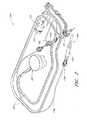
例えば、図1は、本発明におけるカテーテルポンプシステムの一使用事例を示している。インペラーアセンブリ116Aを備えていてもよい、ポンプの基端部は、心臓の左心室(LV)から大動脈に血液を送り込むためにLV内に留置される。ポンプは、心臓性ショック、心筋梗塞、および他の心臓状態を含む、様々な状態にある患者を治療し、また、経皮冠動脈インターベンションなどの処置で患者を補助するためにもこの方法で使用され得る。心臓内にポンプの基端部を留置する有利な一方法は、セルジンガー法または心臓専門医に馴染みのある他の方法を使用して経皮的アクセスおよびデリバリーを行うものである。これらのアプローチにより、救急医療、カテーテルラボ、および他の外科手術を行わない周囲環境においてポンプを使用することができる。修正により、ポンプで心臓の右側を補助することもできる。右側補助に使用することが可能な例示的な修正は、デリバリー特徴部を用意すること、および/または静脈側から少なくとも1つの心臓弁を通して留置される基端部を整形することを含み、これはそれらの全体があらゆる目的のために参照により本明細書に組み込まれている特許文献1〜3などにおいて開示されている。 For example, FIG. 1 shows one use case of the catheter pump system in the present invention. The proximal end of the pump, which may include an
図2には、カテーテルアセンブリ100Aが斜視図で示されている。カテーテルアセンブリ100Aは、上述した心臓ポンプシステムの使い捨て可能な部分に対応することができる。例えば、カテーテルアセンブリ100Aは、カテーテルアセンブリ100Aの先端部の近傍に位置したインペラーアセンブリ116Aと、このインペラーアセンブリ116Aから基端向きに延在する長尺ボディ174Aと、カテーテルアセンブリ100Aに対して注入剤を供給し得るよう構成された注入システム195と、被駆動アセンブリ101と駆動アセンブリ103とを有してなるモータアセンブリと、このモータアセンブリから基端向きに延在する1つまたは複数の導管302(例えば、電気的な導管、および/または、流体用の導管)と、導管302の基端部のところに連結されたインターフェース部材300と、を備えることができる。 In FIG. 2, the
図2のカテーテルアセンブリ100Aの先端部から基端部まで移動して、インペラーアセンブリ116Aを、カテーテルアセンブリ100Aの先端部のところに配置することができる。上述したように、インペラーアセンブリ116Aは、拡張可能なカニューレすなわちハウジングと、1つまたは複数のブレードを有したインペラーと、を備えることができる。インペラーの回転により、血液を、基端向きに(あるいは、状況によっては、先端向きに)ポンピングすることができ、これにより、心臓支援デバイスとして機能することができる。プライミング装置1400を、インペラーアセンブリ116A上に配置することができる。図7,8を参照して後述するように、プライミング装置1400は、カテーテルアセンブリの動作デバイスを患者内へと挿入する前に、カテーテルアセンブリ100Aからエアを排出するプロセスを促進し得るよう構成することができる。 Moving from the distal end to the proximal end of the
引き続き図2を参照すると、長尺ボディ174Aは、インペラーアセンブリ116Aから、注入システム195まで、基端向きに、延在している。注入システム195は、注入剤をカテーテルアセンブリ100A内へと導入し得るとともに、廃棄流体をカテーテルアセンブリ100Aから導出し得るよう構成されている。カテーテルボディ120A(長尺ボディ174Aを挿通している)は、基端向きに延在しており、モータアセンブリの被駆動アセンブリ101に対して連結することができる。カテーテルボディ120Aは、長尺ボディ174A内を挿通することができる。これにより、長尺ボディ174Aは、カテーテルボディ120Aに対して相対的に、軸線方向に並進移動することができる。カテーテルボディ120Aに対しての長尺ボディ174Aの軸線方向並進移動により、インペラーアセンブリ116Aの拡張や折り畳みを行うことができる。例えば、カテーテルボディ120Aの先端部に連結されたインペラーアセンブリ116Aは、長尺ボディ174Aを、インペラーアセンブリ116Aに対して基端向きに移動させることにより、拡径状態へと移行させることができる。いくつかの実施形態においては、インペラーアセンブリ116Aは、拡径状態へと、自己拡張することができる。拡径状態においては、インペラーアセンブリ116Aは、大きな流速でもって血液をポンピングすることができる。処置の後には、インペラーアセンブリ116Aは、長尺ボディ174Aの先端部170Aを、インペラーアセンブリ116Aを超えた先端位置にまで前進させることにより、折り畳み状態へと圧縮することができる。これにより、インペラーアセンブリ116Aを折り畳み状態とすることができる。 With continued reference to FIG. 2, the
上述したように、カテーテルボディ120Aは、モータアセンブリの被駆動アセンブリ101に対して連結することができる。被駆動アセンブリ101は、駆動アセンブリ103によって印加されたトルクを受領し得るよう構成することができる。駆動アセンブリ103は、図2においては、被駆動アセンブリ101およびカテーテルアセンブリ100Aとは非連結の態様で図示されている。駆動アセンブリ103は、被駆動アセンブリ101に対して、駆動アセンブリ103に対して被駆動アセンブリ101の基端部を係合させることによって、例えば、駆動アセンブリ103の開口105内に被駆動アセンブリ101の基端部を挿入することによって、連結することができる。 As mentioned above, the
図2には図示していないけれども、駆動シャフトが、被駆動アセンブリ101からカテーテルボディ120Aを通して延在することができる。これにより、駆動シャフトを、インペラーアセンブリ116Aのところにおいてあるいはインペラーアセンブリ116Aよりも基端側において、インペラーシャフトに対して連結することができる。駆動アセンブリ103は、コンソール(例えば、図3A,3Bを参照することができる)内のコントローラに対して、電気的に連通することができる。コントローラは、モータアセンブリの動作を制御し得るとともに、カテーテルアセンブリ100A内へと注入剤を供給する注入システム195の動作を制御することができる。よって、インペラーアセンブリ116Aのインペラーは、様々な実施形態におけるカテーテルポンプの動作時には、モータアセンブリによって遠隔的に回転駆動されることができる。例えば、モータアセンブリは、患者の体外に配置され得る。いくつかの実施形態において、モータアセンブリは、コントローラまたはコンソールから隔てられ、例えば患者により近い位置に留置される。他の実施形態では、モータアセンブリは、コントローラの一部とされる。さらに他の実施形態では、モータアセンブリは、患者体内に挿入可能なように小型化される。このような実施形態では、駆動シャフトをかなり短く、例えば、大動脈弁から大動脈弓までの距離より短く(約5cm以下に)することができる。小型化されたモータを使用するカテーテルポンプおよび関連構成部材および方法のいくつかの例は、それらの全体があらゆる目的のために参照により本明細書に組み込まれている特許文献4〜7で説明されている。 Although not shown in FIG. 2, a drive shaft can extend from the driven
図2に示すように、モータアセンブリ(例えば、駆動アセンブリ103、および、被駆動アセンブリ101)は、電気配線を有し得る導管302を介して、コントローラおよびコンソールに対して、電気的に接続されている。特に、図2に示すように、電気配線は、モータアセンブリから基端向きにインターフェース部材300にまで、延在することができる。コンソール内のコントローラを、モータアセンブリに対しておよび/またはカテーテルアセンブリ100A内の他のセンサ(例えば、圧力センサ、流量センサ、温度センサ、バブル検出器、等)に対して電気的に接続することを可能とし得るよう、有利には、インターフェース部材300とコンソールとの間に信頼性の高い電気的接続を設けることができる。したがって、様々な実施形態においては、着脱可能なインターフェース部材300は、コンソール内の1つまたは複数の電気的コンタクト(本明細書では、時に、相互接続と称される)に対して接続され得るよう構成された電気的構成部材を備えることができる。電気的接続は、単純な、ユーザーフレンドリーな態様で行うことができる。本発明の様々な実施形態においては、例えば、電気的接続は、インターフェース部材300とコンソールとの間において、流体連結が形成されるのと実質的に同時に形成することができる。これにより、ポンプシステムの動作の複雑さを低減させた構成を提供することができ、これにより、生命に関わるような緊急時にポンプを使用する場合でも、設定時のエラーの発生や遅延の発生を低減させることができる。 As shown in FIG. 2, the motor assembly (e.g.,
インペラーアセンブリ116A内においてインペラーを回転可能に支持するための機械的構成部材は、高回転速度となるにつれて発生するような熱および粒子の生成を制御しつつ、高回転速度を可能とする。注入システム195は、この目的のために、カテーテルアセンブリ100Aの先端部に対して、冷却溶液および潤滑溶液を供給することができる。図2に示すように、注入システム195は、流体用の導管すなわちチューブを有し得る導管302を介して、インターフェース部材300に対して流体連通することができる。カテーテルアセンブリ100Aを、使い捨て可能なものとし得ることにより、および/または、コンソールから着脱可能なものとし得ることにより、インターフェース部材300をコンソールに対して安定的に連結することが重要である。さらに、処置時に安定的なままであるような流体連結をユーザーが容易に形成し得るよう、使用が容易であるインターフェースとすることが重要である。連結を安定的に維持することは、導管302によって運ばれる流体および信号がインペラーの連続的な動作を可能としていることのために、重要である。状況によっては、ポンプシステムが停止した場合には、カテーテルアセンブリ100Aを患者から取り外して、交換する必要がある。このような状況は、生命に関わりかねず、少なくとも極めて不利なものである。 The mechanical components for rotatably supporting the impeller within the
動作時には、カテーテルポンプシステムは、心臓から出て患者の脈管系を通る血液の流れを効果的に増大させることができる。本明細書で開示されている様々な実施形態において、ポンプは、最大流量(例えば、低いmmHg)として、4Lpmより大きい、4.5Lpmより大きい、5Lpmより大きい、5.5Lpmより大きい、6Lpmより大きい、6.5Lpmより大きい、7Lpmより大きい、7.5Lpmより大きい、8Lpmより大きい、9Lpmより大きい、または10Lpmよりも大きい流量を発生するように構成され得る。様々な実施形態において、ポンプは、62mmHgという圧力ヘッドにおける平均流量として、2Lpmより大きい、2.5Lpmより大きい、3Lpmより大きい、3.5Lpmより大きい、4Lpmより大きい、4.25Lpmより大きい、4.5Lpmより大きい、5Lpmより大きい、5.5Lpmより大きい、または6Lpmより大きい流量を発生するように構成され得る。 In operation, the catheter pump system can effectively increase the flow of blood out of the heart and through the patient's vasculature. In various embodiments disclosed herein, the pump has a maximum flow rate (e.g., low mmHg) greater than 4 Lpm, greater than 4.5 Lpm, greater than 5 Lpm, greater than 5.5 Lpm, greater than 6 Lpm , Greater than 6.5 Lpm, greater than 7 Lpm, greater than 7.5 Lpm, greater than 8 Lpm, greater than 9 Lpm, or greater than 10 Lpm. In various embodiments, the pump has an average flow at the pressure head of 62 mm Hg, greater than 2 Lpm, greater than 2.5 Lpm, greater than 3 Lpm, greater than 3.5 Lpm, greater than 4 Lpm, greater than 4.25 Lpm. It may be configured to generate flow rates greater than 5 Lpm, greater than 5 Lpm, greater than 5.5 Lpm, or greater than 6 Lpm.
ポンプおよび関連構成部材の様々な追加態様は、その全体の内容があらゆる目的のために参照により本明細書に組み込まれている特許文献8〜17で開示されているものに類似する。それに加えて、本出願には、参照により、またあらゆる目的のために、以下の同時に提出された出願のそれぞれにおいて開示されている主題全体が組み込まれる。
特許文献18:米国特許出願第13/802,556号:2013年3月13日出願、整理番号THOR.072Aに対応、名称「DISTAL BEARING SUPPORT」;
特許文献19:米国特許出願第13/801,833号:2013年3月13日出願、整理番号THOR.089Aに対応、名称「SHEATH SYSTEM FOR CATHETER PUMP」;
特許文献20:米国特許出願第13/802,570号:2013年3月13日出願、整理番号THOR.090Aに対応、名称「IMPELLER FOR CATHETER PUMP」;
特許文献21:出願第13/801,528号:2013年3月13日出願、整理番号THOR.092Aに対応、名称「CATHETER PUMP」;
特許文献22:米国特許出願第13/802,468号:2013年3月13日出願、整理番号THOR.093Aに対応、名称「MOTOR ASSEMBLY FOR CATHETER PUMP」Various additional aspects of the pump and related components are similar to those disclosed in US Pat. In addition, the present application incorporates by reference, and for all purposes, the entire subject matter disclosed in each of the following simultaneously filed applications:
No. 13 / 802,556: filed Mar. 13, 2013, ref. Compatible with 072A, Name "DISTAL BEARING SUPPORT";
No. 13 / 801,833: filed Mar. 13, 2013, serial number THOR. Corresponding to 089A, the name "SHEATH SYSTEM FOR CATHETER PUMP";
No. 13 / 802,570: filed Mar. 13, 2013, serial number THOR. Compatible with 090A, name "IMPELLER FOR CATHETER PUMP";
Patent Document 21: Application No. 13 / 801,528: filed on March 13, 2013, reference number THOR. Corresponding to 092A, the name "CATHETER PUMP";
No. 13 / 802,468: filed Mar. 13, 2013, Serial No. THOR. Corresponding to 093A, the name "MOTOR ASSEMBLY FOR CATHETER PUMP"
流体導出入システム
図3Aは、流体導出入システム350を示す斜視図である。流体導出入システム350は、コンソール301と、図2のカテーテルアセンブリ100Aと、を備えている。コンソール301は、インターフェース部材300を介して、電力と、制御信号と、注入のための医療用流体(例えば、生理的食塩水)と、を提供することができるとともに、カテーテルアセンブリ100Aからの廃棄流体の抽出を行うことができる。よって、有利には、複数の流体連結を、単一のインターフェースを使用して、行うことができる。図2に示すように、例えば、着脱可能なインターフェース部材300は、カテーテルアセンブリ100Aの基端部のところに配置することができ、インターフェース領域303のところにおいてコンソール301に対して連結し得るよう構成することができる。Fluid Delivery / Inlet System FIG. 3A is a perspective view of fluid delivery /
いくつかの実施形態においては、流体導出入システム350は、カテーテルアセンブリ100Aに対して流体を供給し得るよう構成することができるとともに、カテーテルアセンブリ100Aから流体を抽出し得るよう構成することができる。上述したように、また、ここに組み込まれた特許文献に開示されているように、生理的食塩水および/または他の医療用溶液は、モータアセンブリと動作デバイスとの間の構成部材を潤滑したり冷却したりすることができる。要望によっては、流体導出入システム350を使用して、カテーテルアセンブリ100Aから廃棄流体を除去することができる。いくつかの実施形態においては、流体導出入システム350は、基端と先端とを有した複数管腔カテーテルボディを有することができる。カテーテルボディは、1つまたは複数の管腔を有することができ、それら管腔を通して、医療用溶液(例えば、生理的食塩水)や、廃棄流体や、血液を、流すことができる。カテーテルアセンブリ100Aを通して(例えば、カテーテルアセンブリ100A内へと、あるいは、カテーテルアセンブリ100Aから)流体を駆動するために、コンソール301は、カテーテルアセンブリ100Aがコンソール301に対して連結されてポンプに対して係合されたときに、カテーテルアセンブリ100Aに対して正圧または負圧を印加し得るよう構成された1つまたは複数のポンプを備えることができる。 In some embodiments, the fluid inlet /
加えて、流体導出入システム350は、また、コンソール301とカテーテルアセンブリ100Aとの間の電気接続を提供し得るよう構成することができる。例えば、コンソールは、モータアセンブリの動作を制御および/または管理し得るようプログラムされたコントローラ(例えば、プロセッサ)を備えることができる。コンソール301は、さらに、モータアセンブリに対して、および/または、インターフェース部材300がコンソール301に対して連結された際に電力によって駆動される他の構成部材に対して、電力を供給し得るよう構成された電気的インターフェースを備えることができる。さらに、1つまたは複数の電気的なあるいは電子的なセンサを、カテーテルアセンブリ100A内に設けることができ、これらセンサを、流体導出入システム350を介して、コンソール301に対して電気的に接続することができる。よって、本発明による様々な実施形態は、カテーテルアセンブリ100Aとコンソール301との間にわたっての、流体連結と電気的接続とを提供することができる。 In addition, the fluid outlet and
上述したように、流体導出入システム350は、カテーテルアセンブリ100Aとコンソール301との間に、着脱可能なインターフェースを提供することができる。流体導出入システム350は、例えば1つまたは複数のポンプやプロセッサ(例えば、コントローラ)や電気的相互接続等といったような様々な構成部材を備えることができる。例えば、コンソール301内の1つまたは複数のポンプを活性化するために、および/または、コンソール301とインターフェース部材300との間の1つまたは複数の電気的接続を係合させるために、ユーザーは、単に、インターフェース部材300の先端部(例えば、閉塞部材を含む)を、図示のZ方向に沿って、ポンプが活性化されるまでまた電気的接続が形成されるまで、インターフェース領域303の開口304内へと、挿入するだけでよい。いくつかの見地においては、Z方向に沿ったインターフェース部材の挿入は、ポンプの連結と電気的な接続とを実質的に同時に達成することができる。 As mentioned above, the fluid outlet /
いくつかの実施形態においては、インターフェース部材300は、インターフェース領域303とインターフェースとの間にロックデバイスを係合させることによって、コンソール301に対して固定することができる。ロックデバイスを係合させるための1つの簡便な方法は、インターフェース部材300の一部分を、後述するようにして、インターフェース部材の他の部分に対して、あるいは、コンソール301に対して、回転させることである。例えば、最も外側の構造(Zで示す向きとは反対側の構造)であって、時に「キャップ」と称される構造を、コンソールに対して回転させることにより、インターフェース部材300をコンソール301に対して機械的に固定し得るよう構成されたロック機構を係合させることができる。これにより、処置時に、インターフェース部材300が偶発的に外れてしまうことを防止することができる。 In some embodiments,
コンソール301は、さらに、ユーザーインターフェース312を備えることができる。ユーザーインターフェース312は、ディスプレイデバイス、および/または、タッチスクリーンディスプレイを備えることができる。ユーザーは、ユーザーインターフェース312に対して相互作用することにより、経皮的心臓ポンプシステムを駆動することができ、例えば所望の流速や他の処理パラメータといったようなものを選択することができる。ユーザーは、また、ユーザーインターフェース312上において、処置の特性を観測することもできる。 The
図3Bは、図3Aに示すコンソール301のインターフェース領域303を示す斜視図である。インターフェース領域303は、インターフェース部材300の先端部を受領し得るよう構成された開口304を備えることができる。開口304は、インターフェース部材300の一部を受領し得る形状およびサイズとされた全体的に円形のキャビティを備えることができる。バブル検出器308(例えば、いくつかの実施形態においては、光学的センサ)を、開口304の背面壁のところに配置することができる。バブル検出器308は、2つの壁によって形成された凹所であるとともに、チューブの一セグメントを受領し得るサイズおよび形状とされた凹所を備えることができる。そのチューブを通して流体が流れたときには(例えば、図4におけるバブル検出器チューブセグメント326を参照することができる)、バブル検出器308は、流体を観測することができ、これにより、流体が望ましくない物質を含有しているかどうかを、例えば、流体がエアバブルやあるいは他のガスバブルを含有しているかどうかを、決定することができる。いくつかの実施形態においては、バブル検出器308は、チューブセグメントを通して流れる流体内のバブルの量(数、あるいは、容積)を測定することができる。患者内に塞栓を誘起することを防止するために、処理流体内のバブルを検出することが重要であることは、理解されるであろう。バブル検出器308は、コンソール301内のコントローラに対して電気的に接続することができ、処理流体内のバブルの量を表示することができる。処理流体内にバブルが存在する場合には、コンソール301は、ユーザーに対して警告を発することができる。 FIG. 3B is a perspective view showing the
インターフェース領域303は、また、いくつかの実施形態においては、1つまたは複数のポンプを、例えば、1つまたは複数の蠕動ポンプを、備えることができる。蠕動ポンプを使用することにより、カテーテルアセンブリ100A内へと、あるいは、カテーテルアセンブリ100Aから、流体をポンピングすることができる。これにより、医療用流体を供給したり、廃棄流体を抽出したり、することができる。そのようなポンプは、1つまたは複数のローラ306を使用することができ、これにより、それぞれのチューブ(例えば、図4におけるポンプチューブセグメント324a,324bを参照することができる)内への流体の供給を制御することができる。例えば、1つまたは複数のポンプローラ306は、コンソール301内に収容することができる。図示のように、2つのポンプローラ306は、開口304の背面壁のところに、それぞれの回転軸線(例えば、図3Bに図示されたY方向)まわりに取り付けられる。ポンプローラ306は、コンソール内の蠕動ポンプモータによって、回転駆動することができる(図3A,3Bには図示されていない)。図4を参照して詳細に後述するように、ローラ306は、ポンプチューブセグメント324a,324bに対して係合することができ、これにより、カテーテルアセンブリ100A内へとあるいはカテーテルアセンブリ100Aから流体をポンピングすることができる。ポンプローラ306は、インターフェース部材300の閉塞ベッド領域(例えば、図4における閉塞ベッド322a,322bを参照することができる)内に受領され得るよう構成することができる。これにより、カテーテルアセンブリ100Aを通して流体をポンピングすることができる。
電気的相互接続307を、また、開口304の背面壁に設けることができる。電気的相互接続307は、モータアセンブリに対して、電力を、および/または、電気信号または指示を、提供し得るよう構成することができる。これにより、モータアセンブリの動作を制御することができる。電気的相互接続307は、また、圧力や流速やおよび/またはカテーテルアセンブリ100A内の1つまたは複数の構成部材の温度に関してのセンサ読取値を表す電気信号を受領し得るよう構成することができる。凹所チャネル309は、開口304の底部から、側面に沿って、コンソール301の下エッジにまで、延在することができる。凹所チャネル309は、インターフェース部材300とモータアセンブリとの間にわたって延在する1つまたは複数の導管302(例えば、電気的導管、および/または、流体用導管)を受領し得る形状およびサイズとすることができる。一実施形態においては、インターフェース部材300がインターフェース開口304内に配置されたときには、すべての導管302をチャネル309内に受領することができ、これにより、側面を面一なものとすることができる。
加えて、インターフェース部材300が、コンソール301内に制御可能に固定されることが重要である。これにより、ユーザーがインターフェース部材300をコンソール301に対して取り付けたり取り外したりするときにのみ、インターフェース部材300を、取り付けたり取り外したりすることができる。例えば、図5A〜5Cを参照して詳細に後述するように、インターフェース領域303は、グルーブ313を備えることができる。グルーブ313は、インターフェース部材300上のロック機構(例えば、X方向に突出したタブあるいはフランジ)を受領し得るサイズおよび形状とすることができる。一実施形態においては、係合解除部材305は、スプリングを搭載した解放機構310を備えている。スプリングを搭載した解放機構310は、開口304の上方に、および、インターフェース部材300(例えば、図5A〜5Cの図示、および、関連する後述の記載を参照することができる)の孔内に挿入し得るピン311の上方に、配置されている。図5A〜5Cを参照して後述するように、ピン311は、インターフェース部材300をコンソール301から解放することを支援することができる。スプリングを搭載した解放機構310を押圧することにより、ピン311を解放することができ、コンソール301からインターフェース部材300をロック解除することができる。したがって、スプリングを搭載した解放機構310は、さらなる安全機構として機能することができる。これにより、ユーザーによってカセットが偶発的に係合解除されることを防止することができる。 In addition, it is important that
着脱可能なインターフェース部材
図4は、本発明の一実施形態によるインターフェース部材300を示す斜視図である。インターフェース部材300は、コンソール301のインターフェース領域303内に適合し得る形状およびサイズとされたボディを備えることができる。図4に示すように、インターフェース部材300は、実質的に円形のプロファイルを有することができ、時に、パックと称される。いくつかの実施形態においては、インターフェース部材300は、手動インターフェース320に対して動作可能に連結された外側ボディ333を備えることができる。手動インターフェース320は、時に、キャップと称される。手動インターフェース320は、全体的に、手のひらサイズとされている。これにより、ユーザーは、その手の中に受領することができ、例えばキャップの外側リム上へと指で圧力を印加することによって、快適に動作させることができる。1つまたは複数の閉塞ベッドを、インターフェース部材300とコンソール301との間の境界部分に、例えばインターフェース部材300内にあるいはインターフェース部材300上に、形成するあるいは設けることができる。例えば、第1および第2の閉塞ベッド322a,322bを、インターフェース部材300内に形成することができる。図4に示すように、例えば、閉塞ベッド322a,322bは、インターフェース部材300内に形成された円弧形状の凹所領域を備えることができる。Detachable Interface Member FIG. 4 is a perspective view of the
インターフェース部材300は、さらに、インターフェース部材300内に形成された閉塞ベッド322a,322bに沿って配置された第1および第2のポンプチューブセグメント324a,324bを備えることができる。インターフェース部材300がコンソール301内に配置されたときには、ポンプローラ306は、インターフェース部材300に対して係合することができる。これにより、閉塞ベッド322a,322bに対してチューブセグメント324a,324bを圧縮することができる。コンソール301内のポンプモータローラ306を回転駆動したときには、流体は、チューブセグメント324a,324bの非圧縮部分内を流れ、カテーテルアセンブリ100A内を通して流れ続ける。例えば、チューブセグメント324a,324bを圧縮することにより、流体を、インターフェース部材300からモータアセンブリへと延在するさらにモータアセンブリを超えて延在する導管302を介して、カテーテルアセンブリ100A内へとまたカテーテルアセンブリ100Aからポンピングすることができる。 The
蠕動ポンプのための許容誤差をかなり厳しいものとし得ることにより、インターフェース部材300のボディ(例えば、外側ボディ333、および/または、例えば図5B〜5Cに図示された内側ボディ339といったような内側ボディ)は、正確な許容誤差でもって形成することができる(例えば、いくつかの実施態様においては、一体構造からモールド成型される)。これにより、インターフェース部材300がコンソール301内に挿入されたときには、ポンプローラ306は、正確にかつ自動的に、セグメント324a,324bに対しておよび閉塞ベッド322a,322bに対して、係合する。これにより、チューブセグメント324a,324bを信頼性高く閉塞することができ、カテーテルアセンブリ100Aを通して流体をポンピングすることができる。よって、インターフェース部材300が、インターフェース領域303内へと十分に奥深くまで挿入されたときには、コンソール301内のポンプは、インターフェース部材300に対して自動的に係合することができる。 The body of the interface member 300 (e.g., the
例えば、ローラ306と閉塞ベッド322a,322bとの間のギャップは、いくつかの構成においては、チューブセグメント324a,324bの2壁厚さと比較して、より小さなものとすることができる。これにより、チューブ324a,324bを、効果的に閉塞することができる。インターフェース部材300の正確な許容誤差のために、ポンプは、インターフェース部材300をコンソール301内へと単に挿入することによって、係合することができる。いくつかの実施形態においては、ポンプを個別的に起動する必要はない。インターフェース部材300の寸法は、インターフェース部材300のコンソール301内への挿入時に閉塞ベッド322a,322bがそれぞれのポンプローラ306に対して自動的に係合するように、選択することができる。 For example, the gap between
上記の構成は、様々な利点を提供する。本明細書により当業者であれば理解されるように、インターフェース部材300およびインターフェース領域303は、1つまたは複数のローラ306に対してのチューブセグメントの使用が容易なかつ迅速な連結を提供する。さらに、構成部材は、容易にかつ安価に製造することができる。なぜなら、ただ1つの構成部材だけしか厳しい許容誤差を必要としないからであり、また、インターフェース領域303に対してのインターフェース部材300の境界部分が、自己軸合わせされるからである。境界部分は、第2機構を使用してあるいは操作者ステップによってポンプに対して係合する必要性を除去し、心臓ポンプの操作を簡略化して、コンソール301に対してのカテーテルアセンブリ100Aの係合を単純化する。また、コンソール301がローラによってIVポール上に取り付けられる態様においては、あるいは、コンソール301が他のタイプの軽量カート上に取り付けられる態様においては、例えば、本発明による単純化された係合機構を、有利なものとすることができる。なぜなら、ポールに対して最小限に印加された力しか必要としないからである。これにより、ポンプが係合される際に、ポールが回転したり曲がったりすることが防止される。 The above configuration provides various advantages. As will be appreciated by one skilled in the art from the present specification,
ポンプチューブセグメント324a,324bは、それぞれ対応する閉塞ベッド322a,322bの近傍であるいはそれぞれ対応する閉塞ベッド322a,322b内で、インターフェース部材300上に取り付けることができる。図示のように、第1および第2のポンプチューブセグメント324a,324bは、上述したように、コンソール301内でポンプローラ306に対して係合し得るよう構成することができる。第1および第2のポンプチューブセグメント324a,324bは、円弧形状を有することができる(本発明の様々な構成においては、予成形されたものとすることができる)。そのような円弧形状は、それぞれ対応する閉塞ベッド322a,322bの湾曲形状に対して、全体的に適合する。よって、コンソール301内におけるポンプローラ306は、閉塞ベッド322a,322b内に配置することができる。これにより、閉塞ベッド322a,322bの壁に対して、ポンプチューブセグメント324a,324bを圧縮することができる。加えて、バブル検出器チューブセグメント326を、また、インターフェース部材300内にあるいはインターフェース部材300上に取り付けることができ、図3Bに示すように、バブル検出器308に対して係合し得るよう構成することができるあるいはバブル検出器308に対して隣接して配置し得るよう構成することができる。バブル検出器チューブセグメント326は、任意の適切な形状とすることができる。図示のように、バブル検出器チューブセグメントは、実質的に直線形状とすることができ、バブル検出器308によってコンソール301内に受領され得るサイズおよび形状とすることができる。図3A〜3Bを参照して上述したように、バブル検出器308(光学的センサとすることができる)を使用することにより、患者に対して供給される処理流体または潤滑流体内におけるエアバブルの存在を検出することができる。 The
ポンプチューブセグメントは、例えばカテーテルボディの1つまたは複数の管腔を含めたカテーテルアセンブリ100Aの残部に対して、導管302を介して、流体的に連結することができる。したがって、動作時には、着脱可能なインターフェース部材300は、制御されたシステム内において、流体を、患者内へとまたは患者からポンピングすることができる。これにより、例えば、流体に関する滅菌環境を維持しつつ、カテーテルアセンブリ100A内の流体をポンピングすることができる。実施態様に応じて、カテーテルボディ内へと導入される医療溶液の量は、カテーテルボディから導出される医療溶液の量と比較して、同じとすることができる、あるいは、最少量だけ多いものとすることができる。これにより、心臓ポンプの血液フリー部分内へと血液が流入することを防止することができる。 The pump tube segment can be fluidly coupled via
加えて、1つまたは複数の電気的コンタクト328を、インターフェース部材300内に設けることができる。電気的コンタクト328は、コンソール301とカテーテルアセンブリ100A(例えば、モータアセンブリ、および/または、任意の適切なセンサ)との間にわたって電気信号を伝達し得るよう構成された任意の適切な電気的インターフェースとすることができる。例えば、電気的コンタクト328は、コンソール301内に配置された電気的相互接続307に対して電気的に接続し得るよう構成することができる。電気的コンタクト328と電気的相互接続307との間の電気接続を介して、電気的制御信号および/または電力を、コンソール301とカテーテルアセンブリ100Aとの間にわたって伝達することができる。有利には、電気的コンタクト328と電気的相互接続307との間の電気接続は、インターフェース部材300をコンソール301のインターフェース領域303内へと挿入した時点で、形成することができるすなわち完了させることができる。例えば、いくつかの実施形態においては、電気的コンタクト328と電気的相互接続307との間の電気接続は、インターフェース部材300をインターフェース領域303内へと挿入した時点で、流体連結(例えば、ポンプの係合)と実質的に同時に形成することができる。いくつかの見地においては、例えば、電気接続は、電気的コンタクト328からの複数の電気的ピンを、コンソール301の電気的相互接続307のそれぞれ対応する孔内へと挿入することによって、形成することができる。あるいはこの逆に、電気接続は、コンソール301の電気的相互接続307からの複数の電気的ピンを、電気的コンタクト328のそれぞれ対応する孔内へと挿入することによって、形成することができる。 Additionally, one or more
また、図4に示すように、手動インターフェース320を、外側ボディ333の基端部に対して機械的に連結することができ、図5A〜5Cを参照して後述するように、制限された態様でもって、外側ボディ333に対して相対的に回転させ得るよう構成することができる。例えば、外側ボディ333は、1つまたは複数のロック開口331を有することができる。1つまたは複数のロック開口331は、手動インターフェース320をコンソール301に対してロックし得るよう構成されたロックタブ332を受領し得るよう構成される。さらに、図5A〜5Cを参照して後述するように、外側ボディ333は、図3Bに図示されたピン311を受領し得るサイズおよび形状とされたピン孔321を備えることができる。 Also, as shown in FIG. 4, the
本明細書により、ポンプローラや閉塞ベッドやチューブの構成を、本発明の用途に応じて修正し得ることは、理解されるであろう。例えば、本発明の構成は、サービスおよび修理のためのアクセスを容易なものとし得るように、修正することができる。様々な実施形態においては、ポンプローラは、コンソールの外部に配置することができる。様々な実施形態においては、ポンプローラと閉塞ベッドとの双方を、カセット内に配置することができる。様々な実施形態においては、コンソールは、カセット内のポンプローラを起動するための機構を備えている。様々な実施形態においては、ポンプローラは、固定することができる。様々な実施形態においては、ポンプローラは、回転駆動し得るように、あるいは、並進駆動し得るように、あるいは、これらの双方と、することができる。ポンプローラと閉塞ベッドとの一方または双方を、移動可能とされたベース上に配置することができる。いくつかの実施形態においては、コンソールとカセットとの間の境界部分は、患者の脈管系内へと流体(例えば、生理的食塩水)をポンピングするための正圧インターフェースを有することができる、また、患者の脈管系から流体(例えば、廃棄流体)をポンピングするための負圧インターフェースを有することができる。 It will be appreciated from this specification that the configuration of the pump rollers and the occlusive beds and tubes may be modified according to the application of the present invention. For example, the configuration of the present invention can be modified to facilitate access for service and repair. In various embodiments, the pump roller can be located outside the console. In various embodiments, both the pump roller and the occlusion bed can be disposed within the cassette. In various embodiments, the console includes a mechanism for activating the pump roller in the cassette. In various embodiments, the pump roller can be fixed. In various embodiments, the pump roller can be rotationally driven, translationally driven, or both. One or both of the pump roller and the occlusion bed can be arranged on a movable base. In some embodiments, the interface between the console and the cassette can have a positive pressure interface for pumping fluid (eg, saline) into the patient's vasculature, It can also have a negative pressure interface for pumping fluid (eg, waste fluid) from the patient's vasculature.
ロック機構
上述したように、インターフェース部材300は、有利には、コンソール301のハウジング内の対応形状開口304内へとインターフェース部材300を単に挿入することによって、コンソール301に対して完全に係合することができる。インターフェース部材300を、コンソールのインターフェース領域303の背面壁に対して近接させた際には、例えば、インターフェース部材300を開口304内へと挿入した際には、流体の導出入と電気接続とを行うことができ、システム350を動作可能とすることができる。インターフェース部材300内のロック機構は、追加的な固定特性のために設けることができる。追加的な固定特性は、患者の輸送に際しておよび他の動的設定に際して、特に有効なものとすることができる。例えば、処置の全体にわたってカテーテルアセンブリ100Aがコンソール301に対して固定されていることが望ましい。これにより、コンソール301からインターフェース部材300が偶発的に係合解除されることがなく、処置が妨害されることがない。Locking Mechanism As mentioned above, the
一実施形態においては、ロック機構は、コンソール301とインターフェース部材300との間に配置することができ、アクチュエータの最小の移動によって係合され得るように構成することができる。例えば、手動インターフェース320は、コンソール301に対しての手動インターフェース320の少しの回転量でもってロックデバイスの係合を引き起こし得るように構成することができる。 In one embodiment, the locking mechanism can be disposed between the
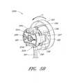
図5Aは、手動インターフェース320を示す斜視図である。図5Aに示すように、手動インターフェース320は、内部カム335を有することができるあるいは内部カム335に対して連結することができる。内部カム335は、例えばローブ336a,336bといったような1つまたは複数の突出ローブを有することができる。さらに、内部カム335は、ローブ336a,336bに対して内方に凹んだ凹所領域337を有することができる。内部カム335は、さらに、段付き領域338を有することができる。段付き領域338により、後述するように、インターフェース部材300を、コンソール301に対してロックし得るとともに、コンソール301からロック解除することができる。 FIG. 5A is a perspective view showing the
図5Bは、ロック解除位置においてインターフェース部材300Aを示す斜視図であり、図5Cは、ロック状態においてインターフェース部材300Bを示す斜視図である。図5Bのインターフェース部材300Aおよび図5Cのインターフェース部材300Bにおいては、外側ボディ333の図示が、図示の明瞭化の目的のために、省略されていることは、理解されるであろう。特に断らない限り、図5B,5Cにおける構成部材は、図4に図示した構成部材と同じあるいは同様である。図5B,5Cに示すように、インターフェース部材300A,300Bは、図4に示す外側ボディ333内に配置され得る内側ボディ339を備えることができる。閉塞ベッド322a,322bは、図5B,5Cに示すように、インターフェース部材300A,300Bの内側ボディ339内に形成することができる。しかしながら、他の構成においては、閉塞ベッド322a,322bは、外側ボディ333内に形成することができる、あるいは、インターフェース部材300A,300Bの他の部分内に形成することができる。加えて、図5A,5Bに示すように、電気的構成部材340を、内側ボディ339の凹所内に、あるいは、内側ボディ339の他の部分内に、配置することができる。電気的構成部材340に関する追加的な詳細は、図6A,6Bを参照して後述する。 FIG. 5B is a perspective view showing the
インターフェース部材300A,300Bの内側ボディ339は、さらに、突起330を備えることができる。突起330は、その先端のところに、タブ332を有している。インターフェース部材300Aが、非ロック状態とされたときには、突起330は、手動インターフェース320のカム335の凹所337内にあるいは凹所337の近傍に、位置することができる。したがって、図5Bに示すように、インターフェース部材300Aが非ロック状態とされたときには、カム335は、突起330に対して接触することができず突起330に対して力を印加することができない。 The
しかしながら、インターフェース部材300をコンソール301内に挿入した後には、手動インターフェース320を内側ボディ339に対しておよびコンソール301に対して相対的に回転させることにより、例えば図5Bにおける矢印Aの向きに回転させることにより、インターフェース部材300を所定位置にロックすることができる。手動インターフェース320を回転させたときには、インターフェース部材300A,300B内において内部カム335も一緒に回転する。カムが回転した後には、カム335のローブ336a,336bは、内側ボディ339の1つまたは複数の突起330に対して係合することができ、突起330を、内側ボディ339に対して外側へと押すことができる。一実施形態においては、タブ332が、外側ボディ333上に形成されたロック開口331を通して外向きに延出することができる。タブ332が、ロック開口331を通して押し込まれたときには、タブ332は、外側ボディ333から横方向外向きに突出する。この状態において、いくつかの実施形態においては、複数のタブ332の各々を、コンソール301のグルーブ313(図3Bを参照することができる)内にロックすることができ、これにより、インターフェース部材300Bをコンソール301に対して固定することができる。よって、非ロック状態においては、タブ332は、インターフェース部材300Aの外表面に対して実質的に面一とすることができ、また、ロック状態においては、タブ332は、ロック開口331を通して延出することができて、コンソール301のグルーブ313内におけるロックされることができる。 However, after the
いくつかの実施形態においては、突起330は、内側ボディ339から片持ち式に突出することができる。上述したように、インターフェース部材300をコンソール301に対して係合させた際に、インターフェース部材に形成された閉塞ベッド322a,322bとポンプローラ306との間の許容誤差を厳しいものに維持することが重要である。閉塞ベッド322a,322bを、片持ち式の突起330と同じボディ内に形成し得ることにより、例えば成型プロセスといったような従来的製造プロセスを使用することにより、インターフェース部材300(例えば、外側ボディ333、および/または、内側ボディ339)を、厳密な寸法で製造することができる。よって、突起330と、タブ332と、閉塞ベッド322a,322bとは、厳しい寸法誤差の範囲内で形成することができ、タブ332および/または突起330を、非常に良好な精度でもって、閉塞ベッド322a,322bに対して配置することができる。これにより、インターフェース部材300をコンソール301に対して係合させた際には、ポンプチューブセグメント324a,324bを、最適に閉塞することができる。さらに、インターフェース部材300は、コンソール301に対して最小の力を印加するだけで、インターフェース部材300上において手動インターフェース320を回転させることにより、ロックすることができる。このことは、システムを連結し得るモバイルカートやIVポールの破損を最小化するという利点を、増強する。 In some embodiments, the
係合解除機構
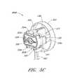
また、コンソール301からインターフェース部材300を係合解除し得るよう構成された係合解除機構を設けることが重要である。図3B,4,5B,5Cに示すように、コンソール301の係合解除機構305は、コンソール301からインターフェース部材300を係合解除して非ロック状態とし得るよう構成することができる。例えば、ピン311は、スプリング付勢されたものとすることができる。これにより、インターフェース部材300Aが非ロック状態とされたときには、ピン311は、外側ボディ333のピン孔321を通して延在し、カム335の複数のローブ336のうちの1つのローブの側面に対して接触するのみである。よって、インターフェース部材300Aの非ロック状態においては、ピン311は、カム表面に沿って単にスライドすることができる。これにより、ピン311およびコンソール301に対して相対的に手動インターフェース320を回転させることができる。Disengagement Mechanisms It is also important to provide an disengagement mechanism configured to disengage the
しかしながら、図3B,5Cに示すように、インターフェース部材300Bがロック状態へと回転された後には、ピン311は、内部カム335の段付き領域338に対して係合することができる。例えば、スプリング付勢されたピン311は、カム335の段付き領域338内へとあるいはカム335の肩部内へと延出されることができる。段付き領域338に対して係合することにより、ピン311は、カム335がロック状態から非ロック状態へと回転することを防止する。ユーザーは、スプリング付勢された係合解除機構310を押圧することにより、カセットを係合解除することができる。これにより、スプリングを解除して、段付き領域338からピン311を取り外すことができる。これにより、ピン311を、段付き領域338から係合解除することができ、内部カム335を、非ロック状態へと戻り回転させることができる。カム335が、非ロック状態へと戻り移動したときには、タブ332は、コンソール301のグルーブ313から離脱させることができる。 However, as shown in FIGS. 3B and 5C, the
電気的相互接続、構成部材、および、ケーブル
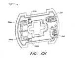
図6Aは、図4に示す電気的構成部材340の第1面を示す斜視図である。図6Bは、図6Aの電気的構成部材340の反対側の第2面を示す斜視図である。図5B,5Cに示すように、電気的構成部材340は、インターフェース部材300の凹所内に配置することができる。電気的構成部材340は、例えばプリント回路基板(PCB)といったような任意の適切な電気的なまたは電子的な構成部材とすることができ、カテーテルアセンブリ100A内の様々な構成部材とコンソール301との間の電気的インターフェースを提供し得るよう構成されている。上述したように、電気的構成部材340は、インターフェース部材300とコンソール301との間の電気的インターフェースを形成することができる。これにより、コンソール301とカテーテルアセンブリ100A(例えば、モータアセンブリ、および/または、様々なセンサ)との間の電気通信を提供することができる。Electrical Interconnections, Components, and Cables FIG. 6A is a perspective view showing a first side of the
例えば、インターフェース部材300の電気的構成部材340は、コンソール301の対応する電気的相互接続307に対して係合し得るよう構成された1つまたは複数の電気的コンタクト328を備えることができる。電気的コンタクト328および/または電気的相互接続307は、例えば、9個のピンからなる電気的相互接続とすることができる。しかしながら、任意の適切な相互接続を使用することができる。カテーテルポンプの動作デバイス(例えば、インペラー)を駆動するモータアセンブリは、1つまたは複数の電気的ケーブルを介して、例えば導管302を介して、インターフェース部材300に対して電気的に接続することができる。また、コンソール301は、電源に対して接続することができる。電源は、インターフェース部材のコンタクト328を介して、および、インターフェース部材300をモータアセンブリに対して接続する電気的導管302を介して、カテーテルポンプのモータアセンブリを駆動することができる。電気的構成部材340は、また、コンソール301と、カテーテルポンプのモータアセンブリあるいはカテーテルアセンブリ100Aの他の部分と、の間において電気信号を中継し得るよう構成された通信相互接続を備えることができる。例えば、コンソール301内の(あるいは、インターフェース部材内の)コントローラは、コンソール301とインターフェース部材300との間の電気的構成部材340を介して、カテーテルポンプのモータアセンブリに対して、指示を送信することができる。いくつかの実施形態においては、電気的構成部材340は、動作デバイスのところのセンサを含めて、カテーテルアセンブリ100A内のセンサ(例えば、圧力センサあるいは温度センサ)、のための相互接続を備えることができる。センサを使用することにより、1つまたは複数のチューブ内の流体の特性(例えば、生理的食塩水の圧力)を測定することができる。センサを使用することにより、システムの動作パラメータ(例えば、心室の圧力、あるいは、大動脈の圧力)を測定することができる。センサは、付属の治療法の一部として設けることができる。 For example, the
インターフェース部材300内の電気的構成部材340を使用することにより、ケーブル(および、モータアセンブリ、センサ、等)を、コンソール301の対応する相互接続307に対して、電気的に接続することができる。例えば、電気的構成部材340の第2面上の1つまたは複数の内部コネクタ348,348は、コンタクト328(コンソール301の相互接続307に対して連結し得るよう構成されている)と、カテーテルアセンブリ100と、の間の電気通信を提供することができる。例えば、電気ケーブル(例えば、導管302)は、第1内部コネクタ346と第2内部コネクタ348とを接続することができる。内部コネクタ346,348は、電気的構成部材340の第1面上のコンタクト328に対して電気的に連通することができる。電気的構成部材340は、コンソール301の相互接続307に対して電気的に連通することができる。 The
様々な実施形態においては、電気的構成部材340は、流体的にシールすることができる。これにより、内部の電気系統が濡れてしまうことが防止される。このことは、湿気のある環境下においておよび/または滅菌環境下において、有利なものとすることができる。これは、また、有利には、高圧用途において潜在的なリスクとなるような1つまたは複数の流体チューブの漏洩や破裂が起こった際に、エレクトロニクス系統を保護することができる。 In various embodiments, the
加えて、電気的構成部材340(例えば、PCB)は、この電気的構成部材340上に設置された様々な電気的構成部材あるいは電子的構成部材を備えることができる。図6Bに示すように、例えば、2つの圧力センサ344a,344bを、電気的構成部材340上に設置することができる。これにより、ポンプチューブセグメント324a,324b内の圧力を検出することができる。圧力センサ344a,344bを使用することにより、ポンプチューブセグメント324a,324b内の流体の流れを観測することができる。これにより、心臓ポンプの適切な動作を確認することができる。例えば、カテーテルボディ内への医療用溶液の導入とカテーテルボディからの廃棄流体の導出との間の適切なバランスを確認することができる。様々な他の構成部材を、例えばプロセッサやメモリや特定用途向け集積回路(ASIC)といったような構成部材を、回路基板上に設けることができる。例えば、それぞれ対応する圧力センサASIC345a,345bを、圧力センサ344a,344bに対して接続することができる。これにより、圧力センサ344a,344bによって検出された信号を処理することができる。処理された信号は、PCB内の内部トレース(図示せず)を介しておよびコンタクト328を介して、ASIC345a,345bからコンソール301へと、伝送することができる。 In addition, the electrical component 340 (eg, PCB) can comprise various electrical or electronic components disposed on the
プライミング、注入システム、および、装置
注入システムの一実施形態が、図7に図示されている。上述した様々な構成部材は、参考のためここに組み込まれた特許文献を参照することにより、より詳細に理解することができる。注入システム1300は、カテーテルアセンブリの動作デバイス(例えば、インペラーアセンブリ116)に対して、処理流体および/または潤滑流体を供給し得るよう構成することができ、また、カテーテルアセンブリから廃棄流体を抽出し得るよう構成することができる。さらに、上述したように、長尺ボディ174は、カテーテルボディ120上にわたってスライド可能に配置することができる。これにより、カテーテルボディ120の外表面と長尺ボディ174の内表面との間に、ギャップまたはチャネルを設けることができる。そのようなギャップまたはチャネルは、医療処理時に患者にとって有害なエアポケットを含有することができる。加えて、カテーテルボディ120内に延在する管腔も、また、患者にとって有害なエアポケットを含有することができる。よって、処理を行う前に、カテーテルボディ120内の管腔内から、および、長尺ボディ174とカテーテルボディ120との間に位置したギャップあるいはチャネル内から、エアを吐出することが望ましい。One embodiment of apriming, infusion system, and device infusion system is illustrated in FIG. The various components described above can be more fully understood by reference to the patent documents incorporated herein by reference.
図7のシステム1300は、処理時にカテーテルアセンブリに対して流体を供給し得るように、および/または、処理時に廃棄流体を抽出し得るように、および/または、長尺ボディ174からエアを吐出し得るように例えば処理前に長尺ボディ174の内表面とカテーテルボディ120の外表面との間からエアを吐出し得るように、構成することができる。この実施形態においては、インターフェース部材1313(いくつかの見地において、上述したインターフェース部材300と同様のものあるいは同じもの)は、上述したように、カテーテルアセンブリの様々な構成部材どうしを連結するために設けることができる。外側シースチューブ1303aは、流体リザーバ1305から、注入デバイスに対して連結し得るよう構成されたルアー102まで、延在することができる。図7に示すように、外側シースチューブ1303aは、外側シースへと流体を供給し得るよう構成することができる、例えば、長尺ボディ174とカテーテルボディ120との間のスペースへと流体を供給し得るよう構成することができる。流体リザーバ1305は、付加的には、圧力カフを備えることができる。これにより、外側シースチューブ1303aを通して流体を付勢することができる。圧力カフは、重力によって誘起された流体の流れを使用した流体供給の実施形態において、特に有効なものとすることができる。ルアー102は、長尺ボディ174に対して注入流体をあるいは他のプライミング流体を供給し得るよう構成することができる。これにより、上述したように、長尺ボディ174からエアを吐出することができる。これにより、システム1300を「プライミング」することができる。加えて、モータハウジング1314上に配置し得る圧力センサ1309aを、外側シースチューブ1303aに対して接続することができる。これにより、外側シースチューブ1303aを通してルアー102内へと流れる注入流体またはプライミング流体の圧力を測定することができる。図7に図示されたモータハウジング1314は、例えば駆動アセンブリ103が被駆動アセンブリ101に対して連結されたときといったようなときには、図2を参照して上述したモータアセンブリと同じものあるいは同様のものとすることができる。 The
図7の実施形態に示すように、内側カテーテルチューブ1303bは、T字形状の連結部材1320を介して、モータハウジング1314と流体アセンブリ1305との間にわたって延在することができる。内側カテーテルチューブ1303bは、処理時にカテーテルボディ120内の管腔に対して流体を供給し得るように、および/または、カテーテル120からエアを吐出し得るように、および/または、システム1300をプライミングし得るように、構成することができる。例えばローラポンプといったようなポンピング機構1306aを、カテーテルチューブ1303bに沿って設けることができる。これにより、システム1300を通して注入流体またはプライミング流体をポンピングすることを支援することができる。上述したように、ローラポンプは、いくつかの実施形態においては、蠕動ポンプとすることができる。加えて、エア検出器1308を、内側カテーテルチューブ1303bに対して接続することができ、システム1300内に導入されたエアまたはバブルの存在を検出し得るよう構成することができる。いくつかの実施形態においては、圧力センサ1309aを、内側カテーテルチューブ1303bに対して接続することができる。これにより、チューブ内の流体の圧力を測定することができる。加えて、フィルタ1311を使用することができ、これにより、カテーテルボディ120に対して液体が注入される前にあるいはプライミングされる前に、注入流体からあるいはプライミング流体から、破片や他の望ましくない粒子を除去することができる。いくつかの実施形態においては、エア検出器1308や圧力センサ1309aやポンピング機構1306aを、上述したインターフェース部材1313(例えば、インターフェース部材300)に対して接続することができる。1つまたは複数の電気ライン1315は、モータハウジング1314をカセット1313に対して接続することができる。電気ライン1315は、モータを励起するために、あるいは、センサ1309aに対して電力を供給するために、あるいは、他の構成部材に対して電力を供給するために、電気信号を提供することができる。カテーテルボディ120からエアを吐出するために、カテーテルアセンブリの基端部のところに、注入流体あるいはプライミング流体を導入することができる。流体を先端側に前進させることができ、カテーテルボディ120からエアを追い出して、システムをプライミングすることができる。 As shown in the embodiment of FIG. 7, the
いくつかの見地においては、廃棄流体ライン1304を、カテーテルボディ120と廃棄物リザーバ1310との間にわたって流体連通可能に連結することができる。圧力センサ1309cは、インターフェース部材1313上に配置し得るあるいはインターフェース部材1313に対して接続し得るものであって、廃棄流体ライン1304内の流体の圧力を測定することができる。例えばローラポンプといったようなポンピング機構1306bを、例えば、インターフェース部材1313に対して接続することができ、廃棄流体ライン1304を通して廃棄物リザーバ1310へと廃棄流体をポンピングすることができる。 In some aspects,
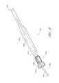
図8は、図2に示すプライミング装置1400を拡大して示す図である。上述したように、プライミング装置1400は、長尺ボディ174Aの先端部170Aの近傍において、インペラーアセンブリ116A上に配置することができる。プライミング装置1400は、処理に関連して使用することができ、インペラーアセンブリ116Aからエアを吐出することができる。例えば、ハウジング内に拘束されたすべてのエアを吐出することができる、あるいは、先端部170Aの近傍において長尺ボディ174A内に留まったままでいるすべてのエアを吐出することができる。例えば、プライミング操作は、患者の脈管系内へとポンプが挿入される前に、行うことができる。これにより、エアバブルを患者内に導入させることがない、および/または、エアバブルが患者を損傷することがない。プライミング装置1400は、長尺ボディ174Aとインペラーアセンブリ116Aとの双方の周縁まわりに配置され得るよう構成されたプライミングハウジング1401を備えることができる。シールキャップ1406を、プライミングハウジング1401の基端部1402に対して付与することができる。これにより、プライミングのためにプライミング装置1400を実質的にシールすることができる。すなわち、エアが、長尺ボディ174A内へと基端向きに導入されることがなく、また、プライミング流体が、ハウジング1401の基端部から流出することがない。シールキャップ1406は、当業者に公知であるような任意の手法でもって、プライミングハウジング1401に対して連結することができる。しかしながら、いくつかの実施形態においては、シールキャップ1406は、プライミングハウジング1401の基端部1402のところに配置されたネジ山付きコネクタ1405を介して、プライミングハウジング上に螺着することができる。シールキャップ1406は、このシールキャップ1406の先端部のところに配置されたシール凹所を備えることができる。シール凹所は、シールキャップ1406を通して長尺ボディ174Aを延在させ得るように、構成することができる。 FIG. 8 is an enlarged view of the
プライミング操作においては、次に、流体を、シールされたプライミング装置1400内へと導入することができる。これにより、インペラーアセンブリ116Aおよび長尺ボディ174Aからエアを吐出することができる。流体は、様々な手法でもって、プライミング装置1400内へと導入することができる。例えば、流体は、プライミング装置1400内へと長尺ボディ174Aを通して先端向きに導入することができる。他の実施形態においては、例えばルアーといったような導出口を、付加的には、プライミングハウジング1401の側面上に形成することができる。これにより、流体を、プライミング装置1400内へと導入することができる。 In the priming operation, fluid can then be introduced into the sealed
ガス透過性メンブランを、プライミングハウジング1401の先端部1404上に配置することができる。ガス透過性メンブランは、プライミング時には、プライミングハウジング1401からエアを逃がすことができる。 A gas permeable membrane can be disposed on the
プライミング装置1400は、また、有利には、カテーテルアセンブリ100Aの拡張可能部分を折り畳み得るよう構成することができる。プライミングハウジング1401は、漏斗形状部分1415を備えることができる。漏斗形状部分1415においては、ハウジングの内径は、先端から基端へと縮径している。漏斗形状部分は、ゆっくりと湾曲することができる。これにより、インペラーハウジングの相対的な基端移動は、インペラーハウジングを、漏斗形状部分1415によって折り畳み可能とすることができる。インペラーハウジングが完全に折り畳まれたときにはあるいはインペラーハウジングが完全に折り畳まれた後には、長尺ボディ174Aの先端部170Aは、折り畳まれたハウジングに対して相対的に先端向きに移動することができる。インペラーハウジングが完全に折り畳まれて、シースアセンブリの長尺ボディ174A内へと退避された後には、カテーテルアセンブリ100Aを、経皮的心臓処理が行われるに先立って、例えば血液をポンピングするようにポンプが起動されるに先立って、プライミングハウジング1401から取り外すことができる。ここで開示された様々な実施形態は、システムに対して注入を行うための合計時間が最小化されるようにあるいは低減されるように、実施することができる。例えば、いくつかの実施形態においては、システムに対して完全に注入を行うための時間は、6分以下とすることができる。他の実施態様においては、注入時間は、5分未満や、4分未満や、3分未満、とすることができる。さらに他の実施態様においては、システムに対して注入を行うための合計時間は、45秒以下とすることができる。心臓血管に疾病を有した患者に対しての使用に関しては、より短い注入時間を有利なものとし得ることは、理解されるであろう。 The
血管系内への挿入のための経皮的心臓ポンプの製造
本明細書において説明したように、および、参考のためにここに組み込まれた特許文献に開示されているように、様々な実施形態においては、心臓ポンプは、例えばカテーテル研究において使用し得る手法を使用するといったような低侵襲的な態様で挿入される。Fabrication of a Percutaneous Heart Pump for Insertion into the Vasculature Various embodiments as described herein and as disclosed in the patent documents incorporated herein for reference In, the cardiac pump is inserted in a minimally invasive manner, such as using techniques that can be used in catheter studies.
心臓ポンプのカテーテルアセンブリ100Aの挿入の前に、様々な技術を使用することにより、挿入のためのシステムを準備することができる。例えば、図8に関して上述したように、カテーテルアセンブリ100Aをプライミングすることにより、患者に対して処理を行う前に内部に含有され得るガスを除去することができる。このプライミング技法は、カテーテルアセンブリ100Aの先端部を、プライミング容器内に、例えばプライミング装置1400内に、配置することによって、行うことができる。その後、カテーテルアセンブリ100A内へと、加圧状態で媒体が供給される。これにより、潜在的に有害なすべての物質を、例えばエアや他のガスを、カテーテルアセンブリ100Aから除去することができる。一技法においては、プライミング装置1400は、例えば生理的食塩水といったような生体適合性液体によって充填される。その後、例えば生理的食塩水といったような生体適合性液体を、カテーテルアセンブリ100を通して先端向きに流す。これにより、上述したように、内部に形成されたすべてのキャビティ内のエアを除去することができる。プライミング流体の圧力や流速は、プライミングに適したものとして設定することができる。例えば、圧力や流速は、動作圧力や動作流速よりも小さい。 Prior to insertion of the cardiac
一技法においては、生体適合性液体は、カテーテルアセンブリ100Aを通して、基端部から正圧で加圧されつつ押し出される。これにより、内部の空隙からすべてのガスが除去される。すべてのガスが除去されたことを確認するための一技法は、ポンプの抽出流や背圧を観測することである。上述したように、プライミング装置1400は、生理的食塩水や他の生体適合性液体の流出を防止しつつ、ガスを除去し得るよう構成することができる。よって、所定の流れを維持するための背圧または抽出流は、すべてのガスが除去され終わった時点で、劇的に変化することとなる。 In one technique, a biocompatible liquid is extruded through the
他の技法においては、プライミング装置1400は、カテーテルアセンブリ100Aの基端部内に生体適合性液体を抽出するための負圧源を備えることができる。プライミング装置1400に対して負圧を印加することは、心臓ポンプの駆動時に使用されるポンプとは個別的に、カテーテルアセンブリ100Aのプライミングを可能とし得るという利点を有することができる。その結果、プライミングを、患者に対して直接的に関与していない操作者によって、患者に対して行われている他の医療処理と並行して、行うことができる。 In another technique, the
他のアプローチにおいては、心臓ポンプを駆動するためのポンプとは個別的な正圧ポンプを使用することにより、基端部に対して印加される正圧によってプライミングを行うことができる。プライミング装置1400の容量をより高速で充填するための個別の導入口を設けることにより、様々なプライミング手法を想定することができる。 In another approach, priming can be performed by a positive pressure applied to the proximal end by using a positive pressure pump separate from the pump for driving the cardiac pump. Various priming approaches can be envisioned by providing separate inlets for faster filling of the
完全にプライミングされたカテーテルアセンブリの拡張可能ハウジングの折り畳み
患者内への挿入のためにカテーテルアセンブリ100Aを準備するためのある種の方法におけるさらなる見地においては、インペラーハウジング116Aを折り畳むことができる。インペラーハウジング116Aの折り畳み状態は、システムの先端部のサイズを、例えば横断方向におけるサイズを、低減させる。これにより、例えばカテーテル研究タイプの処理を使用すること等によって、皮膚表面の近くの小さな容器を通して、患者は、右側の支持、あるいは、左側の支持、あるいは、左右の支持、を有することができる。上述したように、一技法においては、プライミング装置1400は、漏斗形状部分を有している。すなわち、先端部のところにおいて大きな直径を有しており、基端部のところにおいてより小さな直径を有している。漏斗形状部分は、大径から小径へのゆっくりとした移行をもたらす。小さな直径は、インペラーハウジング116Aの折り畳まれたサイズに近いものであり、大きな直径は、インペラーハウジング116Aの拡径したサイズに近いものであるあるいは拡径したサイズよりも大きなものである。一手法においては、カテーテルアセンブリ100Aをプライミングした後に、インペラーハウジング116Aを、プライミング装置1400とインペラーハウジング116Aとの間において相対移動をもたらすことによって、折り畳むことができる。例えば、プライミング装置1400は、例えば手によってといったようにして固定位置に保持することができ、カテーテルアセンブリ100Aは、インペラーハウジング116Aの少なくとも一部がプライミング装置1400の小径セグメント内に配置されるまで、引き抜くことができる。その後、シースアセンブリの長尺ボディ174Aを、折り畳まれたインペラーハウジング116A上にわたって前進させることができる。In a further aspect of certain methods for preparing the
他の技法においては、カテーテルアセンブリ100Aがなおも保持され、プライミング装置1400が、インペラーハウジング116A上にわたって先端側にスライドされる。これにより、インペラーハウジング116Aを折り畳むことができる。その後、長尺ボディ174Aとインペラーハウジング116Aとの間の相対移動は、カテーテルアセンブリ100Aが完全にプライミングされた後に、インペラーハウジング116A上にわたって長尺ボディ174Aの先端部170Aを位置させることができる。 In another technique, the
複数の特定の実施形態を参照して本発明について上述したけれども、それらの実施形態が、本発明の原理や用途を単に例示しているに過ぎないことは、理解されるであろう。したがって、上記の様々な実施形態に対して多様な修正を加え得ることは、また、特許請求の範囲によって規定された本発明の精神および範囲を逸脱することなく他の構成を採用し得ることは、理解されるであろう。よって、本発明が、上記の様々な実施形態に関してのおよびそれらの等価物に関してのすべての修正や変形を包含することが意図されている。 While the invention has been described above with reference to a plurality of specific embodiments, it will be understood that the embodiments are merely illustrative of the principles and applications of the present invention. Therefore, it is possible that various modifications can be made to the various embodiments described above, and that other configurations can be adopted without departing from the spirit and scope of the present invention defined by the claims. Will be understood. Thus, it is intended that the present invention encompass all modifications and variations of the various embodiments described above and their equivalents.
100A カテーテルアセンブリ
116A インペラーアセンブリ(動作デバイス)
120A カテーテルボディ
174A 長尺ボディ
195 注入システム
300 インターフェース部材
301 コンソール
302 導管
303 インターフェース領域
304 開口(インターフェース開口)
306 ポンプローラ
307 電気的相互接続(電気的相互接続部材)
320 手動インターフェース
322a 閉塞ベッド
322b 閉塞ベッド
324a ポンプチューブセグメント
324b ポンプチューブセグメント
333 外側ボディ
350 流体導出入システム
1400 プライミング装置
306
320
Claims (1)
Translated fromJapaneseApplications Claiming Priority (2)
| Application Number | Priority Date | Filing Date | Title |
|---|---|---|---|
| US201361780656P | 2013-03-13 | 2013-03-13 | |
| US61/780,656 | 2013-03-13 |
Related Parent Applications (1)
| Application Number | Title | Priority Date | Filing Date |
|---|---|---|---|
| JP2016500668ADivisionJP6530367B2 (en) | 2013-03-13 | 2014-03-05 | Fluid outlet / inlet system |
Related Child Applications (1)
| Application Number | Title | Priority Date | Filing Date |
|---|---|---|---|
| JP2021021670ADivisionJP7128923B2 (en) | 2013-03-13 | 2021-02-15 | Fluid in-and-out system |
Publications (2)
| Publication Number | Publication Date |
|---|---|
| JP2019069348Atrue JP2019069348A (en) | 2019-05-09 |
| JP6991170B2 JP6991170B2 (en) | 2022-01-12 |
Family
ID=51530250
Family Applications (4)
| Application Number | Title | Priority Date | Filing Date |
|---|---|---|---|
| JP2016500668AActiveJP6530367B2 (en) | 2013-03-13 | 2014-03-05 | Fluid outlet / inlet system |
| JP2019024350AActiveJP6991170B2 (en) | 2013-03-13 | 2019-02-14 | Fluid derivation input system |
| JP2021021670AActiveJP7128923B2 (en) | 2013-03-13 | 2021-02-15 | Fluid in-and-out system |
| JP2022039080AActiveJP7239757B2 (en) | 2013-03-13 | 2022-03-14 | Fluid in-and-out system |
Family Applications Before (1)
| Application Number | Title | Priority Date | Filing Date |
|---|---|---|---|
| JP2016500668AActiveJP6530367B2 (en) | 2013-03-13 | 2014-03-05 | Fluid outlet / inlet system |
Family Applications After (2)
| Application Number | Title | Priority Date | Filing Date |
|---|---|---|---|
| JP2021021670AActiveJP7128923B2 (en) | 2013-03-13 | 2021-02-15 | Fluid in-and-out system |
| JP2022039080AActiveJP7239757B2 (en) | 2013-03-13 | 2022-03-14 | Fluid in-and-out system |
Country Status (4)
| Country | Link |
|---|---|
| US (5) | US9381288B2 (en) |
| EP (3) | EP3834876B1 (en) |
| JP (4) | JP6530367B2 (en) |
| WO (1) | WO2014164136A1 (en) |
Families Citing this family (83)
| Publication number | Priority date | Publication date | Assignee | Title |
|---|---|---|---|---|
| US7393181B2 (en) | 2004-09-17 | 2008-07-01 | The Penn State Research Foundation | Expandable impeller pump |
| CN102380135A (en) | 2006-03-23 | 2012-03-21 | 宾州研究基金会 | Heart assist device with expandable impeller pump |
| WO2012094641A2 (en) | 2011-01-06 | 2012-07-12 | Thoratec Corporation | Percutaneous heart pump |
| EP4218887A1 (en) | 2012-05-14 | 2023-08-02 | Tc1 Llc | Mechanical circulatory support device for stabilizing a patient after cardiogenic shock |
| US8721517B2 (en) | 2012-05-14 | 2014-05-13 | Thoratec Corporation | Impeller for catheter pump |
| US9327067B2 (en) | 2012-05-14 | 2016-05-03 | Thoratec Corporation | Impeller for catheter pump |
| US9872947B2 (en) | 2012-05-14 | 2018-01-23 | Tc1 Llc | Sheath system for catheter pump |
| US9446179B2 (en) | 2012-05-14 | 2016-09-20 | Thoratec Corporation | Distal bearing support |
| US9421311B2 (en) | 2012-07-03 | 2016-08-23 | Thoratec Corporation | Motor assembly for catheter pump |
| US9358329B2 (en) | 2012-07-03 | 2016-06-07 | Thoratec Corporation | Catheter pump |
| EP4186557A1 (en) | 2012-07-03 | 2023-05-31 | Tc1 Llc | Motor assembly for catheter pump |
| WO2014164136A1 (en)* | 2013-03-13 | 2014-10-09 | Thoratec Corporation | Fluid handling system |
| US11077294B2 (en) | 2013-03-13 | 2021-08-03 | Tc1 Llc | Sheath assembly for catheter pump |
| US11033728B2 (en) | 2013-03-13 | 2021-06-15 | Tc1 Llc | Fluid handling system |
| EP4190376A1 (en) | 2013-03-15 | 2023-06-07 | Tc1 Llc | Catheter pump assembly including a stator |
| US9308302B2 (en) | 2013-03-15 | 2016-04-12 | Thoratec Corporation | Catheter pump assembly including a stator |
| EP3131599B1 (en) | 2014-04-15 | 2019-02-20 | Tc1 Llc | Catheter pump with access ports |
| WO2015160943A1 (en) | 2014-04-15 | 2015-10-22 | Thoratec Corporation | Sensors for catheter pumps |
| US10583232B2 (en) | 2014-04-15 | 2020-03-10 | Tc1 Llc | Catheter pump with off-set motor position |
| EP3131597B1 (en) | 2014-04-15 | 2020-12-02 | Tc1 Llc | Catheter pump introducer systems |
| EP3583973A1 (en) | 2014-08-18 | 2019-12-25 | Tc1 Llc | Guide features for percutaneous catheter pump |
| EP3045184B1 (en)* | 2015-01-13 | 2019-01-09 | ECP Entwicklungsgesellschaft mbH | Container for a heart pump device and method for operating a heart pump device |
| DK3572120T3 (en)* | 2015-01-22 | 2024-07-22 | Ecp Entw Mbh | Catheter device containing a valve for controlling a fluid flow through a catheter |
| US9770543B2 (en) | 2015-01-22 | 2017-09-26 | Tc1 Llc | Reduced rotational mass motor assembly for catheter pump |
| WO2016118781A2 (en) | 2015-01-22 | 2016-07-28 | Thoratec Corporation | Motor assembly with heat exchanger for catheter pump |
| US9675738B2 (en) | 2015-01-22 | 2017-06-13 | Tc1 Llc | Attachment mechanisms for motor of catheter pump |
| US9907890B2 (en) | 2015-04-16 | 2018-03-06 | Tc1 Llc | Catheter pump with positioning brace |
| EP3848089A1 (en)* | 2015-09-14 | 2021-07-14 | Tc1 Llc | Fluid handling system |
| JP2019080594A (en)* | 2016-03-18 | 2019-05-30 | テルモ株式会社 | Catheter pump and treatment method |
| EP3808401A1 (en) | 2016-07-21 | 2021-04-21 | Tc1 Llc | Gas-filled chamber for catheter pump motor assembly |
| US11160970B2 (en) | 2016-07-21 | 2021-11-02 | Tc1 Llc | Fluid seals for catheter pump motor assembly |
| CA3039285A1 (en) | 2016-10-25 | 2018-05-03 | Magenta Medical Ltd. | Ventricular assist device |
| DE102017102829A1 (en) | 2017-02-13 | 2018-08-16 | Cardiobridge Gmbh | flushing system |
| CA3066361A1 (en) | 2017-06-07 | 2018-12-13 | Shifamed Holdings, Llc | Intravascular fluid movement devices, systems, and methods of use |
| US10090616B1 (en)* | 2017-06-27 | 2018-10-02 | Ethicon Llc | Surgical instrument handle assembly with feature to clean electrical contacts at modular shaft interface |
| WO2019094963A1 (en) | 2017-11-13 | 2019-05-16 | Shifamed Holdings, Llc | Intravascular fluid movement devices, systems, and methods of use |
| US10905808B2 (en) | 2018-01-10 | 2021-02-02 | Magenta Medical Ltd. | Drive cable for use with a blood pump |
| EP3638336B1 (en) | 2018-01-10 | 2022-04-06 | Magenta Medical Ltd. | Ventricular assist device |
| DE102018201030B4 (en) | 2018-01-24 | 2025-10-16 | Kardion Gmbh | Magnetic dome element with magnetic bearing function |
| CN112004563B (en) | 2018-02-01 | 2024-08-06 | 施菲姆德控股有限责任公司 | Intravascular blood pump and methods of use and manufacture |
| EP3787707B1 (en) | 2018-04-30 | 2023-12-27 | Tc1 Llc | Improved blood pump connectors |
| DE102018207575A1 (en) | 2018-05-16 | 2019-11-21 | Kardion Gmbh | Magnetic face turning coupling for the transmission of torques |
| DE102018207611A1 (en) | 2018-05-16 | 2019-11-21 | Kardion Gmbh | Rotor bearing system |
| DE102018208538A1 (en) | 2018-05-30 | 2019-12-05 | Kardion Gmbh | Intravascular blood pump and process for the production of electrical conductors |
| DE102018208541A1 (en) | 2018-05-30 | 2019-12-05 | Kardion Gmbh | Axial pump for a cardiac assist system and method of making an axial pump for a cardiac assist system |
| DE102018208539A1 (en) | 2018-05-30 | 2019-12-05 | Kardion Gmbh | A motor housing module for sealing an engine compartment of a motor of a cardiac assist system and cardiac assistance system and method for mounting a cardiac assist system |
| DE102018208555A1 (en) | 2018-05-30 | 2019-12-05 | Kardion Gmbh | Apparatus for anchoring a cardiac assist system in a blood vessel, method of operation, and method of making a device and cardiac assist system |
| DE102018208550A1 (en) | 2018-05-30 | 2019-12-05 | Kardion Gmbh | A lead device for directing blood flow to a cardiac assist system, cardiac assist system, and method of making a lead device |
| DE102018208929A1 (en) | 2018-06-06 | 2019-12-12 | Kardion Gmbh | A method of determining a flow rate of fluid flowing through an implanted vascular support system |
| DE102018208933A1 (en) | 2018-06-06 | 2019-12-12 | Kardion Gmbh | A method of determining a flow rate of fluid flowing through an implanted vascular support system |
| DE102018208879A1 (en) | 2018-06-06 | 2020-01-30 | Kardion Gmbh | Method for determining a total fluid volume flow in the area of an implanted, vascular support system |
| DE102018208936A1 (en) | 2018-06-06 | 2019-12-12 | Kardion Gmbh | Determining device and method for determining a viscosity of a fluid |
| DE102018208862A1 (en) | 2018-06-06 | 2019-12-12 | Kardion Gmbh | Implantable vascular support system |
| DE102018208899A1 (en) | 2018-06-06 | 2019-12-12 | Kardion Gmbh | A method for determining the speed of sound in a fluid in the region of an implanted vascular support system |
| DE102018208913A1 (en) | 2018-06-06 | 2019-12-12 | Kardion Gmbh | A method of operating an implanted ventricular assist device |
| DE102018208945A1 (en) | 2018-06-06 | 2019-12-12 | Kardion Gmbh | An analysis device and method for analyzing a viscosity of a fluid |
| DE102018210076A1 (en) | 2018-06-21 | 2019-12-24 | Kardion Gmbh | Method and device for detecting a state of wear of a cardiac support system, method and device for operating a cardiac support system and cardiac support system |
| DE102018210058A1 (en) | 2018-06-21 | 2019-12-24 | Kardion Gmbh | Stator blade device for guiding the flow of a fluid flowing out of an outlet opening of a heart support system, heart support system with stator blade device, method for operating a stator blade device and manufacturing method |
| DE102018211327A1 (en) | 2018-07-10 | 2020-01-16 | Kardion Gmbh | Impeller for an implantable vascular support system |
| WO2020018742A1 (en)* | 2018-07-19 | 2020-01-23 | Abiomed, Inc. | Systems and methods for reducing leaks from a catheter |
| DE102018212153A1 (en) | 2018-07-20 | 2020-01-23 | Kardion Gmbh | Inlet line for a pump unit of a cardiac support system, cardiac support system and method for producing an inlet line for a pump unit of a cardiac support system |
| US12161857B2 (en) | 2018-07-31 | 2024-12-10 | Shifamed Holdings, Llc | Intravascular blood pumps and methods of use |
| CN112654389A (en) | 2018-08-07 | 2021-04-13 | 开迪恩有限公司 | Bearing device for a cardiac support system and method for flushing an intermediate space in a bearing device for a cardiac support system |
| WO2020073047A1 (en) | 2018-10-05 | 2020-04-09 | Shifamed Holdings, Llc | Intravascular blood pumps and methods of use |
| AU2020211431B2 (en) | 2019-01-24 | 2024-10-24 | Magenta Medical Ltd | Ventricular assist device |
| WO2021011473A1 (en) | 2019-07-12 | 2021-01-21 | Shifamed Holdings, Llc | Intravascular blood pumps and methods of manufacture and use |
| US11654275B2 (en) | 2019-07-22 | 2023-05-23 | Shifamed Holdings, Llc | Intravascular blood pumps with struts and methods of use and manufacture |
| US12171994B2 (en) | 2019-09-11 | 2024-12-24 | Boston Scientific Scimed, Inc. | Reduced thrombosis blood pump with washout bearing |
| WO2021062265A1 (en) | 2019-09-25 | 2021-04-01 | Shifamed Holdings, Llc | Intravascular blood pump systems and methods of use and control thereof |
| US12121713B2 (en) | 2019-09-25 | 2024-10-22 | Shifamed Holdings, Llc | Catheter blood pumps and collapsible blood conduits |
| EP4501393A3 (en) | 2019-09-25 | 2025-04-09 | Shifamed Holdings, LLC | Catheter blood pumps and collapsible pump housings |
| EP4072650A4 (en) | 2019-12-11 | 2024-01-10 | Shifamed Holdings, LLC | Descending aorta and vena cava blood pumps |
| US20210178055A1 (en)* | 2019-12-17 | 2021-06-17 | Carefusion 303, Inc. | Modular power and connectivity system for infusion devices |
| DE102020102474A1 (en) | 2020-01-31 | 2021-08-05 | Kardion Gmbh | Pump for conveying a fluid and method for manufacturing a pump |
| EP3984589B1 (en) | 2020-04-07 | 2023-08-23 | Magenta Medical Ltd. | Magnetic phase sensing |
| US12329410B2 (en) | 2020-08-12 | 2025-06-17 | Mazor Robotics Ltd. | Cannulation devices, systems, and methods |
| JP7633858B2 (en)* | 2020-11-06 | 2025-02-20 | 株式会社カネカ | Injection tool |
| US20240001101A1 (en) | 2020-12-04 | 2024-01-04 | Shifamed Holdings, Llc | Catheter blood pumps and external fluid control consoles |
| EP4291287A1 (en) | 2021-04-14 | 2023-12-20 | Boston Scientific Scimed Inc. | Flexible tip for transvalvular circulatory support device |
| AU2022390146B2 (en) | 2021-11-17 | 2025-04-03 | Boston Scientific Scimed Inc. | Device housing features to facilitate damage free guidewire translations |
| WO2023096892A1 (en) | 2021-11-23 | 2023-06-01 | Boston Scientific Scimed Inc. | Percutaneous circulatory support device facilitating reduced hemolysis |
| CN115629204A (en)* | 2022-10-20 | 2023-01-20 | 南京医科大学第二附属医院 | A ventricular assist pump hemolysis experimental loop device and its experimental method |
| CN119424895A (en)* | 2023-07-31 | 2025-02-14 | 丰凯利医疗器械(上海)有限公司 | A perfusion reflux device for medical equipment |
Citations (6)
| Publication number | Priority date | Publication date | Assignee | Title |
|---|---|---|---|---|
| JPH1099440A (en)* | 1996-09-27 | 1998-04-21 | Terumo Corp | Catheter device and priming apparatus for it |
| US20030093086A1 (en)* | 2001-08-17 | 2003-05-15 | Briggs Leonard F. | Balloon protector sleeve |
| JP2007252960A (en)* | 2007-06-29 | 2007-10-04 | Kaneka Corp | Protector for balloon catheter |
| US20080011640A1 (en)* | 2004-02-12 | 2008-01-17 | Medtronic Vascular, Inc. | Packaged System Including a Protective Housing for a Treatment Device Carried on a Catheter |
| JP2016515000A (en)* | 2013-03-13 | 2016-05-26 | ソーラテック コーポレイション | Fluid lead-in system |
| JP2021021670A (en)* | 2019-07-30 | 2021-02-18 | 三菱パワー株式会社 | Visual inspection device |
Family Cites Families (508)
| Publication number | Priority date | Publication date | Assignee | Title |
|---|---|---|---|---|
| US1902418A (en) | 1931-11-02 | 1933-03-21 | Jensen Salsbery Lab Inc | Surgical instrument |
| US2356659A (en) | 1941-11-24 | 1944-08-22 | Aguiar Clovis De Paiva | Nozzle for duodenal pump tubes |
| US2649052A (en) | 1947-04-17 | 1953-08-18 | Marine Products Company | Rotary pump or motor |
| US2684035A (en) | 1947-10-02 | 1954-07-20 | Philip G Kemp | Fluid pump |
| US2664050A (en) | 1949-03-02 | 1953-12-29 | Gen Motors Corp | Domestic appliance |
| US2789511A (en) | 1953-05-25 | 1957-04-23 | Jabsco Pump Co | Flexible vane pump impeller |
| US2935068A (en) | 1955-08-04 | 1960-05-03 | Donaldson John Shearman | Surgical procedure and apparatus for use in carrying out the same |
| US2896926A (en) | 1956-01-10 | 1959-07-28 | Chapman Harold Eric | Device for mixing or treating fluids or free-flowing powders |
| US3080824A (en) | 1961-02-27 | 1963-03-12 | James A Boyd | Fluid moving device |
| US3455540A (en) | 1968-01-04 | 1969-07-15 | Emil G Marcmann | Stirring device |
| JPS4823295Y1 (en) | 1968-03-09 | 1973-07-06 | ||
| US3510229A (en) | 1968-07-23 | 1970-05-05 | Maytag Co | One-way pump |
| US3860968A (en) | 1969-11-20 | 1975-01-21 | Max Shapiro | Compact, implantable apparatus for pumping blood to sustain blood circulation in a living body |
| US3995617A (en) | 1972-05-31 | 1976-12-07 | Watkins David H | Heart assist method and catheter |
| CH591178A5 (en) | 1972-11-03 | 1977-09-15 | Anvar | |
| US3812812A (en) | 1973-06-25 | 1974-05-28 | M Hurwitz | Trolling propeller with self adjusting hydrodynamic spoilers |
| FR2267800A1 (en) | 1974-04-17 | 1975-11-14 | Anvar | Catheter insertion system - uses auxiliary fluid injected in catheter and forming propulsion jets |
| US4458366C1 (en) | 1975-05-09 | 2001-02-20 | David C Macgregor | Artificial implantable blood pump |
| LU77252A1 (en) | 1976-05-06 | 1977-08-22 | ||
| DE2624058C2 (en) | 1976-05-28 | 1984-11-15 | Franz Klaus-Union, 4630 Bochum | Permanent magnet pump |
| US4066556A (en)* | 1976-10-28 | 1978-01-03 | Johnson & Johnson | Fluid filter and method of making same |
| US4135253A (en) | 1976-11-30 | 1979-01-23 | Medtronic, Inc. | Centrifugal blood pump for cardiac assist |
| US4129129A (en) | 1977-03-18 | 1978-12-12 | Sarns, Inc. | Venous return catheter and a method of using the same |
| US4143425A (en) | 1977-10-27 | 1979-03-13 | Runge Thomas M | Left atrial to descending thoracic aorta left ventricular assist device |
| USD264134S (en) | 1979-05-07 | 1982-04-27 | Stewart-Reiss Laboratories, Inc. | Disposable cassette for use in a peristaltic pump |
| GB2058231B (en) | 1979-09-07 | 1982-01-20 | Woodcoxon Eng International Lt | Variable pitch marine propellers |
| JPH0247496Y2 (en) | 1980-05-21 | 1990-12-13 | ||
| US4382199A (en) | 1980-11-06 | 1983-05-03 | Nu-Tech Industries, Inc. | Hydrodynamic bearing system for a brushless DC motor |
| DE3214397C2 (en) | 1982-04-20 | 1984-07-26 | Karl Dr. 6301 Pohlheim Aigner | Double lumen perfusion catheter |
| US4537561A (en) | 1983-02-24 | 1985-08-27 | Medical Technology, Ltd. | Peristaltic infusion pump and disposable cassette for use therewith |
| US4560375A (en) | 1983-06-30 | 1985-12-24 | Pudenz-Schulte Medical Research Corp. | Flow control valve |
| US4704121A (en) | 1983-09-28 | 1987-11-03 | Nimbus, Inc. | Anti-thrombogenic blood pump |
| US4625712A (en) | 1983-09-28 | 1986-12-02 | Nimbus, Inc. | High-capacity intravascular blood pump utilizing percutaneous access |
| US4673334A (en) | 1984-05-25 | 1987-06-16 | Isco, Inc. | Peristaltic pump |
| US4589822A (en) | 1984-07-09 | 1986-05-20 | Mici Limited Partnership Iv | Centrifugal blood pump with impeller |
| US4686982A (en) | 1985-06-19 | 1987-08-18 | John Nash | Spiral wire bearing for rotating wire drive catheter |
| US4769006A (en) | 1985-05-13 | 1988-09-06 | Kos Medical Technologies, Ltd. | Hydrodynamically propelled pacing catheter |
| US4655745A (en) | 1985-07-29 | 1987-04-07 | Corbett Joseph E | Ventricular catheter |
| US4728319A (en) | 1986-03-20 | 1988-03-01 | Helmut Masch | Intravascular catheter |
| US4696667A (en) | 1986-03-20 | 1987-09-29 | Helmut Masch | Intravascular catheter and method |
| US4819653A (en) | 1986-04-11 | 1989-04-11 | Lloyd A. Marks | Multi-function fluid communication control system |
| US4930341A (en)* | 1986-08-08 | 1990-06-05 | Scimed Life Systems, Inc. | Method of prepping a dilatation catheter |
| US4790315A (en)* | 1986-09-02 | 1988-12-13 | Advanced Cardiovascular Systems, Inc. | Perfusion dilatation catheter and method of manufacture |
| US4777951A (en) | 1986-09-19 | 1988-10-18 | Mansfield Scientific, Inc. | Procedure and catheter instrument for treating patients for aortic stenosis |
| US4753221A (en) | 1986-10-22 | 1988-06-28 | Intravascular Surgical Instruments, Inc. | Blood pumping catheter and method of use |
| US5195960A (en)* | 1987-04-27 | 1993-03-23 | Site Microsurgical Systems, Inc. | Disposable vacuum/peristaltic pump cassette system |
| US4902272A (en) | 1987-06-17 | 1990-02-20 | Abiomed Cardiovascular, Inc. | Intra-arterial cardiac support system |
| US4846152A (en) | 1987-11-24 | 1989-07-11 | Nimbus Medical, Inc. | Single-stage axial flow blood pump |
| US4817586A (en) | 1987-11-24 | 1989-04-04 | Nimbus Medical, Inc. | Percutaneous bloom pump with mixed-flow output |
| US4895557A (en) | 1987-12-07 | 1990-01-23 | Nimbus Medical, Inc. | Drive mechanism for powering intravascular blood pumps |
| AU2807389A (en) | 1987-12-07 | 1989-07-05 | Nimbus Medical, Inc. | Inflow cannula for intravascular blood pumps |
| US5061256A (en) | 1987-12-07 | 1991-10-29 | Johnson & Johnson | Inflow cannula for intravascular blood pumps |
| US4906229A (en) | 1988-05-03 | 1990-03-06 | Nimbus Medical, Inc. | High-frequency transvalvular axisymmetric blood pump |
| US5074756A (en) | 1988-05-17 | 1991-12-24 | Patient Solutions, Inc. | Infusion device with disposable elements |
| US5246347A (en) | 1988-05-17 | 1993-09-21 | Patients Solutions, Inc. | Infusion device with disposable elements |
| FR2632686B1 (en) | 1988-06-14 | 1993-07-16 | Thomson Brandt Armements | |
| US4908012A (en) | 1988-08-08 | 1990-03-13 | Nimbus Medical, Inc. | Chronic ventricular assist system |
| US4964864A (en) | 1988-09-27 | 1990-10-23 | American Biomed, Inc. | Heart assist pump |
| JPH0653161B2 (en) | 1988-09-28 | 1994-07-20 | 東洋紡績株式会社 | Circulator |
| US4919647A (en) | 1988-10-13 | 1990-04-24 | Kensey Nash Corporation | Aortically located blood pumping catheter and method of use |
| US4957504A (en) | 1988-12-02 | 1990-09-18 | Chardack William M | Implantable blood pump |
| US5112292A (en) | 1989-01-09 | 1992-05-12 | American Biomed, Inc. | Helifoil pump |
| US4969865A (en) | 1989-01-09 | 1990-11-13 | American Biomed, Inc. | Helifoil pump |
| US4944722A (en) | 1989-02-23 | 1990-07-31 | Nimbus Medical, Inc. | Percutaneous axial flow blood pump |
| FR2644212B1 (en) | 1989-03-13 | 1991-11-15 | Malbec Edouard | CASSETTE FOR PERISTALTIC PUMP WITH DEFORMABLE TUBE, AND PERISTALTIC PUMP EQUIPPED WITH SUCH A CASSETTE |
| US5163900A (en) | 1989-03-16 | 1992-11-17 | Surgin Surgical Instrumentation, Inc. | Disposable cassette systems |
| US4976270A (en) | 1989-03-28 | 1990-12-11 | Vanderbilt University | Apparatus for continuously sampling plasma |
| US4995857A (en) | 1989-04-07 | 1991-02-26 | Arnold John R | Left ventricular assist device and method for temporary and permanent procedures |
| US5049134A (en) | 1989-05-08 | 1991-09-17 | The Cleveland Clinic Foundation | Sealless heart pump |
| US5045072A (en) | 1989-06-13 | 1991-09-03 | Cordis Corporation | Catheter having highly radiopaque, flexible tip |
| US5089016A (en) | 1989-06-15 | 1992-02-18 | Abiomed Cardiovascular, Inc. | Blood pump |
| US4955856A (en) | 1989-06-30 | 1990-09-11 | Phillips Steven J | Method and apparatus for installing a ventricular assist device cannulae |
| US4985014A (en) | 1989-07-11 | 1991-01-15 | Orejola Wilmo C | Ventricular venting loop |
| US5147186A (en) | 1989-08-04 | 1992-09-15 | Bio Medicus, Inc. | Blood pump drive system |
| US5021048A (en) | 1989-08-04 | 1991-06-04 | Medtronic, Inc. | Blood pump drive system |
| US5098256A (en) | 1989-11-21 | 1992-03-24 | The Cleveland Clinic Foundation | Viscous seal blood pump |
| GB2239675A (en) | 1989-12-05 | 1991-07-10 | Man Fai Shiu | Pump for pumping liquid |
| US5000177A (en) | 1990-01-29 | 1991-03-19 | Cardiac Pacemakers, Inc. | Bipolar lead adapter with resilient housing and rigid retainers for plug seals |
| US5092844A (en) | 1990-04-10 | 1992-03-03 | Mayo Foundation For Medical Education And Research | Intracatheter perfusion pump apparatus and method |
| US5163910A (en) | 1990-04-10 | 1992-11-17 | Mayo Foundation For Medical Education And Research | Intracatheter perfusion pump apparatus and method |
| US5106368A (en) | 1990-04-20 | 1992-04-21 | Cook Incorporated | Collapsible lumen catheter for extracorporeal treatment |
| US5112200A (en) | 1990-05-29 | 1992-05-12 | Nu-Tech Industries, Inc. | Hydrodynamically suspended rotor axial flow blood pump |
| US5211546A (en) | 1990-05-29 | 1993-05-18 | Nu-Tech Industries, Inc. | Axial flow blood pump with hydrodynamically suspended rotor |
| DE4020120A1 (en) | 1990-06-25 | 1991-01-31 | Klaus Prof Dr Ing Affeld | MEDICAL DEVICE FOR GENERATING AN ALTERNATING VOLUME FLOW FOR DRIVING IMPLANTABLE BLOOD PUMPS |
| CA2022019C (en) | 1990-07-26 | 1992-12-29 | Michael Black | Catheter |
| US5059174A (en)* | 1990-08-23 | 1991-10-22 | Vaillancourt Vincent L | Fluid infusion delivery system |
| US5190528A (en) | 1990-10-19 | 1993-03-02 | Boston University | Percutaneous transseptal left atrial cannulation system |
| US5171212A (en) | 1991-02-08 | 1992-12-15 | Minnesota Mining And Manufacturing Company | Blood pumping system with backflow warning |
| US5234407A (en) | 1991-03-06 | 1993-08-10 | Baxter International Inc. | Method and device for exchanging cardiovascular guide catheter while a previously inserted angioplasty guide wire remains in place |
| US5142155A (en) | 1991-03-11 | 1992-08-25 | Hewlett-Packard Company | Catheter tip fluorescence-quenching fiber optic pressure sensor |
| US5234416A (en) | 1991-06-06 | 1993-08-10 | Advanced Cardiovascular Systems, Inc. | Intravascular catheter with a nontraumatic distal tip |
| US5221270A (en) | 1991-06-28 | 1993-06-22 | Cook Incorporated | Soft tip guiding catheter |
| US5584803A (en) | 1991-07-16 | 1996-12-17 | Heartport, Inc. | System for cardiac procedures |
| US5741429A (en) | 1991-09-05 | 1998-04-21 | Cardia Catheter Company | Flexible tubular device for use in medical applications |
| US6027863A (en) | 1991-09-05 | 2000-02-22 | Intratherapeutics, Inc. | Method for manufacturing a tubular medical device |
| JP2713515B2 (en) | 1991-09-17 | 1998-02-16 | 禎祐 山内 | Catheter device |
| US5449342A (en) | 1991-09-30 | 1995-09-12 | Nippon Zeon Co., Ltd. | Apparatus for assisting blood circulation |
| US5201679A (en) | 1991-12-13 | 1993-04-13 | Attwood Corporation | Marine propeller with breakaway hub |
| US5267956A (en) | 1992-02-05 | 1993-12-07 | Alcon Surgical, Inc. | Surgical cassette |
| EP0633798B1 (en) | 1992-03-31 | 2003-05-07 | Boston Scientific Corporation | Vascular filter |
| DE4222380A1 (en) | 1992-07-08 | 1994-01-13 | Ernst Peter Prof Dr M Strecker | Endoprosthesis implantable percutaneously in a patient's body |
| US5300112A (en) | 1992-07-14 | 1994-04-05 | Aai Corporation | Articulated heart pump |
| US5458459A (en) | 1992-07-30 | 1995-10-17 | Haemonetics Corporation | Centrifugal blood pump with impeller blades forming a spin inducer |
| EP0653022B1 (en) | 1992-07-30 | 2001-12-05 | Cobe Cardiovascular, Inc. | Centrifugal blood pump |
| US5290227A (en) | 1992-08-06 | 1994-03-01 | Pasque Michael K | Method of implanting blood pump in ascending aorta or main pulmonary artery |
| US5676651A (en) | 1992-08-06 | 1997-10-14 | Electric Boat Corporation | Surgically implantable pump arrangement and method for pumping body fluids |
| US5312341A (en) | 1992-08-14 | 1994-05-17 | Wayne State University | Retaining apparatus and procedure for transseptal catheterization |
| SE501215C2 (en) | 1992-09-02 | 1994-12-12 | Oeyvind Reitan | catheter Pump |
| US5344443A (en) | 1992-09-17 | 1994-09-06 | Rem Technologies, Inc. | Heart pump |
| JP3265650B2 (en) | 1992-09-30 | 2002-03-11 | 日本ゼオン株式会社 | Blood circulation assist device |
| US5376114A (en) | 1992-10-30 | 1994-12-27 | Jarvik; Robert | Cannula pumps for temporary cardiac support and methods of their application and use |
| US5393207A (en) | 1993-01-21 | 1995-02-28 | Nimbus, Inc. | Blood pump with disposable rotor assembly |
| US5643226A (en) | 1993-02-24 | 1997-07-01 | Minnesota Mining And Manufacturing | Low velocity aortic cannula |
| DE69317548T2 (en) | 1993-04-23 | 1998-08-13 | Schneider (Europe) Gmbh, Buelach | Stent with a coating of elastic material and method for applying the coating on the stent |
| US5752932A (en) | 1993-04-29 | 1998-05-19 | Scimed Life Systems, Inc. | Intravascular catheter with a recoverable guide wire lumen and method of use |
| US5405341A (en) | 1993-06-03 | 1995-04-11 | Med-Pro Design, Inc. | Catheter with multiple lumens |
| WO1995010989A1 (en) | 1993-10-19 | 1995-04-27 | Scimed Life Systems, Inc. | Intravascular stent pump |
| US5397222A (en) | 1993-11-01 | 1995-03-14 | Moss; Richard | Reusable medical cassette for ambulatory medical infusion pumps |
| US5393197A (en) | 1993-11-09 | 1995-02-28 | Lemont Aircraft Corporation | Propulsive thrust ring system |
| US5527159A (en) | 1993-11-10 | 1996-06-18 | The United States Of America As Represented By The Administrator Of The National Aeronautics And Space Administration | Rotary blood pump |
| ES2077519B1 (en) | 1993-11-22 | 1996-07-01 | Fernandez De Lomana Euge Anaya | INTRAAORTIC CATHETER FOR RENAL PERFUSION AND CONSERVATION. |
| US5437541A (en) | 1993-12-30 | 1995-08-01 | Vainrub; John | Blade for axial fan |
| CA2157575C (en) | 1994-04-01 | 2000-03-07 | Lilip Lau | Self-expandable stent and stent-graft and method of using them |
| US5597377A (en) | 1994-05-06 | 1997-01-28 | Trustees Of Boston University | Coronary sinus reperfusion catheter |
| ATE245040T1 (en) | 1994-05-13 | 2003-08-15 | Abbott Lab | DISPOSABLE INFUSION CASSETTE WITH A PUSH-BUTTON OPERATED APSOCKET VALVE |
| US5403292A (en) | 1994-05-18 | 1995-04-04 | Schneider (Usa) Inc. | Thin wall catheter having enhanced torqueability characteristics |
| US5601420A (en) | 1994-09-12 | 1997-02-11 | Ivac Medical Systems, Inc. | Interlock, latching, and retaining mechanism for an infusion pump |
| US5490763A (en) | 1994-09-15 | 1996-02-13 | Abrams; Andrew L. | Pump for shear sensitive fluids |
| AU4242996A (en) | 1994-11-23 | 1996-06-17 | Navarre Biomedical, Ltd. | Flexible catheter |
| US5613935A (en) | 1994-12-16 | 1997-03-25 | Jarvik; Robert | High reliability cardiac assist system |
| US5904668A (en) | 1995-03-06 | 1999-05-18 | Sabratek Corporation | Cassette for an infusion pump |
| US6203528B1 (en) | 1995-03-06 | 2001-03-20 | Baxter International Inc. | Unitary molded elastomer conduit for use with a medical infusion pump |
| US5707218A (en) | 1995-04-19 | 1998-01-13 | Nimbus, Inc. | Implantable electric axial-flow blood pump with blood cooled bearing |
| US5588812A (en) | 1995-04-19 | 1996-12-31 | Nimbus, Inc. | Implantable electric axial-flow blood pump |
| US5793974A (en) | 1995-06-30 | 1998-08-11 | Sun Microsystems, Inc. | Network navigation and viewing system for network management system |
| US6007479A (en) | 1996-07-08 | 1999-12-28 | H.D.S. Systems Ltd. | Heart assist system and method |
| US5702418A (en) | 1995-09-12 | 1997-12-30 | Boston Scientific Corporation | Stent delivery system |
| DE19535781C2 (en) | 1995-09-26 | 1999-11-11 | Fraunhofer Ges Forschung | Device for active flow support of body fluids |
| US5776161A (en) | 1995-10-16 | 1998-07-07 | Instent, Inc. | Medical stents, apparatus and method for making same |
| US6287336B1 (en) | 1995-10-16 | 2001-09-11 | Medtronic, Inc. | Variable flexibility stent |
| AU7431396A (en) | 1995-10-26 | 1997-05-15 | Medisystems Technology Corporation | Pressure measurement in blood treatment |
| US5824070A (en) | 1995-10-30 | 1998-10-20 | Jarvik; Robert | Hybrid flow blood pump |
| US5911685A (en) | 1996-04-03 | 1999-06-15 | Guidant Corporation | Method and apparatus for cardiac blood flow assistance |
| DE19613564C1 (en) | 1996-04-04 | 1998-01-08 | Guenter Prof Dr Rau | Intravascular blood pump |
| DE19613565C1 (en) | 1996-04-04 | 1997-07-24 | Guenter Prof Dr Rau | Intravasal blood pump with drive motor |
| US5868703A (en) | 1996-04-10 | 1999-02-09 | Endoscopic Technologies, Inc. | Multichannel catheter |
| US5738649A (en) | 1996-04-16 | 1998-04-14 | Cardeon Corporation | Peripheral entry biventricular catheter system for providing access to the heart for cardiopulmonary surgery or for prolonged circulatory support of the heart |
| US5814011A (en) | 1996-04-25 | 1998-09-29 | Medtronic, Inc. | Active intravascular lung |
| US5746709A (en) | 1996-04-25 | 1998-05-05 | Medtronic, Inc. | Intravascular pump and bypass assembly and method for using the same |
| US6254359B1 (en) | 1996-05-10 | 2001-07-03 | The United States Of America As Represented By The Administrator Of The National Aeronautics And Space Administration | Method for providing a jewel bearing for supporting a pump rotor shaft |
| DE19622335C2 (en) | 1996-06-04 | 1999-03-18 | Voelker Wolfram Priv Doz Dr Me | Balloon catheter |
| CA2206729A1 (en) | 1996-06-13 | 1997-12-13 | Nitinol Devices & Components, Inc. | A stent |
| US6015272A (en) | 1996-06-26 | 2000-01-18 | University Of Pittsburgh | Magnetically suspended miniature fluid pump and method of designing the same |
| US5741234A (en) | 1996-07-16 | 1998-04-21 | Aboul-Hosn; Walid Nagib | Anatomical cavity access sealing condit |
| DE19629614A1 (en) | 1996-07-23 | 1998-01-29 | Cardiotools Herzchirurgietechn | Left-heart assist pump for post-operative period |
| JP2807786B2 (en) | 1996-07-26 | 1998-10-08 | 工業技術院長 | Artificial heart pump |
| US5779721A (en) | 1996-07-26 | 1998-07-14 | Kensey Nash Corporation | System and method of use for revascularizing stenotic bypass grafts and other blood vessels |
| US6245026B1 (en) | 1996-07-29 | 2001-06-12 | Farallon Medsystems, Inc. | Thermography catheter |
| US6053705A (en) | 1996-09-10 | 2000-04-25 | Sulzer Electronics Ag | Rotary pump and process to operate it |
| FR2753235B1 (en)* | 1996-09-10 | 1998-12-04 | Conseilray Sa | PORTABLE PERISTALTIC PUMP |
| US5851174A (en) | 1996-09-17 | 1998-12-22 | Robert Jarvik | Cardiac support device |
| US5730628A (en) | 1996-09-25 | 1998-03-24 | Pacesetter, Inc. | Multi-contact connector for an implantable medical device |
| US5957941A (en) | 1996-09-27 | 1999-09-28 | Boston Scientific Corporation | Catheter system and drive assembly thereof |
| US6783328B2 (en) | 1996-09-30 | 2004-08-31 | Terumo Cardiovascular Systems Corporation | Method and apparatus for controlling fluid pumps |
| US5895557A (en) | 1996-10-03 | 1999-04-20 | Kimberly-Clark Worldwide, Inc. | Latex-saturated paper |
| ES2227718T3 (en) | 1996-10-04 | 2005-04-01 | United States Surgical Corporation | CIRCULATORY SUPPORT SYSTEM. |
| US6071093A (en) | 1996-10-18 | 2000-06-06 | Abiomed, Inc. | Bearingless blood pump and electronic drive system |
| US5888242A (en) | 1996-11-01 | 1999-03-30 | Nimbus, Inc. | Speed control system for implanted blood pumps |
| US5776111A (en) | 1996-11-07 | 1998-07-07 | Medical Components, Inc. | Multiple catheter assembly |
| US5807311A (en) | 1996-11-29 | 1998-09-15 | Palestrant; Aubrey M. | Dialysis catheter having rigid and collapsible lumens and related method |
| US5859482A (en) | 1997-02-14 | 1999-01-12 | General Electric Company | Liquid cooled electric motor frame |
| US5964694A (en) | 1997-04-02 | 1999-10-12 | Guidant Corporation | Method and apparatus for cardiac blood flow assistance |
| US6178922B1 (en) | 1997-04-15 | 2001-01-30 | Seefar Technologies, Inc. | Mastication article possessing microbe-inhibiting properties |
| AUPO902797A0 (en) | 1997-09-05 | 1997-10-02 | Cortronix Pty Ltd | A rotary blood pump with hydrodynamically suspended impeller |
| US6129704A (en) | 1997-06-12 | 2000-10-10 | Schneider (Usa) Inc. | Perfusion balloon catheter having a magnetically driven impeller |
| WO1999000368A1 (en) | 1997-06-27 | 1999-01-07 | Merck Sharp & Dohme Limited | Substituted 3-(benzylamino)piperidine derivatives and their use as therapeutic agents |
| US6532964B2 (en) | 1997-07-11 | 2003-03-18 | A-Med Systems, Inc. | Pulmonary and circulatory blood flow support devices and methods for heart surgery procedures |
| US6395026B1 (en) | 1998-05-15 | 2002-05-28 | A-Med Systems, Inc. | Apparatus and methods for beating heart bypass surgery |
| US6123725A (en) | 1997-07-11 | 2000-09-26 | A-Med Systems, Inc. | Single port cardiac support apparatus |
| US6709418B1 (en) | 1997-07-11 | 2004-03-23 | A-Med Systems, Inc. | Apparatus and methods for entering cavities of the body |
| WO1999065546A1 (en) | 1998-06-19 | 1999-12-23 | A-Med Systems, Inc. | Apparatus and methods for entering cavities of the body |
| US6059760A (en) | 1997-08-14 | 2000-05-09 | Medtronic, Inc. | Cannula having reverse flow tip |
| US6250880B1 (en) | 1997-09-05 | 2001-06-26 | Ventrassist Pty. Ltd | Rotary pump with exclusively hydrodynamically suspended impeller |
| US6371935B1 (en) | 1999-01-22 | 2002-04-16 | Cardeon Corporation | Aortic catheter with flow divider and methods for preventing cerebral embolization |
| US6042606A (en) | 1997-09-29 | 2000-03-28 | Cook Incorporated | Radially expandable non-axially contracting surgical stent |
| JP2003521260A (en) | 1997-09-30 | 2003-07-15 | エル.ヴァド テクノロジー,インコーポレイテッド | Cardiovascular support control system |
| UA56262C2 (en) | 1997-10-09 | 2003-05-15 | Орквіс Медікел Корпорейшн | Extracardiac pumping system for supplementing blood circulation |
| US6889082B2 (en) | 1997-10-09 | 2005-05-03 | Orqis Medical Corporation | Implantable heart assist system and method of applying same |
| US6387037B1 (en) | 1997-10-09 | 2002-05-14 | Orqis Medical Corporation | Implantable heart assist system and method of applying same |
| US6610004B2 (en) | 1997-10-09 | 2003-08-26 | Orqis Medical Corporation | Implantable heart assist system and method of applying same |
| US6007478A (en) | 1997-11-13 | 1999-12-28 | Impella Cardiotechnik Aktiengesellschaft | Cannula having constant wall thickness with increasing distal flexibility and method of making |
| US6234995B1 (en) | 1998-11-12 | 2001-05-22 | Advanced Interventional Technologies, Inc. | Apparatus and method for selectively isolating a proximal anastomosis site from blood in an aorta |
| US6422990B1 (en) | 1997-11-26 | 2002-07-23 | Vascor, Inc. | Blood pump flow rate control method and apparatus utilizing multiple sensors |
| US6056719A (en) | 1998-03-04 | 2000-05-02 | Scimed Life Systems, Inc. | Convertible catheter incorporating a collapsible lumen |
| DE29804046U1 (en) | 1998-03-07 | 1998-04-30 | Günther, Rolf W., Prof. Dr.med., 52074 Aachen | Percutaneously implantable, self-expanding axial pump for temporary heart support |
| US6176822B1 (en) | 1998-03-31 | 2001-01-23 | Impella Cardiotechnik Gmbh | Intracardiac blood pump |
| US6086527A (en) | 1998-04-02 | 2000-07-11 | Scimed Life Systems, Inc. | System for treating congestive heart failure |
| US6190357B1 (en) | 1998-04-21 | 2001-02-20 | Cardiothoracic Systems, Inc. | Expandable cannula for performing cardiopulmonary bypass and method for using same |
| US6511492B1 (en) | 1998-05-01 | 2003-01-28 | Microvention, Inc. | Embolectomy catheters and methods for treating stroke and other small vessel thromboembolic disorders |
| US6508777B1 (en) | 1998-05-08 | 2003-01-21 | Cardeon Corporation | Circulatory support system and method of use for isolated segmental perfusion |
| DE19821307C1 (en) | 1998-05-13 | 1999-10-21 | Impella Cardiotech Gmbh | Intra-cardiac blood pump |
| US6162194A (en) | 1998-05-20 | 2000-12-19 | Apollo Camera, Llc | Surgical irrigation apparatus and methods for use |
| US6135943A (en) | 1998-08-07 | 2000-10-24 | Cardiac Assist Technologies, Inc. | Non-invasive flow indicator for a rotary blood pump |
| US6634364B2 (en) | 2000-12-15 | 2003-10-21 | Cardiac Pacemakers, Inc. | Method of deploying a ventricular lead containing a hemostasis mechanism |
| US6554798B1 (en) | 1998-08-18 | 2003-04-29 | Medtronic Minimed, Inc. | External infusion device with remote programming, bolus estimator and/or vibration alarm capabilities |
| JP2002525138A (en) | 1998-08-27 | 2002-08-13 | エイ−メド システムズ, インコーポレイテッド | Intravascular cannula insertion device and method of use |
| US5927956A (en) | 1998-09-01 | 1999-07-27 | Linvatec Corporation | Peristaltic pump tubing system with latching cassette |
| US6254564B1 (en) | 1998-09-10 | 2001-07-03 | Percardia, Inc. | Left ventricular conduit with blood vessel graft |
| US6086570A (en) | 1998-09-29 | 2000-07-11 | A-Med Systems, Inc. | Hemostasis valve with membranes having offset apertures |
| US6210133B1 (en) | 1998-09-30 | 2001-04-03 | A-Med Systems, Inc. | Blood pump with sterile motor housing |
| US6152704A (en) | 1998-09-30 | 2000-11-28 | A-Med Systems, Inc. | Blood pump with turbine drive |
| US6113536A (en) | 1998-09-30 | 2000-09-05 | A-Med Systems, Inc. | Device and method of attaching a blood pump and tubes to a surgical retractor |
| WO2000019097A1 (en) | 1998-09-30 | 2000-04-06 | A-Med Systems, Inc. | Blood pump system with magnetic cable drive |
| US6641558B1 (en) | 1998-09-30 | 2003-11-04 | A-Med Systems, Inc. | Method and apparatus for preventing air embolisms |
| US6234960B1 (en) | 1998-09-30 | 2001-05-22 | A-Med Systems, Inc. | Heart stabilizer apparatus |
| DE29821565U1 (en) | 1998-12-02 | 2000-06-15 | Impella Cardiotechnik AG, 52074 Aachen | Bearingless blood pump |
| AU2485100A (en) | 1998-12-23 | 2000-07-12 | A-Med Systems, Inc. | Left and right side heart support |
| GB9828696D0 (en) | 1998-12-29 | 1999-02-17 | Houston J G | Blood-flow tubing |
| US6217541B1 (en) | 1999-01-19 | 2001-04-17 | Kriton Medical, Inc. | Blood pump using cross-flow principles |
| US6749598B1 (en) | 1999-01-11 | 2004-06-15 | Flowmedica, Inc. | Apparatus and methods for treating congestive heart disease |
| US7329236B2 (en) | 1999-01-11 | 2008-02-12 | Flowmedica, Inc. | Intra-aortic renal drug delivery catheter |
| US7780628B1 (en) | 1999-01-11 | 2010-08-24 | Angiodynamics, Inc. | Apparatus and methods for treating congestive heart disease |
| US7122019B1 (en) | 2000-11-28 | 2006-10-17 | Flowmedica Inc. | Intra-aortic renal drug delivery catheter |
| US6210397B1 (en) | 1999-01-13 | 2001-04-03 | A-Med Systems, Inc. | Sealing cannula device |
| US6186665B1 (en) | 1999-01-26 | 2001-02-13 | Nimbus, Inc. | Motor rotor bearing assembly for a blood pump |
| US6018208A (en) | 1999-01-26 | 2000-01-25 | Nimbus, Inc. | Articulated motor stator assembly for a pump |
| US6123659A (en) | 1999-01-26 | 2000-09-26 | Nimbus Inc. | Blood pump with profiled outflow region |
| US6245007B1 (en) | 1999-01-28 | 2001-06-12 | Terumo Cardiovascular Systems Corporation | Blood pump |
| DE19904975A1 (en) | 1999-02-06 | 2000-09-14 | Impella Cardiotech Ag | Device for intravascular heart valve surgery |
| US6305962B1 (en) | 1999-02-16 | 2001-10-23 | Nimbus, Incorporated | Inline cable connector |
| EP1034808A1 (en) | 1999-03-09 | 2000-09-13 | Paul Frederik Gründeman | A device for transventricular mechanical circulatory support |
| US6210318B1 (en) | 1999-03-09 | 2001-04-03 | Abiomed, Inc. | Stented balloon pump system and method for using same |
| US6106494A (en) | 1999-03-19 | 2000-08-22 | Stryker Corporation | Self-contained fluid management pump system for surgical procedures |
| US6295877B1 (en) | 1999-03-30 | 2001-10-02 | A-Med Systems, Inc. | Pressure sensing cannula |
| US6287319B1 (en) | 1999-03-30 | 2001-09-11 | Amed Systems, Inc. | Cannula with balloon tip |
| AUPP995999A0 (en) | 1999-04-23 | 1999-05-20 | University Of Technology, Sydney | Non-contact estimation and control system |
| JP4489219B2 (en) | 1999-09-17 | 2010-06-23 | 株式会社カネカ | Balloon catheter protection |
| AU5151700A (en) | 1999-05-18 | 2000-12-05 | A-Med Systems, Inc. | Supplemental port for catheter perfusion of surgical site |
| US20050165269A9 (en) | 1999-06-18 | 2005-07-28 | Aboul-Hosn Walid N. | Cannulation system and related methods |
| US6190304B1 (en) | 1999-07-13 | 2001-02-20 | University Of North Texas Health Science Center At Fort Worth | Enhanced intra-aortic balloon assist device |
| US6247892B1 (en) | 1999-07-26 | 2001-06-19 | Impsa International Inc. | Continuous flow rotary pump |
| US6136025A (en) | 1999-07-27 | 2000-10-24 | Barbut; Denise R. | Endoscopic arterial pumps for treatment of cardiac insufficiency and venous pumps for right-sided cardiac support |
| US6293926B1 (en) | 1999-11-10 | 2001-09-25 | Alcon Universal Ltd. | Peristaltic pump and cassette |
| US20040253129A1 (en) | 1999-08-31 | 2004-12-16 | Sorensen Gary P. | Liquid venting surgical cassette |
| US6962488B2 (en) | 1999-11-10 | 2005-11-08 | Alcon, Inc. | Surgical cassette having an aspiration pressure sensor |
| US20030225366A1 (en) | 1999-08-31 | 2003-12-04 | Morgan Michael D. | Liquid venting surgical cassette |
| AU7354400A (en) | 1999-09-03 | 2001-04-10 | A-Med Systems, Inc. | Guidable intravascular blood pump and related methods |
| US7022100B1 (en) | 1999-09-03 | 2006-04-04 | A-Med Systems, Inc. | Guidable intravascular blood pump and related methods |
| US7655016B2 (en) | 1999-09-17 | 2010-02-02 | Covidien | Mechanical pump for removal of fragmented matter and methods of manufacture and use |
| US6454775B1 (en) | 1999-12-06 | 2002-09-24 | Bacchus Vascular Inc. | Systems and methods for clot disruption and retrieval |
| DE19947907A1 (en) | 1999-10-06 | 2001-04-19 | Thomas Wolffgram | Catheter for the combined examination of the left ventricle and the right and left coronary arteries |
| DE19951607A1 (en) | 1999-10-26 | 2001-05-10 | Biotronik Mess & Therapieg | Stent with a closed structure |
| US7758521B2 (en) | 1999-10-29 | 2010-07-20 | Medtronic, Inc. | Methods and systems for accessing the pericardial space |
| US20030205233A1 (en) | 1999-12-02 | 2003-11-06 | A-Med Systems, Inc. | Surgical drape and panel assembly |
| DE29921352U1 (en) | 1999-12-04 | 2001-04-12 | Impella Cardiotechnik AG, 52074 Aachen | Intravascular blood pump |
| MXPA02009410A (en) | 2000-03-27 | 2004-05-17 | Cleveland Clinic Foundation | Chronic performance control system for rotodynamic blood pumps. |
| US20010031981A1 (en) | 2000-03-31 | 2001-10-18 | Evans Michael A. | Method and device for locating guidewire and treating chronic total occlusions |
| DE10016422B4 (en) | 2000-04-01 | 2013-10-31 | Impella Cardiosystems Ag | Paracardiac blood pump |
| AU5317301A (en) | 2000-04-05 | 2001-10-23 | Stx Medical Inc | Intralumenal material removal systems and methods |
| US6517528B1 (en) | 2000-04-13 | 2003-02-11 | Scimed Life Systems, Inc. | Magnetic catheter drive shaft clutch |
| US6413222B1 (en) | 2000-04-13 | 2002-07-02 | Boston Scientific Corporation | Catheter drive shaft clutch |
| JP4363746B2 (en) | 2000-05-25 | 2009-11-11 | 株式会社東芝 | Permanent magnet type reluctance type rotating electrical machine |
| US6527699B1 (en) | 2000-06-02 | 2003-03-04 | Michael P. Goldowsky | Magnetic suspension blood pump |
| US6613008B2 (en) | 2000-06-13 | 2003-09-02 | A-Med Systems, Inc. | Integrated system for cardiopulmonary bypass and related methods |
| US20030018380A1 (en) | 2000-07-07 | 2003-01-23 | Craig Charles H. | Platinum enhanced alloy and intravascular or implantable medical devices manufactured therefrom |
| DE10040403A1 (en) | 2000-08-18 | 2002-02-28 | Impella Cardiotech Ag | Intracardiac blood pump |
| DE10043151A1 (en) | 2000-08-31 | 2002-03-28 | Peter Steinruecke | Bone cement with antimicrobial effectiveness |
| GB0024304D0 (en) | 2000-10-04 | 2000-11-15 | Mcgill Shane R | Food blending apparatus |
| CN1157545C (en) | 2000-10-25 | 2004-07-14 | 李国坤 | Magnetic suspension bearing |
| DE10058528A1 (en) | 2000-11-24 | 2002-05-29 | Emhart Inc | Clip arrangement for releasably attaching an object to at least one line |
| DE10058669B4 (en) | 2000-11-25 | 2004-05-06 | Impella Cardiotechnik Ag | micromotor |
| DE10059714C1 (en) | 2000-12-01 | 2002-05-08 | Impella Cardiotech Ag | Intravasal pump has pump stage fitted with flexible expandible sleeve contricted during insertion through blood vessel |
| DE10060275A1 (en) | 2000-12-05 | 2002-06-13 | Impella Cardiotech Ag | Method for calibrating a pressure sensor or a flow sensor on a rotary pump |
| US6468298B1 (en) | 2000-12-28 | 2002-10-22 | Advanced Cardiovascular Systems, Inc. | Gripping delivery system for self-expanding stents and method of using the same |
| US6901289B2 (en) | 2000-12-29 | 2005-05-31 | Medtronic, Inc. | System for providing electrical stimulation to a left chamber of a heart |
| US6858019B2 (en) | 2001-01-09 | 2005-02-22 | Rex Medical, L.P. | Dialysis catheter and methods of insertion |
| EP1229244A1 (en) | 2001-01-31 | 2002-08-07 | Precimedix S.A. | Occlusion detector for a peristaltic pump |
| US7566320B2 (en)* | 2001-02-14 | 2009-07-28 | Acist Medical Systems, Inc. | Fluid injector system |
| WO2002070039A2 (en) | 2001-03-01 | 2002-09-12 | Three Arch Partners | Intravascular device for treatment of hypertension |
| US6673105B1 (en) | 2001-04-02 | 2004-01-06 | Advanced Cardiovascular Systems, Inc. | Metal prosthesis coated with expandable ePTFE |
| EP1249606A1 (en)* | 2001-04-10 | 2002-10-16 | Precimedix S.A. | Medical infusion pump with programmable pump fluid cassette |
| US6547519B2 (en) | 2001-04-13 | 2003-04-15 | Hewlett Packard Development Company, L.P. | Blower impeller apparatus with pivotable blades |
| US6814713B2 (en) | 2001-04-25 | 2004-11-09 | A-Med Systems, Inc. | Systems for performing minimally invasive cardiac medical procedures |
| US6494694B2 (en) | 2001-04-25 | 2002-12-17 | Abbott Laboratories | Disposable infusion cassette with low air bubble retention and improved valves |
| DE10164898B4 (en) | 2001-04-30 | 2010-09-23 | Berlin Heart Gmbh | Method for controlling a support pump for pulsatile pressure fluid delivery systems |
| US6517315B2 (en) | 2001-05-29 | 2003-02-11 | Hewlett-Packard Company | Enhanced performance fan with the use of winglets |
| US6887215B2 (en) | 2001-06-01 | 2005-05-03 | Boston Scientific Scimed, Inc. | Compressible ureteral stent for comfort |
| US20020188167A1 (en) | 2001-06-06 | 2002-12-12 | Anthony Viole | Multilumen catheter for minimizing limb ischemia |
| US6939373B2 (en) | 2003-08-20 | 2005-09-06 | Advanced Cardiovascular Systems, Inc. | Intravascular stent |
| AU2002331563A1 (en) | 2001-08-16 | 2003-03-03 | Apex Medical, Inc. | Physiological heart pump control |
| US6692318B2 (en) | 2001-10-26 | 2004-02-17 | The Penn State Research Foundation | Mixed flow pump |
| TW500877B (en) | 2001-11-09 | 2002-09-01 | Ind Tech Res Inst | Thermolysis reaction actuating pump system |
| US6981942B2 (en) | 2001-11-19 | 2006-01-03 | University Of Medicine And Dentristy Of New Jersey | Temporary blood circulation assist device |
| US6776794B1 (en) | 2001-11-28 | 2004-08-17 | Advanced Cardiovascular Systems, Inc. | Stent pattern with mirror image |
| DE10158146A1 (en) | 2001-11-28 | 2003-06-18 | Horn Gmbh & Co Kg | Self-priming hybrid pump |
| WO2003054660A2 (en)* | 2001-12-20 | 2003-07-03 | Wit Ip Corporation | Modular thermal treatment systems with single-use disposable catheter assemblies and related methods |
| US6866805B2 (en) | 2001-12-27 | 2005-03-15 | Advanced Cardiovascular Systems, Inc. | Hybrid intravascular stent |
| US7241307B2 (en)* | 2001-12-31 | 2007-07-10 | Medcool, Inc. | Method and apparatus for managing temperature in a patient |
| ATE485850T1 (en) | 2002-01-08 | 2010-11-15 | Micromed Technology Inc | SYSTEM FOR DETECTING VENTRICULAR COLLAPSE |
| US8364278B2 (en) | 2002-01-29 | 2013-01-29 | Boston Scientific Neuromodulation Corporation | Lead assembly for implantable microstimulator |
| US7288111B1 (en) | 2002-03-26 | 2007-10-30 | Thoratec Corporation | Flexible stent and method of making the same |
| WO2003103534A2 (en) | 2002-06-01 | 2003-12-18 | Walid Aboul-Hosn | Percutaneously introduced blood pump and related methods |
| AU2003236497A1 (en) | 2002-06-11 | 2003-12-22 | Walid Aboul-Hosn | Expandable blood pump and related methods |
| US20030231959A1 (en) | 2002-06-12 | 2003-12-18 | William Hackett | Impeller assembly for centrifugal pumps |
| US7998190B2 (en) | 2002-06-17 | 2011-08-16 | California Institute Of Technology | Intravascular miniature stent pump |
| US7241257B1 (en) | 2002-06-28 | 2007-07-10 | Abbott Cardiovascular Systems, Inc. | Devices and methods to perform minimally invasive surgeries |
| US7267667B2 (en) | 2002-07-11 | 2007-09-11 | Boston Scientific Scimed, Inc. | Fluid management system for coronary intervention |
| US6949066B2 (en) | 2002-08-21 | 2005-09-27 | World Heart Corporation | Rotary blood pump diagnostics and cardiac output controller |
| EP1393762A1 (en)* | 2002-08-29 | 2004-03-03 | Precimedix S.A. | Peristaltic medical pump |
| ITMI20021895A1 (en) | 2002-09-06 | 2004-03-07 | Gambro Lundia Ab | FLOW INTERCEPTION BODY. |
| US6817836B2 (en) | 2002-09-10 | 2004-11-16 | Miwatec Incorporated | Methods and apparatus for controlling a continuous flow rotary blood pump |
| US7284956B2 (en) | 2002-09-10 | 2007-10-23 | Miwatec Co., Ltd. | Methods and apparatus for controlling a continuous flow rotary blood pump |
| DE10244090A1 (en) | 2002-09-23 | 2004-04-01 | Ismatec S.A. | Hose cassette for a peristaltic pump |
| US6860713B2 (en) | 2002-11-27 | 2005-03-01 | Nidec Corporation | Fan with collapsible blades, redundant fan system, and related method |
| US6972956B2 (en) | 2003-01-16 | 2005-12-06 | Hewlett-Packard Development Company, L.P. | Collapsible fan and system and method incorporating same |
| US20040249442A1 (en) | 2003-02-26 | 2004-12-09 | Fleming James A. | Locking stent having multiple locking points |
| US20070255167A1 (en) | 2004-03-01 | 2007-11-01 | Wolfe Tory Medical, Inc. | Apparatus for monitoring intra-abdominal pressure |
| US7018182B2 (en) | 2003-03-13 | 2006-03-28 | Chf Solutions, Inc. | Self-loading peristaltic pump for extracorporeal blood circuit |
| US20080269846A1 (en) | 2003-03-14 | 2008-10-30 | Light Sciences Oncology, Inc. | Device for treatment of blood vessels using light |
| DE20304533U1 (en) | 2003-03-21 | 2004-08-05 | Impella Cardiosystems Ag | An insertion device for inserting an object into a body vessel |
| US7238010B2 (en) | 2003-04-14 | 2007-07-03 | Stryker Corporation | Surgical irrigation pump and tool system |
| CA2428741A1 (en) | 2003-05-13 | 2004-11-13 | Cardianove Inc. | Dual inlet mixed-flow blood pump |
| ITMO20030201A1 (en)* | 2003-07-11 | 2005-01-12 | Hs Hospital Service Spa | SYSTEM OF INFUSION OF PHARMACOLOGICAL SOLUTIONS |
| WO2005007223A2 (en)* | 2003-07-16 | 2005-01-27 | Sasha John | Programmable medical drug delivery systems and methods for delivery of multiple fluids and concentrations |
| DE10336902C5 (en) | 2003-08-08 | 2019-04-25 | Abiomed Europe Gmbh | Intracardiac pumping device |
| US7229258B2 (en) | 2003-09-25 | 2007-06-12 | Medforte Research Foundation | Streamlined unobstructed one-pass axial-flow pump |
| US20050085683A1 (en) | 2003-10-15 | 2005-04-21 | Bolling Steven F. | Implantable heart assist system and method of applying same |
| US7037069B2 (en) | 2003-10-31 | 2006-05-02 | The Gorman-Rupp Co. | Impeller and wear plate |
| US20050113631A1 (en) | 2003-11-12 | 2005-05-26 | Bolling Steven F. | Cannulae having a redirecting tip |
| US7918828B2 (en) | 2003-11-28 | 2011-04-05 | Health Equipment Denmark Aps | Medical securing device |
| US7763011B2 (en) | 2003-12-22 | 2010-07-27 | Boston Scientific Scimed, Inc. | Variable density braid stent |
| DE102004001594B4 (en) | 2004-01-09 | 2006-09-21 | Bio-Gate Ag | Wound dressing and process for its preparation |
| US7290929B2 (en) | 2004-02-09 | 2007-11-06 | Varian Medical Systems Technologies, Inc. | Mounting system for an X-ray tube |
| CA2557915A1 (en) | 2004-03-04 | 2005-03-22 | Cole-Parmer Instrument Company | Peristaltic pump |
| JP2007529273A (en) | 2004-03-15 | 2007-10-25 | メドトロニック ヴァスキュラー インコーポレイテッド | Stent resistant to radial crush |
| US7160243B2 (en) | 2004-03-25 | 2007-01-09 | Terumo Corporation | Method and system for controlling blood pump flow |
| US7172551B2 (en) | 2004-04-12 | 2007-02-06 | Scimed Life Systems, Inc. | Cyclical pressure coronary assist pump |
| US7942804B2 (en) | 2004-05-20 | 2011-05-17 | Cor-Med Vascular, Inc. | Replaceable expandable transmyocardial ventricular assist device |
| WO2005123158A1 (en) | 2004-06-10 | 2005-12-29 | Orqis Medical Corporation | Cannulae and system having reduced flow resistance |
| FR2871858B1 (en) | 2004-06-22 | 2006-10-27 | Gilson Sas Soc Par Actions Sim | PERISTALTIC PUMP COMPRISING A LOCKABLE REMOVABLE CASSETTE |
| FR2871857B1 (en) | 2004-06-22 | 2008-09-12 | Gilson Sas Soc Par Actions Sim | PERISTALTIC PUMP CASSETTE COMPRISING A TUBE PINCH ADJUSTING MEMBER |
| EP2151257B1 (en) | 2004-08-13 | 2013-04-17 | Delgado, Reynolds M., III | Apparatus for long-term assisting a left ventricle to pump blood |
| US20060058869A1 (en) | 2004-09-14 | 2006-03-16 | Vascular Architects, Inc., A Delaware Corporation | Coiled ladder stent |
| US7393181B2 (en) | 2004-09-17 | 2008-07-01 | The Penn State Research Foundation | Expandable impeller pump |
| US7597662B2 (en)* | 2004-09-30 | 2009-10-06 | Boston Scientific Scimed, Inc. | Multi-fluid delivery system |
| KR101327660B1 (en) | 2004-10-05 | 2013-11-12 | 아이노벡스 가부시키가이샤 | Composition and method for therapy or prevention of mental symptom |
| DE102004049986A1 (en) | 2004-10-14 | 2006-04-20 | Impella Cardiosystems Gmbh | Intracardiac blood pump |
| US20060089521A1 (en) | 2004-10-21 | 2006-04-27 | Chang Sheldon S L | Rotor driven linear flow blood pump |
| KR101223820B1 (en) | 2004-10-29 | 2013-01-17 | 제리아 신야쿠 고교 가부시키 가이샤 | Carbazole derivative, solvate thereof, or pharmaceutically acceptable salt thereof |
| DE102004054714A1 (en) | 2004-11-12 | 2006-05-24 | Impella Cardiosystems Gmbh | Foldable intravascular insertable blood pump |
| US8419609B2 (en) | 2005-10-05 | 2013-04-16 | Heartware Inc. | Impeller for a rotary ventricular assist device |
| DE102005017546A1 (en) | 2005-04-16 | 2006-10-19 | Impella Cardiosystems Gmbh | Method for controlling a blood pump |
| AU2006255059A1 (en) | 2005-06-06 | 2006-12-14 | Foster-Miller, Inc. | Blood pump |
| WO2006131886A2 (en) | 2005-06-08 | 2006-12-14 | Nxp B.V. | Gps processing arrangement |
| US20130209292A1 (en) | 2005-07-01 | 2013-08-15 | Doan Baykut | Axial flow blood pump with hollow rotor |
| US7878967B1 (en) | 2005-10-06 | 2011-02-01 | Sanjaya Khanal | Heart failure/hemodynamic device |
| DE102006008325B4 (en) | 2006-02-20 | 2013-09-12 | W.O.M. World Of Medicine Ag | Hose cassette for a peristaltic pump |
| CN102380135A (en) | 2006-03-23 | 2012-03-21 | 宾州研究基金会 | Heart assist device with expandable impeller pump |
| US20070248477A1 (en) | 2006-03-29 | 2007-10-25 | Alcon, Inc. | Cassette having elastomeric clamping ribs |
| US8348991B2 (en) | 2006-03-29 | 2013-01-08 | Boston Scientific Scimed, Inc. | Stent with overlap and high expansion |
| US7955365B2 (en) | 2006-04-07 | 2011-06-07 | Medtronic Vascular, Inc. | Closed loop catheter photopolymerization system and method of treating a vascular condition |
| US7942844B2 (en) | 2006-04-28 | 2011-05-17 | Medtronic Minimed, Inc. | Remote monitoring for networked fluid infusion systems |
| US7914436B1 (en) | 2006-06-12 | 2011-03-29 | Abiomed, Inc. | Method and apparatus for pumping blood |
| US20090018566A1 (en) | 2006-06-30 | 2009-01-15 | Artheromed, Inc. | Atherectomy devices, systems, and methods |
| US9314263B2 (en) | 2006-06-30 | 2016-04-19 | Atheromed, Inc. | Atherectomy devices, systems, and methods |
| US7981128B2 (en) | 2006-06-30 | 2011-07-19 | Atheromed, Inc. | Atherectomy devices and methods |
| US9492192B2 (en) | 2006-06-30 | 2016-11-15 | Atheromed, Inc. | Atherectomy devices, systems, and methods |
| EP2043567B1 (en) | 2006-06-30 | 2011-07-13 | Boston Scientific Limited | Stent design with variable expansion columns along circumference |
| EP2650029B1 (en) | 2006-08-30 | 2015-01-14 | CircuLite, Inc. | Devices and systems for establishing supplemental blood flow in the circulatory system |
| EP2061531B1 (en) | 2006-09-14 | 2016-04-13 | CircuLite, Inc. | Intravascular blood pump and catheter |
| EP2462882B1 (en) | 2006-10-04 | 2016-12-28 | Boston Scientific Limited | Interventional catheters |
| US9622888B2 (en) | 2006-11-16 | 2017-04-18 | W. L. Gore & Associates, Inc. | Stent having flexibly connected adjacent stent elements |
| US20100286791A1 (en) | 2006-11-21 | 2010-11-11 | Goldsmith David S | Integrated system for the ballistic and nonballistic infixion and retrieval of implants |
| US20140163664A1 (en) | 2006-11-21 | 2014-06-12 | David S. Goldsmith | Integrated system for the ballistic and nonballistic infixion and retrieval of implants with or without drug targeting |
| US20080132748A1 (en) | 2006-12-01 | 2008-06-05 | Medical Value Partners, Llc | Method for Deployment of a Medical Device |
| US20080167679A1 (en) | 2007-01-06 | 2008-07-10 | Papp John E | Cage and Sleeve Assembly for a Filtering Device |
| US7633193B2 (en) | 2007-01-17 | 2009-12-15 | Honeywell International Inc. | Thermal and secondary flow management of electrically driven compressors |
| US7722568B2 (en) | 2007-01-29 | 2010-05-25 | Onset Medical Corporation | Expandable intra-aortic balloon pump sheath |
| AU2008219653B2 (en) | 2007-02-26 | 2014-01-16 | Heartware, Inc. | Intravascular ventricular assist device |
| AT504990B1 (en) | 2007-02-27 | 2008-12-15 | Miracor Medizintechnik Handels | CATHETER FOR SUPPORTING THE PERFORMANCE OF A HEART |
| DE102007012817A1 (en) | 2007-03-16 | 2008-09-18 | Mwf Consult Ltd. | Device for supporting the heart and the circulation |
| DE102007014224A1 (en) | 2007-03-24 | 2008-09-25 | Abiomed Europe Gmbh | Blood pump with micromotor |
| US9138534B2 (en) | 2007-05-11 | 2015-09-22 | Roche Diabetes Care, Inc. | Positive displacement pump |
| US7828710B2 (en) | 2007-06-05 | 2010-11-09 | Medical Value Partners, Llc | Apparatus comprising a drive cable for a medical device |
| EP2173408A1 (en) | 2007-06-27 | 2010-04-14 | Medingo Ltd. | Tubing for fluid delivery device |
| DE602007004842D1 (en) | 2007-07-18 | 2010-04-01 | Surgery In Motion Ltd | Device for assisting in cardiac treatment |
| WO2009011993A1 (en) | 2007-07-19 | 2009-01-22 | Circulite, Inc. | Cannula for heart chamber implantation and related systems and methods |
| US20090053085A1 (en) | 2007-08-24 | 2009-02-26 | Thompson Loren M | Peristalitic pump assembly and method for attaching a cassette thereto |
| US8079948B2 (en) | 2007-08-29 | 2011-12-20 | NuCardia, Inc. | Article comprising an impeller |
| US7934912B2 (en) | 2007-09-27 | 2011-05-03 | Curlin Medical Inc | Peristaltic pump assembly with cassette and mounting pin arrangement |
| US8083503B2 (en) | 2007-09-27 | 2011-12-27 | Curlin Medical Inc. | Peristaltic pump assembly and regulator therefor |
| US8062008B2 (en) | 2007-09-27 | 2011-11-22 | Curlin Medical Inc. | Peristaltic pump and removable cassette therefor |
| ATE480274T1 (en) | 2007-10-08 | 2010-09-15 | Ais Gmbh Aachen Innovative Sol | CATHETER DEVICE |
| US8439859B2 (en) | 2007-10-08 | 2013-05-14 | Ais Gmbh Aachen Innovative Solutions | Catheter device |
| EP2047873B1 (en) | 2007-10-08 | 2010-12-15 | Ais Gmbh Aachen Innovative Solutions | Catheter device |
| US8489190B2 (en) | 2007-10-08 | 2013-07-16 | Ais Gmbh Aachen Innovative Solutions | Catheter device |
| WO2009048600A2 (en) | 2007-10-09 | 2009-04-16 | Glenn Bradley J | Enhanced stability implantable medical device |
| US20090099638A1 (en) | 2007-10-11 | 2009-04-16 | Med Institute, Inc. | Motorized deployment system |
| US8052399B2 (en) | 2007-10-18 | 2011-11-08 | Cole-Parmer Instrument Company | Peristaltic pump |
| US8070762B2 (en) | 2007-10-22 | 2011-12-06 | Atheromed Inc. | Atherectomy devices and methods |
| US8343029B2 (en) | 2007-10-24 | 2013-01-01 | Circulite, Inc. | Transseptal cannula, tip, delivery system, and method |
| US9199020B2 (en) | 2007-11-01 | 2015-12-01 | Abiomed, Inc. | Purge-free miniature rotary pump |
| ES2465915T3 (en)* | 2007-11-26 | 2014-06-09 | C.R. Bard, Inc. | Integrated system for intravascular catheter placement |
| AU2007362036B2 (en) | 2007-12-07 | 2012-01-19 | NuCardia, Inc. | Medical device |
| US20110054592A1 (en) | 2007-12-12 | 2011-03-03 | Cornova, Inc. | Flexible expandable stent and methods of deployment |
| US7935102B2 (en) | 2007-12-21 | 2011-05-03 | Indian Wells Medical, Inc | Method and apparatus for prevention of catheter air intake |
| US8235943B2 (en) | 2007-12-21 | 2012-08-07 | Indian Wells Medical, Inc. | Method and apparatus for prevention of catheter air intake |
| US20130053693A1 (en)* | 2007-12-21 | 2013-02-28 | Indian Wells Medical, Inc. | Method and apparatus for prevention of catheter air intake |
| JP4681625B2 (en) | 2008-02-22 | 2011-05-11 | 三菱重工業株式会社 | Blood pump and pump unit |
| US8236040B2 (en) | 2008-04-11 | 2012-08-07 | Endologix, Inc. | Bifurcated graft deployment systems and methods |
| EP2127864A1 (en) | 2008-05-30 | 2009-12-02 | Jacob Zeilon AB | Multi-layered structure, product comprising said structure and a method for producing said structure |
| US8496652B2 (en)* | 2008-06-06 | 2013-07-30 | Ethicon, Inc. | Balloon catheter systems and methods for treating uterine disorders |
| JP5473085B2 (en) | 2008-06-23 | 2014-04-16 | カーディオブリッジ ゲーエムベーハー | Catheter pump for circulatory assistance |
| US20100004595A1 (en)* | 2008-07-01 | 2010-01-07 | Ethicon, Inc. | Balloon catheter systems for treating uterine disorders having fluid line de-gassing assemblies and methods therefor |
| US8257312B2 (en) | 2008-07-30 | 2012-09-04 | Medtronic, Inc. | Integrated slitter for medical instrument inserter |
| US8465456B2 (en) | 2008-07-31 | 2013-06-18 | Boston Scientific Scimed, Inc. | Extendable aspiration catheter |
| JP5298699B2 (en)* | 2008-08-20 | 2013-09-25 | セイコーエプソン株式会社 | Control unit, tube unit, micro pump |
| WO2010030390A1 (en) | 2008-09-15 | 2010-03-18 | Leonid Grigorov | Methods and devices having replaceable cartridge for programmable delivery of microdoses of liquid drugs and other fluids |
| CA2738638A1 (en) | 2008-09-26 | 2010-04-01 | Carnegie Mellon University | Magnetically-levitated blood pump with optimization method enabling miniaturization |
| EP2341956B1 (en) | 2008-10-06 | 2015-12-23 | Indiana University Research and Technology Corporation | Methods and apparatus for active or passive assistance in the circulatory system |
| US20100127871A1 (en) | 2008-11-26 | 2010-05-27 | Pontin Srl | System and method for verification of shipped products using rfid tags |
| EP2194278A1 (en) | 2008-12-05 | 2010-06-09 | ECP Entwicklungsgesellschaft mbH | Fluid pump with a rotor |
| US7993259B2 (en) | 2009-01-23 | 2011-08-09 | Wei-Chang Kang | Percutaneous intra-aortic ventricular assist device |
| EP2216059A1 (en) | 2009-02-04 | 2010-08-11 | ECP Entwicklungsgesellschaft mbH | Catheter device with a catheter and an actuation device |
| CA2721282C (en) | 2009-03-17 | 2011-10-11 | Opsens Inc. | Eccentric pressure catheter with guidewire compatibility |
| EP2248544A1 (en) | 2009-05-05 | 2010-11-10 | ECP Entwicklungsgesellschaft mbH | Fluid pump with variable circumference, particularly for medical use |
| US8617239B2 (en) | 2009-05-18 | 2013-12-31 | Cardiobridge Gmbh | Catheter pump |
| JP2011000620A (en) | 2009-06-19 | 2011-01-06 | Showa Denko Kk | Method of joining pipe and member to be joined |
| EP2266640A1 (en) | 2009-06-25 | 2010-12-29 | ECP Entwicklungsgesellschaft mbH | Compressible and expandable turbine blade for a fluid pump |
| CN102481398A (en) | 2009-07-01 | 2012-05-30 | 宾夕法尼亚州研究基金会 | Blood pump with expandable cannula |
| US8382818B2 (en) | 2009-07-02 | 2013-02-26 | Tryton Medical, Inc. | Ostium support for treating vascular bifurcations |
| WO2011008858A1 (en) | 2009-07-15 | 2011-01-20 | Fresenius Medical Care Holdings, Inc. | Medical fluid cassettes and related systems and methods |
| EP2282070B1 (en) | 2009-08-06 | 2012-10-17 | ECP Entwicklungsgesellschaft mbH | Catheter device with a coupling device for a drive device |
| US9072540B2 (en) | 2009-08-12 | 2015-07-07 | Boston Scientific Limited | Adaptive tubing cassettes for use in connection with interventional catheter assemblies |
| US8388582B2 (en)* | 2009-08-12 | 2013-03-05 | Medrad, Inc. | Systems and methods for operating interventional catheters using a common operating console and adaptive interface components |
| EP2470119B1 (en) | 2009-08-27 | 2017-05-10 | Medtronic Inc. | Transcatheter valve delivery systems |
| AU2010292247B2 (en) | 2009-09-09 | 2015-05-14 | Abiomed, Inc. | Method for simultaneously delivering fluid to a dual lumen catheter with a single fluid source |
| EP2298372A1 (en) | 2009-09-22 | 2011-03-23 | ECP Entwicklungsgesellschaft mbH | Rotor for an axial pump for transporting a fluid |
| EP2299119B1 (en) | 2009-09-22 | 2018-11-07 | ECP Entwicklungsgesellschaft mbH | Inflatable rotor for a fluid pump |
| EP2298371A1 (en) | 2009-09-22 | 2011-03-23 | ECP Entwicklungsgesellschaft mbH | Function element, in particular fluid pump with a housing and a transport element |
| EP2298373A1 (en) | 2009-09-22 | 2011-03-23 | ECP Entwicklungsgesellschaft mbH | Fluid pump with at least one turbine blade and a seating device |
| DE102009047845A1 (en) | 2009-09-30 | 2011-03-31 | Abiomed Europe Gmbh | Ventricular Assist Device |
| EP2314331B1 (en) | 2009-10-23 | 2013-12-11 | ECP Entwicklungsgesellschaft mbH | Catheter pump arrangement and flexible shaft arrangement with a cable core |
| US8690749B1 (en) | 2009-11-02 | 2014-04-08 | Anthony Nunez | Wireless compressible heart pump |
| US8142400B2 (en) | 2009-12-22 | 2012-03-27 | Q-Core Medical Ltd. | Peristaltic pump with bi-directional pressure sensor |
| US8371832B2 (en) | 2009-12-22 | 2013-02-12 | Q-Core Medical Ltd. | Peristaltic pump with linear flow control |
| EP2338539A1 (en) | 2009-12-23 | 2011-06-29 | ECP Entwicklungsgesellschaft mbH | Pump device with a detection device |
| EP2338541A1 (en) | 2009-12-23 | 2011-06-29 | ECP Entwicklungsgesellschaft mbH | Radial compressible and expandable rotor for a fluid pump |
| EP2338540A1 (en) | 2009-12-23 | 2011-06-29 | ECP Entwicklungsgesellschaft mbH | Delivery blade for a compressible rotor |
| EP2347778A1 (en) | 2010-01-25 | 2011-07-27 | ECP Entwicklungsgesellschaft mbH | Fluid pump with a radially compressible rotor |
| US9662431B2 (en) | 2010-02-17 | 2017-05-30 | Flow Forward Medical, Inc. | Blood pump systems and methods |
| EP2363157A1 (en) | 2010-03-05 | 2011-09-07 | ECP Entwicklungsgesellschaft mbH | Device for exerting mechanical force on a medium, in particular fluid pump |
| EP4088762A1 (en) | 2010-03-30 | 2022-11-16 | DEKA Products Limited Partnership | Infusion pump methods, systems and apparatus |
| EP2388029A1 (en) | 2010-05-17 | 2011-11-23 | ECP Entwicklungsgesellschaft mbH | Pump array |
| WO2011150116A1 (en) | 2010-05-26 | 2011-12-01 | Corbett Scott C | Anatomic fit of a percutaneous vad for right heart support |
| EP2399639A1 (en) | 2010-06-25 | 2011-12-28 | ECP Entwicklungsgesellschaft mbH | System for introducing a pump |
| EP2407185A1 (en) | 2010-07-15 | 2012-01-18 | ECP Entwicklungsgesellschaft mbH | Radial compressible and expandable rotor for a pump with a turbine blade |
| EP2407187A3 (en) | 2010-07-15 | 2012-06-20 | ECP Entwicklungsgesellschaft mbH | Blood pump for invasive application within the body of a patient |
| EP2407186A1 (en) | 2010-07-15 | 2012-01-18 | ECP Entwicklungsgesellschaft mbH | Rotor for a pump, produced with an initial elastic material |
| EP2422735A1 (en) | 2010-08-27 | 2012-02-29 | ECP Entwicklungsgesellschaft mbH | Implantable blood transportation device, manipulation device and coupling device |
| WO2012033847A1 (en) | 2010-09-07 | 2012-03-15 | Spence Paul A | Cannula systems and methods |
| US8262619B2 (en) | 2010-09-30 | 2012-09-11 | Tyco Healthcare Group Lp | Introducer sheath for catheters |
| EP2646099B1 (en) | 2010-12-01 | 2015-04-08 | Abiomed, Inc. | Radiopaque cannula marker |
| ES2786754T3 (en) | 2010-12-01 | 2020-10-13 | Abiomed Inc | Loading guide lumen |
| US8562509B2 (en) | 2010-12-30 | 2013-10-22 | Cook Medical Technologies Llc | Ventricular assist device |
| US8485961B2 (en) | 2011-01-05 | 2013-07-16 | Thoratec Corporation | Impeller housing for percutaneous heart pump |
| US8597170B2 (en) | 2011-01-05 | 2013-12-03 | Thoratec Corporation | Catheter pump |
| WO2012094535A2 (en) | 2011-01-06 | 2012-07-12 | Thoratec Corporation | Percutaneous heart pump |
| WO2012094641A2 (en) | 2011-01-06 | 2012-07-12 | Thoratec Corporation | Percutaneous heart pump |
| EP2497521A1 (en) | 2011-03-10 | 2012-09-12 | ECP Entwicklungsgesellschaft mbH | Push device for axial insertion of a string-shaped, flexible body |
| US8849398B2 (en) | 2011-08-29 | 2014-09-30 | Minnetronix, Inc. | Expandable blood pump for cardiac support |
| US9162017B2 (en) | 2011-08-29 | 2015-10-20 | Minnetronix, Inc. | Expandable vascular pump |
| US8734331B2 (en) | 2011-08-29 | 2014-05-27 | Minnetronix, Inc. | Expandable blood pumps and methods of their deployment and use |
| US8864643B2 (en) | 2011-10-13 | 2014-10-21 | Thoratec Corporation | Pump and method for mixed flow blood pumping |
| JP5926532B2 (en) | 2011-10-27 | 2016-05-25 | コベルコ建機株式会社 | Electric motor |
| JP6139550B2 (en) | 2011-11-28 | 2017-05-31 | ミ‐ヴァド インコーポレイテッド | Auxiliary circulation apparatus and method |
| EP2606919A1 (en) | 2011-12-22 | 2013-06-26 | ECP Entwicklungsgesellschaft mbH | Sluice device for inserting a catheter |
| EP2607712B1 (en) | 2011-12-22 | 2016-07-13 | ECP Entwicklungsgesellschaft mbH | Pump housing with an interior for holding a pump rotor |
| EP2606920A1 (en) | 2011-12-22 | 2013-06-26 | ECP Entwicklungsgesellschaft mbH | Sluice device for inserting a catheter |
| JP2015505515A (en) | 2012-02-07 | 2015-02-23 | フリダヤ インコーポレーテッドHridaya, Inc. | Blood circulation assist device |
| DE102012202411B4 (en) | 2012-02-16 | 2018-07-05 | Abiomed Europe Gmbh | INTRAVASAL BLOOD PUMP |
| US9199019B2 (en) | 2012-08-31 | 2015-12-01 | Thoratec Corporation | Ventricular cuff |
| EP2830675B1 (en) | 2012-03-26 | 2025-06-25 | Procyrion, Inc. | Systems and methods for fluid flows and/or pressures for circulation and perfusion enhancement |
| DE102012207053A1 (en) | 2012-04-27 | 2013-10-31 | Abiomed Europe Gmbh | INTRAVASAL ROTATION BLOOD PUMP |
| DE102012207049A1 (en) | 2012-04-27 | 2015-08-13 | Abiomed Europe Gmbh | INTRAVASAL ROTATION BLOOD PUMP |
| DE102012207056B4 (en) | 2012-04-27 | 2021-11-11 | Abiomed Europe Gmbh | CATHETHER SYSTEM AND INTRAVASAL BLOOD PUMP WITH THIS CATHETER SYSTEM |
| EP2662099B1 (en) | 2012-05-09 | 2014-09-10 | Abiomed Europe GmbH | Intravascular blood pump |
| US9446179B2 (en) | 2012-05-14 | 2016-09-20 | Thoratec Corporation | Distal bearing support |
| US8721517B2 (en) | 2012-05-14 | 2014-05-13 | Thoratec Corporation | Impeller for catheter pump |
| US9872947B2 (en) | 2012-05-14 | 2018-01-23 | Tc1 Llc | Sheath system for catheter pump |
| US9327067B2 (en) | 2012-05-14 | 2016-05-03 | Thoratec Corporation | Impeller for catheter pump |
| WO2013184932A1 (en) | 2012-06-06 | 2013-12-12 | Heartware, Inc. | Speed change algorithm for a continuous flow blood pump |
| KR101382717B1 (en) | 2012-06-28 | 2014-04-17 | 현대자동차주식회사 | Vibration Insulator |
| US9421311B2 (en) | 2012-07-03 | 2016-08-23 | Thoratec Corporation | Motor assembly for catheter pump |
| US9358329B2 (en) | 2012-07-03 | 2016-06-07 | Thoratec Corporation | Catheter pump |
| EP2692369B1 (en) | 2012-07-31 | 2015-04-15 | Rheinisch-Westfälische Technische Hochschule Aachen | Axial flow blood pump device |
| CN103191476B (en) | 2012-08-03 | 2015-03-11 | 上海交通大学医学院附属上海儿童医学中心 | Single-fulcrum magnetomotive centrifugal blood pump |
| EP2745869A1 (en) | 2012-12-21 | 2014-06-25 | ECP Entwicklungsgesellschaft mbH | Sluice assembly for the introduction of a cord-like body, in particular of a catheter, into a patient |
| US20140188086A1 (en) | 2012-12-31 | 2014-07-03 | Biosense Webster (Israel), Ltd. | Catheter connector |
| US9308302B2 (en) | 2013-03-15 | 2016-04-12 | Thoratec Corporation | Catheter pump assembly including a stator |
| JP6114101B2 (en) | 2013-04-26 | 2017-04-12 | 株式会社日立製作所 | Plant control system and plant control method |
| EP2860849B1 (en) | 2013-10-11 | 2016-09-14 | ECP Entwicklungsgesellschaft mbH | Compressible motor, implanting assembly and method for positioning the motor |
| EP2860399A1 (en) | 2013-10-14 | 2015-04-15 | ECP Entwicklungsgesellschaft mbH | Method for operating a supply device that supplies a channel with a liquid, and supply device |
| EP2868289A1 (en) | 2013-11-01 | 2015-05-06 | ECP Entwicklungsgesellschaft mbH | Flexible catheter with a drive shaft |
| EP2868331B1 (en) | 2013-11-01 | 2016-07-13 | ECP Entwicklungsgesellschaft mbH | Pump, in particular blood pump |
| US9616159B2 (en) | 2014-03-05 | 2017-04-11 | Medtronic Vascular Galway | Modular implantable ventricular assist device |
| WO2015160943A1 (en) | 2014-04-15 | 2015-10-22 | Thoratec Corporation | Sensors for catheter pumps |
| EP3808401A1 (en)* | 2016-07-21 | 2021-04-21 | Tc1 Llc | Gas-filled chamber for catheter pump motor assembly |
- 2014
- 2014-03-05WOPCT/US2014/020790patent/WO2014164136A1/enactiveApplication Filing
- 2014-03-05EPEP21150599.5Apatent/EP3834876B1/enactiveActive
- 2014-03-05JPJP2016500668Apatent/JP6530367B2/enactiveActive
- 2014-03-05EPEP22195112.2Apatent/EP4122520A1/enactivePending
- 2014-03-05EPEP14779928.2Apatent/EP2968718B1/enactiveActive
- 2014-03-11USUS14/203,978patent/US9381288B2/enactiveActive
- 2016
- 2016-06-30USUS15/198,342patent/US10632241B2/enactiveActive
- 2019
- 2019-02-14JPJP2019024350Apatent/JP6991170B2/enactiveActive
- 2020
- 2020-04-15USUS16/849,700patent/US11547845B2/enactiveActive
- 2020-11-30USUS17/107,500patent/US20210077690A1/ennot_activeAbandoned
- 2020-11-30USUS17/107,379patent/US20210077689A1/enactivePending
- 2021
- 2021-02-15JPJP2021021670Apatent/JP7128923B2/enactiveActive
- 2022
- 2022-03-14JPJP2022039080Apatent/JP7239757B2/enactiveActive
Patent Citations (6)
| Publication number | Priority date | Publication date | Assignee | Title |
|---|---|---|---|---|
| JPH1099440A (en)* | 1996-09-27 | 1998-04-21 | Terumo Corp | Catheter device and priming apparatus for it |
| US20030093086A1 (en)* | 2001-08-17 | 2003-05-15 | Briggs Leonard F. | Balloon protector sleeve |
| US20080011640A1 (en)* | 2004-02-12 | 2008-01-17 | Medtronic Vascular, Inc. | Packaged System Including a Protective Housing for a Treatment Device Carried on a Catheter |
| JP2007252960A (en)* | 2007-06-29 | 2007-10-04 | Kaneka Corp | Protector for balloon catheter |
| JP2016515000A (en)* | 2013-03-13 | 2016-05-26 | ソーラテック コーポレイション | Fluid lead-in system |
| JP2021021670A (en)* | 2019-07-30 | 2021-02-18 | 三菱パワー株式会社 | Visual inspection device |
Also Published As
| Publication number | Publication date |
|---|---|
| US11547845B2 (en) | 2023-01-10 |
| JP7128923B2 (en) | 2022-08-31 |
| WO2014164136A1 (en) | 2014-10-09 |
| US20210077689A1 (en) | 2021-03-18 |
| EP2968718A4 (en) | 2016-11-09 |
| EP2968718A1 (en) | 2016-01-20 |
| US9381288B2 (en) | 2016-07-05 |
| US10632241B2 (en) | 2020-04-28 |
| EP3834876B1 (en) | 2022-09-14 |
| JP2022087103A (en) | 2022-06-09 |
| JP2021073043A (en) | 2021-05-13 |
| EP4122520A1 (en) | 2023-01-25 |
| EP2968718B1 (en) | 2021-04-21 |
| JP6530367B2 (en) | 2019-06-12 |
| US20200254164A1 (en) | 2020-08-13 |
| US20140275725A1 (en) | 2014-09-18 |
| EP3834876A1 (en) | 2021-06-16 |
| JP7239757B2 (en) | 2023-03-14 |
| US20160303302A1 (en) | 2016-10-20 |
| JP6991170B2 (en) | 2022-01-12 |
| JP2016515000A (en) | 2016-05-26 |
| US20210077690A1 (en) | 2021-03-18 |
Similar Documents
| Publication | Publication Date | Title |
|---|---|---|
| JP7239757B2 (en) | Fluid in-and-out system | |
| US11850414B2 (en) | Fluid handling system | |
| US11925797B2 (en) | Motor assembly for catheter pump | |
| US20240252809A1 (en) | Motor assembly for catheter pump | |
| EP3331596B1 (en) | Fluid handling system | |
| CN112867531B (en) | System and method for minimizing leakage during pump insertion | |
| EP3183024B1 (en) | Guide features for percutaneous catheter pump | |
| CN107080871B (en) | Catheter sheath and ventricular assist circulation device | |
| US20230201560A1 (en) | Guidewire configurations for implantable medical devices | |
| ES2275651T3 (en) | CANCELLATION SYSTEM |
Legal Events
| Date | Code | Title | Description |
|---|---|---|---|
| A621 | Written request for application examination | Free format text:JAPANESE INTERMEDIATE CODE: A621 Effective date:20190306 | |
| A131 | Notification of reasons for refusal | Free format text:JAPANESE INTERMEDIATE CODE: A131 Effective date:20200309 | |
| A521 | Request for written amendment filed | Free format text:JAPANESE INTERMEDIATE CODE: A523 Effective date:20200603 | |
| A131 | Notification of reasons for refusal | Free format text:JAPANESE INTERMEDIATE CODE: A131 Effective date:20201124 | |
| A521 | Request for written amendment filed | Free format text:JAPANESE INTERMEDIATE CODE: A523 Effective date:20210215 | |
| A131 | Notification of reasons for refusal | Free format text:JAPANESE INTERMEDIATE CODE: A132 Effective date:20210719 | |
| A521 | Request for written amendment filed | Free format text:JAPANESE INTERMEDIATE CODE: A523 Effective date:20211015 | |
| TRDD | Decision of grant or rejection written | ||
| A01 | Written decision to grant a patent or to grant a registration (utility model) | Free format text:JAPANESE INTERMEDIATE CODE: A01 Effective date:20211108 | |
| A61 | First payment of annual fees (during grant procedure) | Free format text:JAPANESE INTERMEDIATE CODE: A61 Effective date:20211207 | |
| R150 | Certificate of patent or registration of utility model | Ref document number:6991170 Country of ref document:JP Free format text:JAPANESE INTERMEDIATE CODE: R150 | |
| R250 | Receipt of annual fees | Free format text:JAPANESE INTERMEDIATE CODE: R250 |