JP2019048018A - Warming device - Google Patents
Warming deviceDownload PDFInfo
- Publication number
- JP2019048018A JP2019048018AJP2017187153AJP2017187153AJP2019048018AJP 2019048018 AJP2019048018 AJP 2019048018AJP 2017187153 AJP2017187153 AJP 2017187153AJP 2017187153 AJP2017187153 AJP 2017187153AJP 2019048018 AJP2019048018 AJP 2019048018A
- Authority
- JP
- Japan
- Prior art keywords
- heat source
- main body
- heating device
- heating
- heat
- Prior art date
- Legal status (The legal status is an assumption and is not a legal conclusion. Google has not performed a legal analysis and makes no representation as to the accuracy of the status listed.)
- Granted
Links
- 238000010792warmingMethods0.000titleclaimsabstractdescription8
- 239000011324beadSubstances0.000claimsabstractdescription4
- 238000010438heat treatmentMethods0.000claimsdescription52
- 239000007788liquidSubstances0.000claimsdescription4
- 230000035699permeabilityEffects0.000abstract1
- 239000000835fiberSubstances0.000description12
- 239000000463materialSubstances0.000description5
- 230000017531blood circulationEffects0.000description3
- 229910052782aluminiumInorganic materials0.000description2
- XAGFODPZIPBFFR-UHFFFAOYSA-NaluminiumChemical compound[Al]XAGFODPZIPBFFR-UHFFFAOYSA-N0.000description2
- 238000001816coolingMethods0.000description2
- 230000004308accommodationEffects0.000description1
- 239000000956alloySubstances0.000description1
- 229910045601alloyInorganic materials0.000description1
- 230000036760body temperatureEffects0.000description1
- 238000009835boilingMethods0.000description1
- 239000004973liquid crystal related substanceSubstances0.000description1
- 210000002751lymphAnatomy0.000description1
- 229910052751metalInorganic materials0.000description1
- 239000002184metalSubstances0.000description1
- 238000000034methodMethods0.000description1
- 230000000149penetrating effectEffects0.000description1
- 239000000843powderSubstances0.000description1
- 239000008262pumiceSubstances0.000description1
- 239000011347resinSubstances0.000description1
- 229920005989resinPolymers0.000description1
- 238000002791soakingMethods0.000description1
- 210000004243sweatAnatomy0.000description1
- XLYOFNOQVPJJNP-UHFFFAOYSA-NwaterSubstancesOXLYOFNOQVPJJNP-UHFFFAOYSA-N0.000description1
Images


Landscapes
- Thermotherapy And Cooling Therapy Devices (AREA)
Abstract
Description
Translated fromJapanese本発明は、加温装置に関するものである。 The present invention relates to a heating device.
従来から、特許文献1に記載があるように、加温装置はあった。この加温装置では、熱源をレンジで暖めて、足などを加温するものである。 Conventionally, as described in Patent Document 1, there has been a heating device. In this warming device, a heat source is warmed by a range to warm feet and the like.
しかし、従来の加温装置では、長時間、加温するのが目的である。そのため、短時間、加温する用途には、利用できなかった。
よって、本願の課題は、短時間、加温する加温装置を提供することである。However, the purpose of the conventional warming device is to warm for a long time. Therefore, it could not be used for the purpose of heating for a short time.
Therefore, the subject of this application is providing the heating apparatus which heats for a short time.
上記課題を解決するために、手または足に巻かれる本体と、前記本体に配置される熱源と、を有し、前記本体は、通気性がある加温装置を用いる。 In order to solve the above-mentioned problems, a heating device having a main body wound around a hand or a leg and a heat source disposed in the main body is used, and the main body uses a breathable heating device.
本発明の加温装置によれば、短時間、加温する加温装置を提供できる。 According to the heating device of the present invention, it is possible to provide a heating device that heats for a short time.
(実施の形態1)
<構造>
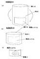
実施の形態1の加温装置100を図1(a)、図1(b)で説明する。図1(a)は、加温装置100の斜視図である。図1(b)は、加温装置100の断面図である。(Embodiment 1)
<Structure>
The heating apparatus 100 of Embodiment 1 is demonstrated with FIG. 1 (a) and FIG.1 (b). FIG. 1A is a perspective view of the heating device 100. FIG. 1B is a cross-sectional view of the heating device 100.
加温装置100は、開口10と本体11とを含む。
開口10は、本体11を貫通する穴であり、腕や足を通すための開口である。
本体11は、繊維などで編まれている。表繊維12aと裏繊維12bとからなる。その間に熱源13が配置されている。本体11は通気性があり、熱源13が外部から見える。繊維としては、遠赤外線を発生する繊維、血行をよくする繊維などを使用すると、より短時間で手足を温めることができ好ましい。また、繊維はシルクの繊維でもよい。シルクなら汗などを吸収せず、外部へ放熱できる。急加温、冷却に対して、好ましい。The heating device 100 includes an opening 10 and a main body 11.
The opening 10 is a hole penetrating the main body 11 and is an opening for passing an arm or a leg.
The main body 11 is knitted with fibers or the like. It consists of a front fiber 12a and a back fiber 12b. In the meantime, the heat source 13 is arranged. The main body 11 is air permeable and the heat source 13 is visible from the outside. As the fiber, it is preferable to use a fiber that generates far-infrared rays, a fiber that improves blood circulation, or the like because the limbs can be warmed in a shorter time. The fiber may be a silk fiber. Silk can absorb heat without absorbing sweat. Preferred for rapid heating and cooling.
図1(a)の点線で示したように、本体11の内側にライン状の突起12があると好ましい。リンパ線に沿って配置され、活性化できる。ライン方向は、開口10の穴の方向と平行である。つまり、手、足が伸びている方向である。
図2は、加温装置100を表から見た拡大平面図である。表繊維12aの間から熱源13が見える。As indicated by the dotted line in FIG. 1A, it is preferable that the main body 11 has a line-shaped protrusion 12 inside. It can be placed along the lymph line and activated. The line direction is parallel to the direction of the hole of the opening 10. That is, it is the direction in which the hands and feet are extended.
FIG. 2 is an enlarged plan view of the heating device 100 as seen from the table. The heat source 13 can be seen between the front fibers 12a.
熱源13は、金属のビーズやゲルなどであり、比熱が小さく、温まりやすく、冷めやすい。例えば、アルミニウム、アルミニウムの合金、または、軽石、炭酸系の粉末を固めたものなどが使用できる。
熱源13は、表繊維12a間から外気に触れ、冷めやすい。The heat source 13 is a metal bead, gel, or the like, has a small specific heat, is easy to warm, and is easy to cool. For example, aluminum, an alloy of aluminum, pumice, carbonized powder, or the like can be used.
The heat source 13 touches the outside air between the front fibers 12a and is easy to cool.
<使用方法>
加温装置100は、電子レンジなどで温められる。その後、手や足などに装着される。
手や足などを温める。ただし、保温はせず、自然に熱が逃げ、温度が下がる。<How to use>
The warming device 100 is heated by a microwave oven or the like. After that, it is worn on hands and feet.
Warm hands and feet. However, it does not keep warm, the heat escapes naturally and the temperature drops.
人が、寝る前に、加温装置100で手や足を温め、血行を良くする。つまり、手や足などを温め、血の流れをよくし、体の熱を手や足から逃がす。このことで、人の体温は下がり、自然と眠りへ進む。快適な睡眠ができる。
このため、加温装置100は、長時間の保温をしないように、上記の構造となっている。Before a person goes to sleep, he warms his hands and feet with the heating device 100 to improve blood circulation. In other words, it warms hands and feet, improves blood flow, and releases body heat from hands and feet. This lowers the body temperature and goes to sleep naturally. You can sleep comfortably.
For this reason, the heating apparatus 100 has the above-described structure so as not to keep the heat for a long time.
(実施の形態2)
実施の形態2の加温装置200を図3(a)〜図3(c)で説明する。記載しない事項は、実施の形態1と同様である。
図3(a)、図3(b)は、実施の形態2の加温装置200の斜視図である。実施の形態1の加温装置100と異なり、熱源13を有する熱源ユニット13aが、本体11から取り外ずせる。図3(a)の状態から、本体11を折り返せば、図3(b)となる。(Embodiment 2)
A heating apparatus 200 according to the second embodiment will be described with reference to FIGS. Matters not described are the same as those in the first embodiment.
FIGS. 3A and 3B are perspective views of the heating device 200 according to the second embodiment. Unlike the heating device 100 of the first embodiment, the heat source unit 13 a having the heat source 13 can be detached from the main body 11. If the main body 11 is folded back from the state of FIG. 3A, FIG. 3B is obtained.
図3(c)に熱源ユニット13aの斜視図を示す。熱源13を内部に有する。
なお使用方法は、実施の形態1と同様である。ただし、電子レンジなどで熱源ユニット13aのみを温め、図3(a)から図3(b)のように、熱源ユニット13aを本体11へセットする。本体11をあたためる必要はない。より衛生的である。FIG. 3C shows a perspective view of the heat source unit 13a. It has a heat source 13 inside.
The method of use is the same as in the first embodiment. However, only the heat source unit 13a is heated with a microwave oven or the like, and the heat source unit 13a is set in the main body 11 as shown in FIGS. 3 (a) to 3 (b). There is no need to warm the body 11. It is more hygienic.
なお、本体11、熱源ユニット13aは、実施の形態1と同様、繊維などの隙間を有する材料でできている。熱源13が外気で冷却される。
(実施の形態3)
実施の形態3の加温装置400を図4で説明する。記載しない事項は、実施の形態1、2と同様である。The main body 11 and the heat source unit 13a are made of a material having a gap such as a fiber as in the first embodiment. The heat source 13 is cooled by outside air.
(Embodiment 3)
A heating apparatus 400 according to Embodiment 3 will be described with reference to FIG. Matters not described are the same as in the first and second embodiments.
図4は、加温装置400の斜視図である。加温装置400は、本体11の外周に熱源ユニット13aを保持している。
電源ユニット13aは、複数の粒子状の熱源13を、樹脂袋などで1つにまとめたものである。電子レンジなどで、熱源ユニット13aを加熱した時、熱源13は熱くなるが、電源ユニット13aの端部をあまり厚くならず、扱いやすい。FIG. 4 is a perspective view of the heating device 400. The heating device 400 holds the heat source unit 13 a on the outer periphery of the main body 11.
The power supply unit 13a is a unit in which a plurality of particulate heat sources 13 are combined into one with a resin bag or the like. When the heat source unit 13a is heated by a microwave oven or the like, the heat source 13 becomes hot, but the end of the power supply unit 13a is not so thick and easy to handle.
熱源ユニット13aを電子レンジなどで温め、本体11に付着させる。
熱源ユニット13aを袋状にしておき、熱源13の数など調整できるのが好ましい。人ごと、季節ごろなどで熱源13の数を変更できる。The heat source unit 13a is warmed with a microwave oven or the like and attached to the main body 11.
It is preferable that the heat source unit 13a is formed in a bag shape and the number of heat sources 13 can be adjusted. The number of heat sources 13 can be changed for each person or around the season.
(実施の形態4)
実施の形態4の加温装置500を図5で説明する。記載しない事項は、実施の形態1〜3と同様である。
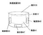
図5は、加温装置500の斜視図である。加温装置500は、加熱材41と、電源部40と、制御部43と、表示部42と、を有する。(Embodiment 4)
A heating apparatus 500 according to Embodiment 4 will be described with reference to FIG. Matters not described are the same as in the first to third embodiments.
FIG. 5 is a perspective view of the heating device 500. The heating device 500 includes a heating material 41, a power supply unit 40, a control unit 43, and a display unit 42.
熱源41は、ヒータなどである。電源部40に温度が上がる。
電源部40は、電池、コンセントと繋がる部分である。加熱材41へ電力などを供給する。
制御部43は、加熱材41の制御をする。実施の形態1〜3と同様、短時間で温度を上げ、下げる制御をする。一定時間で加温が切れること、時間調整可能なこと、温度調整できることなどが制御できる。The heat source 41 is a heater or the like. The temperature rises in the power supply unit 40.
The power supply unit 40 is a part connected to a battery and an outlet. Electric power is supplied to the heating material 41.
The control unit 43 controls the heating material 41. As in the first to third embodiments, the temperature is raised and lowered in a short time. It is possible to control that the heating is stopped in a certain time, that the time can be adjusted, and that the temperature can be adjusted.
表示部47は、液晶などで、温度の表示、制御の入力などをする部分である。
(実施の形態5)
実施の形態5の加温装置600a〜600dを図6(a)〜図6(d)で説明する。
記載しない事項は、実施の形態1〜4と同様である。The display unit 47 is a part for displaying temperature, inputting control, and the like using liquid crystal or the like.
(Embodiment 5)
Heating apparatuses 600a to 600d according to Embodiment 5 will be described with reference to FIGS. 6 (a) to 6 (d).
Matters not described are the same as in the first to fourth embodiments.
図6(a)〜図6(b)、図6(d)では、熱源42a、42bがある。この熱源は、液状の媒体45を内部に有する。それらをつなぐ連結部44により、その媒体は、両者を移動できる。媒体は、沸点が60℃以上の液体、水などである。
熱源42a、42b、連結部44を電子レンジなどで温める。加温装置600aにセットする。熱源42aは、本体11に、熱源42bは、本体11外とする。熱源42a中の液状の媒体45は、熱源42aから熱源42bへ連結部44を介して移動する。このことで、熱源42aの熱が外部へだされるので、加温しなくなる。6 (a) to 6 (b) and 6 (d), there are heat sources 42a and 42b. This heat source has a liquid medium 45 inside. The medium can be moved by the connecting portion 44 connecting them. The medium is a liquid having a boiling point of 60 ° C. or higher, water, and the like.
The heat sources 42a and 42b and the connecting portion 44 are warmed with a microwave oven or the like. Set in the heating device 600a. The heat source 42 a is outside the main body 11 and the heat source 42 b is outside the main body 11. The liquid medium 45 in the heat source 42a moves from the heat source 42a to the heat source 42b via the connecting portion 44. As a result, the heat of the heat source 42a is given to the outside, so that it is not heated.
図6(b)では、熱源42a、42b、連結部44を本体11へ固定するものである。同様の動作となる。媒体45が移動することで、均熱化し、より冷却されやすい。
どちらも、連結部44の径や、調整部を設けることで媒体45の移動量を調整できる。In FIG. 6B, the heat sources 42 a and 42 b and the connecting portion 44 are fixed to the main body 11. The operation is similar. As the medium 45 moves, it is soaked and more easily cooled.
In both cases, the moving amount of the medium 45 can be adjusted by providing the diameter of the connecting portion 44 and the adjusting portion.
図6(c)は、熱源42を1つにしたものである。媒体45の量は、熱源42の内部の空間は半分程度とする。加温装置600cを動かすことで、媒体45が移動し、均熱化、冷却される。
なお、熱源42、42a、42b、連結部44は、密閉され、内部で媒体45が移動できる。また、一部に蓋を設け、媒体45の量を調整できるのが好ましい。FIG. 6C shows one heat source 42. The amount of the medium 45 is about half of the space inside the heat source 42. By moving the heating device 600c, the medium 45 moves, soaking and cooling.
The heat sources 42, 42a, 42b and the connecting portion 44 are sealed, and the medium 45 can move inside. Moreover, it is preferable that a lid is provided in part and the amount of the medium 45 can be adjusted.
図6(d)は、熱源42a、42bが、積層されている。熱源42aが加温装置600dの内側に位置し、熱源42bが外側に位置する。はじめ、熱源42aに媒体45が多く位置し、その後、媒体45は、熱源42bへ連結部44を介して流れ移動する。媒体45が内から外へ流れ、開口10内の手、足の温めを短時間で終わらせる。
なお、熱源42a、42bは、ペットボトルなどの容器を利用できる。熱源42a、42bは、加温装置へ出し入れできるようにすることが好ましい。In FIG. 6D, the heat sources 42a and 42b are stacked. The heat source 42a is located inside the heating device 600d, and the heat source 42b is located outside. First, a large amount of the medium 45 is located in the heat source 42a, and then the medium 45 flows and moves to the heat source 42b via the connecting portion 44. The medium 45 flows from the inside to the outside, and the warming of the hands and feet in the opening 10 is completed in a short time.
In addition, containers, such as a PET bottle, can be utilized for the heat sources 42a and 42b. It is preferable that the heat sources 42a and 42b can be taken in and out of the heating device.
(全体として)
上記実施の形態を組み合わせること、また、一部を入れ替えることができる。
株式会社記録素材総合研究所のサーマルカラーを本体11または熱源13または熱源ユニット13aに配置すれば、色で温度を認識できる。取り扱い上便利である。(as a whole)
The above embodiments can be combined and a part thereof can be replaced.
If the thermal color of the recording material research institute is arranged in the main body 11, the heat source 13, or the heat source unit 13a, the temperature can be recognized by the color. Convenient in handling.
本発明の加温措置は、家庭、宿泊施設などで使用される。 The heating measure of the present invention is used in homes, accommodation facilities, and the like.
10 開口
11 本体
12 突起
12a 表繊維
12b 裏繊維
13 熱源(ビーズ)
13a 熱源ユニット
40 電源
41 熱源
42、42a、42b 熱源
43 制御部
44 連結部
45 媒体
47 表示部
100、200、300,400、500、600a、600b、600c、600d 加温装置10 Opening 11 Main Body 12 Protrusion 12a Front Fiber 12b Back Fiber 13 Heat Source (Bead)
13a Heat source unit 40 Power source 41 Heat source 42, 42a, 42b Heat source 43 Control unit 44 Connection unit 45 Medium 47 Display unit 100, 200, 300, 400, 500, 600a, 600b, 600c, 600d
Claims (10)
Translated fromJapanese前記本体に配置される熱源と、を有し、
前記本体は、通気性がある加温装置。A body wrapped around the hand or foot,
A heat source disposed in the main body,
The main body is a breathable warming device.
Priority Applications (1)
| Application Number | Priority Date | Filing Date | Title |
|---|---|---|---|
| JP2017187153AJP6945117B2 (en) | 2017-09-07 | 2017-09-07 | Heating device |
Applications Claiming Priority (1)
| Application Number | Priority Date | Filing Date | Title |
|---|---|---|---|
| JP2017187153AJP6945117B2 (en) | 2017-09-07 | 2017-09-07 | Heating device |
Publications (2)
| Publication Number | Publication Date |
|---|---|
| JP2019048018Atrue JP2019048018A (en) | 2019-03-28 |
| JP6945117B2 JP6945117B2 (en) | 2021-10-06 |
Family
ID=65905159
Family Applications (1)
| Application Number | Title | Priority Date | Filing Date |
|---|---|---|---|
| JP2017187153AActiveJP6945117B2 (en) | 2017-09-07 | 2017-09-07 | Heating device |
Country Status (1)
| Country | Link |
|---|---|
| JP (1) | JP6945117B2 (en) |
Citations (9)
| Publication number | Priority date | Publication date | Assignee | Title |
|---|---|---|---|---|
| JP3047931U (en)* | 1997-08-11 | 1998-04-28 | 利助 三田村 | Simple warmer |
| JP2000229095A (en)* | 1998-12-08 | 2000-08-22 | Daishin Sankei:Kk | Fixing or mounting tools and methods of fixing or mounting members |
| JP2003021482A (en)* | 2001-07-03 | 2003-01-24 | Kobayashi Pharmaceut Co Ltd | Heat reservoir and warm pad having the same |
| JP2005160707A (en)* | 2003-12-02 | 2005-06-23 | Maruka Kk | Hot-water bottle cover |
| JP3136407U (en)* | 2007-08-13 | 2007-10-25 | いづみ 宮崎 | Health equipment |
| JP2010252971A (en)* | 2009-04-23 | 2010-11-11 | Maruka Kk | Hot-water bottle |
| JP2013094352A (en)* | 2011-10-31 | 2013-05-20 | Ncc:Kk | Heating pad |
| JP2013141480A (en)* | 2012-01-10 | 2013-07-22 | Nippon Koden Corp | Body temperature maintaining apparatus |
| JP2016509637A (en)* | 2013-01-22 | 2016-03-31 | アナトミック フォーカス リミテッド | Anatomically targeted compression clothing |
- 2017
- 2017-09-07JPJP2017187153Apatent/JP6945117B2/enactiveActive
Patent Citations (9)
| Publication number | Priority date | Publication date | Assignee | Title |
|---|---|---|---|---|
| JP3047931U (en)* | 1997-08-11 | 1998-04-28 | 利助 三田村 | Simple warmer |
| JP2000229095A (en)* | 1998-12-08 | 2000-08-22 | Daishin Sankei:Kk | Fixing or mounting tools and methods of fixing or mounting members |
| JP2003021482A (en)* | 2001-07-03 | 2003-01-24 | Kobayashi Pharmaceut Co Ltd | Heat reservoir and warm pad having the same |
| JP2005160707A (en)* | 2003-12-02 | 2005-06-23 | Maruka Kk | Hot-water bottle cover |
| JP3136407U (en)* | 2007-08-13 | 2007-10-25 | いづみ 宮崎 | Health equipment |
| JP2010252971A (en)* | 2009-04-23 | 2010-11-11 | Maruka Kk | Hot-water bottle |
| JP2013094352A (en)* | 2011-10-31 | 2013-05-20 | Ncc:Kk | Heating pad |
| JP2013141480A (en)* | 2012-01-10 | 2013-07-22 | Nippon Koden Corp | Body temperature maintaining apparatus |
| JP2016509637A (en)* | 2013-01-22 | 2016-03-31 | アナトミック フォーカス リミテッド | Anatomically targeted compression clothing |
Also Published As
| Publication number | Publication date |
|---|---|
| JP6945117B2 (en) | 2021-10-06 |
Similar Documents
| Publication | Publication Date | Title |
|---|---|---|
| CN105878008A (en) | Novel physiotherapeutic moxibustion instrument | |
| CN113645929A (en) | Portable heat generating apparatus with temperature maintaining member | |
| JP2013010337A (en) | Effective heat retaining and heat generating structure in cold protection product by laminating aluminum vapor deposition layer inserted film sheet material and moisture absorbing and heat generating fiber material | |
| JP2019048018A (en) | Warming device | |
| US20190059619A1 (en) | Self-heating personal covering | |
| KR101880858B1 (en) | Scraping therapy apparatus having a warming device | |
| CN205505153U (en) | Scald preventing warms up handwarmer | |
| CN204208140U (en) | A kind of heatable fixed plate for infusion | |
| CN208081614U (en) | A kind of gloves with woven hose heating and monitoring function | |
| CN108175563A (en) | A kind of mask hot application device | |
| CN206324537U (en) | A kind of far infrared water-heating mattress | |
| US7945976B2 (en) | Living water system pad and method for its use | |
| CN203710197U (en) | Thermal protection device for testicles | |
| CN103504893B (en) | Water warming blanket | |
| CN201064518Y (en) | Structure of hot compress device | |
| CN218634328U (en) | An outdoor portable multifunctional heating blanket | |
| CN207545573U (en) | A kind of woven hose warmer | |
| JP5181092B2 (en) | Anka that is heated using a microwave oven | |
| GB2518907A (en) | Re-useable self heating hair roller | |
| CN204091479U (en) | A kind of heating cushion | |
| CN104225734A (en) | Heatable infusion fixed plate | |
| CN204352216U (en) | A kind of intestinal nutrient solution heating and heat-insulating device | |
| CN109481796A (en) | A kind of graphene transfusion heater | |
| JP3126982U (en) | Sweating promoting device | |
| CN102144947A (en) | Hand and foot warming device and application method thereof |
Legal Events
| Date | Code | Title | Description |
|---|---|---|---|
| A711 | Notification of change in applicant | Free format text:JAPANESE INTERMEDIATE CODE: A711 Effective date:20200811 | |
| A871 | Explanation of circumstances concerning accelerated examination | Free format text:JAPANESE INTERMEDIATE CODE: A871 Effective date:20200826 | |
| A621 | Written request for application examination | Free format text:JAPANESE INTERMEDIATE CODE: A621 Effective date:20200826 | |
| A975 | Report on accelerated examination | Free format text:JAPANESE INTERMEDIATE CODE: A971005 Effective date:20201026 | |
| A131 | Notification of reasons for refusal | Free format text:JAPANESE INTERMEDIATE CODE: A131 Effective date:20201110 | |
| A521 | Request for written amendment filed | Free format text:JAPANESE INTERMEDIATE CODE: A523 Effective date:20210107 | |
| A131 | Notification of reasons for refusal | Free format text:JAPANESE INTERMEDIATE CODE: A131 Effective date:20210323 | |
| A521 | Request for written amendment filed | Free format text:JAPANESE INTERMEDIATE CODE: A523 Effective date:20210509 | |
| TRDD | Decision of grant or rejection written | ||
| A01 | Written decision to grant a patent or to grant a registration (utility model) | Free format text:JAPANESE INTERMEDIATE CODE: A01 Effective date:20210810 | |
| A61 | First payment of annual fees (during grant procedure) | Free format text:JAPANESE INTERMEDIATE CODE: A61 Effective date:20210813 | |
| R150 | Certificate of patent or registration of utility model | Ref document number:6945117 Country of ref document:JP Free format text:JAPANESE INTERMEDIATE CODE: R150 | |
| R250 | Receipt of annual fees | Free format text:JAPANESE INTERMEDIATE CODE: R250 |