JP2019041864A - Back flush needle - Google Patents
Back flush needleDownload PDFInfo
- Publication number
- JP2019041864A JP2019041864AJP2017165799AJP2017165799AJP2019041864AJP 2019041864 AJP2019041864 AJP 2019041864AJP 2017165799 AJP2017165799 AJP 2017165799AJP 2017165799 AJP2017165799 AJP 2017165799AJP 2019041864 AJP2019041864 AJP 2019041864A
- Authority
- JP
- Japan
- Prior art keywords
- needle
- cannula
- core member
- soft
- backflush
- Prior art date
- Legal status (The legal status is an assumption and is not a legal conclusion. Google has not performed a legal analysis and makes no representation as to the accuracy of the status listed.)
- Granted
Links
Images


Classifications
- A—HUMAN NECESSITIES
- A61—MEDICAL OR VETERINARY SCIENCE; HYGIENE
- A61M—DEVICES FOR INTRODUCING MEDIA INTO, OR ONTO, THE BODY; DEVICES FOR TRANSDUCING BODY MEDIA OR FOR TAKING MEDIA FROM THE BODY; DEVICES FOR PRODUCING OR ENDING SLEEP OR STUPOR
- A61M25/00—Catheters; Hollow probes
- A61M25/01—Introducing, guiding, advancing, emplacing or holding catheters
- A61M25/06—Body-piercing guide needles or the like
- A61M25/0612—Devices for protecting the needle; Devices to help insertion of the needle, e.g. wings or holders
- A61M25/0631—Devices for protecting the needle; Devices to help insertion of the needle, e.g. wings or holders having means for fully covering the needle after its withdrawal, e.g. needle being withdrawn inside the handle or a cover being advanced over the needle
- A—HUMAN NECESSITIES
- A61—MEDICAL OR VETERINARY SCIENCE; HYGIENE
- A61F—FILTERS IMPLANTABLE INTO BLOOD VESSELS; PROSTHESES; DEVICES PROVIDING PATENCY TO, OR PREVENTING COLLAPSING OF, TUBULAR STRUCTURES OF THE BODY, e.g. STENTS; ORTHOPAEDIC, NURSING OR CONTRACEPTIVE DEVICES; FOMENTATION; TREATMENT OR PROTECTION OF EYES OR EARS; BANDAGES, DRESSINGS OR ABSORBENT PADS; FIRST-AID KITS
- A61F9/00—Methods or devices for treatment of the eyes; Devices for putting in contact-lenses; Devices to correct squinting; Apparatus to guide the blind; Protective devices for the eyes, carried on the body or in the hand
- A61F9/007—Methods or devices for eye surgery
- A61F9/00736—Instruments for removal of intra-ocular material or intra-ocular injection, e.g. cataract instruments
- A—HUMAN NECESSITIES
- A61—MEDICAL OR VETERINARY SCIENCE; HYGIENE
- A61F—FILTERS IMPLANTABLE INTO BLOOD VESSELS; PROSTHESES; DEVICES PROVIDING PATENCY TO, OR PREVENTING COLLAPSING OF, TUBULAR STRUCTURES OF THE BODY, e.g. STENTS; ORTHOPAEDIC, NURSING OR CONTRACEPTIVE DEVICES; FOMENTATION; TREATMENT OR PROTECTION OF EYES OR EARS; BANDAGES, DRESSINGS OR ABSORBENT PADS; FIRST-AID KITS
- A61F9/00—Methods or devices for treatment of the eyes; Devices for putting in contact-lenses; Devices to correct squinting; Apparatus to guide the blind; Protective devices for the eyes, carried on the body or in the hand
- A61F9/007—Methods or devices for eye surgery
- A—HUMAN NECESSITIES
- A61—MEDICAL OR VETERINARY SCIENCE; HYGIENE
- A61B—DIAGNOSIS; SURGERY; IDENTIFICATION
- A61B17/00—Surgical instruments, devices or methods
- A61B17/34—Trocars; Puncturing needles
- A61B17/3494—Trocars; Puncturing needles with safety means for protection against accidental cutting or pricking, e.g. limiting insertion depth, pressure sensors
- A61B17/3496—Protecting sleeves or inner probes; Retractable tips
- A—HUMAN NECESSITIES
- A61—MEDICAL OR VETERINARY SCIENCE; HYGIENE
- A61B—DIAGNOSIS; SURGERY; IDENTIFICATION
- A61B90/00—Instruments, implements or accessories specially adapted for surgery or diagnosis and not covered by any of the groups A61B1/00 - A61B50/00, e.g. for luxation treatment or for protecting wound edges
- A61B90/08—Accessories or related features not otherwise provided for
- A61B2090/0801—Prevention of accidental cutting or pricking
- A61B2090/08021—Prevention of accidental cutting or pricking of the patient or his organs
- A—HUMAN NECESSITIES
- A61—MEDICAL OR VETERINARY SCIENCE; HYGIENE
- A61M—DEVICES FOR INTRODUCING MEDIA INTO, OR ONTO, THE BODY; DEVICES FOR TRANSDUCING BODY MEDIA OR FOR TAKING MEDIA FROM THE BODY; DEVICES FOR PRODUCING OR ENDING SLEEP OR STUPOR
- A61M2210/00—Anatomical parts of the body
- A61M2210/06—Head
- A61M2210/0612—Eyes
Landscapes
- Health & Medical Sciences (AREA)
- Ophthalmology & Optometry (AREA)
- Life Sciences & Earth Sciences (AREA)
- General Health & Medical Sciences (AREA)
- Public Health (AREA)
- Biomedical Technology (AREA)
- Heart & Thoracic Surgery (AREA)
- Veterinary Medicine (AREA)
- Engineering & Computer Science (AREA)
- Animal Behavior & Ethology (AREA)
- Surgery (AREA)
- Nuclear Medicine, Radiotherapy & Molecular Imaging (AREA)
- Vascular Medicine (AREA)
- Biophysics (AREA)
- Pulmonology (AREA)
- Anesthesiology (AREA)
- Hematology (AREA)
- Infusion, Injection, And Reservoir Apparatuses (AREA)
- Prostheses (AREA)
- Surgical Instruments (AREA)
Abstract
Translated fromJapaneseDescription
Translated fromJapanese本発明は、硝子体手術に用いられるバックフラッシュニードルに関する。 The present invention relates to a backflush needle used in vitreous surgery.
眼科で行われる硝子体手術は、眼球内のゼリー状の硝子体や硝子体が変性して形成された網膜上の増殖膜及び出血や濁り等を吸引・除去する手術である。このような硝子体手術において使用される手術器具の一つとして、バックフラッシュニードルがある(例えば、特許文献1参照)。 Vitreous surgery to be performed by ophthalmology is a surgery for sucking and removing a proliferation film on the retina formed by denaturation of jelly-like vitreous body and vitreous body in the eye, hemorrhage, turbidity and the like. As one of the surgical instruments used in such vitreous surgery, there is a back flush needle (see, for example, Patent Document 1).
図4は、バックフラッシュニードルの使用説明図である。バックフラッシュニードル110は、施術者が把持するハンドル12に接続し眼球内に挿入される細い管形状のニードル本体11と、そのニードル本体11の先端に接続される軟質部材20を有している。この軟質部材20は、手術中に器具の先端が網膜に接触したとしても網膜を傷つけないように備えられており、この軟質部材20を設けることで、網膜に近い硝子体等も吸引することが可能となる。 FIG. 4 is an explanatory view of the use of the back flush needle. The
ニードル本体11と軟質部材20との接続は、接着剤を使用したり、接続部分を嵌合構造にしたりすることで行われる。なお、軟質部材20としては、素材は特に限定しないが、例えばシリコーン樹脂を用いることができ、形状としても管形状に限らず、ブラシのような形状にしたものもある。 The connection between the needle
バックフラッシュニードル110は、眼球Eに装着しているカニューレ30を通して使用される。カニューレ30は、金属性のカニューレパイプ31を樹脂製のカニューレベース32に嵌め込んだものである。カニューレ30を眼球Eに装着するときは、カニューレパイプ31を強膜に突き刺すのだが、このとき突き刺し過ぎないようにカニューレベース32がストッパとして機能する。また、カニューレ30を眼球Eに装着した状態のときに、眼球内から硝子体液がカニューレパイプ31を通って排出されることを抑えるために、カニューレベース32からカニューレパイプ31の後端を覆うカニューレキャップ33が用いられる。なお、カニューレキャップ33には、バックフラッシュニードル110などの眼科手術器具を通すためのスリットが設けられている。 The
ここで、バックフラッシュニードル110をカニューレ30に通す際、先端の軟質部材20がカニューレキャップ33のスリットやカニューレパイプ32の中空内面に接触することで、軟質部材20が変形したり、軟質部材20とニードル本体11との接続部分が剥がれたりすることがある。軟質部材20が変形すると、硝子体等の吸引を阻害する要因になることがあるし、軟質部材20がニードル本体11から外れると、眼球内から軟質部材20を取り出すのに苦労することになる。 Here, when the
上記のような事情に鑑み、本発明は、カニューレに通す際に先端の軟質部材の形状を保持することができるバックフラッシュニードルを提供することを目的としている。 SUMMARY OF THE INVENTION In view of the above-described circumstances, the present invention aims to provide a backflush needle capable of retaining the shape of the soft member at the tip when passing through a cannula.
上記の目的を達成するために本発明のバックフラッシュニードルは、眼科手術において眼球に装着されたカニューレを通して用いるバックフラッシュニードルであって、カニューレを貫通する管形状のニードル本体と、そのニードル本体の先端に接続された管形状の軟質部材と、ニードル本体及び軟質部材のそれぞれの管形状の中空を貫通する棒状の芯部材と、を有し、その芯部材が軸方向に移動自在であって、芯部材の先端を軟質部材から突出させたりニードル本体から離れる位置まで引っ込めたりできるものである。 In order to achieve the above object, a backflush needle according to the present invention is a backflush needle for use in eye surgery through an eyepiece-mounted cannula, comprising a tubular needle body penetrating the cannula and the tip of the needle body. And a rod-shaped core member penetrating through the hollows of the needle main body and the soft member, the core member being movable in the axial direction, the core The tip of the member can be protruded from the soft member or retracted to a position away from the needle body.
ここで、芯部材は移動部材に接合しており、ニードル本体が接合されているハンドル部から突出している移動部材を動かすことで、芯部材の軸方向の移動が行われることにするとよい。 Here, the core member is joined to the moving member, and it is preferable that axial movement of the core member is performed by moving the moving member projecting from the handle portion to which the needle body is joined.
本発明のバックフラッシュニードルによれば、ニードル本体をカニューレに通す際に、ニードル本体の先端に接続された軟質部材が変形したり取れたりするのを抑制する効果を奏する。 According to the backflush needle of the present invention, when passing the needle main body through the cannula, it is possible to suppress the deformation and removal of the soft member connected to the tip of the needle main body.
以下、本発明の実施の形態を添付図面を参照して説明する。 Hereinafter, embodiments of the present invention will be described with reference to the attached drawings.
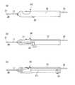
図1は、本発明のバックフラッシュニードルの説明図であって、(a)は正面図、(b)は芯部材を突出させた内部構造図、(c)は芯部材を引っ込めた内部構造図である。また、図2は、本発明のバックフラッシュニードルの先端拡大図である。 FIG. 1 is an explanatory view of a back flush needle according to the present invention, wherein (a) is a front view, (b) is an internal structural view in which the core member is protruded, and (c) is an internal structural view in which the core member is retracted. It is. FIG. 2 is an enlarged view of the tip of the back flush needle of the present invention.
バックフラッシュニードル10を通すカニューレは、従来のカニューレと同様の構成であって、金属性のカニューレパイプを樹脂製のカニューレベースに嵌め込んだものである。そして、眼球に装着した状態のときに硝子体液がカニューレパイプを通って排出されるのを抑えるために、カニューレベースとカニューレパイプの後端を覆うカニューレキャップが備えられている。 The cannula through which the
バックフラッシュニードル10の基本の構成も従来と同様に、施術者が把持するハンドル12に接続する細い管形状のニードル本体11と、そのニードル本体11の先端に接続された軟質部材20とを有している。軟質部材20は、シリコーン樹脂等の軟質な材料で形成され、ニードル本体11と同様の管形状であり、外径及び中空の径は、ニードル本体11と同程度とする。また、ニードル本体11と軟質部材20との接続も従来と同様に、接着剤を用いて接着したり、接続部分を嵌合構造にしたりすることで行われる。 The basic configuration of the
本発明のバックフラッシュニードル10は、ニードル本体11と軟質部材20の管形状の中空を貫通する芯部材21を有しているという特徴がある。芯部材21の材質は、ステンレスが適しているが、特にステンレスに限定するものではない。 The
芯部材21は、ニードル本体11及び軟質部材20の中空の径より僅かに細い外径の棒状の部材とし、芯部材21をハンドル12の外部から動かすことができる移動部材22に繋がっている。なお、芯部材21が細すぎると軟質部材20の変形を抑えることができず、また、ニードル本体11及び軟質部材20の中空の径とほぼ同じ外径とすると、芯部材21を軸方向に前後に動かすときに、摩擦で芯部材21の動きが鈍くなったり、軟質部材20に引っ掛かって軟質部材20がニードル本体11から剥がれる原因になったりするので、ニードル本体11及び軟質部材20の中空の径より僅かに細い外径とするのがよい。 The
図1で例示した移動部材22は、ハンドル12の側面から突出したものであって、この移動部材22を摘んでバックフラッシュニードル10の軸方向に動かすことで芯部材21も軸方向に動かすことができる。 The moving
移動部材の構造は、図1の構造以外であってもよい。図3の(a)及び(b)は、他の移動部材を例示する図である。なお、これらの図は、移動部材22の構造を簡単に図示したものなので、説明に不要な部材は省略している。 The structure of the moving member may be other than the structure of FIG. (A) and (b) of FIG. 3 is a figure which illustrates another moving member. Note that, since these drawings simply illustrate the structure of the moving
図3(a)は、ノック式ボールペンの芯を出し入れする構造のように、ハンドル12の内部にバネ41を備え、ハンドル12の後端に設けたボタン形状の移動部材22を押すことで、芯部材21を軸方向に前後させる構造である。 In FIG. 3A, a
次に、図3(b)は、芯部材21にネジ部材42を接続し、移動部材22を回転させて動かすことで、ネジ部材42が軸方向に動くので、芯部材21も軸方向に動かすことができるという構造である。 Next, in FIG. 3B, the
なお、移動部材22はこれらの構造に限定するものではなく、芯部材21を軸方向に前後させることが可能であれば、これら以外の構造であってもよい。 The moving
移動部材22を使って芯部材21を最も前に出したとき(図1(b))は、芯部材21の先端が軟質部材20の先端から若干突出する状態(図2)になり、芯部材を最も後ろに引いたとき(図1(c))は、芯部材21がニードル本体11から後方に離れた状態になるようにするのがよい。 When the
芯部材21を前に出したときに、軟質部材20の先端から突出していれば、軟質部材20の全体に亘って変形を防ぐ効果があり、また、芯部材21を後ろに引いたときに芯部材21がニードル本体11から後方に離れていれば、吸引された硝子体等をニードル本体11の中空からハンドル12の内部を通過させて、ハンドル12の後端側に設けられているパイプ13へと導くことができるからである(図1(c)矢印参照)。 When protruding from the tip of the
以上のような芯部材21を備えたバックフラッシュニードル10とすることで、軟質部材20及びニードル本体11がカニューレを貫通する際に、芯部材21を軟質部材20から突出させておけば、軟質部材20の変形や軟質部材20とニードル本体11との接続部分が剥がれることを防ぐことができる。そして、吸引作業中は、芯部材21を引っ込めることで、硝子体等を問題なく吸引することができる。 By making the
10 バックフラッシュニードル
11 ニードル本体
12 ハンドル
13 パイプ
20 軟質部材
21 芯部材
22 移動部材
30 カニューレ
31 カニューレパイプ
32 カニューレベース
33 カニューレキャップ
41 バネ
42 ネジ部材
E 眼球DESCRIPTION OF
Claims (2)
Translated fromJapaneseカニューレを貫通する管形状のニードル本体と、前記ニードル本体の先端に接続された管形状の軟質部材と、前記ニードル本体及び前記軟質部材のそれぞれの管形状の中空を貫通する棒状の芯部材と、を有し、
前記芯部材が軸方向に移動自在であって、前記芯部材の先端を前記軟質部材から突出させたり前記ニードル本体から離れる位置まで引っ込めたりできることを特徴とするバックフラッシュニードル。A backflush needle for use through an eyepiece mounted cannula in eye surgery,
A tube-shaped needle body penetrating a cannula, a tube-shaped soft member connected to the tip of the needle body, and a rod-shaped core member penetrating the tube-shaped hollows of the needle body and the soft member; Have
A backflush needle characterized in that the core member is axially movable, and the tip of the core member can be protruded from the soft member or retracted to a position away from the needle body.
Priority Applications (7)
| Application Number | Priority Date | Filing Date | Title |
|---|---|---|---|
| JP2017165799AJP6902966B2 (en) | 2017-08-30 | 2017-08-30 | Back flush needle |
| EP18850672.9AEP3662875B1 (en) | 2017-08-30 | 2018-08-29 | Backflush needle |
| PCT/JP2018/031900WO2019044884A1 (en) | 2017-08-30 | 2018-08-29 | Backflush needle |
| CN201880056187.3ACN111031974B (en) | 2017-08-30 | 2018-08-29 | Back-flushing needle |
| US16/642,367US20200179656A1 (en) | 2017-08-30 | 2018-08-29 | Backflush needle |
| RU2020112097ARU2768164C2 (en) | 2017-08-30 | 2018-08-29 | Backflow flushing needle |
| AU2018327087AAU2018327087B2 (en) | 2017-08-30 | 2018-08-29 | Backflush needle |
Applications Claiming Priority (1)
| Application Number | Priority Date | Filing Date | Title |
|---|---|---|---|
| JP2017165799AJP6902966B2 (en) | 2017-08-30 | 2017-08-30 | Back flush needle |
Publications (2)
| Publication Number | Publication Date |
|---|---|
| JP2019041864Atrue JP2019041864A (en) | 2019-03-22 |
| JP6902966B2 JP6902966B2 (en) | 2021-07-14 |
Family
ID=65525709
Family Applications (1)
| Application Number | Title | Priority Date | Filing Date |
|---|---|---|---|
| JP2017165799AActiveJP6902966B2 (en) | 2017-08-30 | 2017-08-30 | Back flush needle |
Country Status (7)
| Country | Link |
|---|---|
| US (1) | US20200179656A1 (en) |
| EP (1) | EP3662875B1 (en) |
| JP (1) | JP6902966B2 (en) |
| CN (1) | CN111031974B (en) |
| AU (1) | AU2018327087B2 (en) |
| RU (1) | RU2768164C2 (en) |
| WO (1) | WO2019044884A1 (en) |
Families Citing this family (2)
| Publication number | Priority date | Publication date | Assignee | Title |
|---|---|---|---|---|
| US11751909B2 (en)* | 2019-06-24 | 2023-09-12 | Alcon Inc. | Retractable instrument |
| CN116600835A (en)* | 2020-12-17 | 2023-08-15 | 爱尔康公司 | retractable recoil device |
Citations (3)
| Publication number | Priority date | Publication date | Assignee | Title |
|---|---|---|---|---|
| US20060229563A1 (en)* | 2005-04-12 | 2006-10-12 | Span-America Medical Systems, Inc. | Passive needle-stick protector |
| JP2015016203A (en)* | 2013-07-12 | 2015-01-29 | Hoya株式会社 | Ophthalmic surgical instrument and method of manufacturing an ophthalmic surgical instrument |
| US20150173947A1 (en)* | 2013-12-20 | 2015-06-25 | Alcon Research, Ltd. | Variable Stiffness Cannula and Methods for a Surgical System |
Family Cites Families (31)
| Publication number | Priority date | Publication date | Assignee | Title |
|---|---|---|---|---|
| DE3434930A1 (en)* | 1984-09-22 | 1986-04-03 | Hans Geuder GmbH, 6900 Heidelberg | Ophthalmic surgical instrument (capsulotome) for perforation of the crystalline capsule of the eye |
| US4792334A (en)* | 1987-11-06 | 1988-12-20 | Py Daniel C | Occular treatment apparatus |
| CN2039564U (en)* | 1988-06-29 | 1989-06-21 | 侯小滨 | Cannula type synchronous syringe-suction apparatus for cataract |
| US5318560A (en)* | 1991-11-06 | 1994-06-07 | Surgical Technologies, Inc. | Laser delivery system |
| CN2314742Y (en)* | 1997-11-23 | 1999-04-21 | 张延亮 | Medical biopsy puncture needle |
| US6699285B2 (en)* | 1999-09-24 | 2004-03-02 | Scieran Technologies, Inc. | Eye endoplant for the reattachment of a retina |
| AUPR568901A0 (en)* | 2001-06-14 | 2001-07-12 | Occupational & Medical Innovations Ltd | A retractable needle assembly for a catheter and which uses an elastomeric member to retract the needle |
| US7316676B2 (en)* | 2002-08-20 | 2008-01-08 | Gholam A. Peyman | Treatment of retinal detachment |
| US7060028B2 (en)* | 2003-06-06 | 2006-06-13 | Insight Instruments, Inc. | Endoilluminator |
| US20070118065A1 (en)* | 2004-12-03 | 2007-05-24 | Leonard Pinchuk | Glaucoma Implant Device |
| DE102005008235A1 (en)* | 2005-02-22 | 2006-08-31 | Reinhardt Thyzel | Sealing device for use with an eye operating instrument has a sealing element that is set down on an area around an opening made in the eye to permit the passage of an instrument or laser beam, while protecting the eye tissue |
| JP5396272B2 (en)* | 2006-06-30 | 2014-01-22 | アクエシス インコーポレイテッド | Method, system and apparatus for reducing pressure in an organ |
| US8216246B2 (en)* | 2006-08-09 | 2012-07-10 | Insight Instruments Inc. | Retractable tip for vitrectomy tool |
| US7682338B2 (en)* | 2006-08-23 | 2010-03-23 | Medtronic Minimed, Inc. | Infusion medium delivery system, device and method with needle inserter and needle inserter device and method |
| JP2008142533A (en)* | 2006-11-16 | 2008-06-26 | Manii Kk | Trocar |
| US20080177239A1 (en)* | 2007-01-18 | 2008-07-24 | Yong Li | Trocar cannula system |
| CA2688825C (en)* | 2007-05-17 | 2016-06-28 | Medgenesis Therapeutix Inc. | Convection-enhanced delivery catheter with removable stiffening member and method for using same |
| WO2010003011A1 (en)* | 2008-07-01 | 2010-01-07 | Bruce Becker | Retrobulbar needle and methods of use |
| US8425473B2 (en)* | 2009-01-23 | 2013-04-23 | Iscience Interventional Corporation | Subretinal access device |
| CN201855477U (en)* | 2010-10-29 | 2011-06-08 | 中国人民解放军第三军医大学第一附属医院 | Needle withdrawing core cover for venous retention needle |
| US9138346B2 (en)* | 2012-01-26 | 2015-09-22 | Katalyst Surgical, Llc | Surgical instrument sleeve |
| US9757536B2 (en)* | 2012-07-17 | 2017-09-12 | Novartis Ag | Soft tip cannula |
| JP6164811B2 (en) | 2012-09-05 | 2017-07-19 | Hoya株式会社 | Ophthalmic surgical instruments |
| US9320534B2 (en)* | 2012-12-13 | 2016-04-26 | Alcon Research, Ltd. | Fine membrane forceps with integral scraping feature |
| US9649223B2 (en)* | 2013-06-13 | 2017-05-16 | Innfocus, Inc. | Inserter for tubular medical implant devices |
| CN203417286U (en)* | 2013-08-22 | 2014-02-05 | 宁波艾克伦医疗科技有限公司 | Ultrasonic emulsification cannula |
| US9044301B1 (en)* | 2013-11-25 | 2015-06-02 | Innfocus, Inc. | Methods, systems and devices for treating glaucoma |
| CA2960278A1 (en)* | 2014-09-11 | 2016-03-17 | Psivida Us, Inc. | Injector apparatus |
| MA42406A (en)* | 2015-06-03 | 2018-05-16 | Aquesys Inc | IMPLEMENTATION OF INTRAOCULAR AB EXTERNO SHUNT |
| CN205827737U (en)* | 2016-04-11 | 2016-12-21 | 李宇轩 | A kind of period of single pendulum measurement apparatus |
| US10895699B2 (en)* | 2017-07-06 | 2021-01-19 | Alcon Inc. | Metal wire for optical fiber cable and strain relief |
- 2017
- 2017-08-30JPJP2017165799Apatent/JP6902966B2/enactiveActive
- 2018
- 2018-08-29EPEP18850672.9Apatent/EP3662875B1/enactiveActive
- 2018-08-29WOPCT/JP2018/031900patent/WO2019044884A1/ennot_activeCeased
- 2018-08-29RURU2020112097Apatent/RU2768164C2/enactive
- 2018-08-29USUS16/642,367patent/US20200179656A1/ennot_activeAbandoned
- 2018-08-29CNCN201880056187.3Apatent/CN111031974B/enactiveActive
- 2018-08-29AUAU2018327087Apatent/AU2018327087B2/enactiveActive
Patent Citations (3)
| Publication number | Priority date | Publication date | Assignee | Title |
|---|---|---|---|---|
| US20060229563A1 (en)* | 2005-04-12 | 2006-10-12 | Span-America Medical Systems, Inc. | Passive needle-stick protector |
| JP2015016203A (en)* | 2013-07-12 | 2015-01-29 | Hoya株式会社 | Ophthalmic surgical instrument and method of manufacturing an ophthalmic surgical instrument |
| US20150173947A1 (en)* | 2013-12-20 | 2015-06-25 | Alcon Research, Ltd. | Variable Stiffness Cannula and Methods for a Surgical System |
Also Published As
| Publication number | Publication date |
|---|---|
| CN111031974B (en) | 2022-04-05 |
| RU2020112097A3 (en) | 2021-11-03 |
| CN111031974A (en) | 2020-04-17 |
| WO2019044884A1 (en) | 2019-03-07 |
| JP6902966B2 (en) | 2021-07-14 |
| AU2018327087B2 (en) | 2022-06-30 |
| RU2768164C2 (en) | 2022-03-23 |
| EP3662875A1 (en) | 2020-06-10 |
| AU2018327087A1 (en) | 2020-03-05 |
| EP3662875C0 (en) | 2024-10-02 |
| EP3662875B1 (en) | 2024-10-02 |
| EP3662875A4 (en) | 2021-04-28 |
| RU2020112097A (en) | 2021-09-30 |
| US20200179656A1 (en) | 2020-06-11 |
Similar Documents
| Publication | Publication Date | Title |
|---|---|---|
| US9649223B2 (en) | Inserter for tubular medical implant devices | |
| EP3378427A3 (en) | Catheter with deformable distal electrode | |
| JP2020511291A5 (en) | ||
| JP2016521624A5 (en) | ||
| US20200375844A1 (en) | Retina massage and smoothing device | |
| JP2019041864A (en) | Back flush needle | |
| CN114641266A (en) | A tympanic membrane treatment device | |
| US20210338944A1 (en) | A medical device | |
| JP4313110B2 (en) | Lacrimal intubation device | |
| EP2042097A3 (en) | Phlebotomy Needle with Shape Memory Alloy Flashback Sensor | |
| JP2017046876A (en) | Vitreous body cutter | |
| JP2007275386A (en) | Medical forceps | |
| JP5850315B2 (en) | Intraocular lens | |
| CN204318867U (en) | Disposable celiac mirror bile duct puncture attracts pin | |
| HK40024580A (en) | Backflush needle | |
| CN111821097B (en) | Minimally invasive lacrimal punctum dilator | |
| CN218943685U (en) | ophthalmic surgery needle | |
| JP5783509B2 (en) | Observation cutter and method for manufacturing observation cutter | |
| CN203971160U (en) | Attract tube head | |
| CN222787979U (en) | A device for removing foreign matter from the eye | |
| JP2014050552A (en) | Surgical instrument | |
| CN209529472U (en) | Improve iris repositor | |
| JP5265229B2 (en) | Intraocular lens insertion device | |
| CN209361075U (en) | Suction crochet hook | |
| CN206822775U (en) | The ear of endotoscpe lower band attractor stripping prong |
Legal Events
| Date | Code | Title | Description |
|---|---|---|---|
| A621 | Written request for application examination | Free format text:JAPANESE INTERMEDIATE CODE: A621 Effective date:20200807 | |
| TRDD | Decision of grant or rejection written | ||
| A01 | Written decision to grant a patent or to grant a registration (utility model) | Free format text:JAPANESE INTERMEDIATE CODE: A01 Effective date:20210621 | |
| A61 | First payment of annual fees (during grant procedure) | Free format text:JAPANESE INTERMEDIATE CODE: A61 Effective date:20210622 | |
| R150 | Certificate of patent or registration of utility model | Ref document number:6902966 Country of ref document:JP Free format text:JAPANESE INTERMEDIATE CODE: R150 | |
| R250 | Receipt of annual fees | Free format text:JAPANESE INTERMEDIATE CODE: R250 | |
| R250 | Receipt of annual fees | Free format text:JAPANESE INTERMEDIATE CODE: R250 |