JP2019032076A - Angle connector of support material - Google Patents
Angle connector of support materialDownload PDFInfo
- Publication number
- JP2019032076A JP2019032076AJP2018096182AJP2018096182AJP2019032076AJP 2019032076 AJP2019032076 AJP 2019032076AJP 2018096182 AJP2018096182 AJP 2018096182AJP 2018096182 AJP2018096182 AJP 2018096182AJP 2019032076 AJP2019032076 AJP 2019032076A
- Authority
- JP
- Japan
- Prior art keywords
- angle connector
- profile
- corner element
- corner
- free end
- Prior art date
- Legal status (The legal status is an assumption and is not a legal conclusion. Google has not performed a legal analysis and makes no representation as to the accuracy of the status listed.)
- Granted
Links
Images


Classifications
- F—MECHANICAL ENGINEERING; LIGHTING; HEATING; WEAPONS; BLASTING
- F16—ENGINEERING ELEMENTS AND UNITS; GENERAL MEASURES FOR PRODUCING AND MAINTAINING EFFECTIVE FUNCTIONING OF MACHINES OR INSTALLATIONS; THERMAL INSULATION IN GENERAL
- F16B—DEVICES FOR FASTENING OR SECURING CONSTRUCTIONAL ELEMENTS OR MACHINE PARTS TOGETHER, e.g. NAILS, BOLTS, CIRCLIPS, CLAMPS, CLIPS OR WEDGES; JOINTS OR JOINTING
- F16B7/00—Connections of rods or tubes, e.g. of non-circular section, mutually, including resilient connections
- F16B7/18—Connections of rods or tubes, e.g. of non-circular section, mutually, including resilient connections using screw-thread elements
- F16B7/182—Connections of rods or tubes, e.g. of non-circular section, mutually, including resilient connections using screw-thread elements for coaxial connections of two rods or tubes
- F—MECHANICAL ENGINEERING; LIGHTING; HEATING; WEAPONS; BLASTING
- F16—ENGINEERING ELEMENTS AND UNITS; GENERAL MEASURES FOR PRODUCING AND MAINTAINING EFFECTIVE FUNCTIONING OF MACHINES OR INSTALLATIONS; THERMAL INSULATION IN GENERAL
- F16B—DEVICES FOR FASTENING OR SECURING CONSTRUCTIONAL ELEMENTS OR MACHINE PARTS TOGETHER, e.g. NAILS, BOLTS, CIRCLIPS, CLAMPS, CLIPS OR WEDGES; JOINTS OR JOINTING
- F16B7/00—Connections of rods or tubes, e.g. of non-circular section, mutually, including resilient connections
- F16B7/04—Clamping or clipping connections
- F16B7/044—Clamping or clipping connections for rods or tubes being in angled relationship
- F16B7/0446—Clamping or clipping connections for rods or tubes being in angled relationship for tubes using the innerside thereof
- F16B7/0453—Clamping or clipping connections for rods or tubes being in angled relationship for tubes using the innerside thereof the tubes being drawn towards each other
- F16B7/046—Clamping or clipping connections for rods or tubes being in angled relationship for tubes using the innerside thereof the tubes being drawn towards each other by rotating an eccenter-mechanism
- F—MECHANICAL ENGINEERING; LIGHTING; HEATING; WEAPONS; BLASTING
- F16—ENGINEERING ELEMENTS AND UNITS; GENERAL MEASURES FOR PRODUCING AND MAINTAINING EFFECTIVE FUNCTIONING OF MACHINES OR INSTALLATIONS; THERMAL INSULATION IN GENERAL
- F16B—DEVICES FOR FASTENING OR SECURING CONSTRUCTIONAL ELEMENTS OR MACHINE PARTS TOGETHER, e.g. NAILS, BOLTS, CIRCLIPS, CLAMPS, CLIPS OR WEDGES; JOINTS OR JOINTING
- F16B7/00—Connections of rods or tubes, e.g. of non-circular section, mutually, including resilient connections
- F16B7/04—Clamping or clipping connections
- F16B7/044—Clamping or clipping connections for rods or tubes being in angled relationship
- F16B7/0446—Clamping or clipping connections for rods or tubes being in angled relationship for tubes using the innerside thereof
- F16B7/0453—Clamping or clipping connections for rods or tubes being in angled relationship for tubes using the innerside thereof the tubes being drawn towards each other
- F16B7/0466—Clamping or clipping connections for rods or tubes being in angled relationship for tubes using the innerside thereof the tubes being drawn towards each other by a screw-threaded stud with a conical tip acting on an inclined surface
- F—MECHANICAL ENGINEERING; LIGHTING; HEATING; WEAPONS; BLASTING
- F16—ENGINEERING ELEMENTS AND UNITS; GENERAL MEASURES FOR PRODUCING AND MAINTAINING EFFECTIVE FUNCTIONING OF MACHINES OR INSTALLATIONS; THERMAL INSULATION IN GENERAL
- F16B—DEVICES FOR FASTENING OR SECURING CONSTRUCTIONAL ELEMENTS OR MACHINE PARTS TOGETHER, e.g. NAILS, BOLTS, CIRCLIPS, CLAMPS, CLIPS OR WEDGES; JOINTS OR JOINTING
- F16B7/00—Connections of rods or tubes, e.g. of non-circular section, mutually, including resilient connections
- F16B7/18—Connections of rods or tubes, e.g. of non-circular section, mutually, including resilient connections using screw-thread elements
Landscapes
- Engineering & Computer Science (AREA)
- General Engineering & Computer Science (AREA)
- Mechanical Engineering (AREA)
- Mutual Connection Of Rods And Tubes (AREA)
- Clamps And Clips (AREA)
- Furniture Connections (AREA)
- Connection Of Plates (AREA)
Abstract
Description
Translated fromJapanese本発明は、支持形材(supporting profiles)のそれぞれのキャビティに挿入される、互いに対して垂直に整合される2つの自由端部を有するアングルコネクタ(angle connector)であって、アングルコネクタの各自由端部には、固定の受動手段(a passive means of fixation)が設けられ、その手段を介して、支持形材の1つの外面から、アングルコネクタのそれぞれの端部を相補的な能動固定要素により、関連付けられた支持形材に脱着可能に接続することができる、アングルコネクタに関する。 The present invention relates to an angle connector having two free ends that are vertically aligned with respect to each other and inserted into the respective cavities of the supporting profiles, each free of the angle connector The ends are provided with a passive means of fixation, through which each end of the angle connector is connected by a complementary active fixing element from one outer surface of the support profile. An angle connector that can be removably connected to an associated support profile.
特許文献1から、留め継ぎされる支持形材の関連付けられたキャビティに、自由端部が挿入されるL字形アングルコネクタが知られている。支持形材のそれぞれには、L字形コネクタの自由端部を収納するそれぞれのキャビティが設けられる。互いに対して垂直に接続されることになる2つの支持形材のそれぞれの内側には、それぞれのねじ穴が設けられ、このねじ穴を通して、ねじが、L字形コネクタのそれぞれの対応する相補的な孔にねじ込まれる。その結果として、支持形材の前側の形材壁を、隅部において互いに突き合わせ接合することができる。 From Patent Document 1, an L-shaped angle connector is known in which a free end is inserted into an associated cavity of a supporting profile to be spliced. Each of the support profiles is provided with a respective cavity that houses the free end of the L-shaped connector. Inside each of the two support profiles that are to be connected perpendicular to each other, a respective screw hole is provided, through which the screw can be respectively correspondingly complementary in the L-shaped connector. Screw into the hole. As a result, the front profile walls of the support profile can be butted together at the corners.
特許文献2から、2つのL字形プレートが、2つの支持形材の相補的な溝に挿入される、類似の適用形態が知られている。 A similar application is known from US Pat. No. 6,057,056, in which two L-shaped plates are inserted into complementary grooves in two support profiles.
この従来技術から出発して(departing from)、本発明の課題は、支持形材の改善されたコーナーコネクタを提供することである。この改善は、より僅かな回転を必要とする、相補的な固定要素としてのねじの操作からなることができる。この改善は、支持形材を単に接続することに加えて、さらに、支持形材を互いに対して締め付けることからなることができる。最後に、本発明による装置の1つの利点は、形材コネクタをモジュール式に構成することができ、最終的にコネクタを容易に予め組み立てることができることにある。同時に、このコネクタは、コーナー要素により、隅部において2つの当接する支持形材の完全な機能性を担うことができる。 Starting from this prior art, the object of the present invention is to provide a corner connector with improved support profile. This improvement can consist of manipulating the screw as a complementary locking element that requires less rotation. This improvement may consist in addition to simply connecting the support profiles, and further tightening the support profiles against each other. Finally, one advantage of the device according to the invention is that the profile connector can be configured modularly and finally the connector can be easily preassembled. At the same time, this connector can take on the full functionality of two abutting support profiles at the corners by means of corner elements.
本発明によれば、コーナー要素は互いに対して垂直に整合される自由端部間に設けられ、形材要素は、互いに対して垂直に配置される該形材要素の2つの外面に配される支持形材と適合し、コーナー要素の関連付けられた表面の高さまでそれぞれ到達する。 According to the invention, the corner elements are provided between free ends that are aligned perpendicular to each other, and the profile elements are arranged on two outer surfaces of the profile elements that are arranged perpendicular to each other. Matches with the support profile, each reaching the associated surface height of the corner element.
コーナー要素を越えて延在する部分におけるアングルコネクタの自由端部は、支持形材の関連付けられた自由端部における相補的な凹部に、形状嵌合による一体化のための(for form-fitting absorption)直方形の外形を有する本体を特徴とすることができる。 The free end of the angle connector in the part extending beyond the corner element is fitted into a complementary recess in the associated free end of the support profile for form-fitting absorption. ) A main body having a rectangular outer shape can be characterized.
このような場合において、アングルコネクタの少なくとも1つの自由端部は、円筒マントルにおける円錐キャビティを特徴とする直方形の本体を越えて延在するボルトの形態の受動固定手段を特徴とする場合が有利である。ボルトは、ボルトを収納する横断ボアと、スリーブを支持形材に取り付けるためのスリーブの自由端部における雌ねじ部とを有するスリーブと関連付けられる。これにより、支持形材を、雌ねじ部にねじ込むことができる円錐端部を有する係止ねじによって、コーナー要素に対して締め付けることが可能になる。その結果として、コーナーコネクタが支持形材に接続されるだけでなく、2つの要素が、外面が互いに当接するように支持形材の方向に対して縦方向に相互係止する。 In such a case, it is advantageous if at least one free end of the angle connector is characterized by passive fastening means in the form of bolts extending beyond a rectangular body characterized by a conical cavity in a cylindrical mantle. It is. The bolt is associated with a sleeve having a transverse bore that houses the bolt and an internal thread at the free end of the sleeve for attaching the sleeve to the support profile. This makes it possible to tighten the support profile against the corner element by means of a locking screw having a conical end that can be screwed into the internal thread. As a result, not only is the corner connector connected to the support profile, but the two elements interlock in the longitudinal direction relative to the direction of the support profile so that the outer surfaces abut one another.
1つの代替形態において、アングルコネクタの少なくとも1つの自由端部は、それぞれの支持形材に構成される係止部と関連付けられた直方形の本体における凹部を伴う、係止スロットの形態の固定の受動手段である。係止部は、例えば欧州特許出願公開第0871824号によるように、係止部のアクチュエーターによって、凹部に係合する係止フックを後方に引くことができ、支持形材をコーナー要素に対して締め付けることができるように実施することができる。2つの要素を突き合わせ接続部において互いに対して縦方向に同様に相互係止する、この係止機構のより複雑な構成では、完全回転に達しない量だけ相互係止ボタンを回転させることによる素早い係止が可能である。一方、より単純なスリーブによる解決策は、通例、複数回の完全回転によるねじ頭部の駆動を必要とする。 In one alternative, at least one free end of the angle connector is fixed in the form of a locking slot with a recess in the rectangular body associated with the locking portion configured in the respective support profile. Passive means. The locking part can be pulled backward by a locking hook that engages with the recess by an actuator of the locking part, for example according to EP 0 718 824, and tightens the support profile against the corner element Can be implemented. In a more complex arrangement of this locking mechanism that similarly interlocks the two elements in the longitudinal direction relative to each other at the butt connection, a quick engagement by rotating the interlock button by an amount that does not reach full rotation. Can be stopped. On the other hand, simpler sleeve solutions typically require driving the screw head with multiple full rotations.
アングルコネクタの自由端部は、例えば溶接によって、コーナー要素に一体に接続することができる。 The free end of the angle connector can be integrally connected to the corner element, for example by welding.
コーナー要素は、2つの垂直外面の反対側に位置する内面におけるマウント面を特徴とすることができる。このために、コーナー要素の向かい側に配置される端面が、関連付けられたマウント面上に設置されるように設計されている、2つの自由端部ピースが設けられる。さらに、コーナー要素を関連付けられた自由端部ピースと接続するために、固定要素が設けられる。 The corner element can be characterized by a mounting surface on the inner surface located opposite the two vertical outer surfaces. For this purpose, two free end pieces are provided in which the end face located opposite the corner element is designed to be placed on the associated mounting face. Furthermore, a fixing element is provided for connecting the corner element with the associated free end piece.
この場合、マウント面は、端面を形状嵌合により一体化するキャビティを形成することが有利である。 In this case, it is advantageous that the mount surface forms a cavity that integrates the end surfaces by shape fitting.
2つの垂直外面に設けられる形材要素は、形材壁面と、凹部を伴う中央に配置されるスロットとを形成し、垂直な形材壁面が、コーナー要素の隅縁部において合わさるようになっている。結果として、それぞれの端面がコーナー要素に統合され、それにより、必要な場合に従来技術よりも容易に取り替えることができる、より単純かつより頑強な「コーナー」がもたらされる。 The profile elements provided on the two vertical outer surfaces form a profile wall and a centrally located slot with a recess so that the vertical profile walls meet at the corner edges of the corner element. Yes. As a result, each end face is integrated into a corner element, which results in a simpler and more robust “corner” that can be replaced more easily than the prior art when needed.
更なる実施形態は、従属請求項に記載されている。 Further embodiments are described in the dependent claims.
以下、単に明確さのためのものであり、限定的に解釈されるべきでない図面に基づき、本発明の好ましい実施形態を記載する。 Hereinafter, preferred embodiments of the present invention will be described based on the drawings, which are merely for clarity and should not be construed as limiting.
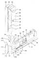
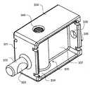
図1は、本発明の第1の例示的な実施形態による形材コネクタ100の斜視図を示している。 FIG. 1 shows a perspective view of a
形材コネクタ100は、コーナー要素110と、第1の接続アーム120と、第2の接続アーム130とからなる。図1の例示的な実施形態において、これらの接続アーム120及び130は、コーナー要素110と一体に接続され、コーナー要素110の自由端部を形成する。 The
コーナー要素110は、中央に配置される形材スロット112によって分離される形材壁111の部分を特徴とする。これらの形材壁111は、コーナー要素110の隅部において互いに垂直に当接する。形材スロット112の後方には、中央本体114のコーナー要素部分においてスロットの後壁52の前方で終端する横凹部113が設けられる。スロット112には、他の形材又は追加の要素をフランジ接続するために、係止部が係合する凹部113が設けられる。この側において、コーナー要素110の中央本体114の下方に、中央本体114におけるより小さな凹部119を有するスロット118が存在する。同時に、形材のこのL字形突出部19の反対側に、更なる小さな凹部が存在するが、この凹部は、形材壁111の前縁部又は後縁部から横方向に凹んでいる。 The
上述したように、第2の接続アーム130は、コーナー要素110の表面55に一体に接続される。接続アーム130は、スロットの後壁52から引っ込んでおり、したがって棚状部51を形成する。図2に関して後述するように、支持形材20において、形材壁21及びスロット22の同様の設計の接続部を、この形材壁111及びこのスロット112に対応するように設置することができる。支持形材20の反対側の最も内方の部分は、縁部56に近接して、好ましくは縁部56に当接して配置される。 As described above, the
第1の接続アーム120は、断面において、第2の接続アーム130と同様にH字形の壁、特に、中間壁137によって間を接続されている2つの対向する側壁134を本質的に有する。中間壁137には、キャビティ139の反対側で終端する連続的な横断ねじ穴136を特徴とするスリーブが設けられる。 The first connecting
コーナー要素110の反対側の自由端部において、端面131を有する係止スロットが設けられ、端面131は、この端面を分断する形材スロット132から分離している。形材スロットは、端面131の後方で横凹部133に拡大する。 At the free end opposite to the
図1に見ることができるように、第2の接続アーム130に対して垂直に配置される第1の接続アーム120は、第2の接続アーム130と全く同じように設置されるが、ただし、第1の接続アーム120は、コーナー要素110の他方の自由内面に設置され、この自由内面に一体に接続される。接続は、図5〜図10に示される個々の構成要素の接着又は溶接によるものとすることができる。図2に示されている支持形材10は、ここでも他方の支持形材20に単に接触することができるように縁部56に当接することが重要である。したがって、移行部は、支持形材10及び20が隅部において互いに距離を置かない範囲で、この縁部において実現される。 As can be seen in FIG. 1, the
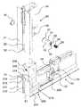
図2は、一部を断面図で示すとともに一部を分解図で示す、2つの形材、すなわち水平支持形材10及び鉛直支持形材20を伴う図1の形材コネクタ100の斜視図を記載している。同一の特徴部は、全ての図面において同じ参照符号で示されている。特に、類似の例示的な実施形態による類似の特徴部は、機能の類似性を示唆する類似の参照符号で示されている。 2 shows a perspective view of the
第2の接続アーム130上の棚状部51に言及するが、ここで、鉛直形材20が第2の接続アーム130上に移動される場合、鉛直形材20には第2の接続アーム130のための孔が設けられており、スロットの後壁52は、第2の接続アーム130の前壁の直前に摺動し、特に、第2の接続アーム130を包囲する他の構成要素と形状嵌合する。 Reference is made to the
形材壁21及び中央に配置される形材スロット22は、コーナー要素130のそれぞれの形材壁111及び形材スロット112にも直接接触させられ、支持形材20の機能のために、コーナー要素130の移行部まで継ぎ目なく移行し、端部までコーナー要素130に入る(take in)ようになっている。 The
水平支持形材10を参照してその部分断面に言及するが、水平支持形材10は、他の点では鉛直形材20と同じ要素を特徴とする。特に、中央本体24を通る横断ボア26が設けられており、ここで、偏心係止ヘッド44が面一になっているか又は僅かに突出している。 Reference is made to the
作動されることになる偏心係止ヘッド44を伴う係止部40は、従来技術から既知である多くの係止部のうちの1つ、特に、欧州特許出願公開第0871824号に従って作製される本出願人による係止部とすることができる。これらの係止部は、偏心係止ヘッドを回転させることでスロット132に挿入されるとともに凹部133に掛止されるラッチであって、これらの掛止要素の軽い引張力によって、取り付けられることになる1つの形材の方向に接続アーム130を引っ張るラッチを備える。 The locking
図1の接続アーム100の使用の例示的な実施形態において、2つの形材10及び20は、中央本体24における相補的な孔によって第1の接続アーム120及び第2の接続アーム130の自由端部に取り付けられ、形材10及び20に使用されている係止部40の係止要素がスロット132に滑り込むまで前進される。係止部のタイプに応じた回転により偏心ヘッド44を作動させることで、係止部がスロット132に係止され、それぞれの支持形材がL字形コーナーコネクタ100と固定接続される。 In the exemplary embodiment of the use of the
図3は、本発明の第2の例示的な実施形態による形材コネクタ200の斜視図を示しており、図4は、図2と同様に、すなわち一部を断面図で示すとともに一部を分解図で示す、2つの形材10及び20を伴う図3の形材コネクタ200の斜視図を示している。コーナー要素210において、形材コネクタ200は、第1の例示的な実施形態のコーナー要素110と同じ特徴を有する。2つの接続アーム220及び230は、同じようにコーナー要素210と一体に接続されている。これらの接続アーム220及び230もまた、断面において、2つの対向側面234及び中間壁237を有するH字形の中央本体を特徴とする。 FIG. 3 shows a perspective view of a
重要な違いは、端面231の設計にあり、端面231から、円錐キャビティ233を1つの側面に有するボルト又はピン232がそれぞれ突出している。この円錐キャビティ233は、L字形スロット212の構成に対して垂直に、すなわち、特に横断ねじ穴236の軸に対しても垂直に配置される。形材10及び20を取り付けるために、使用されることになるそれぞれの形材10及び20における横断ボア26とともに、スリーブ30を使用しなければならず、このスリーブ30は、支持形材10、20の中央本体24の反対側に配置されるスナップリング36を設置することができる、スリーブの端部のうちの一方における溝37を特徴とする。図面において前側に存在するものに関して、フランジ32には、垂直整合スロット33が設けられる。整合スロット33は、スリーブ30におけるボア31の軸に対して平行に配置される。スリーブ30をボア26に滑り込ませる際、整合スロット33の位置により、鉛直形材20に対して、ボルト232をこの横断ボアに挿通させることができるようにボア31が鉛直に整合されることを確実にすることができる。キャビティ233は、おおよそスリーブ30の内部ボアの高さにあり、ソケットねじ34をねじ込むことによって、第2の形材20を形材コネクタ200に取り付けることができるようになっている。ねじ込まれることになるソケットねじ頭部34の先端の円錐テーパー部35は、ここではキャビティ233におけるセンタリング要素として機能する。 An important difference lies in the design of the
同じ取付けプロセスを、水平形材10に用いることができる。 The same attachment process can be used for the
例示的な実施形態の画像が示されていない場合でも、コーナー要素110/210の一方の側面においてボルトコネクタ220又は230が設けられ、他方の側面及び他方の自由端部において係止コネクタ120又は130が設けられる、L字形アングルコネクタを示唆することができることは明らかである。これにより、特に、第1の支持形材の2つの対向自由端部において、ボルトコネクタ端部220、230が形材20の中央本体に挿入され、ソケットねじ34のそれぞれのねじの回転によって締め付けられるように形材10及び20を予め固定することが可能になる。これらのコネクタは、係止端部を有する接続アームが、形材20の2つの自由端部において形材20から垂直に突出するように、スリーブ30とスナップリング36とソケットねじ34とのみからなるので、技術的により単純である。したがって、係止部40が組み込まれた形材10を、停止部まで2つの対向側面に滑り込ませることができ、これらの形材10を、偏心係止ヘッド44の適度の回転によってコーナー要素に対して締め付けることができるようになっている。 Even if the image of the exemplary embodiment is not shown, a
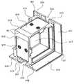
図5は、本発明の第3の例示的な実施形態による形材コネクタのコーナー要素310の斜視図を示している。このコーナー要素310は、図1〜図4の自由端部を提供する接続アームとともに使用しなければならない。特に、設けられる接続アームは、図7又は図9のものとすることができる。形材壁311は、L字形であり、コーナーコネクタ310の中央本体314の2つの側面を囲む。この形材壁311は、中央部において、凹部313を伴う形材スロット312から分離している。スロット312は、受けキャビティ315がそこに設けられることが有利であるコーナー要素310の側壁において終端する。受けキャビティ315は、縁面351が形材スロット312の向かい側に延在するように、側壁において形材スロット312の方向に構成される。設置されることになる形材10又は20の中央本体24の後壁は、この縁面351に押し当てられる。 FIG. 5 shows a perspective view of a
コーナーコネクタの前述の例示的な実施形態と同様に、凹部319を伴う横方向スロット318が存在し、中央本体314は、中間壁317が側壁間の中央部に立てられているので、断面において(例えば、この組又は上記組のねじ穴316によって形成される平面において)それぞれのH字形を特徴とする。2つのねじ穴316が、受けキャビティ315の中央部に横方向に並んで構成されることが有利である。他の例示的な実施形態において、これらの穴は、縦方向に構成することもできる。通常は、2つの穴が設けられる。 Similar to the previous exemplary embodiment of the corner connector, there is a
縁面351を含む受けキャビティ315の縁部は、コーナーコネクタの自由端部が支持形材10及び20の壁によって囲まれる、支持形材10及び20における凹部の寸法を規定することが有利である。 The edge of the receiving
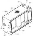
図6は、図5のコーナー要素310の異なる方向からの斜視図を示しており、ここでは、本体314の内側の内部空間の向かい側のねじ穴316が、それぞれのねじがより長い係合長さで係合する強化部を有することを見て取ることができる。内部キャビティの空間が中間壁317によって分断されているため、1つのねじ穴316しか見ることができない。 FIG. 6 shows a perspective view from a different direction of the
図7は、コーナー要素310と組み合わせて使用することができる、本発明の第3の例示的な実施形態による形材コネクタの接続アーム320の第1の例示的な実施形態の斜視図を示している。図8は、図7の接続アーム320の異なる方向からの斜視図を更に示している。接続アーム320の外形は、直方形である。端面のうちの一方は、マウント面325としてのより長い辺長の端部において、接続アーム320における2つの貫通孔326がコーナー要素310のねじ穴316の向かい側に配置されるように、受けキャビティ315に挿入される。したがって、中央に配置される分断壁327の両側において、ねじをボア326に挿入することができ、それにより、接続アーム320を、係止部を用いるようにコーナー要素310に接続することができる。 FIG. 7 shows a perspective view of a first exemplary embodiment of a
一方で、2つの対向側面324は、分断壁327に接続され、他方で、ボア346が設けられるスリーブによって接続されている。最初の複数の図の例示的な実施形態におけるように、マウント面325の反対側の側面、すなわちコーナー要素310の方向の向かい側の側面には、形材壁321が設けられ、形材壁321の間には、凹部323によって拡大する形材スロット322が延在する。形材スロット322とねじ穴346とは、互いに対して平行に位置合わせされる。この場合、要素の自由端部は、形材10又は20に設けられる係止部40に対応して接続しなければならない。 On the other hand, the two opposing side surfaces 324 are connected to the dividing
図9は、本発明の第3の例示的な実施形態による形材コネクタの接続アーム330の例示的な実施形態の斜視図を示しており、マウント面335は、受けキャビティ315に挿入されるように意図されており、コネクタ330を固定するために、ねじをボア336に通してコーナー要素310に挿入することができるようになっている。図10は、図9の接続アームの異なる方向からの斜視図を示している。ここでも、2つの側壁334は、ボア346を有するスリーブによって分離されている。ピン332が、面335の反対側の形材壁331の表面に配置され、キャビティ333が、ピン332の外側マントルにおいて横方向に構成される。 FIG. 9 shows a perspective view of an exemplary embodiment of a
全ての自由端部コネクタ320、330は、図9及び図10の例示的な実施形態では331及び335である対向端面の、直方体の縦方向における4つの縦断溝又はスロット347を特徴とする。一体的なコーナーコネクタ120、130、220、230において、スロット347は、自由端面131、231にのみ設けられる。これらのスロット347は、スロット347を通る支持形材10、20のそれぞれのリブのガイドとしての役割を果たすことができる。 All the
10 水平形材
19 形材突出部
20 鉛直形材
21 形材壁
22 形材スロット
23 凹部
24 中央本体
26 横断ボア
28 形材スロット
29 凹部
30 スリーブ
31 ボア
32 フランジ
33 整合スロット
34 ソケットねじ
35 円錐端部
36 スナップリング
37 溝
40 係止部
44 偏心係止ヘッド
51 棚状部
52 スロットの後壁
55 表面
56 内縁部
57 隅縁部
100 形材コネクタ
110 コーナー要素
111 形材壁
112 形材スロット
113 凹部
114 中央本体
115 受けキャビティ
116 ねじ穴
117 中間壁
118 形材スロット
119 凹部
120 第1の接続アーム
130 第2の接続アーム
131 端面
132 形材スロット
133 凹部
134 側壁
136 横断ねじ穴
137 中間壁
139 キャビティ
200 形材コネクタ
210 コーナー要素
211 形材壁
212 形材スロット
213 凹部
214 中央本体
215 受けキャビティ
216 ねじ穴
217 中間壁
218 形材スロット
219 凹部
220 第1の接続アーム
230 第2の接続アーム
231 端面
232 ボルト
233 キャビティ
234 側壁
236 横断ねじ穴
237 中間壁
310 コーナー要素
311 形材壁
312 形材スロット
313 凹部
314 中央本体
315 受けキャビティ
316 ねじ穴
317 中間壁
318 形材スロット
319 凹部
320 係止用接続アーム
321 形材壁
322 形材スロット
323 凹部
324 中央本体
325 マウント面
326 ボア
327 中間壁
330 ねじ係止用接続アーム
331 形材壁
332 ボルト
333 キャビティ
334 中央本体
335 マウント面
336 ボア
337 中間壁
346 ねじボア
347 スロット
351 縁面
10 horizontal profile 19 profile projection 20 vertical profile 21 profile wall 22 profile slot 23 recess 24 central body 26 transverse bore 28 profile slot 29 recess 30 sleeve 31 bore 32 flange 33 alignment slot 34 socket screw 35 cone end Part 36 Snap ring 37 Groove 40 Locking part 44 Eccentric locking head 51 Shelf-like part 52 Slot rear wall 55 Surface 56 Inner edge 57 Corner edge 100 Profile connector 110 Corner element 111 Profile wall 112 Profile slot 113 Recess 114 central body 115 receiving cavity 116 screw hole 117 intermediate wall 118 profile slot 119 recess 120 first connection arm 130 second connection arm 131 end face 132 profile slot 133 recess 134 side wall 136 transverse screw hole 137 intermediate wall 139 cavity 20 Profile Connector 210 Corner Element 211 Profile Wall 212 Profile Slot 213 Recess 214 Central Body 215 Receiving Cavity 216 Screw Hole 217 Intermediate Wall 218 Profile Slot 219 Recess 220 First Connection Arm 230 Second Connection Arm 231 End Face 232 Bolt 233 Cavity 234 Side wall 236 Transverse screw hole 237 Intermediate wall 310 Corner element 311 Profile wall 312 Profile slot 313 Recess 314 Central body 315 Receiving cavity 316 Screw hole 317 Intermediate wall 318 Profile slot 319 Recess 320 Locking connection arm 321 type Material wall 322 Shape slot 323 Recess 324 Central body 325 Mount surface 326 Bore 327 Intermediate wall 330 Connection arm for screw locking 331 Shape wall 332 Bolt 333 Cavity 334 Center Body 335 Mount surface 336 Bore 337 Intermediate wall 346 Screw bore 347 Slot 351 Edge surface
Claims (8)
Translated fromJapanese互いに対して垂直に整合される前記自由端部間において、形材要素(111、112)を伴うコーナー要素(110;210;310)が設けられ、前記形材要素は、互いに対して垂直に配置される前記コーナー要素の2つの外面に配される前記支持形材と適合し、前記コーナー要素(110;210;310)の関連付けられた表面(55)の高さまでそれぞれ到達することを特徴とする、アングルコネクタ。Angle connector (100) with two free ends (110, 120; 210, 220; 310, 320) aligned perpendicular to each other, inserted into the associated cavities of the support profile (10, 20) 200; 310, 320, 330), wherein each free end (110, 120; 210, 220; 310, 320) of the angle connector is fixed passive means (131, 132, 133; 231; 232, 233; 321, 332, 323; 331, 332, 333) via the fixed passive means from one outer surface of the support profile (10, 20), each of the angle connectors. The end can be removably connected to the associated support profile by complementary active fixation elements (30, 34; 40, 44);
Between the free ends aligned perpendicular to each other, corner elements (110; 210; 310) with profile elements (111, 112) are provided, the profile elements being arranged perpendicular to each other Adapted to the support profiles arranged on the two outer surfaces of the corner element to be reached, respectively up to the height of the associated surface (55) of the corner element (110; 210; 310) Angle connector.
The angle connector according to any one of claims 1 to 7, wherein the profile elements (111, 112; 211, 212) provided on the two vertical outer surfaces are profile wall surfaces (111; 211). ) And a slot (112; 212) centrally arranged with a recess (113; 213), the vertical profile wall surface (111; 211) being formed on the corner element (110; 210). An angle connector characterized by being fitted at the corner edge (57).
Applications Claiming Priority (2)
| Application Number | Priority Date | Filing Date | Title |
|---|---|---|---|
| EP17173061.7 | 2017-05-26 | ||
| EP17173061.7AEP3406916B1 (en) | 2017-05-26 | 2017-05-26 | Angle connector for loadbearing sections |
Publications (2)
| Publication Number | Publication Date |
|---|---|
| JP2019032076Atrue JP2019032076A (en) | 2019-02-28 |
| JP7145645B2 JP7145645B2 (en) | 2022-10-03 |
Family
ID=58800698
Family Applications (1)
| Application Number | Title | Priority Date | Filing Date |
|---|---|---|---|
| JP2018096182AActiveJP7145645B2 (en) | 2017-05-26 | 2018-05-18 | Angle connectors for support profiles |
Country Status (6)
| Country | Link |
|---|---|
| US (1) | US20180340561A1 (en) |
| EP (1) | EP3406916B1 (en) |
| JP (1) | JP7145645B2 (en) |
| CN (1) | CN108953324A (en) |
| AU (1) | AU2018203356A1 (en) |
| PL (1) | PL3406916T3 (en) |
Families Citing this family (1)
| Publication number | Priority date | Publication date | Assignee | Title |
|---|---|---|---|---|
| NL2024208B1 (en)* | 2019-11-11 | 2021-07-28 | Walraven Holding Bv J Van | Wall mounting bracket for channel profile element |
Citations (10)
| Publication number | Priority date | Publication date | Assignee | Title |
|---|---|---|---|---|
| JPS4939754U (en)* | 1972-07-10 | 1974-04-08 | ||
| JPS4972917A (en)* | 1972-10-12 | 1974-07-15 | ||
| JPS55176906U (en)* | 1979-06-08 | 1980-12-18 | ||
| JPS61190012U (en)* | 1985-05-18 | 1986-11-27 | ||
| JPS62215109A (en)* | 1986-03-10 | 1987-09-21 | コンネ−ク・アクチエンゲゼルシヤフト・ジステ−ムバウ−テヒニ−ク | Fixing device with clamping locking mechanism for engaging with molded shape with undercut section in releasable manner |
| JPS6446510U (en)* | 1987-09-17 | 1989-03-22 | ||
| JPH06299763A (en)* | 1993-03-17 | 1994-10-25 | Schueco Internatl Kg | Butting bonder |
| JP2000515222A (en)* | 1996-01-09 | 2000-11-14 | シーマ インターコンチネンタル アーゲー | Fixing device for releasably connecting two members |
| JP3108428U (en)* | 2004-10-27 | 2005-04-14 | 株式会社内山商会 | Square pipe fitting |
| JP3122684U (en)* | 2006-04-10 | 2006-06-29 | 株式会社ミサキ三伸 | Member connection structure |
Family Cites Families (14)
| Publication number | Priority date | Publication date | Assignee | Title |
|---|---|---|---|---|
| DE2833428A1 (en)* | 1978-07-21 | 1980-02-07 | Josef Amstadt | Connector for hollow sectional frame members - has insert in frame part non-rotatably secured to connector block by screw |
| DE19712100A1 (en)* | 1997-03-22 | 1998-06-04 | Bosch Gmbh Robert | Connector joining two bar sections comprising pin and sleeve |
| CA2270709A1 (en)* | 1998-05-08 | 1999-01-04 | Scott Gammon | Panel construction and connection system |
| DE29818474U1 (en)* | 1998-10-16 | 1999-01-14 | Octanorm-Vertriebs-GmbH für Bauelemente, 70794 Filderstadt | Profile arrangement for setting up exhibition or shop facilities |
| US6969211B2 (en)* | 2002-12-19 | 2005-11-29 | Altman Lee E | Tubular frame structure connector system |
| DE102004063465A1 (en)* | 2004-12-23 | 2006-07-13 | Murjahn, Wolfgang | Multi-arm pipe connector |
| DE102006010012B3 (en)* | 2006-03-04 | 2007-04-12 | Rittal Gmbh & Co. Kg | Switch cabinet with cladding parts and hinged door has connecting end pieces and vertical sections with protruding bearing sections for the door hinges |
| EP2146101A2 (en)* | 2008-07-17 | 2010-01-20 | Hewi Heinrich Wilke Gmbh | Connecting element |
| WO2012129598A1 (en)* | 2011-03-30 | 2012-10-04 | Burgundy Trial Pty Ltd | Connector |
| CN103591093A (en)* | 2012-08-18 | 2014-02-19 | 李思模 | Aluminium alloy section connecting device |
| US9121433B1 (en)* | 2013-04-14 | 2015-09-01 | Hilton Raymond Bacon | Joining elements for channelled structural members |
| DE202014001278U1 (en) | 2014-02-10 | 2014-03-31 | Octanorm-Vertriebs-GmbH für Bauelemente | Support profile for creating superstructures |
| BE1021297B1 (en) | 2014-04-29 | 2015-10-26 | Aluvision | CORNER PIECE FOR ATTACHING TWO PROFILES, PROFILE, SET, CORNER ELEMENT, FRAMEWORK, STAND BUILDING ELEMENT, STAND AND METHOD AND APPARATUS FOR MAKING THEM UNDER AN ANGLE |
| CN205298175U (en)* | 2015-12-15 | 2016-06-08 | 河南奥斯派克科技有限公司 | High strength tongue and groove square tube or circle quarter bend connection structure |
- 2017
- 2017-05-26EPEP17173061.7Apatent/EP3406916B1/enactiveActive
- 2017-05-26PLPL17173061.7Tpatent/PL3406916T3/enunknown
- 2018
- 2018-05-14AUAU2018203356Apatent/AU2018203356A1/ennot_activeAbandoned
- 2018-05-18JPJP2018096182Apatent/JP7145645B2/enactiveActive
- 2018-05-25USUS15/989,546patent/US20180340561A1/ennot_activeAbandoned
- 2018-05-25CNCN201810560709.5Apatent/CN108953324A/enactivePending
Patent Citations (10)
| Publication number | Priority date | Publication date | Assignee | Title |
|---|---|---|---|---|
| JPS4939754U (en)* | 1972-07-10 | 1974-04-08 | ||
| JPS4972917A (en)* | 1972-10-12 | 1974-07-15 | ||
| JPS55176906U (en)* | 1979-06-08 | 1980-12-18 | ||
| JPS61190012U (en)* | 1985-05-18 | 1986-11-27 | ||
| JPS62215109A (en)* | 1986-03-10 | 1987-09-21 | コンネ−ク・アクチエンゲゼルシヤフト・ジステ−ムバウ−テヒニ−ク | Fixing device with clamping locking mechanism for engaging with molded shape with undercut section in releasable manner |
| JPS6446510U (en)* | 1987-09-17 | 1989-03-22 | ||
| JPH06299763A (en)* | 1993-03-17 | 1994-10-25 | Schueco Internatl Kg | Butting bonder |
| JP2000515222A (en)* | 1996-01-09 | 2000-11-14 | シーマ インターコンチネンタル アーゲー | Fixing device for releasably connecting two members |
| JP3108428U (en)* | 2004-10-27 | 2005-04-14 | 株式会社内山商会 | Square pipe fitting |
| JP3122684U (en)* | 2006-04-10 | 2006-06-29 | 株式会社ミサキ三伸 | Member connection structure |
Also Published As
| Publication number | Publication date |
|---|---|
| AU2018203356A1 (en) | 2018-12-13 |
| EP3406916B1 (en) | 2023-06-07 |
| CN108953324A (en) | 2018-12-07 |
| EP3406916A1 (en) | 2018-11-28 |
| PL3406916T3 (en) | 2023-10-02 |
| JP7145645B2 (en) | 2022-10-03 |
| US20180340561A1 (en) | 2018-11-29 |
| EP3406916C0 (en) | 2023-06-07 |
Similar Documents
| Publication | Publication Date | Title |
|---|---|---|
| US9371849B2 (en) | Corner connector for hollow profiles | |
| US20190316623A1 (en) | Quick Locking Piece and Display Screen Assembly | |
| CN104329602B (en) | Splicing joint assembly and splicing joint type LED (light emitting diode) lamp | |
| KR101620677B1 (en) | System for prventing mating errors between electrical connectors | |
| CN109640741A (en) | Connector | |
| JP2010523347A (en) | Multi-part pin puller for pulling pins or bolts out of member holes | |
| KR20170038885A (en) | Corner connector for rod-shaped profile elements | |
| JP2006207818A (en) | Connector for plate, especially for shelf board | |
| JP2016540163A (en) | Device for fastening a component to a support component | |
| JP2019032076A (en) | Angle connector of support material | |
| US3383127A (en) | Split bracket | |
| CN205909221U (en) | Lighting appliance | |
| JPS5847564B2 (en) | Shimetsukeketsugousouchi | |
| KR20160150481A (en) | Fuel supply nozzle comprises a sealing structure | |
| US20160377659A1 (en) | Fastening element for a current sensor | |
| US20190051998A1 (en) | Quick connect plug for cables | |
| JP2009270390A (en) | Handle seat of door | |
| KR20200027744A (en) | Hanger band for pole transformer | |
| JP7462944B2 (en) | Connection structure of structural frame materials | |
| JP2010071296A (en) | Connector of structural frame material | |
| CN104405741B (en) | A kind of connection part | |
| CN218763083U (en) | Lampshade mounting structure and linear lamp thereof | |
| IT201900005034A1 (en) | HOOKING DEVICE AND RELATIVE HOOKING METHOD | |
| CN217552330U (en) | Test platform and its fixed structure | |
| CN210540317U (en) | A display frame connector |
Legal Events
| Date | Code | Title | Description |
|---|---|---|---|
| A621 | Written request for application examination | Free format text:JAPANESE INTERMEDIATE CODE: A621 Effective date:20210510 | |
| A977 | Report on retrieval | Free format text:JAPANESE INTERMEDIATE CODE: A971007 Effective date:20220316 | |
| A131 | Notification of reasons for refusal | Free format text:JAPANESE INTERMEDIATE CODE: A131 Effective date:20220329 | |
| A601 | Written request for extension of time | Free format text:JAPANESE INTERMEDIATE CODE: A601 Effective date:20220629 | |
| A521 | Request for written amendment filed | Free format text:JAPANESE INTERMEDIATE CODE: A523 Effective date:20220715 | |
| TRDD | Decision of grant or rejection written | ||
| A01 | Written decision to grant a patent or to grant a registration (utility model) | Free format text:JAPANESE INTERMEDIATE CODE: A01 Effective date:20220830 | |
| A61 | First payment of annual fees (during grant procedure) | Free format text:JAPANESE INTERMEDIATE CODE: A61 Effective date:20220920 | |
| R150 | Certificate of patent or registration of utility model | Ref document number:7145645 Country of ref document:JP Free format text:JAPANESE INTERMEDIATE CODE: R150 |