JP2019020782A - Vehicle control device and vehicle control method - Google Patents
Vehicle control device and vehicle control methodDownload PDFInfo
- Publication number
- JP2019020782A JP2019020782AJP2017135690AJP2017135690AJP2019020782AJP 2019020782 AJP2019020782 AJP 2019020782AJP 2017135690 AJP2017135690 AJP 2017135690AJP 2017135690 AJP2017135690 AJP 2017135690AJP 2019020782 AJP2019020782 AJP 2019020782A
- Authority
- JP
- Japan
- Prior art keywords
- vehicle
- mismatch
- information
- automatic driving
- map information
- Prior art date
- Legal status (The legal status is an assumption and is not a legal conclusion. Google has not performed a legal analysis and makes no representation as to the accuracy of the status listed.)
- Granted
Links
Images


Classifications
- G—PHYSICS
- G05—CONTROLLING; REGULATING
- G05D—SYSTEMS FOR CONTROLLING OR REGULATING NON-ELECTRIC VARIABLES
- G05D1/00—Control of position, course, altitude or attitude of land, water, air or space vehicles, e.g. using automatic pilots
- G05D1/0055—Control of position, course, altitude or attitude of land, water, air or space vehicles, e.g. using automatic pilots with safety arrangements
- G05D1/0061—Control of position, course, altitude or attitude of land, water, air or space vehicles, e.g. using automatic pilots with safety arrangements for transition from automatic pilot to manual pilot and vice versa
- B—PERFORMING OPERATIONS; TRANSPORTING
- B60—VEHICLES IN GENERAL
- B60W—CONJOINT CONTROL OF VEHICLE SUB-UNITS OF DIFFERENT TYPE OR DIFFERENT FUNCTION; CONTROL SYSTEMS SPECIALLY ADAPTED FOR HYBRID VEHICLES; ROAD VEHICLE DRIVE CONTROL SYSTEMS FOR PURPOSES NOT RELATED TO THE CONTROL OF A PARTICULAR SUB-UNIT
- B60W30/00—Purposes of road vehicle drive control systems not related to the control of a particular sub-unit, e.g. of systems using conjoint control of vehicle sub-units
- B60W30/10—Path keeping
- B—PERFORMING OPERATIONS; TRANSPORTING
- B60—VEHICLES IN GENERAL
- B60W—CONJOINT CONTROL OF VEHICLE SUB-UNITS OF DIFFERENT TYPE OR DIFFERENT FUNCTION; CONTROL SYSTEMS SPECIALLY ADAPTED FOR HYBRID VEHICLES; ROAD VEHICLE DRIVE CONTROL SYSTEMS FOR PURPOSES NOT RELATED TO THE CONTROL OF A PARTICULAR SUB-UNIT
- B60W30/00—Purposes of road vehicle drive control systems not related to the control of a particular sub-unit, e.g. of systems using conjoint control of vehicle sub-units
- B60W30/14—Adaptive cruise control
- B60W30/16—Control of distance between vehicles, e.g. keeping a distance to preceding vehicle
- B—PERFORMING OPERATIONS; TRANSPORTING
- B60—VEHICLES IN GENERAL
- B60W—CONJOINT CONTROL OF VEHICLE SUB-UNITS OF DIFFERENT TYPE OR DIFFERENT FUNCTION; CONTROL SYSTEMS SPECIALLY ADAPTED FOR HYBRID VEHICLES; ROAD VEHICLE DRIVE CONTROL SYSTEMS FOR PURPOSES NOT RELATED TO THE CONTROL OF A PARTICULAR SUB-UNIT
- B60W30/00—Purposes of road vehicle drive control systems not related to the control of a particular sub-unit, e.g. of systems using conjoint control of vehicle sub-units
- B60W30/18—Propelling the vehicle
- B60W30/182—Selecting between different operative modes, e.g. comfort and performance modes
- B—PERFORMING OPERATIONS; TRANSPORTING
- B60—VEHICLES IN GENERAL
- B60W—CONJOINT CONTROL OF VEHICLE SUB-UNITS OF DIFFERENT TYPE OR DIFFERENT FUNCTION; CONTROL SYSTEMS SPECIALLY ADAPTED FOR HYBRID VEHICLES; ROAD VEHICLE DRIVE CONTROL SYSTEMS FOR PURPOSES NOT RELATED TO THE CONTROL OF A PARTICULAR SUB-UNIT
- B60W50/00—Details of control systems for road vehicle drive control not related to the control of a particular sub-unit, e.g. process diagnostic or vehicle driver interfaces
- B60W50/02—Ensuring safety in case of control system failures, e.g. by diagnosing, circumventing or fixing failures
- B60W50/0205—Diagnosing or detecting failures; Failure detection models
- B—PERFORMING OPERATIONS; TRANSPORTING
- B60—VEHICLES IN GENERAL
- B60W—CONJOINT CONTROL OF VEHICLE SUB-UNITS OF DIFFERENT TYPE OR DIFFERENT FUNCTION; CONTROL SYSTEMS SPECIALLY ADAPTED FOR HYBRID VEHICLES; ROAD VEHICLE DRIVE CONTROL SYSTEMS FOR PURPOSES NOT RELATED TO THE CONTROL OF A PARTICULAR SUB-UNIT
- B60W50/00—Details of control systems for road vehicle drive control not related to the control of a particular sub-unit, e.g. process diagnostic or vehicle driver interfaces
- B60W50/08—Interaction between the driver and the control system
- B60W50/14—Means for informing the driver, warning the driver or prompting a driver intervention
- B—PERFORMING OPERATIONS; TRANSPORTING
- B60—VEHICLES IN GENERAL
- B60W—CONJOINT CONTROL OF VEHICLE SUB-UNITS OF DIFFERENT TYPE OR DIFFERENT FUNCTION; CONTROL SYSTEMS SPECIALLY ADAPTED FOR HYBRID VEHICLES; ROAD VEHICLE DRIVE CONTROL SYSTEMS FOR PURPOSES NOT RELATED TO THE CONTROL OF A PARTICULAR SUB-UNIT
- B60W60/00—Drive control systems specially adapted for autonomous road vehicles
- B60W60/005—Handover processes
- B60W60/0053—Handover processes from vehicle to occupant
- G—PHYSICS
- G01—MEASURING; TESTING
- G01C—MEASURING DISTANCES, LEVELS OR BEARINGS; SURVEYING; NAVIGATION; GYROSCOPIC INSTRUMENTS; PHOTOGRAMMETRY OR VIDEOGRAMMETRY
- G01C21/00—Navigation; Navigational instruments not provided for in groups G01C1/00 - G01C19/00
- G01C21/26—Navigation; Navigational instruments not provided for in groups G01C1/00 - G01C19/00 specially adapted for navigation in a road network
- G01C21/28—Navigation; Navigational instruments not provided for in groups G01C1/00 - G01C19/00 specially adapted for navigation in a road network with correlation of data from several navigational instruments
- G01C21/30—Map- or contour-matching
- G01C21/32—Structuring or formatting of map data
- G—PHYSICS
- G05—CONTROLLING; REGULATING
- G05D—SYSTEMS FOR CONTROLLING OR REGULATING NON-ELECTRIC VARIABLES
- G05D1/00—Control of position, course, altitude or attitude of land, water, air or space vehicles, e.g. using automatic pilots
- G05D1/0088—Control of position, course, altitude or attitude of land, water, air or space vehicles, e.g. using automatic pilots characterized by the autonomous decision making process, e.g. artificial intelligence, predefined behaviours
- G—PHYSICS
- G06—COMPUTING OR CALCULATING; COUNTING
- G06V—IMAGE OR VIDEO RECOGNITION OR UNDERSTANDING
- G06V20/00—Scenes; Scene-specific elements
- G06V20/50—Context or environment of the image
- G06V20/56—Context or environment of the image exterior to a vehicle by using sensors mounted on the vehicle
- G06V20/58—Recognition of moving objects or obstacles, e.g. vehicles or pedestrians; Recognition of traffic objects, e.g. traffic signs, traffic lights or roads
- B—PERFORMING OPERATIONS; TRANSPORTING
- B60—VEHICLES IN GENERAL
- B60W—CONJOINT CONTROL OF VEHICLE SUB-UNITS OF DIFFERENT TYPE OR DIFFERENT FUNCTION; CONTROL SYSTEMS SPECIALLY ADAPTED FOR HYBRID VEHICLES; ROAD VEHICLE DRIVE CONTROL SYSTEMS FOR PURPOSES NOT RELATED TO THE CONTROL OF A PARTICULAR SUB-UNIT
- B60W2540/00—Input parameters relating to occupants
- B60W2540/30—Driving style
- G—PHYSICS
- G06—COMPUTING OR CALCULATING; COUNTING
- G06V—IMAGE OR VIDEO RECOGNITION OR UNDERSTANDING
- G06V20/00—Scenes; Scene-specific elements
- G06V20/50—Context or environment of the image
- G06V20/56—Context or environment of the image exterior to a vehicle by using sensors mounted on the vehicle
- G06V20/588—Recognition of the road, e.g. of lane markings; Recognition of the vehicle driving pattern in relation to the road
Landscapes
- Engineering & Computer Science (AREA)
- Automation & Control Theory (AREA)
- Remote Sensing (AREA)
- Radar, Positioning & Navigation (AREA)
- Physics & Mathematics (AREA)
- General Physics & Mathematics (AREA)
- Mechanical Engineering (AREA)
- Transportation (AREA)
- Aviation & Aerospace Engineering (AREA)
- Human Computer Interaction (AREA)
- Health & Medical Sciences (AREA)
- Business, Economics & Management (AREA)
- Artificial Intelligence (AREA)
- Evolutionary Computation (AREA)
- Game Theory and Decision Science (AREA)
- Medical Informatics (AREA)
- Theoretical Computer Science (AREA)
- Multimedia (AREA)
- Traffic Control Systems (AREA)
- Instructional Devices (AREA)
- Navigation (AREA)
- Control Of Driving Devices And Active Controlling Of Vehicle (AREA)
Abstract
Translated fromJapaneseDescription
Translated fromJapanese自動運転制御を実施する車両制御装置、及び車両制御方法に関する。 The present invention relates to a vehicle control apparatus and a vehicle control method that perform automatic driving control.
近年、車両の挙動を自動で制御する自動運転制御が知られている(例えば、特許文献1参照)。また、自動運転制御を実現するために、地図情報を用いて目的地までの走行経路を設定するとともに、車載センサの検出情報に基づいてこの走行経路に沿って自車挙動を制御する車両制御装置が存在する。 In recent years, automatic driving control for automatically controlling the behavior of a vehicle has been known (see, for example, Patent Document 1). In addition, in order to realize automatic driving control, a vehicle control device that sets a travel route to a destination using map information and controls the behavior of the vehicle along the travel route based on detection information of an in-vehicle sensor. Exists.
車両制御装置による自動運転制御中に、地図情報と車載センサの検出情報とが一致しない場合が想定される。例えば、地図情報は、走行経路上の一部で道路改修されること等により実際の道路状況とは異なることが考えられる。これに対して、車載センサは故障等により対象を誤って認識する場合がある。従来では、地図情報と車載センサの検出情報とが一致しない場合に、何ら対策がなされておらず、運転者がブレーキを操作するなどして車両を停止させる必要があった。 It is assumed that the map information and the detection information of the in-vehicle sensor do not match during the automatic driving control by the vehicle control device. For example, it is conceivable that the map information differs from the actual road condition due to the road being repaired at a part of the travel route. On the other hand, the vehicle-mounted sensor may erroneously recognize the target due to a failure or the like. Conventionally, when the map information does not match the detection information of the in-vehicle sensor, no measures are taken, and it is necessary for the driver to stop the vehicle by operating a brake or the like.
本発明は、上記課題に鑑みたものであり、自動運転制御により車両を適正に走行させることができる車両制御装置、及び車両制御方法を提供することを目的とする。 The present invention has been made in view of the above problems, and an object of the present invention is to provide a vehicle control device and a vehicle control method capable of appropriately driving a vehicle by automatic driving control.
上記課題を解決するために本発明では、地図情報を用いて目的地までの走行経路を設定し、その走行経路と、車載センサにより検出される自車周辺の検出情報とに基づいて車両の自動運転制御を実施する車両制御装置であって、前記自動運転制御の実施中において前記地図情報と前記車載センサの検出情報とが一致するか否かを判定する判定部と、前記判定部により不一致判定がなされた場合に、その不一致の状況に応じて前記自動運転制御の制御態様を変更する変更部と、を備える。 In order to solve the above-mentioned problems, in the present invention, a travel route to a destination is set using map information, and the vehicle is automatically detected based on the travel route and detection information around the host vehicle detected by an in-vehicle sensor. A vehicle control device that performs driving control, wherein a determination unit that determines whether or not the map information and detection information of the in-vehicle sensor match during execution of the automatic driving control, and the determination unit determines a mismatch And a changing unit that changes the control mode of the automatic operation control according to the inconsistent situation.
地図情報と車載センサによる自車周辺の検出情報とが一致しない場合、これら地図情報及びセンサ検出情報を用いた自動運転制御の信頼性が低下する。そのため、自動運転制御を停止させて手動運転への切替が行われることが考えられ、その切替が適正に行われることが望ましい。この点、上記構成では、地図情報と車載センサの検出情報との不一致判定がなされた場合に、その不一致の状況に応じて自動運転制御の制御態様を変更するようにした。この場合、地図情報と車載センサの検出情報とが不一致になっても、その不一致の状況に応じて制御態様が変更されて自動運転制御が継続される。したがって、車両において自動運転制御を適正に実施することができる。 When the map information and the detection information around the vehicle by the in-vehicle sensor do not match, the reliability of the automatic driving control using the map information and the sensor detection information is lowered. Therefore, it is conceivable that automatic operation control is stopped and switching to manual operation is performed, and it is desirable that the switching be performed appropriately. In this regard, in the above configuration, when the mismatch between the map information and the detection information from the vehicle-mounted sensor is determined, the control mode of the automatic driving control is changed according to the mismatch situation. In this case, even if the map information does not match the detection information of the vehicle-mounted sensor, the control mode is changed according to the mismatch situation, and the automatic driving control is continued. Therefore, automatic driving control can be appropriately performed in the vehicle.
(第1実施形態)
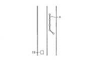
以下、車両制御装置を具体化した実施形態について、図面を参照しつつ説明する。本実施形態に係る車両制御装置は車両に搭載されており、車両の周辺環境に基づいて、自動運転制御を実施するものである。以下では、本車両制御装置を搭載する車両を自車として記載する。まずは、本実施形態の車両制御システムの概略構成について図1を用いて説明する。(First embodiment)
Hereinafter, an embodiment in which a vehicle control device is embodied will be described with reference to the drawings. The vehicle control device according to the present embodiment is mounted on a vehicle and performs automatic driving control based on the surrounding environment of the vehicle. Below, the vehicle carrying this vehicle control apparatus is described as an own vehicle. First, a schematic configuration of the vehicle control system of the present embodiment will be described with reference to FIG.
車両制御システム100は、車載センサ10と、地図情報を記録するメモリ20と、GPS受信機21と、車両制御装置として機能するECU30と、駆動源41と、操舵装置42と、ブレーキ装置43と、を備えている。 The vehicle control system 100 includes an in-
車載センサ10は、車両に備えられており、自車周囲の状況を検出情報として検出する。本実施形態では、車載センサ10として、撮像装置11と、レーダ装置12と、レーザ装置13と、を備えている。 The in-
撮像装置11は車載カメラであり、CCDカメラ、CMOSイメージセンサ、近赤外線カメラ等である。撮像装置11は、自車の周辺環境を撮影し、撮影した画像に対応する画像データをECU30に逐次出力する。 The
レーダ装置12は、送信波として電磁波を送信し、その反射波を受信することで自車周囲の物体を検出する装置である。レーダ装置12は、自車の前部に取り付けられており、自車前方に向けて電磁波を送信してから反射波を受信するまでの時間に基づき測距データを作成し、作成した測距データをECU30に逐次出力する。測距データには、物体が存在する方位、物体までの距離及び相対速度に関する情報が含まれている。 The
レーザ装置13は、送信波としてレーザ波を送信し、その反射波を受信することで自車周囲の物体を検出する装置である。レーザ装置13は、レーザ光を照射してから反射光を受信するまでの時間に基づき測距データを作成し、作成した測距データをECU30に逐次出力する。 The
駆動源41は、自車を走行させる動力源であり、エンジンや、走行用モータにより構成されている。操舵装置42は、自車が備える車輪の向きを変化させることで、自車が進む方向を変更する。ブレーキ装置43は、自車に対して制動力を付与する。 The
ECU30は、演算の中枢をなすCPU、ROM、及びRAMを備えている。CPUは、ROM内の演算プログラムや制御データを参照して、駆動源41、操舵装置42、及びブレーキ装置43等を制御対象とする制御信号を適宜出力する。 The
また、ECU30は、メモリ20に記録された地図情報MP1を参照することで、地図情報MP1に登録された道路の位置及び形状取得する。例えば、地図情報MP1には、道路上の車線を示すリンクと車線の連結点を示すノードとを記録している。このノードには地図上での絶対座標が記録されており、ノードの位置を参照することにより、地図上でこのノードに対応する位置を検出することができる。また、ECU30は、ノードとリンクとの接続関係を用いることで、ある地点を示すノードから目的地点を示すノードまでの経路を走行経路として計画することができる。 Further, the ECU 30 acquires the position and shape of the road registered in the map information MP1 by referring to the map information MP1 recorded in the
また、地図情報MP1には、道路情報や、道路周辺の地物が登録されている。道路情報は、車線の形状、道路の境界を区画する区画線、及び路面表示を含む情報である。また、地物は、ガードレール、縁石、信号機、道路標識、及び道路壁を含む物体である。地図情報MP1に登録されている道路情報及び地物には、地図情報MP1上での絶対位置を示す位置情報が関連付けて登録されている。ECU30は、地図情報MP1を用いることで、自車周囲に存在する道路情報及び地物の種別や、その位置を抽出することが可能となる。以下では、地図情報MP1に登録されている地物を登録地物F1と記載する。 In the map information MP1, road information and features around the road are registered. The road information is information including the shape of the lane, the lane line that divides the road boundary, and the road surface display. The features are objects including guardrails, curbs, traffic lights, road signs, and road walls. The road information and features registered in the map information MP1 are registered in association with position information indicating the absolute position on the map information MP1. By using the map information MP1, the
GPS受信機21は、周知の衛星測位システム(GNSS)の一部として機能することで、衛星から送信される電波をGPS情報として受信する。ECU30は、GPS情報により地図情報MP1上での自車の現在位置を検出することができる。 The
車両制御システム100は、運転者の操作を受け付ける操作部44と、各種情報を表示する表示装置45と、を備えている。操作部44は、自車両のインストロメンツパネル等、ドライバの視認性が可能な車室内に設けられている。また、表示装置45は、地図情報MP1に基づいて、運転者に自車が走行する道路等を表示するナビゲーション装置としても機能する。 The vehicle control system 100 includes an
車両制御システム100は、自車外部に位置する外部サーバとの通信を可能にするネットワークインタフェース46が接続されている。本実施形態では、外部サーバには、最新の地図情報MP1が記録されている。そのため、ECU30がネットワークインタフェース46を通じて外部サーバと通信することで、外部サーバが記録する最新の地図情報MP1をダウンロードすることができる。 The vehicle control system 100 is connected to a
次に、車両制御システム100により実施される自動運転制御を説明する。自動運転制御では、ECU30は、地図情報MP1を用いて目的地までの走行経路を設定し、その走行経路と、車載センサ10により検出される自車周辺の検出情報とに基づいて車両を制御する。 Next, automatic driving control performed by the vehicle control system 100 will be described. In the automatic driving control, the
ECU30は、地図情報MP1を用いて、自車の現在地点から目的地までの走行経路を計画する。ECU30は、計画した走行経路に沿って自車を走行させるべく、駆動源41、操舵装置42、及びブレーキ装置43等を制御対象とする制御信号を適宜出力する。 The
また、自動走行中には、ECU30は、自車を周囲の状況に沿って走行させるべく、レーダ装置12又はレーザ装置13により検出された測距データを用いて自車挙動を制御する。具体的には、ECU30は、測距データを用いて自車周囲に存在する所定の認識対象の位置を認識し、認識した位置に応じて、自車挙動を制御すべく、駆動源41、操舵装置42、及びブレーキ装置43のそれぞれを制御する。ECU30は、測距データによりその位置を検出できる地物の内、ガードレール、縁石、道路壁等を自車挙動を制御するために用いる対象として認識することができる。 Further, during the automatic traveling, the
本実施形態では、ECU30は、測距データを用いて生成する計測点情報MP2により、自車周囲の認識対象を認識する。図2は、計測点情報MP2を説明する図である。図2で示す計測点情報MP2は、X方向を横方向とし、Y方向を車両の進行方向として示している。 In the present embodiment, the
計測点情報MP2は、自車CSの前方を横方向と進行方向とで規定される2次元領域により示す情報である。計測点情報MP2では、横方向と進行方向とにそれぞれ格子状に配列する複数のブロックにより2次元領域の各位置が定められている。また、測距データが示す位置に対応する各ブロックには、地物が存在する確率を示す存在確率が記録されている。 The measurement point information MP2 is information indicating the front of the host vehicle CS by a two-dimensional region defined by the lateral direction and the traveling direction. In the measurement point information MP2, each position of the two-dimensional region is determined by a plurality of blocks arranged in a grid pattern in the horizontal direction and the traveling direction. Further, in each block corresponding to the position indicated by the distance measurement data, an existence probability indicating the probability that the feature exists is recorded.
ECU30は、計測点情報MP2において、存在確率が所定値以上となるブロックの集合を認識対象として認識する。以下では、計測点情報MP2を用いてECU30により認識された認識対象を検出地物F2とする。図2では、検出地物F2は太線で囲まれた領域として示している。例えば、ECU30は、測距データの取得毎に、各ブロックの存在確率を増加させる。地物は移動物と比べて、測距データの時系列の変化が小さい。そのため、ECU30は、測距データの時系列の変化量に応じて、地物と移動物とを判別し、地物と判別したブロックに対しては、存在確率を、順次増加させていく。 In the measurement point information MP2, the
ECU30は、計測点情報MP2を用いて認識した検出地物F2の位置に基づいて走行可能領域を推定する。具体的には、検出地物F2として認識されなかったブロックが連続する領域を、走行可能領域として推定する。即ち、走行可能領域は、自車CSが道路上の地物と衝突する可能性が低い領域である。そして、ECU30は、推定した走行可能領域内において自車挙動を制御すべく、駆動源41、操舵装置42、及びブレーキ装置43のそれぞれを制御する。 The
上述した、自動運転制御において、地図情報MP1と、計測点情報MP2とが一致しない場合、地図情報MP1及び車載センサ10を用いた自動運転制御の信頼性が低下するおそれがある。地図情報MP1は、例えば走行経路上の一部で道路改修されること等により実際の道路状況とは異なることが考えられ、登録地物F1が実際の自車周囲の状況を適正に表していない場合がある。これに対して、車載センサ10の故障又はECU30のエラーにより、認識対象を誤って認識する場合がある。 In the above-described automatic driving control, when the map information MP1 and the measurement point information MP2 do not match, the reliability of the automatic driving control using the map information MP1 and the in-
図3では、一例としての地図情報MP1と計測点情報MP2との不一致を説明する図である。図3の例では、自車が走行する車線の隣接車線が過去において工事中であり、通行が禁止されていたが、現在は通行が可能となっている。しかし、地図情報MP1は、隣接車線が工事中の状態から更新がされておらず、隣接車線に仮置きされたガードレールAが登録されたままとなっている。そして、実際の隣接車線にはガードレールAが存在していないものとする。 FIG. 3 is a diagram for explaining an inconsistency between map information MP1 and measurement point information MP2 as an example. In the example of FIG. 3, the lane adjacent to the lane in which the vehicle travels has been under construction in the past, and traffic is prohibited, but now traffic is allowed. However, the map information MP1 has not been updated since the adjacent lane is under construction, and the guardrail A temporarily placed in the adjacent lane remains registered. It is assumed that the guard rail A does not exist in the actual adjacent lane.
ECU30は、走行経路の計画において、地図情報MP1に登録されているガードレールAを考慮して走行経路を計画する。しかし、実際の隣接車線には、ガードレールAが存在していないため、自動運転中は、計測点情報MP2からガードレールAを認識対象として認識することはない。このような場合において、ECU30は、地図情報MP1上でガードレールAが登録されている隣接車線を、自車の走行可能領域として推定し、自車を走行させる可能性がある。そのため、ナビゲージョン画像上でガードレールが表示されている車線を、自車が走行することとなり、運転者に違和感を覚えさせるおそれがある。その結果、運転者の自動運転制御に対する信頼性を低下させることが懸念される。このような運転者の自動運転制御に対する信頼性の低下は、地図情報MP1では登録されていない地物を、車載センサ10により検出している場合にも生じうる。 In planning the travel route, the
地図情報MP1と計測点情報MP2との不一致としては、登録地物F1及び検出地物F2のうち、ECU30が一方を抽出し、かつ他方を抽出していない場合である。これ以外にも、地図情報MP1に登録されている登録地物F1の位置と、計測点情報MP2を用いて認識される検出地物F2の位置とが一致しない場合である。 The mismatch between the map information MP1 and the measurement point information MP2 is a case where the
地図情報MP1と計測点情報MP2とが一致しない場合、地図情報MP1及び計測点情報MP2のいずれかが正しくない可能性が高い。しかし、ECU30に地図情報MP1と計測点情報MP2とのいずれが正しいかを判断させることは困難である。そこで、ECU30は、地図情報MP1と計測点情報MP2とが一致するか否かを判定する。そして、自動運転制御の実施中に地図情報MP1と計測点情報MP2との不一致判定を行った場合に、その不一致の状況に応じて自動運転制御の制御態様を変更することとした。 When the map information MP1 and the measurement point information MP2 do not match, it is highly possible that either the map information MP1 or the measurement point information MP2 is not correct. However, it is difficult for the
本実施形態では、ECU30は、自動運転制御の実施中に地図情報MP1と計測点情報MP2との不一致判定を行った場合に、一致判定を行った場合に比べて認識対象を認識し易くすることにより、自動運転制御の制御態様を変更する。ECU30が不一致判定を行う場合、地図情報MP1と計測点情報MP2とのいずれかが実際の道路状況を反映していない場合が想定される。そのため、ECU30は、認識対象を認識し易くすることで、自車と認識対象との衝突可能性が低くなるように、自動運転制御の制御態様を変更する。 In the present embodiment, the
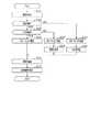
次に、ECU30により実施される自動運転制御を、図4を用いて説明する。図4のフローチャートで示す処理は、自動運転制御の実施下において、ECU30により所定周期で繰り返し実施される。そのため、図4の処理の実施前に、ECU30は、地図情報MP1により、自車の走行経路を計画しているものとする。 Next, automatic operation control performed by the
ステップS11では、計測点情報MP2から、検出地物F2を抽出する。本実施形態では、計測点情報MP2のうち、存在確率が判定閾値以上となるブロックの集合を検出地物F2として抽出する。 In step S11, the detected feature F2 is extracted from the measurement point information MP2. In the present embodiment, from the measurement point information MP2, a set of blocks whose existence probability is equal to or higher than the determination threshold is extracted as the detected feature F2.
ステップS12では、ステップS11で抽出した全ての検出地物F2と地図情報MP1から抽出される登録地物F1との間で、比較処理を実施したか否かを判定する。全ての検出地物F2を比較処理していれば、ステップS20に進む。一方、ステップS11で抽出した全ての検出地物F2を比較処理していなければ、ステップS13に進む。 In step S12, it is determined whether comparison processing has been performed between all the detected features F2 extracted in step S11 and the registered features F1 extracted from the map information MP1. If all the detected features F2 have been compared, the process proceeds to step S20. On the other hand, if not all the detected features F2 extracted in step S11 have been compared, the process proceeds to step S13.
ステップS13では、ステップS11で抽出した検出地物F2のうち、地図情報MP1と計測点情報MP2との一致を判定するための対象を選択する。 In step S13, a target for determining a match between the map information MP1 and the measurement point information MP2 is selected from the detected features F2 extracted in step S11.
ステップS14では、ステップS13で選択した検出地物F2が自車の走行範囲に近い位置に存在しているか否かを判定する。例えば、自車中心からステップS13で選択した検出地物F2までの横方向Xでの距離が予め定められた範囲内である場合、検出地物F2が自車の走行範囲に近い位置に存在していると判定する。選択した検出地物F2が自車の走行範囲に近い位置に存在していないと判定すれば、ステップS12に戻る。一方、選択した検出地物F2が自車の走行範囲に近い位置に存在していると判定すると、ステップS15に進む。 In step S14, it is determined whether or not the detected feature F2 selected in step S13 is present at a position close to the traveling range of the own vehicle. For example, when the distance in the lateral direction X from the center of the vehicle to the detected feature F2 selected in step S13 is within a predetermined range, the detected feature F2 exists at a position close to the traveling range of the own vehicle. It is determined that If it is determined that the selected detected feature F2 does not exist at a position close to the traveling range of the host vehicle, the process returns to step S12. On the other hand, if it is determined that the selected detected feature F2 is present at a position close to the traveling range of the host vehicle, the process proceeds to step S15.
ステップS15では、ステップS13で選択した検出地物F2を対象として、計測点情報MP2と地図情報MP1との一致状態を判定する。具体的には、検出地物F2が抽出されたブロックに対応する位置を地図情報MP1から特定し、特定した位置を含む所定範囲内に登録されている登録地物F1を抽出する。そして、抽出した登録地物F1と、検出地物F2との種別及び位置の比較を行う。 In step S15, the coincidence state of the measurement point information MP2 and the map information MP1 is determined for the detected feature F2 selected in step S13. Specifically, the position corresponding to the block from which the detected feature F2 is extracted is specified from the map information MP1, and the registered feature F1 registered within a predetermined range including the specified position is extracted. Then, the type and position of the extracted registered feature F1 and the detected feature F2 are compared.
ステップS15における一致状態の判定において、検出地物F2と登録地物F1とが一致すれば一致判定し、ステップS16に進む。一方、ステップS15において、検出地物F2と同一種別の登録地物F1を抽出できない場合は、不一致判定をし、ステップS17に進む。ステップS15が判定部及び判定工程に相当する。 In the determination of the coincidence state in step S15, if the detected feature F2 and the registered feature F1 match, a match determination is made, and the process proceeds to step S16. On the other hand, if the registered feature F1 of the same type as the detected feature F2 cannot be extracted in step S15, a mismatch determination is made, and the process proceeds to step S17. Step S15 corresponds to a determination unit and a determination step.
ステップS16では、対象とする検出地物F2が地図情報MP1に登録された登録地物F1と一致しているとし、ステップS12に戻る。一致判定を行った検出地物F2に対して一致判定フラグを設定してもよい。 In step S16, it is assumed that the target detected feature F2 matches the registered feature F1 registered in the map information MP1, and the process returns to step S12. A match determination flag may be set for the detected feature F2 for which the match determination has been performed.
ステップS17では、不一致判定を行った検出地物F2が、進行方向Yにおいて、登録地物F1よりも自車側に位置しているか否かを判定する。進行方向Yにおいて、検出地物F2よりも自車側に移動物が存在している場合、レーダ装置12又はレーザ装置13が地物と移動物とを1つの地物として検出している可能性が高くなる。そのため、進行方向Yにおいて、検出地物F2が登録地物F1よりも自車側に位置している場合、ステップS18に進む。 In step S <b> 17, it is determined whether or not the detected feature F <b> 2 that has been subjected to the discrepancy determination is positioned closer to the vehicle side than the registered feature F <b> 1 in the traveling direction Y. In the traveling direction Y, when there is a moving object on the vehicle side with respect to the detected feature F2, the
ステップS18では、検出地物F2の周囲に移動物が存在していると判定する。本実施形態では、検出地物F2を抽出したブロックに対して、移動物が存在する可能性を示す情報を付与する。例えば、移動物の存在する可能性を示す移動確率を高くする。 In step S18, it is determined that there is a moving object around the detected feature F2. In the present embodiment, information indicating the possibility that a moving object exists is assigned to the block from which the detected feature F2 is extracted. For example, the movement probability indicating the possibility of moving objects is increased.
一方、ステップS17において、検出地物F2が登録地物F1よりも進行方向Yにおいて自車側に位置していない場合、ステップS19に進む。ステップS19では、対象とする検出地物F2を地図情報MP1に登録されている登録地物F1と一致していないと判定する。例えば、不一致判定した検出地物F2に対して不一致判定フラグを設定してもよい。 On the other hand, when the detected feature F2 is not located on the own vehicle side in the traveling direction Y with respect to the registered feature F1 in step S17, the process proceeds to step S19. In step S19, it is determined that the target detected feature F2 does not match the registered feature F1 registered in the map information MP1. For example, a mismatch determination flag may be set for the detected feature F2 determined to be mismatched.
ステップS12において、ステップS11で抽出した全ての検出地物F2に対して比較処理を実施した場合、ステップS20に進む。ステップS20では、不一致判定を行った検出地物F2が存在するか否かを判定する。不一致判定を行った検出地物F2が存在する場合、ステップS21に進み、認識対象を認識し易くすることで自車挙動を制御する。一方、不一致判定フラグを設定している検出地物F2が存在しない場合、ステップS22に進み、検出地物F2を認識対象として認識することで自車挙動を制御する。ステップS21,S22が挙動制御部に相当する。 In step S12, when the comparison process is performed on all the detected features F2 extracted in step S11, the process proceeds to step S20. In step S20, it is determined whether or not the detected feature F2 that has been subjected to the mismatch determination exists. If there is a detected feature F2 that has been determined to be inconsistent, the process proceeds to step S21, and the vehicle behavior is controlled by making it easy to recognize the recognition target. On the other hand, when there is no detected feature F2 for which the mismatch determination flag is set, the process proceeds to step S22, and the vehicle behavior is controlled by recognizing the detected feature F2 as a recognition target. Steps S21 and S22 correspond to a behavior control unit.
図5は、ステップS22で実施する走行可能領域の推定処理を詳細に示すフローチャートである。ステップS22に進む場合、計測点情報MP2と地図情報MP1とが一致しているため、ステップS31では、検出地物F2により自車周囲の認識対象を認識する。 FIG. 5 is a flowchart showing in detail the estimation process of the travelable area performed in step S22. When the process proceeds to step S22, since the measurement point information MP2 and the map information MP1 coincide with each other, in step S31, the recognition target around the own vehicle is recognized by the detected feature F2.
ステップS32では、走行可能領域を推定する。本実施形態では、ステップS31で認識対象として認識した検出地物F2の位置により、自車の走行可能領域を推定する。 In step S32, a travelable area is estimated. In the present embodiment, the travelable area of the host vehicle is estimated based on the position of the detected feature F2 recognized as the recognition target in step S31.
図6は、一致判定がなされた場合の、走行可能領域の推定を説明する図である。各ブロックのうち、認識対象に対応するブロックに対してハッチングを付している。また、走行可能領域ARを破線で囲む領域により示している。図6では、自車の前方において、進行方向Yに延びる縁石が存在しており、ECU30は、この縁石を検出地物F21,F22として抽出しているものとする。そのため、認識対象の位置は、検出地物F21,F22として抽出したブロックとなる。 FIG. 6 is a diagram for explaining the estimation of the travelable area when the coincidence determination is made. Among each block, the block corresponding to the recognition target is hatched. Further, the travelable area AR is indicated by an area surrounded by a broken line. In FIG. 6, it is assumed that there is a curb extending in the traveling direction Y in front of the host vehicle, and the
計測点情報MP2において、認識対象に対応するブロックを障害物として判定することで、判定した位置を避けるように走行可能領域を推定する。図6では、進行方向Yにおいて、検出地物F21,F22を除く領域を、走行可能領域ARとして推定している。例えば、周知のカルマンフィルターを用いることで、前回の処理において抽出している検出地物F2の位置を反映させて走行可能領域を推定するものであってもよい。 In the measurement point information MP2, by determining the block corresponding to the recognition target as an obstacle, the travelable area is estimated so as to avoid the determined position. In FIG. 6, in the traveling direction Y, an area excluding the detected features F21 and F22 is estimated as the travelable area AR. For example, the travelable area may be estimated by reflecting the position of the detected feature F2 extracted in the previous process by using a known Kalman filter.
図4に戻り、不一致判定を行った検出地物F2が存在する場合、ステップS21に進む。この場合、地図情報MP1と計測点情報MP2とが一致しておらず、認識対象を認識し易くすることで、自車挙動を制御する。以下では、ステップS21で実施する一例の処理をフェイル処理とする。 Returning to FIG. 4, if there is a detected feature F2 for which the mismatch determination has been made, the process proceeds to step S21. In this case, the map information MP1 and the measurement point information MP2 do not match, and the vehicle behavior is controlled by making it easy to recognize the recognition target. Hereinafter, the example process performed in step S21 is referred to as a fail process.
図7は、ステップS21で実施する走行可能領域の推定を説明するフローチャートである。 FIG. 7 is a flowchart for explaining the estimation of the travelable area performed in step S21.
ステップS41では、地図情報MP1及び計測点情報MP2を含む範囲において認識対象が存在していると認識する。本実施形態では、計測点情報MP2から抽出した検出地物F2と、地図情報MP1から抽出できる登録地物F1とを融合させて、自車周囲に位置する認識対象を認識するための新たなマップである融合マップMP3を作成する。そして、作成した融合マップMP3により認識対象を認識する。 In step S41, it recognizes that the recognition target exists in the range containing map information MP1 and measurement point information MP2. In the present embodiment, a new map for recognizing recognition objects located around the vehicle by fusing the detected feature F2 extracted from the measurement point information MP2 and the registered feature F1 that can be extracted from the map information MP1. A fusion map MP3 is created. Then, the recognition target is recognized by the created fusion map MP3.
融合マップMP3は、地図情報MP1及び計測点情報MP2のそれぞれから抽出できる各地物F1,F2の位置を記録することにより作成される。ECU30は、融合マップMP3により自車周囲から抽出できる登録地物F1及び検出地物F2を認識対象として認識する。 The fusion map MP3 is created by recording the positions of the feature points F1 and F2 that can be extracted from the map information MP1 and the measurement point information MP2. The
例えば、ECU30は、融合マップMP3から登録地物F1及び検出地物F2のいずれかのみを抽出した場合、抽出した登録地物F1及び検出地物F2のいずれかを、認識対象として認識する。一方、ECU30は、融合マップMP3から、登録地物F1と検出地物F2との両者を抽出した場合において、登録地物F1と検出地物F2との位置にずれがある場合、抽出した各地物F1,F2を共に含む領域を全体として、認識対象を認識する。 For example, when only one of the registered feature F1 and the detected feature F2 is extracted from the fusion map MP3, the
図8は、ステップS41で作成される融合マップMP3を説明する図である。図8(a),(b)では、自車進行方向に延びる2つの縁石が存在している場合を示している。図8(a),(b)において、検出地物F23,F24,F25,F26が縁石に対応している。 FIG. 8 is a diagram for explaining the fusion map MP3 created in step S41. FIGS. 8A and 8B show a case where there are two curbs extending in the traveling direction of the host vehicle. In FIGS. 8A and 8B, the detected features F23, F24, F25, and F26 correspond to curbstones.
図8(a)において、地図情報MP1には、実際には存在していないガードレールが登録地物F11として登録されている。そのため、図8(a)の例では、ステップS41において、検出地物F23,F24と、登録地物F11とのそれぞれを別々の認識対象として認識する。また、図8(b)では、地図情報MP1には、登録地物F12,F13として登録されている縁石の位置が、検出地物F25,F26の位置に対して横方向Xにずれが生じている。図8(b)の例では、ステップS41において、検出地物F25と登録地物F12とを1つの認識対象として認識し、センサ検出地物26と登録地物F13とを1つの認識対象として認識する。 In FIG. 8A, a guardrail that does not actually exist is registered as a registered feature F11 in the map information MP1. Therefore, in the example of FIG. 8A, in step S41, the detected features F23 and F24 and the registered feature F11 are recognized as separate recognition targets. In FIG. 8B, in the map information MP1, the position of the curb registered as the registered features F12 and F13 is shifted in the lateral direction X with respect to the positions of the detected features F25 and F26. Yes. In the example of FIG. 8B, in step S41, the detected feature F25 and the registered feature F12 are recognized as one recognition target, and the sensor detection feature 26 and the registered feature F13 are recognized as one recognition target. To do.
ステップS42では、ステップS41で認識した認識対象により、走行可能領域を推定する。具体的には、融合マップMP3により認識した認識対象を障害物として判定し、判定した位置を除く自車前方の領域を走行可能領域として推定する。図8(a)の例では、検出地物F23及びF24と、登録地物F11と、を避けるように走行可能領域ARが推定されている。図8(b)の例では、検出地物F25と登録地物F12とを一体として認識した領域、及び検出地物F26と登録地物F13とを一体として認識した領域を避けるように走行可能領域ARが推定されている。そのため、S42で推定される走行可能領域は、地図情報MP1及び計測点情報MP2の両者を含む範囲により推定されたものとなる。 In step S42, the travelable area is estimated based on the recognition target recognized in step S41. Specifically, the recognition target recognized by the fusion map MP3 is determined as an obstacle, and an area in front of the host vehicle excluding the determined position is estimated as a travelable area. In the example of FIG. 8A, the travelable area AR is estimated so as to avoid the detected features F23 and F24 and the registered feature F11. In the example of FIG. 8B, the travelable region avoids the region in which the detected feature F25 and the registered feature F12 are recognized as a unit and the region in which the detected feature F26 and the registered feature F13 are recognized as a unit. AR is estimated. Therefore, the travelable area estimated in S42 is estimated based on a range including both the map information MP1 and the measurement point information MP2.
図7に戻り、ステップS43では、外部サーバに対して地図情報MP1と計測点情報MP2とが一致しないこと通知する。例えば、外部サーバから最新の地図情報MP1をダウンロードするものであってもよい。 Returning to FIG. 7, in step S43, the external server is notified that the map information MP1 and the measurement point information MP2 do not match. For example, the latest map information MP1 may be downloaded from an external server.
ステップS44では、自動運転から手動運転への切り替えを運転者に要請する。例えば、表示装置45に、運転者に自動運転から手動運転への切り替えを要請する画像を表示する。運転者は、表示装置45に表示された画像を確認することで、自動運転から手動運転への切り替えが要請されていることを判断することができる。 In step S44, the driver is requested to switch from automatic operation to manual operation. For example, the
ステップS45では、自車速度を低下させる。地図情報MP1と計測点情報MP2とが一致しない場合、推定した走行可能範囲が実際の認識対象の位置に対応していないおそれがある。運転者が自動運転を手動運転に切り替えるまでは、自動運転を継続するため、自車速度を低下させることで、自動運転を継続することによる自車と対象物体との衝突可能性を低下させる。例えば、図7の処理を実施する毎に、自車速を段階的に低下させる。ステップS41,S42,S43,S45が変更部及び変更工程に相当する。 In step S45, the host vehicle speed is reduced. If the map information MP1 and the measurement point information MP2 do not match, the estimated travelable range may not correspond to the actual position of the recognition target. Until the driver switches the automatic driving to the manual driving, the automatic driving is continued. Therefore, by reducing the speed of the own vehicle, the possibility of collision between the own vehicle and the target object by continuing the automatic driving is reduced. For example, every time the process of FIG. 7 is performed, the host vehicle speed is decreased stepwise. Steps S41, S42, S43, and S45 correspond to a changing unit and a changing process.
図4に戻り、ステップS23では、運転者による自動運転から手動運転への切替操作が実施されたか否かを判定する。例えば、運転者が操作部44を操作することで、切替操作に伴う入力信号がECU30に入力される。そのため、切替操作に伴う入力信号を検出することで、自動運転から手動運転への切替操作の実施の有無を判定する。 Returning to FIG. 4, in step S <b> 23, it is determined whether or not the switching operation from the automatic driving to the manual driving by the driver has been performed. For example, when the driver operates the
切替操作が実施されていないと判定した場合、図4の処理を一旦終了する。一方、切替操作が実施されたと判定した場合、ステップS24では、手動運転から自動運転への切り替えを禁止する。地図情報MP1と計測点情報MP2とが一致していない状態で、自動運転を再度実施させることは望ましくないためである。ステップS24が、変更禁止部に相当する。そして、図4の処理を一旦終了する。 If it is determined that the switching operation has not been performed, the process of FIG. 4 is temporarily terminated. On the other hand, if it is determined that the switching operation has been performed, switching from manual operation to automatic operation is prohibited in step S24. This is because it is not desirable to perform the automatic driving again in a state where the map information MP1 and the measurement point information MP2 do not match. Step S24 corresponds to a change prohibition unit. Then, the process of FIG. 4 is temporarily terminated.
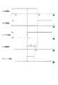
図9は、図7の処理において、自動運転を手動運転へ切り替えるまでの流れを説明するタイミングチャートである。図9(a)は、自動運転の実施の有無の推移を示している。図9(b)は、手動運転の実施の有無の推移を示している。図9(c)は、不一致判定の推移を示している。図9(d)は、運転者による手動運転から自動運転への切替操作の有無の推移を示している。図9(e)は、フェイル処理の実施の有無の推移を示している。 FIG. 9 is a timing chart for explaining the flow until the automatic operation is switched to the manual operation in the process of FIG. FIG. 9A shows a transition of whether or not automatic driving is performed. FIG. 9B shows a transition of whether or not manual operation is performed. FIG. 9C shows the transition of the mismatch determination. FIG. 9D shows the transition of the presence or absence of a switching operation from manual driving to automatic driving by the driver. FIG. 9E shows the transition of whether or not the fail process is performed.
時刻t0では、運転者により自動運転が選択されており、自車が自動運転されている。時刻t1において、地図情報MP1と計測点情報MP2との不一致が判定されたとする。時刻t1において、自動運転を継続させるべくフェイル処理の実施が開始される。 At time t0, automatic driving is selected by the driver, and the vehicle is automatically driven. Assume that a mismatch between the map information MP1 and the measurement point information MP2 is determined at time t1. At time t1, the fail process is started to continue the automatic operation.
時刻t2において、運転者による切替操作の入力がされることで、フェイル処理が終了される。即ち、フェイル処理は、地図情報MP1と計測点情報MP2との不一致が判定されてから、運転者による自動運転から手動運転への切替操作がなされるまでの期間Tf(t1−t2)において継続される。そして、時刻t3において、自動運転が終了し、運転者による手動運転が開始される。 At time t2, the fail process is terminated by inputting the switching operation by the driver. That is, the fail process is continued in a period Tf (t1-t2) from when the mismatch between the map information MP1 and the measurement point information MP2 is determined until the driver performs a switching operation from automatic driving to manual driving. The Then, at time t3, the automatic operation ends, and the manual operation by the driver is started.
以上説明したように、本実施形態では、ECU30は、自動運転制御の実施中に地図情報MP1と計測点情報MP2との不一致判定を行った場合に、その不一致の状況に応じて自動運転制御の制御態様を変更する。この場合、地図情報MP1と計測点情報MP2とが不一致になっても、その不一致の状況に応じて制御態様が変更されて自動運転制御が継続される。したがって、自車において自動運転制御を適正に実施することができる。 As described above, in the present embodiment, when the
・ECU30は、自動運転制御の実施中に不一致判定を行った場合に、運転者による手動運転への切り替えを要請する。そして、手動運転への切り替えが要請された後、運転者による手動運転が開始されるまでの期間において、自動運転制御の制御態様を変更することとした。上記構成によれば、地図情報MP1及び計測点情報MP2の不一致判定がなされ、運転者による手動運転への切り替えが要請された場合に、運転者による手動運転が開始されるまでの期間で自動運転制御の制御態様が変更される。この場合、手動運転への切替要請から実際に手動運転に切り替えられるまでに時間を要しても、自車を適正に走行させることができる。 -ECU30 requests | requires switching to a manual driving | operation by a driver | operator, when a mismatch determination is performed during implementation of automatic driving | operation control. And after switching to the manual operation was requested | required, it decided to change the control aspect of automatic operation control in the period until the manual operation by a driver | operator is started. According to the above configuration, when the mismatch between the map information MP1 and the measurement point information MP2 is determined and the driver requests switching to manual driving, automatic driving is performed until the driver starts manual driving. The control mode of control is changed. In this case, even if it takes time from the request for switching to manual driving to the actual switching to manual driving, the host vehicle can travel appropriately.
・ECU30は、自動運転制御として、地図情報MP1及び計測点情報MP2により自車周辺における検出地物F2を認識し、その認識結果に基づいて自車挙動を制御する。そして、CU30は、自動運転制御の実施中に不一致判定を行った場合に、一致判定を行った場合に比べて地物を認識し易くすることにより、自動運転制御の制御態様を変更することとした。この場合、自動運転制御の実施に際し、地図情報MP1及び計測点情報MP2が不一致である場合に、一致している場合に比べて自車周辺の認識対象を認識し易くすることで、地図情報MP1及び車載センサ10のいずれに不備がある場合でも、認識対象の認識漏れを抑制することができる。これにより、自車挙動を適正に制御することができる。 The
・ECU30は、一致判定を行った場合は、計測点情報MP2により認識対象を認識し、その認識結果に基づいて自車挙動を制御する。これに対し、ECU30は、不一致判定を行った場合には、その不一致の各情報が含まれる範囲で認識対象を認識し、その認識結果に基づいて自車挙動を制御する。本構成によれば、地図情報MP1及び計測点情報MP2が不一致となる場合には、地物を認識し易くすることで、地物の認識漏れの抑制を優先することができる。これにより、地図情報MP1及び計測点情報MP2が不一致となる状況下でも、自車挙動を適正に制御することができる。 -ECU30 recognizes a recognition target by measurement point information MP2, and controls own vehicle behavior based on the recognition result, when a coincidence determination is performed. On the other hand, when the mismatch determination is made, the
・ECU30は、不一致判定に伴い手動運転への切替を実施した場合に、手動運転から自動運転への変更を禁止することとした。この場合、自動運転制御が適正に実施されないおそれがある状況下で、自動運転制御が再実施されるのを防止することができる。 The
(第2実施形態)
この第2実施形態では、第1実施形態と異なる構成を中心に説明する。なお、同一の符号は第1実施形態と同一の構成を示すため、その説明を繰り返さない。(Second Embodiment)
In the second embodiment, a description will be given focusing on a configuration different from the first embodiment. In addition, since the same code | symbol shows the structure same as 1st Embodiment, the description is not repeated.
図10は、地図情報MP1と計測点情報MP2との各地物F1,F2の抽出タイミングの推移を説明する図である。図10(a)は、地図情報MP1が不一致の原因となる場合の抽出タイミングの推移を示している。図10(b)は、車載センサ10が不一致の原因となる場合の抽出タイミングの推移を示している。図10(a)、(b)では、ECU30により、同一の登録地物F1及び検出地物F2を抽出するタイミングを矢印により示している。このうち、登録地物F1を抽出するタイミングを下向きの矢印により示し、検出地物F2を抽出するタイミングを上向きの矢印により示している。そのため、地図情報MP1と計測点情報MP2とが一致する場合、同時刻において2つの矢印が向き合うことになる。 FIG. 10 is a diagram for explaining the transition of the extraction timing of the local features F1, F2 between the map information MP1 and the measurement point information MP2. FIG. 10A shows the transition of the extraction timing when the map information MP1 causes a mismatch. FIG. 10B shows the transition of the extraction timing when the in-
地図情報MP1は、例えば走行経路上の一部で道路改修されること等により実際の道路状況とは異なることが考えられる。そのため、地図情報MP1と計測点情報MP2とが不一致となる原因が地図情報MP1である場合には、その不一致は時系列で一時的であると考えられる。図10(a)では、時刻t11で地図情報MP1と計測点情報MP2とが一致した後、時刻t12で不一致となり、その後、一致している。 It is conceivable that the map information MP1 differs from the actual road condition due to, for example, the road being repaired on a part of the travel route. For this reason, when the cause of the mismatch between the map information MP1 and the measurement point information MP2 is the map information MP1, the mismatch is considered to be temporary in time series. In FIG. 10A, after the map information MP1 and the measurement point information MP2 match at time t11, they do not match at time t12, and then match.
車載センサ10が異常となる場合、その出力の異常は継続するため、時系列の長い期間にわたって不一致の状態が続くと考えられる。図10(b)では、時刻t22以降は、不一致が継続している。かかる事情を加味すると、不一致状態の時系列変化によって、地図情報MP1と計測点情報MP2とが不一致となる原因を適正に判定することが可能となる。そして、原因特定できることにより、原因に応じた適正な自動運転制御を実施することが可能となる。 When the in-
図11は、第2実施形態において、図4のステップS21で、ECU30が実施するフェイル処理を説明するフローチャートである。 FIG. 11 is a flowchart illustrating a fail process performed by the
ステップS51では、不一致状態の時系列変化に基づいて、不一致の原因が地図情報MP1及び車載センサ10のいずれであるかを特定する。例えば、ECU30は、不一判定が継続する時間を監視し、継続時間を所定の判定時間T1,T2と比較することで、不一致の原因を判定する。継続時間が所定の第1判定時間T1よりも長く、第2判定時間T2よりも短い場合、不一致判定の原因を地図情報MP1とする。継続時間が、第2判定時間T2よりも長い期間で継続する場合、不一致判定の原因を車載センサ10とする。 In step S51, it is specified whether the cause of the mismatch is the map information MP1 or the in-
第2判定時間T2で示される時間は、道路において道路工事等が行われることを想定した場合に、自車がその工事区間を走行するのに要する時間に基づき定められていてもよい。具体的には、数10メートルから数100メートルの工事区間を自車が所定速度(例えば、法定速度)で走行することを想定して、第2判定時間T2が定められればよい。また、第1判定時間T1は第2判定時間T2よりも小さい時間であればよい。ステップS51が、原因特定部に相当する。 The time indicated by the second determination time T2 may be determined based on the time required for the host vehicle to travel through the construction section when it is assumed that road construction or the like is performed on the road. Specifically, the second determination time T2 may be determined on the assumption that the vehicle travels at a predetermined speed (for example, legal speed) in a construction section of several tens of meters to several hundreds of meters. Further, the first determination time T1 may be a time shorter than the second determination time T2. Step S51 corresponds to a cause identifying unit.
ステップS52では、不一致の原因を特定できたか否かを判定する。不一致の原因を特定できた場合、ステップS53に進む。ステップS53では、不一致の原因が車載センサ10であるか否かを判定する。 In step S52, it is determined whether or not the cause of the mismatch has been identified. If the cause of the mismatch can be identified, the process proceeds to step S53. In step S53, it is determined whether or not the cause of the mismatch is the in-
ステップS53において、不一判定の原因が車載センサ10であると特定している場合、ステップS54に進む。ステップS54では、地図情報MP1を用いて走行可能領域を推定する。この場合、車載センサ10が不一致の原因である可能性が高いため、不一致の原因でない地図情報MP1を走行可能領域の推定に用い、計測点情報MP2を走行可能領域の推定に用いない。 If it is determined in step S53 that the cause of the non-uniformity determination is the in-
ステップS53において、不一致の原因が車載センサ10でなく地図情報MP1であると特定している場合、ステップS55に進む。ステップS55では、計測点情報MP2を用いて走行可能領域を推定する。この場合、地図情報MP1が不一致の原因である可能性が高いため、不一致の原因でない計測点情報MP2を走行可能領域の推定に用い、地図情報MP1を走行可能領域の推定に用いない。 If it is determined in step S53 that the cause of the mismatch is not the in-
ステップS56では、外部サーバに対して地図情報の更新を要求する。地図情報MP1を更新することで、地図情報MP1と計測点情報MP2との不一致が解消される可能性が高いためである。 In step S56, the external server is requested to update the map information. This is because updating the map information MP1 is likely to eliminate the discrepancy between the map information MP1 and the measurement point information MP2.
ステップS52において、不一致の原因を特定できない場合、ステップS41に進む。例えば、不一致判定の継続時間が第1判定時間T1以下である場合である。ステップS41では、地図情報MP1と計測点情報MP2とを共に用いて認識対象を認識する。本実施形態では、融合マップMP3を作成し、この融合マップMP3により認識対象を認識する。 If the cause of the mismatch cannot be identified in step S52, the process proceeds to step S41. For example, this is a case where the duration of the mismatch determination is equal to or shorter than the first determination time T1. In step S41, the recognition target is recognized using both the map information MP1 and the measurement point information MP2. In the present embodiment, a fusion map MP3 is created, and a recognition target is recognized by this fusion map MP3.
ステップS42では、ステップS41で認識した認識対象を用いて走行可能領域を推定する。そして、ステップS44,S45の処理を実施すると、図11の処理を一旦終了する。 In step S42, a travelable area is estimated using the recognition target recognized in step S41. Then, when the processes of steps S44 and S45 are performed, the process of FIG.
以上説明したように、本実施形態では、ECU30は、自動運転制御の実施中に不一致判定を行った場合に、その不一致状態の時系列変化に基づいて、不一致の原因が地図情報MP1及び計測点情報MP2のいずれであるかを特定する。そして、原因の特定結果に基づいて、自動運転制御の制御態様を変更することとした。この場合、不一致状態の時系列変化によって、地図情報MP1と計測点情報MP2とが不一致となる原因を適正に判定することが可能となる。そして、原因特定できることにより、原因に応じた適正な自動運転制御を実施することが可能となる。 As described above, in the present embodiment, when the
・ECU30は、不一致判定の原因を特定していない場合に、地図情報MP1及び計測点情報MP2を用いた自動運転制御を実施し、不一致判定の原因を特定した場合に、地図情報MP1及び計測点情報MP2のうち不一致の原因でない方を用いて自動運転制御を実施する。上記構成では、地図情報MP1と計測点情報MP2との不一致の原因が特定されていない場合に、地図情報MP1及び計測点情報MP2を用いた自動運転制御を実施することにより、認識対象の認識漏れの抑制を優先することができる。また、不一致の原因が特定されている場合に、地図情報MP1及び計測点情報MP2のうち不一致の原因でない方を用いて自動運転制御を実施することにより、誤った情報を不採用とすることで、自動運転制御の信頼性を高めることができる。 The
(第3実施形態)
この第3実施形態では、第2実施形態と異なる構成を中心に説明する。なお、同一の符号は第1実施形態と同一の構成を示すため、その説明を繰り返さない。(Third embodiment)
In the third embodiment, the description will be focused on a configuration different from that of the second embodiment. In addition, since the same code | symbol shows the structure same as 1st Embodiment, the description is not repeated.
手動運転中は、運転者の目視に基づく自車の認識対象に対する回避動作が実施されるため、手動運転での走行経路は周囲の認識対象を適正に反映しているといえる。そのため、第3実施形態では、ECU30による不一致判定により自動運転から手動運転に変更された場合に、手動運転時での回避動作を用いて、不一致の原因を特定する。 During manual driving, the avoidance operation for the recognition target of the own vehicle based on the visual observation of the driver is performed, so it can be said that the travel route in manual driving appropriately reflects the surrounding recognition target. Therefore, in 3rd Embodiment, when it changes from automatic driving | running | working to manual driving | running | working by mismatch determination by ECU30, the cause of mismatch is specified using the avoidance operation | movement at the time of manual driving | operation.
図12は、手動運転時においてECU30により実施される原因特定処理を説明するフローチャートである。図12に示す処理は、自動運転から手動運転への変更が行われた場合に、ECU30により所定周期で実施される処理である。 FIG. 12 is a flowchart for explaining cause identifying processing performed by the
ステップS60では、運転者による自車挙動操作の情報を取得する。本実施形態では、挙動操作の情報として、運転者がハンドルを操作したことで操舵装置42が生成する操作情報を取得する。ステップS60が取得部に相当する。 In step S60, information on the own vehicle behavior operation by the driver is acquired. In the present embodiment, operation information generated by the
ステップS61では、不一致判定に基づく自動運転から手動運転への切替を実施したか否かを判定する。肯定判定した場合、ステップS62に進む。例えば図4のステップS23において運転者が自動運転から手動運転への切替操作を実施していればS62に進む。一方、運転者が自動運転から手動運転への切替操作を実施していなければ、図12の処理を一旦終了する。 In step S61, it is determined whether or not switching from automatic operation to manual operation based on the mismatch determination is performed. If a positive determination is made, the process proceeds to step S62. For example, if the driver has performed switching operation from automatic driving to manual driving in step S23 of FIG. 4, the process proceeds to S62. On the other hand, if the driver has not performed the switching operation from the automatic driving to the manual driving, the processing of FIG.
ステップS62では、不一致判定の原因が車載センサ10であったか否かを判定する。図11のステップS53において、車載センサ10を不一致の原因としている場合、ステップS63に進む。 In step S62, it is determined whether or not the cause of the mismatch determination is the in-
ステップS63では、運転者の手動運転による自車挙動が検出地物F2に沿ったものであるか否かを判定する。例えば、ステップS60で取得した挙動操作の情報により、検出地物F2を避けるように自車が走行している場合、自車挙動が計測点情報MP2に沿ったものであると判定する。例えば、検出地物F2を避けるように自車挙動が操作されることにより、進行方向Y及び横方向Xのいずれかにおいて、自車から検出地物F2までの距離が大きくなっている場合に、自車挙動が検出地物F2に沿ったものであると判定すればよい。 In step S63, it is determined whether or not the own vehicle behavior by the driver's manual driving is along the detected feature F2. For example, when the host vehicle is traveling so as to avoid the detected feature F2 based on the behavior operation information acquired in step S60, it is determined that the host vehicle behavior is along the measurement point information MP2. For example, when the own vehicle behavior is operated so as to avoid the detected feature F2, the distance from the own vehicle to the detected feature F2 is increased in either the traveling direction Y or the lateral direction X. What is necessary is just to determine with the own vehicle behavior being along the detected feature F2.
自車挙動が検出地物F2に沿ったものであると判定すれば、ステップS64では、自動運転の復帰を許可する。この場合、手動運転による挙動を用いた精度が高い判定により、車載センサ10が正常であることを判定しているためである。一方、自車挙動が検出地物F2に沿ったものでないと判定すれば、自動運転の復帰を許可することなく図12の処理を終了する。 If it is determined that the vehicle behavior is along the detected feature F2, in step S64, the return of automatic driving is permitted. In this case, it is because it determines with the vehicle-mounted
ステップS62において、車載センサ10を不一致の原因と判定していない場合、ステップS65に進む。ステップS65では、地図情報MP1を不一致の原因と判定しているか否かを判定する。例えば、図11のステップS53において、地図情報MP1を不一致の原因として判定している場合は、ステップS66に進む。 If it is not determined in step S62 that the in-
ステップS66では、自車挙動が登録地物F1に沿ったものであるか否かを判定する。例えば、ステップS60で取得した挙動操作の情報により、自車が登録地物F1を避けるように走行している場合、自車挙動が地図情報MP1に沿ったものであると判定する。例えば、登録地物F1を避けるように自車挙動が操作されることにより、進行方向Y及び横方向Xのいずれかにおいて、自車から登録地物F1までの距離が大きくなっている場合に、自車挙動が登録地物F1に沿ったものであると判定すればよい。 In step S66, it is determined whether or not the own vehicle behavior is along the registered feature F1. For example, if the vehicle is traveling so as to avoid the registered feature F1 based on the behavior operation information acquired in step S60, it is determined that the vehicle behavior is along the map information MP1. For example, when the own vehicle behavior is manipulated so as to avoid the registered feature F1, the distance from the own vehicle to the registered feature F1 is increased in either the traveling direction Y or the lateral direction X. What is necessary is just to determine with the own vehicle behavior being along the registration feature F1.
自車挙動が登録地物F1に沿ったものであると判定した場合、ステップS67では、自動運転の復帰を許可する。地図情報MP1が正常であると判定しているためである。一方、自車挙動が登録地物F1に沿ったものでないと判定した場合、自動運転の復帰を許可することなく、図12の処理を終了する。ステップS64,S67が復帰許可部に相当する。また、ステップS61〜S63,S65,S66が切替後特定部に相当する。 When it is determined that the vehicle behavior is along the registered feature F1, in step S67, the return of automatic driving is permitted. This is because it is determined that the map information MP1 is normal. On the other hand, when it is determined that the vehicle behavior is not along the registered feature F1, the processing of FIG. 12 is terminated without permitting the return of automatic driving. Steps S64 and S67 correspond to a return permission unit. Steps S61 to S63, S65, and S66 correspond to the post-switching specifying unit.
ステップS65において、地図情報MP1と車載センサ10とのいずれも不一致の原因と判定していない場合、図12の処理を一旦終了する。この場合、図11のステップS52において、不一致の原因が特定されていない場合である。なお、ステップS66の後、車の挙動が登録地物F1及び検出地物F2のいずれに沿ったものであるかを比較するものであってもよい。 If it is determined in step S65 that neither the map information MP1 nor the in-
以上説明したように本実施形態では、ECU30は、不一致判定による要請に伴い運転者による手動運転への切替が行われた場合に、運転者による車両の挙動操作の情報を取得する。そして、取得した挙動操作の情報と、地図情報MP1及び計測点情報MP2とのうち不一致の原因とされた方とを対比し、それら各情報が一致する場合に、手動運転制御への復帰を許可することとした。この場合、運転者の目視により不一致判定が適正であったか否かを事後的に判定することができ、不用意に自動運転が禁止されるのを防止することができる。 As described above, in the present embodiment, the
ECU30は、不一致判定に伴い手動運転への切替が行われた場合に、運転者による自車挙動操作の情報を取得する。そして、取得した挙動操作の情報と、地図情報MP1及び計測点情報MP2とを対比することに基づいて、不一致の原因が地図情報MP1及び計測点情報MP2のいずれであるかを特定することとした。この場合、運転者の目視を不一致判定の原因の特定に用いることで、地図情報MP1及び車載センサ10のいずれが不一致の原因となるかを精度良く特定することができる。 The
(その他の実施形態)
・上記第3実施形態では、自動運転から手動運転に切り替えられた場合において、運転者による挙動操作の情報と、手動運転への切り替え前に地図情報MP1及び計測点情報MP2のうち不一致の原因とされた方とを対比する構成としたが、これを変更してもよい。例えば、自動運転時に地図情報MP1と計測点情報MP2との不一致判定がなされた場合に、その原因特定を実施せず、自動運転から手動運転に切り替えられた後に、運転者による挙動操作の情報と、地図情報MP1及び計測点情報MP2との対比により、不一致の原因が地図情報MP1及び計測点情報MP2のいずれであるかを特定する構成であってもよい。(Other embodiments)
In the third embodiment, when switching from automatic driving to manual driving, the behavior operation information by the driver and the cause of mismatch between the map information MP1 and the measurement point information MP2 before switching to manual driving However, this may be changed. For example, when a mismatch between the map information MP1 and the measurement point information MP2 is determined during automatic driving, the cause is not specified, and after switching from automatic driving to manual driving, the behavior operation information by the driver and The configuration may be such that the cause of the mismatch is either the map information MP1 or the measurement point information MP2 by comparison with the map information MP1 and the measurement point information MP2.
・ECU30は、一致判定を行った場合に、地図情報MP1と計測点情報MP2とを共に用いて、認識対象を認識するものであってもよい。この場合、登録地物F1と検出地物F2とが共に抽出されたことを条件に認識対象を認識するため、認識対象の信頼度を高めることができる。 The
・ECU30は、自動運転制御の実施中に一致判定を行った場合に、地図情報MP1に登録されている登録地物F1に基づいて、認識対象を認識してもよい。 The
・ECU30は、自動運転制御の実施中に不一致判定を行った場合に、一致判定を行った場合に比べて、認識対象として認識するブロックの存在確率を低い値としてもよい。この場合、図4のステップS21において実施するフェイル処理において、計測点情報MP2から認識対象を認識する際に、検出地物F2の抽出に用いた判定閾値よりも低い判定閾値を用いて認識対象を認識する。 -ECU30 is good also as a value with a low existence probability of the block recognized as recognition object, when compared with the case where a coincidence determination is performed when a mismatch determination is performed during implementation of automatic driving control. In this case, when the recognition target is recognized from the measurement point information MP2 in the fail process performed in step S21 of FIG. 4, the recognition target is determined using a determination threshold lower than the determination threshold used for extraction of the detected feature F2. recognize.
・車両制御システム100は、車載センサ10として撮像装置11,レーダ装置12,及びレーザ装置13をそれぞれ備えることに代えて、レーダ装置12及びレーザ装置13を備えるものであってもよい。 The vehicle control system 100 may include the
・車載センサ10としてレーザ装置13の検出結果である状況マップを用いたのは一例に過ぎない。これ以外にも、撮像装置11の検出結果を用いるものであってもよい。 -The situation map which is a detection result of the
ECU30は、測距データを用いて認識した認識対象の位置と、撮像装置11から入力した画像データとを併用して、自車挙動を制御してもよい。この場合、ECU30は、画像データから得られる自車線の区画線を認識し、その区画線に基づく自車線の中心線を自車の目標横位置として設定する。そして、認識対象の位置と、自車の目標横位置とを用いて、自車挙動を制御する。 The
10…車載センサ、30…ECU、100…車両制御システム、MP1…地図情報、MP2…計測点情報。 DESCRIPTION OF
Claims (11)
Translated fromJapanese前記自動運転制御の実施中において前記地図情報と前記車載センサの検出情報とが一致するか否かを判定する判定部と、
前記判定部により不一致判定がなされた場合に、その不一致の状況に応じて前記自動運転制御の制御態様を変更する変更部と、を備える車両制御装置。A vehicle control device that sets a travel route to a destination using map information and performs automatic driving control of the vehicle based on the travel route and detection information around the vehicle detected by the in-vehicle sensor (10) (30)
A determination unit that determines whether or not the map information and the detection information of the in-vehicle sensor match during the execution of the automatic driving control;
A vehicle control device comprising: a change unit that changes a control mode of the automatic driving control in accordance with a mismatch situation when the determination unit makes a mismatch determination.
前記変更部は、前記手動運転への切り替えが要請された後、運転者による前記手動運転が開始されるまでの期間において、前記不一致の状況に応じて前記自動運転制御の制御態様を変更する、請求項1に記載の車両制御装置。In the automatic driving control, when a mismatch is determined by the determination unit, a request for switching to manual driving by the driver is requested.
The change unit changes the control mode of the automatic driving control according to the mismatched state in a period until the manual driving by the driver is started after switching to the manual driving is requested. The vehicle control device according to claim 1.
前記変更部は、前記判定部により不一致判定がなされた場合に、一致判定がなされた場合に比べて前記認識対象を認識し易くすることにより、前記自動運転制御の制御態様を変更する請求項1又は2に記載の車両制御装置。As the automatic driving control, a behavior control unit that recognizes a predetermined recognition target around the vehicle by the map information and detection information of the vehicle-mounted sensor, and controls the behavior of the vehicle based on the recognition result,
The said change part changes the control aspect of the said automatic driving | operation control by making it easy to recognize the said recognition object when the mismatch determination is made by the said determination part compared with the case where a match determination is made. Or the vehicle control apparatus of 2.
前記判定部により一致判定がなされた場合に、前記地図情報及び前記車載センサの検出情報のうち予め定めた一方の情報に基づいて前記認識対象の存在を認識し、
前記判定部により不一致判定がなされた場合に、前記認識対象を認識し易くすべく、前記地図情報に基づいて前記認識対象の存在を認識するとともに、前記車載センサの検出情報に基づいて前記認識対象の存在を認識する請求項3に記載の車両制御装置。The changing unit is
When the determination is made by the determination unit, the presence of the recognition target is recognized based on one of the predetermined information of the map information and the detection information of the in-vehicle sensor,
In order to make it easy to recognize the recognition target when the determination unit makes a mismatch determination, the presence of the recognition target is recognized based on the map information, and the recognition target is determined based on detection information of the in-vehicle sensor. The vehicle control device according to claim 3, wherein the existence of the vehicle is recognized.
前記変更部は、前記原因特定部の特定結果に基づいて、前記自動運転制御の制御態様を変更する請求項1〜4のいずれか1項に記載の車両制御装置。A cause identifying unit that identifies whether the cause of the mismatch is the map information or the detection information of the in-vehicle sensor based on a time-series change of the mismatch state when the determination unit performs a mismatch determination; Prepared,
The vehicle control device according to claim 1, wherein the changing unit changes a control mode of the automatic driving control based on a specifying result of the cause specifying unit.
前記要請に伴い前記運転者による前記手動運転への切替が行われた場合に、運転者による車両の挙動操作の情報を取得する取得部と、
前記取得部により取得された前記挙動操作の情報と、前記地図情報及び前記車載センサの検出情報のうち前記原因特定部により不一致の原因とされた方とを対比し、それら各情報が一致する場合に、前記手動運転への復帰を許可する復帰許可部と、を備える、請求項6に記載の車両制御装置。In the automatic driving control, when a mismatch is determined by the determination unit, a request for switching to manual driving by the driver is requested.
An acquisition unit that acquires information on behavior operation of the vehicle by the driver when the driver is switched to the manual driving in response to the request;
When the behavior operation information acquired by the acquisition unit and the map information and the detection information of the vehicle-mounted sensor are compared with the cause of the mismatch by the cause specifying unit, and the respective information matches. The vehicle control device according to claim 6, further comprising: a return permission unit that permits return to the manual operation.
前記要請に伴い前記運転者による前記手動運転への切替が行われた場合に、運転者による車両の挙動操作の情報を取得する取得部と、
前記取得部により取得された前記挙動操作の情報と、前記地図情報及び前記車載センサの検出情報とを対比することに基づいて、前記不一致の原因が前記地図情報及び前記車載センサの検出情報のいずれであるかを特定する切替後特定部と、
を備える、請求項1〜6のいずれか一項に記載の車両制御装置。In the automatic driving control, when a mismatch is determined by the determination unit, a request for switching to manual driving by the driver is requested.
An acquisition unit that acquires information on behavior operation of the vehicle by the driver when the driver is switched to the manual driving in response to the request;
Based on comparing the behavior operation information acquired by the acquisition unit with the map information and the detection information of the in-vehicle sensor, the cause of the mismatch is either the map information or the detection information of the in-vehicle sensor. A post-switching identifying unit that identifies whether or not
The vehicle control device according to any one of claims 1 to 6, comprising:
前記要請に伴い前記運転者による前記手動運転への切替が行われた場合に、前記手動運転から前記自動運転への変更を禁止する変更禁止部を備える、請求項1〜8のいずれか一項に記載の車両制御装置。In the automatic driving control, when a mismatch is determined by the determination unit, a request for switching to manual driving by the driver is requested.
9. A change prohibiting unit that prohibits a change from the manual driving to the automatic driving when the driver switches to the manual driving in response to the request. 9. The vehicle control device described in 1.
前記自動運転制御の実施中において前記地図情報と前記車載センサの検出情報とが一致するか否かを判定する判定工程と、
前記判定工程により不一致判定がなされた場合に、その不一致の状況に応じて前記自動運転制御の制御態様を変更する変更工程と、を備える車両制御方法。A vehicle control method for setting a travel route to a destination using map information and performing automatic driving control of the vehicle based on the travel route and detection information around the vehicle detected by the in-vehicle sensor (10) Because
A determination step of determining whether or not the map information and the detection information of the in-vehicle sensor match during the execution of the automatic driving control;
A vehicle control method comprising: a change step of changing a control mode of the automatic driving control in accordance with a mismatch situation when a mismatch determination is made in the determination step.
Priority Applications (2)
| Application Number | Priority Date | Filing Date | Title |
|---|---|---|---|
| JP2017135690AJP7003464B2 (en) | 2017-07-11 | 2017-07-11 | Vehicle control device, vehicle control method |
| US16/029,928US11016484B2 (en) | 2017-07-11 | 2018-07-09 | Vehicle control apparatus and method for performing automatic driving control |
Applications Claiming Priority (1)
| Application Number | Priority Date | Filing Date | Title |
|---|---|---|---|
| JP2017135690AJP7003464B2 (en) | 2017-07-11 | 2017-07-11 | Vehicle control device, vehicle control method |
Publications (2)
| Publication Number | Publication Date |
|---|---|
| JP2019020782Atrue JP2019020782A (en) | 2019-02-07 |
| JP7003464B2 JP7003464B2 (en) | 2022-01-20 |
Family
ID=64999617
Family Applications (1)
| Application Number | Title | Priority Date | Filing Date |
|---|---|---|---|
| JP2017135690AActiveJP7003464B2 (en) | 2017-07-11 | 2017-07-11 | Vehicle control device, vehicle control method |
Country Status (2)
| Country | Link |
|---|---|
| US (1) | US11016484B2 (en) |
| JP (1) | JP7003464B2 (en) |
Cited By (12)
| Publication number | Priority date | Publication date | Assignee | Title |
|---|---|---|---|---|
| JP2020142717A (en)* | 2019-03-07 | 2020-09-10 | 本田技研工業株式会社 | Vehicle control apparatus, vehicle control method, vehicle, and program |
| WO2021002223A1 (en)* | 2019-07-01 | 2021-01-07 | 住友電気工業株式会社 | Vehicle-mounted device, control method therefor, and vehicle |
| JP2021123262A (en)* | 2020-02-06 | 2021-08-30 | 本田技研工業株式会社 | Vehicle control devices, vehicle control methods, and programs |
| KR20220019111A (en)* | 2020-08-05 | 2022-02-16 | 한양대학교 에리카산학협력단 | Decision system for self driving cars |
| JP2022096906A (en)* | 2020-12-18 | 2022-06-30 | 株式会社Soken | Driving support system, driving support device, driving support method, image recognition device, and image recognition method |
| JP2022172444A (en)* | 2021-05-03 | 2022-11-16 | バイエリシエ・モトーレンウエルケ・アクチエンゲゼルシヤフト | METHOD AND ASSIST DEVICE FOR ASSISTING RUNNING OPERATION OF MOTOR VEHICLE, AND MOTOR VEHICLE |
| JPWO2023145740A1 (en)* | 2022-01-26 | 2023-08-03 | ||
| JP2023143308A (en)* | 2022-03-25 | 2023-10-06 | 本田技研工業株式会社 | Control device |
| JP2023544030A (en)* | 2020-09-29 | 2023-10-19 | メルセデス・ベンツ グループ アクチェンゲゼルシャフト | Map verification method |
| US12172671B2 (en) | 2021-07-09 | 2024-12-24 | Subaru Corporation | Vehicle navigation apparatus |
| US12249160B2 (en) | 2021-12-07 | 2025-03-11 | Toyota Jidosha Kabushiki Kaisha | Object assessment device, storage medium storing computer program for object assessment, and object assessment method |
| US12304531B2 (en) | 2022-01-17 | 2025-05-20 | Toyota Jidosha Kabushiki Kaisha | Device and method for generating trajectory, and non-transitory computer-readable medium storing computer program therefor |
Families Citing this family (7)
| Publication number | Priority date | Publication date | Assignee | Title |
|---|---|---|---|---|
| WO2019173611A1 (en)* | 2018-03-07 | 2019-09-12 | Mile Auto, Inc. | Monitoring and tracking mode of operation of vehicles to determine services |
| JP6985207B2 (en)* | 2018-05-09 | 2021-12-22 | トヨタ自動車株式会社 | Autonomous driving system |
| DE102019000899B4 (en) | 2019-02-07 | 2023-05-04 | Mercedes-Benz Group AG | Method and device for supporting a driver of a vehicle |
| US11549815B2 (en) | 2019-06-28 | 2023-01-10 | GM Cruise Holdings LLC. | Map change detection |
| WO2022144957A1 (en)* | 2020-12-28 | 2022-07-07 | 本田技研工業株式会社 | Vehicle control device, vehicle control method, and program |
| JP7540375B2 (en)* | 2021-03-22 | 2024-08-27 | トヨタ自動車株式会社 | Vehicle control device, vehicle control method, and vehicle control computer program |
| CN113393669A (en)* | 2021-06-11 | 2021-09-14 | 阿波罗智联(北京)科技有限公司 | Control method, device, equipment, medium and program product for vehicle |
Citations (7)
| Publication number | Priority date | Publication date | Assignee | Title |
|---|---|---|---|---|
| JPH06298108A (en)* | 1993-04-12 | 1994-10-25 | Aisin Seiki Co Ltd | Automatic steering device for vehicle |
| JPH09160643A (en)* | 1995-12-11 | 1997-06-20 | Toyota Motor Corp | Vehicle diagnostic system |
| JPH10141969A (en)* | 1996-11-11 | 1998-05-29 | Daihatsu Motor Co Ltd | Navigation system |
| JP2011215474A (en)* | 2010-04-01 | 2011-10-27 | Toyota Motor Corp | Road information acquisition device |
| US8521352B1 (en)* | 2012-05-07 | 2013-08-27 | Google Inc. | Controlling a vehicle having inadequate map data |
| JP2016095831A (en)* | 2014-11-07 | 2016-05-26 | 株式会社デンソー | Driving support system and center |
| JP2016162299A (en)* | 2015-03-03 | 2016-09-05 | 富士重工業株式会社 | Travel control device for vehicle |
Family Cites Families (6)
| Publication number | Priority date | Publication date | Assignee | Title |
|---|---|---|---|---|
| JP2001023094A (en) | 1999-07-12 | 2001-01-26 | Nissan Motor Co Ltd | Semi-automatic driving system |
| KR101703144B1 (en)* | 2012-02-09 | 2017-02-06 | 한국전자통신연구원 | Apparatus and method for autonomous driving |
| JP2014106854A (en) | 2012-11-29 | 2014-06-09 | Toyota Infotechnology Center Co Ltd | Automatic driving vehicle control apparatus and method |
| US8825258B2 (en)* | 2012-11-30 | 2014-09-02 | Google Inc. | Engaging and disengaging for autonomous driving |
| US10496766B2 (en)* | 2015-11-05 | 2019-12-03 | Zoox, Inc. | Simulation system and methods for autonomous vehicles |
| US10775792B2 (en)* | 2017-06-13 | 2020-09-15 | United Parcel Service Of America, Inc. | Autonomously delivering items to corresponding delivery locations proximate a delivery route |
- 2017
- 2017-07-11JPJP2017135690Apatent/JP7003464B2/enactiveActive
- 2018
- 2018-07-09USUS16/029,928patent/US11016484B2/enactiveActive
Patent Citations (7)
| Publication number | Priority date | Publication date | Assignee | Title |
|---|---|---|---|---|
| JPH06298108A (en)* | 1993-04-12 | 1994-10-25 | Aisin Seiki Co Ltd | Automatic steering device for vehicle |
| JPH09160643A (en)* | 1995-12-11 | 1997-06-20 | Toyota Motor Corp | Vehicle diagnostic system |
| JPH10141969A (en)* | 1996-11-11 | 1998-05-29 | Daihatsu Motor Co Ltd | Navigation system |
| JP2011215474A (en)* | 2010-04-01 | 2011-10-27 | Toyota Motor Corp | Road information acquisition device |
| US8521352B1 (en)* | 2012-05-07 | 2013-08-27 | Google Inc. | Controlling a vehicle having inadequate map data |
| JP2016095831A (en)* | 2014-11-07 | 2016-05-26 | 株式会社デンソー | Driving support system and center |
| JP2016162299A (en)* | 2015-03-03 | 2016-09-05 | 富士重工業株式会社 | Travel control device for vehicle |
Cited By (21)
| Publication number | Priority date | Publication date | Assignee | Title |
|---|---|---|---|---|
| JP2020142717A (en)* | 2019-03-07 | 2020-09-10 | 本田技研工業株式会社 | Vehicle control apparatus, vehicle control method, vehicle, and program |
| WO2021002223A1 (en)* | 2019-07-01 | 2021-01-07 | 住友電気工業株式会社 | Vehicle-mounted device, control method therefor, and vehicle |
| US12134398B2 (en) | 2019-07-01 | 2024-11-05 | Sumitomo Electric Industries, Ltd. | Vehicle-mounted device, control method therefor, and vehicle |
| JP2021123262A (en)* | 2020-02-06 | 2021-08-30 | 本田技研工業株式会社 | Vehicle control devices, vehicle control methods, and programs |
| JP7010981B2 (en) | 2020-02-06 | 2022-01-26 | 本田技研工業株式会社 | Vehicle control devices, vehicle control methods, and programs |
| KR102382114B1 (en) | 2020-08-05 | 2022-04-05 | 한양대학교 에리카산학협력단 | Decision system for self driving cars |
| KR20220019111A (en)* | 2020-08-05 | 2022-02-16 | 한양대학교 에리카산학협력단 | Decision system for self driving cars |
| JP2023544030A (en)* | 2020-09-29 | 2023-10-19 | メルセデス・ベンツ グループ アクチェンゲゼルシャフト | Map verification method |
| JP7701975B2 (en) | 2020-09-29 | 2025-07-02 | メルセデス・ベンツ グループ アクチェンゲゼルシャフト | Map Validation Method |
| JP7437296B2 (en) | 2020-12-18 | 2024-02-22 | 株式会社Soken | Driving support system, driving support device and driving support method |
| JP2022096906A (en)* | 2020-12-18 | 2022-06-30 | 株式会社Soken | Driving support system, driving support device, driving support method, image recognition device, and image recognition method |
| JP7461399B2 (en) | 2021-05-03 | 2024-04-03 | バイエリシエ・モトーレンウエルケ・アクチエンゲゼルシヤフト | Method and device for assisting the running operation of a motor vehicle, and motor vehicle |
| JP2022172444A (en)* | 2021-05-03 | 2022-11-16 | バイエリシエ・モトーレンウエルケ・アクチエンゲゼルシヤフト | METHOD AND ASSIST DEVICE FOR ASSISTING RUNNING OPERATION OF MOTOR VEHICLE, AND MOTOR VEHICLE |
| US12172671B2 (en) | 2021-07-09 | 2024-12-24 | Subaru Corporation | Vehicle navigation apparatus |
| US12249160B2 (en) | 2021-12-07 | 2025-03-11 | Toyota Jidosha Kabushiki Kaisha | Object assessment device, storage medium storing computer program for object assessment, and object assessment method |
| US12304531B2 (en) | 2022-01-17 | 2025-05-20 | Toyota Jidosha Kabushiki Kaisha | Device and method for generating trajectory, and non-transitory computer-readable medium storing computer program therefor |
| WO2023145740A1 (en)* | 2022-01-26 | 2023-08-03 | 株式会社デンソー | Map information system, in-vehicle device, and management server |
| JPWO2023145740A1 (en)* | 2022-01-26 | 2023-08-03 | ||
| JP2023143308A (en)* | 2022-03-25 | 2023-10-06 | 本田技研工業株式会社 | Control device |
| JP7441258B2 (en) | 2022-03-25 | 2024-02-29 | 本田技研工業株式会社 | Control device |
| US12304490B2 (en) | 2022-03-25 | 2025-05-20 | Honda Motor Co., Ltd. | Control device |
Also Published As
| Publication number | Publication date |
|---|---|
| US20190018410A1 (en) | 2019-01-17 |
| US11016484B2 (en) | 2021-05-25 |
| JP7003464B2 (en) | 2022-01-20 |
Similar Documents
| Publication | Publication Date | Title |
|---|---|---|
| JP7003464B2 (en) | Vehicle control device, vehicle control method | |
| US11680820B2 (en) | Map information system | |
| EP2826687B1 (en) | Technique for lane assignment in a vehicle | |
| CN113386752B (en) | Method and device for determining an optimal cruising lane in a driver assistance system | |
| CN111354187A (en) | Method and driver assistance system for assisting a driver of a vehicle | |
| WO2018063245A1 (en) | Autonomous vehicle localization | |
| JP6790638B2 (en) | Travel control method and travel control device | |
| US9983307B2 (en) | Method for providing information about at least one object in a surrounding region of a motor vehicle and system | |
| CN114889602B (en) | Method for generating a lane change recommendation, lane change assistance system, and motor vehicle | |
| JP7419359B2 (en) | Abnormality diagnosis device | |
| JP2008083816A (en) | Automobile travel control system and vehicle control device | |
| JP2023085371A (en) | Travel storage system and travel storage method | |
| US20190385444A1 (en) | Vehicle control system, data processing apparatus, and vehicle control method | |
| JP2019207651A (en) | Detection device and detection system | |
| CN113734193A (en) | System and method for estimating take over time | |
| JP2020076726A (en) | Map information system | |
| JP6933069B2 (en) | Pathfinding device | |
| CN115497323B (en) | V2X-based vehicle collaborative lane changing method and device | |
| WO2017013692A1 (en) | Travel lane determination device and travel lane determination method | |
| CN116946127A (en) | Method, controller and vehicle for identifying the vehicle changing or maintaining lanes | |
| US20220073103A1 (en) | Metacognition-based autonomous driving correction device and method | |
| US20240344845A1 (en) | Systems and methods of maintaining map for autonomous driving | |
| US20250172399A1 (en) | Method for predicting the availability of a feature-based localization of a vehicle, and method for controlling a vehicle | |
| KR20130006752A (en) | Lane recognizing apparatus and method thereof | |
| JP2017117422A (en) | Lane recognition device and drive support device |
Legal Events
| Date | Code | Title | Description |
|---|---|---|---|
| A621 | Written request for application examination | Free format text:JAPANESE INTERMEDIATE CODE: A621 Effective date:20200616 | |
| A977 | Report on retrieval | Free format text:JAPANESE INTERMEDIATE CODE: A971007 Effective date:20210517 | |
| A131 | Notification of reasons for refusal | Free format text:JAPANESE INTERMEDIATE CODE: A131 Effective date:20210601 | |
| A521 | Request for written amendment filed | Free format text:JAPANESE INTERMEDIATE CODE: A523 Effective date:20210726 | |
| TRDD | Decision of grant or rejection written | ||
| A01 | Written decision to grant a patent or to grant a registration (utility model) | Free format text:JAPANESE INTERMEDIATE CODE: A01 Effective date:20211130 | |
| A61 | First payment of annual fees (during grant procedure) | Free format text:JAPANESE INTERMEDIATE CODE: A61 Effective date:20211213 | |
| R151 | Written notification of patent or utility model registration | Ref document number:7003464 Country of ref document:JP Free format text:JAPANESE INTERMEDIATE CODE: R151 | |
| R250 | Receipt of annual fees | Free format text:JAPANESE INTERMEDIATE CODE: R250 |