JP2019018661A - Deposit removal device and deposit removal method - Google Patents
Deposit removal device and deposit removal methodDownload PDFInfo
- Publication number
- JP2019018661A JP2019018661AJP2017137383AJP2017137383AJP2019018661AJP 2019018661 AJP2019018661 AJP 2019018661AJP 2017137383 AJP2017137383 AJP 2017137383AJP 2017137383 AJP2017137383 AJP 2017137383AJP 2019018661 AJP2019018661 AJP 2019018661A
- Authority
- JP
- Japan
- Prior art keywords
- deposit
- removal
- instruction
- sound
- period
- Prior art date
- Legal status (The legal status is an assumption and is not a legal conclusion. Google has not performed a legal analysis and makes no representation as to the accuracy of the status listed.)
- Pending
Links
Images


Classifications
- B—PERFORMING OPERATIONS; TRANSPORTING
- B08—CLEANING
- B08B—CLEANING IN GENERAL; PREVENTION OF FOULING IN GENERAL
- B08B5/00—Cleaning by methods involving the use of air flow or gas flow
- B08B5/02—Cleaning by the force of jets, e.g. blowing-out cavities
- B—PERFORMING OPERATIONS; TRANSPORTING
- B60—VEHICLES IN GENERAL
- B60S—SERVICING, CLEANING, REPAIRING, SUPPORTING, LIFTING, OR MANOEUVRING OF VEHICLES, NOT OTHERWISE PROVIDED FOR
- B60S1/00—Cleaning of vehicles
- B60S1/02—Cleaning windscreens, windows or optical devices
- B60S1/56—Cleaning windscreens, windows or optical devices specially adapted for cleaning other parts or devices than front windows or windscreens
- B—PERFORMING OPERATIONS; TRANSPORTING
- B08—CLEANING
- B08B—CLEANING IN GENERAL; PREVENTION OF FOULING IN GENERAL
- B08B13/00—Accessories or details of general applicability for machines or apparatus for cleaning
Landscapes
- Engineering & Computer Science (AREA)
- Mechanical Engineering (AREA)
- Cleaning In General (AREA)
- Studio Devices (AREA)
Abstract
Description
Translated fromJapanese本発明は、付着物除去装置および付着物除去方法に関する。 The present invention relates to a deposit removing device and a deposit removing method.
従来、車両の外部に設けられたカメラのレンズに付着した付着物を除去する付着物除去装置がある(例えば、特許文献1参照)。ここで、付着物としては、例えば、雨滴や雪片、埃、泥などがある。 2. Description of the Related Art Conventionally, there is an attached matter removing device that removes attached matter attached to a lens of a camera provided outside a vehicle (see, for example, Patent Document 1). Here, examples of the deposit include raindrops, snowflakes, dust, and mud.
しかしながら、上記した従来技術に係る付着物除去装置は、付着物の除去動作に伴って作動音が発生する。かかる作動音は、車両の搭乗者に不快な騒音との印象を与える可能性がある。 However, the adhering matter removing apparatus according to the above-described prior art generates an operation sound along with the adhering matter removing operation. Such operating noise may give the vehicle occupant the impression of unpleasant noise.
本発明は、上記に鑑みてなされたものであって、付着物の除去動作に伴う騒音を目立たなくすることができる付着物除去装置および付着物除去方法を提供することを目的とする。 The present invention has been made in view of the above, and an object of the present invention is to provide a deposit removal apparatus and a deposit removal method that can make noise accompanying the removal operation of deposits inconspicuous.
上記課題を解決し、目的を達成するために、本発明の付着物除去装置は、取得部と、指示部と、除去部とを備える。取得部は、車両に搭載された外部装置から出力される音の出力情報を取得する。指示部は、出力情報に基づき、外部装置が音を出力している期間に車両の外部に設けられたカメラのレンズに付着した付着物の除去動作を指示する。除去部は、指示部による指示に基づいて除去動作を行う。 In order to solve the above problems and achieve the object, the deposit removing apparatus of the present invention includes an acquisition unit, an instruction unit, and a removal unit. An acquisition part acquires the output information of the sound output from the external device mounted in the vehicle. The instructing unit instructs the removal operation of the adhered matter attached to the lens of the camera provided outside the vehicle during a period in which the external device outputs sound based on the output information. The removal unit performs a removal operation based on an instruction from the instruction unit.
実施形態の一態様によれば、付着物の除去動作に伴う騒音を目立たなくすることが可能な付着物除去装置および付着物除去方法を提供することができる。 According to one aspect of the embodiment, it is possible to provide a deposit removing device and a deposit removing method capable of making the noise accompanying the deposit removing operation inconspicuous.
以下、添付図面を参照して、本願の開示する付着物除去装置および付着物除去方法の実施形態を詳細に説明する。なお、以下に示す実施形態によりこの発明が限定されるものではない。 DESCRIPTION OF EMBODIMENTS Hereinafter, embodiments of a deposit removal apparatus and a deposit removal method disclosed in the present application will be described in detail with reference to the accompanying drawings. In addition, this invention is not limited by embodiment shown below.
また、以下では、本実施形態に係る付着物除去方法の概要について図1を用いて説明した後、実施形態に係る付着物除去方法を適用した付着物除去装置1について、図2〜図6を用いて説明する。 In the following, the outline of the deposit removal method according to the present embodiment will be described with reference to FIG. 1, and then the
まず、図1を用いて、本実施形態に係る付着物除去方法の概要について説明する。図1は、実施形態に係る付着物除去方法の概要を説明する図である。 First, the outline | summary of the deposit | attachment removal method which concerns on this embodiment is demonstrated using FIG.
図1に示すように、付着物除去装置1は、車両100に搭載される。かかる付着物除去装置1は、車両100に搭載されたカメラ3のレンズ30に付着した付着物(例えば、雨滴や雪片、埃、泥など)を除去する。このため、付着物除去装置1は、カメラ3の近傍に取り付けられる。 As shown in FIG. 1, the
カメラ3は、例えば、車両100の後方を撮像するバックカメラである。かかるカメラ3は、例えば、運転者(ユーザ)によるギア操作によって車両100のギアポジションがリバースギアに入ったことを示すトリガー情報が入力された場合に起動して所定領域を撮像する。 The
また、カメラ3によって撮像された映像は、図示しないナビゲーション装置の表示部に表示され、車両100の搭乗者に提供される。また、カメラ3は、例えば、バックドアなど車両100の外部に取り付けられる。このため、カメラ3のレンズ30には、雨や雪、泥などを含む付着物が付着する場合がある。 In addition, the video imaged by the
ここで、従来の付着物除去装置におけるレンズに付着した付着物の除去動作について説明する。従来の付着物除去装置では、上記したトリガー情報の取得によって空気を圧縮するなどの噴射準備を行い、かかる準備が終了してから圧縮空気をレンズへ向けて噴射することで付着物を除去していた。 Here, the removal operation of the deposits adhered to the lens in the conventional deposit removal apparatus will be described. In the conventional deposit removal device, preparation for injection such as compression of air is performed by acquiring the trigger information described above, and the deposit is removed by injecting compressed air toward the lens after the preparation is completed. It was.
つまり、従来技術においては、車両がバックしていることを運転者に報知するためのバック警告音が発せられる前に、圧縮空気の噴射による噴射音が発生していた。かかる噴射音は、車両の搭乗者に不快な騒音との印象を与える可能性があった。 That is, in the prior art, an injection sound due to the injection of compressed air is generated before a back warning sound is generated to notify the driver that the vehicle is backing. Such an injection sound may give an impression of unpleasant noise to the vehicle occupant.
そこで、本実施形態に係る付着物除去装置1では、車両100に搭載された外部装置2が音を出力している期間に付着物の除去動作を行うことで付着物の除去動作に伴う騒音を目立たなくすることとした。 Therefore, in the attached
具体的には、本実施形態に係る付着物除去装置1は、例えば、スピーカなどの外部装置2から出力される音の出力情報を取得する(ステップS1)。なお、音の出力情報とは、音が出力されるオン状態と音が出力されないオフ状態とのタイミングを含む情報である。 Specifically, the
次に、付着物除去装置1は、取得した出力情報に基づき、外部装置2が音を出力している期間に付着物の除去動作を指示する(ステップS2)。そして、付着物除去装置1は、かかる指示に基づいてカメラ3のレンズ30に付着した付着物の除去動作を行う(ステップS3)。 Next, the
すなわち、本実施形態に係る付着物除去装置1は、付着物の除去動作に伴って発生する作動音を外部装置2から出力される音によってマスキングすることで、付着物の除去動作に伴う騒音を目立たなくすることができる。したがって、結果的に付着物の除去動作に伴う騒音を低減することができる。 That is, the
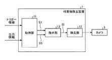
次に、図2を用いて、実施形態に係る付着物除去装置1の構成について説明する。図2は、実施形態に係る付着物除去装置1の構成の一例を示すブロック図である。なお、図2には、付着物除去装置1に加えて、カメラ3をあわせて示す。また、図2では、本実施形態の特徴を説明するために必要な構成要素のみを機能ブロックで表しており、一般的な構成要素についての記載を省略している。 Next, the configuration of the
つまり、図2に図示される各構成要素は機能概念的なものであり、必ずしも物理的に図示のように構成されていることを要しない。例えば、各機能ブロックの分散・統合の具体的形態は図示のものに限られず、その全部または一部を、各種の負荷や使用状況などに応じて、任意の単位で機能的または物理的に分散・統合して構成することが可能である。 That is, each component illustrated in FIG. 2 is functionally conceptual and does not necessarily need to be physically configured as illustrated. For example, the specific form of distribution / integration of each functional block is not limited to the one shown in the figure, and all or a part thereof is functionally or physically distributed in arbitrary units according to various loads or usage conditions.・ It can be integrated and configured.
図2に示すように、付着物除去装置1は、取得部11と、指示部12と、除去部13とを備える。 As shown in FIG. 2, the
取得部11は、自装置を起動するためのトリガー情報と、外部装置2から出力される音の出力情報とを取得する。ここでトリガー情報とは、例えば、車両100のギアポジションがリバースギアに入ったことを示す情報である。また、ここで外部装置2から出力される音の出力情報とは、車両100のギアポジションがリバースギアに入ったことに伴って車両100がバックしていることを運転者に報知するためのバック警告音の情報である。かかる出力情報は、例えば、繰り返し周期を有する音のオン状態、オフ状態のタイミングを示す情報である。 The acquisition unit 11 acquires trigger information for starting up the own device and output information of sound output from the
取得部11は、上記したトリガー情報を取得すると、トリガー情報に基づくオン/オフの状態を示すトリガー信号STを指示部12へ出力する。また、取得部11は、上記した出力情報を取得すると、出力情報に基づくオン/オフの状態を示す同期信号SSを指示部12へ出力する。 When acquiring the trigger information described above, the acquisition unit 11 outputs a trigger signal ST indicating an on / off state based on the trigger information to the
指示部12は、取得部11から入力されたトリガー信号STおよび同期信号SSが共にオン状態である場合に、オン状態の指示信号SIを除去部13へ出力する。 The
除去部13は、指示部12から上記した指示信号SIが入力された場合に、カメラ3のレンズ30に付着した付着物の除去動作を行う。なお、除去部13による除去動作の具体例については、図3を用いて後述する。 When the instruction signal SI is input from the
カメラ3は、CCD(Charge Coupled Device)やCMOS(Complementary Metal Oxide Semiconductor)などの撮像素子を備えたバックカメラであり、例えば、車両100の後方の所定領域を撮像する。なお、以下では、カメラ3をバックカメラ3として記載する場合がある。 The
また、カメラ3は、トリガー情報が入力された場合に起動する。この例では、カメラ3は、車両100のギアポジションがリバースギアに入ったことを示す情報が入力された場合に起動する。また、カメラ3は、所定領域を撮像した映像信号を図示しないカーナビゲーション装置へ出力する。 The
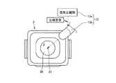
次に、図3を用いて、除去部13による除去動作について説明する。図3は、除去部13による除去動作の具体例を示す図である。 Next, the removing operation by the removing
図3に示すように、除去部13は、空気圧縮部13aと、ノズル13bとを備える。空気圧縮部13aは、指示部12から上記した指示信号SIが入力された場合に、空気を圧縮し、圧縮空気をノズル13bへ噴出する。 As shown in FIG. 3, the
ノズル13bは、例えば、噴出方向がレンズ30の斜め上方向からレンズ30の中心点31へ向くように配置される。そして、ノズル13bは、空気圧縮部13aによって生成された圧縮空気をレンズ30の中心点31へ向けて噴出することで、レンズ30に付着した付着物を除去する。 For example, the
このように、除去部13は、圧縮空気を噴出させることでカメラ3のレンズ30に付着した付着物を除去する。なお、除去部13は、水や洗浄液などの液体を圧縮空気とともに噴出することで、付着物を除去するようにしてもよい。 Thus, the removing
また、図3に示した除去部13による除去動作は一例であって、これに限定されるものではない。除去部13は、カメラワイパでレンズ30の表面を拭うことで付着物を除去することにしてもよい。 Further, the removing operation by the removing
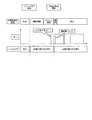
次に、図4を用いて、指示部12による処理の詳細について説明する。図4は、実施形態に係る指示部12による処理の一例を示す図である。なお、図4に示す横軸は、時間経過を示している。 Next, details of processing by the
また、図4中のAはトリガー信号STのオン/オフ状態を示しており、Bは同期信号SSのオン/オフ状態を示しており、Cは指示信号SIのオン/オフ状態を示している。 4 indicates the on / off state of the trigger signal ST, B indicates the on / off state of the synchronization signal SS, and C indicates the on / off state of the instruction signal SI. .
図4に示すように、時刻t1においてトリガー信号STがオフからオンになったとする。そして、時刻t1から所定の時間が経過した時刻である時刻t2において同期信号SSがオフからオンになったとする。 As shown in FIG. 4, it is assumed that the trigger signal ST is turned on from off at time t1. Then, it is assumed that the synchronization signal SS is turned on from off at a time t2, which is a time when a predetermined time has elapsed from the time t1.
指示部12は、トリガー信号STがオン状態であり、同期信号SSがオン状態であることを検知すると、時刻t2から所定の時間が経過した時刻である時刻t3において指示信号SIをオフからオンに切り替える。 When the
このように、時刻t2から所定の時間が経過したタイミングで指示信号SIをオフからオンに切り替えることで、指示信号SIのオンが確実にオン状態の同期信号SS内で行われるようにしている。 In this way, the instruction signal SI is switched from OFF to ON at a timing when a predetermined time has elapsed from time t2, so that the instruction signal SI is reliably turned on in the on-state synchronization signal SS.
そして、時刻t3においてオンの指示信号SIが入力された除去部13によって付着物の除去動作が行われる。つまり、この例では、同期信号SSにおける最初の周期Tにおけるバック警告音が出力されている期間Dに指示信号SIをオフからオンに切り替えている。これにより、ノズル13bから噴射される噴射音を外部装置2から出力されるバック警告音によってマスキングすることができる。 At time t3, the
なお、上記の例では、同期信号SSにおける最初の周期Tにおけるバック警告音が出力されている期間Dに指示信号SIをオフからオンに切り替えているが、同期信号SSにおける次の周期において指示信号SIをオフからオンに切り替えてもよい。 In the above example, the instruction signal SI is switched from OFF to ON during the period D in which the back warning sound in the first period T in the synchronization signal SS is output. However, the instruction signal is output in the next period in the synchronization signal SS. SI may be switched from off to on.
また、同期信号SSにおける最初の周期Tにおける指示信号SIのオフからオンへの切り替えは、1回に限られず、指示信号SIのオフからオンへの切り替えを複数回行ってもよい。また、指示信号SIのオフからオンへの切り替えを、最初の周期Tの立ち上がりのタイミングで行ってもよい。 In addition, the switching from OFF to ON of the instruction signal SI in the first period T in the synchronization signal SS is not limited to once, and the switching of the instruction signal SI from OFF to ON may be performed a plurality of times. Further, the instruction signal SI may be switched from off to on at the rising timing of the first cycle T.
次に、図5を用いて、より具体的に付着物除去装置1とバックカメラ3との動作関係について説明する。図5は、実施形態に係る付着物除去装置1とバックカメラ3との動作関係を説明する図である。 Next, the operational relationship between the
図5に示したのは、運転者によるギア操作によって車両100のギアポジションがリバースギアに入った場合の動作関係である。図5に示すように、付着物除去装置1は、取得部11が、車両100のリバースギア操作に伴って生じたトリガー情報を取得すると、空気を圧縮するなどの噴射準備を行う。 FIG. 5 shows an operational relationship when the gear position of the
一方、バックカメラ3においては、リバースギア操作に伴って生じたトリガー情報が入力される。そして、バックカメラ3によって撮像された映像が、例えば、ナビゲーション装置の表示部に表示される。かかる映像には、バックカメラ3のレンズ30に付着した雨滴が映り込んでいるものとする。 On the other hand, in the
次に、付着物除去装置1は、噴射準備が終わったあと、噴射のタイミングを調整するためのディレイ期間が経過するまで圧縮空気の噴射を待機させる。かかるディレイ期間は、指示部12が設定する。 Next, the adhering
具体的には、指示部12は、最初の周期におけるバック警告音が出力されている期間内で終わるようにディレイ期間を設定する。なお、指示部12は、ディレイ期間を、最初の周期の立ち上がりのタイミングで終了するように設定してもよい。これにより、付着物除去装置1は、バック警告音と同時に圧縮空気の噴射を行うことができる。 Specifically, the
また、指示部12は、次の周期におけるバック警告音が出力されている期間内で終わるようにディレイ期間を設定してもよい。これにより、付着物除去装置1は、圧縮空気の噴射による噴射音を次の周期におけるバック警告音によってマスキングすることができる。 Further, the
続いて、付着物除去装置1は、ディレイ期間が経過したあと、ノズル13bから圧縮空気を噴出させる。つまり、付着物除去装置1は、最初の周期におけるバック警告が出力されている期間内に圧縮空気の噴射が行われる。圧縮空気の噴射による噴射音は、バック警告音よりも音量が低い。このため、かかる噴射音をバック警告音によってマスキングすることで、噴射音の「プシュ」という音をバック警告音の「ピー」という音でかき消すことができる。 Subsequently, the
一方、バックカメラ3においては、ノズル13bから噴射された圧縮空気によってレンズ30に付着した雨滴が除去される。そして、例えば、ナビゲーション装置の表示部には、バックカメラ3によって撮像された雨滴の映り込みが無いきれいな映像が表示されることとなる。 On the other hand, in the
なお、上記の例では、最初の周期におけるバック警告が出力されている期間内に圧縮空気の噴射が1回行われているが、例えば、最初の周期におけるバック警告が出力されている期間内に圧縮空気の噴射を複数回行ってもよい。 In the above example, the compressed air is injected once within the period during which the back warning is output in the first cycle. For example, within the period during which the back warning is output during the first cycle. You may perform injection of compressed air in multiple times.
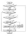
次に、図6を用いて、実施形態に係る付着物除去装置1が実行する処理手順について説明する。図6は、実施形態に係る付着物除去装置1が実行する処理手順の一例を示すフローチャートである。 Next, a processing procedure executed by the
図6に示すように、まず、付着物除去装置1は、トリガー信号STを検出したか否かを判定する(ステップS101)。そして、付着物除去装置1は、トリガー信号STを検出しなかった場合(ステップS101,No)、処理を終了する。 As shown in FIG. 6, first, the
一方、付着物除去装置1は、トリガー信号STを検出した場合(ステップS101,Yes)、空気を圧縮するなどの噴射準備を行う(ステップS102)。続いて、付着物除去装置1は、同期信号SSを検出したか否かを判定する(ステップS103)。そして、付着物除去装置1は、同期信号SSを検出しなかった場合(ステップS103,No)、処理を終了する。 On the other hand, when the adhering
一方、付着物除去装置1は、同期信号SSを検出した場合(ステップS103,Yes)、ステップS104の処理へ進む。そして、付着物除去装置1は、ディレイ期間が終了したか否かを判定する。 On the other hand, when the adhering
付着物除去装置1は、ディレイ期間がまだ終了していないと判定した場合(ステップS104,No)、ディレイ期間が終了するまでステップS104の処理を繰り返し実行する。 If it is determined that the delay period has not yet ended (No in step S104), the
一方、付着物除去装置1は、ディレイ期間が終了したと判定した場合(ステップS104,Yes)、カメラ3のレンズ30に付着した付着物の除去動作を指示する(ステップS105)。そして、付着物除去装置1は、外部装置2が音を出力している期間に除去動作を実行し(ステップS106)、処理を終了する。 On the other hand, when it is determined that the delay period has ended (step S104, Yes), the attached
上述したように、実施形態に係る付着物除去装置1は、取得部11と、指示部12と、除去部13とを備える。 As described above, the
取得部11は、車両100に搭載された外部装置2から出力される音の出力情報を取得する。指示部12は、出力情報に基づき、外部装置2が音を出力している期間に車両100の外部に設けられたカメラ3のレンズ30に付着した付着物の除去動作を指示する。除去部13は、指示部12による指示に基づいて除去動作を行う。 The acquisition unit 11 acquires sound output information output from the
これにより、実施形態に係る付着物除去装置1は、付着物の除去動作に伴う騒音を目立たなくすることができる。したがって、結果的に付着物の除去動作に伴う騒音を低減することができる。 Thereby, the deposit |
また、上述したように、取得部11は出力情報として繰り返し周期を有する音の出力情報を取得し、指示部12はかかる周期における音が出力されている期間に除去動作を指示する。 As described above, the acquisition unit 11 acquires sound output information having a repetition period as output information, and the
これにより、実施形態に係る付着物除去装置1は、繰り返し周期を有する音の出力情報において、効果的に付着物の除去動作に伴う騒音を目立たなくすることができる。 Thereby, the
また、上述したように、取得部11は自装置を起動するためのトリガー情報をさらに取得し、指示部12はトリガー情報を取得してから所定のディレイ期間が経過した後に除去動作を指示する。 Further, as described above, the acquisition unit 11 further acquires trigger information for starting up the own device, and the
これにより、実施形態に係る付着物除去装置1は、付着物の除去動作に伴って発生する作動音を外部装置2から出力される音によって確実にマスキングすることができる。 Thereby, the
また、上述したように、取得部11は、トリガー情報として車両100のギアポジションがリバースギアに入ったことを示す情報を取得する。 As described above, the acquisition unit 11 acquires information indicating that the gear position of the
これにより、実施形態に係る付着物除去装置1は、車両100のバック走行により外部装置2からバック警告音が出力されている期間にカメラ3のレンズ30に付着した付着物を除去することができる。 Thereby, the
また、上述したように、除去部13は、圧縮空気の噴射によってカメラ3に付着した付着物を除去する。これにより、実施形態に係る付着物除去装置1は、圧縮空気の噴射による噴射音を外部装置2から出力されるバック警告音によってマスキングすることができる。 Further, as described above, the removing
次に、図7を用いて、実施形態の変形例に係る付着物除去装置1について説明する。図7は、実施形態の変形例に係る付着物除去装置1の構成の一例を示すブロック図である。なお、図7に示す構成要素のうち、図2に示す構成要素と同じ構成要素については、図2に示す符号と同じ符号を付すことにより、ここではその説明を省略する。 Next, the
図7に示すように、変形例に係る付着物除去装置1は、指示部12が、カメラ3のレンズ30に付着した付着物を検出する付着物検出装置4による検出結果に基づいて除去動作を指示する点で図2の構成とは異なる。 As shown in FIG. 7, the
具体的には、付着物検出装置4は、カメラ3の画像に基づいてレンズ30に付着した付着物を検出する。そして、付着物検出装置4は、かかる検出結果を指示部12へ出力する。 Specifically, the attached matter detection device 4 detects the attached matter attached to the
指示部12は、付着物検出装置4による検出値が所定値以上である場合に、外部装置2が音を出力している期間に車両100の外部に設けられたカメラ3のレンズ30に付着した付着物の除去動作を複数回行うように指示する。 The
具体的に、図8Aおよび図8Bを用いて、上記した指示部12における処理について説明する。図8Aは、実施形態の変形例に係る指示部12における処理の一例を示す図(その1)である。また、図8Bは、実施形態の変形例に係る指示部12における処理の一例を示す図(その2)である。 Specifically, the processing in the above-described
なお、図8Aおよび図8Bにおいて、Aはトリガー信号STのオン/オフ状態を示しており、Bは同期信号SSのオン/オフ状態を示しており、Cは指示信号SIのオン/オフ状態を示している。 8A and 8B, A represents the on / off state of the trigger signal ST, B represents the on / off state of the synchronization signal SS, and C represents the on / off state of the instruction signal SI. Show.
図8Aに示すように、指示部12は、付着物検出装置4による検出値が所定値以上である場合、同期信号SSにおける最初の周期Tにおけるバック警告音が出力されている期間Dに除去動作を2回行うように除去部13に対して指示信号SIを出力する。この例では、時刻t3と時刻t4において指示信号SIがオフからオンに切り替えられている。なお、時刻t3と時刻t4との間で2回目の除去動作を行うための空気を圧縮するなどの噴射準備が行われる。 As illustrated in FIG. 8A, the
また、図8Bに示すように、指示部12は、同期信号SSにおける最初の周期Tおよび次の周期におけるバック警告音が出力されている期間に除去動作を1回ずつ行うように除去部13に対して指示信号SIを出力してもよい。この例では、時刻t3と時刻t5において指示信号SIがオフからオンに切り替えられている。 Also, as shown in FIG. 8B, the
なお、同期信号SSの立ち上がりの時刻t2から指示信号SIの立ち上がりの時刻t3までの経過時間と、同期信号SSの立ち上がりの時刻t4から指示信号SIの立ち上がりの時刻t5までの経過時間とは略同じであることが好ましい。これにより、複数回の除去動作に伴う噴射音をより違和感なくバック警告音によってマスキングすることができる。 The elapsed time from the rising time t2 of the synchronization signal SS to the rising time t3 of the instruction signal SI is substantially the same as the elapsed time from the rising time t4 of the synchronizing signal SS to the rising time t5 of the instruction signal SI. It is preferable that Thereby, the injection sound accompanying a plurality of removal operations can be masked by the back warning sound without a sense of incongruity.
このように、指示部12は、付着物検出装置4による検出値が所定値以上である場合に、外部装置2から出力されるバック警告音に合わせて除去動作を複数回行うように除去部13に対して指示する。 In this manner, the
次に、図9を用いて、上記した変形例に係る付着物除去装置1が実行する処理手順について説明する。図9は、実施形態の変形例に係る付着物除去装置1が実行する処理手順の一例を示すフローチャートである。 Next, a processing procedure executed by the
なお、図9に示すステップS201からステップS204までの処理は、上述した図6でのステップS101からステップS104までの処理と同じであるため、重複する説明を省略してステップS205から説明する。 Note that the processing from step S201 to step S204 shown in FIG. 9 is the same as the processing from step S101 to step S104 in FIG. 6 described above.
また、図9に示すフローチャートは、付着物検出装置4による検出値が所定値以上である場合に、同期信号SSにおける最初の周期Tにおけるバック警告音が出力されている期間Dに除去動作を複数回行う場合の例である。 In the flowchart shown in FIG. 9, when the detected value by the adhering matter detection device 4 is equal to or larger than a predetermined value, a plurality of removal operations are performed in the period D in which the back warning sound is output in the first cycle T in the synchronization signal SS. This is an example in the case of performing it once.
図9に示すように、付着物除去装置1は、ステップS205の処理において、付着物検出装置4による検出値が所定値以上であるか否かを判定する。そして、付着物除去装置1は、検出値が所定値以上でない場合(ステップS205,No)、カメラ3のレンズ30に付着した付着物の除去動作を1回行うように指示する(ステップS206)。そして、付着物除去装置1は、外部装置2が音を出力している期間に除去動作を1回実行し(ステップS208)、処理を終了する。 As shown in FIG. 9, the
一方、付着物除去装置1は、検出値が所定値以上である場合(ステップS205,Yes)、カメラ3のレンズ30に付着した付着物の除去動作を複数回行うように指示する(ステップS207)。そして、付着物除去装置1は、外部装置2が音を出力している期間に除去動作を複数回実行し(ステップS208)、処理を終了する。 On the other hand, when the detected value is equal to or greater than the predetermined value (Yes at Step S205), the attached
なお、付着物除去装置1は、指示部12において検出値が所定値以上であると判定した場合に、かかる所定値が所定値のデータテーブルから除去動作が2回必要な値の範囲に入っていれば、除去動作を2回行う。 When the
また、付着物除去装置1は、指示部12において検出値が所定値以下であると判定した場合に、かかる所定値が所定値のデータテーブルから除去動作が1回必要な値の範囲に入っていなければ、除去動作を行わないようにしてもよい。 In addition, when the
上述したように、実施形態の変形例に係る付着物除去装置1は、指示部12がレンズ30に付着した付着物を検出する付着物検出装置4による検出結果に基づいて除去動作を指示する。 As described above, the
これにより、実施形態の変形例に係る付着物除去装置1は、付着物の除去動作に伴う騒音を目立たなくすることができるとともに、カメラ3のレンズ30に付着した付着物を確実に除去することができる。 Thereby, the
また、上述したように、実施形態の変形例に係る付着物除去装置1は、指示部12が付着物検出装置4による検出値が所定値以上である場合に、除去動作を複数回行うように指示する。 Further, as described above, the
これにより、実施形態の変形例に係る付着物除去装置1は、付着物の除去動作に伴う騒音を目立たなくすることができるとともに、カメラ3のレンズ30に付着した付着物をより確実に除去することができる。 Thereby, the
なお、上述した実施形態に係る付着物除去装置1は、バックカメラ3の近傍に取り付けられる場合を例に挙げて説明したが、車両100の外部に設けられたフロントカメラやサイドカメラの近傍に取り付けられてもよい。 The
かかる形態において、トリガー情報は、例えば、キーセンサやイグニッションスイッチなどによってエンジンが始動したことを示す情報である。また、外部装置2から出力される音の出力情報は、例えば、エンジンが始動したことを運転者に報知するための音の情報である。 In such a form, the trigger information is information indicating that the engine has been started by, for example, a key sensor or an ignition switch. The sound output information output from the
なお、かかる出力情報は、繰り返し周期を有する音のオン状態、オフ状態のタイミングを示す情報でなくてもよく、例えば、1回の周期を有する音のオン状態、オフ状態のタイミングを示す情報であってもよい。この場合、音のオン状態(音が出力される状態)がより長いことが好ましい。 Note that the output information may not be information indicating the on-state and off-state timings of a sound having a repetition cycle, for example, information indicating the on-state and off-state timings of a sound having a single cycle. There may be. In this case, it is preferable that the sound ON state (state in which sound is output) is longer.
つまり、かかる形態では、エンジンが始動したことにより外部装置2から音が出力されている期間にフロントカメラやサイドカメラのレンズに付着した付着物を除去する。 That is, in this embodiment, the adhering matter attached to the lens of the front camera or the side camera is removed during a period in which sound is output from the
また、上述した実施形態に係る付着物除去装置1は、トリガー情報と音の出力情報とに基づき、外部装置2から音が出力されている期間にカメラ3のレンズ30に付着した付着物を除去しているが、これに限られない。 Moreover, the
他の形態としては、音の出力情報だけに基づき、外部装置2から音が出力されている期間にカメラ3のレンズ30に付着した付着物を除去してもよい。 As another form, the adhering matter adhering to the
つまり、付着物除去装置1は、トリガー情報が入力されてから起動する構成とするのではなく、外部装置2から入力される音の出力情報をトリガー信号として起動する構成としてもよい。 That is, the attached
かかる形態における外部装置2として、例えば、カーナビゲーション装置、カーオーディオ装置などを挙げることができる。かかる場合、例えば、カーオーディオ装置から出力される音の出力情報に基づき、カーオーディオ装置が音を出力している期間にカメラ3のレンズ30に付着した付着物の除去動作が行われる。 Examples of the
また、他の形態として、車両100に搭載された集音マイクから出力される音の出力情報に基づき、かかる集音マイクが車両100内外の所定の大きさの音を集音している期間にカメラ3のレンズ30に付着した付着物の除去動作が行われるようにしてもよい。 Moreover, as another form, based on the output information of the sound output from the sound collecting microphone mounted on the
かかる場合であっても、付着物の除去動作に伴って発生する作動音を車両100内外の所定の大きさの音によってマスキングすることができる。 Even in such a case, it is possible to mask the operation sound generated in accordance with the operation of removing the deposits with a predetermined loud sound inside and outside the
さらなる効果や変形例は、当業者によって容易に導き出すことができる。このため、本発明のより広範な態様は、以上のように表しかつ記述した特定の詳細および代表的な実施形態に限定されるものではない。したがって、添付の特許請求の範囲およびその均等物によって定義される総括的な発明の概念の精神または範囲から逸脱することなく、様々な変更が可能である。 Further effects and modifications can be easily derived by those skilled in the art. Thus, the broader aspects of the present invention are not limited to the specific details and representative embodiments shown and described above. Accordingly, various modifications can be made without departing from the spirit or scope of the general inventive concept as defined by the appended claims and their equivalents.
1 付着物除去装置
11 取得部
12 指示部
13 除去部
13a 空気圧縮部
13b ノズル
2 外部装置
3 カメラ
30 レンズ
4 付着物検出装置
100 車両
ST トリガー信号
SS 同期信号
SI 指示信号DESCRIPTION OF
Claims (8)
Translated fromJapanese前記出力情報に基づき、前記外部装置が音を出力している期間に前記車両の外部に設けられたカメラのレンズに付着した付着物の除去動作を指示する指示部と、
前記指示部による指示に基づいて前記除去動作を行う除去部と
を備えることを特徴とする付着物除去装置。An acquisition unit for acquiring output information of sound output from an external device mounted on the vehicle;
Based on the output information, an instruction unit for instructing the removal operation of the adhered matter attached to the lens of the camera provided outside the vehicle during a period in which the external device outputs sound;
And a removal unit that performs the removal operation based on an instruction from the instruction unit.
前記出力情報として繰り返し周期を有する音の出力情報を取得し、
前記指示部は、
前記繰り返し周期を有する音が出力されている期間に前記除去動作を指示すること
を特徴とする請求項1に記載の付着物除去装置。The acquisition unit
Obtaining output information of a sound having a repetition period as the output information;
The instruction unit includes:
The deposit removal apparatus according to claim 1, wherein the removal operation is instructed during a period in which sound having the repetition period is output.
自装置を起動するためのトリガー情報をさらに取得し、
前記指示部は、
前記トリガー情報を取得してから所定のディレイ期間が経過した後に前記除去動作を指示すること
を特徴とする請求項1または2に記載の付着物除去装置。The acquisition unit
Get more trigger information to activate your device,
The instruction unit includes:
The deposit removal apparatus according to claim 1 or 2, wherein the removal operation is instructed after a predetermined delay period has elapsed since the trigger information was acquired.
前記トリガー情報として前記車両のギアポジションがリバースギアに入ったことを示す情報を取得すること
を特徴とする請求項3に記載の付着物除去装置。The acquisition unit
The deposit removing apparatus according to claim 3, wherein information indicating that the gear position of the vehicle has entered a reverse gear is acquired as the trigger information.
圧縮空気の噴射によって前記カメラに付着した付着物を除去すること
を特徴とする請求項1〜4のいずれか一つに記載の付着物除去装置。The removing unit is
The deposit removing apparatus according to any one of claims 1 to 4, wherein deposits attached to the camera are removed by jetting compressed air.
前記レンズに付着した付着物を検出する付着物検出装置による検出結果に基づいて前記除去動作を指示すること
を特徴とする請求項1〜5のいずれか一つに記載の付着物除去装置。The instruction unit includes:
The deposit removal apparatus according to any one of claims 1 to 5, wherein the removal operation is instructed based on a detection result by a deposit detection apparatus that detects the deposit adhered to the lens.
前記付着物検出装置による検出値が所定値以上である場合に、前記除去動作を複数回行うように指示すること
を特徴とする請求項6に記載の付着物除去装置。The instruction unit includes:
The deposit removal apparatus according to claim 6, wherein when the detected value by the deposit detection apparatus is equal to or greater than a predetermined value, the removal operation is instructed to be performed a plurality of times.
前記取得工程により取得した前記出力情報に基づき、前記外部装置が音を出力している期間に前記車両の外部に設けられたカメラのレンズに付着した付着物の除去動作を指示する指示工程と、
前記指示工程による指示に基づいて前記除去動作を行う除去工程と
を含むことを特徴とする付着物除去方法。An acquisition step of acquiring output information of sound output from an external device mounted on the vehicle;
Based on the output information acquired by the acquisition step, an instruction step for instructing an operation for removing the deposits attached to a lens of a camera provided outside the vehicle during a period in which the external device outputs sound;
A removal step of performing the removal operation based on an instruction by the instruction step.
Priority Applications (2)
| Application Number | Priority Date | Filing Date | Title |
|---|---|---|---|
| JP2017137383AJP2019018661A (en) | 2017-07-13 | 2017-07-13 | Deposit removal device and deposit removal method |
| US15/981,224US20190015877A1 (en) | 2017-07-13 | 2018-05-16 | Adhered-substance removing apparatus and adhered-substance removing method |
Applications Claiming Priority (1)
| Application Number | Priority Date | Filing Date | Title |
|---|---|---|---|
| JP2017137383AJP2019018661A (en) | 2017-07-13 | 2017-07-13 | Deposit removal device and deposit removal method |
Publications (1)
| Publication Number | Publication Date |
|---|---|
| JP2019018661Atrue JP2019018661A (en) | 2019-02-07 |
Family
ID=65000415
Family Applications (1)
| Application Number | Title | Priority Date | Filing Date |
|---|---|---|---|
| JP2017137383APendingJP2019018661A (en) | 2017-07-13 | 2017-07-13 | Deposit removal device and deposit removal method |
Country Status (2)
| Country | Link |
|---|---|
| US (1) | US20190015877A1 (en) |
| JP (1) | JP2019018661A (en) |
Citations (6)
| Publication number | Priority date | Publication date | Assignee | Title |
|---|---|---|---|---|
| JPH079661U (en)* | 1993-07-23 | 1995-02-10 | 日産ディーゼル工業株式会社 | Rear-end collision warning system for automobiles |
| JPH07329569A (en)* | 1994-06-07 | 1995-12-19 | Toyota Motor Corp | Slip control abnormality detection device |
| JP2012171417A (en)* | 2011-02-18 | 2012-09-10 | Toyota Motor Corp | Wiper motor control circuit for automobile |
| JP2013237348A (en)* | 2012-05-15 | 2013-11-28 | Mitsubishi Motors Corp | Negative pressure pump control device for vehicle |
| JP2014201150A (en)* | 2013-04-03 | 2014-10-27 | クラリオン株式会社 | On-vehicle imaging device, dirt preventing method of optical member, and camera module |
| WO2017045832A1 (en)* | 2015-09-14 | 2017-03-23 | Valeo Systèmes d'Essuyage | Optical detection system for motor vehicle and method for cleaning the lens of the optical detection system |
Family Cites Families (2)
| Publication number | Priority date | Publication date | Assignee | Title |
|---|---|---|---|---|
| US7167796B2 (en)* | 2000-03-09 | 2007-01-23 | Donnelly Corporation | Vehicle navigation system for use with a telematics system |
| JP6576887B2 (en)* | 2016-08-09 | 2019-09-18 | クラリオン株式会社 | In-vehicle device |
- 2017
- 2017-07-13JPJP2017137383Apatent/JP2019018661A/enactivePending
- 2018
- 2018-05-16USUS15/981,224patent/US20190015877A1/ennot_activeAbandoned
Patent Citations (6)
| Publication number | Priority date | Publication date | Assignee | Title |
|---|---|---|---|---|
| JPH079661U (en)* | 1993-07-23 | 1995-02-10 | 日産ディーゼル工業株式会社 | Rear-end collision warning system for automobiles |
| JPH07329569A (en)* | 1994-06-07 | 1995-12-19 | Toyota Motor Corp | Slip control abnormality detection device |
| JP2012171417A (en)* | 2011-02-18 | 2012-09-10 | Toyota Motor Corp | Wiper motor control circuit for automobile |
| JP2013237348A (en)* | 2012-05-15 | 2013-11-28 | Mitsubishi Motors Corp | Negative pressure pump control device for vehicle |
| JP2014201150A (en)* | 2013-04-03 | 2014-10-27 | クラリオン株式会社 | On-vehicle imaging device, dirt preventing method of optical member, and camera module |
| WO2017045832A1 (en)* | 2015-09-14 | 2017-03-23 | Valeo Systèmes d'Essuyage | Optical detection system for motor vehicle and method for cleaning the lens of the optical detection system |
Also Published As
| Publication number | Publication date |
|---|---|
| US20190015877A1 (en) | 2019-01-17 |
Similar Documents
| Publication | Publication Date | Title |
|---|---|---|
| US11065653B2 (en) | Cleaning apparatus, cleaning method, and imaging apparatus | |
| JP6902850B2 (en) | System for cleaning vehicle-mounted sensors | |
| JP6836194B2 (en) | Camera cleaning device for vehicle rear door | |
| JP2023171852A (en) | Vehicle cleaner systems and vehicles equipped with vehicle cleaner systems | |
| CN107107879B (en) | Foreign matter removal device, removal drive device | |
| JP6332692B2 (en) | In-vehicle optical sensor foreign material removal device | |
| WO2007038198A3 (en) | Image capture method and device also capturing audio | |
| CN103533231A (en) | Diagnostic equipment decontamination vehicle camera devices, diagnostics and vehicle systems | |
| JP2013080177A (en) | Camera with water droplet removal function | |
| JP6835548B2 (en) | Adhesion remover | |
| CN107666570B (en) | Imaging apparatus, imaging system, and moving body | |
| JP2011240920A (en) | On-board optical sensor cover and on-board optical sensor apparatus | |
| JP2011240917A (en) | On-board optical sensor apparatus | |
| WO2006062966A3 (en) | Image capture device and method | |
| EP1493632A4 (en) | SYSTEM TO SUPPORT THE PARKING PROCESS | |
| JP7228826B2 (en) | Video recording device | |
| JP2009301355A (en) | Drive recorder and system | |
| JP2018116159A (en) | Foreign matter removal control device, foreign matter removal control method and foreign matter removal control program | |
| JP2010033108A (en) | Image processing system, imaging device, image processing method, and computer program | |
| JP2019018661A (en) | Deposit removal device and deposit removal method | |
| JP2018114853A (en) | Foreign matter removal control device, foreign matter removal control method, and foreign matter removal control program | |
| JP6700584B2 (en) | In-vehicle optical sensor cleaning device | |
| JP2018114852A (en) | Foreign matter removal control device, foreign matter removal control method, and foreign matter removal control program | |
| WO2009051234A1 (en) | Color filter, method for producing the same, and solid-state imaging device | |
| JP2007088630A5 (en) |
Legal Events
| Date | Code | Title | Description |
|---|---|---|---|
| A621 | Written request for application examination | Free format text:JAPANESE INTERMEDIATE CODE: A621 Effective date:20200331 | |
| A871 | Explanation of circumstances concerning accelerated examination | Free format text:JAPANESE INTERMEDIATE CODE: A871 Effective date:20200521 | |
| A975 | Report on accelerated examination | Free format text:JAPANESE INTERMEDIATE CODE: A971005 Effective date:20200615 | |
| A131 | Notification of reasons for refusal | Free format text:JAPANESE INTERMEDIATE CODE: A131 Effective date:20200623 | |
| A02 | Decision of refusal | Free format text:JAPANESE INTERMEDIATE CODE: A02 Effective date:20201222 |