JP2019016316A - Display system and display control method for display system - Google Patents
Display system and display control method for display systemDownload PDFInfo
- Publication number
- JP2019016316A JP2019016316AJP2017135288AJP2017135288AJP2019016316AJP 2019016316 AJP2019016316 AJP 2019016316AJP 2017135288 AJP2017135288 AJP 2017135288AJP 2017135288 AJP2017135288 AJP 2017135288AJP 2019016316 AJP2019016316 AJP 2019016316A
- Authority
- JP
- Japan
- Prior art keywords
- information
- display device
- unit
- display
- terminal display
- Prior art date
- Legal status (The legal status is an assumption and is not a legal conclusion. Google has not performed a legal analysis and makes no representation as to the accuracy of the status listed.)
- Pending
Links
Images


Classifications
- G—PHYSICS
- G06—COMPUTING OR CALCULATING; COUNTING
- G06F—ELECTRIC DIGITAL DATA PROCESSING
- G06F3/00—Input arrangements for transferring data to be processed into a form capable of being handled by the computer; Output arrangements for transferring data from processing unit to output unit, e.g. interface arrangements
- G06F3/01—Input arrangements or combined input and output arrangements for interaction between user and computer
- G06F3/011—Arrangements for interaction with the human body, e.g. for user immersion in virtual reality
- G06F3/012—Head tracking input arrangements
- H—ELECTRICITY
- H04—ELECTRIC COMMUNICATION TECHNIQUE
- H04N—PICTORIAL COMMUNICATION, e.g. TELEVISION
- H04N21/00—Selective content distribution, e.g. interactive television or video on demand [VOD]
- H04N21/40—Client devices specifically adapted for the reception of or interaction with content, e.g. set-top-box [STB]; Operations thereof
- H04N21/41—Structure of client; Structure of client peripherals
- H04N21/422—Input-only peripherals, i.e. input devices connected to specially adapted client devices, e.g. global positioning system [GPS]
- H04N21/42202—Input-only peripherals, i.e. input devices connected to specially adapted client devices, e.g. global positioning system [GPS] environmental sensors, e.g. for detecting temperature, luminosity, pressure, earthquakes
- A—HUMAN NECESSITIES
- A63—SPORTS; GAMES; AMUSEMENTS
- A63F—CARD, BOARD, OR ROULETTE GAMES; INDOOR GAMES USING SMALL MOVING PLAYING BODIES; VIDEO GAMES; GAMES NOT OTHERWISE PROVIDED FOR
- A63F13/00—Video games, i.e. games using an electronically generated display having two or more dimensions
- A63F13/20—Input arrangements for video game devices
- A63F13/21—Input arrangements for video game devices characterised by their sensors, purposes or types
- A63F13/211—Input arrangements for video game devices characterised by their sensors, purposes or types using inertial sensors, e.g. accelerometers or gyroscopes
- A—HUMAN NECESSITIES
- A63—SPORTS; GAMES; AMUSEMENTS
- A63F—CARD, BOARD, OR ROULETTE GAMES; INDOOR GAMES USING SMALL MOVING PLAYING BODIES; VIDEO GAMES; GAMES NOT OTHERWISE PROVIDED FOR
- A63F13/00—Video games, i.e. games using an electronically generated display having two or more dimensions
- A63F13/25—Output arrangements for video game devices
- A63F13/26—Output arrangements for video game devices having at least one additional display device, e.g. on the game controller or outside a game booth
- A—HUMAN NECESSITIES
- A63—SPORTS; GAMES; AMUSEMENTS
- A63F—CARD, BOARD, OR ROULETTE GAMES; INDOOR GAMES USING SMALL MOVING PLAYING BODIES; VIDEO GAMES; GAMES NOT OTHERWISE PROVIDED FOR
- A63F13/00—Video games, i.e. games using an electronically generated display having two or more dimensions
- A63F13/50—Controlling the output signals based on the game progress
- A63F13/52—Controlling the output signals based on the game progress involving aspects of the displayed game scene
- A63F13/525—Changing parameters of virtual cameras
- A63F13/5255—Changing parameters of virtual cameras according to dedicated instructions from a player, e.g. using a secondary joystick to rotate the camera around a player's character
- A—HUMAN NECESSITIES
- A63—SPORTS; GAMES; AMUSEMENTS
- A63F—CARD, BOARD, OR ROULETTE GAMES; INDOOR GAMES USING SMALL MOVING PLAYING BODIES; VIDEO GAMES; GAMES NOT OTHERWISE PROVIDED FOR
- A63F13/00—Video games, i.e. games using an electronically generated display having two or more dimensions
- A63F13/90—Constructional details or arrangements of video game devices not provided for in groups A63F13/20 or A63F13/25, e.g. housing, wiring, connections or cabinets
- A63F13/92—Video game devices specially adapted to be hand-held while playing
- G—PHYSICS
- G06—COMPUTING OR CALCULATING; COUNTING
- G06F—ELECTRIC DIGITAL DATA PROCESSING
- G06F3/00—Input arrangements for transferring data to be processed into a form capable of being handled by the computer; Output arrangements for transferring data from processing unit to output unit, e.g. interface arrangements
- G06F3/01—Input arrangements or combined input and output arrangements for interaction between user and computer
- G06F3/011—Arrangements for interaction with the human body, e.g. for user immersion in virtual reality
- G—PHYSICS
- G06—COMPUTING OR CALCULATING; COUNTING
- G06F—ELECTRIC DIGITAL DATA PROCESSING
- G06F3/00—Input arrangements for transferring data to be processed into a form capable of being handled by the computer; Output arrangements for transferring data from processing unit to output unit, e.g. interface arrangements
- G06F3/01—Input arrangements or combined input and output arrangements for interaction between user and computer
- G06F3/03—Arrangements for converting the position or the displacement of a member into a coded form
- G06F3/033—Pointing devices displaced or positioned by the user, e.g. mice, trackballs, pens or joysticks; Accessories therefor
- G06F3/0346—Pointing devices displaced or positioned by the user, e.g. mice, trackballs, pens or joysticks; Accessories therefor with detection of the device orientation or free movement in a 3D space, e.g. 3D mice, 6-DOF [six degrees of freedom] pointers using gyroscopes, accelerometers or tilt-sensors
- G—PHYSICS
- G06—COMPUTING OR CALCULATING; COUNTING
- G06F—ELECTRIC DIGITAL DATA PROCESSING
- G06F3/00—Input arrangements for transferring data to be processed into a form capable of being handled by the computer; Output arrangements for transferring data from processing unit to output unit, e.g. interface arrangements
- G06F3/01—Input arrangements or combined input and output arrangements for interaction between user and computer
- G06F3/048—Interaction techniques based on graphical user interfaces [GUI]
- G06F3/0481—Interaction techniques based on graphical user interfaces [GUI] based on specific properties of the displayed interaction object or a metaphor-based environment, e.g. interaction with desktop elements like windows or icons, or assisted by a cursor's changing behaviour or appearance
- G06F3/04815—Interaction with a metaphor-based environment or interaction object displayed as three-dimensional, e.g. changing the user viewpoint with respect to the environment or object
- G—PHYSICS
- G06—COMPUTING OR CALCULATING; COUNTING
- G06F—ELECTRIC DIGITAL DATA PROCESSING
- G06F3/00—Input arrangements for transferring data to be processed into a form capable of being handled by the computer; Output arrangements for transferring data from processing unit to output unit, e.g. interface arrangements
- G06F3/01—Input arrangements or combined input and output arrangements for interaction between user and computer
- G06F3/048—Interaction techniques based on graphical user interfaces [GUI]
- G06F3/0484—Interaction techniques based on graphical user interfaces [GUI] for the control of specific functions or operations, e.g. selecting or manipulating an object, an image or a displayed text element, setting a parameter value or selecting a range
- G—PHYSICS
- G09—EDUCATION; CRYPTOGRAPHY; DISPLAY; ADVERTISING; SEALS
- G09G—ARRANGEMENTS OR CIRCUITS FOR CONTROL OF INDICATING DEVICES USING STATIC MEANS TO PRESENT VARIABLE INFORMATION
- G09G3/00—Control arrangements or circuits, of interest only in connection with visual indicators other than cathode-ray tubes
- G09G3/001—Control arrangements or circuits, of interest only in connection with visual indicators other than cathode-ray tubes using specific devices not provided for in groups G09G3/02 - G09G3/36, e.g. using an intermediate record carrier such as a film slide; Projection systems; Display of non-alphanumerical information, solely or in combination with alphanumerical information, e.g. digital display on projected diapositive as background
- G09G3/002—Control arrangements or circuits, of interest only in connection with visual indicators other than cathode-ray tubes using specific devices not provided for in groups G09G3/02 - G09G3/36, e.g. using an intermediate record carrier such as a film slide; Projection systems; Display of non-alphanumerical information, solely or in combination with alphanumerical information, e.g. digital display on projected diapositive as background to project the image of a two-dimensional display, such as an array of light emitting or modulating elements or a CRT
- H—ELECTRICITY
- H04—ELECTRIC COMMUNICATION TECHNIQUE
- H04N—PICTORIAL COMMUNICATION, e.g. TELEVISION
- H04N21/00—Selective content distribution, e.g. interactive television or video on demand [VOD]
- H04N21/40—Client devices specifically adapted for the reception of or interaction with content, e.g. set-top-box [STB]; Operations thereof
- H04N21/47—End-user applications
- H04N21/478—Supplemental services, e.g. displaying phone caller identification, shopping application
- H04N21/4781—Games
- H—ELECTRICITY
- H04—ELECTRIC COMMUNICATION TECHNIQUE
- H04N—PICTORIAL COMMUNICATION, e.g. TELEVISION
- H04N21/00—Selective content distribution, e.g. interactive television or video on demand [VOD]
- H04N21/40—Client devices specifically adapted for the reception of or interaction with content, e.g. set-top-box [STB]; Operations thereof
- H04N21/47—End-user applications
- H04N21/485—End-user interface for client configuration
- H04N21/4854—End-user interface for client configuration for modifying image parameters, e.g. image brightness, contrast
- A—HUMAN NECESSITIES
- A63—SPORTS; GAMES; AMUSEMENTS
- A63F—CARD, BOARD, OR ROULETTE GAMES; INDOOR GAMES USING SMALL MOVING PLAYING BODIES; VIDEO GAMES; GAMES NOT OTHERWISE PROVIDED FOR
- A63F2300/00—Features of games using an electronically generated display having two or more dimensions, e.g. on a television screen, showing representations related to the game
- A63F2300/10—Features of games using an electronically generated display having two or more dimensions, e.g. on a television screen, showing representations related to the game characterized by input arrangements for converting player-generated signals into game device control signals
- A63F2300/105—Features of games using an electronically generated display having two or more dimensions, e.g. on a television screen, showing representations related to the game characterized by input arrangements for converting player-generated signals into game device control signals using inertial sensors, e.g. accelerometers, gyroscopes
- A—HUMAN NECESSITIES
- A63—SPORTS; GAMES; AMUSEMENTS
- A63F—CARD, BOARD, OR ROULETTE GAMES; INDOOR GAMES USING SMALL MOVING PLAYING BODIES; VIDEO GAMES; GAMES NOT OTHERWISE PROVIDED FOR
- A63F2300/00—Features of games using an electronically generated display having two or more dimensions, e.g. on a television screen, showing representations related to the game
- A63F2300/30—Features of games using an electronically generated display having two or more dimensions, e.g. on a television screen, showing representations related to the game characterized by output arrangements for receiving control signals generated by the game device
- A63F2300/301—Features of games using an electronically generated display having two or more dimensions, e.g. on a television screen, showing representations related to the game characterized by output arrangements for receiving control signals generated by the game device using an additional display connected to the game console, e.g. on the controller
- A—HUMAN NECESSITIES
- A63—SPORTS; GAMES; AMUSEMENTS
- A63F—CARD, BOARD, OR ROULETTE GAMES; INDOOR GAMES USING SMALL MOVING PLAYING BODIES; VIDEO GAMES; GAMES NOT OTHERWISE PROVIDED FOR
- A63F2300/00—Features of games using an electronically generated display having two or more dimensions, e.g. on a television screen, showing representations related to the game
- A63F2300/40—Features of games using an electronically generated display having two or more dimensions, e.g. on a television screen, showing representations related to the game characterised by details of platform network
- A63F2300/403—Connection between platform and handheld device
- A—HUMAN NECESSITIES
- A63—SPORTS; GAMES; AMUSEMENTS
- A63F—CARD, BOARD, OR ROULETTE GAMES; INDOOR GAMES USING SMALL MOVING PLAYING BODIES; VIDEO GAMES; GAMES NOT OTHERWISE PROVIDED FOR
- A63F2300/00—Features of games using an electronically generated display having two or more dimensions, e.g. on a television screen, showing representations related to the game
- A63F2300/60—Methods for processing data by generating or executing the game program
- A63F2300/66—Methods for processing data by generating or executing the game program for rendering three dimensional images
- A63F2300/6661—Methods for processing data by generating or executing the game program for rendering three dimensional images for changing the position of the virtual camera
- A63F2300/6676—Methods for processing data by generating or executing the game program for rendering three dimensional images for changing the position of the virtual camera by dedicated player input
- G—PHYSICS
- G06—COMPUTING OR CALCULATING; COUNTING
- G06F—ELECTRIC DIGITAL DATA PROCESSING
- G06F2203/00—Indexing scheme relating to G06F3/00 - G06F3/048
- G06F2203/048—Indexing scheme relating to G06F3/048
- G06F2203/04806—Zoom, i.e. interaction techniques or interactors for controlling the zooming operation
- G—PHYSICS
- G09—EDUCATION; CRYPTOGRAPHY; DISPLAY; ADVERTISING; SEALS
- G09G—ARRANGEMENTS OR CIRCUITS FOR CONTROL OF INDICATING DEVICES USING STATIC MEANS TO PRESENT VARIABLE INFORMATION
- G09G2340/00—Aspects of display data processing
- G09G2340/04—Changes in size, position or resolution of an image
- G09G2340/0407—Resolution change, inclusive of the use of different resolutions for different screen areas
- G—PHYSICS
- G09—EDUCATION; CRYPTOGRAPHY; DISPLAY; ADVERTISING; SEALS
- G09G—ARRANGEMENTS OR CIRCUITS FOR CONTROL OF INDICATING DEVICES USING STATIC MEANS TO PRESENT VARIABLE INFORMATION
- G09G2354/00—Aspects of interface with display user
- G—PHYSICS
- G09—EDUCATION; CRYPTOGRAPHY; DISPLAY; ADVERTISING; SEALS
- G09G—ARRANGEMENTS OR CIRCUITS FOR CONTROL OF INDICATING DEVICES USING STATIC MEANS TO PRESENT VARIABLE INFORMATION
- G09G5/00—Control arrangements or circuits for visual indicators common to cathode-ray tube indicators and other visual indicators
- G09G5/36—Control arrangements or circuits for visual indicators common to cathode-ray tube indicators and other visual indicators characterised by the display of a graphic pattern, e.g. using an all-points-addressable [APA] memory
- G09G5/39—Control of the bit-mapped memory
- G09G5/391—Resolution modifying circuits, e.g. variable screen formats
Landscapes
- Engineering & Computer Science (AREA)
- Theoretical Computer Science (AREA)
- General Engineering & Computer Science (AREA)
- Multimedia (AREA)
- Human Computer Interaction (AREA)
- Physics & Mathematics (AREA)
- General Physics & Mathematics (AREA)
- Signal Processing (AREA)
- Computer Hardware Design (AREA)
- Business, Economics & Management (AREA)
- Biodiversity & Conservation Biology (AREA)
- Ecology (AREA)
- Emergency Management (AREA)
- Environmental & Geological Engineering (AREA)
- Environmental Sciences (AREA)
- Remote Sensing (AREA)
- Life Sciences & Earth Sciences (AREA)
- User Interface Of Digital Computer (AREA)
- Controls And Circuits For Display Device (AREA)
Abstract
Translated fromJapaneseDescription
Translated fromJapanese本発明は、表示システム、及び表示システムの表示制御方法に関する。 The present invention relates to a display system and a display control method for the display system.
近年、眼鏡のように頭部に装着する端末表示装置としてヘッドマウントディスプレイ(Head Mount Display, HMD)が開発されており、産業向けや民生向けに種々の活用方法が検討されている。 In recent years, a head mounted display (HMD) has been developed as a terminal display device that is worn on the head like glasses, and various utilization methods are being studied for industrial use and consumer use.
HMDは、現実世界にコンピュータグラフィックス(CG)で構築された仮想空間の情報を重ね合わせた視覚情報を提供することができる拡張現実(Augmented Reality, AR)や
、現実世界とは全く異なるCGで生成された視覚体験を装着者に体感させることができる仮想現実(Virtual Reality, VR)の機能を実現するためのデバイスとして利用することが
できる。HMD is Augmented Reality (AR), which can provide visual information by superimposing virtual space information constructed by computer graphics (CG) on the real world, and CG that is completely different from the real world. It can be used as a device for realizing a virtual reality (VR) function that allows the wearer to experience the generated visual experience.
例えば産業分野では、物流現場、製造現場での各種作業、機器の保守などにおいて、ARを利用することにより直観的に作業指示を出すことを可能とし、それによって作業効率を上げる試みが行われている。しかし、HMDを装着したときにCG情報が見える範囲、すなわち視野角が狭いため、情報の視認性に課題がある。また、産業分野で利用する場合には、作業効率を上げる目的のためにHMDを装着したときには手に何も持たない状態、すなわちハンズフリーでHMDによるCG情報を制御可能であることが求められる。しかし、現状マウス、キーボード等の手入力デバイスに代わってHMDをハンズフリーで操作できる仕組みはまだ実用的ではない。 For example, in the industrial field, it is possible to give work instructions intuitively by using AR in various operations at distribution sites and manufacturing sites, maintenance of equipment, etc., thereby trying to increase work efficiency. Yes. However, since the range in which CG information can be seen when the HMD is mounted, that is, the viewing angle is narrow, there is a problem in information visibility. In addition, when used in the industrial field, it is required to control the CG information by the HMD in a state in which no hand is held when the HMD is mounted for the purpose of improving work efficiency, that is, hands-free. However, a mechanism that can operate the HMD in a hands-free manner instead of a manual input device such as a mouse or a keyboard is not practical yet.
擬似的に視野角を広げる試みとして、端末表示装置に設けた加速度センサ、ジャイロセンサ、磁気センサなどを活用することで、端末表示装置の向きに応じて表示させる情報を変化させる仕組みが提案されている。例えば特許文献1はマルチディスプレイヒューマンマシンインタフェースに関する。特許文献1では、可動窓は仮想空間への一人称の観点か
らの覗き窓を提示することができる。この覗き窓からのビューは、多次元空間内での静止窓に対する可動窓の空間特性の向きに基づいて変化する。ディスプレイは、仮想空間の画像を提示することができ、追加の可動型ディスプレイは同一の仮想空間の追加の画像を提示することができるものである。As an attempt to broaden the viewing angle in a pseudo manner, a mechanism has been proposed in which information to be displayed is changed according to the orientation of the terminal display device by utilizing an acceleration sensor, a gyro sensor, a magnetic sensor, etc. provided in the terminal display device. Yes. For example,
しかし、特許文献1では、HMDを装着して周辺を見る動作をすることで、仮想空間の一部を視認することは可能だが、HMDを用いて仮想空間を表示したとき、表示された情報をハンズフリーで制御するための操作方法については何も開示されていない。 However, in
上記の、及び他の課題を解決するための本発明の一態様は、ユーザが頭部に装着する端末表示装置を備える表示システムであって、前記端末表示装置が、前記ユーザの視界に重畳して情報オブジェクトを表示するための表示部と、前記端末表示装置の動きを検出するための動作検出部と、前記端末表示装置の動作のパターンと前記表示部が表示している前
記情報オブジェクトに対する操作内容を対応づけて記憶している動作パターン記憶部と、各前記情報オブジェクトについての表示形態に関する情報を記憶している情報種別管理記憶部と、前記動作検出部が検出した前記端末表示装置の動作と、前記動作パターン記憶部に記憶されている前記動作パターンと前記操作内容との関連付けに基づいて前記端末表示装置に対する操作内容を判定するための動作判定部と、前記表示部の所定の位置に配置されている前記情報オブジェクトを特定するための情報種別判定部と、判定された前記操作内容で特定される操作を前記特定された情報オブジェクトに対して実行するための表示処理部とを備えている。One aspect of the present invention for solving the above and other problems is a display system including a terminal display device that a user wears on a head, wherein the terminal display device is superimposed on the field of view of the user. A display unit for displaying information objects, an operation detection unit for detecting movement of the terminal display device, an operation pattern of the terminal display device, and an operation on the information object displayed by the display unit Operation of the terminal display device detected by the operation detection unit detected by the operation pattern storage unit storing information in association with each other, information type management storage unit storing information relating to the display form of each information object And determining the operation content for the terminal display device based on the association between the operation pattern stored in the operation pattern storage unit and the operation content. An operation type determination unit, an information type determination unit for specifying the information object arranged at a predetermined position of the display unit, and an operation specified by the determined operation content. A display processing unit for executing the object.
本発明の一態様によれば、ユーザが頭部に装着した端末表示装置の動作に応じて、当該端末表示装置によって提供される仮想空間内の表示情報を制御することが可能となる。 According to one aspect of the present invention, it is possible to control display information in a virtual space provided by a terminal display device according to the operation of the terminal display device worn by the user on the head.
以下、本発明について、その実施形態に即して図面を用いて説明する。なお、図面において、同一符号は、同一または相当部分を示す。また、本発明は、図示の構成例に限定されるものではない。 Hereinafter, the present invention will be described with reference to the drawings according to the embodiment. In the drawings, the same reference numerals indicate the same or corresponding parts. Further, the present invention is not limited to the illustrated configuration example.
[実施形態1]
本発明の一実施形態に係る頭部装着型端末表示装置について、図1〜図7を参照して説明する。図1は、頭部装着型端末表示装置10の使用状態を例示する模式図である。なお、簡単のため、以下、本明細書において、人が頭部に装着することにより装着した人に対する画像あるいは映像表示機能を提供する装置である頭部装着型端末表示装置をHMDと
称することとする。HMDには通常の視力矯正のための眼鏡の形態を有するもの、眼の周りを覆うように装着するゴーグル様の形状を有するもの、あるいはヘルメットのように頭部全体を覆うもの等、種々の形状の装置が含まれる。[Embodiment 1]
A head-mounted terminal display device according to an embodiment of the present invention will be described with reference to FIGS. FIG. 1 is a schematic view illustrating the usage state of the head-mounted
本実施形態の表示システムとしてのHMD10では、各種センサを活用して表示された情報を操作することが可能である。図1に示すように、本実施形態のHMD10は、ユーザ11が頭部に装着するゴーグルに類する形態を有する端末装置である。HMD10は、手でなんらかのデバイスを操作したり、ジェスチャーによってセンサ信号を生成したりすることなく、完全なハンズフリーを実現しながら表示情報を制御することができる。ハンズフリーで表示情報を制御することができるので、HMD10を装着する作業者は表示情報を制御するためのデバイスを別に手で保持して操作する必要がない。このため、HMD10を使用することで、物流、製造、保守作業などを行う各種産業において作業効率、作業品質の向上を期待することができ、高い需要が見込まれる。 In the HMD 10 as the display system of the present embodiment, it is possible to operate information displayed using various sensors. As shown in FIG. 1, the
HMD10は、ユーザ11の頭部に装着され、ユーザ11が作業を行うために必要な情報を表示し、ユーザ11の操作に応じて情報を制御する機能を備えた端末装置である。本実施形態ではHMD10に全ての機能が備えられている場合を説明するが、HMD10の一部が分離可能である構成、例えばHMD10の一部の機能がスマートフォン等の携帯通信端末装置に設けられ、HMD10の主要な処理を実行する場合であっても、得られる効果は以下に説明する本実施形態と同様である。 The HMD 10 is a terminal device that is mounted on the head of the
なお、図1に示すように、以下の説明では、便宜的に、HMD10の幅方向(ユーザ11の左右方向)をx軸方向、鉛直方向をy軸方向、xy軸いずれとも直交するユーザ11の前後方向をz軸方向と定めることとする。 As shown in FIG. 1, in the following description, for convenience, the width direction of the HMD 10 (the left-right direction of the user 11) is the x-axis direction, the vertical direction is the y-axis direction, and the xy-axis is orthogonal to the
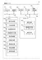
図2は、HMD10の構成の一例を示す図である。HMD10は、プロセッサ111、通信部112、方位検出部113、加速度検出部114、表示部115、メモリ116、ストレージ117、入力部118、電源供給部119、及びバス120を備える。なお、HMD10は、動作判定部1161、方位処理部1162、加速度処理部1163、情報種別判定部1164、表示処理部1165、及び制御処理部1166をメモリ116に格納している。制御処理部1166がストレージ117から上記処理部に対応するプログラムモジュールを読み出してメモリ116に展開し、制御処理部1166が上記プログラムモジュールを実行することで本実施形態の処理を実現する。なお、これらのプログラムモジュールはHMD10に係る装置が出荷されるまでに予めストレージ117に格納されていても良いし、CD(Compact Disk)、DVD(Digital Versatile Disk)、Blu−ray Disc(登録商標)などの光学メディアや半導体メモリ等の記憶媒体に格納され
て図示しない媒体接続部を介してHMD10に係る装置にインストールされても良い。FIG. 2 is a diagram illustrating an example of the configuration of the
プロセッサ111は、CPU(Central Processing Unit)、MPU(Micro Processing Unit)、及びDSP(Digital Signal Processor)等の総称であり、所定のプログラムを実行する機能を有する。 The
通信部112は、無線LAN、Bluetooth(登録商標)、赤外線通信、ICタグ機能、TransferJET(登録商標)、LTE(Long Term Evolution)、HS
PA(High Speed Packet Access)、EV−DO(Evolution Data Only)、及びWiM
AX等の無線通信機能、または、Ethernet(登録商標)等の有線通信機能を備え、各種の情報を送受信する。無線通信機能は、所要のアンテナ、及び変復調回路等を含む。有線通信機能は、所要のコネクタ、及び変復調回路等を含む。データの送受信には、ネットワークを介して行うネットワーク通信と、ネットワークを介さずに各機器間で直接通信を行う直接通信(例えばBluetooth(登録商標)、ワイヤレスUSB、Fel
ica(登録商標)、ZigBee(登録商標)、Z−WAVE(登録商標)、可視光通信、赤外線通信、NFC(Near Field Communication)(登録商標)を適宜切り替えて使用できる。通信部112は、複数の通信方式に対応するように構成されても良い。The
PA (High Speed Packet Access), EV-DO (Evolution Data Only), and WiM
It has a wireless communication function such as AX or a wired communication function such as Ethernet (registered trademark), and transmits and receives various types of information. The wireless communication function includes a required antenna, a modulation / demodulation circuit, and the like. The wired communication function includes a required connector, a modulation / demodulation circuit, and the like. For data transmission / reception, network communication performed via a network and direct communication performed directly between devices without using a network (for example, Bluetooth (registered trademark), wireless USB, Fel)
ica (registered trademark), ZigBee (registered trademark), Z-WAVE (registered trademark), visible light communication, infrared communication, and NFC (Near Field Communication) (registered trademark) can be appropriately switched and used. The
方位検出部113は、ジャイロセンサ等を用いて、HMD10のx、y、z軸回りの回転角度を検出する機能を有する。なお、方位検出部113はHMD10に内蔵されていてもよいし、別体としてHMD10と有線通信または無線通信で接続されていてもよい。 The
加速度検出部114は、加速度センサ等を用いて、HMD10のx、y、z軸方向の加速度を検出する機能を有する。なお、加速度検出部114はHMD10に内蔵されていてもよいし、別体としてHMD10と有線通信または無線通信で接続されていてもよい。 The
表示部115は、液晶ディスプレイ、有機EL(Electro-Luminescence)ディスプレイ、電子ペーパー等の表示パネルや光源、ドライバ回路等から構成され、制御処理部1166の制御下にて任意の情報(例えば、文字、静止画、及び動画等)を表示する。なお、表示部115は、それぞれ異なる情報を表示可能な複数の表示機能から構成されていてもよい。 The
メモリ116は、DRAM(Dynamic Random Access Memory)などから構成され、制御処理部1166の指示により制御される。メモリ116に、ストレージ117に格納しているアプリケーションプログラムの機能部が展開される。 The
ストレージ117は、HMD10に内蔵される記録媒体や、取り外し可能な外部記録媒体や光ディスクなどから構成され、各種の情報を記憶する機能を有する。例えば、ストレージ117は制御処理部1166の指示により制御され、アプリケーションプログラムを保存することができる。また、ストレージ117は、アプリケーションプログラムで作成した各種情報を保存する。例えば、ストレージ117は、ユーザ11の動作からHMD10の動作のパターンを判定する動作判定データベース1171、情報別の表示方法が管理された情報種別管理データベース1172(情報種別管理記憶部)、前記動作パターンと表示操作とを対応づける操作対応データベース1173を保存する。動作判定データベース1171と操作対応データベース1173とは、HMD10の動作のパターンと表示部115が表示している情報オブジェクトに対する操作内容を対応づけている、動作パターン記憶部を構成している。 The
入力部118は、キーボード、マウス、カーソルキー、及びテンキー等の一または複数を備え、ユーザ11の操作を受け付け、当該操作に基づいた入力信号をプロセッサ111に入力する機能を有する。なお、HMD10にマイクやカメラを備え、音声認識、画像認識、またはジェスチャー認識等によって入力信号を生成し、プロセッサ111に入力するようにしても良い。なお、入力部118は、タッチパネルのように、表示部115と入力部118とが一体となった構成であっても良い。また、入力部118は同様の機能を持つ処理部として、HMD10と離れた場所に設置され、機器間の直接通信を介して当該操作に基づいた入力信号をプロセッサ111に入力する構成としても良い。なお念のため述べると、本実施形態ではHMD10の表示制御を、入力部118を操作することなくハンズフリーで行えるように構成されている。 The
電源供給部119は、バッテリ、ACアダプタ、及び充電回路等から構成され、HMD10の各部への電源供給や、バッテリへの充電を行う機能を有する。また、電源供給部119は、HMD10のバッテリの残量確認を行う。バス120は、HMD10の各部が相互に信号を伝送するための伝送路である。 The
なお、本明細書において、プロセッサ111がメモリ116に格納されたプログラムモジュールに基づいて実行する処理を、当該プログラムモジュールに対応する処理部が実行する処理として説明する場合がある。例えば、制御処理部1166が実行する処理は、実際には、メモリ116に格納された制御処理部1166に対応するプログラムモジュールに従って、プロセッサ111が実行する。他の処理部についても同様である。 Note that in this specification, processing executed by the
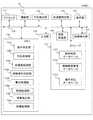
次に、以上の構成を有する本実施形態のHMD10によって実行されるデータ処理について説明する。この説明の過程で、データ処理に使用されるデータベースの構成についてもあわせて説明する。図3は、HMD10における、取得したセンサデータからユーザの操作を判定し、判定した操作に基づいて表示情報を変化させるまでの処理の一例である。本実施形態のHMD10では、装着したユーザ11が頭部を動かす動作によってHMD10に表示されている画像や映像の表示状態を制御することができる。 Next, data processing executed by the
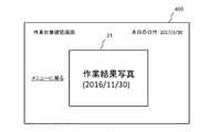
本実施形態のHMD10では、HMD10を装着したユーザが頭を動かすと、方位検出部113と加速度検出部114の検出する値が変化する。図4に、HMD10の表示部115に表示される情報オブジェクトの一例を示している。図4に示すように、HMD10の表示領域400には、日時情報、メニュー画面への復帰ボタン、及び画像情報20が含まれている。画像情報20はある画像データを代表するオブジェクトであり、以下このオブジェクトをアイコンと称する。図4の画像情報であるアイコン20は、この画像情報が写真イメージデータであることを示している。図5は図4のアイコン20を選択しているとき、HMD10の動作を通じてアイコン20を写真画像21に変更したときの、表示部115に表示される内容の例である。HMD10で写真イメージデータのような高解像度のイメージデータを表示するには、多量の電力が必要とされる。そこで、本実施形態のHMD10では、ユーザ11からの指示がない限り図4のような対応するアイコン20を表示しておくことで省電力を実現している。以下、本実施形態では、方位検出部113と加速度検出部114の値変化を元にして、HMD10の表示部115に表示される情報を変化させる例を説明する。 In the
HMD10は、電源投入等をトリガとして図3のデータ処理を開始すると(S100)、動作判定部1161は、入力部118から動作検出開始のトリガが検出されるのを待機する(S101、No)。動作判定部1161がトリガを検出したと判定した場合(S101、Yes)、方位処理部1162と加速度処理部1163が検出処理を実行する(S102)。 When the
動作判定部1161は、方位処理部1162を通じて、方位検出部113がx軸回りの回転角度変化が基準値を超えているかを判定する(S103)。この基準値は、例えば50度のように任意の値とすることができる。 The
回転角度変化が基準値を超えていると判定された場合(S103、Yes)、動作判定部1161は、加速度処理部1163を通じて加速度検出部114が検出するx軸方向の加速度が基準値を超えているか判定する(S104)。S103の回転角度変化と同様に、加速度の基準値は、5.0m/s2等と任意に定めることができる。基準値を超えていると判定した場合(S104、Yes)、動作判定部1161はHMD10を装着したユ
ーザが何らかの操作を行ったと判断してS105の処理に移る。When it is determined that the rotation angle change exceeds the reference value (S103, Yes), the
なお、一般的にジャイロセンサ、加速度センサ、方位センサを始めとする各種センサには出力にゆらぎがあり、静止していてもランダムな値であるノイズを出力し続ける事象が認められる。そこでノイズの出力の影響を取り除くため、センサの値が所定回数連続して基準値を超えたことをもって判定する手段、所定回数分の平均値で基準値との差を判定する手段、移動平均フィルタを用いる手段、ソフトウェアによる有限インパルス応答フィル
タを用いる手段などが考えられ、これらのいずれかをセンサ出力に適用することができる。ノイズ出力の影響を除去するためにハードウェア的なフィルタを用いても良い。また前記の複数の手段から選択して組み合わせて用いても良い。本明細書では、各種センサによる条件判定はノイズ除去後の値を用いる前提で説明している。In general, various sensors such as a gyro sensor, an acceleration sensor, and a direction sensor have fluctuations in output, and an event of continuously outputting noise that is a random value even when stationary is recognized. Therefore, in order to remove the influence of noise output, means for determining when the sensor value exceeds the reference value for a predetermined number of times, means for determining the difference from the reference value by the average value for the predetermined number of times, moving average filter And a means using a finite impulse response filter by software, and any of these can be applied to the sensor output. A hardware filter may be used to remove the influence of noise output. Further, a plurality of means may be selected and used in combination. In this specification, the condition determination by various sensors is described on the assumption that the value after noise removal is used.
ここで、動作判定データベース1171について説明する。図6に、動作判定データベース1171の構成例を示している。動作判定データベース1171は、ユーザ11が行う可能性のある動作について、上体を傾ける動作である前傾、後傾、頭を左右に振る動作である左向、右向、頭を左右に傾ける動作である左傾、右傾、前後に移動する動作である前進、後進、及び停止と分類して登録されている。また、各種動作の変位が「大きい」、「小さい」の種別を登録し、各変位種別についてさらに動作速度が「速い」、「遅い」の種別が登録されている。 Here, the
本実施形態の動作判定データベース1171では、各動作の分類項目について、その変位の大小に対してさらに動作速度の遅速が対応づけられており、停止を含めて33種類の情報を表現することができるように構成している。例えば、動作判定データベース1171の符号Cは、前傾動作をある基準値より小さい範囲で速く実行したことを表している。方位検出部113と加速度検出部114とで検出される値の変化がこの条件に合致した場合、符号Cに対応する動作が実行されたと判定される。 In the
HMD10のデータ処理に戻ると、動作判定部1161は、動作判定データベース1171を参照し、ユーザ11の行った動作による方位検出部113と加速度処理部114のデータ変化に最も近い動作パターンと合う項目を抽出し、その項目に対応する操作とみなす。例えば、画像情報20(アイコン)を写真画像21に拡大する、「情報を拡大する」という操作が、動作判定データベース1171の符号C、すなわち前傾姿勢を検出後、符号Gg、すなわち停止姿勢を合わせて検出した場合に対応すると判定する(S105)。この判定には、例えば動作判定データベース1171とともに、操作対応テーブル1173を設けることで実現することができる。操作対応テーブル1173の構成例を図7に示している。操作対応テーブル1173は、前記した動作パターン例えば符号C、Ggと、それが表す操作内容である「情報を拡大する」とを対応づけて格納している。 Returning to the data processing of the
図3に戻ると、「情報を拡大する」という操作を検出後、情報種別判定部1164は、表示部115に表示されている表示内容で、現在画面の中心に配置されている情報を識別する(S106)。表示内容の例は前記の図4、図5で述べた通りである。具体的には、情報種別判定部1164は、現在画面の中心に配置されている情報に対応するファイル名等のデータ属性を抽出する。 Returning to FIG. 3, after detecting the operation of “enlarging information”, the information
図8に、情報種別管理データベース1172の一例を示している。情報種別管理データベース1172は、情報オブジェクト番号90、情報オブジェクト名91、種別タグ92、実データ名93、表示アイコンファイル名94、遠方時の表示形態95、及び接近時の表示形態96の各項目を管理する。例えば、図4のアイコン20は、図5の作業結果を示す写真画像21に対応している。情報種別判定部1164は、S106で識別した情報を情報種別管理データベース1172と照合する。本例では、S106でアイコン20にファイル名「Picture.jpg」が関連付けられているとしている。ここでS105にて符号C
、Ggが特定された場合、情報種別判定部1164が情報種別管理データベース1172と照合して、「Picture.jpg」アイコンから写真イメージデータに変更して表示し処理を
終了する(S107、S108)。アイコン20から画像に表示が変更されたときの、表示部115に表示される内容は図5の通りである。図5の作業結果写真画像21は、図8の情報オブジェクト番号90の11番に対応しており、実データ名93の「20170220_機
器Aパネル点検終了写真.jpg」を表示している。FIG. 8 shows an example of the information
, Gg is specified, the information
以上説明したように、本実施形態のHMD10によれば、HMD10を装着しているユーザ11の頭部の動作を検出することにより、手で他の機器を操作することなく表示内容の制御を行うことができる。 As described above, according to the
なお、以上では、身体あるいは頭部を前に傾ける「前傾」の動作を検出した場合の表示情報の変化を説明した。他の例として、「ユーザ11が見ている画面の左に表示されているオブジェクトを選択する」という操作を考える。この場合、図6に示した動作判定データベース1171の符号K、すなわち首を左に大きく素早く回す動作を行った後、符号Gg、すなわち停止姿勢を合わせて検出した場合に、図7に例示するように上記選択操作と対応づけておく。動作判定部1161は、方位処理部1162を通じて、方位検出部113がz軸回りの回転角度変化が基準値を超えているかを確認する(S103)。以後、S104、S105は前記と同様であり、「前傾」と「左向」とを区別することができる。このように、人が実際に行う動作を動作判定データベース1171に示すように分類し、分類した判定基準を組み合わせることで、精度の高い動作認識を可能としている。 In the above description, the change in the display information in the case of detecting the “forward tilt” motion in which the body or the head is tilted forward has been described. As another example, consider an operation of “selecting an object displayed on the left of the screen viewed by the
なお、本実施例の処理で説明に使用した数値は一例であり、本発明はこれらの数値を使用した処理系に限定されることはない。また、本実施形態では、動作判定データベース1171に登録された動作として「拡大」と「左選択」とを例にとって説明したが、この他、例えば図6の符号Wと符号Ggで「右選択」、上体を後ろに反る動作である後傾動作を2回実施する動作、すなわち、符号E、符号Gg、符号Eを2回連続して検出した場合に「直前操作の取り消し操作(アンドゥ)」と対応づけるなど、図7に例示するように、他の動作を操作に割り当てることが可能であるのは言うまでもない。 In addition, the numerical value used for description by the process of a present Example is an example, and this invention is not limited to the processing system using these numerical values. In this embodiment, “enlargement” and “left selection” are described as examples of operations registered in the
[実施形態2]
次に、本発明の第2の実施形態について、図9〜図13を参照して説明する。
第1の実施形態では、HMD10の方位検出部113と加速度検出部114とによってユーザ11の動作を検出し、検出した動作に基づいて表示情報を制御する構成について説明した。本実施形態ではHMD10に撮像素子を設けており、撮像情報の変化によってユーザの動作を検出して表示されている情報オブジェクトを制御する構成を説明する。[Embodiment 2]
Next, a second embodiment of the present invention will be described with reference to FIGS.
In 1st Embodiment, the structure which detects the operation | movement of the
図9は、本実施形態におけるHMD10の構成例を示す図である。第1の実施形態におけるHMD10と同等の構成部分については説明を省略する。本実施形態のHMD10は、第1実施形態のHMD10の構成に加えて、映像検出部121を備えている。映像検出部121はCCD(Charge Coupled Device)素子やCMOS(Complementary Metal Oxide Semiconductor)素子等の撮像素子を備えており、被写体からの入射光を電子的なデータに変換する機能を有する。映像検出部121はHMD10に内蔵してもよいし、スマートフォンや携帯電話等の携帯端末、あるいはカメラ機能を持った機器を用いて実現し、HMD10と有線通信または無線通信によって接続してもよい。 FIG. 9 is a diagram illustrating a configuration example of the
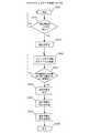
図10に、本実施形態のHMD10によって実行される、映像検出部121からの情報に基づいてユーザ11の動作を検出して表示情報を制御するまでのデータ処理の一例を示している。図10の処理フロー例において、S200〜S202での処理は、実施形態1におけるS100〜S102での処理とそれぞれ同等であるから説明を省略する。 FIG. 10 shows an example of data processing executed by the
S202でユーザ11の動作の検出を開始すると、映像処理部1168は映像検出部121の機能を有効化し、HMD10の前方の風景を映像データとして取得する。その際、映像処理部1168は、1つの時間フレーム毎に映像データに含まれる特徴点を4つ以上識別する(S203)。なお、特徴点は3つであってもよい。また特徴点の抽出は、例えばOpenCVから提供される画像解析用ライブラリ等を用いて実現することができる。 When the detection of the operation of the
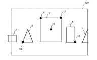
図11は、映像検出部121が撮像した映像データの一例を示している。図11の例では、HMD10の前方にある被写体として、物体α、β、γ、δ、εが撮像されている。このとき、これらの物体における特徴点31、32、33、34が特徴点として抽出された場合、映像処理部1168は特徴点31、32、33、34の座標、及び特徴点31、32、33、34の座標上の重心35の座標を記憶する。 FIG. 11 shows an example of video data captured by the
次に、視差抽出部1167は、映像処理部1168によって識別された特徴点の画面上の座標を、映像の時間フレーム毎に確認する。HMD10が移動すると映像処理部121が取得する映像もそれにつれて移動するため、識別した特徴点の座標も変化する。ここで、座標とは、例えば映像処理部1168が時間フレーム毎に取得した画像の解像度を基準として定義することができる。図12は、ある映像フレームで取得された特徴点座標の例を示している。ここでは、映像の解像度を横1024pixel、縦768pixelとしているが、他の解像度に設定されていてもよい。 Next, the
図10に戻ると、S204では、所定の期間内に、映像に含まれる特徴点に関する情報、例えば特徴点の座標、特徴点で構成される図形の面積等の情報が変化しているか判定する。図13は、HMD10が図11で示す状態よりも物体γに近づいたときに、映像検出部121が撮像した映像データの一例である。この場合、図13の特徴点31、32、33、34で構成される略台形の面積は、図11における対応する部分の面積よりも大きくなる。そこで本実施形態では、例えば、取得された5つの時間フレームの中で、最初の時間フレームで識別した特徴点座標で構成される面積を基準とし、残り4つの時間フレームの中での対応部分の面積が3つ以上最初の面積を上回っている場合、所定の基準値を超えたと判定する(S204、Yes)。特徴点に関する情報の変化が所定の基準値以下であると判定した場合(S204、No)、視差抽出部1167は反復して該当する変化がないか判定を実行する。 Returning to FIG. 10, in S204, it is determined whether information on the feature points included in the video, for example, information on the coordinates of the feature points, the area of the figure composed of the feature points, or the like has changed within a predetermined period. FIG. 13 is an example of video data captured by the
物体γに近づく以外の動作検出の例として、例えばユーザ11が右方向に頭を向ける動作を行う場合を説明する。図14は、ユーザ11が頭部を右に回したときに、映像検出部121が撮像した映像データの一例である。図13では、頭部が右を向いたことにより、HMD10も右に動いている。このとき、図14では図11と比較して特徴点31、32、33、34の重心35の座標が変化している。例えば、取得した5つの時間フレームの中で、最初に識別した物体の重心35の座標を基準とし、残り4つの時間フレームのうち、3つの時間フレームでの重心座標が左方向に100pixel以上ずれていることが検出さ
れた場合、視差抽出部1167は特徴点の重心の座標の変化が基準値を超えたと判定する(S204、Yes)。以上の例のように、本実施形態ではセンサの出力値に代えてユーザ11が見ている方向、距離の変化を取得した映像における特徴点の情報変化として捉えている。動作判定部1161は、この特徴点の情報変化が所定の基準値を超えたと判定された場合、HMD10を装着したユーザ11が操作を目的とした動作を行ったと判断する。このため、本実施形態では、動作判定データベース1171内の各項目は、特徴点に関する情報変化の方向、大きさと変化率とに基づいて規定すればよい。As an example of motion detection other than approaching the object γ, for example, a case where the
図10の処理フロー例に戻ると、以後、S205〜S208の処理は、実施形態1の図3におけるS105〜S108の処理とそれぞれ同等であるため、説明を省略する。 Returning to the processing flow example of FIG. 10, the processing of S205 to S208 is the same as the processing of S105 to S108 in FIG.
なお、本実施形態では、HMD10を装着したユーザ11が物体に近づく、右を向くという動作を表示制御に関する操作として割り当てる例を説明したが、ユーザ11が左を向く、後ろに反るなど、その他の動作も同様に識別して操作として割り当てることが可能である。
以上のように、本実施形態によれば、HMD10の動作の変化を映像データに基づいて
検出し、映像の解析結果により表示情報を制御することが可能になる。In the present embodiment, the example in which the
As described above, according to the present embodiment, it is possible to detect a change in the operation of the
[実施形態3]
次に、本発明の第3の実施形態について、図15〜図18を参照して説明する。実施形態1、2では、HMD10の処理によってユーザ11の動作を表示情報制御のための操作に割り当てる方式を説明した。本実施形態では、ユーザ11の動作を検出して操作に割り当てる処理を、ネットワーク上で実施する構成を説明する。[Embodiment 3]
Next, a third embodiment of the present invention will be described with reference to FIGS. In the first and second embodiments, the method of assigning the operation of the
図15は、本実施形態におけるシステム構成の一例である。本実施形態に係る表示システム1は、HMD10、通信ネットワーク14、及び管理サーバ15を備えて構成される。 FIG. 15 is an example of a system configuration in the present embodiment. The
通信ネットワーク14は、例えばインターネット、ローカルエリアネットワーク(LAN
)、USB(Universal Serial Bus)、リモートUSB、無線LAN、Bluetooth(登録商標)、赤外線通信、ICタグ機能、TransferJET(登録商標)、LTE、HSPA(High Speed Packet Access)、またはEV−DO(Evolution Data Only)などで構成することができる。HMD10と管理サーバ15は、通信ネットワーク1
4を介して相互に接続可能とされている。The
), USB (Universal Serial Bus), remote USB, wireless LAN, Bluetooth (registered trademark), infrared communication, IC tag function, TransferJET (registered trademark), LTE, HSPA (High Speed Packet Access), or EV-DO (Evolution Data Only). The
4 can be connected to each other.
管理サーバ15は、例えばサーバコンピュータであり、通信ネットワーク14を介してHMD10の検出データを取得し、解析して、HMD10に判定結果を返す機能を有する。なお、本実施形態ではHMD10と管理サーバ15とが1対1の関係で設置されている場合で説明するが、管理サーバ15が複数のHMD10と接続され、それぞれのHMD10についての処理を行う場合においても、本実施形態の構成を適用することができる。管理サーバ15は1台のサーバコンピュータとしてもよいし、管理サーバ15自体を通信ネットワーク14上のクラウド環境で構成してもよい。 The
図16は本実施形態のHMD10の構成の一例を示す図である。図2及び図9に示した実施形態1、2の構成部分と同等の構成部分については、同一符号を付して説明を省略する。図16のHMD10は、表示処理部1165、制御処理部1166、及び通信処理部1167以外のプログラムモジュールがメモリ116から除外されている。またストレージ117にもデータベースは格納されていない。通信処理部1167は、通信ネットワーク14を介して管理サーバ15とデータ送受信処理を実行するために通信部112を制御する機能を備えている。 FIG. 16 is a diagram illustrating an example of the configuration of the
図17は管理サーバ15の構成の一例を示す図である。管理サーバ15は、プロセッサ151、通信部152、表示部153、入力部154、電源供給部155、メモリ156、ストレージ157、及びバス158を備え、これらはそれぞれ実施形態1、2のHMD10におけるプロセッサ111、通信部112、表示部115、入力部118、電源供給部119、メモリ116、ストレージ117、及びバス120と対応しているので説明を省略する。 FIG. 17 is a diagram illustrating an example of the configuration of the
管理サーバ15のメモリ156には、動作判定部1561、方位処理部1562、加速度処理部1563、情報種別判定部1564、表示処理部1565、制御処理部1566、視差抽出部1567、映像処理部1568、及び通信処理部1569のプログラムモジュールが格納されている。通信処理部1569以外のプログラムモジュールは、実施形態1、2におけるHMD10の対応構成部分と同等であるから説明を省略する。通信処理部1569は、通信ネットワーク14を介してHMD10とデータ送受信処理を実行するために通信部152を制御する機能を備えている。 The
なお、図16、図17に示すように、本実施形態ではHMD10が方位検出部113、加速度検出部114、映像検出部121を備え、それに対応して管理サーバ15が方位処理部1562、加速度処理部1563、視差抽出部1567、及び映像処理部1568を備えている構成としている。この構成は、HMD10の動作をセンサで検出する方式、あるいは映像解析による方式のいずれかの方式のみを採用するように変更することができる。 As shown in FIGS. 16 and 17, in this embodiment, the
図18は、HMD10が、取得したデータを管理サーバ15に送信し、管理サーバ15が受信したデータを解析してユーザ11の動作を判定してHMD10にその判定結果を送信し、HMD10が受信した判定結果に基づいて表示情報を変化させるまでの処理の一例を示している。 18, the
HMD10、管理サーバ15は、いずれも電源投入等のイベントをトリガとして処理を開始する(S300、S304)。ユーザが装着しているHMD10では、実施形態1の図3におけるS101、S102の処理ステップと同様に、ユーザ11の動作を表すセンサデータを取得する(S301、S302)。 Both the
次に、HMD10の通信処理部1166は、取得したデータを管理サーバ15に送信する(S303)。ここで取得したデータは、例えば図2に例示したようなHMD10の方位検出部113と加速度検出部114が取得した数値データであり、あるいは映像検出部118が取得した映像データである。管理サーバ15に対して複数のHMD10が通信可能とされている場合には、S303で送信するデータに送信元HMDを一意に識別可能とするIDデータを付与すればよい。 Next, the
管理サーバ15の通信処理部1569は、HMD10からデータを受信する(S305)。以後、管理サーバ15では、実施形態1の図3に示すS103〜S106の処理ステップと同様に、データの解析と操作内容の判定、選択情報の種別確認処理が実行される(S306〜S309)。なお、HMD10から実施形態2で説明した映像データを受信する場合には、本実施形態のS306〜S307の処理ステップは、図10のS203〜S205の処理ステップで代替される。管理サーバ15で特定された操作内容と選択情報種別の情報は、HMD10へ送信される(S310)。 The
HMD10は管理サーバ15から受信した操作内容と選択情報種別とを含む指示を受信し(S312)、その指示に従って表示処理部1165が選択情報の表示を変更して処理を終了する(S313、S314)。 The
以上のように、本実施形態によれば、HMD10の動作の変化を管理サーバ15が解析することで、HMD10の表示情報を制御することが可能になる。また、HMD10の動作の変化を解析するためのデータ処理をHMD10で実行しないこととなるので、HMD10の構成を単純化し、より安価に製造することが可能となり、またHMD10における電力消費量低減を実現することもできる。 As described above, according to the present embodiment, the
なお、本発明の技術的範囲は上記の実施形態に限定されることはなく、他の変形例、応用例等も、特許請求の範囲に記載した事項の範囲内に含まれるものである。 The technical scope of the present invention is not limited to the above-described embodiment, and other modifications, application examples, and the like are included in the scope of the matters described in the claims.
1 表示システム 10 HMD
20 アイコン 21 写真画像
14 通信ネットワーク 15 管理サーバ
111 プロセッサ 112 通信部
113 方位検出部 114 加速度検出部
115 表示部 116 メモリ
117 ストレージ 118 入力部
119 電源供給部 120 バス
121 映像検出部 400 表示領域
1161、1561 動作判定部
1162、1562 方位処理部
1163、1563 加速度処理部
1164、1564 情報種別判定部
1165、1565 表示処理部
1166、1566 制御処理部
1167、1567 視差抽出部
1168、1568 映像処理部
1169、1569 通信処理部
1171、1571 動作判定データベース
1172、1572 情報種別管理データベース
1173、1573 操作対応データベース
1
20
Claims (15)
Translated fromJapanese前記端末表示装置が、
前記ユーザの視界に重畳して情報オブジェクトを表示するための表示部と、
前記端末表示装置の動きを検出するための動作検出部と、
前記端末表示装置の動作のパターンと前記表示部が表示している前記情報オブジェクトに対する操作内容を対応づけて記憶している動作パターン記憶部と、
各前記情報オブジェクトについての表示形態に関する情報を記憶している情報種別管理記憶部と、
前記動作検出部が検出した前記端末表示装置の動作と、前記動作パターン記憶部に記憶されている前記動作パターンと前記操作内容との関連付けに基づいて前記端末表示装置に対する操作内容を判定するための動作判定部と、
前記表示部の所定の位置に配置されている前記情報オブジェクトを特定するための情報種別判定部と、
判定された前記操作内容で特定される操作を前記特定された情報オブジェクトに対して実行するための表示処理部と、
を備えている表示システム。A display system comprising a terminal display device worn by a user on the head,
The terminal display device
A display unit for displaying an information object superimposed on the user's field of view;
An operation detector for detecting movement of the terminal display device;
An operation pattern storage unit that stores an operation pattern of the terminal display device and an operation content for the information object displayed on the display unit in association with each other;
An information type management storage unit storing information related to a display form for each of the information objects;
For determining an operation content for the terminal display device based on an association between the operation pattern detected by the motion detection unit and the operation pattern stored in the operation pattern storage unit and the operation content. An operation determination unit;
An information type determination unit for specifying the information object arranged at a predetermined position of the display unit;
A display processing unit for executing an operation specified by the determined operation content on the specified information object;
Display system.
前記動作検出部は、前記端末表示装置の動作による方位変化を検出するための方位検出部と、
前記端末表示装置の動作における加速度変化を検出するための加速度検出部とを含む、表示システム。The display system according to claim 1,
The motion detection unit is a bearing detection unit for detecting a bearing change due to the operation of the terminal display device,
An acceleration detection unit for detecting an acceleration change in the operation of the terminal display device.
前記端末表示装置が前記表示部によって表示される映像情報を経時的に複数取得する映像検出部を備え、
前記端末表示装置の前記動作検出部が、各前記映像情報に含まれる複数の情報オブジェクトについて各情報オブジェクトの特徴点を検出し、複数の当該特徴点相互間の位置関係の変化によって前記端末表示装置の動作パターンを判定する、表示システム。The display system according to claim 1,
The terminal display device includes a video detection unit that acquires a plurality of video information displayed by the display unit over time,
The operation detection unit of the terminal display device detects feature points of each information object for a plurality of information objects included in each of the video information, and the terminal display device according to a change in positional relationship between the plurality of feature points Display system that determines the operation pattern of
前記操作内容として、前記表示部によって表示されている複数の前記情報オブジェクトのうち、操作対象となる前記情報オブジェクトを選択することが含まれる、表示システム。The display system according to claim 1,
The display system, wherein the operation content includes selecting the information object to be operated from among the plurality of information objects displayed by the display unit.
前記操作内容として、前記表示部によって解像度が低い小型の画像情報として表示されている前記情報オブジェクトを、当該情報オブジェクトのより解像度の大きい画像情報として表示することが含まれる、表示システム。The display system according to claim 1,
The display system, wherein the operation content includes displaying the information object displayed as small-sized image information having a low resolution by the display unit as image information having a higher resolution of the information object.
前記端末表示装置が、
前記ユーザの視界に重畳して情報オブジェクトを表示するための表示部と、
前記端末表示装置の動作を検出するための動作検出部と、を備え、
前記管理計算機が、
前記端末表示装置の動作のパターンと前記表示部が表示している前記情報オブジェクトに対する操作内容を対応づけて記憶している動作パターン記憶部と、
各前記情報オブジェクトについての表示形態に関する情報を記憶している情報種別管理記憶部と、
前記動作検出部が検出した前記端末表示装置の動作と、前記動作パターン記憶部に記憶されている前記動作パターンと前記操作内容との関連付けに基づいて前記端末表示装置に対する操作内容を判定するための動作判定部と、
前記表示部の所定の位置に配置されている前記情報オブジェクトを特定するための情報種別判定部と、
前記操作内容と前記情報オブジェクトとに関する情報を含む操作指示情報を前記端末表示装置に送信する通信処理部と、を備え、
前記端末表示装置がさらに、
前記操作指示情報に基づく操作を前記表示部に表示されている前記特定された情報オブジェクトに対して実行するための表示処理部を備えている、
表示システム。A display system comprising a terminal display device worn by a user on a head, and a management computer connected to the terminal display device in a communicable manner,
The terminal display device
A display unit for displaying an information object superimposed on the user's field of view;
An operation detection unit for detecting the operation of the terminal display device,
The management computer is
An operation pattern storage unit that stores an operation pattern of the terminal display device and an operation content for the information object displayed on the display unit in association with each other;
An information type management storage unit storing information related to a display form for each of the information objects;
For determining an operation content for the terminal display device based on an association between the operation pattern detected by the motion detection unit and the operation pattern stored in the operation pattern storage unit and the operation content. An operation determination unit;
An information type determination unit for specifying the information object arranged at a predetermined position of the display unit;
A communication processing unit that transmits operation instruction information including information on the operation content and the information object to the terminal display device,
The terminal display device further includes
A display processing unit for executing an operation based on the operation instruction information with respect to the specified information object displayed on the display unit;
Display system.
前記動作検出部は、前記端末表示装置の動作による方位変化を検出するための方位検出部と、
前記端末表示装置の動作における加速度変化を検出するための加速度検出部とを含む、表示システム。The display system according to claim 6,
The motion detection unit is a bearing detection unit for detecting a bearing change due to the operation of the terminal display device,
An acceleration detection unit for detecting an acceleration change in the operation of the terminal display device.
前記端末表示装置が前記表示部によって表示される映像情報を経時的に複数取得する映像検出部を備え、
前記端末表示装置の前記動作検出部が、各前記映像情報に含まれる複数の情報オブジェクトについて各情報オブジェクトの特徴点を検出し、複数の当該特徴点相互間の位置関係の変化によって前記端末表示装置の動作パターンを判定する、表示システム。The display system according to claim 1,
The terminal display device includes a video detection unit that acquires a plurality of video information displayed by the display unit over time,
The operation detection unit of the terminal display device detects feature points of each information object for a plurality of information objects included in each of the video information, and the terminal display device according to a change in positional relationship between the plurality of feature points Display system that determines the operation pattern of
前記操作内容として、前記表示部によって表示されている複数の前記情報オブジェクトのうち、操作対象となる前記情報オブジェクトを選択することが含まれる、表示システム。The display system according to claim 6,
The display system, wherein the operation content includes selecting the information object to be operated from among the plurality of information objects displayed by the display unit.
前記操作内容として、前記表示部によって解像度が低い小型の画像情報として表示されている前記情報オブジェクトを、当該情報オブジェクトのより解像度の大きい画像情報として表示することが含まれる、表示システム。The display system according to claim 6,
The display system, wherein the operation content includes displaying the information object displayed as small-sized image information having a low resolution by the display unit as image information having a higher resolution of the information object.
前記ユーザの視界に重畳して情報オブジェクトを表示し、
前記端末表示装置の動作を検出し、
前記端末表示装置の動作のパターンと前記表示部が表示している前記情報オブジェクトに対する操作内容を対応づけて記憶している動作パターン記憶部と、各前記情報オブジェクトについての表示形態に関する情報を記憶している情報種別管理記憶部とを参照し、
前記検出された前記端末表示装置の動作と、前記動作パターン記憶部に記憶されている前記動作パターンと前記操作内容との関連付けに基づいて前記端末表示装置に対する操作内容を判定し、
前記表示部の所定の位置に配置されている前記情報オブジェクトを特定し、
判定された前記操作内容で特定される操作を前記特定された情報オブジェクトに対して実行する、
端末表示装置の表示制御方法。A display control method for a terminal display device worn by a user on a head,
Displaying an information object superimposed on the user's field of view;
Detecting the operation of the terminal display device;
An operation pattern storage unit that stores an operation pattern of the terminal display device and an operation content for the information object displayed on the display unit in association with each other, and information on a display form for each of the information objects is stored. The information type management storage unit
Determining an operation content for the terminal display device based on an association between the detected operation of the terminal display device and the operation pattern stored in the operation pattern storage unit and the operation content;
Identifying the information object arranged at a predetermined position of the display unit;
Performing an operation specified by the determined operation content on the specified information object;
A display control method for a terminal display device.
前記動作の検出処理は、前記端末表示装置の動作による方位変化を検出するための方位検出部と、前記端末表示装置の動作における加速度変化を検出するための加速度検出部とにより実行される、端末表示装置の表示制御方法。A display control method for a terminal display device according to claim 11,
The operation detection processing is executed by an orientation detection unit for detecting an orientation change due to the operation of the terminal display device and an acceleration detection unit for detecting an acceleration change in the operation of the terminal display device. A display control method for a display device.
前記端末表示装置が表示される映像情報を経時的に複数取得し、
前記端末表示装置が、各前記映像情報に含まれる複数の情報オブジェクトについて各情報オブジェクトの特徴点を検出し、複数の当該特徴点相互間の位置関係の変化によって前記端末表示装置の動作パターンを判定する、端末表示装置の表示制御方法。A display control method for a terminal display device according to claim 11,
Obtain a plurality of video information displayed over time on the terminal display device,
The terminal display device detects feature points of each information object for a plurality of information objects included in the video information, and determines an operation pattern of the terminal display device based on a change in a positional relationship between the plurality of feature points. A display control method for a terminal display device.
前記操作内容として、前記表示部によって表示されている複数の前記情報オブジェクトのうち、操作対象となる前記情報オブジェクトを選択することが含まれる、端末表示装置の表示制御方法。A display control method for a terminal display device according to claim 11,
A display control method for a terminal display device, wherein the operation content includes selecting the information object to be operated from among the plurality of information objects displayed by the display unit.
前記操作内容として、前記表示部によって解像度が低い小型の画像情報として表示されている前記情報オブジェクトを、当該情報オブジェクトのより解像度の大きい画像情報として表示することが含まれる、端末表示装置の表示制御方法。
A display control method for a terminal display device according to claim 11,
The display control of the terminal display device includes displaying, as the operation content, the information object displayed as small-size image information having a low resolution by the display unit as image information having a higher resolution of the information object. Method.
Priority Applications (4)
| Application Number | Priority Date | Filing Date | Title |
|---|---|---|---|
| JP2017135288AJP2019016316A (en) | 2017-07-11 | 2017-07-11 | Display system and display control method for display system |
| CN201810732796.8ACN109246456A (en) | 2017-07-11 | 2018-07-05 | The display control method of display system and display system |
| US16/029,889US11016559B2 (en) | 2017-07-11 | 2018-07-09 | Display system and display control method of display system |
| JP2021081833AJP7064040B2 (en) | 2017-07-11 | 2021-05-13 | Display system and display control method of display system |
Applications Claiming Priority (1)
| Application Number | Priority Date | Filing Date | Title |
|---|---|---|---|
| JP2017135288AJP2019016316A (en) | 2017-07-11 | 2017-07-11 | Display system and display control method for display system |
Related Child Applications (1)
| Application Number | Title | Priority Date | Filing Date |
|---|---|---|---|
| JP2021081833ADivisionJP7064040B2 (en) | 2017-07-11 | 2021-05-13 | Display system and display control method of display system |
Publications (2)
| Publication Number | Publication Date |
|---|---|
| JP2019016316Atrue JP2019016316A (en) | 2019-01-31 |
| JP2019016316A5 JP2019016316A5 (en) | 2020-01-30 |
Family
ID=64998885
Family Applications (2)
| Application Number | Title | Priority Date | Filing Date |
|---|---|---|---|
| JP2017135288APendingJP2019016316A (en) | 2017-07-11 | 2017-07-11 | Display system and display control method for display system |
| JP2021081833AActiveJP7064040B2 (en) | 2017-07-11 | 2021-05-13 | Display system and display control method of display system |
Family Applications After (1)
| Application Number | Title | Priority Date | Filing Date |
|---|---|---|---|
| JP2021081833AActiveJP7064040B2 (en) | 2017-07-11 | 2021-05-13 | Display system and display control method of display system |
Country Status (3)
| Country | Link |
|---|---|
| US (1) | US11016559B2 (en) |
| JP (2) | JP2019016316A (en) |
| CN (1) | CN109246456A (en) |
Cited By (3)
| Publication number | Priority date | Publication date | Assignee | Title |
|---|---|---|---|---|
| JP2020149594A (en)* | 2019-03-15 | 2020-09-17 | Dynabook株式会社 | Electronic device and display control method |
| JP2023087307A (en)* | 2021-12-13 | 2023-06-23 | 株式会社コロプラ | Program, information processing method, and portable terminal |
| JP2024069187A (en)* | 2019-09-27 | 2024-05-21 | アップル インコーポレイテッド | DEVICE, METHOD AND GRAPHICAL USER INTERFACE FOR INTERACTING WITH A THREE-DIM |
Families Citing this family (8)
| Publication number | Priority date | Publication date | Assignee | Title |
|---|---|---|---|---|
| JP6440910B2 (en)* | 2016-07-29 | 2018-12-19 | 三菱電機株式会社 | Display device, display control device, and display control method |
| KR102374404B1 (en)* | 2017-07-25 | 2022-03-15 | 삼성전자주식회사 | Device and method for providing content |
| US20200089940A1 (en)* | 2018-09-19 | 2020-03-19 | XRSpace CO., LTD. | Human behavior understanding system and method |
| USD921691S1 (en)* | 2018-12-11 | 2021-06-08 | Lg Electronics Inc. | Display screen with graphical user interface |
| US11308520B2 (en)* | 2019-06-11 | 2022-04-19 | Toyota Boshoku Kabushiki Kaisha | Vehicle advertisement display system |
| EP3792817A1 (en)* | 2019-09-10 | 2021-03-17 | XRSpace CO., LTD. | Method and system for human behavior identification |
| JP7243691B2 (en)* | 2020-07-22 | 2023-03-22 | 横河電機株式会社 | Apparatus, system, method and program |
| WO2022252150A1 (en)* | 2021-06-02 | 2022-12-08 | 陈盈吉 | Virtual reality control method for avoiding motion sickness |
Citations (10)
| Publication number | Priority date | Publication date | Assignee | Title |
|---|---|---|---|---|
| JP2007134785A (en)* | 2005-11-08 | 2007-05-31 | Konica Minolta Photo Imaging Inc | Head mounted video display apparatus |
| US20120235902A1 (en)* | 2009-10-13 | 2012-09-20 | Recon Instruments Inc. | Control systems and methods for head-mounted information systems |
| JP2013254251A (en)* | 2012-06-05 | 2013-12-19 | Nec System Technologies Ltd | Head-mounted display device, control method, and program |
| JP2015028654A (en)* | 2014-09-24 | 2015-02-12 | ソニー株式会社 | Head-mounted type display device and display method |
| JP2015165437A (en)* | 2015-06-24 | 2015-09-17 | セイコーエプソン株式会社 | Transmission type head-mounted display device |
| US20160187969A1 (en)* | 2014-12-29 | 2016-06-30 | Sony Computer Entertainment America Llc | Methods and Systems for User Interaction within Virtual Reality Scene using Head Mounted Display |
| JP2017010120A (en)* | 2015-06-17 | 2017-01-12 | キヤノン株式会社 | Information processing device, video processing device, control method for those, and video processing system |
| JP2017021461A (en)* | 2015-07-08 | 2017-01-26 | 株式会社ソニー・インタラクティブエンタテインメント | Operation input device and operation input method |
| KR20170016753A (en)* | 2015-08-04 | 2017-02-14 | 엘지전자 주식회사 | Head mounted display and method for controlling the same |
| JP2017045296A (en)* | 2015-08-27 | 2017-03-02 | 株式会社コロプラ | Program to control the head mounted display system |
Family Cites Families (11)
| Publication number | Priority date | Publication date | Assignee | Title |
|---|---|---|---|---|
| JPH09305743A (en)* | 1996-05-20 | 1997-11-28 | Toshiba Corp | Human face motion detection method |
| JP2001325069A (en)* | 2000-03-07 | 2001-11-22 | Nikon Gijutsu Kobo:Kk | Position detecting apparatus and method |
| JP4725526B2 (en)* | 2006-08-28 | 2011-07-13 | ソニー株式会社 | Information processing apparatus, imaging apparatus, information processing system, apparatus control method, and program |
| JP5433935B2 (en)* | 2007-07-24 | 2014-03-05 | 日本電気株式会社 | Screen display control method, screen display control method, electronic device, and program |
| US8913009B2 (en) | 2010-02-03 | 2014-12-16 | Nintendo Co., Ltd. | Spatially-correlated multi-display human-machine interface |
| KR101154636B1 (en) | 2010-02-03 | 2012-06-08 | 닌텐도가부시키가이샤 | Display device, game system, and game method |
| EP2485119A3 (en) | 2011-02-02 | 2012-12-12 | Nintendo Co., Ltd. | Spatially-correlated multi-display human-machine interface |
| JP6011154B2 (en)* | 2012-08-24 | 2016-10-19 | 富士通株式会社 | Image processing apparatus and image processing method |
| JP6377759B2 (en)* | 2014-03-14 | 2018-08-22 | 株式会社ソニー・インタラクティブエンタテインメント | Calibration method and system for head mounted display (HMD) tracking and HMD headband adjustment |
| JP6534292B2 (en)* | 2015-04-24 | 2019-06-26 | パナソニック インテレクチュアル プロパティ コーポレーション オブ アメリカPanasonic Intellectual Property Corporation of America | Head mounted display and control method of head mounted display |
| CN106200899A (en)* | 2016-06-24 | 2016-12-07 | 北京奇思信息技术有限公司 | The method and system that virtual reality is mutual are controlled according to user's headwork |
- 2017
- 2017-07-11JPJP2017135288Apatent/JP2019016316A/enactivePending
- 2018
- 2018-07-05CNCN201810732796.8Apatent/CN109246456A/enactivePending
- 2018-07-09USUS16/029,889patent/US11016559B2/enactiveActive
- 2021
- 2021-05-13JPJP2021081833Apatent/JP7064040B2/enactiveActive
Patent Citations (11)
| Publication number | Priority date | Publication date | Assignee | Title |
|---|---|---|---|---|
| JP2007134785A (en)* | 2005-11-08 | 2007-05-31 | Konica Minolta Photo Imaging Inc | Head mounted video display apparatus |
| US20120235902A1 (en)* | 2009-10-13 | 2012-09-20 | Recon Instruments Inc. | Control systems and methods for head-mounted information systems |
| JP2013254251A (en)* | 2012-06-05 | 2013-12-19 | Nec System Technologies Ltd | Head-mounted display device, control method, and program |
| JP2015028654A (en)* | 2014-09-24 | 2015-02-12 | ソニー株式会社 | Head-mounted type display device and display method |
| US20160187969A1 (en)* | 2014-12-29 | 2016-06-30 | Sony Computer Entertainment America Llc | Methods and Systems for User Interaction within Virtual Reality Scene using Head Mounted Display |
| JP2018508805A (en)* | 2014-12-29 | 2018-03-29 | 株式会社ソニー・インタラクティブエンタテインメント | Method and system for user interaction in a virtual or augmented reality scene using a head mounted display |
| JP2017010120A (en)* | 2015-06-17 | 2017-01-12 | キヤノン株式会社 | Information processing device, video processing device, control method for those, and video processing system |
| JP2015165437A (en)* | 2015-06-24 | 2015-09-17 | セイコーエプソン株式会社 | Transmission type head-mounted display device |
| JP2017021461A (en)* | 2015-07-08 | 2017-01-26 | 株式会社ソニー・インタラクティブエンタテインメント | Operation input device and operation input method |
| KR20170016753A (en)* | 2015-08-04 | 2017-02-14 | 엘지전자 주식회사 | Head mounted display and method for controlling the same |
| JP2017045296A (en)* | 2015-08-27 | 2017-03-02 | 株式会社コロプラ | Program to control the head mounted display system |
Cited By (5)
| Publication number | Priority date | Publication date | Assignee | Title |
|---|---|---|---|---|
| JP2020149594A (en)* | 2019-03-15 | 2020-09-17 | Dynabook株式会社 | Electronic device and display control method |
| JP7286357B2 (en) | 2019-03-15 | 2023-06-05 | Dynabook株式会社 | Electronic device and display control method |
| JP2024069187A (en)* | 2019-09-27 | 2024-05-21 | アップル インコーポレイテッド | DEVICE, METHOD AND GRAPHICAL USER INTERFACE FOR INTERACTING WITH A THREE-DIM |
| JP7649396B2 (en) | 2019-09-27 | 2025-03-19 | アップル インコーポレイテッド | DEVICE, METHOD AND GRAPHICAL USER INTERFACE FOR INTERACTING WITH A THREE-DIMENSIONAL ENVIRONMENT - Patent application |
| JP2023087307A (en)* | 2021-12-13 | 2023-06-23 | 株式会社コロプラ | Program, information processing method, and portable terminal |
Also Published As
| Publication number | Publication date |
|---|---|
| JP7064040B2 (en) | 2022-05-09 |
| US11016559B2 (en) | 2021-05-25 |
| CN109246456A (en) | 2019-01-18 |
| JP2021114343A (en) | 2021-08-05 |
| US20190018477A1 (en) | 2019-01-17 |
Similar Documents
| Publication | Publication Date | Title |
|---|---|---|
| JP7064040B2 (en) | Display system and display control method of display system | |
| US11886633B2 (en) | Virtual object display interface between a wearable device and a mobile device | |
| US10095458B2 (en) | Information processing apparatus, information processing method, non-transitory computer-readable storage medium, and system | |
| JP5869177B1 (en) | Virtual reality space video display method and program | |
| US11195341B1 (en) | Augmented reality eyewear with 3D costumes | |
| US9779517B2 (en) | Method and system for representing and interacting with augmented reality content | |
| JP5966510B2 (en) | Information processing system | |
| US20150062164A1 (en) | Head mounted display, method of controlling head mounted display, computer program, image display system, and information processing apparatus | |
| JP4679661B1 (en) | Information presenting apparatus, information presenting method, and program | |
| EP3422153A1 (en) | System and method for selective scanning on a binocular augmented reality device | |
| US20150170418A1 (en) | Method to Provide Entry Into a Virtual Map Space Using a Mobile Device's Camera | |
| US20150193977A1 (en) | Self-Describing Three-Dimensional (3D) Object Recognition and Control Descriptors for Augmented Reality Interfaces | |
| JP5869712B1 (en) | Head-mounted display system and computer program for presenting a user's surrounding environment in an immersive virtual space | |
| JP2021002301A (en) | Image display system, image display device, image display method, program, and head-mounted type image display device | |
| US12169968B2 (en) | Augmented reality eyewear with mood sharing | |
| US11900058B2 (en) | Ring motion capture and message composition system | |
| JP2016082411A (en) | Head-mounted display, image display method and program | |
| KR102719501B1 (en) | Electronic device, and method for identifing realted external electronic device in augmented reality of electronic device | |
| JP2017059196A (en) | Virtual reality space video display method and program | |
| CN118747039A (en) | Method, device, electronic device and storage medium for moving virtual objects | |
| US12340036B2 (en) | Selectively activating a handheld device to control a user interface displayed by a wearable device | |
| EP4592809A1 (en) | Electronic device for displaying change of virtual object, and method thereof |
Legal Events
| Date | Code | Title | Description |
|---|---|---|---|
| A521 | Request for written amendment filed | Free format text:JAPANESE INTERMEDIATE CODE: A523 Effective date:20191212 | |
| A621 | Written request for application examination | Free format text:JAPANESE INTERMEDIATE CODE: A621 Effective date:20191212 | |
| A977 | Report on retrieval | Free format text:JAPANESE INTERMEDIATE CODE: A971007 Effective date:20201014 | |
| A131 | Notification of reasons for refusal | Free format text:JAPANESE INTERMEDIATE CODE: A131 Effective date:20201117 | |
| A521 | Request for written amendment filed | Free format text:JAPANESE INTERMEDIATE CODE: A523 Effective date:20201223 | |
| A131 | Notification of reasons for refusal | Free format text:JAPANESE INTERMEDIATE CODE: A131 Effective date:20210126 | |
| A521 | Request for written amendment filed | Free format text:JAPANESE INTERMEDIATE CODE: A523 Effective date:20210225 | |
| A02 | Decision of refusal | Free format text:JAPANESE INTERMEDIATE CODE: A02 Effective date:20210406 |