JP2019013098A - Current sensor state determination device, vehicle-mounted rotating electrical machine system - Google Patents
Current sensor state determination device, vehicle-mounted rotating electrical machine systemDownload PDFInfo
- Publication number
- JP2019013098A JP2019013098AJP2017128904AJP2017128904AJP2019013098AJP 2019013098 AJP2019013098 AJP 2019013098AJP 2017128904 AJP2017128904 AJP 2017128904AJP 2017128904 AJP2017128904 AJP 2017128904AJP 2019013098 AJP2019013098 AJP 2019013098A
- Authority
- JP
- Japan
- Prior art keywords
- current
- value
- current sensor
- electrical machine
- phase
- Prior art date
- Legal status (The legal status is an assumption and is not a legal conclusion. Google has not performed a legal analysis and makes no representation as to the accuracy of the status listed.)
- Granted
Links
- 230000005856abnormalityEffects0.000claimsabstractdescription83
- 238000001514detection methodMethods0.000claimsabstractdescription23
- 238000004804windingMethods0.000claimsdescription34
- 238000010586diagramMethods0.000abstractdescription2
- 238000000034methodMethods0.000description62
- 101000685824Homo sapiens Probable RNA polymerase II nuclear localization protein SLC7A6OSProteins0.000description21
- 102100023136Probable RNA polymerase II nuclear localization protein SLC7A6OSHuman genes0.000description21
- ZGSXEXBYLJIOGF-BOPNQXPFSA-Niwr-1Chemical compoundC=1C=CC2=CC=CN=C2C=1NC(=O)C(C=C1)=CC=C1N1C(=O)[C@@H]2C(C=C3)CC3[C@@H]2C1=OZGSXEXBYLJIOGF-BOPNQXPFSA-N0.000description21
- 230000000052comparative effectEffects0.000description10
- 230000007704transitionEffects0.000description10
- 238000006243chemical reactionMethods0.000description3
- 239000003990capacitorSubstances0.000description2
- 239000003638chemical reducing agentSubstances0.000description2
- 230000000694effectsEffects0.000description2
- 230000005611electricityEffects0.000description2
- 230000007935neutral effectEffects0.000description2
- 230000002159abnormal effectEffects0.000description1
- 230000001133accelerationEffects0.000description1
- 238000009795derivationMethods0.000description1
- 238000006073displacement reactionMethods0.000description1
- 230000005389magnetismEffects0.000description1
- 239000004065semiconductorSubstances0.000description1
Images


Classifications
- H—ELECTRICITY
- H02—GENERATION; CONVERSION OR DISTRIBUTION OF ELECTRIC POWER
- H02P—CONTROL OR REGULATION OF ELECTRIC MOTORS, ELECTRIC GENERATORS OR DYNAMO-ELECTRIC CONVERTERS; CONTROLLING TRANSFORMERS, REACTORS OR CHOKE COILS
- H02P29/00—Arrangements for regulating or controlling electric motors, appropriate for both AC and DC motors
- H02P29/02—Providing protection against overload without automatic interruption of supply
- H02P29/024—Detecting a fault condition, e.g. short circuit, locked rotor, open circuit or loss of load
- H02P29/0243—Detecting a fault condition, e.g. short circuit, locked rotor, open circuit or loss of load the fault being a broken phase
- H—ELECTRICITY
- H02—GENERATION; CONVERSION OR DISTRIBUTION OF ELECTRIC POWER
- H02P—CONTROL OR REGULATION OF ELECTRIC MOTORS, ELECTRIC GENERATORS OR DYNAMO-ELECTRIC CONVERTERS; CONTROLLING TRANSFORMERS, REACTORS OR CHOKE COILS
- H02P21/00—Arrangements or methods for the control of electric machines by vector control, e.g. by control of field orientation
- H02P21/22—Current control, e.g. using a current control loop
- B—PERFORMING OPERATIONS; TRANSPORTING
- B62—LAND VEHICLES FOR TRAVELLING OTHERWISE THAN ON RAILS
- B62D—MOTOR VEHICLES; TRAILERS
- B62D5/00—Power-assisted or power-driven steering
- B62D5/04—Power-assisted or power-driven steering electrical, e.g. using an electric servo-motor connected to, or forming part of, the steering gear
- B62D5/0457—Power-assisted or power-driven steering electrical, e.g. using an electric servo-motor connected to, or forming part of, the steering gear characterised by control features of the drive means as such
- B62D5/046—Controlling the motor
- B62D5/0463—Controlling the motor calculating assisting torque from the motor based on driver input
- B—PERFORMING OPERATIONS; TRANSPORTING
- B62—LAND VEHICLES FOR TRAVELLING OTHERWISE THAN ON RAILS
- B62D—MOTOR VEHICLES; TRAILERS
- B62D5/00—Power-assisted or power-driven steering
- B62D5/04—Power-assisted or power-driven steering electrical, e.g. using an electric servo-motor connected to, or forming part of, the steering gear
- B62D5/0457—Power-assisted or power-driven steering electrical, e.g. using an electric servo-motor connected to, or forming part of, the steering gear characterised by control features of the drive means as such
- B62D5/0475—Controlling other elements
- B—PERFORMING OPERATIONS; TRANSPORTING
- B62—LAND VEHICLES FOR TRAVELLING OTHERWISE THAN ON RAILS
- B62D—MOTOR VEHICLES; TRAILERS
- B62D5/00—Power-assisted or power-driven steering
- B62D5/04—Power-assisted or power-driven steering electrical, e.g. using an electric servo-motor connected to, or forming part of, the steering gear
- B62D5/0457—Power-assisted or power-driven steering electrical, e.g. using an electric servo-motor connected to, or forming part of, the steering gear characterised by control features of the drive means as such
- B62D5/0481—Power-assisted or power-driven steering electrical, e.g. using an electric servo-motor connected to, or forming part of, the steering gear characterised by control features of the drive means as such monitoring the steering system, e.g. failures
- B62D5/0484—Power-assisted or power-driven steering electrical, e.g. using an electric servo-motor connected to, or forming part of, the steering gear characterised by control features of the drive means as such monitoring the steering system, e.g. failures for reaction to failures, e.g. limp home
- B—PERFORMING OPERATIONS; TRANSPORTING
- B62—LAND VEHICLES FOR TRAVELLING OTHERWISE THAN ON RAILS
- B62D—MOTOR VEHICLES; TRAILERS
- B62D5/00—Power-assisted or power-driven steering
- B62D5/04—Power-assisted or power-driven steering electrical, e.g. using an electric servo-motor connected to, or forming part of, the steering gear
- B62D5/0457—Power-assisted or power-driven steering electrical, e.g. using an electric servo-motor connected to, or forming part of, the steering gear characterised by control features of the drive means as such
- B62D5/0481—Power-assisted or power-driven steering electrical, e.g. using an electric servo-motor connected to, or forming part of, the steering gear characterised by control features of the drive means as such monitoring the steering system, e.g. failures
- B62D5/0487—Power-assisted or power-driven steering electrical, e.g. using an electric servo-motor connected to, or forming part of, the steering gear characterised by control features of the drive means as such monitoring the steering system, e.g. failures detecting motor faults
- B—PERFORMING OPERATIONS; TRANSPORTING
- B62—LAND VEHICLES FOR TRAVELLING OTHERWISE THAN ON RAILS
- B62D—MOTOR VEHICLES; TRAILERS
- B62D5/00—Power-assisted or power-driven steering
- B62D5/04—Power-assisted or power-driven steering electrical, e.g. using an electric servo-motor connected to, or forming part of, the steering gear
- B62D5/0457—Power-assisted or power-driven steering electrical, e.g. using an electric servo-motor connected to, or forming part of, the steering gear characterised by control features of the drive means as such
- B62D5/0481—Power-assisted or power-driven steering electrical, e.g. using an electric servo-motor connected to, or forming part of, the steering gear characterised by control features of the drive means as such monitoring the steering system, e.g. failures
- B62D5/049—Power-assisted or power-driven steering electrical, e.g. using an electric servo-motor connected to, or forming part of, the steering gear characterised by control features of the drive means as such monitoring the steering system, e.g. failures detecting sensor failures
- H—ELECTRICITY
- H02—GENERATION; CONVERSION OR DISTRIBUTION OF ELECTRIC POWER
- H02P—CONTROL OR REGULATION OF ELECTRIC MOTORS, ELECTRIC GENERATORS OR DYNAMO-ELECTRIC CONVERTERS; CONTROLLING TRANSFORMERS, REACTORS OR CHOKE COILS
- H02P25/00—Arrangements or methods for the control of AC motors characterised by the kind of AC motor or by structural details
- H02P25/16—Arrangements or methods for the control of AC motors characterised by the kind of AC motor or by structural details characterised by the circuit arrangement or by the kind of wiring
- H02P25/22—Multiple windings; Windings for more than three phases
- H—ELECTRICITY
- H02—GENERATION; CONVERSION OR DISTRIBUTION OF ELECTRIC POWER
- H02P—CONTROL OR REGULATION OF ELECTRIC MOTORS, ELECTRIC GENERATORS OR DYNAMO-ELECTRIC CONVERTERS; CONTROLLING TRANSFORMERS, REACTORS OR CHOKE COILS
- H02P27/00—Arrangements or methods for the control of AC motors characterised by the kind of supply voltage
- H02P27/04—Arrangements or methods for the control of AC motors characterised by the kind of supply voltage using variable-frequency supply voltage, e.g. inverter or converter supply voltage
- H02P27/06—Arrangements or methods for the control of AC motors characterised by the kind of supply voltage using variable-frequency supply voltage, e.g. inverter or converter supply voltage using DC to AC converters or inverters
- H02P27/08—Arrangements or methods for the control of AC motors characterised by the kind of supply voltage using variable-frequency supply voltage, e.g. inverter or converter supply voltage using DC to AC converters or inverters with pulse width modulation
- H02P27/12—Arrangements or methods for the control of AC motors characterised by the kind of supply voltage using variable-frequency supply voltage, e.g. inverter or converter supply voltage using DC to AC converters or inverters with pulse width modulation pulsing by guiding the flux vector, current vector or voltage vector on a circle or a closed curve, e.g. for direct torque control
- H—ELECTRICITY
- H02—GENERATION; CONVERSION OR DISTRIBUTION OF ELECTRIC POWER
- H02P—CONTROL OR REGULATION OF ELECTRIC MOTORS, ELECTRIC GENERATORS OR DYNAMO-ELECTRIC CONVERTERS; CONTROLLING TRANSFORMERS, REACTORS OR CHOKE COILS
- H02P29/00—Arrangements for regulating or controlling electric motors, appropriate for both AC and DC motors
- H02P29/02—Providing protection against overload without automatic interruption of supply
- H02P29/024—Detecting a fault condition, e.g. short circuit, locked rotor, open circuit or loss of load
- H02P29/027—Detecting a fault condition, e.g. short circuit, locked rotor, open circuit or loss of load the fault being an over-current
Landscapes
- Engineering & Computer Science (AREA)
- Power Engineering (AREA)
- Chemical & Material Sciences (AREA)
- Combustion & Propulsion (AREA)
- Transportation (AREA)
- Mechanical Engineering (AREA)
- Control Of Ac Motors In General (AREA)
- Control Of Electric Motors In General (AREA)
- Steering Control In Accordance With Driving Conditions (AREA)
- Power Steering Mechanism (AREA)
Abstract
Translated fromJapaneseDescription
Translated fromJapanese本発明は、電流センサの状態判定装置、及び状態判定装置を備える車載回転電機システムに関する。 The present invention relates to a current sensor state determination device and a vehicle-mounted rotating electrical machine system including the state determination device.
従来、例えば特許文献1に見られるように、多相の回転電機と、回転電機に流れる各相電流を検出する電流センサと、電流センサの電流検出値に基づいて制御されることにより、直流電源から出力された直流電力を交流電力に変換して回転電機に供給する電力変換器と、を備える制御システムが知られている。 Conventionally, as seen in, for example,
上記制御システムにおいて、電流センサに異常が生じ得る。このため、制御システムには、電流センサに異常が生じていることを判定する状態判定装置が適用される。回転電機に相電流が流れている場合において、電流センサに異常が生じていないとき、回転電機に流れる相電流の合計値は理論的には常に0となる。一方、回転電機に相電流が流れている場合において、電流センサに異常が生じているとき、相電流の合計値は常に0にはならなくなる。この点に鑑み、状態判定装置は、電流センサの電流検出値に基づいて算出した各相電流の合計値が第1判定値以下であると判定した場合、電流センサに異常が生じていないと判定する。一方、状態判定装置は、各相電流の合計値が第1判定値よりも大きいと判定した場合、電流センサに異常が生じていると判定する。 In the control system, an abnormality may occur in the current sensor. For this reason, the state determination apparatus which determines that abnormality has arisen in the current sensor is applied to the control system. When a phase current is flowing through the rotating electrical machine, the total value of the phase currents flowing through the rotating electrical machine is theoretically always 0 when no abnormality occurs in the current sensor. On the other hand, when the phase current is flowing in the rotating electrical machine, when the abnormality occurs in the current sensor, the total value of the phase current does not always become zero. In view of this point, the state determination device determines that there is no abnormality in the current sensor when it is determined that the total value of each phase current calculated based on the current detection value of the current sensor is equal to or less than the first determination value. To do. On the other hand, the state determination device determines that an abnormality has occurred in the current sensor when it is determined that the total value of the phase currents is greater than the first determination value.
電流センサの信頼性を向上させる上では、電流センサに異常が生じていないことだけではなく、電流センサが正常であることを判定できる状態判定装置が望まれる。 In order to improve the reliability of the current sensor, a state determination device that can determine that the current sensor is normal as well as that no abnormality has occurred in the current sensor is desired.
本発明は、電流センサが正常であることを判定できる電流センサの状態判定装置及び状態判定装置を備える車載回転電機システムを提供することを主たる目的とする。 A main object of the present invention is to provide a state determination device for a current sensor that can determine that the current sensor is normal and a vehicle-mounted rotating electrical machine system that includes the state determination device.
本発明は、多相の回転電機の各相に対応して設けられ、前記回転電機に流れる相電流を検出する電流センサと、前記電流センサの電流検出値に基づいて制御されることにより、直流電源から出力された直流電力を交流電力に変換して前記回転電機に供給する電力変換器と、前記電流検出値に基づいて算出した各相電流の合計値が第1判定値よりも大きいと判定した場合、前記電流センサに異常が生じていると判定し、前記各相電流の合計値が前記第1判定値以下であると判定した場合、前記電流センサに異常が生じていないと判定する異常判定部と、前記回転電機の1電気角周期以下の所定の電気角範囲に渡って、前記異常判定部により異常が生じていないと判定されて、かつ、前記電流検出値に基づいて算出した前記回転電機に流れる回転座標系の電流値が第2判定値以上であると判定した場合、前記電流センサが正常であると判定する正常判定部と、を備える。 The present invention is provided corresponding to each phase of a multi-phase rotating electrical machine, detects a phase current flowing through the rotating electrical machine, and is controlled based on a current detection value of the current sensor, thereby It is determined that the total value of each phase current calculated based on the power converter that converts DC power output from the power source into AC power and supplies it to the rotating electrical machine and based on the current detection value is greater than the first determination value If it is determined that an abnormality has occurred in the current sensor, and if it is determined that the total value of the currents of the respective phases is equal to or less than the first determination value, it is determined that no abnormality has occurred in the current sensor. The determination unit and the abnormality determined by the abnormality determination unit over a predetermined electrical angle range equal to or less than one electrical angle period of the rotating electrical machine, and calculated based on the detected current value Rotation flowing through the rotating electrical machine If the current value of the target system is determined to be the second judgment value or more, and a normality determination unit that the current sensor is determined to be normal.
電流センサに異常が生じている場合であっても、相電流が流れていないときには、各相電流の合計値は常に0となる。このため、電流センサの電流検出値に基づく各相電流の合計値を用いて電流センサに異常が生じていることを判定するには、相電流が流れていることが必要となる。ここで、相電流が流れていることを判定するためのパラメータとして、各相電流それぞれの絶対値を用いるよりも回転座標系の電流値を用いた方が、電流センサの状態判定を実施するために回転電機に流すべき相電流の振幅を小さくできることを本願発明者は見出した。 Even when an abnormality occurs in the current sensor, the total value of the phase currents is always 0 when no phase current is flowing. For this reason, in order to determine that an abnormality has occurred in the current sensor using the total value of each phase current based on the current detection value of the current sensor, it is necessary that the phase current is flowing. Here, as the parameter for determining that the phase current is flowing, the current sensor state determination is performed using the current value of the rotating coordinate system rather than using the absolute value of each phase current. The inventors of the present application have found that the amplitude of the phase current to be passed through the rotating electrical machine can be reduced.
そこで、本発明の正常判定部は、1電気角周期以下の所定の電気角範囲に渡って、異常判定部により異常が生じていないと判定されて、かつ、電流検出値に基づいて算出した回転座標系の電流値が第2判定値以上であると判定した場合、電流センサが正常であると判定する。本発明によれば、回転電機に流すべき相電流の振幅を小さくしつつ、電流センサが正常であることを判定できる。また、相電流の振幅を小さくできるため、電流センサが正常であることを判定するための機会を増やすことができる。 Accordingly, the normality determination unit of the present invention determines that the abnormality determination unit has determined that no abnormality has occurred over a predetermined electrical angle range equal to or less than one electrical angle cycle, and the rotation calculated based on the current detection value. If it is determined that the current value in the coordinate system is greater than or equal to the second determination value, it is determined that the current sensor is normal. According to the present invention, it is possible to determine that the current sensor is normal while reducing the amplitude of the phase current to be passed through the rotating electrical machine. Moreover, since the amplitude of the phase current can be reduced, the opportunity for determining that the current sensor is normal can be increased.
以下、本発明に係る電流センサの状態判定装置を具体化した一実施形態について、図面を参照しつつ説明する。本実施形態に係る状態判定装置は、ドライバのステアリング操作を補助する電動パワーステアリング装置(以下、EPS装置)を含む回転電機システムを構成する。 Hereinafter, an embodiment of a current sensor state determination device according to the present invention will be described with reference to the drawings. The state determination device according to the present embodiment constitutes a rotating electrical machine system including an electric power steering device (hereinafter referred to as an EPS device) that assists the steering operation of the driver.
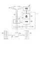
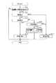
図1に示すように、車両は、ステアリングホイール90、ステアリングシャフト91、ピニオンギア92、ラック軸93、EPS装置10及び自動運転ECU80を備えている。本実施形態において、EPS装置10及び自動運転ECU80が車載回転電機システムを構成する。ステアリングホイール90には、ステアリングシャフト91が接続されている。ステアリングシャフト91の先端には、ピニオンギア92が設けられている。ピニオンギア92は、ラック軸93に噛み合っている。ラック軸93の両端には、タイロッド等を介して車輪95が回転可能に連結されている。ドライバによりステアリングホイール90が回転操作されると、ステアリングシャフト91が回転する。ステアリングシャフト91の回転運動は、ピニオンギア92によってラック軸93の直線運動に変換され、ラック軸93の変位量に応じた操舵角に車輪95が操舵される。 As shown in FIG. 1, the vehicle includes a
EPS装置10は、トルクセンサ94、減速機96、回転電機20及び通電回路部30を備えている。トルクセンサ94は、ステアリングシャフト91に設けられており、ステアリングシャフト91の操舵トルクを検出する。回転電機20は、検出された操舵トルク及びステアリングホイール90の操舵方向に応じた補助トルクを発生する。通電回路部30は、回転電機20の駆動制御を行う。減速機96は、回転電機20のロータの回転軸の回転を減速しつつ、補助トルクをステアリングシャフト91に伝達する。 The
図2を用いて、回転電機20及び通電回路部30について説明する。 The rotating
回転電機20としては、永久磁石界磁型又は巻線界磁型のものを用いることができる。回転電機20の固定子は、第1巻線群M1及び第2巻線群M2を備えている。第1巻線群M1は、星形結成された第1U相巻線U1、第1V相巻線V1及び第1W相巻線W1を備え、第2巻線群M2は、星形結線された第2U相巻線U2、第2V相巻線V2及び第2W相巻線W2を備えている。第1U,V,W相巻線U1,V1,W1それぞれの第1端は、中性点で接続されている。第1U,V,W相巻線U1,V1,W1は、電気角で120°ずつずれている。第2U,V,W相巻線U2,V2,W2それぞれの第1端は、中性点で接続されている。第2U,V,W相巻線U2,V2,W2は、電気角で120°ずつずれている。 As the rotating
通電回路部30は、電力変換器としての第1インバータ40及び第2インバータ50を備えている。第1インバータ40において、第1U相上,下アームスイッチSU1p,SU1nの接続点には、第1U相巻線U1の第2端が接続されており、第1V相上,下アームスイッチSV1p,SV1nの接続点には、第1V相巻線V1の第2端が接続されており、第1W相上,下アームスイッチSW1p,SW1nの接続点には、第1W相巻線W1の第2端が接続されている。第2インバータ50において、第2U相上,下アームスイッチSU2p,SU2nの接続点には、第2U相巻線U2の第2端が接続されており、第2V相上,下アームスイッチSV2p,SV2nの接続点には、第2V相巻線V2の第2端が接続されており、第2W相上,下アームスイッチSW2p,SW2nの接続点には、第2W相巻線W2の第2端が接続されている。 The
なお、各スイッチSU1p〜SW2nは、例えば、IGBT又はNチャネルMOSFET等の電圧制御形の半導体スイッチング素子であればよい。また、各スイッチSU1p〜SW2nには、ダイオードが逆並列に接続されている。また、本実施形態において、第1,第2インバータ40,50及び回転電機20が制御システムを構成する。 Each of the switches SU1p to SW2n may be a voltage-controlled semiconductor switching element such as an IGBT or an N-channel MOSFET. A diode is connected in antiparallel to each of the switches SU1p to SW2n. Moreover, in this embodiment, the 1st,
通電回路部30は、第1高電位側経路Lp1、第1低電位側経路Ln1、第2高電位側経路Lp2、第2低電位側経路Ln2及びコンデンサ31を備えている。第1U,V,W相上アームスイッチSU1p,SV1p,SW1pの高電位側端子には、第1高電位側経路Lp1を介して、直流電源であるバッテリ97の正極端子に接続されている。第1U,V,W相下アームスイッチSU1n,SV1n,SW1nの低電位側端子には、第1低電位側経路Ln1を介してバッテリ97の負極端子に接続されている。バッテリ97の負極端子は、グランドに接続されている。第2U,V,W相上アームスイッチSU2p,SV2p,SW2pの高電位側端子には、第2高電位側経路Lp2及び第1高電位側経路Lp1を介してバッテリ97の正極端子に接続されている。第2U,V,W相下アームスイッチSU2n,SV2n,SW2nの低電位側端子には、第2低電位側経路Ln2及び第1低電位側経路Ln1を介してバッテリ97の負極端子に接続されている。 The
続いて、通電回路部30が備える電流センサについて説明する。本実施形態に係る電流センサは、シャント抵抗と、増幅器とを備えている。 Next, the current sensor provided in the
第1インバータ40において、第1U,V,W相下アームスイッチSU1n,SV1n,SW1nの低電位側端子と第1低電位側経路Ln1とを接続する電気経路には、第1U,V,W相シャント抵抗RU1,RV1,RW1が設けられている。通電回路部30は、第1U,V,W相増幅器AMU1,AMV1,AMW1を備えている。第1U,V,W相増幅器AMU1,AMV1,AMW1は、第1U,V,W相シャント抵抗RU1,RV1,RW1の電圧降下量を増幅した信号を第1U,V,W相電流値Iur1,Ivr1,Iwr1として出力する。 In the
なお、第2インバータ50においても同様に、第2U,V,W相シャント抵抗RU2,RV2,RW2と、第2U,V,W相増幅器AMU2,AMV2,AMW2とが設けられている。第2U,V,W相増幅器AMU2,AMV2,AMW2は、第2U,V,W相シャント抵抗RU2,RV2,RW2の電圧降下量を増幅した信号を第2U,V,W相電流値Iur2,Ivr2,Iwr2として出力する。 Similarly, in the
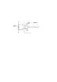
第1U相を例にして説明すると、図3に示すように、第1U相増幅器AMU1の正極電源端子には、定電圧電源Vpが接続されており、負極電源端子にはグランドが接続されている。定電圧電源Vpの出力電圧は、例えば5Vである。 The first U phase will be described as an example. As shown in FIG. 3, the constant voltage power supply Vp is connected to the positive power supply terminal of the first U phase amplifier AMU1, and the ground is connected to the negative power supply terminal. . The output voltage of the constant voltage power supply Vp is, for example, 5V.
通電回路部30は、電圧センサ32及び角度センサ33を備えている。電圧センサ32は、コンデンサ31の端子電圧を電源電圧VDCとして検出する。角度センサ33は、回転電機20の電気角に応じた角度信号を出力する。角度センサ33は、例えば、回転電機20の回転子側に設けられた磁気発生部である磁石と、磁石に近接して設けられた磁気検出素子とを備えている。電圧センサ32、角度センサ33及びトルクセンサ94の出力信号は、通電回路部30の備える制御装置であるEPSECU60に入力される。 The
EPSECU60は、マイコンを主体として構成され、回転電機20のトルクを合計指令トルクTrallに制御すべく、第1,第2インバータ40,50の各スイッチを操作する。合計指令トルクTrallは、例えば、トルクセンサ94により検出された操舵トルクに基づいて設定される。EPSECU60は、角度センサ33の出力信号に基づいて、回転電機20の電気角θeを算出する。なお、EPSECU60が提供する機能は、例えば、実体的なメモリ装置に記録されたソフトウェア及びそれを実行するコンピュータ、ハードウェア、又はそれらの組み合わせによって提供することができる。 The
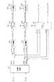
図4を用いて、EPSECU60により実行される回転電機20のトルク制御処理について説明する。 A torque control process of the rotating
2相変換部61は、第1巻線群M1に対応する電流センサにより検出された各相電流Iur1,Ivr1,Iwr1及び電気角θeに基づいて、回転電機20の3相固定座標系におけるU,V,W相電流Iur1,Ivr1,Iwr1を、2相回転座標系(dq座標系)における第1d,q軸電流Idr1,Iqr1に変換する。また、2相変換部61は、第2巻線群M2に対応する電流センサにより検出された各相電流Iur2,Ivr2,Iwr2及び電気角θeに基づいて、U,V,W相電流Iur2,Ivr2,Iwr2をdq座標系における第2d,q軸電流Idr2,Iqr2に変換する。 The two-
指令電流設定部62は、第1指令トルクTr1*に基づいて、第1巻線群M1に対応するトルクを第1指令トルクTr1*とするための第1d,q軸指令電流Id1*,Iq1*を設定する。また、指令電流設定部62は、第2指令トルクTr2*に基づいて、第2巻線群M2に対応するトルクを第2指令トルクTr2*とするための第2d,q軸指令電流Id2*,Iq2*を設定する。第1,第2指令トルクTr1*,Tr2*のそれぞれは、例えば、合計指令トルクTrallを2等分した値に設定されればよい。 Based on the first command torque Tr1 *, the command
第1制御部63aは、第1d軸電流Idr1を第1d軸指令電流Id1*にフィードバック制御するための操作量として、第1d軸指令電圧Vd1*を算出する。具体的には、第1制御部63aは、第1d軸指令電流Id1*から第1d軸電流Idr1を減算した値として第1d軸電流偏差ΔId1を算出し、算出した第1d軸電流偏差ΔId1を0にフィードバック制御するための操作量として、第1d軸指令電圧Vd1*を算出する。同様にして、第1制御部63aは、第1q軸電流Iqr1を第1q軸指令電流Iq1*にフィードバック制御するための操作量として、第1q軸指令電圧Vq1*を算出する。なお、第1制御部63aで用いられるフィードバック制御は、例えば比例積分制御であればよい。 The first control unit 63a calculates the first d-axis command voltage Vd1 * as an operation amount for performing feedback control of the first d-axis current Idr1 to the first d-axis command current Id1 *. Specifically, the first control unit 63a calculates the first d-axis current deviation ΔId1 as a value obtained by subtracting the first d-axis current Idr1 from the first d-axis command current Id1 *, and sets the calculated first d-axis current deviation ΔId1 to 0. The first d-axis command voltage Vd1 * is calculated as an operation amount for performing feedback control. Similarly, the first controller 63a calculates the first q-axis command voltage Vq1 * as an operation amount for performing feedback control of the first q-axis current Iqr1 to the first q-axis command current Iq1 *. Note that the feedback control used in the first control unit 63a may be proportional integral control, for example.
第1変換部64aは、第1d,q軸指令電圧Vd1*,Vq1*及び電気角θeに基づいて、第1d,q軸指令電圧Vd1*,Vq1*を、3相固定座標系における第1U,V,W相指令電圧Vu1,Vv1,Vw1に変換する。本実施形態において、第1U,V,W相指令電圧Vu1,Vv1,Vw1は、電気角で位相が120°ずれた正弦波状の信号となる。 Based on the first d, q-axis command voltages Vd1 *, Vq1 * and the electrical angle θe, the
第1変調部65aは、キャリア信号、第1U,V,W相指令電圧Vu1,Vv1,Vw1及び電源電圧VDCに基づいて、正弦波PWM制御により、第1インバータ40の各スイッチSU1p〜SW1nをオンオフするための各駆動信号を生成する。詳しくは、正弦波PWM制御は、各相指令電圧Vu1,Vv1,Vw1を「VDC/2」で除算した値と、キャリア信号との大小比較に基づいて、各駆動信号を生成するものである。 The first modulator 65a turns on / off the switches SU1p to SW1n of the
なお、EPSECU60は、第2制御部63b、第2変換部64b及び第2変調部65bを備えている。第2制御部63bは、第2d軸電流Idr2を第2d軸指令電流Id2*にフィードバック制御するための操作量として、第2d軸指令電圧Vd2*を算出する。また、第2制御部63bは、第2q軸電流Iqr2を第2q軸指令電流Iq2*にフィードバック制御するための操作量として、第2q軸指令電圧Vq2*を算出する。第2変換部64bは、第2d,q軸指令電圧Vd2*,Vq2*及び電気角θeに基づいて、3相固定座標系における第2U,V,W相指令電圧Vu2,Vv2,Vw2を算出する。第2変調部65bは、キャリア信号、第2U,V,W相指令電圧Vu2,Vv2,Vw2及び電源電圧VDCに基づいて、正弦波PWM制御により、第2インバータ50の各スイッチSU2p〜SW2nをオンオフするための各駆動信号を生成する。 The
図1に示す自動運転ECU80は、検出された操舵トルクに応じたトルクを回転電機20から出力させるように各インバータ40,50を制御する通常制御と、操舵トルクによらず、自車両の自動運転制御に基づいて回転電機20からトルクを出力させる自動制御とを実施する。上記自動運転制御では、加速、操舵及び制動のうち少なくとも操舵の操作が行われる。 The
自動運転ECU80は、通常制御から自動制御への切り替えを行う。自動運転ECU80は、自動制御を行う場合、検出された操舵トルクに依存しない合計指令トルクTrallをEPSECU60に通知する。 The
ここで、通電回路部30の備える電流センサに異常が生じている場合、自動制御を適正に実施できない。このため、EPSECU60は、電流センサが正常であるか否かを判定する状態判定処理を行う。自動運転ECU80は、状態判定処理によって電流センサが正常であると判定されていることを条件として、通常制御から自動制御への切り替えを許可する。このため、自動運転ECU80は、電流センサが正常であると判定されていない場合には、通常制御から自動制御への切り替えを禁止する。 Here, when abnormality has arisen in the current sensor with which the electricity
本実施形態に係る電流センサの異常とは、検出された電流値が0Aに固着する異常である。本実施形態では、電流センサの電流検出範囲の上限値が、増幅器の正極電源端子に印加される定電圧電源Vpの出力電位に対応している。また、電流検出範囲の下限値が、増幅器の負極電源端子に印加されるグランド電位に対応している。そして、電流検出範囲の中央値が0Aとされ、電流検出範囲の中央値は、定電圧電源Vpの出力電位及びグランド電位の中央値に対応している。なお、電流センサの異常として、検出された電流値が電流検出範囲の上限値又は下限値に固着する異常もある。ただし、上限値又は下限値に固着する異常は、回転電機20の駆動時において通常は取り得ない電流値を示す異常であるため、この異常はEPSECU60において容易に判定できる。これに対し、0Aは、回転電機20の駆動時において通常取り得る値である。このため、0Aに固着する異常は、上限値又は下限値に固着する異常よりも判定しにくい。 The abnormality of the current sensor according to the present embodiment is an abnormality in which the detected current value is fixed at 0A. In the present embodiment, the upper limit value of the current detection range of the current sensor corresponds to the output potential of the constant voltage power supply Vp applied to the positive power supply terminal of the amplifier. The lower limit value of the current detection range corresponds to the ground potential applied to the negative power supply terminal of the amplifier. The median value of the current detection range is 0 A, and the median value of the current detection range corresponds to the median value of the output potential and the ground potential of the constant voltage power supply Vp. As an abnormality of the current sensor, there is an abnormality in which the detected current value is fixed to the upper limit value or the lower limit value of the current detection range. However, the abnormality that adheres to the upper limit value or the lower limit value is an abnormality that indicates a current value that cannot normally be taken when the rotating
まず、電流センサの状態判定処理について説明する。なお、第1インバータ40及び第2インバータ50それぞれに対応する状態判定方法は同じである。このため、第1インバータ40に対応する状態判定方法を例にして説明する。 First, the current sensor state determination process will be described. The state determination method corresponding to each of the
EPSECU60は、第1U,V,W相電流値Iur1,Ivr1,Iwr1に基づいて、各相電流の合計値である合計電流値Itotal1(=Iur1+Ivr1+Iwr1)を算出する。EPSECU60は、算出した合計電流値Itotal1の絶対値が第1判定値Ithよりも大きいと判定した場合、電流センサに異常が生じていると判定する。EPSECU60は、合計電流値Itotal1が第1判定値Ith以下であると判定した場合、電流センサに異常が生じていないと判定する。 The
EPSECU60は、回転電機20の1電気角周期に渡って、電流センサに異常が生じていないと判定して、かつ、第1q軸電流Iqr1が第2判定値Iqthよりも大きいと判定した場合、電流センサが正常であると判定する。 When
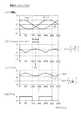
図5に、電流センサに異常が生じていない場合を示す。図5(a)は第1U,V,W相電流値Iur1,Ivr1,Iwr1の推移を示し、図5(b)は合計電流値Itotal1の絶対値の推移を示し、図5(c)は第1q軸電流Iqr1の推移を示し、図5(d)は判定信号Sigの推移を示す。判定信号Sigは、合計電流値Itotal1の絶対値が第1判定値Ithよりも大きい場合にLとなり、合計電流値Itotal1が第1判定値Ith以下である場合にHとなる。なお、図5では、便宜上、相電流の振幅Amを1としている。 FIG. 5 shows a case where no abnormality has occurred in the current sensor. FIG. 5A shows the transition of the first U, V, and W phase current values Iur1, Ivr1, and Iwr1, FIG. 5B shows the transition of the absolute value of the total current value Itotal1, and FIG. The transition of the 1q axis current Iqr1 is shown, and FIG. 5D shows the transition of the determination signal Sig. The determination signal Sig is L when the absolute value of the total current value Itotal1 is larger than the first determination value Ith, and is H when the total current value Itotal1 is equal to or less than the first determination value Ith. In FIG. 5, the amplitude Am of the phase current is set to 1 for convenience.
電流センサに異常が生じていない場合には、図5(b)に示すように、合計電流値Itotal1の絶対値は常に0となる。 When no abnormality occurs in the current sensor, the absolute value of the total current value Itotal1 is always 0 as shown in FIG.
図6に、第1W相に対応する電流センサに異常が生じている場合を示す。図6(a)〜図6(d)は図5(a)〜図5(d)に対応している。 FIG. 6 shows a case where an abnormality has occurred in the current sensor corresponding to the first W phase. 6 (a) to 6 (d) correspond to FIGS. 5 (a) to 5 (d).
図6(a)に示すように、第1W相電流値Iwr1が0Aに固着している。この場合、図6(b)に示すように、合計電流値Itotal1の絶対値は常に0にはならない。したがって、合計電流値Itotal1の絶対値が0でないことを判定できる第1判定値Ithと、合計電流値Itotal1の絶対値とを比較することにより、電流センサに異常が生じていることを判定できる。ただし、電流センサに異常が生じている場合であっても、相電流が流れていないときには、合計電流値Itotal1の絶対値は常に0となる。このため、合計電流値Itotal1の絶対値を用いて電流センサに異常が生じていることを判定するには、相電流が流れていることが必要となる。本実施形態では、第1q軸電流Iqr1が第2判定値Iqthであると判定されたことをもって、相電流が流れていると判定する。以下、第1判定値Ith及び第2判定値Iqthの設定方法について説明する。 As shown in FIG. 6A, the first W-phase current value Iwr1 is fixed at 0A. In this case, as shown in FIG. 6B, the absolute value of the total current value Itotal1 does not always become zero. Therefore, by comparing the first determination value Ith that can determine that the absolute value of the total current value Itotal1 is not 0 with the absolute value of the total current value Itotal1, it can be determined that an abnormality has occurred in the current sensor. However, even when an abnormality has occurred in the current sensor, the absolute value of the total current value Itotal1 is always 0 when no phase current is flowing. For this reason, in order to determine that an abnormality has occurred in the current sensor using the absolute value of the total current value Itotal1, it is necessary that the phase current flows. In the present embodiment, it is determined that the phase current is flowing when it is determined that the first q-axis current Iqr1 is the second determination value Iqth. Hereinafter, a method for setting the first determination value Ith and the second determination value Iqth will be described.
第1判定値Ithの設定方法について説明する。 A method for setting the first determination value Ith will be described.
3相のうちいずれか1相の電流センサに異常が生じている場合において、図6(b)に示すように、合計電流値Itotal1の絶対値が最大となる電気角θ1が特定される。そして、この電気角θ1を中心とした±30°の範囲における合計電流値Itotal1の絶対値の最小値が第1判定値Ithに設定される。第1判定値Ithは、相電流の振幅Amを用いて下式(eq1)で表される。 When an abnormality occurs in any one of the three phase current sensors, as shown in FIG. 6B, the electrical angle θ1 that maximizes the absolute value of the total current value Itotal1 is specified. Then, the minimum value of the absolute value of the total current value Itotal1 in a range of ± 30 ° centered on the electrical angle θ1 is set as the first determination value Ith. The first determination value Ith is expressed by the following equation (eq1) using the amplitude Am of the phase current.

第1U,V,W相電流値Iur1,Ivr1,Iwr1を座標変換して第1d,q軸電流Idr1,Iqr1とする式を下式(eq3)に示す。 The following equation (eq3) is an equation for converting the first U, V, and W phase current values Iur1, Ivr1, and Iwr1 into the first d and q axis currents Idr1 and Iqr1.
本実施形態では、回転電機20の1電気角周期をN等分したそれぞれの電気角範囲「360°/N」が、第1〜第N判定範囲として設定されている。本実施形態では、N=16に設定されており、各判定範囲が22.5°の電気角範囲に設定されている。EPSECU60は、各判定範囲の全てに渡って、電流センサに異常が生じていないと判定して、かつ、第1q軸電流Iqr1が第2判定値Iqth以上であると判定した場合、電流センサが正常であると判定する。 In the present embodiment, each electrical angle range “360 ° / N” obtained by equally dividing one electrical angle cycle of the rotating
図7に、電流センサの状態判定処理の手順を示す。この処理は、EPSECU60により、例えば所定の処理周期毎に繰り返し実行される。なお、図7では、第1インバータ40に対応する状態判定処理を例にして説明する。 FIG. 7 shows a procedure of current sensor state determination processing. This process is repeatedly executed by the
ステップS10では、第1U,V,W相電流値Iur1,Ivr1,Iwr1と、電気角θeとを取得する。 In step S10, the first U, V, W phase current values Iur1, Ivr1, Iwr1 and the electrical angle θe are acquired.
ステップS11では、取得した電気角θeが、第k判定範囲に含まれているか否かを判定する。なお、kの初期値は1である。 In step S11, it is determined whether or not the acquired electrical angle θe is included in the kth determination range. Note that the initial value of k is 1.
ステップS11において含まれていると判定した場合には、ステップS12に進む。ステップS12では、取得した第1U,V,W相電流値Iur1,Ivr1,Iwr1に基づいて、合計電流値Itotal1の絶対値を算出する。そして、算出した絶対値が第1判定値Ithよりも大きいか否かを判定する。ステップS12の処理は、電流センサの異常が生じているか否かを判定するための処理である。なお、第1判定値Ithには、相電流の振幅Amが含まれている。このため、第1判定値Ithは、例えば、取得した第1U,V,W相電流値Iur1,Ivr1,Iwr1の絶対値のうち、0Aに固着していない絶対値の最大値に基づいて設定されてもよい。 If it is determined in step S11 that it is included, the process proceeds to step S12. In step S12, the absolute value of the total current value Itotal1 is calculated based on the acquired first U, V, W phase current values Iur1, Ivr1, Iwr1. Then, it is determined whether or not the calculated absolute value is greater than the first determination value Ith. The process of step S12 is a process for determining whether an abnormality of the current sensor has occurred. The first determination value Ith includes the phase current amplitude Am. Therefore, the first determination value Ith is set based on, for example, the maximum absolute value that is not fixed to 0A among the absolute values of the acquired first U, V, and W phase current values Iur1, Ivr1, and Iwr1. May be.
ステップS12において否定判定した場合には、電流センサに異常が生じていないと判定し、ステップS13に進み、異常判定カウンタCabnを0にリセットする。なお、異常判定カウンタCabnの初期値は0である。 If a negative determination is made in step S12, it is determined that no abnormality has occurred in the current sensor, the process proceeds to step S13, and the abnormality determination counter Cabn is reset to zero. The initial value of the abnormality determination counter Cabn is 0.
一方、ステップS12において肯定判定した場合には、電流センサに異常が生じていると判定し、ステップS14に進む。ステップS14では、異常判定カウンタCabnを1インクリメントする。また、第k正常判定フラグCnor(k)(k=1〜N、N=16)を0にする。第k正常判定フラグCnor(k)は、1によって第k判定範囲において電流センサが正常であることを示す。なお、第1〜第N正常判定フラグCnor(1)〜Cnor(N)の初期値は0である。また、ステップS12,S14の処理が異常判定部に相当する。 On the other hand, if an affirmative determination is made in step S12, it is determined that an abnormality has occurred in the current sensor, and the process proceeds to step S14. In step S14, the abnormality determination counter Cabn is incremented by one. Further, the kth normality determination flag Cnor (k) (k = 1 to N, N = 16) is set to 0. The kth normality determination flag Cnor (k) indicates that the current sensor is normal in the kth determination range by 1. The initial values of the first to Nth normality determination flags Cnor (1) to Cnor (N) are zero. Moreover, the process of step S12, S14 is equivalent to an abnormality determination part.
ステップS13又はS14の処理の完了後、ステップS15に進む。ステップS15では、異常判定カウンタCabnが、正の整数である規定値Cth以下であるか否かを判定する。本実施形態において、規定値Cthは、2以上の整数に設定されている。 After completion of the process of step S13 or S14, the process proceeds to step S15. In step S15, it is determined whether or not the abnormality determination counter Cabn is equal to or less than a specified value Cth that is a positive integer. In the present embodiment, the specified value Cth is set to an integer of 2 or more.
ステップS15において異常判定カウンタCabnが規定値Cthよりも大きいと判定した場合には、ステップS16に進み、電流センサに異常が生じているとの判定を確定する。そして、異常が生じている旨を自動運転ECU80に通知する。なお、ステップS16の処理が行われた場合、例えば、図7に示す処理は終了される。 When it is determined in step S15 that the abnormality determination counter Cabn is greater than the specified value Cth, the process proceeds to step S16, and determination is made that an abnormality has occurred in the current sensor. Then, the
ステップS15において異常判定カウンタCabnが規定値Cth以下であると判定した場合には、ステップS17に進む。ステップS17では、取得した第1U,V,W相電流値Iur1,Ivr1,Iwr1及び電気角θeに基づいて、第1q軸電流Iqr1を算出する。そして、算出した第1q軸電流Iqr1が第2判定値Iqthよりも大きいか否かを判定する。なお、第2判定値Iqthは、例えば、取得した第1U,V,W相電流値Iur1,Ivr1,Iwr1の絶対値のうち、0Aに固着していない絶対値の最大値に基づいて設定されてもよい。 When it is determined in step S15 that the abnormality determination counter Cabn is equal to or less than the specified value Cth, the process proceeds to step S17. In step S17, the first q-axis current Iqr1 is calculated based on the acquired first U, V, W phase current values Iur1, Ivr1, Iwr1 and the electrical angle θe. Then, it is determined whether or not the calculated first q-axis current Iqr1 is larger than the second determination value Iqth. The second determination value Iqth is set based on, for example, the maximum absolute value that is not fixed to 0A among the absolute values of the acquired first U, V, and W phase current values Iur1, Ivr1, and Iwr1. Also good.
ステップS17において第1q軸電流Iqr1が第2判定値Iqthよりも大きいと判定した場合には、ステップS18に進み、異常判定カウンタCabnが0であるか否かを判定する。ステップS18において異常判定カウンタCabnが0であると判定した場合には、ステップS19に進み、第k正常判定フラグCnor(k)を1にする。 When it is determined in step S17 that the first q-axis current Iqr1 is larger than the second determination value Iqth, the process proceeds to step S18, and it is determined whether or not the abnormality determination counter Cabn is zero. When it is determined in step S18 that the abnormality determination counter Cabn is 0, the process proceeds to step S19, and the kth normality determination flag Cnor (k) is set to 1.
続くステップS20では、第1〜第N正常判定フラグCnor(1)〜Cnor(N)の全てが1であるか否かを判定する。ステップS20において否定判定した場合には、その後、ステップS10を経由してステップS11に移行する。ステップS11において、取得した電気角θeが、第k判定範囲に含まれていないと判定した場合には、ステップS21に進み、kを1インクリメントする。 In a subsequent step S20, it is determined whether or not all of the first to Nth normality determination flags Cnor (1) to Cnor (N) are 1. If a negative determination is made in step S20, then the process proceeds to step S11 via step S10. If it is determined in step S11 that the acquired electrical angle θe is not included in the kth determination range, the process proceeds to step S21, and k is incremented by one.
ステップS20において肯定判定した場合には、ステップS22に進み、電流センサが正常であるとの判定を確定する。そして、正常である旨を自動運転ECU80に通知する。なお、ステップS20では、kを1にリセットし、第1〜第N正常判定フラグCnor(1)〜Cnor(N)を0にする。また、ステップS17〜S20,S22の処理が正常判定部に相当する。また、ステップS22の処理が通知部に相当する。 If an affirmative determination is made in step S20, the process proceeds to step S22, and a determination that the current sensor is normal is confirmed. Then, the
ちなみに、第2インバータ50に対応する電流センサについても、図7に示した処理と同様の状態判定処理が行われる。 Incidentally, the state determination process similar to the process shown in FIG. 7 is also performed for the current sensor corresponding to the
続いて、図8に、自動運転ECU80により実行される通常制御から自動制御への切り替え処理の手順を示す。この処理は、例えば所定の処理周期毎に繰り返し実行される。 Next, FIG. 8 shows a procedure of switching processing from normal control to automatic control executed by the
ステップS30では、通常制御から自動制御への切り替えが指示されているか否かを判定する。 In step S30, it is determined whether switching from normal control to automatic control is instructed.
ステップS30において指示されていると判定した場合には、ステップS31に進む。ステップS31では、状態判定処理により、第1インバータ40又は第2インバータ50に対応する電流センサに異常が生じているとの通知が入力されたか否かを判定する。例えば、図7のステップS16の処理が行われた場合、第1インバータ40に対応する電流センサに異常が生じているとの通知が入力される。 If it is determined in step S30 that the instruction is given, the process proceeds to step S31. In step S31, it is determined whether or not a notification that an abnormality has occurred in the current sensor corresponding to the
ステップS41において異常が生じているとの通知が入力されたと判定した場合には、ステップS32に進み、通常制御から自動制御への切り替えを禁止する。これにより、自動制御を適正に実施できない状況において、自動制御が実施されることが回避される。その結果、車両の走行安全性の低下を抑制できる。 If it is determined in step S41 that a notification that an abnormality has occurred is input, the process proceeds to step S32, and switching from normal control to automatic control is prohibited. Thereby, it is avoided that automatic control is performed in a situation where automatic control cannot be properly performed. As a result, it is possible to suppress a decrease in traveling safety of the vehicle.
ステップS31において異常が生じているとの通知が入力されていないと判定した場合には、ステップS33に進み、第1インバータ40及び第2インバータ50双方に対応する電流センサが正常であるとの通知が入力されたか否かを判定する。例えば、図7のステップS22の処理が行われた場合、第1インバータ40に対応する電流センサが正常であるとの通知が入力される。 If it is determined in step S31 that a notification that an abnormality has occurred is not input, the process proceeds to step S33, and notification that the current sensors corresponding to both the
ステップS33において肯定判定した場合には、ステップS34に進み、通常制御から自動制御への切り替えを許可する。 If an affirmative determination is made in step S33, the process proceeds to step S34, and switching from normal control to automatic control is permitted.
ステップS33において否定判定した場合には、ステップS35に進み、所定の実行条件が成立しているか否かを判定する。所定の実行条件とは、例えば、車両の走行開始前であるとの条件である。 If a negative determination is made in step S33, the process proceeds to step S35 to determine whether or not a predetermined execution condition is satisfied. The predetermined execution condition is, for example, a condition that it is before the vehicle starts to travel.
ステップS35において否定判定した場合には、ステップS32に進む。一方、ステップS35において肯定判定した場合には、ステップS36に進む。ステップS36では、第1,第2インバータ40,50双方に対応する電流センサが正常であるとの判定を状態判定処理において確定させるために、第1,第2巻線群M1,M2に対して所定の通電パターンを実施すべく第1,第2インバータ40,50のスイッチを制御する。ステップS36の処理が強制制御部に相当する。本実施形態において、所定の通電パターンは、第1巻線群M1への通電により発生するトルクと第2巻線群M2への通電により発生するトルクとが打ち消し合う通電パターンである。この通電パターンは、「Tr1*=−Tr2*」又は「Tr2*=−Tr1*」に設定することで実現できる。ステップS36の処理によれば回転電機20でトルクが発生しないため、ドライバに違和感を与えることを防止できる。 If a negative determination is made in step S35, the process proceeds to step S32. On the other hand, if a positive determination is made in step S35, the process proceeds to step S36. In step S36, the first and second winding groups M1 and M2 are determined for determining in the state determination process that the current sensors corresponding to both the first and
続いて、本実施形態の効果を比較例と対比しつつ説明する。 Next, the effect of this embodiment will be described in comparison with a comparative example.
まず、図9を用いて、比較例について説明する。図9(a),(b),(d)は図6(a),(b),(d)に対応しており、図9(c)は第1U,V,W相電流値Iur1,Ivr1,Iwr1の絶対値の推移を示す。図9は、第1W相の電流センサに異常が生じている場合を示す。図9では、便宜上、相電流の振幅Amを1としている。 First, a comparative example will be described with reference to FIG. 9A, 9B, and 9D correspond to FIGS. 6A, 6B, and 6D, and FIG. 9C shows the first U, V, and W-phase current values Iur1, The transition of absolute values of Ivr1 and Iwr1 is shown. FIG. 9 shows a case where an abnormality has occurred in the first W-phase current sensor. In FIG. 9, the amplitude Am of the phase current is set to 1 for convenience.
比較例は、本実施形態の構成のうち、先の図7のステップS17の処理を、第1U,V,W相電流値Iur1,Ivr1,Iwr1の絶対値の少なくとも1つが「1/2×Am」よりも大きいか否かを判定する処理に置き換えたものである。ここで、閾値が「1/2×Am」に設定されているのは、3相のうちいずれか1相の電流検出値が0Aに固着する場合、異常が生じていない電流センサの電流検出値のうち少なくとも一方が「1/2×Am」以上となることに基づく。 In the comparative example, in the configuration of the present embodiment, the process of step S17 of FIG. 7 is performed by changing at least one of the absolute values of the first U, V, and W phase current values Iur1, Ivr1, and Iwr1 to “1/2 × Am. ”Is replaced with a process for determining whether or not it is larger than“ ”. Here, the threshold is set to “1/2 × Am” when the current detection value of any one of the three phases is fixed at 0 A, the current detection value of the current sensor in which no abnormality has occurred. Based on the fact that at least one of them becomes “½ × Am” or more.
本実施形態によれば、図10に示すように、比較例と比べて、電流センサの異常判定を実施するために回転電機20に流すべき相電流の振幅を小さくできる。比較例では、相電流を「1/2×Am」よりも大きくするために要求される相電流の振幅が1/(√3)×Amであるのに対し、本実施形態では、第1q軸電流Iqr1を第2判定値Iqthよりも大きくするために要求される相電流の振幅が「1/3×Am」となる。このため、本実施形態の相電流の振幅は、比較例の相電流の振幅よりも小さい。 According to the present embodiment, as shown in FIG. 10, the amplitude of the phase current to be passed through the rotating
本実施形態の状態判定方法によれば、電流センサが正常であることを判定するための機会を増やすことができる。つまり、電流センサの状態判定を例えば車両の走行中に実施する場合において、回転電機に流れる相電流が小さくなることがある。例えば、車両の車輪が小さかったり、路面の摩擦係数が小さかったりすることにより、回転電機20が発生する補助トルクが小さくなり、相電流が小さくなり得る。本実施形態によれば、電流センサの異常判定を実施するために回転電機20に流すべき相電流の振幅を小さくできる。このため、補助トルクが小さくなり、回転電機20に流れる相電流が小さくなる場合であっても、判定の機会を増やすことができる。なお、図11には、比較例において、相電流が大きい場合と小さい場合とのそれぞれの第1U,V,W相電流値Iur1,Ivr1,Iwr1、合計電流値Itotal1の絶対値、及び判定信号Sigの推移を示す。図11に示す比較例において、相電流が小さい場合には、第1W相電流値Iwr1が0Aに固着しているにもかかわらず、合計電流値Itotal1の絶対値が第1判定値Ithよりも大きくならない。このため、判定信号SigがHに維持され、電流センサに異常が生じていることを判定できない。 According to the state determination method of this embodiment, the opportunity for determining that the current sensor is normal can be increased. That is, when the current sensor state determination is performed, for example, while the vehicle is running, the phase current flowing through the rotating electrical machine may be small. For example, when the vehicle wheel is small or the friction coefficient of the road surface is small, the auxiliary torque generated by the rotating
以上説明した本実施形態によれば、回転電機20に流すべき相電流の振幅を小さくしつつ、電流センサが正常であることを判定できる。これにより、電流センサの信頼性を向上させることができる。 According to the present embodiment described above, it is possible to determine that the current sensor is normal while reducing the amplitude of the phase current to be passed through the rotating
<その他の実施形態>
なお、上記実施形態は、以下のように変更して実施してもよい。<Other embodiments>
The above embodiment may be modified as follows.
・図7のステップS17の処理を、第1q軸電流Iqr1が第2判定値Iqth以上であるか否かの処理に置き換えてもよい。 The process in step S17 in FIG. 7 may be replaced with a process for determining whether or not the first q-axis current Iqr1 is greater than or equal to the second determination value Iqth.
・ステップS17の処理において、第1q軸電流Iqr1に代えて、第1d軸電流Idr1が用いられてもよい。この場合における第2判定値の設定方法について説明する。 In the process of step S17, the first d-axis current Idr1 may be used instead of the first q-axis current Iqr1. A method for setting the second determination value in this case will be described.
上式(eq3),(eq4)より、第1d軸電流Idr1は下式(eq9)のように表される。 From the above equations (eq3) and (eq4), the first d-axis current Idr1 is expressed as the following equation (eq9).
また、ステップS17の処理において、第1d軸電流Idr1及び第1q軸電流Iqr1の双方が用いられてもよい。具体的には、例えば、回転座標系における相電流振幅相当量が第2判定値よりも大きいか否かが判定されればよい。この場合、第2判定値は、振幅相当量に対応した値となる。振幅相当量としては、例えば、第1d軸電流を2乗した値と第1q軸電流を2乗した値との和の平方根が用いられればよい。 In the process of step S17, both the first d-axis current Idr1 and the first q-axis current Iqr1 may be used. Specifically, for example, it may be determined whether the phase current amplitude equivalent amount in the rotating coordinate system is larger than the second determination value. In this case, the second determination value is a value corresponding to the amplitude equivalent amount. As the amplitude equivalent amount, for example, the square root of the sum of the value obtained by squaring the first d-axis current and the value obtained by squaring the first q-axis current may be used.
・図8のステップS36の所定の通電パターンは、第1,第2d軸電流Idr1,Idr2が0以外の値とされて、かつ、第1,第2q軸電流Iqr1,Iqr2が0又は略0とされる通電パターンであってもよい。 The predetermined energization pattern in step S36 in FIG. 8 is such that the first and second d-axis currents Idr1 and Idr2 are values other than 0, and the first and second q-axis currents Iqr1 and Iqr2 are 0 or substantially 0. An energization pattern may be used.
・第1判定値Ithが√3/2×Amよりも大きい値に設定されていてもよい。また、第2判定値Iqthが1/√6×Amよりも大きい値に設定されていてもよい。 The first determination value Ith may be set to a value larger than √3 / 2 × Am. Further, the second determination value Iqth may be set to a value larger than 1 / √6 × Am.
・電流センサの正常判定を実施するための判定範囲としては、1電気角周期を16等分したものに限らない。例えば、判定範囲として、1電気角周期をM等分(Mは6以上の整数)したものを用いてもよい。なお、判定範囲としては、1電気角周期をL等分(Lは12以上の整数)したものが望ましい。 The determination range for performing normal determination of the current sensor is not limited to one electrical angle period divided into 16 equal parts. For example, as the determination range, one electrical angle period divided into M (M is an integer of 6 or more) may be used. In addition, as a determination range, what divided one electrical angle period into L equally (L is an integer greater than or equal to 12) is desirable.
・上記実施形態では、EPSECU60は、1電気角周期に渡って、電流センサに異常が生じていないと判定して、かつ、第1q軸電流Iqr1が第2判定値Iqthよりも大きいと判定した場合、電流センサが正常であると判定したがこれに限らない。例えば、図5(a)を参照して、1電気角周期のうち、15°〜45°の電気角範囲、75°〜105°の電気角範囲、135°〜165°の電気角範囲、195°〜205°の電気角範囲、255°〜285°の電気角範囲、及び315°〜345°の電気角範囲それぞれに渡って、電流センサに異常が生じていないと判定して、かつ、第1q軸電流Iqr1が第2判定値Iqthよりも大きいと判定した場合、電流センサが正常であると判定してもよい。この場合、例えば、15°〜45°の電気角範囲には、第1V相電流値Ivr1の絶対値が最大になる電気角(30°)が含まれ、75°〜105°の電気角範囲には、第1U相電流値Iur1の絶対値が最大になる電気角(90°)が含まれる。 In the above embodiment, the
・上記実施形態で説明した構成に代えて、回転電機の1電気角周期以下の所定の電気角範囲に渡って、異常判定部により異常が生じていないと判定されて、かつ、電流検出値に基づいて算出した回転電機に流れる回転座標系の電流値が第2判定値(Iqth)以上であると判定された場合、回転電機の断線異常が生じていないことを判定できる。 In place of the configuration described in the above embodiment, the abnormality determination unit determines that no abnormality has occurred over a predetermined electrical angle range of one electrical angle period or less of the rotating electrical machine, and the current detection value is When it is determined that the current value of the rotating coordinate system flowing to the rotating electrical machine calculated based on the second determination value (Iqth) is equal to or greater than that, it can be determined that no disconnection abnormality of the rotating electrical machine has occurred.
・電流センサとしては、図3に示す構成のものに限らない。 The current sensor is not limited to the one shown in FIG.
・回転電機としては、1つの巻線群を備えるものであってもよい。 -As a rotary electric machine, you may provide one winding group.
・回転電機システムとしては、EPS装置を構成するものに限らない。 -As a rotating electrical machine system, it is not restricted to what comprises an EPS apparatus.
20…回転電機、40,50…インバータ、60…EPSECU、80…自動運転ECU、RU1〜RW2…シャント抵抗、AMU1〜AMW2…増幅器。 DESCRIPTION OF
Claims (11)
Translated fromJapanese前記電流センサの電流検出値に基づいて制御されることにより、直流電源(97)から出力された直流電力を交流電力に変換して前記回転電機に供給する電力変換器(40,50)と、
前記電流検出値に基づいて算出した各相電流の合計値が第1判定値(Ith)よりも大きいと判定した場合、前記電流センサに異常が生じていると判定し、前記各相電流の合計値が前記第1判定値以下であると判定した場合、前記電流センサに異常が生じていないと判定する異常判定部と、
前記回転電機の1電気角周期以下の所定の電気角範囲に渡って、前記異常判定部により異常が生じていないと判定されて、かつ、前記電流検出値に基づいて算出した前記回転電機に流れる回転座標系の電流値が第2判定値(Iqth)以上であると判定した場合、前記電流センサが正常であると判定する正常判定部と、を備える電流センサの状態判定装置。A current sensor (RU1 to RW2, AMU1 to AMW2) that is provided corresponding to each phase of the multiphase rotating electrical machine (20) and detects a phase current flowing through the rotating electrical machine;
A power converter (40, 50) that is controlled based on a current detection value of the current sensor, converts DC power output from a DC power source (97) into AC power, and supplies the AC power to the rotating electrical machine;
When it is determined that the total value of the phase currents calculated based on the detected current value is greater than the first determination value (Ith), it is determined that an abnormality has occurred in the current sensor, and the total of the phase currents An abnormality determination unit that determines that no abnormality has occurred in the current sensor when it is determined that the value is equal to or less than the first determination value;
The abnormality determining unit determines that no abnormality has occurred over a predetermined electrical angle range of one electrical angle cycle or less of the rotating electrical machine, and flows to the rotating electrical machine calculated based on the detected current value. A current sensor state determination device comprising: a normal determination unit that determines that the current sensor is normal when it is determined that the current value of the rotating coordinate system is equal to or greater than a second determination value (Iqth).
前記電流センサの異常とは、各相に対応する前記電流センサのうちいずれか1相に対応する電流センサの電流検出値が0Aに固着する異常のことであり、
前記回転電機に流れる相電流の振幅をAmとする場合において、前記第2判定値は、
The abnormality of the current sensor is an abnormality in which the current detection value of the current sensor corresponding to any one of the current sensors corresponding to each phase is fixed to 0A.
When the amplitude of the phase current flowing through the rotating electrical machine is Am, the second determination value is
前記電流センサの異常とは、各相に対応する前記電流センサのうちいずれか1相に対応する電流センサの電流検出値が0Aに固着する異常のことであり、
前記回転電機に流れる相電流の振幅をAmとする場合において、前記第1判定値は、
The abnormality of the current sensor is an abnormality in which the current detection value of the current sensor corresponding to any one of the current sensors corresponding to each phase is fixed to 0A.
When the amplitude of the phase current flowing through the rotating electrical machine is Am, the first determination value is
ドライバのステアリング操作によって発生する操舵トルクに応じたトルクを前記回転電機から出力する電動パワーステアリング装置(10)を構成する車載回転電機システム。In the vehicle-mounted rotating electrical machine system comprising the current sensor state determination device according to claim 7,
An in-vehicle rotating electrical machine system that constitutes an electric power steering device (10) that outputs torque corresponding to a steering torque generated by a steering operation of a driver from the rotating electrical machine.
前記外部装置として、前記自動制御を行う自動運転制御装置を備え、
前記自動運転制御装置は、前記通知部により正常である旨が通知されていない場合、前記通常制御から前記自動制御への切り替えを禁止する請求項8に記載の車載回転電機システム。The electric power steering device is based on normal control for controlling the power converter so that torque corresponding to the steering torque is output from the rotating electrical machine, and on automatic driving control of the host vehicle regardless of the steering torque. Automatic control for outputting torque from the rotating electrical machine can be performed,
As the external device, comprising an automatic operation control device for performing the automatic control,
The in-vehicle rotating electrical machine system according to claim 8, wherein the automatic operation control device prohibits switching from the normal control to the automatic control when the notification unit does not notify that the normal operation is normal.
前記所定の通電パターンは、前記第1巻線群への通電により発生するトルクと前記第2巻線群への通電により発生するトルクとが打ち消し合う通電パターンである請求項10に記載の車載回転電機システム。The rotating electrical machine has a first winding group (M1) and a second winding group (M2),
The on-vehicle rotation according to claim 10, wherein the predetermined energization pattern is an energization pattern in which a torque generated by energizing the first winding group cancels out a torque generated by energizing the second winding group. Electric system.
Priority Applications (3)
| Application Number | Priority Date | Filing Date | Title |
|---|---|---|---|
| JP2017128904AJP6863136B2 (en) | 2017-06-30 | 2017-06-30 | Current sensor status determination device, in-vehicle rotary electric machine system |
| US16/021,563US11251740B2 (en) | 2017-06-30 | 2018-06-28 | Current sensor state determination device and in-vehicle rotating electric machine system having same |
| US17/221,360US11616466B2 (en) | 2017-06-30 | 2021-04-02 | Current sensor state determination device and in vehicle rotating electric machine system having same |
Applications Claiming Priority (1)
| Application Number | Priority Date | Filing Date | Title |
|---|---|---|---|
| JP2017128904AJP6863136B2 (en) | 2017-06-30 | 2017-06-30 | Current sensor status determination device, in-vehicle rotary electric machine system |
Publications (2)
| Publication Number | Publication Date |
|---|---|
| JP2019013098Atrue JP2019013098A (en) | 2019-01-24 |
| JP6863136B2 JP6863136B2 (en) | 2021-04-21 |
Family
ID=64739202
Family Applications (1)
| Application Number | Title | Priority Date | Filing Date |
|---|---|---|---|
| JP2017128904AActiveJP6863136B2 (en) | 2017-06-30 | 2017-06-30 | Current sensor status determination device, in-vehicle rotary electric machine system |
Country Status (2)
| Country | Link |
|---|---|
| US (2) | US11251740B2 (en) |
| JP (1) | JP6863136B2 (en) |
Cited By (1)
| Publication number | Priority date | Publication date | Assignee | Title |
|---|---|---|---|---|
| WO2022019083A1 (en)* | 2020-07-22 | 2022-01-27 | 株式会社デンソー | Rotaing electric machine drive device |
Families Citing this family (12)
| Publication number | Priority date | Publication date | Assignee | Title |
|---|---|---|---|---|
| WO2017150639A1 (en)* | 2016-03-04 | 2017-09-08 | 日本電産株式会社 | Power conversion device, motor drive unit, electric power steering device, and relay module |
| KR102033556B1 (en)* | 2017-09-11 | 2019-11-08 | 주식회사 만도 | Apparatus and method for processing sensor signal, apparatus for controlling steering |
| KR102614137B1 (en) | 2018-04-13 | 2023-12-14 | 현대자동차주식회사 | Inverter system for vehicle and control method of the same |
| KR102588932B1 (en) | 2018-04-18 | 2023-10-16 | 현대자동차주식회사 | Inverter system for vehicle |
| JP2019207204A (en)* | 2018-05-30 | 2019-12-05 | 株式会社デンソー | Rotation detector and electric power steering device using the same |
| KR102712336B1 (en)* | 2018-08-17 | 2024-09-30 | 현대자동차주식회사 | Inverter system for vehicle |
| KR102659245B1 (en) | 2018-11-02 | 2024-04-22 | 현대자동차주식회사 | Inverter system for vehicle |
| JP7063240B2 (en)* | 2018-11-05 | 2022-05-09 | 株式会社デンソー | Rotating electric machine control device |
| DE102019205471A1 (en)* | 2019-04-16 | 2020-10-22 | Robert Bosch Gmbh | Method for checking measured values of current intensities of currents which are provided by a six-phase converter to at least one electrical machine |
| EP4024700A4 (en)* | 2019-08-30 | 2023-05-17 | Hitachi Industrial Equipment Systems Co., Ltd. | Power converting device and sign diagnostic method used in same |
| CN115461981B (en)* | 2020-05-07 | 2024-12-03 | 三菱电机株式会社 | Motor control device and electric power steering device |
| JP7400682B2 (en)* | 2020-10-06 | 2023-12-19 | トヨタ自動車株式会社 | Electric car |
Citations (6)
| Publication number | Priority date | Publication date | Assignee | Title |
|---|---|---|---|---|
| JPH10309097A (en)* | 1997-04-30 | 1998-11-17 | Toyota Motor Corp | Abnormality detection device for current sensor for AC motor control |
| US20090133947A1 (en)* | 2007-11-22 | 2009-05-28 | Hitachi, Ltd. | Motor control apparatus |
| JP2011151986A (en)* | 2010-01-22 | 2011-08-04 | Denso Corp | Abnormality diagnostic device for current sensor, and abnormality diagnostic device for sensor |
| CN103715955A (en)* | 2012-09-28 | 2014-04-09 | 株式会社电装 | Control device for AC motor |
| JP2015220852A (en)* | 2014-05-16 | 2015-12-07 | 株式会社ジェイテクト | Current sensor abnormality identification device |
| JP2016120913A (en)* | 2016-02-19 | 2016-07-07 | 日本精工株式会社 | Electric power steering device |
Family Cites Families (6)
| Publication number | Priority date | Publication date | Assignee | Title |
|---|---|---|---|---|
| US7994798B2 (en)* | 2007-11-30 | 2011-08-09 | Caterpillar Inc. | Power converter current sensor testing method |
| JP5942337B2 (en)* | 2011-04-28 | 2016-06-29 | 株式会社ジェイテクト | Vehicle steering system |
| JP5765589B2 (en) | 2013-03-11 | 2015-08-19 | 株式会社デンソー | Power converter |
| JP6211443B2 (en)* | 2014-03-14 | 2017-10-11 | 日立オートモティブシステムズ株式会社 | Electric motor control device |
| JP6407556B2 (en) | 2014-05-12 | 2018-10-17 | 東芝ライフスタイル株式会社 | Washing machine |
| JP6822074B2 (en) | 2016-11-04 | 2021-01-27 | 株式会社デンソー | Rotating electrical system |
- 2017
- 2017-06-30JPJP2017128904Apatent/JP6863136B2/enactiveActive
- 2018
- 2018-06-28USUS16/021,563patent/US11251740B2/enactiveActive
- 2021
- 2021-04-02USUS17/221,360patent/US11616466B2/enactiveActive
Patent Citations (6)
| Publication number | Priority date | Publication date | Assignee | Title |
|---|---|---|---|---|
| JPH10309097A (en)* | 1997-04-30 | 1998-11-17 | Toyota Motor Corp | Abnormality detection device for current sensor for AC motor control |
| US20090133947A1 (en)* | 2007-11-22 | 2009-05-28 | Hitachi, Ltd. | Motor control apparatus |
| JP2011151986A (en)* | 2010-01-22 | 2011-08-04 | Denso Corp | Abnormality diagnostic device for current sensor, and abnormality diagnostic device for sensor |
| CN103715955A (en)* | 2012-09-28 | 2014-04-09 | 株式会社电装 | Control device for AC motor |
| JP2015220852A (en)* | 2014-05-16 | 2015-12-07 | 株式会社ジェイテクト | Current sensor abnormality identification device |
| JP2016120913A (en)* | 2016-02-19 | 2016-07-07 | 日本精工株式会社 | Electric power steering device |
Cited By (3)
| Publication number | Priority date | Publication date | Assignee | Title |
|---|---|---|---|---|
| WO2022019083A1 (en)* | 2020-07-22 | 2022-01-27 | 株式会社デンソー | Rotaing electric machine drive device |
| JP2022021849A (en)* | 2020-07-22 | 2022-02-03 | 株式会社Soken | Drive device for rotary electric machine |
| JP7441135B2 (en) | 2020-07-22 | 2024-02-29 | 株式会社Soken | Rotating electric machine drive device |
Also Published As
| Publication number | Publication date |
|---|---|
| US20190006979A1 (en) | 2019-01-03 |
| JP6863136B2 (en) | 2021-04-21 |
| US20210226572A1 (en) | 2021-07-22 |
| US11251740B2 (en) | 2022-02-15 |
| US11616466B2 (en) | 2023-03-28 |
Similar Documents
| Publication | Publication Date | Title |
|---|---|---|
| JP6863136B2 (en) | Current sensor status determination device, in-vehicle rotary electric machine system | |
| EP3281844B1 (en) | Motor control device | |
| JP5590076B2 (en) | Control device for multi-phase rotating machine | |
| JP5760830B2 (en) | Control device for three-phase rotating machine | |
| JP5907314B2 (en) | Motor control device, electric power steering device using the same, and vehicle | |
| JP6040963B2 (en) | Rotating machine control device | |
| JP6852522B2 (en) | Control device for multi-phase rotating machine | |
| EP3544174B1 (en) | Rotating electric-machine-control apparatus and electric power steering apparatus equipped with said rotating-electric-machine control apparatus | |
| JP6445937B2 (en) | Electric power steering device | |
| JP6769247B2 (en) | Rotating electrical system | |
| JP2017169405A (en) | Motor control device and steering control device | |
| CN102916641A (en) | Multi-phase rotary machine control apparatus and electric power steering system using the same | |
| JP2017093056A (en) | Power conversion device and electric power steering device | |
| US10560044B2 (en) | Motor control method, motor control system, and electric power steering system | |
| JP2014007784A (en) | Motor controller, and electrically-driven power steering device using the same | |
| JP7517205B2 (en) | MOTOR CONTROL DEVICE AND ELECTRIC POWER STEERING DEVICE INCLUDING THE SAME | |
| JP2013519347A (en) | Circuit device and method and apparatus for operating the circuit device | |
| JP2017017829A (en) | Left-and-right wheel independent control device of electric automobile | |
| JP2016096608A (en) | Motor control device, electric power steering device using the same, and vehicle | |
| JP6822074B2 (en) | Rotating electrical system | |
| JP7634808B2 (en) | Electric power steering device | |
| US20200001915A1 (en) | Motor controlling method, motor controlling system, and electronic power steering system | |
| JP2019068642A (en) | Control device of multiphase rotating machine | |
| JP5325806B2 (en) | Railway vehicle drive control device | |
| JP2016067147A (en) | Electric car control device |
Legal Events
| Date | Code | Title | Description |
|---|---|---|---|
| A621 | Written request for application examination | Free format text:JAPANESE INTERMEDIATE CODE: A621 Effective date:20200522 | |
| A977 | Report on retrieval | Free format text:JAPANESE INTERMEDIATE CODE: A971007 Effective date:20210218 | |
| TRDD | Decision of grant or rejection written | ||
| A01 | Written decision to grant a patent or to grant a registration (utility model) | Free format text:JAPANESE INTERMEDIATE CODE: A01 Effective date:20210302 | |
| A61 | First payment of annual fees (during grant procedure) | Free format text:JAPANESE INTERMEDIATE CODE: A61 Effective date:20210315 | |
| R151 | Written notification of patent or utility model registration | Ref document number:6863136 Country of ref document:JP Free format text:JAPANESE INTERMEDIATE CODE: R151 | |
| R250 | Receipt of annual fees | Free format text:JAPANESE INTERMEDIATE CODE: R250 | |
| R250 | Receipt of annual fees | Free format text:JAPANESE INTERMEDIATE CODE: R250 |