JP2019007751A - Wearable device and method for controlling the same - Google Patents
Wearable device and method for controlling the sameDownload PDFInfo
- Publication number
- JP2019007751A JP2019007751AJP2017121028AJP2017121028AJP2019007751AJP 2019007751 AJP2019007751 AJP 2019007751AJP 2017121028 AJP2017121028 AJP 2017121028AJP 2017121028 AJP2017121028 AJP 2017121028AJP 2019007751 AJP2019007751 AJP 2019007751A
- Authority
- JP
- Japan
- Prior art keywords
- state
- display
- determined
- wearable device
- activity
- Prior art date
- Legal status (The legal status is an assumption and is not a legal conclusion. Google has not performed a legal analysis and makes no representation as to the accuracy of the status listed.)
- Pending
Links
Images


Classifications
- G—PHYSICS
- G04—HOROLOGY
- G04G—ELECTRONIC TIME-PIECES
- G04G9/00—Visual time or date indication means
- G—PHYSICS
- G09—EDUCATION; CRYPTOGRAPHY; DISPLAY; ADVERTISING; SEALS
- G09G—ARRANGEMENTS OR CIRCUITS FOR CONTROL OF INDICATING DEVICES USING STATIC MEANS TO PRESENT VARIABLE INFORMATION
- G09G3/00—Control arrangements or circuits, of interest only in connection with visual indicators other than cathode-ray tubes
- G09G3/20—Control arrangements or circuits, of interest only in connection with visual indicators other than cathode-ray tubes for presentation of an assembly of a number of characters, e.g. a page, by composing the assembly by combination of individual elements arranged in a matrix no fixed position being assigned to or needed to be assigned to the individual characters or partial characters
- G09G3/34—Control arrangements or circuits, of interest only in connection with visual indicators other than cathode-ray tubes for presentation of an assembly of a number of characters, e.g. a page, by composing the assembly by combination of individual elements arranged in a matrix no fixed position being assigned to or needed to be assigned to the individual characters or partial characters by control of light from an independent source
- G09G3/3433—Control arrangements or circuits, of interest only in connection with visual indicators other than cathode-ray tubes for presentation of an assembly of a number of characters, e.g. a page, by composing the assembly by combination of individual elements arranged in a matrix no fixed position being assigned to or needed to be assigned to the individual characters or partial characters by control of light from an independent source using light modulating elements actuated by an electric field and being other than liquid crystal devices and electrochromic devices
- G09G3/344—Control arrangements or circuits, of interest only in connection with visual indicators other than cathode-ray tubes for presentation of an assembly of a number of characters, e.g. a page, by composing the assembly by combination of individual elements arranged in a matrix no fixed position being assigned to or needed to be assigned to the individual characters or partial characters by control of light from an independent source using light modulating elements actuated by an electric field and being other than liquid crystal devices and electrochromic devices based on particles moving in a fluid or in a gas, e.g. electrophoretic devices
- A—HUMAN NECESSITIES
- A63—SPORTS; GAMES; AMUSEMENTS
- A63B—APPARATUS FOR PHYSICAL TRAINING, GYMNASTICS, SWIMMING, CLIMBING, OR FENCING; BALL GAMES; TRAINING EQUIPMENT
- A63B24/00—Electric or electronic controls for exercising apparatus of preceding groups; Controlling or monitoring of exercises, sportive games, training or athletic performances
- A63B24/0062—Monitoring athletic performances, e.g. for determining the work of a user on an exercise apparatus, the completed jogging or cycling distance
- G—PHYSICS
- G04—HOROLOGY
- G04F—TIME-INTERVAL MEASURING
- G04F7/00—Apparatus for measuring unknown time intervals by non-electric means
- G04F7/04—Apparatus for measuring unknown time intervals by non-electric means using a mechanical oscillator
- G04F7/08—Watches or clocks with stop devices, e.g. chronograph
- G04F7/0866—Special arrangements
- G04F7/088—Special arrangements with display of fraction of seconds, e.g. foudroyante
- G—PHYSICS
- G06—COMPUTING OR CALCULATING; COUNTING
- G06F—ELECTRIC DIGITAL DATA PROCESSING
- G06F1/00—Details not covered by groups G06F3/00 - G06F13/00 and G06F21/00
- G06F1/16—Constructional details or arrangements
- G06F1/1613—Constructional details or arrangements for portable computers
- G06F1/163—Wearable computers, e.g. on a belt
- G—PHYSICS
- G06—COMPUTING OR CALCULATING; COUNTING
- G06F—ELECTRIC DIGITAL DATA PROCESSING
- G06F1/00—Details not covered by groups G06F3/00 - G06F13/00 and G06F21/00
- G06F1/26—Power supply means, e.g. regulation thereof
- G06F1/32—Means for saving power
- G06F1/3203—Power management, i.e. event-based initiation of a power-saving mode
- G06F1/3206—Monitoring of events, devices or parameters that trigger a change in power modality
- G06F1/3231—Monitoring the presence, absence or movement of users
- G—PHYSICS
- G06—COMPUTING OR CALCULATING; COUNTING
- G06F—ELECTRIC DIGITAL DATA PROCESSING
- G06F1/00—Details not covered by groups G06F3/00 - G06F13/00 and G06F21/00
- G06F1/26—Power supply means, e.g. regulation thereof
- G06F1/32—Means for saving power
- G06F1/3203—Power management, i.e. event-based initiation of a power-saving mode
- G06F1/3234—Power saving characterised by the action undertaken
- G06F1/325—Power saving in peripheral device
- G06F1/3265—Power saving in display device
- G—PHYSICS
- G06—COMPUTING OR CALCULATING; COUNTING
- G06F—ELECTRIC DIGITAL DATA PROCESSING
- G06F3/00—Input arrangements for transferring data to be processed into a form capable of being handled by the computer; Output arrangements for transferring data from processing unit to output unit, e.g. interface arrangements
- G06F3/01—Input arrangements or combined input and output arrangements for interaction between user and computer
- G06F3/011—Arrangements for interaction with the human body, e.g. for user immersion in virtual reality
- G06F3/013—Eye tracking input arrangements
- G—PHYSICS
- G06—COMPUTING OR CALCULATING; COUNTING
- G06F—ELECTRIC DIGITAL DATA PROCESSING
- G06F3/00—Input arrangements for transferring data to be processed into a form capable of being handled by the computer; Output arrangements for transferring data from processing unit to output unit, e.g. interface arrangements
- G06F3/01—Input arrangements or combined input and output arrangements for interaction between user and computer
- G06F3/017—Gesture based interaction, e.g. based on a set of recognized hand gestures
- G—PHYSICS
- G06—COMPUTING OR CALCULATING; COUNTING
- G06F—ELECTRIC DIGITAL DATA PROCESSING
- G06F3/00—Input arrangements for transferring data to be processed into a form capable of being handled by the computer; Output arrangements for transferring data from processing unit to output unit, e.g. interface arrangements
- G06F3/01—Input arrangements or combined input and output arrangements for interaction between user and computer
- G06F3/048—Interaction techniques based on graphical user interfaces [GUI]
- G06F3/0484—Interaction techniques based on graphical user interfaces [GUI] for the control of specific functions or operations, e.g. selecting or manipulating an object, an image or a displayed text element, setting a parameter value or selecting a range
- G—PHYSICS
- G06—COMPUTING OR CALCULATING; COUNTING
- G06F—ELECTRIC DIGITAL DATA PROCESSING
- G06F3/00—Input arrangements for transferring data to be processed into a form capable of being handled by the computer; Output arrangements for transferring data from processing unit to output unit, e.g. interface arrangements
- G06F3/14—Digital output to display device ; Cooperation and interconnection of the display device with other functional units
- G06F3/147—Digital output to display device ; Cooperation and interconnection of the display device with other functional units using display panels
- G—PHYSICS
- G09—EDUCATION; CRYPTOGRAPHY; DISPLAY; ADVERTISING; SEALS
- G09G—ARRANGEMENTS OR CIRCUITS FOR CONTROL OF INDICATING DEVICES USING STATIC MEANS TO PRESENT VARIABLE INFORMATION
- G09G3/00—Control arrangements or circuits, of interest only in connection with visual indicators other than cathode-ray tubes
- G09G3/20—Control arrangements or circuits, of interest only in connection with visual indicators other than cathode-ray tubes for presentation of an assembly of a number of characters, e.g. a page, by composing the assembly by combination of individual elements arranged in a matrix no fixed position being assigned to or needed to be assigned to the individual characters or partial characters
- G09G3/34—Control arrangements or circuits, of interest only in connection with visual indicators other than cathode-ray tubes for presentation of an assembly of a number of characters, e.g. a page, by composing the assembly by combination of individual elements arranged in a matrix no fixed position being assigned to or needed to be assigned to the individual characters or partial characters by control of light from an independent source
- G09G3/3406—Control of illumination source
- A—HUMAN NECESSITIES
- A63—SPORTS; GAMES; AMUSEMENTS
- A63B—APPARATUS FOR PHYSICAL TRAINING, GYMNASTICS, SWIMMING, CLIMBING, OR FENCING; BALL GAMES; TRAINING EQUIPMENT
- A63B24/00—Electric or electronic controls for exercising apparatus of preceding groups; Controlling or monitoring of exercises, sportive games, training or athletic performances
- A63B24/0062—Monitoring athletic performances, e.g. for determining the work of a user on an exercise apparatus, the completed jogging or cycling distance
- A63B2024/0071—Distinction between different activities, movements, or kind of sports performed
- G—PHYSICS
- G09—EDUCATION; CRYPTOGRAPHY; DISPLAY; ADVERTISING; SEALS
- G09G—ARRANGEMENTS OR CIRCUITS FOR CONTROL OF INDICATING DEVICES USING STATIC MEANS TO PRESENT VARIABLE INFORMATION
- G09G2310/00—Command of the display device
- G09G2310/04—Partial updating of the display screen
- G—PHYSICS
- G09—EDUCATION; CRYPTOGRAPHY; DISPLAY; ADVERTISING; SEALS
- G09G—ARRANGEMENTS OR CIRCUITS FOR CONTROL OF INDICATING DEVICES USING STATIC MEANS TO PRESENT VARIABLE INFORMATION
- G09G2320/00—Control of display operating conditions
- G09G2320/04—Maintaining the quality of display appearance
- G09G2320/043—Preventing or counteracting the effects of ageing
- G—PHYSICS
- G09—EDUCATION; CRYPTOGRAPHY; DISPLAY; ADVERTISING; SEALS
- G09G—ARRANGEMENTS OR CIRCUITS FOR CONTROL OF INDICATING DEVICES USING STATIC MEANS TO PRESENT VARIABLE INFORMATION
- G09G2330/00—Aspects of power supply; Aspects of display protection and defect management
- G09G2330/02—Details of power systems and of start or stop of display operation
- G09G2330/021—Power management, e.g. power saving
- G09G2330/022—Power management, e.g. power saving in absence of operation, e.g. no data being entered during a predetermined time
- G—PHYSICS
- G09—EDUCATION; CRYPTOGRAPHY; DISPLAY; ADVERTISING; SEALS
- G09G—ARRANGEMENTS OR CIRCUITS FOR CONTROL OF INDICATING DEVICES USING STATIC MEANS TO PRESENT VARIABLE INFORMATION
- G09G2354/00—Aspects of interface with display user
- Y—GENERAL TAGGING OF NEW TECHNOLOGICAL DEVELOPMENTS; GENERAL TAGGING OF CROSS-SECTIONAL TECHNOLOGIES SPANNING OVER SEVERAL SECTIONS OF THE IPC; TECHNICAL SUBJECTS COVERED BY FORMER USPC CROSS-REFERENCE ART COLLECTIONS [XRACs] AND DIGESTS
- Y02—TECHNOLOGIES OR APPLICATIONS FOR MITIGATION OR ADAPTATION AGAINST CLIMATE CHANGE
- Y02D—CLIMATE CHANGE MITIGATION TECHNOLOGIES IN INFORMATION AND COMMUNICATION TECHNOLOGIES [ICT], I.E. INFORMATION AND COMMUNICATION TECHNOLOGIES AIMING AT THE REDUCTION OF THEIR OWN ENERGY USE
- Y02D10/00—Energy efficient computing, e.g. low power processors, power management or thermal management
Landscapes
- Engineering & Computer Science (AREA)
- Theoretical Computer Science (AREA)
- Physics & Mathematics (AREA)
- General Physics & Mathematics (AREA)
- General Engineering & Computer Science (AREA)
- Human Computer Interaction (AREA)
- Computer Hardware Design (AREA)
- Health & Medical Sciences (AREA)
- General Health & Medical Sciences (AREA)
- Physical Education & Sports Medicine (AREA)
- Control Of Indicators Other Than Cathode Ray Tubes (AREA)
- Electrochromic Elements, Electrophoresis, Or Variable Reflection Or Absorption Elements (AREA)
- Electric Clocks (AREA)
Abstract
Translated fromJapaneseDescription
Translated fromJapanese本発明は、ウェアラブル装置及び制御方法等に関する。 The present invention relates to a wearable device, a control method, and the like.
ユーザーが身につけて使用し、例えば装置内部で生成した情報やセンサー等により検出した情報等をユーザーに提示するウェアラブル装置が知られている。ウェアラブル装置の一例として、例えば特許文献1にはデジタル表示式の腕時計が開示されている。またウェアラブル装置としては、例えば脈拍計、歩数計、活動量計等のウェアラブル健康機器(生体情報検出装置)等がある。 2. Description of the Related Art There are known wearable devices that are worn by a user and that present information, for example, information generated inside the device, information detected by a sensor, and the like to the user. As an example of a wearable device, for example,
また、いわゆる電子ペーパーの表示パネルの一種として電気泳動パネルが知られている。例えば特許文献2には、対向して配置されている一対の基板の間に単位セルが配置され、単位セル内には、分散媒と、色(例えば白と黒)及び帯電特性(正と負)が互いに異なる粒子群とが含まれる電気泳動パネルが開示されている。或いは特許文献3には、対向して配置される第1基板と第2基板の間に、隔壁で区切られた複数のセルが配置され、各セル内には、分散媒と、色(例えば白と黒)及び帯電特性(正と負)が互いに異なる粒子群とが含まれる電気泳動パネルが開示されている。 An electrophoretic panel is known as a kind of so-called electronic paper display panel. For example, in Patent Document 2, a unit cell is arranged between a pair of substrates arranged opposite to each other, and in the unit cell, a dispersion medium, color (for example, white and black), and charging characteristics (positive and negative). ) Discloses an electrophoretic panel including particle groups different from each other. Alternatively, in Patent Document 3, a plurality of cells separated by partition walls are arranged between a first substrate and a second substrate that are arranged to face each other, and in each cell, a dispersion medium and a color (for example, white) are arranged. And black) and particle groups having different charging characteristics (positive and negative) are disclosed.
上述のようなウェアラブル装置に電気泳動パネルを用いた場合、電気泳動パネルは書き替え回数に応じて劣化が進行する特性があるため、電気泳動パネルの画面内で不均一に劣化が進行するおそれがある。例えば、時刻表示において秒は時や分に比べて更新頻度が高いため、秒の表示領域がそれ以外の表示領域に比べて劣化が早く進行し、秒の表示領域の劣化が目立つ(例えば薄いグレーに見える)おそれがある。 When the electrophoresis panel is used in the wearable device as described above, the electrophoresis panel has a characteristic that the deterioration progresses according to the number of rewrites, and therefore there is a possibility that the deterioration progresses unevenly in the screen of the electrophoresis panel. is there. For example, in the time display, since the second has a higher update frequency than the hour and minute, the second display area deteriorates faster than the other display areas, and the deterioration of the second display area is conspicuous (for example, light gray) May appear).
本発明の幾つかの態様によれば、電気泳動パネルの画面内での不均一な劣化の進行を低減できるウェアラブル装置及び制御方法等を提供できる。 According to some aspects of the present invention, it is possible to provide a wearable device, a control method, and the like that can reduce the progress of non-uniform deterioration in the screen of the electrophoresis panel.
本発明の一態様は、電気泳動パネルと、前記電気泳動パネルの表示処理を行う処理回路と、を含み、前記処理回路は、ユーザーの活動状態が、第1の状態から前記第1の状態とは異なる第2の状態に遷移したと判断されるとき、前記第1の状態で行う第1の表示処理とは異なる第2の表示処理を行うウェアラブル装置に関係する。 One embodiment of the present invention includes an electrophoretic panel and a processing circuit that performs display processing of the electrophoretic panel, wherein the processing circuit changes the user activity state from the first state to the first state. Is related to a wearable device that performs a second display process different from the first display process performed in the first state when it is determined that the state has transitioned to a different second state.
本発明の一態様によれば、活動状態が第1の状態である場合において電気泳動パネルに対する第1の表示処理が行われ、活動状態が第1の状態から第2の状態に遷移したと判断されるとき、電気泳動パネルに対する第2の表示処理が行われる。このようにユーザーの活動状態に応じて異なる表示処理を行うことで、例えば表示更新の回数、或いは画面内での表示更新の回数の不均一性を低減することが可能となる。これにより、電気泳動パネルの画面内での不均一な劣化の進行を低減できるようになる。 According to one aspect of the present invention, when the activity state is the first state, the first display process is performed on the electrophoresis panel, and it is determined that the activity state has transitioned from the first state to the second state. When this is done, a second display process for the electrophoresis panel is performed. Thus, by performing different display processes depending on the user's activity state, it is possible to reduce non-uniformity in the number of display updates or the number of display updates in the screen, for example. As a result, the progress of non-uniform deterioration in the screen of the electrophoresis panel can be reduced.
また本発明の一態様では、前記処理回路は、前記活動状態が前記第2の状態であると判定されたとき、前記第2の表示処理として、前記電気泳動パネルの表示を更新する表示更新処理を行ってもよい。 In one aspect of the present invention, the processing circuit updates the display of the electrophoretic panel as the second display process when the activity state is determined to be the second state. May be performed.
このようにすれば、第1の状態において画面全体又は画面の一部の領域において表示更新が行われないようにできるので、電気泳動パネルの画面内での不均一な劣化の進行を低減できる。また、第2の状態において画面全体又は画面の一部の領域において表示更新が行われるので、第2の状態において必要な情報をユーザーに提示できる。 In this way, the display can be prevented from being updated in the entire screen or a part of the screen in the first state, so that the progress of non-uniform deterioration in the screen of the electrophoresis panel can be reduced. In addition, since the display update is performed in the entire screen or a partial area of the screen in the second state, necessary information can be presented to the user in the second state.
また本発明の一態様では、前記処理回路は、前記活動状態が前記第1の状態から前記第2の状態に遷移したと判定された後、所定の時間が経過したとき、前記表示更新処理を停止してもよい。 In one embodiment of the present invention, the processing circuit performs the display update processing when a predetermined time has elapsed after it is determined that the active state has transitioned from the first state to the second state. You may stop.
このように、第2の状態に遷移したと判定された後、所定の時間が経過したとき、第2の状態であっても表示更新処理を停止することで、表示更新の回数を更に低減できる。これにより、電気泳動パネルの画面内での不均一な劣化の進行を更に低減できる。 In this way, when it is determined that the state has transitioned to the second state, when the predetermined time has elapsed, the number of display updates can be further reduced by stopping the display update process even in the second state. . Thereby, the progress of non-uniform deterioration in the screen of the electrophoresis panel can be further reduced.
また本発明の一態様では、前記処理回路は、前記活動状態が前記第1の状態であると判定されたとき、前記電気泳動パネルに表示される表示オブジェクトの表示更新処理を停止する、又は前記表示オブジェクトの更新頻度を、前記活動状態が前記第1の状態であると判定されたときの第1の更新頻度よりも低い第2の更新頻度に設定してもよい。 In one embodiment of the present invention, the processing circuit stops display update processing of a display object displayed on the electrophoretic panel when the activity state is determined to be the first state, or You may set the update frequency of a display object to the 2nd update frequency lower than the 1st update frequency when it determines with the said active state being the said 1st state.
このようにすれば、第1の状態において、表示オブジェクトの表示更新処理を停止される、又は、更新頻度が低減されるので、その表示オブジェクトが表示される表示領域の表示更新の回数を低減できる。これにより、電気泳動パネルの画面内での不均一な劣化の進行を低減できる。 In this way, in the first state, the display object display update process is stopped or the update frequency is reduced, so the number of display updates in the display area in which the display object is displayed can be reduced. . Thereby, the progress of non-uniform deterioration in the screen of the electrophoresis panel can be reduced.
また本発明の一態様では、前記処理回路は、前記活動状態が前記第1の状態であると判定されたとき、前記電気泳動パネルに表示される第1の表示オブジェクトと第2の表示オブジェクトのうち、相対的に更新頻度が高い表示オブジェクトの表示更新を停止する、又は前記更新頻度が高い表示オブジェクトの更新頻度を前記第2の更新頻度に設定してもよい。 In the aspect of the invention, the processing circuit may be configured to display a first display object and a second display object displayed on the electrophoretic panel when the activity state is determined to be the first state. Among them, display update of a display object having a relatively high update frequency may be stopped, or an update frequency of a display object having a high update frequency may be set as the second update frequency.
このようにすれば、第1、第2の表示オブジェクトのうち相対的に更新頻度が高い表示オブジェクトの更新回数を低減することができるので、表示オブジェクト間の更新回数の差を低減することができる。これにより、電気泳動パネルの画面内での不均一な劣化の進行を低減できる。 In this way, it is possible to reduce the number of updates of a display object having a relatively high update frequency among the first and second display objects, so that the difference in the number of updates between display objects can be reduced. . Thereby, the progress of non-uniform deterioration in the screen of the electrophoresis panel can be reduced.
また本発明の一態様では、前記処理回路は、前記活動状態が前記第1の状態であると判定されたとき、前記電気泳動パネルに所与の静止画像を表示させる、又は表示をオフにしてもよい。 In one embodiment of the present invention, when the activity state is determined to be the first state, the processing circuit displays a given still image on the electrophoresis panel or turns off the display. Also good.
このようにすれば、第1の状態において電気泳動パネルに静止画像が表示され、或いは電気泳動パネルの表示がオフになるので、表示更新の回数を低減できる。これにより、電気泳動パネルの画面内での不均一な劣化の進行を低減できる。また、第1の状態において電気泳動パネルが駆動されないので、表示更新による消費電力を低減できる。 In this way, the still image is displayed on the electrophoretic panel in the first state, or the display of the electrophoretic panel is turned off, so that the number of display updates can be reduced. Thereby, the progress of non-uniform deterioration in the screen of the electrophoresis panel can be reduced. In addition, since the electrophoretic panel is not driven in the first state, power consumption due to display update can be reduced.
また本発明の一態様では、前記処理回路は、前記活動状態が前記第1の状態であると判定されたとき、前記活動状態が前記第2の状態から前記第1の状態に遷移した際に前記電気泳動パネルに表示された画像の表示を維持してもよい。 In one embodiment of the present invention, when the processing state is determined to be the first state, the processing circuit is configured to change the activity state from the second state to the first state. You may maintain the display of the image displayed on the said electrophoresis panel.
このようにすれば、第1の状態において電気泳動パネルの表示更新が停止するので、表示更新の回数を低減できる。これにより、電気泳動パネルの画面内での不均一な劣化の進行を低減できる。また、第1の状態において電気泳動パネルが駆動されないので、表示更新による消費電力を低減できる。 By doing so, the display update of the electrophoretic panel is stopped in the first state, so that the number of display updates can be reduced. Thereby, the progress of non-uniform deterioration in the screen of the electrophoresis panel can be reduced. In addition, since the electrophoretic panel is not driven in the first state, power consumption due to display update can be reduced.
また本発明の一態様では、前記処理回路は、前記活動状態が前記第1の状態であると判定されたとき、前記電気泳動パネルのリフレッシュ処理を行ってもよい。 In the aspect of the invention, the processing circuit may perform the refreshing process of the electrophoretic panel when it is determined that the activity state is the first state.
このようにすれば、例えば目視していない状態、或いは頻繁に目視しないと想定される状態において、リフレッシュ処理を行うことが可能になる。これにより、目視時の表示に影響を与えることなく表示品質を向上できる。また、リフレッシュ処理は画素を駆動するので、第2の状態において表示更新されなかった(或いは更新頻度が低かった)表示領域が、第1の状態において駆動されることになる。これにより、電気泳動パネルの表示更新回数の均一化に寄与すると考えられ、電気泳動パネルの画面内での不均一な劣化の進行を低減できる。 In this way, for example, the refresh process can be performed in a state where it is not visually observed or in a state where it is assumed that it is not frequently observed. Thereby, display quality can be improved without affecting the display at the time of visual observation. Further, since the refresh process drives the pixels, the display area that has not been updated (or updated less frequently) in the second state is driven in the first state. Thereby, it is thought that it contributes to the uniformization of the display update frequency of the electrophoresis panel, and the progress of non-uniform deterioration in the screen of the electrophoresis panel can be reduced.
また本発明の一態様では、前記処理回路は、前記活動状態が前記第2の状態であると判定されたとき、前記電気泳動パネルの所与の表示領域に表示される表示オブジェクトの表示更新処理を行い、前記活動状態が前記第1の状態であると判定されたとき、前記所与の表示領域以外の表示領域の前記表示更新処理を行ってもよい。 In one embodiment of the present invention, the processing circuit performs display update processing of a display object displayed in a given display area of the electrophoretic panel when the activity state is determined to be the second state. When the activity state is determined to be the first state, the display update processing of the display area other than the given display area may be performed.
このようにすれば、所与の表示領域における表示更新回数と、所与の表示領域以外の表示領域における表示更新回数との差が小さくなる。これにより、電気泳動パネルの画面内での不均一な劣化の進行を低減できる。 In this way, the difference between the number of display updates in a given display area and the number of display updates in a display area other than the given display area is reduced. Thereby, the progress of non-uniform deterioration in the screen of the electrophoresis panel can be reduced.
また本発明の一態様では、前記第2の状態において前記所与の表示領域が表示更新される回数と、前記第1の状態において前記所与の表示領域以外の表示領域が表示更新される回数と、が同じであってもよい。 In one aspect of the present invention, the number of times the given display area is updated in the second state, and the number of times display areas other than the given display area are updated in the first state. And may be the same.
このようにすれば、所与の表示領域における表示更新回数と、所与の表示領域以外の表示領域における表示更新回数とを一致させることが可能になる。これにより、電気泳動パネルの画面内での不均一な劣化の進行を更に低減できる。 In this way, it is possible to make the display update count in a given display area coincide with the display update count in a display area other than the given display area. Thereby, the progress of non-uniform deterioration in the screen of the electrophoresis panel can be further reduced.
また本発明の一態様では、ウェアラブル装置は、前記表示処理に基づいて前記電気泳動パネルを駆動する駆動回路を含み、前記処理回路は、前記活動状態が前記第1の状態であると判定されたとき、前記駆動回路を動作オフ状態に設定してもよい。 In one aspect of the present invention, the wearable device includes a drive circuit that drives the electrophoretic panel based on the display processing, and the processing circuit determines that the activity state is the first state. At this time, the driving circuit may be set in an operation-off state.
このようにすれば、第1の状態において駆動回路が動作オフ状態に設定されることで、駆動回路の消費電力が低減され、ウェアラブル装置を低消費電力化できる。また、第1の状態において電気泳動パネルの表示更新が行われなくなるので、電気泳動パネルの画面内での不均一な劣化の進行を更に低減できる。 In this way, the drive circuit is set to the operation-off state in the first state, so that the power consumption of the drive circuit is reduced and the wearable device can be reduced in power consumption. Further, since the display update of the electrophoretic panel is not performed in the first state, it is possible to further reduce the progress of non-uniform deterioration in the screen of the electrophoretic panel.
また本発明の一態様では、前記処理回路は、前記電気泳動パネルに表示される第1の表示オブジェクトと第2の表示オブジェクトのうち、相対的に更新頻度が高い表示オブジェクトの表示態様を、前記活動状態が前記第1の状態であると判定されたとき第1の表示態様に設定し、前記活動状態が前記第2の状態であると判定されたとき前記第1の表示態様とは異なる第2の表示態様に設定してもよい。 In the aspect of the invention, the processing circuit may be configured to display a display object having a relatively high update frequency among the first display object and the second display object displayed on the electrophoretic panel. When it is determined that the activity state is the first state, the first display mode is set. When it is determined that the activity state is the second state, the first display mode is different from the first display mode. You may set to the display mode of 2.
このようにすれば、相対的に更新頻度が高い表示オブジェクトの表示態様を、ユーザーの活動状態に応じて変更できる。これにより、例えば表示更新の回数、或いは画面内での表示更新の回数の不均一性を低減することが可能となり、電気泳動パネルの画面内での不均一な劣化の進行を低減できるようになる。 If it does in this way, the display mode of a display object with relatively high update frequency can be changed according to a user's activity state. This makes it possible to reduce, for example, the number of display updates or the non-uniformity of the number of display updates within the screen, and the progress of non-uniform degradation within the screen of the electrophoresis panel can be reduced. .
また本発明の一態様では、前記処理回路は、前記活動状態が前記第2の状態であると判定されたとき、前記電気泳動パネルに第1の表示コンテンツを表示させ、前記活動状態が前記第1の状態に遷移した後に前記第2の状態に遷移したと判定されたとき、前記電気泳動パネルに前記第1の表示コンテンツとは異なる第2の表示コンテンツを表示させてもよい。 In the aspect of the invention, the processing circuit causes the electrophoretic panel to display a first display content when the activity state is determined to be the second state, and the activity state is the first state. When it is determined that the state has transitioned to the second state after the transition to the first state, a second display content different from the first display content may be displayed on the electrophoretic panel.
このようにすれば、第2の状態に遷移する度に(例えば電気泳動パネルを目視する度に)表示コンテンツが変化するため、ユーザーがランニング中等においてボタン操作等を行うことなく所与の動作(例えば目視)を行うだけで表示コンテンツを切り替えることが可能になる。 In this way, since the display content changes every time the state transitions to the second state (for example, every time the electrophoretic panel is visually checked), the user can perform a given operation (without operating a button or the like during running, etc.) For example, display contents can be switched only by visual inspection.
また本発明の一態様では、ウェアラブル装置は、前記電気泳動パネルを照明する光源を含み、前記処理回路は、前記活動状態が前記第1の状態であると判定されたとき、前記光源をオフしてもよい。 In one aspect of the present invention, the wearable device includes a light source that illuminates the electrophoretic panel, and the processing circuit turns off the light source when it is determined that the activity state is the first state. May be.
このようにすれば、第2の状態において光源がオンになり、第1の状態において光源がオフになるので、照明による消費電力を低減することが可能になる。 In this way, the light source is turned on in the second state, and the light source is turned off in the first state, so that it is possible to reduce power consumption due to illumination.
また本発明の一態様では、前記第2の状態は、前記ユーザーの活動量が前記第1の状態とは異なる状態であり、前記処理回路は、前記活動状態が前記第1の状態であると判定されたとき、前記電気泳動パネルに第1の表示コンテンツを表示させ、前記活動状態が前記第2の状態であると判定されたとき、前記電気泳動パネルに前記第1の表示コンテンツとは異なる第2の表示コンテンツを表示させてもよい。 In the aspect of the invention, the second state is a state in which the amount of activity of the user is different from the first state, and the processing circuit has the activity state in the first state. When the determination is made, the first display content is displayed on the electrophoretic panel, and when the activity state is determined to be the second state, the electrophoretic panel is different from the first display content. The second display content may be displayed.
このようにすれば、ユーザーの活動量に応じて適切な表示コンテンツを表示することができるようになる。これにより、ユーザーの利便性が向上する。また、表示コンテンツが変化することで、表示更新される表示領域の位置が変わるので、電気泳動パネルの画面内での不均一な劣化の進行が低減されることを期待できる。 In this way, appropriate display content can be displayed according to the amount of user activity. This improves user convenience. Further, since the position of the display area to be updated is changed by changing the display content, it can be expected that the progress of non-uniform deterioration in the screen of the electrophoretic panel is reduced.
また本発明の一態様では、前記第2の状態は、前記ユーザーが前記電気泳動パネルを目視したと判断される状態であり、前記活動状態は、前記ユーザーの活動量が互いに異なる第3の状態と第4の状態とを含み、前記処理回路は、前記活動状態が前記第3の状態と判定されたとき、第1の判定処理で目視の状態を検出し、前記活動状態が前記第4の状態と判定されたとき、前記第1の判定処理とは異なる第2の判定処理で前記目視の状態を検出してもよい。 In the aspect of the invention, the second state is a state in which it is determined that the user has visually observed the electrophoretic panel, and the activity state is a third state in which the amount of activity of the user is different from each other. When the activity state is determined to be the third state, the processing circuit detects a visual state in the first determination process, and the activity state is determined to be the fourth state. When the state is determined, the visual state may be detected by a second determination process different from the first determination process.
このようにすれば、ユーザーが電気泳動パネルを目視した状態(第2の状態)であるか否かを、ユーザーの活動量に応じた適切な判定手法で判定できる。これにより、ユーザーが電気泳動パネルを目視した状態であるか否かを正確に判定することが可能になり、目視した際にユーザーに情報が提示されない可能性を低減できる。また、非目視の際に電気泳動パネルの表示更新を停止されない可能性を低減できるので、電気泳動パネルの画面内での不均一な劣化の進行を低減できる。 If it does in this way, it can be judged by the suitable judgment method according to a user's activity amount whether it is in the state (second state) which the user looked at the electrophoretic panel. As a result, it is possible to accurately determine whether or not the user is viewing the electrophoretic panel, and the possibility that information is not presented to the user when viewed is reduced. Moreover, since the possibility that the display update of the electrophoretic panel is not stopped at the time of non-viewing can be reduced, the progress of non-uniform deterioration in the screen of the electrophoretic panel can be reduced.
また本発明の一態様では、前記処理回路は、前記ユーザーに装着されているウェアラブル装置の姿勢及び動きの少なくとも一方に基づいて前記活動状態を判定してもよい。 In one embodiment of the present invention, the processing circuit may determine the activity state based on at least one of a posture and a motion of a wearable device worn by the user.
このようにすれば、ウェアラブル装置の動き及び姿勢の少なくとも一方に基づいてユーザーの活動状態が、第1の状態から第2の状態に遷移したか否かを判定できる。そして、第2の状態に遷移したと判断されるとき、第1の状態で行う第1の表示処理とは異なる第2の表示処理を行うことで、電気泳動パネルの画面内での不均一な劣化の進行を低減することが可能になる。 If it does in this way, it can be judged whether a user's activity state changed from the 1st state to the 2nd state based on at least one of a motion and a posture of a wearable device. And when it is judged that it changed to the 2nd state, by performing the 2nd display processing different from the 1st display processing performed in the 1st state, it is non-uniform in the screen of an electrophoresis panel It is possible to reduce the progress of deterioration.
また本発明の一態様では、前記処理回路は、前記ウェアラブル装置の姿勢及び動きの少なくとも一方に基づいて、前記活動状態を前記ユーザーが前記電気泳動パネルを目視した状態と判定してもよい。 In the aspect of the invention, the processing circuit may determine that the activity state is a state in which the user views the electrophoretic panel based on at least one of a posture and a movement of the wearable device.
このようにすれば、ユーザーの活動状態が、目視の状態である第2の状態に遷移したか否かを判定できる。そして、目視の状態において第2の表示処理を行うことで、ユーザーに情報を提示できる。一方、非目視の状態である第1の状態において第1の表示処理を行うことで、電気泳動パネルの画面内での不均一な劣化の進行を低減することが可能になる。 If it does in this way, it can be judged whether a user's activity state changed to the 2nd state which is a visual state. And information can be shown to a user by performing the 2nd display processing in a visual state. On the other hand, by performing the first display process in the first state, which is a non-visual state, it is possible to reduce the progress of non-uniform degradation in the screen of the electrophoresis panel.
また本発明の他の態様は、電気泳動パネルを含むウェアラブル装置の制御方法であって、ユーザーの活動状態が、第1の状態から前記第1の状態とは異なる第2の状態に遷移したと判断されるとき、前記第1の状態で行う第1の表示処理とは異なる第2の表示処理を行う制御方法に関係する。 According to another aspect of the present invention, there is provided a method for controlling a wearable device including an electrophoresis panel, wherein a user's activity state transitions from a first state to a second state different from the first state. When determined, the present invention relates to a control method for performing a second display process different from the first display process performed in the first state.
以下、本発明の好適な実施の形態について詳細に説明する。なお以下に説明する本実施形態は特許請求の範囲に記載された本発明の内容を不当に限定するものではなく、本実施形態で説明される構成の全てが本発明の解決手段として必須であるとは限らない。 Hereinafter, preferred embodiments of the present invention will be described in detail. The present embodiment described below does not unduly limit the contents of the present invention described in the claims, and all the configurations described in the present embodiment are indispensable as means for solving the present invention. Not necessarily.
1.構成
図1は、本実施形態のウェアラブル装置の構成例である。ウェアラブル装置100は、処理回路110、電気泳動パネル140(電気泳動ディスプレイ)を含む。またウェアラブル装置100は、加速度センサー120、駆動回路130(表示ドライバー)、操作部150(操作装置)、記憶部160(メモリー)、通信部170(通信回路、インターフェース)、光源180(照明装置)を含むことができる。なお、本実施形態は図1の構成に限定されず、その構成要素の一部を省略したり、他の構成要素を追加したりする等の種々の変形実施が可能である。1. Configuration FIG. 1 is a configuration example of a wearable device according to the present embodiment. The
ウェアラブル装置100は、ユーザーが身につける(身体のいずれかの位置に装着する)ことが可能な機器であり、表示部(本実施形態では電気泳動パネル140)に表示された情報を、その表示部を目視(視認)したユーザーに提示する機器である。なお、以下ではウェアラブル装置100を腕に装着する場合を例に説明するが、装着位置は腕に限定されない。また以下ではウェアラブル装置100が時間情報や時間計測情報(ストップウォッチ機能により計測された情報)を表示する場合を例に説明するが、ウェアラブル装置100が表示する情報はこれに限定されない。例えば、ウェアラブル装置100は、脈拍計、歩数計、活動量計等の生体情報検出装置(ウェアラブル健康機器)等であってもよい。 The
加速度センサー120は、ウェアラブル装置100の加速度を検出するセンサーである。加速度センサー120は、ウェアラブル装置100の動きにより発生する加速度(大きさ、或いは大きさ及び方向)を検出する。また、更に重力加速度(方向)を検出してもよい。例えば、可動部の電極と固定部の電極の間の静電容量の変化を加速度情報として検出する静電容量型の加速度センサーや、ピエゾ素子に取り付けられている重りが変位した際のピエゾ素子の抵抗値を加速度情報として検出するピエゾ抵抗型の加速度センサー等を採用できる。なお、加速度センサーに限らず、ウェアラブル装置100の動きを検出する体動センサー(モーションセンサー)であれば、どのようなセンサーを採用してもよい。例えば、角速度を検出するジャイロセンサーを採用してもよい。 The
電気泳動パネル140は、電気泳動方式を用いた反射型の表示パネルである。電気泳動方式では、第1電極(光透過性電極、画素電極)と第2電極(対向電極)の間にセルを設け、セルに分散媒(媒質)と帯電粒子を封入し、電極間に電圧を印加することで帯電粒子を移動させる。例えば、帯電粒子が、正電荷を有する白色粒子と、負電荷を有する黒色粒子である場合、第2電極に対して第1電極側を正電圧にすると黒色粒子が第1電極側に移動して黒色表示となり、第2電極に対して第1電極側を負電圧にすると白色粒子が第1電極側に移動して白色表示となる。電気泳動パネル140の具体的な構成は種々想定できるが、例えば分散媒及び帯電粒子が封入されたカプセルを電極間に配置するカプセル型や、或いは対向配置された第1基板及び第2基板との間に設けられ、隔壁で複数のセルに区切られた分散媒(帯電粒子を含む)を有する電気泳動層を設ける隔壁型等がある。 The
駆動回路130は、電気泳動パネル140を駆動する駆動信号(駆動電圧波形、駆動電圧パターン)を出力する回路である。即ち、電気泳動パネル140の各画素の電極に対して、その画素に表示させる階調に対応した駆動信号を出力し、電気泳動パネル140に画像を表示させる。駆動回路130は、電気泳動パネル140の一部の領域を選択し、その領域の画素のみを駆動できるように構成される。例えば、前回書き込んだ画像から更新があった領域のみ書き込み(表示更新)を行う。駆動回路130は、例えば集積回路装置により実現される。 The
操作部150は、ユーザーがウェアラブル装置100を操作するための装置である。例えば、ボタンやタッチパネル等で構成される。 The
記憶部160は、例えばRAMや不揮発性メモリーである。例えば、記憶部160は、処理回路110のワーキングメモリーや、種々のデータ(例えば加速度センサー120が取得した加速度のデータ、或いは生体情報検出装置の場合には検出された生体情報のデータ等)の一時記憶メモリーや、ウェアラブル装置100の設定情報を記憶するメモリー等として機能する。 The
通信部170は、ウェアラブル装置100と外部装置(例えば情報処理装置、携帯型情報処理端末等)との間の通信を行う回路である。例えば、通信部170を介して外部装置からウェアラブル装置100に対して設定情報が転送される。或いは、通信部170を介してウェアラブル装置100から外部装置に対して種々のデータ(例えば生体情報検出装置の場合には検出された生体情報のデータ等)が転送される。 The
光源180は、電気泳動パネル140を照明するための照明光を発生する光源である。電気泳動パネル140は反射型であるため、電気泳動パネル140の表示面(透明電極である第1の電極が配置される側)から照明光を照射する。 The
処理回路110は、例えば種々のデータを処理するデータ処理や、ウェアラブル装置100を制御する制御処理や、電気泳動パネル140に画像を表示させる表示処理等を行う。処理回路110は、例えばプロセッサーであり、プロセッサーは、デジタル信号を処理する回路及びアナログ信号を処理する回路の少なくとも一方を含む。例えばプロセッサーは、MPU(Micro Processing Unit)や、CPU(Central Processing Unit)、DSP(Digital Signal Processor)等により実現される。この場合、処理回路110の機能が記述されたプログラム(命令、ソフトウェア)が記憶部160(例えばROM、不揮発性メモリー等)に記憶され、そのプログラムを処理回路110が読み出して実行することで処理回路110の機能が実現される。或いは、プロセッサーは、ASIC(Application Specific Integrated Circuit)等の専用ハードウェアにより実現されてもよい。 The
図1に示すように、処理回路110は、活動状態判定部112、表示処理部118を含む。処理回路110がMPU等である場合、例えば各部はプログラムモジュールにより実現される。 As illustrated in FIG. 1, the
活動状態判定部112は、加速度センサー120により検出された加速度に基づいて、ウェアラブル装置100の動き及び姿勢の少なくとも一方の情報を取得(検出)し、その情報に基づいてウェアラブル装置100の状態を判定する。具体的には、ウェアラブル装置100を装着したユーザーの活動状態を判定する。活動状態は、ユーザーがどのような行動を行っているかを判定する行動判定と、ユーザーがウェアラブル装置100を所与の使用状態で使用しているかを判定する使用状態判定と、を行う。具体的には、活動状態判定部112は行動判定を行う行動判定部114と、使用状態判定を行う目視判定部116(使用状態判定部)とを含む。 The activity state determination unit 112 acquires (detects) information on at least one of the movement and posture of the
なお、以下では行動判定として、ランニング(又はウォーキング)であるか、日常生活状態(非運動状態)であるかを判定する場合を例に説明するが、行動判定はこれに限定されない。例えば、何らかのスポーツを行っている運動状態と、非運動状態とを判定してもよいし、覚醒状態と睡眠状態とを判定してもよい。また以下では、使用状態判定として、ユーザーが電気泳動パネル140を目視可能な向きに保持する目視状態を判定する場合を例に説明するが、使用状態判定はこれに限定されない。例えば、ユーザーがウェアラブル装置100を装着しているか否かを判定してもよい。 In the following description, a case where the behavior determination is a running (or walking) or a daily life state (non-exercise state) is described as an example, but the behavior determination is not limited thereto. For example, an exercise state in which some sport is performed and a non-exercise state may be determined, or an awake state and a sleep state may be determined. In the following description, a case where the user determines a visual state in which the
表示処理部118は、駆動回路130を制御して電気泳動パネル140に画像を表示させる表示処理(表示制御)を行う。例えば、表示処理部118が駆動回路130に表示データを送信し、駆動回路130が、表示データに対応する駆動電圧波形を生成して電気泳動パネル140を駆動する。或いは、表示処理部118が、表示データに対応する駆動電圧波形を生成して駆動回路130に出力し、駆動回路130が、駆動電圧波形を増幅して電気泳動パネル140を駆動する。また表示処理部118は、電気泳動パネル140に表示させる表示コンテンツ(表示内容。例えば、年月日、時分、時間計測情報、生体情報等)を制御する。また表示処理部118は、表示コンテンツに基づいて、画像の書き込み(表示更新、画素の駆動)を行う表示領域を設定(制御)する。また表示処理部118は、所定タイミング(例えばウェアラブル装置100の電源をオフする際、駆動回路130を動作オフする際等)において電気泳動パネル140の全画素に白又は黒を書き込む処理や、所定の静止画像を書き込む処理を行う。また表示処理部118は、所定タイミング(例えば所定回数の表示更新ごと、ユーザーが所定の活動状態になった際等)に電気泳動パネル140のリフレッシュ処理を行う。 The display processing unit 118 performs display processing (display control) for controlling the
図2に、ウェアラブル装置100の一例として、腕時計型の装置(リスト機器)の構成例を示す。なお、ウェアラブル装置100は腕時計型に限定されず、身体の所与の部位に装着する装置であればよい。 FIG. 2 shows a configuration example of a wristwatch-type device (list device) as an example of the
図2には、電気泳動パネル140の表示面に対する平面視で見たウェアラブル装置100を図示している。ウェアラブル装置100は、機器本体20と、機器本体20をユーザーの手首(身体の所与の部位)に装着するためのバンド30(装着器具)と、を含む。 FIG. 2 shows the
機器本体20は、ユーザーへの装着側(裏側)の反対側(表側)に開口が設けられたケース40を有する。ケース40の開口の外側にはベゼル62が設けられ、ベゼル62の内側には、ケース40の開口を塞ぐように風防板70(例えばガラス板)が設けられる。ケースの側面には操作ボタン51〜54が設けられている。この操作ボタン51〜54は、図1の操作部150に対応し、操作ボタン51〜54を操作することによってウェアラブル装置100の動作モードや表示コンテンツ等を設定できるようになっている。風防板70の下(ケース40内)には、表示面が風防板70に対向するように電気泳動パネル80が設けられる。電気泳動パネル80は図1の電気泳動パネル140に対応する。風防板70の外縁部の風防板70と電気泳動パネル140の間には、見切り板61(リング状の板)が設けられる。この見切り板61の開口を介して電気泳動パネル140を視認できるようになっている。 The apparatus
図1の処理回路110(表示処理部118)は、電気泳動パネル140の表示面のうち、少なくとも見切り板61から視認できる領域について、本実施形態の表示処理を実行する。なお、見切り板61から視認できる領域以外の領域を含めて、表示面の全体について、本実施形態の表示処理が実行されてもよい。 The processing circuit 110 (display processing unit 118) in FIG. 1 performs the display processing of the present embodiment on at least a region that can be viewed from the
2.動作
上述のように、本実施形態のウェアラブル装置100は、表示パネルとして電気泳動パネル140を用いている。電気泳動パネルは、視認可能な視野角が液晶表示パネル等と比べて広いこと、反射型であるため明るい場所(室外、太陽光下)でも視認性が高いこと等の利点がある。また、電気泳動パネルは画素に対して一旦書き込みを行えば、その書き込まれた階調が維持されるので、同じ表示画像を表示し続ける場合には低消費電力である。2. Operation As described above, the
しかしながら、ウェアラブル装置100がユーザーに提示する情報には更新頻度が比較的高いもの(例えば時刻の秒桁、時間計測(ストップウォッチ機能)の秒桁、脈拍、歩数等)が含まれる。ウェアラブル装置100は通常、バッテリー又は電池を電源とするため低消費電力であることが望ましく、電気泳動パネルの駆動による消費電力を削減することが望ましい。このため、画像が更新される表示領域だけ表示更新(画素の駆動)を行うことが考えられる。しかしながら、電気泳動パネルは表示更新の回数が多いほど劣化する特性があるため、一部の表示領域を頻繁に表示更新すると、それ以外の表示領域との間で劣化の度合いに差が生じてしまう。例えば、帯電粒子の媒質内での動きが悪くなる、帯電粒子の電荷が変化して駆動信号に対する応答が変化する等の原因で、表示のコントラストが経時的に低下する。このような劣化が生じた場合、頻繁に表示更新した表示領域が、それ以外の表示領域に比べて色が異なって見える(グレーに見える)可能性がある。 However, the information that the
そこで本実施形態のウェアラブル装置100は、電気泳動パネル140と、電気泳動パネル140の表示処理を行う処理回路110(プロセッサー)と、を含み、処理回路110は、ユーザーの活動状態が、第1の状態から第1の状態とは異なる第2の状態に遷移したと判断されるとき、第1の状態で行う第1の表示処理とは異なる第2の表示処理を行う。 Therefore, the
活動状態が判断される際のユーザーとウェアラブル装置100の状態は、例えばユーザーがウェアラブル装置100を装着している状態である。なお、これに限定されず、ユーザーの体動がウェアラブル装置100に伝達される状態であればよい。例えば、ユーザーがウェアラブル装置100を所持している状態であってもよい。 The state of the user and the
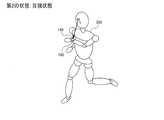
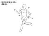
図3に、活動状態の第1の状態の第1の例を示す。また図4に、活動状態の第2の状態の第1の例を示す。この例では、ウェアラブル装置100は腕時計型の装置であり、ユーザー200の左手首に装着されている。第1の状態は、ユーザー200がランニング又はウォーキングを行っており、ユーザー200が自然に腕を振っている状態である。即ち、電気泳動パネル140の表示面の向きは、腕の動きに合わせて変化しており、ユーザー200が表示面を目視していない状態である。一方、第2の状態は、ユーザー200がランニング又はウォーキングを行っているが、ユーザー200が電気泳動パネル140の表示面を目視できる位置に保持している状態である。 FIG. 3 shows a first example of the first active state. FIG. 4 shows a first example of the second state of the active state. In this example,
図5に、活動状態の第1の状態の第2の例を示す。また図6に、活動状態の第2の状態の第2の例を示す。この例では、ウェアラブル装置100は腕時計型の装置であり、ユーザー200の左手首に装着されている。第1の状態は、ユーザー200が日常生活状態(非運動状態)である。即ち、運動強度の大きな活動をしておらず、比較的運動強度が小さい(例えば加速度センサーが検出する加速度の平均値が小さい)状態である。一方、第2の状態は、ユーザー200が運動を行っている状態である。即ち、運動強度の大きな活動(例えば加速度センサーが検出する加速度の平均値が大きい)状態である。図6には、ユーザー200がランニング又はウォーキングを行っている状態を図示しているが、これに限らず、第1の状態よりも相対的に運動強度が大きい活動であればよい。例えば第1の状態が睡眠状態であり、第2の状態が日常生活状態(覚醒状態)であってもよい。 FIG. 5 shows a second example of the first state in the active state. FIG. 6 shows a second example of the second state of the active state. In this example,
処理回路110の活動状態判定部112は、加速度センサー120(体動センサー)の検出結果に基づいて、活動状態が第1の状態であるか否か、及び活動状態が第2の状態であるか否かを判定する。そして、活動状態が第1の状態から第2の状態に遷移したと活動状態判定部112が判断した場合に、表示処理部118が第1の表示処理から第2の表示処理に変更する。例えば、図3、図4の例では、活動状態判定部112の目視判定部116が、非目視状態であるか否か、目視状態であるか否かを判定する。また図5、図6の例では、活動状態判定部112の行動判定部14が、日常生活状態であるか否か、運動状態であるか否かを判定する。なお、これらの判定手法の詳細については後述する。 The activity state determination unit 112 of the
第1の表示処理と第2の表示処理は、例えば表示の更新頻度、表示更新を行う領域、表示コンテンツ、表示更新の種類(例えば通常の画像表示、リフレッシュ処理)等の少なくとも1つが異なる表示処理である。より具体的には、第1の表示処理は、電気泳動パネル140の劣化の進行(画面内での劣化の進行度合いの差)が第2の表示処理に比べて小さくなるような表示処理である。 The first display process and the second display process are different from each other in at least one of display update frequency, display update area, display content, display update type (for example, normal image display, refresh process), and the like. It is. More specifically, the first display process is a display process in which the progress of deterioration of the electrophoretic panel 140 (difference in progress of deterioration within the screen) is smaller than that of the second display process. .
図3、図4の例では、第1の状態はユーザー200がウェアラブル装置100を見ていない状態であるため、基本的には第2の状態(目視状態)において電気泳動パネル140に情報を表示すればよい。また図5、図6の例では、日常生活状態に比べて運動状態の方が、より更新頻度の高い情報、或いは、より多くの内容の情報を表示することが想定できる。このため、第1の状態、第2の状態に応じて表示処理を変更することで、活動状態に応じた適切な表示処理を行い、電気泳動パネル140の劣化の進行(画面内での劣化の進行度合いの差)を低減できる。具体的には、第1の状態では電気泳動パネル140の劣化の進行を低減させる表示処理(例えば更新頻度の低減等)を行っておき、第1の状態から第2の状態に遷移したと判断された場合、第2の状態で必要な情報を提示する表示処理(例えば更新頻度を上げる等)を行う。このようにして、第1の状態において電気泳動パネル140の劣化の進行(画面内での劣化の進行度合いの差)を低減できる。 In the example of FIGS. 3 and 4, since the first state is a state in which the
より具体的には、処理回路110は、活動状態が第2の状態であると判定されたとき、第2の表示処理として、電気泳動パネル140の表示を更新する表示更新処理を行う。 More specifically, when it is determined that the activity state is the second state, the
表示更新処理は、電気泳動パネル140の画素を駆動する(階調の書き込み、或いは書き替えを行う)処理である。画素の駆動は電気泳動パネル140の画面全体に対して行ってもよいし、或いは画面の一部の領域においてのみ行ってもよい。例えば、表示更新処理は、白表示又は黒表示から通常の表示(画像、文字等の表示)への移行、リフレッシュ処理から通常の表示への移行等である。また、駆動回路130が動作オフ状態から動作状態に移行することによって表示更新が行われる場合も、表示更新処理に相当する。 The display update process is a process of driving the pixels of the electrophoretic panel 140 (performing gradation writing or rewriting). The pixels may be driven over the entire screen of the
このようにすれば、第1の状態において画面全体又は画面の一部の領域において表示更新が行われないので、電気泳動パネル140の劣化の進行(画面内での劣化の進行度合いの差)を低減できる。また、第2の状態において画面全体又は画面の一部の領域において表示更新が行われるので、第2の状態において必要な情報をユーザーに提示できる。 In this way, the display update is not performed on the entire screen or a part of the screen in the first state, so that the deterioration of the electrophoresis panel 140 (the difference in the progress of the deterioration within the screen) is determined. Can be reduced. In addition, since the display update is performed in the entire screen or a partial area of the screen in the second state, necessary information can be presented to the user in the second state.
また本実施形態では、処理回路110は、活動状態が第1の状態から第2の状態に遷移したと判定された後、所定の時間が経過したとき、表示更新処理を停止する。 In the present embodiment, the
所定の時間は、第2の状態がどのような状態であるかに関わらず一定の時間であってもよいし、第2の状態がどのような状態であるかに応じて異なる時間であってもよい。例えば、図4の目視状態に遷移した後、第1の所定の時間が経過したとき、表示更新処理を停止し、図6の運動状態に遷移した後、第1の所定の時間とは異なる第2の所定の時間が経過したとき、表示更新処理を停止してもよい。また、図5の日常生活状態を第3の状態とし、図6の運動状態を第4の状態とした場合に、日常生活状態において非目視状態(第1の状態)から目視状態(第2の状態)に遷移した後、第1の所定の時間が経過したとき、表示更新処理を停止し、運動状態において非目視状態から目視状態に遷移した後、第1の所定の時間とは異なる第2の所定の時間が経過したとき、表示更新処理を停止してもよい。 The predetermined time may be a fixed time regardless of what the second state is, or may be a different time depending on what the second state is. Also good. For example, when the first predetermined time has elapsed after the transition to the visual state of FIG. 4, the display update process is stopped, and after the transition to the motion state of FIG. 6, the first predetermined time is different from the first predetermined time. When the predetermined time 2 has elapsed, the display update process may be stopped. Further, when the daily life state of FIG. 5 is the third state and the exercise state of FIG. 6 is the fourth state, the visual state (second state) is changed from the non-visual state (first state) in the daily life state. When the first predetermined time has elapsed after the transition to the state), the display update processing is stopped, and after the transition from the non-visual state to the visual state in the motion state, the second different from the first predetermined time. When the predetermined time elapses, the display update process may be stopped.
このように、第2の状態に遷移したと判定された後、所定の時間が経過したとき、第2の状態であっても表示更新処理を停止することで、電気泳動パネル140の劣化の進行(画面内での劣化の進行度合いの差)を更に低減できる。また、表示更新処理を行う時間が短くなるので、表示更新による消費電流を削減でき、ウェアラブル装置100を低消費電力化できる。なお、表示更新処理を停止すると共に更に駆動回路130を動作オフ状態に設定してもよい。このようにすれば、更にウェアラブル装置100を低消費電力化できる。 As described above, when it is determined that the state has transitioned to the second state, when the predetermined time has elapsed, the display update process is stopped even in the second state, so that the deterioration of the
また本実施形態では、処理回路110は、活動状態が第1の状態であると判定されたとき、電気泳動パネル140に表示される表示オブジェクトの表示更新処理を停止する、又は、表示オブジェクトの更新頻度を、活動状態が第1の状態であると判定されたときの第1の更新頻度よりも低い第2の更新頻度に設定する。 Further, in the present embodiment, when the
表示オブジェクトは、電気泳動パネル140の画面内に表示されるオブジェクトであり、そのオブジェクトに対応した所与の表示領域に表示されるオブジェクトである。例えば、時刻表示の時、分、秒が、それぞれ表示オブジェクトに相当し、これらの表示オブジェクトの組み合わせによって時刻表示という表示コンテンツが構成される。なお、表示オブジェクトは、これに限定されず、文字、記号、画像、マーク等、種々のものを想定できる。 The display object is an object displayed on the screen of the
本実施形態によれば、第1の状態において、表示オブジェクトの表示更新処理を停止される、又は、更新頻度が低減されるので、電気泳動パネル140の劣化の進行(画面内での劣化の進行度合いの差)を低減できる。 According to this embodiment, in the first state, the display object display update process is stopped or the update frequency is reduced, so that the
また本実施形態では、処理回路110は、活動状態が第1の状態であると判定されたとき、電気泳動パネル140に表示される第1の表示オブジェクトと第2の表示オブジェクトのうち、相対的に更新頻度が高い表示オブジェクトの表示更新を停止する、又はその更新頻度が高い表示オブジェクトの更新頻度を第2の更新頻度に設定する。第2の更新頻度は、相対的に更新頻度が高い表示オブジェクトの第1の状態における第1の更新頻度よりも低い更新頻度である。 In the present embodiment, the
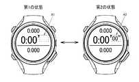
図7は、本実施形態の表示処理の第1の例である。なお、図7に示す点線の四角は説明のために図示するものであり、実際に表示されるものではない。図7には、一例として、例えばランニング等においてラップタイム、スプリットタイム等の計測時間を表示する時間計測画面を示している。計測時間は、時、分、秒の情報を含んでおり、このうち秒は、時や分に比べて更新頻度が高い表示オブジェクトである。この場合、図7のA2に示すように、第2の状態では秒を表示して1秒ごとに秒表示を更新し、A1に示すように、第1の状態では秒の表示更新を停止する。図7では、秒の表示領域を白表示とした後に秒の表示更新を停止する場合を図示しているが、例えば秒の表示領域を白表示にせずに秒の表示更新を停止し、第2の状態から第1の状態に遷移した際の秒の数値がそのまま表示し続けられるようにしてもよい。また、第1の状態において秒の表示更新を停止せずに、更新頻度を低下させてもよい。例えば、第2の状態では1秒ごとに秒表示を更新し、第1の状態では10秒毎に秒表示を更新してもよい。 FIG. 7 is a first example of display processing according to the present embodiment. Note that the dotted-line squares shown in FIG. 7 are shown for explanation and are not actually displayed. FIG. 7 shows, as an example, a time measurement screen that displays measurement times such as a lap time and a split time in running, for example. The measurement time includes information on hours, minutes, and seconds. Of these, seconds are display objects that are updated more frequently than hours and minutes. In this case, as shown in A2 of FIG. 7, in the second state, the second is displayed and the second display is updated every second, and as shown in A1, the display update of the second is stopped in the first state. . FIG. 7 illustrates a case where the display update of the second is stopped after the display area of the second is displayed in white. For example, the display update of the second is stopped without displaying the display area of the second in white. The numerical value of the second at the time of transition from the state to the first state may be continuously displayed as it is. Further, the update frequency may be reduced without stopping the display update for the second in the first state. For example, the second display may be updated every second in the second state, and the second display may be updated every 10 seconds in the first state.
本実施形態によれば、複数の表示オブジェクトのうち相対的に更新頻度が高い表示オブジェクトの更新回数を低減することができるので、表示オブジェクト間の更新回数の差を低減することができる。これにより、電気泳動パネル140の劣化の進行(画面内での劣化の進行度合いの差)を低減できる。 According to the present embodiment, it is possible to reduce the number of updates of a display object having a relatively high update frequency among a plurality of display objects, so that the difference in the number of updates between display objects can be reduced. Thereby, the progress of deterioration of the electrophoretic panel 140 (difference in the progress of deterioration within the screen) can be reduced.
また本実施形態では、処理回路110は、活動状態が第1の状態であると判定されたとき、電気泳動パネル140に所与の静止画像を表示させる、又は表示をオフにしてもよい。 In the present embodiment, the
図8は、本実施形態の表示処理の第2の例である。図8では、第2の状態において時計及びカレンダー(例えば月、日、曜日)の表示を行い、第2の状態から第1の状態に遷移した際に所与の静止画像に表示更新し、以降は第1の状態において表示更新を行わない(所与の静止画像が表示されたまま維持される)。図8では、所与の静止画像として文字の画像を表示しているが、これに限定されず、模様や写真等の画像を表示してもよい。 FIG. 8 is a second example of the display process of this embodiment. In FIG. 8, a clock and a calendar (for example, month, day, day of the week) are displayed in the second state, and the display is updated to a given still image when transitioning from the second state to the first state. Does not update the display in the first state (a given still image remains displayed). In FIG. 8, a character image is displayed as a given still image. However, the present invention is not limited to this, and an image such as a pattern or a photograph may be displayed.
図9は、本実施形態の表示処理の第3の例である。図9では、第2の状態において時計及びカレンダーの表示を行い、第2の状態から第1の状態に遷移した際に画面全体を白表示に更新し、以降は第1の状態において表示更新を行わない(白表示のまま維持される)。表示オフは白表示に限定されず、文字や絵、模様、図形、写真等の画像が表示されていない状態であればよい。例えば、黒表示や、画面全体が単一階調の表示等であってもよい。 FIG. 9 is a third example of the display processing of the present embodiment. In FIG. 9, the clock and calendar are displayed in the second state, and when the transition from the second state to the first state is performed, the entire screen is updated to white display, and thereafter the display is updated in the first state. Do not perform (maintain white display). Display off is not limited to white display, and may be any state in which images such as characters, pictures, patterns, figures, and photographs are not displayed. For example, black display or a single gradation display on the entire screen may be used.
本実施形態によれば、第1の状態において電気泳動パネル140に静止画像が表示され、或いは電気泳動パネル140の表示がオフになるので、電気泳動パネル140の劣化の進行(画面内での劣化の進行度合いの差)を低減できる。また、第1の状態において電気泳動パネル140が駆動されないので、表示更新による消費電力を低減できる。 According to the present embodiment, a still image is displayed on the
また本実施形態では、処理回路110は、活動状態が第1の状態であると判定されたとき、活動状態が第2の状態から第1の状態に遷移した際に電気泳動パネル140に表示された画像の表示を維持してもよい。 In the present embodiment, the
即ち、処理回路110は、活動状態が第2の状態から第1の状態に遷移した際に表示更新を停止し、それ以降は第1の状態において表示更新を行わない。これにより、結果的に、第2の状態から第1の状態に遷移した際に電気泳動パネル140に表示された画像の表示が維持されることになる。例えば、第2の状態において時計及びカレンダーを表示していた場合、第2の状態から第1の状態に遷移した際の時計及びカレンダーの表示が、更新されることなく、そのまま維持される。 That is, the
本実施形態によれば、第1の状態において電気泳動パネル140の表示更新が停止するので、電気泳動パネル140の劣化の進行(画面内での劣化の進行度合いの差)を低減できる。また、第1の状態において電気泳動パネル140が駆動されないので、表示更新による消費電力を低減できる。 According to the present embodiment, display update of the
また本実施形態では、処理回路110は、活動状態が第1の状態であると判定されたとき、電気泳動パネル140のリフレッシュ処理を行ってもよい。 In the present embodiment, the
リフレッシュ処理は、電気泳動パネル140のセル内の粒子の位置を、所与の位置に戻す(リフレッシュ、初期化)する処理であり、例えば所定の駆動電圧波形(例えば白黒の交互書き込み)を電気泳動パネル140の画素に印加することで実現される。 The refresh process is a process for returning the position of the particle in the cell of the
電気泳動パネル140では、ある階調を画素に書き込んだ際に、その前に書き込まれていた画素の階調に依存して、実際に書き込まれた階調が変化する(誤差をもつ)可能性がある。このため、秒表示等の更新を繰り返した表示領域では、コントラストが低下したり、ゴーストが発生したりする可能性がある。本実施形態によれば、目視していない状態(或いは、頻繁に目視しないと想定される日常生活状態)においてリフレッシュ処理を行うことができ、目視時の表示に影響を与えることなく表示品質を向上できる。また、リフレッシュ処理は画素を駆動するので、第2の状態において表示更新されなかった(或いは更新頻度が低かった)表示領域が、第1の状態において駆動されることになる。これにより、リフレッシュ処理は、電気泳動パネル140の表示更新回数の均一化に寄与し、電気泳動パネル140の劣化の進行(画面内での劣化の進行度合いの差)が低減されると期待できる。 In the
また本実施形態では、処理回路110は、活動状態が第2の状態であると判定されたとき、電気泳動パネル140の所与の表示領域に表示される表示オブジェクトの表示更新処理を行い、活動状態が第1の状態であると判定されたとき、所与の表示領域以外の表示領域の表示更新処理を行ってもよい。例えば、第2の状態から第1の状態に遷移したと判定されたとき、所与の表示領域以外の表示領域の表示更新処理を行う。 In the present embodiment, when the
例えば、図7では、A2に示す秒の表示領域(点線四角の内側)が、所与の表示領域である。この場合、第1の状態において、秒の表示領域以外の表示領域(点線四角の外側)を表示更新する。例えば、秒の表示領域以外の表示領域に対して所定回数の白表示、黒表示を行った後、元の画像を再び書き込む。或いは、秒の表示領域以外の表示領域に対してリフレッシュ処理を行った後、元の画像を再び書き込む。 For example, in FIG. 7, the second display area (inside the dotted square) indicated by A2 is a given display area. In this case, in the first state, the display area other than the second display area (outside the dotted square) is updated. For example, after performing a predetermined number of white display and black display on a display area other than the second display area, the original image is written again. Alternatively, after the refresh process is performed on the display area other than the second display area, the original image is written again.
本実施形態によれば、所与の表示領域における表示更新回数と、所与の表示領域以外の表示領域における表示更新回数との差が小さくなる。これにより、電気泳動パネル140の劣化の進行(画面内での劣化の進行度合いの差)を低減できる。 According to the present embodiment, the difference between the number of display updates in a given display area and the number of display updates in a display area other than the given display area is reduced. Thereby, the progress of deterioration of the electrophoretic panel 140 (difference in the progress of deterioration within the screen) can be reduced.
また本実施形態では、第2の状態において所与の表示領域が表示更新される回数と、第1の状態において所与の表示領域以外の表示領域が表示更新される回数とが同じである。 In the present embodiment, the number of times that a given display area is updated in the second state is the same as the number of times that display areas other than the given display area are updated in the first state.
1回の表示更新は、1つの階調を1回書き込む(その階調に対応する駆動電圧波形を画素に1回印加する)ことに対応する。リフレッシュ処理の場合、1回のリフレッシュ処理を1回の表示更新としてもよいし、白黒の繰り返しの1つ1つを1回の表示更新としてもよい。 One display update corresponds to writing one gradation once (applying a drive voltage waveform corresponding to the gradation once to the pixel). In the case of the refresh process, one refresh process may be performed as one display update, and each black and white repetition may be performed as one display update.
本実施形態によれば、所与の表示領域における表示更新回数と、所与の表示領域以外の表示領域における表示更新回数とを一致させることが可能になる。これにより、電気泳動パネル140の劣化の進行(画面内での劣化の進行度合いの差)を更に低減できる。 According to the present embodiment, it is possible to match the display update count in a given display area with the display update count in a display area other than the given display area. Thereby, the progress of deterioration of the electrophoresis panel 140 (difference in the progress of deterioration within the screen) can be further reduced.
また本実施形態では、ウェアラブル装置100は、表示処理に基づいて電気泳動パネル140を駆動する駆動回路130を含む。そして、処理回路110は、活動状態が第1の状態であると判定されたとき、駆動回路130を動作オフ状態に設定してもよい。 In the present embodiment, the
動作オフ状態は、例えば駆動回路130が電気泳動パネル140を駆動しない状態(例えば出力がハイインピーダンス、或いは一定電圧の状態)、或いは駆動回路130にバイアス電流が供給されない状態、或いは駆動回路130のバイアス電流が低減された状態である。なお、所与の表示更新(例えば白表示、黒表示、所与の静止画像の表示)を行ってから駆動回路130を動作オフ状態に設定してもよいし、表示更新をせずに駆動回路130を動作オフ状態に設定してもよい(後者では、動作オフ状態に設定される直前の表示が維持される)。 The operation off state is, for example, a state in which the
本実施形態によれば、第1の状態において駆動回路130が動作オフ状態に設定されることで、駆動回路130の消費電力が低減され、ウェアラブル装置100を低消費電力化できる。また、第1の状態において電気泳動パネル140の表示更新が行われなくなるので、電気泳動パネル140の劣化の進行(画面内での劣化の進行度合いの差)を低減できる。 According to the present embodiment, the
また本実施形態では、処理回路110は、電気泳動パネル140に表示される第1の表示オブジェクトと第2の表示オブジェクトのうち、相対的に更新頻度が高い表示オブジェクトの表示態様を、活動状態が第1の状態であると判定されたとき第1の表示態様に設定し、活動状態が第2の状態であると判定されたとき第1の表示態様とは異なる第2の表示態様に設定してもよい。 Further, in the present embodiment, the
表示態様は、ユーザーに提示しようとする内容の提示の仕方(態様)である。表示態様が異なるとは、ユーザーに提示しようとする内容は基本的に同じであるが、その提示の仕方(態様)が異なるということである。具体的には、第1の表示態様は、電気泳動パネル140の劣化の進行(画面内での劣化の進行度合いの差)が第2の表示態様に比べて小さくなるような表示態様である。 The display mode is a method (mode) of presenting contents to be presented to the user. The difference in display mode means that the contents to be presented to the user are basically the same, but the way of presentation (mode) is different. Specifically, the first display mode is a display mode in which the progress of deterioration of the electrophoretic panel 140 (difference in the progress of deterioration within the screen) is smaller than that in the second display mode.
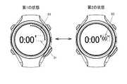
図10は、本実施形態の表示処理の第4の例である。なお、図10に示す点線の四角は説明のために図示するものであり、実際に表示されるものではない。図10の例は、時、分、秒が表示されており、そのうち秒が最も更新頻度が高い表示オブジェクトである。図10のB2に示すように、第2の状態では秒が数字で表示され、その数字が1秒ごとに更新される。一方、第1の状態では、B1に示すように秒の数字表示がオフになり(例えば秒の表示領域が白表示になり)、B3に示すように画面の外縁部(外縁の内周)に沿って周回するようにドット(黒丸)が表示される。例えば、1秒に1ドットずつ時計回りにドットが追加されていく。或いは、白抜きのドット(白丸)が画面の外縁部に沿って予め表示され、1秒に1ドットずつ時計回りにドットが黒丸に変化していく。 FIG. 10 is a fourth example of the display process of this embodiment. Note that the dotted-line squares shown in FIG. 10 are shown for explanation, and are not actually displayed. In the example of FIG. 10, hour, minute, and second are displayed, and the second is the display object with the highest update frequency. As shown in B2 of FIG. 10, in the second state, the seconds are displayed as numbers, and the numbers are updated every second. On the other hand, in the first state, the second number display is turned off as shown at B1 (for example, the second display area is displayed in white), and at the outer edge of the screen (the inner periphery of the outer edge) as shown at B3. Dots (black circles) are displayed so as to go around. For example, dots are added clockwise by one dot per second. Alternatively, white dots (white circles) are displayed in advance along the outer edge of the screen, and the dots change to black circles clockwise one dot at a time.
本実施形態によれば、相対的に更新頻度が高い表示オブジェクトの表示態様を第1の状態と第2の状態で異ならせることで、ユーザーが目視しない(又は目視の頻度が低いと想定される)第1の状態において、電気泳動パネル140の劣化の進行(画面内での劣化の進行度合いの差)が小さい表示態様を設定できる。例えば図10の例では、1つのドットは60秒に1回しか表示更新されないので、秒の数字表示に比べて更新頻度が低下する。また、秒の数字表示とは異なる領域にドットを表示するので、表示更新する領域が分散される。また本実施形態によれば、ユーザーが目視する(又は目視の頻度が高いと想定される)第2の状態において、適切な表示態様を設定できる。例えば図10の例では、秒が数字で表示されるので、ユーザーが正確な秒数を認識しやすくなる。 According to the present embodiment, it is assumed that the user does not visually check (or the frequency of visual inspection is low) by changing the display mode of the display object having a relatively high update frequency between the first state and the second state. In the first state, it is possible to set a display mode in which the progress of deterioration of the electrophoretic panel 140 (difference in the progress of deterioration within the screen) is small. For example, in the example of FIG. 10, since one dot is displayed and updated only once every 60 seconds, the update frequency is reduced as compared with the second number display. In addition, since dots are displayed in an area different from the second number display, the display update area is dispersed. Further, according to the present embodiment, an appropriate display mode can be set in the second state in which the user visually observes (or is assumed that the frequency of visual observation is high). For example, in the example of FIG. 10, since the seconds are displayed as numbers, the user can easily recognize the accurate number of seconds.
また本実施形態では、処理回路110は、活動状態が第2の状態であると判定されたとき、電気泳動パネル140に第1の表示コンテンツを表示させ、活動状態が第1の状態に遷移した後に第2の状態に遷移したと判定されたとき、電気泳動パネル140に第1の表示コンテンツとは異なる第2の表示コンテンツを表示させる。 Further, in this embodiment, when the
図11は、本実施形態の表示処理の第5の例である。図11に示すように、1回目の第2の状態ではラップペース(ラップタイム)が表示されている。ラップペースは、所定距離(又はトラック1周)を通過するのにかかった時間である。第1の状態に遷移すると表示更新が停止され、ラップペースの表示が維持される。2回目の第2の状態に遷移すると、スプリットタイムが表示される。スプリットタイムは、スタート地点から現在地点まで通過するのにかかった時間である。第2の状態の間はスプリットタイムが更新され、第1の状態に遷移すると表示更新が停止され、その直前のスプリットタイムの表示が維持される。3回目の第2の状態に遷移すると、スタート地点から現在地点までの距離が表示される。例えば、ウェアラブル装置100が不図示の測位装置(例えばGPS(Global Positioning System)等)を有し、処理回路110が、その測位装置の測位結果に基づいて距離を算出する。或いは、処理回路110が、加速度センサー120の検出結果により歩数を計測し、その歩数に基づいて距離を算出(推定)する。第1の状態に遷移すると表示更新が停止され、距離の表示が維持される。4回目の第2の状態では、例えばラップペースの表示に戻る。 FIG. 11 is a fifth example of the display process of the present embodiment. As shown in FIG. 11, a lap pace (lap time) is displayed in the first second state. The lap pace is the time taken to pass a predetermined distance (or one track lap). When transitioning to the first state, the display update is stopped and the display of the lap pace is maintained. When transitioning to the second state for the second time, the split time is displayed. Split time is the time taken to pass from the starting point to the current point. The split time is updated during the second state, and when the transition is made to the first state, the display update is stopped and the display of the immediately preceding split time is maintained. When transitioning to the second state for the third time, the distance from the start point to the current point is displayed. For example, the
本実施形態によれば、第2の状態に遷移する度に(例えば電気泳動パネル140を目視する度に)表示コンテンツが変化するため、ユーザーがランニング中等においてボタン操作等を行うことなく所与の動作(例えば目視)を行うだけで表示コンテンツを切り替えることが可能になる。また、第1の状態において表示更新が停止されるので、電気泳動パネル140の劣化の進行(画面内での劣化の進行度合いの差)を低減できる。 According to the present embodiment, since the display content changes every time the state transitions to the second state (for example, every time the
また本実施形態では、ウェアラブル装置100は、電気泳動パネル140を照明する光源180を含む。そして処理回路110は、活動状態が第1の状態であると判定されたとき、光源180をオフしてもよい。 In the present embodiment, the
図12は、本実施形態の表示処理の第6の例である。第1の状態では、光源180がオフされ、電気泳動パネル140の表示面が照明されていない。図12では、ハッチングにより、照明されていない状態を表している。第2の状態では、光源180がオンされ、電気泳動パネル140の表示面が照明されている。例えば、電気泳動パネル140の表示面の外縁(例えば図2のベゼル62の下)に導光体が設けられ、光源180からの光が導光体により表示面に照射されるようになっている。 FIG. 12 is a sixth example of the display process of this embodiment. In the first state, the
本実施形態によれば、第2の状態において光源180がオンになり、第1の状態において光源180がオフになるので、照明による消費電力を低減することが可能になる。なお、第1の状態から第2の状態に遷移した後、所定の時間が経過したときに光源180をオフしてもよい。このようにすれば、更に低消費電力化できる。 According to this embodiment, since the
また本実施形態では、第2の状態は、ユーザーの活動量が第1の状態とは異なる状態であり、処理回路110は、活動状態が第1の状態であると判定されたとき、電気泳動パネル140に第1の表示コンテンツを表示させ、活動状態が第2の状態であると判定されたとき、電気泳動パネル140に第1の表示コンテンツとは異なる第2の表示コンテンツを表示させてもよい。 In the present embodiment, the second state is a state in which the amount of activity of the user is different from the first state, and the
ユーザーの活動量が異なる状態は、例えば図5、図6で説明した日常生活状態と運動状態のように、運動強度が異なる状態である。なお、日常生活状態と運動状態に限定されず、例えば睡眠状態と日常生活状態(覚醒状態)であってもよい。詳細は後述するが、例えば加速度センサー120の検出結果に基づいてユーザーの活動量が異なる第1、第2の状態を判定できる。 The state where the amount of activity of the user is different is a state where the exercise intensity is different, such as the daily life state and the exercise state described with reference to FIGS. In addition, it is not limited to a daily life state and an exercise state, For example, a sleep state and a daily life state (wake state) may be sufficient. Although details will be described later, for example, the first and second states in which the amount of activity of the user is different can be determined based on the detection result of the
例えば、第2の状態は、第1の状態よりも活動量が大きい状態である。この場合、第1の状態では活動量が小さい場合にユーザーに提示することが望ましい表示コンテンツを電気泳動パネル140に表示させ、第2の状態では活動量が大きい場合にユーザーに提示することが望ましい表示コンテンツを電気泳動パネル140に表示させる。例えば第1の状態が日常生活状態の場合、例えば時計及びカレンダーを表示させ、第2の状態が運動状態の場合、時間計測画面(ラップペース、スプリットタイム等)を表示させる。 For example, the second state is a state where the amount of activity is larger than that of the first state. In this case, in the first state, it is desirable to display on the
本実施形態によれば、ユーザーの活動量に応じて適切な表示コンテンツを表示することができるようになる。これにより、ユーザーの利便性が向上する。また、表示コンテンツが変化することで、表示更新される表示領域の位置が変わるので、電気泳動パネル140の劣化の進行(画面内での劣化の進行度合いの差)が低減されることを期待できる。 According to the present embodiment, it is possible to display appropriate display content according to the amount of user activity. This improves user convenience. In addition, since the position of the display area to be updated is changed by changing the display content, it can be expected that the progress of deterioration of the electrophoretic panel 140 (difference in the progress of deterioration within the screen) is reduced. .
また本実施形態では、第2の状態は、ユーザーが電気泳動パネル140を目視したと判断される状態であり、活動状態は、ユーザーの活動量が互いに異なる第3の状態と第4の状態とを含む。そして、処理回路110は、活動状態が第3の状態と判定されたとき、第1の判定処理で目視の状態(第2の状態)を検出し、活動状態が第4の状態と判定されたとき、第1の判定処理とは異なる第2の判定処理で目視の状態(第2の状態)を検出してもよい。 In the present embodiment, the second state is a state in which it is determined that the user has viewed the
例えば、第3の状態は図5の日常生活状態であり、第4の状態は図6の運動状態である。この場合、日常生活状態と運動状態とで目視判定(ユーザーが電気泳動パネル140を目視しているか否かの判定)の手法を異ならせる。例えば、日常生活状態では、加速度センサー120により検出される重力加速度の方向に基づいて目視判定を行い、重力加速度の方向が所定の角度範囲内である(ウェアラブル装置100が所与の姿勢範囲内である)場合に目視状態(第2の状態)であると判定する。一方、運動状態では、加速度センサー120により検出される腕振り(ユーザーの動き)に基づいて目視判定を行い、腕振りが検出されない場合に目視状態であると判定する。 For example, the third state is the daily life state of FIG. 5, and the fourth state is the exercise state of FIG. In this case, the method of visual determination (determination as to whether or not the user is viewing the electrophoretic panel 140) differs between the daily life state and the exercise state. For example, in the daily life state, visual determination is performed based on the direction of gravity acceleration detected by the
本実施形態によれば、ユーザーが電気泳動パネル140を目視した第2の状態であるか否かを、ユーザーの活動量に応じた適切な判定手法で判定できる。これにより、ユーザーが電気泳動パネル140を目視した第2の状態であるか否かを正確に判定することが可能になり、目視した際にユーザーに情報が提示されない可能性を低減できる。また、非目視の際に電気泳動パネル140の表示更新を停止されない可能性を低減できるので、電気泳動パネル140の劣化の進行(画面内での劣化の進行度合いの差)を低減できる。 According to the present embodiment, whether or not the user is in the second state when viewing the
なお、以上では本実施形態のウェアラブル装置100の構成及び動作について説明したが、その手法を、ウェアラブル装置100の制御方法として実行することも可能である。即ち、電気泳動パネル140を含むウェアラブル装置100の制御方法であって、ユーザーの活動状態が、第1の状態から第1の状態とは異なる第2の状態に遷移したと判断されるとき、第1の状態で行う第1の表示処理とは異なる第2の表示処理を行う制御方法として実行してもよい。例えば、各ステップはウェアラブル装置100或いは処理回路110が実行する。 In addition, although the structure and operation | movement of the
3.活動状態を判定する手法
以下、日常生活状態と運動状態を判定(検出)する手法について説明する。以下に説明する手法は、そのいずれかを用いてもよいし、複数の手法を組み合わせ用いてもよい。3. Method for Determining Activity State A method for determining (detecting) the daily life state and the exercise state will be described below. Any of the methods described below may be used, or a plurality of methods may be used in combination.
第1の手法は、加速度センサー120により検出された加速度の大きさを閾値判定する手法である。即ち、加速度の大きさが第1の閾値より大きい場合に運動状態(第2の状態)と判定し、加速度の大きさが、第1の閾値よりも小さい第2の閾値よりも小さい場合に日常生活状態(第1の状態)と判定する。 The first method is a method for determining a threshold value of the magnitude of acceleration detected by the
第2の手法は、加速度センサー120により検出された加速度のヒストグラムに基づいて判定する手法である。ヒストグラムは、例えば加速度の大きさのヒストグラムであってもよいし、或いは加速度の大きさ及び向きのヒストグラムであってもよい。例えば、ヒストグラムのピーク(ヒストグラムの標本数が最大の加速度)や、或いはヒストグラムの形状が、日常生活状態の判定条件を満たすか否か、運動状態の判定条件を満たすか否かを判定する。 The second method is a method of determining based on the acceleration histogram detected by the
第3の手法は、加速度センサー120により検出された加速度の周波数特性に基づいて判定する手法である。ここでは、ランニングやウォーキング等の周期的な動きを伴う運動状態を例に説明するが、これに限定されず、日常生活状態と運動状態とで加速度の周波数特性が異なる場合であれば、本手法を適用できる。 The third method is a method for determining based on the frequency characteristics of acceleration detected by the
図13は、運動状態(第2の状態)において検出された加速度の周波数特性である。図14は、日常生活状態(第1の状態)において検出された加速度の周波数特性である。これらの周波数特性は、加速度センサー120により検出された時系列の加速度をフーリエ変換したものである。 FIG. 13 shows frequency characteristics of acceleration detected in the motion state (second state). FIG. 14 shows frequency characteristics of acceleration detected in the daily life state (first state). These frequency characteristics are obtained by Fourier transforming time-series acceleration detected by the
図13に示すように、運動状態では、ランニングやウォーキングの腕振りにより加速度に周期性があるため、その周期に対応する周波数に周波数特性のピークがある。このピークでの強度(周波数成分の大きさ)は、それ以外の周波数での強度に比べて非常に大きくなる。一方、図14に示すように、日常生活状態では、加速度の周期性が小さいため、周波数特性の最大のピークでの強度と、それ以外の周波数での強度との差が、運動状態に比べて小さい。このような差を判定することで、日常生活状態と運動状態を区別できる。例えば、最大ピークとその他のピークの差分が閾値を超えた場合に運動状態と判定してもよいし、或いは、閾値を超えるピークが存在する場合に運動状態と判定してもよい。 As shown in FIG. 13, in the exercise state, the acceleration has a periodicity due to the swinging of the arms for running and walking, and therefore there is a frequency characteristic peak at the frequency corresponding to the cycle. The intensity at this peak (the magnitude of the frequency component) is much larger than the intensity at other frequencies. On the other hand, as shown in FIG. 14, in the daily life state, since the periodicity of acceleration is small, the difference between the intensity at the maximum peak of the frequency characteristic and the intensity at other frequencies is smaller than that in the exercise state. small. By determining such a difference, the daily life state and the exercise state can be distinguished. For example, when the difference between the maximum peak and another peak exceeds a threshold value, the exercise state may be determined, or when a peak exceeding the threshold value exists, the exercise state may be determined.
第4の手法は、所与の判定回数を満たした場合に、最終的に状態が遷移したと判定する手法である。即ち、日常生活状態において、運動状態とN回判定された場合に、最終的に運動状態に遷移したと判定する。また運動状態において、日常生活状態とM回判定された場合に、最終的に日常生活状態に遷移したと判定する。各回の判定には第1〜第3の手法のいずれを用いてもよい。N、Mは1以上の整数であり、NとMが同数であってもよいし、異なる数であってもよい。 The fourth method is a method of finally determining that the state has changed when a given number of determinations is satisfied. That is, in the daily life state, when it is determined N times as the exercise state, it is finally determined that the state has changed to the exercise state. Further, in the exercise state, when it is determined M times as the daily life state, it is finally determined that the state has changed to the daily life state. Any of the first to third methods may be used for each determination. N and M are integers of 1 or more, and N and M may be the same number or different numbers.
なお、以上では加速度センサー120により検出された加速度を動きの評価値として用いる場合を例に説明したが、動きの評価値はこれに限定されない。例えば、体動センサーとしてジャイロセンサーを用いた場合、角速度を動きの評価値としてもよい。或いは、加速度又は角速度を処理して求めた値を動きの評価値としてもよい。或いは、ウェアラブル装置100が不図示の脈拍センサーを含み、その脈拍センサーにより検出される脈拍に基づいて日常生活状態と運動状態を判定してもよい。 Although the case where the acceleration detected by the
次に、非目視状態と目視状態を判定(検出)する手法について説明する。なお、以下では運動状態と日常生活状態で異なる判定手法を用いる場合を例に説明するが、これに限定されず、運動状態と日常生活状態で同じ判定手法(例えばウェアラブル装置100の姿勢に基づく検出)を用いてもよい。 Next, a method for determining (detecting) the non-visual state and the visual state will be described. In the following, a case where different determination methods are used for the exercise state and the daily life state will be described as an example. However, the present invention is not limited to this, and the same determination method (for example, detection based on the posture of the wearable device 100) is used. ) May be used.
図15は、運動状態において非目視状態と目視状態を判定する手法の説明図である。ランニング又はウォーキングを行っている運動状態では、図15のS1〜S3に示すように、腕振り等の周期性がある動きによって加速度に周期的なピークが生じる。ユーザーが腕振りをしている第1の状態(非目視状態)では、ピークが大きくなるので、加速度(のピーク)が第1の閾値より大きくなった場合に第1の状態(非目視状態)であると判定する。一方、S4に示すように、加速度(のピーク)が第2の閾値より小さくなった場合に第2の状態(目視状態)であると判定する。第2の閾値は、第1の閾値よりも小さい値である。 FIG. 15 is an explanatory diagram of a method for determining a non-visual state and a visual state in a motion state. In an exercise state where running or walking is performed, as shown in S1 to S3 of FIG. 15, a periodic peak occurs in acceleration due to periodic movement such as arm swing. In the first state (non-viewing state) in which the user is swinging the arm, the peak is large. Therefore, when the acceleration (peak) is larger than the first threshold, the first state (non-viewing state). It is determined that On the other hand, as shown in S4, when the acceleration (peak thereof) becomes smaller than the second threshold value, it is determined that the state is the second state (viewing state). The second threshold value is smaller than the first threshold value.
日常生活状態では、上記のような動きの周期性が明確でないので、ウェアラブル装置100の姿勢に基づいて非目視状態と目視状態を判定する。例えば、加速度センサー120は、XYZの3軸の加速度を検出するセンサーである。例えばZ軸は電気泳動パネル140の表示面の法線方向に沿った軸であり、X軸、Y軸は、Z軸に直交すると共に互いに直交する軸である。日常生活状態では動きによる加速度が小さいと考えられるので、3軸の加速度は重力加速度の加速度ベクトルと考えることができる。この重力加速度の加速度ベクトルの方向(XYZの各軸と加速度ベクトルとが成す角度)に基づいて非目視状態と目視状態を判定する。ユーザーが起立した(少なくとも上体を起こした)状態で電気泳動パネル140を目視した場合、電気泳動パネル140の表示面がおおよそ鉛直上方向を向く(重力加速度が−Z方向を向く)と予想される。このため、−Z方向を中心として所定の角度範囲(姿勢範囲)に重力加速度が入っていると判定した場合に、目視状態と判定する。 Since the periodicity of movement as described above is not clear in the daily life state, the non-visual state and the visual state are determined based on the posture of the
以上のように、本実施形態では、処理回路110は、ユーザーに装着されているウェアラブル装置100の動き及び姿勢の少なくとも一方に基づいて活動状態を判定する。 As described above, in the present embodiment, the
このようにすれば、ウェアラブル装置100の動き及び姿勢の少なくとも一方に基づいてユーザーの活動状態が、第1の状態から第2の状態に遷移したか否かを判定できる。そして、第2の状態に遷移したと判断されるとき、第1の状態で行う第1の表示処理とは異なる第2の表示処理を行うことで、電気泳動パネル140の劣化の進行(画面内での劣化の進行度合いの差)を低減することが可能になる。 In this way, it is possible to determine whether or not the user's activity state has transitioned from the first state to the second state based on at least one of the movement and posture of the
また本実施形態では、処理回路110は、ウェアラブル装置100の動き及び姿勢の少なくとも一方に基づいて、活動状態を、ユーザーが電気泳動パネル140を目視した状態と判定する。即ち、処理回路110は、ウェアラブル装置100の動き及び姿勢の少なくとも一方に基づいて、ユーザーが電気泳動パネル140を目視したと判断されるとき、活動状態が第2の状態であると判定する。 In the present embodiment, the
即ち、動き及び姿勢の少なくとも一方は、ユーザーが電気泳動パネル140を目視したときに所与の条件を満たし、処理回路110は、動き及び姿勢の少なくとも一方が、その所与の条件を満たしたと判定した場合に、活動状態が第2の状態であると判定する。 That is, at least one of movement and posture satisfies a given condition when the user views the
このようにすれば、ユーザーの活動状態が、目視状態である第2の状態に遷移したか否かを判定できる。そして、目視状態において第2の表示処理を行うことで、ユーザーに情報を提示できる。一方、非目視状態である第1の状態において第1の表示処理を行うことで、電気泳動パネル140の劣化の進行(画面内での劣化の進行度合いの差)を低減することが可能になる。 If it does in this way, it can be judged whether a user's activity state changed to the 2nd state which is a visual observation state. Then, information can be presented to the user by performing the second display process in the visual state. On the other hand, by performing the first display process in the first state that is a non-visual state, it is possible to reduce the progress of deterioration of the electrophoresis panel 140 (difference in the degree of progress of deterioration in the screen). .
なお、上記のように本実施形態について詳細に説明したが、本発明の新規事項および効果から実体的に逸脱しない多くの変形が可能であることは当業者には容易に理解できるであろう。従って、このような変形例はすべて本発明の範囲に含まれるものとする。例えば、明細書又は図面において、少なくとも一度、より広義または同義な異なる用語と共に記載された用語は、明細書又は図面のいかなる箇所においても、その異なる用語に置き換えることができる。また本実施形態及び変形例の全ての組み合わせも、本発明の範囲に含まれる。また処理回路、ウェアラブル装置等の構成及び動作等や、ウェアラブル装置の制御方法等も、本実施形態で説明したものに限定されず、種々の変形実施が可能である。 Although the present embodiment has been described in detail as described above, it will be easily understood by those skilled in the art that many modifications can be made without departing from the novel matters and effects of the present invention. Accordingly, all such modifications are intended to be included in the scope of the present invention. For example, a term described at least once together with a different term having a broader meaning or the same meaning in the specification or the drawings can be replaced with the different term in any part of the specification or the drawings. All combinations of the present embodiment and the modified examples are also included in the scope of the present invention. Further, the configuration and operation of the processing circuit, the wearable device, etc., the control method of the wearable device, and the like are not limited to those described in the present embodiment, and various modifications can be made.
14…行動判定部、20…機器本体、30…バンド、40…ケース、
51〜54…操作ボタン、61…見切り板、62…ベゼル、70…風防板、
80…電気泳動パネル、100…ウェアラブル装置、110…処理回路、
112…活動状態判定部、116…目視判定部、118…表示処理部、
120…加速度センサー、130…駆動回路、140…電気泳動パネル、
150…操作部、160…記憶部、170…通信部、180…光源、200…ユーザー14 ... Action determination unit, 20 ... Device main body, 30 ... Band, 40 ... Case,
51-54 ... operation buttons, 61 ... parting plate, 62 ... bezel, 70 ... windshield,
80 ... Electrophoresis panel, 100 ... Wearable device, 110 ... Processing circuit,
112 ... Activity state determination unit, 116 ... Visual determination unit, 118 ... Display processing unit,
120 ... Accelerometer, 130 ... Drive circuit, 140 ... Electrophoresis panel,
150 ... operation unit, 160 ... storage unit, 170 ... communication unit, 180 ... light source, 200 ... user
Claims (19)
Translated fromJapanese前記電気泳動パネルの表示処理を行う処理回路と、
を含み、
前記処理回路は、
ユーザーの活動状態が、第1の状態から前記第1の状態とは異なる第2の状態に遷移したと判断されるとき、前記第1の状態で行う第1の表示処理とは異なる第2の表示処理を行うことを特徴とするウェアラブル装置。An electrophoresis panel;
A processing circuit for performing display processing of the electrophoresis panel;
Including
The processing circuit includes:
When it is determined that the user's activity state has transitioned from the first state to a second state different from the first state, a second display different from the first display process performed in the first state A wearable device that performs display processing.
前記処理回路は、
前記活動状態が前記第2の状態であると判定されたとき、前記第2の表示処理として、前記電気泳動パネルの表示を更新する表示更新処理を行うことを特徴とするウェアラブル装置。In claim 1,
The processing circuit includes:
When it determines with the said active state being the said 2nd state, the wearable apparatus characterized by performing the display update process which updates the display of the said electrophoresis panel as said 2nd display process.
前記処理回路は、
前記活動状態が前記第1の状態から前記第2の状態に遷移したと判定された後、所定の時間が経過したとき、前記表示更新処理を停止することを特徴とするウェアラブル装置。In claim 2,
The processing circuit includes:
The wearable device, wherein the display update process is stopped when a predetermined time elapses after it is determined that the active state has transitioned from the first state to the second state.
前記処理回路は、
前記活動状態が前記第1の状態であると判定されたとき、
前記電気泳動パネルに表示される表示オブジェクトの表示更新処理を停止する、
又は前記表示オブジェクトの更新頻度を、前記活動状態が前記第1の状態であると判定されたときの第1の更新頻度よりも低い第2の更新頻度に設定することを特徴とするウェアラブル装置。In any one of Claims 1 thru | or 3,
The processing circuit includes:
When it is determined that the activity state is the first state,
Stopping the display update process of the display object displayed on the electrophoresis panel;
Alternatively, the wearable device is characterized in that the update frequency of the display object is set to a second update frequency lower than the first update frequency when it is determined that the activity state is the first state.
前記処理回路は、
前記活動状態が前記第1の状態であると判定されたとき、
前記電気泳動パネルに表示される第1の表示オブジェクトと第2の表示オブジェクトのうち、相対的に更新頻度が高い表示オブジェクトの表示更新を停止する、
又は前記更新頻度が高い表示オブジェクトの更新頻度を前記第2の更新頻度に設定することを特徴とするウェアラブル装置。In claim 4,
The processing circuit includes:
When it is determined that the activity state is the first state,
Of the first display object and the second display object displayed on the electrophoretic panel, the display update of a display object having a relatively high update frequency is stopped.
Or the wearable device, wherein the update frequency of the display object having a high update frequency is set to the second update frequency.
前記処理回路は、
前記活動状態が前記第1の状態であると判定されたとき、前記電気泳動パネルに所与の静止画像を表示させる、又は表示をオフにすることを特徴とするウェアラブル装置。In any one of Claims 1 thru | or 3,
The processing circuit includes:
A wearable device characterized in that when it is determined that the activity state is the first state, a given still image is displayed on the electrophoretic panel or the display is turned off.
前記処理回路は、
前記活動状態が前記第1の状態であると判定されたとき、前記活動状態が前記第2の状態から前記第1の状態に遷移した際に前記電気泳動パネルに表示された画像の表示を維持することを特徴とするウェアラブル装置。In any one of Claims 1 thru | or 3,
The processing circuit includes:
When it is determined that the activity state is the first state, the display of the image displayed on the electrophoretic panel when the activity state transitions from the second state to the first state is maintained. A wearable device characterized by:
前記処理回路は、
前記活動状態が前記第1の状態であると判定されたとき、前記電気泳動パネルのリフレッシュ処理を行うことを特徴とするウェアラブル装置。In any one of Claims 1 thru | or 3,
The processing circuit includes:
A wearable device that performs refresh processing of the electrophoretic panel when it is determined that the activity state is the first state.
前記処理回路は、
前記活動状態が前記第2の状態であると判定されたとき、前記電気泳動パネルの所与の表示領域に表示される表示オブジェクトの表示更新処理を行い、
前記活動状態が前記第1の状態であると判定されたとき、前記所与の表示領域以外の表示領域の前記表示更新処理を行うことをウェアラブル装置。In any one of Claims 1 thru | or 3,
The processing circuit includes:
When it is determined that the activity state is the second state, display update processing of a display object displayed in a given display area of the electrophoresis panel is performed,
When it is determined that the activity state is the first state, the wearable device performs the display update process for a display area other than the given display area.
前記第2の状態において前記所与の表示領域が表示更新される回数と、前記第1の状態において前記所与の表示領域以外の表示領域が表示更新される回数と、が同じであることを特徴とするウェアラブル装置。In claim 9,
The number of times the given display area is updated in the second state and the number of times display areas other than the given display area are updated in the first state are the same. A wearable device characterized.
前記表示処理に基づいて前記電気泳動パネルを駆動する駆動回路を含み、
前記処理回路は、
前記活動状態が前記第1の状態であると判定されたとき、前記駆動回路を動作オフ状態に設定することを特徴とするウェアラブル装置。In any one of Claims 1 thru | or 3,
A drive circuit for driving the electrophoretic panel based on the display processing;
The processing circuit includes:
A wearable device characterized in that, when it is determined that the active state is the first state, the drive circuit is set to an operation-off state.
前記処理回路は、
前記電気泳動パネルに表示される第1の表示オブジェクトと第2の表示オブジェクトのうち、相対的に更新頻度が高い表示オブジェクトの表示態様を、
前記活動状態が前記第1の状態であると判定されたとき第1の表示態様に設定し、
前記活動状態が前記第2の状態であると判定されたとき前記第1の表示態様とは異なる第2の表示態様に設定することを特徴とするウェアラブル装置。In any one of Claims 1 thru | or 3,
The processing circuit includes:
Of the first display object and the second display object displayed on the electrophoretic panel, a display mode of a display object having a relatively high update frequency,
When it is determined that the activity state is the first state, the first display mode is set,
A wearable device that sets a second display mode different from the first display mode when it is determined that the activity state is the second state.
前記処理回路は、
前記活動状態が前記第2の状態であると判定されたとき、前記電気泳動パネルに第1の表示コンテンツを表示させ、
前記活動状態が前記第1の状態に遷移した後に前記第2の状態に遷移したと判定されたとき、前記電気泳動パネルに前記第1の表示コンテンツとは異なる第2の表示コンテンツを表示させることを特徴とするウェアラブル装置。In any one of Claims 1 thru | or 3,
The processing circuit includes:
When it is determined that the activity state is the second state, the display content is displayed on the electrophoresis panel,
Displaying a second display content different from the first display content on the electrophoretic panel when it is determined that the activity state has transitioned to the first state and then the second state. Wearable device characterized by.
前記電気泳動パネルを照明する光源を含み、
前記処理回路は、
前記活動状態が前記第1の状態であると判定されたとき、前記光源をオフすることを特徴とするウェアラブル装置。In any one of Claims 1 thru | or 13,
A light source for illuminating the electrophoretic panel;
The processing circuit includes:
The wearable device, wherein the light source is turned off when it is determined that the activity state is the first state.
前記第2の状態は、前記ユーザーの活動量が前記第1の状態とは異なる状態であり、
前記処理回路は、
前記活動状態が前記第1の状態であると判定されたとき、前記電気泳動パネルに第1の表示コンテンツを表示させ、
前記活動状態が前記第2の状態であると判定されたとき、前記電気泳動パネルに前記第1の表示コンテンツとは異なる第2の表示コンテンツを表示させることを特徴とするウェアラブル装置。In claim 1,
The second state is a state in which the amount of activity of the user is different from the first state,
The processing circuit includes:
When it is determined that the activity state is the first state, the first display content is displayed on the electrophoresis panel;
A wearable device that displays second display content different from the first display content on the electrophoretic panel when it is determined that the activity state is the second state.
前記第2の状態は、前記ユーザーが前記電気泳動パネルを目視したと判断される状態であり、
前記活動状態は、前記ユーザーの活動量が互いに異なる第3の状態と第4の状態とを含み、
前記処理回路は、
前記活動状態が前記第3の状態と判定されたとき、第1の判定処理で目視の状態を検出し、
前記活動状態が前記第4の状態と判定されたとき、前記第1の判定処理とは異なる第2の判定処理で前記目視の状態を検出することを特徴とするウェアラブル装置。In claim 1,
The second state is a state in which it is determined that the user has visually observed the electrophoresis panel,
The activity state includes a third state and a fourth state in which the amount of activity of the user is different from each other,
The processing circuit includes:
When the activity state is determined to be the third state, a visual state is detected in the first determination process,
The wearable device, wherein when the activity state is determined to be the fourth state, the visual state is detected by a second determination process different from the first determination process.
前記処理回路は、
前記ユーザーに装着されているウェアラブル装置の姿勢及び動きの少なくとも一方に基づいて前記活動状態を判定することを特徴とするウェアラブル装置。In any one of Claims 1 to 16,
The processing circuit includes:
The wearable device, wherein the activity state is determined based on at least one of a posture and a movement of a wearable device worn by the user.
前記処理回路は、
前記ウェアラブル装置の姿勢及び動きの少なくとも一方に基づいて、前記活動状態を前記ユーザーが前記電気泳動パネルを目視した状態と判定することを特徴とするウェアラブル装置。In claim 17,
The processing circuit includes:
The wearable device, wherein the activity state is determined to be a state in which the user visually views the electrophoretic panel based on at least one of a posture and a movement of the wearable device.
ユーザーの活動状態が、第1の状態から前記第1の状態とは異なる第2の状態に遷移したと判断されるとき、前記第1の状態で行う第1の表示処理とは異なる第2の表示処理を行うことを特徴とする制御方法。A method for controlling a wearable device including an electrophoresis panel,
When it is determined that the user's activity state has transitioned from the first state to a second state different from the first state, a second display different from the first display process performed in the first state A control method characterized by performing display processing.
Priority Applications (3)
| Application Number | Priority Date | Filing Date | Title |
|---|---|---|---|
| JP2017121028AJP2019007751A (en) | 2017-06-21 | 2017-06-21 | Wearable device and method for controlling the same |
| CN201810622058.8ACN109100929B (en) | 2017-06-21 | 2018-06-15 | Wearable device and control method |
| US16/013,113US10726799B2 (en) | 2017-06-21 | 2018-06-20 | Wearable device and control method |
Applications Claiming Priority (1)
| Application Number | Priority Date | Filing Date | Title |
|---|---|---|---|
| JP2017121028AJP2019007751A (en) | 2017-06-21 | 2017-06-21 | Wearable device and method for controlling the same |
Publications (1)
| Publication Number | Publication Date |
|---|---|
| JP2019007751Atrue JP2019007751A (en) | 2019-01-17 |
Family
ID=64693479
Family Applications (1)
| Application Number | Title | Priority Date | Filing Date |
|---|---|---|---|
| JP2017121028APendingJP2019007751A (en) | 2017-06-21 | 2017-06-21 | Wearable device and method for controlling the same |
Country Status (3)
| Country | Link |
|---|---|
| US (1) | US10726799B2 (en) |
| JP (1) | JP2019007751A (en) |
| CN (1) | CN109100929B (en) |
Cited By (2)
| Publication number | Priority date | Publication date | Assignee | Title |
|---|---|---|---|---|
| JP2022006370A (en)* | 2020-06-24 | 2022-01-13 | シチズン時計株式会社 | Watch |
| WO2025005479A1 (en)* | 2023-06-30 | 2025-01-02 | 삼성전자주식회사 | Message output method and electronic device for performing same method |
Families Citing this family (33)
| Publication number | Priority date | Publication date | Assignee | Title |
|---|---|---|---|---|
| KR102511376B1 (en) | 2014-08-02 | 2023-03-17 | 애플 인크. | Context-specific user interfaces |
| US10452253B2 (en) | 2014-08-15 | 2019-10-22 | Apple Inc. | Weather user interface |
| WO2016144385A1 (en) | 2015-03-08 | 2016-09-15 | Apple Inc. | Sharing user-configurable graphical constructs |
| CN107921317B (en) | 2015-08-20 | 2021-07-06 | 苹果公司 | Movement-based watch faces and complications |
| US12175065B2 (en) | 2016-06-10 | 2024-12-24 | Apple Inc. | Context-specific user interfaces for relocating one or more complications in a watch or clock interface |
| KR102208257B1 (en) | 2016-09-23 | 2021-01-27 | 애플 인크. | Watch theater mode |
| DK179412B1 (en) | 2017-05-12 | 2018-06-06 | Apple Inc | Context-Specific User Interfaces |
| DK179555B1 (en) | 2017-05-16 | 2019-02-13 | Apple Inc. | User interface for a flashlight mode on an electronic device |
| JP2019007751A (en)* | 2017-06-21 | 2019-01-17 | セイコーエプソン株式会社 | Wearable device and method for controlling the same |
| US11327650B2 (en) | 2018-05-07 | 2022-05-10 | Apple Inc. | User interfaces having a collection of complications |
| US11596833B2 (en)* | 2018-09-20 | 2023-03-07 | Pacebycolor, INC. | Pace management systems and methods |
| JP6921338B2 (en) | 2019-05-06 | 2021-08-18 | アップル インコーポレイテッドApple Inc. | Limited operation of electronic devices |
| US11131967B2 (en) | 2019-05-06 | 2021-09-28 | Apple Inc. | Clock faces for an electronic device |
| US11960701B2 (en) | 2019-05-06 | 2024-04-16 | Apple Inc. | Using an illustration to show the passing of time |
| US10852905B1 (en) | 2019-09-09 | 2020-12-01 | Apple Inc. | Techniques for managing display usage |
| USD936684S1 (en)* | 2019-11-22 | 2021-11-23 | Honor Device Co., Ltd. | Electronic display for a wearable device presenting a graphical user interface |
| USD942483S1 (en)* | 2019-11-22 | 2022-02-01 | Honor Device Co., Ltd. | Electronic display for a wearable device presenting a graphical user interface |
| USD941858S1 (en)* | 2019-11-25 | 2022-01-25 | Honor Device Co., Ltd. | Electronic display for a wearable device presenting a graphical user interface |
| USD942484S1 (en)* | 2019-11-25 | 2022-02-01 | Honor Device Co., Ltd. | Electronic display for a wearable device presenting a graphical user interface |
| USD941857S1 (en)* | 2019-11-25 | 2022-01-25 | Honor Device Co., Ltd. | Electronic display for a wearable device presenting a graphical user interface |
| DK202070624A1 (en) | 2020-05-11 | 2022-01-04 | Apple Inc | User interfaces related to time |
| US11526256B2 (en) | 2020-05-11 | 2022-12-13 | Apple Inc. | User interfaces for managing user interface sharing |
| US11372659B2 (en) | 2020-05-11 | 2022-06-28 | Apple Inc. | User interfaces for managing user interface sharing |
| CN111596751B (en)* | 2020-05-19 | 2022-07-29 | 歌尔智能科技有限公司 | Display control method and device for wrist-worn device, wrist-worn device and storage medium |
| USD941856S1 (en)* | 2020-05-21 | 2022-01-25 | Honor Device Co., Ltd. | Electronic display for a wearable device presenting a graphical user interface |
| US11694590B2 (en) | 2020-12-21 | 2023-07-04 | Apple Inc. | Dynamic user interface with time indicator |
| US11720239B2 (en) | 2021-01-07 | 2023-08-08 | Apple Inc. | Techniques for user interfaces related to an event |
| US12182373B2 (en) | 2021-04-27 | 2024-12-31 | Apple Inc. | Techniques for managing display usage |
| US11921992B2 (en) | 2021-05-14 | 2024-03-05 | Apple Inc. | User interfaces related to time |
| CN113633953B (en)* | 2021-06-21 | 2022-05-31 | 国家体育总局体育科学研究所 | Relay baton integrated with positioning module |
| US20230236547A1 (en) | 2022-01-24 | 2023-07-27 | Apple Inc. | User interfaces for indicating time |
| US12218950B1 (en)* | 2022-02-02 | 2025-02-04 | Amazon Technologies, Inc. | State determination and device control |
| US12272321B2 (en)* | 2022-09-21 | 2025-04-08 | Apple Inc. | Method and apparatus for LED driver to reduce cross talk or flicker |
Family Cites Families (28)
| Publication number | Priority date | Publication date | Assignee | Title |
|---|---|---|---|---|
| JP4085565B2 (en) | 2000-09-21 | 2008-05-14 | 富士ゼロックス株式会社 | Image display medium driving method and image display apparatus |
| US6621766B2 (en)* | 2001-08-01 | 2003-09-16 | Fossil, Inc. | Flexible timepiece in multiple environments |
| JP4433700B2 (en) | 2003-06-24 | 2010-03-17 | カシオ計算機株式会社 | Electronics |
| EP1647001A1 (en)* | 2003-07-15 | 2006-04-19 | Koninklijke Philips Electronics N.V. | An electrophoretic display panel with reduced power consumption |
| JP2007040888A (en)* | 2005-08-04 | 2007-02-15 | Seiko Epson Corp | Time display device and control method thereof |
| JP2008096543A (en)* | 2006-10-06 | 2008-04-24 | Seiko Epson Corp | Display device |
| US20100194789A1 (en)* | 2009-01-30 | 2010-08-05 | Craig Lin | Partial image update for electrophoretic displays |
| US9141087B2 (en)* | 2009-04-26 | 2015-09-22 | Nike, Inc. | Athletic watch |
| JP5526976B2 (en)* | 2010-04-23 | 2014-06-18 | セイコーエプソン株式会社 | Memory display device driving method, memory display device, and electronic apparatus |
| JP5640451B2 (en)* | 2010-05-13 | 2014-12-17 | セイコーエプソン株式会社 | Display device control method, display device, and display device control device |
| CN202025193U (en)* | 2011-05-04 | 2011-11-02 | 北京凡达讯科技有限公司 | Electronic paper wristwatch |
| US9636567B2 (en)* | 2011-05-20 | 2017-05-02 | Icon Health & Fitness, Inc. | Exercise system with display programming |
| US9990063B1 (en)* | 2011-09-28 | 2018-06-05 | Amazon Technologies, Inc. | Techniques for operating electronic paper displays |
| CN103869691A (en)* | 2012-12-17 | 2014-06-18 | 鸿富锦精密工业(深圳)有限公司 | Electronic device and power saving method thereof |
| KR102138503B1 (en)* | 2013-04-09 | 2020-07-28 | 엘지전자 주식회사 | Smart watch |
| JP6303307B2 (en) | 2013-07-10 | 2018-04-04 | セイコーエプソン株式会社 | Electrophoresis device, method of manufacturing electrophoresis device, and electronic apparatus |
| JP2015137939A (en)* | 2014-01-22 | 2015-07-30 | セイコーエプソン株式会社 | electronic watch |
| US20170213498A1 (en)* | 2014-07-23 | 2017-07-27 | What Watch Ag | A device with an art showing function |
| US10593296B2 (en)* | 2014-09-05 | 2020-03-17 | Royole Corporation | Electronic device and method for selectively illuminating regions of a display screen of the electronic device |
| US9557717B2 (en)* | 2014-11-26 | 2017-01-31 | Hisense Usa Corp. | Devices and methods for automatic adjustment of display elements |
| CN104749943A (en)* | 2015-04-13 | 2015-07-01 | 深圳市欧珀通信软件有限公司 | Screen light-up method and device and intelligent watch |
| US10134368B2 (en)* | 2015-06-04 | 2018-11-20 | Paypal, Inc. | Movement based graphical user interface |
| US9782126B2 (en)* | 2015-12-07 | 2017-10-10 | Pebble Technology, Corp. | System for providing insightful lifestyle notifications |
| US20170232294A1 (en)* | 2016-02-16 | 2017-08-17 | SensorKit, Inc. | Systems and methods for using wearable sensors to determine user movements |
| JP6660514B2 (en)* | 2016-08-08 | 2020-03-11 | イー インク コーポレイション | Wearable device with flexible electrophoretic display |
| KR102613490B1 (en)* | 2016-08-30 | 2023-12-14 | 삼성전자주식회사 | Electronic device and method for providing user's activity information thereof |
| JP2019007751A (en)* | 2017-06-21 | 2019-01-17 | セイコーエプソン株式会社 | Wearable device and method for controlling the same |
| JP2019020558A (en)* | 2017-07-14 | 2019-02-07 | セイコーエプソン株式会社 | Portable electronic device, control method, and program |
- 2017
- 2017-06-21JPJP2017121028Apatent/JP2019007751A/enactivePending
- 2018
- 2018-06-15CNCN201810622058.8Apatent/CN109100929B/ennot_activeExpired - Fee Related
- 2018-06-20USUS16/013,113patent/US10726799B2/enactiveActive
Cited By (2)
| Publication number | Priority date | Publication date | Assignee | Title |
|---|---|---|---|---|
| JP2022006370A (en)* | 2020-06-24 | 2022-01-13 | シチズン時計株式会社 | Watch |
| WO2025005479A1 (en)* | 2023-06-30 | 2025-01-02 | 삼성전자주식회사 | Message output method and electronic device for performing same method |
Also Published As
| Publication number | Publication date |
|---|---|
| US10726799B2 (en) | 2020-07-28 |
| US20180374429A1 (en) | 2018-12-27 |
| CN109100929A (en) | 2018-12-28 |
| CN109100929B (en) | 2022-02-18 |
Similar Documents
| Publication | Publication Date | Title |
|---|---|---|
| CN109100929B (en) | Wearable device and control method | |
| US20190018445A1 (en) | Portable electronic apparatus, control method, and program | |
| US12271156B2 (en) | User interface visualizations in a hybrid smart watch | |
| US20210212620A1 (en) | Drowsiness detection | |
| EP3133585B1 (en) | Display device having reduced power consumption and driving method therefor | |
| JP6819730B2 (en) | Information display device and its information display method, program, and communication system | |
| JP6421920B2 (en) | Display device, display control method thereof, and control program | |
| US20150301506A1 (en) | Transparent capacitive touchscreen device overlying a mechanical component | |
| US11656579B2 (en) | Bidirectional and expressive interaction in a hybrid smart watch | |
| JP2017116621A (en) | Display device, and control method and control program of the same | |
| JP2008175800A (en) | Pointer type display device | |
| JP2007057274A (en) | Electronics | |
| JP2012189531A (en) | Electronic clock | |
| CN101013543A (en) | Display device | |
| CN110968283A (en) | Display device, burn-in suppression method, and recording medium | |
| JP2010117551A (en) | Electrophoretic device, drive method of the same, and electronic equipment | |
| JP6801630B2 (en) | Electronic devices, electronic clocks, display control methods, and programs | |
| JP2020101834A (en) | Display device, method of controlling display of display device, and control program | |
| JP2015138119A (en) | Arm-attaching electronic apparatus | |
| JP2009150668A (en) | clock | |
| JP2019015983A (en) | Display device, method of controlling display of display device, and control program | |
| JP2017187783A (en) | Display device, and control method and control program of the same |