JP2019007344A - Arena and construction method of arena - Google Patents
Arena and construction method of arenaDownload PDFInfo
- Publication number
- JP2019007344A JP2019007344AJP2018170166AJP2018170166AJP2019007344AJP 2019007344 AJP2019007344 AJP 2019007344AJP 2018170166 AJP2018170166 AJP 2018170166AJP 2018170166 AJP2018170166 AJP 2018170166AJP 2019007344 AJP2019007344 AJP 2019007344A
- Authority
- JP
- Japan
- Prior art keywords
- arena
- frame
- building
- fixed
- foundation
- Prior art date
- Legal status (The legal status is an assumption and is not a legal conclusion. Google has not performed a legal analysis and makes no representation as to the accuracy of the status listed.)
- Pending
Links
- 238000010276constructionMethods0.000titledescription21
- 238000000034methodMethods0.000claimsdescription15
- 230000008569processEffects0.000claimsdescription11
- 230000009467reductionEffects0.000claimsdescription3
- 238000005192partitionMethods0.000abstractdescription23
- 238000010586diagramMethods0.000description12
- 229910000831SteelInorganic materials0.000description4
- 239000010959steelSubstances0.000description4
- 238000004378air conditioningMethods0.000description3
- 230000007704transitionEffects0.000description3
- 240000004050Pentaglottis sempervirensSpecies0.000description2
- 235000004522Pentaglottis sempervirensNutrition0.000description2
- 239000000463materialSubstances0.000description2
- 229910001294Reinforcing steelInorganic materials0.000description1
- 230000008901benefitEffects0.000description1
- 238000009435building constructionMethods0.000description1
- 238000012423maintenanceMethods0.000description1
- 230000007246mechanismEffects0.000description1
- NJPPVKZQTLUDBO-UHFFFAOYSA-NnovaluronChemical compoundC1=C(Cl)C(OC(F)(F)C(OC(F)(F)F)F)=CC=C1NC(=O)NC(=O)C1=C(F)C=CC=C1FNJPPVKZQTLUDBO-UHFFFAOYSA-N0.000description1
- 239000000725suspensionSubstances0.000description1
- 239000002699waste materialSubstances0.000description1
Images


Landscapes
- Working Measures On Existing Buildindgs (AREA)
Abstract
Description
Translated fromJapanese本発明は、アリーナ及びアリーナの施工方法に関する。 The present invention relates to an arena and an arena construction method.
近年、スポーツ観戦、コンサート、展示会など多目的に使うイベント会場として、数千人〜数万人規模の観客を収容できるアリーナが各地に建設されている。アリーナは、バスケットボールなどのスポーツやコンサートが実際に行われるフィールド部(床部,アリーナコートなどともいう)と、そのフィールド部を取り囲むように設置された階段式の観客席を備えている。アリーナの建物全体を上から俯瞰した時の形状は、略円形や楕円形を含めてさまざまなものがある。アリーナは、それぞれの事情に合わせて独自に設計されていて、汎用的な構成のものは見当たらない。 In recent years, arenas that can accommodate thousands to tens of thousands of spectators have been constructed in various places as multipurpose event venues such as sports games, concerts, and exhibitions. The arena has a field part (also called a floor part, an arena court, etc.) where sports and concerts such as basketball are actually held, and a staircase type spectator seat installed so as to surround the field part. There are various shapes, including a substantially circular shape and an oval shape, when the entire building of the arena is viewed from above. The arena is uniquely designed for each situation, and there are no general-purpose configurations.
多目的に使うアリーナでは、イベントの種類や規模に応じて、観客席の数や配置、フィールド部の面積、屋根の高さなどを変更できるようにすることが提案されている。 In the multi-purpose arena, it has been proposed that the number and arrangement of spectator seats, the area of the field section, the height of the roof, etc. can be changed according to the type and scale of the event.
たとえば、特許文献1では、空間量可変の多目的つり屋根アリーナの構造が提案されている。特許文献2では、昇降および進退方式のスライドスタンドを持つアリーナが提案されている。特許文献3では、多目的アリーナを備えた建物の天井構造が提案されている。 For example,
しかし、上記提案されているアリーナの構造では、1つの大規模アリーナの使用空間量を多少変更することはできるが、同時に使用できるアリーナが複数になるわけではない。また、構造が複雑であり、初期コストも運用コストも大きい。たとえば1万人の観客を収容できる大規模なアリーナを建設したとしても、実際に1万人を集客できるイベントを開催するのは年に2〜3回程度のことであり、それ以外の期間は、3千人とか5千人程度で事足りることが多い。それでは設備が有効利用されず、空調などの維持費がかさんでコスト高になる。 However, in the proposed arena structure, the amount of space used by one large-scale arena can be slightly changed, but the number of arenas that can be used simultaneously is not plural. In addition, the structure is complicated, and the initial cost and operation cost are high. For example, even if a large-scale arena that can accommodate 10,000 spectators is constructed, an event that can actually attract 10,000 people is held about 2 to 3 times a year. Often 3,000 or 5,000 are sufficient. Then, the facilities are not used effectively, and the maintenance costs such as air conditioning are high and the cost becomes high.
そこで、本発明が解決しようとする課題は、極めてシンプルな構造で、初期コスト、運用コストを抑えることができるアリーナを提供することである。また、複数空間のアリーナとして利用することも1つの大空間アリーナとして利用することもできるアリーナをも提供することである。併せて、集客規模に合わせて増築、減築が容易となるアリーナをも提供することである。 Therefore, the problem to be solved by the present invention is to provide an arena that has an extremely simple structure and can suppress initial costs and operation costs. Another object is to provide an arena that can be used as an arena for a plurality of spaces or can be used as a single large space arena. At the same time, it will provide an arena that can be easily expanded and reduced in accordance with the scale of attracting customers.
上記課題を解決するため、本発明の一態様によるアリーナは、略矩形のフィールド部と、該フィールド部を囲むように配置された階段状の観客席部と、屋根を含む建屋を支えるフレーム部を備えたアリーナであって、前記フレーム部は、同一形状の単位フレームを一方向に所定間隔で連続して配設した構成であることを特徴とする。 In order to solve the above problems, an arena according to an aspect of the present invention includes a substantially rectangular field part, a staircase-shaped audience seat part arranged so as to surround the field part, and a frame part that supports a building including a roof. The arena is provided, wherein the frame portion has a structure in which unit frames having the same shape are continuously arranged in one direction at a predetermined interval.
このように、本発明の一態様によるアリーナは、同一形状の単位フレームを一方向に所定間隔で連続して配設するという、極めてシンプルなフレーム構成を採用している。したがって、アリーナ全体を上から見たときの構造は、略長方形となる。シンプルな構成であるから、部材の調達も施工も容易であり、初期コストを抑えることができる。シンプルな構成であっても必要な機能と強度は確保できる。 As described above, the arena according to one aspect of the present invention employs a very simple frame configuration in which unit frames having the same shape are continuously arranged in one direction at a predetermined interval. Therefore, the structure when the entire arena is viewed from above is substantially rectangular. Since it has a simple configuration, it is easy to procure and construct the material, and the initial cost can be reduced. Necessary functions and strength can be secured even with a simple configuration.
また、本発明の一態様によるアリーナは、より小規模なサイズの個別アリーナ棟を複数並べた構成としてもよい。この場合、隣接する個別アリーナ棟間の壁を、可動式間仕切としてこれを別途設けた収納部に収納可能とし、建屋の短手方向の観客席の一部を可動式観客席として、建屋の長手方向に一定距離移動してブロック単位で反対向きとなって固定するように構成すればよい。そうすることで、複数の個別アリーナを一体化した大規模アリーナとして使用することができる。大イベントがない通常時には、個別利用できるので、無駄が少なく、経済的である。 The arena according to one embodiment of the present invention may have a structure in which a plurality of individual arena buildings having smaller sizes are arranged. In this case, the wall between adjacent individual arena buildings can be stored in a separate storage section as a movable partition, and a part of the spectator seat in the short direction of the building can be used as a movable spectator seat. What is necessary is just to comprise so that it may move to a fixed distance in a direction and it may become the opposite direction and fixed in a block unit. By doing so, it can be used as a large-scale arena integrated with a plurality of individual arenas. It can be used individually during normal times when there are no major events, so there is little waste and it is economical.
また、本発明の一態様によるアリーナは、上記のようなフレーム構成を採用しているので、建屋の長手方向に単位フレームをさらに配設することで増築が容易であり、逆に減築も容易である。最初から大きなアリーナを建設するという必要がなく、実情に応じた規模で建設し、実情に応じて増設したり減築したりできるので、初期コスト・運用コストを抑えることができる。 In addition, the arena according to one aspect of the present invention employs the frame configuration as described above, so that the unit frame can be further arranged in the longitudinal direction of the building, so that the extension can be easily performed. It is. It is not necessary to build a large arena from the beginning, and it can be constructed on a scale according to the actual situation, and can be expanded or reduced according to the actual situation, so that the initial cost and operation cost can be suppressed.
また、本発明の一態様によるアリーナの施工方法は、アリーナの土台となる基礎を製作する基礎工事工程と、製作された基礎の上に単位フレームを組み立て一方向に所定の間隔で配設しフレームを構築する建方工事工程と、前記構築されたフレームにパネル式外壁及び屋根板を取り付ける外装工事工程と、外装工事の後、座席架台を組み立てて、前記基礎に固定する内装工事工程と、を含むことを特徴とする。
また、本発明の一態様によるアリーナの施工方法は、アリーナの土台となる基礎を製作する基礎工事工程と、製作された基礎の上に単位フレームを組み立てて一方向に所定の間隔で配設しフレーム部を構築する建方工事工程と、前記フレーム部のうちの所定の単位フレームに間仕切りを設けて、複数の個別アリーナを形成する工程と、を含むことを特徴とする。Also, an arena construction method according to an aspect of the present invention includes a foundation construction process for producing a foundation serving as a foundation of an arena, and a unit frame is assembled on the produced foundation and arranged at predetermined intervals in one direction. A building construction process for constructing a panel, an exterior construction process for attaching a panel-type outer wall and a roof plate to the constructed frame, and an interior construction process for assembling a seat base after exterior construction and fixing it to the foundation. It is characterized by including.
The arena construction method according to one aspect of the present invention includes a foundation construction process for producing a foundation serving as a foundation of the arena, and a unit frame is assembled on the produced foundation and arranged in one direction at a predetermined interval. It includes a construction work process for constructing a frame part, and a process for forming a plurality of individual arenas by providing a partition in a predetermined unit frame of the frame part.
本発明によれば、シンプルな構造で、初期コスト、運用コストを抑えることができるアリーナを提供することができる。同時に複数のイベントを開催できる複数空間のアリーナを提供することができ、1つの大空間アリーナとして利用することもできるアリーナを提供することができる。さらに、建屋の長手方向に単位フレームをさらに配設することで増築が容易であり、逆に減築も容易である。また、フレームは再利用できるので、移築も可能である。 ADVANTAGE OF THE INVENTION According to this invention, an arena which can suppress an initial cost and an operating cost with a simple structure can be provided. It is possible to provide an arena that can hold multiple events at the same time, and to provide an arena that can be used as one large space arena. Furthermore, by further disposing the unit frame in the longitudinal direction of the building, the extension can be facilitated, and conversely the reduction can be facilitated. Also, since the frame can be reused, it can be relocated.
以下、本発明の一実施形態によるアリーナ1について図面を参照して説明する。このアリーナ1は、一例として、5,000人規模のアリーナ棟3,4を横に並べた構成であり、それぞれ個別アリーナとして使用できる他、全体として1万人規模のアリーナとして一体利用することもできる施設である。 Hereinafter, an
図1は、本発明の一実施形態によるアリーナの建物全体のフレーム部の概略を示した俯瞰図であり、図2は、フレーム部を構成する単位フレームの一例を模式的に示した図である。図1において、単位フレームの奥行きなどの詳細は省略している。
図1及び図2に示すように、アリーナ1は、同一形状の単位フレーム2が、複数個、アリーナ1の長手方向に連続して配設された極めてシンプルなフレーム構造を有している。フレーム構造に屋根や壁が固定されて建屋となる。トイレ,事務室,空調設備等の付帯設備(図示せず)、及び観客席は、建屋には固定されず、それぞれが自立する構造となっている。FIG. 1 is a bird's-eye view showing an outline of a frame portion of an entire arena building according to an embodiment of the present invention, and FIG. 2 is a diagram schematically showing an example of a unit frame constituting the frame portion. . In FIG. 1, details such as the depth of the unit frame are omitted.
As shown in FIGS. 1 and 2, the
アリーナ1の短辺の長さ、すなわち、単位フレーム2の2本の柱部分の間隔は、たとえば80メートルである。これは、建築基準を満たしかつ経済的に構築できる長さを考慮したものである。アリーナ棟3及びアリーナ棟4の短辺の長さは、たとえば50メートルである。これは、1棟を5,000人規模としたこと等を考慮したもので、一例である。また、図1ではアリーナ棟3及びアリーナ棟4を構成する単位フレーム2の個数は6であるが、図面上模式的に示したものであり、この個数は、構造設計において適宜定められる。 The length of the short side of the
単位フレーム2は、図2に示すように、鉛直方向の柱と山形屋根を支える斜辺部分とが一体化されたシンプルな構造である。単位フレーム2としては、例えばH形鋼などの鉄骨部材をクレーンで吊り上げてボルト止めして組み立てていくもので、必要な強度と機能を確保できるように用意したものを用いる。これにより、一定の品質を保ちつつコストを抑えることができる。 As shown in FIG. 2, the
このように、本発明の一態様によるアリーナ1は、同一形状の単位フレームを一方向に所定間隔で連続して配設するという、シンプルなフレーム構成を採用している。したがって、アリーナ全体を上から見たときの構造は、略長方形となり、アリーナとしては一般的でない形である。しかし、シンプルな構成であるから、部材の調達も施工も容易であり、初期コストを抑えることができる。シンプルな構成であっても必要な機能と強度は確保できる。 As described above, the
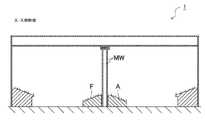
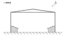
次に、本発明の一実施形態によるアリーナ1を2つの別空間のアリーナとして個別使用する場合について説明する。図3は、個別使用時の平面形状を模式的に示した図である。図4は、図3のX−X線断面図であり、個別使用時のアリーナ1の長手方向断面を模式的に示す図である。図5は、図3のY−Y線断面図であり、本発明の一実施形態によるアリーナ1の短手方向の断面形状を模式的に示した図である。 Next, the case where the
図3〜図5に示すように、アリーナ1は、ほぼ半分の大きさのアリーナ棟3とアリーナ棟4に分かれており、別個に使用することができる。個別アリーナ棟3には、略矩形のフィールド部を囲むように、かつ、外側に向かって高くなる階段状の観客席が複数設けられている。これら観客席のうち、隣接するアリーナ棟4側に位置する客席ブロックA,B,Cは、可動式観客席である。個別アリーナ棟4も同様であり、隣接するアリーナ棟3側に位置する客席ブロックD,E,Fは、可動式観客席である。A〜F以外の部分の観客席は、固定式である。可動式観客席の仕組みは問わないが、例えば、底部に小さな車輪(キャスター)の付いた客席ブロックを用いることができる。 As shown in FIGS. 3 to 5, the
固定式観客席ブロックは、フレーム2や壁とは独立に、基礎に固定されている。すなわち、観客席は、屋根、フレーム2、壁などの建屋に依存せずに自立する構成を採用している。アリーナとして使用するために必要な、トイレ、事務室などの付帯設備も図示を省略しているが、建屋に依存せずに自立する構成を採用している。なお、図面では、扉や照明、空調などは省略している。 The fixed spectator seat block is fixed to the foundation independently of the
2つのアリーナ棟3,4の境の壁は、少し間隔を置いて配置された2枚の可動式間仕切り板MWである。可動式間仕切り板MWは、図4に示すように、上部から吊り下げられる方式で固定されている。可動式間仕切り板MWをどこにどのように吊り下げるかは、特に限定しないが、例えば、アリーナ棟3,4の境に位置する2つの単位フレーム2に、水平方向の梁若しくはレールを設け、その梁若しくはレールに左右方向に移動可能となるように吊るす構成が挙げられる。 The wall at the boundary between the two
アリーナ1の長辺外側の中央部には、すなわち、個別アリーナ棟3,4の境目近傍の外側には、一体使用時に可動式間仕切り板MWを収納するための間仕切り板収納部5が設けられている。可動式間仕切り板MWは、間仕切りとして使用しないときは、分解され、または、折り畳まれて、間仕切り板収納部5に収納される。
なお、フィールド部としては、展示会利用の際など、特段の床が必要ない場合には、スラブのままであるが、スポーツが行われる場合には、バスケットボールなどの競技の種類に応じて必要な床が配設される。A partition
In addition, as a field part, when using a special floor, such as when using an exhibition, it remains a slab, but when sports are performed, it is necessary according to the type of competition such as basketball. A floor is provided.
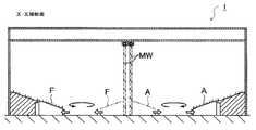
次に、本発明の一実施形態によるアリーナ1を1つの大空間アリーナとして一体使用する場合について説明する。図6は、一体使用時のアリーナ1の平面形状を模式的に示した図である。図7は、図6のX−X線断面図であり、一体利用時の断面を模式的に示す図である。
図6及び図7に示すように、一体使用時には、2つのアリーナ空間3,4を仕切っていた可動式間仕切り板MWは、間仕切り板収納部5に収納されている。可動式観客席ブロックA,B,C及び、D,E,Fは、図6に示すように、それぞれ、1つの大きなフィールド部を臨める位置、かつ、固定式観客席よりも内側に配置されている。可動式観客席ブロックA,B,C及び、D,E,Fは、図7に示すように、固定式観客席よりも少し低くなるように構成されている。このような構成を採用しているので、アリーナ1は、1つの大きなフィールド部を有する大空間アリーナとして使用することができる。Next, the case where the
As shown in FIGS. 6 and 7, the movable partition plate MW that partitions the two
次に、アリーナ1を2つの別空間のアリーナ3,4から1つの大空間アリーナとして使用する場合の移行方法の一例について図8〜図10を参照して説明する。図8〜図10は、アリーナ1を2つの別空間のアリーナから1つの大空間アリーナとして使用する場合の移行方法を説明するための図であり、図8は平面形状を模式的に示した図、図9は図8のX−X線断面図、図10は図8のIX−IX断面図である。 Next, an example of a transition method when the
図8〜図10に示す通り、可動式観客席ブロックA,B,C及び、D,E,Fは、ブロックごとに回転しながら外側に移動する。可動式間仕切り板MWは、両側に移動しながら間仕切り板収納部5に収納される。このような構成を採っているので、アリーナ1は、2つのアリーナ棟3,4が並んだ構成であっても、1つの大空間アリーナとして使用することができる。 As shown in FIGS. 8 to 10, the movable spectator seat blocks A, B, C and D, E, F move outward while rotating for each block. The movable partition plate MW is stored in the partition
次に、本発明の一実施形態であるアリーナ1の施工方法を、図11を用いて簡単に説明する。本発明に関係のない細部は省略している。
まず、基礎工事を行う(ステップ1(S1))。基礎は、アリーナ1を建てる土台となるものである。基礎の材料としては、たとえば、鉄筋とコンクリートを用いることができる。
続いて、建方工事を行う(ステップ2(S2))。この建方工事では、基礎工事で造られた基礎の上に、フレーム部材である鉄骨をクレーンで吊り上げて、単位フレーム2を組み立てて適宜ボルト止めするなどして固定し、図1に示すアリーナ1のフレーム構造を造り上げていく。すなわち、基礎工事で造られた基礎の上に、所定間隔で、所定の長さ分、複数の単位フレーム2を順次(連続して)配設する。
このとき、図1及び図3に示すように、アリーナ1の長手方向の中央付近、すなわち、アリーナ棟3とアリーナ棟4との境になる位置には、間仕切りを設けるため、他の部分に比べて短い間隔で単位フレーム2を2つ配設する。以上により、図1に示すアリーナ1のフレーム構造(フレーム部)が完成する。なお、中央の2つの単位フレーム2には、後の内装工事工程若しくはこの工程で、水平方向に梁またはレールを設けるなどして、可動式間仕切り板MWを吊り下げられるようにする。Next, the construction method of the
First, foundation work is performed (step 1 (S1)). The foundation is the foundation on which
Subsequently, construction work is performed (step 2 (S2)). In this construction work, a steel frame as a frame member is lifted by a crane on a foundation made by foundation work, and the
At this time, as shown in FIGS. 1 and 3, a partition is provided in the vicinity of the center in the longitudinal direction of the
続いて、外装工事を行う(ステップ3(S3))。外装工事では、建方工事で組み立てられたフレーム部に、外壁及び屋根板を取り付け、図3に示すように可動式間仕切り板収納部5も設けて、建物の外装を完成させる。ここで、外壁としてパネル式を採用すると良い。パネル式外壁を採用することで、工期を短縮することができ、コストダウンすることができる。
続いて、内装工事を行う(ステップ4(S4))。内装工事では、アリーナの内部に配設される観客席の土台となる座席架台を組み立てていく。座席架台としては、鉄骨を用いることができる。固定式観客席ブロックの座席架台は、基礎の上に組み立てて固定し、可動式観客席ブロックは固定せずに所定位置に配置する。本発明のアリーナでは、外部のフレームと内部の座席架台がそれぞれ独立した構造であるため、このような施工順序となる。なお、可動式間仕切り板MWも、この内装工事のステップで設ける。Subsequently, exterior work is performed (step 3 (S3)). In the exterior work, the outer wall and the roof plate are attached to the frame part assembled in the construction work, and the movable partition
Subsequently, interior work is performed (step 4 (S4)). In the interior work, we will assemble a seat base that will be the foundation of the spectator seats that will be placed inside the arena. A steel frame can be used as the seat mount. The seat base of the fixed spectator seat block is assembled and fixed on the foundation, and the movable spectator seat block is not fixed and is arranged at a predetermined position. In the arena of the present invention, the external frame and the internal seat base are independent structures, and thus the construction sequence is as described above. The movable partition plate MW is also provided in the interior construction step.
次に、本発明の他の実施形態として、同規模のアリーナ棟を複数並べるのではなく、最初は、実情に合わせた妥当な規模、例えば5,000人規模のアリーナとして構築し、その後営業状況を見ながら、徐々に7,000人規模、1万人規模と増築していくアリーナの例について図12を参照して説明する。 Next, as another embodiment of the present invention, rather than arranging a plurality of arena buildings of the same scale, first, an appropriate scale according to the actual situation, for example, an arena with a scale of 5,000 people is constructed, and then the business situation is checked. However, an example of an arena that is gradually expanded to a scale of 7,000 and 10,000 will be described with reference to FIG.
図12に示すように、最初は5,000人規模のアリーナとして、図1のアリーナ1の半分のサイズで構築する。サイズが異なるだけで、構造、施工方法は、先の実施形態と同様である。そして、その後の営業状況が良く、7,000人規模に増築したいとなったときに、その土地の空き状況に合わせて、増築できる方向に単位フレームを必要数、所定間隔で基礎の上に配設していく。その際、増築する側の壁は、一旦取り壊すことになるが、外壁はパネル式なので、取り壊しも取り付けも容易である。基礎に固定した固定式観客席ブロックは、座席架台と共に一旦取り外して移動し、また固定することとなるが、これも比較的容易にできる。1万人規模に増築するときも同様である。
逆に、大人数の集客が望めない状況となり減築する必要が出てきた際には、外壁パネルをフレームから取り外し、減築するサイズに合わせて単位フレームを取り外し、新たに外壁パネルをフレームに取り付ければよい。As shown in FIG. 12, it is constructed as an arena with a scale of 5,000 people at half the size of the
Conversely, when it is necessary to reduce the number of customers because a large number of customers cannot be expected, the outer wall panel is removed from the frame, the unit frame is removed according to the size to be reduced, and the outer wall panel is newly added to the frame. It only has to be attached.
以上説明したように、本発明によれば、初期コスト・運用コストを圧縮することができる。また、単位フレーム2や外壁パネル等の主要部材の再利用・移設も可能であり、フレキシビリティが高い。規模に合わせて、たとえば3,000人用、5,000人用,7000人用,1万人用というように増築したり、逆に減築したりすることも容易である。本発明によれば、事情に合わせた規模で短期間に建設でき、初期コスト・運用コストも抑えることができる。 As described above, according to the present invention, the initial cost and the operation cost can be reduced. In addition, the main members such as the
本発明によれば、初期コスト・運用コストを圧縮することができ、増築・減築が容易なので、資金が比較的少ない事業主体でもアリーナを建設できる。また、数年後に取り壊す前提で構築する期間限定のテーマパークやオリンピック施設としてのアリーナにも本発明を利用することができる。 According to the present invention, the initial cost and the operation cost can be reduced, and the expansion and reduction can be easily performed, so that the arena can be constructed even by a business entity with relatively little funds. The present invention can also be used for a limited-time theme park or an arena as an Olympic facility that is constructed on the assumption that it will be demolished after several years.
1 … アリーナ
2 … 単位フレーム
3 … 個別アリーナ棟
4 … 個別アリーナ棟
5 … 間仕切り板収納部
A,B,C … 可動式客席ブロック
D,E,F … 可動式客席ブロック
MW … 可動式間仕切り板
DESCRIPTION OF
Claims (3)
Translated fromJapanese略矩形のフィールド部と、
上記フィールド部を囲むように配置された階段状の観客席部と、
屋根を含む建屋を支えるフレーム部と、を備え、
前記フレーム部は、所定のサイズに応じて、同一形状の単位フレームを一方向に所定間隔で連続して配設した構成からなり、
前記観客席部は、前記フレーム部の内側に、前記フレーム部とは独立して基礎に固定されている、
ことを特徴とするアリーナ。An arena that can be expanded and reduced,
A substantially rectangular field part;
A staircase-shaped auditorium seat arranged so as to surround the field section;
A frame part that supports the building including the roof, and
The frame portion has a configuration in which unit frames of the same shape are continuously arranged at a predetermined interval in one direction according to a predetermined size,
The spectator seat part is fixed to the inside of the frame part, independently of the frame part,
An arena characterized by that.
請求項1記載のアリーナ。Ancillary equipment that is not fixed to the building but provided independently is further provided.
The arena according to claim 1.
略矩形のフィールド部と、
上記フィールド部を囲むように配置された階段状の観客席部と、
屋根を含む建屋を支えるフレーム部と、を備え、
前記フレーム部は、所定のサイズに応じて、同一形状の単位フレームを一方向に所定間隔で連続して配設した構成からなり、
前記観客席部は、前記フレーム部とは独立して基礎に固定されたアリーナにおいて、
増築又は減築する側の壁を取り壊す工程と、
既設の上記単位フレームの配設方向に沿って、増築又は減築するサイズに必要な数だけ上記単位フレームを配設又は取り外す工程と、
配設又は取り外しを行った後の上記単位フレームに新たな壁を設ける工程と、を有する、
ことを特徴とするアリーナの増減築の方法。
A method of adding or reducing an arena that can be expanded or reduced,
A substantially rectangular field part;
A staircase-shaped auditorium seat arranged so as to surround the field section;
A frame part that supports the building including the roof, and
The frame portion has a configuration in which unit frames of the same shape are continuously arranged at a predetermined interval in one direction according to a predetermined size,
In the arena fixed to the foundation independently of the frame part, the spectator seat part,
The process of demolishing the wall to be expanded or reduced;
Arranging or removing the unit frames as many as required for the size of extension or reduction along the arrangement direction of the existing unit frames;
Providing a new wall on the unit frame after the placement or removal.
How to increase or decrease the arena characterized by that.
Priority Applications (1)
| Application Number | Priority Date | Filing Date | Title |
|---|---|---|---|
| JP2018170166AJP2019007344A (en) | 2018-09-12 | 2018-09-12 | Arena and construction method of arena |
Applications Claiming Priority (1)
| Application Number | Priority Date | Filing Date | Title |
|---|---|---|---|
| JP2018170166AJP2019007344A (en) | 2018-09-12 | 2018-09-12 | Arena and construction method of arena |
Related Parent Applications (1)
| Application Number | Title | Priority Date | Filing Date |
|---|---|---|---|
| JP2017072416ADivisionJP6404395B1 (en) | 2017-03-31 | 2017-03-31 | Arena and arena construction method |
Publications (1)
| Publication Number | Publication Date |
|---|---|
| JP2019007344Atrue JP2019007344A (en) | 2019-01-17 |
Family
ID=65026891
Family Applications (1)
| Application Number | Title | Priority Date | Filing Date |
|---|---|---|---|
| JP2018170166APendingJP2019007344A (en) | 2018-09-12 | 2018-09-12 | Arena and construction method of arena |
Country Status (1)
| Country | Link |
|---|---|
| JP (1) | JP2019007344A (en) |
Cited By (1)
| Publication number | Priority date | Publication date | Assignee | Title |
|---|---|---|---|---|
| JP7654183B1 (en) | 2023-09-19 | 2025-04-01 | 山口 康史 | How to assemble a building frame set |
Citations (8)
| Publication number | Priority date | Publication date | Assignee | Title |
|---|---|---|---|---|
| JPS55157921U (en)* | 1979-05-01 | 1980-11-13 | ||
| JPS55157923U (en)* | 1979-05-01 | 1980-11-13 | ||
| JPH07310448A (en)* | 1994-03-24 | 1995-11-28 | Kajima Corp | Structure of multi-purpose suspended roof arena with variable amount of space |
| JPH09228483A (en)* | 1996-02-23 | 1997-09-02 | Shimizu Corp | Method for constructing roof on structure and structure |
| US5921032A (en)* | 1997-12-31 | 1999-07-13 | Hellmuth Obata & Kassabaum, Inc. | Convertible sports and exhibition facility and conversion method |
| JP2001207550A (en)* | 2000-01-26 | 2001-08-03 | Misawa Homes Co Ltd | Building unit, foundation for extension of building, and building extension method for unit type building |
| JP2008025865A (en)* | 2006-07-18 | 2008-02-07 | Nippon Ps:Kk | Structure of rifle range |
| JP2013133662A (en)* | 2011-12-27 | 2013-07-08 | Nippon Steel & Sumikin Engineering Co Ltd | Suspension type steel-framed roof frame, and method for constructing steel-framed roof |
- 2018
- 2018-09-12JPJP2018170166Apatent/JP2019007344A/enactivePending
Patent Citations (8)
| Publication number | Priority date | Publication date | Assignee | Title |
|---|---|---|---|---|
| JPS55157921U (en)* | 1979-05-01 | 1980-11-13 | ||
| JPS55157923U (en)* | 1979-05-01 | 1980-11-13 | ||
| JPH07310448A (en)* | 1994-03-24 | 1995-11-28 | Kajima Corp | Structure of multi-purpose suspended roof arena with variable amount of space |
| JPH09228483A (en)* | 1996-02-23 | 1997-09-02 | Shimizu Corp | Method for constructing roof on structure and structure |
| US5921032A (en)* | 1997-12-31 | 1999-07-13 | Hellmuth Obata & Kassabaum, Inc. | Convertible sports and exhibition facility and conversion method |
| JP2001207550A (en)* | 2000-01-26 | 2001-08-03 | Misawa Homes Co Ltd | Building unit, foundation for extension of building, and building extension method for unit type building |
| JP2008025865A (en)* | 2006-07-18 | 2008-02-07 | Nippon Ps:Kk | Structure of rifle range |
| JP2013133662A (en)* | 2011-12-27 | 2013-07-08 | Nippon Steel & Sumikin Engineering Co Ltd | Suspension type steel-framed roof frame, and method for constructing steel-framed roof |
Cited By (1)
| Publication number | Priority date | Publication date | Assignee | Title |
|---|---|---|---|---|
| JP7654183B1 (en) | 2023-09-19 | 2025-04-01 | 山口 康史 | How to assemble a building frame set |
Similar Documents
| Publication | Publication Date | Title |
|---|---|---|
| JPWO2009011029A1 (en) | Building structure | |
| US9874007B2 (en) | Transformable platform | |
| JP2019007344A (en) | Arena and construction method of arena | |
| JP2000314237A (en) | Method for enlarging existing building | |
| JP6404395B1 (en) | Arena and arena construction method | |
| US10407893B2 (en) | Building system for a multi-story building and method | |
| JPH09228671A (en) | Event facility | |
| JP6095610B2 (en) | Building renovation method and building | |
| JP3112852U (en) | Unit bleachers | |
| JP7068695B2 (en) | Arena and arena construction method | |
| JP4019881B2 (en) | Small business building and its construction method | |
| JP4985816B2 (en) | Upper floor expansion method for existing buildings | |
| JP6465758B2 (en) | Construction method of roof structure | |
| JP2019214840A (en) | Arena | |
| RU127111U1 (en) | TRANSFORMABLE AREA | |
| KR102720423B1 (en) | How to construct the internal facilities of an existing movie theater | |
| JP2008308931A (en) | Reformed skip floor structure | |
| RU2245969C2 (en) | Panel building erection method | |
| JP2003213791A (en) | Building structure | |
| JP2774912B2 (en) | Dome roof facility | |
| JP2020105759A (en) | Ground reinforcement structure and reinforcement method | |
| RAMBABU et al. | DESIGN AND ANALYSIS OF AUDITORIUM BY USING STAAD-PRO SOFTWARE | |
| JP2001348955A (en) | Mobile building | |
| JPH08260738A (en) | Variable wall of multipurpose building | |
| JP2017031733A (en) | Lightweight banking structure |
Legal Events
| Date | Code | Title | Description |
|---|---|---|---|
| A621 | Written request for application examination | Free format text:JAPANESE INTERMEDIATE CODE: A621 Effective date:20191029 | |
| A977 | Report on retrieval | Free format text:JAPANESE INTERMEDIATE CODE: A971007 Effective date:20200821 | |
| A131 | Notification of reasons for refusal | Free format text:JAPANESE INTERMEDIATE CODE: A131 Effective date:20200826 | |
| A521 | Request for written amendment filed | Free format text:JAPANESE INTERMEDIATE CODE: A523 Effective date:20201026 | |
| A131 | Notification of reasons for refusal | Free format text:JAPANESE INTERMEDIATE CODE: A131 Effective date:20210319 | |
| A02 | Decision of refusal | Free format text:JAPANESE INTERMEDIATE CODE: A02 Effective date:20210930 |