JP2019001538A - Cap unit and container with cap - Google Patents
Cap unit and container with capDownload PDFInfo
- Publication number
- JP2019001538A JP2019001538AJP2017119678AJP2017119678AJP2019001538AJP 2019001538 AJP2019001538 AJP 2019001538AJP 2017119678 AJP2017119678 AJP 2017119678AJP 2017119678 AJP2017119678 AJP 2017119678AJP 2019001538 AJP2019001538 AJP 2019001538A
- Authority
- JP
- Japan
- Prior art keywords
- outer cylinder
- rib wall
- inner plug
- cap
- cap unit
- Prior art date
- Legal status (The legal status is an assumption and is not a legal conclusion. Google has not performed a legal analysis and makes no representation as to the accuracy of the status listed.)
- Granted
Links
Images


Landscapes
- Closures For Containers (AREA)
- Thermally Insulated Containers For Foods (AREA)
Abstract
Translated fromJapaneseDescription
Translated fromJapanese本発明は、キャップユニット及びキャップ付き容器に関する。 The present invention relates to a cap unit and a container with a cap.
従来より、上部が開口した容器本体の口頸部に着脱自在に取り付けることによって、容器本体の上部開口部を閉塞するキャップユニット(栓体)を備えたキャップ付き容器がある(例えば、特許文献1〜3を参照。)。 Conventionally, there is a container with a cap provided with a cap unit (plug body) that closes the upper opening of the container main body by detachably attaching to the mouth and neck of the container main body having an upper opening (for example, Patent Document 1). See ~ 3).
このようなキャップユニットは、容器本体の口頸部を覆う外筒と、上部開口部から容器本体の内側に嵌め込まれる中栓とを有して、キャップ本体に対して外筒又は中栓が螺合により取り付けられる構造となっている。 Such a cap unit has an outer cylinder that covers the mouth and neck of the container main body, and an inner plug that is fitted inside the container main body from the upper opening, and the outer cylinder or the inner plug is screwed into the cap main body. It has a structure that can be attached together.
ところで、上述したキャップ付き容器では、キャップユニットを洗浄する際に、外筒と中栓との間が非常に洗いづらくなっている。このため、キャップユニットでは、外筒と中栓とに分割可能な構造を採用して、清掃性を高めることが行われている。 By the way, in the container with a cap mentioned above, when wash | cleaning a cap unit, it is very difficult to wash | clean between an outer cylinder and an inner stopper. For this reason, in the cap unit, the structure which can be divided | segmented into an outer cylinder and an inner stopper is employ | adopted, and cleaning property is improved.
しかしながら、従来のキャップユニットでは、外筒と中栓とに分割可能な構造とした場合、外筒に対して中栓を取り付けるための構造(脱着機構)が複雑となってしまうといった問題があった。 However, in the conventional cap unit, when the structure can be divided into the outer cylinder and the inner plug, there is a problem that the structure (detachment mechanism) for attaching the inner plug to the outer cylinder becomes complicated. .
本発明は、このような従来の事情に鑑みて提案されたものであり、外筒に対して中栓を取り付ける構造を簡素化し、これら外筒及び中栓の清掃性を高めることを可能としたキャップユニット、並びにそのようなキャップユニットを備えることによって、更なる使い勝手の向上を可能としたキャップ付き容器を提供することを目的とする。 The present invention has been proposed in view of such conventional circumstances, simplifying the structure for attaching the inner plug to the outer cylinder, and making it possible to improve the cleaning properties of the outer cylinder and the inner plug. It is an object of the present invention to provide a cap unit and a container with a cap that can be further improved in usability by including such a cap unit.
上記目的を達成するために、本発明は以下の手段を提供する。
〔1〕 上部が開口した容器本体の口頸部に着脱自在に取り付けられることによって、前記容器本体の上部開口部を閉塞するキャップユニットであって、
前記容器本体の口頸部を覆う外筒と、
前記容器本体の上部開口部から前記容器本体の内側に嵌め込まれる中栓と、
前記外筒に対して前記中栓を着脱自在に取り付ける脱着機構とを備え、
前記脱着機構は、前記外筒の内周側から周方向に亘って突出された第1のリブ壁と、前記外筒の内周側から周方向に亘って突出されると共に弾性変形可能な第2のリブ壁と、前記中栓の外周側から周方向に亘って突出された第3のリブ壁とを有し、
互いに平行に並ぶ前記第1のリブ壁と前記第2のリブ壁とのうち、前記第2のリブ壁側から前記外筒の内側に向かって前記中栓を挿入し、前記第2のリブ壁を弾性変形させながら、前記第3のリブ壁を前記第1のリブ壁と前記第2のリブ壁との間に嵌入させることによって、前記外筒に対して前記中栓が取り付けられることを特徴とするキャップユニット。
〔2〕 前記外筒は、前記第1のリブ壁が設けられた筒本体と、前記第2のリブ壁が設けられた弾性変形可能なカバー部材とを有し、
前記カバー部材は、前記筒本体に対して着脱自在又は一体に取り付けられていることを特徴とする前記〔1〕に記載のキャップユニット。
〔3〕 前記カバー部材は、前記筒本体の外周面を覆う弾性リング部を有し、
前記第2のリブ壁は、前記弾性リング部の上端から前記筒本体の上端よりも内側に向かって突出して設けられていることを特徴とする前記〔2〕に記載のキャップユニット。
〔4〕 前記脱着機構は、前記外筒と前記中栓との何れか一方に設けられた係止部と、何れか他方に設けられた被係止部とを有し、
前記被係止部に前記係止部が係止されることによって、前記外筒に対して前記中栓が固定されることを特徴とする前記〔1〕〜〔3〕の何れか一項に記載のキャップユニット。
〔5〕 前記脱着機構は、前記外筒と前記中栓との何れか一方に設けられた位置決め凹部と、何れか他方に設けられた位置決め凸部とを有し、
前記位置決め凹部に前記位置決め凸部が係合されることによって、前記外筒に対して前記中栓が回り止めされることを特徴とする前記〔1〕〜〔4〕の何れか一項に記載のキャップユニット。
〔6〕 前記キャップ本体に対して前記外筒又は前記中栓が螺合により取り付けられることを特徴とする前記〔1〕〜〔5〕の何れか一項に記載のキャップユニット。
〔7〕 前記中栓に取り付けられた状態で、前記キャップ本体の内側と前記中栓との間を密閉するシール部材を備えることを特徴とする前記〔1〕〜〔6〕の何れか一項に記載のキャップユニット。
〔8〕 前記〔1〕〜〔7〕の何れか一項に記載のキャップユニットと、
前記キャップユニットが取り付けられた容器本体とを備えるキャップ付き容器。In order to achieve the above object, the present invention provides the following means.
[1] A cap unit that closes the upper opening of the container body by being detachably attached to the mouth and neck of the container body having an upper opening,
An outer cylinder covering the mouth and neck of the container body;
An inner plug fitted inside the container body from the upper opening of the container body,
A detachable mechanism for detachably attaching the inner plug to the outer cylinder,
The desorption mechanism includes a first rib wall protruding from the inner peripheral side of the outer cylinder in the circumferential direction, and a first rib wall protruding from the inner peripheral side of the outer cylinder in the circumferential direction and elastically deformable. 2 rib walls and a third rib wall protruding from the outer peripheral side of the inner plug in the circumferential direction,
Of the first rib wall and the second rib wall arranged in parallel with each other, the inner plug is inserted from the second rib wall side toward the inner side of the outer cylinder, and the second rib wall The inner plug is attached to the outer cylinder by fitting the third rib wall between the first rib wall and the second rib wall while elastically deforming the outer tube. Cap unit.
[2] The outer cylinder includes a cylinder main body provided with the first rib wall, and an elastically deformable cover member provided with the second rib wall;
The cap unit according to [1], wherein the cover member is detachably or integrally attached to the cylinder body.
[3] The cover member includes an elastic ring portion that covers an outer peripheral surface of the cylinder body,
The cap unit according to [2], wherein the second rib wall is provided so as to protrude from the upper end of the elastic ring portion toward the inner side of the upper end of the cylinder main body.
[4] The desorption mechanism includes a locking portion provided in one of the outer cylinder and the inner plug, and a locked portion provided in either of the other,
In any one of [1] to [3], the inner plug is fixed to the outer cylinder by locking the locking portion to the locked portion. Cap unit as described.
[5] The desorption mechanism has a positioning recess provided in one of the outer cylinder and the inner plug, and a positioning projection provided in either of the other,
The inner plug is prevented from rotating with respect to the outer cylinder by engaging the positioning convex portion with the positioning concave portion, according to any one of [1] to [4], Cap unit.
[6] The cap unit according to any one of [1] to [5], wherein the outer cylinder or the inner plug is screwed to the cap body.
[7] The device according to any one of [1] to [6], further including a seal member that seals a gap between the inside of the cap body and the inner plug while being attached to the inner plug. Cap unit as described in.
[8] The cap unit according to any one of [1] to [7],
A container with a cap comprising a container body to which the cap unit is attached.
以上のように、本発明によれば、外筒に対して中栓を取り付ける構造を簡素化し、これら外筒及び中栓の清掃性を高めることを可能としたキャップユニット、並びにそのようなキャップユニットを備えることによって、更なる使い勝手の向上を可能としたキャップ付き容器を提供することが可能である。 As described above, according to the present invention, the cap unit that simplifies the structure for attaching the inner plug to the outer cylinder, and can improve the cleanability of the outer cylinder and the inner plug, and such a cap unit. By providing this, it is possible to provide a container with a cap that can further improve usability.
以下、本発明の実施形態について、図面を参照して詳細に説明する。
本発明の一実施形態として、例えば図1〜図6に示すキャップユニット1を備えたキャップ付き容器100について説明する。Hereinafter, embodiments of the present invention will be described in detail with reference to the drawings.
As one embodiment of the present invention, for example, a cap-equipped
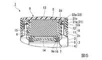
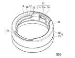
なお、図1は、キャップユニット1を備えたキャップ付き容器100の外観を示す斜視図である。図2は、キャップユニット1の構成を示す分解斜視図である。図3は、キャップユニット1の構成を示す上面図である。図4は、図3中に示す線分A−Aによるキャップユニット1の断面図である。図5は、図3中に示す線分B−Bによるキャップユニット1の断面図である。図6は、キャップユニット1が備える外筒8の構成を示す斜視図である。 FIG. 1 is a perspective view showing an appearance of a
本実施形態のキャップ付き容器100は、本実施形態のキャップユニット1と、このキャップユニット1が着脱自在に取り付けられる容器本体2とを備えている。キャップ付き容器100は、真空断熱構造を有する容器本体2によって、この容器本体2に収容された飲料(内容物)を保温又は保冷することが可能な飲料用容器である。 The cap-equipped
具体的に、この容器本体2は、例えばステンレス等からなる有底筒状の外容器3及び内容器4を有し、外容器3の内側に内容器4を収容した状態で互いの口元部を接合した二重構造の容器により構成されている。また、外容器3と内容器4との間には、真空断熱層5が設けられている。真空断熱層5は、例えば、高真空に減圧(真空引き)されたチャンバー内で、外容器3の底面中央部に設けられた脱気孔を塞ぐことによって形成することができる。 Specifically, the
容器本体2は、略円形状の底面部2aと、底面部2aの外周から略円筒状に起立した胴部2bと、胴部2bの上部側において縮径された略円筒状の口頸部2cとを有している。また、口頸部2cの上端部は、容器本体2の上部開口部2dとして、円形状に開口している。 The
口頸部2cの内周面は、胴部2bの内周面よりも縮径されている。また、口頸部2cの内周面には、雌ネジ部6が設けられている。雌ネジ部6は、口頸部2cの上端側から下方に向けて螺旋状に突出したネジ山から構成されている。さらに、雌ネジ部6の下方には、リング状の張出部7が容器本体2の内周面から全周に亘って突出して設けられている。 The inner peripheral surface of the mouth-and-
なお、本実施形態のキャップ付き容器100は、全体として略円筒状の外観形状を有しているが、キャップ付き容器100の外観形状については、特に限定されるものではなく、サイズやデザイン等に合わせて、適宜変更を加えることが可能である。また、容器本体2の外周面には、塗装や印刷等が施されていてもよい。 In addition, although the
本実施形態のキャップユニットは、容器本体2の上部開口部2dを閉塞する栓体を構成するものである。具体的に、このキャップユニット1は、容器本体2の口頸部2cを覆う外筒8と、容器本体2の上部開口部2dから容器本体2の内側に嵌め込まれる中栓9と、外筒8に対して中栓9を着脱自在に取り付ける脱着機構10とを備えている。 The cap unit of the present embodiment constitutes a plug that closes the
外筒8は、筒本体11と、筒本体11とは別体に形成されたカバー部材12とを有して、筒本体11に対してカバー部材12が着脱自在に取り付けられた構成を有している。また、外筒8の外周面は、容器本体2の胴部2bと面一となるように略円筒状に形成されている。 The
筒本体11は、例えばポリプロピレン等の合成樹脂からなり、全体として略円筒状に形成されている。また、筒本体11の外周面には、カバー部材12に対応した段差部11aと、段差部11aが形成された面に取付凹部11bとが設けられている。 The
カバー部材12は、例えばシリコーン樹脂や熱可塑性ポリウレタン(TPU)などの弾性部材からなる。カバー部材12は、筒本体11の外周面と面一となるように略円筒状に形成された弾性リング部12aと、弾性リング部12aの内周面から突出された取付凸部12bとを有している。 The
カバー部材12は、この弾性リング部12aが筒本体11の段差部11aに全周に亘って嵌め付けられ、取付凹部11bに取付凸部12bが係合されることによって、筒本体11に対して取り付け可能となっている。一方、カバー部材12は、それ自体を弾性変形させる(引っ張り伸ばす)ことによって、筒本体11から取り外すことが可能である。 The
なお、外筒8は、上述した筒本体11とは別体に形成されたカバー部材12が筒本体11に対して着脱自在に取り付けられた構成に限定されるものではなく、例えば二色成形などによりカバー部材12を筒本体11と一体に形成することによって、筒本体11に対してカバー部材12が一体に取り付けられた構成とすることも可能である。 The
中栓9は、例えばポリプロピレン等の耐熱性樹脂からなる。中栓9は、天面を形成する略円形状の上側栓部材13と、底面及び周面を形成する有底略円筒状の下側栓部材14とを有して、上側栓部材13の下面に下側栓部材14が超音波溶着や高周波溶着等により一体に取り付けられた構成となっている。なお、中栓9の内部は、断熱層となる空気に限らず、断熱材Sを配置した構成としてもよい。 The
上側栓部材13の天面は、外筒8に中栓9が取り付けられた状態において、外筒8(カバー部材12)の上面と面一となっている。下側栓部材14は、外筒8に中栓9が取り付けられた状態において、筒本体11の内側に同心円状に配置されている。 The top surface of the
中栓9の外周面には、雄ネジ部15が設けられている。雄ネジ部15は、中栓9の下端側から上方に向けて螺旋状に突出したネジ山から構成されている。これにより、キャップユニット1は、雌ネジ部6と雄ネジ部15とを構成するネジ山同士の螺合によって、容器本体2に対して着脱自在に取り付けられている。 A
なお、キャップユニット1は、上述した容器本体2側に設けられた雌ネジ部6と、中栓9側に設けられた雄ネジ部15との螺合によって、容器本体2に着脱自在に取り付けられる構成となっているが、口頸部2cの外周面(容器本体2側)に設けられた雄ネジ部と、筒本体11の内周面(外筒8側)に設けられた雌ネジ部との螺合によって、容器本体2に対して着脱自在に取り付けられる構成としてもよい。 The
中栓9の下端部には、止水パッキン16が着脱自在に取り付けられている。止水パッキン16は、リング状のシール部材であり、例えばシリコーンゴム等の耐熱性を有するゴムやエラストマーなどの弾性部材からなる。一方、中栓9の下端部には、フランジ部9aが拡径方向に突出して設けられている。止水パッキン16は、このフランジ部9aに全周に亘って嵌め付けられている。 A water stop packing 16 is detachably attached to the lower end portion of the
止水パッキン16は、容器本体2の口頸部2cに中栓9が取り付けられた際に、弾性変形しながら、容器本体2の張出部7に全周に亘って密着した状態となる。これにより、張出部7(容器本体2)と中栓9との間を密閉することが可能となっている。なお、止水パッキン16の張出部7に密着させるための形状等については、特に限定されるものではなく、その形状等について適宜変更を加えることが可能である。 When the
一方、止水パッキン16は、それ自体を弾性変形させる(引っ張り伸ばす)ことによって、フランジ部9aから取り外すことが可能である。これにより、止水パッキン16と中栓9とをそれぞれ別々に洗浄することができ、止水パッキン16とフランジ部9aとの間を衛生的に保つことができる。 On the other hand, the water-stop packing 16 can be removed from the
脱着機構10は、外筒8の内周側に設けられた第1のリブ壁17及び第2のリブ壁18と、中栓9の外周側に設けられた第3のリブ壁19とを有している。 The
第1のリブ壁17は、筒本体11の内周面に周方向において等間隔に並ぶ複数(本実施形態では2つ)のリブ壁から構成されている。すなわち、これら2つの第1のリブ壁17は、筒本体11の内周面における相対(対向)する位置から、互いに同一の高さで縮径方向に突出されると共に、互いに同一の長さで周方向に亘って突出して設けられている。 The
第2のリブ壁18は、カバー部材12の上端に周方向において等間隔に並ぶ複数(本実施形態では2つ)の弾性変形可能なリブ壁から構成されている。すなわち、これら2つの第2のリブ壁18は、弾性リング部12aの上端における相対(対向)する位置から、互いに同一の高さで縮径方向に突出されると共に、互いに同一の長さで周方向に亘って突出して設けられている。また、第2のリブ壁18は、弾性リング部12aの上端から筒本体11の上端よりも内側に向かって突出して設けられている。 The
第1のリブ壁17と第2のリブ壁18とは、外筒8の軸線方向(上下方向)において互いに平行に並んで設けられている。また、第1のリブ壁17と第2のリブ壁18との間には、第3のリブ壁19に対応した溝部20が設けられている。 The
第3のリブ壁19は、中栓9(下側栓部材14)の外周面に周方向において等間隔に並ぶ複数(本実施形態では2つ)のリブ壁から構成されている。すなわち、これら2つの第3のリブ壁19は、中栓9の外周面における相対(対向)する位置から、互いに同一の高さで拡径方向に突出されると共に、互いに同一の長さで周方向に亘って突出して設けられている。 The
脱着機構10では、第2のリブ壁18側から外筒8の内側(下方)に向かって中栓9を挿入する。このとき、第2のリブ壁18に当接した第3のリブ壁19が、第2のリブ壁18を弾性変形させながら、第1のリブ壁17と第2のリブ壁18との間(溝部20)へと嵌入される。これにより、第1のリブ壁17と第2のリブ壁18との間(溝部20)に第3のリブ壁19が嵌合されることによって、外筒8に対して中栓9を取り付けることが可能である。 In the
一方、外筒8から中栓9を取り外す際は、第2のリブ壁18側(上方)に向かって中栓9を押し上げる。このとき、第2のリブ壁18に当接した第3のリブ壁19が、第2のリブ壁18を弾性変形させながら、溝部20の外側(上方)へと押し出される。これにより、外筒8から中栓9を取り外すことが可能である。 On the other hand, when removing the
脱着機構10は、外筒8と中栓9との何れか一方(本実施形態では外筒8)に設けられた係止部21と、何れか他方(本実施形態では中栓9)に設けられた被係止部22とを有している。 The
係止部21は、筒本体11の第1のリブ壁17が設けられた位置の各間に設けられた一対の弾性片21aからなる。一対の弾性片21aは、筒本体11の相対(対向)する位置において、その周囲を切り欠くスリット21bの内側に設けられている。また、各弾性片21aは、上方に向かって延長されると共に、先端側が拡径方向に弾性変形可能となっている。また、各弾性片21aの先端側には、爪部21cが縮径方向に突出して設けられている。 The locking
被係止部22は、中栓9の第3のリブ壁19が設けられた位置の各間に設けられた一対の凹部22aからなる。一対の凹部22aは、中栓9の相対(対向)する位置において、各弾性片21aの爪部21cに対応して設けられている。 The locked
脱着機構10では、上述した外筒8の内側に向かって中栓9を挿入し、第1のリブ壁17と第2のリブ壁18との間(溝部20)に第3のリブ壁19が嵌入された際に、各弾性片21aの爪部21cが凹部22aに係止される。これにより、外筒8に対して中栓9が固定された状態となる。一方、脱着機構10では、外筒8から中栓9を取り外す際に、中栓9を押し上げることによって、凹部22aに対する爪部21cの係止状態を解除することが可能である。 In the
なお、本実施形態では、上述した外筒8側に係止部21を設け、中栓9側に被係止部22を設けた構成となっているが、それとは逆の構成、すなわち、中栓9側に係止部21を設け、外筒8側に被係止部22を設けた構成とすることも可能である。また、係止部21と被係止部22とは、上述した爪部21cが凹部22aに係止される構成に限らず、互いの係止構造を適宜変更することが可能である。 In addition, in this embodiment, although it has the structure which provided the latching | locking
脱着機構10は、外筒8と中栓9との何れか一方(本実施形態では外筒8)に設けられた位置決め凹部23と、何れか他方(本実施形態では中栓9)に設けられた位置決め凸部24とを有している。 The
位置決め凹部23は、筒本体11の第1のリブ壁17が設けられた位置の各間に設けられている。一方、位置決め凸部24は、中栓9の第3のリブ壁19が設けられた位置の各間から拡径方向に突出して設けられている。凹部22aは、この位置決め凸部24の内側に設けられている。 The
脱着機構10では、上述した第1のリブ壁17と第2のリブ壁18との間(溝部20)に第3のリブ壁19が嵌入された際に、位置決め凹部23に位置決め凸部24が係合された状態となる。これにより、外筒8に対して中栓9が中心軸回りに移動(回転)することを規制(回り止め)することができる。 In the
なお、本実施形態では、上述した外筒8側に位置決め凹部23を設け、中栓9側に位置決め凸部24を設けた構成となっているが、それとは逆の構成、すなわち、中栓9側に位置決め凹部23を設け、外筒8側に位置決め凸部24を設けた構成とすることも可能である。また、位置決め凹部23と位置決め凸部24とは、上述した構成に限らず、互いの係合構造を適宜変更することが可能である。 In the present embodiment, the positioning
以上のような構造を有する本実施形態のキャップユニット1では、上述した脱着機構10によって、外筒8に対して中栓9を取り付ける構造を簡素化することが可能である。また、外筒8から中栓9を取り外すことによって、外筒8と中栓9とをそれぞれ別々に洗浄することができ、これら外筒8と中栓9との間を衛生的に保つことが可能である。したがって、このようなキャップユニット1を備えるキャップ付き容器100では、使い勝手の更なる向上を図ることが可能である。 In the
なお、本発明は、上記実施形態のものに必ずしも限定されるものではなく、本発明の趣旨を逸脱しない範囲において種々の変更を加えることが可能である。
すなわち、上記実施形態では、上述した真空断熱構造を有する容器本体2によって保温・保冷機能を持たせたキャップ付き容器100に本発明を適用した場合を例示しているが、このような真空断熱構造を有する容器本体2を備えたものに必ずしも限定されるものではない。すなわち、本発明は、キャップユニットが容器本体の口頸部に着脱自在に取り付けられるキャップ付き容器に対して幅広く適用することが可能である。In addition, this invention is not necessarily limited to the thing of the said embodiment, A various change can be added in the range which does not deviate from the meaning of this invention.
That is, in the said embodiment, although the case where this invention is applied to the
1…キャップユニット 2…容器本体 3…外容器 4…内容器 5…真空断熱層 6…雌ネジ部 7…張出部 8…外筒 9…中栓 10…脱着機構 11…筒本体 12…カバー部材 12a…弾性リング部 13…上側栓部材 14…下側栓部材 15…雄ネジ部 16…止水パッキン(シール部材) 17…第1のリブ壁 18…第2のリブ壁 19…第3のリブ壁 20…溝部 21…係止部 22…被係止部 23…位置決め凹部 24…位置決め凸部 100…キャップ付き容器 DESCRIPTION OF
Claims (8)
Translated fromJapanese前記容器本体の口頸部を覆う外筒と、
前記容器本体の上部開口部から前記容器本体の内側に嵌め込まれる中栓と、
前記外筒に対して前記中栓を着脱自在に取り付ける脱着機構とを備え、
前記脱着機構は、前記外筒の内周側から周方向に亘って突出された第1のリブ壁と、前記外筒の内周側から周方向に亘って突出されると共に弾性変形可能な第2のリブ壁と、前記中栓の外周側から周方向に亘って突出された第3のリブ壁とを有し、
互いに平行に並ぶ前記第1のリブ壁と前記第2のリブ壁とのうち、前記第2のリブ壁側から前記外筒の内側に向かって前記中栓を挿入し、前記第2のリブ壁を弾性変形させながら、前記第3のリブ壁を前記第1のリブ壁と前記第2のリブ壁との間に嵌入させることによって、前記外筒に対して前記中栓が取り付けられることを特徴とするキャップユニット。A cap unit that closes the upper opening of the container body by being detachably attached to the mouth and neck of the container body having an upper opening,
An outer cylinder covering the mouth and neck of the container body;
An inner plug fitted inside the container body from the upper opening of the container body,
A detachable mechanism for detachably attaching the inner plug to the outer cylinder,
The desorption mechanism includes a first rib wall protruding from the inner peripheral side of the outer cylinder in the circumferential direction, and a first rib wall protruding from the inner peripheral side of the outer cylinder in the circumferential direction and elastically deformable. 2 rib walls and a third rib wall protruding from the outer peripheral side of the inner plug in the circumferential direction,
Of the first rib wall and the second rib wall arranged in parallel with each other, the inner plug is inserted from the second rib wall side toward the inner side of the outer cylinder, and the second rib wall The inner plug is attached to the outer cylinder by fitting the third rib wall between the first rib wall and the second rib wall while elastically deforming the outer tube. Cap unit.
前記カバー部材は、前記筒本体に対して着脱自在又は一体に取り付けられていることを特徴とする請求項1に記載のキャップユニット。The outer cylinder has a cylinder body provided with the first rib wall, and an elastically deformable cover member provided with the second rib wall,
The cap unit according to claim 1, wherein the cover member is detachably or integrally attached to the cylinder main body.
前記第2のリブ壁は、前記弾性リング部の上端から前記筒本体の上端よりも内側に向かって突出して設けられていることを特徴とする請求項2に記載のキャップユニット。The cover member has an elastic ring portion that covers an outer peripheral surface of the cylinder body,
3. The cap unit according to claim 2, wherein the second rib wall is provided so as to protrude from an upper end of the elastic ring portion toward an inner side than an upper end of the cylinder main body.
前記被係止部に前記係止部が係止されることによって、前記外筒に対して前記中栓が固定されることを特徴とする請求項1〜3の何れか一項に記載のキャップユニット。The desorption mechanism has a locking portion provided in one of the outer cylinder and the inner plug, and a locked portion provided in either of the other,
The cap according to any one of claims 1 to 3, wherein the inner plug is fixed to the outer cylinder by locking the locking portion to the locked portion. unit.
前記位置決め凹部に前記位置決め凸部が係合されることによって、前記外筒に対して前記中栓が回り止めされることを特徴とする請求項1〜4の何れか一項に記載のキャップユニット。The desorption mechanism has a positioning recess provided in one of the outer cylinder and the inner plug, and a positioning projection provided in either of the other,
The cap unit according to any one of claims 1 to 4, wherein the inner stopper is prevented from rotating with respect to the outer cylinder by engaging the positioning convex portion with the positioning concave portion. .
前記キャップユニットが取り付けられた容器本体とを備えるキャップ付き容器。The cap unit according to any one of claims 1 to 7,
A container with a cap comprising a container body to which the cap unit is attached.
Priority Applications (1)
| Application Number | Priority Date | Filing Date | Title |
|---|---|---|---|
| JP2017119678AJP6921640B2 (en) | 2017-06-19 | 2017-06-19 | Cap unit and container with cap |
Applications Claiming Priority (1)
| Application Number | Priority Date | Filing Date | Title |
|---|---|---|---|
| JP2017119678AJP6921640B2 (en) | 2017-06-19 | 2017-06-19 | Cap unit and container with cap |
Publications (2)
| Publication Number | Publication Date |
|---|---|
| JP2019001538Atrue JP2019001538A (en) | 2019-01-10 |
| JP6921640B2 JP6921640B2 (en) | 2021-08-18 |
Family
ID=65007307
Family Applications (1)
| Application Number | Title | Priority Date | Filing Date |
|---|---|---|---|
| JP2017119678AActiveJP6921640B2 (en) | 2017-06-19 | 2017-06-19 | Cap unit and container with cap |
Country Status (1)
| Country | Link |
|---|---|
| JP (1) | JP6921640B2 (en) |
Cited By (18)
| Publication number | Priority date | Publication date | Assignee | Title |
|---|---|---|---|---|
| USD860716S1 (en) | 2017-03-27 | 2019-09-24 | Yeti Coolers, Llc | Container lid |
| USD871133S1 (en) | 2018-10-17 | 2019-12-31 | Yeti Coolers, Llc | Lid |
| USD876905S1 (en) | 2015-11-20 | 2020-03-03 | Yeti Coolers, Llc | Jug |
| USD883737S1 (en) | 2018-10-17 | 2020-05-12 | Yeti Coolers, Llc | Lid |
| USD883738S1 (en) | 2018-10-17 | 2020-05-12 | Yeti Coolers, Llc | Lid |
| USD896572S1 (en) | 2018-08-20 | 2020-09-22 | Yeti Coolers, Llc | Container lid |
| USD897151S1 (en) | 2018-10-17 | 2020-09-29 | Yeti Coolers, Llc | Lid |
| CN111907906A (en)* | 2019-05-10 | 2020-11-10 | 膳魔师(中国)家庭制品有限公司 | container with lid |
| CN111977160A (en)* | 2019-05-23 | 2020-11-24 | 膳魔师(中国)家庭制品有限公司 | Cap unit and capped container |
| US10926925B2 (en) | 2015-08-14 | 2021-02-23 | Yeti Coolers, Llc | Container with magnetic cap |
| US10959553B2 (en) | 2016-10-17 | 2021-03-30 | Yeti Coolers, Llc | Container and method of forming a container |
| US10959552B2 (en) | 2016-10-17 | 2021-03-30 | Yeti Coolers, Llc | Container and method of forming a container |
| US11021314B2 (en) | 2016-10-17 | 2021-06-01 | Yeti Coolers, Llc | Container and method of forming a container |
| US11034505B2 (en) | 2016-10-17 | 2021-06-15 | Yeti Coolers, Llc | Container and method of forming a container |
| CN113716203A (en)* | 2020-05-26 | 2021-11-30 | 膳魔师(中国)家庭制品有限公司 | Cap unit and capped container |
| JP2023138580A (en)* | 2019-05-23 | 2023-10-02 | サーモス株式会社 | container with cap |
| KR20230140340A (en) | 2022-03-29 | 2023-10-06 | 서어모스 케이.케이. | Cap unit and cap-equipped container |
| JP2023146507A (en)* | 2022-03-29 | 2023-10-12 | サーモス株式会社 | Cap unit and container with cap |
Citations (5)
| Publication number | Priority date | Publication date | Assignee | Title |
|---|---|---|---|---|
| US4488660A (en)* | 1981-10-12 | 1984-12-18 | Tiger Vacuum Bottle Industrial Company, Limited | Vacuum bottle |
| JP2013240472A (en)* | 2012-05-21 | 2013-12-05 | Tiger Vacuum Bottle Co Ltd | Beverage container |
| JP5544545B2 (en)* | 2010-04-09 | 2014-07-09 | 象印マホービン株式会社 | Container stoppers and beverage containers |
| JP2014162518A (en)* | 2013-02-26 | 2014-09-08 | Takeo Tanabe | Plug body of beverage container, and beverage container |
| JP2015221087A (en)* | 2014-05-22 | 2015-12-10 | 象印マホービン株式会社 | Food and drink container |
- 2017
- 2017-06-19JPJP2017119678Apatent/JP6921640B2/enactiveActive
Patent Citations (5)
| Publication number | Priority date | Publication date | Assignee | Title |
|---|---|---|---|---|
| US4488660A (en)* | 1981-10-12 | 1984-12-18 | Tiger Vacuum Bottle Industrial Company, Limited | Vacuum bottle |
| JP5544545B2 (en)* | 2010-04-09 | 2014-07-09 | 象印マホービン株式会社 | Container stoppers and beverage containers |
| JP2013240472A (en)* | 2012-05-21 | 2013-12-05 | Tiger Vacuum Bottle Co Ltd | Beverage container |
| JP2014162518A (en)* | 2013-02-26 | 2014-09-08 | Takeo Tanabe | Plug body of beverage container, and beverage container |
| JP2015221087A (en)* | 2014-05-22 | 2015-12-10 | 象印マホービン株式会社 | Food and drink container |
Cited By (43)
| Publication number | Priority date | Publication date | Assignee | Title |
|---|---|---|---|---|
| US12227340B2 (en) | 2015-08-14 | 2025-02-18 | Yeti Coolers, Llc | Container with magnetic cap |
| US11273961B2 (en) | 2015-08-14 | 2022-03-15 | Yeti Coolers, Llc | Container with magnetic cap |
| US10926925B2 (en) | 2015-08-14 | 2021-02-23 | Yeti Coolers, Llc | Container with magnetic cap |
| US11794960B2 (en) | 2015-08-14 | 2023-10-24 | Yeti Coolers, Llc | Container with magnetic cap |
| USD1039919S1 (en) | 2015-11-20 | 2024-08-27 | Yeti Coolers, Llc | Jug |
| USD876905S1 (en) | 2015-11-20 | 2020-03-03 | Yeti Coolers, Llc | Jug |
| USD1018214S1 (en) | 2015-11-20 | 2024-03-19 | Yeti Coolers, Llc | Jug |
| USD960660S1 (en) | 2015-11-20 | 2022-08-16 | Yeti Coolers, Llc | Jug |
| USD899871S1 (en) | 2015-11-20 | 2020-10-27 | Yeti Coolers, Llc | Jug |
| US12269666B2 (en) | 2016-10-17 | 2025-04-08 | Yeti Coolers, Llc | Container and method of forming a container |
| US11021314B2 (en) | 2016-10-17 | 2021-06-01 | Yeti Coolers, Llc | Container and method of forming a container |
| US11814235B2 (en) | 2016-10-17 | 2023-11-14 | Yeti Coolers, Llc | Container and method of forming a container |
| US11034505B2 (en) | 2016-10-17 | 2021-06-15 | Yeti Coolers, Llc | Container and method of forming a container |
| US11524833B2 (en) | 2016-10-17 | 2022-12-13 | Yeti Coolers, Llc | Container and method of forming a container |
| US10959553B2 (en) | 2016-10-17 | 2021-03-30 | Yeti Coolers, Llc | Container and method of forming a container |
| US10959552B2 (en) | 2016-10-17 | 2021-03-30 | Yeti Coolers, Llc | Container and method of forming a container |
| US11840365B2 (en) | 2016-10-17 | 2023-12-12 | Yeti Coolers, Llc | Container and method of forming a container |
| US11930944B2 (en) | 2016-10-17 | 2024-03-19 | Yeti Coolers, Llc | Container and method of forming a container |
| US11503932B2 (en) | 2016-10-17 | 2022-11-22 | Yeti Coolers, Llc | Container and method of forming a container |
| USD860716S1 (en) | 2017-03-27 | 2019-09-24 | Yeti Coolers, Llc | Container lid |
| USD988789S1 (en) | 2018-08-20 | 2023-06-13 | Yeti Coolers, Llc | Container lid |
| USD896572S1 (en) | 2018-08-20 | 2020-09-22 | Yeti Coolers, Llc | Container lid |
| USD913746S1 (en) | 2018-08-20 | 2021-03-23 | Yeti Coolers, Llc | Container lid |
| USD1061140S1 (en) | 2018-08-20 | 2025-02-11 | Yeti Coolers, Llc | Container lid |
| USD913745S1 (en) | 2018-08-20 | 2021-03-23 | Yeti Coolers, Llc | Container lid |
| USD897151S1 (en) | 2018-10-17 | 2020-09-29 | Yeti Coolers, Llc | Lid |
| USD1046619S1 (en) | 2018-10-17 | 2024-10-15 | Yeti Coolers, Llc | Lid |
| USD871133S1 (en) | 2018-10-17 | 2019-12-31 | Yeti Coolers, Llc | Lid |
| USD935268S1 (en) | 2018-10-17 | 2021-11-09 | Yeti Coolers, Llc | Lid |
| USD883737S1 (en) | 2018-10-17 | 2020-05-12 | Yeti Coolers, Llc | Lid |
| USD883738S1 (en) | 2018-10-17 | 2020-05-12 | Yeti Coolers, Llc | Lid |
| CN111907906A (en)* | 2019-05-10 | 2020-11-10 | 膳魔师(中国)家庭制品有限公司 | container with lid |
| JP2023138580A (en)* | 2019-05-23 | 2023-10-02 | サーモス株式会社 | container with cap |
| KR102808612B1 (en)* | 2019-05-23 | 2025-05-15 | 서어모스 케이.케이. | cap unit and cap-equipped container |
| JP7417458B2 (en) | 2019-05-23 | 2024-01-18 | サーモス株式会社 | Cap unit and container with cap |
| CN111977160A (en)* | 2019-05-23 | 2020-11-24 | 膳魔师(中国)家庭制品有限公司 | Cap unit and capped container |
| KR20200135215A (en)* | 2019-05-23 | 2020-12-02 | 서어모스 케이.케이. | cap unit and cap-equipped container |
| JP2020193036A (en)* | 2019-05-23 | 2020-12-03 | サーモス株式会社 | Cap unit and container with cap |
| CN111977160B (en)* | 2019-05-23 | 2023-03-28 | 膳魔师(中国)家庭制品有限公司 | Cap unit and capped container |
| CN113716203A (en)* | 2020-05-26 | 2021-11-30 | 膳魔师(中国)家庭制品有限公司 | Cap unit and capped container |
| JP2021187450A (en)* | 2020-05-26 | 2021-12-13 | サーモス株式会社 | Cap unit and container with cap unit |
| JP2023146507A (en)* | 2022-03-29 | 2023-10-12 | サーモス株式会社 | Cap unit and container with cap |
| KR20230140340A (en) | 2022-03-29 | 2023-10-06 | 서어모스 케이.케이. | Cap unit and cap-equipped container |
Also Published As
| Publication number | Publication date |
|---|---|
| JP6921640B2 (en) | 2021-08-18 |
Similar Documents
| Publication | Publication Date | Title |
|---|---|---|
| JP2019001538A (en) | Cap unit and container with cap | |
| JP5841220B1 (en) | Container with lid | |
| JP7153768B2 (en) | Cap unit and container with cap | |
| JP5494717B2 (en) | Container with lid | |
| JP5801596B2 (en) | Container with cap and lid | |
| JP7445794B2 (en) | container with lid | |
| JP2018144832A (en) | Cap unit and container with cap | |
| US2781063A (en) | Dropper bottle cap | |
| JP2018144840A (en) | Cap unit and container with cap | |
| JP2017197274A (en) | Double container having refill container | |
| JP2018087027A (en) | Cap unit and container with cap | |
| TW202144245A (en) | Lid assembly and container with lid | |
| JP6372032B2 (en) | Container with lid | |
| JP5899051B2 (en) | Discharge container | |
| JP2007314233A (en) | Highly airtight container with lid | |
| JP7482595B2 (en) | Container with lid | |
| JP2008296947A (en) | Extrusion vessel | |
| JP7076759B2 (en) | lid | |
| JP2008105715A (en) | Container | |
| JP3216121U (en) | Beverage container closure | |
| JP2023172837A (en) | Container provided with lid | |
| JP6487594B1 (en) | Beverage container closure | |
| JP7656506B2 (en) | Cap unit and container with cap | |
| JP6118520B2 (en) | Application container | |
| JP7471753B2 (en) | Container with overcap |
Legal Events
| Date | Code | Title | Description |
|---|---|---|---|
| RD02 | Notification of acceptance of power of attorney | Free format text:JAPANESE INTERMEDIATE CODE: A7422 Effective date:20181116 | |
| A621 | Written request for application examination | Free format text:JAPANESE INTERMEDIATE CODE: A621 Effective date:20200317 | |
| A977 | Report on retrieval | Free format text:JAPANESE INTERMEDIATE CODE: A971007 Effective date:20210202 | |
| A131 | Notification of reasons for refusal | Free format text:JAPANESE INTERMEDIATE CODE: A131 Effective date:20210216 | |
| A521 | Request for written amendment filed | Free format text:JAPANESE INTERMEDIATE CODE: A523 Effective date:20210408 | |
| TRDD | Decision of grant or rejection written | ||
| A01 | Written decision to grant a patent or to grant a registration (utility model) | Free format text:JAPANESE INTERMEDIATE CODE: A01 Effective date:20210713 | |
| A61 | First payment of annual fees (during grant procedure) | Free format text:JAPANESE INTERMEDIATE CODE: A61 Effective date:20210728 | |
| R150 | Certificate of patent or registration of utility model | Ref document number:6921640 Country of ref document:JP Free format text:JAPANESE INTERMEDIATE CODE: R150 | |
| R250 | Receipt of annual fees | Free format text:JAPANESE INTERMEDIATE CODE: R250 | |
| R250 | Receipt of annual fees | Free format text:JAPANESE INTERMEDIATE CODE: R250 |