JP2018536454A - Portable blood pressure and vital sign monitoring device, system, and method - Google Patents
Portable blood pressure and vital sign monitoring device, system, and methodDownload PDFInfo
- Publication number
- JP2018536454A JP2018536454AJP2018519422AJP2018519422AJP2018536454AJP 2018536454 AJP2018536454 AJP 2018536454AJP 2018519422 AJP2018519422 AJP 2018519422AJP 2018519422 AJP2018519422 AJP 2018519422AJP 2018536454 AJP2018536454 AJP 2018536454A
- Authority
- JP
- Japan
- Prior art keywords
- determined
- blood pressure
- mapping
- subject
- processor
- Prior art date
- Legal status (The legal status is an assumption and is not a legal conclusion. Google has not performed a legal analysis and makes no representation as to the accuracy of the status listed.)
- Pending
Links
Images


Classifications
- A—HUMAN NECESSITIES
- A61—MEDICAL OR VETERINARY SCIENCE; HYGIENE
- A61B—DIAGNOSIS; SURGERY; IDENTIFICATION
- A61B5/00—Measuring for diagnostic purposes; Identification of persons
- A61B5/72—Signal processing specially adapted for physiological signals or for diagnostic purposes
- A61B5/7271—Specific aspects of physiological measurement analysis
- A61B5/7278—Artificial waveform generation or derivation, e.g. synthesizing signals from measured signals
- A—HUMAN NECESSITIES
- A61—MEDICAL OR VETERINARY SCIENCE; HYGIENE
- A61B—DIAGNOSIS; SURGERY; IDENTIFICATION
- A61B5/00—Measuring for diagnostic purposes; Identification of persons
- A61B5/0002—Remote monitoring of patients using telemetry, e.g. transmission of vital signals via a communication network
- A61B5/0004—Remote monitoring of patients using telemetry, e.g. transmission of vital signals via a communication network characterised by the type of physiological signal transmitted
- A—HUMAN NECESSITIES
- A61—MEDICAL OR VETERINARY SCIENCE; HYGIENE
- A61B—DIAGNOSIS; SURGERY; IDENTIFICATION
- A61B5/00—Measuring for diagnostic purposes; Identification of persons
- A61B5/0002—Remote monitoring of patients using telemetry, e.g. transmission of vital signals via a communication network
- A61B5/0015—Remote monitoring of patients using telemetry, e.g. transmission of vital signals via a communication network characterised by features of the telemetry system
- A—HUMAN NECESSITIES
- A61—MEDICAL OR VETERINARY SCIENCE; HYGIENE
- A61B—DIAGNOSIS; SURGERY; IDENTIFICATION
- A61B5/00—Measuring for diagnostic purposes; Identification of persons
- A61B5/01—Measuring temperature of body parts ; Diagnostic temperature sensing, e.g. for malignant or inflamed tissue
- A—HUMAN NECESSITIES
- A61—MEDICAL OR VETERINARY SCIENCE; HYGIENE
- A61B—DIAGNOSIS; SURGERY; IDENTIFICATION
- A61B5/00—Measuring for diagnostic purposes; Identification of persons
- A61B5/02—Detecting, measuring or recording for evaluating the cardiovascular system, e.g. pulse, heart rate, blood pressure or blood flow
- A61B5/0205—Simultaneously evaluating both cardiovascular conditions and different types of body conditions, e.g. heart and respiratory condition
- A61B5/02055—Simultaneously evaluating both cardiovascular condition and temperature
- A—HUMAN NECESSITIES
- A61—MEDICAL OR VETERINARY SCIENCE; HYGIENE
- A61B—DIAGNOSIS; SURGERY; IDENTIFICATION
- A61B5/00—Measuring for diagnostic purposes; Identification of persons
- A61B5/02—Detecting, measuring or recording for evaluating the cardiovascular system, e.g. pulse, heart rate, blood pressure or blood flow
- A61B5/021—Measuring pressure in heart or blood vessels
- A61B5/02108—Measuring pressure in heart or blood vessels from analysis of pulse wave characteristics
- A61B5/02125—Measuring pressure in heart or blood vessels from analysis of pulse wave characteristics of pulse wave propagation time
- A—HUMAN NECESSITIES
- A61—MEDICAL OR VETERINARY SCIENCE; HYGIENE
- A61B—DIAGNOSIS; SURGERY; IDENTIFICATION
- A61B5/00—Measuring for diagnostic purposes; Identification of persons
- A61B5/02—Detecting, measuring or recording for evaluating the cardiovascular system, e.g. pulse, heart rate, blood pressure or blood flow
- A61B5/024—Measuring pulse rate or heart rate
- A61B5/02416—Measuring pulse rate or heart rate using photoplethysmograph signals, e.g. generated by infrared radiation
- A—HUMAN NECESSITIES
- A61—MEDICAL OR VETERINARY SCIENCE; HYGIENE
- A61B—DIAGNOSIS; SURGERY; IDENTIFICATION
- A61B5/00—Measuring for diagnostic purposes; Identification of persons
- A61B5/02—Detecting, measuring or recording for evaluating the cardiovascular system, e.g. pulse, heart rate, blood pressure or blood flow
- A61B5/026—Measuring blood flow
- A61B5/0285—Measuring or recording phase velocity of blood waves
- A—HUMAN NECESSITIES
- A61—MEDICAL OR VETERINARY SCIENCE; HYGIENE
- A61B—DIAGNOSIS; SURGERY; IDENTIFICATION
- A61B5/00—Measuring for diagnostic purposes; Identification of persons
- A61B5/103—Measuring devices for testing the shape, pattern, colour, size or movement of the body or parts thereof, for diagnostic purposes
- A61B5/11—Measuring movement of the entire body or parts thereof, e.g. head or hand tremor or mobility of a limb
- A—HUMAN NECESSITIES
- A61—MEDICAL OR VETERINARY SCIENCE; HYGIENE
- A61B—DIAGNOSIS; SURGERY; IDENTIFICATION
- A61B5/00—Measuring for diagnostic purposes; Identification of persons
- A61B5/68—Arrangements of detecting, measuring or recording means, e.g. sensors, in relation to patient
- A61B5/6801—Arrangements of detecting, measuring or recording means, e.g. sensors, in relation to patient specially adapted to be attached to or worn on the body surface
- A61B5/6802—Sensor mounted on worn items
- A61B5/681—Wristwatch-type devices
- A—HUMAN NECESSITIES
- A61—MEDICAL OR VETERINARY SCIENCE; HYGIENE
- A61B—DIAGNOSIS; SURGERY; IDENTIFICATION
- A61B5/00—Measuring for diagnostic purposes; Identification of persons
- A61B5/68—Arrangements of detecting, measuring or recording means, e.g. sensors, in relation to patient
- A61B5/6801—Arrangements of detecting, measuring or recording means, e.g. sensors, in relation to patient specially adapted to be attached to or worn on the body surface
- A61B5/6813—Specially adapted to be attached to a specific body part
- A61B5/6825—Hand
- A61B5/6826—Finger
- A—HUMAN NECESSITIES
- A61—MEDICAL OR VETERINARY SCIENCE; HYGIENE
- A61B—DIAGNOSIS; SURGERY; IDENTIFICATION
- A61B5/00—Measuring for diagnostic purposes; Identification of persons
- A61B5/72—Signal processing specially adapted for physiological signals or for diagnostic purposes
- A61B5/7225—Details of analogue processing, e.g. isolation amplifier, gain or sensitivity adjustment, filtering, baseline or drift compensation
- A—HUMAN NECESSITIES
- A61—MEDICAL OR VETERINARY SCIENCE; HYGIENE
- A61B—DIAGNOSIS; SURGERY; IDENTIFICATION
- A61B2505/00—Evaluating, monitoring or diagnosing in the context of a particular type of medical care
- A61B2505/09—Rehabilitation or training
- A—HUMAN NECESSITIES
- A61—MEDICAL OR VETERINARY SCIENCE; HYGIENE
- A61B—DIAGNOSIS; SURGERY; IDENTIFICATION
- A61B2560/00—Constructional details of operational features of apparatus; Accessories for medical measuring apparatus
- A61B2560/02—Operational features
- A61B2560/0204—Operational features of power management
- A61B2560/0214—Operational features of power management of power generation or supply
- A—HUMAN NECESSITIES
- A61—MEDICAL OR VETERINARY SCIENCE; HYGIENE
- A61B—DIAGNOSIS; SURGERY; IDENTIFICATION
- A61B2560/00—Constructional details of operational features of apparatus; Accessories for medical measuring apparatus
- A61B2560/02—Operational features
- A61B2560/0223—Operational features of calibration, e.g. protocols for calibrating sensors
- A—HUMAN NECESSITIES
- A61—MEDICAL OR VETERINARY SCIENCE; HYGIENE
- A61B—DIAGNOSIS; SURGERY; IDENTIFICATION
- A61B2560/00—Constructional details of operational features of apparatus; Accessories for medical measuring apparatus
- A61B2560/02—Operational features
- A61B2560/0242—Operational features adapted to measure environmental factors, e.g. temperature, pollution
- A61B2560/0247—Operational features adapted to measure environmental factors, e.g. temperature, pollution for compensation or correction of the measured physiological value
- A61B2560/0261—Operational features adapted to measure environmental factors, e.g. temperature, pollution for compensation or correction of the measured physiological value using hydrostatic pressure
- A—HUMAN NECESSITIES
- A61—MEDICAL OR VETERINARY SCIENCE; HYGIENE
- A61B—DIAGNOSIS; SURGERY; IDENTIFICATION
- A61B2560/00—Constructional details of operational features of apparatus; Accessories for medical measuring apparatus
- A61B2560/04—Constructional details of apparatus
- A61B2560/0462—Apparatus with built-in sensors
- A—HUMAN NECESSITIES
- A61—MEDICAL OR VETERINARY SCIENCE; HYGIENE
- A61B—DIAGNOSIS; SURGERY; IDENTIFICATION
- A61B2562/00—Details of sensors; Constructional details of sensor housings or probes; Accessories for sensors
- A61B2562/02—Details of sensors specially adapted for in-vivo measurements
- A61B2562/0204—Acoustic sensors
- A—HUMAN NECESSITIES
- A61—MEDICAL OR VETERINARY SCIENCE; HYGIENE
- A61B—DIAGNOSIS; SURGERY; IDENTIFICATION
- A61B2562/00—Details of sensors; Constructional details of sensor housings or probes; Accessories for sensors
- A61B2562/02—Details of sensors specially adapted for in-vivo measurements
- A61B2562/0219—Inertial sensors, e.g. accelerometers, gyroscopes, tilt switches
- A—HUMAN NECESSITIES
- A61—MEDICAL OR VETERINARY SCIENCE; HYGIENE
- A61B—DIAGNOSIS; SURGERY; IDENTIFICATION
- A61B2562/00—Details of sensors; Constructional details of sensor housings or probes; Accessories for sensors
- A61B2562/02—Details of sensors specially adapted for in-vivo measurements
- A61B2562/0233—Special features of optical sensors or probes classified in A61B5/00
- A61B2562/0238—Optical sensor arrangements for performing transmission measurements on body tissue
- A—HUMAN NECESSITIES
- A61—MEDICAL OR VETERINARY SCIENCE; HYGIENE
- A61B—DIAGNOSIS; SURGERY; IDENTIFICATION
- A61B2562/00—Details of sensors; Constructional details of sensor housings or probes; Accessories for sensors
- A61B2562/02—Details of sensors specially adapted for in-vivo measurements
- A61B2562/0247—Pressure sensors
- A—HUMAN NECESSITIES
- A61—MEDICAL OR VETERINARY SCIENCE; HYGIENE
- A61B—DIAGNOSIS; SURGERY; IDENTIFICATION
- A61B5/00—Measuring for diagnostic purposes; Identification of persons
- A61B5/0002—Remote monitoring of patients using telemetry, e.g. transmission of vital signals via a communication network
- A61B5/0015—Remote monitoring of patients using telemetry, e.g. transmission of vital signals via a communication network characterised by features of the telemetry system
- A61B5/0017—Remote monitoring of patients using telemetry, e.g. transmission of vital signals via a communication network characterised by features of the telemetry system transmitting optical signals
- A—HUMAN NECESSITIES
- A61—MEDICAL OR VETERINARY SCIENCE; HYGIENE
- A61B—DIAGNOSIS; SURGERY; IDENTIFICATION
- A61B5/00—Measuring for diagnostic purposes; Identification of persons
- A61B5/02—Detecting, measuring or recording for evaluating the cardiovascular system, e.g. pulse, heart rate, blood pressure or blood flow
- A61B5/02028—Determining haemodynamic parameters not otherwise provided for, e.g. cardiac contractility or left ventricular ejection fraction
- A—HUMAN NECESSITIES
- A61—MEDICAL OR VETERINARY SCIENCE; HYGIENE
- A61B—DIAGNOSIS; SURGERY; IDENTIFICATION
- A61B5/00—Measuring for diagnostic purposes; Identification of persons
- A61B5/02—Detecting, measuring or recording for evaluating the cardiovascular system, e.g. pulse, heart rate, blood pressure or blood flow
- A61B5/026—Measuring blood flow
- A61B5/029—Measuring blood output from the heart, e.g. minute volume
- A—HUMAN NECESSITIES
- A61—MEDICAL OR VETERINARY SCIENCE; HYGIENE
- A61B—DIAGNOSIS; SURGERY; IDENTIFICATION
- A61B5/00—Measuring for diagnostic purposes; Identification of persons
- A61B5/103—Measuring devices for testing the shape, pattern, colour, size or movement of the body or parts thereof, for diagnostic purposes
- A61B5/11—Measuring movement of the entire body or parts thereof, e.g. head or hand tremor or mobility of a limb
- A61B5/1118—Determining activity level
- A—HUMAN NECESSITIES
- A61—MEDICAL OR VETERINARY SCIENCE; HYGIENE
- A61B—DIAGNOSIS; SURGERY; IDENTIFICATION
- A61B5/00—Measuring for diagnostic purposes; Identification of persons
- A61B5/68—Arrangements of detecting, measuring or recording means, e.g. sensors, in relation to patient
- A61B5/6801—Arrangements of detecting, measuring or recording means, e.g. sensors, in relation to patient specially adapted to be attached to or worn on the body surface
- A61B5/6802—Sensor mounted on worn items
- A61B5/6804—Garments; Clothes
- A61B5/6806—Gloves
- A—HUMAN NECESSITIES
- A61—MEDICAL OR VETERINARY SCIENCE; HYGIENE
- A61B—DIAGNOSIS; SURGERY; IDENTIFICATION
- A61B5/00—Measuring for diagnostic purposes; Identification of persons
- A61B5/68—Arrangements of detecting, measuring or recording means, e.g. sensors, in relation to patient
- A61B5/6801—Arrangements of detecting, measuring or recording means, e.g. sensors, in relation to patient specially adapted to be attached to or worn on the body surface
- A61B5/6813—Specially adapted to be attached to a specific body part
- A61B5/6814—Head
- A61B5/6815—Ear
- A61B5/6816—Ear lobe
- A—HUMAN NECESSITIES
- A61—MEDICAL OR VETERINARY SCIENCE; HYGIENE
- A61B—DIAGNOSIS; SURGERY; IDENTIFICATION
- A61B5/00—Measuring for diagnostic purposes; Identification of persons
- A61B5/68—Arrangements of detecting, measuring or recording means, e.g. sensors, in relation to patient
- A61B5/6801—Arrangements of detecting, measuring or recording means, e.g. sensors, in relation to patient specially adapted to be attached to or worn on the body surface
- A61B5/6813—Specially adapted to be attached to a specific body part
- A61B5/6822—Neck
- A—HUMAN NECESSITIES
- A61—MEDICAL OR VETERINARY SCIENCE; HYGIENE
- A61B—DIAGNOSIS; SURGERY; IDENTIFICATION
- A61B5/00—Measuring for diagnostic purposes; Identification of persons
- A61B5/68—Arrangements of detecting, measuring or recording means, e.g. sensors, in relation to patient
- A61B5/6801—Arrangements of detecting, measuring or recording means, e.g. sensors, in relation to patient specially adapted to be attached to or worn on the body surface
- A61B5/6813—Specially adapted to be attached to a specific body part
- A61B5/6824—Arm or wrist
- A—HUMAN NECESSITIES
- A61—MEDICAL OR VETERINARY SCIENCE; HYGIENE
- A61B—DIAGNOSIS; SURGERY; IDENTIFICATION
- A61B5/00—Measuring for diagnostic purposes; Identification of persons
- A61B5/72—Signal processing specially adapted for physiological signals or for diagnostic purposes
- A61B5/7235—Details of waveform analysis
- A61B5/7239—Details of waveform analysis using differentiation including higher order derivatives
- A—HUMAN NECESSITIES
- A61—MEDICAL OR VETERINARY SCIENCE; HYGIENE
- A61B—DIAGNOSIS; SURGERY; IDENTIFICATION
- A61B5/00—Measuring for diagnostic purposes; Identification of persons
- A61B5/72—Signal processing specially adapted for physiological signals or for diagnostic purposes
- A61B5/7235—Details of waveform analysis
- A61B5/7264—Classification of physiological signals or data, e.g. using neural networks, statistical classifiers, expert systems or fuzzy systems
- A—HUMAN NECESSITIES
- A61—MEDICAL OR VETERINARY SCIENCE; HYGIENE
- A61B—DIAGNOSIS; SURGERY; IDENTIFICATION
- A61B5/00—Measuring for diagnostic purposes; Identification of persons
- A61B5/74—Details of notification to user or communication with user or patient; User input means
- A61B5/742—Details of notification to user or communication with user or patient; User input means using visual displays
- A—HUMAN NECESSITIES
- A61—MEDICAL OR VETERINARY SCIENCE; HYGIENE
- A61B—DIAGNOSIS; SURGERY; IDENTIFICATION
- A61B5/00—Measuring for diagnostic purposes; Identification of persons
- A61B5/74—Details of notification to user or communication with user or patient; User input means
- A61B5/7475—User input or interface means, e.g. keyboard, pointing device, joystick
Landscapes
- Health & Medical Sciences (AREA)
- Life Sciences & Earth Sciences (AREA)
- Engineering & Computer Science (AREA)
- Physics & Mathematics (AREA)
- Public Health (AREA)
- Veterinary Medicine (AREA)
- Biophysics (AREA)
- Pathology (AREA)
- General Health & Medical Sciences (AREA)
- Biomedical Technology (AREA)
- Heart & Thoracic Surgery (AREA)
- Medical Informatics (AREA)
- Molecular Biology (AREA)
- Surgery (AREA)
- Animal Behavior & Ethology (AREA)
- Physiology (AREA)
- Cardiology (AREA)
- Signal Processing (AREA)
- Artificial Intelligence (AREA)
- Psychiatry (AREA)
- Computer Vision & Pattern Recognition (AREA)
- Hematology (AREA)
- Computer Networks & Wireless Communication (AREA)
- Power Engineering (AREA)
- Vascular Medicine (AREA)
- Dentistry (AREA)
- Oral & Maxillofacial Surgery (AREA)
- Pulmonology (AREA)
- Measuring Pulse, Heart Rate, Blood Pressure Or Blood Flow (AREA)
- Evolutionary Computation (AREA)
- Fuzzy Systems (AREA)
- Mathematical Physics (AREA)
Abstract
Translated fromJapaneseDescription
Translated fromJapanese [関連出願に対する相互参照]
本出願は、Jung-En Wuらを発明者とする、「Ambulatory Blood Pressure and Vital Sign Monitoring Apparatus, System and Method」と題する2016年5月31日に出願された米国仮特許出願第62/343,256号の非仮出願であり、その利益及び優先権を主張し、また更に、Jung-En Wuらを発明者とする、「Ambulatory Blood Pressure Monitor」と題する2015年10月12日に出願された米国仮特許出願第62/240,360号の非仮出願であり、その利益及び優先権を主張する。これらの出願は、本出願の譲受人に譲渡され、これらの出願の全ては、その全体が本明細書で述べられているかのごとく同じ効力を持って、引用することによりその全体が本明細書の一部をなす。[Cross-reference to related applications]
This application is a US Provisional Patent Application No. 62/343, filed May 31, 2016 entitled "Ambulatory Blood Pressure and Vital Sign Monitoring Apparatus, System and Method", invented by Jung-En Wu et al. No. 256, a non-provisional application, claiming its benefits and priorities, and further filed on October 12, 2015 entitled “Ambulatory Blood Pressure Monitor”, invented by Jung-En Wu et al. This is a non-provisional application of US Provisional Patent Application No. 62 / 240,360 and claims its benefits and priority. These applications are assigned to the assignee of the present application, and all of these applications have the same effect as if recited in full herein, and are hereby incorporated by reference in their entirety. Part of
本発明は、包括的に、血圧及び他のバイタルサインモニタリングに関し、より詳細には、非侵襲的な携行式血圧及びバイタルサインモニタリングのための装置、システム、及び方法に関する。 The present invention relates generally to blood pressure and other vital sign monitoring, and more particularly to devices, systems, and methods for non-invasive portable blood pressure and vital sign monitoring.
高血圧とも呼ばれる高い血圧(「BP:blood pressure」)は、例えば、心臓発作、心不全、動脈瘤、脳卒中、及び腎臓病等の、種々の医療状態、疾病、及び事象の一因となる主要な心血管危険因子である。通常、高血圧は医療的に処置可能であるが、特に、高いBPは個人にとって容易に気づくことができる他の症候を全くもたらさない場合があるため、高いBPの検出及び制御についてのレートは低いままである。結果として、こうしたモニタリングは、病院環境で行われるか、医師のオフィスで行われるか、又は患者の家若しくはオフィスで行われるかどうかに関わらず、また、こうしたモニタリングが、個人が、同様に例えば、座る、歩く、運動する、又は寝る等、安静にしている又は活動に関わっている間に行われるかどうかに関わらず、血圧及び他のバイタルサインモニタリングについての十分に確立された必要性が存在する。 High blood pressure (“BP”), also called hypertension, is a major heart that contributes to various medical conditions, diseases, and events, such as heart attack, heart failure, aneurysm, stroke, and kidney disease. It is a vascular risk factor. High blood pressure is usually treatable medically, but the rate for detection and control of high BP remains low, especially because high BP may not cause any other symptoms that can be easily noticed by an individual. There is. As a result, whether such monitoring is performed in a hospital environment, in a doctor's office, or in a patient's home or office, and such monitoring can be performed by an individual, for example, There is a well-established need for blood pressure and other vital sign monitoring, whether done while sitting or engaged in activities, such as sitting, walking, exercising, or sleeping .
いろいろな理由で、病院、診療所、又は医師のオフィスから遠く離れた個人によって行われてもよい、ユビキタスな、継続した、及び/又は携行式のBPモニタリングについての必要性が同様に高まっている。例えば、BPモニタリングは、個人が、実際に高血圧を有するか、又は、単に臨床環境で高いBPを有し、医療処置を必要としない(しばしば「白衣高血圧(white coat hypertension)」と呼ばれる状態)かを判定するために必要である場合がある。BPモニタリングは、個人について処方される血圧薬剤に対する応答を判定し、その適切な投与量を決定するために必要である場合がある。BPモニタリングは、同様に、例えば、個人のBPが、寝ている又は読書している間に比較的低いか、あるいは、コーヒーを飲む、運転する、又は仕事上の会議に出席するときに比較的高いか等、個人の血圧を上げる又は下げる傾向がある1日のうちの時間及び個人の活動のタイプを決定するために必要である場合がある。 There is a similar need for ubiquitous, continuous, and / or portable BP monitoring that may be performed by individuals remote from a hospital, clinic, or doctor's office for a variety of reasons. . For example, BP monitoring is whether an individual actually has high blood pressure or simply has a high BP in the clinical environment and does not require medical treatment (a condition often referred to as “white coat hypertension”). May be necessary to determine BP monitoring may be necessary to determine the response to blood pressure medication prescribed for an individual and to determine the appropriate dose. BP monitoring is similarly relatively, for example, when an individual's BP is relatively low while sleeping or reading or when drinking coffee, driving, or attending a business meeting. It may be necessary to determine the time of day and the type of personal activity that tend to increase or decrease an individual's blood pressure, such as high.
BPを決定する既存の方法は、これらの環境のうちの多くの環境において血圧及び他のバイタルサインモニタリングに対する適用性を制限してきた。例えば、カテーテル法を使用するBPモニタリング技術は、非常に侵襲的であり、病院又は他の臨床環境において実施されるだけである場合がある。聴診又はオシロメトリ等の他の技術は、通常、加圧式カフを利用して、動脈を閉塞させ、それに続いて、カフの収縮中に、通常、カフの内部の圧力計又は圧力センサーを使用する圧力決定と連携して聴診器を使用してコロトコフ音の検出を行う。多くの状況下で一般に正確であるが、これらのカフは、扱いにくく、不便で、使用するのに時間がかかり、携行式モニタリング中に、特に睡眠中に乱れる。加圧式カフ法は、同様に、高い高度や、大気のより高いレベル、宇宙(in space)等、或る特定の状況について不適である。これらの方法及び装置は、同様に、比較的費用がかかり、低いリソース環境等、或る特定の環境においてその有用性が制限される。 Existing methods for determining BP have limited applicability to blood pressure and other vital sign monitoring in many of these environments. For example, BP monitoring technology using catheterization may be very invasive and only performed in a hospital or other clinical environment. Other techniques, such as auscultation or oscillometry, typically utilize a pressurized cuff to occlude the artery, followed by pressure, usually using a pressure gauge or pressure sensor inside the cuff, during cuff contraction. In conjunction with the decision, Korotkoff sounds are detected using a stethoscope. Although generally accurate under many circumstances, these cuffs are cumbersome, inconvenient, time consuming to use and disturbed during portable monitoring, especially during sleep. The pressurized cuff method is likewise unsuitable for certain situations, such as high altitudes, higher levels of the atmosphere, in space. These methods and devices are likewise relatively expensive and have limited utility in certain environments, such as low resource environments.
別のカフなし法は、携行式BPモニタリング用のBPインジケーターとしてパルス伝搬時間(「PTT:pulse transit time」)を利用しようと試みてきた。パルス圧力波が2つの動脈部位間を移動するための時間遅延であるPTTは、BPと反比例関係を有し、より高いBPは、より低いPTTをもたらす。しかしながら、既存のPTT法は、幾つかの問題に悩まされており、問題は、PTTを測定するときの困難さ、個人のBPによって個人のPTTを較正するときの困難さを含み、ノイズ及びユーザーの運動からの干渉等の種々の因子による有意の不正確さを伴い、心臓の近傍の動脈BPにおいて実際の対応する変化がない状態で、流体静力学的及び流体動力学的因子による測定PTTの変化による事実上誤った又は不正確なBP決定を伴う。 Another cuffless method has attempted to use pulse transit time ("PTT") as a BP indicator for portable BP monitoring. PTT, which is the time delay for the pulse pressure wave to travel between two arterial sites, has an inverse relationship with BP, with higher BP resulting in lower PTT. However, existing PTT methods suffer from several problems, including difficulties in measuring PTT, difficulties in calibrating a personal PTT with a personal BP, noise and user Measurement of PTT measured by hydrostatic and hydrodynamic factors in the absence of actual corresponding changes in arterial BP near the heart, with significant inaccuracies due to various factors such as interference from movement of the heart It involves virtually incorrect or inaccurate BP decisions due to changes.
したがって、非侵襲的な携行式血圧及び他のバイタルサインモニタリングのための新しい装置、方法、及び/又はシステムについての継続的な必要性が存在する。こうした装置及び/又はシステムは、個人顧客にとって、比較的目立たず、便利で、使用するのが容易であり、一方、それでも、比較的速いBP取得時間で、有意な結果及び利用できる情報を取得するために比較的又は十分に正確であるべきである。こうした装置、方法、及び/又はシステムは、ユーザーの日常の活動に容易に統合可能であることによって、改善された適合性を提供すべきである。選択される実施形態に応じて、こうした技術は、必要又は所望に応じて1日中及び/又は夜間にユビキタスなモニタリングを提供するように、容易に持ち運び可能及び/又は装着可能(wearable)であるべきでる。 Accordingly, there is a continuing need for new devices, methods, and / or systems for non-invasive portable blood pressure and other vital sign monitoring. Such devices and / or systems are relatively inconspicuous, convenient and easy to use for individual customers, while still obtaining significant results and available information with relatively fast BP acquisition times. In order to be relatively or sufficiently accurate. Such devices, methods, and / or systems should provide improved suitability by being easily integrated into the user's daily activities. Depending on the embodiment selected, such techniques are easily portable and / or wearable to provide ubiquitous monitoring throughout the day and / or at night as needed or desired. Should.
以下でより詳細に論じられるように、代表的な装置、システム、及び方法は、非侵襲的な携行式血圧及び他のバイタルサインモニタリング等のモニタリング用の人間被検者の生理的パラメーターを決定することを可能にする。BP及び他のバイタルサインモニタリング用等の代表的な生理的パラメーターモニタリング装置、方法、及びシステムは、BPのインジケーターとして、以下でより詳細に同様に論じられる差分パルス到着時間(「DPAT:differential pulse arrival time」)の測定を利用し、その測定は、個人の耳、首、上腕又は前腕、手首、指、又は指先上の概ね対称な左及び右ロケーションにおいて等、人間の末梢動脈に沿う対称な左及び右ロケーションにおいて取得される。限定はしないが、心拍数、心拍出量、1回拍出量、及び酸素飽和度を含む、他のバイタルサインが、同様に、生理的パラメーターとして決定されてもよい。 As discussed in more detail below, representative devices, systems, and methods determine the physiological parameters of a human subject for monitoring, such as non-invasive ambulatory blood pressure and other vital sign monitoring. Make it possible. Representative physiological parameter monitoring devices, methods, and systems, such as for BP and other vital sign monitoring, are used as an indicator of BP, as described in more detail below in the same way as differential pulse arrival time ("DPAT"). time ") measurement, which is a symmetrical left along a human peripheral artery, such as at a generally symmetrical left and right location on an individual's ear, neck, upper arm or forearm, wrist, finger, or fingertip. And at the right location. Other vital signs may be determined as physiological parameters as well, including but not limited to heart rate, cardiac output, stroke volume, and oxygen saturation.
本発明の代表的な実施形態は、多数の利点を提供する。代表的な装置、方法、及び/又はシステムの実施形態は、非侵襲的な携行式血圧及び他のバイタルサインモニタリング等のモニタリング用の人間被検者の生理的パラメーターを決定することを可能にする。代表的な装置及び/又はシステムの実施形態は、個人顧客にとって、比較的目立たず、便利で、使用するのが容易であり、一方、それでも、比較的速いBP取得時間で、有意な結果及び利用できる情報を取得するために比較的又は十分に正確である。代表的な装置及び/又はシステムの実施形態は、同様に、ユーザーの日常の活動に容易に統合可能であることによって、改善された適合性を提供することができる。選択される実施形態に応じて、こうした代表的な装置及び/又はシステムの実施形態は、必要又は所望に応じて1日中及び/又は夜間にユビキタスなモニタリングを提供するように、容易に持ち運び可能及び/又は装着可能である。 Exemplary embodiments of the present invention provide a number of advantages. Exemplary device, method, and / or system embodiments allow for determining physiological parameters of a human subject for monitoring, such as non-invasive ambulatory blood pressure and other vital sign monitoring. . Exemplary device and / or system embodiments are relatively inconspicuous, convenient, and easy to use for individual customers, while still providing significant results and utilization with relatively fast BP acquisition times. It is relatively or sufficiently accurate to obtain possible information. Exemplary device and / or system embodiments can also provide improved suitability by being easily integrated into the user's daily activities. Depending on the embodiment chosen, such exemplary device and / or system embodiments can be easily carried to provide ubiquitous monitoring during the day and / or night as needed or desired. And / or wearable.
モニタリング用の人間被検者の生理的パラメーターを決定する代表的な方法の一実施形態が開示され、被検者は左側及び右側を有し、代表的な方法は、被検者に関する対応する左及び右位置に対して左信号及び右信号を生成することと、被検者に関する対応する左及び右位置から左及び右アナログセンサー電気信号を受信することと、左及び右アナログセンサー電気信号をサンプリングし、左及び右動脈圧力波の振幅を表す複数のデジタル振幅値に変換することと、左及び右動脈圧力波の対応する特徴部を決定することと、決定された対応する特徴部を使用して、左及び右動脈圧力波の差分パルス到着時間を測定することと、測定された差分パルス到着時間を使用して、血圧、心拍数、拍出レート及び心拍出量からなる群から選択される少なくとも1つの生理的パラメーターを決定することとを含む。 One embodiment of an exemplary method for determining a physiological parameter of a human subject for monitoring is disclosed, the subject having a left side and a right side, the exemplary method comprising a corresponding left for the subject And generating left and right signals for the right position, receiving left and right analog sensor electrical signals from the corresponding left and right positions for the subject, and sampling the left and right analog sensor electrical signals Converting to a plurality of digital amplitude values representing the amplitudes of the left and right arterial pressure waves, determining corresponding features of the left and right arterial pressure waves, and using the determined corresponding features. Measuring the differential pulse arrival times of the left and right arterial pressure waves, and using the measured differential pulse arrival times, selected from the group consisting of blood pressure, heart rate, output rate and cardiac output Small Both and determining the one physiological parameter.
例えば、被検者の対応する左及び右位置は、被検者の首、耳、並びに、腕、手首、指、及び指先等の上肢を含む。 For example, the corresponding left and right positions of the subject include the subject's neck, ears, and upper limbs such as arms, wrists, fingers, and fingertips.
代表的な一実施形態において、決定された生理的パラメーターが血圧であるとき、少なくとも1つの生理的パラメーターを決定するステップは、被検者についての較正データを使用して、測定された差分パルス到着時間を、較正データによって決定される対応する血圧にマッピングすることを更に含む。例えば、種々の実施形態の任意の実施形態について、マッピングは、非線形マッピング、シグモイドマッピング、区分線形マッピング、外部入力付き非線形自己回帰マッピング(nonlinear autoregressive exogenous mapping)、人工ニューラルネットワークマッピング、再帰的ベイジアンネットワークマッピング、及びその組合せからなる群から選択されることができる。 In an exemplary embodiment, when the determined physiological parameter is blood pressure, the step of determining at least one physiological parameter uses the calibration data for the subject to measure the measured differential pulse arrival Further comprising mapping the time to a corresponding blood pressure determined by the calibration data. For example, for any of the various embodiments, the mapping can be nonlinear mapping, sigmoid mapping, piecewise linear mapping, nonlinear autoregressive exogenous mapping, artificial neural network mapping, recursive Bayesian network mapping , And combinations thereof.
また、例えば、種々の実施形態の任意の実施形態について、較正データは、独立して決定された対応する複数の血圧値について決定された複数の差分パルス到着時間を含んでもよい。別の例として、較正データは、独立して決定された対応する複数の血圧値について決定される複数の差分パルス到着時間、複数の運動、複数の温度、及び複数のセンサー圧力を含んでもよい。 Also, for example, for any of the various embodiments, the calibration data may include a plurality of differential pulse arrival times determined for the corresponding plurality of blood pressure values determined independently. As another example, the calibration data may include a plurality of differential pulse arrival times, a plurality of movements, a plurality of temperatures, and a plurality of sensor pressures that are determined for a corresponding plurality of independently determined blood pressure values.
代表的な一実施形態において、方法は、複数のデジタル振幅値の複数の1次微分(first derivative)を生成することを更に含んでもよい。代表的な一実施形態において、決定された対応する特徴部は、複数の1次微分を使用して決定された左及び右動脈圧力波の対応するフット(foot)としてもよく、複数の1次微分は、収縮期のピーク前の拡張期最小値を示し、また、収縮期のピークの立ち上がりエッジにおける圧力波の増加する変化の最大レートを示す。 In an exemplary embodiment, the method may further include generating a plurality of first derivatives of the plurality of digital amplitude values. In an exemplary embodiment, the determined corresponding feature may be the corresponding foot of the left and right arterial pressure waves determined using a plurality of first derivatives, and the plurality of primary The derivative shows the diastolic minimum before the systolic peak and the maximum rate of change of the pressure wave at the rising edge of the systolic peak.
代表的な一実施形態において、例えば、生成される左及び右信号は、所定の波長帯の光信号である。 In an exemplary embodiment, for example, the generated left and right signals are optical signals in a predetermined wavelength band.
代表的な方法は、温度センサーを使用して、温度データを受信することと、圧力センサーを使用して、圧力データを受信することとを更に含んでもよい。こうした実施形態について、決定された生理的パラメーターが血圧であるとき、代表的な方法は、受信された温度及び圧力データに基づいて決定された血圧を修正することを更に含んでもよい。代表的な方法は、加速度計を使用して、運動データを受信することと、受信された運動データに基づいて決定された血圧を修正することとを更に含んでもよい。代表的な方法は、同様に、複数のデジタル振幅値をフィルタリングすることを更に含んでもよい。 An exemplary method may further include receiving temperature data using a temperature sensor and receiving pressure data using a pressure sensor. For such embodiments, when the determined physiological parameter is blood pressure, the exemplary method may further include modifying the determined blood pressure based on the received temperature and pressure data. The exemplary method may further include using an accelerometer to receive the motion data and modifying the blood pressure determined based on the received motion data. The exemplary method may also further include filtering a plurality of digital amplitude values as well.
代表的な方法は、血圧値等の決定された生理的パラメーターの値及び他のバイタルサイン情報をユーザーに表示すること、及び/又は、血圧値等の決定された生理的パラメーターの値及び他のバイタルサイン情報を中央ロケーションに送信すること、及び/又は、血圧値等の決定された生理的パラメーターの値及び他のバイタルサイン情報をメモリ回路に格納することを更に含んでもよい。 Exemplary methods include displaying a determined physiological parameter value such as blood pressure value and other vital sign information to the user, and / or a determined physiological parameter value such as blood pressure value and other It may further comprise transmitting vital sign information to the central location and / or storing values of determined physiological parameters such as blood pressure values and other vital sign information in a memory circuit.
モニタリング用の人間被検者の生理的パラメーターを決定するためのシステムが同様に開示され、被検者は左側及び右側を有し、代表的なシステムは、複数のウェアラブル装置及び中央バイタルサインモニターを備える。第1のウェアラブル装置は左側に装着されるように適合され、第2のウェアラブル装置は右側に装着されるように適合され、複数のウェアラブル装置の各ウェアラブル装置は、被検者に関する対応する左及び右位置に対して左信号又は右信号を生成する信号生成器と、被検者に関する対応する左及び右位置から左又は右アナログセンサー電気信号を受信するセンサーと、左及び右アナログセンサー電気信号をサンプリングし、左及び右動脈圧力波の振幅を表す複数のデジタル振幅値に変換する、センサーに結合されたアナログデジタル変換器と、複数のデジタル振幅値を送信する、アナログデジタル変換器に結合された無線送信機とを備える。中央バイタルサインモニターは、被検者について較正データを格納するメモリ回路と、送信された複数のデジタル振幅値を受信する無線送受信機と、無線送受信機及びメモリに結合されたプロセッサとを備え、プロセッサは、左及び右動脈圧力波の対応する特徴部を決定し、決定された対応する特徴部を使用して、左及び右動脈圧力波の差分パルス到着時間を測定し、測定された差分パルス到着時間及び較正データを使用して、血圧、心拍数、拍出レート、及び心拍出量からなる群から選択される少なくとも1つの生理的パラメーターを決定するように適合される。 A system for determining the physiological parameters of a human subject for monitoring is also disclosed, the subject having a left side and a right side, a representative system comprising a plurality of wearable devices and a central vital sign monitor. Prepare. The first wearable device is adapted to be worn on the left side, the second wearable device is adapted to be worn on the right side, and each wearable device of the plurality of wearable devices has a corresponding left and A signal generator for generating a left or right signal for the right position, a sensor for receiving a left or right analog sensor electrical signal from a corresponding left and right position for the subject, and a left and right analog sensor electrical signal An analog-to-digital converter coupled to the sensor that samples and converts to multiple digital amplitude values that represent the amplitude of the left and right arterial pressure waves, and an analog-to-digital converter that transmits the multiple digital amplitude values A wireless transmitter. The central vital sign monitor includes a memory circuit that stores calibration data for a subject, a wireless transceiver that receives a plurality of transmitted digital amplitude values, and a processor coupled to the wireless transceiver and the memory, the processor Determine the corresponding features of the left and right arterial pressure waves, use the determined corresponding features to measure the differential pulse arrival times of the left and right arterial pressure waves, and measure the measured differential pulse arrivals The time and calibration data are used to determine at least one physiological parameter selected from the group consisting of blood pressure, heart rate, stroke rate, and cardiac output.
モニタリング用の人間被検者の生理的パラメーターを決定するための別の代表的なシステムが開示され、被検者は左側及び右側を有し、代表的なシステムは、第1のウェアラブル装置及び第2のウェアラブル装置を備える。第1のウェアラブル装置は、左又は右側に装着されるように適合され、第1のウェアラブル装置は、被検者に関する対応する左又は右位置に対して左信号又は右信号を生成する第1の信号生成器、被検者に関する対応する左及び右位置から左又は右アナログセンサー電気信号を受信する第1のセンサー、左又は右アナログセンサー電気信号をサンプリングし、左又は右動脈圧力波の振幅を表す第1の複数のデジタル振幅値に変換する、第1のセンサーに結合された第1のアナログデジタル変換器、及び、複数のデジタル振幅値を送信する、第1のアナログデジタル変換器に結合された無線送信機を備える。第2のウェアラブル装置は、対応する右又は左側に装着されるように適合され、第2のウェアラブル装置は、被検者に関する対応する右又は左位置に対して右信号又は左信号を生成する第2の信号生成器、被検者に関する対応する右又は左位置から右又は左アナログセンサー電気信号を受信する第2のセンサー、右又は左アナログセンサー電気信号をサンプリングし、右又は左動脈圧力波の振幅を表す第2の複数のデジタル振幅値に変換する、第2のセンサーに結合された第2のアナログデジタル変換器、被検者について較正データを格納するメモリ回路、送信された第1の複数のデジタル振幅値を受信する無線送受信機、並びに、無線送受信機及びメモリに結合されたプロセッサを備え、プロセッサは、左及び右動脈圧力波の対応する特徴部を決定し、決定された対応する特徴部を使用して、左及び右動脈圧力波の差分パルス到着時間を測定し、測定された差分パルス到着時間及び較正データを使用して、血圧、心拍数、拍出レート、及び心拍出量からなる群から選択される少なくとも1つの生理的パラメーターを決定するように適合される。 Another exemplary system for determining physiological parameters of a human subject for monitoring is disclosed, the subject having a left side and a right side, the exemplary system comprising a first wearable device and a first wearable device. 2 wearable devices. The first wearable device is adapted to be worn on the left or right side, and the first wearable device generates a left signal or a right signal for a corresponding left or right position with respect to the subject. A signal generator, a first sensor that receives a left or right analog sensor electrical signal from corresponding left and right positions for the subject, samples the left or right analog sensor electrical signal, and determines the amplitude of the left or right arterial pressure wave A first analog-to-digital converter coupled to a first sensor that converts the first plurality of digital amplitude values to represent, and a first analog-to-digital converter that transmits the plurality of digital amplitude values. Equipped with a wireless transmitter. The second wearable device is adapted to be worn on the corresponding right or left side, and the second wearable device generates a right signal or a left signal for a corresponding right or left position with respect to the subject. Two signal generators, a second sensor receiving a right or left analog sensor electrical signal from a corresponding right or left position for the subject, sampling the right or left analog sensor electrical signal, and generating a right or left arterial pressure wave A second analog-to-digital converter coupled to the second sensor for converting to a second plurality of digital amplitude values representative of the amplitude, a memory circuit for storing calibration data for the subject, the transmitted first plurality And a processor coupled to the wireless transceiver and memory, the processor corresponding features of the left and right arterial pressure waves Measure the differential pulse arrival times of the left and right arterial pressure waves using the determined corresponding features, and use the measured differential pulse arrival times and calibration data to determine blood pressure, heart rate , Adapted to determine at least one physiological parameter selected from the group consisting of: stroke rate; and cardiac output.
モニタリング用の人間被検者の生理的パラメーターを決定するための代表的な装置が同様に開示され、被検者は左側及び右側を有し、代表的な装置は、第1の左指配置ロケーション及び第2の右指配置ロケーションを有するハウジングと、被検者の左指に対して左信号を生成する、第1の指配置ロケーションにおいてハウジング内に配置される第1の信号生成器と、被検者の右指に対して右信号を生成する、第2の指配置ロケーションにおいてハウジング内に配置される第2の信号生成器と、被検者の左指から左アナログセンサー電気信号を受信する、第1の指配置ロケーションにおいてハウジング内に配置される第1のセンサーと、被検者の右指から右アナログセンサー電気信号を受信する、第2の指配置ロケーションにおいてハウジング内に配置される第2のセンサーと、左アナログセンサー電気信号をサンプリングし、左動脈圧力波の振幅を表す第1の複数のデジタル振幅値に変換する、ハウジング内に配置され、第1のセンサーに結合された第1のアナログデジタル変換器と、右アナログセンサー電気信号をサンプリングし、右動脈圧力波の振幅を表す第2の複数のデジタル振幅値に変換する、ハウジング内に配置され、第2のセンサーに結合された第2のアナログデジタル変換器と、被検者のための較正データを格納する、ハウジング内に配置されたメモリ回路と、ハウジング内に配置され、メモリ並びに第1及び第2のアナログデジタル変換器に結合されたプロセッサとを備え、プロセッサは、左及び右動脈圧力波の対応する特徴部を決定し、決定された対応する特徴部を使用して、左及び右動脈圧力波の差分パルス到着時間を測定し、測定された差分パルス到着時間及び較正データを使用して、血圧、心拍数、拍出レート、及び心拍出量からなる群から選択される少なくとも1つの生理的パラメーターを決定するように適合される。 An exemplary device for determining physiological parameters of a human subject for monitoring is also disclosed, wherein the subject has a left side and a right side, and the exemplary device has a first left finger placement location. And a housing having a second right finger placement location, a first signal generator disposed in the housing at the first finger placement location for generating a left signal for the left finger of the subject, A second signal generator disposed within the housing at a second finger placement location that generates a right signal for the examiner's right finger and a left analog sensor electrical signal received from the subject's left finger A first sensor disposed within the housing at a first finger placement location and a housing at a second finger placement location for receiving a right analog sensor electrical signal from a subject's right finger A second sensor disposed in the housing, and a left analog sensor for sampling the electrical signal and converting it into a first plurality of digital amplitude values representative of the amplitude of the left arterial pressure wave, disposed in the housing, A first analog-to-digital converter coupled and a right analog sensor electrical signal disposed within the housing for sampling and converting to a second plurality of digital amplitude values representative of the amplitude of the right arterial pressure wave; A second analog-to-digital converter coupled to the sensor; a memory circuit disposed within the housing for storing calibration data for the subject; a memory disposed within the housing; the memory and the first and second A processor coupled to the analog to digital converter, wherein the processor determines corresponding features of the left and right arterial pressure waves and determines the corresponding features determined Is used to measure the differential pulse arrival times of the left and right arterial pressure waves, and using the measured differential pulse arrival times and calibration data, from the blood pressure, heart rate, output rate, and cardiac output Adapted to determine at least one physiological parameter selected from the group consisting of:
モニタリング用の人間被検者の生理的パラメーターを決定するための別の代表的な装置が開示され、被検者は左側及び右側を有し、装置は、コンピューティングデバイスとともに利用され、装置は、第1の左指配置ロケーション及び第2の右指配置ロケーションを有するハウジングと、被検者の左指に対して左信号を生成する、第1の指配置ロケーションにおいてハウジング内に配置される第1の信号生成器と、被検者の右指に対して右信号を生成する、第2の指配置ロケーションにおいてハウジング内に配置される第2の信号生成器と、被検者の左指から左アナログセンサー電気信号を受信する、第1の指配置ロケーションにおいてハウジング内に配置される第1のセンサーと、被検者の右指から右アナログセンサー電気信号を受信する、第2の指配置ロケーションにおいてハウジング内に配置される第2のセンサーと、左アナログセンサー電気信号をサンプリングし、左動脈圧力波の振幅を表す第1の複数のデジタル振幅値に変換する、ハウジング内に配置され、第1のセンサーに結合された第1のアナログデジタル変換器と、右アナログセンサー電気信号をサンプリングし、右動脈圧力波の振幅を表す第2の複数のデジタル振幅値に変換する、ハウジング内に配置され、第2のセンサーに結合された第2のアナログデジタル変換器と、コンピューティングデバイスに第1及び第2の複数のデジタル振幅値を送信する、第1及び第2のアナログデジタル変換器に結合された無線送信機とを備える。 Another exemplary apparatus for determining a physiological parameter of a human subject for monitoring is disclosed, the subject has a left side and a right side, the apparatus is utilized with a computing device, A housing having a first left finger placement location and a second right finger placement location and a first finger placed in the housing at a first finger placement location that generates a left signal for the left finger of the subject. A second signal generator disposed within the housing at a second finger placement location for generating a right signal for the subject's right finger, and from the subject's left finger to the left Receiving an analog sensor electrical signal, receiving a right analog sensor electrical signal from a first sensor disposed within the housing at a first finger placement location and a right finger of the subject; A second sensor disposed in the housing at two finger placement locations and a left analog sensor in the housing that samples the electrical signal and converts it into a first plurality of digital amplitude values representative of the amplitude of the left arterial pressure wave A first analog to digital converter disposed and coupled to the first sensor and a housing that samples the right analog sensor electrical signal and converts it to a second plurality of digital amplitude values representative of the amplitude of the right arterial pressure wave A second analog-to-digital converter disposed within and coupled to the second sensor, and first and second analog-to-digital conversions transmitting the first and second plurality of digital amplitude values to the computing device A wireless transmitter coupled to the receiver.
こうした代表的な実施形態について、コンピューティングデバイスは、第1及び第2の複数のデジタル振幅値を受信する無線送受信機と、被検者について較正データを格納するメモリ回路と、メモリ及び無線送受信機に結合されたプロセッサとを備え、プロセッサは、左及び右動脈圧力波の対応する特徴部を決定し、決定された対応する特徴部を使用して、左及び右動脈圧力波の差分パルス到着時間を測定し、測定された差分パルス到着時間及び較正データを使用して、血圧、心拍数、拍出レート、及び心拍出量からなる群から選択される少なくとも1つの生理的パラメーターを決定するように適合される。 For such an exemplary embodiment, the computing device includes a wireless transceiver that receives the first and second plurality of digital amplitude values, a memory circuit that stores calibration data for the subject, and a memory and wireless transceiver A processor coupled to the processor, wherein the processor determines corresponding features of the left and right arterial pressure waves and uses the determined corresponding features to determine the differential pulse arrival times of the left and right arterial pressure waves. And using the measured differential pulse arrival time and calibration data to determine at least one physiological parameter selected from the group consisting of blood pressure, heart rate, cardiac output rate, and cardiac output Is adapted to.
代表的な一実施形態において、決定された生理的パラメーターが血圧であるとき、プロセッサは、測定された差分パルス到着時間を、較正データによって決定される対応する血圧にマッピングすることによって血圧を決定するように更に適合され、マッピングは、非線形マッピング、シグモイドマッピング、区分線形マッピング、外部入力付き非線形自己回帰マッピング、人工ニューラルネットワークマッピング、再帰的ベイジアンネットワークマッピング、及びその組合せからなる群から選択される。 In an exemplary embodiment, when the determined physiological parameter is blood pressure, the processor determines the blood pressure by mapping the measured differential pulse arrival time to the corresponding blood pressure determined by the calibration data. Further adapted, the mapping is selected from the group consisting of non-linear mapping, sigmoid mapping, piecewise linear mapping, non-linear autoregressive mapping with external input, artificial neural network mapping, recursive Bayesian network mapping, and combinations thereof.
代表的な一実施形態において、プロセッサは、複数のデジタル振幅値の複数の1次微分を生成し、複数の1次微分を使用して、決定された対応する特徴部として左及び右動脈圧力波の対応するフットを決定するように更に適合してもよく、複数の1次微分は、収縮期ピークの前の拡張期最小値を示し、また、収縮期ピークの立ち上がりエッジにおける圧力波の増加する変化の最大レートを示す。 In an exemplary embodiment, the processor generates a plurality of first derivatives of a plurality of digital amplitude values and uses the plurality of first derivatives to determine left and right arterial pressure waves as corresponding features determined. May be further adapted to determine a corresponding foot of the plurality of first derivatives, wherein the first derivative indicates a diastolic minimum prior to the systolic peak and the pressure wave increases at the rising edge of the systolic peak Indicates the maximum rate of change.
代表的な一実施形態において、信号生成器は、所定の波長帯の光を生成する光信号生成器としてもよい。 In an exemplary embodiment, the signal generator may be an optical signal generator that generates light of a predetermined wavelength band.
代表的な一実施形態において、各ウェアラブル装置は、温度データを受信する温度センサーと、圧力データを受信する圧力センサーとを更に備えてもよく、プロセッサは、受信された温度データ及び圧力データに基づいて、決定された血圧を修正するように更に適合される。 In an exemplary embodiment, each wearable device may further comprise a temperature sensor that receives temperature data and a pressure sensor that receives pressure data, and the processor is based on the received temperature data and pressure data. And is further adapted to correct the determined blood pressure.
代表的な一実施形態において、各ウェアラブル装置は、運動データを受信する加速度計を更に備えてもよく、プロセッサは、受信された運動データに基づいて、決定された血圧を修正するように更に適合される。別の代表的な実施形態において、例えば、プロセッサは、複数のデジタル振幅値をフィルタリングするように更に適合される。 In an exemplary embodiment, each wearable device may further comprise an accelerometer that receives motion data, and the processor is further adapted to modify the determined blood pressure based on the received motion data. Is done. In another exemplary embodiment, for example, the processor is further adapted to filter a plurality of digital amplitude values.
種々の実施形態の任意の実施形態について、中央バイタルサインモニター又はウェアラブル装置のうちの1つのウェアラブル装置は、決定された血圧値及び他のバイタルサイン情報をユーザーに表示するビジュアルディスプレイデバイスを更に備えてもよい。 For any of the various embodiments, the wearable device of one of the central vital sign monitors or wearable devices further comprises a visual display device that displays the determined blood pressure value and other vital sign information to the user. Also good.
種々の実施形態の任意の実施形態について、無線送受信機は、決定された血圧値及び他のバイタルサイン情報を中央ロケーションに送信するように更に適合してもよい。また、種々の実施形態の任意の実施形態について、プロセッサは、決定された血圧値及び他のバイタルサイン情報をメモリ回路に格納するように更に適合してもよい。 For any of the various embodiments, the wireless transceiver may be further adapted to transmit the determined blood pressure value and other vital sign information to the central location. Also, for any of the various embodiments, the processor may be further adapted to store the determined blood pressure value and other vital sign information in a memory circuit.
代表的な一実施形態において、ウェアラブル装置のうちの少なくとも1つのウェアラブル装置は、接着パッチ、手首バンド、指輪、指スリーブ、指クリップ、グローブ、イヤクリップ、及びブレスレットからなる群から選択されるウェアラブル取付け具を更に備える。 In one exemplary embodiment, at least one of the wearable devices is a wearable attachment selected from the group consisting of an adhesive patch, a wrist band, a ring, a finger sleeve, a finger clip, a glove, an ear clip, and a bracelet. The tool is further provided.
別の代表的な実施形態において、中央バイタルサインモニターは、別個のコンピューティングデバイス内で具現化される。 In another exemplary embodiment, the central vital sign monitor is embodied in a separate computing device.
本発明の多数の他の利点及び特徴は、本発明及びその実施形態の以下の詳細な説明から、特許請求の範囲から、並びに添付の図面から容易に明らかとなろう。 Numerous other advantages and features of the present invention will become readily apparent from the following detailed description of the invention and the embodiments thereof, from the claims and from the accompanying drawings.
本発明の目的、特徴及び利点は、添付の図面とともに考慮するとき、以下の開示を参照してより容易に理解される。図面では、それぞれの図において同様の参照符号を用いて同一の構成要素が識別されており、アルファベット文字を伴う参照符号は、それぞれの図において選択された構成要素実施形態の更なるタイプ、実例又は変形を識別するために利用される。 The objects, features and advantages of the present invention will be more readily understood with reference to the following disclosure when considered in conjunction with the accompanying drawings. In the drawings, like reference numerals are used to identify identical elements in the respective drawings, and reference signs with alphabetical characters may indicate additional types, examples or examples of component embodiments selected in each figure. Used to identify deformations.
本発明は、多くの異なる形態での実施形態が可能であるが、本開示は、本発明の原理の例示としてみなされるべきであり、かつ本発明を例示する具体的な実施形態に限定するようには意図されていないという理解のもと、本発明の具体的な例示的な実施形態が図面に示されかつ本明細書において詳細に記載される。これに関して、本発明に一貫する少なくとも1つの実施形態について詳細に説明する前に、本発明は、上述しかつ後述し、図面に示し、又は例に記載する構造の詳細及び構成要素の構成にその適用が限定されないことが理解されるべきである。本発明と一貫する方法及び装置は、他の実施形態が可能であり、様々な方法で実施され実現されることができる。また、添付の要約書とともに本明細書で採用する専門語及び術語は、説明を目的とするものであり、限定するものとみなされるべきではないことが理解されるべきである。 While the invention is susceptible to embodiments in many different forms, the disclosure is to be regarded as illustrative of the principles of the invention and is intended to be limited to specific embodiments that illustrate the invention. With the understanding that this is not intended, specific exemplary embodiments of the invention are shown in the drawings and are described in detail herein. In this regard, before describing in detail at least one embodiment consistent with the present invention, the present invention is described in detail in the construction details and components described above and hereinafter, shown in the drawings or illustrated in the examples. It should be understood that the application is not limited. Other embodiments are possible and methods and apparatus consistent with the present invention can be implemented and implemented in various ways. It is also to be understood that the terminology and terminology employed herein with the accompanying abstract are for illustrative purposes and should not be considered limiting.
上記で述べたようにまた以下でより詳細に論じるように、代表的な装置、システム、及び方法は、非侵襲的な携行式血圧及び他のバイタルサインモニタリング等のモニタリング用の人間被検者の生理的パラメーターを決定することを可能にする。代表的な装置、システム、及び方法は、血圧、心拍数、拍出レート、及び心拍出量等の少なくとも1つの生理的パラメーターを決定することになる。 As discussed above and as discussed in more detail below, representative devices, systems, and methods are provided for human subjects for monitoring such as non-invasive portable blood pressure and other vital sign monitoring. Allows to determine physiological parameters. Exemplary devices, systems, and methods will determine at least one physiological parameter such as blood pressure, heart rate, stroke rate, and cardiac output.
説明を容易にするため、種々の代表的な実施形態は、生理的パラメーターの非常に有用でかつ価値がある例として被検者個人の血圧の決定を参照して、以下でより詳細に論じられる。種々の代表的な実施形態が、同様に、血圧に加えて、心拍数、拍出レート、及び心拍出量等のいろいろな生理的パラメーターの決定をより幅広く可能にすることを当業者は認識するであろう。したがって、代表的な装置、システム、及び方法は、血圧モニタリングに限定されるといずれの点でも考えられるべきでなく、全てのこうした代表的な実施形態は、血圧、心拍数、拍出レート、及び心拍出量等の少なくとも1つの生理的パラメーターを決定するための能力を意味し含むと理解されるべきである。 For ease of explanation, various representative embodiments are discussed in more detail below with reference to determining a subject's individual blood pressure as a very useful and valuable example of a physiological parameter. . Those skilled in the art will recognize that various exemplary embodiments also allow a wider range of determination of various physiological parameters, such as heart rate, output rate, and cardiac output, in addition to blood pressure. Will do. Thus, representative devices, systems, and methods should not be considered in any respect as limited to blood pressure monitoring, and all such exemplary embodiments include blood pressure, heart rate, stroke rate, and It should be understood to mean and include the ability to determine at least one physiological parameter, such as cardiac output.
BP及び他のバイタルサインモニタリングのため等の代表的な生理的パラメーターモニタリング装置、方法、及びシステムは、BPのインジケーターとして、以下でより詳細に同様に論じられる差分パルス到着時間の測定又は他の決定を利用し、その測定値又は決定値は、個人の耳、首、上腕又は前腕、手首、指、又は指先上の概ね対称な左及び右ロケーション又は位置において等、人間の末梢動脈に沿う対称な左及び右ロケーションにおいて取得される。限定はしないが、心拍数、心拍出量、1回拍出量、及び酸素飽和度を含む、他のバイタルサインが、同様に決定されてもよい。 Representative physiological parameter monitoring devices, methods, and systems, such as for BP and other vital sign monitoring, measure differential pulse arrival times or other determinations as discussed in more detail below as BP indicators. The measured or determined value is symmetrical along the human peripheral artery, such as at generally symmetrical left and right locations or positions on the individual's ear, neck, upper arm or forearm, wrist, finger, or fingertip. Obtained at the left and right locations. Other vital signs may be similarly determined, including but not limited to heart rate, cardiac output, stroke volume, and oxygen saturation.
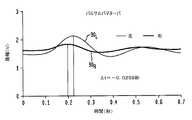
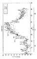
理論上は、心臓の収縮によって生成される圧力波は、圧力波(又はパルス)が横断する距離が可変であるため、遠位ロケーションにおいて異なる時間に到着することになる。心臓を出る血液は、最初に上行大動脈に入り、次に、幾つかの動脈経路に追従し、幾つかの動脈経路は、腕頭動脈(イノミネート動脈)(更に分岐して、右橈骨動脈及び右頸動脈を形成する)で始まり、左総頚動脈及び左鎖骨下動脈(更に分岐して、左橈骨動脈を形成する)が続き、下行大動脈が続く。この動脈解剖学的構造は、左動脈に沿う対応する(又は対称の)ロケーションに到着する前に右動脈に沿うロケーションに到着する動脈パルス波をもたらす。すなわち、左パルスは遅延し、それにより、頭、首、及び上肢に沿う対称な右及び左ロケーションにおいて差分パルス到着時間を生じる。例えば、圧力波は、左橈骨動脈より先に右橈骨動脈に到着する。こうした代表的な差分パルス到着時間は図1に示される。 Theoretically, the pressure wave generated by the heart contraction will arrive at different times at the distal location because the distance that the pressure wave (or pulse) traverses is variable. The blood exiting the heart first enters the ascending aorta and then follows several arterial pathways, some of which pass through the brachiocephalic artery (innominate artery) (further branching into the right radial artery and Forming the right carotid artery), followed by the left common carotid artery and the left subclavian artery (further branching to form the left radial artery), followed by the descending aorta. This arterial anatomy results in an arterial pulse wave that arrives at a location along the right artery before arriving at a corresponding (or symmetric) location along the left artery. That is, the left pulse is delayed, thereby producing a differential pulse arrival time at symmetrical right and left locations along the head, neck, and upper limb. For example, the pressure wave arrives at the right radial artery before the left radial artery. Such a typical differential pulse arrival time is shown in FIG.
図1は、代表的な右動脈圧力波90R及び左動脈圧力波90Lの所定期間にわたる代表的なそれぞれの振幅、及び、代表的なフォトプレチスモグラフ(「PPG:photoplethysmograph」)から等の対応するDPAT60を示すグラフ図である。対応するDPAT60は、個人の首、耳、又は上肢における対称な右ロケーションR及び左ロケーションLにおいて取得されてもよい。代表的なDPATは、DPAT時間間隔Δt60として示す、右及び左動脈圧力波のそれぞれの収縮期ピーク50R及び50Lの間の到着時間差によって図1に示される。図1は、同様に、代表的な動脈圧力波の幾つかの他の特徴部を示す。それぞれの右及び左動脈圧力波は、一般に、収縮期ピーク50R及び50L、収縮期ピーク50の立ち上がりエッジ40R及び40L、拡張期ピーク55R及び55L、圧力波の反射を通常示す1つ以上の大動脈・腹部反射又は他の反射85R及び85L、収縮期の終りを示すダイクロティックノッチ62R及び62L、及び収縮期ピーク50R及び50Lの直前の拡張期最小値65R及び65Lを含む。以下でより詳細に論じるように、右及び左動脈圧力波90R及び90Lに沿うこうした対応する任意の特徴部は、それぞれの収縮期ピーク50R及び50Lに加えて、DPAT測定又は決定のために利用されてもよい。FIG. 1 shows representative respective amplitudes of a typical right
BP測定又は推定のためのPTT測定に勝るDPATの利点は、例えばまた限定はしないが、代表的な実施形態によるDPAT測定が、ECG測定を必要とせず、また更に、上記で述べたパルス波の収縮と発生との間の、わかっていない電気機械的時間的分離をなくすことを含む。さらに、代表的な実施形態によるDPAT測定は、同様に、移動する距離に無関係な対称なロケーションにおけるパルス到着を記録することによって、心臓におけるパルス発生と遠位ロケーションとの間の距離を大雑把に推定する必要性をなくす。最後に、以下でより詳細に論じるように、代表的な実施形態によるDPAT測定は、安静時と種々の他の条件下との両方において、各個人について再帰的に較正されることができ、種々の他の条件は、DPAT測定に影響を及ぼす場合がある流体静力学的及び流体動力学的条件についての較正を含み、また、血圧に影響を及ぼす他の事象についてのDPAT測定の較正を含む。 The advantages of DPAT over PTT measurement for BP measurement or estimation, for example and without limitation, are that DPAT measurement according to exemplary embodiments does not require ECG measurement, and furthermore, the pulse wave described above Including eliminating the unknown electromechanical temporal separation between shrinkage and development. Furthermore, DPAT measurements according to representative embodiments also roughly estimate the distance between pulse generation and distal location in the heart by recording the pulse arrival at a symmetric location independent of the distance traveled. Eliminate the need to do. Finally, as discussed in more detail below, DPAT measurements according to exemplary embodiments can be recursively calibrated for each individual, both at rest and in various other conditions, Other conditions include calibration for hydrostatic and hydrodynamic conditions that may affect DPAT measurements, and calibration of DPAT measurements for other events that affect blood pressure.
図2は、ドットライン(各ドットは対応するデジタルサンプルである)として示す、個人の首、耳、又は上肢の或るロケーションで取得された代表的な圧力波90の(所定期間にわたる)振幅の複数のデジタルサンプル95を示すグラフ図であり、(拡張期最小65の)BP波形「フット」特徴部80を含む動脈圧力波の幾つかの特徴部を更に示す。BP波形「フット」特徴部80は、同様に、DPAT測定又は決定のために利用されてもよい(また、通常は、動脈圧力波の他の特徴部の使用と比較して、DPAT測定又は決定についてより正確である場合がある)。図2に示すように、ライン70は、ゼロに等しい、すなわち、拡張期最小値65における時間に関する1次微分がほぼゼロに等しい傾斜を有する接線(すなわち、拡張期最小値65において圧力波95を表す曲線に対する接線)として拡張期最小値65によって規定されてもよい。同様に、図2に示すように、ライン75は、圧力波95の収縮期ピーク50の立ち上がりエッジを表す曲線のポイント45に示す、収縮期ピーク50の立ち上がりエッジの時間に関する1次微分がほぼ最大である接線(すなわち、収縮期ピーク50の立ち上がりエッジに沿う圧力波95を表す曲線に対する接線75)として、収縮期ピーク50の立ち上がりエッジにおける圧力波の増加する変化の最大レートによって規定されてもよい。圧力波のBP波形フット特徴部は、BP波形フット特徴部80(又はポイント80)として図2に示す、これら2つの接線70と75との交差ポイントとして規定されてもよい。上述した交差接線法に加えて、拡張期最小値65又は拡張期最小値65のBP波形フット特徴部80のロケーションを決定する他の知られている方法が、同等に利用されてもよく、それらの方法は、例としてまた限定することなく、拡張期最小値65と収縮期ピーク50との間の時間に関する最大1次微分、拡張期最小値65と時間に関する最大1次微分との間の時間に関する最大2次微分、及びパルス圧力の一部を含む。 FIG. 2 shows the amplitude (over a period of time) of a
代表的な一実施形態において、個人の首、耳、又は上肢の上の又はそこにおける対称な右及び左位置(又はロケーション)で取得される測定値からの、右及び左圧力波の対応するBP波形フット特徴部80は、特に、高められたBP条件におけるDPAT測定又は決定のために利用される。その理由は、それが、ノイズ及び他の波反射の影響を受けにくいからである。別の代表的な実施形態において、同様に、個人の首、耳、又は上肢の上の又はそこにおける対称な右及び左位置(又はロケーション)で取得される測定値からの、右及び左圧力波の対応する収縮期ピーク50R及び50Lは、DPAT測定又は決定のために利用される。更に別の代表的な実施形態において、同様に、個人の首、耳、又は上肢の上の又はそこにおける対称な右及び左位置(又はロケーション)で取得される測定値からの、右及び左圧力波の増加する変化の最大レートの対応するポイント45は、DPAT測定又は決定のために利用される。更に別の代表的な実施形態において、同様に、個人の首、耳、又は上肢の上の又はそこにおける対称な右及び左位置(又はロケーション)で取得される測定値からの、右及び左圧力波においてそれぞれの収縮期ピーク50R及び50Lをもたらす立ち上がりエッジ40(圧力増加)の所定のパーセンテージ(例えば、例としてまた限定することなく、50%又は75%)は、DPAT測定又は決定のために利用される。In an exemplary embodiment, the corresponding BP of right and left pressure waves from measurements taken at symmetrical right and left positions (or locations) on or in the individual's neck, ear, or upper limb. The
更に別の代表的な実施形態において、同様に、個人の首、耳、又は上肢の上の又はそこにおける対称な右及び左位置(又はロケーション)で取得される測定値からの、右及び左圧力波の種々の特徴部の振幅の比は、BP測定又は推定のために利用される。例としてまた限定することなく、右圧力波90Rについての収縮期ピーク50Rの振幅と大動脈・腹部反射85Rの振幅との比は、左圧力波90Lについての収縮期ピーク50Lの振幅と大動脈・腹部反射85Lの振幅との比と比較され、BPのインジケーターとして利用されてもよい。In yet another exemplary embodiment, similarly, right and left pressure from measurements taken at symmetrical right and left positions (or locations) on or in an individual's neck, ear, or upper limb. The ratio of the amplitudes of the various features of the wave is used for BP measurement or estimation. Also without limitation as examples, the ratio of the amplitudes of the aorta
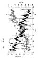
DPATは、全身血圧と反比例し、より高い血圧は、対称的に(右及び左の)増加した動脈パルス速度をもたらし、それが、左右のパルス到着時間の差を減少させる。この反比例関係は、図3〜図7に示される。図3は、個人が安静にしているときの、個人の首、耳、又は上肢における対称な右及び左ロケーション又は位置で取得された代表的な右及び左動脈圧力波90R及び90Lからのベースライン差分パルス到着時間を示すグラフ図である。図4は、BPを下げるバルサルバマヌーバの実施の後における、個人の首、耳、又は上肢における対称な右及び左ロケーション又は位置で取得された代表的な右及び左動脈圧力波90R及び90Lからの増加した差分パルス到着時間を示すグラフ図である。図5は、血圧を増加させる運動の後における、個人の首、耳、又は上肢における対称な右及び左ロケーション又は位置で取得された代表的な右及び左動脈圧力波からの減少した差分パルス到着時間を示すグラフ図である。図6は、血圧を同様に増加させる寒冷昇圧試験の後における、個人の首、耳、又は上肢における対称な右及び左ロケーション又は位置で取得された代表的な右及び左動脈圧力波90R及び90Lからの減少した差分パルス到着時間を示すグラフ図である。図7Aは、バーチャート図であり、安静時における個人のベースライン血圧86A、及び、寒冷昇圧試験の後における(87A)、また運動の後における(88A)個人の増加した血圧を示す。図7Bは、バーチャート図であり、安静時における個人のベースラインDPAT86B、及び、寒冷昇圧試験の後における(87B)、また運動の後における(88B)、個人の首、耳、又は上肢における対称な右及び左ロケーション又は位置で取得された代表的な右及び左動脈圧力波からの対応する減少した差分パルス到着時間を示す。DPAT is inversely proportional to systemic blood pressure, with higher blood pressure resulting in symmetrical (right and left) increased arterial pulse rates, which reduces the difference in left and right pulse arrival times. This inverse proportion is shown in FIGS. FIG. 3 shows from representative right and left arterial pressure waves 90R and 90L acquired at symmetrical right and left locations or positions in the individual's neck, ear, or upper limb when the individual is at rest. It is a graph which shows a baseline difference pulse arrival time. FIG. 4 shows representative right and left arterial pressure waves 90R and 90L acquired at symmetrical right and left locations or positions in an individual's neck, ears, or upper limbs after the implementation of Valsalva Maneuver to lower BP. It is a graph which shows the difference pulse arrival time which increased from. FIG. 5 shows reduced differential pulse arrivals from representative right and left arterial pressure waves acquired at symmetrical right and left locations or positions in an individual's neck, ear, or upper limb after an exercise that increases blood pressure. It is a graph which shows time. FIG. 6 shows representative right and left arterial pressure waves 90R acquired at symmetrical right and left locations or positions in an individual's neck, ear, or upper limb after a cold pressor test that similarly increases blood pressure. is a graph showing the reduced differential pulse arrival time from 90L. FIG. 7A is a bar chart diagram showing an individual's baseline blood pressure 86A at rest and (87A ) after the cold pressor test and increased blood pressure of the individual after exercise (88A ). . FIG. 7B is a bar chart diagram of an individual's baseline DPAT86B at rest and (87B ) after a cold pressor test and (88B ) after exercise (88B ). FIG. 6 shows corresponding reduced differential pulse arrival times from representative right and left arterial pressure waves acquired at symmetrical right and left locations or positions in the upper limb.
図11は、代表的な第1の装置100及び第1のシステム200の実施形態のブロック図である。図11に示すように、第1の装置100L及び第1の装置100Rとして示す2つの概ね同一の第1の装置100が第1のシステム200内で利用され、第1の装置100L及び第1の装置100Rは、DPAT測定又は決定において利用される、個人の首、耳、又は上肢における対称な左及び右ロケーション又は位置から、測定値又はデータを取得するためにそれぞれ利用される。第1の装置100L及び第1の装置100Rは、一方が個人の左側から測定値又はデータを受信し、他方が個人の右側から測定値又はデータを受信する限りにおいてのみ異なり、他の点では、同一であり、交換可能であり、また完全に同じように機能し、結果として、一般性又は特異性を失うことなく、第1の装置100L及び第1の装置100Rは、個々にまた総称的に同等に第1の装置100と呼ばれる。第1のシステム200は、第1の中央バイタルサインモニター150を更に備え、第1の中央バイタルサインモニター150は、上記で述べたように、第1の装置100L及び第1の装置100Rのそれぞれから測定値又はデータを受信し、DPAT測定値又は決定値を生成し、血圧及び他のバイタルサインの測定の対応する推定値を提供する。FIG. 11 is a block diagram of an exemplary embodiment of the
第1の中央バイタルサインモニター150(及び以下で論じる第2の中央バイタルサインモニター250)が、装置100、500からの信号の主な、支配的な、又は主要な受信装置であり、かつ、血圧及び他のバイタルサインの測定の対応する推定値の提供装置であるという意味で「中央(central)」であり、「中央血圧(central blood pressure)」を決定する点での「中央」でないことが留意されるべきである。 The first central vital sign monitor 150 (and the second central vital sign monitor 250 discussed below) is the main, dominant, or primary receiver of signals from the
第1の装置100L及び第1の装置100Rのそれぞれは、信号生成器105、1つ以上のセンサー110、アナログデジタル変換器(ADC)115、及び無線送信機135を備える。光送信機(例えば、複数の発光ダイオード)等の信号生成器105は、個人の首、耳、又は上肢内のロケーション又は位置に送信するため、第1の選択済みの波長帯内の光放出等の、信号(電気、光、音響、又は圧力等)を生成する。1つ以上のセンサー110(光センサー(複数の場合もある)、音響センサー(複数の場合もある)(例えば、1つ以上のマイクロフォン)、表面音響センサー(複数の場合もある)、圧力センサー(複数の場合もある)、バイオインピーダンスセンサー(複数の場合もある)、温度センサー(複数の場合もある)等)は、個人の首、耳、又は上肢内のロケーション又は位置から概ね反射される第2の選択済みの波長帯の光又は音等の動脈圧力波90R又は90Lを示す戻り又は検知信号を受信し、対応するアナログセンサー電気信号を生成する。アナログデジタル変換器(ADC)115は、1つ以上のセンサー110からのアナログセンサー電気信号をサンプリングし、対応するデジタル振幅値のストリーム又は一連の対応するデジタル振幅値を生成し、対応するデジタル振幅値のそれぞれは、図2を参照して上記で示し論じたサンプリング済みデジタル値等、サンプリング時間間隔中の動脈圧力波90R及び90Lの振幅を示す又は表す。無線送信機135は、対応するデジタル振幅値の対応するストリーム又は一連の対応するデジタル振幅値を第1の中央バイタルサインモニター150に無線送信する。Each of the
任意選択で、第1の装置100L及び第1の装置100Rのそれぞれは、同様に、加速度計140、気圧計145、コントローラー160、及びウェアラブル取付け具155を含んでもよい。含まれるとき、ウェアラブル取付け具155は、例としてまた限定はしないが、手首バンド、指用リング、指スリーブ、グローブ、耳クリップ、あるいは、使い捨て可能な又は再使用可能な接着材料であってもよい。含まれるとき、加速度計140は、個人の運動を測定又は決定し、対応する運動データを生成し、コントローラー160に提供する。同様に含まれるとき、気圧計145は、腕を上げること又は下げること等の個人の高度(又は高度変化)を測定又は決定し、対応する高度データを生成し、コントローラー160に提供する。こうした運動及び/又は高度データは、第1の中央バイタルサインモニター150によって利用されて、DPAT測定又は決定に影響を及ぼす、こうした運動又は個人の位置の変化等の高度の変化を反映するBPの測定の対応する推定値を生成してもよく、また、血圧の測定の対応する推定において考慮されてもよい。この第1のシステム200の場合、コントローラーは、対応するデジタル値(動脈圧力波90R又は90Lを示す)のストリーム又は系列を、運動データ及び/又は高度データと組み合わせて、無線送信機135によって第1の中央バイタルサインモニター150に無線送信する。Optionally, each of the
以下でより詳細に論じるように、ウェアラブル取付け具155が含まれる代表的な実施形態において、第1の装置100L及び第1の装置100Rのそれぞれは、首、耳、又は上肢内の対称なロケーション又は位置に配置され、個人によって装着されてもよい。ウェアラブル取付け具155を含まない他の代表的な実施形態において、同様に例としてまた限定することなく、第1の装置100L及び第1の装置100Rはともに、手持ち式デバイス、スマートフォン用のケース等のような、以下で示し論じるハウジング内にともに配置されてもよい。こうした配置構成の場合、個人は、それぞれの右手の指先及び左手の指先を、対応する1つ以上の右及び左センサー110に接触させるようにハウジングを保持して、例としてまた限定することなく、個人が自分の電子メール又はメッセージをチェックするためスマートフォンを保持しているときはいつでも等、DPAT測定又は決定のためのデータを生成する。As discussed in more detail below, in the exemplary embodiment includes a
第1の中央バイタルサインモニター150は、一般に、無線送受信機(又は受信機及び送信機)165、プロセッサ120、メモリ125、ネットワークインターフェース回路130、並びに、例えば、タッチスクリーンディスプレイ195又は任意の他のタイプのビジュアルディスプレイ等のユーザー入力及び出力デバイス190を備える。メモリ125は、一般に、以下でより詳細に論じるように、較正データを格納し、また同様に、DPAT測定又は決定並びに個人のBP及び他のバイタルサインの対応する推定又は測定等の、収集済みのデータ及び対応する結果を格納してもよい。ネットワークインターフェース回路130内に含まれてもよい無線送受信機165は、第1の装置100L及び第1の装置100Rのそれぞれから、動脈圧力波90R及び90Lを示す又は表す対応するデジタル振幅値のストリーム又は一連の対応するデジタル振幅値、及びおそらくは同様に、任意の運動データ及び/又は高度データを受信し、このデータをプロセッサ120に提供又は転送する。任意の運動データ及び/又は高度データとともに、(動脈圧力波90R及び90Lを示す又は表す)対応するデジタル振幅値のこのストリーム又は一連の対応するデジタル振幅値を使用して、プロセッサ120は、DPAT測定値又は決定値並びに個人のBP及び他のバイタルサインの対応する推定値又は測定値を生成する。図15のフローチャートを参照して以下でより詳細に論じるように、プロセッサ120は、同様に、構成又はプログラミングを通して等で、フィルター170、高速フーリエ変換(又は離散フーリエ変換)回路又はブロック175、及びデジタル信号プロセッサ(「DSP:digital signal processor」)又はDSPブロック180を含むと考えられてもよい。The first central
プロセッサ120は、その後、タッチスクリーンディスプレイ195上で個人に表示するため等で、個人のBP及び他のバイタルサインの推定又は測定をユーザー入力及び出力デバイス190に提供してもよい。プロセッサ120は、同様にその後、同様に例としてまた限定することなく、病院又は臨床コンピューティングシステム等、別のロケーション又はデバイスに個人のBP及び他のバイタルサインの推定又は測定を送信するため等で、個人のBP及び他のバイタルサインの推定値又は測定値をネットワークインターフェース回路130に提供してもよい。 The
図11に別個に示さないが、第1の中央バイタルサインモニター150、第1の装置100L、及び第1の装置100R等のデバイスが、同様に一般に、クロック回路要素及び分配部、並びに、例としてまた限定することなく、電池又は他のエネルギー源であってもよい、電力分配部を有する電源を含むことを当業者は認識するであろう。Although not separately shown in FIG. 11, devices such as the first central
電気、光、音、圧力等のような如何なるタイプの信号生成器105が所与の実施形態について選択されても、例としてまた限定することなく、光センサー(複数の場合もある)110、音響センサー(複数の場合もある)110としての1つ以上のマイクロフォン、圧力センサー(複数の場合もある)110、電気信号を検出するバイオインピーダンスセンサー(複数の場合もある)、温度センサー(複数の場合もある)等の信号取得用の対応するタイプのセンサー(複数の場合もある)110が同様に選択されることを当業者は同様に認識するであろう。選択される検知のタイプに応じて、同様に例としてまた限定することなく、バイオインピーダンス検知及び温度検知について等で、信号生成器105がオプションになる場合があり、また必要とされないことが同様に留意されるべきである。これらの変形の全ては、同等でありかつ本開示の範囲内にあると考えられ、また、以下で論じる他の装置300、500、700、及びシステム400、600(及び/又は700)の実施形態に更に適用される。 What type of
光信号生成器105及び光センサー(複数の場合もある)110は、第1の装置100の選択される実施形態で利用されて、DPAT測定又は決定並びに個人のBP及び他のバイタルサインの対応する推定又は測定のために利用されることになるフォトプレチスモグラフ(「PPG」)データを生成してもよい。例としてまた限定することなく、1つ以上の光信号生成器105は、約520nmを含む第1の波長帯内の光を放出するLED等の複数の発光ダイオード(「LED」)を備えてもよい。動脈パルスが伝搬するにつれて、血液容量が増加し、更なる赤血球が存在し、その赤血球が緑波長の吸収を増加させ、個人の首、耳、又は上肢のロケーション又は位置から反射する光の量を減少させ、動脈圧力波90R又は90Lの指標又は表示を提供する。その後、光センサー(複数の場合もある)110が利用されて、例としてまた限定することなく、通常、約520nm〜560nmの帯域内の反射光を検出する。以下で論じる他の装置300、500、700及びシステム400、600(及び/又は700)の実施形態は、同様に、PPGデータの生成を含んでもよい。The
第1の装置100の代表的な一実施形態において、複数のタイプのセンサー(複数の場合もある)110が利用される(また、以下で論じる他の装置300、500、700及びシステム400、600(及び/又は700)の実施形態に更に適用される)。PPGデータを取得するための光センサー110に加えて、温度センサー110及び圧力センサー110が同様に利用されて、DPAT測定値又は決定値を、個人のBP及び他のバイタルサインの絶対測定値に変換する、トランスフォームする、又はその他の方法でマッピングするときのより高い精度を提供する。個人の手が冷たい又は温かいとき等で、動脈血管が収縮又は拡張し得るとき、動脈圧力波90R又は90L及び対応するDPAT測定値又は決定値は、被検者の絶対BPの対応する実際の変化なしで、影響を受ける場合がある。同様に、第1の装置100によって被検者個人に加えられる接触圧力は、同様に、ウェアラブル装置155が含まれるとき、又は、被検者個人が使用中に第1の装置100に圧力を印加するとき等に、やはり被検者の絶対BPの対応する変化なしで、動脈圧力波90R又は90Lの振幅及び結果として得られるDPAT測定値又は決定値に影響を及ぼす場合がある。したがって、以下でより詳細に論じる較正プロセス中に、温度及び圧力データは、DPAT測定値又は決定値とともに、種々の状況及び事象下で、(代表的なシステム200、400、600、及び700によって測定又は決定される)個人のDPATの、(カフベースシステムを使用して等で独立に測定される)自分のBPに関する全体較正に含まれる。この較正データは、温度及び圧力データ、及び、通常、被検者の絶対BPのカフベース測定値とともに、DPAT測定値又は決定値を含むことになる。較正データ(メモリ125に格納される)は、その後、システム200、400、600、700の動作中に利用され、システムにおいて、被検者の温度、接触圧力、及びDPATが、測定されるか又はその他の方法で決定され、その後、被検者のBPに変換、トランスフォーム、又はマッピングされて、被検者個人のBP及び他のバイタルサインのより正確な推定値又は測定値を提供する。In an exemplary embodiment of the
図12は、代表的な第2の装置300及び第2のシステム400の実施形態のブロック図である。図12に示すように、第2のシステム400は、一般に、第1の装置100とともに第2の装置300を備え、装置はともに、DPAT測定又は決定で利用される測定値又はデータを、個人の首、耳、又は上肢における対称な左及び右ロケーション又は位置から取得するためにそれぞれ利用される。例としてまた限定することなく、第2のシステム400において、第2の装置300は左手首に装着されてもよく、第1の装置100は右手首に装着されてもよく、又はその逆も同様である。第1の装置100は図11を参照して上述したように動作する。第2の装置300は、第1の装置100について上述したように動作し、また、第1の中央バイタルサインモニター150の構成要素及び機能の多くを更に備える。したがって、第2の装置300は、同様に、個人の首、耳、又は上肢の選択済みの左又は右ロケーション又は位置からの測定値又はデータを生成するが、それぞれ、個人の首、耳、又は上肢における対称な右又は左ロケーション又は位置からの測定値又はデータを第1の装置100から同様に受信し、また更に、上記で論じたように、DPAT測定値又は決定値を生成し、血圧及び他のバイタルサインの測定の対応する推定値を提供する。 FIG. 12 is a block diagram of an exemplary
第2のシステム400は、第1のシステム200の構成要素及び機能を3つのデバイス(第1の装置100L、第1の装置100R、及び第1の中央バイタルサインモニター150)の2つの間でまた3つの中で分配するのではなく、第1のシステム200の(一般に全てではないが)多くの構成要素及び機能のうちの構成要素及び機能を組み合わせて2つのデバイス(第2の装置300及び第1の装置100)にするものと見なされてもよい。第2のシステム400は、同様に、第1の中央バイタルサインモニター150の選択済みの構成要素及び機能が第2の装置300に含まれるとき、冗長である、オプションである、又は不必要であると今や考えられ得る構成要素をなくす(例えば、第2の装置300内のコントローラー160及び無線送信機135をなくす、また任意選択で、第2の装置300内のネットワークインターフェース回路130をなくす)。したがって、逆に指定されない限り、第2のシステム400の構成要素は、一般に、上述した第1のシステム200の構成要素と完全に同じように機能する。The
したがって、第2のシステム400の実施形態の構成要素は、第1の装置100及び第2の装置300を使用すると非対称であり、第2の装置300は、一般に、冗長性なしで、第1の装置100及び第1の中央バイタルサインモニター150の全体の機能を含む又は組み合わせる。 Accordingly, the components of the embodiment of the
第2の装置300は、同様に、信号生成器105、1つ以上のセンサー110、及びアナログデジタル変換器(ADC)115を備え、それらの全ては上記で論じたように機能する。任意選択で、第2の装置300は、同様に、加速度計140、気圧計145、及びウェアラブル取付け具155を含んでもよく、それらの全ては上記で論じたように機能する。 The
第2の装置300は、同様に一般に、無線送受信機(又は受信機及び送信機)165、プロセッサ120、メモリ125、並びに、タッチスクリーンディスプレイ195又は任意の他のタイプのビジュアルディスプレイ、オン/オフボタン等のようなユーザー入力及び出力デバイス190を備え、同様に例えば、それらの全ては上記で論じたように機能する。任意選択で、第2の装置300は、ネットワークインターフェース回路130を含んでもよい。第2の装置300のメモリ125は、同様に一般に、以下でより詳細に論じるように、較正データを格納し、また同様に、DPAT測定又は決定並びに個人のBP及び他のバイタルサインの対応する推定又は測定等の、収集済みのデータ及び対応する結果を格納してもよい。第2の装置300の無線送受信機165は、第2のシステム400内の第1の装置100から、動脈圧力波90R又は90Lを示す又は表す対応するデジタル振幅値のストリーム又は系列、及びおそらくは同様に、任意の運動データ及び/又は高度データを受信し、このデータを第2の装置300のプロセッサ120に提供又は転送する。第2の装置300のセンサー(複数の場合もある)110によって提供される対応するアナログセンサー電気信号から、アナログデジタル変換器(ADC)115によって生成される動脈圧力波90L又は90Rを示す又は表すデジタル振幅値は、同様に、第2の装置300のプロセッサ120に転送される。個人の首、耳、又は上肢における対称なロケーション又は位置から、任意の運動データ及び/又は高度データとともに、(動脈圧力波90R又は90Lを示す又は表す)対応するデジタル振幅値のこのストリーム又は一連の対応するデジタル振幅値を使用して、第2の装置300のプロセッサ120は、上記で論じたように、DPAT測定値又は決定値並びに個人のBP及び他のバイタルサインの対応する推定値又は測定値を生成する。同様に、図15のフローチャートを参照して以下でより詳細に論じるように、プロセッサ120は、同様に、構成又はプログラミングを通して等で、フィルター170、高速フーリエ変換(又は離散フーリエ変換)回路又はブロック175、及びデジタル信号プロセッサ(「DSP」)又はDSPブロック180を含むと考えられてもよい。The
プロセッサ120は、その後、タッチスクリーン又は他のディスプレイ195上で個人に表示するため等で、個人のBP及び他のバイタルサインの推定値又は測定値を第2の装置300のユーザー入力及び出力デバイス190に提供してもよい。例えば、第2の装置300が、ウェアラブル取付け具155としての手首バンド又はブレスレットを使用して、被検者個人によって左又は右手首に装着される代表的な一実施形態において、個人のBP及び他のバイタルサインは、手首時計を読取ることと同様に又は同等にリアルタイムに表示され、ユーザーによって閲覧されてもよい。同様に、図12に別個に示さないが、第1の装置100及び第2の装置300等のデバイスが、同様に一般に、クロック回路要素及び分配部、並びに、例としてまた限定することなく、電池又は他のエネルギー源であってもよい、電力分配部を有する電源を含むことを当業者は認識するであろう。 The
システム200、400、600、700の任意のシステムが、別個に示さない、オプションのリレーステーション又はドッキングユニット等の、コンピューター及び通信分野で知られている他のデバイス及びシステムとともに利用されてもよいことが留意されるべきである。例としてまた限定することなく、こうしたオプションのリレーステーション又はドッキングユニットは、第2の装置300からDPAT又はBP測定値又は決定値を受信し、このデータを、ネットワーク又はクラウドストレージデバイス(同様に、別個に示さない)に転送してもよく、このストレージデバイスは、同様に、病院又は臨床コンピューティングシステムにおける互換性のあるポータルを通して等で、医師又は他の臨床スタッフによってアクセスされてもよい。 Any
図13は、代表的な第3の装置500及び第3のシステム600の実施形態のブロック図である。図13に示すように、第3のシステム600は、一般に、第1の装置100及び第2の中央バイタルサインモニター250とともに第3の装置500を備える。第3の装置500及び第1の装置100は、DPAT測定又は決定で利用される測定値又はデータを、個人の首、耳、又は上肢における対称な左及び右ロケーション又は位置から取得するためにそれぞれ利用される。例としてまた限定することなく、第3のシステム600において、第3の装置500は左手首に装着されてもよく、第1の装置100は右手首に装着されてもよく、又はその逆も同様である。第1の装置100は図11を参照して上述したように動作する。第3の装置500は、第1の装置100について上述したように動作し、また、第1の中央バイタルサインモニター150の2つの更なる構成要素及び機能を更に備える。すなわち、第3の装置500は、第1の無線送受信機(又は受信機及び送信機)165(無線送信機135の代わり)、及び、タッチスクリーンディスプレイ195又は任意の他のタイプのビジュアルディスプレイ、オン/オフボタン等のようなユーザー入力及び出力デバイス190を更に備え、同様に例えば、それらの全ては上記で論じたように機能する。したがって、第3の装置500は、同様に、個人の首、耳、又は上肢の選択済みの左又は右ロケーション又は位置からの測定値又はデータを生成し、第3の装置500のセンサー(複数の場合もある)110によって提供される対応するアナログセンサー電気信号から、アナログデジタル変換器(ADC)115によって生成される動脈圧力波90L又は90Rを示す又は表すデジタル振幅値を、第2の中央バイタルサインモニター250に送信し、第2の中央バイタルサインモニター250は、次に、上記で論じたように、DPAT測定値又は決定値を生成し、血圧及び他のバイタルサインの測定の対応する推定値を提供する。FIG. 13 is a block diagram of an exemplary
第3のシステム600は、3つのデバイス、すなわち、第1の装置100、第3の装置500、及び第2の中央バイタルサインモニター250になるような異なる組合せ又は分配として、第1のシステム200の(一般に全てではないが)多くの構成要素及び機能のうちの構成要素及び機能を組み合わせるものと見なされてもよい。したがって、逆に指定されない限り、第3のシステム600の構成要素は、一般に、上述した第1のシステム200の構成要素と完全に同じように機能する。 The
第3の装置500は、同様に、信号生成器105、1つ以上のセンサー110、及びアナログデジタル変換器(ADC)115を備え、それらの全ては上記で論じたように機能する。任意選択で、第3の装置500は、同様に、加速度計140、気圧計145(別個に示さず)、及びウェアラブル取付け具155を含んでもよく、それらの全ては上記で論じたように機能する。 The
第3の装置500は、同様に一般に、無線送受信機(又は受信機及び送信機)165、コントローラー160、並びに、タッチスクリーンディスプレイ195又は任意の他のタイプのビジュアルディスプレイ、オン/オフボタン等のようなユーザー入力及び出力デバイス190を備え、同様に例えば、それらの全ては上記で論じたように機能する。この第3の装置500の実施形態の場合、コントローラー160は、同様に、ディスプレイコントローラーとして動作して、血圧及び他のバイタルサインの測定の対応する推定を表示するため、ユーザー入力及び出力デバイス190に第1の制御信号を提供し、第1の無線送受信機(又は受信機及び送信機)165に第2の制御信号を更に提供し、また同様に、第3の装置500の信号生成器105に制御信号を提供してもよい。第3の装置500の第1の無線送受信機165は、(第3の装置500のセンサー(複数の場合もある)110及びアナログデジタル変換器(ADC)115によって生成される)動脈圧力波90R又は90Lを示す又は表す対応するデジタル振幅値のストリーム又は一連の対応するデジタル振幅値、及びおそらくは同様に、任意の運動データ及び/又は高度データを第2の中央バイタルサインモニター250に送信する。The
第1の装置100と第3の装置500との両方から、個人の首、耳、又は上肢における対称なロケーション又は位置から、任意の運動データ及び/又は高度データとともに、(動脈圧力波90R又は90Lを示す又は表す)対応するデジタル振幅値のこのストリーム又は一連の対応するデジタル振幅値を使用して、第2の中央バイタルサインモニター250のプロセッサ120は、同様に、上記で論じたように、DPAT測定値又は決定値並びに個人のBP及び他のバイタルサインの対応する推定値又は測定値を生成する。同様に、図15のフローチャートを参照して以下でより詳細に論じるように、プロセッサ120は、同様に、構成又はプログラミングを通して等で、フィルター170、高速フーリエ変換(又は離散フーリエ変換)回路又はブロック175、及びデジタル信号プロセッサ(「DSP」)又はDSPブロック180を含むと考えられてもよい。From both the
第2の中央バイタルサインモニター250のプロセッサ120は、その後、タッチスクリーン又は他のディスプレイ195上で個人に表示するため等、第3の装置500のユーザー入力及び出力デバイス190を介してユーザーに表示するために(第1の無線送受信機165を介して)第3の装置500に送信するため、個人のBP及び他のバイタルサインの推定値又は測定値を第2の無線送受信機165に提供してもよい。例えば、第2の装置300が、ウェアラブル取付け具155としての手首バンド又はブレスレットを使用して、被検者個人によって左又は右手首に装着される代表的な一実施形態において、個人のBP及び他のバイタルサインは、手首時計を読取ることと同様に又は同等にリアルタイムに表示され、ユーザーによって閲覧されてもよい。同様に、図13に別個に示さないが、第1の装置100、第3の装置500、及び第2の中央バイタルサインモニター250等のデバイスが、同様に一般に、クロック回路要素及び分配部、並びに、例としてまた限定することなく、電池又は他のエネルギー源であってもよい、電力分配部を有する電源を含むことを当業者は認識するであろう。 The
図14は、第4の装置700及び/又は第4のシステム700として同等に呼ばれてもよい代表的な第4の組合せ式の装置及びシステム700の実施形態のブロック図である。その理由は、上述した構成要素及び機能の(全てではないが)ほとんどが単一デバイスに(通常、図14に別個に示さないが、図28及び図29を参照して以下に示すハウジング内に)含まれるからである。第4の装置700及び/又は第4のシステム700は、2つの(左及び右の)第1の装置100の構成要素及び機能の多くを、第1の中央バイタルサインモニター150の構成要素及び機能の多くと組み合わせて(そして、上述した不必要な又は冗長な構成要素をなくして)、示すように、単一デバイスにする。したがって、逆に指定されない限り、第4の装置700及び/又は第4のシステム700の構成要素は、一般に、上述した第1、第2、及び第3のシステム200、400、600の構成要素と完全に同じように機能する。 FIG. 14 is a block diagram of an exemplary fourth combinational apparatus and
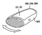
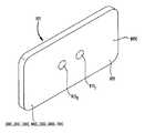
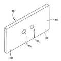
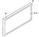
この代表的な第4の装置700及び/又は第4のシステム700は、単一の手持ち式デバイスであるように設計され、その手持ち式デバイスは、自分自身のハウジングを有してもよい、又は、スマートフォン又はタブレットコンピューターのケース又はハウジング等の別の第2のデバイス又は製品とともに利用されるハウジング内に一体化されてもよい。この代表的な第4の装置700及び/又は第4のシステム700の動作の場合、被検者個人は、第4の装置700及び/又は第4のシステム700を両手で、通常、ほぼ心臓のレベルで保持し、左及び右指を、概して(以下で示し論じる)ハウジング内の対応する位置又はロケーション内に(対称に)配置することになる。これは、ノイズレベル並びに運動及び流体静力学的又は流体動力学的効果からの潜在的なエラー源を減少させるのに非常に有利である。結果として、加速度計140及び/又は気圧計145は、オプションであり、一般に、代表的な第4の装置700及び/又は第4のシステム700に含まれない。 This exemplary
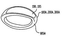
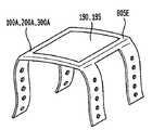
第4の装置700が利用されて、DPAT測定又は決定で利用される測定値又はデータを、個人の上肢、通常、手又は指の対称な左及び右ロケーション又は位置から取得する。第4の装置700及び/又は第4のシステム700は、第1及び第2の信号生成器105L及び105R、第1及び第2のセンサー(複数の場合もある)110L及び110R、第1及び第2のアナログデジタル変換器(ADC)115L及び115R、及び無線送受信機(又は受信機及び送信機)165、プロセッサ120、メモリ125、ネットワークインターフェース回路130、並びに、例えば、タッチスクリーンディスプレイ195又は任意の他のタイプのビジュアルディスプレイ等のユーザー入力及び出力デバイス190を備える。A
光送信機(例えば、複数の発光ダイオード)等の第1の信号生成器105Lは、個人の左上肢(例えば、左指先)内のロケーション又は位置に送信するための、第1の選択済みの波長帯内の光放出等の、信号(電気、光、音響、又は圧力等)を生成する。1つ以上の第1のセンサー110L(上記で論じた、光センサー(複数の場合もある)、音響センサー(複数の場合もある)(例えば、1つ以上のマイクロフォン)、表面音響センサー(複数の場合もある)、圧力センサー(複数の場合もある)、バイオインピーダンスセンサー(複数の場合もある)、温度センサー(複数の場合もある)等)は、個人の左上肢内のロケーション又は位置から概ね反射される第2の選択済みの波長帯の光又は音等の動脈圧力波90Lを示す戻り又は検知信号を受信し、対応するアナログセンサー電気信号を生成する。第1のアナログデジタル変換器(ADC)115Lは、同様に、第1のセンサー(複数の場合もある)110Lからのアナログセンサー電気信号をサンプリングし、対応するデジタル振幅値のストリーム又は一連の対応するデジタル振幅値を生成し、対応するデジタル振幅値のそれぞれは、図2を参照して上記で示し論じたサンプリング済みデジタル値等、サンプリング時間間隔中の動脈圧力波90Lの振幅を示すか又は表し、第4の装置700のプロセッサ120に提供される。A
同様に、光送信機(例えば、複数の発光ダイオード)等の第2の信号生成器105Rは、個人の右上肢(例えば、右指先)内のロケーション又は位置に送信するための、第1の選択済みの波長帯内の光放出等の、信号(電気、光、音響、又は圧力等)を生成する。1つ以上の第2のセンサー110R(上記で論じた、光センサー(複数の場合もある)、音響センサー(複数の場合もある)(例えば、1つ以上のマイクロフォン)、表面音響センサー(複数の場合もある)、圧力センサー(複数の場合もある)、バイオインピーダンスセンサー(複数の場合もある)、温度センサー(複数の場合もある)等)は、個人の右上肢内のロケーション又は位置から概ね反射される第2の選択済みの波長帯の光又は音等の動脈圧力波90Rを示す戻り又は検知信号を受信し、対応するアナログセンサー電気信号を生成する。第2のアナログデジタル変換器(ADC)115Rは、同様に、第2のセンサー(複数の場合もある)110Rからのアナログセンサー電気信号をサンプリングし、対応するデジタル振幅値のストリーム又は一連の対応するデジタル振幅値を生成し、対応するデジタル振幅値のそれぞれは、図2を参照して上記で示し論じたサンプリング済みデジタル値等、サンプリング時間間隔中の動脈圧力波90Rの振幅を示すか又は表し、第4の装置700のプロセッサ120に提供される。Similarly, a
第4の装置700のメモリ125は、同様に一般に、以下でより詳細に論じるように、較正データを格納し、また同様に、DPAT測定又は決定並びに個人のBP及び他のバイタルサインの対応する推定又は測定等の、収集済みのデータ及び対応する結果を格納してもよい。(動脈圧力波90R又は90Lを示す又は表す)対応するデジタル振幅値の2つのストリーム又は系列を使用して、プロセッサ120は、DPAT測定値又は決定値並びに個人のBP及び他のバイタルサインの対応する推定値又は測定値を生成する。図15のフローチャートを参照して以下でより詳細に論じるように、第4の装置700のプロセッサ120は、同様に、構成又はプログラミングを通して等で、フィルター170、高速フーリエ変換(又は離散フーリエ変換)回路又はブロック175、及びデジタル信号プロセッサ(「DSP」)又はDSPブロック180を含むと考えられてもよい。The
プロセッサ120は、その後、タッチスクリーンディスプレイ195上で個人に表示するため等で、個人のBP及び他のバイタルサインの推定値又は測定値をユーザー入力及び出力デバイス190に提供してもよい。プロセッサ120は、同様にその後、同様に例としてまた限定することなく、病院又は臨床コンピューティングシステム等、別のロケーション又はデバイスに個人のBP及び他のバイタルサインの推定値又は測定値を送信するため等で、個人のBP及び他のバイタルサインの推定値又は測定値をネットワークインターフェース回路130及び/又は無線送受信機165(ネットワークインターフェース回路130に同様に含まれてもよい)に提供してもよい。 The
図14に別個に示さないが、第4の装置700等のデバイスが、同様に一般に、クロック回路要素及び分配部、並びに、例としてまた限定することなく、電池又は他のエネルギー源であってもよい、電力分配部を有する電源を含むことを当業者は認識するであろう。 Although not shown separately in FIG. 14, a device such as the
第4の装置700の変形は、同様に本開示の範囲内にある。この変形の場合、第1及び第2の信号生成器105、第1及び第2のセンサー110、並びに第1及び第2のアナログデジタル変換器115は、ハウジング(図27に示すハウジング805C等)に含まれ、無線送受信機は、第1及び第2のアナログデジタル変換器115に結合されて、左及び右動脈圧力波の振幅を表す第1及び第2の複数のデジタル振幅値を送信する。こうした実施形態の場合、第1及び第2の複数のデジタル振幅値は、例としてまた限定することなく、スマートフォン(ハウジング805Cに挿入可能であってもよい又はその他の方法で結合されてもよい)、タブレットコンピューター、ラップトップ、又はデスクトップコンピューター等の別個のコンピューティングデバイスに送信される。プロセッサ120、メモリ125、無線送受信機165、ディスプレイ195を有するユーザー入力/出力デバイス190、及びネットワークインターフェース回路は、その後、こうしたスマートフォン、タブレットコンピューター、ラップトップ、又はデスクトップコンピューター内に位置し、上述したように機能する。 Variations on the
図15A及び図15B(総称的に図15と呼ぶ)は、代表的な方法の実施形態のフローチャートであり、有用な要約を提供する。方法が始まり(開始ステップ305)、通常、対応する信号生成器105によって左及び右信号が生成される(ステップ310)。左及び右アナログセンサー電気信号は、通常、センサー110によって受信される(ステップ315)。任意の更なる圧力、温度、運動、及び/又は高度データは、更なる温度及び圧力センサー110、加速度計140、及び/又は気圧計145を通して等で、受信される(ステップ320)。左及び右アナログセンサー電気信号は、通常、アナログデジタル変換器115によってサンプリング時間間隔中に、サンプリングされ、動脈圧力波90R又は90Lを示す又は表す対応するデジタル振幅値に変換される(ステップ325)。プロセッサ120を使用して、方法は、その後、完全なデータセットが1つ以上の動脈圧力波90R又は90Lについて取得されたかどうかを判定し(ステップ330)、取得されていない場合、ステップ310に戻り、反復ステップ310〜ステップ325を繰返して、継続して信号を生成し、アナログセンサー電気信号を受信し、サンプリングし、対応するデジタル振幅値を生成する。ステップ330にて、完全なデータセットが1つ以上の動脈圧力波90R又は90Lについて取得されたとき、プロセッサ120は、例としてまた限定することなく、動脈圧力波90R又は90Lの対応するデジタル振幅値をフィルタリングして、及び/又は、対応するデジタル振幅値の高速(又は離散)フーリエ変換を実施して(ステップ335)、通常、ノイズ及び任意の運動アーチファクトをフィルタリング除去する。プロセッサ120は、同様に、通常、運動及び/又は高度データを使用して、任意の運動又は姿勢変化が存在したかどうかを判定する(ステップ340)。プロセッサ120は、通常、(DSPブロック180の)デジタル信号処理構成要素を使用して、一般に、左及び右の各動脈圧力波90R又は90Lの1次数学的微分及びおそらくは同様に2次数学的微分を生成又は決定する(ステップ345)。1次及び2次の数学的微分を使用して、プロセッサ120は、通常、(DSPブロック180の)デジタル信号処理構成要素を使用して、一般に、左及び右の各動脈圧力波90R又は90Lの、上述した対応する(左及び右の)フット80及び/又は収縮期ピーク50等の対応する特徴部を決定する(ステップ350)。これらの決定された特徴部を使用して、プロセッサ120は、その後、差分パルス到着時間を決定する(ステップ355)。15A and 15B (collectively referred to as FIG. 15) are flow charts of exemplary method embodiments, providing a useful summary. The method begins (start step 305) and typically left and right signals are generated by the corresponding signal generator 105 (step 310). Left and right analog sensor electrical signals are typically received by sensor 110 (step 315). Any additional pressure, temperature, motion, and / or altitude data is received (step 320), such as through additional temperature and
プロセッサ120は、メモリ125から較正データを取出す(ステップ360)。較正データを使用して、プロセッサ120は、測定された又は決定されたDPATを、個人の収縮期及び拡張期血圧値にマッピング又はトランスフォームし(ステップ365)、上述したように、心拍数及び1回拍出量等の他のバイタルサインを決定する(ステップ370)。プロセッサ120は、その後、タッチスクリーンディスプレイ195上で個人に表示するため等で、通常ユーザー入力及び出力デバイス190を介して個人に表示するため、個人の収縮期及び拡張期血圧値、心拍数、及び他のバイタルサインを出力する(ステップ375)。血圧決定プロセスが、定期的なモニタリングのため等でステップ380にて終了するとき、方法は終了してもよい(戻りステップ385)。血圧決定プロセスが、継続する携行式モニタリングのため等でステップ380にて終了しないとき、方法は、ステップ310に戻ることを繰返す。 The
図16は、収縮期及び拡張期血圧値、心拍数、及び他のバイタルサインを決定するための代表的な装置及びシステムの実施形態を較正するための代表的な方法の実施形態のフローチャートである。システム200、400、600、又は700が個人についてまだ較正されていないとき、較正プロセスが始まる(ステップ405)。較正プロセスの場合、個人は、複数の異なる位置に置かれ、複数の異なる活動に関与することになり、その間に、個人の収縮期及び拡張期血圧値は、カフベースシステムを通して等で(例えば、血圧計及び聴診器を使用して)独立に取得され、個人の差分パルス到着時間は、図15を参照して上述したステップ310〜ステップ355を実施することによって、代表的な装置及びシステムの実施形態を使用して決定される。 FIG. 16 is a flowchart of an exemplary method embodiment for calibrating an exemplary apparatus and system embodiment for determining systolic and diastolic blood pressure values, heart rate, and other vital signs. . When the
較正プロセスを開始するため、個人は、座る等、安静位置に置かれ、DPAT測定又は決定(ステップ310〜ステップ355を実施すること)が行われ、対応する血圧値が、独立に取得又は決定される(ステップ410)。個人に立ってもらう又は寝てもらう等、較正時に使用するための更なる位置が存在するとき(ステップ415)、このプロセスは、更なる各位置についてステップ410に戻って反復される。個人は、その後、BPを増加させる傾向がある、運動を実施する又は寒冷昇圧試験が個人に適用される等の、或る活動、事象、又は状態に置かれ、DPAT測定又は決定(ステップ310〜ステップ355を実施すること)が行われ、対応する血圧値が、独立に取得又は決定される(ステップ420)。個人は、その後、BPを減少させる傾向がある、バルサルバ又は起立マヌーバを実施する等の、或る活動、事象、又は状態に置かれ、DPAT測定又は決定(ステップ310〜ステップ355を実施すること)が行われ、対応する血圧値が、独立に取得又は決定される(ステップ425)。個人は、その後、DPAT測定に影響を及ぼす場合がある流体静力学及び/又は流体動力学を変化させる傾向がある(DPAT測定が、例えば、左及び右の手首、手、又は指において行われているときに)腕を上下させる等の複数の異なる運動及び/又は流体静力学的又は流体動力学的位置に置かれ、DPAT測定又は決定(ステップ310〜ステップ355を実施すること)が行われ、対応する血圧値が、独立に取得又は決定される(ステップ430)。この較正プロセスは、その後、更なる再帰部について反復されてもよい(ステップ435)。任意の更なる再帰部が実施されると、取得されたDPAT測定値又は決定値は、独立して取得されたBP値に対するDPAT測定値若しくは決定値の区分線形マッピング、又は、独立して取得されたBP値に対するDPAT測定値若しくは決定値のシグモイドマッピング、又は、全てが対応する係数を有する外部入力付き自己回帰モデルを使用する非線形ニューラルネットワーク時系列分析を作成又は決定することによって、独立して取得されたBP値に対して較正され、較正データとして格納され(ステップ440)、較正プロセスは終了してもよい(戻りステップ445)。独立して取得されたBP値に対するDPAT測定値又は決定値の、区分線形又はシグモイドマッピングのオーバーレイを有する幾つかの非線形ニューラルネットワーク時系列マッピングは、図17〜図21を参照して以下に示され論じられる。 To initiate the calibration process, the individual is placed in a resting position, such as sitting, a DPAT measurement or determination (performing steps 310-355) is performed, and a corresponding blood pressure value is independently acquired or determined. (Step 410). When there are additional locations for use during calibration, such as having an individual stand or sleep (step 415), the process is repeated returning to step 410 for each additional location. The individual is then placed in a certain activity, event, or state, such as tending to increase BP, performing exercise or applying a cold pressor test to the individual, and measuring or determining DPAT (steps 310-310). Performing step 355), and corresponding blood pressure values are obtained or determined independently (step 420). The individual is then placed in some activity, event, or state that tends to decrease BP, such as performing Valsalva or standing maneuvers, and performing a DPAT measurement or determination (performing steps 310-355) And the corresponding blood pressure value is obtained or determined independently (step 425). Individuals then tend to change hydrostatics and / or fluid dynamics that may affect DPAT measurements (DPAT measurements are made, for example, on the left and right wrists, hands, or fingers) A plurality of different movements and / or hydrostatic or hydrodynamic positions, such as raising and lowering the arm, and DPAT measurements or determinations (performing steps 310-355) are made, Corresponding blood pressure values are acquired or determined independently (step 430). This calibration process may then be repeated for further recursion (step 435). If any further recursion is implemented, the acquired DPAT measurement or decision value is obtained by piecewise linear mapping of the DPAT measurement or decision value to the independently acquired BP value, or independently. Independently obtained by creating or determining a sigmoid mapping of DPAT measurements or decision values to a specific BP value, or a nonlinear neural network time series analysis using an autoregressive model with external inputs, all with corresponding coefficients The calibrated BP value is calibrated and stored as calibration data (step 440), and the calibration process may end (return step 445). Some nonlinear neural network time series mappings with a piecewise linear or sigmoid mapping overlay of DPAT measurements or determined values to independently acquired BP values are shown below with reference to FIGS. Discussed.
背景として、血圧は、血液によって血管壁に加えられる力である。最大(収縮期)圧力と最小(拡張期)圧力との差は、全身を通して血液を移動させる一因となる勾配を生成する。生理的システムの平均血圧は、平均動脈圧力(「MAP:mean arterial pressure」)として規定される。MAPは、全末梢抵抗及び心拍出量によって決定される。血管抵抗は、動脈収縮が抵抗を増加させ、拡張が抵抗を減少させるような血液流に対する動脈の抵抗を指す。動脈血管は、血液用の導管と、拡張及び収縮による血液圧力の自律調整器の両方として機能して、抵抗を調節する。血管伸展性は、血圧の変化に応答して拡張又は収縮する壁の能力であり、次の通りに、血管サイズ及び弾性の関数である。
高血圧の場合、心筋収縮によって生成されるパルス波の速度は、血管内で増加し、伸展性及び吐出性の減少を伴う。Bramwell−Hill及びMons−Kortewegの式は、パルス波速度(「PWV:pulse wave velocity」)と血管弾性との間の関係を立証する。特に、それらの式は、次の通りに、弾性係数と長さL当たりの動脈反復(arterial iterance)(すなわち、血液を加速させる圧力)の関数として血管壁弾性を立証する。
DPATからBPへの数学的関係は、血管伸展性をBPに関連付ける仮定関数を有するMoens−Kortweg及びBramwell−Hillの式に基づく実証的回帰モデルを通して推定されてもよい。代表的な実施形態によれば、(2)においてDPATをPTT1−PTT2(例えば、PTTR−PTTL又はその逆)として規定し、式(1)を式(2)に代入することは、DPATに対するBPの非線形関係(式(3))を提供する。
較正プロセス中に、安静時のDPAT及びBP測定に加えて、被検者個人は、以下を実施してもよい:
A.バルサルバマヌーバは、胸腔内及び腹腔内圧力の増加をもたらす固定圧力(通常、閉じた声門)に対する強制呼気を含む。マヌーバは、4つの生理的フェーズを有する。4つの生理的フェーズとは、(フェーズ1)胸腔内圧力の増加が静脈血液を心臓に強制的に入れるため、収縮期血圧が上昇する;(フェーズ2)静脈還流の減少が心拍出量の減少をもたらすため、収縮期血圧がゆっくりベースラインに戻る;(フェーズ3)緊張が解放され、それに続いて、胸腔内圧力の急激な減少によるベースラインより低くなる収縮期血圧の急激な降下がもたらされる;及び、(フェーズ4)フェーズ3に見られる収縮期BPの減少に対する反射交感神経反応による収縮期BPの2次的上昇。
B.被検者は、その後、5分の間、エアロビック運動を維持するように求められて、心拍数を高め、平均動脈圧力を増加させ、血管伸展性を減少させ、心拍出量を増加させた。上行大動脈と上腕/橈骨動脈との間のパルス圧力は、同様に、中心圧力と比較して末梢圧力の相対的圧力が高いため大幅に増幅される。より高い末梢血管運動神経緊張度は、伸展性を減少させ、触診パルスの成分である反射波のより速いパルス波速度をもたらす。
C.寒冷昇圧試験は、外部寒冷刺激に対する血管反応性の測定である。寒冷刺激に対する血圧反応性は、血管健全性に相関する再現性のある特性であることが立証されてきた。血圧は、寒冷への曝露に対する交感神経反応として急激に上昇する。試験は、一般に、正常血圧及び高血圧被検者のストレスに対する心血管反応性を評価するために使用されてきた。試験は、参加者が、1分間隔で、膝のちょうど下まで氷水バス(3℃〜5℃)内に自分の下肢を浸すことから構成される。During the calibration process, in addition to DPAT and BP measurements at rest, the subject individual may:
A. Valsalva maneuver includes forced exhalation to a fixed pressure (usually closed glottis) that results in an increase in intrathoracic and intraperitoneal pressure. Maneuver has four physiological phases. The four physiological phases are: (Phase 1) Increased intrathoracic pressure forces venous blood into the heart, thus increasing systolic blood pressure; (Phase 2) Decreasing venous return is a measure of cardiac output Systolic blood pressure slowly returns to baseline to cause a decrease; (Phase 3) tension is released, followed by a sharp drop in systolic blood pressure that falls below baseline due to a sharp decrease in intrathoracic pressure. (Phase 4) Secondary rise in systolic BP due to reflex sympathetic responses to the decrease in systolic BP seen in
B. The subject is then asked to maintain aerobic exercise for 5 minutes to increase heart rate, increase mean arterial pressure, decrease vascular extensibility, increase cardiac output It was. The pulse pressure between the ascending aorta and the brachial / radial artery is also greatly amplified due to the higher relative pressure of the peripheral pressure compared to the central pressure. A higher peripheral vasomotor tone reduces extensibility and results in a faster pulse wave velocity of the reflected wave that is a component of the palpation pulse.
C. The cold pressor test is a measurement of vascular reactivity to external cold stimuli. Blood pressure responsiveness to cold stimuli has been demonstrated to be a reproducible characteristic that correlates with vascular health. Blood pressure rises rapidly as a sympathetic response to exposure to cold. The test has generally been used to assess cardiovascular responsiveness to stress in normotensive and hypertensive subjects. The test consists of participants immersing their lower limbs in an ice-water bath (3 ° C. to 5 ° C.) at 1 minute intervals just below the knee.
上記で述べたように、較正は、通常、代表的な調査において、再帰的に、例えば、3回実施される。差分パルス到着時間は、右橈骨動脈に到着するパルスと左橈骨動脈に到着するパルスとの時間差として規定される。負のDPAT値は、左記録部位より先の右記録部位への到着を示す。データは、AVG±SEMとして報告される。統計分析が、群の事後評価用のTukey検定とともに一元配置分散分析を使用して行われた。全ての場合に、P<0.05の値が有意であると考えられた。 As mentioned above, calibration is typically performed recursively, eg, three times in a representative study. The difference pulse arrival time is defined as the time difference between the pulse arriving at the right radial artery and the pulse arriving at the left radial artery. A negative DPAT value indicates arrival at the right recording site ahead of the left recording site. Data are reported as AVG ± SEM. Statistical analysis was performed using a one-way analysis of variance with a Tukey test for group post-hoc evaluation. In all cases, a value of P <0.05 was considered significant.
得られた予備調査結果は図3〜図10に示される。ピボタルバリデーション調査は、全ての場合に差分パルス到着時間と血圧との間に強い相関を立証した。さらに、調査は、血圧上昇が、パルス波速度の増加を、その後、DPATの減少をもたらす点でDPATと血圧との間の逆の関係を確認した。 The obtained preliminary investigation results are shown in FIGS. The pivotal validation study demonstrated a strong correlation between differential pulse arrival time and blood pressure in all cases. In addition, the study confirmed the inverse relationship between DPAT and blood pressure in that increasing blood pressure leads to an increase in pulse wave velocity followed by a decrease in DPAT.
簡潔に言えば、カフベース家庭モニターによって記録される平均被検者安静時血圧は、約130/75mmHgであり、−0.014±0.000143秒の対応するDPAT値を伴った。逆に、寒冷昇圧試験に被検者をさらすことは、約150/80mmHgへの統計的に有意な血圧の増加をもたらした。予測されるように、平均DPAT値は、血圧上昇に応答して−0.0087±0.00014秒まで減少した。同様に、運動は、140/90mmHgへの統計的に有意な血圧の上昇を生成し、−0.00188±0.000174秒の各DPAT値を伴った。バルサルバマヌーバの実施は、手技が圧力の増加及び減少の両方をもたらしたため、血圧とDPATとの間の関係に対する更に深い洞察を提供した。上記で説明したように、バルサルバマヌーバ中、血圧は、最初に急激に上昇し、その後、ベースラインに向かって絶えず降下し、オーバーシュート及び最終的に再びの上昇を伴う。DPATは、血圧との逆相関の本発明者らの仮定を支持するこれらの双方向変化をたどった。図3〜図6は、右及び左の橈骨記録部位に到着する波形の間の位相分離を立証するため、実験の各手技中に取得した代表的な波形を示す。さらに、60秒期間にわたって記録されたリアルタイムの拍動と拍動との間の値が図8〜図10に示され、安静時のDPAT値と種々の環境ストレスに応答したDPAT値との差を立証する。 Briefly, the average subject resting blood pressure recorded by a cuff-based home monitor was approximately 130/75 mmHg, with a corresponding DPAT value of −0.014 ± 0.000143 seconds. Conversely, subject exposure to a cold pressor test resulted in a statistically significant increase in blood pressure to about 150/80 mmHg. As expected, the average DPAT value decreased to -0.0087 ± 0.00014 seconds in response to increased blood pressure. Similarly, exercise produced a statistically significant increase in blood pressure to 140/90 mmHg with each DPAT value of -0.00188 ± 0.000174 seconds. The implementation of Valsalva Maneuver provided deeper insight into the relationship between blood pressure and DPAT because the procedure resulted in both an increase and decrease in pressure. As explained above, during Valsalva Maneuver, blood pressure rises rapidly first, then falls continuously towards the baseline, with an overshoot and finally a rise again. DPAT followed these bi-directional changes in support of our assumption of inverse correlation with blood pressure. 3-6 show representative waveforms acquired during each procedure in the experiment to demonstrate phase separation between the waveforms arriving at the right and left rib recording sites. In addition, the values between real-time beats recorded over a 60 second period are shown in FIGS. 8-10, and the difference between the DPAT value at rest and the DPAT value in response to various environmental stresses is shown. Prove it.
較正及びバリデーション調査は、同様に、図17〜図21に示す外部入力付き自己回帰モデルを使用する非線形ニューラルネットワーク時系列分析を使用して実施されて、複雑な動力学及び心血管変数の動的相互作用を検出した。外部入力付き非線形自己回帰モデル(例えば、NARX)は、時系列の現在値を関連付けるために使用されることができ、(1)同じ系列の過去の値並びに(2)ドライビング(外部入力)系列の現在及び過去の値が説明又は予測され得る。較正について外部入力付き非線形自己回帰モデルを適用する場合:(1)入力時系列データストリングは、測定されたDPAT及び心拍数(HR)値を使用して、入力(xi):DPAT(フットからフットまで)(x1)及びHR(x2)として規定され、(2)出力時系列データストリングは、独立して測定された収縮期及び拡張期BP値を使用して、出力(yn):収縮期BP又は拡張期BP(y1)として規定された。全てのパラメーターは、ゼロ平均時系列データにトランスフォームされ、較正係数は、代表的なNARXモデルとして式(4)を使用して計算された。
予測測定と実際測定との間の2乗相関係数は式(5)として取得される。
図17A及び図17Bは、グラフ図であり、収集されたDPAT測定値又は決定値(黒円525、520で示す)及び独立型BP測定デバイスを使用して実施された平均動脈BP測定値(黒ドット515及びライン510で示す)を図17Aにおいて示し、また、収集されたDPAT測定値又は決定値からの推定された収縮期BP値及び独立型BP測定デバイスを使用して実施された収縮期BP測定値を図17Bにおいて示す。図18は、収集されたDPAT測定値又は決定値からの推定された拡張期BP値及び独立型BP測定デバイスを使用して実施された拡張期BP測定値を示すグラフ図である。 FIGS. 17A and 17B are graphs showing collected DPAT measurements or determined values (shown as
独立型BP測定デバイスは、図17〜図22について、血管無負荷血行動態指カフシステム(vascular unloading, hemodynamic finger-cuff system)(Finapres Medical Systems B.V.(オランダ)からの商業的に入手可能なデバイス等)であった。図17Aは、被検者のBPを決定するための差分パルス到着時間の使用を支持する予備調査データを示す。図17Aに示すように、6分のコースにわたって寒冷昇圧試験を実施する2人の個人被検者について、連続した平均動脈圧力(MAP)は、mmHg単位で2次軸上に示され、差分パルス到着時間(DPAT)は秒単位で1次軸上に示される。安静時ベースライン測定は、被検者が、2分(間隔535)の間、冷水(40°F±2°F)内に自分の脚を置く前に2分(間隔530)の間、記録されて、自分の脚を水から取出し、安静時ベースライン(間隔540)に戻る前の、血圧を増加させた(約+40mmHg)ストレス反応を引出した。その結果は、DPATが、有意にかつ再現性よく血圧の変化をリアルタイムにたどることを確認する。 A stand-alone BP measurement device is shown in FIGS. 17-22, such as a commercially available device from the vascular unloading, hemodynamic finger-cuff system (Finapres Medical Systems BV, The Netherlands) )Met. FIG. 17A shows preliminary survey data supporting the use of differential pulse arrival times to determine a subject's BP. As shown in FIG. 17A, for two individual subjects performing a cold pressor test over a 6 minute course, the continuous mean arterial pressure (MAP) is shown on the secondary axis in mmHg and the differential pulse Arrival time (DPAT) is shown on the primary axis in seconds. Resting baseline measurements are recorded for 2 minutes (Interval 530) before the subject places his / her legs in cold water (40 ° F ± 2 ° F) for 2 minutes (Interval 535). He took his leg out of the water and elicited a stress response that increased blood pressure (about +40 mmHg) before returning to a resting baseline (interval 540). The result confirms that DPAT follows changes in blood pressure in real time significantly and with good reproducibility.
図17及び図18に示すように、被検者個人は、2分の時間間隔530の間、安静にしており、その後、次の2分の時間間隔535の間、寒冷昇圧試験を受け、それに続いて、次の2分の時間間隔540の間、回復及び安静期間がある。血圧は、図17Aの黒ドット515及び図17Bのライン510で示され、独立型BP測定デバイス(上述したFinapresの血管無負荷血行動態指カフシステム)を使用して、連続して心拍動ごとに測定され、BPは、図17A及び図17Bの黒円525、520で示す同時測定された又は決定されたDPAT値を使用して推定された。代表的なシステム200、400、600、700の較正用の外部入力付き非線形自己回帰モデルは、驚くほど頑健でかつ正確であることを証明し、測定された又は決定されたDPAT値からのBP推定は、独立して測定された(カフベース)BP値を厳密にたどる。収縮期BP推定値は、78.67%の相関係数、及び、4.76mmHgの2乗平均平方根誤差(「RMSE:root mean square error」)を有し、一方、拡張期BP推定値は、80.32%の相関係数、及び、4.03mmHgのRMSEを有した。推定はともに、本質的に10心拍動にわたって値を平均する、10心拍動移動平均フィルターによって行われた。 As shown in FIGS. 17 and 18, the subject individual is resting for a two-
図19は、図16のステップ430を参照して上記で述べたように、第1及び第2の流体静力学的及び/又は流体動力学的運動、状態、又は事象に対してDPAT測定値又は決定値を較正するための、収縮期BP測定又は決定のための収集されたDPAT測定値又は決定値(黒ドット)、及び、独立型BP測定デバイスを使用して実施された収縮期BP測定値(黒円)を示すグラフ図である。図19に示すように、被検者が安静にしている間(0秒〜60秒)に、DPAT測定値又は決定値が収集され、収縮期BP測定が、独立型BP測定デバイスを使用して実施され、収縮期BP測定値が収集される。次に、(第1の流体静力学的及び/又は流体動力学的運動、状態、又は事象として)被検者が自分の(右)腕を、0度の左腕を基準として、30度上げる(60秒〜120秒)ことに続いて、そして再び、(第2の流体静力学的及び/又は流体動力学的運動、状態、又は事象として)被検者が自分の(右)腕を、同様に0度の左腕を基準として、更に45度上げる(120秒〜180秒)ことに続いて、DPAT測定値又は決定値が収集され、収縮期BP測定が、独立型BP測定デバイスを使用して実施され、収縮期BP測定値が収集される。予想されるように、BPは、流体静力学的力に基づいて、上げられた腕内で減少することになり、一方、パルス波に対する抵抗は、流体静力学的力によって増加し、右腕内のパルス速度を下げ、DPATが小さな負になることをもたらす。その理由は、パルス到着時間が等化し、パルス到着時間の差が小さくなるからである。 FIG. 19 illustrates DPAT measurements or values for first and second hydrostatic and / or hydrodynamic motions, conditions, or events, as described above with reference to step 430 of FIG. Collected DPAT measurements or determination values (black dots) for systolic BP measurements or determinations to calibrate the determination values, and systolic BP measurements performed using a stand-alone BP measurement device It is a graph which shows (black circle). As shown in FIG. 19, while the subject is at rest (0 second to 60 seconds), DPAT measurements or decision values are collected, and systolic BP measurement is performed using a stand-alone BP measurement device. Perform and collect systolic BP measurements. Next, the subject raises his (right) arm by 30 degrees relative to the 0 degree left arm (as a first hydrostatic and / or hydrodynamic motion, condition or event) ( 60 seconds to 120 seconds), and again (as a second hydrostatic and / or hydrodynamic movement, condition, or event) the subject holds his (right) arm as well Following a further 45 degree increase (120 seconds to 180 seconds) with the left arm at 0 degrees as a reference, DPAT measurements or decision values are collected and systolic BP measurements are performed using a stand-alone BP measurement device. Perform and collect systolic BP measurements. As expected, BP will decrease in the raised arm based on hydrostatic forces, while the resistance to the pulse wave increases due to hydrostatic forces and in the right arm. Reduces the pulse rate, resulting in a small negative DPAT. This is because the pulse arrival times are equalized and the difference in pulse arrival times is reduced.
図20は、同様に図16のステップ430を参照して上記で述べたように、第3及び第4の流体静力学的及び/又は流体動力学的運動、状態、又は事象に対してDPAT測定値又は決定値を較正するための、収縮期BP測定又は決定のための収集されたDPAT測定値又は決定値、及び、独立型BP測定デバイスを使用して実施された収縮期BP測定値を示すグラフ図である。図20に示すように、被検者が安静にしている間(0秒〜60秒)に、DPAT測定値又は決定値が収集され、収縮期BP測定が、独立型BP測定デバイスを使用して実施され、収縮期BP測定値が収集される。次に、(第3の流体静力学的及び/又は流体動力学的運動、状態、又は事象として)被検者が自分の(右)腕を、0度の左腕を基準として、30度下げる(60秒〜120秒)ことに続いて、そして再び、(第4の流体静力学的及び/又は流体動力学的運動、状態、又は事象として)被検者が自分の(右)腕を、同様に0度の左腕を基準として、更に45度下げる(120秒〜180秒)ことに続いて、DPAT測定値又は決定値が収集され、収縮期BP測定が、独立型BP測定デバイスを使用して実施され、収縮期BP測定値が収集される。予想されるように、BPは、流体静力学的力に基づいて、下げられた腕内で増加することになり、一方、パルス波に対する抵抗は、流体静力学的力によって減少し、右腕内のパルス速度を増加させ、DPATが大きな負になることをもたらす。その理由は、パルス到着時間の差が大きくなるからである。 FIG. 20 also illustrates DPAT measurements for third and fourth hydrostatic and / or hydrodynamic motions, conditions, or events, as described above with reference to step 430 of FIG. Shows collected DPAT measurements or determinations for systolic BP measurements or determinations, and systolic BP measurements performed using a stand-alone BP measurement device to calibrate the values or determinations FIG. As shown in FIG. 20, while the subject is at rest (0 second to 60 seconds), DPAT measurements or decision values are collected, and systolic BP measurement is performed using a stand-alone BP measurement device. Perform and collect systolic BP measurements. The subject then lowers his (right) arm by 30 degrees relative to the 0 degree left arm (as a third hydrostatic and / or hydrodynamic movement, condition or event) ( 60 seconds to 120 seconds), and again (as a fourth hydrostatic and / or hydrodynamic movement, condition, or event) the subject holds his (right) arm as well Following a further 45 degree reduction (from 120 seconds to 180 seconds) with the left arm at 0 degrees as a reference, DPAT measurements or decision values are collected and systolic BP measurements are performed using a stand-alone BP measurement device Perform and collect systolic BP measurements. As expected, BP will increase in the lowered arm based on hydrostatic force, while the resistance to the pulse wave will decrease due to hydrostatic force and in the right arm. Increasing the pulse rate results in a large negative DPAT. The reason is that the difference in pulse arrival time becomes large.
図21は、区分線形較正マッピングを使用して、第1、第2、第3、及び第4の流体静力学的及び/又は流体動力学的運動、状態、又は事象に対してDPAT測定値又は決定値を較正するための、収縮期BP測定又は決定のための収集されたDPAT測定値又は決定値、及び、独立型BP測定デバイスを使用して実施された収縮期BP測定値を示す図19及び図20のグラフ図である。図21に示すように、DPAT測定値又は決定値は、DPAT測定又は決定用の区分線形曲線575(破線)及び独立したBP測定用の区分線形曲線585(実線)を使用して、区分線形方法で、独立して決定された絶対BP値にマッピングされてもよい。例としてまた限定することなく、変曲点550、595、580、及び635が、DPAT測定値又は決定値について識別されてもよく、また、変曲点605、615、625、及び570が、BP測定値について識別されてもよい。DPAT測定値又は決定値の範囲について等、変曲点の間で、対応する係数が作成されることができ、対応する係数は、その後、DPAT測定値又は決定値を、その範囲のDPAT値についての対応する絶対BP値にトランスフォームするために利用され得る。換言すると、1つ以上の係数は、この較正プロセスにおいて作成されることができ、その係数は、その後、DPAT測定値又は決定値の範囲を、対応するBP値の範囲にマッピングするために利用される。対応するBP範囲にマッピングされたこれらのDPAT範囲のそれぞれは、一般に、対応する係数を生成することになり、その係数は、その後、所与の範囲内の任意の所与のDPAT測定値又は決定値を、対応するBP範囲についての絶対BP値に、また同様におそらくは補間値を同様に使用してトランスフォームするために利用され得る。 FIG. 21 illustrates a DPAT measurement for first, second, third, and fourth hydrostatic and / or hydrodynamic motions, states, or events using piecewise linear calibration mapping. FIG. 19 shows collected DPAT measurements or determined values for systolic BP measurements or determinations to calibrate the determined values and systolic BP measurements performed using a stand-alone BP measuring device. FIG. 21 is a graph of FIG. 20. As shown in FIG. 21, the DPAT measurement value or the determination value is obtained by a piecewise linear method using a piecewise linear curve 575 (dashed line) for DPAT measurement or determination and a piecewise linear curve 585 (solid line) for independent BP measurement. And may be mapped to an independently determined absolute BP value. By way of example and not limitation,
図22は、非線形シグモイド較正マッピングを使用して、第1、第2、第3、及び第4の流体静力学的及び/又は流体動力学的運動、状態、又は事象に対してDPAT測定値又は決定値を較正するための、収縮期BP測定又は決定のための収集されたDPAT測定値又は決定値、及び、独立型BP測定デバイスを使用して実施された収縮期BP測定値を示す図19及び図20のグラフ図である。図22に示すように、区分線形曲線について上述したように、DPAT測定値又は決定値は、DPAT測定又は決定用のシグモイド曲線730(破線)及び独立したBP測定用のシグモイド曲線735(実線)を使用して、シグモイド方法で、独立して決定された絶対BP値にマッピングされてもよい。例としてまた限定することなく、任意の所与の領域についての曲線730、735上の対応する値は、互いにマッピングされてもよい。1つ以上の係数は、シグモイド曲線を使用してこの較正プロセスにおいて作成されることができ、その係数は、その後、上述したように、DPAT測定値又は決定値の範囲を、対応するBP値の範囲にマッピングするために利用される。シグモイド曲線上の対応するBP範囲にマッピングされたこれらのDPAT範囲のそれぞれは、一般に、対応する係数を生成することになり、その係数は、その後、所与の範囲内の任意の所与のDPAT測定値又は決定値を、対応するBP範囲についての絶対BP値に、また同様におそらくは補間値を同様に使用してトランスフォームするために利用され得る。 FIG. 22 illustrates DPAT measurements for first, second, third, and fourth hydrostatic and / or hydrodynamic motions, conditions, or events using a non-linear sigmoid calibration mapping. FIG. 19 shows collected DPAT measurements or determined values for systolic BP measurements or determinations to calibrate the determined values and systolic BP measurements performed using a stand-alone BP measuring device. FIG. 21 is a graph of FIG. 20. As shown in FIG. 22, as described above for the piecewise linear curve, the DPAT measurement value or the determination value is obtained by replacing the DPAT measurement or determination sigmoid curve 730 (broken line) and the independent BP measurement sigmoid curve 735 (solid line). It may be used to map to an independently determined absolute BP value in a sigmoid manner. By way of example and without limitation, corresponding values on
例としてまた限定することなく、再帰的ベイジアンネットワークマッピング及び人工ニューラルネットワークマッピングを含む他の較正方法が、同様に本開示の範囲内にある。再帰的ベイジアンネットワークマッピング較正を達成するため、BPの推定は、新しい測定値が到着するたびに更新される。換言すれば、ベイジアン較正は、独立して測定されたBPの経験的結果に基づいて、所与のBPに対するDPAT測定値又は決定値のマッピングの事前確率の修正を可能にする。換言すれば、異なる状態空間(入力、出力、及び状態変数のセットとしての物理システムの数学的モデル)における事前密度関数は、式6で与えられるように、連続して更新され、
同様に、人工ニューラルネットワークマッピングは、補強方式で、関数を推定又は近似するのを助ける神経結節のセットを利用することになり、(確率としての)結節間の経路は、測定がその経路にわたるときはいつでも強化される。再帰的ベイジアンネットワークと同様に、強化式接続は、事前確率密度関数を更新することに類似する。 Similarly, artificial neural network mapping will utilize a set of neural nodules that help to estimate or approximate the function in a reinforcement manner, and the path between the nodules (as a probability) is when the measurement spans that path Will be strengthened at any time. Similar to recursive Bayesian networks, enhanced connections are similar to updating the prior probability density function.
種々の較正計算及び決定のうちの任意のものが、(装置及び/又はシステムの実施形態100、200、300、400、500、600、700のうちの任意のものからの)動脈圧力波90R又は90Lの対応するデジタル振幅値及び独立型BP測定デバイスを使用して実施されたBP測定値を受信する別個のコンピューティングデバイスによって行われてもよいことが同様に留意されるべきである。結果として得られる又は決定される較正データは、その後、装置及び/又はシステムの実施形態100、200、300、400、500、600、700に送信されるか又はその他の方法で転送され、上述したように使用されてもよい。Any of the various calibration calculations and determinations may be performed by the arterial pressure wave 90R (from any of the apparatus and / or
図23は、ウェアラブル手首バンド取付け具を有する代表的な第1、第2、及び/又は第3の装置の実施形態を示す等角図である。図24は、ウェアラブルリング取付け具を有する代表的な第1、第2、及び/又は第3の装置の実施形態を示す等角図である。図25A、図25B、図25C、図25D、図25E、及び図25F(総称的に図25と呼ぶ)は、等角図であり、ウェアラブル手首バンド取付け具を有する代表的な第1、第2、及び/又は第3の装置の実施形態を図25A、図25B、図25C、及び図25Dにおいて示し、ウェアラブル接着パッチ取付け具を有する代表的な第1、第2、及び/又は第3の装置の実施形態を図25Eにおいて示し、ウェアラブル手首バンド取付け具が人間被検者の手首の周りに取付けられた状態の代表的な第1、第2、及び/又は第3の装置の実施形態を図25Fにおいて示す。図26は、ウェアラブル手首バンド取付け具が人間被検者の手首の周りに取付けられた状態の代表的な第1、第2、及び/又は第3の装置の実施形態を示す等角図である。図23、図25A、図25B、図25C、図25D、図25F、及び図26に示すように、第1、第2、及び/又は第3の装置100A、200A、300Aの実施形態として示した代表的な第1、第2、及び/又は第3の装置100、200、300の実施形態は、被検者個人の手首上に装着するのに適したフォームファクターを有する。信号生成器105A及びセンサー110Aは、手首の手のひら側に配置されるように位置決めされる。一般に、2つのこうした装置100A、200A、300Aが、図26に示すように、それぞれの左及び右手首上に1つ、被検者個人によって装着されることになる。装置100A、200A、300Aの電子機器は、一般に、手首バンドウェアラブル取付け具155Aの一部であってもよいハウジング805A内に含まれることになる。充電インジケーター810A等の他の特徴部が、同様に含まれてもよい。 FIG. 23 is an isometric view illustrating exemplary first, second, and / or third device embodiments having wearable wrist band attachments. FIG. 24 is an isometric view illustrating exemplary first, second, and / or third apparatus embodiments having wearable ring fittings. 25A, 25B, 25C, 25D, 25E, and 25F (generally referred to as FIG. 25) are isometric views and representative first and second having wearable wrist band attachments. And / or a third device embodiment is shown in FIGS. 25A, 25B, 25C, and 25D, with the representative first, second, and / or third devices having wearable adhesive patch fittings. FIG. 25E illustrates an exemplary first, second, and / or third device embodiment with the wearable wrist band attachment attached around the wrist of a human subject. Shown at 25F. FIG. 26 is an isometric view illustrating an exemplary first, second, and / or third device embodiment with a wearable wrist band attachment attached around the wrist of a human subject. . As shown in FIGS. 23, 25A, 25B, 25C, 25D, 25F, and 26, shown as an embodiment of the first, second, and / or
図24に示すように、第1、第2、及び/又は第3の装置100B、200B、300Bの実施形態として示した代表的な第1、第2、及び/又は第3の装置100、200、300の実施形態は、被検者個人の指上のリングとして装着するのに適したフォームファクターを有する。信号生成器105A及びセンサー110Aは、手の手のひら側に配置されるように位置決めされている。一般に、2つのこうした装置100B、200B、300Bが、同様に、左手及び右手の対応する指上に1つ、被検者個人によって装着されることになる。装置100B、200B、300Bの電子機器は、一般に、リングウェアラブル取付け具155Bの一部であってもよいハウジング805B内に含まれることになる。充電インジケーター810B等の他の特徴部が、同様に含まれてもよい。リングとしてウェアラブルであるように十分に小さなフォームファクターを有するデバイスの考えられるサイズ制約のために、装置100だけが、代表的な100Bの実施形態として利用される。 As shown in FIG. 24, exemplary first, second, and / or
図25Eに示すように、第1、第2、及び/又は第3の装置100D、200D、300Dの実施形態として示した代表的な第1、第2、及び/又は第3の装置100、200、300の実施形態は、接着性で可撓性のパッチ814として装着するのに適したフォームファクターを有し、接着性で可撓性のパッチ814は、例としてまた限定することなく、手首、上腕、又は首等の、当技術分野で知られているか又はこれから知られる被検者の身体上の複数の及び/又は異なる場所に接着するのに適した接着膜812及び可撓性で生体適合性の材料を備える。信号生成器105A及びセンサー110Aは、例えば、接着膜812を有する接着パッチ814の側で、これらの場所のうちの任意の場所の被検者の皮膚上に配置されるように位置決めされる。一般に、2つのこうした装置100D、200D、300Dが、同様に、被検者個人の対応する場所にそれぞれ1つ、被検者個人によって装着されることになる。装置100D、200D、300Dの電子機器は、一般に、接着パッチ814の一部であってもよいハウジング805G内に含まれることになる。同様に、接着パッチ814としてウェアラブルであるように十分に小さなフォームファクターを有するデバイスの考えられるサイズ制約のために、装置100だけが、代表的な100Dの実施形態として利用される。 As shown in FIG. 25E, exemplary first, second, and / or
これらの装置100A、200A、300A、100B、200B、300B、及び100D、200D、300Dの実施形態の他の変形は、容易に明らかになることができ、上記で述べたように、本開示の範囲内に含まれる。例えば、種々の装置100A、200A、300A、100B、200B、300B、及び100D、200D、300Dの実施形態は、グローブ、指スリーブ、ブレスレット等のようないろいろなハウジングの間に又はハウジングの中で含まれてもよい及び/又は分配されてもよい。 Other variations of the embodiments of these
こうした装置100A、200A、300A、100B、200B、300B、及び100D、200D、300Dの実施形態の場合、第1及び第2の中央バイタルサインモニター150、250が、複数の場所及びデバイスのうちの任意のところに位置してもよいことを当業者は認識するであろう。例えば、第1及び第2の中央バイタルサインモニター150、250は、例としてまた限定することなく、別個に示さない、ユーザーのコンピューティングシステム又はデバイス、タブレットコンピューター、又はスマートフォン内で具現されてもよい。 For these
種々のシステム200、400、600、700は、種々の状況でまた種々の他のデバイスとともに利用されてもよい。例としてまた限定することなく、装置100(「スレーブ(slave)」デバイスとして)は、そのデジタル振幅値を、Bluetooth(登録商標)又は他の無線通信接続を介して等で、装置300のうちの任意の装置に及び/又は第1及び第2の中央バイタルサインモニター150、250の実施形態(「マスター(master)」デバイスとして)に転送してもよい。BP測定又は決定に続いて、装置300及び/又は第1及び第2の中央バイタルサインモニター150、250の実施形態のうちの任意のものは、次に、結果として得られるデータを、Bluetooth(登録商標)又は他の無線通信接続を介して等で、スマートフォン又はタブレットコンピューター等の「スマート(smart)」デバイスに転送してもよい。こうした「スマート」デバイスは、次に、要約レポートを生成してもよく、要約レポートは、臨床的検討のため、上記で述べたように、クラウドストレージ等の中央に位置するストレージデバイスにアップロードされる。
図27は、スマートフォン又はタブレットコンピューターケース等のハウジング805C内に配置された代表的な第1、第2、第3、及び他の装置100C、200C、300C、500Cの実施形態を示す等角図である。スマートフォンは、通常、ハウジング805C内に、通常、ユーザーに向くハウジング805Cの側面825上に配置されることになる。ハウジング805Cの対向する側面、すなわち側面820は、通常、ユーザーから見て外方に向くことになり、また、上述したように、DPATデータを取得するため、対応する右及び左指先をそれぞれ配置するための、対応する右及び左信号生成器105C及びセンサー110Cを含み露出させる2つの穴、パッド、又は他の配置エリア815R及び815Lを含むことになる。上記で述べたように、選択される実施形態に応じて、第1及び第2の中央バイタルサインモニター150、250は、例としてまた限定することなく、ハウジング805C内に同様に保持されてもよいタブレットコンピューター又はスマートフォン等のユーザーのコンピューティングシステム又はデバイス内で具現されてもよい。FIG. 27 is an isometric view illustrating embodiments of representative first, second, third, and other devices 100C, 200C, 300C, 500C disposed within a
図28及び図29は、単一デバイスとしてハウジング805D内に配置された代表的な第4の装置700Aの実施形態を示す等角図である。ディスプレイ195等のユーザー入力/出力デバイス190は、通常、ハウジング805D内に、通常、ユーザーに向くハウジング805Dの側面835上に配置されることになる。ハウジング805Dの対向する側面、すなわち側面830は、通常、ユーザーから見て外方に向くことになり、また、上述したように、DPATデータを取得するため、対応する右及び左指先をそれぞれ配置するための、対応する右及び左信号生成器105C及びセンサー110Cを含み露出させる2つの穴、パッド、又は他の配置エリア815R及び815Lを含むことになる。対応するBP測定、心拍数、及び他のバイタルサインは、その後、ディスプレイ195等のユーザー入力/出力デバイス190上でユーザーに表示されてもよい。28 and 29 are isometric views showing an exemplary
上記で述べたように、装置100C、200C、300C、500C、700Aの実施形態にとって幾つかの利点が存在する。ユーザーは、通常、これらのデバイスを両手で胸部又は心臓の高さに保持し、このことは、DPAT測定又は決定に影響を及ぼす場合があるモーションアーチファクトを大幅に減少させる。これは、同様に、システムに影響を及ぼす場合があるどんなノイズをも大幅に減少させる傾向がある。さらに、このDPAT測定又は決定は、例としてまた限定することなく、ユーザーが、ハウジング805C内に保持されるスマートフォン又はタブレットデバイス上で自分の電子メールをチェックするときはいつでも等、通常、自分の通常活動の一部としてユーザーを妨げることなく行われてもよい。 As mentioned above, there are several advantages for the embodiments of the
本明細書で使用するとき、「プロセッサ」120又は「コントローラー」160は、任意のタイプのプロセッサ又はコントローラーであってもよく、また、本明細書で論じる機能を実施するように構成されるか、設計されるか、プログラムされるか、又はその他の方法で適合される1つ以上のプロセッサ120又はコントローラー160として具現化されてもよい。コントローラー又はプロセッサという用語が本明細書で使用されるとき、プロセッサ120又はコントローラー160は、単一集積回路(「IC」)の使用を含んでもよい、又は、コントローラー、マイクロプロセッサ、デジタル信号プロセッサ(「DSP」)、アレイプロセッサ、グラフィクス又は画像プロセッサ、並列プロセッサ、マルチコアプロセッサ、カスタムIC、特定用途向け集積回路(「ASIC」)、フィールドプログラマブルゲートアレイ(「FPGA」)、適応型コンピューティングIC、関連するメモリ(RAM、DRAM、及びROM等)、並びに他のIC及び構成要素(アナログであれ、デジタルであれ)等の、複数の集積回路又はともに接続されるか、配置されるか、又はグループ化された他の構成要素の使用を含んでもよい。結果として、本明細書で使用するとき、プロセッサ(又はコントローラー)という用語は、マイクロプロセッサメモリ又は更なるRAM、DRAM、SDRAM、SRAM、MRAM、ROM、FLASH、EPROM、又はE2PROM等の関連するメモリとともに、単一IC、又は、以下で論じる機能を実施するカスタムIC、ASIC、プロセッサ、マイクロプロセッサ、コントローラー、FPGA、適応型コンピューティングIC、又は集積回路の何らかの他のグループ化の配置構成を同等に意味し含むと理解されるべきである。プロセッサ120又はコントローラー160は、関連するメモリとともに、本明細書で論じるように、本発明の方法を実施するように(プログラミング、FPGA相互接続、又は実配線によって)適合又は構成されてもよい。例えば、方法は、プログラムされ、プロセッサ又はコントローラーが動作している(すなわち、パワーオンされ機能している)ときに後で実行するため、プログラム命令又は他のコード(あるいは同等の構成又は他のプログラム)のセットとして、その関連するメモリ(及び/又はメモリ125)及び他の同等の構成要素を有するプロセッサ120又はコントローラー160に格納されてもよい。同等に、プロセッサ120又はコントローラー160が、全体的に又は部分的に、FPGA、カスタムIC、及び/又はASICとして実装されてもよいとき、FPGA、カスタムIC、又はASICは、同様に、本発明の方法を実装するように設計、構成、及び/又は実配線されてもよい。例えば、プロセッサ120又はコントローラー160は、おそらくはメモリ125と連携して、を含んで、本発明の方法を実装するように、それぞれ、実配線、プログラム、設計、適合、又は構成される、「プロセッサ」又は「コントローラー」と総称的に呼ばれる、アナログ及び/又はデジタル回路、コントローラー、マイクロプロセッサ、DSP、及び/又はASICの配置構成として実装されてもよい。As used herein, “processor” 120 or “controller” 160 may be any type of processor or controller and is configured to perform the functions discussed herein, It may be embodied as one or
データレポジトリ(又はデータベース)を含むことができるメモリ125は、現時点で既知であるか又は将来利用可能となる、任意のコンピューター又は他の機械可読データ記憶媒体、メモリデバイス、又は情報の格納若しくは通信用の他の記憶デバイス若しくは通信デバイスを含む、任意の数の形態で具体化することができる。これらの形態には、限定されないが、選択される実施形態に応じて、既知であるか又は将来的に利用可能となる、揮発性であるか又は不揮発性であるか、着脱可能であるか又は着脱不能であるかにかかわらず、限定ではなくRAM、FLASH、DRAM、SDRAM、SRAM、MRAM、FeRAM、ROM、EPROM若しくはE2PROMを含む、メモリ集積回路(「IC」)若しくは集積回路のメモリ部分(プロセッサ120、コントローラー160、又はプロセッサIC内の常駐メモリ等)、又は、磁気ハードドライブ、光ドライブ、磁気ディスク若しくはテープドライブ、ハードディスクドライブ、フロッピーディスク、CDROM、CD−RW、デジタル多用途ディスク(DVD)若しくは他の光メモリ等の他の機械可読記憶機構若しくはメモリ媒体、又は他の任意のタイプのメモリ、記憶媒体、若しくはデータ記憶装置若しくは回路等の他の任意の形態のメモリデバイスが含まれる。メモリ125は、様々なルックアップテーブル、パラメーター、係数、他の情報及びデータ、(本発明のソフトウェアの)プログラム又は命令、及びデータベーステーブル等の他のタイプのテーブルを格納するように適合させることができる。
上述したように、プロセッサ120又はコントローラー160は、例えば本発明のソフトウェア及びデータ構造を用いて、本発明の方法を実行するように実配線又はプログラムされている。結果として、本発明のシステム及び方法は、上述した非一時的コンピューター可読媒体内で具体化される命令及び/又はメタデータのセット等、こうしたプログラミング又は他の命令を提供するソフトウェアとして具体化することができる。さらに、メタデータを利用して、ルックアップテーブル又はデータベースの様々なデータ構造を定義することもできる。こうしたソフトウェアは、例としてまた限定ではなく、ソースコード又はオブジェクトコードの形態とすることができる。ソースコードは、何らかの形態の命令又はオブジェクトコード(アセンブリ言語命令又はコンフィギュレーション情報を含む)に更にコンパイルすることができる。本発明のソフトウェア、ソースコード又はメタデータは、C、C++、Matlab、SystemC、LISA、XML、Java(登録商標)、Brew、SQL及びその変形形態(例えばSQL99又はSQLのプロプライエタリ版)、DB2、Oracle、又は様々なハードウェア定義言語若しくはハードウェアモデリング言語(例えばVerilog、VHDL、RTL)及び結果として得られるデータベースファイル(例えばGDSII)を含む、本明細書で説明した機能を実行する、他のあらゆるタイプのプログラミング言語の任意のタイプのコードとして具体化することができる。結果として、本明細書で等価に用いる「構造」、「プログラム構造」、「ソフトウェア構造」又は「ソフトウェア」は、あらゆるシンタックス又はシグネチャを有するあらゆる種類のあらゆるプログラム言語をも意味しかつ指し、それは、(例えば、インスタンス化されるか、又はプロセッサ120、160を含むプロセッサ又はコンピューターにロードされ実行されたとき)関連する機能又は指定された方法を提供するか、又は提供すると解釈することができる。 As described above, the
本発明のソフトウェア、メタデータ又は他のソースコード及びあらゆる結果として得られるビットファイル(オブジェクトコード、データベース又はルックアップテーブル)は、メモリ125に関して上述したようなコンピューター可読命令、データ構造、プログラムモジュール又は他のデータとして、コンピューター又は他の機械可読データ記憶媒体のいずれか等の任意の有形の非一時的記憶媒体、例えば、上述したようなフロッピーディスク、CDROM、CD−RW、DVD、磁気ハードドライブ、光ドライブ又は他のあらゆるタイプのデータ記憶装置若しくは媒体内で具体化することができる。 The software, metadata or other source code and any resulting bit file (object code, database or lookup table) of the present invention may be computer readable instructions, data structures, program modules or others as described above with respect to
ネットワークI/Oインターフェース回路(複数の場合もある)130は、関連するチャネル、ネットワーク、又はバスに対する適切な接続のために利用される。例えば、ネットワークI/Oインターフェース回路(複数の場合もある)130は、有線インターフェースのためにインピーダンス整合、ドライバー、及び他の機能を提供してもよく、無線インターフェースのために復調及びアナログデジタル変換を提供してもよく、プロセッサ120又はコントローラー160及び/又はメモリ125のための他のデバイスとの物理インターフェースを提供してもよい。一般に、ネットワークI/Oインターフェース回路(複数の場合もある)130は、選択される実施形態に応じて、プログラム命令、パラメーター、構成情報、制御メッセージ、データ、及び他の関連する情報等のデータを受信し送信するために使用される。 The network I / O interface circuit (s) 130 is utilized for proper connection to the associated channel, network, or bus. For example, the network I / O interface circuit (s) 130 may provide impedance matching, drivers, and other functions for wired interfaces, and provide demodulation and analog-to-digital conversion for wireless interfaces. A physical interface with the
無線送信機135及び/又は無線送受信機165は、同様に、当技術分野で知られているように又は知られるようになり得るように実装されて、任意の他のデバイスに対して及び/又はそれから、また、任意の適用可能な規格(例えば、例としてまた限定することなく、IEEE802.11規格、モバイル通信用グローバルシステム(GSM:Global System for Mobile Communications)、汎用パケット無線サービス(GPRS:General Packet Radio Service)、cdmaOne、CDMA2000、エボリューションデータオプティマイズド(EV−DO:Evolution-Data Optimized)、GSM拡張版向け高速データレート(EDGE:Enhanced Data Rates for GSM Evolution)、ユニバーサルモバイル通信システム(UMTS:Universal Mobile Telecommunications System)、デジタルエンハーンストコードレス通信(DECT:Digital Enhanced Cordless Telecommunications)、Digital AMPS(IS−136/TDMA)、及び統合デジタルエンハーンストネットワーク(iDEN:Integrated Digital Enhanced Network)、WCDMA(登録商標)、WiFi、3G、4G、及び LTE規格のうちの任意のもの)を使用して無線又は光通信等の無線データ通信を提供してもよい。さらに、無線送信機135及び/又は無線送受信機165は、同様に、例としてまた限定することなく、例えば、ディスプレイ上に出力するためリアルタイムに情報を受信するため、例えば、実配線又はRF又は赤外シグナリング等の信号を、システム200、400、600に対して外部に受信及び/又は送信するように同様に構成及び/又は適合されてもよい。 The
ネットワークI/Oインターフェース回路(複数の場合もある)130は、当技術分野で知られているように又は知られるようになり得るように実装されて、プロセッサ120又はコントローラー160と、無線、光、又は有線等の任意のタイプのネットワーク又は外部デバイスとの間で、また、任意の適用可能な規格(例えば、例としてまた限定することなく、種々のPCI、USB、RJ45、Ethernet(Fast Ethernet、Gigabit Ethernet、100Base−TX、100Base−FX等)、IEEE802.11、WCDMA(登録商標)、WiFi、GSM、GPRS、EDGE、3G、及び上記で述べた他の規格及びシステムのうちの1つ)を使用してデータ通信を提供してもよく、また、インピーダンス整合能力、高電圧制御バスとインターフェースするための低電圧プロセッサ用の電圧変換、有線又は無線送受信機、及び、プロセッサ120又はコントローラー160からのシグナリングに応答して種々のライン又はコネクタをターンオン又はオフする種々のスイッチング機構(例えば、トランジスタ)を含んでもよい。さらに、ネットワークI/Oインターフェース回路(複数の場合もある)130は、同様に、例えば、ディスプレイ上に出力するためリアルタイムに情報を受信するため、RF又は赤外シグナリングを通して等で信号を、システム200、400、600に対して外部に受信及び/又は送信するように同様に構成及び/又は適合されてもよい。ネットワークI/Oインターフェース回路(複数の場合もある)130は、選択される任意のアーキテクチャを使用して、任意のタイプのバス又はネットワーク構造又は媒体に対する接続を提供してもよい。例としてまた限定することなく、こうしたアーキテクチャは、業界標準アーキテクチャ(ISA:Industry Standard Architecture)バス、Enhanced ISA(EISA)バス、マイクロチャネルアーキテクチャ(MCA:Micro Channel Architecture)バス、周辺コンポーネント相互接続(PCI:Peripheral Component Interconnect)バス、SANバス、あるいは、Ethernet、ISDN、Tl、衛星、無線等のような任意の他の通信又はシグナリング媒体を含む。 The network I / O interface circuit (s) 130 is implemented as known or may become known in the art, and includes a
代表的な実施形態の多数の利点が容易に明らかである。代表的な装置、方法、及び/又はシステムの実施形態は、非侵襲的な携行式血圧及び他のバイタルサインモニタリングを可能にする。代表的な装置及び/又はシステムの実施形態は、個人消費者にとって、比較的目立たず、便利で、使用するのが容易であり、一方、それでも、比較的速いBP取得時間によって、有意な結果及び利用できる情報を取得するために比較的又は十分に正確である。代表的な装置及び/又はシステムの実施形態は、同様に、ユーザーの日常の活動に容易に統合可能であることによって改善された適合性を提供してもよい。選択される実施形態に応じて、こうした代表的な装置及び/又はシステムの実施形態は、必要又は所望に応じて1日中及び/又は夜間にユビキタスなモニタリングを提供するように、容易に可搬型及び/又は装着可能である。 Numerous advantages of the representative embodiment are readily apparent. Exemplary device, method, and / or system embodiments enable non-invasive ambulatory blood pressure and other vital sign monitoring. Exemplary device and / or system embodiments are relatively inconspicuous, convenient, and easy to use for individual consumers, while still having significant results and a relatively fast BP acquisition time. It is relatively or sufficiently accurate to obtain available information. Exemplary device and / or system embodiments may also provide improved suitability by being easily integrated into the user's daily activities. Depending on the embodiment chosen, such exemplary device and / or system embodiments are easily portable to provide ubiquitous monitoring during the day and / or night as needed or desired. And / or wearable.
本開示は、本発明の原理の例示として考えられ、示した特定の実施形態に本発明を限定することを意図されない。この点に関して、本発明が、その適用において、上記及び以下で述べられる、図面に示される、又は例において述べられる構成の詳細及び構成要素の配置構成に限定されないことが理解される。本発明と一貫性があるシステム、方法、及び装置は、他の実施形態が可能であり、種々の方法で実践され実施されることが可能である。 This disclosure is considered as an exemplification of the principles of the invention and is not intended to limit the invention to the particular embodiments illustrated. In this regard, it is understood that the present invention is not limited in its application to the details of construction and the arrangement of components set forth above and hereinafter, shown in the drawings or described in the examples. Systems, methods, and apparatus consistent with the present invention are capable of other embodiments and can be practiced and implemented in various ways.
本発明について、その具体的な実施形態に関して記載したが、これらの実施形態は、単に例示的なものであり、本発明を限定するものではない。本明細書における記載では、本発明の実施形態が完全に理解されるように、電子部品、電子及び構造的接続、材料並びに構造的変形の例等、多数の具体的な詳細を提供している。しかしながら、当業者は、本発明の実施形態を、具体的な詳細のうちの1つ以上を伴わずに、又は他の装置、システム、アセンブリ、構成要素、材料、部品等とともに実施することができることを理解するであろう。他の場合では、既知の構造、材料又は動作は、本発明の実施形態の態様を不明瞭にしないように具体的に示さずかつ詳細に記載していない。さらに、様々な図は、正確な縮尺で描かれておらず、限定するものとみなされるべきではない。 Although the invention has been described with reference to specific embodiments thereof, these embodiments are merely exemplary and are not intended to limit the invention. The description herein provides numerous specific details such as examples of electronic components, electronic and structural connections, materials, and structural variations so that embodiments of the present invention can be fully understood. . However, one of ordinary skill in the art may practice the embodiments of the invention without one or more of the specific details, or with other devices, systems, assemblies, components, materials, components, etc. Will understand. In other instances, well-known structures, materials or operations are not specifically shown or described in detail so as not to obscure aspects of the embodiments of the invention. Further, the various figures are not drawn to scale and should not be considered limiting.
本明細書を通して、「1つの実施形態」、「一実施形態」又は具体的な「実施形態」に対して言及する場合、それは、その実施形態に関連して記載される特定の特徴、構造又は特性が、本発明の少なくとも1つの実施形態に含まれ、必ずしも全ての実施形態に含まれるものではなく、さらに、必ずしも同じ実施形態を指すものではないことを意味する。さらに、本発明の任意の具体的な実施形態の特定の特徴、構造又は特性を、任意の適切な方法で、かつ他の特徴を対応して使用することなく選択された特徴を使用することを含む、1つ以上の他の実施形態との任意の適切な組合せで、組み合わせることができる。さらに、本発明の本質的な範囲及び趣旨に対して特定の応用、状況又は材料を採用するように、多くの変更を行うことができる。本明細書に記載し例示する本発明の実施形態の他の変形及び変更が、本明細書における教示に鑑みて可能であり、本発明の趣旨及び範囲の一部であるとみなされるべきであることが理解されるべきである。 Throughout this specification, references to “one embodiment,” “one embodiment,” or a specific “embodiment” refer to a particular feature, structure, or structure described in connection with that embodiment. A characteristic is included in at least one embodiment of the present invention, and is not necessarily included in all embodiments, and further does not necessarily refer to the same embodiment. Further, the particular features, structures or characteristics of any particular embodiment of the invention may be used in any suitable manner and without the corresponding use of other features. Including any suitable combination with one or more other embodiments can be combined. In addition, many modifications may be made to adopt a particular application, situation, or material to the essential scope and spirit of the invention. Other variations and modifications of the embodiments of the invention described and illustrated herein are possible in light of the teachings herein and should be considered part of the spirit and scope of the invention. It should be understood.
図に示す要素のうちの1つ以上を、特定の用途に従って有用である可能性があるように、より別個に又は統合して実施することもでき、又はさらには、場合によっては除去するか若しくは動作不能とみなすこともできることも理解される。特に、別個の構成要素の分離又は組合せが不明瞭であるか又は識別できない実施形態の場合、構成要素の一体的に形成された組合せもまた、本発明の範囲内にある。さらに、本明細書における「結合された」という用語(「結合する」又は「結合可能な」等のその様々な形態も含む)を使用する場合、それは、一体的に形成された構成要素及び別の構成要素を介して又は通して結合される構成要素を含む、任意の直接的な若しくは間接的な電気的、構造的、若しくは磁気的結合、接続若しくは取付け、又はこうした直接的な若しくは間接的な電気的、構造的、若しくは磁気的結合、接続若しくは取付けに対する適応若しくは能力を意味しかつ含む。 One or more of the elements shown in the figures may be implemented more separately or integrated so that they may be useful according to a particular application, or even removed or It is also understood that it can be considered inoperable. In particular, in the case of embodiments where the separation or combination of separate components is unclear or indistinguishable, integrally formed combinations of components are also within the scope of the present invention. Further, where the term “coupled” is used herein (including its various forms, such as “coupled” or “coupleable”), it includes an integrally formed component and another Any direct or indirect electrical, structural, or magnetic coupling, connection or attachment, or such direct or indirect, including components coupled through or through Means and includes adaptations or capabilities to electrical, structural, or magnetic coupling, connection or attachment.
信号に関して、本発明者らは、本明細書において、所与のメトリックを「表す(represent)」又は所与のメトリックを「代表する(representative)」パラメーターを指す。ここで、メトリックは、調整器あるいはその入力又は出力の少なくとも一部の状態の尺度である。パラメーターが十分直接にメトリックに関連するため、パラメーターを調整することがメトリックを申し分なく調整することになる場合には、パラメーターはメトリックを表すと考えられる。パラメーターは、メトリックの複数又は一部を表す場合にメトリックの許容可能な表現であると考えられてもよい。 With respect to signals, we refer herein to parameters that “represent” a given metric or “representative” a given metric. Here, the metric is a measure of the state of the regulator or at least a part of its input or output. A parameter is considered to represent a metric if the parameter is related directly to the metric, so that adjusting the parameter would fine tune the metric. A parameter may be considered an acceptable representation of a metric when it represents a plurality or part of a metric.
さらに、図面/図におけるいかなる信号矢印も、具体的に別段の言及がない限り、限定するものではなく単に例示するものとみなされるべきである。ステップの構成要素の組合せもまた、特に、分離又は組み合わせることができることが不明瞭である場合でも予見可能である場合でも、本発明の範囲内にあるとみなされる。本明細書でかつ添付の特許請求の範囲を通して用いる「又は」という選言的な用語は、概して、別段の示唆がない限り、連言的意味及び選言的意味の両方を有する「及び/又は」を意味するように意図されている(「排他的論理和」の意味に制限されない)。本明細書の記載においてかつ添付の特許請求の範囲を通して用いる「a」、「an」、及び「the」は、文脈において明確な別段の指示がない限り、複数の言及を含む。また、本明細書の記載においてかつ添付の特許請求の範囲を通して用いる「内(in)」の意味は、文脈において明確な別段の指示がない限り、「内」及び「上(on)」を含む。 Moreover, any signal arrows in the drawings / drawings should be regarded as illustrative rather than limiting unless specifically stated otherwise. Combinations of step components are also considered to be within the scope of the present invention, especially where it is unclear or foreseeable that they can be separated or combined. As used herein and throughout the appended claims, the disjunctive term “or” generally has “and / or has the conjunctive and disjunctive meanings unless otherwise indicated. "Is intended to mean (not limited to the meaning of" exclusive OR "). As used herein and throughout the appended claims, “a”, “an”, and “the” include plural references unless the context clearly dictates otherwise. Also, the meaning of “in” as used herein and throughout the appended claims includes “in” and “on” unless the context clearly dictates otherwise. .
概要又は要約書に記載されるものを含む本発明の例示的な実施形態の上述した説明は、網羅的であるように、又は本明細書に開示した厳密な形態に本発明を限定するようには意図されていない。上述したことから、本発明の新規な概念の趣旨及び範囲から逸脱することなく、多数の変形、変更及び置換が意図され、それらを行うことができることが理解されよう。本明細書において例示する具体的な方法及び装置に関するいかなる限定も意図されておらず、推断されるべきではないことが理解されるべきである。当然ながら、こうした全ての変更を添付の特許請求の範囲によってその請求項の範囲内にあるものとして包含することが意図されている。 The above description of exemplary embodiments of the invention, including those described in the summary or summary, is intended to be exhaustive or to limit the invention to the precise forms disclosed herein. Is not intended. From the foregoing, it will be appreciated that numerous variations, modifications and substitutions may be made and made without departing from the spirit and scope of the novel concepts of the present invention. It is to be understood that no limitation with respect to the specific methods and apparatus illustrated herein is intended and should not be inferred. Of course, all such modifications are intended to be included within the scope of the appended claims.
Claims (64)
Translated fromJapanese前記被検者に関する対応する左及び右位置に対して左信号及び右信号を生成することと、
前記被検者に関する対応する左及び右位置から左及び右アナログセンサー電気信号を受信することと、
前記左及び右アナログセンサー電気信号をサンプリングし、左及び右動脈圧力波の振幅を表す複数のデジタル振幅値に変換することと、
前記左及び右動脈圧力波の対応する特徴部を決定することと、
前記決定された対応する特徴部を使用して、前記左及び右動脈圧力波の差分パルス到着時間を測定することと、
前記測定された差分パルス到着時間を使用して、血圧、心拍数、拍出レート、及び心拍出量からなる群から選択される少なくとも1つの生理的パラメーターを決定することと、
を含む、方法。A method for determining a physiological parameter of a human subject for monitoring, the subject having a left side and a right side, the method comprising:
Generating left and right signals for corresponding left and right positions for the subject;
Receiving left and right analog sensor electrical signals from corresponding left and right positions for the subject;
Sampling the left and right analog sensor electrical signals and converting them to a plurality of digital amplitude values representing the amplitude of the left and right arterial pressure waves;
Determining corresponding features of the left and right arterial pressure waves;
Measuring the differential pulse arrival times of the left and right arterial pressure waves using the determined corresponding features;
Using the measured differential pulse arrival time to determine at least one physiological parameter selected from the group consisting of blood pressure, heart rate, stroke rate, and cardiac output;
Including a method.
前記被検者の較正データを使用して、前記測定された差分パルス到着時間を、前記較正データによって、決定された対応する血圧にマッピングすることを更に含む、請求項1に記載の方法。Determining the at least one physiological parameter comprises:
The method of claim 1, further comprising mapping the measured differential pulse arrival time to a corresponding blood pressure determined by the calibration data using the subject calibration data.
前記決定された対応する特徴部はそれぞれ、前記複数の1次微分を使用して決定された前記左及び右動脈圧力波の対応するフットであり、前記複数の1次微分は、収縮期ピークの前の拡張期最小値を示し、また、前記収縮期ピークの立ち上がりエッジにおける前記圧力波の増加する変化の最大レートを示す、請求項1に記載の方法。Generating a plurality of first derivatives of the plurality of digital amplitude values;
Each of the determined corresponding features is a corresponding foot of the left and right arterial pressure waves determined using the plurality of first derivatives, wherein the plurality of first derivatives is a systolic peak. The method of claim 1, wherein the method shows a previous minimum diastolic value and a maximum rate of increasing change in the pressure wave at the rising edge of the systolic peak.
圧力センサーを使用して、圧力データを受信することと、
を更に含む、請求項1に記載の方法。Using temperature sensors to receive temperature data;
Using a pressure sensor to receive pressure data;
The method of claim 1, further comprising:
前記受信された温度及び圧力データに基づいて前記決定された血圧を修正することを更に含む、請求項9に記載の方法。The determined physiological parameter is blood pressure, and the method comprises:
The method of claim 9, further comprising modifying the determined blood pressure based on the received temperature and pressure data.
加速度計を使用して、運動データを受信することと、
前記受信された運動データに基づいて前記決定された血圧を修正することと、
を更に含む、請求項1に記載の方法。The determined physiological parameter is blood pressure, and the method comprises:
Using an accelerometer to receive motion data;
Modifying the determined blood pressure based on the received exercise data;
The method of claim 1, further comprising:
複数のウェアラブル装置、すなわち、前記左側に装着されるように適合される第1のウェアラブル装置、前記右側に装着されるように適合される第2のウェアラブル装置を備え、前記複数のウェアラブル装置の各ウェアラブル装置は、
前記被検者に関する対応する左及び右位置に対して左信号又は右信号を生成する信号生成器と、
前記被検者に関する対応する左及び右位置から左又は右アナログセンサー電気信号を受信するセンサーと、
前記左及び右アナログセンサー電気信号をサンプリングし、左及び右動脈圧力波の振幅を表す複数のデジタル振幅値に変換する、前記センサーに結合されたアナログデジタル変換器と、
前記複数のデジタル振幅値を送信する、前記アナログデジタル変換器に結合された無線送信機と、
を備え、さらに、
中央バイタルサインモニターを備え、前記中央バイタルサインモニターは、
前記被検者について較正データを格納するメモリ回路と、
前記送信された複数のデジタル振幅値を受信する無線送受信機と、
前記無線送受信機及び前記メモリに結合されたプロセッサと、
を備え、前記プロセッサは、前記左及び右動脈圧力波の対応する特徴部を決定し、前記決定された対応する特徴部を使用して、前記左及び右動脈圧力波の差分パルス到着時間を測定し、前記測定された差分パルス到着時間及び前記較正データを使用して、血圧、心拍数、拍出レート、及び心拍出量からなる群から選択される少なくとも1つの生理的パラメーターを決定するように適合される、システム。A system for determining physiological parameters of a human subject for monitoring, wherein the subject has a left side and a right side, the system comprising:
Each of the plurality of wearable devices comprises a plurality of wearable devices, i.e., a first wearable device adapted to be worn on the left side, and a second wearable device adapted to be worn on the right side. Wearable device
A signal generator for generating a left signal or a right signal for corresponding left and right positions with respect to the subject;
A sensor for receiving a left or right analog sensor electrical signal from a corresponding left and right position for the subject; and
An analog-to-digital converter coupled to the sensor for sampling the left and right analog sensor electrical signals and converting them into a plurality of digital amplitude values representing the amplitude of the left and right arterial pressure waves;
A wireless transmitter coupled to the analog-to-digital converter for transmitting the plurality of digital amplitude values;
In addition,
A central vital signs monitor, the central vital signs monitor
A memory circuit for storing calibration data for the subject;
A wireless transceiver for receiving the transmitted plurality of digital amplitude values;
A processor coupled to the wireless transceiver and the memory;
The processor determines corresponding features of the left and right arterial pressure waves and uses the determined corresponding features to measure differential pulse arrival times of the left and right arterial pressure waves And using the measured differential pulse arrival time and the calibration data to determine at least one physiological parameter selected from the group consisting of blood pressure, heart rate, stroke rate, and cardiac output. Adapted to the system.
前記複数の1次微分を使用して、前記決定された対応する特徴部として前記左及び右動脈圧力波の対応するフットを決定するように更に適合され、前記複数の1次微分は、収縮期ピークの前の拡張期最小値を示し、また、前記収縮期ピークの立ち上がりエッジにおける前記圧力波の増加する変化の最大レートを示す、請求項16に記載のシステム。The processor generates a plurality of first derivatives of the plurality of digital amplitude values;
The plurality of first derivatives is further adapted to determine corresponding feet of the left and right arterial pressure waves as the determined corresponding features, wherein the plurality of first derivatives is a systolic phase. The system of claim 16, wherein the system shows a diastolic minimum before the peak and a maximum rate of increasing change in the pressure wave at the rising edge of the systolic peak.
温度データを受信する温度センサーと、
圧力データを受信する圧力センサーと、
を更に備え、
前記プロセッサは、前記受信された温度及び圧力データに基づいて前記決定された血圧を修正するように更に適合される、請求項16に記載のシステム。The determined physiological parameter is blood pressure, and each wearable device
A temperature sensor for receiving temperature data;
A pressure sensor for receiving pressure data;
Further comprising
The system of claim 16, wherein the processor is further adapted to modify the determined blood pressure based on the received temperature and pressure data.
運動データを受信する加速度計を更に備え、
前記プロセッサは、前記受信された運動データに基づいて前記決定された血圧を修正するように更に適合される、請求項16に記載のシステム。The determined physiological parameter is blood pressure, and each wearable device
An accelerometer for receiving the motion data;
The system of claim 16, wherein the processor is further adapted to modify the determined blood pressure based on the received exercise data.
前記決定された生理的パラメーターの値及び他のバイタルサイン情報をユーザーに表示するビジュアルディスプレイデバイスを更に備える、請求項16に記載のシステム。One of the central vital sign monitor or the wearable device is a wearable device,
The system of claim 16, further comprising a visual display device that displays the determined physiological parameter value and other vital sign information to a user.
前記左又は右側に装着されるように適合される第1のウェアラブル装置であって、
前記被検者に関する対応する左又は右位置に対して左信号又は右信号を生成する第1の信号生成器、
前記被検者に関する対応する左及び右位置から左又は右アナログセンサー電気信号を受信する第1のセンサー、
前記左又は右アナログセンサー電気信号をサンプリングし、左又は右動脈圧力波の振幅を表す第1の複数のデジタル振幅値に変換する、前記第1のセンサーに結合された第1のアナログデジタル変換器、及び、
前記複数のデジタル振幅値を送信する、前記第1のアナログデジタル変換器に結合された無線送信機、
を備える、第1のウェアラブル装置と、
前記対応する右又は左側に装着されるように適合される第2のウェアラブル装置であって、
前記被検者に関する対応する右又は左位置に対して右信号又は左信号を生成する第2の信号生成器、
前記被検者に関する対応する右及び左位置から右又は左アナログセンサー電気信号を受信する第2のセンサー、
前記右又は左アナログセンサー電気信号をサンプリングし、右又は左動脈圧力波の振幅を表す第2の複数のデジタル振幅値に変換する、前記第2のセンサーに結合された第2のアナログデジタル変換器、
前記被検者について較正データを格納するメモリ回路、
前記送信された第1の複数のデジタル振幅値を受信する無線送受信機、及び、
前記無線送受信機及び前記メモリに結合されたプロセッサ、
を備える、第2のウェアラブル装置と、
を備え、前記プロセッサは、前記左及び右動脈圧力波の対応する特徴部を決定し、前記決定された対応する特徴部を使用して、前記左及び右動脈圧力波の差分パルス到着時間を測定し、前記測定された差分パルス到着時間及び前記較正データを使用して、血圧、心拍数、拍出レート、及び心拍出量からなる群から選択される少なくとも1つの生理的パラメーターを決定するように適合される、システム。A system for determining physiological parameters of a human subject for monitoring, wherein the subject has a left side and a right side, the system comprising:
A first wearable device adapted to be worn on the left or right side,
A first signal generator for generating a left signal or a right signal for a corresponding left or right position with respect to the subject;
A first sensor for receiving a left or right analog sensor electrical signal from corresponding left and right positions for the subject;
A first analog-to-digital converter coupled to the first sensor that samples the left or right analog sensor electrical signal and converts it to a first plurality of digital amplitude values representing the amplitude of the left or right arterial pressure wave ,as well as,
A wireless transmitter coupled to the first analog-to-digital converter for transmitting the plurality of digital amplitude values;
A first wearable device comprising:
A second wearable device adapted to be mounted on the corresponding right or left side,
A second signal generator for generating a right signal or a left signal for a corresponding right or left position with respect to the subject;
A second sensor for receiving a right or left analog sensor electrical signal from a corresponding right and left position for the subject;
A second analog-to-digital converter coupled to the second sensor that samples the right or left analog sensor electrical signal and converts it to a second plurality of digital amplitude values representing the amplitude of the right or left arterial pressure wave ,
A memory circuit for storing calibration data for the subject;
A wireless transceiver for receiving the transmitted first plurality of digital amplitude values; and
A processor coupled to the wireless transceiver and the memory;
A second wearable device comprising:
The processor determines corresponding features of the left and right arterial pressure waves and uses the determined corresponding features to measure differential pulse arrival times of the left and right arterial pressure waves And using the measured differential pulse arrival time and the calibration data to determine at least one physiological parameter selected from the group consisting of blood pressure, heart rate, stroke rate, and cardiac output. Adapted to the system.
温度データを受信する温度センサーと、
圧力データを受信する圧力センサーと、
運動データを受信する加速度計と、
を更に備え、
前記プロセッサは、前記受信された温度データ、圧力データ、及び運動データに基づいて前記決定された血圧を修正するように更に適合される、請求項30に記載のシステム。The determined physiological parameter is blood pressure, and each of the first and second wearable devices includes:
A temperature sensor for receiving temperature data;
A pressure sensor for receiving pressure data;
An accelerometer that receives motion data;
Further comprising
32. The system of claim 30, wherein the processor is further adapted to modify the determined blood pressure based on the received temperature data, pressure data, and exercise data.
第1の左指配置ロケーション及び第2の右指配置ロケーションを有するハウジングと、
前記被検者の左指に対して左信号を生成する、前記第1の指配置ロケーションにおいて前記ハウジング内に配置される第1の信号生成器と、
前記被検者の右指に対して右信号を生成する、前記第2の指配置ロケーションにおいて前記ハウジング内に配置される第2の信号生成器と、
前記被検者の前記左指から左アナログセンサー電気信号を受信する、前記第1の指配置ロケーションにおいて前記ハウジング内に配置される第1のセンサーと、
前記被検者の右指から右アナログセンサー電気信号を受信する、前記第2の指配置ロケーションにおいて前記ハウジング内に配置される第2のセンサーと、
前記左アナログセンサー電気信号をサンプリングし、左動脈圧力波の振幅を表す第1の複数のデジタル振幅値に変換する、前記ハウジング内に配置され、前記第1のセンサーに結合された第1のアナログデジタル変換器と、
前記右アナログセンサー電気信号をサンプリングし、右動脈圧力波の振幅を表す第2の複数のデジタル振幅値に変換する、前記ハウジング内に配置され、前記第2のセンサーに結合された第2のアナログデジタル変換器と、
前記被検者のための較正データを格納する、前記ハウジング内に配置されたメモリ回路と、
前記ハウジング内に配置され、前記メモリ並びに前記第1及び第2のアナログデジタル変換器に結合されたプロセッサと、
を備え、前記プロセッサは、前記左及び右動脈圧力波の対応する特徴部を決定し、前記決定された対応する特徴部を使用して、前記左及び右動脈圧力波の差分パルス到着時間を測定し、前記測定された差分パルス到着時間及び前記較正データを使用して、血圧、心拍数、拍出レート、及び心拍出量からなる群から選択される少なくとも1つの生理的パラメーターを決定するように適合される、装置。An apparatus for determining a physiological parameter of a human subject for monitoring, the subject having a left side and a right side, the device comprising:
A housing having a first left finger placement location and a second right finger placement location;
A first signal generator disposed within the housing at the first finger placement location for generating a left signal for the subject's left finger;
A second signal generator disposed within the housing at the second finger placement location for generating a right signal for the subject's right finger;
A first sensor disposed within the housing at the first finger placement location that receives a left analog sensor electrical signal from the left finger of the subject;
A second sensor disposed within the housing at the second finger placement location for receiving a right analog sensor electrical signal from the subject's right finger;
A first analog disposed within the housing and coupled to the first sensor for sampling the left analog sensor electrical signal and converting it to a first plurality of digital amplitude values representing the amplitude of a left arterial pressure wave A digital converter,
A second analog disposed within the housing and coupled to the second sensor that samples the right analog sensor electrical signal and converts it to a second plurality of digital amplitude values representative of the amplitude of the right arterial pressure wave. A digital converter,
A memory circuit disposed within the housing for storing calibration data for the subject;
A processor disposed within the housing and coupled to the memory and the first and second analog to digital converters;
The processor determines corresponding features of the left and right arterial pressure waves and uses the determined corresponding features to measure differential pulse arrival times of the left and right arterial pressure waves And using the measured differential pulse arrival time and the calibration data to determine at least one physiological parameter selected from the group consisting of blood pressure, heart rate, stroke rate, and cardiac output. Adapted to the device.
前記複数の1次微分を使用して、前記決定された対応する特徴部として前記左及び右動脈圧力波の対応するフットを決定するように更に適合され、前記複数の1次微分は、収縮期ピークの前の拡張期最小値を示し、また、前記収縮期ピークの立ち上がりエッジにおける前記圧力波の増加する変化の最大レートを示す、請求項42に記載の装置。The processor generates a plurality of first derivatives of the plurality of digital amplitude values;
The plurality of first derivatives is further adapted to determine corresponding feet of the left and right arterial pressure waves as the determined corresponding features, wherein the plurality of first derivatives is a systolic phase. 43. The apparatus of claim 42, wherein the apparatus shows a diastolic minimum before a peak and a maximum rate of increasing change of the pressure wave at the rising edge of the systolic peak.
圧力データを受信する圧力センサーと、
を更に備え、
前記決定された生理的パラメーターは血圧であり、前記プロセッサは、前記受信された温度データ及び圧力データに基づいて前記決定された血圧を修正するように更に適合される、請求項42に記載の装置。A temperature sensor for receiving temperature data;
A pressure sensor for receiving pressure data;
Further comprising
43. The apparatus of claim 42, wherein the determined physiological parameter is blood pressure, and the processor is further adapted to modify the determined blood pressure based on the received temperature and pressure data. .
第1の左指配置ロケーション及び第2の右指配置ロケーションを有するハウジングと、
前記被検者の左指に対して左信号を生成する、前記第1の指配置ロケーションにおいて前記ハウジング内に配置される第1の信号生成器と、
前記被検者の右指に対して右信号を生成する、前記第2の指配置ロケーションにおいて前記ハウジング内に配置される第2の信号生成器と、
前記被検者の前記左指から左アナログセンサー電気信号を受信する、前記第1の指配置ロケーションにおいて前記ハウジング内に配置される第1のセンサーと、
前記被検者の右指から右アナログセンサー電気信号を受信する、前記第2の指配置ロケーションにおいて前記ハウジング内に配置される第2のセンサーと、
前記左アナログセンサー電気信号をサンプリングし、左動脈圧力波の振幅を表す第1の複数のデジタル振幅値に変換する、前記ハウジング内に配置され、前記第1のセンサーに結合された第1のアナログデジタル変換器と、
前記右アナログセンサー電気信号をサンプリングし、右動脈圧力波の振幅を表す第2の複数のデジタル振幅値に変換する、前記ハウジング内に配置され、前記第2のセンサーに結合された第2のアナログデジタル変換器と、
前記コンピューティングデバイスに前記第1及び第2の複数のデジタル振幅値を送信する、前記第1及び第2のアナログデジタル変換器に結合された無線送信機と、
を備える、装置。An apparatus for determining a physiological parameter of a human subject for monitoring, the subject having a left side and a right side, wherein the device is utilized with a computing device,
A housing having a first left finger placement location and a second right finger placement location;
A first signal generator disposed within the housing at the first finger placement location for generating a left signal for the subject's left finger;
A second signal generator disposed within the housing at the second finger placement location for generating a right signal for the subject's right finger;
A first sensor disposed within the housing at the first finger placement location that receives a left analog sensor electrical signal from the left finger of the subject;
A second sensor disposed within the housing at the second finger placement location for receiving a right analog sensor electrical signal from the subject's right finger;
A first analog disposed within the housing and coupled to the first sensor for sampling the left analog sensor electrical signal and converting it to a first plurality of digital amplitude values representing the amplitude of a left arterial pressure wave A digital converter,
A second analog disposed within the housing and coupled to the second sensor that samples the right analog sensor electrical signal and converts it to a second plurality of digital amplitude values representative of the amplitude of the right arterial pressure wave. A digital converter,
A wireless transmitter coupled to the first and second analog-to-digital converters for transmitting the first and second digital amplitude values to the computing device;
An apparatus comprising:
前記第1及び第2の複数のデジタル振幅値を受信する無線送受信機と、
前記被検者のための較正データを格納するメモリ回路と、
前記メモリ及び前記無線送受信機に結合されたプロセッサと、
を備え、前記プロセッサは、前記左及び右動脈圧力波の対応する特徴部を決定し、前記決定された対応する特徴部を使用して、前記左及び右動脈圧力波の差分パルス到着時間を測定し、前記測定された差分パルス到着時間及び前記較正データを使用して、血圧、心拍数、拍出レート、及び心拍出量からなる群から選択される少なくとも1つの生理的パラメーターを決定するように適合される、請求項53に記載の装置。The computing device is
A wireless transceiver for receiving the first and second digital amplitude values;
A memory circuit for storing calibration data for the subject;
A processor coupled to the memory and the wireless transceiver;
The processor determines corresponding features of the left and right arterial pressure waves and uses the determined corresponding features to measure differential pulse arrival times of the left and right arterial pressure waves And using the measured differential pulse arrival time and the calibration data to determine at least one physiological parameter selected from the group consisting of blood pressure, heart rate, stroke rate, and cardiac output. 54. The apparatus of claim 53, adapted to.
圧力データを受信する圧力センサーと、
を更に備える、請求項53に記載の装置。A temperature sensor for receiving temperature data;
A pressure sensor for receiving pressure data;
54. The apparatus of claim 53, further comprising:
Applications Claiming Priority (5)
| Application Number | Priority Date | Filing Date | Title |
|---|---|---|---|
| US201562240360P | 2015-10-12 | 2015-10-12 | |
| US62/240,360 | 2015-10-12 | ||
| US201662343256P | 2016-05-31 | 2016-05-31 | |
| US62/343,256 | 2016-05-31 | ||
| PCT/US2016/056350WO2017066149A1 (en) | 2015-10-12 | 2016-10-11 | Ambulatory blood pressure and vital sign monitoring apparatus, system and method |
Publications (1)
| Publication Number | Publication Date |
|---|---|
| JP2018536454Atrue JP2018536454A (en) | 2018-12-13 |
Family
ID=58518537
Family Applications (1)
| Application Number | Title | Priority Date | Filing Date |
|---|---|---|---|
| JP2018519422APendingJP2018536454A (en) | 2015-10-12 | 2016-10-11 | Portable blood pressure and vital sign monitoring device, system, and method |
Country Status (5)
| Country | Link |
|---|---|
| US (1) | US20180279965A1 (en) |
| EP (1) | EP3361944A4 (en) |
| JP (1) | JP2018536454A (en) |
| CN (1) | CN108366749A (en) |
| WO (1) | WO2017066149A1 (en) |
Cited By (2)
| Publication number | Priority date | Publication date | Assignee | Title |
|---|---|---|---|---|
| JP2021097861A (en)* | 2019-12-23 | 2021-07-01 | カシオ計算機株式会社 | Body information deriving device |
| JP7581243B2 (en) | 2019-05-17 | 2024-11-12 | オプセンス インコーポレイテッド | Pressure-Based Structural Cardiac Assessment System and Method - Patent application |
Families Citing this family (47)
| Publication number | Priority date | Publication date | Assignee | Title |
|---|---|---|---|---|
| US10852069B2 (en) | 2010-05-04 | 2020-12-01 | Fractal Heatsink Technologies, LLC | System and method for maintaining efficiency of a fractal heat sink |
| US10973422B2 (en) | 2016-01-22 | 2021-04-13 | Fitbit, Inc. | Photoplethysmography-based pulse wave analysis using a wearable device |
| US11589758B2 (en) | 2016-01-25 | 2023-02-28 | Fitbit, Inc. | Calibration of pulse-transit-time to blood pressure model using multiple physiological sensors and various methods for blood pressure variation |
| WO2017147493A1 (en) | 2016-02-24 | 2017-08-31 | Incept, Llc | Enhanced flexibility neurovascular catheter |
| EP3419511B1 (en)* | 2016-02-25 | 2024-10-23 | Itamar Medical Spry 2021, Limited Partnership | Systems and methods for modified pulse transit time measurement |
| US11457824B2 (en) | 2016-03-07 | 2022-10-04 | Fitbit, Inc. | Blood pressure sensors |
| WO2018072175A1 (en)* | 2016-10-20 | 2018-04-26 | Boe Technology Group Co., Ltd. | Apparatus and method for determining a blood pressure of a subject |
| KR102806304B1 (en)* | 2016-12-28 | 2025-05-09 | 삼성전자주식회사 | bio-signal feature scaling apparatus and method |
| JP7264581B2 (en) | 2017-01-06 | 2023-04-25 | インセプト、リミテッド、ライアビリティ、カンパニー | Antithrombotic coating for aneurysm treatment devices |
| US10993627B1 (en)* | 2017-01-24 | 2021-05-04 | James Eric Dotter | Device for determining blood pressure without a cuff |
| WO2018139973A1 (en)* | 2017-01-24 | 2018-08-02 | Tan Tock Seng Hospital | Apparatus, system and method for obtaining hemodynamic data of an individual |
| US10691072B1 (en)* | 2017-09-11 | 2020-06-23 | Apple Inc. | Identification of bands for wearable electronic devices |
| CN108095708A (en)* | 2018-01-19 | 2018-06-01 | 动析智能科技有限公司 | Physiological monitoring and analyzing method and system based on hybrid sensing |
| US11284843B2 (en)* | 2018-02-19 | 2022-03-29 | Samsung Electronics Co., Ltd. | Apparatus and method for estimating bio-information |
| US11395665B2 (en) | 2018-05-01 | 2022-07-26 | Incept, Llc | Devices and methods for removing obstructive material, from an intravascular site |
| AU2019262972B2 (en) | 2018-05-01 | 2025-02-27 | Incept, Llc | Devices and methods for removing obstructive material from an intravascular site |
| EP3578100A1 (en)* | 2018-06-05 | 2019-12-11 | Koninklijke Philips N.V. | Method and apparatus for estimating a trend in a blood pressure surrogate |
| US11471582B2 (en) | 2018-07-06 | 2022-10-18 | Incept, Llc | Vacuum transfer tool for extendable catheter |
| US11517335B2 (en) | 2018-07-06 | 2022-12-06 | Incept, Llc | Sealed neurovascular extendable catheter |
| KR102640331B1 (en)* | 2018-10-19 | 2024-02-26 | 삼성전자주식회사 | Apparatus and method for estimating bio-information, and apparatus for supporting bio-information estimation |
| KR20200054723A (en)* | 2018-11-12 | 2020-05-20 | 삼성전자주식회사 | Apparatus and method for measuring blood pressure |
| US11000198B2 (en)* | 2018-12-05 | 2021-05-11 | Viavi Solutions Inc. | Autonomous full spectrum biometric monitoring |
| CN110876614B (en)* | 2018-12-26 | 2022-09-02 | 中山乐心电子有限公司 | Electronic sphygmomanometer |
| US10650657B1 (en)* | 2019-02-20 | 2020-05-12 | Nancy Curran | Smart wearable accessory as a rescue and tracking device |
| US20200275845A1 (en)* | 2019-02-28 | 2020-09-03 | Kabushiki Kaisha Toshiba | Blood-pressure measurement apparatus and blood-pressure measurement method |
| US11766539B2 (en) | 2019-03-29 | 2023-09-26 | Incept, Llc | Enhanced flexibility neurovascular catheter |
| EP4013297A4 (en) | 2019-08-16 | 2023-12-13 | Poltorak Technologies, LLC | DEVICE AND METHOD FOR MEDICAL DIAGNOSTICS |
| US11134859B2 (en)* | 2019-10-15 | 2021-10-05 | Imperative Care, Inc. | Systems and methods for multivariate stroke detection |
| US11510619B2 (en) | 2019-12-12 | 2022-11-29 | Jabil Inc. | Health and vital signs monitoring ring with integrated display and making of same |
| EP4076611A4 (en) | 2019-12-18 | 2023-11-15 | Imperative Care, Inc. | Methods and systems for treating venous thromboembolic disease |
| US20210316127A1 (en) | 2019-12-18 | 2021-10-14 | Imperative Care, Inc. | Hemostasis valve |
| US11638637B2 (en) | 2019-12-18 | 2023-05-02 | Imperative Care, Inc. | Method of removing embolic material with thrombus engagement tool |
| WO2021178772A1 (en) | 2020-03-06 | 2021-09-10 | Verily Life Sciences Llc | Core temperature estimation from skin and ambient temperature sensors using a dynamic model |
| US20210278290A1 (en)* | 2020-03-06 | 2021-09-09 | Verily Life Sciences Llc | Temperature sensor and fever alert generator with tunable parameters |
| CN113747934B (en) | 2020-03-10 | 2024-07-09 | 因普瑞缇夫护理公司 | Enhanced flexibility neurovascular catheter |
| WO2021240439A1 (en)* | 2020-05-29 | 2021-12-02 | Atcor Medical Pty Ltd | Wearable device with plethysmogram sensor |
| CN111800134B (en)* | 2020-06-30 | 2024-11-26 | 青岛歌尔智能传感器有限公司 | Signal processing method, device, electronic device and computer readable storage medium |
| US11207497B1 (en) | 2020-08-11 | 2021-12-28 | Imperative Care, Inc. | Catheter with enhanced tensile strength |
| WO2022109428A1 (en) | 2020-11-20 | 2022-05-27 | Poltorak Technologies Llc | Multiple partially redundant biometric sensing devices |
| CN114468990B (en)* | 2021-02-11 | 2023-03-24 | 先阳科技有限公司 | Method, device and wearable device for detecting components of living tissue |
| CN113171067B (en)* | 2021-03-05 | 2022-03-15 | 上海立阖泰医疗科技有限公司 | Blood pressure measurement watch based on PWV |
| US20230052862A1 (en) | 2021-08-12 | 2023-02-16 | Imperative Care, Inc. | Sterile packaging assembly for robotic interventional device |
| USD1077996S1 (en) | 2021-10-18 | 2025-06-03 | Imperative Care, Inc. | Inline fluid filter |
| CN114947782B (en)* | 2022-06-09 | 2024-10-25 | 重庆理工大学 | Central artery pressure waveform reconstruction system and method based on PPG signals |
| CN115299899B (en)* | 2022-08-09 | 2024-08-27 | 东北大学 | Multi-sensor-based activity identification and beat-to-beat blood pressure monitoring, analyzing and early warning system |
| USD1069809S1 (en) | 2022-08-25 | 2025-04-08 | Kandu Health, Inc. | Display screen or portion thereof with graphical user interface |
| CN119700065B (en)* | 2025-02-25 | 2025-07-11 | 北京航空航天大学 | Dynamic noninvasive cardiac output monitoring system and method |
Citations (8)
| Publication number | Priority date | Publication date | Assignee | Title |
|---|---|---|---|---|
| JP2006212218A (en)* | 2005-02-03 | 2006-08-17 | Toshiba Corp | Health management device, health management system, health management method, and health management program |
| US20070276632A1 (en)* | 2006-05-26 | 2007-11-29 | Triage Wireless, Inc. | System for measuring vital signs using bilateral pulse transit time |
| JP2011104208A (en)* | 2009-11-19 | 2011-06-02 | Sharp Corp | Pulse wave propagation velocity measuring device |
| JP2011200412A (en)* | 2010-03-25 | 2011-10-13 | Panasonic Electric Works Co Ltd | Biological information measuring system |
| US20120029363A1 (en)* | 2010-07-30 | 2012-02-02 | Nellcor Puritan Bennett Llc | Systems and methods for improved computation of differential pulse transit time from photoplethysmograph signals |
| JP2012071018A (en)* | 2010-09-29 | 2012-04-12 | Denso Corp | Pulse wave analyzer and blood pressure estimator |
| WO2014196514A1 (en)* | 2013-06-05 | 2014-12-11 | 株式会社村田製作所 | Blood vessel abnormality detection device |
| KR20150102592A (en)* | 2014-02-28 | 2015-09-07 | 삼성전자주식회사 | Method and Apparatus for Measuring The Difference of Pulse Wave Velocity in Mobile Device |
Family Cites Families (10)
| Publication number | Priority date | Publication date | Assignee | Title |
|---|---|---|---|---|
| US6120459A (en)* | 1999-06-09 | 2000-09-19 | Nitzan; Meir | Method and device for arterial blood pressure measurement |
| US7991460B2 (en)* | 2002-09-20 | 2011-08-02 | Angel Medical Systems, Inc. | Methods and apparatus for detecting cardiac events based on heart rate sensitive parameters |
| KR101084554B1 (en)* | 2003-09-12 | 2011-11-17 | 보디미디어 인코퍼레이티드 | Method and apparatus for measuring heart related parameters |
| CN2798135Y (en)* | 2005-01-10 | 2006-07-19 | 捷飞科研有限公司 | Glasses to monitor physiological system parameters |
| US8016764B1 (en)* | 2006-11-08 | 2011-09-13 | Pacesetter, Inc. | Systems and methods for evaluating ventricular dyssynchrony using atrial and ventricular pressure measurements obtained by an implantable medical device |
| US8301246B2 (en)* | 2007-06-07 | 2012-10-30 | Pacesetter, Inc. | System and method for improving CRT response and identifying potential non-responders to CRT therapy |
| CN103190891B (en)* | 2013-04-26 | 2015-06-10 | 西安嵌牛电子科技有限公司 | Measurement device and method for pulse wave velocity physiological parameters based on photoelectric plethysmography |
| GB201322491D0 (en)* | 2013-12-19 | 2014-02-05 | Imonsys | Sensor |
| EP3015132B1 (en)* | 2014-10-27 | 2017-11-22 | Sorin CRM SAS | Active implantable stimulator, in particular an autonomous intracardiac capsule, with detection of atrium activity without collecting atrial electrical activity |
| CN204909423U (en)* | 2015-08-06 | 2015-12-30 | 深圳杉源医疗科技有限公司 | But electrosphygmomanometer of both arms blood pressure about simultaneous measurement |
- 2016
- 2016-10-11WOPCT/US2016/056350patent/WO2017066149A1/ennot_activeCeased
- 2016-10-11CNCN201680072773.8Apatent/CN108366749A/enactivePending
- 2016-10-11JPJP2018519422Apatent/JP2018536454A/enactivePending
- 2016-10-11USUS15/764,538patent/US20180279965A1/ennot_activeAbandoned
- 2016-10-11EPEP16856015.9Apatent/EP3361944A4/ennot_activeWithdrawn
Patent Citations (8)
| Publication number | Priority date | Publication date | Assignee | Title |
|---|---|---|---|---|
| JP2006212218A (en)* | 2005-02-03 | 2006-08-17 | Toshiba Corp | Health management device, health management system, health management method, and health management program |
| US20070276632A1 (en)* | 2006-05-26 | 2007-11-29 | Triage Wireless, Inc. | System for measuring vital signs using bilateral pulse transit time |
| JP2011104208A (en)* | 2009-11-19 | 2011-06-02 | Sharp Corp | Pulse wave propagation velocity measuring device |
| JP2011200412A (en)* | 2010-03-25 | 2011-10-13 | Panasonic Electric Works Co Ltd | Biological information measuring system |
| US20120029363A1 (en)* | 2010-07-30 | 2012-02-02 | Nellcor Puritan Bennett Llc | Systems and methods for improved computation of differential pulse transit time from photoplethysmograph signals |
| JP2012071018A (en)* | 2010-09-29 | 2012-04-12 | Denso Corp | Pulse wave analyzer and blood pressure estimator |
| WO2014196514A1 (en)* | 2013-06-05 | 2014-12-11 | 株式会社村田製作所 | Blood vessel abnormality detection device |
| KR20150102592A (en)* | 2014-02-28 | 2015-09-07 | 삼성전자주식회사 | Method and Apparatus for Measuring The Difference of Pulse Wave Velocity in Mobile Device |
Cited By (3)
| Publication number | Priority date | Publication date | Assignee | Title |
|---|---|---|---|---|
| JP7581243B2 (en) | 2019-05-17 | 2024-11-12 | オプセンス インコーポレイテッド | Pressure-Based Structural Cardiac Assessment System and Method - Patent application |
| JP2021097861A (en)* | 2019-12-23 | 2021-07-01 | カシオ計算機株式会社 | Body information deriving device |
| JP7363461B2 (en) | 2019-12-23 | 2023-10-18 | カシオ計算機株式会社 | Physical information derivation device |
Also Published As
| Publication number | Publication date |
|---|---|
| WO2017066149A1 (en) | 2017-04-20 |
| CN108366749A (en) | 2018-08-03 |
| US20180279965A1 (en) | 2018-10-04 |
| EP3361944A1 (en) | 2018-08-22 |
| EP3361944A4 (en) | 2019-05-29 |
Similar Documents
| Publication | Publication Date | Title |
|---|---|---|
| JP2018536454A (en) | Portable blood pressure and vital sign monitoring device, system, and method | |
| Elgendi et al. | The use of photoplethysmography for assessing hypertension | |
| CN109069031B (en) | Device and method for determining blood pressure of a subject | |
| Thomas et al. | BioWatch—A wrist watch based signal acquisition system for physiological signals including blood pressure | |
| JP5984088B2 (en) | Noninvasive continuous blood pressure monitoring method and apparatus | |
| JP7247444B2 (en) | device for measuring blood pressure | |
| US11678809B2 (en) | Apparatus and method for determining a calibration parameter for a blood pressure measurement device | |
| CN103892818B (en) | A kind of non-invasive central arterial blood pressure measuring method and equipment | |
| CN107016225B (en) | Method for continuously detecting physiological information track by personal wearable device | |
| JP2018528807A (en) | Apparatus and system for monitoring heart rate related information of a subject | |
| US20230301529A1 (en) | Continuous blood pressure monitoring | |
| CN113470805A (en) | Method for establishing blood pressure model | |
| US11850029B2 (en) | Tonometry based blood pressure measurements using a two-dimensional force sensor array | |
| KR20240130151A (en) | Photoplethysmography-based blood pressure monitoring device | |
| JP6615970B1 (en) | Blood pressure estimation device and blood pressure estimation program | |
| Liu et al. | Blood pressure monitoring techniques in the natural state of multi-scenes: A review | |
| KR102272019B1 (en) | Blood Pressure Meter And Method For Measuring Blood Pressure Using The Same | |
| Zaki et al. | Cuff-less continuous blood pressure monitoring system using pulse transit time techniques | |
| Sunitha et al. | Microcontroller based heartbeat, blood pressure, and body temperature monitoring and alerting system using GSM modem | |
| KR20200069545A (en) | Blood Pressure Meter And Method For Measuring Blood Pressure Using The Same | |
| Hsiao et al. | Effects of pulse transit time and physiological differences on wearable device based blood pressure estimation | |
| KR102622935B1 (en) | Medical apparatus | |
| Aboughaly et al. | NICBPM: Non-invasive cuff-less blood pressure monitor | |
| Anchan | Estimating pulse wave velocity using mobile phone sensors | |
| Koay et al. | Cuffless Blood Pressure Meter with Mobile Application for Home-Care Service |
Legal Events
| Date | Code | Title | Description |
|---|---|---|---|
| A621 | Written request for application examination | Free format text:JAPANESE INTERMEDIATE CODE: A621 Effective date:20191011 | |
| A131 | Notification of reasons for refusal | Free format text:JAPANESE INTERMEDIATE CODE: A131 Effective date:20200901 | |
| A977 | Report on retrieval | Free format text:JAPANESE INTERMEDIATE CODE: A971007 Effective date:20200831 | |
| A601 | Written request for extension of time | Free format text:JAPANESE INTERMEDIATE CODE: A601 Effective date:20201201 | |
| A02 | Decision of refusal | Free format text:JAPANESE INTERMEDIATE CODE: A02 Effective date:20210427 |