JP2018534092A - Surgical stapler with current mirror based motor control - Google Patents
Surgical stapler with current mirror based motor controlDownload PDFInfo
- Publication number
- JP2018534092A JP2018534092AJP2018534478AJP2018534478AJP2018534092AJP 2018534092 AJP2018534092 AJP 2018534092AJP 2018534478 AJP2018534478 AJP 2018534478AJP 2018534478 AJP2018534478 AJP 2018534478AJP 2018534092 AJP2018534092 AJP 2018534092A
- Authority
- JP
- Japan
- Prior art keywords
- current
- circuit
- current mirror
- bridge circuit
- surgical stapler
- Prior art date
- Legal status (The legal status is an assumption and is not a legal conclusion. Google has not performed a legal analysis and makes no representation as to the accuracy of the status listed.)
- Granted
Links
Images


Classifications
- A—HUMAN NECESSITIES
- A61—MEDICAL OR VETERINARY SCIENCE; HYGIENE
- A61B—DIAGNOSIS; SURGERY; IDENTIFICATION
- A61B17/00—Surgical instruments, devices or methods
- A61B17/068—Surgical staplers, e.g. containing multiple staples or clamps
- A61B17/072—Surgical staplers, e.g. containing multiple staples or clamps for applying a row of staples in a single action, e.g. the staples being applied simultaneously
- A61B17/07207—Surgical staplers, e.g. containing multiple staples or clamps for applying a row of staples in a single action, e.g. the staples being applied simultaneously the staples being applied sequentially
- A—HUMAN NECESSITIES
- A61—MEDICAL OR VETERINARY SCIENCE; HYGIENE
- A61B—DIAGNOSIS; SURGERY; IDENTIFICATION
- A61B17/00—Surgical instruments, devices or methods
- G—PHYSICS
- G01—MEASURING; TESTING
- G01R—MEASURING ELECTRIC VARIABLES; MEASURING MAGNETIC VARIABLES
- G01R19/00—Arrangements for measuring currents or voltages or for indicating presence or sign thereof
- H—ELECTRICITY
- H02—GENERATION; CONVERSION OR DISTRIBUTION OF ELECTRIC POWER
- H02P—CONTROL OR REGULATION OF ELECTRIC MOTORS, ELECTRIC GENERATORS OR DYNAMO-ELECTRIC CONVERTERS; CONTROLLING TRANSFORMERS, REACTORS OR CHOKE COILS
- H02P7/00—Arrangements for regulating or controlling the speed or torque of electric DC motors
- H02P7/06—Arrangements for regulating or controlling the speed or torque of electric DC motors for regulating or controlling an individual DC dynamo-electric motor by varying field or armature current
- H02P7/18—Arrangements for regulating or controlling the speed or torque of electric DC motors for regulating or controlling an individual DC dynamo-electric motor by varying field or armature current by master control with auxiliary power
- H02P7/24—Arrangements for regulating or controlling the speed or torque of electric DC motors for regulating or controlling an individual DC dynamo-electric motor by varying field or armature current by master control with auxiliary power using discharge tubes or semiconductor devices
- H02P7/28—Arrangements for regulating or controlling the speed or torque of electric DC motors for regulating or controlling an individual DC dynamo-electric motor by varying field or armature current by master control with auxiliary power using discharge tubes or semiconductor devices using semiconductor devices
- H02P7/285—Arrangements for regulating or controlling the speed or torque of electric DC motors for regulating or controlling an individual DC dynamo-electric motor by varying field or armature current by master control with auxiliary power using discharge tubes or semiconductor devices using semiconductor devices controlling armature supply only
- H02P7/29—Arrangements for regulating or controlling the speed or torque of electric DC motors for regulating or controlling an individual DC dynamo-electric motor by varying field or armature current by master control with auxiliary power using discharge tubes or semiconductor devices using semiconductor devices controlling armature supply only using pulse modulation
- A—HUMAN NECESSITIES
- A61—MEDICAL OR VETERINARY SCIENCE; HYGIENE
- A61B—DIAGNOSIS; SURGERY; IDENTIFICATION
- A61B17/00—Surgical instruments, devices or methods
- A61B17/04—Surgical instruments, devices or methods for suturing wounds; Holders or packages for needles or suture materials
- A61B17/0469—Suturing instruments for use in minimally invasive surgery, e.g. endoscopic surgery
- A—HUMAN NECESSITIES
- A61—MEDICAL OR VETERINARY SCIENCE; HYGIENE
- A61B—DIAGNOSIS; SURGERY; IDENTIFICATION
- A61B18/00—Surgical instruments, devices or methods for transferring non-mechanical forms of energy to or from the body
- A61B18/04—Surgical instruments, devices or methods for transferring non-mechanical forms of energy to or from the body by heating
- A61B18/12—Surgical instruments, devices or methods for transferring non-mechanical forms of energy to or from the body by heating by passing a current through the tissue to be heated, e.g. high-frequency current
- A61B18/14—Probes or electrodes therefor
- A61B18/1442—Probes having pivoting end effectors, e.g. forceps
- A61B18/1445—Probes having pivoting end effectors, e.g. forceps at the distal end of a shaft, e.g. forceps or scissors at the end of a rigid rod
- A—HUMAN NECESSITIES
- A61—MEDICAL OR VETERINARY SCIENCE; HYGIENE
- A61B—DIAGNOSIS; SURGERY; IDENTIFICATION
- A61B17/00—Surgical instruments, devices or methods
- A61B2017/00017—Electrical control of surgical instruments
- A—HUMAN NECESSITIES
- A61—MEDICAL OR VETERINARY SCIENCE; HYGIENE
- A61B—DIAGNOSIS; SURGERY; IDENTIFICATION
- A61B17/00—Surgical instruments, devices or methods
- A61B2017/00017—Electrical control of surgical instruments
- A61B2017/00137—Details of operation mode
- A—HUMAN NECESSITIES
- A61—MEDICAL OR VETERINARY SCIENCE; HYGIENE
- A61B—DIAGNOSIS; SURGERY; IDENTIFICATION
- A61B17/00—Surgical instruments, devices or methods
- A61B2017/00367—Details of actuation of instruments, e.g. relations between pushing buttons, or the like, and activation of the tool, working tip, or the like
- A61B2017/00398—Details of actuation of instruments, e.g. relations between pushing buttons, or the like, and activation of the tool, working tip, or the like using powered actuators, e.g. stepper motors, solenoids
- A—HUMAN NECESSITIES
- A61—MEDICAL OR VETERINARY SCIENCE; HYGIENE
- A61B—DIAGNOSIS; SURGERY; IDENTIFICATION
- A61B17/00—Surgical instruments, devices or methods
- A61B2017/0046—Surgical instruments, devices or methods with a releasable handle; with handle and operating part separable
- A—HUMAN NECESSITIES
- A61—MEDICAL OR VETERINARY SCIENCE; HYGIENE
- A61B—DIAGNOSIS; SURGERY; IDENTIFICATION
- A61B17/00—Surgical instruments, devices or methods
- A61B2017/00477—Coupling
- A61B2017/00486—Adaptors for coupling parts with incompatible geometries
- A—HUMAN NECESSITIES
- A61—MEDICAL OR VETERINARY SCIENCE; HYGIENE
- A61B—DIAGNOSIS; SURGERY; IDENTIFICATION
- A61B17/00—Surgical instruments, devices or methods
- A61B2017/00681—Aspects not otherwise provided for
- A61B2017/00734—Aspects not otherwise provided for battery operated
- A—HUMAN NECESSITIES
- A61—MEDICAL OR VETERINARY SCIENCE; HYGIENE
- A61B—DIAGNOSIS; SURGERY; IDENTIFICATION
- A61B90/00—Instruments, implements or accessories specially adapted for surgery or diagnosis and not covered by any of the groups A61B1/00 - A61B50/00, e.g. for luxation treatment or for protecting wound edges
- A61B90/08—Accessories or related features not otherwise provided for
- A61B2090/0803—Counting the number of times an instrument is used
- A—HUMAN NECESSITIES
- A61—MEDICAL OR VETERINARY SCIENCE; HYGIENE
- A61B—DIAGNOSIS; SURGERY; IDENTIFICATION
- A61B90/00—Instruments, implements or accessories specially adapted for surgery or diagnosis and not covered by any of the groups A61B1/00 - A61B50/00, e.g. for luxation treatment or for protecting wound edges
- A61B90/08—Accessories or related features not otherwise provided for
- A61B2090/0807—Indication means
- A61B2090/0811—Indication means for the position of a particular part of an instrument with respect to the rest of the instrument, e.g. position of the anvil of a stapling instrument
- A—HUMAN NECESSITIES
- A61—MEDICAL OR VETERINARY SCIENCE; HYGIENE
- A61B—DIAGNOSIS; SURGERY; IDENTIFICATION
- A61B2560/00—Constructional details of operational features of apparatus; Accessories for medical measuring apparatus
- A61B2560/02—Operational features
- A61B2560/0204—Operational features of power management
- H—ELECTRICITY
- H01—ELECTRIC ELEMENTS
- H01M—PROCESSES OR MEANS, e.g. BATTERIES, FOR THE DIRECT CONVERSION OF CHEMICAL ENERGY INTO ELECTRICAL ENERGY
- H01M10/00—Secondary cells; Manufacture thereof
- H01M10/42—Methods or arrangements for servicing or maintenance of secondary cells or secondary half-cells
- H01M10/425—Structural combination with electronic components, e.g. electronic circuits integrated to the outside of the casing
- H—ELECTRICITY
- H01—ELECTRIC ELEMENTS
- H01M—PROCESSES OR MEANS, e.g. BATTERIES, FOR THE DIRECT CONVERSION OF CHEMICAL ENERGY INTO ELECTRICAL ENERGY
- H01M10/00—Secondary cells; Manufacture thereof
- H01M10/42—Methods or arrangements for servicing or maintenance of secondary cells or secondary half-cells
- H01M10/44—Methods for charging or discharging
- H—ELECTRICITY
- H01—ELECTRIC ELEMENTS
- H01M—PROCESSES OR MEANS, e.g. BATTERIES, FOR THE DIRECT CONVERSION OF CHEMICAL ENERGY INTO ELECTRICAL ENERGY
- H01M2220/00—Batteries for particular applications
- H01M2220/30—Batteries in portable systems, e.g. mobile phone, laptop
- H—ELECTRICITY
- H01—ELECTRIC ELEMENTS
- H01M—PROCESSES OR MEANS, e.g. BATTERIES, FOR THE DIRECT CONVERSION OF CHEMICAL ENERGY INTO ELECTRICAL ENERGY
- H01M50/00—Constructional details or processes of manufacture of the non-active parts of electrochemical cells other than fuel cells, e.g. hybrid cells
- H01M50/20—Mountings; Secondary casings or frames; Racks, modules or packs; Suspension devices; Shock absorbers; Transport or carrying devices; Holders
- H01M50/204—Racks, modules or packs for multiple batteries or multiple cells
- H01M50/207—Racks, modules or packs for multiple batteries or multiple cells characterised by their shape
- H01M50/213—Racks, modules or packs for multiple batteries or multiple cells characterised by their shape adapted for cells having curved cross-section, e.g. round or elliptic
- Y—GENERAL TAGGING OF NEW TECHNOLOGICAL DEVELOPMENTS; GENERAL TAGGING OF CROSS-SECTIONAL TECHNOLOGIES SPANNING OVER SEVERAL SECTIONS OF THE IPC; TECHNICAL SUBJECTS COVERED BY FORMER USPC CROSS-REFERENCE ART COLLECTIONS [XRACs] AND DIGESTS
- Y02—TECHNOLOGIES OR APPLICATIONS FOR MITIGATION OR ADAPTATION AGAINST CLIMATE CHANGE
- Y02E—REDUCTION OF GREENHOUSE GAS [GHG] EMISSIONS, RELATED TO ENERGY GENERATION, TRANSMISSION OR DISTRIBUTION
- Y02E60/00—Enabling technologies; Technologies with a potential or indirect contribution to GHG emissions mitigation
- Y02E60/10—Energy storage using batteries
Landscapes
- Health & Medical Sciences (AREA)
- Life Sciences & Earth Sciences (AREA)
- Surgery (AREA)
- Engineering & Computer Science (AREA)
- Medical Informatics (AREA)
- General Health & Medical Sciences (AREA)
- Veterinary Medicine (AREA)
- Public Health (AREA)
- Biomedical Technology (AREA)
- Heart & Thoracic Surgery (AREA)
- Nuclear Medicine, Radiotherapy & Molecular Imaging (AREA)
- Molecular Biology (AREA)
- Animal Behavior & Ethology (AREA)
- Power Engineering (AREA)
- Physics & Mathematics (AREA)
- General Physics & Mathematics (AREA)
- Surgical Instruments (AREA)
- Control Of Direct Current Motors (AREA)
- Control Of Electric Motors In General (AREA)
- Connection Of Motors, Electrical Generators, Mechanical Devices, And The Like (AREA)
- Control Of Multiple Motors (AREA)
Abstract
Translated fromJapaneseDescription
Translated fromJapanese本明細書で開示する発明は、外科用器具に関し、様々な実施形態において、外科用ステープル留め及び切断器具、並びにそれと共に使用するステープルカートリッジに関する。 The invention disclosed herein relates to surgical instruments and, in various embodiments, to surgical stapling and cutting instruments and staple cartridges for use therewith.
ステープル留め器具は、一対の協働する細長い顎部材を含むことができ、各顎部材が患者の中に挿入され、ステープル留め及び/又は切開される組織に対して位置付けられるように適合させることができる。様々な実施形態では、顎部材のうちの一方は、横方向に離隔された少なくとも2列のステープルを中に収容したステープルカートリッジを支持することができ、他方の顎部材は、ステープルカートリッジ内のステープル列と位置合わせされたステープル形成ポケットを有するアンビルを支持することができる。概して、ステープル留め器具は、顎部材に対して摺動可能な押し込みバー及びナイフブレードを更に含んでおり、これらが押し込みバー上のカム面、及び/又は押し込みバーによって押し込まれるウェッジスレッド上のカム面を介して、ステープルカートリッジからステープルを連続的に排出することができる。少なくとも1つの実施形態では、ステープルをアンビルに対して押し込み、顎部材の間で把持された組織内に変形したステープルの横方向に離隔された列を形成するために、カートリッジによって保持され、ステープルと関連付けられた複数のステープルドライバを作動させるように、カム面を構成することができる。少なくとも1つの実施形態では、ナイフブレードはカム面に追従し、ステープル列間の線に沿って組織を切断することができる。 The stapling instrument can include a pair of cooperating elongate jaw members that are adapted to be inserted into the patient and positioned relative to the tissue to be stapled and / or incised. it can. In various embodiments, one of the jaw members can support a staple cartridge having at least two rows of laterally spaced staples therein, the other jaw member being a staple in the staple cartridge. An anvil having staple forming pockets aligned with the rows can be supported. In general, the stapling instrument further includes a push bar and a knife blade that are slidable relative to the jaw members, the cam surface on the push bar and / or the cam surface on the wedge sled that is pushed by the push bar. The staples can be continuously discharged from the staple cartridge. In at least one embodiment, the staples are held by the cartridge to push the staples against the anvil and form laterally spaced rows of deformed staples in the tissue grasped between the jaw members, The cam surface can be configured to actuate a plurality of associated staple drivers. In at least one embodiment, the knife blade can follow the cam surface and cut tissue along a line between staple rows.
上述の議論は、当時の本発明の分野における関連技術の様々な態様を説明することのみを意図したものであり、特許請求の範囲を否定するものとみなされるべきではない。 The above discussion is intended only to illustrate various aspects of the related art in the field of the present invention at that time and should not be construed as denying the scope of the claims.
本明細書に記載する実施形態の様々な特徴は、それらの利点と共に、以下の添付図面と併せて以下の説明によって理解することができる。
複数の図面を通して、対応する参照符号は対応する部材を示す。本明細書に記載される例示は、本発明の様々な実施形態を1つの形態で例示するものであり、かかる例示は、いかなる方法によっても本発明の範囲を限定するものとして解釈されるべきではない。 Corresponding reference characters indicate corresponding parts throughout the several views. The illustrations described herein are illustrative of various embodiments of the invention in one form, and such illustration should not be construed as limiting the scope of the invention in any way. Absent.
本願の出願人は、本願と同日に出願された以下の特許出願を所有しており、これらはそれぞれの全体内容が参照により本明細書に組み込まれる:
米国特許出願第_______号、発明の名称「SURGICAL STAPLER HAVING DOWNSTREAM CURRENT−BASED MOTOR CONTROL」、代理人整理番号第END7660USNP/150095号、
米国特許出願第_______号、発明の名称「SURGICAL STAPLER HAVING MOTOR CONTROL BASED ON A DRIVE SYSTEM COMPONENT」、代理人整理番号第END7661USNP/150096号、
米国特許出願第_______号、発明の名称「SURGICAL STAPLER HAVING TEMPERATURE−BASED MOTOR CONTROL」、代理人整理番号第END7662USNP/150097号、
米国特許出願第_______号、発明の名称「SURGICAL STAPLER HAVING MAGNETIC FIELD−BASED MOTOR CONTROL」、代理人整理番号第END7663USNP/150098号、
米国特許出願第_______号、発明の名称「SURGICAL STAPLER HAVING FORCE−BASED MOTOR CONTROL」、代理人整理番号第END7664USNP/150099号、及び
米国特許出願第_______号、発明の名称「SURGICAL STAPLER HAVING MOTOR CONTROL BASED ON AN ELECTRICAL PARAMETER RELATED TO A MOTOR CURRENT」、代理人整理番号第END7666USNP/150101号。The applicant of this application owns the following patent applications filed on the same day as this application, each of which is hereby incorporated by reference in its entirety:
U.S. Patent Application No. _________________________________________________________________________, name of invention “SURGICAL STAPLER HAVING DOWNSTREAM CURRENT-BASED MOTOR CONTROL”, Attorney Docket No. END7660USNP / 150095,
U.S. Patent Application No. ______________________________________________________________________ ,, “SURGICAL STAPLER HAVING MOTOR CONTROL BASED ON A DRIVE SYSTEM COMPONENT”, Attorney Docket No. END7661 USNP / 150096,
U.S. Patent Application No. ________________________________________________________ ,, “SURGICAL STAPLLER HAVING TEMPERATURE-BASED MOTOR CONTROL”, Attorney Docket No.
U.S. Patent Application No. _________________________________________________________ ,, "SURGICAL STAPLLER HAVING MANETIC FIELD-BASED MOTOR CONTROL", Attorney Docket No. END7663 USNP / 150098,
U.S. Patent Application No. _______________________, “SURGICAL STAPLLER HAVING FORCE-BASED MOTOR CONTROL”, Attorney Docket No. END7664USNP / 150099, and U.S. Patent Application No. ____________________________, AN ELECTRICAL PARAMETER RELATED TO A MOTOR CURRENT ", agent reference number END 7666 USNP / 150101.
本願の出願人は、2015年3月6日に出願された以下の特許出願を所有しており、これらはそれぞれの全体内容が参照により本明細書に組み込まれる:
米国特許出願第14/640,746号、発明の名称「POWERED SURGICAL INSTRUMENT」、
米国特許出願第14/640,765号、発明の名称「SYSTEM FOR DETECTING THE MIS−INSERTION OF A STAPLE CARTRIDGE INTO A SURGICAL STAPLER」、
米国特許出願第14/640,780号、発明の名称「SURGICAL INSTRUMENT COMPRISING A LOCKABLE BATTERY HOUSING」、
米国特許出願第14/640,795号、発明の名称「MULTIPLE LEVEL THRESHOLDS TO MODIFY OPERATION OF POWERED SURGICAL INSTRUMENTS」、
米国特許出願第14/640,799号、発明の名称「SIGNAL AND POWER COMMUNICATION SYSTEM POSITIONED ON A ROTATABLE SHAFT」、
米国特許出願第14/640,817号、発明の名称「INTERACTIVE FEEDBACK SYSTEM FOR POWERED SURGICAL INSTRUMENTS」、
米国特許出願第14/640,831号、発明の名称「MONITORING SPEED CONTROL AND PRECISION INCREMENTING OF MOTOR FOR POWERED SURGICAL INSTRUMENTS」、
米国特許出願第14/640,832号、発明の名称「ADAPTIVE TISSUE COMPRESSION TECHNIQUES TO ADJUST CLOSURE RATES FOR MULTIPLE TISSUE TYPES」、
米国特許出願第14/640,837号、発明の名称「SMART SENSORS WITH LOCAL SIGNAL PROCESSING」、
米国特許出願第14/640,844号、発明の名称「CONTROL TECHNIQUES AND SUB−PROCESSOR CONTAINED WITHIN MODULAR SHAFT WITH SELECT CONTROL PROCESSING FROM HANDLE」、
米国特許出願第14/640,859号、発明の名称「TIME DEPENDENT EVALUATION OF SENSOR DATA TO DETERMINE STABILITY,CREEP,AND VISCOELASTIC ELEMENTS OF MEASURES」、及び
米国特許出願第14/640,935号、発明の名称「OVERLAID MULTI SENSOR RADIO FREQUENCY(RF)ELECTRODE SYSTEM TO MEASURE TISSUE COMPRESSION」。The applicant of this application owns the following patent applications filed on March 6, 2015, each of which is hereby incorporated by reference in its entirety:
US Patent Application No. 14 / 640,746, title of invention “POWERED SURGICAL INSTRUMENT”,
U.S. Patent Application No. 14 / 640,765, title of invention "SYSTEM FOR DETECTING THE MIS-INSERTION OF A STAY CARTRIDGE INTO A SURGICAL STAPLE"
U.S. Patent Application No. 14 / 640,780, title of invention "SURGICAL INSTRUMENT COMPRISING A LOCKABLE BATTERY HOUSING",
US Patent Application No. 14 / 640,795, title of invention “MULTIPLE LEVEL THRESHOLDS TO MODIFY OPERATION OF POWERED SURGICAL INSTRUMENTS”,
US Patent Application No. 14 / 640,799, title of invention “SIGNAL AND POWER COMMUNICATION SYSTEM POSITIONED ON A ROTABLE TABLE”
US Patent Application No. 14 / 640,817, title of invention “INTERACTIVE FEEDBACK SYSTEM FOR POWERED SURGICAL INSTRUMENTS”,
US Patent Application No. 14 / 640,831, title of invention “MONITORING SPEED CONTROL AND PRECISION INCREMENTING OF MOTOR FOR POWERED SURGICAL INSTRUMENTS”,
US patent application Ser. No. 14 / 640,832, title of invention “ADAPTIVE TISSUE COMPRESION TECHNIQUES TO ADJUST CLOSERATES FOR MULTIPLE TISSUE TYPES”,
US patent application No. 14 / 640,837, title of invention “SMART SENSORS WITH LOCAL SIGNAL PROCESSING”,
U.S. Patent Application No. 14 / 640,844, title of invention "CONTROL TECHNIQUES AND SUB-PROCESSOR CONTAINED WITH MODULAR SHAFFT WITH SELECT CONTROL PROCESSING FROM HANDLE",
US patent application No. 14 / 640,859, title of invention “TIME DEPENDENT EVALUATION OF SENSOR DATA TO DETERMINE STABILITY, CREEP, AND VISCOELASTIC ELEMENTS OF MEASURES”, US patent application No. OVERLAID MULTI SENSOR RADIO FREQUENCY (RF) ELECTRODE SYSTEM TO MEASURE TISSUE COMPRESION ".
本願の出願人は、2015年2月27日に出願された以下の特許出願を所有しており、これらはそれぞれの全体内容が参照により本明細書に組み込まれる:
米国特許出願第14/633,526号、発明の名称「ADAPTABLE SURGICAL INSTRUMENT HANDLE」、
米国特許出願第14/633,541号、発明の名称「MODULAR STAPLING ASSEMBLY」、
米国特許出願第14/633,542号、発明の名称「REINFORCED BATTERY FOR A SURGICAL INSTRUMENT」、
米国特許出願第14/633,546号、発明の名称「SURGICAL APPARATUS CONFIGURED TO ASSESS WHETHER A PERFORMANCE PARAMETER OF THE SURGICAL APPARATUS IS WITHIN AN ACCEPTABLE PERFORMANCE BAND」、
米国特許出願第14/633,548号、発明の名称「POWER ADAPTER FOR A SURGICAL INSTRUMENT」、
米国特許出願第14/633,555号、発明の名称「SYSTEM FOR MONITORING WHETHER A SURGICAL INSTRUMENT NEEDS TO BE SERVICED」、
米国特許出願第14/633,560号、発明の名称「SURGICAL CHARGING SYSTEM THAT CHARGES AND/OR CONDITIONS ONE OR MORE BATTERIES」、
米国特許出願第14/633,562号、発明の名称「SURGICAL APPARATUS CONFIGURED TO TRACK AN END−OF−LIFE PARAMETER」、
米国特許出願第14/633,566号、発明の名称「CHARGING SYSTEM THAT ENABLES EMERGENCY RESOLUTIONS FOR CHARGING A BATTERY」、及び
米国特許出願第14/633,576号、発明の名称「SURGICAL INSTRUMENT SYSTEM COMPRISING AN INSPECTION STATION」。The applicant of this application owns the following patent applications filed on February 27, 2015, each of which is hereby incorporated by reference in its entirety:
US patent application No. 14 / 633,526, title of invention “ADAPTABLE SURGICAL INSTRUMENT HANDLE”,
U.S. Patent Application No. 14 / 633,541, entitled "MODULAR STAPLING ASSEMBLY",
US patent application Ser. No. 14 / 633,542, title of invention “REINFORCED BATTERY FOR A SURGICAL INSTRUMENT”,
U.S. Patent Application No. 14 / 633,546, Title of Invention "SURGICAL APPARATUS CONFIGULED TO ASSESS WHEHER A PERFORMANCE PARAMETER OF THE SURGICAL APPARATUS IS WITH BAND
US patent application Ser. No. 14 / 633,548, title of invention “POWER ADAPTER FOR A SURGICAL INSTRUMENT”,
U.S. Patent Application No. 14 / 633,555, title of invention "SYSTEM FOR MONITORING WHERE A SURGICAL INSTRUMENT NEEDS TO BE SERVICED",
US Patent Application No. 14 / 633,560, title of invention “SURGICAL CHARGING SYSTEM THET CHARGES AND / OR CONDITIONS ONE OR MORE BATTERIES”,
US patent application No. 14 / 633,562, title of invention “SURGICAL APPARATUS CONFIGULED TO TRACK AN END-OF-LIFE PARAMETER”,
US Patent Application No. 14 / 633,566, Title of Invention “CHARGING SYSTEM THAT ENABLES EMERGENCY RESOLUTIONS FOR CHARGING A BATTERY”, and US Patent Application No. 14 / 633,576, Title of Invention “SURGICAL INSTRUME INSTRUME INSTRUME INSTRUM "
本願の出願人は、2014年12月18日に出願された以下の特許出願を所有しており、これらはそれぞれの全体内容が参照により本明細書に組み込まれる:
米国特許出願第14/574,478号、発明の名称「SURGICAL INSTRUMENT SYSTEMS COMPRISING AN ARTICULATABLE END EFFECTOR AND MEANS FOR ADJUSTING THE FIRING STROKE OF A FIRING」、
米国特許出願第14/574,483号、発明の名称「SURGICAL INSTRUMENT ASSEMBLY COMPRISING LOCKABLE SYSTEMS」、
米国特許出願第14/574,493号、発明の名称「SURGICAL INSTRUMENT ASSEMBLY COMPRISING A FLEXIBLE ARTICULATION SYSTEM」、
米国特許出願第14/574,500号、発明の名称「SURGICAL INSTRUMENT ASSEMBLY COMPRISING A LOCKABLE ARTICULATION SYSTEM」、
米国特許出願第14/575,117号、発明の名称「SURGICAL INSTRUMENTS WITH ARTICULATABLE END EFFECTORS AND MOVABLE FIRING BEAM SUPPORT ARRANGEMENTS」、
米国特許出願第14/575,130号、発明の名称「SURGICAL INSTRUMENT WITH AN ANVIL THAT IS SELECTIVELY MOVABLE ABOUT A DISCRETE NON−MOVABLE AXIS RELATIVE TO A STAPLE CARTRIDGE」、
米国特許出願第14/575,139号、発明の名称「DRIVE ARRANGEMENTS FOR ARTICULATABLE SURGICAL INSTRUMENTS」、
米国特許出願第14/575,143号、発明の名称「SURGICAL INSTRUMENTS WITH IMPROVED CLOSURE ARRANGEMENTS」、
米国特許出願第14/575,148号、発明の名称「LOCKING ARRANGEMENTS FOR DETACHABLE SHAFT ASSEMBLIES WITH ARTICULATABLE SURGICAL END EFFECTORS」、及び
米国特許出願第14/575,154号、発明の名称「SURGICAL INSTRUMENTS WITH ARTICULATABLE END EFFECTORS AND IMPROVED FIRING BEAM SUPPORT ARRANGEMENTS」。The applicant of this application owns the following patent applications filed on December 18, 2014, each of which is hereby incorporated by reference in its entirety:
US Patent Application No. 14 / 574,478, Title of Invention “SURGICAL INSTRUMENT SYSTEMS COMPRISING AN ARTICULABLE END EFFECTOR AND MEANS FOR ADJUSTING THE FIRING STRAF OF A”
U.S. Patent Application No. 14 / 574,483, title of invention "SURGICAL INSTRUMENT ASEMBLY COMPRISING LOCKABLE SYSTEMS",
U.S. Patent Application No. 14 / 574,493, title of invention "SURGICAL INSTRUMENT ASEMBLY COMPRISING A FLEXIBLE ARTULATION SYSTEM",
U.S. Patent Application No. 14 / 574,500, title of invention "SURGICAL INSTRUMENT ASEMBLING COMPRISING A LOCKABLE ARTICULATION SYSTEM",
US Patent Application No. 14 / 575,117, title of invention “SURGICAL INSTRUMENTS WITH ARTULABLE END EFFECTORS AND MOVEABLE FIRING BEAM SUPPORT ARRANGEENTS”,
US Patent Application No. 14 / 575,130, Title of Invention “SURGICAL INSTRUMENT WITH AN ANVIL THAT IS SELECTIVELY MOVABLE ABOUT A DISCLE NON-MOVABLE AXIS RELATIVE TO ASTAGLE”
U.S. Patent Application No. 14 / 575,139, entitled "DRIVE ARRANGEMENTS FOR ARTICULABLE SURGICAL INSTRUMENTS",
U.S. Patent Application No. 14 / 575,143, entitled "SURGICAL INSTRUMENTS WITH IMPROVED CLOSER ARRANGEMENTS",
US patent application No. 14 / 575,148, title of invention "LOCKING ARRANGEMENTS FOR DETACHABLE SHAFFT ASSEMBLIES WITH ARTICULABLE SURGICAL END EFFECTORS", and US patent application No. 14 / 575,154, RU "AND IMPROVED FIRING BEAM SUPPORT ARRANGEMENTS".
本願の出願人はまた、2014年9月5日に出願された以下の特許出願を所有しており、これらはそれぞれの全体内容が参照により本明細書に組み込まれる:
米国特許出願第14/478,895号、発明の名称「MULTIPLE SENSORS WITH ONE SENSOR AFFECTING A SECOND SENSOR’S OUTPUT OR INTERPRETATION」、
米国特許出願第14/478,908号、発明の名称「MONITORING DEVICE DEGRADATION BASED ON COMPONENT EVALUATION」、
米国特許出願第14/479,098号、発明の名称「SMART CARTRIDGE WAKE UP OPERATION AND DATA RETENTION」、
米国特許出願第14/479,103号、発明の名称「CIRCUITRY AND SENSORS FOR POWERED MEDICAL DEVICE」、
米国特許出願第14/479,108号、発明の名称「LOCAL DISPLAY OF TISSUE PARAMETER STABILIZATION」、
米国特許出願第14/479,110号、発明の名称「USE OF POLARITY OF HALL MAGNET DETECTION TO DETECT MISLOADED CARTRIDGE」、
米国特許出願第14/479,115号、発明の名称「MULTIPLE MOTOR CONTROL FOR POWERED MEDICAL DEVICE」、及び
米国特許出願第14/479,119号、発明の名称「ADJUNCT WITH INTEGRATED SENSORS TO QUANTIFY TISSUE COMPRESSION」。The Applicant also has the following patent applications filed on September 5, 2014, each of which is hereby incorporated by reference in its entirety:
U.S. Patent Application No. 14 / 478,895, title of invention "MULTIPLE SENSORS WITH ONE SENSOR AFFECTING A SECONDS SENSOR'S OUTPUT OR INTERRETATION",
US Patent Application No. 14 / 478,908, title of invention “MONITORING DEVICE DEGRADATION BASIC ON COMPONENT EVALUATION”,
US Patent Application No. 14 / 479,098, title of invention “SMART CARTRIDGE WAKE UP OPERATION AND DATA RETENTION”,
US Patent Application No. 14 / 479,103, title of invention “CIRCUITRY AND SENSORS FOR POWERED MEDICAL DEVICE”,
US patent application Ser. No. 14 / 479,108, title of invention “LOCAL DISPLAY OF TISSUE PARAMETER STABILIZATION”,
US patent application No. 14 / 479,110, title of invention “USE OF POLARITY OF HALL MAGNET DETECTION TO DETECT MISLOADED CARTRIDGE”,
US patent application No. 14 / 479,115, title of the invention “MULTIPLE MOTOR CONTROL FOR POWERED MEDICAL DEVICE”, and US patent application No. 14 / 479,119, title of the invention “ADJUNCT WITH INTEGRATED SENSORS TO QUIS TO QUIS S
本願の出願人はまた、2014年4月9日に出願された以下の特許出願を所有しており、これらはそれぞれの全体内容が参照により本明細書に組み込まれる:
米国特許出願第14/248,581号、発明の名称「SURGICAL INSTRUMENT COMPRISING A CLOSING DRIVE AND A FIRING DRIVE OPERATED FROM THE SAME ROTATABLE OUTPUT」、現在は米国特許出願公開第2014/0305989号、
米国特許出願第14/248,584号、発明の名称「MODULAR MOTOR DRIVEN SURGICAL INSTRUMENTS WITH ALIGNMENT FEATURES FOR ALIGNING ROTARY DRIVE SHAFTS WITH SURGICAL END EFFECTOR SHAFTS」、現在は米国特許出願公開第2014/0305994号、
米国特許出願第14/248,586号、発明の名称「DRIVE SYSTEM DECOUPLING ARRANGEMENT FOR A SURGICAL INSTRUMENT」、現在は米国特許出願公開第2014/0305990号、
米国特許出願第14/248,587号、発明の名称「POWERED SURGICAL STAPLER」、現在は米国特許出願公開第2014/0309665号、
米国特許出願第14/248,588号、発明の名称「POWERED LINEAR SURGICAL STAPLER」、現在は米国特許出願公開第2014/0309666号、
米国特許出願第14/248,590号、発明の名称「MOTOR DRIVEN SURGICAL INSTRUMENTS WITH LOCKABLE DUAL DRIVE SHAFTS」、現在は米国特許出願公開第2014/0305987号、
米国特許出願第14/248,591号、発明の名称「TRANSMISSION ARRANGEMENT FOR A SURGICAL INSTRUMENT」、現在は米国特許出願公開第2014/0305991号、
米国特許出願第14/248,595号、発明の名称「SURGICAL INSTRUMENT SHAFT INCLUDING SWITCHES FOR CONTROLLING THE OPERATION OF THE SURGICAL INSTRUMENT」、現在は米国特許出願公開第2014/0305988号、及び
米国特許出願第14/248,607号、発明の名称「MODULAR MOTOR DRIVEN SURGICAL INSTRUMENTS WITH STATUS INDICATION ARRANGEMENTS」、現在は米国特許出願公開第2014/0305992号。Applicant also owns the following patent applications filed on April 9, 2014, each of which is hereby incorporated by reference in its entirety:
U.S. Patent Application No. 14 / 248,581, title of invention "SURGICAL INSTRUMENT COMPRISING A CLOSEING DRIVE AND A FIRING DRIVE OPERATED FROM THE THE SAME ROTABLE TABLE OUTPUT", currently U.S. Pat.
U.S. Patent Application No. 14 / 248,584, Title of Invention "MODULAR MOTOR DRIVER SURGICAL INSTRUMENTS WITH ALIGNMENT FEATURES FOR ALIGNING ROTARY DRIVER SHAFTS0 published in the United States Patent Application No. 14 / 248,584
U.S. Patent Application No. 14 / 248,586, title of invention "DRIVE SYSTEM DECOUPLING ARRANGEMENT FOR A SURGICAL INSTRUMENT", now U.S. Patent Application Publication No. 2014/0305990,
U.S. Patent Application No. 14 / 248,587, title of invention "POWERED SURGICAL STAPLER", currently U.S. Patent Application Publication No. 2014/0309665,
US Patent Application No. 14 / 248,588, Title of Invention “POWERED LINEAR SURGICAL STAPLE”, currently US Patent Application Publication No. 2014/0309666,
US Patent Application No. 14 / 248,590, title of invention “MOTOR DRIVER SURGICAL INSTRUMENTS WITH LOCKABLE DUAL DRIVE SHAFTS”, currently US Patent Application Publication No. 2014/03030587,
US Patent Application No. 14 / 248,591, title of invention “TRANSMISSION ARRANGEMENT FOR A SURGICAL INSTRUMENT”, currently US Patent Application Publication No. 2014/0305991,
US Patent Application No. 14 / 248,595, Title of Invention “SURGICAL INSTRUMENT SHAFFT INCLUDING SWITCHES FOR CONTROLLING THE OPERATION OF THE US SURGICAL INSTRUMENT” No. 607, the title of the invention “MODULAR MOTOR DRIVER SURGICAL INSTRUMENTS WITH STATUS INDICATION ARRANGEMENTS”, currently US Patent Application Publication No. 2014/0305992.
本願の出願人はまた、2014年3月26日に出願された以下の特許出願を所有しており、これらはそれぞれの全体内容が参照により本明細書に組み込まれる:
米国特許出願第14/226,071号、発明の名称「SURGICAL INSTRUMENT CONTROL CIRCUIT HAVING A SAFETY PROCESSOR」、
米国特許出願第14/226,075号、発明の名称「MODULAR POWERED SURGICAL INSTRUMENT WITH DETACHABLE SHAFT ASSEMBLIES」、
米国特許出願第14/226,076号、発明の名称「POWER MANAGEMENT THROUGH SEGMENTED CIRCUIT AND VARIABLE VOLTAGE PROTECTION」、
米国特許出願第14/226,081号、発明の名称「SYSTEMS AND METHODS FOR CONTROLLING A SEGMENTED CIRCUIT」、
米国特許出願第14/226,093号、発明の名称「FEEDBACK ALGORITHMS FOR MANUAL BAILOUT SYSTEMS FOR SURGICAL INSTRUMENTS」、
米国特許出願第14/226,094号、発明の名称「VERIFICATION OF NUMBER OF BATTERY EXCHANGES/PROCEDURE COUNT」、
米国特許出願第14/226,097号、発明の名称「SURGICAL INSTRUMENT COMPRISING INTERACTIVE SYSTEMS」、
米国特許出願第14/226,099号、発明の名称「STERILIZATION VERIFICATION CIRCUIT」、
米国特許出願第14/226,106号、発明の名称「POWER MANAGEMENT CONTROL SYSTEMS FOR SURGICAL INSTRUMENTS」、
米国特許出願第14/226,111号、発明の名称「SURGICAL STAPLING INSTRUMENT SYSTEM」、
米国特許出願第14/226,116号、発明の名称「SURGICAL INSTRUMENT UTILIZING SENSOR ADAPTATION」、
米国特許出願第14/226,117号、発明の名称「POWER MANAGEMENT THROUGH SLEEP OPTIONS OF SEGMENTED CIRCUIT AND WAKE UP CONTROL」、
米国特許出願第14/226,125号、発明の名称「SURGICAL INSTRUMENT COMPRISING A ROTATABLE SHAFT」、
米国特許出願第14/226,126号、発明の名称「INTERFACE SYSTEMS FOR USE WITH SURGICAL INSTRUMENTS」、及び
米国特許出願第14/226,133号、発明の名称「MODULAR SURGICAL INSTRUMENT SYSTEM」。The Applicant also has the following patent applications filed on March 26, 2014, each of which is hereby incorporated by reference in its entirety:
US patent application No. 14 / 226,071, entitled “SURGICAL INSTRUMENT CONTROL CIRCUIT HAVING A SAFETY PROCESSOR”,
US Patent Application No. 14 / 226,075, title of invention “MODULAR POWERED SURGICAL INSTRUMENT WITH DETACHABLE SHAFFT ASSEMBLIES”,
U.S. Patent Application No. 14 / 226,076, title of invention "POWER MANAGEMENT THROUGH SEGMENTED CIRCUIT AND VARIABLE VOLTAGE PROTECTION",
US patent application Ser. No. 14 / 226,081, entitled “SYSTEMS AND METHODS FOR CONTROLLING A SEGMENTED CIRCUIT”,
U.S. Patent Application No. 14 / 226,093, title of invention "FEEDBACK ALGORITHMS FOR MANUAL BAILOUT SYSTEMS FOR SURGICAL INSTRUMENTS",
US Patent Application No. 14 / 226,094, title of invention “VERIFICATION OF NUMBER OF BATTERY EXCHANGES / PROCEDURE COUNT”,
US patent application Ser. No. 14 / 226,097, title of invention “SURGICAL INSTRUMENT COMPRISING INTERACTIVE SYSTEMS”,
U.S. Patent Application No. 14 / 226,099, title of invention "STERILIZATION VERIFICATION CIRCUIT"
US patent application Ser. No. 14 / 226,106, title of the invention “POWER MANAGENENT CONTROL SYSTEMS FOR SURGICAL INSTRUMENTS”,
US Patent Application No. 14 / 226,111, title of invention “SURGICAL STAPLING INSTRUMENT SYSTEM”,
US Patent Application No. 14 / 226,116, title of invention “SURGICAL INSTRUMENT UTILIZEN SENSOR ADAPTATION”,
U.S. Patent Application No. 14 / 226,117, title of invention "POWER MANAGEMENT THROUGH SLEEP OPTIONS OF SEGMENTED CIRCUIT AND WAKE UP CONTROL",
US patent application No. 14 / 226,125, title of invention “SURGICAL INSTRUMENT COMPRISING A ROTATABLE SHAFT”,
US patent application No. 14 / 226,126, title of invention “INTERFACE SYSTEMS FOR US WITH SURGICAL INSTRUMENTS”, and US patent application No. 14 / 226,133, title of invention “MODULAR SURGICAL INSTRUMENT SYSTEM”.
本願の出願人はまた、2014年3月7日に出願された以下の特許出願を所有しており、その全体内容が参照により本明細書に組み込まれる:
米国特許出願第14/200,111号、発明の名称「CONTROL SYSTEMS FOR SURGICAL INSTRUMENTS」、現在は米国特許出願公開第2014/0263539号。Applicant also owns the following patent application filed on March 7, 2014, the entire contents of which are hereby incorporated by reference:
U.S. Patent Application No. 14 / 200,111, title of invention "CONTROL SYSTEMS FOR SURGICAL INSTRUMENTS", currently U.S. Patent Application Publication No. 2014/0263539.
本願の出願人はまた、2013年4月16日に出願された以下の特許出願を所有しており、これらはそれぞれの全体内容が参照により本明細書に組み込まれる:
米国仮特許出願第61/812,365号、発明の名称「SURGICAL INSTRUMENT WITH MULTIPLE FUNCTIONS PERFORMED BY A SINGLE MOTOR」、
米国仮特許出願第61/812,372号、発明の名称「SURGICAL INSTRUMENT WITH MULTIPLE FUNCTIONS PERFORMED BY A SINGLE MOTOR」、
米国仮特許出願第61/812,376号、発明の名称「LINEAR CUTTER WITH POWER」、
米国仮特許出願第61/812,382号、発明の名称「LINEAR CUTTER WITH MOTOR AND PISTOL GRIP」、及び
米国仮特許出願第61/812,385号、発明の名称「SURGICAL INSTRUMENT HANDLE WITH MULTIPLE ACTUATION MOTORS AND MOTOR CONTROL」。The applicant of this application also has the following patent applications filed on April 16, 2013, each of which is hereby incorporated by reference in its entirety:
US Provisional Patent Application No. 61 / 812,365, title of invention "SURGICAL INSTRUMENT WITH MOLTIPLE FUNCTIONS PERFORMED BY A SINGLE MOTOR",
US Provisional Patent Application No. 61 / 812,372, title of invention “SURGICAL INSTRUMENT WITH MOLTIPLE FUNCTIONS PERFORMED BY A SINGLE MOTOR”,
US Provisional Patent Application No. 61 / 812,376, title of invention “LINEAR CUTTER WITH POWER”,
US Provisional Patent Application No. 61 / 812,382, Title of Invention “LINEAR CUTTER WITH MOTOR AND PISTOL GRIP”, and US Provisional Patent Application No. 61 / 812,385, Title of Invention “SURGICAL INSTRUMENT HANDLE WITH MULTIPLEON ACT "MOTOR CONTROL".
本願の出願人はまた、2013年3月14日に出願された以下の特許出願を所有しており、これらはそれぞれの全体内容が参照により本明細書に組み込まれる:
米国特許出願第13/803,053号、発明の名称「INTERCHANGEABLE SHAFT ASSEMBLIES FOR USE WITH A SURGICAL INSTRUMENT」、現在は米国特許出願公開第2014/0263564号、
米国特許出願第13/803,066号、発明の名称「DRIVE SYSTEM LOCKOUT ARRANGEMENTS FOR MODULAR SURGICAL INSTRUMENTS」、現在は米国特許出願公開第2014/0263565号、
米国特許出願第13/803,086号、発明の名称「ARTICULATABLE SURGICAL INSTRUMENT COMPRISING AN ARTICULATION LOCK」、現在は米国特許出願公開第2014/0263541号、
米国特許出願第13/803,097号、発明の名称「ARTICULATABLE SURGICAL INSTRUMENT COMPRISING A FIRING DRIVE」、現在は米国特許出願公開第2014/0263542号、
米国特許出願第13/803,117号、発明の名称「ARTICULATION CONTROL SYSTEM FOR ARTICULATABLE SURGICAL INSTRUMENTS」、現在は米国特許出願公開第2014/0263553号、
米国特許出願第13/803,130号、発明の名称「DRIVE TRAIN CONTROL ARRANGEMENTS FOR MODULAR SURGICAL INSTRUMENTS」、現在は米国特許出願公開第2014/0263543号、
米国特許出願第13/803,148号、発明の名称「MULTI−FUNCTION MOTOR FOR A SURGICAL INSTRUMENT」、現在は米国特許出願公開第2014/0263554号、
米国特許出願第13/803,159号、発明の名称「METHOD AND SYSTEM FOR OPERATING A SURGICAL INSTRUMENT」、現在は米国特許出願公開第2014/0277017号。The Applicant also has the following patent applications filed on March 14, 2013, each of which is hereby incorporated by reference in its entirety:
US patent application No. 13 / 803,053, title of the invention “INTERCHANGABLE SHAF ASSEMBLIES FOR US WITH A SURGICAL INSTRUMENT”, currently US Patent Application Publication No. 2014/0263564,
U.S. Patent Application No. 13 / 803,066, title of invention "DRIVE SYSTEM LOCKOUT ARRANGEMENTS FOR MODULAR SURGICAL INSTRUMENTS", currently U.S. Patent Application Publication No. 2014/0263565,
US Patent Application No. 13 / 803,086, title of the invention "ARTICULABLE SURGICAL INSTRUMENT COMPRISING AN ARTULATION LOCK", currently US Patent Application Publication No. 2014/0263541,
U.S. Patent Application No. 13 / 803,097, Title of Invention "ARTICULABLE SURGICAL INSTRUMENT COMPRISING A FIRING DRIVE", now U.S. Patent Application Publication No. 2014/0263542,
US Patent Application No. 13 / 803,117, title of the invention "ARTICULATION CONTROL SYSTEM FOR ARTICULABLE TABLE SURGICAL INSTRUMENTS", currently US Patent Application Publication No. 2014/0263553,
U.S. Patent Application No. 13 / 803,130, title of the invention "DRIVE TRAIN CONTROL ARRANGEMENTS FOR MODULAR SURGICAL INSTRUMENTS", currently U.S. Patent Application Publication No. 2014/0263543,
U.S. Patent Application No. 13 / 803,148, entitled "MULTI-FUNCTION MOTOR FOR A SURGICAL INSTRUMENT", now U.S. Patent Application Publication No. 2014/0263554,
No. 13 / 803,159, title of invention “METHOD AND SYSTEM FOR OPERATING A SURGICAL INSTRUMENT”, currently US Patent Application Publication No. 2014/0277017.
米国特許出願第13/803,193号、発明の名称「CONTROL ARRANGEMENTS FOR A DRIVE MEMBER OF A SURGICAL INSTRUMENT」、現在は米国特許出願公開第2014/0263537号、及び
米国特許出願第13/803,210号、発明の名称「SENSOR ARRANGEMENTS FOR ABSOLUTE POSITIONING SYSTEM FOR SURGICAL INSTRUMENTS」、現在は米国特許出願公開第2014/0263538号。U.S. Patent Application No. 13 / 803,193, title of the invention "CONTROL ARRANGEMENTS FOR A DRIVER MEMBER OF A SURGICAL INSTRUMENT", currently U.S. Patent Application Publication No. 2014/0263537, and U.S. Patent Application No. 13 / 803,210 The title of the invention is “SENSOR ARRANGEMENTS FOR ABSOLUTE POSITIONING SYSTEM FOR SURGICAL INSTRUMENTS”, currently US Patent Application Publication No. 2014/0263538.
本願の出願人は、2013年3月1日に出願された以下の特許出願を所有しており、これらはそれぞれの全体内容が参照により本明細書に組み込まれる:
米国特許出願第13/782,295号、発明の名称「ARTICULATABLE SURGICAL INSTRUMENTS WITH CONDUCTIVE PATHWAYS FOR SIGNAL COMMUNICATION」、現在は米国特許出願公開第2014/0246471号、
米国特許出願第13/782,323号、発明の名称「ROTARY POWERED ARTICULATION JOINTS FOR SURGICAL INSTRUMENTS」、現在は米国特許出願公開第2014/0246472号、
米国特許出願第13/782,338号、発明の名称「THUMBWHEEL SWITCH ARRANGEMENTS FOR SURGICAL INSTRUMENTS」、現在は米国特許出願公開第2014/0249557号、
米国特許出願第13/782,358号、発明の名称「JOYSTICK SWITCH ASSEMBLIES FOR SURGICAL INSTRUMENTS」、現在は米国特許出願公開第2014/0246477号、
米国特許出願第13/782,375号、発明の名称「ROTARY POWERED SURGICAL INSTRUMENTS WITH MULTIPLE DEGREES OF FREEDOM」、現在は米国特許出願公開第2014/0246473号、
米国特許出願第13/782,460号、発明の名称「MULTIPLE PROCESSOR MOTOR CONTROL FOR MODULAR SURGICAL INSTRUMENTS」、現在は米国特許出願公開第2014/0246478号、
米国特許出願第13/782,481号、発明の名称「SENSOR STRAIGHTENED END EFFECTOR DURING REMOVAL THROUGH TROCAR」、現在は米国特許出願公開第2014/0246479号、
米国特許出願第13/782,499号、発明の名称「ELECTROMECHANICAL SURGICAL DEVICE WITH SIGNAL RELAY ARRANGEMENt」、現在は米国特許出願公開第2014/0246474号、
米国特許出願第13/782,518号、発明の名称「CONTROL METHODS FOR SURGICAL INSTRUMENTS WITH REMOVABLE IMPLEMENT PORTIONS」、現在は米国特許出願公開第2014/0246475号、及び
米国特許出願第13/782,536号、発明の名称「SURGICAL INSTRUMENT SOFT STOP」、現在は米国特許出願公開第2014/0246476号。The applicant of this application owns the following patent applications filed on March 1, 2013, each of which is hereby incorporated by reference in its entirety:
U.S. Patent Application No. 13 / 782,295, title of invention "ARTICULABLE SURGICAL INSTRUMENTS WITH CONDUCTIVE PATHWAYS FOR SIGNAL COMMUNICATION", currently U.S. Patent Application Publication No. 2014/0246471,
US Patent Application No. 13 / 782,323, title of invention “ROTARY POWERED ARTICULATION JOINTS FOR SURGICAL INSTRUMENTS”, currently US Patent Application Publication No. 2014/0246472,
U.S. Patent Application No. 13 / 782,338, Title of Invention "THUMBWHHEEL SWITCH ARRANGEMENTS FOR SURGICAL INSTRUMENTS", now U.S. Patent Application Publication No. 2014/0249557,
U.S. Patent Application No. 13 / 782,358, title of invention "JOYSTICK SWITCH ASSEMBLIES FOR SURGICAL INSTRUMENTS", currently U.S. Patent Application Publication No. 2014/0246477,
US Patent Application No. 13 / 782,375, title of invention “ROTARY POWERED SURGICAL INSTRUMENTS WITH MULTIPLE DEGREES OF FREEDOM”, currently US Patent Application Publication No. 2014/0246473,
U.S. Patent Application No. 13 / 782,460, title of "MULTIPLE PROCESSOR MOTOR CONTROL FOR MODULAR SURGICAL INSTRUMENTS", currently U.S. Patent Application Publication No. 2014/0246478,
US patent application No. 13 / 782,481, title of invention “SENSOR STRAIGHTTENED END EFFECTOR DURING REMOVAL THROUGH TROCAR”, currently US Patent Application Publication No. 2014/0246479,
U.S. Patent Application No. 13 / 782,499, title of invention "ELECTROMECHANICAL SURGICAL DEVICE WITH SIGNAL RELAY ARRANGEMENT", currently U.S. Patent Application Publication No. 2014/0246474,
U.S. Patent Application No. 13 / 782,518, title of the invention "CONTROL METHODS FOR SURGICAL INSTRUMENTS WITH REMOVABLE IMPLEMENT PORTIONS", currently U.S. Patent Application Publication No. 2014/0246475, and U.S. Patent Application No. 13 / 782,536 Title of invention “SURGICAL INSTRUMENT SOFT STOP”, currently US Patent Application Publication No. 2014/0246476.
本明細書に記載され添付の図面に示される実施形態の全体的な構造、機能、製造、及び使用の完全な理解をもたらすように、多くの具体的詳細が示される。周知の動作、構成要素、及び要素は、本明細書に記載される実施形態を不明瞭にしないようにするため詳細に記載されていない。本明細書に記載され図示される実施形態は非限定例であることが読者には理解され、それ故、本明細書に開示される特定の構造的及び機能的詳細は、典型であり例示であり得ることが理解されるであろう。それらに対する変形及び変更が、特許請求の範囲から逸脱することなく行われ得る。 Numerous specific details are set forth to provide a thorough understanding of the overall structure, function, manufacture, and use of the embodiments described herein and illustrated in the accompanying drawings. Well-known operations, components, and elements have not been described in detail so as not to obscure the embodiments described herein. The reader will understand that the embodiments described and illustrated herein are non-limiting examples, and thus the specific structural and functional details disclosed herein are exemplary and exemplary. It will be understood that this is possible. Variations and changes thereto may be made without departing from the scope of the claims.
用語「備える(comprise)」(「comprises」及び「comprising」など、compriseの任意の語形)、「有する(have)」(「has」及び「having」など、haveの任意の語形)、「含む(include)」(「includes」及び「including」など、includeの任意の語形)、「含有する(contain)」(「contains」及び「containing」など、containの任意の語形)は、開放型の連結動詞である。結果として、1つ又は2つ以上の要素を「備える」か、「有する」か、「含む」か、若しくは「含有する」外科用システム、デバイス、又は装置は、それら1つ又は2つ以上の要素を有しているが、それら1つ又は2つ以上の要素のみを有することに限定されない。同様に、1つ又は2つ以上の特徴を「備える」か、「有する」か、「含む」か、若しくは「含有する」、システム、デバイス、又は装置の要素は、それら1つ又は2つ以上の特徴を有しているが、それら1つ又は2つ以上の特徴のみを有することに限定されない。 The term “comprise” (any word form of complies, such as “comprises” and “comprising”), “have” (any word form in have, such as “has” and “having”), “including” include) "(arbitrary word forms such as" includes "and" inclusioning ")," contain "(arbitrary word forms such as" contains "and" containing ") are open connective verbs It is. As a result, a surgical system, device, or apparatus that “comprises”, “haves”, “includes”, or “contains” one or more elements may comprise one or more of them. Having elements, but not limited to having only one or more of those elements. Similarly, a system, device, or apparatus element that “comprises”, “haves”, “includes”, or “contains” one or more features is one or more of those However, the present invention is not limited to having only one or two or more features.
「近位」及び「遠位」という用語は、本明細書では、外科用器具のハンドル部分を操作する臨床医を基準として使用される。「近位」という用語は臨床医に最も近い部分を指し、「遠位」という用語は臨床医から離れて位置する部分を指す。便宜上及び明確性のために、「垂直」、「水平」、「上」、及び「下」などの空間的用語が、本明細書において図面に対して使用され得ることが更に理解されるであろう。しかしながら、外科用器具は多くの向き及び位置で使用されるものであり、これらの用語は限定的及び/又は絶対的であることを意図したものではない。 The terms “proximal” and “distal” are used herein with reference to the clinician operating the handle portion of the surgical instrument. The term “proximal” refers to the portion closest to the clinician, and the term “distal” refers to the portion located away from the clinician. It will be further understood that for convenience and clarity, spatial terms such as “vertical”, “horizontal”, “top”, and “bottom” may be used herein with respect to the drawings. Let's go. However, surgical instruments are used in many orientations and positions, and these terms are not intended to be limiting and / or absolute.
腹腔鏡下及び低侵襲性の外科的処置を行うための、様々な例示的なデバイス及び方法が提供される。しかしながら、本明細書で開示される様々な方法及びデバイスが、例えば開放型の外科的処置と関連するものを含む、多くの外科的処置及び用途で使用され得ることが、読者には容易に理解されるであろう。本明細書の「発明を実施するための形態」を読み進めることで、読者は、本明細書に開示される様々な器具が、例えば、天然の開口部を通じて、組織に形成された切開又は穿刺穴を通じてなど、任意の方法で体内に挿入され得ることを更に理解するであろう。これらの器具の作用部分即ちエンドエフェクタ部分は、患者の体内に直接に挿入することもでき、又は、外科用器具のエンドエフェクタ及び細長いシャフトを進めることが可能な作用通路を有するトロカールのようなアクセス装置を通じて挿入することもできる。 Various exemplary devices and methods are provided for performing laparoscopic and minimally invasive surgical procedures. However, the reader will readily appreciate that the various methods and devices disclosed herein can be used in many surgical procedures and applications, including, for example, those associated with open surgical procedures. Will be done. By reading the “Mode for Carrying Out the Invention” herein, the reader will be able to see that the various instruments disclosed herein can be incised or punctured into tissue, eg, through natural openings. It will be further understood that it can be inserted into the body in any way, such as through a hole. The working or end effector portions of these instruments can be inserted directly into the patient's body, or a trocar-like access having a working channel through which the surgical instrument end effector and elongate shaft can be advanced. It can also be inserted through the device.
外科用ステープル留めシステムは、シャフトと、シャフトから延在するエンドエフェクタとを備えることができる。エンドエフェクタは、第1顎部と第2顎部とを備える。第1の顎部は、ステープルカートリッジを備える。ステープルカートリッジは、第1の顎部に挿入可能であり、かつ第1の顎部から着脱可能であるが、ステープルカートリッジが第1の顎部から着脱可能でないか、又は少なくとも容易に交換可能でない、他の実施形態も想起される。第2の顎部は、ステープルカートリッジから排出されたステープルを変形させるように構成されたアンビルを備える。第2の顎部は、閉鎖軸を中心にして第1の顎部に対して枢動可能であるが、第1の顎部が第2の顎部に対して枢動可能である、他の実施形態も想起される。外科用ステープル留めシステムは、エンドエフェクタをシャフトに対して回転させる、即ち関節運動させることができるように構成された関節継手を更に備える。エンドエフェクタは、関節継手を通って延在する関節運動軸線を中心にして回転可能である。関節継手を含まない他の実施形態も想起される。 The surgical stapling system can include a shaft and an end effector extending from the shaft. The end effector includes a first jaw and a second jaw. The first jaw includes a staple cartridge. The staple cartridge is insertable into the first jaw and removable from the first jaw, but the staple cartridge is not removable from the first jaw or at least not easily replaceable. Other embodiments are also envisioned. The second jaw includes an anvil configured to deform the staples ejected from the staple cartridge. The second jaw is pivotable relative to the first jaw about the closure axis, but the first jaw is pivotable relative to the second jaw, Embodiments are also recalled. The surgical stapling system further comprises an articulation joint configured to allow the end effector to rotate or articulate relative to the shaft. The end effector is rotatable about an articulation axis extending through the articulation joint. Other embodiments that do not include articulated joints are also envisioned.
ステープルカートリッジは、カートリッジ本体を備える。カートリッジ本体は、近位端部と、遠位端部と、近位端部と遠位端部との間に延在するデッキとを含む。使用の際、ステープルカートリッジは、ステープル留めされる組織の第1の側に位置付けられ、アンビルは、組織の第2の側に位置付けられる。アンビルは、ステープルカートリッジに向かって移動させられて、デッキに対して組織を圧縮及びクランプする。続いて、カートリッジ本体内に着脱可能に格納されたステープルを、組織内に配備することができる。カートリッジ本体は、その内部に画定されたステープルキャビティを含み、ステープルは、ステープルキャビティ内に着脱可能に格納される。ステープルキャビティは、長手方向6列に配置される。3列のステープルキャビティは、長手方向スロットの第1の側に位置付けられ、3列のステープルキャビティは、長手方向スロットの第2の側に位置付けられる。ステープルキャビティ及びステープルの他の配置も可能であり得る。 The staple cartridge includes a cartridge body. The cartridge body includes a proximal end, a distal end, and a deck extending between the proximal and distal ends. In use, the staple cartridge is positioned on the first side of the tissue to be stapled and the anvil is positioned on the second side of the tissue. The anvil is moved toward the staple cartridge to compress and clamp the tissue against the deck. Subsequently, staples removably stored in the cartridge body can be deployed in the tissue. The cartridge body includes a staple cavity defined therein, and the staple is removably stored within the staple cavity. The staple cavities are arranged in six rows in the longitudinal direction. Three rows of staple cavities are positioned on the first side of the longitudinal slot, and three rows of staple cavities are positioned on the second side of the longitudinal slot. Other arrangements of staple cavities and staples may be possible.
ステープルは、カートリッジ本体内のステープルドライバによって支持される。ドライバは、第1の、即ち未発射位置と、ステープルをステープルキャビティから排出する、第2の、即ち発射位置との間で移動可能である。ドライバは、カートリッジ本体の底部周辺に延在する保定具によってカートリッジ本体内に保持され、また、カートリッジ本体を把持し、保定具をカートリッジ本体に対して保持するように構成された、弾性部材を含む。ドライバは、スレッドによってその未発射位置とその発射位置との間で移動可能である。スレッドは、近位端部に隣接した近位位置と、遠位端部に隣接した遠位位置との間で移動可能である。スレッドは、ドライバの下を摺動し、ドライバを持ち上げるように構成された複数の傾斜面を備え、ステープルがその上に支持され、アンビルに向かう。 Staples are supported by a staple driver in the cartridge body. The driver is movable between a first or unfired position and a second or fired position that ejects the staples from the staple cavity. The driver includes an elastic member that is held within the cartridge body by a retainer that extends around the bottom of the cartridge body and that is configured to grip the cartridge body and hold the retainer against the cartridge body. . The driver can be moved between its unfired position and its fired position by a sled. The sled is moveable between a proximal position adjacent to the proximal end and a distal position adjacent to the distal end. The sled includes a plurality of inclined surfaces configured to slide under the driver and lift the driver, with the staples supported thereon and toward the anvil.
上記に加えて、スレッドは発射部材によって遠位側に移動される。発射部材は、スレッドに接触し、スレッドを遠位端部に向かって押し出すように構成される。カートリッジ本体内に画定された長手方向スロットは、発射部材を受け入れるように構成される。アンビルはまた、発射部材を受け入れるように構成されたスロットを含む。発射部材は、第1の顎部を係合する第1のカムと、第2の顎部を係合する第2のカムとを更に備える。発射部材を遠位側に前進させる際、第1のカム及び第2のカムは、ステープルカートリッジのデッキとアンビルとの間の距離、即ち組織隙間を制御することができる。発射部材はまた、ステープルカートリッジとアンビルとの中間に捕捉された組織を切開するように構成されたナイフを備える。ステープルがナイフよりも前方に排出されるように、ナイフが傾斜面に対して少なくとも部分的に近位側に位置付けられることが望ましい。 In addition to the above, the sled is moved distally by the firing member. The firing member is configured to contact the sled and push the sled toward the distal end. A longitudinal slot defined in the cartridge body is configured to receive a firing member. The anvil also includes a slot configured to receive the firing member. The firing member further includes a first cam that engages the first jaw and a second cam that engages the second jaw. As the firing member is advanced distally, the first cam and the second cam can control the distance between the staple cartridge deck and the anvil, ie, the tissue gap. The firing member also includes a knife configured to cut through the tissue captured midway between the staple cartridge and the anvil. Desirably, the knife is positioned at least partially proximal to the ramp so that the staple is ejected forward of the knife.
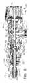
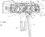
図1〜図6は、再使用されてもされなくてもよい、モータ駆動される外科用切断及び締結器具10を示している。図示の例では、器具10は、臨床医が把持し、操作し、作動させるように構成されたハンドル組立体14を備えるハウジング12を含む。ハウジング12は、1つ又は2つ以上の外科的タスク又は処置を行うように構成された外科用エンドエフェクタ300が動作可能に結合されている、交換式シャフト組立体200に動作可能に取り付けるように構成されている。本発明を実施するための形態を読み進めるに従って、本明細書で開示する様々な形態の交換式シャフト組立体の様々な独自で新規な構成が、ロボット制御式の外科用システムと関連させて効果的に用いられ得ることも理解されよう。したがって、「ハウジング」という用語はまた、本明細書に開示する交換式シャフト組立体及びそれらそれぞれの等価物を作動させるのに使用することができる、少なくとも1つの制御運動を生成し適用するように構成された、少なくとも1つの駆動システムを収容するか又は別の方法で動作可能に支持する、ロボットシステムのハウジング又は類似の部分を包含してもよい。「フレーム」という用語は、手持ち式外科用器具の一部分を指してもよい。「フレーム」という用語はまた、ロボット制御式の外科用器具の一部分、及び/又は外科用器具を動作可能に制御するために使用され得るロボットシステムの一部分を表す場合もある。例えば、本明細書に開示する交換式シャフト組立体は、米国特許出願第13/118,241号、発明の名称「SURGICAL STAPLING INSTRUMENTS WITH ROTATABLE STAPLE DEPLOYMENT ARRANGEMENTS」、現在の米国特許第9,072,535号に開示されている、様々なロボットシステム、器具、構成要素、及び方法と共に用いられてもよい。米国特許出願第13/118,241号、発明の名称「SURGICAL STAPLING INSTRUMENTS WITH ROTATABLE STAPLE DEPLOYMENT ARRANGEMENTS」、現在の米国特許第9,072,535号は、その全体が参照により本明細書に組み込まれる。 1-6 illustrate a motor-driven surgical cutting and
図1〜図3に示されるハウジング12は、外科用ステープルカートリッジ304を中で動作可能に支持するように構成された、外科用切断及び締結デバイスを備えるエンドエフェクタ300を含む、交換式シャフト組立体200と接続されて示されている。ハウジング12は、種々のサイズ及びタイプのステープルカートリッジを支持するように適合されたエンドエフェクタを含み、種々のシャフトの長さ、サイズ、及びタイプなどを有する交換式シャフト組立体と接続されて使用するように構成されてもよい。加えて、ハウジング12はまた、例えば、運動、並びに高周波(RF)エネルギー、超音波エネルギー及び/又は運動などの他の形態のエネルギーを、様々な外科用途及び処置に関連して用いられるように適合されたエンドエフェクタ構成に印加するように構成された組立体を含んだ様々な他の交換式シャフト組立体と共に効果的に用いられてもよい。更に、エンドエフェクタ、シャフト組立体、ハンドル、外科用器具、及び/又は外科用器具システムは、任意の好適な締結具を利用して組織を締結することができる。例えば、中に着脱可能に格納された複数の締結具を備える締結具カートリッジが、シャフト組立体のエンドエフェクタに着脱可能に挿入及び/又は装着され得る。 The
図1は、交換式シャフト組立体200が動作可能に連結された外科用器具10を示している。図2及び図3は、ハウジング12又はハンドル組立体14への交換式シャフト組立体200の取り付けを示している。図4に示すように、ハンドル組立体14は、ねじ、スナップ機構、接着剤などで相互連結され得る一対の相互連結可能なハンドルハウジングセグメント16及び18を備え得る。図示の構成において、ハンドルハウジングセグメント16、18は、臨床医に握持及び操作され得るピストルグリップ部分19を形成するように協働する。以下で更に詳細に論じられるように、ハンドル組立体14は、その中に複数の駆動システムを動作可能に支持し、それら駆動システムは、ハンドル組立体に動作可能に装着された交換式シャフト組立体の対応部分に、様々な制御運動を生成して適用するように構成されている。 FIG. 1 illustrates a
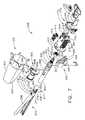
ここで図4を参照すると、ハンドル組立体14は、複数の駆動システムを動作可能に支持するフレーム20を更に含んでもよい。例えば、フレーム20は、全体として30で示される「第1の」即ち閉鎖駆動システムを動作可能に支持することができ、この閉鎖駆動システムは、動作可能に取り付けられた又は結合された交換式シャフト組立体200に対して開閉運動を適用するために用いられてもよい。少なくとも1つの形態では、閉鎖駆動システム30は、フレーム20によって枢動可能に支持される閉鎖トリガ32の形態のアクチュエータを含んでもよい。より具体的には、図4に示されるように、閉鎖トリガ32は、ピン33によってハウジング14に枢動可能に結合されている。かかる構成により、臨床医が閉鎖トリガ32を操作することが可能になり、そのため、臨床医がハンドル組立体14のピストルグリップ部分19を把持するとき、閉鎖トリガ32は、開始位置又は「非作動」位置から「作動」位置へ、より具体的には完全圧縮位置又は完全作動位置へと容易に枢動できるようになっている。閉鎖トリガ32は、ばね又は他の付勢装置(図示せず)によって、非作動位置へと付勢されてもよい。様々な形態では、閉鎖駆動システム30は、閉鎖トリガ32に枢動可能に連結された閉鎖リンク機構組立体34を更に含む。図4に示されるように、閉鎖リンク機構組立体34は、ピン35によって閉鎖トリガ32に枢動可能に結合された第1の閉鎖リンク36及び第2の閉鎖リンク38を含んでもよい。第2の閉鎖リンク38は、本明細書では「取り付け部材」と呼ばれることもあり、横断取り付けピン37を含み得る。 Referring now to FIG. 4, the
図4を引き続き参照すると、第1の閉鎖リンク36はその上に、フレーム20に枢動可能に結合された閉鎖解除組立体60と協働するように構成された、ロック壁又は端部39を有してもよいことを観察することができる。少なくとも1つの形態では、閉鎖解除組立体60は、遠位側に突出するロック爪64がその上に形成された解除ボタン組立体62を備えてもよい。解除ボタン組立体62は、解除ばね(図示せず)によって反時計方向に枢動させられてもよい。臨床医が閉鎖トリガ32をその非作動位置からハンドル組立体14のピストルグリップ部分19に向かって押下すると、ロック爪64が第1の閉鎖リンク36上のロック壁39との保持係合に至る地点に向かって第1の閉鎖リンク36が上向きに枢動し、それによって閉鎖トリガ32が非作動位置に復帰することが防止される。図18を参照されたい。したがって、閉鎖解除組立体60は、閉鎖トリガ32を完全作動位置でロックするように働く。臨床医が、閉鎖トリガ32をロック解除して、それを非作動位置へ付勢することができるようにしたい場合、臨床医は単純に、閉鎖解除ボタン組立体62を枢動させ、それによってロック爪64を移動させて、第1の閉鎖リンク36上のロック壁39との係合から外す。ロック爪64が移動させられて第1の閉鎖リンク36との係合から外れると、閉鎖トリガ32は枢動して非作動位置に戻ってもよい。他の閉鎖トリガロック及び解放構成が用いられてもよい。 With continued reference to FIG. 4, the
上記に加えて更に、図13〜図15は、組織をシャフト組立体200の顎部間に位置付けることができる、シャフト組立体200の開放構成、即ち非クランプ構成と関連付けられる非作動位置にある、閉鎖トリガ32を示している。図16〜図18は、組織がシャフト組立体200の顎部の間でクランプされる、シャフト組立体200の閉鎖構成、即ちクランプ構成と関連付けられる作動位置にある、閉鎖トリガ32を示している。図14及び図17を比較すると、閉鎖トリガ32をその非作動位置(図14)から作動位置(図17)へと移動させると、閉鎖解除ボタン62が第1の位置(図14)と第2の位置(図17)との間で枢動することが、読者には理解されるであろう。閉鎖解除ボタン62の回転は、上向きの回転であるとして言及され得るが、閉鎖解除ボタン62の少なくとも一部分は、回路基板100に向かって回転させられている。図4を参照すると、閉鎖解除ボタン62は、そこから延在するアーム61と、アーム61に装着される、例えば永久磁石などの磁気素子63とを含むことができる。閉鎖解除ボタン62をその第1の位置から第2の位置へと回転させると、磁気素子63は、回路基板100に向かって移動することができる。回路基板100は、磁気素子63の移動を検出するように構成された、少なくとも1つのセンサを含むことができる。少なくとも1つの態様では、例えば、磁場センサ65が回路基板100の底面に装着され得る。磁場センサ65は、磁気素子63の移動によって生じる磁場センサ65を取り巻く磁場の変化を検出するように構成され得る。磁場センサ65は、例えば、マイクロコントローラ1500(図19)と信号連通することができ、マイクロコントローラ1500は、閉鎖解除ボタン62が、閉鎖トリガ32の非作動位置及びエンドエフェクタの開放構成と関連付けられるその第1の位置、閉鎖トリガ32の作動位置及びエンドエフェクタの閉鎖構成と関連付けられるその第2の位置、及び/又は第1の位置と第2の位置との間の任意の位置のどこにあるかを判断することができる。 In addition to the above, FIGS. 13-15 are in an unactuated position associated with the open or unclamped configuration of the
本開示の全体にわたって用いられているように、磁場センサは、とりわけ、ホール効果センサ、探りコイル、フラックスゲート、光ポンピング、核摂動、SQUID、ホール効果、異方性磁気抵抗、巨大磁気抵抗、磁気トンネル接合、巨大磁気インピーダンス、磁歪/圧電複合材、磁気ダイオード、磁気トランジスタ、光ファイバ、光磁気、及び微小電気機械システム系の磁気センサであってよい。 As used throughout this disclosure, magnetic field sensors include, inter alia, Hall effect sensors, probe coils, fluxgates, optical pumping, nuclear perturbation, SQUID, Hall effect, anisotropic magnetoresistance, giant magnetoresistance, magnetic It may be a tunnel junction, giant magnetoimpedance, magnetostrictive / piezoelectric composite, magnetic diode, magnetic transistor, optical fiber, magneto-optical, and microelectromechanical system based magnetic sensor.
少なくとも1つの形態では、ハンドル組立体14及びフレーム20は、取り付けられた交換式シャフト組立体の対応部分に対して発射運動を適用するように構成されている、本明細書では発射駆動システム80と呼ばれる別の駆動システムを動作可能に支持してもよい。発射駆動システム80はまた、本明細書では「第2の駆動システム」と呼ばれることもある。発射駆動システム80は、ハンドル組立体14のピストルグリップ部分19に設置された電気モータ82を用いてもよい。様々な形態では、モータ82は、例えば、約25,000RPMの最大回転数を有するブラシ付きDC駆動モータであってもよい。別の構成において、モータ82としては、ブラシレスモータ、コードレスモータ、同期モータ、ステッパモータ、又は任意の他の好適な電動モータが挙げられる。モータ82は、1つの形態では着脱可能なパワーパック92を備えてもよい、電源90によって給電されてもよい。例えば、図4に示されるように、パワーパック92は、遠位側ハウジング部分96に取り付けるために構成された、近位側ハウジング部分94を備えてもよい。近位側ハウジング部分94及び遠位側ハウジング部分96は、複数の電池98を中に動作可能に支持するように構成されている。電池98はそれぞれ、例えば、リチウムイオン(「LI」)又は他の好適な電池を含んでもよい。遠位側ハウジング部分96は、モータ82にやはり動作可能に結合されている、制御回路基板組立体100に着脱可能かつ動作可能に取り付けられるために構成されている。直列に接続されてもよい多数の電池98が、外科用器具10の電源として使用されてもよい。それに加えて、電源90は、交換可能及び/又は再充電可能であってもよい。 In at least one form, the
他の様々な形態に関連して上に概説したように、電気モータ82は、長手方向に移動可能な駆動部材120上にある駆動歯122の組又はラックと噛合係合して装着されるギヤ減速機組立体84と動作可能に連係する、回転式シャフト(図示せず)を含むことができる。使用の際、電源90によって提供される電圧極性によって電気モータ82を時計方向に動作させることができるが、電池によって電気モータに印加される電圧極性は、電気モータ82を反時計方向に動作させるために反転させることができる。電気モータ82がある方向に回転されると、駆動部材120は、遠位方向「DD」に軸方向駆動されることになる。モータ82が反対の回転方向に駆動されると、駆動部材120は、近位方向「PD」に軸方向駆動されることになる。ハンドル組立体14は、電源90によって電動モータ82に付与される極性を逆転させるように構成され得るスイッチを備えることができる。本明細書で説明する他の形態と同様に、ハンドル組立体14はまた、駆動部材120の位置、及び/又は駆動部材120が移動されている方向を検出するように構成されたセンサを含むこともできる。 As outlined above in connection with various other configurations, the
モータ82の作動は、ハンドル組立体14上に枢動可能に支持される発射トリガ130によって制御され得る。発射トリガ130は、非作動位置と作動位置との間で枢動させられてもよい。発射トリガ130は、ばね132若しくは他の付勢装置によって非作動位置へと付勢されてもよく、それにより、臨床医が発射トリガ130を解放すると、それがばね132若しくは付勢装置によって非作動位置へと枢動されるか又は別の方法で復帰させられてもよい。少なくとも1つの形態では、発射トリガ130は、上述したように、閉鎖トリガ32の「外側」に位置付けることができる。少なくとも1つの形態では、発射トリガ安全ボタン134が、ピン35によって閉鎖トリガ32に枢動可能に装着されてもよい。安全ボタン134は、発射トリガ130と閉鎖トリガ32との間に位置付けられ、そこから突出する枢動アーム136を有してもよい。図4を参照されたい。閉鎖トリガ32が非作動位置にあるとき、安全ボタン134は、ハンドル組立体14内に収容され、臨床医は容易には安全ボタン134にアクセスすることができず、発射トリガ130の作動を防止する安全位置と、発射トリガ130が発射され得る発射位置との間で移動することもできない。臨床医が閉鎖トリガ32を押下すると、安全ボタン134及び発射トリガ130が下に枢動して、次いで、臨床医がそれらを操作することが可能になる。 Operation of the
上述したように、ハンドル組立体14は、閉鎖トリガ32及び発射トリガ130を含むことができる。図14〜図18Aを参照すると、発射トリガ130を閉鎖トリガ32に枢動可能に装着することができる。閉鎖トリガ32は、そこから延在するアーム31を含むことができ、発射トリガ130は、枢動ピン33を中心にして枢動可能にアーム31に装着することができる。閉鎖トリガ32をその非作動位置(図14)から作動位置(図17)へと移動させると、上に概説したように、発射トリガ130が下向きに下降することができる。安全ボタン134がその発射位置へと移動した後、主に図18Aを参照すると、発射トリガ130を押下して、外科用器具発射システムのモータを動作させることができる。様々な例では、ハンドル組立体14は、例えば、閉鎖トリガ32の位置及び/又は発射トリガ130の位置を判断するように構成された、システム800などの追跡システムを含むことができる。主に図14、図17、及び図18Aを参照すると、追跡システム800は、例えば、発射トリガ130から延在するアーム801に装着される、永久磁石802などの磁気素子を含むことができる。追跡システム800は、例えば、磁石802の位置を追跡するように構成され得る、第1の磁場センサ803及び第2の磁場センサ804など、1つ又は2つ以上のセンサを備えることができる。 As described above, the
図14及び図17を比較すると、閉鎖トリガ32をその非作動位置から作動位置へと移動させると、磁石802が、第1の磁場センサ803に隣接した第1の位置と、第2の磁場804に隣接した第2の位置との間で移動することができることが、読者には理解されるであろう。 14 and 17, when the
図17及び図18Aを比較すると、発射トリガ130を未発射位置(図17)から発射後位置(図18A)へと移動させると、磁石802が第2の磁場センサ804に対して移動することができることが、読者には更に理解されるであろう。センサ803及び804は、磁石802の移動を追跡することができ、回路基板100のマイクロコントローラと信号連通することができる。第1のセンサ803及び/又は第2のセンサ804からのデータを用いて、マイクロコントローラは、事前定義された経路に沿って磁石802の位置を判断することができ、その位置に基づいて、マイクロコントローラは、閉鎖トリガ32がその非作動位置、その作動位置、又はそれらの間の位置のどこにあるかを判断することができる。同様に、第1のセンサ803及び/又は第2のセンサ804からのデータを用いて、マイクロコントローラは、事前定義された経路に沿って磁石802の位置を判断することができ、その位置に基づいて、マイクロコントローラは、発射トリガ130がその未発射位置、その完全発射後位置、又はそれらの位置の間のどこにあるかを判断することができる。 17 and 18A, when the firing
上に示されるように、少なくとも一形態において、長手方向に移動可能な駆動部材120は、ギヤ減速機組立体84の対応する駆動ギヤ86と噛合係合するために、その上に形成された歯122のラックを有する。少なくとも1つの形態はまた、モータ82が使用不能になった場合に、臨床医が長手方向に移動可能な駆動部材120を手動で後退させることができるように構成された、手動作動式の「緊急離脱」組立体140を含む。緊急離脱組立体140は、手動で枢動させて、駆動部材120にやはり設けられた歯124とラチェット係合するように構成された、レバー又は緊急離脱ハンドル組立体142を含んでもよい。したがって、臨床医は、緊急離脱ハンドル組立体142を使用して駆動部材120を近位方向「PD」にラチェットさせることによって、駆動部材120を手動により後退させることができる。米国特許出願公開第2010/0089970号、現在の米国特許第8,608,045号は、本明細書において開示される様々な器具と共に同様に用いられることもできる緊急離脱装置、並びに他の構成要素、装置、及びシステムを開示している。米国特許出願第12/249,117号、発明の名称「POWERED SURGICAL CUTTING AND STAPLING APPARATUS WITH MANUALLY RETRACTABLE FIRING SYSTEM」、米国特許出願公開第2010/0089970号、現在の米国特許第8,608,045号は、その全体を参照により本明細書に組み込む。 As indicated above, in at least one form, the longitudinally
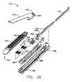
ここで図1及び図7を参照すると、交換式シャフト組立体200は、ステープルカートリッジ304を中で動作可能に支持するように構成された細長いチャネル302を備える、外科用エンドエフェクタ300を含む。エンドエフェクタ300は、細長いチャネル302に対して枢動可能に支持されるアンビル306を更に含んでもよい。交換式シャフト組立体200は、シャフト軸線SA−SAに対して所望の位置でエンドエフェクタ300を解除可能に保持するように構成することができる、関節継手270及び関節ロック350(図8)を更に含んでもよい。エンドエフェクタ300、関節継手270、及び関節ロック350の構造と動作に関する詳細は、2013年3月14日出願の米国特許出願第13/803,086号、発明の名称「ARTICULATABLE SURGICAL INSTRUMENT COMPRISING AN ARTICULATION LOCK」、現在の米国特許出願公開第2014/0263541号に説明されている。2013年3月14日出願の米国特許出願第13/803,086号、発明の名称「ARTICULATABLE SURGICAL INSTRUMENT COMPRISING AN ARTICULATION LOCK」、現在の米国特許出願公開第2014/0263541号の開示全体が参照により本明細書に組み込まれる。図7及び図8に示されるように、交換式シャフト組立体200は、ノズル部分202及び203で構成される近位側ハウジング又はノズル201を更に含むことができる。交換式シャフト組立体200は、エンドエフェクタ300のアンビル306を開閉するために利用することができる、閉鎖管260を更に含むことができる。次に図8及び図9を主に参照すると、シャフト組立体200は、関節ロック350のシャフトフレーム部分212を固定可能に支持するように構成することができる、スパイン210を含むことができる。図8を参照されたい。スパイン210は、(1)発射部材220を中で摺動可能に支持するように、かつ(2)スパイン210の周りに延在する閉鎖管260を摺動可能に支持するように、構成することができる。スパイン210はまた、近位側関節ドライバ230を摺動可能に支持するように構成することができる。関節ドライバ230は、関節ロック350を動作可能に係合するように構成された遠位端部231を有する。関節ロック350は、エンドエフェクタフレーム(図示せず)上の駆動ピン(図示せず)に動作可能に係合するように適合された、関節フレーム352と連係する。上述したように、関節ロック350及び関節フレームの動作に関する更なる詳細は、米国特許出願第13/803,086号、現在の米国特許出願公開第2014/0263541号に見出すことができる。様々な状況において、スパイン210は、シャーシ240内で回転可能に支持される近位端部211を備えることができる。1つの構成では、例えば、スパイン210の近位端部211には、シャーシ240内で支持されるように構成されたスパイン軸受216にねじ込みによって取り付けられるように、ねじ山214が形成される。図7を参照されたい。かかる構成により、シャーシ240に対するスパイン210の回転可能な取り付けが容易になって、スパイン210を、シャーシ240に対してシャフト軸線SA−SAを中心にして選択可能に回転させることができる。 Referring now to FIGS. 1 and 7, the
主に図7を参照すると、交換式シャフト組立体200は、シャーシ240に対して軸方向に移動され得るようにその中で摺動可能に支持される、閉鎖シャトル250を含む。図3及び図7に示されるように、閉鎖シャトル250は、更に詳細に後述するように、第2の閉鎖リンク38に取り付けられる取り付けピン37に取り付けるために構成された、一対の近位側に突出するフック252を含む。閉鎖管260の近位端部261は、相対回転するように閉鎖シャトル250に結合されている。例えば、U字コネクタ263は、閉鎖管260の近位端部261にある環状スロット262に挿入され、閉鎖シャトル250の垂直スロット253内で保定される。図7を参照されたい。かかる構成は、閉鎖管260を閉鎖シャトル250と共に軸方向移動するようにそれに取り付ける役割を果たし、一方で閉鎖管260がシャフト軸線SA−SAを中心にして閉鎖シャトル250に対して回転することを可能にする。閉鎖ばね268は、閉鎖管260上で軸止され、閉鎖管260を近位方向「PD」に付勢する役割を果たし、それによって、シャフト組立体がハンドル組立体14に動作可能に結合されると、閉鎖トリガを非作動位置へと枢動する役割を果たすことができる。 Referring primarily to FIG. 7, the
少なくとも1つの形態では、交換式シャフト組立体200は、関節継手270を更に含んでもよい。しかしながら、他の交換式シャフト組立体は関節屈曲可能でなくてもよい。図7に示されるように、例えば、関節継手270は、二重枢動閉鎖スリーブ組立体271を含む。様々な形態によれば、二重枢動閉鎖スリーブ組立体271は、上側及び下側の遠位側に突出するタング273、274を有する、エンドエフェクタ閉鎖スリーブ組立体272を含む。エンドエフェクタ閉鎖スリーブ組立体272は、参照により本明細書に組み込まれている、2013年3月14日出願の米国特許出願第13/803,086号、発明の名称「ARTICULATABLE SURGICAL INSTRUMENT COMPRISING AN ARTICULATION LOCK」、現在の米国特許出願公開第2014/0263541号に記載されている様々な形式で、アンビル306上の開放タブに係合する馬蹄形アパーチャ275及びタブ276を含む。本明細書で更に詳述するように、馬蹄形アパーチャ275及びタブ276は、アンビル306が開放されているときにアンビル上のタブに係合する。上側二重枢動リンク277は、閉鎖管260上にある上部近位突出タング273の上部遠位ピンホール、及び上部遠位突出タング264の上部近位ピンホールにそれぞれ係合する、上向きに突出する遠位及び近位枢動ピンを含む。下側二重枢動リンク278は、下部近位突出タング274の下部遠位ピンホール、及び下部遠位突出タング265の下部近位ピンホールにそれぞれ係合する、上向きに突出する遠位及び近位枢動ピンを含む。図8も参照されたい。 In at least one form, the
使用の際、閉鎖管260は、例えば、閉鎖トリガ32の作動に応答して、アンビル306を閉鎖するように遠位側(方向「DD」)に並進される。アンビル306は、閉鎖管260を、したがってシャフト閉鎖スリーブ組立体272を遠位側に並進させて、上述した参照文献の米国特許出願第13/803,086号、現在の米国特許出願公開第2014/0263541号に記載されている方法で、アンビル360の近位面に衝突させることによって閉鎖される。同参照文献にやはり詳細に記載されているように、閉鎖管260及びシャフト閉鎖スリーブ組立体272を近位側に並進させて、タブ276及び馬蹄形アパーチャ275をアンビルタブに接触させ、それを押してアンビル306を持ち上げることによって、アンビル306が開放される。アンビル開位置において、シャフト閉鎖管260は、その近位位置へと移動させられる。 In use,
上述したように、外科用器具10は、エンドエフェクタ300を定位置で選択的にロックするように構成し動作させることができる、米国特許出願第13/803,086号、現在の米国特許出願公開第2014/0263541号に更に詳細に記載されているタイプ及び構造の関節ロック350を更に含んでもよい。かかる構成によって、関節ロック350がそのロック解除状態にあるとき、エンドエフェクタ300を、シャフト閉鎖管260に対して回転させること、即ち関節運動させることが可能になる。かかるロック解除状態では、エンドエフェクタ300を閉鎖管260に対して関節運動させるために、エンドエフェクタ300を、例えば、患者の体内の手術部位を取り囲む軟組織及び/又は骨に対して位置付け、押すことができる。エンドエフェクタ300はまた、関節ドライバ230によって閉鎖管260に対して関節運動させてもよい。 As discussed above, the
やはり上述したように、交換式シャフト組立体200は、シャフトスパイン210内で軸方向移動するように支持される発射部材220を更に含む。発射部材220は、遠位側切断部分又はナイフバー280に取り付けるために構成された中間発射シャフト部分222を含む。発射部材220はまた、本明細書において「第2のシャフト」及び/又は「第2のシャフト組立体」と呼ばれることもある。図8及び図9に示されるように、中間発射シャフト部分222は、その遠位端部に、遠位側ナイフバー280の近位端部282にあるタブ284を受け入れるように構成することができる、長手方向スロット223を含んでもよい。長手方向スロット223及び近位端部282は、それらの間の相対運動を可能にするようにサイズ決めして構成することができ、かつスリップ継手286を備えることができる。スリップ継手286は、ナイフバー280を移動させずに、又は少なくとも実質的に移動させずに、発射駆動部220の中間発射シャフト部分222を移動させて、エンドエフェクタ300を関節運動させることを可能にすることができる。エンドエフェクタ300が適切に方向付けられると、中間発射シャフト部分222は、ナイフバー280を前進させ、チャネル302内に配置されたステープルカートリッジを発射するために、長手方向スロット223の近位側壁がタブ284と接触するまで、遠位方向に前進され得る。図8及び図9で更に分かるように、シャフトスパイン210は、シャフトフレーム210への中間発射シャフト部分222の組み付け及び挿入を容易にするために、細長い開口部又は窓部213を有している。中間発射シャフト部分222が挿入されると、頂部フレームセグメント215がシャフトフレーム212と係合されて、中間発射シャフト部分222及びナイフバー280を中に封入してもよい。発射部材220の動作に関する更なる記載は、米国特許出願第13/803,086号、現在の米国特許出願公開第2014/0263541号に見出すことができる。 As also described above, the
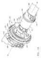
上記に加えて更に、シャフト組立体200は、関節ドライバ230を発射部材220に選択的かつ解除可能に結合するように構成することができる、クラッチ組立体400を含むことができる。1つの形態では、クラッチ組立体400は、発射部材220の周りに位置付けられるロックカラー、即ちスリーブ402を含み、ロックスリーブ402は、ロックスリーブ402が関節ドライバ360を発射部材220に結合する係合位置と、関節ドライバ360が発射部材200に動作可能に結合されない係合解除位置との間で回転させることができる。ロックスリーブ402がその係合位置にあるとき、発射部材220の遠位方向移動によって、関節ドライバ360を遠位側に移動させることができ、それに対応して、発射部材220の近位方向移動によって、関節ドライバ230を近位側に移動させることができる。ロックスリーブ402がその係合解除位置にあるとき、発射部材220の移動は、関節ドライバ230に伝達されず、その結果、発射部材220は、関節ドライバ230とは独立して移動することができる。様々な状況において、関節ドライバ230が発射部材220によって近位又は遠位方向で移動させられていないとき、関節ドライバ230を関節ロック350によって定位置で保持することができる。 In addition to the above, the
主に図9を参照すると、ロックスリーブ402は、発射部材220を受け入れるように構成された長手方向アパーチャ403が中に画定された、円筒状の、又は少なくとも実質的に円筒状の本体を備えることができる。ロックスリーブ402は、直径方向に対向する内向きのロック突出部404と外向きのロック部材406とを備え得る。ロック突出部404は、発射部材220と選択的に係合されるように構成され得る。より具体的には、ロックスリーブ402が係合位置にあるとき、ロック突出部404は、発射部材220に画定された駆動ノッチ224内に配置され、そのため、遠位側に押す力及び/又は近位側に引っ張る力が発射部材220からロックスリーブ402に伝達され得るようになっている。ロックスリーブ402がその係合位置にあるとき、第2のロック部材406は、関節ドライバ230に画定された駆動ノッチ232内に受け入れられ、それによって、ロックスリーブ402に加えられる遠位側に押す力及び/又は近位側に引っ張る力を関節ドライバ230に伝達することができる。実質的に、発射部材220、ロックスリーブ402、及び関節ドライバ230は、ロックスリーブ402がその係合位置にあると、共に移動するようになる。他方で、ロックスリーブ402がその係合解除位置にあるとき、ロック突出部404は、発射部材220の駆動ノッチ224内に配置され得ず、結果として、遠位側に押す力及び/又は近位側に引っ張る力が発射部材220からロックスリーブ402に伝達され得ないようになっている。それに対応して、遠位側に押す力及び/又は近位側に引っ張る力が関節ドライバ230に伝達されないことがある。そのような状況下で、発射部材220は、ロックスリーブ402及び近位関節ドライバ230に対して近位側及び/又は遠位側に摺動され得る。 Referring primarily to FIG. 9, the locking
図8〜図12に示されるように、シャフト組立体200は、閉鎖管260上に回転可能に受け入れられるスイッチドラム500を更に含む。スイッチドラム500は、外向き突出作動ピン410を中に受容するためのシャフトボス504が形成された中空シャフトセグメント502を備える。様々な状況において、作動ピン410は、スロット267を通って、ロックスリーブ402に設けられた長手方向スロット408内へと延在して、ロックスリーブ402が関節ドライバ230と係合されたときにその軸方向運動を容易にする。回転ねじりばね420は、図10に示されるように、スイッチドラム500のボス504及びノズルハウジング203の一部分に係合して、付勢力をスイッチドラム500に加えるように構成されている。スイッチドラム500は、そこに画定された少なくとも部分的に円周方向の開口部506を更に備えることができ、その開口部は、図5及び図6を参照すると、ノズル半片202、203から延在する円周方向マウント204、205を受け入れ、スイッチドラム500と近位側ノズル201との間の相対回転は許容するが並進は許容しないように構成することができる。それらの図に示されるように、マウント204及び205はまた、閉鎖管260の開口部266を通って延在して、シャフトスパイン210の陥凹部209に収まる。しかしながら、マウント204、205がスイッチドラム500内のそれぞれのスロット506の端部に達する点までノズル201が回転すると、スイッチドラム500がシャフト軸線SA−SAを中心にして回転する。スイッチドラム500が回転すると、最終的に作動ピン410及びロックスリーブ402が、その係合位置と係合解除位置との間で回転することになる。したがって、本質的に、ノズル201は、米国特許出願第13/803,086号、現在の米国特許出願公開第2014/0263541号に更に詳細に記載されている様々な方式で、関節駆動システムと発射駆動システムとを動作可能に係合及び係合解除するために用いられてもよい。 As shown in FIGS. 8-12, the
やはり図8〜図12に示されるように、シャフト組立体200は、例えば、エンドエフェクタ300との間で電力を伝導し、かつ/又はエンドエフェクタ300との間で信号を通信するように構成することができる、スリップリング組立体600を備えることができる。スリップリング組立体600は、シャーシ240から延在するシャーシフランジ242に装着される近位コネクタフランジ604と、シャフトハウジング202、203に画定されたスロット内に位置付けられる遠位コネクタフランジ601とを備えることができる。近位コネクタフランジ604は第1の面を備えることができ、遠位コネクタフランジ601は、第1の面に隣接して位置付けられ、かつ第1の面に対して移動可能である第2の面を備えることができる。遠位コネクタフランジ601は、シャフト軸線SA−SAを中心にして、近位コネクタフランジ604に対して回転することができる。近位コネクタフランジ604は、その第1の面に画定される、複数の同心の、又は少なくとも実質的に同心の導体602を備えることができる。コネクタ607は、コネクタフランジ601の近位面に装着することができ、複数の接点(図示せず)を有してもよく、各接点は、導体602の1つに対応し、それと電気的に接触する。かかる構成により、近位側コネクタフランジ604と遠位側コネクタフランジ601とが、それらの間の電気的接触を維持したまま相対回転することが可能になる。近位コネクタフランジ604は、例えば、シャフトシャーシ240に装着されたシャフト回路基板610と信号連通して導体602を配置することができる、電気コネクタ606を含むことができる。少なくとも1つの例では、複数の導体を備える配線ハーネスが、電気コネクタ606とシャフト回路基板610との間に延在することができる。電気コネクタ606は、シャーシ装着フランジ242に画定されたコネクタ開口部243を通って近位側に延在してもよい。図7を参照されたい。2013年3月13日に出願された米国特許出願第13/800,067号、発明の名称「STAPLE CARTRIDGE TISSUE THICKNESS SENSOR SYSTEM」、現在の米国特許出願公開第2014/0263552号は、参照によりその全体が本明細書に組み込まれる。2013年3月13日に出願された米国特許出願第13/800,025号、発明の名称「STAPLE CARTRIDGE TISSUE THICKNESS SENSOR SYSTEM」、現在の米国特許出願公開第2014/0263551号は、参照によりその全体が本明細書に組み込まれる。スリップリング組立体600に関する更なる詳細は、米国特許出願第13/803,086号、現在の米国特許出願公開第2014/0263541号に見出すことができる。 As also shown in FIGS. 8-12, the
上述のように、シャフト組立体200は、ハンドル組立体14に固定可能に取り付けられる近位部分と、長手方向軸線を中心に回転可能である遠位部分とを含み得る。回転可能な遠位シャフト部分は、上述したように、スリップリング組立体600を中心にして近位部分に対して回転させることができる。スリップリング組立体600の遠位コネクタフランジ601は、回転可能な遠位シャフト部分内に位置付けることができる。また、上記に加えて更に、スイッチドラム500も、回転可能な遠位シャフト部分内に位置付けることができる。回転可能な遠位シャフト部分を回転させると、遠位コネクタフランジ601及びスイッチドラム500を互いに同期して回転させることができる。それに加えて、スイッチドラム500を、遠位コネクタフランジ601に対して第1の位置と第2の位置との間で回転させることができる。スイッチドラム500がその第1の位置にあると、関節駆動システムが発射駆動システムから動作可能に係合解除されてもよく、したがって、発射駆動システムの動作によって、シャフト組立体200のエンドエフェクタ300を関節運動させることができない。スイッチドラム500がその第2の位置にあると、関節駆動システムが発射駆動システムと動作可能に係合されてもよく、したがって、発射駆動システムの動作によってシャフト組立体200のエンドエフェクタ300を関節運動させることができる。スイッチドラム500をその第1の位置と第2の位置との間で移動させると、スイッチドラム500は、遠位コネクタフランジ601に対して移動させられる。様々な例において、シャフト組立体200は、スイッチドラム500の位置を検出するように構成された少なくとも1つのセンサを備えることができる。次に図11及び図12を参照すると、遠位コネクタフランジ601は、例えば磁場センサ605を備えることができ、スイッチドラム500は、例えば永久磁石505などの磁気素子を備えることができる。磁場センサ605は、永久磁石505の位置を検出するように構成され得る。スイッチドラム500が第1の位置と第2の位置との間で回転されるとき、永久磁石505は磁場センサ605に対して移動し得る。様々な事例において、磁場センサ605は、永久磁石505が移動されるときに生じる磁場の変化を検出し得る。磁場センサ605は、例えば、シャフト回路基板610及び/又はハンドル回路基板100と信号連通し得る。磁場センサ605からの信号に基づき、シャフト回路基板610及び/又はハンドル回路基板100上のマイクロコントローラは、関節駆動システムが発射駆動システムと係合されるか又はそこから係合解除されるかどうかを判断し得る。 As described above, the
再び図3及び図7を参照すると、シャーシ240は、フレーム20の遠位側取り付けフランジ部分700内に形成された、対応するダブテールスロット702に受け入れられるように適合された、シャーシ上に形成された少なくとも1つの、好ましくは2つの先細取り付け部分244を含む。各ダブテールスロット702は、取り付け部分244を中に収めて受け入れるように、先細であってもよく、又は言い換えればある程度V字形であってもよい。図3及び図7から更に分かるように、シャフト取り付けラグ226が、中間発射シャフト222の近位端部に形成される。更に詳細に後述するように、交換式シャフト組立体200がハンドル組立体14に結合されると、シャフト取り付けラグ226は、例えば、図3及び図6に示すように、長手方向駆動部材120の遠位端部125に形成された発射シャフト取り付けクレードル126に受け入れられる。 Referring again to FIGS. 3 and 7, the
様々なシャフト組立体は、シャフト組立体200をハウジング12に、より具体的にはフレーム20に着脱可能に結合するためのラッチシステム710を用いる。図7に示されるように、例えば、少なくとも1つの形態では、ラッチシステム710は、シャーシ240に移動可能に結合されている、ロック部材又はロックヨーク712を含む。例示されている例では、例えば、ロックヨーク712は、2つの離れて下向きに延びる脚部714を備えたU字形を有する。脚部714にはそれぞれ、シャーシ240に形成された対応する穴245に受け入れられるように適合された、枢動ラグ715が形成される。かかる構成により、ロックヨーク712をシャーシ240に枢動可能に取り付けやすくなる。ロックヨーク712は、フレーム20の遠位側取り付けフランジ700の対応するロック移動止め又は溝704と解除可能に係合するように構成された、2つの近位側に突出するロックラグ716を含んでもよい。図3を参照されたい。様々な形態では、ロックヨーク712は、ばね又は付勢部材(図示せず)によって近位方向に付勢される。ロックヨーク712の作動は、シャーシ240に装着されたラッチアクチュエータ組立体720上に摺動可能に装着される、ラッチボタン722によって遂行されてもよい。ラッチボタン722は、ロックヨーク712に対して近位方向に付勢されていてもよい。更に詳細に後述するように、ロックヨーク712は、ラッチボタンを遠位方向で付勢することによってロック解除位置へと移動させられてもよく、それによってまた、ロックヨーク712が枢動して、フレーム20の遠位側取り付けフランジ700との保定係合から外れる。ロックヨーク712がフレーム20の遠位側取り付けフランジ700と「保定係合」しているとき、ロックラグ716は、遠位側取り付けフランジ700の対応するロック移動止め又は溝704内に保定されて収まっている。 Various shaft assemblies employ a
組織を切断し締結するように適合された本明細書に記載されるタイプのエンドエフェクタ、並びに他のタイプのエンドエフェクタを含む、交換式シャフト組立体を用いる場合、エンドエフェクタの作動中に交換式シャフト組立体がハウジングから不用意に分離されることを防止することが望ましいことがある。例えば、使用の際、臨床医は、閉鎖トリガ32を作動させて標的組織を把持し、所望の位置へと操作することがある。標的組織がエンドエフェクタ300内に所望の配向で位置付けられると、臨床医は、次に、閉鎖トリガ32を完全に作動させてアンビル306を閉鎖し、標的組織を切断及びステープル留めの位置でクランプしてもよい。その場合、第1の駆動システム30は、完全に作動している。標的組織がエンドエフェクタ300にクランプされた後、シャフト組立体200がハウジング12から不用意に分離されることを防止することが望ましいことがある。ラッチシステム710の1つの形態は、かかる不用意な分離を防止するように構成されている。 When using a replaceable shaft assembly that includes an end effector of the type described herein adapted to cut and fasten tissue, as well as other types of end effectors, it is replaceable during operation of the end effector. It may be desirable to prevent inadvertent separation of the shaft assembly from the housing. For example, in use, the clinician may actuate the
図7で最も具体的に分かるように、ロックヨーク712は、閉鎖シャトル250上に形成された対応するロックラグ部分256に接触するように適合された、少なくとも1つの、好ましくは2つのロックフック718を含む。図13〜図15を参照すると、閉鎖シャトル250が非作動位置にある(即ち、第1の駆動システム30が非作動で、アンビル306が開放されている)とき、ロックヨーク712を遠位方向で枢動させて、交換式シャフト組立体200をハウジング12からロック解除してもよい。その位置では、ロックフック718は、閉鎖シャトル250上のロックラグ部分256に接触しない。しかしながら、閉鎖シャトル250を作動位置へと移動させる(即ち、第1の駆動システム30を作動させ、アンビル306が閉位置にある)と、ロックヨーク712がロック解除位置へと枢動することが防止される。図16〜図18を参照のこと。言い換えると、臨床医がロックヨーク712をロック解除位置へと枢動させようとした場合、又は例えば、ロックヨーク712が、別の場合では遠位側に枢動することがあるような形で不用意に突き当たるか又は接触した場合、ロックヨーク712上のロックフック718が閉鎖シャトル250上のロックラグ256に接触し、ロックヨーク712がロック解除位置へと移動することを防止する。 As can be seen most specifically in FIG. 7, the
これから、ハンドル組立体14への交換式シャフト組立体200の取り付けについて、図3を参照して記載する。結合プロセスを開始するために、臨床医は、シャーシ240上に形成された先細取り付け部分244がフレーム20のダブテールスロット702と位置合わせされるようにして、交換式シャフト組立体200のシャーシ240をフレーム20の遠位側取り付けフランジ700の上方に、又はそれに隣接して位置付けてもよい。臨床医は、次に、シャフト組立体200を、シャフト軸線SA−SAに垂直な設置軸線IAに沿って移動させて、取り付け部分244を対応するダブテール受け入れスロット702と「動作可能に係合」させて収めてもよい。その際、中間発射シャフト222上のシャフト取り付けラグ226もまた、長手方向に移動可能な駆動部材120のクレードル126に収められ、第2の閉鎖リンク38上にあるピン37の部分が、閉鎖ヨーク250の対応するフック252に収められる。本明細書で使用するとき、2つの構成要素の文脈における「動作可能な係合」という用語は、それら2つの構成要素が互いに十分に係合され、それにより、作動運動をそれらに適用すると、構成要素が意図される行為、機能、及び/又は手順を実施し得ることを意味する。 The attachment of the
上で議論したように、交換式シャフト組立体200の少なくとも5つのシステムが、ハンドル組立体14の少なくとも5つの対応するシステムと動作可能に結合され得る。第1のシステムは、シャフト組立体200のフレーム又はスパインをハンドル組立体14のフレーム20と結合及び/又は位置合わせするフレームシステムを備えることができる。別のシステムは、ハンドル組立体14の閉鎖トリガ32と、閉鎖管260と、シャフト組立体200のアンビル306とを動作可能に接続することができる閉鎖駆動システム30を備えることができる。上で概説したように、シャフト組立体200の閉鎖管取り付けヨーク250を、第2の閉鎖リンク38のピン37と係合させることができる。別のシステムは、ハンドル組立体14の発射トリガ130をシャフト組立体200の中間発射シャフト222と動作可能に接続することができる発射駆動システム80を備えることができる。 As discussed above, at least five systems of
上で概説したように、シャフト取り付けラグ226は、長手方向駆動部材120のクレードル126と動作可能に接続することができる。別のシステムは、例えばシャフト組立体200などのシャフト組立体が、ハンドル組立体14と動作可能に係合されていることを、例えばマイクロコントローラなど、ハンドル組立体14内のコントローラに信号伝達することができ、並びに/又は,(2)電力及び/若しくは通信信号をシャフト組立体200とハンドル組立体14との間で伝導することができる電気システムを含むことができる。例えば、シャフト組立体200は、シャフト回路基板610に動作可能に装着される電気コネクタ1410を含むことができる。電気コネクタ1410は、ハンドル制御基板100上の対応する電気コネクタ1400と噛合係合するように構成されている。回路類及び制御システムに関する更なる詳細は、米国特許出願第13/803,086号、現在は米国特許出願公開第2014/0263541号に見出すことができ、その開示内容全体は、参照により本明細書に既に組み込まれている。第5のシステムは、シャフト組立体200をハンドル組立体14に解除可能にロックするラッチングシステムで構成されてもよい。 As outlined above, the
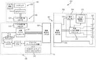
図2及び図3を再び参照すると、ハンドル組立体14は、複数の電気接点を備える電気コネクタ1400を含むことができる。ここで図19を参照すると、電気コネクタ1400は、例えば、第1の接点1401aと、第2の接点1401bと、第3の接点1401cと、第4の接点1401dと、第5の接点1401eと、第6の接点1401fとを備えることができる。図示の例は6つの接点を利用しているが、6つより多い接点又は6つより少ない接点を利用し得る他の例も考えられる。 Referring back to FIGS. 2 and 3, the
図19に示されるように、第1の接点1401aは、トランジスタ1408と電気的に連通することができ、接点1401b〜1401eは、マイクロコントローラ1500と電気的に連通することができ、第6の接点1401fは、アースと電気的に連通することができる。特定の状況では、ハンドル組立体14が給電状態にあるとき、電気接点1401b〜1401eのうちの1つ又は2つ以上が、マイクロコントローラ1500のうちの1つ又は2つ以上の出力チャネルと電気的に連通していてもよく、通電することができ、又は電位を印加することができる。いくつかの状況では、電気接点1401b〜1401eのうち1つ又は2つ以上が、マイクロコントローラ1500の1つ又は2つ以上の入力チャネルと電気的に連通していてもよく、ハンドル組立体14が給電状態にあるとき、マイクロコントローラ1500は、かかる電気接点に電位が印加されたときにそれを検出するように構成することができる。例えば、シャフト組立体200などのシャフト組立体が、ハンドル組立体14に組み付けられたとき、電気接点1401a〜1401fは、互いに連通しなくてもよい。しかしながら、シャフト組立体がハンドル組立体14に組み付けられていないとき、電気コネクタ1400の電気接点1401a〜1401fは、露出していてもよく、またいくつかの状況では、接点1401a〜1401fのうち1つ又は2つ以上が、偶然に互いに電気的に連通されて配置されてもよい。かかる状況は、例えば、接点1401a〜1401fのうち1つ又は2つ以上が導電性材料と接触すると生じる可能性がある。これが生じると、例えば、マイクロコントローラ1500が、エラー入力を受信する場合があり、かつ/又はシャフト組立体200が、エラー出力を受信する場合がある。この問題に対処するために、様々な状況では、例えば、シャフト組立体200などのシャフト組立体がハンドル組立体14に取り付けられていないとき、ハンドル組立体14は、給電されなくてもよい。 As shown in FIG. 19, the
他の状況では、例えば、シャフト組立体200などのシャフト組立体が、ハンドル組立体14に取り付けられていないとき、ハンドル組立体14に給電することができる。かかる状況では、マイクロコントローラ1500は、シャフト組立体がハンドル組立体14に取り付けられるまで、マイクロコントローラ1500と電気的に連通している接点、即ち、例えば接点1401b〜1401eに印加される、入力又は電位を無視するように構成することができる。マイクロコントローラ1500は、そのような状況下でハンドル組立体14の他の機能を操作するために電力を供給されてもよいが、ハンドル組立体14は非給電状態にあってもよい。ある意味で、電気接点1401b〜1401eに加えられる電位がハンドル組立体14の動作に影響することがないので、電気コネクタ1400は非給電状態にあってもよい。接点1401b〜1401eが給電停止状態にあっても、マイクロコントローラ1500と電気的に連通していない電気接点1401a及び1401fは給電停止状態にあってもなくてもよいことが、読者には理解されるであろう。例えば、第6の接点1401fは、ハンドル組立体14が給電状態にあるか給電停止状態にあるかに関わらず、アースと電気的に連通したままであってもよい。 In other situations, for example, a shaft assembly, such as
更に、トランジスタ1408、及び/又は例えばトランジスタ1410などの任意の他の好適なトランジスタの配置、及び/又はスイッチは、ハンドル組立体14が給電状態にあるか給電停止状態にあるかに関わらず、例えばハンドル組立体14内の電池90などの電源1404から第1の電気接点1401aへの電力の供給を制御するように構成されてもよい。様々な状況では、シャフト組立体200は、例えば、シャフト組立体200がハンドル組立体14と係合されたときにトランジスタ1408の状態を変化させるように構成することができる。特定の状況下では、以下に加えて、磁場センサ1402は、トランジスタ1410の状態を切り換えるように構成され得、トランジスタ1410は結果として、トランジスタ1408の状態を切り換えて、最終的に電源1404から第1の接点1401aに電力を供給することができる。このようにして、コネクタ1400までの電源回路と信号回路の両方に対して、シャフト組立体がハンドル組立体14に設置されていないときは給電停止し、シャフト組立体がハンドル組立体14に設置されているときは給電することができる。 Further, the arrangement and / or switch of any other suitable transistor, such as
様々な状況では、図19を再び参照すると、ハンドル組立体14は、例えば磁場センサ1402を含むことができ、磁場センサ1402は、シャフト組立体がハンドル組立体14に結合されると、例えばシャフト組立体200などのシャフト組立体上の、例えば磁気素子1407(図3)などの検出可能な要素を検出するように構成することができる。磁場センサ1402は、例えば電池などの電源1406によって給電することができ、電源1406は実際に、磁場センサ1402の検出信号を増幅し、図19に示される回路を介してマイクロコントローラ1500の入力チャネルと通信することができる。マイクロコントローラ1500が、シャフト組立体がハンドル組立体14に少なくとも部分的に結合されていること、またその結果として、電気接点1401a〜1401fが露出しなくなっていることを示す入力を受信すると、マイクロコントローラ1500は、通常の、つまり給電動作状態に入ることができる。かかる動作状態では、マイクロコントローラ1500は、その通常の使用時に、接点1401b〜1401eのうち1つ又は2つ以上にシャフト組立体から伝達された信号を評価し、かつ/又は、接点1401b〜1401eのうち1つ又は2つ以上を通してシャフト組立体に信号を伝達する。様々な状況において、磁場センサ1402が磁気素子1407を検出し得るにはその前に、シャフト組立体200が完全に着座されなければならない場合がある。シャフト組立体200の存在を検出するために磁場センサ1402を利用することができるが、例えば、シャフト組立体がハンドル組立体14に組み付けられているか否かを検出するために、センサ及び/又はスイッチの任意の好適なシステムを利用することができる。このようにして、上記に加えて更に、コネクタ1400までの電源回路と信号回路の両方に対して、シャフト組立体がハンドル組立体14に設置されていないときは給電停止し、シャフト組立体がハンドル組立体14に設置されているときは給電することができる。 In various situations, referring again to FIG. 19, the
様々な実施形態において、本開示の全体にわたって用いられているように、例えば、シャフト組立体がハンドル組立体14に組み付けられているか否かを検出するために、任意の好適な磁場センサが用いられてもよい。例えば、磁界感知に使用される技術としては、とりわけ、ホール効果センサ、探りコイル、フラックスゲート、光ポンピング、核摂動、SQUID、ホール効果、異方性磁気抵抗、巨大磁気抵抗、磁気トンネル接合、巨大磁気インピーダンス、磁歪/圧電複合材、磁気ダイオード、磁気トランジスタ、光ファイバ、光磁気、及び微小電気機械システム系の磁気センサが挙げられる。 In various embodiments, as used throughout this disclosure, any suitable magnetic field sensor may be used, for example, to detect whether the shaft assembly is assembled to the
図19を参照すると、マイクロコントローラ1500は、一般に、マイクロプロセッサ(「プロセッサ」)と、プロセッサに動作可能に結合された1つ又は2つ以上のメモリユニットとを備えてもよい。メモリに記憶された命令コードを実行することによって、プロセッサは、例えば、モータ、様々な駆動システム、及び/又はユーザディスプレイなど、外科用器具の様々な構成要素を制御してもよい。マイクロコントローラ1500は、集積型及び/若しくは離散的なハードウェア要素、ソフトウェア要素、並びに/又はそれら両方の組み合わせを使用して実装されてもよい。集積型ハードウェア要素の例は、プロセッサ、マイクロプロセッサ、マイクロコントローラ、集積回路、特定用途向け集積回路(ASIC)、プログラマブル論理デバイス(PLD)、デジタル信号プロセッサ(DSP)、フィールドプログラマブルゲートアレイ(FPGA)、論理ゲート、レジスタ、半導体素子、チップ、マイクロチップ、チップセット、マイクロコントローラ、システムオンチップ(SoC)、及び/又はシステムインパッケージ(SIP)を含んでもよい。離散的なハードウェア要素の例としては、論理ゲート、電界効果トランジスタ、バイポーラトランジスタ、抵抗、コンデンサ、インダクタ、及び/若しくはリレーなど、回路並びに/又は回路素子が挙げられ得る。特定の例では、マイクロコントローラ1500は、例えば、1つ又は2つ以上の基板上に離散的及び集積型回路素子又は構成要素を含む、ハイブリッド回路を含んでもよい。 With reference to FIG. 19, the
図19を参照すると、マイクロコントローラ1500は、例えば、Texas Instrumentsから入手可能なLM 4F230H5QRであってもよい。特定の例では、Texas InstrumentsのLM 4F230H5QRは、容易に利用可能な他の特性の中でも特に、最大40MHz、256KBの単一サイクルフラッシュメモリ若しくは他の不揮発性メモリのオンチップメモリと、40MHz超の性能を改善するプリフェッチバッファと、32KBの単一サイクルシリアルランダムアクセスメモリ(SRAM)と、StellarisWare(登録商標)ソフトウェアを搭載した内部読出し専用メモリ(ROM)と、2KBの電気的消去可能プログラマブル読出し専用メモリ(EEPROM)と、1つ又は2つ以上のパルス幅変調(PWM)モジュールと、1つ又は2つ以上の直交エンコーダ入力(QEI)アナログと、12のアナログ入力チャネルを備えた1つ又は2つ以上の12ビットアナログデジタル変換器(ADC)とを備える、ARM Cortex−M4Fプロセッサコアである。他のマイクロコントローラが、本開示と共に使用するために容易に代用され得る。したがって、本開示は、この文脈に限定されるべきではない。 Referring to FIG. 19, the
上述したように、ハンドル組立体14及び/又はシャフト組立体200は、シャフト組立体200がハンドル組立体14に組み付けられていないとき、又は完全に組み付けられていないときに、ハンドルの電気コネクタ1400の接点及び/又はシャフトの電気コネクタ1410の接点が短絡することを防止するか、又は少なくともその可能性を低減するように構成された、システム及び構成を含むことができる。図3を参照すると、ハンドルの電気コネクタ1400は、ハンドルフレーム20に画定されたキャビティ1409内に少なくとも部分的に入り込ませることができる。電気コネクタ1400の6つの接点1401a〜1401fは、キャビティ1409内に完全に入り込ませることができる。かかる配置は、物体が接点1401a〜1401fの1つ又は2つ以上に偶発的に接触する可能性を低減することができる。同様に、シャフトの電気コネクタ1410を、シャフトシャーシ240に画定された陥凹部内に位置付けることができ、それによって、物体がシャフトの電気コネクタ1410の接点1411a〜1411fのうち1つ又は2つ以上に偶発的に接触する可能性を低減することができる。図3に示される特定の例に関して、シャフト接点1411a〜1411fは、雄接点を備えることができる。少なくとも1つの例では、各シャフト接点1411a〜1411fは、例えば、対応するハンドル接点1401a〜1401fを係合するように構成することができる、シャフト接点から延在する可撓性突出部を備えることができる。ハンドル接点1401a〜1401fは、雌接点を備えることができる。少なくとも1つの例では、各ハンドル接点1401a〜1401fは、例えば、平坦面を備えることができ、それに接して雄シャフト接点1401a〜1401fがワイプし、即ち摺動し、接点間の導電性の連係を維持することができる。様々な事例では、シャフト組立体200がハンドル組立体14に組み付けられる方向は、ハンドル接点1401a〜1401fに対して平行であるか、又は少なくとも実質的に平行であることができ、それにより、シャフト組立体200がハンドル組立体14に組み付けられると、シャフト接点1411a〜1411fはハンドル接点1401a〜1401fに接して摺動する。様々な代替的な例では、ハンドル接点1401a〜1401fが雄接点を備えることができ、シャフト接点1411a〜1411fが雌接点を備えることができる。特定の代替的な例では、ハンドル接点1401a〜1401f及びシャフト接点1411a〜1411fは、接点の任意の好適な配置を備えることができる。 As described above, the
様々な事例では、ハンドル組立体14は、ハンドルの電気コネクタ1400を少なくとも部分的に被覆するように構成されたコネクタガード、及び/又はシャフトの電気コネクタ1410を少なくとも部分的に被覆するように構成されたコネクタガードを備えることができる。コネクタガードは、シャフト組立体がハンドルに組み付けられていないとき、又は部分的にのみ組み付けられているとき、物体が電気コネクタの接点に偶発的に触れることを防止するか、又は少なくともその可能性を低減することができる。コネクタガードは、可動であることができる。例えば、コネクタガードは、コネクタを少なくとも部分的に防護する防護位置と、コネクタを防護しないか、又は少なくともわずかしか防護しない非防護位置との間で移動させることができる。少なくとも1つの例では、シャフト組立体がハンドルに組み付けられるにつれて、コネクタガードを変位させることができる。例えば、ハンドルがハンドルコネクタガードを備える場合、シャフト組立体がハンドルに組み付けられるにつれて、シャフト組立体がハンドルコネクタガードに接触し、それを変位させることができる。同様に、シャフト組立体がシャフトコネクタガードを備える場合、シャフト組立体がハンドルに組み付けられるにつれて、ハンドルがシャフトコネクタガードに接触し、それを変位させることができる。様々な例では、コネクタガードは、例えばドアを備えることができる。少なくとも1つの例では、ドアは、ハンドル又はシャフトが接触すると、ドアを特定の方向に変位させることを容易にすることができる、傾斜面を備えることができる。様々な例では、コネクタガードを、例えば、並進及び/又は回転させることができる。特定の例では、コネクタガードは、電気コネクタの接点を被覆する少なくとも1つのフィルムを備えることができる。シャフト組立体がハンドルに組み付けられると、フィルムは破断され得る。少なくとも1つの例では、コネクタの雄接点は、フィルムを貫通することができ、その後、フィルムの下に位置付けられた対応する接点に係合する。 In various instances, the
上述したように、外科用器具は、例えば、電気コネクタ1400などの電気コネクタの接点を、選択的に給電又は活性化することができるシステムを含むことができる。様々な例では、接点を不活性状態と活性化状態との間で遷移させることができる。特定の例では、接点を、監視状態、非活性化状態、及び活性化状態の間で遷移させることができる。例えば、マイクロコントローラ1500は例えば、シャフト組立体がハンドル組立体14に組み付けられていないときの接点1401a〜1401fを監視して、接点1401a〜1401fのうち1つ又は2つ以上が短絡されている可能性があるか否かを判断することができる。マイクロコントローラ1500は、接点1401a〜1401fそれぞれに低電位を印加し、接点それぞれに最小限の抵抗のみが存在するか否かを見積もるように構成することができる。かかる動作状態は、監視状態を含むことができる。接点において検出された抵抗が高い場合、又は閾値抵抗を上回る場合、マイクロコントローラ1500は、その接点を、1つを超える接点を、あるいは全ての接点を非活性化することができる。かかる動作状態は、非活性化状態を含むことができる。シャフト組立体がハンドル組立体14に組み付けられ、上述したように、それがマイクロコントローラ1500によって検出された場合、マイクロコントローラ1500は、接点1401a〜1401fに対する電位を増加することができる。かかる動作状態は、活性化状態を含むことができる。 As described above, a surgical instrument can include a system that can selectively power or activate contacts of an electrical connector, such as
本明細書に開示される様々なシャフト組立体は、センサ、及びハウジング内のコントローラとの電気的連通を要する他の様々な構成要素を用いてもよい。これらのシャフト組立体は、一般に、ハウジングに対して回転することができるように構成されており、互いに対して回転してもよい2つ以上の構成要素間でのかかる電気的連通を容易にする接続を要する。本明細書に開示されるタイプのエンドエフェクタを用いると、コネクタ装置は、本質的に比較的堅牢でもある一方、シャフト組立体コネクタ部分にフィットするように、ある程度コンパクトでなければならない。 The various shaft assemblies disclosed herein may use sensors and various other components that require electrical communication with the controller in the housing. These shaft assemblies are generally configured to be rotatable with respect to the housing, facilitating such electrical communication between two or more components that may rotate with respect to each other. Requires connection. With an end effector of the type disclosed herein, the connector device must be relatively compact so as to fit the shaft assembly connector portion while being inherently relatively robust.
図20を参照すると、エンドエフェクタ300の非限定的な形態が示されている。上述したように、エンドエフェクタ300は、アンビル306及びステープルカートリッジ304を含んでもよい。この非限定的な例では、アンビル306は、細長いチャネル198に結合されている。例えば、アパーチャ199を、アンビル306から延在するピン152を受け入れることができる細長いチャネル198内に画定することができ、アパーチャ199によって、細長いチャネル198及びステープルカートリッジ304に対してアンビル306を開位置から閉位置まで枢動させることができる。それに加えて、図20は、エンドエフェクタ300内へと長手方向で並進するように構成された発射バー172を示している。発射バー172は、1つの中実部分から構築されてもよく、又は様々な例では、例えば鋼板のスタックを含む、積層材料を含んでもよい。発射バー172の遠位側に突出する端部は、E型梁178に取り付けることができ、E型梁178は、中でも特に、アンビル306が閉位置にあるとき、細長いチャネル198内に位置付けられたステープルカートリッジ304からアンビル306を離すことを支援することができる。E型梁178はまた、E型梁178を発射バー172によって遠位側に前進させながら組織を切るために使用することができる、鋭利な切刃182を含むことができる。動作の際、E型梁178はまた、ステープルカートリッジ304を作動させること、即ち発射することができる。ステープルカートリッジ304は、ステープルドライバ192上に載置された複数のステープル191を、それぞれの上向きに開いたステープルキャビティ195内で保持する、成型カートリッジ本体194を含むことができる。楔形スレッド190は、E型梁178によって遠位側に駆動されて、交換可能なステープルカートリッジ304の様々な構成要素を共に保持するカートリッジトレイ196上を摺動する。楔形スレッド190は、E型梁178の切断面182がクランプされた組織を切る間、ステープルドライバ192を上向きにカム駆動して、ステープル191を追い出してアンビル306と変形接触させる。 Referring to FIG. 20, a non-limiting form of
上記に加えて更に、E型梁178は、発射の間、アンビル306に係合する上部ピン180を含むことができる。E型梁178は、カートリッジ本体194、カートリッジトレイ196、及び細長いチャネル198の様々な部分に係合することができる、中央ピン184と下部フット186とを更に含むことができる。ステープルカートリッジ304が細長いチャネル198内に位置付けられると、カートリッジ本体194に画定されたスロット193を、カートリッジトレイ196に画定されたスロット197及び細長いチャネル198に画定されたスロット189と位置合わせすることができる。使用の際、E型梁178は、位置合わせされたスロット193、197、及び189を通って摺動することができ、図20に示されるように、E型梁178の下部フット186は、スロット189の長さに沿ってチャネル198の底面に沿って通っている溝に係合することができ、中央ピン184は、長手方向スロット197の長さに沿ってカートリッジトレイ196の上面に係合することができ、上部ピン180は、アンビル306に係合することができる。かかる状況では、発射バー172が遠位側へと移動させられて、ステープルをステープルカートリッジ304から発射し、かつ/又はアンビル306とステープルカートリッジ304との間に捕捉された組織を切開するにつれて、E型梁178は、アンビル306とステープルカートリッジ304とを離すか、又はそれらの相対移動を制限することができる。その後、発射バー172及びE型梁178を近位側へと後退させることができ、それによってアンビル306を開いて、ステープル留めされ切られた2つの組織部分を解放することができる(図示せず)。 In addition to the above, the
外科用器具10(図1〜図4)について一般的用語で記載してきたが、ここで、外科用器具10の様々な電気/電子構成要素について詳細に記載する。ここで、複数の回路セグメント2002a〜2002gを備えるセグメント化回路2000の一例が示されている、図21A〜図21Bに移る。複数の回路セグメント2002a〜2002gを備えるセグメント化回路2000は、非限定的に、例えば図1〜図18Aに示される外科用器具10など、電動外科用器具を制御するように構成されている。複数の回路セグメント2002a〜2002gは、電動外科用器具10の1つ又は2つ以上の動作を制御するように構成されている。安全プロセッサセグメント2002a(セグメント1)は、安全プロセッサ2004を備える。一次プロセッサセグメント2002b(セグメント2)は、一次つまりメインプロセッサ2006を備える。安全プロセッサ2004及び/又は一次プロセッサ2006は、1つ又は2つ以上の追加の回路セグメント2002c〜2002gと相互作用して、電動外科用器具10の動作を制御するように構成されている。一次プロセッサ2006は、例えば、1つ又は2つ以上の回路セグメント2002c〜2002g、電池2008、及び/又は複数のスイッチ2056〜2070に結合された、複数の入力を備える。セグメント化回路2000は、例えば、電動外科用器具10内のプリント回路基板組立体(PCBA)など、任意の好適な回路によって実装されてもよい。プロセッサという用語は、本明細書で使用するとき、任意のマイクロプロセッサ、マイクロコントローラ、又は、コンピュータの中央処理装置(CPU)の機能を1つの集積回路又は最大で数個の集積回路上に組み込んだ、他の基本コンピューティングデバイスを含むことが理解されるべきである。プロセッサは、デジタルデータを入力として受理し、メモリに記憶された命令に従ってそのデータを処理し、結果を出力として提供する、多目的のプログラマブルデバイスである。これは、内部メモリを有するので、逐次的デジタル論理の一例である。プロセッサは、二進数法で表される数字及び記号で動作する。 Having described the surgical instrument 10 (FIGS. 1-4) in general terms, the various electrical / electronic components of the
一態様では、メインプロセッサ2006は、Texas Instruments製のARM Cortexの商品名で知られているものなど、任意のシングルコア又はマルチコアプロセッサであってもよい。一例では、安全プロセッサ2004は、やはりTexas Instruments製の、Hercules ARM Cortex R4の商品名で知られている、TMS570及びRM4xなど、2つのマイクロコントローラ系ファミリーを備える安全マイクロコントローラプラットフォームであってもよい。それにもかかわらず、マイクロコントローラ及び安全プロセッサに好適な他の置換品も制限なく用いることができる。一例では、安全プロセッサ2004は、拡張性がある性能、接続性、及びメモリの選択肢を提供しながら、高度な集積化された安全特性を提供するため、中でも特に、IEC 61508及びISO 26262の安全限界用途向けに特定的に構成されてもよい。 In one aspect,
特定の例では、メインプロセッサ2006は、例えば、Texas Instrumentsから入手可能なLM 4F230H5QRであってもよい。少なくとも1つの例では、Texas InstrumentsのLM4F230H5QRは、製品データシートに関して容易に利用可能な他の特性の中でも特に、最大40MHz、256KBの単一サイクルフラッシュメモリ若しくは他の不揮発性メモリのオンチップメモリと、40MHz超の性能を改善するプリフェッチバッファと、32KBの単一サイクルSRAMと、StellarisWare(登録商標)ソフトウェアを搭載した内部ROMと、2KBのEEPROMと、1つ又は2つ以上のPWMモジュールと、1つ又は2つ以上のQEIアナログと、12のアナログ入力チャネルを備えた1つ又は2つ以上の12ビットADCとを備える、ARM Cortex−M4Fプロセッサコアである。他のプロセッサが容易に代用されてもよく、したがって、本開示は、この文脈に限定されるべきではない。 In a particular example,
一例では、セグメント化回路2000は、加速度セグメント2002c(セグメント3)を備える。加速度セグメント2002cは、加速度センサ2022を備える。加速度センサ2022は、例えば、加速度計を備えてもよい。加速度センサ2022は、電動外科用器具10の移動又は加速度を検出するように構成されている。いくつかの例では、加速度センサ2022からの入力は、例えば、スリープモードとの間での遷移、電動外科用器具の配向の識別、及び/又は外科用器具が落下したときの識別に使用される。いくつかの例では、加速度セグメント2002cは、安全プロセッサ2004及び/又は一次プロセッサ2006に結合されている。 In one example, the
いくつかの態様では、セグメント化回路2000は、ディスプレイセグメント2002d(セグメント4)を備える。様々な実施形態により、ディスプレイセグメント2002dは、一次プロセッサ2006に結合されているディスプレイコネクタ(図示せず)、ディスプレイコネクタに結合されている1つ又は2つ以上のディスプレイドライバ集積回路(図示せず)、及び、1つ又は2つ以上のディスプレイドライバ集積回路に結合されているディスプレイ2028を備える。ディスプレイコネクタ及び1つ又は2つ以上のディスプレイドライバ集積回路は、例えば、米国特許出願第14/226,076号の図4Bに示されており、この内容は、全体が参照により本明細書に組み込まれる。ディスプレイドライバ集積回路は、ディスプレイ2028と一体化されてもよく、及び/又は、ディスプレイ2028とは別個に配置されてもよい。ディスプレイ2028は、例えば、有機発光ダイオード(OLED)ディスプレイ、液晶ディスプレイ(LCD)、及び/又は任意の他の好適なディスプレイなど、任意の好適なディスプレイを含んでもよい。いくつかの例では、ディスプレイセグメント2002dは、安全プロセッサ2004に結合されている。 In some aspects, the
いくつかの態様では、セグメント化回路2000は、シャフトセグメント2002e(セグメント5)を備える。シャフトセグメント2002eは、外科用器具10に結合されたシャフト200に対する1つ又は2つ以上の制御、及び/又はシャフト200に結合されたエンドエフェクタ300に対する1つ又は2つ以上の制御を備える。様々な実施形態により、シャフトセグメント2002eは、シャフトコネクタ2030及びシャフトプリント回路基板組立体(PCBA)2031を備える。シャフトコネクタ2030は、シャフトPCBA 2031を一次プロセッサ2006に結合するように構成されている。様々な実施形態により、シャフトPCBA 2031は、第1の関節運動スイッチ(図示せず)、第2の関節運動スイッチ(図示せず)、及び、シャフトPCBA EEPROM(図示せず)を備える。いくつかの例では、シャフトPCBA EEPROMは、シャフト組立体200及び/又はシャフトPCBA2031固有の1つ又は2つ以上のパラメータ、ルーチン、及び/又はプログラムを含む。シャフトPCBA 2031は、シャフト組立体200に結合され、及び/又は、外科用器具10と一体であってもよい。いくつかの例では、シャフトセグメント2002eは、第2のシャフトEEPROM(図示せず)を備える。第2のシャフトEEPROMは、電動外科用器具10と接続され得る1つ又は2つ以上のシャフト組立体200及び/又はエンドエフェクタ300に対応する複数のアルゴリズム、ルーチン、パラメータ、及び/又は他のデータを含む。第1の関節運動スイッチ、第2の関節運動スイッチ及びシャフトPCBA EEPROMは、例えば、米国特許出願第14/226,076号の図4Aに示されており、この内容全体は、全体が参照により本明細書に組み込まれる。他の実施形態により、図21Aに示すように、シャフトセグメント2002eは、シャフトPCBA 2031、ホール効果センサ2070、及びシャフトコネクタ2025を備える。シャフトPCBA 2031は、強誘電体メモリ(FRAM)技術、機械的関節運動スイッチ2092、シャフト解放ホール効果スイッチ2094、及びフラッシュメモリ2034を有する低出力マイクロプロセッサ2090を備える。ホール効果センサ2070は、シャフト組立体200の係合を示すために利用され、従って、シャフト係合スイッチと考えられ得る。 In some aspects, the
いくつかの態様では、セグメント化回路2000は、位置エンコーダセグメント2002f(セグメント6)を備える。位置エンコーダセグメント2002fは、1つ又は2つ以上の磁気回転位置エンコーダ2040a〜2040bを備える。1つ又は2つ以上の磁気回転位置エンコーダ2040a〜2040bは、外科用器具10のモータ2048、シャフト組立体200、及び/又はエンドエフェクタ300の回転位置を識別するように構成されている。いくつかの例では、磁気回転位置エンコーダ2040a〜2040bは、安全プロセッサ2004及び/又は一次プロセッサ2006に結合されてもよい。 In some aspects, the
いくつかの態様では、セグメント化回路2000は、モータセグメント2002g(セグメント7)を備える。モータセグメント2002gは、電動外科用器具10の1つ又は2つ以上の移動を制御するように構成された、例えば、ブラシ付きDCモータなど、モータ2048を備える。モータ2048は、モータコントローラ2043、複数のHブリッジドライバ2042、及び複数のHブリッジ電界効果トランジスタ(図示せず)を介して一次プロセッサ2006に結合されている。様々な実施形態により、Hブリッジ電界効果トランジスタ(FET)は、安全プロセッサ2004に結合されている。HブリッジFETは、例えば、米国特許出願第14/226,076号の図4Bに示されており、この内容は、全体が参照により本明細書に組み込まれる。モータコントローラ2043は、第1のモータフラグ2074a及び第2のモータフラグ2074bを、モータ2048の状態及び位置を一次プロセッサ2006に示すように制御する。一次プロセッサ2006は、パルス幅変調(PWM)高信号2076a、PWM低信号2076b、方向信号2078、同期信号2080及びモータリセット信号2082をモータコントローラ2043にバッファ2084を介して供給する。モータ電流センサ2046は、モータ2048の電流引き出しを測定するため、モータ2048と直列に結合されている。モータ電流センサ2046は、一次プロセッサ2006及び/又は安全プロセッサ2004と信号連通している。いくつかの例では、モータ2048はモータ電磁界干渉(EMI)フィルタ(図示せず)に結合されている。EMIフィルタは、例えば、米国特許出願第14/226,076号の図3Bに示されており、この内容は、全体が参照により本明細書に組み込まれる。 In some aspects, the
いくつかの態様では、セグメント化回路2000は、セグメント電圧を回路セグメント1102a〜1102gのそれぞれに供給するように構成された電力セグメント2002h(セグメント8)を備える。電池2008は、安全プロセッサ2004、一次プロセッサ2006、及び追加回路セグメント2002c〜2002gのうちの1つ又は2つ以上に結合されている。電池2008は、電池コネクタ2010及び電流センサ2012によってセグメント化回路2000に結合されている。電流センサ2012は、セグメント化回路2000の合計電流引き出しを測定するように構成されている。いくつかの例では、1つ又は2つ以上の電圧変換器2014a、2014b、2016が、既定の電圧値を1つ又は2つ以上の回路セグメント2002a〜2002gに提供するように構成されている。例えば、いくつかの例では、セグメント化回路2000は、3.3V電圧変換器2014a〜2014b及び/又は5V電圧変換器2016を備えてもよい。ブースト変換器2018は、例えば13V以下など、既定量以下のブースト電圧を提供するように構成されている。ブースト変換器2018は、電力集約的な動作の間、追加の電圧及び/又は電流を提供し、電圧低下又は低電力状態を防止するように構成されている。トランジスタスイッチ(例えば、NチャネルMOSFET)2015は、電力変換器2014B、2016に結合されている。 In some aspects, the
いくつかの態様では、安全セグメント2002aは、モータ電力遮断2020を備える。モータ電力遮断2020は、電源セグメント2002hとモータセグメント2002gとの間に結合されている。トランジスタスイッチ(例えば、NチャネルMOSFET)2057は、モータ電力割り込み2020に結合されている。安全セグメント2002aは、本明細書で更に詳細に考察するように、安全プロセッサ2004及び/又は一次プロセッサ2006によってエラー若しくは障害状態が検出されると、モータセグメント2002gに対する電力を遮断するように構成されている。回路セグメント2002a〜2002gは、回路セグメント2002a〜2002hの全ての構成要素が物理的に近接して配置されて示されているが、回路セグメント2002a〜2002hは、同じ回路セグメント2002a〜2002gの他の構成要素から物理的及び/又は電気的に分離している構成要素を備えてもよいことが、当業者には認識されるであろう。いくつかの例では、1つ又は2つ以上の構成要素が、2つ又は3つ以上の回路セグメント2002a〜2002gの間で共有されてもよい。 In some aspects, the
いくつかの態様では、複数のスイッチ2056〜2070が、安全プロセッサ2004及び/又は一次プロセッサ2006に結合されている。複数のスイッチ2056〜2070は、外科用器具10の1つ又は2つ以上の動作を制御し、セグメント化回路2000の1つ又は2つ以上の動作を制御し、かつ/又は外科用器具10の状態を示すように構成されてもよい。例えば、緊急離脱ドアスイッチ2056は、緊急離脱ドアの状態を示すように構成されている。例えば、左側関節左スイッチ2058a、左側関節右スイッチ2060a、左側関節中央スイッチ2062a、右側関節左スイッチ2058b、右側関節右スイッチ2060b、及び右側関節中央スイッチ2062bなど、複数の関節運動スイッチは、シャフト組立体200及び/又はエンドエフェクタ300の関節運動を制御するように構成されている。左側反転スイッチ2064a及び右側反転スイッチ2064bは、一次プロセッサ2006に結合されている。いくつかの例では、左側関節左スイッチ2058a、左側関節右スイッチ2060a、左側関節中央スイッチ2062a、及び左側反転スイッチ2064aを備える左側スイッチは、左側可撓コネクタ(図示せず)によって一次プロセッサ2006に結合されている。右側関節左スイッチ2058b、右側関節右スイッチ2060b、右側関節中央スイッチ2062b、及び右側反転スイッチ2064bを備える右側スイッチは、右側可撓コネクタ(図示せず)によって一次プロセッサ2006に結合されている。左可撓コネクタ及び右可撓コネクタは、例えば、米国特許出願第14/226,076号の図3Aに示されており、この内容は、全体が参照により本明細書に組み込まれる。いくつかの例では、発射スイッチ2066、クランプ解除スイッチ2068、及び、ホール効果センサ/シャフト係合スイッチ2070は、一次プロセッサ2006に結合されている。 In some aspects, a plurality of switches 2056-2070 are coupled to the
いくつかの態様では、複数のスイッチ2056〜2070は、例えば、外科用器具10のハンドル、複数のインジケータスイッチ、及び/又はそれらの任意の組み合わせに装着される、複数のハンドル制御を備えてもよい。様々な例では、複数のスイッチ2056〜2070により、外科医が外科用器具を操作し、セグメント化回路2000に対して外科用器具の位置及び/若しくは動作に関するフィードバックを提供し、かつ/又は外科用器具10の安全でない動作を示すことが可能になる。いくつかの例では、追加のスイッチ又はより少数のスイッチが、セグメント化回路2000に結合されてもよく、スイッチ2056〜2070のうちの1つ又は2つ以上を組み合わせて単一のスイッチとしてもよく、かつ/又は拡張して複数のスイッチとしてもよい。例えば、一例では、左側及び/又は右側関節運動スイッチ2058a〜2064bのうちの1つ又は2つ以上を組み合わせて、単一の多重位置スイッチとしてもよい。 In some aspects, the plurality of switches 2056-2070 may comprise a plurality of handle controls mounted on, for example, the handle of the
一態様では、安全プロセッサ2004は、他の安全動作の中でも特に、ウォッチドッグ機能を実現するように構成されている。セグメント化回路2000の安全プロセッサ2004及び一次プロセッサ2006は、信号連通している。一次プロセッサ2006はまた、フラッシュメモリ2086に結合されている。マイクロプロセッサのアライブハートビート信号は、出力2096で提供される。加速度セグメント2002cは、外科用器具10の移動を監視するように構成された加速度計2022を備える。様々な例では、加速度計2022は、単軸、二軸、又は三軸加速度計であってもよい。加速度計2022は、必ずしも座標加速度(速度の変化率)ではない適正な加速度を測定するのに用いられてもよい。その代わりに、加速度計は、加速度計2022の基準フレーム内で静止している試験質量が経験する重量の現象と関連付けられる加速度を見る。例えば、地表面で静止している加速度計2022は、その重量により、g=9.8m/s2(重力)の真っ直ぐ上向きの加速度を測定する。加速度計2022が測定することができる別のタイプの加速度は、g力加速度である。他の様々な例では、加速度計2022は、単軸、二軸、又は三軸加速度計を備えてもよい。更に、加速度セグメント2002cは、加速度、傾き、衝撃、振動、回転、及び複数の自由度(DoF)を検出し測定する、1つ又は2つ以上の慣性センサを備えてもよい。好適な慣性センサは、加速度計(単軸、二軸、若しくは三軸)、地球の磁界などの空間中の磁界を測定する磁力計、及び/又は角速度を測定するジャイロスコープを備えてもよい。In one aspect, the
一態様では、安全プロセッサ2004は、例えばモータセグメント2002gなど、1つ又は2つ以上の回路セグメント2002c〜2002hに関して、ウォッチドッグ機能を実現するように構成されている。これに関して、安全プロセッサ2004は、ウォッチドッグ機能を用いて、一次プロセッサ2006の誤動作を検出しそこから復帰する。正常動作の間、安全プロセッサ2004は、一次プロセッサ2006のハードウェア障害又はプログラムエラーを監視し、修正動作(単数若しくは複数)を開始する。修正動作は、一次プロセッサ2006を安全状態に置くこと、及び正常なシステム動作を復元することを含んでもよい。一例では、安全プロセッサ2004は、少なくとも第1のセンサに結合されている。第1のセンサは、外科用器具10(図1〜図4)の第1の特性を測定する。いくつかの例では、安全プロセッサ2004は、外科用器具10の測定された特性を既定値と比較するように構成されている。例えば、一例において、モータセンサ2040a(例えば、磁気回転位置エンコーダ)は、安全プロセッサ2004に結合されている。モータセンサ2040aは、モータの速度及び位置情報を安全プロセッサ2004に提供する。安全プロセッサ2004は、モータセンサ2040aを監視し、その値を速度及び/又は位置の最大値と比較し、既定値を上回るモータ2048の動作を防止する。いくつかの例では、既定値は、一次プロセッサ2006と連通している第2のモータセンサ2040b(例えば、磁気回転位置エンコーダ)によって供給される値、及び/又は例えば安全プロセッサ2004に結合されたメモリモジュールから、安全プロセッサ2004に提供される値から計算される、モータ2048のリアルタイムの速度及び/又は位置に基づいて計算される。 In one aspect,
いくつかの態様では、第2のセンサが、一次プロセッサ2006に結合されている。第2のセンサは、第1の物理的特性を測定するように構成されている。安全プロセッサ2004及び一次プロセッサ2006は、第1のセンサ及び第2のセンサそれぞれの値を示す信号を提供するように構成されている。安全プロセッサ2004又は一次プロセッサ2006のどちらかが許容可能な範囲外の値を示しているとき、セグメント化回路2000は、例えばモータセグメント2002gなど、回路セグメント2002c〜2002hのうちの少なくとも1つの動作を防止する。例えば、図21A〜図21Bに示される例では、安全プロセッサ2004は、第1のモータ位置センサ2040aに結合され、一次プロセッサ2006は、第2のモータ位置センサ2040bに結合されている。モータ位置センサ2040a、2040bは、例えば、サイン及びコサイン出力を含む磁気角度回転入力など、任意の好適なモータ位置センサを含んでもよい。モータ位置センサ2040a、2040bは、モータ2048の位置を示すそれぞれの信号を、安全プロセッサ2004及び一次プロセッサ2006に提供する。 In some aspects, the second sensor is coupled to the
安全プロセッサ2004及び一次プロセッサ2006は、第1のモータセンサ2040a及び第2のモータセンサ2040bの値が既定範囲内のとき、活性化信号を生成する。一次プロセッサ2006又は安全プロセッサ2004のどちらかが既定範囲外の値を検出すると、活性化信号は終了され、例えばモータセグメント2002gなど、少なくとも1つの回路セグメント2002c〜2002hの動作が遮断及び/又は防止される。例えば、いくつかの例では、一次プロセッサ2006からの活性化信号及び安全プロセッサ2004からの活性化信号は、ANDゲート2059に結合されている。ANDゲート2059は、モータ電源スイッチ2020に結合されている。ANDゲート2059は、安全プロセッサ2004及び一次プロセッサ2006の両方からの活性化信号が高であり、モータセンサ2040a、2040bの値が既定範囲内にあることが示されたとき、モータ電源スイッチ2020を閉位置で、即ちオン位置で維持する。モータセンサ2040a、2040bのどちらかが既定範囲外の値を検出すると、そのモータセンサ2040a、2040bからの活性化信号は低に設定され、ANDゲート2059の出力は低に設定されて、モータ電源スイッチ2020が開放される。いくつかの例では、第1のセンサ2040a及び第2のセンサ2040bの値は、例えば、安全プロセッサ2004及び/又は一次プロセッサ2006によって比較される。第1のセンサと第2のセンサの値が異なる場合、安全プロセッサ2004及び/又は一次プロセッサ2006は、モータセグメント2002gの動作を防止してもよい。 The
いくつかの態様では、安全プロセッサ2004は、第2のセンサ2040bの値を示す信号を受信し、第2のセンサ値を第1のセンサ値と比較する。例えば、一態様では、安全プロセッサ2004は、第1のモータセンサ2040aに直接結合されている。第2のモータセンサ2040bは、一次プロセッサ2006に結合され、それによって第2のモータセンサ2040bの値が安全プロセッサ2004に提供され、かつ/又は安全プロセッサ2004に直接結合されている。安全プロセッサ2004は、第1のモータセンサ2040の値を第2のモータセンサ2040bの値と比較する。安全プロセッサ2004が第1のモータセンサ2040aと第2のモータセンサ2040bとの間の不整合を検出すると、安全プロセッサ2004は、例えばモータセグメント2002gへの電力を止めることによって、モータセグメント2002gの動作を遮断してもよい。 In some aspects, the
いくつかの態様では、安全プロセッサ2004及び/又は一次プロセッサ2006は、外科用器具の第1の特性を測定するように構成された第1のセンサ2040a、及び外科用器具の第2の特性を測定するように構成された第2のセンサ2040bに結合されている。第1の特性及び第2の特性は、外科用器具が正常に動作しているときは既定の関係を含む。安全プロセッサ2004は、第1の特性及び第2の特性を監視する。既定の関係と矛盾する第1の特性及び/又は第2の特性の値が検出されると、障害が生じる。障害が生じると、安全プロセッサ2004は、例えば、回路セグメントのうち少なくとも1つの動作を防止する、既定の動作を実行する、かつ/又は一次プロセッサ2006をリセットするなど、少なくとも1つの動作を行う。例えば、障害が検出されると、安全プロセッサ2004は、モータ電源スイッチ2020を開いて、モータ回路セグメント2002gに対する電力を止めてもよい。 In some aspects, the
一態様では、安全プロセッサ2004は、独立制御アルゴリズムを実行するように構成されている。動作の際、安全プロセッサ2004は、セグメント化回路2000を監視し、例えば一次プロセッサ2006など、他の回路構成要素からの信号を独立して制御及び/又はオーバーライドするように構成されている。安全プロセッサ2004は、外科用器具10の1つ又は2つ以上の動作及び/又は位置に基づいて、プログラムされたアルゴリズムを実行してもよく、かつ/又は動作中にオンザフライで更新若しくはプログラムされてもよい。例えば、一例では、安全プロセッサ2004は、新しいシャフト及び/又はエンドエフェクタが外科用器具10に結合される毎に、新しいパラメータ及び/又は安全アルゴリズムを用いて再プログラムされる。いくつかの例では、安全プロセッサ2004によって記憶された1つ又は2つ以上の安全値が、一次プロセッサ2006によって複製される。プロセッサ2004、2006のどちらかによって記憶された値及び/又はパラメータが適正であることを担保するため、双方向エラー検出が行われる。 In one aspect, the
いくつかの態様では、安全プロセッサ2004及び一次プロセッサ2006は、冗長安全チェックを実現する。安全プロセッサ2004及び一次プロセッサ2006は、正常動作を示す周期信号を提供する。例えば、動作の間、安全プロセッサ2004は、安全プロセッサ2004がコードを実行しており、正常に動作していることを、一次プロセッサ2006に対して示してもよい。一次プロセッサ2006は、同様に、一次プロセッサ2006がコードを実行しており、正常に動作していることを、安全プロセッサ2004に対して示してもよい。いくつかの例では、安全プロセッサ2004と一次プロセッサ2006との間の通信は、既定の間隔で起こる。既定の間隔は、一定であってもよく、又は外科用器具10の回路状態及び/若しくは動作に基づいて可変であってもよい。 In some aspects, the
図22は、電源組立体2100の使用サイクル計数を監視するように構成された、使用サイクル回路2102を備える電源組立体2100の一例を示している。電源組立体2100は、外科用器具2110に結合されてもよい。使用サイクル回路2102は、プロセッサ2104及び使用インジケータ2106を備える。使用インジケータ2106は、信号をプロセッサ2104に提供して、電池バック2100、及び/又は電源組立体2100に結合された外科用器具2110の使用を示すように構成されている。「使用」は、例えば、外科用器具2110のモジュール式構成要素の変更、外科用器具2110に結合された使い捨て構成要素の配備又は発射、外科用器具2110からの電気外科的エネルギーの送達、外科用器具2110及び/若しくは電源組立体2100の再調整、電源組立体2100の交換、電源組立体2100の再充電、並びに/又は外科用器具2110及び/若しくは電池バック2100の安全限界の超過など、任意の好適な動作、状態、及び/又はパラメータを含んでもよい。 FIG. 22 illustrates an example of a
いくつかの例では、使用サイクル、即ち使用は、1つ又は2つ以上の電源組立体2100のパラメータによって定義される。例えば、1つの例では、使用サイクルは、電源組立体2100が完全充電レベルのとき、電源組立体2100から利用可能な合計エネルギーの5%超過を使用することを含む。別の例では、使用サイクルは、既定の時限を超過する電源組立体2100からの連続エネルギー流出を含む。例えば、使用サイクルは、電源組立体2100からの5分間の連続及び/又は合計エネルギー引き出しに相当してもよい。いくつかの例では、電源組立体2100は、例えば、使用インジケータ2106及び/又はカウンタ2108など、使用サイクル回路2102の1つ又は2つ以上の構成要素を活動状態で維持するため、連続電力引き出しを有する使用サイクル回路2102を備える。 In some examples, the usage cycle, or usage, is defined by one or more
プロセッサ2104は、使用サイクル計数を維持する。使用サイクル計数は、電源組立体2100及び/又は外科用器具2110に対して、使用インジケータ2106によって検出される使用回数を示す。プロセッサ2104は、使用インジケータ2106からの入力に基づいて、使用サイクル計数を増分及び/又は減分してもよい。使用サイクル計数は、電源組立体2100及び/又は外科用器具2110の1つ又は2つ以上の動作を制御するために使用される。例えば、いくつかの例では、使用サイクル計数が既定の使用限界を超過すると、電源組立体2100は使用不能にされる。本明細書で考察する例は、既定の使用限界を上回って使用サイクル計数を増分することに関して考察しているが、使用サイクル計数は既定量で開始してもよく、プロセッサ2104によって減分されてもよいことが、当業者には認識されるであろう。この例では、プロセッサ2104は、使用サイクル計数が既定の使用限界を下回ると、電源組立体2100の1つ又は2つ以上の動作を開始及び/又は防止する。 The
使用サイクル計数は、カウンタ2108によって維持される。カウンタ2108は、例えば、メモリモジュール、アナログカウンタ、及び/又は使用サイクル計数を維持するように構成された任意の回路など、任意の好適な回路を備える。いくつかの例では、カウンタ2108は、プロセッサ2104と一体的に形成される。他の例では、カウンタ2108は、例えば固体メモリモジュールなど、別個の構成要素を備える。いくつかの例では、使用サイクル計数は、例えば中央データベースなど、遠隔システムに提供される。使用サイクル計数は、通信モジュール2112によって遠隔システムに伝達される。通信モジュール2112は、例えば有線及び/又は無線通信など、任意の好適な通信媒体を使用するように構成されている。いくつかの例では、通信モジュール2112は、使用サイクル計数が既定の使用限界を超過すると、例えば制御信号など、遠隔システムからの1つ又は2つ以上の命令を受信するように構成されている。 The use cycle count is maintained by
いくつかの例では、使用インジケータ2106は、電源組立体2100に結合された外科用器具2110と共に使用される、モジュール式構成要素の数を監視するように構成されている。モジュール式構成要素は、例えば、モジュール式シャフト、モジュール式エンドエフェクタ、及び/又は他の任意のモジュール式構成要素を備えてもよい。いくつかの例では、使用インジケータ2106は、例えば、外科用器具2110に結合されたエンドエフェクタ内におけるステープルカートリッジの挿入及び/又は配備など、1つ又は2つ以上の使い捨て構成要素の使用を監視する。使用インジケータ2106は、外科用器具2110の1つ又は2つ以上のモジュール式及び/又は使い捨て構成要素の交換を検出する、1つ又は2つ以上のセンサを備える。 In some examples,
いくつかの例では、使用インジケータ2106は、電源組立体2100が設置された状態で行われる単一患者の外科的処置を監視するように構成されている。例えば、使用インジケータ2106は、電源組立体2100が外科用器具2110に結合されている状態での外科用器具2110の発射を監視するように構成されてもよい。発射は、ステープルカートリッジの配備、電気外科的エネルギーの適用、及び/又は他の任意の好適な外科的行為に相当してもよい。使用インジケータ2106は、電源組立体2100が設置されている状態での発射回数を測定する1つ又は2つ以上の回路を備えてもよい。使用インジケータ2106は、単一患者処置が行われると、プロセッサ2104に信号を提供し、プロセッサ2104は、使用サイクル計数を増分する。 In some examples,
いくつかの例では、使用インジケータ2106は、例えば、電源2114からの電流引き出しなど、電源2114の1つ又は2つ以上のパラメータを監視するように構成された回路を備える。電源2114の1つ又は2つ以上のパラメータは、例えば切断及び封着動作など、外科用器具2110によって実行可能な1つ又は2つ以上の動作に対応する。使用インジケータ2106は、処置が行われたことを1つ又は2つ以上のパラメータが示す場合、1つ又は2つ以上のパラメータをプロセッサ2104に提供し、それによって使用サイクル計数を増分する。 In some examples,
いくつかの例では、使用インジケータ2106は、既定の期間後に使用サイクル計数を増分するように構成されたタイミング回路を備える。既定の期間は、操作者が、例えば切断及び封着処置などの処置を行うのに要する時間である、単一患者処置時間に相当する。電源組立体2100が外科用器具2110に結合されると、プロセッサ2104は、使用インジケータ2106をポーリングして、単一患者処置時間がいつ期限切れしたかを判断する。既定の期間が経過すると、プロセッサ2104は、使用サイクル計数を増分する。使用サイクル計数を増分した後、プロセッサ2104は、使用インジケータ2106のタイミング回路をリセットする。 In some examples,
いくつかの例では、使用インジケータ2106は、単一患者処置時間に近似する時定数を含む。一例では、使用サイクル回路2102は、抵抗容量結合型(RC)タイミング回路2506を備える。RCタイミング回路は、抵抗・コンデンサ対によって定義される時定数を含む。時定数は、抵抗及びコンデンサの値によって定義される。一例では、使用サイクル回路2552は、充電式電池及びクロックを備える。電源組立体2100が外科用器具に設置されると、充電式電池が電源によって充電される。充電式電池は、少なくとも単一患者処置時間の間、クロックを稼働させるのに十分な電力を含む。クロックは、リアルタイムクロック、時間関数を実現するように構成されたプロセッサ、又は任意の他の好適なタイミング回路を備えてもよい。 In some examples,
依然として図22を参照すると、いくつかの例では、使用インジケータ2106は、電源組立体2100が経験する1つ又は2つ以上の環境状態を監視するように構成されたセンサを備える。例えば、使用インジケータ2106は、加速度計を備えてもよい。加速度計は、電源組立体2100の加速度を監視するように構成されている。電源組立体2100は、最大許容加速度を含む。既定の閾値を上回る加速度は、例えば、電源組立体2100が落下していることを示す。使用インジケータ2106が最大許容加速度を上回る加速度を検出すると、プロセッサ2104は、使用サイクル計数を増分する。いくつかの例では、使用インジケータ2106は、水分センサを備える。水分センサは、電源組立体2100が水分に晒されるとそれを示すように構成されている。水分センサは、例えば、電源組立体2100が洗浄流体に完全に浸漬しているとそれを示すように構成された浸漬センサ、使用中に水分が電源組立体2100と接触しているとそれを示すように構成された水分センサ、及び/又は任意の他の好適な水分センサを備えてもよい。 Still referring to FIG. 22, in some examples,
いくつかの例では、使用インジケータ2106は、化学物質曝露センサを備える。化学物質曝露センサは、電源組立体2100が有害及び/又は危険な化学物質と接触しているとそれを示すように構成されている。例えば、滅菌処置の間、不適切な化学物質が使用され、それが電源組立体2100の劣化に結び付くことがある。プロセッサ2104は、使用インジケータ2106が不適切な化学物質を検出すると、使用サイクル計数を増分する。 In some examples,
いくつかの例では、使用サイクル回路2102は、電源組立体2100が経験する再調整サイクルの回数を監視するように構成されている。再調整サイクルは、例えば、洗浄サイクル、滅菌サイクル、充電サイクル、定期及び/若しくは予防整備、並びに/又は任意の他の好適な再調整サイクルを含んでもよい。使用インジケータ2106は、再調整サイクルを検出するように構成されている。例えば、使用インジケータ2106は、洗浄及び/又は滅菌サイクルを検出する水分センサを備えてもよい。いくつかの例では、使用サイクル回路2102は、電源組立体2100が経験する再調整サイクルの回数を監視し、再調整サイクルの回数が既定の閾値を超過した後、電源組立体2100を使用不能にする。 In some examples,
使用サイクル回路2102は、電源組立体2100の交換回数を監視するように構成されてもよい。使用サイクル回路2102は、電源組立体2100が交換される毎に使用サイクル計数を増分する。最大交換回数を超過すると、使用サイクル回路2102は、電源組立体2100及び/又は外科用器具2110をロックアウトする。いくつかの例では、電源組立体2100が外科用器具2110に結合されると、使用サイクル回路2102は、電源組立体2100のシリアル番号を識別し、電源組立体2100が外科用器具2110のみと共に使用可能であるように、電源組立体2100をロックする。いくつかの例では、使用サイクル回路2102は、電源組立体2100が外科用器具2110から取り外される毎、及び/又は外科用器具2110に結合される毎に、使用サイクルを増分する。 The
いくつかの例では、使用サイクル計数は、電源組立体2100の滅菌に対応する。使用インジケータ2106は、例えば、温度パラメータ、化学物質パラメータ、水分パラメータ、及び/又は任意の他の好適なパラメータなど、滅菌サイクルの1つ又は2つ以上のパラメータを検出するように構成されたセンサを備える。プロセッサ2104は、滅菌パラメータが検出されると使用サイクル計数を増分する。使用サイクル回路2102は、既定の滅菌回数後、電源組立体2100を使用不能にする。いくつかの例では、使用サイクル回路2102は、滅菌サイクルの間に、充電サイクルを検出する電圧センサ、及び/又は任意の好適なセンサをリセットする。プロセッサ2104は、再調整サイクルが検出されると、使用サイクル計数を増分する。使用サイクル回路2102は、滅菌サイクルが検出されると、使用不能にされる。使用サイクル回路2102は、電源組立体2100が外科用器具2110に結合されると、再活性化及び/又はリセットされる。いくつかの例では、使用インジケータは、ゼロ電力インジケータを含む。ゼロ電力インジケータは、滅菌サイクル中に状態を変化させ、電源組立体2100が外科用器具2110に結合されると、プロセッサ2104によってチェックされる。ゼロ電力インジケータが、滅菌サイクルが起こっていることを示すと、プロセッサ2104は、使用サイクル計数を増分する。 In some examples, the use cycle count corresponds to sterilization of the
カウンタ2108は、使用サイクル計数を維持する。いくつかの例では、カウンタ2108は、不揮発性メモリモジュールを備える。プロセッサ2104は、使用サイクルが検出される毎に、不揮発性メモリモジュールに記憶された使用サイクル計数を増分する。メモリモジュールは、プロセッサ2104、及び/又は例えば制御回路2000などの制御回路によってアクセスされてもよい。使用サイクル計数が既定の閾値を超過すると、プロセッサ2104は、電源組立体2100を使用不能にする。いくつかの例では、使用サイクル計数は、複数の回路構成要素によって維持される。例えば、1つの例では、カウンタ2108は、抵抗(又はヒューズ)パックを備える。電源組立体2100の各使用後に、抵抗(又はヒューズ)が焼けて開位置に至って、抵抗パックの抵抗が変化する。電源組立体2100及び/又は外科用器具2110は、残りの抵抗を読み取る。抵抗パックの最後の抵抗が焼損したとき、抵抗パックは、例えば、電源組立体2100がその使用限界に達していることを示す、開回路に相当する無限抵抗など、既定の抵抗を有する。いくつかの例では、抵抗パックの抵抗は、残りの使用回数を導き出すために使用される。
いくつかの事例では、使用サイクル回路2102は、使用サイクル計数が既定の使用限界を超過したとき、電源組立体2100及び/又は外科用器具2110の更なる使用を防止する。1つの例では、電源組立体2100と関連付けられた使用サイクル計数は、例えば、外科用器具2110と一体的に形成された画面を利用して、操作者に提供される。外科用器具2110は、操作者に対して、使用サイクル計数が電源組立体2100の既定の限界を超過していることの指示を提供し、外科用器具2110の更なる動作を防止する。 In some cases,
いくつかの例では、使用サイクル回路2102は、既定の使用限界に達すると、動作を物理的に防止するように構成されている。例えば、電源組立体2100は、使用サイクル計数が既定の使用限界を超過すると、電源組立体2100の接点の上に配備するように構成されたシールドを備えてもよい。シールドは、電源組立体2100の電気接続を被覆することによって、電源組立体2100の充電及び使用を防止する。 In some examples,
いくつかの例では、使用サイクル回路2102は、少なくとも部分的に外科用器具2110内に配置され、外科用器具2110の使用サイクル計数を維持するように構成されている。図22は、外科用器具2110内の使用サイクル回路2102の1つ又は2つ以上の構成要素を仮想線で示して、使用サイクル回路2102の代替の位置付けを示している。外科用器具2110の既定の使用限界を超過すると、使用サイクル回路2102は、外科用器具2110を使用不能にし、かつ/又はその動作を防止する。使用サイクル計数は、例えば、外科用器具2110の発射、単一患者処置時間に対応する既定の期間、外科用器具2110の1つ又は2つ以上のモータパラメータに基づくもの、1つ又は2つ以上の既定の閾値が満たされていることを示すシステム診断に対する応答、及び/又は任意の他の好適な要件など、使用インジケータ2106が特定の事象及び/又は要件を検出すると、使用サイクル回路2102によって増分される。上述したように、いくつかの例では、使用インジケータ2106は、単一患者処置時間に対応するタイミング回路を備える。他の例では、使用インジケータ2106は、外科用器具2110の特定の事象及び/又は状態を検出するように構成された1つ又は2つ以上のセンサを備える。 In some examples,
いくつかの例では、使用サイクル回路2102は、既定の使用限界に達した後、外科用器具2110の動作を防止するように構成されている。いくつかの例では、外科用器具2110は、既定の使用限界に達すると、かつ/又は既定の使用限界を超過するとそれを示す、可視インジケータを備える。例えば、赤いフラグなどのフラグが、ハンドルからなど、外科用器具2110から飛び出して、外科用器具2110が既定の使用限界を超過していることの視覚的指示を操作者に提供してもよい。別の例として、使用サイクル回路2102は、外科用器具2110と一体的に形成されたディスプレイに結合されてもよい。使用サイクル回路2102は、既定の使用限界を超過していることを示すメッセージを表示する。外科用器具2110は、既定の使用限界を超過していることの可聴指示を操作者に提供してもよい。例えば、1つの例では、外科用器具2110は、既定の使用限界を超過すると可聴音を放出し、電源組立体2100が外科用器具2110から取り外される。可聴音は、外科用器具2110の最後の使用を示し、外科用器具2110を廃棄又は再調整すべきであることを示す。 In some examples, the
いくつかの例では、使用サイクル回路2102は、外科用器具2110の使用サイクル計数を、例えば中央データベースなどの遠隔位置に伝達するように構成されている。使用サイクル回路2102は、使用サイクル計数を遠隔位置に伝達するように構成された通信モジュール2112を備える。通信モジュール2112は、例えば有線又は無線通信システムなど、任意の好適な通信システムを利用してもよい。遠隔位置は、使用情報を維持するように構成された中央データベースを備えてもよい。いくつかの例では、電源組立体2100が外科用器具2110に結合されると、電源組立体2100は、外科用器具2110のシリアル番号を記録する。シリアル番号は、例えば、電源組立体2100が充電器に結合されると、中央データベースに伝達される。いくつかの例では、中央データベースは、外科用器具2110の各使用に対応する計数を維持する。例えば、外科用器具2110が使用される毎に、外科用器具2110と関連付けられたバーコードがスキャンされてもよい。使用計数が既定の使用限界を超過すると、中央データベースは、外科用器具2110を処分すべきであることを示す信号を外科用器具2110に提供する。 In some examples,
外科用器具2110は、使用サイクル計数が既定の使用限界を超過すると、外科用器具2110の動作をロック及び/又は防止するように構成されてもよい。いくつかの例では、外科用器具2110は、使い捨て器具を含み、使用サイクル計数が既定の使用限界を超過した後で処分される。他の例では、外科用器具2110は、使用サイクル計数が既定の使用限界を超過した後で再調整されてもよい、再使用可能な外科用器具を含む。外科用器具2110は、既定の使用限界が満たされた後に可逆的なロックアウトを開始する。技術者は、例えば、使用サイクル回路2102をリセットするように構成された専用技術者キーを利用して、外科用器具2110を再調整し、ロックアウトを解除する。
いくつかの態様では、セグメント化回路2000は、逐次的起動向けに構成されている。エラーチェックは、次の順番の回路セグメント2002a〜2002gに通電する前に、各回路セグメント2002a〜2002gによって行われる。図23は、例えばセグメント化回路2000などのセグメント化回路2270に逐次的に通電するプロセスの一例を示している。電池2008がセグメント化回路2000に結合されると、安全プロセッサ2004が通電される(2272)。安全プロセッサ2004は、自己エラーチェックを行う(2274)。エラーが検出されると(2276a)、安全プロセッサは、セグメント化回路2000の通電を停止し、エラーコードを生成する(2278a)。エラーが検出されなければ(2276b)、安全プロセッサ2004は、一次プロセッサ2006の給電を開始する(2278b)。一次プロセッサ2006は、自己エラーチェックを行う。エラーが検出されなければ、一次プロセッサ2006は、残りの回路セグメントそれぞれの逐次的給電を始める(2278b)。一次プロセッサ2006によって、各回路セグメントが通電され、エラーチェックされる。エラーが検出されなければ、次の回路セグメントが通電される(2278b)。エラーが検出されると、安全プロセッサ2004及び/又は一次プロセスが、現在のセグメントの通電を停止し、エラーを生成する(2278a)。逐次的起動は、回路セグメント2002a〜2002gが全て通電されるまで継続する。 In some aspects,
図24は、複数のデイジーチェーン接続された電力変換器2314、2316、2318を備える、電源セグメント2302の一態様を示している。電源セグメント2302は、電池2308を備える。電池2308は、例えば12Vなどのソース電圧を提供するように構成されている。電流センサ2312は、電池2308に結合されて、セグメント化回路及び/又は1つ又は2つ以上の回路セグメントの電流引き出しを監視する。電流センサ2312は、FETスイッチ2313に結合されている。電池2308は、1つ又は2つ以上の電圧変換器2309、2314、2316に結合されている。常時接続型(always on)変換器2309は、例えば運動センサ2322など、1つ又は2つ以上の回路構成要素に定電圧を提供する。常時接続型変換器2309は、例えば、3.3V変換器である。常時接続型変換器2309は、例えば安全プロセッサ(図示せず)など、追加の回路構成要素に定電圧を提供してもよい。電池2308は、ブースト変換器2318に結合されている。ブースト変換器2318は、電池2308によって提供される電圧を上回るブースト電圧を提供するように構成されている。例えば、例示される例では、電池2308は、12Vの電圧を提供する。ブースト変換器2318は、電圧を13Vまでブーストするように構成されている。ブースト変換器2318は、外科用器具、例えば外科用器具10(図1〜図4)の動作中、最小電圧を維持するように構成されている。モータの動作によって、一次プロセッサ2306に提供される電力を最小閾値よりも下まで降下させ、一次プロセッサ2306の電圧低減又はリセット状態を作り出すことができる。ブースト変換器2318は、外科用器具10の動作中、一次プロセッサ2306、及び/又はモータコントローラ2343などの他の回路構成要素に対して、十分な電力が利用可能であることを担保する。いくつかの例は、ブースト変換器2318は、例えばOLEDディスプレイ2388など、1つ又は2つ以上の回路構成要素に直接結合されている。 FIG. 24 illustrates one aspect of a
ブースト変換器2318は、ブースト電圧レベルを下回る電圧を提供するように、1つ又は2つ以上の逓降変換器に結合されている。第1の電圧変換器2316は、ブースト変換器2318に結合され、第1の逓降電圧を1つ又は2つ以上の回路構成要素に提供する。例示される例では、第1の電圧変換器2316は、5Vの電圧を提供する。第1の電圧変換器2316は、回転位置エンコーダ2340に結合されている。FETスイッチ2317は、第1の電圧変換器2316と回転位置エンコーダ2340との間に結合されている。FETスイッチ2317は、プロセッサ2306によって制御される。プロセッサ2306は、FETスイッチ2317を開放して、例えば電力集約的な動作の間、位置エンコーダ2340を非活性化する。第1の電圧変換器2316は、第2の逓降電圧を提供するように構成された第2の電圧変換器2314に結合されている。第2の逓降電圧は、例えば3.3Vを含む。第2の電圧変換器2314は、プロセッサ2306に結合されている。いくつかの例では、ブースト変換器2318、第1の電圧変換器2316、及び第2の電圧変換器2314は、デイジーチェーン構成で結合されている。デイジーチェーン構成によって、ブースト電圧レベルを下回る電圧レベルを生成する、より小型でより効率的な変換器を使用することが可能になる。しかしながら、これらの例は、本明細書の文脈において記載される特定の電圧範囲に限定されない。
図25は、臨界及び/又は電力集約的機能に利用可能な電力を最大限にするように構成されたセグメント化回路2400の一態様を示している。セグメント化回路2400は、電池2408を備える。電池2408は、例えば12Vなどのソース電圧を提供するように構成されている。ソース電圧は、複数の電圧変換器2409、2418に提供される。常時接続型電圧変換器2409は、例えば、運動センサ2422及び安全プロセッサ2404など、1つ又は2つ以上の回路構成要素に定電圧を提供する。常時接続型電圧変換器2409は、電池2408に直接結合されている。常時接続型変換器2409は、例えば3.3Vの電圧を提供する。しかしながら、これらの例は、本明細書の文脈において記載される特定の電圧範囲に限定されない。 FIG. 25 illustrates one aspect of a
セグメント化回路2400は、ブースト変換器2418を備える。ブースト変換器2418は、例えば13Vなど、電池2408によって提供されるソース電圧を上回るブースト電圧を提供する。ブースト変換器2418は、例えば、OLEDディスプレイ2488及びモータコントローラ2443など、1つ又は2つ以上の回路構成要素にブースト電圧を直接提供する。OLEDディスプレイ2488をブースト変換器2418に直接結合することによって、セグメント化回路2400は、OLEDディスプレイ2488専用の電力変換器の必要性を排除する。ブースト変換器2418は、例えば切断動作など、モータ2448の1つ又は2つ以上の電力集約的な動作の間、モータコントローラ2443及びモータ2448にブースト電圧を提供する。ブースト変換器2418は、逓降変換器2416に結合されている。逓降変換器2416は、例えば5Vなど、1つ又は2つ以上の回路構成要素にブースト電圧を下回る電圧を提供するように構成されている。逓降変換器2416は、例えば、FETスイッチ2451及び位置エンコーダ2440に結合されている。FETスイッチ2451は、一次プロセッサ2406に結合されている。一次プロセッサ2406は、セグメント化回路2400をスリープモードへと遷移するとき、及び/又はモータ2448に送達される追加電圧を要する電力集約的な機能の間、FETスイッチ2451を開放する。FETスイッチ2451を開放すると、位置エンコーダ2440が非活性化され、位置エンコーダ2440の電力引き出しが排除される。しかしながら、これらの例は、本明細書の文脈において記載される特定の電圧範囲に限定されない。
逓降変換器2416は、線形変換器2414に結合されている。線形変換器2414は、例えば3.3Vの電圧を提供するように構成されている。線形変換器2414は、一次プロセッサ2406に結合されている。線形変換器2414は、一次プロセッサ2406に動作電圧を提供する。線形変換器2414は、1つ又は2つ以上の追加の回路構成要素に結合されてもよい。しかしながら、これらの例は、本明細書の文脈において記載される特定の電圧範囲に限定されない。 Down
セグメント化回路2400は、緊急離脱スイッチ2456を備える。緊急離脱スイッチ2456は、外科用器具10の緊急離脱ドアに結合されている。緊急離脱スイッチ2456及び安全プロセッサ2404は、ANDゲート2419に結合されている。ANDゲート2419は、FETスイッチ2413に入力を提供する。緊急離脱スイッチ2456が緊急離脱状態を検出すると、緊急離脱スイッチ2456は、緊急離脱停止信号をANDゲート2419に提供する。安全プロセッサ2404が、例えばセンサの不整合によるものなど、安全でない状態を検出すると、安全プロセッサ2404は、停止信号をANDゲート2419に提供する。いくつかの例では、緊急離脱停止信号及び停止信号は両方とも、正常動作の間は高であり、緊急離脱状態又は安全でない状態が検出されたときは低である。ANDゲート2419の出力が低のとき、FETスイッチ2413が開放され、モータ2448の動作が防止される。いくつかの例では、安全プロセッサ2404は、停止信号を利用して、モータ2448をスリープモードのオフ状態へと遷移させる。FETスイッチ2413に対する第3の入力は、電池2408に結合された電流センサ2412によって提供される。電流センサ2412は、回路2400によって引き出される電流を監視し、既定の閾値を上回る電流が検出されると、FETスイッチ2413を開放してモータ2448に対する電力を遮断する。FETスイッチ2413及びモータコントローラ2443は、モータ2448の動作を制御するように構成された、FETスイッチ2445のバンクに結合されている。 The
モータ電流センサ2446は、モータ2448と直列で結合されて、モータ電流センサ読み取り値を電流モニタ2447に提供する。電流モニタ2447は、一次プロセッサ2406に結合されている。電流モニタ2447は、モータ2448の電流引き出しを示す信号を提供する。一次プロセッサ2406は、モータ電流2447からの信号を利用して、例えば、モータの動作を制御し、モータ2448の電流引き出しが許容可能な範囲内であることを担保し、モータ2448の電流引き出しを、例えば位置エンコーダ2440など、回路2400の1つ又は2つ以上の他のパラメータと比較し、かつ/又は治療部位の1つ又は2つ以上のパラメータを判断してもよい。いくつかの例では、電流モニタ2447は、安全プロセッサ2404に結合されてもよい。 Motor current sensor 2446 is coupled in series with
いくつかの態様では、1つ又は2つ以上のハンドルの作動は、例えば発射トリガなどを制御し、一次プロセッサ2406によって、ハンドル制御を作動させた状態で1つ又は2つ以上の構成要素に対する電力を減少させる。例えば、一例では、発射トリガは、切断部材の発射行程を制御する。切断部材は、モータ2448によって駆動される。発射トリガの作動によって、モータ2448の順方向動作及び切断部材の前進がもたらされる。発射の間、一次プロセッサ2406は、FETスイッチ2451を開にし、電力を位置エンコーダ2440から除去する。1つ又は2つ以上の回路構成要素を非活性化することによって、より高い電力をモータ2448に送達することが可能になる。発射トリガが解除されると、例えばFETスイッチ2451を閉鎖し、位置エンコーダ2440を再活性化することによって、非活性化された構成要素に対する全電力が回復される。 In some aspects, actuation of one or more handles controls power to one or more components with a handle control activated by primary processor 2406, such as controlling a firing trigger, for example. Decrease. For example, in one example, the firing trigger controls the firing stroke of the cutting member. The cutting member is driven by a
いくつかの態様では、安全プロセッサ2404は、セグメント化回路2400の動作を制御する。例えば、安全プロセッサ2404は、セグメント化回路2400の逐次的給電を開始し、セグメント化回路2400をスリープモードへ、またスリープモードから遷移してもよく、かつ/又は一次プロセッサ2406からの1つ又は2つ以上の制御信号をオーバーライドしてもよい。例えば、例示される例では、安全プロセッサ2404は、逓降変換器2416に結合されている。安全プロセッサ2404は、逓降変換器2416を活性化又は非活性化することによって、セグメント化回路2400の動作を制御して、電力をセグメント化回路2400の残りに提供する。 In some aspects, safety processor 2404 controls the operation of
図26は、逐次的に通電されるように構成された複数のデイジーチェーン接続された電力変換器2514、2516、2518を備える、電源システム2500の一態様を示している。複数のデイジーチェーン接続された電力変換器2514、2516、2518は、最初の給電及び/又はスリープモードからの遷移の間、例えば安全プロセッサによって、逐次的に活性化されてもよい。安全プロセッサは、独立した電力変換器(図示せず)によって給電されてもよい。例えば、一例では、電池電圧VBATTが電源システム2500に結合されると、かつ/又は加速度計がスリープモードにおける移動を検出すると、安全プロセッサは、デイジーチェーン接続された電力変換器2514、2516、2518の逐次的始動を開始する。安全プロセッサは、13Vブースト区画2518を活性化する。ブースト区画2518が通電され、自己チェックを行う。いくつかの例では、ブースト区画2518は、ソース電圧をブーストし、自己チェックを行うように構成された集積回路2520を備える。ダイオードDは、ブースト区画2518が自己チェックを完了し、ブースト区画2518がエラーを何ら識別しなかったことを示す信号をダイオードDに提供するまで、5V電源区画2516の給電を防止する。いくつかの例では、この信号は、安全プロセッサによって提供される。しかしながら、これらの例は、本明細書の文脈において記載される特定の電圧範囲に限定されない。 FIG. 26 illustrates one aspect of a
5V電源区画2516は、ブースト区画2518の後に逐次的に給電される。5V電源区画2516は、給電の間に自己チェックを行って、5V電源区画2516に何らかのエラーがあればそれを識別する。5V電源区画2516は、ブースト電圧から逓降電圧を提供し、エラーチェックを行うように構成された集積回路2515を備える。エラーが検出されない場合、5V電源区画2516は逐次的給電を完了し、活性化信号を3.3V電源区画2514に提供する。いくつかの例では、安全プロセッサが、活性化信号を3.3V電源区画2514に提供する。3.3V電源区画は、5V電源区画2516から逓降電圧を提供し、給電の間に自己エラーチェックを行うように構成された集積回路2513を備える。自己チェックの間にエラーが検出されない場合、3.3V電源区画2514は、一次プロセッサに電力を提供する。一次プロセッサは、残りの回路セグメントそれぞれに逐次的に通電するように構成されている。電源システム2500及び/又はセグメント化回路の残りに逐次的に通電することによって、電源システム2500はエラーリスクを低減し、負荷が加えられる前の電圧レベルの安定化が可能になり、大きい電流引き出しによって全てのハードウェアが制御されない形で同時にオンになることを防止する。しかしながら、これらの例は、本明細書の文脈において記載される特定の電圧範囲に限定されない。 The 5V
一態様では、電源システム2500は、過電圧識別及び緩和回路を備える。過電圧識別及び緩和回路は、外科用器具内の単極リターン電流を検出し、単極リターン電流が検出されると電源セグメントからの電力を遮断するように構成されている。過電圧識別及び緩和回路は、電源システムのアース浮き(ground floatation)を識別するように構成されている。過電圧識別及び緩和回路は、金属酸化物バリスタを備える。過電圧識別及び緩和回路は、少なくとも1つの過渡電圧抑制ダイオードを備える。 In one aspect, the
図27は、隔離制御区画2602を備えるセグメント化回路2600の一態様を示している。隔離制御区画2602は、セグメント化回路2600の制御ハードウェアをセグメント化回路2600の電源区画(図示せず)から隔離する。制御区画2602は、例えば、一次プロセッサ2606、安全プロセッサ(図示せず)、及び/又は追加制御ハードウェア、例えばFETスイッチ2617を備える。電源区画は、例えば、モータ、モータドライバ、及び/又は複数のモータMOSFETを備える。隔離制御区画2602は、5V電力変換器2616に結合されている、充電回路2603及び充電式電池2608を備える。充電回路2603及び充電式電池2608は、一次プロセッサ2606を電源区画から隔離する。いくつかの例では、充電式電池2608は、安全プロセッサ及び任意の追加の支援ハードウェアに結合されている。制御区画2602を電源区画から隔離することによって、主電源を取り外した場合であっても、制御区画2602、例えば一次プロセッサ2606が活動状態のままであることができ、充電式電池2608を通してノイズを制御区画2602から遠ざけるフィルタが提供され、制御区画2602が電池電圧の大幅なスイングから隔離されて、重いモータ負荷の間であっても適正な動作が担保され、かつ/又はセグメント化回路2600がリアルタイムオペレーティングシステム(RTOS)を使用することが可能になる。いくつかの例では、充電式電池2608は、例えば3.3Vなどの逓降電圧を一次プロセッサに提供する。しかしながら、これらの例は、本明細書の文脈において記載される特定の電圧範囲に限定されない。 FIG. 27 illustrates one aspect of a
図28A及び図28Bは、図1〜図18Aに示す電動外科用器具10を制御するように構成された制御回路3000の別の態様を示す。図18A、図28Bに示すように、ハンドル組立体14はモータ3014を含んでもよく、モータ3014は、モータドライバ3015によって制御され得るものであり、また外科用器具10の発射システムによって用いられ得るものである。様々な形態では、モータ3014は、例えば、約25,000RPMの最大回転数を有するブラシ付きDC駆動モータであってもよい。別の構成において、モータ3014としては、ブラシレスモータ、コードレスモータ、同期モータ、ステッパモータ、又は任意の他の好適な電動モータが挙げられる。特定の状況下では、モータドライバ3015は、例えば図28Bに示されているように、HブリッジFET 3019を備えてよい。モータ3014は、ハンドル組立体14に解除可能に取り付けられ得る電源組立体3006によって給電することができる。電源組立体3006は、制御電力を外科用器具10に供給するように構成される。電源組立体3006は、外科用器具10に給電するための電源として使用され得る、直列に接続された複数の電池を備えてもよい。かかる構成では、電源組立体3006は、電池パックと呼ばれ得る。特定の状況下では、電源組立体3006の電池セルは、交換可能及び/又は再充電可能であってよい。少なくとも1つの例では、電池セルは、電源組立体3006に別個に連結され得るリチウムイオン電池であってよい。 28A and 28B illustrate another aspect of a
外科用器具10での使用に適した駆動システム及び閉鎖システムの例は、2013年3月14日に出願された「CONTROL SYSTEM OF A SURGICAL INSTRUMENT」と題する米国特許仮出願第61/782,866号に開示されており、その開示内容全体が本明細書に参照により組み込まれる。例えば、電気モータ3014は、回転式シャフト(図示せず)を含むことができ、その回転式シャフトは、長手方向に移動可能な駆動部材上の駆動歯の組又はラックとの噛合い係合をなして取り付けられ得るギヤ減速機組立体と動作可能に連係し得る。使用の際に、電池によって提供される電圧極性は、電気モータ3014を動作させて、エンドエフェクタ300を実行するように長手方向に移動可能な駆動部材を駆動し得る。例えば、モータ3014は、長手方向に移動可能な駆動部材を駆動して発射機構を前進させることで、例えば、エンドエフェクタ300と共に組み立てられたステープルカートリッジから、エンドエフェクタ300によって捕捉された組織へステープルを発射するように、かつ/又は切断部材を前進させることで、エンドエフェクタ300によって捕捉された組織を切断するように、構成され得る。 An example of a drive system and closure system suitable for use with the
図28A及び図28Bに示すように、また以下で更に詳細に説明するように、電源組立体3006は、電源管理コントローラ3016を含むことができ、電源管理コントローラ3016は、例えば、交換式シャフト組立体200がハンドル組立体14(図1)に結合されている間に、モータ3014に給電するための第1の電源出力を送出して切断部材を前進させるために、また、交換式シャフト組立体200がハンドル組立体14に結合されている間に、モータ3014に給電するための第2の電源出力を送出して切断部材を前進させるために、電源組立体3006の電源出力を変調させるように構成され得る。そのような変調は、ハンドル組立体14に結合されている交換式シャフト組立体に必要以上の過剰な電力をモータ3014に伝達することを回避する上で有益となり得る。 As shown in FIGS. 28A and 28B, and as described in more detail below, the
シャフト組立体200及び電力組立体3006がハンドル組立体14に結合されている一方で、シャフト組立体200は、インターフェイス(例えば、図29のインターフェイス3024)を介して電力管理コントローラ3016と通信することができるシャフト組立体コントローラ3022を含むシャフトPCBA 3031を含んでよい。例えば、インターフェイスは、シャフト組立体200及び電力組立体3006がハンドル組立体14に結合されている間にシャフト組立体コントローラ3022と電力管理コントローラ3016との間の電気通信を可能にするために、対応するシャフト組立体電気コネクタとの連結係合のために1つ又は2つ以上の電気コネクタを含み得る第1のインターフェイス部分3025、及び、対応する電力組立体電気コネクタとの連結係合のために1つ又は2つ以上の電気コネクタを含み得る第2のインターフェイス部分3027を含み得る。1つ又は2つ以上の通信信号をインターフェイスを介して送信して、装着された交換式シャフト組立体200、1つ又は2つ以上の電力要件を電源管理コントローラ3016に伝達することができる。それに応じて、電源管理コントローラ3016は、装着されたシャフト組立体200の電力要件に従って、以下により詳細に記載されているように、電源組立体3006の電池の電力出力を変調し得る。特定の状況下では、1つ又は2つ以上の電気コネクタは、シャフト組立体200、及び/又は電源組立体3006とのハンドル組立体14の機械的連結係合後に起動され得るスイッチを備えてよく、それにより、シャフト組立体コントローラ3022と電源管理コントローラ3016との間の電気通信が可能になる。 While
特定の状況下では、インターフェイスは、例えば、ハンドル組立体14に存在するメインコントローラ3017を介してかかる通信信号を経路指定することにより、電源管理コントローラ3016とシャフト組立体コントローラ3022との間の1つ又は2つ以上の通信信号の伝送を容易にし得る。他の状況下では、シャフト組立体200及び電源組立体3006がハンドル組立体14に連結されている一方で、インターフェイスは、ハンドル組立体14を介して電源管理コントローラ3016とシャフト組立体コントローラ3022との間の直接線の通信を容易にし得る。 Under certain circumstances, the interface is one between the
一例として、メインマイクロコントローラ3017は、Texas Instrumentsの商標名ARM Cortexとして知られるものなど、任意のシングルコア又はマルチコアプロセッサであってよい。一例として、外科用器具10(図1〜図4)は、例えば、同じくTexas Instrumentsの商標名Hercules ARM Cortex R4として知られる、TMS570及びRM4xなどの2つのマイクロコントローラベースファミリを備える、安全なマイクロコントローラプラットフォームなどの、電源管理コントローラ3016を備え得る。それにもかかわらず、マイクロコントローラ及び安全プロセッサに好適な他の置換品も制限なく用いることができる。一例では、安全プロセッサ2004(図21A)は、拡張性がある性能、接続性、及びメモリの選択肢を提供しながら、高度な集積化された安全特性を提供するため、中でも特に、IEC 61508及びISO 26262の安全限界用途向けに特定的に構成されてもよい。 As an example,
特定の例では、マイクロコントローラ3017は、例えば、Texas Instrumentsから入手可能なLM 4F230H5QRであってもよい。少なくとも一例では、Texas InstrumentsのLM4F230H5QRは、製品データシートから容易に入手可能な他の機構の中でも、最大40MHz、256KBの単一サイクルフラッシュメモリ若しくは他の不揮発性メモリのオンチップメモリと、40MHz超の性能を改善するためのプリフェッチバッファと、32KBの単一サイクルシリアルランダムアクセスメモリ(SRAM)と、StellarisWare(登録商標)ソフトウェアを搭載した内部読み取り専用メモリ(ROM)と、2KBの電気的消去可能なプログラマブル読み取り専用メモリ(EEPROM)と、1つ又は2つ以上のパルス幅変調(PWM)モジュールと、1つ又は2つ以上のアナログ直交エンコーダ入力部(QEI)と、12個のアナログ入力チャネルを備えた、1つ又は2つ以上の12ビットアナログデジタル変換器(ADC)と、を備えたARM Cortex−M4Fプロセッサコアである。本開示は、この文脈条件に限定されるべきではない。 In a particular example, the
電源組立体3006は、電力管理回路を含んでよく、電力管理回路は、電源管理コントローラ3016、電力変調器3038、及び電流検出回路3036を含み得る。シャフト組立体200及び電源組立体3006がハンドル組立体14に連結されている一方で、電源管理回路は、シャフト組立体200の電力要件に基づいて電池の電力出力を変調するように構成され得る。例えば、電源管理コントローラ3016は、電源組立体3006の電力出力の電力変調器3038を制御するようにプログラムされ得、電流検出回路3036は、電池の電力出力に関するフィードバックを電源管理コントローラ3016に提供するため、電源組立体3006の電力出力を監視するように用いられ得、そのため、電源管理コントローラ3016は、電源組立体3006の電力出力を調節して、所望の出力を維持することができる。 The
電源管理コントローラ3016及び/又はシャフト組立体コントローラ3022はそれぞれ、多数のソフトウェアモジュールを記憶し得る1つ又は2つ以上のプロセッサ及び/又はメモリ装置を備え得る点に注目すべきである。外科用器具10の特定のモジュール及び/又はブロックが例として記載され得るが、より多くの若しくはより少ない数のモジュール及び/又はブロックが使用され得ることが理解されるであろう。更に、様々な事例が、説明を容易にするためにモジュール及び/又はブロックとして記載される場合があるが、そのようなモジュール及び/又はブロックは、1つ又は2つ以上の、例えばプロセッサ、デジタル信号プロセッサ(DSP)、プログラマブルロジックデバイス(PLD)、特定用途向け集積回路(ASIC)、回路、レジスタのような、ハードウェアコンポーネント、及び/若しくは、例えばプログラム、サブルーチン、ロジックのようなソフトウェアコンポーネント、並びに/又は、ハードウェアコンポーネントとソフトウェアコンポーネントとの組み合わせ、によって実施され得る。 It should be noted that each
特定の事例では、外科用器具10は、ユーザに感覚フィードバックを提供するための1つ又は2つ以上の装置を含み得る、出力装置3042を備えてよい。このような装置は、例えば、視覚的フィードバック装置(例えば、LCDディスプレイスクリーン、LEDインジケータ)、可聴フィードバック装置(例えば、スピーカー、ブザー)又は触覚フィードバック装置(例えば、触覚作動装置)を含んでもよい。特定の状況下では、出力装置3042は、ハンドル組立体14に含まれ得るディスプレイ3043を備えてよい。シャフト組立体コントローラ3022及び/又は電源管理コントローラ3016は、出力装置3042を介して外科用器具10のユーザにフィードバックを提供し得る。インターフェイス(例えば、図29のインターフェイス3024)は、シャフト組立体コントローラ3022及び/又は電源管理コントローラ3016を出力装置3042に接続するように構成され得る。読者は、出力装置3042が代わりに電源組立体3006と統合され得ることを理解するであろう。このような状況下では、シャフト組立体200がハンドル組立体14に連結されている一方で、出力装置3042とシャフト組立体コントローラ3022との間の通信はインターフェイスを介して成し遂げられ得る。 In certain instances, the
図29は、ハンドル組立体14と電源組立体3006との間及びハンドル組立体14と交換式シャフト組立体200との間のインターフェイス(集合的に3024)を示す、図1の外科用器具のブロック図である。図29に示すように、電源組立体3006は、電力管理回路3034を含んでよく、電力管理回路3034は、電源管理コントローラ3016、電力変調器3038、電流検出回路3036、及び電源組立体コネクタ3032を含み得る。シャフト組立体200及び電源組立体3006がハンドル組立体14に連結されている一方で、電源管理回路3034は、シャフト組立体200の電力要件に基づいて電池3007の電力出力を変調するように構成され得る。例えば、電源管理コントローラ3016は、電源組立体3006の電力出力の電力変調器3038を制御するようにプログラムされ得、電流検出回路3036は、電池3007の電力出力に関するフィードバックを電源管理コントローラ3016に提供するため、電源組立体3006の電力出力を監視するように用いられ得、そのため、電源管理コントローラ3016は、電源組立体3006の電力出力を調節して、所望の出力を維持することができる。電源組立体コネクタ3032は、電源組立体3006をハンドル組立体14に接続するためにインターフェイス3027にてハンドル組立体14の電源組立体コネクタ3030に接続するように構成されている。 29 is a block of the surgical instrument of FIG. 1 showing the interfaces (collectively 3024) between the
シャフト組立体200は、シャフト組立体コントローラ3022及びシャフト組立体コネクタ3028を含む。シャフト組立体コネクタ3028は、シャフト組立体200をハンドル組立体14に接続するためにインターフェイス3025にてハンドル組立体14のシャフト組立体コネクタ3026に接続するように構成されている。図29に示すように、ハンドル組立体14は、ディスプレイ3043を備えるメインマイクロコントローラ3017及び出力装置3042を含み得る。 The
本明細書で先述したように、様々な構成要素が、電動外科用器具のモータの制御を手助けするように協働し得る。例えば、電動外科用器具10については、モータ電流センサ2046は、モータ2048に送給されている電流を測定し、測定された電流を表す入力信号をメインプロセッサ2006に送給し、メインプロセッサ2006は、次に、パルス幅変調信号をモータコントローラ2043に印加し、モータコントローラ2043は、次に、モータ2048の回転方向だけでなく、電池2008から経時的にモータ2048に送給される電流の量を制御するために制御信号をFET 2044のゲート端子に供給する。1つのモータ電流センサ2046は、モータが第1の方向に回転しているときにモータ2048に送給されている電流を測定するために利用され得、別のモータ電流センサ2046は、モータが第2の方向に回転しているモータ2048に送給されている電流を測定するために利用され得る。集合的に、そのような構成要素は、制御回路/システム又はモータ制御回路/システムの一部をなすと考え得る。様々な実施形態では、モータ2048に送給されている電流を測定するために、モータ電流センサ2046は、モータ2048とモータ2048の上流側にあるFET 2044との間のHブリッジ回路(Hブリッジ回路は、FET 2044を含んで、モータ2048が第1の方向及び第2の方向に回転することを可能にするために電圧をいずれかの方向にモータ2048全体にわたって印加することを可能にする)内を流れる電流を測定するために位置決めされている。測定された電流は、モータ2048を制御し、拡張によって、電動外科用器具10の発射駆動システム80に印加された力を制御するために利用され得る。 As previously described herein, the various components may cooperate to help control the motor of the powered surgical instrument. For example, for the electric
実際には、モータ2048とモータ2048の上流側にあるFET 2044との間のHブリッジ回路内を流れる電流を測定するためにモータ電流センサ2046を位置決めすることは相対的に難しい。したがって、様々な実施形態により、Hブリッジ回路内で測定された電流以外の電流を利用してモータ2048を制御することが望まれる。例えば、本明細書で先述したようにHブリッジ回路内で測定された電流を利用する代わりに、外科用器具10内で別の地点にて測定された電流を利用して、モータ2048を制御することができる。 In practice, it is relatively difficult to position the
図30は、外科用ステープラ3100の様々な実施形態の略示図を例示する。様々な実施形態により、外科用ステープラ3100は、駆動システムと、電気モータ3102と、電池3104と、制御システムとを含む。駆動システムは、簡潔さのために図30には示されていないが、発射駆動システム80と類似又は全く同じであり得る。電気モータ3102は、駆動システムに機械的に結合され、モータ2048と類似又は全く同じであり得る。電池3104は、電気モータ3102に電気的に結合可能であり、電池2008と類似又は全く同じであり得る。制御システムは、電気モータ3102に電気的に接続されており、Hブリッジ回路、第1の電流ミラー回路3106、及び第2の電流ミラー回路3108を含む。Hブリッジ回路は、第1のスイッチ素子3110、第2のスイッチ素子3112、第3のスイッチ素子3114、及び第4のスイッチ素子3116を含む。第1、第2、第3、及び第4のスイッチ素子3110〜3116は、任意の好適な形式のスイッチ素子であり得、FET 2044と類似又は全く同じであり得る。Hブリッジ回路はまた、電気モータ3102に対して高側及び低側を画成する。高側は、第1及び第2の脚部を含み、第1のスイッチ素子3110は、第1の脚部の一部であり、第2のスイッチ素子3112は、第2の脚部の一部である。低側は、第3及び第4の脚部を含み、第3のスイッチ素子3114は、第3の脚部の一部であり、第4のスイッチ素子3116は、第4の脚部の一部である。Hブリッジ回路の高側は、Hブリッジ回路の上流側とみなされ、Hブリッジ回路の低側はHブリッジ回路の下流側とみなされる。電気モータ3102は、Hブリッジ回路を介して電池3104に電気的に結合可能である。 FIG. 30 illustrates a schematic diagram of various embodiments of a
動作時、第1及び第4のスイッチ素子3110、3116が「閉」であり、第2及び第3のスイッチ素子3112、3114が「開」であるとき、電気モータ3102は、電流を電池3104から引き込み、第1の方向(例えば、駆動システムの構成要素を遠位に前進させる方向)に回転することができる。この状態については、電流の経路は、電池3104の正端子から、第1のスイッチ素子3110を通り、電気モータ3102を通り、第4のスイッチ素子3116を通り、第1の電流ミラー回路3106を通って電池3104の負端子に戻る。同様に、第2及び第3のスイッチ素子3112、3114が「閉」であり、第1及び第4のスイッチ素子3110、3116が「開」であるとき、電気モータ3102は、電流を電池3104から引き込み、第2の方向(例えば、駆動システムの構成要素を近位に退避させる方向)に回転することができる。この状態については、電流の経路は、電池3104の正端子から、第2のスイッチ素子3112を通り、電気モータ3102を通り、第3のスイッチ素子3114を通り、第2の電流ミラー回路3108を通って、電池3104の負端子に戻る。 In operation, when the first and
第1の電流ミラー回路3106は、Hブリッジ回路の低側の脚部(例えば、第4の脚部)に電気的に接続されており、ノードA及びBを含む。ノードAは、Hブリッジ回路と電気的に直列に接続されているとみなされ、ノードBは、Hブリッジ回路と並列に、バッテリ3104と直列に、電気的に接続されているとみなされる。当技術分野で知られているように、電流ミラー回路は、1つの能動素子を通る電流を、回路の別の能動素子内の電流を制御することによって複製し、出力電流を負荷に関係なく一定に保つように設計された回路である。第1及び第4のスイッチ素子3110、3116が「閉」であり、第2及び第3のスイッチ素子3112、3114が「開」であるとき、ノードAでの電流に基づいて、第1の電流ミラー回路3106は、ノードAでの電流に大きさにおいて同等であるノードBでの電流を維持するよう動作するように構成され得る。第1の電流ミラー回路3106のノードBでの電流は、電流センサ3118によって感知/測定され得る。感知された電流に応答して、電流センサ3118は、感知された電流の大きさを示す(また、ノードAでのHブリッジ回路の下流側の電流を示す)信号を出力し得る。電流センサ3118からの出力信号は、電気モータ3102を制御し、拡張によって、電気モータ3102が第1の方向で動作しているときに外科用ステープラ3100の駆動システムに印加された力を制御するためにメインプロセッサ2006に入力され得る。電流センサ3118は、制御システムの一部とみなされ得る。他の実施形態により、第1の電流ミラー回路3106は、ノードAでの電流に相関するが、必ずしもノードAでの電流と大きさが同等であるというわけではないノードBでの電流を維持するよう動作するように構成され得る。そのような実施形態については、1つ又は2つ以上の抵抗要素(例えば、抵抗器)が、第1の電流ミラー回路3106の「脚部」内に含まれ得る。 The first
第2の電流ミラー回路3108は、Hブリッジ回路の低側の第2の脚部(例えば、第3の脚部)に電気的に接続されており、ノードC及びDを含む。ノードCは、Hブリッジ回路と電気的に直列に接続されているとみなされ、ノードDは、Hブリッジ回路と並列に、バッテリ3104と直列に,電気的に接続されているとみなされる。第2及び第3のスイッチ素子3112、3114が「閉」であり、第1及び第4のスイッチ素子3110、3116が「開」であるとき、ノードCでの電流に基づいて、第2の電流ミラー回路3108は、ノードCでの電流と大きさが同等であるノードDでの電流を維持するように動作する。第2の電流ミラー回路3108のノードDでの電流は、電流センサ3120によって感知/測定され得る。感知された電流に応答して、電流センサ3120は、感知された電流の大きさを示す(また、ノードCでのHブリッジ回路の下流側の電流を示す)信号を出力し得る。電流センサ3120からの出力信号は、電気モータ3102を制御し、拡張によって、電気モータ3102が第2の方向で動作しているときに外科用ステープラ3100の駆動システムに印加された力を制御するためにメインプロセッサ2006に入力され得る。電流センサ3120は、制御システムの一部とみなされ得る。他の実施形態により、第2の電流ミラー回路3108は、ノードCでの電流に相関するが、必ずしもノードCでの電流と大きさが同等であるというわけではないノードDでの電流を維持するよう動作するように構成され得る。そのような実施形態については、1つ又は2つ以上の抵抗要素(例えば、抵抗器)が、第1の電流ミラー回路3108の「脚部」内に含まれ得る。 The second
第1及び第2の電流ミラー回路3106、3108は、同じであり得るか又は異なり得、任意の好適な形式の電流ミラー回路として具現化され得る。例えば、本明細書で以下により詳細に説明するように、様々な実施形態により、第1の電流ミラー回路3106は、3トランジスタウィルソン電流ミラー、4トランジスタウィルソン電流ミラーなどとして具現化され得、第2の電流ミラー回路3108は、3トランジスタウィルソン電流ミラー、4トランジスタウィルソン電流ミラーなどとして具現化され得る。簡潔さのために、以下で説明するそれぞれの電流ミラー回路をウィルソン電流ミラーであるという文脈で説明する。しかしながら、第1及び第2の電流ミラー回路3106、3108、及び、以下で説明する任意の電流ミラー回路は、任意の好適な形式の電流ミラー回路として具現化され得ることが理解されるであろう。 The first and second
外科用ステープラ3100は、2つの電流ミラー回路3106、3108をそれぞれHブリッジ回路の下流側に有すると図30に示されているが、他の実施形態により、外科用ステープラ3100は、本明細書で先述したように、Hブリッジ回路の第3の脚部又は第4の脚部のいずれかに電気的に接続された単一の電流ミラー回路を含み得ることが理解されるであろう。 Although
図31は、様々な実施形態による外科用ステープラ3100のより詳細な図を示す。図31に示すように、第1及び第2の電流ミラー回路3106、3108は、3トランジスタウィルソン電流ミラーとして具現化されている。第1の3トランジスタウィルソン電流ミラー3106は、Hブリッジ回路の低側の第1の脚部(例えば、第4の脚部)に電気的に接続されており、ノードA及びBを含む。第2の3トランジスタウィルソン電流ミラー3108は、Hブリッジ回路の低側の第2の脚部(例えば、第3の脚部)に電気的に接続されており、ノードC及びDを含む。第1の3トランジスタウィルソン電流ミラー3106については、ノードAでの電流に基づいて、第1の3トランジスタウィルソン電流ミラー3106は、ノードAでの電流と大きさが同等であるノードBでの電流を維持するように動作する。第1の3トランジスタウィルソン電流ミラー3106のノードBでの電流は、電流センサ3118によって感知/測定され得る。感知された電流に応答して、電流センサ3118は、感知された電流の大きさを示す(また、ノードAでのHブリッジ回路の下流側の電流を示す)信号を出力し得る。電流センサ3118からの出力信号は、電気モータ3102を制御し、拡張によって、電気モータ3102が第1の方向で動作しているときに外科用ステープラ3100の駆動システムに印加された力を制御するためにメインプロセッサ2006に入力され得る。他の実施形態により、第1の3トランジスタウィルソン電流ミラー3106は、ノードAでの電流に相関するが、必ずしもノードAでの電流と大きさが同等であるというわけではないノードBでの電流を維持するように動作するように構成され得る。そのような実施形態については、1つ又は2つ以上の抵抗要素(図示せず)が、第1の3トランジスタウィルソン電流ミラー3106の「脚部」内に含まれ得る。 FIG. 31 shows a more detailed view of a
第2の3トランジスタウィルソン電流ミラー3108については、ノードCでの電流に基づいて、第2の3トランジスタウィルソン電流ミラー3108は、ノードCでの電流と大きさが同等であるノードDでの電流を維持するように動作する。第2の3トランジスタウィルソン電流ミラー3108のノードDでの電流は、電流センサ3120によって感知/測定され得る。感知された電流に応答して、電流センサ3120は、感知された電流の大きさを示す(また、ノードCでのHブリッジ回路の下流側の電流を示す)信号を出力し得る。電流センサ3120からの出力信号は、電気モータ3102を制御し、拡張によって、電気モータ3102が第2の方向で動作しているときに外科用ステープラ3100の駆動システムに印加された力を制御するためにメインプロセッサ2006に入力され得る。他の実施形態により、第2の3トランジスタウィルソン電流ミラー3108は、ノードCでの電流に相関するが、必ずしもノードCでの電流と大きさが同等であるというわけではないノードDでの電流を維持するように動作するように構成され得る。そのような実施形態については、1つ又は2つ以上の抵抗要素(図示せず)が、第2の3トランジスタウィルソン電流ミラー3108の「脚部」内に含まれ得る。 For the second three-transistor Wilson
外科用ステープラ3100は、2つの3トランジスタウィルソン電流ミラーをそれぞれHブリッジ回路の下流側に有すると図31に示されているが、他の実施形態により、外科用ステープラ3100は、本明細書で先述したように、Hブリッジ回路の第3の脚部又は第4の脚部のいずれかに電気的に接続された単一の3トランジスタウィルソン電流ミラーを含み得ることが理解されるであろう。 Although
図32は、様々な実施形態による外科用ステープラ3100のより詳細な図を示す。図31に示すように、第1及び第2の電流ミラー回路3106、3108は、4トランジスタウィルソン電流ミラーとして具現化されている。第1の4トランジスタウィルソン電流ミラー3106は、Hブリッジ回路の低側の第1の脚部(例えば、第4の脚部)に電気的に接続されており、ノードA及びBを含む。第2の4トランジスタウィルソン電流ミラー3108は、Hブリッジ回路の低側の第2の脚部(例えば、第3の脚部)に電気的に接続されており、ノードC及びDを含む。第1の4トランジスタウィルソン電流ミラー3106については、ノードAでの電流に基づいて、第1の4トランジスタウィルソン電流ミラー3106は、ノードAでの電流と大きさが同等であるノードBでの電流を維持するように動作する。第1の4トランジスタウィルソン電流ミラー3106のノードBでの電流は、電流センサ3118によって感知/測定され得る。感知された電流に応答して、電流センサ3118は、感知された電流の大きさを示す(また、ノードAでのHブリッジ回路の下流側の電流を示す)信号を出力し得る。電流センサ3118からの出力信号は、電気モータ3102を制御し、拡張によって、電気モータ3102が第1の方向で動作しているときに外科用ステープラ3100の駆動システムに印加された力を制御するためにメインプロセッサ2006に入力され得る。他の実施形態により、第1の4トランジスタウィルソン電流ミラー3106は、ノードAでの電流に相関するが、必ずしもノードAでの電流と大きさが同等であるというわけではないノードBでの電流を維持するように動作するように構成され得る。そのような実施形態については、1つ又は2つ以上の抵抗要素(図示せず)が、第1の4トランジスタウィルソン電流ミラー3106の「脚部」内に含まれ得る。 FIG. 32 shows a more detailed view of a
第2の4トランジスタウィルソン電流ミラー3108については、ノードCでの電流に基づいて、第2の4トランジスタウィルソン電流ミラー3108は、ノードCでの電流と大きさが同等であるノードDでの電流を維持するように動作する。第2の4トランジスタウィルソン電流ミラー3108のノードDでの電流は、電流センサ3120によって感知/測定され得る。感知された電流に応答して、電流センサ3120は、感知された電流の大きさを示す(また、ノードCでのHブリッジ回路の下流側の電流を示す)信号を出力し得る。電流センサ3120からの出力信号は、電気モータ3102を制御し、拡張によって、電気モータ3102が第2の方向で動作しているときに外科用ステープラ3100の駆動システムに印加された力を制御するためにメインプロセッサ2006に入力され得る。他の実施形態により、第2の4トランジスタウィルソン電流ミラー3108は、ノードCでの電流に相関するが、必ずしもノードCでの電流と大きさが同等であるというわけではないノードDでの電流を維持するように動作するように構成され得る。そのような実施形態については、1つ又は2つ以上の抵抗要素(図示せず)が、第2の4トランジスタウィルソン電流ミラー3108の「脚部」内に含まれ得る。 For the second four-transistor Wilson
外科用ステープラ3100は、2つの4トランジスタウィルソン電流ミラーをそれぞれHブリッジ回路の下流側に有すると図32に示されているが、他の実施形態により、外科用ステープラ3100は、本明細書で先述したように、Hブリッジ回路の第3の脚部又は第4の脚部のいずれかに電気的に接続された単一の4トランジスタウィルソン電流ミラーを含み得ることが理解されるであろう。 Although
2つの電流ミラー回路を(それぞれ、Hブリッジ回路の下流側に)含む外科用ステープラ3100の実施形態については、2つの電流ミラー回路は、同じ又は異なるものとすることができる。その結果、図31は、両方の電流ミラー回路が3トランジスタウィルソン電流ミラーであると示し、図32は、両方の電流ミラー回路が4トランジスタウィルソン電流ミラーであると示すが、他の実施形態により、2つの電流ミラー回路は異なり得ることが理解されるであろう。例えば、電流ミラー回路の一方は、3トランジスタウィルソン電流ミラーであり得、電流ミラー回路の他方は、4トランジスタウィルソン電流ミラーであり得る。 For embodiments of
図33は、外科用ステープラ3300の様々な実施形態の略示バージョンを例示する。外科用ステープラ3300は、外科用ステープラ3100と類似であるが異なる。様々な実施形態により、外科用ステープラ3300は、駆動システムと、電気モータ3102と、電池3104と、制御システムとを含む。駆動システムは、簡潔さのために図33には示されていないが、発射駆動システム80と類似又は全く同じであり得る。制御システムは、電気モータ3102に電気的に接続されており、ミラーブリッジ回路を含む。ミラーブリッジ回路は、第1のスイッチ素子3110、第2のスイッチ素子3112、第3のスイッチ素子3114、第4のスイッチ素子3116を含むHブリッジ回路、第1の電流ミラー回路3306、及び第2の電流ミラー回路3308を含む。Hブリッジ回路はまた、電気モータ3102に対して高側及び低側を画成する。高側は、第1及び第2の脚部を含み、第1のスイッチ素子3110は、第1の脚部の一部であり、第2のスイッチ素子3112は、第2の脚部の一部である。低側は、第3及び第4の脚部を含み、第3のスイッチ素子3114は、第3の脚部の一部であり、第4のスイッチ素子3116は、第4の脚部の一部である。Hブリッジ回路の高側は、Hブリッジ回路の上流側とみなされ、Hブリッジ回路の低側はHブリッジ回路の下流側とみなされる。電気モータ3102は、Hブリッジ回路を介して電池3104に電気的に結合可能である。 FIG. 33 illustrates a simplified version of various embodiments of a
第1の電流ミラー回路3306は、電気モータ3102と第4のスイッチ素子3116との間でHブリッジ回路の低側の脚部(例えば、第4の脚部)に電気的に接続されており、電池3322にも電気的に接続されている。電池3322は、電池3104を表し得るか、又は、電池3104に追加し得る。第1の電流ミラー回路3406は、ノードA及びBを含む。ノードAは、電気モータ3102及び第4のスイッチ素子3116と電気的に直列に接続されているとみなされ、ノードBは、Hブリッジ回路の外部にあるとみなされる。第1及び第4のスイッチ素子3110、3116が「閉」であり、第2及び第3のスイッチ素子3112、3114が「開」であるとき、電流は、電池3104の正端子から流れて、第1のスイッチ素子3110を通り、電気モータ3102を通り、第1の電流ミラー回路3406の脚部を通り、第4のスイッチ素子3116を通って、電池3104の負端子に戻る。ノードAでの電流に基づいて、第1の電流ミラー回路3306は、ノードAでの電流と大きさが同等であるノードBでの電流を維持するように動作する。第1の電流ミラー回路3306のノードBでの電流は、電流センサ3118によって感知/測定され得る。感知された電流に応答して、電流センサ3118は、感知された電流の大きさを示す(また、ノードAでの電気モータ3102の下流側での電流を示す)信号を出力し得る。電流センサ3118からの出力信号は、電気モータ3102を制御し、拡張によって、電気モータ3102が第1の方向で動作しているときに外科用ステープラ3100の駆動システムに印加された力を制御するためにメインプロセッサ2006に入力され得る。他の実施形態により、第1の電流ミラー回路3306は、ノードAでの電流に相関するが、必ずしもノードAでの電流と大きさが同等であるというわけではないノードBでの電流を維持するよう動作するように構成され得る。そのような実施形態については、1つ又は2つ以上の抵抗要素(例えば、抵抗器)が、第1の電流ミラー回路3306の「脚部」内に含まれ得る。 The first
第2の電流ミラー回路3308は、電気モータ3102と第3のスイッチ素子3114との間でHブリッジ回路の低側の脚部(例えば、第3の脚部)に電気的に接続されており、電池3324にも電気的に接続されている。第2の電流ミラー回路3308は、ノードC及びDを含む。ノードCは、電気モータ3102及び第3のスイッチ素子3114と電気的に直列に接続されているとみなされ、ノードDは、Hブリッジ回路の外部にあるとみなされる。第2及び第3のスイッチ素子3112、3114が「閉」であり、第1及び第4のスイッチ素子3110、3116が「開」であるとき、電流は、電池3104の正端子から流れて、第2のスイッチ素子3112を通り、電気モータ3102を通り、第2の電流ミラー回路3308の脚部を通り、第3のスイッチ素子3114を通って、電池3104の負端子に戻る。ノードCでの電流に基づいて、第2の電流ミラー回路3308は、ノードCでの電流と大きさが同等であるノードDでの電流を維持するように動作する。第2の電流ミラー回路3308のノードDでの電流は、電流センサ3120によって感知/測定され得る。感知された電流に応答して、電流センサ3120は、感知された電流の大きさを示す(また、ノードCでの電気モータ3102の下流側での電流を示す)信号を出力し得る。電流センサ3120からの出力信号は、電気モータ3102を制御し、拡張によって、電気モータ3102が第2の方向で動作しているときに外科用ステープラ3100の駆動システムに印加された力を制御するためにメインプロセッサ2006に入力され得る。他の実施形態により、第2の電流ミラー回路3308は、ノードCでの電流に相関するが、必ずしもノードCでの電流と大きさが同等であるというわけではないノードDでの電流を維持するよう動作するように構成され得る。そのような実施形態については、1つ又は2つ以上の抵抗要素(例えば、抵抗器)が、第2の電流ミラー回路3308の「脚部」内に含まれ得る。 The second
ミラーブリッジ回路の第1及び第2の電流ミラー回路3306、3308は、同じか又は異なるものであり得、任意の好適な形式の電流ミラー回路として具現化され得る。例えば、図34に関して本明細書で以下により詳細に説明するように、様々な実施形態により、第1及び第2の電流ミラー回路3306、3308は、4トランジスタウィルソン電流ミラーとして具現化され得る。しかしながら、ミラーブリッジ回路の第1及び第2の電流ミラー回路3306、3308は、任意の好適な形式の電流ミラー回路として具現化され得ることが理解されるであろう。また、ミラーブリッジ回路は、2つの電流ミラー回路3306、3308をそれぞれHブリッジ回路の下流側に有すると図33に示されているが、他の実施形態により、外科用ステープラ3300は、本明細書で先述したように、Hブリッジ回路の第3の脚部又は第4の脚部のいずれかに電気的に接続された単一の電流ミラー回路を含み得ることが理解されるであろう。 The first and second
図34は、様々な実施形態による外科用ステープラ3300のより詳細な図を示す。図34に示すように、第1及び第2の電流ミラー回路3306、3308は、4トランジスタウィルソン電流ミラーとして具現化されている。第1の4トランジスタウィルソン電流ミラー3306は、電気モータ302と第4のスイッチ素子3116との間でHブリッジ回路の低側の脚部(例えば、第4の脚部)に電気的に接続されており、電池3322にも電気的に接続されている。第1の電流ミラーは、ノードA及びBを含む。ノードAは、電気モータ3102及び第4のスイッチ素子3116と電気的に直列に接続されているとみなされ、ノードBは、Hブリッジ回路の外部にあるとみなされる。第1及び第4のスイッチ素子3110、3116が「閉」であり、第2及び第3のスイッチ素子3112、3114が「開」であるとき、電流は、電池3102の正端子から流れて、第1のスイッチ素子3110を通り、電気モータ3102を通り、第1の4トランジスタ電流ミラー3306の脚部を通り、第4のスイッチ素子3116を通って、電池3104の負端子に戻る。ノードAでの電流に基づいて、第1の4トランジスタ電流ミラー3306は、ノードAでの電流と大きさが同等であるノードBでの電流を維持するように動作する。第1の4トランジスタ電流ミラー3306のノードBでの電流は、電流センサ3118によって感知/測定され得る。感知された電流に応答して、電流センサ3118は、感知された電流の大きさを示す(また、ノードAでの電気モータ3102の下流側での電流を示す)信号を出力し得る。電流センサ3118からの出力信号は、電気モータ3102を制御し、拡張によって、電気モータ3102が第1の方向で動作しているときに外科用ステープラ3100の駆動システムに印加された力を制御するためにメインプロセッサ2006に入力され得る。他の実施形態により、第1の4トランジスタウィルソン電流ミラー3306は、ノードAでの電流に相関するが、必ずしもノードAでの電流と大きさが同等であるというわけではないノードBでの電流を維持するように動作するように構成され得る。そのような実施形態については、1つ又は2つ以上の抵抗要素(図示せず)が、第1の4トランジスタウィルソン電流ミラー3306の「脚部」内に含まれ得る。 FIG. 34 shows a more detailed view of a
第2の4トランジスタ電流ミラー回路3308は、電気モータ3102と第3のスイッチ素子3114との間でHブリッジ回路の低側の脚部(例えば、第3の脚部)に電気的に接続されており、電池3324にも電気的に接続されている。第2の4トランジスタ電流ミラー3308は、ノードC及びDを含む。ノードCは、電気モータ3102及び第3のスイッチ素子3114と電気的に直列に接続されているとみなされ、ノードDは、Hブリッジ回路の外部にあるとみなされている。第2及び第3のスイッチ素子3112、3114が「閉」であり、第1及び第4のスイッチ素子3110、3116が「開」であるとき、電流は、電池3104の正端子から流れて、第2のスイッチ素子3112を通り、電気モータ3102を通り、第2の4トランジスタ電流ミラー3308の脚部を通り、第3のスイッチ素子3114を通って、電池3104の負端子に戻る。ノードCでの電流に基づいて、第2の4トランジスタ電流ミラー3308は、ノードCでの電流と大きさが同等であるノードDでの電流を維持するように動作する。第2の4トランジスタ電流ミラー3308のノードDでの電流は、電流センサ3120によって感知/測定され得る。感知された電流に応答して、電流センサ3120は、感知された電流の大きさを示す(また、ノードCでの電気モータ3102の下流側での電流を示す)信号を出力し得る。電流センサ3120からの出力信号は、電気モータ3102を制御し、拡張によって、電気モータ3102が第2の方向で動作しているときに外科用ステープラ3100の駆動システムに印加された力を制御するためにメインプロセッサ2006に入力され得る。他の実施形態により、第2の4トランジスタウィルソン電流ミラー3308は、ノードCでの電流に相関するが、必ずしもノードCでの電流と大きさが同等であるというわけではないノードDでの電流を維持するように動作するように構成され得る。そのような実施形態については、1つ又は2つ以上の抵抗要素(図示せず)が、第2の4トランジスタウィルソン電流ミラー3308の「脚部」内に含まれ得る。 The second four-transistor
実施例1−外科用ステープラを提供する。外科用ステープラは、駆動システムと、駆動システムに機械的に結合された電気モータと、電気モータに電気的に結合可能な電池と、電気モータに電気的に接続された制御システムとを備える。制御システムは、Hブリッジ回路と、Hブリッジ回路に電気的に接続された電流ミラー回路とを備える。Hブリッジ回路は、複数のスイッチ素子を含む。制御システムは、駆動システムに印加された力を、電流ミラー回路のノードにて測定された電流に基づいて制御するように構成されており、ノードは、Hブリッジ回路と並列に電気的に接続されている。 Example 1-A surgical stapler is provided. The surgical stapler includes a drive system, an electric motor mechanically coupled to the drive system, a battery electrically connectable to the electric motor, and a control system electrically connected to the electric motor. The control system includes an H-bridge circuit and a current mirror circuit electrically connected to the H-bridge circuit. The H bridge circuit includes a plurality of switch elements. The control system is configured to control the force applied to the drive system based on the current measured at the node of the current mirror circuit, which is electrically connected in parallel with the H-bridge circuit. ing.
実施例2−Hブリッジ回路は、高側及び低側を含み、電流ミラー回路は、Hブリッジ回路の低側に電気的に接続されている、実施例1の外科用ステープラ。 Example 2 The surgical stapler according to Example 1, wherein the H-bridge circuit includes a high side and a low side, and the current mirror circuit is electrically connected to the low side of the H-bridge circuit.
実施例3−Hブリッジ回路の低側は、第1及び第2の脚部を含み、電流ミラー回路は、Hブリッジ回路の第1及び第2の脚部のうちの1つに電気的に接続されている、実施例2の外科用ステープラ。 Example 3-The low side of the H-bridge circuit includes first and second legs, and the current mirror circuit is electrically connected to one of the first and second legs of the H-bridge circuit. The surgical stapler according to
実施例4−電流ミラー回路は、3トランジスタウィルソン電流ミラーを含む、実施例1、2、又は3の外科用ステープラ。 Example 4 The surgical stapler of Examples 1, 2, or 3, wherein the current mirror circuit comprises a three transistor Wilson current mirror.
実施例5−制御システムは、電流を測定するように構成された電流センサを更に備える、実施例1、2、3、又は4の外科用ステープラ。 Example 5 The surgical stapler of Examples 1, 2, 3, or 4 wherein the control system further comprises a current sensor configured to measure current.
実施例6−制御システムは、Hブリッジ回路に電気的に接続された第2の電流ミラー回路を更に備え、制御システムは、駆動システムに印加された第2の力を、第2の電流ミラー回路のノードにて測定された第2の電流に基づいて制御するように更に構成されている、実施例1、2、3、4、又は5の外科用ステープラ。第2の電流ミラーのノードは、Hブリッジ回路と並列に電気的に接続されている。 Example 6 The control system further comprises a second current mirror circuit electrically connected to the H-bridge circuit, and the control system converts the second force applied to the drive system to the second current mirror circuit. The surgical stapler of Examples 1, 2, 3, 4, or 5 that is further configured to control based on a second current measured at the nodes of FIG. The node of the second current mirror is electrically connected in parallel with the H bridge circuit.
実施例7−Hブリッジ回路は、高側及び低側を含み、電流ミラー回路及び第2の電流ミラー回路は、それぞれ、Hブリッジ回路の低側に電気的に接続されている、実施例6の外科用ステープラ。 Example 7-The H-bridge circuit includes a high side and a low side, and the current mirror circuit and the second current mirror circuit are each electrically connected to the low side of the H-bridge circuit. Surgical stapler.
実施例8−Hブリッジ回路の低側は、第1及び第2の脚部を含み、電流ミラー回路は、Hブリッジ回路の第1の脚部に電気的に接続されており、第2の電流ミラー回路は、Hブリッジ回路の第2の脚部に電気的に接続されている、実施例6又は7の外科用ステープラ。 Example 8-The low side of the H-bridge circuit includes first and second legs, and the current mirror circuit is electrically connected to the first leg of the H-bridge circuit and the second current The surgical stapler of Example 6 or 7, wherein the mirror circuit is electrically connected to the second leg of the H-bridge circuit.
実施例9−制御システムは、第2の電流センサを更に備え、第2の電流センサは、第2の電流を測定するように構成されている、実施例6、7、又は8の外科用ステープラ。 Example 9-The control system further comprises a second current sensor, wherein the second current sensor is configured to measure the second current, the surgical stapler of Example 6, 7, or 8 .
実施例10−外科用ステープラを提供する。外科用ステープラは、駆動システムと、駆動システムに機械的に結合された電気モータと、電気モータに電気的に結合可能な電池と、電気モータに電気的に接続された制御システムとを備える。制御システムは、Hブリッジ回路と、Hブリッジ回路に電気的に接続された第1の電流ミラー回路と、Hブリッジ回路に電気的に接続された第2の電流ミラー回路とを備える。Hブリッジ回路は、複数のスイッチ素子を含む。制御システムは、(1)駆動システムに印加された第1の力を、第1の電流ミラー回路のノードにて測定された第1の電流に基づいて制御するように構成されており、ノードは、Hブリッジ回路と並列に電気的に接続され、(2)駆動システムに印加された第2の力を、第2の電流ミラー回路のノードにて測定された第2の電流に基づいて制御するように構成されており、第2の電流ミラー回路のノードは、Hブリッジ回路と並列に電気的に接続されている。 Example 10-A surgical stapler is provided. The surgical stapler includes a drive system, an electric motor mechanically coupled to the drive system, a battery electrically connectable to the electric motor, and a control system electrically connected to the electric motor. The control system includes an H-bridge circuit, a first current mirror circuit electrically connected to the H-bridge circuit, and a second current mirror circuit electrically connected to the H-bridge circuit. The H bridge circuit includes a plurality of switch elements. The control system is configured to (1) control a first force applied to the drive system based on a first current measured at a node of the first current mirror circuit, , Electrically connected in parallel with the H-bridge circuit, and (2) controlling the second force applied to the drive system based on the second current measured at the node of the second current mirror circuit. The node of the second current mirror circuit is electrically connected in parallel with the H bridge circuit.
実施例11−Hブリッジ回路は、高側及び低側を含み、第1及び第2の電流ミラー回路は、Hブリッジ回路の低側に電気的に接続されている、実施例10の外科用ステープラ。 Example 11-The surgical stapler of Example 10, wherein the H-bridge circuit includes a high side and a low side, and the first and second current mirror circuits are electrically connected to the low side of the H-bridge circuit. .
実施例12−Hブリッジ回路の低側は、第1及び第2の脚部を含み、第1の電流ミラー回路は、Hブリッジ回路の第1の脚部に電気的に接続されており、第2の電流ミラーは、Hブリッジ回路の第2の脚部に電気的に接続されている、実施例11の外科用ステープラ。 Example 12-The low side of the H-bridge circuit includes first and second legs, and the first current mirror circuit is electrically connected to the first leg of the H-bridge circuit; The surgical stapler of embodiment 11 wherein the two current mirrors are electrically connected to the second leg of the H-bridge circuit.
実施例13−第1及び第2の電流ミラー回路のうちの少なくとも1つは、3トランジスタウィルソン電流ミラーである、実施例10、11、又は12の外科用ステープラ。 Example 13-The surgical stapler of Example 10, 11 or 12, wherein at least one of the first and second current mirror circuits is a three-transistor Wilson current mirror.
実施例14−制御システムは、第1の電流を測定するように構成された第1の電流センサと、第2の電流を測定するように構成された第2の電流センサとを更に備える、実施例10、11、12、又は13の外科用ステープラ。 Example 14-The control system further comprises a first current sensor configured to measure a first current and a second current sensor configured to measure a second current. The surgical stapler of Example 10, 11, 12, or 13.
実施例15−外科用ステープラを提供する。外科用ステープラは、駆動システムと、駆動システムに機械的に結合された電気モータと、電気モータに電気的に結合可能な電池と、電気モータに電気的に接続された制御システムとを備える。制御システムは、ミラーブリッジ回路を備える。ミラーブリッジ回路は、Hブリッジ回路を含む。Hブリッジ回路は、複数のスイッチ素子と、電気モータと電気的に直列に接続された電流ミラー回路とを含む。制御システムは、駆動システムに印加された力を、電流ミラー回路のノードにて測定された電流に基づいて制御するように構成されている。ノードは、Hブリッジ回路の外部にある。 Example 15-A surgical stapler is provided. The surgical stapler includes a drive system, an electric motor mechanically coupled to the drive system, a battery electrically connectable to the electric motor, and a control system electrically connected to the electric motor. The control system includes a mirror bridge circuit. The mirror bridge circuit includes an H bridge circuit. The H-bridge circuit includes a plurality of switch elements and a current mirror circuit electrically connected in series with the electric motor. The control system is configured to control the force applied to the drive system based on the current measured at the node of the current mirror circuit. The node is external to the H bridge circuit.
実施例16−Hブリッジ回路は、高側及び低側を含み、Hブリッジ回路の低側は、電流ミラー回路を含む、実施例15の外科用ステープラ。 Example 16-The surgical stapler of Example 15, wherein the H-bridge circuit includes a high side and a low side, and the low side of the H-bridge circuit includes a current mirror circuit.
実施例17−Hブリッジ回路の低側は、第1及び第2の脚部を含み、Hブリッジ回路の第1及び第2の脚部のうちの1つは、電流ミラー回路を含む、実施例16の外科用ステープラ。 Example 17-The low side of the H-bridge circuit includes first and second legs, and one of the first and second legs of the H-bridge circuit includes a current mirror circuit. 16 surgical staplers.
実施例18−Hブリッジ回路の低側は、第2の電流ミラー回路を更に含み、制御システムは、駆動システムに印加された第2の力を、第2の電流ミラー回路のノードにて測定された第2の電流に基づいて制御するように更に構成されている、実施例16又は17の外科用ステープラ。第2の電流ミラー回路のノードは、Hブリッジ回路の外部にある。 Example 18-The low side of the H-bridge circuit further includes a second current mirror circuit, and the control system measures a second force applied to the drive system at a node of the second current mirror circuit. The surgical stapler of
実施例19−第1及び第2の電流ミラー回路のうちの少なくとも1つは、4トランジスタウィルソン電流ミラーである、実施例18の外科用ステープラ。 Example 19-The surgical stapler according to example 18, wherein at least one of the first and second current mirror circuits is a four-transistor Wilson current mirror.
実施例20−制御システムは、電流を測定するように構成された第1の電流センサと、第2の電流を測定するように構成された第2の電流センサとを更に備える、実施例18又は19の外科用ステープラ。 Example 20-The control system further comprises a first current sensor configured to measure current and a second current sensor configured to measure second current, or Example 18 or 19 surgical staplers.
実施例21−外科用ステープラを提供する。外科用ステープラは、駆動システムと、駆動システムに機械的に結合された電気モータと、電気モータに電気的に結合可能な電池と、電気モータに電気的に接続された制御システムとを備える。制御システムは、Hブリッジ回路と、Hブリッジ回路に電気的に接続された電気回路とを備える。Hブリッジ回路は、複数のスイッチ素子を含む。制御システムは、電気モータを、電気回路において測定された電流に基づいて制御するように構成されている。 Example 21-A surgical stapler is provided. The surgical stapler includes a drive system, an electric motor mechanically coupled to the drive system, a battery electrically connectable to the electric motor, and a control system electrically connected to the electric motor. The control system includes an H-bridge circuit and an electrical circuit electrically connected to the H-bridge circuit. The H bridge circuit includes a plurality of switch elements. The control system is configured to control the electric motor based on the current measured in the electric circuit.
以下の開示内容全体を参照により本明細書に援用するものである。即ち、
1995年4月4日に発行された米国特許第5,403,312号、発明の名称「ELECTROSURGICAL HEMOSTATIC DEVICE」、
2006年2月21日に発行された米国特許第7,000,818号、発明の名称「SURGICAL STAPLING INSTRUMENT HAVING SEPARATE DISTINCT CLOSING AND FIRING SYSTEMS」、
2008年9月9日に発行された米国特許第7,422,139号、発明の名称「MOTOR−DRIVEN SURGICAL CUTTING AND FASTENING INSTRUMENT WITH TACTILE POSITION FEEDBACK」、
2008年12月16日に発行された米国特許第7,464,849号、発明の名称「ELECTRO−MECHANICAL SURGICAL INSTRUMENT WITH CLOSURE SYSTEM AND ANVIL ALIGNMENT COMPONENTS」、
2010年3月2日に発行された米国特許第7,670,334号、発明の名称「SURGICAL INSTRUMENT HAVING AN ARTICULATING END EFFECTOR」、
2010年7月13日に発行された米国特許第7,753,245号、発明の名称「SURGICAL STAPLING INSTRUMENTS」、
2013年3月12日に発行された米国特許第8,393,514号、発明の名称「SELECTIVELY ORIENTABLE IMPLANTABLE FASTENER CARTRIDGE」、
米国特許出願第11/343,803号、発明の名称「SURGICAL INSTRUMENT HAVING RECORDING CAPABILITIES」、現在は、米国特許第7,845,537号、
2008年2月14日に出願された米国特許出願第12/031,573号、発明の名称「SURGICAL CUTTING AND FASTENING INSTRUMENT HAVING RF ELECTRODES」、
2008年2月15日に出願された米国特許出願第12/031,873号、発明の名称「END EFFECTORS FOR A SURGICAL CUTTING AND STAPLING INSTRUMENT」、現在は米国特許第7,980,443号、
米国特許出願第12/235,782号、発明の名称「MOTOR−DRIVEN SURGICAL CUTTING INSTRUMENT」、現在は、米国特許第8,210,411号、
米国特許出願第12/249,117号、発明の名称「POWERED SURGICAL CUTTING AND STAPLING APPARATUS WITH MANUALLY RETRACTABLE FIRING SYSTEM」、現在は、米国特許第8,608,045号、
2009年12月24日に出願された米国特許出願第12/647,100号、発明の名称「MOTOR−DRIVEN SURGICAL CUTTING INSTRUMENT WITH ELECTRIC ACTUATOR DIRECTIONAL CONTROL ASSEMBLY」、現在は、米国特許第8,220,688号、
2012年9月29日に出願された米国特許出願第12/893,461号、発明の名称「STAPLE CARTRIDGE」、現在は米国特許第8,733,613号、
2011年2月28日に出願された米国特許出願第13/036,647号、発明の名称「SURGICAL STAPLING INSTRUMENT」、現在は米国特許第8,561,870号、
米国特許出願第13/118,241号、発明の名称「SURGICAL STAPLING INSTRUMENTS WITH ROTATABLE STAPLE DEPLOYMENT ARRANGEMENTS」、現在は米国特許第9,072,535号、
2012年6月15日出願の米国特許出願第13/524,049号、発明の名称「ARTICULATABLE SURGICAL INSTRUMENT COMPRISING A FIRING DRIVE」、現在は米国特許第9,101,358号、
2013年3月13日に出願された米国特許出願第13/800,025号、発明の名称「STAPLE CARTRIDGE TISSUE THICKNESS SENSOR SYSTEM」、現在は米国特許出願公開第2014/0263551号、
2013年3月13日に出願された米国特許出願第13/800,067号、発明の名称「STAPLE CARTRIDGE TISSUE THICKNESS SENSOR SYSTEM」、現在は米国特許出願公開第2014/0263552号、
2006年1月31日に出願された米国特許出願公開第2007/0175955号、発明の名称「SURGICAL CUTTING AND FASTENING INSTRUMENT WITH CLOSURE TRIGGER LOCKING MECHANISM」、及び、
2010年4月22日に出願された米国特許出願公開第2010/0264194号、発明の名称「SURGICAL STAPLING INSTRUMENT WITH AN ARTICULATABLE END EFFECTOR」、現在は米国特許第8,308,040号。The entire disclosure below is incorporated herein by reference. That is,
U.S. Pat. No. 5,403,312 issued on April 4, 1995, title of the invention "ELECTROSURICALIC HEMOSSTATIC DEVICE",
US Patent No. 7,000,818 issued on February 21, 2006, title of invention "SURGICAL STAPLING INSTRUMENT HAVING SEPARATE DISTINCT CLOSEING AND FIRING SYSTEMS",
US Pat. No. 7,422,139 issued on September 9, 2008, the title of the invention “MOTOR-DRIVEN SURGICAL CUTING AND FASTENING INSTRUMENT WITH TACTILE POSITION FEEDBACK”,
US Pat. No. 7,464,849 issued on December 16, 2008, the title of the invention “ELECTRO-MECHANICAL SURGICAL INSTRUMENT WITH CLOSURE SYSTEM AND ANVIL ALIGNMENT COMPONENTS”,
US Pat. No. 7,670,334 issued on March 2, 2010, the title of the invention “SURGICAL INSTRUMENT HAVING AN ARTURALING END EFFECTOR”,
US Pat. No. 7,753,245 issued on July 13, 2010, the title of the invention “SURGICAL STAPLING INSTRUMENTS”,
US Patent No. 8,393,514 issued on March 12, 2013, the title of the invention "SELECTIVELY ORIENTABLE IMPLANTABLE FASTENER CARTRIDGE",
US patent application Ser. No. 11 / 343,803, title of invention “SURGICAL INSTRUMENT HAVING RECORDING CAPABILITIES”, currently US Pat. No. 7,845,537,
US patent application Ser. No. 12 / 031,573, filed Feb. 14, 2008; title of invention “SURGICAL CUTTING AND FASTENING INSTRUMENT HAVING RF ELECTRODES”;
US patent application Ser. No. 12 / 031,873, filed Feb. 15, 2008, entitled “END EFFECTORS FOR A SURGICAL CUTTING AND STAPLING INSTRUMENT”, currently US Pat. No. 7,980,443,
US patent application Ser. No. 12 / 235,782, title of invention “MOTOR-DRIVEN SURGICAL COUNTING INSTRUMENT”, currently US Pat. No. 8,210,411,
U.S. Patent Application No. 12 / 249,117, Title of Invention "POWERED SURGICAL COUNTING AND STAPLING APPARATUS WITH MANUALLY RETRACTABLE FIRING SYSTEM", currently U.S. Pat. No. 8,608,045,
No. 12 / 647,100, filed on Dec. 24, 2009, entitled “MOTOR-DRIVEN SURGICAL UTTING INSTRUCTION WITH ELECTRIC ACTURAT DIRECTIONAL CONTROL ASSEMBLY”, currently US Pat. No. 8,220 issue,
US patent application Ser. No. 12 / 893,461, filed Sep. 29, 2012, entitled “STAPLE CARTRIDGE”, currently US Pat. No. 8,733,613,
US Patent Application No. 13 / 036,647, filed February 28, 2011, title of invention “SURGICAL STAPLING INSTRUMENT”, currently US Pat. No. 8,561,870,
US patent application No. 13 / 118,241, title of invention “SURGICAL STAPLING INSTRUMENTS WITH ROTATABLE STAPLE DEPLOYMENT ARRANGEMENTS”, currently US Pat. No. 9,072,535,
US Patent Application No. 13 / 524,049 filed on June 15, 2012, entitled “ARTICULABLE SURGICAL INSTRUMENT COMPRISING A FIRING DRIVE”, currently US Pat. No. 9,101,358,
US Patent Application No. 13 / 800,025, filed March 13, 2013, entitled "STAPLE CARTRIDGE TISSUE THICKNESS SENSOR SYSTEM", currently US Patent Application Publication No. 2014/0263551,
US Patent Application No. 13 / 800,067, filed March 13, 2013, entitled "STAPLE CARTRIDGE TISSUE THICKNESS SENSOR SYSTEM", currently US Patent Application Publication No. 2014/0263552,
US Patent Application Publication No. 2007/0175955, filed on January 31, 2006, the title of the invention "SURGICAL CUTING AND FASTENING INSTRUMENT WITH CLOSEURE TRIGGER LOCKING MECHANISM", and
US Patent Application Publication No. 2010/0264194, filed April 22, 2010, entitled “SURGICAL STAPLING INSTRUMENT WITH AN ARTICULABLE END EFFECTOR”, currently US Pat. No. 8,308,040.
特定の開示された実施形態と関連してデバイスの様々な実施形態について本明細書に記載してきたが、それらの実施形態に対して多くの修正及び変形が実施可能である。また、材料が特定の構成要素に関して開示されているが、他の材料が使用されてもよい。更に、様々な実施形態に従って、所与の機能を実行するために、単一の構成要素を複数の構成要素に置き換えてもよく、また複数の構成要素を単一の構成要素に置き換えてもよい。以上の説明及び以下の特許請求の範囲は、そのような修正及び変形を全て包含することが意図される。 Although various embodiments of the device have been described herein in connection with certain disclosed embodiments, many modifications and variations can be made to those embodiments. Also, although materials have been disclosed for specific components, other materials may be used. Further, in accordance with various embodiments, a single component may be replaced with multiple components, and multiple components may be replaced with a single component to perform a given function. . The foregoing description and the following claims are intended to cover all such modifications and variations.
本明細書に開示されるデバイスは、1回の使用後に廃棄されるように設計することができ、又は複数回使用されるように設計することができる。しかしながら、いずれの場合も、本デバイスは、少なくとも1回の使用後に再使用のために再調整することができる。再調整には、デバイスの分解工程、それに続く特定の部品の洗浄工程又は交換工程、及びその後の再組立工程の任意の組み合わせを含むことができる。特に、デバイスは分解することができ、デバイスの任意の数の特定の部品又は部分を、任意の組み合わせで選択的に交換するか又は取り外すことができる。特定の部分を洗浄及び/又は交換した後、デバイスを後の使用のために、再調整施設で、又は外科処置の直前に外科チームによって再組み立てすることができる。当業者であれば、デバイスの再調整が、分解、洗浄/交換、及び再組み立てのための様々な技術を利用できることを理解するであろう。かかる技術の使用、及び結果として得られる再調整されたデバイスは、全て本発明の範囲内にある。 The devices disclosed herein can be designed to be discarded after a single use, or can be designed to be used multiple times. In either case, however, the device can be reconditioned for reuse after at least one use. Reconditioning can include any combination of device disassembly steps followed by specific component cleaning or replacement steps and subsequent reassembly steps. In particular, the device can be disassembled and any number of the particular parts or portions of the device can be selectively replaced or removed in any combination. After cleaning and / or replacing certain parts, the device can be reassembled for later use either at a reconditioning facility or by a surgical team immediately prior to a surgical procedure. One skilled in the art will appreciate that device reconditioning can utilize a variety of techniques for disassembly, cleaning / replacement, and reassembly. The use of such techniques and the resulting reconditioned device are all within the scope of the present invention.
単なる例として、本明細書に記載される態様は、手術前に処理されてもよい。最初に、新品又は使用済みの器具が入手され、必要に応じて洗浄されてもよい。次いで器具を滅菌することができる。1つの滅菌法では、器具をプラスチック製若しくはTYVEK(E.I.du Pont de Nemours and Companyより市販)製バッグ又はホイルバッグなどの閉鎖かつ密封された容器に入れる。次いで、容器及び器具を、γ線、X線、又は高エネルギー電子などの容器を透過し得る放射線野に置くことができる。放射線は、器具上及び容器内の細菌を死滅させることができる。この後、滅菌済みの器具を滅菌容器内で保管することができる。密封容器は、医療施設で開けられるまで、器具を滅菌状態に保つことができる。デバイスはまた、β線若しくはγ線、エチレンオキシド、過酸化水素プラズマ、又は水蒸気が挙げられるが、これらに限定されない、当該技術分野で既知の任意の他の技術を用いて滅菌され得る。 Merely by way of example, the aspects described herein may be processed before surgery. Initially, new or used instruments may be obtained and cleaned as needed. The instrument can then be sterilized. In one sterilization method, the instrument is placed in a closed and sealed container such as a plastic or TYVEK (commercially available from EI du Pont de Nemours and Company) or foil bag. The container and instrument can then be placed in a field of radiation that can penetrate the container, such as gamma rays, x-rays, or high energy electrons. Radiation can kill bacteria on the instrument and in the container. After this, the sterilized instrument can be stored in a sterile container. The sealed container can keep the instrument sterile until it is opened in the medical facility. The device can also be sterilized using any other technique known in the art including, but not limited to, beta or gamma radiation, ethylene oxide, hydrogen peroxide plasma, or water vapor.
代表的な設計を有するものとして本発明について記載してきたが、本発明は、本開示の趣旨及び範囲内で更に修正されてもよい。したがって、本出願は、その一般的原理を使用する本発明のあらゆる変形、使用、又は適合を包含するものとする。 While this invention has been described as having a representative design, the present invention may be further modified within the spirit and scope of this disclosure. This application is therefore intended to cover any variations, uses, or adaptations of the invention using its general principles.
全体又は部分的に、参照によって本明細書に組み込まれるとされるいずれの特許、刊行物又はその他の開示物も、援用される内容が既存の定義、記載、又は本開示に記載されているその他の開示物と矛盾しない範囲でのみ本明細書に組み込まれるものとする。それ自体、また必要な範囲で、本明細書に明瞭に記載される開示内容は、参照により本明細書に援用されるあらゆる矛盾する記載に優先するものとする。参照により本明細書に援用されるものとするが、既存の定義、記載、又は本明細書に記載される他の開示文献と矛盾する任意の文献、又はそれらの部分は、援用文献と既存の開示内容との間に矛盾が生じない範囲においてのみ援用されるものとする。 Any patents, publications or other disclosures incorporated herein by reference, in whole or in part, may be incorporated by reference into existing definitions, descriptions, or others described in this disclosure To the extent that they are not inconsistent with this disclosure. As such and to the extent necessary, the disclosure explicitly described herein shall supersede any conflicting description incorporated herein by reference. Any reference, or part thereof, that is incorporated herein by reference but is inconsistent with an existing definition, description, or other disclosure document described herein, It shall be incorporated only to the extent that no contradiction arises between the disclosure contents.
〔実施の態様〕
(1) 外科用ステープラであって、
駆動システムと、
前記駆動システムに機械的に結合された電気モータと、
前記電気モータに電気的に結合可能な電池と、
前記電気モータに電気的に接続された制御システムと、を備え、前記制御システムは、
複数のスイッチ素子を含むHブリッジ回路と、
前記Hブリッジ回路に電気的に接続された電流ミラー回路と、を備え、前記制御システムは、前記駆動システムに印加された力を、前記電流ミラー回路のノードにて測定された電流に基づいて制御するように構成されており、前記ノードは、前記Hブリッジ回路と並列に電気的に接続されている、外科用ステープラ。
(2) 前記Hブリッジ回路は、高側及び低側を含み、
前記電流ミラー回路は、前記Hブリッジ回路の前記低側に電気的に接続されている、実施態様1に記載の外科用ステープラ。
(3) 前記Hブリッジ回路の前記低側は、第1及び第2の脚部を含み、
前記電流ミラー回路は、前記Hブリッジ回路の前記第1及び第2の脚部のうちの1つに電気的に接続されている、実施態様2に記載の外科用ステープラ。
(4) 前記電流ミラー回路は、3トランジスタウィルソン電流ミラー(three-transistor Wilson current mirror)を含む、実施態様1に記載の外科用ステープラ。
(5) 前記制御システムは、前記電流を測定するように構成された電流センサを更に備える、実施態様1に記載の外科用ステープラ。Embodiment
(1) a surgical stapler,
A drive system;
An electric motor mechanically coupled to the drive system;
A battery electrically connectable to the electric motor;
A control system electrically connected to the electric motor, the control system comprising:
An H-bridge circuit including a plurality of switch elements;
A current mirror circuit electrically connected to the H-bridge circuit, wherein the control system controls a force applied to the drive system based on a current measured at a node of the current mirror circuit. A surgical stapler, wherein the node is electrically connected in parallel with the H-bridge circuit.
(2) The H-bridge circuit includes a high side and a low side,
The surgical stapler according to
(3) The low side of the H-bridge circuit includes first and second legs,
The surgical stapler according to
4. The surgical stapler according to
5. The surgical stapler according to
(6) 前記制御システムは、前記Hブリッジ回路に電気的に接続された第2の電流ミラー回路を更に備え、
前記制御システムは、前記駆動システムに印加された第2の力を、前記第2の電流ミラー回路のノードにて測定された第2の電流に基づいて制御するように更に構成されており、前記第2の電流ミラーの前記ノードは、前記Hブリッジ回路と並列に電気的に接続されている、実施態様1に記載の外科用ステープラ。
(7) 前記Hブリッジ回路は、高側及び低側を含み、
前記電流ミラー回路及び前記第2の電流ミラー回路は、それぞれ、前記Hブリッジ回路の前記低側に電気的に接続されている、実施態様6に記載の外科用ステープラ。
(8) 前記Hブリッジ回路の前記低側は、第1及び第2の脚部を含み、
前記電流ミラー回路は、前記Hブリッジ回路の第1の脚部に電気的に接続されており、
前記第2の電流ミラー回路は、前記Hブリッジ回路の前記第2の脚部に電気的に接続されている、実施態様7に記載の外科用ステープラ。
(9) 前記制御システムは、第2の電流センサを更に備え、前記第2の電流センサは、前記第2の電流を測定するように構成されている、実施態様6に記載の外科用ステープラ。
(10) 外科用ステープラであって、
駆動システムと、
前記駆動システムに機械的に結合された電気モータと、
前記電気モータに電気的に結合可能な電池と、
前記電気モータに電気的に接続された制御システムと、を備え、前記制御システムは、
複数のスイッチ素子を含むHブリッジ回路と、
前記Hブリッジ回路に電気的に接続された第1の電流ミラー回路と、
前記Hブリッジ回路に電気的に接続された第2の電流ミラー回路と、を備え、前記制御システムは、
前記駆動システムに印加された第1の力を、前記第1の電流ミラー回路のノードにて測定された第1の電流に基づいて制御するように構成されており、前記ノードは、前記Hブリッジ回路と並列に電気的に接続され、
前記駆動システムに印加された第2の力を、前記第2の電流ミラー回路のノードにて測定された第2の電流に基づいて制御するように構成されており、前記第2のミラー回路の前記ノードは、前記Hブリッジ回路と並列に電気的に接続されている、外科用ステープラ。(6) The control system further includes a second current mirror circuit electrically connected to the H-bridge circuit,
The control system is further configured to control a second force applied to the drive system based on a second current measured at a node of the second current mirror circuit; The surgical stapler according to
(7) The H-bridge circuit includes a high side and a low side,
The surgical stapler according to
(8) The low side of the H-bridge circuit includes first and second legs.
The current mirror circuit is electrically connected to a first leg of the H-bridge circuit;
The surgical stapler according to embodiment 7, wherein the second current mirror circuit is electrically connected to the second leg of the H-bridge circuit.
(9) The surgical stapler according to
(10) a surgical stapler,
A drive system;
An electric motor mechanically coupled to the drive system;
A battery electrically connectable to the electric motor;
A control system electrically connected to the electric motor, the control system comprising:
An H-bridge circuit including a plurality of switch elements;
A first current mirror circuit electrically connected to the H-bridge circuit;
A second current mirror circuit electrically connected to the H-bridge circuit, the control system comprising:
The first force applied to the drive system is configured to be controlled based on a first current measured at a node of the first current mirror circuit, the node comprising the H bridge Electrically connected in parallel with the circuit,
The second force applied to the driving system is configured to control based on a second current measured at a node of the second current mirror circuit, The surgical stapler, wherein the node is electrically connected in parallel with the H-bridge circuit.
(11) 前記Hブリッジ回路は、高側及び低側を含み、
前記第1及び第2の電流ミラー回路は、前記Hブリッジ回路の前記低側に電気的に結合されている、実施態様10に記載の外科用ステープラ。
(12) 前記Hブリッジ回路の前記低側は、第1及び第2の脚部を含み、
前記第1の電流ミラーは、前記Hブリッジ回路の前記第1の脚部に電気的に接続されており、
前記第2の電流ミラーは、前記Hブリッジ回路の前記第2の脚部に電気的に接続されている、実施態様11に記載の外科用ステープラ。
(13) 前記第1及び第2の電流ミラー回路のうちの少なくとも1つは、3トランジスタウィルソン電流ミラーである、実施態様10に記載の外科用ステープラ。
(14) 前記制御システムは、
前記第1の電流を測定するように構成された第1の電流センサと、
前記第2の電流を測定するように構成された第2の電流センサとを更に備える、実施態様10に記載の外科用ステープラ。
(15) 外科用ステープラであって、
駆動システムと、
前記駆動システムに機械的に結合された電気モータと、
前記電気モータに電気的に結合可能な電池と、
前記電気モータに電気的に接続された制御システムと、を備え、前記制御システムは、
ミラーブリッジ回路を備え、前記ミラーブリッジ回路は、
Hブリッジ回路を含み、前記Hブリッジ回路は、
複数のスイッチ素子と、
前記電気モータと電気的に直列に接続された電流ミラー回路と、を含み、前記制御システムは、前記駆動システムに印加された力を、前記電流ミラー回路のノードにて測定された電流に基づいて制御するように構成されており、前記ノードは、前記Hブリッジ回路の外部にある、外科用ステープラ。(11) The H-bridge circuit includes a high side and a low side,
The surgical stapler according to
(12) The low side of the H-bridge circuit includes first and second legs,
The first current mirror is electrically connected to the first leg of the H-bridge circuit;
The surgical stapler according to embodiment 11, wherein the second current mirror is electrically connected to the second leg of the H-bridge circuit.
13. The surgical stapler according to
(14) The control system includes:
A first current sensor configured to measure the first current;
The surgical stapler according to
(15) a surgical stapler,
A drive system;
An electric motor mechanically coupled to the drive system;
A battery electrically connectable to the electric motor;
A control system electrically connected to the electric motor, the control system comprising:
A mirror bridge circuit, the mirror bridge circuit,
Including an H-bridge circuit, the H-bridge circuit comprising:
A plurality of switch elements;
A current mirror circuit electrically connected in series with the electric motor, wherein the control system determines a force applied to the drive system based on a current measured at a node of the current mirror circuit. A surgical stapler configured to control, wherein the node is external to the H-bridge circuit.
(16) 前記Hブリッジ回路は、高側及び低側を含み、
前記Hブリッジ回路の前記低側は、前記電流ミラー回路を含む、実施態様15に記載の外科用ステープラ。
(17) 前記Hブリッジ回路の前記低側は、第1及び第2の脚部を含み、
前記Hブリッジ回路の前記第1及び第2の脚部のうちの1つは、前記電流ミラー回路を含む、実施態様16に記載の外科用ステープラ。
(18) 前記Hブリッジ回路の前記低側は、第2の電流ミラー回路を更に含み、
前記制御システムは、前記駆動システムに印加された第2の力を、前記第2の電流ミラー回路のノードにて測定された第2の電流に基づいて制御するように更に構成されており、前記第2の電流ミラー回路の前記ノードは、前記Hブリッジ回路の外部にある、実施態様16に記載の外科用ステープラ。
(19) 前記第1及び第2の電流ミラー回路のうちの少なくとも1つは、4トランジスタウィルソン電流ミラーである、実施態様18に記載の外科用ステープラ。
(20) 前記制御システムは、
前記電流を測定するように構成された第1の電流センサと、
前記第2の電流を測定するように構成された第2の電流センサとを更に備える、実施態様18に記載の外科用ステープラ。(16) The H-bridge circuit includes a high side and a low side,
The surgical stapler according to embodiment 15, wherein the low side of the H-bridge circuit includes the current mirror circuit.
(17) The low side of the H-bridge circuit includes first and second legs,
The surgical stapler according to
(18) The low side of the H-bridge circuit further includes a second current mirror circuit;
The control system is further configured to control a second force applied to the drive system based on a second current measured at a node of the second current mirror circuit; The surgical stapler according to
19. The surgical stapler according to
(20) The control system includes:
A first current sensor configured to measure the current;
The surgical stapler according to
(21) 外科用ステープラであって、
駆動システムと、
前記駆動システムに機械的に結合された電気モータと、
前記電気モータに電気的に結合可能な電池と、
前記電気モータに電気的に接続された制御システムと、を備え、前記制御システムは、
複数のスイッチ素子を含むHブリッジ回路と、
前記Hブリッジ回路に電気的に接続された電気回路と、を備え、前記制御システムは、前記電気モータを、前記電気回路において測定された電流に基づいて制御するように構成されている、外科用ステープラ。(21) a surgical stapler,
A drive system;
An electric motor mechanically coupled to the drive system;
A battery electrically connectable to the electric motor;
A control system electrically connected to the electric motor, the control system comprising:
An H-bridge circuit including a plurality of switch elements;
An electrical circuit electrically connected to the H-bridge circuit, wherein the control system is configured to control the electric motor based on a current measured in the electrical circuit. Stapler.
Claims (21)
Translated fromJapanese駆動システムと、
前記駆動システムに機械的に結合された電気モータと、
前記電気モータに電気的に結合可能な電池と、
前記電気モータに電気的に接続された制御システムと、を備え、前記制御システムは、
複数のスイッチ素子を含むHブリッジ回路と、
前記Hブリッジ回路に電気的に接続された電流ミラー回路と、を備え、前記制御システムは、前記駆動システムに印加された力を、前記電流ミラー回路のノードにて測定された電流に基づいて制御するように構成されており、前記ノードは、前記Hブリッジ回路と並列に電気的に接続されている、外科用ステープラ。A surgical stapler,
A drive system;
An electric motor mechanically coupled to the drive system;
A battery electrically connectable to the electric motor;
A control system electrically connected to the electric motor, the control system comprising:
An H-bridge circuit including a plurality of switch elements;
A current mirror circuit electrically connected to the H-bridge circuit, wherein the control system controls a force applied to the drive system based on a current measured at a node of the current mirror circuit. A surgical stapler, wherein the node is electrically connected in parallel with the H-bridge circuit.
前記電流ミラー回路は、前記Hブリッジ回路の前記低側に電気的に接続されている、請求項1に記載の外科用ステープラ。The H-bridge circuit includes a high side and a low side,
The surgical stapler according to claim 1, wherein the current mirror circuit is electrically connected to the low side of the H-bridge circuit.
前記電流ミラー回路は、前記Hブリッジ回路の前記第1及び第2の脚部のうちの1つに電気的に接続されている、請求項2に記載の外科用ステープラ。The low side of the H-bridge circuit includes first and second legs,
The surgical stapler according to claim 2, wherein the current mirror circuit is electrically connected to one of the first and second legs of the H-bridge circuit.
前記制御システムは、前記駆動システムに印加された第2の力を、前記第2の電流ミラー回路のノードにて測定された第2の電流に基づいて制御するように更に構成されており、前記第2の電流ミラーの前記ノードは、前記Hブリッジ回路と並列に電気的に接続されている、請求項1に記載の外科用ステープラ。The control system further comprises a second current mirror circuit electrically connected to the H-bridge circuit,
The control system is further configured to control a second force applied to the drive system based on a second current measured at a node of the second current mirror circuit; The surgical stapler according to claim 1, wherein the node of the second current mirror is electrically connected in parallel with the H-bridge circuit.
前記電流ミラー回路及び前記第2の電流ミラー回路は、それぞれ、前記Hブリッジ回路の前記低側に電気的に接続されている、請求項6に記載の外科用ステープラ。The H-bridge circuit includes a high side and a low side,
The surgical stapler according to claim 6, wherein the current mirror circuit and the second current mirror circuit are each electrically connected to the low side of the H-bridge circuit.
前記電流ミラー回路は、前記Hブリッジ回路の第1の脚部に電気的に接続されており、
前記第2の電流ミラー回路は、前記Hブリッジ回路の前記第2の脚部に電気的に接続されている、請求項7に記載の外科用ステープラ。The low side of the H-bridge circuit includes first and second legs,
The current mirror circuit is electrically connected to a first leg of the H-bridge circuit;
The surgical stapler according to claim 7, wherein the second current mirror circuit is electrically connected to the second leg of the H-bridge circuit.
駆動システムと、
前記駆動システムに機械的に結合された電気モータと、
前記電気モータに電気的に結合可能な電池と、
前記電気モータに電気的に接続された制御システムと、を備え、前記制御システムは、
複数のスイッチ素子を含むHブリッジ回路と、
前記Hブリッジ回路に電気的に接続された第1の電流ミラー回路と、
前記Hブリッジ回路に電気的に接続された第2の電流ミラー回路と、を備え、前記制御システムは、
前記駆動システムに印加された第1の力を、前記第1の電流ミラー回路のノードにて測定された第1の電流に基づいて制御するように構成されており、前記ノードは、前記Hブリッジ回路と並列に電気的に接続され、
前記駆動システムに印加された第2の力を、前記第2の電流ミラー回路のノードにて測定された第2の電流に基づいて制御するように構成されており、前記第2のミラー回路の前記ノードは、前記Hブリッジ回路と並列に電気的に接続されている、外科用ステープラ。A surgical stapler,
A drive system;
An electric motor mechanically coupled to the drive system;
A battery electrically connectable to the electric motor;
A control system electrically connected to the electric motor, the control system comprising:
An H-bridge circuit including a plurality of switch elements;
A first current mirror circuit electrically connected to the H-bridge circuit;
A second current mirror circuit electrically connected to the H-bridge circuit, the control system comprising:
The first force applied to the drive system is configured to be controlled based on a first current measured at a node of the first current mirror circuit, the node comprising the H bridge Electrically connected in parallel with the circuit,
The second force applied to the driving system is configured to control based on a second current measured at a node of the second current mirror circuit, The surgical stapler, wherein the node is electrically connected in parallel with the H-bridge circuit.
前記第1及び第2の電流ミラー回路は、前記Hブリッジ回路の前記低側に電気的に結合されている、請求項10に記載の外科用ステープラ。The H-bridge circuit includes a high side and a low side,
The surgical stapler according to claim 10, wherein the first and second current mirror circuits are electrically coupled to the low side of the H-bridge circuit.
前記第1の電流ミラーは、前記Hブリッジ回路の前記第1の脚部に電気的に接続されており、
前記第2の電流ミラーは、前記Hブリッジ回路の前記第2の脚部に電気的に接続されている、請求項11に記載の外科用ステープラ。The low side of the H-bridge circuit includes first and second legs,
The first current mirror is electrically connected to the first leg of the H-bridge circuit;
The surgical stapler according to claim 11, wherein the second current mirror is electrically connected to the second leg of the H-bridge circuit.
前記第1の電流を測定するように構成された第1の電流センサと、
前記第2の電流を測定するように構成された第2の電流センサとを更に備える、請求項10に記載の外科用ステープラ。The control system includes:
A first current sensor configured to measure the first current;
The surgical stapler according to claim 10, further comprising a second current sensor configured to measure the second current.
駆動システムと、
前記駆動システムに機械的に結合された電気モータと、
前記電気モータに電気的に結合可能な電池と、
前記電気モータに電気的に接続された制御システムと、を備え、前記制御システムは、
ミラーブリッジ回路を備え、前記ミラーブリッジ回路は、
Hブリッジ回路を含み、前記Hブリッジ回路は、
複数のスイッチ素子と、
前記電気モータと電気的に直列に接続された電流ミラー回路と、を含み、前記制御システムは、前記駆動システムに印加された力を、前記電流ミラー回路のノードにて測定された電流に基づいて制御するように構成されており、前記ノードは、前記Hブリッジ回路の外部にある、外科用ステープラ。A surgical stapler,
A drive system;
An electric motor mechanically coupled to the drive system;
A battery electrically connectable to the electric motor;
A control system electrically connected to the electric motor, the control system comprising:
A mirror bridge circuit, the mirror bridge circuit,
Including an H-bridge circuit, the H-bridge circuit comprising:
A plurality of switch elements;
A current mirror circuit electrically connected in series with the electric motor, wherein the control system determines a force applied to the drive system based on a current measured at a node of the current mirror circuit. A surgical stapler configured to control, wherein the node is external to the H-bridge circuit.
前記Hブリッジ回路の前記低側は、前記電流ミラー回路を含む、請求項15に記載の外科用ステープラ。The H-bridge circuit includes a high side and a low side,
The surgical stapler according to claim 15, wherein the low side of the H-bridge circuit includes the current mirror circuit.
前記Hブリッジ回路の前記第1及び第2の脚部のうちの1つは、前記電流ミラー回路を含む、請求項16に記載の外科用ステープラ。The low side of the H-bridge circuit includes first and second legs,
The surgical stapler according to claim 16, wherein one of the first and second legs of the H-bridge circuit includes the current mirror circuit.
前記制御システムは、前記駆動システムに印加された第2の力を、前記第2の電流ミラー回路のノードにて測定された第2の電流に基づいて制御するように更に構成されており、前記第2の電流ミラー回路の前記ノードは、前記Hブリッジ回路の外部にある、請求項16に記載の外科用ステープラ。The low side of the H-bridge circuit further includes a second current mirror circuit;
The control system is further configured to control a second force applied to the drive system based on a second current measured at a node of the second current mirror circuit; The surgical stapler according to claim 16, wherein the node of the second current mirror circuit is external to the H-bridge circuit.
前記電流を測定するように構成された第1の電流センサと、
前記第2の電流を測定するように構成された第2の電流センサとを更に備える、請求項18に記載の外科用ステープラ。The control system includes:
A first current sensor configured to measure the current;
The surgical stapler according to claim 18, further comprising a second current sensor configured to measure the second current.
駆動システムと、
前記駆動システムに機械的に結合された電気モータと、
前記電気モータに電気的に結合可能な電池と、
前記電気モータに電気的に接続された制御システムと、を備え、前記制御システムは、
複数のスイッチ素子を含むHブリッジ回路と、
前記Hブリッジ回路に電気的に接続された電気回路と、を備え、前記制御システムは、前記電気モータを、前記電気回路において測定された電流に基づいて制御するように構成されている、外科用ステープラ。A surgical stapler,
A drive system;
An electric motor mechanically coupled to the drive system;
A battery electrically connectable to the electric motor;
A control system electrically connected to the electric motor, the control system comprising:
An H-bridge circuit including a plurality of switch elements;
An electrical circuit electrically connected to the H-bridge circuit, wherein the control system is configured to control the electric motor based on a current measured in the electrical circuit. Stapler.
Applications Claiming Priority (3)
| Application Number | Priority Date | Filing Date | Title |
|---|---|---|---|
| US14/862,455 | 2015-09-23 | ||
| US14/862,455US10076326B2 (en) | 2015-09-23 | 2015-09-23 | Surgical stapler having current mirror-based motor control |
| PCT/US2016/052576WO2017053257A1 (en) | 2015-09-23 | 2016-09-20 | Surgical stapler having current mirror-based motor control |
Publications (2)
| Publication Number | Publication Date |
|---|---|
| JP2018534092Atrue JP2018534092A (en) | 2018-11-22 |
| JP6862455B2 JP6862455B2 (en) | 2021-04-21 |
Family
ID=56985554
Family Applications (1)
| Application Number | Title | Priority Date | Filing Date |
|---|---|---|---|
| JP2018534478AActiveJP6862455B2 (en) | 2015-09-23 | 2016-09-20 | Surgical stapler with current mirror based motor control |
Country Status (9)
| Country | Link |
|---|---|
| US (1) | US10076326B2 (en) |
| EP (1) | EP3154188B1 (en) |
| JP (1) | JP6862455B2 (en) |
| CN (1) | CN108141164B (en) |
| BR (1) | BR112018005606B1 (en) |
| MA (1) | MA41330A (en) |
| MX (1) | MX378811B (en) |
| RU (1) | RU2727594C2 (en) |
| WO (1) | WO2017053257A1 (en) |
Families Citing this family (565)
| Publication number | Priority date | Publication date | Assignee | Title |
|---|---|---|---|---|
| US9060770B2 (en) | 2003-05-20 | 2015-06-23 | Ethicon Endo-Surgery, Inc. | Robotically-driven surgical instrument with E-beam driver |
| US20070084897A1 (en) | 2003-05-20 | 2007-04-19 | Shelton Frederick E Iv | Articulating surgical stapling instrument incorporating a two-piece e-beam firing mechanism |
| US9072535B2 (en) | 2011-05-27 | 2015-07-07 | Ethicon Endo-Surgery, Inc. | Surgical stapling instruments with rotatable staple deployment arrangements |
| US8215531B2 (en) | 2004-07-28 | 2012-07-10 | Ethicon Endo-Surgery, Inc. | Surgical stapling instrument having a medical substance dispenser |
| US11890012B2 (en) | 2004-07-28 | 2024-02-06 | Cilag Gmbh International | Staple cartridge comprising cartridge body and attached support |
| US11998198B2 (en) | 2004-07-28 | 2024-06-04 | Cilag Gmbh International | Surgical stapling instrument incorporating a two-piece E-beam firing mechanism |
| US11291443B2 (en)* | 2005-06-03 | 2022-04-05 | Covidien Lp | Surgical stapler with timer and feedback display |
| US7669746B2 (en) | 2005-08-31 | 2010-03-02 | Ethicon Endo-Surgery, Inc. | Staple cartridges for forming staples having differing formed staple heights |
| US11246590B2 (en) | 2005-08-31 | 2022-02-15 | Cilag Gmbh International | Staple cartridge including staple drivers having different unfired heights |
| US10159482B2 (en) | 2005-08-31 | 2018-12-25 | Ethicon Llc | Fastener cartridge assembly comprising a fixed anvil and different staple heights |
| US9237891B2 (en) | 2005-08-31 | 2016-01-19 | Ethicon Endo-Surgery, Inc. | Robotically-controlled surgical stapling devices that produce formed staples having different lengths |
| US7934630B2 (en) | 2005-08-31 | 2011-05-03 | Ethicon Endo-Surgery, Inc. | Staple cartridges for forming staples having differing formed staple heights |
| US11484312B2 (en) | 2005-08-31 | 2022-11-01 | Cilag Gmbh International | Staple cartridge comprising a staple driver arrangement |
| US20070106317A1 (en) | 2005-11-09 | 2007-05-10 | Shelton Frederick E Iv | Hydraulically and electrically actuated articulation joints for surgical instruments |
| US11793518B2 (en) | 2006-01-31 | 2023-10-24 | Cilag Gmbh International | Powered surgical instruments with firing system lockout arrangements |
| US7753904B2 (en) | 2006-01-31 | 2010-07-13 | Ethicon Endo-Surgery, Inc. | Endoscopic surgical instrument with a handle that can articulate with respect to the shaft |
| US8186555B2 (en) | 2006-01-31 | 2012-05-29 | Ethicon Endo-Surgery, Inc. | Motor-driven surgical cutting and fastening instrument with mechanical closure system |
| US11278279B2 (en) | 2006-01-31 | 2022-03-22 | Cilag Gmbh International | Surgical instrument assembly |
| US20120292367A1 (en) | 2006-01-31 | 2012-11-22 | Ethicon Endo-Surgery, Inc. | Robotically-controlled end effector |
| US20110295295A1 (en) | 2006-01-31 | 2011-12-01 | Ethicon Endo-Surgery, Inc. | Robotically-controlled surgical instrument having recording capabilities |
| US8820603B2 (en) | 2006-01-31 | 2014-09-02 | Ethicon Endo-Surgery, Inc. | Accessing data stored in a memory of a surgical instrument |
| US11224427B2 (en) | 2006-01-31 | 2022-01-18 | Cilag Gmbh International | Surgical stapling system including a console and retraction assembly |
| US7845537B2 (en) | 2006-01-31 | 2010-12-07 | Ethicon Endo-Surgery, Inc. | Surgical instrument having recording capabilities |
| US20110024477A1 (en) | 2009-02-06 | 2011-02-03 | Hall Steven G | Driven Surgical Stapler Improvements |
| US8708213B2 (en) | 2006-01-31 | 2014-04-29 | Ethicon Endo-Surgery, Inc. | Surgical instrument having a feedback system |
| US8992422B2 (en) | 2006-03-23 | 2015-03-31 | Ethicon Endo-Surgery, Inc. | Robotically-controlled endoscopic accessory channel |
| US8322455B2 (en) | 2006-06-27 | 2012-12-04 | Ethicon Endo-Surgery, Inc. | Manually driven surgical cutting and fastening instrument |
| US7506791B2 (en) | 2006-09-29 | 2009-03-24 | Ethicon Endo-Surgery, Inc. | Surgical stapling instrument with mechanical mechanism for limiting maximum tissue compression |
| US10568652B2 (en) | 2006-09-29 | 2020-02-25 | Ethicon Llc | Surgical staples having attached drivers of different heights and stapling instruments for deploying the same |
| US11980366B2 (en) | 2006-10-03 | 2024-05-14 | Cilag Gmbh International | Surgical instrument |
| US11291441B2 (en) | 2007-01-10 | 2022-04-05 | Cilag Gmbh International | Surgical instrument with wireless communication between control unit and remote sensor |
| US8632535B2 (en) | 2007-01-10 | 2014-01-21 | Ethicon Endo-Surgery, Inc. | Interlock and surgical instrument including same |
| US8684253B2 (en) | 2007-01-10 | 2014-04-01 | Ethicon Endo-Surgery, Inc. | Surgical instrument with wireless communication between a control unit of a robotic system and remote sensor |
| US8652120B2 (en) | 2007-01-10 | 2014-02-18 | Ethicon Endo-Surgery, Inc. | Surgical instrument with wireless communication between control unit and sensor transponders |
| US11039836B2 (en) | 2007-01-11 | 2021-06-22 | Cilag Gmbh International | Staple cartridge for use with a surgical stapling instrument |
| US20080169333A1 (en) | 2007-01-11 | 2008-07-17 | Shelton Frederick E | Surgical stapler end effector with tapered distal end |
| US7673782B2 (en) | 2007-03-15 | 2010-03-09 | Ethicon Endo-Surgery, Inc. | Surgical stapling instrument having a releasable buttress material |
| US8893946B2 (en) | 2007-03-28 | 2014-11-25 | Ethicon Endo-Surgery, Inc. | Laparoscopic tissue thickness and clamp load measuring devices |
| US8931682B2 (en) | 2007-06-04 | 2015-01-13 | Ethicon Endo-Surgery, Inc. | Robotically-controlled shaft based rotary drive systems for surgical instruments |
| US11564682B2 (en) | 2007-06-04 | 2023-01-31 | Cilag Gmbh International | Surgical stapler device |
| US7753245B2 (en) | 2007-06-22 | 2010-07-13 | Ethicon Endo-Surgery, Inc. | Surgical stapling instruments |
| US11849941B2 (en) | 2007-06-29 | 2023-12-26 | Cilag Gmbh International | Staple cartridge having staple cavities extending at a transverse angle relative to a longitudinal cartridge axis |
| US8636736B2 (en) | 2008-02-14 | 2014-01-28 | Ethicon Endo-Surgery, Inc. | Motorized surgical cutting and fastening instrument |
| US7819298B2 (en) | 2008-02-14 | 2010-10-26 | Ethicon Endo-Surgery, Inc. | Surgical stapling apparatus with control features operable with one hand |
| US11986183B2 (en) | 2008-02-14 | 2024-05-21 | Cilag Gmbh International | Surgical cutting and fastening instrument comprising a plurality of sensors to measure an electrical parameter |
| US7866527B2 (en) | 2008-02-14 | 2011-01-11 | Ethicon Endo-Surgery, Inc. | Surgical stapling apparatus with interlockable firing system |
| JP5410110B2 (en) | 2008-02-14 | 2014-02-05 | エシコン・エンド−サージェリィ・インコーポレイテッド | Surgical cutting / fixing instrument with RF electrode |
| US8758391B2 (en) | 2008-02-14 | 2014-06-24 | Ethicon Endo-Surgery, Inc. | Interchangeable tools for surgical instruments |
| US8573465B2 (en) | 2008-02-14 | 2013-11-05 | Ethicon Endo-Surgery, Inc. | Robotically-controlled surgical end effector system with rotary actuated closure systems |
| US9179912B2 (en) | 2008-02-14 | 2015-11-10 | Ethicon Endo-Surgery, Inc. | Robotically-controlled motorized surgical cutting and fastening instrument |
| US11272927B2 (en) | 2008-02-15 | 2022-03-15 | Cilag Gmbh International | Layer arrangements for surgical staple cartridges |
| US9585657B2 (en) | 2008-02-15 | 2017-03-07 | Ethicon Endo-Surgery, Llc | Actuator for releasing a layer of material from a surgical end effector |
| US11648005B2 (en) | 2008-09-23 | 2023-05-16 | Cilag Gmbh International | Robotically-controlled motorized surgical instrument with an end effector |
| US9005230B2 (en) | 2008-09-23 | 2015-04-14 | Ethicon Endo-Surgery, Inc. | Motorized surgical instrument |
| US9386983B2 (en) | 2008-09-23 | 2016-07-12 | Ethicon Endo-Surgery, Llc | Robotically-controlled motorized surgical instrument |
| US8210411B2 (en) | 2008-09-23 | 2012-07-03 | Ethicon Endo-Surgery, Inc. | Motor-driven surgical cutting instrument |
| US8608045B2 (en) | 2008-10-10 | 2013-12-17 | Ethicon Endo-Sugery, Inc. | Powered surgical cutting and stapling apparatus with manually retractable firing system |
| US8517239B2 (en) | 2009-02-05 | 2013-08-27 | Ethicon Endo-Surgery, Inc. | Surgical stapling instrument comprising a magnetic element driver |
| RU2525225C2 (en) | 2009-02-06 | 2014-08-10 | Этикон Эндо-Серджери, Инк. | Improvement of drive surgical suturing instrument |
| US8444036B2 (en) | 2009-02-06 | 2013-05-21 | Ethicon Endo-Surgery, Inc. | Motor driven surgical fastener device with mechanisms for adjusting a tissue gap within the end effector |
| US8851354B2 (en) | 2009-12-24 | 2014-10-07 | Ethicon Endo-Surgery, Inc. | Surgical cutting instrument that analyzes tissue thickness |
| US8220688B2 (en) | 2009-12-24 | 2012-07-17 | Ethicon Endo-Surgery, Inc. | Motor-driven surgical cutting instrument with electric actuator directional control assembly |
| US8783543B2 (en) | 2010-07-30 | 2014-07-22 | Ethicon Endo-Surgery, Inc. | Tissue acquisition arrangements and methods for surgical stapling devices |
| US9016542B2 (en) | 2010-09-30 | 2015-04-28 | Ethicon Endo-Surgery, Inc. | Staple cartridge comprising compressible distortion resistant components |
| US11298125B2 (en) | 2010-09-30 | 2022-04-12 | Cilag Gmbh International | Tissue stapler having a thickness compensator |
| US9232941B2 (en) | 2010-09-30 | 2016-01-12 | Ethicon Endo-Surgery, Inc. | Tissue thickness compensator comprising a reservoir |
| US9386988B2 (en) | 2010-09-30 | 2016-07-12 | Ethicon End-Surgery, LLC | Retainer assembly including a tissue thickness compensator |
| US9351730B2 (en) | 2011-04-29 | 2016-05-31 | Ethicon Endo-Surgery, Llc | Tissue thickness compensator comprising channels |
| US9629814B2 (en) | 2010-09-30 | 2017-04-25 | Ethicon Endo-Surgery, Llc | Tissue thickness compensator configured to redistribute compressive forces |
| US10945731B2 (en) | 2010-09-30 | 2021-03-16 | Ethicon Llc | Tissue thickness compensator comprising controlled release and expansion |
| US11925354B2 (en) | 2010-09-30 | 2024-03-12 | Cilag Gmbh International | Staple cartridge comprising staples positioned within a compressible portion thereof |
| US11812965B2 (en) | 2010-09-30 | 2023-11-14 | Cilag Gmbh International | Layer of material for a surgical end effector |
| US9788834B2 (en) | 2010-09-30 | 2017-10-17 | Ethicon Llc | Layer comprising deployable attachment members |
| US9364233B2 (en) | 2010-09-30 | 2016-06-14 | Ethicon Endo-Surgery, Llc | Tissue thickness compensators for circular surgical staplers |
| US12213666B2 (en) | 2010-09-30 | 2025-02-04 | Cilag Gmbh International | Tissue thickness compensator comprising layers |
| US8695866B2 (en) | 2010-10-01 | 2014-04-15 | Ethicon Endo-Surgery, Inc. | Surgical instrument having a power control circuit |
| AU2012250197B2 (en) | 2011-04-29 | 2017-08-10 | Ethicon Endo-Surgery, Inc. | Staple cartridge comprising staples positioned within a compressible portion thereof |
| US11207064B2 (en) | 2011-05-27 | 2021-12-28 | Cilag Gmbh International | Automated end effector component reloading system for use with a robotic system |
| US9044230B2 (en) | 2012-02-13 | 2015-06-02 | Ethicon Endo-Surgery, Inc. | Surgical cutting and fastening instrument with apparatus for determining cartridge and firing motion status |
| BR112014024098B1 (en) | 2012-03-28 | 2021-05-25 | Ethicon Endo-Surgery, Inc. | staple cartridge |
| MX358135B (en) | 2012-03-28 | 2018-08-06 | Ethicon Endo Surgery Inc | Tissue thickness compensator comprising a plurality of layers. |
| JP6224070B2 (en) | 2012-03-28 | 2017-11-01 | エシコン・エンド−サージェリィ・インコーポレイテッドEthicon Endo−Surgery,Inc. | Retainer assembly including tissue thickness compensator |
| US11871901B2 (en) | 2012-05-20 | 2024-01-16 | Cilag Gmbh International | Method for situational awareness for surgical network or surgical network connected device capable of adjusting function based on a sensed situation or usage |
| US9101358B2 (en) | 2012-06-15 | 2015-08-11 | Ethicon Endo-Surgery, Inc. | Articulatable surgical instrument comprising a firing drive |
| US9282974B2 (en) | 2012-06-28 | 2016-03-15 | Ethicon Endo-Surgery, Llc | Empty clip cartridge lockout |
| US9289256B2 (en) | 2012-06-28 | 2016-03-22 | Ethicon Endo-Surgery, Llc | Surgical end effectors having angled tissue-contacting surfaces |
| US9408606B2 (en) | 2012-06-28 | 2016-08-09 | Ethicon Endo-Surgery, Llc | Robotically powered surgical device with manually-actuatable reversing system |
| US20140005718A1 (en) | 2012-06-28 | 2014-01-02 | Ethicon Endo-Surgery, Inc. | Multi-functional powered surgical device with external dissection features |
| US11278284B2 (en) | 2012-06-28 | 2022-03-22 | Cilag Gmbh International | Rotary drive arrangements for surgical instruments |
| BR112014032776B1 (en) | 2012-06-28 | 2021-09-08 | Ethicon Endo-Surgery, Inc | SURGICAL INSTRUMENT SYSTEM AND SURGICAL KIT FOR USE WITH A SURGICAL INSTRUMENT SYSTEM |
| US20140001231A1 (en) | 2012-06-28 | 2014-01-02 | Ethicon Endo-Surgery, Inc. | Firing system lockout arrangements for surgical instruments |
| US12383267B2 (en) | 2012-06-28 | 2025-08-12 | Cilag Gmbh International | Robotically powered surgical device with manually-actuatable reversing system |
| JP6290201B2 (en) | 2012-06-28 | 2018-03-07 | エシコン・エンド−サージェリィ・インコーポレイテッドEthicon Endo−Surgery,Inc. | Lockout for empty clip cartridge |
| RU2672520C2 (en) | 2013-03-01 | 2018-11-15 | Этикон Эндо-Серджери, Инк. | Hingedly turnable surgical instruments with conducting ways for signal transfer |
| BR112015021082B1 (en) | 2013-03-01 | 2022-05-10 | Ethicon Endo-Surgery, Inc | surgical instrument |
| US9629629B2 (en) | 2013-03-14 | 2017-04-25 | Ethicon Endo-Surgey, LLC | Control systems for surgical instruments |
| US9808244B2 (en) | 2013-03-14 | 2017-11-07 | Ethicon Llc | Sensor arrangements for absolute positioning system for surgical instruments |
| US9826976B2 (en) | 2013-04-16 | 2017-11-28 | Ethicon Llc | Motor driven surgical instruments with lockable dual drive shafts |
| BR112015026109B1 (en) | 2013-04-16 | 2022-02-22 | Ethicon Endo-Surgery, Inc | surgical instrument |
| US9775609B2 (en) | 2013-08-23 | 2017-10-03 | Ethicon Llc | Tamper proof circuit for surgical instrument battery pack |
| MX369362B (en) | 2013-08-23 | 2019-11-06 | Ethicon Endo Surgery Llc | Firing member retraction devices for powered surgical instruments. |
| US9962161B2 (en) | 2014-02-12 | 2018-05-08 | Ethicon Llc | Deliverable surgical instrument |
| JP6462004B2 (en) | 2014-02-24 | 2019-01-30 | エシコン エルエルシー | Fastening system with launcher lockout |
| US10004497B2 (en) | 2014-03-26 | 2018-06-26 | Ethicon Llc | Interface systems for use with surgical instruments |
| US12232723B2 (en) | 2014-03-26 | 2025-02-25 | Cilag Gmbh International | Systems and methods for controlling a segmented circuit |
| BR112016021943B1 (en) | 2014-03-26 | 2022-06-14 | Ethicon Endo-Surgery, Llc | SURGICAL INSTRUMENT FOR USE BY AN OPERATOR IN A SURGICAL PROCEDURE |
| US20150272580A1 (en) | 2014-03-26 | 2015-10-01 | Ethicon Endo-Surgery, Inc. | Verification of number of battery exchanges/procedure count |
| US10013049B2 (en) | 2014-03-26 | 2018-07-03 | Ethicon Llc | Power management through sleep options of segmented circuit and wake up control |
| BR112016023825B1 (en) | 2014-04-16 | 2022-08-02 | Ethicon Endo-Surgery, Llc | STAPLE CARTRIDGE FOR USE WITH A SURGICAL STAPLER AND STAPLE CARTRIDGE FOR USE WITH A SURGICAL INSTRUMENT |
| US10470768B2 (en) | 2014-04-16 | 2019-11-12 | Ethicon Llc | Fastener cartridge including a layer attached thereto |
| CN106456176B (en) | 2014-04-16 | 2019-06-28 | 伊西康内外科有限责任公司 | Fastener Cartridge Including Extensions With Different Configurations |
| US20150297225A1 (en) | 2014-04-16 | 2015-10-22 | Ethicon Endo-Surgery, Inc. | Fastener cartridges including extensions having different configurations |
| US10327764B2 (en) | 2014-09-26 | 2019-06-25 | Ethicon Llc | Method for creating a flexible staple line |
| CN106456159B (en) | 2014-04-16 | 2019-03-08 | 伊西康内外科有限责任公司 | Fastener Cartridge Assembly and Nail Retainer Cover Arrangement |
| US9730694B2 (en)* | 2014-07-01 | 2017-08-15 | Covidien Lp | Loading unit including shipping assembly |
| BR112017004361B1 (en) | 2014-09-05 | 2023-04-11 | Ethicon Llc | ELECTRONIC SYSTEM FOR A SURGICAL INSTRUMENT |
| US10135242B2 (en) | 2014-09-05 | 2018-11-20 | Ethicon Llc | Smart cartridge wake up operation and data retention |
| US11311294B2 (en) | 2014-09-05 | 2022-04-26 | Cilag Gmbh International | Powered medical device including measurement of closure state of jaws |
| US10105142B2 (en) | 2014-09-18 | 2018-10-23 | Ethicon Llc | Surgical stapler with plurality of cutting elements |
| US11523821B2 (en) | 2014-09-26 | 2022-12-13 | Cilag Gmbh International | Method for creating a flexible staple line |
| CN107427300B (en) | 2014-09-26 | 2020-12-04 | 伊西康有限责任公司 | Surgical suture buttresses and auxiliary materials |
| US10076325B2 (en) | 2014-10-13 | 2018-09-18 | Ethicon Llc | Surgical stapling apparatus comprising a tissue stop |
| US9924944B2 (en) | 2014-10-16 | 2018-03-27 | Ethicon Llc | Staple cartridge comprising an adjunct material |
| US11141153B2 (en) | 2014-10-29 | 2021-10-12 | Cilag Gmbh International | Staple cartridges comprising driver arrangements |
| US10517594B2 (en) | 2014-10-29 | 2019-12-31 | Ethicon Llc | Cartridge assemblies for surgical staplers |
| US11504192B2 (en) | 2014-10-30 | 2022-11-22 | Cilag Gmbh International | Method of hub communication with surgical instrument systems |
| US9844376B2 (en) | 2014-11-06 | 2017-12-19 | Ethicon Llc | Staple cartridge comprising a releasable adjunct material |
| US10736636B2 (en) | 2014-12-10 | 2020-08-11 | Ethicon Llc | Articulatable surgical instrument system |
| US9844374B2 (en) | 2014-12-18 | 2017-12-19 | Ethicon Llc | Surgical instrument systems comprising an articulatable end effector and means for adjusting the firing stroke of a firing member |
| US9987000B2 (en) | 2014-12-18 | 2018-06-05 | Ethicon Llc | Surgical instrument assembly comprising a flexible articulation system |
| US9844375B2 (en) | 2014-12-18 | 2017-12-19 | Ethicon Llc | Drive arrangements for articulatable surgical instruments |
| US10188385B2 (en) | 2014-12-18 | 2019-01-29 | Ethicon Llc | Surgical instrument system comprising lockable systems |
| US10117649B2 (en) | 2014-12-18 | 2018-11-06 | Ethicon Llc | Surgical instrument assembly comprising a lockable articulation system |
| MX389118B (en) | 2014-12-18 | 2025-03-20 | Ethicon Llc | SURGICAL INSTRUMENT WITH AN ANVIL THAT CAN BE SELECTIVELY MOVED ON A DISCRETE, NON-MOBILE AXIS RELATIVE TO A STAPLE CARTRIDGE. |
| US9943309B2 (en) | 2014-12-18 | 2018-04-17 | Ethicon Llc | Surgical instruments with articulatable end effectors and movable firing beam support arrangements |
| US10085748B2 (en) | 2014-12-18 | 2018-10-02 | Ethicon Llc | Locking arrangements for detachable shaft assemblies with articulatable surgical end effectors |
| US10159483B2 (en) | 2015-02-27 | 2018-12-25 | Ethicon Llc | Surgical apparatus configured to track an end-of-life parameter |
| US10180463B2 (en) | 2015-02-27 | 2019-01-15 | Ethicon Llc | Surgical apparatus configured to assess whether a performance parameter of the surgical apparatus is within an acceptable performance band |
| US11154301B2 (en) | 2015-02-27 | 2021-10-26 | Cilag Gmbh International | Modular stapling assembly |
| US9924961B2 (en) | 2015-03-06 | 2018-03-27 | Ethicon Endo-Surgery, Llc | Interactive feedback system for powered surgical instruments |
| US9901342B2 (en) | 2015-03-06 | 2018-02-27 | Ethicon Endo-Surgery, Llc | Signal and power communication system positioned on a rotatable shaft |
| US10548504B2 (en) | 2015-03-06 | 2020-02-04 | Ethicon Llc | Overlaid multi sensor radio frequency (RF) electrode system to measure tissue compression |
| US9993248B2 (en) | 2015-03-06 | 2018-06-12 | Ethicon Endo-Surgery, Llc | Smart sensors with local signal processing |
| US10245033B2 (en) | 2015-03-06 | 2019-04-02 | Ethicon Llc | Surgical instrument comprising a lockable battery housing |
| US10617412B2 (en) | 2015-03-06 | 2020-04-14 | Ethicon Llc | System for detecting the mis-insertion of a staple cartridge into a surgical stapler |
| JP2020121162A (en) | 2015-03-06 | 2020-08-13 | エシコン エルエルシーEthicon LLC | Time dependent evaluation of sensor data to determine stability element, creep element and viscoelastic element of measurement |
| US10687806B2 (en) | 2015-03-06 | 2020-06-23 | Ethicon Llc | Adaptive tissue compression techniques to adjust closure rates for multiple tissue types |
| US10441279B2 (en) | 2015-03-06 | 2019-10-15 | Ethicon Llc | Multiple level thresholds to modify operation of powered surgical instruments |
| US9808246B2 (en) | 2015-03-06 | 2017-11-07 | Ethicon Endo-Surgery, Llc | Method of operating a powered surgical instrument |
| US10433844B2 (en) | 2015-03-31 | 2019-10-08 | Ethicon Llc | Surgical instrument with selectively disengageable threaded drive systems |
| US10154841B2 (en) | 2015-06-18 | 2018-12-18 | Ethicon Llc | Surgical stapling instruments with lockout arrangements for preventing firing system actuation when a cartridge is spent or missing |
| US10835249B2 (en) | 2015-08-17 | 2020-11-17 | Ethicon Llc | Implantable layers for a surgical instrument |
| US10980538B2 (en) | 2015-08-26 | 2021-04-20 | Ethicon Llc | Surgical stapling configurations for curved and circular stapling instruments |
| US10238386B2 (en) | 2015-09-23 | 2019-03-26 | Ethicon Llc | Surgical stapler having motor control based on an electrical parameter related to a motor current |
| US10327769B2 (en)* | 2015-09-23 | 2019-06-25 | Ethicon Llc | Surgical stapler having motor control based on a drive system component |
| US10085751B2 (en) | 2015-09-23 | 2018-10-02 | Ethicon Llc | Surgical stapler having temperature-based motor control |
| US10105139B2 (en) | 2015-09-23 | 2018-10-23 | Ethicon Llc | Surgical stapler having downstream current-based motor control |
| US10363036B2 (en)* | 2015-09-23 | 2019-07-30 | Ethicon Llc | Surgical stapler having force-based motor control |
| US10299878B2 (en) | 2015-09-25 | 2019-05-28 | Ethicon Llc | Implantable adjunct systems for determining adjunct skew |
| US10478188B2 (en) | 2015-09-30 | 2019-11-19 | Ethicon Llc | Implantable layer comprising a constricted configuration |
| US10980539B2 (en) | 2015-09-30 | 2021-04-20 | Ethicon Llc | Implantable adjunct comprising bonded layers |
| US10433846B2 (en) | 2015-09-30 | 2019-10-08 | Ethicon Llc | Compressible adjunct with crossing spacer fibers |
| US11890015B2 (en) | 2015-09-30 | 2024-02-06 | Cilag Gmbh International | Compressible adjunct with crossing spacer fibers |
| US10368865B2 (en) | 2015-12-30 | 2019-08-06 | Ethicon Llc | Mechanisms for compensating for drivetrain failure in powered surgical instruments |
| US10265068B2 (en) | 2015-12-30 | 2019-04-23 | Ethicon Llc | Surgical instruments with separable motors and motor control circuits |
| US10292704B2 (en) | 2015-12-30 | 2019-05-21 | Ethicon Llc | Mechanisms for compensating for battery pack failure in powered surgical instruments |
| US11213293B2 (en) | 2016-02-09 | 2022-01-04 | Cilag Gmbh International | Articulatable surgical instruments with single articulation link arrangements |
| US10413291B2 (en) | 2016-02-09 | 2019-09-17 | Ethicon Llc | Surgical instrument articulation mechanism with slotted secondary constraint |
| BR112018016098B1 (en) | 2016-02-09 | 2023-02-23 | Ethicon Llc | SURGICAL INSTRUMENT |
| US10258331B2 (en) | 2016-02-12 | 2019-04-16 | Ethicon Llc | Mechanisms for compensating for drivetrain failure in powered surgical instruments |
| US11224426B2 (en) | 2016-02-12 | 2022-01-18 | Cilag Gmbh International | Mechanisms for compensating for drivetrain failure in powered surgical instruments |
| US10448948B2 (en) | 2016-02-12 | 2019-10-22 | Ethicon Llc | Mechanisms for compensating for drivetrain failure in powered surgical instruments |
| US10617413B2 (en) | 2016-04-01 | 2020-04-14 | Ethicon Llc | Closure system arrangements for surgical cutting and stapling devices with separate and distinct firing shafts |
| US10413297B2 (en) | 2016-04-01 | 2019-09-17 | Ethicon Llc | Surgical stapling system configured to apply annular rows of staples having different heights |
| US10335145B2 (en) | 2016-04-15 | 2019-07-02 | Ethicon Llc | Modular surgical instrument with configurable operating mode |
| US10492783B2 (en) | 2016-04-15 | 2019-12-03 | Ethicon, Llc | Surgical instrument with improved stop/start control during a firing motion |
| US11607239B2 (en) | 2016-04-15 | 2023-03-21 | Cilag Gmbh International | Systems and methods for controlling a surgical stapling and cutting instrument |
| US11179150B2 (en) | 2016-04-15 | 2021-11-23 | Cilag Gmbh International | Systems and methods for controlling a surgical stapling and cutting instrument |
| US10828028B2 (en) | 2016-04-15 | 2020-11-10 | Ethicon Llc | Surgical instrument with multiple program responses during a firing motion |
| US10405859B2 (en) | 2016-04-15 | 2019-09-10 | Ethicon Llc | Surgical instrument with adjustable stop/start control during a firing motion |
| US10426467B2 (en) | 2016-04-15 | 2019-10-01 | Ethicon Llc | Surgical instrument with detection sensors |
| US10357247B2 (en) | 2016-04-15 | 2019-07-23 | Ethicon Llc | Surgical instrument with multiple program responses during a firing motion |
| US10456137B2 (en) | 2016-04-15 | 2019-10-29 | Ethicon Llc | Staple formation detection mechanisms |
| US20170296173A1 (en) | 2016-04-18 | 2017-10-19 | Ethicon Endo-Surgery, Llc | Method for operating a surgical instrument |
| US10363037B2 (en) | 2016-04-18 | 2019-07-30 | Ethicon Llc | Surgical instrument system comprising a magnetic lockout |
| US11317917B2 (en) | 2016-04-18 | 2022-05-03 | Cilag Gmbh International | Surgical stapling system comprising a lockable firing assembly |
| US10500000B2 (en) | 2016-08-16 | 2019-12-10 | Ethicon Llc | Surgical tool with manual control of end effector jaws |
| US10485543B2 (en) | 2016-12-21 | 2019-11-26 | Ethicon Llc | Anvil having a knife slot width |
| US10568625B2 (en) | 2016-12-21 | 2020-02-25 | Ethicon Llc | Staple cartridges and arrangements of staples and staple cavities therein |
| US10813638B2 (en) | 2016-12-21 | 2020-10-27 | Ethicon Llc | Surgical end effectors with expandable tissue stop arrangements |
| US10542982B2 (en) | 2016-12-21 | 2020-01-28 | Ethicon Llc | Shaft assembly comprising first and second articulation lockouts |
| US10426471B2 (en) | 2016-12-21 | 2019-10-01 | Ethicon Llc | Surgical instrument with multiple failure response modes |
| CN110087565A (en) | 2016-12-21 | 2019-08-02 | 爱惜康有限责任公司 | Surgical stapling system |
| US10898186B2 (en) | 2016-12-21 | 2021-01-26 | Ethicon Llc | Staple forming pocket arrangements comprising primary sidewalls and pocket sidewalls |
| US10695055B2 (en) | 2016-12-21 | 2020-06-30 | Ethicon Llc | Firing assembly comprising a lockout |
| JP7010957B2 (en) | 2016-12-21 | 2022-01-26 | エシコン エルエルシー | Shaft assembly with lockout |
| US11090048B2 (en) | 2016-12-21 | 2021-08-17 | Cilag Gmbh International | Method for resetting a fuse of a surgical instrument shaft |
| JP7010956B2 (en) | 2016-12-21 | 2022-01-26 | エシコン エルエルシー | How to staple tissue |
| MX2019007295A (en) | 2016-12-21 | 2019-10-15 | Ethicon Llc | Surgical instrument system comprising an end effector lockout and a firing assembly lockout. |
| JP2020501815A (en) | 2016-12-21 | 2020-01-23 | エシコン エルエルシーEthicon LLC | Surgical stapling system |
| US20180168615A1 (en) | 2016-12-21 | 2018-06-21 | Ethicon Endo-Surgery, Llc | Method of deforming staples from two different types of staple cartridges with the same surgical stapling instrument |
| US11419606B2 (en) | 2016-12-21 | 2022-08-23 | Cilag Gmbh International | Shaft assembly comprising a clutch configured to adapt the output of a rotary firing member to two different systems |
| US20180168625A1 (en) | 2016-12-21 | 2018-06-21 | Ethicon Endo-Surgery, Llc | Surgical stapling instruments with smart staple cartridges |
| US11134942B2 (en) | 2016-12-21 | 2021-10-05 | Cilag Gmbh International | Surgical stapling instruments and staple-forming anvils |
| JP6983893B2 (en) | 2016-12-21 | 2021-12-17 | エシコン エルエルシーEthicon LLC | Lockout configuration for surgical end effectors and replaceable tool assemblies |
| US10980536B2 (en) | 2016-12-21 | 2021-04-20 | Ethicon Llc | No-cartridge and spent cartridge lockout arrangements for surgical staplers |
| US10758229B2 (en) | 2016-12-21 | 2020-09-01 | Ethicon Llc | Surgical instrument comprising improved jaw control |
| US10973516B2 (en) | 2016-12-21 | 2021-04-13 | Ethicon Llc | Surgical end effectors and adaptable firing members therefor |
| US10582928B2 (en) | 2016-12-21 | 2020-03-10 | Ethicon Llc | Articulation lock arrangements for locking an end effector in an articulated position in response to actuation of a jaw closure system |
| US11517325B2 (en) | 2017-06-20 | 2022-12-06 | Cilag Gmbh International | Closed loop feedback control of motor velocity of a surgical stapling and cutting instrument based on measured displacement distance traveled over a specified time interval |
| US10327767B2 (en) | 2017-06-20 | 2019-06-25 | Ethicon Llc | Control of motor velocity of a surgical stapling and cutting instrument based on angle of articulation |
| US10881396B2 (en) | 2017-06-20 | 2021-01-05 | Ethicon Llc | Surgical instrument with variable duration trigger arrangement |
| US10888321B2 (en) | 2017-06-20 | 2021-01-12 | Ethicon Llc | Systems and methods for controlling velocity of a displacement member of a surgical stapling and cutting instrument |
| USD879809S1 (en) | 2017-06-20 | 2020-03-31 | Ethicon Llc | Display panel with changeable graphical user interface |
| US10813639B2 (en) | 2017-06-20 | 2020-10-27 | Ethicon Llc | Closed loop feedback control of motor velocity of a surgical stapling and cutting instrument based on system conditions |
| US11090046B2 (en) | 2017-06-20 | 2021-08-17 | Cilag Gmbh International | Systems and methods for controlling displacement member motion of a surgical stapling and cutting instrument |
| US10307170B2 (en) | 2017-06-20 | 2019-06-04 | Ethicon Llc | Method for closed loop control of motor velocity of a surgical stapling and cutting instrument |
| US10368864B2 (en) | 2017-06-20 | 2019-08-06 | Ethicon Llc | Systems and methods for controlling displaying motor velocity for a surgical instrument |
| USD879808S1 (en) | 2017-06-20 | 2020-03-31 | Ethicon Llc | Display panel with graphical user interface |
| US11382638B2 (en) | 2017-06-20 | 2022-07-12 | Cilag Gmbh International | Closed loop feedback control of motor velocity of a surgical stapling and cutting instrument based on measured time over a specified displacement distance |
| US10646220B2 (en) | 2017-06-20 | 2020-05-12 | Ethicon Llc | Systems and methods for controlling displacement member velocity for a surgical instrument |
| US11071554B2 (en) | 2017-06-20 | 2021-07-27 | Cilag Gmbh International | Closed loop feedback control of motor velocity of a surgical stapling and cutting instrument based on magnitude of velocity error measurements |
| US10779820B2 (en) | 2017-06-20 | 2020-09-22 | Ethicon Llc | Systems and methods for controlling motor speed according to user input for a surgical instrument |
| US10980537B2 (en) | 2017-06-20 | 2021-04-20 | Ethicon Llc | Closed loop feedback control of motor velocity of a surgical stapling and cutting instrument based on measured time over a specified number of shaft rotations |
| US10624633B2 (en) | 2017-06-20 | 2020-04-21 | Ethicon Llc | Systems and methods for controlling motor velocity of a surgical stapling and cutting instrument |
| USD890784S1 (en) | 2017-06-20 | 2020-07-21 | Ethicon Llc | Display panel with changeable graphical user interface |
| US10881399B2 (en) | 2017-06-20 | 2021-01-05 | Ethicon Llc | Techniques for adaptive control of motor velocity of a surgical stapling and cutting instrument |
| US10390841B2 (en) | 2017-06-20 | 2019-08-27 | Ethicon Llc | Control of motor velocity of a surgical stapling and cutting instrument based on angle of articulation |
| US11653914B2 (en) | 2017-06-20 | 2023-05-23 | Cilag Gmbh International | Systems and methods for controlling motor velocity of a surgical stapling and cutting instrument according to articulation angle of end effector |
| USD835785S1 (en) | 2017-06-27 | 2018-12-11 | Ethicon Llc | Handle for surgical stapler |
| US10856869B2 (en) | 2017-06-27 | 2020-12-08 | Ethicon Llc | Surgical anvil arrangements |
| US11324503B2 (en) | 2017-06-27 | 2022-05-10 | Cilag Gmbh International | Surgical firing member arrangements |
| US11090049B2 (en) | 2017-06-27 | 2021-08-17 | Cilag Gmbh International | Staple forming pocket arrangements |
| US11266405B2 (en) | 2017-06-27 | 2022-03-08 | Cilag Gmbh International | Surgical anvil manufacturing methods |
| US10993716B2 (en) | 2017-06-27 | 2021-05-04 | Ethicon Llc | Surgical anvil arrangements |
| US10772629B2 (en) | 2017-06-27 | 2020-09-15 | Ethicon Llc | Surgical anvil arrangements |
| US10211586B2 (en) | 2017-06-28 | 2019-02-19 | Ethicon Llc | Surgical shaft assemblies with watertight housings |
| USD851762S1 (en) | 2017-06-28 | 2019-06-18 | Ethicon Llc | Anvil |
| US10903685B2 (en) | 2017-06-28 | 2021-01-26 | Ethicon Llc | Surgical shaft assemblies with slip ring assemblies forming capacitive channels |
| US10765427B2 (en) | 2017-06-28 | 2020-09-08 | Ethicon Llc | Method for articulating a surgical instrument |
| US10716614B2 (en) | 2017-06-28 | 2020-07-21 | Ethicon Llc | Surgical shaft assemblies with slip ring assemblies with increased contact pressure |
| US11484310B2 (en) | 2017-06-28 | 2022-11-01 | Cilag Gmbh International | Surgical instrument comprising a shaft including a closure tube profile |
| EP3420947B1 (en) | 2017-06-28 | 2022-05-25 | Cilag GmbH International | Surgical instrument comprising selectively actuatable rotatable couplers |
| US11259805B2 (en) | 2017-06-28 | 2022-03-01 | Cilag Gmbh International | Surgical instrument comprising firing member supports |
| USD906355S1 (en) | 2017-06-28 | 2020-12-29 | Ethicon Llc | Display screen or portion thereof with a graphical user interface for a surgical instrument |
| USD854151S1 (en) | 2017-06-28 | 2019-07-16 | Ethicon Llc | Surgical instrument shaft |
| USD869655S1 (en) | 2017-06-28 | 2019-12-10 | Ethicon Llc | Surgical fastener cartridge |
| US11246592B2 (en) | 2017-06-28 | 2022-02-15 | Cilag Gmbh International | Surgical instrument comprising an articulation system lockable to a frame |
| US11564686B2 (en) | 2017-06-28 | 2023-01-31 | Cilag Gmbh International | Surgical shaft assemblies with flexible interfaces |
| US10758232B2 (en) | 2017-06-28 | 2020-09-01 | Ethicon Llc | Surgical instrument with positive jaw opening features |
| US11007022B2 (en) | 2017-06-29 | 2021-05-18 | Ethicon Llc | Closed loop velocity control techniques based on sensed tissue parameters for robotic surgical instrument |
| US10398434B2 (en) | 2017-06-29 | 2019-09-03 | Ethicon Llc | Closed loop velocity control of closure member for robotic surgical instrument |
| US10932772B2 (en) | 2017-06-29 | 2021-03-02 | Ethicon Llc | Methods for closed loop velocity control for robotic surgical instrument |
| US10258418B2 (en) | 2017-06-29 | 2019-04-16 | Ethicon Llc | System for controlling articulation forces |
| US10898183B2 (en) | 2017-06-29 | 2021-01-26 | Ethicon Llc | Robotic surgical instrument with closed loop feedback techniques for advancement of closure member during firing |
| US11944300B2 (en) | 2017-08-03 | 2024-04-02 | Cilag Gmbh International | Method for operating a surgical system bailout |
| US11304695B2 (en) | 2017-08-03 | 2022-04-19 | Cilag Gmbh International | Surgical system shaft interconnection |
| US11471155B2 (en) | 2017-08-03 | 2022-10-18 | Cilag Gmbh International | Surgical system bailout |
| US11974742B2 (en) | 2017-08-03 | 2024-05-07 | Cilag Gmbh International | Surgical system comprising an articulation bailout |
| USD917500S1 (en) | 2017-09-29 | 2021-04-27 | Ethicon Llc | Display screen or portion thereof with graphical user interface |
| US10743872B2 (en) | 2017-09-29 | 2020-08-18 | Ethicon Llc | System and methods for controlling a display of a surgical instrument |
| US11399829B2 (en) | 2017-09-29 | 2022-08-02 | Cilag Gmbh International | Systems and methods of initiating a power shutdown mode for a surgical instrument |
| USD907647S1 (en) | 2017-09-29 | 2021-01-12 | Ethicon Llc | Display screen or portion thereof with animated graphical user interface |
| US10729501B2 (en) | 2017-09-29 | 2020-08-04 | Ethicon Llc | Systems and methods for language selection of a surgical instrument |
| USD907648S1 (en) | 2017-09-29 | 2021-01-12 | Ethicon Llc | Display screen or portion thereof with animated graphical user interface |
| US10796471B2 (en) | 2017-09-29 | 2020-10-06 | Ethicon Llc | Systems and methods of displaying a knife position for a surgical instrument |
| US10765429B2 (en) | 2017-09-29 | 2020-09-08 | Ethicon Llc | Systems and methods for providing alerts according to the operational state of a surgical instrument |
| US11291510B2 (en) | 2017-10-30 | 2022-04-05 | Cilag Gmbh International | Method of hub communication with surgical instrument systems |
| US11229436B2 (en) | 2017-10-30 | 2022-01-25 | Cilag Gmbh International | Surgical system comprising a surgical tool and a surgical hub |
| US11925373B2 (en) | 2017-10-30 | 2024-03-12 | Cilag Gmbh International | Surgical suturing instrument comprising a non-circular needle |
| EP3477654B1 (en)* | 2017-10-30 | 2025-06-25 | Ethicon LLC | Electrical power output control based on mechanical forces |
| US11317919B2 (en) | 2017-10-30 | 2022-05-03 | Cilag Gmbh International | Clip applier comprising a clip crimping system |
| US11311342B2 (en) | 2017-10-30 | 2022-04-26 | Cilag Gmbh International | Method for communicating with surgical instrument systems |
| US10932804B2 (en) | 2017-10-30 | 2021-03-02 | Ethicon Llc | Surgical instrument with sensor and/or control systems |
| US11090075B2 (en) | 2017-10-30 | 2021-08-17 | Cilag Gmbh International | Articulation features for surgical end effector |
| US10736616B2 (en) | 2017-10-30 | 2020-08-11 | Ethicon Llc | Surgical instrument with remote release |
| US11129634B2 (en) | 2017-10-30 | 2021-09-28 | Cilag Gmbh International | Surgical instrument with rotary drive selectively actuating multiple end effector functions |
| US11510741B2 (en) | 2017-10-30 | 2022-11-29 | Cilag Gmbh International | Method for producing a surgical instrument comprising a smart electrical system |
| US11911045B2 (en) | 2017-10-30 | 2024-02-27 | Cllag GmbH International | Method for operating a powered articulating multi-clip applier |
| US11134944B2 (en) | 2017-10-30 | 2021-10-05 | Cilag Gmbh International | Surgical stapler knife motion controls |
| US11801098B2 (en) | 2017-10-30 | 2023-10-31 | Cilag Gmbh International | Method of hub communication with surgical instrument systems |
| US11564756B2 (en) | 2017-10-30 | 2023-01-31 | Cilag Gmbh International | Method of hub communication with surgical instrument systems |
| US11026687B2 (en) | 2017-10-30 | 2021-06-08 | Cilag Gmbh International | Clip applier comprising clip advancing systems |
| WO2019089305A1 (en)* | 2017-10-30 | 2019-05-09 | Ethicon Llc | Surgical suturing instrument configured to manipulate tissue using mechanical and electrical power |
| US10779903B2 (en) | 2017-10-31 | 2020-09-22 | Ethicon Llc | Positive shaft rotation lock activated by jaw closure |
| US10842490B2 (en) | 2017-10-31 | 2020-11-24 | Ethicon Llc | Cartridge body design with force reduction based on firing completion |
| US10869666B2 (en) | 2017-12-15 | 2020-12-22 | Ethicon Llc | Adapters with control systems for controlling multiple motors of an electromechanical surgical instrument |
| US11033267B2 (en) | 2017-12-15 | 2021-06-15 | Ethicon Llc | Systems and methods of controlling a clamping member firing rate of a surgical instrument |
| US11197670B2 (en) | 2017-12-15 | 2021-12-14 | Cilag Gmbh International | Surgical end effectors with pivotal jaws configured to touch at their respective distal ends when fully closed |
| US10743874B2 (en) | 2017-12-15 | 2020-08-18 | Ethicon Llc | Sealed adapters for use with electromechanical surgical instruments |
| US11071543B2 (en) | 2017-12-15 | 2021-07-27 | Cilag Gmbh International | Surgical end effectors with clamping assemblies configured to increase jaw aperture ranges |
| US10779826B2 (en) | 2017-12-15 | 2020-09-22 | Ethicon Llc | Methods of operating surgical end effectors |
| US10687813B2 (en) | 2017-12-15 | 2020-06-23 | Ethicon Llc | Adapters with firing stroke sensing arrangements for use in connection with electromechanical surgical instruments |
| US11006955B2 (en) | 2017-12-15 | 2021-05-18 | Ethicon Llc | End effectors with positive jaw opening features for use with adapters for electromechanical surgical instruments |
| US10743875B2 (en) | 2017-12-15 | 2020-08-18 | Ethicon Llc | Surgical end effectors with jaw stiffener arrangements configured to permit monitoring of firing member |
| US10828033B2 (en) | 2017-12-15 | 2020-11-10 | Ethicon Llc | Handheld electromechanical surgical instruments with improved motor control arrangements for positioning components of an adapter coupled thereto |
| US10966718B2 (en) | 2017-12-15 | 2021-04-06 | Ethicon Llc | Dynamic clamping assemblies with improved wear characteristics for use in connection with electromechanical surgical instruments |
| US10779825B2 (en) | 2017-12-15 | 2020-09-22 | Ethicon Llc | Adapters with end effector position sensing and control arrangements for use in connection with electromechanical surgical instruments |
| US10716565B2 (en) | 2017-12-19 | 2020-07-21 | Ethicon Llc | Surgical instruments with dual articulation drivers |
| US10729509B2 (en) | 2017-12-19 | 2020-08-04 | Ethicon Llc | Surgical instrument comprising closure and firing locking mechanism |
| USD910847S1 (en) | 2017-12-19 | 2021-02-16 | Ethicon Llc | Surgical instrument assembly |
| US11045270B2 (en) | 2017-12-19 | 2021-06-29 | Cilag Gmbh International | Robotic attachment comprising exterior drive actuator |
| US10835330B2 (en) | 2017-12-19 | 2020-11-17 | Ethicon Llc | Method for determining the position of a rotatable jaw of a surgical instrument attachment assembly |
| US11020112B2 (en) | 2017-12-19 | 2021-06-01 | Ethicon Llc | Surgical tools configured for interchangeable use with different controller interfaces |
| US11129680B2 (en) | 2017-12-21 | 2021-09-28 | Cilag Gmbh International | Surgical instrument comprising a projector |
| US12336705B2 (en) | 2017-12-21 | 2025-06-24 | Cilag Gmbh International | Continuous use self-propelled stapling instrument |
| US11076853B2 (en) | 2017-12-21 | 2021-08-03 | Cilag Gmbh International | Systems and methods of displaying a knife position during transection for a surgical instrument |
| US11179151B2 (en) | 2017-12-21 | 2021-11-23 | Cilag Gmbh International | Surgical instrument comprising a display |
| US11311290B2 (en) | 2017-12-21 | 2022-04-26 | Cilag Gmbh International | Surgical instrument comprising an end effector dampener |
| US12376855B2 (en) | 2017-12-28 | 2025-08-05 | Cilag Gmbh International | Safety systems for smart powered surgical stapling |
| US11464559B2 (en) | 2017-12-28 | 2022-10-11 | Cilag Gmbh International | Estimating state of ultrasonic end effector and control system therefor |
| US11234756B2 (en) | 2017-12-28 | 2022-02-01 | Cilag Gmbh International | Powered surgical tool with predefined adjustable control algorithm for controlling end effector parameter |
| US11266468B2 (en) | 2017-12-28 | 2022-03-08 | Cilag Gmbh International | Cooperative utilization of data derived from secondary sources by intelligent surgical hubs |
| US11304763B2 (en) | 2017-12-28 | 2022-04-19 | Cilag Gmbh International | Image capturing of the areas outside the abdomen to improve placement and control of a surgical device in use |
| US11786245B2 (en) | 2017-12-28 | 2023-10-17 | Cilag Gmbh International | Surgical systems with prioritized data transmission capabilities |
| US12096916B2 (en) | 2017-12-28 | 2024-09-24 | Cilag Gmbh International | Method of sensing particulate from smoke evacuated from a patient, adjusting the pump speed based on the sensed information, and communicating the functional parameters of the system to the hub |
| US11424027B2 (en) | 2017-12-28 | 2022-08-23 | Cilag Gmbh International | Method for operating surgical instrument systems |
| US10987178B2 (en) | 2017-12-28 | 2021-04-27 | Ethicon Llc | Surgical hub control arrangements |
| US11937769B2 (en) | 2017-12-28 | 2024-03-26 | Cilag Gmbh International | Method of hub communication, processing, storage and display |
| US11419630B2 (en) | 2017-12-28 | 2022-08-23 | Cilag Gmbh International | Surgical system distributed processing |
| US11864728B2 (en) | 2017-12-28 | 2024-01-09 | Cilag Gmbh International | Characterization of tissue irregularities through the use of mono-chromatic light refractivity |
| US20190201142A1 (en) | 2017-12-28 | 2019-07-04 | Ethicon Llc | Automatic tool adjustments for robot-assisted surgical platforms |
| US12127729B2 (en) | 2017-12-28 | 2024-10-29 | Cilag Gmbh International | Method for smoke evacuation for surgical hub |
| US12062442B2 (en) | 2017-12-28 | 2024-08-13 | Cilag Gmbh International | Method for operating surgical instrument systems |
| US11464535B2 (en) | 2017-12-28 | 2022-10-11 | Cilag Gmbh International | Detection of end effector emersion in liquid |
| US11202570B2 (en) | 2017-12-28 | 2021-12-21 | Cilag Gmbh International | Communication hub and storage device for storing parameters and status of a surgical device to be shared with cloud based analytics systems |
| US11132462B2 (en) | 2017-12-28 | 2021-09-28 | Cilag Gmbh International | Data stripping method to interrogate patient records and create anonymized record |
| US11896322B2 (en) | 2017-12-28 | 2024-02-13 | Cilag Gmbh International | Sensing the patient position and contact utilizing the mono-polar return pad electrode to provide situational awareness to the hub |
| US11069012B2 (en) | 2017-12-28 | 2021-07-20 | Cilag Gmbh International | Interactive surgical systems with condition handling of devices and data capabilities |
| US11998193B2 (en) | 2017-12-28 | 2024-06-04 | Cilag Gmbh International | Method for usage of the shroud as an aspect of sensing or controlling a powered surgical device, and a control algorithm to adjust its default operation |
| US10892995B2 (en) | 2017-12-28 | 2021-01-12 | Ethicon Llc | Surgical network determination of prioritization of communication, interaction, or processing based on system or device needs |
| US11818052B2 (en) | 2017-12-28 | 2023-11-14 | Cilag Gmbh International | Surgical network determination of prioritization of communication, interaction, or processing based on system or device needs |
| US11284936B2 (en) | 2017-12-28 | 2022-03-29 | Cilag Gmbh International | Surgical instrument having a flexible electrode |
| US11304745B2 (en) | 2017-12-28 | 2022-04-19 | Cilag Gmbh International | Surgical evacuation sensing and display |
| US11376002B2 (en) | 2017-12-28 | 2022-07-05 | Cilag Gmbh International | Surgical instrument cartridge sensor assemblies |
| US11666331B2 (en) | 2017-12-28 | 2023-06-06 | Cilag Gmbh International | Systems for detecting proximity of surgical end effector to cancerous tissue |
| US10758310B2 (en) | 2017-12-28 | 2020-09-01 | Ethicon Llc | Wireless pairing of a surgical device with another device within a sterile surgical field based on the usage and situational awareness of devices |
| US11559307B2 (en) | 2017-12-28 | 2023-01-24 | Cilag Gmbh International | Method of robotic hub communication, detection, and control |
| US10695081B2 (en) | 2017-12-28 | 2020-06-30 | Ethicon Llc | Controlling a surgical instrument according to sensed closure parameters |
| US11147607B2 (en) | 2017-12-28 | 2021-10-19 | Cilag Gmbh International | Bipolar combination device that automatically adjusts pressure based on energy modality |
| US10892899B2 (en) | 2017-12-28 | 2021-01-12 | Ethicon Llc | Self describing data packets generated at an issuing instrument |
| US11056244B2 (en) | 2017-12-28 | 2021-07-06 | Cilag Gmbh International | Automated data scaling, alignment, and organizing based on predefined parameters within surgical networks |
| US11253315B2 (en) | 2017-12-28 | 2022-02-22 | Cilag Gmbh International | Increasing radio frequency to create pad-less monopolar loop |
| US10849697B2 (en) | 2017-12-28 | 2020-12-01 | Ethicon Llc | Cloud interface for coupled surgical devices |
| US11832840B2 (en) | 2017-12-28 | 2023-12-05 | Cilag Gmbh International | Surgical instrument having a flexible circuit |
| US11160605B2 (en) | 2017-12-28 | 2021-11-02 | Cilag Gmbh International | Surgical evacuation sensing and motor control |
| US12396806B2 (en) | 2017-12-28 | 2025-08-26 | Cilag Gmbh International | Adjustment of a surgical device function based on situational awareness |
| US11696760B2 (en) | 2017-12-28 | 2023-07-11 | Cilag Gmbh International | Safety systems for smart powered surgical stapling |
| US11179175B2 (en) | 2017-12-28 | 2021-11-23 | Cilag Gmbh International | Controlling an ultrasonic surgical instrument according to tissue location |
| US11076921B2 (en) | 2017-12-28 | 2021-08-03 | Cilag Gmbh International | Adaptive control program updates for surgical hubs |
| US11969216B2 (en) | 2017-12-28 | 2024-04-30 | Cilag Gmbh International | Surgical network recommendations from real time analysis of procedure variables against a baseline highlighting differences from the optimal solution |
| US11179208B2 (en) | 2017-12-28 | 2021-11-23 | Cilag Gmbh International | Cloud-based medical analytics for security and authentication trends and reactive measures |
| US11540855B2 (en) | 2017-12-28 | 2023-01-03 | Cilag Gmbh International | Controlling activation of an ultrasonic surgical instrument according to the presence of tissue |
| US10932872B2 (en) | 2017-12-28 | 2021-03-02 | Ethicon Llc | Cloud-based medical analytics for linking of local usage trends with the resource acquisition behaviors of larger data set |
| US11410259B2 (en) | 2017-12-28 | 2022-08-09 | Cilag Gmbh International | Adaptive control program updates for surgical devices |
| US10966791B2 (en) | 2017-12-28 | 2021-04-06 | Ethicon Llc | Cloud-based medical analytics for medical facility segmented individualization of instrument function |
| US11576677B2 (en) | 2017-12-28 | 2023-02-14 | Cilag Gmbh International | Method of hub communication, processing, display, and cloud analytics |
| US11096693B2 (en) | 2017-12-28 | 2021-08-24 | Cilag Gmbh International | Adjustment of staple height of at least one row of staples based on the sensed tissue thickness or force in closing |
| US11832899B2 (en) | 2017-12-28 | 2023-12-05 | Cilag Gmbh International | Surgical systems with autonomously adjustable control programs |
| US11273001B2 (en) | 2017-12-28 | 2022-03-15 | Cilag Gmbh International | Surgical hub and modular device response adjustment based on situational awareness |
| US11304699B2 (en) | 2017-12-28 | 2022-04-19 | Cilag Gmbh International | Method for adaptive control schemes for surgical network control and interaction |
| US11311306B2 (en) | 2017-12-28 | 2022-04-26 | Cilag Gmbh International | Surgical systems for detecting end effector tissue distribution irregularities |
| US11432885B2 (en) | 2017-12-28 | 2022-09-06 | Cilag Gmbh International | Sensing arrangements for robot-assisted surgical platforms |
| US11602393B2 (en) | 2017-12-28 | 2023-03-14 | Cilag Gmbh International | Surgical evacuation sensing and generator control |
| US11100631B2 (en) | 2017-12-28 | 2021-08-24 | Cilag Gmbh International | Use of laser light and red-green-blue coloration to determine properties of back scattered light |
| US11896443B2 (en) | 2017-12-28 | 2024-02-13 | Cilag Gmbh International | Control of a surgical system through a surgical barrier |
| US11308075B2 (en) | 2017-12-28 | 2022-04-19 | Cilag Gmbh International | Surgical network, instrument, and cloud responses based on validation of received dataset and authentication of its source and integrity |
| US11969142B2 (en) | 2017-12-28 | 2024-04-30 | Cilag Gmbh International | Method of compressing tissue within a stapling device and simultaneously displaying the location of the tissue within the jaws |
| US11423007B2 (en) | 2017-12-28 | 2022-08-23 | Cilag Gmbh International | Adjustment of device control programs based on stratified contextual data in addition to the data |
| US11419667B2 (en) | 2017-12-28 | 2022-08-23 | Cilag Gmbh International | Ultrasonic energy device which varies pressure applied by clamp arm to provide threshold control pressure at a cut progression location |
| US11364075B2 (en) | 2017-12-28 | 2022-06-21 | Cilag Gmbh International | Radio frequency energy device for delivering combined electrical signals |
| US11589888B2 (en) | 2017-12-28 | 2023-02-28 | Cilag Gmbh International | Method for controlling smart energy devices |
| US11529187B2 (en) | 2017-12-28 | 2022-12-20 | Cilag Gmbh International | Surgical evacuation sensor arrangements |
| US11109866B2 (en) | 2017-12-28 | 2021-09-07 | Cilag Gmbh International | Method for circular stapler control algorithm adjustment based on situational awareness |
| US11013563B2 (en) | 2017-12-28 | 2021-05-25 | Ethicon Llc | Drive arrangements for robot-assisted surgical platforms |
| US11903601B2 (en) | 2017-12-28 | 2024-02-20 | Cilag Gmbh International | Surgical instrument comprising a plurality of drive systems |
| US11678881B2 (en) | 2017-12-28 | 2023-06-20 | Cilag Gmbh International | Spatial awareness of surgical hubs in operating rooms |
| US11659023B2 (en) | 2017-12-28 | 2023-05-23 | Cilag Gmbh International | Method of hub communication |
| US20190206569A1 (en) | 2017-12-28 | 2019-07-04 | Ethicon Llc | Method of cloud based data analytics for use with the hub |
| US10943454B2 (en) | 2017-12-28 | 2021-03-09 | Ethicon Llc | Detection and escalation of security responses of surgical instruments to increasing severity threats |
| US11051876B2 (en) | 2017-12-28 | 2021-07-06 | Cilag Gmbh International | Surgical evacuation flow paths |
| US11304720B2 (en) | 2017-12-28 | 2022-04-19 | Cilag Gmbh International | Activation of energy devices |
| US11257589B2 (en) | 2017-12-28 | 2022-02-22 | Cilag Gmbh International | Real-time analysis of comprehensive cost of all instrumentation used in surgery utilizing data fluidity to track instruments through stocking and in-house processes |
| US11324557B2 (en) | 2017-12-28 | 2022-05-10 | Cilag Gmbh International | Surgical instrument with a sensing array |
| US11446052B2 (en) | 2017-12-28 | 2022-09-20 | Cilag Gmbh International | Variation of radio frequency and ultrasonic power level in cooperation with varying clamp arm pressure to achieve predefined heat flux or power applied to tissue |
| US11026751B2 (en) | 2017-12-28 | 2021-06-08 | Cilag Gmbh International | Display of alignment of staple cartridge to prior linear staple line |
| US20190201090A1 (en) | 2017-12-28 | 2019-07-04 | Ethicon Llc | Capacitive coupled return path pad with separable array elements |
| US11559308B2 (en) | 2017-12-28 | 2023-01-24 | Cilag Gmbh International | Method for smart energy device infrastructure |
| US10755813B2 (en) | 2017-12-28 | 2020-08-25 | Ethicon Llc | Communication of smoke evacuation system parameters to hub or cloud in smoke evacuation module for interactive surgical platform |
| US11389164B2 (en) | 2017-12-28 | 2022-07-19 | Cilag Gmbh International | Method of using reinforced flexible circuits with multiple sensors to optimize performance of radio frequency devices |
| US11786251B2 (en) | 2017-12-28 | 2023-10-17 | Cilag Gmbh International | Method for adaptive control schemes for surgical network control and interaction |
| US11291495B2 (en) | 2017-12-28 | 2022-04-05 | Cilag Gmbh International | Interruption of energy due to inadvertent capacitive coupling |
| WO2019133144A1 (en) | 2017-12-28 | 2019-07-04 | Ethicon Llc | Detection and escalation of security responses of surgical instruments to increasing severity threats |
| US11633237B2 (en) | 2017-12-28 | 2023-04-25 | Cilag Gmbh International | Usage and technique analysis of surgeon / staff performance against a baseline to optimize device utilization and performance for both current and future procedures |
| US11857152B2 (en) | 2017-12-28 | 2024-01-02 | Cilag Gmbh International | Surgical hub spatial awareness to determine devices in operating theater |
| US11278281B2 (en) | 2017-12-28 | 2022-03-22 | Cilag Gmbh International | Interactive surgical system |
| US11612444B2 (en) | 2017-12-28 | 2023-03-28 | Cilag Gmbh International | Adjustment of a surgical device function based on situational awareness |
| US11317937B2 (en) | 2018-03-08 | 2022-05-03 | Cilag Gmbh International | Determining the state of an ultrasonic end effector |
| US10918310B2 (en) | 2018-01-03 | 2021-02-16 | Biosense Webster (Israel) Ltd. | Fast anatomical mapping (FAM) using volume filling |
| US10944728B2 (en) | 2017-12-28 | 2021-03-09 | Ethicon Llc | Interactive surgical systems with encrypted communication capabilities |
| US20190201112A1 (en) | 2017-12-28 | 2019-07-04 | Ethicon Llc | Computer implemented interactive surgical systems |
| US11166772B2 (en) | 2017-12-28 | 2021-11-09 | Cilag Gmbh International | Surgical hub coordination of control and communication of operating room devices |
| US20190201039A1 (en) | 2017-12-28 | 2019-07-04 | Ethicon Llc | Situational awareness of electrosurgical systems |
| US10898622B2 (en) | 2017-12-28 | 2021-01-26 | Ethicon Llc | Surgical evacuation system with a communication circuit for communication between a filter and a smoke evacuation device |
| US11744604B2 (en) | 2017-12-28 | 2023-09-05 | Cilag Gmbh International | Surgical instrument with a hardware-only control circuit |
| US11571234B2 (en) | 2017-12-28 | 2023-02-07 | Cilag Gmbh International | Temperature control of ultrasonic end effector and control system therefor |
| US11986233B2 (en) | 2018-03-08 | 2024-05-21 | Cilag Gmbh International | Adjustment of complex impedance to compensate for lost power in an articulating ultrasonic device |
| US12303159B2 (en) | 2018-03-08 | 2025-05-20 | Cilag Gmbh International | Methods for estimating and controlling state of ultrasonic end effector |
| US11534196B2 (en) | 2018-03-08 | 2022-12-27 | Cilag Gmbh International | Using spectroscopy to determine device use state in combo instrument |
| US11259830B2 (en) | 2018-03-08 | 2022-03-01 | Cilag Gmbh International | Methods for controlling temperature in ultrasonic device |
| US11096688B2 (en) | 2018-03-28 | 2021-08-24 | Cilag Gmbh International | Rotary driven firing members with different anvil and channel engagement features |
| US11219453B2 (en) | 2018-03-28 | 2022-01-11 | Cilag Gmbh International | Surgical stapling devices with cartridge compatible closure and firing lockout arrangements |
| US11471156B2 (en) | 2018-03-28 | 2022-10-18 | Cilag Gmbh International | Surgical stapling devices with improved rotary driven closure systems |
| US11278280B2 (en) | 2018-03-28 | 2022-03-22 | Cilag Gmbh International | Surgical instrument comprising a jaw closure lockout |
| US10973520B2 (en) | 2018-03-28 | 2021-04-13 | Ethicon Llc | Surgical staple cartridge with firing member driven camming assembly that has an onboard tissue cutting feature |
| US11090047B2 (en) | 2018-03-28 | 2021-08-17 | Cilag Gmbh International | Surgical instrument comprising an adaptive control system |
| US11213294B2 (en) | 2018-03-28 | 2022-01-04 | Cilag Gmbh International | Surgical instrument comprising co-operating lockout features |
| US11589865B2 (en) | 2018-03-28 | 2023-02-28 | Cilag Gmbh International | Methods for controlling a powered surgical stapler that has separate rotary closure and firing systems |
| US11207067B2 (en) | 2018-03-28 | 2021-12-28 | Cilag Gmbh International | Surgical stapling device with separate rotary driven closure and firing systems and firing member that engages both jaws while firing |
| US20200054321A1 (en) | 2018-08-20 | 2020-02-20 | Ethicon Llc | Surgical instruments with progressive jaw closure arrangements |
| US11253256B2 (en) | 2018-08-20 | 2022-02-22 | Cilag Gmbh International | Articulatable motor powered surgical instruments with dedicated articulation motor arrangements |
| US10912559B2 (en) | 2018-08-20 | 2021-02-09 | Ethicon Llc | Reinforced deformable anvil tip for surgical stapler anvil |
| US11207065B2 (en) | 2018-08-20 | 2021-12-28 | Cilag Gmbh International | Method for fabricating surgical stapler anvils |
| USD914878S1 (en) | 2018-08-20 | 2021-03-30 | Ethicon Llc | Surgical instrument anvil |
| US10856870B2 (en) | 2018-08-20 | 2020-12-08 | Ethicon Llc | Switching arrangements for motor powered articulatable surgical instruments |
| US11039834B2 (en) | 2018-08-20 | 2021-06-22 | Cilag Gmbh International | Surgical stapler anvils with staple directing protrusions and tissue stability features |
| US11291440B2 (en) | 2018-08-20 | 2022-04-05 | Cilag Gmbh International | Method for operating a powered articulatable surgical instrument |
| US11324501B2 (en) | 2018-08-20 | 2022-05-10 | Cilag Gmbh International | Surgical stapling devices with improved closure members |
| US11045192B2 (en) | 2018-08-20 | 2021-06-29 | Cilag Gmbh International | Fabricating techniques for surgical stapler anvils |
| US10779821B2 (en) | 2018-08-20 | 2020-09-22 | Ethicon Llc | Surgical stapler anvils with tissue stop features configured to avoid tissue pinch |
| US10842492B2 (en) | 2018-08-20 | 2020-11-24 | Ethicon Llc | Powered articulatable surgical instruments with clutching and locking arrangements for linking an articulation drive system to a firing drive system |
| US11083458B2 (en) | 2018-08-20 | 2021-08-10 | Cilag Gmbh International | Powered surgical instruments with clutching arrangements to convert linear drive motions to rotary drive motions |
| US11369377B2 (en) | 2019-02-19 | 2022-06-28 | Cilag Gmbh International | Surgical stapling assembly with cartridge based retainer configured to unlock a firing lockout |
| US11331100B2 (en) | 2019-02-19 | 2022-05-17 | Cilag Gmbh International | Staple cartridge retainer system with authentication keys |
| US11357503B2 (en) | 2019-02-19 | 2022-06-14 | Cilag Gmbh International | Staple cartridge retainers with frangible retention features and methods of using same |
| US11317915B2 (en) | 2019-02-19 | 2022-05-03 | Cilag Gmbh International | Universal cartridge based key feature that unlocks multiple lockout arrangements in different surgical staplers |
| US11464511B2 (en) | 2019-02-19 | 2022-10-11 | Cilag Gmbh International | Surgical staple cartridges with movable authentication key arrangements |
| US11147553B2 (en) | 2019-03-25 | 2021-10-19 | Cilag Gmbh International | Firing drive arrangements for surgical systems |
| US11696761B2 (en) | 2019-03-25 | 2023-07-11 | Cilag Gmbh International | Firing drive arrangements for surgical systems |
| US11172929B2 (en) | 2019-03-25 | 2021-11-16 | Cilag Gmbh International | Articulation drive arrangements for surgical systems |
| US11147551B2 (en) | 2019-03-25 | 2021-10-19 | Cilag Gmbh International | Firing drive arrangements for surgical systems |
| US11432816B2 (en) | 2019-04-30 | 2022-09-06 | Cilag Gmbh International | Articulation pin for a surgical instrument |
| US11471157B2 (en) | 2019-04-30 | 2022-10-18 | Cilag Gmbh International | Articulation control mapping for a surgical instrument |
| US11253254B2 (en) | 2019-04-30 | 2022-02-22 | Cilag Gmbh International | Shaft rotation actuator on a surgical instrument |
| US11426251B2 (en) | 2019-04-30 | 2022-08-30 | Cilag Gmbh International | Articulation directional lights on a surgical instrument |
| US11452528B2 (en) | 2019-04-30 | 2022-09-27 | Cilag Gmbh International | Articulation actuators for a surgical instrument |
| US11648009B2 (en) | 2019-04-30 | 2023-05-16 | Cilag Gmbh International | Rotatable jaw tip for a surgical instrument |
| US11903581B2 (en) | 2019-04-30 | 2024-02-20 | Cilag Gmbh International | Methods for stapling tissue using a surgical instrument |
| USD964564S1 (en) | 2019-06-25 | 2022-09-20 | Cilag Gmbh International | Surgical staple cartridge retainer with a closure system authentication key |
| USD952144S1 (en) | 2019-06-25 | 2022-05-17 | Cilag Gmbh International | Surgical staple cartridge retainer with firing system authentication key |
| USD950728S1 (en) | 2019-06-25 | 2022-05-03 | Cilag Gmbh International | Surgical staple cartridge |
| US12004740B2 (en) | 2019-06-28 | 2024-06-11 | Cilag Gmbh International | Surgical stapling system having an information decryption protocol |
| US11497492B2 (en) | 2019-06-28 | 2022-11-15 | Cilag Gmbh International | Surgical instrument including an articulation lock |
| US11224497B2 (en) | 2019-06-28 | 2022-01-18 | Cilag Gmbh International | Surgical systems with multiple RFID tags |
| US11291451B2 (en) | 2019-06-28 | 2022-04-05 | Cilag Gmbh International | Surgical instrument with battery compatibility verification functionality |
| US11051807B2 (en) | 2019-06-28 | 2021-07-06 | Cilag Gmbh International | Packaging assembly including a particulate trap |
| US11638587B2 (en) | 2019-06-28 | 2023-05-02 | Cilag Gmbh International | RFID identification systems for surgical instruments |
| US11219455B2 (en) | 2019-06-28 | 2022-01-11 | Cilag Gmbh International | Surgical instrument including a lockout key |
| US11660163B2 (en) | 2019-06-28 | 2023-05-30 | Cilag Gmbh International | Surgical system with RFID tags for updating motor assembly parameters |
| US11376098B2 (en) | 2019-06-28 | 2022-07-05 | Cilag Gmbh International | Surgical instrument system comprising an RFID system |
| US11553971B2 (en) | 2019-06-28 | 2023-01-17 | Cilag Gmbh International | Surgical RFID assemblies for display and communication |
| US11478241B2 (en) | 2019-06-28 | 2022-10-25 | Cilag Gmbh International | Staple cartridge including projections |
| US11241235B2 (en) | 2019-06-28 | 2022-02-08 | Cilag Gmbh International | Method of using multiple RFID chips with a surgical assembly |
| US11399837B2 (en) | 2019-06-28 | 2022-08-02 | Cilag Gmbh International | Mechanisms for motor control adjustments of a motorized surgical instrument |
| US11298132B2 (en) | 2019-06-28 | 2022-04-12 | Cilag GmbH Inlernational | Staple cartridge including a honeycomb extension |
| US11246678B2 (en) | 2019-06-28 | 2022-02-15 | Cilag Gmbh International | Surgical stapling system having a frangible RFID tag |
| US11426167B2 (en) | 2019-06-28 | 2022-08-30 | Cilag Gmbh International | Mechanisms for proper anvil attachment surgical stapling head assembly |
| US11523822B2 (en) | 2019-06-28 | 2022-12-13 | Cilag Gmbh International | Battery pack including a circuit interrupter |
| US11771419B2 (en) | 2019-06-28 | 2023-10-03 | Cilag Gmbh International | Packaging for a replaceable component of a surgical stapling system |
| US11684434B2 (en) | 2019-06-28 | 2023-06-27 | Cilag Gmbh International | Surgical RFID assemblies for instrument operational setting control |
| US11464601B2 (en) | 2019-06-28 | 2022-10-11 | Cilag Gmbh International | Surgical instrument comprising an RFID system for tracking a movable component |
| US11298127B2 (en) | 2019-06-28 | 2022-04-12 | Cilag GmbH Interational | Surgical stapling system having a lockout mechanism for an incompatible cartridge |
| US11259803B2 (en) | 2019-06-28 | 2022-03-01 | Cilag Gmbh International | Surgical stapling system having an information encryption protocol |
| US11627959B2 (en) | 2019-06-28 | 2023-04-18 | Cilag Gmbh International | Surgical instruments including manual and powered system lockouts |
| US11677230B2 (en) | 2019-08-30 | 2023-06-13 | Eaton Intelligent Power Limited | Motor protection relay interface using magnetometer-based sensors |
| TWI709389B (en)* | 2019-12-12 | 2020-11-11 | 台灣先進手術醫療器材股份有限公司 | Handle with slide-opening structure |
| US11464512B2 (en) | 2019-12-19 | 2022-10-11 | Cilag Gmbh International | Staple cartridge comprising a curved deck surface |
| US11234698B2 (en) | 2019-12-19 | 2022-02-01 | Cilag Gmbh International | Stapling system comprising a clamp lockout and a firing lockout |
| US11291447B2 (en) | 2019-12-19 | 2022-04-05 | Cilag Gmbh International | Stapling instrument comprising independent jaw closing and staple firing systems |
| US11701111B2 (en) | 2019-12-19 | 2023-07-18 | Cilag Gmbh International | Method for operating a surgical stapling instrument |
| US11446029B2 (en) | 2019-12-19 | 2022-09-20 | Cilag Gmbh International | Staple cartridge comprising projections extending from a curved deck surface |
| US12035913B2 (en) | 2019-12-19 | 2024-07-16 | Cilag Gmbh International | Staple cartridge comprising a deployable knife |
| US11504122B2 (en) | 2019-12-19 | 2022-11-22 | Cilag Gmbh International | Surgical instrument comprising a nested firing member |
| US11304696B2 (en) | 2019-12-19 | 2022-04-19 | Cilag Gmbh International | Surgical instrument comprising a powered articulation system |
| US11529137B2 (en) | 2019-12-19 | 2022-12-20 | Cilag Gmbh International | Staple cartridge comprising driver retention members |
| US11931033B2 (en) | 2019-12-19 | 2024-03-19 | Cilag Gmbh International | Staple cartridge comprising a latch lockout |
| US11529139B2 (en) | 2019-12-19 | 2022-12-20 | Cilag Gmbh International | Motor driven surgical instrument |
| US11559304B2 (en) | 2019-12-19 | 2023-01-24 | Cilag Gmbh International | Surgical instrument comprising a rapid closure mechanism |
| US11607219B2 (en) | 2019-12-19 | 2023-03-21 | Cilag Gmbh International | Staple cartridge comprising a detachable tissue cutting knife |
| US11911032B2 (en) | 2019-12-19 | 2024-02-27 | Cilag Gmbh International | Staple cartridge comprising a seating cam |
| US11576672B2 (en) | 2019-12-19 | 2023-02-14 | Cilag Gmbh International | Surgical instrument comprising a closure system including a closure member and an opening member driven by a drive screw |
| US11844520B2 (en) | 2019-12-19 | 2023-12-19 | Cilag Gmbh International | Staple cartridge comprising driver retention members |
| USD974560S1 (en) | 2020-06-02 | 2023-01-03 | Cilag Gmbh International | Staple cartridge |
| USD966512S1 (en) | 2020-06-02 | 2022-10-11 | Cilag Gmbh International | Staple cartridge |
| USD975278S1 (en) | 2020-06-02 | 2023-01-10 | Cilag Gmbh International | Staple cartridge |
| USD975851S1 (en) | 2020-06-02 | 2023-01-17 | Cilag Gmbh International | Staple cartridge |
| USD967421S1 (en) | 2020-06-02 | 2022-10-18 | Cilag Gmbh International | Staple cartridge |
| USD975850S1 (en) | 2020-06-02 | 2023-01-17 | Cilag Gmbh International | Staple cartridge |
| USD976401S1 (en) | 2020-06-02 | 2023-01-24 | Cilag Gmbh International | Staple cartridge |
| JP7537152B2 (en)* | 2020-07-17 | 2024-08-21 | セイコーエプソン株式会社 | Overshoot amount detection method and robot system |
| US11871925B2 (en) | 2020-07-28 | 2024-01-16 | Cilag Gmbh International | Surgical instruments with dual spherical articulation joint arrangements |
| US12053175B2 (en) | 2020-10-29 | 2024-08-06 | Cilag Gmbh International | Surgical instrument comprising a stowed closure actuator stop |
| US11534259B2 (en) | 2020-10-29 | 2022-12-27 | Cilag Gmbh International | Surgical instrument comprising an articulation indicator |
| US11717289B2 (en) | 2020-10-29 | 2023-08-08 | Cilag Gmbh International | Surgical instrument comprising an indicator which indicates that an articulation drive is actuatable |
| US11452526B2 (en) | 2020-10-29 | 2022-09-27 | Cilag Gmbh International | Surgical instrument comprising a staged voltage regulation start-up system |
| US11617577B2 (en) | 2020-10-29 | 2023-04-04 | Cilag Gmbh International | Surgical instrument comprising a sensor configured to sense whether an articulation drive of the surgical instrument is actuatable |
| US11931025B2 (en) | 2020-10-29 | 2024-03-19 | Cilag Gmbh International | Surgical instrument comprising a releasable closure drive lock |
| US11779330B2 (en) | 2020-10-29 | 2023-10-10 | Cilag Gmbh International | Surgical instrument comprising a jaw alignment system |
| US11844518B2 (en) | 2020-10-29 | 2023-12-19 | Cilag Gmbh International | Method for operating a surgical instrument |
| USD980425S1 (en) | 2020-10-29 | 2023-03-07 | Cilag Gmbh International | Surgical instrument assembly |
| US11517390B2 (en) | 2020-10-29 | 2022-12-06 | Cilag Gmbh International | Surgical instrument comprising a limited travel switch |
| US11896217B2 (en) | 2020-10-29 | 2024-02-13 | Cilag Gmbh International | Surgical instrument comprising an articulation lock |
| USD1013170S1 (en) | 2020-10-29 | 2024-01-30 | Cilag Gmbh International | Surgical instrument assembly |
| US11653920B2 (en) | 2020-12-02 | 2023-05-23 | Cilag Gmbh International | Powered surgical instruments with communication interfaces through sterile barrier |
| US11944296B2 (en) | 2020-12-02 | 2024-04-02 | Cilag Gmbh International | Powered surgical instruments with external connectors |
| US11849943B2 (en) | 2020-12-02 | 2023-12-26 | Cilag Gmbh International | Surgical instrument with cartridge release mechanisms |
| US11627960B2 (en) | 2020-12-02 | 2023-04-18 | Cilag Gmbh International | Powered surgical instruments with smart reload with separately attachable exteriorly mounted wiring connections |
| US11737751B2 (en) | 2020-12-02 | 2023-08-29 | Cilag Gmbh International | Devices and methods of managing energy dissipated within sterile barriers of surgical instrument housings |
| US11890010B2 (en) | 2020-12-02 | 2024-02-06 | Cllag GmbH International | Dual-sided reinforced reload for surgical instruments |
| US11744581B2 (en) | 2020-12-02 | 2023-09-05 | Cilag Gmbh International | Powered surgical instruments with multi-phase tissue treatment |
| US11653915B2 (en) | 2020-12-02 | 2023-05-23 | Cilag Gmbh International | Surgical instruments with sled location detection and adjustment features |
| US11678882B2 (en) | 2020-12-02 | 2023-06-20 | Cilag Gmbh International | Surgical instruments with interactive features to remedy incidental sled movements |
| US11751869B2 (en) | 2021-02-26 | 2023-09-12 | Cilag Gmbh International | Monitoring of multiple sensors over time to detect moving characteristics of tissue |
| US11730473B2 (en) | 2021-02-26 | 2023-08-22 | Cilag Gmbh International | Monitoring of manufacturing life-cycle |
| US12108951B2 (en) | 2021-02-26 | 2024-10-08 | Cilag Gmbh International | Staple cartridge comprising a sensing array and a temperature control system |
| US11812964B2 (en) | 2021-02-26 | 2023-11-14 | Cilag Gmbh International | Staple cartridge comprising a power management circuit |
| US12324580B2 (en) | 2021-02-26 | 2025-06-10 | Cilag Gmbh International | Method of powering and communicating with a staple cartridge |
| US11793514B2 (en) | 2021-02-26 | 2023-10-24 | Cilag Gmbh International | Staple cartridge comprising sensor array which may be embedded in cartridge body |
| US11701113B2 (en) | 2021-02-26 | 2023-07-18 | Cilag Gmbh International | Stapling instrument comprising a separate power antenna and a data transfer antenna |
| US11950779B2 (en) | 2021-02-26 | 2024-04-09 | Cilag Gmbh International | Method of powering and communicating with a staple cartridge |
| US11696757B2 (en) | 2021-02-26 | 2023-07-11 | Cilag Gmbh International | Monitoring of internal systems to detect and track cartridge motion status |
| US11744583B2 (en) | 2021-02-26 | 2023-09-05 | Cilag Gmbh International | Distal communication array to tune frequency of RF systems |
| US11980362B2 (en) | 2021-02-26 | 2024-05-14 | Cilag Gmbh International | Surgical instrument system comprising a power transfer coil |
| US11749877B2 (en) | 2021-02-26 | 2023-09-05 | Cilag Gmbh International | Stapling instrument comprising a signal antenna |
| US11950777B2 (en) | 2021-02-26 | 2024-04-09 | Cilag Gmbh International | Staple cartridge comprising an information access control system |
| US11723657B2 (en) | 2021-02-26 | 2023-08-15 | Cilag Gmbh International | Adjustable communication based on available bandwidth and power capacity |
| US11925349B2 (en) | 2021-02-26 | 2024-03-12 | Cilag Gmbh International | Adjustment to transfer parameters to improve available power |
| US11759202B2 (en) | 2021-03-22 | 2023-09-19 | Cilag Gmbh International | Staple cartridge comprising an implantable layer |
| US11806011B2 (en) | 2021-03-22 | 2023-11-07 | Cilag Gmbh International | Stapling instrument comprising tissue compression systems |
| US11826042B2 (en) | 2021-03-22 | 2023-11-28 | Cilag Gmbh International | Surgical instrument comprising a firing drive including a selectable leverage mechanism |
| US11737749B2 (en) | 2021-03-22 | 2023-08-29 | Cilag Gmbh International | Surgical stapling instrument comprising a retraction system |
| US11717291B2 (en) | 2021-03-22 | 2023-08-08 | Cilag Gmbh International | Staple cartridge comprising staples configured to apply different tissue compression |
| US11723658B2 (en) | 2021-03-22 | 2023-08-15 | Cilag Gmbh International | Staple cartridge comprising a firing lockout |
| US11826012B2 (en) | 2021-03-22 | 2023-11-28 | Cilag Gmbh International | Stapling instrument comprising a pulsed motor-driven firing rack |
| US11857183B2 (en) | 2021-03-24 | 2024-01-02 | Cilag Gmbh International | Stapling assembly components having metal substrates and plastic bodies |
| US11896219B2 (en) | 2021-03-24 | 2024-02-13 | Cilag Gmbh International | Mating features between drivers and underside of a cartridge deck |
| US11786239B2 (en) | 2021-03-24 | 2023-10-17 | Cilag Gmbh International | Surgical instrument articulation joint arrangements comprising multiple moving linkage features |
| US12102323B2 (en) | 2021-03-24 | 2024-10-01 | Cilag Gmbh International | Rotary-driven surgical stapling assembly comprising a floatable component |
| US11793516B2 (en) | 2021-03-24 | 2023-10-24 | Cilag Gmbh International | Surgical staple cartridge comprising longitudinal support beam |
| US11832816B2 (en) | 2021-03-24 | 2023-12-05 | Cilag Gmbh International | Surgical stapling assembly comprising nonplanar staples and planar staples |
| US11944336B2 (en) | 2021-03-24 | 2024-04-02 | Cilag Gmbh International | Joint arrangements for multi-planar alignment and support of operational drive shafts in articulatable surgical instruments |
| US11903582B2 (en) | 2021-03-24 | 2024-02-20 | Cilag Gmbh International | Leveraging surfaces for cartridge installation |
| US11849944B2 (en) | 2021-03-24 | 2023-12-26 | Cilag Gmbh International | Drivers for fastener cartridge assemblies having rotary drive screws |
| US11744603B2 (en) | 2021-03-24 | 2023-09-05 | Cilag Gmbh International | Multi-axis pivot joints for surgical instruments and methods for manufacturing same |
| US11896218B2 (en) | 2021-03-24 | 2024-02-13 | Cilag Gmbh International | Method of using a powered stapling device |
| US11786243B2 (en) | 2021-03-24 | 2023-10-17 | Cilag Gmbh International | Firing members having flexible portions for adapting to a load during a surgical firing stroke |
| US11849945B2 (en) | 2021-03-24 | 2023-12-26 | Cilag Gmbh International | Rotary-driven surgical stapling assembly comprising eccentrically driven firing member |
| US11826047B2 (en) | 2021-05-28 | 2023-11-28 | Cilag Gmbh International | Stapling instrument comprising jaw mounts |
| US11877745B2 (en) | 2021-10-18 | 2024-01-23 | Cilag Gmbh International | Surgical stapling assembly having longitudinally-repeating staple leg clusters |
| US12239317B2 (en) | 2021-10-18 | 2025-03-04 | Cilag Gmbh International | Anvil comprising an arrangement of forming pockets proximal to tissue stop |
| US11980363B2 (en) | 2021-10-18 | 2024-05-14 | Cilag Gmbh International | Row-to-row staple array variations |
| US11957337B2 (en) | 2021-10-18 | 2024-04-16 | Cilag Gmbh International | Surgical stapling assembly with offset ramped drive surfaces |
| US11937816B2 (en) | 2021-10-28 | 2024-03-26 | Cilag Gmbh International | Electrical lead arrangements for surgical instruments |
| US12089841B2 (en) | 2021-10-28 | 2024-09-17 | Cilag CmbH International | Staple cartridge identification systems |
| US12432790B2 (en) | 2021-10-28 | 2025-09-30 | Cilag Gmbh International | Method and device for transmitting UART communications over a security short range wireless communication |
Citations (6)
| Publication number | Priority date | Publication date | Assignee | Title |
|---|---|---|---|---|
| JPH05226945A (en)* | 1991-04-09 | 1993-09-03 | Olympus Optical Co Ltd | Voltage current conversion circuit and differential amplifier circuit having same circuit |
| JP2003299363A (en)* | 2002-04-01 | 2003-10-17 | Nissan Motor Co Ltd | Semiconductor device with current detection function |
| JP2005261134A (en)* | 2004-03-12 | 2005-09-22 | Denso Corp | Motor rotation information detecting apparatus |
| JP2009142015A (en)* | 2007-12-04 | 2009-06-25 | Canon Inc | Recording device |
| JP2011224368A (en)* | 2010-04-16 | 2011-11-10 | Tyco Healthcare Group Lp | Hand-held surgical device |
| JP2014083440A (en)* | 2012-10-23 | 2014-05-12 | Covidien Lp | Surgical instrument with quick event post-detection |
Family Cites Families (3121)
| Publication number | Priority date | Publication date | Assignee | Title |
|---|---|---|---|---|
| US66052A (en) | 1867-06-25 | smith | ||
| DE273689C (en) | 1913-08-07 | 1914-05-08 | ||
| US1314601A (en) | 1919-09-02 | Flexible shaft | ||
| US1306107A (en) | 1919-06-10 | Assigotob to amebxcak | ||
| US662587A (en) | 1900-05-18 | 1900-11-27 | Charles Chandler Blake | Insulated support for electric conductors. |
| US670748A (en) | 1900-10-25 | 1901-03-26 | Paul Weddeler | Flexible shafting. |
| US951393A (en) | 1909-04-06 | 1910-03-08 | John N Hahn | Staple. |
| FR459743A (en) | 1912-09-14 | 1913-11-12 | Bariquant Et Marre Des Atel | Flexible transmission |
| US1677337A (en) | 1924-09-27 | 1928-07-17 | Thomas E Grove | Antrum drill |
| US1794907A (en) | 1929-07-19 | 1931-03-03 | Joseph N Kelly | Worm and gear |
| US2037727A (en) | 1934-12-27 | 1936-04-21 | United Shoe Machinery Corp | Fastening |
| US2132295A (en) | 1937-05-05 | 1938-10-04 | Hawkins Earl | Stapling device |
| US2211117A (en) | 1937-09-06 | 1940-08-13 | Rieter Joh Jacob & Cie Ag | Device for drawing rovings in speeders and spinning machines |
| US2161632A (en) | 1937-12-20 | 1939-06-06 | Martin L Nattenheimer | Fastening device |
| US2214870A (en) | 1938-08-10 | 1940-09-17 | William J West | Siding cutter |
| US2329440A (en) | 1941-04-02 | 1943-09-14 | Bocjl Corp | Fastener |
| US2318379A (en) | 1941-04-17 | 1943-05-04 | Walter S Davis | Suture package |
| US2441096A (en) | 1944-09-04 | 1948-05-04 | Singer Mfg Co | Control means for portable electric tools |
| US2448741A (en) | 1945-04-25 | 1948-09-07 | American Cystoscope Makers Inc | Endoscopic surgical instrument |
| US2450527A (en) | 1945-10-27 | 1948-10-05 | P & V Quicklocking Co | Semiautomatic coupling |
| US2526902A (en) | 1947-07-31 | 1950-10-24 | Norman C Rublee | Insulating staple |
| US2527256A (en) | 1947-11-07 | 1950-10-24 | Earle R Jackson | Connector for brushes, brooms, and the like |
| US2578636A (en) | 1948-03-17 | 1951-12-11 | Equipment Dev Co Inc | Tube thickener |
| FR999646A (en) | 1949-11-16 | 1952-02-04 | Cable clamp device | |
| US2674149A (en) | 1952-03-01 | 1954-04-06 | Jerry S Benson | Multiple pronged fastener device with spreading means |
| US2711461A (en) | 1953-12-24 | 1955-06-21 | Singer Mfg Co | Portable electric tool handle assemblies |
| US2804848A (en) | 1954-09-30 | 1957-09-03 | Chicago Pneumatic Tool Co | Drilling apparatus |
| FR1112936A (en) | 1954-10-20 | 1956-03-20 | Electric motor and three-speed control enclosed in a sheath | |
| US2887004A (en) | 1954-11-04 | 1959-05-19 | William H Stewart | Staple having flat depressed head with reinforcing ridge |
| US2808482A (en) | 1956-04-12 | 1957-10-01 | Miniature Switch Corp | Toggle switch construction |
| US2853074A (en) | 1956-06-15 | 1958-09-23 | Edward A Olson | Stapling instrument for surgical purposes |
| US2959974A (en) | 1958-05-28 | 1960-11-15 | Melvin H Emrick | Forward and reverse friction drive tapping attachment |
| US3032769A (en) | 1959-08-18 | 1962-05-08 | John R Palmer | Method of making a bracket |
| US3078465A (en) | 1959-09-09 | 1963-02-26 | Bobrov Boris Sergueevitch | Instrument for stitching gastric stump |
| GB939929A (en) | 1959-10-30 | 1963-10-16 | Vasilii Fedotovich Goodov | Instrument for stitching blood vessels, intestines, bronchi and other soft tissues |
| US3079606A (en) | 1960-01-04 | 1963-03-05 | Bobrov Boris Sergeevich | Instrument for placing lateral gastrointestinal anastomoses |
| US3075062A (en) | 1960-02-02 | 1963-01-22 | J B T Instr Inc | Toggle switch |
| US3204731A (en) | 1961-05-26 | 1965-09-07 | Gardner Denver Co | Positive engaging jaw clutch or brake |
| US3157308A (en) | 1961-09-05 | 1964-11-17 | Clark Mfg Co J L | Canister type container and method of making the same |
| US3196869A (en) | 1962-06-13 | 1965-07-27 | William M Scholl | Buttress pad and method of making the same |
| US3166072A (en) | 1962-10-22 | 1965-01-19 | Jr John T Sullivan | Barbed clips |
| US3266494A (en) | 1963-08-26 | 1966-08-16 | Possis Machine Corp | Powered forceps |
| US3317105A (en) | 1964-03-25 | 1967-05-02 | Niiex Khirurgicheskoi Apparatu | Instrument for placing lateral intestinal anastomoses |
| US3269630A (en) | 1964-04-30 | 1966-08-30 | Fleischer Harry | Stapling instrument |
| US3317103A (en) | 1965-05-03 | 1967-05-02 | Cullen | Apparatus for handling hose or similar elongate members |
| US3275211A (en) | 1965-05-10 | 1966-09-27 | United States Surgical Corp | Surgical stapler with replaceable cartridge |
| US3357296A (en) | 1965-05-14 | 1967-12-12 | Keuneth W Lefever | Staple fastener |
| US3494533A (en) | 1966-10-10 | 1970-02-10 | United States Surgical Corp | Surgical stapler for stitching body organs |
| GB1210522A (en) | 1966-10-10 | 1970-10-28 | United States Surgical Corp | Instrument for placing lateral gastro-intestinal anastomoses |
| US3490675A (en) | 1966-10-10 | 1970-01-20 | United States Surgical Corp | Instrument for placing lateral gastrointestinal anastomoses |
| US3499591A (en) | 1967-06-23 | 1970-03-10 | United States Surgical Corp | Instrument for placing lateral gastro-intestinal anastomoses |
| US3503396A (en) | 1967-09-21 | 1970-03-31 | American Hospital Supply Corp | Atraumatic surgical clamp |
| GB1217159A (en) | 1967-12-05 | 1970-12-31 | Coventry Gauge & Tool Co Ltd | Torque limiting device |
| US3583393A (en) | 1967-12-26 | 1971-06-08 | Olympus Optical Co | Bendable tube assembly |
| JPS4711908Y1 (en) | 1968-01-18 | 1972-05-02 | ||
| DE1775926A1 (en) | 1968-08-28 | 1972-01-27 | Ver Deutsche Metallwerke Ag | Verfaerkungen for plastic Bowden cable guide hoses without wire reinforcement |
| US3568675A (en) | 1968-08-30 | 1971-03-09 | Clyde B Harvey | Fistula and penetrating wound dressing |
| US3551987A (en) | 1968-09-12 | 1971-01-05 | Jack E Wilkinson | Stapling clamp for gastrointestinal surgery |
| US3640317A (en) | 1969-03-21 | 1972-02-08 | Jack Panfili | Clip for closing fragile stuffed casings |
| US3572159A (en) | 1969-06-12 | 1971-03-23 | Teleflex Inc | Motion transmitting remote control assembly |
| US3643851A (en) | 1969-08-25 | 1972-02-22 | United States Surgical Corp | Skin stapler |
| US3709221A (en) | 1969-11-21 | 1973-01-09 | Pall Corp | Microporous nonadherent surgical dressing |
| US3598943A (en) | 1969-12-01 | 1971-08-10 | Illinois Tool Works | Actuator assembly for toggle switch |
| US3744495A (en) | 1970-01-02 | 1973-07-10 | M Johnson | Method of securing prolapsed vagina in cattle |
| US3608549A (en) | 1970-01-15 | 1971-09-28 | Merrill Edward Wilson | Method of administering drugs and capsule therefor |
| US3662939A (en) | 1970-02-26 | 1972-05-16 | United States Surgical Corp | Surgical stapler for skin and fascia |
| FR2084475A5 (en) | 1970-03-16 | 1971-12-17 | Brumlik George | |
| US3695646A (en) | 1970-06-18 | 1972-10-03 | Metal Matic Inc | Ball and socket pipe joint with clip spring |
| US3661666A (en) | 1970-08-06 | 1972-05-09 | Philip Morris Inc | Method for making swab applicators |
| US3740994A (en) | 1970-10-13 | 1973-06-26 | Surgical Corp | Three stage medical instrument |
| US3717294A (en) | 1970-12-14 | 1973-02-20 | Surgical Corp | Cartridge and powering instrument for stapling skin and fascia |
| US3799151A (en) | 1970-12-21 | 1974-03-26 | Olympus Optical Co | Controllably bendable tube of an endoscope |
| US3746002A (en) | 1971-04-29 | 1973-07-17 | J Haller | Atraumatic surgical clamp |
| CA960189A (en) | 1971-07-12 | 1974-12-31 | Hilti Aktiengesellschaft | Nail holder assembly |
| US3851196A (en) | 1971-09-08 | 1974-11-26 | Xynetics Inc | Plural axis linear motor structure |
| US3734207A (en) | 1971-12-27 | 1973-05-22 | M Fishbein | Battery powered orthopedic cutting tool |
| US3751902A (en) | 1972-02-22 | 1973-08-14 | Emhart Corp | Apparatus for installing insulation on a staple |
| US3940844A (en) | 1972-02-22 | 1976-03-02 | Pci Group, Inc. | Method of installing an insulating sleeve on a staple |
| US4198734A (en) | 1972-04-04 | 1980-04-22 | Brumlik George C | Self-gripping devices with flexible self-gripping means and method |
| GB1339394A (en) | 1972-04-06 | 1973-12-05 | Vnii Khirurgicheskoi Apparatur | Dies for surgical stapling instruments |
| US3819100A (en) | 1972-09-29 | 1974-06-25 | United States Surgical Corp | Surgical stapling instrument |
| USRE28932E (en) | 1972-09-29 | 1976-08-17 | United States Surgical Corporation | Surgical stapling instrument |
| US3892228A (en) | 1972-10-06 | 1975-07-01 | Olympus Optical Co | Apparatus for adjusting the flexing of the bending section of an endoscope |
| US3821919A (en) | 1972-11-10 | 1974-07-02 | Illinois Tool Works | Staple |
| SU511939A1 (en) | 1973-07-13 | 1976-04-30 | Центральная Научно-Исследовательская Лаборатория При 4-М Главном Управлении | Apparatus for imposing arcuate suture on the greater curvature of the stomach |
| JPS5033988U (en) | 1973-07-21 | 1975-04-11 | ||
| US3885491A (en) | 1973-12-21 | 1975-05-27 | Illinois Tool Works | Locking staple |
| JPS543B2 (en) | 1974-02-28 | 1979-01-05 | ||
| US4169990A (en) | 1974-06-24 | 1979-10-02 | General Electric Company | Electronically commutated motor |
| US3894174A (en) | 1974-07-03 | 1975-07-08 | Emhart Corp | Insulated staple and method of making the same |
| US3955581A (en) | 1974-10-18 | 1976-05-11 | United States Surgical Corporation | Three-stage surgical instrument |
| US4129059A (en) | 1974-11-07 | 1978-12-12 | Eck William F Van | Staple-type fastener |
| US3950686A (en) | 1974-12-11 | 1976-04-13 | Trw Inc. | Series redundant drive system |
| SU566574A1 (en) | 1975-05-04 | 1977-07-30 | Всесоюзный научно-исследовательский и испытательный институт медицинской техники | Apparatus for applying linear agraffe suture on organs and tissue |
| US4060089A (en) | 1975-09-03 | 1977-11-29 | United States Surgical Corporation | Surgical fastening method and device therefor |
| US4054108A (en) | 1976-08-02 | 1977-10-18 | General Motors Corporation | Internal combustion engine |
| US4226242A (en) | 1977-09-13 | 1980-10-07 | United States Surgical Corporation | Repeating hemostatic clip applying instruments and multi-clip cartridges therefor |
| SU674747A1 (en) | 1976-11-24 | 1979-07-25 | Всесоюзный научно-исследовательский и испытательный институт медицинской техники | Apparatus for mechanical suturing of tissues |
| FR2446509A1 (en) | 1977-04-29 | 1980-08-08 | Garret Roger | PROGRAMMER |
| US4573468A (en) | 1977-05-26 | 1986-03-04 | United States Surgical Corporation | Hollow body organ stapling instrument and disposable cartridge employing relief vents |
| US4304236A (en) | 1977-05-26 | 1981-12-08 | United States Surgical Corporation | Stapling instrument having an anvil-carrying part of particular geometric shape |
| CA1124605A (en) | 1977-08-05 | 1982-06-01 | Charles H. Klieman | Surgical stapler |
| US4900303A (en) | 1978-03-10 | 1990-02-13 | Lemelson Jerome H | Dispensing catheter and method |
| US4321002A (en) | 1978-03-27 | 1982-03-23 | Minnesota Mining And Manufacturing Company | Medical stapling device |
| US4207898A (en) | 1978-03-27 | 1980-06-17 | Senco Products, Inc. | Intralumenal anastomosis surgical stapling instrument |
| US4274304A (en) | 1978-03-29 | 1981-06-23 | Cooper Industries, Inc. | In-line reversing mechanism |
| SU1036324A1 (en) | 1978-03-31 | 1983-08-23 | Всесоюзный научно-исследовательский и испытательный институт медицинской техники | Surgical suturing device |
| US4198982A (en) | 1978-03-31 | 1980-04-22 | Memorial Hospital For Cancer And Allied Diseases | Surgical stapling instrument and method |
| GB2024012B (en) | 1978-04-10 | 1982-07-28 | Johnson & Johnson | Oxygen-generating surgical dressing |
| US4180285A (en) | 1978-05-11 | 1979-12-25 | Reneau Bobby J | Articulated ball connector for use with pipeline |
| DE2839990C2 (en) | 1978-09-14 | 1980-05-14 | Audi Nsu Auto Union Ag, 7107 Neckarsulm | Method for remelt hardening the surface of a workpiece rotating about its axis of rotation, which surface is at a different distance from the axis of rotation |
| SE419421B (en) | 1979-03-16 | 1981-08-03 | Ove Larson | RESIDENTIAL ARM IN SPECIAL ROBOT ARM |
| US4340331A (en) | 1979-03-26 | 1982-07-20 | Savino Dominick J | Staple and anviless stapling apparatus therefor |
| SU886900A1 (en) | 1979-03-26 | 1981-12-07 | Всесоюзный научно-исследовательский и испытательный институт медицинской техники | Surgical apparatus for applying line sutures |
| US4512038A (en) | 1979-04-27 | 1985-04-23 | University Of Medicine And Dentistry Of New Jersey | Bio-absorbable composite tissue scaffold |
| US4261244A (en) | 1979-05-14 | 1981-04-14 | Senco Products, Inc. | Surgical staple |
| US4272662A (en) | 1979-05-21 | 1981-06-09 | C & K Components, Inc. | Toggle switch with shaped wire spring contact |
| US4275813A (en) | 1979-06-04 | 1981-06-30 | United States Surgical Corporation | Coherent surgical staple array |
| US4272002A (en) | 1979-07-23 | 1981-06-09 | Lawrence M. Smith | Internal surgical stapler |
| US4296654A (en) | 1979-08-20 | 1981-10-27 | Mercer Albert E | Adjustable angled socket wrench extension |
| US4250436A (en) | 1979-09-24 | 1981-02-10 | The Singer Company | Motor braking arrangement and method |
| SU1022703A1 (en) | 1979-12-20 | 1983-06-15 | Всесоюзный научно-исследовательский и испытательный институт медицинской техники | Device for correcting and fixing vertebral column of patients ill with scoliosis surgical apparatus for applying compression sutures |
| AU534210B2 (en) | 1980-02-05 | 1984-01-12 | United States Surgical Corporation | Surgical staples |
| US4429695A (en) | 1980-02-05 | 1984-02-07 | United States Surgical Corporation | Surgical instruments |
| JPS56112235A (en) | 1980-02-07 | 1981-09-04 | Vnii Ispytatel Med Tech | Surgical suturing implement for suturing staple |
| US4396139A (en) | 1980-02-15 | 1983-08-02 | Technalytics, Inc. | Surgical stapling system, apparatus and staple |
| US4317451A (en) | 1980-02-19 | 1982-03-02 | Ethicon, Inc. | Plastic surgical staple |
| US4289133A (en) | 1980-02-28 | 1981-09-15 | Senco Products, Inc. | Cut-through backup washer for the scalpel of an intraluminal surgical stapling instrument |
| US4428376A (en) | 1980-05-02 | 1984-01-31 | Ethicon Inc. | Plastic surgical staple |
| US4331277A (en) | 1980-05-23 | 1982-05-25 | United States Surgical Corporation | Self-contained gas powered surgical stapler |
| US4380312A (en) | 1980-07-17 | 1983-04-19 | Minnesota Mining And Manufacturing Company | Stapling tool |
| US4606343A (en) | 1980-08-18 | 1986-08-19 | United States Surgical Corporation | Self-powered surgical fastening instrument |
| US4328839A (en) | 1980-09-19 | 1982-05-11 | Drilling Development, Inc. | Flexible drill pipe |
| US4353371A (en) | 1980-09-24 | 1982-10-12 | Cosman Eric R | Longitudinally, side-biting, bipolar coagulating, surgical instrument |
| DE3036217C2 (en) | 1980-09-25 | 1986-12-18 | Siemens AG, 1000 Berlin und 8000 München | Remote-controlled medical device |
| US4349028A (en) | 1980-10-03 | 1982-09-14 | United States Surgical Corporation | Surgical stapling apparatus having self-contained pneumatic system for completing manually initiated motion sequence |
| AU542936B2 (en) | 1980-10-17 | 1985-03-28 | United States Surgical Corporation | Self centering staple |
| JPS5778844A (en) | 1980-11-04 | 1982-05-17 | Kogyo Gijutsuin | Lasre knife |
| US4500024A (en) | 1980-11-19 | 1985-02-19 | Ethicon, Inc. | Multiple clip applier |
| US4347450A (en) | 1980-12-10 | 1982-08-31 | Colligan Wallace M | Portable power tool |
| US4451743A (en) | 1980-12-29 | 1984-05-29 | Citizen Watch Company Limited | DC-to-DC Voltage converter |
| US4382326A (en) | 1981-01-19 | 1983-05-10 | Minnesota Mining & Manufacturing Company | Staple supporting and staple removing strip |
| US4409057A (en) | 1981-01-19 | 1983-10-11 | Minnesota Mining & Manufacturing Company | Staple supporting and removing strip |
| US4379457A (en) | 1981-02-17 | 1983-04-12 | United States Surgical Corporation | Indicator for surgical stapler |
| SU1009439A1 (en) | 1981-03-24 | 1983-04-07 | Предприятие П/Я Р-6094 | Surgical suturing device for application of anastomosis on digestive tract |
| US4526174A (en) | 1981-03-27 | 1985-07-02 | Minnesota Mining And Manufacturing Company | Staple and cartridge for use in a tissue stapling device and a tissue closing method |
| SU982676A1 (en) | 1981-04-07 | 1982-12-23 | Всесоюзный научно-исследовательский и испытательный институт медицинской техники | Surgical cramp |
| DE3115192C2 (en) | 1981-04-15 | 1983-05-19 | Christian Prof. Dr.med. 2400 Lübeck Krüger | Medical instrument |
| US4383634A (en) | 1981-05-26 | 1983-05-17 | United States Surgical Corporation | Surgical stapler apparatus with pivotally mounted actuator assemblies |
| US4485816A (en) | 1981-06-25 | 1984-12-04 | Alchemia | Shape-memory surgical staple apparatus and method for use in surgical suturing |
| US4486928A (en) | 1981-07-09 | 1984-12-11 | Magnavox Government And Industrial Electronics Company | Apparatus for tool storage and selection |
| FR2509490B1 (en) | 1981-07-09 | 1985-02-22 | Tractel Sa | RELEASE MECHANISM FOR TRACTION EQUIPMENT ACTING ON A CABLE THROUGH IT |
| US4373147A (en) | 1981-07-23 | 1983-02-08 | General Signal Corporation | Torque compensated electric motor |
| US4475679A (en) | 1981-08-07 | 1984-10-09 | Fleury Jr George J | Multi-staple cartridge for surgical staplers |
| US4632290A (en) | 1981-08-17 | 1986-12-30 | United States Surgical Corporation | Surgical stapler apparatus |
| US4576167A (en) | 1981-09-03 | 1986-03-18 | United States Surgical Corporation | Surgical stapler apparatus with curved shaft |
| JPS5844033A (en) | 1981-09-11 | 1983-03-14 | 富士写真光機株式会社 | Adaptor type treating tool introducing apparatus for endoscope |
| US4402445A (en) | 1981-10-09 | 1983-09-06 | United States Surgical Corporation | Surgical fastener and means for applying same |
| JPS5861747A (en) | 1981-10-08 | 1983-04-12 | 馬渕 健一 | Beauty tool |
| EP0077526B1 (en) | 1981-10-15 | 1987-09-16 | Olympus Optical Co., Ltd. | Endoscope system with an electric bending mechanism |
| US4809695A (en) | 1981-10-21 | 1989-03-07 | Owen M. Gwathmey | Suturing assembly and method |
| US4416276A (en) | 1981-10-26 | 1983-11-22 | Valleylab, Inc. | Adaptive, return electrode monitoring system |
| US4415112A (en) | 1981-10-27 | 1983-11-15 | United States Surgical Corporation | Surgical stapling assembly having resiliently mounted anvil |
| US4442964A (en) | 1981-12-07 | 1984-04-17 | Senco Products, Inc. | Pressure sensitive and working-gap controlled surgical stapling instrument |
| US4448194A (en) | 1982-02-03 | 1984-05-15 | Ethicon, Inc. | Full stroke compelling mechanism for surgical instrument with drum drive |
| DE3204532C2 (en) | 1982-02-10 | 1983-12-08 | B. Braun Melsungen Ag, 3508 Melsungen | Surgical skin staple |
| SU1114405A1 (en) | 1982-02-23 | 1984-09-23 | Всесоюзный научно-исследовательский и испытательный институт медицинской техники | Surgical suturing apparatus for placing compression anastomoses on the organs of digestive tract |
| DE3210466A1 (en) | 1982-03-22 | 1983-09-29 | Peter Dipl.-Kfm. Dr. 6230 Frankfurt Gschaider | Method and device for carrying out handling processes |
| US4408692A (en) | 1982-04-12 | 1983-10-11 | The Kendall Company | Sterile cover for instrument |
| US4664305A (en) | 1982-05-04 | 1987-05-12 | Blake Joseph W Iii | Surgical stapler |
| US4485817A (en) | 1982-05-28 | 1984-12-04 | United States Surgical Corporation | Surgical stapler apparatus with flexible shaft |
| US4473077A (en) | 1982-05-28 | 1984-09-25 | United States Surgical Corporation | Surgical stapler apparatus with flexible shaft |
| US4467805A (en) | 1982-08-25 | 1984-08-28 | Mamoru Fukuda | Skin closure stapling device for surgical procedures |
| US4488523A (en) | 1982-09-24 | 1984-12-18 | United States Surgical Corporation | Flexible, hydraulically actuated device for applying surgical fasteners |
| US4604786A (en) | 1982-11-05 | 1986-08-12 | The Grigoleit Company | Method of making a composite article including a body having a decorative metal plate attached thereto |
| US4790225A (en) | 1982-11-24 | 1988-12-13 | Panduit Corp. | Dispenser of discrete cable ties provided on a continuous ribbon of cable ties |
| US4676245A (en) | 1983-02-09 | 1987-06-30 | Mamoru Fukuda | Interlocking surgical staple assembly |
| JPS59163608A (en) | 1983-03-08 | 1984-09-14 | Hitachi Koki Co Ltd | jigsaw |
| JPS59168848A (en) | 1983-03-11 | 1984-09-22 | エチコン・インコ−ポレ−テツド | Antiseptic surgical apparatus made of nonmetal having affinity to organism |
| US4652820A (en) | 1983-03-23 | 1987-03-24 | North American Philips Corporation | Combined position sensor and magnetic motor or bearing |
| US4506671A (en) | 1983-03-30 | 1985-03-26 | United States Surgical Corporation | Apparatus for applying two-part surgical fasteners |
| GB2138298B (en) | 1983-04-21 | 1986-11-05 | Hundon Forge Ltd | Pellet implanter |
| US4522327A (en) | 1983-05-18 | 1985-06-11 | United States Surgical Corporation | Surgical fastener applying apparatus |
| US4527724A (en) | 1983-06-10 | 1985-07-09 | Senmed, Inc. | Disposable linear surgical stapling instrument |
| US4573469A (en) | 1983-06-20 | 1986-03-04 | Ethicon, Inc. | Two-piece tissue fastener with coinable leg staple and retaining receiver and method and instrument for applying same |
| US4548202A (en) | 1983-06-20 | 1985-10-22 | Ethicon, Inc. | Mesh tissue fasteners |
| GR81919B (en) | 1983-06-20 | 1984-12-12 | Ethicon Inc | |
| US4693248A (en) | 1983-06-20 | 1987-09-15 | Ethicon, Inc. | Two-piece tissue fastener with deformable retaining receiver |
| US4532927A (en) | 1983-06-20 | 1985-08-06 | Ethicon, Inc. | Two-piece tissue fastener with non-reentry bent leg staple and retaining receiver |
| US4531522A (en) | 1983-06-20 | 1985-07-30 | Ethicon, Inc. | Two-piece tissue fastener with locking top and method for applying same |
| SU1175891A1 (en) | 1983-08-16 | 1985-08-30 | Предприятие П/Я А-7840 | Device for moulding articles |
| US4944443A (en) | 1988-04-22 | 1990-07-31 | Innovative Surgical Devices, Inc. | Surgical suturing instrument and method |
| US4669647A (en) | 1983-08-26 | 1987-06-02 | Technalytics, Inc. | Surgical stapler |
| US4530453A (en) | 1983-10-04 | 1985-07-23 | United States Surgical Corporation | Surgical fastener applying apparatus |
| US4667674A (en) | 1983-10-04 | 1987-05-26 | United States Surgical Corporation | Surgical fastener exhibiting improved hemostasis |
| US4589416A (en) | 1983-10-04 | 1986-05-20 | United States Surgical Corporation | Surgical fastener retainer member assembly |
| US4505414A (en) | 1983-10-12 | 1985-03-19 | Filipi Charles J | Expandable anvil surgical stapler |
| US4610383A (en) | 1983-10-14 | 1986-09-09 | Senmed, Inc. | Disposable linear surgical stapler |
| US4571213A (en) | 1983-11-17 | 1986-02-18 | Nikko Co., Ltd. | Direction-converting device for a toy car |
| US4565109A (en) | 1983-12-27 | 1986-01-21 | Tsay Chi Chour | Instantaneous direction changing rotation mechanism |
| JPS60137406U (en) | 1984-02-24 | 1985-09-11 | シ−アイ化成株式会社 | magnetic sheet |
| US4600037A (en) | 1984-03-19 | 1986-07-15 | Texas Eastern Drilling Systems, Inc. | Flexible drill pipe |
| US4612933A (en) | 1984-03-30 | 1986-09-23 | Senmed, Inc. | Multiple-load cartridge assembly for a linear surgical stapling instrument |
| US4619391A (en) | 1984-04-18 | 1986-10-28 | Acme United Corporation | Surgical stapling instrument |
| US4607638A (en) | 1984-04-20 | 1986-08-26 | Design Standards Corporation | Surgical staples |
| US5002553A (en) | 1984-05-14 | 1991-03-26 | Surgical Systems & Instruments, Inc. | Atherectomy system with a clutch |
| US5464013A (en) | 1984-05-25 | 1995-11-07 | Lemelson; Jerome H. | Medical scanning and treatment system and method |
| GB8417562D0 (en) | 1984-07-10 | 1984-08-15 | Surgical Design Services | Fasteners |
| US4605004A (en) | 1984-07-16 | 1986-08-12 | Ethicon, Inc. | Surgical instrument for applying fasteners said instrument including force supporting means (case IV) |
| IN165375B (en) | 1984-07-16 | 1989-10-07 | Ethicon Inc | |
| US4591085A (en) | 1984-07-16 | 1986-05-27 | Ethicon, Inc. | Surgical instrument for applying fasteners, said instrument having an improved trigger interlocking mechanism (Case VI) |
| US4585153A (en) | 1984-07-16 | 1986-04-29 | Ethicon, Inc. | Surgical instrument for applying two-piece fasteners comprising frictionally held U-shaped staples and receivers (Case III) |
| US4655222A (en) | 1984-07-30 | 1987-04-07 | Ethicon, Inc. | Coated surgical staple |
| US4754909A (en) | 1984-08-09 | 1988-07-05 | Barker John M | Flexible stapler |
| US4671445A (en) | 1984-08-09 | 1987-06-09 | Baxter Travenol Laboratories, Inc. | Flexible surgical stapler assembly |
| IL73079A (en) | 1984-09-26 | 1989-01-31 | Porat Michael | Gripper means for medical instruments |
| US4573622A (en) | 1984-10-19 | 1986-03-04 | United States Surgical Corporation | Surgical fastener applying apparatus with variable fastener arrays |
| US4633874A (en) | 1984-10-19 | 1987-01-06 | Senmed, Inc. | Surgical stapling instrument with jaw latching mechanism and disposable staple cartridge |
| US4608981A (en) | 1984-10-19 | 1986-09-02 | Senmed, Inc. | Surgical stapling instrument with staple height adjusting mechanism |
| US4566620A (en) | 1984-10-19 | 1986-01-28 | United States Surgical Corporation | Articulated surgical fastener applying apparatus |
| US4605001A (en) | 1984-10-19 | 1986-08-12 | Senmed, Inc. | Surgical stapling instrument with dual staple height mechanism |
| US4580712A (en) | 1984-10-19 | 1986-04-08 | United States Surgical Corporation | Surgical fastener applying apparatus with progressive application of fastener |
| US4767044A (en) | 1984-10-19 | 1988-08-30 | United States Surgical Corporation | Surgical fastener applying apparatus |
| US4787387A (en) | 1984-11-08 | 1988-11-29 | American Cyanamid Company | Surgical closure element |
| US4646722A (en) | 1984-12-10 | 1987-03-03 | Opielab, Inc. | Protective endoscope sheath and method of installing same |
| SU1271497A1 (en) | 1985-01-07 | 1986-11-23 | Научно-производственное объединение "Мединструмент" | Apparatus for bringing together the wound edges |
| US4641076A (en) | 1985-01-23 | 1987-02-03 | Hall Surgical-Division Of Zimmer, Inc. | Method and apparatus for sterilizing and charging batteries |
| US4705038A (en) | 1985-01-23 | 1987-11-10 | Dyonics, Inc. | Surgical system for powered instruments |
| US4569469A (en) | 1985-02-15 | 1986-02-11 | Minnesota Mining And Manufacturing Company | Bone stapler cartridge |
| JPS635697Y2 (en) | 1985-04-04 | 1988-02-17 | ||
| SU1377052A1 (en) | 1985-04-17 | 1988-02-28 | Всесоюзный онкологический научный центр | Arrangement for connecting hollow organs |
| US5012411A (en) | 1985-07-23 | 1991-04-30 | Charles J. Policastro | Apparatus for monitoring, storing and transmitting detected physiological information |
| US4665916A (en) | 1985-08-09 | 1987-05-19 | United States Surgical Corporation | Surgical stapler apparatus |
| US4643731A (en) | 1985-08-16 | 1987-02-17 | Alza Corporation | Means for providing instant agent from agent dispensing system |
| US4750488A (en) | 1986-05-19 | 1988-06-14 | Sonomed Technology, Inc. | Vibration apparatus preferably for endoscopic ultrasonic aspirator |
| US4750902A (en) | 1985-08-28 | 1988-06-14 | Sonomed Technology, Inc. | Endoscopic ultrasonic aspirators |
| US4728020A (en) | 1985-08-30 | 1988-03-01 | United States Surgical Corporation | Articulated surgical fastener applying apparatus |
| CH670753A5 (en) | 1985-09-10 | 1989-07-14 | Vnii Ispytatel Med Tech | |
| SU1377053A1 (en) | 1985-10-02 | 1988-02-28 | В. Г. Сахаутдинов, Р. А. Талипов, Р. М. Халиков и 3. X. Гарифуллин | Surgical suturing apparatus |
| US4610250A (en) | 1985-10-08 | 1986-09-09 | United States Surgical Corporation | Two-part surgical fastener for fascia wound approximation |
| US4715520A (en) | 1985-10-10 | 1987-12-29 | United States Surgical Corporation | Surgical fastener applying apparatus with tissue edge control |
| US4729260A (en) | 1985-12-06 | 1988-03-08 | Desoutter Limited | Two speed gearbox |
| SU1333319A2 (en) | 1985-12-10 | 1987-08-30 | Петрозаводский государственный университет им.О.В.Куусинена | Suture appliance for hollow organs |
| US4634419A (en) | 1985-12-13 | 1987-01-06 | Cooper Lasersonics, Inc. | Angulated ultrasonic surgical handpieces and method for their production |
| FR2593905B1 (en) | 1986-02-03 | 1990-05-25 | France Etat Armement | DESTRUCTIBLE IGNITER FOR PROPELLANT CHARGES |
| US4728876A (en) | 1986-02-19 | 1988-03-01 | Minnesota Mining And Manufacturing Company | Orthopedic drive assembly |
| US4662555A (en) | 1986-03-11 | 1987-05-05 | Edward Weck & Company, Inc. | Surgical stapler |
| US4700703A (en) | 1986-03-27 | 1987-10-20 | Semion Resnick | Cartridge assembly for a surgical stapling instrument |
| US4903697A (en) | 1986-03-27 | 1990-02-27 | Semion Resnick | Cartridge assembly for a surgical stapling instrument |
| US4827911A (en) | 1986-04-02 | 1989-05-09 | Cooper Lasersonics, Inc. | Method and apparatus for ultrasonic surgical fragmentation and removal of tissue |
| US4988334A (en) | 1986-04-09 | 1991-01-29 | Valleylab, Inc. | Ultrasonic surgical system with aspiration tubulation connector |
| US4747820A (en) | 1986-04-09 | 1988-05-31 | Cooper Lasersonics, Inc. | Irrigation/aspiration manifold and fittings for ultrasonic surgical aspiration system |
| JPS62170011U (en) | 1986-04-16 | 1987-10-28 | ||
| US4817847A (en) | 1986-04-21 | 1989-04-04 | Finanzaktiengesellschaft Globe Control | Instrument and a procedure for performing an anastomosis |
| SU1561964A1 (en) | 1986-04-24 | 1990-05-07 | Благовещенский государственный медицинский институт | Surgical suturing apparatus |
| US4691703A (en) | 1986-04-25 | 1987-09-08 | Board Of Regents, University Of Washington | Thermal cautery system |
| US4709120A (en) | 1986-06-06 | 1987-11-24 | Pearson Dean C | Underground utility equipment vault |
| US5190544A (en) | 1986-06-23 | 1993-03-02 | Pfizer Hospital Products Group, Inc. | Modular femoral fixation system |
| DE8620714U1 (en) | 1986-08-01 | 1986-11-20 | C. & E. Fein GmbH & Co KG, 70176 Stuttgart | Sterilizable battery |
| US4727308A (en) | 1986-08-28 | 1988-02-23 | International Business Machines Corporation | FET power converter with reduced switching loss |
| US4743214A (en) | 1986-09-03 | 1988-05-10 | Tai Cheng Yang | Steering control for toy electric vehicles |
| US4875486A (en) | 1986-09-04 | 1989-10-24 | Advanced Techtronics, Inc. | Instrument and method for non-invasive in vivo testing for body fluid constituents |
| US4830015A (en) | 1986-09-16 | 1989-05-16 | Kabushiki Kaisha Toshiba | Method and system for measuring an ultrasound tissue characterization |
| US4890613A (en) | 1986-09-19 | 1990-01-02 | Ethicon, Inc. | Two piece internal organ fastener |
| US4893622A (en) | 1986-10-17 | 1990-01-16 | United States Surgical Corporation | Method of stapling tubular body organs |
| US4752024A (en) | 1986-10-17 | 1988-06-21 | Green David T | Surgical fastener and surgical stapling apparatus |
| US4933843A (en) | 1986-11-06 | 1990-06-12 | Storz Instrument Company | Control system for ophthalmic surgical instruments |
| JPH0755222B2 (en) | 1986-12-12 | 1995-06-14 | オリンパス光学工業株式会社 | Treatment tool |
| SE457680B (en) | 1987-01-15 | 1989-01-16 | Toecksfors Verkstads Ab | ELECTRONIC SWITCH INCLUDING ONE IN A MUCH MOVABLE MANUAL |
| US4865030A (en) | 1987-01-21 | 1989-09-12 | American Medical Systems, Inc. | Apparatus for removal of objects from body passages |
| CA1322314C (en) | 1987-02-10 | 1993-09-21 | Paul Mulhauser | Venous cuff applicator |
| US4873977A (en) | 1987-02-11 | 1989-10-17 | Odis L. Avant | Stapling method and apparatus for vesicle-urethral re-anastomosis following retropubic prostatectomy and other tubular anastomosis |
| US4719917A (en) | 1987-02-17 | 1988-01-19 | Minnesota Mining And Manufacturing Company | Surgical staple |
| US5217478A (en) | 1987-02-18 | 1993-06-08 | Linvatec Corporation | Arthroscopic surgical instrument drive system |
| DE3709067A1 (en) | 1987-03-19 | 1988-09-29 | Ewald Hensler | Medical, especially surgical, instrument |
| US4730726A (en) | 1987-04-21 | 1988-03-15 | United States Surgical Corporation | Sealed sterile package |
| US4777780A (en) | 1987-04-21 | 1988-10-18 | United States Surgical Corporation | Method for forming a sealed sterile package |
| SU1443874A1 (en) | 1987-04-23 | 1988-12-15 | Всесоюзный научно-исследовательский и испытательный институт медицинской техники | Surgical apparatus for applying compression anastomoses |
| US4941623A (en) | 1987-05-12 | 1990-07-17 | United States Surgical Corporation | Stapling process and device for use on the mesentery of the abdomen |
| US5542949A (en) | 1987-05-14 | 1996-08-06 | Yoon; Inbae | Multifunctional clip applier instrument |
| US5285944A (en) | 1987-05-26 | 1994-02-15 | United States Surgical Corporation | Surgical stapler apparatus |
| US4844068A (en) | 1987-06-05 | 1989-07-04 | Ethicon, Inc. | Bariatric surgical instrument |
| US4930503A (en) | 1987-06-11 | 1990-06-05 | Pruitt J Crayton | Stapling process and device for use on the mesenteries of the abdomen |
| US5027834A (en) | 1987-06-11 | 1991-07-02 | United States Surgical Corporation | Stapling process for use on the mesenteries of the abdomen |
| US4848637A (en) | 1987-06-11 | 1989-07-18 | Pruitt J Crayton | Staple device for use on the mesenteries of the abdomen |
| US4773420A (en) | 1987-06-22 | 1988-09-27 | U.S. Surgical Corporation | Purse string applicator |
| DE3723310A1 (en) | 1987-07-15 | 1989-01-26 | John Urquhart | PHARMACEUTICAL PREPARATION AND METHOD FOR THE PRODUCTION THEREOF |
| US4821939A (en) | 1987-09-02 | 1989-04-18 | United States Surgical Corporation | Staple cartridge and an anvilless surgical stapler |
| US5158567A (en) | 1987-09-02 | 1992-10-27 | United States Surgical Corporation | One-piece surgical staple |
| SU1509051A1 (en) | 1987-09-14 | 1989-09-23 | Институт прикладной физики АН СССР | Appliance for suturing organs |
| US4931047A (en) | 1987-09-30 | 1990-06-05 | Cavitron, Inc. | Method and apparatus for providing enhanced tissue fragmentation and/or hemostasis |
| US5015227A (en) | 1987-09-30 | 1991-05-14 | Valleylab Inc. | Apparatus for providing enhanced tissue fragmentation and/or hemostasis |
| US4805617A (en) | 1987-11-05 | 1989-02-21 | Ethicon, Inc. | Surgical fastening systems made from polymeric materials |
| US4830855A (en) | 1987-11-13 | 1989-05-16 | Landec Labs, Inc. | Temperature-controlled active agent dispenser |
| US5106627A (en) | 1987-11-17 | 1992-04-21 | Brown University Research Foundation | Neurological therapy devices |
| US5018515A (en) | 1987-12-14 | 1991-05-28 | The Kendall Company | See through absorbent dressing |
| US4834720A (en) | 1987-12-24 | 1989-05-30 | Becton, Dickinson And Company | Implantable port septum |
| US4951860A (en) | 1987-12-28 | 1990-08-28 | Edward Weck & Co. | Method and apparatus for storing, dispensing and applying surgical staples |
| US4819853A (en) | 1987-12-31 | 1989-04-11 | United States Surgical Corporation | Surgical fastener cartridge |
| US5084057A (en) | 1989-07-18 | 1992-01-28 | United States Surgical Corporation | Apparatus and method for applying surgical clips in laparoscopic or endoscopic procedures |
| US5383881A (en) | 1989-07-18 | 1995-01-24 | United States Surgical Corporation | Safety device for use with endoscopic instrumentation |
| US5100420A (en) | 1989-07-18 | 1992-03-31 | United States Surgical Corporation | Apparatus and method for applying surgical clips in laparoscopic or endoscopic procedures |
| GB8800909D0 (en) | 1988-01-15 | 1988-02-17 | Ethicon Inc | Gas powered surgical stapler |
| JPH01182196A (en) | 1988-01-18 | 1989-07-20 | Sanshin Ind Co Ltd | Auxiliary shift device |
| FR2628488B1 (en) | 1988-03-14 | 1990-12-28 | Ecia Equip Composants Ind Auto | QUICK ATTACHMENT OF THE IMPROVED BAYONET TYPE |
| US4805823A (en) | 1988-03-18 | 1989-02-21 | Ethicon, Inc. | Pocket configuration for internal organ staplers |
| US4856078A (en) | 1988-03-23 | 1989-08-08 | Zenith Electronics Corporation | DC fan speed control |
| US5185717A (en) | 1988-08-05 | 1993-02-09 | Ryoichi Mori | Tamper resistant module having logical elements arranged in multiple layers on the outer surface of a substrate to protect stored information |
| US5444113A (en) | 1988-08-08 | 1995-08-22 | Ecopol, Llc | End use applications of biodegradable polymers |
| US5024671A (en) | 1988-09-19 | 1991-06-18 | Baxter International Inc. | Microporous vascular graft |
| US5071052A (en) | 1988-09-22 | 1991-12-10 | United States Surgical Corporation | Surgical fastening apparatus with activation lockout |
| US4869415A (en) | 1988-09-26 | 1989-09-26 | Ethicon, Inc. | Energy storage means for a surgical stapler |
| CA1308782C (en) | 1988-10-13 | 1992-10-13 | Gyrus Medical Limited | Screening and monitoring instrument |
| US4892244A (en) | 1988-11-07 | 1990-01-09 | Ethicon, Inc. | Surgical stapler cartridge lockout device |
| DE68924692T2 (en) | 1988-11-11 | 1996-04-25 | United States Surgical Corp | Surgical instrument. |
| US5197648A (en) | 1988-11-29 | 1993-03-30 | Gingold Bruce S | Surgical stapling apparatus |
| US4915100A (en) | 1988-12-19 | 1990-04-10 | United States Surgical Corporation | Surgical stapler apparatus with tissue shield |
| US4978333A (en) | 1988-12-20 | 1990-12-18 | Valleylab, Inc. | Resonator for surgical handpiece |
| US4986808A (en) | 1988-12-20 | 1991-01-22 | Valleylab, Inc. | Magnetostrictive transducer |
| US5098360A (en) | 1988-12-26 | 1992-03-24 | Tochigifujisangyo Kabushiki Kaisha | Differential gear with limited slip and locking mechanism |
| US5108368A (en) | 1990-01-04 | 1992-04-28 | Pilot Cardiovascular System, Inc. | Steerable medical device |
| US5111987A (en) | 1989-01-23 | 1992-05-12 | Moeinzadeh Manssour H | Semi-disposable surgical stapler |
| US5061269A (en) | 1989-02-07 | 1991-10-29 | Joseph J. Berke | Surgical rongeur power grip structure and method |
| EP0389102B1 (en) | 1989-02-22 | 1995-05-10 | United States Surgical Corporation | Skin fastener |
| US4930674A (en) | 1989-02-24 | 1990-06-05 | Abiomed, Inc. | Surgical stapler |
| US5186711A (en) | 1989-03-07 | 1993-02-16 | Albert Einstein College Of Medicine Of Yeshiva University | Hemostasis apparatus and method |
| US5522817A (en) | 1989-03-31 | 1996-06-04 | United States Surgical Corporation | Absorbable surgical fastener with bone penetrating elements |
| US5062563A (en) | 1989-04-10 | 1991-11-05 | United States Surgical Corporation | Fascia stapler |
| US5104397A (en) | 1989-04-14 | 1992-04-14 | Codman & Shurtleff, Inc. | Multi-position latching mechanism for forceps |
| US5009661A (en) | 1989-04-24 | 1991-04-23 | Michelson Gary K | Protective mechanism for surgical rongeurs |
| SU1708312A1 (en) | 1989-05-16 | 1992-01-30 | Всесоюзный научно-исследовательский и испытательный институт медицинской техники | Surgical apparatus for suturing bone tissue |
| US5222976A (en) | 1989-05-16 | 1993-06-29 | Inbae Yoon | Suture devices particularly useful in endoscopic surgery |
| US5318221A (en) | 1989-05-26 | 1994-06-07 | United States Surgical Corporation | Apparatus and method for placing staples in laparoscopic or endoscopic procedures |
| US4955959A (en) | 1989-05-26 | 1990-09-11 | United States Surgical Corporation | Locking mechanism for a surgical fastening apparatus |
| US4978049A (en) | 1989-05-26 | 1990-12-18 | United States Surgical Corporation | Three staple drive member |
| US5505363A (en) | 1989-05-26 | 1996-04-09 | United States Surgical Corporation | Surgical staples with plated anvils |
| US5031814A (en) | 1989-05-26 | 1991-07-16 | United States Surgical Corporation | Locking mechanism for surgical fastening apparatus |
| US5413268A (en) | 1989-05-26 | 1995-05-09 | United States Surgical Corporation | Apparatus and method for placing stables in laparoscopic or endoscopic procedures |
| US5040715B1 (en) | 1989-05-26 | 1994-04-05 | United States Surgical Corp | Apparatus and method for placing staples in laparoscopic or endoscopic procedures |
| US5106008A (en) | 1989-05-26 | 1992-04-21 | United States Surgical Corporation | Locking mechanism for a surgical fastening apparatus |
| US5035040A (en) | 1989-05-30 | 1991-07-30 | Duo-Fast Corporation | Hog ring fastener, tool and methods |
| JPH034831A (en) | 1989-06-01 | 1991-01-10 | Toshiba Corp | endoscope equipment |
| US4932960A (en) | 1989-09-01 | 1990-06-12 | United States Surgical Corporation | Absorbable surgical fastener |
| US5155941A (en) | 1989-09-18 | 1992-10-20 | Olympus Optical Co., Ltd. | Industrial endoscope system having a rotary treatment member |
| US4965709A (en) | 1989-09-25 | 1990-10-23 | General Electric Company | Switching converter with pseudo-resonant DC link |
| CH677728A5 (en) | 1989-10-17 | 1991-06-28 | Bieffe Medital Sa | |
| US5264218A (en) | 1989-10-25 | 1993-11-23 | C. R. Bard, Inc. | Modifiable, semi-permeable, wound dressing |
| US5239981A (en) | 1989-11-16 | 1993-08-31 | Effner Biomet Gmbh | Film covering to protect a surgical instrument and an endoscope to be used with the film covering |
| JPH0737603Y2 (en) | 1989-11-30 | 1995-08-30 | 晴夫 高瀬 | Surgical suture instrument |
| JPH0527929Y2 (en) | 1989-12-19 | 1993-07-16 | ||
| US5156609A (en) | 1989-12-26 | 1992-10-20 | Nakao Naomi L | Endoscopic stapling device and method |
| US5195968A (en) | 1990-02-02 | 1993-03-23 | Ingemar Lundquist | Catheter steering mechanism |
| US6033378A (en) | 1990-02-02 | 2000-03-07 | Ep Technologies, Inc. | Catheter steering mechanism |
| AU7082091A (en) | 1990-02-13 | 1991-08-15 | Ethicon Inc. | Rotating head skin stapler |
| US5100042A (en) | 1990-03-05 | 1992-03-31 | United States Surgical Corporation | Surgical fastener apparatus |
| US5217457A (en) | 1990-03-15 | 1993-06-08 | Valleylab Inc. | Enhanced electrosurgical apparatus |
| US5244462A (en) | 1990-03-15 | 1993-09-14 | Valleylab Inc. | Electrosurgical apparatus |
| US5088997A (en) | 1990-03-15 | 1992-02-18 | Valleylab, Inc. | Gas coagulation device |
| US5014899A (en) | 1990-03-30 | 1991-05-14 | United States Surgical Corporation | Surgical stapling apparatus |
| SU1722476A1 (en) | 1990-04-02 | 1992-03-30 | Свердловский Филиал Научно-Производственного Объединения "Фтизиопульмонология" | Appliance for temporary occlusion of tubular organs |
| US5005754A (en) | 1990-04-04 | 1991-04-09 | Ethicon, Inc. | Bladder and mandrel for use with surgical stapler |
| US5002543A (en) | 1990-04-09 | 1991-03-26 | Bradshaw Anthony J | Steerable intramedullary fracture reduction device |
| US5343391A (en) | 1990-04-10 | 1994-08-30 | Mushabac David R | Device for obtaining three dimensional contour data and for operating on a patient and related method |
| US5124990A (en) | 1990-05-08 | 1992-06-23 | Caterpillar Inc. | Diagnostic hardware for serial datalink |
| US5454378A (en) | 1993-02-11 | 1995-10-03 | Symbiosis Corporation | Biopsy forceps having a detachable proximal handle and distal jaws |
| US5086401A (en) | 1990-05-11 | 1992-02-04 | International Business Machines Corporation | Image-directed robotic system for precise robotic surgery including redundant consistency checking |
| US5290271A (en) | 1990-05-14 | 1994-03-01 | Jernberg Gary R | Surgical implant and method for controlled release of chemotherapeutic agents |
| US5116349A (en) | 1990-05-23 | 1992-05-26 | United States Surgical Corporation | Surgical fastener apparatus |
| US5074454A (en) | 1990-06-04 | 1991-12-24 | Peters Ronald L | Surgical stapler |
| US5342395A (en) | 1990-07-06 | 1994-08-30 | American Cyanamid Co. | Absorbable surgical repair devices |
| SU1752361A1 (en) | 1990-07-10 | 1992-08-07 | Производственное Объединение "Челябинский Тракторный Завод Им.В.И.Ленина" | Surgical sutural material |
| RU2008830C1 (en) | 1990-07-13 | 1994-03-15 | Константин Алексеевич Додонов | Electrosurgical apparatus |
| US5163598A (en) | 1990-07-23 | 1992-11-17 | Rudolph Peters | Sternum stapling apparatus |
| US5234447A (en) | 1990-08-28 | 1993-08-10 | Robert L. Kaster | Side-to-end vascular anastomotic staple apparatus |
| US5094247A (en) | 1990-08-31 | 1992-03-10 | Cordis Corporation | Biopsy forceps with handle having a flexible coupling |
| US5389102A (en) | 1990-09-13 | 1995-02-14 | United States Surgical Corporation | Apparatus and method for subcuticular stapling of body tissue |
| US5653373A (en) | 1990-09-17 | 1997-08-05 | United States Surgical Corporation | Arcuate apparatus for applying two-part surgical fasteners |
| US5156614A (en) | 1990-09-17 | 1992-10-20 | United States Surgical Corporation | Apparatus for applying two-part surgical fasteners |
| US5253793A (en) | 1990-09-17 | 1993-10-19 | United States Surgical Corporation | Apparatus for applying two-part surgical fasteners |
| US5156315A (en) | 1990-09-17 | 1992-10-20 | United States Surgical Corporation | Arcuate apparatus for applying two-part surgical fasteners |
| US5080556A (en) | 1990-09-28 | 1992-01-14 | General Electric Company | Thermal seal for a gas turbine spacer disc |
| US5104025A (en) | 1990-09-28 | 1992-04-14 | Ethicon, Inc. | Intraluminal anastomotic surgical stapler with detached anvil |
| EP0484677B2 (en) | 1990-10-05 | 2000-07-05 | United States Surgical Corporation | Apparatus for placing staples in laparoscopic or endoscopic procedures |
| US5088979A (en) | 1990-10-11 | 1992-02-18 | Wilson-Cook Medical Inc. | Method for esophageal invagination and devices useful therein |
| US5042707A (en) | 1990-10-16 | 1991-08-27 | Taheri Syde A | Intravascular stapler, and method of operating same |
| USD330699S (en) | 1990-10-19 | 1992-11-03 | W. W. Cross, Inc. | Insulated staple |
| FR2668361A1 (en) | 1990-10-30 | 1992-04-30 | Mai Christian | OSTEOSYNTHESIS CLIP AND PLATE WITH SELF-RETENTIVE DYNAMIC COMPRESSION. |
| US5344454A (en) | 1991-07-24 | 1994-09-06 | Baxter International Inc. | Closed porous chambers for implanting tissue in a host |
| US5658307A (en) | 1990-11-07 | 1997-08-19 | Exconde; Primo D. | Method of using a surgical dissector instrument |
| US5129570A (en) | 1990-11-30 | 1992-07-14 | Ethicon, Inc. | Surgical stapler |
| CA2055943C (en) | 1990-12-06 | 2003-09-23 | Daniel P. Rodak | Surgical fastening apparatus with locking mechanism |
| US5470009A (en) | 1990-12-06 | 1995-11-28 | United States Surgical Corporation | Surgical fastening apparatus with locking mechanism |
| USRE36720E (en) | 1990-12-13 | 2000-05-30 | United States Surgical Corporation | Apparatus and method for applying latchless surgical clips |
| US5209747A (en) | 1990-12-13 | 1993-05-11 | Knoepfler Dennis J | Adjustable angle medical forceps |
| US7384417B2 (en) | 1990-12-14 | 2008-06-10 | Cucin Robert L | Air-powered tissue-aspiration instrument system employing curved bipolar-type electro-cauterizing dual cannula assembly |
| US5122156A (en) | 1990-12-14 | 1992-06-16 | United States Surgical Corporation | Apparatus for securement and attachment of body organs |
| US5141144A (en) | 1990-12-18 | 1992-08-25 | Minnesota Mining And Manufacturing Company | Stapler and firing device |
| BR9107241A (en) | 1990-12-18 | 1994-02-16 | Minnesota Mining & Mfg | CLAMP CARTRIDGE SET ADAPTED FOR USE IN A SURGICAL STAPLER |
| US5083695A (en) | 1990-12-18 | 1992-01-28 | Minnesota Mining And Manufacturing Company | Stapler and firing device |
| CA2055985A1 (en) | 1990-12-20 | 1992-06-21 | Daniel Shichman | Fascia clip |
| US5354303A (en) | 1991-01-09 | 1994-10-11 | Endomedix Corporation | Devices for enclosing, manipulating, debulking and removing tissue through minimal incisions |
| US5222963A (en) | 1991-01-17 | 1993-06-29 | Ethicon, Inc. | Pull-through circular anastomosic intraluminal stapler with absorbable fastener means |
| US5188111A (en) | 1991-01-18 | 1993-02-23 | Catheter Research, Inc. | Device for seeking an area of interest within a body |
| CA2060635A1 (en) | 1991-02-12 | 1992-08-13 | Keith D'alessio | Bioabsorbable medical implants |
| DE4104755A1 (en) | 1991-02-15 | 1992-08-20 | Heidmueller Harald | SURGICAL INSTRUMENT |
| AU1102192A (en) | 1991-02-19 | 1992-08-27 | Ethicon Inc. | Surgical staple for insertion into tissue |
| US5571285A (en) | 1991-02-19 | 1996-11-05 | Ethicon, Inc. | Surgical staple for insertion into tissue |
| US5219111A (en) | 1991-03-11 | 1993-06-15 | Ethicon, Inc. | Pneumatically actuated linear stapling device |
| US5445155A (en) | 1991-03-13 | 1995-08-29 | Scimed Life Systems Incorporated | Intravascular imaging apparatus and methods for use and manufacture |
| US5336232A (en) | 1991-03-14 | 1994-08-09 | United States Surgical Corporation | Approximating apparatus for surgical jaw structure and method of using the same |
| CA2061885A1 (en) | 1991-03-14 | 1992-09-15 | David T. Green | Approximating apparatus for surgical jaw structure |
| US5170925A (en) | 1991-03-18 | 1992-12-15 | Ethicon, Inc. | Laparoscopic stapler with knife means |
| US5217453A (en) | 1991-03-18 | 1993-06-08 | Wilk Peter J | Automated surgical system and apparatus |
| SU1814161A1 (en) | 1991-03-19 | 1993-05-07 | Penzen Nii Elektronno Mekh Pri | Electric motor |
| US5171253A (en) | 1991-03-22 | 1992-12-15 | Klieman Charles H | Velcro-like closure system with absorbable suture materials for absorbable hemostatic clips and surgical strips |
| US5065929A (en) | 1991-04-01 | 1991-11-19 | Ethicon, Inc. | Surgical stapler with locking means |
| US5246156A (en) | 1991-09-12 | 1993-09-21 | Ethicon, Inc. | Multiple fire endoscopic stapling mechanism |
| US5171247A (en) | 1991-04-04 | 1992-12-15 | Ethicon, Inc. | Endoscopic multiple ligating clip applier with rotating shaft |
| US5470010A (en) | 1991-04-04 | 1995-11-28 | Ethicon, Inc. | Multiple fire endoscopic stapling mechanism |
| US5171249A (en) | 1991-04-04 | 1992-12-15 | Ethicon, Inc. | Endoscopic multiple ligating clip applier |
| JPH05208014A (en) | 1991-04-10 | 1993-08-20 | Olympus Optical Co Ltd | Treating tool |
| US5297714A (en) | 1991-04-17 | 1994-03-29 | Ethicon, Inc. | Surgical staple with modified "B" shaped configuration |
| US5339799A (en) | 1991-04-23 | 1994-08-23 | Olympus Optical Co., Ltd. | Medical system for reproducing a state of contact of the treatment section in the operation unit |
| US5257713A (en) | 1991-05-07 | 1993-11-02 | United States Surgical Corporation | Surgical fastening device |
| US5413267A (en) | 1991-05-14 | 1995-05-09 | United States Surgical Corporation | Surgical stapler with spent cartridge sensing and lockout means |
| US5137198A (en) | 1991-05-16 | 1992-08-11 | Ethicon, Inc. | Fast closure device for linear surgical stapling instrument |
| DE4116343A1 (en) | 1991-05-18 | 1992-11-19 | Bosch Gmbh Robert | HAND-MADE ELECTRIC TOOL, ESPECIALLY DRILLING MACHINE |
| FI93607C (en) | 1991-05-24 | 1995-05-10 | John Koivukangas | Cutting Remedy |
| JP2581082Y2 (en) | 1991-05-24 | 1998-09-17 | 三洋電機株式会社 | Battery device |
| US5190517A (en) | 1991-06-06 | 1993-03-02 | Valleylab Inc. | Electrosurgical and ultrasonic surgical system |
| US5221036A (en) | 1991-06-11 | 1993-06-22 | Haruo Takase | Surgical stapler |
| US5190560A (en) | 1991-06-20 | 1993-03-02 | Woods John B | Instrument for ligation and castration |
| US5262678A (en) | 1991-06-21 | 1993-11-16 | Lutron Electronics Co., Inc. | Wallbox-mountable switch and dimmer |
| US5268622A (en) | 1991-06-27 | 1993-12-07 | Stryker Corporation | DC powered surgical handpiece having a motor control circuit |
| US5207697A (en) | 1991-06-27 | 1993-05-04 | Stryker Corporation | Battery powered surgical handpiece |
| US5735290A (en) | 1993-02-22 | 1998-04-07 | Heartport, Inc. | Methods and systems for performing thoracoscopic coronary bypass and other procedures |
| US5383888A (en) | 1992-02-12 | 1995-01-24 | United States Surgical Corporation | Articulating endoscopic surgical apparatus |
| US5391180A (en) | 1991-08-05 | 1995-02-21 | United States Surgical Corporation | Articulating endoscopic surgical apparatus |
| AU2063592A (en) | 1991-08-09 | 1993-02-11 | Emerson Electric Co. | Cordless power tool |
| US5282829A (en) | 1991-08-15 | 1994-02-01 | United States Surgical Corporation | Hollow body implants |
| US5333773A (en) | 1991-08-23 | 1994-08-02 | Ethicon, Inc. | Sealing means for endoscopic surgical anastomosis stapling instrument |
| GR920100358A (en) | 1991-08-23 | 1993-06-07 | Ethicon Inc | Surgical anastomosis stapling instrument. |
| US5350104A (en) | 1991-08-23 | 1994-09-27 | Ethicon, Inc. | Sealing means for endoscopic surgical anastomosis stapling instrument |
| US5259835A (en) | 1991-08-29 | 1993-11-09 | Tri-Point Medical L.P. | Wound closure means and method using flowable adhesive |
| US5263973A (en) | 1991-08-30 | 1993-11-23 | Cook Melvin S | Surgical stapling method |
| US5142932A (en) | 1991-09-04 | 1992-09-01 | The United States Of America As Represented By The Administrator Of The National Aeronautics And Space Administration | Flexible robotic arm |
| US5200280A (en) | 1991-09-05 | 1993-04-06 | Black & Decker Inc. | Terminal cover for a battery pack |
| IT1251206B (en) | 1991-09-18 | 1995-05-04 | Magneti Marelli Spa | ELECTRICAL SYSTEM OF A MOTOR VEHICLE, INCLUDING AT LEAST A SUPER CAPACITOR. |
| US5476479A (en) | 1991-09-26 | 1995-12-19 | United States Surgical Corporation | Handle for endoscopic surgical instruments and jaw structure |
| US5431654A (en) | 1991-09-30 | 1995-07-11 | Stryker Corporation | Bone cement injector |
| US5697909A (en) | 1992-01-07 | 1997-12-16 | Arthrocare Corporation | Methods and apparatus for surgical cutting |
| US5275608A (en) | 1991-10-16 | 1994-01-04 | Implemed, Inc. | Generic endoscopic instrument |
| CA2075141C (en) | 1991-10-17 | 1998-06-30 | Donald A. Morin | Anvil for surgical staplers |
| US5478003A (en) | 1991-10-18 | 1995-12-26 | United States Surgical Corporation | Surgical apparatus |
| US5431322A (en) | 1991-10-18 | 1995-07-11 | United States Surgical Corporation | Self contained gas powered surgical apparatus |
| AU660712B2 (en) | 1991-10-18 | 1995-07-06 | United States Surgical Corporation | Apparatus for applying surgical fasteners |
| CA2078794C (en) | 1991-10-18 | 1998-10-06 | Frank J. Viola | Locking device for an apparatus for applying surgical fasteners |
| US5364001A (en) | 1991-10-18 | 1994-11-15 | United States Surgical Corporation | Self contained gas powered surgical apparatus |
| CA2075227C (en) | 1991-10-18 | 2004-02-10 | Robert J. Geiste | Surgical fastening apparatus with shipping interlock |
| US6250532B1 (en) | 1991-10-18 | 2001-06-26 | United States Surgical Corporation | Surgical stapling apparatus |
| US5289963A (en) | 1991-10-18 | 1994-03-01 | United States Surgical Corporation | Apparatus and method for applying surgical staples to attach an object to body tissue |
| US5307976A (en) | 1991-10-18 | 1994-05-03 | Ethicon, Inc. | Linear stapling mechanism with cutting means |
| AU657364B2 (en) | 1991-10-18 | 1995-03-09 | United States Surgical Corporation | Self contained gas powered surgical apparatus |
| US5497933A (en) | 1991-10-18 | 1996-03-12 | United States Surgical Corporation | Apparatus and method for applying surgical staples to attach an object to body tissue |
| US5366134A (en) | 1991-10-18 | 1994-11-22 | United States Surgical Corporation | Surgical fastening apparatus |
| US5312023A (en) | 1991-10-18 | 1994-05-17 | United States Surgical Corporation | Self contained gas powered surgical apparatus |
| US5397046A (en) | 1991-10-18 | 1995-03-14 | United States Surgical Corporation | Lockout mechanism for surgical apparatus |
| US5443198A (en) | 1991-10-18 | 1995-08-22 | United States Surgical Corporation | Surgical fastener applying apparatus |
| US5579978A (en) | 1991-10-18 | 1996-12-03 | United States Surgical Corporation | Apparatus for applying surgical fasteners |
| CA2079756A1 (en) | 1991-10-18 | 1993-04-19 | David T. Green | Apparatus for applying surgical fasteners |
| US5474223A (en) | 1991-10-18 | 1995-12-12 | United States Surgical Corporation | Surgical fastener applying apparatus |
| US5395312A (en) | 1991-10-18 | 1995-03-07 | Desai; Ashvin | Surgical tool |
| US5711472A (en) | 1991-10-18 | 1998-01-27 | United States Surgical Corporation | Self contained gas powered surgical apparatus |
| US5326013A (en) | 1991-10-18 | 1994-07-05 | United States Surgical Corporation | Self contained gas powered surgical apparatus |
| US5332142A (en) | 1991-10-18 | 1994-07-26 | Ethicon, Inc. | Linear stapling mechanism with cutting means |
| EP0540461A1 (en) | 1991-10-29 | 1993-05-05 | SULZER Medizinaltechnik AG | Sterile puncturing apparatus for blood vessels with non-sterile ultrasound probe and device for preparing the apparatus |
| US5197649A (en) | 1991-10-29 | 1993-03-30 | The Trustees Of Columbia University In The City Of New York | Gastrointestinal endoscoptic stapler |
| US5350400A (en) | 1991-10-30 | 1994-09-27 | American Cyanamid Company | Malleable, bioabsorbable, plastic staple; and method and apparatus for deforming such staple |
| US5240163A (en) | 1991-10-30 | 1993-08-31 | American Cyanamid Company | Linear surgical stapling instrument |
| JPH05123325A (en) | 1991-11-01 | 1993-05-21 | Olympus Optical Co Ltd | Treating tool |
| US5531744A (en) | 1991-11-01 | 1996-07-02 | Medical Scientific, Inc. | Alternative current pathways for bipolar surgical cutting tool |
| US5713896A (en) | 1991-11-01 | 1998-02-03 | Medical Scientific, Inc. | Impedance feedback electrosurgical system |
| US5665085A (en) | 1991-11-01 | 1997-09-09 | Medical Scientific, Inc. | Electrosurgical cutting tool |
| GB2282424B (en) | 1991-11-07 | 1995-09-20 | Daimler Benz Ag | A method of determining a brake pressure ratio between a tractor and a trailer or semitrailer |
| US5395034A (en) | 1991-11-07 | 1995-03-07 | American Cyanamid Co. | Linear surgical stapling instrument |
| CA2106410C (en) | 1991-11-08 | 2004-07-06 | Stuart D. Edwards | Ablation electrode with insulated temperature sensing elements |
| US5439467A (en) | 1991-12-03 | 1995-08-08 | Vesica Medical, Inc. | Suture passer |
| US5458579A (en) | 1991-12-31 | 1995-10-17 | Technalytics, Inc. | Mechanical trocar insertion apparatus |
| WO1993013704A1 (en) | 1992-01-09 | 1993-07-22 | Endomedix Corporation | Bi-directional miniscope |
| US5433721A (en) | 1992-01-17 | 1995-07-18 | Ethicon, Inc. | Endoscopic instrument having a torsionally stiff drive shaft for applying fasteners to tissue |
| US5383880A (en) | 1992-01-17 | 1995-01-24 | Ethicon, Inc. | Endoscopic surgical system with sensing means |
| DE9290164U1 (en) | 1992-01-21 | 1994-09-15 | Valleylab, Inc., Boulder, Col. | Electrosurgical control for a trocar |
| US6963792B1 (en) | 1992-01-21 | 2005-11-08 | Sri International | Surgical method |
| CA2128606C (en) | 1992-01-21 | 2008-07-22 | Philip S. Green | Teleoperator system and method with telepresence |
| US5284128A (en) | 1992-01-24 | 1994-02-08 | Applied Medical Resources Corporation | Surgical manipulator |
| DE9290173U1 (en) | 1992-02-07 | 1994-10-27 | Valleylab, Inc., Boulder, Col. | Ultrasonic surgical device |
| WO1993015648A1 (en) | 1992-02-07 | 1993-08-19 | Wilk Peter J | Endoscope with disposable insertion member |
| US5271543A (en) | 1992-02-07 | 1993-12-21 | Ethicon, Inc. | Surgical anastomosis stapling instrument with flexible support shaft and anvil adjusting mechanism |
| US5348259A (en) | 1992-02-10 | 1994-09-20 | Massachusetts Institute Of Technology | Flexible, articulable column |
| US5514157A (en) | 1992-02-12 | 1996-05-07 | United States Surgical Corporation | Articulating endoscopic surgical apparatus |
| US5626595A (en) | 1992-02-14 | 1997-05-06 | Automated Medical Instruments, Inc. | Automated surgical instrument |
| US5282806A (en) | 1992-08-21 | 1994-02-01 | Habley Medical Technology Corporation | Endoscopic surgical instrument having a removable, rotatable, end effector assembly |
| CA2089999A1 (en) | 1992-02-24 | 1993-08-25 | H. Jonathan Tovey | Resilient arm mesh deployer |
| US5658238A (en) | 1992-02-25 | 1997-08-19 | Olympus Optical Co., Ltd. | Endoscope apparatus capable of being switched to a mode in which a curvature operating lever is returned and to a mode in which the curvature operating lever is not returned |
| US5352235A (en) | 1992-03-16 | 1994-10-04 | Tibor Koros | Laparoscopic grasper and cutter |
| GR1002537B (en) | 1992-03-30 | 1997-01-27 | Ethicon Inc. | Surgical staple for insertion into tissue. |
| US5484095A (en) | 1992-03-31 | 1996-01-16 | United States Surgical Corporation | Apparatus for endoscopically applying staples individually to body tissue |
| US5281216A (en) | 1992-03-31 | 1994-01-25 | Valleylab, Inc. | Electrosurgical bipolar treating apparatus |
| US5223675A (en) | 1992-04-02 | 1993-06-29 | Taft Anthony W | Cable fastener |
| US5314424A (en) | 1992-04-06 | 1994-05-24 | United States Surgical Corporation | Surgical instrument locking mechanism |
| US5411481A (en) | 1992-04-08 | 1995-05-02 | American Cyanamid Co. | Surgical purse string suturing instrument and method |
| US5314466A (en) | 1992-04-13 | 1994-05-24 | Ep Technologies, Inc. | Articulated unidirectional microwave antenna systems for cardiac ablation |
| WO1993020886A1 (en) | 1992-04-13 | 1993-10-28 | Ep Technologies, Inc. | Articulated systems for cardiac ablation |
| FR2689749B1 (en) | 1992-04-13 | 1994-07-22 | Toledano Haviv | FLEXIBLE SURGICAL STAPLING INSTRUMENT FOR CIRCULAR ANASTOMOSES. |
| US5563481A (en) | 1992-04-13 | 1996-10-08 | Smith & Nephew Endoscopy, Inc. | Brushless motor |
| US5236440A (en) | 1992-04-14 | 1993-08-17 | American Cyanamid Company | Surgical fastener |
| US5355897A (en) | 1992-04-16 | 1994-10-18 | Ethicon, Inc. | Method of performing a pyloroplasty/pylorectomy using a stapler having a shield |
| US5417203A (en) | 1992-04-23 | 1995-05-23 | United States Surgical Corporation | Articulating endoscopic surgical apparatus |
| GR1002336B (en) | 1992-05-06 | 1996-05-21 | Ethicon Inc. | Endoscopic surgical apparatus capable of ligation and division. |
| US5484451A (en) | 1992-05-08 | 1996-01-16 | Ethicon, Inc. | Endoscopic surgical instrument and staples for applying purse string sutures |
| US5211655A (en) | 1992-05-08 | 1993-05-18 | Hasson Harrith M | Multiple use forceps for endoscopy |
| US5242457A (en) | 1992-05-08 | 1993-09-07 | Ethicon, Inc. | Surgical instrument and staples for applying purse string sutures |
| US5389098A (en) | 1992-05-19 | 1995-02-14 | Olympus Optical Co., Ltd. | Surgical device for stapling and/or fastening body tissues |
| JPH0630945A (en) | 1992-05-19 | 1994-02-08 | Olympus Optical Co Ltd | Suturing apparatus |
| US5344059A (en) | 1992-05-19 | 1994-09-06 | United States Surgical Corporation | Surgical apparatus and anvil delivery system therefor |
| US5197966A (en) | 1992-05-22 | 1993-03-30 | Sommerkamp T Greg | Radiodorsal buttress blade plate implant for repairing distal radius fractures |
| US5192288A (en) | 1992-05-26 | 1993-03-09 | Origin Medsystems, Inc. | Surgical clip applier |
| US5658300A (en) | 1992-06-04 | 1997-08-19 | Olympus Optical Co., Ltd. | Tissue fixing surgical instrument, tissue-fixing device, and method of fixing tissues |
| US5906625A (en) | 1992-06-04 | 1999-05-25 | Olympus Optical Co., Ltd. | Tissue-fixing surgical instrument, tissue-fixing device, and method of fixing tissue |
| JPH0647050A (en) | 1992-06-04 | 1994-02-22 | Olympus Optical Co Ltd | Tissue suture and ligature device |
| JP3442423B2 (en) | 1992-06-05 | 2003-09-02 | 積水化学工業株式会社 | Simple corset and simple corset stuck body |
| US5279416A (en) | 1992-06-05 | 1994-01-18 | Edward Weck Incorporated | Ligating device cartridge with separable retainer |
| US7928281B2 (en) | 1992-06-19 | 2011-04-19 | Arizant Technologies Llc | Wound covering |
| US5263629A (en) | 1992-06-29 | 1993-11-23 | Ethicon, Inc. | Method and apparatus for achieving hemostasis along a staple line |
| US5221281A (en) | 1992-06-30 | 1993-06-22 | Valleylab Inc. | Electrosurgical tubular trocar |
| US5258009A (en) | 1992-06-30 | 1993-11-02 | American Cyanamid Company | Malleable, bioabsorbable,plastic staple having a knotted configuration; and method and apparatus for deforming such staple |
| US5258012A (en) | 1992-06-30 | 1993-11-02 | Ethicon, Inc. | Surgical fasteners |
| US5368606A (en) | 1992-07-02 | 1994-11-29 | Marlow Surgical Technologies, Inc. | Endoscopic instrument system |
| US5222975A (en) | 1992-07-13 | 1993-06-29 | Lawrence Crainich | Surgical staples |
| US5360428A (en) | 1992-07-22 | 1994-11-01 | Hutchinson Jr William B | Laparoscopic instrument with electrical cutting wires |
| US5511564A (en) | 1992-07-29 | 1996-04-30 | Valleylab Inc. | Laparoscopic stretching instrument and associated method |
| US5657429A (en) | 1992-08-10 | 1997-08-12 | Computer Motion, Inc. | Automated endoscope system optimal positioning |
| US5762458A (en) | 1996-02-20 | 1998-06-09 | Computer Motion, Inc. | Method and apparatus for performing minimally invasive cardiac procedures |
| DE4228909C2 (en) | 1992-08-28 | 1994-06-09 | Ethicon Gmbh | Endoscopic instrument for the application of ligature binders and ligature binders |
| JP3421038B2 (en) | 1992-09-01 | 2003-06-30 | エドウィン エル アデアー, | Sterilizable endoscope having a detachable disposable tube assembly |
| US5630782A (en) | 1992-09-01 | 1997-05-20 | Adair; Edwin L. | Sterilizable endoscope with separable auxiliary assembly |
| CA2104345A1 (en) | 1992-09-02 | 1994-03-03 | David T. Green | Surgical clamp apparatus |
| US5368215A (en) | 1992-09-08 | 1994-11-29 | United States Surgical Corporation | Surgical apparatus and detachable anvil rod therefor |
| US5285381A (en) | 1992-09-09 | 1994-02-08 | Vanderbilt University | Multiple control-point control system and method of use |
| US5485952A (en) | 1992-09-23 | 1996-01-23 | United States Surgical Corporation | Apparatus for applying surgical fasteners |
| US5465819A (en) | 1992-09-29 | 1995-11-14 | Borg-Warner Automotive, Inc. | Power transmitting assembly |
| US5423471A (en) | 1992-10-02 | 1995-06-13 | United States Surgical Corporation | Apparatus for applying two-part surgical fasteners in laparoscopic or endoscopic procedures |
| US5569161A (en) | 1992-10-08 | 1996-10-29 | Wendell V. Ebling | Endoscope with sterile sleeve |
| US5626587A (en) | 1992-10-09 | 1997-05-06 | Ethicon Endo-Surgery, Inc. | Method for operating a surgical instrument |
| US5662662A (en) | 1992-10-09 | 1997-09-02 | Ethicon Endo-Surgery, Inc. | Surgical instrument and method |
| US5330502A (en) | 1992-10-09 | 1994-07-19 | Ethicon, Inc. | Rotational endoscopic mechanism with jointed drive mechanism |
| US5431323A (en) | 1992-10-09 | 1995-07-11 | Ethicon, Inc. | Endoscopic surgical instrument with pivotable and rotatable staple cartridge |
| US5381943A (en) | 1992-10-09 | 1995-01-17 | Ethicon, Inc. | Endoscopic surgical stapling instrument with pivotable and rotatable staple cartridge |
| US5601224A (en) | 1992-10-09 | 1997-02-11 | Ethicon, Inc. | Surgical instrument |
| US5374277A (en) | 1992-10-09 | 1994-12-20 | Ethicon, Inc. | Surgical instrument |
| US5350391A (en) | 1992-10-19 | 1994-09-27 | Benedetto Iacovelli | Laparoscopic instruments |
| US5718548A (en) | 1992-10-20 | 1998-02-17 | Clipmaster Corporation Pty Ltd | Staple assembly |
| CA2108605A1 (en) | 1992-10-21 | 1994-04-22 | Nagabhushanam Totakura | Bioabsorbable foam pledget |
| US5309927A (en) | 1992-10-22 | 1994-05-10 | Ethicon, Inc. | Circular stapler tissue retention spring method |
| US5259366A (en) | 1992-11-03 | 1993-11-09 | Boris Reydel | Method of using a catheter-sleeve assembly for an endoscope |
| US5409498A (en) | 1992-11-05 | 1995-04-25 | Ethicon, Inc. | Rotatable articulating endoscopic fastening instrument |
| GB2272159A (en) | 1992-11-10 | 1994-05-11 | Andreas G Constantinides | Surgical/diagnostic aid |
| IL103737A (en) | 1992-11-13 | 1997-02-18 | Technion Res & Dev Foundation | Stapler device particularly useful in medical suturing |
| US5441483A (en) | 1992-11-16 | 1995-08-15 | Avitall; Boaz | Catheter deflection control |
| US5389104A (en) | 1992-11-18 | 1995-02-14 | Symbiosis Corporation | Arthroscopic surgical instruments |
| US5346504A (en) | 1992-11-19 | 1994-09-13 | Ethicon, Inc. | Intraluminal manipulator with a head having articulating links |
| US5372602A (en) | 1992-11-30 | 1994-12-13 | Device For Vascular Intervention, Inc. | Method of removing plaque using catheter cutter with torque control |
| AU672227B2 (en) | 1992-11-30 | 1996-09-26 | Sherwood Services Ag | An ultrasonic surgical handpiece and an energy initiator to maintain the vibration and linear dynamics |
| US5333422A (en) | 1992-12-02 | 1994-08-02 | The United States Of America As Represented By The United States Department Of Energy | Lightweight extendable and retractable pole |
| US5400267A (en) | 1992-12-08 | 1995-03-21 | Hemostatix Corporation | Local in-device memory feature for electrically powered medical equipment |
| US5356006A (en) | 1992-12-16 | 1994-10-18 | Ethicon, Inc. | Sterile package for surgical devices |
| US5330487A (en) | 1992-12-17 | 1994-07-19 | Tfi Acquistion Corp. | Drive mechanism for surgical instruments |
| US5403312A (en) | 1993-07-22 | 1995-04-04 | Ethicon, Inc. | Electrosurgical hemostatic device |
| US5807393A (en) | 1992-12-22 | 1998-09-15 | Ethicon Endo-Surgery, Inc. | Surgical tissue treating device with locking mechanism |
| US5558671A (en) | 1993-07-22 | 1996-09-24 | Yates; David C. | Impedance feedback monitor for electrosurgical instrument |
| FR2699806B1 (en) | 1992-12-30 | 1995-03-24 | Duthoit Francois | Instrument, intended in particular to allow the extraction of pathological venous sections such as varicose veins. |
| US5468253A (en) | 1993-01-21 | 1995-11-21 | Ethicon, Inc. | Elastomeric medical device |
| US5358510A (en) | 1993-01-26 | 1994-10-25 | Ethicon, Inc. | Two part surgical fastener |
| CA2114282A1 (en) | 1993-01-28 | 1994-07-29 | Lothar Schilder | Multi-layered implant |
| US5304204A (en) | 1993-02-09 | 1994-04-19 | Ethicon, Inc. | Receiverless surgical fasteners |
| US5336229A (en) | 1993-02-09 | 1994-08-09 | Laparomed Corporation | Dual ligating and dividing apparatus |
| US5383895A (en) | 1993-02-10 | 1995-01-24 | Unisurge, Inc. | Endoscopic surgical grasper and method |
| US5342381A (en) | 1993-02-11 | 1994-08-30 | Everest Medical Corporation | Combination bipolar scissors and forceps instrument |
| JPH06237937A (en) | 1993-02-12 | 1994-08-30 | Olympus Optical Co Ltd | Suturing device for surgery |
| JPH08502438A (en) | 1993-02-22 | 1996-03-19 | ヴァリーラブ・インコーポレーテッド | Laparoscopic distraction tension retractor device and method |
| JP2672713B2 (en) | 1993-03-02 | 1997-11-05 | ホロビーム インコーポレイティド | Surgical equipment |
| US5342396A (en) | 1993-03-02 | 1994-08-30 | Cook Melvin S | Staples |
| DE4306786C1 (en) | 1993-03-04 | 1994-02-10 | Wolfgang Daum | Hand-type surgical manipulator for areas hard to reach - has distal components actuated by fingers via Bowden cables |
| US5397324A (en) | 1993-03-10 | 1995-03-14 | Carroll; Brendan J. | Surgical stapler instrument and method for vascular hemostasis |
| US5360305A (en) | 1993-03-19 | 1994-11-01 | Duo-Fast Corporation | Clinch staples and method of manufacturing and applying clinch staples |
| US5312329A (en) | 1993-04-07 | 1994-05-17 | Valleylab Inc. | Piezo ultrasonic and electrosurgical handpiece |
| US5370645A (en) | 1993-04-19 | 1994-12-06 | Valleylab Inc. | Electrosurgical processor and method of use |
| USD352780S (en) | 1993-04-19 | 1994-11-22 | Valleylab Inc. | Combined suction, irrigation and electrosurgical handle |
| US5540375A (en) | 1993-04-20 | 1996-07-30 | United States Surgical Corporation | Endoscopic stapler |
| DE69406845T2 (en) | 1993-04-20 | 1998-04-09 | United States Surgical Corp | Surgical stapling instrument |
| US5467911A (en) | 1993-04-27 | 1995-11-21 | Olympus Optical Co., Ltd. | Surgical device for stapling and fastening body tissues |
| DE69403271T2 (en) | 1993-04-27 | 1997-09-18 | American Cyanamid Co | Automatic laparoscopic applicator for ligation clips |
| US5431668A (en) | 1993-04-29 | 1995-07-11 | Ethicon, Inc. | Ligating clip applier |
| US5464300A (en) | 1993-04-29 | 1995-11-07 | Crainich; Lawrence | Medical instrument and coupling apparatus for same |
| US5407293A (en) | 1993-04-29 | 1995-04-18 | Crainich; Lawrence | Coupling apparatus for medical instrument |
| US6716232B1 (en) | 1993-04-30 | 2004-04-06 | United States Surgical Corporation | Surgical instrument having an articulated jaw structure and a detachable knife |
| ES2122282T3 (en) | 1993-04-30 | 1998-12-16 | United States Surgical Corp | SURGICAL INSTRUMENT THAT HAS AN ARTICULATED JAW STRUCTURE. |
| US5447265A (en) | 1993-04-30 | 1995-09-05 | Minnesota Mining And Manufacturing Company | Laparoscopic surgical instrument with a mechanism for preventing its entry into the abdominal cavity once it is depleted and removed from the abdominal cavity |
| GB9309142D0 (en) | 1993-05-04 | 1993-06-16 | Gyrus Medical Ltd | Laparoscopic instrument |
| US5415334A (en) | 1993-05-05 | 1995-05-16 | Ethicon Endo-Surgery | Surgical stapler and staple cartridge |
| US5364003A (en) | 1993-05-05 | 1994-11-15 | Ethicon Endo-Surgery | Staple cartridge for a surgical stapler |
| US5449370A (en) | 1993-05-12 | 1995-09-12 | Ethicon, Inc. | Blunt tipped ultrasonic trocar |
| US5352229A (en) | 1993-05-12 | 1994-10-04 | Marlowe Goble E | Arbor press staple and washer and method for its use |
| US6406472B1 (en) | 1993-05-14 | 2002-06-18 | Sri International, Inc. | Remote center positioner |
| EP0699053B1 (en) | 1993-05-14 | 1999-03-17 | Sri International | Surgical apparatus |
| US5549621A (en) | 1993-05-14 | 1996-08-27 | Byron C. Sutherland | Apparatus and method for performing vertical banded gastroplasty |
| JPH06327684A (en) | 1993-05-19 | 1994-11-29 | Olympus Optical Co Ltd | Surgical suture instrument |
| CA2124109A1 (en) | 1993-05-24 | 1994-11-25 | Mark T. Byrne | Endoscopic surgical instrument with electromagnetic sensor |
| US5381649A (en) | 1993-06-04 | 1995-01-17 | Webb; Stephen A. | Medical staple forming die and punch |
| RU2066128C1 (en) | 1993-06-21 | 1996-09-10 | Иван Александрович Корольков | Surgical suture appliance |
| US5341724A (en) | 1993-06-28 | 1994-08-30 | Bronislav Vatel | Pneumatic telescoping cylinder and method |
| GB9314391D0 (en) | 1993-07-12 | 1993-08-25 | Gyrus Medical Ltd | A radio frequency oscillator and an electrosurgical generator incorporating such an oscillator |
| US5478354A (en) | 1993-07-14 | 1995-12-26 | United States Surgical Corporation | Wound closing apparatus and method |
| DE4323815C2 (en) | 1993-07-15 | 1997-09-25 | Siemens Ag | Method and device for the hygienic preparation of medical, in particular dental, instruments |
| DE9310601U1 (en) | 1993-07-15 | 1993-09-02 | Siemens AG, 80333 München | Cassette for holding medical, in particular dental, instruments |
| US5501654A (en) | 1993-07-15 | 1996-03-26 | Ethicon, Inc. | Endoscopic instrument having articulating element |
| US5805140A (en) | 1993-07-16 | 1998-09-08 | Immersion Corporation | High bandwidth force feedback interface using voice coils and flexures |
| US5792165A (en) | 1993-07-21 | 1998-08-11 | Charles H. Klieman | Endoscopic instrument with detachable end effector |
| ATE209875T1 (en) | 1993-07-21 | 2001-12-15 | Charles H Klieman | SURGICAL INSTRUMENT FOR ENDOSCOPIC AND GENERAL OPERATIONS |
| US5582617A (en) | 1993-07-21 | 1996-12-10 | Charles H. Klieman | Surgical instrument for endoscopic and general surgery |
| US5709680A (en) | 1993-07-22 | 1998-01-20 | Ethicon Endo-Surgery, Inc. | Electrosurgical hemostatic device |
| US5688270A (en) | 1993-07-22 | 1997-11-18 | Ethicon Endo-Surgery,Inc. | Electrosurgical hemostatic device with recessed and/or offset electrodes |
| GR940100335A (en) | 1993-07-22 | 1996-05-22 | Ethicon Inc. | Electrosurgical device for placing staples. |
| US5693051A (en) | 1993-07-22 | 1997-12-02 | Ethicon Endo-Surgery, Inc. | Electrosurgical hemostatic device with adaptive electrodes |
| US5810811A (en) | 1993-07-22 | 1998-09-22 | Ethicon Endo-Surgery, Inc. | Electrosurgical hemostatic device |
| US5817093A (en) | 1993-07-22 | 1998-10-06 | Ethicon Endo-Surgery, Inc. | Impedance feedback monitor with query electrode for electrosurgical instrument |
| US5372596A (en) | 1993-07-27 | 1994-12-13 | Valleylab Inc. | Apparatus for leakage control and method for its use |
| JPH079622U (en) | 1993-07-27 | 1995-02-10 | 和光化成工業株式会社 | Vehicle sun visor holder structure |
| US5441494A (en) | 1993-07-29 | 1995-08-15 | Ethicon, Inc. | Manipulable hand for laparoscopy |
| US5503320A (en) | 1993-08-19 | 1996-04-02 | United States Surgical Corporation | Surgical apparatus with indicator |
| US5447417A (en) | 1993-08-31 | 1995-09-05 | Valleylab Inc. | Self-adjusting pump head and safety manifold cartridge for a peristaltic pump |
| US5441193A (en) | 1993-09-23 | 1995-08-15 | United States Surgical Corporation | Surgical fastener applying apparatus with resilient film |
| US5405344A (en) | 1993-09-30 | 1995-04-11 | Ethicon, Inc. | Articulable socket joint assembly for an endoscopic instrument for surgical fastner track therefor |
| CA2133159A1 (en) | 1993-09-30 | 1995-03-31 | Eric J. Butterfield | Surgical instrument having improved manipulating means |
| US5542594A (en) | 1993-10-06 | 1996-08-06 | United States Surgical Corporation | Surgical stapling apparatus with biocompatible surgical fabric |
| CA2132917C (en) | 1993-10-07 | 2004-12-14 | John Charles Robertson | Circular anastomosis device |
| US5439155A (en) | 1993-10-07 | 1995-08-08 | United States Surgical Corporation | Cartridge for surgical fastener applying apparatus |
| US5496312A (en) | 1993-10-07 | 1996-03-05 | Valleylab Inc. | Impedance and temperature generator control |
| US6210403B1 (en) | 1993-10-07 | 2001-04-03 | Sherwood Services Ag | Automatic control for energy from an electrosurgical generator |
| US5562682A (en) | 1993-10-08 | 1996-10-08 | Richard-Allan Medical Industries, Inc. | Surgical Instrument with adjustable arms |
| US5487499A (en) | 1993-10-08 | 1996-01-30 | United States Surgical Corporation | Surgical apparatus for applying surgical fasteners including a counter |
| US5560532A (en) | 1993-10-08 | 1996-10-01 | United States Surgical Corporation | Apparatus and method for applying surgical staples to body tissue |
| US5725554A (en) | 1993-10-08 | 1998-03-10 | Richard-Allan Medical Industries, Inc. | Surgical staple and stapler |
| RU2098025C1 (en) | 1993-10-11 | 1997-12-10 | Аркадий Вениаминович Дубровский | Rotary device |
| US5556416A (en) | 1993-10-12 | 1996-09-17 | Valleylab, Inc. | Endoscopic instrument |
| GB9322464D0 (en) | 1993-11-01 | 1993-12-22 | Gyrus Medical Ltd | Electrosurgical apparatus |
| US5571100B1 (en) | 1993-11-01 | 1998-01-06 | Gyrus Medical Ltd | Electrosurgical apparatus |
| JP3414455B2 (en) | 1993-11-02 | 2003-06-09 | オリンパス光学工業株式会社 | Suture device |
| US5376095A (en) | 1993-11-04 | 1994-12-27 | Ethicon Endo-Surgery | Endoscopic multi-fire flat stapler with low profile |
| US5531305A (en) | 1993-11-05 | 1996-07-02 | Borg-Warner Automotive, Inc. | Synchronizer clutch assembly for multiple ratio gearing |
| US5562690A (en) | 1993-11-12 | 1996-10-08 | United States Surgical Corporation | Apparatus and method for performing compressional anastomoses |
| US5503635A (en) | 1993-11-12 | 1996-04-02 | United States Surgical Corporation | Apparatus and method for performing compressional anastomoses |
| US5449355A (en) | 1993-11-24 | 1995-09-12 | Valleylab Inc. | Retrograde tissue splitter and method |
| DE4340707C2 (en) | 1993-11-30 | 1997-03-27 | Wolf Gmbh Richard | manipulator |
| US5514129A (en) | 1993-12-03 | 1996-05-07 | Valleylab Inc. | Automatic bipolar control for an electrosurgical generator |
| US5405073A (en) | 1993-12-06 | 1995-04-11 | Ethicon, Inc. | Flexible support shaft assembly |
| US5465894A (en) | 1993-12-06 | 1995-11-14 | Ethicon, Inc. | Surgical stapling instrument with articulated stapling head assembly on rotatable and flexible support shaft |
| US5743456A (en) | 1993-12-16 | 1998-04-28 | Stryker Corporation | Hand actuable surgical handpiece |
| US5422567A (en) | 1993-12-27 | 1995-06-06 | Valleylab Inc. | High frequency power measurement |
| US5441191A (en) | 1993-12-30 | 1995-08-15 | Linden; Gerald E. | Indicating "staples low" in a paper stapler |
| WO1995017855A1 (en) | 1993-12-30 | 1995-07-06 | Valleylab, Inc. | Bipolar ultrasonic surgery |
| US5782397A (en) | 1994-01-04 | 1998-07-21 | Alpha Surgical Technologies, Inc. | Stapling device |
| US5437681A (en) | 1994-01-13 | 1995-08-01 | Suturtek Inc. | Suturing instrument with thread management |
| US5452837A (en) | 1994-01-21 | 1995-09-26 | Ethicon Endo-Surgery, Inc. | Surgical stapler with tissue gripping ridge |
| US5382247A (en) | 1994-01-21 | 1995-01-17 | Valleylab Inc. | Technique for electrosurgical tips and method of manufacture and use |
| JP2925036B2 (en) | 1994-01-31 | 1999-07-26 | ヴァリーラブ・インコーポレーテッド | Telescopic telescopic bipolar electrode for non-invasive therapy |
| US5487500A (en) | 1994-02-03 | 1996-01-30 | Ethicon Endo-Surgery, Inc. | Surgical stapler instrument |
| US5465895A (en) | 1994-02-03 | 1995-11-14 | Ethicon Endo-Surgery, Inc. | Surgical stapler instrument |
| US5597107A (en) | 1994-02-03 | 1997-01-28 | Ethicon Endo-Surgery, Inc. | Surgical stapler instrument |
| US5452836A (en) | 1994-02-07 | 1995-09-26 | Ethicon Endo-Surgery, Inc. | Surgical stapling instrument with improved jaw closure and staple firing actuator mechanism |
| US5503638A (en) | 1994-02-10 | 1996-04-02 | Bio-Vascular, Inc. | Soft tissue stapling buttress |
| US5527320A (en) | 1994-02-10 | 1996-06-18 | Pilling Weck Inc. | Surgical clip applying instrument |
| US5413107A (en) | 1994-02-16 | 1995-05-09 | Tetrad Corporation | Ultrasonic probe having articulated structure and rotatable transducer head |
| US5507773A (en) | 1994-02-18 | 1996-04-16 | Ethicon Endo-Surgery | Cable-actuated jaw assembly for surgical instruments |
| JPH0833642A (en) | 1994-02-25 | 1996-02-06 | Ethicon Endo Surgery Inc | Improved anvil receiving port for surgical stapler |
| WO1995023557A1 (en) | 1994-03-01 | 1995-09-08 | United States Surgical Corporation | Surgical stapler with anvil sensor and lockout |
| CA2143560C (en) | 1994-03-02 | 2007-01-16 | Mark Fogelberg | Sterile occlusion fasteners and instrument and method for their placement |
| CA2144211C (en) | 1994-03-16 | 2005-05-24 | David T. Green | Surgical instruments useful for endoscopic spinal procedures |
| DE9404459U1 (en) | 1994-03-16 | 1994-07-14 | Chr. Renz GmbH & Co, 73540 Heubach | Device for packaging binding elements |
| JP3421117B2 (en) | 1994-03-17 | 2003-06-30 | テルモ株式会社 | Surgical instruments |
| US5484398A (en) | 1994-03-17 | 1996-01-16 | Valleylab Inc. | Methods of making and using ultrasonic handpiece |
| US5561881A (en) | 1994-03-22 | 1996-10-08 | U.S. Philips Corporation | Electric toothbrush |
| RU2052979C1 (en) | 1994-03-22 | 1996-01-27 | Товарищество с ограниченной ответственностью "Дипы" ЛТД | Apparatus for application of clamping clips and magazine for suturing staples or clamping clips |
| US5472442A (en) | 1994-03-23 | 1995-12-05 | Valleylab Inc. | Moveable switchable electrosurgical handpiece |
| US5860581A (en) | 1994-03-24 | 1999-01-19 | United States Surgical Corporation | Anvil for circular stapler |
| US5541376A (en) | 1994-03-28 | 1996-07-30 | Valleylab Inc | Switch and connector |
| CA2145723A1 (en) | 1994-03-30 | 1995-10-01 | Steven W. Hamblin | Surgical stapling instrument with remotely articulated stapling head assembly on rotatable support shaft |
| US5695524A (en) | 1994-04-05 | 1997-12-09 | Tracor Aerospace, Inc. | Constant width, adjustable grip, staple apparatus and method |
| US5715987A (en) | 1994-04-05 | 1998-02-10 | Tracor Incorporated | Constant width, adjustable grip, staple apparatus and method |
| CA2144818C (en) | 1994-04-07 | 2006-07-11 | Henry Bolanos | Graduated anvil for surgical stapling instruments |
| US5415335A (en) | 1994-04-07 | 1995-05-16 | Ethicon Endo-Surgery | Surgical stapler cartridge containing lockout mechanism |
| US5653677A (en) | 1994-04-12 | 1997-08-05 | Fuji Photo Optical Co. Ltd | Electronic endoscope apparatus with imaging unit separable therefrom |
| JPH07285089A (en) | 1994-04-14 | 1995-10-31 | Mitsubishi Heavy Ind Ltd | Pentadactylic hand arm mechanism |
| US5529235A (en) | 1994-04-28 | 1996-06-25 | Ethicon Endo-Surgery, Inc. | Identification device for surgical instrument |
| US5489058A (en) | 1994-05-02 | 1996-02-06 | Minnesota Mining And Manufacturing Company | Surgical stapler with mechanisms for reducing the firing force |
| US5470007A (en) | 1994-05-02 | 1995-11-28 | Minnesota Mining And Manufacturing Company | Laparoscopic stapler with overload sensor and interlock |
| US5474566A (en) | 1994-05-05 | 1995-12-12 | United States Surgical Corporation | Self-contained powered surgical apparatus |
| CA2148667A1 (en) | 1994-05-05 | 1995-11-06 | Carlo A. Mililli | Self-contained powered surgical apparatus |
| US5628446A (en) | 1994-05-05 | 1997-05-13 | United States Surgical Corporation | Self-contained powered surgical apparatus |
| US5843021A (en) | 1994-05-09 | 1998-12-01 | Somnus Medical Technologies, Inc. | Cell necrosis apparatus |
| US5480409A (en) | 1994-05-10 | 1996-01-02 | Riza; Erol D. | Laparoscopic surgical instrument |
| US5782749A (en) | 1994-05-10 | 1998-07-21 | Riza; Erol D. | Laparoscopic surgical instrument with adjustable grip |
| US6704210B1 (en) | 1994-05-20 | 2004-03-09 | Medtronic, Inc. | Bioprothesis film strip for surgical stapler and method of attaching the same |
| US5454827A (en) | 1994-05-24 | 1995-10-03 | Aust; Gilbert M. | Surgical instrument |
| USRE38335E1 (en) | 1994-05-24 | 2003-11-25 | Endius Incorporated | Surgical instrument |
| ES2135012T3 (en) | 1994-05-30 | 1999-10-16 | Canon Kk | RECHARGEABLE BATTERIES. |
| US5814057A (en) | 1994-06-03 | 1998-09-29 | Gunze Limited | Supporting element for staple region |
| GB9411429D0 (en) | 1994-06-08 | 1994-07-27 | Seton Healthcare Group Plc | Wound dressings |
| US5553675A (en) | 1994-06-10 | 1996-09-10 | Minnesota Mining And Manufacturing Company | Orthopedic surgical device |
| US5522831A (en) | 1994-06-13 | 1996-06-04 | Dennis R. Sleister | Incising trocar and cannula assembly |
| US5473204A (en) | 1994-06-16 | 1995-12-05 | Temple; Thomas D. | Time delay switch |
| US5732872A (en) | 1994-06-17 | 1998-03-31 | Heartport, Inc. | Surgical stapling instrument |
| US5807376A (en) | 1994-06-24 | 1998-09-15 | United States Surgical Corporation | Apparatus and method for performing surgical tasks during laparoscopic procedures |
| US5558665A (en) | 1994-06-24 | 1996-09-24 | Archimedes Surgical, Inc. | Surgical instrument and method for intraluminal retraction of an anatomic structure |
| US5746224A (en) | 1994-06-24 | 1998-05-05 | Somnus Medical Technologies, Inc. | Method for ablating turbinates |
| DE4422621C1 (en) | 1994-06-28 | 1995-08-31 | Aesculap Ag | Surgical instrument for gripping, transporting or fixing objects |
| GB9413070D0 (en) | 1994-06-29 | 1994-08-17 | Gyrus Medical Ltd | Electrosurgical apparatus |
| US5833695A (en) | 1994-07-13 | 1998-11-10 | Yoon; Inbae | Surgical stapling system and method of applying staples from multiple staple cartridges |
| US5551622A (en) | 1994-07-13 | 1996-09-03 | Yoon; Inbae | Surgical stapler |
| US5623582A (en) | 1994-07-14 | 1997-04-22 | Immersion Human Interface Corporation | Computer interface or control input device for laparoscopic surgical instrument and other elongated mechanical objects |
| US5533521A (en) | 1994-07-15 | 1996-07-09 | United States Surgical Corporation | Interchangeable tissue measuring device |
| US5629577A (en) | 1994-07-15 | 1997-05-13 | Micro Medical Devices | Miniature linear motion actuator |
| US5712460A (en) | 1994-07-19 | 1998-01-27 | Linvatec Corporation | Multi-function surgical device control system |
| DE9412228U1 (en) | 1994-07-28 | 1994-09-22 | Loctite Europa E.E.I.G. (E.W.I.V.), 85748 Garching | Peristaltic pump for precise dosing of small amounts of liquid |
| AU694225B2 (en) | 1994-08-02 | 1998-07-16 | Ethicon Endo-Surgery, Inc. | Ultrasonic hemostatic and cutting instrument |
| US5779130A (en) | 1994-08-05 | 1998-07-14 | United States Surgical Corporation | Self-contained powered surgical apparatus |
| EP0699418A1 (en) | 1994-08-05 | 1996-03-06 | United States Surgical Corporation | Self-contained powered surgical apparatus |
| US5507426A (en) | 1994-08-05 | 1996-04-16 | United States Surgical Corporation | Apparatus for applying surgical fasteners |
| US5509916A (en) | 1994-08-12 | 1996-04-23 | Valleylab Inc. | Laser-assisted electrosurgery system |
| US5480089A (en) | 1994-08-19 | 1996-01-02 | United States Surgical Corporation | Surgical stapler apparatus with improved staple pockets |
| CA2146508C (en) | 1994-08-25 | 2006-11-14 | Robert H. Schnut | Anvil for circular stapler |
| US6120433A (en) | 1994-09-01 | 2000-09-19 | Olympus Optical Co., Ltd. | Surgical manipulator system |
| US5609601A (en) | 1994-09-23 | 1997-03-11 | United States Surgical Corporation | Endoscopic surgical apparatus with rotation lock |
| US5569284A (en) | 1994-09-23 | 1996-10-29 | United States Surgical Corporation | Morcellator |
| US5916225A (en) | 1994-09-29 | 1999-06-29 | Surgical Sense, Inc. | Hernia mesh patch |
| DE4434864C2 (en) | 1994-09-29 | 1997-06-19 | United States Surgical Corp | Surgical staple applicator with interchangeable staple magazine |
| US5571116A (en) | 1994-10-02 | 1996-11-05 | United States Surgical Corporation | Non-invasive treatment of gastroesophageal reflux disease |
| US5797538A (en) | 1994-10-05 | 1998-08-25 | United States Surgical Corporation | Articulating apparatus for applying surgical fasteners to body tissue |
| US5901895A (en) | 1994-10-05 | 1999-05-11 | United States Surgical Corporation | Articulating apparatus for applying surgical fasteners to body tissue |
| US5540374A (en) | 1994-10-06 | 1996-07-30 | Minnesota Mining And Manufacturing Company | Bone stapler cartridge |
| US5571090A (en) | 1994-10-07 | 1996-11-05 | United States Surgical Corporation | Vascular suturing apparatus |
| US5575805A (en) | 1994-10-07 | 1996-11-19 | Li Medical Technologies, Inc. | Variable tip-pressure surgical grasper |
| EP0705571A1 (en) | 1994-10-07 | 1996-04-10 | United States Surgical Corporation | Self-contained powered surgical apparatus |
| CN1163558A (en) | 1994-10-11 | 1997-10-29 | 查尔斯·H·克利曼 | Endoscopic instrument with detachable end effector |
| US5718714A (en) | 1994-10-11 | 1998-02-17 | Circon Corporation | Surgical instrument with removable shaft assembly |
| US5591170A (en) | 1994-10-14 | 1997-01-07 | Genesis Orthopedics | Intramedullary bone cutting saw |
| US5599852A (en) | 1994-10-18 | 1997-02-04 | Ethicon, Inc. | Injectable microdispersions for soft tissue repair and augmentation |
| US5549627A (en) | 1994-10-21 | 1996-08-27 | Kieturakis; Maciej J. | Surgical instruments and method for applying progressive intracorporeal traction |
| AU706434B2 (en) | 1994-10-18 | 1999-06-17 | Ethicon Inc. | Injectable liquid copolymers for soft tissue repair and augmentation |
| US5575789A (en) | 1994-10-27 | 1996-11-19 | Valleylab Inc. | Energizable surgical tool safety device and method |
| US5549637A (en) | 1994-11-10 | 1996-08-27 | Crainich; Lawrence | Articulated medical instrument |
| US5891558A (en) | 1994-11-22 | 1999-04-06 | Tissue Engineering, Inc. | Biopolymer foams for use in tissue repair and reconstruction |
| US6206897B1 (en) | 1994-12-02 | 2001-03-27 | Ethicon, Inc. | Enhanced visualization of the latching mechanism of latching surgical devices |
| US7235089B1 (en) | 1994-12-07 | 2007-06-26 | Boston Scientific Corporation | Surgical apparatus and method |
| US5868760A (en) | 1994-12-07 | 1999-02-09 | Mcguckin, Jr.; James F. | Method and apparatus for endolumenally resectioning tissue |
| JPH08164141A (en) | 1994-12-13 | 1996-06-25 | Olympus Optical Co Ltd | Treating tool |
| US5569270A (en) | 1994-12-13 | 1996-10-29 | Weng; Edward E. | Laparoscopic surgical instrument |
| US5988479A (en) | 1994-12-13 | 1999-11-23 | United States Surgical Corporation | Apparatus for applying surgical fasteners |
| US5636779A (en) | 1994-12-13 | 1997-06-10 | United States Surgical Corporation | Apparatus for applying surgical fasteners |
| US5704534A (en) | 1994-12-19 | 1998-01-06 | Ethicon Endo-Surgery, Inc. | Articulation assembly for surgical instruments |
| US5713505A (en) | 1996-05-13 | 1998-02-03 | Ethicon Endo-Surgery, Inc. | Articulation transmission mechanism for surgical instruments |
| US5632432A (en) | 1994-12-19 | 1997-05-27 | Ethicon Endo-Surgery, Inc. | Surgical instrument |
| GB9425781D0 (en) | 1994-12-21 | 1995-02-22 | Gyrus Medical Ltd | Electrosurgical instrument |
| US5628743A (en) | 1994-12-21 | 1997-05-13 | Valleylab Inc. | Dual mode ultrasonic surgical apparatus |
| US5613966A (en) | 1994-12-21 | 1997-03-25 | Valleylab Inc | System and method for accessory rate control |
| US5620452A (en) | 1994-12-22 | 1997-04-15 | Yoon; Inbae | Surgical clip with ductile tissue penetrating members |
| US5695494A (en) | 1994-12-22 | 1997-12-09 | Valleylab Inc | Rem output stage topology |
| AU701320B2 (en) | 1994-12-22 | 1999-01-28 | Ethicon Endo-Surgery, Inc. | Impedance feedback monitor with query electrode for electrosurgical instrument |
| US5713895A (en) | 1994-12-30 | 1998-02-03 | Valleylab Inc | Partially coated electrodes |
| US5466020A (en) | 1994-12-30 | 1995-11-14 | Valleylab Inc. | Bayonet connector for surgical handpiece |
| US6430298B1 (en) | 1995-01-13 | 2002-08-06 | Lonnie Joe Kettl | Microphone mounting structure for a sound amplifying respirator and/or bubble suit |
| CA2210517A1 (en) | 1995-02-03 | 1996-08-08 | Valleylab, Inc. | Electrosurgical aspirator combined with a pencil |
| USD372086S (en) | 1995-02-03 | 1996-07-23 | Valleylab Inc. | Aspirator attachment for a surgical device |
| US5669907A (en) | 1995-02-10 | 1997-09-23 | Valleylab Inc. | Plasma enhanced bipolar electrosurgical system |
| US5695504A (en) | 1995-02-24 | 1997-12-09 | Heartport, Inc. | Devices and methods for performing a vascular anastomosis |
| US5735445A (en) | 1995-03-07 | 1998-04-07 | United States Surgical Corporation | Surgical stapler |
| US6213999B1 (en) | 1995-03-07 | 2001-04-10 | Sherwood Services Ag | Surgical gas plasma ignition apparatus and method |
| US5669904A (en) | 1995-03-07 | 1997-09-23 | Valleylab Inc. | Surgical gas plasma ignition apparatus and method |
| DE19509116C2 (en) | 1995-03-16 | 2000-01-05 | Deutsch Zentr Luft & Raumfahrt | Flexible structure |
| DE19509115C2 (en) | 1995-03-16 | 1997-11-27 | Deutsche Forsch Luft Raumfahrt | Surgical device for preparing an anastomosis using minimally invasive surgical techniques |
| US5575799A (en) | 1995-03-30 | 1996-11-19 | United States Surgical Corporation | Articulating surgical apparatus |
| US5599350A (en) | 1995-04-03 | 1997-02-04 | Ethicon Endo-Surgery, Inc. | Electrosurgical clamping device with coagulation feedback |
| US5618307A (en) | 1995-04-03 | 1997-04-08 | Heartport, Inc. | Clamp assembly and method of use |
| US5619992A (en) | 1995-04-06 | 1997-04-15 | Guthrie; Robert B. | Methods and apparatus for inhibiting contamination of reusable pulse oximetry sensors |
| US6056735A (en) | 1996-04-04 | 2000-05-02 | Olympus Optical Co., Ltd. | Ultrasound treatment system |
| US5624452A (en) | 1995-04-07 | 1997-04-29 | Ethicon Endo-Surgery, Inc. | Hemostatic surgical cutting or stapling instrument |
| JPH10513390A (en) | 1995-04-21 | 1998-12-22 | ダブリュ.エル.ゴア アンド アソシエイツ,インコーポレイティド | Surgical pledget dispensing and feeding system |
| JPH08289895A (en) | 1995-04-21 | 1996-11-05 | Olympus Optical Co Ltd | Suture device |
| US5553765A (en) | 1995-04-28 | 1996-09-10 | Ethicon Endo-Surgery, Inc. | Surgical stapler with improved operating lever mounting arrangement |
| JP3526487B2 (en) | 1995-05-08 | 2004-05-17 | 株式会社伊垣医療設計 | Medical sutures |
| JP3795100B2 (en) | 1995-05-08 | 2006-07-12 | 株式会社伊垣医療設計 | Medical suture material |
| AU5741296A (en) | 1995-05-12 | 1996-11-29 | Rodney C. Perkins | Translumenal circumferential injector |
| US6123241A (en) | 1995-05-23 | 2000-09-26 | Applied Tool Development Corporation | Internal combustion powered tool |
| US5678748A (en) | 1995-05-24 | 1997-10-21 | Vir Engineering | Surgical stapler with improved safety mechanism |
| US5630540A (en) | 1995-05-24 | 1997-05-20 | United States Surgical Corporation | Surgical staple and staple drive member |
| JPH10506564A (en) | 1995-06-06 | 1998-06-30 | ヴァリーラブ・インコーポレーテッド | Digital waveform generation for electrosurgical generators |
| US5720744A (en) | 1995-06-06 | 1998-02-24 | Valleylab Inc | Control system for neurosurgery |
| WO1996039086A1 (en) | 1995-06-06 | 1996-12-12 | Valleylab Inc. | Power control for an electrosurgical generator |
| US5628745A (en) | 1995-06-06 | 1997-05-13 | Bek; Robin B. | Exit spark control for an electrosurgical generator |
| US5599344A (en) | 1995-06-06 | 1997-02-04 | Valleylab Inc. | Control apparatus for electrosurgical generator power output |
| US5814038A (en) | 1995-06-07 | 1998-09-29 | Sri International | Surgical manipulator for a telerobotic system |
| US5649956A (en) | 1995-06-07 | 1997-07-22 | Sri International | System and method for releasably holding a surgical instrument |
| FR2735350B1 (en) | 1995-06-15 | 1997-12-26 | Maurice Lanzoni | DEVICE FOR DEVELOPING EFFORTS OF A CUTTER |
| US5849011A (en) | 1995-06-19 | 1998-12-15 | Vidamed, Inc. | Medical device with trigger actuation assembly |
| KR19990028365A (en) | 1995-06-23 | 1999-04-15 | 니겔 마크 고블 | Electrosurgical surgical instruments |
| US6015406A (en) | 1996-01-09 | 2000-01-18 | Gyrus Medical Limited | Electrosurgical instrument |
| EP1025807B1 (en) | 1995-06-23 | 2004-12-08 | Gyrus Medical Limited | An electrosurgical instrument |
| US6293942B1 (en) | 1995-06-23 | 2001-09-25 | Gyrus Medical Limited | Electrosurgical generator method |
| GB9604770D0 (en) | 1995-06-23 | 1996-05-08 | Gyrus Medical Ltd | An electrosurgical generator and system |
| US6780180B1 (en) | 1995-06-23 | 2004-08-24 | Gyrus Medical Limited | Electrosurgical instrument |
| GB9526627D0 (en) | 1995-12-29 | 1996-02-28 | Gyrus Medical Ltd | An electrosurgical instrument and an electrosurgical electrode assembly |
| GB9600377D0 (en) | 1996-01-09 | 1996-03-13 | Gyrus Medical Ltd | Electrosurgical instrument |
| US5902312A (en) | 1995-07-03 | 1999-05-11 | Frater; Dirk A. | System for mounting bolster material on tissue staplers |
| US5878607A (en) | 1995-07-06 | 1999-03-09 | Johnson & Johnson Professional, Inc. | Surgical cast cutter |
| USRE38708E1 (en) | 1995-07-11 | 2005-03-01 | United States Surgical Corporation | Disposable loading unit for surgical stapler |
| US5752644A (en) | 1995-07-11 | 1998-05-19 | United States Surgical Corporation | Disposable loading unit for surgical stapler |
| US5591187A (en) | 1995-07-14 | 1997-01-07 | Dekel; Moshe | Laparoscopic tissue retrieval device and method |
| US5706998A (en) | 1995-07-17 | 1998-01-13 | United States Surgical Corporation | Surgical stapler with alignment pin locking mechanism |
| AU6499596A (en) | 1995-07-18 | 1997-02-18 | Edwards, Garland U. | Flexible shaft |
| US6447518B1 (en) | 1995-07-18 | 2002-09-10 | William R. Krause | Flexible shaft components |
| US5702409A (en) | 1995-07-21 | 1997-12-30 | W. L. Gore & Associates, Inc. | Device and method for reinforcing surgical staples |
| US5810855A (en) | 1995-07-21 | 1998-09-22 | Gore Enterprise Holdings, Inc. | Endoscopic device and method for reinforcing surgical staples |
| US6023638A (en) | 1995-07-28 | 2000-02-08 | Scimed Life Systems, Inc. | System and method for conducting electrophysiological testing using high-voltage energy pulses to stun tissue |
| US5810846A (en) | 1995-08-03 | 1998-09-22 | United States Surgical Corporation | Vascular hole closure |
| US5549583A (en) | 1995-08-04 | 1996-08-27 | Adam Spence Corporation | Surgical connector |
| US5611709A (en) | 1995-08-10 | 1997-03-18 | Valleylab Inc | Method and assembly of member and terminal |
| US5715988A (en) | 1995-08-14 | 1998-02-10 | United States Surgical Corporation | Surgical stapler with lockout mechanism |
| US5718359A (en) | 1995-08-14 | 1998-02-17 | United States Of America Surgical Corporation | Surgical stapler with lockout mechanism |
| US5839639A (en) | 1995-08-17 | 1998-11-24 | Lasersurge, Inc. | Collapsible anvil assembly and applicator instrument |
| US5931853A (en) | 1995-08-25 | 1999-08-03 | Mcewen; James A. | Physiologic tourniquet with safety circuit |
| US6032849A (en) | 1995-08-28 | 2000-03-07 | United States Surgical | Surgical stapler |
| US5762256A (en) | 1995-08-28 | 1998-06-09 | United States Surgical Corporation | Surgical stapler |
| US5782396A (en) | 1995-08-28 | 1998-07-21 | United States Surgical Corporation | Surgical stapler |
| US5574431A (en) | 1995-08-29 | 1996-11-12 | Checkpoint Systems, Inc. | Deactivateable security tag |
| US5630932A (en) | 1995-09-06 | 1997-05-20 | Molecular Imaging Corporation | Tip etching system and method for etching platinum-containing wire |
| US5667526A (en) | 1995-09-07 | 1997-09-16 | Levin; John M. | Tissue retaining clamp |
| DE19534043A1 (en) | 1995-09-14 | 1997-03-20 | Carisius Christensen Gmbh Dr | Surgical machine with inductively stored electric energy driven electric motor |
| DE19534112A1 (en) | 1995-09-14 | 1997-03-20 | Wolf Gmbh Richard | Endoscopic instrument with steerable distal end |
| US5776130A (en) | 1995-09-19 | 1998-07-07 | Valleylab, Inc. | Vascular tissue sealing pressure control |
| US5814055A (en) | 1995-09-19 | 1998-09-29 | Ethicon Endo-Surgery, Inc. | Surgical clamping mechanism |
| US5662667A (en) | 1995-09-19 | 1997-09-02 | Ethicon Endo-Surgery, Inc. | Surgical clamping mechanism |
| US5704087A (en) | 1995-09-19 | 1998-01-06 | Strub; Richard | Dental care apparatus and technique |
| US5827271A (en) | 1995-09-19 | 1998-10-27 | Valleylab | Energy delivery system for vessel sealing |
| US5797959A (en) | 1995-09-21 | 1998-08-25 | United States Surgical Corporation | Surgical apparatus with articulating jaw structure |
| US5772659A (en) | 1995-09-26 | 1998-06-30 | Valleylab Inc. | Electrosurgical generator power control circuit and method |
| US5702387A (en) | 1995-09-27 | 1997-12-30 | Valleylab Inc | Coated electrosurgical electrode |
| US5732821A (en) | 1995-09-28 | 1998-03-31 | Biomet, Inc. | System for sterilizing medical devices |
| US5707392A (en) | 1995-09-29 | 1998-01-13 | Symbiosis Corporation | Hermaphroditic stamped forceps jaw for disposable endoscopic biopsy forceps and method of making the same |
| US5796188A (en) | 1995-10-05 | 1998-08-18 | Xomed Surgical Products, Inc. | Battery-powered medical instrument with power booster |
| US5697542A (en) | 1995-10-19 | 1997-12-16 | Ethicon Endo-Surgery, Inc. | Endoscopic surgical stapler with compact profile |
| US5653721A (en) | 1995-10-19 | 1997-08-05 | Ethicon Endo-Surgery, Inc. | Override mechanism for an actuator on a surgical instrument |
| US5809441A (en) | 1995-10-19 | 1998-09-15 | Case Corporation | Apparatus and method of neutral start control of a power transmission |
| US5700270A (en) | 1995-10-20 | 1997-12-23 | United States Surgical Corporation | Surgical clip applier |
| US5997552A (en) | 1995-10-20 | 1999-12-07 | United States Surgical Corporation | Meniscal fastener applying device |
| GB9521772D0 (en) | 1995-10-24 | 1996-01-03 | Gyrus Medical Ltd | An electrosurgical instrument |
| US5941442A (en) | 1995-10-27 | 1999-08-24 | United States Surgical | Surgical stapler |
| US5651491A (en) | 1995-10-27 | 1997-07-29 | United States Surgical Corporation | Surgical stapler having interchangeable loading units |
| CA2188738A1 (en) | 1995-10-27 | 1997-04-28 | Lisa W. Heaton | Surgical stapler having interchangeable loading units |
| US5827298A (en) | 1995-11-17 | 1998-10-27 | Innovasive Devices, Inc. | Surgical fastening system and method for using the same |
| US5860953A (en) | 1995-11-21 | 1999-01-19 | Catheter Imaging Systems, Inc. | Steerable catheter having disposable module and sterilizable handle and method of connecting same |
| US5658281A (en) | 1995-12-04 | 1997-08-19 | Valleylab Inc | Bipolar electrosurgical scissors and method of manufacture |
| US5971916A (en) | 1995-12-27 | 1999-10-26 | Koren; Arie | Video camera cover |
| BR9612395A (en) | 1995-12-29 | 1999-07-13 | Gyrus Medical Ltd | Electrosurgical instrument and an electrosurgical electrode set |
| US6090106A (en) | 1996-01-09 | 2000-07-18 | Gyrus Medical Limited | Electrosurgical instrument |
| GB9600354D0 (en) | 1996-01-09 | 1996-03-13 | Gyrus Medical Ltd | Electrosurgical instrument |
| US6013076A (en) | 1996-01-09 | 2000-01-11 | Gyrus Medical Limited | Electrosurgical instrument |
| US5755717A (en) | 1996-01-16 | 1998-05-26 | Ethicon Endo-Surgery, Inc. | Electrosurgical clamping device with improved coagulation feedback |
| US5738648A (en) | 1996-01-23 | 1998-04-14 | Valleylab Inc | Method and apparatus for a valve and irrigator |
| US6015417A (en) | 1996-01-25 | 2000-01-18 | Reynolds, Jr.; Walker | Surgical fastener |
| DE19603889C2 (en) | 1996-02-03 | 1999-05-06 | Aesculap Ag & Co Kg | Surgical application device |
| US5624398A (en) | 1996-02-08 | 1997-04-29 | Symbiosis Corporation | Endoscopic robotic surgical tools and methods |
| GB9602580D0 (en) | 1996-02-08 | 1996-04-10 | Dual Voltage Ltd | Plastics flexible core |
| US5620289A (en) | 1996-02-09 | 1997-04-15 | Curry; Rinda M. | Colored staples |
| WO1997029680A1 (en) | 1996-02-13 | 1997-08-21 | Imagyn Medical, Inc. | Surgical access device and method of constructing same |
| US5749889A (en) | 1996-02-13 | 1998-05-12 | Imagyn Medical, Inc. | Method and apparatus for performing biopsy |
| US5713128A (en) | 1996-02-16 | 1998-02-03 | Valleylab Inc | Electrosurgical pad apparatus and method of manufacture |
| US5820009A (en) | 1996-02-20 | 1998-10-13 | Richard-Allan Medical Industries, Inc. | Articulated surgical instrument with improved jaw closure mechanism |
| US5855583A (en) | 1996-02-20 | 1999-01-05 | Computer Motion, Inc. | Method and apparatus for performing minimally invasive cardiac procedures |
| US6010054A (en) | 1996-02-20 | 2000-01-04 | Imagyn Medical Technologies | Linear stapling instrument with improved staple cartridge |
| US5725536A (en) | 1996-02-20 | 1998-03-10 | Richard-Allen Medical Industries, Inc. | Articulated surgical instrument with improved articulation control mechanism |
| US5762255A (en) | 1996-02-20 | 1998-06-09 | Richard-Allan Medical Industries, Inc. | Surgical instrument with improvement safety lockout mechanisms |
| US5797537A (en) | 1996-02-20 | 1998-08-25 | Richard-Allan Medical Industries, Inc. | Articulated surgical instrument with improved firing mechanism |
| US6436107B1 (en) | 1996-02-20 | 2002-08-20 | Computer Motion, Inc. | Method and apparatus for performing minimally invasive surgical procedures |
| US5894843A (en) | 1996-02-20 | 1999-04-20 | Cardiothoracic Systems, Inc. | Surgical method for stabilizing the beating heart during coronary artery bypass graft surgery |
| US6063095A (en) | 1996-02-20 | 2000-05-16 | Computer Motion, Inc. | Method and apparatus for performing minimally invasive surgical procedures |
| US5891160A (en) | 1996-02-23 | 1999-04-06 | Cardiovascular Technologies, Llc | Fastener delivery and deployment mechanism and method for placing the fastener in minimally invasive surgery |
| US5716370A (en) | 1996-02-23 | 1998-02-10 | Williamson, Iv; Warren | Means for replacing a heart valve in a minimally invasive manner |
| US5800379A (en) | 1996-02-23 | 1998-09-01 | Sommus Medical Technologies, Inc. | Method for ablating interior sections of the tongue |
| US6099537A (en) | 1996-02-26 | 2000-08-08 | Olympus Optical Co., Ltd. | Medical treatment instrument |
| US5810721A (en) | 1996-03-04 | 1998-09-22 | Heartport, Inc. | Soft tissue retractor and method for providing surgical access |
| US5673842A (en) | 1996-03-05 | 1997-10-07 | Ethicon Endo-Surgery | Surgical stapler with locking mechanism |
| US5605272A (en) | 1996-03-12 | 1997-02-25 | Ethicon Endo-Surgery, Inc. | Trigger mechanism for surgical instruments |
| US5697543A (en) | 1996-03-12 | 1997-12-16 | Ethicon Endo-Surgery, Inc. | Linear stapler with improved firing stroke |
| US5810240A (en) | 1996-03-15 | 1998-09-22 | United States Surgical Corporation | Surgical fastener applying device |
| IL117607A0 (en) | 1996-03-21 | 1996-07-23 | Dev Of Advanced Medical Produc | Surgical stapler and method of surgical fastening |
| WO1997035533A1 (en) | 1996-03-25 | 1997-10-02 | Enrico Nicolo | Surgical mesh prosthetic material and methods of use |
| US5747953A (en) | 1996-03-29 | 1998-05-05 | Stryker Corporation | Cordless, battery operated surical tool |
| US5728121A (en) | 1996-04-17 | 1998-03-17 | Teleflex Medical, Inc. | Surgical grasper devices |
| US5785232A (en) | 1996-04-17 | 1998-07-28 | Vir Engineering | Surgical stapler |
| US6149660A (en) | 1996-04-22 | 2000-11-21 | Vnus Medical Technologies, Inc. | Method and apparatus for delivery of an appliance in a vessel |
| US5836503A (en) | 1996-04-22 | 1998-11-17 | United States Surgical Corporation | Insertion device for surgical apparatus |
| US6050472A (en) | 1996-04-26 | 2000-04-18 | Olympus Optical Co., Ltd. | Surgical anastomosis stapler |
| JP3791856B2 (en) | 1996-04-26 | 2006-06-28 | オリンパス株式会社 | Medical suture device |
| US5928137A (en) | 1996-05-03 | 1999-07-27 | Green; Philip S. | System and method for endoscopic imaging and endosurgery |
| US5741305A (en) | 1996-05-06 | 1998-04-21 | Physio-Control Corporation | Keyed self-latching battery pack for a portable defibrillator |
| DE19618291A1 (en) | 1996-05-07 | 1998-01-29 | Storz Karl Gmbh & Co | Instrument with a bendable handle |
| US5823066A (en) | 1996-05-13 | 1998-10-20 | Ethicon Endo-Surgery, Inc. | Articulation transmission mechanism for surgical instruments |
| US5792135A (en) | 1996-05-20 | 1998-08-11 | Intuitive Surgical, Inc. | Articulated surgical instrument for performing minimally invasive surgery with enhanced dexterity and sensitivity |
| US5772379A (en) | 1996-05-24 | 1998-06-30 | Evensen; Kenneth | Self-filling staple fastener |
| US6119913A (en) | 1996-06-14 | 2000-09-19 | Boston Scientific Corporation | Endoscopic stapler |
| GB2314274A (en) | 1996-06-20 | 1997-12-24 | Gyrus Medical Ltd | Electrode construction for an electrosurgical instrument |
| US5735874A (en) | 1996-06-21 | 1998-04-07 | Ethicon Endo-Surgery, Inc. | Variable position handle locking mechanism |
| US6911916B1 (en) | 1996-06-24 | 2005-06-28 | The Cleveland Clinic Foundation | Method and apparatus for accessing medical data over a network |
| US5782748A (en) | 1996-07-10 | 1998-07-21 | Symbiosis Corporation | Endoscopic surgical instruments having detachable proximal and distal portions |
| US5702408A (en) | 1996-07-17 | 1997-12-30 | Ethicon Endo-Surgery, Inc. | Articulating surgical instrument |
| US6024748A (en) | 1996-07-23 | 2000-02-15 | United States Surgical Corporation | Singleshot anastomosis instrument with detachable loading unit and method |
| US6440146B2 (en) | 1996-07-23 | 2002-08-27 | United States Surgical Corporation | Anastomosis instrument and method |
| US5785647A (en) | 1996-07-31 | 1998-07-28 | United States Surgical Corporation | Surgical instruments useful for spinal surgery |
| US5830598A (en) | 1996-08-15 | 1998-11-03 | Ericsson Inc. | Battery pack incorporating battery pack contact assembly and method |
| US6017354A (en)* | 1996-08-15 | 2000-01-25 | Stryker Corporation | Integrated system for powered surgical tools |
| USD393067S (en) | 1996-08-27 | 1998-03-31 | Valleylab Inc. | Electrosurgical pencil |
| US5997528A (en) | 1996-08-29 | 1999-12-07 | Bausch & Lomb Surgical, Inc. | Surgical system providing automatic reconfiguration |
| US5873885A (en) | 1996-08-29 | 1999-02-23 | Storz Instrument Company | Surgical handpiece |
| US6065679A (en) | 1996-09-06 | 2000-05-23 | Ivi Checkmate Inc. | Modular transaction terminal |
| US6364888B1 (en) | 1996-09-09 | 2002-04-02 | Intuitive Surgical, Inc. | Alignment of master and slave in a minimally invasive surgical apparatus |
| US5730758A (en) | 1996-09-12 | 1998-03-24 | Allgeyer; Dean O. | Staple and staple applicator for use in skin fixation of catheters |
| US20050143769A1 (en) | 2002-08-19 | 2005-06-30 | White Jeffrey S. | Ultrasonic dissector |
| US5833696A (en) | 1996-10-03 | 1998-11-10 | United States Surgical Corporation | Apparatus for applying surgical clips |
| US6109500A (en) | 1996-10-04 | 2000-08-29 | United States Surgical Corporation | Lockout mechanism for a surgical stapler |
| US5843132A (en) | 1996-10-07 | 1998-12-01 | Ilvento; Joseph P. | Self-contained, self-powered temporary intravenous pacing catheter assembly |
| US5904647A (en) | 1996-10-08 | 1999-05-18 | Asahi Kogyo Kabushiki Kaisha | Treatment accessories for an endoscope |
| JP3091420B2 (en) | 1996-10-18 | 2000-09-25 | 株式会社貝印刃物開発センター | Endoscope treatment tool |
| US5752965A (en) | 1996-10-21 | 1998-05-19 | Bio-Vascular, Inc. | Apparatus and method for producing a reinforced surgical fastener suture line |
| US5769892A (en) | 1996-10-22 | 1998-06-23 | Mitroflow International Inc. | Surgical stapler sleeve for reinforcing staple lines |
| US6162537A (en) | 1996-11-12 | 2000-12-19 | Solutia Inc. | Implantable fibers and medical articles |
| US6165184A (en) | 1996-11-18 | 2000-12-26 | Smith & Nephew, Inc. | Systems methods and instruments for minimally invasive surgery |
| BR9714740A (en) | 1996-11-18 | 2002-01-02 | Univ Massachusetts | Systems, methods and instruments for minimized penetration surgery |
| US6159224A (en) | 1996-11-27 | 2000-12-12 | Yoon; Inbae | Multiple needle suturing instrument and method |
| US5899915A (en) | 1996-12-02 | 1999-05-04 | Angiotrax, Inc. | Apparatus and method for intraoperatively performing surgery |
| US6165188A (en) | 1996-12-02 | 2000-12-26 | Angiotrax, Inc. | Apparatus for percutaneously performing myocardial revascularization having controlled cutting depth and methods of use |
| US6162211A (en) | 1996-12-05 | 2000-12-19 | Thermolase Corporation | Skin enhancement using laser light |
| CA2224366C (en) | 1996-12-11 | 2006-10-31 | Ethicon, Inc. | Meniscal repair device |
| US6331181B1 (en) | 1998-12-08 | 2001-12-18 | Intuitive Surgical, Inc. | Surgical robotic tools, data architecture, and use |
| US6132368A (en) | 1996-12-12 | 2000-10-17 | Intuitive Surgical, Inc. | Multi-component telepresence system and method |
| US9050119B2 (en) | 2005-12-20 | 2015-06-09 | Intuitive Surgical Operations, Inc. | Cable tensioning in a robotic surgical system |
| GB9626512D0 (en) | 1996-12-20 | 1997-02-05 | Gyrus Medical Ltd | An improved electrosurgical generator and system |
| US6063098A (en) | 1996-12-23 | 2000-05-16 | Houser; Kevin | Articulable ultrasonic surgical apparatus |
| US5849023A (en) | 1996-12-27 | 1998-12-15 | Mericle; Robert William | Disposable remote flexible drive cutting apparatus |
| US5931847A (en) | 1997-01-09 | 1999-08-03 | Ethicon Endo-Surgery, Inc. | Surgical cutting instrument with improved cutting edge |
| US6074401A (en) | 1997-01-09 | 2000-06-13 | Coalescent Surgical, Inc. | Pinned retainer surgical fasteners, instruments and methods for minimally invasive vascular and endoscopic surgery |
| US5769748A (en) | 1997-01-16 | 1998-06-23 | Hughes Electronics Corporation | Gimbal employing differential combination of offset drives |
| US6485667B1 (en) | 1997-01-17 | 2002-11-26 | Rayonier Products And Financial Services Company | Process for making a soft, strong, absorbent material for use in absorbent articles |
| US5784934A (en) | 1997-01-30 | 1998-07-28 | Shinano Pneumatic Industries, Inc. | Ratchet wrench with pivotable head |
| US5908402A (en) | 1997-02-03 | 1999-06-01 | Valleylab | Method and apparatus for detecting tube occlusion in argon electrosurgery system |
| US6376971B1 (en) | 1997-02-07 | 2002-04-23 | Sri International | Electroactive polymer electrodes |
| US6545384B1 (en) | 1997-02-07 | 2003-04-08 | Sri International | Electroactive polymer devices |
| DE19707373C1 (en) | 1997-02-25 | 1998-02-05 | Storz Karl Gmbh & Co | Releasable connection of two tube shaft instruments or instrument parts |
| CA2283392C (en) | 1997-03-05 | 2009-06-30 | The Trustees Of Columbia University In The City Of New York | Electrothermal device for sealing and joining or cutting tissue |
| US5810821A (en) | 1997-03-28 | 1998-09-22 | Biomet Inc. | Bone fixation screw system |
| WO1998043543A1 (en) | 1997-03-31 | 1998-10-08 | Kabushikikaisha Igaki Iryo Sekkei | Suture retaining member for use in medical treatment |
| US6050172A (en) | 1997-04-04 | 2000-04-18 | Emhart Glass S.A. | Pneumatically operated mechanism |
| US5843169A (en) | 1997-04-08 | 1998-12-01 | Taheri; Syde A. | Apparatus and method for stapling graft material to a blood vessel wall while preserving the patency of orifices |
| US5846254A (en) | 1997-04-08 | 1998-12-08 | Ethicon Endo-Surgery, Inc. | Surgical instrument for forming a knot |
| US6033399A (en) | 1997-04-09 | 2000-03-07 | Valleylab, Inc. | Electrosurgical generator with adaptive power control |
| RU2144791C1 (en) | 1997-04-14 | 2000-01-27 | Дубровский Аркадий Вениаминович | Gently sloping turning device |
| TW473600B (en) | 1997-04-15 | 2002-01-21 | Swagelok Co | Tube fitting, rear ferrule for a two ferrule tube fitting and ferrule for a tube fitting and a non-flared tube fitting |
| US5919198A (en) | 1997-04-17 | 1999-07-06 | Ethicon Endo-Surgery, Inc. | Disposable cartridge with drivers |
| GB9708268D0 (en) | 1997-04-24 | 1997-06-18 | Gyrus Medical Ltd | An electrosurgical instrument |
| US5893878A (en) | 1997-04-24 | 1999-04-13 | Pierce; Javin | Micro traumatic tissue manipulator apparatus |
| JPH10296660A (en) | 1997-04-25 | 1998-11-10 | Hitachi Koki Co Ltd | Battery-powered portable tools |
| US6017358A (en) | 1997-05-01 | 2000-01-25 | Inbae Yoon | Surgical instrument with multiple rotatably mounted offset end effectors |
| US6037724A (en) | 1997-05-01 | 2000-03-14 | Osteomed Corporation | Electronic controlled surgical power tool |
| US6867248B1 (en) | 1997-05-12 | 2005-03-15 | Metabolix, Inc. | Polyhydroxyalkanoate compositions having controlled degradation rates |
| USH2037H1 (en) | 1997-05-14 | 2002-07-02 | David C. Yates | Electrosurgical hemostatic device including an anvil |
| USH1904H (en) | 1997-05-14 | 2000-10-03 | Ethicon Endo-Surgery, Inc. | Electrosurgical hemostatic method and device |
| DE19721076A1 (en) | 1997-05-20 | 1998-11-26 | Trw Repa Gmbh | Method for producing a rope section with a fastening element for a vehicle occupant restraint system, and rope section produced with this method |
| US5817091A (en) | 1997-05-20 | 1998-10-06 | Medical Scientific, Inc. | Electrosurgical device having a visible indicator |
| US5899914A (en) | 1997-06-11 | 1999-05-04 | Endius Incorporated | Surgical instrument |
| US6231565B1 (en) | 1997-06-18 | 2001-05-15 | United States Surgical Corporation | Robotic arm DLUs for performing surgical tasks |
| US5947996A (en) | 1997-06-23 | 1999-09-07 | Medicor Corporation | Yoke for surgical instrument |
| US5951552A (en) | 1997-06-30 | 1999-09-14 | Ethicon Endo-Surgery, Inc. | Capacitively coupled cordless electrosurgical instrument |
| US7021878B1 (en) | 1997-07-03 | 2006-04-04 | Trackers Company | Categorizing fasteners and construction connectors using visual identifiers |
| US6049145A (en) | 1997-07-07 | 2000-04-11 | Motorola, Inc. | Tamper proof safety circuit |
| FR2765794B1 (en) | 1997-07-11 | 1999-09-03 | Joel Bardeau | DRAINAGE DEVICE, PARTICULARLY FOR COVERING |
| US6338737B1 (en) | 1997-07-17 | 2002-01-15 | Haviv Toledano | Flexible annular stapler for closed surgery of hollow organs |
| US5937951A (en) | 1997-07-18 | 1999-08-17 | Ethicon Endo-Surgery, Inc. | Skin stapler with rack and pinion staple feed mechanism |
| WO1999003408A1 (en) | 1997-07-18 | 1999-01-28 | Gyrus Medical Limited | An electrosurgical instrument |
| GB9900964D0 (en) | 1999-01-15 | 1999-03-10 | Gyrus Medical Ltd | An electrosurgical system |
| US7278994B2 (en) | 1997-07-18 | 2007-10-09 | Gyrus Medical Limited | Electrosurgical instrument |
| AU731398B2 (en) | 1997-07-18 | 2001-03-29 | Gyrus Medical Limited | An electrosurgical instrument |
| US6923803B2 (en) | 1999-01-15 | 2005-08-02 | Gyrus Medical Limited | Electrosurgical system and method |
| GB2327352A (en) | 1997-07-18 | 1999-01-27 | Gyrus Medical Ltd | Electrosurgical instrument |
| WO1999003409A1 (en) | 1997-07-18 | 1999-01-28 | Gyrus Medical Limited | An electrosurgical instrument |
| US5948030A (en) | 1997-07-25 | 1999-09-07 | General Motors Corporation | Steering angle determaination method and apparatus |
| AU8586298A (en) | 1997-07-25 | 1999-02-16 | University Of Massachusetts | Designed protein pores as components for biosensors |
| JP3418317B2 (en) | 1997-07-28 | 2003-06-23 | アルプス電気株式会社 | IC card connector |
| DE69824545T2 (en) | 1997-07-29 | 2005-06-16 | Thomas & Betts International, Inc., Wilmington | DEVICE FOR DISTRIBUTING CABLE TIES |
| JP3811291B2 (en) | 1998-07-02 | 2006-08-16 | オリンパス株式会社 | Endoscope system |
| US5878938A (en) | 1997-08-11 | 1999-03-09 | Ethicon Endo-Surgery, Inc. | Surgical stapler with improved locking mechanism |
| US5904702A (en) | 1997-08-14 | 1999-05-18 | University Of Massachusetts | Instrument for thoracic surgical procedures |
| US6024764A (en) | 1997-08-19 | 2000-02-15 | Intermedics, Inc. | Apparatus for imparting physician-determined shapes to implantable tubular devices |
| AUPO889497A0 (en) | 1997-09-01 | 1997-09-25 | N.J. Phillips Pty. Limited | An applicator |
| US6267761B1 (en) | 1997-09-09 | 2001-07-31 | Sherwood Services Ag | Apparatus and method for sealing and cutting tissue |
| WO1999012488A1 (en) | 1997-09-10 | 1999-03-18 | Sherwood Services Ag | Bipolar instrument for vessel fusion |
| AU9478498A (en) | 1997-09-11 | 1999-03-29 | Genzyme Corporation | Articulating endoscopic implant rotator surgical apparatus and method for using same |
| KR19990029749A (en) | 1997-09-17 | 1999-04-26 | 미우라 아끼라 | Divalent reactive water soluble polymer derivatives and composites containing them |
| EP2362286B1 (en) | 1997-09-19 | 2015-09-02 | Massachusetts Institute Of Technology | Robotic apparatus |
| US6017356A (en) | 1997-09-19 | 2000-01-25 | Ethicon Endo-Surgery Inc. | Method for using a trocar for penetration and skin incision |
| US20040236352A1 (en) | 1997-09-22 | 2004-11-25 | Yulun Wang | Method and apparatus for performing minimally invasive cardiac procedures |
| US5865361A (en) | 1997-09-23 | 1999-02-02 | United States Surgical Corporation | Surgical stapling apparatus |
| US5921956A (en) | 1997-09-24 | 1999-07-13 | Smith & Nephew, Inc. | Surgical instrument |
| GB2329840C (en) | 1997-10-03 | 2007-10-05 | Johnson & Johnson Medical | Biopolymer sponge tubes |
| US5984949A (en) | 1997-10-06 | 1999-11-16 | Levin; John M. | Tissue hooks and tools for applying same |
| US6293941B1 (en) | 1997-10-06 | 2001-09-25 | Somnus Medical Technologies, Inc. | Method and apparatus for impedance measurement in a multi-channel electro-surgical generator |
| US5944172A (en) | 1997-10-06 | 1999-08-31 | Allen-Bradley Company, Llc | Biasing assembly for a switching device |
| US5893835A (en) | 1997-10-10 | 1999-04-13 | Ethicon Endo-Surgery, Inc. | Ultrasonic clamp coagulator apparatus having dual rotational positioning |
| US5947984A (en) | 1997-10-10 | 1999-09-07 | Ethicon Endo-Surger, Inc. | Ultrasonic clamp coagulator apparatus having force limiting clamping mechanism |
| US6171316B1 (en) | 1997-10-10 | 2001-01-09 | Origin Medsystems, Inc. | Endoscopic surgical instrument for rotational manipulation |
| US6241723B1 (en) | 1997-10-15 | 2001-06-05 | Team Medical Llc | Electrosurgical system |
| US6511468B1 (en) | 1997-10-17 | 2003-01-28 | Micro Therapeutics, Inc. | Device and method for controlling injection of liquid embolic composition |
| US6117148A (en) | 1997-10-17 | 2000-09-12 | Ravo; Biagio | Intraluminal anastomotic device |
| US6224617B1 (en) | 1997-10-17 | 2001-05-01 | Angiotrax, Inc. | Methods and apparatus for defibrillating a heart refractory to electrical stimuli |
| US5903117A (en) | 1997-10-28 | 1999-05-11 | Xomed Surgical Products, Inc. | Method and adaptor for connecting a powered surgical instrument to a medical console |
| JP4121615B2 (en) | 1997-10-31 | 2008-07-23 | オリンパス株式会社 | Endoscope |
| US6187003B1 (en) | 1997-11-12 | 2001-02-13 | Sherwood Services Ag | Bipolar electrosurgical instrument for sealing vessels |
| US6050996A (en) | 1997-11-12 | 2000-04-18 | Sherwood Services Ag | Bipolar electrosurgical instrument with replaceable electrodes |
| US6228083B1 (en) | 1997-11-14 | 2001-05-08 | Sherwood Services Ag | Laparoscopic bipolar electrosurgical instrument |
| US6010513A (en) | 1997-11-26 | 2000-01-04 | Bionx Implants Oy | Device for installing a tissue fastener |
| US6273876B1 (en) | 1997-12-05 | 2001-08-14 | Intratherapeutics, Inc. | Catheter segments having circumferential supports with axial projection |
| US6068627A (en) | 1997-12-10 | 2000-05-30 | Valleylab, Inc. | Smart recognition apparatus and method |
| US6171330B1 (en) | 1997-12-15 | 2001-01-09 | Sofradim Production | Pneumatic surgical instrument for the distribution and placement of connecting or fastening means |
| ES2227877T3 (en) | 1997-12-16 | 2005-04-01 | B. Braun Celsa | MEDICAL SET FOR THE TREATMENT OF AN ANATOMICAL CONDUCT AFFECTION. |
| US6472784B2 (en) | 1997-12-16 | 2002-10-29 | Fred N. Miekka | Methods and apparatus for increasing power of permanent magnet motors |
| EP0923907A1 (en) | 1997-12-19 | 1999-06-23 | Gyrus Medical Limited | An electrosurgical instrument |
| US6154946A (en) | 1998-01-05 | 2000-12-05 | Elmhurst Research, Inc. | Method for the manufacture of very high pressure vessels to survive high cycle fatigue loading |
| US6033427A (en) | 1998-01-07 | 2000-03-07 | Lee; Benjamin I. | Method and device for percutaneous sealing of internal puncture sites |
| US6245081B1 (en) | 1998-01-09 | 2001-06-12 | Steven M. Bowman | Suture buttress |
| US6156056A (en) | 1998-01-09 | 2000-12-05 | Ethicon, Inc. | Suture buttress |
| US6620166B1 (en) | 1998-01-09 | 2003-09-16 | Ethicon, Inc. | Suture buttress system |
| GB2336214A (en) | 1998-01-16 | 1999-10-13 | David William Taylor | Preventionof multiple use of limited use devices |
| US6036544A (en) | 1998-01-16 | 2000-03-14 | Molex Incorporated | Coupled electrical connector assembly |
| US6096074A (en) | 1998-01-27 | 2000-08-01 | United States Surgical | Stapling apparatus and method for heart valve replacement |
| US6228454B1 (en) | 1998-02-02 | 2001-05-08 | Fort James Corporation | Sheet material having weakness zones and a system for dispensing the material |
| US6165175A (en) | 1999-02-02 | 2000-12-26 | Ethicon Endo-Surgery, Inc. | RF bipolar mesentery takedown device including improved bipolar end effector |
| US6296640B1 (en) | 1998-02-06 | 2001-10-02 | Ethicon Endo-Surgery, Inc. | RF bipolar end effector for use in electrosurgical instruments |
| US7052499B2 (en) | 1998-02-18 | 2006-05-30 | Walter Lorenz Surgical, Inc. | Method and apparatus for bone fracture fixation |
| US6645201B1 (en) | 1998-02-19 | 2003-11-11 | Curon Medical, Inc. | Systems and methods for treating dysfunctions in the intestines and rectum |
| US6033234A (en) | 1998-02-19 | 2000-03-07 | Packard Hughes Interconnect Company | Printed circuit board to flexible printed circuit connection system |
| US7789875B2 (en) | 1998-02-24 | 2010-09-07 | Hansen Medical, Inc. | Surgical instruments |
| US20020095175A1 (en) | 1998-02-24 | 2002-07-18 | Brock David L. | Flexible instrument |
| US20020128661A1 (en) | 1998-02-24 | 2002-09-12 | Brock David L. | Surgical instrument |
| US7090683B2 (en) | 1998-02-24 | 2006-08-15 | Hansen Medical, Inc. | Flexible instrument |
| US7713190B2 (en)* | 1998-02-24 | 2010-05-11 | Hansen Medical, Inc. | Flexible instrument |
| RU2141279C1 (en) | 1998-03-11 | 1999-11-20 | Кондратюк Георгий Константинович | Multipurpose attachment |
| US6099551A (en) | 1998-03-12 | 2000-08-08 | Shelhigh, Inc. | Pericardial strip and stapler assembly for dividing and sealing visceral tissues and method of use thereof |
| US6042601A (en) | 1998-03-18 | 2000-03-28 | United States Surgical Corporation | Apparatus for vascular hole closure |
| US6592538B1 (en) | 1998-03-20 | 2003-07-15 | New York Society For The Ruptured And Crippled Maintaining The Hospital For Special Surgery | Dynamic orthopedic braces |
| GB9807303D0 (en) | 1998-04-03 | 1998-06-03 | Gyrus Medical Ltd | An electrode assembly for an electrosurgical instrument |
| AU3157599A (en) | 1998-03-26 | 1999-10-18 | Gyrus Medical Limited | An electrosurgical instrument |
| GB2335858A (en) | 1998-04-03 | 1999-10-06 | Gyrus Medical Ltd | Resectoscope having pivoting electrode assembly |
| US6249076B1 (en) | 1998-04-14 | 2001-06-19 | Massachusetts Institute Of Technology | Conducting polymer actuator |
| US6047861A (en) | 1998-04-15 | 2000-04-11 | Vir Engineering, Inc. | Two component fluid dispenser |
| US6450989B2 (en) | 1998-04-27 | 2002-09-17 | Artemis Medical, Inc. | Dilating and support apparatus with disease inhibitors and methods for use |
| US6003517A (en) | 1998-04-30 | 1999-12-21 | Ethicon Endo-Surgery, Inc. | Method for using an electrosurgical device on lung tissue |
| US6558378B2 (en) | 1998-05-05 | 2003-05-06 | Cardiac Pacemakers, Inc. | RF ablation system and method having automatic temperature control |
| US6171305B1 (en) | 1998-05-05 | 2001-01-09 | Cardiac Pacemakers, Inc. | RF ablation apparatus and method having high output impedance drivers |
| US6517566B1 (en) | 1998-05-11 | 2003-02-11 | Surgical Connections, Inc. | Devices and methods for treating e.g. urinary stress incontinence |
| US6062360A (en) | 1998-05-13 | 2000-05-16 | Brunswick Corporation | Synchronizer for a gear shift mechanism for a marine propulsion system |
| US6165929A (en) | 1998-05-18 | 2000-12-26 | Phillips Petroleum Company | Compositions that can produce polymers |
| US20050283188A1 (en) | 1998-05-29 | 2005-12-22 | By-Pass, Inc. | Vascular closure device |
| US6309403B1 (en) | 1998-06-01 | 2001-10-30 | Board Of Trustees Operating Michigan State University | Dexterous articulated linkage for surgical applications |
| US6036600A (en) | 1998-06-02 | 2000-03-14 | Kruckman; Harold D. | Combine dust eliminator |
| JP3331172B2 (en) | 1998-06-12 | 2002-10-07 | 旭光学工業株式会社 | Endoscope foreign matter collection tool |
| US6126058A (en) | 1998-06-19 | 2000-10-03 | Scimed Life Systems, Inc. | Method and device for full thickness resectioning of an organ |
| US6629630B2 (en) | 1998-06-19 | 2003-10-07 | Scimed Life Systems, Inc. | Non-circular resection device and endoscope |
| US6478210B2 (en) | 2000-10-25 | 2002-11-12 | Scimed Life Systems, Inc. | Method and device for full thickness resectioning of an organ |
| US6601749B2 (en) | 1998-06-19 | 2003-08-05 | Scimed Life Systems, Inc. | Multi fire full thickness resectioning device |
| US6585144B2 (en) | 1998-06-19 | 2003-07-01 | Acimed Life Systems, Inc. | Integrated surgical staple retainer for a full thickness resectioning device |
| US6018227A (en) | 1998-06-22 | 2000-01-25 | Stryker Corporation | Battery charger especially useful with sterilizable, rechargeable battery packs |
| US5941890A (en) | 1998-06-26 | 1999-08-24 | Ethicon Endo-Surgery, Inc. | Implantable surgical marker |
| US6066132A (en) | 1998-06-30 | 2000-05-23 | Ethicon, Inc. | Articulating endometrial ablation device |
| US6228098B1 (en) | 1998-07-10 | 2001-05-08 | General Surgical Innovations, Inc. | Apparatus and method for surgical fastening |
| US6352503B1 (en) | 1998-07-17 | 2002-03-05 | Olympus Optical Co., Ltd. | Endoscopic surgery apparatus |
| JP3806518B2 (en) | 1998-07-17 | 2006-08-09 | オリンパス株式会社 | Endoscopic treatment device |
| US5977746A (en) | 1998-07-21 | 1999-11-02 | Stryker Corporation | Rechargeable battery pack and method for manufacturing same |
| JP2000055752A (en) | 1998-08-03 | 2000-02-25 | Kayaba Ind Co Ltd | Torque detector |
| WO2000007503A1 (en) | 1998-08-04 | 2000-02-17 | Intuitive Surgical, Inc. | Manipulator positioning linkage for robotic surgery |
| US6818018B1 (en) | 1998-08-14 | 2004-11-16 | Incept Llc | In situ polymerizable hydrogels |
| DE19836950B4 (en) | 1998-08-17 | 2004-09-02 | Deutsches Zentrum für Luft- und Raumfahrt e.V. | Surgical instrument in the form of a suturing device |
| US6554798B1 (en) | 1998-08-18 | 2003-04-29 | Medtronic Minimed, Inc. | External infusion device with remote programming, bolus estimator and/or vibration alarm capabilities |
| US6131790A (en) | 1998-09-02 | 2000-10-17 | Piraka; Hadi A. | Surgical stapler and cartridge |
| FR2783429B1 (en) | 1998-09-18 | 2002-04-12 | Imedex Biomateriaux | BICOMPOSITE COLLAGENIC MATERIAL, ITS OBTAINING PROCESS AND ITS THERAPEUTIC APPLICATIONS |
| JP3766552B2 (en) | 1998-10-01 | 2006-04-12 | 富士写真フイルム株式会社 | Film unit with lens with data imprinting device |
| US6245084B1 (en) | 1998-10-20 | 2001-06-12 | Promex, Inc. | System for controlling a motor driven surgical cutting instrument |
| US5951574A (en) | 1998-10-23 | 1999-09-14 | Ethicon Endo-Surgery, Inc. | Multiple clip applier having a split feeding mechanism |
| US7137980B2 (en) | 1998-10-23 | 2006-11-21 | Sherwood Services Ag | Method and system for controlling output of RF medical generator |
| WO2000024322A1 (en) | 1998-10-23 | 2000-05-04 | Applied Medical Resources Corporation | Surgical grasper with inserts and method of using same |
| JP4164235B2 (en) | 1998-10-23 | 2008-10-15 | コビディエン アクチェンゲゼルシャフト | Endoscopic bipolar electrosurgical forceps |
| AU756626B2 (en) | 1998-10-23 | 2003-01-16 | Covidien Ag | Open vessel sealing forceps with disposable electrodes |
| US6270508B1 (en) | 1998-10-26 | 2001-08-07 | Charles H. Klieman | End effector and instrument for endoscopic and general surgery needle control |
| DE19851291A1 (en) | 1998-11-06 | 2000-01-05 | Siemens Ag | Data input unit suitable for use in operating theatre |
| US6249105B1 (en) | 1998-11-13 | 2001-06-19 | Neal Andrews | System and method for detecting performance components of a battery pack |
| US6659939B2 (en) | 1998-11-20 | 2003-12-09 | Intuitive Surgical, Inc. | Cooperative minimally invasive telesurgical system |
| US6459926B1 (en) | 1998-11-20 | 2002-10-01 | Intuitive Surgical, Inc. | Repositioning and reorientation of master/slave relationship in minimally invasive telesurgery |
| US6398726B1 (en) | 1998-11-20 | 2002-06-04 | Intuitive Surgical, Inc. | Stabilizer for robotic beating-heart surgery |
| US6102271A (en) | 1998-11-23 | 2000-08-15 | Ethicon Endo-Surgery, Inc. | Circular stapler for hemorrhoidal surgery |
| US6200330B1 (en) | 1998-11-23 | 2001-03-13 | Theodore V. Benderev | Systems for securing sutures, grafts and soft tissue to bone and periosteum |
| JP2000171730A (en) | 1998-12-08 | 2000-06-23 | Olympus Optical Co Ltd | Battery type portable endoscopic device |
| JP4233656B2 (en) | 1998-12-11 | 2009-03-04 | ジョンソン・エンド・ジョンソン株式会社 | Automatic anastomosis instrument and guide balloon attachable to the anastomosis instrument |
| US6828902B2 (en) | 1998-12-14 | 2004-12-07 | Soundcraft, Inc. | Wireless data input to RFID reader |
| US6126670A (en) | 1998-12-16 | 2000-10-03 | Medtronic, Inc. | Cordless surgical handpiece with disposable battery; and method |
| DE19858512C1 (en) | 1998-12-18 | 2000-05-25 | Storz Karl Gmbh & Co Kg | Bipolar medical instrument for minimally invasive surgery for endoscopic operations; has mutually insulated leads passing through tubular shaft to conductor elements on linked jaw parts |
| US20040030333A1 (en) | 1999-01-15 | 2004-02-12 | Gyrus Medical Ltd. | Electrosurgical system and method |
| US7001380B2 (en) | 1999-01-15 | 2006-02-21 | Gyrus Medical Limited | Electrosurgical system and method |
| US6554861B2 (en) | 1999-01-19 | 2003-04-29 | Gyrus Ent L.L.C. | Otologic prosthesis |
| US6394998B1 (en) | 1999-01-22 | 2002-05-28 | Intuitive Surgical, Inc. | Surgical tools for use in minimally invasive telesurgical applications |
| US8529588B2 (en) | 1999-01-25 | 2013-09-10 | Applied Medical Resources Corporation | Multiple clip applier apparatus and method |
| DE19905085A1 (en) | 1999-01-29 | 2000-08-03 | Black & Decker Inc N D Ges D S | Battery operated, hand-held power tool |
| US6387113B1 (en) | 1999-02-02 | 2002-05-14 | Biomet, Inc. | Method and apparatus for repairing a torn meniscus |
| US6174309B1 (en) | 1999-02-11 | 2001-01-16 | Medical Scientific, Inc. | Seal & cut electrosurgical instrument |
| DE19906191A1 (en) | 1999-02-15 | 2000-08-17 | Ingo F Herrmann | Mouldable endoscope for transmitting light and images with supplementary device has non-round cross section along longitudinal section for inserting in human or animal body opening |
| US6295888B1 (en) | 1999-02-16 | 2001-10-02 | Shimano Inc. | Gear indicator for a bicycle |
| US6065919A (en) | 1999-02-18 | 2000-05-23 | Peck; Philip D. | Self-tapping screw with an improved thread design |
| US6806808B1 (en) | 1999-02-26 | 2004-10-19 | Sri International | Wireless event-recording device with identification codes |
| US6582427B1 (en) | 1999-03-05 | 2003-06-24 | Gyrus Medical Limited | Electrosurgery system |
| US20020022836A1 (en) | 1999-03-05 | 2002-02-21 | Gyrus Medical Limited | Electrosurgery system |
| US6666875B1 (en) | 1999-03-05 | 2003-12-23 | Olympus Optical Co., Ltd. | Surgical apparatus permitting recharge of battery-driven surgical instrument in noncontact state |
| US6398781B1 (en) | 1999-03-05 | 2002-06-04 | Gyrus Medical Limited | Electrosurgery system |
| GB9905209D0 (en) | 1999-03-05 | 1999-04-28 | Gyrus Medical Ltd | Electrosurgery system |
| GB9905210D0 (en) | 1999-03-05 | 1999-04-28 | Gyrus Medical Ltd | Electrosurgical system |
| GB9905211D0 (en) | 1999-03-05 | 1999-04-28 | Gyrus Medical Ltd | Electrosurgery system and instrument |
| US6190386B1 (en) | 1999-03-09 | 2001-02-20 | Everest Medical Corporation | Electrosurgical forceps with needle electrodes |
| US6179776B1 (en) | 1999-03-12 | 2001-01-30 | Scimed Life Systems, Inc. | Controllable endoscopic sheath apparatus and related method of use |
| US6159146A (en) | 1999-03-12 | 2000-12-12 | El Gazayerli; Mohamed Mounir | Method and apparatus for minimally-invasive fundoplication |
| US6512360B1 (en) | 1999-03-15 | 2003-01-28 | Amiteq Co., Ltd | Self-induction-type stroke sensor |
| DE19912038C1 (en) | 1999-03-17 | 2001-01-25 | Storz Karl Gmbh & Co Kg | Handle for a medical instrument |
| CA2368470C (en) | 1999-03-25 | 2011-05-17 | Metabolix, Inc. | Medical devices and applications of polyhydroxyalkanoate polymers |
| AU4187800A (en) | 1999-03-31 | 2000-10-16 | Peter L. Rosenblatt | Systems and methods for soft tissue reconstruction |
| US6120462A (en) | 1999-03-31 | 2000-09-19 | Ethicon Endo-Surgery, Inc. | Control method for an automated surgical biopsy device |
| US6416486B1 (en) | 1999-03-31 | 2002-07-09 | Ethicon Endo-Surgery, Inc. | Ultrasonic surgical device having an embedding surface and a coagulating surface |
| JP2000287987A (en) | 1999-04-01 | 2000-10-17 | Olympus Optical Co Ltd | Chargeable battery type medical treatment apparatus |
| DE19915291A1 (en) | 1999-04-03 | 2000-10-05 | Gardena Kress & Kastner Gmbh | Pipe connector comprises two connecting sections and locking sleeve which can be slid back to undo joint, sleeve and one part of the coupling having stops which fit into sockets on other part to lock connector together |
| US6228084B1 (en) | 1999-04-06 | 2001-05-08 | Kirwan Surgical Products, Inc. | Electro-surgical forceps having recessed irrigation channel |
| US6182673B1 (en) | 1999-04-12 | 2001-02-06 | Mike Kindermann Marketing/Vertriebs Gmbh | Dump facility for cassette sewage tanks |
| US6308089B1 (en) | 1999-04-14 | 2001-10-23 | O.B. Scientific, Inc. | Limited use medical probe |
| US6689153B1 (en) | 1999-04-16 | 2004-02-10 | Orthopaedic Biosystems Ltd, Inc. | Methods and apparatus for a coated anchoring device and/or suture |
| US6248117B1 (en) | 1999-04-16 | 2001-06-19 | Vital Access Corp | Anastomosis apparatus for use in intraluminally directed vascular anastomosis |
| US6319510B1 (en) | 1999-04-20 | 2001-11-20 | Alayne Yates | Gum pad for delivery of medication to mucosal tissues |
| US6325805B1 (en) | 1999-04-23 | 2001-12-04 | Sdgi Holdings, Inc. | Shape memory alloy staple |
| US6181105B1 (en) | 1999-04-26 | 2001-01-30 | Exonix Corporation | Self contained transportable power source maintenance and charge |
| US6383201B1 (en) | 1999-05-14 | 2002-05-07 | Tennison S. Dong | Surgical prosthesis for repairing a hernia |
| JP4503725B2 (en) | 1999-05-17 | 2010-07-14 | オリンパス株式会社 | Endoscopic treatment device |
| US6921412B1 (en) | 1999-05-18 | 2005-07-26 | Cryolife, Inc. | Self-supporting, shaped, three-dimensional biopolymeric materials and methods |
| US6547786B1 (en) | 1999-05-21 | 2003-04-15 | Gyrus Medical | Electrosurgery system and instrument |
| US6762339B1 (en) | 1999-05-21 | 2004-07-13 | 3M Innovative Properties Company | Hydrophilic polypropylene fibers having antimicrobial activity |
| GB9911954D0 (en) | 1999-05-21 | 1999-07-21 | Gyrus Medical Ltd | Electrosurgery system and instrument |
| GB9911956D0 (en) | 1999-05-21 | 1999-07-21 | Gyrus Medical Ltd | Electrosurgery system and method |
| US6454781B1 (en) | 1999-05-26 | 2002-09-24 | Ethicon Endo-Surgery, Inc. | Feedback control in an ultrasonic surgical instrument for improved tissue effects |
| DE19924311A1 (en) | 1999-05-27 | 2000-11-30 | Walter A Rau | Clip cutting device to cut body tissue and place staple on at least one side of cut line; has clamp head with staples and pressure plate part, with collagen and fibrin fleece underlay covering staples |
| GB9912625D0 (en) | 1999-05-28 | 1999-07-28 | Gyrus Medical Ltd | An electrosurgical generator and system |
| US6409724B1 (en) | 1999-05-28 | 2002-06-25 | Gyrus Medical Limited | Electrosurgical instrument |
| GB9912627D0 (en) | 1999-05-28 | 1999-07-28 | Gyrus Medical Ltd | An electrosurgical instrument |
| US6491201B1 (en) | 2000-02-22 | 2002-12-10 | Power Medical Interventions, Inc. | Fluid delivery mechanism for use with anastomosing, stapling, and resecting instruments |
| US7695485B2 (en) | 2001-11-30 | 2010-04-13 | Power Medical Interventions, Llc | Surgical device |
| US8241322B2 (en) | 2005-07-27 | 2012-08-14 | Tyco Healthcare Group Lp | Surgical device |
| US6981941B2 (en) | 1999-06-02 | 2006-01-03 | Power Medical Interventions | Electro-mechanical surgical device |
| US6264087B1 (en) | 1999-07-12 | 2001-07-24 | Powermed, Inc. | Expanding parallel jaw device for use with an electromechanical driver device |
| US8025199B2 (en) | 2004-02-23 | 2011-09-27 | Tyco Healthcare Group Lp | Surgical cutting and stapling device |
| US6315184B1 (en) | 1999-06-02 | 2001-11-13 | Powermed, Inc. | Stapling device for use with an electromechanical driver device for use with anastomosing, stapling, and resecting instruments |
| US7951071B2 (en) | 1999-06-02 | 2011-05-31 | Tyco Healthcare Group Lp | Moisture-detecting shaft for use with an electro-mechanical surgical device |
| US6517565B1 (en) | 1999-06-02 | 2003-02-11 | Power Medical Interventions, Inc. | Carriage assembly for controlling a steering wire steering mechanism within a flexible shaft |
| US6716233B1 (en) | 1999-06-02 | 2004-04-06 | Power Medical Interventions, Inc. | Electromechanical driver and remote surgical instrument attachment having computer assisted control capabilities |
| US6443973B1 (en) | 1999-06-02 | 2002-09-03 | Power Medical Interventions, Inc. | Electromechanical driver device for use with anastomosing, stapling, and resecting instruments |
| US7032798B2 (en) | 1999-06-02 | 2006-04-25 | Power Medical Interventions, Inc. | Electro-mechanical surgical device |
| US6793652B1 (en) | 1999-06-02 | 2004-09-21 | Power Medical Interventions, Inc. | Electro-mechanical surgical device |
| US6223833B1 (en) | 1999-06-03 | 2001-05-01 | One World Technologies, Inc. | Spindle lock and chipping mechanism for hammer drill |
| GB9913652D0 (en) | 1999-06-11 | 1999-08-11 | Gyrus Medical Ltd | An electrosurgical generator |
| SE519023C2 (en) | 1999-06-21 | 2002-12-23 | Micromuscle Ab | Catheter-borne microsurgical tool kit |
| FR2795301B1 (en) | 1999-06-25 | 2001-08-31 | Prec | ENDOSCOPIC SURGERY INSTRUMENT |
| US7637905B2 (en) | 2003-01-15 | 2009-12-29 | Usgi Medical, Inc. | Endoluminal tool deployment system |
| US6257351B1 (en) | 1999-06-29 | 2001-07-10 | Microaire Surgical Instruments, Inc. | Powered surgical instrument having locking systems and a clutch mechanism |
| US6175290B1 (en) | 1999-06-30 | 2001-01-16 | Gt Development Corporation | Contactless stalk mounted control switch |
| US6488196B1 (en) | 1999-06-30 | 2002-12-03 | Axya Medical, Inc. | Surgical stapler and method of applying plastic staples to body tissue |
| US6355699B1 (en) | 1999-06-30 | 2002-03-12 | Ethicon, Inc. | Process for manufacturing biomedical foams |
| US6333029B1 (en) | 1999-06-30 | 2001-12-25 | Ethicon, Inc. | Porous tissue scaffoldings for the repair of regeneration of tissue |
| US6325810B1 (en) | 1999-06-30 | 2001-12-04 | Ethicon, Inc. | Foam buttress for stapling apparatus |
| US6104304A (en) | 1999-07-06 | 2000-08-15 | Conexant Systems, Inc. | Self-test and status reporting system for microcontroller-controlled devices |
| JP3293802B2 (en) | 1999-07-07 | 2002-06-17 | エスエムシー株式会社 | Chuck with position detection function |
| US6117158A (en) | 1999-07-07 | 2000-09-12 | Ethicon Endo-Surgery, Inc. | Ratchet release mechanism for hand held instruments |
| US6168605B1 (en) | 1999-07-08 | 2001-01-02 | Ethicon Endo-Surgery, Inc. | Curved laparoscopic scissor having arcs of curvature |
| JP2001035827A (en) | 1999-07-16 | 2001-02-09 | Memc Kk | High concentration ozone water, preparation method thereof and cleaning method using the same |
| US6436110B2 (en) | 1999-07-23 | 2002-08-20 | Ethicon, Inc. | Method of securing a graft using a graft fixation device |
| US6402766B2 (en) | 1999-07-23 | 2002-06-11 | Ethicon, Inc. | Graft fixation device combination |
| US7285131B1 (en) | 1999-07-28 | 2007-10-23 | Cardica, Inc. | System for performing anastomosis |
| US7303570B2 (en) | 1999-07-28 | 2007-12-04 | Cardica, Inc. | Anastomosis tool having a connector holder |
| US7682368B1 (en) | 1999-07-28 | 2010-03-23 | Cardica, Inc. | Anastomosis tool actuated with stored energy |
| US7766924B1 (en) | 1999-07-28 | 2010-08-03 | Cardica, Inc. | System for performing anastomosis |
| US6391038B2 (en) | 1999-07-28 | 2002-05-21 | Cardica, Inc. | Anastomosis system and method for controlling a tissue site |
| US7063712B2 (en) | 2001-04-27 | 2006-06-20 | Cardica, Inc. | Anastomosis method |
| DE19935904C1 (en) | 1999-07-30 | 2001-07-12 | Karlsruhe Forschzent | Applicator tip of a surgical applicator for placing clips / clips for the connection of tissue |
| CA2380111A1 (en) | 1999-08-03 | 2001-02-08 | Smith & Nephew, Inc. | Controlled release implantable devices |
| US6527785B2 (en) | 1999-08-03 | 2003-03-04 | Onux Medical, Inc. | Surgical suturing instrument and method of use |
| US6788018B1 (en) | 1999-08-03 | 2004-09-07 | Intuitive Surgical, Inc. | Ceiling and floor mounted surgical robot set-up arms |
| AU6519100A (en) | 1999-08-05 | 2001-03-05 | Biocardia, Inc. | A system and method for delivering thermally sensitive and reverse-thermal gelation matrials |
| IT1307263B1 (en) | 1999-08-05 | 2001-10-30 | Sorin Biomedica Cardio Spa | ANGIOPLASTIC STENT WITH RESTENOSIS ANTAGONIST ACTION, RELATED KIT AND COMPONENTS. |
| EP1206254A1 (en) | 1999-08-06 | 2002-05-22 | The Board Of Regents, The University Of Texas System | Drug releasing biodegradable fiber implant |
| US6611793B1 (en) | 1999-09-07 | 2003-08-26 | Scimed Life Systems, Inc. | Systems and methods to identify and disable re-use single use devices based on detecting environmental changes |
| DE50014373D1 (en) | 1999-09-09 | 2007-07-12 | Tuebingen Scient Medical Gmbh | SURGICAL INSTRUMENT FOR MINIMALLY INVASIVE INTERVENTIONS |
| US7267679B2 (en) | 1999-09-13 | 2007-09-11 | Rex Medical, L.P | Vascular hole closure device |
| US7662161B2 (en) | 1999-09-13 | 2010-02-16 | Rex Medical, L.P | Vascular hole closure device |
| US6636412B2 (en) | 1999-09-17 | 2003-10-21 | Taser International, Inc. | Hand-held stun gun for incapacitating a human target |
| US7075770B1 (en) | 1999-09-17 | 2006-07-11 | Taser International, Inc. | Less lethal weapons and methods for halting locomotion |
| JP2001087272A (en) | 1999-09-24 | 2001-04-03 | Motoko Iwabuchi | Automatic suturing unit for excising living body tissue |
| US6358224B1 (en) | 1999-09-24 | 2002-03-19 | Tyco Healthcare Group Lp | Irrigation system for endoscopic surgery |
| US6356072B1 (en) | 1999-09-24 | 2002-03-12 | Jacob Chass | Hall effect sensor of displacement of magnetic core |
| CA2322061A1 (en) | 1999-10-05 | 2001-04-05 | Anil K. Nalagatla | Stapling instrument having two staple forming surfaces |
| US7887535B2 (en) | 1999-10-18 | 2011-02-15 | Covidien Ag | Vessel sealing wave jaw |
| US6320123B1 (en) | 1999-10-20 | 2001-11-20 | Steven S. Reimers | System and method for shielding electrical components from electromagnetic waves |
| US6749560B1 (en) | 1999-10-26 | 2004-06-15 | Circon Corporation | Endoscope shaft with slotted tube |
| US6780151B2 (en) | 1999-10-26 | 2004-08-24 | Acmi Corporation | Flexible ureteropyeloscope |
| EP1095627A1 (en) | 1999-10-27 | 2001-05-02 | Everest Medical Corporation | Electrosurgical probe for surface treatment |
| US6471659B2 (en) | 1999-12-27 | 2002-10-29 | Neothermia Corporation | Minimally invasive intact recovery of tissue |
| DE19951940C2 (en) | 1999-10-28 | 2001-11-29 | Karlsruhe Forschzent | Clamping device that can be used endoscopically |
| DE19954497C1 (en) | 1999-11-11 | 2001-04-19 | Norbert Lemke | Electrical apparatus operating device for use in sterile area uses magnetic field device within sterile device cooperating with magnetic field sensor outside sterile area |
| US6666846B1 (en) | 1999-11-12 | 2003-12-23 | Edwards Lifesciences Corporation | Medical device introducer and obturator and methods of use |
| GB9927338D0 (en) | 1999-11-18 | 2000-01-12 | Gyrus Medical Ltd | Electrosurgical system |
| US6324339B1 (en) | 1999-11-29 | 2001-11-27 | Eveready Battery Company, Inc. | Battery pack including input and output waveform modification capability |
| US6494896B1 (en) | 1999-11-30 | 2002-12-17 | Closure Medical Corporation | Applicator for laparoscopic or endoscopic surgery |
| US6184655B1 (en) | 1999-12-10 | 2001-02-06 | Stryker Corporation | Battery charging system with internal power manager |
| US6352532B1 (en) | 1999-12-14 | 2002-03-05 | Ethicon Endo-Surgery, Inc. | Active load control of ultrasonic surgical instruments |
| US6736825B2 (en) | 1999-12-14 | 2004-05-18 | Integrated Vascular Interventional Technologies, L C (Ivit Lc) | Paired expandable anastomosis devices and related methods |
| US6428487B1 (en) | 1999-12-17 | 2002-08-06 | Ethicon Endo-Surgery, Inc. | Surgical biopsy system with remote control for selecting an operational mode |
| TW429637B (en) | 1999-12-17 | 2001-04-11 | Synergy Scientech Corp | Electrical energy storage device |
| US6432065B1 (en) | 1999-12-17 | 2002-08-13 | Ethicon Endo-Surgery, Inc. | Method for using a surgical biopsy system with remote control for selecting and operational mode |
| US6942674B2 (en) | 2000-01-05 | 2005-09-13 | Integrated Vascular Systems, Inc. | Apparatus and methods for delivering a closure device |
| US6197042B1 (en) | 2000-01-05 | 2001-03-06 | Medical Technology Group, Inc. | Vascular sheath with puncture site closure apparatus and methods of use |
| RU2181566C2 (en) | 2000-01-10 | 2002-04-27 | Дубровский Аркадий Вениаминович | Controllable pivoting mechanism |
| US20030205029A1 (en) | 2000-01-20 | 2003-11-06 | Chapolini Robert J. | Method and apparatus for introducing a non-sterile component into a sterile device |
| HU225908B1 (en) | 2000-01-24 | 2007-12-28 | Ethicon Endo Surgery Europe | Surgical circular stapling head |
| US6193129B1 (en) | 2000-01-24 | 2001-02-27 | Ethicon Endo-Surgery, Inc. | Cutting blade for a surgical anastomosis stapling instrument |
| DE10003020C2 (en) | 2000-01-25 | 2001-12-06 | Aesculap Ag & Co Kg | Bipolar barrel instrument |
| US6429611B1 (en) | 2000-01-28 | 2002-08-06 | Hui Li | Rotary and linear motor |
| DE10004264C2 (en) | 2000-02-01 | 2002-06-13 | Storz Karl Gmbh & Co Kg | Device for the intracorporeal, minimally invasive treatment of a patient |
| KR20020081295A (en) | 2000-02-04 | 2002-10-26 | 이매진 메디칼 테크놀로지즈 캘리포니아, 인코포레이티드. | Surgical clip applier |
| GB0223348D0 (en) | 2002-10-08 | 2002-11-13 | Gyrus Medical Ltd | A surgical instrument |
| GB0002849D0 (en) | 2000-02-08 | 2000-03-29 | Gyrus Medical Ltd | An electrosurgical instrument and an electosurgery system including such an instrument |
| US20040181219A1 (en) | 2000-02-08 | 2004-09-16 | Gyrus Medical Limited | Electrosurgical instrument and an electrosugery system including such an instrument |
| US6758846B2 (en) | 2000-02-08 | 2004-07-06 | Gyrus Medical Limited | Electrosurgical instrument and an electrosurgery system including such an instrument |
| US20040068307A1 (en) | 2000-02-08 | 2004-04-08 | Gyrus Medical Limited | Surgical instrument |
| US7963964B2 (en) | 2000-02-10 | 2011-06-21 | Santilli Albert N | Surgical clamp assembly with electrodes |
| US6306149B1 (en) | 2000-02-15 | 2001-10-23 | Microline, Inc. | Medical clip device with cyclical pusher mechanism |
| US6569171B2 (en) | 2001-02-28 | 2003-05-27 | Microline, Inc. | Safety locking mechanism for a medical clip device |
| US6589164B1 (en) | 2000-02-15 | 2003-07-08 | Transvascular, Inc. | Sterility barriers for insertion of non-sterile apparatus into catheters or other medical devices |
| US6911033B2 (en) | 2001-08-21 | 2005-06-28 | Microline Pentax Inc. | Medical clip applying device |
| DE10007919C2 (en) | 2000-02-21 | 2003-07-17 | Wolf Gmbh Richard | Forceps for free preparation of tissue in a body cavity |
| US7335199B2 (en) | 2000-02-22 | 2008-02-26 | Rhytec Limited | Tissue resurfacing |
| US8016855B2 (en) | 2002-01-08 | 2011-09-13 | Tyco Healthcare Group Lp | Surgical device |
| US6488197B1 (en) | 2000-02-22 | 2002-12-03 | Power Medical Interventions, Inc. | Fluid delivery device for use with anastomosing resecting and stapling instruments |
| US6629974B2 (en) | 2000-02-22 | 2003-10-07 | Gyrus Medical Limited | Tissue treatment method |
| JP4447196B2 (en) | 2000-02-22 | 2010-04-07 | パワー メディカル インターベンションズ, エルエルシー | Telesurgical instrument attachment with electromechanical driver and computer control capability |
| US6533157B1 (en) | 2000-02-22 | 2003-03-18 | Power Medical Interventions, Inc. | Tissue stapling attachment for use with an electromechanical driver device |
| GB0004179D0 (en) | 2000-02-22 | 2000-04-12 | Gyrus Medical Ltd | Tissue resurfacing |
| US6723091B2 (en) | 2000-02-22 | 2004-04-20 | Gyrus Medical Limited | Tissue resurfacing |
| US7770773B2 (en) | 2005-07-27 | 2010-08-10 | Power Medical Interventions, Llc | Surgical device |
| US6582441B1 (en) | 2000-02-24 | 2003-06-24 | Advanced Bionics Corporation | Surgical insertion tool |
| US6273897B1 (en) | 2000-02-29 | 2001-08-14 | Ethicon, Inc. | Surgical bettress and surgical stapling apparatus |
| DE60136862D1 (en) | 2000-03-06 | 2009-01-15 | Tyco Healthcare | DEVICE FOR IMPLEMENTING A BYPASS IN THE DIGESTING SYSTEM |
| US6423079B1 (en) | 2000-03-07 | 2002-07-23 | Blake, Iii Joseph W | Repeating multi-clip applier |
| US6663623B1 (en) | 2000-03-13 | 2003-12-16 | Olympus Optical Co., Ltd. | Electric surgical operation apparatus |
| JP4477280B2 (en) | 2000-03-16 | 2010-06-09 | メディガス リミテッド | Gastric fistula wall forming device |
| US7819799B2 (en) | 2000-03-16 | 2010-10-26 | Immersion Medical, Inc. | System and method for controlling force applied to and manipulation of medical instruments |
| US6510854B2 (en) | 2000-03-16 | 2003-01-28 | Gyrus Medical Limited | Method of treatment of prostatic adenoma |
| IL139788A (en) | 2000-11-20 | 2006-10-05 | Minelu Zonnenschein | Stapler for endoscopes |
| US6770070B1 (en) | 2000-03-17 | 2004-08-03 | Rita Medical Systems, Inc. | Lung treatment apparatus and method |
| JP2001276091A (en) | 2000-03-29 | 2001-10-09 | Toshiba Corp | Medical manipulator |
| JP4723156B2 (en) | 2000-03-31 | 2011-07-13 | アンジオ ダイナミクス インコーポレイテッド | Tissue biopsy and treatment equipment |
| US8888688B2 (en) | 2000-04-03 | 2014-11-18 | Intuitive Surgical Operations, Inc. | Connector device for a controllable instrument |
| US6984203B2 (en) | 2000-04-03 | 2006-01-10 | Neoguide Systems, Inc. | Endoscope with adjacently positioned guiding apparatus |
| WO2005018428A2 (en) | 2000-04-03 | 2005-03-03 | Neoguide Systems, Inc. | Activated polymer articulated instruments and methods of insertion |
| US6837846B2 (en) | 2000-04-03 | 2005-01-04 | Neo Guide Systems, Inc. | Endoscope having a guide tube |
| US6858005B2 (en) | 2000-04-03 | 2005-02-22 | Neo Guide Systems, Inc. | Tendon-driven endoscope and methods of insertion |
| US6517528B1 (en) | 2000-04-13 | 2003-02-11 | Scimed Life Systems, Inc. | Magnetic catheter drive shaft clutch |
| US6264037B1 (en) | 2000-04-27 | 2001-07-24 | R. H. Murphy Co., Inc. | Tray for ball grid array integrated circuit |
| US6905498B2 (en) | 2000-04-27 | 2005-06-14 | Atricure Inc. | Transmural ablation device with EKG sensor and pacing electrode |
| RU2187249C2 (en) | 2000-04-27 | 2002-08-20 | Общество с ограниченной ответственностью "ЭНДОМЕДИУМ+" | Surgical instrument |
| DE60111517T2 (en) | 2000-04-27 | 2006-05-11 | Medtronic, Inc., Minneapolis | VIBRATION-SENSITIVE ABLATION DEVICE |
| US6387114B2 (en) | 2000-04-28 | 2002-05-14 | Scimed Life Systems, Inc. | Gastrointestinal compression clips |
| DE10058796A1 (en) | 2000-05-09 | 2001-11-15 | Heidelberger Druckmasch Ag | Saddle stitcher with separate drives |
| US6305891B1 (en) | 2000-05-15 | 2001-10-23 | Mark S. Burlingame | Fastening device and a spacer, and a method of using the same |
| US7510566B2 (en) | 2000-05-19 | 2009-03-31 | Coapt Systems, Inc. | Multi-point tissue tension distribution device and method, a chin lift variation |
| US6485503B2 (en) | 2000-05-19 | 2002-11-26 | Coapt Systems, Inc. | Multi-point tissue tension distribution device, a brow and face lift variation, and a method of tissue approximation using the device |
| US6419695B1 (en) | 2000-05-22 | 2002-07-16 | Shlomo Gabbay | Cardiac prosthesis for helping improve operation of a heart valve |
| US6805273B2 (en) | 2002-11-04 | 2004-10-19 | Federico Bilotti | Surgical stapling instrument |
| DE10026683C2 (en) | 2000-05-30 | 2003-07-10 | Ethicon Endo Surgery Europe | Surgical stapling device |
| US6602262B2 (en) | 2000-06-02 | 2003-08-05 | Scimed Life Systems, Inc. | Medical device having linear to rotation control |
| AU2001275511A1 (en) | 2000-06-07 | 2001-12-17 | Stereotaxis, Inc. | Guide for medical devices |
| US6492785B1 (en) | 2000-06-27 | 2002-12-10 | Deere & Company | Variable current limit control for vehicle electric drive system |
| DE10031436A1 (en) | 2000-06-28 | 2002-01-10 | Alexander Von Fuchs | Anti-slip protection for a housing head of medical instruments |
| US6863694B1 (en) | 2000-07-03 | 2005-03-08 | Osteotech, Inc. | Osteogenic implants derived from bone |
| JP3789733B2 (en) | 2000-07-06 | 2006-06-28 | アルプス電気株式会社 | Compound operation switch |
| JP3897962B2 (en) | 2000-07-19 | 2007-03-28 | 株式会社モリタ製作所 | Identification-type instrument body, identification-type adapter, identification-type tube, and medical device using these |
| EP2005914B1 (en) | 2000-07-20 | 2012-04-04 | CareFusion 2200, Inc. | Hand-actuated articulating surgical tool |
| EP1303222A1 (en) | 2000-07-21 | 2003-04-23 | Atropos Limited | A cannula |
| US6494882B1 (en) | 2000-07-25 | 2002-12-17 | Verimetra, Inc. | Cutting instrument having integrated sensors |
| JP2004520865A (en) | 2000-07-25 | 2004-07-15 | リタ メディカル システムズ インコーポレイテッド | Apparatus for tumor detection and treatment using localized impedance measurements |
| US6392854B1 (en) | 2000-07-27 | 2002-05-21 | Motorola, Inc. | Method and system for testing continuity of a motor and associated drive circuitry |
| US6585664B2 (en)* | 2000-08-02 | 2003-07-01 | Ethicon Endo-Surgery, Inc. | Calibration method for an automated surgical biopsy device |
| US8366787B2 (en) | 2000-08-04 | 2013-02-05 | Depuy Products, Inc. | Hybrid biologic-synthetic bioabsorbable scaffolds |
| JP2002051974A (en) | 2000-08-14 | 2002-02-19 | Fuji Photo Optical Co Ltd | Endoscope manipulator |
| GB0020461D0 (en) | 2000-08-18 | 2000-10-11 | Oliver Crispin Consulting Ltd | Improvements in and relating to the robotic positioning of a work tool to a sensor |
| AU2001288462A1 (en) | 2000-08-30 | 2002-03-13 | Cerebral Vascular Applications Inc. | Medical instrument |
| US20040093024A1 (en) | 2000-09-01 | 2004-05-13 | James Lousararian | Advanced wound site management systems and methods |
| US6767356B2 (en) | 2000-09-01 | 2004-07-27 | Angiolink Corporation | Advanced wound site management systems and methods |
| GB0021799D0 (en) | 2000-09-05 | 2000-10-18 | Gyrus Medical Ltd | Electrosurgery system |
| AU2001288945A1 (en) | 2000-09-07 | 2002-03-22 | Eva Arkin | Fluorescent surgical device |
| JP2002078674A (en) | 2000-09-08 | 2002-03-19 | Fuji Photo Optical Co Ltd | Curved surface structure of endoscope |
| DE60144328D1 (en) | 2000-09-08 | 2011-05-12 | Abbott Vascular Inc | Surgical clamp |
| US6712773B1 (en) | 2000-09-11 | 2004-03-30 | Tyco Healthcare Group Lp | Biopsy system |
| JP4297603B2 (en) | 2000-09-19 | 2009-07-15 | 株式会社トップ | Surgical stapler |
| WO2002026143A1 (en) | 2000-09-27 | 2002-04-04 | Applied Medical Resources | Surgical apparatus with detachable handle assembly |
| BR0017336B1 (en) | 2000-10-04 | 2008-11-18 | device for supplying electric power to an electric pen, electric pen for use with such a device as well as device with such an electric pen. | |
| US6817508B1 (en) | 2000-10-13 | 2004-11-16 | Tyco Healthcare Group, Lp | Surgical stapling device |
| US7334717B2 (en) | 2001-10-05 | 2008-02-26 | Tyco Healthcare Group Lp | Surgical fastener applying apparatus |
| US7407076B2 (en) | 2000-10-13 | 2008-08-05 | Tyco Healthcare Group Lp | Surgical stapling device |
| WO2003079909A2 (en) | 2002-03-19 | 2003-10-02 | Tyco Healthcare Group, Lp | Surgical fastener applying apparatus |
| US7055730B2 (en) | 2000-10-13 | 2006-06-06 | Tyco Healthcare Group Lp | Surgical fastener applying apparatus |
| US6773438B1 (en) | 2000-10-19 | 2004-08-10 | Ethicon Endo-Surgery | Surgical instrument having a rotary lockout mechanism |
| US7485124B2 (en) | 2000-10-19 | 2009-02-03 | Ethicon Endo-Surgery, Inc. | Surgical instrument having a fastener delivery mechanism |
| US6551333B2 (en) | 2000-10-19 | 2003-04-22 | Ethicon Endo-Surgery, Inc. | Method for attaching hernia mesh |
| US6908472B2 (en) | 2000-10-20 | 2005-06-21 | Ethicon Endo-Surgery, Inc. | Apparatus and method for altering generator functions in an ultrasonic surgical system |
| AU2002234140A1 (en) | 2000-10-20 | 2002-05-06 | Onux Medical, Inc. | Surgical suturing instrument and method of use |
| US20040267310A1 (en) | 2000-10-20 | 2004-12-30 | Racenet David C | Directionally biased staple and anvil assembly for forming the staple |
| US6945981B2 (en) | 2000-10-20 | 2005-09-20 | Ethicon-Endo Surgery, Inc. | Finger operated switch for controlling a surgical handpiece |
| US7273483B2 (en) | 2000-10-20 | 2007-09-25 | Ethicon Endo-Surgery, Inc. | Apparatus and method for alerting generator functions in an ultrasonic surgical system |
| US6656177B2 (en) | 2000-10-23 | 2003-12-02 | Csaba Truckai | Electrosurgical systems and techniques for sealing tissue |
| US6913608B2 (en) | 2000-10-23 | 2005-07-05 | Viacor, Inc. | Automated annular plication for mitral valve repair |
| US6500176B1 (en) | 2000-10-23 | 2002-12-31 | Csaba Truckai | Electrosurgical systems and techniques for sealing tissue |
| US6605090B1 (en) | 2000-10-25 | 2003-08-12 | Sdgi Holdings, Inc. | Non-metallic implant devices and intra-operative methods for assembly and fixation |
| US6793661B2 (en) | 2000-10-30 | 2004-09-21 | Vision Sciences, Inc. | Endoscopic sheath assemblies having longitudinal expansion inhibiting mechanisms |
| US20030139741A1 (en) | 2000-10-31 | 2003-07-24 | Gyrus Medical Limited | Surgical instrument |
| GB0026586D0 (en) | 2000-10-31 | 2000-12-13 | Gyrus Medical Ltd | An electrosurgical system |
| FR2815842B1 (en) | 2000-10-31 | 2003-05-09 | Assist Publ Hopitaux De Paris | MECHANICAL STAPLER FOR RECTUM SURGERY |
| US6893435B2 (en) | 2000-10-31 | 2005-05-17 | Gyrus Medical Limited | Electrosurgical system |
| US6843789B2 (en) | 2000-10-31 | 2005-01-18 | Gyrus Medical Limited | Electrosurgical system |
| JP2002143078A (en) | 2000-11-08 | 2002-05-21 | Olympus Optical Co Ltd | Outside tube for endoscope |
| US6498480B1 (en) | 2000-11-22 | 2002-12-24 | Wabash Technologies, Inc. | Magnetic non-contacting rotary transducer |
| US6821282B2 (en) | 2000-11-27 | 2004-11-23 | Scimed Life Systems, Inc. | Full thickness resection device control handle |
| US8286845B2 (en) | 2000-11-27 | 2012-10-16 | Boston Scientific Scimed, Inc. | Full thickness resection device control handle |
| JP2002159500A (en) | 2000-11-28 | 2002-06-04 | Koseki Ika Kk | Ligament fixing system |
| US7081114B2 (en) | 2000-11-29 | 2006-07-25 | St. Jude Medical, Atrial Fibrillation Division, Inc. | Electrophysiology/ablation catheter having lariat configuration of variable radius |
| US6398795B1 (en) | 2000-11-30 | 2002-06-04 | Scimed Life Systems, Inc. | Stapling and cutting in resectioning for full thickness resection devices |
| JP2002170622A (en) | 2000-11-30 | 2002-06-14 | Sumitomo Wiring Syst Ltd | Connector |
| US6439446B1 (en) | 2000-12-01 | 2002-08-27 | Stephen J. Perry | Safety lockout for actuator shaft |
| US6569085B2 (en) | 2001-08-16 | 2003-05-27 | Syntheon, Llc | Methods and apparatus for delivering a medical instrument over an endoscope while the endoscope is in a body lumen |
| US6588931B2 (en) | 2000-12-07 | 2003-07-08 | Delphi Technologies, Inc. | Temperature sensor with flexible circuit substrate |
| ES2326467T3 (en) | 2000-12-08 | 2009-10-13 | Osteotech, Inc. | IMPLANT FOR ORTHOPEDIC APPLICATIONS. |
| US6406440B1 (en) | 2000-12-21 | 2002-06-18 | Ethicon Endo-Surgery, Inc. | Specimen retrieval bag |
| US20020127265A1 (en) | 2000-12-21 | 2002-09-12 | Bowman Steven M. | Use of reinforced foam implants with enhanced integrity for soft tissue repair and regeneration |
| US6503259B2 (en) | 2000-12-27 | 2003-01-07 | Ethicon, Inc. | Expandable anastomotic device |
| US6840938B1 (en) | 2000-12-29 | 2005-01-11 | Intuitive Surgical, Inc. | Bipolar cauterizing instrument |
| US7041868B2 (en) | 2000-12-29 | 2006-05-09 | Kimberly-Clark Worldwide, Inc. | Bioabsorbable wound dressing |
| US6482200B2 (en) | 2001-01-03 | 2002-11-19 | Ronald D. Shippert | Cautery apparatus and method |
| DE60218814T2 (en) | 2001-01-03 | 2007-12-06 | Santa Fe Science and Technology, Inc., Santa Fe | STABLE, CONJUGATED POLYMER-CONTAINING ELECTROCHROMIC DEVICES WITH IONIC LIQUIDS |
| US20020133131A1 (en) | 2001-01-09 | 2002-09-19 | Krishnakumar Rangachari | Absorbent material incorporating synthetic fibers and process for making the material |
| IL156876A0 (en) | 2001-01-11 | 2004-02-08 | Given Imaging Ltd | Device and system for in-vivo procedures |
| US6439439B1 (en) | 2001-01-12 | 2002-08-27 | Telios Orthopedic Systems, Inc. | Bone cement delivery apparatus and hand-held fluent material dispensing apparatus |
| JP4121730B2 (en) | 2001-01-19 | 2008-07-23 | 富士通コンポーネント株式会社 | Pointing device and portable information device |
| US6695774B2 (en) | 2001-01-19 | 2004-02-24 | Endactive, Inc. | Apparatus and method for controlling endoscopic instruments |
| EP1357844B1 (en) | 2001-01-24 | 2008-06-25 | Tyco Healthcare Group Lp | Anastomosis instrument and method for performing same |
| US6626834B2 (en) | 2001-01-25 | 2003-09-30 | Shane Dunne | Spiral scanner with electronic control |
| US20020134811A1 (en) | 2001-01-29 | 2002-09-26 | Senco Products, Inc. | Multi-mode power tool utilizing attachment |
| US6835199B2 (en) | 2001-01-31 | 2004-12-28 | Rex Medical, L.P. | Apparatus and method for resectioning gastro-esophageal tissue |
| US20020103494A1 (en) | 2001-01-31 | 2002-08-01 | Pacey John Allen | Percutaneous cannula delvery system for hernia patch |
| US8313496B2 (en) | 2001-02-02 | 2012-11-20 | Lsi Solutions, Inc. | System for endoscopic suturing |
| US6997931B2 (en) | 2001-02-02 | 2006-02-14 | Lsi Solutions, Inc. | System for endoscopic suturing |
| JP3939158B2 (en) | 2001-02-06 | 2007-07-04 | オリンパス株式会社 | Endoscope device |
| US6723109B2 (en) | 2001-02-07 | 2004-04-20 | Karl Storz Endoscopy-America, Inc. | Deployable surgical clamp with delivery/retrieval device and actuator |
| US20030135204A1 (en) | 2001-02-15 | 2003-07-17 | Endo Via Medical, Inc. | Robotically controlled medical instrument with a flexible section |
| US7766894B2 (en) | 2001-02-15 | 2010-08-03 | Hansen Medical, Inc. | Coaxial catheter system |
| US7699835B2 (en) | 2001-02-15 | 2010-04-20 | Hansen Medical, Inc. | Robotically controlled surgical instruments |
| AU2002251958A1 (en) | 2001-02-15 | 2002-09-04 | Brock Rogers Surgical, Inc. | Surgical master/slave system |
| EP2298220B1 (en) | 2001-02-15 | 2016-06-08 | Hansen Medical, Inc. | Flexible instrument |
| DE10108732A1 (en) | 2001-02-23 | 2002-09-05 | Philips Corp Intellectual Pty | Device with a magnetic position sensor |
| US6533784B2 (en) | 2001-02-24 | 2003-03-18 | Csaba Truckai | Electrosurgical working end for transecting and sealing tissue |
| WO2002067798A1 (en) | 2001-02-26 | 2002-09-06 | Ntero Surgical, Inc. | System and method for reducing post-surgical complications |
| DE60224990T2 (en) | 2001-02-27 | 2009-02-05 | Tyco Healthcare Group Lp, Norwalk | EXTERNAL MIXING ARRANGEMENT |
| US7139016B2 (en) | 2001-02-28 | 2006-11-21 | Eastman Kodak Company | Intra-oral camera system with chair-mounted display |
| US6682527B2 (en) | 2001-03-13 | 2004-01-27 | Perfect Surgical Techniques, Inc. | Method and system for heating tissue with a bipolar instrument |
| US20020135474A1 (en) | 2001-03-21 | 2002-09-26 | Sylliassen Douglas G. | Method and device for sensor-based power management of a consumer electronic device |
| US6802844B2 (en) | 2001-03-26 | 2004-10-12 | Nuvasive, Inc | Spinal alignment apparatus and methods |
| JP2002282269A (en) | 2001-03-28 | 2002-10-02 | Gc Corp | Pin for fixing dental tissue regenerated membrane |
| US20030181900A1 (en) | 2002-03-25 | 2003-09-25 | Long Gary L. | Endoscopic ablation system with a plurality of electrodes |
| US7097644B2 (en) | 2001-03-30 | 2006-08-29 | Ethicon Endo-Surgery, Inc. | Medical device with improved wall construction |
| US6769590B2 (en) | 2001-04-02 | 2004-08-03 | Susan E. Vresh | Luminal anastomotic device and method |
| US6605669B2 (en) | 2001-04-03 | 2003-08-12 | E. I. Du Pont De Nemours And Company | Radiation-curable coating compounds |
| EP2397080B1 (en) | 2001-04-03 | 2018-08-01 | Covidien LP | Surgical stapling device |
| US7090673B2 (en) | 2001-04-06 | 2006-08-15 | Sherwood Services Ag | Vessel sealer and divider |
| ES2262639T3 (en) | 2001-04-06 | 2006-12-01 | Sherwood Services Ag | SHUTTER AND DIVIDER OF GLASSES WITH BUMPER MEMBERS N OCONDUCTIVES. |
| DE10117597C1 (en) | 2001-04-07 | 2002-11-28 | Itt Mfg Enterprises Inc | Switch |
| US6638285B2 (en) | 2001-04-16 | 2003-10-28 | Shlomo Gabbay | Biological tissue strip and system and method to seal tissue |
| JP2002314298A (en) | 2001-04-18 | 2002-10-25 | Matsushita Electric Ind Co Ltd | Electronic component mounting equipment |
| US6783524B2 (en) | 2001-04-19 | 2004-08-31 | Intuitive Surgical, Inc. | Robotic surgical tool with ultrasound cauterizing and cutting instrument |
| US6994708B2 (en) | 2001-04-19 | 2006-02-07 | Intuitive Surgical | Robotic tool with monopolar electro-surgical scissors |
| US7824401B2 (en) | 2004-10-08 | 2010-11-02 | Intuitive Surgical Operations, Inc. | Robotic tool with wristed monopolar electrosurgical end effectors |
| US20040110439A1 (en) | 2001-04-20 | 2004-06-10 | Chaikof Elliot L | Native protein mimetic fibers, fiber networks and fabrics for medical use |
| ATE551955T1 (en) | 2001-04-20 | 2012-04-15 | Tyco Healthcare | SURGICAL DEVICE HAVING BIPOLAR OR ULTRASONIC FEATURES |
| WO2002085254A1 (en) | 2001-04-20 | 2002-10-31 | The Research Foundation Of State University Of Newyork | Apparatus and method for fixation of vascular grafts |
| IL158527A0 (en) | 2001-04-26 | 2004-05-12 | Control Delivery Sys Inc | Sustained release drug delivery system containing codrugs |
| US20020188170A1 (en) | 2001-04-27 | 2002-12-12 | Santamore William P. | Prevention of myocardial infarction induced ventricular expansion and remodeling |
| US6535764B2 (en) | 2001-05-01 | 2003-03-18 | Intrapace, Inc. | Gastric treatment and diagnosis device and method |
| US6913579B2 (en) | 2001-05-01 | 2005-07-05 | Surgrx, Inc. | Electrosurgical working end and method for obtaining tissue samples for biopsy |
| DE10121305A1 (en) | 2001-05-02 | 2002-12-12 | Ethicon Endo Surgery Europe | Surgical instrument |
| US6656193B2 (en) | 2001-05-07 | 2003-12-02 | Ethicon Endo-Surgery, Inc. | Device for attachment of buttress material to a surgical fastening device |
| US6503257B2 (en) | 2001-05-07 | 2003-01-07 | Ethicon Endo-Surgery, Inc. | Method for releasing buttress material attached to a surgical fastening device |
| US6827725B2 (en) | 2001-05-10 | 2004-12-07 | Gyrus Medical Limited | Surgical instrument |
| US7160296B2 (en) | 2001-05-10 | 2007-01-09 | Rita Medical Systems, Inc. | Tissue ablation apparatus and method |
| US6630047B2 (en) | 2001-05-21 | 2003-10-07 | 3M Innovative Properties Company | Fluoropolymer bonding composition and method |
| US20050010158A1 (en) | 2001-05-24 | 2005-01-13 | Brugger James M. | Drop-in blood treatment cartridge with filter |
| US8740987B2 (en) | 2001-06-04 | 2014-06-03 | Warsaw Orthopedic, Inc. | Tissue-derived mesh for orthopedic regeneration |
| DE50214070D1 (en) | 2001-06-07 | 2010-01-21 | Kaltenbach & Voigt | MEDICAL OR DENTAL MEDICINE INSTRUMENT AND / OR SUPPLY APPARATUS AND / OR CARE INSTRUMENT FOR THE MEDICAL OR DENTAL MEDICINE INSTRUMENT |
| IES20010547A2 (en) | 2001-06-07 | 2002-12-11 | Christy Cummins | Surgical Staple |
| US7371403B2 (en) | 2002-06-14 | 2008-05-13 | Providence Health System-Oregon | Wound dressing and method for controlling severe, life-threatening bleeding |
| DE20121753U1 (en) | 2001-06-15 | 2003-04-17 | BEMA GmbH + Co. KG Endochirurgische Instrumente, 78576 Emmingen-Liptingen | Handle for a surgical instrument comprises a locking device having a sliding element attached to one handle part and axially moving in a clamping housing attached to the other handle part |
| AU2002315397A1 (en) | 2001-06-20 | 2003-01-08 | Power Medical Interventions, Inc. | A method and system for integrated medical tracking |
| CA2814279C (en) | 2001-06-22 | 2015-12-29 | Tyco Healthcare Group Lp | Electro-mechanical surgical device with data memory unit |
| US6726706B2 (en) | 2001-06-26 | 2004-04-27 | Steven Dominguez | Suture tape and method for use |
| AU2002322374B2 (en) | 2001-06-29 | 2006-10-26 | Intuitive Surgical, Inc. | Platform link wrist mechanism |
| US20050182298A1 (en) | 2002-12-06 | 2005-08-18 | Intuitive Surgical Inc. | Cardiac tissue ablation instrument with flexible wrist |
| US20060178556A1 (en) | 2001-06-29 | 2006-08-10 | Intuitive Surgical, Inc. | Articulate and swapable endoscope for a surgical robot |
| US6817974B2 (en) | 2001-06-29 | 2004-11-16 | Intuitive Surgical, Inc. | Surgical tool having positively positionable tendon-actuated multi-disk wrist joint |
| US20040243147A1 (en) | 2001-07-03 | 2004-12-02 | Lipow Kenneth I. | Surgical robot and robotic controller |
| CN2488482Y (en) | 2001-07-05 | 2002-05-01 | 天津市华志计算机应用有限公司 | Joint locking mechanism for mechanical arm |
| CA2451102C (en) | 2001-07-09 | 2009-09-15 | Tyco Healthcare Group Lp | Right angle clip applier apparatus and method |
| AU2002313694B2 (en) | 2001-07-16 | 2007-08-30 | Depuy Products, Inc. | Cartilage repair apparatus and method |
| DE50109817D1 (en) | 2001-07-19 | 2006-06-22 | Hilti Ag | Bolt setting tool with setting depth control |
| IL144446A0 (en) | 2001-07-19 | 2002-05-23 | Prochon Biotech Ltd | Plasma protein matrices and methods for their preparation |
| JP3646163B2 (en) | 2001-07-31 | 2005-05-11 | 国立大学法人 東京大学 | Active forceps |
| DE20112837U1 (en) | 2001-08-02 | 2001-10-04 | Aesculap AG & Co. KG, 78532 Tuttlingen | Forceps or tweezers shaped surgical instrument |
| WO2003013374A1 (en) | 2001-08-06 | 2003-02-20 | Penn State Research Foundation | Multifunctional tool and method for minimally invasive surgery |
| DE60216676T2 (en) | 2001-08-07 | 2007-10-04 | Universitair Medisch Centrum Utrecht | Device for connecting a surgical device with a stable base |
| JP4235105B2 (en) | 2001-08-07 | 2009-03-11 | 並木精密宝石株式会社 | Magnetic microencoder and micromotor |
| EP2314233B1 (en) | 2001-08-08 | 2013-06-12 | Stryker Corporation | A surgical tool system with an intermediate attachment located between the handpiece and an accessory or an implant, the attachment able to transmit energy from the handpiece to the accessory or the implant and the transmission of data signals from the accessory or implant to the handpiece |
| DE10139153A1 (en) | 2001-08-09 | 2003-02-27 | Ingo F Herrmann | Disposable endoscope sheath |
| US6592608B2 (en) | 2001-12-07 | 2003-07-15 | Biopsy Sciences, Llc | Bioabsorbable sealant |
| IES20010748A2 (en) | 2001-08-09 | 2003-02-19 | Christy Cummins | Surgical Stapling Device and Method |
| JP3926119B2 (en) | 2001-08-10 | 2007-06-06 | 株式会社東芝 | Medical manipulator |
| US6705503B1 (en) | 2001-08-20 | 2004-03-16 | Tricord Solutions, Inc. | Electrical motor driven nail gun |
| US6692507B2 (en) | 2001-08-23 | 2004-02-17 | Scimed Life Systems, Inc. | Impermanent biocompatible fastener |
| US7563862B2 (en) | 2001-08-24 | 2009-07-21 | Neuren Pharmaceuticals Limited | Neural regeneration peptides and methods for their use in treatment of brain damage |
| US6808525B2 (en) | 2001-08-27 | 2004-10-26 | Gyrus Medical, Inc. | Bipolar electrosurgical hook probe for cutting and coagulating tissue |
| US6929641B2 (en) | 2001-08-27 | 2005-08-16 | Gyrus Medical Limited | Electrosurgical system |
| WO2004078051A2 (en) | 2001-08-27 | 2004-09-16 | Gyrus Medial Limited | Electrosurgical system |
| US7282048B2 (en) | 2001-08-27 | 2007-10-16 | Gyrus Medical Limited | Electrosurgical generator and system |
| EP1287788B1 (en) | 2001-08-27 | 2011-04-20 | Gyrus Medical Limited | Electrosurgical system |
| GB0425051D0 (en) | 2004-11-12 | 2004-12-15 | Gyrus Medical Ltd | Electrosurgical generator and system |
| US6966907B2 (en) | 2001-08-27 | 2005-11-22 | Gyrus Medical Limited | Electrosurgical generator and system |
| US7344532B2 (en) | 2001-08-27 | 2008-03-18 | Gyrus Medical Limited | Electrosurgical generator and system |
| US6629988B2 (en) | 2001-08-28 | 2003-10-07 | Ethicon, Inc. | Composite staple for completing an anastomosis |
| US6755338B2 (en) | 2001-08-29 | 2004-06-29 | Cerebral Vascular Applications, Inc. | Medical instrument |
| NL1018874C2 (en) | 2001-09-03 | 2003-03-05 | Michel Petronella Hub Vleugels | Surgical instrument. |
| JP2003070804A (en) | 2001-09-05 | 2003-03-11 | Olympus Optical Co Ltd | Remote medical support system |
| US6747121B2 (en) | 2001-09-05 | 2004-06-08 | Synthes (Usa) | Poly(L-lactide-co-glycolide) copolymers, methods for making and using same, and devices containing same |
| US6802843B2 (en) | 2001-09-13 | 2004-10-12 | Csaba Truckai | Electrosurgical working end with resistive gradient electrodes |
| US6773409B2 (en) | 2001-09-19 | 2004-08-10 | Surgrx Llc | Surgical system for applying ultrasonic energy to tissue |
| GB2379878B (en) | 2001-09-21 | 2004-11-10 | Gyrus Medical Ltd | Electrosurgical system and method |
| DE10147145C2 (en) | 2001-09-25 | 2003-12-18 | Kunz Reiner | Multi-function instrument for micro-invasive surgery |
| US6587750B2 (en) | 2001-09-25 | 2003-07-01 | Intuitive Surgical, Inc. | Removable infinite roll master grip handle and touch sensor for robotic surgery |
| US6578751B2 (en) | 2001-09-26 | 2003-06-17 | Scimed Life Systems, Inc. | Method of sequentially firing staples using springs and a rotary or linear shutter |
| JP3557186B2 (en) | 2001-09-26 | 2004-08-25 | 三洋電機株式会社 | DC-DC converter |
| US7108701B2 (en) | 2001-09-28 | 2006-09-19 | Ethicon, Inc. | Drug releasing anastomosis devices and methods for treating anastomotic sites |
| JP4450622B2 (en) | 2001-09-28 | 2010-04-14 | アンジオ ダイナミクス インコーポレイテッド | Impedance-controlled tissue peeling device and method |
| SE523684C2 (en) | 2001-10-04 | 2004-05-11 | Isaberg Rapid Ab | Control device for a drive motor in a stapler |
| JP4245480B2 (en) | 2001-10-05 | 2009-03-25 | タイコ ヘルスケア グループ エルピー | Surgical stapling apparatus and method |
| US6770027B2 (en) | 2001-10-05 | 2004-08-03 | Scimed Life Systems, Inc. | Robotic endoscope with wireless interface |
| EP1434571B1 (en) | 2001-10-05 | 2005-05-11 | SurModics, Inc. | Particle immobilized coatings and uses thereof |
| EP1432358B1 (en) | 2001-10-05 | 2015-08-12 | Covidien LP | Surgical stapling device |
| US6835173B2 (en) | 2001-10-05 | 2004-12-28 | Scimed Life Systems, Inc. | Robotic endoscope |
| US6929644B2 (en) | 2001-10-22 | 2005-08-16 | Surgrx Inc. | Electrosurgical jaw structure for controlled energy delivery |
| US7070597B2 (en) | 2001-10-18 | 2006-07-04 | Surgrx, Inc. | Electrosurgical working end for controlled energy delivery |
| US7464847B2 (en) | 2005-06-03 | 2008-12-16 | Tyco Healthcare Group Lp | Surgical stapler with timer and feedback display |
| US10285694B2 (en) | 2001-10-20 | 2019-05-14 | Covidien Lp | Surgical stapler with timer and feedback display |
| US6905497B2 (en) | 2001-10-22 | 2005-06-14 | Surgrx, Inc. | Jaw structure for electrosurgical instrument |
| US6770072B1 (en) | 2001-10-22 | 2004-08-03 | Surgrx, Inc. | Electrosurgical jaw structure for controlled energy delivery |
| US20030216732A1 (en) | 2002-05-20 | 2003-11-20 | Csaba Truckai | Medical instrument with thermochromic or piezochromic surface indicators |
| US6926716B2 (en) | 2001-11-09 | 2005-08-09 | Surgrx Inc. | Electrosurgical instrument |
| US7125409B2 (en) | 2001-10-22 | 2006-10-24 | Surgrx, Inc. | Electrosurgical working end for controlled energy delivery |
| US7083619B2 (en) | 2001-10-22 | 2006-08-01 | Surgrx, Inc. | Electrosurgical instrument and method of use |
| US7041102B2 (en) | 2001-10-22 | 2006-05-09 | Surgrx, Inc. | Electrosurgical working end with replaceable cartridges |
| US7011657B2 (en) | 2001-10-22 | 2006-03-14 | Surgrx, Inc. | Jaw structure for electrosurgical instrument and method of use |
| US20060020336A1 (en) | 2001-10-23 | 2006-01-26 | Liddicoat John R | Automated annular plication for mitral valve repair |
| WO2003054849A1 (en) | 2001-10-23 | 2003-07-03 | Immersion Corporation | Method of using tactile feedback to deliver silent status information to a user of an electronic device |
| FR2831417B1 (en) | 2001-10-30 | 2004-08-06 | Eurosurgical | SURGICAL INSTRUMENT |
| JP2003135473A (en) | 2001-11-01 | 2003-05-13 | Mizuho Co Ltd | Active forceps for endoscopic surgery |
| US6716223B2 (en) | 2001-11-09 | 2004-04-06 | Micrus Corporation | Reloadable sheath for catheter system for deploying vasoocclusive devices |
| US8089509B2 (en) | 2001-11-09 | 2012-01-03 | Karl Storz Imaging, Inc. | Programmable camera control unit with updatable program |
| US6471106B1 (en) | 2001-11-15 | 2002-10-29 | Intellectual Property Llc | Apparatus and method for restricting the discharge of fasteners from a tool |
| US6997935B2 (en)* | 2001-11-20 | 2006-02-14 | Advanced Medical Optics, Inc. | Resonant converter tuning for maintaining substantially constant phaco handpiece power under increased load |
| JP2003164066A (en) | 2001-11-21 | 2003-06-06 | Hitachi Koki Co Ltd | Battery pack |
| US6605078B2 (en) | 2001-11-26 | 2003-08-12 | Scimed Life Systems, Inc. | Full thickness resection device |
| DE10158246C1 (en) | 2001-11-28 | 2003-08-21 | Ethicon Endo Surgery Europe | Surgical stapling instrument |
| US6671185B2 (en) | 2001-11-28 | 2003-12-30 | Landon Duval | Intelligent fasteners |
| DE60238362D1 (en) | 2001-11-29 | 2010-12-30 | Max Co Ltd | Electric stapler |
| US7591818B2 (en) | 2001-12-04 | 2009-09-22 | Endoscopic Technologies, Inc. | Cardiac ablation devices and methods |
| EP1453432B1 (en) | 2001-12-04 | 2012-08-01 | Tyco Healthcare Group LP | System and method for calibrating a surgical instrument |
| US7542807B2 (en) | 2001-12-04 | 2009-06-02 | Endoscopic Technologies, Inc. | Conduction block verification probe and method of use |
| US7331968B2 (en) | 2004-06-14 | 2008-02-19 | Ethicon Endo-Surgery, Inc. | Endoscopic clip applier with threaded clip |
| US7918867B2 (en) | 2001-12-07 | 2011-04-05 | Abbott Laboratories | Suture trimmer |
| US20030114851A1 (en) | 2001-12-13 | 2003-06-19 | Csaba Truckai | Electrosurgical jaws for controlled application of clamping pressure |
| GB2383006A (en) | 2001-12-13 | 2003-06-18 | Black & Decker Inc | Mechanism for use in a power tool and a power tool including such a mechanism |
| US6723087B2 (en) | 2001-12-14 | 2004-04-20 | Medtronic, Inc. | Apparatus and method for performing surgery on a patient |
| US7122028B2 (en) | 2001-12-19 | 2006-10-17 | Allegiance Corporation | Reconfiguration surgical apparatus |
| US6974462B2 (en) | 2001-12-19 | 2005-12-13 | Boston Scientific Scimed, Inc. | Surgical anchor implantation device |
| US6939358B2 (en) | 2001-12-20 | 2005-09-06 | Gore Enterprise Holdings, Inc. | Apparatus and method for applying reinforcement material to a surgical stapler |
| EP1465555B1 (en) | 2001-12-21 | 2015-05-06 | QuickRing Medical Technologies Ltd. | Implantation system for annuloplasty rings |
| US7729742B2 (en) | 2001-12-21 | 2010-06-01 | Biosense, Inc. | Wireless position sensor |
| RU2225170C2 (en) | 2001-12-25 | 2004-03-10 | Дубровский Аркадий Вениаминович | Instrument having rotation device |
| US20060264929A1 (en) | 2001-12-27 | 2006-11-23 | Gyrus Group Plc | Surgical system |
| GB0425842D0 (en) | 2004-11-24 | 2004-12-29 | Gyrus Group Plc | An electrosurgical instrument |
| GB0130975D0 (en) | 2001-12-27 | 2002-02-13 | Gyrus Group Plc | A surgical instrument |
| US6942662B2 (en) | 2001-12-27 | 2005-09-13 | Gyrus Group Plc | Surgical Instrument |
| JP4313205B2 (en) | 2001-12-27 | 2009-08-12 | ジラス メディカル リミティド | Surgical instruments |
| US6729119B2 (en) | 2001-12-28 | 2004-05-04 | The Schnipke Family Limited Liability Company | Robotic loader for surgical stapling cartridge |
| US6913594B2 (en) | 2001-12-31 | 2005-07-05 | Biosense Webster, Inc. | Dual-function catheter handle |
| US6602252B2 (en) | 2002-01-03 | 2003-08-05 | Starion Instruments Corporation | Combined dissecting, cauterizing, and stapling device |
| US6740030B2 (en) | 2002-01-04 | 2004-05-25 | Vision Sciences, Inc. | Endoscope assemblies having working channels with reduced bending and stretching resistance |
| DE60335080D1 (en) | 2002-01-16 | 2011-01-05 | Toyota Motor Co Ltd | TESTING PROCEDURE, STORAGE MEDIUM, PROGRAM, DRIVE |
| AU2003205148A1 (en) | 2002-01-16 | 2003-09-02 | Eva Corporation | Catheter hand-piece apparatus and method of using the same |
| US6869435B2 (en) | 2002-01-17 | 2005-03-22 | Blake, Iii John W | Repeating multi-clip applier |
| US6676660B2 (en) | 2002-01-23 | 2004-01-13 | Ethicon Endo-Surgery, Inc. | Feedback light apparatus and method for use with an electrosurgical instrument |
| DE10203282A1 (en) | 2002-01-29 | 2003-08-21 | Behrens Ag Friedrich Joh | Fasteners and process for its manufacture |
| EP1478263B1 (en) | 2002-01-30 | 2011-03-09 | Tyco Healthcare Group LP | Surgical imaging device |
| US7530985B2 (en) | 2002-01-30 | 2009-05-12 | Olympus Corporation | Endoscopic suturing system |
| US7501198B2 (en) | 2002-02-07 | 2009-03-10 | Linvatec Corporation | Sterile transfer battery container |
| JP2005516714A (en) | 2002-02-13 | 2005-06-09 | アプライド メディカル リソーシーズ コーポレイション | Tissue melting / welding apparatus and method |
| EP1336392A1 (en) | 2002-02-14 | 2003-08-20 | John S. Geis | Body vessel support and catheter system |
| US7494499B2 (en) | 2002-02-15 | 2009-02-24 | Olympus Corporation | Surgical therapeutic instrument |
| US7427607B2 (en) | 2002-02-20 | 2008-09-23 | Next21 K.K. | Drug administration method |
| US6646307B1 (en) | 2002-02-21 | 2003-11-11 | Advanced Micro Devices, Inc. | MOSFET having a double gate |
| US7400752B2 (en) | 2002-02-21 | 2008-07-15 | Alcon Manufacturing, Ltd. | Video overlay system for surgical apparatus |
| US7831292B2 (en) | 2002-03-06 | 2010-11-09 | Mako Surgical Corp. | Guidance system and method for surgical procedures with improved feedback |
| US7289139B2 (en) | 2002-03-12 | 2007-10-30 | Karl Storz Imaging, Inc. | Endoscope reader |
| GB0206208D0 (en) | 2002-03-15 | 2002-05-01 | Gyrus Medical Ltd | A surgical instrument |
| USD484243S1 (en) | 2002-03-22 | 2003-12-23 | Gyrus Ent L.L.C. | Surgical tool blade holder |
| US7247161B2 (en) | 2002-03-22 | 2007-07-24 | Gyrus Ent L.L.C. | Powered surgical apparatus, method of manufacturing powered surgical apparatus, and method of using powered surgical apparatus |
| USD484977S1 (en) | 2002-03-22 | 2004-01-06 | Gyrus Ent L.L.C. | Surgical tool blade holder |
| USD478665S1 (en) | 2002-03-22 | 2003-08-19 | Gyrus Ent L.L.C. | Disposable trigger |
| USD484595S1 (en) | 2002-03-22 | 2003-12-30 | Gyrus Ent L.L.C. | Surgical tool blade holder |
| USD484596S1 (en) | 2002-03-22 | 2003-12-30 | Gyrus Ent L.L.C. | Surgical tool blade holder |
| USD478986S1 (en) | 2002-03-22 | 2003-08-26 | Gyrus Ent L.L.C. | Surgical tool |
| US7137981B2 (en) | 2002-03-25 | 2006-11-21 | Ethicon Endo-Surgery, Inc. | Endoscopic ablation system with a distally mounted image sensor |
| JP4071642B2 (en) | 2002-03-25 | 2008-04-02 | 株式会社リコー | Paper processing apparatus and image forming system |
| US7128748B2 (en) | 2002-03-26 | 2006-10-31 | Synovis Life Technologies, Inc. | Circular stapler buttress combination |
| JP2003300416A (en) | 2002-04-10 | 2003-10-21 | Kyowa Sangyo Kk | Sun visor for vehicles |
| US7070083B2 (en) | 2002-04-11 | 2006-07-04 | Tyco Healthcare Group Lp | Surgical stapling apparatus including an anvil and cartridge each having cooperating mating surfaces |
| WO2003088854A1 (en) | 2002-04-15 | 2003-10-30 | Tyco Healthcare Group, Lp | Instrument introducer |
| CA2479765C (en) | 2002-04-15 | 2009-01-27 | Cook Biotech Incorporated | Apparatus and method for producing a reinforced surgical staple line |
| EP2298187B1 (en) | 2002-04-16 | 2017-06-07 | Covidien LP | Surgical stapler and method |
| US8241308B2 (en) | 2002-04-24 | 2012-08-14 | Boston Scientific Scimed, Inc. | Tissue fastening devices and processes that promote tissue adhesion |
| WO2003090630A2 (en) | 2002-04-25 | 2003-11-06 | Tyco Healthcare Group, Lp | Surgical instruments including micro-electromechanical systems (mems) |
| US6692692B2 (en) | 2002-04-29 | 2004-02-17 | Eric J. Stetzel | Dental drill sterilization through application of high amperage current |
| US7101394B2 (en) | 2002-05-02 | 2006-09-05 | Boston Scientific Scimed, Inc. | Energetically-controlled delivery of biologically active material from an implanted medical device |
| US7674270B2 (en) | 2002-05-02 | 2010-03-09 | Laparocision, Inc | Apparatus for positioning a medical instrument |
| CN1457139A (en) | 2002-05-08 | 2003-11-19 | 精工爱普生株式会社 | Stabilized voltage swtich supply with overpressure output protective circuit and electronic device |
| AU2003224567A1 (en) | 2002-05-08 | 2003-11-11 | Radi Medical Systems Ab | Dissolvable medical sealing device |
| US7044350B2 (en) | 2002-05-09 | 2006-05-16 | Toshiyuki Kameyama | Cartridge for stapler and stapler |
| JP4316491B2 (en) | 2002-05-10 | 2009-08-19 | タイコ ヘルスケア グループ エルピー | Wound closure material applicator and stapler |
| EP2292151B1 (en) | 2002-05-10 | 2014-08-27 | Covidien LP | Surgical stapling apparatus having a wound closure material applicator assembly |
| US6736854B2 (en) | 2002-05-10 | 2004-05-18 | C. R. Bard, Inc. | Prosthetic repair fabric with erosion resistant edge |
| AU2003230359B2 (en) | 2002-05-10 | 2008-11-13 | Covidien Lp | Electrosurgical stapling apparatus |
| AU2003234551A1 (en) | 2002-05-13 | 2003-11-11 | Tyco Healthcare Group, Lp | Surgical stapler and disposable loading unit having different size staples |
| US20040254455A1 (en) | 2002-05-15 | 2004-12-16 | Iddan Gavriel J. | Magneic switch for use in a system that includes an in-vivo device, and method of use thereof |
| US7967839B2 (en) | 2002-05-20 | 2011-06-28 | Rocky Mountain Biosystems, Inc. | Electromagnetic treatment of tissues and cells |
| US6638297B1 (en) | 2002-05-30 | 2003-10-28 | Ethicon Endo-Surgery, Inc. | Surgical staple |
| US6769594B2 (en) | 2002-05-31 | 2004-08-03 | Tyco Healthcare Group, Lp | End-to-end anastomosis instrument and method for performing same |
| US7056330B2 (en) | 2002-05-31 | 2006-06-06 | Ethicon Endo-Surgery, Inc. | Method for applying tissue fastener |
| US7004174B2 (en) | 2002-05-31 | 2006-02-28 | Neothermia Corporation | Electrosurgery with infiltration anesthesia |
| US6543456B1 (en) | 2002-05-31 | 2003-04-08 | Ethicon Endo-Surgery, Inc. | Method for minimally invasive surgery in the digestive system |
| US6861142B1 (en) | 2002-06-06 | 2005-03-01 | Hills, Inc. | Controlling the dissolution of dissolvable polymer components in plural component fibers |
| US6790173B2 (en) | 2002-06-13 | 2004-09-14 | Usgi Medical, Inc. | Shape lockable apparatus and method for advancing an instrument through unsupported anatomy |
| US7166133B2 (en) | 2002-06-13 | 2007-01-23 | Kensey Nash Corporation | Devices and methods for treating defects in the tissue of a living being |
| US20050137454A1 (en) | 2002-06-13 | 2005-06-23 | Usgi Medical Corp. | Shape lockable apparatus and method for advancing an instrument through unsupported anatomy |
| CA2489727C (en) | 2002-06-14 | 2011-04-26 | Power Medical Interventions, Inc. | Surgical device |
| EP1719461B1 (en) | 2002-06-17 | 2009-06-03 | Tyco Healthcare Group Lp | Annular support structures |
| EP1515645B1 (en) | 2002-06-17 | 2006-08-16 | Tyco Healthcare Group Lp | Annular support structures |
| US7063671B2 (en) | 2002-06-21 | 2006-06-20 | Boston Scientific Scimed, Inc. | Electronically activated capture device |
| US6635838B1 (en) | 2002-06-24 | 2003-10-21 | Brent A. Kornelson | Switch actuating device and method of mounting same |
| US7112214B2 (en) | 2002-06-25 | 2006-09-26 | Incisive Surgical, Inc. | Dynamic bioabsorbable fastener for use in wound closure |
| US7699856B2 (en) | 2002-06-27 | 2010-04-20 | Van Wyk Robert A | Method, apparatus, and kit for thermal suture cutting |
| GB2390024B (en) | 2002-06-27 | 2005-09-21 | Gyrus Medical Ltd | Electrosurgical system |
| US9126317B2 (en) | 2002-06-27 | 2015-09-08 | Snap-On Incorporated | Tool apparatus system and method of use |
| US7220260B2 (en) | 2002-06-27 | 2007-05-22 | Gyrus Medical Limited | Electrosurgical system |
| US8287561B2 (en) | 2002-06-28 | 2012-10-16 | Boston Scientific Scimed, Inc. | Balloon-type actuator for surgical applications |
| US20040006340A1 (en) | 2002-07-02 | 2004-01-08 | Gyrus Medical, Inc. | Bipolar electrosurgical instrument for cutting, desiccating and sealing tissue |
| US7033356B2 (en) | 2002-07-02 | 2006-04-25 | Gyrus Medical, Inc. | Bipolar electrosurgical instrument for cutting desiccating and sealing tissue |
| US6932218B2 (en) | 2002-07-03 | 2005-08-23 | Monica Rich Kosann Photography Llc | Folding photo case |
| EP1646320B1 (en) | 2002-07-03 | 2009-02-25 | Abbott Vascular Inc | Surgical stapling device |
| US20040006335A1 (en) | 2002-07-08 | 2004-01-08 | Garrison Lawrence L. | Cauterizing surgical saw |
| US7029439B2 (en) | 2002-07-09 | 2006-04-18 | Welch Allyn, Inc. | Medical diagnostic instrument |
| US20060089535A1 (en) | 2002-07-11 | 2006-04-27 | Dan Raz | Piston-actuated endoscopic steering system |
| US20040006860A1 (en) | 2002-07-15 | 2004-01-15 | Haytayan Harry M. | Method and apparatus for attaching structural components with fasteners |
| US7769427B2 (en) | 2002-07-16 | 2010-08-03 | Magnetics, Inc. | Apparatus and method for catheter guidance control and imaging |
| IL150853A0 (en) | 2002-07-22 | 2003-02-12 | Niti Medical Technologies Ltd | Imppoved intussusception and anastomosis apparatus |
| US7074880B2 (en) | 2002-07-22 | 2006-07-11 | Aspen Aerogels, Inc. | Polyimide aerogels, carbon aerogels, and metal carbide aerogels and methods of making same |
| JP4046569B2 (en) | 2002-07-30 | 2008-02-13 | オリンパス株式会社 | Surgical instrument |
| WO2004011037A2 (en) | 2002-07-31 | 2004-02-05 | Tyco Heathcare Group, Lp | Tool member cover and cover deployment device |
| US8016881B2 (en) | 2002-07-31 | 2011-09-13 | Icon Interventional Systems, Inc. | Sutures and surgical staples for anastamoses, wound closures, and surgical closures |
| US7179223B2 (en) | 2002-08-06 | 2007-02-20 | Olympus Optical Co., Ltd. | Endoscope apparatus having an internal channel |
| US6969395B2 (en) | 2002-08-07 | 2005-11-29 | Boston Scientific Scimed, Inc. | Electroactive polymer actuated medical devices |
| US9271753B2 (en) | 2002-08-08 | 2016-03-01 | Atropos Limited | Surgical device |
| AU2003257309A1 (en) | 2002-08-13 | 2004-02-25 | Microbotics Corporation | Microsurgical robot system |
| US6866173B2 (en) | 2002-08-15 | 2005-03-15 | Robert Haber | Backpack for carrying an umbrella and/or child hands free |
| EP1531750B1 (en) | 2002-08-28 | 2014-08-27 | Heribert Schmid | Dental treatment system |
| US20040044364A1 (en) | 2002-08-29 | 2004-03-04 | Devries Robert | Tissue fasteners and related deployment systems and methods |
| US6981978B2 (en) | 2002-08-30 | 2006-01-03 | Satiety, Inc. | Methods and devices for maintaining a space occupying device in a relatively fixed location within a stomach |
| US7223230B2 (en) | 2002-09-06 | 2007-05-29 | C. R. Bard, Inc. | External endoscopic accessory control system |
| US8298161B2 (en) | 2002-09-12 | 2012-10-30 | Intuitive Surgical Operations, Inc. | Shape-transferring cannula system and method of use |
| GB0221707D0 (en) | 2002-09-18 | 2002-10-30 | Gyrus Medical Ltd | Electrical system |
| US8454628B2 (en) | 2002-09-20 | 2013-06-04 | Syntheon, Llc | Surgical fastener aligning instrument particularly for transoral treatment of gastroesophageal reflux disease |
| US7001408B2 (en) | 2002-09-20 | 2006-02-21 | Ethicon Endo-Surgery,Inc. | Surgical device with expandable member |
| US7256695B2 (en) | 2002-09-23 | 2007-08-14 | Microstrain, Inc. | Remotely powered and remotely interrogated wireless digital sensor telemetry system |
| WO2004028402A2 (en) | 2002-09-26 | 2004-04-08 | Bioaccess, Inc. | Orthopedic medical device with unitary components |
| AU2002368279A1 (en) | 2002-09-27 | 2004-05-04 | Aesculap Ag And Co. Kg | Set of instruments for performing a surgical operation |
| WO2004028585A2 (en) | 2002-09-30 | 2004-04-08 | Sightline Technologies Ltd. | Piston-actuated endoscopic tool |
| US7326203B2 (en) | 2002-09-30 | 2008-02-05 | Depuy Acromed, Inc. | Device for advancing a functional element through tissue |
| US7087054B2 (en) | 2002-10-01 | 2006-08-08 | Surgrx, Inc. | Electrosurgical instrument and method of use |
| US20040068161A1 (en) | 2002-10-02 | 2004-04-08 | Couvillon Lucien Alfred | Thrombolysis catheter |
| JP4049217B2 (en) | 2002-10-02 | 2008-02-20 | イーメックス株式会社 | Conductive polymer molded article and apparatus using laminate |
| US20040068224A1 (en) | 2002-10-02 | 2004-04-08 | Couvillon Lucien Alfred | Electroactive polymer actuated medication infusion pumps |
| JP4422027B2 (en) | 2002-10-04 | 2010-02-24 | タイコ ヘルスケア グループ エルピー | Surgical stapling device |
| ES2730694T3 (en) | 2002-10-04 | 2019-11-12 | Covidien Lp | Surgical stapler with universal joint and prior tissue support |
| CA2500785C (en) | 2002-10-04 | 2011-04-26 | Philip C. Roy | Pneumatic powered surgical stapling device |
| ES2289334T3 (en) | 2002-10-04 | 2008-02-01 | Tyco Healthcare Group Lp | TOOL ASSEMBLY FOR SURGICAL STAPLING DEVICE. |
| AU2003279854B2 (en) | 2002-10-04 | 2008-12-18 | Covidien Lp | Tool assembly for a surgical stapling device |
| US20040070369A1 (en) | 2002-10-11 | 2004-04-15 | Makita Corporation | Adapters for battery chargers |
| KR100860523B1 (en) | 2002-10-11 | 2008-09-26 | 엘지디스플레이 주식회사 | Transverse electric field liquid crystal display device and manufacturing method thereof |
| US6958035B2 (en) | 2002-10-15 | 2005-10-25 | Dusa Pharmaceuticals, Inc | Medical device sheath apparatus and method of making and using same |
| US7023159B2 (en) | 2002-10-18 | 2006-04-04 | Black & Decker Inc. | Method and device for braking a motor |
| US8100872B2 (en) | 2002-10-23 | 2012-01-24 | Tyco Healthcare Group Lp | Medical dressing containing antimicrobial agent |
| JP4086621B2 (en) | 2002-10-28 | 2008-05-14 | 株式会社トップ | Surgical instrument handle structure |
| US6923093B2 (en) | 2002-10-29 | 2005-08-02 | Rizwan Ullah | Tool drive system |
| US7083620B2 (en) | 2002-10-30 | 2006-08-01 | Medtronic, Inc. | Electrosurgical hemostat |
| US8070743B2 (en) | 2002-11-01 | 2011-12-06 | Valentx, Inc. | Devices and methods for attaching an endolumenal gastrointestinal implant |
| US20090149871A9 (en) | 2002-11-01 | 2009-06-11 | Jonathan Kagan | Devices and methods for treating morbid obesity |
| US7037344B2 (en) | 2002-11-01 | 2006-05-02 | Valentx, Inc. | Apparatus and methods for treatment of morbid obesity |
| CA2505743A1 (en) | 2002-11-14 | 2004-06-03 | Ethicon Endo-Surgery, Inc. | Methods and devices for detecting tissue cells |
| US20050256452A1 (en) | 2002-11-15 | 2005-11-17 | Demarchi Thomas | Steerable vascular sheath |
| DE10253572A1 (en) | 2002-11-15 | 2004-07-29 | Vega Grieshaber Kg | Wireless communication |
| US7211092B2 (en) | 2002-11-19 | 2007-05-01 | Pilling Weck Incorporated | Automated-feed surgical clip applier and related methods |
| CN1486667A (en) | 2002-11-22 | 2004-04-07 | Endoscope system with disposable sheath | |
| US20040101822A1 (en) | 2002-11-26 | 2004-05-27 | Ulrich Wiesner | Fluorescent silica-based nanoparticles |
| DE10257760A1 (en) | 2002-11-26 | 2004-06-17 | Stefan Koscher | Surgical instrument |
| US20040102783A1 (en) | 2002-11-27 | 2004-05-27 | Sutterlin Chester E. | Powered Kerrison-like Rongeur system |
| CA2507803C (en) | 2002-11-29 | 2012-12-04 | John R. Liddicoat | Apparatus and method for manipulating tissue |
| KR100486596B1 (en) | 2002-12-06 | 2005-05-03 | 엘지전자 주식회사 | Apparatus and control method for driving of reciprocating compressor |
| KR100803798B1 (en) | 2002-12-16 | 2008-02-14 | 군제 가부시키가이샤 | Medical film |
| EP1572009A2 (en) | 2002-12-17 | 2005-09-14 | Applied Medical Resources Corporation | Surgical staple-clip and applier |
| US7119534B2 (en) | 2002-12-18 | 2006-10-10 | Koninklijke Philips Electronics N.V. | Magnetic position sensor |
| US20040147909A1 (en) | 2002-12-20 | 2004-07-29 | Gyrus Ent L.L.C. | Surgical instrument |
| US7343920B2 (en) | 2002-12-20 | 2008-03-18 | Toby E Bruce | Connective tissue repair system |
| US7348763B1 (en) | 2002-12-20 | 2008-03-25 | Linvatec Corporation | Method for utilizing temperature to determine a battery state |
| US7249267B2 (en) | 2002-12-21 | 2007-07-24 | Power-One, Inc. | Method and system for communicating filter compensation coefficients for a digital power control system |
| US7131445B2 (en) | 2002-12-23 | 2006-11-07 | Gyrus Medical Limited | Electrosurgical method and apparatus |
| US6931830B2 (en) | 2002-12-23 | 2005-08-23 | Chase Liao | Method of forming a wire package |
| GB0230055D0 (en) | 2002-12-23 | 2003-01-29 | Gyrus Medical Ltd | Electrosurgical method and apparatus |
| GB0426648D0 (en) | 2004-12-03 | 2005-01-05 | Gyrus Medical Ltd | An electrosurgical generator |
| CN1323649C (en) | 2003-01-09 | 2007-07-04 | 盖拉斯医疗有限公司 | electrosurgical generator |
| US7195627B2 (en) | 2003-01-09 | 2007-03-27 | Gyrus Medical Limited | Electrosurgical generator |
| US7287682B1 (en) | 2003-01-20 | 2007-10-30 | Hazem Ezzat | Surgical device and method |
| US20040143297A1 (en) | 2003-01-21 | 2004-07-22 | Maynard Ramsey | Advanced automatic external defibrillator powered by alternative and optionally multiple electrical power sources and a new business method for single use AED distribution and refurbishment |
| US6960220B2 (en) | 2003-01-22 | 2005-11-01 | Cardia, Inc. | Hoop design for occlusion device |
| US6821284B2 (en) | 2003-01-22 | 2004-11-23 | Novare Surgical Systems, Inc. | Surgical clamp inserts with micro-tractive surfaces |
| US20040225186A1 (en) | 2003-01-29 | 2004-11-11 | Horne Guy E. | Composite flexible endoscope insertion shaft with tubular substructure |
| US7341591B2 (en) | 2003-01-30 | 2008-03-11 | Depuy Spine, Inc. | Anterior buttress staple |
| EP1442720A1 (en) | 2003-01-31 | 2004-08-04 | Tre Esse Progettazione Biomedica S.r.l | Apparatus for the maneuvering of flexible catheters in the human cardiovascular system |
| JP2004229976A (en) | 2003-01-31 | 2004-08-19 | Nippon Zeon Co Ltd | Forceps type electric treatment instrument |
| US7067038B2 (en) | 2003-02-06 | 2006-06-27 | The Procter & Gamble Company | Process for making unitary fibrous structure comprising randomly distributed cellulosic fibers and non-randomly distributed synthetic fibers |
| US7041196B2 (en) | 2003-02-06 | 2006-05-09 | The Procter & Gamble Company | Process for making a fibrous structure comprising cellulosic and synthetic fibers |
| DE602004015729D1 (en) | 2003-02-11 | 2008-09-25 | Olympus Corp | ABOUT TUBE |
| CN100442622C (en) | 2003-02-18 | 2008-12-10 | 美商波特-凯博公司 | Over current protective amperage control for battery of electric tool |
| US20040167572A1 (en) | 2003-02-20 | 2004-08-26 | Roth Noah M. | Coated medical devices |
| US7083615B2 (en) | 2003-02-24 | 2006-08-01 | Intuitive Surgical Inc | Surgical tool having electrocautery energy supply conductor with inhibited current leakage |
| EP2604216B1 (en) | 2003-02-25 | 2018-08-22 | Tria Beauty, Inc. | Self-contained, diode-laser-based dermatologic treatment apparatus |
| JP4231707B2 (en) | 2003-02-25 | 2009-03-04 | オリンパス株式会社 | Capsule medical device |
| US7476237B2 (en) | 2003-02-27 | 2009-01-13 | Olympus Corporation | Surgical instrument |
| WO2004078236A2 (en) | 2003-03-04 | 2004-09-16 | Norton Healthcare Limited | Medicament dispensing device with a display indicative of the state of an internal medicament reservoir |
| AU2004216886B9 (en) | 2003-03-05 | 2010-02-25 | Gyrus Medical Limited | Electrosurgical generator and system |
| IL154814A0 (en) | 2003-03-09 | 2003-10-31 | Edward G Shifrin | Sternal closure system, method and apparatus therefor |
| US7126879B2 (en) | 2003-03-10 | 2006-10-24 | Healthtrac Systems, Inc. | Medication package and method |
| US20060064086A1 (en) | 2003-03-13 | 2006-03-23 | Darren Odom | Bipolar forceps with multiple electrode array end effector assembly |
| EP1603452B1 (en) | 2003-03-17 | 2017-05-17 | Covidien LP | Endoscopic tissue removal apparatus |
| US20040193189A1 (en) | 2003-03-25 | 2004-09-30 | Kortenbach Juergen A. | Passive surgical clip |
| US20060041188A1 (en) | 2003-03-25 | 2006-02-23 | Dirusso Carlo A | Flexible endoscope |
| US7559449B2 (en) | 2003-03-26 | 2009-07-14 | Tyco Healthcare Group Lp | Energy stored in spring with controlled release |
| DE10314072B4 (en) | 2003-03-28 | 2009-01-15 | Aesculap Ag | Surgical instrument |
| US7295893B2 (en) | 2003-03-31 | 2007-11-13 | Kabushiki Kaisha Toshiba | Manipulator and its control apparatus and method |
| JP3944108B2 (en) | 2003-03-31 | 2007-07-11 | 株式会社東芝 | Power transmission mechanism and manipulator for medical manipulator |
| JP3752494B2 (en) | 2003-03-31 | 2006-03-08 | 株式会社東芝 | Master-slave manipulator, control device and control method thereof |
| US7591783B2 (en) | 2003-04-01 | 2009-09-22 | Boston Scientific Scimed, Inc. | Articulation joint for video endoscope |
| DE10314827B3 (en) | 2003-04-01 | 2004-04-22 | Tuebingen Scientific Surgical Products Gmbh | Surgical instrument used in minimal invasive surgery comprises an effector-operating gear train having a push bar displaceably arranged in a tubular shaft and lying in contact with a push bolt interacting with an engaging element |
| DE10324844A1 (en) | 2003-04-01 | 2004-12-23 | Tuebingen Scientific Surgical Products Gmbh | Surgical instrument with instrument handle and zero point adjustment |
| DE10330604A1 (en) | 2003-04-01 | 2004-10-28 | Tuebingen Scientific Surgical Products Gmbh | Surgical instrument |
| US20040199181A1 (en) | 2003-04-02 | 2004-10-07 | Knodel Bryan D. | Surgical device for anastomosis |
| US20040243163A1 (en) | 2003-04-02 | 2004-12-02 | Gyrus Ent L.L.C | Surgical instrument |
| US20070010702A1 (en) | 2003-04-08 | 2007-01-11 | Xingwu Wang | Medical device with low magnetic susceptibility |
| US20050116673A1 (en) | 2003-04-18 | 2005-06-02 | Rensselaer Polytechnic Institute | Methods and systems for controlling the operation of a tool |
| US8377029B2 (en) | 2003-04-23 | 2013-02-19 | Otsuka Pharmaceutical Factory, Inc. | Drug solution filling plastic ampoule and process for producing the same |
| CA2523270A1 (en) | 2003-04-25 | 2004-11-11 | Applied Medical Resources Corporation | Steerable kink-resistant sheath |
| US20040243151A1 (en) | 2003-04-29 | 2004-12-02 | Demmy Todd L. | Surgical stapling device with dissecting tip |
| US8714429B2 (en) | 2003-04-29 | 2014-05-06 | Covidien Lp | Dissecting tip for surgical stapler |
| RU32984U1 (en) | 2003-04-30 | 2003-10-10 | Институт экспериментальной ветеринарии Сибири и Дальнего Востока СО РАСХН | CUTIMETER |
| US8128624B2 (en) | 2003-05-01 | 2012-03-06 | Covidien Ag | Electrosurgical instrument that directs energy delivery and protects adjacent tissue |
| US7160299B2 (en) | 2003-05-01 | 2007-01-09 | Sherwood Services Ag | Method of fusing biomaterials with radiofrequency energy |
| JP4391762B2 (en) | 2003-05-08 | 2009-12-24 | オリンパス株式会社 | Surgical instrument |
| AU2003243219B2 (en) | 2003-05-09 | 2009-10-29 | Covidien Lp | Anastomotic staple with fluid dispensing capillary |
| US7431694B2 (en) | 2003-05-16 | 2008-10-07 | Ethicon Endo-Surgery, Inc. | Method of guiding medical devices |
| US7815565B2 (en) | 2003-05-16 | 2010-10-19 | Ethicon Endo-Surgery, Inc. | Endcap for use with an endoscope |
| US7615003B2 (en) | 2005-05-13 | 2009-11-10 | Ethicon Endo-Surgery, Inc. | Track for medical devices |
| US7380696B2 (en) | 2003-05-20 | 2008-06-03 | Ethicon Endo-Surgery, Inc. | Articulating surgical stapling instrument incorporating a two-piece E-beam firing mechanism |
| US20070084897A1 (en) | 2003-05-20 | 2007-04-19 | Shelton Frederick E Iv | Articulating surgical stapling instrument incorporating a two-piece e-beam firing mechanism |
| US7140528B2 (en) | 2003-05-20 | 2006-11-28 | Ethicon Endo-Surgery, Inc. | Surgical stapling instrument having an electroactive polymer actuated single lockout mechanism for prevention of firing |
| US7286850B2 (en) | 2003-05-20 | 2007-10-23 | Agere Systems Inc. | Wireless communication module system and method for performing a wireless communication |
| US7044352B2 (en) | 2003-05-20 | 2006-05-16 | Ethicon Endo-Surgery, Inc. | Surgical stapling instrument having a single lockout mechanism for prevention of firing |
| US6988649B2 (en) | 2003-05-20 | 2006-01-24 | Ethicon Endo-Surgery, Inc. | Surgical stapling instrument having a spent cartridge lockout |
| US20070010838A1 (en) | 2003-05-20 | 2007-01-11 | Shelton Frederick E Iv | Surgical stapling instrument having a firing lockout for an unclosed anvil |
| US9060770B2 (en) | 2003-05-20 | 2015-06-23 | Ethicon Endo-Surgery, Inc. | Robotically-driven surgical instrument with E-beam driver |
| US7143923B2 (en) | 2003-05-20 | 2006-12-05 | Ethicon Endo-Surgery, Inc. | Surgical stapling instrument having a firing lockout for an unclosed anvil |
| US6978921B2 (en) | 2003-05-20 | 2005-12-27 | Ethicon Endo-Surgery, Inc. | Surgical stapling instrument incorporating an E-beam firing mechanism |
| US7380695B2 (en) | 2003-05-20 | 2008-06-03 | Ethicon Endo-Surgery, Inc. | Surgical stapling instrument having a single lockout mechanism for prevention of firing |
| US8100824B2 (en) | 2003-05-23 | 2012-01-24 | Intuitive Surgical Operations, Inc. | Tool with articulation lock |
| US7410483B2 (en) | 2003-05-23 | 2008-08-12 | Novare Surgical Systems, Inc. | Hand-actuated device for remote manipulation of a grasping tool |
| US7090637B2 (en) | 2003-05-23 | 2006-08-15 | Novare Surgical Systems, Inc. | Articulating mechanism for remote manipulation of a surgical or diagnostic tool |
| US7583063B2 (en) | 2003-05-27 | 2009-09-01 | Pratt & Whitney Canada Corp. | Architecture for electric machine |
| US6965183B2 (en) | 2003-05-27 | 2005-11-15 | Pratt & Whitney Canada Corp. | Architecture for electric machine |
| US7413563B2 (en) | 2003-05-27 | 2008-08-19 | Cardia, Inc. | Flexible medical device |
| US6921397B2 (en) | 2003-05-27 | 2005-07-26 | Cardia, Inc. | Flexible delivery device |
| US6865093B2 (en) | 2003-05-27 | 2005-03-08 | Power Integrations, Inc. | Electronic circuit control element with tap element |
| DE10325393B3 (en) | 2003-05-28 | 2005-01-05 | Karl Storz Gmbh & Co. Kg | retractor |
| JP3521910B1 (en) | 2003-05-29 | 2004-04-26 | 清輝 司馬 | External forceps channel device for endoscope |
| US7346344B2 (en) | 2003-05-30 | 2008-03-18 | Aol Llc, A Delaware Limited Liability Company | Identity-based wireless device configuration |
| US20040247415A1 (en) | 2003-06-04 | 2004-12-09 | Mangone Peter G. | Slotted fastener and fastening method |
| US8007511B2 (en) | 2003-06-06 | 2011-08-30 | Hansen Medical, Inc. | Surgical instrument design |
| US7043852B2 (en) | 2003-06-09 | 2006-05-16 | Mitutoyo Corporation | Measuring instrument |
| DE10326677A1 (en) | 2003-06-13 | 2005-01-20 | Zf Friedrichshafen Ag | planetary gear |
| US7597693B2 (en) | 2003-06-13 | 2009-10-06 | Covidien Ag | Vessel sealer and divider for use with small trocars and cannulas |
| US7905902B2 (en) | 2003-06-16 | 2011-03-15 | Ethicon Endo-Surgery, Inc. | Surgical implant with preferential corrosion zone |
| US20060052825A1 (en) | 2003-06-16 | 2006-03-09 | Ransick Mark H | Surgical implant alloy |
| US20040254590A1 (en) | 2003-06-16 | 2004-12-16 | Hoffman Gary H. | Method and instrument for the performance of stapled anastamoses |
| US20040260315A1 (en) | 2003-06-17 | 2004-12-23 | Dell Jeffrey R. | Expandable tissue support member and method of forming the support member |
| EP2474272B1 (en) | 2003-06-17 | 2020-11-04 | Covidien LP | Surgical stapling device |
| US7494039B2 (en) | 2003-06-17 | 2009-02-24 | Tyco Healthcare Group Lp | Surgical stapling device |
| WO2004112652A2 (en) | 2003-06-20 | 2004-12-29 | Medtronic Vascular, Inc. | Device, system, and method for contracting tissue in a mammalian body |
| EP1635712B1 (en) | 2003-06-20 | 2015-09-30 | Covidien LP | Surgical stapling device |
| SE526852C2 (en) | 2003-06-26 | 2005-11-08 | Kongsberg Automotive Ab | Method and arrangement for controlling DC motor |
| DE10328934B4 (en) | 2003-06-27 | 2005-06-02 | Christoph Zepf | Motor drive for surgical instruments |
| JP2005013573A (en) | 2003-06-27 | 2005-01-20 | Olympus Corp | Electronic endoscope system |
| US6998816B2 (en) | 2003-06-30 | 2006-02-14 | Sony Electronics Inc. | System and method for reducing external battery capacity requirement for a wireless card |
| US8226715B2 (en) | 2003-06-30 | 2012-07-24 | Depuy Mitek, Inc. | Scaffold for connective tissue repair |
| US20050010213A1 (en) | 2003-07-08 | 2005-01-13 | Depuy Spine, Inc. | Attachment mechanism for surgical instrument |
| US7126303B2 (en) | 2003-07-08 | 2006-10-24 | Board Of Regents Of The University Of Nebraska | Robot for surgical applications |
| US6964363B2 (en) | 2003-07-09 | 2005-11-15 | Ethicon Endo-Surgery, Inc. | Surgical stapling instrument having articulation joint support plates for supporting a firing bar |
| US7111769B2 (en) | 2003-07-09 | 2006-09-26 | Ethicon Endo-Surgery, Inc. | Surgical instrument incorporating an articulation mechanism having rotation about the longitudinal axis |
| US7055731B2 (en) | 2003-07-09 | 2006-06-06 | Ethicon Endo-Surgery Inc. | Surgical stapling instrument incorporating a tapered firing bar for increased flexibility around the articulation joint |
| US7213736B2 (en) | 2003-07-09 | 2007-05-08 | Ethicon Endo-Surgery, Inc. | Surgical stapling instrument incorporating an electroactive polymer actuated firing bar track through an articulation joint |
| US6786382B1 (en) | 2003-07-09 | 2004-09-07 | Ethicon Endo-Surgery, Inc. | Surgical stapling instrument incorporating an articulation joint for a firing bar track |
| US6981628B2 (en) | 2003-07-09 | 2006-01-03 | Ethicon Endo-Surgery, Inc. | Surgical instrument with a lateral-moving articulation control |
| US7066879B2 (en) | 2003-07-15 | 2006-06-27 | The Trustees Of Columbia University In The City Of New York | Insertable device and system for minimal access procedure |
| US7931695B2 (en) | 2003-07-15 | 2011-04-26 | Kensey Nash Corporation | Compliant osteosynthesis fixation plate |
| CA2531909C (en) | 2003-07-16 | 2011-02-15 | Tyco Healthcare Group Lp | Surgical stapling device with tissue tensioner |
| US7183737B2 (en) | 2003-07-17 | 2007-02-27 | Asmo Co., Ltd. | Motor control device and motor control method |
| ATE482656T1 (en) | 2003-07-17 | 2010-10-15 | Gunze Kk | SEAM REINFORCEMENT MATERIAL FOR AN AUTOMATIC SEWING DEVICE |
| US7712182B2 (en) | 2003-07-25 | 2010-05-11 | Milwaukee Electric Tool Corporation | Air flow-producing device, such as a vacuum cleaner or a blower |
| US20050032511A1 (en) | 2003-08-07 | 2005-02-10 | Cardiac Pacemakers, Inc. | Wireless firmware download to an external device |
| DE10337489B4 (en) | 2003-08-14 | 2007-04-19 | P & L Gmbh & Co. Kg | Method for automatic tool wear correction |
| FI120333B (en) | 2003-08-20 | 2009-09-30 | Bioretec Oy | Porous medical agent and process for its manufacture |
| US7686201B2 (en) | 2003-09-01 | 2010-03-30 | Tyco Healthcare Group Lp | Circular stapler for hemorrhoid operations |
| CA2439536A1 (en) | 2003-09-04 | 2005-03-04 | Jacek Krzyzanowski | Variations of biopsy jaw and clevis and method of manufacture |
| JP4190983B2 (en) | 2003-09-04 | 2008-12-03 | ジョンソン・エンド・ジョンソン株式会社 | Staple device |
| US20050058890A1 (en) | 2003-09-15 | 2005-03-17 | Kenneth Brazell | Removable battery pack for a portable electric power tool |
| US20050059997A1 (en) | 2003-09-17 | 2005-03-17 | Bauman Ann M. | Circular stapler buttress |
| US7547312B2 (en) | 2003-09-17 | 2009-06-16 | Gore Enterprise Holdings, Inc. | Circular stapler buttress |
| US6959852B2 (en) | 2003-09-29 | 2005-11-01 | Ethicon Endo-Surgery, Inc. | Surgical stapling instrument with multistroke firing incorporating an anti-backup mechanism |
| US7364061B2 (en) | 2003-09-29 | 2008-04-29 | Ethicon Endo-Surgery, Inc. | Surgical stapling instrument incorporating a multistroke firing position indicator and retraction mechanism |
| US7083075B2 (en) | 2003-09-29 | 2006-08-01 | Ethicon Endo-Surgery, Inc. | Multi-stroke mechanism with automatic end of stroke retraction |
| US7434715B2 (en) | 2003-09-29 | 2008-10-14 | Ethicon Endo-Surgery, Inc. | Surgical stapling instrument having multistroke firing with opening lockout |
| US6905057B2 (en) | 2003-09-29 | 2005-06-14 | Ethicon Endo-Surgery, Inc. | Surgical stapling instrument incorporating a firing mechanism having a linked rack transmission |
| US7094202B2 (en) | 2003-09-29 | 2006-08-22 | Ethicon Endo-Surgery, Inc. | Method of operating an endoscopic device with one hand |
| US7303108B2 (en) | 2003-09-29 | 2007-12-04 | Ethicon Endo-Surgery, Inc. | Surgical stapling instrument incorporating a multi-stroke firing mechanism with a flexible rack |
| US7000819B2 (en) | 2003-09-29 | 2006-02-21 | Ethicon Endo-Surgery, Inc. | Surgical stapling instrument having multistroke firing incorporating a traction-biased ratcheting mechanism |
| US20050070929A1 (en) | 2003-09-30 | 2005-03-31 | Dalessandro David A. | Apparatus and method for attaching a surgical buttress to a stapling apparatus |
| US20050075561A1 (en) | 2003-10-01 | 2005-04-07 | Lucent Medical Systems, Inc. | Method and apparatus for indicating an encountered obstacle during insertion of a medical device |
| US7556647B2 (en) | 2003-10-08 | 2009-07-07 | Arbor Surgical Technologies, Inc. | Attachment device and methods of using the same |
| US7097650B2 (en) | 2003-10-14 | 2006-08-29 | Satiety, Inc. | System for tissue approximation and fixation |
| US7533906B2 (en) | 2003-10-14 | 2009-05-19 | Water Pik, Inc. | Rotatable and pivotable connector |
| US7914543B2 (en) | 2003-10-14 | 2011-03-29 | Satiety, Inc. | Single fold device for tissue fixation |
| US7029435B2 (en) | 2003-10-16 | 2006-04-18 | Granit Medical Innovation, Llc | Endoscope having multiple working segments |
| US20090090763A1 (en) | 2007-10-05 | 2009-04-09 | Tyco Healthcare Group Lp | Powered surgical stapling device |
| US10105140B2 (en) | 2009-11-20 | 2018-10-23 | Covidien Lp | Surgical console and hand-held surgical device |
| US10588629B2 (en) | 2009-11-20 | 2020-03-17 | Covidien Lp | Surgical console and hand-held surgical device |
| EP1680028B1 (en) | 2003-10-17 | 2012-01-25 | Tyco Healthcare Group LP | Surgical stapling device |
| US7296722B2 (en) | 2003-10-17 | 2007-11-20 | Tyco Healthcare Group Lp | Surgical fastener applying apparatus with controlled beam deflection |
| US8968276B2 (en) | 2007-09-21 | 2015-03-03 | Covidien Lp | Hand held surgical handle assembly, surgical adapters for use between surgical handle assembly and surgical end effectors, and methods of use |
| US9055943B2 (en) | 2007-09-21 | 2015-06-16 | Covidien Lp | Hand held surgical handle assembly, surgical adapters for use between surgical handle assembly and surgical end effectors, and methods of use |
| US8770459B2 (en) | 2003-10-17 | 2014-07-08 | Covidien Lp | Surgical stapling device with independent tip rotation |
| US8806973B2 (en) | 2009-12-02 | 2014-08-19 | Covidien Lp | Adapters for use between surgical handle assembly and surgical end effector |
| US9113880B2 (en) | 2007-10-05 | 2015-08-25 | Covidien Lp | Internal backbone structural chassis for a surgical device |
| US20050090817A1 (en) | 2003-10-22 | 2005-04-28 | Scimed Life Systems, Inc. | Bendable endoscopic bipolar device |
| US20050214318A1 (en) | 2003-10-23 | 2005-09-29 | Nmk Research, Llc | Immunogenic composition and method of developing a vaccine based on fusion protein |
| CA2542849C (en) | 2003-10-23 | 2013-08-20 | Sherwood Services Ag | Redundant temperature monitoring in electrosurgical systems for safety mitigation |
| DE602004015134D1 (en) | 2003-10-30 | 2008-08-28 | Mcneil Ppc Inc | VACUUM ARTICLES WITH METAL-LOADED NANOTEILES |
| US7338513B2 (en) | 2003-10-30 | 2008-03-04 | Cambridge Endoscopic Devices, Inc. | Surgical instrument |
| US7842028B2 (en) | 2005-04-14 | 2010-11-30 | Cambridge Endoscopic Devices, Inc. | Surgical instrument guide device |
| US7686826B2 (en) | 2003-10-30 | 2010-03-30 | Cambridge Endoscopic Devices, Inc. | Surgical instrument |
| US7147650B2 (en) | 2003-10-30 | 2006-12-12 | Woojin Lee | Surgical instrument |
| JP2005131212A (en) | 2003-10-31 | 2005-05-26 | Olympus Corp | External channel for endoscope and endoscope device |
| JP2005131173A (en) | 2003-10-31 | 2005-05-26 | Olympus Corp | Externally mounted channel for endoscope |
| JP2005131164A (en) | 2003-10-31 | 2005-05-26 | Olympus Corp | External channel for endoscope |
| JP2005131163A (en) | 2003-10-31 | 2005-05-26 | Olympus Corp | External channel for endoscope |
| JP2005131211A (en) | 2003-10-31 | 2005-05-26 | Olympus Corp | Externally mounted channel for endoscope |
| US20050096683A1 (en) | 2003-11-01 | 2005-05-05 | Medtronic, Inc. | Using thinner laminations to reduce operating temperature in a high speed hand-held surgical power tool |
| JP2005137423A (en) | 2003-11-04 | 2005-06-02 | Olympus Corp | External channel for endoscope and branch member for external channel |
| US7397364B2 (en) | 2003-11-11 | 2008-07-08 | Biosense Webster, Inc. | Digital wireless position sensor |
| JP4614965B2 (en) | 2003-11-12 | 2011-01-19 | アプライド メディカル リソーシーズ コーポレイション | Overmold gripping jaw |
| US7030769B2 (en) | 2003-11-13 | 2006-04-18 | Eaton Corporation | Monitor providing cause of trip indication and circuit breaker incorporating the same |
| DE10353846A1 (en) | 2003-11-18 | 2005-06-16 | Maquet Gmbh & Co. Kg | Method of preparation of equipment intended for the performance of medical or surgical procedures |
| US8122128B2 (en) | 2003-11-18 | 2012-02-21 | Burke Ii Robert M | System for regulating access to and distributing content in a network |
| JP4594612B2 (en) | 2003-11-27 | 2010-12-08 | オリンパス株式会社 | Insertion aid |
| GB0327904D0 (en) | 2003-12-02 | 2004-01-07 | Qinetiq Ltd | Gear change mechanism |
| US8389588B2 (en) | 2003-12-04 | 2013-03-05 | Kensey Nash Corporation | Bi-phasic compressed porous reinforcement materials suitable for implant |
| GB2408936B (en) | 2003-12-09 | 2007-07-18 | Gyrus Group Plc | A surgical instrument |
| US7439354B2 (en) | 2003-12-11 | 2008-10-21 | E.I. Du Pont De Nemours And Company | Process for preparing amide acetals |
| MXPA06006362A (en) | 2003-12-12 | 2006-08-23 | Automated Merchandising System | Adjustable storage rack for a vending machine. |
| EP1723475A4 (en) | 2003-12-12 | 2009-03-25 | Dce Aprilis Inc | Methods and apparatus for the fixing of holographic media in holographic data storage systems |
| US20050131457A1 (en) | 2003-12-15 | 2005-06-16 | Ethicon, Inc. | Variable stiffness shaft |
| US8221424B2 (en) | 2004-12-20 | 2012-07-17 | Spinascope, Inc. | Surgical instrument for orthopedic surgery |
| JP4552435B2 (en) | 2003-12-22 | 2010-09-29 | 住友化学株式会社 | Oxime production method |
| US7742036B2 (en) | 2003-12-22 | 2010-06-22 | Immersion Corporation | System and method for controlling haptic devices having multiple operational modes |
| JP4398716B2 (en) | 2003-12-24 | 2010-01-13 | 呉羽テック株式会社 | Highly stretchable nonwoven fabric provided with a clear embossed pattern and method for producing the same |
| US8590764B2 (en) | 2003-12-24 | 2013-11-26 | Boston Scientific Scimed, Inc. | Circumferential full thickness resectioning device |
| CN1634601A (en) | 2003-12-26 | 2005-07-06 | 吉林省中立实业有限公司 | Method for sterilizing medical appliance |
| US20050143759A1 (en) | 2003-12-30 | 2005-06-30 | Kelly William D. | Curved cutter stapler shaped for male pelvis |
| US7207472B2 (en) | 2003-12-30 | 2007-04-24 | Ethicon Endo-Surgery, Inc. | Cartridge with locking knife for a curved cutter stapler |
| US7147140B2 (en) | 2003-12-30 | 2006-12-12 | Ethicon Endo - Surgery, Inc. | Cartridge retainer for a curved cutter stapler |
| US6988650B2 (en) | 2003-12-30 | 2006-01-24 | Ethicon Endo-Surgery, Inc. | Retaining pin lever advancement mechanism for a curved cutter stapler |
| US20050139636A1 (en) | 2003-12-30 | 2005-06-30 | Schwemberger Richard F. | Replaceable cartridge module for a surgical stapling and cutting instrument |
| US7204404B2 (en) | 2003-12-30 | 2007-04-17 | Ethicon Endo-Surgery, Inc. | Slotted pins guiding knife in a curved cutter stapler |
| US7147139B2 (en) | 2003-12-30 | 2006-12-12 | Ethicon Endo-Surgery, Inc | Closure plate lockout for a curved cutter stapler |
| US7549563B2 (en) | 2003-12-30 | 2009-06-23 | Ethicon Endo-Surgery, Inc. | Rotating curved cutter stapler |
| US7766207B2 (en) | 2003-12-30 | 2010-08-03 | Ethicon Endo-Surgery, Inc. | Articulating curved cutter stapler |
| US7134587B2 (en) | 2003-12-30 | 2006-11-14 | Ethicon Endo-Surgery, Inc. | Knife retraction arm for a curved cutter stapler |
| US6995729B2 (en) | 2004-01-09 | 2006-02-07 | Biosense Webster, Inc. | Transponder with overlapping coil antennas on a common core |
| TWI228850B (en) | 2004-01-14 | 2005-03-01 | Asia Optical Co Inc | Laser driver circuit for burst mode and making method thereof |
| US7146191B2 (en) | 2004-01-16 | 2006-12-05 | United States Thermoelectric Consortium | Wireless communications apparatus and method |
| GB2410161B (en) | 2004-01-16 | 2008-09-03 | Btg Int Ltd | Method and system for calculating and verifying the integrity of data in data transmission system |
| US7219980B2 (en) | 2004-01-21 | 2007-05-22 | Silverbrook Research Pty Ltd | Printhead assembly with removable cover |
| US20050171522A1 (en) | 2004-01-30 | 2005-08-04 | Christopherson Mark A. | Transurethral needle ablation system with needle position indicator |
| US7204835B2 (en) | 2004-02-02 | 2007-04-17 | Gyrus Medical, Inc. | Surgical instrument |
| DE102004005709A1 (en) | 2004-02-05 | 2005-08-25 | Polydiagnost Gmbh | Endoscope with a flexible probe |
| GB0403020D0 (en) | 2004-02-11 | 2004-03-17 | Pa Consulting Services | Portable charging device |
| US7886952B2 (en) | 2004-02-17 | 2011-02-15 | Tyco Healthcare Group Lp | Surgical stapling apparatus with locking mechanism |
| ES2285586T3 (en) | 2004-02-17 | 2007-11-16 | Tyco Healthcare Group Lp | SURGICAL ENGRAVING DEVICE WITH LOCKING MECHANISM. |
| GB2429651C (en) | 2004-02-17 | 2009-03-25 | Cook Biotech Inc | Medical devices and methods useful for applying bolster material |
| US7097089B2 (en) | 2004-02-17 | 2006-08-29 | Tyco Healthcare Group Lp | Surgical stapling apparatus with locking mechanism |
| ES2285587T3 (en) | 2004-02-17 | 2007-11-16 | Tyco Healthcare Group Lp | SURGICAL ENGRAVING DEVICE WITH LOCKING MECHANISM. |
| US20100191292A1 (en) | 2004-02-17 | 2010-07-29 | Demeo Joseph | Oriented polymer implantable device and process for making same |
| DE602005001328T2 (en) | 2004-02-17 | 2008-02-14 | Tyco Healthcare Group Lp, Norwalk | Surgical stapler |
| US6953138B1 (en) | 2004-02-18 | 2005-10-11 | Frank W. Dworak | Surgical stapler anvil with nested staple forming pockets |
| US20050187545A1 (en) | 2004-02-20 | 2005-08-25 | Hooven Michael D. | Magnetic catheter ablation device and method |
| US8046049B2 (en) | 2004-02-23 | 2011-10-25 | Biosense Webster, Inc. | Robotically guided catheter |
| GB2411527B (en) | 2004-02-26 | 2006-06-28 | Itt Mfg Enterprises Inc | Electrical connector |
| JP2005279253A (en) | 2004-03-02 | 2005-10-13 | Olympus Corp | Endoscope |
| US20060100610A1 (en) | 2004-03-05 | 2006-05-11 | Wallace Daniel T | Methods using a robotic catheter system |
| WO2005087128A1 (en) | 2004-03-05 | 2005-09-22 | Hansen Medical, Inc. | Robotic catheter system |
| JP4610934B2 (en) | 2004-06-03 | 2011-01-12 | オリンパス株式会社 | Surgical instrument |
| WO2005084556A1 (en) | 2004-03-10 | 2005-09-15 | Olympus Corporation | Treatment tool for surgery |
| US7066944B2 (en) | 2004-03-11 | 2006-06-27 | Laufer Michael D | Surgical fastening system |
| JP4368702B2 (en) | 2004-03-11 | 2009-11-18 | 株式会社リコー | Charging device, process cartridge, image forming apparatus |
| GB2412232A (en) | 2004-03-15 | 2005-09-21 | Ims Nanofabrication Gmbh | Particle-optical projection system |
| US8181840B2 (en) | 2004-03-19 | 2012-05-22 | Tyco Healthcare Group Lp | Tissue tensioner assembly and approximation mechanism for surgical stapling device |
| ES2400050T3 (en) | 2004-03-19 | 2013-04-05 | Covidien Lp | Anvil set with improved cutting ring |
| JP4727158B2 (en) | 2004-03-23 | 2011-07-20 | オリンパス株式会社 | Endoscope system |
| TWI234339B (en) | 2004-03-25 | 2005-06-11 | Richtek Techohnology Corp | High-efficiency voltage transformer |
| US7036680B1 (en) | 2004-04-07 | 2006-05-02 | Avery Dennison Corporation | Device for dispensing plastic fasteners |
| JP2005296412A (en) | 2004-04-13 | 2005-10-27 | Olympus Corp | Endoscopic treatment apparatus |
| WO2006033671A2 (en) | 2004-04-15 | 2006-03-30 | Wilson-Cook Medical Inc. | Endoscopic surgical access devices and methods of articulating an external accessory channel |
| US6960107B1 (en) | 2004-04-16 | 2005-11-01 | Brunswick Corporation | Marine transmission with a cone clutch used for direct transfer of torque |
| US7758612B2 (en) | 2004-04-27 | 2010-07-20 | Tyco Healthcare Group Lp | Surgery delivery device and mesh anchor |
| US7377918B2 (en) | 2004-04-28 | 2008-05-27 | Gyrus Medical Limited | Electrosurgical method and apparatus |
| US7098794B2 (en) | 2004-04-30 | 2006-08-29 | Kimberly-Clark Worldwide, Inc. | Deactivating a data tag for user privacy or tamper-evident packaging |
| CA2562096A1 (en) | 2004-05-03 | 2005-11-24 | Ams Research Corporation | Surgical implants and related methods |
| CA2563426C (en) | 2004-05-05 | 2013-12-24 | Direct Flow Medical, Inc. | Unstented heart valve with formed in place support structure |
| US7736374B2 (en) | 2004-05-07 | 2010-06-15 | Usgi Medical, Inc. | Tissue manipulation and securement system |
| US8333764B2 (en) | 2004-05-12 | 2012-12-18 | Medtronic, Inc. | Device and method for determining tissue thickness and creating cardiac ablation lesions |
| JP2005328882A (en) | 2004-05-18 | 2005-12-02 | Olympus Corp | Treatment instrument for endoscope, and endoscopic system |
| GB2414185A (en) | 2004-05-20 | 2005-11-23 | Gyrus Medical Ltd | Morcellating device using cutting electrodes on end-face of tube |
| US7260431B2 (en) | 2004-05-20 | 2007-08-21 | Cardiac Pacemakers, Inc. | Combined remodeling control therapy and anti-remodeling therapy by implantable cardiac device |
| JP2005335432A (en) | 2004-05-24 | 2005-12-08 | Nissan Motor Co Ltd | Rear wheel steering control device |
| IES20040368A2 (en) | 2004-05-25 | 2005-11-30 | James E Coleman | Surgical stapler |
| US7828808B2 (en) | 2004-06-07 | 2010-11-09 | Novare Surgical Systems, Inc. | Link systems and articulation mechanisms for remote manipulation of surgical or diagnostic tools |
| DE102004027850A1 (en) | 2004-06-08 | 2006-01-05 | Henke-Sass Wolf Gmbh | Bendable section of an introducer tube of an endoscope and method for its manufacture |
| GB2415140A (en) | 2004-06-18 | 2005-12-21 | Gyrus Medical Ltd | A surgical instrument |
| US7059508B2 (en) | 2004-06-30 | 2006-06-13 | Ethicon Endo-Surgery, Inc. | Surgical stapling instrument incorporating an uneven multistroke firing mechanism having a rotary transmission |
| EP1614394A3 (en) | 2004-07-02 | 2006-11-02 | Discus Dental Impressions Inc. | Support system for dentistry |
| US7443547B2 (en) | 2004-07-03 | 2008-10-28 | Science Forge, Inc. | Portable electronic faxing, scanning, copying, and printing device |
| US7485133B2 (en) | 2004-07-14 | 2009-02-03 | Warsaw Orthopedic, Inc. | Force diffusion spinal hook |
| US20060020258A1 (en) | 2004-07-20 | 2006-01-26 | Medtronic, Inc. | Surgical apparatus with a manually actuatable assembly and a method of operating same |
| US20090078736A1 (en) | 2004-07-26 | 2009-03-26 | Van Lue Stephen J | Surgical stapler with magnetically secured components |
| RU42750U1 (en) | 2004-07-26 | 2004-12-20 | Альбертин Сергей Викторович | DEVICE FOR DOSED SUBMISSION OF SUBSTANCES |
| US7143925B2 (en) | 2004-07-28 | 2006-12-05 | Ethicon Endo-Surgery, Inc. | Surgical instrument incorporating EAP blocking lockout mechanism |
| US7513408B2 (en) | 2004-07-28 | 2009-04-07 | Ethicon Endo-Surgery, Inc. | Multiple firing stroke surgical instrument incorporating electroactive polymer anti-backup mechanism |
| US20060025812A1 (en) | 2004-07-28 | 2006-02-02 | Ethicon Endo-Surgery, Inc. | Surgical instrument incorporating an electrically actuated pivoting articulation mechanism |
| US8215531B2 (en) | 2004-07-28 | 2012-07-10 | Ethicon Endo-Surgery, Inc. | Surgical stapling instrument having a medical substance dispenser |
| US9072535B2 (en) | 2011-05-27 | 2015-07-07 | Ethicon Endo-Surgery, Inc. | Surgical stapling instruments with rotatable staple deployment arrangements |
| US7506790B2 (en) | 2004-07-28 | 2009-03-24 | Ethicon Endo-Surgery, Inc. | Surgical instrument incorporating an electrically actuated articulation mechanism |
| US8057508B2 (en) | 2004-07-28 | 2011-11-15 | Ethicon Endo-Surgery, Inc. | Surgical instrument incorporating an electrically actuated articulation locking mechanism |
| US7487899B2 (en) | 2004-07-28 | 2009-02-10 | Ethicon Endo-Surgery, Inc. | Surgical instrument incorporating EAP complete firing system lockout mechanism |
| US8905977B2 (en) | 2004-07-28 | 2014-12-09 | Ethicon Endo-Surgery, Inc. | Surgical stapling instrument having an electroactive polymer actuated medical substance dispenser |
| US7879070B2 (en) | 2004-07-28 | 2011-02-01 | Ethicon Endo-Surgery, Inc. | Electroactive polymer-based actuation mechanism for grasper |
| US7407074B2 (en) | 2004-07-28 | 2008-08-05 | Ethicon Endo-Surgery, Inc. | Electroactive polymer-based actuation mechanism for multi-fire surgical fastening instrument |
| US7407077B2 (en) | 2004-07-28 | 2008-08-05 | Ethicon Endo-Surgery, Inc. | Electroactive polymer-based actuation mechanism for linear surgical stapler |
| CA2512948C (en) | 2004-07-28 | 2013-10-01 | Ethicon Endo-Surgery, Inc. | Surgical stapling instrument having an electroactive polymer actuated medical substance dispenser |
| US7147138B2 (en) | 2004-07-28 | 2006-12-12 | Ethicon Endo-Surgery, Inc. | Surgical stapling instrument having an electroactive polymer actuated buttress deployment mechanism |
| US7410086B2 (en) | 2004-07-28 | 2008-08-12 | Ethicon Endo-Surgery, Inc. | Electroactive polymer-based actuation mechanism for circular stapler |
| AU2005203215B2 (en) | 2004-07-28 | 2011-06-09 | Ethicon Endo-Surgery, Inc. | Surgical instrument incorporating an electrically actuated pivoting articulation mechanism |
| US7143926B2 (en) | 2005-02-07 | 2006-12-05 | Ethicon Endo-Surgery, Inc. | Surgical stapling instrument incorporating a multi-stroke firing mechanism with return spring rotary manual retraction system |
| US7354447B2 (en) | 2005-11-10 | 2008-04-08 | Ethicon Endo-Surgery, Inc. | Disposable loading unit and surgical instruments including same |
| US7857183B2 (en) | 2004-07-28 | 2010-12-28 | Ethicon Endo-Surgery, Inc. | Surgical instrument incorporating an electrically actuated articulation mechanism |
| US7210609B2 (en) | 2004-07-30 | 2007-05-01 | Tools For Surgery, Llc | Stapling apparatus having a curved anvil and driver |
| DE202004012389U1 (en) | 2004-07-30 | 2004-09-30 | Aesculap Ag & Co. Kg | Surgical machine has brushless electric motor with space vector pulse width modulation control using rotor position sensing by reverse EMF during coil disconnection |
| EP1774037B1 (en) | 2004-08-06 | 2011-05-11 | Genentech, Inc. | Assays and methods using biomarkers |
| CN2716900Y (en) | 2004-08-09 | 2005-08-10 | 陈永 | Novel feeling mouse |
| AU2005277448B2 (en) | 2004-08-17 | 2011-04-21 | Covidien Lp | Stapling support structures |
| EP1778752B1 (en) | 2004-08-19 | 2012-02-15 | Tyco Healthcare Group LP | Water-swellable copolymers and articles and coating made therefrom |
| US7182239B1 (en) | 2004-08-27 | 2007-02-27 | Myers Stephan R | Segmented introducer device for a circular surgical stapler |
| JP4733373B2 (en) | 2004-08-30 | 2011-07-27 | 保土谷化学工業株式会社 | High concentration pesticide water dispersion or high concentration pesticide oil dispersion |
| WO2006026520A2 (en) | 2004-08-31 | 2006-03-09 | Surgical Solutions Llc | Medical device with articulating shaft |
| DE102004042886A1 (en) | 2004-09-04 | 2006-03-30 | Roche Diagnostics Gmbh | Lancet device for creating a puncture wound |
| US7128254B2 (en) | 2004-09-07 | 2006-10-31 | Ethicon Endo-Surgery, Inc. | Surgical stapling instrument incorporating a multistroke firing mechanism having a rotary slip-clutch transmission |
| KR100646762B1 (en) | 2004-09-10 | 2006-11-23 | 인하대학교 산학협력단 | Surgical staples and surgical anastomosis device having the same |
| CA2579606C (en) | 2004-09-10 | 2012-04-17 | Ethicon Endo-Surgery, Inc. | Surgical stapling instrument |
| US7391164B2 (en) | 2004-09-15 | 2008-06-24 | Research In Motion Limited | Visual notification methods for candy-bar type cellphones |
| JP2006081687A (en) | 2004-09-15 | 2006-03-30 | Max Co Ltd | Medical stapler |
| GB0519252D0 (en) | 2005-09-21 | 2005-10-26 | Dezac Ltd | Laser hair removal device |
| US7336184B2 (en) | 2004-09-24 | 2008-02-26 | Intel Corporation | Inertially controlled switch and RFID tag |
| JP5047797B2 (en) | 2004-09-30 | 2012-10-10 | コヴァロン・テクノロジーズ・インコーポレーテッド | Non-adhesive elastic gelatin matrix |
| US20120016239A1 (en) | 2004-10-06 | 2012-01-19 | Guided Therapy Systems, Llc | Systems for cosmetic treatment |
| FR2876020B1 (en) | 2004-10-06 | 2007-03-09 | Sofradim Production Sa | APPARATUS FOR STORAGE, DISTRIBUTION AND INSTALLATION OF SURGICAL ATTACHES |
| US8409222B2 (en) | 2004-10-08 | 2013-04-02 | Covidien Lp | Endoscopic surgical clip applier |
| CA2809110A1 (en) | 2004-10-08 | 2006-04-20 | Tyco Healthcare Group Lp | Apparatus for applying surgical clips |
| US7819886B2 (en) | 2004-10-08 | 2010-10-26 | Tyco Healthcare Group Lp | Endoscopic surgical clip applier |
| WO2006044581A2 (en) | 2004-10-13 | 2006-04-27 | Medtronic, Inc. | Single-use transurethral needle ablation device |
| US8257356B2 (en) | 2004-10-15 | 2012-09-04 | Baxano, Inc. | Guidewire exchange systems to treat spinal stenosis |
| US7857813B2 (en) | 2006-08-29 | 2010-12-28 | Baxano, Inc. | Tissue access guidewire system and method |
| US8372094B2 (en) | 2004-10-15 | 2013-02-12 | Covidien Lp | Seal element for anastomosis |
| ES2748926T3 (en) | 2004-10-18 | 2020-03-18 | Covidien Lp | Surgical fixings coated with wound treatment materials |
| US7823592B2 (en) | 2004-10-18 | 2010-11-02 | Tyco Healthcare Group Lp | Annular adhesive structure |
| US7717313B2 (en) | 2004-10-18 | 2010-05-18 | Tyco Healthcare Group Lp | Surgical apparatus and structure for applying sprayable wound treatment material |
| US7845536B2 (en) | 2004-10-18 | 2010-12-07 | Tyco Healthcare Group Lp | Annular adhesive structure |
| US7455682B2 (en) | 2004-10-18 | 2008-11-25 | Tyco Healthcare Group Lp | Structure containing wound treatment material |
| CA2583800C (en) | 2004-10-18 | 2013-12-10 | Tyco Healthcare Group Lp | Apparatus for applying wound treatment material using tissue-penetrating needles |
| US7922743B2 (en) | 2004-10-18 | 2011-04-12 | Tyco Healthcare Group Lp | Structure for applying sprayable wound treatment material |
| US7938307B2 (en) | 2004-10-18 | 2011-05-10 | Tyco Healthcare Group Lp | Support structures and methods of using the same |
| CN201515238U (en) | 2004-10-18 | 2010-06-23 | 布莱克和戴克公司 | Cordless power tool system and battery pack for cordless power tool system |
| WO2006044799A2 (en) | 2004-10-18 | 2006-04-27 | Tyco Healthcare Group, Lp | Extraluminal sealant applicator and method |
| CN101137402B (en) | 2004-10-20 | 2012-01-11 | 伊西康公司 | Reinforced absorbable multilayered fabric for use in medical devices and its preparation thereof |
| US20060087746A1 (en) | 2004-10-22 | 2006-04-27 | Kenneth Lipow | Remote augmented motor-sensory interface for surgery |
| US20060086032A1 (en) | 2004-10-27 | 2006-04-27 | Joseph Valencic | Weapon and input device to record information |
| ATE479387T1 (en) | 2004-11-02 | 2010-09-15 | Medtronic Inc | TECHNIQUES FOR USER-ACTIVATED DATA RETENTION IN AN IMPLANTABLE MEDICAL DEVICE |
| KR20060046933A (en) | 2004-11-12 | 2006-05-18 | 노틸러스효성 주식회사 | Pinpad module protector |
| US7774462B2 (en) | 2004-11-12 | 2010-08-10 | International Business Machines Corporation | Apparatus, system, and method for establishing an agency relationship to perform delegated computing tasks |
| CN2738962Y (en) | 2004-11-15 | 2005-11-09 | 胡建坤 | Electric shaver and electric shaver with charger |
| US7182763B2 (en) | 2004-11-23 | 2007-02-27 | Instrasurgical, Llc | Wound closure device |
| EP1838223A2 (en) | 2004-11-23 | 2007-10-03 | Novare Surgical Systems, Inc. | Articulating mechanisms and link systems with torque transmission in remote manipulation of instruments and tools |
| GB0425843D0 (en) | 2004-11-24 | 2004-12-29 | Gyrus Group Plc | An electrosurgical instrument |
| CA2526541C (en) | 2004-12-01 | 2013-09-03 | Tyco Healthcare Group Lp | Novel biomaterial drug delivery and surface modification compositions |
| US7328829B2 (en) | 2004-12-13 | 2008-02-12 | Niti Medical Technologies Ltd. | Palm size surgical stapler for single hand operation |
| US7121446B2 (en) | 2004-12-13 | 2006-10-17 | Niti Medical Technologies Ltd. | Palm-size surgical stapler for single hand operation |
| US7568619B2 (en) | 2004-12-15 | 2009-08-04 | Alcon, Inc. | System and method for identifying and controlling ophthalmic surgical devices and components |
| US20060142772A1 (en) | 2004-12-29 | 2006-06-29 | Ralph James D | Surgical fasteners and related implant devices having bioabsorbable components |
| US7611474B2 (en) | 2004-12-29 | 2009-11-03 | Ethicon Endo-Surgery, Inc. | Core sampling biopsy device with short coupled MRI-compatible driver |
| US7896869B2 (en) | 2004-12-29 | 2011-03-01 | Depuy Products, Inc. | System and method for ensuring proper medical instrument use in an operating room |
| US7419321B2 (en) | 2005-01-05 | 2008-09-02 | Misha Tereschouk | Hand applicator of encapsulated liquids |
| US7686804B2 (en) | 2005-01-14 | 2010-03-30 | Covidien Ag | Vessel sealer and divider with rotating sealer and cutter |
| US20060161185A1 (en) | 2005-01-14 | 2006-07-20 | Usgi Medical Inc. | Methods and apparatus for transmitting force to an end effector over an elongate member |
| EP1847225B1 (en) | 2005-01-26 | 2011-12-21 | Suzhou Touchstone International Medical Science Co., Ltd. | Surgical stapler having a stapling head with a rotatable cutter |
| US20060167471A1 (en) | 2005-01-27 | 2006-07-27 | Vector Surgical | Surgical marker |
| US20060173470A1 (en) | 2005-01-31 | 2006-08-03 | Oray B N | Surgical fastener buttress material |
| EP1690638A1 (en) | 2005-02-09 | 2006-08-16 | BLACK & DECKER INC. | Power tool gear-train and torque overload clutch therefor |
| WO2006085389A1 (en) | 2005-02-09 | 2006-08-17 | Johnson & Johnson Kabushiki Kaisha | Stapling instrument |
| JP2006218129A (en) | 2005-02-10 | 2006-08-24 | Olympus Corp | Surgery supporting system |
| GB2423199B (en) | 2005-02-11 | 2009-05-13 | Pa Consulting Services | Power supply systems for electrical devices |
| US7336365B2 (en) | 2005-02-11 | 2008-02-26 | Optoplan As | Method and apparatus for suppression of crosstalk and noise in time-division multiplexed interferometric sensor systems |
| JP2006218228A (en) | 2005-02-14 | 2006-08-24 | Olympus Corp | Battery unit, battery device having the same, medical instrument and endoscope |
| US7780054B2 (en) | 2005-02-18 | 2010-08-24 | Ethicon Endo-Surgery, Inc. | Surgical instrument with laterally moved shaft actuator coupled to pivoting articulation joint |
| US7654431B2 (en) | 2005-02-18 | 2010-02-02 | Ethicon Endo-Surgery, Inc. | Surgical instrument with guided laterally moving articulation member |
| US7559450B2 (en) | 2005-02-18 | 2009-07-14 | Ethicon Endo-Surgery, Inc. | Surgical instrument incorporating a fluid transfer controlled articulation mechanism |
| US7784662B2 (en) | 2005-02-18 | 2010-08-31 | Ethicon Endo-Surgery, Inc. | Surgical instrument with articulating shaft with single pivot closure and double pivot frame ground |
| US20060289602A1 (en) | 2005-06-23 | 2006-12-28 | Ethicon Endo-Surgery, Inc. | Surgical instrument with articulating shaft with double pivot closure and single pivot frame ground |
| US7559452B2 (en) | 2005-02-18 | 2009-07-14 | Ethicon Endo-Surgery, Inc. | Surgical instrument having fluid actuated opposing jaws |
| US7674263B2 (en) | 2005-03-04 | 2010-03-09 | Gyrus Ent, L.L.C. | Surgical instrument and method |
| US7699846B2 (en) | 2005-03-04 | 2010-04-20 | Gyrus Ent L.L.C. | Surgical instrument and method |
| US20060206100A1 (en) | 2005-03-09 | 2006-09-14 | Brasseler Usa Medical Llc | Surgical apparatus and power module for same, and a method of preparing a surgical apparatus |
| US20060217729A1 (en) | 2005-03-09 | 2006-09-28 | Brasseler Usa Medical Llc | Surgical apparatus and tools for same |
| US20060201989A1 (en) | 2005-03-11 | 2006-09-14 | Ojeda Herminio F | Surgical anvil and system for deploying the same |
| AU2012200178B2 (en) | 2005-03-15 | 2013-07-11 | Covidien Lp | Anastomosis composite gasket |
| US20070203510A1 (en) | 2006-02-28 | 2007-08-30 | Bettuchi Michael J | Annular disk for reduction of anastomotic tension and methods of using the same |
| US7942890B2 (en) | 2005-03-15 | 2011-05-17 | Tyco Healthcare Group Lp | Anastomosis composite gasket |
| US9364229B2 (en) | 2005-03-15 | 2016-06-14 | Covidien Lp | Circular anastomosis structures |
| US7784663B2 (en) | 2005-03-17 | 2010-08-31 | Ethicon Endo-Surgery, Inc. | Surgical stapling instrument having load sensing control circuitry |
| WO2006100658A2 (en) | 2005-03-22 | 2006-09-28 | Atropos Limited | A surgical instrument |
| US20060252993A1 (en) | 2005-03-23 | 2006-11-09 | Freed David I | Medical devices and systems |
| US7918848B2 (en) | 2005-03-25 | 2011-04-05 | Maquet Cardiovascular, Llc | Tissue welding and cutting apparatus and method |
| ATE543455T1 (en) | 2005-03-29 | 2012-02-15 | Toshiba Kk | MANIPULATOR |
| US9138226B2 (en) | 2005-03-30 | 2015-09-22 | Covidien Lp | Cartridge assembly for a surgical stapling device |
| JP4857585B2 (en) | 2005-04-04 | 2012-01-18 | 日立工機株式会社 | Cordless power tool |
| US7780055B2 (en) | 2005-04-06 | 2010-08-24 | Tyco Healthcare Group Lp | Loading unit having drive assembly locking mechanism |
| US7211979B2 (en) | 2005-04-13 | 2007-05-01 | The Broad Of Trustees Of The Leland Stanford Junior University | Torque-position transformer for task control of position controlled robots |
| US7699860B2 (en) | 2005-04-14 | 2010-04-20 | Ethicon Endo-Surgery, Inc. | Surgical clip |
| US8038686B2 (en) | 2005-04-14 | 2011-10-18 | Ethicon Endo-Surgery, Inc. | Clip applier configured to prevent clip fallout |
| US7731724B2 (en) | 2005-04-14 | 2010-06-08 | Ethicon Endo-Surgery, Inc. | Surgical clip advancement and alignment mechanism |
| US7297149B2 (en) | 2005-04-14 | 2007-11-20 | Ethicon Endo-Surgery, Inc. | Surgical clip applier methods |
| US9204830B2 (en) | 2005-04-15 | 2015-12-08 | Surgisense Corporation | Surgical instruments with sensors for detecting tissue properties, and system using such instruments |
| US7837694B2 (en) | 2005-04-28 | 2010-11-23 | Warsaw Orthopedic, Inc. | Method and apparatus for surgical instrument identification |
| US20060244460A1 (en) | 2005-04-29 | 2006-11-02 | Weaver Jeffrey S | System and method for battery management |
| US8084001B2 (en) | 2005-05-02 | 2011-12-27 | Cornell Research Foundation, Inc. | Photoluminescent silica-based sensors and methods of use |
| DE102005020377B4 (en) | 2005-05-02 | 2021-08-12 | Robert Bosch Gmbh | Method for operating an electric machine tool |
| US20100100124A1 (en) | 2005-05-05 | 2010-04-22 | Tyco Healthcare Group Lp | Bioabsorbable surgical composition |
| US20090177226A1 (en) | 2005-05-05 | 2009-07-09 | Jon Reinprecht | Bioabsorbable Surgical Compositions |
| US20100016888A1 (en) | 2005-05-05 | 2010-01-21 | Allison Calabrese | Surgical Gasket |
| US20060252990A1 (en) | 2005-05-06 | 2006-11-09 | Melissa Kubach | Systems and methods for endoscope integrity testing |
| US7418078B2 (en) | 2005-05-06 | 2008-08-26 | Siemens Medical Solutions Usa, Inc. | Spot-size effect reduction |
| US7806871B2 (en) | 2005-05-09 | 2010-10-05 | Boston Scientific Scimed, Inc. | Method and device for tissue removal and for delivery of a therapeutic agent or bulking agent |
| US20060258904A1 (en) | 2005-05-13 | 2006-11-16 | David Stefanchik | Feeding tube and track |
| US7648457B2 (en) | 2005-05-13 | 2010-01-19 | Ethicon Endo-Surgery, Inc. | Method of positioning a device on an endoscope |
| US8108072B2 (en) | 2007-09-30 | 2012-01-31 | Intuitive Surgical Operations, Inc. | Methods and systems for robotic instrument tool tracking with adaptive fusion of kinematics information and image information |
| SG127831A1 (en) | 2005-05-17 | 2006-12-29 | Ethicon Endo Surgery Inc | Surgical stapler having a plastic closure plate |
| US8157815B2 (en) | 2005-05-20 | 2012-04-17 | Neotract, Inc. | Integrated handle assembly for anchor delivery system |
| US20060265031A1 (en) | 2005-05-20 | 2006-11-23 | Medtronic, Inc. | Operation indicator for a portable therapy delivery device |
| EP1883358B1 (en) | 2005-05-25 | 2009-12-02 | Gyrus Medical, Inc. | A surgical instrument |
| US20060271042A1 (en) | 2005-05-26 | 2006-11-30 | Gyrus Medical, Inc. | Cutting and coagulating electrosurgical forceps having cam controlled jaw closure |
| JP2006334029A (en) | 2005-05-31 | 2006-12-14 | Olympus Medical Systems Corp | Surgical surgical device |
| US20060291981A1 (en) | 2005-06-02 | 2006-12-28 | Viola Frank J | Expandable backspan staple |
| CA2549209C (en) | 2005-06-02 | 2014-03-25 | Tyco Healthcare Group Lp | Multiple coil staple and staple applier |
| US7909191B2 (en) | 2005-06-03 | 2011-03-22 | Greatbatch Ltd. | Connectable instrument trays for creating a modular case |
| CA2609970C (en) | 2005-06-03 | 2014-08-12 | Tyco Healthcare Group Lp | Battery powered surgical instrument |
| US7717312B2 (en) | 2005-06-03 | 2010-05-18 | Tyco Healthcare Group Lp | Surgical instruments employing sensors |
| AU2006344427B2 (en) | 2005-06-03 | 2012-03-01 | Covidien Lp | Surgical stapler with timer and feedback display |
| MX2007015387A (en) | 2005-06-06 | 2008-02-19 | Lutron Electronics Co | Method and apparatus for quiet variable motor speed control. |
| US7265374B2 (en) | 2005-06-10 | 2007-09-04 | Arima Computer Corporation | Light emitting semiconductor device |
| US7295907B2 (en) | 2005-06-14 | 2007-11-13 | Trw Automotive U.S. Llc | Recovery of calibrated center steering position after loss of battery power |
| EP1736112B1 (en) | 2005-06-20 | 2011-08-17 | Heribert Schmid | Medical device |
| EP2241270B1 (en) | 2005-06-28 | 2012-10-10 | Stryker Corporation | Control assembly for a motorized surgical tool that contains a sensor that monitors the state of the motor rotor |
| US20070005002A1 (en) | 2005-06-30 | 2007-01-04 | Intuitive Surgical Inc. | Robotic surgical instruments for irrigation, aspiration, and blowing |
| US8627995B2 (en) | 2006-05-19 | 2014-01-14 | Ethicon Endo-Sugery, Inc. | Electrically self-powered surgical instrument with cryptographic identification of interchangeable part |
| US7479608B2 (en) | 2006-05-19 | 2009-01-20 | Ethicon Endo-Surgery, Inc. | Force switch |
| US8573462B2 (en) | 2006-05-19 | 2013-11-05 | Ethicon Endo-Surgery, Inc. | Electrical surgical instrument with optimized power supply and drive |
| US7959050B2 (en) | 2005-07-26 | 2011-06-14 | Ethicon Endo-Surgery, Inc | Electrically self-powered surgical instrument with manual release |
| US8679154B2 (en) | 2007-01-12 | 2014-03-25 | Ethicon Endo-Surgery, Inc. | Adjustable compression staple and method for stapling with adjustable compression |
| JP4336386B2 (en) | 2005-07-26 | 2009-09-30 | エシコン エンド−サージェリー,インク. | Surgical stapling and cutting device and method of using the device |
| US8579176B2 (en) | 2005-07-26 | 2013-11-12 | Ethicon Endo-Surgery, Inc. | Surgical stapling and cutting device and method for using the device |
| US8627993B2 (en) | 2007-02-12 | 2014-01-14 | Ethicon Endo-Surgery, Inc. | Active braking electrical surgical instrument and method for braking such an instrument |
| WO2007014354A2 (en) | 2005-07-27 | 2007-02-01 | Power Medical Interventions, Inc. | Staple pocket arrangement for surgical stapler |
| CN101495046B (en) | 2005-07-27 | 2012-12-12 | Tyco医疗健康集团 | e.g. shafts for electromechanical surgical equipment |
| US7655584B2 (en) | 2005-07-29 | 2010-02-02 | Gore Enterprise Holdings, Inc. | Highly porous self-cohered web materials |
| US20070155010A1 (en) | 2005-07-29 | 2007-07-05 | Farnsworth Ted R | Highly porous self-cohered fibrous tissue engineering scaffold |
| US20070026040A1 (en) | 2005-07-29 | 2007-02-01 | Crawley Jerald M | Composite self-cohered web materials |
| US20070026039A1 (en) | 2005-07-29 | 2007-02-01 | Drumheller Paul D | Composite self-cohered web materials |
| US20070027551A1 (en) | 2005-07-29 | 2007-02-01 | Farnsworth Ted R | Composite self-cohered web materials |
| US7655288B2 (en) | 2005-07-29 | 2010-02-02 | Gore Enterprise Holdings, Inc. | Composite self-cohered web materials |
| US8048503B2 (en) | 2005-07-29 | 2011-11-01 | Gore Enterprise Holdings, Inc. | Highly porous self-cohered web materials |
| US20070027468A1 (en) | 2005-08-01 | 2007-02-01 | Wales Kenneth S | Surgical instrument with an articulating shaft locking mechanism |
| US7641092B2 (en) | 2005-08-05 | 2010-01-05 | Ethicon Endo - Surgery, Inc. | Swing gate for device lockout in a curved cutter stapler |
| US7559937B2 (en) | 2005-08-09 | 2009-07-14 | Towertech Research Group | Surgical fastener apparatus and reinforcing material |
| US7407075B2 (en) | 2005-08-15 | 2008-08-05 | Tyco Healthcare Group Lp | Staple cartridge having multiple staple sizes for a surgical stapling instrument |
| US8579178B2 (en) | 2005-08-15 | 2013-11-12 | Covidien Lp | Surgical stapling instruments including a cartridge having multiple staples sizes |
| US7401721B2 (en) | 2005-08-15 | 2008-07-22 | Tyco Healthcare Group Lp | Surgical stapling instruments including a cartridge having multiple staple sizes |
| US7398908B2 (en) | 2005-08-15 | 2008-07-15 | Tyco Healthcare Group Lp | Surgical stapling instruments including a cartridge having multiple staple sizes |
| US7388484B2 (en) | 2005-08-16 | 2008-06-17 | Honeywell International Inc. | Conductive tamper switch for security devices |
| DE102005038919A1 (en) | 2005-08-17 | 2007-03-15 | BSH Bosch und Siemens Hausgeräte GmbH | Electric motor kitchen appliance with electrical or electronic interlock |
| US7448505B2 (en) | 2005-08-22 | 2008-11-11 | Kastalon, Inc. | Support cradle for rolled coils and other cylindrical objects |
| US8657814B2 (en) | 2005-08-22 | 2014-02-25 | Medtronic Ablation Frontiers Llc | User interface for tissue ablation system |
| US7828794B2 (en) | 2005-08-25 | 2010-11-09 | Covidien Ag | Handheld electrosurgical apparatus for controlling operating room equipment |
| US20070049950A1 (en) | 2005-08-25 | 2007-03-01 | Microline Pentax Inc. | Medical clip applying device |
| US9237891B2 (en) | 2005-08-31 | 2016-01-19 | Ethicon Endo-Surgery, Inc. | Robotically-controlled surgical stapling devices that produce formed staples having different lengths |
| US7669746B2 (en) | 2005-08-31 | 2010-03-02 | Ethicon Endo-Surgery, Inc. | Staple cartridges for forming staples having differing formed staple heights |
| US7673781B2 (en) | 2005-08-31 | 2010-03-09 | Ethicon Endo-Surgery, Inc. | Surgical stapling device with staple driver that supports multiple wire diameter staples |
| US7500979B2 (en) | 2005-08-31 | 2009-03-10 | Ethicon Endo-Surgery, Inc. | Surgical stapling device with multiple stacked actuator wedge cams for driving staple drivers |
| US10159482B2 (en) | 2005-08-31 | 2018-12-25 | Ethicon Llc | Fastener cartridge assembly comprising a fixed anvil and different staple heights |
| US8800838B2 (en) | 2005-08-31 | 2014-08-12 | Ethicon Endo-Surgery, Inc. | Robotically-controlled cable-based surgical end effectors |
| US7934630B2 (en) | 2005-08-31 | 2011-05-03 | Ethicon Endo-Surgery, Inc. | Staple cartridges for forming staples having differing formed staple heights |
| US20070051375A1 (en) | 2005-09-06 | 2007-03-08 | Milliman Keith L | Instrument introducer |
| US7778004B2 (en) | 2005-09-13 | 2010-08-17 | Taser International, Inc. | Systems and methods for modular electronic weaponry |
| JP2009507617A (en) | 2005-09-14 | 2009-02-26 | ネオガイド システムズ, インコーポレイテッド | Method and apparatus for performing transluminal and other operations |
| US7467740B2 (en) | 2005-09-21 | 2008-12-23 | Ethicon Endo-Surgery, Inc. | Surgical stapling instruments having flexible channel and anvil features for adjustable staple heights |
| US7407078B2 (en) | 2005-09-21 | 2008-08-05 | Ehthicon Endo-Surgery, Inc. | Surgical stapling instrument having force controlled spacing end effector |
| EP1767163A1 (en) | 2005-09-22 | 2007-03-28 | Sherwood Services AG | Bipolar forceps with multiple electrode array end effector assembly |
| US7691106B2 (en) | 2005-09-23 | 2010-04-06 | Synvasive Technology, Inc. | Transverse acting surgical saw blade |
| US7451904B2 (en) | 2005-09-26 | 2008-11-18 | Ethicon Endo-Surgery, Inc. | Surgical stapling instrument having end effector gripping surfaces |
| US7357287B2 (en) | 2005-09-29 | 2008-04-15 | Ethicon Endo-Surgery, Inc. | Surgical stapling instrument having preloaded firing assistance mechanism |
| US8079950B2 (en) | 2005-09-29 | 2011-12-20 | Intuitive Surgical Operations, Inc. | Autofocus and/or autoscaling in telesurgery |
| US7722607B2 (en) | 2005-09-30 | 2010-05-25 | Covidien Ag | In-line vessel sealer and divider |
| AU2006222753B2 (en) | 2005-09-30 | 2012-09-27 | Ethicon Endo-Surgery, Inc. | Electroactive polymer-based actuation mechanism for linear surgical stapler |
| US9055942B2 (en) | 2005-10-03 | 2015-06-16 | Boston Scienctific Scimed, Inc. | Endoscopic plication devices and methods |
| US20070078484A1 (en) | 2005-10-03 | 2007-04-05 | Joseph Talarico | Gentle touch surgical instrument and method of using same |
| US20080190989A1 (en) | 2005-10-03 | 2008-08-14 | Crews Samuel T | Endoscopic plication device and method |
| US7635074B2 (en) | 2005-10-04 | 2009-12-22 | Tyco Healthcare Group Lp | Staple drive assembly |
| US7641091B2 (en) | 2005-10-04 | 2010-01-05 | Tyco Healthcare Group Lp | Staple drive assembly |
| CA2563147C (en) | 2005-10-14 | 2014-09-23 | Tyco Healthcare Group Lp | Surgical stapling device |
| US20070244471A1 (en) | 2005-10-21 | 2007-10-18 | Don Malackowski | System and method for managing the operation of a battery powered surgical tool and the battery used to power the tool |
| DE602006018510D1 (en) | 2005-10-21 | 2011-01-05 | Stryker Corp | SYSTEM AND METHOD FOR RECHARGING A HARSH ENVIRONMENT EXPOSED BATTERY |
| US8080004B2 (en) | 2005-10-26 | 2011-12-20 | Earl Downey | Laparoscopic surgical instrument |
| EP2919295B1 (en) | 2005-10-31 | 2018-08-29 | Black & Decker, Inc. | Method of arranging the components of a battery pack |
| US7656131B2 (en) | 2005-10-31 | 2010-02-02 | Black & Decker Inc. | Methods of charging battery packs for cordless power tool systems |
| CN101030709A (en) | 2005-11-01 | 2007-09-05 | 布莱克和戴克公司 | Recharging battery group and operation system |
| US20070102472A1 (en) | 2005-11-04 | 2007-05-10 | Ethicon Endo-Surgery, Inc. | Electrosurgical stapling instrument with disposable severing / stapling unit |
| US7607557B2 (en) | 2005-11-04 | 2009-10-27 | Ethicon Endo-Surgery, Inc. | Surgical stapling instruments structured for pump-assisted delivery of medical agents |
| US7673783B2 (en) | 2005-11-04 | 2010-03-09 | Ethicon Endo-Surgery, Inc. | Surgical stapling instruments structured for delivery of medical agents |
| US7328828B2 (en) | 2005-11-04 | 2008-02-12 | Ethicon Endo-Surgery, Inc, | Lockout mechanisms and surgical instruments including same |
| US20070106113A1 (en) | 2005-11-07 | 2007-05-10 | Biagio Ravo | Combination endoscopic operative delivery system |
| US7799039B2 (en) | 2005-11-09 | 2010-09-21 | Ethicon Endo-Surgery, Inc. | Surgical instrument having a hydraulically actuated end effector |
| US20070106317A1 (en) | 2005-11-09 | 2007-05-10 | Shelton Frederick E Iv | Hydraulically and electrically actuated articulation joints for surgical instruments |
| CN2868212Y (en) | 2005-11-11 | 2007-02-14 | 钟李宽 | Random-replaceable laparoscope surgical forceps |
| CN101351236B (en) | 2005-11-15 | 2013-05-29 | 约翰霍普金斯大学 | An active sleeve for biosensing and surgery |
| US7651017B2 (en) | 2005-11-23 | 2010-01-26 | Ethicon Endo-Surgery, Inc. | Surgical stapler with a bendable end effector |
| US7896895B2 (en) | 2005-11-23 | 2011-03-01 | Ethicon Endo-Surgery, Inc. | Surgical clip and applier device and method of use |
| US7246734B2 (en) | 2005-12-05 | 2007-07-24 | Ethicon Endo-Surgery, Inc. | Rotary hydraulic pump actuated multi-stroke surgical instrument |
| US20070135686A1 (en) | 2005-12-14 | 2007-06-14 | Pruitt John C Jr | Tools and methods for epicardial access |
| RU61114U1 (en) | 2005-12-23 | 2007-02-27 | Мирзакарим Санакулович Норбеков | DEVICE FOR THE DEVELOPMENT OF BRAIN ACTIVITY |
| US20100145146A1 (en) | 2005-12-28 | 2010-06-10 | Envisionier Medical Technologies, Inc. | Endoscopic digital recording system with removable screen and storage device |
| WO2007074430A1 (en) | 2005-12-28 | 2007-07-05 | Given Imaging Ltd. | Device, system and method for activation of an in vivo device |
| US8628518B2 (en) | 2005-12-30 | 2014-01-14 | Intuitive Surgical Operations, Inc. | Wireless force sensor on a distal portion of a surgical instrument and method |
| US7930065B2 (en) | 2005-12-30 | 2011-04-19 | Intuitive Surgical Operations, Inc. | Robotic surgery system including position sensors using fiber bragg gratings |
| US7481824B2 (en) | 2005-12-30 | 2009-01-27 | Ethicon Endo-Surgery, Inc. | Surgical instrument with bending articulation controlled articulation pivot joint |
| US7553173B2 (en) | 2005-12-30 | 2009-06-30 | Click, Inc. | Vehicle connector lockout apparatus and method of using same |
| US7955257B2 (en) | 2006-01-05 | 2011-06-07 | Depuy Spine, Inc. | Non-rigid surgical retractor |
| US7670334B2 (en) | 2006-01-10 | 2010-03-02 | Ethicon Endo-Surgery, Inc. | Surgical instrument having an articulating end effector |
| US20120064483A1 (en) | 2010-09-13 | 2012-03-15 | Kevin Lint | Hard-wired and wireless system with footswitch for operating a dental or medical treatment apparatus |
| US8147485B2 (en) | 2006-01-24 | 2012-04-03 | Covidien Ag | System and method for tissue sealing |
| US20070173813A1 (en) | 2006-01-24 | 2007-07-26 | Sherwood Services Ag | System and method for tissue sealing |
| CA2574934C (en) | 2006-01-24 | 2015-12-29 | Sherwood Services Ag | System and method for closed loop monitoring of monopolar electrosurgical apparatus |
| CA2854625C (en) | 2006-01-27 | 2017-01-24 | Suturtek Incorporated | Apparatus and method for tissue closure |
| US20070198039A1 (en) | 2006-01-27 | 2007-08-23 | Wilson-Cook Medical, Inc. | Intragastric device for treating obesity |
| US7568603B2 (en) | 2006-01-31 | 2009-08-04 | Ethicon Endo-Surgery, Inc. | Motor-driven surgical cutting and fastening instrument with articulatable end effector |
| US8763879B2 (en) | 2006-01-31 | 2014-07-01 | Ethicon Endo-Surgery, Inc. | Accessing data stored in a memory of surgical instrument |
| US7770775B2 (en) | 2006-01-31 | 2010-08-10 | Ethicon Endo-Surgery, Inc. | Motor-driven surgical cutting and fastening instrument with adaptive user feedback |
| US8161977B2 (en) | 2006-01-31 | 2012-04-24 | Ethicon Endo-Surgery, Inc. | Accessing data stored in a memory of a surgical instrument |
| US20110024477A1 (en) | 2009-02-06 | 2011-02-03 | Hall Steven G | Driven Surgical Stapler Improvements |
| US20070175951A1 (en) | 2006-01-31 | 2007-08-02 | Shelton Frederick E Iv | Gearing selector for a powered surgical cutting and fastening instrument |
| US7845537B2 (en) | 2006-01-31 | 2010-12-07 | Ethicon Endo-Surgery, Inc. | Surgical instrument having recording capabilities |
| US8186555B2 (en) | 2006-01-31 | 2012-05-29 | Ethicon Endo-Surgery, Inc. | Motor-driven surgical cutting and fastening instrument with mechanical closure system |
| US7464846B2 (en) | 2006-01-31 | 2008-12-16 | Ethicon Endo-Surgery, Inc. | Surgical instrument having a removable battery |
| US20120292367A1 (en) | 2006-01-31 | 2012-11-22 | Ethicon Endo-Surgery, Inc. | Robotically-controlled end effector |
| US20110295295A1 (en) | 2006-01-31 | 2011-12-01 | Ethicon Endo-Surgery, Inc. | Robotically-controlled surgical instrument having recording capabilities |
| US20070175950A1 (en) | 2006-01-31 | 2007-08-02 | Shelton Frederick E Iv | Disposable staple cartridge having an anvil with tissue locator for use with a surgical cutting and fastening instrument and modular end effector system therefor |
| US7644848B2 (en) | 2006-01-31 | 2010-01-12 | Ethicon Endo-Surgery, Inc. | Electronic lockouts and surgical instrument including same |
| US8820603B2 (en) | 2006-01-31 | 2014-09-02 | Ethicon Endo-Surgery, Inc. | Accessing data stored in a memory of a surgical instrument |
| US7575144B2 (en) | 2006-01-31 | 2009-08-18 | Ethicon Endo-Surgery, Inc. | Surgical fastener and cutter with single cable actuator |
| US20070175955A1 (en) | 2006-01-31 | 2007-08-02 | Shelton Frederick E Iv | Surgical cutting and fastening instrument with closure trigger locking mechanism |
| US7766210B2 (en) | 2006-01-31 | 2010-08-03 | Ethicon Endo-Surgery, Inc. | Motor-driven surgical cutting and fastening instrument with user feedback system |
| US7753904B2 (en) | 2006-01-31 | 2010-07-13 | Ethicon Endo-Surgery, Inc. | Endoscopic surgical instrument with a handle that can articulate with respect to the shaft |
| US8708213B2 (en) | 2006-01-31 | 2014-04-29 | Ethicon Endo-Surgery, Inc. | Surgical instrument having a feedback system |
| US7891531B1 (en) | 2006-01-31 | 2011-02-22 | Ward Gary L | Sub-miniature surgical staple cartridge |
| US7464849B2 (en) | 2006-01-31 | 2008-12-16 | Ethicon Endo-Surgery, Inc. | Electro-mechanical surgical instrument with closure system and anvil alignment components |
| US7416101B2 (en) | 2006-01-31 | 2008-08-26 | Ethicon Endo-Surgery, Inc. | Motor-driven surgical cutting and fastening instrument with loading force feedback |
| US7422139B2 (en) | 2006-01-31 | 2008-09-09 | Ethicon Endo-Surgery, Inc. | Motor-driven surgical cutting fastening instrument with tactile position feedback |
| US7422138B2 (en) | 2006-02-01 | 2008-09-09 | Ethicon Endo-Surgery, Inc. | Elliptical intraluminal surgical stapler for anastomosis |
| US9629626B2 (en) | 2006-02-02 | 2017-04-25 | Covidien Lp | Mechanically tuned buttress material to assist with proper formation of surgical element in diseased tissue |
| EP1815950A1 (en) | 2006-02-03 | 2007-08-08 | The European Atomic Energy Community (EURATOM), represented by the European Commission | Robotic surgical system for performing minimally invasive medical procedures |
| EP1837041A1 (en) | 2006-03-20 | 2007-09-26 | Tissuemed Limited | Tissue-adhesive materials |
| US20070185545A1 (en) | 2006-02-06 | 2007-08-09 | Medtronic Emergency Response Systems, Inc. | Post-download patient data protection in a medical device |
| WO2007095005A1 (en) | 2006-02-10 | 2007-08-23 | Z-Medica Corporation | Agents and devices for providing blood clotting functions to wounds |
| CN201263101Y (en) | 2006-02-20 | 2009-06-24 | 布莱克和戴克公司 | DC motor with double commutator strip set and selectable series/parallel connection adjacent coil |
| US7955380B2 (en) | 2006-03-17 | 2011-06-07 | Medtronic Vascular, Inc. | Prosthesis fixation apparatus and methods |
| US7771396B2 (en) | 2006-03-22 | 2010-08-10 | Ethicon Endo-Surgery, Inc. | Intubation device for enteral feeding |
| US20110163146A1 (en) | 2006-03-23 | 2011-07-07 | Ortiz Mark S | Surgical Stapling And Cuttting Device |
| US8236010B2 (en) | 2006-03-23 | 2012-08-07 | Ethicon Endo-Surgery, Inc. | Surgical fastener and cutter with mimicking end effector |
| US8721630B2 (en) | 2006-03-23 | 2014-05-13 | Ethicon Endo-Surgery, Inc. | Methods and devices for controlling articulation |
| US8992422B2 (en) | 2006-03-23 | 2015-03-31 | Ethicon Endo-Surgery, Inc. | Robotically-controlled endoscopic accessory channel |
| JP4689511B2 (en) | 2006-03-24 | 2011-05-25 | 株式会社エヌ・ティ・ティ・ドコモ | Portable base station equipment |
| US9675375B2 (en) | 2006-03-29 | 2017-06-13 | Ethicon Llc | Ultrasonic surgical system and method |
| US7748567B2 (en) | 2006-03-29 | 2010-07-06 | Nordson Corporation | Single dose dual fluid cartridge for use with hand-held applicators |
| US20090020958A1 (en) | 2006-03-31 | 2009-01-22 | Soul David F | Methods and apparatus for operating an internal combustion engine |
| US7836400B2 (en) | 2006-03-31 | 2010-11-16 | Research In Motion Limited | Snooze support for event reminders |
| EP2007466A4 (en) | 2006-03-31 | 2012-01-18 | Automated Medical Instr Inc | System and method for advancing, orienting, and immobilizing on internal body tissue a catheter or other therapeutic device |
| JP4102409B2 (en) | 2006-04-03 | 2008-06-18 | オリンパス株式会社 | Suture and ligature applier |
| US20100081883A1 (en) | 2008-09-30 | 2010-04-01 | Ethicon Endo-Surgery, Inc. | Methods and devices for performing gastroplasties using a multiple port access device |
| MX2008012555A (en) | 2006-04-11 | 2008-10-14 | Tyco Healthcare | Wound dressings with anti-microbial and zinc-containing agents. |
| US7741273B2 (en) | 2006-04-13 | 2010-06-22 | Warsaw Orthopedic, Inc. | Drug depot implant designs |
| US20070243227A1 (en) | 2006-04-14 | 2007-10-18 | Michael Gertner | Coatings for surgical staplers |
| US20070246505A1 (en) | 2006-04-24 | 2007-10-25 | Medical Ventures Inc. | Surgical buttress assemblies and methods of uses thereof |
| US7650185B2 (en) | 2006-04-25 | 2010-01-19 | Cardiac Pacemakers, Inc. | System and method for walking an implantable medical device from a sleep state |
| US7278563B1 (en) | 2006-04-25 | 2007-10-09 | Green David T | Surgical instrument for progressively stapling and incising tissue |
| JP4566943B2 (en) | 2006-04-26 | 2010-10-20 | 株式会社マキタ | Charger |
| JP2009535161A (en) | 2006-04-29 | 2009-10-01 | ボード・オブ・リージエンツ,ザ・ユニバーシテイ・オブ・テキサス・システム | Device for use in transmural and intraluminal surgery |
| EP2015681B1 (en) | 2006-05-03 | 2018-03-28 | Datascope Corp. | Tissue closure device |
| WO2007129121A1 (en) | 2006-05-08 | 2007-11-15 | Tayside Health Board | Device and method for improved surgical suturing |
| JP4829005B2 (en) | 2006-05-12 | 2011-11-30 | テルモ株式会社 | manipulator |
| EP2486862B1 (en) | 2006-05-19 | 2019-03-27 | Ethicon Endo-Surgery, Inc. | Electrical surgical instrument |
| EP2018248B1 (en) | 2006-05-19 | 2015-11-04 | Applied Medical Resources Corporation | Surgical stapler |
| US8105350B2 (en) | 2006-05-23 | 2012-01-31 | Cambridge Endoscopic Devices, Inc. | Surgical instrument |
| US20070275035A1 (en) | 2006-05-24 | 2007-11-29 | Microchips, Inc. | Minimally Invasive Medical Implant Devices for Controlled Drug Delivery |
| US20070276409A1 (en) | 2006-05-25 | 2007-11-29 | Ethicon Endo-Surgery, Inc. | Endoscopic gastric restriction methods and devices |
| WO2007138571A2 (en) | 2006-06-01 | 2007-12-06 | Mor Research Applications Ltd. | Membrane augmentation, such as of for treatment of cardiac valves, and fastening devices for membrane augmentation |
| IL176133A0 (en) | 2006-06-05 | 2006-10-05 | Medigus Ltd | Stapler |
| US7530984B2 (en) | 2006-06-05 | 2009-05-12 | Medigus Ltd. | Transgastric method for carrying out a partial fundoplication |
| US7615067B2 (en) | 2006-06-05 | 2009-11-10 | Cambridge Endoscopic Devices, Inc. | Surgical instrument |
| KR101477133B1 (en) | 2006-06-13 | 2014-12-29 | 인튜어티브 서지컬 인코포레이티드 | Minimally invasive surgical system |
| US9561045B2 (en) | 2006-06-13 | 2017-02-07 | Intuitive Surgical Operations, Inc. | Tool with rotation lock |
| DE202007003114U1 (en) | 2006-06-13 | 2007-06-21 | Olympus Winter & Ibe Gmbh | Medical forceps has a removable tool that fits into a retaining sleeve that has a snap action element that prevents rotation |
| US20070286892A1 (en) | 2006-06-13 | 2007-12-13 | Uri Herzberg | Compositions and methods for preventing or reducing postoperative ileus and gastric stasis in mammals |
| US8551076B2 (en) | 2006-06-13 | 2013-10-08 | Intuitive Surgical Operations, Inc. | Retrograde instrument |
| EP2040635A1 (en) | 2006-06-14 | 2009-04-01 | MacDonald Dettwiler & Associates Inc. | Surgical manipulator with right-angle pulley drive mechanisms |
| EP2035723A4 (en) | 2006-06-20 | 2011-11-30 | Aortx Inc | Torque shaft and torque drive |
| DE502006006482C5 (en) | 2006-06-21 | 2017-08-17 | Steffpa Gmbh | DEVICE FOR INTRODUCING AND POSITIONING SURGICAL INSTRUMENTS |
| US8322455B2 (en) | 2006-06-27 | 2012-12-04 | Ethicon Endo-Surgery, Inc. | Manually driven surgical cutting and fastening instrument |
| US20080003196A1 (en) | 2006-06-30 | 2008-01-03 | Jonn Jerry Y | Absorbable cyanoacrylate compositions |
| US20080200835A1 (en) | 2006-06-30 | 2008-08-21 | Monson Gavin M | Energy Biopsy Device for Tissue Penetration and Hemostasis |
| US7391173B2 (en) | 2006-06-30 | 2008-06-24 | Intuitive Surgical, Inc | Mechanically decoupled capstan drive |
| CN101500630B (en) | 2006-07-03 | 2012-05-30 | 诺沃-诺迪斯克有限公司 | Coupling for an injection device |
| DE602006010845D1 (en) | 2006-07-07 | 2010-01-14 | Ethicon Endo Surgery Inc | Surgical stapling device |
| US7776037B2 (en) | 2006-07-07 | 2010-08-17 | Covidien Ag | System and method for controlling electrode gap during tissue sealing |
| US7993360B2 (en) | 2006-07-11 | 2011-08-09 | Arthrex, Inc. | Rotary shaver with improved connection between flexible and rigid rotatable tubes |
| CA2592221C (en) | 2006-07-11 | 2014-10-07 | Tyco Healthcare Group Lp | Skin staples with thermal properties |
| DE102006031971A1 (en) | 2006-07-11 | 2008-01-17 | Karl Storz Gmbh & Co. Kg | Medical instrument |
| IL176889A0 (en) | 2006-07-16 | 2006-10-31 | Medigus Ltd | Devices and methods for treating morbid obesity |
| US7431189B2 (en) | 2006-08-02 | 2008-10-07 | Ethicon Endo-Surgery, Inc. | Pneumatically powered surgical cutting and fastening instrument with mechanical linkage coupling end effector and trigger motion |
| US20080029574A1 (en) | 2006-08-02 | 2008-02-07 | Shelton Frederick E | Pneumatically powered surgical cutting and fastening instrument with actuator at distal end |
| US7740159B2 (en) | 2006-08-02 | 2010-06-22 | Ethicon Endo-Surgery, Inc. | Pneumatically powered surgical cutting and fastening instrument with a variable control of the actuating rate of firing with mechanical power assist |
| US20080030170A1 (en) | 2006-08-03 | 2008-02-07 | Bruno Dacquay | Safety charging system for surgical hand piece |
| JP4755047B2 (en) | 2006-08-08 | 2011-08-24 | テルモ株式会社 | Working mechanism and manipulator |
| WO2008021969A2 (en) | 2006-08-09 | 2008-02-21 | Coherex Medical, Inc. | Methods, systems and devices for reducing the size of an internal tissue opening |
| US8271179B2 (en) | 2006-08-14 | 2012-09-18 | Honeywell International Inc. | System and method for aiding airdrop computations |
| US7708758B2 (en) | 2006-08-16 | 2010-05-04 | Cambridge Endoscopic Devices, Inc. | Surgical instrument |
| US20080042861A1 (en) | 2006-08-16 | 2008-02-21 | Bruno Dacquay | Safety battery meter system for surgical hand piece |
| US7674253B2 (en) | 2006-08-18 | 2010-03-09 | Kensey Nash Corporation | Catheter for conducting a procedure within a lumen, duct or organ of a living being |
| US20080051833A1 (en) | 2006-08-25 | 2008-02-28 | Vincent Gramuglia | Suture passer and method of passing suture material |
| US20080125749A1 (en) | 2006-08-29 | 2008-05-29 | Boston Scientific Scimed, Inc. | Self-powered medical devices |
| DE102006041951B4 (en) | 2006-08-30 | 2022-05-05 | Deltatech Controls Usa, Llc | Switch |
| US8323789B2 (en) | 2006-08-31 | 2012-12-04 | Cambridge Enterprise Limited | Nanomaterial polymer compositions and uses thereof |
| US20080071328A1 (en) | 2006-09-06 | 2008-03-20 | Medtronic, Inc. | Initiating medical system communications |
| US8982195B2 (en) | 2006-09-07 | 2015-03-17 | Abbott Medical Optics Inc. | Digital video capture system and method with customizable graphical overlay |
| US20080065153A1 (en) | 2006-09-08 | 2008-03-13 | Warsaw Orthopedic, Inc. | Surgical staple |
| CN100464715C (en) | 2006-09-11 | 2009-03-04 | 苏州天臣国际医疗科技有限公司 | Surgical binding instrument binding mechanism |
| US8794496B2 (en) | 2006-09-11 | 2014-08-05 | Covidien Lp | Rotating knob locking mechanism for surgical stapling device |
| US7648519B2 (en) | 2006-09-13 | 2010-01-19 | Cambridge Endoscopic Devices, Inc. | Surgical instrument |
| US7780663B2 (en) | 2006-09-22 | 2010-08-24 | Ethicon Endo-Surgery, Inc. | End effector coatings for electrosurgical instruments |
| US20110087276A1 (en) | 2009-10-09 | 2011-04-14 | Ethicon Endo-Surgery, Inc. | Method for forming a staple |
| US10568652B2 (en) | 2006-09-29 | 2020-02-25 | Ethicon Llc | Surgical staples having attached drivers of different heights and stapling instruments for deploying the same |
| US20100133317A1 (en) | 2006-09-29 | 2010-06-03 | Shelton Iv Frederick E | Motor-Driven Surgical Cutting And Fastening Instrument with Tactile Position Feedback |
| US10130359B2 (en) | 2006-09-29 | 2018-11-20 | Ethicon Llc | Method for forming a staple |
| US20080082114A1 (en) | 2006-09-29 | 2008-04-03 | Mckenna Robert H | Adhesive Mechanical Fastener for Lumen Creation Utilizing Tissue Necrosing Means |
| US7506791B2 (en) | 2006-09-29 | 2009-03-24 | Ethicon Endo-Surgery, Inc. | Surgical stapling instrument with mechanical mechanism for limiting maximum tissue compression |
| US8708210B2 (en) | 2006-10-05 | 2014-04-29 | Covidien Lp | Method and force-limiting handle mechanism for a surgical instrument |
| JP5481194B2 (en) | 2006-10-05 | 2014-04-23 | コヴィディエン リミテッド パートナーシップ | Flexible endoscopic suturing device |
| US8475453B2 (en) | 2006-10-06 | 2013-07-02 | Covidien Lp | Endoscopic vessel sealer and divider having a flexible articulating shaft |
| US8584921B2 (en) | 2006-10-06 | 2013-11-19 | Covidien Lp | Surgical instrument with articulating tool assembly |
| US8807414B2 (en) | 2006-10-06 | 2014-08-19 | Covidien Lp | System and method for non-contact electronic articulation sensing |
| US20080086078A1 (en) | 2006-10-06 | 2008-04-10 | Powell Darrel M | Devices for reduction of post operative ileus |
| US20080085296A1 (en) | 2006-10-06 | 2008-04-10 | Powell Darrel M | Methods for reduction of post operative ileus. |
| JP5225996B2 (en) | 2006-10-06 | 2013-07-03 | タイコ ヘルスケア グループ リミテッド パートナーシップ | Endoscopic vessel sealer and divider with flexible articulation shaft |
| US7967178B2 (en) | 2006-10-06 | 2011-06-28 | Tyco Healthcare Group Lp | Grasping jaw mechanism |
| EP1908422B1 (en) | 2006-10-06 | 2009-07-08 | Ethicon Endo-Surgery, Inc. | Improvements relating to an anastomotic ring applier |
| US7866525B2 (en) | 2006-10-06 | 2011-01-11 | Tyco Healthcare Group Lp | Surgical instrument having a plastic surface |
| US7481348B2 (en) | 2006-10-06 | 2009-01-27 | Tyco Healthcare Group Lp | Surgical instrument with articulating tool assembly |
| US8733614B2 (en) | 2006-10-06 | 2014-05-27 | Covidien Lp | End effector identification by mechanical features |
| DE102006047882B3 (en) | 2006-10-10 | 2007-08-02 | Rasmussen Gmbh | Pluggable connection arrangement for hose and pipe or tube, uses leaf-spring ring for latching into annular groove |
| US7857135B2 (en) | 2006-10-12 | 2010-12-28 | Mckee Foods Kingman, Inc. | Flexible composite snack package |
| ATE470399T1 (en) | 2006-10-13 | 2010-06-15 | Terumo Corp | MANIPULATOR |
| CA2605135C (en) | 2006-10-17 | 2014-12-30 | Tyco Healthcare Group Lp | Apparatus for applying surgical clips |
| US8226635B2 (en) | 2006-10-23 | 2012-07-24 | Boston Scientific Scimed, Inc. | Device for circulating heated fluid |
| JP5085996B2 (en) | 2006-10-25 | 2012-11-28 | テルモ株式会社 | Manipulator system |
| US8157793B2 (en) | 2006-10-25 | 2012-04-17 | Terumo Kabushiki Kaisha | Manipulator for medical use |
| JP5198014B2 (en) | 2006-10-25 | 2013-05-15 | テルモ株式会社 | Medical manipulator |
| US7845533B2 (en) | 2007-06-22 | 2010-12-07 | Tyco Healthcare Group Lp | Detachable buttress material retention systems for use with a surgical stapling device |
| US8028883B2 (en) | 2006-10-26 | 2011-10-04 | Tyco Healthcare Group Lp | Methods of using shape memory alloys for buttress attachment |
| US7828854B2 (en) | 2006-10-31 | 2010-11-09 | Ethicon, Inc. | Implantable repair device |
| US8822934B2 (en) | 2006-11-03 | 2014-09-02 | Accuray Incorporated | Collimator changer |
| US20080129253A1 (en) | 2006-11-03 | 2008-06-05 | Advanced Desalination Inc. | Battery energy reclamation apparatus and method thereby |
| JP2008114339A (en) | 2006-11-06 | 2008-05-22 | Terumo Corp | manipulator |
| US7708180B2 (en) | 2006-11-09 | 2010-05-04 | Ethicon Endo-Surgery, Inc. | Surgical fastening device with initiator impregnation of a matrix or buttress to improve adhesive application |
| US7946453B2 (en) | 2006-11-09 | 2011-05-24 | Ethicon Endo-Surgery, Inc. | Surgical band fluid media dispenser |
| US7780685B2 (en) | 2006-11-09 | 2010-08-24 | Ethicon Endo-Surgery, Inc. | Adhesive and mechanical fastener |
| US20080114250A1 (en) | 2006-11-10 | 2008-05-15 | Penrith Corporation | Transducer array imaging system |
| US7721930B2 (en) | 2006-11-10 | 2010-05-25 | Thicon Endo-Surgery, Inc. | Disposable cartridge with adhesive for use with a stapling device |
| US8834498B2 (en) | 2006-11-10 | 2014-09-16 | Ethicon Endo-Surgery, Inc. | Method and device for effecting anastomosis of hollow organ structures using adhesive and fasteners |
| US8114100B2 (en) | 2006-12-06 | 2012-02-14 | Ethicon Endo-Surgery, Inc. | Safety fastener for tissue apposition |
| US20080140159A1 (en) | 2006-12-06 | 2008-06-12 | Transoma Medical, Inc. | Implantable device for monitoring biological signals |
| WO2008073362A2 (en) | 2006-12-08 | 2008-06-19 | Bovie Medical | Forceps for performing endoscopic surgery |
| CN200991269Y (en) | 2006-12-20 | 2007-12-19 | 张红 | Reload-unit structure of alimentary tract stapler |
| PL2094173T3 (en) | 2006-12-21 | 2016-09-30 | Disposable vitrectomy handpiece | |
| US7434716B2 (en) | 2006-12-21 | 2008-10-14 | Tyco Healthcare Group Lp | Staple driver for articulating surgical stapler |
| CN201001747Y (en) | 2006-12-25 | 2008-01-09 | 苏州天臣国际医疗科技有限公司 | Illuminated round tube surgical stapler |
| WO2008083266A2 (en) | 2006-12-28 | 2008-07-10 | Union Rich Usa | Drill holder tool belt |
| CN201029899Y (en) | 2007-01-05 | 2008-03-05 | 苏州天臣国际医疗科技有限公司 | Minimally Invasive Surgery Side-to-Side Binding Instruments |
| US7721936B2 (en) | 2007-01-10 | 2010-05-25 | Ethicon Endo-Surgery, Inc. | Interlock and surgical instrument including same |
| US7954682B2 (en) | 2007-01-10 | 2011-06-07 | Ethicon Endo-Surgery, Inc. | Surgical instrument with elements to communicate between control unit and end effector |
| US7738971B2 (en) | 2007-01-10 | 2010-06-15 | Ethicon Endo-Surgery, Inc. | Post-sterilization programming of surgical instruments |
| US8652120B2 (en) | 2007-01-10 | 2014-02-18 | Ethicon Endo-Surgery, Inc. | Surgical instrument with wireless communication between control unit and sensor transponders |
| US7721931B2 (en) | 2007-01-10 | 2010-05-25 | Ethicon Endo-Surgery, Inc. | Prevention of cartridge reuse in a surgical instrument |
| US7900805B2 (en) | 2007-01-10 | 2011-03-08 | Ethicon Endo-Surgery, Inc. | Surgical instrument with enhanced battery performance |
| US20110174861A1 (en) | 2007-01-10 | 2011-07-21 | Shelton Iv Frederick E | Surgical Instrument With Wireless Communication Between Control Unit and Remote Sensor |
| US8684253B2 (en) | 2007-01-10 | 2014-04-01 | Ethicon Endo-Surgery, Inc. | Surgical instrument with wireless communication between a control unit of a robotic system and remote sensor |
| US8632535B2 (en) | 2007-01-10 | 2014-01-21 | Ethicon Endo-Surgery, Inc. | Interlock and surgical instrument including same |
| US8459520B2 (en) | 2007-01-10 | 2013-06-11 | Ethicon Endo-Surgery, Inc. | Surgical instrument with wireless communication between control unit and remote sensor |
| US20080169328A1 (en) | 2007-01-11 | 2008-07-17 | Shelton Frederick E | Buttress material for use with a surgical stapler |
| US20080169333A1 (en) | 2007-01-11 | 2008-07-17 | Shelton Frederick E | Surgical stapler end effector with tapered distal end |
| WO2008089404A2 (en) | 2007-01-19 | 2008-07-24 | Synovis Life Technologies, Inc. | Circular stapler anvil introducer |
| US7753246B2 (en) | 2007-01-31 | 2010-07-13 | Tyco Healthcare Group Lp | Surgical instrument with replaceable loading unit |
| US7789883B2 (en) | 2007-02-14 | 2010-09-07 | Olympus Medical Systems Corp. | Curative treatment system, curative treatment device, and treatment method for living tissue using energy |
| US20080249536A1 (en) | 2007-02-15 | 2008-10-09 | Hansen Medical, Inc. | Interface assembly for controlling orientation of robotically controlled medical instrument |
| US20080200933A1 (en) | 2007-02-15 | 2008-08-21 | Bakos Gregory J | Surgical devices and methods for forming an anastomosis between organs by gaining access thereto through a natural orifice in the body |
| US20080200762A1 (en) | 2007-02-16 | 2008-08-21 | Stokes Michael J | Flexible endoscope shapelock |
| US7682367B2 (en) | 2007-02-28 | 2010-03-23 | Tyco Healthcare Group Lp | Surgical stapling apparatus |
| US8011555B2 (en) | 2007-03-06 | 2011-09-06 | Tyco Healthcare Group Lp | Surgical stapling apparatus |
| EP3087929B1 (en) | 2007-03-06 | 2020-04-29 | Covidien LP | Surgical stapling apparatus |
| US9888924B2 (en) | 2007-03-06 | 2018-02-13 | Covidien Lp | Wound closure material |
| CA2678889A1 (en) | 2007-03-06 | 2008-09-12 | Tyco Healthcare Group Lp | Wound closure material |
| US8011550B2 (en) | 2009-03-31 | 2011-09-06 | Tyco Healthcare Group Lp | Surgical stapling apparatus |
| US20100076489A1 (en) | 2007-03-06 | 2010-03-25 | Joshua Stopek | Wound closure material |
| US20110016960A1 (en) | 2007-03-13 | 2011-01-27 | Franck Debrailly | Device For Detecting Angular Position, Electric Motor, Steering Column And Reduction Gear |
| US20100318085A1 (en) | 2007-03-13 | 2010-12-16 | Smith & Nephew, Inc. | Internal fixation devices |
| US7422136B1 (en) | 2007-03-15 | 2008-09-09 | Tyco Healthcare Group Lp | Powered surgical stapling device |
| US7673782B2 (en) | 2007-03-15 | 2010-03-09 | Ethicon Endo-Surgery, Inc. | Surgical stapling instrument having a releasable buttress material |
| US7431188B1 (en) | 2007-03-15 | 2008-10-07 | Tyco Healthcare Group Lp | Surgical stapling apparatus with powered articulation |
| US7776065B2 (en) | 2007-03-20 | 2010-08-17 | Symmetry Medical New Bedford Inc | End effector mechanism for a surgical instrument |
| CA2681186C (en) | 2007-03-22 | 2015-07-21 | Tyco Healthcare Group Lp | Apparatus for forming variable height surgical fasteners |
| US8608745B2 (en) | 2007-03-26 | 2013-12-17 | DePuy Synthes Products, LLC | System, apparatus, and method for cutting bone during an orthopaedic surgical procedure |
| EP2157920B1 (en) | 2007-03-26 | 2017-09-27 | Covidien LP | Endoscopic surgical clip applier |
| US7490749B2 (en) | 2007-03-28 | 2009-02-17 | Ethicon Endo-Surgery, Inc. | Surgical stapling and cutting instrument with manually retractable firing member |
| US8056787B2 (en) | 2007-03-28 | 2011-11-15 | Ethicon Endo-Surgery, Inc. | Surgical stapling and cutting instrument with travel-indicating retraction member |
| EP1975161A1 (en) | 2007-03-28 | 2008-10-01 | Laboratorios del Dr. Esteve S.A. | Heterocyclyl-substituted- tetrahydro-napthalen-amine derivatives, their preparation and use as medicaments |
| US8893946B2 (en) | 2007-03-28 | 2014-11-25 | Ethicon Endo-Surgery, Inc. | Laparoscopic tissue thickness and clamp load measuring devices |
| US8377044B2 (en) | 2007-03-30 | 2013-02-19 | Ethicon Endo-Surgery, Inc. | Detachable end effectors |
| US7923144B2 (en) | 2007-03-31 | 2011-04-12 | Tesla Motors, Inc. | Tunable frangible battery pack system |
| JP5006093B2 (en) | 2007-04-03 | 2012-08-22 | テルモ株式会社 | Manipulator system and control device |
| US20080249608A1 (en) | 2007-04-04 | 2008-10-09 | Vipul Dave | Bioabsorbable Polymer, Bioabsorbable Composite Stents |
| FR2914554B1 (en) | 2007-04-05 | 2009-07-17 | Germitec Soc Par Actions Simpl | METHOD OF MONITORING THE USE OF A MEDICAL DEVICE. |
| US8951274B2 (en) | 2007-04-06 | 2015-02-10 | Hologic, Inc. | Methods of high rate, low profile tissue removal |
| US8006885B2 (en) | 2007-04-09 | 2011-08-30 | Tyco Healthcare Group Lp | Surgical stapling apparatus with powered retraction |
| EP2144660A4 (en) | 2007-04-09 | 2016-05-04 | Creative Surgical Llc | FRAME DEVICE |
| CN102327136B (en) | 2007-04-11 | 2014-04-23 | 柯惠Lp公司 | Surgical clip applier |
| US8800837B2 (en) | 2007-04-13 | 2014-08-12 | Covidien Lp | Powered surgical instrument |
| US20080255413A1 (en) | 2007-04-13 | 2008-10-16 | Michael Zemlok | Powered surgical instrument |
| US7950560B2 (en) | 2007-04-13 | 2011-05-31 | Tyco Healthcare Group Lp | Powered surgical instrument |
| US7708182B2 (en) | 2007-04-17 | 2010-05-04 | Tyco Healthcare Group Lp | Flexible endoluminal surgical instrument |
| CN101765414B (en) | 2007-04-20 | 2013-09-25 | 多汉尼眼科研究所 | Independent surgical center |
| EP1986123A1 (en) | 2007-04-27 | 2008-10-29 | Italdata Ingegneria Dell'Idea S.p.A. | Data survey device, integrated with an anti-tamper system |
| US7823760B2 (en) | 2007-05-01 | 2010-11-02 | Tyco Healthcare Group Lp | Powered surgical stapling device platform |
| US20080281171A1 (en) | 2007-05-08 | 2008-11-13 | Abbott Diabetes Care, Inc. | Analyte monitoring system and methods |
| US7931660B2 (en) | 2007-05-10 | 2011-04-26 | Tyco Healthcare Group Lp | Powered tacker instrument |
| JP4348714B2 (en) | 2007-05-10 | 2009-10-21 | シャープ株式会社 | Data transmission system and data transmission method |
| CA2691269C (en) | 2007-05-12 | 2016-04-12 | Barosense, Inc. | Devices and methods for stomach partitioning |
| US7832611B2 (en) | 2007-05-16 | 2010-11-16 | The Invention Science Fund I, Llc | Steerable surgical stapler |
| US7810691B2 (en) | 2007-05-16 | 2010-10-12 | The Invention Science Fund I, Llc | Gentle touch surgical stapler |
| US7823761B2 (en) | 2007-05-16 | 2010-11-02 | The Invention Science Fund I, Llc | Maneuverable surgical stapler |
| US9545258B2 (en) | 2007-05-17 | 2017-01-17 | Boston Scientific Scimed, Inc. | Tissue aperture securing and sealing apparatuses and related methods of use |
| US8910846B2 (en) | 2007-05-17 | 2014-12-16 | Covidien Lp | Gear driven knife drive mechanism |
| US8038045B2 (en) | 2007-05-25 | 2011-10-18 | Tyco Healthcare Group Lp | Staple buttress retention system |
| US7549564B2 (en) | 2007-06-22 | 2009-06-23 | Ethicon Endo-Surgery, Inc. | Surgical stapling instrument with an articulating end effector |
| US20080297287A1 (en) | 2007-05-30 | 2008-12-04 | Magnetecs, Inc. | Magnetic linear actuator for deployable catheter tools |
| US7798386B2 (en) | 2007-05-30 | 2010-09-21 | Ethicon Endo-Surgery, Inc. | Surgical instrument articulation joint cover |
| US7810693B2 (en) | 2007-05-30 | 2010-10-12 | Ethicon Endo-Surgery, Inc. | Surgical stapling and cutting instrument with articulatable end effector |
| US20080296346A1 (en) | 2007-05-31 | 2008-12-04 | Shelton Iv Frederick E | Pneumatically powered surgical cutting and fastening instrument with electrical control and recording mechanisms |
| US8157145B2 (en) | 2007-05-31 | 2012-04-17 | Ethicon Endo-Surgery, Inc. | Pneumatically powered surgical cutting and fastening instrument with electrical feedback |
| US8931682B2 (en) | 2007-06-04 | 2015-01-13 | Ethicon Endo-Surgery, Inc. | Robotically-controlled shaft based rotary drive systems for surgical instruments |
| US7819299B2 (en) | 2007-06-04 | 2010-10-26 | Ethicon Endo-Surgery, Inc. | Surgical instrument having a common trigger for actuating an end effector closing system and a staple firing system |
| US7905380B2 (en) | 2007-06-04 | 2011-03-15 | Ethicon Endo-Surgery, Inc. | Surgical instrument having a multiple rate directional switching mechanism |
| US7832408B2 (en) | 2007-06-04 | 2010-11-16 | Ethicon Endo-Surgery, Inc. | Surgical instrument having a directional switching mechanism |
| US8534528B2 (en) | 2007-06-04 | 2013-09-17 | Ethicon Endo-Surgery, Inc. | Surgical instrument having a multiple rate directional switching mechanism |
| US8657803B2 (en) | 2007-06-13 | 2014-02-25 | Carmel Pharma Ab | Device for providing fluid to a receptacle |
| US9096033B2 (en) | 2007-06-13 | 2015-08-04 | Intuitive Surgical Operations, Inc. | Surgical system instrument sterile adapter |
| US7731072B2 (en) | 2007-06-18 | 2010-06-08 | Ethicon Endo-Surgery, Inc. | Surgical stapling and cutting instrument with improved anvil opening features |
| US7665646B2 (en) | 2007-06-18 | 2010-02-23 | Tyco Healthcare Group Lp | Interlocking buttress material retention system |
| US7950561B2 (en) | 2007-06-18 | 2011-05-31 | Tyco Healthcare Group Lp | Structure for attachment of buttress material to anvils and cartridges of surgical staplers |
| US7658311B2 (en) | 2007-06-22 | 2010-02-09 | Ethicon Endo-Surgery, Inc. | Surgical stapling instrument with a geared return mechanism |
| US7753245B2 (en) | 2007-06-22 | 2010-07-13 | Ethicon Endo-Surgery, Inc. | Surgical stapling instruments |
| US8408439B2 (en) | 2007-06-22 | 2013-04-02 | Ethicon Endo-Surgery, Inc. | Surgical stapling instrument with an articulatable end effector |
| US7441685B1 (en) | 2007-06-22 | 2008-10-28 | Ethicon Endo-Surgery, Inc. | Surgical stapling instrument with a return mechanism |
| US7604150B2 (en) | 2007-06-22 | 2009-10-20 | Ethicon Endo-Surgery, Inc. | Surgical stapling instrument with an anti-back up mechanism |
| US7597229B2 (en) | 2007-06-22 | 2009-10-06 | Ethicon Endo-Surgery, Inc. | End effector closure system for a surgical stapling instrument |
| US20090004455A1 (en) | 2007-06-27 | 2009-01-01 | Philippe Gravagna | Reinforced composite implant |
| US8062330B2 (en) | 2007-06-27 | 2011-11-22 | Tyco Healthcare Group Lp | Buttress and surgical stapling apparatus |
| CN101873834B (en) | 2007-06-29 | 2012-12-05 | 伊西康内外科公司 | Washer for use with a surgical stapling instrument |
| DE102007031008A1 (en) | 2007-07-04 | 2009-01-08 | Braun Gmbh | Device with electrical device and charging station |
| US7600663B2 (en) | 2007-07-05 | 2009-10-13 | Green David T | Apparatus for stapling and incising tissue |
| US8758366B2 (en) | 2007-07-09 | 2014-06-24 | Neotract, Inc. | Multi-actuating trigger anchor delivery system |
| US9492278B2 (en) | 2007-07-10 | 2016-11-15 | Warsaw Orthopedic, Inc. | Delivery system |
| US8348972B2 (en) | 2007-07-11 | 2013-01-08 | Covidien Lp | Surgical staple with augmented compression area |
| JP2009028157A (en) | 2007-07-25 | 2009-02-12 | Terumo Corp | Medical manipulator system |
| US8430898B2 (en) | 2007-07-31 | 2013-04-30 | Ethicon Endo-Surgery, Inc. | Ultrasonic surgical instruments |
| US7787256B2 (en) | 2007-08-10 | 2010-08-31 | Gore Enterprise Holdings, Inc. | Tamper respondent system |
| WO2009023745A1 (en) | 2007-08-14 | 2009-02-19 | The Regents Of The University Of California | Mesocellular oxide foams as hemostatic compositions and methods of use |
| US20090048589A1 (en) | 2007-08-14 | 2009-02-19 | Tomoyuki Takashino | Treatment device and treatment method for living tissue |
| EP2626030A3 (en) | 2007-08-14 | 2017-03-08 | Koninklijke Philips N.V. | Robotic instrument systems and methods utilizing optical fiber sensors |
| CA2695619C (en) | 2007-08-15 | 2015-11-24 | Board Of Regents Of The University Of Nebraska | Modular and cooperative medical devices and related systems and methods |
| US7556185B2 (en) | 2007-08-15 | 2009-07-07 | Tyco Healthcare Group Lp | Surgical instrument with flexible drive mechanism |
| KR100905784B1 (en) | 2007-08-16 | 2009-07-02 | 주식회사 하이닉스반도체 | Through-electrode for semiconductor package and semiconductor package having same |
| US9005238B2 (en) | 2007-08-23 | 2015-04-14 | Covidien Lp | Endoscopic surgical devices |
| US7967181B2 (en) | 2007-08-29 | 2011-06-28 | Tyco Healthcare Group Lp | Rotary knife cutting systems |
| US8061576B2 (en) | 2007-08-31 | 2011-11-22 | Tyco Healthcare Group Lp | Surgical instrument |
| US8579897B2 (en) | 2007-11-21 | 2013-11-12 | Ethicon Endo-Surgery, Inc. | Bipolar forceps |
| US8262655B2 (en) | 2007-11-21 | 2012-09-11 | Ethicon Endo-Surgery, Inc. | Bipolar forceps |
| US7624902B2 (en) | 2007-08-31 | 2009-12-01 | Tyco Healthcare Group Lp | Surgical stapling apparatus |
| US7988026B2 (en) | 2007-09-06 | 2011-08-02 | Cardica, Inc. | Endocutter with staple feed |
| US8257386B2 (en) | 2007-09-11 | 2012-09-04 | Cambridge Endoscopic Devices, Inc. | Surgical instrument |
| US8556151B2 (en) | 2007-09-11 | 2013-10-15 | Covidien Lp | Articulating joint for surgical instruments |
| US8317790B2 (en) | 2007-09-14 | 2012-11-27 | W. L. Gore & Associates, Inc. | Surgical staple line reinforcements |
| EP2039302A3 (en) | 2007-09-18 | 2009-06-10 | Ethicon Endo-Surgery, Inc. | Devices for reduction of post operative ileus |
| US20090076506A1 (en) | 2007-09-18 | 2009-03-19 | Surgrx, Inc. | Electrosurgical instrument and method |
| CN102793571B (en) | 2007-09-21 | 2014-12-17 | 柯惠Lp公司 | Surgical device |
| AU2008302043B2 (en) | 2007-09-21 | 2013-06-27 | Covidien Lp | Surgical device |
| US9023014B2 (en) | 2007-09-21 | 2015-05-05 | Covidien Lp | Quick connect assembly for use between surgical handle assembly and surgical accessories |
| US8678263B2 (en) | 2007-09-24 | 2014-03-25 | Covidien Lp | Materials delivery system for stapling device |
| US9597080B2 (en) | 2007-09-24 | 2017-03-21 | Covidien Lp | Insertion shroud for surgical instrument |
| US8721666B2 (en) | 2007-09-26 | 2014-05-13 | Ethicon, Inc. | Method of facial reconstructive surgery using a self-anchoring tissue lifting device |
| US20090088659A1 (en) | 2007-09-27 | 2009-04-02 | Immersion Corporation | Biological Sensing With Haptic Feedback |
| US7703653B2 (en) | 2007-09-28 | 2010-04-27 | Tyco Healthcare Group Lp | Articulation mechanism for surgical instrument |
| US9050120B2 (en) | 2007-09-30 | 2015-06-09 | Intuitive Surgical Operations, Inc. | Apparatus and method of user interface with alternate tool mode for robotic surgical tools |
| US8285367B2 (en) | 2007-10-05 | 2012-10-09 | The Invention Science Fund I, Llc | Vasculature and lymphatic system imaging and ablation associated with a reservoir |
| US8012170B2 (en) | 2009-04-27 | 2011-09-06 | Tyco Healthcare Group Lp | Device and method for controlling compression of tissue |
| US10500309B2 (en) | 2007-10-05 | 2019-12-10 | Cook Biotech Incorporated | Absorbable adhesives and their formulation for use in medical applications |
| US20110022032A1 (en) | 2007-10-05 | 2011-01-27 | Tyco Healthcare Group Lp | Battery ejection design for a surgical device |
| EP2044888B1 (en) | 2007-10-05 | 2016-12-07 | Covidien LP | Articulation mechanism for a surgical instrument |
| US8960520B2 (en) | 2007-10-05 | 2015-02-24 | Covidien Lp | Method and apparatus for determining parameters of linear motion in a surgical instrument |
| US20130214025A1 (en) | 2007-10-05 | 2013-08-22 | Covidien Lp | Powered surgical stapling device |
| US8967443B2 (en) | 2007-10-05 | 2015-03-03 | Covidien Lp | Method and apparatus for determining parameters of linear motion in a surgical instrument |
| US20120289979A1 (en) | 2007-10-08 | 2012-11-15 | Sherif Eskaros | Apparatus for Supplying Surgical Staple Line Reinforcement |
| AU2008311321B2 (en) | 2007-10-08 | 2012-11-08 | W. L. Gore & Associates, Inc. | Apparatus for supplying surgical staple line reinforcement |
| US8044536B2 (en) | 2007-10-10 | 2011-10-25 | Ams Research Corporation | Powering devices having low and high voltage circuits |
| US20090099579A1 (en) | 2007-10-16 | 2009-04-16 | Tyco Healthcare Group Lp | Self-adherent implants and methods of preparation |
| US7945792B2 (en) | 2007-10-17 | 2011-05-17 | Spansion Llc | Tamper reactive memory device to secure data from tamper attacks |
| EP2995276B1 (en) | 2007-10-17 | 2017-07-05 | Davol, Inc. | Fixating means between a mesh and mesh deployment means especially useful for hernia repair surgeries |
| US8142425B2 (en) | 2007-10-30 | 2012-03-27 | Hemostatix Medical Techs, LLC | Hemostatic surgical blade, system and method of blade manufacture |
| JP5364255B2 (en) | 2007-10-31 | 2013-12-11 | テルモ株式会社 | Medical manipulator |
| AU2008318560B2 (en) | 2007-10-31 | 2014-12-04 | Cardinal Health 529, Llc | Method of making a vascular closure device |
| US7922063B2 (en) | 2007-10-31 | 2011-04-12 | Tyco Healthcare Group, Lp | Powered surgical instrument |
| US7954687B2 (en) | 2007-11-06 | 2011-06-07 | Tyco Healthcare Group Lp | Coated surgical staples and an illuminated staple cartridge for a surgical stapling instrument |
| JP2009115640A (en) | 2007-11-07 | 2009-05-28 | Honda Motor Co Ltd | Navigation device |
| RU2010123052A (en) | 2007-11-08 | 2011-12-20 | Сеапро Инк. (Ca) | AVENANTRAMID COMPOSITIONS |
| US8425600B2 (en) | 2007-11-14 | 2013-04-23 | G. Patrick Maxwell | Interfaced medical implant assembly |
| US8125168B2 (en) | 2007-11-19 | 2012-02-28 | Honeywell International Inc. | Motor having controllable torque |
| EP2214612B1 (en) | 2007-11-21 | 2019-05-01 | Smith & Nephew PLC | Wound dressing |
| WO2009067649A2 (en) | 2007-11-21 | 2009-05-28 | Ethicon Endo-Surgery, Inc. | Bipolar forceps having a cutting element |
| ES2715605T3 (en) | 2007-11-21 | 2019-06-05 | Smith & Nephew | Wound dressing |
| GB0722820D0 (en) | 2007-11-21 | 2008-01-02 | Smith & Nephew | Vacuum assisted wound dressing |
| US8457757B2 (en) | 2007-11-26 | 2013-06-04 | Micro Transponder, Inc. | Implantable transponder systems and methods |
| US20090143855A1 (en) | 2007-11-29 | 2009-06-04 | Boston Scientific Scimed, Inc. | Medical Device Including Drug-Loaded Fibers |
| JP5377944B2 (en) | 2007-11-30 | 2013-12-25 | 住友ベークライト株式会社 | Gastrostomy sheath, sheathed dilator, gastrostomy sheath with insertion aid, gastrostomy catheter kit |
| US9314261B2 (en) | 2007-12-03 | 2016-04-19 | Covidien Ag | Battery-powered hand-held ultrasonic surgical cautery cutting device |
| US7772720B2 (en) | 2007-12-03 | 2010-08-10 | Spx Corporation | Supercapacitor and charger for secondary power |
| US8425545B2 (en) | 2007-12-03 | 2013-04-23 | Covidien Ag | Cordless hand-held ultrasonic cautery cutting device and method |
| US8663262B2 (en) | 2007-12-03 | 2014-03-04 | Covidien Ag | Battery assembly for battery-powered surgical instruments |
| US9107690B2 (en) | 2007-12-03 | 2015-08-18 | Covidien Ag | Battery-powered hand-held ultrasonic surgical cautery cutting device |
| US8334468B2 (en) | 2008-11-06 | 2012-12-18 | Covidien Ag | Method of switching a cordless hand-held ultrasonic cautery cutting device |
| US8061014B2 (en) | 2007-12-03 | 2011-11-22 | Covidien Ag | Method of assembling a cordless hand-held ultrasonic cautery cutting device |
| US20090143800A1 (en) | 2007-12-03 | 2009-06-04 | Derek Dee Deville | Cordless Hand-Held Ultrasonic Cautery Cutting Device |
| JP5235394B2 (en) | 2007-12-06 | 2013-07-10 | 株式会社ハーモニック・エイディ | Switchable rotary drive |
| WO2009073815A1 (en) | 2007-12-06 | 2009-06-11 | Cpair, Inc. | Cpr system with feed back instruction |
| US8319002B2 (en) | 2007-12-06 | 2012-11-27 | Nanosys, Inc. | Nanostructure-enhanced platelet binding and hemostatic structures |
| US8180458B2 (en) | 2007-12-17 | 2012-05-15 | Thermage, Inc. | Method and apparatus for digital signal processing for radio frequency surgery measurements |
| US20090171147A1 (en) | 2007-12-31 | 2009-07-02 | Woojin Lee | Surgical instrument |
| TWI348086B (en) | 2008-01-02 | 2011-09-01 | Mstar Semiconductor Inc | Dc power converter and mode-switching method |
| US8727199B2 (en) | 2008-01-03 | 2014-05-20 | Covidien Lp | Surgical stapler |
| US8647258B2 (en) | 2008-01-10 | 2014-02-11 | Covidien Lp | Apparatus for endoscopic procedures |
| EP2240083B8 (en) | 2008-01-10 | 2015-08-19 | Covidien LP | Imaging system for a surgical device |
| US8031069B2 (en) | 2008-01-14 | 2011-10-04 | Oded Yair Cohn | Electronic security seal and system |
| WO2009091497A2 (en) | 2008-01-16 | 2009-07-23 | John Hyoung Kim | Minimally invasive surgical instrument |
| US20110287082A1 (en) | 2008-01-25 | 2011-11-24 | Jennifer Margaret Smith | Multilayer Scaffold |
| WO2009097468A2 (en) | 2008-01-29 | 2009-08-06 | Kliman Gilbert H | Drug delivery devices, kits and methods therefor |
| US8006365B2 (en) | 2008-01-30 | 2011-08-30 | Easylap Ltd. | Device and method for applying rotary tacks |
| CN101219648B (en) | 2008-01-31 | 2010-12-08 | 北京经纬恒润科技有限公司 | Car lamp steering driving mechanism |
| US20090198272A1 (en) | 2008-02-06 | 2009-08-06 | Lawrence Kerver | Method and apparatus for articulating the wrist of a laparoscopic grasping instrument |
| US7766209B2 (en) | 2008-02-13 | 2010-08-03 | Ethicon Endo-Surgery, Inc. | Surgical stapling instrument with improved firing trigger arrangement |
| US8540133B2 (en) | 2008-09-19 | 2013-09-24 | Ethicon Endo-Surgery, Inc. | Staple cartridge |
| US8561870B2 (en) | 2008-02-13 | 2013-10-22 | Ethicon Endo-Surgery, Inc. | Surgical stapling instrument |
| US8453908B2 (en) | 2008-02-13 | 2013-06-04 | Ethicon Endo-Surgery, Inc. | Surgical stapling instrument with improved firing trigger arrangement |
| US8758391B2 (en) | 2008-02-14 | 2014-06-24 | Ethicon Endo-Surgery, Inc. | Interchangeable tools for surgical instruments |
| US7793812B2 (en) | 2008-02-14 | 2010-09-14 | Ethicon Endo-Surgery, Inc. | Disposable motor-driven loading unit for use with a surgical cutting and stapling apparatus |
| US8657174B2 (en) | 2008-02-14 | 2014-02-25 | Ethicon Endo-Surgery, Inc. | Motorized surgical cutting and fastening instrument having handle based power source |
| JP5496520B2 (en) | 2008-02-14 | 2014-05-21 | エシコン・エンド−サージェリィ・インコーポレイテッド | Motorized cutting and fastening device with control circuit to optimize battery use |
| US8573465B2 (en) | 2008-02-14 | 2013-11-05 | Ethicon Endo-Surgery, Inc. | Robotically-controlled surgical end effector system with rotary actuated closure systems |
| US7819296B2 (en) | 2008-02-14 | 2010-10-26 | Ethicon Endo-Surgery, Inc. | Surgical stapling apparatus with retractable firing systems |
| US8622274B2 (en) | 2008-02-14 | 2014-01-07 | Ethicon Endo-Surgery, Inc. | Motorized cutting and fastening instrument having control circuit for optimizing battery usage |
| US7913891B2 (en) | 2008-02-14 | 2011-03-29 | Ethicon Endo-Surgery, Inc. | Disposable loading unit with user feedback features and surgical instrument for use therewith |
| US8636736B2 (en) | 2008-02-14 | 2014-01-28 | Ethicon Endo-Surgery, Inc. | Motorized surgical cutting and fastening instrument |
| US7819298B2 (en) | 2008-02-14 | 2010-10-26 | Ethicon Endo-Surgery, Inc. | Surgical stapling apparatus with control features operable with one hand |
| US7866527B2 (en) | 2008-02-14 | 2011-01-11 | Ethicon Endo-Surgery, Inc. | Surgical stapling apparatus with interlockable firing system |
| JP5410110B2 (en) | 2008-02-14 | 2014-02-05 | エシコン・エンド−サージェリィ・インコーポレイテッド | Surgical cutting / fixing instrument with RF electrode |
| US20090206133A1 (en) | 2008-02-14 | 2009-08-20 | Ethicon Endo-Surgery, Inc. | Articulatable loading units for surgical stapling and cutting instruments |
| US7819297B2 (en) | 2008-02-14 | 2010-10-26 | Ethicon Endo-Surgery, Inc. | Surgical stapling apparatus with reprocessible handle assembly |
| US8459525B2 (en) | 2008-02-14 | 2013-06-11 | Ethicon Endo-Sugery, Inc. | Motorized surgical cutting and fastening instrument having a magnetic drive train torque limiting device |
| US8752749B2 (en) | 2008-02-14 | 2014-06-17 | Ethicon Endo-Surgery, Inc. | Robotically-controlled disposable motor-driven loading unit |
| US7861906B2 (en) | 2008-02-14 | 2011-01-04 | Ethicon Endo-Surgery, Inc. | Surgical stapling apparatus with articulatable components |
| US8584919B2 (en) | 2008-02-14 | 2013-11-19 | Ethicon Endo-Sugery, Inc. | Surgical stapling apparatus with load-sensitive firing mechanism |
| US9179912B2 (en) | 2008-02-14 | 2015-11-10 | Ethicon Endo-Surgery, Inc. | Robotically-controlled motorized surgical cutting and fastening instrument |
| US7810692B2 (en) | 2008-02-14 | 2010-10-12 | Ethicon Endo-Surgery, Inc. | Disposable loading unit with firing indicator |
| US11272927B2 (en) | 2008-02-15 | 2022-03-15 | Cilag Gmbh International | Layer arrangements for surgical staple cartridges |
| JP5507093B2 (en) | 2008-02-15 | 2014-05-28 | エシコン・エンド−サージェリィ・インコーポレイテッド | Surgical end effector with support retention feature |
| US9585657B2 (en) | 2008-02-15 | 2017-03-07 | Ethicon Endo-Surgery, Llc | Actuator for releasing a layer of material from a surgical end effector |
| US7980443B2 (en) | 2008-02-15 | 2011-07-19 | Ethicon Endo-Surgery, Inc. | End effectors for a surgical cutting and stapling instrument |
| US20090206131A1 (en) | 2008-02-15 | 2009-08-20 | Ethicon Endo-Surgery, Inc. | End effector coupling arrangements for a surgical cutting and stapling instrument |
| US8398673B2 (en) | 2008-02-15 | 2013-03-19 | Surgical Innovations V.O.F. | Surgical instrument for grasping and cutting tissue |
| US20090206141A1 (en) | 2008-02-15 | 2009-08-20 | Ethicon Endo-Surgery, Inc. | Buttress material having an activatable adhesive |
| US20090206137A1 (en) | 2008-02-15 | 2009-08-20 | Ethicon Endo-Surgery, Inc. | Disposable loading units for a surgical cutting and stapling instrument |
| US7959051B2 (en) | 2008-02-15 | 2011-06-14 | Ethicon Endo-Surgery, Inc. | Closure systems for a surgical cutting and stapling instrument |
| US8608044B2 (en) | 2008-02-15 | 2013-12-17 | Ethicon Endo-Surgery, Inc. | Feedback and lockout mechanism for surgical instrument |
| DE102008009993B4 (en) | 2008-02-19 | 2016-01-28 | Hof Sonderanlagenbau Gmbh | A method for serially separating a number of vials from a plurality of multi-row vials and apparatus therefor |
| US20090234273A1 (en) | 2008-03-17 | 2009-09-17 | Alfred Intoccia | Surgical trocar with feedback |
| US8020741B2 (en) | 2008-03-18 | 2011-09-20 | Barosense, Inc. | Endoscopic stapling devices and methods |
| US8491581B2 (en) | 2008-03-19 | 2013-07-23 | Covidien Ag | Method for powering a surgical instrument |
| US8328802B2 (en) | 2008-03-19 | 2012-12-11 | Covidien Ag | Cordless medical cauterization and cutting device |
| US8197501B2 (en) | 2008-03-20 | 2012-06-12 | Medtronic Xomed, Inc. | Control for a powered surgical instrument |
| US20090247901A1 (en) | 2008-03-25 | 2009-10-01 | Brian Zimmer | Latching side removal spacer |
| US8136713B2 (en) | 2008-03-25 | 2012-03-20 | Tyco Healthcare Group Lp | Surgical stapling instrument having transducer effecting vibrations |
| US20090242610A1 (en) | 2008-03-26 | 2009-10-01 | Shelton Iv Frederick E | Disposable loading unit and surgical instruments including same |
| US8317744B2 (en) | 2008-03-27 | 2012-11-27 | St. Jude Medical, Atrial Fibrillation Division, Inc. | Robotic catheter manipulator assembly |
| ES2442241T3 (en) | 2008-03-31 | 2014-02-10 | Applied Medical Resources Corporation | Electrosurgical system with a switching mechanism |
| US9895813B2 (en) | 2008-03-31 | 2018-02-20 | Intuitive Surgical Operations, Inc. | Force and torque sensing in a surgical robot setup arm |
| US7886743B2 (en) | 2008-03-31 | 2011-02-15 | Intuitive Surgical Operations, Inc. | Sterile drape interface for robotic surgical instrument |
| US20090247368A1 (en) | 2008-03-31 | 2009-10-01 | Boson Technology Co., Ltd. | Sports health care apparatus with physiological monitoring function |
| JP5301867B2 (en) | 2008-04-07 | 2013-09-25 | オリンパスメディカルシステムズ株式会社 | Medical manipulator system |
| DE102008018158A1 (en) | 2008-04-10 | 2009-10-15 | Aesculap Ag | Ligature clip magazine and bearing body for use in this |
| US20090255974A1 (en) | 2008-04-14 | 2009-10-15 | Tyco Healthcare Group Lp | Single loop surgical fastener apparatus for applying variable compression |
| US8231040B2 (en) | 2008-04-14 | 2012-07-31 | Tyco Healthcare Group Lp | Variable compression surgical fastener cartridge |
| US7926691B2 (en) | 2008-04-14 | 2011-04-19 | Tyco Healthcare Group, L.P. | Variable compression surgical fastener cartridge |
| US8100310B2 (en) | 2008-04-14 | 2012-01-24 | Tyco Healthcare Group Lp | Variable compression surgical fastener apparatus |
| US8231041B2 (en) | 2008-04-14 | 2012-07-31 | Tyco Healthcare Group Lp | Variable compression surgical fastener cartridge |
| US8170241B2 (en) | 2008-04-17 | 2012-05-01 | Intouch Technologies, Inc. | Mobile tele-presence system with a microphone system |
| US20090262078A1 (en) | 2008-04-21 | 2009-10-22 | David Pizzi | Cellular phone with special sensor functions |
| US8021375B2 (en) | 2008-04-21 | 2011-09-20 | Conmed Corporation | Surgical clip applicator |
| US8028884B2 (en) | 2008-04-22 | 2011-10-04 | Tyco Healthcare Group Lp | Cartridge for applying varying amounts of tissue compression |
| US7997468B2 (en) | 2008-05-05 | 2011-08-16 | Tyco Healthcare Group Lp | Surgical instrument with clamp |
| EP2502595B1 (en) | 2008-05-05 | 2014-10-01 | Stryker Corporation | Control console for a surgical tool, the console capable of reading data from a memory integral with the tool from the console terminals over which power is sourced to the tool |
| US9016541B2 (en) | 2008-05-09 | 2015-04-28 | Covidien Lp | Varying tissue compression with an anvil configuration |
| US8091756B2 (en) | 2008-05-09 | 2012-01-10 | Tyco Healthcare Group Lp | Varying tissue compression using take-up component |
| JP5267288B2 (en) | 2008-05-09 | 2013-08-21 | 横浜ゴム株式会社 | Tire noise reduction device |
| US8308659B2 (en) | 2008-05-09 | 2012-11-13 | Greatbatch Ltd. | Bi-directional sheath deflection mechanism |
| US8795308B2 (en) | 2008-05-09 | 2014-08-05 | Elmer Valin | Laparoscopic gastric and intestinal trocar |
| US8967446B2 (en) | 2008-05-09 | 2015-03-03 | Covidien Lp | Variable compression surgical fastener cartridge |
| US8464922B2 (en) | 2008-05-09 | 2013-06-18 | Covidien Lp | Variable compression surgical fastener cartridge |
| US8186556B2 (en) | 2008-05-09 | 2012-05-29 | Tyco Healthcare Group Lp | Variable compression surgical fastener apparatus |
| US8409079B2 (en) | 2008-05-14 | 2013-04-02 | Olympus Medical Systems Corp. | Electric bending operation device and medical treatment system including electric bending operation device |
| US8273404B2 (en) | 2008-05-19 | 2012-09-25 | Cordis Corporation | Extraction of solvents from drug containing polymer reservoirs |
| US20090290016A1 (en) | 2008-05-20 | 2009-11-26 | Hoya Corporation | Endoscope system |
| DE112009001239T5 (en) | 2008-05-21 | 2011-04-07 | Cook Biotech, Inc., West Lafayette | Apparatus and methods for attaching reinforcing materials to surgical fasteners |
| US7922061B2 (en) | 2008-05-21 | 2011-04-12 | Ethicon Endo-Surgery, Inc. | Surgical instrument with automatically reconfigurable articulating end effector |
| US8179705B2 (en) | 2008-05-27 | 2012-05-15 | Power-One, Inc. | Apparatus and method of optimizing power system efficiency using a power loss model |
| US8016176B2 (en) | 2008-06-04 | 2011-09-13 | Tyco Healthcare Group, Lp | Surgical stapling instrument with independent sequential firing |
| US7942303B2 (en) | 2008-06-06 | 2011-05-17 | Tyco Healthcare Group Lp | Knife lockout mechanisms for surgical instrument |
| US8701959B2 (en) | 2008-06-06 | 2014-04-22 | Covidien Lp | Mechanically pivoting cartridge channel for surgical instrument |
| US20090306639A1 (en) | 2008-06-06 | 2009-12-10 | Galil Medical Ltd. | Cryoprobe incorporating electronic module, and system utilizing same |
| BRPI0915375B8 (en) | 2008-06-12 | 2021-06-22 | Ethicon Endo Surgery Inc | surgical stapler for installing staples in fabrics |
| US8267951B2 (en) | 2008-06-12 | 2012-09-18 | Ncontact Surgical, Inc. | Dissecting cannula and methods of use thereof |
| US8007513B2 (en) | 2008-06-12 | 2011-08-30 | Ethicon Endo-Surgery, Inc. | Partially reusable surgical stapler |
| EP2303353B1 (en) | 2008-06-12 | 2018-01-10 | Ramot at Tel-Aviv University Ltd. | Drug-eluting medical devices |
| US8628545B2 (en) | 2008-06-13 | 2014-01-14 | Covidien Lp | Endoscopic stitching devices |
| US20140100558A1 (en) | 2012-10-05 | 2014-04-10 | Gregory P. Schmitz | Micro-articulated surgical instruments using micro gear actuation |
| US8011551B2 (en) | 2008-07-01 | 2011-09-06 | Tyco Healthcare Group Lp | Retraction mechanism with clutch-less drive for use with a surgical apparatus |
| JP2011527611A (en) | 2008-07-08 | 2011-11-04 | パワー メディカル インターベンションズ, エルエルシー | Surgical attachment for use with robotic surgical systems |
| US8888792B2 (en) | 2008-07-14 | 2014-11-18 | Ethicon Endo-Surgery, Inc. | Tissue apposition clip application devices and methods |
| US9204923B2 (en) | 2008-07-16 | 2015-12-08 | Intuitive Surgical Operations, Inc. | Medical instrument electronically energized using drive cables |
| US8074858B2 (en) | 2008-07-17 | 2011-12-13 | Tyco Healthcare Group Lp | Surgical retraction mechanism |
| US20100023024A1 (en) | 2008-07-25 | 2010-01-28 | Zeiner Mark S | Reloadable laparoscopic fastener deploying device with disposable cartridge for use in a gastric volume reduction procedure |
| US20110088921A1 (en) | 2008-07-25 | 2011-04-21 | Sylvain Forgues | Pneumatic hand tool rotational speed control method and portable apparatus |
| US8968355B2 (en) | 2008-08-04 | 2015-03-03 | Covidien Lp | Articulating surgical device |
| US8801752B2 (en) | 2008-08-04 | 2014-08-12 | Covidien Lp | Articulating surgical device |
| US8058771B2 (en) | 2008-08-06 | 2011-11-15 | Ethicon Endo-Surgery, Inc. | Ultrasonic device for cutting and coagulating with stepped output |
| US20100036370A1 (en) | 2008-08-07 | 2010-02-11 | Al Mirel | Electrosurgical instrument jaw structure with cutting tip |
| US8109426B2 (en) | 2008-08-12 | 2012-02-07 | Tyco Healthcare Group Lp | Surgical tilt anvil assembly |
| US8211125B2 (en) | 2008-08-15 | 2012-07-03 | Ethicon Endo-Surgery, Inc. | Sterile appliance delivery device for endoscopic procedures |
| US8465475B2 (en) | 2008-08-18 | 2013-06-18 | Intuitive Surgical Operations, Inc. | Instrument with multiple articulation locks |
| US8532747B2 (en) | 2008-08-22 | 2013-09-10 | Devicor Medical Products, Inc. | Biopsy marker delivery device |
| US8465502B2 (en) | 2008-08-25 | 2013-06-18 | Covidien Lp | Surgical clip applier and method of assembly |
| US9358015B2 (en) | 2008-08-29 | 2016-06-07 | Covidien Lp | Endoscopic surgical clip applier with wedge plate |
| US8409223B2 (en) | 2008-08-29 | 2013-04-02 | Covidien Lp | Endoscopic surgical clip applier with clip retention |
| US8113405B2 (en) | 2008-09-03 | 2012-02-14 | Tyco Healthcare Group, Lp | Surgical instrument with indicator |
| US20100051668A1 (en) | 2008-09-03 | 2010-03-04 | Milliman Keith L | Surgical instrument with indicator |
| WO2010028332A2 (en) | 2008-09-08 | 2010-03-11 | Mayo Foundation For Medical Education And Research | Devices, kits and methods for surgical fastening |
| US8808294B2 (en) | 2008-09-09 | 2014-08-19 | William Casey Fox | Method and apparatus for a multiple transition temperature implant |
| CN101669833A (en) | 2008-09-11 | 2010-03-17 | 苏州天臣国际医疗科技有限公司 | Automatic purse-string device |
| US8047236B2 (en) | 2008-09-12 | 2011-11-01 | Boston Scientific Scimed, Inc. | Flexible conduit with locking element |
| US8083120B2 (en) | 2008-09-18 | 2011-12-27 | Ethicon Endo-Surgery, Inc. | End effector for use with a surgical cutting and stapling instrument |
| US20100069942A1 (en) | 2008-09-18 | 2010-03-18 | Ethicon Endo-Surgery, Inc. | Surgical instrument with apparatus for measuring elapsed time between actions |
| US7837080B2 (en) | 2008-09-18 | 2010-11-23 | Ethicon Endo-Surgery, Inc. | Surgical stapling instrument with device for indicating when the instrument has cut through tissue |
| US7954686B2 (en) | 2008-09-19 | 2011-06-07 | Ethicon Endo-Surgery, Inc. | Surgical stapler with apparatus for adjusting staple height |
| BRPI0903919B8 (en) | 2008-09-19 | 2021-06-22 | Ethicon Endo Surgery Inc | staple cartridge and surgical stapler |
| BRPI0904975B1 (en) | 2008-09-19 | 2019-09-10 | Ethicon Endo Surgery Inc | surgical stapler |
| US9050083B2 (en) | 2008-09-23 | 2015-06-09 | Ethicon Endo-Surgery, Inc. | Motorized surgical instrument |
| US8360298B2 (en) | 2008-09-23 | 2013-01-29 | Covidien Lp | Surgical instrument and loading unit for use therewith |
| US7896214B2 (en) | 2008-09-23 | 2011-03-01 | Tyco Healthcare Group Lp | Tissue stop for surgical instrument |
| US9386983B2 (en) | 2008-09-23 | 2016-07-12 | Ethicon Endo-Surgery, Llc | Robotically-controlled motorized surgical instrument |
| US8215532B2 (en) | 2008-09-23 | 2012-07-10 | Tyco Healthcare Group Lp | Tissue stop for surgical instrument |
| US9005230B2 (en) | 2008-09-23 | 2015-04-14 | Ethicon Endo-Surgery, Inc. | Motorized surgical instrument |
| US8210411B2 (en) | 2008-09-23 | 2012-07-03 | Ethicon Endo-Surgery, Inc. | Motor-driven surgical cutting instrument |
| US7988028B2 (en) | 2008-09-23 | 2011-08-02 | Tyco Healthcare Group Lp | Surgical instrument having an asymmetric dynamic clamping member |
| JP2010075242A (en) | 2008-09-24 | 2010-04-08 | Terumo Corp | Medical manipulator |
| US9259274B2 (en) | 2008-09-30 | 2016-02-16 | Intuitive Surgical Operations, Inc. | Passive preload and capstan drive for surgical instruments |
| JP5475262B2 (en) | 2008-10-01 | 2014-04-16 | テルモ株式会社 | Medical manipulator |
| US8608045B2 (en)* | 2008-10-10 | 2013-12-17 | Ethicon Endo-Sugery, Inc. | Powered surgical cutting and stapling apparatus with manually retractable firing system |
| US8808308B2 (en) | 2008-10-13 | 2014-08-19 | Alcon Research, Ltd. | Automated intraocular lens injector device |
| US20100094340A1 (en) | 2008-10-15 | 2010-04-15 | Tyco Healthcare Group Lp | Coating compositions |
| US8020743B2 (en) | 2008-10-15 | 2011-09-20 | Ethicon Endo-Surgery, Inc. | Powered articulatable surgical cutting and fastening instrument with flexible drive member |
| US7918377B2 (en) | 2008-10-16 | 2011-04-05 | Ethicon Endo-Surgery, Inc. | Surgical stapling instrument with apparatus for providing anvil position feedback |
| JP2010098844A (en) | 2008-10-16 | 2010-04-30 | Toyota Motor Corp | Power supply system of vehicle |
| US9889230B2 (en) | 2008-10-17 | 2018-02-13 | Covidien Lp | Hemostatic implant |
| US8063619B2 (en) | 2008-10-20 | 2011-11-22 | Dell Products L.P. | System and method for powering an information handling system in multiple power states |
| US8996165B2 (en) | 2008-10-21 | 2015-03-31 | Intouch Technologies, Inc. | Telepresence robot with a camera boom |
| US9370341B2 (en) | 2008-10-23 | 2016-06-21 | Covidien Lp | Surgical retrieval apparatus |
| US8561617B2 (en) | 2008-10-30 | 2013-10-22 | Ethicon, Inc. | Implant systems and methods for treating obstructive sleep apnea |
| KR101075363B1 (en) | 2008-10-31 | 2011-10-19 | 정창욱 | Surgical Robot System Having Tool for Minimally Invasive Surgery |
| US8231042B2 (en) | 2008-11-06 | 2012-07-31 | Tyco Healthcare Group Lp | Surgical stapler |
| US9119898B2 (en) | 2008-11-07 | 2015-09-01 | Sofradim Production | Medical implant including a 3D mesh of oxidized cellulose and a collagen sponge |
| US7934631B2 (en) | 2008-11-10 | 2011-05-03 | Barosense, Inc. | Multi-fire stapling systems and methods for delivering arrays of staples |
| US8657821B2 (en) | 2008-11-14 | 2014-02-25 | Revascular Therapeutics Inc. | Method and system for reversibly controlled drilling of luminal occlusions |
| EP2355720A4 (en)* | 2008-11-14 | 2015-11-11 | Cole Isolation Tech Llc | Follicular dissection device and method |
| US7886951B2 (en) | 2008-11-24 | 2011-02-15 | Tyco Healthcare Group Lp | Pouch used to deliver medication when ruptured |
| GB0822110D0 (en) | 2008-12-03 | 2009-01-07 | Angiomed Ag | Catheter sheath for implant delivery |
| US8034363B2 (en) | 2008-12-11 | 2011-10-11 | Advanced Technologies And Regenerative Medicine, Llc. | Sustained release systems of ascorbic acid phosphate |
| US20100331856A1 (en) | 2008-12-12 | 2010-12-30 | Hansen Medical Inc. | Multiple flexible and steerable elongate instruments for minimally invasive operations |
| US8060250B2 (en) | 2008-12-15 | 2011-11-15 | GM Global Technology Operations LLC | Joint-space impedance control for tendon-driven manipulators |
| US20100147921A1 (en) | 2008-12-16 | 2010-06-17 | Lee Olson | Surgical Apparatus Including Surgical Buttress |
| US8245594B2 (en) | 2008-12-23 | 2012-08-21 | Intuitive Surgical Operations, Inc. | Roll joint and method for a surgical apparatus |
| US8770460B2 (en) | 2008-12-23 | 2014-07-08 | George E. Belzer | Shield for surgical stapler and method of use |
| US8281974B2 (en) | 2009-01-14 | 2012-10-09 | Tyco Healthcare, Group LP | Surgical stapler with suture locator |
| US20100180711A1 (en) | 2009-01-19 | 2010-07-22 | Comau, Inc. | Robotic end effector system and method |
| US20110278343A1 (en) | 2009-01-29 | 2011-11-17 | Cardica, Inc. | Clamping of Hybrid Surgical Instrument |
| US8228048B2 (en) | 2009-01-30 | 2012-07-24 | Hewlett-Packard Development Company, L.P. | Method and system of regulating voltages |
| US8037591B2 (en) | 2009-02-02 | 2011-10-18 | Ethicon Endo-Surgery, Inc. | Surgical scissors |
| US8523900B2 (en) | 2009-02-03 | 2013-09-03 | Terumo Kabushiki Kaisha | Medical manipulator |
| US20100193566A1 (en) | 2009-02-05 | 2010-08-05 | Ethicon Endo-Surgery, Inc. | Surgical stapling instrument |
| US8485413B2 (en) | 2009-02-05 | 2013-07-16 | Ethicon Endo-Surgery, Inc. | Surgical stapling instrument comprising an articulation joint |
| US8414577B2 (en) | 2009-02-05 | 2013-04-09 | Ethicon Endo-Surgery, Inc. | Surgical instruments and components for use in sterile environments |
| US8397971B2 (en) | 2009-02-05 | 2013-03-19 | Ethicon Endo-Surgery, Inc. | Sterilizable surgical instrument |
| US8517239B2 (en) | 2009-02-05 | 2013-08-27 | Ethicon Endo-Surgery, Inc. | Surgical stapling instrument comprising a magnetic element driver |
| US8444036B2 (en) | 2009-02-06 | 2013-05-21 | Ethicon Endo-Surgery, Inc. | Motor driven surgical fastener device with mechanisms for adjusting a tissue gap within the end effector |
| RU2525225C2 (en) | 2009-02-06 | 2014-08-10 | Этикон Эндо-Серджери, Инк. | Improvement of drive surgical suturing instrument |
| US8245899B2 (en) | 2009-02-06 | 2012-08-21 | Ethicon Endo-Surgery, Inc. | Driven surgical stapler improvements |
| US20110024478A1 (en) | 2009-02-06 | 2011-02-03 | Shelton Iv Frederick E | Driven Surgical Stapler Improvements |
| US8453907B2 (en) | 2009-02-06 | 2013-06-04 | Ethicon Endo-Surgery, Inc. | Motor driven surgical fastener device with cutting member reversing mechanism |
| EP2395941B1 (en) | 2009-02-11 | 2017-01-11 | Nanyang Technological University | Multi-layered surgical prosthesis |
| US20100204717A1 (en) | 2009-02-12 | 2010-08-12 | Cardica, Inc. | Surgical Device for Multiple Clip Application |
| US8708211B2 (en) | 2009-02-12 | 2014-04-29 | Covidien Lp | Powered surgical instrument with secondary circuit board |
| US20100298636A1 (en) | 2009-02-19 | 2010-11-25 | Salvatore Castro | Flexible rigidizing instruments |
| US8393516B2 (en) | 2009-02-26 | 2013-03-12 | Covidien Lp | Surgical stapling apparatus with curved cartridge and anvil assemblies |
| US20130066304A1 (en) | 2009-02-27 | 2013-03-14 | Modular Surgical, Inc. | Apparatus and methods for hybrid endoscopic and laparoscopic surgery |
| US8356740B1 (en) | 2009-03-09 | 2013-01-22 | Cardica, Inc. | Controlling compression applied to tissue by surgical tool |
| US7918376B1 (en) | 2009-03-09 | 2011-04-05 | Cardica, Inc. | Articulated surgical instrument |
| US8317071B1 (en) | 2009-03-09 | 2012-11-27 | Cardica, Inc. | Endocutter with auto-feed buttress |
| DE102009013034B4 (en) | 2009-03-16 | 2015-11-19 | Olympus Winter & Ibe Gmbh | Autoclavable charging device for an energy store of a surgical instrument and method for charging a rechargeable energy store in an autoclaved surgical instrument or for an autoclaved surgical instrument |
| US8066167B2 (en) | 2009-03-23 | 2011-11-29 | Ethicon Endo-Surgery, Inc. | Circular surgical stapling instrument with anvil locking system |
| US8110208B1 (en) | 2009-03-30 | 2012-02-07 | Biolife, L.L.C. | Hemostatic compositions for arresting blood flow from an open wound or surgical site |
| US20100249497A1 (en) | 2009-03-30 | 2010-09-30 | Peine William J | Surgical instrument |
| US8092443B2 (en) | 2009-03-30 | 2012-01-10 | Medtronic, Inc. | Element for implantation with medical device |
| US7988027B2 (en) | 2009-03-31 | 2011-08-02 | Tyco Healthcare Group Lp | Crimp and release of suture holding buttress material |
| US8016178B2 (en) | 2009-03-31 | 2011-09-13 | Tyco Healthcare Group Lp | Surgical stapling apparatus |
| US7967179B2 (en) | 2009-03-31 | 2011-06-28 | Tyco Healthcare Group Lp | Center cinch and release of buttress material |
| US8348126B2 (en) | 2009-03-31 | 2013-01-08 | Covidien Lp | Crimp and release of suture holding buttress material |
| US8945163B2 (en) | 2009-04-01 | 2015-02-03 | Ethicon Endo-Surgery, Inc. | Methods and devices for cutting and fastening tissue |
| KR101132659B1 (en) | 2009-04-02 | 2012-04-02 | 한국과학기술원 | A Laparoscopic Surgical Instrument with 4 Degree of Freedom |
| AU2010232921B2 (en) | 2009-04-03 | 2016-04-28 | The Board Of Trustees Of The Leland Stanford Junior University | Surgical device and method |
| US8257251B2 (en) | 2009-04-08 | 2012-09-04 | Ethicon Endo-Surgery, Inc. | Methods and devices for providing access into a body cavity |
| US8444549B2 (en) | 2009-04-16 | 2013-05-21 | Covidien Lp | Self-steering endoscopic device |
| US20100274160A1 (en) | 2009-04-22 | 2010-10-28 | Chie Yachi | Switching structure and surgical equipment |
| WO2010121356A1 (en) | 2009-04-24 | 2010-10-28 | Storefront.Com Online Inc. | Automated battery and data delivery system |
| EP2424448A4 (en) | 2009-04-27 | 2015-03-04 | Intersect Ent Inc | Devices and methods for treating pain associated with tonsillectomies |
| US8167898B1 (en) | 2009-05-05 | 2012-05-01 | Cardica, Inc. | Flexible cutter for surgical stapler |
| US8365975B1 (en) | 2009-05-05 | 2013-02-05 | Cardica, Inc. | Cam-controlled knife for surgical instrument |
| US8328064B2 (en) | 2009-05-06 | 2012-12-11 | Covidien Lp | Pin locking mechanism for a surgical instrument |
| US8523881B2 (en) | 2010-07-26 | 2013-09-03 | Valtech Cardio, Ltd. | Multiple anchor delivery tool |
| US8127976B2 (en) | 2009-05-08 | 2012-03-06 | Tyco Healthcare Group Lp | Stapler cartridge and channel interlock |
| US20100292540A1 (en) | 2009-05-12 | 2010-11-18 | Hess Christopher J | Surgical retractor and method |
| US8308043B2 (en) | 2009-05-19 | 2012-11-13 | Covidien Lp | Recognition of interchangeable component of a device |
| US8418909B2 (en) | 2009-06-02 | 2013-04-16 | Covidien Lp | Surgical instrument and method for performing a resection |
| US8056789B1 (en) | 2009-06-03 | 2011-11-15 | Cardica, Inc. | Staple and feeder belt configurations for surgical stapler |
| US9086875B2 (en) | 2009-06-05 | 2015-07-21 | Qualcomm Incorporated | Controlling power consumption of a mobile device based on gesture recognition |
| US8132706B2 (en) | 2009-06-05 | 2012-03-13 | Tyco Healthcare Group Lp | Surgical stapling apparatus having articulation mechanism |
| CH701320B1 (en) | 2009-06-16 | 2013-10-15 | Frii S A | A device for resection treatments / endoscopic tissue removal. |
| US8827134B2 (en) | 2009-06-19 | 2014-09-09 | Covidien Lp | Flexible surgical stapler with motor in the head |
| US8784404B2 (en) | 2009-06-29 | 2014-07-22 | Carefusion 2200, Inc. | Flexible wrist-type element and methods of manufacture and use thereof |
| US9463260B2 (en) | 2009-06-29 | 2016-10-11 | Covidien Lp | Self-sealing compositions |
| KR101180665B1 (en) | 2009-07-03 | 2012-09-07 | 주식회사 이턴 | Hybrid surgical robot system and control method thereof |
| CN101940844A (en) | 2009-07-03 | 2011-01-12 | 林翠琼 | Analog dog tail oscillator |
| US8146790B2 (en) | 2009-07-11 | 2012-04-03 | Tyco Healthcare Group Lp | Surgical instrument with safety mechanism |
| US8276802B2 (en) | 2009-07-11 | 2012-10-02 | Tyco Healthcare Group Lp | Surgical instrument with double cartridge and anvil assemblies |
| CN102497827B (en) | 2009-07-15 | 2016-06-01 | 伊西康内外科公司 | Electrosurgical generator for ultrasonic surgical instrument |
| US20110011916A1 (en) | 2009-07-16 | 2011-01-20 | New York University | Anastomosis device |
| US8328062B2 (en) | 2009-07-21 | 2012-12-11 | Covidien Lp | Surgical instrument with curvilinear tissue-contacting surfaces |
| US8205779B2 (en) | 2009-07-23 | 2012-06-26 | Tyco Healthcare Group Lp | Surgical stapler with tactile feedback system |
| US20110021871A1 (en) | 2009-07-27 | 2011-01-27 | Gerry Berkelaar | Laparoscopic surgical instrument |
| US20110025311A1 (en) | 2009-07-29 | 2011-02-03 | Logitech Europe S.A. | Magnetic rotary system for input devices |
| FR2948594B1 (en) | 2009-07-31 | 2012-07-20 | Dexterite Surgical | ERGONOMIC AND SEMI-AUTOMATIC MANIPULATOR AND INSTRUMENT APPLICATIONS FOR MINI-INVASIVE SURGERY |
| US8968358B2 (en) | 2009-08-05 | 2015-03-03 | Covidien Lp | Blunt tissue dissection surgical instrument jaw designs |
| US10383629B2 (en) | 2009-08-10 | 2019-08-20 | Covidien Lp | System and method for preventing reprocessing of a powered surgical instrument |
| US8360299B2 (en) | 2009-08-11 | 2013-01-29 | Covidien Lp | Surgical stapling apparatus |
| US8955732B2 (en) | 2009-08-11 | 2015-02-17 | Covidien Lp | Surgical stapling apparatus |
| US20110036891A1 (en) | 2009-08-11 | 2011-02-17 | Tyco Healthcare Group Lp | Surgical stapler with visual positional indicator |
| US8276801B2 (en) | 2011-02-01 | 2012-10-02 | Tyco Healthcare Group Lp | Surgical stapling apparatus |
| US8342378B2 (en) | 2009-08-17 | 2013-01-01 | Covidien Lp | One handed stapler |
| US20110046667A1 (en) | 2009-08-17 | 2011-02-24 | Patrick John Culligan | Apparatus for housing a plurality of needles and method of use therefor |
| US8733612B2 (en) | 2009-08-17 | 2014-05-27 | Covidien Lp | Safety method for powered surgical instruments |
| US9265500B2 (en) | 2009-08-19 | 2016-02-23 | Covidien Lp | Surgical staple |
| US8387848B2 (en) | 2009-08-20 | 2013-03-05 | Covidien Lp | Surgical staple |
| US8162965B2 (en) | 2009-09-09 | 2012-04-24 | Tyco Healthcare Group Lp | Low profile cutting assembly with a return spring |
| US8258745B2 (en) | 2009-09-10 | 2012-09-04 | Syntheon, Llc | Surgical sterilizer with integrated battery charging device |
| US9168144B2 (en) | 2009-09-14 | 2015-10-27 | Evgeny Rivin | Prosthesis for replacement of cartilage |
| DE102009041329A1 (en) | 2009-09-15 | 2011-03-24 | Celon Ag Medical Instruments | Combined Ultrasonic and HF Surgical System |
| US8470355B2 (en) | 2009-10-01 | 2013-06-25 | Covidien Lp | Mesh implant |
| WO2011041571A2 (en) | 2009-10-01 | 2011-04-07 | Kardium Inc. | Medical device, kit and method for constricting tissue or a bodily orifice, for example, a mitral valve |
| US8970507B2 (en) | 2009-10-02 | 2015-03-03 | Blackberry Limited | Method of waking up and a portable electronic device configured to perform the same |
| US8430892B2 (en) | 2009-10-06 | 2013-04-30 | Covidien Lp | Surgical clip applier having a wireless clip counter |
| US9168054B2 (en) | 2009-10-09 | 2015-10-27 | Ethicon Endo-Surgery, Inc. | Surgical generator for ultrasonic and electrosurgical devices |
| WO2011044343A2 (en) | 2009-10-09 | 2011-04-14 | Ethicon Endo-Surgery, Inc. | Surgical instrument |
| US8152041B2 (en) | 2009-10-14 | 2012-04-10 | Tyco Healthcare Group Lp | Varying tissue compression aided by elastic members |
| US20150231409A1 (en) | 2009-10-15 | 2015-08-20 | Covidien Lp | Buttress brachytherapy and integrated staple line markers for margin identification |
| US8157151B2 (en) | 2009-10-15 | 2012-04-17 | Tyco Healthcare Group Lp | Staple line reinforcement for anvil and cartridge |
| US9610080B2 (en) | 2009-10-15 | 2017-04-04 | Covidien Lp | Staple line reinforcement for anvil and cartridge |
| US9693772B2 (en) | 2009-10-15 | 2017-07-04 | Covidien Lp | Staple line reinforcement for anvil and cartridge |
| US8413872B2 (en) | 2009-10-28 | 2013-04-09 | Covidien Lp | Surgical fastening apparatus |
| US8322590B2 (en) | 2009-10-28 | 2012-12-04 | Covidien Lp | Surgical stapling instrument |
| US8430292B2 (en) | 2009-10-28 | 2013-04-30 | Covidien Lp | Surgical fastening apparatus |
| JPWO2011052391A1 (en) | 2009-10-28 | 2013-03-21 | オリンパスメディカルシステムズ株式会社 | Medical device |
| US8398633B2 (en) | 2009-10-30 | 2013-03-19 | Covidien Lp | Jaw roll joint |
| US20110112517A1 (en) | 2009-11-06 | 2011-05-12 | Peine Willliam J | Surgical instrument |
| US20110112530A1 (en) | 2009-11-06 | 2011-05-12 | Keller Craig A | Battery Powered Electrosurgery |
| US8162138B2 (en) | 2009-11-09 | 2012-04-24 | Containmed, Inc. | Universal surgical fastener sterilization caddy |
| EP2498710B1 (en) | 2009-11-13 | 2018-05-16 | Intuitive Surgical Operations, Inc. | Motor interface for parallel drive shafts within an independently rotating member |
| EP2467065B1 (en) | 2009-11-13 | 2020-01-08 | Intuitive Surgical Operations, Inc. | End effector with redundant closing mechanisms |
| US20110114697A1 (en) | 2009-11-19 | 2011-05-19 | Ethicon Endo-Surgery, Inc. | Circular stapler introducer with multi-lumen sheath |
| US8136712B2 (en) | 2009-12-10 | 2012-03-20 | Ethicon Endo-Surgery, Inc. | Surgical stapler with discrete staple height adjustment and tactile feedback |
| US8220688B2 (en) | 2009-12-24 | 2012-07-17 | Ethicon Endo-Surgery, Inc. | Motor-driven surgical cutting instrument with electric actuator directional control assembly |
| US8851354B2 (en) | 2009-12-24 | 2014-10-07 | Ethicon Endo-Surgery, Inc. | Surgical cutting instrument that analyzes tissue thickness |
| US8267300B2 (en) | 2009-12-30 | 2012-09-18 | Ethicon Endo-Surgery, Inc. | Dampening device for endoscopic surgical stapler |
| US8714430B2 (en) | 2009-12-31 | 2014-05-06 | Covidien Lp | Indicator for surgical stapler |
| US8608046B2 (en) | 2010-01-07 | 2013-12-17 | Ethicon Endo-Surgery, Inc. | Test device for a surgical tool |
| US8313509B2 (en) | 2010-01-19 | 2012-11-20 | Covidien Lp | Suture and retainer assembly and SULU |
| AU2011341678B2 (en) | 2010-01-21 | 2014-12-11 | OrthAlign, Inc. | Systems and methods for joint replacement |
| CN102811675B (en) | 2010-01-22 | 2016-01-20 | 奥林巴斯株式会社 | Treatment instrument for treatment, treatment device for treatment, and treatment method for treatment |
| ES2662543T3 (en) | 2010-01-26 | 2018-04-06 | Artack Medical (2013) Ltd. | Articulated medical instrument |
| US9510925B2 (en) | 2010-02-02 | 2016-12-06 | Covidien Lp | Surgical meshes |
| US8328061B2 (en) | 2010-02-02 | 2012-12-11 | Covidien Lp | Surgical instrument for joining tissue |
| WO2011097634A1 (en) | 2010-02-08 | 2011-08-11 | On Demand Therapeutics, Inc. | Low-permeability, laser-activated drug delivery device |
| JP5432761B2 (en) | 2010-02-12 | 2014-03-05 | 株式会社マキタ | Electric tool powered by multiple battery packs |
| US20110199225A1 (en) | 2010-02-15 | 2011-08-18 | Honeywell International Inc. | Use of token switch to indicate unauthorized manipulation of a protected device |
| US8403945B2 (en) | 2010-02-25 | 2013-03-26 | Covidien Lp | Articulating endoscopic surgical clip applier |
| CN101779977B (en) | 2010-02-25 | 2011-12-14 | 上海创亿医疗器械技术有限公司 | Nail bin for surgical linear cut stapler |
| US8403832B2 (en) | 2010-02-26 | 2013-03-26 | Covidien Lp | Drive mechanism for articulation of a surgical instrument |
| US20110218550A1 (en) | 2010-03-08 | 2011-09-08 | Tyco Healthcare Group Lp | System and method for determining and adjusting positioning and orientation of a surgical device |
| AU2011200961B2 (en) | 2010-03-12 | 2014-05-29 | Covidien Lp | Method and apparatus for determining parameters of linear motion in a surgical instrument |
| US8575880B2 (en) | 2010-03-17 | 2013-11-05 | Alan Lyndon Grantz | Direct current motor with independently driven and switchable stators |
| US8696665B2 (en) | 2010-03-26 | 2014-04-15 | Ethicon Endo-Surgery, Inc. | Surgical cutting and sealing instrument with reduced firing force |
| DE102010013150A1 (en) | 2010-03-27 | 2011-09-29 | Volkswagen Ag | Device for thermal insulation of e.g. lead acid battery utilized in engine component of hybrid car, has battery arranged at distance from inner surfaces of base part, side panel and upper part of housing |
| US20110241597A1 (en) | 2010-03-30 | 2011-10-06 | Lin Engineering | H-bridge drive circuit for step motor control |
| CN102834064B (en) | 2010-03-30 | 2016-01-27 | 卡尔·施托尔茨两合公司 | Medical manipulator system |
| US8894654B2 (en) | 2010-03-31 | 2014-11-25 | Smart Medical Devices, Inc. | Depth controllable and measurable medical driver devices and methods of use |
| US20120265220A1 (en) | 2010-04-06 | 2012-10-18 | Pavel Menn | Articulating Steerable Clip Applier for Laparoscopic Procedures |
| US8348127B2 (en) | 2010-04-07 | 2013-01-08 | Covidien Lp | Surgical fastener applying apparatus |
| US8662370B2 (en) | 2010-04-08 | 2014-03-04 | Hidehisa Thomas Takei | Introducer system and assembly for surgical staplers |
| US8961504B2 (en) | 2010-04-09 | 2015-02-24 | Covidien Lp | Optical hydrology arrays and system and method for monitoring water displacement during treatment of patient tissue |
| EP2377477B1 (en) | 2010-04-14 | 2012-05-30 | Tuebingen Scientific Medical GmbH | Surgical instrument with elastically moveable instrument head |
| CA2797582C (en) | 2010-04-29 | 2018-04-10 | Ethicon, Llc | High-density self-retaining sutures, manufacturing equipment and methods |
| US20110276083A1 (en) | 2010-05-07 | 2011-11-10 | Ethicon Endo-Surgery, Inc. | Bendable shaft for handle positioning |
| US20110275901A1 (en) | 2010-05-07 | 2011-11-10 | Ethicon Endo-Surgery, Inc. | Laparoscopic devices with articulating end effectors |
| US8464925B2 (en) | 2010-05-11 | 2013-06-18 | Ethicon Endo-Surgery, Inc. | Methods and apparatus for delivering tissue treatment compositions to stapled tissue |
| US8646674B2 (en) | 2010-05-11 | 2014-02-11 | Ethicon Endo-Surgery, Inc. | Methods and apparatus for delivering tissue treatment compositions to stapled tissue |
| CN101828940A (en) | 2010-05-12 | 2010-09-15 | 苏州天臣国际医疗科技有限公司 | Flexural linear closed cutter |
| US8685020B2 (en) | 2010-05-17 | 2014-04-01 | Ethicon Endo-Surgery, Inc. | Surgical instruments and end effectors therefor |
| US8958860B2 (en) | 2010-05-17 | 2015-02-17 | Covidien Lp | Optical sensors for intraoperative procedures |
| US20110293690A1 (en) | 2010-05-27 | 2011-12-01 | Tyco Healthcare Group Lp | Biodegradable Polymer Encapsulated Microsphere Particulate Film and Method of Making Thereof |
| US9144455B2 (en)* | 2010-06-07 | 2015-09-29 | Just Right Surgical, Llc | Low power tissue sealing device and method |
| KR101095099B1 (en) | 2010-06-07 | 2011-12-16 | 삼성전기주식회사 | Flat vibration motor |
| US8795276B2 (en) | 2010-06-09 | 2014-08-05 | Ethicon Endo-Surgery, Inc. | Electrosurgical instrument employing a plurality of electrodes |
| US8825164B2 (en) | 2010-06-11 | 2014-09-02 | Enteromedics Inc. | Neural modulation devices and methods |
| US8596515B2 (en) | 2010-06-18 | 2013-12-03 | Covidien Lp | Staple position sensor system |
| US20110313894A1 (en) | 2010-06-18 | 2011-12-22 | Dye Alan W | System and Method for Surgical Pack Manufacture, Monitoring, and Tracking |
| US8302323B2 (en) | 2010-06-21 | 2012-11-06 | Confluent Surgical, Inc. | Hemostatic patch |
| US8366559B2 (en) | 2010-06-23 | 2013-02-05 | Lenkbar, Llc | Cannulated flexible drive shaft |
| US9028495B2 (en) | 2010-06-23 | 2015-05-12 | Covidien Lp | Surgical instrument with a separable coaxial joint |
| US20110315413A1 (en) | 2010-06-25 | 2011-12-29 | Mako Surgical Corp. | Kit-Of Parts for Multi-Functional Tool, Drive Unit, and Operating Members |
| US20120004636A1 (en) | 2010-07-02 | 2012-01-05 | Denny Lo | Hemostatic fibrous material |
| WO2012006306A2 (en) | 2010-07-08 | 2012-01-12 | Ethicon Endo-Surgery, Inc. | Surgical instrument comprising an articulatable end effector |
| US9149324B2 (en) | 2010-07-08 | 2015-10-06 | Ethicon Endo-Surgery, Inc. | Surgical instrument comprising an articulatable end effector |
| US8453906B2 (en) | 2010-07-14 | 2013-06-04 | Ethicon Endo-Surgery, Inc. | Surgical instruments with electrodes |
| US20120016413A1 (en) | 2010-07-14 | 2012-01-19 | Ethicon Endo-Surgery, Inc. | Surgical fastening devices comprising rivets |
| US8439246B1 (en) | 2010-07-20 | 2013-05-14 | Cardica, Inc. | Surgical stapler with cartridge-adjustable clamp gap |
| US8840609B2 (en) | 2010-07-23 | 2014-09-23 | Conmed Corporation | Tissue fusion system and method of performing a functional verification test |
| US8968337B2 (en) | 2010-07-28 | 2015-03-03 | Covidien Lp | Articulating clip applier |
| US8783543B2 (en) | 2010-07-30 | 2014-07-22 | Ethicon Endo-Surgery, Inc. | Tissue acquisition arrangements and methods for surgical stapling devices |
| US8801734B2 (en) | 2010-07-30 | 2014-08-12 | Ethicon Endo-Surgery, Inc. | Circular stapling instruments with secondary cutting arrangements and methods of using same |
| US8789740B2 (en) | 2010-07-30 | 2014-07-29 | Ethicon Endo-Surgery, Inc. | Linear cutting and stapling device with selectively disengageable cutting member |
| US8852199B2 (en) | 2010-08-06 | 2014-10-07 | Abyrx, Inc. | Method and device for handling bone adhesives |
| CN102378503A (en) | 2010-08-06 | 2012-03-14 | 鸿富锦精密工业(深圳)有限公司 | Electronic device combination |
| CN101912284B (en) | 2010-08-13 | 2012-07-18 | 李东瑞 | Arc-shaped cutting anastomat |
| US8360296B2 (en) | 2010-09-09 | 2013-01-29 | Ethicon Endo-Surgery, Inc. | Surgical stapling head assembly with firing lockout for a surgical stapler |
| US9289212B2 (en) | 2010-09-17 | 2016-03-22 | Ethicon Endo-Surgery, Inc. | Surgical instruments and batteries for surgical instruments |
| US8632525B2 (en) | 2010-09-17 | 2014-01-21 | Ethicon Endo-Surgery, Inc. | Power control arrangements for surgical instruments and batteries |
| US20120078244A1 (en) | 2010-09-24 | 2012-03-29 | Worrell Barry C | Control features for articulating surgical device |
| US9220559B2 (en) | 2010-09-24 | 2015-12-29 | Ethicon Endo-Surgery, Inc. | Articulation joint features for articulating surgical device |
| US20130131651A1 (en) | 2010-09-24 | 2013-05-23 | Ethicon Endo-Surgery, Inc. | Features providing linear actuation through articulation joint in surgical instrument |
| DK2621339T3 (en) | 2010-09-29 | 2020-02-24 | Dexcom Inc | ADVANCED SYSTEM FOR CONTINUOUS ANALYTICAL MONITORING |
| US8733613B2 (en) | 2010-09-29 | 2014-05-27 | Ethicon Endo-Surgery, Inc. | Staple cartridge |
| US9277919B2 (en) | 2010-09-30 | 2016-03-08 | Ethicon Endo-Surgery, Llc | Tissue thickness compensator comprising fibers to produce a resilient load |
| US8893949B2 (en) | 2010-09-30 | 2014-11-25 | Ethicon Endo-Surgery, Inc. | Surgical stapler with floating anvil |
| US9220501B2 (en) | 2010-09-30 | 2015-12-29 | Ethicon Endo-Surgery, Inc. | Tissue thickness compensators |
| US9301753B2 (en) | 2010-09-30 | 2016-04-05 | Ethicon Endo-Surgery, Llc | Expandable tissue thickness compensator |
| CN102440813B (en) | 2010-09-30 | 2013-05-08 | 上海创亿医疗器械技术有限公司 | Endoscopic surgical cutting anastomat with chain joints |
| RU2013119928A (en) | 2010-09-30 | 2014-11-10 | Этикон Эндо-Серджери, Инк. | A STAPLING SYSTEM CONTAINING A RETAINING MATRIX AND A LEVELING MATRIX |
| US9351730B2 (en) | 2011-04-29 | 2016-05-31 | Ethicon Endo-Surgery, Llc | Tissue thickness compensator comprising channels |
| US9314246B2 (en) | 2010-09-30 | 2016-04-19 | Ethicon Endo-Surgery, Llc | Tissue stapler having a thickness compensator incorporating an anti-inflammatory agent |
| US9364233B2 (en) | 2010-09-30 | 2016-06-14 | Ethicon Endo-Surgery, Llc | Tissue thickness compensators for circular surgical staplers |
| US9113862B2 (en) | 2010-09-30 | 2015-08-25 | Ethicon Endo-Surgery, Inc. | Surgical stapling instrument with a variable staple forming system |
| US9016542B2 (en) | 2010-09-30 | 2015-04-28 | Ethicon Endo-Surgery, Inc. | Staple cartridge comprising compressible distortion resistant components |
| US9332974B2 (en) | 2010-09-30 | 2016-05-10 | Ethicon Endo-Surgery, Llc | Layered tissue thickness compensator |
| US9788834B2 (en) | 2010-09-30 | 2017-10-17 | Ethicon Llc | Layer comprising deployable attachment members |
| US9386988B2 (en) | 2010-09-30 | 2016-07-12 | Ethicon End-Surgery, LLC | Retainer assembly including a tissue thickness compensator |
| US20120248169A1 (en) | 2010-09-30 | 2012-10-04 | Ethicon Endo-Surgery, Inc. | Methods for forming tissue thickness compensator arrangements for surgical staplers |
| US9232941B2 (en) | 2010-09-30 | 2016-01-12 | Ethicon Endo-Surgery, Inc. | Tissue thickness compensator comprising a reservoir |
| US9055941B2 (en) | 2011-09-23 | 2015-06-16 | Ethicon Endo-Surgery, Inc. | Staple cartridge including collapsible deck |
| US9307989B2 (en) | 2012-03-28 | 2016-04-12 | Ethicon Endo-Surgery, Llc | Tissue stapler having a thickness compensator incorportating a hydrophobic agent |
| US9301752B2 (en) | 2010-09-30 | 2016-04-05 | Ethicon Endo-Surgery, Llc | Tissue thickness compensator comprising a plurality of capsules |
| US9629814B2 (en) | 2010-09-30 | 2017-04-25 | Ethicon Endo-Surgery, Llc | Tissue thickness compensator configured to redistribute compressive forces |
| EP2621390A2 (en) | 2010-10-01 | 2013-08-07 | Ethicon Endo-Surgery, Inc. | Surgical instrument with jaw member |
| US8979890B2 (en) | 2010-10-01 | 2015-03-17 | Ethicon Endo-Surgery, Inc. | Surgical instrument with jaw member |
| US8695866B2 (en) | 2010-10-01 | 2014-04-15 | Ethicon Endo-Surgery, Inc. | Surgical instrument having a power control circuit |
| USD650074S1 (en) | 2010-10-01 | 2011-12-06 | Ethicon Endo-Surgery, Inc. | Surgical instrument |
| JP5636247B2 (en) | 2010-10-06 | 2014-12-03 | Hoya株式会社 | Electronic endoscope processor and electronic endoscope apparatus |
| US9039694B2 (en)* | 2010-10-22 | 2015-05-26 | Just Right Surgical, Llc | RF generator system for surgical vessel sealing |
| US20120109186A1 (en) | 2010-10-29 | 2012-05-03 | Parrott David A | Articulating laparoscopic surgical instruments |
| US8568425B2 (en) | 2010-11-01 | 2013-10-29 | Covidien Lp | Wire spool for passing of wire through a rotational coupling |
| US8292150B2 (en) | 2010-11-02 | 2012-10-23 | Tyco Healthcare Group Lp | Adapter for powered surgical devices |
| US9161803B2 (en) | 2010-11-05 | 2015-10-20 | Ethicon Endo-Surgery, Inc. | Motor driven electrosurgical device with mechanical and electrical feedback |
| US9072523B2 (en) | 2010-11-05 | 2015-07-07 | Ethicon Endo-Surgery, Inc. | Medical device with feature for sterile acceptance of non-sterile reusable component |
| US20120116265A1 (en) | 2010-11-05 | 2012-05-10 | Houser Kevin L | Surgical instrument with charging devices |
| US9597143B2 (en) | 2010-11-05 | 2017-03-21 | Ethicon Endo-Surgery, Llc | Sterile medical instrument charging device |
| US9039720B2 (en) | 2010-11-05 | 2015-05-26 | Ethicon Endo-Surgery, Inc. | Surgical instrument with ratcheting rotatable shaft |
| US9510895B2 (en) | 2010-11-05 | 2016-12-06 | Ethicon Endo-Surgery, Llc | Surgical instrument with modular shaft and end effector |
| US9782214B2 (en) | 2010-11-05 | 2017-10-10 | Ethicon Llc | Surgical instrument with sensor and powered control |
| US9011471B2 (en) | 2010-11-05 | 2015-04-21 | Ethicon Endo-Surgery, Inc. | Surgical instrument with pivoting coupling to modular shaft and end effector |
| EP2640301B1 (en) | 2010-11-15 | 2016-03-30 | Intuitive Surgical Operations, Inc. | Decoupling instrument shaft roll and end effector actuation in a surgical instrument |
| US8480703B2 (en) | 2010-11-19 | 2013-07-09 | Covidien Lp | Surgical device |
| US20120175398A1 (en) | 2010-11-22 | 2012-07-12 | Mayo Foundation For Medical Education And Research | Stapling apparatus and methods of assembling or operating the same |
| US8679093B2 (en) | 2010-11-23 | 2014-03-25 | Microchips, Inc. | Multi-dose drug delivery device and method |
| CN102038532A (en) | 2010-12-07 | 2011-05-04 | 苏州天臣国际医疗科技有限公司 | Nail bin assembly |
| US8523043B2 (en) | 2010-12-07 | 2013-09-03 | Immersion Corporation | Surgical stapler having haptic feedback |
| CN201949071U (en) | 2010-12-10 | 2011-08-31 | 苏州天臣国际医疗科技有限公司 | Linear type cutting suturing device |
| US8348130B2 (en) | 2010-12-10 | 2013-01-08 | Covidien Lp | Surgical apparatus including surgical buttress |
| US8540735B2 (en) | 2010-12-16 | 2013-09-24 | Apollo Endosurgery, Inc. | Endoscopic suture cinch system |
| US8936614B2 (en) | 2010-12-30 | 2015-01-20 | Covidien Lp | Combined unilateral/bilateral jaws on a surgical instrument |
| DE102011002404A1 (en) | 2011-01-03 | 2012-07-05 | Robert Bosch Gmbh | Hand machine tool power supply unit |
| DE102012100086A1 (en) | 2011-01-07 | 2012-08-02 | Z-Medical Gmbh & Co. Kg | Surgical instrument |
| WO2012097342A1 (en) | 2011-01-14 | 2012-07-19 | Transenterix, Inc. | Surgical stapling device and method |
| US8603089B2 (en) | 2011-01-19 | 2013-12-10 | Covidien Lp | Surgical instrument including inductively coupled accessory |
| US9084602B2 (en) | 2011-01-26 | 2015-07-21 | Covidien Lp | Buttress film with hemostatic action for surgical stapling apparatus |
| US9730717B2 (en) | 2011-02-03 | 2017-08-15 | Karl Storz Gmbh & Co. Kg | Medical manipulator system |
| US8336754B2 (en) | 2011-02-04 | 2012-12-25 | Covidien Lp | Locking articulation mechanism for surgical stapler |
| US9393017B2 (en) | 2011-02-15 | 2016-07-19 | Intuitive Surgical Operations, Inc. | Methods and systems for detecting staple cartridge misfire or failure |
| US9216062B2 (en) | 2011-02-15 | 2015-12-22 | Intuitive Surgical Operations, Inc. | Seals and sealing methods for a surgical instrument having an articulated end effector actuated by a drive shaft |
| KR102359695B1 (en) | 2011-02-15 | 2022-02-09 | 인튜어티브 서지컬 오퍼레이션즈 인코포레이티드 | Systems for detecting clamping or firing failure |
| BR112013021042B1 (en) | 2011-02-18 | 2021-08-17 | DePuy Synthes Products, LLC | MANUAL TOOL |
| JP6518403B2 (en) | 2011-02-18 | 2019-05-22 | インテュイティブ サージカル オペレーションズ, インコーポレイテッド | Fusion and cutting surgical instruments and related methods |
| US8968340B2 (en) | 2011-02-23 | 2015-03-03 | Covidien Lp | Single actuating jaw flexible endolumenal stitching device |
| US8479968B2 (en) | 2011-03-10 | 2013-07-09 | Covidien Lp | Surgical instrument buttress attachment |
| US9211122B2 (en) | 2011-03-14 | 2015-12-15 | Ethicon Endo-Surgery, Inc. | Surgical access devices with anvil introduction and specimen retrieval structures |
| US8857693B2 (en) | 2011-03-15 | 2014-10-14 | Ethicon Endo-Surgery, Inc. | Surgical instruments with lockable articulating end effector |
| US20120234895A1 (en) | 2011-03-15 | 2012-09-20 | Ethicon Endo-Surgery, Inc. | Surgical staple cartridges and end effectors with vessel measurement arrangements |
| US8800841B2 (en) | 2011-03-15 | 2014-08-12 | Ethicon Endo-Surgery, Inc. | Surgical staple cartridges |
| US9044229B2 (en) | 2011-03-15 | 2015-06-02 | Ethicon Endo-Surgery, Inc. | Surgical fastener instruments |
| US8926598B2 (en) | 2011-03-15 | 2015-01-06 | Ethicon Endo-Surgery, Inc. | Surgical instruments with articulatable and rotatable end effector |
| US8540131B2 (en) | 2011-03-15 | 2013-09-24 | Ethicon Endo-Surgery, Inc. | Surgical staple cartridges with tissue tethers for manipulating divided tissue and methods of using same |
| WO2012127462A1 (en) | 2011-03-22 | 2012-09-27 | Human Extensions Ltd. | Motorized surgical instruments |
| US8136555B1 (en) | 2011-03-23 | 2012-03-20 | Ribbon Webbing Corp. | Abrasion resistant product and method of fabricating an abrasion resistant product |
| US10729458B2 (en) | 2011-03-30 | 2020-08-04 | Covidien Lp | Ultrasonic surgical instruments |
| US20120251861A1 (en) | 2011-03-31 | 2012-10-04 | De Poan Pneumatic Corp. | Shock proof structure of battery pack for receiving battery cell |
| WO2012141679A1 (en) | 2011-04-11 | 2012-10-18 | Hassan Chandra | Surgical technique(s) and/or device(s) |
| CA2774751C (en) | 2011-04-15 | 2018-11-06 | Covidien Ag | Battery powered hand-held ultrasonic surgical cautery cutting device |
| US9655615B2 (en) | 2011-04-19 | 2017-05-23 | Dextera Surgical Inc. | Active wedge and I-beam for surgical stapler |
| US20140039549A1 (en) | 2011-04-21 | 2014-02-06 | Novogate Medical Ltd | Tissue closure device and method of deliver and uses thereof |
| US8789737B2 (en) | 2011-04-27 | 2014-07-29 | Covidien Lp | Circular stapler and staple line reinforcement material |
| AU2012250197B2 (en) | 2011-04-29 | 2017-08-10 | Ethicon Endo-Surgery, Inc. | Staple cartridge comprising staples positioned within a compressible portion thereof |
| AU2012201645B2 (en) | 2011-04-29 | 2015-04-16 | Covidien Lp | Surgical stapling apparatus |
| HK1198738A1 (en) | 2011-05-03 | 2015-06-05 | Endosee股份有限公司 | Method and apparatus for hysteroscopy and endometrial biopsy |
| US9820741B2 (en) | 2011-05-12 | 2017-11-21 | Covidien Lp | Replaceable staple cartridge |
| US8852185B2 (en) | 2011-05-19 | 2014-10-07 | Covidien Lp | Apparatus for performing an electrosurgical procedure |
| FR2975534B1 (en) | 2011-05-19 | 2013-06-28 | Electricite De France | METAL-AIR ACCUMULATOR WITH PROTECTION DEVICE FOR THE AIR ELECTRODE |
| WO2012160163A1 (en) | 2011-05-25 | 2012-11-29 | Sanofi-Aventis Deutschland Gmbh | Medicament delivery device with cap |
| US10542978B2 (en) | 2011-05-27 | 2020-01-28 | Covidien Lp | Method of internally potting or sealing a handheld medical device |
| WO2012166817A2 (en) | 2011-05-31 | 2012-12-06 | Intuitive Surgical Operations, Inc. | Surgical instrument with single drive input for two end effector mechanisms |
| KR102109615B1 (en) | 2011-05-31 | 2020-05-12 | 인튜어티브 서지컬 오퍼레이션즈 인코포레이티드 | Positive control of robotic surgical instrument end effector |
| US9913694B2 (en) | 2011-05-31 | 2018-03-13 | Intuitive Surgical Operations, Inc. | Grip force control in a robotic surgical instrument |
| CN102835977A (en) | 2011-06-21 | 2012-12-26 | 达华国际股份有限公司 | Minimally invasive medical device |
| US8963714B2 (en) | 2011-06-24 | 2015-02-24 | Abbvie Inc. | Tamper-evident packaging |
| US20130012983A1 (en) | 2011-07-08 | 2013-01-10 | Tyco Healthcare Group Lp | Surgical Instrument with Flexible Shaft |
| WO2013009252A2 (en) | 2011-07-11 | 2013-01-17 | Medical Vision Research & Development Ab | Status control for electrically powered surgical tool systems |
| EP2734121A2 (en) | 2011-07-11 | 2014-05-28 | Agile Endosurgery, Inc. | Articulated surgical tool |
| US8758235B2 (en) | 2011-07-13 | 2014-06-24 | Cook Medical Technologies Llc | Foldable surgical retractor |
| US8960521B2 (en) | 2011-07-15 | 2015-02-24 | Covidien Lp | Loose staples removal system |
| US8574263B2 (en) | 2011-07-20 | 2013-11-05 | Covidien Lp | Coaxial coil lock |
| US8603135B2 (en) | 2011-07-20 | 2013-12-10 | Covidien Lp | Articulating surgical apparatus |
| TWI485572B (en) | 2011-07-26 | 2015-05-21 | 睿能創意公司 | Apparatus, method and article for physical preservation of power storage devices in vehicles |
| CN103891089B (en) | 2011-07-26 | 2016-10-12 | 睿能创意公司 | Apparatus, method and article for authentication, security and control of electric power storage devices such as batteries |
| US10512459B2 (en) | 2011-07-27 | 2019-12-24 | William Casey Fox | Bone staple, instrument and method of use and manufacturing |
| US8998059B2 (en) | 2011-08-01 | 2015-04-07 | Ethicon Endo-Surgery, Inc. | Adjunct therapy device having driver with cavity for hemostatic agent |
| US9492170B2 (en) | 2011-08-10 | 2016-11-15 | Ethicon Endo-Surgery, Inc. | Device for applying adjunct in endoscopic procedure |
| KR20130017624A (en) | 2011-08-11 | 2013-02-20 | 주식회사 모바수 | Apparatus for holding articulative structure |
| JP5859650B2 (en) | 2011-08-25 | 2016-02-10 | アンドコントロルEndocontrol | Surgical instrument with disengageable handle |
| US8956342B1 (en) | 2011-09-01 | 2015-02-17 | Microaire Surgical Instruments Llc | Method and device for ergonomically and ambidextrously operable surgical device |
| US9707043B2 (en) | 2011-09-02 | 2017-07-18 | Stryker Corporation | Surgical instrument including housing, a cutting accessory that extends from the housing and actuators that establish the position of the cutting accessory relative to the housing |
| US8833632B2 (en) | 2011-09-06 | 2014-09-16 | Ethicon Endo-Surgery, Inc. | Firing member displacement system for a stapling instrument |
| US9099863B2 (en) | 2011-09-09 | 2015-08-04 | Covidien Lp | Surgical generator and related method for mitigating overcurrent conditions |
| EP2755549A1 (en) | 2011-09-13 | 2014-07-23 | Dose Medical Corporation | Intraocular physiological sensor |
| US8679098B2 (en) | 2011-09-13 | 2014-03-25 | Covidien Lp | Rotation knobs for surgical instruments |
| US9999408B2 (en) | 2011-09-14 | 2018-06-19 | Ethicon Endo-Surgery, Inc. | Surgical instrument with fluid fillable buttress |
| US20130068816A1 (en) | 2011-09-15 | 2013-03-21 | Venkataramanan Mandakolathur Vasudevan | Surgical instrument and buttress material |
| US8814025B2 (en) | 2011-09-15 | 2014-08-26 | Ethicon Endo-Surgery, Inc. | Fibrin pad matrix with suspended heat activated beads of adhesive |
| US9393018B2 (en) | 2011-09-22 | 2016-07-19 | Ethicon Endo-Surgery, Inc. | Surgical staple assembly with hemostatic feature |
| US9050084B2 (en) | 2011-09-23 | 2015-06-09 | Ethicon Endo-Surgery, Inc. | Staple cartridge including collapsible deck arrangement |
| US8899464B2 (en) | 2011-10-03 | 2014-12-02 | Ethicon Endo-Surgery, Inc. | Attachment of surgical staple buttress to cartridge |
| US9089326B2 (en) | 2011-10-07 | 2015-07-28 | Ethicon Endo-Surgery, Inc. | Dual staple cartridge for surgical stapler |
| US8585721B2 (en) | 2011-10-12 | 2013-11-19 | Covidien Lp | Mesh fixation system |
| DE102011084499A1 (en) | 2011-10-14 | 2013-04-18 | Robert Bosch Gmbh | tool attachment |
| US9333025B2 (en) | 2011-10-24 | 2016-05-10 | Ethicon Endo-Surgery, Llc | Battery initialization clip |
| US8657177B2 (en) | 2011-10-25 | 2014-02-25 | Covidien Lp | Surgical apparatus and method for endoscopic surgery |
| US9480492B2 (en) | 2011-10-25 | 2016-11-01 | Covidien Lp | Apparatus for endoscopic procedures |
| US20130098970A1 (en) | 2011-10-25 | 2013-04-25 | David Racenet | Surgical Apparatus and Method for Endoluminal Surgery |
| US9016539B2 (en) | 2011-10-25 | 2015-04-28 | Covidien Lp | Multi-use loading unit |
| US8672206B2 (en) | 2011-10-25 | 2014-03-18 | Covidien Lp | Apparatus for endoscopic procedures |
| US9675351B2 (en) | 2011-10-26 | 2017-06-13 | Covidien Lp | Buttress release from surgical stapler by knife pushing |
| US9364231B2 (en) | 2011-10-27 | 2016-06-14 | Covidien Lp | System and method of using simulation reload to optimize staple formation |
| WO2013063674A1 (en) | 2011-11-04 | 2013-05-10 | Titan Medical Inc. | Apparatus and method for controlling an end-effector assembly |
| US8584920B2 (en) | 2011-11-04 | 2013-11-19 | Covidien Lp | Surgical stapling apparatus including releasable buttress |
| US9486213B2 (en) | 2011-11-14 | 2016-11-08 | Thd Lap Ltd. | Drive mechanism for articulating tacker |
| CN111281457B (en) | 2011-11-15 | 2023-10-20 | 直观外科手术操作公司 | Surgical instrument with retracting blade |
| WO2013074694A1 (en) | 2011-11-15 | 2013-05-23 | Oneeros, Inc. | Pulse oximetry system |
| US8968312B2 (en) | 2011-11-16 | 2015-03-03 | Covidien Lp | Surgical device with powered articulation wrist rotation |
| US8967448B2 (en) | 2011-12-14 | 2015-03-03 | Covidien Lp | Surgical stapling apparatus including buttress attachment via tabs |
| US9010608B2 (en) | 2011-12-14 | 2015-04-21 | Covidien Lp | Releasable buttress retention on a surgical stapler |
| US9113885B2 (en) | 2011-12-14 | 2015-08-25 | Covidien Lp | Buttress assembly for use with surgical stapling device |
| US9237892B2 (en) | 2011-12-14 | 2016-01-19 | Covidien Lp | Buttress attachment to the cartridge surface |
| US9351731B2 (en) | 2011-12-14 | 2016-05-31 | Covidien Lp | Surgical stapling apparatus including releasable surgical buttress |
| CN202426586U (en) | 2011-12-22 | 2012-09-12 | 苏州天臣国际医疗科技有限公司 | Nail cabinet for surgical suture cutter |
| CA2796525A1 (en) | 2011-12-23 | 2013-06-23 | Covidien Lp | Apparatus for endoscopic procedures |
| US9220502B2 (en) | 2011-12-28 | 2015-12-29 | Covidien Lp | Staple formation recognition for a surgical device |
| CN202397539U (en) | 2011-12-29 | 2012-08-29 | 瑞奇外科器械(中国)有限公司 | Surgical suturing machine and suturing nail drive thereof |
| US9186148B2 (en) | 2012-01-05 | 2015-11-17 | Ethicon Endo-Surgery, Inc. | Tissue stapler anvil feature to prevent premature jaw opening |
| US8894647B2 (en) | 2012-01-13 | 2014-11-25 | Covidien Lp | System and method for performing surgical procedures with a reusable instrument module |
| US8864010B2 (en) | 2012-01-20 | 2014-10-21 | Covidien Lp | Curved guide member for articulating instruments |
| WO2013116869A1 (en) | 2012-02-02 | 2013-08-08 | Transenterix, Inc. | Mechanized multi-instrument surgical system |
| WO2013119545A1 (en) | 2012-02-10 | 2013-08-15 | Ethicon-Endo Surgery, Inc. | Robotically controlled surgical instrument |
| US9044230B2 (en) | 2012-02-13 | 2015-06-02 | Ethicon Endo-Surgery, Inc. | Surgical cutting and fastening instrument with apparatus for determining cartridge and firing motion status |
| US8820606B2 (en) | 2012-02-24 | 2014-09-02 | Covidien Lp | Buttress retention system for linear endostaplers |
| US20130231661A1 (en) | 2012-03-01 | 2013-09-05 | Hasan M. Sh. Sh. Alshemari | Electrosurgical midline clamping scissors |
| ES2422332B1 (en) | 2012-03-05 | 2014-07-01 | Iv�n Jes�s ARTEAGA GONZ�LEZ | Surgical device |
| KR101965892B1 (en) | 2012-03-05 | 2019-04-08 | 삼성디스플레이 주식회사 | DC-DC Converter and Organic Light Emitting Display Device Using the same |
| US8752264B2 (en) | 2012-03-06 | 2014-06-17 | Covidien Lp | Surgical tissue sealer |
| US9078653B2 (en) | 2012-03-26 | 2015-07-14 | Ethicon Endo-Surgery, Inc. | Surgical stapling device with lockout system for preventing actuation in the absence of an installed staple cartridge |
| BR112014024098B1 (en) | 2012-03-28 | 2021-05-25 | Ethicon Endo-Surgery, Inc. | staple cartridge |
| JP6224070B2 (en) | 2012-03-28 | 2017-11-01 | エシコン・エンド−サージェリィ・インコーポレイテッドEthicon Endo−Surgery,Inc. | Retainer assembly including tissue thickness compensator |
| US9198662B2 (en) | 2012-03-28 | 2015-12-01 | Ethicon Endo-Surgery, Inc. | Tissue thickness compensator having improved visibility |
| US20130256373A1 (en) | 2012-03-28 | 2013-10-03 | Ethicon Endo-Surgery, Inc. | Devices and methods for attaching tissue thickness compensating materials to surgical stapling instruments |
| CA2809613C (en) | 2012-04-09 | 2019-11-12 | Covidien Lp | Surgical fastener applying apparatus |
| US9113887B2 (en) | 2012-04-10 | 2015-08-25 | Covidien Lp | Electrosurgical generator |
| AU2013201994B2 (en) | 2012-04-11 | 2017-09-07 | Covidien Lp | Apparatus for endoscopic procedures |
| DE102012207707A1 (en) | 2012-05-09 | 2013-11-28 | Deutsches Zentrum für Luft- und Raumfahrt e.V. | Minimally invasive instrument for robotic surgery |
| US9868198B2 (en) | 2012-06-01 | 2018-01-16 | Covidien Lp | Hand held surgical handle assembly, surgical adapters for use between surgical handle assembly and surgical loading units, and methods of use |
| US9597104B2 (en) | 2012-06-01 | 2017-03-21 | Covidien Lp | Handheld surgical handle assembly, surgical adapters for use between surgical handle assembly and surgical end effectors, and methods of use |
| US9101358B2 (en) | 2012-06-15 | 2015-08-11 | Ethicon Endo-Surgery, Inc. | Articulatable surgical instrument comprising a firing drive |
| US9364220B2 (en) | 2012-06-19 | 2016-06-14 | Covidien Lp | Apparatus for endoscopic procedures |
| US20140005640A1 (en) | 2012-06-28 | 2014-01-02 | Ethicon Endo-Surgery, Inc. | Surgical end effector jaw and electrode configurations |
| US20140005718A1 (en) | 2012-06-28 | 2014-01-02 | Ethicon Endo-Surgery, Inc. | Multi-functional powered surgical device with external dissection features |
| US9101385B2 (en) | 2012-06-28 | 2015-08-11 | Ethicon Endo-Surgery, Inc. | Electrode connections for rotary driven surgical tools |
| US9289256B2 (en) | 2012-06-28 | 2016-03-22 | Ethicon Endo-Surgery, Llc | Surgical end effectors having angled tissue-contacting surfaces |
| US8747238B2 (en) | 2012-06-28 | 2014-06-10 | Ethicon Endo-Surgery, Inc. | Rotary drive shaft assemblies for surgical instruments with articulatable end effectors |
| US9561038B2 (en) | 2012-06-28 | 2017-02-07 | Ethicon Endo-Surgery, Llc | Interchangeable clip applier |
| US9408606B2 (en) | 2012-06-28 | 2016-08-09 | Ethicon Endo-Surgery, Llc | Robotically powered surgical device with manually-actuatable reversing system |
| US9282974B2 (en) | 2012-06-28 | 2016-03-15 | Ethicon Endo-Surgery, Llc | Empty clip cartridge lockout |
| US20140001231A1 (en) | 2012-06-28 | 2014-01-02 | Ethicon Endo-Surgery, Inc. | Firing system lockout arrangements for surgical instruments |
| US9119657B2 (en) | 2012-06-28 | 2015-09-01 | Ethicon Endo-Surgery, Inc. | Rotary actuatable closure arrangement for surgical end effector |
| US9125662B2 (en) | 2012-06-28 | 2015-09-08 | Ethicon Endo-Surgery, Inc. | Multi-axis articulating and rotating surgical tools |
| US9028494B2 (en) | 2012-06-28 | 2015-05-12 | Ethicon Endo-Surgery, Inc. | Interchangeable end effector coupling arrangement |
| US9072536B2 (en) | 2012-06-28 | 2015-07-07 | Ethicon Endo-Surgery, Inc. | Differential locking arrangements for rotary powered surgical instruments |
| US9226767B2 (en) | 2012-06-29 | 2016-01-05 | Ethicon Endo-Surgery, Inc. | Closed feedback control for electrosurgical device |
| US9820768B2 (en) | 2012-06-29 | 2017-11-21 | Ethicon Llc | Ultrasonic surgical instruments with control mechanisms |
| US20140005702A1 (en) | 2012-06-29 | 2014-01-02 | Ethicon Endo-Surgery, Inc. | Ultrasonic surgical instruments with distally positioned transducers |
| US9283045B2 (en) | 2012-06-29 | 2016-03-15 | Ethicon Endo-Surgery, Llc | Surgical instruments with fluid management system |
| US9408622B2 (en) | 2012-06-29 | 2016-08-09 | Ethicon Endo-Surgery, Llc | Surgical instruments with articulating shafts |
| JP6235008B2 (en) | 2012-07-02 | 2017-11-22 | ボストン サイエンティフィック サイムド,インコーポレイテッドBoston Scientific Scimed,Inc. | Stapling apparatus and staple cartridge assembly |
| US9955965B2 (en) | 2012-07-09 | 2018-05-01 | Covidien Lp | Switch block control assembly of a medical device |
| US10492814B2 (en) | 2012-07-09 | 2019-12-03 | Covidien Lp | Apparatus for endoscopic procedures |
| US9839480B2 (en) | 2012-07-09 | 2017-12-12 | Covidien Lp | Surgical adapter assemblies for use between surgical handle assembly and surgical end effectors |
| WO2014010998A1 (en) | 2012-07-13 | 2014-01-16 | Samsung Electronics Co., Ltd. | Method for transmitting and receiving data between memo layer and application and electronic device using the same |
| AU2013206807A1 (en) | 2012-07-18 | 2014-02-06 | Covidien Lp | Apparatus for endoscopic procedures |
| US9402604B2 (en) | 2012-07-20 | 2016-08-02 | Covidien Lp | Apparatus for endoscopic procedures |
| KR101359053B1 (en) | 2012-08-14 | 2014-02-06 | 정창욱 | Apparatus for holding articulative structure |
| US9468447B2 (en) | 2012-08-14 | 2016-10-18 | Insurgical, LLC | Limited-use tool system and method of reprocessing |
| US20140048580A1 (en) | 2012-08-20 | 2014-02-20 | Covidien Lp | Buttress attachment features for surgical stapling apparatus |
| US9131957B2 (en) | 2012-09-12 | 2015-09-15 | Gyrus Acmi, Inc. | Automatic tool marking |
| US9526564B2 (en) | 2012-10-08 | 2016-12-27 | Covidien Lp | Electric stapler device |
| US9161753B2 (en) | 2012-10-10 | 2015-10-20 | Covidien Lp | Buttress fixation for a circular stapler |
| US9386985B2 (en) | 2012-10-15 | 2016-07-12 | Ethicon Endo-Surgery, Llc | Surgical cutting instrument |
| US9421014B2 (en) | 2012-10-18 | 2016-08-23 | Covidien Lp | Loading unit velocity and position feedback |
| US10201365B2 (en) | 2012-10-22 | 2019-02-12 | Ethicon Llc | Surgeon feedback sensing and display methods |
| US9192384B2 (en) | 2012-11-09 | 2015-11-24 | Covidien Lp | Recessed groove for better suture retention |
| WO2014080862A1 (en) | 2012-11-20 | 2014-05-30 | オリンパスメディカルシステムズ株式会社 | Tissue ablation apparatus |
| US9038831B2 (en) | 2012-11-27 | 2015-05-26 | Oracle International Corporation | Disaster resistant system for maintaining operation of computing devices mounted within storage racks during water and other related contaminating events |
| US9289207B2 (en) | 2012-11-29 | 2016-03-22 | Ethicon Endo-Surgery, Llc | Surgical staple with integral pledget for tip deflection |
| US9295466B2 (en) | 2012-11-30 | 2016-03-29 | Covidien Lp | Surgical apparatus including surgical buttress |
| US20140158747A1 (en) | 2012-12-06 | 2014-06-12 | Ethicon Endo-Surgery, Inc. | Surgical stapler with varying staple widths along different circumferences |
| US9050100B2 (en) | 2012-12-10 | 2015-06-09 | Ethicon Endo-Surgery, Inc. | Surgical instrument with feedback at end effector |
| CN102973300B (en) | 2012-12-13 | 2014-10-15 | 常州市新能源吻合器总厂有限公司 | Tissue clamping piece of linear cutting anastomat and nail bin seat thereof |
| US9470297B2 (en) | 2012-12-19 | 2016-10-18 | Covidien Lp | Lower anterior resection 90 degree instrument |
| CN103908313A (en) | 2012-12-29 | 2014-07-09 | 苏州天臣国际医疗科技有限公司 | Surgical operating instrument |
| GB2509523A (en) | 2013-01-07 | 2014-07-09 | Anish Kumar Mampetta | Surgical instrument with flexible members and a motor |
| US9345480B2 (en) | 2013-01-18 | 2016-05-24 | Covidien Lp | Surgical instrument and cartridge members for use therewith |
| US9433420B2 (en) | 2013-01-23 | 2016-09-06 | Covidien Lp | Surgical apparatus including surgical buttress |
| US10918364B2 (en) | 2013-01-24 | 2021-02-16 | Covidien Lp | Intelligent adapter assembly for use with an electromechanical surgical system |
| US9149325B2 (en) | 2013-01-25 | 2015-10-06 | Ethicon Endo-Surgery, Inc. | End effector with compliant clamping jaw |
| US9386984B2 (en) | 2013-02-08 | 2016-07-12 | Ethicon Endo-Surgery, Llc | Staple cartridge comprising a releasable cover |
| CN105120771B (en) | 2013-02-08 | 2018-07-24 | 伊西康内外科公司 | Multi-thickness for surgical stapling device can plant layer |
| US20140224857A1 (en) | 2013-02-08 | 2014-08-14 | Ethicon Endo-Surgery, Inc. | Staple cartridge comprising a compressible portion |
| US9421003B2 (en) | 2013-02-18 | 2016-08-23 | Covidien Lp | Apparatus for endoscopic procedures |
| US9839421B2 (en) | 2013-02-28 | 2017-12-12 | Ethicon Llc | Jaw closure feature for end effector of surgical instrument |
| US9795379B2 (en) | 2013-02-28 | 2017-10-24 | Ethicon Llc | Surgical instrument with multi-diameter shaft |
| US9468438B2 (en) | 2013-03-01 | 2016-10-18 | Eticon Endo-Surgery, LLC | Sensor straightened end effector during removal through trocar |
| BR112015021082B1 (en) | 2013-03-01 | 2022-05-10 | Ethicon Endo-Surgery, Inc | surgical instrument |
| US9492189B2 (en) | 2013-03-13 | 2016-11-15 | Covidien Lp | Apparatus for endoscopic procedures |
| US9668729B2 (en) | 2013-03-13 | 2017-06-06 | Covidien Lp | Surgical stapling apparatus |
| US9345481B2 (en) | 2013-03-13 | 2016-05-24 | Ethicon Endo-Surgery, Llc | Staple cartridge tissue thickness sensor system |
| EP2967564B1 (en) | 2013-03-14 | 2018-09-12 | Applied Medical Resources Corporation | Surgical stapler with partial pockets |
| US9808244B2 (en) | 2013-03-14 | 2017-11-07 | Ethicon Llc | Sensor arrangements for absolute positioning system for surgical instruments |
| US9629629B2 (en) | 2013-03-14 | 2017-04-25 | Ethicon Endo-Surgey, LLC | Control systems for surgical instruments |
| US20140276730A1 (en) | 2013-03-14 | 2014-09-18 | Ethicon Endo-Surgery, Inc. | Surgical instrument with reinforced articulation section |
| KR102526549B1 (en) | 2013-03-15 | 2023-04-27 | 어플라이드 메디컬 리소시스 코포레이션 | Surgical stapler having actuation mechanism with rotatable shaft |
| US20140263558A1 (en) | 2013-03-15 | 2014-09-18 | Cardica, Inc. | Extended curved tip for surgical apparatus |
| US9283028B2 (en)* | 2013-03-15 | 2016-03-15 | Covidien Lp | Crest-factor control of phase-shifted inverter |
| US9332984B2 (en) | 2013-03-27 | 2016-05-10 | Ethicon Endo-Surgery, Llc | Fastener cartridge assemblies |
| US9795384B2 (en) | 2013-03-27 | 2017-10-24 | Ethicon Llc | Fastener cartridge comprising a tissue thickness compensator and a gap setting element |
| US9572577B2 (en) | 2013-03-27 | 2017-02-21 | Ethicon Endo-Surgery, Llc | Fastener cartridge comprising a tissue thickness compensator including openings therein |
| US20140291379A1 (en) | 2013-03-27 | 2014-10-02 | Ethicon Endo-Surgery, Inc. | Tissue thickness compensator comprising a cutting member path |
| US9775610B2 (en) | 2013-04-09 | 2017-10-03 | Covidien Lp | Apparatus for endoscopic procedures |
| US9826976B2 (en) | 2013-04-16 | 2017-11-28 | Ethicon Llc | Motor driven surgical instruments with lockable dual drive shafts |
| ES2799580T3 (en) | 2013-05-15 | 2020-12-18 | Aesculap Ag | Stapling and cutting surgical apparatus |
| US9574644B2 (en) | 2013-05-30 | 2017-02-21 | Ethicon Endo-Surgery, Llc | Power module for use with a surgical instrument |
| US20140367445A1 (en) | 2013-06-18 | 2014-12-18 | Covidien Lp | Emergency retraction for electro-mechanical surgical devices and systems |
| TWM473838U (en) | 2013-06-19 | 2014-03-11 | Mouldex Co Ltd | Rotary medical connector |
| US9757129B2 (en) | 2013-07-08 | 2017-09-12 | Covidien Lp | Coupling member configured for use with surgical devices |
| CN104337556B (en) | 2013-08-09 | 2016-07-13 | 瑞奇外科器械(中国)有限公司 | Curved rotation control apparatus and surgical operating instrument |
| WO2015025493A1 (en) | 2013-08-23 | 2015-02-26 | 日本電産コパル電子株式会社 | Damping mechanism |
| US9775609B2 (en) | 2013-08-23 | 2017-10-03 | Ethicon Llc | Tamper proof circuit for surgical instrument battery pack |
| US9662108B2 (en) | 2013-08-30 | 2017-05-30 | Covidien Lp | Surgical stapling apparatus |
| WO2015032797A1 (en) | 2013-09-03 | 2015-03-12 | Frank Wenger | Intraluminal stapler |
| US20140018832A1 (en) | 2013-09-13 | 2014-01-16 | Ethicon Endo-Surgery, Inc. | Method For Applying A Surgical Clip Having A Compliant Portion |
| CN203564287U (en) | 2013-09-23 | 2014-04-30 | 瑞奇外科器械(中国)有限公司 | End effector, surgical operating instrument and purse-string forceps |
| CN203564285U (en) | 2013-09-23 | 2014-04-30 | 瑞奇外科器械(中国)有限公司 | End effector, surgical operating instrument and purse-string clamp |
| US20140175150A1 (en) | 2013-10-01 | 2014-06-26 | Ethicon Endo-Surgery, Inc. | Providing Near Real Time Feedback To A User of A Surgical Instrument |
| CN203597997U (en) | 2013-10-31 | 2014-05-21 | 山东威瑞外科医用制品有限公司 | Nail bin of anastomat and anastomat |
| US20150173756A1 (en) | 2013-12-23 | 2015-06-25 | Ethicon Endo-Surgery, Inc. | Surgical cutting and stapling methods |
| US20150173789A1 (en) | 2013-12-23 | 2015-06-25 | Ethicon Endo-Surgery, Inc. | Surgical instruments with articulatable shaft arrangements |
| US9642620B2 (en) | 2013-12-23 | 2017-05-09 | Ethicon Endo-Surgery, Llc | Surgical cutting and stapling instruments with articulatable end effectors |
| US9681870B2 (en) | 2013-12-23 | 2017-06-20 | Ethicon Llc | Articulatable surgical instruments with separate and distinct closing and firing systems |
| US20150173749A1 (en) | 2013-12-23 | 2015-06-25 | Ethicon Endo-Surgery, Inc. | Surgical staples and staple cartridges |
| US9724092B2 (en) | 2013-12-23 | 2017-08-08 | Ethicon Llc | Modular surgical instruments |
| US9839428B2 (en) | 2013-12-23 | 2017-12-12 | Ethicon Llc | Surgical cutting and stapling instruments with independent jaw control features |
| CN203736251U (en) | 2013-12-30 | 2014-07-30 | 瑞奇外科器械(中国)有限公司 | Support of flexible driving element, end effector and surgical operating instrument |
| CN103750872B (en) | 2013-12-31 | 2016-05-11 | 苏州天臣国际医疗科技有限公司 | Straight line stitching instrument cutter sweep |
| US9962161B2 (en) | 2014-02-12 | 2018-05-08 | Ethicon Llc | Deliverable surgical instrument |
| US20140166724A1 (en) | 2014-02-24 | 2014-06-19 | Ethicon Endo-Surgery, Inc. | Staple cartridge including a barbed staple |
| US9913642B2 (en) | 2014-03-26 | 2018-03-13 | Ethicon Llc | Surgical instrument comprising a sensor system |
| US20150272580A1 (en) | 2014-03-26 | 2015-10-01 | Ethicon Endo-Surgery, Inc. | Verification of number of battery exchanges/procedure count |
| US10013049B2 (en) | 2014-03-26 | 2018-07-03 | Ethicon Llc | Power management through sleep options of segmented circuit and wake up control |
| US10004497B2 (en) | 2014-03-26 | 2018-06-26 | Ethicon Llc | Interface systems for use with surgical instruments |
| CN106163445B (en) | 2014-03-31 | 2019-11-29 | 直观外科手术操作公司 | Surgical instruments with switchable drives |
| US20150297225A1 (en) | 2014-04-16 | 2015-10-22 | Ethicon Endo-Surgery, Inc. | Fastener cartridges including extensions having different configurations |
| US10470768B2 (en) | 2014-04-16 | 2019-11-12 | Ethicon Llc | Fastener cartridge including a layer attached thereto |
| US10327764B2 (en) | 2014-09-26 | 2019-06-25 | Ethicon Llc | Method for creating a flexible staple line |
| US9936954B2 (en) | 2014-06-10 | 2018-04-10 | Ethicon Llc | Devices and methods for sealing staples in tissue |
| US10045781B2 (en) | 2014-06-13 | 2018-08-14 | Ethicon Llc | Closure lockout systems for surgical instruments |
| US10135242B2 (en)* | 2014-09-05 | 2018-11-20 | Ethicon Llc | Smart cartridge wake up operation and data retention |
| US20160069449A1 (en) | 2014-09-08 | 2016-03-10 | Nidec Copal Electronics Corporation | Thin-type gear motor and muscle force assisting device using thin-type gear motor |
| US10076325B2 (en) | 2014-10-13 | 2018-09-18 | Ethicon Llc | Surgical stapling apparatus comprising a tissue stop |
| US9974539B2 (en)* | 2014-10-15 | 2018-05-22 | Ethicon Llc | Surgical instrument battery pack with voltage polling |
| US9924944B2 (en) | 2014-10-16 | 2018-03-27 | Ethicon Llc | Staple cartridge comprising an adjunct material |
| US11141153B2 (en) | 2014-10-29 | 2021-10-12 | Cilag Gmbh International | Staple cartridges comprising driver arrangements |
| US10517594B2 (en) | 2014-10-29 | 2019-12-31 | Ethicon Llc | Cartridge assemblies for surgical staplers |
| US9844376B2 (en) | 2014-11-06 | 2017-12-19 | Ethicon Llc | Staple cartridge comprising a releasable adjunct material |
| US10736636B2 (en) | 2014-12-10 | 2020-08-11 | Ethicon Llc | Articulatable surgical instrument system |
| US9844374B2 (en) | 2014-12-18 | 2017-12-19 | Ethicon Llc | Surgical instrument systems comprising an articulatable end effector and means for adjusting the firing stroke of a firing member |
| US9844375B2 (en) | 2014-12-18 | 2017-12-19 | Ethicon Llc | Drive arrangements for articulatable surgical instruments |
| US10117649B2 (en) | 2014-12-18 | 2018-11-06 | Ethicon Llc | Surgical instrument assembly comprising a lockable articulation system |
| US10085748B2 (en) | 2014-12-18 | 2018-10-02 | Ethicon Llc | Locking arrangements for detachable shaft assemblies with articulatable surgical end effectors |
| US9943309B2 (en) | 2014-12-18 | 2018-04-17 | Ethicon Llc | Surgical instruments with articulatable end effectors and movable firing beam support arrangements |
| US10188385B2 (en) | 2014-12-18 | 2019-01-29 | Ethicon Llc | Surgical instrument system comprising lockable systems |
| US9987000B2 (en) | 2014-12-18 | 2018-06-05 | Ethicon Llc | Surgical instrument assembly comprising a flexible articulation system |
| US9993258B2 (en) | 2015-02-27 | 2018-06-12 | Ethicon Llc | Adaptable surgical instrument handle |
| US10159483B2 (en) | 2015-02-27 | 2018-12-25 | Ethicon Llc | Surgical apparatus configured to track an end-of-life parameter |
| US10180463B2 (en) | 2015-02-27 | 2019-01-15 | Ethicon Llc | Surgical apparatus configured to assess whether a performance parameter of the surgical apparatus is within an acceptable performance band |
| US9924961B2 (en) | 2015-03-06 | 2018-03-27 | Ethicon Endo-Surgery, Llc | Interactive feedback system for powered surgical instruments |
| US10548504B2 (en) | 2015-03-06 | 2020-02-04 | Ethicon Llc | Overlaid multi sensor radio frequency (RF) electrode system to measure tissue compression |
| US9808246B2 (en) | 2015-03-06 | 2017-11-07 | Ethicon Endo-Surgery, Llc | Method of operating a powered surgical instrument |
| US10687806B2 (en) | 2015-03-06 | 2020-06-23 | Ethicon Llc | Adaptive tissue compression techniques to adjust closure rates for multiple tissue types |
| US10045776B2 (en) | 2015-03-06 | 2018-08-14 | Ethicon Llc | Control techniques and sub-processor contained within modular shaft with select control processing from handle |
| US9895148B2 (en) | 2015-03-06 | 2018-02-20 | Ethicon Endo-Surgery, Llc | Monitoring speed control and precision incrementing of motor for powered surgical instruments |
| US9901342B2 (en) | 2015-03-06 | 2018-02-27 | Ethicon Endo-Surgery, Llc | Signal and power communication system positioned on a rotatable shaft |
| US10245033B2 (en) | 2015-03-06 | 2019-04-02 | Ethicon Llc | Surgical instrument comprising a lockable battery housing |
| US10617412B2 (en) | 2015-03-06 | 2020-04-14 | Ethicon Llc | System for detecting the mis-insertion of a staple cartridge into a surgical stapler |
| US9993248B2 (en) | 2015-03-06 | 2018-06-12 | Ethicon Endo-Surgery, Llc | Smart sensors with local signal processing |
| US10441279B2 (en) | 2015-03-06 | 2019-10-15 | Ethicon Llc | Multiple level thresholds to modify operation of powered surgical instruments |
| US10433844B2 (en) | 2015-03-31 | 2019-10-08 | Ethicon Llc | Surgical instrument with selectively disengageable threaded drive systems |
| US10154841B2 (en) | 2015-06-18 | 2018-12-18 | Ethicon Llc | Surgical stapling instruments with lockout arrangements for preventing firing system actuation when a cartridge is spent or missing |
| US10085751B2 (en) | 2015-09-23 | 2018-10-02 | Ethicon Llc | Surgical stapler having temperature-based motor control |
| US20170079642A1 (en) | 2015-09-23 | 2017-03-23 | Ethicon Endo-Surgery, Llc | Surgical stapler having magnetic field-based motor control |
| US10363036B2 (en) | 2015-09-23 | 2019-07-30 | Ethicon Llc | Surgical stapler having force-based motor control |
| US10238386B2 (en) | 2015-09-23 | 2019-03-26 | Ethicon Llc | Surgical stapler having motor control based on an electrical parameter related to a motor current |
| US10105139B2 (en) | 2015-09-23 | 2018-10-23 | Ethicon Llc | Surgical stapler having downstream current-based motor control |
- 2015
- 2015-09-23USUS14/862,455patent/US10076326B2/enactiveActive
- 2016
- 2016-09-20RURU2018114665Apatent/RU2727594C2/enactive
- 2016-09-20WOPCT/US2016/052576patent/WO2017053257A1/ennot_activeCeased
- 2016-09-20BRBR112018005606-5Apatent/BR112018005606B1/enactiveIP Right Grant
- 2016-09-20CNCN201680055839.2Apatent/CN108141164B/enactiveActive
- 2016-09-20JPJP2018534478Apatent/JP6862455B2/enactiveActive
- 2016-09-20MXMX2018003575Apatent/MX378811B/enunknown
- 2016-09-22MAMA041330Apatent/MA41330A/enunknown
- 2016-09-22EPEP16190223.4Apatent/EP3154188B1/enactiveActive
Patent Citations (6)
| Publication number | Priority date | Publication date | Assignee | Title |
|---|---|---|---|---|
| JPH05226945A (en)* | 1991-04-09 | 1993-09-03 | Olympus Optical Co Ltd | Voltage current conversion circuit and differential amplifier circuit having same circuit |
| JP2003299363A (en)* | 2002-04-01 | 2003-10-17 | Nissan Motor Co Ltd | Semiconductor device with current detection function |
| JP2005261134A (en)* | 2004-03-12 | 2005-09-22 | Denso Corp | Motor rotation information detecting apparatus |
| JP2009142015A (en)* | 2007-12-04 | 2009-06-25 | Canon Inc | Recording device |
| JP2011224368A (en)* | 2010-04-16 | 2011-11-10 | Tyco Healthcare Group Lp | Hand-held surgical device |
| JP2014083440A (en)* | 2012-10-23 | 2014-05-12 | Covidien Lp | Surgical instrument with quick event post-detection |
Also Published As
| Publication number | Publication date |
|---|---|
| US20170079650A1 (en) | 2017-03-23 |
| RU2727594C2 (en) | 2020-07-22 |
| JP6862455B2 (en) | 2021-04-21 |
| RU2018114665A (en) | 2019-10-25 |
| RU2018114665A3 (en) | 2020-02-14 |
| BR112018005606A2 (en) | 2018-10-02 |
| WO2017053257A1 (en) | 2017-03-30 |
| EP3154188B1 (en) | 2022-05-25 |
| CN108141164A (en) | 2018-06-08 |
| CN108141164B (en) | 2022-04-15 |
| US10076326B2 (en) | 2018-09-18 |
| MX378811B (en) | 2025-03-10 |
| MA41330A (en) | 2021-06-02 |
| EP3154188A1 (en) | 2017-04-12 |
| BR112018005606B1 (en) | 2023-04-18 |
| MX2018003575A (en) | 2018-08-24 |
Similar Documents
| Publication | Publication Date | Title |
|---|---|---|
| US20210282776A1 (en) | Surgical stapler having motor control based on a drive system component | |
| US11490889B2 (en) | Surgical stapler having motor control based on an electrical parameter related to a motor current | |
| US10863986B2 (en) | Surgical stapler having downstream current-based motor control | |
| JP6862455B2 (en) | Surgical stapler with current mirror based motor control | |
| JP6786506B2 (en) | A system for detecting incorrect insertion of staple cartridges into surgical staplers | |
| JP6855486B2 (en) | Surgical stapler with force-based motor control | |
| JP6858781B2 (en) | Surgical stapler with temperature-based motor control | |
| US20170079642A1 (en) | Surgical stapler having magnetic field-based motor control | |
| JP2018510694A (en) | Motor speed control monitoring and accuracy increments for powered surgical instruments | |
| JP2018510697A (en) | Surgical instrument including a lockable battery housing | |
| JP2018510696A (en) | Sub-processor housed in control technology and modular shaft, with selective control processing from handle |
Legal Events
| Date | Code | Title | Description |
|---|---|---|---|
| A621 | Written request for application examination | Free format text:JAPANESE INTERMEDIATE CODE: A621 Effective date:20190920 | |
| A977 | Report on retrieval | Free format text:JAPANESE INTERMEDIATE CODE: A971007 Effective date:20201016 | |
| A131 | Notification of reasons for refusal | Free format text:JAPANESE INTERMEDIATE CODE: A131 Effective date:20201027 | |
| A521 | Request for written amendment filed | Free format text:JAPANESE INTERMEDIATE CODE: A523 Effective date:20210114 | |
| TRDD | Decision of grant or rejection written | ||
| A01 | Written decision to grant a patent or to grant a registration (utility model) | Free format text:JAPANESE INTERMEDIATE CODE: A01 Effective date:20210302 | |
| A61 | First payment of annual fees (during grant procedure) | Free format text:JAPANESE INTERMEDIATE CODE: A61 Effective date:20210331 | |
| R150 | Certificate of patent or registration of utility model | Ref document number:6862455 Country of ref document:JP Free format text:JAPANESE INTERMEDIATE CODE: R150 | |
| R250 | Receipt of annual fees | Free format text:JAPANESE INTERMEDIATE CODE: R250 | |
| R250 | Receipt of annual fees | Free format text:JAPANESE INTERMEDIATE CODE: R250 |