JP2018532484A - Device for minimally invasive attachment of a tracker and / or alignment phantom to a patient's bone - Google Patents
Device for minimally invasive attachment of a tracker and / or alignment phantom to a patient's boneDownload PDFInfo
- Publication number
- JP2018532484A JP2018532484AJP2018518689AJP2018518689AJP2018532484AJP 2018532484 AJP2018532484 AJP 2018532484AJP 2018518689 AJP2018518689 AJP 2018518689AJP 2018518689 AJP2018518689 AJP 2018518689AJP 2018532484 AJP2018532484 AJP 2018532484A
- Authority
- JP
- Japan
- Prior art keywords
- base
- tracker
- bone
- pin
- patient
- Prior art date
- Legal status (The legal status is an assumption and is not a legal conclusion. Google has not performed a legal analysis and makes no representation as to the accuracy of the status listed.)
- Granted
Links
- 210000000988bone and boneAnatomy0.000titleclaimsabstractdescription80
- 239000000463materialSubstances0.000claimsabstractdescription15
- 238000003780insertionMethods0.000claimsdescription2
- 230000037431insertionEffects0.000claimsdescription2
- 210000000459calcaneusAnatomy0.000abstract1
- 238000011477surgical interventionMethods0.000description15
- 230000003287optical effectEffects0.000description11
- 238000002059diagnostic imagingMethods0.000description8
- 238000003384imaging methodMethods0.000description7
- 238000001356surgical procedureMethods0.000description7
- 230000004807localizationEffects0.000description6
- 239000011159matrix materialSubstances0.000description5
- 239000007943implantSubstances0.000description4
- 239000002390adhesive tapeSubstances0.000description3
- 230000008878couplingEffects0.000description3
- 238000010168coupling processMethods0.000description3
- 238000005859coupling reactionMethods0.000description3
- 239000012634fragmentSubstances0.000description3
- 238000002513implantationMethods0.000description3
- 238000000034methodMethods0.000description3
- 230000000399orthopedic effectEffects0.000description3
- 210000001519tissueAnatomy0.000description3
- 230000000295complement effectEffects0.000description2
- 208000014674injuryDiseases0.000description2
- 230000002093peripheral effectEffects0.000description2
- 230000008733traumaEffects0.000description2
- 208000004210Pressure UlcerDiseases0.000description1
- 210000002659acromionAnatomy0.000description1
- 230000003044adaptive effectEffects0.000description1
- 230000001070adhesive effectEffects0.000description1
- 238000006073displacement reactionMethods0.000description1
- 238000005516engineering processMethods0.000description1
- 238000002594fluoroscopyMethods0.000description1
- 239000006260foamSubstances0.000description1
- 210000003127kneeAnatomy0.000description1
- 230000013011matingEffects0.000description1
- 239000011325microbeadSubstances0.000description1
- 239000004005microsphereSubstances0.000description1
- 230000004048modificationEffects0.000description1
- 238000012986modificationMethods0.000description1
- 239000011505plasterSubstances0.000description1
- 206010039722scoliosisDiseases0.000description1
- 229910052710siliconInorganic materials0.000description1
- 239000010703siliconSubstances0.000description1
- 210000004872soft tissueAnatomy0.000description1
- 210000005166vasculatureAnatomy0.000description1
- 210000000707wristAnatomy0.000description1
Images


Classifications
- A—HUMAN NECESSITIES
- A61—MEDICAL OR VETERINARY SCIENCE; HYGIENE
- A61B—DIAGNOSIS; SURGERY; IDENTIFICATION
- A61B90/00—Instruments, implements or accessories specially adapted for surgery or diagnosis and not covered by any of the groups A61B1/00 - A61B50/00, e.g. for luxation treatment or for protecting wound edges
- A61B90/39—Markers, e.g. radio-opaque or breast lesions markers
- A—HUMAN NECESSITIES
- A61—MEDICAL OR VETERINARY SCIENCE; HYGIENE
- A61B—DIAGNOSIS; SURGERY; IDENTIFICATION
- A61B17/00—Surgical instruments, devices or methods
- A61B17/00234—Surgical instruments, devices or methods for minimally invasive surgery
- A—HUMAN NECESSITIES
- A61—MEDICAL OR VETERINARY SCIENCE; HYGIENE
- A61B—DIAGNOSIS; SURGERY; IDENTIFICATION
- A61B17/00—Surgical instruments, devices or methods
- A61B17/56—Surgical instruments or methods for treatment of bones or joints; Devices specially adapted therefor
- A61B17/58—Surgical instruments or methods for treatment of bones or joints; Devices specially adapted therefor for osteosynthesis, e.g. bone plates, screws or setting implements
- A61B17/68—Internal fixation devices, including fasteners and spinal fixators, even if a part thereof projects from the skin
- A61B17/70—Spinal positioners or stabilisers, e.g. stabilisers comprising fluid filler in an implant
- A61B17/7074—Tools specially adapted for spinal fixation operations other than for bone removal or filler handling
- A—HUMAN NECESSITIES
- A61—MEDICAL OR VETERINARY SCIENCE; HYGIENE
- A61B—DIAGNOSIS; SURGERY; IDENTIFICATION
- A61B17/00—Surgical instruments, devices or methods
- A61B17/56—Surgical instruments or methods for treatment of bones or joints; Devices specially adapted therefor
- A61B17/58—Surgical instruments or methods for treatment of bones or joints; Devices specially adapted therefor for osteosynthesis, e.g. bone plates, screws or setting implements
- A61B17/68—Internal fixation devices, including fasteners and spinal fixators, even if a part thereof projects from the skin
- A61B17/84—Fasteners therefor or fasteners being internal fixation devices
- A61B17/846—Nails or pins, i.e. anchors without movable parts, holding by friction only, with or without structured surface
- A—HUMAN NECESSITIES
- A61—MEDICAL OR VETERINARY SCIENCE; HYGIENE
- A61B—DIAGNOSIS; SURGERY; IDENTIFICATION
- A61B34/00—Computer-aided surgery; Manipulators or robots specially adapted for use in surgery
- A61B34/20—Surgical navigation systems; Devices for tracking or guiding surgical instruments, e.g. for frameless stereotaxis
- A—HUMAN NECESSITIES
- A61—MEDICAL OR VETERINARY SCIENCE; HYGIENE
- A61B—DIAGNOSIS; SURGERY; IDENTIFICATION
- A61B90/00—Instruments, implements or accessories specially adapted for surgery or diagnosis and not covered by any of the groups A61B1/00 - A61B50/00, e.g. for luxation treatment or for protecting wound edges
- A61B90/90—Identification means for patients or instruments, e.g. tags
- A61B90/94—Identification means for patients or instruments, e.g. tags coded with symbols, e.g. text
- A61B90/96—Identification means for patients or instruments, e.g. tags coded with symbols, e.g. text using barcodes
- A—HUMAN NECESSITIES
- A61—MEDICAL OR VETERINARY SCIENCE; HYGIENE
- A61B—DIAGNOSIS; SURGERY; IDENTIFICATION
- A61B17/00—Surgical instruments, devices or methods
- A61B2017/00681—Aspects not otherwise provided for
- A61B2017/00707—Dummies, phantoms; Devices simulating patient or parts of patient
- A—HUMAN NECESSITIES
- A61—MEDICAL OR VETERINARY SCIENCE; HYGIENE
- A61B—DIAGNOSIS; SURGERY; IDENTIFICATION
- A61B17/00—Surgical instruments, devices or methods
- A61B2017/00681—Aspects not otherwise provided for
- A61B2017/00725—Calibration or performance testing
- A—HUMAN NECESSITIES
- A61—MEDICAL OR VETERINARY SCIENCE; HYGIENE
- A61B—DIAGNOSIS; SURGERY; IDENTIFICATION
- A61B17/00—Surgical instruments, devices or methods
- A61B2017/00831—Material properties
- A61B2017/00902—Material properties transparent or translucent
- A61B2017/00915—Material properties transparent or translucent for radioactive radiation
- A61B2017/0092—Material properties transparent or translucent for radioactive radiation for X-rays
- A—HUMAN NECESSITIES
- A61—MEDICAL OR VETERINARY SCIENCE; HYGIENE
- A61B—DIAGNOSIS; SURGERY; IDENTIFICATION
- A61B34/00—Computer-aided surgery; Manipulators or robots specially adapted for use in surgery
- A61B34/20—Surgical navigation systems; Devices for tracking or guiding surgical instruments, e.g. for frameless stereotaxis
- A61B2034/2046—Tracking techniques
- A61B2034/2051—Electromagnetic tracking systems
- A—HUMAN NECESSITIES
- A61—MEDICAL OR VETERINARY SCIENCE; HYGIENE
- A61B—DIAGNOSIS; SURGERY; IDENTIFICATION
- A61B34/00—Computer-aided surgery; Manipulators or robots specially adapted for use in surgery
- A61B34/20—Surgical navigation systems; Devices for tracking or guiding surgical instruments, e.g. for frameless stereotaxis
- A61B2034/2046—Tracking techniques
- A61B2034/2055—Optical tracking systems
- A—HUMAN NECESSITIES
- A61—MEDICAL OR VETERINARY SCIENCE; HYGIENE
- A61B—DIAGNOSIS; SURGERY; IDENTIFICATION
- A61B34/00—Computer-aided surgery; Manipulators or robots specially adapted for use in surgery
- A61B34/20—Surgical navigation systems; Devices for tracking or guiding surgical instruments, e.g. for frameless stereotaxis
- A61B2034/2072—Reference field transducer attached to an instrument or patient
- A—HUMAN NECESSITIES
- A61—MEDICAL OR VETERINARY SCIENCE; HYGIENE
- A61B—DIAGNOSIS; SURGERY; IDENTIFICATION
- A61B90/00—Instruments, implements or accessories specially adapted for surgery or diagnosis and not covered by any of the groups A61B1/00 - A61B50/00, e.g. for luxation treatment or for protecting wound edges
- A61B90/36—Image-producing devices or illumination devices not otherwise provided for
- A61B90/37—Surgical systems with images on a monitor during operation
- A61B2090/376—Surgical systems with images on a monitor during operation using X-rays, e.g. fluoroscopy
- A—HUMAN NECESSITIES
- A61—MEDICAL OR VETERINARY SCIENCE; HYGIENE
- A61B—DIAGNOSIS; SURGERY; IDENTIFICATION
- A61B90/00—Instruments, implements or accessories specially adapted for surgery or diagnosis and not covered by any of the groups A61B1/00 - A61B50/00, e.g. for luxation treatment or for protecting wound edges
- A61B90/39—Markers, e.g. radio-opaque or breast lesions markers
- A61B2090/3904—Markers, e.g. radio-opaque or breast lesions markers specially adapted for marking specified tissue
- A61B2090/3916—Bone tissue
- A—HUMAN NECESSITIES
- A61—MEDICAL OR VETERINARY SCIENCE; HYGIENE
- A61B—DIAGNOSIS; SURGERY; IDENTIFICATION
- A61B90/00—Instruments, implements or accessories specially adapted for surgery or diagnosis and not covered by any of the groups A61B1/00 - A61B50/00, e.g. for luxation treatment or for protecting wound edges
- A61B90/39—Markers, e.g. radio-opaque or breast lesions markers
- A61B2090/3937—Visible markers
- A61B2090/3945—Active visible markers, e.g. light emitting diodes
- A—HUMAN NECESSITIES
- A61—MEDICAL OR VETERINARY SCIENCE; HYGIENE
- A61B—DIAGNOSIS; SURGERY; IDENTIFICATION
- A61B90/00—Instruments, implements or accessories specially adapted for surgery or diagnosis and not covered by any of the groups A61B1/00 - A61B50/00, e.g. for luxation treatment or for protecting wound edges
- A61B90/39—Markers, e.g. radio-opaque or breast lesions markers
- A61B2090/3966—Radiopaque markers visible in an X-ray image
- A—HUMAN NECESSITIES
- A61—MEDICAL OR VETERINARY SCIENCE; HYGIENE
- A61B—DIAGNOSIS; SURGERY; IDENTIFICATION
- A61B90/00—Instruments, implements or accessories specially adapted for surgery or diagnosis and not covered by any of the groups A61B1/00 - A61B50/00, e.g. for luxation treatment or for protecting wound edges
- A61B90/39—Markers, e.g. radio-opaque or breast lesions markers
- A61B2090/3983—Reference marker arrangements for use with image guided surgery
- A—HUMAN NECESSITIES
- A61—MEDICAL OR VETERINARY SCIENCE; HYGIENE
- A61B—DIAGNOSIS; SURGERY; IDENTIFICATION
- A61B90/00—Instruments, implements or accessories specially adapted for surgery or diagnosis and not covered by any of the groups A61B1/00 - A61B50/00, e.g. for luxation treatment or for protecting wound edges
- A61B90/39—Markers, e.g. radio-opaque or breast lesions markers
- A61B2090/3991—Markers, e.g. radio-opaque or breast lesions markers having specific anchoring means to fixate the marker to the tissue, e.g. hooks
Landscapes
- Health & Medical Sciences (AREA)
- Life Sciences & Earth Sciences (AREA)
- Surgery (AREA)
- Engineering & Computer Science (AREA)
- Orthopedic Medicine & Surgery (AREA)
- Molecular Biology (AREA)
- General Health & Medical Sciences (AREA)
- Biomedical Technology (AREA)
- Heart & Thoracic Surgery (AREA)
- Medical Informatics (AREA)
- Veterinary Medicine (AREA)
- Animal Behavior & Ethology (AREA)
- Nuclear Medicine, Radiotherapy & Molecular Imaging (AREA)
- Public Health (AREA)
- Neurology (AREA)
- Oral & Maxillofacial Surgery (AREA)
- Pathology (AREA)
- Robotics (AREA)
- Surgical Instruments (AREA)
- Prostheses (AREA)
Abstract
Translated fromJapaneseDescription
Translated fromJapanese本発明は、患者の骨へのトラッカ(tracker)及び/又は位置合わせファントム(registration phantom)の最小侵襲的な取付けのためのデバイスに関する。 The present invention relates to a device for minimally invasive attachment of a tracker and / or registration phantom to a patient's bone.
整形外科及び外傷手術では、しばしば、X線蛍光透視法を利用して、インプラントを骨領域に挿入する外科的処置を案内し、骨折縮小をモニタリングし、骨折を固定する。 In orthopedic and trauma surgery, x-ray fluoroscopy is often used to guide the surgical procedure to insert the implant into the bone region, monitor fracture reduction, and fix the fracture.
蛍光ナビゲーション(フロオロナビゲーション)(fluoro-navigation)は、上述の目標を達成する、手術中に取得される蛍光透視画像に対するリアルタイムナビゲーションの適用である。 Fluoro-navigation is the application of real-time navigation to fluoroscopic images acquired during surgery that achieves the above goals.
蛍光ナビゲーションを実行する観点から、外科的介入の間に使用されるツールは、トラッカ、例えば、光学又は電磁トラッカを備え、位置特定システムの少なくとも1つのカメラ又は電磁センサが後続する。他のトラッカは、患者に取り付けられ、位置特定システムのカメラによっても見られる。 From the point of view of performing fluorescent navigation, tools used during surgical intervention comprise a tracker, for example an optical or electromagnetic tracker, followed by at least one camera or electromagnetic sensor of the localization system. Other trackers are attached to the patient and are also viewed by the positioning system camera.
文献FR2941364は、光学トラッカを患者に取り付けた装置を記載している。装置は、複数の貫通ボアを含む実質的に平坦な放射線不透過性の本体を含む。ピンをボアに通して、本体を患者の骨に経皮的に固定する。この装置は、本体と一体的に、光学トラッカを受けることを意図する突出部材を更に含む。 Document FR 2941364 describes a device with an optical tracker attached to a patient. The apparatus includes a substantially flat radiopaque body including a plurality of through bores. A pin is passed through the bore to percutaneously secure the body to the patient's bone. The apparatus further includes a protruding member that is integral with the body and intended to receive an optical tracker.
しかしながら、突出部材を外科的介入の領域から遠ざけるために、突出部材は本体の長手方向の端に位置付けられるが、医療スタッフは外科的介入中に光学トラッカ及び/又は突出部材に当たらないように注意しなければならず、それは装置を移動させ、それにより、ナビゲーションデータを関連性のないものにすることがある。 However, in order to move the protruding member away from the area of surgical intervention, the protruding member is positioned at the longitudinal end of the body, but medical staff should be careful not to hit the optical tracker and / or protruding member during the surgical intervention. It may move the device, thereby making the navigation data irrelevant.
X線撮像デバイスによって取得される画像に対して手術ツールをナビゲートする観点から、患者に固定された光学トラッカに対するX線画像検出器の位置を知ることが必要である。この目的を達成するために、従来的なシステムにおいて、X線撮像装置は、位置特定システムの少なくとも1つのカメラによって見られる光学トラッカも備える。しかしながら、患者の光学トラッカとX線撮像システムの光学トラッカとの間には大きな距離が存在することがあるので、位置特定システムのカメラの視界が外科的介入中に医療スタッフによって妨げられるリスクがある。 From the point of view of navigating the surgical tool with respect to the image acquired by the X-ray imaging device, it is necessary to know the position of the X-ray image detector relative to the optical tracker fixed to the patient. To achieve this goal, in conventional systems, the x-ray imaging device also comprises an optical tracker that is viewed by at least one camera of the localization system. However, because there may be a large distance between the patient's optical tracker and the optical tracker of the x-ray imaging system, there is a risk that the field of view of the positioning system's camera will be hindered by medical staff during surgical intervention .
本発明の目的は、既知の器具の上述の欠点を克服する患者の骨へのトラッカ及び/又は位置合わせファントムの最小侵襲的な取付けのためのデバイスを提供することである。特に、本発明の目的は、蛍光ナビゲーションを可能にする最小侵襲性デバイスを設計することである。 It is an object of the present invention to provide a device for minimally invasive attachment of a tracker and / or alignment phantom to a patient's bone that overcomes the aforementioned drawbacks of known instruments. In particular, an object of the present invention is to design a minimally invasive device that allows fluorescent navigation.
本発明は、放射線不透過性の材料で作られるベースを含む、患者の骨へのトラッカ及び/又は位置合わせファントムの最小侵襲的な取付けのためのデバイスであって、
ベースは、
− 骨に面することが意図される支持面と、
− ベースを通じてそれぞれの経皮的ピンを通す複数の非平行な貫通穴と、
− 貫通穴に対して横方向にベースの縁から延びる少なくとも1つのスロットと、
− トラッカ及び/又は位置合わせファントムをベースに取り付ける再現可能な固定システムとを含み、
スロットは、支持面までベースを通じて延び、スロットは、ベースが経皮的ピンに沿って滑動することを可能にするよう、患者の骨内に移植される経皮的ピンと係合することが意図される、
デバイスに関する。The present invention is a device for minimally invasive attachment of a tracker and / or alignment phantom to a patient's bone comprising a base made of a radiopaque material comprising:
The base is
-A support surface intended to face the bone;
-A plurality of non-parallel through-holes through each percutaneous pin through the base;
-At least one slot extending transversely to the through-hole from the edge of the base;
A reproducible fastening system for attaching a tracker and / or alignment phantom to the base;
The slot extends through the base to the support surface, and the slot is intended to engage a percutaneous pin that is implanted into the patient's bone to allow the base to slide along the percutaneous pin. The
Regarding devices.
好ましくは、非平行な貫通穴のそれぞれの向きは、貫通穴を通過する経皮的ピンが患者の皮膚に移植されるときに、ベースと患者の皮膚との間の如何なる接触をも回避するよう、設計される。 Preferably, each orientation of the non-parallel through holes avoids any contact between the base and the patient's skin when a percutaneous pin passing through the through hole is implanted in the patient's skin. Designed.
ある実施形態によれば、非平行な貫通穴の少なくとも部分は、円の貫通穴が、全て、円によって異なる共通の点に向かって集束するよう、複数の同心状の円に沿って配置される。 According to certain embodiments, at least portions of the non-parallel through holes are arranged along a plurality of concentric circles such that all the through holes of the circle converge toward a common point that varies from one circle to another. .
ある実施形態によれば、ベースは、中央部分と、中央部分の両側に延びる非平行な貫通穴を含む2つのウイングとを含む。 According to certain embodiments, the base includes a central portion and two wings including non-parallel through holes extending on opposite sides of the central portion.
デバイスは、少なくとも1つのスロット及び非平行な貫通穴を通過することができる複数の経皮的ピンを更に含んでよい。 The device may further include a plurality of percutaneous pins that can pass through the at least one slot and the non-parallel through hole.
好ましくは、ピンは、患者の骨に移植されることが意図される先端からある距離に配置される肩部を含み、肩部は、開業医がピンを前記距離から更に骨内に挿入するのを防止する当接部を形成する。 Preferably, the pin includes a shoulder disposed at a distance from a tip intended to be implanted in the patient's bone, the shoulder allowing the practitioner to insert the pin further into the bone from said distance. A contact portion to prevent is formed.
有利には、デバイスは、ピンの各々をベースに剛的に取り付ける固定システムを更に含む。固定システムは、貫通穴のそれぞれのネジ山付き区画と協働するピンのネジ山付き区画、ベースの対応するハウジングと強制的に係合することができるピンに沿って滑動可能な要素、圧力ネジ、クランプ、及び楔要素のうちの少なくとも1つを含んでよい。 Advantageously, the device further comprises a fastening system that rigidly attaches each of the pins to the base. The fastening system includes threaded sections of pins that cooperate with respective threaded sections of the through-holes, elements that can slide along the pins that can be forcibly engaged with the corresponding housings of the base, pressure screws , A clamp, and a wedge element.
ある実施形態によれば、再現可能な固定システムは、ベースに対するトラッカについての1つ又はそれよりも多くの確定的なアセンブリ位置と、ベースに対する位置合わせファントムについての特異な位置とを提供するように、構成される。 According to certain embodiments, the reproducible fixation system provides one or more deterministic assembly positions for the tracker relative to the base and a unique position for the alignment phantom relative to the base. Configured.
ある実施形態によれば、デバイスは、異なるサイズ及び/又は形状を有する複数のベースと、ベースの各々に再現可能に取り付けることができる単一のトラッカ及び単一の位置合わせファントムとを含む。 According to certain embodiments, the device includes a plurality of bases having different sizes and / or shapes, and a single tracker and a single alignment phantom that can be reproducibly attached to each of the bases.
ある実施形態によれば、デバイスは、単一のベースと、ベースに再現可能に取り付けることができる複数のトラッカ及び複数の位置合わせファントムとを含む。 According to certain embodiments, the device includes a single base and a plurality of trackers and a plurality of alignment phantoms that can be reproducibly attached to the base.
ある実施形態によれば、デバイスは、異なるサイズ及び/又は形状を有する複数のベースと、ベースの各々に再現可能に取り付けることができる複数のトラッカ及び複数の位置合わせファントムとを含む。 According to certain embodiments, the device includes a plurality of bases having different sizes and / or shapes, a plurality of trackers and a plurality of alignment phantoms that can be reproducibly attached to each of the bases.
本発明の更なる構成及び利点は、添付の図面に基づく以下の記載から明らかであろう。 Further configurations and advantages of the present invention will be apparent from the following description based on the accompanying drawings.
本発明は、蛍光ナビゲーション(フルオロナビゲーション)(fluoro-navigation)の脈絡において、即ち、位置特定システム(localization system)の関係において医療撮像システムによって取得されるX線画像内で位置特定システムによってトラッキング(追跡)されるツールをナビゲートするために、実行される。 The present invention tracks in the context of fluoro-navigation, i.e., by a localization system within an X-ray image acquired by a medical imaging system in the context of a localization system. Executed to navigate the tool being).
有柄ネジのような整形外科インプラントの移植、椎体形成術処置で使用される脊柱トロカールのような外科器具の挿入、股関節(hip)、膝関節(knee)又は肩関節(shoulder)インプラントのような様々な整形外科インプラントの移植、外傷処置中の骨折の縮小(reduction)及び固定(fixation)を非限定的に含む、患者の骨に対して実行される様々な種類の外科的介入において、そのようなナビゲーションを実行することができる。 Implantation of orthopedic implants such as handle screws, insertion of surgical instruments such as spinal trocars used in vertebroplasty procedures, such as hip, knee or shoulder implants In various types of surgical interventions performed on a patient's bone, including but not limited to implantation of various orthopedic implants, fracture reduction and fixation during trauma procedures Such navigation can be executed.
医療撮像システムは、少なくとも1つのX線源と、少なくとも1つのX線検出器とを含む。例えば、医療撮像システムは、Cアーム、Oアーム又はスキャナであり得る。 The medical imaging system includes at least one x-ray source and at least one x-ray detector. For example, the medical imaging system can be a C-arm, an O-arm, or a scanner.
医療撮像システムは、3D取得軌跡を生成するのに寄与する少なくとも1つの動きで電動化される。即ち、自由度に従ったシステムの各動きは、それぞれのモータによって生成される。各モータは、エンコーダに関連付けられて、基準位置(reference position)に対する医療撮像システムの相対的位置を常に知ることを可能にする。2D画像が取得されるとき、撮像システムの対応する位置が記録される。よって、各2D画像は、撮像システムの関係において記録される。 The medical imaging system is motorized with at least one movement that contributes to generating a 3D acquisition trajectory. That is, each movement of the system according to the degree of freedom is generated by a respective motor. Each motor is associated with an encoder and allows to always know the relative position of the medical imaging system with respect to a reference position. When a 2D image is acquired, the corresponding position of the imaging system is recorded. Thus, each 2D image is recorded in relation to the imaging system.
一般的に、幾つかの画像が外科的介入の開始に取得され、前記画像は3Dボリューム又は3D画像の再構築のために使用される。その上、外科的介入中、1つ又はそれよりも多くの2D又は3Dの余分な画像を取得して、介入の進行を確認してよい。 In general, several images are acquired at the beginning of a surgical intervention, and the images are used for 3D volume or 3D image reconstruction. Moreover, during a surgical intervention, one or more 2D or 3D extra images may be acquired to confirm the progress of the intervention.
蛍光ナビゲーションは、3Dボリュームを所与の参照(referential)と位置合わせするのを可能にするアルゴリズムを実行する少なくとも1つのプロセッサを含むコンピュータを更に必要とする。 Fluorescent navigation further requires a computer that includes at least one processor that executes an algorithm that allows the 3D volume to be aligned with a given referential.
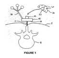
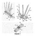
図1は、モジュール式の器具1の実施形態を示している。 FIG. 1 shows an embodiment of a modular instrument 1.
器具1は、放射線不透過性材料、例えば、プラスチックで作られたベース10(基部)を含む。 The instrument 1 includes a base 10 (base) made of radiopaque material, for example plastic.
ベース10は、患者の骨Bに剛的に固定されることが意図されている。 The
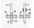
本明細書において、「剛的に固定される」(“rigidly fixed”)は、外科的介入中にベースが骨に対して動かないことを意味する。固定は、(例えば、図1に示すように、最小侵襲的な方法で骨に移植される少なくとも1つの経皮的ピン2、針、ブローチ又はネジを使用して)直接的であってよく、或いは間接的であってよい(即ち、骨に近い皮膚上の接着テープ、ストラップ等のような、骨に対して外部的な取付手段を使用して、患者の皮膚を通過せずに、骨に対してベースを固定してよい)。例えば、図2に示すように、変形可能な材料3がベース10と皮膚Sとの間に介装される。変形可能な材料は、シリコン、熱硬化性樹脂フォーム(thermodurcissable form)、真空下で堅くさせることができるマイクロビーズを含むバッグ、又は接着テープであり得る。身体部分形状に適合する材料3は、特に平坦でない領域において、骨に対するベースに対して幾らかの安定性をもたらす。材料の接着特性によって、或いはベースを取り囲む接着テープ、ストラップのような、外部手段によって、材料3と皮膚及びベースとの間の接着を得ることができる。間接的な固定は、骨とベースとの間に小さい厚さの軟組織があるに過ぎないときに特に適応性がある。何故ならば、この状況は、骨に対するベースの如何なる動きをも妨げる十分な剛性をもたらすと考えられるからである。例えば、骨が患者の指、手首、足などに関係するときに、間接的な固定を使用することができる。そのような間接的な固定は、非侵襲的であるという利点を有する。必要とされるならば、直接的及び間接的な固定を組み合わせることができる。例えば、図3の実施形態において、ベース10は、身体部分形状に適合する変形可能な材料3を介して皮膚Sに連結(リンク)され、少なくとも1つの経皮的ピン2、ブローチ、針又はネジが、骨Bをベース10に更に固定する。幾つかの骨又は幾つかの骨片に対して介入が行われるならば、多数のベース、即ち、骨又は骨片毎に1つのベースを使用することが可能である。幾つかの骨の複雑な関節のような好ましい実施形態では、剛的になることができる変形可能な材料を先ず使用して個々の骨又は骨片を互いに固定する。即ち、従来的なプラスタ、熱変形可能な材料、真空を有する微小球のポーチ(poach)など。次に、この変形可能な材料がひとたび剛的になると、ベースをこの変形可能な材料に固定する。 As used herein, “rigidly fixed” means that the base does not move relative to the bone during a surgical intervention. The fixation may be direct (eg, using at least one
ベース10は、骨に面することが意図された支持面11を有する(患者の皮膚又は骨を取り囲む組織は、ベースと骨との間に配置されてよい)。支持面11は、特に、ベースが固定されなければならない身体部分の形状及びサイズ(大きさ)に依存して、意図された用途に適した任意の形状(例えば、円形、長方形など)及びサイズを有してよい。例えば、脊柱手術の場合、ベースは、好ましくは、少なくとも2つ又は3つの隣接する椎骨に固定されるよう細長い形状を有するが、肩関節手術の場合、ベースは、むしろ、肩峰に固定されるよう長円形の拡張部を備える円形である。支持面11は、平面内で延びてよく、或いは、凹状又は凸状であってよく、剛性又は変形可能であってよい。 The
以下により詳細に示すように、固定は、好ましくは、患者を傷つるのを避けるために、特に、数時間続くことがある外科的介入の間に褥瘡を引き起こすのを避けるために、支持面11と皮膚Sとの間のあらゆる接触を避けるように設計される。よって、好ましい実施形態において、支持面11は、患者の皮膚から一定の距離に維持されることが有利である。 As will be shown in more detail below, the fixation preferably supports
ベースは、概ね20mm未満の高さを有することが有利である。このようにして、ベースは極めてコンパクトであり、患者の皮膚から限定的な程度までしか突出しない。よって、医療スタッフが意図せずにベースに当たること、よって、外科的介入中に骨に対してベースを変位させる可能性は極めて低い。 Advantageously, the base has a height of generally less than 20 mm. In this way, the base is extremely compact and protrudes to a limited extent from the patient's skin. Thus, it is very unlikely that the medical staff will unintentionally hit the base and thus displace the base relative to the bone during surgical intervention.
ベース10は、ベースに剛的に結合されたトラッカ20を有する。結合(coupling)は、恒久的であり得る(トラッカはベースと一体であるか或いはベースに不可逆的に固定され得る)し、或いは一時的であり得る(トラッカはベースから取り外し可能であり得る)。 The
好ましい実施形態によれば、トラッキングが必要とされないときには、トラッカをベースから取り外すことによって一時的な結合を提供することができる。これは医療スタッフをトラッカに当たらせることによって骨に対するベースの変位を引き起こすリスクを減少させる。それはトラッカが必要とされないときに手術空間(operating space)も節約する。 According to a preferred embodiment, when tracking is not required, a temporary coupling can be provided by removing the tracker from the base. This reduces the risk of causing base displacement relative to the bone by hitting the medical staff against the tracker. It also saves operating space when a tracker is not needed.
一時的な結合の場合、ベース及びトラッカは、再現可能な方法で(即ち、ベースに対して常に同じ既知の位置及び向きで)トラッカを取り外し且つ取り付けることを可能にする、協働する固定手段を有する。 In the case of temporary coupling, the base and the tracker have cooperating locking means that allow the tracker to be removed and attached in a reproducible manner (ie always in the same known position and orientation relative to the base). Have.
ある実施形態によれば、トラッカは、(能動的又は受動的な)光学トラッカである。例えば、図1に示す実施形態において、トラッカは、既知の相対的な位置を有する複数の反射ボールを含む。 According to an embodiment, the tracker is an optical tracker (active or passive). For example, in the embodiment shown in FIG. 1, the tracker includes a plurality of reflective balls having known relative positions.
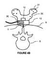
他の実施形態によれば、トラッカは電磁トラッカである。電磁トラッカは、光学トラッカよりもコンパクトであるという利点を有する。例えば、図4Aに示す実施形態において、トラッカ20は、再現可能な固定手段12,250でベース10に取り付けることができる支持体25に埋め込まれている。図4Bに示す代替的な実施形態において、トラッカ20は、ベース10の凹部内に収容され、よって、ベースから突出しない。トラッカ20は、ベース10から取り外し可能であっても取り外し可能でなくてもよい。好ましい実施形態において、電磁トラッカは、アーチファクトの存在を検出するために使用することができる慣性センサを含む。 According to another embodiment, the tracker is an electromagnetic tracker. Electromagnetic trackers have the advantage of being more compact than optical trackers. For example, in the embodiment shown in FIG. 4A, the
本発明は、特定のトラッキングに限定されず、当業者は、記載された実施形態を選択された技術に適合させることができる。 The present invention is not limited to a particular tracking, and those skilled in the art can adapt the described embodiments to the chosen technology.
器具1は、ベース10に剛的に取り付けられるように意図された位置合わせファントム30(registration phantom)を更に含む。位置合わせファントム30は、放射線不透過性材料で作られ、既知の位置に配置される既知の形状及びサイズを有する複数の放射線不透過性基準31(radiopaque fiducials)(例えば、ボール又はピン)を含む。 The instrument 1 further includes a
2D画像が医療撮像システムで取得されるとき、放射線不透過性基準は2D画像内で見える。放射線不透過性基準の形状、サイズ及び配置(arrangement)は知られているので、較正ファントム(calibration phantom)を参照して画像を決定することができ、各2D画像内の放射線不透過性基準の位置に基づいて3D再構築を実行することができる。基準を使用せずに直接的に3D画像再構築を実行し、次に、再構築された3D画像内の基準を直接的に検出することも可能である。 When a 2D image is acquired with a medical imaging system, the radiopaque criteria are visible in the 2D image. Since the shape, size and arrangement of radiopaque criteria are known, the images can be determined with reference to a calibration phantom, and the radiopaque criteria of each 2D image can be determined. A 3D reconstruction can be performed based on the location. It is also possible to perform 3D image reconstruction directly without using the criteria, and then directly detect the criteria in the reconstructed 3D image.
位置合わせファントム30は、外科的介入の全体の間に必要とされるのでなく、医療撮像システムによって取得される画像の位置合わせが実行されなければならない特定の時間にのみ必要とされるので、位置合わせファントム30はベース10から取り外し可能である。 The
この目的を達成するために、ベース10及び位置合わせファントム30は、位置合わせファントムを再現可能な方法で(即ち、ベースに対して常に同じ既知の位置及び向きで)取り付けることを可能にする、協働する固定手段12,32を有する。これはファントムが必要とされないときに手術空間を節約するのを可能にする。 To achieve this goal, the
位置合わせファントム30は、意図される用途に適した任意の形状及びサイズを有してよい。特に、位置合わせファントム30は、画像位置合わせのために必要とされるときにのみベースに取り付けられるので、位置合わせファントム30は、ベースよりも大きいサイズを有することができる。このようにして、放射線不透過性ボールを互いからより大きな距離に配置させることによって位置合わせの精度を向上させることが可能である。 The
ある実施形態によれば、固定手段は、支持面11とは反対側のベースの表面に突出する少なくとも1つのフィンガ12と、位置決めファントム30にある少なくとも1つの相補的な開口32とを含む。しかしながら、この実施形態は限定的でなく、当業者は、本発明の範囲から逸脱することなく、他の種類の再現可能な固定を設計することができる。 According to an embodiment, the fixing means comprise at least one
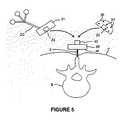
好ましくは、図5に示すように、位置合わせファントム30のための再現可能な固定は、(トラッカがベースから取り外し可能であるときの)トラッカ20についてと同じである。このように、ベースの設計は可能な限り単純であり、ベース上に2つの別個の固定領域を設けることによって空間が失われることはない。 Preferably, as shown in FIG. 5, the reproducible fixation for the
有利には、位置合わせファントムは、そして、該当する場合、トラッカは、ベースに配置される磁石の故に、磁力を用いてベース上で維持される。よって、位置合わせファントムの、そして、当て嵌まる場合、トラッカの取付け及び取外しを、如何なるツールをも必要とせずに容易に行うことができる。この磁気固定は、ある程度のレベルの力がベースに取り付けられる部分に対して加えられるならば自動的に取り外され、それは骨に対するベースの相対的な位置及び固定を損傷し或いは変位させるのを回避するという利点を有する。 Advantageously, the alignment phantom and, if applicable, the tracker are maintained on the base using magnetic forces because of the magnets arranged on the base. Thus, the alignment phantom and, if applicable, the tracker can be easily attached and removed without the need for any tools. This magnetic fixation is automatically removed if a certain level of force is applied to the part attached to the base, which avoids damaging or displacing the relative position and fixation of the base with respect to the bone. Has the advantage.
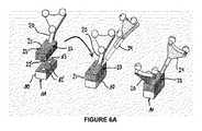
図6Aに示す実施形態によれば、ベースに対するトラッカの1つ又はそれよりも多くの決定された可能な位置を可能にする再現可能な固定によって、トラッカをベースに取り外し可能に固定することができる。例えば、トラッカ20は、ベースの支持面11とは反対側の表面にあるそれぞれの円筒形の開口12’と係合する2つの円筒形の突起22’を含む支持体21を含む。ベースは、支持面11とは反対側の表面から延びるフィンガ13を更に含む。トラッカの支持体21は、トラッカが第1の可能な位置でベースに固定されるときに1つの通路23と係入するように構成され(図6Aの中央を参照)且つトラッカが第2の可能な位置でベースに固定されるときに他の通路に係入するように構成される(図6Aの右側を参照)2つの通路23を含む。以下により詳細に説明するように、フィンガ13の頂部は、トラッキングされたツール24を用いてベースに対するトラッカの実際の位置を決定する基準点(reference point)として働く。そのような対称的な固定は、特にナビゲーションのために使用される位置特定カメラの位置に依存して、手術空間にトラッカを位置付けるより多くの柔軟性を医療スタッフにもたらす点において、有利である。それは外科処置の開始時に骨の上でのベースの位置決めに関連する制約を解除することにも有利である。医療スタッフは、骨に対するベースの位置決めに焦点を置き、骨固定の骨質のみに依存して位置決め方向を選択し、然る後、適切な手術設定に依存してベースの上にトラッカを位置付けることができる。他方、図6Bに示すように、ベース10に対する位置合わせファントム30の再現可能な固定は特異である。この目的を達成するために、位置合わせファントム30は、ベースの支持面11とは反対側の表面にある円筒形の開口12’と協働するが、フィンガ13について1つの通路33とだけ協働する、2つの円筒形の突起32’を含む。上述の実施形態において、ベースに対するトラッカの2つの可能な位置は対称的である。しかしながら、トラッカのために2つよりも多くの可能な位置があってよい。例えば、実質的に円形の形状を有するベースの場合(図示せず)、再現可能な固定は、ベースの中心にある円錐の突起と、トラッカの可能な位置を定めるよう所与の角度位置に配置されるフィンガとを含むことができる。 According to the embodiment shown in FIG. 6A, the tracker can be removably secured to the base by a reproducible fixation that allows one or more determined possible positions of the tracker relative to the base. . For example, the
図7は、少なくとも1つの経皮的ピン2、ネジ、針、又はブローチによって骨に固定されることが意図されるベース10の3つの実施形態(A)乃至(C)を示している。以下の記述において、「ピン」(“pin”)という用語は、ネジ、ブローチ、針を含む、ベースを骨に固定するあらゆる細長い経皮デバイスを示すために使用される。一般的に、そのようなピンは、皮膚の穿孔及び骨への移植を可能にするよう尖った先端200を有し、0.5〜8mmの間の直径を有する。 FIG. 7 shows three embodiments (A) to (C) of the base 10 intended to be fixed to the bone by at least one
好ましい実施形態によれば、ピン2は、先端200から限定的な距離(数ミリメートル、例えば4mm)に配置された肩部201(shoulder)を含む。肩部201は、開業医がピンを前記限定的な距離から更に骨内に挿入することを防止する当接部(abutment)を形成する。これは、ピンが骨の所望の領域に正確に挿入されない場合に、骨又は周囲の組織(例えば、脊柱管(spine canal)、血管構造)を損傷するのを避ける安全手段である。加えて、開業医は、肩部が骨に接触することを検知することによって、ピンが骨内に十分に移植されていることを制御してもよい。 According to a preferred embodiment, the
ベースは、それぞれのピン2を通すための複数の貫通穴14を含む。各貫通穴14は、ピンの直径と相補的な直径を備える円筒形状を有する。各貫通穴14は、ピンを案内し且つベースに対するピンの如何なる枢動をも回避するよう、十分な高さを有する。貫通穴の数は、骨への最適な固定をもたらすために、開業医がピンを受け入れるのに最も適した穴を選択するための大きな選択肢を提供するよう、多いのが有利である。骨に対するベースの回転を防止するためには、少なくとも3つのピンが必要とされる。好ましくは、ベースのあらゆる動きも防止することを可能にする多数の拘束(constrains)を創り出すために、より多くの数のピンを使用する。 The base includes a plurality of through
有利には、貫通穴14は、ベースのより安定的な固定をもたらすよう、互いに平行でない(ピンの多数の角度は、多数の拘束状況を創り出す)。加えて、非平行ピンは、ベースと皮膚との間の距離を維持することを可能にし(図8を参照)、それは下に位置する組織に適用される機械的拘束を制限する。 Advantageously, the through
ピンは、ひとたび各ピンが骨に移植されてベースに固定されると、各ピンが破損されるのを可能にする、ノッチ(図示せず)を含んでよい。このようにして、ベースより上に延びるピンの部分を除去することができ、よって、手術空間を妨害しない。これはファントム及びトラッカの固定も容易にする。さもなければ、ピンは鋭いエッジを備える適切なプライヤによって切断されてよい。 The pins may include notches (not shown) that allow each pin to be broken once each pin is implanted in the bone and secured to the base. In this way, the portion of the pin that extends above the base can be removed and thus does not interfere with the surgical space. This also facilitates fixing of the phantom and tracker. Otherwise, the pins may be cut by suitable pliers with sharp edges.
図7の実施形態(A)において、ベース10は、貫通穴14を含む幾つかの領域を備える実質的に長方形の形状を有する。有利には、貫通穴が配置される領域は、貫通穴の所要の高さを定める限定的な厚さを有し、前記領域は、ベースの剛性を増大させるために、周辺フランジによって取り囲まれる。ピンが骨に固定されてベースに固定された後に、ピンが破壊され或いは切断されるならば、切口は、ベースから突出しないように、周辺フランジ内に配置されるのが好ましい。 In the embodiment (A) of FIG. 7, the
図7の実施形態(B)において、ベースは、部分10aの長手方向の側部から延びる2つのウイング10b(翼)を備える実質的に長方形の中央部分10aを有する。各ウイング10bは、有利には、支持面11に対して傾斜させられ、同様に支持面11に対して傾斜させられた複数の貫通穴14を含む。ウイング10bは、貫通穴のアクセス性の増大の故に、使いやすさの向上をもたらす。中央部分10aは、複数の貫通穴を含むこともできる。 In the embodiment (B) of FIG. 7, the base has a substantially rectangular
図7の実施形態(A)、(B)及び(C)において、ベース10は、ベースのそれぞれの縁から内向きに延びる少なくとも1つの(好ましくは2つの)長手方向スロット15を更に含む。各スロットは、支持面11までベースの高さを通じて延在する。スロットは、ベースを骨に対して予め位置決めすることを可能にする。第1に、開業医は、互いに平行でない2つのピン2を骨に取り付けることができる。ピンの位置は、骨への良好な固定を保証するよう有利に選択される。具体的には、開業医は、ピンの先端を移植するのに最適な骨領域を選択する。次に、開業医は、各々の予め位置決めされたピン2がそれぞれのスロット15に入るよう、ベースを位置付けることができる。次に、開業医は、ベース10がピン2に楔止めされる、ベースの最終位置に達するまで、ベースをピン2に沿ってスライドさせる。例えば、開業医は、下に位置する骨の形状を手動で検知して、ベースがベースを最適に固定し得る骨の部分に対して正しく配置されているか否かを決定することができる。次に、ベースを骨に剛的に固定するために、追加的なピン2を貫通穴14に通すことができる。 In the embodiments (A), (B) and (C) of FIG. 7, the base 10 further includes at least one (preferably two)
図7の実施形態(C)において、貫通穴14は、ベースの中央部分にある同心円に沿って更に配置される。中央の貫通穴を前記円の中心に配置することもできる。有利には、円の貫通穴は、全て、円によって異なる共通の点に向かって収束する。 In the embodiment (C) of FIG. 7, the through
もちろん、実施形態(A)乃至(C)は限定的でなく、当業者は、貫通穴14のための、存在するならば、スロット15のための、他の構成を定めることができる。具体的には、本発明の範囲から逸脱することなくこれらの実施形態の構成を組み合わせることができる。 Of course, the embodiments (A) to (C) are not limiting, and those skilled in the art can define other configurations for the through
モジュール式の器具は、異なるサイズ及び/又は形状の幾つかのベースを含むが、単一のトラッカ及び単一の位置合わせファントムを含む、キットとして提示されてよい。ベースのこの多様性は、開業医が、治療されるべき身体部分及び/又は患者の特殊性に依存して、最も適切なベースを選択するのを可能にする。例えば、肥満の患者の場合、貫通穴の角度は、やせた患者の場合よりも大きいことが必要とされることがある。逆に、モジュール式の器具は、異なるサイズ及び/又は形状の幾つかの位置合わせファントム及び/又はトラッカを含むが、単一のベースを含む、キットとして提示されてよい。他の実施形態によれば、キットは、異なるサイズ及び/又は形状を有する複数のベースと、ベースの各々に再現可能に取り付けられることができる異なるサイズ及び/又は形状の複数のトラッカ及び複数の位置合わせファントムとを含む。この多様性は、開業医が、実現することを欲する外科処置に依存して適切な器具を選択することを可能にする。例えば、その椎骨が大きく変形した脊柱側弯症の患者の場合、トラッカの再現可能な面に関する反射球の向き及びその全体的な外形寸法は、標準的な患者に対して変更させられることが必要とされることがある。 Modular instruments include several bases of different sizes and / or shapes, but may be presented as a kit that includes a single tracker and a single alignment phantom. This variety of bases allows the practitioner to select the most appropriate base depending on the body part to be treated and / or the patient's particularity. For example, for obese patients, the angle of the through hole may be required to be larger than for thin patients. Conversely, a modular instrument may be presented as a kit that includes several alignment phantoms and / or trackers of different sizes and / or shapes, but includes a single base. According to other embodiments, the kit includes a plurality of bases having different sizes and / or shapes, a plurality of trackers and a plurality of positions of different sizes and / or shapes that can be reproducibly attached to each of the bases. Including a matching phantom. This diversity allows the practitioner to select the appropriate instrument depending on the surgical procedure they wish to achieve. For example, in a scoliosis patient whose vertebrae are greatly deformed, the orientation of the reflective sphere with respect to the reproducible surface of the tracker and its overall outer dimensions need to be changed with respect to a standard patient. May be.
骨に対するベースの正しい位置が決定され、ピンが貫通穴(そして、該当する場合には、(複数の)スロット)に通され、骨に移植されるとき、開業医は、ピンをベースに可逆的に固定する。 When the correct position of the base relative to the bone is determined and the pin is passed through the through hole (and slot (s) if applicable) and implanted into the bone, the practitioner reversibly relies on the pin as a base. Fix it.
図9は、ピンをベースに固定する様々な方法を例示している。 FIG. 9 illustrates various methods of securing the pin to the base.
実施形態(A)において、ピン2は、貫通穴14のネジ山付き区画と協働するネジ山付き端を有する。 In embodiment (A), the
実施例(B)において、ピン2は、ピンの周りに滑動的(摺動的)に配置された要素2bを備える。ひとたびピンが骨に移植されると(左側)、開業医は、対応するハウジング10cをベースに係入するまで、要素2bをスライド(摺動)させる。次に、開業医は、埋伏(impaction)(及び要素の外形の可能な変形)を介して、要素2bをハウジング10c内に固定する(中央)。要素は、楔形(左側及び中央)又は丸い状形(右側)を有することができる。 In the embodiment (B), the
実施形態(C)において、ベースは、貫通穴の方向に対して実質的に直交する方向に延びて貫通穴に至る、ネジ山付き穴10dを備える。よって、ピンを骨に移植するときには、ピン2に接触して加圧するまで、圧力ネジ2dを穴10dにネジ込むことができる。 In embodiment (C), the base includes a threaded hole 10d that extends in a direction substantially perpendicular to the direction of the through hole to reach the through hole. Therefore, when the pin is transplanted into the bone, the pressure screw 2d can be screwed into the hole 10d until the
実施形態(D)において、貫通穴を取り囲むベースの領域は、ピン2のためのクランプを形成するよう変形可能であることができ、圧力ネジ2d、変形可能なクリップ又は任意の他の適切な手段によって、ピンがひとたび骨に移植されると、クランプに圧力を加えることができる。この実施形態は、図7(B)及び(C)に示すように、ピンをスロット15内に固定するのにも適している。 In embodiment (D), the region of the base surrounding the through hole can be deformed to form a clamp for the
実施形態(E)において、貫通穴14は、ベースの外側から延び、ピン2の直径よりも大きい幅を有する、スロットの形態である。ピンがひとたび骨に移植されると、楔要素2eが穴に挿入され、ピンを貫通穴の壁に対して強制的に維持する。この実施形態は、図7(B)及び(C)に示すように、ピンをスロット15内に固定するのにも適している。 In embodiment (E), the through
他の実施形態において、(図8に示すような)様々な角度で方向付けられた多数のピンは、如何なる外部手段をも必要とせずにベースを固定することを可能にする。 In other embodiments, multiple pins oriented at various angles (as shown in FIG. 8) allow the base to be secured without the need for any external means.
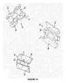
図10は、位置合わせファントム30の様々な実施形態を例示している。有利には、位置合わせファントム30は、ベースに固定されることが意図される中央部分30aと、中央部分30aの両側で延びる2つの側方ウイング30bとを含む。好ましくは、側方ウイングは、中央部分と一体的である。用途に依存して、ベース及び側方ウイングは、実質的に平面内に延在してよい。さもなければ、側方ウイングは、中央部分に対して傾斜してよい。他の実施形態において、側方ウイングは、中央部分より上に延びてよい。 FIG. 10 illustrates various embodiments of the
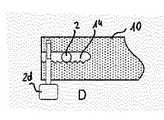
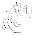
図11は、トラッカ20及び位置合わせファントム30の概略的な実施形態を示している。ベース10は、骨に対する最適な安定性を有するためにコンパクトであるのが好ましいが(例示において、ベースは2つのピンによって骨に固定されるが、ベースは上述のいずれかの直接的又は間接的な方法で固定されることもできる)。対照的に、トラッカ20及び/又は位置合わせファントム30は、トラッカ及び/又は位置合わせファントムをベースに対してオフセットした位置に配置することを可能にするそれぞれの細長い部材26,34を含む。細長い部材26,34は、破線で表されており、それらの形状及び寸法は、意図される外科的適用に依存する。これらの細長い部材は、骨固定及びアクセス性に関してベースを最適な位置に維持しながら、トラッカ及び/又はベースの位置を最適化することを可能にする。例えば、細長い部材34は、3D画像の再構築のために放射線不透過性基準31を最適な位置にあるようにさせるために、位置合わせを撮像領域の中心付近に配置することを可能にすることがある。光学トラッカの場合、細長い部材26は、トラッカを位置特定カメラの視野内の最適な位置に配置することを可能にすることがある。細長い部材26は、開業医のための空間を解放するために、介入部位から離してトラッカを配置することを可能にすることがある。電磁トラッカの場合、細長い部材26は、より精密な位置特定をもたらすために、介入部位の近くにトラッカを配置することを可能にすることがある。 FIG. 11 shows a schematic embodiment of the
以下のプロトコルに従ってモジュール式の器具を使用することができる。 Modular instruments can be used according to the following protocol.
プロトコル1 Protocol 1
図12は、上述のような器具を使用して外科的介入の間に実施されてよいプロトコルを表すフローチャートである。 FIG. 12 is a flowchart representing a protocol that may be performed during a surgical intervention using an instrument as described above.
ステップ101において、ベースを直接的又は間接的な方法で骨に剛的に取り付ける。 In
ステップ102において、再現可能な固定手段を用いて位置合わせファントムをベースに取り付ける。 In
ステップ103において、電動医療撮像システムは、骨の領域内の患者の画像を取得する。 In
ステップ104では、撮像システムを参照して定められる3DボリュームVimageを生成するために、コンピュータによって3D再構築アルゴリズムを実行する。3D再構築自体は知られている。よって、ここでは3D再構築を詳細に記載しない。In
他方、コンピュータのメモリに格納されている或いは他のシステムからダウンロードされてよい(RFphantomと印す)既知のファントム寸法に基づいて位置合わせファントムを参照して3Dボリュームを生成するために、コンピュータによって位置合わせアルゴリズムを実行する。この3DボリュームをVphantomと呼ぶ。On the other hand, by a computer to generate a 3D volume with reference to an alignment phantom based on known phantom dimensions (marked as RFphantom ) that may be stored in a computer's memory or downloaded from another system Run the alignment algorithm. This 3D volume is called Vphantom .
ステップ105において、位置合わせファントムをベースから取り除き、(トラッカがベースに恒久的に取り付けられていないならば)再現可能な固定を使用してトラッカをベースに取り付ける(その場合、トラッカは全プロトコル中に存在する)。 In
トラッカはベースに対する(RFtrackerと印す)既知の位置及び固定を有するので、コンピュータは、トラッカを参照して上述の3Dボリュームを生成するアルゴリズムを実装する。この3DボリュームをVtrackerと呼ぶ。Since the tracker has a known position and fixation (marked as RFtracker ) with respect to the base, the computer implements an algorithm that generates the 3D volume described above with reference to the tracker. This 3D volume is called a Vtracker .
ステップ106では、トラッカがカメラの視野内にあるように、位置特定カメラを患者の近傍に設置する。 In
コンピュータは、カメラを参照して3Dボリュームを生成するアルゴリズムを実装する。この3DボリュームをVcameraと呼ぶ。The computer implements an algorithm that generates a 3D volume with reference to the camera. This 3D volumeis referred to as Vcamera .
ステップ107において、外科的介入を実行するために、トラッキングされたツールを手術野に導入する。(RFtoolと印す)ツール先端の位置が毎回知られているように、このツールは位置特定カメラの視野にもある。ツール先端の位置はコンピュータのメモリに格納されてよく、或いは他のシステムからダウンロードされてよい。 In
次に、コンピュータは、トラッキングされたツールを参照して3Dボリュームを生成するために、アルゴリズムを実行する。この3DボリュームをVtoolと呼ぶ。よって、ボリュームVtool内のツールのナビゲーションを行うことができる。The computer then executes an algorithm to generate a 3D volume with reference to the tracked tool. This 3D volume is referred to asVtool . Therefore, navigation of tools in the volume Vtool can be performed.
プロトコル2
図13は、ベースに対するトラッカの対称的固定の場合に実行されてよい代替的なプロトコルを表すフローチャートである。 FIG. 13 is a flow chart representing an alternative protocol that may be executed in the case of symmetric fixing of the tracker to the base.
図12と同じ参照番号を有するステップは、第1のプロトコルにおけると同じステップに対応する。よって、それらのステップを再び記載しない。 Steps having the same reference numbers as in FIG. 12 correspond to the same steps as in the first protocol. Therefore, those steps are not described again.
ステップ105において、トラッカを2つの可能な対称位置のいずれか1つにおいてベースに取り付ける。有利には、ナビゲーションのために使用される位置特定カメラの最適な視野に対応する或いは手術室内のカメラ構成の直接的な結果としての位置にトラッカを位置付ける。 In
トラッカはベースに対して既知の位置及び固定を有するので、コンピュータは、トラッカが第1の位置(例えば、左側)にあると想定してトラッカを参照する第1の3Dボリューム、及びトラッカが第2の位置(例えば、右側)にあると想定してトラッカを参照する第2の3Dボリュームを生成する、アルゴリズムを実装する。これらの3DボリュームをそれぞれVtracker L及びVtracker Rと呼ぶ。Since the tracker has a known position and fixation relative to the base, the computer assumes that the tracker is in a first position (eg, the left side) and a first 3D volume that references the tracker and a tracker is the second. Implement an algorithm that generates a second 3D volume that references a tracker assuming that it is in the position (eg, on the right). These 3D volumes are called Vtracker L and Vtracker R , respectively.
ステップ106では、トラッカがカメラの視野内にあるように、位置特定カメラを患者の近くに設置する。 In
コンピュータは、カメラを参照して上述の3Dボリュームの各々を生成するアルゴリズムを実装する。これらの3DボリュームをそれぞれVcamera L及びVcamera Rと呼ぶ。The computer implements an algorithm that generates each of the 3D volumes described above with reference to the camera. These 3D volumes are referred to as Vcamera L and Vcamera R , respectively.
ステップ107では、外科的介入を実行するために、トラッキングされたツールを手術野に導入する。ツール先端の位置が毎回知られているように、このツールは位置特定カメラの視野にもある。ツール先端の位置はコンピュータのメモリ内に格納されてよく、或いは他のシステムからダウンロードされてよい。 In
次に、コンピュータは、トラッキングされたツールを参照して上述の3Dボリュームの各々を生成するために、アルゴリズムを実行する。これらの3DボリュームをそれぞれVtool L及びVtool Rと呼ぶ。The computer then executes an algorithm to generate each of the 3D volumes described above with reference to the tracked tool. These 3D volumes are referred to as Vtool L and Vtool R , respectively.
ベースに対するトラッカの現実の位置を決定するために、よって、Vtool L又はVtool Rの間を選択するために、ベース上の基準点をその先端と接触させるように、(上記のツールと同じツール又は他のツールであってよい)トラッキングされたツールを位置付ける(ステップ108)。In order to determine the actual position of the tracker relative to the base, and thus to select between Vtool L or Vtool R , the reference point on the base is brought into contact with its tip (same as above tool Position the tracked tool (which may be a tool or other tool) (step 108).
(RFreference pointと呼ぶ)基準点の位置は知られているので、コンピュータは、基準点の位置とツール先端の位置とを比較し、相応して参照(referential)(L又はR)を選択する、アルゴリズムを実行する(ステップ109)。Since the position of thereference point (referred to as RFreference point ) is known, the computer compares the position of the reference point with the position of the tool tip and selects the referential (L or R) accordingly. The algorithm is executed (step 109).
よって、適切な参照におけるツールのナビゲーションを実行することができる。 Thus, tool navigation in an appropriate reference can be performed.
上述のプロトコルは、各時点で知られているツール先端、基準点、ファントム寸法、トラッカ寸法のような基準特徴(reference features)を参照する。 The above protocol refers to reference features such as tool tips, reference points, phantom dimensions, tracker dimensions known at each point in time.
好ましい実施形態において、これらの基準特徴は、コンピュータのメモリ内に格納されてよい。 In preferred embodiments, these reference features may be stored in the memory of the computer.
他の実施形態において、基準特徴は、器具の較正器及び/又は位置特定システム自体の較正アルゴリズムのような、システムの一部によって生成されてよい。この実施形態は、特に再使用可能な器具の使用に適する。 In other embodiments, the reference features may be generated by a part of the system, such as an instrument calibrator and / or a calibration algorithm of the localization system itself. This embodiment is particularly suitable for use with reusable instruments.
他の実施形態において、基準特徴は、記憶装置(即ち、外部USBデバイス)又はメモリデバイスに直接的にリンクされる或いはシステムに据え付けられるバーコードリーダ若しくはデータ行列リーダのような講義デバイスであってよい、他のシステムからダウンロードされてよい。有利には、データ行列(データマトリックス)(datamatrix)(即ち、QRコード(登録商標))は、システムに転送されるべき全ての基準寸法を含み、器具パッケージ内のカードフォーマットに印刷されてよい。この実施形態は、特に使捨て器具の使用に適する。それは参照特徴の修正の場合にソフトウェアのアップグレードを必要としないという利点を提示する。例えば、図14は、ベースのための識別カードC10を示している。この実施形態において、ベースの基準特徴は、カードに印刷されたバーコードBCに含められる。図15は、ベース、位置合わせファントム、トラッカ及びツールのための識別カードC10、C30、C20及びC24をそれぞれ示している。前記コンポーネントのそれぞれの基準特徴は、カードに印刷されたデータ行列(それぞれQR10、QR30、QR20及びQR24)に含められる。よって、ユーザが新しいコンポーネントを使用することを欲するとき、ユーザは、前記コンポーネントの基準特徴をダウンロードするために、適切なリーダを使用してバーコード又はデータ行列を読み取るだけでよい。次に、コンピュータは、プロトコルの実行中に前記基準特徴を使用する。 In other embodiments, the reference feature may be a storage device (ie, an external USB device) or a lecture device such as a barcode reader or data matrix reader that is directly linked to the memory device or installed in the system. May be downloaded from other systems. Advantageously, a data matrix (ie QR code®) may be printed in a card format within the instrument package, including all reference dimensions to be transferred to the system. This embodiment is particularly suitable for use with disposable instruments. It presents the advantage that no software upgrade is required in case of reference feature modification. For example, FIG. 14 shows an identification card C10 for the base. In this embodiment, the base reference features are included in the barcode BC printed on the card. FIG. 15 shows identification cards C10, C30, C20 and C24 for the base, alignment phantom, tracker and tool, respectively. Each reference feature of the component is included in a data matrix printed on the card (respectively QR10, QR30, QR20 and QR24). Thus, when a user wants to use a new component, the user need only read the barcode or data matrix using an appropriate reader in order to download the reference features of the component. The computer then uses the reference feature during the execution of the protocol.
Claims (12)
Translated fromJapanese前記ベースは、
前記骨に面することが意図される支持面と、
前記ベースを通じてそれぞれの経皮的ピンを通す複数の非平行な貫通穴と、
該貫通穴に対して横方向に前記ベースの縁から延びる少なくとも1つのスロットと、
前記トラッカ及び/又は前記位置合わせファントムを前記ベースに取り付ける再現可能な固定システムとを含み、
前記スロットは、前記支持面まで前記ベースを通じて延び、前記スロットは、前記ベースが経皮的ピンに沿って滑動することを可能にするよう、前記患者の骨内に移植される経皮的ピンと係合することが意図される、
デバイス。A device for minimally invasive attachment of a tracker and / or alignment phantom to a patient's bone comprising a base made of a radiopaque material comprising:
The base is
A support surface intended to face the bone;
A plurality of non-parallel through-holes through each percutaneous pin through the base;
At least one slot extending from an edge of the base transversely to the through hole;
A reproducible fastening system for attaching the tracker and / or the alignment phantom to the base,
The slot extends through the base to the support surface, and the slot is associated with a percutaneous pin that is implanted into the patient's bone to allow the base to slide along the percutaneous pin. Intended to
device.
Applications Claiming Priority (3)
| Application Number | Priority Date | Filing Date | Title |
|---|---|---|---|
| EP15306635 | 2015-10-14 | ||
| EP15306635.2 | 2015-10-14 | ||
| PCT/EP2016/074784WO2017064290A1 (en) | 2015-10-14 | 2016-10-14 | Device for minimally invasive attachment of a tracker and/or a registration phantom to a patient's bone |
Publications (3)
| Publication Number | Publication Date |
|---|---|
| JP2018532484Atrue JP2018532484A (en) | 2018-11-08 |
| JP2018532484A5 JP2018532484A5 (en) | 2021-02-18 |
| JP6843851B2 JP6843851B2 (en) | 2021-03-17 |
Family
ID=54360376
Family Applications (1)
| Application Number | Title | Priority Date | Filing Date |
|---|---|---|---|
| JP2018518689AActiveJP6843851B2 (en) | 2015-10-14 | 2016-10-14 | Device for minimally invasive attachment of tracker and / or alignment phantom to patient bone |
Country Status (7)
| Country | Link |
|---|---|
| US (1) | US11147649B2 (en) |
| EP (1) | EP3361957B1 (en) |
| JP (1) | JP6843851B2 (en) |
| CN (1) | CN108135590B (en) |
| AU (1) | AU2016337011B2 (en) |
| BR (1) | BR112018007487B1 (en) |
| WO (1) | WO2017064290A1 (en) |
Cited By (1)
| Publication number | Priority date | Publication date | Assignee | Title |
|---|---|---|---|---|
| JP2024521954A (en)* | 2021-06-08 | 2024-06-04 | ストライカー ヨーロピアン オペレーションズ リミテッド | Surgical reference bodies to reference the patient's anatomy during surgery |
Families Citing this family (24)
| Publication number | Priority date | Publication date | Assignee | Title |
|---|---|---|---|---|
| US10653497B2 (en)* | 2006-02-16 | 2020-05-19 | Globus Medical, Inc. | Surgical tool systems and methods |
| US11395706B2 (en)* | 2012-06-21 | 2022-07-26 | Globus Medical Inc. | Surgical robot platform |
| GB2536650A (en) | 2015-03-24 | 2016-09-28 | Augmedics Ltd | Method and system for combining video-based and optic-based augmented reality in a near eye display |
| US10624764B2 (en)* | 2015-11-26 | 2020-04-21 | Orthosoft Ulc | System and method for the registration of an anatomical feature |
| EP3241518B1 (en)* | 2016-04-11 | 2024-10-23 | Globus Medical, Inc | Surgical tool systems |
| FR3057757B1 (en) | 2016-10-21 | 2021-04-16 | Medtech | AUTOMATIC REGISTRATION DEVICE AND METHOD FOR 3D INTRA-OPERATIVE IMAGES |
| TWI689279B (en)* | 2018-04-03 | 2020-04-01 | 寶楠生技股份有限公司 | External fixing device for fracture fixing needle |
| US11980507B2 (en) | 2018-05-02 | 2024-05-14 | Augmedics Ltd. | Registration of a fiducial marker for an augmented reality system |
| US11766296B2 (en) | 2018-11-26 | 2023-09-26 | Augmedics Ltd. | Tracking system for image-guided surgery |
| US20200170751A1 (en)* | 2018-11-30 | 2020-06-04 | Think Surgical, Inc. | System and method for fiducial attachment for orthopedic surgical procedures |
| US12178666B2 (en) | 2019-07-29 | 2024-12-31 | Augmedics Ltd. | Fiducial marker |
| US11980506B2 (en)* | 2019-07-29 | 2024-05-14 | Augmedics Ltd. | Fiducial marker |
| EP4041115A1 (en)* | 2019-10-10 | 2022-08-17 | Intersect ENT International GmbH | Registration method and navigation system |
| EP3821844A1 (en) | 2019-11-12 | 2021-05-19 | Surgivisio | System for determining an optimal position of a surgical instrument relative to a patient's bone tracker |
| US11382712B2 (en) | 2019-12-22 | 2022-07-12 | Augmedics Ltd. | Mirroring in image guided surgery |
| US11389252B2 (en) | 2020-06-15 | 2022-07-19 | Augmedics Ltd. | Rotating marker for image guided surgery |
| US12239385B2 (en) | 2020-09-09 | 2025-03-04 | Augmedics Ltd. | Universal tool adapter |
| US12150821B2 (en) | 2021-07-29 | 2024-11-26 | Augmedics Ltd. | Rotating marker and adapter for image-guided surgery |
| WO2023021448A1 (en) | 2021-08-18 | 2023-02-23 | Augmedics Ltd. | Augmented-reality surgical system using depth sensing |
| EP4230172A1 (en) | 2022-02-17 | 2023-08-23 | Ecential Robotics | Surgical robotic system for cementoplasty |
| EP4511809A1 (en) | 2022-04-21 | 2025-02-26 | Augmedics Ltd. | Systems and methods for medical image visualization |
| IL319523A (en) | 2022-09-13 | 2025-05-01 | Augmedics Ltd | Augmented reality eyewear for image-guided medical intervention |
| EP4344667B1 (en)* | 2022-09-28 | 2025-01-29 | Stryker European Operations Limited | Bone clamp and surgical tracking system comprising the bone clamp |
| WO2024160896A1 (en)* | 2023-01-31 | 2024-08-08 | Lem Surgical Ag | Single origin marker assemblies and methods for their use |
Citations (4)
| Publication number | Priority date | Publication date | Assignee | Title |
|---|---|---|---|---|
| US5935128A (en)* | 1997-04-18 | 1999-08-10 | Bristol-Myers Squibb Co. | Orthopaedic template system including a joint locator |
| JP2005533579A (en)* | 2002-07-25 | 2005-11-10 | オルトソフト インコーポレイテッド | Multiple bone tracker |
| US20060015018A1 (en)* | 2003-02-04 | 2006-01-19 | Sebastien Jutras | CAS modular body reference and limb position measurement system |
| US20140194883A1 (en)* | 2013-01-07 | 2014-07-10 | Zimmer, Inc. | Distal resection systems and methods |
Family Cites Families (10)
| Publication number | Priority date | Publication date | Assignee | Title |
|---|---|---|---|---|
| US5078719A (en) | 1990-01-08 | 1992-01-07 | Schreiber Saul N | Osteotomy device and method therefor |
| US5720752A (en) | 1993-11-08 | 1998-02-24 | Smith & Nephew, Inc. | Distal femoral cutting guide apparatus with anterior or posterior referencing for use in knee joint replacement surgery |
| US8535329B2 (en)* | 2004-10-29 | 2013-09-17 | Kinamed, Inc. | Tracking tools and method for computer-assisted shoulder replacement surgery |
| FR2941364B1 (en) | 2009-01-26 | 2011-02-25 | Univ Joseph Fourier | APPARATUS FOR FIXING AN OPTICAL REFERENTIAL TO A PERSON |
| US9655628B2 (en)* | 2009-05-06 | 2017-05-23 | Blue Ortho | Reduced invasivity fixation system for trackers in computer assisted surgery |
| AU2011239570A1 (en)* | 2010-04-14 | 2012-11-01 | Smith & Nephew, Inc. | Systems and methods for patient- based computer assisted surgical procedures |
| DE202011005573U1 (en)* | 2011-04-21 | 2012-04-23 | Isys Medizintechnik Gmbh | Device for fixation |
| EP2676627B1 (en)* | 2012-04-18 | 2021-07-28 | Medtronic Navigation, Inc. | System and method for automatic registration between an image and a subject |
| EP3175791B1 (en)* | 2013-11-04 | 2021-09-08 | Ecential Robotics | Method for reconstructing a 3d image from 2d x-ray images |
| WO2015090434A1 (en) | 2013-12-20 | 2015-06-25 | Brainlab Ag | Holder for the attachement of a reference marker device to a body part |
- 2016
- 2016-10-14CNCN201680059851.0Apatent/CN108135590B/ennot_activeExpired - Fee Related
- 2016-10-14WOPCT/EP2016/074784patent/WO2017064290A1/ennot_activeCeased
- 2016-10-14AUAU2016337011Apatent/AU2016337011B2/ennot_activeCeased
- 2016-10-14EPEP16784457.0Apatent/EP3361957B1/enactiveActive
- 2016-10-14BRBR112018007487-0Apatent/BR112018007487B1/ennot_activeIP Right Cessation
- 2016-10-14JPJP2018518689Apatent/JP6843851B2/enactiveActive
- 2016-10-14USUS15/768,493patent/US11147649B2/enactiveActive
Patent Citations (4)
| Publication number | Priority date | Publication date | Assignee | Title |
|---|---|---|---|---|
| US5935128A (en)* | 1997-04-18 | 1999-08-10 | Bristol-Myers Squibb Co. | Orthopaedic template system including a joint locator |
| JP2005533579A (en)* | 2002-07-25 | 2005-11-10 | オルトソフト インコーポレイテッド | Multiple bone tracker |
| US20060015018A1 (en)* | 2003-02-04 | 2006-01-19 | Sebastien Jutras | CAS modular body reference and limb position measurement system |
| US20140194883A1 (en)* | 2013-01-07 | 2014-07-10 | Zimmer, Inc. | Distal resection systems and methods |
Cited By (1)
| Publication number | Priority date | Publication date | Assignee | Title |
|---|---|---|---|---|
| JP2024521954A (en)* | 2021-06-08 | 2024-06-04 | ストライカー ヨーロピアン オペレーションズ リミテッド | Surgical reference bodies to reference the patient's anatomy during surgery |
Also Published As
| Publication number | Publication date |
|---|---|
| EP3361957B1 (en) | 2023-07-05 |
| CN108135590B (en) | 2021-10-15 |
| BR112018007487B1 (en) | 2022-11-16 |
| BR112018007487A2 (en) | 2019-04-24 |
| WO2017064290A1 (en) | 2017-04-20 |
| AU2016337011B2 (en) | 2021-07-08 |
| JP6843851B2 (en) | 2021-03-17 |
| US11147649B2 (en) | 2021-10-19 |
| CN108135590A (en) | 2018-06-08 |
| AU2016337011A1 (en) | 2018-05-10 |
| US20180311011A1 (en) | 2018-11-01 |
| EP3361957A1 (en) | 2018-08-22 |
Similar Documents
| Publication | Publication Date | Title |
|---|---|---|
| JP6843851B2 (en) | Device for minimally invasive attachment of tracker and / or alignment phantom to patient bone | |
| US11253322B2 (en) | Fluoro-navigation system for navigating a tool relative to a medical image | |
| JP6850289B2 (en) | Modular fluorescent navigation equipment | |
| EP3494903B1 (en) | Spinous process clamp | |
| JP7661007B2 (en) | Hip replacement navigation system and method | |
| US20180206860A1 (en) | Devices and methods for intra-operative spinal alignment | |
| US8182491B2 (en) | Rigidly guided implant placement | |
| CN116348059A (en) | Spinous process clamp | |
| EP2914187A1 (en) | Patient-specific sacroiliac and pedicle guides | |
| IL262864A (en) | Spinous process clamp | |
| JP2008532707A (en) | Medical fixing member placement system | |
| EP3551113A1 (en) | Systems and methods for en bloc registration in navigated surgery | |
| CN113876423B (en) | Positioning device and system for orthopedic surgery |
Legal Events
| Date | Code | Title | Description |
|---|---|---|---|
| A621 | Written request for application examination | Free format text:JAPANESE INTERMEDIATE CODE: A621 Effective date:20190909 | |
| A977 | Report on retrieval | Free format text:JAPANESE INTERMEDIATE CODE: A971007 Effective date:20200831 | |
| A131 | Notification of reasons for refusal | Free format text:JAPANESE INTERMEDIATE CODE: A131 Effective date:20200929 | |
| A521 | Request for written amendment filed | Free format text:JAPANESE INTERMEDIATE CODE: A523 Effective date:20201222 | |
| A524 | Written submission of copy of amendment under article 19 pct | Free format text:JAPANESE INTERMEDIATE CODE: A524 Effective date:20201222 | |
| TRDD | Decision of grant or rejection written | ||
| A01 | Written decision to grant a patent or to grant a registration (utility model) | Free format text:JAPANESE INTERMEDIATE CODE: A01 Effective date:20210209 | |
| A61 | First payment of annual fees (during grant procedure) | Free format text:JAPANESE INTERMEDIATE CODE: A61 Effective date:20210224 | |
| R150 | Certificate of patent or registration of utility model | Ref document number:6843851 Country of ref document:JP Free format text:JAPANESE INTERMEDIATE CODE: R150 | |
| R250 | Receipt of annual fees | Free format text:JAPANESE INTERMEDIATE CODE: R250 |