JP2018529403A - Scope-mounted INOD handle - Google Patents
Scope-mounted INOD handleDownload PDFInfo
- Publication number
- JP2018529403A JP2018529403AJP2018504245AJP2018504245AJP2018529403AJP 2018529403 AJP2018529403 AJP 2018529403AJP 2018504245 AJP2018504245 AJP 2018504245AJP 2018504245 AJP2018504245 AJP 2018504245AJP 2018529403 AJP2018529403 AJP 2018529403A
- Authority
- JP
- Japan
- Prior art keywords
- distal
- proximal
- sheath
- needle
- proximal end
- Prior art date
- Legal status (The legal status is an assumption and is not a legal conclusion. Google has not performed a legal analysis and makes no representation as to the accuracy of the status listed.)
- Pending
Links
Images


Classifications
- A—HUMAN NECESSITIES
- A61—MEDICAL OR VETERINARY SCIENCE; HYGIENE
- A61B—DIAGNOSIS; SURGERY; IDENTIFICATION
- A61B10/00—Instruments for taking body samples for diagnostic purposes; Other methods or instruments for diagnosis, e.g. for vaccination diagnosis, sex determination or ovulation-period determination; Throat striking implements
- A61B10/02—Instruments for taking cell samples or for biopsy
- A61B10/04—Endoscopic instruments, e.g. catheter-type instruments
- A—HUMAN NECESSITIES
- A61—MEDICAL OR VETERINARY SCIENCE; HYGIENE
- A61B—DIAGNOSIS; SURGERY; IDENTIFICATION
- A61B1/00—Instruments for performing medical examinations of the interior of cavities or tubes of the body by visual or photographical inspection, e.g. endoscopes; Illuminating arrangements therefor
- A61B1/00064—Constructional details of the endoscope body
- A61B1/00066—Proximal part of endoscope body, e.g. handles
- A—HUMAN NECESSITIES
- A61—MEDICAL OR VETERINARY SCIENCE; HYGIENE
- A61B—DIAGNOSIS; SURGERY; IDENTIFICATION
- A61B1/00—Instruments for performing medical examinations of the interior of cavities or tubes of the body by visual or photographical inspection, e.g. endoscopes; Illuminating arrangements therefor
- A61B1/00112—Connection or coupling means
- A61B1/00121—Connectors, fasteners and adapters, e.g. on the endoscope handle
- A61B1/00128—Connectors, fasteners and adapters, e.g. on the endoscope handle mechanical, e.g. for tubes or pipes
- A—HUMAN NECESSITIES
- A61—MEDICAL OR VETERINARY SCIENCE; HYGIENE
- A61B—DIAGNOSIS; SURGERY; IDENTIFICATION
- A61B1/00—Instruments for performing medical examinations of the interior of cavities or tubes of the body by visual or photographical inspection, e.g. endoscopes; Illuminating arrangements therefor
- A61B1/012—Instruments for performing medical examinations of the interior of cavities or tubes of the body by visual or photographical inspection, e.g. endoscopes; Illuminating arrangements therefor characterised by internal passages or accessories therefor
- A61B1/018—Instruments for performing medical examinations of the interior of cavities or tubes of the body by visual or photographical inspection, e.g. endoscopes; Illuminating arrangements therefor characterised by internal passages or accessories therefor for receiving instruments
- A—HUMAN NECESSITIES
- A61—MEDICAL OR VETERINARY SCIENCE; HYGIENE
- A61B—DIAGNOSIS; SURGERY; IDENTIFICATION
- A61B10/00—Instruments for taking body samples for diagnostic purposes; Other methods or instruments for diagnosis, e.g. for vaccination diagnosis, sex determination or ovulation-period determination; Throat striking implements
- A61B10/02—Instruments for taking cell samples or for biopsy
- A61B10/0233—Pointed or sharp biopsy instruments
- A61B10/0266—Pointed or sharp biopsy instruments means for severing sample
- A—HUMAN NECESSITIES
- A61—MEDICAL OR VETERINARY SCIENCE; HYGIENE
- A61B—DIAGNOSIS; SURGERY; IDENTIFICATION
- A61B10/00—Instruments for taking body samples for diagnostic purposes; Other methods or instruments for diagnosis, e.g. for vaccination diagnosis, sex determination or ovulation-period determination; Throat striking implements
- A61B10/02—Instruments for taking cell samples or for biopsy
- A61B10/0233—Pointed or sharp biopsy instruments
- A61B10/0283—Pointed or sharp biopsy instruments with vacuum aspiration, e.g. caused by retractable plunger or by connected syringe
- A—HUMAN NECESSITIES
- A61—MEDICAL OR VETERINARY SCIENCE; HYGIENE
- A61B—DIAGNOSIS; SURGERY; IDENTIFICATION
- A61B8/00—Diagnosis using ultrasonic, sonic or infrasonic waves
- A61B8/12—Diagnosis using ultrasonic, sonic or infrasonic waves in body cavities or body tracts, e.g. by using catheters
- A—HUMAN NECESSITIES
- A61—MEDICAL OR VETERINARY SCIENCE; HYGIENE
- A61B—DIAGNOSIS; SURGERY; IDENTIFICATION
- A61B10/00—Instruments for taking body samples for diagnostic purposes; Other methods or instruments for diagnosis, e.g. for vaccination diagnosis, sex determination or ovulation-period determination; Throat striking implements
- A61B10/02—Instruments for taking cell samples or for biopsy
- A61B2010/0208—Biopsy devices with actuators, e.g. with triggered spring mechanisms
- A—HUMAN NECESSITIES
- A61—MEDICAL OR VETERINARY SCIENCE; HYGIENE
- A61B—DIAGNOSIS; SURGERY; IDENTIFICATION
- A61B10/00—Instruments for taking body samples for diagnostic purposes; Other methods or instruments for diagnosis, e.g. for vaccination diagnosis, sex determination or ovulation-period determination; Throat striking implements
- A61B10/02—Instruments for taking cell samples or for biopsy
- A61B10/04—Endoscopic instruments, e.g. catheter-type instruments
- A61B2010/045—Needles
- A—HUMAN NECESSITIES
- A61—MEDICAL OR VETERINARY SCIENCE; HYGIENE
- A61B—DIAGNOSIS; SURGERY; IDENTIFICATION
- A61B17/00—Surgical instruments, devices or methods
- A61B17/34—Trocars; Puncturing needles
- A61B17/3403—Needle locating or guiding means
- A61B2017/3405—Needle locating or guiding means using mechanical guide means
- A61B2017/3409—Needle locating or guiding means using mechanical guide means including needle or instrument drives
- A—HUMAN NECESSITIES
- A61—MEDICAL OR VETERINARY SCIENCE; HYGIENE
- A61B—DIAGNOSIS; SURGERY; IDENTIFICATION
- A61B17/00—Surgical instruments, devices or methods
- A61B17/34—Trocars; Puncturing needles
- A61B17/3403—Needle locating or guiding means
- A61B2017/3413—Needle locating or guiding means guided by ultrasound
- A—HUMAN NECESSITIES
- A61—MEDICAL OR VETERINARY SCIENCE; HYGIENE
- A61B—DIAGNOSIS; SURGERY; IDENTIFICATION
- A61B8/00—Diagnosis using ultrasonic, sonic or infrasonic waves
- A61B8/44—Constructional features of the ultrasonic, sonic or infrasonic diagnostic device
- A61B8/4444—Constructional features of the ultrasonic, sonic or infrasonic diagnostic device related to the probe
- A61B8/445—Details of catheter construction
Landscapes
- Health & Medical Sciences (AREA)
- Life Sciences & Earth Sciences (AREA)
- Surgery (AREA)
- Engineering & Computer Science (AREA)
- General Health & Medical Sciences (AREA)
- Veterinary Medicine (AREA)
- Pathology (AREA)
- Public Health (AREA)
- Animal Behavior & Ethology (AREA)
- Molecular Biology (AREA)
- Biomedical Technology (AREA)
- Heart & Thoracic Surgery (AREA)
- Medical Informatics (AREA)
- Nuclear Medicine, Radiotherapy & Molecular Imaging (AREA)
- Radiology & Medical Imaging (AREA)
- Biophysics (AREA)
- Physics & Mathematics (AREA)
- Optics & Photonics (AREA)
- Mechanical Engineering (AREA)
- Ultra Sonic Daignosis Equipment (AREA)
- Endoscopes (AREA)
Abstract
Translated fromJapaneseDescription
Translated fromJapanese医療用デバイス用のハンドルに関する。 The present invention relates to a handle for a medical device.
生検は、細胞学的研究、内視鏡検査、腫瘍学又は気管支学のために例えば乳房、肝臓又は肺から組織の細胞又は少量試料を得るために、超音波内視鏡下穿刺吸引生検(EUS‐FNA:Endoscopic Ultrasound Fine Needle Aspiration)デバイスを用いて実施されうる。当業者には理解されるように、生検針は診断及び治療を容易にするための試料の捕捉を可能にする。これらの生検針は一般に、標的組織への該生検針の挿入を容易にするためにその近位端部においてハンドルに接続される。現在利用可能なハンドルは、典型的には、2以上の部分的に重なり合うほぼ円筒状の要素であって、第1の要素は内視鏡に取り付けられ、第2のより大きな直径の要素は、針を生体中の標的部位へと前進させるために使用されている第1の要素の近位側部分に部分的に重なり合う要素として形成される。 A biopsy is an ultrasonic endoscopic fine needle aspiration biopsy to obtain tissue cells or small samples from, for example, breast, liver or lung for cytological studies, endoscopy, oncology or bronchology. (EUS-FNA: Endoscopic Ultra Fine Fine Needle Aspiration) device. As will be appreciated by those skilled in the art, biopsy needles allow for sample capture to facilitate diagnosis and treatment. These biopsy needles are generally connected to a handle at their proximal ends to facilitate insertion of the biopsy needle into the target tissue. Currently available handles are typically two or more partially overlapping generally cylindrical elements, where the first element is attached to the endoscope and the second larger diameter element is Formed as an element that partially overlaps the proximal portion of the first element being used to advance the needle to the target site in the body.
本開示は、遠位側部分、中央部分及び近位側部分を備える、医療用デバイス用のハンドルに関する。遠位側部分は近位端部から遠位端部へと長手方向に伸び、かつ該部分を通って伸びる遠位側チャネルを備えており、遠位側部分の遠位端部は内視鏡の近位端部に接続するように構成されたコネクタを備えている。中央部分は遠位側部分の近位端部に摺動可能に接続される大きさ及び形状であり、該中央部分は近位端部から遠位端部へと長手方向に伸び、かつ該部分を通って伸びる中央チャネル(すなわち中央部分に位置するチャネル)を備えており、中央部分の遠位端部はシースに接続されるように構成されており、中央部分は該部分から側方に伸びる導入ポートを備えて、該導入ポートを通して挿入された補助ツールがシースのルーメンを通るように方向付けられるようになっている。近位側部分は中央部分の近位端部に摺動可能に接続される大きさ及び形状であり、該近位側部分は近位端部から遠位端部へと長手方向に伸び、かつ該部分を通って伸びる近位側チャネルを備えており、近位側部分の遠位端部は、針に接続されて針がシースのルーメンを通過せしめられるように構成されており、遠位側部分、中央部分及び近位側部分は、内視鏡、シース及び針の間の相対的位置付けを調整するために、互いに対して長手方向に移動可能である。 The present disclosure relates to a handle for a medical device comprising a distal portion, a central portion, and a proximal portion. The distal portion extends longitudinally from the proximal end to the distal end and includes a distal channel extending through the portion, the distal end of the distal portion being an endoscope And a connector configured to connect to the proximal end of the connector. The central portion is sized and shaped to be slidably connected to the proximal end of the distal portion, the central portion extending longitudinally from the proximal end to the distal end, and the portion A central channel extending therethrough (i.e., a channel located in the central portion), the distal end of the central portion being configured to be connected to the sheath, the central portion extending laterally from the portion An introduction port is provided for directing an auxiliary tool inserted through the introduction port through the lumen of the sheath. The proximal portion is sized and shaped to be slidably connected to the proximal end of the central portion, the proximal portion extending longitudinally from the proximal end to the distal end; and A proximal channel extending through the portion, the distal end of the proximal portion being configured to be connected to the needle and allowing the needle to pass through the lumen of the sheath; The portion, the central portion and the proximal portion are movable longitudinally relative to each other to adjust the relative positioning between the endoscope, sheath and needle.
例示となる実施形態では、遠位側部分は、その近位端部から長手方向に伸びる長手方向スロットであって、その中に中央部分の導入ポートを摺動可能に受承する大きさ及び形状の長手方向スロットを備えうる。 In an exemplary embodiment, the distal portion is a longitudinal slot extending longitudinally from its proximal end, and is sized and shaped to slidably receive the central portion introduction port therein. Longitudinal slots.
例示となる実施形態では、遠位側部分はC字形状のチューブであってもよい。
例示となる実施形態では、近位側部分の近位端部は、針を吸引源に接続するように構成された接続機構を備えうる。In an exemplary embodiment, the distal portion may be a C-shaped tube.
In an exemplary embodiment, the proximal end of the proximal portion may comprise a connection mechanism configured to connect the needle to a suction source.
例示となる実施形態では、導入ポートは該ポートに対して補助ツールを係止するための係止部を備えうる。
例示となる実施形態では、係止部は、その中に補助ツールの一部分を楔着する大きさ及び形状のスロット、並びに補助ツールを導入ポートに挟持するように構成されたクランプのうちの1つを備えうる。In an exemplary embodiment, the introduction port may include a locking portion for locking the auxiliary tool relative to the port.
In an exemplary embodiment, the lock is one of a slot sized and shaped to wedge a portion of the auxiliary tool therein, and a clamp configured to clamp the auxiliary tool to the introduction port. Can be provided.
例示となる実施形態では、ハンドルは、遠位側部分及び中央部分を互いに対して係止するための係止要素をさらに備えることができる。
例示となる実施形態では、係止要素は、遠位側部分を通って側方に伸びる穴にねじ込み式で係合するつまみねじを備えて、係止された状態では該つまみねじの端部が中央部分の外面に係合するようになっていてもよい。In an exemplary embodiment, the handle may further comprise a locking element for locking the distal portion and the central portion relative to each other.
In an exemplary embodiment, the locking element comprises a thumbscrew that threadably engages a hole extending laterally through the distal portion, with the end of the thumbscrew being in the locked state. It may be adapted to engage the outer surface of the central portion.
例示となる実施形態では、ハンドルは、シースに対する針の前進を制限するように構成された調整可能な針停止具をさらに備えることができる。
例示となる実施形態では、調整可能な針停止具は、近位側部分の上に摺動可能に設置されたカラーと、カラーを通って側方に伸びる穴にねじ込み式で係合するつまみねじとを備えて、該つまみねじが穴の中で締められたとき、調整可能な針停止具が近位側部分に沿った所望位置に固着されるようになっており、カラーの横断面積は中央部分の横断面積よりも大きい。In an exemplary embodiment, the handle may further comprise an adjustable needle stop configured to limit needle advancement relative to the sheath.
In an exemplary embodiment, the adjustable needle stop includes a collar slidably mounted on the proximal portion and a thumbscrew that threadably engages a hole extending laterally through the collar. The adjustable needle stop is secured in a desired position along the proximal portion when the thumbscrew is tightened in the hole, and the cross-sectional area of the collar is central It is larger than the cross-sectional area of the part.
本開示はさらに、ハンドル部材を備える組織試料採取デバイスであって、該ハンドル部材は、遠位側部分であって、近位端部から遠位端部へと長手方向に伸び、かつ該部分を通って伸びる遠位側チャネルを備えている遠位側部分と、遠位側部分の近位端部に摺動可能に接続される大きさ及び形状の中央部分であって、近位端部から遠位端部へと長手方向に伸び、かつ該部分を通って伸びる中央チャネル(すなわち中央部分に位置するチャネル)を、該部分から側方に伸びる導入ポートと併せて備えている中央部分と、中央部分の近位端部に摺動可能に接続される大きさ及び形状の近位側部分であって、近位端部から遠位端部へと長手方向に伸び、かつ該部分を通って伸びる近位側チャネルを備えている近位側部分とを備えている、組織試料採取デバイスに関する。該デバイスはさらに、遠位側部分に該部分の遠位端部のコネクタを介して接続された内視鏡と、近位端部から遠位端部へと長手方向に伸びるシースであって該シースを通って伸びるルーメンを備え、近位端部が中央部分の遠位端部に接続されたシースと、近位端部から遠位へと長手方向に伸びる針であって、近位端部が近位側チャネル内部に搭載されて針がシースのルーメンを通過するようになっている針と、を備える。 The present disclosure further comprises a tissue sampling device comprising a handle member, wherein the handle member is a distal portion extending longitudinally from the proximal end to the distal end, and A distal portion having a distal channel extending therethrough and a central portion sized and shaped to be slidably connected to the proximal end of the distal portion, from the proximal end A central portion having a central channel extending longitudinally to and through the portion (i.e., a channel located in the central portion) in combination with an introduction port extending laterally from the portion; A proximal portion sized and shaped slidably connected to the proximal end of the central portion, extending longitudinally from the proximal end to the distal end and through the portion A tissue sample having a proximal portion with an extending proximal channel. About the device. The device further comprises an endoscope connected to the distal portion via a connector at a distal end of the portion, and a sheath extending longitudinally from the proximal end to the distal end. A sheath having a lumen extending through the sheath and having a proximal end connected to the distal end of the central portion and a needle extending longitudinally from the proximal end to the distal end Is mounted within the proximal channel so that the needle passes through the lumen of the sheath.
例示となる実施形態では、デバイスは、導入ポートを通して挿入される大きさ及び形状の補助ツールであって、導入ポートを通して挿入された時にシースのルーメンを通るように方向付けられる補助ツールをさらに備えることができる。 In an exemplary embodiment, the device further comprises an auxiliary tool sized and shaped to be inserted through the introducer port and oriented to pass through the lumen of the sheath when inserted through the introducer port. Can do.
例示となる実施形態では、補助ツールは超音波プローブであってよい。
例示となる実施形態では、遠位側部分は、該部分の近位端部から長手方向に伸びる長手方向スロットであって、その中に中央部分の導入ポートを摺動可能に受承する大きさ及び形状の長手方向スロットを備えうる。In an exemplary embodiment, the auxiliary tool may be an ultrasound probe.
In an exemplary embodiment, the distal portion is a longitudinal slot that extends longitudinally from the proximal end of the portion and is sized to slidably receive an introduction port of the central portion therein. And a longitudinal slot in shape.
例示となる実施形態では、導入ポートは、該ポートに対して補助ツールを係止するために補助ツールの一部分をその中に楔着する大きさ及び形状のスロットを備えうる。
本開示はさらに、組織試料採取のための方法であって、ハンドル部材の遠位側部分の遠位端部に、該遠位側部分の遠位端部のコネクタを介して内視鏡を接続するステップであって、該ハンドル部材は、互いに対して摺動可能な遠位側部分、中央部分及び近位側部分を備えており、中央部分の遠位端部は内視鏡を通り抜けるシースに接続され、近位側部分は針に接続されて針がシースのルーメンを通り抜けるようになっている、ステップと、遠位側部分、中央部分及び近位側部分を互いに対して調整して、内視鏡、シース及び針が互いに対して所望の挿入構成にあるようにするステップと、内視鏡を生体内の標的領域に挿入するステップと、シースを内視鏡から外へ遠位側に前進させてその遠位端部が試料採取される標的組織に近接するようにするステップと、補助ツールを導入ポート内及びシースを通して挿入するステップと、針をシースから外へ遠位側に前進させて針の遠位端部が試料採取される標的組織に挿入されるようにするステップとを備える方法に関する。In an exemplary embodiment, the introduction port may include a slot sized and shaped to wedge a portion of the auxiliary tool therein to lock the auxiliary tool relative to the port.
The present disclosure is further a method for tissue sampling, wherein an endoscope is connected to a distal end of a distal portion of a handle member via a connector at the distal end of the distal portion. The handle member includes a distal portion, a central portion, and a proximal portion that are slidable relative to each other, the distal end of the central portion being a sheath that passes through the endoscope. Connected, the proximal portion is connected to the needle so that the needle passes through the lumen of the sheath, and the inner portion is adjusted by adjusting the distal portion, the central portion and the proximal portion relative to each other. Ensuring that the endoscope, sheath and needle are in a desired insertion configuration relative to each other, inserting the endoscope into a target area in the body, and advancing the sheath distally out of the endoscope So that its distal end is close to the target tissue being sampled. Inserting the auxiliary tool into the introduction port and through the sheath, and advancing the needle distally out of the sheath so that the distal end of the needle is inserted into the target tissue to be sampled. And a step comprising:
実施形態において、補助ツールは試料採取される標的組織の視覚化をもたらす超音波プローブであってよい。
実施形態において、該方法は、針に吸引性を提供するために近位側部分の近位端部に吸引源を接続するステップをさらに備えることができる。In embodiments, the auxiliary tool may be an ultrasound probe that provides visualization of the target tissue being sampled.
In embodiments, the method can further comprise connecting a suction source to the proximal end of the proximal portion to provide suction to the needle.
実施形態において、該方法は、導入ポートに沿ったスロットの中に補助ツールを楔着することにより、シースに対して補助ツールを係止するステップをさらに備えることができる。 In an embodiment, the method may further comprise locking the auxiliary tool relative to the sheath by wedgeing the auxiliary tool into a slot along the introduction port.
実施形態において、該方法は、シースに対する針の最大限の前進を制限するためにハンドル部材の近位側部分の上に搭載された針停止具を調整するステップをさらに備えることができる。 In embodiments, the method can further comprise adjusting a needle stop mounted on the proximal portion of the handle member to limit maximum advancement of the needle relative to the sheath.
本発明は、以降の説明及び添付の図面(図中、同様の要素は同じ参照数字で参照される)を参照すればさらに理解されうる。本発明は組織試料を得るためのデバイス用のハンドルに関し、特にFNAデバイスに関する。ハンドルの例示となる実施形態は、針と針を通して挿入せしめる内視鏡との間の相対的移動を可能にすると同時に、例えば超音波プローブのような補助ツールの挿入をも可能にする。例示となる実施形態は具体的には気管支鏡的手技の際のデバイスの使用について説明するが、本発明のデバイスは様々な内視鏡的手技のうち任意のものについても使用されうる。注意されるべきなのは、用語「遠位(側)」及び「近位(側)」は、本明細書中で使用されるように、デバイスのユーザから離れる方向(遠位側)及びユーザに向かう方向(近位側)を指すように意図されていることである。 The present invention may be further understood with reference to the following description and the appended drawings, wherein like elements are referred to with the same reference numerals. The present invention relates to a handle for a device for obtaining a tissue sample, and in particular to an FNA device. The exemplary embodiment of the handle allows for relative movement between the needle and the endoscope that is inserted through the needle, while at the same time allowing the insertion of an auxiliary tool such as an ultrasound probe. Although the illustrative embodiments specifically describe the use of the device during a bronchoscopic procedure, the device of the present invention may be used for any of a variety of endoscopic procedures. It should be noted that the terms “distal (side)” and “proximal (side)” are used away from the user of the device (distal) and toward the user, as used herein. It is intended to point in the direction (proximal side).
図1〜4に示されるように、本発明の例示となる実施形態によるハンドルデバイス100は、入れ子方式で互いに摺動可能に結合された遠位側部分102、中央部分104及び近位側部分106を備え、そこに結合されたシース108及び針110が、互いに対して、かつ該ハンドルが結合される内視鏡(図示せず)に対して、遠位側部分102、中央部分104及び近位側部分106の互いに対する移動を介して移動可能であるようになっている。中央部分104は、該部分から側方に伸びる導入ポート112をさらに備え、該ポートを通して例えば狭半径の超音波プローブ114のような補助ツールが、針110による標的組織の試料採取を視覚化するために針110と並行してシース108を通して挿入されうる。例えば、気管支鏡的生検の際、内視鏡は肺の中の標的領域へと患者の気管を通して挿入される。しかしながら場合によっては、試料採取されるべき標的組織が、内視鏡をその中に挿入することができない二次又は三次気管支の通路内にある場合もある。この場合、シース108及び針110は、二次及び/又は三次の通路に入るために内視鏡の遠位端部から外へ遠位側に移動されうる。そのような状況では、内視鏡の視覚システムによって標的組織の実際の試料採取を視覚化することが可能でない場合がある。導入ポート112は、身体の狭い通路をも通して挿入される大きさの超音波プローブ114の、針110と並行してシース108を通した挿入を可能にするので、超音波プローブ114が試料採取を視覚化するために使用されうる。このことは、組織の適正な試料が標的組織塊から針110によって得られたことを保証する助けとなる。 1-4, a
具体的には、遠位側部分102は近位端部116から遠位端部118へと長手方向に及び、かつ該部分を通って伸びる遠位側チャネル120を備えている。遠位側部分102はさらに、該部分の長さの一部に沿って近位端部116から伸びる長手方向スロット122を備えている。1つの実施形態では、遠位側部分102はC字形状のチューブとして構成されうる。遠位端部118は、内視鏡に接続されるように構成されたコネクタ124を備えている。1つの実施形態では、コネクタ124は、遠位端部118の上に回転自在に設置され、かつその内部に内側ねじ切り部126を備えて、その結果コネクタ124がその中に内視鏡の近位端部を受承し、内視鏡にねじ込み式で係合するために内視鏡に対して回転されうるようになっていてもよい。別の実施形態では、コネクタ124は、遠位側部分102に非可動式に設置されて、その結果遠位側部分102全体が、該部分に内視鏡をねじ込み式で係合するために内視鏡に対して回転されなければならないようになっていてもよい。内視鏡とコネクタ124との間のその他の係合機構も可能である。例えば、別の実施形態では、コネクタ124は内視鏡とのルアーロック接続を可能にするように構成されてもよい。 Specifically, the
中央部分104は近位端部128から遠位端部130へと長手方向に伸び、かつ該部分を通って伸びる中央チャネル132を備えている。中央チャネル132は、遠位端部134においてテーパ状をなしてシース108の近位端部136を遠位端部134の内側に固着して、シース108が例えば中央部分104の中心軸に沿って伸びるようになっている。中央部分104は、遠位側部分102の近位端部116を通して遠位側チャネル120の内側に摺動可能に受承されて、その結果中央部分104及び遠位側部分102が、遠位側部分102を結合済みである内視鏡に対してシース108を近位側及び遠位側に移動させるために互いに対して長手方向に移動されうるようになっていてもよい。 The
シース108の近位端部136の近位側において、中央部分104は、該部分から側方に伸びる導入ポート112であって中央チャネル132と連通している導入ポートを備えている。導入ポート112の開口部138は中央部分104の近位端部128に向かって広がり、その結果超音波プローブ114のような補助ツールが導入ポート112の開口部138を通って中央チャネル132に挿入されて、超音波プローブ114がシース108を通して挿入されることが可能となるようになっている。中央チャネル132の遠位端部のテーパ状部134は、超音波プローブ114が該テーパ状部に対して遠位側に移動せしめられるにつれて、超音波プローブ114をシース108の中へと方向付ける。中央部分104は遠位側部分102の内側に位置付けられて、導入ポート112が長手方向スロット122の内側で長手方向に摺動可能でありかつ中央部分104の近位端部128が遠位側部分102の近位端部116より近位側に伸びるようになっている。 Proximal to the proximal end 136 of the
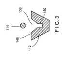
導入ポート112は、超音波プローブ114を該ポートに対して係止するための係止部148を備えうる。1つの例示となる実施形態では、図3及び4に示されるように、導入ポート112の開口部138は係止部148を備える大きさ及び形状であることが可能であり、該係止部は、超音波プローブ114を摩擦嵌合によってその中に係合させる大きさのスロット150として構成されうる。具体的には、超音波プローブ114がひとたび所望通りにシース108を通して挿入されてしまえば、超音波プローブ114は、超音波プローブ114を該スロットに対して係止するために、図4に示されるようにスロット150の中に楔着されうる。例示の実施形態は係止部148をスロット付きの楔として図示及び説明しているが、その他の楔の構成も可能な場合がある。係止部148には、様々な係止機構のうち任意のものが備えうる。例えば、別の実施形態では、係止部148は超音波プローブ114を挟持可能なクランプとして構成されてもよい。 The
中央部分104は、係止要素140によって遠位側部分102に対して係止されてもよい。係止要素140は、例えば、遠位側部分102を通って側方に伸びる穴142にねじ込み式で係合するつまみねじとして構成されうる。係止要素は、該要素の端部144が遠位側チャネル120の中まで伸びて中央部分104の外面146に係合して中央部分104を遠位側部分に対して係止する係止状態と、端部144が遠位側チャネル120の中までは伸びず中央部分104が遠位側部分に対して移動可能な非係止状態との間を移行可能である。係止要素144は、係止状態と非係止状態との間で係止要素144を移行させるために、穴142の内部で回転されうる。
近位側部分106は、近位端部152から遠位端部154へと長手方向に伸び、かつ該部分を通って伸びる近位側チャネル156を備えている。針110の近位端部158は近位側チャネル156の内部に固着される。近位側部分106は中央部分104の近位端部128に摺動可能に接続され、かつ例えば、中央チャネル132の内部に受承されて、針110が近位側部分106からシース108の中へと遠位側に伸び、近位側部分106の近位端部152が中央部分104の近位端部128より近位側に伸びるようになっていてもよい。よって、中央部分104に対する近位側部分106の長手方向の移動は、針110をシース108に対して近位側及び遠位側へ移動させる。1つの実施形態では、近位側部分106の長さは、中央部分104に対して最も遠位側の配置状態であっても近位側部分106が挿入ポート112を通した補助ツールの挿入を妨げないように、選択されうる。この実施形態では、近位側部分106は中央部分104に対して、かつそれにより遠位側部分102に対して、回転自在であってよく、その結果針110は、針110が挿入されるシース108及び内視鏡102に対してデバイス100全体を回転させることなく回転されることができるようになっている。しかしながら別の実施形態では、近位側部分106は、該部分の遠位側部分を通って側方に伸びる細長スロットを備えて、その結果、中央部分104に対して最も遠位側の配置状態において、細長スロットが導入ポート112と一直線上に配列されて近位側部分106が該ポートの使用を妨げないようになっていてもよい。
近位側部分106の近位端部152は、必要に応じて、スタイレットが近位端部152を通じて近位側チャネル156に挿入されて該スタイレットが針110を通過することができるように、構成される。近位端部152はさらに、針110にシリンジ又は他の吸引源を結合するように構成された、例えばルアー嵌合のような接続部180を備えうる。 The
近位側部分106はさらに、調整可能な針停止具160も備えうる。1つの実施形態では、針停止具160はカラー162及びつまみねじ164を備えうる。カラー162は、近位側部分106の一部分の上、中央部分104の近位端部128より近位側に、摺動可能に設置される。カラー162は、近位側部分106に沿った所望位置へと移動されてつまみねじ164によって所望位置に固定されることができる。具体的には、つまみねじ164は、カラー162を通って側方に伸びている対応するねじ穴166を通って伸びて、カラー162が所望位置にあるときに近位側部分106の外面168に係合する。この所望位置は、シース108に対する針110の挿入の最大深度を決定する。例えば、カラー162が中央部分104の近位端部128に当接するとき、近位側部分106はそこからさらに遠位側への移動を妨げられる。
上述のように、シース108及び針110は、コネクタ124を介して遠位側部分102に結合された内視鏡を通過することができる。近位側、中央及び遠位側部分106、104、102はそれぞれ、針110、シース108を互いに対して、また内視鏡に対して移動させるために、互いに対して長手方向に移動可能である。シース108は、中央チャネル132の遠位端部134内部に固着された近位端部136から遠位端部170へと長手方向に伸びる。シース108は、該シースを通って伸びるルーメン172であって、針110及び超音波プローブ114のような補助ツールの両方を摺動可能に収容する大きさ及び形状のルーメン172を備えている。別の実施形態では、シース108は、第1のルーメンが針110を受承するように構成され、第2のルーメンが補助ツールを受承するように構成された、二重ルーメンのシースであってもよい。シース108の長さは、中央部分104が遠位側部分102に対して遠位側に移動されたときにシース108の遠位端部170が内視鏡の遠位端部を過ぎて遠位側へ伸びるように、選択されうる。 As described above, the
針110は、近位端部158から遠位端部174へと伸び、かつそれを通って伸びるルーメン(図示せず)を備えた標準的なFNA針であってよい。針110の長さは、近位側部分106が中央部分104に対して遠位側に移動されたときに、針110の遠位端部174が試料採取される標的組織に挿入されるようにシース108の遠位端部170を過ぎて遠位側へ伸びるように、選択されうる。同様に、超音波プローブ114の長さは、挿入ポート112を通って針110と並行してシース108に挿入されたときに、超音波プローブ114の遠位端部176が標的組織の試料採取を視覚化するために針110の遠位端部174に近接して配置されるように、選択されうる。
デバイス100を使用する例示の方法によれば、内視鏡は、遠位側部分102の遠位端部118のコネクタ124を介してデバイス100に結合されうる。遠位側部分102、中央部分104及び近位側部分106は、内視鏡、シース108及び針110の互いに対する所望の位置及び配向のうち少なくともいずれか一方を達成するために、互いに対して移動されうる。例えば、挿入時、シース108及び針110は、遠位端部170、174がそれぞれ内視鏡の遠位端部を過ぎて遠位側へと伸びないように配置されうる。より具体的には、針110の遠位端部174はさらに、シース108の遠位端部170を過ぎて遠位側へは伸びない。内視鏡、シース108及び針110がひとたび互いに対して所望のとおりに配置されてしまえば、内視鏡は、該内視鏡に受承されたシース108及び針110とともに、内視鏡の遠位端部が生体内の標的領域に近接するまで身体の通路を通過せしめられる。内視鏡は例えば気管支の通路を通して挿入されうるが、二次及び/又は三次気管支の通路内にさらに進むのは妨げられることもある。この場合、シース108は、該シース内を伸びる針110とともに、中央部分104を遠位側部分102に対して遠位側へ移動させることにより、内視鏡から二次及び/又は三次通路へと遠位側に延長されうる。 According to an exemplary method of using the
シース108の遠位端部170がひとたび試料採取される標的組織に近接してしまえば、超音波プローブ114のような補助ツールが導入ポート112の中及びシース108のルーメン172を通して挿入されて、遠位端部176が、試料採取される組織を視覚化するためにシース108の遠位端部170を過ぎて遠位側へと伸びるようになされてもよい。超音波プローブ114がシース108に対して所望位置に配置されると、超音波プローブ114は係止部148によってその所望位置に固着されうる。1つの実施形態では、超音波プローブ114はスロット150に楔着されてもよい。その後針110は、近位側部分106を中央部分104に対して遠位側へ移動させることによりシース108に対して遠位側へ移動されて、針110の遠位端部174がシース108の遠位端部170を過ぎて遠位側へ伸びるようになされうる。超音波プローブ114によって提供される視覚化は、標的組織が針110によって正確に試料採取されていることを保証する。 Once the
実施形態について上述してきたが、多くの改変及び変更が本開示の範囲から逸脱することなく為されうる。よって、本開示は、改変及び変更が添付の特許請求の範囲及びその等価物の範囲内に入るという条件での該改変及び変更を対象としているということが意図されている。
While embodiments have been described above, many modifications and changes may be made without departing from the scope of the present disclosure. Accordingly, the present disclosure is intended to cover modifications and variations provided that such modifications and variations fall within the scope of the appended claims and their equivalents.
Claims (15)
Translated fromJapanese遠位側部分であって、近位端部から遠位端部へと長手方向に伸び、かつ前記部分を通って伸びる遠位側チャネルを備えており、前記遠位側部分の前記遠位端部は内視鏡の近位端部に接続するように構成されたコネクタを備えている、遠位側部分と、
前記遠位側部分の前記近位端部に摺動可能に接続される大きさ及び形状の中央部分であって、前記中央部分は近位端部から遠位端部へと長手方向に伸び、かつ前記部分を通って伸びる中央チャネルを備えており、前記中央部分の前記遠位端部はシースに接続されるように構成されており、前記中央部分は前記部分から側方に伸びる導入ポートを備えて、前記導入ポートを通して挿入された補助ツールが前記シースのルーメンを通るように方向付けられている、中央部分と、
前記中央部分の前記近位端部に摺動可能に接続される大きさ及び形状の近位側部分であって、前記近位側部分は近位端部から遠位端部へと長手方向に伸び、かつ前記部分を通って伸びる近位側チャネルを備えており、前記近位側部分の前記遠位端部は、針に接続されて針が前記シースの前記ルーメンを通過するように構成されている、近位側部分と
を備え、前記遠位側部分、前記中央部分及び前記近位側部分は、前記内視鏡、前記シース及び前記針の間の相対的位置付けを調整するために、互いに対して長手方向に移動可能である、ハンドル。A handle for a medical device,
A distal portion comprising a distal channel extending longitudinally from a proximal end to a distal end and extending through the portion, the distal end of the distal portion A distal portion comprising a connector configured to connect to a proximal end of an endoscope;
A central portion sized and shaped to be slidably connected to the proximal end of the distal portion, the central portion extending longitudinally from the proximal end to the distal end; And a central channel extending through the portion, the distal end of the central portion being configured to be connected to a sheath, the central portion having an introduction port extending laterally from the portion. A central portion, wherein an auxiliary tool inserted through the introduction port is oriented to pass through the lumen of the sheath;
A proximal portion sized and shaped to be slidably connected to the proximal end of the central portion, the proximal portion being longitudinally from the proximal end to the distal end; A proximal channel extending through and extending through the portion, the distal end of the proximal portion configured to be connected to a needle and the needle passing through the lumen of the sheath. A proximal portion, wherein the distal portion, the central portion, and the proximal portion are configured to adjust relative positioning between the endoscope, the sheath, and the needle. Handles that are movable longitudinally relative to each other.
遠位側部分であって、近位端部から遠位端部へと長手方向に伸び、かつ前記部分を通って伸びる遠位側チャネルを備えている遠位側部分と、
前記遠位側部分の前記近位端部に摺動可能に接続される大きさ及び形状の中央部分であって、近位端部から遠位端部へと長手方向に伸び、かつ前記部分を通って伸びる中央チャネルを、前記部分から側方に伸びる導入ポートと併せて備えている中央部分と、
前記中央部分の前記近位端部に摺動可能に接続される大きさ及び形状の近位側部分であって、近位端部から遠位端部へと長手方向に伸び、かつ前記部分を通って伸びる近位側チャネルを備えている近位側部分と
を備えているハンドル部材と、
前記遠位側部分に前記部分の前記遠位端部に位置するコネクタを介して接続された内視鏡と、
シースであって、近位端部から遠位端部へと長手方向に伸び、かつ前記シースを通って伸びるルーメンを備え、該シースの前記近位端部が前記中央部分の遠位端部に接続されたシースと、
針であって、近位端部から遠位へと長手方向に伸び、該針の前記近位端部が前記近位側チャネル内部に装着されて該針が前記シースの前記ルーメンを通過する、針と
を備える組織試料採取デバイス。A handle member,
A distal portion comprising a distal channel extending longitudinally from the proximal end to the distal end and extending through said portion;
A central portion sized and shaped to be slidably connected to the proximal end of the distal portion, extending longitudinally from the proximal end to the distal end; and A central portion comprising a central channel extending therethrough in combination with an introduction port extending laterally from said portion;
A proximal portion sized and shaped to be slidably connected to the proximal end of the central portion, extending longitudinally from the proximal end to the distal end; and A handle member comprising a proximal portion comprising a proximal channel extending therethrough;
An endoscope connected to the distal portion via a connector located at the distal end of the portion;
A sheath comprising a lumen extending longitudinally from a proximal end to a distal end and extending through the sheath, wherein the proximal end of the sheath is at the distal end of the central portion A connected sheath;
A needle extending longitudinally from a proximal end distally, wherein the proximal end of the needle is mounted within the proximal channel and the needle passes through the lumen of the sheath; A tissue sampling device comprising a needle.
Priority Applications (1)
| Application Number | Priority Date | Filing Date | Title |
|---|---|---|---|
| JP2020012464AJP6906073B2 (en) | 2015-09-01 | 2020-01-29 | Handle for medical devices |
Applications Claiming Priority (3)
| Application Number | Priority Date | Filing Date | Title |
|---|---|---|---|
| US201562212866P | 2015-09-01 | 2015-09-01 | |
| US62/212,866 | 2015-09-01 | ||
| PCT/US2016/049291WO2017040414A1 (en) | 2015-09-01 | 2016-08-29 | Scope-mounted inod handle |
Related Child Applications (1)
| Application Number | Title | Priority Date | Filing Date |
|---|---|---|---|
| JP2020012464ADivisionJP6906073B2 (en) | 2015-09-01 | 2020-01-29 | Handle for medical devices |
Publications (1)
| Publication Number | Publication Date |
|---|---|
| JP2018529403Atrue JP2018529403A (en) | 2018-10-11 |
Family
ID=56894304
Family Applications (2)
| Application Number | Title | Priority Date | Filing Date |
|---|---|---|---|
| JP2018504245APendingJP2018529403A (en) | 2015-09-01 | 2016-08-29 | Scope-mounted INOD handle |
| JP2020012464AActiveJP6906073B2 (en) | 2015-09-01 | 2020-01-29 | Handle for medical devices |
Family Applications After (1)
| Application Number | Title | Priority Date | Filing Date |
|---|---|---|---|
| JP2020012464AActiveJP6906073B2 (en) | 2015-09-01 | 2020-01-29 | Handle for medical devices |
Country Status (5)
| Country | Link |
|---|---|
| US (3) | US20170055967A1 (en) |
| EP (2) | EP3344154B1 (en) |
| JP (2) | JP2018529403A (en) |
| CN (2) | CN116942216A (en) |
| WO (1) | WO2017040414A1 (en) |
Cited By (2)
| Publication number | Priority date | Publication date | Assignee | Title |
|---|---|---|---|---|
| JP2021030088A (en)* | 2019-08-27 | 2021-03-01 | ジャイラス・エーシーエムアイ・インコーポレーテッド | Real-time sampling system |
| JP2023149923A (en)* | 2022-03-31 | 2023-10-16 | 日本ゼオン株式会社 | Endoscope treatment instrument |
Families Citing this family (8)
| Publication number | Priority date | Publication date | Assignee | Title |
|---|---|---|---|---|
| JP7147079B2 (en)* | 2019-05-17 | 2022-10-04 | ボストン サイエンティフィック サイムド,インコーポレイテッド | Medical imaging device and system |
| WO2020237420A1 (en)* | 2019-05-24 | 2020-12-03 | Becton, Dickinson And Company | Needle-tract assistant including components and methods thereof |
| CN110169812A (en)* | 2019-05-27 | 2019-08-27 | 成长勇 | A kind of medical puncture needle |
| DE102019003965A1 (en)* | 2019-06-05 | 2020-12-10 | Joimax Gmbh | Surgical needle set and method for determining the position of a surgical instrument |
| US12390202B2 (en) | 2019-10-09 | 2025-08-19 | Praxis Holding Llc | Telescoping needle assembly with side cutting needle |
| US11849927B2 (en)* | 2019-10-09 | 2023-12-26 | Praxis Holding Llc | Telescoping needle assembly with rotating needle |
| US11253236B2 (en)* | 2019-10-21 | 2022-02-22 | Onepass Medical Ltd. | Needle-handling device |
| CN118076282A (en) | 2021-08-11 | 2024-05-24 | W腔内机器人有限公司 | A two-pronged approach to bronchoscopy |
Citations (7)
| Publication number | Priority date | Publication date | Assignee | Title |
|---|---|---|---|---|
| JPH10512771A (en)* | 1994-12-23 | 1998-12-08 | ユーン,インバエ | Universal handle for medical instruments |
| JP2001104315A (en)* | 1999-10-08 | 2001-04-17 | Olympus Optical Co Ltd | Ultrasonic-guided paracentesis system device |
| JP2002543938A (en)* | 1999-05-14 | 2002-12-24 | ボストン サイエンティフィック リミテッド | Guide wire insertion and reinsertion tool and method of using the same |
| US6514215B1 (en)* | 1999-10-13 | 2003-02-04 | Pentax Corporation | Endoscopic tissue collecting instrument |
| JP2007513692A (en)* | 2003-12-09 | 2007-05-31 | ウィルソン−クック・メディカル・インコーポレーテッド | Cell collection device |
| JP2010503476A (en)* | 2006-09-13 | 2010-02-04 | ウィルソン−クック・メディカル・インコーポレーテッド | A medical catheter with a stress concentrating part in the access port and reduced breaking force |
| WO2014125707A1 (en)* | 2013-02-15 | 2014-08-21 | オリンパスメディカルシステムズ株式会社 | Biopsy system |
Family Cites Families (18)
| Publication number | Priority date | Publication date | Assignee | Title |
|---|---|---|---|---|
| US5599300A (en)* | 1992-05-11 | 1997-02-04 | Arrow Precision Products, Inc. | Method for electrosurgically obtaining access to the biliary tree with an adjustably positionable needle-knife |
| EP1284123B1 (en)* | 1996-08-12 | 2005-07-20 | Ethicon Endo-Surgery, Inc. | Apparatus for marking tissue |
| JP4744294B2 (en)* | 2003-06-19 | 2011-08-10 | ウィルソン−クック・メディカル・インコーポレーテッド | Handle for medical instrument and medical instrument assembly including the handle |
| JP4056989B2 (en)* | 2003-06-24 | 2008-03-05 | オリンパス株式会社 | Endoscopic treatment tool |
| JP3922284B2 (en)* | 2004-03-31 | 2007-05-30 | 有限会社エスアールジェイ | Holding device |
| JP5111112B2 (en)* | 2004-12-08 | 2012-12-26 | エックスルミナ, インコーポレイテッド | Device for performing needle-guided therapy |
| US9332973B2 (en)* | 2008-10-01 | 2016-05-10 | Covidien Lp | Needle biopsy device with exchangeable needle and integrated needle protection |
| FR2942393B1 (en)* | 2009-02-25 | 2011-03-04 | Charles Henri Pineau | MULTIFUNCTIONAL DEVICE FOR EXPLORATION AND / OR INTERVENTION, IN PARTICULAR FOR MEDICAL USE |
| US9445714B2 (en)* | 2010-03-29 | 2016-09-20 | Endoclear Llc | Endotracheal tube coupling adapters |
| JP4906978B2 (en)* | 2010-04-15 | 2012-03-28 | オリンパスメディカルシステムズ株式会社 | Ultrasound diagnostic system |
| CN103200878B (en)* | 2010-09-07 | 2015-09-09 | 波士顿科学医学有限公司 | Endoscopic ultrasound fine needle aspiration device |
| US20130304030A1 (en)* | 2011-11-05 | 2013-11-14 | Vadiswire Corp. | Medical guidewire system with plural parallel guidewires |
| US9295454B2 (en)* | 2012-09-21 | 2016-03-29 | Ko-Pen Wang | Double lumen or double wire endobronchial ultrasound-guided histology needle (EBUS) |
| EP3513747A1 (en)* | 2013-05-17 | 2019-07-24 | Interscope, Inc. | Insertable endoscopic instrument for tissue removal |
| US20150080764A1 (en)* | 2013-07-22 | 2015-03-19 | Children's Medical Center Corporation | Disposable instrument including working channels for endoscopy |
| CN114366181B (en)* | 2013-12-13 | 2024-08-02 | 直观外科手术操作公司 | Telescopic biopsy needle |
| CN203763040U (en)* | 2014-01-17 | 2014-08-13 | 苏州朗开医疗技术有限公司 | Positioning guide line for bronchoscope |
| WO2016099614A1 (en)* | 2014-12-15 | 2016-06-23 | Gyrus Acmi, Inc. (D/B/A/ Olympus Surgical Technologies America) | Improved control of a basket retrieval device |
- 2016
- 2016-08-29JPJP2018504245Apatent/JP2018529403A/enactivePending
- 2016-08-29WOPCT/US2016/049291patent/WO2017040414A1/ennot_activeCeased
- 2016-08-29USUS15/250,478patent/US20170055967A1/ennot_activeAbandoned
- 2016-08-29EPEP16763421.1Apatent/EP3344154B1/enactiveActive
- 2016-08-29CNCN202311049603.6Apatent/CN116942216A/enactivePending
- 2016-08-29CNCN201680049498.8Apatent/CN107920811A/enactivePending
- 2016-08-29EPEP21151188.6Apatent/EP3909517A1/enactivePending
- 2020
- 2020-01-29JPJP2020012464Apatent/JP6906073B2/enactiveActive
- 2020-09-23USUS17/029,902patent/US12349879B2/enactiveActive
- 2025
- 2025-06-17USUS19/240,483patent/US20250312020A1/enactivePending
Patent Citations (7)
| Publication number | Priority date | Publication date | Assignee | Title |
|---|---|---|---|---|
| JPH10512771A (en)* | 1994-12-23 | 1998-12-08 | ユーン,インバエ | Universal handle for medical instruments |
| JP2002543938A (en)* | 1999-05-14 | 2002-12-24 | ボストン サイエンティフィック リミテッド | Guide wire insertion and reinsertion tool and method of using the same |
| JP2001104315A (en)* | 1999-10-08 | 2001-04-17 | Olympus Optical Co Ltd | Ultrasonic-guided paracentesis system device |
| US6514215B1 (en)* | 1999-10-13 | 2003-02-04 | Pentax Corporation | Endoscopic tissue collecting instrument |
| JP2007513692A (en)* | 2003-12-09 | 2007-05-31 | ウィルソン−クック・メディカル・インコーポレーテッド | Cell collection device |
| JP2010503476A (en)* | 2006-09-13 | 2010-02-04 | ウィルソン−クック・メディカル・インコーポレーテッド | A medical catheter with a stress concentrating part in the access port and reduced breaking force |
| WO2014125707A1 (en)* | 2013-02-15 | 2014-08-21 | オリンパスメディカルシステムズ株式会社 | Biopsy system |
Cited By (4)
| Publication number | Priority date | Publication date | Assignee | Title |
|---|---|---|---|---|
| JP2021030088A (en)* | 2019-08-27 | 2021-03-01 | ジャイラス・エーシーエムアイ・インコーポレーテッド | Real-time sampling system |
| JP7633009B2 (en) | 2019-08-27 | 2025-02-19 | ジャイラス エーシーエムアイ インク ディー/ビー/エー オリンパス サージカル テクノロジーズ アメリカ | Real-time Sampling System |
| US12310566B2 (en) | 2019-08-27 | 2025-05-27 | Olympus Medical Systems Corporation | Real-time sampling system |
| JP2023149923A (en)* | 2022-03-31 | 2023-10-16 | 日本ゼオン株式会社 | Endoscope treatment instrument |
Also Published As
| Publication number | Publication date |
|---|---|
| EP3344154A1 (en) | 2018-07-11 |
| JP6906073B2 (en) | 2021-07-21 |
| EP3344154B1 (en) | 2021-01-13 |
| JP2020096858A (en) | 2020-06-25 |
| WO2017040414A1 (en) | 2017-03-09 |
| CN107920811A (en) | 2018-04-17 |
| US20210000457A1 (en) | 2021-01-07 |
| US12349879B2 (en) | 2025-07-08 |
| EP3909517A1 (en) | 2021-11-17 |
| CN116942216A (en) | 2023-10-27 |
| US20250312020A1 (en) | 2025-10-09 |
| US20170055967A1 (en) | 2017-03-02 |
Similar Documents
| Publication | Publication Date | Title |
|---|---|---|
| JP6906073B2 (en) | Handle for medical devices | |
| US20230110289A1 (en) | Endoscopic Ultrasound Fine Needle Aspiration Device | |
| EP2957209B1 (en) | Biopsy system | |
| US9693803B2 (en) | Puncture needle for endoscope and biopsy system | |
| US10335194B2 (en) | Handles for needle assemblies | |
| US11717275B2 (en) | Needle-handling device | |
| US11253236B2 (en) | Needle-handling device | |
| US11134927B2 (en) | Endoscopic treatment tool | |
| US20160220234A1 (en) | Multiple sample biopsy device | |
| CN107072647A (en) | Spoon formula core needle | |
| AU2014221219B2 (en) | Endoscopic ultrasound fine needle aspiration device |
Legal Events
| Date | Code | Title | Description |
|---|---|---|---|
| A621 | Written request for application examination | Free format text:JAPANESE INTERMEDIATE CODE: A621 Effective date:20180126 | |
| A131 | Notification of reasons for refusal | Free format text:JAPANESE INTERMEDIATE CODE: A131 Effective date:20190122 | |
| A521 | Request for written amendment filed | Free format text:JAPANESE INTERMEDIATE CODE: A523 Effective date:20190422 | |
| A02 | Decision of refusal | Free format text:JAPANESE INTERMEDIATE CODE: A02 Effective date:20191001 |