JP2018525634A - Accelerometer - Google Patents
AccelerometerDownload PDFInfo
- Publication number
- JP2018525634A JP2018525634AJP2018507634AJP2018507634AJP2018525634AJP 2018525634 AJP2018525634 AJP 2018525634AJP 2018507634 AJP2018507634 AJP 2018507634AJP 2018507634 AJP2018507634 AJP 2018507634AJP 2018525634 AJP2018525634 AJP 2018525634A
- Authority
- JP
- Japan
- Prior art keywords
- fingers
- fixed
- damping
- movable
- proof mass
- Prior art date
- Legal status (The legal status is an assumption and is not a legal conclusion. Google has not performed a legal analysis and makes no representation as to the accuracy of the status listed.)
- Granted
Links
Images


Classifications
- G—PHYSICS
- G01—MEASURING; TESTING
- G01P—MEASURING LINEAR OR ANGULAR SPEED, ACCELERATION, DECELERATION, OR SHOCK; INDICATING PRESENCE, ABSENCE, OR DIRECTION, OF MOVEMENT
- G01P15/00—Measuring acceleration; Measuring deceleration; Measuring shock, i.e. sudden change of acceleration
- G01P15/02—Measuring acceleration; Measuring deceleration; Measuring shock, i.e. sudden change of acceleration by making use of inertia forces using solid seismic masses
- G01P15/08—Measuring acceleration; Measuring deceleration; Measuring shock, i.e. sudden change of acceleration by making use of inertia forces using solid seismic masses with conversion into electric or magnetic values
- G01P15/125—Measuring acceleration; Measuring deceleration; Measuring shock, i.e. sudden change of acceleration by making use of inertia forces using solid seismic masses with conversion into electric or magnetic values by capacitive pick-up
- B—PERFORMING OPERATIONS; TRANSPORTING
- B81—MICROSTRUCTURAL TECHNOLOGY
- B81B—MICROSTRUCTURAL DEVICES OR SYSTEMS, e.g. MICROMECHANICAL DEVICES
- B81B3/00—Devices comprising flexible or deformable elements, e.g. comprising elastic tongues or membranes
- B81B3/0035—Constitution or structural means for controlling the movement of the flexible or deformable elements
- B81B3/0051—For defining the movement, i.e. structures that guide or limit the movement of an element
- B—PERFORMING OPERATIONS; TRANSPORTING
- B81—MICROSTRUCTURAL TECHNOLOGY
- B81B—MICROSTRUCTURAL DEVICES OR SYSTEMS, e.g. MICROMECHANICAL DEVICES
- B81B3/00—Devices comprising flexible or deformable elements, e.g. comprising elastic tongues or membranes
- B81B3/0035—Constitution or structural means for controlling the movement of the flexible or deformable elements
- B81B3/0059—Constitution or structural means for controlling the movement not provided for in groups B81B3/0037 - B81B3/0056
- G—PHYSICS
- G01—MEASURING; TESTING
- G01P—MEASURING LINEAR OR ANGULAR SPEED, ACCELERATION, DECELERATION, OR SHOCK; INDICATING PRESENCE, ABSENCE, OR DIRECTION, OF MOVEMENT
- G01P15/00—Measuring acceleration; Measuring deceleration; Measuring shock, i.e. sudden change of acceleration
- G01P15/02—Measuring acceleration; Measuring deceleration; Measuring shock, i.e. sudden change of acceleration by making use of inertia forces using solid seismic masses
- G01P15/08—Measuring acceleration; Measuring deceleration; Measuring shock, i.e. sudden change of acceleration by making use of inertia forces using solid seismic masses with conversion into electric or magnetic values
- G01P15/13—Measuring acceleration; Measuring deceleration; Measuring shock, i.e. sudden change of acceleration by making use of inertia forces using solid seismic masses with conversion into electric or magnetic values by measuring the force required to restore a proofmass subjected to inertial forces to a null position
- G01P15/131—Measuring acceleration; Measuring deceleration; Measuring shock, i.e. sudden change of acceleration by making use of inertia forces using solid seismic masses with conversion into electric or magnetic values by measuring the force required to restore a proofmass subjected to inertial forces to a null position with electrostatic counterbalancing means
- B—PERFORMING OPERATIONS; TRANSPORTING
- B81—MICROSTRUCTURAL TECHNOLOGY
- B81B—MICROSTRUCTURAL DEVICES OR SYSTEMS, e.g. MICROMECHANICAL DEVICES
- B81B2201/00—Specific applications of microelectromechanical systems
- B81B2201/02—Sensors
- B81B2201/0228—Inertial sensors
- B81B2201/0235—Accelerometers
- B—PERFORMING OPERATIONS; TRANSPORTING
- B81—MICROSTRUCTURAL TECHNOLOGY
- B81B—MICROSTRUCTURAL DEVICES OR SYSTEMS, e.g. MICROMECHANICAL DEVICES
- B81B2203/00—Basic microelectromechanical structures
- B81B2203/05—Type of movement
- B81B2203/051—Translation according to an axis parallel to the substrate
- G—PHYSICS
- G01—MEASURING; TESTING
- G01P—MEASURING LINEAR OR ANGULAR SPEED, ACCELERATION, DECELERATION, OR SHOCK; INDICATING PRESENCE, ABSENCE, OR DIRECTION, OF MOVEMENT
- G01P15/00—Measuring acceleration; Measuring deceleration; Measuring shock, i.e. sudden change of acceleration
- G01P15/02—Measuring acceleration; Measuring deceleration; Measuring shock, i.e. sudden change of acceleration by making use of inertia forces using solid seismic masses
- G01P15/08—Measuring acceleration; Measuring deceleration; Measuring shock, i.e. sudden change of acceleration by making use of inertia forces using solid seismic masses with conversion into electric or magnetic values
- G01P2015/0805—Measuring acceleration; Measuring deceleration; Measuring shock, i.e. sudden change of acceleration by making use of inertia forces using solid seismic masses with conversion into electric or magnetic values being provided with a particular type of spring-mass-system for defining the displacement of a seismic mass due to an external acceleration
- G01P2015/0808—Measuring acceleration; Measuring deceleration; Measuring shock, i.e. sudden change of acceleration by making use of inertia forces using solid seismic masses with conversion into electric or magnetic values being provided with a particular type of spring-mass-system for defining the displacement of a seismic mass due to an external acceleration for defining in-plane movement of the mass, i.e. movement of the mass in the plane of the substrate
- G01P2015/0811—Measuring acceleration; Measuring deceleration; Measuring shock, i.e. sudden change of acceleration by making use of inertia forces using solid seismic masses with conversion into electric or magnetic values being provided with a particular type of spring-mass-system for defining the displacement of a seismic mass due to an external acceleration for defining in-plane movement of the mass, i.e. movement of the mass in the plane of the substrate for one single degree of freedom of movement of the mass
- G01P2015/0814—Measuring acceleration; Measuring deceleration; Measuring shock, i.e. sudden change of acceleration by making use of inertia forces using solid seismic masses with conversion into electric or magnetic values being provided with a particular type of spring-mass-system for defining the displacement of a seismic mass due to an external acceleration for defining in-plane movement of the mass, i.e. movement of the mass in the plane of the substrate for one single degree of freedom of movement of the mass for translational movement of the mass, e.g. shuttle type
- G—PHYSICS
- G01—MEASURING; TESTING
- G01P—MEASURING LINEAR OR ANGULAR SPEED, ACCELERATION, DECELERATION, OR SHOCK; INDICATING PRESENCE, ABSENCE, OR DIRECTION, OF MOVEMENT
- G01P15/00—Measuring acceleration; Measuring deceleration; Measuring shock, i.e. sudden change of acceleration
- G01P15/02—Measuring acceleration; Measuring deceleration; Measuring shock, i.e. sudden change of acceleration by making use of inertia forces using solid seismic masses
- G01P15/08—Measuring acceleration; Measuring deceleration; Measuring shock, i.e. sudden change of acceleration by making use of inertia forces using solid seismic masses with conversion into electric or magnetic values
- G01P2015/0862—Measuring acceleration; Measuring deceleration; Measuring shock, i.e. sudden change of acceleration by making use of inertia forces using solid seismic masses with conversion into electric or magnetic values being provided with particular means being integrated into a MEMS accelerometer structure for providing particular additional functionalities to those of a spring mass system
- G01P2015/0882—Measuring acceleration; Measuring deceleration; Measuring shock, i.e. sudden change of acceleration by making use of inertia forces using solid seismic masses with conversion into electric or magnetic values being provided with particular means being integrated into a MEMS accelerometer structure for providing particular additional functionalities to those of a spring mass system for providing damping of vibrations
Landscapes
- Physics & Mathematics (AREA)
- General Physics & Mathematics (AREA)
- Engineering & Computer Science (AREA)
- Computer Hardware Design (AREA)
- Microelectronics & Electronic Packaging (AREA)
- Pressure Sensors (AREA)
Abstract
Translated fromJapaneseDescription
Translated fromJapanese本開示は加速度計に関し、詳細には容量型加速度計に関する。 The present disclosure relates to accelerometers, and in particular to capacitive accelerometers.
加速度計は、現代の電子機器の多くに含まれており、加速度を測定するために利用される。微小電気機械システム(MEMS)に基づく加速度計は近年いたるところに存在するようになり、従来の巨視的な対応物よりもはるかに高い効力をしばしば有する。 Accelerometers are included in many modern electronic devices and are used to measure acceleration. Accelerometers based on microelectromechanical systems (MEMS) have become ubiquitous in recent years and often have a much higher potency than conventional macroscopic counterparts.
加速度を感知するために交互嵌合型の容量型電極「フィンガー」を利用することが当該技術分野においては公知である。このような容量型加速度計の一例が、US7,047,808に記載されている。加速度計が加速度を受ける際に、プルーフマスに取り付けられた容量型電極フィンガーの可動セットは、慣性フレームに取り付けられた容量型電極フィンガーの固定セットに対するヌル位置から移動する傾向にある。 It is known in the art to utilize interdigitated capacitive electrode “fingers” to sense acceleration. An example of such a capacitive accelerometer is described in US 7,047,808. As the accelerometer receives acceleration, the movable set of capacitive electrode fingers attached to the proof mass tends to move from a null position relative to the fixed set of capacitive electrode fingers attached to the inertia frame.
容量型加速度計は、「開ループ」または「閉ループ」として知られるいずれかで操作することができる。開ループシステムにおいて、容量型加速度計は、プルーフマスの相対移動によって発生する電極フィンガー間の容量の変化を感知するように配設され、例えば加速度を測定するために、いわゆる「ピックオフ」電圧が利用される。閉ループシステムにおいて、駆動及び感知の両方に電極フィンガーが利用される。典型的には、同相及び逆相パルス幅変調(PWM)電圧波形が固定電極フィンガーに印加され、プルーフマスをそのヌル位置に戻して(すなわち、それがある位置が加速度を受けていない位置である)駆動するようPWMマークスペース比が調整される。マークスペース比は加速度の尺度を提供する。 Capacitive accelerometers can be operated in either known as “open loop” or “closed loop”. In open loop systems, capacitive accelerometers are arranged to sense changes in capacitance between electrode fingers caused by relative movement of the proof mass, and so-called “pick-off” voltages are used, for example, to measure acceleration. Is done. In a closed loop system, electrode fingers are utilized for both driving and sensing. Typically, in-phase and out-of-phase pulse width modulation (PWM) voltage waveforms are applied to the fixed electrode fingers, returning the proof mass to its null position (ie where it is not receiving acceleration). ) PWM mark space ratio is adjusted to drive. Mark space ratio provides a measure of acceleration.
容量型加速度計、特に閉ループにおいて操作される容量型加速度計では、振動整流誤差(VRE)が非常に低いことが求められる。プルーフマス位置の静電力の非線形依存性(静電力が電極間の間隙の2乗に反比例する)により、容量型加速度計の応答性が運動に対して非線形であるため、振動は加速しないが加速度計にDC加速出力を持たせ、大幅なVREにつながる。残留プルーフマス運動を低減することでVREの低減が達成可能である。閉ループにおいては、高帯域幅を通常必要とするループの周囲で高ゲインを有することで残留運動を低減することができる。しかし、印加することができる最大ゲインは制限されており、帯域幅も同様に、計算遅延及びMEMSの共振周波数によって制限されるため、ある程度の残留運動は避けられない。ループにおけるあらゆる遅延により、帯域幅が、その結果、最大開ループゲインが制限される。 Capacitive accelerometers, particularly capacitive accelerometers operated in a closed loop, are required to have very low vibration rectification error (VRE). Due to the non-linear dependence of the electrostatic force at the proof mass position (the electrostatic force is inversely proportional to the square of the gap between the electrodes), the response of the capacitive accelerometer is non-linear with respect to motion, so the vibration is not accelerated but accelerated. Give the meter a DC acceleration output, leading to a significant VRE. By reducing the residual proof mass motion, a reduction in VRE can be achieved. In a closed loop, residual motion can be reduced by having a high gain around the loop that normally requires high bandwidth. However, the maximum gain that can be applied is limited and the bandwidth is likewise limited by the computational delay and the resonant frequency of the MEMS, so some residual motion is inevitable. Any delay in the loop limits the bandwidth and consequently the maximum open loop gain.
さらに、開閉ループシステムの両方の場合において、容量型加速度計が大きな「衝撃」加速度を受ける場合に電極フィンガーの可動セットが移動しすぎないようにすることも重要である。フィンガーの可動セットが移動しすぎる場合、それは「タッチダウンする」、すなわち、フィンガーの固定セットと物理的に接触する。この発生を防止するためにバンプストップが適切に配置されているが、高レベルの加速度において、フィンガーのたわみのためにそれは依然として発生する可能性があり、これにより、加速度計の操作範囲が制限される。特に電極フィンガーの交互嵌合型セットが異なる電位にある際に、衝撃により加速度計に損傷が起きる可能性がある。例えば、Silicon Sensing社より入手可能なMEMS加速度計のGemini範囲は、1000gの操作衝撃で最大±96gのダイナミックレンジを提供する。 In addition, in both cases of open and closed loop systems, it is also important that the movable set of electrode fingers does not move too much when the capacitive accelerometer is subjected to large “impact” acceleration. If the movable set of fingers moves too much, it “touches down”, ie, makes physical contact with the fixed set of fingers. Bump stops are properly positioned to prevent this occurrence, but at high levels of acceleration, it can still occur due to finger deflection, which limits the operating range of the accelerometer. The The accelerometer can be damaged by impact, particularly when the interdigitated sets of electrode fingers are at different potentials. For example, the Gemini range of MEMS accelerometers available from Silicon Sensing provides a dynamic range of up to ± 96 g with 1000 g operating impact.
電極フィンガー間に比較的小さな空間が存在するため、スクイーズフィルムダンピングとして知られる効果が生じ、電極フィンガー間のガス状媒体がガス状媒体の粘性のためにフィンガーの運動を減衰させる。プルーフマスの残留運動はしたがって、このスクイーズフィルムダンピング効果によってある程度まで減衰する。しかし、特に閉ループ加速度計に関して、印加電圧(例えば、35V)においてフィンガーがその変形を防止するために十分な剛性を有する必要があり、そのために最小限の厚さを必要とする交互嵌合型の電極フィンガーの形状には、固有の制限が存在する。典型的には、容量型電極フィンガーは、20ミクロンの典型的な付け根の幅を有する台形であり、先端に向かって12ミクロン前後に幅が狭くなる。また、各フィンガーの両側には十分な間隙が必要であり、任意の電極フィンガーの一方の側に他方の側よりも大きな間隙が存在するように、連続して隣接する容量型電極フィンガーの組合せ間にオフセットが存在する。交互嵌合型の容量型電極フィンガー間の典型的な間隔は、より小さな間隙については6ミクロン前後、また、より大きな間隙については16ミクロンであってもよい。結果として得られる交互嵌合型の容量型電極フィンガーのセットのピッチ(すなわち、セット内のフィンガー組の間の間隔)は典型的には50ミクロン前後であり、残留運動を打ち消す際にスクイーズフィルムダンピングの効力を制限する。 Since there is a relatively small space between the electrode fingers, an effect known as squeeze film damping occurs, and the gaseous medium between the electrode fingers attenuates the movement of the fingers due to the viscosity of the gaseous medium. The residual movement of the proof mass is therefore attenuated to some extent by this squeeze film damping effect. However, particularly with closed loop accelerometers, the fingers must be sufficiently stiff to prevent their deformation at an applied voltage (eg, 35V), and therefore an interdigitated type that requires a minimum thickness. There are inherent limitations on the shape of the electrode fingers. Typically, capacitive electrode fingers are trapezoidal with a typical root width of 20 microns, narrowing around 12 microns toward the tip. Also, there must be sufficient clearance on both sides of each finger, and between adjacent electrode pairs of capacitive electrodes so that there is a larger clearance on one side of any electrode finger than on the other side. Has an offset. Typical spacing between interdigitated capacitive electrode fingers may be around 6 microns for smaller gaps and 16 microns for larger gaps. The resulting pitch of the interdigitated capacitive electrode fingers set (ie, the spacing between the finger pairs in the set) is typically around 50 microns, and squeeze film damping when canceling residual motion Limit the effectiveness of.
容量型加速度計内のプルーフマスの残留運動を低減し、様々な利点を提供することが望ましい。本開示は、上記で略述した欠点を低減するかまたは、克服しようとするものである。 It would be desirable to reduce residual motion of the proof mass in a capacitive accelerometer and provide various benefits. The present disclosure seeks to reduce or overcome the shortcomings outlined above.
本開示は、第1の態様から見た場合に、
印加加速度に応じて面内感知方向に直線移動可能であるように可撓性の支持脚によって固定基板に取り付けられた略平面状のプルーフマスであって、
プルーフマスから感知方向に略垂直に延在し、感知方向で横方向に相隔てられた移動可能な容量型電極フィンガーの第1及び第2のセットを備えたプルーフマスと、
固定基板に取り付けられた第1及び第2の固定コンデンサ電極であって、第1の固定コンデンサ電極が固定容量型電極フィンガーの第1のセットを備え、第2の固定コンデンサ電極が固定容量型電極フィンガーの第2のセットを備え、固定容量型電極フィンガーの第1及び第2のセットが感知方向に略垂直に延在し、感知方向で横方向に相隔てられ、
固定容量型電極フィンガーの第1のセットがプルーフマスの移動可能な容量型電極フィンガーの第1のセットと交互嵌合するように配設され、固定容量型電極フィンガーの第2のセットがプルーフマスの移動可能な容量型電極フィンガーの第2のセットと交互嵌合するように配設され、移動可能な容量型電極フィンガーの第1及び第2のセットが、利用時に印加加速度を感知するために出力電圧を提供するように配設された電気ピックオフ接続部をさらに備え、
移動可能な容量型電極フィンガーの第1のセットが、固定容量型電極フィンガーの第1のセットの隣接するフィンガーの間の第1の中線から第1の方向に第1の0以外のオフセットで提供され、
移動可能な容量型電極フィンガーの第2のセットが、固定容量型電極フィンガーの第2のセットの隣接するフィンガーの間の第2の中線から第2の、反対方向に第2の0以外のオフセットで提供され、第1及び第2のオフセットが第1及び第2の固定コンデンサ電極の間の中線を挟んで略対称形状であり、
プルーフマスが、プルーフマスから感知方向に略垂直に延在し、感知方向で横方向に相隔てられた移動可能ダンピングフィンガーのセットをさらに備える、第1及び第2の固定コンデンサ電極と、
固定基板に取り付けられ、移動可能ダンピングフィンガーのセットと交互嵌合するように配設された固定ダンピングフィンガーのセットであって、固定ダンピングフィンガーが感知方向に略垂直に延在し、感知方向で横方向に相隔てられ、
交互嵌合型の固定及び移動可能ダンピングフィンガーが電気的に共通であるように、固定ダンピングフィンガーのセットがプルーフマスとの電気接続部を備え、
プルーフマスが印加加速度に応じて移動する傾向にある場合に、交互嵌合型の移動可能及び固定ダンピングフィンガーが、移動可能及び固定ダンピングフィンガー間の相対移動を打ち消すダンピング効果を提供するガス状媒体内で取り付けられている、固定ダンピングフィンガーのセットと、
を備える、容量型加速度計を提供する。The present disclosure, when viewed from the first aspect,
A substantially planar proof mass attached to a fixed substrate by a flexible support leg so as to be linearly movable in the in-plane sensing direction according to applied acceleration,
A proof mass comprising first and second sets of movable capacitive electrode fingers extending from the proof mass substantially perpendicular to the sensing direction and spaced laterally in the sensing direction;
First and second fixed capacitor electrodes attached to a fixed substrate, wherein the first fixed capacitor electrode comprises a first set of fixed capacitance electrode fingers, and the second fixed capacitor electrode is a fixed capacitance electrode A second set of fingers, the first and second sets of fixed capacitive electrode fingers extending substantially perpendicular to the sensing direction and spaced laterally in the sensing direction;
A first set of fixed capacitive electrode fingers is arranged to interdigitate with a first set of movable capacitive electrode fingers of the proof mass, and a second set of fixed capacitive electrode fingers is proof mass. The first and second sets of movable capacitive electrode fingers are arranged to interdigitate with a second set of movable capacitive electrode fingers for sensing applied acceleration when in use. Further comprising an electrical pickoff connection arranged to provide an output voltage;
The first set of movable capacitive electrode fingers is at a first non-zero offset in a first direction from a first midline between adjacent fingers of the first set of fixed capacitive electrode fingers. Provided,
A second set of movable capacitive electrode fingers is second non-zero in a second, opposite direction from a second midline between adjacent fingers of the second set of fixed capacitive electrode fingers. Provided with an offset, wherein the first and second offsets are substantially symmetrical with respect to a midline between the first and second fixed capacitor electrodes;
First and second fixed capacitor electrodes, the proof mass further comprising a set of movable damping fingers extending substantially perpendicular to the sensing direction from the proof mass and spaced laterally in the sensing direction;
A set of fixed damping fingers attached to a fixed substrate and arranged to interdigitate with a set of movable damping fingers, the fixed damping fingers extending substantially perpendicular to the sensing direction and laterally extending in the sensing direction Separated in direction,
The set of fixed damping fingers comprises an electrical connection with the proof mass so that the interdigitated fixed and movable damping fingers are electrically common;
In a gaseous medium where the interdigitated movable and fixed damping fingers provide a damping effect that counteracts relative movement between the movable and fixed damping fingers when the proof mass tends to move in response to applied acceleration A set of fixed damping fingers, attached with
A capacitive accelerometer is provided.
したがって、本開示により、加速度を感知するために利用される交互嵌合型の容量型電極フィンガーとは別個にガス状媒体スクイーズフィルムダンピングを提供する交互嵌合型のダンピングフィンガーの専用セットを有する加速度計が提供されることが当業者には理解される。 Thus, in accordance with the present disclosure, acceleration having a dedicated set of interdigitated damping fingers that provide gaseous media squeeze film damping separately from interdigitated capacitive electrode fingers utilized to sense acceleration. One skilled in the art will appreciate that a meter is provided.
いくつかの例において、固定容量型電極フィンガーの第1及び第2のセットは、印加加速度に応じて入力電圧を提供するように配設された電気接続部をさらに備える。このような例において加速度計は、プルーフマスをヌル位置に駆動するために電圧が印加されてもよい、閉ループにおいて操作することができる。これらの電気接続部は、交互嵌合型の移動可能及び固定ダンピングフィンガーが製作される導電性MEMS層に直接接続することによって達成され得ることが理解される。固定容量型電極フィンガーの第1及び第2のセット上のこれらの電気接続部はまた、以下により詳細に記載する開ループ操作のために利用することができる。 In some examples, the first and second sets of fixed capacitive electrode fingers further comprise electrical connections arranged to provide an input voltage in response to applied acceleration. In such an example, the accelerometer can be operated in a closed loop where a voltage may be applied to drive the proof mass to the null position. It will be appreciated that these electrical connections can be achieved by connecting directly to the conductive MEMS layer in which the interdigitated movable and fixed damping fingers are fabricated. These electrical connections on the first and second sets of fixed capacitive electrode fingers can also be utilized for the open loop operation described in more detail below.
開示された加速度計により改善された減衰特性は、プルーフマスの残留運動を低減し、それによって次に、加速度計のVREが低減される。これにより、加速度計の振動時の加速度計の出力における不要なバイアス電圧の出現を解消することができる。残留運動の低減により、同様に、バンプストップが電極フィンガーのタッチダウンを防止する前により高い振幅を加えることが可能になる。それにより、残留運動の低減を受けて操作振動範囲が広がる。さらに、残留運動を低減することにより、加速度計がより完璧な、時間及び温度の結果として変動のない移動しないシステムとして作用するため、バイアス変動を低減することができる。 The improved damping characteristics with the disclosed accelerometer reduce the residual motion of the proof mass, which in turn reduces the VRE of the accelerometer. Thereby, the appearance of an unnecessary bias voltage in the output of the accelerometer when the accelerometer vibrates can be eliminated. The reduction in residual motion also allows higher amplitudes to be applied before the bump stop prevents electrode finger touchdown. Thereby, the operation vibration range is expanded in response to the reduction of the residual motion. Furthermore, by reducing residual motion, bias variations can be reduced because the accelerometer acts as a more complete, non-moving system as a result of time and temperature.
本開示による加速度計が開閉ループの両方の実施形態において有益であり、タッチダウン事象からの回復(すなわち、プルーフマスをそのヌル位置に戻すこと)には時間がかかり、その間は加速度計が動作不能であるため、タッチダウンを防止することが望ましいことも同様に当業者によって理解される。しかし、上述の通り、残留運動の減衰は、静電力及びプルーフマスの運動をヌルまで印加するために電極フィンガーが利用されるので、閉ループにおいて動作するように設計された加速度計において特に制限され、同様に、プルーフマスのヌル位置からの移動を感知するために出力「ピックオフ」電圧を提供するため、フィンガーはたわみを防止するように剛性である必要がある。 An accelerometer according to the present disclosure is beneficial in both open and closed loop embodiments, and recovery from a touchdown event (ie, returning the proof mass to its null position) takes time, during which the accelerometer is inoperable As such, it will be appreciated by those skilled in the art that it is desirable to prevent touchdown. However, as noted above, the attenuation of residual motion is particularly limited in accelerometers designed to operate in a closed loop, since electrode fingers are utilized to apply electrostatic force and proof mass motion to the null, Similarly, in order to provide an output “pickoff” voltage to sense movement of the proof mass from the null position, the fingers need to be rigid to prevent deflection.
本開示によって提供される追加的なダンピングフィンガーが閉ループ動作において駆動しないため、印加電圧のもとでの変形のリスクはなく、したがってダンピングフィンガーは容量型電極フィンガーよりも大きさを小さくし、より小さいピッチを提供することが可能である。減衰率はピッチの3乗に反比例するため、スクイーズフィルムダンピング効果の増大は容易に達成される。もちろん、従来の加速度計の交互嵌合型の容量型電極フィンガーは、35Vの典型的なHT電圧に耐え、たわみを0.5ミクロン未満にするようにするために十分な剛性を有しなければならないので、より小さいダンピングフィンガーよりも少ない量の固有のスクイーズフィルムダンピングに寄与する。一方、ダンピングフィンガーは電気的に共通であるため、それらの間に静電力は存在しない。 Since the additional damping fingers provided by the present disclosure do not drive in closed loop operation, there is no risk of deformation under applied voltage, so the damping fingers are smaller and smaller than capacitive electrode fingers. It is possible to provide a pitch. Since the attenuation rate is inversely proportional to the cube of the pitch, an increase in the squeeze film damping effect is easily achieved. Of course, the interdigitated capacitive electrode fingers of a conventional accelerometer must be rigid enough to withstand a typical HT voltage of 35V and bend less than 0.5 microns. This contributes to a smaller amount of inherent squeeze film damping than smaller damping fingers. On the other hand, since the damping fingers are electrically common, there is no electrostatic force between them.
ダンピングフィンガーは、容量型電極フィンガーよりも幅狭に(すなわち、感知方向により小さい幅を有するように)製作することができる。したがって、いくつかのセットの例において、交互嵌合型のダンピングフィンガーの各々は、交互嵌合型の容量型電極フィンガーよりも幅狭である。フィンガーの深さは通常、特定のMEMS製作プロセスによって設定されるが(典型的には100ミクロン前後)、製作中にエッチングされたチャネルの幅は、所望の幅のフィンガーを作成するために制御することができる。いくつかの例では、各ダンピングフィンガーの付け根の幅は15ミクロン以下、好ましくは10ミクロン以下、さらに好ましくは8ミクロン以下である。これにより、専用交互嵌合型のダンピングフィンガーのセットを、交互嵌合型の容量型電極フィンガーのセットよりも高い密度で製作することが可能になる。 Damping fingers can be made narrower than capacitive electrode fingers (ie, having a smaller width in the sensing direction). Thus, in some sets of examples, each of the interdigitated damping fingers is narrower than the interdigitated capacitive electrode fingers. The finger depth is usually set by a specific MEMS fabrication process (typically around 100 microns), but the width of the channel etched during fabrication is controlled to create the desired width finger. be able to. In some examples, the base width of each damping finger is 15 microns or less, preferably 10 microns or less, more preferably 8 microns or less. This makes it possible to manufacture a dedicated interfitting type damping finger set with a higher density than an interfitting type capacitive electrode finger set.
上記で略述したように、その感知能力によって加速度計を提供する移動可能な容量型電極フィンガーは、第1及び第2のオフセットにより横方向に隔てられている(すなわち、任意のフィンガーの一方の側の間隙は、他方の側の間隙よりも広い)。典型的には、大小の間隙各々の大きさは、それぞれ6ミクロン及び16ミクロンである場合がある。しかし、前記ダンピングフィンガーにはこのようなオフセットは必要なく、したがっていくつかの例では、交互嵌合型のダンピングフィンガーは感知方向において等しく隔てられている。いくつかの例では、隣接するダンピングフィンガー間の間隙は、16ミクロン未満、好ましくは10ミクロン以下、さらに好ましくは6ミクロン以下である。つまり、少なくともより好ましい例においては、ダンピングフィンガーの交互嵌合型のセットは、容量型電極フィンガーの交互嵌合型のセットよりも高い密度で、横方向に相隔てられ、加速度計の減衰率を大幅に増大させる。 As outlined above, the movable capacitive electrode fingers that provide accelerometers by their sensing capabilities are laterally separated by a first and second offset (ie, one of any of the fingers). The gap on the side is wider than the gap on the other side). Typically, the size of each large and small gap may be 6 microns and 16 microns, respectively. However, such an offset is not required for the damping fingers, so in some instances the interdigitated damping fingers are equally spaced in the sensing direction. In some examples, the gap between adjacent damping fingers is less than 16 microns, preferably 10 microns or less, more preferably 6 microns or less. That is, in at least a more preferred example, the interdigitated set of damping fingers is laterally spaced at a higher density than the interdigitated set of capacitive electrode fingers, resulting in an accelerometer attenuation factor. Increase significantly.
ダンピングフィンガーは互いにより近づけて隔て、より薄く作成することができるため、ダンピングフィンガーの結果として得られるピッチもまた、容量型電極フィンガーのピッチよりも小さく、典型的には約50ミクロンにすることができる。いくつかの例では、ダンピングフィンガーのピッチは50ミクロン未満、好ましくは40ミクロン未満、さらに好ましくは25ミクロン未満、例えば20ミクロン以下である。本開示による例示的な加速度計は、容量型電極フィンガーの2.5倍もの数のダンピングフィンガーを有する可能性があり、従来の加速度計に関連する減衰率が典型的には0.5前後である場合がある一方で、結果として得られる減衰率は3から10前後である場合がある。 Since the damping fingers can be made thinner and closer together, the resulting pitch of the damping fingers is also smaller than the pitch of the capacitive electrode fingers, typically about 50 microns. it can. In some examples, the pitch of the damping fingers is less than 50 microns, preferably less than 40 microns, more preferably less than 25 microns, such as 20 microns or less. An exemplary accelerometer according to the present disclosure may have 2.5 times as many damping fingers as capacitive electrode fingers, with a damping rate typically associated with conventional accelerometers around 0.5. While there may be, the resulting attenuation factor may be around 3 to 10.
最適なスクイーズフィルムダンピングに関しては、固定及び移動可能ダンピングフィンガーが感知方向に垂直に(すなわち、90度で)延在することが望ましいが、準最適な減衰は、感知方向に対して斜角に延在する固定及び/または移動可能ダンピングフィンガーを有することで依然として達成することができることが当業者には理解される。したがって、「略垂直(substantially perpendicular)」の語は、固定及び/または移動可能ダンピングフィンガーが感知方向に垂直な構成要素を有する方向に延在する、すなわち、固定及び/または移動可能ダンピングフィンガーが、感知方向に0度より大きく、90度以下の角度を形成する方向に延在する配置を含むことが理解される。 For optimal squeeze film damping, it is desirable that the fixed and movable damping fingers extend perpendicular to the sensing direction (ie at 90 degrees), but the sub-optimal attenuation extends at an oblique angle with respect to the sensing direction. It will be appreciated by those skilled in the art that it can still be achieved by having a fixed and / or movable damping finger present. Thus, the term “substantially perpendicular” extends in a direction where the fixed and / or movable damping finger has a component perpendicular to the sensing direction, ie, the fixed and / or movable damping finger is It is understood to include an arrangement that extends in a direction that forms an angle greater than 0 degrees and no greater than 90 degrees in the sense direction.
交互嵌合型の固定及び移動可能ダンピングフィンガーのセットの好適な構成がいくつか存在する場合があるが、好ましい例において加速度計は、略対称形状に配設された複数の交互嵌合型のダンピングフィンガーのセットを備える。加速度計の高度な対称性を保ち、支持部(すなわち、支持脚)に対して中央にプルーフマスの重心を位置決定することにより、構造体が感知方向に垂直な方向に移動するリスクが低減され、これによって、装置が不所望にねじれることを防止する。例えば加速度計は、プルーフマスの一方の側に取り付けられた交互嵌合型の移動可能及び固定ダンピングフィンガーの第1のセットならびに、プルーフマスの他方の側に取り付けられた交互嵌合型の移動可能及び固定ダンピングフィンガーの第2のセットを備えてもよい。交互嵌合型のダンピングフィンガーの第1及び第2のセットは、感知方向に、かつ/または感知方向の横方向に対称となるように取り付けられてもよい。 Although there may be several suitable configurations of a set of interdigitated fixed and movable damping fingers, in a preferred example the accelerometer has a plurality of interdigitated damping arranged in a generally symmetrical shape. With a set of fingers. By maintaining the high degree of symmetry of the accelerometer and locating the center of gravity of the proof mass in the center relative to the support (ie support legs), the risk of the structure moving in a direction perpendicular to the sensing direction is reduced. This prevents the device from undesirably twisting. For example, the accelerometer is interdigitated movable and attached to one side of the proof mass, and a first set of stationary damping fingers and interdigitated movable attached to the other side of the proof mass. And a second set of stationary damping fingers. The first and second sets of interdigitated damping fingers may be mounted so as to be symmetrical in the sensing direction and / or transverse to the sensing direction.
いくつかの例では、プルーフマスは、移動可能及び固定容量型電極フィンガーを囲むフレームの形を取ってもよい。1つ以上のダンピングフィンガーの可動セットは、プルーフマスのフレーム内部に延在してもよい。しかし、代わりに(または追加的に)1つ以上のダンピングフィンガーの可動セットがプルーフマスのフレームの外部に延在してもよい。したがって、ダンピングフィンガーの交互嵌合型のセットは、フレーム外部に位置してもよい。ダンピングフィンガーは感知配設の一部を形成しないため、例えば特定のMEMSの実装にとって、どこでも便利な場所に位置付けられてもよいことが当業者には理解される。 In some examples, the proof mass may take the form of a frame surrounding movable and fixed capacitive electrode fingers. The movable set of one or more damping fingers may extend inside the frame of the proof mass. However, alternatively (or in addition) a movable set of one or more damping fingers may extend outside the frame of the proof mass. Thus, the interdigitated set of damping fingers may be located outside the frame. It will be appreciated by those skilled in the art that the damping fingers do not form part of the sensing arrangement and may therefore be located anywhere convenient, eg, for a particular MEMS implementation.
電気的に共通である固定及び移動可能ダンピングフィンガーのセットによりすなわち、ダンピングフィンガーがそれぞれ概ね同じ電位(すなわち、電圧)で保持され、したがって、感知または駆動機能を提供することができないことが当業者には理解される。これは固定ダンピングフィンガーとプルーフマスとの間の、ダンピングフィンガーの間で静電力が高まることができないように短絡回路を効果的に提供する電気接続部によって確実にされる。これは、感知及び/または駆動のために、その間に電位差を必ず有する固定及び移動可能な容量型電極フィンガーとは対照的である。本開示の例においては、プルーフマスとの電気接続部は、固定ダンピングフィンガーから走る1つ以上の金属トラックを備えてもよい。固定ダンピングフィンガーは固定基板(例えば、ガラス)に取り付けられているため、金属トラックは、固定基板層とプルーフマス層(例えば、ガラス上シリコンMEMS構造)との間に延在するダウンホールビアによってプルーフマス(例えば、シリコン)に接続されてもよい。 For those skilled in the art, a set of fixed and movable damping fingers that are electrically common, i.e., the damping fingers are each held at approximately the same potential (i.e., voltage) and therefore cannot provide a sensing or driving function. Is understood. This is ensured by an electrical connection between the fixed damping finger and the proof mass that effectively provides a short circuit so that electrostatic forces cannot be increased between the damping fingers. This is in contrast to fixed and movable capacitive electrode fingers that necessarily have a potential difference between them for sensing and / or driving. In the examples of the present disclosure, the electrical connection with the proof mass may comprise one or more metal tracks that run from fixed damping fingers. Because the fixed damping fingers are attached to a fixed substrate (eg, glass), the metal track is proofed by a downhole via that extends between the fixed substrate layer and the proof mass layer (eg, a silicon-on-glass MEMS structure). It may be connected to a mass (eg, silicon).
特にスクイーズフィルムダンピングを提供するために専用交互嵌合型の「ダンピング」フィンガーを有することで、電気的に共通である固定及び移動可能ダンピングフィンガーが、固定及び移動可能ダンピングフィンガー間で静電力が確実に存在しないようにし、減衰効果を高めて、損傷の可能性を低減することを出願人は理解している。 In particular, it has a dedicated inter-mating “dumping” finger to provide squeeze film damping, so that the fixed and movable damping fingers that are electrically common can ensure electrostatic forces between the fixed and movable damping fingers Applicants understand that they will not be present in the surface, increasing the damping effect and reducing the possibility of damage.
典型的な実施態様において、交互嵌合型の容量型電極フィンガーは、交互嵌合型のダンピングフィンガーと同じガス状媒体内で取り付けられている。例えば加速度計は、容量型電極フィンガー及びダンピングフィンガーが同じガス状媒体内に取り付けられる密閉ユニットの形を取ってもよい。加速度計は、スクイーズフィルムダンピング効果を提供するための任意の好適なガス状媒体を備えてもよい。ガス状媒体は、空気、窒素、アルゴン、ヘリウムまたはネオンのうち、1つ以上を含んでもよい。ガス状媒体は、大気圧下または加圧下において含まれてもよい。例えばガス状媒体は、最大約10バールの圧力において含まれてもよい。減衰率はガス状媒体の圧力に弱く依存するのみであるが、ネオン及びアルゴン等のより高い粘性を有するガスは、空気等のより粘性の低いガスと比較すると、改善されたダンピング効果を有し、したがって、最適な減衰特性を実現する上で好ましい。 In an exemplary embodiment, the interdigitated capacitive electrode fingers are mounted in the same gaseous medium as the interdigitated damping fingers. For example, the accelerometer may take the form of a sealed unit in which capacitive electrode fingers and damping fingers are mounted in the same gaseous medium. The accelerometer may comprise any suitable gaseous medium for providing a squeeze film damping effect. The gaseous medium may include one or more of air, nitrogen, argon, helium or neon. The gaseous medium may be included under atmospheric pressure or under pressure. For example, the gaseous medium may be included at a pressure of up to about 10 bar. Although the decay rate only depends weakly on the pressure of the gaseous medium, gases with higher viscosity such as neon and argon have an improved damping effect compared to less viscous gases such as air. Therefore, it is preferable for realizing an optimum attenuation characteristic.
容量型電極フィンガー及び/またはダンピングフィンガーが取り得る潜在的な形状及び構成がいくつか存在するが、いくつかの例では、容量型電極フィンガー及び/またはダンピングフィンガーは台形である。フィンガーの「付け根」(すなわち、表面に取り付けられたフィンガーの端部)が「先端」(すなわち、フィンガーの他端)よりも広い台形の形状を有するフィンガーを提供することで、フィンガーはそれ以上の物理的空間を必要とすることがないまま、より高い剛性を有する。 Although there are some potential shapes and configurations that capacitive electrode fingers and / or damping fingers can take, in some examples, capacitive electrode fingers and / or damping fingers are trapezoidal. By providing a finger having a trapezoidal shape in which the “base” of the finger (ie, the end of the finger attached to the surface) is wider than the “tip” (ie, the other end of the finger), It has higher rigidity without requiring physical space.
特に移動可能なプルーフマスの構成に関して、本開示を容易に適用し得る装置の形状もいくつか存在する。例のセットにおいて、コンプライアント脚部上に、プルーフマスは移動可能なフレーム、例えば長方形のフレームを備える。このようなフレームはその後、少なくともいくつかの例では、アンカー配設によって固定基板に取り付けることができる。移動可能な容量型電極フィンガーは、プルーフマスのフレーム内部に対称形状に配設されてもよい。 There are also a number of device configurations to which the present disclosure can be readily applied, particularly with respect to movable proof mass configurations. In a set of examples, on a compliant leg, the proof mass comprises a movable frame, for example a rectangular frame. Such a frame can then be attached to the stationary substrate by an anchor arrangement in at least some examples. The movable capacitive electrode fingers may be arranged symmetrically inside the proof mass frame.
特定の実施態様に応じて、固定基板は異なる形状及び構造を取ってもよい。しかし、いくつかの例では、固定基板は略平面状である。固定基板は例えば、プルーフマスの形状に一致するように長方形であってもよい。固定基板はまた、任意の好適な材料から作成されてもよいが、好ましくは、ガラス等の絶縁体から作成される。固定ダンピングフィンガーの1つ以上のセットはその後、プルーフマス支持脚及び固定容量型電極フィンガーと同じプロセスにおいて、ガラス基板と陽極接合されてもよい。交互嵌合型のダンピングフィンガーは、プルーフマス及び固定容量型電極フィンガーと同じMEMS層から製作されるが、製作中に実行されたエッチングプロセスより生じる深いトレンチによって電気的に絶縁されている。 Depending on the particular implementation, the stationary substrate may take different shapes and structures. However, in some examples, the fixed substrate is substantially planar. The fixed substrate may be rectangular, for example, to match the shape of the proof mass. The fixed substrate may also be made from any suitable material, but is preferably made from an insulator such as glass. One or more sets of fixed damping fingers may then be anodically bonded to the glass substrate in the same process as the proof mass support legs and fixed capacitive electrode fingers. Interdigitated damping fingers are fabricated from the same MEMS layer as the proof mass and fixed capacitance electrode fingers, but are electrically isolated by deep trenches resulting from the etching process performed during fabrication.
本開示の任意の例において、プルーフマス及び固定電極フィンガーは、半導体基板、例えばシリコン基板から一体的に形成されてもよい。容量型加速度計は、MEMS加速度計の形を取ってもよい。 In any example of the present disclosure, the proof mass and the fixed electrode fingers may be integrally formed from a semiconductor substrate, such as a silicon substrate. The capacitive accelerometer may take the form of a MEMS accelerometer.
印加加速度に応じて面内感知方向に直線移動可能であるように可撓性の支持脚によって固定基板に取り付けられた略平面状のプルーフマスであって、
プルーフマスから感知方向に略垂直に延在し、感知方向で横方向に相隔てられた移動可能な容量型電極フィンガーの第1及び第2のセットを備えたプルーフマスと、
固定基板に取り付けられた第1及び第2の固定コンデンサ電極であって、第1の固定コンデンサ電極が固定容量型電極フィンガーの第1のセットを備え、第2の固定コンデンサ電極が固定容量型電極フィンガーの第2のセットを備え、固定容量型電極フィンガーの第1及び第2のセットが感知方向に略垂直に延在し、感知方向で横方向に相隔てられ、
固定容量型電極フィンガーの第1のセットがプルーフマスの移動可能な容量型電極フィンガーの第1のセットと交互嵌合するように配設され、固定容量型電極フィンガーの第2のセットがプルーフマスの移動可能な容量型電極フィンガーの第2のセットと交互嵌合するように配設され、移動可能な容量型電極フィンガーの第1及び第2のセットが、利用時に印加加速度を感知するために出力電圧を提供するように配設された電気ピックオフ接続部をさらに備え、
移動可能な容量型電極フィンガーの第1のセットが、固定容量型電極フィンガーの第1のセットの隣接するフィンガーの間の第1の中線から第1の方向に第1の0以外のオフセットで提供され、
移動可能な容量型電極フィンガーの第2のセットが、固定容量型電極フィンガーの第2のセットの隣接するフィンガーの間の第2の中線から第2の、反対方向に第2の0以外のオフセットで提供され、第1及び第2のオフセットが第1及び第2の固定コンデンサ電極の間の中線を挟んで略対称形状であり、
プルーフマスが、プルーフマスから感知方向に略垂直に延在し、感知方向で横方向に相隔てられた移動可能ダンピングフィンガーのセットをさらに備える、第1及び第2の固定コンデンサ電極と、
移動可能ダンピングフィンガーのセットと交互嵌合するように配設された固定ダンピングフィンガーのセットであって、固定ダンピングフィンガーが感知方向に略垂直に延在し、感知方向で横方向に相隔てられ、
交互嵌合型の固定及び移動可能ダンピングフィンガーが電気的に共通であるように、固定ダンピングフィンガーのセットがプルーフマスとの電気接続部を備え、
プルーフマスが印加加速度に応じて移動する傾向にある場合に、交互嵌合型の移動可能及び固定ダンピングフィンガーが、移動可能及び固定ダンピングフィンガー間の相対移動を打ち消すダンピング効果を提供するガス状媒体内で取り付けられている、固定ダンピングフィンガーのセットと、
を備えた、容量型加速度計の操作方法であって、
電気ピックオフ接続部から出力電圧を得ることと、そこから印加加速度を決定するために出力電圧を処理することと、
を含む、容量型加速度計の操作方法に本開示が及ぶことが当業者には理解される。A substantially planar proof mass attached to a fixed substrate by a flexible support leg so as to be linearly movable in the in-plane sensing direction according to applied acceleration,
A proof mass comprising first and second sets of movable capacitive electrode fingers extending from the proof mass substantially perpendicular to the sensing direction and spaced laterally in the sensing direction;
First and second fixed capacitor electrodes attached to a fixed substrate, wherein the first fixed capacitor electrode comprises a first set of fixed capacitance electrode fingers, and the second fixed capacitor electrode is a fixed capacitance electrode A second set of fingers, the first and second sets of fixed capacitive electrode fingers extending substantially perpendicular to the sensing direction and spaced laterally in the sensing direction;
A first set of fixed capacitive electrode fingers is arranged to interdigitate with a first set of movable capacitive electrode fingers of the proof mass, and a second set of fixed capacitive electrode fingers is proof mass. The first and second sets of movable capacitive electrode fingers are arranged to interdigitate with a second set of movable capacitive electrode fingers for sensing applied acceleration when in use. Further comprising an electrical pickoff connection arranged to provide an output voltage;
The first set of movable capacitive electrode fingers is at a first non-zero offset in a first direction from a first midline between adjacent fingers of the first set of fixed capacitive electrode fingers. Provided,
A second set of movable capacitive electrode fingers is second non-zero in a second, opposite direction from a second midline between adjacent fingers of the second set of fixed capacitive electrode fingers. Provided with an offset, wherein the first and second offsets are substantially symmetrical with respect to a midline between the first and second fixed capacitor electrodes;
First and second fixed capacitor electrodes, the proof mass further comprising a set of movable damping fingers extending substantially perpendicular to the sensing direction from the proof mass and spaced laterally in the sensing direction;
A set of stationary damping fingers arranged to interdigitate with a set of movable damping fingers, the stationary damping fingers extending substantially perpendicular to the sensing direction and spaced laterally in the sensing direction;
The set of fixed damping fingers comprises an electrical connection with the proof mass so that the interdigitated fixed and movable damping fingers are electrically common;
In a gaseous medium where the interdigitated movable and fixed damping fingers provide a damping effect that counteracts relative movement between the movable and fixed damping fingers when the proof mass tends to move in response to applied acceleration A set of fixed damping fingers, attached with
A method for operating a capacitive accelerometer, comprising:
Obtaining an output voltage from an electrical pickoff connection, processing the output voltage to determine applied acceleration therefrom,
Those skilled in the art will appreciate that the present disclosure extends to methods of operating capacitive accelerometers, including:
開示された方法は、開ループまたは閉ループにおける加速度計の操作に好適である。いずれの場合にも、専用ダンピングフィンガーによって提供される追加的なスクイーズフィルムダンピングは、(閉ループ操作において)プルーフマスの残留運動を低減し、(開ループ操作において)振動が誘起する運動を低減し、上述の利点をもたらす。開ループ操作において、出力電圧を処理することは、印加加速度を測定するために出力電圧の振幅を計測することを含んでもよい。様々な例において、本方法は、同相及び逆相駆動信号を印加することによって、固定容量型電極フィンガーを駆動することを含んでもよい。開ループ操作においては、同相及び逆相方形波が2つの固定電極に印加され、対向するオフセットのために、差動静電容量は印加加速度によって変化し、プルーフマス運動(すなわち、印加加速度)に比例する出力信号を提供するために、結果として得られる(プルーフマスからの)ピックオフ信号を(駆動周波数が知られているため)復調し、低域フィルタリングすることができる。 The disclosed method is suitable for the operation of accelerometers in open loop or closed loop. In any case, the additional squeeze film damping provided by the dedicated damping finger reduces the residual motion of the proof mass (in closed loop operation) and the vibration induced motion (in open loop operation) Provides the advantages described above. In an open loop operation, processing the output voltage may include measuring the amplitude of the output voltage to measure applied acceleration. In various examples, the method may include driving the fixed capacitive electrode fingers by applying in-phase and anti-phase drive signals. In open loop operation, in-phase and anti-phase square waves are applied to the two fixed electrodes, and due to the opposing offset, the differential capacitance varies with applied acceleration and is proportional to the proof mass motion (ie, applied acceleration). The resulting pickoff signal (from the proof mass) can be demodulated (because the drive frequency is known) and low-pass filtered to provide an output signal to perform.
しかし、閉ループにおける加速度計の操作に関しては、容量型電極フィンガーによって提供される固有の減衰がその後、フィンガーの必要な剛性したがって厚さによって制限されるため、特定の改善が達成されてもよい。閉ループ操作において、駆動信号はパルス幅変調(PWM)信号を含んでもよく、出力電圧を処理することは、PWM駆動信号のマークスペース比を変化させるために、例えば、プルーフマスをヌル位置で維持する(すなわち、プルーフマスからのPWM感知信号はエラー信号として作用する)ために印加加速度下でプルーフマスの機械慣性力が静電力によって均衡化され、印加されたPWM駆動信号のマークスペース比が印加加速度に対して線形関係を有する出力を提供するように、電気接続部から得られた出力電圧を利用することを含んでもよい。開ループ操作と同様に、駆動信号のマークスペース比を設定するために、ピックオフ信号を復調し、利用することができる。PWM駆動信号は通常、パルス波信号(すなわち、可変マークスペース比を有する矩形波)であり、固定電極に印加される。本明細書に参照文献として援用されるWO2005/084351は、このようなPWM駆動信号を利用する閉ループ電子制御回路の一例を提供する。印加加速度から生じる慣性力を打ち消す静電力によりプルーフマスをそのヌル位置に留まらせるために、同相及び逆相のPWM信号をそれぞれ用いて固定電極フィンガーの第1及び第2のセットを駆動するように制御回路が配設される。可変再平衡力を発生させるためにPWM駆動信号のマークスペース比を調整することができる。正弦波はサイクルの間中静電力を変化させるため、典型的には利用されず、静電力のマークスペース比との線形性を確保するために、定電圧が必要とされる。 However, with respect to accelerometer operation in a closed loop, certain improvements may be achieved because the inherent damping provided by the capacitive electrode fingers is then limited by the required stiffness and thus thickness of the fingers. In closed loop operation, the drive signal may include a pulse width modulation (PWM) signal, and processing the output voltage may, for example, maintain the proof mass in the null position to change the mark space ratio of the PWM drive signal. (Ie, the PWM sensing signal from the proof mass acts as an error signal), so that the mechanical inertia force of the proof mass is balanced by electrostatic force under the applied acceleration, and the mark space ratio of the applied PWM drive signal is the applied acceleration. Utilizing an output voltage obtained from the electrical connection to provide an output having a linear relationship to. Similar to the open loop operation, the pickoff signal can be demodulated and utilized to set the mark space ratio of the drive signal. The PWM drive signal is usually a pulse wave signal (that is, a rectangular wave having a variable mark space ratio) and is applied to the fixed electrode. WO 2005/084351, which is incorporated herein by reference, provides an example of a closed loop electronic control circuit that utilizes such a PWM drive signal. To drive the first and second sets of fixed electrode fingers using in-phase and anti-phase PWM signals, respectively, in order to keep the proof mass in its null position by an electrostatic force that counteracts the inertial force resulting from the applied acceleration. A control circuit is provided. The mark space ratio of the PWM drive signal can be adjusted to generate a variable rebalancing force. A sine wave is typically not used because it changes the electrostatic force during the cycle, and a constant voltage is required to ensure linearity with the mark space ratio of the electrostatic force.
したがって、上記に開示された加速度計の例において、固定容量型電極フィンガーの第1及び第2のセットはさらに、駆動電圧を提供するように配設された電気接続部を備えてもよい。上述のように、これらの電気接続部はMEMS層(すなわち、典型的な実施態様におけるシリコン層)と直接インターフェースしてもよい。閉ループ操作に関しては、同相及び逆相パルス幅変調(PWM)駆動信号を固定容量型電極フィンガーの2つのセットに印加するように信号制御装置が配設されてもよい。電気ピックオフ接続部から(すなわち、プルーフマスから)得られる出力電圧はその後、閉ループサーボを駆動するためのエラー入力信号として利用され、PWM駆動信号のマークスペース比を変化させ、プルーフマスをヌル位置で維持する。 Thus, in the example accelerometer disclosed above, the first and second sets of fixed capacitive electrode fingers may further comprise an electrical connection arranged to provide a drive voltage. As mentioned above, these electrical connections may interface directly with the MEMS layer (ie, the silicon layer in the exemplary embodiment). For closed loop operation, a signal controller may be arranged to apply in-phase and anti-phase pulse width modulation (PWM) drive signals to the two sets of fixed capacitive electrode fingers. The output voltage obtained from the electrical pick-off connection (ie, from the proof mass) is then used as an error input signal to drive the closed loop servo, changing the mark space ratio of the PWM drive signal and bringing the proof mass at the null position. maintain.
次に1つ以上の非限定例について、添付図面を参照して説明する。 One or more non-limiting examples will now be described with reference to the accompanying drawings.
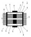
図1は、当該技術分野において公知である従来の加速度計102を示す。加速度計102は、2つのアンカーポイント106、108を介してガラス基板(図示せず)に固定された移動可能なフレーム104(すなわち、プルーフマス)を備える。加速度計102はまた、基板に取り付けられた2つの電極110、112を備える。 FIG. 1 shows a
テーパ状のフィンガー(図2に示す)のセットが電極110、112及びフレーム104の両方から延在し、交互嵌合型のフィンガー121、122の4つの象限114、116、118、120を画定する。 A set of tapered fingers (shown in FIG. 2) extends from both
加速度計102が感知軸100に沿って感応し、この軸100に沿った加速度により、フレーム104が支持部に対して移動して、電極110、112から延在する固定容量型電極フィンガーに対してフレーム104から延在する移動可能なフィンガーの直線移動を引き起こすよう配設される。この移動により、隣接するフィンガーの組間の容量が、それらの間の距離の変化に応じて、変化する。差動静電容量のこの変化はその後、電極110、112によって感知することができる。 The
図2は、図1の加速度計102に特有の組み合わせられたフィンガー配置を示す。より詳細には、図2は、象限114、116、118、120の各々に見ることができる交互嵌合型のフィンガー121、122の拡大図を示す。テーパ状の固定フィンガー121のあるセットは電極110、112から延在し、別の可動セット122は移動可能なフレーム104から延在する。電極110、112から延在する容量型電極フィンガー121は、適切に固定されており、加速度計102に対して移動することができない。フレーム104から延在する容量型電極フィンガー122は移動することができ、したがって、移動可能なフィンガー122と固定フィンガー121との間の間隙124、126は変化する。 FIG. 2 shows a combined finger arrangement typical of the
交互嵌合型の組における各フィンガーの両側の間隙124、126の大きさには差異が存在し、すなわち、容量型電極フィンガー間にはオフセットが存在することに注目すべきである。加速度計102は、左手用電極110に隣接する2つの象限114、116が、アンカーポイント106に最も近いより大きな間隙124を有し、一方で右手用電極112に隣接する他の2つの象限118、120がアンカーポイント108に最も近いより大きな間隙124を有するように設計される。この対称性(装置を通る垂直線を挟んで対称形状である)により、中心電極(すなわち、移動可能な容量型電極フィンガー122)及び2つの側電極110、112を有する差動コンデンサが提供される。この差動コンデンサ配置により、装置は、感知軸100に沿って両方向で加速度を感知することができる。フレーム104(すなわち、プルーフマス)は感知軸100に沿って移動するため、中心電極122と側電極110、112の一方の間の容量は増大するが、中心電極と他方の側電極110、112との間の容量は減少する。 It should be noted that there is a difference in the size of the
この特定の例において、容量型電極フィンガー121、122の各々は、典型的には付け根が20ミクロンの幅であり、先端に向かって12ミクロンまで幅が狭くなる。より大きな間隙124は典型的には16ミクロンであるが、より小さな間隙126は典型的には6ミクロンであり、したがって、44ミクロンのピッチにつながる。 In this particular example, each of
図3は、本開示の一例による、加速度計202を示す。加速度計202は、可撓性の脚250によって2つのアンカーポイント206、208を介してガラス基板(図示せず)に固定された移動可能なフレーム204を備える。加速度計202はまた、基板に取り付けられた2つの固定電極210、212を備える。 FIG. 3 illustrates an
テーパ状のフィンガーのセット(図2に示すものと同様に)は固定電極210、212と移動可能なフレーム204の両方から延在し、交互嵌合型の容量型電極フィンガー221、222の4つの象限214、216、218、220を画定する。 A set of tapered fingers (similar to that shown in FIG. 2) extends from both the fixed
加速度計202は、感知軸200に沿って感応するように配設され、この軸200に沿った加速度により、移動可能なフレーム204が支持部に対して移動し、固定電極210、212から延在する固定容量型電極フィンガーに対してフレーム204から延在する移動可能な容量型電極フィンガーが移動する。図2を参照して説明するように、加速度計202は必ず中心電極(すなわち、移動可能な容量型電極フィンガー)及び2つの側固定電極210、212を有する差動コンデンサとして配設されるため、加速度計202は、感知軸200に沿って両方向で加速度を感知するように配設される。移動可能なフレーム204(すなわち、プルーフマス)は感知軸200に沿って移動するため、中心電極と側電極210、212の一方との間の容量は増大するが、中心電極と他方の側電極210、212間の容量は減少する。移動可能なフレーム204は、印加加速度を感知する目的で加速度計202から出力電圧Voutを取り出すために利用することができる電気ピックオフ接続部(図示せず)を提供する。固定電極210、212はさらに、図5及び図6A〜図6Cを参照してさらに詳しく説明するように、対向する静電力を利用して(すなわち、閉ループにおいて加速度計202を操作するため)プルーフマス(すなわち、移動可能なフレーム204)をヌル位置に維持するために、駆動電圧V1、V2を加速度計202に印加する能力を提供する電気接続部を提供する。The
可撓性の支持脚250は、脚250によって支持された組み合わせられた質量とともに、典型的には(加速度計の必要な感応度に応じて)1〜5kHzの範囲にある共振周波数を設定する特定の長さ及び幅によって実装される。 The
図5及び図6A〜図6Cをさらに参照して説明するように、閉ループにおいて操作する際には、加速度によって発生するあらゆる位置の変化に対抗するべく駆動電圧V1、V2を固定電極210、212に提供するために固定電極210、212が利用される。駆動電圧V1、V2はまた、開ループ操作において固定電極210、212に印加されるが、移動可能なフレーム204をヌル位置に戻すためには利用されず、したがって、閉ループ操作において利用されるものよりも振幅が低くなる。As described further with reference to FIGS. 5 and 6A-6C, when operating in a closed loop, the drive voltages V1, V2 are applied to the fixed
図4において以下により詳細に示される専用ダンピングフィンガー228、230の2つのセットも加速度計202に取り付けられる。これらのダンピングフィンガー228、230は容量型感知または復旧電圧の印加のために利用されないが、代わりに、スクイーズフィルムダンピングを高めるために特に適合される。 Two sets of dedicated damping
ダンピングフィンガー228、230の専用セットは、開閉ループのいずれかにおいて操作される際に加速度計202に利点をもたらし、従来の加速度計に見ることができるよりも減衰特性を向上させる。 The dedicated set of damping
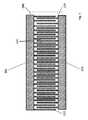
図4は、図3に示す加速度計202に特有のダンピングフィンガー228、230のセットを示す。ダンピングフィンガー228、230のこれらのセットはまた、交互嵌合型であり、ガラス基板201に取り付けられたダンピングフィンガー222の固定セット及び、フレーム204から延在するダンピングフィンガー224の可動セットを備える。 FIG. 4 shows a set of damping
図4から分かるように、隣接する交互嵌合型の固定及び移動可能ダンピングフィンガー222、224間の間隔226は、両側において等しい。これにより、均一なスクイーズフィルムダンピング効果が、感知軸200に沿って両方向において発生することが可能になる。 As can be seen from FIG. 4, the spacing 226 between adjacent interdigitating fixed and movable damping
この特定の例において、ダンピングフィンガーの各々は、幅8ミクロン及び長さ700ミクロンであり、固定及び移動可能なフィンガーのセット222、224内の隣接するフィンガー間の間隔は6ミクロンである。これにより、ピッチは28ミクロンとなり、これは、感知のため、及び、閉ループ操作の際には駆動のために利用される容量型電極フィンガーのそれよりもはるかに低い。これにより、加速度計202の減衰率は、当該技術分野において公知である従来の加速度計202に特有の0.5の減衰率と比較して増大し、およそ2.5となる。 In this particular example, each of the damping fingers is 8 microns wide and 700 microns long, and the spacing between adjacent fingers in the set of fixed and
ダンピングフィンガー222、224の2つのセットは、ダンピングフィンガー222、224のセットを互いに電気的に共通にするために作用する導電金属製の接触部260によって互いに電気的に接続される。これにより、スクイーズフィルムダンピング効果に対抗するあらゆる静電力がダンピングフィンガー222、224に作用することが防止され、したがって加速度計202の減衰率をさらに高める。本明細書においては破線で例示されているが、金属製の接触部260は典型的には、ダンピングフィンガー222の固定セットからのガラス基板201の表面に沿った経路をたどり、その後、ダウンホールビアによってフレーム204に接続される1つ以上の金属トラックとして実装される。1つ以上の金属トラック260が固定ダンピングフィンガー222のセットをプルーフマス(すなわち、前記フレーム204)に電気的に接続するため、交互嵌合型の固定及び移動可能ダンピングフィンガー222、224は電気的に共通である。 The two sets of damping
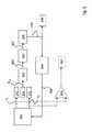
図5は、図3の加速度計を操作するための例示的な閉ループ電子制御回路のブロック図を示す。パルス幅変調(PWM)駆動電圧発生装置822は、同相及び逆相電圧信号V1及びV2をそれぞれ固定電極210、212の第1及び第2のセットに提供する(例示的な波形が図6A〜図6Cに示される)。移動可能なフレーム204からの出力電圧Voutがプリアンプ823に提供され、その出力825が復調装置824に提供される。結果として得られる出力827は、プルーフマス(すなわち、移動可能なフレーム204)のヌル位置からの移動を表す。出力827はその後、積分器/ループフィルタ826を通り、移動可能なフレーム204のヌル位置からの移動による、すなわち、印加加速度に比例する必要な復元力を表す出力832を提供する。FIG. 5 shows a block diagram of an exemplary closed loop electronic control circuit for operating the accelerometer of FIG. A pulse width modulation (PWM) drive
積分され、フィルタリングされた出力832は、移動可能なフレーム204がヌル位置に保持されるようにPWM駆動電圧発生装置822を駆動し、その後、復調装置出力827をヌル値に駆動するPWMマークスペース比発生装置を備えたPWM駆動電圧制御回路834に送られる。PWMマーク:スペース比率が復元力を決定し、印加加速度に比例する。2つの代替的な出力段が利用可能であることが分かる。1つの選択肢は、積分器/ループフィルタ826が、出力840において、印加加速度に比例する、適切にフィルタリングされた信号832を直接提供することである。これはデジタル信号であるため、追加的なエラーを導入することなく利用することができる。代わりに、または加えて、差動増幅器829等の比較器は、PWM駆動電圧V1及びV2を比較し、復元力を計測することで、印加加速度に比例する、831における出力を提供してもよい。この信号831は、システムの要件に一致するよう適切にフィルタリングするか、またはデジタル化することができるアナログ信号である。これにより、PWM電圧発生装置822または制御部834内のエラーが閉ループ操作によって抑制されるため、より性能の高いシステムが提供されてもよい。The integrated and filtered
図6A〜図6Cは、固定電極210、212にそれぞれ印加される電圧信号V1、V2の一連のPWM波形を示し、図3に示す加速度計202の操作を例示する。加速度計202は、電極210、212の各々に印加されるパルス幅変調(PWM)信号を利用して操作され、それによって、電極210、212の各々に印加される電圧は逆相であり、したがって「高」電圧500(典型的には、閉ループ操作において35V前後)が一方の電極に印加されるが、「低」電圧502(典型的には0ボルト)が他方に印加される。6A-6C show a series of PWM waveforms of voltage signals V1 and V2 applied to fixed
図6Aは、加速度計202が加速度を受けていないか、または開ループにおいて操作されている際のPWM波形を例示する。図6Aは、固定電極210、212のそれぞれに印加される、加速度計202が加速度を受けていない(すなわち、それが0gを計測している)際の典型的な同相及び逆相電圧信号V1、V2を示す。この例では、マークスペース比(すなわち、所与の電極が正電圧500を提供される長さの低電圧502と比較した比率)は50:50である。フレーム204(すなわち、プルーフマス)はそのヌル位置にあるため、象限214、216、218、220の各々における移動可能な容量型電極フィンガーセットはすべて同様に、それらのヌル位置にあり、復旧力が必要とされない。FIG. 6A illustrates a PWM waveform when the
図6Aに示す電圧信号V1、V2は、加速度計202が開ループにおいて操作されており、マークスペース比が変化しない、固定電極210、212に印加されるものと同じ形式である。開ループにおける操作時に、これらの信号高電圧500は典型的には3V前後である。開ループにおいては印加加速度に関わらず復旧力が印加されないため、マークスペース比は50:50で維持される。The voltage signals V1 and V2 shown in FIG. 6A are in the same format as those applied to the fixed
図6Bは、加速度計202が閉ループにおいて操作されている場合に、加速度計202が感知軸200に沿って負方向に加速度を受けている(すなわち、それが大きな負のgを計測している)際の固定電極210、212にそれぞれ印加される典型的な電圧信号V1、V2を示す。ここでは、象限214、216、218、220の各々におけるフレーム204したがって移動可能な容量型電極フィンガーセットがそれらのヌル位置からずれるため、(図5に見られる)制御部834及びPWM電圧発生装置822によって、一方の側、例えば、左固定電極210に高電圧500が、それが低電圧502を提供されるよりも長く提供され、他方の側、例えば、右固定電極212についてはその逆が真となるようにマークスペース比が調整される。これは、フレーム204をそのヌル位置に戻すように作用する。FIG. 6B shows that when the
図6Cは、加速度計202が閉ループにおいて操作されている場合に、加速度計202が感知軸200に沿って正方向で加速度を受けている(すなわち、それが大きな正のgを計測している)際の固定電極210、212にそれぞれ印加される、典型的な電圧信号V1、V2を示す。ここでは、一方の側、例えば、右固定電極212に高電圧500が、それが低電圧502を提供されるよりも長く提供され、他方の側、例えば、左固定電極210についてはその逆が真となるようにマークスペース比が調整される。これもフレーム204をそのヌル位置に戻すように作用するが、ここでは反対方向の力を印加する。このような閉ループ操作については、WO2005/083451においてより詳細に説明されており、その内容が参照文献として組み込まれる。FIG. 6C shows that when the
加速度計202の閉ループ操作に関してより詳細に説明しているが、本明細書に開示の加速度計の高められた減衰性能はまた、開ループ加速度計にとっても有益である(すなわち、一定の50:50のマークスペース比及び典型的な約3Vのピーク電圧を有する駆動信号が、開ループ駆動及び感知をもたらすために利用されるが、図6Aを参照して上述した復旧力についてはそうではない)ことが当業者には理解される。 Although described in more detail with respect to closed-loop operation of
したがって、減衰のためにフィンガーの別個の、専用セットを備える、改善された加速度計について、本明細書において説明されたことが分かる。特定の例に関して詳細に説明したが、本明細書に記載の本開示の原則を利用して、多くの変形例及び修正例が可能であることが当業者には理解される。 Thus, it can be seen that an improved accelerometer with a separate, dedicated set of fingers for damping has been described herein. Although described in detail with respect to particular examples, those skilled in the art will appreciate that many variations and modifications are possible utilizing the principles of the present disclosure as described herein.
Claims (15)
Translated fromJapanese前記プルーフマスから前記感知方向に略垂直に延在し、前記感知方向で横方向に相隔てられた移動可能な容量型電極フィンガーの第1及び第2のセットを備えた前記プルーフマスと、
前記固定基板に取り付けられた第1及び第2の固定コンデンサ電極であって、前記第1の固定コンデンサ電極が固定容量型電極フィンガーの第1のセットを備え、前記第2の固定コンデンサ電極が固定容量型電極フィンガーの第2のセットを備え、前記固定容量型電極フィンガーの第1及び第2のセットが前記感知方向に略垂直に延在し、前記感知方向で横方向に相隔てられ、
前記固定容量型電極フィンガーの第1のセットが前記プルーフマスの前記移動可能な容量型電極フィンガーの第1のセットと交互嵌合するように配設され、前記固定容量型電極フィンガーの第2のセットが前記プルーフマスの前記移動可能な容量型電極フィンガーの第2のセットと交互嵌合するように配設され、前記移動可能な容量型電極フィンガーの第1及び第2のセットが、利用時に印加加速度を感知するために出力電圧を提供するように配設された電気ピックオフ接続部をさらに備え、
前記移動可能な容量型電極フィンガーの第1のセットが、前記固定容量型電極フィンガーの第1のセットの隣接するフィンガーの間の第1の中線から第1の方向に第1の0以外のオフセットで提供され、
前記移動可能な容量型電極フィンガーの第2のセットが、前記固定容量型電極フィンガーの第2のセットの隣接するフィンガーの間の第2の中線から第2の、反対方向に第2の0以外のオフセットで提供され、前記第1及び第2のオフセットが前記第1及び第2の固定コンデンサ電極の間の中線を挟んで略対称形状であり、
前記プルーフマスが、前記プルーフマスから前記感知方向に略垂直に延在し、前記感知方向で横方向に相隔てられた移動可能ダンピングフィンガーのセットをさらに備える、前記第1及び第2の固定コンデンサ電極と、
前記固定基板に取り付けられ、前記移動可能ダンピングフィンガーのセットと交互嵌合するように配設された固定ダンピングフィンガーのセットであって、前記固定ダンピングフィンガーが前記感知方向に略垂直に延在し、前記感知方向で横方向に相隔てられ、
前記交互嵌合型の固定及び移動可能ダンピングフィンガーが電気的に共通であるように、前記固定ダンピングフィンガーのセットが前記プルーフマスとの電気接続部を備え、
前記プルーフマスが印加加速度に応じて移動する傾向にある場合に、前記交互嵌合型の移動可能及び固定ダンピングフィンガーが、前記移動可能及び固定ダンピングフィンガー間の相対移動を打ち消すダンピング効果を提供するガス状媒体内で取り付けられている、前記固定ダンピングフィンガーのセットと、
を備える、容量型加速度計。A substantially planar proof mass attached to a fixed substrate by a flexible support leg so as to be linearly movable in the in-plane sensing direction according to applied acceleration,
The proof mass comprising first and second sets of movable capacitive electrode fingers extending substantially perpendicular to the sensing direction from the proof mass and spaced laterally in the sensing direction;
First and second fixed capacitor electrodes attached to the fixed substrate, wherein the first fixed capacitor electrode comprises a first set of fixed capacitance type electrode fingers, and the second fixed capacitor electrode is fixed A second set of capacitive electrode fingers, wherein the first and second sets of fixed capacitive electrode fingers extend substantially perpendicular to the sensing direction and are laterally spaced in the sensing direction;
The first set of fixed capacitive electrode fingers is arranged to interdigitate with the first set of movable capacitive electrode fingers of the proof mass, and the second set of fixed capacitive electrode fingers. A set is arranged to interdigitate with the second set of movable capacitive electrode fingers of the proof mass, the first and second sets of movable capacitive electrode fingers being in use Further comprising an electrical pickoff connection arranged to provide an output voltage for sensing applied acceleration;
The first set of movable capacitive electrode fingers is non-zero in a first direction from a first midline between adjacent fingers of the first set of fixed capacitive electrode fingers. Provided in offset,
The second set of movable capacitive electrode fingers has a second zero in a second, opposite direction from a second midline between adjacent fingers of the second set of fixed capacitive electrode fingers. The first and second offsets are substantially symmetrical with respect to a middle line between the first and second fixed capacitor electrodes,
The first and second fixed capacitors, wherein the proof mass further comprises a set of movable damping fingers extending substantially perpendicular to the sensing direction from the proof mass and spaced laterally in the sensing direction Electrodes,
A set of fixed damping fingers attached to the fixed substrate and arranged to interdigitate with the set of movable damping fingers, the fixed damping fingers extending substantially perpendicular to the sensing direction; Spaced laterally in the sensing direction,
The set of fixed damping fingers comprises an electrical connection with the proof mass so that the interdigitated fixed and movable damping fingers are electrically common;
Gas that provides a damping effect in which the interdigitated movable and fixed damping fingers counteract relative movement between the movable and fixed damping fingers when the proof mass tends to move in response to applied acceleration A set of said fixed damping fingers mounted in a cylindrical medium;
A capacitive accelerometer.
前記PWM駆動信号のマークスペース比を変化させるために、前記電気ピックオフ接続部から得られる出力電圧を利用する、
ように配設された信号制御装置をさらに備える、請求項12に記載の容量型加速度計。Applying in-phase and anti-phase pulse width modulation (PWM) drive signals to the first and second sets of fixed capacitance electrode fingers;
In order to change the mark space ratio of the PWM drive signal, an output voltage obtained from the electric pick-off connection is used.
The capacitive accelerometer according to claim 12, further comprising a signal control device arranged as described above.
前記プルーフマスから前記感知方向に略垂直に延在し、前記感知方向で横方向に相隔てられた移動可能な容量型電極フィンガーの第1及び第2のセットを備えた前記プルーフマスと、
前記固定基板に取り付けられた第1及び第2の固定コンデンサ電極であって、前記第1の固定コンデンサ電極が固定容量型電極フィンガーの第1のセットを備え、前記第2の固定コンデンサ電極が固定容量型電極フィンガーの第2のセットを備え、前記固定容量型電極フィンガーの第1及び第2のセットが前記感知方向に略垂直に延在し、前記感知方向で横方向に相隔てられ、
前記固定容量型電極フィンガーの第1のセットが前記プルーフマスの前記移動可能な容量型電極フィンガーの第1のセットと交互嵌合するように配設され、前記固定容量型電極フィンガーの第2のセットが前記プルーフマスの前記移動可能な容量型電極フィンガーの第2のセットと交互嵌合するように配設され、前記移動可能な容量型電極フィンガーの第1及び第2のセットが、利用時に印加加速度を感知するために出力電圧を提供するように配設された電気ピックオフ接続部をさらに備え、
前記移動可能な容量型電極フィンガーの第1のセットが、前記固定容量型電極フィンガーの第1のセットの隣接するフィンガーの間の第1の中線から第1の方向に第1の0以外のオフセットで提供され、
前記移動可能な容量型電極フィンガーの第2のセットが、前記固定容量型電極フィンガーの第2のセットの隣接するフィンガーの間の第2の中線から第2の、反対方向に第2の0以外のオフセットで提供され、前記第1及び第2のオフセットが前記第1及び第2の固定コンデンサ電極の間の中線を挟んで略対称形状であり、
前記プルーフマスが、前記プルーフマスから前記感知方向に略垂直に延在し、前記感知方向で横方向に相隔てられた移動可能ダンピングフィンガーのセットをさらに備える、前記第1及び第2の固定コンデンサ電極と、
前記移動可能ダンピングフィンガーのセットと交互嵌合するように配設された固定ダンピングフィンガーのセットであって、前記固定ダンピングフィンガーが前記感知方向に略垂直に延在し、前記感知方向で横方向に相隔てられ、
前記交互嵌合型の固定及び移動可能ダンピングフィンガーが電気的に共通であるように、前記固定ダンピングフィンガーのセットが前記プルーフマスとの電気接続部を備え、
前記プルーフマスが印加加速度に応じて移動する傾向にある場合に、前記交互嵌合型の移動可能及び固定ダンピングフィンガーが、前記移動可能及び固定ダンピングフィンガー間の相対移動を打ち消すダンピング効果を提供するガス状媒体内で取り付けられる、前記固定ダンピングフィンガーのセットと、
を備えた、容量型加速度計の操作方法であって、
前記電気ピックオフ接続部から前記出力電圧を得ることと、そこから前記印加加速度を決定するために前記出力電圧を処理することと、
を含む、前記容量型加速度計の操作方法。A substantially planar proof mass attached to a fixed substrate by a flexible support leg so as to be linearly movable in the in-plane sensing direction according to applied acceleration,
The proof mass comprising first and second sets of movable capacitive electrode fingers extending substantially perpendicular to the sensing direction from the proof mass and spaced laterally in the sensing direction;
First and second fixed capacitor electrodes attached to the fixed substrate, wherein the first fixed capacitor electrode comprises a first set of fixed capacitance type electrode fingers, and the second fixed capacitor electrode is fixed A second set of capacitive electrode fingers, wherein the first and second sets of fixed capacitive electrode fingers extend substantially perpendicular to the sensing direction and are laterally spaced in the sensing direction;
The first set of fixed capacitive electrode fingers is arranged to interdigitate with the first set of movable capacitive electrode fingers of the proof mass, and the second set of fixed capacitive electrode fingers. A set is arranged to interdigitate with the second set of movable capacitive electrode fingers of the proof mass, the first and second sets of movable capacitive electrode fingers being in use Further comprising an electrical pickoff connection arranged to provide an output voltage for sensing applied acceleration;
The first set of movable capacitive electrode fingers is non-zero in a first direction from a first midline between adjacent fingers of the first set of fixed capacitive electrode fingers. Provided in offset,
The second set of movable capacitive electrode fingers has a second zero in a second, opposite direction from a second midline between adjacent fingers of the second set of fixed capacitive electrode fingers. The first and second offsets are substantially symmetrical with respect to a middle line between the first and second fixed capacitor electrodes,
The first and second fixed capacitors, wherein the proof mass further comprises a set of movable damping fingers extending substantially perpendicular to the sensing direction from the proof mass and spaced laterally in the sensing direction Electrodes,
A set of fixed damping fingers arranged to interdigitate with the set of movable damping fingers, the fixed damping fingers extending substantially perpendicular to the sensing direction and laterally in the sensing direction Separated,
The set of fixed damping fingers comprises an electrical connection with the proof mass so that the interdigitated fixed and movable damping fingers are electrically common;
Gas that provides a damping effect in which the interdigitated movable and fixed damping fingers counteract relative movement between the movable and fixed damping fingers when the proof mass tends to move in response to applied acceleration A set of said fixed damping fingers, mounted in a cylindrical medium;
A method for operating a capacitive accelerometer, comprising:
Obtaining the output voltage from the electrical pick-off connection and processing the output voltage to determine the applied acceleration therefrom;
A method of operating the capacitive accelerometer, comprising:
を含み、
前記出力電圧を処理することが、前記PWM駆動信号のマークスペース比を変化させるために前記電気ピックオフ接続部から得られる前記出力電圧を利用することを含む、
請求項14に記載の方法。Applying in-phase and anti-phase pulse width modulation (PWM) drive signals to the first and second sets of fixed capacitance electrode fingers;
Including
Processing the output voltage includes utilizing the output voltage obtained from the electrical pickoff connection to change a mark space ratio of the PWM drive signal;
The method according to claim 14.
Applications Claiming Priority (3)
| Application Number | Priority Date | Filing Date | Title |
|---|---|---|---|
| GBGB1514319.1AGB201514319D0 (en) | 2015-08-12 | 2015-08-12 | Accelerometers |
| GB1514319.1 | 2015-08-12 | ||
| PCT/GB2016/052501WO2017025753A1 (en) | 2015-08-12 | 2016-08-11 | Accelerometers |
Publications (2)
| Publication Number | Publication Date |
|---|---|
| JP2018525634Atrue JP2018525634A (en) | 2018-09-06 |
| JP6732012B2 JP6732012B2 (en) | 2020-07-29 |
Family
ID=54200663
Family Applications (1)
| Application Number | Title | Priority Date | Filing Date |
|---|---|---|---|
| JP2018507634AActiveJP6732012B2 (en) | 2015-08-12 | 2016-08-11 | Accelerometer |
Country Status (6)
| Country | Link |
|---|---|
| US (1) | US10670623B2 (en) |
| EP (1) | EP3335052B1 (en) |
| JP (1) | JP6732012B2 (en) |
| KR (1) | KR102095475B1 (en) |
| GB (1) | GB201514319D0 (en) |
| WO (1) | WO2017025753A1 (en) |
Cited By (1)
| Publication number | Priority date | Publication date | Assignee | Title |
|---|---|---|---|---|
| JP2020085891A (en)* | 2018-11-16 | 2020-06-04 | アトランティック・イナーシャル・システムズ・リミテッドAtlantic Inertial Systems Limited | Accelerometer, and method of producing accelerometer for sensing accelerations in out-of-plane sensing direction |
Families Citing this family (7)
| Publication number | Priority date | Publication date | Assignee | Title |
|---|---|---|---|---|
| GB2570714B (en)* | 2018-02-05 | 2022-03-02 | Atlantic Inertial Systems Ltd | Accelerometers |
| DE102018210487A1 (en)* | 2018-06-27 | 2020-01-02 | Robert Bosch Gmbh | Electrode arrangement for a microelectromechanical system, microelectromechanical system, method for operating a microelectromechanical system |
| GB2593132A (en)* | 2019-11-01 | 2021-09-22 | Atlantic Inertial Systems Ltd | Methods for closed loop operation of capacitive accelerometers |
| US11493531B2 (en)* | 2019-11-07 | 2022-11-08 | Honeywell International Inc. | Resonator electrode configuration to avoid capacitive feedthrough for vibrating beam accelerometers |
| CN111223671B (en)* | 2020-02-27 | 2021-02-05 | 清华大学 | Self-sensing supercapacitor with both energy storage and shock sensing functions and its manufacturing method |
| DE102020211928A1 (en) | 2020-09-23 | 2022-05-19 | Robert Bosch Gesellschaft mit beschränkter Haftung | Damping device for micromechanical component |
| US20240410914A1 (en)* | 2023-06-09 | 2024-12-12 | Honeywell International Inc. | Translational mass accelerometer |
Citations (7)
| Publication number | Priority date | Publication date | Assignee | Title |
|---|---|---|---|---|
| JPH11118827A (en)* | 1997-10-14 | 1999-04-30 | Denso Corp | Capacity type physical quantity detector |
| JP2007501938A (en)* | 2003-08-13 | 2007-02-01 | セルセル | External vibration suppression accelerometer with improved electrode shape |
| JP2009168777A (en)* | 2008-01-21 | 2009-07-30 | Hitachi Ltd | Inertial sensor |
| JP2010085313A (en)* | 2008-10-01 | 2010-04-15 | Murata Mfg Co Ltd | Compound sensor |
| US8590376B2 (en)* | 2008-03-27 | 2013-11-26 | Fraunhofer-Gesellschaft Zur Foerderung Der Angewandten Forschung E.V. | Microelectromechanical inertial sensor with atmospheric damping |
| JP2014016341A (en)* | 2012-06-13 | 2014-01-30 | Denso Corp | Capacitance type physical quantity sensor |
| JP6067926B2 (en)* | 2013-05-02 | 2017-01-25 | ノースロップ グルマン リテフ ゲーエムベーハーNorthrop Grumman LITEF GmbH | Acceleration sensor and method of manufacturing acceleration sensor |
Family Cites Families (13)
| Publication number | Priority date | Publication date | Assignee | Title |
|---|---|---|---|---|
| US7047808B2 (en)* | 2003-02-28 | 2006-05-23 | Bae Systems Plc | Accelerometer |
| WO2004107242A2 (en) | 2003-05-28 | 2004-12-09 | Koninklijke Philips Electronics N.V. | Hospital information system |
| DE602005021754D1 (en)* | 2004-02-27 | 2010-07-22 | Atlantic Inertial Systems Ltd | ACCELEROMETER |
| US7069784B1 (en)* | 2004-12-29 | 2006-07-04 | Honeywell International Inc. | Pendulous in-plane MEMS accelerometer device |
| WO2007008935A2 (en) | 2005-07-11 | 2007-01-18 | Ready Solar, Inc. | Solar panel and frame and related methods |
| JP4310325B2 (en)* | 2006-05-24 | 2009-08-05 | 日立金属株式会社 | Angular velocity sensor |
| KR100899812B1 (en)* | 2006-12-05 | 2009-05-27 | 한국전자통신연구원 | Capacitive accelerometer |
| GB201020722D0 (en)* | 2010-12-07 | 2011-01-19 | Atlantic Inertial Systems Ltd | Accelerometer |
| US20140090468A1 (en)* | 2012-03-16 | 2014-04-03 | Advanced Numicro Systems, Inc. | Tri-axial mems inertial sensor |
| GB201317859D0 (en)* | 2013-10-09 | 2013-11-20 | Atlantic Inertial Systems Ltd | Accelerometer control |
| GB201322918D0 (en)* | 2013-12-23 | 2014-02-12 | Atlantic Inertial Systems Ltd | Accelerometers |
| GB2523320A (en)* | 2014-02-19 | 2015-08-26 | Atlantic Inertial Systems Ltd | Accelerometers |
| GB2524245A (en)* | 2014-03-17 | 2015-09-23 | Atlantic Inertial Systems Ltd | Accelerometers |
- 2015
- 2015-08-12GBGBGB1514319.1Apatent/GB201514319D0/ennot_activeCeased
- 2016
- 2016-08-11KRKR1020187006830Apatent/KR102095475B1/enactiveActive
- 2016-08-11USUS15/754,293patent/US10670623B2/enactiveActive
- 2016-08-11JPJP2018507634Apatent/JP6732012B2/enactiveActive
- 2016-08-11EPEP16753433.8Apatent/EP3335052B1/enactiveActive
- 2016-08-11WOPCT/GB2016/052501patent/WO2017025753A1/ennot_activeCeased
Patent Citations (12)
| Publication number | Priority date | Publication date | Assignee | Title |
|---|---|---|---|---|
| JPH11118827A (en)* | 1997-10-14 | 1999-04-30 | Denso Corp | Capacity type physical quantity detector |
| JP2007501938A (en)* | 2003-08-13 | 2007-02-01 | セルセル | External vibration suppression accelerometer with improved electrode shape |
| JP5442785B2 (en)* | 2003-08-13 | 2014-03-12 | セルセル | External vibration suppression accelerometer with improved electrode shape |
| JP5599832B2 (en)* | 2003-08-13 | 2014-10-01 | セルセル | External vibration suppression accelerometer with improved electrode shape |
| JP2009168777A (en)* | 2008-01-21 | 2009-07-30 | Hitachi Ltd | Inertial sensor |
| JP5319122B2 (en)* | 2008-01-21 | 2013-10-16 | 日立オートモティブシステムズ株式会社 | Inertial sensor |
| US8590376B2 (en)* | 2008-03-27 | 2013-11-26 | Fraunhofer-Gesellschaft Zur Foerderung Der Angewandten Forschung E.V. | Microelectromechanical inertial sensor with atmospheric damping |
| JP2010085313A (en)* | 2008-10-01 | 2010-04-15 | Murata Mfg Co Ltd | Compound sensor |
| JP5267023B2 (en)* | 2008-10-01 | 2013-08-21 | 株式会社村田製作所 | Compound sensor |
| JP2014016341A (en)* | 2012-06-13 | 2014-01-30 | Denso Corp | Capacitance type physical quantity sensor |
| JP5772873B2 (en)* | 2012-06-13 | 2015-09-02 | 株式会社デンソー | Capacitance type physical quantity sensor |
| JP6067926B2 (en)* | 2013-05-02 | 2017-01-25 | ノースロップ グルマン リテフ ゲーエムベーハーNorthrop Grumman LITEF GmbH | Acceleration sensor and method of manufacturing acceleration sensor |
Cited By (1)
| Publication number | Priority date | Publication date | Assignee | Title |
|---|---|---|---|---|
| JP2020085891A (en)* | 2018-11-16 | 2020-06-04 | アトランティック・イナーシャル・システムズ・リミテッドAtlantic Inertial Systems Limited | Accelerometer, and method of producing accelerometer for sensing accelerations in out-of-plane sensing direction |
Also Published As
| Publication number | Publication date |
|---|---|
| EP3335052A1 (en) | 2018-06-20 |
| KR102095475B1 (en) | 2020-04-01 |
| US20180217179A1 (en) | 2018-08-02 |
| JP6732012B2 (en) | 2020-07-29 |
| WO2017025753A1 (en) | 2017-02-16 |
| GB201514319D0 (en) | 2015-09-23 |
| US10670623B2 (en) | 2020-06-02 |
| KR20180040613A (en) | 2018-04-20 |
| EP3335052B1 (en) | 2021-04-14 |
Similar Documents
| Publication | Publication Date | Title |
|---|---|---|
| JP6732012B2 (en) | Accelerometer | |
| JP6461993B2 (en) | Accelerometer | |
| JP4654668B2 (en) | Gyro sensor and sensor device using the same | |
| JP5960257B2 (en) | Apparatus and method for time domain measurement of vibrational perturbations | |
| CN106030314B (en) | Accelerometer | |
| US10274511B2 (en) | Accelerometers | |
| KR20050107470A (en) | An accelerometer | |
| JP2009271052A (en) | Parametric amplification of mems gyroscope by capacitance modulation | |
| JP2007524854A (en) | Accelerometer | |
| EP2060871A2 (en) | Inertial sensor | |
| KR101313267B1 (en) | Torque driving circuit | |
| US11249106B2 (en) | Methods for closed loop operation of capacitive accelerometers | |
| JP2007078648A (en) | Sensor device | |
| US20250313452A1 (en) | Fully symmetrical structures for microelectromechanical devices | |
| JP5783201B2 (en) | Capacitive physical quantity sensor | |
| JP2025002014A (en) | Acceleration Sensor Device | |
| JPH11258264A (en) | Capacitive acceleration sensor | |
| JP2009063328A (en) | Capacitance change detection device |
Legal Events
| Date | Code | Title | Description |
|---|---|---|---|
| A621 | Written request for application examination | Free format text:JAPANESE INTERMEDIATE CODE: A621 Effective date:20190213 | |
| A977 | Report on retrieval | Free format text:JAPANESE INTERMEDIATE CODE: A971007 Effective date:20191127 | |
| A131 | Notification of reasons for refusal | Free format text:JAPANESE INTERMEDIATE CODE: A131 Effective date:20191203 | |
| A601 | Written request for extension of time | Free format text:JAPANESE INTERMEDIATE CODE: A601 Effective date:20200302 | |
| A601 | Written request for extension of time | Free format text:JAPANESE INTERMEDIATE CODE: A601 Effective date:20200501 | |
| TRDD | Decision of grant or rejection written | ||
| A01 | Written decision to grant a patent or to grant a registration (utility model) | Free format text:JAPANESE INTERMEDIATE CODE: A01 Effective date:20200609 | |
| A61 | First payment of annual fees (during grant procedure) | Free format text:JAPANESE INTERMEDIATE CODE: A61 Effective date:20200707 | |
| R150 | Certificate of patent or registration of utility model | Ref document number:6732012 Country of ref document:JP Free format text:JAPANESE INTERMEDIATE CODE: R150 | |
| R250 | Receipt of annual fees | Free format text:JAPANESE INTERMEDIATE CODE: R250 | |
| R250 | Receipt of annual fees | Free format text:JAPANESE INTERMEDIATE CODE: R250 | |
| R250 | Receipt of annual fees | Free format text:JAPANESE INTERMEDIATE CODE: R250 |