JP2018522746A - Glassy bonded abrasive article and manufacturing method thereof - Google Patents
Glassy bonded abrasive article and manufacturing method thereofDownload PDFInfo
- Publication number
- JP2018522746A JP2018522746AJP2017566791AJP2017566791AJP2018522746AJP 2018522746 AJP2018522746 AJP 2018522746AJP 2017566791 AJP2017566791 AJP 2017566791AJP 2017566791 AJP2017566791 AJP 2017566791AJP 2018522746 AJP2018522746 AJP 2018522746A
- Authority
- JP
- Japan
- Prior art keywords
- abrasive
- particles
- vitreous bond
- abrasive article
- precursor
- Prior art date
- Legal status (The legal status is an assumption and is not a legal conclusion. Google has not performed a legal analysis and makes no representation as to the accuracy of the status listed.)
- Granted
Links
Images


Classifications
- B—PERFORMING OPERATIONS; TRANSPORTING
- B24—GRINDING; POLISHING
- B24D—TOOLS FOR GRINDING, BUFFING OR SHARPENING
- B24D18/00—Manufacture of grinding tools or other grinding devices, e.g. wheels, not otherwise provided for
- B24D18/0009—Manufacture of grinding tools or other grinding devices, e.g. wheels, not otherwise provided for using moulds or presses
- B—PERFORMING OPERATIONS; TRANSPORTING
- B24—GRINDING; POLISHING
- B24D—TOOLS FOR GRINDING, BUFFING OR SHARPENING
- B24D5/00—Bonded abrasive wheels, or wheels with inserted abrasive blocks, designed for acting only by their periphery; Bushings or mountings therefor
- B24D5/02—Wheels in one piece
- B—PERFORMING OPERATIONS; TRANSPORTING
- B22—CASTING; POWDER METALLURGY
- B22F—WORKING METALLIC POWDER; MANUFACTURE OF ARTICLES FROM METALLIC POWDER; MAKING METALLIC POWDER; APPARATUS OR DEVICES SPECIALLY ADAPTED FOR METALLIC POWDER
- B22F10/00—Additive manufacturing of workpieces or articles from metallic powder
- B22F10/10—Formation of a green body
- B22F10/14—Formation of a green body by jetting of binder onto a bed of metal powder
- B—PERFORMING OPERATIONS; TRANSPORTING
- B22—CASTING; POWDER METALLURGY
- B22F—WORKING METALLIC POWDER; MANUFACTURE OF ARTICLES FROM METALLIC POWDER; MAKING METALLIC POWDER; APPARATUS OR DEVICES SPECIALLY ADAPTED FOR METALLIC POWDER
- B22F10/00—Additive manufacturing of workpieces or articles from metallic powder
- B22F10/30—Process control
- B22F10/34—Process control of powder characteristics, e.g. density, oxidation or flowability
- B—PERFORMING OPERATIONS; TRANSPORTING
- B24—GRINDING; POLISHING
- B24D—TOOLS FOR GRINDING, BUFFING OR SHARPENING
- B24D11/00—Constructional features of flexible abrasive materials; Special features in the manufacture of such materials
- B—PERFORMING OPERATIONS; TRANSPORTING
- B24—GRINDING; POLISHING
- B24D—TOOLS FOR GRINDING, BUFFING OR SHARPENING
- B24D11/00—Constructional features of flexible abrasive materials; Special features in the manufacture of such materials
- B24D11/04—Zonally-graded surfaces
- B—PERFORMING OPERATIONS; TRANSPORTING
- B24—GRINDING; POLISHING
- B24D—TOOLS FOR GRINDING, BUFFING OR SHARPENING
- B24D3/00—Physical features of abrasive bodies, or sheets, e.g. abrasive surfaces of special nature; Abrasive bodies or sheets characterised by their constituents
- B24D3/02—Physical features of abrasive bodies, or sheets, e.g. abrasive surfaces of special nature; Abrasive bodies or sheets characterised by their constituents the constituent being used as bonding agent
- B24D3/04—Physical features of abrasive bodies, or sheets, e.g. abrasive surfaces of special nature; Abrasive bodies or sheets characterised by their constituents the constituent being used as bonding agent and being essentially inorganic
- B24D3/06—Physical features of abrasive bodies, or sheets, e.g. abrasive surfaces of special nature; Abrasive bodies or sheets characterised by their constituents the constituent being used as bonding agent and being essentially inorganic metallic or mixture of metals with ceramic materials, e.g. hard metals, "cermets", cements
- B—PERFORMING OPERATIONS; TRANSPORTING
- B24—GRINDING; POLISHING
- B24D—TOOLS FOR GRINDING, BUFFING OR SHARPENING
- B24D3/00—Physical features of abrasive bodies, or sheets, e.g. abrasive surfaces of special nature; Abrasive bodies or sheets characterised by their constituents
- B24D3/02—Physical features of abrasive bodies, or sheets, e.g. abrasive surfaces of special nature; Abrasive bodies or sheets characterised by their constituents the constituent being used as bonding agent
- B24D3/04—Physical features of abrasive bodies, or sheets, e.g. abrasive surfaces of special nature; Abrasive bodies or sheets characterised by their constituents the constituent being used as bonding agent and being essentially inorganic
- B24D3/14—Physical features of abrasive bodies, or sheets, e.g. abrasive surfaces of special nature; Abrasive bodies or sheets characterised by their constituents the constituent being used as bonding agent and being essentially inorganic ceramic, i.e. vitrified bondings
- B—PERFORMING OPERATIONS; TRANSPORTING
- B24—GRINDING; POLISHING
- B24D—TOOLS FOR GRINDING, BUFFING OR SHARPENING
- B24D5/00—Bonded abrasive wheels, or wheels with inserted abrasive blocks, designed for acting only by their periphery; Bushings or mountings therefor
- B24D5/10—Bonded abrasive wheels, or wheels with inserted abrasive blocks, designed for acting only by their periphery; Bushings or mountings therefor with cooling provisions, e.g. with radial slots
- B—PERFORMING OPERATIONS; TRANSPORTING
- B24—GRINDING; POLISHING
- B24D—TOOLS FOR GRINDING, BUFFING OR SHARPENING
- B24D5/00—Bonded abrasive wheels, or wheels with inserted abrasive blocks, designed for acting only by their periphery; Bushings or mountings therefor
- B24D5/14—Zonally-graded wheels; Composite wheels comprising different abrasives
- B—PERFORMING OPERATIONS; TRANSPORTING
- B24—GRINDING; POLISHING
- B24D—TOOLS FOR GRINDING, BUFFING OR SHARPENING
- B24D7/00—Bonded abrasive wheels, or wheels with inserted abrasive blocks, designed for acting otherwise than only by their periphery, e.g. by the front face; Bushings or mountings therefor
- B24D7/02—Wheels in one piece
- B—PERFORMING OPERATIONS; TRANSPORTING
- B24—GRINDING; POLISHING
- B24D—TOOLS FOR GRINDING, BUFFING OR SHARPENING
- B24D7/00—Bonded abrasive wheels, or wheels with inserted abrasive blocks, designed for acting otherwise than only by their periphery, e.g. by the front face; Bushings or mountings therefor
- B24D7/10—Bonded abrasive wheels, or wheels with inserted abrasive blocks, designed for acting otherwise than only by their periphery, e.g. by the front face; Bushings or mountings therefor with cooling provisions
- B—PERFORMING OPERATIONS; TRANSPORTING
- B24—GRINDING; POLISHING
- B24D—TOOLS FOR GRINDING, BUFFING OR SHARPENING
- B24D7/00—Bonded abrasive wheels, or wheels with inserted abrasive blocks, designed for acting otherwise than only by their periphery, e.g. by the front face; Bushings or mountings therefor
- B24D7/14—Zonally-graded wheels; Composite wheels comprising different abrasives
- B—PERFORMING OPERATIONS; TRANSPORTING
- B33—ADDITIVE MANUFACTURING TECHNOLOGY
- B33Y—ADDITIVE MANUFACTURING, i.e. MANUFACTURING OF THREE-DIMENSIONAL [3-D] OBJECTS BY ADDITIVE DEPOSITION, ADDITIVE AGGLOMERATION OR ADDITIVE LAYERING, e.g. BY 3-D PRINTING, STEREOLITHOGRAPHY OR SELECTIVE LASER SINTERING
- B33Y10/00—Processes of additive manufacturing
- B—PERFORMING OPERATIONS; TRANSPORTING
- B24—GRINDING; POLISHING
- B24D—TOOLS FOR GRINDING, BUFFING OR SHARPENING
- B24D2203/00—Tool surfaces formed with a pattern
- B—PERFORMING OPERATIONS; TRANSPORTING
- B29—WORKING OF PLASTICS; WORKING OF SUBSTANCES IN A PLASTIC STATE IN GENERAL
- B29C—SHAPING OR JOINING OF PLASTICS; SHAPING OF MATERIAL IN A PLASTIC STATE, NOT OTHERWISE PROVIDED FOR; AFTER-TREATMENT OF THE SHAPED PRODUCTS, e.g. REPAIRING
- B29C64/00—Additive manufacturing, i.e. manufacturing of three-dimensional [3D] objects by additive deposition, additive agglomeration or additive layering, e.g. by 3D printing, stereolithography or selective laser sintering
- B29C64/10—Processes of additive manufacturing
- B29C64/165—Processes of additive manufacturing using a combination of solid and fluid materials, e.g. a powder selectively bound by a liquid binder, catalyst, inhibitor or energy absorber
Landscapes
- Engineering & Computer Science (AREA)
- Mechanical Engineering (AREA)
- Chemical & Material Sciences (AREA)
- Manufacturing & Machinery (AREA)
- Ceramic Engineering (AREA)
- Inorganic Chemistry (AREA)
- Materials Engineering (AREA)
- Automation & Control Theory (AREA)
- Polishing Bodies And Polishing Tools (AREA)
Abstract
Translated fromJapaneseDescription
Translated fromJapanese本開示は概して、ガラス質結合マトリックス内の研磨粒子を有する研磨物品の製造方法、及びそれらの製造方法に関する。 The present disclosure generally relates to methods of making abrasive articles having abrasive particles in a vitreous bond matrix, and methods of making the same.
従来より、ビトリファイドボンド研磨物品(例えば、研磨ホイール、研磨セグメント、及び砥石)は、研磨粒子(例えば、ダイヤモンド、立方窒化ホウ素、アルミナ、若しくはSiC)、ガラス質ボンド前駆体(例えば、ガラスフリット、セラミック前駆体)、任意選択的な細孔誘導剤(例えば、ガラス気泡、ナフタレン、破砕されたヤシ若しくはクルミ殻、又はアクリルガラス若しくはPMMA)、並びに液状ビヒクル中の一時的有機バインダ(例えば、フェノール樹脂、ポリビニルアルコール、尿素ホルムアルデヒド樹脂、若しくはデキストリンの水溶液)のブレンドを圧縮することによって製造されている。通例、研磨粒子、ガラス質ボンド前駆体、及び通常、細孔誘導剤をともにドライブレンドする。次に、一時的有機バインダ溶液を加え、粒子混合物を浸潤させる。次に、ブレンドされた混合物を、離型剤で処理された焼入鋼成形型内に配置し、次に、ガラス質ボンド前駆体がガラス質ボンドマトリックス(当技術分野において、「ガラス質ボンド」及び「ガラス質バインダ」とも呼ばれる)に転換されるまで加熱する。 Conventionally, vitrified bond abrasive articles (eg, abrasive wheels, abrasive segments, and grinding wheels) are made of abrasive particles (eg, diamond, cubic boron nitride, alumina, or SiC), glassy bond precursors (eg, glass frit, ceramics). Precursors), optional pore inducers (eg, glass bubbles, naphthalene, crushed palm or walnut shells, or acrylic glass or PMMA), and temporary organic binders in liquid vehicles (eg, phenolic resins, Polyvinyl alcohol, urea formaldehyde resin, or an aqueous solution of dextrin). Typically, the abrasive particles, the glassy bond precursor, and usually the pore inducer are dry blended together. Next, a temporary organic binder solution is added to infiltrate the particle mixture. The blended mixture is then placed in a hardened steel mold that has been treated with a mold release agent, and the glassy bond precursor is then converted into a glassy bond matrix (in the art, “glassy bond” And also called “glassy binder”).
この製作手法には多くの欠点がある。それらは各研磨物品の形状によって専用の成形型が必要となること、成形型は通例、高価であり、かつ製作のための長いリードタイムを有すること、いかなる設計変更も、新たな成形型の製作を必要とすること、成形できる形状が制限がされ、アンダーカット、又は冷却通路などの内部構造を有する複雑な形状が概ね不可能であること、成形型が摩耗し、成形型当りで製造できるユニット数が制限されること、成形型に研磨材混合物が充填されている間、成分が分離する場合があり、容易に視認可能な、不均質な研磨成分及び密度のむらを引き起こすこと。更に、プロセスが手動であり、労働集約的である。 There are many drawbacks to this fabrication technique. They require a dedicated mold depending on the shape of each abrasive article, the mold is usually expensive and has a long lead time for production, any design changes will produce a new mold Units that can be manufactured per mold, because the shape that can be molded is limited, undercuts, or complex shapes with internal structures such as cooling passages are almost impossible, the mold is worn out The number is limited, the components may separate while the mold is filled with the abrasive mixture, causing non-uniform polishing components and density variations that are easily visible. Furthermore, the process is manual and labor intensive.
粉末床バインダ噴射は、積層造形法、すなわち「3Dプリンティング」の技術であり、この技術では、粉末の薄層が、噴射された液状バインダ混合物により所望の箇所で一時的に結合される。一般的に、そのバインダ混合物は、インクジェットプリントヘッドにより吐出され、好適な溶剤又は担体液に溶けたポリマーから成る。一方法では、バインダは、他の粉末と混合した粉末、又は粉末にコーティングし乾燥した粉末であり、次いで、水又は溶剤混合物などの活性化液を、粉末に噴射して、選択エリアのバインダを活性化する。 Powder bed binder injection is an additive manufacturing technique, or “3D printing” technique, in which a thin layer of powder is temporarily bonded at a desired location by an injected liquid binder mixture. Generally, the binder mixture consists of a polymer that is ejected by an inkjet printhead and dissolved in a suitable solvent or carrier liquid. In one method, the binder is a powder mixed with other powders, or a powder coated and dried powder, and then an activation liquid, such as water or a solvent mixture, is sprayed onto the powder to remove the binder in the selected area. Activate.
そして、プリントされた粉末層を、少なくとも部分的に乾燥し、位置を下げて、次の粉末層を展開できるようにする。完全な物体が形成されるまで、粉末の展開、結合及び乾燥のプロセスを繰り返すことができる。物体及び周囲の粉末を、プリンタから取り出し、多くの場合、乾燥又は硬化して更に強度を付加して、硬化した物体を周囲の粉末から取り出せるようにする。 The printed powder layer is then at least partially dried and lowered so that the next powder layer can be developed. The powder development, bonding and drying process can be repeated until a complete object is formed. The object and surrounding powder are removed from the printer, often dried or cured to add more strength so that the cured object can be removed from the surrounding powder.
一態様では、本開示は、ガラス質ボンド研磨物品の製造方法を提供する。この製造方法は、逐次的な工程を含み、逐次的な工程は、
a)
i)固まっていない粉末粒子の層を限られた領域内に堆積する工程であり、固まっていない粉末粒子は、ガラス質ボンド前駆体粒子及び研磨粒子を含み、固まっていない粉末粒子の層は、実質的に均一な厚さを有する、工程、
ii)固まっていない粉末粒子の層の所定の領域に液状バインダ前駆体物質を噴出する工程、並びに
iii)液状バインダ前駆体物質を、所定の領域の固まっていない粉末粒子の粒子を一緒に結合する一時的バインダ物質に転換して、結合した粉末粒子の層を形成する工程、を逐次的に行うサブプロセスと、
b)工程a)を独立して複数回実施して、結合した粉末粒子及び残った固まっていない粉末粒子を含む研磨物品プリフォームを生成する工程であり、各工程a)において、固まっていない粉末粒子が独立して選択され、液状バインダ前駆体物質は、独立して選択される、工程と、
c)残った固まっていない粉末粒子の実質的に全てを研磨物品プリフォームから分離する工程と、
d)研磨物品プリフォームを加熱して、ガラス質ボンド材料中に保持された研磨粒子を含むガラス質ボンド研磨物品を提供する工程と、を逐次的に行う工程を含む。In one aspect, the present disclosure provides a method of manufacturing a vitreous bond abrasive article. This manufacturing method includes sequential steps, and the sequential steps are:
a)
i) depositing a layer of uncured powder particles in a limited area, the uncured powder particles comprising vitreous bond precursor particles and abrasive particles, A process having a substantially uniform thickness;
ii) jetting the liquid binder precursor material into a predetermined region of the layer of unconsolidated powder particles; and iii) combining the liquid binder precursor material with the particles of unconsolidated powder particles in the predetermined region together. A sub-process for sequentially converting to a temporary binder material to form a layer of bonded powder particles;
b) Step a) is carried out a plurality of times independently to produce an abrasive article preform containing the combined powder particles and the remaining unhardened powder particles. In each step a), the unhardened powder A process wherein the particles are independently selected and the liquid binder precursor material is independently selected;
c) separating substantially all of the remaining unset powder particles from the abrasive article preform;
d) sequentially heating the abrasive article preform to provide a vitreous bond abrasive article comprising abrasive particles retained in the vitreous bond material.
有利なことに、本開示に係る方法は、ガラス質ボンド研磨物品を大量又は短期間の生産で製造するのに適している。 Advantageously, the method according to the present disclosure is suitable for manufacturing glassy bonded abrasive articles in high volume or short term production.
したがって、別の態様では、本開示は、研磨粒子を内部に保持するガラス質ボンド物質を含むガラス質ボンド研磨物品であって、ガラス質ボンド研磨物品の少なくとも一部を通って延びる少なくとも1つの蛇行状の冷却通路を有する、ガラス質ボンド研磨物品を提供する。 Accordingly, in another aspect, the present disclosure provides a vitreous bond abrasive article that includes a vitreous bond material that retains abrasive particles therein, the at least one meander extending through at least a portion of the vitreous bond abrasive article. A vitreous bond abrasive article is provided having a shaped cooling passage.
更に別の態様では、本開示は、研磨粒子を内部に保持するガラス質ボンド物質を含むガラス質ボンド研磨物品であって、ガラス質ボンド研磨物品の少なくとも一部を通って延びる少なくとも1つの弓状の冷却通路を有する、ガラス質ボンド研磨物品を提供する。 In yet another aspect, the present disclosure provides a vitreous bond abrasive article comprising a vitreous bond material that retains abrasive particles therein, the at least one arcuate shape extending through at least a portion of the vitreous bond abrasive article. A glassy bonded abrasive article is provided having a cooling passage.
更に別の態様では、本開示は、ガラス質ボンド前駆体物質により一緒に結合した研磨粒子を含むガラス質ボンド研磨物品前駆体であって、
ガラス質ボンド研磨物品前駆体の少なくとも一部を通って延びる少なくとも1つの蛇行状の冷却通路、又は
ガラス質ボンド研磨物品前駆体の少なくとも一部を通って延びる少なくとも1つの弓状の冷却通路、のうちの少なくとも1つを更に含む、ガラス質ボンド研磨物品前駆体を提供する。In yet another aspect, the present disclosure is a vitreous bond abrasive article precursor comprising abrasive particles bonded together by a vitreous bond precursor material comprising:
At least one serpentine cooling passage extending through at least a portion of the vitreous bond abrasive article precursor or at least one arcuate cooling passage extending through at least a portion of the vitreous bond abrasive article precursor. A vitreous bond abrasive article precursor is provided that further comprises at least one of them.
更に別の態様では、本開示は、単体構造化された研磨ディスクであって、
作業主表面を有する平面状セラミック基材と、
作業主表面から延びる精密に賦形されたセラミック研磨要素と、を備え、この精密に賦形されたセラミック研磨要素と平面状セラミック基材とで単体の本体を形成する、単体構造化された研磨ディスクを提供する。In yet another aspect, the present disclosure is a unitary structured abrasive disc comprising:
A planar ceramic substrate having a working main surface;
A precisely shaped ceramic polishing element extending from the main working surface, wherein the precisely shaped ceramic polishing element and the planar ceramic substrate form a unitary body, the unitary structured polishing Provide a disc.
第22の実施形態では、本開示は、精密に賦形された研磨要素は、共通回転軸の周りに湾曲している、第19の実施形態に係る単体構造化された研磨ディスクを提供する。 In a twenty-second embodiment, the present disclosure provides a unitary structured abrasive disc according to the nineteenth embodiment, wherein the precisely shaped abrasive element is curved about a common axis of rotation.
本明細書で使用する時、用語「ガラス質ボンド」は、無機セラミック、ガラス、及びガラスセラミックを含む。 As used herein, the term “glassy bond” includes inorganic ceramics, glasses, and glass ceramics.
本開示の特徴及び利点は、「発明を実施するための形態」並びに添付された「特許請求の範囲」を考慮することで、更に理解される。 The features and advantages of the present disclosure will be further understood in view of the “DETAILED DESCRIPTION” and the appended claims.
本開示によるガラス質ボンド研磨物品の製造方法は共通の積層サブプロセスを含む。サブプロセスは、少なくとも3つの工程を逐次的に、好ましくは連続的に(ただし、必須ではない)実施することを含む。 The method of manufacturing a vitreous bond abrasive article according to the present disclosure includes a common lamination sub-process. The sub-process includes performing at least three steps sequentially, preferably sequentially (but not essential).
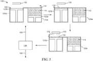
図1は、ガラス質ボンド研磨物品の製造に使用される例示的な粉末噴射プロセス100を概略的に図示している。 FIG. 1 schematically illustrates an exemplary
第1の工程では、固まっていない粉末粒子110の層138を、限られた領域140に堆積する。層138は、実質的に均一な厚さとするべきである。例えば、層の厚さは、50ミクロン未満、好ましくは、30ミクロン未満、及びより好ましくは、10ミクロン未満で変化しうる。層は、噴射された液状バインダ前駆体物質が、適用された場所にある、固まっていない粉末の全てを結合できる限り、約1ミリメートルまでの任意の厚さを有してもよい。好ましくは、層の厚さは、約10ミクロン〜約500ミクロン、10ミクロン〜約250ミクロン、より好ましくは、約50ミクロン〜約250ミクロン、及びより好ましくは、約100ミクロン〜約200ミクロンである。 In the first step, a
固まっていない粉末粒子はガラス質ボンド前駆体粒子及び研磨粒子を含む。 Non-set powder particles include glassy bond precursor particles and abrasive particles.
ガラス質ボンド前駆体粒子は、ガラス質物質に熱的に転換され得る任意の物質の粒子を含み得る。例としては、ガラスフリット粒子、セラミック粒子、セラミック前駆体粒子、及びこれらの組合わせが挙げられる。 The vitreous bond precursor particles can include particles of any material that can be thermally converted to a vitreous material. Examples include glass frit particles, ceramic particles, ceramic precursor particles, and combinations thereof.
本開示に係る研磨粒を互いに固結するガラス質ボンドは、例えば、研磨材の技術分野において知られた任意の好適な組成のものであることができる。ガラス質ボンド相はまた、当技術分野において、「セラミックボンド」、「ガラス質相」、「ガラス質マトリックス」、又は「ガラスボンド」として様々に知られており、(例えば、組成に依存して)、高温に加熱されると反応して一体的なガラス質ボンド相を形成する、1つ以上の酸化物(例えば、金属酸化物及び/若しくはボリア)、並びに/又はフリット(即ち、小粒子)としての少なくとも1つのケイ酸塩から生成されてもよい。例としては、ガラス粒子(例えば、再生ガラスフリット、水ガラスフリット)、シリカフリット(例えば、ゾル−ゲルシリカフリット)、アルミナ三水和物粒子、アルミナ粒子、ジルコニア粒子、及びこれらの組合わせが挙げられる。好適なフリット、これらの原料、及び組成物は当該技術分野において既知である。 The vitreous bond that consolidates the abrasive grains according to the present disclosure can be of any suitable composition known in the art of abrasives, for example. Glassy bond phases are also known variously in the art as “ceramic bonds”, “glassy phases”, “glassy matrices”, or “glass bonds” (eg, depending on the composition ), One or more oxides (eg, metal oxides and / or boria) and / or frit (ie, small particles) that react when heated to high temperatures to form an integral glassy bond phase. As at least one silicate. Examples include glass particles (eg, recycled glass frit, water glass frit), silica frit (eg, sol-gel silica frit), alumina trihydrate particles, alumina particles, zirconia particles, and combinations thereof. It is done. Suitable frits, these ingredients, and compositions are known in the art.
研磨物品は通例、研磨粒、ガラス質ボンド前駆体、任意選択の細孔形成剤、及び一時的バインダで構成された未焼成構造体を形成することによって調製される。未焼成構造体はその後焼成される。ガラス質ボンド相は通常、本開示の研磨物品を生成するためのプロセスの焼成工程において生成される。典型的な焼成温度は、540℃〜1700℃(1000°F〜3100°F)の範囲である。焼成工程のために選択される温度及びガラス質ボンド相の組成は、ガラス質ボンド研磨物品中に含有される研磨粒子の物理的特性及び/又は組成に悪影響を与えないように選定されなければならないことを理解されたい。 Abrasive articles are typically prepared by forming a green structure composed of abrasive grains, a glassy bond precursor, an optional pore former, and a temporary binder. The green structure is then fired. The glassy bond phase is typically produced in the firing step of the process for producing the abrasive article of the present disclosure. Typical firing temperatures range from 540 ° C to 1700 ° C (1000 ° F to 3100 ° F). The temperature selected for the firing process and the composition of the glassy bond phase must be selected so as not to adversely affect the physical properties and / or composition of the abrasive particles contained in the glassy bond abrasive article. Please understand that.
有用なガラスフリット粒子は、ガラス質ボンド研磨物品における使用のために知られている任意のガラスフリット物質を含み得る。例としては、シリカガラスフリット、ケイ酸塩ガラスフリット、ホウケイ酸塩ガラスフリット、及びこれらの組合わせから成る群から選択されるガラスフリットが挙げられる。一実施形態では、代表的なガラス質固結物質は、約70〜90%のSiO2+B2O3、1〜20%のアルカリ酸化物、1〜20%のアルカリ土類酸化物、及び1〜20%の遷移金属酸化物を含有する。別の実施形態では、ガラス質固結物質は、約82wt%のSiO2+B2O3、5%のアルカリ金属酸化物、5%の遷移系列金属酸化物、4%のAl2O3、及び4%のアルカリ土類酸化物の組成を有する。別の実施形態では、ガラス質固結物質として、約20%のB2O3、60%のシリカ、2%のソーダ、及び4%のマグネシアを有するフリットを使用することができる。当業者であれば、上記の特定の成分及びそれらの成分の量が、該組成物で形成される最終研磨物品に特定の性質を与えることを一部目的として選択されることができる点が理解されよう。Useful glass frit particles can include any glass frit material known for use in vitreous bond abrasive articles. Examples include glass frit selected from the group consisting of silica glass frit, silicate glass frit, borosilicate glass frit, and combinations thereof. In one embodiment, a typical vitreous consolidation material is about 70-90% SiO2 + B2 O3 , 1-20% alkali oxide, 1-20% alkaline earth oxide, and 1 Contains -20% transition metal oxide. In another embodiment, the vitreous consolidation material comprises about 82 wt% SiO2 + B2 O3 , 5% alkali metal oxide, 5% transition series metal oxide, 4% Al2 O3 , and It has a 4% alkaline earth oxide composition. In another embodiment, a frit having about 20% B2 O3 , 60% silica, 2% soda, and 4% magnesia can be used as the vitreous consolidation material. One skilled in the art understands that the specific components described above and the amounts of those components can be selected in part for the purpose of imparting specific properties to the final abrasive article formed from the composition. Let's be done.
ガラスフリットのサイズは様々であり得る。例えば、それは研磨粒子と同じサイズであっても異なってもよい。典型的には、ガラスフリットの平均粒径は、約0.01マイクロメートル〜約100マイクロメートル、好ましくは、約0.05マイクロメートル〜約50マイクロメートル、及び最も好ましくは、約0.1マイクロメートル〜約25マイクロメートルの範囲である。少なくとも約5のモース硬度を有する研磨粒子の平均粒径に対する、ガラスフリットの平均粒径は、様々であり得る。通例、ガラスフリットの平均粒径は、研磨剤の平均粒径の約1〜約200パーセント、好ましくは、約10〜約100パーセント、及び最も好ましくは、約15〜約50パーセントである。 The size of the glass frit can vary. For example, it can be the same size or different from the abrasive particles. Typically, the average particle size of the glass frit is about 0.01 micrometers to about 100 micrometers, preferably about 0.05 micrometers to about 50 micrometers, and most preferably about 0.1 micrometers. The range is from meter to about 25 micrometers. The average particle size of the glass frit can vary with respect to the average particle size of the abrasive particles having a Mohs hardness of at least about 5. Typically, the average particle size of the glass frit is about 1 to about 200 percent, preferably about 10 to about 100 percent, and most preferably about 15 to about 50 percent of the average particle size of the abrasive.
典型的には、固まっていない粉末粒子中における、ガラス質ボンド前駆体粒子の、研磨粒子に対する重量比は、約10:90〜約90:10の範囲である。ガラス質ボンド前駆体粒子の形状もまた、様々であり得る。典型的に、それらは形状が不規則である(例えば、破砕され、任意選択的に選別される)。ただし、これは必要条件ではない。例えば、それらは、球状、立方体状、又は何らかの他の所定の形状であってもよい。 Typically, the weight ratio of vitreous bond precursor particles to abrasive particles in the uncured powder particles ranges from about 10:90 to about 90:10. The shape of the vitreous bond precursor particles can also vary. Typically, they are irregular in shape (eg, crushed and optionally sorted). However, this is not a requirement. For example, they may be spherical, cubic, or some other predetermined shape.
好ましくは、ガラス質ボンド前駆体粒子の熱膨張係数は研磨粒子のものと同じであるか、又は実質的に同じである。 Preferably, the thermal expansion coefficient of the vitreous bond precursor particles is the same as or substantially the same as that of the abrasive particles.
1つの好ましいガラス質ボンドは、SiO2 63.28、TiO2 0.32、Al2O3 10.99、B2O3 5.11、Fe2O3 0.13、K2O 3.81、Na2O 4.20、Li2O 4.98、CaO 3.88、MgO 3.04及びBaO 0.26の酸化物ベースのモルパーセント(%)組成を有する。これらの含有成分の焼成は通例、温度を長時間(例えば、約25〜26時間)にわたって室温から1149℃(2100°F)へ上昇させ、最大温度で(例えば、数時間)保持し、その後、焼成された物品を更に長時間(例えば、25〜30時間)にわたって室温まで冷却することによって達成される。One preferred glassy bond is SiO2 63.28, TiO2 0.32, Al2 O3 10.99, B2 O3 5.11, Fe2 O3 0.13, K2 O 3.81. , Na2 O 4.20, Li2 O 4.98, CaO 3.88, MgO 3.04 and BaO 0.26 oxide based mole percent (%) composition. Firing of these ingredients typically raises the temperature from room temperature to 1149 ° C. (2100 ° F.) over a long period of time (eg, about 25-26 hours) and is held at the maximum temperature (eg, several hours), after which This is accomplished by cooling the fired article to room temperature for an extended period of time (eg, 25-30 hours).
ガラス質ボンド前駆体粒子はセラミック粒子を含んでもよい。このような場合には、セラミック粒子の焼結及び/又は溶融がガラス質マトリックスを形成する。任意の焼結可能及び/又は溶融可能セラミック物質が用いられ得る。好ましいセラミック物質としては、アルミナ、ジルコニア、及びこれらの組合わせが挙げられる。 The vitreous bond precursor particles may include ceramic particles. In such cases, sintering and / or melting of the ceramic particles forms a vitreous matrix. Any sinterable and / or meltable ceramic material can be used. Preferred ceramic materials include alumina, zirconia, and combinations thereof.
所望の場合には、αアルミナセラミック粒子は、マグネシウム、ニッケル、亜鉛、イットリア、希土類酸化物、ジルコニア、ハフニウム、クロム、又は同様のものなどの金属の酸化物で修飾されてもよい。アルミナ及びジルコニア研磨粒子は、例えば、米国特許第4,314,827号(Leitheiserら)、同第4,518,397号(Leitheiserら)、同第4,574,003号(Gerk)、同第4,623,364号(Cottringerら)、同第4,744,802号(Schwabel)、及び同第5,551,963号(Larmie)において開示されているとおりの、ゾル−ゲルプロセスによって製造されてもよい。 If desired, the alpha alumina ceramic particles may be modified with a metal oxide such as magnesium, nickel, zinc, yttria, rare earth oxide, zirconia, hafnium, chromium, or the like. Alumina and zirconia abrasive particles are described, for example, in U.S. Pat. Nos. 4,314,827 (Leithiser et al.), 4,518,397 (Leithiser et al.), 4,574,003 (Gerk), ibid. Produced by a sol-gel process as disclosed in US 4,623,364 (Cottringer et al.), US 4,744,802 (Schwabel), and US 5,551,963 (Larmie). May be.
ガラス質ボンド前駆体粒子は、ガラス質ボンド前駆体粒子と研磨粒子との複合体積の10〜40体積パーセント、好ましくは、研磨組成物の15〜35体積パーセントの量で存在してもよい。 The glassy bond precursor particles may be present in an amount of 10 to 40 volume percent of the composite volume of glassy bond precursor particles and abrasive particles, preferably 15 to 35 volume percent of the polishing composition.
研磨物品の製造を補助し、及び/又はこのような物品の性能を工場させるために、様々な結合接着物品の製造において様々な添加物を使用することは既知である。本開示の実施において同様に使用され得るこのような従来の添加物としては、限定するものではないが、潤滑剤、充填剤、細孔誘導剤、及び加工助剤が挙げられる。潤滑剤の例としては、黒鉛、硫黄、ポリテトラフルオロエチレン及び二硫化モリブデンが挙げられる。細孔誘導剤の例としては、ガラス気泡及び有機粒子が挙げられる。例えば、添加物の意図された目的のために、当技術分野において知られているとおりの添加物の濃度が採用されてもよい。好ましくは、添加物は、本開示の実施において採用された研磨粒子に対してほとんど又は全く悪影響を及ぼさない。 It is known to use various additives in the manufacture of various bonded adhesive articles to assist in the manufacture of abrasive articles and / or to factory the performance of such articles. Such conventional additives that may also be used in the practice of the present disclosure include, but are not limited to, lubricants, fillers, pore inducers, and processing aids. Examples of lubricants include graphite, sulfur, polytetrafluoroethylene and molybdenum disulfide. Examples of pore inducers include glass bubbles and organic particles. For example, additive concentrations as known in the art may be employed for the intended purpose of the additive. Preferably, the additive has little or no adverse effect on the abrasive particles employed in the practice of this disclosure.
固まっていない粉末粒子は、任意選択的に、それらの流動性及び層の展開の均一性を向上するために改質されていてもよい。粉末の改良方法としては、凝集、噴霧乾燥、ガス噴霧又は水噴霧、フレーム形成、粒状化、ミリング加工、及び篩分けが挙げられる。追加的に、例えば、ヒュームドシリカ、ナノシリカ、ステアリン酸塩類、及びデンプンなどの流動剤が任意選択的に添加されてもよい。 The non-set powder particles may optionally be modified to improve their fluidity and the uniformity of the layer development. Methods for improving the powder include agglomeration, spray drying, gas spraying or water spraying, frame formation, granulation, milling, and sieving. In addition, flow agents such as fumed silica, nano silica, stearates, and starch may optionally be added.
ガラス質ボンド前駆体粒子は、例えば、焼成されると、対応するセラミック形態へ転換する、ボーキサイト、ベーマイト、か焼アルミナ、又はか焼ジルコニアなどのセラミック前駆体(例えば、アルミナ又はジルコニアの前駆体)を含んでもよい。 A glassy bond precursor particle, for example, when fired, converts to the corresponding ceramic form, a ceramic precursor such as bauxite, boehmite, calcined alumina, or calcined zirconia (eg, a precursor of alumina or zirconia). May be included.
ガラス質結合研磨物品(例えば、研磨ホイール)を製造するための、当該技術分野において既知の手順及び条件、並びに特に、ガラス質ボンド研磨物品を製造するための手順及び条件が、本開示の研磨物品を製造するために使用され得る。これらの手順は、当該技術分野における従来的かつ既知の器具を利用し得る。 Procedures and conditions known in the art for producing glassy bonded abrasive articles (eg, abrasive wheels), and in particular, procedures and conditions for producing glassy bonded abrasive articles are disclosed in the present disclosure. Can be used to manufacture. These procedures may utilize conventional and known instruments in the art.
研磨粒子は、研磨材産業において用いられる任意の研磨粒子を含み得る。好ましくは、研磨粒子は、少なくとも4、好ましくは、少なくとも5、より好ましくは、少なくとも6、より好ましくは、少なくとも7、より好ましくは、少なくとも8、より好ましくは、少なくとも8.5、及びより好ましくは、少なくとも9のモース硬度を有する。一部の実施形態では、研磨粒子は超砥粒(superabrasive)粒子を含む。本明細書で使用する時、用語「超砥粒」は、炭化ケイ素のもの以上の硬度を有する任意の研磨粒子(例えば、炭化ケイ素、炭化ホウ素、立方窒化ホウ素、及びダイヤモンド)を指す。 The abrasive particles can include any abrasive particles used in the abrasive industry. Preferably, the abrasive particles are at least 4, preferably at least 5, more preferably at least 6, more preferably at least 7, more preferably at least 8, more preferably at least 8.5, and more preferably. A Mohs hardness of at least 9. In some embodiments, the abrasive particles comprise superabrasive particles. As used herein, the term “superabrasive” refers to any abrasive particle having a hardness greater than that of silicon carbide (eg, silicon carbide, boron carbide, cubic boron nitride, and diamond).
好適な研磨物質の具体例としては、酸化アルミニウム(例えば、αアルミナ)物質(例えば、溶融、熱処理、セラミック、及び/若しくは焼結酸化アルミニウム物質)、炭化ケイ素、二ホウ化チタン、窒化チタン、炭化ホウ素、炭化タングステン、炭化チタン、窒化アルミニウム、ダイヤモンド、立方窒化ホウ素(CBN)、ガーネット、溶融アルミナ−ジルコニア、ゾル−ゲル由来研磨粒子、酸化セリウム、酸化ジルコニウム、酸化チタン、並びにこれらの組合わせが挙げられる。米国特許第4,314,827号(Leitheiserら)、同第4,623,364号(Cottringerら)、同第4,744,802号(Schwabel)、同第4,770,671号(Monroeら)、及び同第4,881,951号(Monroeら)に、ゾル−ゲル由来研磨粒子の例を見出すことができる。(例えば、米国特許第6,551,366号(D’Souzaら)に記載されているとおりの)ガラス質ボンドマトリックス中により微細な研磨粒子を含む凝集研磨粒子も同様に用いられ得る。 Specific examples of suitable abrasive materials include aluminum oxide (eg, alpha alumina) materials (eg, fused, heat treated, ceramic, and / or sintered aluminum oxide materials), silicon carbide, titanium diboride, titanium nitride, carbonized. Examples include boron, tungsten carbide, titanium carbide, aluminum nitride, diamond, cubic boron nitride (CBN), garnet, fused alumina-zirconia, sol-gel derived abrasive particles, cerium oxide, zirconium oxide, titanium oxide, and combinations thereof. It is done. U.S. Pat. Nos. 4,314,827 (Leithiser et al.), 4,623,364 (Cottringer et al.), 4,744,802 (Schwabel), 4,770,671 (Monroe et al.) ), And 4,881,951 (Monroe et al.), Examples of sol-gel derived abrasive particles can be found. Agglomerated abrasive particles comprising finer abrasive particles in a glassy bond matrix (eg, as described in US Pat. No. 6,551,366 (D'Souza et al.)) Can be used as well.
微細な細粒度を達成するために、固まっていない粉末粒子は、好ましくは、400ミクロン以下、好ましくは、250ミクロン以下、より好ましくは、200ミクロン以下、より好ましくは、150ミクロン以下、100ミクロン以下、又は更に80ミクロン以下の最大サイズを有するように(例えば、篩い分けによって)サイズが設定される。ただし、より大きなサイズもまた用いられ得る。ガラス質ボンド前駆体粒子、研磨粒子、及びあらゆる任意選択の追加的な粒子成分は、同じ、又は異なる最大粒子サイズ、D90、D50、及び/又はD10粒径分布パラメータを有し得る。In order to achieve a fine fine particle size, the non-set powder particles are preferably 400 microns or less, preferably 250 microns or less, more preferably 200 microns or less, more preferably 150 microns or less, 100 microns or less. Or, further, the size is set to have a maximum size of 80 microns or less (eg, by sieving). However, larger sizes can also be used. The vitreous bond precursor particles, abrasive particles, and any optional additional particle components may have the same or different maximum particle sizes, D90 , D50 , and / or D10 particle size distribution parameters.
固まっていない粉末粒子は、例えば、細孔誘導剤、及び/又は充填剤粒子などの他の成分を任意選択的に更に含んでもよい。細孔誘導剤の例としては、ガラス気泡及び有機粒子が挙げられる。 The non-set powder particles may optionally further comprise other components such as, for example, pore inducers and / or filler particles. Examples of pore inducers include glass bubbles and organic particles.
次に、液状バインダ前駆体物質170を、層138の(1つ以上の)所定の領域180にプリンタ150により噴射する。液状バインダ前駆体物質は、よって、領域180内の固まっていない粉末粒子をコーティングし、その後に、領域180内の固まっていない粉末粒子を互いに結合するバインダ物質に転換される。液状バインダ前駆体物質は、(例えば、気化、又は熱硬化、化学硬化、及び/又は(例えば、UV光又は可視光を用いる)放射線硬化によって)、噴射パターン(及び、複数の繰返しによる最終3D形状)に従って、固まっていない粉末粒子を結合するバインダ物質に転換されうる任意の組成であってよい。 Next, the liquid
一部の実施形態では、液状バインダ前駆体物質は、溶存ポリマーを含有する液状ビヒクルを含む。液体は、有機溶剤及び水の1つ以上を含みうる。例示的な有機溶剤としては、アルコール(例えば、ブタノール、エチレングリコールモノメチルエーテル)、ケトン、及びエーテルが挙げられ、100℃超の引火点を有することが好ましい。 In some embodiments, the liquid binder precursor material comprises a liquid vehicle containing dissolved polymer. The liquid can include one or more of an organic solvent and water. Exemplary organic solvents include alcohols (eg, butanol, ethylene glycol monomethyl ether), ketones, and ethers, and preferably have a flash point greater than 100 ° C.
好適な1つ又は複数の溶剤の選択は、一般的に、例えば、所望の表面張力及び粘度、選択された微粒子固体など、具体的な用途の要件に依存する。 The selection of a suitable solvent or solvents generally depends on the specific application requirements, such as, for example, the desired surface tension and viscosity, the selected particulate solid.
液状ビヒクルは、完全に水とすることができ、又は1つ以上の有機溶剤との組合せで水を含むことができる。水溶性ビヒクルは、総重量ベースで、少なくとも20パーセントの水、少なくとも30パーセントの水、少なくとも40パーセントの水、少なくとも50パーセントの水、又は少なくとも75パーセントの水を含むことが好ましい。 The liquid vehicle can be completely water or can contain water in combination with one or more organic solvents. The water soluble vehicle preferably comprises at least 20 percent water, at least 30 percent water, at least 40 percent water, at least 50 percent water, or at least 75 percent water, based on the total weight.
一部の実施形態では、1つ以上の有機溶剤が、例えば、液状ビヒクルの乾燥スピードを制御するために、液状ビヒクルの表面張力を制御するために、(例えば、界面活性物質等の)含有成分の溶解を可能にするために、又は、含有成分のうちのいずれかの二次的成分として、液状ビヒクルに含まれていてもよく、例えば、有機助溶剤が、液状ビヒクルの含有成分として添加された界面活性物質内に存在してもよい。例示的な有機溶剤としては、メチルアルコール、エチルアルコール、n−プロピルアルコール、イソプロピルアルコール、n−ブチルアルコール、sec−ブチルアルコール、t−ブチルアルコール、及びイソブチルアルコールなどのアルコール;アセトン、メチルエチルケトン、及びジアセトンアルコールなどのケトン又はケトアルコール;酢酸エチル及び乳酸エチルなどのエステル;エチレングリコール、ジエチレングリコール、トリエチレングリコール、プロピレングリコール、ブチレングリコール、1,4−ブタンジオール、1,2,4−ブタントリオール、1,5−ペンタンジオール、1,2,6−ヘキサントリオール、ヘキシレングリコール、グリセロール、グリセロールエトキシレート、トリメチロールプロパンエトキシレートなどの多価アルコール類;エチレングリコールメチル若しくはエチルエーテル、ジエチレングリコールエチルエーテル、トリエチレングリコールメチル若しくはエチルエーテル、エチレングリコールn−ブチルエーテル、ジエチレングリコールn−ブチルエーテル、ジエチレングリコールメチルエーテル、エチレングリコールフェニルエーテル、プロピレングリコールメチルエーテル、ジプロピレングリコールメチルエーテル、トリプロピレングリコールメチルエーテル、酢酸プロピレングリコールメチルエーテル、酢酸ジプロピレングリコールメチルエーテル、プロピレングリコールn−プロピルエーテル、ジプロピレングリコールn−プロピルエーテル、トリプロピレングリコールn−プロピルエーテル、プロピレングリコールn−ブチルエーテル、ジプロピレングリコールn−ブチルエーテル、トリプロピレングリコールn−ブチルエーテル、プロピレングリコールフェニルエーテル、及びジプロピレングリコールジメチルエーテルなどの低級アルキルエーテル;2−ピロリジノン及びN−メチル−2−ピロリジノンなどの窒素含有化合物;ジメチルスルホキシド、テトラメチレンスルホン、及びチオグリコールなどの硫黄含有化合物類、並びに前述したものの任意の組合わせが挙げられる。 In some embodiments, one or more organic solvents include components (eg, surfactants) to control the surface tension of the liquid vehicle, eg, to control the drying speed of the liquid vehicle. May be included in the liquid vehicle as a secondary component of any of the components, eg, an organic co-solvent is added as a component of the liquid vehicle. May be present in the surface active material. Exemplary organic solvents include alcohols such as methyl alcohol, ethyl alcohol, n-propyl alcohol, isopropyl alcohol, n-butyl alcohol, sec-butyl alcohol, t-butyl alcohol, and isobutyl alcohol; acetone, methyl ethyl ketone, and di- Ketones or keto alcohols such as acetone alcohol; esters such as ethyl acetate and ethyl lactate; ethylene glycol, diethylene glycol, triethylene glycol, propylene glycol, butylene glycol, 1,4-butanediol, 1,2,4-butanetriol, 1 , 5-pentanediol, 1,2,6-hexanetriol, hexylene glycol, glycerol, glycerol ethoxylate, trimethylolpropane ethoxylate Polyhydric alcohols such as ethylene glycol methyl or ethyl ether, diethylene glycol ethyl ether, triethylene glycol methyl or ethyl ether, ethylene glycol n-butyl ether, diethylene glycol n-butyl ether, diethylene glycol methyl ether, ethylene glycol phenyl ether, propylene glycol methyl ether , Dipropylene glycol methyl ether, tripropylene glycol methyl ether, propylene glycol methyl ether acetate, dipropylene glycol methyl ether acetate, propylene glycol n-propyl ether, dipropylene glycol n-propyl ether, tripropylene glycol n-propyl ether, propylene Glycol n-bu Lower ethers such as ether, dipropylene glycol n-butyl ether, tripropylene glycol n-butyl ether, propylene glycol phenyl ether, and dipropylene glycol dimethyl ether; nitrogen-containing compounds such as 2-pyrrolidinone and N-methyl-2-pyrrolidinone; dimethyl Sulfur-containing compounds such as sulfoxide, tetramethylene sulfone, and thioglycol, and any combination of those described above.
液状ビヒクル内の有機溶剤及び/又は水の量は、特に、粘度、表面張力、及び/又は乾燥速度など、液状バインダ前駆体物質の所望の特性などの多くの要因に依存する場合があり、それらは、例えば、ピエゾ式又はサーマル式のプリントヘッドなど、液状ビヒクルインクとともに使用されることが意図されるインクジェット印刷技術のタイプなどの要因に依存する場合がある。 The amount of organic solvent and / or water in the liquid vehicle may depend on many factors such as the desired properties of the liquid binder precursor material, such as viscosity, surface tension, and / or drying rate, among others. May depend on factors such as the type of ink jet printing technology that is intended to be used with the liquid vehicle ink, such as, for example, a piezo or thermal print head.
液状バインダ前駆体物質は、液状ビヒクル内に溶解可能又は分散可能であるポリマーを含みうる。好適なポリマーの例としては、ポリビニルピロリドン、ポリビニルカプロラクタム、ポリビニルアルコール、ポリアクリルアミド、ポリ(2−エチル−2−オキサゾリン)(PEOX)、ポリビニルブチラート、メチルビニルエーテル及び無水マイレン酸のコポリマー、アクリル酸の特定のコポリマー、及び/又はヒドロキシエチルアクリレート、メチルセルロース、天然ポリマー(例えば、デキストリン、グアーガム、キサンタンガム)が挙げられうる。これらのうち、主に水である液状ビヒクルともに使用するためには、ポリビニルピロリドン類が好ましい。所望に応じて、代わりに又は追加で、上に列挙したもの以外の他の有機ポリマーを使用してもよい。 The liquid binder precursor material may include a polymer that is soluble or dispersible in the liquid vehicle. Examples of suitable polymers include polyvinylpyrrolidone, polyvinylcaprolactam, polyvinyl alcohol, polyacrylamide, poly (2-ethyl-2-oxazoline) (PEOX), polyvinyl butyrate, copolymers of methyl vinyl ether and maleic anhydride, acrylic acid Specific copolymers and / or hydroxyethyl acrylate, methylcellulose, natural polymers (eg dextrin, guar gum, xanthan gum) may be mentioned. Of these, polyvinylpyrrolidones are preferred for use with a liquid vehicle that is primarily water. Other organic polymers other than those listed above may be used instead or in addition, as desired.
液状バインダ前駆体物質は、1つ以上のフリーラジカル重合性、そうでなければ放射線硬化性材料の物質、例えば、アクリル系モノマー類及び/若しくはオリゴマー類並びに/又はエポキシ樹脂類を含んでもよい。また、フリーラジカル重合性の、そうでなければ放射線硬化性の物質を硬化させるための有効量の光開始剤及び/又は光触媒が含まれてもよい。好適な(メタ)アクリレートモノマー及びオリゴマー、そうでなければ放射線硬化性物質(例えば、エポキシ樹脂)の例が、例えば米国特許第5,766,277号(DeVoeら)に見られる。 The liquid binder precursor material may comprise one or more free-radically polymerizable or otherwise radiation curable material materials such as acrylic monomers and / or oligomers and / or epoxy resins. An effective amount of photoinitiator and / or photocatalyst for curing free radically polymerizable, otherwise radiation curable materials may also be included. Examples of suitable (meth) acrylate monomers and oligomers, otherwise radiation curable materials (eg, epoxy resins) can be found, for example, in US Pat. No. 5,766,277 (DeVoe et al.).
一部の好ましい実施形態では、液状バインダ前駆体物質は、金属ナノ粒子及び/又は金属酸化物ナノ粒子を本質的に含まない(例えば、それらを1パーセント未満、0.1パーセント未満、0.01パーセント未満を含むか、又は含まない)。本明細書で使用する時、用語「ナノ粒子」は、1ミクロン以下、例えば、500ナノメートル(nm)以下、又は更に150nm以下の平均粒子径を有する粒子を指す。 In some preferred embodiments, the liquid binder precursor material is essentially free of metal nanoparticles and / or metal oxide nanoparticles (eg, less than 1 percent, less than 0.1 percent, 0.01% With or without percent). As used herein, the term “nanoparticle” refers to a particle having an average particle size of 1 micron or less, such as 500 nanometers (nm) or less, or even 150 nm or less.
代替的に、又は加えて、液状バインダ前駆体は、アルミナ及び/又はジルコニアのためのセラミック前駆体を含む水性ゾルであってもよい。例としては、水性ベーマイトゾル類及びジルコニアゾル類が挙げられる。このような場合には、焼成後に、液状バインダ前駆体は、研磨粒子と同じ、又は異なる組成を有し得る。例えば、米国特許第6,376,590号(Kolbら)に、ジルコニアゾル類に関する詳細を見出すことができる。例えば、米国特許第4,314,827号(Leitheiserら)、同第5,178,849号(Bauer)、同第4,518,397号(Leitheiserら)、同第4,623,364号(Cottringerら)、同第4,744,802号(Schwabel)、同第4,770,671号(Monroeら)、同第4,881,951号(Woodら)、同第4,960,441号(Pellowら)、同第5,011,508号(Waldら)、同第5,090,968号(Pellow)、同第5,139,978号(Wood)、同第5,201,916号(Bergら)、同第5,227,104号(Bauer)、同第5,366,523号(Rowenhorstら)、同第5,429,647号(Larmie)、同第5,547,479号(Conwellら)、同第5,498,269号(Larmie)、同第5,551,963号(Larmie)、同第5,725,162号(Gargら)、及び同第5,776,214号(Wood)に、ベーマイトゾル類に関する詳細を見出すことができる。 Alternatively or in addition, the liquid binder precursor may be an aqueous sol comprising a ceramic precursor for alumina and / or zirconia. Examples include aqueous boehmite sols and zirconia sols. In such cases, after firing, the liquid binder precursor may have the same or different composition as the abrasive particles. For example, details regarding zirconia sols can be found in US Pat. No. 6,376,590 (Kolb et al.). For example, U.S. Pat. Nos. 4,314,827 (Leithiser et al.), 5,178,849 (Bauer), 4,518,397 (Leithiser et al.), 4,623,364 ( Cotringer et al., 4,744,802 (Schwabel), 4,770,671 (Monroe et al.), 4,881,951 (Wood et al.), 4,960,441. (Pellow et al.), 5,011,508 (Wald et al.), 5,090,968 (Pellow), 5,139,978 (Wood), 5,201,916. (Berg et al.), 5,227,104 (Bauer), 5,366,523 (Rowenhorst et al.), 5,429,647 (La mie), 5,547,479 (Conwell et al.), 5,498,269 (Larmie), 5,551,963 (Larmie), 5,725,162 (Garg) Et al., And 5,776,214 (Wood), details regarding boehmite sols can be found.
噴出された液状バインダ前駆体物質は、例えば、液状バインダ前駆体物質中の液状ビヒクルの蒸発によって、固まっていない粉末粒子の所定の領域内で固まっていない粉末粒子を一緒に結合するバインダ物質へ転換されて、結合した粉末粒子の層を形成する。これらの実施形態では、バインダ物質を十分に高い温度に加熱することで、後続の焼成工程の間にそれを揮発及び/又は分解(例えば、「バーンアウト」)させる。冷却は、当技術分野において周知の任意の手段(例えば、サブゼロ急冷又は室温への空冷)によって達成されうる。 The ejected liquid binder precursor material is converted into a binder material that binds together the unsolidified powder particles within a predetermined region of the unsolidified powder particles, for example, by evaporation of the liquid vehicle in the liquid binder precursor material. To form a layer of bonded powder particles. In these embodiments, heating the binder material to a sufficiently high temperature causes it to volatilize and / or decompose (eg, “burn out”) during subsequent firing steps. Cooling can be accomplished by any means known in the art, such as sub-zero quenching or air cooling to room temperature.
図1を再び参照すると、噴出された液状バインダ前駆体物質170は、例えば、液状バインダ前駆体物質中の液状ビヒクルの気化によって、固まっていない粉末粒子の少なくとも1つの所定の領域にある固まっていない粉末粒子を結合するバインダ物質へ転換されて(工程190)、結合した粉末粒子の層を形成する。これらの実施形態では、バインダ物質を十分に高い温度に加熱することによって、その後の焼結又は注入工程において揮発及び/又は分解(例えば、「バーンアウト」)させる。 Referring again to FIG. 1, the ejected liquid
次いで、上記の工程は、3次元(3−D)研磨物品プリフォームにおいて、繰返しにより得られる所定のデザインに従って、噴射が実施される領域を層毎に変更しながら、繰り返される(工程185)。各々の繰返しでは、固まっていない粉末粒子及び液状バインダ前駆体物質は、独立して選択されてよい。すなわち、固まっていない粉末粒子及び液状バインダ前駆体物質のうちのいずれか又は両方が、隣接する堆積層のものと同じでもよく、異なっていてもよい。 The above steps are then repeated in a three-dimensional (3-D) abrasive article preform, changing the area where injection is performed layer by layer, according to a predetermined design obtained by repetition (step 185). In each iteration, the unsolidified powder particles and the liquid binder precursor material may be independently selected. That is, either or both of the unsolidified powder particles and the liquid binder precursor material may be the same as or different from those of the adjacent deposited layer.
研磨物品プリフォームは、結合した粉末粒子及び残った固まっていない粉末粒子を含む。研磨物品プリフォームを形成するために十分な繰返しを実施した後、同プリフォームを、残った固まっていない粉末粒子の実質的に全て(例えば、少なくとも85パーセント、少なくとも90パーセント、好ましくは少なくとも95パーセント、より好ましくは少なくとも99パーセント)から分離することが好ましいが、このことは必須ではない。 The abrasive article preform includes bound powder particles and remaining unset powder particles. After performing sufficient repetition to form the abrasive article preform, the preform is substantially all of the remaining unconsolidated powder particles (eg, at least 85 percent, at least 90 percent, preferably at least 95 percent). , More preferably at least 99 percent), but this is not essential.
所望に応じて、異なる粉末を各々に収容する複数の粒子貯蔵槽を使用してもよい。同様に、共通のプリントヘッド、又は好ましくは別個のプリントヘッドのいずれかを用いて、異なる複数の液状バインダ前駆体物質を使用してもよい。これによって、ビトリファイドボンド研磨物品に、異なる個別の領域に分布した、異なる粉末/バインダがもたらされる。例えば、比較的廉価であるが、性能の低い研磨粒子及び又はガラス質ボンド前駆体粒子は、高い性能特性を有することが特に重要とされない(例えば、研磨面から離れた内部における)ビトリファイドボンド研磨物品の領域に割り当ててもよい。 If desired, multiple particle reservoirs may be used, each containing a different powder. Similarly, different liquid binder precursor materials may be used, either using a common printhead, or preferably separate printheads. This results in different powder / binders distributed in different discrete areas in the vitrified bond abrasive article. For example, relatively inexpensive but poorly performing abrasive particles and / or vitreous bond precursor particles are not particularly important to have high performance characteristics (eg, in the interior away from the polishing surface). It may be assigned to the area.
概して、このような仕方で製造されたガラス質ボンド研磨物品はそれらの体積全体にわたって相当な多孔性を有する。したがって、研磨物品プリフォームは、次に、追加のガラス質ボンド前駆体物質の溶液若しくは分散液、又は結晶粒成長変性剤を注入されてもよい。 Generally, vitreous bond abrasive articles made in this manner have substantial porosity throughout their volume. Accordingly, the abrasive article preform may then be injected with a solution or dispersion of additional glassy bond precursor material, or a grain growth modifier.
本開示を実施するために適した粉末噴射機器が、例えば、ExOne,North Huntington,Pennsylvaniaから市販されている。例えば、米国特許第5,340,656号(Sachsら)及び同第6,403,002(B1)号(van der Geest)に、本開示を実施するために適した粉末噴射技法に関する更なる詳細を見出すことができる。 Powder injection equipment suitable for carrying out the present disclosure is commercially available from, for example, ExOne, North Huntington, Pennsylvania. For example, US Pat. Nos. 5,340,656 (Sachs et al.) And 6,403,002 (B1) (van der Geest) provide further details regarding powder injection techniques suitable for carrying out the present disclosure. Can be found.
有利に、本開示に係る方法は、他の方法によっては容易に、又はたやすく製作され得ない様々なガラス質ボンド研磨物品を製造するために適している。例えば、結合していない固まっていない粉末の除去のための研磨材プリフォームの外部への開口部が存在している限り、内部空隙を含むことが可能である。したがって、本開示の方法を用いて、蛇行状及び又は弓状経路を有する冷却通路を容易に製作することができる。冷却通路はガラス質ボンド研磨物品の外部へ開く。いくつかの実施形態では、それらは単一の開口部を有するが、より典型的には、それらは2つ以上の開口部を有する。冷却媒体(例えば、空気、水又は油)が冷却通路(単数又は複数)を通して循環し、研磨の間に発生した熱を除去する。 Advantageously, the method according to the present disclosure is suitable for producing a variety of glassy bonded abrasive articles that cannot be easily or easily manufactured by other methods. For example, internal voids can be included as long as there are openings to the exterior of the abrasive preform for removal of unbonded, unsolidified powder. Accordingly, a cooling passage having a serpentine and / or arcuate path can be easily fabricated using the method of the present disclosure. The cooling passage opens out of the vitreous bond abrasive article. In some embodiments, they have a single opening, but more typically they have more than one opening. A cooling medium (eg, air, water or oil) circulates through the cooling passage (s) to remove heat generated during polishing.
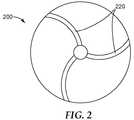
次に図2を参照すると、例示的なガラス質ボンド研磨ホイール200は弓状及び蛇行状の冷却通路210をそれぞれ有する。 Referring now to FIG. 2, an exemplary vitreous bond
図3は、蛇行状の冷却通路320を有する別の例示的なガラス質ボンド研磨ホイール300を示す。 FIG. 3 shows another exemplary vitreous
本開示の方法に従って調製可能なガラス質ボンド研磨物品は、本質的に任意の既知のガラス質ボンド研磨物品、例えば、単体構造化された研磨ディスク、研削刃、研磨セグメント、賦形された研磨粒子(例えば、三角形状研磨粒子)、及び研磨ホイール、並びに現在のところ未知の多くのガラス質ボンド研磨物品を含む。 The vitreous bond abrasive article that can be prepared according to the method of the present disclosure can be essentially any known vitreous bond abrasive article, such as a unitary structured abrasive disc, grinding blade, abrasive segment, shaped abrasive particles. (E.g., triangular abrasive particles), and abrasive wheels, as well as many glassy bond abrasive articles currently unknown.
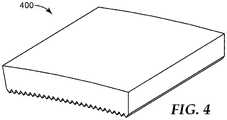
図4は例示的なガラス質ボンド研磨セグメント400を示す。一般的な使用においては、複数のガラス質ボンド研磨セグメント400を、金属ディスクの周縁に沿って一様に間隔を設けて取り付け、研磨ホイールを形成する。 FIG. 4 shows an exemplary vitreous bond
図5はガラス質ボンド研磨ディスク500を示し、2つの領域510、520を有する。各領域は、ガラス質ボンドマトリックス材料550、560中に保持された研磨粒子530、540をそれぞれ有する。 FIG. 5 shows a vitreous bond
図6A〜図6B及び図7A〜図7Bは、セラミック平面状基材620、720と一体的に形成された、精密に賦形されたセラミック研磨要素610、710を有する様々な単体構造化された研磨ディスクをそれぞれ示す。 6A-6B and 7A-7B show various unit structured structures having precisely shaped
図8は、回転研磨工具800(例えば、Dremel工具などの、手持ち式モータ駆動シャフトのための刃)を示す。 FIG. 8 shows a rotary polishing tool 800 (e.g., a blade for a handheld motor driven shaft, such as a Dremel tool).
図2及び図3に示される上述のガラス質研磨ホイールは、対応する未焼成体(即ち、同じ大まかな形状特徴を有するが、一時的バインダによってくっつけられたガラス質ボンド前駆体粒子を含む)を焼成することによって、調製することができる。 The above-described vitreous polishing wheel shown in FIGS. 2 and 3 has a corresponding green body (ie, having the same general shape characteristics, but containing vitreous bond precursor particles attached by a temporary binder). It can be prepared by firing.
本開示の選択される実施形態
第1の実施形態では、本開示は、ガラス質ボンド研磨物品の製造方法であって、製造方法は、逐次的な工程を含み、逐次的な工程は、
a)
i)固まっていない粉末粒子の層を限られた領域内に堆積する工程であり、固まっていない粉末粒子は、ガラス質ボンド前駆体粒子及び研磨粒子を含み、固まっていない粉末粒子の層は、実質的に均一な厚さを有する、工程、
ii)固まっていない粉末粒子の層の所定の領域に液状バインダ前駆体物質を噴出する工程、並びに
iii)液状バインダ前駆体物質を、所定の領域の固まっていない粉末粒子の粒子を一緒に結合する一時的バインダ物質に転換して、結合した粉末粒子の層を形成する工程、を逐次的に行うサブプロセスと、
b)工程a)を独立して複数回実施して、結合した粉末粒子及び残った固まっていない粉末粒子を含む研磨物品プリフォームを生成する工程であり、各工程a)において、固まっていない粉末粒子が独立して選択され、液状バインダ前駆体物質は、独立して選択される、工程と、
c)残った固まっていない粉末粒子の実質的に全てを研磨物品プリフォームから分離する工程と、
d)研磨物品プリフォームを加熱して、ガラス質ボンド材料中に保持された研磨粒子を含むガラス質ボンド研磨物品を提供する工程と、を逐次的に行う工程を含む。Selected Embodiments of the Present Disclosure In a first embodiment, the present disclosure is a method of manufacturing a vitreous bonded abrasive article, the manufacturing method comprising sequential steps, the sequential steps comprising:
a)
i) depositing a layer of uncured powder particles in a limited area, the uncured powder particles comprising vitreous bond precursor particles and abrasive particles, A process having a substantially uniform thickness;
ii) jetting the liquid binder precursor material into a predetermined region of the layer of unconsolidated powder particles; and iii) combining the liquid binder precursor material with the particles of unconsolidated powder particles in the predetermined region together. A sub-process for sequentially converting to a temporary binder material to form a layer of bonded powder particles;
b) Step a) is carried out a plurality of times independently to produce an abrasive article preform containing the combined powder particles and the remaining unhardened powder particles. In each step a), the unhardened powder A process wherein the particles are independently selected and the liquid binder precursor material is independently selected;
c) separating substantially all of the remaining unset powder particles from the abrasive article preform;
d) sequentially heating the abrasive article preform to provide a vitreous bond abrasive article comprising abrasive particles retained in the vitreous bond material.
第2の実施形態では、本開示は、研磨粒子は、ダイヤモンド粒子又は立方窒化ホウ素粒子のうちの少なくとも1つを含む、第1の実施形態に係る方法を提供する。 In a second embodiment, the present disclosure provides a method according to the first embodiment, wherein the abrasive particles comprise at least one of diamond particles or cubic boron nitride particles.
第3の実施形態では、本開示は、研磨粒子は、金属酸化物セラミック粒子を含む、第1又は第2の実施形態に係る方法を提供する。 In a third embodiment, the present disclosure provides a method according to the first or second embodiment, wherein the abrasive particles comprise metal oxide ceramic particles.
第4の実施形態では、本開示は、研磨粒子及びガラス質ボンド材料は、同じ化学組成を有する、第1〜第3の実施形態のいずれか1つに係る方法を提供する。 In a fourth embodiment, the present disclosure provides a method according to any one of the first to third embodiments, wherein the abrasive particles and the glassy bond material have the same chemical composition.
第5の実施形態では、本開示は、ガラス質ボンド研磨物品は、少なくとも1つの冷却通路を含む、第1〜第4の実施形態のいずれか1つに係る方法を提供する。 In a fifth embodiment, the present disclosure provides a method according to any one of the first to fourth embodiments, wherein the vitreous bond abrasive article includes at least one cooling passage.
第6の実施形態では、本開示は、ガラス質ボンド研磨物品は、単体構造化された研磨ディスク、研磨研削ビット、研磨セグメント、及び研磨ホイールから成る群から選択される、第1〜第5の実施形態のいずれか1つに係る方法を提供する。 In a sixth embodiment, the disclosure provides that the vitreous bond abrasive article is selected from the group consisting of a unitary structured abrasive disc, an abrasive grinding bit, an abrasive segment, and an abrasive wheel. A method according to any one of the embodiments is provided.
第7の実施形態では、本開示は、液状バインダ前駆体物質は、溶存及び/又は分散ポリマーを含有する液状ビヒクルを含む、第1〜第6の実施形態のいずれか1つに係る方法を提供する。 In a seventh embodiment, the present disclosure provides a method according to any one of the first to sixth embodiments, wherein the liquid binder precursor material comprises a liquid vehicle containing a dissolved and / or dispersed polymer. To do.
第8の実施形態では、本開示は、液状バインダ前駆体物質は、溶存及び/又は分散した無機ガラス質ボンド前駆体を含有する液状ビヒクルを含む、第1〜第7の実施形態のいずれか1つに係る方法を提供する。 In an eighth embodiment, the present disclosure provides any one of the first to seventh embodiments, wherein the liquid binder precursor material comprises a liquid vehicle containing dissolved and / or dispersed inorganic glassy bond precursor. Provide a method.
第9の実施形態では、本開示は、無機ガラス質ボンド前駆体は、αアルミナの前駆体を含む、第8の実施形態に係る方法を提供する。 In a ninth embodiment, the present disclosure provides a method according to the eighth embodiment, wherein the inorganic vitreous bond precursor comprises a precursor of alpha alumina.
第10の実施形態では、本開示は、固まっていない粉末粒子は、サブミクロンセラミック粒子を含む、第8又は第9の実施形態に係る方法を提供する。 In a tenth embodiment, the present disclosure provides a method according to the eighth or ninth embodiment, wherein the unsolidified powder particles comprise submicron ceramic particles.
第11の実施形態では、本開示は、固まっていない粉末粒子は、流動剤粒子を更に含む、第1〜第10の実施形態のいずれか1つに係る方法を提供する。 In an eleventh embodiment, the present disclosure provides the method according to any one of the first to tenth embodiments, wherein the unsolidified powder particles further comprise flow agent particles.
第12の実施形態では、本開示は、工程d)は、一時的バインダ物質をバーンアウトすることを更に含む、第8〜第11の実施形態のいずれか1つに係る方法を提供する。 In a twelfth embodiment, the present disclosure provides a method according to any one of the eighth to eleventh embodiments, wherein step d) further comprises burning out the temporary binder material.
第13の実施形態では、本開示は、研磨粒子を内部に保持するガラス質ボンド材料を含むガラス質ボンド研磨物品であって、ガラス質ボンド研磨物品の少なくとも一部を通って延びる少なくとも1つの蛇行状の冷却通路を有する、ガラス質ボンド研磨物品を提供する。 In a thirteenth embodiment, the present disclosure provides a vitreous bond abrasive article comprising a vitreous bond material that holds abrasive particles therein, the at least one meander extending through at least a portion of the vitreous bond abrasive article. A vitreous bond abrasive article is provided having a shaped cooling passage.
第14の実施形態では、本開示は、研磨粒子を内部に保持する有するガラス質ボンド材料を含むガラス質ボンド研磨物品であって、ガラス質ボンド研磨物品の少なくとも一部を通って延びる少なくとも1つの弓状の冷却通路を有する、ガラス質ボンド研磨物品を提供する。 In a fourteenth embodiment, the present disclosure provides a vitreous bond abrasive article comprising a vitreous bond material having abrasive particles retained therein, the at least one extending through at least a portion of the vitreous bond abrasive article. A vitreous bond abrasive article is provided having an arcuate cooling passage.
第15の実施形態では、本開示は、研磨粒子は、第1の研磨粒子及び第2の研磨粒子を含み、第1の研磨粒子及び第2の研磨粒子はガラス質ボンド研磨物品内の所定の異なる領域内に配置されている、第13又は第14の実施形態に係るガラス質ボンド研磨物品を提供する。 In a fifteenth embodiment, the present disclosure provides that the abrasive particles include a first abrasive particle and a second abrasive particle, wherein the first abrasive particle and the second abrasive particle are predetermined in the vitreous bond abrasive article. A vitreous bond abrasive article according to a thirteenth or fourteenth embodiment is provided that is disposed in a different region.
第16の実施形態では、本開示は、異なる領域は層である、第15の実施形態に係るガラス質ボンド研磨物品を提供する。 In a sixteenth embodiment, the present disclosure provides a vitreous bond abrasive article according to the fifteenth embodiment, wherein the different regions are layers.
第17の実施形態では、本開示は、研磨粒子は、ダイヤモンド粒子又は立方窒化ホウ素粒子のうちの少なくとも1つを含む、第13〜第16の実施形態のいずれか1つに係るガラス質ボンド研磨物品を提供する。 In a seventeenth embodiment, the present disclosure provides the glassy bond polish according to any one of the thirteenth to sixteenth embodiments, wherein the abrasive particles include at least one of diamond particles or cubic boron nitride particles. Provide the goods.
第18の実施形態では、本開示は、研磨粒子は、炭化ケイ素、炭化ホウ素、窒化ケイ素、又は金属酸化物セラミック粒子のうちの少なくとも1つを含む、第13〜第17の実施形態のいずれか1つに係るガラス質ボンド研磨物品を提供する。 In an eighteenth embodiment, the present disclosure provides any of the thirteenth to seventeenth embodiments, wherein the abrasive particles comprise at least one of silicon carbide, boron carbide, silicon nitride, or metal oxide ceramic particles. A vitreous bond abrasive article according to one is provided.
第19の実施形態では、本開示は、ガラス質ボンド研磨物品は、単体構造化された研磨ディスク、研磨研削ビット、研磨セグメント、及び研磨ホイールから成る群から選択される、第13〜第18の実施形態のいずれか1つに係るガラス質ボンド研磨物品前駆体を提供する。 In a nineteenth embodiment, the present disclosure provides in the thirteenth through eighteenth aspects, wherein the vitreous bond abrasive article is selected from the group consisting of a unitary structured abrasive disc, an abrasive grinding bit, an abrasive segment, and an abrasive wheel. A vitreous bond abrasive article precursor according to any one of the embodiments is provided.
第20の実施形態では、本開示は、ガラス質ボンド前駆体物質により一緒に結合した研磨粒子を含むガラス質ボンド研磨物品前駆体であって、
ガラス質ボンド研磨物品前駆体の少なくとも一部を通って延びる少なくとも1つの蛇行状の冷却通路、又は
ガラス質ボンド研磨物品前駆体の少なくとも一部を通って延びる少なくとも1つの弓状の冷却通路、のうちの少なくとも1つを更に含む、ガラス質ボンド研磨物品前駆体を提供する。In a twentieth embodiment, the present disclosure is a vitreous bond abrasive article precursor comprising abrasive particles bonded together by a vitreous bond precursor material,
At least one serpentine cooling passage extending through at least a portion of the vitreous bond abrasive article precursor or at least one arcuate cooling passage extending through at least a portion of the vitreous bond abrasive article precursor. A vitreous bond abrasive article precursor is provided that further comprises at least one of them.
第21の実施形態では、本開示は、研磨粒子は、炭化ケイ素、炭化ホウ素、窒化ケイ素、又は金属酸化物セラミック粒子のうちの少なくとも1つを含む、第20の実施形態に係るガラス質ボンド研磨前駆体を提供する。 In a twenty-first embodiment, the present disclosure provides the glassy bond polish according to the twentieth embodiment, wherein the abrasive particles comprise at least one of silicon carbide, boron carbide, silicon nitride, or metal oxide ceramic particles. A precursor is provided.
第22の実施形態では、本開示は、単体構造化された研磨ディスクであって、
作業主表面を有するセラミック基材と、
作業主表面から延びる精密に賦形されたセラミック研磨要素と、を備え、この精密に賦形されたセラミック研磨要素と平面状セラミック基材とで単体の本体を形成する、単体構造化された研磨ディスクを提供する。In a twenty-second embodiment, the present disclosure is a unitary structured abrasive disc,
A ceramic substrate having a working main surface;
A precisely shaped ceramic polishing element extending from the main working surface, wherein the precisely shaped ceramic polishing element and the planar ceramic substrate form a unitary body, the unitary structured polishing Provide a disc.
第23の実施形態では、本開示は、精密に賦形された研磨要素は、共通回転軸の周りに湾曲している、第22の実施形態に係る単体構造化された研磨ディスクを提供する。 In a twenty-third embodiment, the present disclosure provides a unitary structured abrasive disc according to the twenty-second embodiment, wherein precisely shaped abrasive elements are curved around a common axis of rotation.
第24の実施形態では、本開示は、精密に賦形されたセラミック研磨要素が湾曲している、第23又は第24の実施形態に係る単体構造化された研磨ディスクを提供する。 In a twenty-fourth embodiment, the present disclosure provides a unitary structured abrasive disc according to the twenty-third or twenty-fourth embodiment, wherein a precisely shaped ceramic abrasive element is curved.
本開示の目的及び利点は、以下の非限定的な実施例によって更に例示されるが、これらの実施例で引用される特定の材料及びそれらの量、並びに他の条件及び詳細は、本開示を不当に限定するものとして解釈されるべきではない。 The objects and advantages of this disclosure are further illustrated by the following non-limiting examples, although the specific materials and their amounts quoted in these examples, as well as other conditions and details, It should not be construed as unduly limiting.
特に断らない限り、実施例及び明細書の他の部分における全ての割合、パーセンテージ、比率などは、重量による。実施例において、℃=セルシウス度、g=グラム、min=分、mm=ミリメートル、sec=秒、及びrpm=回転/分である。 Unless otherwise noted, all percentages, percentages, ratios, etc. in the examples and other parts of the specification are by weight. In the examples, ° C = degree Celsius, g = grams, min = minutes, mm = millimeters, sec = seconds, and rpm = revolutions per minute.
下の表1は、実施例で使用された材料のための略称を列記する。
凝集手順
以下のように説明される噴霧乾燥微粒化方法を用いて、研磨粒子(PDR5又はPDR8)を、バインダマトリックスPDR3を用いて凝集させ、5マイクロメートル〜45マイクロメートルの範囲のサイズを有する粒塊(それぞれ、AG1又はAG2)を形成した。以下の成分を含有する混合物を、実験室超音波浴の助けを借りてブレンドした:123.0グラム(g)の25wt.%デキストリン水溶液、100.0gのPDR3、90.0gのPDR5(AG1を製造するため)又はPDR8(AG2を製造するため)、295.0gの蒸留水、1.9gのN−オクタデシルスルホサクシナメート(American Cyanamid Co.,Wayne,New JerseyよりCYANASOL AYとして入手)。次に、混合物を遠心微粒化器(Niro Inc.,Columbia,MarylandからのMobile Minor)内で微粒化した。微粒化ホイールは20000rpmで動作した。粒子が液滴を形成するのに従い、200℃で微粒化チャンバ内へ供給される空気を用いて粒子を乾燥させた。次に、微粒化器を備えるサイクロンを用いて粒子を収集し、45マイクロメートルの篩を通して篩分し、より粗い粒子を除去した。Agglomeration procedure Abrasive particles (PDR5 or PDR8) are agglomerated using a binder matrix PDR3 using a spray drying atomization method as described below and have a size ranging from 5 micrometers to 45 micrometers. A mass (AG1 or AG2 respectively) was formed. A mixture containing the following ingredients was blended with the help of a laboratory ultrasonic bath: 123.0 grams (g) of 25 wt. % Dextrin aqueous solution, 100.0 g PDR3, 90.0 g PDR5 (to produce AG1) or PDR8 (to produce AG2), 295.0 g distilled water, 1.9 g N-octadecylsulfosuccinate (Acquired as CYANASOL AY from American Cyanamid Co., Wayne, New Jersey). The mixture was then atomized in a centrifugal atomizer (Mobile Minor from Niro Inc., Columbia, Maryland). The atomization wheel operated at 20000 rpm. The particles were dried using air supplied into the atomization chamber at 200 ° C. as the particles formed droplets. The particles were then collected using a cyclone equipped with an atomizer and sieved through a 45 micrometer sieve to remove coarser particles.
実施例1
混合重量に基づき、80wt.%のPDR1及び20wt.%のPDR3を混合することによって、プリント材料を準備した。プリント材料を、The ExOne Company,North Huntingdon,Pennsylvaniaより入手した、X1−LAB 3Dプリンタのビルドボックスに詰めた。プリンタのバインダ供給ボトルにBINを詰めた。以下の操作パラメータを使用して、製造者の操作指示書によるプリント手順及び順序によって、3Dプリンティングを実行した。層厚100ミクロン、スプレッダスピード1mm/秒、プリント飽和度70%レベル、90%ヒータ出力時の乾燥時間45秒。印刷を終了した後に、印刷された物体及び粉体床をプリンタから取り出し、周囲雰囲気オーブン(ambient atmosphere oven)内に配置し、195℃で2時間硬化させた。23℃に冷却した後に、印刷された物体を粉体床から除去し、柔らかい毛ブラシを用いて固まっていない粉末を除去した。次に、物体を炉内に配置し、400℃で2時間、バーンアウトし、それに続き、700℃で4時間、焼結させ、その結果、手持ち式回転工具デバイス(例えば、Robert Bosch Tool Corp.,Mount Prospect,IllinoisのためのDremel回転工具)とともに使用するために適した研磨刃を得た。Example 1
Based on the blend weight, 80 wt. % PDR1 and 20 wt. The print material was prepared by mixing% PDR3. The print material was packed into a build box for an X1-LAB 3D printer obtained from The ExOne Company, North Huntingdon, Pennsylvania. BIN was packed in the binder supply bottle of the printer. 3D printing was performed according to the printing procedure and sequence according to the manufacturer's operating instructions using the following operating parameters.
実施例2
混合重量に基づき、85wt.%のPDR2及び15wt.%のPDR4を混合することによって、プリント材料を調製した。以下の点を除いて、実施例1において一般的に説明した手順を繰り返した:スプレッダ速度=10mm/秒、プリント飽和度=130%レベル、乾燥時間=90%の加熱器出力において55秒、及び炉焼結温度=900℃で4時間。Example 2
Based on the mixing weight, 85 wt. % PDR2 and 15 wt. Print material was prepared by mixing% PDR4. The procedure generally described in Example 1 was repeated with the following exceptions: spreader speed = 10 mm / second, print saturation = 130% level, drying time = 55 seconds at 90% heater output, and Furnace sintering temperature = 900 ° C. for 4 hours.
実施例3
混合重量に基づき、80wt.%のAG1及び20wt.%のPDR3を混合することによって、プリント材料を調製した。以下の点を除いて、実施例1において一般的に説明した手順を繰り返した:プリント飽和度=150%レベル、乾燥時間=90%の加熱器出力において25秒、及び炉焼結温度=630℃で4時間。Example 3
Based on the blend weight, 80 wt. % AG1 and 20 wt. Print material was prepared by mixing% PDR3. The procedure generally described in Example 1 was repeated with the following exceptions: print saturation = 150% level, drying time = 25 seconds at 90% heater power, and furnace sintering temperature = 630 ° C. 4 hours.
実施例4
混合重量に基づき、83.0wt.%のPDR6、16.9wt.%のAG1及び0.1wt.%のPDR7を混合することによって、プリント材料を調製した。以下の点を除いて、実施例1において説明した手順を繰り返した:プリント飽和度=125%レベル、乾燥時間=90%の加熱器出力において60秒、及び炉焼結温度=600℃で4時間。Example 4
83.0 wt. % PDR6, 16.9 wt. % AG1 and 0.1 wt. Print material was prepared by mixing% PDR7. The procedure described in Example 1 was repeated with the following exceptions: print saturation = 125% level, drying time = 60 seconds at 90% heater power, and furnace sintering temperature = 600 ° C. for 4 hours. .
実施例5
混合重量に基づき、80wt.%のAG2及び20wt.%のPDR3を混合することによって、プリント材料を調製した。炉焼結温度を630℃で4時間に設定した点を除いて、実施例4において説明した手順を繰り返した。Example 5
Based on the blend weight, 80 wt. % AG2 and 20 wt. Print material was prepared by mixing% PDR3. The procedure described in Example 4 was repeated except that the furnace sintering temperature was set at 630 ° C. for 4 hours.
研磨性能の評価
実施例1〜5からのガラス質ボンド研磨物品を、研磨性能について、アルミニウム、顕微鏡ガラススライド、及び木片などの、種々の材料に対して評価した。いくつかの場合には、回転工具をマンドレル上に組み立て、Dremel手持ち式回転工具を用いて試験した。全ての物体が、材料を研磨するために有効であった。Evaluation of Polishing Performance The glassy bonded abrasive articles from Examples 1-5 were evaluated for various materials such as aluminum, microscope glass slides, and wood chips for polishing performance. In some cases, rotating tools were assembled on a mandrel and tested using a Dremel handheld rotating tool. All objects were effective for polishing the material.
実施例6
以下の点を除いて、実施例1において説明した手順を繰り返した:物品の設計が正三角形(3mmの辺、0.6の厚さ)であったこと、PDR9を、まず、180ミクロンの開口部を有する篩を通し、次に、62ミクロンの開口部を有する篩を通して篩い分けすることによって、プリント粉末材料を調製したこと、層高さ=100ミクロン、粉末比=1.6、スプレッダ速度=15mm/秒、プリント飽和度=160%レベル、乾燥時間=60秒、23℃に冷却した後に、ブラシの代わりに300ミクロンの篩を用いて、印刷された物体を粉末から除去し、次に、物体を、5℃/分の速度で1500℃の最終温度まで加熱した炉内で焼成し、そこでそれを20分間、保持したこと。Example 6
The procedure described in Example 1 was repeated with the following exceptions: the design of the article was an equilateral triangle (3 mm side, 0.6 thickness), PDR 9 was first opened with a 180 micron opening. The print powder material was prepared by passing through a sieve having a portion and then through a sieve having an opening of 62 microns, layer height = 100 microns, powder ratio = 1.6, spreader speed = After cooling to 15 mm / second, print saturation = 160% level, drying time = 60 seconds, 23 ° C., the printed object is removed from the powder using a 300 micron sieve instead of a brush, then The body was fired in a furnace heated to a final temperature of 1500 ° C. at a rate of 5 ° C./min, where it was held for 20 minutes.
実施例7
80wt.%のPDR9及び20wt.%のPDR10(混合重量に基づく百分率)を混合し、まず、180ミクロンの開口部を有する篩を通し、次に、62ミクロンの開口部を有する篩を通して篩い分けすることによって、印刷粉末材料を調製した。以下の点を除いて、実施例6において一般的に説明した手順を繰り返した:スプレッダ速度=1.0mm/秒、プリント飽和度=140%レベル、乾燥時間=40秒、及び炉を5℃/分の速度で1555℃の最終温度まで加熱したこと。Example 7
80 wt. % PDR9 and 20 wt. Printed powder material is prepared by mixing% PDR10 (percentage based on blend weight) and first sieving through a sieve with 180 micron openings and then through a sieve with 62 micron openings did. The procedure generally described in Example 6 was repeated with the following exceptions: spreader speed = 1.0 mm / sec, print saturation = 140% level, drying time = 40 sec, and oven at 5 ° C./sec. Heated to a final temperature of 1555 ° C. at a rate of minutes.
特許証のための上記出願において引用された全ての参考文献、特許、又は特許出願は、一貫してその全文を参照により本明細書に組み込む。組み込まれた参照文献の部分と本出願の部分との間に不一致又は矛盾がある場合は、前述の説明の情報が優先されるものとする。前述の説明は、特許請求されている開示を当業者が実施することを可能にするために示されており、請求項及びその全ての均等物によって規定される本開示の範囲を限定するものとして解釈されるべきではない。 All references, patents, or patent applications cited in the above applications for patent certificates are hereby incorporated by reference in their entirety. In case of discrepancies or inconsistencies between the incorporated reference parts and this application part, the information in the above description shall prevail. The previous description is presented to enable any person skilled in the art to practice the claimed disclosure and is intended to limit the scope of the disclosure as defined by the claims and all equivalents thereof. Should not be interpreted.
Claims (24)
Translated fromJapanesea)
i)固まっていない粉末粒子の層を限られた領域内に堆積する工程であり、前記固まっていない粉末粒子は、ガラス質ボンド前駆体粒子及び研磨粒子を含み、前記固まっていない粉末粒子の層は、実質的に均一な厚さを有する、工程、
ii)前記固まっていない粉末粒子の層の所定の領域に液状バインダ前駆体物質を噴出する工程、並びに
iii)前記液状バインダ前駆体物質を、前記所定の領域の前記固まっていない粉末粒子の粒子を一緒に結合する一時的バインダ物質に転換して、結合した粉末粒子の層を形成する工程、を逐次的に行うサブプロセスと、
b)工程a)を独立して複数回実施して、前記結合した粉末粒子及び残った固まっていない粉末粒子を含む研磨物品プリフォームを生成する工程であり、各工程a)において、前記固まっていない粉末粒子が独立して選択され、前記液状バインダ前駆体物質は、独立して選択される、工程と、
c)前記残った固まっていない粉末粒子の実質的に全てを前記研磨物品プリフォームから分離する工程と、
d)前記研磨物品プリフォームを加熱して、ガラス質ボンド材料中に保持された前記研磨粒子を含む前記ガラス質ボンド研磨物品を提供する工程と、を逐次的に行う工程を含む、製造方法。A method for manufacturing a glassy bonded abrasive article, wherein the manufacturing method includes sequential steps, wherein the sequential steps include:
a)
i) a step of depositing a layer of uncured powder particles in a limited area, the uncured powder particles comprising vitreous bond precursor particles and abrasive particles, wherein the uncured layer of powder particles Has a substantially uniform thickness, the process,
ii) ejecting a liquid binder precursor material into a predetermined region of the unsolidified powder particle layer; and iii) removing the liquid binder precursor material from the unconsolidated powder particle particles in the predetermined region. A sub-process that sequentially converts the temporary binder material that binds together to form a layer of bound powder particles;
b) a step of performing step a) independently multiple times to produce an abrasive article preform comprising the combined powder particles and the remaining unset powder particles, wherein in each step a) the set No powder particles are independently selected, and the liquid binder precursor material is independently selected, and
c) separating substantially all of the remaining unset powder particles from the abrasive article preform;
d) heating the abrasive article preform to provide the vitreous bond abrasive article comprising the abrasive particles retained in the vitreous bond material, and sequentially performing a manufacturing method.
前記ガラス質ボンド研磨物品前駆体の少なくとも一部を通って延びる延びる少なくとも1つの蛇行状の冷却通路、又は
前記ガラス質ボンド研磨物品前駆体の少なくとも一部を通って延びる少なくとも1つの弓状の冷却通路、のうちの少なくとも1つを更に含む、ガラス質ボンド研磨物品前駆体。A glassy bond abrasive article precursor comprising abrasive particles bonded together by a glassy bond precursor material,
At least one serpentine cooling passage extending through at least a portion of the vitreous bond abrasive article precursor, or at least one arcuate cooling extending through at least a portion of the vitreous bond abrasive article precursor. A vitreous bond abrasive article precursor further comprising at least one of a passageway.
作業主表面を有する平面状セラミック基材と、
前記作業主表面から延びる精密に賦形されたセラミック研磨要素と、を備え、前記精密に賦形されたセラミック研磨要素と前記平面状セラミック基材とで単体の本体を形成する、単体構造化された研磨ディスク。A unitary structured abrasive disc,
A planar ceramic substrate having a working main surface;
A precision-shaped ceramic polishing element extending from the work main surface, and the single-piece structure is formed by the precisely-shaped ceramic polishing element and the planar ceramic substrate. Polishing disc.
Applications Claiming Priority (3)
| Application Number | Priority Date | Filing Date | Title |
|---|---|---|---|
| US201562184695P | 2015-06-25 | 2015-06-25 | |
| US62/184,695 | 2015-06-25 | ||
| PCT/US2016/038902WO2016210057A1 (en) | 2015-06-25 | 2016-06-23 | Vitreous bond abrasive articles and methods of making the same |
Publications (2)
| Publication Number | Publication Date |
|---|---|
| JP2018522746Atrue JP2018522746A (en) | 2018-08-16 |
| JP7458693B2 JP7458693B2 (en) | 2024-04-01 |
Family
ID=57586429
Family Applications (1)
| Application Number | Title | Priority Date | Filing Date |
|---|---|---|---|
| JP2017566791AActiveJP7458693B2 (en) | 2015-06-25 | 2016-06-23 | Glassy bond abrasive article and method for manufacturing the same |
Country Status (5)
| Country | Link |
|---|---|
| US (1) | US20180104793A1 (en) |
| EP (1) | EP3313614A4 (en) |
| JP (1) | JP7458693B2 (en) |
| CN (1) | CN107787264B (en) |
| WO (1) | WO2016210057A1 (en) |
Families Citing this family (62)
| Publication number | Priority date | Publication date | Assignee | Title |
|---|---|---|---|---|
| KR20170018102A (en) | 2011-12-30 | 2017-02-15 | 생-고뱅 세라믹스 앤드 플라스틱스, 인코포레이티드 | Shaped abrasive particle and method of forming same |
| JP5903502B2 (en) | 2011-12-30 | 2016-04-13 | サン−ゴバン セラミックス アンド プラスティクス,インコーポレイティド | Particle material with shaped abrasive particles |
| BR112014017050B1 (en) | 2012-01-10 | 2021-05-11 | Saint-Gobain Ceramics & Plastics, Inc. | molded abrasive particle |
| US8840696B2 (en) | 2012-01-10 | 2014-09-23 | Saint-Gobain Ceramics & Plastics, Inc. | Abrasive particles having particular shapes and methods of forming such particles |
| KR102360055B1 (en) | 2012-05-23 | 2022-02-09 | 생-고뱅 세라믹스 앤드 플라스틱스, 인코포레이티드 | Shaped abrasive particles and methods of forming same |
| KR20150023034A (en) | 2012-06-29 | 2015-03-04 | 생-고뱅 세라믹스 앤드 플라스틱스, 인코포레이티드 | Abrasive particles having particular shapes and methods of forming such particles |
| CA2887561C (en) | 2012-10-15 | 2019-01-15 | Saint-Gobain Abrasives, Inc. | Abrasive particles having particular shapes and methods of forming such particles |
| CN104994995B (en) | 2012-12-31 | 2018-12-14 | 圣戈本陶瓷及塑料股份有限公司 | Granular materials and forming method thereof |
| CA2907372C (en) | 2013-03-29 | 2017-12-12 | Saint-Gobain Abrasives, Inc. | Abrasive particles having particular shapes and methods of forming such particles |
| CN105764653B (en) | 2013-09-30 | 2020-09-11 | 圣戈本陶瓷及塑料股份有限公司 | Shaped abrasive particles and method of forming the same |
| CA2934938C (en) | 2013-12-31 | 2019-04-30 | Saint-Gobain Abrasives, Inc. | Abrasive article including shaped abrasive particles |
| US9771507B2 (en) | 2014-01-31 | 2017-09-26 | Saint-Gobain Ceramics & Plastics, Inc. | Shaped abrasive particle including dopant material and method of forming same |
| JP6484647B2 (en) | 2014-04-14 | 2019-03-13 | サン−ゴバン セラミックス アンド プラスティクス,インコーポレイティド | Abrasive articles containing shaped abrasive particles |
| WO2015160854A1 (en) | 2014-04-14 | 2015-10-22 | Saint-Gobain Ceramics & Plastics, Inc. | Abrasive article including shaped abrasive particles |
| KR102168792B1 (en) | 2014-05-08 | 2020-10-23 | 스트라타시스 엘티디. | Method and apparatus for 3d printing by selective sintering |
| US9902045B2 (en) | 2014-05-30 | 2018-02-27 | Saint-Gobain Abrasives, Inc. | Method of using an abrasive article including shaped abrasive particles |
| US9914864B2 (en) | 2014-12-23 | 2018-03-13 | Saint-Gobain Ceramics & Plastics, Inc. | Shaped abrasive particles and method of forming same |
| US9707529B2 (en) | 2014-12-23 | 2017-07-18 | Saint-Gobain Ceramics & Plastics, Inc. | Composite shaped abrasive particles and method of forming same |
| US9676981B2 (en) | 2014-12-24 | 2017-06-13 | Saint-Gobain Ceramics & Plastics, Inc. | Shaped abrasive particle fractions and method of forming same |
| US10196551B2 (en) | 2015-03-31 | 2019-02-05 | Saint-Gobain Abrasives, Inc. | Fixed abrasive articles and methods of forming same |
| TWI634200B (en) | 2015-03-31 | 2018-09-01 | 聖高拜磨料有限公司 | Fixed abrasive article and method of forming same |
| WO2016175832A1 (en)* | 2015-04-30 | 2016-11-03 | Hewlett-Packard Development Company, L.P. | Three-dimensional (3d) printing |
| PL3307483T3 (en) | 2015-06-11 | 2020-11-16 | Saint-Gobain Ceramics&Plastics, Inc. | Abrasive article containing shaped abrasive particles |
| WO2016209696A1 (en) | 2015-06-25 | 2016-12-29 | 3M Innovative Properties Company | Methods of making metal bond abrasive articles and metal bond abrasive articles |
| DE102016210872B4 (en)* | 2015-07-28 | 2018-10-04 | Il-Metronic Sensortechnik Gmbh | Process for producing blanks for sintered glass bodies for glass feedthroughs |
| BR112018015021A2 (en) | 2016-01-21 | 2019-02-12 | 3M Innovative Properties Co | methods for producing abrasive and glass bonded abrasive articles and abrasive article precursors |
| WO2017173009A1 (en)* | 2016-03-30 | 2017-10-05 | 3M Innovative Properties Company | Methods of making metal bond and vitreous bond abrasive articles, and abrasive article precursors |
| EP3442727B1 (en) | 2016-04-11 | 2021-03-17 | Stratasys Ltd. | Method and apparatus for additive manufacturing with powder material |
| EP3666462A1 (en) | 2016-04-11 | 2020-06-17 | 3M Innovative Properties Company | A green body, a grinding wheel and a method for manufacturing at least a green body |
| WO2017180205A1 (en)* | 2016-04-13 | 2017-10-19 | 3M Innovative Properties Company | Abrasive article |
| PL3455321T3 (en) | 2016-05-10 | 2022-12-12 | Saint-Gobain Ceramics&Plastics, Inc. | Methods of forming abrasive particles |
| US20170335155A1 (en) | 2016-05-10 | 2017-11-23 | Saint-Gobain Ceramics & Plastics, Inc. | Abrasive particles and methods of forming same |
| US11230653B2 (en) | 2016-09-29 | 2022-01-25 | Saint-Gobain Abrasives, Inc. | Fixed abrasive articles and methods of forming same |
| CN108015906A (en) | 2016-10-28 | 2018-05-11 | 圣戈班磨料磨具有限公司 | Hollow drill bit and its manufacture method |
| CN110121400B (en)* | 2016-12-23 | 2022-01-18 | 3M创新有限公司 | Polymer-bonded abrasive article and method of making same |
| US10759024B2 (en) | 2017-01-31 | 2020-09-01 | Saint-Gobain Ceramics & Plastics, Inc. | Abrasive article including shaped abrasive particles |
| US10563105B2 (en) | 2017-01-31 | 2020-02-18 | Saint-Gobain Ceramics & Plastics, Inc. | Abrasive article including shaped abrasive particles |
| KR102464517B1 (en) | 2017-02-28 | 2022-11-10 | 쓰리엠 이노베이티브 프로퍼티즈 캄파니 | Metal Bonded Abrasive Articles and Methods of Making Metal Bonded Abrasive Articles |
| US11400516B2 (en) | 2017-03-20 | 2022-08-02 | Stratasys Ltd. | Method and system for additive manufacturing with powder material |
| EP3642293A4 (en) | 2017-06-21 | 2021-03-17 | Saint-Gobain Ceramics&Plastics, Inc. | Particulate materials and methods of forming same |
| US11404180B2 (en)* | 2017-10-09 | 2022-08-02 | Ut-Battelle, Llc | Method for producing collimators and other components from neutron absorbing materials using additive manufacturing |
| JP6977537B2 (en)* | 2017-12-19 | 2021-12-08 | セイコーエプソン株式会社 | Manufacturing method of 3D model |
| WO2020123203A1 (en)* | 2018-12-12 | 2020-06-18 | Corning Incorporated | Grinding wheels and methods of producing the same |
| EP3894363A2 (en) | 2018-12-13 | 2021-10-20 | Corning Incorporated | Conveying apparatus and conveying ribbon |
| US20220001604A1 (en) | 2018-12-18 | 2022-01-06 | 3M Innovative Properties Company | Abrasive wheel maker and method for forming an abrasive wheel |
| DE102019207822A1 (en)* | 2019-05-28 | 2020-12-03 | Robert Bosch Gmbh | Process for making an abrasive article and abrasive articles |
| WO2021009673A1 (en) | 2019-07-15 | 2021-01-21 | 3M Innovative Properties Company | Abrasive articles having internal coolant features and methods of manufacturing the same |
| US12434351B2 (en) | 2019-12-12 | 2025-10-07 | 3M Innovative Properties Company | Polymer bond abrasive articles including continuous polymer matrix, and methods of making same |
| CN114846112A (en) | 2019-12-27 | 2022-08-02 | 圣戈本陶瓷及塑料股份有限公司 | Abrasive article and method of forming the same |
| CN114867582B (en) | 2019-12-27 | 2024-10-18 | 圣戈本陶瓷及塑料股份有限公司 | Abrasive article and method of forming the same |
| US12338384B2 (en) | 2019-12-27 | 2025-06-24 | Saint-Gobain Ceramics & Plastics, Inc. | Abrasive articles and methods of forming same |
| WO2021152456A1 (en)* | 2020-01-31 | 2021-08-05 | 3M Innovative Properties Company | Bonded abrasive articles and methods of manufacture |
| WO2021171141A1 (en) | 2020-02-25 | 2021-09-02 | 3M Innovative Properties Company | Bonded abrasive articles and methods of manufacture |
| WO2022090904A1 (en) | 2020-10-28 | 2022-05-05 | 3M Innovative Properties Company | Systems and methods for providing coolant to an active grinding area |
| US20220282144A1 (en)* | 2021-03-05 | 2022-09-08 | Saint-Gobain Abrasives, Inc. | Abrasive articles and methods for forming same |
| WO2023279024A1 (en) | 2021-06-30 | 2023-01-05 | Saint-Gobain Abrasives, Inc. | Abrasive articles and methods for forming same |
| US20240278496A1 (en) | 2021-07-05 | 2024-08-22 | Admatec Europe B.V. | Additive manufacturing method and apparatus for abrasive articles |
| CN113910116B (en)* | 2021-10-29 | 2024-01-09 | 江西冠亿研磨股份有限公司 | Preparation method of soluble inorganic liquid binder for ceramic grinding wheel forming |
| EP4457058A1 (en) | 2021-12-30 | 2024-11-06 | Saint-gobain Abrasives, Inc | Abrasive articles and methods for forming same |
| WO2023130059A1 (en) | 2021-12-30 | 2023-07-06 | Saint-Gobain Abrasives, Inc. | Abrasive articles and methods for forming same |
| AU2022426850B2 (en) | 2021-12-30 | 2025-09-18 | Saint-Gobain Abrasifs | Abrasive articles and methods of forming same |
| EP4457295A1 (en)* | 2021-12-30 | 2024-11-06 | Saint-Gobain Abrasives, Inc. | Abrasive articles and methods for forming same |
Citations (5)
| Publication number | Priority date | Publication date | Assignee | Title |
|---|---|---|---|---|
| JPH07299085A (en)* | 1994-02-18 | 1995-11-14 | Johnson & Johnson Professional Inc | Transplantatiion article with as cast micro-texture surface region,and manufacture of said article |
| JP2003508828A (en)* | 1999-01-12 | 2003-03-04 | サーリックス インコーポレイテッド | Method and apparatus for managing and / or utilizing data received from a CAD model |
| JP2012045708A (en)* | 2005-02-22 | 2012-03-08 | Saint-Gobain Abrasives Inc | Rapid tooling system and method for manufacturing abrasive article |
| JP2012521647A (en)* | 2009-03-24 | 2012-09-13 | ビーエーエスエフ ソシエタス・ヨーロピア | Printing method for producing a thermomagnetic molded body for a heat exchanger |
| JP2014522331A (en)* | 2011-06-01 | 2014-09-04 | バム ブンデサンスタルト フィア マテリアルフォルシュングウント−プリュフング | Method and apparatus for producing molded body |
Family Cites Families (30)
| Publication number | Priority date | Publication date | Assignee | Title |
|---|---|---|---|---|
| US3850590A (en)* | 1970-09-28 | 1974-11-26 | Impregnated Diamond Prod Ltd | An abrasive tool comprising a continuous porous matrix of sintered metal infiltrated by a continuous synthetic resin |
| JPS5148831B2 (en)* | 1972-11-28 | 1976-12-23 | ||
| US5204055A (en)* | 1989-12-08 | 1993-04-20 | Massachusetts Institute Of Technology | Three-dimensional printing techniques |
| US5178644A (en)* | 1992-01-23 | 1993-01-12 | Cincinnati Milacron Inc. | Method for making vitreous bonded abrasive article and article made by the method |
| US6258137B1 (en)* | 1992-02-05 | 2001-07-10 | Saint-Gobain Industrial Ceramics, Inc. | CMP products |
| US5876268A (en)* | 1997-01-03 | 1999-03-02 | Minnesota Mining And Manufacturing Company | Method and article for the production of optical quality surfaces on glass |
| KR19990081117A (en)* | 1998-04-25 | 1999-11-15 | 윤종용 | CMP Pad Conditioning Disc and Conditioner, Manufacturing Method, Regeneration Method and Cleaning Method of the Disc |
| WO2000000344A1 (en)* | 1998-06-30 | 2000-01-06 | Trustees Of Tufts College | Multiple-material prototyping by ultrasonic adhesion |
| US6123744A (en)* | 1999-06-02 | 2000-09-26 | Milacron Inc. | Vitreous bond compositions for abrasive articles |
| HK1048617B (en)* | 1999-11-05 | 2004-12-03 | 3D系统公司 | Methods of three-dimensional printing |
| JP3679013B2 (en)* | 2001-02-07 | 2005-08-03 | 株式会社ノリタケカンパニーリミテド | Vitrified grinding wheel manufacturing method |
| US6797023B2 (en)* | 2002-05-14 | 2004-09-28 | Saint-Gobain Abrasives Technology Company | Coated abrasives |
| US20050077226A1 (en)* | 2003-10-14 | 2005-04-14 | Bishop Bruce A. | Membrane devices using reaction bonded monolith supports |
| US7121924B2 (en)* | 2004-04-20 | 2006-10-17 | 3M Innovative Properties Company | Abrasive articles, and methods of making and using the same |
| US6945857B1 (en)* | 2004-07-08 | 2005-09-20 | Applied Materials, Inc. | Polishing pad conditioner and methods of manufacture and recycling |
| WO2006058247A2 (en)* | 2004-11-26 | 2006-06-01 | Aprecia Pharmaceuticals Co. | Dosage forms and methods of use thereof |
| US20060145397A1 (en)* | 2005-01-05 | 2006-07-06 | Steil Frederick G | Method and tool for molding |
| US7524345B2 (en)* | 2005-02-22 | 2009-04-28 | Saint-Gobain Abrasives, Inc. | Rapid tooling system and methods for manufacturing abrasive articles |
| US7867302B2 (en)* | 2005-02-22 | 2011-01-11 | Saint-Gobain Abrasives, Inc. | Rapid tooling system and methods for manufacturing abrasive articles |
| US7375214B2 (en)* | 2005-02-22 | 2008-05-20 | Lenlo Chem, Inc. | Hydrophobic starch having near-neutral dry product pH |
| US7510760B2 (en)* | 2005-03-07 | 2009-03-31 | Boardof Trustees Of The University Of Arkansas | Nanoparticle compositions, coatings and articles made therefrom, methods of making and using said compositions, coatings and articles |
| DE102006015014B4 (en)* | 2006-03-31 | 2008-07-24 | Uibel, Krishna, Dipl.-Ing. | Process for producing three-dimensional ceramic shaped bodies |
| WO2007114895A2 (en)* | 2006-04-06 | 2007-10-11 | Z Corporation | Production of three-dimensional objects by use of electromagnetic radiation |
| KR20090013366A (en)* | 2007-08-01 | 2009-02-05 | 주식회사 세라코리 | Conditioning Discs for Polishing Pads |
| CN201419362Y (en)* | 2009-06-16 | 2010-03-10 | 河南富耐克超硬材料有限公司 | Composite abrasive grinding disc |
| WO2011028700A2 (en)* | 2009-09-01 | 2011-03-10 | Saint-Gobain Abrasives, Inc. | Chemical mechanical polishing conditioner |
| MX2012006146A (en) | 2009-12-02 | 2012-07-10 | Saint Gobain Abrasifs Sa | Bonded abrasive article and method of forming. |
| JP6113167B2 (en)* | 2011-09-07 | 2017-04-12 | スリーエム イノベイティブ プロパティズ カンパニー | Bonded abrasive article |
| EP2879837B1 (en)* | 2012-08-02 | 2018-09-19 | 3M Innovative Properties Company | Abrasive element precursor with precisely shaped features and method of making thereof |
| KR102146313B1 (en)* | 2012-10-31 | 2020-08-21 | 쓰리엠 이노베이티브 프로퍼티즈 컴파니 | Shaped abrasive particles, methods of making, and abrasive articles including the same |
- 2016
- 2016-06-23CNCN201680036945.6Apatent/CN107787264B/enactiveActive
- 2016-06-23EPEP16815259.3Apatent/EP3313614A4/enactivePending
- 2016-06-23USUS15/573,326patent/US20180104793A1/ennot_activeAbandoned
- 2016-06-23JPJP2017566791Apatent/JP7458693B2/enactiveActive
- 2016-06-23WOPCT/US2016/038902patent/WO2016210057A1/ennot_activeCeased
Patent Citations (5)
| Publication number | Priority date | Publication date | Assignee | Title |
|---|---|---|---|---|
| JPH07299085A (en)* | 1994-02-18 | 1995-11-14 | Johnson & Johnson Professional Inc | Transplantatiion article with as cast micro-texture surface region,and manufacture of said article |
| JP2003508828A (en)* | 1999-01-12 | 2003-03-04 | サーリックス インコーポレイテッド | Method and apparatus for managing and / or utilizing data received from a CAD model |
| JP2012045708A (en)* | 2005-02-22 | 2012-03-08 | Saint-Gobain Abrasives Inc | Rapid tooling system and method for manufacturing abrasive article |
| JP2012521647A (en)* | 2009-03-24 | 2012-09-13 | ビーエーエスエフ ソシエタス・ヨーロピア | Printing method for producing a thermomagnetic molded body for a heat exchanger |
| JP2014522331A (en)* | 2011-06-01 | 2014-09-04 | バム ブンデサンスタルト フィア マテリアルフォルシュングウント−プリュフング | Method and apparatus for producing molded body |
Also Published As
| Publication number | Publication date |
|---|---|
| CN107787264A (en) | 2018-03-09 |
| WO2016210057A1 (en) | 2016-12-29 |
| CN107787264B (en) | 2020-10-13 |
| US20180104793A1 (en) | 2018-04-19 |
| JP7458693B2 (en) | 2024-04-01 |
| EP3313614A4 (en) | 2019-05-15 |
| EP3313614A1 (en) | 2018-05-02 |
Similar Documents
| Publication | Publication Date | Title |
|---|---|---|
| JP7458693B2 (en) | Glassy bond abrasive article and method for manufacturing the same | |
| US11597058B2 (en) | Methods of making metal bond abrasive articles and metal bond abrasive articles | |
| US20230219195A1 (en) | Polymer bond abrasive articles and methods of making them | |
| JP6926094B2 (en) | Metal bond and vitreous bond Polished article manufacturing method, and polished article precursor | |
| KR102427116B1 (en) | Bonded Abrasive Article Comprising Oriented Abrasive Particles, and Method of Making the Same | |
| WO2021001730A1 (en) | Methods of making metal bond abrasive articles and metal bond abrasive articles | |
| US20240001511A1 (en) | Systems and methods for providing coolant to an active grinding area | |
| CN114144282B (en) | Abrasive articles having internal coolant features and methods of making the same |
Legal Events
| Date | Code | Title | Description |
|---|---|---|---|
| A621 | Written request for application examination | Free format text:JAPANESE INTERMEDIATE CODE: A621 Effective date:20190621 | |
| A977 | Report on retrieval | Free format text:JAPANESE INTERMEDIATE CODE: A971007 Effective date:20200828 | |
| A131 | Notification of reasons for refusal | Free format text:JAPANESE INTERMEDIATE CODE: A131 Effective date:20200908 | |
| A521 | Request for written amendment filed | Free format text:JAPANESE INTERMEDIATE CODE: A523 Effective date:20201201 | |
| A131 | Notification of reasons for refusal | Free format text:JAPANESE INTERMEDIATE CODE: A131 Effective date:20210706 | |
| A521 | Request for written amendment filed | Free format text:JAPANESE INTERMEDIATE CODE: A523 Effective date:20210719 | |
| A131 | Notification of reasons for refusal | Free format text:JAPANESE INTERMEDIATE CODE: A131 Effective date:20220104 | |
| A02 | Decision of refusal | Free format text:JAPANESE INTERMEDIATE CODE: A02 Effective date:20220621 | |
| C60 | Trial request (containing other claim documents, opposition documents) | Free format text:JAPANESE INTERMEDIATE CODE: C60 Effective date:20220711 | |
| C22 | Notice of designation (change) of administrative judge | Free format text:JAPANESE INTERMEDIATE CODE: C22 Effective date:20230314 | |
| C13 | Notice of reasons for refusal | Free format text:JAPANESE INTERMEDIATE CODE: C13 Effective date:20230425 | |
| A521 | Request for written amendment filed | Free format text:JAPANESE INTERMEDIATE CODE: A523 Effective date:20230525 | |
| A61 | First payment of annual fees (during grant procedure) | Free format text:JAPANESE INTERMEDIATE CODE: A61 Effective date:20240319 | |
| R150 | Certificate of patent or registration of utility model | Ref document number:7458693 Country of ref document:JP Free format text:JAPANESE INTERMEDIATE CODE: R150 |