JP2018522678A - Device and method for temporarily attaching parts to bone - Google Patents
Device and method for temporarily attaching parts to boneDownload PDFInfo
- Publication number
- JP2018522678A JP2018522678AJP2018506594AJP2018506594AJP2018522678AJP 2018522678 AJP2018522678 AJP 2018522678AJP 2018506594 AJP2018506594 AJP 2018506594AJP 2018506594 AJP2018506594 AJP 2018506594AJP 2018522678 AJP2018522678 AJP 2018522678A
- Authority
- JP
- Japan
- Prior art keywords
- fixture
- prongs
- bone
- prong
- temporary
- Prior art date
- Legal status (The legal status is an assumption and is not a legal conclusion. Google has not performed a legal analysis and makes no representation as to the accuracy of the status listed.)
- Granted
Links
Images


Classifications
- A—HUMAN NECESSITIES
- A61—MEDICAL OR VETERINARY SCIENCE; HYGIENE
- A61B—DIAGNOSIS; SURGERY; IDENTIFICATION
- A61B34/00—Computer-aided surgery; Manipulators or robots specially adapted for use in surgery
- A61B34/20—Surgical navigation systems; Devices for tracking or guiding surgical instruments, e.g. for frameless stereotaxis
- A—HUMAN NECESSITIES
- A61—MEDICAL OR VETERINARY SCIENCE; HYGIENE
- A61B—DIAGNOSIS; SURGERY; IDENTIFICATION
- A61B17/00—Surgical instruments, devices or methods
- A61B17/56—Surgical instruments or methods for treatment of bones or joints; Devices specially adapted therefor
- A—HUMAN NECESSITIES
- A61—MEDICAL OR VETERINARY SCIENCE; HYGIENE
- A61B—DIAGNOSIS; SURGERY; IDENTIFICATION
- A61B90/00—Instruments, implements or accessories specially adapted for surgery or diagnosis and not covered by any of the groups A61B1/00 - A61B50/00, e.g. for luxation treatment or for protecting wound edges
- A61B90/10—Instruments, implements or accessories specially adapted for surgery or diagnosis and not covered by any of the groups A61B1/00 - A61B50/00, e.g. for luxation treatment or for protecting wound edges for stereotaxic surgery, e.g. frame-based stereotaxis
- A—HUMAN NECESSITIES
- A61—MEDICAL OR VETERINARY SCIENCE; HYGIENE
- A61B—DIAGNOSIS; SURGERY; IDENTIFICATION
- A61B90/00—Instruments, implements or accessories specially adapted for surgery or diagnosis and not covered by any of the groups A61B1/00 - A61B50/00, e.g. for luxation treatment or for protecting wound edges
- A61B90/39—Markers, e.g. radio-opaque or breast lesions markers
- A—HUMAN NECESSITIES
- A61—MEDICAL OR VETERINARY SCIENCE; HYGIENE
- A61B—DIAGNOSIS; SURGERY; IDENTIFICATION
- A61B90/00—Instruments, implements or accessories specially adapted for surgery or diagnosis and not covered by any of the groups A61B1/00 - A61B50/00, e.g. for luxation treatment or for protecting wound edges
- A61B90/50—Supports for surgical instruments, e.g. articulated arms
- A—HUMAN NECESSITIES
- A61—MEDICAL OR VETERINARY SCIENCE; HYGIENE
- A61B—DIAGNOSIS; SURGERY; IDENTIFICATION
- A61B34/00—Computer-aided surgery; Manipulators or robots specially adapted for use in surgery
- A61B34/20—Surgical navigation systems; Devices for tracking or guiding surgical instruments, e.g. for frameless stereotaxis
- A61B2034/2068—Surgical navigation systems; Devices for tracking or guiding surgical instruments, e.g. for frameless stereotaxis using pointers, e.g. pointers having reference marks for determining coordinates of body points
- A—HUMAN NECESSITIES
- A61—MEDICAL OR VETERINARY SCIENCE; HYGIENE
- A61B—DIAGNOSIS; SURGERY; IDENTIFICATION
- A61B90/00—Instruments, implements or accessories specially adapted for surgery or diagnosis and not covered by any of the groups A61B1/00 - A61B50/00, e.g. for luxation treatment or for protecting wound edges
- A61B90/39—Markers, e.g. radio-opaque or breast lesions markers
- A61B2090/3904—Markers, e.g. radio-opaque or breast lesions markers specially adapted for marking specified tissue
- A61B2090/3916—Bone tissue
- A—HUMAN NECESSITIES
- A61—MEDICAL OR VETERINARY SCIENCE; HYGIENE
- A61B—DIAGNOSIS; SURGERY; IDENTIFICATION
- A61B90/00—Instruments, implements or accessories specially adapted for surgery or diagnosis and not covered by any of the groups A61B1/00 - A61B50/00, e.g. for luxation treatment or for protecting wound edges
- A61B90/39—Markers, e.g. radio-opaque or breast lesions markers
- A61B2090/3983—Reference marker arrangements for use with image guided surgery
- A—HUMAN NECESSITIES
- A61—MEDICAL OR VETERINARY SCIENCE; HYGIENE
- A61B—DIAGNOSIS; SURGERY; IDENTIFICATION
- A61B90/00—Instruments, implements or accessories specially adapted for surgery or diagnosis and not covered by any of the groups A61B1/00 - A61B50/00, e.g. for luxation treatment or for protecting wound edges
- A61B90/39—Markers, e.g. radio-opaque or breast lesions markers
- A61B2090/3991—Markers, e.g. radio-opaque or breast lesions markers having specific anchoring means to fixate the marker to the tissue, e.g. hooks
Landscapes
- Health & Medical Sciences (AREA)
- Surgery (AREA)
- Life Sciences & Earth Sciences (AREA)
- Engineering & Computer Science (AREA)
- Heart & Thoracic Surgery (AREA)
- Animal Behavior & Ethology (AREA)
- Veterinary Medicine (AREA)
- Biomedical Technology (AREA)
- Nuclear Medicine, Radiotherapy & Molecular Imaging (AREA)
- Medical Informatics (AREA)
- Molecular Biology (AREA)
- Public Health (AREA)
- General Health & Medical Sciences (AREA)
- Pathology (AREA)
- Oral & Maxillofacial Surgery (AREA)
- Robotics (AREA)
- Orthopedic Medicine & Surgery (AREA)
- Surgical Instruments (AREA)
Abstract
Translated fromJapaneseDescription
Translated fromJapanese本開示は、概して、装置を骨に一時的に取り付けるためのデバイス及び方法に関する。例えば、これらの一時的な取付具は、手術ナビゲーション中に基準点を提供するために、追跡可能な基準アレイなどの装置を患者の体内の骨構造に取設するのに好適であり得る。 The present disclosure generally relates to devices and methods for temporarily attaching an apparatus to bone. For example, these temporary fixtures may be suitable for attaching a device, such as a trackable reference array, to a bone structure within the patient's body to provide a reference point during surgical navigation.
手術中に、露出した骨に装置を一時的に取り付けることが必要な場合がある。例えば、手術ナビゲーションを使用する場合、手術部位に対する器具の位置を正確に追跡するために、光学マーカーの追跡可能な基準アレイのようなトラッカーを患者に取設することが必要な場合がある。骨ねじなどを挿入する場合のように、骨が手術の標的である場合、基準アレイを骨に取設することによって、基準アレイを周辺軟組織に取設するよりも良好な精度が提供され、骨に対する手術器具の位置がより正確に追跡される。外科手術が完了(例えば、骨ねじ、ロッド、インプラントなどを挿入)した後、取り付けられていたトラッカーは通常除去される。 During surgery, it may be necessary to temporarily attach the device to the exposed bone. For example, when using surgical navigation, it may be necessary to attach a tracker, such as a trackable reference array of optical markers, to the patient to accurately track the position of the instrument relative to the surgical site. When bone is the target of surgery, such as when inserting bone screws, installing the reference array in the bone provides better accuracy than installing the reference array in the surrounding soft tissue. The position of the surgical instrument relative to is more accurately tracked. After the surgery is complete (eg, inserting bone screws, rods, implants, etc.), the attached tracker is usually removed.
トラッカー、基準アレイ、または他のデバイスを骨に一時的に取設するための現在の方法は、デバイスを保持するために1つ以上のねじが骨に挿入されるねじベースの取り付けデバイス、締め具(複数可)の歯及び顎部が骨ばった隆起部の周りに締め付けられる締め具ベースの取り付けデバイス、または1つ以上のスパイクが槌で骨に打ち込まれるスパイクベースのデバイスのうちの1つ以上を含み得る。しかしながら、これらのデバイスは、骨に単一の固定点を提供するだけであり、それにより骨への取設が弱く、潜在的にトラッカーの精度を損なう。さらに、従来のデバイスは、誤って骨構造の中にあまりにも遠くに前進する可能性があり、骨または周辺領域に損傷を与えるか、または処置が完了した後、骨の中にあまりにも深く埋め込まれた一時的な取り付けデバイスを除去することを困難にする可能性がある。 Current methods for temporarily attaching a tracker, reference array, or other device to bone include screw-based attachment devices, fasteners in which one or more screws are inserted into the bone to hold the device One or more of a fastener-based attachment device in which the tooth (s) and jaws are clamped around a boned ridge, or a spike-based device in which one or more spikes are driven into the bone with a scissors May be included. However, these devices only provide a single fixation point for the bone, thereby weakening the attachment to the bone and potentially compromising the accuracy of the tracker. Furthermore, conventional devices can accidentally advance too far into the bone structure, damaging the bone or surrounding area, or being embedded too deep into the bone after the procedure is complete It may be difficult to remove a temporary attachment device.
この必要性及び他の必要性を満たすために、トラッカーなどの装置を骨構造に一時的に取り付けるためのデバイス、システム、キット及び方法が提供される。具体的には、一時的なデバイスは、骨への複数の固定点を提供することができ、それにより、骨への強力な取設を提供し、手術ナビゲーションのためのトラッカーのような取設デバイスの精度を向上させる。一時的な取り付けデバイスは、例えば、一時的な取り付けデバイスが誤って骨構造の中にあまりにも遠くに前進することを防止する、突起部及びアーチ状領域を含む止め具のような特徴部を含むこともできる。一時的な取付具の設計は、骨及び周辺領域を保護するのに役立ち、手術ナビゲーション及び/または外科手術が完了したときに骨からより容易に除去することができる。 To meet this and other needs, devices, systems, kits and methods are provided for temporarily attaching devices such as trackers to bone structures. Specifically, the temporary device can provide multiple fixation points to the bone, thereby providing a powerful attachment to the bone and a tracker-like installation for surgical navigation Improve device accuracy. Temporary attachment devices include features such as stops including protrusions and arcuate regions that prevent the temporary attachment device from accidentally moving too far into the bone structure, for example. You can also. The temporary fixture design helps protect the bone and surrounding area and can be more easily removed from the bone when surgical navigation and / or surgery is complete.
一実施形態によると、手術装置を骨構造(例えば、背骨の1つ以上の椎骨)に一時的に装着するための取付具は、挿入デバイスによって押し込まれるように構成された上面を有するベース部材と、ベース部材から下方に延び、骨構造と係合するように構成された複数の細長いプロングと、を含む。複数の細長いプロングは各々、互いにある距離で離間されている。プロングは、挿入デバイスによって骨構造の中に下方に打ち込まれると、互いに向かって内方に移動するように構成され得る。取付具は、骨構造との複数の固定点を有し、骨への強固で信頼性のある取設を提供する。例えば、複数のプロングは、ベース部材から延びる2つ以上、3つ以上、または4つ以上のプロングを含むことができる。プロングは、脚、尖叉、スパイク、ピンなどの形態で細長くてもよい。 According to one embodiment, an attachment for temporarily attaching a surgical device to a bone structure (eg, one or more vertebrae of the spine) includes a base member having an upper surface configured to be pushed by an insertion device; A plurality of elongated prongs extending downwardly from the base member and configured to engage the bone structure. Each of the plurality of elongate prongs is spaced a distance from each other. The prongs can be configured to move inward toward one another when driven down into the bone structure by the insertion device. The fixture has a plurality of points of fixation with the bone structure and provides a strong and reliable attachment to the bone. For example, the plurality of prongs can include two or more, three or more, or four or more prongs extending from the base member. The prongs may be elongated in the form of legs, tines, spikes, pins or the like.
一時的な取付具は、例えば、以下の特徴の1つ以上を有していてもよい。複数のプロングは各々、そこから延びて、骨構造内への取付具の過挿入を防止するための止め具としての役割を果たすように構成された突起部を含むことができる。突起部は、(例えば、最遠位端から離間された)プロングの長さに沿って位置付けられた丘形状の隆起部の形態であってもよい。複数の細長いプロングは、ベース部材の長さを超える長さで延びることができる。(例えば、デバイスの高さが主としてプロングの高さに起因するように、プロングが取付具のベース部材部分よりも長い)。複数の細長いプロングは、第1のプロング及び第2のプロングの形態であってもよく、第1のプロングから第2のプロングへの遷移は、骨構造内への取付具の過挿入を防止するための最終止め具としての役割を果たすためにアーチ状または湾曲状であってもよい。アーチ状止め具は、各プロング間に設けられ得る。複数の細長いプロングは、第1のプロング、第2のプロング、第3のプロング、及び第4のプロングを含み得、第1のプロングと第2のプロングとの間の第1のアーチ状部分は、上面からの第1の距離を有し、第2のプロングから第3のプロングまでの第2のアーチ状部分は、上面からの第2の距離を有し、第2の距離は、第1の距離とは異なっている。具体的には、第2の距離は、第1の距離を超えてもよく、またはその逆であってもよい。デバイスの両面上のアーチ状部分は、同じであっても、実質的に同等であってもよい。いくつかの実施形態では、取付具はまた、ベース部材の外面と係合するように構成された中空内部を有する外側スリーブ及び/またはプロングの1つ以上の外面の一部をも含むことができる。外側スリーブは、例えば、互いに向かって内方にプロングを圧縮するために摺動または回転するように構成され得る。複数のプロングは各々、骨からの摘出に抵抗するように構成されたテクスチャ内面を有することができる。複数のプロングは各々、骨構造を貫通するように構成された鋭い最遠位先端部を有することができる。ベース部材が挿入デバイスによって押し込まれると、一時的な取付具は、可聴音を提供し、プロングが各々下方に打ち込まれるにつれて、可聴音の周波数が変化して、骨内の取付具の相対位置を示す(例えば、取付具が完全に骨構造内に着座した場合)。取付具は、例えば、手術用ロボットで、手術ナビゲーションを補助することができる追跡可能な基準アレイの一部を保持してそれと係合するように構成される。 The temporary fixture may have, for example, one or more of the following features. Each of the plurality of prongs can include a protrusion extending therefrom to serve as a stop to prevent over-insertion of the fitting into the bone structure. The protrusion may be in the form of a hill-shaped ridge positioned along the length of the prong (eg, spaced from the most distal end). The plurality of elongated prongs can extend for a length that exceeds the length of the base member. (For example, the prongs are longer than the base member portion of the fixture, such that the height of the device is primarily due to the height of the prongs). The plurality of elongated prongs may be in the form of a first prong and a second prong, and the transition from the first prong to the second prong prevents over-insertion of the fixture into the bone structure. It may be arcuate or curved to serve as a final stop for. An arch stop may be provided between each prong. The plurality of elongate prongs can include a first prong, a second prong, a third prong, and a fourth prong, wherein the first arcuate portion between the first prong and the second prong is The second arcuate portion from the second prong to the third prong has the second distance from the upper surface, and the second distance is the first distance from the upper surface, The distance is different. Specifically, the second distance may exceed the first distance or vice versa. The arcuate portions on both sides of the device may be the same or substantially equivalent. In some embodiments, the fixture can also include a portion of one or more outer surfaces of the outer sleeve and / or prongs having a hollow interior configured to engage the outer surface of the base member. . The outer sleeves can be configured to slide or rotate, for example, to compress the prongs inwardly toward each other. Each of the plurality of prongs can have a textured inner surface configured to resist extraction from the bone. Each of the plurality of prongs can have a sharp distal most tip configured to penetrate the bone structure. When the base member is pushed by the insertion device, the temporary fixture provides an audible sound, and as the prongs are each driven down, the frequency of the audible sound changes to change the relative position of the fixture within the bone. Shown (eg, when the fixture is fully seated within the bone structure). The fixture is configured to hold and engage a portion of a trackable reference array that can assist in surgical navigation, for example, with a surgical robot.
別の実施形態によると、キットは、異なるサイズ及び異なる構成の複数の一時的な取付具を含むことができる。加えて、キットは、例えば追跡可能なアレイを含み、一時的な取付具に取設することができるように構成された、手術ナビゲーションに適した1つ以上のデバイス、軟組織を通して取付具をガイドして、骨と接触させるように構成された1つ以上の中心シャフト、打ち込みスリーブに力を加えて、一時的な取付具を骨の中に前進させるように構成された1つ以上の打ち込みスリーブ、取付具、中心シャフト、及び/または打ち込みスリーブを係合するように構成されたインパクトドライバ、槌などの1つ以上の挿入デバイス、一時的な取付具を骨から回収して取り出すように構成されたスラップハンマー、スライドハンマーなどの1つ以上の除去可能なデバイス、及び手術に適し得る他の器具及びデバイスを含むことができる。 According to another embodiment, the kit can include a plurality of temporary fixtures of different sizes and configurations. In addition, the kit guides the fixture through one or more devices suitable for surgical navigation, soft tissue, for example, including a trackable array and configured to be attached to a temporary fixture. One or more central shafts configured to contact the bone, one or more driving sleeves configured to apply force to the driving sleeve to advance the temporary fitting into the bone; One or more insertion devices, such as impact drivers, scissors or the like configured to engage the fixture, center shaft, and / or driving sleeve, configured to retrieve and remove the temporary fixture from the bone One or more removable devices such as slap hammers, slide hammers, and other instruments and devices that may be suitable for surgery may be included.
別の実施形態によると、手術装置を骨構造に一時的に装着するためのシステムは、少なくとも1つの一時的な取付具及び手術ナビゲーションのための追跡可能な基準アレイのような少なくとも1つの追跡デバイスを含む。一時的な取付具は、挿入デバイスによって押し込まれるように構成された上面を有するベース部材と、ベース部材から下方に延び、骨構造と係合するように構成された複数の細長いプロングと、を含み、複数の細長いプロングは各々、互いにある距離で離間され、プロングは、例えば、骨構造の中に下方に打ち込まれると、互いに向かって内方に移動するように構成される。追跡可能な基準アレイは、一時的な取付具のベース部材、例えば、ベース部材の上面の開口部に接続されている。 According to another embodiment, a system for temporarily attaching a surgical device to a bone structure includes at least one tracking device, such as at least one temporary fixture and a trackable reference array for surgical navigation. including. The temporary fixture includes a base member having an upper surface configured to be pushed by an insertion device and a plurality of elongated prongs extending downward from the base member and configured to engage the bone structure. The plurality of elongate prongs are each spaced apart from each other by a distance, and the prongs are configured to move inward toward each other, for example, when driven downward into the bone structure. The trackable reference array is connected to a base member of the temporary fixture, for example, an opening in the top surface of the base member.
別の実施形態によると、手術装置を骨構造に一時的に装着するための方法は、(a)軟組織を通して中心シャフトを挿入して、骨と接触させることと、(b)カニューレ状の一時的な取付具を中心シャフト上に挿入し、一時的な取付具を下方に移動させて骨と接触させることであって、カニューレ状の一時的な取付具は、挿入器具によって係合されるように構成された第1の端部及び骨と係合するように構成された複数の細長いプロングとして終結する第2の端部を有し、複数の細長いプロングは各々、互いにある距離で離間され、プロングは、骨構造の中に下方に打ち込まれると、互いに向かって内方に移動するように構成される、接触させることと、(c)任意に、打ち込みスリーブを中心シャフト上に位置付けて、一時的な取付具の第1の端部と接触させることと、(d)任意に、打ち込みスリーブに力を加えることによって、一時的な取付具に力を加えて、プロングの少なくとも一部を骨の中に前進させることと、(e)任意に、打ち込みスリーブ及び中心シャフトを除去して、一時的な取付具を骨内に埋め込まれた状態で残すことと、を含む。一実施形態によると、一時的な取付具は、外側スリーブをさらに含み、この方法は、(f)任意に、外側スリーブを回転させて、プロングを互いに向かって内方に圧縮して、取付具を骨にさらに固定することを付加的に含む。この方法はまた、(g)手術ナビゲーションのための追跡可能な基準アレイの一部を一時的な取付具に取設することと、及び/または(h)手術ナビゲーションが完了した後に、骨から一時的な取付具を除去することと、も含むことができる。 According to another embodiment, a method for temporarily attaching a surgical device to a bone structure includes: (a) inserting a central shaft through soft tissue to contact the bone; and (b) a cannulated temporary Inserting a simple fitting onto the central shaft and moving the temporary fitting downwardly into contact with the bone so that the cannulated temporary fitting is engaged by the insertion tool. A first end configured and a second end terminating in a plurality of elongate prongs configured to engage the bone, each of the plurality of elongate prongs spaced apart from each other by a prong Are configured to move inward toward each other when driven down into the bone structure, and (c) optionally temporarily position the driving sleeve on the central shaft, Fitting fixture number Contacting the ends of the prongs; (d) optionally applying force to the driving sleeve to apply force to the temporary attachment to advance at least a portion of the prongs into the bone; (E) optionally, removing the driving sleeve and the central shaft, leaving the temporary fitting embedded in the bone. According to one embodiment, the temporary fixture further comprises an outer sleeve, the method comprising (f) optionally rotating the outer sleeve to compress the prongs inwardly toward each other, the fixture. In addition to the bone. The method also includes (g) attaching a portion of the trackable reference array for surgical navigation to a temporary fixture, and / or (h) temporarily from the bone after surgical navigation is complete. Removing a typical fixture.
本発明及びそれに付随する利点及び特徴のより完全な理解は、添付の図面と併せて考慮すると、以下の詳細な説明を参照することによってより容易に理解されるであろう。
本開示の実施形態は、概して、手術ナビゲーションのためのトラッカーなどの取設具を骨構造に一時的に取り付けるためのデバイス、システム、キット、及び方法を対象とする。具体的には、一時的な取付具は、骨構造に複数の固定点を提供する、ベース部材から延びる複数のプロング、脚、スパイク、尖叉などを含むことができる。骨構造は、患者のあらゆる骨、骨質部分、骨性部分、骨関節などを含むことができる。例えば、骨構造は、椎骨などの脊椎、腸骨などの寛骨、大腿骨などの脚骨、遠位前腕骨や近位上腕骨などの腕の骨からなる骨、または哺乳動物の任意の他の骨からなる領域を含むことができる。例示的な一実施形態では、骨構造または骨は、ヒト患者の脊柱内に1つ以上の椎骨を含む。複数の固定点を提供することによって、骨への強力な取設を可能にさせ、手術ナビゲーションのためのトラッカーのような、取設された装置の位置精度を維持または向上することができる。 Embodiments of the present disclosure are generally directed to devices, systems, kits, and methods for temporarily attaching a fixture, such as a tracker for surgical navigation, to a bone structure. In particular, the temporary fixture can include a plurality of prongs, legs, spikes, tines, etc. extending from the base member that provide a plurality of fixation points to the bone structure. The bone structure can include any bone, bony portion, bony portion, bone joint, etc. of the patient. For example, the bone structure can be a spine such as a vertebra, a hipbone such as the iliac bone, a leg bone such as a femur, a bone composed of an arm bone such as a distal forearm or proximal humerus, or any other of a mammal Can comprise a region of bone. In one exemplary embodiment, the bone structure or bone includes one or more vertebrae in the spinal column of a human patient. By providing a plurality of fixation points, a strong attachment to the bone is possible and the positional accuracy of the installed device, such as a tracker for surgical navigation, can be maintained or improved.
一時的な取り付けデバイスはまた、例えば、一時的な取り付けデバイスが骨構造の中にあまりにも遠くに前進することの発生を防止または最小限にするための止め具のような特徴部を含むこともできる。一時的な取り付けデバイスの1つ以上の特徴部はまた、骨及び周辺領域を保護するのに役立ち、手術ナビゲーションが完了したときに、外科医が一時的な取り付けデバイスを骨から除去することをより容易にすることもできる。 Temporary attachment devices may also include features such as stops, for example, to prevent or minimize the occurrence of the temporary attachment device being advanced too far into the bone structure. it can. One or more features of the temporary attachment device also help protect the bone and surrounding area, making it easier for the surgeon to remove the temporary attachment device from the bone when surgical navigation is complete. It can also be.
本開示の実施形態とその様々な特徴及び有利な詳細とは、添付の図面に記載及び/または図示され、以下の説明において詳述される非限定的な実施形態及び実施例を参照して、より完全に説明される。一実施形態の特徴は、本明細書で明示的に述べられていなくても、当業者が認識するであろう他の実施形態とともに使用されてもよい。周知の構成要素及び処理技術の説明は、本開示の実施形態を不必要に不明瞭にしないように省略することができる。本明細書で使用される実施例は、単に、本開示が実施され得る方法の理解を容易にし、さらに、当業者が本開示の実施形態を実行することを可能にすることを意図している。したがって、本明細書の実施例及び実施形態は、添付の特許請求の範囲及び適用法によってのみ定義される本開示の範囲を限定するものと解釈されるべきではない。さらに、同様の参照番号は、図面のいくつかの図を通して、同様の特徴及び構造を表すことに留意されたい。 Embodiments of the present disclosure and various features and advantageous details thereof are described and / or illustrated in the accompanying drawings and are described in detail in the following description with reference to non-limiting embodiments and examples. More fully explained. Features of one embodiment may be used with other embodiments that would be recognized by one of ordinary skill in the art, even if not explicitly stated herein. Descriptions of well-known components and processing techniques may be omitted so as not to unnecessarily obscure the embodiments of the present disclosure. The examples used herein are merely intended to facilitate an understanding of the manner in which the present disclosure may be implemented and to further enable those skilled in the art to practice the embodiments of the present disclosure. . Accordingly, the examples and embodiments herein should not be construed as limiting the scope of the present disclosure, which is defined only by the appended claims and applicable law. Furthermore, it is noted that like reference numerals represent like features and structures throughout the several views of the drawings.
第1の実施形態によれば、スパイクベースのデバイスは、剛性基部から延びる複数のプロングまたは尖叉を含むことができる。例えば、手術装置を骨構造(例えば、背骨の椎骨)に一時的に装着するための取付具は、挿入デバイスによって押し込まれるように構成された上面を有するベース部材と、ベース部材から下方に延び、骨構造と係合するように構成された複数の細長いプロングとを含む。複数のプロングは各々、互いにある距離で離間されている。プロングは、例えば、骨構造の中に下方に打ち込まれたときに、またはその後に、互いに向かって内方に移動するように構成され得る。取付具は、骨構造との複数の固定点を有して骨に対する強固で信頼性のある取設具を提供する。このデバイスは、基準アレイやその他のデバイスを一時的に骨に取設するために使用する場合に利点がある、いくつかの独自の特徴を有する。 According to the first embodiment, the spike-based device can include a plurality of prongs or tines extending from the rigid base. For example, an attachment for temporarily attaching a surgical device to a bone structure (e.g., a spine vertebra) has a base member having an upper surface configured to be pushed by an insertion device, and extends downwardly from the base member. A plurality of elongated prongs configured to engage the bone structure. The plurality of prongs are each separated from each other by a certain distance. The prongs can be configured to move inward toward each other, for example, when driven down into the bone structure or thereafter. The fixture has a plurality of fixation points with the bone structure to provide a robust and reliable fixture for the bone. This device has several unique features that have advantages when used to temporarily attach a reference array or other device to the bone.
ここで図面を参照すると、図1A〜1Eは、骨構造18と係合するように構成された複数のプロング20を含む一時的な取り付け装置10を示している。図1Aを参照すると、そこから下方に延びる複数のプロング20を有するベース部材12を含む一時的な取り付け装置10の斜視図が示されている。ベース部材12は、好ましくは、取り付け装置10のための剛性基部またはフレームを形成する。ベース部材12の上面14は、1つ以上の隣接する側面(例えば、この場合は4つの隣接している側面)と接続することができる。例えば、ベース部材12は、部分的に立方体形状または矩形形状のブロックを形成することができる。4つの側面が示されているが、ベース部材12は、より多くのまたはより少ない側面を含んでもよい。したがって、上面14は、上から見ると、実質的に正方形(例えば、すべての辺が同じサイズである)、矩形(例えば、2つの辺が同じサイズである)、または他の任意の適切な形状であり得る。隣接している側面は各々、それらの間にコーナーエッジを形成することができる。コーナーエッジは各々、鋭い、面取りされた、丸みを帯びた、または同様のものであってもよい。 Referring now to the drawings, FIGS. 1A-1E illustrate a
ベース部材12は、インパクトドライバ、槌インパクトドライバ、槌などの挿入器具からの押し込み力を受けるように構成された上面14を有することができる。上面14は、実質的に平坦な、湾曲した、角度をつけたものでもよく、例えば、または他の適切な形状または輪郭のものであってもよい。例示的な実施形態では、デバイス10の上面14は、平坦であり、例えば、インパクトドライバまたは槌でデバイス10を打つのに適した面である。ベース部材12の上面14は、隙間または開口部16を含むことができる。開口部16は、ベース部材12を通って部分的にまたは完全に延びる。完全に貫通する場合、開口部16は、カニューレ状のデバイス10を提供することができる。開口部16は、デバイス10を低侵襲外科手術に挿入するために、例えば、本明細書でより詳細に説明するガイドワイヤ、ポスト、または中心シャフトを受け入れるような大きさ及び寸法にすることができる。例えば、デバイス10が骨18内に打ち込まれる前に、ポストを予めスパイク10に取り付け、そこから上方に延ばすことができる。デバイス10は、このポストを打つことによって打ち込まれ得、特に、厚い組織によって囲まれた領域を通ってスパイク10を下に打ち込む場合、示された平坦部分を打つよりも簡単であり得る。 The
取付具10が骨18に定位置に着座した後、様々な方法で取設具をデバイス10の一部に取り付けることができる。具体的には、孔または開口部16は、手術ナビゲーション及び/またはロボットシステムのために、追跡可能な光学マーカーの基準アレイなどのトラッカー(図示せず)の一部を除去可能に接続するようなサイズ及び寸法にすることもできる。手術ナビゲーションシステム及び追跡可能なマーカーは、参照によりすべての目的のためにその全体が本明細書に組み込まれる米国特許第8,010,181号、同第8,219,177号、同第8,219,178号、同第9,078,685号、及び米国公開第2013/0345718号、同第2014/0275955号、同第2014/0378999号、同第2015/0032164に、より詳細に記載されている。開口部16は、例えば、その長さに沿って、非ねじ式、部分的ねじ式、または完全ねじ式であってもよい。開口部16がねじ式である場合、取り付けられた、またはボルトもしくはシャフトを有する別個のデバイスを取設することができる。あるいは、基準アレイなどの他のデバイスをデバイス10に取設するために、キー付きスロット、スナップオン取設具、クランプ、または他の手段を使用することができる。 After the
図1Aに示すように、複数のプロング20は、ベース部材12から延びる。プロング20は、例えば、図1Eに示すように、骨18を貫通して骨18と一時的に係合するように構成され得る。具体的には、プロング20は、外科手術中、取付具10を骨18に固定するように構成され得、手術が完了すると、骨18から除去されるように構成され得る。したがって、取付具10は、骨18に恒久的に装着されることを意図していない。複数のプロング20は、例えば、2つ以上、3つ以上、4つ以上のプロング、5つ以上のプロング、または6つ以上のプロングを含むことができる。プロング20は、尖叉、脚、スパイク、ピンなどの形態であってもよい。複数のプロング20は、好ましくは、それらの幅を実質的に超える長さを有するように、細長い。プロング20は、ベース部材12の長さまたは高さを超える長さまたは高さを有していてもよい(例えば、ベース部材12の高さの約2倍の高さ)。したがって、プロング20は、デバイス10の高さのかなりの割合を構成することができる。プロング20は各々、骨構造18を貫通するように構成された遠位端で終結し得る。一実施形態では、プロング20は、鋭い遠位端を有する尖叉の形態である。しかしながら、プロング20は、プロング20の設計に応じて、鈍い、角を削がれた、または面取りされた遠位端を有し得ることも想定される。 As shown in FIG. 1A, the plurality of
一実施形態では、4つの別個のプロング20は、立方体ベース部材12の各コーナーから突出しており、上面14からほぼ離れるように延びている。引き続き図1Aを参照すると、4つのプロング20は、ベース部材12の第1のコーナーから下方に延びる第1の尖叉22と、ベース部材12の第2のコーナーから下方に延びる第2の尖叉24と、ベース部材12の第3のコーナーから下方に延びる第3の尖叉26と、ベース部材12の第4のコーナーから下方に延びる第4の尖叉28とを含むことができる。したがって、一時的な取り付け装置10は、4つの尖頭スパイクの形態であってもよい。4つの尖叉22、24、26、28については、一時的な取り付け装置10を参照して本明細書でより詳細に説明するが、尖叉の位置及び構成は、当業者によって理解されるように、変化または変更され得ることが想定される。 In one embodiment, four
さらに図1Aを参照すると、尖叉22、24、26、28は、それぞれのコーナーのベース部材12から下方に延びる。ベース部材12からの各コーナーは、それぞれの、尖叉22、24、26、28に沿って、連続的に延びる。したがって、複数の鋭いエッジは、デバイス10の第1の端部(例えば、挿入器具からの打ち込みを受けるように構成された上面14)から第2の端部(例えば、骨18を貫通して骨18と係合するように構成された尖叉22、24、26、28の遠位端)に延びる。尖叉22、24、26、28は各々、側部の1つから見た場合に、ベース部材12に近接したより広い部分を有し、その遠位端に向かって漸進的に狭くなるように、テーパ状に形成され得る。スパイク10のプロング20は、デバイス10が骨18の中に打ち込まれる間に塑性変形またはねじ曲げるように、意図的に十分に薄く設計され得る。この湾曲によって、プロング20が骨18と絡み合っているため、改善された固定強度及び固定剛性がもたらされ得る。 Still referring to FIG. 1A, the
デバイス10は、適切に強固で剛性な単一の材料から構築され得る。材料は、好ましくは、生体適合性のものである。例えば、材料は、ステンレス鋼、チタンまたはチタン合金などの金属を含むことができる。デバイス10の寸法は、約10mm×15mm×60mmとすることができるが、骨及び用途に応じて必要に応じてより小さくても大きくてもよい。
図1Bの側面図に最もよく見られるように、1対のプロング20(それぞれの側面図からの各対の尖叉22、24、26、28を表す)は、互いにある距離で離間されている。プロング20は、わずかに内方に傾斜していてもよい。デバイス10が骨18の中に下方に打ち込まれたときに、プロング20によって生成され得る横方向の拡散力または圧迫力の量は、例えば、4つのプロング20のテーパの設計によって影響され得る。垂直下方に打ち込まれると、プロング20は、図1Bに矢印で示すように互いに向かって移動する。状況に応じて、プロング20を互いに向かって、互いに離して、または不変のままにすることが望ましい場合がある。例示的な一実施形態では、プロング20は、強固で信頼性のある取設具を骨18に提供するために、骨構造の中に下方に打ち込まれたときに、またはその後に、互いに向かって内方に移動するように構成され得る。 As best seen in the side view of FIG. 1B, a pair of prongs 20 (representing each pair of
4つのプロングのスパイク10の別の特徴は、薄くて細長いプロング20は音楽的な音がすることである。言い換えれば、デバイス10がインパクトドライバまたは槌によって打たれると、デバイスは周波数または可聴音波を放出する。周波数の可聴感覚は、一般には音のピッチと呼ばれる。高いピッチ音は高周波の音波に対応し、低いピッチ音は低周波の音波に対応する。ほとんどの人は、2つの別々の音、したがって異なるピッチ間の周波数の差を検出することができる。各プロング20が下方に打ち込まれ、骨18内にますます閉じ込められるにつれて、例えば、デバイス10が槌で打たれたときのリンギングノイズの周波数が変化する。例えば、デバイスが骨18に入り始めると、周波数は、より低いピッチを提供することができる。しかしながら、デバイス10が骨18内に、より閉じ込められた状態になると、周波数が変化して、より高いピッチを提供する。このリンギング品質は、骨18内のデバイス10の位置または深さを外科医に知らせるためのフィードバック機構を果たすことができる。さらに、より高いピッチは、デバイス10が骨18内に完全かつ堅固に着座していることを外科医に知らせることができる。 Another feature of the four
図1Cのプロング20(例えば、尖叉22、24、26、28の各々を表す)の拡大図で最も良く見られるように、プロング20は、プロング20の長さに沿って位置付けられた丘形状の突起部または丘形状の隆起部などの突起部30を有することができる。例えば、突起部30は、プロング20の遠位端とプロング20がベース部材12から延びるところの間のほぼ中間に位置付けてもよい。これらの突起部は、プロング20の各々に沿って、同じ位置または異なる位置に位置付けられ得る。一実施形態では、丘形状の隆起部30は、プロング20の遠位先端部からおよそ10〜20mmである。突起部30は、プロング20によって画定された中央キャビティに向かって実質的に内方に面していてもよい。例えば、第1の尖叉22上の突起部30は、第2の尖叉24上の同様の突起部30に面していてもよい。同様に、第4の尖叉28上の突起部30は、第3の尖叉26上の同様の突起部30に面していてもよい。単一の突起部30のみが各プロング20上に示されているが、各プロング20は、その長さに沿って、及びその長さに沿って変化した位置に、多かれ少なかれ突起部を含むことができる。 As best seen in the enlarged view of the
これらの隆起部または突起部30は、少なくとも部分的に、骨18の中へのデバイス10の過挿入を防止するための止め具としての役割を果たすように構成される。デバイス10が下方に打ち込まれて骨18がこれらの隆起部または突起部30に到達すると、デバイス10は、停止または減速する。この地点を越えてデバイス10を打ち込むことは依然可能であるが、より多くの努力が必要である。平坦なバットレスの代わりにこれらの隆起部または突起部30を小さな丘とすることにより、骨表面18の不規則性がある場合には、1つ以上のプロング20は前進させ続けることができる。さらに、デバイス10が下方に打ち込まれると、骨18に対するこれらの隆起部30の楔作用が剛性及び保持強度を増加させる。 These ridges or
図1Dのベース部材12の拡大斜視図に示すように、1つのプロング20から別の動作への遷移32、34は、最終的に停止する。特に、遷移32、34は、アーチ、曲線、アーク、カテナリーなどの形態であってもよい。アーチまたは曲線は、正常または不規則な形状であってもよい。遷移32、34のアーチ状部分は、実質的に、2つの隣接するプロング20の間の中心点に頂点を有することができる。特に、第1の尖叉22から第2の尖叉24へのアーチ状遷移32は、上面14からの第1の距離を有する。第3の尖叉26から第4の尖叉28には、図では見えないが同じアーチ状遷移32が存在する。第2の尖叉24から第3の尖叉26へのアーチ状遷移34は、上面14からの第2の距離を有する。第4の尖叉28から第1の尖叉22には、同じアーチ状遷移34が存在する。アーチ状遷移34への第2の距離は、アーチ状遷移への第1の距離を超える。距離は、隣接するプロング20の間の遷移32、34の各々について、同じであっても異なっていてもよいことも想定されている。 As shown in the enlarged perspective view of the
これらの止め具または遷移32、34に到達するのに十分遠くに打ち込まれると、デバイス10のさらなる前進が停止され、デバイス10は、かなりの労力を要することなく、さらに遠くに打ち込むことができない。これらの止め具は、ユーザがデバイス10を神経または脊柱管のような危険な領域に打ち込むことを防止するために、安全止めとして機能するように位置付けられるように設計することができる。デバイス10の遷移領域は、この設計により、デバイス10が下方に打ち込まれたときに、プロング20が水平方向に(例えば、互いに離れて、または互いに向かい合って)拡散または圧迫することが可能になるので、コーナーの代わりにアーチとして形成される。曲げ金属の弾性抵抗に対してプロング20を水平方向に圧迫すると、プロング20間の骨18に圧縮力が生じ、これによりデバイス10の剛性及び骨18への取設が改善される。デバイス10のこれらの遷移部分32、34はまた、外科医がデバイス10を除去する準備ができていたときに、引き出し点としての役割を果たすこともできる。すなわち、スクリュードライバまたは類似の器具のような除去器具は、これらのアーチ状領域32、34の下に押し付けられ、デバイス10を上方に引き出して骨18から取り外すために使用され得る。 When driven far enough to reach these stops or transitions 32, 34, further advancement of the
図1Eで最も良く見られるように、デバイス10は、例えば、槌(図示せず)を用いて、上面14またはそこから延びるポストを打つことによって、下方に打ち込まれ得る。正しく取り付けられると、4つの尖叉22、24、26、28のすべてが皮質殻を通って椎体の海綿骨の中に固定される。従来的に使用されている1つのスパイクとは対照的に、4つの尖叉22、24、26、28は、骨18内のより多くの貫通点及び本明細書に記載された独特の特徴のために、1本のスパイクまたは釘よりも良好な保持力をデバイス10に与える。 As best seen in FIG. 1E, the
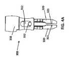
別の実施形態によると、図2は、ベース部材112から下方に延びる複数のプロング120と、そこから上方に延びるポスト136を含む一時的な取り付け装置100の前面図及び側面図を示す。ベース部材112の上面114は、面取りされた、または丸みを帯びたエッジを有する4つの隣接している側面と接続する。この実施形態では、上面114は、ベース部材112の残りの部分よりも幅が小さい。上面114は、例えば、本明細書に記載された開口部16と同様の開口部(図示せず)内に、固定された、または除去可能なポスト136を受け入れるように構成される。例えば、ポスト136は、デバイス100が骨18内に打ち込まれる前に、そこから上方に延びるベース部材112に除去可能に取り付けることができる。スパイク100は、このポスト136を打つことによって打ち込むことができ、特に、厚い組織によって取り囲まれた領域を通って、デバイス100を下に打ち込むときに、ベース部材112を直接打つより簡単であり得る。この実施形態では、プロング120はまた、プロング120が別のものよりも一側面においてより広い断面を有するように変更もされている。加えて、丘形状の隆起部130は、細長く、プロング20の長さに沿って異なる位置に位置付けられている。 In accordance with another embodiment, FIG. 2 shows a front and side view of a
さらに別の実施形態によると、図3A〜3Bは、外側スリーブ238によって圧縮可能なプロング220を備えた一時的な取り付け装置200を示す。この実施形態では、実質的に平行なプロング220がベース部材212から延びる。ベース部材212は、上から見ると、実質的に丸いまたは楕円形の上面214を有する。ベース部材212及びプロング220は、実質的に円筒形状のデバイス200を形成することができる。一時的な取付具200は、デバイス200のプロング220間で骨18を圧縮するのを容易にするために、外側スリーブ238を組み込んでいる。外側スリーブ238は、そこを通って延び、ベース部材212の一部を受け入れるように構成された中央の中空部分を有するナット、環状リング、カラーなどの形態であってもよい。外側スリーブ238は、スリーブ238を把持することと、デバイス200を中心にスリーブ238を回転することとを容易にするために、テクスチャ外面を有することができる。ベース部材212及びプロング220の一部は、外側スリーブ238を受け入れるためにねじ式であってもよく、このスリーブ238は、対応する内ねじ(図面内には見えない)を有していてもよい。ベース部材212のねじ部は、様々な直径(例えば、上面に近接するより小さい直径を有し、プロング220に近接するより大きい直径を有する)であってもよい。図示のように、プロング220の外面の遠位部分は、骨18の中への貫通を改善し、スリーブ238による圧縮量を制限するために、実質的に平滑であり得る。 According to yet another embodiment, FIGS. 3A-3B illustrate a
ベース部材212の上面214は、ベース部材212を通って部分的にまたは完全に延びる隙間または開口部216を有することができる。したがって、デバイス200は、十分にカニューレ状になり得る。開口部16は、例えば、デバイス200を誘導するためのガイドワイヤ、ポスト、または中心シャフトを受け入れるようなサイズ及び寸法とすることができ、及び/または手術ナビゲーションシステムのための追跡可能な基準アレイなどのトラッカーの一部分に除去可能に接続するようなサイズ及び寸法とすることができる。 The
デバイス10及び100と同様に、最初にデバイス200を正しい場所に槌で打つことができる。続いて、例えば、外側スリーブ238を摺動または回転させることによって外側スリーブ238を作動して、プロング220を互いに向かって内方に圧縮するために、プロング20に向かって第1の方向に外側スリーブ238を移動させる。一時的な取り付け装置200が除去される時、プロング220を解放するために、外側スリーブ238を摺動または回転させて、外側スリーブ238を第1の方向とは反対のプロングから離れた第2の方向に移動させる。このような機構は、プロング220が棘突起のような骨の隆起部に押し下げられ、次いで、プロング220間で骨18を圧縮し締付することにより、さらに固定する必要がある場合に特に有用である。図3A及び3Bに見られるように、この設計の1つのバージョンでは、外側ナットまたは外側スリーブ238が回転してプロング220に向かって下方に前進する場合、デバイス200のプロング220が最初に外側に広がっても、ナットまたはスリーブ238の直径に対して内方に押し付けられるように、ねじ式になっているスリープ238の内側部分を有する。 As with
デバイス200と同様に、図4A〜4Bは、下方への力またはねじ式機構によって前進され、次いで、半回転機構で圧縮位置にロックされるスリーブ338を有するプロング320を備えた一時的な取り付け装置300を示す。プロング320は、外側スリーブまたはナット338がプロング320によって前進する場合、それらがちょうどナット338の直径の代わりに内方に押し付けられるように、凸部を有することができる。図4Aに示すように、プロング320の内面321は、プロング320の残りの部分を隆起させるか、または突出させて、締付または圧縮の特徴を向上させることができる。この設計の別の特徴は、図4Bに最もよく示されているように、プロング320のギザギザのある、またはそうでなければテクスチャ内面322を含むことができ、これはデバイスの摘出にも抵抗する。 Similar to
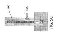
図5A〜5Cに示されている別の実施形態は、一時的な取り付け装置10、100、200、300を、皮膚、脂肪、及び筋肉などの軟組織の深層を通って骨18の中に配置する際に有用であり得る。例えば、4つのプロングスパイク(例えば、装置10、100、200または300)を大きな患者の腸骨稜に取設する場合、スパイクは、骨18に達する前に、数インチの軟組織を貫通する必要があり得る。本明細書に記載されたデバイス10、100、200、300が軟組織を通って小さな始動孔をスライスした後に使用される場合、プロング12、112、212、312は、プロング12、112、212、312が骨18と係合し始める前、下方に前進したときに、軟組織にかみ合う可能性がある。一例として、中心シャフト400が最初に挿入され、続いてデバイス10のうちの1つ(デバイスを通って延びる開口部16で構成されている)、200(デバイスを通って延びる開口部216で構成されている)、100または300(それは中空または中央にカニューレ状に修正されている)が挿入される。デバイス10、100、200、300が定位置にあり、望ましくは骨18内に挿入された後、次に、中央シャフト400を除去することができる。 Another embodiment shown in FIGS. 5A-5C places the
第1のステップは、中心シャフト400を骨18の隣に配置することであってもよい。そのような中心シャフト400の一例を図5Aに示す。例えば、直径はおよそ10〜25mmであり、長さは150〜250mmである。シャフト400は、骨表面に沿ってさまようことなく、骨18にそれをピン止めするのに役立つ歯402を遠位先端部に有することができる。歯402は、デバイス400の長手方向中心軸線に沿って中央に位置付けられ得る。あるいは、2つ以上の歯402は、中心シャフト400の遠位先端部上の代替位置に位置付けられ得る。外科医は、手動力または槌打ちを用いて、軟組織を通してそれらが骨18に達したと感じるまでシャフト400を押し下げることができる。入る経路は、フリーハンドで確立することも、ナビゲーションまたはロボットを使用して誘導することもできる。 The first step may be to place the
中心シャフト400を軟組織の最初のペネトレータとして使用することの1つの利点は、それが最終的に必要とされるデバイス10、100、200、300のサイズを測定するために使用できることである。図5Cに示すように、印404が皮膚のレベルまたは所望の取設のレベルで読み取られるように、目盛り付の印404をシャフト400の長さに沿って設けることができる。これらの目盛り付の印40を用いて、外科医は、追跡アレイが最終的にどこに位置するかを決定することができる。この位置に基づいて、適切なサイズのカニューレ状のデバイス10、100、200、300を一組の選択肢から選択することができる。したがって、例えば、異なるサイズ及び異なる構成の、複数の異なる取付具10、100、200、300をキットとして提供することができる。このようなキットはまた、例えば、追跡アレイなどの取設可能な構成要素を含む、手術に適した他の器具と同様に、中心シャフト400を含むこともできる。 One advantage of using the
図6に示すように、デバイス10に中心シャフト400をはめ込むステップを示す。取付具10を参照して説明したが、これらのステップは、本明細書で説明する他のカニューレ状のデバイス100、200、300にも等しく適用されることが理解される。 As shown in FIG. 6, the step of fitting the
ステップ(a1)に示すように、シャフト400の遠位先端部が骨18に対して定位置にあると、中心シャフト400の近位端が外科医の手のうちの1つに保持され、摩擦によって所定の位置に残され、またはアシスタントまたはロボットによって保持される。ステップ(b1)に示すように、カニューレ状の一時的な取付具10を中心シャフト400上に前進させる。ステップ(c1)に示すように、叉のある取付具10が下降して骨18と接触する。中心シャフト400及び取付具10は、プロング20がシャフト400を抱き込むように設計することができ、プロング20とシャフト400との間に軟組織が引っ掛かるのを防止する。 As shown in step (a1), when the distal tip of the
カニューレ状のデバイス10が中心シャフト400よりも長い場合、その時は、デバイス10について上述されているように、カニューレ状のデバイス10を槌で打つことで骨18の中にカニューレ状のデバイス10を打ち込むことになる。デバイス10が定位置に配置された後、中心シャフト400は、定位置に残すか、中央シャフト400(図示せず)内のソケットの中にねじ込まれたねじ付ロッドのような器具で取り出すことができる。中心シャフト400を定位置に残すことが望ましくない場合がある。カニューレ状のデバイス10を打つ間に定位置に残された場合、デバイス10が中心シャフト400の端部の地点を過ぎて前進すると、中心シャフト400の骨18の中へのさらなる槌打ちを不必要に強いる可能性がある。代わりに、デバイス10の寸法は、中心シャフト400がデバイス10よりも長くなるようなものであってもよい。 If the cannulated
あるいは、デバイス10を中心シャフト400で下に打ち込むために、スリーブ部材406を使用することができる。スリーブ部材406は、任意にヘッド部分を含むことができる。打ち込みスリーブ406の設計では、拡大ヘッドは、その断片を打つためのより大きな表面領域として役立つように、シャフトの残りの部分よりも直径が大きくてもよい。別のステップ(a2)に見られるように、シャフト400は、デバイス10が骨18と接触して位置決めされる。ステップ(b2)では、スリーブ部材406は、中心シャフト400上に位置決めされ、デバイス10と接触する。ステップ(c2)では、外科医は、スリーブ部材406を槌打ちし、スパイク10の前進を引き起こす。次に、ステップ(d2)に示すように、スリーブ部材400を除去する。続いて、ステップ(e2)では、中心シャフト400が除去され、デバイス10を骨内18に埋め込まれた状態で残す。これらの構成要素は、1つずつまたは一緒に追加及び削除することができる。その後、ナビゲーションアレイのような所望の取設具を、当技術分野で既知の適切な技術を用いて、デバイス10上に配置し、デバイス10に取設することができる。 Alternatively, the
ナビゲーションが完了した後及び/または手術が完了した後であるが、患者が閉鎖される前に、デバイス10、100、200、300は、例えば、それを引き抜くか、それを引き出すか、または開口部16、216に取設されたスラップハンマーまたはデバイス10、100、200、300上のねじ付ソケットを用いることによって除去することができる。デバイス10、100、200、300は、再使用のために消毒され得る。あるいは、デバイス10、100、200、300は、使い捨て部分として使用され得る。 After navigation is complete and / or after surgery is complete, but before the patient is closed, the
本明細書に記載された取付具10、100、200、300の設計は、1本の釘または先頭形のデバイスを使用する既存の方法に対して、利点を有する。具体的には、従来の釘などに見られる単一の点の代わりに、皮質を通って海綿骨への複数の固定点(例えば、4つの固定点)がある。この複数の固定点は、骨18への強力な取設と、手術ナビゲーションのためのトラッカーのような取設装置の改善された精度とを提供する。プロング20、120、220、320はまた、固定剛性を改善するために骨18の中に打ち込まれる間に、それらが変形するほど繊細であるように設計される。一時的な取り付けデバイス10、100、200、300はまた、1本の釘または槍頭でしばしば起こるよりも、骨の中にデバイス10、100、200、300を誤って骨構造の中にあまりにも遠くに前進させる機会が少なくなるように、1つ以上の止め具を含むことができる。したがって、一時的な取付具10、100、200、300の設計は、骨18及びその周囲領域を保護するのに役立ち、手術ナビゲーション及び/または外科手術が完了したときに、骨18から容易に除去することができる。 The design of
本発明を詳細にまた特定の実施形態を参照して説明してきたが、本発明の趣旨及び範囲から逸脱することなく、様々な変更及び修正を行うことができることは当業者には明らかであろう。したがって、本発明は、添付の特許請求の範囲及びその等価物の範囲内に入るならば、本発明の修正及び変形を包含することが意図される。例えば、本明細書で広く言及されている全ての範囲は、その範囲内に、より広い範囲に属するすべてのより狭い範囲を含むことが明確に意図されている。上に開示した様々なデバイスの構成要素は、任意の適切な構成で組み合わせるまたは修正することができることも意図している。 Although the invention has been described in detail and with reference to specific embodiments, it will be apparent to those skilled in the art that various changes and modifications can be made without departing from the spirit and scope of the invention. . Thus, it is intended that the present invention cover modifications and variations of this invention provided they come within the scope of the appended claims and their equivalents. For example, all ranges broadly referred to herein are expressly intended to include within their scope all narrower ranges belonging to the broader range. It is also contemplated that the various device components disclosed above may be combined or modified in any suitable configuration.
Claims (20)
Translated fromJapanese挿入デバイスによって押し込まれるように構成された上面を有するベース部材と、
前記ベース部材から下方に延び、骨構造と係合するように構成された複数の細長いプロングであって、前記複数の細長いプロングは各々、互いにある距離で離間され、前記複数の細長いプロングは、前記骨構造の中に下方に打ち込まれると、互いに向かって内方に移動するように構成される、複数の細長いプロングと、を備える、取付具。An attachment for temporarily attaching a surgical device to a bone structure,
A base member having an upper surface configured to be pushed by an insertion device;
A plurality of elongate prongs extending downwardly from the base member and configured to engage a bone structure, the plurality of elongate prongs each being spaced apart from each other by the plurality of elongate prongs; And a plurality of elongated prongs configured to move inwardly toward each other when driven downward into the bone structure.
一時的な取付具であって、
挿入デバイスによって押し込まれるように構成された上面を有するベース部材と、
前記ベース部材から下方に延び、骨構造と係合するように構成された複数の細長いプロングであって、前記複数の細長いプロングは各々、互いにある距離で離間され、前記複数の細長いプロングは、前記骨構造の中に下方に打ち込まれると、互いに向かって内方に移動するように構成される、複数の細長いプロングと、を備える、一時的な取付具と、
前記一時的な取付具の前記ベース部材に接続された手術ナビゲーションのための追跡可能な基準アレイと、を備える、システム。A system for temporarily attaching a surgical device to a bone structure,
A temporary fixture,
A base member having an upper surface configured to be pushed by an insertion device;
A plurality of elongate prongs extending downwardly from the base member and configured to engage a bone structure, the plurality of elongate prongs each being spaced apart from each other by the plurality of elongate prongs; A temporary attachment comprising a plurality of elongated prongs configured to move inwardly toward each other when driven downward into the bone structure;
A trackable reference array for surgical navigation connected to the base member of the temporary fixture.
軟組織を通して中心シャフトを挿入して、骨と接触させることと、
カニューレ状の一時的な取付具を前記中心シャフト上に挿入し、前記一時的な取付具を下方に移動させて前記骨と接触させることであって、前記カニューレ状の一時的な取付具は、第1の端部及び複数の細長いプロングとして終結する第2の端部を有し、前記複数の細長いプロングは各々、互いにある距離で離間され、前記複数の細長いプロングは、前記骨構造の中に下方に打ち込まれると、互いに向かって内方に移動するように構成される、接触させることと、
打ち込みスリーブを前記中心シャフト上に位置付けて、前記一時的な取付具の前記第1の端部と接触させることと、
前記打ち込みスリーブに力を加えて、前記一時的な取付具を骨の中に前進させることと、
前記打ち込みスリーブ及び前記中心シャフトを除去して、前記一時的な取付具を骨内に埋め込まれた状態で残すことと、を含む、方法。A method of temporarily attaching a surgical device to a bone structure,
Inserting the central shaft through the soft tissue and making contact with the bone;
Inserting a cannulated temporary attachment onto the central shaft and moving the temporary attachment downwardly into contact with the bone, the cannulated temporary attachment comprising: A first end and a second end terminating in a plurality of elongate prongs, each of the plurality of elongate prongs spaced apart from each other by the plurality of elongate prongs in the bone structure Contacting, configured to move inward toward each other when driven downward;
Positioning a driving sleeve on the central shaft to contact the first end of the temporary fixture;
Applying force to the driving sleeve to advance the temporary fitting into the bone;
Removing the driving sleeve and the central shaft, leaving the temporary fixture embedded in the bone.
Applications Claiming Priority (3)
| Application Number | Priority Date | Filing Date | Title |
|---|---|---|---|
| US14/824,586US10080615B2 (en) | 2015-08-12 | 2015-08-12 | Devices and methods for temporary mounting of parts to bone |
| US14/824,586 | 2015-08-12 | ||
| PCT/US2016/045607WO2017027331A1 (en) | 2015-08-12 | 2016-08-04 | Devices and methods for temporary mounting of parts to bone |
Publications (2)
| Publication Number | Publication Date |
|---|---|
| JP2018522678Atrue JP2018522678A (en) | 2018-08-16 |
| JP6794428B2 JP6794428B2 (en) | 2020-12-02 |
Family
ID=57984608
Family Applications (1)
| Application Number | Title | Priority Date | Filing Date |
|---|---|---|---|
| JP2018506594AActiveJP6794428B2 (en) | 2015-08-12 | 2016-08-04 | Devices and methods for temporarily attaching parts to bone |
Country Status (4)
| Country | Link |
|---|---|
| US (3) | US10080615B2 (en) |
| EP (1) | EP3334365B1 (en) |
| JP (1) | JP6794428B2 (en) |
| WO (1) | WO2017027331A1 (en) |
Families Citing this family (9)
| Publication number | Priority date | Publication date | Assignee | Title |
|---|---|---|---|---|
| US10893912B2 (en)* | 2006-02-16 | 2021-01-19 | Globus Medical Inc. | Surgical tool systems and methods |
| EP2863827B1 (en)* | 2012-06-21 | 2022-11-16 | Globus Medical, Inc. | Surgical robot platform |
| US20170258535A1 (en)* | 2012-06-21 | 2017-09-14 | Globus Medical, Inc. | Surgical robotic automation with tracking markers |
| CN110248618B (en) | 2016-09-09 | 2024-01-09 | 莫比乌斯成像公司 | Method and system for displaying patient data in computer-assisted surgery |
| WO2018209042A2 (en) | 2017-05-10 | 2018-11-15 | Mako Surgical Corp. | Robotic spine surgery system and methods |
| US11033341B2 (en) | 2017-05-10 | 2021-06-15 | Mako Surgical Corp. | Robotic spine surgery system and methods |
| CN118662240A (en) | 2018-01-26 | 2024-09-20 | 马科外科公司 | End effector, system, and method for impacting a prosthesis guided by a surgical robot |
| US10485632B1 (en) | 2018-11-27 | 2019-11-26 | King Saud University | Intraoral attachment clip for attachment of objects to edentulous ridges |
| CN111839734B (en)* | 2020-07-07 | 2022-06-03 | 天津大学 | Surgical robot end device with manual quick-change mechanism |
Citations (4)
| Publication number | Priority date | Publication date | Assignee | Title |
|---|---|---|---|---|
| JP2001502572A (en)* | 1996-10-18 | 2001-02-27 | ディピュイ フランス | Device for fixing at least two vertebrae |
| JP2002541966A (en)* | 1999-04-23 | 2002-12-10 | エスディージーアイ・ホールディングス・インコーポレーテッド | Treatment method for treating abnormal spinal column alignment and correction method for correcting abnormal spinal column deformation |
| JP2008507361A (en)* | 2004-07-23 | 2008-03-13 | スミス アンド ネフュー インコーポレーテッド | Surgical navigation system component fault interface and related processes |
| US20140142628A1 (en)* | 2012-11-19 | 2014-05-22 | Warsaw Orthopedic, Inc. | Surgical implant system and method |
Family Cites Families (569)
| Publication number | Priority date | Publication date | Assignee | Title |
|---|---|---|---|---|
| DE2614083B2 (en) | 1976-04-01 | 1979-02-08 | Siemens Ag, 1000 Berlin Und 8000 Muenchen | X-ray film device for the production of transverse slice images |
| US5487739A (en)* | 1987-11-17 | 1996-01-30 | Brown University Research Foundation | Implantable therapy systems and methods |
| US4979949A (en)* | 1988-04-26 | 1990-12-25 | The Board Of Regents Of The University Of Washington | Robot-aided system for surgery |
| EP0703757B1 (en) | 1988-06-13 | 2003-08-27 | Karlin Technology, Inc. | Apparatus for inserting spinal implants |
| US5354314A (en) | 1988-12-23 | 1994-10-11 | Medical Instrumentation And Diagnostics Corporation | Three-dimensional beam localization apparatus and microscope for stereotactic diagnoses or surgery mounted on robotic type arm |
| US5246010A (en) | 1990-12-11 | 1993-09-21 | Biotrine Corporation | Method and apparatus for exhalation analysis |
| US5417210A (en) | 1992-05-27 | 1995-05-23 | International Business Machines Corporation | System and method for augmentation of endoscopic surgery |
| US6963792B1 (en) | 1992-01-21 | 2005-11-08 | Sri International | Surgical method |
| US5631973A (en) | 1994-05-05 | 1997-05-20 | Sri International | Method for telemanipulation with telepresence |
| US5657429A (en) | 1992-08-10 | 1997-08-12 | Computer Motion, Inc. | Automated endoscope system optimal positioning |
| US5397323A (en) | 1992-10-30 | 1995-03-14 | International Business Machines Corporation | Remote center-of-motion robot for surgery |
| EP0699053B1 (en) | 1993-05-14 | 1999-03-17 | Sri International | Surgical apparatus |
| JP3378401B2 (en) | 1994-08-30 | 2003-02-17 | 株式会社日立メディコ | X-ray equipment |
| US6646541B1 (en) | 1996-06-24 | 2003-11-11 | Computer Motion, Inc. | General purpose distributed operating room control system |
| FR2725126B1 (en)* | 1994-10-04 | 1997-04-25 | Mai Christian | LIGAMENT IMPLANT WITH SHAPE MEMORY |
| US6978166B2 (en) | 1994-10-07 | 2005-12-20 | Saint Louis University | System for use in displaying images of a body part |
| ATE228338T1 (en) | 1994-10-07 | 2002-12-15 | Univ St Louis | SURGICAL NAVIGATION ARRANGEMENT INCLUDING REFERENCE AND LOCATION SYSTEMS |
| US5882206A (en) | 1995-03-29 | 1999-03-16 | Gillio; Robert G. | Virtual surgery system |
| US5887121A (en) | 1995-04-21 | 1999-03-23 | International Business Machines Corporation | Method of constrained Cartesian control of robotic mechanisms with active and passive joints |
| US6122541A (en) | 1995-05-04 | 2000-09-19 | Radionics, Inc. | Head band for frameless stereotactic registration |
| US5649956A (en) | 1995-06-07 | 1997-07-22 | Sri International | System and method for releasably holding a surgical instrument |
| US5825982A (en) | 1995-09-15 | 1998-10-20 | Wright; James | Head cursor control interface for an automated endoscope system for optimal positioning |
| US6351659B1 (en) | 1995-09-28 | 2002-02-26 | Brainlab Med. Computersysteme Gmbh | Neuro-navigation system |
| US5772594A (en) | 1995-10-17 | 1998-06-30 | Barrick; Earl F. | Fluoroscopic image guided orthopaedic surgery system with intraoperative registration |
| US5855583A (en) | 1996-02-20 | 1999-01-05 | Computer Motion, Inc. | Method and apparatus for performing minimally invasive cardiac procedures |
| SG64340A1 (en) | 1996-02-27 | 1999-04-27 | Inst Of Systems Science Nation | Curved surgical instruments and methods of mapping a curved path for stereotactic surgery |
| US6167145A (en) | 1996-03-29 | 2000-12-26 | Surgical Navigation Technologies, Inc. | Bone navigation system |
| US5792135A (en) | 1996-05-20 | 1998-08-11 | Intuitive Surgical, Inc. | Articulated surgical instrument for performing minimally invasive surgery with enhanced dexterity and sensitivity |
| US6167296A (en) | 1996-06-28 | 2000-12-26 | The Board Of Trustees Of The Leland Stanford Junior University | Method for volumetric image navigation |
| US7302288B1 (en) | 1996-11-25 | 2007-11-27 | Z-Kat, Inc. | Tool position indicator |
| US8529582B2 (en) | 1996-12-12 | 2013-09-10 | Intuitive Surgical Operations, Inc. | Instrument interface of a robotic surgical system |
| US9050119B2 (en) | 2005-12-20 | 2015-06-09 | Intuitive Surgical Operations, Inc. | Cable tensioning in a robotic surgical system |
| US7727244B2 (en) | 1997-11-21 | 2010-06-01 | Intuitive Surgical Operation, Inc. | Sterile surgical drape |
| US6205411B1 (en) | 1997-02-21 | 2001-03-20 | Carnegie Mellon University | Computer-assisted surgery planner and intra-operative guidance system |
| US6012216A (en) | 1997-04-30 | 2000-01-11 | Ethicon, Inc. | Stand alone swage apparatus |
| US5820559A (en) | 1997-03-20 | 1998-10-13 | Ng; Wan Sing | Computerized boundary estimation in medical images |
| US5911449A (en) | 1997-04-30 | 1999-06-15 | Ethicon, Inc. | Semi-automated needle feed method and apparatus |
| US6042582A (en) | 1997-05-20 | 2000-03-28 | Ray; Charles D. | Instrumentation and method for facilitating insertion of spinal implant |
| US6231565B1 (en) | 1997-06-18 | 2001-05-15 | United States Surgical Corporation | Robotic arm DLUs for performing surgical tasks |
| EP2362286B1 (en) | 1997-09-19 | 2015-09-02 | Massachusetts Institute Of Technology | Robotic apparatus |
| US6226548B1 (en) | 1997-09-24 | 2001-05-01 | Surgical Navigation Technologies, Inc. | Percutaneous registration apparatus and method for use in computer-assisted surgical navigation |
| US5951475A (en) | 1997-09-25 | 1999-09-14 | International Business Machines Corporation | Methods and apparatus for registering CT-scan data to multiple fluoroscopic images |
| US5987960A (en) | 1997-09-26 | 1999-11-23 | Picker International, Inc. | Tool calibrator |
| US6212419B1 (en) | 1997-11-12 | 2001-04-03 | Walter M. Blume | Method and apparatus using shaped field of repositionable magnet to guide implant |
| US6157853A (en) | 1997-11-12 | 2000-12-05 | Stereotaxis, Inc. | Method and apparatus using shaped field of repositionable magnet to guide implant |
| US6031888A (en) | 1997-11-26 | 2000-02-29 | Picker International, Inc. | Fluoro-assist feature for a diagnostic imaging device |
| US6165170A (en) | 1998-01-29 | 2000-12-26 | International Business Machines Corporation | Laser dermablator and dermablation |
| US6949106B2 (en) | 1998-02-24 | 2005-09-27 | Endovia Medical, Inc. | Surgical instrument |
| FR2779339B1 (en) | 1998-06-09 | 2000-10-13 | Integrated Surgical Systems Sa | MATCHING METHOD AND APPARATUS FOR ROBOTIC SURGERY, AND MATCHING DEVICE COMPRISING APPLICATION |
| US6477400B1 (en) | 1998-08-20 | 2002-11-05 | Sofamor Danek Holdings, Inc. | Fluoroscopic image guided orthopaedic surgery system with intraoperative registration |
| DE19839825C1 (en) | 1998-09-01 | 1999-10-07 | Siemens Ag | Diagnostic X=ray device |
| US6033415A (en) | 1998-09-14 | 2000-03-07 | Integrated Surgical Systems | System and method for performing image directed robotic orthopaedic procedures without a fiducial reference system |
| DE19842798C1 (en) | 1998-09-18 | 2000-05-04 | Howmedica Leibinger Gmbh & Co | Calibration device |
| WO2000021442A1 (en) | 1998-10-09 | 2000-04-20 | Surgical Navigation Technologies, Inc. | Image guided vertebral distractor |
| US6659939B2 (en) | 1998-11-20 | 2003-12-09 | Intuitive Surgical, Inc. | Cooperative minimally invasive telesurgical system |
| US8527094B2 (en) | 1998-11-20 | 2013-09-03 | Intuitive Surgical Operations, Inc. | Multi-user medical robotic system for collaboration or training in minimally invasive surgical procedures |
| US6325808B1 (en) | 1998-12-08 | 2001-12-04 | Advanced Realtime Control Systems, Inc. | Robotic system, docking station, and surgical tool for collaborative control in minimally invasive surgery |
| US7125403B2 (en) | 1998-12-08 | 2006-10-24 | Intuitive Surgical | In vivo accessories for minimally invasive robotic surgery |
| US6322567B1 (en) | 1998-12-14 | 2001-11-27 | Integrated Surgical Systems, Inc. | Bone motion tracking system |
| US6451027B1 (en) | 1998-12-16 | 2002-09-17 | Intuitive Surgical, Inc. | Devices and methods for moving an image capture device in telesurgical systems |
| US7016457B1 (en) | 1998-12-31 | 2006-03-21 | General Electric Company | Multimode imaging system for generating high quality images |
| DE19905974A1 (en) | 1999-02-12 | 2000-09-07 | Siemens Ag | Computer tomography scanning method using multi-line detector |
| US6560354B1 (en) | 1999-02-16 | 2003-05-06 | University Of Rochester | Apparatus and method for registration of images to physical space using a weighted combination of points and surfaces |
| US6501981B1 (en) | 1999-03-16 | 2002-12-31 | Accuray, Inc. | Apparatus and method for compensating for respiratory and patient motions during treatment |
| US6144875A (en) | 1999-03-16 | 2000-11-07 | Accuray Incorporated | Apparatus and method for compensating for respiratory and patient motion during treatment |
| US6778850B1 (en) | 1999-03-16 | 2004-08-17 | Accuray, Inc. | Frameless radiosurgery treatment system and method |
| US6470207B1 (en) | 1999-03-23 | 2002-10-22 | Surgical Navigation Technologies, Inc. | Navigational guidance via computer-assisted fluoroscopic imaging |
| JP2000271110A (en) | 1999-03-26 | 2000-10-03 | Hitachi Medical Corp | Medical x-ray system |
| US6565554B1 (en) | 1999-04-07 | 2003-05-20 | Intuitive Surgical, Inc. | Friction compensation in a minimally invasive surgical apparatus |
| US6594552B1 (en) | 1999-04-07 | 2003-07-15 | Intuitive Surgical, Inc. | Grip strength with tactile feedback for robotic surgery |
| US6424885B1 (en) | 1999-04-07 | 2002-07-23 | Intuitive Surgical, Inc. | Camera referenced control in a minimally invasive surgical apparatus |
| US6296643B1 (en) | 1999-04-23 | 2001-10-02 | Sdgi Holdings, Inc. | Device for the correction of spinal deformities through vertebral body tethering without fusion |
| US6301495B1 (en) | 1999-04-27 | 2001-10-09 | International Business Machines Corporation | System and method for intra-operative, image-based, interactive verification of a pre-operative surgical plan |
| DE19927953A1 (en) | 1999-06-18 | 2001-01-11 | Siemens Ag | X=ray diagnostic apparatus |
| US6314311B1 (en) | 1999-07-28 | 2001-11-06 | Picker International, Inc. | Movable mirror laser registration system |
| US6788018B1 (en) | 1999-08-03 | 2004-09-07 | Intuitive Surgical, Inc. | Ceiling and floor mounted surgical robot set-up arms |
| US7594912B2 (en) | 2004-09-30 | 2009-09-29 | Intuitive Surgical, Inc. | Offset remote center manipulator for robotic surgery |
| US8271130B2 (en) | 2009-03-09 | 2012-09-18 | Intuitive Surgical Operations, Inc. | Master controller having redundant degrees of freedom and added forces to create internal motion |
| US8004229B2 (en) | 2005-05-19 | 2011-08-23 | Intuitive Surgical Operations, Inc. | Software center and highly configurable robotic systems for surgery and other uses |
| US6312435B1 (en) | 1999-10-08 | 2001-11-06 | Intuitive Surgical, Inc. | Surgical instrument with extended reach for use in minimally invasive surgery |
| US6235038B1 (en) | 1999-10-28 | 2001-05-22 | Medtronic Surgical Navigation Technologies | System for translation of electromagnetic and optical localization systems |
| US8644907B2 (en) | 1999-10-28 | 2014-02-04 | Medtronic Navigaton, Inc. | Method and apparatus for surgical navigation |
| US6379302B1 (en) | 1999-10-28 | 2002-04-30 | Surgical Navigation Technologies Inc. | Navigation information overlay onto ultrasound imagery |
| US6499488B1 (en) | 1999-10-28 | 2002-12-31 | Winchester Development Associates | Surgical sensor |
| US7366562B2 (en) | 2003-10-17 | 2008-04-29 | Medtronic Navigation, Inc. | Method and apparatus for surgical navigation |
| US8239001B2 (en) | 2003-10-17 | 2012-08-07 | Medtronic Navigation, Inc. | Method and apparatus for surgical navigation |
| US20010036302A1 (en) | 1999-12-10 | 2001-11-01 | Miller Michael I. | Method and apparatus for cross modality image registration |
| US7635390B1 (en) | 2000-01-14 | 2009-12-22 | Marctec, Llc | Joint replacement component having a modular articulating surface |
| US6377011B1 (en) | 2000-01-26 | 2002-04-23 | Massachusetts Institute Of Technology | Force feedback user interface for minimally invasive surgical simulator and teleoperator and other similar apparatus |
| AU2001233019A1 (en) | 2000-01-28 | 2001-08-07 | Intersense, Inc. | Self-referenced tracking |
| US6722371B1 (en)* | 2000-02-18 | 2004-04-20 | Thomas J. Fogarty | Device for accurately marking tissue |
| US6725080B2 (en) | 2000-03-01 | 2004-04-20 | Surgical Navigation Technologies, Inc. | Multiple cannula image guided tool for image guided procedures |
| JP2003534035A (en) | 2000-03-15 | 2003-11-18 | オーソソフト インコーポレイテッド | Automatic calibration system for computer assisted surgical instruments |
| US6535756B1 (en) | 2000-04-07 | 2003-03-18 | Surgical Navigation Technologies, Inc. | Trajectory storage apparatus and method for surgical navigation system |
| US6484049B1 (en) | 2000-04-28 | 2002-11-19 | Ge Medical Systems Global Technology Company, Llc | Fluoroscopic tracking and visualization system |
| US6856827B2 (en) | 2000-04-28 | 2005-02-15 | Ge Medical Systems Global Technology Company, Llc | Fluoroscopic tracking and visualization system |
| US6856826B2 (en) | 2000-04-28 | 2005-02-15 | Ge Medical Systems Global Technology Company, Llc | Fluoroscopic tracking and visualization system |
| US6614453B1 (en) | 2000-05-05 | 2003-09-02 | Koninklijke Philips Electronics, N.V. | Method and apparatus for medical image display for surgical tool planning and navigation in clinical environments |
| US6645196B1 (en) | 2000-06-16 | 2003-11-11 | Intuitive Surgical, Inc. | Guided tool change |
| US6782287B2 (en) | 2000-06-27 | 2004-08-24 | The Board Of Trustees Of The Leland Stanford Junior University | Method and apparatus for tracking a medical instrument based on image registration |
| US6837892B2 (en) | 2000-07-24 | 2005-01-04 | Mazor Surgical Technologies Ltd. | Miniature bone-mounted surgical robot |
| US6902560B1 (en) | 2000-07-27 | 2005-06-07 | Intuitive Surgical, Inc. | Roll-pitch-roll surgical tool |
| DE10037491A1 (en) | 2000-08-01 | 2002-02-14 | Stryker Leibinger Gmbh & Co Kg | Process for three-dimensional visualization of structures inside the body |
| US6823207B1 (en) | 2000-08-26 | 2004-11-23 | Ge Medical Systems Global Technology Company, Llc | Integrated fluoroscopic surgical navigation and imaging workstation with command protocol |
| US7139418B2 (en) | 2000-09-25 | 2006-11-21 | Z-Kat, Inc. | Fluoroscopic registration artifact with optical and/or magnetic markers |
| WO2002034152A1 (en) | 2000-10-23 | 2002-05-02 | Deutsches Krebsforschungszentrum Stiftung des öffentlichen Rechts | Method, device and navigation aid for navigation during medical interventions |
| US6718194B2 (en) | 2000-11-17 | 2004-04-06 | Ge Medical Systems Global Technology Company, Llc | Computer assisted intramedullary rod surgery system with enhanced features |
| US6666579B2 (en) | 2000-12-28 | 2003-12-23 | Ge Medical Systems Global Technology Company, Llc | Method and apparatus for obtaining and displaying computed tomography images using a fluoroscopy imaging system |
| US6840938B1 (en) | 2000-12-29 | 2005-01-11 | Intuitive Surgical, Inc. | Bipolar cauterizing instrument |
| EP1364183B1 (en) | 2001-01-30 | 2013-11-06 | Mako Surgical Corp. | Tool calibrator and tracker system |
| US7220262B1 (en) | 2001-03-16 | 2007-05-22 | Sdgi Holdings, Inc. | Spinal fixation system and related methods |
| FR2822674B1 (en) | 2001-04-03 | 2003-06-27 | Scient X | STABILIZED INTERSOMATIC MELTING SYSTEM FOR VERTEBERS |
| US8046057B2 (en) | 2001-04-11 | 2011-10-25 | Clarke Dana S | Tissue structure identification in advance of instrument |
| US6994708B2 (en) | 2001-04-19 | 2006-02-07 | Intuitive Surgical | Robotic tool with monopolar electro-surgical scissors |
| US7824401B2 (en) | 2004-10-08 | 2010-11-02 | Intuitive Surgical Operations, Inc. | Robotic tool with wristed monopolar electrosurgical end effectors |
| US8398634B2 (en) | 2002-04-18 | 2013-03-19 | Intuitive Surgical Operations, Inc. | Wristed robotic surgical tool for pluggable end-effectors |
| US6783524B2 (en) | 2001-04-19 | 2004-08-31 | Intuitive Surgical, Inc. | Robotic surgical tool with ultrasound cauterizing and cutting instrument |
| US6636757B1 (en) | 2001-06-04 | 2003-10-21 | Surgical Navigation Technologies, Inc. | Method and apparatus for electromagnetic navigation of a surgical probe near a metal object |
| US7607440B2 (en) | 2001-06-07 | 2009-10-27 | Intuitive Surgical, Inc. | Methods and apparatus for surgical planning |
| ES2292593T3 (en) | 2001-06-13 | 2008-03-16 | Volume Interactions Pte. Ltd. | GUIDING SYSTEM |
| US6584339B2 (en) | 2001-06-27 | 2003-06-24 | Vanderbilt University | Method and apparatus for collecting and processing physical space data for use while performing image-guided surgery |
| US7063705B2 (en) | 2001-06-29 | 2006-06-20 | Sdgi Holdings, Inc. | Fluoroscopic locator and registration device |
| AU2002322374B2 (en) | 2001-06-29 | 2006-10-26 | Intuitive Surgical, Inc. | Platform link wrist mechanism |
| US20040243147A1 (en) | 2001-07-03 | 2004-12-02 | Lipow Kenneth I. | Surgical robot and robotic controller |
| ITMI20011759A1 (en) | 2001-08-09 | 2003-02-09 | Nuovo Pignone Spa | SCRAPER DEVICE FOR PISTON ROD OF ALTERNATIVE COMPRESSORS |
| US7708741B1 (en) | 2001-08-28 | 2010-05-04 | Marctec, Llc | Method of preparing bones for knee replacement surgery |
| US6728599B2 (en) | 2001-09-07 | 2004-04-27 | Computer Motion, Inc. | Modularity system for computer assisted surgery |
| US6587750B2 (en) | 2001-09-25 | 2003-07-01 | Intuitive Surgical, Inc. | Removable infinite roll master grip handle and touch sensor for robotic surgery |
| US6619840B2 (en) | 2001-10-15 | 2003-09-16 | Koninklijke Philips Electronics N.V. | Interventional volume scanner |
| US6839612B2 (en) | 2001-12-07 | 2005-01-04 | Institute Surgical, Inc. | Microwrist system for surgical procedures |
| US6947786B2 (en) | 2002-02-28 | 2005-09-20 | Surgical Navigation Technologies, Inc. | Method and apparatus for perspective inversion |
| US8996169B2 (en) | 2011-12-29 | 2015-03-31 | Mako Surgical Corp. | Neural monitor-based dynamic haptics |
| AU2003224711A1 (en) | 2002-03-19 | 2003-10-08 | Breakaway Imaging, Llc | Computer tomograph with a detector following the movement of a pivotable x-ray source |
| AU2003224882A1 (en) | 2002-04-05 | 2003-10-27 | The Trustees Of Columbia University In The City Of New York | Robotic scrub nurse |
| US7099428B2 (en) | 2002-06-25 | 2006-08-29 | The Regents Of The University Of Michigan | High spatial resolution X-ray computed tomography (CT) system |
| US7248914B2 (en) | 2002-06-28 | 2007-07-24 | Stereotaxis, Inc. | Method of navigating medical devices in the presence of radiopaque material |
| US7630752B2 (en) | 2002-08-06 | 2009-12-08 | Stereotaxis, Inc. | Remote control of medical devices using a virtual device interface |
| US6922632B2 (en) | 2002-08-09 | 2005-07-26 | Intersense, Inc. | Tracking, auto-calibration, and map-building system |
| US7231063B2 (en) | 2002-08-09 | 2007-06-12 | Intersense, Inc. | Fiducial detection system |
| AU2003257309A1 (en) | 2002-08-13 | 2004-02-25 | Microbotics Corporation | Microsurgical robot system |
| US6892090B2 (en) | 2002-08-19 | 2005-05-10 | Surgical Navigation Technologies, Inc. | Method and apparatus for virtual endoscopy |
| US20040087948A1 (en)* | 2002-08-29 | 2004-05-06 | Loubert Suddaby | Spinal facet fixation device |
| US7331967B2 (en) | 2002-09-09 | 2008-02-19 | Hansen Medical, Inc. | Surgical instrument coupling mechanism |
| ES2204322B1 (en) | 2002-10-01 | 2005-07-16 | Consejo Sup. De Invest. Cientificas | FUNCTIONAL BROWSER. |
| US20040068263A1 (en)* | 2002-10-04 | 2004-04-08 | Benoit Chouinard | CAS bone reference with articulated support |
| JP3821435B2 (en) | 2002-10-18 | 2006-09-13 | 松下電器産業株式会社 | Ultrasonic probe |
| US7318827B2 (en) | 2002-12-02 | 2008-01-15 | Aesculap Ag & Co. Kg | Osteotomy procedure |
| US7319897B2 (en) | 2002-12-02 | 2008-01-15 | Aesculap Ag & Co. Kg | Localization device display method and apparatus |
| US8814793B2 (en) | 2002-12-03 | 2014-08-26 | Neorad As | Respiration monitor |
| US7386365B2 (en) | 2004-05-04 | 2008-06-10 | Intuitive Surgical, Inc. | Tool grip calibration for robotic surgery |
| US7945021B2 (en) | 2002-12-18 | 2011-05-17 | Varian Medical Systems, Inc. | Multi-mode cone beam CT radiotherapy simulator and treatment machine with a flat panel imager |
| US7505809B2 (en) | 2003-01-13 | 2009-03-17 | Mediguide Ltd. | Method and system for registering a first image with a second image relative to the body of a patient |
| US7542791B2 (en) | 2003-01-30 | 2009-06-02 | Medtronic Navigation, Inc. | Method and apparatus for preplanning a surgical procedure |
| US7660623B2 (en) | 2003-01-30 | 2010-02-09 | Medtronic Navigation, Inc. | Six degree of freedom alignment display for medical procedures |
| EP1615577A2 (en)* | 2003-02-04 | 2006-01-18 | Orthosoft, Inc. | Cas modular bone reference assembly and limb position measurement system |
| US6988009B2 (en) | 2003-02-04 | 2006-01-17 | Zimmer Technology, Inc. | Implant registration device for surgical navigation system |
| WO2004069040A2 (en) | 2003-02-04 | 2004-08-19 | Z-Kat, Inc. | Method and apparatus for computer assistance with intramedullary nail procedure |
| US7083615B2 (en) | 2003-02-24 | 2006-08-01 | Intuitive Surgical Inc | Surgical tool having electrocautery energy supply conductor with inhibited current leakage |
| JP4163991B2 (en) | 2003-04-30 | 2008-10-08 | 株式会社モリタ製作所 | X-ray CT imaging apparatus and imaging method |
| US9060770B2 (en) | 2003-05-20 | 2015-06-23 | Ethicon Endo-Surgery, Inc. | Robotically-driven surgical instrument with E-beam driver |
| US7194120B2 (en) | 2003-05-29 | 2007-03-20 | Board Of Regents, The University Of Texas System | Methods and systems for image-guided placement of implants |
| US7171257B2 (en) | 2003-06-11 | 2007-01-30 | Accuray Incorporated | Apparatus and method for radiosurgery |
| US9002518B2 (en) | 2003-06-30 | 2015-04-07 | Intuitive Surgical Operations, Inc. | Maximum torque driving of robotic surgical tools in robotic surgical systems |
| US7042184B2 (en) | 2003-07-08 | 2006-05-09 | Board Of Regents Of The University Of Nebraska | Microrobot for surgical applications |
| US7960935B2 (en) | 2003-07-08 | 2011-06-14 | The Board Of Regents Of The University Of Nebraska | Robotic devices with agent delivery components and related methods |
| WO2005004722A2 (en) | 2003-07-15 | 2005-01-20 | Koninklijke Philips Electronics N.V. | Computed tomography scanner with large gantry bore |
| US7313430B2 (en) | 2003-08-28 | 2007-12-25 | Medtronic Navigation, Inc. | Method and apparatus for performing stereotactic surgery |
| US7835778B2 (en) | 2003-10-16 | 2010-11-16 | Medtronic Navigation, Inc. | Method and apparatus for surgical navigation of a multiple piece construct for implantation |
| US7840253B2 (en) | 2003-10-17 | 2010-11-23 | Medtronic Navigation, Inc. | Method and apparatus for surgical navigation |
| US20050171558A1 (en) | 2003-10-17 | 2005-08-04 | Abovitz Rony A. | Neurosurgery targeting and delivery system for brain structures |
| US20050096502A1 (en) | 2003-10-29 | 2005-05-05 | Khalili Theodore M. | Robotic surgical device |
| US9393039B2 (en) | 2003-12-17 | 2016-07-19 | Brainlab Ag | Universal instrument or instrument set for computer guided surgery |
| US7466303B2 (en) | 2004-02-10 | 2008-12-16 | Sunnybrook Health Sciences Center | Device and process for manipulating real and virtual objects in three-dimensional space |
| WO2005086062A2 (en) | 2004-03-05 | 2005-09-15 | Depuy International Limited | Registration methods and apparatus |
| US20060100610A1 (en) | 2004-03-05 | 2006-05-11 | Wallace Daniel T | Methods using a robotic catheter system |
| US20080269596A1 (en) | 2004-03-10 | 2008-10-30 | Ian Revie | Orthpaedic Monitoring Systems, Methods, Implants and Instruments |
| US7657298B2 (en) | 2004-03-11 | 2010-02-02 | Stryker Leibinger Gmbh & Co. Kg | System, device, and method for determining a position of an object |
| US8475495B2 (en) | 2004-04-08 | 2013-07-02 | Globus Medical | Polyaxial screw |
| WO2005112563A2 (en) | 2004-04-13 | 2005-12-01 | The University Of Georgia Research Foundation, Inc. | Virtual surgical system and methods |
| WO2006055186A2 (en)* | 2004-10-25 | 2006-05-26 | Archus Orthopedics, Inc. | Spinal prosthesis having a modular design |
| KR100617974B1 (en) | 2004-04-22 | 2006-08-31 | 한국과학기술원 | Laparoscopic device capable of command following |
| US7567834B2 (en) | 2004-05-03 | 2009-07-28 | Medtronic Navigation, Inc. | Method and apparatus for implantation between two vertebral bodies |
| US7379790B2 (en) | 2004-05-04 | 2008-05-27 | Intuitive Surgical, Inc. | Tool memory-based software upgrades for robotic surgery |
| US7974674B2 (en) | 2004-05-28 | 2011-07-05 | St. Jude Medical, Atrial Fibrillation Division, Inc. | Robotic surgical system and method for surface modeling |
| US8528565B2 (en) | 2004-05-28 | 2013-09-10 | St. Jude Medical, Atrial Fibrillation Division, Inc. | Robotic surgical system and method for automated therapy delivery |
| FR2871363B1 (en) | 2004-06-15 | 2006-09-01 | Medtech Sa | ROBOTIZED GUIDING DEVICE FOR SURGICAL TOOL |
| US7327865B2 (en) | 2004-06-30 | 2008-02-05 | Accuray, Inc. | Fiducial-less tracking with non-rigid image registration |
| ITMI20041448A1 (en) | 2004-07-20 | 2004-10-20 | Milano Politecnico | APPARATUS FOR THE MERGER AND NAVIGATION OF ECOGRAPHIC AND VOLUMETRIC IMAGES OF A PATIENT USING A COMBINATION OF ACTIVE AND PASSIVE OPTICAL MARKERS FOR THE LOCALIZATION OF ECHOGRAPHIC PROBES AND SURGICAL INSTRUMENTS COMPARED TO THE PATIENT |
| US7440793B2 (en) | 2004-07-22 | 2008-10-21 | Sunita Chauhan | Apparatus and method for removing abnormal tissue |
| CA2513202C (en) | 2004-07-23 | 2015-03-31 | Mehran Anvari | Multi-purpose robotic operating system and method |
| US9072535B2 (en) | 2011-05-27 | 2015-07-07 | Ethicon Endo-Surgery, Inc. | Surgical stapling instruments with rotatable staple deployment arrangements |
| GB2422759B (en) | 2004-08-05 | 2008-07-16 | Elekta Ab | Rotatable X-ray scan apparatus with cone beam offset |
| US7702379B2 (en) | 2004-08-25 | 2010-04-20 | General Electric Company | System and method for hybrid tracking in surgical navigation |
| US7555331B2 (en) | 2004-08-26 | 2009-06-30 | Stereotaxis, Inc. | Method for surgical navigation utilizing scale-invariant registration between a navigation system and a localization system |
| DE102004042489B4 (en) | 2004-08-31 | 2012-03-29 | Siemens Ag | Medical examination or treatment facility with associated method |
| US7726171B2 (en) | 2004-09-15 | 2010-06-01 | Ao Technology Ag | Device and process for calibrating geometrical measurements of surgical tools and orienting the same in space |
| WO2006038145A1 (en) | 2004-10-06 | 2006-04-13 | Philips Intellectual Property & Standards Gmbh | Computed tomography method |
| US7831294B2 (en) | 2004-10-07 | 2010-11-09 | Stereotaxis, Inc. | System and method of surgical imagining with anatomical overlay for navigation of surgical devices |
| US8128662B2 (en)* | 2004-10-20 | 2012-03-06 | Vertiflex, Inc. | Minimally invasive tooling for delivery of interspinous spacer |
| US7983733B2 (en) | 2004-10-26 | 2011-07-19 | Stereotaxis, Inc. | Surgical navigation using a three-dimensional user interface |
| US7062006B1 (en) | 2005-01-19 | 2006-06-13 | The Board Of Trustees Of The Leland Stanford Junior University | Computed tomography with increased field of view |
| US7837674B2 (en) | 2005-01-24 | 2010-11-23 | Intuitive Surgical Operations, Inc. | Compact counter balance for robotic surgical systems |
| US7763015B2 (en) | 2005-01-24 | 2010-07-27 | Intuitive Surgical Operations, Inc. | Modular manipulator support for robotic surgery |
| US20060184396A1 (en) | 2005-01-28 | 2006-08-17 | Dennis Charles L | System and method for surgical navigation |
| US7231014B2 (en) | 2005-02-14 | 2007-06-12 | Varian Medical Systems Technologies, Inc. | Multiple mode flat panel X-ray imaging system |
| US7623902B2 (en) | 2005-03-07 | 2009-11-24 | Leucadia 6, Llc | System and methods for improved access to vertebral bodies for kyphoplasty, vertebroplasty, vertebral body biopsy or screw placement |
| US8496647B2 (en) | 2007-12-18 | 2013-07-30 | Intuitive Surgical Operations, Inc. | Ribbed force sensor |
| US8375808B2 (en) | 2005-12-30 | 2013-02-19 | Intuitive Surgical Operations, Inc. | Force sensing for surgical instruments |
| US8465771B2 (en) | 2005-03-30 | 2013-06-18 | The University Of Western Ontario | Anisotropic hydrogels |
| US7720523B2 (en) | 2005-04-20 | 2010-05-18 | General Electric Company | System and method for managing power deactivation within a medical imaging system |
| US8208988B2 (en) | 2005-05-13 | 2012-06-26 | General Electric Company | System and method for controlling a medical imaging device |
| US8398541B2 (en) | 2006-06-06 | 2013-03-19 | Intuitive Surgical Operations, Inc. | Interactive user interfaces for robotic minimally invasive surgical systems |
| JP4999012B2 (en) | 2005-06-06 | 2012-08-15 | インチュイティブ サージカル,インコーポレイテッド | Laparoscopic ultrasonic robotic surgical system |
| JP2007000406A (en) | 2005-06-24 | 2007-01-11 | Ge Medical Systems Global Technology Co Llc | X-ray ct method and x-ray ct apparatus |
| US7840256B2 (en) | 2005-06-27 | 2010-11-23 | Biomet Manufacturing Corporation | Image guided tracking array and method |
| US20070005002A1 (en) | 2005-06-30 | 2007-01-04 | Intuitive Surgical Inc. | Robotic surgical instruments for irrigation, aspiration, and blowing |
| US20070038059A1 (en) | 2005-07-07 | 2007-02-15 | Garrett Sheffer | Implant and instrument morphing |
| US20080302950A1 (en) | 2005-08-11 | 2008-12-11 | The Brigham And Women's Hospital, Inc. | System and Method for Performing Single Photon Emission Computed Tomography (Spect) with a Focal-Length Cone-Beam Collimation |
| US7787699B2 (en) | 2005-08-17 | 2010-08-31 | General Electric Company | Real-time integration and recording of surgical image data |
| US8800838B2 (en) | 2005-08-31 | 2014-08-12 | Ethicon Endo-Surgery, Inc. | Robotically-controlled cable-based surgical end effectors |
| US7643862B2 (en) | 2005-09-15 | 2010-01-05 | Biomet Manufacturing Corporation | Virtual mouse for use in surgical navigation |
| US20070073133A1 (en) | 2005-09-15 | 2007-03-29 | Schoenefeld Ryan J | Virtual mouse for use in surgical navigation |
| US7835784B2 (en) | 2005-09-21 | 2010-11-16 | Medtronic Navigation, Inc. | Method and apparatus for positioning a reference frame |
| US8079950B2 (en) | 2005-09-29 | 2011-12-20 | Intuitive Surgical Operations, Inc. | Autofocus and/or autoscaling in telesurgery |
| EP1946243A2 (en) | 2005-10-04 | 2008-07-23 | Intersense, Inc. | Tracking objects with markers |
| WO2007061890A2 (en) | 2005-11-17 | 2007-05-31 | Calypso Medical Technologies, Inc. | Apparatus and methods for using an electromagnetic transponder in orthopedic procedures |
| US7711406B2 (en) | 2005-11-23 | 2010-05-04 | General Electric Company | System and method for detection of electromagnetic radiation by amorphous silicon x-ray detector for metal detection in x-ray imaging |
| DE602005007509D1 (en) | 2005-11-24 | 2008-07-24 | Brainlab Ag | Medical referencing system with gamma camera |
| US8182470B2 (en) | 2005-12-20 | 2012-05-22 | Intuitive Surgical Operations, Inc. | Telescoping insertion axis of a robotic surgical system |
| US8672922B2 (en) | 2005-12-20 | 2014-03-18 | Intuitive Surgical Operations, Inc. | Wireless communication in a robotic surgical system |
| US7762825B2 (en) | 2005-12-20 | 2010-07-27 | Intuitive Surgical Operations, Inc. | Electro-mechanical interfaces to mount robotic surgical arms |
| US7689320B2 (en) | 2005-12-20 | 2010-03-30 | Intuitive Surgical Operations, Inc. | Robotic surgical system with joint motion controller adapted to reduce instrument tip vibrations |
| US7819859B2 (en) | 2005-12-20 | 2010-10-26 | Intuitive Surgical Operations, Inc. | Control system for reducing internally generated frictional and inertial resistance to manual positioning of a surgical manipulator |
| US8054752B2 (en) | 2005-12-22 | 2011-11-08 | Intuitive Surgical Operations, Inc. | Synchronous data communication |
| ES2292327B1 (en) | 2005-12-26 | 2009-04-01 | Consejo Superior Investigaciones Cientificas | MINI CAMERA GAMMA AUTONOMA AND WITH LOCATION SYSTEM, FOR INTRACHIRURGICAL USE. |
| US7930065B2 (en) | 2005-12-30 | 2011-04-19 | Intuitive Surgical Operations, Inc. | Robotic surgery system including position sensors using fiber bragg gratings |
| EP2289455B1 (en) | 2005-12-30 | 2019-11-13 | Intuitive Surgical Operations, Inc. | Modular force sensor |
| US7907166B2 (en) | 2005-12-30 | 2011-03-15 | Intuitive Surgical Operations, Inc. | Stereo telestration for robotic surgery |
| US7533892B2 (en) | 2006-01-05 | 2009-05-19 | Intuitive Surgical, Inc. | Steering system for heavy mobile medical equipment |
| KR100731052B1 (en) | 2006-01-23 | 2007-06-22 | 한양대학교 산학협력단 | Computer Integrated Surgery Support System for Microinvasive Surgery |
| US8162926B2 (en) | 2006-01-25 | 2012-04-24 | Intuitive Surgical Operations Inc. | Robotic arm with five-bar spherical linkage |
| US8142420B2 (en) | 2006-01-25 | 2012-03-27 | Intuitive Surgical Operations Inc. | Robotic arm with five-bar spherical linkage |
| US7845537B2 (en) | 2006-01-31 | 2010-12-07 | Ethicon Endo-Surgery, Inc. | Surgical instrument having recording capabilities |
| US20110295295A1 (en) | 2006-01-31 | 2011-12-01 | Ethicon Endo-Surgery, Inc. | Robotically-controlled surgical instrument having recording capabilities |
| EP1815950A1 (en) | 2006-02-03 | 2007-08-08 | The European Atomic Energy Community (EURATOM), represented by the European Commission | Robotic surgical system for performing minimally invasive medical procedures |
| US8219177B2 (en) | 2006-02-16 | 2012-07-10 | Catholic Healthcare West | Method and system for performing invasive medical procedures using a surgical robot |
| US8219178B2 (en) | 2007-02-16 | 2012-07-10 | Catholic Healthcare West | Method and system for performing invasive medical procedures using a surgical robot |
| US8526688B2 (en) | 2006-03-09 | 2013-09-03 | General Electric Company | Methods and systems for registration of surgical navigation data and image data |
| WO2007113703A2 (en) | 2006-03-30 | 2007-10-11 | Koninklijke Philips Electronics N. V. | Targeting method, targeting device, computer readable medium and program element |
| US20070233238A1 (en) | 2006-03-31 | 2007-10-04 | Medtronic Vascular, Inc. | Devices for Imaging and Navigation During Minimally Invasive Non-Bypass Cardiac Procedures |
| WO2007120744A2 (en) | 2006-04-14 | 2007-10-25 | William Beaumont Hospital | Scanning slot cone-beam computed tomography and scanning focus spot cone-beam computed tomography |
| US8112292B2 (en) | 2006-04-21 | 2012-02-07 | Medtronic Navigation, Inc. | Method and apparatus for optimizing a therapy |
| US8021310B2 (en) | 2006-04-21 | 2011-09-20 | Nellcor Puritan Bennett Llc | Work of breathing display for a ventilation system |
| US7940999B2 (en) | 2006-04-24 | 2011-05-10 | Siemens Medical Solutions Usa, Inc. | System and method for learning-based 2D/3D rigid registration for image-guided surgery using Jensen-Shannon divergence |
| US20090259123A1 (en) | 2006-05-16 | 2009-10-15 | Surgiceye Gmbh | Method and device for 3d acquisition, 3d visualization and computer guided surgery using nuclear probes |
| US20080004523A1 (en) | 2006-06-29 | 2008-01-03 | General Electric Company | Surgical tool guide |
| DE102006032127B4 (en) | 2006-07-05 | 2008-04-30 | Aesculap Ag & Co. Kg | Calibration method and calibration device for a surgical referencing unit |
| US20080013809A1 (en) | 2006-07-14 | 2008-01-17 | Bracco Imaging, Spa | Methods and apparatuses for registration in image guided surgery |
| DE502006005408D1 (en) | 2006-08-08 | 2009-12-31 | Brainlab Ag | Planning procedure and system for free-form implant adaptation |
| RU2452385C2 (en) | 2006-08-17 | 2012-06-10 | Конинклейке Филипс Электроникс Н.В. | Obtaining computer-tomographic images |
| DE102006041033B4 (en) | 2006-09-01 | 2017-01-19 | Siemens Healthcare Gmbh | Method for reconstructing a three-dimensional image volume |
| US8231610B2 (en) | 2006-09-06 | 2012-07-31 | National Cancer Center | Robotic surgical system for laparoscopic surgery |
| WO2008031077A2 (en) | 2006-09-08 | 2008-03-13 | Hansen Medical, Inc. | Robotic surgical system with forward-oriented field of view guide instrument navigation |
| US8532741B2 (en) | 2006-09-08 | 2013-09-10 | Medtronic, Inc. | Method and apparatus to optimize electrode placement for neurological stimulation |
| US8150497B2 (en) | 2006-09-08 | 2012-04-03 | Medtronic, Inc. | System for navigating a planned procedure within a body |
| US8150498B2 (en) | 2006-09-08 | 2012-04-03 | Medtronic, Inc. | System for identification of anatomical landmarks |
| US8248413B2 (en) | 2006-09-18 | 2012-08-21 | Stryker Corporation | Visual navigation system for endoscopic surgery |
| JP5609112B2 (en) | 2006-09-25 | 2014-10-22 | メイザー ロボティックス リミテッド | How to create 3D image data |
| US8660635B2 (en) | 2006-09-29 | 2014-02-25 | Medtronic, Inc. | Method and apparatus for optimizing a computer assisted surgical procedure |
| US8052688B2 (en) | 2006-10-06 | 2011-11-08 | Wolf Ii Erich | Electromagnetic apparatus and method for nerve localization during spinal surgery |
| US20080144906A1 (en) | 2006-10-09 | 2008-06-19 | General Electric Company | System and method for video capture for fluoroscopy and navigation |
| US20080109012A1 (en) | 2006-11-03 | 2008-05-08 | General Electric Company | System, method and apparatus for tableside remote connections of medical instruments and systems using wireless communications |
| US8551114B2 (en) | 2006-11-06 | 2013-10-08 | Human Robotics S.A. De C.V. | Robotic surgical device |
| US20080108912A1 (en) | 2006-11-07 | 2008-05-08 | General Electric Company | System and method for measurement of clinical parameters of the knee for use during knee replacement surgery |
| US20080108991A1 (en) | 2006-11-08 | 2008-05-08 | General Electric Company | Method and apparatus for performing pedicle screw fusion surgery |
| US8682413B2 (en) | 2006-11-15 | 2014-03-25 | General Electric Company | Systems and methods for automated tracker-driven image selection |
| EP2081494B1 (en) | 2006-11-16 | 2018-07-11 | Vanderbilt University | System and method of compensating for organ deformation |
| US7935130B2 (en) | 2006-11-16 | 2011-05-03 | Intuitive Surgical Operations, Inc. | Two-piece end-effectors for robotic surgical tools |
| US8727618B2 (en) | 2006-11-22 | 2014-05-20 | Siemens Aktiengesellschaft | Robotic device and method for trauma patient diagnosis and therapy |
| US7835557B2 (en) | 2006-11-28 | 2010-11-16 | Medtronic Navigation, Inc. | System and method for detecting status of imaging device |
| US8320991B2 (en) | 2006-12-01 | 2012-11-27 | Medtronic Navigation Inc. | Portable electromagnetic navigation system |
| US7683332B2 (en) | 2006-12-08 | 2010-03-23 | Rush University Medical Center | Integrated single photon emission computed tomography (SPECT)/transmission computed tomography (TCT) system for cardiac imaging |
| US7683331B2 (en) | 2006-12-08 | 2010-03-23 | Rush University Medical Center | Single photon emission computed tomography (SPECT) system for cardiac imaging |
| US8556807B2 (en) | 2006-12-21 | 2013-10-15 | Intuitive Surgical Operations, Inc. | Hermetically sealed distal sensor endoscope |
| US20080177203A1 (en) | 2006-12-22 | 2008-07-24 | General Electric Company | Surgical navigation planning system and method for placement of percutaneous instrumentation and implants |
| DE102006061178A1 (en) | 2006-12-22 | 2008-06-26 | Siemens Ag | Medical system for carrying out and monitoring a minimal invasive intrusion, especially for treating electro-physiological diseases, has X-ray equipment and a control/evaluation unit |
| US20080161680A1 (en) | 2006-12-29 | 2008-07-03 | General Electric Company | System and method for surgical navigation of motion preservation prosthesis |
| US9220573B2 (en) | 2007-01-02 | 2015-12-29 | Medtronic Navigation, Inc. | System and method for tracking positions of uniform marker geometries |
| US8684253B2 (en) | 2007-01-10 | 2014-04-01 | Ethicon Endo-Surgery, Inc. | Surgical instrument with wireless communication between a control unit of a robotic system and remote sensor |
| US8374673B2 (en) | 2007-01-25 | 2013-02-12 | Warsaw Orthopedic, Inc. | Integrated surgical navigational and neuromonitoring system having automated surgical assistance and control |
| CA2920567C (en) | 2007-02-01 | 2019-03-05 | Ravish V. Patwardhan | Surgical navigation system for guiding an access member |
| US20090036900A1 (en) | 2007-02-02 | 2009-02-05 | Hansen Medical, Inc. | Surgery methods using a robotic instrument system |
| US8233963B2 (en) | 2007-02-19 | 2012-07-31 | Medtronic Navigation, Inc. | Automatic identification of tracked surgical devices using an electromagnetic localization system |
| US8600478B2 (en) | 2007-02-19 | 2013-12-03 | Medtronic Navigation, Inc. | Automatic identification of instruments used with a surgical navigation system |
| DE102007009017B3 (en) | 2007-02-23 | 2008-09-25 | Siemens Ag | Arrangement for supporting a percutaneous procedure |
| US10039613B2 (en) | 2007-03-01 | 2018-08-07 | Surgical Navigation Technologies, Inc. | Method for localizing an imaging device with a surgical navigation system |
| US8098914B2 (en) | 2007-03-05 | 2012-01-17 | Siemens Aktiengesellschaft | Registration of CT volumes with fluoroscopic images |
| US20080228068A1 (en) | 2007-03-13 | 2008-09-18 | Viswanathan Raju R | Automated Surgical Navigation with Electro-Anatomical and Pre-Operative Image Data |
| US8821511B2 (en) | 2007-03-15 | 2014-09-02 | General Electric Company | Instrument guide for use with a surgical navigation system |
| US20080235052A1 (en) | 2007-03-19 | 2008-09-25 | General Electric Company | System and method for sharing medical information between image-guided surgery systems |
| US8150494B2 (en) | 2007-03-29 | 2012-04-03 | Medtronic Navigation, Inc. | Apparatus for registering a physical space to image space |
| US7879045B2 (en) | 2007-04-10 | 2011-02-01 | Medtronic, Inc. | System for guiding instruments having different sizes |
| US8560118B2 (en) | 2007-04-16 | 2013-10-15 | Neuroarm Surgical Ltd. | Methods, devices, and systems for non-mechanically restricting and/or programming movement of a tool of a manipulator along a single axis |
| WO2009044287A2 (en) | 2007-04-16 | 2009-04-09 | The Governors Of The University Of Calgary | Methods, devices, and systems for automated movements involving medical robots |
| US8108025B2 (en) | 2007-04-24 | 2012-01-31 | Medtronic, Inc. | Flexible array for use in navigated surgery |
| US8311611B2 (en) | 2007-04-24 | 2012-11-13 | Medtronic, Inc. | Method for performing multiple registrations in a navigated procedure |
| US8301226B2 (en) | 2007-04-24 | 2012-10-30 | Medtronic, Inc. | Method and apparatus for performing a navigated procedure |
| US20090012509A1 (en) | 2007-04-24 | 2009-01-08 | Medtronic, Inc. | Navigated Soft Tissue Penetrating Laser System |
| US8010177B2 (en) | 2007-04-24 | 2011-08-30 | Medtronic, Inc. | Intraoperative image registration |
| US8062364B1 (en) | 2007-04-27 | 2011-11-22 | Knee Creations, Llc | Osteoarthritis treatment and device |
| DE102007022122B4 (en) | 2007-05-11 | 2019-07-11 | Deutsches Zentrum für Luft- und Raumfahrt e.V. | Gripping device for a surgery robot arrangement |
| US8057397B2 (en) | 2007-05-16 | 2011-11-15 | General Electric Company | Navigation and imaging system sychronized with respiratory and/or cardiac activity |
| US20080287771A1 (en) | 2007-05-17 | 2008-11-20 | General Electric Company | Surgical navigation system with electrostatic shield |
| US8934961B2 (en) | 2007-05-18 | 2015-01-13 | Biomet Manufacturing, Llc | Trackable diagnostic scope apparatus and methods of use |
| US20080300478A1 (en) | 2007-05-30 | 2008-12-04 | General Electric Company | System and method for displaying real-time state of imaged anatomy during a surgical procedure |
| US20080300477A1 (en) | 2007-05-30 | 2008-12-04 | General Electric Company | System and method for correction of automated image registration |
| US9096033B2 (en) | 2007-06-13 | 2015-08-04 | Intuitive Surgical Operations, Inc. | Surgical system instrument sterile adapter |
| US9468412B2 (en) | 2007-06-22 | 2016-10-18 | General Electric Company | System and method for accuracy verification for image based surgical navigation |
| US8343171B2 (en) | 2007-07-12 | 2013-01-01 | Board Of Regents Of The University Of Nebraska | Methods and systems of actuation in robotic devices |
| US7834484B2 (en) | 2007-07-16 | 2010-11-16 | Tyco Healthcare Group Lp | Connection cable and method for activating a voltage-controlled generator |
| JP2009045428A (en) | 2007-07-25 | 2009-03-05 | Terumo Corp | Operating mechanism, medical manipulator and surgical robot system |
| WO2009018086A2 (en) | 2007-07-27 | 2009-02-05 | The Cleveland Clinic Foundation | Oblique lumbar interbody fusion |
| US8035685B2 (en) | 2007-07-30 | 2011-10-11 | General Electric Company | Systems and methods for communicating video data between a mobile imaging system and a fixed monitor system |
| US8328818B1 (en) | 2007-08-31 | 2012-12-11 | Globus Medical, Inc. | Devices and methods for treating bone |
| CA2737938C (en) | 2007-09-19 | 2016-09-13 | Walter A. Roberts | Direct visualization robotic intra-operative radiation therapy applicator device |
| US20090080737A1 (en) | 2007-09-25 | 2009-03-26 | General Electric Company | System and Method for Use of Fluoroscope and Computed Tomography Registration for Sinuplasty Navigation |
| US9050120B2 (en) | 2007-09-30 | 2015-06-09 | Intuitive Surgical Operations, Inc. | Apparatus and method of user interface with alternate tool mode for robotic surgical tools |
| US9522046B2 (en) | 2010-08-23 | 2016-12-20 | Gip | Robotic surgery system |
| JP2011502567A (en) | 2007-11-06 | 2011-01-27 | コーニンクレッカ フィリップス エレクトロニクス エヌ ヴィ | Nuclear medicine SPECT-CT apparatus with integrated asymmetric flat panel cone beam CT and SPECT system |
| DE102007055203A1 (en) | 2007-11-19 | 2009-05-20 | Kuka Roboter Gmbh | A robotic device, medical workstation and method for registering an object |
| US8561473B2 (en) | 2007-12-18 | 2013-10-22 | Intuitive Surgical Operations, Inc. | Force sensor temperature compensation |
| JP2011507581A (en) | 2007-12-21 | 2011-03-10 | コーニンクレッカ フィリップス エレクトロニクス エヌ ヴィ | Synchronous interventional scanner |
| US8400094B2 (en) | 2007-12-21 | 2013-03-19 | Intuitive Surgical Operations, Inc. | Robotic surgical system with patient support |
| US8864798B2 (en) | 2008-01-18 | 2014-10-21 | Globus Medical, Inc. | Transverse connector |
| EP2244784A2 (en) | 2008-01-30 | 2010-11-03 | The Trustees of Columbia University in the City of New York | Systems, devices, and methods for robot-assisted micro-surgical stenting |
| US20090198121A1 (en) | 2008-02-01 | 2009-08-06 | Martin Hoheisel | Method and apparatus for coordinating contrast agent injection and image acquisition in c-arm computed tomography |
| US8573465B2 (en) | 2008-02-14 | 2013-11-05 | Ethicon Endo-Surgery, Inc. | Robotically-controlled surgical end effector system with rotary actuated closure systems |
| US8696458B2 (en) | 2008-02-15 | 2014-04-15 | Thales Visionix, Inc. | Motion tracking system and method using camera and non-camera sensors |
| US7925653B2 (en) | 2008-02-27 | 2011-04-12 | General Electric Company | Method and system for accessing a group of objects in an electronic document |
| US20090228019A1 (en) | 2008-03-10 | 2009-09-10 | Yosef Gross | Robotic surgical system |
| US8282653B2 (en) | 2008-03-24 | 2012-10-09 | Board Of Regents Of The University Of Nebraska | System and methods for controlling surgical tool elements |
| US8808164B2 (en) | 2008-03-28 | 2014-08-19 | Intuitive Surgical Operations, Inc. | Controlling a robotic surgical tool with a display monitor |
| DK2255560T3 (en) | 2008-03-28 | 2016-06-06 | ERICSSON TELEFON AB L M (publ) | Identification of a manipulated or defect base station during a handover |
| US7843158B2 (en) | 2008-03-31 | 2010-11-30 | Intuitive Surgical Operations, Inc. | Medical robotic system adapted to inhibit motions resulting in excessive end effector forces |
| US7886743B2 (en) | 2008-03-31 | 2011-02-15 | Intuitive Surgical Operations, Inc. | Sterile drape interface for robotic surgical instrument |
| US8333755B2 (en) | 2008-03-31 | 2012-12-18 | Intuitive Surgical Operations, Inc. | Coupler to transfer controller motion from a robotic manipulator to an attached instrument |
| US9002076B2 (en) | 2008-04-15 | 2015-04-07 | Medtronic, Inc. | Method and apparatus for optimal trajectory planning |
| US9345875B2 (en) | 2008-04-17 | 2016-05-24 | Medtronic, Inc. | Method and apparatus for cannula fixation for an array insertion tube set |
| US8169468B2 (en) | 2008-04-26 | 2012-05-01 | Intuitive Surgical Operations, Inc. | Augmented stereoscopic visualization for a surgical robot |
| US8364243B2 (en) | 2008-04-30 | 2013-01-29 | Nanosys, Inc. | Non-fouling surfaces for reflective spheres |
| US9579161B2 (en) | 2008-05-06 | 2017-02-28 | Medtronic Navigation, Inc. | Method and apparatus for tracking a patient |
| WO2009151206A1 (en) | 2008-06-09 | 2009-12-17 | (주)미래컴퍼니 | Master interface for surgical robot and control method |
| TW201004607A (en) | 2008-07-25 | 2010-02-01 | Been-Der Yang | Image guided navigation system and method thereof |
| US8054184B2 (en) | 2008-07-31 | 2011-11-08 | Intuitive Surgical Operations, Inc. | Identification of surgical instrument attached to surgical robot |
| US8771170B2 (en) | 2008-08-01 | 2014-07-08 | Microaccess, Inc. | Methods and apparatus for transesophageal microaccess surgery |
| JP2010035984A (en) | 2008-08-08 | 2010-02-18 | Canon Inc | X-ray imaging apparatus |
| ES2608820T3 (en) | 2008-08-15 | 2017-04-17 | Stryker European Holdings I, Llc | System and method of visualization of the inside of a body |
| US8500728B2 (en) | 2008-08-18 | 2013-08-06 | Encision, Inc. | Enhanced control systems including flexible shielding and support systems for electrosurgical applications |
| DE102008041813B4 (en) | 2008-09-04 | 2013-06-20 | Carl Zeiss Microscopy Gmbh | Method for the depth analysis of an organic sample |
| US7900524B2 (en) | 2008-09-09 | 2011-03-08 | Intersense, Inc. | Monitoring tools |
| US8165658B2 (en) | 2008-09-26 | 2012-04-24 | Medtronic, Inc. | Method and apparatus for positioning a guide relative to a base |
| US8073335B2 (en) | 2008-09-30 | 2011-12-06 | Intuitive Surgical Operations, Inc. | Operator input device for a robotic surgical system |
| WO2010041193A2 (en) | 2008-10-10 | 2010-04-15 | Koninklijke Philips Electronics N.V. | Method and apparatus to improve ct image acquisition using a displaced geometry |
| KR100944412B1 (en) | 2008-10-13 | 2010-02-25 | (주)미래컴퍼니 | Surgical slave robot |
| WO2010044852A2 (en) | 2008-10-14 | 2010-04-22 | University Of Florida Research Foundation, Inc. | Imaging platform to provide integrated navigation capabilities for surgical guidance |
| WO2010048160A2 (en) | 2008-10-20 | 2010-04-29 | The Johns Hopkins University | Environment property estimation and graphical display |
| EP2179703B1 (en) | 2008-10-21 | 2012-03-28 | BrainLAB AG | Integration of surgical instrument and display device for supporting image-based surgery |
| US8784385B2 (en) | 2008-10-31 | 2014-07-22 | The Invention Science Fund I, Llc | Frozen piercing implements and methods for piercing a substrate |
| KR101075363B1 (en) | 2008-10-31 | 2011-10-19 | 정창욱 | Surgical Robot System Having Tool for Minimally Invasive Surgery |
| US9033958B2 (en) | 2008-11-11 | 2015-05-19 | Perception Raisonnement Action En Medecine | Surgical robotic system |
| TWI435705B (en) | 2008-11-20 | 2014-05-01 | Been Der Yang | Surgical position device and image guided navigation system using the same |
| US8787520B2 (en) | 2008-11-27 | 2014-07-22 | Hitachi Medical Corporation | Radiation imaging device |
| US8483800B2 (en) | 2008-11-29 | 2013-07-09 | General Electric Company | Surgical navigation enabled imaging table environment |
| US8992580B2 (en) | 2008-12-01 | 2015-03-31 | Mazor Robotics Ltd. | Robot guided oblique spinal stabilization |
| ES2341079B1 (en) | 2008-12-11 | 2011-07-13 | Fundacio Clinic Per A La Recerca Biomedica | EQUIPMENT FOR IMPROVED VISION BY INFRARED VASCULAR STRUCTURES, APPLICABLE TO ASSIST PHYTOSCOPIC, LAPAROSCOPIC AND ENDOSCOPIC INTERVENTIONS AND SIGNAL TREATMENT PROCESS TO IMPROVE SUCH VISION. |
| US8021393B2 (en) | 2008-12-12 | 2011-09-20 | Globus Medical, Inc. | Lateral spinous process spacer with deployable wings |
| US8184880B2 (en) | 2008-12-31 | 2012-05-22 | Intuitive Surgical Operations, Inc. | Robust sparse image matching for robotic surgery |
| US8594841B2 (en) | 2008-12-31 | 2013-11-26 | Intuitive Surgical Operations, Inc. | Visual force feedback in a minimally invasive surgical procedure |
| US8830224B2 (en) | 2008-12-31 | 2014-09-09 | Intuitive Surgical Operations, Inc. | Efficient 3-D telestration for local robotic proctoring |
| US8374723B2 (en) | 2008-12-31 | 2013-02-12 | Intuitive Surgical Operations, Inc. | Obtaining force information in a minimally invasive surgical procedure |
| EP2389114A1 (en) | 2009-01-21 | 2011-11-30 | Koninklijke Philips Electronics N.V. | Method and apparatus for large field of view imaging and detection and compensation of motion artifacts |
| FR2941364B1 (en)* | 2009-01-26 | 2011-02-25 | Univ Joseph Fourier | APPARATUS FOR FIXING AN OPTICAL REFERENTIAL TO A PERSON |
| US8611985B2 (en) | 2009-01-29 | 2013-12-17 | Imactis | Method and device for navigation of a surgical tool |
| KR101038417B1 (en) | 2009-02-11 | 2011-06-01 | 주식회사 이턴 | Surgical Robot System and Its Control Method |
| US8120301B2 (en) | 2009-03-09 | 2012-02-21 | Intuitive Surgical Operations, Inc. | Ergonomic surgeon control console in robotic surgical systems |
| US8418073B2 (en) | 2009-03-09 | 2013-04-09 | Intuitive Surgical Operations, Inc. | User interfaces for electrosurgical tools in robotic surgical systems |
| US8918207B2 (en) | 2009-03-09 | 2014-12-23 | Intuitive Surgical Operations, Inc. | Operator input device for a robotic surgical system |
| US9737235B2 (en) | 2009-03-09 | 2017-08-22 | Medtronic Navigation, Inc. | System and method for image-guided navigation |
| US20120053597A1 (en) | 2009-03-10 | 2012-03-01 | Mcmaster University | Mobile robotic surgical system |
| US8335552B2 (en) | 2009-03-20 | 2012-12-18 | Medtronic, Inc. | Method and apparatus for instrument placement |
| CN107510506A (en) | 2009-03-24 | 2017-12-26 | 伊顿株式会社 | Utilize the surgical robot system and its control method of augmented reality |
| US20100249571A1 (en) | 2009-03-31 | 2010-09-30 | General Electric Company | Surgical navigation system with wireless magnetoresistance tracking sensors |
| US8882803B2 (en) | 2009-04-01 | 2014-11-11 | Globus Medical, Inc. | Orthopedic clamp and extension rod |
| EP2429438A1 (en) | 2009-04-24 | 2012-03-21 | Medtronic, Inc. | Electromagnetic navigation of medical instruments for cardiothoracic surgery |
| CA2876807C (en) | 2009-05-18 | 2016-07-12 | Teleflex Medical Incorporated | Method and devices for performing minimally invasive surgery |
| ES2388029B1 (en) | 2009-05-22 | 2013-08-13 | Universitat Politècnica De Catalunya | ROBOTIC SYSTEM FOR LAPAROSCOPIC SURGERY. |
| CN101897593B (en) | 2009-05-26 | 2014-08-13 | 清华大学 | A computer tomography device and method |
| US8121249B2 (en) | 2009-06-04 | 2012-02-21 | Virginia Tech Intellectual Properties, Inc. | Multi-parameter X-ray computed tomography |
| WO2011013164A1 (en) | 2009-07-27 | 2011-02-03 | 株式会社島津製作所 | Radiographic apparatus |
| WO2011015957A1 (en) | 2009-08-06 | 2011-02-10 | Koninklijke Philips Electronics N.V. | Method and apparatus for generating computed tomography images with offset detector geometries |
| EP2467798B1 (en) | 2009-08-17 | 2020-04-15 | Mazor Robotics Ltd. | Device for improving the accuracy of manual operations |
| US9844414B2 (en) | 2009-08-31 | 2017-12-19 | Gregory S. Fischer | System and method for robotic surgical intervention in a magnetic resonance imager |
| EP2298223A1 (en) | 2009-09-21 | 2011-03-23 | Stryker Leibinger GmbH & Co. KG | Technique for registering image data of an object |
| US8465476B2 (en) | 2009-09-23 | 2013-06-18 | Intuitive Surgical Operations, Inc. | Cannula mounting fixture |
| WO2011038759A1 (en) | 2009-09-30 | 2011-04-07 | Brainlab Ag | Two-part medical tracking marker |
| NL1037348C2 (en) | 2009-10-02 | 2011-04-05 | Univ Eindhoven Tech | Surgical robot, instrument manipulator, combination of an operating table and a surgical robot, and master-slave operating system. |
| US8556979B2 (en) | 2009-10-15 | 2013-10-15 | Globus Medical, Inc. | Expandable fusion device and method of installation thereof |
| US8685098B2 (en) | 2010-06-25 | 2014-04-01 | Globus Medical, Inc. | Expandable fusion device and method of installation thereof |
| US8679183B2 (en) | 2010-06-25 | 2014-03-25 | Globus Medical | Expandable fusion device and method of installation thereof |
| US8062375B2 (en) | 2009-10-15 | 2011-11-22 | Globus Medical, Inc. | Expandable fusion device and method of installation thereof |
| US20110098553A1 (en) | 2009-10-28 | 2011-04-28 | Steven Robbins | Automatic registration of images for image guided surgery |
| USD631966S1 (en) | 2009-11-10 | 2011-02-01 | Globus Medical, Inc. | Basilar invagination implant |
| US8521331B2 (en) | 2009-11-13 | 2013-08-27 | Intuitive Surgical Operations, Inc. | Patient-side surgeon interface for a minimally invasive, teleoperated surgical instrument |
| US20110137152A1 (en) | 2009-12-03 | 2011-06-09 | General Electric Company | System and method for cooling components of a surgical navigation system |
| US8277509B2 (en) | 2009-12-07 | 2012-10-02 | Globus Medical, Inc. | Transforaminal prosthetic spinal disc apparatus |
| US9750465B2 (en) | 2009-12-10 | 2017-09-05 | Koninklijke Philips N.V. | Scanning system for differential phase contrast imaging |
| US8694075B2 (en) | 2009-12-21 | 2014-04-08 | General Electric Company | Intra-operative registration for navigated surgical procedures |
| US8353963B2 (en) | 2010-01-12 | 2013-01-15 | Globus Medical | Expandable spacer and method for use thereof |
| CN102711650B (en) | 2010-01-13 | 2015-04-01 | 皇家飞利浦电子股份有限公司 | Image integration based registration and navigation for endoscopic surgery |
| US9381045B2 (en) | 2010-01-13 | 2016-07-05 | Jcbd, Llc | Sacroiliac joint implant and sacroiliac joint instrument for fusing a sacroiliac joint |
| WO2011085814A1 (en) | 2010-01-14 | 2011-07-21 | Brainlab Ag | Controlling and/or operating a medical device by means of a light pointer |
| US9039769B2 (en) | 2010-03-17 | 2015-05-26 | Globus Medical, Inc. | Intervertebral nucleus and annulus implants and method of use thereof |
| US20140330288A1 (en) | 2010-03-25 | 2014-11-06 | Precision Automation And Robotics India Ltd. | Articulating Arm for a Robotic Surgical Instrument System |
| US20110238080A1 (en) | 2010-03-25 | 2011-09-29 | Date Ranjit | Robotic Surgical Instrument System |
| IT1401669B1 (en) | 2010-04-07 | 2013-08-02 | Sofar Spa | ROBOTIC SURGERY SYSTEM WITH PERFECT CONTROL. |
| US8870880B2 (en) | 2010-04-12 | 2014-10-28 | Globus Medical, Inc. | Angling inserter tool for expandable vertebral implant |
| IT1399603B1 (en) | 2010-04-26 | 2013-04-26 | Scuola Superiore Di Studi Universitari E Di Perfez | ROBOTIC SYSTEM FOR MINIMUM INVASIVE SURGERY INTERVENTIONS |
| US8717430B2 (en) | 2010-04-26 | 2014-05-06 | Medtronic Navigation, Inc. | System and method for radio-frequency imaging, registration, and localization |
| CA2797302C (en) | 2010-04-28 | 2019-01-15 | Ryerson University | System and methods for intraoperative guidance feedback |
| JP2013530028A (en) | 2010-05-04 | 2013-07-25 | パスファインダー セラピューティクス,インコーポレイテッド | System and method for abdominal surface matching using pseudo features |
| US8738115B2 (en) | 2010-05-11 | 2014-05-27 | Siemens Aktiengesellschaft | Method and apparatus for selective internal radiation therapy planning and implementation |
| DE102010020284A1 (en) | 2010-05-12 | 2011-11-17 | Siemens Aktiengesellschaft | Determination of 3D positions and orientations of surgical objects from 2D X-ray images |
| US8603077B2 (en) | 2010-05-14 | 2013-12-10 | Intuitive Surgical Operations, Inc. | Force transmission for robotic surgical instrument |
| US8883210B1 (en) | 2010-05-14 | 2014-11-11 | Musculoskeletal Transplant Foundation | Tissue-derived tissuegenic implants, and methods of fabricating and using same |
| KR101181569B1 (en) | 2010-05-25 | 2012-09-10 | 정창욱 | Surgical robot system capable of implementing both of single port surgery mode and multi-port surgery mode and method for controlling same |
| US20110295370A1 (en) | 2010-06-01 | 2011-12-01 | Sean Suh | Spinal Implants and Methods of Use Thereof |
| DE102010026674B4 (en) | 2010-07-09 | 2012-09-27 | Siemens Aktiengesellschaft | Imaging device and radiotherapy device |
| US8675939B2 (en) | 2010-07-13 | 2014-03-18 | Stryker Leibinger Gmbh & Co. Kg | Registration of anatomical data sets |
| EP2593922A1 (en) | 2010-07-14 | 2013-05-22 | BrainLAB AG | Method and system for determining an imaging direction and calibration of an imaging apparatus |
| US20120035507A1 (en) | 2010-07-22 | 2012-02-09 | Ivan George | Device and method for measuring anatomic geometries |
| US8740882B2 (en) | 2010-07-30 | 2014-06-03 | Lg Electronics Inc. | Medical robotic system and method of controlling the same |
| EP3659490B1 (en) | 2010-08-20 | 2025-10-01 | Veran Medical Technologies, Inc. | Apparatus and method for four dimensional soft tissue navigation |
| JP2012045278A (en) | 2010-08-30 | 2012-03-08 | Fujifilm Corp | X-ray imaging apparatus and x-ray imaging method |
| WO2012030304A1 (en) | 2010-09-01 | 2012-03-08 | Agency For Science, Technology And Research | A robotic device for use in image-guided robot assisted surgical training |
| KR20120030174A (en) | 2010-09-17 | 2012-03-28 | 삼성전자주식회사 | Surgery robot system and surgery apparatus and method for providing tactile feedback |
| EP2431003B1 (en) | 2010-09-21 | 2018-03-21 | Medizinische Universität Innsbruck | Registration device, system, kit and method for a patient registration |
| US8679125B2 (en) | 2010-09-22 | 2014-03-25 | Biomet Manufacturing, Llc | Robotic guided femoral head reshaping |
| US8657809B2 (en) | 2010-09-29 | 2014-02-25 | Stryker Leibinger Gmbh & Co., Kg | Surgical navigation system |
| US8526700B2 (en) | 2010-10-06 | 2013-09-03 | Robert E. Isaacs | Imaging system and method for surgical and interventional medical procedures |
| US8718346B2 (en) | 2011-10-05 | 2014-05-06 | Saferay Spine Llc | Imaging system and method for use in surgical and interventional medical procedures |
| US9913693B2 (en) | 2010-10-29 | 2018-03-13 | Medtronic, Inc. | Error correction techniques in surgical navigation |
| CA2821110A1 (en) | 2010-12-13 | 2012-06-21 | Ortho Kinematics, Inc. | Methods, systems and devices for clinical data reporting and surgical navigation |
| US8876866B2 (en) | 2010-12-13 | 2014-11-04 | Globus Medical, Inc. | Spinous process fusion devices and methods thereof |
| EP3266381B1 (en) | 2010-12-22 | 2022-01-05 | ViewRay Technologies, Inc. | System and method for image guidance during medical procedures |
| EP2663252A1 (en) | 2011-01-13 | 2013-11-20 | Koninklijke Philips N.V. | Intraoperative camera calibration for endoscopic surgery |
| KR101181613B1 (en) | 2011-02-21 | 2012-09-10 | 윤상진 | Surgical robot system for performing surgery based on displacement information determined by user designation and control method therefor |
| US20120226145A1 (en) | 2011-03-03 | 2012-09-06 | National University Of Singapore | Transcutaneous robot-assisted ablation-device insertion navigation system |
| US9026247B2 (en) | 2011-03-30 | 2015-05-05 | University of Washington through its Center for Communication | Motion and video capture for tracking and evaluating robotic surgery and associated systems and methods |
| US9308050B2 (en) | 2011-04-01 | 2016-04-12 | Ecole Polytechnique Federale De Lausanne (Epfl) | Robotic system and method for spinal and other surgeries |
| US20150213633A1 (en) | 2011-04-06 | 2015-07-30 | The Trustees Of Columbia University In The City Of New York | System, method and computer-accessible medium for providing a panoramic cone beam computed tomography (cbct) |
| US20120256092A1 (en) | 2011-04-06 | 2012-10-11 | General Electric Company | Ct system for use in multi-modality imaging system |
| WO2012149548A2 (en) | 2011-04-29 | 2012-11-01 | The Johns Hopkins University | System and method for tracking and navigation |
| US20140096369A1 (en) | 2011-06-06 | 2014-04-10 | Ono & Co., Ltd. | Method for manufacturing registration template |
| US8498744B2 (en) | 2011-06-30 | 2013-07-30 | Mako Surgical Corporation | Surgical robotic systems with manual and haptic and/or active control modes |
| WO2013009887A1 (en) | 2011-07-11 | 2013-01-17 | Board Of Regents Of The University Of Nebraska | Robotic surgical devices, systems and related methods |
| US8818105B2 (en) | 2011-07-14 | 2014-08-26 | Accuray Incorporated | Image registration for image-guided surgery |
| KR20130015146A (en) | 2011-08-02 | 2013-02-13 | 삼성전자주식회사 | Method and apparatus for processing medical image, robotic surgery system using image guidance |
| US10866783B2 (en) | 2011-08-21 | 2020-12-15 | Transenterix Europe S.A.R.L. | Vocally activated surgical control system |
| US9427330B2 (en) | 2011-09-06 | 2016-08-30 | Globus Medical, Inc. | Spinal plate |
| US8864833B2 (en) | 2011-09-30 | 2014-10-21 | Globus Medical, Inc. | Expandable fusion device and method of installation thereof |
| US9060794B2 (en) | 2011-10-18 | 2015-06-23 | Mako Surgical Corp. | System and method for robotic surgery |
| US8894688B2 (en) | 2011-10-27 | 2014-11-25 | Globus Medical Inc. | Adjustable rod devices and methods of using the same |
| DE102011054910B4 (en) | 2011-10-28 | 2013-10-10 | Ovesco Endoscopy Ag | Magnetic end effector and means for guiding and positioning same |
| US8693730B2 (en) | 2011-11-15 | 2014-04-08 | Macdonald Dettwiler & Associates Inc. | Method of real-time tracking of moving/flexible surfaces |
| FR2983059B1 (en) | 2011-11-30 | 2014-11-28 | Medtech | ROBOTIC-ASSISTED METHOD OF POSITIONING A SURGICAL INSTRUMENT IN RELATION TO THE BODY OF A PATIENT AND DEVICE FOR CARRYING OUT SAID METHOD |
| WO2013084221A1 (en) | 2011-12-05 | 2013-06-13 | Mazor Robotics Ltd. | Active bed mount for surgical robot |
| KR101901580B1 (en) | 2011-12-23 | 2018-09-28 | 삼성전자주식회사 | Surgical robot and control method thereof |
| US9265583B2 (en) | 2011-12-30 | 2016-02-23 | Mako Surgical Corp. | Method for image-based robotic surgery |
| CN106923903B (en) | 2011-12-30 | 2020-09-29 | 玛口外科股份有限公司 | System for image-based robotic surgery |
| FR2985167A1 (en) | 2011-12-30 | 2013-07-05 | Medtech | ROBOTISE MEDICAL METHOD FOR MONITORING PATIENT BREATHING AND CORRECTION OF ROBOTIC TRAJECTORY. |
| KR20130080909A (en) | 2012-01-06 | 2013-07-16 | 삼성전자주식회사 | Surgical robot and method for controlling the same |
| US9138297B2 (en) | 2012-02-02 | 2015-09-22 | Intuitive Surgical Operations, Inc. | Systems and methods for controlling a robotic surgical system |
| EP2816966B1 (en) | 2012-02-22 | 2023-10-25 | Veran Medical Technologies, Inc. | Steerable surgical catheter comprising a biopsy device at the distal end portion thereof |
| US11207132B2 (en) | 2012-03-12 | 2021-12-28 | Nuvasive, Inc. | Systems and methods for performing spinal surgery |
| US8855822B2 (en) | 2012-03-23 | 2014-10-07 | Innovative Surgical Solutions, Llc | Robotic surgical system with mechanomyography feedback |
| KR101946000B1 (en) | 2012-03-28 | 2019-02-08 | 삼성전자주식회사 | Robot system and Control Method thereof for surgery |
| US8888821B2 (en) | 2012-04-05 | 2014-11-18 | Warsaw Orthopedic, Inc. | Spinal implant measuring system and method |
| WO2013158640A1 (en) | 2012-04-16 | 2013-10-24 | Neurologica Corp. | Wireless imaging system |
| JP6338570B2 (en) | 2012-04-16 | 2018-06-06 | ニューロロジカ・コーポレーション | Imaging system with fixedly mounted reference markers |
| US10383765B2 (en) | 2012-04-24 | 2019-08-20 | Auris Health, Inc. | Apparatus and method for a global coordinate system for use in robotic surgery |
| US20140142591A1 (en) | 2012-04-24 | 2014-05-22 | Auris Surgical Robotics, Inc. | Method, apparatus and a system for robotic assisted surgery |
| WO2013166098A1 (en) | 2012-05-01 | 2013-11-07 | The Johns Hopkins University | Improved method and apparatus for robotically assisted cochlear implant surgery |
| JP2015519108A (en) | 2012-05-02 | 2015-07-09 | 医百科技股▲ふん▼有限公司 | Auxiliary guide method during intraoral surgery |
| US9125556B2 (en) | 2012-05-14 | 2015-09-08 | Mazor Robotics Ltd. | Robotic guided endoscope |
| WO2013173666A1 (en) | 2012-05-18 | 2013-11-21 | Carestream Health, Inc. | Cone beam computed tomography volumetric imaging system |
| KR20130132109A (en) | 2012-05-25 | 2013-12-04 | 삼성전자주식회사 | Supporting device and surgical robot system adopting the same |
| EP4070755A1 (en) | 2012-06-01 | 2022-10-12 | Intuitive Surgical Operations, Inc. | Multi-port surgical robotic system architecture |
| CN107595392B (en) | 2012-06-01 | 2020-11-27 | 直观外科手术操作公司 | Avoidance of manipulator arm collisions with patient using null space |
| US20130345757A1 (en) | 2012-06-22 | 2013-12-26 | Shawn D. Stad | Image Guided Intra-Operative Contouring Aid |
| EP3189948B1 (en) | 2012-06-22 | 2018-10-17 | Board of Regents of the University of Nebraska | Local control robotic surgical devices |
| US9408606B2 (en) | 2012-06-28 | 2016-08-09 | Ethicon Endo-Surgery, Llc | Robotically powered surgical device with manually-actuatable reversing system |
| US8880223B2 (en) | 2012-07-16 | 2014-11-04 | Florida Institute for Human & Maching Cognition | Anthro-centric multisensory interface for sensory augmentation of telesurgery |
| US20140031829A1 (en)* | 2012-07-30 | 2014-01-30 | Orthosoft, Inc. | Method and system for creating frame of reference for cas with inertial sensors |
| US20140031664A1 (en) | 2012-07-30 | 2014-01-30 | Mako Surgical Corp. | Radiographic imaging device |
| KR101997566B1 (en) | 2012-08-07 | 2019-07-08 | 삼성전자주식회사 | Surgical robot system and control method thereof |
| EP2882331A4 (en) | 2012-08-08 | 2016-03-23 | Univ Nebraska | ROBOTIC SURGICAL SYSTEMS AND DEVICES, AND ASSOCIATED METHODS |
| US9770305B2 (en) | 2012-08-08 | 2017-09-26 | Board Of Regents Of The University Of Nebraska | Robotic surgical devices, systems, and related methods |
| US10110785B2 (en) | 2012-08-10 | 2018-10-23 | Karl Storz Imaging, Inc. | Deployable imaging system equipped with solid state imager |
| KR102109594B1 (en) | 2012-08-15 | 2020-05-12 | 인튜어티브 서지컬 오퍼레이션즈 인코포레이티드 | Systems and methods for cancellation of joint motion using the null-space |
| HK1211820A1 (en) | 2012-08-24 | 2016-06-03 | University Of Houston | Robotic device and systems for image-guided and robot-assisted surgery |
| US20140080086A1 (en) | 2012-09-20 | 2014-03-20 | Roger Chen | Image Navigation Integrated Dental Implant System |
| US8892259B2 (en) | 2012-09-26 | 2014-11-18 | Innovative Surgical Solutions, LLC. | Robotic surgical system with mechanomyography feedback |
| US9757160B2 (en) | 2012-09-28 | 2017-09-12 | Globus Medical, Inc. | Device and method for treatment of spinal deformity |
| KR102038632B1 (en) | 2012-11-06 | 2019-10-30 | 삼성전자주식회사 | surgical instrument, supporting device, and surgical robot system adopting the same |
| WO2014078425A1 (en) | 2012-11-14 | 2014-05-22 | Intuitive Surgical Operations, Inc. | Smart drapes for collision avoidance |
| KR102079945B1 (en) | 2012-11-22 | 2020-02-21 | 삼성전자주식회사 | Surgical robot and method for controlling the surgical robot |
| US9008752B2 (en) | 2012-12-14 | 2015-04-14 | Medtronic, Inc. | Method to determine distribution of a material by an infused magnetic resonance image contrast agent |
| US9393361B2 (en) | 2012-12-14 | 2016-07-19 | Medtronic, Inc. | Method to determine a material distribution |
| DE102012025101A1 (en) | 2012-12-20 | 2014-06-26 | avateramedical GmBH | Active positioning device of a surgical instrument and a surgical robotic system comprising it |
| US20150005784A2 (en) | 2012-12-20 | 2015-01-01 | avateramedical GmBH | Device for Supporting and Positioning of a Surgical Instrument and/or an Endoscope for Use in Minimal-Invasive Surgery and a Surgical Robotic System |
| US9001962B2 (en) | 2012-12-20 | 2015-04-07 | Triple Ring Technologies, Inc. | Method and apparatus for multiple X-ray imaging applications |
| US9974588B2 (en)* | 2012-12-27 | 2018-05-22 | Wright Medical Technology, Inc. | Ankle replacement system and method |
| US9002437B2 (en) | 2012-12-27 | 2015-04-07 | General Electric Company | Method and system for position orientation correction in navigation |
| US10028788B2 (en) | 2012-12-31 | 2018-07-24 | Mako Surgical Corp. | System for image-based robotic surgery |
| KR20140090374A (en) | 2013-01-08 | 2014-07-17 | 삼성전자주식회사 | Single port surgical robot and control method thereof |
| CN103969269B (en) | 2013-01-31 | 2018-09-18 | Ge医疗系统环球技术有限公司 | Method and apparatus for geometric calibration CT scanner |
| US20140221819A1 (en) | 2013-02-01 | 2014-08-07 | David SARMENT | Apparatus, system and method for surgical navigation |
| EP2951743B1 (en) | 2013-02-04 | 2020-04-29 | Children's National Medical Center | Hybrid control surgical robotic system |
| KR20140102465A (en) | 2013-02-14 | 2014-08-22 | 삼성전자주식회사 | Surgical robot and method for controlling the same |
| KR102117270B1 (en) | 2013-03-06 | 2020-06-01 | 삼성전자주식회사 | Surgical robot system and method for controlling the same |
| KR20140110685A (en) | 2013-03-08 | 2014-09-17 | 삼성전자주식회사 | Method for controlling of single port surgical robot |
| KR20140110620A (en) | 2013-03-08 | 2014-09-17 | 삼성전자주식회사 | surgical robot system and operating method thereof |
| KR20140112207A (en) | 2013-03-13 | 2014-09-23 | 삼성전자주식회사 | Augmented reality imaging display system and surgical robot system comprising the same |
| KR102119534B1 (en) | 2013-03-13 | 2020-06-05 | 삼성전자주식회사 | Surgical robot and method for controlling the same |
| US9314308B2 (en) | 2013-03-13 | 2016-04-19 | Ethicon Endo-Surgery, Llc | Robotic ultrasonic surgical device with articulating end effector |
| CA2905948C (en) | 2013-03-14 | 2022-01-11 | Board Of Regents Of The University Of Nebraska | Methods, systems, and devices relating to robotic surgical devices, end effectors, and controllers |
| US9629595B2 (en) | 2013-03-15 | 2017-04-25 | Hansen Medical, Inc. | Systems and methods for localizing, tracking and/or controlling medical instruments |
| US9486212B2 (en)* | 2013-03-15 | 2016-11-08 | Orthohelix Surgical Designs, Inc. | Bone staple storage, inserter, and method for use therewith |
| CA2906772C (en) | 2013-03-15 | 2021-09-21 | Board Of Regents Of The University Of Nebraska | Robotic surgical devices, systems and related methods |
| KR102117273B1 (en) | 2013-03-21 | 2020-06-01 | 삼성전자주식회사 | Surgical robot system and method for controlling the same |
| KR20140121581A (en) | 2013-04-08 | 2014-10-16 | 삼성전자주식회사 | Surgical robot system |
| KR20140123122A (en) | 2013-04-10 | 2014-10-22 | 삼성전자주식회사 | Surgical Robot and controlling method of thereof |
| US9414859B2 (en) | 2013-04-19 | 2016-08-16 | Warsaw Orthopedic, Inc. | Surgical rod measuring system and method |
| US8964934B2 (en) | 2013-04-25 | 2015-02-24 | Moshe Ein-Gal | Cone beam CT scanning |
| KR20140129702A (en) | 2013-04-30 | 2014-11-07 | 삼성전자주식회사 | Surgical robot system and method for controlling the same |
| US20140364720A1 (en) | 2013-06-10 | 2014-12-11 | General Electric Company | Systems and methods for interactive magnetic resonance imaging |
| DE102013012397B4 (en) | 2013-07-26 | 2018-05-24 | Rg Mechatronics Gmbh | Surgical robot system |
| US10786283B2 (en) | 2013-08-01 | 2020-09-29 | Musc Foundation For Research Development | Skeletal bone fixation mechanism |
| US20150085970A1 (en) | 2013-09-23 | 2015-03-26 | General Electric Company | Systems and methods for hybrid scanning |
| CN105813585B (en) | 2013-10-07 | 2020-01-10 | 泰克尼恩研究和发展基金有限公司 | Needle steering by lever manipulation |
| US10561465B2 (en) | 2013-10-09 | 2020-02-18 | Nuvasive, Inc. | Surgical spinal correction |
| US9848922B2 (en) | 2013-10-09 | 2017-12-26 | Nuvasive, Inc. | Systems and methods for performing spine surgery |
| ITBO20130599A1 (en) | 2013-10-31 | 2015-05-01 | Cefla Coop | METHOD AND APPARATUS TO INCREASE THE FIELD OF VIEW IN A COMPUTERIZED TOMOGRAPHIC ACQUISITION WITH CONE-BEAM TECHNIQUE |
| US20150146847A1 (en) | 2013-11-26 | 2015-05-28 | General Electric Company | Systems and methods for providing an x-ray imaging system with nearly continuous zooming capability |
| EP4248901A3 (en) | 2014-03-17 | 2023-11-29 | Intuitive Surgical Operations, Inc. | System and method for breakaway clutching in an articulated arm |
| US10709509B2 (en) | 2014-06-17 | 2020-07-14 | Nuvasive, Inc. | Systems and methods for planning, performing, and assessing spinal correction during surgery |
| CN106687062B (en) | 2014-09-17 | 2019-11-22 | 直观外科手术操作公司 | System and method for controlling movement of manipulator joints using augmented Jacobian matrix |
| WO2016088130A1 (en) | 2014-12-04 | 2016-06-09 | Mazor Robotics Ltd. | Shaper for vertebral fixation rods |
| US20160166329A1 (en) | 2014-12-15 | 2016-06-16 | General Electric Company | Tomographic imaging for interventional tool guidance |
| US10959783B2 (en) | 2015-04-15 | 2021-03-30 | Mobius Imaging, Llc | Integrated medical imaging and surgical robotic system |
| US10180404B2 (en) | 2015-04-30 | 2019-01-15 | Shimadzu Corporation | X-ray analysis device |
| US20170143284A1 (en) | 2015-11-25 | 2017-05-25 | Carestream Health, Inc. | Method to detect a retained surgical object |
| US10070939B2 (en) | 2015-12-04 | 2018-09-11 | Zaki G. Ibrahim | Methods for performing minimally invasive transforaminal lumbar interbody fusion using guidance |
| WO2017127838A1 (en) | 2016-01-22 | 2017-07-27 | Nuvasive, Inc. | Systems and methods for facilitating spine surgery |
| US10448910B2 (en) | 2016-02-03 | 2019-10-22 | Globus Medical, Inc. | Portable medical imaging system |
| US10842453B2 (en) | 2016-02-03 | 2020-11-24 | Globus Medical, Inc. | Portable medical imaging system |
| US11058378B2 (en) | 2016-02-03 | 2021-07-13 | Globus Medical, Inc. | Portable medical imaging system |
| US9962133B2 (en) | 2016-03-09 | 2018-05-08 | Medtronic Navigation, Inc. | Transformable imaging system |
| US9931025B1 (en) | 2016-09-30 | 2018-04-03 | Auris Surgical Robotics, Inc. | Automated calibration of endoscopes with pull wires |
- 2015
- 2015-08-12USUS14/824,586patent/US10080615B2/enactiveActive
- 2016
- 2016-08-04EPEP16835670.7Apatent/EP3334365B1/enactiveActive
- 2016-08-04JPJP2018506594Apatent/JP6794428B2/enactiveActive
- 2016-08-04WOPCT/US2016/045607patent/WO2017027331A1/ennot_activeCeased
- 2018
- 2018-08-07USUS16/056,744patent/US10786313B2/enactiveActive
- 2020
- 2020-09-22USUS17/027,767patent/US11751950B2/enactiveActive
Patent Citations (4)
| Publication number | Priority date | Publication date | Assignee | Title |
|---|---|---|---|---|
| JP2001502572A (en)* | 1996-10-18 | 2001-02-27 | ディピュイ フランス | Device for fixing at least two vertebrae |
| JP2002541966A (en)* | 1999-04-23 | 2002-12-10 | エスディージーアイ・ホールディングス・インコーポレーテッド | Treatment method for treating abnormal spinal column alignment and correction method for correcting abnormal spinal column deformation |
| JP2008507361A (en)* | 2004-07-23 | 2008-03-13 | スミス アンド ネフュー インコーポレーテッド | Surgical navigation system component fault interface and related processes |
| US20140142628A1 (en)* | 2012-11-19 | 2014-05-22 | Warsaw Orthopedic, Inc. | Surgical implant system and method |
Also Published As
| Publication number | Publication date |
|---|---|
| JP6794428B2 (en) | 2020-12-02 |
| US11751950B2 (en) | 2023-09-12 |
| US10080615B2 (en) | 2018-09-25 |
| HK1254333A1 (en) | 2019-07-19 |
| WO2017027331A1 (en) | 2017-02-16 |
| US20180338800A1 (en) | 2018-11-29 |
| US20210000552A1 (en) | 2021-01-07 |
| EP3334365B1 (en) | 2020-04-22 |
| EP3334365A4 (en) | 2018-09-19 |
| US10786313B2 (en) | 2020-09-29 |
| EP3334365A1 (en) | 2018-06-20 |
| US20170042620A1 (en) | 2017-02-16 |
Similar Documents
| Publication | Publication Date | Title |
|---|---|---|
| US11751950B2 (en) | Devices and methods for temporary mounting of parts to bone | |
| US10058366B2 (en) | Surgical implant | |
| US8475457B2 (en) | Clip-like implant for osteosynthesis | |
| US9283019B2 (en) | Flexible guide wire | |
| US9848923B2 (en) | Locking system for orthopedic implants | |
| US9675344B2 (en) | Surgical instrument | |
| US9717540B2 (en) | Inter-spinous process device and method | |
| KR101734966B1 (en) | Bone plate screw holes convertible to hooks | |
| JP6571334B2 (en) | Micro fracture pick | |
| JP6473439B2 (en) | Micro fracture pick | |
| US20150157310A1 (en) | Rotary medical anchor, and medical kit comprising said anchor | |
| HK1254333B (en) | Devices for temporary mounting of parts to bone | |
| US20140188181A1 (en) | Apparatus and Device for the Fixation of Osteosynthesis Plates | |
| US20180070988A1 (en) | Minimally invasive system for dynamic correction of a spinal deformity | |
| TW201014561A (en) | Inter-spinal process stabilization device |
Legal Events
| Date | Code | Title | Description |
|---|---|---|---|
| A621 | Written request for application examination | Free format text:JAPANESE INTERMEDIATE CODE: A621 Effective date:20190528 | |
| A131 | Notification of reasons for refusal | Free format text:JAPANESE INTERMEDIATE CODE: A131 Effective date:20200324 | |
| A977 | Report on retrieval | Free format text:JAPANESE INTERMEDIATE CODE: A971007 Effective date:20200327 | |
| A601 | Written request for extension of time | Free format text:JAPANESE INTERMEDIATE CODE: A601 Effective date:20200622 | |
| A521 | Request for written amendment filed | Free format text:JAPANESE INTERMEDIATE CODE: A523 Effective date:20200924 | |
| TRDD | Decision of grant or rejection written | ||
| A01 | Written decision to grant a patent or to grant a registration (utility model) | Free format text:JAPANESE INTERMEDIATE CODE: A01 Effective date:20201027 | |
| A61 | First payment of annual fees (during grant procedure) | Free format text:JAPANESE INTERMEDIATE CODE: A61 Effective date:20201111 | |
| R150 | Certificate of patent or registration of utility model | Ref document number:6794428 Country of ref document:JP Free format text:JAPANESE INTERMEDIATE CODE: R150 | |
| R250 | Receipt of annual fees | Free format text:JAPANESE INTERMEDIATE CODE: R250 | |
| R250 | Receipt of annual fees | Free format text:JAPANESE INTERMEDIATE CODE: R250 |