JP2018520764A - Total joint replacement infection prevention device and method - Google Patents
Total joint replacement infection prevention device and methodDownload PDFInfo
- Publication number
- JP2018520764A JP2018520764AJP2017566017AJP2017566017AJP2018520764AJP 2018520764 AJP2018520764 AJP 2018520764AJP 2017566017 AJP2017566017 AJP 2017566017AJP 2017566017 AJP2017566017 AJP 2017566017AJP 2018520764 AJP2018520764 AJP 2018520764A
- Authority
- JP
- Japan
- Prior art keywords
- stem
- femoral
- therapeutic agent
- channel
- intramedullary
- Prior art date
- Legal status (The legal status is an assumption and is not a legal conclusion. Google has not performed a legal analysis and makes no representation as to the accuracy of the status listed.)
- Granted
Links
Images


Classifications
- A—HUMAN NECESSITIES
- A61—MEDICAL OR VETERINARY SCIENCE; HYGIENE
- A61F—FILTERS IMPLANTABLE INTO BLOOD VESSELS; PROSTHESES; DEVICES PROVIDING PATENCY TO, OR PREVENTING COLLAPSING OF, TUBULAR STRUCTURES OF THE BODY, e.g. STENTS; ORTHOPAEDIC, NURSING OR CONTRACEPTIVE DEVICES; FOMENTATION; TREATMENT OR PROTECTION OF EYES OR EARS; BANDAGES, DRESSINGS OR ABSORBENT PADS; FIRST-AID KITS
- A61F2/00—Filters implantable into blood vessels; Prostheses, i.e. artificial substitutes or replacements for parts of the body; Appliances for connecting them with the body; Devices providing patency to, or preventing collapsing of, tubular structures of the body, e.g. stents
- A61F2/02—Prostheses implantable into the body
- A61F2/30—Joints
- A61F2/32—Joints for the hip
- A61F2/36—Femoral heads ; Femoral endoprostheses
- A61F2/3609—Femoral heads or necks; Connections of endoprosthetic heads or necks to endoprosthetic femoral shafts
- A—HUMAN NECESSITIES
- A61—MEDICAL OR VETERINARY SCIENCE; HYGIENE
- A61F—FILTERS IMPLANTABLE INTO BLOOD VESSELS; PROSTHESES; DEVICES PROVIDING PATENCY TO, OR PREVENTING COLLAPSING OF, TUBULAR STRUCTURES OF THE BODY, e.g. STENTS; ORTHOPAEDIC, NURSING OR CONTRACEPTIVE DEVICES; FOMENTATION; TREATMENT OR PROTECTION OF EYES OR EARS; BANDAGES, DRESSINGS OR ABSORBENT PADS; FIRST-AID KITS
- A61F2/00—Filters implantable into blood vessels; Prostheses, i.e. artificial substitutes or replacements for parts of the body; Appliances for connecting them with the body; Devices providing patency to, or preventing collapsing of, tubular structures of the body, e.g. stents
- A61F2/02—Prostheses implantable into the body
- A61F2/30—Joints
- A61F2/30767—Special external or bone-contacting surface, e.g. coating for improving bone ingrowth
- A61F2/30907—Nets or sleeves applied to surface of prostheses or in cement
- A—HUMAN NECESSITIES
- A61—MEDICAL OR VETERINARY SCIENCE; HYGIENE
- A61F—FILTERS IMPLANTABLE INTO BLOOD VESSELS; PROSTHESES; DEVICES PROVIDING PATENCY TO, OR PREVENTING COLLAPSING OF, TUBULAR STRUCTURES OF THE BODY, e.g. STENTS; ORTHOPAEDIC, NURSING OR CONTRACEPTIVE DEVICES; FOMENTATION; TREATMENT OR PROTECTION OF EYES OR EARS; BANDAGES, DRESSINGS OR ABSORBENT PADS; FIRST-AID KITS
- A61F2/00—Filters implantable into blood vessels; Prostheses, i.e. artificial substitutes or replacements for parts of the body; Appliances for connecting them with the body; Devices providing patency to, or preventing collapsing of, tubular structures of the body, e.g. stents
- A61F2/02—Prostheses implantable into the body
- A61F2/30—Joints
- A61F2/32—Joints for the hip
- A61F2/34—Acetabular cups
- A—HUMAN NECESSITIES
- A61—MEDICAL OR VETERINARY SCIENCE; HYGIENE
- A61F—FILTERS IMPLANTABLE INTO BLOOD VESSELS; PROSTHESES; DEVICES PROVIDING PATENCY TO, OR PREVENTING COLLAPSING OF, TUBULAR STRUCTURES OF THE BODY, e.g. STENTS; ORTHOPAEDIC, NURSING OR CONTRACEPTIVE DEVICES; FOMENTATION; TREATMENT OR PROTECTION OF EYES OR EARS; BANDAGES, DRESSINGS OR ABSORBENT PADS; FIRST-AID KITS
- A61F2/00—Filters implantable into blood vessels; Prostheses, i.e. artificial substitutes or replacements for parts of the body; Appliances for connecting them with the body; Devices providing patency to, or preventing collapsing of, tubular structures of the body, e.g. stents
- A61F2/02—Prostheses implantable into the body
- A61F2/30—Joints
- A61F2/32—Joints for the hip
- A61F2/36—Femoral heads ; Femoral endoprostheses
- A—HUMAN NECESSITIES
- A61—MEDICAL OR VETERINARY SCIENCE; HYGIENE
- A61F—FILTERS IMPLANTABLE INTO BLOOD VESSELS; PROSTHESES; DEVICES PROVIDING PATENCY TO, OR PREVENTING COLLAPSING OF, TUBULAR STRUCTURES OF THE BODY, e.g. STENTS; ORTHOPAEDIC, NURSING OR CONTRACEPTIVE DEVICES; FOMENTATION; TREATMENT OR PROTECTION OF EYES OR EARS; BANDAGES, DRESSINGS OR ABSORBENT PADS; FIRST-AID KITS
- A61F2/00—Filters implantable into blood vessels; Prostheses, i.e. artificial substitutes or replacements for parts of the body; Appliances for connecting them with the body; Devices providing patency to, or preventing collapsing of, tubular structures of the body, e.g. stents
- A61F2/02—Prostheses implantable into the body
- A61F2/30—Joints
- A61F2/38—Joints for elbows or knees
- A—HUMAN NECESSITIES
- A61—MEDICAL OR VETERINARY SCIENCE; HYGIENE
- A61F—FILTERS IMPLANTABLE INTO BLOOD VESSELS; PROSTHESES; DEVICES PROVIDING PATENCY TO, OR PREVENTING COLLAPSING OF, TUBULAR STRUCTURES OF THE BODY, e.g. STENTS; ORTHOPAEDIC, NURSING OR CONTRACEPTIVE DEVICES; FOMENTATION; TREATMENT OR PROTECTION OF EYES OR EARS; BANDAGES, DRESSINGS OR ABSORBENT PADS; FIRST-AID KITS
- A61F2/00—Filters implantable into blood vessels; Prostheses, i.e. artificial substitutes or replacements for parts of the body; Appliances for connecting them with the body; Devices providing patency to, or preventing collapsing of, tubular structures of the body, e.g. stents
- A61F2/02—Prostheses implantable into the body
- A61F2/30—Joints
- A61F2/40—Joints for shoulders
- A—HUMAN NECESSITIES
- A61—MEDICAL OR VETERINARY SCIENCE; HYGIENE
- A61F—FILTERS IMPLANTABLE INTO BLOOD VESSELS; PROSTHESES; DEVICES PROVIDING PATENCY TO, OR PREVENTING COLLAPSING OF, TUBULAR STRUCTURES OF THE BODY, e.g. STENTS; ORTHOPAEDIC, NURSING OR CONTRACEPTIVE DEVICES; FOMENTATION; TREATMENT OR PROTECTION OF EYES OR EARS; BANDAGES, DRESSINGS OR ABSORBENT PADS; FIRST-AID KITS
- A61F2/00—Filters implantable into blood vessels; Prostheses, i.e. artificial substitutes or replacements for parts of the body; Appliances for connecting them with the body; Devices providing patency to, or preventing collapsing of, tubular structures of the body, e.g. stents
- A61F2/02—Prostheses implantable into the body
- A61F2/30—Joints
- A61F2/42—Joints for wrists or ankles; for hands, e.g. fingers; for feet, e.g. toes
- A61F2/4202—Joints for wrists or ankles; for hands, e.g. fingers; for feet, e.g. toes for ankles
- A—HUMAN NECESSITIES
- A61—MEDICAL OR VETERINARY SCIENCE; HYGIENE
- A61B—DIAGNOSIS; SURGERY; IDENTIFICATION
- A61B17/00—Surgical instruments, devices or methods
- A61B17/56—Surgical instruments or methods for treatment of bones or joints; Devices specially adapted therefor
- A61B17/58—Surgical instruments or methods for treatment of bones or joints; Devices specially adapted therefor for osteosynthesis, e.g. bone plates, screws or setting implements
- A61B17/68—Internal fixation devices, including fasteners and spinal fixators, even if a part thereof projects from the skin
- A61B17/72—Intramedullary devices, e.g. pins or nails
- A—HUMAN NECESSITIES
- A61—MEDICAL OR VETERINARY SCIENCE; HYGIENE
- A61F—FILTERS IMPLANTABLE INTO BLOOD VESSELS; PROSTHESES; DEVICES PROVIDING PATENCY TO, OR PREVENTING COLLAPSING OF, TUBULAR STRUCTURES OF THE BODY, e.g. STENTS; ORTHOPAEDIC, NURSING OR CONTRACEPTIVE DEVICES; FOMENTATION; TREATMENT OR PROTECTION OF EYES OR EARS; BANDAGES, DRESSINGS OR ABSORBENT PADS; FIRST-AID KITS
- A61F2/00—Filters implantable into blood vessels; Prostheses, i.e. artificial substitutes or replacements for parts of the body; Appliances for connecting them with the body; Devices providing patency to, or preventing collapsing of, tubular structures of the body, e.g. stents
- A61F2/02—Prostheses implantable into the body
- A61F2/30—Joints
- A61F2002/30001—Additional features of subject-matter classified in A61F2/28, A61F2/30 and subgroups thereof
- A61F2002/30316—The prosthesis having different structural features at different locations within the same prosthesis; Connections between prosthetic parts; Special structural features of bone or joint prostheses not otherwise provided for
- A61F2002/30329—Connections or couplings between prosthetic parts, e.g. between modular parts; Connecting elements
- A61F2002/30383—Connections or couplings between prosthetic parts, e.g. between modular parts; Connecting elements made by laterally inserting a protrusion, e.g. a rib into a complementarily-shaped groove
- A61F2002/30387—Dovetail connection
- A—HUMAN NECESSITIES
- A61—MEDICAL OR VETERINARY SCIENCE; HYGIENE
- A61F—FILTERS IMPLANTABLE INTO BLOOD VESSELS; PROSTHESES; DEVICES PROVIDING PATENCY TO, OR PREVENTING COLLAPSING OF, TUBULAR STRUCTURES OF THE BODY, e.g. STENTS; ORTHOPAEDIC, NURSING OR CONTRACEPTIVE DEVICES; FOMENTATION; TREATMENT OR PROTECTION OF EYES OR EARS; BANDAGES, DRESSINGS OR ABSORBENT PADS; FIRST-AID KITS
- A61F2/00—Filters implantable into blood vessels; Prostheses, i.e. artificial substitutes or replacements for parts of the body; Appliances for connecting them with the body; Devices providing patency to, or preventing collapsing of, tubular structures of the body, e.g. stents
- A61F2/02—Prostheses implantable into the body
- A61F2/30—Joints
- A61F2002/30001—Additional features of subject-matter classified in A61F2/28, A61F2/30 and subgroups thereof
- A61F2002/30316—The prosthesis having different structural features at different locations within the same prosthesis; Connections between prosthetic parts; Special structural features of bone or joint prostheses not otherwise provided for
- A61F2002/30329—Connections or couplings between prosthetic parts, e.g. between modular parts; Connecting elements
- A61F2002/30405—Connections or couplings between prosthetic parts, e.g. between modular parts; Connecting elements made by screwing complementary threads machined on the parts themselves
- A—HUMAN NECESSITIES
- A61—MEDICAL OR VETERINARY SCIENCE; HYGIENE
- A61F—FILTERS IMPLANTABLE INTO BLOOD VESSELS; PROSTHESES; DEVICES PROVIDING PATENCY TO, OR PREVENTING COLLAPSING OF, TUBULAR STRUCTURES OF THE BODY, e.g. STENTS; ORTHOPAEDIC, NURSING OR CONTRACEPTIVE DEVICES; FOMENTATION; TREATMENT OR PROTECTION OF EYES OR EARS; BANDAGES, DRESSINGS OR ABSORBENT PADS; FIRST-AID KITS
- A61F2/00—Filters implantable into blood vessels; Prostheses, i.e. artificial substitutes or replacements for parts of the body; Appliances for connecting them with the body; Devices providing patency to, or preventing collapsing of, tubular structures of the body, e.g. stents
- A61F2/02—Prostheses implantable into the body
- A61F2/30—Joints
- A61F2002/30001—Additional features of subject-matter classified in A61F2/28, A61F2/30 and subgroups thereof
- A61F2002/30316—The prosthesis having different structural features at different locations within the same prosthesis; Connections between prosthetic parts; Special structural features of bone or joint prostheses not otherwise provided for
- A61F2002/30329—Connections or couplings between prosthetic parts, e.g. between modular parts; Connecting elements
- A61F2002/30476—Connections or couplings between prosthetic parts, e.g. between modular parts; Connecting elements locked by an additional locking mechanism
- A61F2002/30507—Connections or couplings between prosthetic parts, e.g. between modular parts; Connecting elements locked by an additional locking mechanism using a threaded locking member, e.g. a locking screw or a set screw
- A—HUMAN NECESSITIES
- A61—MEDICAL OR VETERINARY SCIENCE; HYGIENE
- A61F—FILTERS IMPLANTABLE INTO BLOOD VESSELS; PROSTHESES; DEVICES PROVIDING PATENCY TO, OR PREVENTING COLLAPSING OF, TUBULAR STRUCTURES OF THE BODY, e.g. STENTS; ORTHOPAEDIC, NURSING OR CONTRACEPTIVE DEVICES; FOMENTATION; TREATMENT OR PROTECTION OF EYES OR EARS; BANDAGES, DRESSINGS OR ABSORBENT PADS; FIRST-AID KITS
- A61F2/00—Filters implantable into blood vessels; Prostheses, i.e. artificial substitutes or replacements for parts of the body; Appliances for connecting them with the body; Devices providing patency to, or preventing collapsing of, tubular structures of the body, e.g. stents
- A61F2/02—Prostheses implantable into the body
- A61F2/30—Joints
- A61F2002/30001—Additional features of subject-matter classified in A61F2/28, A61F2/30 and subgroups thereof
- A61F2002/30316—The prosthesis having different structural features at different locations within the same prosthesis; Connections between prosthetic parts; Special structural features of bone or joint prostheses not otherwise provided for
- A61F2002/30329—Connections or couplings between prosthetic parts, e.g. between modular parts; Connecting elements
- A61F2002/30476—Connections or couplings between prosthetic parts, e.g. between modular parts; Connecting elements locked by an additional locking mechanism
- A61F2002/30517—Connections or couplings between prosthetic parts, e.g. between modular parts; Connecting elements locked by an additional locking mechanism using a locking plate
- A—HUMAN NECESSITIES
- A61—MEDICAL OR VETERINARY SCIENCE; HYGIENE
- A61F—FILTERS IMPLANTABLE INTO BLOOD VESSELS; PROSTHESES; DEVICES PROVIDING PATENCY TO, OR PREVENTING COLLAPSING OF, TUBULAR STRUCTURES OF THE BODY, e.g. STENTS; ORTHOPAEDIC, NURSING OR CONTRACEPTIVE DEVICES; FOMENTATION; TREATMENT OR PROTECTION OF EYES OR EARS; BANDAGES, DRESSINGS OR ABSORBENT PADS; FIRST-AID KITS
- A61F2/00—Filters implantable into blood vessels; Prostheses, i.e. artificial substitutes or replacements for parts of the body; Appliances for connecting them with the body; Devices providing patency to, or preventing collapsing of, tubular structures of the body, e.g. stents
- A61F2/02—Prostheses implantable into the body
- A61F2/30—Joints
- A61F2002/30001—Additional features of subject-matter classified in A61F2/28, A61F2/30 and subgroups thereof
- A61F2002/30316—The prosthesis having different structural features at different locations within the same prosthesis; Connections between prosthetic parts; Special structural features of bone or joint prostheses not otherwise provided for
- A61F2002/30535—Special structural features of bone or joint prostheses not otherwise provided for
- A61F2002/30537—Special structural features of bone or joint prostheses not otherwise provided for adjustable
- A61F2002/3055—Special structural features of bone or joint prostheses not otherwise provided for adjustable for adjusting length
- A—HUMAN NECESSITIES
- A61—MEDICAL OR VETERINARY SCIENCE; HYGIENE
- A61F—FILTERS IMPLANTABLE INTO BLOOD VESSELS; PROSTHESES; DEVICES PROVIDING PATENCY TO, OR PREVENTING COLLAPSING OF, TUBULAR STRUCTURES OF THE BODY, e.g. STENTS; ORTHOPAEDIC, NURSING OR CONTRACEPTIVE DEVICES; FOMENTATION; TREATMENT OR PROTECTION OF EYES OR EARS; BANDAGES, DRESSINGS OR ABSORBENT PADS; FIRST-AID KITS
- A61F2/00—Filters implantable into blood vessels; Prostheses, i.e. artificial substitutes or replacements for parts of the body; Appliances for connecting them with the body; Devices providing patency to, or preventing collapsing of, tubular structures of the body, e.g. stents
- A61F2/02—Prostheses implantable into the body
- A61F2/30—Joints
- A61F2002/30001—Additional features of subject-matter classified in A61F2/28, A61F2/30 and subgroups thereof
- A61F2002/30316—The prosthesis having different structural features at different locations within the same prosthesis; Connections between prosthetic parts; Special structural features of bone or joint prostheses not otherwise provided for
- A61F2002/30535—Special structural features of bone or joint prostheses not otherwise provided for
- A61F2002/30593—Special structural features of bone or joint prostheses not otherwise provided for hollow
- A—HUMAN NECESSITIES
- A61—MEDICAL OR VETERINARY SCIENCE; HYGIENE
- A61F—FILTERS IMPLANTABLE INTO BLOOD VESSELS; PROSTHESES; DEVICES PROVIDING PATENCY TO, OR PREVENTING COLLAPSING OF, TUBULAR STRUCTURES OF THE BODY, e.g. STENTS; ORTHOPAEDIC, NURSING OR CONTRACEPTIVE DEVICES; FOMENTATION; TREATMENT OR PROTECTION OF EYES OR EARS; BANDAGES, DRESSINGS OR ABSORBENT PADS; FIRST-AID KITS
- A61F2/00—Filters implantable into blood vessels; Prostheses, i.e. artificial substitutes or replacements for parts of the body; Appliances for connecting them with the body; Devices providing patency to, or preventing collapsing of, tubular structures of the body, e.g. stents
- A61F2/02—Prostheses implantable into the body
- A61F2/30—Joints
- A61F2002/30001—Additional features of subject-matter classified in A61F2/28, A61F2/30 and subgroups thereof
- A61F2002/30667—Features concerning an interaction with the environment or a particular use of the prosthesis
- A61F2002/30672—Features concerning an interaction with the environment or a particular use of the prosthesis temporary
- A—HUMAN NECESSITIES
- A61—MEDICAL OR VETERINARY SCIENCE; HYGIENE
- A61F—FILTERS IMPLANTABLE INTO BLOOD VESSELS; PROSTHESES; DEVICES PROVIDING PATENCY TO, OR PREVENTING COLLAPSING OF, TUBULAR STRUCTURES OF THE BODY, e.g. STENTS; ORTHOPAEDIC, NURSING OR CONTRACEPTIVE DEVICES; FOMENTATION; TREATMENT OR PROTECTION OF EYES OR EARS; BANDAGES, DRESSINGS OR ABSORBENT PADS; FIRST-AID KITS
- A61F2/00—Filters implantable into blood vessels; Prostheses, i.e. artificial substitutes or replacements for parts of the body; Appliances for connecting them with the body; Devices providing patency to, or preventing collapsing of, tubular structures of the body, e.g. stents
- A61F2/02—Prostheses implantable into the body
- A61F2/30—Joints
- A61F2002/30001—Additional features of subject-matter classified in A61F2/28, A61F2/30 and subgroups thereof
- A61F2002/30667—Features concerning an interaction with the environment or a particular use of the prosthesis
- A61F2002/30677—Means for introducing or releasing pharmaceutical products, e.g. antibiotics, into the body
- A61F2002/3068—Means for introducing or releasing pharmaceutical products, e.g. antibiotics, into the body the pharmaceutical product being in a reservoir
- A—HUMAN NECESSITIES
- A61—MEDICAL OR VETERINARY SCIENCE; HYGIENE
- A61F—FILTERS IMPLANTABLE INTO BLOOD VESSELS; PROSTHESES; DEVICES PROVIDING PATENCY TO, OR PREVENTING COLLAPSING OF, TUBULAR STRUCTURES OF THE BODY, e.g. STENTS; ORTHOPAEDIC, NURSING OR CONTRACEPTIVE DEVICES; FOMENTATION; TREATMENT OR PROTECTION OF EYES OR EARS; BANDAGES, DRESSINGS OR ABSORBENT PADS; FIRST-AID KITS
- A61F2/00—Filters implantable into blood vessels; Prostheses, i.e. artificial substitutes or replacements for parts of the body; Appliances for connecting them with the body; Devices providing patency to, or preventing collapsing of, tubular structures of the body, e.g. stents
- A61F2/02—Prostheses implantable into the body
- A61F2/30—Joints
- A61F2/30767—Special external or bone-contacting surface, e.g. coating for improving bone ingrowth
- A61F2/30771—Special external or bone-contacting surface, e.g. coating for improving bone ingrowth applied in original prostheses, e.g. holes or grooves
- A61F2002/30772—Apertures or holes, e.g. of circular cross section
- A61F2002/30784—Plurality of holes
- A—HUMAN NECESSITIES
- A61—MEDICAL OR VETERINARY SCIENCE; HYGIENE
- A61F—FILTERS IMPLANTABLE INTO BLOOD VESSELS; PROSTHESES; DEVICES PROVIDING PATENCY TO, OR PREVENTING COLLAPSING OF, TUBULAR STRUCTURES OF THE BODY, e.g. STENTS; ORTHOPAEDIC, NURSING OR CONTRACEPTIVE DEVICES; FOMENTATION; TREATMENT OR PROTECTION OF EYES OR EARS; BANDAGES, DRESSINGS OR ABSORBENT PADS; FIRST-AID KITS
- A61F2/00—Filters implantable into blood vessels; Prostheses, i.e. artificial substitutes or replacements for parts of the body; Appliances for connecting them with the body; Devices providing patency to, or preventing collapsing of, tubular structures of the body, e.g. stents
- A61F2/02—Prostheses implantable into the body
- A61F2/30—Joints
- A61F2/30767—Special external or bone-contacting surface, e.g. coating for improving bone ingrowth
- A61F2/30771—Special external or bone-contacting surface, e.g. coating for improving bone ingrowth applied in original prostheses, e.g. holes or grooves
- A61F2002/3082—Grooves
- A61F2002/30825—Grooves arcuate
- A—HUMAN NECESSITIES
- A61—MEDICAL OR VETERINARY SCIENCE; HYGIENE
- A61F—FILTERS IMPLANTABLE INTO BLOOD VESSELS; PROSTHESES; DEVICES PROVIDING PATENCY TO, OR PREVENTING COLLAPSING OF, TUBULAR STRUCTURES OF THE BODY, e.g. STENTS; ORTHOPAEDIC, NURSING OR CONTRACEPTIVE DEVICES; FOMENTATION; TREATMENT OR PROTECTION OF EYES OR EARS; BANDAGES, DRESSINGS OR ABSORBENT PADS; FIRST-AID KITS
- A61F2/00—Filters implantable into blood vessels; Prostheses, i.e. artificial substitutes or replacements for parts of the body; Appliances for connecting them with the body; Devices providing patency to, or preventing collapsing of, tubular structures of the body, e.g. stents
- A61F2/02—Prostheses implantable into the body
- A61F2/30—Joints
- A61F2/30767—Special external or bone-contacting surface, e.g. coating for improving bone ingrowth
- A61F2/30771—Special external or bone-contacting surface, e.g. coating for improving bone ingrowth applied in original prostheses, e.g. holes or grooves
- A61F2002/3082—Grooves
- A61F2002/30827—Plurality of grooves
- A—HUMAN NECESSITIES
- A61—MEDICAL OR VETERINARY SCIENCE; HYGIENE
- A61F—FILTERS IMPLANTABLE INTO BLOOD VESSELS; PROSTHESES; DEVICES PROVIDING PATENCY TO, OR PREVENTING COLLAPSING OF, TUBULAR STRUCTURES OF THE BODY, e.g. STENTS; ORTHOPAEDIC, NURSING OR CONTRACEPTIVE DEVICES; FOMENTATION; TREATMENT OR PROTECTION OF EYES OR EARS; BANDAGES, DRESSINGS OR ABSORBENT PADS; FIRST-AID KITS
- A61F2/00—Filters implantable into blood vessels; Prostheses, i.e. artificial substitutes or replacements for parts of the body; Appliances for connecting them with the body; Devices providing patency to, or preventing collapsing of, tubular structures of the body, e.g. stents
- A61F2/02—Prostheses implantable into the body
- A61F2/30—Joints
- A61F2/30767—Special external or bone-contacting surface, e.g. coating for improving bone ingrowth
- A61F2/30771—Special external or bone-contacting surface, e.g. coating for improving bone ingrowth applied in original prostheses, e.g. holes or grooves
- A61F2002/30878—Special external or bone-contacting surface, e.g. coating for improving bone ingrowth applied in original prostheses, e.g. holes or grooves with non-sharp protrusions, for instance contacting the bone for anchoring, e.g. keels, pegs, pins, posts, shanks, stems, struts
- A—HUMAN NECESSITIES
- A61—MEDICAL OR VETERINARY SCIENCE; HYGIENE
- A61F—FILTERS IMPLANTABLE INTO BLOOD VESSELS; PROSTHESES; DEVICES PROVIDING PATENCY TO, OR PREVENTING COLLAPSING OF, TUBULAR STRUCTURES OF THE BODY, e.g. STENTS; ORTHOPAEDIC, NURSING OR CONTRACEPTIVE DEVICES; FOMENTATION; TREATMENT OR PROTECTION OF EYES OR EARS; BANDAGES, DRESSINGS OR ABSORBENT PADS; FIRST-AID KITS
- A61F2/00—Filters implantable into blood vessels; Prostheses, i.e. artificial substitutes or replacements for parts of the body; Appliances for connecting them with the body; Devices providing patency to, or preventing collapsing of, tubular structures of the body, e.g. stents
- A61F2/02—Prostheses implantable into the body
- A61F2/30—Joints
- A61F2/30767—Special external or bone-contacting surface, e.g. coating for improving bone ingrowth
- A61F2/30907—Nets or sleeves applied to surface of prostheses or in cement
- A61F2002/30919—Sleeves
- A—HUMAN NECESSITIES
- A61—MEDICAL OR VETERINARY SCIENCE; HYGIENE
- A61F—FILTERS IMPLANTABLE INTO BLOOD VESSELS; PROSTHESES; DEVICES PROVIDING PATENCY TO, OR PREVENTING COLLAPSING OF, TUBULAR STRUCTURES OF THE BODY, e.g. STENTS; ORTHOPAEDIC, NURSING OR CONTRACEPTIVE DEVICES; FOMENTATION; TREATMENT OR PROTECTION OF EYES OR EARS; BANDAGES, DRESSINGS OR ABSORBENT PADS; FIRST-AID KITS
- A61F2/00—Filters implantable into blood vessels; Prostheses, i.e. artificial substitutes or replacements for parts of the body; Appliances for connecting them with the body; Devices providing patency to, or preventing collapsing of, tubular structures of the body, e.g. stents
- A61F2/02—Prostheses implantable into the body
- A61F2/30—Joints
- A61F2/32—Joints for the hip
- A61F2/34—Acetabular cups
- A61F2002/3401—Acetabular cups with radial apertures, e.g. radial bores for receiving fixation screws
- A—HUMAN NECESSITIES
- A61—MEDICAL OR VETERINARY SCIENCE; HYGIENE
- A61F—FILTERS IMPLANTABLE INTO BLOOD VESSELS; PROSTHESES; DEVICES PROVIDING PATENCY TO, OR PREVENTING COLLAPSING OF, TUBULAR STRUCTURES OF THE BODY, e.g. STENTS; ORTHOPAEDIC, NURSING OR CONTRACEPTIVE DEVICES; FOMENTATION; TREATMENT OR PROTECTION OF EYES OR EARS; BANDAGES, DRESSINGS OR ABSORBENT PADS; FIRST-AID KITS
- A61F2/00—Filters implantable into blood vessels; Prostheses, i.e. artificial substitutes or replacements for parts of the body; Appliances for connecting them with the body; Devices providing patency to, or preventing collapsing of, tubular structures of the body, e.g. stents
- A61F2/02—Prostheses implantable into the body
- A61F2/30—Joints
- A61F2/32—Joints for the hip
- A61F2/36—Femoral heads ; Femoral endoprostheses
- A61F2/3609—Femoral heads or necks; Connections of endoprosthetic heads or necks to endoprosthetic femoral shafts
- A61F2002/3611—Heads or epiphyseal parts of femur
- A61F2002/3613—Heads or epiphyseal parts of femur with lateral or oblique apertures, holes or openings
- A—HUMAN NECESSITIES
- A61—MEDICAL OR VETERINARY SCIENCE; HYGIENE
- A61F—FILTERS IMPLANTABLE INTO BLOOD VESSELS; PROSTHESES; DEVICES PROVIDING PATENCY TO, OR PREVENTING COLLAPSING OF, TUBULAR STRUCTURES OF THE BODY, e.g. STENTS; ORTHOPAEDIC, NURSING OR CONTRACEPTIVE DEVICES; FOMENTATION; TREATMENT OR PROTECTION OF EYES OR EARS; BANDAGES, DRESSINGS OR ABSORBENT PADS; FIRST-AID KITS
- A61F2/00—Filters implantable into blood vessels; Prostheses, i.e. artificial substitutes or replacements for parts of the body; Appliances for connecting them with the body; Devices providing patency to, or preventing collapsing of, tubular structures of the body, e.g. stents
- A61F2/02—Prostheses implantable into the body
- A61F2/30—Joints
- A61F2/32—Joints for the hip
- A61F2/36—Femoral heads ; Femoral endoprostheses
- A61F2/3609—Femoral heads or necks; Connections of endoprosthetic heads or necks to endoprosthetic femoral shafts
- A61F2002/3611—Heads or epiphyseal parts of femur
- A61F2002/3621—Heads or epiphyseal parts of femur pierced with a longitudinal bore
- A—HUMAN NECESSITIES
- A61—MEDICAL OR VETERINARY SCIENCE; HYGIENE
- A61F—FILTERS IMPLANTABLE INTO BLOOD VESSELS; PROSTHESES; DEVICES PROVIDING PATENCY TO, OR PREVENTING COLLAPSING OF, TUBULAR STRUCTURES OF THE BODY, e.g. STENTS; ORTHOPAEDIC, NURSING OR CONTRACEPTIVE DEVICES; FOMENTATION; TREATMENT OR PROTECTION OF EYES OR EARS; BANDAGES, DRESSINGS OR ABSORBENT PADS; FIRST-AID KITS
- A61F2/00—Filters implantable into blood vessels; Prostheses, i.e. artificial substitutes or replacements for parts of the body; Appliances for connecting them with the body; Devices providing patency to, or preventing collapsing of, tubular structures of the body, e.g. stents
- A61F2/02—Prostheses implantable into the body
- A61F2/30—Joints
- A61F2/32—Joints for the hip
- A61F2/36—Femoral heads ; Femoral endoprostheses
- A61F2/3609—Femoral heads or necks; Connections of endoprosthetic heads or necks to endoprosthetic femoral shafts
- A61F2002/3625—Necks
- A61F2002/3647—Necks pierced with a longitudinal bore
- A—HUMAN NECESSITIES
- A61—MEDICAL OR VETERINARY SCIENCE; HYGIENE
- A61F—FILTERS IMPLANTABLE INTO BLOOD VESSELS; PROSTHESES; DEVICES PROVIDING PATENCY TO, OR PREVENTING COLLAPSING OF, TUBULAR STRUCTURES OF THE BODY, e.g. STENTS; ORTHOPAEDIC, NURSING OR CONTRACEPTIVE DEVICES; FOMENTATION; TREATMENT OR PROTECTION OF EYES OR EARS; BANDAGES, DRESSINGS OR ABSORBENT PADS; FIRST-AID KITS
- A61F2/00—Filters implantable into blood vessels; Prostheses, i.e. artificial substitutes or replacements for parts of the body; Appliances for connecting them with the body; Devices providing patency to, or preventing collapsing of, tubular structures of the body, e.g. stents
- A61F2/02—Prostheses implantable into the body
- A61F2/30—Joints
- A61F2/32—Joints for the hip
- A61F2/36—Femoral heads ; Femoral endoprostheses
- A61F2/3609—Femoral heads or necks; Connections of endoprosthetic heads or necks to endoprosthetic femoral shafts
- A61F2002/365—Connections of heads to necks
- A—HUMAN NECESSITIES
- A61—MEDICAL OR VETERINARY SCIENCE; HYGIENE
- A61F—FILTERS IMPLANTABLE INTO BLOOD VESSELS; PROSTHESES; DEVICES PROVIDING PATENCY TO, OR PREVENTING COLLAPSING OF, TUBULAR STRUCTURES OF THE BODY, e.g. STENTS; ORTHOPAEDIC, NURSING OR CONTRACEPTIVE DEVICES; FOMENTATION; TREATMENT OR PROTECTION OF EYES OR EARS; BANDAGES, DRESSINGS OR ABSORBENT PADS; FIRST-AID KITS
- A61F2/00—Filters implantable into blood vessels; Prostheses, i.e. artificial substitutes or replacements for parts of the body; Appliances for connecting them with the body; Devices providing patency to, or preventing collapsing of, tubular structures of the body, e.g. stents
- A61F2/02—Prostheses implantable into the body
- A61F2/30—Joints
- A61F2/32—Joints for the hip
- A61F2/36—Femoral heads ; Femoral endoprostheses
- A61F2/3662—Femoral shafts
- A61F2002/3678—Geometrical features
- A61F2002/368—Geometrical features with lateral apertures, bores, holes or openings, e.g. for reducing the mass, for receiving fixation screws or for communicating with the inside of a hollow shaft
- A—HUMAN NECESSITIES
- A61—MEDICAL OR VETERINARY SCIENCE; HYGIENE
- A61F—FILTERS IMPLANTABLE INTO BLOOD VESSELS; PROSTHESES; DEVICES PROVIDING PATENCY TO, OR PREVENTING COLLAPSING OF, TUBULAR STRUCTURES OF THE BODY, e.g. STENTS; ORTHOPAEDIC, NURSING OR CONTRACEPTIVE DEVICES; FOMENTATION; TREATMENT OR PROTECTION OF EYES OR EARS; BANDAGES, DRESSINGS OR ABSORBENT PADS; FIRST-AID KITS
- A61F2/00—Filters implantable into blood vessels; Prostheses, i.e. artificial substitutes or replacements for parts of the body; Appliances for connecting them with the body; Devices providing patency to, or preventing collapsing of, tubular structures of the body, e.g. stents
- A61F2/02—Prostheses implantable into the body
- A61F2/30—Joints
- A61F2/32—Joints for the hip
- A61F2/36—Femoral heads ; Femoral endoprostheses
- A61F2/3662—Femoral shafts
- A61F2002/3678—Geometrical features
- A61F2002/3694—Geometrical features with longitudinal bores
- A—HUMAN NECESSITIES
- A61—MEDICAL OR VETERINARY SCIENCE; HYGIENE
- A61M—DEVICES FOR INTRODUCING MEDIA INTO, OR ONTO, THE BODY; DEVICES FOR TRANSDUCING BODY MEDIA OR FOR TAKING MEDIA FROM THE BODY; DEVICES FOR PRODUCING OR ENDING SLEEP OR STUPOR
- A61M2205/00—General characteristics of the apparatus
- A61M2205/04—General characteristics of the apparatus implanted
Landscapes
- Health & Medical Sciences (AREA)
- Orthopedic Medicine & Surgery (AREA)
- Animal Behavior & Ethology (AREA)
- General Health & Medical Sciences (AREA)
- Veterinary Medicine (AREA)
- Engineering & Computer Science (AREA)
- Biomedical Technology (AREA)
- Heart & Thoracic Surgery (AREA)
- Public Health (AREA)
- Life Sciences & Earth Sciences (AREA)
- Cardiology (AREA)
- Oral & Maxillofacial Surgery (AREA)
- Vascular Medicine (AREA)
- Transplantation (AREA)
- Physical Education & Sports Medicine (AREA)
- Prostheses (AREA)
- Surgical Instruments (AREA)
- Infusion, Injection, And Reservoir Apparatuses (AREA)
- Media Introduction/Drainage Providing Device (AREA)
- External Artificial Organs (AREA)
- Anesthesiology (AREA)
- Hematology (AREA)
Abstract
Translated fromJapaneseDescription
Translated fromJapanese(相互参照)
本願は、2015年8月31日に出願された米国特許出願第14/841,529号(代理人管理番号第44445−703.201号)のPCT出願であり、これは、2015年6月17日に出願された米国仮特許出願第62/180,986号(代理人管理番号第44445−703.101号、かつての第44057−710.101号)の非仮出願であり、その利益を主張するものであり、これらの全体の内容は、参照により本明細書中に援用される。(Cross-reference)
This application is a PCT application of US patent application No. 14 / 841,529 (attorney management number 44445-703.201) filed on August 31, 2015, which is dated June 17, 2015. US Provisional Patent Application No. 62 / 180,986 (Attorney Administration No. 44445-703.101, formerly 44057-710.101) filed on the same day and claims its benefits The entire contents of which are incorporated herein by reference.
全関節置換術(TJR)は、股関節および膝等の関節の修復ならびに置換を伴う医療手技である。これらの外科手術手技では、股関節または膝関節における骨は、置換される関節の構造を模倣する整形外科用インプラントを受容する。 Total joint replacement (TJR) is a medical procedure that involves the repair and replacement of joints such as the hip and knee. In these surgical procedures, the bone at the hip or knee joint receives an orthopedic implant that mimics the structure of the joint to be replaced.
いくつかの場合では、感染が、起こり、これは、TJR外科手術の深刻な合併症であり得る。感染が元々の外科手術後の最初の2〜4週間以内に適切に診断されない限り(これは、稀である)、感染したインプラントは、周辺関節組織および骨の広範な壊死組織切除と組み合わせて除去されなければならない。 In some cases, an infection occurs, which can be a serious complication of TJR surgery. Unless the infection is properly diagnosed within the first 2-4 weeks after the original surgery (which is rare), the infected implant is removed in combination with extensive debridement of the surrounding joint tissue and bone It must be.
米国における感染したTJRの処置に関する現在の標準治療は、典型的には、2段階再埋込プロセスを伴う。本プロセスの第1段階では、感染した構成要素は、切開によって外科手術的に暴露される。瘢痕組織が、次いで、デバルキングされ、他の軟組織が、解放され得、時として、骨切除術が、実施される。本段階はまた、例えば、アクリル骨セメントを含む、全ての補綴構成要素および異物の除去を含む。感染した軟組織および骨の広範な関節壊死組織切除の後、大量に投与される抗生物質骨セメントから成るスペーサブロックが、関節空間の中に一時的に留置される。抗生物質骨セメントの目的は、関節環境を滅菌し、抗生物質送達システムとしての役割を果たすことである。加えて、骨セメントは、関節空間を保存するためのスペーサとして作用し、靭帯長さを維持する。しかしながら、骨セメントによって放出される抗生物質は、制御できず、使用することが非常に高コストである。加えて、より多くの手術室時間が、本スペーサ材料を調製するために必要である。これは、手術のコストを増加させる。 Current standard therapies for the treatment of infected TJR in the United States typically involve a two-stage reimplantation process. In the first stage of the process, the infected component is surgically exposed through an incision. The scar tissue can then be debulked and other soft tissue can be released, sometimes an osteotomy is performed. This stage also includes the removal of all prosthetic components and foreign objects including, for example, acrylic bone cement. After extensive joint necrotic tissue resection of infected soft tissue and bone, a spacer block consisting of massively administered antibiotic bone cement is temporarily placed in the joint space. The purpose of antibiotic bone cement is to sterilize the joint environment and serve as an antibiotic delivery system. In addition, bone cement acts as a spacer to preserve joint space and maintain ligament length. However, antibiotics released by bone cement are uncontrollable and very expensive to use. In addition, more operating room time is required to prepare the spacer material. This increases the cost of surgery.
感染したインプラントの除去および抗生物質骨セメントスペーサの挿入に続いて、患者は、概して、本手技の第2段階が実施され得る前に、6〜12週間待機しなければならない。本時間周期は、医療専門家が、感染が正常に根絶されたことを確信し得るように必要である。感染状態が排除された後にのみ、第2段階に進み得る。第2段階中、新しいプロテーゼが、再埋込される。 Following removal of the infected implant and insertion of the antibiotic bone cement spacer, the patient generally must wait 6-12 weeks before the second phase of the procedure can be performed. This time period is necessary so that medical professionals can be confident that the infection has been successfully eradicated. Only after the infection state has been eliminated can the second stage be entered. During the second phase, a new prosthesis is reimplanted.
ヨーロッパ全体等の他の国では、1段階再埋込プロセスが、一般的である。これは、上記に留意されるように、感染したインプラントの除去、続けて、積極的な壊死組織除去、次いで、新しいインプラントの即時の再埋込を伴う。本技法に関する成功率は、典型的には、2段階手技よりも低い。1段階埋込プロセスは、概して、伝統的な2段階再埋込プロセスを受けるには弱りすぎている、または病気が重すぎると見なされる患者に対して予定される。 In other countries, such as throughout Europe, a one-step re-embedding process is common. This, as noted above, involves removal of the infected implant followed by aggressive necrotic tissue removal followed by immediate reimplantation of the new implant. The success rate for this technique is typically lower than the two-stage procedure. A one-stage implantation process is generally scheduled for patients who are too weak to receive a traditional two-stage reimplantation process or the illness is considered too severe.
ある状況では、1および2段階手技の両方が、不利点を有し得る。例えば、上記に留意されるように、2段階再埋込プロセスは、手術間に6〜12週間を要求する。これは、患者が機能的な関節を定位置に有しておらず、典型的には、抗生物質スペーサを伴って動く、または歩くことは非常に痛いため、患者にとって非常に困難な時間である。関節運動スペーサは、静的スペーサよりも若干良好であるが、また、より高価であるだけではなく、元々の段階1の手技中に留置することがより困難かつ時間がかかる。ヘルスケアの観点から、2段階手技はまた、2つの別個の入院を要求する。最後に、外科医の観点から、有意な量の瘢痕組織が、2つの手技間のタイムスパン中に発達する。これは、第2段階の手術を非常に困難かつ時間のかかるものにする。加えて、2段階再埋込プロセスは、1つではなく、2つの非常に困難かつ高コストな外科手術手技を伴う。 In certain situations, both one- and two-stage procedures can have disadvantages. For example, as noted above, a two-stage reimplantation process requires 6-12 weeks between operations. This is a very difficult time for the patient because the patient does not have a functional joint in place and is typically very painful to move or walk with antibiotic spacers . Articulating spacers are slightly better than static spacers, but are not only more expensive, but more difficult and time consuming to place in the
一方、1段階再埋込外科手術プロトコルは、進行するために感染する有機体の絶対識別を要求する。残念ながら、現在のヘルスケアシステムでは、本絶対識別を達成することは、非常に困難である。加えて、1段階再埋込プロトコルは、完全に固結された構成要素の使用を要求する。完全に固結された構成要素は、典型的には、それらがセメントを構造的に弱化させ得る大量の抗生物質を要求するため、再置換外科手術に関して米国の外科医に好まれていない。 On the other hand, one-stage reimplantation surgical protocols require absolute identification of organisms that are infected in order to progress. Unfortunately, it is very difficult to achieve this absolute discrimination in current healthcare systems. In addition, the single stage re-embedding protocol requires the use of fully consolidated components. Fully consolidated components are typically not preferred by US surgeons for revision surgery because they require large amounts of antibiotics that can structurally weaken the cement.
さらに、1段階および2段階再埋込外科手術プロトコルの両方では、骨セメントからの抗生物質の放出は、完全に制御できない。これは、両方のプロトコルの有意な不利点であり、本質的に、2段階再埋込プロセスにおける第1および第2の外科手術手技間の時間を延長するように作用する。 Furthermore, antibiotic release from bone cement is not completely controllable in both one-stage and two-stage reimplantation surgical protocols. This is a significant disadvantage of both protocols and essentially acts to prolong the time between the first and second surgical procedures in the two-stage reimplantation process.
したがって、以前の整形外科用インプラントの除去に続く感染を排除する手段として、制御された滴定可能な様式で抗生物質または他の治療剤を滑膜関節腔および隣り合う髄管の中に直接送達するために使用され得る、再埋込外科手術手技中に採用され得るデバイスの必要性がある。加えて、整形外科用インプラントの再埋込を受ける任意の関節において、安定性を提供し、関節空間および正常な軟組織エンベロープの物理的寸法を維持し得る、そのようなデバイスの必要性がある。加えて、容易に採用され得、段階1の再埋込外科手術を実行するために必要とされる時間の短縮を促進し、2段階再埋込外科手術プロトコルの第1および第2段階間の全体的時間を短縮する、そのようなデバイスの必要性がある。これらの少なくともいくつかが、本明細書に説明されるデバイスおよび方法によって対処されるであろう。 Thus, antibiotics or other therapeutic agents are delivered directly into the synovial joint space and adjacent medullary canal in a controlled titratable manner as a means to eliminate infection following removal of the previous orthopedic implant There is a need for a device that can be used to be employed during a reimplantation surgical procedure. In addition, there is a need for such a device that can provide stability and maintain the physical dimensions of the joint space and normal soft tissue envelope in any joint undergoing orthopedic implant reimplantation. In addition, it can be easily adopted to facilitate a reduction in the time required to perform the
髄内管への抗生物質の送達のためのデバイスおよび方法を開示する他の特許は、米国特許第8,900,323号、第8,900,322号、ならびに第8,454,706号を含む。 Other patents disclosing devices and methods for delivery of antibiotics to the intramedullary canal include US Pat. Nos. 8,900,323, 8,900,322, and 8,454,706. Including.
本発明は、概して、医療システム、デバイス、および方法に関し、より具体的には、関節または骨内の髄内管に治療剤を送達するために使用される整形外科デバイスに関する。 The present invention relates generally to medical systems, devices, and methods, and more specifically to orthopedic devices used to deliver therapeutic agents to intramedullary canals in joints or bones.
本発明の一側面では、治療剤送達システムが、第1の骨の第1の髄管内に配置されるように構成される、第1の髄内ステムと、第2の骨の第2の髄管内に配置されるように構成される、第2の髄内ステムと、第1の髄内ステムおよび第2の髄内ステムに結合される、結合部材とを備える。第1の髄内ステムおよび第2の髄内ステムはそれぞれ、縦方向軸と、第1の端部と、第1の端部に対向する第2の端部と、第1の端部と第2の端部との間に延在するチャネルとを有する、伸長本体を備える。第1の髄内ステムおよび第2の髄内ステムはそれぞれさらに、伸長本体から半径方向に外向きに延在する、複数の突出部を備え、隣接する突出部は、その間に1つまたはそれを上回る溝付き領域を画定する。複数の突出部は、安定した方式で第1の髄管に係合するように構成され、1つまたはそれを上回る出口孔が、1つまたはそれを上回る溝付き領域内に配置され、1つまたはそれを上回る出口孔は、チャネルと流体連通する。結合部材は、第1の髄内ステムの第1の端部および第2の髄内ステムの第1の端部に結合され得、結合部材は、第1および第2の髄内ステムをともにかつ固定された距離に保持する。結合部材はさらに、第1および第2の髄内ステム内のチャネルと流体連通する入口を備え得る。 In one aspect of the invention, the therapeutic agent delivery system is configured to be placed in the first medullary canal of the first bone and the second medulla of the second bone. A second intramedullary stem configured to be disposed within the canal; and a coupling member coupled to the first intramedullary stem and the second intramedullary stem. The first intramedullary stem and the second intramedullary stem each have a longitudinal axis, a first end, a second end opposite the first end, a first end and a first end. An elongated body having a channel extending between the two ends. Each of the first intramedullary stem and the second intramedullary stem further comprises a plurality of protrusions extending radially outward from the elongated body, the adjacent protrusions having one or more therebetween. Define greater grooved areas. The plurality of protrusions are configured to engage the first medullary canal in a stable manner, with one or more exit holes disposed in one or more grooved regions, Or, the outlet hole above it is in fluid communication with the channel. The coupling member may be coupled to the first end of the first intramedullary stem and the first end of the second intramedullary stem, wherein the coupling member includes both the first and second intramedullary stems and Hold at a fixed distance. The coupling member may further comprise an inlet in fluid communication with the channels in the first and second intramedullary stems.
いくつかの実施形態では、結合部材は、調節可能高さマニホールドが作動されると、2つの髄内ステムの第1の端部間の距離を増加または減少させるように構成される、調節可能高さマニホールドを備え得る。調節可能高さマニホールドは、それを通して配置される中央筐体チャネルを伴う筐体と、筐体に結合される回転ナットと、筐体チャネル内に配置される調節可能コネクタとを備え得る。調節可能コネクタは、その中に配置される調節可能コネクタチャネルを有し得る。筐体に結合される入口は、調節可能コネクタチャネルに流体的に結合され得、調節可能コネクタチャネルは、第1のステムまたは第2のステム内のチャネルと流体的に結合され得る。ナットの回転は、筐体に対して調節可能コネクタを延在または後退させることができる。回転ナットは、調節可能コネクタと螺合して係合され得、調節可能コネクタは、筐体チャネル内に摺動可能に配置され得、回転ナットの回転は、調節可能コネクタの回転を伴わずに、筐体チャネル内で調節可能コネクタを上または下に移動させる。 In some embodiments, the coupling member is configured to increase or decrease the distance between the first ends of the two intramedullary stems when the adjustable height manifold is activated. A manifold may be provided. The adjustable height manifold may comprise a housing with a central housing channel disposed therethrough, a rotating nut coupled to the housing, and an adjustable connector disposed within the housing channel. The adjustable connector can have an adjustable connector channel disposed therein. The inlet coupled to the housing can be fluidly coupled to the adjustable connector channel, and the adjustable connector channel can be fluidly coupled to a channel in the first stem or the second stem. The rotation of the nut can extend or retract the adjustable connector relative to the housing. The rotating nut can be threadably engaged with the adjustable connector, the adjustable connector can be slidably disposed within the housing channel, and the rotation of the rotating nut does not involve rotation of the adjustable connector Move the adjustable connector up or down in the housing channel.
いくつかの実施形態では、結合部材は、楔要素を備え得、第1の髄内ステムの第1の端部と第2の髄ステムの第1の端部との間の楔要素の配置は、2つの髄内ステムの第1の端部間の距離を調節する。 In some embodiments, the coupling member may comprise a wedge element, and the placement of the wedge element between the first end of the first intramedullary stem and the first end of the second medullary stem is Adjust the distance between the first ends of the two intramedullary stems.
治療剤送達システムはさらに、第1および第2のステムの1つまたはそれを上回る溝付き領域内の1つもしくはそれを上回る出口孔から、髄管への送達のための治療剤の源を備え得る。治療剤は、抗生物質であり得、抗生物質は、バンコマイシン、トブラマイシン、またはそれらの組み合わせを含み得る。 The therapeutic agent delivery system further comprises a source of therapeutic agent for delivery to the medullary canal from one or more exit holes in one or more fluted regions of the first and second stems. obtain. The therapeutic agent can be an antibiotic, and the antibiotic can include vancomycin, tobramycin, or combinations thereof.
いくつかの実施形態では、第1の髄管は、大腿骨内にあり得、第1のステムは、その中に配置されるように構成され得る。第2の髄管は、腓骨内にあり得、第2のステムは、その中に配置されるように構成され得る。 In some embodiments, the first medullary canal can be in the femur and the first stem can be configured to be placed therein. The second medullary canal can be in the radius and the second stem can be configured to be placed therein.
いくつかの実施形態では、結合部材は、第1および第2の髄内ステムに解放可能に結合され得る。 In some embodiments, the coupling member can be releasably coupled to the first and second intramedullary stems.
いくつかの実施形態では、第1のステムは、第2のステムと同じであり得る。 In some embodiments, the first stem can be the same as the second stem.
いくつかの実施形態では、第1のステムまたは第2のステムは、伸長本体の周囲に等しく離間され、その縦方向軸に沿って延在する、4つのフィンを備え得る。第1のステムまたは第2のステムはさらに、その縦方向軸に略平行な線に沿って軸方向に延在する、複数の出口孔を備え得る。 In some embodiments, the first stem or the second stem may comprise four fins that are equally spaced around the elongate body and extend along its longitudinal axis. The first stem or the second stem may further comprise a plurality of outlet holes extending axially along a line substantially parallel to the longitudinal axis.
いくつかの実施形態では、結合部材は、フランジ付き領域を備え得、第1または第2のステムの第1の端部は、フランジ付き領域を受容するための陥凹付き領域を備え、陥凹付き領域に対するフランジ付き領域の回転は、第1の端部を結合部材と解放可能に係止することができる。1つまたはそれを上回るピンが、第1または第2のステムの第1の端部内に配置され得、1つまたはそれを上回るピンは、それから突出し、それによって、フランジ付き領域に係合し、結合部材に対する第1または第2のステムのさらなる回転を防止し得る。いくつかの実施形態では、結合部材は、第1のステムまたは第2のステム上の対応するダブテール付き区分または対応するスナップ嵌合区分に係合するためのスナップ嵌合区分またはダブテール付き区分を備え得る。 In some embodiments, the coupling member can comprise a flanged region, and the first end of the first or second stem comprises a recessed region for receiving the flanged region, Rotation of the flanged region relative to the attached region can releasably lock the first end with the coupling member. One or more pins may be disposed within the first end of the first or second stem, the one or more pins projecting therefrom, thereby engaging the flanged region; Further rotation of the first or second stem relative to the coupling member may be prevented. In some embodiments, the coupling member comprises a corresponding dovetailed section on the first stem or the second stem or a snap-fit section or dovetailed section for engaging the corresponding snap-fit section. obtain.
いくつかの実施形態では、チャネルは、第1または第2のステムの第1の端部から第2の端部に延在し得、チャネルは、第1の端部および第2の端部の両方を通して延在し得る。本システムはさらに、第1のステムまたは第2のステムの第2の端部においてチャネル内に配置されるプラグを備え得る。いくつかの実施形態では、チャネルは、第1のステムまたは第2のステム内の行き止まりチャネルであり、行き止まりチャネルは、閉鎖された第2の端部を有し得る。 In some embodiments, the channel may extend from the first end of the first or second stem to the second end, and the channel may be at the first end and the second end. It can extend through both. The system may further comprise a plug disposed in the channel at the second end of the first stem or the second stem. In some embodiments, the channel is a dead end channel in the first stem or the second stem, and the dead end channel may have a closed second end.
いくつかの実施形態では、第1のステムまたは第2のステムの伸長本体は、テーパ状にされ得る。 In some embodiments, the elongated body of the first stem or the second stem can be tapered.
いくつかの実施形態では、結合部材は、筐体と、第1の髄内ステムの第1の端部に係合するように構成される、第1のステムコネクタと、第2の髄内ステムの第1の端部に係合するように構成される、第2のステムコネクタとを備え得る。第1および第2のステムコネクタは、筐体の対向する側上に配置され得る。第1のステムコネクタは、第2のステムコネクタに対してある配向を有し得、その配向は、調節可能高さマニホールドの作動中に同一のままであり得る。 In some embodiments, the coupling member includes a housing, a first stem connector configured to engage a first end of the first intramedullary stem, and a second intramedullary stem. A second stem connector configured to engage the first end of the second stem connector. The first and second stem connectors may be disposed on opposite sides of the housing. The first stem connector may have an orientation relative to the second stem connector, which orientation may remain the same during operation of the adjustable height manifold.
いくつかの実施形態では、結合部材は、筐体を備え得、凹状溝が、筐体の少なくとも一部の周囲に円周方向に配置される。凹状溝は、管類を受容するように定寸され得る。 In some embodiments, the coupling member can comprise a housing, and the recessed groove is circumferentially disposed about at least a portion of the housing. The concave groove can be sized to receive tubing.
治療剤送達システムはさらに、第1のステムもしくは第2のステムにわたって配置されるカバー、または第1のステムもしくは第2のステムの1つもしくはそれを上回る溝付き領域の少なくともいくつかにおいて配置されるスポンジを備え得る。カバーまたはスポンジは、それから第1または第2の髄内管への治療剤の均一な分布を促進するように構成されることができる。 The therapeutic agent delivery system is further disposed in at least some of the covers disposed over the first stem or the second stem, or one or more of the grooved regions of the first stem or the second stem. A sponge can be provided. The cover or sponge can then be configured to facilitate uniform distribution of the therapeutic agent to the first or second intramedullary canal.
治療剤送達システムはさらに、第1または第2のステムのチャネルの中に治療剤を圧送するように構成される、ポンプを備え得る。 The therapeutic agent delivery system may further comprise a pump configured to pump the therapeutic agent into the channel of the first or second stem.
治療剤送達システムはさらに、真空ポンプを備え、真空ポンプは、第1のステムまたは第2のステム内の1つもしくはそれを上回る出口孔もしくはチャネルを介して、第1または第2の髄管から望ましくない流体を除去するように構成され得る。 The therapeutic agent delivery system further comprises a vacuum pump, from the first or second medullary canal via one or more outlet holes or channels in the first stem or the second stem. It can be configured to remove unwanted fluids.
いくつかの実施形態では、第1のステムもしくは第2のステム内の複数の突出部は、その周囲で渦巻状に配置され得る、または第1のステムもしくは第2のステム内の1つもしくはそれを上回る溝付き領域は、その周囲で渦巻状に配置され得る。 In some embodiments, the plurality of protrusions in the first stem or the second stem can be arranged in a spiral around its circumference, or one or more in the first stem or the second stem. Grooved areas above can be arranged in a spiral around its periphery.
いくつかの実施形態では、第1のステムまたは第2のステムは、ある表面積を有し得、表面積の50%またはそれを下回るものは、第1の髄管もしくは第2の髄管内で骨に接触するように構成され得る。 In some embodiments, the first stem or the second stem may have a surface area, and 50% or less of the surface area is in the bone within the first or second medullary canal. Can be configured to contact.
治療剤送達システムはさらに、第1のステム、第2のステム、または結合部材に流体的に結合される、出口を備え得る。 The therapeutic agent delivery system may further comprise an outlet fluidly coupled to the first stem, the second stem, or the coupling member.
本発明の別の側面では、関節を処置するための方法が、第1の骨の第1の髄管内に第1の髄内ステムを位置付けるステップと、第2の骨の第2の髄管内に第2の髄内ステムを位置付けるステップと、第1の髄内ステムを第2の髄内ステムに、その間の結合部材を用いて結合するステップと、治療剤を第1および第2の髄管に送達するステップとを含む。 In another aspect of the invention, a method for treating a joint includes positioning a first intramedullary stem in a first medullary canal of a first bone, and in a second medullary canal of a second bone. Locating the second intramedullary stem, coupling the first intramedullary stem to the second intramedullary stem using a coupling member therebetween, and treating the therapeutic agent to the first and second medullary canals Delivering.
いくつかの実施形態では、結合部材は、調節可能高さマニホールドを備え得、本方法はさらに、調節可能高さマニホールドを作動させ、それによって、第1の髄内ステムの第1の端部と第2の髄内ステムの第1の端部との間の距離を調節するステップを含み得る。調節可能高さマニホールドを作動させるステップは、調節可能高さマニホールドの筐体に結合されるナットを回転させるステップを含み得、ナットを回転させるステップは、筐体に対して調節可能高さマニホールドの調節可能コネクタを移動させることができる。 In some embodiments, the coupling member may comprise an adjustable height manifold, and the method further activates the adjustable height manifold, whereby the first end of the first intramedullary stem and Adjusting the distance between the first end of the second intramedullary stem may be included. Actuating the adjustable height manifold may include rotating a nut coupled to the housing of the adjustable height manifold, wherein rotating the nut includes rotating the nut of the adjustable height manifold relative to the housing. The adjustable connector can be moved.
いくつかの実施形態では、結合部材は、固定された高さを有する楔要素を備え得、本方法はさらに、異なる固定された高さを有する複数の楔要素から楔要素を選択するステップを含み得る。第1のステムを第2のステムに結合部材を用いて結合するステップは、第1の髄内ステムを第2の髄内ステムに、その間の選択された楔要素を用いて結合し、それによって、第1の髄内ステムの第1の端部と第2の髄内ステムの第1の端部との間の距離を調節するステップを含み得る。 In some embodiments, the coupling member may comprise a wedge element having a fixed height, and the method further includes selecting a wedge element from a plurality of wedge elements having different fixed heights. obtain. The step of coupling the first stem to the second stem using the coupling member couples the first intramedullary stem to the second intramedullary stem using a selected wedge element therebetween, thereby Adjusting the distance between the first end of the first intramedullary stem and the first end of the second intramedullary stem.
いくつかの実施形態では、第1の髄管内に第1の髄内ステムを位置付けるステップまたは第2の髄管内に第2の髄内ステムを位置付けるステップは、第1もしくは第2のステム上の複数の突出部を、個別の第1もしくは第2の髄管を覆う骨と係合させるステップを含み得る。 In some embodiments, positioning the first intramedullary stem within the first medullary canal or positioning the second intramedullary stem within the second medullary canal includes a plurality of steps on the first or second stem. Engaging the projections of the first and second medullary canals with bone.
いくつかの実施形態では、治療剤を送達するステップは、抗生物質を送達するステップを含み得、抗生物質は、バンコマイシン、トブラマイシン、またはそれらの組み合わせを含み得る。 In some embodiments, delivering the therapeutic agent can include delivering an antibiotic, and the antibiotic can include vancomycin, tobramycin, or a combination thereof.
いくつかの実施形態では、治療剤を送達するステップは、第1のステムまたは第2のステムの溝付き領域内に配置される1つもしくはそれを上回る出口孔から治療剤を送達するステップを含み得る。 In some embodiments, delivering the therapeutic agent comprises delivering the therapeutic agent from one or more exit holes located in the grooved region of the first stem or the second stem. obtain.
いくつかの実施形態では、第1の骨は、大腿骨であり得、第2の骨は、腓骨であり得る。 In some embodiments, the first bone can be a femur and the second bone can be a rib.
いくつかの実施形態では、結合するステップは、調節可能高さマニホールド内のフランジ付き領域を、第1のステムまたは第2のステムの第1の端部内の陥凹付き領域と係合させるステップを含み得る。 In some embodiments, the coupling step comprises engaging a flanged region in the adjustable height manifold with a recessed region in the first end of the first stem or the second stem. May be included.
いくつかの実施形態では、治療剤を送達するステップは、治療剤を、第1のステムまたは第2のステムから個別の第1もしくは第2の髄管に圧送するステップを含み得る。 In some embodiments, delivering the therapeutic agent may include pumping the therapeutic agent from the first stem or the second stem to the individual first or second medullary canal.
本方法はさらに、第1または第2の髄管から望ましくない流体を吸引するステップを含み得、望ましくない流体は、第1のステムまたは第2のステム内の1つもしくはそれを上回る孔を通過する。 The method may further comprise aspirating undesired fluid from the first or second medullary canal, the undesired fluid passing through one or more holes in the first stem or the second stem. To do.
いくつかの実施形態では、第1のステムまたは第2のステムを位置付けるステップは、第1のステムまたは第2のステムの表面積の50%もしくはそれを下回るものが個別の第1もしくは第2の髄管内で骨に接触するように、個別の髄管内に第1のステムもしくは第2のステムを位置付けるステップを含み得る。 In some embodiments, the step of positioning the first stem or the second stem comprises the step of positioning the first or second medulla that is 50% or less of the surface area of the first stem or the second stem. Positioning the first stem or the second stem within the individual medullary canal to contact the bone within the tube.
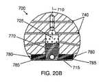
本発明の別の側面では、治療剤送達システムが、寛骨臼内に配置されるように構成される、大腿ヘッドと、大腿ヘッドに結合される、大腿ステムであって、大腿髄管内に配置されるように構成される、大腿ステムとを備える。本システムはさらに、大腿ステムに結合される、入口と、大腿ヘッドまたは大腿ステム内の複数の出口とを備え得る。治療剤は、入口から本システムの中に導入され得、治療剤は、複数の出口から寛骨臼または大腿髄管の中に送達可能であり得る。 In another aspect of the present invention, a therapeutic agent delivery system is a femoral head configured to be placed in an acetabulum and a femoral stem coupled to the femoral head, wherein the therapeutic agent delivery system is placed in the femoral canal And a femoral stem configured to be configured. The system may further comprise an inlet coupled to the femoral stem and a plurality of outlets in the femoral head or femoral stem. The therapeutic agent can be introduced into the system from the inlet and the therapeutic agent can be deliverable into the acetabulum or femoral canal from multiple outlets.
いくつかの実施形態では、大腿ステムは、ねじ山付き縮径部領域を備え、ねじ山付き縮径部領域は、大腿ヘッドと螺合して係合され、それによって、大腿ヘッドと大腿ステムとの間の距離の調節を可能にするように構成され得る。 In some embodiments, the femoral stem comprises a threaded reduced diameter region that is threadably engaged with the femoral head, thereby providing for the femoral head and the femoral stem. Can be configured to allow adjustment of the distance between the two.
いくつかの実施形態では、大腿ステムは、大腿ステムの縦方向軸に沿って軸方向に延在する、複数の突出部を備え得る。 In some embodiments, the femoral stem may comprise a plurality of protrusions that extend axially along the longitudinal axis of the femoral stem.
いくつかの実施形態では、大腿ステムは、それを通して延在する伸長チャネルを備え、チャネルは、入口および複数の出口と流体的に結合され得る。伸長チャネルは、貫通孔であり得、大腿ステムの一方の端部は、プラグを備える。 In some embodiments, the femoral stem comprises an elongated channel extending therethrough, and the channel can be fluidly coupled to the inlet and the plurality of outlets. The extension channel may be a through hole and one end of the femoral stem is provided with a plug.
いくつかの実施形態では、大腿ステムは、テーパ状にされ得る。 In some embodiments, the femoral stem can be tapered.
いくつかの実施形態では、複数の出口は、大腿ヘッド内に配置され得る。大腿ヘッドは、中央チャネルを備え、中央チャネルは、中央チャネルから半径方向に外向きに延在する複数のチャネルを介して、複数の出口と流体的に結合され得る。 In some embodiments, the plurality of outlets may be disposed in the femoral head. The femoral head includes a central channel that can be fluidly coupled to the plurality of outlets via a plurality of channels extending radially outward from the central channel.
治療剤送達システムはさらに、大腿ヘッドまたは大腿ステムからの流体除去のための出口を備え得る。 The therapeutic agent delivery system may further comprise an outlet for fluid removal from the femoral head or femoral stem.
治療剤送達システムはさらに、大腿ヘッドに結合される、寛骨臼カップを備え得、治療剤は、寛骨臼カップから寛骨臼に送達される。 The therapeutic agent delivery system may further comprise an acetabular cup coupled to the femoral head, where the therapeutic agent is delivered from the acetabular cup to the acetabulum.
いくつかの実施形態では、複数の出口は、可変直径を有する複数の孔を備え得る。 In some embodiments, the plurality of outlets may comprise a plurality of holes having a variable diameter.
いくつかの実施形態では、大腿ヘッドは、少なくとも部分的に中空であり得る。 In some embodiments, the femoral head can be at least partially hollow.
治療剤送達システムはさらに、大腿ヘッドを大腿ステムと係止するための係止機構を備え得る。 The therapeutic agent delivery system may further comprise a locking mechanism for locking the femoral head with the femoral stem.
本発明の別の側面では、関節を処置するための方法が、大腿骨の髄管内に大腿ステムを位置付けるステップと、大腿ヘッドを大腿ステムと結合するステップと、寛骨臼内に大腿ヘッドを位置付けるステップと、治療剤を髄管および寛骨臼に送達するステップとを含む。 In another aspect of the present invention, a method for treating a joint includes positioning a femoral stem within the medullary canal of the femur, coupling the femoral head with the femoral stem, and positioning the femoral head within the acetabulum. And delivering a therapeutic agent to the medullary canal and acetabulum.
いくつかの実施形態では、結合するステップは、大腿ヘッドと大腿ヘッドとの間の距離を調節するステップを含み得る。いくつかの実施形態では、結合するステップは、大腿ヘッドを大腿ステムと螺合して係合させるステップを含み得る。 In some embodiments, coupling may include adjusting the distance between the femoral head and the femoral head. In some embodiments, the coupling step can include threading and engaging the femoral head with the femoral stem.
いくつかの実施形態では、大腿ステムを位置付けるステップは、大腿ステム上の複数の突出部を、髄管を覆う骨と係合させるステップを含み得る。 In some embodiments, positioning the femoral stem may include engaging a plurality of protrusions on the femoral stem with bone covering the medullary canal.
いくつかの実施形態では、治療剤を送達するステップは、抗生物質を送達するステップを含み得、抗生物質は、バンコマイシン、トブラマイシン、またはそれらの組み合わせを含み得る。 In some embodiments, delivering the therapeutic agent can include delivering an antibiotic, and the antibiotic can include vancomycin, tobramycin, or a combination thereof.
いくつかの実施形態では、治療剤を送達するステップは、大腿ステムの溝付き領域内に配置される1つまたはそれを上回る出口孔から治療剤を送達するステップを含み得る。 In some embodiments, delivering the therapeutic agent may include delivering the therapeutic agent from one or more exit holes located in the grooved region of the femoral stem.
いくつかの実施形態では、治療剤を送達するステップは、治療剤を、大腿ステムから髄管に、または大腿ヘッドから寛骨臼に圧送するステップを含み得る。 In some embodiments, delivering the therapeutic agent may include pumping the therapeutic agent from the femoral stem to the medullary canal or from the femoral head to the acetabulum.
本方法はさらに、髄管または寛骨臼から望ましくない流体を吸引するステップを含み得る。 The method may further comprise aspirating unwanted fluid from the medullary canal or acetabulum.
いくつかの実施形態では、大腿ステムを位置付けるステップは、大腿ステムの表面積の50%またはそれを下回るものが髄管内で骨に接触するように、髄管の中に大腿ステムを位置付けるステップを含み得る。 In some embodiments, positioning the femoral stem may include positioning the femoral stem in the medullary canal such that 50% or less of the surface area of the femoral stem contacts the bone in the medullary canal. .
本発明の別の側面では、治療剤を患者内の関節に送達するためのデバイスが、治療剤を関節に送達するための複数の出口を有する、インプラントを備え、関節は、肩関節、足首関節、または脊椎関節である。 In another aspect of the invention, a device for delivering a therapeutic agent to a joint in a patient comprises an implant having a plurality of outlets for delivering the therapeutic agent to the joint, the joint comprising a shoulder joint, an ankle joint Or a spinal joint.
これらおよび他の実施形態が、添付される図面に関連する以下の説明においてさらに詳細に説明される。
参照による組み込みThese and other embodiments are described in further detail in the following description, taken in conjunction with the accompanying drawings.
Include by reference
本明細書に言及される全ての公開、特許、および特許出願は、各個々の公開、特許、または特許出願が、具体的かつ個別に参照することによって組み込まれると示される場合と同程度が、参照することによって本明細書に組み込まれる。 All publications, patents, and patent applications mentioned in this specification are to the same extent as if each individual publication, patent, or patent application was shown to be incorporated by reference specifically and individually, Which is incorporated herein by reference.
本発明の新規の特徴は、添付される請求項において具体的に記載される。本発明の特徴および利点のより深い理解は、本発明の原理が利用される、例証的実施形態を記載する以下の詳細な説明と、付随の図面とを参照することによって得られるであろう。 The novel features of the invention are set forth with particularity in the appended claims. A better understanding of the features and advantages of the present invention will be obtained by reference to the following detailed description that sets forth illustrative embodiments, in which the principles of the invention are utilized, and the accompanying drawings of which:
開示されるデバイス、送達システム、および方法の具体的実施形態が、ここで、図面を参照して説明される。本発明を実施するための形態では、任意の特定の構成要素、特徴、またはステップが、本発明に不可欠であることを示唆するように意図されることはない。 Specific embodiments of the disclosed devices, delivery systems, and methods will now be described with reference to the drawings. In the detailed description, it is not intended to imply that any particular component, feature, or step is essential to the invention.
本明細書に説明されるものは、膝関節、股関節、または任意の他の関節において使用され得る、治療剤送達システムである。例えば、治療剤送達システムは、肩または足首関節、もしくは脊椎の一部を処置するために使用され得る。当業者は、他の関節もまた、本明細書に開示されるシステム、デバイス、および方法を用いて処置され得ることを理解するであろう。随意に、任意の実施形態では、治療剤送達システムは、骨の髄管内に安定して配置されるように構成される、1つまたはそれを上回る髄内ステムを備え得る。髄内ステムは、治療剤を髄管、関節空間、またはそれらの組み合わせに送達するように構成され得る。随意に、任意の実施形態では、髄内ステムが、ステムと他の構成要素との間の距離が患者に適合するように調節されることを可能にするように、またはその間の距離が固定され得るように、別の髄内ステムまたは大腿ヘッド等の別の構成要素に結合される。 Described herein are therapeutic agent delivery systems that can be used at the knee, hip, or any other joint. For example, the therapeutic agent delivery system can be used to treat a shoulder or ankle joint, or a portion of the spine. One skilled in the art will appreciate that other joints can also be treated using the systems, devices, and methods disclosed herein. Optionally, in any embodiment, the therapeutic agent delivery system may comprise one or more intramedullary stems configured to be stably placed within the medullary canal of bone. The intramedullary stem can be configured to deliver a therapeutic agent to the medullary canal, joint space, or a combination thereof. Optionally, in any embodiment, the intramedullary stem allows the distance between the stem and other components to be adjusted to fit the patient, or the distance therebetween is fixed. To be coupled to another component, such as another intramedullary stem or femoral head.
本明細書に説明される送達システムによって送達される治療剤は、任意の流体から成り得る。例えば、治療剤は、バンコマイシン、またはトブラマイシン、それらの組み合わせ、もしくはインプラント関連感染を処置するために一般的に使用される他の抗生物質等の抗生物質流体から成り得る。当業者は、任意の治療剤がまた、単独で、または抗生物質もしくは他の治療剤と組み合わせて送達され得ることを理解するであろう。他の例示的治療剤は、生理食塩水または処置されている関節もしくは髄管を灌注するために使用される他の流体を含み得る。 The therapeutic agent delivered by the delivery system described herein can consist of any fluid. For example, the therapeutic agent can consist of an antibiotic fluid such as vancomycin, or tobramycin, combinations thereof, or other antibiotics commonly used to treat implant-related infections. One skilled in the art will appreciate that any therapeutic agent can also be delivered alone or in combination with antibiotics or other therapeutic agents. Other exemplary therapeutic agents may include saline or other fluids used to irrigate the joint or medullary canal being treated.
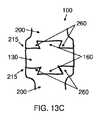
膝のための治療剤送達システム
図1Aおよび1Bは、膝のための例示的治療剤送達システム100を示す。図1Aは、ともに組み立てられた送達システムの構成要素を示す一方、図1Bは、分解され、組み立てのために整合された送達システムの構成要素を示す。送達システム100は、第1の髄内ステム110と、第2の髄内ステム120と、結合部材130とを備える。2つの髄内ステム110および120はそれぞれ、骨の髄管内に配置されるように構成されることができる。例えば、第1の髄内ステム110は、患者の大腿骨の髄管内に配置されるように構成されることができる一方、第2の髄内ステム120は、患者の腓骨の髄管内に配置されるように構成されることができる。関節空間内に配置されるように構成される結合部材130は、安定した構成において2つのステムを結合しながら、患者内の治療剤送達システムの使用の長さ全体を通して、2つのステム間に所望の距離105を維持することができる。Therapeutic Agent Delivery System for Knee FIGS. 1A and 1B show an exemplary therapeutic
第1の髄内ステム110および第2の髄内ステム120は、本明細書に説明されるような任意の髄内ステムであり得る。2つのステムは、2つの同じステムであり得る、またはそれらは、寸法、構成、もしくは特徴において1つもしくはそれを上回る差異を有するように構成される、2つの異なるステムであり得る。例えば、送達システムは、大腿骨に係合するように具体的に構成される、第1の髄内ステムと、腓骨に係合するように具体的に構成される、第2の髄内ステムとを備え得る。2つのステムは、長さ、直径、またはテーパ度等の1つもしくはそれを上回る寸法において異なり得る。代替として、または組み合わせて、2つのステムは、本明細書に説明されるような1つまたはそれを上回る構成もしくは特徴(例えば、ステムチャネルの構成、突出部、溝付き領域、ならびに/または出口孔の数、形状、およびサイズ等)において異なり得る。 The first
結合部材130は、調節可能高さマニホールドまたは固定高さ楔等、本明細書に説明されるような任意の結合部材を備え得る。送達システム100の多くの実施形態では、結合部材130は、患者の解剖学的構造に適応するように、2つのステム間の距離105が調節されることを可能にするように構成されることができる。結合部材は、髄管への送達のために、治療剤の源に流体的に結合し、治療剤を受容し、治療剤を髄内ステムに分配するように構成されることができる。 The
第1のステム110および第2のステム120は、結合部材130に解放可能に結合され得る。第1のステムおよび第2のステムはそれぞれ、結合部材のステムコネクタ132に結合するように構成され得る。第1のステムは、第1のステムコネクタ132aに結合し得、第2のステムは、第2のステムコネクタ132bに結合し得る。ステムと結合部材との間の接続に関する種々の機構が、本明細書に説明され、そのいずれかが、第1のステムまたは第2のステムとの結合のために結合部材130の中に組み込まれ得る。第1のステムおよび第2のステムは、同じ機構を介して、または異なる機構を介して、それぞれ、第1のステムコネクタおよび第2のステムコネクタに結合し得る。故に、結合部材の第1のステムコネクタ132aおよび第2のステムコネクタ132bは、同じである、または異なり得る。好ましい実施形態では、第1のステムおよび第2のステムは、同じであり、したがって、結合部材は、適宜、同じ機構を介して第1のステムおよび第2のステムに結合するように構成される、2つの同じステムコネクタを備える。 The
髄内ステム
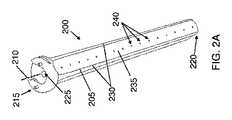
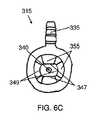
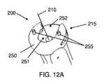
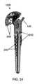
図2A−2Cは、膝のための治療剤送達システムとの組み込みのために好適な例示的髄内ステム200を示す。図2Aは、髄内ステム200の斜視図であり、図2Bおよび2Cは、その側面図である。各髄内ステム200は、縦方向軸210を有する伸長本体205を備え、伸長本体は、第1の端部215と、第1の端部に対向する第2の端部220とを有する。第1または近位の端部は、本明細書に説明されるような調節可能高さマニホールドまたは固定高さ楔等の結合部材130に結合するように構成され得る。第2または遠位の端部は、骨の髄管内に配置され得る。伸長本体205は、第1の端部215と第2の端部220との間に延在するステムチャネル225を備え、ステムチャネルは、治療剤をステムを通して髄管に送達するように構成される。髄内ステム200の第1の端部215は、ステムを結合部材に結合するように構成され得る。第1の端部は、本明細書にさらに詳細に説明されるように、ステムを結合部材に接続するための任意の機構(例えば、フランジ付き領域、ダブテールジョイント、スナップバックル、蝶ナット等)を備え得る。Intramedullary Stem FIGS. 2A-2C illustrate an exemplary intramedullary stem 200 suitable for incorporation with a therapeutic agent delivery system for the knee. FIG. 2A is a perspective view of the
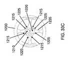
髄内ステム200は、伸長本体205から半径方向に外向きに突出する、複数の突出部230を備え得る。複数の突出部は、安定した方式で髄管に係合するための任意の適切な形状、サイズ、または構成を有する、任意の数の突出部を備え得る。例えば、突出部は、図2A−2Cに示されるように、伸長本体の縦方向長さに沿って延在する、伸長フィンを備え得る。一例示的実施形態では、複数の突出部は、伸長本体の縦方向軸210を中心として約90°に等しく離間される、4つのフィンを備え得る。複数の突出部230および伸長本体205は、別個に形成され、ともに結合され得る。代替として、または組み合わせて、複数の突出部230は、複数の突出部および伸長本体が単一部材として形成されるように、伸長本体205から材料を除去することによって形成され得る。隣接する突出部230は、その間に1つまたはそれを上回る溝付き領域235を画定し、溝付き領域は、突出部と比較して半径方向に陥凹を有し得る。溝付き領域は、隣接する突出部間に凹状陥凹付き領域を形成し得る。 The
複数の突出部および溝付き領域は、髄管を覆う骨に接触するステムの表面積を最小限にするように構成されることができ、したがって、治療剤を豊富に有する骨の面積は、最大限にされ得る。例えば、複数の突出部および溝付き領域は、ステムの表面積の50%を下回るものが髄管を覆う骨と接触するように構成されることができる。当然ながら、これは、限定することを意図されず、当業者は、ステムの任意の割合の表面積が骨に接触し得ることを理解するであろう。ステムは、図2A−2Cに示されるように、ステムの縦方向軸210を中心として対称的に分散される、複数の伸長フィンによって画定される複数の同じ溝付き領域を備え得る。代替として、複数の溝付き領域は、ステムの縦方向軸を中心として非対称的に分散され得る、および/または本明細書にさらに詳細に説明されるような異なる形状もしくはサイズを有し得る。 Multiple protrusions and fluted regions can be configured to minimize the surface area of the stem that contacts the bone covering the medullary canal, and thus the area of bone rich in therapeutic agents is maximized Can be. For example, the plurality of protrusions and grooved regions can be configured such that less than 50% of the surface area of the stem contacts the bone that covers the medullary canal. Of course, this is not intended to be limiting and those skilled in the art will appreciate that any percentage of the surface area of the stem can contact the bone. The stem may comprise a plurality of identical grooved regions defined by a plurality of elongated fins that are symmetrically distributed about the
髄内ステム200はさらに、ステムチャネル225と流体連通する複数の出口孔240を備え得る。複数の出口孔240は、ステムチャネル225を通して分配される治療剤を、髄管ならびに関節を含む隣接する組織に送達するように構成され得る。複数の出口孔は、髄内ステムと接触しない骨の面積に治療剤を送達するように、溝付き領域235内に配置され得る。複数の出口孔は、任意の適切なサイズ、形状、または分布を有する任意の数の出口孔を備え得る。例えば、複数の出口孔は、図2A−2Cに示されるように、ステムの縦方向軸210に略平行な線に沿って軸方向に延在する、複数の等しく定寸および離間された孔を含み得る。複数の出口孔は、本明細書にさらに詳細に説明されるように、種々の構成において配列され得る。複数の出口孔は、同じ形状および/もしくはサイズを有する孔または種々の形状および/もしくはサイズを有する孔を備え得る。孔サイズを変動させることは、治療剤がステムの異なる領域から退出する際のそのさらなる流体制御を可能にし得る。
ステムチャネル225は、第1の端部215から第2の端部220に第1の端部および第2の端部の両方を通して延在する貫通孔であり得、したがって、伸長本体は、開放された第2または遠位の端部を備える。本システムはさらに、第2の端部を閉鎖し、それによって、行き止まりチャネルを作成するように、ステムの開放された第2の端部に結合するように構成されるプラグ(図示せず)を備え得る。代替として、ステムチャネル225は、行き止まりチャネルであり得、伸長本体の第2の端部は、閉鎖される。第2の端部が開放される構成では、治療剤は、第2の端部を通して、および/または本明細書に説明されるような伸長本体205に沿って配置される複数の出口孔を通して、ステムチャネルから髄管の中に退出し得る。ステムが、複数の出口孔を伴わず、第1および第2の端部を通して延在するステムチャネル225のみを備える場合、治療剤は、第2の端部のみを通してステムチャネルから退出し得る。ステムの第2の端部が閉鎖される構成では、治療剤は、複数の出口孔のみを通してステムチャネルから髄管の中に退出し得る。 The
髄内ステム200は、髄管に嵌合するようにテーパ状にされ得る。例えば、伸長本体205および/または複数の突出部230は、示されるように、第1の端部よりも第2の端部において小さい半径方向断面積を有するように、第1の端部215から第2の端部220にかけてテーパ状にされ得る。例えば、テーパは、漸進テーパから成り得、テーパの程度は、好ましくは、約0.1°〜約10°、より好ましくは、約0.5°〜約5°、さらにより好ましくは、約1°〜約5°、または約1°〜約4°の範囲内、もしくは約2°、もしくは約3°であり得る。テーパは、具体的タイプの骨の髄管に適応するように調節され得る。 The
図2A−2Cの例示的実施形態は、図1Aおよび1Bに示されるような膝のための治療剤送達システムの2つの髄内ステムの一方または両方を備え得る。好ましくは、膝のための治療剤送達システムは、図2A−2Cの例示的実施形態等の2つの同じ髄内ステムを備える。 The exemplary embodiment of FIGS. 2A-2C may comprise one or both of the two intramedullary stems of a therapeutic agent delivery system for the knee as shown in FIGS. 1A and 1B. Preferably, the therapeutic agent delivery system for the knee comprises two identical intramedullary stems such as the exemplary embodiment of FIGS. 2A-2C.
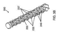
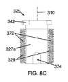
図3Aおよび3Bは、図2A−2Cの髄内ステム200の伸長本体205の代替実施形態を示す。図3Aは、本体の縦方向長さに沿って伸長本体205の周囲に渦巻状に配置される、1つまたはそれを上回る突出部231を備える、伸長本体205を示す。隣接する渦巻または螺旋突出部231は、また、伸長本体の周囲に渦巻状に配置される、その間の1つまたはそれを上回る溝付き領域236を画定する。図3Bは、図3Aに示される渦巻状に配置される突出部231の一部を切断または別様に除去することからもたらされる、複数の突出部232を備える、伸長本体205を示す。例えば、示されるように、複数の半径方向切断は、複数の突出部232を画定するように伸長本体に成され得る。複数の溝付き領域237が、隣接する螺旋突出部の残りの部分間に画定され得る。図3Bに示されるように渦巻突出部231の一部を切断または除去することは、ステムと骨との間の接触面積をさらに減少させ、したがって、治療剤が髄管に沿ってより自由に流動することを可能にすることができる。 3A and 3B show an alternative embodiment of the
図3Aの実施形態では、複数の出口孔(図示せず)が、螺旋または渦巻溝付き領域236に沿って等、螺旋または渦巻線に沿って延在し得る。図3Bに示される実施形態では、複数の出口孔240は、溝付き領域237内に配置され得、したがって、孔は、伸長本体の円周の周囲で複数のリングを中心として延在する。 In the embodiment of FIG. 3A, a plurality of outlet holes (not shown) may extend along the spiral or spiral, such as along the spiral or spiral
調節可能高さマニホールド
図4A−4Bは、図1A−1B等における膝のための治療剤送達システムとの組み込みのために好適な調節可能高さマニホールド300を示す。調節可能高さマニホールド300は、安定した構成において2つの髄内ステムを結合しながら、患者内の治療剤送達システムの使用の長さ全体を通して、2つのステム間に所望の距離を維持し得る、結合部材の一実施例である。調節可能高さマニホールドはさらに、2つのステム間の距離の調節を可能にし、したがって、送達システムは、患者の解剖学的構造に最適に適応するように構成され得る。調節可能高さマニホールド300は、筐体315と、回転ナット320と、調節可能コネクタ325とを備え得る。回転ナット320および調節可能コネクタ325は、筐体315に結合され、患者に関する2つのステム間の所望の設定距離に基づいて、マニホールド高さ305が増加または減少されることを可能にするように構成され得る。時計回りおよび反時計回り方向にナット320を回転させることは、マニホールドの縦方向軸310に沿って調節可能コネクタを平行移動させることによって、マニホールドを圧潰または延在させることができる。図4Aは、マニホールド高さ305が、比較的に短く、マニホードが、したがって、2つの膝ステム間のより短い設定距離を要求する患者に適合し得るように、圧潰された構成における調節可能高さマニホールド300を示す。図4Bは、マニホールド高さ305が、比較的に長く、マニホードが、したがって、2つの膝ステム間のより長い設定距離を要求する患者に適合し得るように、延在された構成における調節可能高さマニホールド300を示す。Adjustable Height Manifold FIGS. 4A-4B illustrate an
調節可能高さマニホールド300はさらに、筐体の対向する側上に配置される、第1のステムコネクタ342および第2のステムコネクタ344を備える。第1のステムコネクタ342は、第1の髄内ステムの第1の端部に結合するように構成され得、第2のステムコネクタ344は、第2の髄内ステムの第1の端部に結合するように構成され得る。第1のステムコネクタ342は、調節可能コネクタ325に結合され得る一方、第2のステムコネクタ344は、筐体315に結合され得る。各ステムコネクタは、髄内ステムの第1の端部上に配置される、対応する接続機構に結合するための接続機構を備え得る。第1および第2のステムコネクタは、異なる接続機構を備え得る、またはそれらは、同じ接続機構を備え得る。好ましい実施形態では、第1および第2のステムコネクタは、同じ接続機構を備え、相互に対して固定された配向を有し、したがって、配向は、マニホールド高さを調節するための調節可能高さマニホールドの作動中に同じままである。相互に対する2つのステムコネクタの固定された配向は、両方のステムに対して同一の作動運動を使用する患者内への送達システムの埋込中、各ステムへのマニホールドの適切かつ同時の結合を可能にすることができる。
図5は、図4A−4Bの調節可能高さマニホールド300の分解図である。調節可能高さマニホールド300は、筐体315と、オペレータの指に対する把持領域を提供するためのスカラップ外面および内部ねじ山を有する回転ナット320と、調節可能コネクタ325とを備え、3つの構成要素は、マニホールドの縦方向軸310に沿って軸方向に整合される。マニホールドはさらに、調節可能コネクタの筐体への結合を確実にし、調節可能コネクタの運動の範囲を制御するように構成される、マニホールドピン330を備える。調節可能コネクタは、第1の髄内ステムに結合するように構成される、第1のステムコネクタ342を備える。筐体は、第2の髄内ステムに結合するように構成される、第2のステムコネクタ344を備える。筐体はさらに、それに結合される入口335を備え、入口は、患者に送達されるべき治療剤の源(図示せず)に流体的に結合するように構成される。筐体は、回転ナットに結合し、調節可能コネクタを摺動可能に受容するように構成される。回転ナットは、ナットが回転されると、調節可能コネクタを縦方向軸310に沿って筐体から外向きに延在させる、または縦方向軸に沿って筐体の中に内向きに後退させるように、調節可能コネクタに螺合して係合するように構成される。 FIG. 5 is an exploded view of the
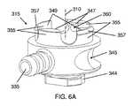
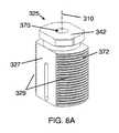
図6A−6Eは、図4A−4Bの調節可能高さマニホールド300の筐体315の例示的実施形態を示す。図6Aは、筐体315の斜視図であり、図6Bは、その側面図であり、図6Cは、その上面図であり、図6Dは、その底面図であり、図6Eは、その垂直断面図(図6Bの断面A−A)である。筐体315は、治療剤の源に流体的に結合するための入口335と、筐体を通して縦方向軸310に沿って延在する筐体チャネル340(図6Eに最良に見られる)とを備える。筐体チャネル340は、入口335と流体連通し、したがって、入口を通して治療剤送達システムに追加された治療剤は、筐体チャネルを通して送達システムの他の構成要素に分配されることができる。入口335は、治療剤を供給する管(図28Aに最良に見られる)の内面に確実に係合するために、返し付き外面を備え得る。筐体はさらに、筐体の円周を中心として少なくとも部分的に、または完全に配置され、それによって、管類/筐体アセンブリの外形を最小限にする、凹状溝345を備え得る。溝は、入口335に結合され、治療剤を供給する管類の配置を可能にすることができる。 6A-6E illustrate an exemplary embodiment of the
筐体315はさらに、本明細書に説明される任意の髄内ステム等の髄内ステムに結合するように構成される、第2のステムコネクタ344を備える。筐体チャネル340は、ステムコネクタ344を通して延在することができ、したがって、筐体チャネルは、ステムコネクタに結合されるステムのステムチャネルに流体的に結合されることができる。ステムコネクタ344は、本明細書にさらに詳細に説明されるように、結合部材をステムに接続するための任意の機構(例えば、フランジ付き領域、ダブテールジョイント、スナップバックル、蝶ナット等)を備え得る。 The
筐体チャネル340は、チャネル内に配置される調節可能コネクタが縦方向軸310に沿って軸方向に摺動することを可能にする一方、調節可能コネクタがチャネル内で回転しないように防止する幾何学的形状を有するように構成され得る。例えば、チャネル340は、相互に対向して配置され、調節可能コネクタの2つの平坦側面とインターフェースをとるように構成される、2つの平坦内面347を備え得る。チャネルはさらに、調節可能コネクタの2つの対応する丸形面とインターフェースをとるように構成される、2つの丸形側内面349を備え得る。例えば、丸形内面347は、凹状面を備え得る一方、調節可能コネクタの丸形側面は、凸状面を備え得る。調節可能コネクタの平坦側面との筐体チャネルの平坦内面のインターフェースは、調節可能コネクタがその中で回転しないように防止し、調節可能コネクタが筐体チャネル内で回転可能ではなく、摺動可能でのみ移動することを確実にすることができる。第1のステムコネクタ342を備える、調節可能コネクタの回転を防止することは、回転ナット320が回転されているときであっても、第2のステムコネクタ344の配向が第1のステムコネクタの配向に対して固定されたままであることを確実にすることができる。相互に対する第1および第2のステムコネクタの固定された配向は、マニホールドが第1のステムおよび第2のステムの両方に容易に結合し得ることを確実にすることができる。例えば、マニホールドは、第1および第2のステム間の空間の中に挿入され、次いで、1つの方向に回転され、両方のステムに結合することができる。ステムコネクタのそのような構成は、ステムが患者の髄腔の中にすでに挿入された後、1つまたはそれを上回る髄内ステムを回転させる潜在的必要性を不要にすることによって、患者内への送達システムの埋込を促進することができる。 The
筐体はさらに、筐体チャネル340の周辺を中心として配置され、筐体から縦方向に突出する、1つまたはそれを上回る突起355を備え得る。突起は、図6A−6Eに示されるような4つの突起を備え、突起の各内面は、筐体チャネル内に配置されるべき調節可能コネクタの4つの側のそれぞれに係合するように構成され得る。相互に対向して配置される突起のうちの2つは、筐体チャネルの平坦内面347を有するように構成されることができる一方、また、相互に対向して配置される残りの突起のうちの2つは、筐体チャネルの丸形内面349を有するように構成されることができる。突起のうちの1つまたはそれを上回るものはさらに、突起の縁に配置される、外向きに面する辺縁357を備え得る。辺縁357は、回転ナットを筐体に確実に結合し、ナットの回転中に縦方向軸310に沿った回転ナットの軸方向移動を防止するように、本明細書にさらに詳細に説明されるような回転ナット内の対応するマニホールド溝に係合するように構成され得る。辺縁357はさらに、辺縁をナットのマニホールド溝の中に誘導することによって、筐体への回転ナットの結合を促進するように構成される、面取り部359を備え得る。 The housing may further include one or
筐体はさらに、マニホールドピンの一部を受容するように構成される、筐体ピン孔360を備え得る。ピン孔360は、回転ナットに係合するように構成される突起355上に配置され得、したがって、ピン孔360は、また、マニホールドピンを受容するように構成される、回転ナット内のナットピン孔と整合されることができる。完全に組み立てられると、マニホールドピンは、本明細書にさらに説明されるように、筐体内に部分的に配置され、筐体チャネル内に配置される調節可能コネクタ内のスロット内に部分的に配置され、マニホールドアセンブリが分解されないように防止するためのハードストップを作成することができる。筐体ピン孔360は、ピン孔内のマニホールドピンの保定を確実にするように寸法決定され得る。例えば、筐体ピン孔は、筐体内に配置されるように構成されるマニホールドピンの一部の直径に実質的に等しい直径を有することができ、したがって、ピンは、筐体ピン孔の中に圧入されることができる。 The housing may further comprise a
図7A−7Cは、図4A−4Bの調節可能高さマニホールド300の回転ナット320の例示的実施形態を示す。図7Aは、回転ナット320の斜視図であり、図7Bは、その上面図であり、図7Cは、その垂直断面図(図7Bの断面A−A)である。回転ナット320は、その内面の一部上に配置される、複数のねじ山362を備える。ねじ山362は、調節可能コネクタの一部上の対応するねじ山に係合するように構成され得、したがって、調節可能コネクタを中心としたナット320の回転は、マニホールドの縦方向軸に沿った調節可能コネクタの軸方向移動を引き起こすことができる。ナット320はさらに、ナットの内面を中心として円周方向に配置される、マニホールド溝364を備え得る。マニホールド溝は、ナットを筐体上に係止しながら、依然として、筐体に対するナットの回転を可能にするように、本明細書に説明されるような筐体の1つまたはそれを上回る突起上に配置される1つもしくはそれを上回る辺縁を受容するように構成され得る。ナットはさらに、マニホールド溝の下方に配置され、ナットの内面を中心として円周方向に延在する、面取り部366を備え得る。面取り部366は、辺縁をマニホールド溝の中に誘導するように、筐体辺縁の面取り部に対応するように構成されることができる。ナットはさらに、ねじ山362の下方のナットの一部上に配置される、ナットピン孔368を備え、ナットピン孔は、それを通してマニホールドピンを受容するように構成され得る。マニホールドの組立中、マニホールドピンは、回転ナットの本体の中に、それを通して完全に押動され、ピンを筐体内に部分的に、かつ調節可能コネクタ内に部分的に配置し、それによって、ピンによるナットの回転の物理的妨害を回避し得る。故に、マニホールドが完全に組み立てられると、マニホールドピンは、回転ナットのいずれの部分も横断せず、したがって、回転ナットは、自由に回転することができる。ナットピン孔368は、ピン孔の中へのそれを通したマニホールドピンの挿入を促進するように寸法決定され得る。例えば、ナットピン孔は、マニホールドピンの最大部分の直径を上回る直径を有することができ、したがって、ピンは、ナットピン孔を容易に通過することができる。 7A-7C illustrate an exemplary embodiment of the
図8A−8Dは、図4A−4Bの調節可能高さマニホールド300の調節可能コネクタ325の例示的実施形態を示す。図8Aは、斜視図であり、図8Bは、底面図であり、図8Cおよび8Dは、側面図である。調節可能コネクタ325は、縦方向軸310に沿って軸方向に延在する、調節可能コネクタチャネル370を備える。チャネル370は、調節可能コネクタの長さを通して延在し、筐体チャネル340と、したがって、筐体チャネルに流体的に結合される入口335と流体連通するように構成される。調節可能コネクタはさらに、本明細書に説明される任意の髄内ステム等の髄内ステムに結合するように構成される、第1のステムコネクタ342を備える。コネクタチャネル370は、ステムコネクタ342を通して軸方向に延在し、したがって、チャネル370は、第1のステムコネクタ342に結合されるステムのステムチャネルと流体連通する。ステムコネクタ342は、本明細書にさらに詳細に説明されるように、結合部材をステムに接続するための任意の機構(例えば、フランジ付き領域、ダブテールジョイント、スナップバックル、蝶ナット等)を備え得る。 8A-8D show an exemplary embodiment of
調節可能コネクタはさらに、回転ナットの対応するねじ山に係合するように構成される、ねじ山372を備え得、したがって、ナットの回転は、筐体の中への、またはその外への調節可能コネクタの垂直移動を引き起こすことができる。調節可能コネクタは、2つの平坦側面327と、2つの丸形側面329とを備え得、平坦側面は、筐体チャネルの平坦内面とインターフェースをとるように構成され得、丸形側面は、筐体チャネルの丸形内面とインターフェースをとるように構成され得る。本明細書に説明されるように、そのような構成は、回転ナットが回転されるとき、調節可能コネクタが回転しないように防止し、調節可能コネクタ、したがって、第1のステムコネクタ342の配向が、第2のステムコネクタの配向に対して一定のままであることを確実にすることができる。さらに、これは、ナットの回転作動を調節可能コネクタの線形運動に変換する。 The adjustable connector may further comprise a
図8Cは、筐体の入口に対して近位に配向されるように構成される、調節可能コネクタの近位平坦側面327aを示す。近位平坦側面は、調節可能コネクタの底部を通して延在する、開放スロット374を有するように構成されることができる。開放スロット374は、調節可能コネクタの底面図を示す図8Bに最良に見られるように、調節可能コネクタチャネル370に流体的に結合され得る。開放スロット374は、組み立てられたマニホールドが、図4Aに示されるような圧潰された構成にあるとき、開放スロットが、調節可能コネクタチャネル370に入口を流体的に結合するように、入口と整合されるように構成され得る。組み立てられたマニホールドが、図4Bに示されるような延在された位置にあるとき、開放スロット374の開放底部は、入口が筐体チャネルと流体連通したままであり、それによって、調節可能コネクタチャネルと流体連通したままであることを確実にすることができる。 FIG. 8C shows the proximal
図8Dは、筐体の入口に対して遠位に配向されるように構成される、調節可能コネクタの遠位平坦側面327bを示す。遠位平坦側面は、筐体内に保定されるマニホールドピンの一部に係合するように構成される、閉鎖スロット376を備える。本明細書に説明されるように、マニホールドピンは、筐体、回転ナット、および調節可能コネクタがともに組み立てられた後、マニホールドアセンブリに結合され得る。完全組立後、マニホールドピンは、筐体内に部分的に配置され、調節可能コネクタの閉鎖スロット376内に部分的に配置され得る。マニホールドピンは、調節可能コネクタの後退または延在中、閉鎖スロット376内に係合されたままであるように構成されることができる。閉鎖スロットは、調節可能コネクタの移動を促進するように、スロット内に配置されるマニホールドピンの一部の直径を上回る幅を有するように構成され得る。組み立てられたマニホールドが、図4Aに示されるような圧潰された構成にあるとき、マニホールドピンは、閉鎖スロット376の上部と整合され得る。組み立てられたマニホールドが、図4Bに示されるような延在された構成にあるとき、マニホールドピンは、閉鎖スロット376の底部と整合され得る。閉鎖スロット376の底部は、筐体からの調節可能コネクタの延在に対するハードストップを提供し、調節可能コネクタがそれ以上延在しないように防止する。したがって、閉鎖スロット376およびマニホールドピンは、マニホールドアセンブリが分解しないように防止することができる。 FIG. 8D shows the distal
図9は、図4A−4Bの調節可能高さマニホールド300のマニホールドピン330の例示的実施形態を示す。マニホールドピン330は、小直径部分332と、大直径部分334とを備え得る。小直径部分332は、調節可能コネクタ内の閉鎖スロットに係合するように構成され得る一方、大直径部分334は、筐体内のマニホールドピン孔内に配置されるように構成され得る。本明細書に説明されるように、マニホールドピンは、ピンを回転ナット内のナットピン孔を通して挿入することによって、マニホールドアセンブリに結合され得る。回転ナットを通したマニホールドピンの挿入を促進するために、大直径部分334は、ナットピン孔の直径よりも小さい直径を有し得る。筐体内のマニホールドピンの保定を確実にするために、大直径部分334は、筐体ピン孔の直径に実質的に等しい直径を有し得、したがって、大直径部分は、筐体ピン孔の中に圧入される。筐体チャネル内の調節可能コネクタの平行移動運動を促進するために、小直径部分322は、調節可能コネクタの閉鎖スロットの幅よりも小さい直径を有し得る。 FIG. 9 illustrates an exemplary embodiment of the
図10Aは、図4Aに示されるように、圧壊された構成における組み立てられた調節可能高さマニホールド300の上面図であり、図10Bは、その垂直断面図(図10Aの断面A−A)である。筐体315は、ナットのマニホールド溝364との辺縁357の係合を介して回転ナット320に結合される。調節可能コネクタ325は、筐体チャネル340内に摺動可能に配置され、回転ナット320と螺合して係合される。マニホールドピン330の大直径部分334は、筐体ピン孔360内に配置される一方、小直径部分332は、調節可能コネクタの閉鎖スロット376内に配置される。回転ナットが時計回りまたは反時計回りに回転されると、調節可能コネクタは、回転することなく筐体チャネル内で上または下に摺動することができる。マニホールドピンは、ピンが閉鎖スロット376の底部に衝突するとき、ハードストップを提供することによって、調節可能コネクタが延在され得る範囲を制御することができる。筐体の入口335は、患者に送達されるべき治療剤の源に結合されることができる。入口は、調節可能コネクタの開放スロット374を通して、直接または間接的のいずれかで筐体チャネル340に流体的に接続されることができる。マニホールドが圧潰された構成にあるとき、入口は、調節可能コネクタの開放スロット374を通して、間接的に筐体チャネルに流体的に結合されることができる。マニホールドが延在された構成にあるとき、入口は、筐体チャネルに直接流体的に結合され得る。筐体チャネルは、調節可能コネクタの第1のステムコネクタに結合される、第1のステムのステムチャネルに流体的に接続するように、調節可能コネクタチャネル370に流体的に接続されることができる。筐体チャネルはまた、筐体の第2のステムコネクタに結合される、第2のステムのステムチャネルに流体的に接続されることができる。したがって、入口335を介して提供される治療剤は、マニホールドに結合される第1および第2の髄内ステムに分配されることができる。 FIG. 10A is a top view of the assembled
固定高さ楔
図11A−11Cは、膝のための治療剤送達システムとの組み込みのために好適な固定高さ楔400を示す。図11Aは、楔400の斜視図を示し、図11Bおよび11Cは、その側面図を示す。固定高さ楔400は、安定した構成において2つの髄内ステムを結合しながら、患者内の治療剤送達システムの使用の長さ全体を通して、2つのステム間に所望の距離を維持し得る、結合部材130の一実施例である。楔は、2つの髄内ステム間に比較的に単純な接続を提供し、楔は、複数の構成要素のアセンブリではなく、単一モノリシック構成要素を備える。楔の楔高さ405は固定されるが、楔は、種々の楔高さを有する複数のサイズにおいて提供され得、最も適切なサイズが、患者の解剖学的構造に従って患者毎に選択され得る。Fixed Height Wedges FIGS. 11A-11C illustrate a fixed
固定高さ楔400は、第1の髄内ステムに結合するように構成される、第1のステムコネクタ442と、第2の髄内ステムに結合するように構成される、第2のステムコネクタ444とを備える。第1および第2のステムコネクタは、本明細書にさらに詳細に説明されるように、ステムを結合部材に接続するための任意の機構(例えば、フランジ付き領域、ダブテールジョイント、スナップバックル、蝶ナット等)を備え得る。楔はさらに、患者に送達されるべき治療剤の源に結合されるように構成される、入口435を備える。入口435は、第1のステムコネクタおよび第2のステムコネクタの両方を通して、楔の縦方向軸410に沿って延在する、楔チャネル440に流体的に接続されることができる。したがって、入口を通して提供される治療剤は、楔に結合される髄内ステムに楔チャネルを介して分配されることができる。 Fixed
固定高さ楔400は、加えて、調節可能高さマニホールド300に関連して説明される任意の適用可能な構造および特徴のうちの1つまたはそれを上回るものを備え得る。例えば、楔は、調節可能高さマニホールドの筐体に関連して説明される凹状溝345に類似する凹状溝445を備え得る。凹状溝345と同様に、凹状溝445は、入口に結合される管類の配置を提供するように、楔の円周を中心として部分的に配置され得る。 The fixed
結合機構
図12A−12Hは、髄内ステム200を結合部材130に結合するための例示的機構を図示する。ステム200は、本明細書に説明されるような髄内ステムの任意の実施形態から成り得、結合部材130は、本明細書に説明されるような結合部材の任意の実施形態から成り得る。ステム200は、結合部材に係合するように構成される、第1の端部215を備え、結合部材130は、ステムの第1の端部に係合するように構成される、ステムコネクタ132を備える。ステムコネクタ132は、説明されるような任意の結合部材に結合される、任意のステムコネクタ(例えば、ステムコネクタ342、344、442、444等)であり得る。図12Aは、髄内ステム200の第1の端部215の斜視図である。図12Bは、結合部材130のステムコネクタ132の斜視図である。図12Cおよび12Dは、組立前の治療剤送達システム100の側面図である。図12Eは、ともに結合される2つのステム200および結合部材130を備える、組み立てられた送達システム100の側面図である。図12Fは、図12Cに示されるような組み立てられたシステム100の一部の拡大垂直断面図である。図12Gおよび12Hは、組立の異なるステップにおける、図12Eに示されるような線A−Aに沿った組み立てられたシステム100の半径方向断面である。Coupling Mechanism FIGS. 12A-12H illustrate an exemplary mechanism for coupling
図12Aに示されるように、第1の端部215は、第1の端部の周辺の一部を中心として配置される、隆起部分250を備える。隆起部分250は、図12Bに示されるような結合部材130のフランジ付き領域150を受容するように構成される、丸形空洞251をその中に画定する。隆起部分250は、それを通して結合部材のフランジ付き領域150を受容するように構成される、円周開口部252を有する。隆起部分250はさらに、図12Fに最良に見られるように、陥凹付き領域254を画定する、陥凹付き辺縁253を備える。陥凹付き領域254は、ステムの縦方向軸210に沿った結合部材の軸方向移動を限定するように、フランジ付き領域150を受容および保定することができる。図12Eおよび12Fに示されるように、フランジ付き領域150は、幅152よりも長い長さ154を有することができる。フランジ付き領域はさらに、フランジ付き領域の長さ154に沿って延在する2つの平坦縁157と、フランジ付き領域の幅152を中心として延在する2つの丸形縁159とを備えることができる。円周開口部252は、図12Gに示されるように、フランジ付き領域150の幅152を上回る、またはそれに等しいが、フランジ付き領域の長さ154を下回る幅を有し得、したがって、フランジ付き領域は、円周開口部252に対して垂直配向151においてのみ円周開口部に進入することができる。 As shown in FIG. 12A, the
図12Cおよび12Dは、組立前の送達システム100を示し、結合部材130は、2つの髄内ステム200間の空間の中への挿入のために整合される。第1のステムコネクタ132aおよび第2のステムコネクタ132bのフランジ付き領域150は、髄内ステムの隆起部分の円周開口部252に対して垂直配向にある。本配向において整合されているが、結合部材は、図12E、12F、および12Gに示されるように、2つの髄内ステム間の空間の中に押動され得、したがって、フランジ付き領域は、各ステムの円周開口部を通して挿入され、隆起部分の陥凹付き領域の中に捕捉される。 12C and 12D show the
いったんフランジ付き領域150が、丸形空洞251内に配置されると、フランジ付き領域は、図12Gに示されるように、矢印155によって示される方向に回転され得る。フランジ付き領域は、図12Hに示されるように、フランジ付き領域が円周開口部252に対して水平方向153に配置されるまで回転され得る。水平配向では、フランジ付き領域は、フランジ付き領域の長さ154が開口部252のサイズを上回るため、円周開口部を通して丸形空洞から摺抜しないように防止されることができる。第1の端部215はさらに、ステムとステム接続との間の結合をさらに確実にするように構成される、その中に配置される1つまたはそれを上回るピン255を備え得る。例えば、第1の端部215は、2つのピン255を備え、各ピンは、円周開口部252の中心から約90°に角度離間され得る。フランジ付き領域150の各丸形縁159は、より小さい直径の縁159aと、より大きい直径の縁159bとを備え得、したがって、切り欠き156が、縁159aおよび159bの交差点において作成される。説明されるように、フランジ付き領域150は、図12Gに示されるような垂直配向151における開口部252を通して挿入され、続けて、第1の端部215の陥凹付き領域254内で矢印155によって示される方向に回転され得る。フランジ付き領域が回転するにつれて、ピン255は、ピンがより大きい直径の縁159bによって作成される切り欠き156に衝突するまで、より小さい直径の縁159aに対して摺動することができる。ピンは、例えば、フランジ付き領域が、ピンに衝突する前に約90°または4分の1回転だけ回転することを可能にするように構成され得る。ピン255との切り欠き156の係合は、結合部材に対するステムのさらなる回転を防止することができる。ピン255は、したがって、フランジ付き領域の回転に対するハードストップを提供し、フランジ付き領域の最終配向が水平配向153であることを確実にすることができ、これは、フランジ付き領域が本明細書に説明されるような丸形空洞から摺抜しないように防止することができる。 Once the
図13A−13Cは、髄内ステムを結合部材130に結合するための別の例示的機構を図示する。図13Aは、例示的接続機構を備える結合部材130の斜視図を示し、図13Bは、その上面図を示す。図13Cは、ともに結合される2つのステム200および結合部材130を備える、組み立てられた送達システム100の一部の側面図を示す。ステム200は、本明細書に説明されるような髄内ステムの任意の実施形態から成り得、結合部材130は、本明細書に説明されるような結合部材の任意の実施形態から成り得る。ステム200は、結合部材に係合するように構成される、第1の端部215を備え、結合部材130は、ステムの第1の端部に係合するように構成される、ステムコネクタ132を備える。ステムコネクタ132は、説明されるような任意の結合部材に結合される、任意のステムコネクタ(例えば、ステムコネクタ342、344、442、444等)であり得る。各ステムコネクタ132は、ステム200の第1の端部215の1つまたはそれを上回る対応するダブテール付き領域260に係合するように構成される、1つまたはそれを上回るダブテール付き領域160を備え得る。各ステムコネクタ132はさらに、ステムの第1の端部215上に配置される対応するスナップバックル(図示せず)に係合するように構成される、スナップバックル162を備え得る。スナップバックル162は、結合部材130がステム200の中に摺動式に挿入されると、中心に引っ張り得る可撓性ステム164を備えることができる。結合部材は、結合部材がステム内で切り欠き166を過ぎて押動されると、定位置にスナップ嵌合することができる。 13A-13C illustrate another exemplary mechanism for coupling the intramedullary stem to the
図14Aおよび14Bは、髄内ステム200を結合部材130に結合するための別の例示的機構を図示する。図14Aは、例示的機構を使用するステムおよび結合部材の組立の第1のステップを示し、図14Bは、組立の第2のステップを示す。ステム200は、本明細書に説明されるような髄内ステムの任意の実施形態から成り得、結合部材130は、本明細書に説明されるような結合部材の任意の実施形態から成り得る。ステム200は、結合部材に係合するように構成される、第1の端部215を備え、結合部材130は、ステムの第1の端部に係合するように構成される、ステムコネクタ132を備える。ステムコネクタ132は、説明されるような任意の結合部材に結合される、任意のステムコネクタ(例えば、ステムコネクタ342、344、442、444等)であり得る。各ステムコネクタ132は、ステム200の第1の端部215の1つまたはそれを上回る対応するダブテール付き領域260に係合するように構成される、1つまたはそれを上回るダブテール付き領域160を備え得る。図14Aは、2つの髄内ステム200間の空間の中への挿入のために整合される結合部材130を示し、結合部材のダブテール付き領域160は、ステムの対応するダブテール付き領域260と整合される。結合部材は、2つのステム間の空間の中に押動され得、したがって、ダブテール付き領域160は、ステムのダブテール付き領域260内に係合される。随意に、各ステムの第1の端部215は、図12A−12Hの実施形態と同様に円周開口部を伴う隆起部分を備え得、ダブテール付き領域260は、隆起部分内に画定される丸形空洞内に配置される。そのような構成では、結合部材は、ダブテール付き領域160がステムの隆起部分に対するハードストップに衝突するまで、2つのステム間の空間の中に押動され得る。結合部材130または髄内ステム200はさらに、いったん結合部材がステムに結合されると、結合部材を定位置に保持するように構成される、1つまたはそれを上回る回転止め具176を備え得る。図14Bは、組み立てられた送達システム100を示し、各ステム200は、結合部材130を保持するように構成される、回転止め具176を備える。各回転止め具は、回転可能であり得、したがって、ステムおよび結合部材に対する回転止め具の位置は、調節されることができる。図14Aに示されるような組立のステップ中、各回転止め具は、回転止め具が各ステムの第1の端部215を越えて延在しないように回転され、それによって、結合部材のダブテール付き領域160が、回転止め具からのいずれの物理的妨害も伴わずにステムのダブテール付き領域260に摺動式に係合することを可能にし得る。いったん結合部材がステムに結合されると、回転止め具は、図14Bに示される位置に回転され得、したがって、回転止め具の長さは、ステムと結合部材との間の接合部にわたって延在する。回転止め具は、したがって、結合部材が、髄内ステムとの係合から摺抜しないように防止することができる。 14A and 14B illustrate another exemplary mechanism for coupling the
図14Cおよび14Dは、図14Aおよび14Bに示される実施形態の変形例を示す。回転止め具の代わりに、結合部材130は、結合部材の前方部分上に回転可能に固定される、蝶ナット170を備え得る。蝶ナット170は、幅172を上回る長さ174を有するように構成されることができる。ナットの長さ174は、結合部材の高さ135を上回り得る。組立中、結合部材130は、図14Aに示されるような水平配向173における蝶ナット170を用いて、ステム200の中に摺動式に挿入され得る。続けて、蝶ナット170は、図14Bに示されるような垂直配向171になるように回転され得、したがって、ナットの長さ174は、ダブテール付き領域160および260間の接合部にわたって延在する。垂直配向では、蝶ナットは、結合部材130がステム200から摺抜しないように防止することができる。 14C and 14D show a variation of the embodiment shown in FIGS. 14A and 14B. Instead of a rotation stop, the
膝のための治療剤送達システムの使用方法
図15は、本明細書に説明されるような膝のための治療剤送達システムを使用して、患者の膝を処置する方法1500を図示する。ステップ1505では、第1の髄内ステムが、患者の大腿骨の髄管内に位置付けられる。ステップ1510では、第2の髄内ステムが、患者の腓骨の髄管内に位置付けられる。ステップ1515では、調節可能高さマニホールドの高さが、第1のステムと第2のステムとの間の関節空間に嵌合するように調節される。ステップ1520では、調節可能高さマニホールドが、第1のステムおよび第2のステムに結合される。調節可能高さマニホールドは、使用される接続機構に対して適切な具体的配向において、第1のステムと第2のステムとの間の関節空間内に挿入され得る。例えば、調節可能高さマニホールドが、ステムの対応する丸形空洞に係合するように構成される、本明細書に説明されるようなフランジ付き領域を伴うステム接続を備える場合、調節可能高さマニホールドは、フランジ付き領域の2つの丸形縁を先導することによって挿入され得る。ステップ1525では、調節可能高さマニホールドと第1および第2のステムとの間の結合が、使用される接続機構に対して適切なステップを介して、さらに確実にされる。例えば、調節可能高さマニホールドが、本明細書に説明されるようなフランジ付き領域を備える場合、マニホールドは、フランジ付き領域をステムの対応する空洞の中に確実に係合させるように回転され得る。調節可能高さマニホールドおよびステムが、本明細書に説明されるような回転止め具を伴うダブテール付き領域を備える場合、回転止め具は、ステムからのマニホールドの結合解除を防止するように、ステムとマニホールドとの間の接合部にわたって延在するように回転され得る。ステップ1530では、治療剤が、大腿骨および腓骨の髄管ならびに関節空間に送達される。Method of Using Therapeutic Agent Delivery System for Knee FIG. 15 illustrates a
図16は、本明細書に説明されるような膝のための治療剤送達システムを使用して、患者の膝を処置する方法1600を図示する。ステップ1605では、第1の髄内ステムが、患者の大腿骨の髄管内に位置付けられる。ステップ1610では、第2の髄内ステムが、患者の腓骨の髄管内に位置付けられる。ステップ1615では、第1のステムと第2のステムとの間の関節空間に嵌合するように適切な高さを伴う固定高さ楔が、選択される。ステップ1620では、固定高さ楔が、第1のステムおよび第2のステムに結合され、固定高さ楔は、使用される接続機構に対して適切な具体的配向において、第1および第2のステム間の関節空間の中に挿入され得る。例えば、固定高さ楔が、ステムの対応する丸形空洞に係合するように構成される、本明細書に説明されるようなフランジ付き領域を伴うステム接続を備える場合、固定高さ楔は、フランジ付き領域の2つの丸形縁を先導することによって挿入され得る。ステップ1625では、固定高さ楔と第1および第2のステムとの間の結合が、使用される接続機構に対して適切なステップを介して、さらに確実にされる。例えば、固定高さ楔が、本明細書に説明されるようなフランジ付き領域を備える場合、固定高さ楔は、フランジ付き領域をステムの対応する空洞の中に確実に係合させるように回転され得る。固定高さ楔およびステムが、本明細書に説明されるような回転止め具を伴うダブテール付き領域を備える場合、回転止め具は、ステムからの固定高さ楔の結合解除を防止するように、ステムと固定高さ楔との間の接合部にわたって延在するように回転され得る。ステップ1630では、治療剤が、大腿骨および腓骨の髄管ならびに関節空間に送達される。 FIG. 16 illustrates a
方法1500および1600のステップは、実施形態による治療剤送達システムを使用する方法の実施例として提供される。当業者は、本明細書に提供される開示に基づいて、方法1500ならびに1600の多くの変形例および修正を認識するであろう。例えば、いくつかのステップが、追加または除去され得る。1つまたはそれを上回るステップが、図15および16に図示されるものと異なる順序で実施され得る。ステップのいくつかは、サブステップを含み得る。ステップの多くは、適切な場合、または必要に応じて、複数回繰り返され得る。 The steps of
股関節のための治療剤送達システム
図17Aおよび17Bは、股関節のための例示的治療剤送達システム500を示す。図17Aは、組み立てられた送達システムの斜視図である一方、図17Bは、本システムの分解斜視図である。送達システム500は、大腿ステム510と、大腿ヘッド520とを備える。大腿ステム510は、患者の大腿髄管内に配置されるように構成されることができる。大腿ヘッド520は、患者の寛骨臼内に配置されるように構成されることができる。大腿ステムは、患者に送達されるべき治療剤の源に結合するように構成される、入口535を備え得る。入口は、治療剤が大腿髄管内に分配されることを可能にするように、大腿ステム内のチャネルに流体的に結合されることができる。大腿ステムおよび大腿ヘッドは、大腿ステムチャネルを大腿ヘッド内の1つまたはそれを上回るチャネルに流体的に接続するように、ともに可撤式に結合するように構成され得、したがって、治療剤はまた、寛骨臼関節空間内に分配されることができる。大腿ステムおよび大腿ヘッドは、患者内の治療剤送達システムの使用の長さを通して、大腿ステムと大腿ヘッドとの間に所望の距離を維持するように、安定した構成において結合するように構成され得る。随意に、大腿ステムおよび大腿ヘッドは、ステムとヘッドとの間の距離が、患者の解剖学的構造に適合するように調節されることを可能にする方式で接続され得る。システム500はさらに、大腿ステムの端部に結合するように構成される、ステムプラグ530を備え得る。Therapeutic Agent Delivery System for the Hip Joint FIGS. 17A and 17B show an exemplary therapeutic
大腿ステム
図18A−18Dは、股関節のための治療剤送達システムとの組み込みのために好適な例示的大腿ステム600を示す。図18Aは、大腿ステム600の斜視図であり、図18Bは、その側面図であり、図18Cは、その底面図であり、図18Dは、その側面断面図である。大腿ステム600は、縦方向軸610を有する伸長本体605を備え、伸長本体は、第1の端部615と、第1の端部に対向する第2の端部620とを有する。伸長本体は、第1の端部615に近接して配置される、縮径部領域650を備え、縮径部領域は、大腿ヘッドに結合するように構成され得る。第2の端部620は、大腿髄管内に配置されるように構成され得る。大腿ステム600はさらに、治療剤の源に結合されるように構成される、入口535を備える。入口535は、図18Dに最良に見られるように、第1の端部615と第2の端部620との間に延在する、ステムチャネル625と流体連通する。ステムチャネルは、治療剤をステムを通して髄管に送達するように構成されることができる。さらに、ステムチャネルは、大腿ヘッド内の1つまたはそれを上回るチャネルに流体的に結合するように構成されることができる。Femoral Stem FIGS. 18A-18D illustrate an exemplary
伸長本体605は、先に説明される髄内ステム200と類似する1つまたはそれを上回る構造もしくは特徴を有し得る。例えば、大腿ステム600は、伸長本体605から半径方向に外向きに突出する、複数の突出部630を備え得る。複数の突出部は、安定した方式で髄管に係合するための任意の適切な形状、サイズ、または構成を有する、任意の数の突出部を備え得る。例えば、突出部は、図18A−18Dに示されるように、伸長本体の縦方向長さに沿って延在する、伸長フィンを備え得る。一例示的実施形態では、複数の突出部は、伸長本体の縦方向軸610を中心として約90°に等しく離間される、4つのフィンを備え得る。当然ながら、これは、限定することを意図されず、フィンの数は、約120度離れて離間される3つのフィン、約72度離れて離間される5つのフィン等、任意の数であり得る。複数の突出部630および伸長本体605は、別個に形成され、ともに結合され得る。代替として、または組み合わせて、複数の突出部630は、複数の突出部および伸長本体が単一部材として形成されるように、伸長本体605から材料を除去することによって形成され得る。隣接する突出部630は、その間に1つまたはそれを上回る溝付き領域635を画定し、溝付き領域は、突出部と比較して半径方向に陥凹を有し得る。 The
複数の突出部および溝付き領域は、髄管を覆う骨に接触するステムの表面積を最小限にするように構成されることができ、したがって、治療剤を豊富に有する骨の面積は、最大限にされ得る。例えば、複数の突出部および溝付き領域は、ステムの表面積の50%を下回るものが髄管を覆う骨と接触するように構成されることができる。当然ながら、これは、限定することを意図されず、当業者は、ステムの任意の割合の表面積が骨に接触し得ることを理解するであろう。ステムは、図18A−18Dに示されるように、ステムの縦方向軸610を中心として対称的に分散される、複数の伸長フィンによって画定される複数の同じ溝付き領域を備え得る。代替として、複数の溝付き領域は、ステムの縦方向軸を中心として非対称的に分散され得る、および/または異なる形状もしくはサイズを有し得る。例えば、伸長本体605は、図3Aならびに3Bに関連して説明されるような突出部および溝付き領域を備え得る。 Multiple protrusions and fluted regions can be configured to minimize the surface area of the stem that contacts the bone covering the medullary canal, and thus the area of bone rich in therapeutic agents is maximized Can be. For example, the plurality of protrusions and grooved regions can be configured such that less than 50% of the surface area of the stem contacts the bone that covers the medullary canal. Of course, this is not intended to be limiting and those skilled in the art will appreciate that any percentage of the surface area of the stem can contact the bone. The stem may comprise a plurality of identical grooved areas defined by a plurality of elongated fins that are symmetrically distributed about the
大腿ステム600はさらに、ステムチャネル625と流体連通する複数の出口孔640を備え得る。複数の出口孔640は、ステムチャネル625を通して分配される治療剤を、大腿髄管ならびに関節を含む隣接する組織に送達するように構成され得る。複数の出口孔は、大腿ステムと接触しない骨の面積に治療剤を送達するように、溝付き領域635内に配置され得る。複数の出口孔は、任意の適切なサイズ、形状、または分布を有する任意の数の出口孔を備え得る。例えば、複数の出口孔は、図18A−18Dに示されるように、ステムの縦方向軸610に略平行な線に沿って軸方向に延在する、複数の等しく定寸および離間された孔を含み得る。代替として、複数の出口孔は、図3Aに示されるような螺旋もしくは渦巻線に沿って延在し得る、または孔は、図3Bに示されるような伸長本体の円周の周囲で複数のリングを中心として延在し得る。複数の出口孔は、同じ形状および/もしくはサイズを有する孔または種々の形状および/もしくはサイズを有する孔を備え得る。孔サイズを変動させることは、治療剤がステムの異なる領域から退出する際のそのさらなる流体制御を可能にし得る。 The
ステムチャネル625は、第1の端部615から第2の端部620に第1の端部および第2の端部の両方を通して延在する貫通孔であり得、したがって、伸長本体は、開放された第2または遠位の端部を備える。本システムはさらに、第2の端部を閉鎖し、それによって、行き止まりチャネルを作成するように、ステムの開放された第2の端部に結合するように構成される、図19に示されるプラグを備え得る。代替として、ステムチャネル625は、行き止まりチャネルであり得、伸長本体の第2の端部は、閉鎖される。第2の端部が開放される構成では、治療剤は、第2の端部を通して、および/または本明細書に説明されるような伸長本体605に沿って配置される複数の出口孔を通して、ステムチャネルから髄管の中に退出し得る。ステムが、複数の出口孔を伴わず、第1および第2の端部を通して延在するステムチャネル625のみを備える場合、治療剤は、第2の端部のみを通してステムチャネルから退出し得る。ステムの第2の端部が閉鎖される構成では、治療剤は、複数の出口孔のみを通してステムチャネルから髄管の中に退出し得る。 The
縮径部領域650は、伸長本体605の縦方向軸610に対して角度660に配置される、縮径部軸655に沿って延在する。角度660は、約120°〜約160°、約130°〜約150°、約140°〜約150°の範囲内、または約145°であり得る。縮径部領域は、大腿ヘッドに結合するための1つまたはそれを上回る接続機構もしくは特徴を備え得る。例えば、示されるように、縮径部領域は、大腿ヘッド上の相補的ねじ山に螺合して係合するように構成される、複数のねじ山670を備え得る。 The reduced
大腿ステム600は、髄管に嵌合するようにテーパ状にされ得る。例えば、伸長本体605および/または複数の突出部630は、示されるように、第1の端部よりも第2の端部において小さい半径方向断面積を有するように、第1の端部615から第2の端部620にかけてテーパ状にされ得る。例えば、テーパは、漸進テーパから成り得、テーパの程度は、約0.1°〜10°、約0.5°〜約5°、約1°〜約5°、約1°〜約4°の範囲内、または約2°、もしくは約3°であり得る。テーパは、具体的タイプの骨の髄管に適応するように調節され得る。 The
図19は、本明細書に説明されるような任意の治療剤送達システムとの組み込みのために好適なステムプラグ530を示す。ステムプラグ530は、より小さい直径の領域535と、より大きい直径の領域540とを備え得る。より小さい直径の領域は、本明細書に説明されるような任意の髄内ステムまたは股関節ステムの伸長本体の開放された第2の端部の中に圧入されるように構成され得る。 FIG. 19 shows a
大腿ヘッド
図20A−20Bは、股関節のための治療剤送達システムとの組み込みのために好適な大腿ヘッド700の例示的実施形態を示す。図20Aは、大腿ヘッド700の側面図であり、図20Bは、図20Aに示されるような線A−Aに沿ったその側面断面図である。大腿ヘッド700は、切頭球体の形状を備えることができ、ヘッドの切頭基部715は、大腿ステムに結合するように構成される。大腿ヘッド700は、大腿ヘッドの中心軸710に沿って軸方向に延在する、ヘッド中央チャネル725を備える。中央チャネル725は、大腿ステムの縮径部に結合し、それによって、大腿ヘッドが大腿ステムに接続されると、股関節ステムチャネルと流体連通するように構成される。大腿ヘッドはさらに、中央チャネル725に流体的に結合される、複数の出口孔740を備える。出口孔は、中央チャネルから半径方向に外向きに延在するように構成され得る。したがって、治療剤は、大腿ステムの入口を介して送達システムに供給され、ステムチャネルを通して大腿ヘッドの中央チャネル725の中に移動し、出口孔740を通して寛骨臼関節空間の中に退出し得る。Femoral Head FIGS. 20A-20B illustrate an exemplary embodiment of a
基部715は、大腿ヘッドを大腿ステムの縮径部領域に結合するための1つまたはそれを上回る機構を備え得る。例えば、示されるように、基部715に近接する中央チャネル725の一部は、大腿ステム縮径部の複数の相補的ねじ山に螺合して係合するように構成される、複数のねじ山770を備え得る。大腿ヘッドと大腿ステム縮径部との間のねじ山付き接続は、大腿ヘッドと大腿ステムとの間の距離が、患者の解剖学的構造に適合するように調節されることを可能にすることができる。随意に、大腿ヘッドはさらに、基部に近接して1つまたはそれを上回る止めねじを受容するように構成され得、止めねじは、いったん距離が適切に設定されると、大腿ヘッドと大腿ステムとの間の距離を固定することができる。例えば、図20Bに示されるように、基部は、2つの止めねじ受容領域780を備え得、各止めねじ受容領域は、相補的ねじ山を有する止めねじに係合するための複数のねじ山785を備える。止めねじ受容領域は、中央チャネルから半径方向に外向きに延在することができ、したがって、止めねじの端部は、中央チャネル内に配置される大腿ステムの縮径部に直接または間接的に結合されることができる。図20Bは、約180°だけ相互に半径方向にオフセットされる2つの止めねじ受容領域を示すが、大腿ヘッドは、任意の適切な構成において分散される任意の数の止めねじを備え得る。例えば、大腿ヘッドは、約120°だけ相互に半径方向にオフセットされる3つの止めねじ受容領域または約90°だけ相互に半径方向にオフセットされる4つの止めねじ受容領域を備え得る。
図21A−21Bは、股関節のための治療剤送達システム500との組み込みのために好適な大腿ヘッド800の別の例示的実施形態を示す。大腿ヘッド800は、大腿ヘッドの材料質量および重量を削減するように、部分的に中空にされる。大腿ヘッド800は、本明細書に説明されるような大腿ステムのステムチャネルと流体連通するように構成される、中央チャネル825を備える。大腿ヘッドはさらに、内側シェル830と、外側シェル835とを備え、内側および外側シェルは、大腿ヘッドの周辺を中心として配置される、薄い切頭球形シェルである。内側シェル830は、中央チャネル825を中心として配置され、それを画定する材料に接続される。外側シェル835は、内側シェルと外側シェルとの間に延在する、複数の支持支柱845を介して内側シェル830に接続される。内側シェルは、内側シェルと中央チャネルを画定する材料との間に内側空洞855を画定する。内側空洞855は、中空であり、中央チャネルおよび内側シェルに対してシールされるように構成され、したがって、いかなる流体も、送達システムの使用中に内側空洞に進入することはできない。内側シェルおよび外側シェルは、その間に外側空洞850を画定し、外側空洞850は、中央チャネル825に流体的に結合される。外側シェルは、複数の出口孔840を備え、したがって、外側空洞850内の流体は、出口孔を通して大腿ヘッドから退出することができる。したがって、大腿ステムの入口を通して供給される治療剤は、ステムチャネルを通して大腿ヘッド800の中央チャネル825の中に、外側空洞850の中に、かつ出口孔840を通して寛骨臼関節空間の中に移動することができる。大腿ヘッド800の構成要素は、3D印刷またはレーザ焼結を介して形成され得る。 FIGS. 21A-21B illustrate another exemplary embodiment of a
図22は、股関節のための治療剤送達システムとの組み込みのために好適な大腿ヘッド900の別の例示的実施形態を示す。大腿ヘッド900は、本明細書に説明されるような大腿ステムのステムチャネルと流体連通するように構成される、中央チャネル925を備える。大腿ヘッドはさらに、中央チャネル925から半径方向に外向きに延在し、中央チャネルに流体的に結合される、複数の中空管940を備える。大腿ヘッドはさらに、大腿ヘッドの周辺を中心として配置される、薄い切頭球形シェルである、外側シェル935を備える。外側シェル935は、複数の中空管940に結合され、したがって、中空管940は、外側シェルの厚さを通して延在する。中空管、外側シェル、および中央チャネルを中心として配置され、それを画定する材料はともに、複数の内側空洞855を画定し、これは、中空であり、流体的にシールされるように構成され、したがって、いかなる流体も、送達システムの使用中に内側空洞に進入することはできない。したがって、大腿ステムの入口を通して供給される治療剤は、ステムチャネルを通して大腿ヘッド900の中央チャネル925の中に、複数の中空管940の中に、かつ寛骨臼関節空間の中に移動することができる。中空管の内径および/または中空管の厚さは、大腿ヘッド内の流体の流動を制御し、中空管によって外側シェルに提供される支持量を調節し、外側シェルの完全性を保護するように変動され得る。 FIG. 22 illustrates another exemplary embodiment of a
結合機構
図23Aおよび23Bは、大腿ヘッド520を大腿ステム510に結合するための例示的機構を示す。大腿ヘッド520は、図20A−22に関連して説明される大腿ヘッド700、800、および900等、本明細書に説明されるような任意の大腿ヘッドから成り得る。大腿ステム510は、本明細書に説明される大腿ステム600の任意の実施形態等、本明細書に説明されるような任意の大腿ステムから成り得る。図23Aは、大腿ステム510に固定して結合される、大腿ヘッド520の側面断面図である。ステムの縮径部領域650は、大腿ヘッドの中央チャネル725の一部に固定して結合され、したがって、大腿ヘッドに係合する縮径部の長さ540は、固定される。例えば、縮径部650は、中央チャネル725の中に圧入され得、したがって、縮径部は、事前判定された長さだけ中央チャネルの中に前進する。縮径部650は、領域間に切り欠きを作成するように異なる直径を有する領域を備え得、切り欠きは、縮径部650が事前判定された長さだけ中央チャネルの中に前進されると、大腿ヘッド表面に対する止め具を提供することができる。そのような接続機構を組み込む送達システムでは、大腿ヘッドと大腿ステムとの間の距離は、固定される。図23Bは、大腿ステム510に調節可能に結合される、大腿ヘッド520の側面断面図である。ステムの縮径部領域650は、例えば、中央チャネル725の一部上に配置される相補的ねじ山770とのステムの縮径部650上に配置されるねじ山670の係合を介して、中央チャネル725の一部に調節可能に結合される。中央チャネルに係合する縮径部の長さ540は、それによって、大腿ステムを中心として大腿ヘッドを螺合して回転させることによって、増加または減少されることができる。大腿ヘッドが、ヘッドを大腿ステムからさらに離れて軸方向に平行移動させるように回転されるにつれて、長さ540は、減少し、大腿ヘッドと大腿ステムとの間の距離は、増加し、したがって、送達システムは、大腿骨と寛骨臼との間により長い設定距離を要求する患者に対して好適であり得る。大腿ヘッドが、ヘッドを大腿ステムにより近接して軸方向に平行移動させるように回転されるにつれて、長さ540は、増加し、大腿ヘッドと大腿ステムとの間の距離は、減少し、したがって、送達システムは、大腿骨と寛骨臼との間により短い設定距離を要求する患者に対して好適であり得る。そのような接続機構を組み込む送達システムでは、大腿ヘッドと大腿ステムとの間の距離は、したがって、患者の解剖学的構造に適応するように調節されることができる。Coupling Mechanism FIGS. 23A and 23B illustrate an exemplary mechanism for coupling the
図24Aおよび24Bは、股関節のための治療剤送達システムの大腿ヘッド520と大腿ステム510との間の設定距離を係止するための例示的機構を示す。大腿ヘッド520は、図20A−22に関連して説明される大腿ヘッド700、800、および900等、本明細書に説明されるような任意の大腿ヘッドから成り得る。大腿ステム510は、本明細書に説明される大腿ステム600の任意の実施形態等、本明細書に説明されるような任意の大腿ステムから成り得る。図24Aは、例示的接続機構を備える大腿ヘッド520の斜視図であり、図24Bは、その底面図である。本明細書に説明されるように、大腿ヘッド520は、ヘッドの基部715に近接して止めねじ受容領域780の対を備え得、これは、その中にステム縮径部の位置を固定するように、大腿ヘッドの中央チャネル725内に配置される大腿ステム縮径部に係合するように構成される、止めねじの対を受容することができる。大腿ヘッドはさらに、中央チャネル725に隣接して、止めねじ受容領域780内に配置される、ブロック550の対を備え得る。各ブロックは、止めねじ554と結合されることができ、ブロックは、止めねじの端部を受容するための丸形空洞を備え得、止めねじの端部は、丸形空洞内で自由に回転し得る。2つのダウエルピン552が、ブロックに対する止めねじの平行移動運動を限定するように、ブロック−止めねじアセンブリに結合され得る。止めねじ受容領域内での止めねじの回転は、それに結合されるブロックを半径方向に内向きまたは外向きに平行移動させることができる。ブロックは、ブロックが中央チャネル内に配置されるステムの縮径部領域に係合し、それに対して押動するまで、半径方向に内向きに平行移動され、それによって、大腿ステムを中心とした大腿ヘッドのさらなる回転を防止し得る。ブロックは、より広い表面を横断して縮径部と止めねじとの間に力を分散し、縮径部の位置をより効果的に係止することができる。図24A−24Fは、約180°だけ相互に半径方向にオフセットされる止めねじ受容領域の対を示すが、係止機構は、任意の適切な構成において分散される任意の数の止めねじを備え得る。例えば、大腿ヘッドは、約120°だけ相互に半径方向にオフセットされる3つの止めねじ受容領域または約90°だけ相互に半径方向にオフセットされる4つの止めねじ受容領域を備え得る。 24A and 24B illustrate an exemplary mechanism for locking a set distance between a
図24C−24Fは、図24Aおよび24Bの係止機構を組み立てる方法を図示する。図24Cは、組立前の係止機構の大腿ヘッド520および構成要素を示す。先に説明されるように、大腿ヘッドは、中央チャネル725から半径方向に外向きに延在する、1つまたはそれを上回る止めねじ受容領域780を備え得る。各止めねじ受容領域は、止めねじ554、ブロック550、およびダウエルピン552の対を受容するように構成されることができる。図24Dは、係止機構の組立の第1のステップを示し、ブロック550は、大腿ヘッド520に結合される。大腿ヘッドは、中央チャネル725に隣接してブロック受容領域556を備え得、ブロックは、大腿ヘッドの基部715からブロック受容領域の中に挿入され得る。図24Bに最良に見られるように、ブロック550は、第1の端部上の凹状面551と、第1の端部に対向する第2の端部上の丸形くぼみ553とを有し得る。図24Cに示されるように、ブロックは、大腿ヘッドの中に挿入され、凹状面は、半径方向に内向きに指向され、中央チャネルに面し、丸形くぼみは、半径方向に外向きに指向され得る。図24Eは、係止機構の組立の第2のステップを示し、止めねじ554は、大腿ヘッド520に結合される。図24Bに最良に見られるように、止めねじ受容領域780は、止めねじのねじ山領域に係合するように構成される、止めねじねじ山785を備える。止めねじは、止めねじ受容領域内で止めねじねじ山と螺合して係合され、止めねじ受容領域内で止めねじを半径方向に内向きに平行移動させ得る。図24Dに最良に見られるように、止めねじは、止めねじ頭555を備え、止めねじのねじ山なし領域が、止めねじのねじ山付き領域よりも小さい直径を有することができる。図24Eに示されるステップ中、止めねじは、(図24Bに最良に見られるように)止めねじ頭がブロック550の丸形くぼみ553内に配置されるまで、半径方向に内向きに平行移動されることができる。図24Fは、係止機構の組立の最終ステップを示し、ダウエルピン552は、大腿ヘッドに結合される。2つのダウエルピンは、締まり嵌めを用いてブロック550の中に押動され得る。ダウエルピンがブロックの中に完全に押動されると、ピンの先端は、止めねじ頭555に係合することができ、したがって、ピンは、止めねじがブロックから分離しないように防止する。例えば、ねじ頭は、止めねじ頭555の円周を中心として延在する、(図24Bおよび24Dに最良に見られるような)凹状溝557を備え得る。ダウエルピンの先端は、(図24Bに最良に見られるように)ピンがブロックの中に完全に押動されると、凹状溝に係合するように構成され得、したがって、止めねじは、ブロックから分離することができない。 24C-24F illustrate a method of assembling the locking mechanism of FIGS. 24A and 24B. FIG. 24C shows the
随意の特徴
図25Aおよび25Bは、寛骨臼カップ560をさらに備える、股関節のための治療剤送達システム500の例示的実施形態を示す。図25Aは、システム500の斜視図であり、図25Bは、その側面断面図である。送達システム500はさらに、股関節の寛骨臼空間の中に挿入されるように構成される、別個の寛骨臼カップ560を備え得る。大腿ヘッド520は、したがって、患者の寛骨臼と直接インターフェースをとるのではなく、寛骨臼カップとインターフェースをとる。寛骨臼カップは、複数の溝付き外部構造565を備え得、それを通して、流体が、寛骨臼に到達するように流動し得る。Optional Features FIGS. 25A and 25B show an exemplary embodiment of a therapeutic
図26は、股関節のための治療剤送達システム500の例示的実施形態を示す。本明細書に説明されるような治療剤送達システム500は、2段階再埋込手技の第1段階のために意図される一時的インプラントとしてではなく、最終インプラントとして機能するように構成され得る。システム500は、本明細書に説明される任意の大腿ステム等の大腿ステム510と、本明細書に説明される任意の大腿ヘッド等の大腿ヘッド520と、ステムプラグ530とを備え得る。加えて、システム500はさらに、大腿ヘッド520と患者の寛骨臼との間に埋込されるように構成される、ライナ570および寛骨臼カップ560を備え得る。流体が、大腿ヘッドを通して、ライナおよび寛骨臼カップの外に流動し、関節空間および寛骨臼の中に流動し得る。随意に、大腿ステム510の入口535の代替として、またはそれと組み合わせて、寛骨臼カップ560は、別個の入口を備え得、それを通して、治療剤が、供給され得る。 FIG. 26 illustrates an exemplary embodiment of a therapeutic
股関節のための治療剤送達システムの使用方法
図27は、本明細書に説明されるような股関節のための治療剤送達システムを使用して、患者の股関節を処置する方法1700を図示する。ステップ1705では、大腿ステムが、患者の大腿骨の髄管内に位置付けられる。ステップ1710では、大腿ヘッドが、大腿ステムに結合される。随意であるステップ1715では、大腿ステムと大腿ヘッドとの間の距離が、送達システムが患者の解剖学的構造に最良に適合するように調節される。例えば、大腿ヘッドが、本明細書に説明されるようなねじ山付き接続機構を介して大腿ステムに結合される場合、大腿ステムおよびヘッド間の距離は、ステムを中心として大腿ヘッドを螺合して回転させることによって調節され得る。ステップ1715はさらに、例えば、図24A−24Fに関連して説明される止めねじ機構を介して、大腿ヘッドと大腿ステムとの間の距離を係止するステップを含み得る。ステップ1720では、大腿ヘッドが、患者の寛骨臼内に位置付けられる。ステップ1725では、治療剤が、送達システムを介して髄管および寛骨臼に送達される。Method of Using Therapeutic Agent Delivery System for Hip Joints FIG. 27 illustrates a
方法1700のステップは、実施形態による治療剤送達システムを使用する方法の実施例として提供される。当業者は、本明細書に提供される開示に基づいて、方法1700の多くの変形例および修正を認識するであろう。例えば、いくつかのステップが、追加または除去され得る。ステップのいくつかは、サブステップを含み得る。ステップの多くは、適切な場合、または必要に応じて、複数回繰り返され得る。1つまたはそれを上回るステップが、図27に図示されるものと異なる順序で実施され得る。例えば、大腿ヘッドおよび大腿ステムは、ともに結合され得、必要に応じて、ヘッドとステムとの間の距離は、組み立てられたデバイスが患者の大腿骨および寛骨臼内に位置付けられる前に調節される。 The steps of
治療剤送達システムの付加的特徴
本明細書に説明される治療剤送達システムのいずれかでは、本システム内の流体の流動は、チャネルおよび/または出口孔の1つもしくはそれを上回る寸法もしくは構成を修正することによって調節され得る。例えば、チャネルおよび/または出口孔の直径は、増加もしくは減少され得る、またはチャネルは、アセンブリの長さに沿って可変直径を有するように構成され得、特定の方向において流体の流動を付勢する。チャネル間の接合部における角度もまた、本システム内の流体流動を付勢するように変動され得る。Additional Features of Therapeutic Agent Delivery System In any of the therapeutic agent delivery systems described herein, the flow of fluid within the system is sized or configured to one or more of the channels and / or outlet holes. It can be adjusted by modifying. For example, the diameter of the channel and / or outlet hole can be increased or decreased, or the channel can be configured to have a variable diameter along the length of the assembly to bias fluid flow in a particular direction. . The angle at the junction between channels can also be varied to force fluid flow within the system.
本明細書に説明されるような任意の治療剤送達システムはさらに、入口に動作可能に結合される、ポンプを備え得る。ポンプは、治療剤を本システムの1つまたはそれを上回るチャネルの中に圧送するように構成され得る。 Any therapeutic agent delivery system as described herein may further comprise a pump operably coupled to the inlet. The pump may be configured to pump the therapeutic agent into one or more channels of the system.
本明細書に説明されるような任意の治療剤送達システムは、随意に、本システムの入口または出口に結合され得る、真空ポンプを備え得る。真空ポンプは、送達システムを使用して身体に治療剤を導入する前に、患者の身体から任意の望ましくない、または過剰な流体を除去するように構成され得る。 Any therapeutic agent delivery system as described herein may optionally comprise a vacuum pump that may be coupled to the inlet or outlet of the system. The vacuum pump may be configured to remove any undesirable or excess fluid from the patient's body prior to introducing the therapeutic agent into the body using the delivery system.
本明細書に説明されるような任意の治療剤送達システムは、随意に、送達システムの入口または出口に結合される、皮膚下のポートを備え得る。ポートは、必要に応じて、針またはシリンジを介してアクセスされ得る。 Any therapeutic agent delivery system as described herein may optionally comprise a subdermal port coupled to the inlet or outlet of the delivery system. The port can be accessed via a needle or syringe as needed.
図28Aおよび28Bは、膝のための治療剤送達システムを用いた負圧創傷治療の使用を図示する。負圧創傷治療は、処置の予後をさらに改善するために、随意に、治療剤送達システムと連携して使用され得る。患者の創傷は、スポンジ90を用いて充填され、随意に、真空ポンプ80に結合される創傷包帯85を用いて被覆されることができる。真空ポンプの作動が、次いで、血液および栄養物を感染面積に引き込むことができる。図28Bに示されるように、負圧創傷治療のための随意のスポンジはまた、送達システム100の髄内ステム200に沿って配置されるように構成される、スポンジのストリップ95として提供され得る。スポンジのストリップは、任意の髄内ステム200の溝付き領域235に沿った空間に嵌合するようにトリミングされ得る。負圧創傷治療は、物質をスポンジを通して、ステムの複数の出口孔の中に、ステムチャネルの中に、かつ本システムの入口または出口を通して体外に引動することができる。膝のための送達システムが、図28Aおよび28Bに示されているが、負圧創傷治療は、膝以外の関節のための送達システムを含む、本明細書に説明されるような任意の治療剤送達システムと併用され得る。 Figures 28A and 28B illustrate the use of negative pressure wound therapy with a therapeutic agent delivery system for the knee. Negative pressure wound therapy can optionally be used in conjunction with a therapeutic agent delivery system to further improve the prognosis of the treatment. The patient's wound can be filled with a
図29は、本明細書に説明される任意の治療剤送達システムとの組み込みのために好適な髄内ステム200のための随意のカバー75を示す。カバー75は、骨と髄内ステム200との間の境界面として、髄管の内側に嵌合するように構成される、薄い円錐形スポンジを備え得る。カバーは、ステムの伸長本体205の実質的に全てを被覆し、したがって、髄内骨と均一にインターフェースをとるように構成されることができる。カバー75を用いて被覆されると、治療剤は、髄内ステムの形状(例えば、突出物および溝付き領域の形状、サイズ、数、または構成)にかかわらず、カバー内に分散し、髄管の対応する表面に到達することができる。本例示的構成もまた、先に説明される負圧創傷治療と併用され得る。 FIG. 29 shows an
図30は、治療剤送達システム1000の例示的実施形態を示す。送達システム1000は、髄内ステム1010を備え得、これは、髄内ステム110、120、もしくは200または大腿ステム510もしくは600等、本明細書に説明されるような任意の髄内ステムであり得る。ステム1010は、ステムの第1の端部1015および第2の端部1020の両方を通して延在する、ステムチャネル1025を備え得る。ステムに結合される結合部材から治療剤を受容する代わりに、ステム1010は、第1の端部1015を通して治療剤を供給するカテーテル1030を受容するように構成され得る。治療剤は、第2の端部1020を通して髄管に送達され得る。 FIG. 30 illustrates an exemplary embodiment of a therapeutic
図31Aおよび31Bは、入口および出口を伴う治療剤送達システムの例示的実施形態を示す。図31Aは、本明細書に説明されるような膝のための治療剤送達システム100の例示的実施形態を示す。送達システム100は、治療剤の源に結合するように構成される、入口140を備え得る。入口140は、結合部材130の1つまたはそれを上回るチャネルに流体的に結合され得、結合部材の1つまたはそれを上回るチャネルは、ステム200内のステムチャネルに流体的に結合され得る。随意に、本システムはさらに、身体から治療剤および/または任意の他の流体を除去するように構成される、出口145を備え得る。ステムおよび結合部材は、入口とステムチャネルとの間およびステムチャネルと出口との間で流体を指向させるように構成される、内部チャネルを備え得る。本システムの他の側面は、概して、先に説明されるものと同一の形態をとり得る。図31Bは、本明細書に説明されるような股関節のための治療剤送達システム500の例示的実施形態を示す。送達システム500は、治療剤の源に結合するように構成される、入口535を備え得る。入口535は、大腿ステム510のチャネルに流体的に結合され得、ステムチャネルは、大腿ステムに結合される大腿ヘッド520の中央チャネルに流体的に結合され得る。随意に、本システムはさらに、身体から治療剤および/または任意の他の流体を除去するように構成される、出口545を備え得る。大腿ステムおよび大腿ヘッドは、ステムの入口およびチャネルとヘッドとの間ならびにステムの出口およびチャネルとヘッドとの間で流体を指向させるように構成される、内部チャネルを備え得る。本システムの他の側面は、概して、先に説明されるものと同一の形態をとり得る。 FIGS. 31A and 31B illustrate an exemplary embodiment of a therapeutic agent delivery system with an inlet and an outlet. FIG. 31A illustrates an exemplary embodiment of a therapeutic
図32Aおよび32Bは、髄内ステムの内部チャネルに関する例示的構成を図示する。図32Aは、複数の別個の内部流路を備える髄内ステム1100の断面図であり、図32Bは、その断面図である。ステム1100は、髄内ステム110、120、もしくは200または大腿ステム510もしくは600等、本明細書に説明されるような任意の髄内ステムから成り得る。ステム1100は、ステムの縦方向軸に沿って中心に配置される、第1の内部チャネル1110と、第1の内部チャネルの周辺を中心として配置される、第2の内部チャネル1120とを備え得る(第2の内部チャネルは、第1の内部チャネルを囲繞する円筒形シェルの形状を形成することができる)。第1の内部チャネルは、第1の複数の出口孔1115に流体的に結合され、第1の複数の出口孔はそれぞれ、第1の内部チャネルから、第2の内部チャネルを通して、ステムの外壁(ステムの溝付き領域1135等)に延在し得る。第2の内部チャネルは、第2の複数の出口孔1125に流体的に結合され、第2の複数の出口孔はそれぞれ、第2の内部チャネルからステムの外壁に直接延在し得る。第1の内部チャネルおよび第2の内部チャネルは、相互に対して流体的にシールされ得、第1の複数の出口孔1115はそれぞれ、第2の内部チャネルに対して流体的にシールされる側チャネルを通して、第2の内部チャネル1120を横切り得る。したがって、第1の内部チャネルおよび第2の内部チャネルは、2つの別個の内部流路を形成することができ、そのそれぞれは、流体を組織に送達する、または流体を組織から除去するために使用されることができる。図32Bに示されるように、第1の複数の出口孔1115および第2の複数の出口孔1125は、交互様式でステムの長さに沿って線形に配列され得、したがって、全ての他の孔は、異なる内部流路と流体連通する。 32A and 32B illustrate an exemplary configuration for the internal channel of the intramedullary stem. FIG. 32A is a cross-sectional view of an
図33A−33Cは、髄内ステムの内部チャネルに関する別の例示的構成を図示する。図33Aは、複数の別個の内部流路を備える髄内ステム1200の斜視図であり、図32Bは、その垂直断面図であり、図33Cは、その水平断面図である。ステム1200は、髄内ステム110、120、もしくは200または大腿ステム510もしくは600等、本明細書に説明されるような任意の髄内ステムから成り得る。ステム1200は、ステムの長さに沿って延設される、第1の内部チャネル1210と、また、ステムの長さに沿って延設される、第1の内部チャネルに隣接する第2の内部チャネル1220とを備え得る。第1および第2の内部チャネルは、相互に対して流体的にシールされ得、したがって、各チャネルは、別個の内部流路を形成する。第1の内部チャネルは、第1の複数の出口孔1215に流体的に結合され、第1の複数の出口孔はそれぞれ、第2の内部チャネルを横切ることなく、第1の内部チャネルからステムの外壁(ステムの溝付き領域1235等)に延在し得る。第2の内部チャネルは、第2の複数の出口孔1225に流体的に結合され、第2の複数の出口孔はそれぞれ、第1の内部チャネルを横切ることなく、第2の内部チャネルからステムの外壁に延在し得る。したがって、第1の内部チャネルおよび第2の内部チャネルは、2つの別個の内部流路を形成することができ、そのそれぞれは、流体を組織に送達する、または流体を組織から除去するために使用されることができる。図33Aに示されるように、第1の複数の出口孔1215および第2の複数の出口孔1225は、交互様式でステムの長さに沿って配列され得、したがって、全ての他の孔は、異なる内部流路と流体連通する。 33A-33C illustrate another exemplary configuration for the internal channel of the intramedullary stem. FIG. 33A is a perspective view of an
図32A−33Cに示されるような2つまたはそれを上回る別個の内部流路を備える髄内ステムは、送達されるべき流体を除去されるべき流体と相互汚染させることなく、同時に流体を組織に送達し、流体をそれから除去するために使用され得る。例えば、第1の内部チャネルは、源から治療剤を受容するように構成される、入口(図31Aの入口140または図31Bの入口535等)に流体的に結合され得る一方、第2の内部チャネルは、組織から流体を除去するように構成される、出口(図31Aの出口145または図31Bの出口545等)に流体的に結合され得る。本構成では、第1の複数の出口孔は、治療剤を組織に送達することができる一方、第2の複数の出口孔は、組織から流体を除去することができ、それによって、治療剤と除去されるべき流体との間の相互汚染を伴わずに、同時の治療剤の送達および組織からの流体の除去を可能にする。別の例示的構成では、第1の内部チャネルは、第1の治療剤を受容するように構成される、第1の入口に流体的に結合され得る一方、第2の内部チャネルは、第1の治療剤とは異なる第2の治療剤を受容するように構成される、第2の入口に流体的に結合され得る。本構成では、2つの異なる治療剤の同時送達が、治療剤が組織に到達する前の2つの治療剤間の相互汚染を伴わずに達成されることができる。 Intramedullary stems with two or more separate internal flow paths as shown in FIGS. 32A-33C allow the fluid to be delivered to the tissue at the same time without cross-contamination with the fluid to be removed. It can be used to deliver and remove fluid from it. For example, the first internal channel can be fluidly coupled to an inlet (such as
図34−36は、種々の関節における使用のために適合される治療剤送達システムの例示的実施形態を示す。治療剤送達システムの説明は、主として、膝または股関節において使用されるべきシステムを対象としているが、類似する構成要素および特徴を備えるシステムが、任意の他の関節を処置するために使用され得る。図34は、肩のための送達システム1200の例示的実施形態を示し、図35は、足首のための送達システム1300の例示的実施形態を示し、図36は、脊椎のための送達システム1400の例示的実施形態を示す。示される実施形態では、送達システム1200、1300、および1400は、それを通して治療剤が供給され得る入口140と、それを通して治療剤が身体の個別の場所に送達され得る複数の出口孔240とを備える。送達システム1200、1300、および1400のいずれかは、膝および股関節のための送達システムに関連して本明細書に開示される任意の他の構造または特徴を組み込み得る。 FIGS. 34-36 illustrate exemplary embodiments of therapeutic agent delivery systems adapted for use in various joints. The description of the therapeutic agent delivery system is primarily directed to a system to be used at the knee or hip joint, but a system with similar components and features can be used to treat any other joint. 34 shows an exemplary embodiment of a
本明細書に説明されるような治療剤送達システムの構成要素は、限定ではないが、チタン合金Ti 6Al−4V、ポリエーテルエーテルケトン(PEEK)、ポリメチルメタクリレート(PMMA)、および超高分子量ポリエチレン(UHMWPE)を含む、整形外科用インプラントにおいて一般的に使用される多くの材料のうちの1つまたはそれを上回るものから形成され得る。材料は、抗生物質含浸PMMA外層等の抗生物質含浸外層を組み込み得る。構成要素の表面は、骨の成長および生物膜の形成を防止するために、研磨され得る。代替として、構成要素の表面は、グリッドブラストもしくはプラズマ噴霧される、ヒアルロン酸(HA)コーティング、銀コーティング、もしくは抗生物質キャリアコーティングのうちの1つもしくはそれを上回るものを組み込む、または親水性ナノ構造を形成するように不動態化および照射され得る。本明細書に説明されるような送達システムは、機械加工された部分または焼結された部分のうちの1つもしくはそれを上回るものを備え得る。 The components of a therapeutic agent delivery system as described herein include, but are not limited to, titanium alloy Ti 6Al-4V, polyetheretherketone (PEEK), polymethyl methacrylate (PMMA), and ultra high molecular weight polyethylene. It can be formed from one or more of many materials commonly used in orthopedic implants, including (UHMWPE). The material may incorporate an antibiotic-impregnated outer layer, such as an antibiotic-impregnated PMMA outer layer. The surface of the component can be polished to prevent bone growth and biofilm formation. Alternatively, the component surface incorporates one or more of a hyaluronic acid (HA) coating, a silver coating, or an antibiotic carrier coating that is grid blasted or plasma sprayed, or a hydrophilic nanostructure Can be passivated and irradiated to form. A delivery system as described herein may comprise one or more of a machined part or a sintered part.
本発明の好ましい実施形態が、本明細書に示され、説明されたが、そのような実施形態は、実施例としてのみ提供されることが、当業者に明白となるであろう。多数の変形例、変更、および代用が、本発明から逸脱することなく、当業者に今後想起されるであろう。本明細書に説明される本発明の実施形態への種々の代替が、本発明を実践する際に採用され得ることを理解されたい。以下の請求項は、本発明の範囲を定義し、これらの請求項ならびにそれらの均等物の範囲内の方法および構造が、それによって網羅されることが意図される。 While preferred embodiments of the present invention have been shown and described herein, it will be apparent to those skilled in the art that such embodiments are provided by way of example only. Numerous variations, modifications, and substitutions will occur to those skilled in the art without departing from the invention. It should be understood that various alternatives to the embodiments of the invention described herein can be employed in practicing the invention. The following claims define the scope of the invention and are intended to cover the methods and structures within the scope of these claims and their equivalents.
Claims (64)
Translated fromJapanese第1の骨の第1の髄管内に配置されるように構成される、第1の髄内ステムであって、
縦方向軸と、第1の端部と、前記第1の端部に対向する第2の端部と、前記第1の端部と前記第2の端部との間に延在するチャネルとを有する、伸長本体と、
前記伸長本体から半径方向に外向きに延在する、複数の突出部であって、隣接する突出部は、その間に1つまたはそれを上回る溝付き領域を画定する、複数の突出部と、
を備え、
前記複数の突出部は、安定した方式で前記第1の髄管に係合するように構成され、1つまたはそれを上回る出口孔が、前記1つまたはそれを上回る溝付き領域内に配置され、前記1つまたはそれを上回る出口孔は、前記チャネルと流体連通する、第1のステムと、
第2の骨の第2の髄管内に配置されるように構成される、第2の髄内ステムであって、
縦方向軸と、第1の端部と、前記第1の端部に対向する第2の端部と、前記第1の端部と前記第2の端部との間に延在するチャネルとを有する、伸長本体と、
前記伸長本体から半径方向に外向きに延在する、複数の突出部であって、隣接する突出部は、その間に1つまたはそれを上回る溝付き領域を画定する、複数の突出部と、
を備え、
前記複数の突出部は、安定した方式で前記第1の髄管に係合するように構成され、1つまたはそれを上回る出口孔が、前記1つまたはそれを上回る溝付き領域内に配置され、前記1つまたはそれを上回る出口孔は、前記チャネルと流体連通する、第2のステムと、
前記第1の髄内ステムの第1の端部および前記第2の髄内ステムの第1の端部に結合される、結合部材であって、前記結合部材は、前記第1の髄内ステムおよび前記第2の髄内ステムをともにかつ固定された距離に保持し、さらに、前記第1および第2の髄内ステム内のチャネルと流体連通する入口を備える、結合部材と、
を備える、システム。A therapeutic agent delivery system comprising:
A first intramedullary stem configured to be placed in the first medullary canal of the first bone,
A longitudinal axis, a first end, a second end opposite the first end, and a channel extending between the first end and the second end Having an elongated body;
A plurality of protrusions extending radially outward from the elongated body, the adjacent protrusions defining one or more grooved regions therebetween;
With
The plurality of protrusions are configured to engage the first medullary canal in a stable manner, and one or more exit holes are disposed in the one or more grooved regions. The one or more outlet holes are in first communication with the channel; and
A second intramedullary stem configured to be placed in a second medullary canal of a second bone,
A longitudinal axis, a first end, a second end opposite the first end, and a channel extending between the first end and the second end Having an elongated body;
A plurality of protrusions extending radially outward from the elongated body, the adjacent protrusions defining one or more grooved regions therebetween;
With
The plurality of protrusions are configured to engage the first medullary canal in a stable manner, and one or more exit holes are disposed in the one or more grooved regions. The one or more outlet holes in fluid communication with the channel; and a second stem;
A coupling member coupled to a first end of the first intramedullary stem and a first end of the second intramedullary stem, wherein the coupling member is the first intramedullary stem. And a coupling member that holds the second intramedullary stem together and at a fixed distance, and further comprises an inlet in fluid communication with a channel in the first and second intramedullary stem;
A system comprising:
前記筐体に結合される、前記入口は、前記調節可能コネクタチャネルに流体的に結合され、前記調節可能コネクタチャネルは、前記第1または第2のステム内のチャネルに流体的に結合され、前記回転ナットの回転は、前記筐体に対して前記調節可能コネクタを延在または後退させる、
請求項2に記載のシステム。The adjustable height manifold comprises a housing with a central housing channel disposed therethrough, a rotating nut coupled to the housing, and an adjustable connector disposed in the housing channel; The adjustable connector has an adjustable connector channel disposed therein;
The inlet coupled to the housing is fluidly coupled to the adjustable connector channel; the adjustable connector channel is fluidly coupled to a channel in the first or second stem; Rotation of the rotating nut extends or retracts the adjustable connector relative to the housing;
The system according to claim 2.
第1の骨の第1の髄管内に第1の髄内ステムを位置付けるステップと、
第2の骨の第2の髄管内に第2の髄内ステムを位置付けるステップと、
前記第1の髄内ステムを前記第2の髄内ステムに、その間の結合部材を用いて結合するステップと、
治療剤を前記第1および第2の髄管に送達するステップと、
を含む、方法。A method for treating a joint comprising:
Positioning a first intramedullary stem within a first medullary canal of a first bone;
Positioning a second intramedullary stem within the second medullary canal of the second bone;
Coupling the first intramedullary stem to the second intramedullary stem using a coupling member therebetween;
Delivering a therapeutic agent to the first and second medullary canals;
Including a method.
寛骨臼内に配置されるように構成される、大腿ヘッドと、
前記大腿ヘッドに結合される、大腿ステムであって、大腿髄管内に配置されるように構成される、大腿ステムと、
前記大腿ステムに結合される、入口と、
前記大腿ヘッドまたは前記大腿ステム内の、複数の出口と、
を備え、
前記治療剤は、前記入口から前記システムの中に導入され、
前記治療剤は、前記複数の出口から前記寛骨臼または前記大腿髄管の中に送達可能である、システム。A therapeutic agent delivery system comprising:
A femoral head configured to be placed in an acetabulum;
A femoral stem coupled to the femoral head, the femoral stem configured to be disposed in the femoral canal;
An inlet coupled to the femoral stem;
A plurality of outlets in the femoral head or the femoral stem;
With
The therapeutic agent is introduced into the system from the inlet;
The system wherein the therapeutic agent can be delivered into the acetabulum or femoral canal from the plurality of outlets.
大腿骨の髄管内に大腿ステムを位置付けるステップと、
大腿ヘッドを前記大腿ステムと結合するステップと、
寛骨臼内に前記大腿ヘッドを位置付けるステップと、
治療剤を前記髄管および前記寛骨臼に送達するステップと、
を含む、方法。A method for treating a joint comprising:
Positioning the femoral stem within the medullary canal of the femur;
Coupling a femoral head with the femoral stem;
Positioning the femoral head in an acetabulum;
Delivering a therapeutic agent to the medullary canal and the acetabulum;
Including a method.
Applications Claiming Priority (5)
| Application Number | Priority Date | Filing Date | Title |
|---|---|---|---|
| US201562180986P | 2015-06-17 | 2015-06-17 | |
| US62/180,986 | 2015-06-17 | ||
| US14/841,529US10433965B2 (en) | 2015-06-17 | 2015-08-31 | Total joint replacement infection control devices and methods |
| US14/841,529 | 2015-08-31 | ||
| PCT/US2016/036761WO2016205077A1 (en) | 2015-06-17 | 2016-06-09 | Total joint replacement infection control devices and methods |
Related Child Applications (1)
| Application Number | Title | Priority Date | Filing Date |
|---|---|---|---|
| JP2021031629ADivisionJP7133871B2 (en) | 2015-06-17 | 2021-03-01 | Total joint replacement infection prevention device and method |
Publications (3)
| Publication Number | Publication Date |
|---|---|
| JP2018520764Atrue JP2018520764A (en) | 2018-08-02 |
| JP2018520764A5 JP2018520764A5 (en) | 2019-07-11 |
| JP7092326B2 JP7092326B2 (en) | 2022-06-28 |
Family
ID=57545851
Family Applications (4)
| Application Number | Title | Priority Date | Filing Date |
|---|---|---|---|
| JP2017566017AActiveJP7092326B2 (en) | 2015-06-17 | 2016-06-09 | Total Joint Replacement Infection Prevention Devices and Methods |
| JP2021031629AActiveJP7133871B2 (en) | 2015-06-17 | 2021-03-01 | Total joint replacement infection prevention device and method |
| JP2022110336AActiveJP7401935B2 (en) | 2015-06-17 | 2022-07-08 | Total joint replacement infection prevention devices and methods |
| JP2023203656AActiveJP7624761B2 (en) | 2015-06-17 | 2023-12-01 | Total joint replacement infection prevention device and method |
Family Applications After (3)
| Application Number | Title | Priority Date | Filing Date |
|---|---|---|---|
| JP2021031629AActiveJP7133871B2 (en) | 2015-06-17 | 2021-03-01 | Total joint replacement infection prevention device and method |
| JP2022110336AActiveJP7401935B2 (en) | 2015-06-17 | 2022-07-08 | Total joint replacement infection prevention devices and methods |
| JP2023203656AActiveJP7624761B2 (en) | 2015-06-17 | 2023-12-01 | Total joint replacement infection prevention device and method |
Country Status (9)
| Country | Link |
|---|---|
| US (5) | US10433965B2 (en) |
| EP (3) | EP4537794A3 (en) |
| JP (4) | JP7092326B2 (en) |
| CN (3) | CN107847250B (en) |
| AU (2) | AU2016280624B2 (en) |
| BR (1) | BR112017027343A2 (en) |
| CA (1) | CA2989610A1 (en) |
| ES (1) | ES2886604T3 (en) |
| WO (1) | WO2016205077A1 (en) |
Cited By (1)
| Publication number | Priority date | Publication date | Assignee | Title |
|---|---|---|---|---|
| JP2020114382A (en)* | 2019-01-16 | 2020-07-30 | ヘレウス メディカル ゲーエムベーハー | Femoral hip spacer with cleaning device |
Families Citing this family (37)
| Publication number | Priority date | Publication date | Assignee | Title |
|---|---|---|---|---|
| US8454706B2 (en) | 2009-02-25 | 2013-06-04 | Brian C. de Beaubien | Antibiotic delivery system and method for treating an infected synovial joint during re-implantation of an orthopedic prosthesis |
| US20140277530A1 (en)* | 2013-03-15 | 2014-09-18 | Smed-Ta/Td, Llc | Fixation of bone implants |
| US10433965B2 (en) | 2015-06-17 | 2019-10-08 | Joint Purification Systems Llc | Total joint replacement infection control devices and methods |
| ITUB20152661A1 (en)* | 2015-07-30 | 2017-01-30 | Tecres Spa | Antibiotic prosthetic device |
| IL258901B2 (en)* | 2015-10-26 | 2024-10-01 | Leon E Popovitz | Joint implant for blood circulation regeneration |
| US10206783B2 (en)* | 2015-12-10 | 2019-02-19 | Cossington Limited | Prosthetic device for human body and production method therefor |
| DE102016202333B3 (en)* | 2016-02-16 | 2017-08-03 | Waldemar Link Gmbh & Co. Kg | Implant for reconstruction of an acetabular cup |
| KR20250080917A (en)* | 2017-01-19 | 2025-06-05 | 앙코르 메디컬, 엘.피.(디/비/에이 디제이오 서지컬) | Shoulder implant components |
| US10022233B1 (en)* | 2017-12-04 | 2018-07-17 | Duke University | Orthopedic implant for sustained drug release |
| DE102018106705B4 (en)* | 2018-03-21 | 2021-05-27 | Heraeus Medical Gmbh | Femoral hip joint spacer with spray device |
| US10993753B2 (en) | 2018-05-09 | 2021-05-04 | Warsaw Orthopedic, Inc. | Bone screw and method of manufacture |
| US10575886B2 (en) | 2018-05-09 | 2020-03-03 | Warsaw Orthopedic, Inc. | Bone screw and method of manufacture |
| US11224470B2 (en) | 2018-05-09 | 2022-01-18 | Warsaw Orthopedic, Inc. | Bone screw and method of manufacture |
| US11191582B2 (en) | 2018-05-09 | 2021-12-07 | Warsaw Orthopedic, Inc. | Bone screw and method of manufacture |
| WO2019226805A1 (en)* | 2018-05-22 | 2019-11-28 | West Virginia University | Selective targeted release |
| US11331123B2 (en) | 2018-11-28 | 2022-05-17 | Warsaw Orthopedic, Inc. | Spinal implant |
| US11103367B2 (en) | 2019-02-15 | 2021-08-31 | Encore Medical, L.P. | Acetabular liner |
| US11426223B2 (en) | 2019-02-22 | 2022-08-30 | Warsaw Orthopedic, Inc. | Bone screw and method of manufacture |
| US10966838B2 (en) | 2019-02-28 | 2021-04-06 | Oxford Performance Materials, Inc. | Articulating knee spacer and method of manufacture |
| EP4400081A3 (en)* | 2019-07-11 | 2024-10-02 | Waldemar Link GmbH & Co. KG | Joint implant for the administration of a medicament |
| USD921200S1 (en)* | 2019-10-31 | 2021-06-01 | Vladimir Radzinsky | Tube clamp for prosthesis |
| EP3881802B1 (en) | 2020-03-20 | 2022-05-11 | Heraeus Medical GmbH | Device and method for producing knee spacer components |
| JP7090186B2 (en) | 2020-03-20 | 2022-06-23 | ヘレウス メディカル ゲーエムベーハー | Equipment and methods for manufacturing spacers |
| EP3881803B1 (en) | 2020-03-20 | 2022-06-29 | Heraeus Medical GmbH | Device and method for producing spacers |
| EP3900680B1 (en) | 2020-04-24 | 2022-06-29 | Heraeus Medical GmbH | Device and method for producing spacers with variable head |
| EP3888576B1 (en)* | 2020-03-31 | 2023-03-22 | Heraeus Medical GmbH | Intramedullary nail for application of pharmaceutical fluids |
| EP3906896A1 (en) | 2020-05-07 | 2021-11-10 | Heraeus Medical GmbH | Manufacture of spacers in casting mould with kink or clamp mechanism |
| EP3939546B1 (en) | 2020-07-17 | 2023-10-11 | Heraeus Medical GmbH | Device and method for producing spacers |
| CN116096328A (en)* | 2020-08-13 | 2023-05-09 | 骨骼治疗公司 | Systems and methods for treating and preventing periprosthetic joint infections |
| EP3957280B1 (en) | 2020-08-17 | 2022-11-16 | Heraeus Medical GmbH | Device and method for producing spacers |
| WO2022049546A1 (en) | 2020-09-04 | 2022-03-10 | DePuy Synthes Products, Inc. | Temporary antimicrobial cement spacer, assembly, kit, and method of manufacture |
| US12070392B2 (en)* | 2021-05-07 | 2024-08-27 | University Of Maryland, Baltimore | Prosthetic stem for a prosthetic implant |
| US20230073521A1 (en)* | 2021-09-07 | 2023-03-09 | Wright Medical Technology, Inc. | Surgical implants having delivery ports and methods of using the same |
| USD1086459S1 (en)* | 2021-11-23 | 2025-07-29 | Howmedica Osteonics Corp. | Femoral hip broach |
| US12433532B2 (en) | 2022-06-02 | 2025-10-07 | Wright Medical Technology, Inc. | Flexion/extension surgical guides and methods of using the same |
| WO2025088167A1 (en)* | 2023-10-26 | 2025-05-01 | Charité - Universitätsmedizin Berlin | Implant comprising a plurality of channels |
| CN118000874B (en)* | 2023-12-12 | 2024-07-16 | 中国人民解放军总医院第四医学中心 | A proximal femoral intraosseous release device |
Citations (10)
| Publication number | Priority date | Publication date | Assignee | Title |
|---|---|---|---|---|
| US4653487A (en)* | 1986-01-29 | 1987-03-31 | Maale Gerhard E | Intramedullary rod assembly for cement injection system |
| DE19722389A1 (en)* | 1997-05-28 | 1998-12-10 | Eska Implants Gmbh & Co | Modular arthrodesic knee joint |
| US20040193268A1 (en)* | 2003-03-31 | 2004-09-30 | Hazebrouck Stephen A. | Intercalary prosthesis, kit and method |
| US20050107794A1 (en)* | 2003-03-31 | 2005-05-19 | Hazebrouck Stephen A. | Orthopaedic spacer |
| JP2006043464A (en)* | 2004-08-05 | 2006-02-16 | Depuy Products Inc | Modular orthopedic implant system with multi-purpose stem |
| JP2008502454A (en)* | 2004-06-11 | 2008-01-31 | ジンテス ゲゼルシャフト ミット ベシュレンクテル ハフツング | Intramedullary rod with spiral flutes |
| JP2009511196A (en)* | 2005-10-13 | 2009-03-19 | シンセス ゲーエムベーハー | Drug impregnation container |
| US20100114324A1 (en)* | 2004-06-04 | 2010-05-06 | Biomet Manufacturing Corp. | Modular Hip Joint Implant |
| US20100217401A1 (en)* | 2009-02-25 | 2010-08-26 | De Beaubien Brian C | Antibiotic delivery system and method for treating an infected synovial joint during re-implantation of an orthopedic prosthesis |
| US20140277532A1 (en)* | 2013-03-15 | 2014-09-18 | Steven M. Teeny | Orthopedic spacer |
Family Cites Families (132)
| Publication number | Priority date | Publication date | Assignee | Title |
|---|---|---|---|---|
| DE1906284A1 (en)* | 1969-02-08 | 1970-09-03 | Dr Esfandiar Shahrestani | Endoprosthesis, especially for hip joints |
| US4274163A (en) | 1979-07-16 | 1981-06-23 | The Regents Of The University Of California | Prosthetic fixation technique |
| US4399814A (en) | 1981-04-27 | 1983-08-23 | Massachusetts Institute Of Technology | Method and apparatus for pressure-coated bones |
| US4488549A (en) | 1981-08-25 | 1984-12-18 | University Of Exeter | Pressurization of cement in bones |
| US4711233A (en) | 1985-06-26 | 1987-12-08 | Brown Byron L | Method and apparatus for cementing an acetabular cup to an acetabulum |
| US4888024A (en) | 1985-11-08 | 1989-12-19 | Powlan Roy Y | Prosthetic device and method of fixation within the medullary cavity of bones |
| US4892550A (en) | 1985-12-30 | 1990-01-09 | Huebsch Donald L | Endoprosthesis device and method |
| DE3704089A1 (en) | 1987-02-10 | 1988-08-25 | Claus Fahrer | Heterologous implant |
| US5156606A (en) | 1988-10-11 | 1992-10-20 | Zimmer, Inc. | Method and apparatus for removing pre-placed prosthetic joints and preparing for their replacement |
| DE3912465C1 (en) | 1989-04-15 | 1990-11-08 | Orthoplant Endoprothetik Gmbh, 2800 Bremen, De | |
| ATE96004T1 (en) | 1989-10-12 | 1993-11-15 | Sulzer Ag | HIP PROSTHESES WITH ANCHORING BY GRID SURFACES. |
| CH680564A5 (en) | 1989-12-07 | 1992-09-30 | Experimentelle Chirurgie Schwe | |
| US5133772B1 (en) | 1990-01-17 | 1997-08-05 | Osteonics Corp | Femoral implant for hip arthroplasty |
| CA2031571A1 (en) | 1990-12-05 | 1992-06-06 | The University Of British Columbia | Antibiotic loaded joint prosthesis |
| DE4143453C2 (en) | 1991-07-11 | 1997-09-11 | Haerle Anton | Centering element for bone implants |
| US5340362A (en) | 1991-10-16 | 1994-08-23 | Carbone John J | Method and apparatus for cementing intramedullary bone prosthesis |
| US5290291A (en) | 1992-03-16 | 1994-03-01 | Hall Surgical, Division Of Zimmer, Inc. | Method for implant removal |
| US5370698A (en) | 1992-04-16 | 1994-12-06 | Clemson University | Isoelastic implants with improved anchorage means |
| US5433718A (en) | 1992-08-20 | 1995-07-18 | Brinker; Mark | Antibiotic eluding intramedullary nail apparatus |
| US6989033B1 (en) | 1992-09-17 | 2006-01-24 | Karlheinz Schmidt | Implant for recreating verterbrae and tubular bones |
| US5702446A (en) | 1992-11-09 | 1997-12-30 | Board Of Regents, The University Of Texas System | Bone prosthesis |
| DE69331586T2 (en) | 1992-11-20 | 2002-10-24 | Dennis W. Burke | IMPROVED FEMORAL CUFF IMPLANT |
| ATE181814T1 (en) | 1992-11-20 | 1999-07-15 | Sulzer Orthopaedie Ag | BODY FOR DISTRIBUTING BONE CEMENT FOR ANCHORING IMPLANTS |
| US5954771A (en) | 1993-02-16 | 1999-09-21 | Wright Medical Technology, Inc. | Dual fixation prosthesis |
| US5514137A (en) | 1993-12-06 | 1996-05-07 | Coutts; Richard D. | Fixation of orthopedic devices |
| US6248110B1 (en) | 1994-01-26 | 2001-06-19 | Kyphon, Inc. | Systems and methods for treating fractured or diseased bone using expandable bodies |
| ATE361028T1 (en) | 1994-01-26 | 2007-05-15 | Kyphon Inc | IMPROVED INFLATABLE DEVICE FOR USE IN SURGICAL METHODS OF FIXATION OF BONE |
| WO1995020362A1 (en) | 1994-01-26 | 1995-08-03 | Reiley Mark A | Improved inflatable device for use in surgical protocol relating to fixation of bone |
| FR2722397A1 (en)* | 1994-07-12 | 1996-01-19 | Laboratoire Perouse Implant | INTERNAL PROSTHESIS AND CORRESPONDING PROSTHETIC DEVICE |
| DE4424883A1 (en) | 1994-07-14 | 1996-01-18 | Merck Patent Gmbh | Femoral prosthesis |
| US5562736A (en) | 1994-10-17 | 1996-10-08 | Raymedica, Inc. | Method for surgical implantation of a prosthetic spinal disc nucleus |
| US5549702A (en)* | 1994-10-25 | 1996-08-27 | Smith & Nephew Richards Inc. | Flexible orthopaedic stem apparatus |
| US5554111A (en) | 1995-03-16 | 1996-09-10 | Mayo Foundation For Medical Education & Research | Bone cleaning and drying system |
| US5681289A (en) | 1995-08-14 | 1997-10-28 | Medicinelodge Inc. | Chemical dispensing system |
| ES2176396T3 (en) | 1995-08-25 | 2002-12-01 | Bristol Myers Squibb Co | PROTESIC IMPLANT WITH FINS. |
| US20020143402A1 (en)* | 1995-09-04 | 2002-10-03 | Limber Ltd. | Hip joint prostheses |
| US6132674A (en) | 1995-10-12 | 2000-10-17 | Bristol-Myers Squibb Company | Method of making an orthopaedic implant having a porous surface |
| US5871484A (en) | 1995-11-09 | 1999-02-16 | General Orthopedics | Apparatus and method for administering a biologically active substance to a bone |
| US5683472A (en) | 1995-12-29 | 1997-11-04 | Johnson & Johnson Professional, Inc. | Femoral stem attachment for a modular knee prosthesis |
| US5741265A (en) | 1996-02-21 | 1998-04-21 | Chan; Kwan-Ho | Bone canal pressurizer |
| US5916269A (en) | 1996-06-03 | 1999-06-29 | Depuy Orthopaedics, Inc. | Wear reduced acetabular component |
| US5980573A (en) | 1997-05-12 | 1999-11-09 | Shaffner; Richard L. | Method and apparatus for fighting infection and maintaining joint spacing in a prosthesis implant area |
| DE19722359A1 (en) | 1997-05-28 | 1998-12-03 | Dynamit Nobel Ag | Press-rolling device and method for producing ring gears with two internal gears |
| DE19754079A1 (en) | 1997-12-05 | 1999-06-10 | Gmt Medizinische Technik Gmbh | Endoprosthesis for at least partial replacement of a tibia |
| US6106495A (en) | 1998-05-20 | 2000-08-22 | Howmedica Inc. | Methods and apparatus for delivering antibiotic powders into the femoral canal for the reduction of orthopaedic sepsis during total hip arthroplasty |
| US6155812A (en) | 1998-07-15 | 2000-12-05 | Biomet, Inc | Cement mold for a temporary implant |
| US6361731B1 (en) | 1998-07-15 | 2002-03-26 | Biomet, Inc. | Method of forming a temporary implant |
| US6336941B1 (en) | 1998-08-14 | 2002-01-08 | G. V. Subba Rao | Modular hip implant with shock absorption system |
| US6361780B1 (en) | 1998-11-12 | 2002-03-26 | Cardiac Pacemakers, Inc. | Microporous drug delivery system |
| EP1168988B1 (en) | 1999-02-19 | 2006-01-18 | James B. Grimes | Bone prosthesis |
| US6113639A (en) | 1999-03-23 | 2000-09-05 | Raymedica, Inc. | Trial implant and trial implant kit for evaluating an intradiscal space |
| US7534240B1 (en) | 1999-04-02 | 2009-05-19 | Kci Licensing, Inc. | Negative pressure wound therapy system with provision for introduction of an agent |
| US6969404B2 (en) | 1999-10-08 | 2005-11-29 | Ferree Bret A | Annulus fibrosis augmentation methods and apparatus |
| US6783515B1 (en) | 1999-09-30 | 2004-08-31 | Arthrocare Corporation | High pressure delivery system |
| US6899716B2 (en) | 2000-02-16 | 2005-05-31 | Trans1, Inc. | Method and apparatus for spinal augmentation |
| US6740090B1 (en) | 2000-02-16 | 2004-05-25 | Trans1 Inc. | Methods and apparatus for forming shaped axial bores through spinal vertebrae |
| US6447514B1 (en) | 2000-03-07 | 2002-09-10 | Zimmer | Polymer filled hip fracture fixation device |
| ITVI20000025U1 (en) | 2000-04-07 | 2001-10-07 | Tecres Spa | TEMPORARY SPACER DEVICE FOR SURGICAL TREATMENT OF THE KNEE |
| US20020169507A1 (en) | 2000-12-14 | 2002-11-14 | David Malone | Interbody spine fusion cage |
| US6589281B2 (en) | 2001-01-16 | 2003-07-08 | Edward R. Hyde, Jr. | Transosseous core approach and instrumentation for joint replacement and repair |
| US7217260B2 (en)* | 2001-01-31 | 2007-05-15 | The Procter & Gamble Co. | Absorbent article with tension-dividing side panels |
| US6679890B2 (en) | 2001-08-28 | 2004-01-20 | Joseph Y. Margulies | Method and apparatus for augmentation of the femoral neck |
| US6692529B2 (en) | 2001-09-27 | 2004-02-17 | Mrugesh K. Shah | Hip replacement system having fat lubricant |
| US7004945B2 (en) | 2001-11-01 | 2006-02-28 | Spinewave, Inc. | Devices and methods for the restoration of a spinal disc |
| JP2003153924A (en) | 2001-11-21 | 2003-05-27 | Tomihisa Koshino | Stem of perforated prosthetic hip joint |
| US7141053B2 (en) | 2001-11-28 | 2006-11-28 | Wright Medical Technology, Inc. | Methods of minimally invasive unicompartmental knee replacement |
| US6942475B2 (en) | 2002-03-13 | 2005-09-13 | Ortho Development Corporation | Disposable knee mold |
| US6979336B2 (en) | 2002-03-26 | 2005-12-27 | Depuy Orthopaedics, Inc. | System and method for delivering biological materials to a prosthesis implantation site |
| US7144427B2 (en)* | 2002-12-05 | 2006-12-05 | Depuy Products, Inc. | Apparatus and method for advancing synovial fluid in a prosthetic joint |
| EP1438932A1 (en) | 2003-01-17 | 2004-07-21 | WALDEMAR LINK GmbH & Co. KG | Hip prosthesis with stem for implantation into the femur |
| US7141067B2 (en) | 2003-03-31 | 2006-11-28 | Depuy Products, Inc. | Intercalary implant |
| US20050021084A1 (en) | 2003-05-19 | 2005-01-27 | Lu William Weijia | Bone treatment device and method |
| US7112205B2 (en) | 2003-06-17 | 2006-09-26 | Boston Scientific Scimed, Inc. | Apparatus and methods for delivering compounds into vertebrae for vertebroplasty |
| EP1638530A2 (en) | 2003-06-20 | 2006-03-29 | Royer Biomedical, INC. | Drug polymer complexes |
| US7306629B2 (en) | 2003-07-03 | 2007-12-11 | Zimmer, Inc. | Femoral head assembly with variable offset |
| WO2005006938A2 (en) | 2003-07-18 | 2005-01-27 | Technion Research & Development Foundation Ltd. | Anti-microbial medical implants and uses thereof |
| US7250055B1 (en) | 2003-08-26 | 2007-07-31 | Biomet Manufacturing Corp. | Method and apparatus for cement delivering buttress pin |
| US7427296B2 (en) | 2003-11-14 | 2008-09-23 | Richard Parker Evans | Total knee joint mold and methods |
| US7255713B2 (en) | 2003-12-18 | 2007-08-14 | Malek Michel H | Systems and methods for agent delivery |
| DE102004009429A1 (en) | 2004-02-24 | 2005-09-22 | Biedermann Motech Gmbh | Bone anchoring element |
| US7211113B2 (en) | 2004-05-18 | 2007-05-01 | Lev Zelener | Hip prosthesis |
| US20060004431A1 (en) | 2004-07-01 | 2006-01-05 | Fuller Thomas A | Prophylactic bactericidal implant |
| US7300282B2 (en) | 2004-07-16 | 2007-11-27 | Sapian Schubert L | Biofunctional dental implant |
| US8038682B2 (en) | 2004-08-17 | 2011-10-18 | Boston Scientific Scimed, Inc. | Apparatus and methods for delivering compounds into vertebrae for vertebroplasty |
| WO2006050106A1 (en) | 2004-10-28 | 2006-05-11 | Microchips, Inc. | Orthopedic and dental implant devices providing controlled drug delivery |
| US20070016163A1 (en) | 2005-06-28 | 2007-01-18 | Microchips, Inc. | Medical and dental implant devices for controlled drug delivery |
| US7572293B2 (en) | 2005-06-30 | 2009-08-11 | Depuy Products, Inc. | Tibial insert and associated surgical method |
| US7862619B2 (en) | 2005-08-05 | 2011-01-04 | Vot, Llc | Knee joint prosthesis |
| US20070088442A1 (en) | 2005-10-14 | 2007-04-19 | Microchips, Inc. | Passive wear-indicating sensor for implantable prosthetic device |
| US20070179609A1 (en) | 2006-01-27 | 2007-08-02 | Medicinelodge, Inc. | Therapeutic agent eluding implant with percutaneous supply |
| EP2094197B8 (en)* | 2006-12-07 | 2016-03-09 | IHip Surgical, LLC | Apparatus for total hip replacement |
| US8579985B2 (en)* | 2006-12-07 | 2013-11-12 | Ihip Surgical, Llc | Method and apparatus for hip replacement |
| EP2129409B2 (en) | 2007-03-14 | 2021-11-24 | The Board of Trustees of the Leland Stanford Junior University | Devices for application of reduced pressure therapy |
| US20110236501A1 (en) | 2007-09-05 | 2011-09-29 | Vanderbilt University | Injectable dual delivery allograph bone/polymer composite for treatment of open fractures |
| US7842095B2 (en) | 2007-09-11 | 2010-11-30 | Howmedica Osteonics Corp. | Antibiotic bone cement spacer |
| EP2052700A1 (en) | 2007-09-26 | 2009-04-29 | Microchips, Inc. | Drug delivery device and method for use with prosthetic device implantation |
| US8685432B2 (en) | 2008-03-25 | 2014-04-01 | University Of Utah Research Foundation | Controlled release tissue graft combination biomaterials |
| WO2009134949A1 (en) | 2008-05-02 | 2009-11-05 | Cook Biotech Incorporated | Self deploying sis in needle |
| PL2326287T3 (en) | 2008-08-06 | 2017-03-31 | Tecres S.P.A. | Modular spacer device for treatment of arthro-prothesis infections |
| US20100042213A1 (en) | 2008-08-13 | 2010-02-18 | Nebosky Paul S | Drug delivery implants |
| US9616205B2 (en)* | 2008-08-13 | 2017-04-11 | Smed-Ta/Td, Llc | Drug delivery implants |
| JP5774989B2 (en) | 2008-08-13 | 2015-09-09 | スメド−ティーエイ/ティーディー・エルエルシー | Orthopedic screw |
| ES2601851T3 (en) | 2008-08-13 | 2017-02-16 | Smed - Ta/Td Llc | Implants for drug supply |
| WO2010025386A1 (en)* | 2008-08-29 | 2010-03-04 | Smed-Ta/Td, Llc | Orthopaedic implant |
| JP5658154B2 (en) | 2008-08-29 | 2015-01-21 | スメド−ティーエイ/ティーディー・エルエルシー | Drug delivery implants |
| DE102008045291B4 (en) | 2008-09-02 | 2013-05-02 | Merete Medical Gmbh | Knee arthrodesis implant |
| EP2330985A4 (en) | 2008-09-04 | 2015-11-18 | Curaseal Inc | Inflatable devices for enteric fistula treatment |
| WO2010068467A1 (en) | 2008-11-25 | 2010-06-17 | Attenuex Technologies, Inc. | Implant with high vapor pressure medium |
| JP5628203B2 (en)* | 2008-12-31 | 2014-11-19 | ケーシーアイ ライセンシング インコーポレイテッド | A system that induces fluid flow to stimulate tissue growth |
| CA2746525C (en)* | 2008-12-31 | 2017-12-12 | Kci Licensing, Inc. | Manifolds, systems, and methods for administering reduced pressure to a subcutaneous tissue site |
| US8388881B2 (en) | 2009-05-17 | 2013-03-05 | The Board Of Trustees Of The Leland Stanford Junior University | Method forming a one-piece articulating spacing device for a knee joint |
| CA2805030C (en)* | 2009-07-10 | 2020-05-05 | Milux Holding S.A. | Implantable lubrication device and method of treating a human or mammal patient by means of the device |
| US20110015754A1 (en) | 2009-07-16 | 2011-01-20 | Teknimed | Articular implant comprising at least two cavities |
| US11937777B2 (en) | 2009-09-30 | 2024-03-26 | Lohmann & Rauscher Gmbh & Co., Kg | Vacuum sponge drainage |
| WO2011063240A1 (en) | 2009-11-20 | 2011-05-26 | Knee Creations, Llc | Implantable devices for subchondral treatment of joint pain |
| US8673018B2 (en) | 2010-02-05 | 2014-03-18 | AMx Tek LLC | Methods of using water-soluble inorganic compounds for implants |
| US8500819B2 (en)* | 2010-03-05 | 2013-08-06 | Biomet Manufacturing, Llc | Drug delivery and diagnostic system for orthopedic implants |
| WO2012030331A1 (en) | 2010-09-01 | 2012-03-08 | Smith & Nephew Orthopaedics Ag | Fluent material delivery implant |
| US20120109303A1 (en) | 2010-10-28 | 2012-05-03 | Warsaw Orthopedic, Inc. | Implant assemblies, devices and methods for providing stabilization between first and second vertebrae |
| DE102010052914B4 (en) | 2010-11-30 | 2012-08-30 | Fraunhofer-Gesellschaft zur Förderung der angewandten Forschung e.V. | Endoprosthesis and use of the endoprosthesis |
| US8936644B2 (en)* | 2011-07-19 | 2015-01-20 | Illuminoss Medical, Inc. | Systems and methods for joint stabilization |
| CN103857362B (en)* | 2011-09-19 | 2017-07-21 | 泰克里斯公司 | Modularization spacer device for the infection of the prosthese for the treatment of human limb |
| US9198759B2 (en)* | 2011-09-19 | 2015-12-01 | Tecres S.P.A. | Modular spacer device for the treatment of infections of prosthesis of human limbs |
| EP2811940A4 (en) | 2012-02-06 | 2015-10-07 | Univ Utah Res Found | RELEASE OF MEDICATION FROM A CONTROLLED LOCAL RELEASE SYSTEM USING A POLYMER-BASED DEGRADABLE BONE GRAFTING (S) |
| KR102119375B1 (en) | 2012-02-16 | 2020-06-09 | 신세스 게엠바하 | Drug eluting insert for implantable body |
| US20130237908A1 (en) | 2012-03-09 | 2013-09-12 | Boston Scientific Scimed, Inc. | Sponge-like left atrial occlusion device and related methods of use |
| WO2014110313A1 (en)* | 2013-01-10 | 2014-07-17 | The Cleveland Clinic Foundation | Systems for treating post-operative infections |
| US9623178B2 (en) | 2013-01-10 | 2017-04-18 | The Cleveland Clinic Foundation | Deployable joint infection treatment system |
| CN106170275B (en) | 2013-10-21 | 2021-05-07 | 史密夫和内修有限公司 | Negative pressure wound closure device |
| AU2016200195B2 (en) | 2015-01-14 | 2020-07-02 | Vb Spine Us Opco Llc | Spinal implant with fluid delivery capabilities |
| US9925363B2 (en) | 2015-02-16 | 2018-03-27 | Augusto Magagnoli | Spacer device for treatment of an infected seat of the human body |
| US10433965B2 (en)* | 2015-06-17 | 2019-10-08 | Joint Purification Systems Llc | Total joint replacement infection control devices and methods |
- 2015
- 2015-08-31USUS14/841,529patent/US10433965B2/enactiveActive
- 2016
- 2016-06-09CACA2989610Apatent/CA2989610A1/enactivePending
- 2016-06-09JPJP2017566017Apatent/JP7092326B2/enactiveActive
- 2016-06-09CNCN201680045688.2Apatent/CN107847250B/enactiveActive
- 2016-06-09EPEP24215743.6Apatent/EP4537794A3/enactivePending
- 2016-06-09ESES16812180Tpatent/ES2886604T3/enactiveActive
- 2016-06-09BRBR112017027343Apatent/BR112017027343A2/ennot_activeApplication Discontinuation
- 2016-06-09EPEP16812180.4Apatent/EP3297556B1/enactiveActive
- 2016-06-09CNCN202111007132.3Apatent/CN114224570A/enactivePending
- 2016-06-09CNCN202111007154.XApatent/CN114224571A/enactivePending
- 2016-06-09EPEP21183114.4Apatent/EP3967276B1/enactiveActive
- 2016-06-09AUAU2016280624Apatent/AU2016280624B2/enactiveActive
- 2016-06-09WOPCT/US2016/036761patent/WO2016205077A1/ennot_activeCeased
- 2019
- 2019-07-16USUS16/513,599patent/US11504242B2/enactiveActive
- 2021
- 2021-02-07AUAU2021200774Apatent/AU2021200774B2/enactiveActive
- 2021-03-01JPJP2021031629Apatent/JP7133871B2/enactiveActive
- 2022
- 2022-07-08JPJP2022110336Apatent/JP7401935B2/enactiveActive
- 2022-10-21USUS17/971,080patent/US12383404B2/enactiveActive
- 2023
- 2023-12-01JPJP2023203656Apatent/JP7624761B2/enactiveActive
- 2024
- 2024-07-19USUS18/778,749patent/US12257154B2/enactiveActive
- 2025
- 2025-01-17USUS19/028,067patent/US20250152369A1/enactivePending
Patent Citations (10)
| Publication number | Priority date | Publication date | Assignee | Title |
|---|---|---|---|---|
| US4653487A (en)* | 1986-01-29 | 1987-03-31 | Maale Gerhard E | Intramedullary rod assembly for cement injection system |
| DE19722389A1 (en)* | 1997-05-28 | 1998-12-10 | Eska Implants Gmbh & Co | Modular arthrodesic knee joint |
| US20040193268A1 (en)* | 2003-03-31 | 2004-09-30 | Hazebrouck Stephen A. | Intercalary prosthesis, kit and method |
| US20050107794A1 (en)* | 2003-03-31 | 2005-05-19 | Hazebrouck Stephen A. | Orthopaedic spacer |
| US20100114324A1 (en)* | 2004-06-04 | 2010-05-06 | Biomet Manufacturing Corp. | Modular Hip Joint Implant |
| JP2008502454A (en)* | 2004-06-11 | 2008-01-31 | ジンテス ゲゼルシャフト ミット ベシュレンクテル ハフツング | Intramedullary rod with spiral flutes |
| JP2006043464A (en)* | 2004-08-05 | 2006-02-16 | Depuy Products Inc | Modular orthopedic implant system with multi-purpose stem |
| JP2009511196A (en)* | 2005-10-13 | 2009-03-19 | シンセス ゲーエムベーハー | Drug impregnation container |
| US20100217401A1 (en)* | 2009-02-25 | 2010-08-26 | De Beaubien Brian C | Antibiotic delivery system and method for treating an infected synovial joint during re-implantation of an orthopedic prosthesis |
| US20140277532A1 (en)* | 2013-03-15 | 2014-09-18 | Steven M. Teeny | Orthopedic spacer |
Cited By (2)
| Publication number | Priority date | Publication date | Assignee | Title |
|---|---|---|---|---|
| JP2020114382A (en)* | 2019-01-16 | 2020-07-30 | ヘレウス メディカル ゲーエムベーハー | Femoral hip spacer with cleaning device |
| JP6994521B2 (en) | 2019-01-16 | 2022-01-14 | ヘレウス メディカル ゲーエムベーハー | Thigh hip spacer with cleaning device |
Also Published As
Similar Documents
| Publication | Publication Date | Title |
|---|---|---|
| JP7624761B2 (en) | Total joint replacement infection prevention device and method | |
| US10758361B2 (en) | Facet joint implant | |
| CN111629695B (en) | Acetabular spacer device containing drug substances | |
| JP2014512875A (en) | System, method and bone screw for injecting fluid into bone and for inserting bone screws | |
| AU2007244933A1 (en) | Cannula with openings of different shape for delivering flowable materials and method for use thereof | |
| US20250268717A1 (en) | System and method for treatment and prevention of periprosthetic joint infections | |
| US9039778B2 (en) | Modular, adjustable, prosthetic, hip/shoulder spacer |
Legal Events
| Date | Code | Title | Description |
|---|---|---|---|
| A521 | Request for written amendment filed | Free format text:JAPANESE INTERMEDIATE CODE: A523 Effective date:20180206 | |
| A521 | Request for written amendment filed | Free format text:JAPANESE INTERMEDIATE CODE: A523 Effective date:20190610 | |
| A621 | Written request for application examination | Free format text:JAPANESE INTERMEDIATE CODE: A621 Effective date:20190610 | |
| A977 | Report on retrieval | Free format text:JAPANESE INTERMEDIATE CODE: A971007 Effective date:20200824 | |
| A131 | Notification of reasons for refusal | Free format text:JAPANESE INTERMEDIATE CODE: A131 Effective date:20200828 | |
| A601 | Written request for extension of time | Free format text:JAPANESE INTERMEDIATE CODE: A601 Effective date:20201113 | |
| A521 | Request for written amendment filed | Free format text:JAPANESE INTERMEDIATE CODE: A523 Effective date:20210301 | |
| A131 | Notification of reasons for refusal | Free format text:JAPANESE INTERMEDIATE CODE: A131 Effective date:20210701 | |
| A601 | Written request for extension of time | Free format text:JAPANESE INTERMEDIATE CODE: A601 Effective date:20210916 | |
| A521 | Request for written amendment filed | Free format text:JAPANESE INTERMEDIATE CODE: A523 Effective date:20211228 | |
| TRDD | Decision of grant or rejection written | ||
| A01 | Written decision to grant a patent or to grant a registration (utility model) | Free format text:JAPANESE INTERMEDIATE CODE: A01 Effective date:20220523 | |
| A61 | First payment of annual fees (during grant procedure) | Free format text:JAPANESE INTERMEDIATE CODE: A61 Effective date:20220609 | |
| R150 | Certificate of patent or registration of utility model | Ref document number:7092326 Country of ref document:JP Free format text:JAPANESE INTERMEDIATE CODE: R150 | |
| R250 | Receipt of annual fees | Free format text:JAPANESE INTERMEDIATE CODE: R250 |