JP2018519860A - Dynamic visual field endoscope - Google Patents
Dynamic visual field endoscopeDownload PDFInfo
- Publication number
- JP2018519860A JP2018519860AJP2017555703AJP2017555703AJP2018519860AJP 2018519860 AJP2018519860 AJP 2018519860AJP 2017555703 AJP2017555703 AJP 2017555703AJP 2017555703 AJP2017555703 AJP 2017555703AJP 2018519860 AJP2018519860 AJP 2018519860A
- Authority
- JP
- Japan
- Prior art keywords
- sensor
- endoscope according
- sensor endoscope
- endoscope
- camera
- Prior art date
- Legal status (The legal status is an assumption and is not a legal conclusion. Google has not performed a legal analysis and makes no representation as to the accuracy of the status listed.)
- Granted
Links
Images


Classifications
- A—HUMAN NECESSITIES
- A61—MEDICAL OR VETERINARY SCIENCE; HYGIENE
- A61B—DIAGNOSIS; SURGERY; IDENTIFICATION
- A61B1/00—Instruments for performing medical examinations of the interior of cavities or tubes of the body by visual or photographical inspection, e.g. endoscopes; Illuminating arrangements therefor
- A61B1/00163—Optical arrangements
- A61B1/00174—Optical arrangements characterised by the viewing angles
- A61B1/00183—Optical arrangements characterised by the viewing angles for variable viewing angles
- A—HUMAN NECESSITIES
- A61—MEDICAL OR VETERINARY SCIENCE; HYGIENE
- A61B—DIAGNOSIS; SURGERY; IDENTIFICATION
- A61B1/00—Instruments for performing medical examinations of the interior of cavities or tubes of the body by visual or photographical inspection, e.g. endoscopes; Illuminating arrangements therefor
- A61B1/00002—Operational features of endoscopes
- A61B1/00004—Operational features of endoscopes characterised by electronic signal processing
- A61B1/00006—Operational features of endoscopes characterised by electronic signal processing of control signals
- A—HUMAN NECESSITIES
- A61—MEDICAL OR VETERINARY SCIENCE; HYGIENE
- A61B—DIAGNOSIS; SURGERY; IDENTIFICATION
- A61B1/00—Instruments for performing medical examinations of the interior of cavities or tubes of the body by visual or photographical inspection, e.g. endoscopes; Illuminating arrangements therefor
- A61B1/00002—Operational features of endoscopes
- A61B1/00043—Operational features of endoscopes provided with output arrangements
- A61B1/00045—Display arrangement
- A—HUMAN NECESSITIES
- A61—MEDICAL OR VETERINARY SCIENCE; HYGIENE
- A61B—DIAGNOSIS; SURGERY; IDENTIFICATION
- A61B1/00—Instruments for performing medical examinations of the interior of cavities or tubes of the body by visual or photographical inspection, e.g. endoscopes; Illuminating arrangements therefor
- A61B1/00064—Constructional details of the endoscope body
- A61B1/00071—Insertion part of the endoscope body
- A61B1/0008—Insertion part of the endoscope body characterised by distal tip features
- A61B1/00096—Optical elements
- A—HUMAN NECESSITIES
- A61—MEDICAL OR VETERINARY SCIENCE; HYGIENE
- A61B—DIAGNOSIS; SURGERY; IDENTIFICATION
- A61B1/00—Instruments for performing medical examinations of the interior of cavities or tubes of the body by visual or photographical inspection, e.g. endoscopes; Illuminating arrangements therefor
- A61B1/00112—Connection or coupling means
- A61B1/00114—Electrical cables in or with an endoscope
- A—HUMAN NECESSITIES
- A61—MEDICAL OR VETERINARY SCIENCE; HYGIENE
- A61B—DIAGNOSIS; SURGERY; IDENTIFICATION
- A61B1/00—Instruments for performing medical examinations of the interior of cavities or tubes of the body by visual or photographical inspection, e.g. endoscopes; Illuminating arrangements therefor
- A61B1/00163—Optical arrangements
- A61B1/00174—Optical arrangements characterised by the viewing angles
- A61B1/00181—Optical arrangements characterised by the viewing angles for multiple fixed viewing angles
- A—HUMAN NECESSITIES
- A61—MEDICAL OR VETERINARY SCIENCE; HYGIENE
- A61B—DIAGNOSIS; SURGERY; IDENTIFICATION
- A61B1/00—Instruments for performing medical examinations of the interior of cavities or tubes of the body by visual or photographical inspection, e.g. endoscopes; Illuminating arrangements therefor
- A61B1/005—Flexible endoscopes
- A61B1/0051—Flexible endoscopes with controlled bending of insertion part
- A—HUMAN NECESSITIES
- A61—MEDICAL OR VETERINARY SCIENCE; HYGIENE
- A61B—DIAGNOSIS; SURGERY; IDENTIFICATION
- A61B1/00—Instruments for performing medical examinations of the interior of cavities or tubes of the body by visual or photographical inspection, e.g. endoscopes; Illuminating arrangements therefor
- A61B1/005—Flexible endoscopes
- A61B1/009—Flexible endoscopes with bending or curvature detection of the insertion part
- A—HUMAN NECESSITIES
- A61—MEDICAL OR VETERINARY SCIENCE; HYGIENE
- A61B—DIAGNOSIS; SURGERY; IDENTIFICATION
- A61B1/00—Instruments for performing medical examinations of the interior of cavities or tubes of the body by visual or photographical inspection, e.g. endoscopes; Illuminating arrangements therefor
- A61B1/04—Instruments for performing medical examinations of the interior of cavities or tubes of the body by visual or photographical inspection, e.g. endoscopes; Illuminating arrangements therefor combined with photographic or television appliances
- A61B1/05—Instruments for performing medical examinations of the interior of cavities or tubes of the body by visual or photographical inspection, e.g. endoscopes; Illuminating arrangements therefor combined with photographic or television appliances characterised by the image sensor, e.g. camera, being in the distal end portion
- A61B1/051—Details of CCD assembly
- A—HUMAN NECESSITIES
- A61—MEDICAL OR VETERINARY SCIENCE; HYGIENE
- A61B—DIAGNOSIS; SURGERY; IDENTIFICATION
- A61B1/00—Instruments for performing medical examinations of the interior of cavities or tubes of the body by visual or photographical inspection, e.g. endoscopes; Illuminating arrangements therefor
- A61B1/06—Instruments for performing medical examinations of the interior of cavities or tubes of the body by visual or photographical inspection, e.g. endoscopes; Illuminating arrangements therefor with illuminating arrangements
- A61B1/0625—Instruments for performing medical examinations of the interior of cavities or tubes of the body by visual or photographical inspection, e.g. endoscopes; Illuminating arrangements therefor with illuminating arrangements for multiple fixed illumination angles
- A—HUMAN NECESSITIES
- A61—MEDICAL OR VETERINARY SCIENCE; HYGIENE
- A61B—DIAGNOSIS; SURGERY; IDENTIFICATION
- A61B1/00—Instruments for performing medical examinations of the interior of cavities or tubes of the body by visual or photographical inspection, e.g. endoscopes; Illuminating arrangements therefor
- A61B1/06—Instruments for performing medical examinations of the interior of cavities or tubes of the body by visual or photographical inspection, e.g. endoscopes; Illuminating arrangements therefor with illuminating arrangements
- A61B1/0661—Endoscope light sources
- A61B1/0676—Endoscope light sources at distal tip of an endoscope
- A—HUMAN NECESSITIES
- A61—MEDICAL OR VETERINARY SCIENCE; HYGIENE
- A61B—DIAGNOSIS; SURGERY; IDENTIFICATION
- A61B1/00—Instruments for performing medical examinations of the interior of cavities or tubes of the body by visual or photographical inspection, e.g. endoscopes; Illuminating arrangements therefor
- A61B1/313—Instruments for performing medical examinations of the interior of cavities or tubes of the body by visual or photographical inspection, e.g. endoscopes; Illuminating arrangements therefor for introducing through surgical openings, e.g. laparoscopes
- A61B1/3132—Instruments for performing medical examinations of the interior of cavities or tubes of the body by visual or photographical inspection, e.g. endoscopes; Illuminating arrangements therefor for introducing through surgical openings, e.g. laparoscopes for laparoscopy
- A—HUMAN NECESSITIES
- A61—MEDICAL OR VETERINARY SCIENCE; HYGIENE
- A61B—DIAGNOSIS; SURGERY; IDENTIFICATION
- A61B5/00—Measuring for diagnostic purposes; Identification of persons
- A61B5/0033—Features or image-related aspects of imaging apparatus, e.g. for MRI, optical tomography or impedance tomography apparatus; Arrangements of imaging apparatus in a room
- A61B5/0035—Features or image-related aspects of imaging apparatus, e.g. for MRI, optical tomography or impedance tomography apparatus; Arrangements of imaging apparatus in a room adapted for acquisition of images from more than one imaging mode, e.g. combining MRI and optical tomography
- A—HUMAN NECESSITIES
- A61—MEDICAL OR VETERINARY SCIENCE; HYGIENE
- A61B—DIAGNOSIS; SURGERY; IDENTIFICATION
- A61B5/00—Measuring for diagnostic purposes; Identification of persons
- A61B5/0059—Measuring for diagnostic purposes; Identification of persons using light, e.g. diagnosis by transillumination, diascopy, fluorescence
- A61B5/0082—Measuring for diagnostic purposes; Identification of persons using light, e.g. diagnosis by transillumination, diascopy, fluorescence adapted for particular medical purposes
- A61B5/0084—Measuring for diagnostic purposes; Identification of persons using light, e.g. diagnosis by transillumination, diascopy, fluorescence adapted for particular medical purposes for introduction into the body, e.g. by catheters
- A61B5/0086—Measuring for diagnostic purposes; Identification of persons using light, e.g. diagnosis by transillumination, diascopy, fluorescence adapted for particular medical purposes for introduction into the body, e.g. by catheters using infrared radiation
- A—HUMAN NECESSITIES
- A61—MEDICAL OR VETERINARY SCIENCE; HYGIENE
- A61B—DIAGNOSIS; SURGERY; IDENTIFICATION
- A61B5/00—Measuring for diagnostic purposes; Identification of persons
- A61B5/01—Measuring temperature of body parts ; Diagnostic temperature sensing, e.g. for malignant or inflamed tissue
- A61B5/015—By temperature mapping of body part
- A—HUMAN NECESSITIES
- A61—MEDICAL OR VETERINARY SCIENCE; HYGIENE
- A61B—DIAGNOSIS; SURGERY; IDENTIFICATION
- A61B6/00—Apparatus or devices for radiation diagnosis; Apparatus or devices for radiation diagnosis combined with radiation therapy equipment
- A61B6/40—Arrangements for generating radiation specially adapted for radiation diagnosis
- A61B6/4057—Arrangements for generating radiation specially adapted for radiation diagnosis by using radiation sources located in the interior of the body
- A—HUMAN NECESSITIES
- A61—MEDICAL OR VETERINARY SCIENCE; HYGIENE
- A61B—DIAGNOSIS; SURGERY; IDENTIFICATION
- A61B8/00—Diagnosis using ultrasonic, sonic or infrasonic waves
- A61B8/12—Diagnosis using ultrasonic, sonic or infrasonic waves in body cavities or body tracts, e.g. by using catheters
- G—PHYSICS
- G02—OPTICS
- G02B—OPTICAL ELEMENTS, SYSTEMS OR APPARATUS
- G02B23/00—Telescopes, e.g. binoculars; Periscopes; Instruments for viewing the inside of hollow bodies; Viewfinders; Optical aiming or sighting devices
- G02B23/24—Instruments or systems for viewing the inside of hollow bodies, e.g. fibrescopes
- G02B23/2476—Non-optical details, e.g. housings, mountings, supports
- G02B23/2484—Arrangements in relation to a camera or imaging device
- A—HUMAN NECESSITIES
- A61—MEDICAL OR VETERINARY SCIENCE; HYGIENE
- A61B—DIAGNOSIS; SURGERY; IDENTIFICATION
- A61B1/00—Instruments for performing medical examinations of the interior of cavities or tubes of the body by visual or photographical inspection, e.g. endoscopes; Illuminating arrangements therefor
- A61B1/00064—Constructional details of the endoscope body
- A61B1/00066—Proximal part of endoscope body, e.g. handles
- A—HUMAN NECESSITIES
- A61—MEDICAL OR VETERINARY SCIENCE; HYGIENE
- A61B—DIAGNOSIS; SURGERY; IDENTIFICATION
- A61B90/00—Instruments, implements or accessories specially adapted for surgery or diagnosis and not covered by any of the groups A61B1/00 - A61B50/00, e.g. for luxation treatment or for protecting wound edges
- A61B90/30—Devices for illuminating a surgical field, the devices having an interrelation with other surgical devices or with a surgical procedure
- A61B2090/309—Devices for illuminating a surgical field, the devices having an interrelation with other surgical devices or with a surgical procedure using white LEDs
Landscapes
- Health & Medical Sciences (AREA)
- Life Sciences & Earth Sciences (AREA)
- Surgery (AREA)
- Physics & Mathematics (AREA)
- Engineering & Computer Science (AREA)
- Medical Informatics (AREA)
- Pathology (AREA)
- General Health & Medical Sciences (AREA)
- Veterinary Medicine (AREA)
- Public Health (AREA)
- Biomedical Technology (AREA)
- Heart & Thoracic Surgery (AREA)
- Biophysics (AREA)
- Molecular Biology (AREA)
- Animal Behavior & Ethology (AREA)
- Nuclear Medicine, Radiotherapy & Molecular Imaging (AREA)
- Radiology & Medical Imaging (AREA)
- Optics & Photonics (AREA)
- Multimedia (AREA)
- Astronomy & Astrophysics (AREA)
- General Physics & Mathematics (AREA)
- High Energy & Nuclear Physics (AREA)
- Signal Processing (AREA)
- Endoscopes (AREA)
- Instruments For Viewing The Inside Of Hollow Bodies (AREA)
- Ultra Sonic Daignosis Equipment (AREA)
Abstract
Translated fromJapaneseDescription
Translated fromJapanese [関連出願の相互参照]
本願の優先権は、「A Dynamic Field of View Endoscope」と題する米国特許仮出願第62/160253号に依存するものであり、当該仮出願の全文が参照により本明細書にも組み込まれる。[Cross-reference of related applications]
The priority of this application is dependent on US Provisional Application No. 62/160253 entitled “A Dynamic Field of View Endoscope”, the entire text of which is incorporated herein by reference.
本明細書は概して、動的視野を有するマルチセンサ内視鏡に関する。 The present specification generally relates to multi-sensor endoscopes having a dynamic field of view.
内視鏡は医師が患者の内部構造を視認することができるようにする一方で、患者に対する外傷を最小限に抑えながら手術を行うための手段を提供するので、医学界で広く受け入れられている。腹腔鏡検査、子宮鏡検査、膀胱鏡検査、大腸鏡検査、上部消化管内視鏡検査といった特定の用途に応じて、数多くの内視鏡が長年にわたって開発および類別されてきた。内視鏡は身体の自然開口部に挿入されてもよいし、皮膚の切開により挿入されてもよい。 Endoscopes are widely accepted in the medical community because they allow doctors to see the internal structure of a patient while providing a means to perform surgery with minimal trauma to the patient . Numerous endoscopes have been developed and categorized over the years for specific applications such as laparoscopic, hysteroscopy, cystoscopy, colonoscopy, and upper gastrointestinal endoscopy. The endoscope may be inserted into a natural opening of the body or may be inserted through skin incision.
内視鏡は通常、硬性または軟性の細長い管状シャフトであり、その遠位端、または管状シャフトの後方にあたる後部に映像カメラまたは光ファイバレンズアセンブリを有する。シャフトは、直視用の接眼レンズを含むこともあるハンドルに接続されている。視認は通常、外部のスクリーンを介して行うことができる。 Endoscopes are typically rigid or flexible elongated tubular shafts having a video camera or fiber optic lens assembly at the distal end thereof or at the rear behind the tubular shaft. The shaft is connected to a handle that may include an eyepiece for direct viewing. Visual recognition can usually be performed via an external screen.
関連技術の先述の例およびそれと関連する限定事項は、排他的ではなく例示的であることを目的としている。本明細書を読み、図を検討すると、関連技術の他の限定事項が当業者に明らかになるであろう。 The foregoing examples of the related art and limitations related therewith are intended to be illustrative rather than exclusive. Upon reading this specification and reviewing the drawings, other limitations of the related art will become apparent to those skilled in the art.
以下の実施形態およびその態様は、範囲を限定することではなく、模範的および例示的であることを想定したシステム、ツール、および方法と関連して記載および図示される。 The following embodiments and aspects thereof are described and illustrated in connection with systems, tools, and methods that are intended to be exemplary and exemplary rather than limiting in scope.
一実施形態において、本発明は動的視野を有するマルチセンサ内視鏡であって、
a.先端部分で終端する細長いシャフトと、
b.少なくとも1つの操作部分と、
c.少なくとも2つのセンサであって、少なくとも1つのセンサが、先端部分の後方に配置されている、少なくとも2つのセンサと、
d.1つまたは複数の照射装置と
を備えるマルチセンサ内視鏡を提供する。In one embodiment, the present invention is a multi-sensor endoscope having a dynamic field of view,
a. An elongate shaft that terminates in a tip portion;
b. At least one operating part;
c. At least two sensors, wherein at least one sensor is disposed behind the tip portion;
d. A multi-sensor endoscope comprising one or more irradiation devices.
「後方」という用語は、内視鏡を保持する人寄りに位置する、内視鏡の一領域として定義される。すなわち、先端部分が特定の組織に挿入される第1の部分である場合、先端部分の後方に位置するセンサは先端部分よりも後に組織に入ることができるということになる。 The term “rear” is defined as a region of the endoscope located near the person holding the endoscope. That is, when the tip portion is a first portion inserted into a specific tissue, a sensor positioned behind the tip portion can enter the tissue after the tip portion.
幾つかの実施形態において、当該操作部分は湾曲、回転、および/または角形成部分を備える。 In some embodiments, the manipulation portion comprises a curved, rotating, and / or angulated portion.
別の実施形態において、内視鏡が1つより多くの操作部分を備える場合、当該操作部分は別々または同時に動作し得る。 In another embodiment, if the endoscope comprises more than one operating part, the operating parts may operate separately or simultaneously.
幾つかの実施形態において、当該操作部分のそれぞれ(湾曲、回転、または角形成部分など)は、手動または電動で操作される。 In some embodiments, each of the operating portions (such as a curved, rotating, or angulated portion) is operated manually or electrically.
幾つかの実施形態では、当該センサのうちの少なくとも幾つかが細長いシャフトの軸から135度、120度、90度、60度、45度もしくは30度までの角度、または0度の角度で基部に配置されている。 In some embodiments, at least some of the sensors are at the base at an angle of 135 degrees, 120 degrees, 90 degrees, 60 degrees, 45 degrees or 30 degrees, or 0 degrees from the axis of the elongated shaft. Has been placed.
幾つかの実施形態において、当該センサは互いに異なる方向に向いている。例えば、3センサシステムにおいて、2つのセンサは互いに逆の方向に配置され得るが、第3のセンサはどの方向に向いていてもよい。 In some embodiments, the sensors are oriented in different directions. For example, in a three sensor system, the two sensors can be arranged in opposite directions, but the third sensor can be oriented in any direction.
幾つかの実施形態では、操作(例えば、回転、湾曲、または角形成)機構を用いて、センサごとに別々にその視認方向を変更することができる。幾つかの実施形態では、当該センサのうちの1つまたは複数がカメラである。 In some embodiments, manipulation (eg, rotation, curving, or angulation) mechanisms can be used to change the viewing direction for each sensor separately. In some embodiments, one or more of the sensors are cameras.
別の実施形態では、当該カメラのそれぞれが電荷結合素子(CCD)または相補型金属酸化膜半導体(CMOS)画像センサを備える。 In another embodiment, each of the cameras comprises a charge coupled device (CCD) or complementary metal oxide semiconductor (CMOS) image sensor.
幾つかの実施形態において、当該マルチセンサ内視鏡は、熱センサもしくは赤外(IR)光センサ、紫外(UV)センサ、超音波センサ、またはX線センサを含む。 In some embodiments, the multi-sensor endoscope includes a thermal sensor or an infrared (IR) light sensor, an ultraviolet (UV) sensor, an ultrasonic sensor, or an X-ray sensor.
別の実施形態では、先端部分の後方に位置する当該センサのうちの1つまたは複数が先端部分の後方の部分のうちの1つまたは複数に位置し得る。 In another embodiment, one or more of the sensors located behind the tip portion may be located in one or more of the portions behind the tip portion.
幾つかの実施形態では、当該カメラのうちの少なくとも1つが45度以上の視野を提供するレンズアセンブリを備える。 In some embodiments, at least one of the cameras comprises a lens assembly that provides a field of view of 45 degrees or greater.
幾つかの実施形態では、当該カメラのうちの少なくとも1つが60度以上の視野を提供するレンズアセンブリを備える。 In some embodiments, at least one of the cameras includes a lens assembly that provides a field of view of 60 degrees or greater.
幾つかの実施形態では、当該カメラのうちの少なくとも1つが80度以上の視野を提供するレンズアセンブリを備える。 In some embodiments, at least one of the cameras includes a lens assembly that provides a field of view greater than 80 degrees.
幾つかの実施形態では、当該カメラのうちの少なくとも1つが100度以上の視野を提供するレンズアセンブリを備える。 In some embodiments, at least one of the cameras includes a lens assembly that provides a field of view of 100 degrees or greater.
幾つかの実施形態では、当該カメラのうちの少なくとも1つが120度以上の視野を提供するレンズアセンブリを備える。 In some embodiments, at least one of the cameras includes a lens assembly that provides a field of view of 120 degrees or greater.
幾つかの実施形態では、当該カメラのうちの少なくとも1つが140度以上の視野を提供するレンズアセンブリを備える。 In some embodiments, at least one of the cameras includes a lens assembly that provides a field of view of 140 degrees or greater.
幾つかの実施形態では、当該カメラのうちの少なくとも1つが約2〜20cmの焦点距離を提供するレンズアセンブリを備える。 In some embodiments, at least one of the cameras comprises a lens assembly that provides a focal length of about 2-20 cm.
幾つかの実施形態では、当該カメラのうちの少なくとも1つが約2〜18cmの焦点距離を提供するレンズアセンブリを備える。 In some embodiments, at least one of the cameras comprises a lens assembly that provides a focal length of about 2-18 cm.
幾つかの実施形態では、当該カメラのうちの少なくとも1つが約2〜15cmの焦点距離を提供するレンズアセンブリを備える。 In some embodiments, at least one of the cameras comprises a lens assembly that provides a focal length of about 2-15 cm.
幾つかの実施形態では、当該カメラのうちの少なくとも1つが約2〜13cmの焦点距離を提供するレンズアセンブリを備える。 In some embodiments, at least one of the cameras comprises a lens assembly that provides a focal length of about 2-13 cm.
幾つかの実施形態では、当該カメラのうちの少なくとも1つが約2〜10cmの焦点距離を提供するレンズアセンブリを備える。 In some embodiments, at least one of the cameras comprises a lens assembly that provides a focal length of about 2-10 cm.
幾つかの実施形態において、当該カメラの視野は視認方向カメラレンズの特定の距離および特定の方向から少なくとも部分的に重複している。これにより、当該1つのカメラを介して視認される対象の特定の距離からの物体は、当該先端部分または先端部分の後方の他の部分が物体の方に向けられた状態、またはその物体に向けて固定された状態で、少なくともその物体が当該カメラのうちの1つを通じて見えるようになるまで、当該第2のカメラの視野に留まる。 In some embodiments, the field of view of the camera at least partially overlaps from a specific distance and a specific direction of the viewing direction camera lens. Thereby, the object from the specific distance of the target visually recognized through the one camera is in a state where the tip part or another part behind the tip part is directed toward the object, or the object. In the fixed state, it remains in the field of view of the second camera at least until the object becomes visible through one of the cameras.
幾つかの実施形態において、当該センサおよび当該照射装置は、様々な組み合わせで別々または同時に動作するように構成されている。幾つかの実施形態では、当該照射装置のそれぞれが発光ダイオード(LED)を備える。幾つかの実施形態では、当該照射装置のうちの少なくとも1つが白色光を発するように構成されている。幾つかの実施形態では、当該照射装置のうちの少なくとも1つが紫外光を発するように構成されている。幾つかの実施形態では、当該照射装置のうちの少なくとも1つが赤外光を発するように構成されている。幾つかの実施形態では、当該照射装置のうちの少なくとも1つが近赤外光を発するように構成されている。 In some embodiments, the sensor and the illumination device are configured to operate separately or simultaneously in various combinations. In some embodiments, each of the illumination devices comprises a light emitting diode (LED). In some embodiments, at least one of the illumination devices is configured to emit white light. In some embodiments, at least one of the irradiation devices is configured to emit ultraviolet light. In some embodiments, at least one of the illumination devices is configured to emit infrared light. In some embodiments, at least one of the illumination devices is configured to emit near infrared light.
幾つかの実施形態では、当該照射装置のうちの少なくとも1つが様々な波長で発光するように構成されている。 In some embodiments, at least one of the illumination devices is configured to emit at various wavelengths.
幾つかの実施形態では、当該照射装置のうちの少なくとも1つが超音波信号を発する超音波変換器である。 In some embodiments, at least one of the irradiation devices is an ultrasonic transducer that emits an ultrasonic signal.
幾つかの実施形態では、当該照射装置のうちの少なくとも1つが様々なX線波長を発するように構成されたX線照射装置である。幾つかの実施形態において、当該内視鏡は腹腔鏡である。 In some embodiments, at least one of the irradiation devices is an X-ray irradiation device configured to emit various X-ray wavelengths. In some embodiments, the endoscope is a laparoscope.
別の実施形態において、本発明は内視鏡の動的視野を実現する方法を提供する。内視鏡は少なくとも2つのセンサを用いてその視野パラメータを入れ替えることができ、少なくとも1つのセンサは他のセンサに対して移動することができる。 In another embodiment, the present invention provides a method for realizing a dynamic field of view of an endoscope. An endoscope can use at least two sensors to swap its visual field parameters, and at least one sensor can move relative to other sensors.
別の実施形態において、本発明はハンドルと、先端部分で終端する細長いシャフトと、操作部分と、少なくとも2つのセンサであって、少なくとも1つのセンサが、先端部分の後方に配置されている、少なくとも2つのセンサと、1つまたは複数の照射装置と、ユーティリティケーブルを用いて当該内視鏡の当該ハンドルに接続された制御装置と、当該制御装置に接続され、かつ当該センサから受信された信号ストリームを表示するように構成されたディスプレイとを有する内視鏡を備えるマルチセンサ内視鏡システムを提供する。 In another embodiment, the invention includes a handle, an elongate shaft terminating in a tip portion, an operating portion, and at least two sensors, at least one sensor being disposed behind the tip portion, at least Two sensors, one or more irradiation devices, a control device connected to the handle of the endoscope using a utility cable, and a signal stream connected to the control device and received from the sensor A multi-sensor endoscope system comprising an endoscope having a display configured to display a display.
図を参照し、以下の詳細な説明を検討することにより、上記の例示的な態様および実施形態に加えて、更なる態様および実施形態が明らかになるであろう。 In addition to the exemplary aspects and embodiments described above, further aspects and embodiments will become apparent by reference to the drawings and by studying the following detailed description.
例示的な実施形態が参照図に図示されている。図に示された部品および特徴の寸法は概して、便宜上および描写を明確にするために選ばれたものであり、必ずしも原寸に比例して示されているわけではない。本明細書に開示される実施形態および図は、制限的というよりは、むしろ例示的と見なされることを目的としている。以下に図を列挙する。
先端部分で終端する細長いシャフトと、操作部分と、2つまたはそれより多くのセンサであって、少なくとも1つのセンサが、先端部分の後方に配置されている、2つまたはそれより多くのセンサとを有する内視鏡に関連する実施形態の一態様。センサはカメラであるのが好ましい。説明を簡略化するため、センサは、範囲を限定することではなく、模範的および例示的であることを想定したカメラで表される。 An elongate shaft terminating in a tip portion, an operating portion, two or more sensors, wherein at least one sensor is located behind the tip portion; An aspect of an embodiment relating to an endoscope having The sensor is preferably a camera. For simplicity of explanation, the sensor is represented by a camera that is intended to be exemplary and exemplary rather than limiting in scope.
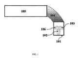
ここで、従来の内視鏡の断面図を示した図1を参照する。本例では、3つのカメラ(102、103および106)(ならびに、図示はしないが、光源または作業チャネルといった他の要素)が先端部分(101)に位置している。この場合は、シャフト(105)が移動しているか、湾曲部分(104)を用いて折り曲げられると、先端全体が移動し、結果的にカメラの方向を互いに相対的に変更するという選択肢がないままセンサの画像全体も移動することになる。本発明は、湾曲、回転、または角形成部分といった、1つまたは複数の操作部分を有する内視鏡を提供する。この構成により、それぞれのセンサを個別に動作させることができ、結果的に動的視野を取得することができる。 Here, reference is made to FIG. 1 showing a sectional view of a conventional endoscope. In this example, three cameras (102, 103 and 106) (and other elements, not shown, such as a light source or working channel) are located at the tip portion (101). In this case, if the shaft (105) is moving or bent using the curved portion (104), the entire tip will move, resulting in no option to change the camera direction relative to each other. The entire sensor image will also move. The present invention provides an endoscope having one or more operating portions, such as curved, rotating, or angulated portions. With this configuration, each sensor can be individually operated, and as a result, a dynamic visual field can be acquired.
本明細書において、「回転部分」という用語は内視鏡の一部分を指す。回転部分は、シャフトの軸の周りを360度またはそれ未満の角度まで回転させることができる。 As used herein, the term “rotating portion” refers to a portion of an endoscope. The rotating part can be rotated around the axis of the shaft to an angle of 360 degrees or less.
本明細書において、「湾曲部分」という用語は内視鏡の一部分を指す。湾曲部分は、湾曲部分の前方に異なる方向で配置された先端部分および/または他の部分が方向転換できるようにする、複数のリンクを有する。 As used herein, the term “curved portion” refers to a portion of an endoscope. The curved portion has a plurality of links that allow the tip portion and / or other portions arranged in different directions in front of the curved portion to turn around.
本明細書において、「角形成部分」という用語は内視鏡の一部分を指す。角形成部分は、角形成部分の前方に異なる方向で配置された先端部分および/または他の部分が方向転換できるようにする。 As used herein, the term “angulated portion” refers to a portion of an endoscope. The angulation portion allows the tip portion and / or other portions arranged in different directions in front of the angulation portion to turn around.
内視鏡手術の最中には、別のカメラが別の部位を視認することができる傍ら、より多くの臓器や腹腔全体さえも見ることができるように視野の拡大を必要とすることが何度もある。それを実現すべく、本発明は1つのカメラの方向を別のカメラの方向に対して動作中に変更することができるようにする。図2Aは、回転部分(206)と、先端部分(201)に位置する前向きカメラ(202)と、回転部分206に位置し、シャフトの軸に沿って90度の角度で配置された別のカメラ(203)とを有する内視鏡の一例を示す。 During endoscopic surgery, what is necessary to enlarge the field of view so that another camera can see another part while seeing more organs and even the entire abdominal cavity? There are times. To achieve that, the present invention allows the direction of one camera to be changed during operation relative to the direction of another camera. FIG. 2A shows a rotating portion (206), a forward-facing camera (202) located at the tip portion (201), and another camera located at the rotating portion 206 and disposed at a 90 degree angle along the axis of the shaft. An example of an endoscope having (203) is shown.
この構成には、動的視野を取得することができるようになるという利点がある。ここでは、シャフト205を回転させずに、1つのセンサ(例えば、前向きカメラ)が静止したまま、回転部分206に位置する追加センサを単独で回転させることができる。図2Bは、回転部分(260)と、先端部分(210)に位置する傾けられた前向きカメラ(220)と、回転部分260に位置し、シャフトの軸に沿って90度の角度で配置された別のカメラ(230)とを有する類似した内視鏡の別の例を示す。前カメラ220が傾けられているので、シャフト(250)のみを(機械的に)回転させると、センサの画像全体が移動することになる。本明細書に記載された回転部分を用いることにより、動的視野を取得することができるようになる。 This configuration has the advantage that a dynamic field of view can be obtained. Here, without rotating the shaft 205, the additional sensor located in the rotating portion 206 can be independently rotated while one sensor (for example, a forward-facing camera) is stationary. FIG. 2B shows a rotating portion (260), a tilted forward-facing camera (220) located at the tip portion (210), and located at the rotating portion 260 and disposed at an angle of 90 degrees along the axis of the shaft. Fig. 5 shows another example of a similar endoscope with another camera (230). Because the front camera 220 is tilted, rotating only the shaft (250) (mechanically) will move the entire sensor image. By using the rotating portion described herein, a dynamic field of view can be acquired.
動的視野を取得する別の方法として、先端部分の後方の湾曲部分を用いるという方法がある。図3は、先端部分(301)の後方の湾曲部分(305)と、先端に位置する前向きカメラ(302)と、湾曲部分の後方に位置する横向きカメラ(306)とを有する内視鏡の一例を示す。横向きカメラ306は、内視鏡の管308の外面307に配置されている。図5に記載した通り、管308は配線がセンサからリモートシステムに情報を運ぶための空洞容量を備える。この構成により、広画角の動的視野を取得することができるようになる。湾曲部分の代わりに角形成部分が存在する場合は、類似したセンサ画像が取得され得る(図示せず)。 As another method for acquiring the dynamic visual field, there is a method of using a curved portion behind the tip portion. FIG. 3 shows an example of an endoscope having a curved portion (305) behind the tip portion (301), a forward-facing camera (302) located at the tip, and a lateral camera (306) located behind the curved portion. Indicates. The lateral camera 306 is disposed on the outer surface 307 of the endoscope tube 308. As described in FIG. 5, tube 308 includes a cavity capacity for wiring to carry information from the sensor to the remote system. With this configuration, a dynamic field of view with a wide angle of view can be acquired. Similar sensor images can be acquired (not shown) if there are angulated portions instead of curved portions.
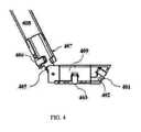
しかし、角形成部分が用いられる場合は、動きを制御するのが好ましい。また、回転部分の代わりに角形成部分が用いられる場合は、より多くのセンサ(例えば、基部での長さが同じ位置にある、同じ品質のカメラ)を含み得る。図4は、角形成部分(405)と、先端部分(409)の一部である前方の先端部分(401)に位置する傾けられた前向きカメラ(402)とを有する内視鏡を示す。別のカメラ(403)がシャフトの軸に沿って90度の角度で配置され、先端部分(409)の後方に位置している。第3のカメラ(406)が角形成部分(405)の後方、先に開示された管308に類似した管408の外面407に位置している。この構成により、広画角の動的視野を有することができるようになる。 However, it is preferable to control the movement when angulated portions are used. Also, if an angled portion is used instead of a rotating portion, it may include more sensors (eg, the same quality camera with the same length at the base). FIG. 4 shows an endoscope having an angled portion (405) and a tilted forward-facing camera (402) located at a forward tip portion (401) that is part of the tip portion (409). Another camera (403) is disposed at an angle of 90 degrees along the axis of the shaft and is located behind the tip portion (409). A third camera (406) is located on the outer surface 407 of the tube 408, similar to the previously disclosed tube 308, behind the angled portion (405). With this configuration, a dynamic field of view with a wide angle of view can be obtained.
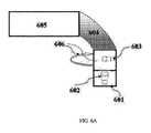
上述したように、本発明のマルチセンサ内視鏡はたった1つの操作部分とは限らず、2つまたはそれより多くの同一または異なる操作部分を含み得る。ここで、1つより多くの操作部分を有するマルチセンサ内視鏡の構成を示した図6A〜図6Bを参照する。これらの構成には、操作中の視野が高度に制御されるという利点がある。構成Aは、湾曲部分(604)および回転部分(606)と、先端部分(601)に位置する前向きカメラ(602)と、シャフトの軸に沿って90度の角度で配置され、先端部分の後方に位置し、回転部分(606)により回転させられ得る別のカメラ(603)とを備える内視鏡を記載している。構成Bは、角形成部分(670)および回転部分(660)と、先端部分(610)の外面630に位置する傾けられた前向きカメラ(620)と、シャフトの軸に沿って90度の角度で配置され、先端部分の後方に位置し、回転部分(660)により回転させられ得る別のカメラ(680)と、シャフトの軸に沿って90度の角度で配置され、角形成部分(670)の後方に位置する第3のカメラ(690)とを備える内視鏡を記載している。同様に、他の構成(図示せず)では、2つまたはそれより多くの操作部分が存在し、これらの部分のそれぞれに2つまたはそれより多くのカメラがシャフトの軸に沿って様々な角度で配置され得る。 As described above, the multi-sensor endoscope of the present invention is not limited to a single operation part, and may include two or more identical or different operation parts. Reference is now made to FIGS. 6A-6B showing the configuration of a multi-sensor endoscope having more than one operating portion. These configurations have the advantage that the field of view during operation is highly controlled. Configuration A is arranged at a 90 degree angle along the axis of the shaft, with a curved portion (604) and a rotating portion (606), a forward-facing camera (602) located in the tip portion (601), and behind the tip portion And an additional camera (603) that can be rotated by a rotating part (606). Configuration B includes an angled portion (670) and a rotating portion (660), a tilted forward-facing camera (620) located on the outer surface 630 of the tip portion (610), and an angle of 90 degrees along the shaft axis. Another camera (680) positioned and rearward of the tip portion, which can be rotated by the rotating portion (660), and disposed at an angle of 90 degrees along the axis of the shaft, of the angle forming portion (670) An endoscope comprising a third camera (690) located in the rear is described. Similarly, in other configurations (not shown) there are two or more operating portions, each of which has two or more cameras at various angles along the axis of the shaft. Can be arranged in
ここで、マルチセンサ内視鏡システムの部分的に絵入りの図を示した図5を参照する。システムは、図2A、2B、3、4および/または6の内視鏡のようなマルチセンサ内視鏡を含み得る。マルチセンサ内視鏡は、細長いシャフト(520)が出てくるハンドル(510)を含み得る。細長いシャフト(520)は先端部分(530)で終端する。ハンドル(510)は、体腔内で細長いシャフト(520)を操作するのに用いられ得る。ハンドルは、湾曲、回転、および/または角形成部分(525)を制御する1つまたは複数のつまみ(515)および/またはスイッチを含み得る。ユーティリティケーブル(580)は、ハンドル(510)と制御装置(540)とを接続し得る。ユーティリティケーブル(580)は、その内部に1つまたは複数の電気チャネルを含み得る。1つまたは複数の電気チャネルは、前向きおよび横向きセンサ(例えば、カメラ)から信号(例えば、映像信号)を受信するための少なくとも1つのデータケーブルも含み得る。更に、光源ケーブル(590)はハンドルと光源装置(550)とを接続し得る。 Reference is now made to FIG. 5, which shows a partially pictorial illustration of a multi-sensor endoscope system. The system may include a multi-sensor endoscope such as the endoscope of FIGS. 2A, 2B, 3, 4 and / or 6. The multi-sensor endoscope may include a handle (510) through which an elongated shaft (520) exits. The elongate shaft (520) terminates at the tip portion (530). The handle (510) can be used to manipulate the elongate shaft (520) within the body cavity. The handle may include one or more knobs (515) and / or switches that control the curvature, rotation, and / or angulation portion (525). Utility cable (580) may connect handle (510) and control device (540). Utility cable (580) may include one or more electrical channels therein. The one or more electrical channels may also include at least one data cable for receiving signals (eg, video signals) from forward and sideways sensors (eg, cameras). Further, the light source cable (590) may connect the handle and the light source device (550).
制御装置(540)は、先端部分のセンサに対してなど、内視鏡の先端部分(530)に対する動力伝達を管理し得る。制御装置(540)は更に、1つまたは複数の湾曲、回転、または角形成部分のハンドルからの信号により操作を制御し得る。人間と制御装置540とのインタラクションを目的として、キーボード(545)のような1つまたは複数の入力機器が制御装置(540)に接続され得る。ディスプレイ(560)が制御装置(540)に接続され得、かつセンサ(例えば、マルチセンサ内視鏡のカメラ)から受信された画像および/または映像ストリームなどの信号を表示するように構成され得る。ディスプレイ(560)は更に、人間のオペレータが様々なシステム機能を設定することができるようにするためのユーザインタフェースを表示するように動作し得る。 The controller (540) may manage the power transmission to the distal portion (530) of the endoscope, such as to a sensor at the distal portion. The controller (540) may further control operation by signals from one or more curved, rotating, or angulation handles. One or more input devices, such as a keyboard (545), may be connected to the controller (540) for the purpose of human interaction with the controller 540. A display (560) may be connected to the controller (540) and configured to display signals such as images and / or video streams received from a sensor (eg, a multi-sensor endoscope camera). The display (560) may be further operable to display a user interface to allow a human operator to set various system functions.
オプションとして、センサがカメラである場合、マルチセンサ内視鏡の異なるカメラから受信された映像ストリームは、ディスプレイ(560)に別々に、左右に並べてまたは切り替え可能に(すなわち、オペレータは異なるカメラからの視点を手動で切り替えることができる)表示され得る。 Optionally, if the sensor is a camera, the video streams received from different cameras of the multi-sensor endoscope can be displayed separately on the display (560) side by side or switchable (ie, the operator can The viewpoint can be switched manually).
代替え的に、これらの映像ストリームは、結合して単一のパノラマ映像フレームにすべく、制御装置(540)によりカメラ視野間の重複に基づいて処理され得る。別の構成(図示せず)では、2つまたはそれより多くのディスプレイが制御装置(540)に接続され得るが、ディスプレイごとにマルチセンサ内視鏡の異なるカメラからの映像ストリームを表示する。 Alternatively, these video streams can be processed by controller (540) based on overlap between camera views to be combined into a single panoramic video frame. In another configuration (not shown), two or more displays may be connected to the controller (540), but each display displays a video stream from a different camera of the multi-sensor endoscope.
Claims (43)
Translated fromJapanesea.先端部分で終端する細長いシャフトと、
b.前記細長いシャフトに接続された少なくとも1つの操作部分と、
c.少なくとも2つのセンサであって、少なくとも1つのセンサが、前記先端部分の後方、前記細長いシャフトの外面に配置されている、少なくとも2つのセンサと、
d.前記細長いシャフトの前記外面に位置する1つまたは複数の照射装置と
を備えるマルチセンサ内視鏡。A multi-sensor endoscope having a dynamic field of view,
a. An elongate shaft that terminates in a tip portion;
b. At least one operating portion connected to the elongated shaft;
c. At least two sensors, wherein the at least one sensor is located behind the tip portion and on an outer surface of the elongate shaft;
d. A multi-sensor endoscope comprising one or more illumination devices located on the outer surface of the elongate shaft.
前記内視鏡は、
ハンドルと、
先端部分で終端する細長いシャフトであって、前記ハンドルにより制御されるシャフトと、
前記細長いシャフトに接続された操作部分と、
少なくとも2つのセンサであって、少なくとも1つのセンサが、前記先端部分の後方、前記操作部分に配置されている、少なくとも2つのセンサと、
1つまたは複数の照射装置と、
ユーティリティケーブルを用いて前記内視鏡の前記ハンドルに接続された制御装置と、
前記制御装置に接続され、かつ前記センサから受信された信号ストリームを表示するディスプレイと
を有する、マルチセンサ内視鏡システム。Equipped with an endoscope,
The endoscope is
A handle,
An elongate shaft terminating in a tip portion, the shaft being controlled by the handle;
An operating portion connected to the elongated shaft;
At least two sensors, wherein the at least one sensor is disposed behind the tip portion and in the operating portion;
One or more irradiation devices;
A control device connected to the handle of the endoscope using a utility cable;
A multi-sensor endoscope system comprising: a display connected to the control device and displaying a signal stream received from the sensor.
Applications Claiming Priority (3)
| Application Number | Priority Date | Filing Date | Title |
|---|---|---|---|
| US201562160253P | 2015-05-12 | 2015-05-12 | |
| US62/160,253 | 2015-05-12 | ||
| PCT/IL2016/050515WO2016181404A1 (en) | 2015-05-12 | 2016-05-15 | A dynamic field of view endoscope |
Publications (3)
| Publication Number | Publication Date |
|---|---|
| JP2018519860Atrue JP2018519860A (en) | 2018-07-26 |
| JP2018519860A5 JP2018519860A5 (en) | 2019-06-13 |
| JP6930062B2 JP6930062B2 (en) | 2021-09-01 |
Family
ID=57249048
Family Applications (1)
| Application Number | Title | Priority Date | Filing Date |
|---|---|---|---|
| JP2017555703AActiveJP6930062B2 (en) | 2015-05-12 | 2016-05-15 | Dynamic field endoscope |
Country Status (6)
| Country | Link |
|---|---|
| US (2) | US10674897B2 (en) |
| EP (1) | EP3294109B1 (en) |
| JP (1) | JP6930062B2 (en) |
| CN (1) | CN107529960B (en) |
| IL (1) | IL255141B (en) |
| WO (1) | WO2016181404A1 (en) |
Cited By (2)
| Publication number | Priority date | Publication date | Assignee | Title |
|---|---|---|---|---|
| KR20220074783A (en)* | 2020-11-27 | 2022-06-03 | 고려대학교 산학협력단 | Laparoscopic camera having X-ray function |
| US12342082B2 (en) | 2020-10-02 | 2025-06-24 | Hoya Corporation | Program, information processing method, and endoscope system for generating a composite endoscopic image |
Families Citing this family (149)
| Publication number | Priority date | Publication date | Assignee | Title |
|---|---|---|---|---|
| US11871901B2 (en) | 2012-05-20 | 2024-01-16 | Cilag Gmbh International | Method for situational awareness for surgical network or surgical network connected device capable of adjusting function based on a sensed situation or usage |
| US11504192B2 (en) | 2014-10-30 | 2022-11-22 | Cilag Gmbh International | Method of hub communication with surgical instrument systems |
| US10499996B2 (en) | 2015-03-26 | 2019-12-10 | Universidade De Coimbra | Methods and systems for computer-aided surgery using intra-operative video acquired by a free moving camera |
| WO2016168307A1 (en) | 2015-04-13 | 2016-10-20 | Universidade De Coimbra | Methods and systems for camera characterization in terms of response function, color, and vignetting under non-uniform illumination |
| JP2019507628A (en)* | 2016-02-24 | 2019-03-22 | エンドチョイス インコーポレイテッドEndochoice, Inc. | Circuit board assembly for multiple view element endoscopes using CMOS sensors |
| EP3596657A4 (en) | 2017-03-14 | 2021-01-13 | Universidade De Coimbra | SYSTEMS AND METHODS FOR 3D REGISTRATION OF CURVES AND SURFACES USING VARIOUS LOCAL INFORMATION |
| EP3664685B1 (en)* | 2017-08-08 | 2023-04-19 | 270 Surgical Ltd. | A two-piece rigid medical surgery illuminating device |
| JP7056847B2 (en)* | 2017-08-17 | 2022-04-19 | 270 サージカル リミテッド | Multi-camera surgical lighting device with variable diameter |
| US11026687B2 (en) | 2017-10-30 | 2021-06-08 | Cilag Gmbh International | Clip applier comprising clip advancing systems |
| US11229436B2 (en) | 2017-10-30 | 2022-01-25 | Cilag Gmbh International | Surgical system comprising a surgical tool and a surgical hub |
| US11564756B2 (en) | 2017-10-30 | 2023-01-31 | Cilag Gmbh International | Method of hub communication with surgical instrument systems |
| US11311342B2 (en) | 2017-10-30 | 2022-04-26 | Cilag Gmbh International | Method for communicating with surgical instrument systems |
| US11510741B2 (en) | 2017-10-30 | 2022-11-29 | Cilag Gmbh International | Method for producing a surgical instrument comprising a smart electrical system |
| US11317919B2 (en) | 2017-10-30 | 2022-05-03 | Cilag Gmbh International | Clip applier comprising a clip crimping system |
| US11801098B2 (en) | 2017-10-30 | 2023-10-31 | Cilag Gmbh International | Method of hub communication with surgical instrument systems |
| EP3706613A4 (en)* | 2017-10-30 | 2021-04-28 | 270 Surgical Ltd. | MEDICAL IMAGING DEVICE EQUIPPED WITH A FOLDABLE ELECTRONIC CIRCUIT BOARD |
| US11925373B2 (en) | 2017-10-30 | 2024-03-12 | Cilag Gmbh International | Surgical suturing instrument comprising a non-circular needle |
| US11911045B2 (en) | 2017-10-30 | 2024-02-27 | Cllag GmbH International | Method for operating a powered articulating multi-clip applier |
| US11291510B2 (en) | 2017-10-30 | 2022-04-05 | Cilag Gmbh International | Method of hub communication with surgical instrument systems |
| US11896322B2 (en) | 2017-12-28 | 2024-02-13 | Cilag Gmbh International | Sensing the patient position and contact utilizing the mono-polar return pad electrode to provide situational awareness to the hub |
| US11311306B2 (en) | 2017-12-28 | 2022-04-26 | Cilag Gmbh International | Surgical systems for detecting end effector tissue distribution irregularities |
| US11304763B2 (en) | 2017-12-28 | 2022-04-19 | Cilag Gmbh International | Image capturing of the areas outside the abdomen to improve placement and control of a surgical device in use |
| US11633237B2 (en) | 2017-12-28 | 2023-04-25 | Cilag Gmbh International | Usage and technique analysis of surgeon / staff performance against a baseline to optimize device utilization and performance for both current and future procedures |
| US10918310B2 (en) | 2018-01-03 | 2021-02-16 | Biosense Webster (Israel) Ltd. | Fast anatomical mapping (FAM) using volume filling |
| US20190201112A1 (en) | 2017-12-28 | 2019-07-04 | Ethicon Llc | Computer implemented interactive surgical systems |
| US11786245B2 (en) | 2017-12-28 | 2023-10-17 | Cilag Gmbh International | Surgical systems with prioritized data transmission capabilities |
| US11744604B2 (en) | 2017-12-28 | 2023-09-05 | Cilag Gmbh International | Surgical instrument with a hardware-only control circuit |
| US11389164B2 (en) | 2017-12-28 | 2022-07-19 | Cilag Gmbh International | Method of using reinforced flexible circuits with multiple sensors to optimize performance of radio frequency devices |
| US11559308B2 (en) | 2017-12-28 | 2023-01-24 | Cilag Gmbh International | Method for smart energy device infrastructure |
| US20190201142A1 (en) | 2017-12-28 | 2019-07-04 | Ethicon Llc | Automatic tool adjustments for robot-assisted surgical platforms |
| US11026751B2 (en) | 2017-12-28 | 2021-06-08 | Cilag Gmbh International | Display of alignment of staple cartridge to prior linear staple line |
| US20190201090A1 (en) | 2017-12-28 | 2019-07-04 | Ethicon Llc | Capacitive coupled return path pad with separable array elements |
| US11013563B2 (en) | 2017-12-28 | 2021-05-25 | Ethicon Llc | Drive arrangements for robot-assisted surgical platforms |
| US11308075B2 (en) | 2017-12-28 | 2022-04-19 | Cilag Gmbh International | Surgical network, instrument, and cloud responses based on validation of received dataset and authentication of its source and integrity |
| US11273001B2 (en) | 2017-12-28 | 2022-03-15 | Cilag Gmbh International | Surgical hub and modular device response adjustment based on situational awareness |
| US11069012B2 (en) | 2017-12-28 | 2021-07-20 | Cilag Gmbh International | Interactive surgical systems with condition handling of devices and data capabilities |
| US11284936B2 (en) | 2017-12-28 | 2022-03-29 | Cilag Gmbh International | Surgical instrument having a flexible electrode |
| US10892995B2 (en) | 2017-12-28 | 2021-01-12 | Ethicon Llc | Surgical network determination of prioritization of communication, interaction, or processing based on system or device needs |
| US11179175B2 (en) | 2017-12-28 | 2021-11-23 | Cilag Gmbh International | Controlling an ultrasonic surgical instrument according to tissue location |
| US11696760B2 (en) | 2017-12-28 | 2023-07-11 | Cilag Gmbh International | Safety systems for smart powered surgical stapling |
| US11464535B2 (en) | 2017-12-28 | 2022-10-11 | Cilag Gmbh International | Detection of end effector emersion in liquid |
| US10943454B2 (en) | 2017-12-28 | 2021-03-09 | Ethicon Llc | Detection and escalation of security responses of surgical instruments to increasing severity threats |
| US11234756B2 (en) | 2017-12-28 | 2022-02-01 | Cilag Gmbh International | Powered surgical tool with predefined adjustable control algorithm for controlling end effector parameter |
| US11202570B2 (en) | 2017-12-28 | 2021-12-21 | Cilag Gmbh International | Communication hub and storage device for storing parameters and status of a surgical device to be shared with cloud based analytics systems |
| US11056244B2 (en) | 2017-12-28 | 2021-07-06 | Cilag Gmbh International | Automated data scaling, alignment, and organizing based on predefined parameters within surgical networks |
| US11076921B2 (en) | 2017-12-28 | 2021-08-03 | Cilag Gmbh International | Adaptive control program updates for surgical hubs |
| US10966791B2 (en) | 2017-12-28 | 2021-04-06 | Ethicon Llc | Cloud-based medical analytics for medical facility segmented individualization of instrument function |
| US11659023B2 (en) | 2017-12-28 | 2023-05-23 | Cilag Gmbh International | Method of hub communication |
| US11304745B2 (en) | 2017-12-28 | 2022-04-19 | Cilag Gmbh International | Surgical evacuation sensing and display |
| US11571234B2 (en) | 2017-12-28 | 2023-02-07 | Cilag Gmbh International | Temperature control of ultrasonic end effector and control system therefor |
| US11304699B2 (en) | 2017-12-28 | 2022-04-19 | Cilag Gmbh International | Method for adaptive control schemes for surgical network control and interaction |
| US11324557B2 (en) | 2017-12-28 | 2022-05-10 | Cilag Gmbh International | Surgical instrument with a sensing array |
| WO2019133144A1 (en) | 2017-12-28 | 2019-07-04 | Ethicon Llc | Detection and escalation of security responses of surgical instruments to increasing severity threats |
| US11291495B2 (en) | 2017-12-28 | 2022-04-05 | Cilag Gmbh International | Interruption of energy due to inadvertent capacitive coupling |
| US11786251B2 (en) | 2017-12-28 | 2023-10-17 | Cilag Gmbh International | Method for adaptive control schemes for surgical network control and interaction |
| US11376002B2 (en) | 2017-12-28 | 2022-07-05 | Cilag Gmbh International | Surgical instrument cartridge sensor assemblies |
| US11051876B2 (en) | 2017-12-28 | 2021-07-06 | Cilag Gmbh International | Surgical evacuation flow paths |
| US11464559B2 (en) | 2017-12-28 | 2022-10-11 | Cilag Gmbh International | Estimating state of ultrasonic end effector and control system therefor |
| US20190206569A1 (en) | 2017-12-28 | 2019-07-04 | Ethicon Llc | Method of cloud based data analytics for use with the hub |
| US11903601B2 (en) | 2017-12-28 | 2024-02-20 | Cilag Gmbh International | Surgical instrument comprising a plurality of drive systems |
| US11529187B2 (en) | 2017-12-28 | 2022-12-20 | Cilag Gmbh International | Surgical evacuation sensor arrangements |
| US11602393B2 (en) | 2017-12-28 | 2023-03-14 | Cilag Gmbh International | Surgical evacuation sensing and generator control |
| US10944728B2 (en) | 2017-12-28 | 2021-03-09 | Ethicon Llc | Interactive surgical systems with encrypted communication capabilities |
| US11832899B2 (en) | 2017-12-28 | 2023-12-05 | Cilag Gmbh International | Surgical systems with autonomously adjustable control programs |
| US11364075B2 (en) | 2017-12-28 | 2022-06-21 | Cilag Gmbh International | Radio frequency energy device for delivering combined electrical signals |
| US11540855B2 (en) | 2017-12-28 | 2023-01-03 | Cilag Gmbh International | Controlling activation of an ultrasonic surgical instrument according to the presence of tissue |
| US11166772B2 (en) | 2017-12-28 | 2021-11-09 | Cilag Gmbh International | Surgical hub coordination of control and communication of operating room devices |
| US20190201039A1 (en) | 2017-12-28 | 2019-07-04 | Ethicon Llc | Situational awareness of electrosurgical systems |
| US12396806B2 (en) | 2017-12-28 | 2025-08-26 | Cilag Gmbh International | Adjustment of a surgical device function based on situational awareness |
| US11317937B2 (en) | 2018-03-08 | 2022-05-03 | Cilag Gmbh International | Determining the state of an ultrasonic end effector |
| US11832840B2 (en) | 2017-12-28 | 2023-12-05 | Cilag Gmbh International | Surgical instrument having a flexible circuit |
| US11857152B2 (en) | 2017-12-28 | 2024-01-02 | Cilag Gmbh International | Surgical hub spatial awareness to determine devices in operating theater |
| US11666331B2 (en) | 2017-12-28 | 2023-06-06 | Cilag Gmbh International | Systems for detecting proximity of surgical end effector to cancerous tissue |
| US11419667B2 (en) | 2017-12-28 | 2022-08-23 | Cilag Gmbh International | Ultrasonic energy device which varies pressure applied by clamp arm to provide threshold control pressure at a cut progression location |
| US12376855B2 (en) | 2017-12-28 | 2025-08-05 | Cilag Gmbh International | Safety systems for smart powered surgical stapling |
| US12127729B2 (en) | 2017-12-28 | 2024-10-29 | Cilag Gmbh International | Method for smoke evacuation for surgical hub |
| US11410259B2 (en) | 2017-12-28 | 2022-08-09 | Cilag Gmbh International | Adaptive control program updates for surgical devices |
| US11132462B2 (en) | 2017-12-28 | 2021-09-28 | Cilag Gmbh International | Data stripping method to interrogate patient records and create anonymized record |
| US12062442B2 (en) | 2017-12-28 | 2024-08-13 | Cilag Gmbh International | Method for operating surgical instrument systems |
| US11419630B2 (en) | 2017-12-28 | 2022-08-23 | Cilag Gmbh International | Surgical system distributed processing |
| US11266468B2 (en) | 2017-12-28 | 2022-03-08 | Cilag Gmbh International | Cooperative utilization of data derived from secondary sources by intelligent surgical hubs |
| US12096916B2 (en) | 2017-12-28 | 2024-09-24 | Cilag Gmbh International | Method of sensing particulate from smoke evacuated from a patient, adjusting the pump speed based on the sensed information, and communicating the functional parameters of the system to the hub |
| US11424027B2 (en) | 2017-12-28 | 2022-08-23 | Cilag Gmbh International | Method for operating surgical instrument systems |
| US10987178B2 (en) | 2017-12-28 | 2021-04-27 | Ethicon Llc | Surgical hub control arrangements |
| US11937769B2 (en) | 2017-12-28 | 2024-03-26 | Cilag Gmbh International | Method of hub communication, processing, storage and display |
| US11969216B2 (en) | 2017-12-28 | 2024-04-30 | Cilag Gmbh International | Surgical network recommendations from real time analysis of procedure variables against a baseline highlighting differences from the optimal solution |
| US11179208B2 (en) | 2017-12-28 | 2021-11-23 | Cilag Gmbh International | Cloud-based medical analytics for security and authentication trends and reactive measures |
| US11998193B2 (en) | 2017-12-28 | 2024-06-04 | Cilag Gmbh International | Method for usage of the shroud as an aspect of sensing or controlling a powered surgical device, and a control algorithm to adjust its default operation |
| US11818052B2 (en) | 2017-12-28 | 2023-11-14 | Cilag Gmbh International | Surgical network determination of prioritization of communication, interaction, or processing based on system or device needs |
| US11559307B2 (en) | 2017-12-28 | 2023-01-24 | Cilag Gmbh International | Method of robotic hub communication, detection, and control |
| US11147607B2 (en) | 2017-12-28 | 2021-10-19 | Cilag Gmbh International | Bipolar combination device that automatically adjusts pressure based on energy modality |
| US10932872B2 (en) | 2017-12-28 | 2021-03-02 | Ethicon Llc | Cloud-based medical analytics for linking of local usage trends with the resource acquisition behaviors of larger data set |
| US11253315B2 (en) | 2017-12-28 | 2022-02-22 | Cilag Gmbh International | Increasing radio frequency to create pad-less monopolar loop |
| US11864728B2 (en) | 2017-12-28 | 2024-01-09 | Cilag Gmbh International | Characterization of tissue irregularities through the use of mono-chromatic light refractivity |
| US11576677B2 (en) | 2017-12-28 | 2023-02-14 | Cilag Gmbh International | Method of hub communication, processing, display, and cloud analytics |
| US11096693B2 (en) | 2017-12-28 | 2021-08-24 | Cilag Gmbh International | Adjustment of staple height of at least one row of staples based on the sensed tissue thickness or force in closing |
| US11100631B2 (en) | 2017-12-28 | 2021-08-24 | Cilag Gmbh International | Use of laser light and red-green-blue coloration to determine properties of back scattered light |
| US11896443B2 (en) | 2017-12-28 | 2024-02-13 | Cilag Gmbh International | Control of a surgical system through a surgical barrier |
| US11423007B2 (en) | 2017-12-28 | 2022-08-23 | Cilag Gmbh International | Adjustment of device control programs based on stratified contextual data in addition to the data |
| US11160605B2 (en) | 2017-12-28 | 2021-11-02 | Cilag Gmbh International | Surgical evacuation sensing and motor control |
| US11589888B2 (en) | 2017-12-28 | 2023-02-28 | Cilag Gmbh International | Method for controlling smart energy devices |
| US10758310B2 (en) | 2017-12-28 | 2020-09-01 | Ethicon Llc | Wireless pairing of a surgical device with another device within a sterile surgical field based on the usage and situational awareness of devices |
| US11678881B2 (en) | 2017-12-28 | 2023-06-20 | Cilag Gmbh International | Spatial awareness of surgical hubs in operating rooms |
| US11432885B2 (en) | 2017-12-28 | 2022-09-06 | Cilag Gmbh International | Sensing arrangements for robot-assisted surgical platforms |
| US11278281B2 (en) | 2017-12-28 | 2022-03-22 | Cilag Gmbh International | Interactive surgical system |
| US11612444B2 (en) | 2017-12-28 | 2023-03-28 | Cilag Gmbh International | Adjustment of a surgical device function based on situational awareness |
| US11969142B2 (en) | 2017-12-28 | 2024-04-30 | Cilag Gmbh International | Method of compressing tissue within a stapling device and simultaneously displaying the location of the tissue within the jaws |
| US11109866B2 (en) | 2017-12-28 | 2021-09-07 | Cilag Gmbh International | Method for circular stapler control algorithm adjustment based on situational awareness |
| US10898622B2 (en) | 2017-12-28 | 2021-01-26 | Ethicon Llc | Surgical evacuation system with a communication circuit for communication between a filter and a smoke evacuation device |
| US11304720B2 (en) | 2017-12-28 | 2022-04-19 | Cilag Gmbh International | Activation of energy devices |
| US11446052B2 (en) | 2017-12-28 | 2022-09-20 | Cilag Gmbh International | Variation of radio frequency and ultrasonic power level in cooperation with varying clamp arm pressure to achieve predefined heat flux or power applied to tissue |
| US11257589B2 (en) | 2017-12-28 | 2022-02-22 | Cilag Gmbh International | Real-time analysis of comprehensive cost of all instrumentation used in surgery utilizing data fluidity to track instruments through stocking and in-house processes |
| US11534196B2 (en) | 2018-03-08 | 2022-12-27 | Cilag Gmbh International | Using spectroscopy to determine device use state in combo instrument |
| US11986233B2 (en) | 2018-03-08 | 2024-05-21 | Cilag Gmbh International | Adjustment of complex impedance to compensate for lost power in an articulating ultrasonic device |
| US12303159B2 (en) | 2018-03-08 | 2025-05-20 | Cilag Gmbh International | Methods for estimating and controlling state of ultrasonic end effector |
| US11259830B2 (en) | 2018-03-08 | 2022-03-01 | Cilag Gmbh International | Methods for controlling temperature in ultrasonic device |
| US11207067B2 (en) | 2018-03-28 | 2021-12-28 | Cilag Gmbh International | Surgical stapling device with separate rotary driven closure and firing systems and firing member that engages both jaws while firing |
| US11096688B2 (en) | 2018-03-28 | 2021-08-24 | Cilag Gmbh International | Rotary driven firing members with different anvil and channel engagement features |
| US11219453B2 (en) | 2018-03-28 | 2022-01-11 | Cilag Gmbh International | Surgical stapling devices with cartridge compatible closure and firing lockout arrangements |
| US11213294B2 (en) | 2018-03-28 | 2022-01-04 | Cilag Gmbh International | Surgical instrument comprising co-operating lockout features |
| US11471156B2 (en) | 2018-03-28 | 2022-10-18 | Cilag Gmbh International | Surgical stapling devices with improved rotary driven closure systems |
| US10973520B2 (en) | 2018-03-28 | 2021-04-13 | Ethicon Llc | Surgical staple cartridge with firing member driven camming assembly that has an onboard tissue cutting feature |
| US11278280B2 (en) | 2018-03-28 | 2022-03-22 | Cilag Gmbh International | Surgical instrument comprising a jaw closure lockout |
| US11090047B2 (en) | 2018-03-28 | 2021-08-17 | Cilag Gmbh International | Surgical instrument comprising an adaptive control system |
| US11589865B2 (en) | 2018-03-28 | 2023-02-28 | Cilag Gmbh International | Methods for controlling a powered surgical stapler that has separate rotary closure and firing systems |
| JP6617191B1 (en) | 2018-12-03 | 2019-12-11 | 三井金属鉱業株式会社 | Method and apparatus for separating or analyzing target components in a solution |
| CN109646052A (en)* | 2018-12-27 | 2019-04-19 | 华中科技大学鄂州工业技术研究院 | A kind of ultrasound capsule endoscope |
| US11331100B2 (en) | 2019-02-19 | 2022-05-17 | Cilag Gmbh International | Staple cartridge retainer system with authentication keys |
| US11464511B2 (en) | 2019-02-19 | 2022-10-11 | Cilag Gmbh International | Surgical staple cartridges with movable authentication key arrangements |
| US11357503B2 (en) | 2019-02-19 | 2022-06-14 | Cilag Gmbh International | Staple cartridge retainers with frangible retention features and methods of using same |
| US11369377B2 (en) | 2019-02-19 | 2022-06-28 | Cilag Gmbh International | Surgical stapling assembly with cartridge based retainer configured to unlock a firing lockout |
| US11317915B2 (en) | 2019-02-19 | 2022-05-03 | Cilag Gmbh International | Universal cartridge based key feature that unlocks multiple lockout arrangements in different surgical staplers |
| CN109846453B (en)* | 2019-03-08 | 2021-05-07 | 湖州市妇幼保健院 | A colonoscopy positioning device |
| USD950728S1 (en) | 2019-06-25 | 2022-05-03 | Cilag Gmbh International | Surgical staple cartridge |
| USD952144S1 (en) | 2019-06-25 | 2022-05-17 | Cilag Gmbh International | Surgical staple cartridge retainer with firing system authentication key |
| USD964564S1 (en) | 2019-06-25 | 2022-09-20 | Cilag Gmbh International | Surgical staple cartridge retainer with a closure system authentication key |
| US20210000337A1 (en)* | 2019-07-02 | 2021-01-07 | Covidien Lp | Colposcope for screening for cervical cancer |
| CN110687672A (en)* | 2019-10-18 | 2020-01-14 | 深圳市道通科技股份有限公司 | an endoscope system |
| US20220395163A1 (en)* | 2019-11-15 | 2022-12-15 | Covidien Lp | Rotation assembly for endoscope lens |
| US12004717B2 (en) | 2019-12-20 | 2024-06-11 | Gyrus Acmi, Inc. | Endoscope with detachable camera module |
| WO2021181376A1 (en)* | 2020-03-12 | 2021-09-16 | Medigus Ltd. | Endoscope devices comprising a moveable camera |
| CN111419352B (en)* | 2020-04-02 | 2025-01-07 | 上海大博医疗科技有限公司 | A visual puncture device |
| US12004708B2 (en) | 2020-04-30 | 2024-06-11 | Gyrus Acmi, Inc. | Insertion sheath for modular disposable endoscope components |
| WO2022137233A1 (en)* | 2020-12-23 | 2022-06-30 | 270 Surgical Ltd. | Multi-camera endoscopes with maneuverable tips |
| US20220395171A1 (en)* | 2021-06-15 | 2022-12-15 | Arthrex, Inc. | Surgical camera system |
| EP4415599A1 (en) | 2021-10-15 | 2024-08-21 | Resnent, LLC | Detachable endoscope shaft |
| DE102021133248B4 (en) | 2021-12-15 | 2023-06-29 | Karl Storz Se & Co. Kg | Endoscopy device and endoscopy system |
| DE102021133252A1 (en) | 2021-12-15 | 2023-06-15 | Karl Storz Se & Co. Kg | Endoscopic Capsule |
| FR3143808B1 (en)* | 2022-12-19 | 2025-05-02 | One Ortho | Stylus for three-dimensional scanning system |
Citations (5)
| Publication number | Priority date | Publication date | Assignee | Title |
|---|---|---|---|---|
| JPH08140976A (en)* | 1994-11-14 | 1996-06-04 | Fuji Photo Optical Co Ltd | Ultrasonic endoscope |
| JP2010178766A (en)* | 2009-02-03 | 2010-08-19 | Hoya Corp | Endoscope for treatment |
| JP2014519873A (en)* | 2011-05-12 | 2014-08-21 | インペリアル・イノベイションズ・リミテッド | device |
| JP2014524819A (en)* | 2011-07-26 | 2014-09-25 | エンドチョイス イノベーション センター リミテッド | Multi-camera endoscope |
| WO2015133608A1 (en)* | 2014-03-07 | 2015-09-11 | 国立大学法人京都大学 | Surgery assistance system and camera unit used therein |
Family Cites Families (49)
| Publication number | Priority date | Publication date | Assignee | Title |
|---|---|---|---|---|
| JPH0666639A (en) | 1992-08-20 | 1994-03-11 | Toyota Central Res & Dev Lab Inc | Infrared thermometer |
| JPH0666639U (en)* | 1993-03-04 | 1994-09-20 | アロカ株式会社 | Ultrasonic probe for body cavity |
| US5547455A (en)* | 1994-03-30 | 1996-08-20 | Medical Media Systems | Electronically steerable endoscope |
| JP3534919B2 (en)* | 1995-10-30 | 2004-06-07 | 富士写真光機株式会社 | Oblique electronic endoscope |
| IL122111A (en)* | 1997-11-04 | 2004-06-01 | Sightline Techn Ltd | Video rectoscope |
| US6277064B1 (en)* | 1997-12-30 | 2001-08-21 | Inbae Yoon | Surgical instrument with rotatably mounted offset endoscope |
| US6679834B2 (en)* | 2000-09-22 | 2004-01-20 | Pilling Weck Incorporated | Endoscopic suction-irrigation instrument for surgery |
| US6846286B2 (en)* | 2001-05-22 | 2005-01-25 | Pentax Corporation | Endoscope system |
| JP4270889B2 (en)* | 2003-01-15 | 2009-06-03 | オリンパス株式会社 | Medical instrument holding device |
| EP1441530B1 (en)* | 2003-01-17 | 2010-04-28 | Tokendo | Video endoscope |
| US20100262000A1 (en)* | 2003-02-26 | 2010-10-14 | Wallace Jeffrey M | Methods and devices for endoscopic imaging |
| WO2009058350A1 (en) | 2007-11-02 | 2009-05-07 | The Trustees Of Columbia University In The City Of New York | Insertable surgical imaging device |
| US8216125B2 (en)* | 2004-04-02 | 2012-07-10 | Civco Medical Instruments Co., Inc. | System and method for positioning a laparoscopic device |
| US8585584B2 (en)* | 2004-10-11 | 2013-11-19 | Nitesh Ratnakar | Dual view endoscope |
| WO2007097034A1 (en)* | 2006-02-27 | 2007-08-30 | Olympus Medical Systems Corp. | Endoscope surgery operation instrument |
| US20070219412A1 (en)* | 2006-03-18 | 2007-09-20 | Digiovanni Christopher William | Flexible arthroscope and method of using the same |
| WO2008017080A2 (en)* | 2006-08-03 | 2008-02-07 | Hansen Medical, Inc. | Systems for performing minimally invasive procedures |
| WO2008048688A2 (en)* | 2006-10-20 | 2008-04-24 | Femsuite, Llc | Optical surgical device and methods of use |
| US8514278B2 (en)* | 2006-12-29 | 2013-08-20 | Ge Inspection Technologies Lp | Inspection apparatus having illumination assembly |
| JP5228161B2 (en)* | 2007-03-09 | 2013-07-03 | 富士フイルム株式会社 | Endoscope bending device |
| US7490791B1 (en)* | 2007-08-01 | 2009-02-17 | Hsu-Li Yen | Reel structure |
| JP2009251574A (en)* | 2008-04-11 | 2009-10-29 | I Systems:Kk | Wide-field endoscope |
| US20090326321A1 (en)* | 2008-06-18 | 2009-12-31 | Jacobsen Stephen C | Miniaturized Imaging Device Including Multiple GRIN Lenses Optically Coupled to Multiple SSIDs |
| EP2145575A1 (en)* | 2008-07-17 | 2010-01-20 | Nederlandse Organisatie voor toegepast-natuurwetenschappelijk Onderzoek TNO | A system, a method and a computer program for inspection of a three-dimensional environment by a user |
| US8834358B2 (en)* | 2009-03-27 | 2014-09-16 | EndoSphere Surgical, Inc. | Cannula with integrated camera and illumination |
| US20100292535A1 (en)* | 2009-05-18 | 2010-11-18 | Larry Paskar | Endoscope with multiple fields of view |
| US8363097B2 (en)* | 2009-07-23 | 2013-01-29 | Smith & Nephew, Inc. | Endoscopic imaging system |
| JP5718077B2 (en)* | 2011-02-03 | 2015-05-13 | オリンパス株式会社 | Endoscope |
| KR101468007B1 (en) | 2011-07-14 | 2014-12-03 | 주식회사 모바수 | Instrument for Minimally Invasive Surgery That Can Selectively Cover Its End Effector |
| CN103732123B (en)* | 2011-08-10 | 2017-12-19 | 奥林巴斯株式会社 | medical equipment |
| DE102011089157A1 (en) | 2011-12-20 | 2013-06-20 | Olympus Winter & Ibe Gmbh | Video endoscope with lateral viewing direction and method for mounting a video endoscope |
| DE102011090132B4 (en)* | 2011-12-29 | 2017-09-14 | Olympus Winter & Ibe Gmbh | Video endoscope and video endoscope system |
| JP6130993B2 (en)* | 2012-01-10 | 2017-05-17 | Hoya株式会社 | Endoscope for large intestine and endoscope system for large intestine |
| US8813239B2 (en) | 2012-01-17 | 2014-08-19 | Bitdefender IPR Management Ltd. | Online fraud detection dynamic scoring aggregation systems and methods |
| EP2817782B1 (en)* | 2012-02-23 | 2023-08-09 | Smith & Nephew, Inc. | Video endoscopic system |
| DE102012206412A1 (en)* | 2012-04-18 | 2013-10-24 | Karl Storz Gmbh & Co. Kg | Rotary device and method for rotating an endoscope |
| JP5475207B1 (en)* | 2012-05-07 | 2014-04-16 | オリンパスメディカルシステムズ株式会社 | Guide device and capsule medical device guide system |
| EP2908714A4 (en)* | 2012-10-18 | 2016-06-29 | Endochoice Innovation Ct Ltd | Multi-camera endoscope |
| CN102957769A (en) | 2012-12-04 | 2013-03-06 | 高国春 | Multifunctional mobile phone |
| DE102012025102A1 (en)* | 2012-12-20 | 2014-06-26 | avateramedical GmBH | Endoscope with a multi-camera system for minimally invasive surgery |
| US20140180072A1 (en)* | 2012-12-21 | 2014-06-26 | Volcano Corporation | System and Method for Precisely Locating an Intravascular Device |
| CN105246428B (en)* | 2013-01-11 | 2019-09-27 | 美的洛博迪克斯公司 | Radial type surgical instruments and its configuration method |
| US20160038017A1 (en)* | 2013-03-15 | 2016-02-11 | James C. Robinson | Retractor vision system |
| EP2996540A4 (en)* | 2013-05-17 | 2018-01-24 | Avantis Medical Systems, Inc. | Secondary imaging endoscopic device |
| US20140375784A1 (en)* | 2013-06-21 | 2014-12-25 | Omnivision Technologies, Inc. | Image Sensor With Integrated Orientation Indicator |
| WO2015009932A1 (en)* | 2013-07-19 | 2015-01-22 | The General Hospital Corporation | Imaging apparatus and method which utilizes multidirectional field of view endoscopy |
| US20160199072A1 (en)* | 2013-08-19 | 2016-07-14 | Smith & Nephew, Inc. | Bone removal under direct visualization |
| US9788856B2 (en)* | 2014-03-11 | 2017-10-17 | Stryker European Holdings I, Llc | Endoscopic surgical systems and methods |
| JP2017513677A (en)* | 2014-04-25 | 2017-06-01 | コーニンクレッカ フィリップス エヌ ヴェKoninklijke Philips N.V. | Optical sensor for catheter |
- 2016
- 2016-05-15JPJP2017555703Apatent/JP6930062B2/enactiveActive
- 2016-05-15EPEP16792315.0Apatent/EP3294109B1/enactiveActive
- 2016-05-15CNCN201680026237.4Apatent/CN107529960B/enactiveActive
- 2016-05-15WOPCT/IL2016/050515patent/WO2016181404A1/ennot_activeCeased
- 2017
- 2017-05-30USUS15/608,683patent/US10674897B2/enactiveActive
- 2017-10-19ILIL255141Apatent/IL255141B/enactiveIP Right Grant
- 2020
- 2020-05-05USUS16/866,706patent/US11490795B2/enactiveActive
Patent Citations (5)
| Publication number | Priority date | Publication date | Assignee | Title |
|---|---|---|---|---|
| JPH08140976A (en)* | 1994-11-14 | 1996-06-04 | Fuji Photo Optical Co Ltd | Ultrasonic endoscope |
| JP2010178766A (en)* | 2009-02-03 | 2010-08-19 | Hoya Corp | Endoscope for treatment |
| JP2014519873A (en)* | 2011-05-12 | 2014-08-21 | インペリアル・イノベイションズ・リミテッド | device |
| JP2014524819A (en)* | 2011-07-26 | 2014-09-25 | エンドチョイス イノベーション センター リミテッド | Multi-camera endoscope |
| WO2015133608A1 (en)* | 2014-03-07 | 2015-09-11 | 国立大学法人京都大学 | Surgery assistance system and camera unit used therein |
Cited By (3)
| Publication number | Priority date | Publication date | Assignee | Title |
|---|---|---|---|---|
| US12342082B2 (en) | 2020-10-02 | 2025-06-24 | Hoya Corporation | Program, information processing method, and endoscope system for generating a composite endoscopic image |
| KR20220074783A (en)* | 2020-11-27 | 2022-06-03 | 고려대학교 산학협력단 | Laparoscopic camera having X-ray function |
| KR102703213B1 (en)* | 2020-11-27 | 2024-09-05 | 고려대학교 산학협력단 | Laparoscopic camera having X-ray function |
Also Published As
| Publication number | Publication date |
|---|---|
| JP6930062B2 (en) | 2021-09-01 |
| US10674897B2 (en) | 2020-06-09 |
| US20170325669A1 (en) | 2017-11-16 |
| IL255141B (en) | 2021-06-30 |
| IL255141A0 (en) | 2017-12-31 |
| CN107529960A (en) | 2018-01-02 |
| EP3294109B1 (en) | 2024-03-27 |
| US20200260938A1 (en) | 2020-08-20 |
| WO2016181404A1 (en) | 2016-11-17 |
| CN107529960B (en) | 2020-10-02 |
| US11490795B2 (en) | 2022-11-08 |
| EP3294109A4 (en) | 2019-01-16 |
| EP3294109A1 (en) | 2018-03-21 |
Similar Documents
| Publication | Publication Date | Title |
|---|---|---|
| US11490795B2 (en) | Dynamic field of view endoscope | |
| US10905320B2 (en) | Multi-camera endoscope | |
| US20200221941A1 (en) | Multi-camera endoscope | |
| US10799095B2 (en) | Multi-viewing element endoscope | |
| JP4500096B2 (en) | Endoscope and endoscope system | |
| JP5942044B2 (en) | Endoscope system | |
| JP2005169009A (en) | Endoscope system and endoscope | |
| JP2013208459A (en) | Endoscope | |
| JP5942047B2 (en) | Endoscope system | |
| JP4554267B2 (en) | Endoscope and endoscope system | |
| WO2015146836A1 (en) | Endoscope system | |
| WO2015122354A1 (en) | Endoscope system | |
| WO2005087080A1 (en) | Endoscope system, endoscope device, and image processing device | |
| JP2006136743A (en) | Endoscope system and endoscope apparatus | |
| JP2015213758A (en) | Endoscope | |
| JP5914787B1 (en) | Endoscope and endoscope system provided with this endoscope | |
| JP2007160123A (en) | Endoscope and endoscope system | |
| JP6407044B2 (en) | Endoscope device |
Legal Events
| Date | Code | Title | Description |
|---|---|---|---|
| A521 | Request for written amendment filed | Free format text:JAPANESE INTERMEDIATE CODE: A523 Effective date:20190513 | |
| A621 | Written request for application examination | Free format text:JAPANESE INTERMEDIATE CODE: A621 Effective date:20190513 | |
| A977 | Report on retrieval | Free format text:JAPANESE INTERMEDIATE CODE: A971007 Effective date:20200528 | |
| A131 | Notification of reasons for refusal | Free format text:JAPANESE INTERMEDIATE CODE: A131 Effective date:20200707 | |
| A521 | Request for written amendment filed | Free format text:JAPANESE INTERMEDIATE CODE: A523 Effective date:20201002 | |
| A131 | Notification of reasons for refusal | Free format text:JAPANESE INTERMEDIATE CODE: A131 Effective date:20210316 | |
| A521 | Request for written amendment filed | Free format text:JAPANESE INTERMEDIATE CODE: A523 Effective date:20210525 | |
| TRDD | Decision of grant or rejection written | ||
| A01 | Written decision to grant a patent or to grant a registration (utility model) | Free format text:JAPANESE INTERMEDIATE CODE: A01 Effective date:20210713 | |
| A61 | First payment of annual fees (during grant procedure) | Free format text:JAPANESE INTERMEDIATE CODE: A61 Effective date:20210720 | |
| R150 | Certificate of patent or registration of utility model | Ref document number:6930062 Country of ref document:JP Free format text:JAPANESE INTERMEDIATE CODE: R150 | |
| R250 | Receipt of annual fees | Free format text:JAPANESE INTERMEDIATE CODE: R250 |