JP2018519761A - HA system including desired scene realization based on user selectable list of addressable home automation (HA) devices and related methods - Google Patents
HA system including desired scene realization based on user selectable list of addressable home automation (HA) devices and related methodsDownload PDFInfo
- Publication number
- JP2018519761A JP2018519761AJP2017568440AJP2017568440AJP2018519761AJP 2018519761 AJP2018519761 AJP 2018519761AJP 2017568440 AJP2017568440 AJP 2017568440AJP 2017568440 AJP2017568440 AJP 2017568440AJP 2018519761 AJP2018519761 AJP 2018519761A
- Authority
- JP
- Japan
- Prior art keywords
- devices
- addressable
- user
- scene
- controller
- Prior art date
- Legal status (The legal status is an assumption and is not a legal conclusion. Google has not performed a legal analysis and makes no representation as to the accuracy of the status listed.)
- Granted
Links
Images


Classifications
- H—ELECTRICITY
- H04—ELECTRIC COMMUNICATION TECHNIQUE
- H04L—TRANSMISSION OF DIGITAL INFORMATION, e.g. TELEGRAPHIC COMMUNICATION
- H04L12/00—Data switching networks
- H04L12/28—Data switching networks characterised by path configuration, e.g. LAN [Local Area Networks] or WAN [Wide Area Networks]
- H04L12/2803—Home automation networks
- H04L12/2816—Controlling appliance services of a home automation network by calling their functionalities
- H04L12/282—Controlling appliance services of a home automation network by calling their functionalities based on user interaction within the home
- G—PHYSICS
- G05—CONTROLLING; REGULATING
- G05B—CONTROL OR REGULATING SYSTEMS IN GENERAL; FUNCTIONAL ELEMENTS OF SUCH SYSTEMS; MONITORING OR TESTING ARRANGEMENTS FOR SUCH SYSTEMS OR ELEMENTS
- G05B15/00—Systems controlled by a computer
- G—PHYSICS
- G05—CONTROLLING; REGULATING
- G05B—CONTROL OR REGULATING SYSTEMS IN GENERAL; FUNCTIONAL ELEMENTS OF SUCH SYSTEMS; MONITORING OR TESTING ARRANGEMENTS FOR SUCH SYSTEMS OR ELEMENTS
- G05B15/00—Systems controlled by a computer
- G05B15/02—Systems controlled by a computer electric
- G—PHYSICS
- G06—COMPUTING OR CALCULATING; COUNTING
- G06F—ELECTRIC DIGITAL DATA PROCESSING
- G06F3/00—Input arrangements for transferring data to be processed into a form capable of being handled by the computer; Output arrangements for transferring data from processing unit to output unit, e.g. interface arrangements
- G06F3/01—Input arrangements or combined input and output arrangements for interaction between user and computer
- G06F3/048—Interaction techniques based on graphical user interfaces [GUI]
- G06F3/0481—Interaction techniques based on graphical user interfaces [GUI] based on specific properties of the displayed interaction object or a metaphor-based environment, e.g. interaction with desktop elements like windows or icons, or assisted by a cursor's changing behaviour or appearance
- G06F3/0482—Interaction with lists of selectable items, e.g. menus
- G—PHYSICS
- G05—CONTROLLING; REGULATING
- G05B—CONTROL OR REGULATING SYSTEMS IN GENERAL; FUNCTIONAL ELEMENTS OF SUCH SYSTEMS; MONITORING OR TESTING ARRANGEMENTS FOR SUCH SYSTEMS OR ELEMENTS
- G05B2219/00—Program-control systems
- G05B2219/20—Pc systems
- G05B2219/26—Pc applications
- G05B2219/2642—Domotique, domestic, home control, automation, smart house
Landscapes
- Engineering & Computer Science (AREA)
- General Engineering & Computer Science (AREA)
- Automation & Control Theory (AREA)
- Physics & Mathematics (AREA)
- General Physics & Mathematics (AREA)
- Human Computer Interaction (AREA)
- Theoretical Computer Science (AREA)
- Computer Networks & Wireless Communication (AREA)
- Signal Processing (AREA)
- Selective Calling Equipment (AREA)
- Telephonic Communication Services (AREA)
Abstract
Translated fromJapaneseDescription
Translated fromJapanese本実施形態はエレクトロニクスの分野に向けられ、より詳細にはホームオートメーションシステム及び関連方法に向けられる。 The present embodiments are directed to the field of electronics, and more particularly to home automation systems and related methods.
家庭内の電気的デバイスの自動化された制御を可能にしようとするホームオートメーションシステム及びアプローチは多数存在する。ホームオートメーションの人気は、スマートフォン及びタブレットのさらなる可用性に起因して増加してきている。2013年9月26日付けのForbesに掲載された“The Problem With Home Automation’s Internet Of Things (IoT)”及び記事に記されるように、ホームオートメーションは典型的には、ライト、ホームシアター、セキュリティ、空調、及びホームオーディオを制御するための高価なシステムを有する裕福な消費者向けであった。この市場が、多くの自作(DIY)プロダクトが今や利用可能になって拡大してきており、上記プロダクトは有用であるが、これらは集約することが困難である場合がある。換言すると、上記記事で説明されるように、消費者がネスト(Nest)のサーモスタット、クイックセット(Kwikset)のドアロック、フィリップス(Phillips)のHueライティングデバイス、ルートロン(Lutron)のライトスイッチ、ソノス(Sonos)のオーディオシステム、及びベルキン(Belkin)のワイヤレスプラグを購入した場合、困難が生じる可能性がある。消費者は、セットアップし、学習し、かつ使用するのに時間を各々要する複数のアプリケーションを有する必要がある。さらに、記事は、例えば、消費者があるデバイスを使用したあるイベントを別のデバイスからの別のイベントに基づいてトリガしたい場合などに、デバイスを一緒に動作させる容易な方法がないと述べている。 There are many home automation systems and approaches that attempt to enable automated control of electrical devices in the home. The popularity of home automation has increased due to the further availability of smartphones and tablets. As noted in “The Problem With Home Automation's Internet of Things (IoT)” and articles published in Forbes dated September 26, 2013, home automation is typically light, home theater, security. Was for wealthy consumers with expensive systems to control, air conditioning, and home audio. This market is expanding as many homegrown (DIY) products are now available, and such products are useful, but they can be difficult to aggregate. In other words, as explained in the article above, consumers can use Nest thermostats, Kwikset door locks, Phillips Hue lighting devices, Lutron light switches, Sonos ( When purchasing a Sonos audio system and a Belkin wireless plug, difficulties can arise. Consumers need to have multiple applications that each take time to set up, learn and use. In addition, the article states that there is no easy way to make devices work together, for example, if a consumer wants to trigger one event using one device based on another event from another device .
複数の通信プロトコルもまた問題になる可能性がある。具体的に、異なるデバイスは、異なる通信プロトコル、例えば、Wifi(登録商標)、Zigbee(登録商標)、Zwave、Insteon、Itron(登録商標)、RadioRA2などを用いて動作することがある。このことは、ホームオートメーションに対するさらなる困難を生み出す可能性がある。 Multiple communication protocols can also be problematic. Specifically, different devices may operate using different communication protocols, such as WiFi (registered trademark), Zigbee (registered trademark), Zwave, Insteon, Itron (registered trademark), RadioRA2, and the like. This can create additional difficulties for home automation.
これらの欠点に対処する1つのアプローチは、ユーザ及び/又は企業を含み得る消費者が、1つのアプリケーションとまとめられたワイヤレスアダプタユニットとを提供するサービス及びデバイスアグリゲータを使用することである。ユーザは、数年の間、こうしたプロバイダと契約することになる。不運なことに、記事に記されるとおり、消費者は、最も高度なハードウェア及びソフトウェアからの恩恵を受けない可能性がある。 One approach to addressing these drawbacks is for consumers and consumers that may include businesses to use services and device aggregators that provide a single application and a bundled wireless adapter unit. Users will contract with these providers for several years. Unfortunately, as noted in the article, consumers may not benefit from the most advanced hardware and software.
Forbesの記事に記された別のアプローチは、例えば、異なる通信プロトコルの各々を用いて、異種のアプリケーションをまとめ、かつワイヤレスアダプタをまとめるよう試みる単一のアプリケーションを提供することである。依然として、デバイスの動作及び統合に対するさらなる向上が望ましい可能性がある。 Another approach described in the Forbes article is to provide a single application that attempts to bundle disparate applications and bundle wireless adapters using, for example, each of the different communication protocols. Still, further improvements to device operation and integration may be desirable.
ホームオートメーション(HA)システムが、所与のロケーションにおける複数のアドレス指定可能HAデバイスと、HAデバイスシーンコントローラとを含むことができる。HAデバイスシーンコントローラは、少なくとも1つの第1のトリガアクションと少なくとも1つの第1の応答イベントとを含む第1の所望シーンをユーザから取得し、第1の所望シーンを実現することができる上記アドレス指定可能HAデバイスのうち対応するデバイスの、第1のユーザ選択可能リストを提示するように構成されてもよい。HAシーンコントローラは、さらに、上記アドレス指定可能HAデバイスのうち第1のユーザ選択されたデバイスを決定し、少なくとも1つの第1のトリガイベントが発生すると、上記アドレス指定可能HAデバイスのうち第1のユーザ選択されたデバイスを用いて少なくとも1つの第1の応答イベントを実行して、これにより第1の所望シーンを実現するように構成されてもよい。HAデバイスシーンコントローラは、さらに、少なくとも1つの第2のトリガアクションと少なくとも1つの第2の応答イベントとを含む第2の所望シーンをクラウドから取得し、第2の所望シーンを実現することができる上記アドレス指定可能HAデバイスのうち対応するデバイスの、第2のユーザ選択可能リストを提示し、上記アドレス指定可能HAデバイスのうち第2のユーザ選択されたデバイスを決定し、少なくとも1つの第2のトリガイベントが発生すると、上記アドレス指定可能HAデバイスのうち第2のユーザ選択されたデバイスを用いて少なくとも1つの第2の応答イベントを実行して、これにより第2の所望シーンを実現するように構成されてもよい。したがって、シーンは、シーンを実現するためのアドレス指定可能デバイスの最初の知識なくセットアップでき、例えば、シーンは、異なるアドレス指定可能HAデバイスを用いた実現のために共有されてもよい。 A home automation (HA) system may include multiple addressable HA devices at a given location and an HA device scene controller. The address at which the HA device scene controller obtains a first desired scene including at least one first trigger action and at least one first response event from the user, and realizes the first desired scene. It may be configured to present a first user selectable list of corresponding devices among the specifiable HA devices. The HA scene controller further determines a first user-selected device of the addressable HA devices and the first of the addressable HA devices when the at least one first trigger event occurs. The user-selected device may be configured to execute at least one first response event, thereby realizing a first desired scene. The HA device scene controller may further obtain a second desired scene including at least one second trigger action and at least one second response event from the cloud to realize the second desired scene. Presenting a second user-selectable list of corresponding devices among the addressable HA devices, determining a second user-selected device of the addressable HA devices, and at least one second When a trigger event occurs, at least one second response event is performed using a second user-selected device of the addressable HA devices, thereby realizing a second desired scene. It may be configured. Thus, a scene can be set up without first knowledge of an addressable device to realize the scene, for example, a scene may be shared for implementation with different addressable HA devices.
HAデバイスシーンコントローラは、例えば、少なくとも1つの第1及び第2のトリガアクションを実現する上記アドレス指定可能HAデバイスうち対応するデバイスを取得することなく、少なくとも1つの第1及び第2のトリガアクションを取得するように構成されてもよい。HAデバイスシーンコントローラは、少なくとも1つの第1及び第2の応答イベントを実現する上記アドレス指定可能HAデバイスのうち対応するデバイスを取得することなく、少なくとも1つの第1及び第2の応答イベントを取得するように構成されてもよい。 The HA device scene controller, for example, performs at least one first and second trigger action without obtaining a corresponding device among the addressable HA devices that implement at least one first and second trigger action. It may be configured to obtain. The HA device scene controller obtains at least one first and second response event without obtaining a corresponding device among the addressable HA devices that realize at least one first and second response event. It may be configured to.
HAシステムは、HAデバイスシーンコントローラに結合されたユーザインターフェースデバイスをさらに含んでもよい。ユーザインターフェースデバイスは、ディスプレイと、ユーザ入力デバイスと、ディスプレイ及びユーザ入力デバイスに結合されたユーザインターフェースコントローラとを含んでもよい。ユーザインターフェースコントローラは、第1及び第2のユーザ選択可能リストをディスプレイに表示し、ユーザ入力デバイスを介して、上記アドレス指定可能デバイスのうち第1及び第2のユーザ選択されたデバイスのユーザ選択を許可するように構成されてもよい。 The HA system may further include a user interface device coupled to the HA device scene controller. The user interface device may include a display, a user input device, and a user interface controller coupled to the display and the user input device. The user interface controller displays the first and second user selectable lists on the display, and makes a user selection of the first and second user selected devices of the addressable devices via the user input device. It may be configured to allow.
HAデバイスシーンコントローラは、例えば、少なくとも1つの第1又は第2のトリガアクションが発生するとユーザに対する通知を生成するように構成されてもよい。デバイスシーンコントローラは、例えば、少なくとも1つの第1及び第2のトリガアクションと少なくとも1つの第1及び第2の応答イベントとをワイヤレスで取得するように構成されてもよい。 The HA device scene controller may be configured, for example, to generate a notification to the user when at least one first or second trigger action occurs. The device scene controller may be configured, for example, to wirelessly obtain at least one first and second trigger action and at least one first and second response event.
HAデバイスシーンコントローラは、第1及び第2の所望シーンをワイヤレスで実現するように構成されてもよい。上記複数のアドレス指定可能HAデバイスの各々は、例えば、動き検出器、サーモスタット、ライトスイッチ、オーディオコントローラ、ドアロック、及びカメラのうち、1つを含んでもよい。 The HA device scene controller may be configured to implement the first and second desired scenes wirelessly. Each of the plurality of addressable HA devices may include, for example, one of a motion detector, a thermostat, a light switch, an audio controller, a door lock, and a camera.
別の態様が、所与のロケーションにおける複数のアドレス指定可能HAデバイスとHAデバイスシーンコントローラとを含み得るHAシステムに向けられる。HAデバイスシーンコントローラは、少なくとも1つの第1のトリガアクションと少なくとも1つの第1の応答イベントとを含む第1の所望シーンをユーザから取得し、所与のロケーションにおける上記複数のアドレス指定可能HAデバイスがシーンを実現することができないときを決定し、さらなるアドレス指定可能HAデバイスの購入オファーを提示するように構成される。HAデバイスコントローラは、さらに、所与のロケーションにおける上記複数のアドレス指定可能HAデバイスがシーンを実現することができるときを決定し、第1の所望シーンを実現することができる上記アドレス指定可能HAデバイスのうち対応するデバイスの、第1のユーザ選択可能リストを提示するように構成される。HAデバイスコントローラは、さらに、上記アドレス指定可能HAデバイスのうち第1のユーザ選択されたデバイスを決定し、少なくとも1つの第1のトリガイベントが発生すると、上記アドレス指定可能HAデバイスのうち第1のユーザ選択されたデバイスを用いて少なくとも1つの第1の応答イベントを実行して、これにより第1の所望シーンを実現するように構成される。 Another aspect is directed to an HA system that may include a plurality of addressable HA devices and HA device scene controllers at a given location. The HA device scene controller obtains from the user a first desired scene that includes at least one first trigger action and at least one first response event, and the plurality of addressable HA devices at a given location. Is configured to determine when the scene cannot be realized and present a purchase offer for additional addressable HA devices. The HA device controller further determines when the plurality of addressable HA devices at a given location can implement a scene, and the addressable HA device can implement a first desired scene. Are configured to present a first user-selectable list of corresponding devices. The HA device controller further determines a first user-selected device of the addressable HA devices, and the first of the addressable HA devices when the at least one first trigger event occurs. At least one first response event is performed using the user-selected device, thereby configuring a first desired scene.
一方法態様が、所与のロケーションに複数のアドレス指定可能HAデバイスを含むHAシステムにおいて第1及び第2の所望シーンを実現する方法に向けられる。方法は、HAデバイスシーンコントローラを使用して、少なくとも1つの第1のトリガアクションと少なくとも1つの第1の応答イベントとを含む第1の所望シーンをユーザから取得し、第1の所望シーンを実現することができる上記アドレス指定可能HAデバイスのうち対応するデバイスの、第1のユーザ選択可能リストを提示することを含み得る。HAシーンコントローラは、さらに、上記アドレス指定可能HAデバイスのうち第1のユーザ選択されたデバイスを決定し、少なくとも1つの第1のトリガイベントが発生すると、上記アドレス指定可能HAデバイスのうち第1のユーザ選択されたデバイスを用いて少なくとも1つの第1の応答イベントを実行して、これにより第1の所望シーンを実現することに使用される。HAシーンコントローラは、さらに、少なくとも1つの第2のトリガアクションと少なくとも1つの第2の応答イベントとを含む第2の所望シーンをクラウドから取得し、第2の所望シーンを実現することができる上記アドレス指定可能HAデバイスのうち対応するデバイスの、第2のユーザ選択可能リストを提示し、上記アドレス指定可能HAデバイスのうち第2のユーザ選択されたデバイスを決定し、少なくとも1つの第2のトリガイベントが発生すると、上記アドレス指定可能HAデバイスのうち第2のユーザ選択されたデバイスを用いて少なくとも1つの第2の応答イベントを実行して、これにより第2の所望シーンを実現することに使用される。 One method aspect is directed to a method for implementing first and second desired scenes in an HA system that includes a plurality of addressable HA devices at a given location. The method uses a HA device scene controller to obtain a first desired scene including at least one first trigger action and at least one first response event from a user to achieve the first desired scene. Presenting a first user selectable list of corresponding devices of the addressable HA device that can be. The HA scene controller further determines a first user-selected device of the addressable HA devices and the first of the addressable HA devices when the at least one first trigger event occurs. It is used to perform at least one first response event with a user-selected device, thereby realizing a first desired scene. The HA scene controller can further obtain a second desired scene including at least one second trigger action and at least one second response event from the cloud to realize the second desired scene. Presenting a second user-selectable list of corresponding devices among the addressable HA devices, determining a second user-selected device among the addressable HA devices, and at least one second trigger When an event occurs, the second user-selected device of the addressable HA devices is used to execute at least one second response event, thereby realizing a second desired scene Is done.
別の方法態様が、所与のロケーションに複数のアドレス指定可能HAデバイスを含むHAシステムにおいて第1の所望シーンを実現する方法に向けられる。方法は、HAデバイスシーンコントローラを使用して、少なくとも1つの第1のトリガアクションと少なくとも1つの第1の応答イベントとを含む第1の所望シーンをユーザから取得し、所与のロケーションにおける上記複数のアドレス指定可能HAデバイスがシーンを実現することができないときを決定し、さらなるアドレス指定可能HAデバイスの購入オファーを提示することを含み得る。HAシーンコントローラは、さらに、所与のロケーションにおける上記複数のアドレス指定可能HAデバイスがシーンを実現することができるときを決定し、第1の所望シーンを実現することができる上記アドレス指定可能HAデバイスのうち対応するデバイスの、第1のユーザ選択可能リストを提示することに使用されてもよい。HAシーンコントローラは、さらに、上記アドレス指定可能HAデバイスのうち第1のユーザ選択されたデバイスを決定し、少なくとも1つの第1のトリガイベントが発生すると、上記アドレス指定可能HAデバイスのうち第1のユーザ選択されたデバイスを用いて少なくとも1つの第1の応答イベントを実行して、これにより第1の所望シーンを実現することに使用されてもよい。 Another method aspect is directed to a method for implementing a first desired scene in an HA system that includes a plurality of addressable HA devices at a given location. The method uses a HA device scene controller to obtain a first desired scene comprising at least one first trigger action and at least one first response event from a user, Determining when no more addressable HA devices can realize the scene and presenting a purchase offer for additional addressable HA devices. The HA scene controller further determines when the plurality of addressable HA devices at a given location can implement a scene, and the addressable HA device can implement a first desired scene. May be used to present a first user-selectable list of corresponding devices. The HA scene controller further determines a first user-selected device of the addressable HA devices and the first of the addressable HA devices when the at least one first trigger event occurs. It may be used to perform at least one first response event with a user-selected device, thereby realizing a first desired scene.
次に、本発明が以降で添付図面を参照してより十分に説明され、添付図面には、本発明の好適な実施形態が示される。本発明は、しかしながら、多くの異なる形式で具現化されてもよく、本明細書に明記される実施形態に限定されるようにみなされるべきではない。むしろ、これら実施形態は、本開示が充分かつ完全になり、かつ本発明の範囲を当業者に十分に伝えるように提供される。同様の番号は、全体を通して同様の要素を参照し、プライム記号表記は、別の実施形態における同様の要素を示すために用いられる。 The invention will now be described more fully hereinafter with reference to the accompanying drawings, in which preferred embodiments of the invention are shown. The present invention may, however, be embodied in many different forms and should not be construed as limited to the embodiments set forth herein. Rather, these embodiments are provided so that this disclosure will be thorough and complete, and will fully convey the scope of the invention to those skilled in the art. Like numbers refer to like elements throughout and prime symbol notation is used to indicate like elements in other embodiments.
図1aを最初参照すると、電子デバイス統合システムが、例示的にホームオートメーション(HA)システム20の形式であり、これは、K4Connectシステムとして参照される。HAシステム20は、複数のアドレス指定可能(addressable)デバイス31a〜31n、ホームデバイス32、リモートデバイス36、及びクラウドデバイス33を例示的に含む。HAシステム20が本明細書において説明されるが、システムは家庭において使用するように限定されず、任意の設定、商業、工業、住居等で使用されてもよいことが理解されるべきである。 Referring first to FIG. 1a, an electronic device integration system is illustratively in the form of a home automation (HA)
アドレス指定可能デバイス31a〜31nは、制御可能デバイス及び/又はセンサ、例えば、動き検出器、サーモスタット、ライトスイッチ、オーディオコントローラ、ドアロック、及び/又はカメラを含んでもよい。当然ながら、アドレス指定可能デバイスは、さらなる又は他のデバイスを含んでもよい。
クラウドデバイス33又はハードウェアサーバが説明されるが、クラウドデバイスにより実行される処理及び機能は、プロセッサ46によって、又は、当業者によりクラウドとして理解されるものにおいて異なる地理的ロケーションにありかつ異なるネットワークにわたる複数のプロセッサによって実行されてもよいことが当業者により理解されるべきである。ホームデバイス32は、パーソナルコンピュータ、タブレットコンピュータ、スタンドアロンコンピューティングデバイス、又は任意の他のコンピューティングデバイスであってもよい。HAシステム20は、ハブデバイス34(すなわち、K4Hub)をさらに含んでもよい。いくつかの実施形態において、ハブデバイス34及びホームデバイス32は、ホーム47内にあり、ホームネットワークにワイヤレスで接続されてもよく、ホームネットワークは、インターネットとの通信を提供してもよい。システム内のこれらデバイスの機能及び相互接続は、以下でさらに詳細に説明される。 Although a
K4Homeソフトウェアプログラムは、プログラムに接続できるアドレス指定可能デバイス31a〜31nについて、ホーム、オフィス、ビジネス、及びビルディングオートメーションの、K4Connect HAシステム20を実行する。K4Homeソフトウェアは、パーソナルコンピュータ又は他のスモールコンピュータデバイス、例えば、ホームデバイス32にロードできるソフトウェアのみのパッケージとして利用可能である。K4Homeソフトウェアの機能は、K4Homeソフトウェアを実行する1つ以上のデバイスのそれぞれのプロセッサ又は処理回路、例えば、以下に説明されるように、ホームデバイス32のプロセッサ38により実行される。 The K4Home software program runs the home, office, business, and building automation
K4Hub34は、K4Homeソフトウェアを同様に実行でき、かつデバイス上のシステムアーキテクチャをホストするデバイスである。K4Hub34は、ハウジング41と、ハウジングにより担体された(carried)ハブ処理回路42とを含む。K4Hub34は、ハウジング41により担体され、かつ複数の無線コントローラ44a〜44nのうち任意のものに結合する複数の無線ポート43a〜43n、例えば、ユニバーサルシリアルバス(USB)ポートをさらに含む。K4Hub34は、クラウドベースの処理を通してルーティングすることに代わって、ローカルでシステムを実行し、直接、アドレス指定可能デバイス31a〜31nと通信することができる。換言すると、ハブ処理回路42は、プラグ接続された(plugged)無線コントローラ44a〜44nと協働して、それぞれのプロトコルに基づいてアドレス指定可能デバイス31a〜31nと通信する。
無線コントローラ44a〜44nは、各々、所与の無線プロトコルに関し得る。例えば、Z‐wave無線コントローラが、無線ポート43a〜43nのうち1つにプラグ接続されてもよく、このことは、K4Hub34がZ‐waveベースのアドレス指定可能デバイスと通信することを可能にする。第2又は第3の無線コントローラが、第2及び第3の無線プロトコルを用いて制御可能デバイスと通信する能力を追加するために、K4Hubの無線ポート43a〜43nにプラグ接続されてもよい。 Each radio controller 44a-44n may be associated with a given radio protocol. For example, a Z-wave radio controller may be plugged into one of the
K4Hub34が、ネットワーク接続を必要とする現在のホームオートメーションデバイスにおいて共通したレイテンシ及びシステム機能停止を低減するため、K4Hub34は、現在のテクノロジーに対する一向上である。K4Hub34と同様に、パーソナルコンピュータ、例えば、ホームデバイス32上で実行するK4Homeソフトウェアは、K4Hub又はコンピュータのUSBポートを通してポートにアタッチすることにより、ZigBee及びZ‐waveなどのさらなるホームオートメーション通信プロトコルで拡張されることができる。
K4Appは、K4Connect HAシステム20のユーザインターフェース35のロケーションであり、ユーザがリモートデバイス36を通して又はリモートデバイス36から、K4Homeソフトウェアにアクセスし、かつK4Connectシステム20を制御することを可能にし、リモートデバイス36は、例えば、ディスプレイ48と、該ディスプレイに結合されたプロセッサ49とを含むスマートフォン又はタブレットデバイスである。ユーザインターフェース35はまた、パーソナルコンピュータのデスクトップアプリケーションによって、及び/又はテレビジョンの画面上のアプリケーションによってアクセスされてもよい。2つ以上のリモートデバイス36が存在してもよく、各リモートデバイスが異なるタイプのデバイスであってもよい。 K4App is the location of the
いくつかの実施形態において、リモートデバイス36は、クラウドデバイス33を通して又はクラウドデバイス33と通信することなく、「ローカルで」接続してもよい。このことは、通信がネットワーク接続性に依存せず、インターネットから独立してローカルで機能し得るため、特に有利な可能性がある。さらに、通信が比較的高速で、より信頼性がある可能性がある。 In some embodiments, the
K4Awayとして参照されるソフトウェアを実行するリモートサーバ又はクラウドデバイス33は、例えばホームデバイス32又はK4Hub34で実行するローカルのK4Homeソフトウェアと、ローカルホームネットワークの外側にいるときに例えばリモートデバイス36で実行するK4Appとの間の接続を提供する、クラウドベースのサブスクリプションシステムである。K4Awayは、K4HomeソフトウェアとK4Connectシステム解析及びヘルプシステムとの間の接続をさらに提供する。K4Appは、いくつかの実施形態において、クラウドデバイス33を通して通信することなくK4Home、すなわちホームデバイス32又はK4Hub34に直接接続してもよく、あるいはクラウドデバイスを通した通信なしに間接的に接続してもよい。 A remote server or
次に図1bを参照し、HAシステム20の上述されたコンポーネントが説明される。HAシステム20は、アドレス指定可能HAデバイス31a〜31nを含み、各々が、異なるHAワイヤレス通信プロトコルの中からそれぞれのHAワイヤレス通信プロトコルを用いてワイヤレスで通信するように構成される。アドレス指定可能HAデバイス31a〜31nは、動き検出器、サーモスタット、ライトスイッチ、オーディオコントローラ、ドアロック、及び/又はカメラのうち任意のものを含んでもよい。当然ながら、アドレス指定可能HAデバイス31a〜31nは、他の及び/又はさらなるデバイスを含んでもよい。 Referring now to FIG. 1b, the above-described components of the
HAシステム20は、HAワイヤレス無線コントローラ44a〜44nをさらに含み、各々が、同様に異なるHAワイヤレス通信プロトコルの中からそれぞれの異なるHAワイヤレス通信プロトコルを用いてワイヤレスで通信するように構成される。各HAワイヤレス無線コントローラ44a〜44nは、回路441a〜441nと、これに結合されたコネクタ442a〜442nとを含む。HAワイヤレス無線コントローラ44a〜44nは、例えば、Zigbeeコントローラ、Z‐Waveコントローラ、及び/又は他タイプのコントローラであってもよい。 The
HAシステム20は、HAハブデバイス34をさらに含み、HAハブデバイス34は、ハウジング41と、該ハウジングにより担体されたワイヤレス無線ポートコネクタ43a〜43nとを含む。各ポートコネクタ43a〜43nは、対応するHAワイヤレス無線コントローラ44a〜44nのそれぞれのコネクタ442a〜442nに結合するように構成される。ポートコネクタ43a〜43nは、例えば、USBコネクタ、及び/又は他の若しくはさらなるタイプのコネクタであってもよい。HAハブデバイス34は、ワイヤレス無線ポートコネクタ43a〜43nに結合されたハブ処理回路42をさらに含む。ハブ処理回路42は、それぞれのHAワイヤレス通信プロトコルに基づいてアドレス指定可能HAデバイス31a〜31nと通信する。いくつかの実施形態において、HAワイヤレス無線コントローラ44a〜44nは、当業者により十分理解されるように、例えば、クラウドベースの処理を通してルーティングされることに代わって、HAハブデバイス34を介してアドレス指定可能デバイスと直接通信してもよい。 The
一方法態様が、HAシステム20において通信する方法に向けられる。方法は、HAワイヤレス無線コントローラ44a〜44nを使用して、異なるHAワイヤレス通信プロトコルの中からそれぞれの異なるHAワイヤレス通信プロトコルを使用してワイヤレスで通信することを含む。方法は、HAハブデバイス34を使用して、それぞれのHAワイヤレス通信プロトコルに基づいてアドレス指定可能HAデバイス31a〜31nと通信することをさらに含む。 One method aspect is directed to a method of communicating in the
次に、図2aをさらに参照すると、HAシステム20(すなわち、K4Connect)の主要な機能が、K4Homeソフトウェアを実行するデバイスに位置する独立したローカルメッセージキュー51とクラウドデバイス33(すなわち、K4Away)上にホストされたクラウドメッセージキュー52との組み合わせである独立したスタンドアロンのメッセージキューサーバ50に基づいており、クラウドデバイス33は、ローカルホームネットワークの外側の登録されたデバイスに対して接続性を提供する。メッセージキュー51、52、及び接続されたアドレス指定可能デバイス31a〜31nと、接続されたサーバと、接続されたブリッジとの間の通信は、例えば、トランスポート媒体としてウェブソケットを使用する。 Referring now further to FIG. 2a, the main functions of the HA system 20 (ie, K4Connect) are on an independent
ローカル及びクラウド双方のメッセージキュー51、52は、独立して機能するが連続的に接続されたままであり、したがって、どのようなユーザロケーションであろうと、接続されたデバイス、例えば、サーバ及びブリッジへの及びからの通信は、依然として利用可能である。連続的な接続は、ローカルメッセージキュー51から開始されて、ローカルネットワークのファイアウォールに穴を開けるときに内在し得るセキュリティ問題を低減する。接続をファイアウォール化された(firewalled)システムの内側から始めさせることは、例えば、ホームシステムのセキュリティ完全性を維持すると同時に、メッセージキュー51、52がより容易に接続することを可能にする。換言すると、各リモートデバイス36は、クラウドメッセージキュー52に接続し、ローカルメッセージキュー51又はK4Home32若しくはK4Hub34のいずれかに直接接続しない。さらに、ローカルメッセージキュー51及びクラウドメッセージキュー52と、接続されたアドレス指定可能デバイス31a〜31nと、サーバと、ブリッジとの間の通信は、増加したセキュリティのためにローカルネットワーク上を含めSSL暗号化されてもよい。K4Appが、例えばリモートデバイス36を介して、クラウド又はリモートサーバ33に接続されるとき、上記連続的な接続は、クラウドサーバに対するユーザの接続がローカルメッセージキュー51に対する直接接続の役割を果たすことを可能にする。 Both local and
ローカルメッセージキュー51は、クラウドメッセージキュー52への及びからの、並びにローカルサーバ81及びデバイスブリッジ82への及びからの、メッセージを受信し、配布する。メッセージに関するこの配布手法は、プログラムの各コンポーネントの独立性を可能にし、ロジック又は規定されたアクションを個々のサーバ又はブリッジに任せる。プログラムのコンポーネントのこの独立性はまた、システムクラッシュエラーの確率を低減する可能性がある。このことはまた、例えば、全部のソフトウェアパッケージを更新することなく、新しいブリッジの連続的な展開と新しいデバイスの互換性とを可能にする。 The
当業者に十分理解されるように、典型的な従来のオートメーション統合システムはメッセージを、すべてがホームネットワーク内か、又はファイアウォールを通って突き抜けることによりすべてがインターネット上かのいずれかで交換する。本明細書に説明される実施形態は、有利には、「ホーム内」メッセージ処理の増加したスピードを含み(インターネットを介した処理は遅延を加える)、かつインターネットの増加したセキュリティを有する(ホームネットワークを晒すようにファイアウォールを突き抜けない)、ハイブリッドメッセージングアプローチを提供する。 As is well understood by those skilled in the art, a typical conventional automation integration system exchanges messages either all within the home network or all through the firewall, all over the Internet. Embodiments described herein advantageously include increased speed of “in-home” message processing (processing over the Internet adds delay) and has increased security of the Internet (home network) Provide a hybrid messaging approach.
次に図2bを参照し、ローカル及びクラウドメッセージキュー51、52に関して、HAシステム20の別の態様が次に説明される。HAシステム20は、アドレス指定可能HAデバイス31a〜31nを含み、各々が該各々にそれぞれのデバイス能力、デバイス構成、及びデバイスステートを関連づけられる。 With reference now to FIG. 2b, another aspect of
各デバイス構成は、例えば、デバイスアドレス、デバイスロケーション、及びデバイス識別子のうち、少なくとも1つを含んでもよい。例示的なデバイス構成が、デバイスのIPアドレス、家の中でのデバイスのロケーション、及びオーディオ構成におけるチャネルロケーション(例えば、左、右)を含んでもよい。当然ながら、デバイス構成は、他の及び/又はさらなる要素を含んでもよい。 Each device configuration may include at least one of a device address, a device location, and a device identifier, for example. An exemplary device configuration may include the device's IP address, the device's location in the house, and the channel location (eg, left, right) in the audio configuration. Of course, the device configuration may include other and / or additional elements.
各デバイス能力は、感知機能及び出力機能のうち、少なくとも1つを含んでもよい。例えば、ライトスイッチに関して、デバイス能力は、「オン」、「オフ」になる、及び異なる「調光レベル」になる能力を含んでもよい。 Each device capability may include at least one of a sensing function and an output function. For example, with respect to a light switch, device capabilities may include the ability to be “on”, “off”, and at different “dimming levels”.
各デバイスステートは、複数のとり得るステートの中からの現在のステートを含んでもよい。例えば、ライトスイッチに関して、現在のステートは、「オン」、「オフ」、及び「所与のレベルに調光されている」であってもよい。 Each device state may include a current state from a plurality of possible states. For example, for a light switch, the current state may be “on”, “off”, and “dimmed to a given level”.
HAシステム20は、クラウドメッセージキューコントローラ521と、これにクラウド内で結合されて複数のアドレス指定可能HAデバイス31a〜31nのデバイス構成、デバイス能力、及びデバイスステートを記憶するクラウドメッセージキューメモリ522とを含む。クラウドメッセージキューコントローラ521及びクラウドメッセージキューメモリ522は、例えば、クラウドメッセージキュー52の一部であってもよい。 The
HAシステム20は、ホームデバイスメッセージキューコントローラ511と、これに結合されて複数のアドレス指定可能HAデバイス31a〜31nのデバイス構成、デバイス能力、及びデバイスステートを記憶するホームデバイスメッセージキューメモリ512とをさらに含む。ホームデバイスメッセージキューコントローラ511及びホームデバイスメッセージキューメモリ512は、例えば、ローカルメッセージキュー51の一部であってもよい。 The
クラウドメッセージキューコントローラ521及びホームデバイスメッセージキューコントローラ511は、アドレス指定可能HAデバイス31a〜31nのデバイス構成、デバイス能力、及びデバイスステートを同期させる。クラウドメッセージキューコントローラ521は、アドレス指定可能HAデバイスに関して、例えば、アドレス指定可能デバイス31a〜31nとの通信のため、及び同期のために、ローカルメッセージキューコントローラ511とメッセージを交換する。例えば、上記メッセージは、アドレス指定可能HAデバイス31a〜31nの動作及び制御に関連したメッセージを含んでもよい。 The cloud
ローカルクライアントデバイス36a又はリモートデバイス(例えば、K4Appを実行している)は、ローカルクライアントデバイスコントローラ361aと、これに結合され、ローカルメッセージキューコントローラ511と同期するとアドレス指定可能HAデバイス31a〜31nのデバイス構成、デバイス能力、及びデバイスステートを記憶するローカルクライアントデバイスメモリ362aとを含む。ローカルクライアントデバイスコントローラ361aは、アドレス指定可能HAデバイス31a〜31n、例えば、感知、応答、及び制御動作に関して、ローカルメッセージキューコントローラ511とメッセージを交換する。 A local client device 36a or a remote device (e.g. running K4App) is coupled to the local client device controller 361a and the device configuration of the
クラウドクライアントデバイス36b又はリモートデバイス(例えば、K4Appを実行している)は、クラウドクライアントデバイスコントローラ361bと、これに結合され、クラウドメッセージキューコントローラ521と同期するとアドレス指定可能HAデバイス31a〜31nのデバイス構成、デバイス能力、及びデバイスステートを記憶するクラウドクライアントデバイスメモリ362bとを含む。クラウドクライアントデバイスコントローラ361bは、アドレス指定可能HAデバイス31a〜31n、例えば、感知、応答、及び制御動作に関して、クラウドメッセージキューコントローラ521とメッセージを交換する。 The
当業者に十分理解されるように、アドレス指定可能HAデバイス31a〜31nのデバイス構成、デバイス能力、及びデバイスステートを、又はメッセージを同期させることにより、クラウド又はローカルクライアントデバイス36a、36bとの通信はより速くなる可能性があり、これは、例えば、メッセージ、応答、ステータス問い合わせ、命令等の処理が、クラウド若しくはローカルクライアントデバイスで、又はクラウド若しくはメッセージキューのうち最も近いもので処理できる(すなわち、要求又は通信は、一般に、ローカル又はクラウドメッセージキュー51、52のうち一方又は他方に進む必要がない可能性がある)からである。 As will be appreciated by those skilled in the art, communication with the cloud or
一方法態様が、複数のアドレス指定可能HAデバイス31a〜31nと通信する方法に向けられ、上記複数のアドレス指定可能HAデバイス31a〜31nは、各々が該各々に関連づけられたそれぞれのデバイス能力、デバイス構成、及びデバイスステートを有する。方法は、クラウドメッセージキューコントローラ521と、これにクラウド内で結合されて複数のアドレス指定可能HAデバイスのデバイス構成、デバイス能力、及びデバイスステートを記憶するクラウドメッセージキューメモリ522とを使用することを含む。方法は、ホームデバイスメッセージキューコントローラ511と、これに結合されて複数のアドレス指定可能HAデバイスのデバイス構成、デバイス能力、及びデバイスステートを記憶するホームデバイスメッセージキューメモリ512とを使用することをさらに含む。クラウドメッセージキューコントローラ521及びホームデバイスメッセージキューコントローラ511は、複数のアドレス指定可能HAデバイス31a〜31nのデバイス構成、デバイス能力、及びデバイスステートを同期させる。 One method aspect is directed to a method of communicating with a plurality of
次に図4〜図13をさらに参照すると、例えばホームデバイス32又はK4Hub34を用いて実行されるK4Homeプログラムが、HAシステム20の機能の各々について、独立したサーバ又は機能モジュールを提供する。サーバ81は、セキュリティのためにHAシステム20上で動作するブリッジ82から分離され、全体としてシステムの独立した実行を可能にすることができる。ホームオートメーション統合システム20のサーバ81は、アクションサーバ69、解析サーバ54、カメラサーバ61、構成サーバ62、デバッグサーバ63、発見サーバ55、ローダサーバ64、メッセージサーバ65、通知サーバ66、ステータスサーバ67、更新サーバ59、ウェブサーバ68、及びセキュリティサーバ56を含む。新しい機能が必要とされる場合、さらなるサーバがソフトウェアに追加されてもよい。用語サーバが本明細書において用いられているが、サーバは、例えば上記で説明されたように、任意のデバイスの1つ以上のプロセッサ上で実行される1つ以上のスタンドアロンソフトウェア処理であり得ることが理解されるべきである。各サーバ81の機能性は、当業者により十分理解されるように、詳細には該機能性が実行されるデバイス上のプロセッサ、コントローラ、及び/又は関連した回路、例えば、ホームデバイスプロセッサ38又はハブデバイス処理回路42により実行される。 With further reference to FIGS. 4-13, a K4Home program executed using, for example, the
アクションサーバは、HAシステム20で、より詳細にはホームデバイス32で連続的に動作し、ホーム内のK4Homeシステム又はコンポーネントの応答シーン(responsive scenes)を実行する(図3)。解析サーバ54は、クラウドストレージシステム又はサーバ33にユーザ及びシステムアクションのログをとり、K4Home HAシステム20を向上させるためにユーザが実現できる可能な応答シーン又はユーザが取ることができるアクションの示唆を受信する(図4)。 The action server runs continuously in the
最初のK4Homeシステムセットアップにおいて、解析サーバ54は、システムのサーバ81及びブリッジ82からのアドバタイズメント(advertisements)を要求する。K4Homeシステム20のサーバ81及びブリッジ82はアドバタイズメントを返信し、このことは、解析サーバ54が個々のサーバ及びブリッジをサブスクライブする(subscribe)ことを可能にする。ひとたびサブスクライブされると、サーバ及びブリッジ82は、個々のイベント、コマンド、及び変数変更を解析サーバ54に送信し、解析サーバ54は、送られたデータのログを保持する。 In the initial K4Home system setup,
周期的又は規則的であり得る間隔で、解析サーバ54は、プライベートのグローバル一意識別子(GUID)を用いて、クラウドシステム又はクラウドデバイス33に、収集されたデータを報告する。クラウドベースの解析又はデバイス33は、匿名化されたデータを処理し、再調査し、データをクラウドデータベースに記憶する。このデータは、次いで、K4Home HAシステム20の機能を再調査するために使用され、このことは、ソフトウェアに存在し得る問題を明らかにする可能性がある。このHAシステム20は、さらに、セキュリティサーバから集められたデータを使用して、セキュリティ脅威を評価し、軽減プランを開発することができる。クラウドベースの分析又はクラウドデバイス33は、さらに、K4Homeシステムを再調査し、プライベートGUIDに対してデバイス及び応答シーンを推奨する。ひとたびクラウド内の情報がクラウドデバイス33により解析され、集められると、この情報は、クラウドへの次の「チェックイン」時間と共にローカルの解析サーバ54にプッシュバックされる。 At intervals that may be periodic or regular, the
カメラサーバ61(図5)は、カメライメージ/ビデオの位置を特定し、イメージ/ビデオをシステムにストリーミングする。カメラサーバは、さらに、例えば、カメラに直接接続することができないリモートのユーザのためのイメージプロキシとして動作する。 The camera server 61 (FIG. 5) locates the camera image / video and streams the image / video to the system. The camera server further operates as an image proxy for remote users who cannot connect directly to the camera, for example.
構成サーバ62(図6)は、ホームオートメーション統合システム20の永続的な構成を記憶する。構成サーバ62は、さらに、デバイス接続処理の間にデバイス記述を使用して、デバイスセットアップウィザードと連動してHAシステム20にアドレス指定可能デバイス31a〜31nをセットアップする。デバッグサーバ63は、ブリッジデバッギングを可能にする(図7)。 The configuration server 62 (FIG. 6) stores the permanent configuration of the home
発見サーバ55(図8a)は、K4Connectシステム20に接続すべきアドレス指定可能デバイスを見つける。発見サーバ55は、その検索において、デバイス、例えばアドレス指定可能デバイス31a〜31nの署名を使用して、システムへの接続に関して自然には発見不可能なデバイスを発見する。典型的な従来技術のホームオートメーション統合システムに関して、特定のアドレス指定可能デバイスは、その可用性を自動的にブロードキャストせず、ゆえに、ユーザにより手動で接続される必要がある。手動のエントリは、しばしば、デバイスをそのホームオートメーションシステムに追加するのに、高度な技術的知識、又は詳細な複雑な命令に従う必要を伴い、例えば、IPアドレス、デバイスID、及び/又は他の識別情報を手動で入力することを伴う。発見サーバ55は、こうした複雑さを低減する。 The discovery server 55 (FIG. 8a) finds an addressable device to be connected to the
ネットワークデバイス及びUSBデバイスに関して発見サーバ55で実行される例示的なコードが、それぞれ、以下のとおりである: Exemplary code executed on the

発見サーバ55の有利な要素は、ARPスキャン及びudevスキャンである。ARPスキャンは、ロードされた制御可能デバイス署名についてポートマッチを実行し、チャレンジレスポンス処理を実行して、アドレス指定可能デバイス31a〜31nを識別する。例えば、発見サーバ55は、データを用いてポートに問い合わせ、問い合わせに基づいて識別応答を取得してもよい。ARPスキャンは、さらに、MACアドレスマッチングによりデバイスを識別する。他方の有利な要素は、K4Homeを実行し、かつTTYマッチを実行するハードウェアに接続されたデバイスについて、USBマッチを使用するUDEVスキャンである。TTYマッチは、チャレンジレスポンス処理でデバイスを識別する。当業者に十分理解されるように、制御可能デバイス署名を定義する任意数の要素又はネットワーク特性が使用されてよい。 Advantageous elements of the
ひとたび発見サーバ55が新しいアドレス指定可能デバイス(すなわち、システム20に対して新しい)を発見すると、発見サーバ55は、メッセージキュー51を通じて制御サーバ62及び通知サーバ66(図7)に通知を送信し、通知サーバ66は、次いで、新たに発見されたアドレス指定可能デバイスをユーザに通知し、ウィザードセットアップ処理を開始する。識別可能な署名が存在しない、新しいアドレス指定可能デバイスが利用可能になったとき(例えば、システムに対してだけでなく市場に対して新しい)、新しい署名フィルタが発見サーバ55に追加されてもよい。 Once
いくつかの実施形態において、アドレス指定可能デバイス31a〜31nからのアドバタイジングが、アドレス指定可能デバイスを限定することに使用されてもよい。例えば、制御可能スピーカーデバイスが、アドバタイジングに基づき一般的デバイスとしてホームオートメーション統合システム20に現れることがある。しかしながら、アドレス又は署名要素のサブセットに基づく問い合わせが使用されてもよく、このことは、制御可能デバイス発見のスピードを増加させる可能性がある。例えば、署名要素が、デバイスタイプを限定又は制限するために使用されてもよく、発見が、上記サブセットに基づいて継続してもよい。 In some embodiments, advertising from
次に図8bをさらに参照し、発見サーバ55がHAシステム20に関して説明される。アドレス指定可能HAデバイス31a〜31nは、各々が、該各々に関連づけられたそれぞれのHAデバイス署名を有し、各々が、異なるワイヤレス通信プロトコルの中からそれぞれの異なるワイヤレス通信プロトコルを用いてワイヤレスで通信するように構成される。アドレス指定可能HAデバイス31a〜31nは、動き検出器、サーモスタット、ライトスイッチ、オーディオコントローラ、ドアロック、及び/又はカメラのうち、任意のものを含んでもよい。当然ながら、アドレス指定可能HAデバイス31a〜31nは、他の及び/又はさらなるデバイスを含んでもよい。 With further reference now to FIG. 8 b, the
発見サーバ55は、コントローラ551、及びこれに結合されたメモリ552の形式であってもよい。メモリ552は、アドレス指定可能HAデバイス31a〜31nのうちペアリングされた(paired)及びペアリングされていない(unpaired)デバイスについて、HAデバイス署名を記憶する。HAデバイス署名は、例えば、MACアドレス、ポートデータ、及び/又はユニバーサルシリアルバス(USB)識別子を含んでもよい。 The
コントローラ551は、アドレス指定可能HAデバイス31a〜31nをポーリングし、ポーリングに基づいて複数のアドレス指定可能HAデバイスの中からペアリングされていないアドレス指定可能HAデバイスを決定する。コントローラ551は、アドレス指定可能HAデバイスからのブロードキャストについてポーリングすることにより、及び/又はメモリ552に記憶された記憶されたHAデバイス署名のうち所与の1つに応答してアドレス指定可能デバイスについてスキャンすることにより、アドレス指定可能HAデバイス31a〜31nをポーリングしてもよい。 The
コントローラ551は、さらに、ペアリングされていないアドレス指定可能HAデバイスの関連づけられたHAデバイス署名を、記憶されたHAデバイス署名と比較する。コントローラ551は、ユニバーサルプラグアンドプレイ(UPnP)処理とマルチキャストドメインネームシステム(mDNS)処理とのうち少なくとも1つに基づいて、ペアリングされていないアドレス指定可能HAデバイスの関連づけられたHAデバイス署名を、記憶されたHAデバイス署名と比較してもよい。UPnP処理及びmDNS処理のうち任意のものが、例えば、テキストマッチ処理に基づいて実行されてもよい。 The
いくつかの実施形態において、アドレス指定可能HAデバイス31a〜31nは、各々が、該各々に関連づけられたポートデータを有してもよく、その場合、コントローラ551は、アドレス解決プロトコル(ARP)スキャンに基づいてアドレス指定可能HAデバイスをポーリングし、ARPスキャンからのポートデータに基づいて、ペアリングされていないアドレス指定可能HAデバイスの関連づけられたHAデバイス署名を、記憶されたHAデバイス署名と比較してもよい。 In some embodiments, the
別法として、又はさらに、コントローラ551は、udevスキャンに基づいてアドレス指定可能HAデバイス31a〜31nをポーリングしてもよく、その場合、コントローラは、udevスキャンに基づいて、ペアリングされていないアドレス指定可能HAデバイスの関連づけられたHAデバイス署名を、記憶されたHAデバイス署名と比較する。 Alternatively or additionally, the
コントローラ551は、ペアリングされていないアドレス指定可能HAデバイスのHAデバイス署名と記憶されたHAデバイス署名のうち1つとの間にマッチが存在するとき、それぞれのワイヤレス通信プロトコルを用いてペアリングされていないアドレス指定可能HAデバイスと通信するように、ペアリングされていないアドレス指定可能HAデバイスのペアリングを許可する。コントローラ551は、ペアリングされていないアドレス指定可能HAデバイスのペアリングを承認するようにユーザに促してもよい。ペアリングされていないアドレス指定可能HAデバイスのペアリングは、ユーザに関連づけられた電子デバイス、例えば、リモートデバイス36からの、チャレンジレスポンスに基づいてもよい。
通信インターフェース553は、コントローラ551と、クラウド、例えばクラウドデバイス33との間の通信を提供する。コントローラ551は、通信インターフェース553を介してクラウドデバイス33と通信して、メモリ552内の記憶されたHAデバイス署名を更新する。 The
HAシステム20は、さらに、コントローラ551に結合された無線コントローラ44a〜44nを含む。アドレス指定可能デバイス31a〜31nの各々は、それぞれの無線コントローラ44a〜44nを介してコントローラ551とワイヤレスで通信するように構成される。
一方法態様が、HAシステム20においてペアリングされていないアドレス指定可能HAデバイス31a〜31nのペアリングを許可する方法に向けられる。方法は、551コントローラと、これに結合されて複数のアドレス指定可能HAデバイスのうちペアリングされた及びペアリングされていないデバイスについて複数のHAデバイス署名を記憶するメモリ552とを使用して、複数のアドレス指定可能HAデバイスをポーリングし、ポーリングに基づいて複数のアドレス指定可能HAデバイスの中からペアリングされていないアドレス指定可能デバイスを決定することを含む。コントローラ551及びメモリ552は、さらに、ペアリングされていないアドレス指定可能HAデバイス31a〜31nの関連づけられたHAデバイス署名を、記憶されたHAデバイス署名と比較し、ペアリングされていないアドレス指定可能HAデバイスのHAデバイス署名と記憶されたHAデバイス署名のうち1つとの間にマッチがあるとき、それぞれのワイヤレス通信プロトコルを用いてペアリングされていないアドレス指定可能HAデバイスと通信するように、ペアリングされていないアドレス指定可能HAデバイスのペアリングを許可することに使用される。 One method aspect is directed to a method for authorizing pairing of
ローダサーバ64は、ブリッジ82及びサーバ81をロードする(図10)。メッセージサーバ65は、メッセージキュー51を実行し、あるいは動作させる。通知サーバ66は、システム20からの通知を、例えばリモートデバイス36の、ユーザインターフェース35に送信する(図9)。 The
ステータスサーバ67は、システム内のデバイスをポーリングする必要なく最後に知ったステートのログを記憶するシステム全体のステートマシンの役割を果たす(図11)。このことは、ステータスサーバ67を、システムの最後に知ったステートを追跡するスタンドアロンステートマシンとして実行させることにより達成される。当業者に十分理解されるように、ステータスサーバ67は、有利には、例えば、システムがドライバスタックにステート情報を記憶する現在の一般的なやり方に対しての一向上である。ウェブサーバ68は、ユーザインターフェースコンテンツを実行する(図12)。いくつかの実施形態において、ユーザインターフェースコンテンツは、ローカルで記憶されてもよい。 The
セキュリティサーバ56は、ホームオートメーション統合システム20のセキュリティ処理を実行する(図13a)。セキュリティサーバ56は、ホームオートメーション統合システム20により使用されていないオープンの通信ポート84をリッスンする。このことは、デバイス、例えばアドレス指定可能デバイス31a〜31n又はリモートデバイス36が、ポートをスキャンし、あるいはポートに接続したときに、セキュリティサーバ56がログをとることを可能にする。セキュリティサーバ56は、次いで、スキャン又は接続することが分かっており、かつシステムに対して脅威でない如何なるデバイスも無視し、セキュリティサーバ56が知らない又は予期しないスキャンを受けたときにログをとってもよい。例えば、オープンポートが、接続されたユーザのリモートのiPhone(登録商標)によりスキャンされ、あるいは該iPhoneに接続されることがある。しかし、このことは、iPhoneからの予期されたアクションであるため、セキュリティサーバ56は、自動的に、これをホームオートメーション統合システム20に対する脅威と考えない。接続されたホームオートメーション又はアドレス指定可能デバイス31a〜31n、例えば、冷蔵庫が、オープンポートの同じスキャンを行い、あるいはオープンポートに接続する場合、セキュリティサーバ56は、そのアクションのログをとり、次いで、ログを解析サーバ54に報告する。セキュリティサーバ56は、すべての既知の制御可能デバイスについて含まれる署名ファイルを用いて、何がアドレス指定可能デバイス31a〜31nの通常の挙動と考えられるかを承知している。換言すると、ネットワーク上のホームオートメーション統合システム20に結合されるリモート及び制御可能の双方のデバイスのタイプが分かっているため、デバイス間のトラフィックは、セキュリティを維持するように監視できる。特定のデバイスに関連づけられたトラフィック又は通信が一定しないと決定された場合、セキュリティサーバ56は、上記デバイスを、乗っ取られている及び/又はマルウェアである、並びに解析サーバ54に報告するようにフラグを立てられているとして識別してもよい。解析サーバ54は、セキュリティ分析のためにデータをクラウドデバイス33にアップロードする。 The
ネットワークデバイスの通常の挙動と考えられ得るものを記述した一例示的なセキュリティサーバ署名が以下のとおりである: An example security server signature that describes what might be considered normal behavior of a network device is as follows:
次に図13bを参照し、HAシステム20に関するセキュリティサーバ56が次に説明される。HAシステム20は、アドレス指定可能HAデバイス31a〜31nを含み、各々が、該各々に関連づけられたそれぞれのHAデバイス署名を有し、HAデバイス署名は、メモリ562に記憶されてもよい。HAデバイス署名は、アドレス指定可能HAデバイス31a〜31nの予期されたアクションに関するデータを含んでもよい。HAデバイス署名はまた、例えば、MACアドレス、ポートデータ、及びユニバーサルシリアルバス(USB)識別子を含んでもよい。当然ながら、HAデバイス署名は、アドレス指定可能HAデバイス31a〜31nの動作挙動を特徴付けるための基礎として使用できるさらなる識別子、及び/又はこれらの任意の組み合わせを含んでもよい。 Referring now to FIG. 13b, the
アドレス指定可能HAデバイス31a〜31nは、動き検出器、サーモスタット、ライトスイッチ、オーディオコントローラ、ドアロック、及び/又はカメラのうち、任意のものを含んでもよい。当然ながら、アドレス指定可能HAデバイス31a〜31nは、他の及び/又はさらなるデバイスを含んでもよい。アドレス指定可能デバイス31a〜31nは、異なるワイヤレス通信プロトコルの中からそれぞれの異なるワイヤレス通信プロトコルを用いてワイヤレスで通信する。
HAシステム20は、メモリ562に結合され、かつ例えば通信ポートをスキャン又はポーリングすることによってそれぞれの通信ポートを介してアドレス指定可能HAデバイス31a〜31nと通信する、HAセキュリティコントローラ561を含む。所与の通信ポートが、現在使用されておらず、あるいはオープンである。所与のアドレス指定可能HAデバイス31a〜31nが、現在使用されていない所与の通信ポートを介して通信したとき、HAセキュリティコントローラ561は、それぞれのHAデバイス署名に基づいて所与のアドレス指定可能HAデバイスが異常に動作しているかどうかを決定し、所与のアドレス指定可能HAデバイスが異常に動作しているかどうかの検証のためにクラウド33に通信する。所与のアドレス指定可能HAデバイス31a〜31nが異常に動作していると検証されたとき、HAセキュリティコントローラ561は、所与のアドレス指定可能HAデバイスとの通信を終了する。 The
HAセキュリティコントローラ561は、所与のアドレス指定可能HAデバイス31a〜31nが異常に動作していると検証されたとき、通知をさらに生成する。いくつかの実施形態において、アドレス指定可能HAデバイス31a〜31nは、各々、該各々に関連づけられた製造業者を有し、HAセキュリティコントローラ561は、通知を、異常に動作していると検証された所与のアドレス指定可能HAデバイスに関連づけられたそれぞれの製造業者に通信してもよい。当然ながら、HAセキュリティコントローラ561は、当業者に十分理解されるように、通知を別のデバイス及び/又はエンティティに通信してもよい。 The
HAシステム20は、HAセキュリティコントローラ561とクラウド33との間の通信を提供する通信インターフェース563をさらに含んでもよい。HAセキュリティコントローラ561は、通信インターフェース563を介してクラウド33と通信して、例えば、メモリ562内の記憶されたHAデバイス署名を更新する。 The
HAシステム20は、HAセキュリティコントローラ561に結合された無線コントローラ44a〜44nをさらに含む。アドレス指定可能デバイス31a〜31nの各々は、それぞれの無線コントローラ44a〜44nを介してHAセキュリティコントローラ561とワイヤレスで通信するように構成されてもよい。
一態様方法が、HAシステム20において通信する方法に向けられる。方法は、HAセキュリティコントローラ561を使用して、通信ポートのうちそれぞれのポートを介して、所与の通信ポートが現在使用されていない状態で、アドレス指定可能HAデバイス31a〜31nと通信することを含む。方法は、HAセキュリティコントローラ561を使用して、アドレス指定可能HAデバイス31a〜31nのうち所与の1つが現在使用されていない所与の通信ポートを介して通信したとき、それぞれのHAデバイス署名に基づいて所与のアドレス指定可能HAデバイスが異常に動作しているかどうかを決定し、所与のアドレス指定可能HAデバイスが異常に動作しているかどうかの検証のためにクラウド33に通信し、所与のアドレス指定可能HAデバイスが異常に動作していると検証されたとき、所与のアドレス指定可能HAデバイスとの通信を終了し、通知を生成することを含む。 One aspect method is directed to a method of communicating in
別の態様が、K4Homeソフトウェアのセットアップウィザードに向けられる。セットアップウィザードが、K4Connectシステム20に接続された、詳細にはK4Homeに接続された各デバイスについて、ますます簡素かつ比較的同形のセットアップ処理を提供することができる。セットアップウィザードは、ウィザードの各画面ステップ上のアクション可能アイテムを限定して、簡素さを維持してもよい。例えば、セットアップウィザードは、ウィザード内で次のステップに移る前、1つの質問とその質問から受け取られる1つのデータ入力とを可能にしてもよい。 Another aspect is directed to the K4Home software setup wizard. A setup wizard can provide an increasingly simple and relatively isomorphous setup process for each device connected to the
各セットアップウィザードは、ソフトウェア開発者が新しいユーザインターフェースコンポーネントを構築する必要なくデバイスのセットアップのためのデータを収集することを可能にする、予め構築されたテンプレートに基づく。各セットアップウィザードは、例えば、開発者及びブリッジ構築者がカスタマイズ可能であってもよい。カスタマイズは、各セットアップウィザードが基本スタイルの一貫性を保持しながら固有のスタイルシートを有することを可能にすることにより達成されてもよい。基本スタイルを越えて、各セットアップウィザード内のユーザインターフェースが変更可能であってもよく、しかし、これらの変更は特定パラメータの範囲内であることが望ましい。例えば、開発者にとって適切なテンプレートが利用可能でない場合、ユーザインターフェースコンポーネントが作成されてもよい。カスタムテンプレートは、利用可能なときはK4Connectコンポーネントを依然として使用することになり、K4Homeソフトウェアにより提供される比較的簡素かつ同形のセットアップ処理に相反し得ない。 Each setup wizard is based on pre-built templates that allow software developers to collect data for device setup without having to build a new user interface component. Each setup wizard may be customizable, for example, by a developer and a bridge builder. Customization may be achieved by allowing each setup wizard to have its own style sheet while maintaining the consistency of the basic style. Beyond the basic style, the user interface within each setup wizard may be changeable, but it is desirable for these changes to be within specific parameters. For example, a user interface component may be created if a template appropriate for the developer is not available. Custom templates will still use the K4Connect component when available and are incompatible with the relatively simple and isomorphous setup process provided by the K4Home software.
さらに図14a及び図14bを参照すると、各セットアップウィザードは、例えば、リモートデバイス36のディスプレイ48に、又はユーザインターフェース35の一部として、プログレスバー71を供給することにより文脈的ヘルプをさらに提供してもよく、これは、例えば、プログレスバー上にヘルプボタン72を含む。ヘルプボタン72は、セットアップウィザード内のユーザの現在のステップに対応するヘルプにリンクする。換言すると、ユーザは、ユーザがセットアップ処理内でどこにいるかに依存して、異なる命令をディスプレイ48に提示されることになる。このことは、頻繁に問題になるセットアップ内のステップにおいてユーザを支援し、かつユーザ体験を現在のホームオートメーションセットアップよりもより適応的かつより容易にすることができる点で、特に有利である可能性がある。 With further reference to FIGS. 14a and 14b, each setup wizard further provides contextual help by providing a
次に図15a〜図15cを参照すると、ユーザインターフェース35は、K4Connectシステム20を制御し、あるいはK4Connectシステム上のアドレス指定可能デバイス31a〜31nを制御するための、いくつかの異なる方法を提供してもよい。例えば、K4Connectシステム20は、部屋ごとに(図15a)、シーンごとに(図15b)、及びデバイスタイプごとに(図15c)制御されてもよい。当然ながら、K4Connectシステム20は、他のやり方で又は他の手法を用いて制御されてもよい。 Referring now to FIGS. 15a-15c, the
リモートデバイス36のディスプレイ48、例えば、モバイルフォンのタッチスクリーンディスプレイを介して提示できるユーザインターフェース35は、ユーザがアドレス指定可能デバイスのデバイスカテゴリごとに又はロケーションごとに(図15a)アドレス指定可能デバイス31a〜31nを見ることを可能にする。ユーザは、さらに、ロケーションからのアドレス指定可能デバイス選択から、直接、アドレス指定可能デバイスカテゴリビューに切り替えることができる。ユーザインターフェース35は、さらに、有利には、最後にコンタクトされたデバイスを追跡することにより、使用されたデバイスのヒストリを追跡する。このことは、ユーザがユーザインターフェースの前のページに戻って検索することに代わって、より迅速に最近使用されたアドレス指定可能デバイス31a〜31nに直接アクセスすることを可能にすることができる。ユーザインターフェース35は、さらに、調整のためにタッチスクリーンディスプレイ上の単一ポイントの位置を特定することに代わって、リモートデバイス36、例えばタッチスクリーンリモートデバイスの画面全体を使用してアドレス指定可能デバイス31a〜31nを調整できるようにすることにより、増加したユーザビリティを提供してもよい。いくつかの実施形態において、アドレス指定可能デバイス31a〜31nは、例えば、音声認識を用いてユーザインターフェース35を介して制御されてもよい。他のタイプの制御もまた、かつ/あるいは追加的に使用されてもよく、例えば、バイオメトリクス又はジェスチャ(例えば、腕、手、目)認識である。 A
次に図16を参照すると、アドレス指定可能デバイス31a〜31nのうち1つ以上が発光ダイオード(LED)電球の形式であるとき、ユーザインターフェース35は、LEDカラーピッカー75機能を含む。LEDカラーピッカー75は、制御可能マルチカラーLED電球31aにおける色を設定するためのより正確な方法を提供する。現在、ユーザはパレットから色を選択しており、電球はとり得る最も近い色に調整される。このことは、ユーザがディスプレイ48から選択したものとマルチカラーLED電球31aからの実際の出力との間の差異を結果としてもたらす可能性がある。 Referring now to FIG. 16, when one or more of the
リモートデバイス36のプロセッサ49によるLEDカラーピッカー75は、マルチカラーLED電球31aが生み出すことができる色を検出し、その色選択肢をユーザに提示する。このことは、例えば、マルチカラーLED電球31aのCIEデルタを決定することにより行われる。CIEデルタは、製造業者により決定されてもよく、そのためのデータは、リモートデバイス36に記憶されてもよく、あるいはクラウドデバイス33から受信されてもよい。 The
図17を参照すると、別の実施形態において、リモートデバイス36’がカメラ86’を含むとき、リモートデバイスのプロセッサ49’がカメラと協働して、マルチカラーLED電球31a’により実際に照射された色を捕捉してもよい。リモートデバイス36’のプロセッサ49’は、次いで、記憶されたCIEデルタ情報又は捕捉されたイメージに基づいて、マルチカラーLED電球の利用可能な色をディスプレイ48’に表示する。色は、デルタの端部における色を見つけることに対してCIE三角形の中で算出される。さらに、いくつかの実施形態において、マルチカラーLED電球の場合の、上記で論じられたリモートデバイス署名が、例えば、モデル番号に基づく電球のCIEデルタを含んでもよい。ユーザは、次いで、ディスプレイ48’上で選択肢から正確な色を選び、マルチカラーLED電球31a’は、選択された色に変化する。このことは、近似に基づいて色を選択する現在の方法と対照的に、ユーザの予期を電球出力にマッチさせる。 Referring to FIG. 17, in another embodiment, when the remote device 36 'includes a camera 86', the remote device processor 49 'cooperates with the camera and is actually illuminated by the
当業者に十分理解されるように、マルチカラーLED電球31aの能力は、典型的なCIE図が示すものよりも典型的にかなり低い。本明細書に説明される実施形態は、有利には、マルチカラーLED電球31aの色表示能力を決定し、近似を行うのでなくその実際の色の選択を可能にする。 As will be appreciated by those skilled in the art, the ability of the
次に図18をさらに参照すると、ユーザインターフェース35は、複数のK4Hubハブ又はハブデバイス、例えば、ホームハブ34a及びオフィスハブ34bとインターフェースをとるインターフェースをさらに提供する。現在、ホームオートメーション市場では、エンドユーザがそのホームで複数のハブをセットアップすることができないか、あるいは、ハブが組み合わせられてクラウドシステムにされ、ユーザがシステム間の明白な区別を行えるようにすることを妨げているかのいずれかである。K4Connectシステム20は、有利には、例えば、自動的にローカルハブに接続し、かつクラウドを通して任意の他のハブに接続することにより、ユーザにユーザインターフェース35から複数のハブを制御する選択肢を可能にする。 Referring now further to FIG. 18,
例えば、Wifiを介してローカルネットワークに接続されたとき、リモートデバイス36のユーザインターフェース35は、同じローカルネットワークのハブデバイス34a、34bに自動的に(すなわち、ユーザ介在なしに)接続してもよい。ハブデバイス34a、34bに接続されないセルラー接続又はWifiネットワークを使用するとき、ユーザインターフェース35は、複数のシステムのうちいずれをユーザが見たいかをユーザが選定することを可能にする。例えば、第1のシナリオは、ユーザのオフィスに位置するハブデバイス34aに対する接続である。K4App又はユーザインターフェース35は、オフィスハブ34aからアドレス指定可能デバイス31a〜31nを制御し、しかし、ユーザは、ユーザインターフェースを切り替えて他の接続されたハブを制御する選択肢を有する。第2のシナリオにおいて、ユーザがLTE(登録商標)ネットワークなどのセルラーネットワークに対してのみ接続されたとき、ユーザインターフェース35は、ユーザが接続されたハブ間で2つ以上ある場合に選ぶための選択肢を提供し、ゆえにユーザは、ホームハブ34b又はオフィスハブ34aの間で選定することができる。第3のシナリオにおいて、ユーザはホームハブ34bに接続され、ユーザインターフェース35はホームのアドレス指定可能デバイス31a〜31nを自動的に制御し、しかしユーザは、ユーザインターフェース上でオフィスハブ34aを制御することへ切り替えることができる。 For example, when connected to a local network via WiFi, the
例えば、新しいアドレス指定可能デバイス31a〜31nがホームデバイス32又はハブデバイス34(すなわち、K4Homeを実行しているデバイス)により検出されたとき、新たに検出されたアドレス指定可能デバイスをサポートする新しいソフトウェアがダウンロードされてもよい。例えば、制御可能デバイスの「アプリストア」が、新たに検出された制御可能デバイスのサポート又はドライバを提供してもよい。「アプリストア」は、例えば、クラウドサーバ33又はサードパーティプロバイダによりホストされてもよい。クラウドサーバ上で利用可能であるアプリストアに関して、クラウドサーバは、アドレス指定可能デバイスドライバをメモリに記憶してもよい。新しいアドレス指定可能デバイス31a〜31nがホームデバイス32又はハブデバイス34により検出されたとき、ホーム又はハブデバイスは、ソフトウェアパッケージ全体でなく対応するドライバ又はソフトウェアを「プルダウンし(pull down)」てもよい。 For example, when a new
次に図19をさらに参照し、ブリッジ82のさらなる詳細が次に説明される。K4Connectブリッジ82は、メッセージキュー又はメッセージキューサーバ50のための変換レイヤを提供して、K4Connectシステム20に接続されたアドレス指定可能デバイス31a〜31nと通信する。ユーザ又は所定シーンがK4Connectシステム20でコマンドを実行したとき、メッセージキュー50は、一般的形式のメッセージをNode.js APIを通して関連づけられたブリッジ82に送信する。当業者に十分理解されるように、一般的形式のメッセージは、異なるAPIを通して、又は異なる手法によって送信されてもよい。ブリッジ82は、次いで、一般的コマンドをアドレス指定可能デバイス31a〜31nのための特定のコマンドに変換し、変換されたコマンドをアドレス指定可能デバイスに送信する。 With further reference to FIG. 19, further details of the
ブリッジ82の独立性は、有利には、開発者がK4Connectシステム20の全体から独立してほぼいかなる制御可能デバイスについてもブリッジを書くことを可能にする。例えば、一般にメッセージキュー50とは別個に記憶され得るブリッジ82がコード化された後、ブリッジ82は、K4Connectソフトウェアプログラム全体を更新する必要なくメッセージキュー50にダウンロードされ、統合されてもよい。 The independence of the
より詳細には、例えば、新しいアドレス指定可能デバイス31a〜31nがホームデバイス32又はハブデバイス34により検出されたとき、この新たに検出された制御可能デバイスをサポートする新しいソフトウェア、すなわち、ブリッジがダウンロードされてもよい。例えば、制御可能デバイスの「アプリストア」が、新たに検出された制御可能デバイスのサポート又はブリッジを提供してもよい。「アプリストア」は、例えば、クラウドサーバ33又はサードパーティプロバイダによりホストされてもよい。クラウドデバイス33上で利用可能であるアプリストアに関して、クラウドデバイスは、アドレス指定可能デバイスブリッジをメモリに記憶してもよい。新しいアドレス指定可能デバイス31a〜31nがホームデバイス32又はハブデバイス34により検出されたとき、ホーム又はハブデバイスは、ソフトウェアパッケージ全体でなく対応するブリッジ又はソフトウェアを「プルダウンし」てもよい。 More specifically, for example, when a new
各ブリッジの独立性は、さらに、ホームK4Connectシステム20上の帯域幅及び記憶空間のより良い使用を可能にする。ブリッジが更新されるたびにソフトウェア更新パッケージ全体をダウンロードしないことにより、ユーザ及びK4Connectは、インターネット帯域幅及びデータを保護する。さらに、各ユーザにより所望されるブリッジ82のみダウンロードする能力は、ユーザがK4Homeを実行するデバイス、例えばホームデバイス32及び/又はK4Hub34上のメモリ空間を保護することを可能にする。この保護されたメモリ空間は、例えば、K4Connectシステム20がユーザデバイス上の膨張したソフトウェア又は限られた記憶空間をあまり懸念することなく、新しいホームオートメーションデバイスのために比較的多数のブリッジを提供することを可能にする。 The independence of each bridge further allows for better use of bandwidth and storage space on the
次に図20を詳細に参照すると、新しいブリッジ91が作成され、K4Connectシステム20にロードされたとき、各K4Connectシステム上の更新サーバ59が、クラウドデバイス33又はK4Awayに接続し、システムがいつ更新を実行するかを通知される。当業者に十分理解されるように、更新サーバ59は、クラウドサーバと通信し、該クラウドサーバとの通信に基づいて更新が存在するかどうかを(例えば、日付、更新ID等に基づいて)決定することにより、更新を実行してもよい。新しいブリッジのデバイス署名及びデバイス記述が、更新サーバ59に送信される。デバイス署名及び記述に関連づけられた1つ又は複数のファイルは、一般に、完全なブリッジファイルよりかなり小さく、完全なブリッジファイルは、新しい制御可能デバイスがK4Connectシステム20に最終的に接続される場合にダウンロードされる。更新サーバ59は、デバイス署名を発見サーバ35に、デバイス記述を構成サーバ62に送信する。デバイス署名は、発見サーバ35が利用可能なポートをスキャンし、新しいブリッジ91により接続できる新しいアドレス指定可能デバイス31a〜31nがホーム内にあるかを認識することを可能にする。デバイス記述は、例えば、新しい制御可能デバイスをセットアップするための、上記で説明されたようなウィザード処理を含む。発見サーバ55が、新しいブリッジ91により接続できる新しい制御可能デバイスを見つけたとき、発見サーバ55は、構成サーバ62にメッセージを送信して、構成サーバに新しいアドレス指定可能デバイスを通知する。発見サーバ55は、さらに、新しいアドレス指定可能デバイス通知を通知サーバ66に送信し、通知サーバ66は、リモートデバイス36のディスプレイ48上でユーザインターフェース35を起動して、ユーザに新しいアドレス指定可能デバイスを知らせる。ブリッジウィザード92がさらに起動される。ブリッジウィザード92は、デバイス記述に関し、かつ構成サーバ62から要求された情報を集める。 Referring now in detail to FIG. 20, when a new bridge 91 is created and loaded into the
ひとたび情報が集められ、ユーザが例えばブリッジウィザード92を介して応答を提供すると、構成サーバ62は、ローダサーバ64に、新しい構成されたアドレス指定可能デバイスを通知する。ローダサーバ64は、更新サーバ59からのフルブリッジダウンロードを要求し、更新サーバは、クラウドデバイス33又はK4Awayからのフルのブリッジを要求する。更新サーバ59は、フルブリッジダウンロードをローダサーバ64に送信し、ローダサーバ64は、そのファイルを記憶し、新しいブリッジを起動する。こうして、新たに接続された制御可能デバイスがK4Connectシステム20に接続される。 Once the information has been gathered and the user has provided a response, for example via the bridge wizard 92, the
次に図21aをさらに参照すると、K4Connectシステム20のブリッジ82a〜82cは、さらに、所与のブリッジが機能しなくなった場合にシステムが中断をあまり被らなくてよいように「サンドボックス化されている(sandboxed)」と当業者に言われ得るものである。ブリッジ82a〜82cのうち1つが機能しなくなった場合、又はメッセージキュー50に対する接続が機能しなくなった場合、残りのシステムコンポーネントは機能し続ける。ブリッジ82a〜82cは、これら自体及びメッセージキュー50の間で通信を実行し、そのため、通信における機能停止がある場合、ブリッジは一般に通信を再スタートさせることになる。ブリッジ82a〜82cがエラーを有する場合、例えば、ローダサーバ64がブリッジ82a〜82cをリロードする。これらのサンドボックス化された処理は、エラーがブリッジ82a〜82cにおいて発生した場合に、ホームデバイス32又はハブデバイス34上で実行するソフトウェアプログラム全体の再スタートを限定し、あるいは低減する。しかしながら、K4Connectシステム20に対する1つの効果は、機能しなくなったブリッジ82a〜82cに関連づけられた特定のアドレス指定可能デバイス31a〜31nを制御できないことであり得、このことは、ローダサーバ64がブリッジをリロードしたときに迅速に是正され得る。メッセージキュー50、他のサーバ、及び他のブリッジの機能性は、一般に影響を受けない。上述されたように、ブリッジは、アドレス指定可能HAデバイスと通信するためにオンデマンドで、例えば、必要に応じて設置されてもよい。 Referring now further to FIG. 21a, the
次に図21bを参照し、「サンドボックス化された」ブリッジ82a〜82cがHAシステム20に関連して次に説明される。HAシステム20は、アドレス指定可能HAデバイス31a〜31nを含む。アドレス指定可能HAデバイス31a〜31nは、動き検出器、サーモスタット、ライトスイッチ、オーディオコントローラ、ドアロック、及び/又はカメラのうち、任意のものを含んでもよい。当然ながら、アドレス指定可能HAデバイス31a〜31nは、他の及び/又はさらなるデバイスを含んでもよい。アドレス指定可能デバイス31a〜31nは、異なるワイヤレス通信プロトコルの中からそれぞれの異なるワイヤレス通信プロトコルを用いてワイヤレスで通信する。 With reference now to FIG. 21 b, “sandboxed”
プロセッサ641と該プロセッサに関連づけられたメモリ642とが協働して、サンドボックス化されたブリッジ82a〜82cに関して上記で説明された機能を実行してもよい。より詳細には、プロセッサ641及びメモリ642は、メッセージキュー50を実現するように構成される。すなわち、メッセージキュー50は、アドレス指定可能HAデバイス31a〜31nのうちそれぞれのデバイスのための一般的メッセージを生成する。プロセッサ641及びメモリ642は、さらに、サンドボックス化されたブリッジ82a〜82cを実現する。各々のサンドボックス化されたブリッジ82a〜82cは、メッセージキュー50からの一般的メッセージ形式を、アドレス指定可能HAデバイス31a〜31nのうち所与の1つのための特定のメッセージにコンバートする。特定のメッセージは、それぞれのサンドボックス化されたブリッジ82a〜82cに対して固有である特定の制御及び/又はステータスメッセージであってもよい。 The
サンドボックス化されたブリッジ82a〜82cのうち1つが機能しなくなると、プロセッサ641及びメモリ642は、他のサンドボックス化されたブリッジを動作可能に維持する間、機能しなくなったサンドボックス化されたブリッジ82a〜82cをリロードすることを実現する。プロセッサ641は、例えば、サンドボックス化されたブリッジとメッセージキュー50との間の通信、及び/又はサンドボックス化されたブリッジ82a〜82c間の通信に基づいて、機能しなくなった1つのサンドボックス化されたブリッジ82a〜82cを決定してもよい。 If one of the
HAシステム20は、プロセッサ641に結合された無線コントローラ44a〜44nをさらに含む。アドレス指定可能デバイス31a〜31nの各々は、それぞれの無線コントローラ44a〜44nを介してプロセッサ641とワイヤレスで通信するように構成されてもよい。
一方法態様が、HAシステム20において複数のサンドボックス化されたブリッジ82a〜82cを動作可能に維持する方法に向けられる。方法は、プロセッサ641と該プロセッサ641に関連づけられたメモリ642とを使用して、メッセージキュー50を介して、複数のアドレス指定可能HAデバイス31a〜31nのうちそれぞれのデバイスのための複数の一般的メッセージを生成し、メッセージキューからの一般的メッセージを、複数のサンドボックス化されたブリッジ82a〜82cを用いてアドレス指定可能HAデバイスのうち所与の1つのための特定のメッセージにコンバートすることを含む。方法は、プロセッサ641及びメモリ642を使用して、複数のサンドボックス化されたブリッジ82a〜82cのうち1つが機能しなくなると、他のサンドボックス化されたブリッジを動作可能に維持する間、機能しなくなったサンドボックス化されたブリッジをリロードすることをさらに含む。 One method aspect is directed to a method of operatively maintaining a plurality of
次に図22をさらに参照すると、ホームデバイス32又はハブデバイス34上で実行され得るK4Homeソフトウェアは、K4Connectシステム20の要素95のリストとして、機能する応答シーンをさらに特徴づける。K4Connectシステム20は、次いで、システム20に接続されたアドレス指定可能デバイス31a〜31nにおけるアクションを引き起こしてもよい。応答シーンは、さらに、例えば、ユーザインターフェース35においてシステム20のステータスに基づいて、平易な言葉の通知をユーザに返すことができる。 With further reference now to FIG. 22, the K4Home software that may be executed on the
標準応答シーンが、シーンウィザードを用いてユーザによりセットアップされてもよい。シーンウィザードは、アドレス指定可能デバイス31a〜31nとコマンドイベント変数又はトリガとのリストを含む。ユーザは、例えばK4Appのユーザインターフェース35を介して、シーンのトリガと、影響を受けるアドレス指定可能デバイス31a〜31nと、シーンに応答するためにアドレス指定可能デバイスが取ることになるアクション又はステートとを選択する。 A standard response scene may be set up by the user using the scene wizard. The scene wizard includes a list of
標準応答シーンは、プログラムにより検出されたトリガのリストによって、又はユーザがユーザインターフェース35内のシーン93をアクティブ化することによって開始されてもよい。コマンド変数又はトリガリストの一例が、以下のとおりである:トリガ1は、時間期間であり、トリガ2は、モバイル制御デバイスがネットワークに接続されることであり、トリガ3は、設定された日であり、トリガ4は、接続された動き検出器が動きを感知することである。 A standard response scene may be initiated by a list of triggers detected by the program, or by a
シーンは、ユーザ定義されたコンポーネント、又は、アドレス指定可能デバイス31a〜31nのうちいずれのセットがこのシーンのためにコンタクトされることになるか、及び、そのアドレス指定可能デバイスがどのステートを取るべきかを指定している。例えば、制御可能デバイス1 31aが、テレビジョン(TV)であり、アドレス指定可能デバイス2 31bが、TVの部屋内のライトのセットであり、アドレス指定可能デバイス3 31cが、TVの部屋内の部屋のサーモスタットであり、アドレス指定可能デバイスn 31nが、コーヒーメーカーの動作を制御する。システム20は、アドレス指定可能デバイスに送信されるコマンドを生成する。アドレス指定可能デバイス31a〜31nは、コマンドに基づいて応答する。 A scene is a user-defined component or which set of
例えば、トリガ1は、7〜9pmにアクティブ化され、トリガ2は、所与のユーザのスマートフォン又はリモートデバイス36がローカルネットワークに接続されたときにアクティブ化され、トリガ3は、平日にアクティブ化され、トリガ4は、リビングルームの動き検出器が動きを検出することによりアクティブ化される。トリガに基づいて、ユーザ定義されたコンポーネントは、TVをオンにして所与のチャネルをつけ、TVの部屋内のライトを調光し、サーモスタットを72度に調整し、晩のカフェイン抜きコーヒーを入れ始める。 For example,
標準応答シーンは、さらに、クラウドデバイス33又はK4Awayを使用するユーザと、利用可能シーンをリストアップするマーケットプレイスとの間で共有されてもよい。K4Connectシステム20は、さらに、K4Homeの個々のユーザに、機能性及びさらなる応答シーンを追加するために接続すべきとり得る他の及び/又はさらなるアドレス指定可能デバイス31a〜31nを示唆してもよい。 The standard response scene may also be shared between the user using the
ひとたびユーザが応答シーンウィザードを完了させ、あるいは共有された応答シーンを追加すると、リモートデバイス36が、ユーザインターフェース35を介して、アクティブ化するとシーンがどのように見えるかを示すシーンのモデル化されたアニメーションを表示してもよい。ユーザが、さらに、1日全体を通して機能することになるシーンのアニメーションとそのトリガとにアクセスしてもよい。 Once the user completes the response scene wizard or adds a shared response scene, a scene modeled showing how the
次に図23〜図29aを参照すると、K4Homeの別の態様は、プロパティベースの構成要素(property based ingredients)に基づく構成要素応答シーンとして参照され得るものであり、これは、レシピ内の同じプロパティを生み出せる異なるアドレス指定可能デバイスの使用を可能にする。例えば、シーンが所与の機能のために特定のアドレス指定可能デバイス31a〜31nに結び付けられることに代わって、シーンは特定のプロパティに基づく。これは、有利には、複数の応答シーンが、応答シーンが必要とする同じ要素を用いて実現されることを可能にし、しかし、同一のデバイスを使用しない。 Referring now to FIGS. 23-29a, another aspect of K4Home can be referred to as a component response scene based on property based ingredients, which is the same property within a recipe. Allows the use of different addressable devices that can produce For example, instead of a scene being tied to a specific
例えば、所与のユーザが、別のユーザがいつ家にいるかを知りたい場合、ユーザは、誰かが家にいるか否かを示すために使用できるアドレス指定可能デバイス31a〜31nを識別する応答シーンをセットアップしてもよい。所与のユーザについて、応答シーンにおけるアドレス指定可能デバイス31a〜31n又は構成要素は、非アクティブ化された警報システムであり得、この警報システムは、始動されたときに、応答シーンをトリガするための所望のプロパティを与える。次いで、応答シーンは、K4Connectシステム20に、所与のユーザに対しての他のユーザが家にいるという通知、例えば、平易な言葉の通知を送信させる。次いで、このシーンは、警報システムを有さず、しかし動き検出器101を有するさらなる第3のユーザとの間で共有でき、動き検出器101は、レシピを完成させるために所望のプロパティを与えることができるデバイスの同じリスト内に入る。換言すると、シーンは、特定のアドレス指定可能デバイス31a〜31nにかかわらず、所望の結果に関連づけられる。レシピがほぼ完成されており、あるいはさらなる制御可能デバイスを追加することにより拡張できる事例において、K4Connectシステム20は、例えばリモートデバイス36のユーザインターフェース35を介して、とり得るレシピベースの応答シーンをユーザに知らせ、これらをオンラインマーケットにリンクする。オンラインマーケットでは、ユーザが無料でか又は購入でかのいずれかで、アドレス指定可能デバイス31a〜31nをダウンロードすることができる。 For example, if a given user wants to know when another user is at home, the user can create a response scene that identifies
構成要素リストに基づく応答シーンの別の例は、システム20がレシピが満たされていないと示す場合に、システム20がレシピが満たされていないという平易な言葉の通知を送信できることである。例えば、人が特定の時間までに家に到着していない場合、そのレシピは、存在(動き検出器、カメラ、及び接続されたスマートフォン(すなわち、リモートデバイス36)によって)と時間との構成要素を含む。特定の時間における存在の欠如が、シーンをトリガし、ユーザに警報する。当然ながら、その他、例えば、監視センタ及び/又は他の指名された人が警報されてもよい。 Another example of a response scene based on a component list is that if the
ユーザは、構成要素応答シーンをセットアップし(ブロック114)、あるいはクラウドデバイス33から共有された応答シーンをダウンロードすることができる。K4Homeは、次いで、すべての構成要素がK4Connectシステム20内に存在するかどうかを決定する(ブロック102)。構成要素プロパティを提供できるアドレス指定可能デバイス31a〜31nがK4Connectシステム20に接続されている場合、システムは、アドレス指定可能デバイスをポーリングすることにより(ブロック103)、アドレス指定可能デバイスのステート(ブロック106)を決定する。シーンの構成要素のすべてが満たされる場合(ブロック104)、K4Connectシステム20は、シーンを実行する(ブロック108)。K4Connectシステム20の構成要素が条件を満たさない場合(ブロック104)、システムは、プロパティステートを再度ポーリングしてもよく(ブロック103)、あるいはK4Home又は応答シーンにより設定された指定量の時間待機してもよい。構成要素を提供できるアドレス指定可能デバイス31a〜31nが接続されていないため、構成要素/プロパティのいずれかがK4Connectシステム20において利用可能でない場合、K4Homeは、メッセージを解析サーバ54に送信して、クラウドデバイス33からの示唆された制御可能デバイスを要求し(ブロック110)、さらに、示唆された制御可能デバイスを購入する機会をユーザに例えばユーザインターフェース35上で提示するように協働してもよい(図24)。新しいアドレス指定可能デバイスは、ブロック112において設置できる。 The user can set up a component response scene (block 114) or download the shared response scene from the
別の例において、ユーザが、カメラを利用して特定の時間期間の間に動きイベントを記録する応答シーンをダウンロードしてもよい。例えば、所与のユーザが、自分が8am〜5pmに仕事をしている間、自分の犬がいつリビングルームのカウチに登るかを記録したい。次いで、所与のユーザは、3つの構成要素、すなわち、ビデオを記録する能力(K4Homeに接続されたカメラにより提供される)と、動き(同じカメラの内蔵の検出器により提供される)と、時間期間とでシーンを構築する。次いで、所与のユーザは、K4Away又はクラウドデバイス33上の応答シーンマーケットプレイスでこれを共有する。別のユーザが、例えば、このシーンをダウンロードし、このシーンを夜のホームセキュリティのために使用しようとする。別のユーザは、カメラを有するが、動きを感知する能力を有さない。K4Homeは、別のユーザに、このシーンを使用可能にするための独立した動きセンサを設置するように示唆し、K4Store又はクラウドデバイス33に対するリンクを提供する。K4Store又はクラウドデバイス33から、複数のブランド及び型の動きセンサのうち任意のものの注文が購入できる。次いで、別のユーザは動きセンサを設置し、上記動きセンサは、すべての構成要素が満たされるため、応答シーンを成立させることが今や可能である。次いで、別のユーザは、構成要素を提供する異なるデバイスを用いると同時に同じベースの応答シーンを用いて、10pm〜6amに自身のリビングルーム内のいかなる動きも記録する。 In another example, a user may download a response scene that uses a camera to record motion events during a specific time period. For example, a given user wants to record when his dog climbs a couch in the living room while he is working from 8am to 5pm. A given user then has three components: the ability to record video (provided by a camera connected to K4Home) and motion (provided by a built-in detector of the same camera); Build scenes with time periods. The given user then shares this in the response scene marketplace on K4Away or
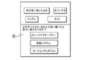
例えば、ユーザが、「ホーム」のアイデアを提供するために応答シーンを生成してもよい。応答シーンは、「私が家にいるとき、私はリビングルームのライトが欲しい」のように、ユーザに関して生成されてもよい。K4Connectシステム20は、例えばメニューを介して、「私が家にいるかどうかを決定するためにあなたが使用できるx個のデバイスがあり、ここにライトを提供するデバイスがある」ことを示し、あるいは表示する。換言すると、シーンが最初構築され、次いで、シーンを作ることができるアドレス指定可能デバイス31a〜31nが提供される。 For example, a user may generate a response scene to provide a “home” idea. A response scene may be generated for the user, such as “When I am at home, I want a light in the living room”. The
次に図29b及び図29cを参照し、HAシステム20に関連するものとしての構成要素応答シーンが次に説明される。HAシステム20は、所与のロケーションにアドレス指定可能HAデバイス31a〜31nを含む。アドレス指定可能HAデバイス31a〜31nは、動き検出器、サーモスタット、ライトスイッチ、オーディオコントローラ、ドアロック、及び/又はカメラのうち、任意のものを含む。当然ながら、アドレス指定可能HAデバイス31a〜31nは、さらなる及び/又は他のデバイスを含んでもよい。 29b and 29c, the component response scene as it relates to the
HAシステム20は、ユーザから例えばワイヤレスで第1のトリガアクションと第1の応答イベントとを含む第1のシーンを取得するHAデバイスシーンコントローラ581をさらに含む。例えば、第1のトリガは「私が家に着いたとき」であってもよく、第1の応答イベントは「リビングルームのライトをオンにする」であってもよい。実際、第1のトリガアクション及び第1の応答イベントは、アドレス指定可能HAデバイス32a〜32nのうちいずれが第1のトリガアクション及び第1の応答イベントを実現することを担うかを識別しない。HAデバイスシーンコントローラ581は、ユーザインターフェースデバイス360、例えば、より詳細にはユーザインターフェースコントローラ353に結合されてユーザ入力を可能にするユーザ入力デバイス351から、第1のトリガアクション及び第1の応答イベントを取得してもよい。ユーザインターフェースデバイス360は、リモートデバイス、例えば、タブレットコンピュータ、スマートフォン等であってもよい。2つ以上の第1のトリガアクション及び任意数の第1の応答イベントがあってもよい。 The
HAデバイスシーンコントローラ581は、さらに、例えばユーザインターフェースコントローラ353に結合されたユーザインターフェースデバイス360のディスプレイ354に、第1の所望シーンを実現することができるアドレス指定可能HAデバイス31a〜31nのうち対応するデバイスの第1のユーザ選択可能リストを提示する。換言すると、HAデバイスシーンコントローラ581は、第1のトリガアクション及び第1の応答イベントに対応するか又はこれらを実行することになるアドレス指定可能HAデバイス31a〜31nを提示する。 The HA
HAデバイスシーンコントローラ581は、さらに、アドレス指定可能HAデバイス31a〜31nのうち第1のユーザ選択されたデバイスを決定し、第1のトリガイベントが発生すると、第1のユーザ選択されたアドレス指定可能HAデバイスを用いて第1の応答イベントを実行し、これにより、第1の所望シーンを実現する。第1の所望シーンは、ワイヤレスで実行されてもよく、例えば、HAデバイスシーンコントローラ581は、アドレス指定可能HAデバイス31a〜31nとワイヤレスで通信して、第1の所望シーンを実現してもよい。いくつかの実施形態において、HAデバイスシーンコントローラ581は、トリガイベントが発生すると通知を生成してもよい。 The HA
HAデバイスシーンコントローラ581は、さらに、クラウドから、例えばワイヤレスで、第2のトリガアクションと第2の応答イベントとを含む第2の所望シーンを取得する。第2のトリガアクション及び第2の応答イベントは、第2のトリガアクション及び第2の応答イベントを実現することを担うアドレス指定可能HAデバイス31a〜31nを識別することなく取得される。 The HA
HAデバイスシーンコントローラ581は、例えばディスプレイ354に、第2の所望シーンを実現することができる対応するアドレス指定可能HAデバイス31a〜31nの第2のユーザ選択可能リストを提示してもよい。換言すると、第2のシーンは共有されたシーンとして、例えば別の人のHAシステムから取得される。HAデバイスシーンコントローラ581は、さらに、第2のユーザ選択されたアドレス指定可能HAデバイス31a〜31nを決定し、上記で説明されたのと同様に、例えばワイヤレスで、第2のトリガイベントが発生すると、第2のユーザ選択されたアドレス指定可能HAデバイスを用いて第2の応答イベントを実行し、これにより、第2の所望シーンを実現する。 The HA
HAデバイスシーンコントローラ581は、さらに、所与のロケーションにおけるアドレス指定可能HAデバイス31a〜31nがシーンを実現することができないときを決定してもよい。このことが当てはまるとき、HAデバイスシーンコントローラ581は、例えばディスプレイ354に、さらなるアドレス指定可能HAデバイスについて、購入オファーを提示する。ユーザは、例えば、ハイパーリンクをクリックすることにより、さらなるアドレス指定可能HAデバイスを購入してもよい。 The HA
一方法態様が、HAシステム20において第1及び第2の所望シーンを実現する方法に向けられる。方法は、HAデバイスシーンコントローラ581を使用して、ユーザから第1のトリガアクションと第1の応答イベントとを含む第1の所望シーンを取得し、第1の所望シーンを実現することができる対応するアドレス指定可能HAデバイス31a〜31nの第1のユーザ選択可能リストを提示することを含む。HAデバイスシーンコントローラ581は、さらに、第1のユーザ選択されたアドレス指定可能HAデバイス31a〜31nを決定し、第1のトリガイベントが発生すると、第1のユーザ選択されたアドレス指定可能HAデバイスを用いて第1の応答イベントを実行し、これにより、第1の所望シーンを実現することに使用される。 One method aspect is directed to a method for realizing first and second desired scenes in the
HAデバイスシーンコントローラ581は、さらに、クラウド331から第2のトリガアクションと第2の応答イベントとを含む第2の所望シーンを取得し、第2の所望シーンを実現することができる対応するアドレス指定可能HAデバイス31a〜31nの第2のユーザ選択可能リストを提示することに使用される。デバイスシーンコントローラ581は、さらに、アドレス指定可能HAデバイスのうち第2のユーザ選択されたデバイスを決定し、少なくとも1つの第2のトリガイベントが発生すると、第2のユーザ選択されたアドレス指定可能HAデバイス31a〜31nを用いて第2の応答イベントを実行し、これにより、第2の所望シーンを実現することに使用される。いくつかの実施形態において、HAデバイスシーンコントローラ581は、所与のロケーションのアドレス指定可能HAデバイス31a〜31nがシーンを実現することができないときを決定し、さらなるアドレス指定可能HAデバイスの購入オファーを提示することに使用される。 The HA
次に、K4Connectシステム20に関連するものとしての開発キットが説明される。K4Connectシステム20は、ソフトウェア及びハードウェア双方の開発キットを提供する。ソフトウェア開発キットは、開発者がメッセージキューとのすべての通信と対話し、かつ該通信を扱うための完全なデバイススタックを構築する。ビルトインのブリッジエディタが、例えば、開発者がウェブブラウザからブリッジを作成及び編集することを可能にし、記述エディタが、デバイス記述XMLファイルを作成する。 Next, a development kit as related to the
ハードウェア開発キットは、開発者が中間ブリッジなしに制御可能デバイスを直接メッセージキューに接続することを可能にする。例えば、開発者がその制御可能デバイスに通信プロトコルを追加するとき、K4Connectシステム20、詳細にはその通信コンポーネントが、そのハードウェアに統合されて、システムのブリッジをバイパスし、メッセージキューと直接通信してもよい。 Hardware development kits allow developers to connect controllable devices directly to message queues without an intermediate bridge. For example, when a developer adds a communication protocol to the controllable device, the
次に、クラウドデバイス33又はK4Awayのさらなる詳細が説明される。すでに説明されたK4Awayの機能に追加で、K4Awayは外部APIをホストする。外部APIは、独自にインターネットベースのサービスに接続することができないデバイスのためのインターフェースを提供する。K4Connectシステム20及びK4Awayに接続されたとき、前にネットワーク化されていないデバイスが、そのK4Awayとの接続を通して、例えばIFTTT、Evernote、及びFacebook(登録商標)などの外側のサービスにアクセス可能になる。 Next, further details of the
セキュリティに関して、K4Connectシステム20のセキュリティモデルは、システムに比較的高いレベルのセキュリティを提供することに基づく。各々の電話又はリモートデバイス36は、2つのレベルで認証される。第1のレベルは、システム管理者により追加されたデバイス固有の許容である。第2のレベルは、リモートデバイス36上のユーザログインである。この2レイヤのシステムは、正当なユーザログインがあった場合でさえ、承認されていないデバイスのログインの発生を低減する。 Regarding security, the security model of the
K4Connectシステム20は、その解析データ収集においてプライバシー手法を通してセキュリティをさらに提供する。データは、2つの別個のサーバに記憶される。一方のサーバが、匿名ユーザを表すトークンを保持し、他方のサーバが、使用及び解析データを保持する。2つのサーバ間の接続は、技術的ヘルプのためにユーザにより承認されたとき、発生する。ユーザが応答シーン又はデバイス推奨を送信されたとき、その示唆は、典型的に、上記ユーザを表すトークンにのみ送信される。ユーザは、常時匿名のままである。換言すると、ユーザに関する情報の一部は、「知る必要」原則と同様に、技術的サポートを提供するために選択的に利用可能であり得る。 The
K4Connectシステム20は、収集されるデータに対する完全な権利及び所有権をユーザに授与するセキュリティ手法をさらに使用する。K4Connectシステム20は、ユーザからのデータを収集し、解析し、それを別個のセキュアサーバ上に記憶する。閾時間期間、例えば、1年の後、データは恒久的に削除される。この方法は、上記データをいつでも恒久的に削除する能力をユーザに授与するユーザオーバーライドを含む。 The
K4Hub34は、ホームルータに接続されたWifiルータとしてさらに使用でき、そのため、K4Connectシステム20に接続されたすべてのデバイスは、K4Hub34のプライベートWifiネットワークを通してルーティングされる。このことは、有利には、K4Connectシステムに接続されたデバイス、例えばパーソナルコンピュータなどの間の分離を可能にする。この分離は、K4Connectシステム20のデバイス間のネットワークに影響することからのパーソナルコンピュータに対する攻撃の機会を低減する可能性がある。 The
次に図30aを参照すると、別の態様が、K4Connectシステム20’’上で使用されるヘルス関連デバイスに向けられる。K4Connectシステム20’’と連動したヘルス関連デバイスの使用は、K4Lifeと称されることがある。しかしながら、ヘルス関連か否かにかかわらず、他の及び/又はさらなるデバイスがK4Lifeシステムの一部であってもよいことが留意されるべきである。上記で説明されたK4Connectシステムと同様に、K4Lifeシステム20’’はアドレス指定可能デバイス31a’’〜31n’’を含み、これらのうちいくつかが、例えば、歩いた歩数、血圧、体重、及び他のメトリクスなどのヒューマンヘルス関連データを測定するヘルスデバイスの形式であり得る。換言すると、K4Lifeシステム20’’は、上記で説明されたK4Connectシステムの機能を実行し、以下でさらに詳細に説明されるようにさらなるヘルス関連機能を含む。例えば、ヘルスデバイスは、例えば、1つ以上のベッドセンサ、動き検出器、フィットネス追跡デバイス、血圧バンド/モニタ、体重計、及び温度プローブを含んでもよい。当然ながら、例えばK4Homeシステムからの、他の及び/又はさらなるヘルスデバイス若しくはセンサが使用されてもよい。 Referring now to FIG. 30a, another aspect is directed to a health related device used on the K4Connect system 20 ''. The use of a health-related device in conjunction with the K4Connect system 20 '' may be referred to as K4Life. However, it should be noted that other and / or additional devices may be part of the K4Life system, whether health related or not. Similar to the K4Connect system described above, the K4Life system 20 '' includes
さらに、K4Appは、社会的交流、例えば、写真共有及びライブビデオチャットを提供する。より詳細には、ライブビデオチャットが開始されるとき、K4Lifeシステム20’’は、ライブビデオチャットの開始時間及び継続時間を、中央サーバ、例えばクラウドデバイス33’’又はローカルサーバデバイスに報告してもよい。 In addition, K4App provides social interaction, such as photo sharing and live video chat. More particularly, when a live video chat is initiated, the
K4Lifeシステム20’’、例えば解析サーバ54’’は、ユーザの全体的ヘルスを示すスコアを計算し、このスコアは、K4Scoreとして参照されてもよい。K4Scoreは、直接測定されたヘルスデータと、アドレス指定可能デバイス又はヘルスデバイス31a’’〜31n’’の使用から測定された活動レベルと、K4Appの使用により測定された社会的関わりとを組み合わせることにより決定される。K4Scoreは、他の及び/又はさらなる情報を含み、あるいは該情報に基づいてもよい。このスコアの過去の傾向が、例えば、ユーザの健康における向上又は低下を予測するために使用されてもよい。当然ながら、このデータは、他の目的で使用されてもよく、例えば、ヘルスケア専門家、モニタリングステーション等のような他のユーザに通信されてもよい。例えば、座りがちな人が、不規則な睡眠パターンを有し、わずかな社会的交流が、潜在的な健康問題を有するとして識別されてもよい。K4Lifeシステム20’’及びK4Scoreが比較的有利であり得る1つの例示的なシナリオは、年配の親によるシステムの使用であって、その子供が親の健康状態をチェックしたい場合であり、あるいはユーザがその自身の健康状態を単に知らされていたい場合である。 The
いくつかの実施形態において、ヘルス又は活動データは、家族メンバによって、又は介護付き住宅などのグループ生活設定において、又はオンサイト若しくはリモートの監督者によって閲覧されてもよい。ヘルスデータは、さらに、例えばリモートデバイス36’’のユーザインターフェース35’’を介して表示されて、個々のユーザのヘルススコア又はユーザのコミュニティの総計を示してもよい。 In some embodiments, health or activity data may be viewed by family members or in a group living setting such as a nursing home or by an onsite or remote supervisor. The health data may also be displayed, for example, via the
次に図30bを参照すると、K4Connect又はHAシステム20’’のヘルス関連の態様が次に説明される。HAシステム20’’は、アドレス指定可能HAデバイス31a’’〜31n’’を含む。アドレス指定可能HAデバイス31a’’〜31n’’は、動き検出器、サーモスタット、ライトスイッチ、オーディオコントローラ、ドアロック、カメラ、及び/又はヘルス関連センサ(例えば、部屋占有センサ、ベッドセンサ、歩数カウンタ、心拍モニタ、血圧モニタ、温度センサ、及び体重計)のうち、任意のものを含んでもよい。当然ながら、アドレス指定可能HAデバイス31a’’〜31n’’は、他の及び/又はさらなるデバイスを含んでもよい。アドレス指定可能デバイス31a’’〜31n’’は、異なるワイヤレス通信プロトコルの中からそれぞれの異なるワイヤレス通信プロトコルを用いてワイヤレスで通信する。 Referring now to FIG. 30b, the health-related aspects of the K4Connect or HA system 20 '' will now be described. The
HAシステム20’’は、ユーザソーシャルネットワーキングを可能にし、かつこれに基づいてユーザソーシャルネットワーキングデータを生成するユーザインターフェースデバイス36’’をさらに含み、上記データは、例えば、いずれのソーシャルネットワーキングアプリケーションか、及び各ソーシャルネットワーキングアプリケーションを用いて費やされた時間の量に関連するデータである。ユーザインターフェースデバイス36’’は、ポータブルハウジング361’’と、ポータブルハウジングにより担体されたディスプレイ48’’と、ポータブルハウジングにより担体されたワイヤレス通信回路362’’と、ディスプレイ及びワイヤレス通信回路に結合されて少なくとも1つのワイヤレス通信機能を実行するユーザインターフェースデバイスコントローラ49’’とを含む。例えば、ユーザインターフェースデバイス36’’は、スマートフォン又はタブレットであってもよく、任意数のソーシャルネットワーキングアプリケーション、例えば、写真共有、ライブビデオチャット、及びソーシャルメディアアプリケーションを実行してもよい。 The HA system 20 '' further includes a user interface device 36 '' that enables user social networking and generates user social networking data based thereon, the data including, for example, which social networking application, and Data related to the amount of time spent using each social networking application. The
HAシステム20’’は、コントローラ381’’と、これに結合されたメモリ382’’とをさらに含み、測定されたユーザヘルスデータを記憶し、アドレス指定可能HAデバイス31a’’〜31n’’に基づいてユーザ身体活動データを決定する。身体活動は、時間期間のある期間に基づいて決定されてもよい。 The HA system 20 '' further includes a controller 381 '' and a memory 382 '' coupled thereto to store measured user health data and to
コントローラ381’’は、さらに、ユーザソーシャルネットワーキングデータとユーザヘルスデータとユーザ身体活動データとに基づいてユーザヘルススコアを生成し、クラウド331’’を介してユーザヘルススコアを通信する。コントローラ381’’は、さらに、例えば、上記時間の期間内に間隔を置いて決定された身体活動レベルに基づいてユーザヘルススコアを生成してもよい。 The
コントローラ381’’は、例えば、ユーザヘルススコアが閾値を超えているとき、通知を生成してもよい。より詳細には、ユーザヘルススコアが不健康を示す場合、例えば、電子メール、SMSメッセージ、ディスプレイ上の視覚的通知等のような通知が生成され、クラウド331’’を介して電子デバイス361’’に通信されてもよい。いくつかの実施形態において、コントローラ381’’は、ある時間期間にわたり連続的な低下するユーザヘルススコアがある場合に通知を生成してもよい。ひとたびユーザヘルススコアがクラウド331’’に通信されると、上記スコアは、例えば、当業者に十分理解されるように、記憶、閲覧、分析、及び/又は他のデータ処理のために電子デバイス361’’によりダウンロードされてもよい。 For example, the
一方法態様が、HAシステム20’’においてユーザヘルススコアを通信する方法に向けられる。方法は、ユーザインターフェース36’’を介して、ユーザソーシャルネットワーキングを許可し、これに基づいてユーザソーシャルネットワーキングデータを生成することを含む。方法は、コントローラ361’’及びこれに結合されたメモリ362’’を使用して、測定されたユーザヘルスデータを記憶し、複数のアドレス指定可能HAデバイスに基づいてユーザ身体活動データを決定し、ユーザソーシャルネットワーキングデータとユーザヘルスデータとユーザ身体活動データとに基づいてユーザヘルススコアを生成し、クラウドを介してユーザヘルススコアを通信することをさらに含む。 One method aspect is directed to a method of communicating user health scores in the HA system 20 ''. The method includes authorizing user social networking via the user interface 36 '' and generating user social networking data based thereon. The method uses a controller 361 '' and a memory 362 '' coupled thereto to store measured user health data and determine user physical activity data based on a plurality of addressable HA devices; The method further includes generating a user health score based on the user social networking data, the user health data, and the user physical activity data, and communicating the user health score via the cloud.
次に図31を参照し、K4Connectシステム20’’’が、ロケーション決定にさらに使用されてもよい。K4Connectシステム20’’’が、K4Hub34’’’の指定された範囲内にあるモバイルデバイス(すなわち、リモートデバイス36’’’)を検出してもよい。これらの検出は、中央サーバ、例えば、クラウドデバイス又はK4Awayに報告でき、中央サーバにおいて、例えば、上記検出が、家又は施設内の人又はデバイスのロケーションを推定するために使用される。2つ以上のK4Hub34’’’が一時にあるモバイル又はリモートデバイス36’’’を検出することができるとき、K4Connectシステム20’’’は、重なったデータの検出強度を比較し、いずれのK4Hubが検出された人又はデバイスに最も近かったかを決定することにより、重複データを低減する。当然ながら、この実施形態に説明されるK4Connectシステム20’’’は、上記で説明されたK4Lifeシステムとの使用に特に有用であり得る。 Referring now to FIG. 31, the K4Connect system 20 '' 'may be further used for location determination.
次に図32を参照すると、別の実施形態において、複数のK4Life(又は、K4Connect)システム20a’’’’〜20n’’’’が、K4Communityとして参照され得るシステムにおいて集合的に使用されてもよい。K4Communityシステムは、有利には、例えばクラウドデバイス又はK4Awayにおいて、複数のK4Life又はK4Connectシステム20a’’’’〜20n’’’’からの集約データがコミュニティ内における比較のために解析されることを可能にする。他のコントローラ及び/又はデバイスからのデータがさらに集約されてもよい。当然ながら、任意の又は各々のシステム20a’’’’〜20n’’’’が、例えば全体的にかあるいは共有又は負荷分散された配置で、データを処理し、あるいは集約してもよい。さらに、K4Community20a’’’’〜20n’’’’におけるユーザは、互いに通信し、いくつかの実施形態において、所与のユーザの実行に対して他がどれほど実行しているかを見ることができてもよい。当業者に十分理解されるように、ヘルス関連データが収集され、可能性として交換されているため、ヘルス関連データは、ヘルスデータのユーザ又は所有者がそれを共有することに同意し、あるいはそれを実際に共有するまで、匿名を維持され、暗号化されてもよい。 Referring now to FIG. 32, in another embodiment, multiple K4Life (or K4Connect) systems 20a ″ ″-20n ″ ″ may be used collectively in a system that may be referred to as K4Community. Good. The K4 Community system advantageously allows aggregate data from multiple K4Life or K4Connect systems 20a ″ ″ to 20n ″ ″ to be analyzed for comparison within a community, for example in a cloud device or K4Away. To. Data from other controllers and / or devices may be further aggregated. Of course, any or each of the systems 20a "" to 20n "" may process or aggregate data, e.g., entirely or in a shared or load-balanced arrangement. Further, users at K4 Community 20a ""-20n "" can communicate with each other and in some embodiments can see how much others are performing for a given user's execution. Also good. As is well understood by those skilled in the art, because health-related data is collected and potentially exchanged, the health-related data agrees with or is shared by the user or owner of the health data Until you actually share it, you may remain anonymous and encrypted.
いくつかの実施形態において、K4Life又はK4Communityシステムは、ヘルス関連デバイス及びヘルス関連データに限られなくてもよい。例えば、上記で説明されたシステムの原理は、ユーティリティ管理、例えば、アパートユーティリティ負荷制御管理に適用されてもよい。こうした実施形態において、センサ又は制御可能デバイスが、例えば、エネルギー及び水道使用を監視し、これに基づいてプロファイルを構築するために使用されてもよい。他のテナントと比べてより多くユーティリティを使用する特定のテナントが識別されてもよい。さらに、共用エリアが監視され、スコア付けされてもよい。さらに、スコアが各テナントに割り当てられてもよい。 In some embodiments, the K4Life or K4 Community system may not be limited to health-related devices and health-related data. For example, the system principles described above may be applied to utility management, eg, apartment utility load control management. In such embodiments, sensors or controllable devices may be used, for example, to monitor energy and water usage and build profiles based thereon. A particular tenant that uses more utilities compared to other tenants may be identified. In addition, common areas may be monitored and scored. Furthermore, a score may be assigned to each tenant.
図33を参照し、別の実施形態において、K4Lifeシステム120がヘルスケア設定において使用されて、どれほどの時間をヘルスケア専門家が患者又はユーザに与えているかを決定してもよい。1つの具体的な例において、システム120が養護ホームにおいて使用されて、どれほどの時間を看護師がユーザ/患者に費やしているか、並びに看護師が患者と共に部屋147にいたとき及び場合を監視してもよい。システム120、詳細にはハブデバイス134は、例えばBluetooth(登録商標)などの短距離通信プロトコルコントローラ199を含む。当然ながら、ハブデバイス134は、上記又は他の実施形態においてホームデバイスと置き換え可能に使用されてもよい。さらに、各看護師は、短距離通信プロトコルを介してシステムと通信するように構成された回路196を含む識別デバイス又はタグ197を装着することになる。看護師がユーザ又は患者と共に部屋にいて、かつ通信範囲内にいるとき、システムとタグとが通信し、通信の時間及び継続時間がログをとられる。この情報は、当業者に十分理解されるように、K4Community環境で使用できる。 Referring to FIG. 33, in another embodiment, the
次に図34を参照し、別の実施形態において、例えば、ヘルスケア施設などのK4Communityシステムにおいて、アドレス指定可能デバイスに基づいたイベント又はチケットが生成されてもよい。上記イベントは、ログをとられ、かつ/あるいはスタッフに割り当てられ、リモートデバイス136’のユーザインターフェース135’に表示されてもよい。スタッフが、例えば、イベント生成に関連づけられた人の部屋に到着したとき、そのスタッフの人の到着時間が、例えば、上記で説明されたようにログをとられてもよい。 Referring now to FIG. 34, in another embodiment, an event or ticket based on an addressable device may be generated, for example, in a K4 Community system such as a healthcare facility. Such events may be logged and / or assigned to staff and displayed on the user interface 135 'of the remote device 136'. When a staff member arrives at a person's room associated with the event generation, for example, the arrival time of the staff member may be logged, for example, as described above.
いくつかの実施形態が、電子デバイスのプロセッサ又は処理回路により実行されるソフトウェアを含むものとして説明されたが、上記ソフトウェアは、ファームウェア、マシンコード、又はプロセッサ若しくは処理回路の構成を含み得ることが当業者に理解されるべきである。さらに、いくつかの実施形態が説明されたが、任意の所与の実施形態において説明された機能は、種々の実施形態において説明されたように、例えば他の及び/又はさらなる機能と共に使用されてもよいことが十分理解されるであろう。またさらに、用語「ホーム」が、特定のデバイス及び/又はロケーションを説明するために(例えば、ホームオートメーションに関して)使用されたが、システム及びそのコンポーネントは、アパート、ヘルスセンタ等などの他の場所において使用されてもよいことが当業者に十分理解されるであろう。ゆえに、用語「ホーム」は、ユーザの家に具体的に限定されない。さらに、プロセッサ及び/又はコントローラが本明細書において説明されたが、プロセッサ及び/又はコントローラは、それぞれの機能を実行する回路を含んでもよく、かつメモリをさらに含んでもよいことが十分理解されるであろう。メモリは、例えば、プロセッサ及び/又はコントローラにさらに結合されてもよい。 Although some embodiments have been described as including software executed by a processor or processing circuit of an electronic device, it is understood that the software may include firmware, machine code, or a configuration of a processor or processing circuit. Should be understood by the contractor. Furthermore, although several embodiments have been described, the functions described in any given embodiment may be used, for example, with other and / or additional functions, as described in various embodiments. It will be appreciated that Still further, although the term “home” has been used to describe a particular device and / or location (eg, with respect to home automation), the system and its components may be used elsewhere in an apartment, health center, etc. Those skilled in the art will appreciate that they may be used. Thus, the term “home” is not specifically limited to the user's home. Further, although a processor and / or controller has been described herein, it is well understood that the processor and / or controller may include circuitry that performs the respective functions and may further include a memory. I will. The memory may be further coupled to, for example, a processor and / or controller.
方法態様が、本明細書に説明された実施形態のうち任意のものにおいて説明されたように、例えば、K4Connect、K4Life、及びK4Communityを含むホームオートメーション統合システムを作成することを含む。他の方法態様が、システム又はその様々なコンポーネントの動作と、上記で詳細化された機能のうち任意のもの、例えば、統合、通信、表示等を実行することとを含む。 A method aspect includes creating a home automation integration system that includes, for example, K4Connect, K4Life, and K4Community as described in any of the embodiments described herein. Other method aspects include the operation of the system or its various components and performing any of the functions detailed above, eg, integration, communication, display, etc.
別の態様が、本明細書に説明されたシステム及び方法の機能のうち任意のものを実行する命令を記憶した非一時的コンピュータ読取可能媒体に向けられる。例えば、K4App、K4Home、及びK4Awayの機能性が、非一時的コンピュータ読取可能媒体に記憶されたコンピュータ実行可能命令として具現化されてもよい。当然ながら、本明細書に説明された他の機能が、非一時的コンピュータ読取可能媒体上に具現化されてもよい。 Another aspect is directed to a non-transitory computer readable medium having stored thereon instructions for performing any of the functions of the systems and methods described herein. For example, the functionality of K4App, K4Home, and K4Away may be embodied as computer-executable instructions stored on a non-transitory computer-readable medium. Of course, other functionality described herein may be embodied on non-transitory computer readable media.
次に図35を参照し、別の実施形態が、屋内建物エリア1022のための暖房、換気、及び空調(HVAC)システム1021を含む気候制御システム1020に向けられる。HVACシステム1021は、暖房と冷房との動作モード間で切り替え可能である。気候制御システム1020は、屋内建物エリア1022内にホームオートメーション(HA)サーモスタットデバイス1030を含む。HAサーモスタットデバイス1030は、ハウジング1031と、ハウジングにより担体された屋内温度センサ1032とを含む。屋内温度センサ1032は、屋内建物エリア1022の屋内温度を感知する。 Referring now to FIG. 35, another embodiment is directed to a
温度コントローラ1033が、ハウジング1031により担体される。HAサーモスタットデバイス1030は、温度コントローラ1033に結合されたワイヤレス通信回路1034をさらに含む。ワイヤレス通信回路1034は、例えば、Wifi、セルラー、又は他のプロトコルを介して通信するように構成されてもよい。 A
温度コントローラ1033は、屋内建物エリア1022の設定点温度を取得する。設定点温度は、ワイヤレスで、例えば、ワイヤレス通信回路1034を介して取得されてもよい。設定点温度は、当業者に十分理解されるように、入力デバイス、リモート電子デバイス、及び/又は他のデバイスから取得されてもよい。 The
HAサーモスタットデバイス1030は、ユーザ設定点温度入力デバイス1035とディスプレイ1036とをさらに含み、双方がハウジング1031により担体され、かつ温度コントローラ1033に結合される。ユーザ設定点温度入力デバイス1035は、当業者に十分理解されるように、タッチディスプレイ、プッシュボタン、回転可能ダイヤル、又は他の入力デバイスの形式であってもよい。ユーザ設定点温度入力デバイス1035は、設定点温度を設定するために使用されてもよい。温度コントローラ1033は、ディスプレイ1036と協働して、屋内温度及び設定点温度を表示してもよい。 The
設定点温度は、さらに、HAコントローラ1037に基づいて生成され、あるいは設定されてもよく、HAコントローラ1037は、例えば、上記で説明されたように、HAサーモスタットデバイス1030に結合され、設定点温度を生成するように構成される。上記で説明されたように、HAコントローラ1037は、アドレス指定可能HAデバイス1038a〜1038n、例えば、動き検出器、ライト等に結合されてもよい。HAコントローラ1037は、アドレス指定可能HAデバイス1038a〜1038nのうち1つに基づいて設定点温度を生成する。例えば、動き検出器から検出された動きに基づいて、HAコントローラ1037は、HAサーモスタットデバイス1030と通信して、設定点温度を設定してもよい(すなわち、誰かが家にいるとき、設定点温度をより冷たく設定する)。当然ながら、設定点温度は、他のタイプのアドレス指定可能HAデバイス1038a〜1038nに基づいて設定可能である。 The set point temperature may further be generated or set based on the
温度コントローラ1033は、屋内建物エリア1022に対して外部からの外部温度をさらに取得する。外部温度は、ワイヤレスで、例えば、インターネットを介して取得されてもよい。外部温度は、例えば、外側温度であってもよく、あるいは屋内建物エリア1022に対して外部と考えられ得る部屋又はエリアの内側温度であってもよい。いくつかの実施形態において、2つ以上の温度センサ(屋内及び/又は屋外)が、外部温度を取得するために使用されてもよい。 The
温度コントローラ1033は、設定点温度の外部温度の交差を決定し、設定点温度の外部温度の交差と、屋内温度が閾温度差、例えば1度だけ設定点温度を超えて移行することとに基づいて、HVACシステム1021を動作モード間で切り替える。他の閾温度差が使用されてもよい。 The
次に図36をさらに参照すると、気候制御システム1020の動作が、グラフ1040と対応するディスプレイ1036a〜1036eとにより例示され、ディスプレイ1036a〜1036eは、グラフ上で識別された異なる時点における対応する屋内温度1043a〜1043eと設定点温度1044a〜1044eとを示す。グラフ1040において、外側温度はライン1041で示され、実際の又は屋内の温度はライン1042で示される。例示的に、屋内温度又は部屋温度は瞬間的に所望温度又は設定点温度からずれ、外部温度はデッドバンド1045を通過する。 Referring now further to FIG. 36, the operation of the
一方法態様が、気候制御システム1020を動作させる方法に向けられる。方法は、屋内温度センサ1032を介して屋内建物エリア1022の屋内温度を感知することを含む。方法は、屋内建物エリア1022内のHAサーモスタットデバイス1030を使用して、屋内建物エリアの設定点温度を取得し、屋内建物エリアの外部からの外部温度を取得し、設定点温度の外部温度の交差を決定し、設定点温度の外部温度の交差と屋内建物エリア1022の屋内温度が閾温度差だけ設定点温度を超えて移行することとに基づいて、HVACシステム1021を動作モード間で切り替えることをさらに含む。 One method aspect is directed to a method of operating a
次に図37a〜37eを参照すると、HAシステム2020の別の実施形態において、アドレス指定可能HAデバイス2031a〜2031nにリモートでアクセスすることが望ましい場合がある。IOTデバイスとしても知られるアドレス指定可能HAデバイス2031a〜2031nのリモートアクセスは、例えば、所与のアドレス指定可能HAデバイスでの問題をトラブルシューティングすること、及び/又はソフトウェア若しくは構成を更新することに特に役立つ可能性がある。 Referring now to FIGS. 37a-37e, in another embodiment of the
アドレス指定可能HAデバイス2031a〜2031nは、当業者に十分理解されるように、典型的には1つ以上のネットワークアドレス変換(NAT)ルータ及び/又はファイアウォールの背後にあり、ゆえに一般にインターネットアクセス可能でない。したがって、アドレス指定可能HAデバイス2031a〜2031nにアクセスするために、オンデマンドセキュアシェル(SSH)トンネリングが使用されてもよい。
オンデマンドSSHトンネリングは、アドレス指定可能HAデバイス2031a〜2031nのうち所与の1つが、例えば周期的接続を通して、既知のホストと通信してトンネリング命令を取り出すことを可能にする。ゆえに、例えば、トンネリング命令が、SSHプロトコルを通して低減されたオーバーヘッドで所与のアドレス指定可能HAデバイスに対するリモートアクセスを可能にすることができる。当然ながら、他のプロトコル、例えば、セキュアプロトコルが使用されてもよい。 On-demand SSH tunneling allows a given one of the
アドレス指定可能HA又はIOTデバイス2031a〜2031nに対するリモート接続を確立するために、要求が、トンネルをオープンするために所与のアドレス指定可能HAデバイスに対して発行される。このことは、例えば、リモートのユーザによって、リモートアクセスワイヤレス通信デバイス2036を介して、オンデマンドSSHトンネリングを用いて実行されてもよく、所与のアドレス指定可能HAデバイスに固有の、ウェブで見える(例えば、パブリックにアクセス可能な)ロケーションにファイルを作成する(図37a)。ウェブで見えるロケーションは、例えば、サーバ2099上、又は他のウェブで見えるロケーションであってもよい。例示的な実施形態において、ファイルは、所与のアドレス指定可能HAデバイスの一意の識別と最後の一意のクラウドセッション識別とのハッシュであるAmazon(登録商標)シンプルストレージサービス(S3)ファイルであってもよい。S3ファイルは、アドレス指定可能HAデバイス2031a〜2031nに関する他の及び/又はさらなる情報を含んでもよい。 In order to establish a remote connection to an addressable HA or
クラウドサーバ2033が、例えば、サーバ2099上で、既知のロケーションにおける所与のHAデバイス2031a〜2031nのためのデバイス固有命令を利用可能にしてもよい(図37b)。いくつかの実施形態において、デバイス固有命令は、クラウドサーバ2033上に併置されてもよい。
アドレス指定可能HAデバイス2031a〜2031nは、例えば、周期的にポーリングすることにより、このロケーションと通信する。例えば、上記ロケーションは、数分ごとにポーリングされてもよい。当然ながら、アドレス指定可能HAデバイス2031a〜2031nは、より長い、より短い、及び/又は異なる間隔で上記ロケーションと通信し、あるいは上記ロケーションをポーリングしてもよい。ポーリングに基づいて、例えば、アドレス指定可能HAデバイス2031a〜2031nは、所与のアドレス指定可能HAデバイスのために記憶されかつ利用可能にされたトンネリング命令を見つける(図37c)。1つの例において、命令は、クラウドで見えるホスト/ポート/ユーザ名/パスワードを含むjsonファイルであってもよい。当然ながら、命令は異なるタイプのファイル内に具現化されてもよく、かつ/あるいは、他のデータ要素が命令ファイルに記憶されてもよい。
所与のアドレス指定可能HAデバイス2031a〜2031nは、ウェブアクセス可能なロケーションから取り出された命令に従ってクラウドサーバ2033に対するSSHトンネルをオープンする(図37d)。次いで、リモートユーザがリモートアクセスワイヤレス通信デバイス2036を介して、例えば、ログインすることにより、所与のアドレス指定可能HAデバイス2031a〜2031nとの通信を可能にするトンネルのクラウド側に、それがインターネットで見えるかのように接続してもよい(図37e)。 A given
本発明の多くの変更及び他の実施形態が、前述の説明及び関連した図面に提示された教示の恩恵を有した当業者に思い浮かぶであろう。したがって、本発明は、開示された特定の実施形態に限定されるべきでなく、変更及び実施形態が別記の特許請求の範囲内に含まれるよう意図されることが理解される。
Many modifications and other embodiments of the invention will occur to those skilled in the art having the benefit of the teachings presented in the foregoing description and the associated drawings. Therefore, it should be understood that the invention is not to be limited to the specific embodiments disclosed, and that modifications and embodiments are intended to be included within the scope of the following claims.
Claims (24)
Translated fromJapanese所与のロケーションにおける複数のアドレス指定可能HAデバイスと、
少なくとも1つの第1のトリガアクションと少なくとも1つの第1の応答イベントとを含む第1の所望シーンをユーザから取得し、
前記第1の所望シーンを実現することができる前記アドレス指定可能HAデバイスのうち対応するデバイスの、第1のユーザ選択可能リストを提示し、
前記アドレス指定可能HAデバイスのうち第1のユーザ選択されたデバイスを決定し、
前記少なくとも1つの第1のトリガイベントが発生すると、前記アドレス指定可能HAデバイスのうち前記第1のユーザ選択されたデバイスを用いて前記少なくとも1つの第1の応答イベントを実行して、これにより前記第1の所望シーンを実現し、
少なくとも1つの第2のトリガアクションと少なくとも1つの第2の応答イベントとを含む第2の所望シーンをクラウドから取得し、
前記第2の所望シーンを実現することができる前記アドレス指定可能HAデバイスのうち対応するデバイスの、第2のユーザ選択可能リストを提示し、
前記アドレス指定可能HAデバイスのうち第2のユーザ選択されたデバイスを決定し、
前記少なくとも1つの第2のトリガイベントが発生すると、前記アドレス指定可能HAデバイスのうち前記第2のユーザ選択されたデバイスを用いて前記少なくとも1つの第2の応答イベントを実行して、これにより前記第2の所望シーンを実現する
ように構成されたHAデバイスシーンコントローラと、
を含むHAシステム。Home automation (HA) system,
A plurality of addressable HA devices at a given location;
Obtaining from a user a first desired scene comprising at least one first trigger action and at least one first response event;
Presenting a first user-selectable list of corresponding devices among the addressable HA devices capable of realizing the first desired scene;
Determining a first user selected device of the addressable HA devices;
When the at least one first trigger event occurs, the at least one first response event is performed using the first user-selected device of the addressable HA devices, thereby Realize the first desired scene,
Obtaining from the cloud a second desired scene comprising at least one second trigger action and at least one second response event;
Presenting a second user-selectable list of corresponding devices of the addressable HA devices capable of realizing the second desired scene;
Determining a second user-selected device of the addressable HA devices;
When the at least one second trigger event occurs, the at least one second response event is performed using the second user-selected device of the addressable HA devices, thereby An HA device scene controller configured to implement a second desired scene;
HA system including
ディスプレイと、
ユーザ入力デバイスと、
前記ディスプレイ及びユーザ入力デバイスに結合され、かつ
前記第1及び第2のユーザ選択可能リストを前記ディスプレイに表示し、
前記ユーザ入力デバイスを介して、前記アドレス指定可能HAデバイスのうち前記第1及び第2のユーザ選択されたデバイスのユーザ選択を許可する
ように構成されたユーザインターフェースコントローラと、
を含む、請求項1に記載のHAシステム。A user interface device coupled to the HA device scene controller, the user interface device comprising:
Display,
A user input device;
Coupled to the display and a user input device, and displaying the first and second user selectable lists on the display;
A user interface controller configured to allow user selection of the first and second user selected devices of the addressable HA device via the user input device;
The HA system according to claim 1, comprising:
所与のロケーションにおける複数のアドレス指定可能HAデバイスと、
少なくとも1つの第1のトリガアクションと少なくとも1つの第1の応答イベントとを含む第1の所望シーンをユーザから取得し、
前記所与のロケーションにおける前記複数のアドレス指定可能HAデバイスが前記シーンを実現することができないときを決定し、さらなるアドレス指定可能HAデバイスの購入オファーを提示し、
前記所与のロケーションにおける前記複数のアドレス指定可能HAデバイスが前記シーンを実現することができるときを決定し、前記第1の所望シーンを実現することができる前記アドレス指定可能HAデバイスのうち対応するデバイスの、第1のユーザ選択可能リストを提示し、
前記アドレス指定可能HAデバイスのうち第1のユーザ選択されたデバイスを決定し、
前記少なくとも1つの第1のトリガイベントが発生すると、前記アドレス指定可能HAデバイスのうち前記第1のユーザ選択されたデバイスを用いて前記少なくとも1つの第1の応答イベントを実行して、これにより前記第1の所望シーンを実現する
ように構成されたHAデバイスシーンコントローラと、
を含むHAシステム。Home automation (HA) system,
A plurality of addressable HA devices at a given location;
Obtaining from a user a first desired scene comprising at least one first trigger action and at least one first response event;
Determining when the plurality of addressable HA devices at the given location are unable to realize the scene, and presenting a purchase offer for additional addressable HA devices;
Determine when the plurality of addressable HA devices at the given location can implement the scene and correspond among the addressable HA devices that can implement the first desired scene. Present a first user-selectable list of devices,
Determining a first user selected device of the addressable HA devices;
When the at least one first trigger event occurs, the at least one first response event is performed using the first user-selected device of the addressable HA devices, thereby An HA device scene controller configured to implement a first desired scene;
HA system including
ディスプレイと、
ユーザ入力デバイスと、
前記ディスプレイ及びユーザ入力デバイスに結合され、かつ
前記購入オファーと前記第1のユーザ選択可能リストとを前記ディスプレイに表示し、
前記ユーザ入力デバイスを介して、前記アドレス指定可能HAデバイスのうち前記第1のユーザ選択されたデバイスのユーザ選択を許可する
ように構成されたユーザインターフェースコントローラと、
を含む、請求項9に記載のHAシステム。A user interface device coupled to the HA device scene controller, the user interface device comprising:
Display,
A user input device;
Coupled to the display and a user input device, and displaying the purchase offer and the first user-selectable list on the display;
A user interface controller configured to allow user selection of the first user selected device of the addressable HA devices via the user input device;
The HA system according to claim 9, comprising:
HAデバイスシーンコントローラを使用して、
少なくとも1つの第1のトリガアクションと少なくとも1つの第1の応答イベントとを含む前記第1の所望シーンをユーザから取得し、
前記第1の所望シーンを実現することができる前記アドレス指定可能HAデバイスのうち対応するデバイスの、第1のユーザ選択可能リストを提示し、
前記アドレス指定可能HAデバイスのうち第1のユーザ選択されたデバイスを決定し、
前記少なくとも1つの第1のトリガイベントが発生すると、前記アドレス指定可能HAデバイスのうち前記第1のユーザ選択されたデバイスを用いて前記少なくとも1つの第1の応答イベントを実行して、これにより前記第1の所望シーンを実現し、
少なくとも1つの第2のトリガアクションと少なくとも1つの第2の応答イベントとを含む前記第2の所望シーンをクラウドから取得し、
前記第2の所望シーンを実現することができる前記アドレス指定可能HAデバイスのうち対応するデバイスの、第2のユーザ選択可能リストを提示し、
前記アドレス指定可能HAデバイスのうち第2のユーザ選択されたデバイスを決定し、
前記少なくとも1つの第2のトリガイベントが発生すると、前記アドレス指定可能HAデバイスのうち前記第2のユーザ選択されたデバイスを用いて前記少なくとも1つの第2の応答イベントを実行して、これにより前記第2の所望シーンを実現すること
を含む方法。A method for realizing first and second desired scenes in an HA system including a plurality of addressable home automation (HA) devices at a given location, comprising:
Using the HA device scene controller
Obtaining from the user the first desired scene comprising at least one first trigger action and at least one first response event;
Presenting a first user-selectable list of corresponding devices among the addressable HA devices capable of realizing the first desired scene;
Determining a first user selected device of the addressable HA devices;
When the at least one first trigger event occurs, the at least one first response event is performed using the first user-selected device of the addressable HA devices, thereby Realize the first desired scene,
Obtaining the second desired scene from the cloud including at least one second trigger action and at least one second response event;
Presenting a second user-selectable list of corresponding devices of the addressable HA devices capable of realizing the second desired scene;
Determining a second user-selected device of the addressable HA devices;
When the at least one second trigger event occurs, the at least one second response event is performed using the second user-selected device of the addressable HA devices, thereby Realizing a second desired scene.
HAデバイスシーンコントローラを使用して、
少なくとも1つの第1のトリガアクションと少なくとも1つの第1の応答イベントとを含む第1の所望シーンをユーザから取得し、
前記所与のロケーションにおける前記複数のアドレス指定可能HAデバイスが前記シーンを実現することができないときを決定し、さらなるアドレス指定可能HAデバイスの購入オファーを提示し、
前記所与のロケーションにおける前記複数のアドレス指定可能HAデバイスが前記シーンを実現することができるときを決定し、前記第1の所望シーンを実現することができる前記アドレス指定可能HAデバイスのうち対応するデバイスの、第1のユーザ選択可能リストを提示し、
前記アドレス指定可能HAデバイスのうち第1のユーザ選択されたデバイスを決定し、
前記少なくとも1つの第1のトリガイベントが発生すると、前記アドレス指定可能HAデバイスのうち前記第1のユーザ選択されたデバイスを用いて前記少なくとも1つの第1の応答イベントを実行して、これにより前記第1の所望シーンを実現すること
を含む方法。A method for realizing a first desired scene in an HA system including a plurality of addressable home automation (HA) devices at a given location, comprising:
Using the HA device scene controller
Obtaining from a user a first desired scene comprising at least one first trigger action and at least one first response event;
Determining when the plurality of addressable HA devices at the given location are unable to realize the scene, and presenting a purchase offer for additional addressable HA devices;
Determine when the plurality of addressable HA devices at the given location can implement the scene and correspond among the addressable HA devices that can implement the first desired scene. Present a first user-selectable list of devices,
Determining a first user selected device of the addressable HA devices;
When the at least one first trigger event occurs, the at least one first response event is performed using the first user-selected device of the addressable HA devices, thereby Realizing the first desired scene.
A user interface device coupled to the HA device scene controller is used to display the first user selectable list on a display, and through a user input device the first of the addressable HA devices. The method of claim 21, further comprising allowing user selection of a user selected device.
Applications Claiming Priority (19)
| Application Number | Priority Date | Filing Date | Title |
|---|---|---|---|
| US201562186491P | 2015-06-30 | 2015-06-30 | |
| US201562186506P | 2015-06-30 | 2015-06-30 | |
| US201562186501P | 2015-06-30 | 2015-06-30 | |
| US201562186473P | 2015-06-30 | 2015-06-30 | |
| US201562186487P | 2015-06-30 | 2015-06-30 | |
| US201562186480P | 2015-06-30 | 2015-06-30 | |
| US201562186469P | 2015-06-30 | 2015-06-30 | |
| US201562186466P | 2015-06-30 | 2015-06-30 | |
| US62/186,480 | 2015-06-30 | ||
| US62/186,473 | 2015-06-30 | ||
| US62/186,501 | 2015-06-30 | ||
| US62/186,506 | 2015-06-30 | ||
| US62/186,491 | 2015-06-30 | ||
| US62/186,469 | 2015-06-30 | ||
| US62/186,487 | 2015-06-30 | ||
| US62/186,466 | 2015-06-30 | ||
| PCT/US2016/040097WO2017004204A1 (en) | 2015-06-30 | 2016-06-29 | Home automation (ha) system including desired scene implementation based upon user-selectable list of addressable ha devices and related methods |
| US15/196,544 | 2016-06-29 | ||
| US15/196,544US10374822B2 (en) | 2015-06-30 | 2016-06-29 | Home automation (HA) system including desired scene implementation based upon user-selectable list of addressable HA devices and related methods |
Publications (2)
| Publication Number | Publication Date |
|---|---|
| JP2018519761Atrue JP2018519761A (en) | 2018-07-19 |
| JP6655635B2 JP6655635B2 (en) | 2020-02-26 |
Family
ID=57609168
Family Applications (1)
| Application Number | Title | Priority Date | Filing Date |
|---|---|---|---|
| JP2017568440AActiveJP6655635B2 (en) | 2015-06-30 | 2016-06-29 | HA system including desired scene realization based on user selectable list of addressable home automation (HA) devices, and related methods |
Country Status (3)
| Country | Link |
|---|---|
| US (1) | US10374822B2 (en) |
| JP (1) | JP6655635B2 (en) |
| WO (1) | WO2017004204A1 (en) |
Families Citing this family (167)
| Publication number | Priority date | Publication date | Assignee | Title |
|---|---|---|---|---|
| US6658091B1 (en) | 2002-02-01 | 2003-12-02 | @Security Broadband Corp. | LIfestyle multimedia security system |
| US8635350B2 (en) | 2006-06-12 | 2014-01-21 | Icontrol Networks, Inc. | IP device discovery systems and methods |
| US10142392B2 (en) | 2007-01-24 | 2018-11-27 | Icontrol Networks, Inc. | Methods and systems for improved system performance |
| US7711796B2 (en) | 2006-06-12 | 2010-05-04 | Icontrol Networks, Inc. | Gateway registry methods and systems |
| US11316958B2 (en) | 2008-08-11 | 2022-04-26 | Icontrol Networks, Inc. | Virtual device systems and methods |
| US11201755B2 (en) | 2004-03-16 | 2021-12-14 | Icontrol Networks, Inc. | Premises system management using status signal |
| US12063220B2 (en) | 2004-03-16 | 2024-08-13 | Icontrol Networks, Inc. | Communication protocols in integrated systems |
| US20090077623A1 (en) | 2005-03-16 | 2009-03-19 | Marc Baum | Security Network Integrating Security System and Network Devices |
| US11582065B2 (en) | 2007-06-12 | 2023-02-14 | Icontrol Networks, Inc. | Systems and methods for device communication |
| US8988221B2 (en) | 2005-03-16 | 2015-03-24 | Icontrol Networks, Inc. | Integrated security system with parallel processing architecture |
| US11277465B2 (en) | 2004-03-16 | 2022-03-15 | Icontrol Networks, Inc. | Generating risk profile using data of home monitoring and security system |
| US11916870B2 (en) | 2004-03-16 | 2024-02-27 | Icontrol Networks, Inc. | Gateway registry methods and systems |
| US10339791B2 (en) | 2007-06-12 | 2019-07-02 | Icontrol Networks, Inc. | Security network integrated with premise security system |
| US11159484B2 (en) | 2004-03-16 | 2021-10-26 | Icontrol Networks, Inc. | Forming a security network including integrated security system components and network devices |
| US9609003B1 (en) | 2007-06-12 | 2017-03-28 | Icontrol Networks, Inc. | Generating risk profile using data of home monitoring and security system |
| US10444964B2 (en) | 2007-06-12 | 2019-10-15 | Icontrol Networks, Inc. | Control system user interface |
| US20170118037A1 (en) | 2008-08-11 | 2017-04-27 | Icontrol Networks, Inc. | Integrated cloud system for premises automation |
| US11244545B2 (en) | 2004-03-16 | 2022-02-08 | Icontrol Networks, Inc. | Cross-client sensor user interface in an integrated security network |
| US10348575B2 (en) | 2013-06-27 | 2019-07-09 | Icontrol Networks, Inc. | Control system user interface |
| US9531593B2 (en) | 2007-06-12 | 2016-12-27 | Icontrol Networks, Inc. | Takeover processes in security network integrated with premise security system |
| US11677577B2 (en) | 2004-03-16 | 2023-06-13 | Icontrol Networks, Inc. | Premises system management using status signal |
| US8963713B2 (en) | 2005-03-16 | 2015-02-24 | Icontrol Networks, Inc. | Integrated security network with security alarm signaling system |
| US10522026B2 (en) | 2008-08-11 | 2019-12-31 | Icontrol Networks, Inc. | Automation system user interface with three-dimensional display |
| US9141276B2 (en) | 2005-03-16 | 2015-09-22 | Icontrol Networks, Inc. | Integrated interface for mobile device |
| US11343380B2 (en) | 2004-03-16 | 2022-05-24 | Icontrol Networks, Inc. | Premises system automation |
| GB2428821B (en) | 2004-03-16 | 2008-06-04 | Icontrol Networks Inc | Premises management system |
| US11113950B2 (en) | 2005-03-16 | 2021-09-07 | Icontrol Networks, Inc. | Gateway integrated with premises security system |
| US11811845B2 (en) | 2004-03-16 | 2023-11-07 | Icontrol Networks, Inc. | Communication protocols over internet protocol (IP) networks |
| US10721087B2 (en) | 2005-03-16 | 2020-07-21 | Icontrol Networks, Inc. | Method for networked touchscreen with integrated interfaces |
| US10375253B2 (en) | 2008-08-25 | 2019-08-06 | Icontrol Networks, Inc. | Security system with networked touchscreen and gateway |
| US10200504B2 (en) | 2007-06-12 | 2019-02-05 | Icontrol Networks, Inc. | Communication protocols over internet protocol (IP) networks |
| US10313303B2 (en) | 2007-06-12 | 2019-06-04 | Icontrol Networks, Inc. | Forming a security network including integrated security system components and network devices |
| US10382452B1 (en) | 2007-06-12 | 2019-08-13 | Icontrol Networks, Inc. | Communication protocols in integrated systems |
| US11489812B2 (en) | 2004-03-16 | 2022-11-01 | Icontrol Networks, Inc. | Forming a security network including integrated security system components and network devices |
| US10237237B2 (en) | 2007-06-12 | 2019-03-19 | Icontrol Networks, Inc. | Communication protocols in integrated systems |
| US9191228B2 (en) | 2005-03-16 | 2015-11-17 | Icontrol Networks, Inc. | Cross-client sensor user interface in an integrated security network |
| US10156959B2 (en) | 2005-03-16 | 2018-12-18 | Icontrol Networks, Inc. | Cross-client sensor user interface in an integrated security network |
| US11190578B2 (en) | 2008-08-11 | 2021-11-30 | Icontrol Networks, Inc. | Integrated cloud system with lightweight gateway for premises automation |
| US11368429B2 (en) | 2004-03-16 | 2022-06-21 | Icontrol Networks, Inc. | Premises management configuration and control |
| US9729342B2 (en) | 2010-12-20 | 2017-08-08 | Icontrol Networks, Inc. | Defining and implementing sensor triggered response rules |
| US11496568B2 (en) | 2005-03-16 | 2022-11-08 | Icontrol Networks, Inc. | Security system with networked touchscreen |
| US11615697B2 (en) | 2005-03-16 | 2023-03-28 | Icontrol Networks, Inc. | Premise management systems and methods |
| US10999254B2 (en) | 2005-03-16 | 2021-05-04 | Icontrol Networks, Inc. | System for data routing in networks |
| US11700142B2 (en) | 2005-03-16 | 2023-07-11 | Icontrol Networks, Inc. | Security network integrating security system and network devices |
| US9306809B2 (en) | 2007-06-12 | 2016-04-05 | Icontrol Networks, Inc. | Security system with networked touchscreen |
| US20170180198A1 (en) | 2008-08-11 | 2017-06-22 | Marc Baum | Forming a security network including integrated security system components |
| US20110128378A1 (en) | 2005-03-16 | 2011-06-02 | Reza Raji | Modular Electronic Display Platform |
| US20120324566A1 (en) | 2005-03-16 | 2012-12-20 | Marc Baum | Takeover Processes In Security Network Integrated With Premise Security System |
| US10079839B1 (en) | 2007-06-12 | 2018-09-18 | Icontrol Networks, Inc. | Activation of gateway device |
| US12063221B2 (en) | 2006-06-12 | 2024-08-13 | Icontrol Networks, Inc. | Activation of gateway device |
| US9318108B2 (en) | 2010-01-18 | 2016-04-19 | Apple Inc. | Intelligent automated assistant |
| US11706279B2 (en) | 2007-01-24 | 2023-07-18 | Icontrol Networks, Inc. | Methods and systems for data communication |
| US7633385B2 (en) | 2007-02-28 | 2009-12-15 | Ucontrol, Inc. | Method and system for communicating with and controlling an alarm system from a remote server |
| US8977255B2 (en) | 2007-04-03 | 2015-03-10 | Apple Inc. | Method and system for operating a multi-function portable electronic device using voice-activation |
| US8451986B2 (en) | 2007-04-23 | 2013-05-28 | Icontrol Networks, Inc. | Method and system for automatically providing alternate network access for telecommunications |
| US10498830B2 (en) | 2007-06-12 | 2019-12-03 | Icontrol Networks, Inc. | Wi-Fi-to-serial encapsulation in systems |
| US10389736B2 (en) | 2007-06-12 | 2019-08-20 | Icontrol Networks, Inc. | Communication protocols in integrated systems |
| US10666523B2 (en) | 2007-06-12 | 2020-05-26 | Icontrol Networks, Inc. | Communication protocols in integrated systems |
| US12003387B2 (en) | 2012-06-27 | 2024-06-04 | Comcast Cable Communications, Llc | Control system user interface |
| US10523689B2 (en) | 2007-06-12 | 2019-12-31 | Icontrol Networks, Inc. | Communication protocols over internet protocol (IP) networks |
| US11218878B2 (en) | 2007-06-12 | 2022-01-04 | Icontrol Networks, Inc. | Communication protocols in integrated systems |
| US11212192B2 (en) | 2007-06-12 | 2021-12-28 | Icontrol Networks, Inc. | Communication protocols in integrated systems |
| US10616075B2 (en) | 2007-06-12 | 2020-04-07 | Icontrol Networks, Inc. | Communication protocols in integrated systems |
| US11423756B2 (en) | 2007-06-12 | 2022-08-23 | Icontrol Networks, Inc. | Communication protocols in integrated systems |
| US12283172B2 (en) | 2007-06-12 | 2025-04-22 | Icontrol Networks, Inc. | Communication protocols in integrated systems |
| US11237714B2 (en) | 2007-06-12 | 2022-02-01 | Control Networks, Inc. | Control system user interface |
| US11646907B2 (en) | 2007-06-12 | 2023-05-09 | Icontrol Networks, Inc. | Communication protocols in integrated systems |
| US11601810B2 (en) | 2007-06-12 | 2023-03-07 | Icontrol Networks, Inc. | Communication protocols in integrated systems |
| US11316753B2 (en) | 2007-06-12 | 2022-04-26 | Icontrol Networks, Inc. | Communication protocols in integrated systems |
| US10051078B2 (en) | 2007-06-12 | 2018-08-14 | Icontrol Networks, Inc. | WiFi-to-serial encapsulation in systems |
| US12184443B2 (en) | 2007-06-12 | 2024-12-31 | Icontrol Networks, Inc. | Controlling data routing among networks |
| US10423309B2 (en) | 2007-06-12 | 2019-09-24 | Icontrol Networks, Inc. | Device integration framework |
| US11089122B2 (en) | 2007-06-12 | 2021-08-10 | Icontrol Networks, Inc. | Controlling data routing among networks |
| US10223903B2 (en) | 2010-09-28 | 2019-03-05 | Icontrol Networks, Inc. | Integrated security system with parallel processing architecture |
| US11831462B2 (en) | 2007-08-24 | 2023-11-28 | Icontrol Networks, Inc. | Controlling data routing in premises management systems |
| US11916928B2 (en) | 2008-01-24 | 2024-02-27 | Icontrol Networks, Inc. | Communication protocols over internet protocol (IP) networks |
| US20170185278A1 (en) | 2008-08-11 | 2017-06-29 | Icontrol Networks, Inc. | Automation system user interface |
| US11729255B2 (en) | 2008-08-11 | 2023-08-15 | Icontrol Networks, Inc. | Integrated cloud system with lightweight gateway for premises automation |
| US11792036B2 (en) | 2008-08-11 | 2023-10-17 | Icontrol Networks, Inc. | Mobile premises automation platform |
| US11758026B2 (en) | 2008-08-11 | 2023-09-12 | Icontrol Networks, Inc. | Virtual device systems and methods |
| US11258625B2 (en) | 2008-08-11 | 2022-02-22 | Icontrol Networks, Inc. | Mobile premises automation platform |
| US8676904B2 (en) | 2008-10-02 | 2014-03-18 | Apple Inc. | Electronic devices with voice command and contextual data processing capabilities |
| US8638211B2 (en) | 2009-04-30 | 2014-01-28 | Icontrol Networks, Inc. | Configurable controller and interface for home SMA, phone and multimedia |
| US20120309363A1 (en) | 2011-06-03 | 2012-12-06 | Apple Inc. | Triggering notifications associated with tasks items that represent tasks to perform |
| US10276170B2 (en) | 2010-01-18 | 2019-04-30 | Apple Inc. | Intelligent automated assistant |
| WO2011143273A1 (en) | 2010-05-10 | 2011-11-17 | Icontrol Networks, Inc | Control system user interface |
| US8836467B1 (en) | 2010-09-28 | 2014-09-16 | Icontrol Networks, Inc. | Method, system and apparatus for automated reporting of account and sensor zone information to a central station |
| US9210031B1 (en)* | 2010-12-09 | 2015-12-08 | Amazon Technologies, Inc. | Brokering for application hosting computing resources of multiple vendor-specific provisioned computing environments |
| US11750414B2 (en) | 2010-12-16 | 2023-09-05 | Icontrol Networks, Inc. | Bidirectional security sensor communication for a premises security system |
| US9147337B2 (en) | 2010-12-17 | 2015-09-29 | Icontrol Networks, Inc. | Method and system for logging security event data |
| US10417037B2 (en) | 2012-05-15 | 2019-09-17 | Apple Inc. | Systems and methods for integrating third party services with a digital assistant |
| KR102746303B1 (en) | 2013-02-07 | 2024-12-26 | 애플 인크. | Voice trigger for a digital assistant |
| US10652394B2 (en) | 2013-03-14 | 2020-05-12 | Apple Inc. | System and method for processing voicemail |
| US10748529B1 (en) | 2013-03-15 | 2020-08-18 | Apple Inc. | Voice activated device for use with a voice-based digital assistant |
| US10176167B2 (en) | 2013-06-09 | 2019-01-08 | Apple Inc. | System and method for inferring user intent from speech inputs |
| CN110442699A (en) | 2013-06-09 | 2019-11-12 | 苹果公司 | Operate method, computer-readable medium, electronic equipment and the system of digital assistants |
| WO2015020942A1 (en) | 2013-08-06 | 2015-02-12 | Apple Inc. | Auto-activating smart responses based on activities from remote devices |
| US11146637B2 (en) | 2014-03-03 | 2021-10-12 | Icontrol Networks, Inc. | Media content management |
| US11405463B2 (en) | 2014-03-03 | 2022-08-02 | Icontrol Networks, Inc. | Media content management |
| US9715875B2 (en) | 2014-05-30 | 2017-07-25 | Apple Inc. | Reducing the need for manual start/end-pointing and trigger phrases |
| EP3149728B1 (en) | 2014-05-30 | 2019-01-16 | Apple Inc. | Multi-command single utterance input method |
| US10170123B2 (en) | 2014-05-30 | 2019-01-01 | Apple Inc. | Intelligent assistant for home automation |
| US9338493B2 (en) | 2014-06-30 | 2016-05-10 | Apple Inc. | Intelligent automated assistant for TV user interactions |
| US9886953B2 (en) | 2015-03-08 | 2018-02-06 | Apple Inc. | Virtual assistant activation |
| US10460227B2 (en) | 2015-05-15 | 2019-10-29 | Apple Inc. | Virtual assistant in a communication session |
| US10200824B2 (en) | 2015-05-27 | 2019-02-05 | Apple Inc. | Systems and methods for proactively identifying and surfacing relevant content on a touch-sensitive device |
| US20160378747A1 (en) | 2015-06-29 | 2016-12-29 | Apple Inc. | Virtual assistant for media playback |
| US10893467B2 (en) | 2015-06-30 | 2021-01-12 | K4Connect Inc. | Home automation system including selective operation of paired device based upon voice commands and related methods |
| WO2017004190A1 (en) | 2015-06-30 | 2017-01-05 | K4Connect Inc. | Home automation system including cloud and home message queue synchronization and related methods |
| US10747498B2 (en) | 2015-09-08 | 2020-08-18 | Apple Inc. | Zero latency digital assistant |
| US10740384B2 (en) | 2015-09-08 | 2020-08-11 | Apple Inc. | Intelligent automated assistant for media search and playback |
| US10671428B2 (en) | 2015-09-08 | 2020-06-02 | Apple Inc. | Distributed personal assistant |
| US10331312B2 (en) | 2015-09-08 | 2019-06-25 | Apple Inc. | Intelligent automated assistant in a media environment |
| US10637678B2 (en)* | 2015-09-24 | 2020-04-28 | Intel Corporation | Facilitating portable, reusable, and shareable internet of things (IoT)-based services and resources |
| US11587559B2 (en) | 2015-09-30 | 2023-02-21 | Apple Inc. | Intelligent device identification |
| US10691473B2 (en) | 2015-11-06 | 2020-06-23 | Apple Inc. | Intelligent automated assistant in a messaging environment |
| US10956666B2 (en) | 2015-11-09 | 2021-03-23 | Apple Inc. | Unconventional virtual assistant interactions |
| US10223066B2 (en) | 2015-12-23 | 2019-03-05 | Apple Inc. | Proactive assistance based on dialog communication between devices |
| US20170284690A1 (en)* | 2016-04-01 | 2017-10-05 | Softarex Technologies, Inc. | Mobile environment monitoring system |
| US12223282B2 (en) | 2016-06-09 | 2025-02-11 | Apple Inc. | Intelligent automated assistant in a home environment |
| US10586535B2 (en) | 2016-06-10 | 2020-03-10 | Apple Inc. | Intelligent digital assistant in a multi-tasking environment |
| US12197817B2 (en) | 2016-06-11 | 2025-01-14 | Apple Inc. | Intelligent device arbitration and control |
| DK179415B1 (en) | 2016-06-11 | 2018-06-14 | Apple Inc | Intelligent device arbitration and control |
| DK201670540A1 (en) | 2016-06-11 | 2018-01-08 | Apple Inc | Application integration with a digital assistant |
| WO2018034935A1 (en) | 2016-08-19 | 2018-02-22 | Pcms Holdings, Inc. | System and method for utilization of device-independent scenes in a smart home environment |
| EP3501144A1 (en)* | 2016-08-22 | 2019-06-26 | PCMS Holdings, Inc. | System and method for crowdsourcing generalized smart home automation scenes |
| US10907853B2 (en)* | 2016-11-11 | 2021-02-02 | Johnson Controls Technology Company | Systems and methods for providing custom applications for HVAC systems |
| US11204787B2 (en) | 2017-01-09 | 2021-12-21 | Apple Inc. | Application integration with a digital assistant |
| BE1024936B1 (en)* | 2017-01-24 | 2018-08-27 | Niko Naamloze Vennootschap | Configuration of programmed behavior in electrical system |
| US10726832B2 (en) | 2017-05-11 | 2020-07-28 | Apple Inc. | Maintaining privacy of personal information |
| DK180048B1 (en) | 2017-05-11 | 2020-02-04 | Apple Inc. | MAINTAINING THE DATA PROTECTION OF PERSONAL INFORMATION |
| DK179496B1 (en) | 2017-05-12 | 2019-01-15 | Apple Inc. | USER-SPECIFIC Acoustic Models |
| DK179745B1 (en) | 2017-05-12 | 2019-05-01 | Apple Inc. | SYNCHRONIZATION AND TASK DELEGATION OF A DIGITAL ASSISTANT |
| DK201770427A1 (en) | 2017-05-12 | 2018-12-20 | Apple Inc. | Low-latency intelligent automated assistant |
| DK201770411A1 (en) | 2017-05-15 | 2018-12-20 | Apple Inc. | MULTI-MODAL INTERFACES |
| DK179560B1 (en) | 2017-05-16 | 2019-02-18 | Apple Inc. | Far-field extension for digital assistant services |
| US20180336892A1 (en) | 2017-05-16 | 2018-11-22 | Apple Inc. | Detecting a trigger of a digital assistant |
| US10303715B2 (en) | 2017-05-16 | 2019-05-28 | Apple Inc. | Intelligent automated assistant for media exploration |
| WO2019009892A1 (en)* | 2017-07-05 | 2019-01-10 | Honeywell International, Inc. | Inbuilt programming tool for use by non-programmers to add intelligence to a building automation system |
| US11057238B2 (en)* | 2018-01-08 | 2021-07-06 | Brilliant Home Technology, Inc. | Automatic scene creation using home device control |
| US10818288B2 (en) | 2018-03-26 | 2020-10-27 | Apple Inc. | Natural assistant interaction |
| US11145294B2 (en) | 2018-05-07 | 2021-10-12 | Apple Inc. | Intelligent automated assistant for delivering content from user experiences |
| US10928918B2 (en) | 2018-05-07 | 2021-02-23 | Apple Inc. | Raise to speak |
| US10536291B2 (en) | 2018-05-25 | 2020-01-14 | K4Connect Inc. | Home automation system including hub device determined time slot wireless communications and related methods |
| DK180639B1 (en) | 2018-06-01 | 2021-11-04 | Apple Inc | DISABILITY OF ATTENTION-ATTENTIVE VIRTUAL ASSISTANT |
| US10892996B2 (en) | 2018-06-01 | 2021-01-12 | Apple Inc. | Variable latency device coordination |
| DK179822B1 (en) | 2018-06-01 | 2019-07-12 | Apple Inc. | Voice interaction at a primary device to access call functionality of a companion device |
| DK201870355A1 (en) | 2018-06-01 | 2019-12-16 | Apple Inc. | Virtual assistant operation in multi-device environments |
| US10581630B2 (en) | 2018-06-05 | 2020-03-03 | K4Connect Inc. | Home automation system including autonomous hub determination of wireless communications link failure and related methods |
| US10805106B2 (en) | 2018-06-05 | 2020-10-13 | K4Connect Inc. | Home automation system including sleep to awake mode device switching and related methods |
| US11462215B2 (en) | 2018-09-28 | 2022-10-04 | Apple Inc. | Multi-modal inputs for voice commands |
| US11348573B2 (en) | 2019-03-18 | 2022-05-31 | Apple Inc. | Multimodality in digital assistant systems |
| DK201970509A1 (en) | 2019-05-06 | 2021-01-15 | Apple Inc | Spoken notifications |
| US11307752B2 (en) | 2019-05-06 | 2022-04-19 | Apple Inc. | User configurable task triggers |
| US11140099B2 (en) | 2019-05-21 | 2021-10-05 | Apple Inc. | Providing message response suggestions |
| CN111399714A (en)* | 2019-05-31 | 2020-07-10 | 苹果公司 | User activity shortcut suggestions |
| DK180129B1 (en) | 2019-05-31 | 2020-06-02 | Apple Inc. | USER ACTIVITY SHORTCUT SUGGESTIONS |
| DK201970510A1 (en) | 2019-05-31 | 2021-02-11 | Apple Inc | Voice identification in digital assistant systems |
| US11468890B2 (en) | 2019-06-01 | 2022-10-11 | Apple Inc. | Methods and user interfaces for voice-based control of electronic devices |
| EP4085307A4 (en) | 2020-01-05 | 2024-01-24 | Brilliant Home Technology, Inc. | TOUCH BASED CONTROL DEVICE |
| US11528028B2 (en) | 2020-01-05 | 2022-12-13 | Brilliant Home Technology, Inc. | Touch-based control device to detect touch input without blind spots |
| US11061543B1 (en) | 2020-05-11 | 2021-07-13 | Apple Inc. | Providing relevant data items based on context |
| US12301635B2 (en) | 2020-05-11 | 2025-05-13 | Apple Inc. | Digital assistant hardware abstraction |
| US11038934B1 (en) | 2020-05-11 | 2021-06-15 | Apple Inc. | Digital assistant hardware abstraction |
| US11755276B2 (en) | 2020-05-12 | 2023-09-12 | Apple Inc. | Reducing description length based on confidence |
| US11490204B2 (en) | 2020-07-20 | 2022-11-01 | Apple Inc. | Multi-device audio adjustment coordination |
| US11438683B2 (en) | 2020-07-21 | 2022-09-06 | Apple Inc. | User identification using headphones |
Citations (15)
| Publication number | Priority date | Publication date | Assignee | Title |
|---|---|---|---|---|
| JP2002315079A (en)* | 2001-04-11 | 2002-10-25 | Matsushita Electric Ind Co Ltd | Consulting home appliance system and method of providing consulting information for home appliances |
| JP2004220375A (en)* | 2003-01-15 | 2004-08-05 | Fujitsu Ltd | Utilization information provision device, utilization information provision method, and utilization information provision program |
| JP2005086473A (en)* | 2003-09-09 | 2005-03-31 | Sanyo Electric Co Ltd | Controller, program and storage medium |
| JP2006196956A (en)* | 2005-01-11 | 2006-07-27 | Matsushita Electric Ind Co Ltd | Terminal device |
| JP2006203518A (en)* | 2005-01-20 | 2006-08-03 | Toshiba Corp | Home appliance control system |
| JP2006350819A (en)* | 2005-06-17 | 2006-12-28 | Toshiba Corp | Home appliance control system |
| JP2008283433A (en)* | 2007-05-10 | 2008-11-20 | Toshiba Corp | Network home appliance system |
| JP2008288980A (en)* | 2007-05-18 | 2008-11-27 | Nippon Telegr & Teleph Corp <Ntt> | Control device and control scenario update method |
| JP2009216469A (en)* | 2008-03-07 | 2009-09-24 | Panasonic Corp | Gas meter and gas safety system |
| US20120158161A1 (en)* | 2010-12-20 | 2012-06-21 | Alan Wade Cohn | Defining and implementing sensor triggered response rules |
| JP2013090141A (en)* | 2011-10-18 | 2013-05-13 | Mitsubishi Electric Corp | System and method for remote controlling equipment |
| JP2013098613A (en)* | 2011-10-28 | 2013-05-20 | Sharp Corp | Apparatus controller, apparatus control method and program |
| WO2014020879A1 (en)* | 2012-07-30 | 2014-02-06 | パナソニック株式会社 | Operation system for home electric appliances and program for operating home electric appliances |
| JP2014138222A (en)* | 2013-01-15 | 2014-07-28 | Fujitsu Ltd | Base station device, and method |
| JP2014175876A (en)* | 2013-03-08 | 2014-09-22 | Sharp Corp | Function management apparatus, remote control system, control method of function management apparatus, control program, and recording medium |
Family Cites Families (18)
| Publication number | Priority date | Publication date | Assignee | Title |
|---|---|---|---|---|
| US7574693B1 (en) | 1998-09-17 | 2009-08-11 | Koninklijke Philips Electronics N.V. | Internet-based service for updating a programmable control device |
| WO2000043900A1 (en) | 1999-01-22 | 2000-07-27 | Leviton Manufacturing Co., Inc. | Method of adding a device to a network |
| US7024256B2 (en) | 2002-06-27 | 2006-04-04 | Openpeak Inc. | Method, system, and computer program product for automatically managing components within a controlled environment |
| US20040039459A1 (en) | 2002-08-06 | 2004-02-26 | Daugherty Paul R. | Universal device control |
| US7155305B2 (en) | 2003-11-04 | 2006-12-26 | Universal Electronics Inc. | System and methods for home appliance identification and control in a networked environment |
| US7324076B2 (en) | 2004-07-28 | 2008-01-29 | Avago Technologies Ecbu Ip (Singapore) Pte. Ltd. | Methods and apparatus for setting the color point of an LED light source |
| EP1894445A2 (en) | 2005-06-17 | 2008-03-05 | Koninklijke Philips Electronics N.V. | Lighting device |
| WO2010018539A1 (en) | 2008-08-13 | 2010-02-18 | Koninklijke Philips Electronics N. V. | Updating scenes in remote controllers of a home control system |
| US20100138007A1 (en) | 2008-11-21 | 2010-06-03 | Qwebl, Inc. | Apparatus and method for integration and setup of home automation |
| US10775960B2 (en) | 2009-06-03 | 2020-09-15 | Savant Systems, Inc. | User generated virtual room-based user interface |
| US8375118B2 (en) | 2010-11-18 | 2013-02-12 | Verizon Patent And Licensing Inc. | Smart home device management |
| US9443492B2 (en) | 2010-12-08 | 2016-09-13 | Schott Ag | Display with non-homogenous spectral transmission curve |
| US20120169482A1 (en) | 2011-01-05 | 2012-07-05 | Ian Chen | System and Method for Selecting a Device for Remote Control Based on Determined Navigational State of a Remote Control Device |
| US9246757B2 (en) | 2012-01-23 | 2016-01-26 | Zonoff, Inc. | Commissioning devices for automation systems |
| US8490006B1 (en) | 2012-09-04 | 2013-07-16 | State Farm Mutual Automobile Insurance Company | Scene creation for building automation systems |
| US9578117B2 (en) | 2013-09-20 | 2017-02-21 | Amazon Technologies, Inc. | Service discovery using a network |
| US10768784B2 (en)* | 2013-12-06 | 2020-09-08 | Vivint, Inc. | Systems and methods for rules-based automations and notifications |
| US10042336B2 (en) | 2014-09-09 | 2018-08-07 | Savant Systems, Llc | User-defined scenes for home automation |
- 2016
- 2016-06-29JPJP2017568440Apatent/JP6655635B2/enactiveActive
- 2016-06-29USUS15/196,544patent/US10374822B2/enactiveActive
- 2016-06-29WOPCT/US2016/040097patent/WO2017004204A1/enactiveIP Right Grant
Patent Citations (15)
| Publication number | Priority date | Publication date | Assignee | Title |
|---|---|---|---|---|
| JP2002315079A (en)* | 2001-04-11 | 2002-10-25 | Matsushita Electric Ind Co Ltd | Consulting home appliance system and method of providing consulting information for home appliances |
| JP2004220375A (en)* | 2003-01-15 | 2004-08-05 | Fujitsu Ltd | Utilization information provision device, utilization information provision method, and utilization information provision program |
| JP2005086473A (en)* | 2003-09-09 | 2005-03-31 | Sanyo Electric Co Ltd | Controller, program and storage medium |
| JP2006196956A (en)* | 2005-01-11 | 2006-07-27 | Matsushita Electric Ind Co Ltd | Terminal device |
| JP2006203518A (en)* | 2005-01-20 | 2006-08-03 | Toshiba Corp | Home appliance control system |
| JP2006350819A (en)* | 2005-06-17 | 2006-12-28 | Toshiba Corp | Home appliance control system |
| JP2008283433A (en)* | 2007-05-10 | 2008-11-20 | Toshiba Corp | Network home appliance system |
| JP2008288980A (en)* | 2007-05-18 | 2008-11-27 | Nippon Telegr & Teleph Corp <Ntt> | Control device and control scenario update method |
| JP2009216469A (en)* | 2008-03-07 | 2009-09-24 | Panasonic Corp | Gas meter and gas safety system |
| US20120158161A1 (en)* | 2010-12-20 | 2012-06-21 | Alan Wade Cohn | Defining and implementing sensor triggered response rules |
| JP2013090141A (en)* | 2011-10-18 | 2013-05-13 | Mitsubishi Electric Corp | System and method for remote controlling equipment |
| JP2013098613A (en)* | 2011-10-28 | 2013-05-20 | Sharp Corp | Apparatus controller, apparatus control method and program |
| WO2014020879A1 (en)* | 2012-07-30 | 2014-02-06 | パナソニック株式会社 | Operation system for home electric appliances and program for operating home electric appliances |
| JP2014138222A (en)* | 2013-01-15 | 2014-07-28 | Fujitsu Ltd | Base station device, and method |
| JP2014175876A (en)* | 2013-03-08 | 2014-09-22 | Sharp Corp | Function management apparatus, remote control system, control method of function management apparatus, control program, and recording medium |
Also Published As
| Publication number | Publication date |
|---|---|
| JP6655635B2 (en) | 2020-02-26 |
| WO2017004204A1 (en) | 2017-01-05 |
| US20170005818A1 (en) | 2017-01-05 |
| US10374822B2 (en) | 2019-08-06 |
Similar Documents
| Publication | Publication Date | Title |
|---|---|---|
| JP6487072B2 (en) | Home automation system including a security controller that terminates communication with an addressable device that operates abnormally and associated method | |
| JP6655635B2 (en) | HA system including desired scene realization based on user selectable list of addressable home automation (HA) devices, and related methods | |
| JP6650475B2 (en) | Home automation system including device signature pairing and related methods | |
| EP3314820B1 (en) | Home automation system including device signature pairing and related methods | |
| US10826716B2 (en) | Home automation system including cloud and home message queue synchronization and related methods | |
| US10630649B2 (en) | Home automation system including encrypted device connection based upon publicly accessible connection file and related methods | |
| US10686620B2 (en) | Home automation system including designated user interface device to push downloaded media content and related methods | |
| US10708079B2 (en) | Home automation system including designated hub device to push downloaded media content and related methods | |
| US10893467B2 (en) | Home automation system including selective operation of paired device based upon voice commands and related methods |
Legal Events
| Date | Code | Title | Description |
|---|---|---|---|
| A621 | Written request for application examination | Free format text:JAPANESE INTERMEDIATE CODE: A621 Effective date:20180209 | |
| A977 | Report on retrieval | Free format text:JAPANESE INTERMEDIATE CODE: A971007 Effective date:20190116 | |
| A131 | Notification of reasons for refusal | Free format text:JAPANESE INTERMEDIATE CODE: A131 Effective date:20190122 | |
| A521 | Request for written amendment filed | Free format text:JAPANESE INTERMEDIATE CODE: A523 Effective date:20190419 | |
| A131 | Notification of reasons for refusal | Free format text:JAPANESE INTERMEDIATE CODE: A131 Effective date:20190903 | |
| A521 | Request for written amendment filed | Free format text:JAPANESE INTERMEDIATE CODE: A523 Effective date:20191203 | |
| TRDD | Decision of grant or rejection written | ||
| A01 | Written decision to grant a patent or to grant a registration (utility model) | Free format text:JAPANESE INTERMEDIATE CODE: A01 Effective date:20200107 | |
| A61 | First payment of annual fees (during grant procedure) | Free format text:JAPANESE INTERMEDIATE CODE: A61 Effective date:20200203 | |
| R150 | Certificate of patent or registration of utility model | Ref document number:6655635 Country of ref document:JP Free format text:JAPANESE INTERMEDIATE CODE: R150 | |
| R250 | Receipt of annual fees | Free format text:JAPANESE INTERMEDIATE CODE: R250 | |
| R250 | Receipt of annual fees | Free format text:JAPANESE INTERMEDIATE CODE: R250 | |
| R250 | Receipt of annual fees | Free format text:JAPANESE INTERMEDIATE CODE: R250 |